micro camera augmented endoscopic instruments: … camera augmented endoscopic instruments: towards...
TRANSCRIPT

Micro Camera Augmented Endoscopic Instruments: TowardsSuperhuman Performance in Remote Surgical Cutting
C. Staub1, C. Lenz1, B. Jensen1, S. Can1, and A. Knoll1
R. Bauernschmitt2
Abstract— This paper introduces a new method for remotesurgical cutting by providing haptic guidance along a trajectorythat is measured in-situ through a miniature, tool-tip mountedendoscopic camera. By directly augmenting the instrument witha camera, instead of relying on an additional conventionalendoscope, the approach becomes independent from inherentcalibration uncertainties of the telemanipulation system, otherthan the micro camera itself, and from registration of pre- andintra-operative surgical data. We calculate a smooth cut pathwith corresponding scalpel orientation to guide the user towardsthe optimal trajectory. Experiments are conducted with passiveand active haptic virtual fixtures. During active fixturing theoptimal forward velocity is calculated to follow the path. Theresults indicate an improvement in terms of position accuracy,blade orientation, and forward velocity.
Index Terms— haptic guidance, surgical cutting, medicalrobotics, telemanipulation
I. INTRODUCTION
Haptic feedback is considered to play an important rolein robotic surgery, relieving the surgeon during tiring anderror-prone tasks, preventing force-induced tissue damages,and contributing to a better performance. A distinction ismade between the direct feedback of forces, measured bymeans of dedicated force sensors [1] and the feedback ofartificially generated forces. The later group includes virtualfixtures (VF), originally defined by Rosenberg [2] as an“abstract perceptual sensory information overlaid on topof reflected sensory feedback from a remote environment”.While the feedback signal can also be given visually orauditory we focus on haptic virtual fixtures (HVF). Hapticconstraints capitalize on the accuracy of robotic systems,enhancing the operation speed, and reduce mental stress,while permitting the user to retain ultimate control over thesystem [3]. The fixtures itself can be characterized in variousways: Forbidden-region virtual fixtures, often referred to asvirtual wall, restrict the movement of an end effector fromentering a certain area, while guiding virtual fixtures aimto help the operator to follow an optimal path. The fixturecan be implemented to take on an active or passive role. Apassive fixture simply scales the user’s input force to drivethe operator back to a desired path, while active guidancegenerates forces to actively guide the operator along thepredetermined path. The direction of movement is therefore
*The authors want to thank Awaiba GmbH and S. Voltz for their supportand for providing us the NanEye sensors.
1Robotics and Embedded Systems, Department of Informatics, Technis-che Universität München, Germany staub at in.tum.de
2Isar Heart Center, Department of Cardiology and Intensive CareMedicine, Munich
subject to an active influence by the system, which overlaysthe user input.
An inherent problem that all types of HVF share is thegeneration of the constraint information itself. More pre-cisely, the question of how to obtain an accurate geometricaldistance measurement between the end effector and a poten-tial fixture, which defines the force vector, and how to relatethis vector with the coordinate frame of the haptic deviceis essential and significantly affects the quality of the hapticfeedback. In remote surgery, geometrical measurements canbe acquired visual e.g., in-situ by means of the endoscopiccamera, or by establishing correspondences between pre-operative data (e.g., CT scans [4]) and the endoscopicimage stream. Although observing the objective defining thevirtual fixture visually has the potential to cope with thedynamic nature of the situs, it strongly suffers from inherentregistration inaccuracies. The registration of models withthe patient’s anatomy will introduce errors that decrease themeasurement accuracy, especially in the case of deformablesoft tissue registration. For instance, fixtures proposed forcardiac surgery can only roughly delineate critical regionsof larger scales [5]. In the case of moving fixtures, as usedduring beating heart surgery (e.g., [6], [7]), motion predictionerrors impede an accurate measurement. In telesurgery, manyerror sources of the robotic system typically contribute toa comparably bad overall calibration [8]. With respect tothe experimental system utilized for this work (cf. Sec. III),these error sources include primarily the absolute accuracyand mounting angles of the robots itself, poorly measurabletransformations between the individual robots, and the flex-ibility of the surgical instrument’s carbon fiber shaft. Alluncertainties mentioned, sum up if the endoscopic camera isused to derive a vision-based fixture for a surgical tool thatis mounted on a different manipulator than the camera. Forour system this measurement error is already about 0.5cm inaverage and therefore does not meet the requirements forhaptic guided tasks in mm-scale, such as surgical cutting[8]. On the other hand, cooperative control systems, such asthe JHU steady hand robot, have demonstrated the feasibleachievable accuracy if the tool to be controlled and thecamera used for fixture generation are combined in a hand-in-eye setup, eliminating most error sources other than thecamera itself [9].
To our knowledge, these are the first reported results oftackling the precise generation of vision-based virtual hapticfixtures on a master/slave type telemanipulation system bymeans of micro-camera augmented instruments, applied to
2012 IEEE/RSJ International Conference onIntelligent Robots and SystemsOctober 7-12, 2012. Vilamoura, Algarve, Portugal
978-1-4673-1736-8/12/S31.00 ©2012 IEEE 2000

drive box
hot-plug adapter blade
camera mount with sensor
θ1
θ2
α β
sensor size: 1x1x1.5mm
Fig. 1. Camera Augmented Surgical Instrument: The end effector consists of wrist and hand. The axis of rotation of the wrist θ1 is arrangedperpendicular to the rotation θ2 of the finger. In combination with robotic arm, which carries the instrument, 6 DoF motion is restored inside the patientdespite the restrictions of the trocar point. The micro camera is fixed on a dedicated mount, which can be plugged onto the distal end of the instrument.The actual blade length is about 2.5mm, the mount size is approximately 0.4× 0.5× 0.5cm. Different versions of the mount come with different bevelangles of the mounting surface in order to experiment with the provided viewing angle (see greenish indicated FOV). A four-conductor flat ribbon cableis connected to the hot-plug system of the instrument.
the delicate task of surgical cutting. Our guidance processconsists of (a) the minimization between actual blade posi-tion and optimal trajectory and (b) the orientation of theblade that is automatically optimized with respect to thecut direction in order to prevent tissue damage. In thisway the approach enjoys similar advantages as traditionalvisual-servoing techniques, but becomes applicable to del-egate processes that are not adequately observable by theconventional endoscopic camera e.g., because the instrumentitself obscures the field of view or small structures suchas the blade with a length of only 2.5mm is difficult toidentify in endoscopic images. The property of the intro-duced method to determine the optimal motion velocity isin particular interesting for active guidance. In this context,[10] investigated the impact of speed characteristics duringdifferent actively guided tasks in an admittance-type setting.Our approach goes beyond this in the sense of choosing theoptimal forward velocity within the path following task.
II. MATERIALS AND METHODS
In this section we define the problem of surgical cutting,derive a method that allows us to precisely follow an arbitrarycut line with optimal velocity while automatically adjustingthe blade orientation and finally investigate how to constrainthe surgeon’s motion to this path.
A. Task Description
We use a commercially available Intuitive Snap-fitTM
scalpel, equipped with a 15◦ blade, to perform cutting. Theinstrument is originally deployed with the daVinciTM system[11]. The distal end of the instrument is augmented with amicro-camera, which observes the cut path area immediatelypreceding (cf. Fig. 1). The camera is mounted stationarywith respect to the blade, capable of observing both thecut path and the blade. Thus, the alignment error can bemeasured in pixel units, since the camera is axis alignedwith the blade. Since the camera moves with the blade,
instrument movements are perceived as counter-movementto the observed surface. We assume the path to be cut tobe visually identifiable (e.g., a vessel or a unique anatomicalstructure). The instrument is mounted on one of the slavemanipulators of our experimental remote surgery system (cf.Sec. III). The operator controls the instrument by means ofa 6 DoF master-side haptic device (Sensable PhantomTM),whereas movements of the input stylus are directly mappedonto the surgical tool. The cut task itself can be decomposedinto two subtasks. The first task involves augmenting themanual cut performed by the operator with haptic feedbackin order to minimize the deviation of the scalpel withrespect to the optimal trajectory. The second task ensuresthe blade orientation is aligned with the current cut directionto prevent tissue fissures. This orientation is perpendicularto the tangent of the trajectory as long as moving along theoptimal path. When holding the scalpel directly in hand, as inconventional surgery, a self-alignment torque of the blade fa-cilitates guidance by damping unwanted angular motions dueto the contact between tissue and blade sides. In telesurgery,this contact force can usually not be measured and fed backto the operator, thus limiting blade alignment to visual-motor mapping of the operator. Simultaneously, the systemkeeps the instrument wrist automatically perpendicular to thesurface (Fig. 1, angle β ), while the steepness of the cuttingangle is kept at a predefined constant value (Fig. 1, angleα).
B. Cut Line Following
For now, we assume the cut line given as a plane para-metric curve equation
c(r)≡(x(r) y(r)
)T, r ∈ [0,1] (1)
Let q = (qx,qy) be the tip of the blade. We define c(r(q))as the curve point with minimal distance from the blade as∥∥c
(r(q)
)−q∥∥= min
r∈[0,1]‖c(r)−q‖ (2)
2001

{I} x
y
y1
s1
θc
e
p
q
blade point
ϑ
θ
θm
Fig. 2. Guided cutting: The position of the blade q is expressed in frame{I} and a Frenet frame {F} rooted in the tangent space of the path. Theangle θm needs to be reduced to zero to guide the scalpel back to the optimaltrajectory.
As long as the blade follows the optimal trajectory thedirection of the tool tip at that point is the normalized tangentdirection θc.
t(q) =ddt
c(r)
∣∣∣∣∣r=r(q)
(3)
θc(q) =t(q)‖t(q)‖
(4)
Once the tool tip differs from the optimal trajectory, we candefine a Cartesian error vector e as
e(q) = q− c(r(q)
)= q−p (5)
In this case, we want to guide the user smoothly back tothe optimum trajectory, taking the current forward motionand the blade orientation into account. It is not desirableto minimize e rapidly, without taking the blade orientationinto account. In terms of smooth guidance, it is desirableto calculate a path that converges as fast as possible tothe optimum trajectory while preventing rapid changes ofdirection. Please note that attaching the micro camera at theinstrument tip allows us to treat the path following problemin the frame of the haptic input device, rather than in acalibration-dependent, error-prone world frame. Instead ofthe global tool position we can directly utilize the input ofthe haptic device, which guides the instrument.
For a given cut path c we obtain a smooth trajectory if thelateral error vector e is minimized and the blade orientationequals θc (cf. Fig. 2). The development of constraints on theblade motion is comparable to the nonholonomic constraintsof differential-driven mobile robots: the motion is governedby a forward velocity and an angular velocity, while anylateral movements are to be avoided. We adapt a solutionpresented in [12] and treat our problem in terms of a Serret-Frenet frame {F} that moves tangential along c and reflectsa virtual target frame. As we follow the curve along a given
direction, we consider the signed curvilinear abscissa of {F},denoted as s1, instead of the undirected tangent t(q) in (3).Now, let Iq be the current blade position on the tissue withIq 6= Ip, where Ip= c(r( Iq)) is the curve point with minimalerror e as defined above. The blade point can be describedin the inertial reference frame {I} as Iq =
[ IqxIqy 0
]Tand in {F} as Fq = e =
[Fqs1Fqy1 0
]T. Equivalently, pis given in {I} as Ip =
[ I pxI py 0
]T and in F alwaysas Fp = 0[3×1]. Further, let I
FR be the rotation matrix from{I} to {F}, parameterized by the angle θc of the curvilinearabscissa s with respect to Iex and F
I R = IFR−1 the reverse
rotation respectively. The tangential velocity in Fp is denotedas s. The angular velocity of θc is then defined by
ωc = θc = κ(c(r(Fq))
)s (6)
with κ(·) being the curvature of the trajectory.According to these definitions, the velocities of both points
p and q can be expressed straightforward in both frames
Fp = IFR Ip (7)
=[s 0 0
]TThe velocity of q in {I} is given by
Iq =[ Iqx
Iqy 0]T (8)
= Ip + FI R e + F
I R(ωc× e)
with e being our error vector from p to q, characterizing thedeviation of the blade from the optimal trajectory. Now, thevelocity of Iq can be expressed in {F} by multiplying bothsides with I
FRFq = I
FR Iq (9)= Fp + e + (ωc × e)
The relation
ωc× e =
00
κ(s)s
× Fqs1
Fqy10
(10)
=
−κ(s)s · Fqy1
κ(s)s · Fqs10
yields to an expression of (9) as
Fq =
s(1−κ(s)Fqy1
)+ Fqs1
Fqy1 +κ(s)s · Fqs10
(11)
which is solved for Fqs1 and Fqy1 :
Fqs1 =[cosθc sinθc
][ IqxIqy
]− s(1−κ(s) · Fqy1
)(12)
Fqy1 =[−sinθc cosθc
][ IqxIqy
]−κ(s)s Fqs1 (13)
Applying the current linear velocity υ of the tip (which isa combination of the velocity applied by the user and thecalculated forward velocity), the rotation angle θm of the
2002

blade in {I}, the respective angular velocity ω = ωm = θm,substituting [ Iqx
Iqy
]= υ
[cosθmsinθm
](14)
in (12) and (13), and applying the mathematical rules forθ = θm−θc:
sinθ = sinθm cosθc + cosθm sinθc (15)cosθ = cosθm cosθc + sinθm sinθc (16)
yields to our final instantaneous kinematic model of the bladetip in {F}
Fqs1 =−s(1−κ(s) · Fqy1
)+υ cosθ (17)
Fqy1 =−κ(s)s · Fqs1 +υ sinθ (18)
θ = ω−κ(s)s (19)
If parameters Fqs1 , Fqy1 and θ are driven towards zero,the blade optimally follows the trajectory. During passivefixturing, we are interested in optimizing only the angularvelocity ω of the blade
ω = θm +κ(s)s (20)
Therefore, we follow [13] and choose θ and s
θ = δ − γ · Fqy1 ·υsinθ − sinδ
θ −δ− k2(θ −δ ) (21)
s = υ cosθ + k1 · Fqs1 (22)
with scaling factors k1,k2 > 0. The function δ shapes thetransition between desired and current trajectory during thepath approach to zero and was chosen as δ = k3 tanhya
1, withk3 > 0 and a being and odd exponent. The forward velocityis manually controlled by the operator.
During active fixturing, we can also control an optimalforward velocity, according to
υ =
{cVmax , if V1 ≥ ε
11+|κ(s)|Vmax , if V1 < ε
(23)
where threshold c < 1 decelerates the movement whenexceeding a path error, and Vmax is the maximum definedforward velocity of the blade. The control law guaranteesthe maximum forward velocity with respect to the currentcurvature. According to [12], we choose for the control lawthe Lyapunov candidate function
V1 =12(Fqs1
2+ Fqy1
2)+
12γ
(θ −δ (Fqy1,υ)
)2 (24)
C. Commanded Input Motion and Feedback Generation
The tool tip mounted camera allows us to evade error-prone intrinsic system uncertainties. The resulting error inpixel units corresponds to the instrument frame, which inturn is aligned with the frame of the haptic device, in orderto allow an intuitive hand-eye coordination during teleop-eration. A deviation between tool-tip and desired trajectory,measured in image space, can thus directly be coupled to thegeneration for haptic guidance.
Recalling the last section, we need to update the currentblade position q as well as the angle θ in every time stepand receive the corresponding cut direction update ω alongwith a forward velocity υ . The input can directly be derivedfrom the motion of the haptic device. In order to cancelinvoluntary jerky movements to the patient-side robots wefirst filter the user’s input motion. Human hand tremor e.g.overlays voluntary motion at the haptic input devices with aroughly sinusoidal approximate motion [14]. In order to sup-press this signal it can be estimated on-line by a weighted-frequency Fourier linear combiner [15]. The algorithm adaptsto the dominant frequency of a quasi-periodic signal overtime, whereas both frequency and amplitude are unknown.The adaption to the input signal is obtained by changingamplitude and frequency weights of a dynamic truncatedFourier series model via gradient descent optimization.
The generation of the feedback signals can be dividedinto a general part, limiting the dynamic behaviour of thehaptic input device with an artificial non-linear damping toprevent rapid changes in direction and high input velocitiesduring the cut, and a task specific part, which generates theactual guiding force. The resistance of the general part isrealized as damping of the commanded stylus movement.It is implemented by means of an exponential envelopesd =
(1− exp
(−al2
))· fmax that restricts the maximum speed
of the stylus, where a is related to the stiffness of the system,fmax is the maximum force value, and l being the distancebetween the current and the previous position l = qt−1−q.The applied force vector is then
fd =qt−1−q‖qt−1−q‖
· sd (25)
The application of an exponential function ensures a smoothforce progression, as sudden force changes usually lead tounpredictable vibrations at the end effector, while being stillcapable of simulating high stiffness. The VF is realized ona proxy-based implementation, where the proxy representsthe calculated optimal position and the master servos to theproxy. The master is controlled by
fg = kp(p−q)+ kd(p− q) (26)
where kp and kd are the proportional and derivative gains re-spectively. Our haptic device has a sampling rate of 1000Hz,which is considered to be the lower limit for jerk-freerendering of rigid contacts. The mismatch between cameraframe rate and haptic loop cycle is compensated by means ofa Kalman filter. While the position of the blade is predictedin between the camera frames, the prediction is corrected assoon as vision-based fixtures can be derived. This effectivelysuppresses an oscillation of the system during cutting. Thefinal force is thus composed of
f = fd + fg (27)
III. IMPLEMENTATION
The algorithms described above were implemented on oursystem for robot-assisted minimally invasive surgery. Webriefly describe the setup, more details can be found in
2003

[1]. The master console of the telepresence system offerssurgeons the ability to operate the slave-side robots viatwo PHANToMTM Premium 1.5 haptic devices. The forcefeedback capabilities of the haptic devices can be usedto exert forces in translational directions (3 DoF). A 3Ddisplay visualizes the data that is acquired by a stereoscopicendoscope. The slave manipulator of the system consistsof four ceiling mounted Mitsubishi 6SLTM manipulators,providing 6 DoF each. A magnetic coupling mechanism,which also establishes all necessary electrical connectionsvia spring contacts (e.g., for the instruments servos), carriesexchangeable minimally invasive instruments.
The micro camera for guided cutting is a prototype ofthe Awaiba NanEye 2BTM , operating at 30fps [16]. Toour knowledge, the system-on-chip sensor is currently thesmallest CMOS camera with a total size of approximately(1× 1× 1.5)mm including a lens that provides 90◦ field ofview and a resolution of 250×250 pixels. In order to attachthe micro camera at the distal end of the instrument wedeveloped a laser sintered mount (cf. Fig. 1). The sensoris orientated such that the field of view begins just behindthe scalpel tip and covers the widest possible view of thecutting path.
IV. EXPERIMENTAL EVALUATION
An evaluation to prove the feasibility and power of our ap-proach was conducted within the simulation environment ofour system and first experiments were transfered to hardware.In order to obtain real-world conditions for the simulation,we artificially delay the image-based fixture generation to 25frames per second. This is the lower limit of the NanEyeTM
sensor. The delay introduces a mismatch between haptic loopand image processing which, if not compensated, can resultin system oscillations (cf. Sec. II-C). The experiments havebeen conducted with the master console presented above,providing an elbow rest for the users to position themselvescomfortably and without physical exertion. The screen isused to either display the video stream of the micro cameraitself or the simulation. The cut task was performed in 2Dspace, hence the user could not alter the height betweentool and surface or change penetration depth. The restrictionwas implemented as VF on both master and slave. Duringguidance experiments, a HVF with high stiffness on themaster-side prevents the user from penetrating a plane, whilethe master neglects commands perpendicular to the cut plane.
The experiments were conducted with 10 untrained sub-jects. Each of them was instructed to move along the pathquickly as possible without sacrificing accuracy, consideringboth factors equally important. After at least one familiariz-ing initial trial the subjects repeated each experiment twotimes. All experiments were randomly performed, testingfour levels of guidance.
1) Experiment 1: Manual control. During this experimentthe user has to follow the trajectory without any type ofguidance. He simultaneously needs to minimize the error tothe trajectory, while taking care of the blade orientation. The
orientation can be adjusted by rotating the stylus of the hapticinput device.
2) Experiment 2: Passive guidance without blade angleoptimization. During this experiment, the user is passivelyguided along the trajectory. The error between current bladeposition and optimal path is calculated and fed back as hapticsignal. The blade angle is automatically set according to thecurrent forward direction. To cope with the 1 kHz rate of thehaptic device the values are smoothed over time by meansof an exponential time series filter [17] to avoid permanentangle adjustments caused by small movements.
3) Experiment 3: Passive guidance, optimized blade angleDuring this experiment, the user is passively guided alongthe trajectory. The error between current blade position andoptimal path is calculated and fed back as haptic signal. Theblade angle is automatically set according to the proposedmethod in Sec. II-B.
4) Experiment 4: Active guidance, optimized blade angleDuring this experiment, the user is actively guided alongthe trajectory. The forward motion of the tool is calculatedaccording to the proposed method in Sec. II-B, as is the bladeangle. The maximum velocity depends on the parameteriza-tion.
During the experiments, the control computer recorded thecompletion time and the movement of the virtual instrument.The user could choose an arbitrary start position at thebeginning of the curve. We calculated the deviation ofthe blade tip from the optimal path in pixels. The bladeorientation was measured with respect to the current forwarddirection, referred to as blade alignment. This parameter ismore meaningful than the alignment error with respect tothe tangent of the given cut path, since it characterizes thesmoothness of the cut and indicates tissue fissures. Figure 4shows plots of the recorded trajectories for each subject. Thecorresponding absolute mean position and angle alignmenterrors (black colored), with standard deviation (red colored),are calculated pixel wise. Table I shows the overall errors,averaged over all subjects and all trajectories with corre-sponding completion times. The overall errors should not beoverstated: the relatively small overall mean position error of7px during unguided cutting sounds like a good result, but alook at the plots reveals a highly irregular motion. This effectis also evident in the corresponding standard deviation, whichis doubled compared to guided cutting and even quadrupledcompared to our guidance approach. Furthermore the averageblade alignment error of 15◦ would make a cut difficult inpractice, whereas the amount of jitter is distinctive. The angleis constantly adjusted by the user. However, as mentionedabove, a smooth movement can be considered as a key factorfor successful cutting. A look at the trajectory plots andpositioning errors shows a strong effect of haptic guidance,whereas the quality with respect to the positioning errorcan be considered equally for all guidance types. Duringpassive fixturing, an error increase can be observed at theturning point of the curve, between pixels 200-300. Activeguidance (experiment 4) could minimize this effect as theinput velocity is adapted and user’s motion decelerates.
2004
0 100 200 300 400 500 600 7000
50
100
150
200
250Experiment 1 - Trajectories
[px]
[px]
0 100 200 300 400 500 600 7000
50
100
150
200
250Experiment 2 - Trajectories
[px]
[px]
0 100 200 300 400 500 600 700-5
0
5
10
15
20
25Experiment 1 - Position Error, Average & Std.Dev.
[px]
[px]
0 100 200 300 400 500 600 700-5
0
5
10
15
20
25Experiment 2 - Position Error, Average & Std.Dev.
[px]
[px]
0 100 200 300 400 500 600 700-20
0
20
40
Experiment 1 - Blade Alignment Error
[px]
[deg]
0 100 200 300 400 500 600 700-20
0
20
40
Experiment 2 - Blade Alignment Error
[px][deg]
0 100 200 300 400 500 600 7000
50
100
150
200
250Experiment 3 - Trajectories
[px]
[px]
0 100 200 300 400 500 600 7000
50
100
150
200
250Experiment 4 - Trajectories
[px]
[px]
0 100 200 300 400 500 600 700-5
0
5
10
15
20
25Experiment 3 - Position Error, Average & Std.Dev.
[px]
[px]
0 100 200 300 400 500 600 700-5
0
5
10
15
20
25Experiment 4 - Position Error, Average & Std.Dev.
[px]
[px]
0 100 200 300 400 500 600 700-20
0
20
40
Experiment 3 - Blade Alignment Error
[px]
[deg]
0 100 200 300 400 500 600 700-20
0
20
40
Experiment 4 - Blade Alignment Error
[px]
[deg]
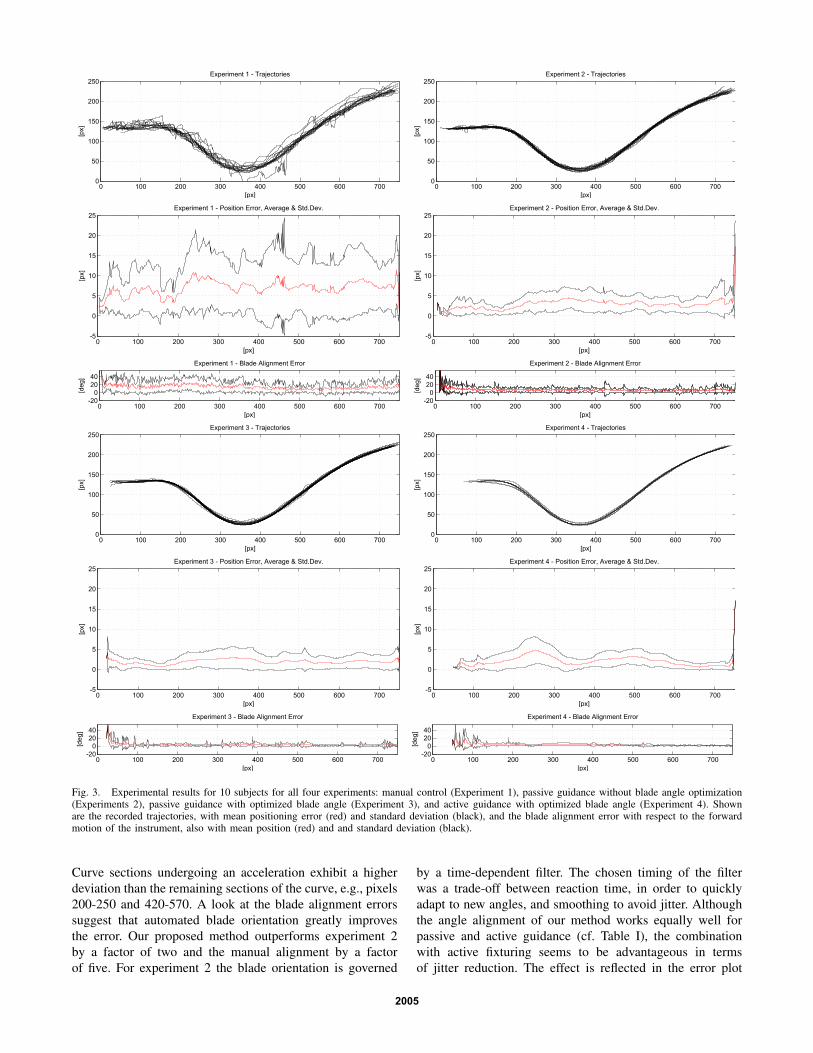
Fig. 3. Experimental results for 10 subjects for all four experiments: manual control (Experiment 1), passive guidance without blade angle optimization(Experiments 2), passive guidance with optimized blade angle (Experiment 3), and active guidance with optimized blade angle (Experiment 4). Shownare the recorded trajectories, with mean positioning error (red) and standard deviation (black), and the blade alignment error with respect to the forwardmotion of the instrument, also with mean position (red) and and standard deviation (black).
Curve sections undergoing an acceleration exhibit a higherdeviation than the remaining sections of the curve, e.g., pixels200-250 and 420-570. A look at the blade alignment errorssuggest that automated blade orientation greatly improvesthe error. Our proposed method outperforms experiment 2by a factor of two and the manual alignment by a factorof five. For experiment 2 the blade orientation is governed
by a time-dependent filter. The chosen timing of the filterwas a trade-off between reaction time, in order to quicklyadapt to new angles, and smoothing to avoid jitter. Althoughthe angle alignment of our method works equally well forpassive and active guidance (cf. Table I), the combinationwith active fixturing seems to be advantageous in termsof jitter reduction. The effect is reflected in the error plot
2005

TABLE IERRORS AND EXECUTION TIME
pos. error [px] angle error [deg] execution time [s]
Exp. mean std.dev. mean std.dev. mean std.dev.
1 7.00 1.97 15.79 4.67 20.01 5.382 2.92 0.82 6.69 3.20 14.90 4.603 1.92 0.54 3.15 3.18 7.87 1.454 2.07 0.74 3.14 3.47 5.83 0.97
of experiments 3 and 4, whereas experiment 4 shows lesspeaks in the alignment error. Task completion time could behalved, whereas active guidance could achieve only a smalladvantage.
During the experiments, most subjects found it difficultand exhausting to follow a path while simultaneously copingwith manual blade alignment. The missing self-alignmentforce during telemanipulation could however be compensatedby an automated alignment of the scalpel. For active fixtur-ing, both the lateral and the angular error were decreased,while task completion time was substantially faster. Onemight argue that a fast execution might not be relevant, how-ever, our method guides the user in the sense of an optimalforward velocity. In doing so the method ensures velocitiesnot exceeding a certain limit on critical path sections, i.e.those with increased curvature. Promising experiments havealso been performed on hardware. At that, the accuracyis currently limited by the play of the servo motors andbowdn-wires that actuate the last three degrees of freedomof the instrument (cf. Fig. 1). Mainly the angular accuracyis affected, while the lateral position can be controlledprecisely.
V. CONCLUSION AND OUTLOOK
A new method for remote surgical cutting by providinghaptic guidance has been proposed. The approach becomesindependent from calibration uncertainties of typical remotesurgery robots by directly augmenting surgical tools with amicro camera. A smooth cut path with corresponding scalpelorientation to guide the user toward the optimal trajectorywas calculated, using both passive and active haptic virtualfixtures. The approach could confirm its advantages in termsof accuracy and execution time during experiments carriedout in a realistic environment.
Future work includes the extension of the task to the thirddimension. Depth perception can be integrated by either astereoscopic setup of the micro cameras, by means of theinstrument’s strain-gauge sensors, or by fusing both modal-ities. Especially the integration of force data seems to bepromising, as it is available at a rate of 1kHz. This allows fora fast adaption of the cutting depth, which is indispensableto avoid tissue fissures. A more advanced haptic device,providing torque force feedback, could potentially support
the angular orientation by actuating the stylus’ self rotation.The calculated angular velocity therewith becomes a virtualself-alignment torque, which can be fed back to the operator.Directly measuring the blade’s torque in-situ and feeding itback through teleoperation would allow a combination withthe angular virtual fixture. However, measuring this angularforce is quite challenging and the authors are not aware ofa suitable solution.
REFERENCES
[1] H. Mayer, I. Nagy, A. Knoll, E. Braun, R. Bauernschmitt, andR. Lange, “Haptic feedback in a telepresence system for endoscopicheart surgery,” MIT PRESENCE: Teleoperators and Virtual Environ-ments, vol. 16, no. 5, pp. 459–470, 2007.
[2] L. Rosenberg, “Virtual fixtures: Perceptual tools for telerobotic ma-nipulation,” in IEEE Virtual Reality Annual International Symposium,1993, pp. 76–82.
[3] C. Passenberg, A. Peer, and M. Buss, “A survey of environment-, operator-, and task-adapted controllers for teleoperation systems,”Mechatronics, vol. 20, no. 7, pp. 787 – 801, 2010.
[4] M. Li and R. Taylor, “Spatial motion constraints in medical robotusing virtual fixtures generated by anatomy,” in Proceedings of theIEEE International Conference of Robotics and Automation, vol. 2,2004, pp. 1270 – 1275.
[5] S. Park, R. D. Howe, and D. F. Torchiana, “Virtual fixtures for roboticcardiac surgery,” in MICCAI, 2001, pp. 1419–1420.
[6] J. Ren, R. Patel, K. McIsaac, G. Guiraudon, and T. Peters, “Dynamic3-d virtual fixtures for minimally invasive beating heart procedures,”IEEE Transactions on Medical Imaging, vol. 27, no. 8, pp. 1061 –1070, 2008.
[7] T. L. Gibo, L. N. Verner, D. D. Yuh, and A. M. Okamura, “Designconsiderations and human-machine performance of moving virtualfixtures,” in Proceedings of the IEEE International Conference ofRobotics and Automation, 2009, pp. 671–676.
[8] C. Staub, G. Panin, A. Knoll, and R. Bauernschmitt, “Visual in-strument guidance in minimaly invasive robot surgery,” InternationalJournal of Advances in Life Sciences, vol. 2, no. 3&4, pp. 103–114,2010.
[9] A. Bettini, P. Marayong, S. Lang, A. M. Okamura, and G. D. Hager,“Vision-assisted control for manipulation using virtual fixtures,” IEEETransactions on Robotics, vol. 20, no. 6, pp. 953 – 966, 2004.
[10] D. Kragic, P. Marayong, M. Li, A. M. Okamura, and G. D. Hager,“Human-machine collaborative systems for microsurgical applica-tions,” Int. J. Rob. Res., vol. 24, no. 9, pp. 731–741, 2005.
[11] G. Guthart and J. Salisbury, “The intuitiveTMtelesurgery system:overview and application,” Proceedings of IEEE ICRA, vol. 1, pp.618–621, 2000.
[12] D. Soetanto, L. Lapierre, and A. Pascoal, “Adaptive, non-singular path-following control of dynamic wheeled robots,” in Proceedings of theIEEE Conference on Decision and Control, vol. 2, 2003, pp. 1765 –1770.
[13] A. Micaelli, A. Micaelli, C. Samson, C. Samson, and P. Icare,“Trajectory tracking for unicycle-type and two-steering-wheels mobilerobots,” INRIA, Research Report RR-2097, 1993.
[14] R. Elble and W. Koller, Tremor. Baltimore, USA: John HopkinsUniversity Press, 1990.
[15] C. Riviere and N. Thakor, “Modeling and canceling tremor in human-machine interfaces,” IEEE Engineering in Medicine and BiologyMagazine, vol. 15, no. 3, pp. 29 –36, 1996.
[16] M. Wäny, S. Voltz, F. Gaspar, and L. Chen, “Minimal form factordigital-image sensor for endoscopic applications,” in Proceedings ofthe SPIE: Sensors, Cameras, and Systems for Industrial/ScientificApplications, vol. 7249, San Jose, USA, 2009.
[17] P. D. Stroud, “A recursive exponential filter for time-sensitive data,”Los Alamos National Laboratory, Tech. Rep. LAUR-99-5573, 1999.
2006