micro switch safety limit switches for … micro switch safety limit switches for hazardous...
TRANSCRIPT
Datasheet
MICRO SWITCH Safety Limit Switches for Hazardous LocationsGSX Series
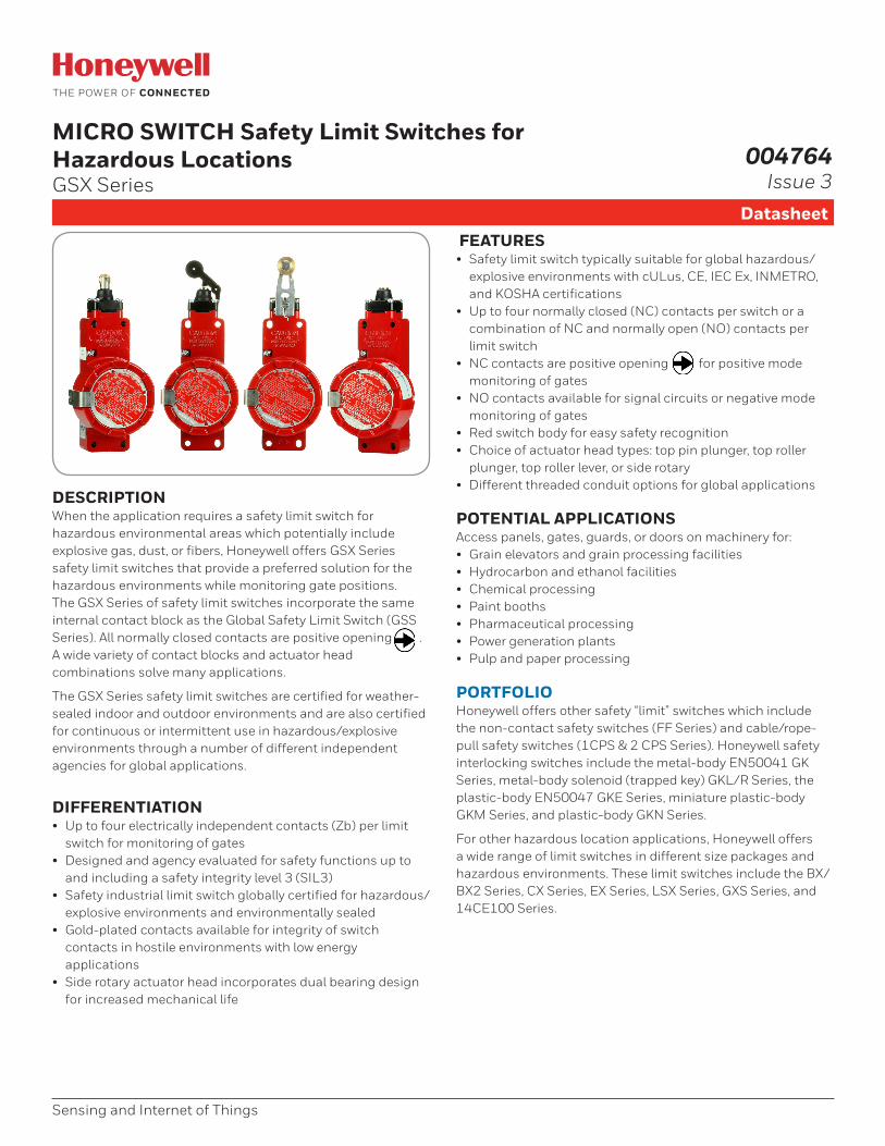
DESCRIPTIONWhen the application requires a safety limit switch for hazardous environmental areas which potentially include explosive gas, dust, or fibers, Honeywell offers GSX Series safety limit switches that provide a preferred solution for the hazardous environments while monitoring gate positions. The GSX Series of safety limit switches incorporate the same internal contact block as the Global Safety Limit Switch (GSS Series). All normally closed contacts are positive opening . A wide variety of contact blocks and actuator head combinations solve many applications.
The GSX Series safety limit switches are certified for weather-sealed indoor and outdoor environments and are also certified for continuous or intermittent use in hazardous/explosive environments through a number of different independent agencies for global applications.
DIFFERENTIATION• Up to four electrically independent contacts (Zb) per limit
switch for monitoring of gates• Designed and agency evaluated for safety functions up to
and including a safety integrity level 3 (SIL3) • Safety industrial limit switch globally certified for hazardous/
explosive environments and environmentally sealed• Gold-plated contacts available for integrity of switch
contacts in hostile environments with low energy applications
• Side rotary actuator head incorporates dual bearing design for increased mechanical life
FEATURES• Safety limit switch typically suitable for global hazardous/
explosive environments with cULus, CE, IEC Ex, INMETRO, and KOSHA certifications
• Up to four normally closed (NC) contacts per switch or a combination of NC and normally open (NO) contacts per limit switch
• NC contacts are positive opening for positive mode monitoring of gates
• NO contacts available for signal circuits or negative mode monitoring of gates
• Red switch body for easy safety recognition• Choice of actuator head types: top pin plunger, top roller
plunger, top roller lever, or side rotary• Different threaded conduit options for global applications
POTENTIAL APPLICATIONSAccess panels, gates, guards, or doors on machinery for:• Grain elevators and grain processing facilities• Hydrocarbon and ethanol facilities• Chemical processing• Paint booths• Pharmaceutical processing • Power generation plants• Pulp and paper processing
PORTFOLIOHoneywell offers other safety “limit” switches which include the non-contact safety switches (FF Series) and cable/rope-pull safety switches (1CPS & 2 CPS Series). Honeywell safety interlocking switches include the metal-body EN50041 GK Series, metal-body solenoid (trapped key) GKL/R Series, the plastic-body EN50047 GKE Series, miniature plastic-body GKM Series, and plastic-body GKN Series.
For other hazardous location applications, Honeywell offers a wide range of limit switches in different size packages and hazardous environments. These limit switches include the BX/BX2 Series, CX Series, EX Series, LSX Series, GXS Series, and 14CE100 Series.
Sensing and Internet of Things
004764Issue 3
2 sensing.honeywell.com
MICRO SWITCH Safety Limit Switches, GSX Series
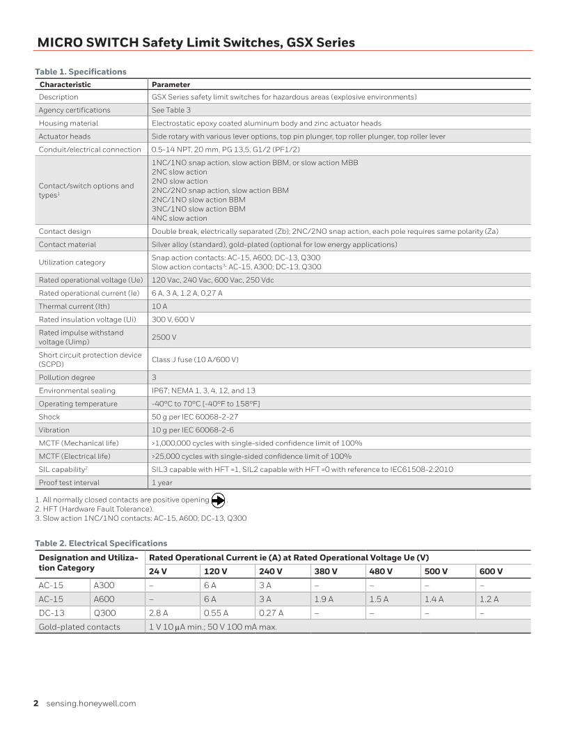
Table 1. SpecificationsCharacteristic Parameter
Description GSX Series safety limit switches for hazardous areas (explosive environments)
Agency certifications See Table 3
Housing material Electrostatic epoxy coated aluminum body and zinc actuator heads
Actuator heads Side rotary with various lever options, top pin plunger, top roller plunger, top roller lever
Conduit/electrical connection 0.5-14 NPT, 20 mm, PG 13,5, G1/2 (PF1/2)
Contact/switch options and types1
1NC/1NO snap action, slow action BBM, or slow action MBB2NC slow action 2NO slow action2NC/2NO snap action, slow action BBM2NC/1NO slow action BBM3NC/1NO slow action BBM4NC slow action
Contact design Double break, electrically separated (Zb); 2NC/2NO snap action, each pole requires same polarity (Za)
Contact material Silver alloy (standard), gold-plated (optional for low energy applications)
Utilization categorySnap action contacts: AC-15, A600; DC-13, Q300Slow action contacts3: AC-15, A300; DC-13, Q300
Rated operational voltage (Ue) 120 Vac, 240 Vac, 600 Vac, 250 Vdc
Rated operational current (Ie) 6 A, 3 A, 1.2 A, 0.27 A
Thermal current (Ith) 10 A
Rated insulation voltage (Ui) 300 V, 600 V
Rated impulse withstand voltage (Uimp)
2500 V
Short circuit protection device (SCPD)
Class J fuse (10 A/600 V)
Pollution degree 3
Environmental sealing IP67; NEMA 1, 3, 4, 12, and 13
Operating temperature -40°C to 70°C [-40°F to 158°F]
Shock 50 g per IEC 60068-2-27
Vibration 10 g per IEC 60068-2-6
MCTF (Mechanical life) >1,000,000 cycles with single-sided confidence limit of 100%
MCTF (Electrical life) >25,000 cycles with single-sided confidence limit of 100%
SIL capability2 SIL3 capable with HFT =1, SIL2 capable with HFT =0 with reference to IEC61508-2:2010
Proof test interval 1 year
1. All normally closed contacts are positive opening .2. HFT (Hardware Fault Tolerance).3. Slow action 1NC/1NO contacts: AC-15, A600; DC-13, Q300
Table 2. Electrical Specifications
Designation and Utiliza-tion Category
Rated Operational Current ie (A) at Rated Operational Voltage Ue (V)
24 V 120 V 240 V 380 V 480 V 500 V 600 V
AC-15 A300 – 6 A 3 A – – – –
AC-15 A600 – 6 A 3 A 1.9 A 1.5 A 1.4 A 1.2 A
DC-13 Q300 2.8 A 0.55 A 0.27 A – – – –
Gold-plated contacts 1 V 10 mA min.; 50 V 100 mA max.
Sensing and Internet of Things 3
MICRO SWITCH Safety Limit Switches, GSX Series
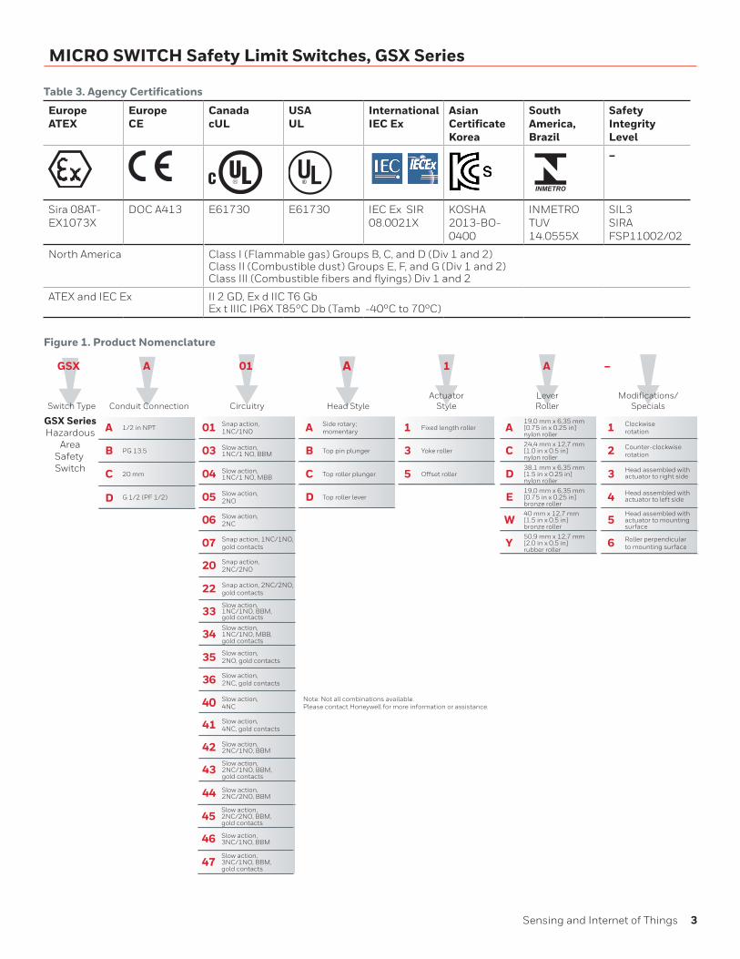
Figure 1. Product Nomenclature
Table 3. Agency Certifications
Europe ATEX
EuropeCE
CanadacUL
USAUL
InternationalIEC Ex
Asian CertificateKorea
South America,Brazil
Safety Integrity Level
–
Sira 08AT-EX1073X
DOC A413 E61730 E61730 IEC Ex SIR 08.0021X
KOSHA 2013-BO-0400
INMETROTUV14.0555X
SIL3SIRAFSP11002/02
North America Class I (Flammable gas) Groups B, C, and D (Div 1 and 2)Class II (Combustible dust) Groups E, F, and G (Div 1 and 2)Class III (Combustible fibers and flyings) Div 1 and 2
ATEX and IEC Ex II 2 GD, Ex d IIC T6 GbEx t IIIC IP6X T85°C Db (Tamb -40°C to 70°C)
GSX
Switch Type
A
LeverRoller
GSX SeriesHazardous
AreaSafety Switch
01
CircuitryActuator
Style
C
D
B
A Side rotary;momentary
Top pin plunger
Top roller plunger
Top roller lever
A
Head Style
04
05
06
07
03
01 Snap action,1NC/1NO
Slow action, 1NC/1 NO, BBM
Slow action, 1NC/1 NO, MBB
Slow action,2NO
Slow action,2NC
Snap action, 1NC/1NO, gold contacts
20
22
Snap action,2NC/2NO
Snap action, 2NC/2NO, gold contacts
33
34
Slow action,1NC/1NO, BBM,gold contacts
Slow action,1NC/1NO, MBB,gold contacts
35 Slow action,2NO, gold contacts
36 Slow action,2NC, gold contacts
40
41
Slow action,4NC
Slow action,4NC, gold contacts
42
43
Slow action,2NC/1NO, BBM
Slow action, 2NC/1NO, BBM,gold contacts
44 Slow action, 2NC/2NO, BBM
D
E
W
Y
C
A19,0 mm x 6,35 mm[0.75 in x 0.25 in]nylon roller
24,4 mm x 12,7 mm[1.0 in x 0.5 in]nylon roller
38,1 mm x 6,35 mm[1.5 in x 0.25 in]nylon roller
19,0 mm x 6,35 mm[0.75 in x 0.25 in]bronze roller40 mm x 12,7 mm[1.5 in x 0.5 in]bronze roller
50,9 mm x 12,7 mm[2.0 in x 0.5 in]rubber roller
5
3
1 Fixed length roller
Yoke roller
Offset rollerC
B
1/2 in NPT
PG 13.5
20 mm
Conduit Connection
A
A
45
46
Slow action,2NC/2NO, BBM,gold contacts
Slow action,3NC/1NO, BBM
47Slow action,3NC/1NO, BBM,gold contacts
Modifications/Specials
3
4
5
6
2
1 Clockwiserotation
Counter-clockwiserotation
Head assembled withactuator to right side
Head assembled withactuator to left side
Head assembled withactuator to mounting surface
Roller perpendicularto mounting surface
–1
D G 1/2 (PF 1/2)
Note: Not all combinations available. Please contact Honeywell for more information or assistance.
4 sensing.honeywell.com
MICRO SWITCH Safety Limit Switches, GSX Series
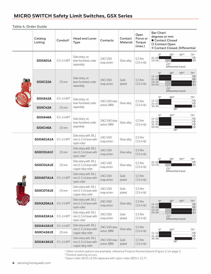
Table 4. Order Guide
Catalog Listing Conduit1 Head and Lever
Type Contacts Contact Material
Oper. Force or Torque (max.)
Bar Chart degrees or mm n Contact Closed o Contact Openn Contact Closed, Differential
GSXA01A 0.5-14 NPTSide rotary, no lever furnished, order separately
1NC/1NO snap action
Silver alloy0,3 Nm [2.6 in lb]
13-1421-22
75°0°
12°1
differential travel
26°
��
55°2
GSXC22A 20 mmSide rotary, no lever furnished, order separately
2NC/2NO snap action
Gold-plated
0,3 Nm [2.6 in lb]
13-1421-22
75°0° 26°
��
55°2
��
11-12
23-24
12°1
differential travel
GSXA42A 0.5-14 NPT Side rotary, no lever furnished, order separately
2NC/1NO slow action, BBM
Silver alloy0,3 Nm [2.6 in lb] 33-34
21-22
75°0°
38°
26°2
��11-12
�GSXC42A 20 mm
GSXA46A 0.5-14 NPT Side rotary, no lever furnished, order separately
3NC/1NO slow action, BBM
Silver alloy0,3 Nm [2.6 in lb] 31-32
21-22
75°0°
38°
26°2
��
�
11-12
43-44
�
GSXC46A 20 mm
GSXA01A1A 0.5-14 NPTSide rotary with 38,1 mm [1.5 in] lever with nylon roller
1NC/1NO snap action
Silver alloy0,3 Nm [2.6 in lb]
13-1421-22
75°0°
12°1
differential travel
26°
��
55°2
GSXC01A1C 20 mmSide rotary with 38,1 mm [1.5 in] lever with nylon roller3
1NC/1NO snap action
Silver alloy0,3 Nm [2.6 in lb]
GSXC01A1E 20 mmSide rotary with 38,1 mm [1.5 in] lever with copper alloy roller
1NC/1NO snap action
Silver alloy0,3 Nm [2.6 in lb]
GSXA07A1A 0.5-14 NPTSide rotary with 38,1 mm [1.5 in] lever with nylon roller
1NC/1NO snap action
Gold-plated
0,3 Nm [2.6 in lb]
GSXC07A1E 20 mmSide rotary with 38,1 mm [1.5 in] lever with copper alloy roller
1NC/1NO snap action
Gold-plated
0,3 Nm [2.6 in lb]
GSXA20A1A 0.5-14 NPTSide rotary with 38,1 mm [1.5 in] lever with nylon roller
2NC/2NO snap action
Silver alloy0,3 Nm [2.6 in lb]
13-1421-22
75°0° 26°
��
55°2
��
11-12
23-24
12°1
differential travelGSXA22A1A 0.5-14 NPT
Side rotary with 38,1 mm [1.5 in] lever with nylon roller
2NC/2NO snap action
Gold-plated
0,3 Nm [2.6 in lb]
GSXA42A1E 0.5-14 NPT Side rotary with 38,1 mm [1.5 in] lever with copper alloy roller
2NC/1NO slow action, BBM
Silver alloy0,3 Nm [2.6 in lb]
33-3421-22
75°0°
38°
26°2
��11-12
�
GSXC42A1E 20 mm
GSXA43A1E 0.5-14 NPTSide rotary with 38,1 mm [1.5 in] lever with copper alloy roller
2NC/1NO slow action, BBM
Gold-plated
0,3 Nm [2.6 in lb]
1 Other conduit options are available, reference Product Nomenclature (Figure 1) on page 3.2 Positive opening occurs.3 Nylon roller (Ø19 x 6,35) replaced with nylon roller (Ø25 x 12,7) .
Sensing and Internet of Things 5
MICRO SWITCH Safety Limit Switches, GSX Series
Catalog Listing Conduit1 Head and Lever
Type Contacts Contact Material
Oper. Force or Torque (max.)
Bar Chart degrees or mm n Contact Closed o Contact Openn Contact Closed, Differential
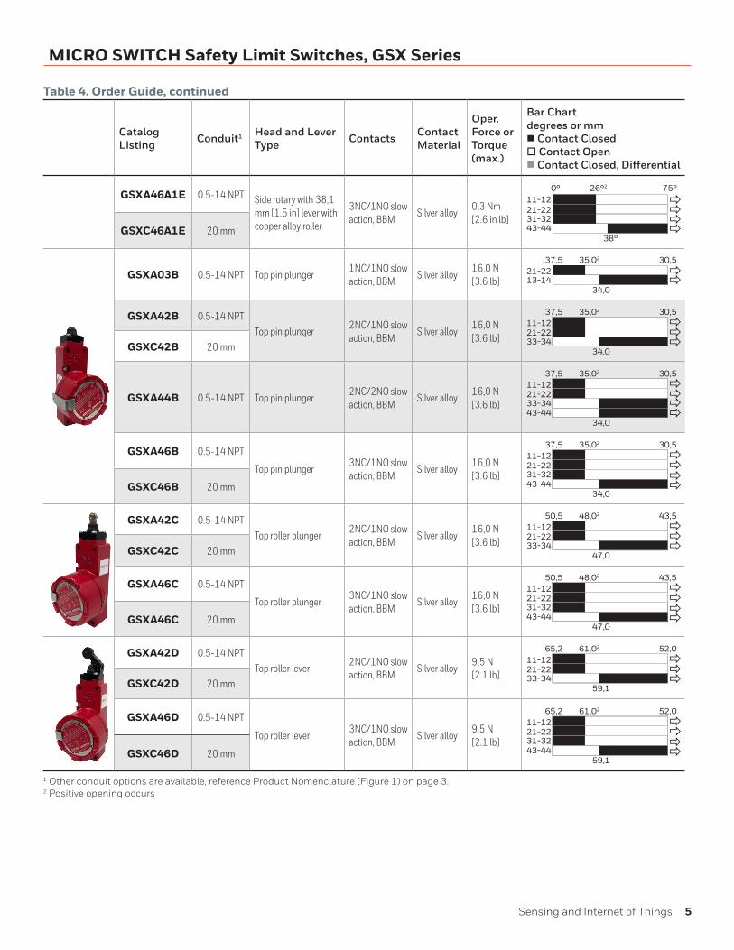
GSXA46A1E 0.5-14 NPT Side rotary with 38,1 mm [1.5 in] lever with copper alloy roller
3NC/1NO slow action, BBM
Silver alloy0,3 Nm [2.6 in lb] 31-32
21-22
75°0°
38°
26°2
��
�
11-12
43-44
�
GSXC46A1E 20 mm
GSXA03B 0.5-14 NPT Top pin plunger1NC/1NO slow action, BBM
Silver alloy16,0 N [3.6 lb] 13-14
21-2230,537,5 35,02
��
34,0
GSXA42B 0.5-14 NPTTop pin plunger
2NC/1NO slow action, BBM
Silver alloy16,0 N [3.6 lb] 33-34
21-22
30,537,5 35,02
�
34,0
��
11-12
GSXC42B 20 mm
GSXA44B 0.5-14 NPT Top pin plunger2NC/2NO slow action, BBM
Silver alloy16,0 N [3.6 lb] 33-34
21-22
30,537,5 35,02
�
34,0
�11-12
43-44 ��
GSXA46B 0.5-14 NPT
Top pin plunger3NC/1NO slow action, BBM
Silver alloy16,0 N [3.6 lb] 31-32
21-22
30,537,5 35,02
�
34,0
�11-12
43-44
��GSXC46B 20 mm
GSXA42C 0.5-14 NPTTop roller plunger
2NC/1NO slow action, BBM
Silver alloy16,0 N [3.6 lb] 33-34
21-22
43,550,5 48,02
�
47,0
��
11-12
GSXC42C 20 mm
GSXA46C 0.5-14 NPT
Top roller plunger3NC/1NO slow action, BBM
Silver alloy16,0 N [3.6 lb] 31-32
21-22
43,550,5 48,02
�
47,0
�11-12
43-44
��GSXA46C 20 mm
GSXA42D 0.5-14 NPTTop roller lever
2NC/1NO slow action, BBM
Silver alloy9,5 N [2.1 lb] 33-34
21-22
52,065,2 61,02
�59,1
��
11-12
GSXC42D 20 mm
GSXA46D 0.5-14 NPT
Top roller lever3NC/1NO slow action, BBM
Silver alloy9,5 N [2.1 lb] 31-32
21-22
52,065,2 61,02
�
59,1
�11-12
43-44
��GSXC46D 20 mm
1 Other conduit options are available, reference Product Nomenclature (Figure 1) on page 3.2 Positive opening occurs
Table 4. Order Guide, continued
6 sensing.honeywell.com
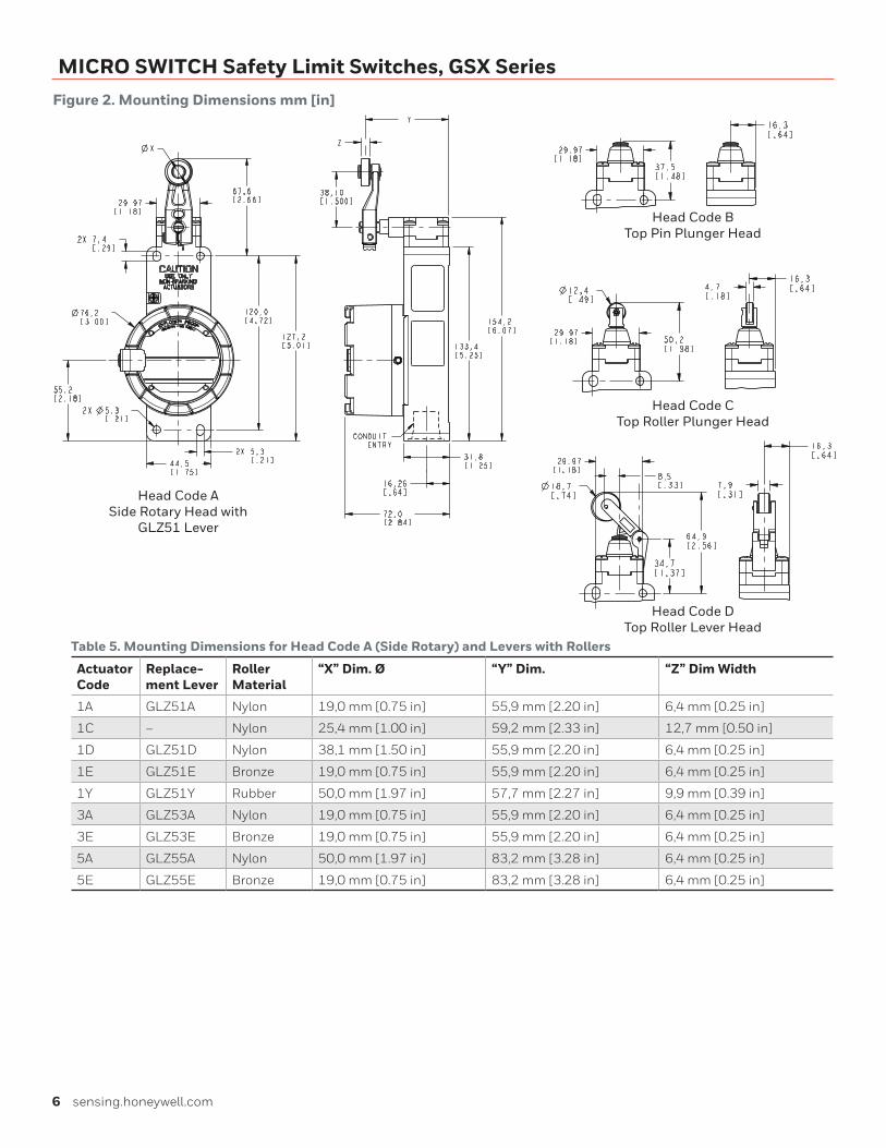
MICRO SWITCH Safety Limit Switches, GSX SeriesFigure 2. Mounting Dimensions mm [in]
Head Code DTop Roller Lever Head
Head Code CTop Roller Plunger Head
Head Code BTop Pin Plunger Head
Head Code ASide Rotary Head with
GLZ51 Lever
Table 5. Mounting Dimensions for Head Code A (Side Rotary) and Levers with Rollers
Actuator Code
Replace-ment Lever
Roller Material
“X” Dim. Ø “Y” Dim. “Z” Dim Width
1A GLZ51A Nylon 19,0 mm [0.75 in] 55,9 mm [2.20 in] 6,4 mm [0.25 in]
1C – Nylon 25,4 mm [1.00 in] 59,2 mm [2.33 in] 12,7 mm [0.50 in]
1D GLZ51D Nylon 38,1 mm [1.50 in] 55,9 mm [2.20 in] 6,4 mm [0.25 in]
1E GLZ51E Bronze 19,0 mm [0.75 in] 55,9 mm [2.20 in] 6,4 mm [0.25 in]
1Y GLZ51Y Rubber 50,0 mm [1.97 in] 57,7 mm [2.27 in] 9,9 mm [0.39 in]
3A GLZ53A Nylon 19,0 mm [0.75 in] 55,9 mm [2.20 in] 6,4 mm [0.25 in]
3E GLZ53E Bronze 19,0 mm [0.75 in] 55,9 mm [2.20 in] 6,4 mm [0.25 in]
5A GLZ55A Nylon 50,0 mm [1.97 in] 83,2 mm [3.28 in] 6,4 mm [0.25 in]
5E GLZ55E Bronze 19,0 mm [0.75 in] 83,2 mm [3.28 in] 6,4 mm [0.25 in]
Warranty/RemedyHoneywell warrants goods of its manufacture as being free of defective materials and faulty workmanship during the appli-cable warranty period. Honeywell’s standard product warranty applies unless agreed to otherwise by Honeywell in writing; please refer to your order acknowledgment or consult your local sales office for specific warranty details. If warranted goods are returned to Honeywell during the period of coverage, Honeywell will repair or replace, at its option, without charge those items that Honeywell, in its sole discretion, finds defec-tive. The foregoing is buyer’s sole remedy and is in lieu of all other warranties, expressed or implied, including those of merchantability and fitness for a particular purpose. In no event shall Honeywell be liable for consequential, special, or indirect damages.
While Honeywell may provide application assistance personally, through our literature and the Honeywell web site, it is buyer’s sole responsibility to determine the suitability of the product in the application.
Specifications may change without notice. The information we supply is believed to be accurate and reliable as of this writing. However, Honeywell assumes no responsibility for its use.
004764-3-EN IL50 GLO May 2017© 2017 Honeywell International Inc. All rights reserved.
m WARNINGIMPROPER INSTALLATION• Consult with local safety agencies and their requirements
when designing a machine-control link, interface and all control elements that affect safety.
• Strictly adhere to all installation instructions.
Failure to comply with these instructions could result in death or serious injury.
m WARNINGMISUSE OF DOCUMENTATION• The information presented in this product sheet is for
reference only. Do not use this document as a product installation guide.
• Complete installation, operation, and maintenance information is provided in the instructions supplied with each product.
Failure to comply with these instructions could result in death or serious injury.
Find out moreHoneywell serves its customers
through a worldwide network of
sales offices and distributors.
For application assistance,
current specifications, pricing
or name of the nearest
Authorized Distributor, contact
your local sales office.
To learn more about
Honeywell’s sensing and
switching products,
call +1-815-235-6847 or 1-800-537-6945, visit sensing.honeywell.com, or e-mail inquiries to
ADDITIONAL MATERIALSThe following associated literature is available at sensing.honeywell.com:
• Product range guide
• Installation instructions
• Application note
Honeywell Sensing and Internet of Things9680 Old Bailes Road
Fort Mill, SC 29707
honeywell.com