microchip announces two new entry-level...
TRANSCRIPT
For more information visit www.microchip.com
Microchip Announces Two New Entry-Level Development ToolsPAGE 1 Microchip Announces Two New Entry-Level Development Tools
PAGE 2 MCP7386X Battery Chargers Maximize Battery Capacity, Life Cycle and Safety
PAGE 3 MCP1630 Power-Supply, Pulse-Width Modulation (PWM) Controller - Fastest in the Market
PAGE 4 Microchip Introduces Eight Flash PIC® Microcontrollers in 28-, 40- and 44-pin Packages
PAGE 5 New Field Reprogrammable Battery Manager Accurately Reports Battery Capacity
PAGE 6 Microchip Delivers Two dsPIC® 16-bit Digital Signal Controllers
PAGE 7-8 Tips n’ Tricks: – PICmicro® Microcontroller Comparators
PAGE 9 – dsPIC® DSC Introductory Seminars are Coming to a City Near You!
– Archived WebSeminars
PAGE 10-11 What’s New in Microchip Literature?
PAGE 12 Web Site Highlights
IN THIS ISSUE
For more product information visit:
www.microchip.com
Microchip’s new, cost-effective development
tools, the PICtail™ Analysis Daughter Board,
(part number AC164120) and the Baseline
Flash Microcontroller Programmer (BFMP),
(part number PG164101), allow user-
friendly evaluation of analog processing
and simple programming with low pin-count
PIC® microcontrollers.
The Signal Analysis PICtail Daughter
Board and accompanying PC software,
when plugged into the PICkit™ 1
Flash Starter Kit, enables engineers to
analyze analog signals as processed
by Microchip’s low pin-count 8-bit
PIC® microcontrollers. This new daughter board, with its Graphical User
Interface (GUI), provides designers with a toolbox for learning and evaluating
the capabilities of low pin-count PIC microcontrollers without expensive test
equipment or tools.
The Baseline Flash Microcontroller Programmer is a simple, In-Circuit Serial
Programming™ (ICSP™) programmer intended to be used with any of
Microchip’s new baseline 8-bit PIC Flash microcontrollers. When paired with
the PIC10F2XX Programmer Adapter, (part number AC163020), the BFMP
provides the least expensive programming method and includes standard
ICSP technology support and stand-alone programming for the 6-pin PIC10F
family. Utilizing USB and the included GUI, the BFMP enables users to easily
read, write and verify Microchip’s Flash-based, Baseline PIC microcontrollers.
“With the introduction of these two development tools, Microchip continues to
make it easy for designers to try our PIC microcontrollers,” said Steve Drehobl,
Vice President of Microchip’s Security, Microcontroller and Technology
Division. “The Signal Analysis PICtail Daughter Board and BFMP allow users
to get up-and-running with minimal time and fi nancial investment.”
The Signal Analysis PICtail Daughter Board is an add-on board to the popular
low-cost PICkit 1 Flash Starter Kit that contains the 14-pin PIC16F684
8-bit Flash microcontroller and 16 Kbytes of serial EEPROM memory. When
the Signal Analysis Board is plugged into the PICkit 1 Flash Starter Kit and
used with the accompanying Signal Analysis PC software, the designer can
perform real-time measurements and display them on a strip chart.
Engineers can also acquire data, which can then be processed and analyzed
in an oscilloscope plot, FFT or histogram. By including an easy-to-use PC
software program, this daughter board can be used both to explore new
concepts and to process and display data in traditional formats that are
familiar to design engineers.
The BFMP is compatible with all of Microchip’s new Baseline 8-bit PIC Flash
microcontrollers, including the following devices:
PIC10F200/202/204/206
PIC12F508/509
PIC16F505
PIC16F54/57/59
The BFMP also provides a 6-pin linear ICSP header for standard ICSP
support. Its powered USB connection eliminates the need for an external
power supply.
Tools and Product Availability
The Signal Analysis PICtail Daughter Board and the Baseline Flash
Microcontroller Programmer are available now.
For additional information, please contact any Microchip sales
representative, authorized worldwide distributor or visit
http://buy.microchip.com.
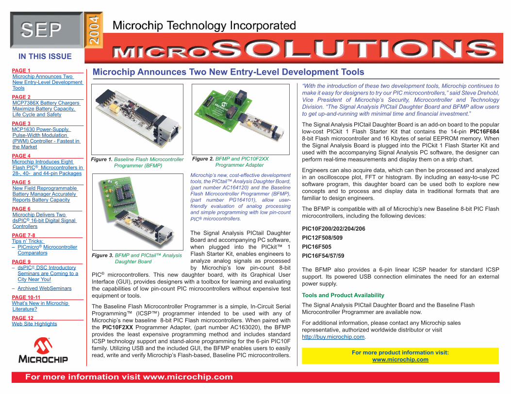
Figure 1. Baseline Flash Microcontroller
Programmer (BFMP)
Figure 2. BFMP and PIC10F2XX
Programmer Adapter
Figure 3. BFMP and PICtail™ Analysis
Daughter Board
MICROCHIP TECHNOLOGY’S MICROSOLUTIONS eNEWSLETTER - September 2004
For more information visit www.microchip.com 2
Microchip’s MCP7386X single-cell and
dual-cell, fully integrated, charge-management
controllers each feature a charge-safety timer and
a temperature monitor. With an overall system
accuracy of ±0.5 percent, these devices maximize
system runtime between charges and ensure that
the battery-cell capacity is fully utilized without
cycle-life degradation. Meanwhile, the on-board
thermal regulation optimizes charge-cycle time,
while maintaining the devices’ reliability and
simplifying the board design.
The MCP7386X devices extract information regarding charge and temperature status, giving the
user elaborate control and sophisticated protection. On-board safety timers and thermal monitor
provide time- and temperature-based charge termination, protecting applications from defective
batteries and increasing the battery safety. The MCP7386X controllers also feature reverse-
blocking protection, which allows current from a correctly installed battery to fl ow to the load and
block current fl ow to a backward-installed battery.
MCP7386X Features
• Built-in pass transistor – minimizes the number of external components and the overall
footprint
• Reverse leakage current of less than 0.4 microamps (typical) extends battery life
• Programmable fast-charge current up to 1.2 amps
• MCP73861 device is specifi ed from 4.5V to 12V
• MCP73862 device is specifi ed from 8.7V to 12V
• Temperature Range –40°C to +85°C (MCP73861/2)
• Available in 4.1V/4.2V and 8.2V/8.4V:
Accommodates a variety of portable products that are powered by one- or two-cell Lithium
Ion/ Lithium Polymer batteries (with coke or graphite anodes)
• Devices are synergistic with Microchip’s power management product portfolio, including the
company’s DC/DC converters, linear regulators in power management applications and its
PowerSmart® battery managers and monitors
• Pb-free, leadless, 4x4 QFN package:
Allows for higher power dissipation and therefore, shorter charging times
Fully Integrated Linear Battery Chargers Maximize Battery Capacity, Life Cycle and Safety
The new MCP7386X devices are available today for sampling and volume production
in the following package.
• MCP73861 - leadless, 4 x 4 QFN
• MCP73862 - leadless, 4 x 4 QFN
For more information, contact your authorized worldwide distributor or visit Microchip’s
Web site at www.microchip.com
For more product information visit:
www.microchip.com/mcp7386X
ENSTAT1 STAT2
VSET
VDD1
VDD2
VSS2
TIMERPROG THERMTHREF
VBAT3
VBAT2
VBAT1
VSS3
CTIMER
Regulated orUnregulatedWall Cube
User-set Current
Charge CurentUp to 1.2A
Safety Timer
Fault and Status Indicators
RPROG RT1
RT2
+
–
SingleLithium-IonCell
VSS1
1
2
3
4
141516
5 6 7 8
9
10
11
12
13
MCP73861
Figure 1. MCP73861 Typical Application Circuit
For more information visit www.microchip.com 3
MICROCHIP TECHNOLOGY’S MICROSOLUTIONS eNEWSLETTER - September 2004
Microchip’s power supply pulse-width modulation (PWM) controller with a current sense-to-output delay of 12 nanoseconds makes it the fastest PWM on the market*. This device enables power-system designers to add precision control, digital communication and programmability for initial settings or an “on-the-fl y” adjustment or calibration.
Microchip’s MCP1630 is comprised of a high-speed comparator with a high-performance error amplifi er and a PWM latch to perform the analog power-supply PWM function. This device, when used in conjunction with a microcontroller, can support the development of high-speed, intelligent, power-system controllers. The
microcontroller adjusts the output voltage (or current), switching frequency, maximum duty cycle and other features, making the power system more intelligent and adaptable. This enables the power system to adapt to many external signals and variables in order to optimize performance and facilitate calibration.
The MCP1630 can yield a power supply with advanced features, communications and programmability and it supports all Switch Mode Power Supply (SMPS) topologies. It is best suited for applications requiring medium-to-high levels of intelligence and operating at frequencies exceeding 200 kHz.
MCP1630 Typical Applications• Battery chargers for Lithium-Ion and Nickel Metal Hydride chemistries • Intelligent power systems • Brick DC/DC converters • AC power-factor correction • Multiple output-power supplies and multiple-phase power supplies
MCP1630 Features• Under-voltage lockout (UVLO)• Output short circuit and over-temperature protection• Low operating current of 2.8 milliamps (typical) • Fast output rise and fall times of 5.9 nanoseconds and 6.2 nanoseconds, respectively • Precise peak-current limit of ±5 percent and a peak-current mode operation to 1 MHz
To aid in the development with this device, Microchip is offering a battery-charger demonstration board. On this board is a SEPIC (Single-End Primary Inductor Circuit) converter that provides a constant charge current to the battery. The MCP1630 regulates this charge current by monitoring it through a battery-sense resistor and by providing the proper pulse-width.
Microchip Offers Digital Control for the Analog Power Supply Function With the World’s Fastest Pulse-Width Modulator
For more product information visit:
www.microchip.com/mcp1630
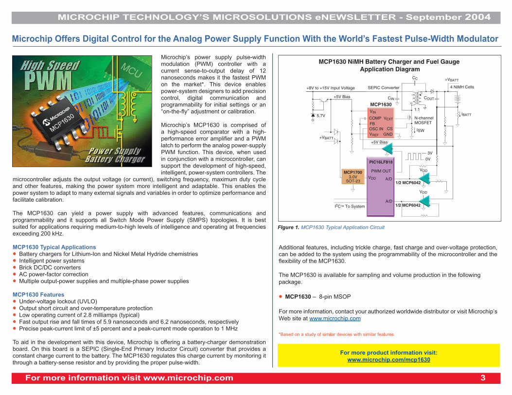
MCP1630
PIC16LF818
+8V to +15V Input Voltage
5.7V
+5V Bias
+5V Bias
1/2 MCP6042
1/2 MCP6042
SEPIC Converter
MCP1630 NiMH Battery Charger and Fuel Gauge Application Diagram
4 NiMH Cells
N-channelMOSFET
1:1
A/D
PWM OUT
A/D
+VBATT
IBATT
VDD
VDD
I2C™ To System
VDD
+VBATT
CC
ISW
CIN
VEXT
VIN
VREF
COUT
3V
0V
MCP17003.0V
SOT-23
GNDCS
COMPFBOSC IN
–+
–+
–+
FIgure 1. MCP1630 Typical Application Circuit
Additional features, including trickle charge, fast charge and over-voltage protection, can be added to the system using the programmability of the microcontroller and the fl exibility of the MCP1630.
The MCP1630 is available for sampling and volume production in the following
package.
• MCP1630 – 8-pin MSOP
For more information, contact your authorized worldwide distributor or visit Microchip’s
Web site at www.microchip.com
*Based on a study of similar devices with similar features.
MICROCHIP TECHNOLOGY’S MICROSOLUTIONS eNEWSLETTER - September 2004
For more information visit www.microchip.com 4
Microchip has expanded its 28-, 40-
and 44-pin Flash PIC® microcontroller
portfolio with eight PIC18FXXXX
devices targeting mid-range
applications requiring up to 32 Kbytes
of program memory in low pin counts.
These cost-effective microcontrollers
feature nanoWatt Technology for
optimum power management and
improved C compiler efficiency for
applications written with re-entrant
code, which is common in real-time
operating systems.
Designers of embedded control applications have a growing need for 8-bit microcontrollers
with the most popular, mid-size memories in small form factors, balanced with a requirement
to consume less power over a broad range of applications. These new 28-, 40- and 44-pin
PIC18FXXXX microcontrollers help solve these design concerns with 16 or 32 Kbytes of Flash
program memory, up to 1.5 Kbytes of RAM and nanoWatt Technology low-power modes.
“Microchip continues to see growing design activity in the already popular 28-, 40- and 44-pin
8-bit microcontroller market,” said Ganesh Moorthy, vice president of Microchip’s Advanced
Microcontroller and Memory Division. “The new Flash PIC microcontrollers expand the options
available to designers in these pin counts by adding the most popular, mid-size program
memories.”
This PIC microcontroller family offers Standard Flash and Enhanced Flash memory technologies.
The Enhanced Flash family has self-programming capability, allowing the microcontroller to be
programmed after being placed in a circuit board, providing tremendous flexibility, reducing
development time, increasing manufacturing efficiency and faster time to market. The Enhanced
Flash devices also contain 256 bytes of high-endurance EEPROM data memory.
Ideal Applications for these new devices include:
• Appliance (controller for air handlers)
• Automotive (LIN-to-LIN gateways, remote-keyless-entry receivers)
• Computing (encrypted security systems)
• Consumer (radio-frequency remote water/gas meter reading)
• Industrial (differential air pressure sensors)
Microchip Introduces Eight Flash PIC® Microcontrollers with Most Popular Memory Sizes and Power Management
For more product information visit:
www.microchip.com/pic18FXXXX
With the unique nanoWatt Technology, these microcontrollers offer power-managed
modes that make them ideal for battery and low-power applications. The devices also
feature Microchip’s advanced PMOS Electrically Erasable Cell (PEEC) Flash process
technology, which enables up to 1,000,000 data memory ERASE/WRITE cycles and
up to 100,000 program memory ERASE/WRITE cycles, with 40 years of data retention.
Additional features include:
• Internal core performance of up to 40 MHz (10 MIPS)
• 32 kHz to 32 MHz internal oscillator, software-configurable in real time
• Fail-safe clock monitor
• Wide voltage range of 2.0 – 5.5 volts and a -40°C to +125°C temperature range
• In-Circuit Serial Programming™ (ICSP™) capability
• 10-bit Analog-to-Digital Converter (ADC) with up to 13 signal channels and 100k samples-per-second
• Two analog comparators with programmable brown-out reset and programmable low-voltage detect
• SPI™, I2C™ and AUSART (supports LIN, RS485 and RS232)
• Two Capture/Compare PWM Modules
Development Tools
All eight microcontrollers are supported by Microchip’s high-performance development
systems, including:
• MPLAB® Integrated Development Environment (IDE)
• MPLAB® C18 C Compiler
• MPLAB® ICD 2 In-Circuit Debugger
• MPLAB® ICE 2000 In-Circuit Emulator
Product Availability
The eight microcontrollers are available today for general sampling and volume
production, in the package options listed below.
• PIC18F2520: 28-pin SDIP, SOIC, QFN
• PIC18F2410, PIC18F2420, PIC18F2510: 28-pin SDIP, SOIC
• PIC18F4510, PIC18F4520, PIC18F4420, PIC18F4410: 40-pin PDIP; 44-pin TQFP, QFN

For more information visit www.microchip.com 5
MICROCHIP TECHNOLOGY’S MICROSOLUTIONS eNEWSLETTER - September 2004
Microchip has expanded its battery-management product line with the introduction of an integrated,
fi eld-reprogrammable, fuel-gauge for two-, three-and four-cell Lithium Ion (Li-Ion) and Lithium
Polymer (Li-Poly), or six to 12-cell Nickel Metal Hydride (NiMH) & Nickel Cadmium (NiCD).
This Smart Battery System (SBS) compliant device provides precise predictions of battery capacity.
It offers cell monitoring for safety conditions along with End of Discharge (EOD) control, thereby
maximizing battery life and runtime.
The PS501 battery-manager IC combines Microchip’s high-performance, low-power PIC18
microcontroller core with its Accuron® proprietary algorithm stored in 16-Kbytes of on-chip Flash
memory. This battery-manager offers a low-operating current of 150 microamps. When the
application is not in use, the device enters a low-power sleep mode using less than 1 microamp,
which optimizes the capacity and minimizes over discharge of the battery.
Also included is a 16-bit programmable, sigma-delta integrating A/D converter and application-
optimized mixed-signal circuitry. This enables precision measurement of battery current,
temperature and voltage as well as direct connection of up to four-series cell Li-Ion or Li-Poly
packs. On-chip EEPROM provides storage of user-customizable and “learned” battery parameters.
The PS501 battery-manager integrates an accurate silicon oscillator, eliminating the need for an
external crystal. To further optimize the PS501 battery-manager for Li-Poly applications, hardware
and advanced algorithms are integrated for cell balancing. Twelve general purpose pins support
charge and safety control or user programmable digital I/O. Eight of them can be used as LED
drivers and two are open-drain for direct FET drive. Communication with the host is compliant with
the industry-standard SMbus protocol and all Sbdata parameters are supported.
New Field Reprogrammable Battery Manager Accurately Reports Battery Capacity Lithium- and Nickel-Based Battery Packs
For more product information visit:
www.microchip.com/PS501
Development system availability for the PS501 battery-manager includes:
• PS5164EV - for the four-series cell
• PS5163EV - for the three-series cell
• PS5162EV - for the two-series cell battery pack for Li-Ion or Li-Poly
For NiMH and NiCD, the PS5200EV is available, which can be confi gured for six-12
cells in series. This development system includes:
• An application board
• PowerInfo™ 2 interface board (PS051)
• Accompanying cables and documents
• Microsoft Windows® software-based PowerTool™ 2 (PS050) software with
embedded wizard allows optimization of application-and-battery specifi c parameters
during evaluation and development as well as production support such as custom
programming and calibration of a PS501 application board
The PS501 battery-manager is available in a Pb-free, 28-pin SSOP package.
Product Availability
Samples and volume production are now available.
For more information, contact your authorized worldwide distributor or visit Microchip’s
Web site at www.microchip.com
The PS501 Maximizes Battery Runtime
and Safety in Mobile Devices
MICROCHIP TECHNOLOGY’S MICROSOLUTIONS eNEWSLETTER - September 2004
For more information visit www.microchip.com 6
Microchip has begun volume production of the dsPIC30F5011 and dsPIC30F5013 dsPIC®
Digital Signal Controllers (DSCs). Both devices offer designers performance speeds of up to 30
Million Instructions Per Second (MIPS) and 66 Kbytes of selfprogramming Flash memory with
industrial and extended temperature ranges. These DSCs are ideal for a variety of embedded
applications that require higher performance than is obtainable on current 16-bit microcontroller
offerings.
“When we coined the term ‘Digital Signal Control’ we saw a rapidly emerging market that
needed a high-performance, 16-bit microcontroller and Digital Signal Processor on a single-
chip solution,” said Sumit Mitra, vice president of Microchip’s Digital Signal Controller Division.
“Our customers were looking for attributes not common to DSPs in this performance range.
Microchip was able to offer them an inexpensive Flash program memory, small form factor,
effi cient C code generation, wide-operating voltage range, integrated mixed-signal elements
and low-cost tools. The dsPIC DSC is a skillful blend of a MCU and a DSP in one device that
provides our customers the best of both worlds.”
Microchip’s Enhanced Flash self-programming capability features a remote upgrade to the
Flash program memory, allowing code and data revisions at the end of the production process
or in end-users’ applications. This combination of features provides:
• Flexibility
• Reduced development time
• Increased manufacturing effi ciency
• Faster time-to-market
Both dsPIC DSC devices integrate an array of on-chip functions, such as:
• 16- and 32-bit timers
• Input capture/output compare
• Communication modules (such as UART, SPI™ interface, I2C™ interface, CAN and
Codec interface) and a 12-bit Analog-to-Digital Converter (ADC)
• 4 Kbytes of data RAM and 1 Kbyte of high-endurance EEPROM data memory. Both are
specifi ed in industrial, extended temperatures ranges and are applicable to a variety of
applications, including industrial, automotive, consumer and offi ce-automation equipment
Microchip Technology Delivers Two dsPIC® 16-bit Digital Signal Controllers for High-Peformance,
General-Purpose Applications
Development Tools, Application Libraries and Reference Designs
All dsPIC DSCs are supported by Microchip’s high-performance development systems,
including:
• MPLAB® Integrated Development Environment (IDE),
• MPLAB® C30 C Compiler,
• MPLAB® SIM tool
• MPLAB® ICD 2 In-Circuit Debugger,
• MPLAB® Visual Device Initializer and
• MPLAB® ICE 4000 In-Circuit Emulator (ICE).
Availability
The dsPIC30F5011 and dsPIC30F5013 are available today for volume production
shipment.
The dsPIC30F5011 is offered in 64-pin TQFP packages
The dsPIC30F5013 is offered in 80-pin TQFP packages
About dsPIC Digital Signal Controllers
The dsPIC DSC is a 16-bit (data) modifi ed Harvard RISC machine that combines the control
advantages of a high-performance 16-bit microcontroller with the high computation speed of
a fully implemented digital signal processor (DSP) to produce a tightly coupled single-chip
single-instruction stream solution for embedded systems design. All dsPIC DSCs integrate
Flash program memory and most have EEPROM data storage.
For more information, contact your authorized worldwide distributor or visit Microchip’s Web
site at www.microchip.com
For more product information visit:
www.microchip.com

For more information visit www.microchip.com 5
MICROCHIP TECHNOLOGY’S MICROSOLUTIONS eNEWSLETTER - September 2004
Tips n’ Tricks - PICmicro® Microcontroller Comparators
TIP 1. Window Comparison
When monitoring an external sensor, it is often convenient to be able to determine when
the signal has moved outside a pre-established safe operating range of values or window of
operation. This windowing provides the circuit with an alarm when the signal moves above or
below safety limits, ignoring minor fl uctuations inside the safe operating range. To implement a
window comparator, two voltage comparators and 3 resistors are required (see Figure 1-1).
TIP 1. Window Comparison (continued)
R2
R3R1
Output
Input
VDD
+
–
Figure 1-1. Window Comparator
TIP 2. Hysteresis
When the voltages on a comparator’s input are nearly equal, external noise and switching
noise from inside the microcontroller can cause the comparator output to oscillate or
“chatter”. To prevent chatter, some of the comparator output voltage is fed back to the
non-inverting input of the comparator to form hysteresis (see Figure 2-1). Hysteresis moves
the comparator threshold up when the input is below the threshold and down when the input
is above the threshold. The result is that the input must overshoot the threshold to cause a
change in the comparator output. If the overshoot is greater than the noise present on the
input, the comparator output will not chatter.
Figure 2-1 Comparator with Hysteresis
Resistors R1, R2 and R3 form a voltage divider
which generates the high and low threshold
voltages. The outputs HIGH LIMIT and LOW
LIMIT are both active high, generating a logic
one on the HIGH LIMIT output when the input
voltage rises above the high threshold, and a
logic one on the LOW LIMIT output when the
input voltage falls below the low threshold. To
calculate values for R1, R2 and R3, fi nd values
that satisfy Equation 1-1 and Equation 1-2.
Note: A continuous current will fl ow
through R1, R2 and R3. To limit the
power dissipation in the resistors, the total
resistance of R1, R2 and R3 should be at
least 1k. The total resistance of R1, R2 and
R3 should also be kept less than 1 megohm
to prevent offset voltages due to the input
bias currents of the comparator.
VTH-HI =
VDD * (R3 + R2)
Equation 1-1:
R1 + R2 + R3
VTH-LO =
VDD * R3
Equation 1-2:
R1 + R2 + R3
Example:
• VDD = 5.0V, VTH = 2.5V, VTL = 2.0V
• R1 = 12k, R2 = 2.7k, R3 = 10k
• VTH (actual) = 2.57V, VTL (actual) = 2.02V
Adding Hysteresis:
To add hysteresis to the HIGH LIMIT comparator, follow the procedure outlined in Tip #2.
Use the series combination of R2 and R3 as the resistor R2 in Tip #2. To add hysteresis to
the LOW LIMIT comparator, choose a suitable value for Req, 1k to 10 kOhm, and place it
between the circuit input and the noninverting input of the LOW LIMIT comparator. Then
calculate the needed feedback resistor using Equation 2-1 and Equation 2-2.
DR = (VTH + VTL)
Equation 2-1:
VDD
Finally, calculate the feedback resistor R3
using Equation 2-2.
Equation 2-2:
Example:
• A VDD = 5.0V, VH = 3.0V and VL = 2.5V
• VAVG = 2.77V
• R = 8.2k and R2 = 10k, gives a VAVG = 2.75V
• REQ = 4.5k
• DR = .1
• R3 = 39k (40.5 calculated)
• VHACT = 2.98V
• VLACT = 2.46V
R3 =
REQ [ (
1 ) – 1]
DR

MICROCHIP TECHNOLOGY’S MICROSOLUTIONS eNEWSLETTER - September 2004
For more information visit www.microchip.com 6
For more information visit:
www.microchip.com/solutions/tipstricks/sep04
Tips n’ Tricks - PICmicro® Microcontroller Comparators
VDD
R1Input
Output
Comparator
C1
R2
R3
In both wired and wireless data transmission, the data signal may be subject to DC offset
shifts due to temperature shifts, ground currents or other factors in the system. When this
happens, using a simple level comparison to recover the data is not possible because the
DC offset may exceed the peak-to-peak amplitude of the signal. The circuit typically used
to recover the signal in this situation is a data slicer.
The data slicer shown in Figure 3-1 operates by comparing the incoming signal with
a sliding reference derived from the average DC value of the incoming signal. The
DC average value is found using a simple RC low-pass fi lter (R1 and C1). The corner
frequency of the RC fi lter should be high enough to ignore the shifts in the DC level while
low enough to pass the data being transferred. Resistors R2 and R3 are optional. They
provide a slight bias to the reference, either high or low, to give a preference to the state of
the output when no data is being received. R2 will bias the output low and R3 will bias the
output high. Only one resistor should be used at a time and its value should be at least 50
to 100 times larger than R1.
TIP 3. Pulse Width Measurement
Figure 3-1. Data Slicer
When dealing with short duration signals or glitches, it is often convenient to stretch out
the event using a mono-stable, multi-vibrator or one-shot. Whenever the input pulses, the
one-shot fi res holding its output for a preset period of time. This stretches the short trigger
input into a long output which the microcontroller can capture.
The circuit is designed with two feedback paths around a comparator. The fi rst is a
positive hysteresis feedback which sets a two level threshold, VHI and VLO, based on the
state of the comparator output. The second feedback path is an RC time circuit. The one-
shot circuit presented in Figure 4-1 is triggered by a low-high transition on its input and
generates a high output pulse. Using the component values from the example, the circuit’s
operation is as follows.
TIP 4. One-Shot Circuit (continued)
VDD
R1
Input
Output
Comparator
C1 R2
C2
V1
V2VDD
D1
R3
R5R4
Figure 4-1. One-Shot Circuit
TPULSE = R2 * C1 In(VTH + VTL)
Equation 4-1:
4
Example:
Data rate of 10 kbits/second. A low pass
fi lter frequency of 500 Hz:
R1 = 10k, C1 = 33 µF. R2 or R3 should
be 500k to 1 MB.
TIP 4. One-Shot Circuit
Prior to triggering, C1 will have charged to a voltage slightly above 0.7V due to resistor divider
R1 and R2 and the voltage drop across D1. The comparator output will be low, holding the non-
inverting input slightly below 0.7V due to the hysteresis feedback through R3, R4 and R5 (the
hysteresis lower limit is designed to be less than 0.7V). With the non-inverting input held low,
C2 will charge up to the difference between the circuit input and the voltage present at the non-
inverting input.
When the circuit input is pulsed high, the voltage present at the non-inverting input is pulled
above 0.7V due to the charge in C2. This causes the output of the comparator to go high, the
hysteresis voltage at the non-inverting input goes to the high threshold voltage and C1 begins
charging through R2. When the voltage across C1 exceeds the high threshold voltage, the output
of the comparator goes low, C1 is discharged to just above the 0.7V limit, the non-inverting input
is pulled below 0.7V and the circuit is reset for the next pulse input, waiting for the next trigger
input.
To design the one-shot, fi rst create the hysteresis feedback using the techniques from
Tip #2. Remember to set the low threshold below 0.7V. Next, choose values for R2 and C1 using
Equation 4-1.
Example:
• VDD = 5V, VTH = 3.0V, VTL = 2.5V
• From Tip 2: R4 = 1k, R5 = 1.5k and R3 = 12k
• TPULSE = IMS, C1 = .1 ∝F and R2 = 15k
• D1 is a 1N4148, R1 = 220. and C2 = 150 pF
D1 can be any low voltage switching diode. R1
should be 1% to 2% of R2 and C2 should be
between 100 and 220 pF.
For more information visit www.microchip.com 9
MICROCHIP TECHNOLOGY’S MICROSOLUTIONS eNEWSLETTER - September 2004
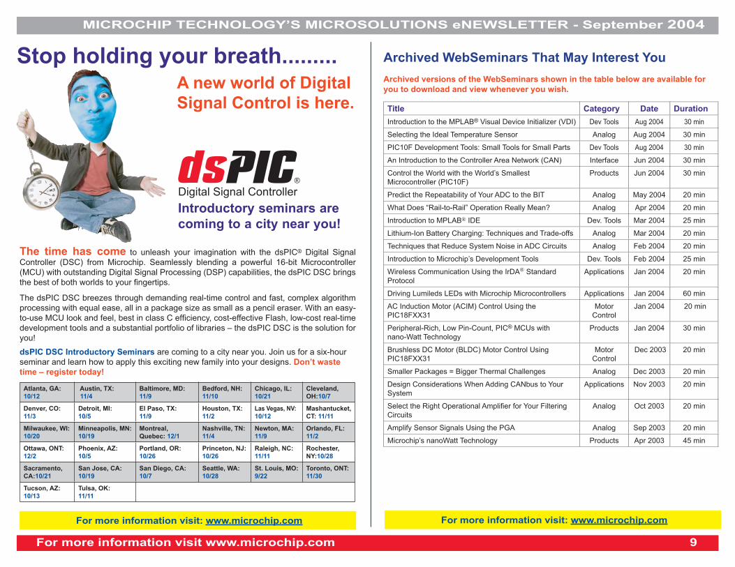
Stop holding your breath.........A new world of Digital
Signal Control is here.
The time has come to unleash your imagination with the dsPIC® Digital Signal
Controller (DSC) from Microchip. Seamlessly blending a powerful 16-bit Microcontroller
(MCU) with outstanding Digital Signal Processing (DSP) capabilities, the dsPIC DSC brings
the best of both worlds to your fi ngertips.
The dsPIC DSC breezes through demanding real-time control and fast, complex algorithm
processing with equal ease, all in a package size as small as a pencil eraser. With an easy-
to-use MCU look and feel, best in class C effi ciency, cost-effective Flash, low-cost real-time
development tools and a substantial portfolio of libraries – the dsPIC DSC is the solution for
you!
Atlanta, GA:
10/12
Austin, TX:
11/4
Baltimore, MD:
11/9
Bedford, NH:
11/10
Chicago, IL:
10/21
Cleveland,
OH:10/7
Denver, CO:
11/3
Detroit, MI:
10/5
El Paso, TX:
11/9
Houston, TX:
11/2
Las Vegas, NV:
10/12
Mashantucket,
CT: 11/11
Milwaukee, WI:
10/20
Minneapolis, MN:
10/19
Montreal,
Quebec: 12/1
Nashville, TN:
11/4
Newton, MA:
11/9
Orlando, FL:
11/2
Ottawa, ONT:
12/2
Phoenix, AZ:
10/5
Portland, OR:
10/26
Princeton, NJ:
10/26
Raleigh, NC:
11/11
Rochester,
NY:10/28
Sacramento,
CA:10/21
San Jose, CA:
10/19
San Diego, CA:
10/7
Seattle, WA:
10/28
St. Louis, MO:
9/22
Toronto, ONT:
11/30
Tucson, AZ:
10/13
Tulsa, OK:
11/11
dsPIC DSC Introductory Seminars are coming to a city near you. Join us for a six-hour
seminar and learn how to apply this exciting new family into your designs. Don’t waste
time – register today!
Digital Signal Controller
Introductory seminars are
coming to a city near you!
For more information visit: www.microchip.com
Archived WebSeminars That May Interest You
Archived versions of the WebSeminars shown in the table below are available for
you to download and view whenever you wish.
Title Category Date Duration
Introduction to the MPLAB® Visual Device Initializer (VDI) Dev Tools Aug 2004 30 min
Selecting the Ideal Temperature Sensor Analog Aug 2004 30 min
PIC10F Development Tools: Small Tools for Small Parts Dev Tools Aug 2004 30 min
An Introduction to the Controller Area Network (CAN) Interface Jun 2004 30 min
Control the World with the World’s Smallest
Microcontroller (PIC10F)
Products Jun 2004 30 min
Predict the Repeatability of Your ADC to the BIT Analog May 2004 20 min
What Does “Rail-to-Rail” Operation Really Mean? Analog Apr 2004 20 min
Introduction to MPLAB® IDE Dev. Tools Mar 2004 25 min
Lithium-Ion Battery Charging: Techniques and Trade-offs Analog Mar 2004 20 min
Techniques that Reduce System Noise in ADC Circuits Analog Feb 2004 20 min
Introduction to Microchip’s Development Tools Dev. Tools Feb 2004 25 min
Wireless Communication Using the IrDA® Standard
Protocol
Applications Jan 2004 20 min
Driving Lumileds LEDs with Microchip Microcontrollers Applications Jan 2004 60 min
AC Induction Motor (ACIM) Control Using the
PIC18FXX31
Motor
Control
Jan 2004 20 min
Peripheral-Rich, Low Pin-Count, PIC® MCUs with
nano-Watt Technology
Products Jan 2004 30 min
Brushless DC Motor (BLDC) Motor Control Using
PIC18FXX31
Motor
Control
Dec 2003 20 min
Smaller Packages = Bigger Thermal Challenges Analog Dec 2003 20 min
Design Considerations When Adding CANbus to Your
System
Applications Nov 2003 20 min
Select the Right Operational Amplifi er for Your Filtering
Circuits
Analog Oct 2003 20 min
Amplify Sensor Signals Using the PGA Analog Sep 2003 20 min
Microchip’s nanoWatt Technology Products Apr 2003 45 min
For more information visit: www.microchip.com
MICROCHIP TECHNOLOGY’S MICROSOLUTIONS eNEWSLETTER - September 2004
For more information visit www.microchip.com 10
What’s New in Microchip Literature?
Click on a Document Title to view the document.
(Continued)
Type of Document Title of Document DS# Print/Web
Analog Design Note Flexible Integrated Temperature Sensors Lower System Costs (ADN11) 21901A Web
Application Notes Practical PICmicro® Oscillator Analysis and Design App. Note (AN943) 00943A Web
Matching MOSFET Drivers to MOSFETs (AN799) 00799B Web
Effi ciently Powering Nine White LEDs with the MCP1650 (AN948) 00948A Web
Data Sheets 24LCS61/62 1K/2K Software Addressable I2C™ Serial EEPROM Data Sheet 21226E Web
25AA320/LC/C320 32K SPI™ Bus Serial EEPROM Data Sheet 21227E Web
TC7129 - 4-1/2 Digit Analog-to-Digital Converter with On-Chip LCD Drivers 21459C Web
MCP6231 - 20 µA, 300 kHz Rail-to-Rail Op Amp 21881B Web
MCP6241 - 50 µA, 650 kHz Rail-to-Rail Op Amp 21882B Web
MCP111/112 - Micropower Voltage Detector 21889B Web
TC54 - Voltage Detector 21434G Web
TC4420/9 - 6A High-Speed MOSFET Drivers 21419C Web
TC650/TC651 - Tiny Integrated Temperature Sensor and Brushless DC Fan Controller with Overtemperature 21450C Web
PIC18F6390/6490/8390/8490 39629B Web
PS700 Data Sheet 21760F Web
dsPIC30F3014, dsPIC30F4013 Data Sheet 70138A Web
dsPIC30F DS Motor Control and Power Conversion Families 70082G Web
dsPIC30F4011/4012 Data Sheet 70135B Web
dsPIC30F DS General Purpose and Sensor Families 70083G Web
PIC16F785 20-Pin, Flash-based, 8-bit CMOS MCU w/Two-Phase Asynchronous Feedback PWM, Dual High
Speed Comparators and Dual Operational Amplifi ers
41249A Web
Design Guides Temperature Sensor Design Guide 21895A Printed/Web
For more information visit www.microchip.com 9
MICROCHIP TECHNOLOGY’S MICROSOLUTIONS eNEWSLETTER - September 2004
Click on a Document Title to view the document.
Type of Document Title of Document DS# Print/Web
Erratas PIC16F688 Rev. A Silicon Errata 80181B Web
PIC12F683 Data Sheet Errata 80196B Web
PIC16F684 Rev. A Silicon Data Sheet 80197B Web
PIC16F818/819 Rev. A4 Silicon/Data Sheet Errata 80159C Web
PIC18F6310/6410/8310/8410 Rev. B3 Silicon Errata 80206A Web
PIC18F6390/6490/8390/8490 Rev. B3 Silicon Errata 80207A Web
dsPIC30F5011/5013 Rev. A1 Silicon Errata 80201A Web
dsPIC30F4011/4012 Rev. A1 Silicon Errata 80205A Web
Product Briefs PIC12F510/16F506 Product Brief 41248A Web
MCP2122 - IrDA® Standard Encoder/Decoder Product Brief 21840B Web
PIC18F6627/6722/8627/8722 Product Brief 39627B Web
Programming Spec. PIC16F91X Memory Programming 41244A Web
Technical Briefs Soft-Start Controller for Switching Power Supplies Tech. Brief (TB81) 91081A Web
Selecting an MCP21XXX Device for IrDA® Applications (TB73) 91073B Web
User Guides MCP1630 NiMH Demo Board User’s Guide 51505A Web
MPLAB® ICE 2000 In-Circuit Emulator User’s Guide 51488A Printed/Web
MPLAB® ICE 4000 In-Circuit Emulator User’s Guide 51490A Printed/Web
dsPIC30F Speech Recognition Word Library Builder User’s Guide 70137A Printed
What’s New in Microchip Literature?
The Microchip name and logo, the Microchip logo, dsPIC, KEELOQ, MPLAB, PIC, PICmicro, and PowerSmart are registered trademarks of Microchip Technology Incorporated in the U.S.A. and other countries.
In-Circuit Serial Programming, ICSP, PICkit and PICtail are trademarks of Microchip Technology Incorporated in the U.S.A. and other countries. All other trademarks mentioned herein are property of their respective companies.

MICROCHIP TECHNOLOGY’S MICROSOLUTIONS eNEWSLETTER - September 2004
For more information visit www.microchip.com 12
DID YOU KNOW.....
� buy.Microchip has grown again? Customers in the following regions can now
purchase products online at http://buy.microchip.com.
– Poland, the Czech Republic, Slovakia, Slovenia, Hungary, Estonia and Vietnam.
– Coming soon: Thailand, Switzerland, Israel, South Africa and China .
web siteHIGHLIGHTS
DID YOU KNOW.....
Microchip design centers for KEELOQ® Authentication and Home Appliance
Solutions have been updated with more links to:
• Technical documentation
• Product recommendations
• Application notes
• Available development tools
• Frequently asked questions
Visit all the design centers to learn more about:
Automotive Solutions
Designing for Mechatronics
Connectivity
Motor Control
Infrared Solutions
Check back often because NEW design centers are coming soon on battery
management and metering!
For more information visit: www.microchip.com
Visit Microchip Technology’s user-friendly
e-commerce site:
� Special offers on silicon and
development systems
� Powerful parametric search tool
� Live inventory status
� Hassle-free buying
Figure 1. Home Page
DID YOU KNOW.....
� Many popular tape and reel as well as tray products are now available at
reduced minimum order quantities. Over 400 products have had their minimum
order quantity reduced, particularly our analog and memory products.