microcomm dxi - hardingsystem troubleshooting guide microcomm dxi page 4 revision 4.5 a master...
TRANSCRIPT

Printed in Canada © Harding Instruments
MicroComm DXI
Troubleshooting Guide
November 2002
System Troubleshooting Guide MicroComm DXI
Page ii Revision 4.5

System Troubleshooting Guide MicroComm DXI
Revision 4.5 Page i
Table of Contents
Section 1 - Introduction .......................................................................................................................................................... 1
The “Family” of DXI Manuals ............................................................................................................................................. 1 Manual Intended Users ............................................................................................................................................... 1
About This Manual ................................................................................................................................................................ 1 Elements of the System .......................................................................................................................................................... 2 Maintenance Functions ......................................................................................................................................................... 2
Section 2 - Normal Operation of the DXI System ................................................................................................................ 3
In This Section... .................................................................................................................................................................... 3 SAC Computer....................................................................................................................................................................... 3 Master Station ....................................................................................................................................................................... 3
Intercom Master Stations................................................................................................................................................... 3 Stations .................................................................................................................................................................................. 4
Intercom Stations............................................................................................................................................................... 4 Intercom Stations with Music Select ................................................................................................................................. 4
Redundancy ........................................................................................................................................................................... 4 How the DXI System Operates .............................................................................................................................................. 5 Networks................................................................................................................................................................................ 5
Card Cage Back plane ....................................................................................................................................................... 6 LonWorks.......................................................................................................................................................................... 6
Free Topology Repeater ................................................................................................................................................ 6 Ethernet ............................................................................................................................................................................. 7 CEPT ................................................................................................................................................................................. 7 Modbus.............................................................................................................................................................................. 7 Serial I/O on SAC Computer............................................................................................................................................. 7 Parallel I/O on SAC computer........................................................................................................................................... 7 Modem connected to SAC Computer................................................................................................................................ 7
Section 3 - Intercom Master Stations .................................................................................................................................... 9
In this Section... ..................................................................................................................................................................... 9 IMS-140, IMS-145, IMS-440 and IMS-445 Master Stations................................................................................................. 9
DB-25 Connector ............................................................................................................................................................ 10 Service Switch and LED ................................................................................................................................................. 10 LonWorks Network LEDs ............................................................................................................................................. 11 Reset Switch .................................................................................................................................................................... 11 Status LEDs.................................................................................................................................................................... 11 Contrast Potentiometer .................................................................................................................................................... 11 Tone Volume Potentiometer............................................................................................................................................ 12 Self test Card ................................................................................................................................................................... 12 Test Card ......................................................................................................................................................................... 12
Functional Testing from the Master Station ................................................................................................................ 13 Audio Tests...................................................................................................................................................................... 13
IMS-130 and IMS-135 Intercom Master Stations and MAI-120 (or MAI-420) Master Audio Interface ............................ 13

System Troubleshooting Guide MicroComm DXI
Page ii Revision 4.5
Master Station Problems..................................................................................................................................................... 14 Network Problems....................................................................................................................................................... 14 Audio Problems .......................................................................................................................................................... 14
100 Series line voltages........................................................................................................................................... 14 400 Series line voltages........................................................................................................................................... 15
Display Problems ........................................................................................................................................................ 15 Keyboard Problems..................................................................................................................................................... 16 Beeper Problems ......................................................................................................................................................... 16 Back-lighting Problems............................................................................................................................................... 16
Section 4 - Stations................................................................................................................................................................ 17
In this Section...................................................................................................................................................................... 17 ICM-120 and ICM-130 Intercom Stations .......................................................................................................................... 17
Intercom Station Problems.............................................................................................................................................. 17 ICM-420 and ICM-430 Intercom Stations .......................................................................................................................... 18
Intercom Station Problems.............................................................................................................................................. 18 Generic Stations.................................................................................................................................................................. 19
Intercom Station Problems.............................................................................................................................................. 19
Section 5 - Card Cage Modules............................................................................................................................................ 21
In this Section...................................................................................................................................................................... 21 Reset and Service Switches ................................................................................................................................................. 21
Service LED.................................................................................................................................................................... 22 Status LED’s ....................................................................................................................................................................... 22 ACB-100, and ACB-101 Audio Control Board................................................................................................................... 23
Status Lights for ACB-100 ............................................................................................................................................. 23 Status Lights for ACB-101 ............................................................................................................................................. 23
AOB-400 Audio Output Board............................................................................................................................................ 24 Status Lights.................................................................................................................................................................... 24
AIB-400 Audio Input Board ................................................................................................................................................ 24 Status Lights.................................................................................................................................................................... 24
AIO-400 Audio Input/Output Board ................................................................................................................................... 24 Status Lights.................................................................................................................................................................... 24
ATB 101 Audio Trunk Board .............................................................................................................................................. 25 Status Lights for ATB-101.............................................................................................................................................. 25
PAB-400, and PAB-401 Paging Amplifier Board............................................................................................................... 25 Status Lights.................................................................................................................................................................... 25 Status Lights.................................................................................................................................................................... 25
SAB-300, SAB-400 and SAB-401 Station Audio Boards .................................................................................................... 26 Audio Lines..................................................................................................................................................................... 26 Status Lights.................................................................................................................................................................... 26
RDB-100 Remote Driver Board.......................................................................................................................................... 27 Status Lights.................................................................................................................................................................... 27 Error Codes ..................................................................................................................................................................... 27
Power-On self test and functional test Error Codes .................................................................................................... 27 TLB-400 Telephone Line Board.......................................................................................................................................... 28

System Troubleshooting Guide MicroComm DXI
Revision 4.5 Page iii
Status Lights .................................................................................................................................................................... 28 TSB-400 Telephone Line Board .......................................................................................................................................... 28
Status Lights .................................................................................................................................................................... 28 DIO-100 Discrete Input/Output Board ............................................................................................................................... 29
Status Lights .................................................................................................................................................................... 29 Discrete Inputs................................................................................................................................................................. 29 Discrete Outputs .............................................................................................................................................................. 31
Source Outputs ............................................................................................................................................................ 31 LED Outputs................................................................................................................................................................ 31 Sink Outputs ................................................................................................................................................................ 32 Relay Outputs .............................................................................................................................................................. 32
DIO Board Problems ....................................................................................................................................................... 33 Network Problems....................................................................................................................................................... 33 Input Problems ............................................................................................................................................................ 33 Output Problems.......................................................................................................................................................... 33
LED Outputs............................................................................................................................................................ 33
Section 6 - Non Card Cage Modules.................................................................................................................................... 35
In this Section... ................................................................................................................................................................... 35 SPD-120 Switch Panel Driver..................................................................................................................................... 35
Status LEDs.................................................................................................................................................................... 35 Functional Testing........................................................................................................................................................... 36
DIO-120 Discrete Input/Output Board ........................................................................................................................... 36 Status Lights .................................................................................................................................................................... 36
FTR-120 Free Topology Repeater .............................................................................................................................. 36 FTR Status LEDs ........................................................................................................................................................... 36
Operation of Status LED’s (all DXI cards)......................................................................................................................... 36 LonWorks Network LEDs ............................................................................................................................................. 37 Ethernet Status LEDs ..................................................................................................................................................... 37
RRR-110 and RRR-120 Remote Receiver Rack .............................................................................................................. 37 RRB-100 Remote Receiver Board ............................................................................................................................... 37
Status Lights .................................................................................................................................................................... 38 Error Codes ..................................................................................................................................................................... 38
Power-On self test and functional test Error Codes .................................................................................................... 38
Section 7 - Power Supplies .................................................................................................................................................... 39
In this Section... ................................................................................................................................................................... 39 PSU-110 and PSU-115 Power Supply Units....................................................................................................................... 39 PSU-310 and PSU-315 Power Supply Units....................................................................................................................... 39
Power Supply Operation ................................................................................................................................................. 39 PSU-123 and PSU-125 Power Supply ................................................................................................................................ 40
Power Supply Connections ............................................................................................................................................. 40 +24 Volt Operation...................................................................................................................................................... 40 ±12 Vdc Operation ...................................................................................................................................................... 40
Power Supply Operation ................................................................................................................................................. 40
Section 8 - Using the Secondary Master Station for Maintenance.................................................................................... 41

System Troubleshooting Guide MicroComm DXI
Page iv Revision 4.5
In This Section... ................................................................................................................................................................. 41 Alarm Annunciation at the Secondary Master Station........................................................................................................ 41
Fault Alarms.................................................................................................................................................................... 41 The Secondary Master Station ............................................................................................................................................ 41
Section 9 – Using the SAC Computer for Troubleshooting .............................................................................................. 43
In this Section… .................................................................................................................................................................. 43 Detecting problems with View Faults ................................................................................................................................. 43
Configuration errors........................................................................................................................................................ 44 Master Station LonWorks failure.................................................................................................................................... 44 Card Cage connections or Audio Control Board failure ................................................................................................. 44 Audio card failure ........................................................................................................................................................... 45 Failure of other card types .............................................................................................................................................. 45 ACB CEPT Loop failure................................................................................................................................................. 46 Remote I/O CEPT failure................................................................................................................................................ 48 Intercom Station or Call Operating Device failure ......................................................................................................... 49
Detecting problems with View Networks ............................................................................................................................ 50 Card not in service .......................................................................................................................................................... 51 Master Station LonWorks failure.................................................................................................................................... 52 Card Cage connections or Audio Control Board failure ................................................................................................. 52 Audio card failure ........................................................................................................................................................... 53 Failure of other card types .............................................................................................................................................. 53 ACB CEPT Loop failure................................................................................................................................................. 54 Remote I/O CEPT failure................................................................................................................................................ 54
Detecting Ethernet and Exchange computer problems with the View Status ..................................................................... 54 Detecting intermittent problems with the Log Viewer ........................................................................................................ 55
Configuration warnings and errors ................................................................................................................................. 56 System reboots ................................................................................................................................................................ 56 LonWorks Failures.......................................................................................................................................................... 56 Intercom Station or Call Operating Device failure ......................................................................................................... 57 Ethernet failure................................................................................................................................................................ 58 CEPT failures.................................................................................................................................................................. 58 Troubleshooting host interfaces ...................................................................................................................................... 59 Troubleshooting LonWorks connections using the service pin ...................................................................................... 61 Other problems................................................................................................................................................................ 61
Section 10 - Maintenance and Troubleshooting Procedures............................................................................................. 63
In This Section... ................................................................................................................................................................. 63 Maintenance Functions....................................................................................................................................................... 63 How You Find Out About Problems ................................................................................................................................... 63 The Secondary Master Station ............................................................................................................................................ 63 Data Logging ...................................................................................................................................................................... 63 The System Administrator ................................................................................................................................................... 64 Configuration Data............................................................................................................................................................. 64 Troubleshooting Procedures............................................................................................................................................... 64
Network Problems .......................................................................................................................................................... 64 Network Wiring and Termination Problems............................................................................................................... 64

System Troubleshooting Guide MicroComm DXI
Revision 4.5 Page v
Network Repeater Problems........................................................................................................................................ 65 Single Device Network Problems................................................................................................................................ 65 Ethernet Problems ....................................................................................................................................................... 66


System Troubleshooting Guide MicroComm DXI
Revision 4.5 Page 1
Section 1 - Introduction
The “Family” of DXI Manuals This manual is one of a set of manuals for the MicroComm DXI system:
Manual Intended Users Intercom Master Station Control Room Operator Operating Instructions Manual
MicroComm DXI System Administrator, System Installer, Maintenance Staff System Administration Manual
MicroComm DXI System Administrator, System Installer, Maintenance Staff Maintenance Manual
SAC Computer System Installer Installation Manuals
Intercom System Equipment System Installer Installation Manuals
MicroComm DXI System Installer, Maintenance Staff Troubleshooting Guide
About This Manual The purpose of this manual is to help you troubleshoot problems in the MicroComm DXI system. The Maintenance Manual is concerned with those aspects of the system that can be diagnosed and controlled from the SAC computer, whereas this manual is more concerned with diagnosing and fixing problems with the wiring and/or hardware aspects of the system.
The Manual is divided into ten sections, each one dealing with a key aspect of the system:
Section One Introduction
Section Two Normal Operation of the DXI System
Section Three Intercom Master Stations
Section Four Stations
Section Five Card Cage Modules
Section Six Non Card Cage Modules
Section Seven Power Supplies
Section Eight Using the Secondary Master Station for Maintenance
Section Nine Using the SAC Computer for Troubleshooting
Section Ten Maintenance and Troubleshooting Procedures for the MicroComm DXI
System Troubleshooting Guide MicroComm DXI
Page 2 Revision 4.5
The MicroComm DXI is an intercom system that is designed to help correctional officers communicate with other staff members and inmates. The system handles alarms as well as two-way voice communication between Intercom Stations and Master Stations.
Elements of the System The DXI consists of:
• intercom stations, • master stations to which intercom stations are connected, • a SAC computer or computers (Service, Administration and Control computer), which drives the DXI
system and is also used for system administration and maintenance, • paging outputs from PAB, TAB and AOB channels, • audio input/output from AIO, AIB and AOB channels, • card cages and power supplies, • hardware cards for card cages (ACB, AIB, AIO, AOB, ATB, DIO, PAB, RDB, SAB, TAB, TLB, TSB), and • other hardware (DIO, FTR, ICM's, IMS’s, MAI, RRB, RRR, SPC/SPD, RNS, TIS, VBS).
All of these elements are linked together on a communications network.
Maintenance Functions Maintenance functions include:
• responding to fault alarms and operating problems brought to your attention by users, • analyzing log data to pinpoint problems, and • troubleshooting to isolate the problem to a particular piece of equipment.
This guide is meant to help you with the troubleshooting aspects of DXI system maintenance.
System Troubleshooting Guide MicroComm DXI
Revision 4.5 Page 3
Section 2 - Normal Operation of the DXI System
In This Section... We will:
• outline the principles of operation of the DXI system, and • describe how the DXI works under normal conditions.
SAC Computer The Service, Administration and Control (SAC) computer is the brain of the DXI system. It:
• controls the operation of the DXI system, and • is used for installation, administration, maintenance and troubleshooting.
The SAC computer is a standard IBM-compatible PC with special network adapters for communication with other parts of the intercom system. The current software installed on the computers consists of:
• QNX V4.25 operating system (this software is updated as new versions are released), and • MicroComm DXI system software
As an option, a redundant SAC computer can be added, so that 100% backup is assured. With the redundant computer, the system can operate on either PC and will automatically switch to the other processor if the need arises.
Master Station The DXI system is based on the concept that system operators can open audio communication channels, deliver page messages, generate tone signals for specific events or times as well as monitor and control the various functions required in the system. These activities are carried out by the operator(s) at a Master Station(s). Master Stations are the focal point for the day-to-day operation of the DXI system. Master Stations can be realized in various forms; large switch panels, touch screen monitors, or compact LCD display Intercom Master Stations.
Intercom Master Stations An Intercom Master Station has a simple structure. It consists of:
• a LCD display (a 4 by 20 character display), • a telephone style keypad for inputting numbers and control characters. The keypad has the normal
telephone entry keys 0 to 9, *, # and the additional keys Clear, ↑, ↓, Enter, HS or HEAD, MUTE and PTT.
• four function keys whose actions are determined by the current message displayed on the LCD display. A fifth → key allows you to scroll through the remaining menu selections when there are more than four.
• a telephone handset, speaker/microphone combination and/or headset. • the head set (HS or HEAD), mute (MUTE) and push to talk (PTT) are used for audio control. The PTT
switch determines the transmission direction for half-duplex voice channels. With the limited display area an easy to use tree structured menu system allows the operator to quickly navigate through the various functions and displays.
System Troubleshooting Guide MicroComm DXI
Page 4 Revision 4.5
A Master Station is simply a terminal for inputting and displaying data. All of the decision-making and control is carried out in the SAC computer. Communications between the SAC computer and the Master Station is achieved by transmitting messages over the LonWorks network.
Stations In the DXI terminology Stations represent any point that can have its input status sent to a Master Station or have its output controlled by a Master Station. A simple single switch can be considered a Station, as well a single LED output. Intercom Stations are stations where voice communications can be established.
Intercom Stations Intercom Stations are stations that can have two-way voice communications with a pre-assigned Master Station (or possibly a group of Master Stations). An Intercom Station consists of:
• speaker, • microphone (the speaker cone may be used as a microphone in some stations), • call request (CRQ) push button switch, and • twisted pair polarity sensitive two-wire connection, normally to either an SAB card or AIO card located
in a card cage. (Connections are made from the card via a connector and cable to a terminal block. Field wiring from the Intercom Station terminates at the terminal block as well.)
The audio between an Intercom Station and a Master Station may be half-duplex or full duplex. If a half-duplex audio channel is used, either the Master Station operator will have a press to talk switch or there will be a DSP on the ACB (Audio Control Board) programmed to operate as a voice operated switch (VOX). The VOX compares the audio levels and determines whether the Master Station or the Intercom Station has the channel.
Intercom Stations with Music Select Intercom Stations are available with two push button switches. The purposes of the switches are:
• one switch acts as a call request (CRQ) switch, and • the second switch acts as a music channel selection switch.
Again the connection back to the SAB card is a two-wire connection.
Redundancy The DXI allows critical components of the system to be duplicated so that a failure of one component does not cause the system to fail. There may be a redundant control computer, redundant power supplies, and redundant networks.
• Redundant SAC Computer redundant SAC computers are used to ensure that if one computer fails the system does not stop working. The two computers run in parallel and process exactly the same information. However, only the primary computer actually sends commands on the LonWorks network.
If the primary computer fails, the secondary computer automatically takes over all functions and begins to drive the LonWorks network.
If either computer fails, an alarm is generated to inform you that the system requires maintenance. • Redundant Power Supplies redundant power supplies are used to ensure that, if a power supply fails, the
device(s) being powered from that supply continue to operate. The Free Topology Repeater (FTR),

System Troubleshooting Guide MicroComm DXI
Revision 4.5 Page 5
Discrete Input/Output Boards (DIO's), Remote Receiver Board (RRB), Switch Panel Controller/Switch Panel Driver (SPC/SPD), and Master Stations can all have main and backup power connections.
• Redundant Networks redundant networks are used to prevent a wiring problem from disabling the system. If a device loses its network connection to the SAC computer, it will not work. The redundant networks allow a device that cannot communicate on one network to switch to the backup network.
How the DXI System Operates The SAC computer running custom application software under QNX, a real-time operating system, controls the MicroComm DXI System. The LonWorks network handles all communications between the SAC computer and devices connected to the SAC computer.
Input devices connected to the system send messages to the SAC computer, telling it about events as they are detected. Events may be switch presses, keypad switch presses, switch faults, or any other input event from devices connected to the system.
The SAC computer responds to an input event by sending messages to output devices connected to the system. These messages may cause an LED to be turned on or off, a LCD display at a Master Station to be updated, a beeper to be turned on or off, or some other event to occur.
When a person presses the CRQ switch on his Intercom Station, the switch press is detected by the SAB to which the Intercom Station is connected. The SAB sends a signal through the back plane to the ACB card. The DSP on the ACB detects this signal and a message describing the switch press is sent by the ACB card to the SAC computer over the LonWorks network. The SAC computer processes the switch press and sends a message over the LonWorks network to update the display screen at the Master Station to which the Intercom Station is assigned.
When the operator at the Master Station presses a key to answer the call, a message is sent from the Master Station to the SAC computer describing the switch press. The SAC computer processes the switch press and sends a message to the ACB telling it to connect the audio channel between the Intercom Station and the Master Station. The SAC computer also updates the display screen at the Master Station with the call information.
To terminate the call, the operator at the Master Station presses a switch at the Master Station. A message is sent to the SAC computer describing the switch press. The SAC computer processes the switch press and sends a message to the ACB telling it to disconnect the audio connection between the intercom station and the master station. The LED at the intercom station goes off. The SAC computer updates the display screen at the Master Station.
Networks A network is an electrical connection that allows data to be transferred between electronic subsystems, cards or boards. The DXI system consists of many subsystems:
• SAC computer(s), • card cages, • cards in a card cage, such as ACB, SAB, AIO cards • Master Stations, • remotely located DIO, SPC/SPD boards, • Intercom Stations (ICM's), • FTR repeaters, and

System Troubleshooting Guide MicroComm DXI
Page 6 Revision 4.5
• Remote Receiver Racks (RRR), which include a Remote Receiver Board (RRB) and an audio board such as an SAB.
Within the DXI system several different types of network connections may be used. They include a card cage Back plane, LonWorks, Modbus, CEPT Audio Remote I/O Link, and Ethernet.
As well the SAC computer can use the Serial I/O, Parallel I/O and Modem ports to communicate with external devices.
Card Cage Back plane Within a card cage all cards plug into connectors located on a back plane circuit board. This board has 36 parallel conductors. Power supply voltages, LonWorks and digital audio and control signals are some of the signals included in the 36 conductors.
LonWorks The LonWorks network is used to connect peripheral input/output devices such as Master Stations and DIO modules to the SAC computer.
When a peripheral device is powered ON, it attempts to connect to the SAC computer. It tries to communicate first on network A, if unsuccessful; it then tries on network B. If unsuccessful on both, the device disconnects from the network. After a period of time, the device attempts once again to connect to the SAC computer. This sequence repeats until a connection is made. Each time that a device is unsuccessful, the amount of time that it remains disconnected increases until a maximum of 17 minutes is reached.
LonWorks networks can use several different types of cabling. The DXI uses a version called Free Topology, or FT LonWorks. A free topology network can be wired in any fashion. It may contain any combination of bus (or multi-drop), star (or home run), or ring (or loop) wiring.
A free topology LonWorks network must have a 51 Ω termination resistor installed at some location on the network cable.
If a free topology LonWorks network has more than 400 m of cable between any 2 nodes or more than 500 m of cable in total (using the recommended category 4 or 5 22 Ga. unshielded twisted pair cable), it must be broken into segments using a network repeater.
Free Topology Repeater The Free Topology Repeater (FTR) is a network repeater for free topology LonWorks networks. It has four ports, all of which are bi-directional. An incoming message that is received at one port is amplified and re-broadcast on the other three ports.
By installing an FTR, a large network, which exceeds the cable length limits, can be broken into 4 smaller network segments. Each network segment is connected to one of the FTR ports. The FTR isolates each network segment from the others, so each segment can have as much cable as was allowed for a single segment network.
The FTR contains 51 Ω termination resistors for each network segment; so external termination resistors are not required.
The FTR is typically installed in a central location where it acts as a hub for the network. If required, multiple FTR's can be installed to connect all the segments of a very large free topology network. Due to the extra delay in an FTR a maximum of two FTR's can be installed between any devices in the network.

System Troubleshooting Guide MicroComm DXI
Revision 4.5 Page 7
Ethernet An Ethernet network is used to connect SAC computers together. It will connect:
• the main and backup SAC computers on a single exchange, and/or • SAC computers on multiple exchanges.
An Ethernet interface card is installed in the SAC computer. The DXI uses a variant of Ethernet that operates on a single 2224 Ga. unshielded twisted pair. Other variants may be used if required for compatibility with other equipment.
The single pair Ethernet network cable used by the DXI requires a 120 Ω termination resistor at each end. These termination resistors are normally provided by installing termination plugs in the unused network ports at each end of the network.
CEPT CEPT, also known as the E1 standard, is used in the DXI system to transmit digital audio signals between card cages. A CEPT channel uses time division multiplexing to simultaneously carry 30 audio channels. A CEPT link transmits data at 2.048 MHz baud.
Modbus For a description of the interface from a PLC Host to the DXI system over a Modbus Plus network see the document MicroComm DXI Modbus Plus Host command/status messages (rev 4, 98-07-15)
Serial I/O on SAC Computer A serial port is often used to connect to an external Host.
Parallel I/O on SAC computer The parallel port of a computer is often used to connect to a printer, where log messages can be printed out.
Modem connected to SAC Computer A modem connection allows data to be sent from the SAC computer over the telephone system to a remote location, often back to Harding Instruments. Such a link is essential so that Harding Instrument personnel can analyze log records and determine the source of any problems that occur in a new installation.

System Troubleshooting Guide MicroComm DXI
Page 8 Revision 4.5

System Troubleshooting Guide MicroComm DXI
Revision 4.5 Page 9
Section 3 - Intercom Master Stations
In this Section... We will:
• discuss the hardware aspects of the DXI Master Stations, • discuss troubleshooting procedures for these devices, and • discuss using the SAC computer as a troubleshooting tool.
IMS-140, IMS-145, IMS-440 and IMS-445 Master Stations An IMS-140, IMS-145, IMS-440 and IMS-445 desktop style Master Station consists of:
• keypad, • LCD, an 4x20 character display, • any combination of speaker/microphone, headset and/or telephone handset, • Master Audio Interface (MAI) board. This board handles the audio portion of a Master Station. • Master Control Board (MCB). This board acts as the interface to the keypad and LCD display. • power supply, audio lines and LonWorks network connections are required for a Master Station.
IMS-2xx Master Stations have a master push to talk (MPTT) audio board rather than a MAI board. In this section we are restricting our discussion to the Master Stations with the MCB, MAI combination.
A view of the back of the Master Station will appear as follows:
At the back of the Master Station there are switches, status LEDs and a connector. These include:
• a DB-25 connector (connected to the MAI board), • push button labeled Service, • red LED for service status, • red LED labeled Network B, • green LED labeled Connect, • push button labeled Reset Switch, • green LED labeled Status #1, • green LED labeled Status #2,

System Troubleshooting Guide MicroComm DXI
Page 10 Revision 4.5
• red LED labeled Status #3, • an adjustable potentiometer labeled Contrast, and • a hole labeled Tone Volume, which is used only on the IMS-2xx series
Within the DB-25 connector are LonWorks network connections, relay connections, a push to talk input, and either full duplex or half-duplex audio lines.
DB-25 Connector The pin connections for the DB-25 pin connector are as follows:
Pin Signal Description 1 main V+ the power supply positive 2 main V- (Gnd) the power supply negative 3 network B+ redundant Echelon network positive 4 Earth Ground Connect to local earth ground – not (Gnd) 5 speaker+ master speaker audio+ 6 microphone+ master microphone audio 7 relay 2 NO relay 2 normally open contact 8 relay 2 NC relay 2 normally closed contact 9 relay 1 Com common contact for relay 1 10 Earth Ground 11 network A+ Echelon network positive 12 backup V- (Gnd) redundant power supply negative 13 backup V+ redundant power supply positive 14 main V+ 15 main V- (Gnd) 16 network B- redundant Echelon network negative 17 speaker- is master speaker audio- 18 microphone- master microphone audio- 19 PTT Input contact input for a PTT switch. The other side of the PTT input goes to main V-. 20 relay 2 Com relay 2 common contact 21 relay 1 NO relay 1 normally open contact 22 relay 1 NC relay 1 normally closed contact 23 network A- Echelon network negative 24 backup V- (Gnd) 25 backup V+
Service Switch and LED The Service Switch is used to inform the SAC computer which MCB card is being configured. It is only used when the card is being configured. When the Service Switch is pressed the service light comes on to indicate that the Master Station has transmitted a message over the LonWorks network to the SAC computer. The message contains the Neuron ID for the MCB.
The service message is only sent when the Master Station is connected to an active LonWorks network. Before pressing the Service Switch, make sure that the Master Station is connected to Network A (see the following paragraph). When replacing an MCB keypad/display module you must use the Card Swap function of the SAC computer and press the service pin on the MAI module to configure it. When replacing an MAI module by itself, this is not required.
System Troubleshooting Guide MicroComm DXI
Revision 4.5 Page 11
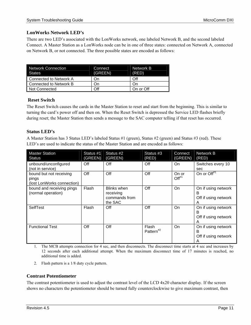
LonWorks Network LED’s There are two LEDs associated with the LonWorks network, one labeled Network B, and the second labeled Connect. A Master Station as a LonWorks node can be in one of three states: connected on Network A, connected on Network B, or not connected. The three possible states are encoded as follows:
Network Connection States
Connect (GREEN)
Network B (RED)
Connected to Network A On Off Connected to Network B On On Not Connected Off On or Off
Reset Switch The Reset Switch causes the cards in the Master Station to reset and start from the beginning. This is similar to turning the cards power off and then on. When the Reset Switch is depressed the Service LED flashes briefly during reset; the Master Station then sends a message to the SAC computer telling if that reset has occurred.
Status LED’s A Master Station has 3 Status LEDs labeled Status #1 (green), Status #2 (green) and Status #3 (red). These LEDs are used to indicate the status of the Master Station and are encoded as follows:
Master Station Status
Status #1 (GREEN)
Status #2 (GREEN)
Status #3 (RED)
Connect (GREEN)
Network B (RED)
unbound/unconfigured (not in service)
Off Off Off On Switches every 10 sec
bound but not receiving pings (lost LonWorks connection)
Off Off Off On or Off#1
On or Off#1
bound and receiving pings (normal operation)
Flash Blinks when receiving commands from the SAC
Off On On if using network B Off if using network A
SelfTest Flash Off Off On On if using network B Off if using network A
Functional Test Off Off Flash Pattern#2
On On if using network B Off if using network A
1. The MCB attempts connection for 4 sec, and then disconnects. The disconnect time starts at 4 sec and increases by 12 seconds after each additional attempt. When the maximum disconnect time of 17 minutes is reached, no additional time is added.
2. Flash pattern is a 1/8 duty cycle pattern.
Contrast Potentiometer The contrast potentiometer is used to adjust the contrast level of the LCD 4x20 character display. If the screen shows no characters the potentiometer should be turned fully counterclockwise to give maximum contrast, then
System Troubleshooting Guide MicroComm DXI
Page 12 Revision 4.5
slowly turned counterclockwise to the desired contrast level. The contrast is set so that the characters are displayed but the background pattern disappears.
The backlighting level also determines the viewing qualities of the display. Backlighting level is determined by a software setting. The System Administrator using the SAC computer initially sets this, however the Master Station operator can adjust the backlighting level to his own preference.
Tone Volume Potentiometer In certain models of Master Stations (IMS-2xx Master Stations that use an MCB and an MPTT rather than a MCB and MAI) Tone volume is a potentiometer that can be used to adjust the buzzer volume level. In all Master Stations that have an MAI buzzer, volume is set in software and can be adjusted by the Master Station operator (there is no potentiometer present on the circuit board).
Self test Card A Master Station can be checked using a SAC computer and the Self-test and Test Card selections found in the Maintenance Module. (See Section 6 of the Maintenance Manual on how to use the SAC computer to run test on individual cards.) This test will determine if there are any problems with the MCB in the Master Station.
The purpose of the Self-test selection is to verify that proper LonWorks communication is taking place between the Master Station and the SAC computer. The test responds with a simple message that the card either passed or failed the test. Once the card ID has been selected and the Enter key pressed, the last line in the screen display is:
“SelfTest? (y/n) n” If the default n is replaced by typing in y, followed by pressing the Enter key, the following message will appear at the bottom of the screen:
“Please wait up to 30 seconds for result...” while the test is being run. Once the test is complete this message will be replaced by:
“Self test result: PASS!” This message will stay on the screen for a few seconds and then the screen will return to the condition that allows you to Self test other cards or Exit
Note that maintenance personnel run this test from the SAC computer.
Test Card The Test Card can be used to functionally test the MCB printed circuit board, LCD display, switches, LonWorks network, and wiring associated with a Master Station. When you select a MCB card to test the system puts the card into a special test state. This test will allow you to isolate any problems with the Master Station. The test steps through the following functions:
1. The 4x20 LCD displays each of the alphabetic characters A to Z, one character at a time. This visually indicates that the LCD is functioning properly; it also verifies that messages are being transmitted properly from the SAC computer to the MCB.
2. A keypad test screen is displayed. Pressing a key on the keyboard results in a key code being displayed on the LCD display. This test verifies proper switch closure as well as proper decoding of the key closure. It also indicates that messages are being properly sent over the LonWorks network from the MCB to the SAC computer.
3. To exit the keyboard test you must press the function key END key (or the D key) twice within 1 second.

System Troubleshooting Guide MicroComm DXI
Revision 4.5 Page 13
4. The next test displays the soft key selections for BUZ1, EXT1 and EXT2. Selecting BUZ1 starts a 30-second test of the beeper. During the BUZ1 test the buzzer volume can be changed by use of the Up-arrow and Down-arrow keys. Selecting EXT1 or EXT2 activates the external relay contacts on the DB25 connector.
DB25 Pin Names External Relay #1 External Relay #2 NC 22 8 Common 9 20 NO 21 7
Pressing the function key END moves you to the next test.
5. The watchdog-reset test causes the unit to reset. It then starts up as it would if the power had just been turned on.
Note that this test is initiated at the SAC computer but an operator must be present at the Master Station to press the keys, and verify proper operation of the Master Stations MCB.
Functional Testing from the Master Station A functional test can be initiated at the Master Station by turning off the power then turning on the power with the Enter and # key pressed simultaneously. Continue to keep the two keys pressed until the test starts.
Audio Tests At present there is no automated test for the audio side of the Master Station. In order to verify the connection between the Master Station and the SAB board, you can measure the voltages on the speaker audio and microphone audio pairs on the SAB terminal blocks. The correct voltages are shown in the following section but in general a voltage measurement of close to 0 or 24 volts indicates a wiring fault. These audio lines are polarity sensitive; if a pair is reversed in polarity you will measure 24 volts across the pair. The Master Station will not operate properly with a faulted or reversed polarity audio pair. Once the correct voltages have been verified, you can make a call to an Intercom Station or another Master Station in order to check that the audio circuits function properly. If the Master Station is equipped with a telephone handset, you should test the operation with the handset as well as the hands-free speaker/microphone. Full duplex operation of the handset should also be tested by calling another handset-equipped master, with both masters using handsets. If the Master Station is also equipped with a headset, the headset should be tested (ensure that the telephone headset is on the hook switch cradle when testing the headset).
IMS-130 and IMS-135 Intercom Master Stations and MAI-120 (or MAI-420) Master Audio Interface The IMS-130 and IMS-135 are panel-mounted versions of the Master Station. These Master Stations operate identically to the desk-mounted versions. The only difference is that the MAI board comes in a separate module and is physically separated from the MCB, keypad and display portion of the Master Station. A 34-conductor ribbon cable is used to connect the MAI and the MCB. The MAI-120 (MAI-420) has display LEDs, a Reset Switch and a Service Switch. They serve the same functions as described for the desktop Master Stations.
System Troubleshooting Guide MicroComm DXI
Page 14 Revision 4.5
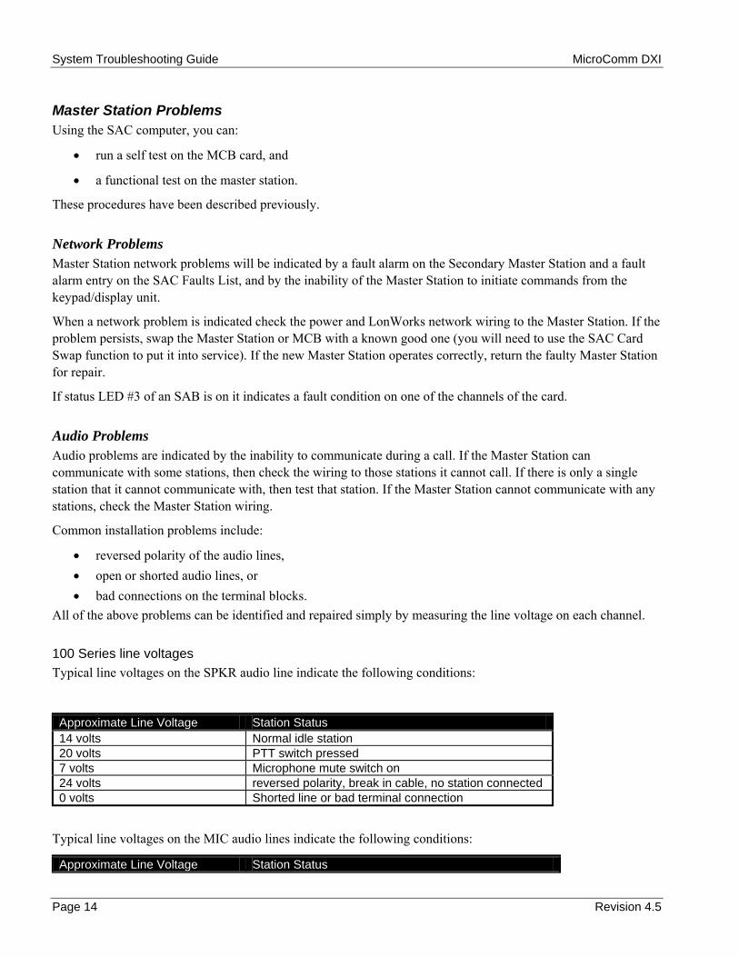
Master Station Problems Using the SAC computer, you can:
• run a self test on the MCB card, and
• a functional test on the master station.
These procedures have been described previously.
Network Problems Master Station network problems will be indicated by a fault alarm on the Secondary Master Station and a fault alarm entry on the SAC Faults List, and by the inability of the Master Station to initiate commands from the keypad/display unit.
When a network problem is indicated check the power and LonWorks network wiring to the Master Station. If the problem persists, swap the Master Station or MCB with a known good one (you will need to use the SAC Card Swap function to put it into service). If the new Master Station operates correctly, return the faulty Master Station for repair.
If status LED #3 of an SAB is on it indicates a fault condition on one of the channels of the card.
Audio Problems Audio problems are indicated by the inability to communicate during a call. If the Master Station can communicate with some stations, then check the wiring to those stations it cannot call. If there is only a single station that it cannot communicate with, then test that station. If the Master Station cannot communicate with any stations, check the Master Station wiring.
Common installation problems include:
• reversed polarity of the audio lines, • open or shorted audio lines, or • bad connections on the terminal blocks.
All of the above problems can be identified and repaired simply by measuring the line voltage on each channel.
100 Series line voltages Typical line voltages on the SPKR audio line indicate the following conditions:
Approximate Line Voltage Station Status 14 volts Normal idle station 20 volts PTT switch pressed 7 volts Microphone mute switch on 24 volts reversed polarity, break in cable, no station connected 0 volts Shorted line or bad terminal connection
Typical line voltages on the MIC audio lines indicate the following conditions:
Approximate Line Voltage Station Status

System Troubleshooting Guide MicroComm DXI
Revision 4.5 Page 15
14 volts Normal idle station 20 volts Hook switch closed 24 volts reversed polarity, break in cable, no station connected 0 volts Shorted line or bad terminal connection
A station that is generating hardware faults that come and go usually has a poor connection at the terminal block.
400 Series line voltages Typical line voltages on the SPKR audio line indicate the following conditions:
Approximate Line Voltage Station Status 16 volts Normal idle station 6 volts PTT switch closed (PTT switch pressed) 10 volts Microphone mute switch closed (Mute switch pressed) 24 volts reversed polarity, break in cable, no station connected 0 volts Shorted line or bad terminal connection
Typical line voltages on the MIC audio lines indicate the following conditions:
Approximate Line Voltage Station Status 16 volts Normal idle station (Off hook) 6 volts Hook switch open (On hook) 10 volts Call Request switch closed1 24 volts reversed polarity, break in cable, no station connected 0 volts Shorted line or bad terminal connection
1 Master Stations with a keypad do not have a call request switch.
A station that is generating hardware faults that come and go usually has a poor connection at the terminal block.
If the audio wiring checks out, make sure that both the master volume and the station volume are not set to a low setting. The DXI uses a separate station volume for each station that is being called.
If the problem persists, swap with a known good Master Station or MAI module and repeat the tests. If the problem is corrected, return the faulty Master Station or MAI for repair.
Display Problems If the proper screen does not appear on the display, first check the contrast adjustment to make sure it is not turned too low. If this does not solve the problem, turn the station off and then on again. As the station powers up, the configuration display should appear:
The Master Station functional test can be used to exercise the display and check for bad pixels. See previous description for further details.
If the master station does not pass the functional test, replace with a working master and return the faulty master station for repair.

System Troubleshooting Guide MicroComm DXI
Page 16 Revision 4.5
Keyboard Problems If a key does not work, first check the function menu to make sure that the key is supposed to work in that mode.
You can test for bad keys using the master self test (tests wiring only) and the master station functional test (tests actual key-switch operation). These tests are described in detail previously.
If the Master Station does not pass the functional test, replace with a working master and return the faulty master station for repair.
The PTT, Mute, Off/On Hook switches on the keyboard communicates with the DXI system via of the SPKR and MIC audio lines. If there are problems with these switches only then:
• check the voltages at the terminal block as given in the tables under Audio Problems.
Beeper Problems If the beeper does not work, make sure that the beeper volume is not set to a low setting.
You can check beeper operation and volume using the master station functional test.
If the Master Station does not pass the functional test, replace with a working master and return the faulty master station for repair.
Back-lighting Problems If the backlighting cannot be turned ON using the menu keys, replace with a working master and return the faulty master station for repair.

System Troubleshooting Guide MicroComm DXI
Revision 4.5 Page 17
Section 4 - Stations
In this Section... We will:
• discuss the types of Intercom Stations, and • discuss possible Intercom Station problems.
ICM-120 and ICM-130 Intercom Stations The ICM-120 and ICM-130 Intercom Stations have a speaker, microphone and one or two pushbuttons. The pushbuttons act as a call request switch (CRQ) and an optional special function switch. The wiring from the Intercom Station back to the terminal block located adjacent to a card cage is a shielded single twisted pair wire connection. The shield is grounded only at the card cage end of the wire run. The ICM-120 and ICM-130 Intercom Stations are designed to operate with the SAB-100.
Intercom Station Problems The Status #3 LED on the SAB card indicates a fault condition on one or more of the channels on the card. The SAC fault list will show the faulted station number, cards and channel for all intercom station faults.
Common installation problems include:
• reversed polarity of the audio lines, • open or shorted audio lines, or • bad connections on the terminal blocks.
All of the above problems can be identified and repaired simply by measuring the line voltage on each channel.
Typical line voltages on the audio line indicate the following conditions:
Approximate Line Voltage Station Status 14 volts Normal idle station 20 volts Switch A pressed (Special function switch) 7 volts Switch B pressed (Call request switch) 24 volts reversed polarity, break in cable, no station connected 0 volts Shorted line or bad terminal connection
A station that is generating hardware faults that come and go usually has a poor connection at the terminal block.
System Troubleshooting Guide MicroComm DXI
Page 18 Revision 4.5
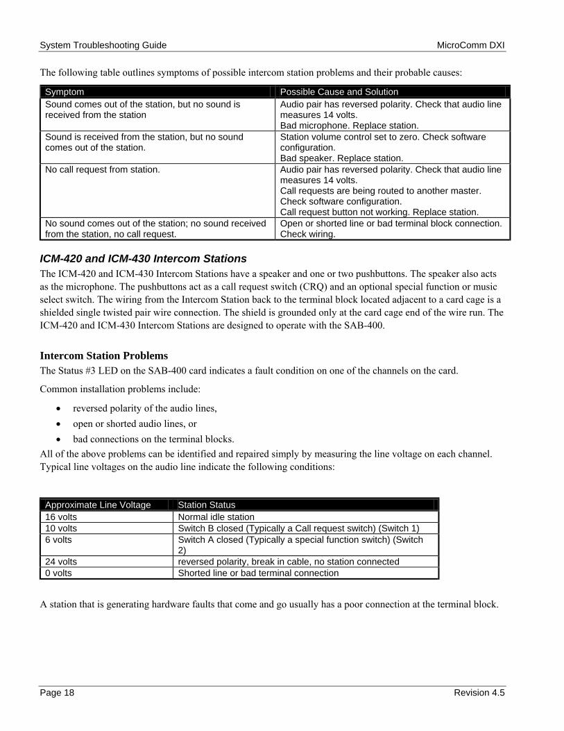
The following table outlines symptoms of possible intercom station problems and their probable causes:
Symptom Possible Cause and Solution Sound comes out of the station, but no sound is received from the station
Audio pair has reversed polarity. Check that audio line measures 14 volts. Bad microphone. Replace station.
Sound is received from the station, but no sound comes out of the station.
Station volume control set to zero. Check software configuration. Bad speaker. Replace station.
No call request from station. Audio pair has reversed polarity. Check that audio line measures 14 volts. Call requests are being routed to another master. Check software configuration. Call request button not working. Replace station.
No sound comes out of the station; no sound received from the station, no call request.
Open or shorted line or bad terminal block connection. Check wiring.
ICM-420 and ICM-430 Intercom Stations The ICM-420 and ICM-430 Intercom Stations have a speaker and one or two pushbuttons. The speaker also acts as the microphone. The pushbuttons act as a call request switch (CRQ) and an optional special function or music select switch. The wiring from the Intercom Station back to the terminal block located adjacent to a card cage is a shielded single twisted pair wire connection. The shield is grounded only at the card cage end of the wire run. The ICM-420 and ICM-430 Intercom Stations are designed to operate with the SAB-400.
Intercom Station Problems The Status #3 LED on the SAB-400 card indicates a fault condition on one of the channels on the card.
Common installation problems include:
• reversed polarity of the audio lines, • open or shorted audio lines, or • bad connections on the terminal blocks.
All of the above problems can be identified and repaired simply by measuring the line voltage on each channel. Typical line voltages on the audio line indicate the following conditions:
Approximate Line Voltage Station Status 16 volts Normal idle station 10 volts Switch B closed (Typically a Call request switch) (Switch 1) 6 volts Switch A closed (Typically a special function switch) (Switch
2) 24 volts reversed polarity, break in cable, no station connected 0 volts Shorted line or bad terminal connection
A station that is generating hardware faults that come and go usually has a poor connection at the terminal block.

System Troubleshooting Guide MicroComm DXI
Revision 4.5 Page 19
Generic Stations Generic Intercom Stations have a speaker and one or two pushbuttons. The speaker also acts as the microphone. The pushbuttons act as a call request switch (CRQ) and an optional music select switch. The wiring for the audio from the Intercom Station back to the terminal block located adjacent to a card cage is a shielded single twisted pair wire connection. The shield is grounded only at the card cage end of the wire run. A two wire unshielded cable bring the switch information from the Station to the terminal blocks. Generic Intercom Stations are designed to operate with the SAB-300.
Intercom Station Problems The Status #3 LED on the SAB-300 card indicates a fault condition on one of the channels on the card when you are using supervised switches. The SAC faults list will show the faulted station number, card, and channel number for all intercom station switch pair faults.
Neither the audio or switch pairs for a Generic Station are polarity sensitive. Common installation problems include:
• open or short audio lines, or open or short switching lines. • poor connections on the terminal blocks.
For the pair of wires used to transmit switch information problems can be identified and repaired simply by measuring the line voltage on each switch channel. The voltage measurements will depend upon whether you are using supervised or unsupervised switches. Typical line voltages on the switch lines indicate the following conditions:
SUPERVISED SWITCHES
Approximate Line Voltage Station Status 7.1 volts Normal idle station 1.7 volts Switch B closed (Call request switch) 4.0 volts Switch A closed (Special function switch) 11.65 volts break in cable, no station connected 0 volts Shorted line or bad terminal connection
UNSUPERVISED SWITCHES
Approximate Line Voltage Station Status 11.65 volts Normal idle station or
Break in cable, no station connected 0 volts Switch A closed (call request switch), or
shorted line or bad terminal connection
A station that is generating hardware faults that come and go usually has a poor connection at the terminal block.
The audio lines on a Generic Station will always measure 0 volts, and cannot be automatically supervised. If you suspect problems with the audio lines you will be required to carry out continuity measurements.

System Troubleshooting Guide MicroComm DXI
Page 20 Revision 4.5

System Troubleshooting Guide MicroComm DXI
Revision 4.5 Page 21
Section 5 - Card Cage Modules
In this Section... We will:
• discuss cards that are located in Card Cage, • discuss how to interpret LED patterns on the Status LEDs, and • discuss the functional test for these cards.
Most cards used in a DXI system are located in a card cage. These cards can communicate with each other over a high-speed back plane connection. The type of cards that can be located in a card cage include:
ACB-100 Audio Control Board
ACB-101 Audio Control Board
AIB-400 Audio Input Board
AIO-400 Audio Input/Output Board
AOB-400 Audio Output Board
ATB-101 Audio Trunk Board
DIO-100 Discrete Input/Output Board
PAB-400, PAB-401 Paging Amplifier Board
TAB-400 Talkback Amplifier Board
RDB-100 Remote Driver Board
RRB-100 Remote Receiver Board
SAB-300 Station Audio Board
SAB-400 Station Audio Board
SAB-401 Station Audio Board
TLB-400 Telephone Line Board
TSB-400 Telephone Set Board
Each card has as a minimum a set of 3 Status LEDs that are used to indicate the status of the card. As well each card cage card has a service push button switch and a Service LED. Some of the cards have more indicator LEDs and switches. Cards that have more than three Status LEDs and a Service Switch include:
• The ACB-100 card has a Card Reset push button switch, a Master Reset push button switch, a Connect LED and a Backup Switch.
• The DIO, TSB, and RDB cards have a Card Reset switch and a Connect LED. The ACB, ATB, DIO, and TSB cards have Neuron processor on board, they can communicate with the SAC computer over the LonWorks network. A card with a Neuron is referred to as an intelligent DXI component. The AIB, AIO, AOB, PAB and SAB cards do not have LonWorks connections but communicate with the ACB card over the card cage back plane network.
Reset and Service Switches The card Reset Switch causes the card to reset and start from the beginning. This is like turning the card's power off and then on.

System Troubleshooting Guide MicroComm DXI
Page 22 Revision 4.5
The master Reset Switch on the ACB card causes the ACB to reset and start from the beginning, and also sends a reset signal to all of the cards in the card cage through the back plane. This will restart all of the cards in the card cage, not just the ACB.
The Service Switch is used to tell the SAC computer that this card is to be configured. It is used only when a card is being swapped in from the SAC menu software.
Service LED Each intelligent DXI component, such as a Master Station or DIO board, has a Service LED. This LED is used with the Service Switch to configure the device.
When either the Service Switch or the Reset Switch is pushed, the Service LED will turn on, to indicate that the device has transmitted a message to the control computer.
If an intelligent DXI cards Service LED is on constantly, it indicates that the devices firmware has failed. Pressing the Service Switch will tell the SAC to attempt to update the firmware for this card. If the Service LED remains on 5 minutes after pressing the Service Switch, attempt to swap the card with another known good card.
Status LED’s On all intelligent DXI components, such as the Master Stations and DIO boards, there are three status LEDs Status #1 (green), Status #2 (green), and Status #3 (red).
Periodically, the SAC computer sends out a ping message to all devices on the network. If a device has received a ping within the last 30 seconds and it is operating normally, the Status #1 LED will be flashing. Each time that a ping message is received, the device resets its time-out clock to 30 seconds.
If a device has not received a ping message within 30 seconds, the Status #1 LED will stop flashing and the device begins to hunt for a valid network connection. First it tries to connect to Network B. If unsuccessful it switches off the network. After a period of time, the device attempts once again to connect to the SAC computer, first on Network A, then on Network B. This sequence repeats until a connection is made. Each time that a device does not succeed in making a connection, the amount of time that it remains disconnected increases until a maximum of 17 minutes is reached.
When a node loses it network connection, an alarm is generated on the SAC Fault List and at the Secondary Master Station.
When a network message (other than a ping) is received during normal operation, the Status #2 LED will flash once for each message that is received.
If there is a fault condition on the device (e.g., a switch fault on a DIO), the Status #3 LED will turn on and remain on until the fault condition is cleared.
If the device is in a functional test, the Status #1 and Status #2 LEDs will be off and the Status #3 LED will be on.

System Troubleshooting Guide MicroComm DXI
Revision 4.5 Page 23
ACB-100, and ACB-101 Audio Control Board The ACB has a Neuron and a LonWorks connection. The ACB card communicates with the SAC computer over the LonWorks network. The ACB runs in conjunction with the audio cards in a card cage, such as AIB, AIO, AOB, PAB and SAB cards. If a fault occurs on one of these cards then the fault light (LED Status #3) will come on the ACB card as well.
Status Lights for ACB-100
Card Status Status #1 (GREEN)
Status #2 (GREEN)
Status #3 (RED)
Connect (GREEN)
unbound/not configured (not in service)
Off Off Off On
bound but not receiving pings (lost LonWorks connection)
Off Off Off On or Off#1
bound and receiving pings (normal operation)
Flash Blinks when receiving commands from SAC
Card Fault Status#2 On
1. The ACB attempts connection for 4 sec and then disconnects. The disconnect time starts at 4 sec and increases by 12 sec after each additional attempt. When the maximum disconnect time of 17 minutes is reached, no additional time is added.
2. If any card in any slot is reporting a fault, then Status #3 is turned on. This LED is turned off when all cards in the card cage are no longer reporting faulty terminations.
Status Lights for ACB-101
Card Status Status #1 (GREEN)
Status #2 (GREEN)
Status #3 (RED)
Connect (GREEN)
unbound/not configured (not in service)
Off Off Off On
bound but not receiving pings (lost LonWorks connection)
Off Off Off On or Off#1
bound and receiving pings (normal operation) Active ACB
Blink (1/8 duty cycle)
Flashes when receiving commands from SAC
Card Fault Status#2
On
bound and receiving pings (normal operation) Inactive ACB (for redundant ACB)
Wink (7/8 duty cycle)
Flashes when receiving commands from SAC
Card Fault Status#2
On
DSP not loading (self-test failure)
Fast Flash (2 Hz) (50% duty cycle)
Off Fast Flash (4 Hz)
(50% duty cycle) On
1. The ACB attempts connection for 4 sec and then disconnects. The disconnect time starts at 4 sec and increases by 12 sec after each additional attempt. When the maximum disconnect time of 17 minutes is reached, no additional time is added.
1. If any card in any slot is reporting a fault, then Status #3 is turned on. This LED is turned off when all cards in the card cage are no longer reporting faulty terminations.

System Troubleshooting Guide MicroComm DXI
Page 24 Revision 4.5
AOB-400 Audio Output Board The AOB card provides up to eight external audio outputs. Each output can be set by software controlled level adjustment. The AOB card requires an ACB card in the same card cage.
Status Lights
Card Status Status #1 (GREEN)
Status #2 (GREEN)
Status #3 (RED)
reset state (ACB not initialized yet)
Slow Flash Off Off
unbound/unconfigured (not in service)
Flash Off Flash Pattern#2
bound and receiving pings (normal operation)
Flash Blinks when receiving commands from SAC#5
Fault Status#1
(On = Fault) Self Test Flash Off Fault Status#1
(On = Fault) ACB Functional Test Slow Flash Off Off Card Cage Functional Test#3 Flash Off Flash Pattern#4
1. If a card slot is reporting a fault, then Status #3 LED is turned on. Status #3 is turned off when all faults are corrected.
2. The flash pattern is a quick reminder that the card has been recognized by the ACB, but the card has yet to be configured by the SAC (i.e. it needs to be swapped in).
3. All switch presses are transmitted to the SAC computer.
4. Flash pattern is 1/8 duty cycle during the Card Cage test; if any faults appear on any slot then the flash pattern is a 7/8 cycle.
5. Blinks when the SAC is sending configuration information to the card.
AIB-400 Audio Input Board The AIB board provides up to eight external audio inputs to the DXI system. These inputs are typically microphones, tape players, radio tuners and two-way radios. The audio input is converted into digital format and switched to the desired locations through the ACB card.
Status Lights The AIB status light encoding is identical to that of the AOB. See the AOB section for the table indicating the status light encoding.
AIO-400 Audio Input/Output Board The AIO board provides up to eight external audio inputs to the DXI system, and eight output external audio outputs. The AIO card requires an ACB card in the same card cage.
Status Lights The AIO status light encoding is identical to that of the AOB. See the AOB section for the table indicating the status light encoding.

System Troubleshooting Guide MicroComm DXI
Revision 4.5 Page 25
ATB 101 Audio Trunk Board The ATB-101 Audio Trunk Boards are used to add additional Audio Trunk Trunks between card cages.
Status Lights for ATB-101
Card Status Status #1 (GREEN)
Status #2 (GREEN)
Status #3 (RED)
Connect (GREEN)
unbound/not configured (not in service)
Flash (1/2 duty cycle)
Off Off On
bound but not configured (lost LonWorks connection)
Flash (1/2 duty cycle)
Off Off On or Off#1
bound and configured (normal operation)
Flash (1/8 duty cycle)
Flashes when receiving commands from SAC
Card Fault Status#2
On
1. The ATB makes an initial connection attempt and listens for the network ping. If does not receive a ping within 16 seconds it disconnects itself from the network (turns off the CONNECT LED) for 24 seconds. After this disconnect time has expired it again performs a connection attempt. If the attempt fails an additional 8 seconds is added to the disconnect time. This procedure is repeated until a maximum disconnect time of 34 minutes is reached.
2. The Status LED #3 indicates the status of the CEPT controllers. If all CEPT controllers are functioning LED #3 is off. If all the CEPT controllers are not functioning LED #3 will be on. If some of the controllers are not functioning but not all LED #3 will flash on and off.
PAB-400, and PAB-401 Paging Amplifier Board The PAB card provides up to eight amplified audio outputs to constant voltage type loudspeaker circuits. The PAB requires an ACB in the same card cage.
Status Lights Operation of the Status Lights is the same as the AOB.TAB-400 Talkback Amplifier Board
The TAB card provides up to eight talkback amplified audio output/inputs to constant voltage loudspeaker circuits. The TAB requires an ACB in the same card cage.
Status Lights Operation of the Status Lights is the same as the AOB.

System Troubleshooting Guide MicroComm DXI
Page 26 Revision 4.5
SAB-300, SAB-400 and SAB-401 Station Audio Boards All Intercom and Master Stations are connected to the system Station Audio Boards (SABs). The SAB supervises the station audio wiring, converts the analog signals to digital audio for signal processing, and converts the outgoing digital signals back to analog format for transmission back to the stations. An SAB has 15 half-duplex audio channels and 1 full duplex audio channel, typically used for Master Stations.
Audio Lines The DXI uses 10 Vp low impedance audio lines to drive 45 Ω speaker/microphones in the Intercom Stations. This allows the system to provide approximately 1 W rms audio power to the Intercom Stations.
The stations associated with the SAB-100 use a separate microphone to transmit audio signals. The stations associated with the SAB-300 and SAB-400 use the speaker coil as a microphone.
With the SAB-100 and SAB-400 Intercom Stations, the loudspeaker, microphone, and switch signals are carried on a single twisted shielded pair cable. The Intercom Stations connected to the SAB-300 have separate audio and switch signal pairs.
Status Lights
Card Status Status #1 (GREEN)
Status #2 (GREEN)
Status #3 (RED)
Reset state (ACB not initialized yet)
Slow Flash Off Off
unbound/unconfigured (not in service)
Flash Off Flash Pattern#2
bound and receiving pings (normal operation)
Flash Blinks when receiving commands from the SAC#5
Fault Status#1 (On = Fault)
Self Test Flash Off Fault Status#1 (On = Fault)
ACB Functional Test Slow Flash Off Off Card Cage Functional Test #3 Flash Off Flash Pattern#4
1. If a card slot is reporting a fault, then Status #3 LED is turned on. Status #3 LED is turned off when all faults are corrected on the card.
2. The flash pattern is a quick reminder that the card has been recognized by the ACB, but the card has yet to be configured by the SAC (i.e. it needs to be swapped in).
3. All switch presses are transmitted to the SAC computer.
4. Flash pattern is 1/8 duty cycle during the Card Cage test; if any faults appear on any slot then the flash pattern is a 7/8 duty cycle.
5. Blinks when the SAC is sending configuration information to the card.
System Troubleshooting Guide MicroComm DXI
Revision 4.5 Page 27
RDB-100 Remote Driver Board The RDB interfaces with a Remote Receiver Board/Remote Receiver Rack combination and one of the DXI standard audio boards (AIB, AIO, AOB, SAB, TSB or PAB). The RDB is located in one of the slots in the main card cage and has a CEPT link to a Remote Receiver Board located in a two card Remote Receiver Rack. A Self Test can be performed on the RDB while the system is operating. A functional test requires that the RDB CEPT link be disconnected and replaced with a loop-back connection.
Status Lights
Card Status Status #1 (GREEN)
Status #2 (GREEN)
Status #3 (RED)
Connect (GREEN)
Unbound/unconfigured (not swapped in yet)
Flash Off CEPT Status#1 (On = Fault)
On
bound but not receiving pings (Lost LonWorks connection)
Flash Off CEPT Status#1 (On = Fault)
On or Off#2
bound and receiving pings (normal operation)
Flash Blinks when receiving commands from the SAC
CEPT Status#1 (On = Fault)
On
ACB Functional Test Flash On Off On Card Cage Functional Test #3 Error Code
(see table below)
Off Flash Pattern On
1. On indicates that the point-to-point CEPT receive connection is not connected to the RRB transmit connection at the other side of the link.
Flash indicates that the receive is connected to the RRB transmit at the other side, but the transmit is not connected to the RRB receive connection on the other side.
Off indicates that both transmit and receive connections between the RDB and RRB are working.
2. RDB attempt connection for 4 seconds, and then disconnects. The disconnect time starts at 4 seconds and increases by 12 seconds after each additional attempt. When the maximum disconnect time of 17 minutes is reached, no additional time is added.
Error Codes
Power-On self test and functional test Error Codes These codes are shown when a RDB board fails its power on self-test, or fail a functional test or self-test originated through a command from the SAC computer. The SAC computer functional test assumes that the CEPT connections have a loop-back connector installed. The connections for the loop-back consist of:
Loop-back connector for CEPT connections (for boards with twisted copper pair interface):
male DB-9 connector with pins 1&2, 6&7, 4&5, and 8&9 connected together.
Loop-back connector for Fiber CEPT cable (for boards with fiber cable connection):
short fiber cable with terminations.
The following error patterns can be displayed.

System Troubleshooting Guide MicroComm DXI
Page 28 Revision 4.5
Status #1 Status #2 Status #3 Error Description Flash On Off functional test passed (SAC functional test command only) Flash Off Fast Flash the DSM test failed On Off Fast Flash the CEPT local test failed Off Off Fast Flash the CEPT remote test failed (SAC functional test commands
only)
In the above test the middle two entries are possible failure modes when a self-test is used. The other two entries represent modes that can be obtained with a functional test.
TLB-400 Telephone Line Board The TLB-400 Telephone Line Board provides four interfaces to central office telephone lines
Status Lights
Card Status Status #1 (GREEN)
Status #2 (GREEN)
Status #3 (RED)
Connect (GREEN)
Xilinx Loading (Card is initializing itself)
Off On Off On
Xilinx Reset State, NVs unbound (ACB not initialized)
Slow Flash Off Off On
NVs unbound (not in service)
Flash Off Off On
NVs bound but not receiving pings (lost LonWorks connection)
Flash Off Off On or Off#1
NVs bound with card not configured (not in correct slot)
Flash Off Flash pattern#2 On
NVs bound and receiving pings (normal operation)
Flash Blinks when receiving commands from SAC
Off On
Functional Test Flash On or Off#3 Flash Pattern#4 On 1. TSB attempts connection on network A for 4 seconds, and then disconnects. The disconnect time is 4 seconds the
first time and increases 12 seconds each additional time. When a maximum disconnect time of 17min is reached no additional disconnect time is added.
2. The flash pattern is a quick reminder that the card has been recognized by the ACB, but the card has yet to be configured by the SAC (i.e. it needs to swapped in).
3. Indicates functional test in use and enabled during DTMF tests
4. Indicates Functional Pass/Fail result
TSB-400 Telephone Line Board TSB-100 Telephone Set Board provides eight interfaces to standard 2500 set compatible DTMF telephones.
Status Lights Operation of the Status Lights is the same as the TLB-400.
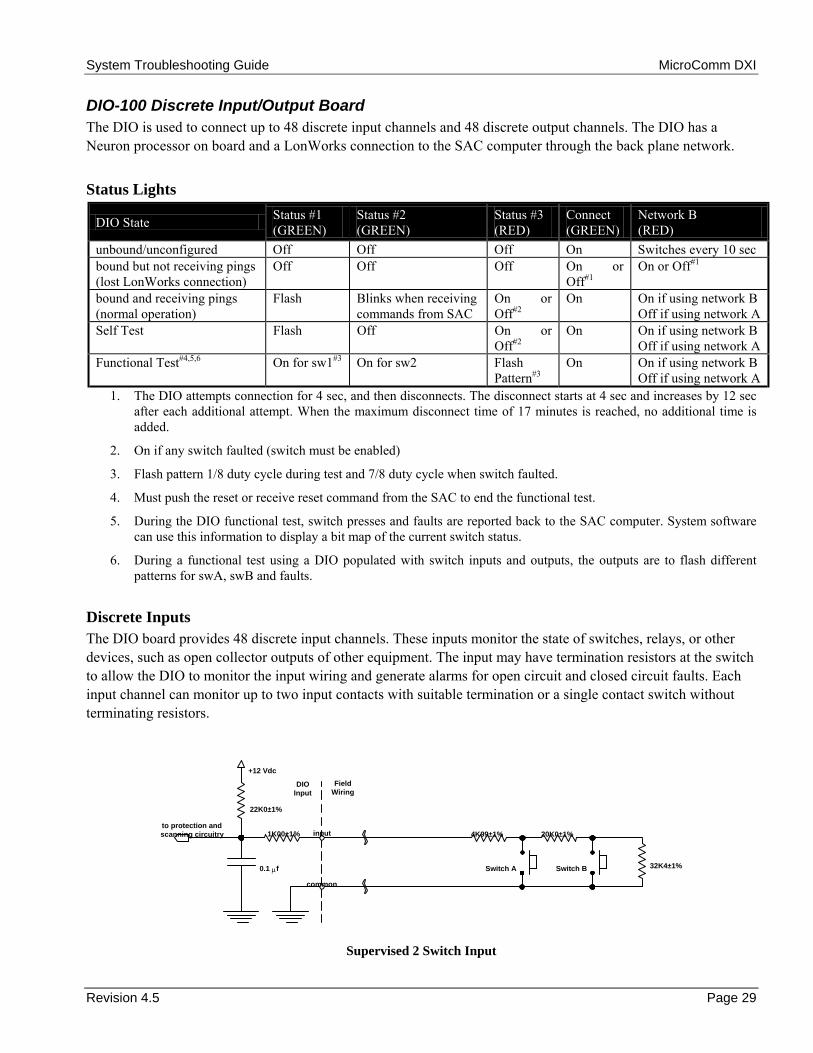
System Troubleshooting Guide MicroComm DXI
Revision 4.5 Page 29
DIO-100 Discrete Input/Output Board The DIO is used to connect up to 48 discrete input channels and 48 discrete output channels. The DIO has a Neuron processor on board and a LonWorks connection to the SAC computer through the back plane network.
Status Lights
DIO State Status #1 (GREEN)
Status #2 (GREEN)
Status #3 (RED)
Connect (GREEN)
Network B (RED)
unbound/unconfigured Off Off Off On Switches every 10 sec bound but not receiving pings (lost LonWorks connection)
Off Off Off On or Off#1
On or Off#1
bound and receiving pings (normal operation)
Flash Blinks when receiving commands from SAC
On or Off#2
On On if using network B Off if using network A
Self Test Flash Off On or Off#2
On On if using network B Off if using network A
Functional Test#4,5,6 On for sw1#3 On for sw2 Flash Pattern#3
On On if using network B Off if using network A
1. The DIO attempts connection for 4 sec, and then disconnects. The disconnect starts at 4 sec and increases by 12 sec after each additional attempt. When the maximum disconnect time of 17 minutes is reached, no additional time is added.
2. On if any switch faulted (switch must be enabled)
3. Flash pattern 1/8 duty cycle during test and 7/8 duty cycle when switch faulted.
4. Must push the reset or receive reset command from the SAC to end the functional test.
5. During the DIO functional test, switch presses and faults are reported back to the SAC computer. System software can use this information to display a bit map of the current switch status.
6. During a functional test using a DIO populated with switch inputs and outputs, the outputs are to flash different patterns for swA, swB and faults.
Discrete Inputs The DIO board provides 48 discrete input channels. These inputs monitor the state of switches, relays, or other devices, such as open collector outputs of other equipment. The input may have termination resistors at the switch to allow the DIO to monitor the input wiring and generate alarms for open circuit and closed circuit faults. Each input channel can monitor up to two input contacts with suitable termination or a single contact switch without terminating resistors.
to protection and scanning circuitry 20K0±1%
32K4±1%Switch B
input
common
DIOInput
FieldWiring
0.1 µf
+12 Vdc
4K99±1%
Switch A
22K0±1%
1K00±1%
Supervised 2 Switch Input

System Troubleshooting Guide MicroComm DXI
Page 30 Revision 4.5
to protection and scanning circuitry 24K9±1%
32K4±1%Switch B
input
common
DIOInput
FieldWiring
0.1 µf
+12 Vdc
22K0±1%
1K00±1%
Supervised 1 Switch Input (Switch B)
to protection and scanning circuitry 4K99±1%
52K4±1%Switch A
input
common
DIOInput
FieldWiring
0.1 µf
+12 Vdc
22K0±1%
1K00±1%
Supervised 1 Switch Input (Switch A)
to protection and scanning circuitry
Switch orcontact input
input
common
DIOInput
FieldWiring
0.1 µf
+12 Vdc
22K0±1%
1K00±1%
Non-Supervised 1 Switch Input
to protection and scanning circuitry
open collectoroutput
input
common
DIOInput
FieldWiring
0.1 µf
+12 Vdc
22K0±1%
1K00±1%
Solid State Switch Input
For the supervised 2 Switch Input the input to the DIO card can be in one of five states. The voltage at the DIO input terminal determines these states. The actual voltage measured will be slightly different from those given in the table due to component tolerances and the resistance of the wiring to the switch.

System Troubleshooting Guide MicroComm DXI
Revision 4.5 Page 31
Input State Wiring Switch A Switch B Voltage Open Fault Open Circuit NA NA 12 Idle Normal Not Pushed Not Pushed 8.6 Switch A Pressed Normal Pushed NA 2.1 Switch B Pressed Normal Not Pushed Pushed 6.3 Short Fault Short Circuit NA NA 0
Discrete Outputs The DIO board provides 48 discrete outputs. Four output types are available from the factory source outputs, LED outputs, sink outputs and relay outputs.
Source Outputs Source outputs are high side voltage driven outputs that provide 12 Vdc @ 30 mA of current capacity per output. They may be used to drive LEDs and 12 V relays. If a source output is used to drive an LED, a current-limit resistor must be provided.
from outputcontrol circuits
output
common
DIOOutput
FieldWiring
protection circuitry
+Vdc
Load
Source Output
from outputcontrol circuits
output
common
DIOOutput
FieldWiring
protection circuitry
+Vdc
LED
1K current limiting resistor
Source Output with Current Limiting
LED Outputs LED outputs are a special version of the source outputs that supply a 10 mA current-limited signal. The current-limit resistor is supplied as an integral part of the LED output.
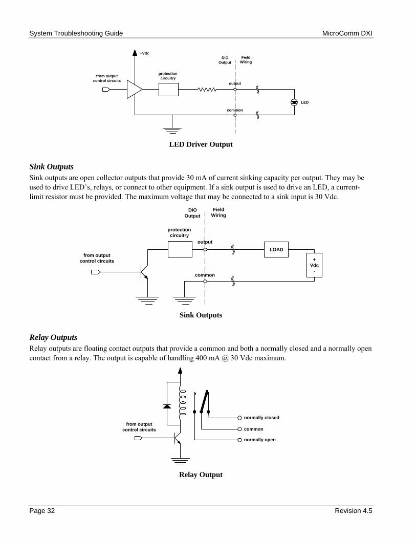
System Troubleshooting Guide MicroComm DXI
Page 32 Revision 4.5
from outputcontrol circuits
output
common
DIOOutput
FieldWiring
protection circuitry
+Vdc
LED
LED Driver Output
Sink Outputs Sink outputs are open collector outputs that provide 30 mA of current sinking capacity per output. They may be used to drive LEDs, relays, or connect to other equipment. If a sink output is used to drive an LED, a current-limit resistor must be provided. The maximum voltage that may be connected to a sink input is 30 Vdc.
from outputcontrol circuits
output
common
DIOOutput
FieldWiring
protection circuitry
+Vdc
-
LOAD
Sink Outputs
Relay Outputs Relay outputs are floating contact outputs that provide a common and both a normally closed and a normally open contact from a relay. The output is capable of handling 400 mA @ 30 Vdc maximum.
from outputcontrol circuits
normally closed
common
normally open
Relay Output
System Troubleshooting Guide MicroComm DXI
Revision 4.5 Page 33
DIO Board Problems DIO board problems may be indicated by fault alarms on the Secondary Master Station or the SAC Fault List, the DIO fault indicator (Status #3 LED), or the inability to detect and report switch presses or drive outputs.
Network Problems Test the network operation using a known good DIO at the connector. If the new DIO operates correctly, return the faulty unit for repair; otherwise check the network wiring for faults.
Input Problems Test V- input on DIO with respect to the common terminal block to make sure that they are at 0V. A small voltage difference (<0.5V) is acceptable. If the difference is greater, the ground wiring to the DIO should be fixed.
If a single input is not operating correctly you should perform the measurements below to identify the cause of the problem.
First, measure the voltage on the switch input with respect to power supply V- (when the switch is in the "idle" state). It should be 9V. A reading of 0V would indicate a short circuit. A reading of approximately 3V would indicate that the switch is pushed. A reading of 11.5 V would indicate an open circuit.
Second, push and hold the switch at the station. Measure voltage on switch input with respect to power supply V-. It should be about 3V. A reading of 0V would indicate a short circuit. A reading of approximately 9V would indicate that the switch was not working. A reading of 11.5 V would indicate an open circuit.
Third, disconnect the switch from the input on the terminal block (be sure to disconnect the wire that goes to the station from the terminal block). Measure the voltage on switch input with respect to power supply voltage V-. It should measure approximately 11.5V. The Status #3 LED on the DIO should turn on, if it is not on already, to indicate that a fault condition exists. (The LED would be on if there were other faults.) An alarm should be queued at the secondary master.
If the voltage is correct, the switch input is properly connected to the DIO. If the LED turns on, it indicates that the DIO detected the fault correctly. If the alarm is annunciated and the station is correctly identified, it indicates that the configuration is correct.
Fourth, connect the switch input on the terminal block to the power supply V-. The Status #3 LED on the DIO should turn on, if not on already, to indicate that a fault condition exists.
Finally, check that the input channel is properly configured, using the SAC computer.
If all of these checks turn out, as they should, replace the DIO board and return the faulty one for repair.
Output Problems
LED Outputs First, disconnect the LED from the output on the terminal block. When there is no call to the station (when the output should be Off), you should measure 0V with respect to the supply V-. When there is a call to the station (the output should be On), you should measure 10.5V. If the output activates (turns on the driver chip and the voltage changes from 0V to 10.5V), the connection from the DIO to the terminal block is good. The problem is probably in the wiring between the terminal blocks and the output LED. There may be a short, or the LED may be burned out.

System Troubleshooting Guide MicroComm DXI
Page 34 Revision 4.5
Next, with the LED still disconnected, run a diode test on the LED. This will indicate whether the LED is good or not.
Finally, check that the output channel is properly configured, using the SAC computer.

System Troubleshooting Guide MicroComm DXI
Revision 4.5 Page 35
Section 6 - Non Card Cage Modules
In this Section... We will:
• discuss cards that are not located in a main card cage,
• discuss network modules used as LonWorks repeaters, and
• discuss Remote Receiver modules.
Many of the cards used in a DXI system are located in central card cages, where short distances and a back plane connection between the various cards makes a compact, convenient and high-speed system. In some situations there is a tradeoff between speed and wiring convenience. In order to reduce the number of wires used in long wiring runs it is convenient to locate equipment away from the central card cage. Signals brought back are multiplexed so few wires are brought back to the card cage. Examples of cards that can be located remote from a SAC computer include SPD-120 Switch Panel Driver and DIO-120 Discrete Input/Output Board. Where long distances or heavy loading are involved network repeaters may be required. The DXI system allows audio remote intercom connections to an RRR-110 or RRR-120 Remote Receiver Rack (a two-slot card cage). A RRR can hold two cards, one is a Remote Receiver Board (RRB-100) and the second is any of the audio boards (AIB, AIO, AOB, PAB, SAB, TLB or TSB). The RRB-100 is connected via a high speed CEPT link back to an RDB-100 located in a main card cage.
SPD-120 Switch Panel Driver The SPD-120 is a wall mount module used to connect manual switch panels and graphic annunciation panels to the DXI system I/O network. The SPD can interface to 128 normally open switch contacts and 128 LED indicators.
Status LED’s
SPD-120 Status Status #1 (GREEN)
Status #2 (GREEN)
Status #3 (RED)
Connect (GREEN)
Network B (GREEN)
unbound/unconfigured Off Off Off On Switches every 10sec bound but not receiving pings
Off Off Off On or Off#1
On or Off#1
bound and receiving pings (normal operation)
Flash Blinks when receiving commands from SAC
Off On On if using network B Off if using network A
Self Test Flash Off Off On On if using network B Off if using network A
Functional Test#3,4 Off Off Flash Pattern#2
On On if using network B Off if using network A
1. SPD attempts connection on network A for 4 sec, then attempts connection on network B for 4 sec, and then disconnects. The disconnect time is 4 sec the first time, and increases 12 sec each additional time. When a maximum disconnect time of 17 minutes is reached, no additional disconnect time is added.
2. Flash pattern is 1/8 duty cycle.
3. Must push the reset or receive reset command from the SAC to end the functional test.
4. During the functional test, switch presses and faults are reported back to the SAC Computer. System software can use this information to display a bit map of the current switch status.

System Troubleshooting Guide MicroComm DXI
Page 36 Revision 4.5
Functional Testing Connecting a special printed circuit board to the output can functionally test the SPD-120. The test reads an input switch and if closed turns on a corresponding LED. In this way all inputs and outputs can be checked to see that they are operating properly.
DIO-120 Discrete Input/Output Board The DIO-120 is identical in operation to the DIO-100 except it can be located remotely away from the card cage. The DIO-120 requires a LonWorks connection back to the SAC computer.
Status Lights The operation of status lights for the DIO-120 is identical to the operation of the status lights for the DIO-100 (See Status Lights under DIO-100 in Section 5).
FTR-120 Free Topology Repeater The FTR-100 is a four port Free Topology Repeater which allows the LonWorks network to be extended both in distance and in the number of nodes that can be connected.
FTR Status LED’s The FTR has six status LEDs: PWR, TX1-4, RX1, RX2, RX3, and RX4.
NET 1
NET 2
NC
RX2
RX1
NET 3
RX1
NET 4
NC
RX4
PWR
A-
PWR
B+
NC
TX 1-4
PWR
B-
PWR
A
+
LED Indicates PWR That the unit has power connected to it TX1-4 That messages are being sent on the three segments that did not receive the message RX1 That a message is received on channel #1, which is connected to a specific network
segment RX2 That a message is received on channel #2, which is connected to a specific network
segment RX3 That a message is received on channel #3, which is connected to a specific network
segment RX4 That a message is received on channel #4, which is connected to a specific network
segment
Operation of Status LED’s (all DXI cards) Each device in the DXI system has status LEDs that provide information about its operation.

System Troubleshooting Guide MicroComm DXI
Revision 4.5 Page 37
LonWorks Network LED’s All devices, or nodes, connected to the LonWorks network have two network status LEDs. There are two network status LEDs Connect (green) and Network B (red). A network device can be in one of three states: connected on network A, connected on network B, or not connected.
Network Connection States Connect LED Network B LED Connect to Network A ON OFF Connect to Network B ON ON Not Connected OFF ON or OFF
If only the Connect LED (green) is ON, the LonWorks network connection is good. If the Network B LED (red) is ON, then a problem exists with Network A.
Ethernet Status LED’s The Ethernet card on the SAC computer has two LEDs on it a green LED to indicate when a message is transmitted/received and a yellow LED to indicate problems.
Under normal operation, the yellow LED is off. The green LED flashes each time that a message is transmitted or received.
If the network is not terminated or the network cable is unplugged, then the yellow LED flashes whenever a message is transmitted or received.
RRR-110 and RRR-120 Remote Receiver Rack The RRR comes in two styles, either panel mount or rack mount. The RRR has room for two cards; one must be a RRB and the second one of the standard audio cards. The RRB is connected through a point-to-point CEPT link to a RDB located in a main card cage. The RDR and RRR act as a transparent interface for the audio card located in the Remote Receiver Rack, that is the audio card will function as if it was located in the main card cage and occupied the same slot as the RDB card. Self-test and functional testing of this audio card is carried out as if the card occupied the slot position of the RDB card in the main card cage. If the point-to-point CEPT connection between the RDB and RRB fails, the audio card will not function until this CEPT connection is restored.
RRB-100 Remote Receiver Board The RRB-100 Remote Receiver Board mounts in one of the DXI Remote Receiver Racks. It interfaces an audio I/O board, also inserted in the remote receiver rack, to an associated Remote Driver Board in an I/O card cage. The Status #3 LED indicates whether the CEPT connection has failed (On = fail). The failure is also repeated in the Fault List on the SAC computer. The method of functional testing a Remote Receiver Board is to make a loop back connection.
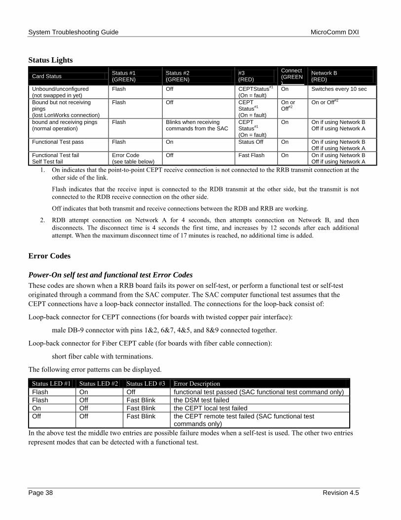
System Troubleshooting Guide MicroComm DXI
Page 38 Revision 4.5
Status Lights
Card Status Status #1 (GREEN)
Status #2 (GREEN)
#3 (RED)
Connect (GREEN)
Network B (RED)
Unbound/unconfigured (not swapped in yet)
Flash Off CEPTStatus#1 (On = fault)
On Switches every 10 sec
Bound but not receiving pings (lost LonWorks connection)
Flash Off CEPT Status#1 (On = fault)
On or Off#2
On or Off#2
bound and receiving pings (normal operation)
Flash Blinks when receiving commands from the SAC
CEPT Status#1 (On = fault)
On On if using Network B Off if using Network A
Functional Test pass Flash On Status Off On On if using Network B Off if using Network A
Functional Test fail Self Test fail
Error Code (see table below)
Off Fast Flash On On if using Network B Off if using Network A
1. On indicates that the point-to-point CEPT receive connection is not connected to the RRB transmit connection at the other side of the link.
Flash indicates that the receive input is connected to the RDB transmit at the other side, but the transmit is not connected to the RDB receive connection on the other side.
Off indicates that both transmit and receive connections between the RDB and RRB are working.
2. RDB attempt connection on Network A for 4 seconds, then attempts connection on Network B, and then disconnects. The disconnect time is 4 seconds the first time, and increases by 12 seconds after each additional attempt. When the maximum disconnect time of 17 minutes is reached, no additional time is added.
Error Codes
Power-On self test and functional test Error Codes These codes are shown when a RRB board fails its power on self-test, or perform a functional test or self-test originated through a command from the SAC computer. The SAC computer functional test assumes that the CEPT connections have a loop-back connector installed. The connections for the loop-back consist of:
Loop-back connector for CEPT connections (for boards with twisted copper pair interface):
male DB-9 connector with pins 1&2, 6&7, 4&5, and 8&9 connected together.
Loop-back connector for Fiber CEPT cable (for boards with fiber cable connection):
short fiber cable with terminations.
The following error patterns can be displayed.
Status LED #1 Status LED #2 Status LED #3 Error Description Flash On Off functional test passed (SAC functional test command only) Flash Off Fast Blink the DSM test failed On Off Fast Blink the CEPT local test failed Off Off Fast Blink the CEPT remote test failed (SAC functional test
commands only) In the above test the middle two entries are possible failure modes when a self-test is used. The other two entries represent modes that can be detected with a functional test.

System Troubleshooting Guide MicroComm DXI
R
Section 7 - Power Supplies
In this Section... We will
• discuss the various power supplies available with the DXI, and
• discuss the proper connections for these power supplies
Most of the DXI card cage boards operate with a ±12 Vdc power supply. This means a 3-wire connection to the system +12 Vdc, -12Vdc and Ground (Labeled GND).
M
Rh
PTib
PTa
PIA
Ia
U
It
Caution: DXI card cages require all three connections to the power supply, especially the ground connection. If one of the connections is loose or not connected, and the supply is turned on, the cards may be damaged. Make sure that all power connections are securely fastened on the power supply and card cage before turningthe power on.
evision 4.5 Page 39
aster Stations can be ordered for either a single 12 Vdc or 24 Vdc power supply option.
emote Receiver Boards can be ordered to operate with either a ±12 Vdc supply or a single +24 Vdc supply, owever the +24 Vdc version has an internal switched power supply to create the ±12 Vdc power.
SU-110 and PSU-115 Power Supply Units hese units supply 10A max. current. The PSU-115 has trickle charge output for battery backup. There are
ndicator LEDs on the front panel to indicate that the +12 Vdc and -12 Vdc are present. The On Switch has a acklit red light to indicate AC power is available.
SU-310 and PSU-315 Power Supply Units hese units supply up to 30A max current. The PSU-315 allows for battery backup trickle charge output. There re green LEDs on the front panel to indicate that ±12 Vdc is present.
ower Supply Operation f the red indicator light does not come on when the power supply is turned on check the AC connection and the C supply.
f the red indicator light comes on but neither green LED for ±12 Vdc, check the 5 Amp (15 Amp for PSU-310 nd PSU-315) fuse located at the back of the power supply.
sing a DC voltmeter the back terminals can be checked for proper dc output voltages.
f the fan is noisy or not working take the power supply out of service until the fan can be replaced. Periodically he fan filter should be checked and cleaned (see MicroComm Installation Instructions: Power Supplies).

System Troubleshooting Guide MicroComm DXI
Page 40 Revision 4.5
PSU-123 and PSU-125 Power Supply The PSU-123 is a wall mount power supply capable of supplying 3.4 A at either +24 Vdc or ±12 Vdc. A 2 amp fuse protects the primary 120 volt AC input.
The PSU-125 is a wall mount power supply capable of supplying 5.0 A at either +24 Vdc or ±12 Vdc. A 3 amp fuse protects the primary 120 volt AC input.
Power Supply Connections
+24 Volt Operation Connect the Earth and 12 Vdc terminals together using a short length of wire
Connect the +12 Vdc terminal to the positive terminal of the 24 Vdc equipment.
Connect the 12 Vdc terminal to the negative (common) terminal of the 24 Vdc equipment
Leave the Ground terminal unconnected
±12 Vdc Operation Connect the Earth and Ground terminals together using a short length of wire
Connect the +12 Vdc terminal to the positive terminal of the ±12 Vdc equipment
Connect the 12 Vdc terminal to the negative (common) terminal of the ±12 Vdc equipment
Connect the Ground terminal to the Ground terminal of the ±12 Vdc equipment.
Power Supply Operation The Power supply has an internal current overload protection. If the measured power supply voltages do not correspond to the rated values, then disconnect the load and recheck the voltages. Replace or repair a faulty power supply. If the load pulls the supply voltage below the rated values then you must reduce the load connected to the power supply.
System Troubleshooting Guide MicroComm DXI
Revision 4.5 Page 41
Section 8 - Using the Secondary Master Station for Maintenance
In This Section... We will:
• discuss alarms received at the secondary Master Station, and • outline how the secondary Master Station handles fault alarms.
You should be sure to read the 100 Series Master Station Operating Instruction Manual and be familiar with all intercom functions before beginning this chapter.
Alarm Annunciation at the Secondary Master Station The DXI system is designed to flag certain unusual or abnormal events as alarms and annunciate them at a designated Master Station. If this Master Station is different than the Master Station receiving calls it is called a Secondary Master Station. In this way, it is possible for a specified Master Station to monitor the operation of the system, through "exception" reporting. The System Administrator in the software configuration specifies the Secondary Master Station.
Three types of alarms are annunciated at the Secondary Master Station:
• Call Request Time-out Alarms (Alarm Code: t), • Disabled Station Alarms (Alarm Code: d), and • Fault Alarms (Alarm Code: F).
Fault Alarms For maintenance purposes, the most important type of alarm is a fault alarm. A fault alarm is initiated by the DXI system. It might indicate a wiring fault, a communications problem or some other internal systems failure. The purpose of annunciating these alarms is to ensure speedy service when required.
There are three types of fault alarms:
Echelon alarms. This type of alarm indicates that there is a communication problem in the LonWorks network.
Ethernet alarms. This type of alarm indicates that there is a problem with the Ethernet connection between the SAC computers. The control computers are not properly communicating with each other.
Hardware alarms. This type of alarm indicates that there is a problem with a switch.
A fault alarm will remain on the Secondary Master until the underlying problem has been corrected. Then it will automatically be canceled.
Fault alarms are also logged at the SAC computer, as part of the DXI data logging function. For more information on data logging, see Section 8 of the System Maintenance Manual.
The Secondary Master Station The Secondary Master does not distinguish between types of alarms. All alarms are treated equally. All are listed on the displays. If you are using the Secondary Master Station to monitor fault alarms, they may be mixed in with other alarm types.

System Troubleshooting Guide MicroComm DXI
Page 42 Revision 4.5
For a full detailed description of how the Secondary Master Station operates and how it handles fault alarms, refer to the Intercom Master Station Operating Instructions Manual.

System Troubleshooting Guide MicroComm DXI
Revision 4.1 Page 43
Section 9 – Using the SAC Computer for Troubleshooting
In this Section… We will:
• discuss the SAC menu functions which can be used to troubleshoot problems, and • give examples of problems that may be detected by the SAC computer.
You should be familiar with the operation of the SAC computer menus, and have read the MicroComm DXI Maintenance Manual before beginning this section.
Detecting problems with View Faults The View Faults function can detect the following types of problems:
• configuration errors, • LonWorks network problems, • power connection problems, • CEPT loop problems (on ACB CEPT loops), • remote I/O CEPT problems (on point-to-point Remote I/O CEPT's), • card failures, • Intercom Station wiring termination problems, and • Intercom Station failures.
View Faults cannot detect the following types of problems:
• problems with any devices (cards, stations, etc.) which have not been entered into the configuration yet, • cards (and stations on those cards) which have not been put into service yet (use View Networks instead), • problems resulting from the failure of another exchange computer or the Ethernet network (use View Status
instead), • Master Station audio wiring problems, and • intermittent problems.
You can enter the View Faults function from the Maintenance module. Select the View menu selection, and select Faults from the popup menu. The SAC will then give a list of all faults detected on the DXI network (which also includes faults on other active exchange computers as well as this exchanges computer). A sample display is shown.
The top line of the display will start out as a moving bar, to indicate the system is currently busy reading the status of all devices in the system. Once all of the faults have been detected (or the screen is full), the bar will disappear and you will see a message indicating that you can hit the END key to quit, or any other key to refresh or go to the next page.
For all of the above numbers, the DXI ID number is given, and the descriptive name of the card or station (assigned in the system configuration screens) is within brackets.
Common faults that are reported in View Faults are described below.
Hit END key to quit. Any key to go to page #2. Page #1Warning @ line 915: Resource 10 on Card 104 has been used twiceCard 1 (Unit 1 Master)Card 101 (Main ACB) CEPT #2 FaultedCard 103 (Main SAB #1)Card 201 (Admin ACB) CEPT #1 FaultedCard 205 (Gate SAB)Card 301 (Bldg 1 ACB)Card 303 (Bldg 1 SAB #1)Card 304 (Bldg 1 SAB #2)Card 305 (Bldg 1 AIO)Card 317 (Bldg 1 PAB)Card 2050 (Gate RDB) CEPT #1 Receive OnlyCard 2051 (Gate RRB) CEPT #1 FaultedCage #101 (Main ACB) slot 4.1.A Stn #16 (Cell A16) Switch #1Cage #201 (Admin ACB) slot 1.15.A Stn #1012 (West Sally) Switch #1
System Troubleshooting Guide MicroComm DXI
Page 44 Revision 4.5
Configuration errors Any warnings or errors in the system configuration are reported by the View Faults function. An example of this type of message is
Warning @ line 915: Resource 10 on Card 104 has been used twice
The line number indicates which line in the hardware configuration text file has the problem. Warning messages still allow the SAC computer to run, but if there are any error messages, the complete DXI system will not operate at all. Editing the configuration file by hand, rather than using the SAC menus usually causes this problem. You should never see this problem once the system has been commissioned, unless the hard drive on the SAC computer has been corrupted. If you see this type of warning or error, notify the system installer or Harding Instruments so that the configuration files can be fixed.
Master Station LonWorks failure Master station network connection faults are reported by the View Faults function. These faults indicate that the SAC computer is no longer able to communicate with the master keypad/display, so that you will not be able to initiate connections or view the connection status with this master. A message such as
Card 1 (Unit 1 Master)
indicates Master 1 (the Unit 1 Master) is not communicating with the LonWorks network. A likely cause is; the master is turned off, the wiring between the master and power supply is not connected, the LonWorks network is not connected to this master, or this master has failed. To determine what type of problem this card has, go to the control room where this master is located and check the master display and card status LED's. Information on Master Station status LED information and troubleshooting problems with Master Stations can be found in Section 3 of the Troubleshooting Guide. Likely, either the power or LonWorks connection to this master has been disconnected. Check the power, then the LonWorks connection to this master. If the problem persists, try replacing the master with a known good master (remember to use the Swap Card function in the Maintenance module when doing this). Remember that View Faults reports problems only with power and network wiring to the master, and not the audio wiring.
Card Cage connections or Audio Control Board failure The main Audio Control Board (ACB) controls all of the connections made on the card cage. Without this card operational, all audio cards in this cage will not work. When the ACB fails (either due to power failure, hardware failure, or the loss of the LonWorks connection), all other cards that depend on the ACB card will also report a failure. When the ACB fails all intercom connections to any master or intercom station in this card cage will fail. In the example above,

System Troubleshooting Guide MicroComm DXI
Revision 4.5 Page 45
Card 301 (Bldg 1 ACB) Card 303 (Bldg 1 SAB #1) Card 304 (Bldg 1 SAB #2) Card 305 (Bldg 1 AIO) Card 317 (Bldg 1 PAB)
Indicates that ACB 301 in Card Cage 3 (Building 1) has stopped communicating to the SAC computer. Cards 303, 304, 305, and 317 report they have failed because they communicate with the SAC computer through ACB 301, which has failed.
To determine what type of problem this ACB card has, go to the control room with the card cage that contains this ACB, and check the ACB status LED's. Card status LED information can be found in Section 5 of the Troubleshooting Guide. Likely, either the power to the card cage has been lost, the LonWorks connection to the card cage has been disconnected, or the ACB card has failed. Check the voltages on the card cage power terminals, then the LonWorks connection to this card cage, and if the ACB still fails, try replacing it with a known good ACB (remember to use the Swap Card function in the Maintenance module when doing this).
Audio card failure When the ACB cannot communicate with an audio card (such as an SAB, AIO, PAB, etc.) in the card cage, the SAC computer will report this failure. An audio card failure means that you will be unable to connect to any master or intercom station on this card For example, the message
Card 103 (Main SAB #1)
indicates that this card has lost communication. If the ACB card controlling this card cage also reports as failed, it is likely that this card cage has a power or LonWorks network problem. If, however, the ACB does not report as a failure, this card, or the card cage slot it is located in, has failed. To determine what type of problem this card has, go to the equipment room with this card, and check the card status LEDs. Card status LED information can be found in Section 5 of the Troubleshooting Guide. To check if the problem is caused by poor seating of the card, you can remove the card and re-seat it. If it still reports failure, check the card slot fingers (in the card cage) to make sure they are not bent out of shape. If the card cage slot fingers seem to look normal, then try replacing the audio card with a known good card (remember to use the Swap Card function in the Maintenance module when doing this).
When an audio card has failed, it implies that all stations on this card have failed. These possible failures are not reported in View Faults, since the fault may only occur on the audio card itself, and not the station termination. Once the problem has been rectified and the audio card put back into service, any station faults will be displayed.
Failure of other card types Other cards with network communication (such as a DIO, SPC, RNS, RDB, or RRB) will also report a failure if they have lost their LonWorks connection. To determine what type of problem this card has, go to the equipment room where this card is located, and check the card status LED's. Card status LED information can be found in Section 5 of the Troubleshooting Guide. The possible causes for this problem could be that the power to the card is turned off (or is not connected), the LonWorks network is not connected to this card, or this card has failed. If the card is located in a card cage (such as a card cage DIO or RDB), check the power and LonWorks connections to the card cage. If other cards within the cage still work properly, you probably have a bad card, which you can test by replacing the card with a known good card. If the card is located externally (such as an SPC, RNS, or RRB), check the power, then the LonWorks connection to this card. If the problem persists, try replacing the card

System Troubleshooting Guide MicroComm DXI
Page 46 Revision 4.5
with a known good card. Remember to use the Swap Card function in the Maintenance module when replacing a card.
ACB CEPT Loop failure The ACB CEPT loop is the digital audio trunk lines that allow card cages (exchanges) to transmit audio to another card cages.
ACB CEPT links are wired as two loops, one primary loop, which runs from Transmit 1 of this ACB to Receive 2 of the next ACB, and one secondary loop, which runs from Transmit 2 of this ACB to Receive 1 of the previous ACB. Each ACB is connected to the next and previous ACB in the same fashion, until two complete loops are formed. For copper (wired) CEPT links, one twisted pair of wires is used for each link, for example, Transmit 1 is composed of Tx1+ and Tx1- wires. For fiber optic CEPT links, each link is a single fiber.
The system is designed in such a way that any one connection can be severed, and still provide a complete audio path between any two card cages in the system. However, two breaks between card cages will result in a part of the system being isolated. Hence, it is important to periodically check the audio CEPT loop status and repair any faults, to avoid loss of service to any part of the facility in the event of a second failure.
Because each link is between two intelligent ACB's, both cards will report any one failure; hence, CEPT failure messages are almost always reported in pairs. Each pair of messages is the failure in one link, so that two reported failure messages indicate one severed link (which still leaves a fully operational system), and 4 reported failure messages indicate two severed links (which leaves one or more card cages in the system isolated from the others).
In the following examples we assume that a system has 3 card cages (ACB 101, 201 and 301). The CEPT loops would normally have the following connections:
Primary Loop Secondary Loop ACB 101 Tx1 to ACB 201 Rx2 ACB 201 Tx2 to ACB 101 Rx1 ACB 201 Tx1 to ACB 301 Rx2 ACB 301 Tx2 to ACB 201 Rx1 ACB 301 Tx1 to ACB 101 Rx2 ACB 101 Tx2 to ACB 301 Rx1
The following block diagram shows the primary and secondary CEPT loops in this 3 card cage system.
Tx1
Rx1
Rx2
Tx2
Secondary Loop
Primary Loop
ACB-100
Rx2
Tx2
ACB-100
Rx1
Tx1
ACB-100
Tx2
Rx2
Rx1
Tx1
Active Data Path (primary loop)
Secondary Data Path (secondary loop)
101 201 301
CEPT Network

System Troubleshooting Guide MicroComm DXI
Revision 4.5 Page 47
When all of the ACB CEPT loop connections are functioning properly, the audio travels in the primary path. The following block diagram shows the ACB CEPT loop connection paths when a master on ACB 101 is in a call to a station on ACB 301.
Tx1
Rx1
Rx2
Tx2
Secondary Loop
Primary Loop
ACB-100
Rx2
Tx2
ACB-100
Rx1
Tx1
ACB-100
Tx2
Rx2
Rx1
Tx1
Active Data Path (primary loop)
Secondary Data Path (secondary loop)
101 201 301
Master Station
Fully Operational CEPT Loop
If one of the links between ACB 201 and ACB 301 were broken, the audio would travel in the path indicated in the following diagram. To overcome the broken connection the system makes use of both the primary and secondary CEPT loops.
Tx1
Rx1
Rx2
Tx2
Secondary Loop
Primary Loop
ACB-100
Rx2
Tx2
ACB-100
Rx1
Tx1
ACB-100
Tx2
Rx2
Rx1
Tx1
Active Data Path
Broken Connection
101 201 301
Master Station
CEPT Loop broken between 201 and 203
The View Faults function would show the following pair of messages in this case:
Card 201 (Main ACB) CEPT #1 Faulted Card 301 (Bldg 1 ACB) CEPT #2 Faulted
The first fault (Card 201 CEPT #1 Faulted) indicates that the connection on the primary loop from ACB 201 Tx1 to ACB 301 Rx2 has failed.
The second fault (Card 301 CEPT #2 Faulted) indicates that the connection on the secondary loop from ACB 301 Tx1 to ACB 201 Rx1 has faulted.

System Troubleshooting Guide MicroComm DXI
Page 48 Revision 4.5
This pair of messages indicates that the CEPT link between ACB 201 and ACB 301 has failed. The current SAC software cannot determine whether the primary or secondary link is broken in this case, so you will have to check both connections (ACB 201 Tx1 to ACB 301 Rx2, and ACB 301 Tx2 to ACB 201 Rx1) to see which link is broken.
Another example of an ACB CEPT fault that is not caused by the actual CEPT connection is shown below. The following failure list is from the View Faults output example at the start of this section:
Card 101 (Main ACB) CEPT #2 Faulted Card 201 (Admin ACB) CEPT #1 Faulted Card 301 (Bldg 1 ACB)
The first fault (Card 101 CEPT #2 Faulted) indicates that the connection on the secondary loop from ACB 101 Tx2 to ACB 301 Rx1 has faulted.
The second fault (Card 201 CEPT #1 Faulted) indicates that the connection on the primary loop from ACB 201 Tx1 to ACB 301 Rx2 has faulted.
The third fault (Card 301) indicated that the ACB on 301 itself has faulted. This group of faults is the result of ACB 301 failing. Because ACB 301 failed, naturally the links between ACB 101 and 201 to ACB 301 will fail.
Remote I/O CEPT failure The Remote I/O point-to-point CEPT link is a digital signal and audio connection between a Remote Driver Board (RDB) located in a card cage and a Remote Receiver Board (RRB) located at the remote location. This RRB can then drive an audio card (such as an SAB) located in the Remote Receiver Rack (RRR) that the RRB is located in. This operation of the RDB and RRB is transparent, so that to the rest of the system, it is as if the audio card (such as an SAB) is located directly in the card cage in the slot where the RDB is located.
If this Remote I/O point-to-point CEPT link fails, then the audio card will not operate, and to the rest of the system, it will appear to be a card failure of that audio card. Remote I/O units do not have redundant CEPT's, so if either link between the RDB and RRB fails, that card will fail.
Remote I/O CEPT links are simple point-to point connections, with the transmit of the RDB being connected to the receive of the RRB, and the transmit of the RRB being connected to the receive of the RDB. For copper (wired) CEPT links, one twisted pair of wires is used for each link, for example, Transmit is composed of Tx+ and Tx- wires. For fiber optic CEPT links, each link is a single fiber.
Because each link is between two intelligent Remote I/O boards, any one failure will be reported by both cards; hence, CEPT failures are almost always reported in pairs.
Remote I/O boards can determine which side of the link has failed, and the status reported by View Faults can be used to pinpoint the faulty connection. The Status 3 LED information on the Remote I/O boards also has this CEPT failure information displayed on it. Card status LED information can be found in Section 5 of the Troubleshooting Guide for Remote Driver Boards (RDB's), or Section 6 of the Troubleshooting Guide for Remote Receiver Boards (RRB's).
Example output from the View Faults example at the start of this section is:
Card 205 (Gate SAB) Card 2050 (Gate RDB) CEPT #1 Receive Only Card 2051 (Gate RRB) CEPT #1 Faulted
System Troubleshooting Guide MicroComm DXI
Revision 4.5 Page 49
First of all, Card 205 (the card in the Remote Receiver Rack) is shown as faulted. This by itself can only indicate that the possible cause of the problem could be that the card has faulted, the RRB has lost power, or the CEPT connection between the RDB has faulted. If you see this message without any RDB or RRB CEPT failures, it usually indicates that just the audio board (the SAB in this case) is faulted, but the link is still good.
The second message (Card 2050 RDB CEPT #1 Receive Only) indicates that the RRB Tx to RDB Rx connection appears to be working, but that the RDB Tx to RRB Tx is not.
The third message (Card 2051 RRB CEPT #1 Faulted) confirms that the RRB Tx to RDB Rx is indeed faulted.
Thus, to fix this problem, you need to check the link between the RRB Tx and the RDB Rx connectors.
If both links were down, both the RDB and RRB would report CEPT #1 Faulted.
If you saw the following messages instead:
Card 205 (Gate SAB) Card 2050 (Gate RDB) CEPT #1 Faulted Card 2051 (Gate RRB)
The Card 2051 (Gate RRB) fault indicates that the power to the RRB, or the RRB itself, has failed.
Since the RRB is inoperable, the RDB cannot with communicate with it, resulting in the Card 2050 (Gate RDB) CEPT #1 Faulted message. In addition, since the CEPT connection (and probably power to the Remote Receiver Board) is down, the SAB in the Remote Receiver Rack cannot function, resulting in the Card 205 (Gate SAB) fault.
Intercom Station or Call Operating Device failure Intercom stations on SAB-100 and SAB-400 Station Audio Boards have supervised wire pairs, so faults can be detected for these station types. Intercom station switch wire pairs on SAB-300 boards and Call Operating Devices on DIO boards can optionally be supervised if the correct termination is used at the switch end of the cabling. With supervised wiring, faults in the wiring, or sometimes even a fault on an intercom station can be detected by the SAC computer. These faults are reported by View Faults.
However, View Faults cannot detect faults on the audio wire pair of a generic intercom station connected to an SAB-300 board.
A sample fault listing for two intercom stations is as follows
Cage #101 (Main ACB) slot 4.1.A Stn #16 (Cell A16) Switch #1 Cage #201 (Admin ACB) slot 1.15.A Stn #1012 (West Sally) Switch #1
The left half of the line describes the physical location of the terminal block that this station is terminated on. The right half of the line describes the logical location (Station ID and name) of the station itself.
Going through the first fault, you can determine the following information:
The card cage that the intercom station is hooked up to is the card cage with ACB #101 in it. This ACB was given the name Main ACB.
The SAB card that the intercom station is hooked up to is in the fourth slot of the card cage (with the slots being numbered 1 (with the ACB in it) to 17 (the last slot).
The channel number on that SAB is channel 1 (the first channel on the board).
System Troubleshooting Guide MicroComm DXI
Page 50 Revision 4.5
The switch that was being checked for was the SWA switch. Since in most cases both station switches (if two-button stations are used) use the same wire pair, this piece of information is usually unnecessary.
This station was given the DXI (phone book) ID of 16
The name given to the station was Cell A16.
The switch (action) number in the configuration was #1. As above, this information is usually irrelevant.
From the data given, you have enough information about which equipment room and where in the equipment room this station is terminated (the terminal block for the card in the fourth slot of cage 101, first channel on the terminal block), and where the intercom station itself is located (Intercom #16, in Cell A16). If the ACB number and name, or Station ID and name were not enough, this information can be cross-referenced in the architectural drawings.
Once you have noted the relevant information, you can then pinpoint the fault by measuring the voltage across the two audio lines (for SAB-100 or SAB-400 boards), or the two switch lines (for SAB-300 or DIO boards). This can be done at the terminal block in the equipment room, and/or at the intercom station itself. See Section 4 (for intercom stations on SAB boards) or Section 5 (for Call Operating Devices on DIO boards) for more information how to troubleshoot station problems.
Detecting problems with View Networks The View Networks function can detect the following types of problems:
• cards that have not been put into service yet, • LonWorks network problems, • power connection problems, • CEPT loop problems (on ACB CEPT loops), • remote I/O CEPT problems (on point-to-point Remote I/O CEPTs), and • card failures.
View Networks cannot detect the following types of problems:
• configuration errors. • any problems with Intercom Stations, • problems with any cards which have not been entered into the configuration yet, • problems resulting from the failure of another exchange computer or the Ethernet network (use View Status
instead), • Master Station audio wiring problems, and • intermittent problems.
You can enter the View Networks function from the Maintenance module. Select the View menu selection, and select Networks from the popup menu. The SAC will then show you the first card in the system (which also includes cards on other active exchange computers as well as this exchanges computer). A sample display when an ACB card is selected is shown below.
PgDn: Next Card PgUp: Previous card End: Exit viewer Card ID: 101 Name (English): Main ACB Name (French): ? Name (Spanish): ? Type: ACB Neuron 8.2 DSP 5a 5a 5a 5a 17 Current channel: Backplane # of active chans: 1 (1 channels) Card status: In Service

System Troubleshooting Guide MicroComm DXI
Revision 4.5 Page 51
CEPT status: CEPT1=Working CEPT2=Faulted F2,F3=Search F7=Test F8=Heal F9=Net status F10=Clear status
You can scroll through the list of cards in the system using the PgUp and PgDn keys on the keyboard.
For intelligent cards (with a Neuron processor), you will see extra information after the Type: field, with the version number of the Neuron firmware, and the version number(s) of any Digital Signal Processor (DSP) firmware on the card. Version numbers of 0 for Neuron versions usually mean that the card has lost its network connection (which is a fault condition), while version numbers of 0 for DSP versions usually mean that the DSP is not installed (which could be a normal condition, depending on what is installed on your system).
For audio cards, you will also see a field named Current slot: which indicates which slot in the card cage that the particular card is currently configured to be in (numbered from 1 for the leftmost slot with the ACB, to 17 for the rightmost slot in the cage).
For ACB and Remote I/O cards, you will also see a field named CEPT status: which indicates the status of any CEPT connections to this card.
Check all of the cards in the system, looking for any of the problem indicated in the following table.
Problem indication Problem Possible causes Current channel: No channel Card not
communicating on LonWorks network.
Power not connected, LonWorks not connected, or card failure.
# of active chans: 0 Card not communicating on LonWorks network.
Power not connected, LonWorks not connected, or card failure.
Card status: NOT in Service Card is not in service. Card has not been put into service or has been taken out of service. Replace card and put back into service.
CEPT status: CEPTx=Faulted -or-CEPT status: CEPTx=Receive only
CEPT connection has reported a failure.
An ACB CEPT loop has failed (on an ACB) or a Remote I/O point-to-point CEPT link has failed (on a RRB or RDB).
Common faults reported by View Network are described below.
Card not in service A card that is not in service can be determined when the card status is NOT in service. The Current channel and # of active chans in this case are not necessarily correct, as they only relate to the last state of the card before it was taken out of service. For audio cards, the slot that the card was last configured to be in is shown in the current slot field (or None if it has never been put into service). An example screen for an SAB-400 that is not in service is shown below
System Troubleshooting Guide MicroComm DXI
Page 52 Revision 4.5
Card ID: 105 Name (English): Main SAB #3 Name (French): ? Name (Spanish): ? Type: SAB-400 Current channel: Backplane # of active chans: 1 (1 channels) Card status: NOT In Service Current slot: 5
To put this card into service, you need to replace the card in the correct slot (or connect the power and network cables if it is a remote type board), and use the Swap Card function in the Maintenance module.
The View Networks function is the only way to detect cards that are not in service.
The other failures described below can be also be detected with the View Faults function. The section above, Detecting problems with View Faults has more detailed explanations on LonWorks, card, and CEPT failures.
Master Station LonWorks failure A Master Station card failure can be determined when the Type is an MCB card, the Current channel is No Channel, the # of active chans is 0, and the card status is In Service. An example screen for a master that has failed is shown below
Card ID: 1 Name (English): Unit 1 Master Name (French): ? Name (Spanish): ? Type: MCB Neuron 0.0 Current channel: No channel # of active chans: 0 (1 channels) Card status: In Service
Information on troubleshooting Master Stations can be found in this section under Detecting problems with View Faults, Master Station LonWorks failure. Remember that View Networks reports problems only with power and network wiring to the master, and not the audio wiring.
Card Cage connections or Audio Control Board failure An Audio Control Board failure can be determined when the Type is an ACB card, the Current channel is No Channel, the # of active chans is 0, and the Card status is In Service. An example screen for an ACB that has failed is shown below
Card ID: 301 Name (English): Bldg 1 ACB Name (French): ? Name (Spanish): ? Type: ACB Neuron 0.0 DSP 0 0 0 0 0 Current channel: No channel # of active chans: 0 (1 channels) Card status: In Service

System Troubleshooting Guide MicroComm DXI
Revision 4.5 Page 53
CEPT status: CEPT1=Working CEPT2=Working When the Audio Control Board has failed, the CEPT status is not necessarily correct. It only indicates the status at the time the board was last working.
Information on troubleshooting ACB's can be found in this section under Detecting problems with View Faults, card cage connections or Audio Control Board failure.
Remember that a faulted ACB will cause all of the audio cards in the card cage to report as faulted also.
Audio card failure An audio card failure can be determined when the Type is an audio card (such as an SAB-400, PAB, AIO, etc.), the Current channel is No Channel, the # of active chans is 0, and the Card status is In Service. The slot that the card is currently configured to be in is shown in the current slot field. An example screen for an SAB-400 that has failed is shown below
Card ID: 103 Name (English): Main SAB #1 Name (French): ? Name (Spanish): ? Type: SAB_400 Current channel: No channel # of active chans: 0 (1 channels) Card status: In Service Current slot: 3
To determine what type of problem this card has, go to the equipment room where this card cage is located, and check the card status LEDs. Card status LED information can be found in Section 5 of the Troubleshooting Guide, while additional information on troubleshooting audio cards can be found in this section Detecting problems with View Faults under Audio card failure.
Failure of other card types Other cards with network communication (such as a DIO, SPC, RNS, RDB, or RRB) will also report a failure if they have lost their LonWorks connection.
The failure of other card types can be determined when the Current channel is No Channel, the # of active chans is 0, and the Card status is In Service. An example screen for a DIO that has failed is shown below
Card ID: 1001 Name (English): DIO 1 Name (French): ? Name (Spanish): ? Type: DIO Neuron 0.0 Current channel: No channel # of active chans: 0 (1 channels) Card status: In Service
Information on troubleshooting other card types can be found in this section under Detecting problems with View Faults, Failure of other card types.

System Troubleshooting Guide MicroComm DXI
Page 54 Revision 4.5
ACB CEPT Loop failure An Audio Control Board CEPT failure can be determined when the Type is an ACB card, the Card status is In Service, and you see CEPT1=Faulted or CEPT2=Faulted in the CEPT status field. An example screen for an ACB that has one CEPT connection faulted is shown below
Card ID: 301 Name (English): Bldg 1 ACB Name (French): ? Name (Spanish): ? Type: ACB Neuron 8.2 DSP 5a 5a 5a 5a 17 Current channel: Backplane # of active chans: 1 (1 channels) Card status: In Service CEPT status: CEPT1=Working CEPT2=Faulted
ACB CEPT loops are the digital audio trunks between card cages. If you have any ACB CEPT faults, it could mean that you will be unable to communicate to one or more card cages in your facility.
Information describing ACB CEPT loop topology, and troubleshooting ACB CEPT loops can be found in this section under Detecting problems with View Faults, ACB CEPT Loop failure.
Remote I/O CEPT failure Remote I/O CEPT failure can be determined when the Type is a RIO card, the Card status is In Service, and you see CEPT1=Faulted or CEPT1=Receive only in the CEPT status field. An example screen for a RRB that has its CEPT connection faulted is shown below
Card ID: 2051 Name (English): Gate RRB Name (French): ? Name (Spanish): ? Type: RIO Neuron 1.4 Current channel: Remote_A # of active chans: 1 (1 channels) Card status: In Service CEPT status: CEPT1=Receive only
Remote I/O CEPT links are the means of communication between the card cage and the audio card in a Remote Receiver Rack (RRR) in a remote location. If a Remote I/O CEPT link is faulted, the audio card will not function properly.
Information on troubleshooting Remote I/O CEPT links can be found in this section under Detecting problems with View Faults, Remote I/O CEPT failure.
Detecting Ethernet and Exchange computer problems with the View Status The View Status function can detect the following types of problems:
• Ethernet network problems,

System Troubleshooting Guide MicroComm DXI
Revision 4.5 Page 55
• SAC Exchange Computer power problems or failures, View Status cannot detect problems that do not relate to the status of the Ethernet connections between SAC computers.
View Status is only useful if you have more than one SAC computer in your system.
You can enter the View Status from the Maintenance module. Select the View menu selection, and select Status from the popup menu.
Information about all of the SAC computers in the system will then be shown on the screen
System status by node ID : 1: Up 2: Up 3: Down 4: Up Status of node #2: Primary node for this exchange Hit any key to continue...
The top two lines of the screen show the status of all of the SAC computers in the system. If all other computers are shown as down, the likely cause is that either the network connection from this SAC computer to the Ethernet hub is broken, or the Ethernet hub has failed. If only one other computer is down, it is likely that only the connection between the Ethernet hub and that computer is down, or that the other computer has failed.
The next two lines show the node number of the SAC computer you are currently on, and whether it is the primary or secondary node for this exchange (if you are using redundant SAC computers).
Detecting intermittent problems with the Log Viewer The system logs can be useful for detecting intermittent problems. The View Faults, View Networks, and View Status are easier to use to detect static (unchanging) problems, but may not be able to detect an intermittent problem. The Log Viewer can also be used to troubleshoot host port communications to external devices (for example, PLC's controlling a graphic panel, or computers running touch screen software).
The System Maintenance Manual, Section 8 Data logging shows you the commands available in the Log Viewer. This section of the Troubleshooting Guide only gives you indications of what the fault messages look like in the Log Viewer.
The Log Viewer should be started with at least the Debug option checked to obtain the following information.
You can enter the Log Viewer function from the Maintenance module. Select the Log menu selection, and select Log Level from the popup. Verify that the Debug info line has a checkmark beside it if it does not, select Debug info to turn it on. Then press the space bar to return to the first popup, and select the Open Viewer from the popup. The Log Viewer will then start up, showing the newest (latest) entries.
The Log Viewer has a search function, which will be useful when searching for particular errors. This search function is activated with the / key (unshifted ?) to search down towards newer entries, or ? (shifted /) to search up towards older entries. A popup box will appear allowing you to type in a string to search for (this string is case sensitive), and then the Log Viewer will scan the logs in that direction looking for an exact match of your string (at any location on a log line). Once it finds a log that matches, it will stop with the cursor on that line. You can then start another search, or you can hit the n key to search in the same direction for the Next match with the same search string.
System Troubleshooting Guide MicroComm DXI
Page 56 Revision 4.5
You can also mark sections of the log file to print or save to disk, which may be helpful when contacting support staff at Harding Instruments if you have any problems.
Sample log file lines and search strings are given below.
Configuration warnings and errors Configuration warnings and errors are easier to track through the View Faults function. However, they can be tracked in the Log Viewer. They are reported in the log files immediately following the SAC computer boot-up. For example:
Config compiler warning at line 437: Resource #2 on Card #302 has been used twice Hardware compiler compiled and loaded config file /home/dxi/config/hw_demo without errors Software compiler compiled and loaded config file /home/dxi/config/sw_demo without errors
You can search for these using the string Config compiler.
System reboots The system knows the time and date of the last system shutdown, as well as the time and date it was restarted. This message is reported as:
DXI system went down on Wed Oct 13 16:17:00 1999
The time and date that the system came back up is the time and date that the log file was reported at.
You can search for the string went down to find out if the SAC computer has been restarted for any reason.
LonWorks Failures LonWorks failures are indicated when the log files report an Echelon Alarm, while fixing a problem reports an Echelon Fix. You can detect these faults in the log by searching for the string Action “Echelon.
These alarms are reported for Master Station Lonworks failures, card cage connections or Audio Control board failures, audio card failures, and failures of other card types. By examining the Card ID, you can determine what type of card the failure occurred on, and from that then go through the appropriate troubleshooting procedures, which are explained in greater detail in the above sections of the Troubleshooting Guide.
Remember that a failure or recovery of an ACB card will result in the failure or recovery of all of the audio cards in the same card cage, therefore many audio card alarm or fix messages will occur in the logs when an alarm or fix message for an ACB occurs.
System Troubleshooting Guide MicroComm DXI
Revision 4.5 Page 57
Problems on card cage cards, such as ACB cards, SAB cards, etc. may look like:
Action “Echelon Backplane Ch Alarm:305” caused by Card 305.105.? BP A failed (pid 198). … Action “Echelon Backplane Ch Fix:305” caused by Card 305.105.? BP A fixed (pid 198).
While problems on other cards (such as masters, DIO boards, Remote Receiver Boards, etc. may look like:
Action “Echelon Remote Ch A Alarm:1” caused by Card 1.102.? Rem A failed (pid 196). … Action “Echelon Remote Ch A Fix:1” caused by Card 1.102.? Rem A fixed (pid 196).
The Lonworks channel the card is located on is indicated in the string within quotes, for example Backplane Ch or Remote Ch A.
Whether the card has faulted or been fixed is reported as Alarm or Fix, and is also repeated at the end of the line as failed or fixed.
The card number is indicated in both the string within quotes after Alarm: or Fix: and immediately after the Card text. The numbers following the card, and the pid number are only useful to Harding staff for advanced debugging.
Messages preceded with Action (as above) indicate the time the actual LonWorks failure is detected, while messages that are not preceded with Action are messages sent to master stations for display to the operational staff.
For example:
Echelon Backplane Ch Alarm on Card #305 (Bldg 1 AIO).
Indicates that an alarm has been reported to the master station that card faults are sent to.
Intercom Station or Call Operating Device failure Failures of a supervised switch Intercom Station or Call Operating Device are also reported in the log files.
You can search for these by using the string Action “Hardware.
An example of an intercom station fault and recovery is:
Action “Hardware Alarm:16” caused by Card 104.1.? Faulted (pid 238). … Action “Hardware Fix:16” caused by Card 104.1.? Corrected (pid 238).
Whether the station has faulted or been fixed is reported as Alarm or Fix and is also repeated at the end of the line as Faulted or Corrected.

System Troubleshooting Guide MicroComm DXI
Page 58 Revision 4.5
The station number is indicated in the string within quotes after Alarm: or Fix. The card number and channel of the audio card is indicated after the Card text (104.1.? means card 104, channel 1).
Messages preceded with Action (as above) indicate the time the actual intercom station failure is detected, while messages that are not preceded with Action are messages sent to master stations for display to the operational staff.
For example:
HW Alarm on Station #16 (Cell A16).
Indicates that an alarm has been reported to the master station that Station 16 normally calls into.
Ethernet failure If the Ethernet network between SAC computers goes down, or another SAC computer fails, an Ethernet failure is reported. You can search for Ethernet problems by searching for Action “Ethernet.
An example of losing the Ethernet link to SAC #1 (assuming you are viewing logs on SAC #2) would be:
Action “Ethernet Alarm:1” caused by Card 1.0.? Ethernet failed (pid 331). … Action “Ethernet Fix:1” caused by Card 1.0.? Ethernet fixed (pid 331).
Whether the Ethernet connection has faulted or been fixed is reported as Alarm or Fix and is also repeated at the end of the line as failed or fixed.
The SAC node number is indicated in the string within quotes after Alarm: or Fix, and after the Card text.
Messages preceded with Action (as above) indicate the time the actual Ethernet failure is detected, while messages that are not preceded with Action are messages sent to master stations for display to the operational staff.
For example:
Ethernet Alarm on Exchange #1 (Exchange 1).
Indicates that an Ethernet alarm has been reported to the master station that Exchange errors are sent to.
CEPT failures CEPT failures are also indicated in the logs.
Both Audio Control Board CEPT loop failures and Remote I/O CEPT failures are reported with this message.
For an ACB CEPT loop failure, you may see:
Card #101 reports CEPT loop #1 failed Card #201 reports CEPT loop #2 failed … Card #101 reports CEPT loop #1 healed

System Troubleshooting Guide MicroComm DXI
Revision 4.5 Page 59
Card #201 reports CEPT loop #2 healed
While for a Remote I/O CEPT failure, you may see:
Card #2050 reports CEPT loop #1 receive only Card #2051 reports CEPT loop #1 failed … Card #2051 reports CEPT loop #1 receive only Card #2050 reports CEPT loop #1 healed Card #2051 reports CEPT loop #1 healed
The Card ID of the card that reports a failure can be used to determine the card type (ACB card or Remote I/O card). From the card type, you can then refer to the troubleshooting procedures for ACB CEPT loops or Remote I/O CEPT links.
CEPT failures are also reported when an ACB, RDB, or RRB card has been reset or has recovered from a LonWorks failure. In these cases, the CEPT failure reported does not indicate a wiring failure, just that the card has reset. These circumstances could be determined by seeing a LonWorks network fix message for the card that has been reset in the log files at around the same time as the CEPT failure message.
You can search for CEPT failures by searching for the string CEPT.
Troubleshooting host interfaces The Log Viewer is useful for troubleshooting communications problems between the SAC computer and external host devices (for example, PLCs controlling a graphic panel, or computers running touch screen software). Each host protocol communicates to the PLC in different ways, but in general, the host messages as seen on the SAC Log Viewer look similar. The following examples show messages using the ASCII TCP/IP Host Protocol.
In general, you want to ensure that:
• The host (external device) correctly initiates the connection to the SAC computer and does not disconnect from the SAC computer.
• The host is able to send commands to the SAC computer. • The SAC computer is sending commands to the host. • The host is sending the right commands to the SAC computer. • The host is acting on the commands sent from the SAC computer.
If you have the ability for multiple external devices to communicate to a SAC computer, each device is given a host card number in the SAC computer configuration. Using this information you can tell which device is trying to communicate with the SAC computer.

System Troubleshooting Guide MicroComm DXI
Page 60 Revision 4.5
To check whether the host is correctly opening the connection to the SAC computer, you can search for Host Card (note: upper case C). An example connect/disconnect message for the TCP/IP protocol is:
Host Card #100 reports “DXI address is 10.0.0.1 port 10000”. … Host Card #100 reports “Connected to 10.0.0.32 port 1025”. … Host Card #100 reports “Disc (closed) 10.0.0.32 port 1025”.
The first message indicates that the SAC computer has set up its TCP/IP port, and that its address is 10.0.0.1 and the port number to access the intercom services for that host card is 10000. This address and port number needs to be entered into your hosts software configuration (in the PLC, touch screen software, etc.).
The other messages indicate that your host has connected and disconnected from the SAC computer respectively, and give the address and port number that the host is using to connect to the SAC computer. Disconnect messages may have different text within the brackets, describing why the SAC computer disconnected. For example, closed means that the host closed the port normally, dup conn means that the SAC computer detected the same host trying to connect twice, thus it deletes the older connection. Other messages may indicate that an inactivity timer has expired or that the host is not responding to messages, etc.
To check whether the SAC computer is receiving commands from or sending commands to the host, you can search for Host card (note: lower case c). Some example commands could be
DXI sent “Icrq 1 16” to Host card #100. … Host card #100 sent “Ical 1 16” to DXI. DXI sent “Done Ical 1 16” to Host card #100.
This example shows an intercom call request (a response to someone pressing an intercom call button at Intercom Station 16) going to the host. The host responds with a command to connect Master Station 1 to Intercom 16, and the DXI confirms to the host that the connection has been placed.
If, on the other hand, the host does not send the correct command, you may see a transaction like this:
DXI sent “Icrq 1 16” to Host card #100. … Host card #100 sent “CALL 1 16” to DXI. DXI sent “Fail CALL 1 16” to Host card #100.
When you see a Fail response, it means that the SAC computer did not recognize or could not initiate the command. In the above case, CALL is not a valid command. A Fail response may also be indicated when a master or station number is invalid, or even when the command, master, and station numbers are valid, but, because of a hardware fault (such as a bad LonWorks connection, failed card, or failed ACB CEPT loop), the connection can not be made.
System Troubleshooting Guide MicroComm DXI
Revision 4.5 Page 61
If your host is not receiving any commands from the SAC computer, check the logs and see if the DXI sent any messages out. If it has sent a message, for example:
DXI sent “Icrq 1 16” to Host card #100.
and the host has not updated its internal information (screen display, registers, etc), verify whether the hosts software is programmed to recognize the command, and that it can process the Master Station ID and Intercom Station ID sent from the SAC computer and set its internal information accordingly. The last place to check is the actual host port connection itself (serial port link, Ethernet, etc.). Generally, if the SAC computer can receive commands through the link, then the link is operational, and the host should be able to receive commands from the SAC computer.
Troubleshooting LonWorks connections using the service pin If you are unable to verify whether your LonWorks connection is operational, and you cannot put cards into service, you can check if the card is properly connected to the network even without a card in service.
If you have the card powered up and connected to the network, wait for the Connect light to turn on, and the Network B light to turn off. Then press and release the service pin on the card. Then you can look through the Log Viewer to see if the service pin was received at the SAC computer.
The Log Viewer displays the following when it sees a service pin press:
Neuron ID “000240000000” ID string “8000000000 08 02 43”.
This information is given in hexadecimal format. The Neuron ID is a unique number given to each card. The ID string consists of four hexadecimal numbers; the first number contains internal card information; the next two numbers specify the firmware version number (in this case 8.2), and the last number identifies the type of card (in this case, an ACB card).
If you have received this information, then the card is on the LonWords network and it should be able to be swapped into service, providing that the configuration files are set up correctly.
You can check for service pin presses by searching for the string Neuron ID.
Other problems There are many other problems that are recorded in the logs. If possible, write down the current time, then try to reproduce the problem, and return to the SAC computer. Scroll up in the Log Viewer until the time you started your test, and look for any out of the ordinary log messages. If you are experiencing problems, you can mark that area of the logs and save them to disk, or write them down, then inform the Harding Instruments support staff about the problem, while referring to the relevant section of the log files.
System Troubleshooting Guide MicroComm DXI
Page 62 Revision 4.5

System Troubleshooting Guide MicroComm DXI
Revision 4.1 Page 63
Section 10 - Maintenance and Troubleshooting Procedures
In This Section... We will discuss:
• maintenance functions, • how you find out about problems, and • troubleshooting procedures for solving problems with the network, intercom stations, master stations and
DIO's.
Maintenance Functions Maintenance consists of preventive maintenance, monitoring the performance of the system, troubleshooting problems, and fixing things that are not working properly.
To assist you in your maintenance activities, the DXI system
• generates fault alarms when it detects wiring or equipment problems, • logs all intercom events, including fault alarms, at the SAC computer, and • provides functions that will help you check network operation, diagnose problems, and carry out repairs.
You should become familiar with the operation of the secondary master, the data logging functions, and the SAC computer. These parts of the DXI system are described in other manuals.
How You Find Out About Problems You will find out about system problems in a number of ways, for example:
• an operator may notice that his handset doesn't work or that his display panel is not performing as it should,
• a communications alarm or hardware alarm may be annunciated at the secondary master, • a review of the data log may indicate problems, or • the system administrator may bring problems to your attention.
The Secondary Master Station Fault (and other types of) alarms are normally annunciated at the Secondary Master Station. Usually you will be notified by the correctional officer(s) responsible for monitoring the secondary master when a fault alarm occurs.
The operation of the Secondary Master Station is described in Section 8.
Data Logging The DXI logs all system activity, including alarms, at the SAC computer. These log messages may be reviewed through the SAC computer monitor. They may also be printed, so that hard copy is available, and copied to text files for use on other computers.
The operation of the DXI data logging functions are described in both the System Administration and Maintenance manuals.
System Troubleshooting Guide MicroComm DXI
Page 64 Revision 4.5
The System Administrator The system administrator is a correctional officer who has special responsibilities for the system. More specifically, his role is to:
• specify the initial software configuration after the system hardware is installed, • make modifications to the software configuration as required, on an on-going basis, • set and maintain passwords, and • monitor the system logs.
The system administrator uses the SAC computer to perform these functions.
Configuration Data There are two major components to the DXI system the hardware and the software.
The hardware consists of the exchanges, cards, master stations, and intercom stations, along with associated wiring. Those items that are hardware-dependent (i.e., that depend on the type or number of components or the actual wiring) are controlled by the hardware configuration.
The DXI system software makes the system operate. Many aspects of the system operation are influenced by the system operating parameters selected by the System Administrator when he specifies the system software configuration.
Both the hardware configuration and software configuration must be specified before the system will operate:
• for a detailed description of the hardware configuration and its specification, see the Maintenance Manual, and
• for a detailed description of the software configuration and its specification, see the System Administration Manual.
Troubleshooting Procedures The following sections outline what can be done to diagnose and fix problems with the system. When troubleshooting a problem, keep any recent changes in mind, as the change and the problem may be related.
Network Problems Network problems are caused by the failure of a device or by a network-wiring problem. They may be identified from fault alarms. In addition, network problems can be detected by running the Heal Network function. (See section six of the System Maintenance Manual.) This function checks to see whether the network is working correctly, by attempting to communicate with each device that is connected to the network. If a problem is found, an alarm is generated.
The Heal Network function is initiated from the SAC computer.
In addition, there may be network wiring and termination problems, network repeater problems, and single device network problems.
Network Wiring and Termination Problems These might be due to poor or loose connections or to a missing termination resistor. These problems result in poor or inconsistent network performance, but will not generate an alarm.
System Troubleshooting Guide MicroComm DXI
Revision 4.5 Page 65
Each segment of a network requires a termination resistor. For a Free Topology (FT) network, the termination requires a 51-ohm resistor. The resistor is located inside the FTR module and can be disabled by removing a jumper. To check the network termination, measure the resistance across the network wires at the FTR. The measured result should be 51 ohms.
If you are measuring across the network at another point you must add the wire resistance to the 51 ohms of the termination resistor. Wire resistance is about 16 ohms per 300 m. This value is not exact, but will give you an approximate figure that you can use to see if the network termination resistance is close to proper values.
Network Repeater Problems If one entire segment of the network fails, i.e., the SAC computer cannot communicate with any of the remote devices on that segment, the cause could be a faulty network repeater. However, if even one device on the segment works properly, then the problem is not the network repeater. (In this event, you should check the power supplies and network wiring to the failed device(s).)
Check that the FTR has power. It should be +12V dc to +24V dc. The power LED should be ON.
Check to see if the RX1, RX2, RX3, RX4, and TX1-4 LEDs are working. The network segment with the SAC computer on it should receive a message every couple of seconds. The other segments with devices on them should receive a message at least once every 30 seconds. Look at the LEDs and see if they are flashing.
Try swapping the NET1 & NET2 terminal block with the NET3 & NET4 terminal block. If one channel is bad, this should move the problem to a different segment of the network. If so, replace the network repeater.
Replace the suspected bad network repeater with a working network repeater. If this solves the problem, then return the bad network repeater to the factory. If the problem persists, then check the network wiring for short circuits or open circuits.
Single Device Network Problems If a device has a problem connecting to the SAC computer, it will show up as a network fault alarm. One alarm will be annunciated for each configured network channel that the SAC computer cannot communicate on.
Note: Before looking for physical problems, run Heal Network to see if the device was temporarily off line. The procedure for using Heal Network is described in Section 6 of the System Maintenance Manual.
If a device cannot communicate on only one network channel, swap the terminal block connectors and see if the connection problem moves to the other channel.
• If it does, then the problem is with the network wiring, not the device.
• If not, then the problem is with the device. The faulty device should be replaced.
If a device cannot communicate on either network channel, move it to a known good location and try again. The best place for a known good location to test a device is right next to the SAC computer. To facilitate this, special network connectors should be installed near the SAC computer for testing only; this will minimize the likelihood of network wiring problems.
If a device still does not work, try a card swap with a known good device. When prompted, press the service pin on the new device. If a service pin message is received, then the old device is faulty and must be returned for repair. The procedure for a card swap is set out in detail in Section 6 of the System Maintenance Manual.

System Troubleshooting Guide MicroComm DXI
Page 66 Revision 4.5
Ethernet Problems
If there is more than one SAC computer in the system, then the computers will communicate via an Ethernet connection. This connection consists of a telephone cord plugged into both computers. The second jack on the network card for each computer should have a network terminator in it. It is a black modular plug with no wire.
If a network termination or the network cable is unplugged, then the yellow LED flashes whenever a message is received/transmitted. Check to see that both ends of the cord are plugged in snugly.