microcontroller bv514 - byvac datasheet.pdf · microcontroller bv514 ©byvac page 1 of 7 ... there...
TRANSCRIPT

ByVac Product Specification
Microcontroller BV514
©ByVac Page 1 of 7
BV514 32bit Microcontroller Product specification March 2012 V0.a

ByVac Product Specification
Microcontroller BV514
©ByVac Page 2 of 7
Contents 1. Introduction ................................................................................................................3 2. Features .....................................................................................................................3 3. Physical Specification ...................................................................................................3
3.1. BV514....................................................................................................................3 3.2. PIC32.....................................................................................................................3 3.3. USB Interface..........................................................................................................3 3.4. Power Supply ..........................................................................................................4 3.5. Bluetooth................................................................................................................4
3.5.1. AT Command ......................................................................................................4 3.5.2. Transceiver.........................................................................................................5
3.6. I2C Interface ..........................................................................................................5 3.7. Serial Interface .......................................................................................................5 3.8. General I/O.............................................................................................................6 3.9. Display...................................................................................................................6 3.10. Programming Socket................................................................................................6
4. Flash..........................................................................................................................6 5. Firmware ....................................................................................................................7
5.1. BASIC ....................................................................................................................7 5.2. Display...................................................................................................................7
6. BV4629-V2 .................................................................................................................7

ByVac Product Specification
Microcontroller BV514
©ByVac Page 3 of 7
Rev Change March 2012
Preliminary
June 2012
Updated Bluetooth description
1. Introduction The BV514 is a PIC32 microcontroller with a 2.8” full colour touch screen attached. It has an optional Bluetooth module and so can be used for remote input / output. It is based on a modular design with I2C or serial being the main methods of communication to other devices although it also has several I/O available. The primary intention is for it to be a low cost control module and to this end the four connectors are spaced on a 0.1” grid to enable other modules to be plugged in. online resource: http://doc.byvac.com/index.php5?title=Product_BV514** See also the datasheet for the BV4629_V2 as this device can be used as a stand alone display and input.
2. Features • 32bit, PIC32 • BASIC Firmware • Optional Bluetooth • 2.8” colour display • 2.8” touch screen • Choice of firmware
3. Physical Specification
3.1. BV514 1) Bluetooth module when fitted 2) 3.3V regulator (1A) 3) USB Connector 4) 32KHz crystal for slow timer and RTC 5) I2C Pull up power selector 6) 16Mb Flash memory 7) Alternative Power input 8) Power Selector 9) DIP switch for Bluetooth
3.2. PIC32 This is a PIC32MX340 with 512k Flash. The specification for this processor is as follows:
• Speed MHz 80 • Program Memory Size (KB) 512 • RAM (KB) 32 • DMA Channels 4 • SPITM 2 • I2CTM Compatible 2 • A/D channels 16 • Max A/D Sample Rate 1000 • Input Capture 5 • Output Compare/Std. PWM 5 • 16-bit Digital Timers 5 • Parallel Port PMP • Comparators 2 • Internal Oscillator 8 MHz x 10 via PLL
The processor is configured to use the internal oscillator and normally runs at 80MHz. The in built RTC is clocked with the 32KHz crystal.
3.3. USB Interface This is based around the FTDI chip (http://www.ftdichip.com/ ) virtual COM port driver and has up to date drivers for nearly all
ByVac Product Specification
Microcontroller BV514
©ByVac Page 4 of 7
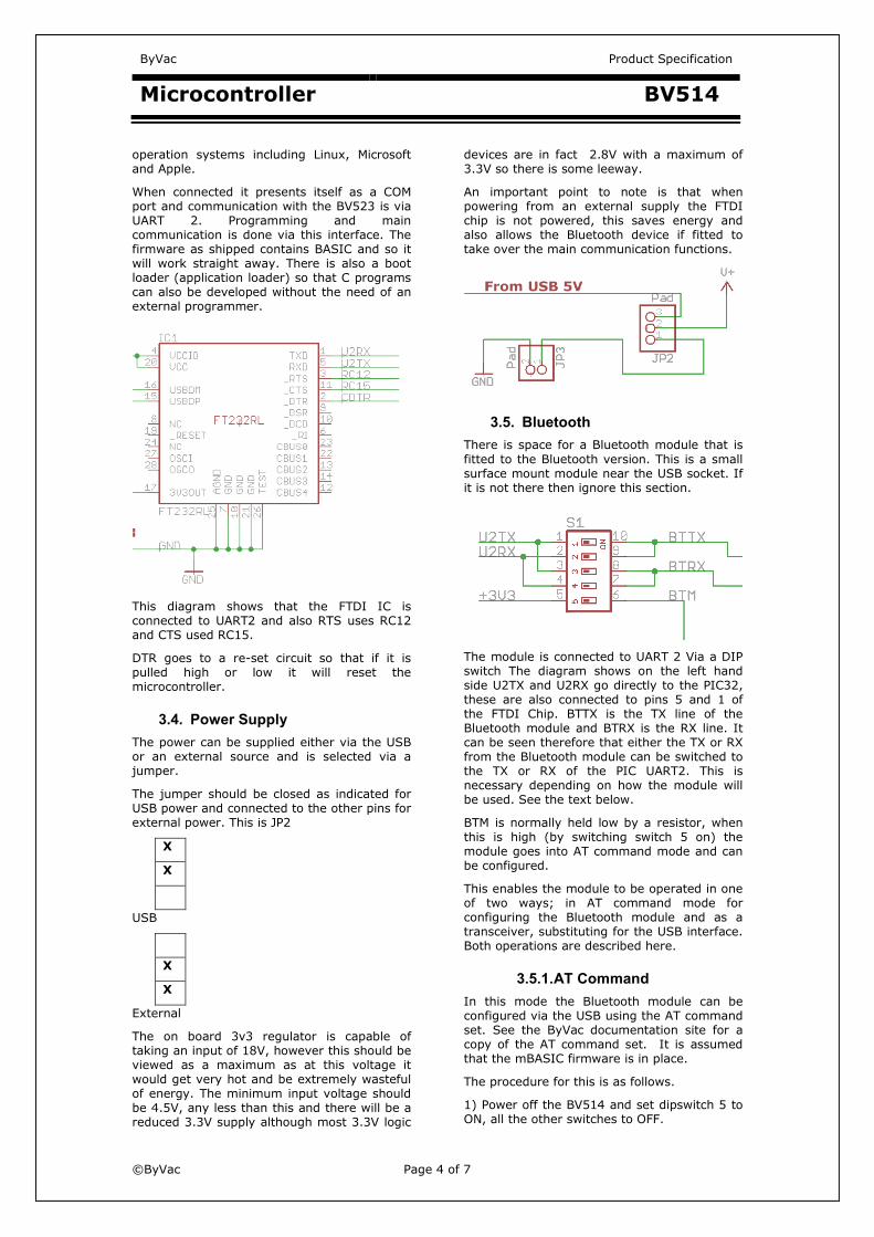
operation systems including Linux, Microsoft and Apple. When connected it presents itself as a COM port and communication with the BV523 is via UART 2. Programming and main communication is done via this interface. The firmware as shipped contains BASIC and so it will work straight away. There is also a boot loader (application loader) so that C programs can also be developed without the need of an external programmer.
This diagram shows that the FTDI IC is connected to UART2 and also RTS uses RC12 and CTS used RC15. DTR goes to a re-set circuit so that if it is pulled high or low it will reset the microcontroller.
3.4. Power Supply The power can be supplied either via the USB or an external source and is selected via a jumper. The jumper should be closed as indicated for USB power and connected to the other pins for external power. This is JP2
XX
USB XX
External The on board 3v3 regulator is capable of taking an input of 18V, however this should be viewed as a maximum as at this voltage it would get very hot and be extremely wasteful of energy. The minimum input voltage should be 4.5V, any less than this and there will be a reduced 3.3V supply although most 3.3V logic
devices are in fact 2.8V with a maximum of 3.3V so there is some leeway. An important point to note is that when powering from an external supply the FTDI chip is not powered, this saves energy and also allows the Bluetooth device if fitted to take over the main communication functions.
3.5. Bluetooth There is space for a Bluetooth module that is fitted to the Bluetooth version. This is a small surface mount module near the USB socket. If it is not there then ignore this section.
The module is connected to UART 2 Via a DIP switch The diagram shows on the left hand side U2TX and U2RX go directly to the PIC32, these are also connected to pins 5 and 1 of the FTDI Chip. BTTX is the TX line of the Bluetooth module and BTRX is the RX line. It can be seen therefore that either the TX or RX from the Bluetooth module can be switched to the TX or RX of the PIC UART2. This is necessary depending on how the module will be used. See the text below. BTM is normally held low by a resistor, when this is high (by switching switch 5 on) the module goes into AT command mode and can be configured. This enables the module to be operated in one of two ways; in AT command mode for configuring the Bluetooth module and as a transceiver, substituting for the USB interface. Both operations are described here.
3.5.1. AT Command In this mode the Bluetooth module can be configured via the USB using the AT command set. See the ByVac documentation site for a copy of the AT command set. It is assumed that the mBASIC firmware is in place. The procedure for this is as follows. 1) Power off the BV514 and set dipswitch 5 to ON, all the other switches to OFF.

ByVac Product Specification
Microcontroller BV514
©ByVac Page 5 of 7
2) Power up the BV514 via the USB. You should notice that the LED marked ‘IND’ flashes slowly, this indicates that the Bluetooth module is ready to accept AT commands 3) The PIC UART is also connected to the UART chip and so we need to disable UART 2 which will make the outputs high impedance. Assuming that mBASIC is installed you will have the Baud rate set at 115200 and communicating with mBASIC. Type comclose(2) and communications will stop. 4) With the power still on close DIP switches 1 and 4. In other words set dip switch 1 to ON and dip switch 4 to ON. Three switches should now be on 1,4 and 5 5) Change the Baud rate on BV_COM to 38400 and type AT. You should have lots of OK scrolling by, press return to stop this. You can now configure the module according to the Bluetooth module AT command set. It may help to set ECHO on, this is done on BV_COMM as one of the menu options. Any parameters set using the AT commands normally remain after power off. To exit this mode simply power off and put all of the switches back to OFF.
3.5.2. Transceiver In this mode the Bluetooth will substitute for the USB so its like USB but without the cable. You will of course need some kind of Bluetooth device on the PC. Set up the BV514 by powering off, Turning on dip switches 2 and 4 and then power up by an external supply (see the power section). We do not want to use the USB here as it will clash with the Bluetooth. Powering externally will disable the USB chip. The default communication speed is 9600 Baud and so you will need to either configure Basic for this speed or configure the Bluetooth module for the default 115200 that Basic normally uses. The IND LED will flash quickly to indicate that it is ready to pair, as the procedure for doing this varies from host to host an outline is given here rather then a detailed description. 1) Discover the device, the name will be something like OmniTek unless it has been changed using the AT command set. 2) Pair with the device using the default password of 1234 unless you have changed it using the AT commands. 3) Connect. The Bluetooth module connects as a COM port, the ‘Bluetooth Serial Service’ The actual COM port will depend on the host. When a
connection is established the PR LED will illuminate and communications can commence.
3.6. I2C Interface The I2C interface uses the PIC channel 1 I2C circuit and has built in pull up resistors, these can either be powered from the 3V3 supply or from the +V supply.
V+ is the raw input voltage, if this is supplied via USB this will be 5V. 3V3 is the regulated 3.3V output from the regulator. The three options therefore for the pull up resistors is:
1. No jumper – make other arrangements to supply pull up resistors
2. Jumper to 3V3 – this will be used on 3V3 I2C devices
3. Jumper to V+ - normally ued on 5V devices but care as it is the raw input from the power input and so it is up to the user to make sure that it is a suitable voltage.
The I2C pins on the processor are: SCL RG2 (J4-pin 1) SDA RG3 (J4-pin 3) Note that this interface is the hardware channel 1 for the PIC. For more information about this consult the PIC32 family data sheet.
3.7. Serial Interface Access to both UARTS is via the general I/O pins, see the relevant section. It should be noted also that UART 2 is connected to the FTDI chip – see the USB section for details.
ByVac Product Specification
Microcontroller BV514
©ByVac Page 6 of 7
The FTDI Chip is powered only from the USB and so if external power is used it is effectively disconnected from UART, this enables that UART to be used for an alternative purpose.
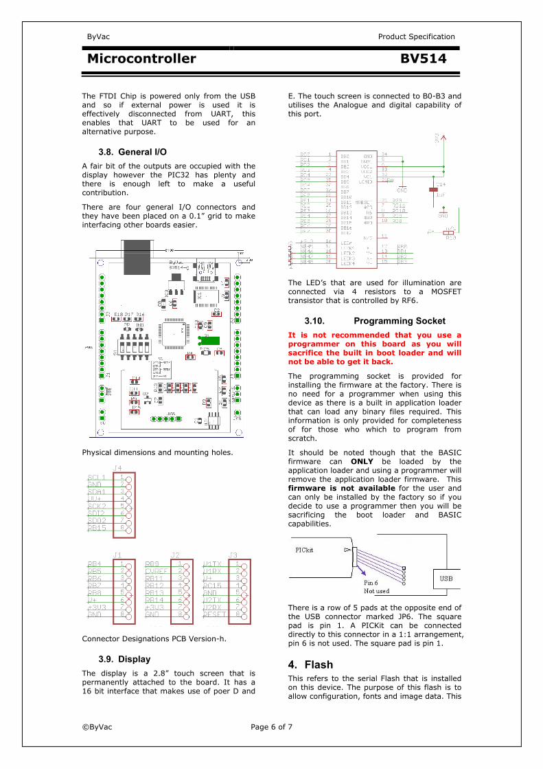
3.8. General I/O A fair bit of the outputs are occupied with the display however the PIC32 has plenty and there is enough left to make a useful contribution. There are four general I/O connectors and they have been placed on a 0.1” grid to make interfacing other boards easier.
Physical dimensions and mounting holes.
Connector Designations PCB Version-h.
3.9. Display The display is a 2.8” touch screen that is permanently attached to the board. It has a 16 bit interface that makes use of poer D and
E. The touch screen is connected to B0-B3 and utilises the Analogue and digital capability of this port.
The LED’s that are used for illumination are connected via 4 resistors to a MOSFET transistor that is controlled by RF6.
3.10. Programming Socket It is not recommended that you use a programmer on this board as you will sacrifice the built in boot loader and will not be able to get it back. The programming socket is provided for installing the firmware at the factory. There is no need for a programmer when using this device as there is a built in application loader that can load any binary files required. This information is only provided for completeness of for those who which to program from scratch. It should be noted though that the BASIC firmware can ONLY be loaded by the application loader and using a programmer will remove the application loader firmware. This firmware is not available for the user and can only be installed by the factory so if you decide to use a programmer then you will be sacrificing the boot loader and BASIC capabilities.
There is a row of 5 pads at the opposite end of the USB connector marked JP6. The square pad is pin 1. A PICKit can be connected directly to this connector in a 1:1 arrangement, pin 6 is not used. The square pad is pin 1.
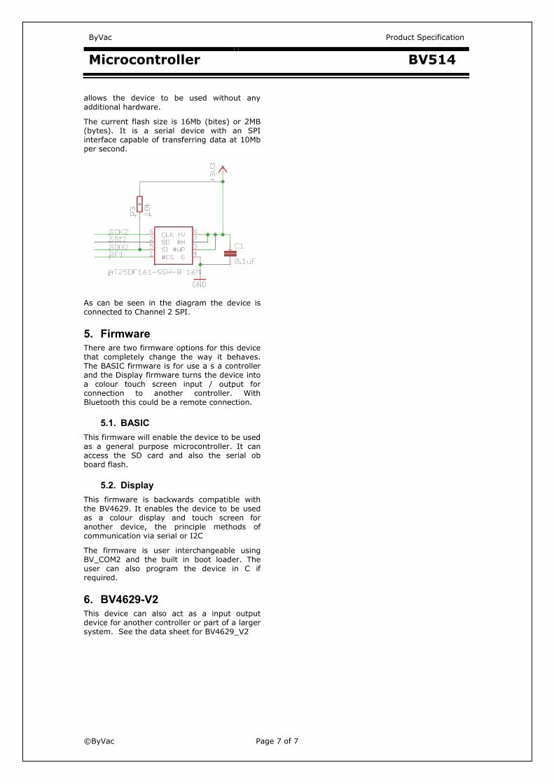
4. Flash This refers to the serial Flash that is installed on this device. The purpose of this flash is to allow configuration, fonts and image data. This
ByVac Product Specification
Microcontroller BV514
©ByVac Page 7 of 7
allows the device to be used without any additional hardware. The current flash size is 16Mb (bites) or 2MB (bytes). It is a serial device with an SPI interface capable of transferring data at 10Mb per second.
As can be seen in the diagram the device is connected to Channel 2 SPI.
5. Firmware There are two firmware options for this device that completely change the way it behaves. The BASIC firmware is for use a s a controller and the Display firmware turns the device into a colour touch screen input / output for connection to another controller. With Bluetooth this could be a remote connection.
5.1. BASIC This firmware will enable the device to be used as a general purpose microcontroller. It can access the SD card and also the serial ob board flash.
5.2. Display This firmware is backwards compatible with the BV4629. It enables the device to be used as a colour display and touch screen for another device, the principle methods of communication via serial or I2C The firmware is user interchangeable using BV_COM2 and the built in boot loader. The user can also program the device in C if required.
6. BV4629-V2 This device can also act as a input output device for another controller or part of a larger system. See the data sheet for BV4629_V2