microfilms - scholarspace at university of hawaii at manoa
TRANSCRIPT

INFORMATION TO USERS
This was produced from a copy of a document sent to us for microfilming. While themost advanced technological means to photograph and reproduce this documenthave been used, the quality is heavily dependent upon the quality of the materialsubmitted.
The following explanation of techniques is provided to help you understandmarkings or notations which may appear on this reproduction.
1. The sign or "target" for pages apparently lacking from the documentphotographed is "Missing Page(s)". If it was possible to obtain the missingpage(s) or section, they are spliced into the film along with adjacent pages.This may have necessitated cutting through an image and duplicatingadjacent pages to assure you of complete continuity.
2. When an image on the film is obliterated with a round black mark it is anindication that the film inspector noticed either blurred copy because ofmovement during exposure, or duplicate copy. Unless we meant to deletecopyrighted materials that should not have been filmed, you will find a goodimage of the page in the adjacent frame. If copyrighted materials weredeleted you will find a target note listing the pages in the adjacent frame.
3. When a map, drawing or chart, etc., is part of the material being photographed the photographer has followed a definite method in "sectioning"the material. It is customary to begin filming at the upper left hand corner ofa large sheet and to continue from left to right in equal sections with smalloverlaps. If necessary, sectioning is continued again-beginning below thefirst row and continuing on until complete.
4. For any illustrations that cannot be reproduced satisfactorily by xerography,photographic prints can be purchased at additional cost and tipped into yourxerographic copy. Requests can be made to our Dissertations CustomerServices Department.
5. Some pages in any document may have indistinct print. In all cases we havefilmed the best available copy.
UniversityMicrOfilms
International300 N. ZEEB RD, ANN ARBOR, MI 48106


8220042
Miller, Michael Joseph
AUTOMATIC-REPEAT-REQUEST SYSTEMS FOR ERROR CONTROL INDIGITAL TRANSMISSION
University 0/Hawaii
UniversityMicrofilms
Internati0 nal 300 N.ZeebRoad, Ann Arbor, MI48106
PH.D. 1982

AUTOMATIC-REPEAT-REQUEST SYSTEMS FOR
ERROR CONTROL IN DIGITAL TRANSMISSION
A DISSERTATION SUBMITTED TO THE GRADUATE DIVISION OF THEUNIVERSITY OF HAWAII IN PARTIAL FULFILLMENT
OF THE REQUIREMENTS FOR THE DEGREE OF
DOCTOR OF PHILOSOPHY
IN ELECTRICAL ENGINEERING
MAY 1982
By
Michael Joseph Miller
Thesis Committee:
Shu Lin, ChairmanN. Thomas GaarderFranklin F. KuoEdward J. WeldonEdward A. Bertram

ACKNOWLEDGEMENTS
I would like to thank the members of my dissertation committee
for their support and, particularly the chairman, Professor Shu Lin.
I also acknowledge the encouragement and support of my colleagues at
the South Australian Institute of Technology, particularly, Alan
Bolton and Ross A. Frick. MY thanks for excellent typing assistance
to Isobel Keegan. I also want to express special gratitude to my
wife and family for their willingness to make many sacrifices on my
behalf.
iii

iv
ABSTRACT
Automatic-repeat-request (ARQ) systems have been the most popular
means for error control in digital transmission systems. They provide
a relatively simple and highly reliable means for eliminating trans
mission errol's. However, the throughput of an ARQ system may deteriorate
badly with increasing bit-error rates especially if there are significant
transmission delays such as experienced in satellite or long terrestrial
circuits.
This dissertation first proposes a class of mixed-mode protocols
which incorporate a selective-repeat mode of retransmission. This is
combined with a secondary mode to prevent receiver buffer overflow. The
throughput analysis for these schemes is presented and shows that they
can significantly outperform the conventional Go-Back-N procedure for
transmission over circuits with delay. The analysis also shows how
throughput is related to the size of buffer provided at the receiver. It
is also demonstrated that the choice of secondary retransmission mode
does not have a significant effect on the throughput but has a bearing on
complexity.
Further improvement in performance may be achieved by use ofa hybrid
ARQ system incorporating forward-error correction as well as retransmission.
The dissertation considers some parity-retransmission schemes in which
blocks of parity bits are used for retransmissions rather than repetition
of the original information block. This enables the system to

v
adaptively incorporate error correction as well as detection when
channel bit-error rates increase. An analysis procedure is presented
which permits comparison of throughput efficiency for a variety of
ARQ retransmission protocols and forward-error correction codes.
Particular attention is focussed on the use of half-rate convolutional
codes for error correction. A trellis algorithm is shown to be useful
for computation of the error correction capability of modestly powerful
convolutional codes with sliding-block feedback decoding. An alterna
tive approach using combinatorial procedures is also presented. New
rate one-half codes are found which are related to optimum orthogonaliz
able rate one-third codes. These related code pairs can be used in
parity-retransmission schemes to provide more powerful error correction
when channel bit-error rates deteriorate badly.
Finally the throughput and reliability performan~e of the hybrid
schemes is outlined for various combinations of retransmission protocols
and error-correction systems. Results are presented for convolutional
codes and block codes and indicate the possible tradeoffs between
complexity and performance. It is concluded that convolutional codes
with relatively simple sliding-block decoding can ensure high through
put is maintained on a hybrid ARQ system despite significant bit-error
rates and transmission delays.

'Tis a Lesson you shouLd heed:Troy ~ t'PY~ t'PY again.
If at first you don't eueceed,T'PY~ t'PY~ t'PY again•
•HICKSON
NihiL est quod non ezpuqnet:pertina::c opera~
et intenta aa diLigens aura.
SENECA
vi

vii
TABLE OF CONTENTS
ACKNOWLEDGEMENTS
ABSTRACT •..
LIST OF TABLES
LIST OF FIGURES . .
1. INTRODUCTION
1.1 Error Control Alternatives1.2 ARQ Systems-Historical1.3 Dissertation Research Tasks
iii
iv
ix
x
159
2. MIXED MODE ARQ SCHEMES
2.1 Introduction •• . . • • . . • . • • • • . • . . . 122.2 Selective-Repeat Plus Stutter (SR + ST) Schemes . . 132.3 Analysis of SR + ST Schemes . . . . • . . • . • • . 202.4 Selective-Repeat Plus Go-Back-N (SR + GBN) Schemes 292.5 Perfonnance Cal cu1ati ons .•.•. . • . • . 332.6 Comparison with ARQ Schemes by Other Authors 392.7 Sunmary. . . . . . . . . . . . . . . . . . . 43
Introduction . . . . . • . . . . • . . .•..Alternate Data-Parity Hybrid ARQ •.•Hybrid Schemes and Their State Diagrams •Throughput Analysis Procedure .• •.SUl'TDnary • • • • • • • • • • • • • • •• •••••
3. PARITY RETRANSMISSION ARQ SCHEMES
3.13.23.33.43.5
4. ANALYSIS OF TYPE-II HYBRID SCHEMES
4546506271
4.1 Alternate Data-Parity with SR + ST Protocol 744.2 Alternate Data-Parity with SR + GBN Protocol .•••. 784.3 Alternate Data-Parity Scheme with SR Protocol
and Infinite Buffer . . . . . . . . • • . • . 804.4 Lin and Yu Hybri d Schemes . . . . • • • . . . 814.5 Rate 1/2, 1/3 Parity Retransmission Scheme . • . . .• 844.6 Alternate Data-Parity with ST + GBN Protocol ..... 844.7 Sumnary , • . . . • • . • • . . . . • • . . . • . 87

viii
5. BLOCK ERROR RATE FOR CONVOLUTIONAL CODES
5.1 Introduction •••.••...•.••••.5.2 Decoder Characteristics •••••••••••5.3 Trellis Algorithm for Block Error Probability (Pa)5.4 Combi natori a1 Approach •••••.•••••5.5 Computed Pa Values ••••...•••.••5.6 Convolutional Versus Block Codes .••••.
899395
101113117
6. RELATED R = 1/2 and R=1/3 ORTHOGONALIZABLE CODES
6.1 Introduction •..••••.•.•6.2 New Orthogona1izab1e Code Design6.3 Encoding and Decoding •••.
120123135
140
142144147155158
Introduction •.• • • • • • . ••••.Conditional Probabilities ql and q2 for BlockCodes • • • • • • • . • • • • • • • • • • • •ql and q2 for Convolutional Codes •.Throughput for Type-II ARQ SchemesReliability ••••.•.•Error Detection Procedures
7.37.47.57.6
7. PERFORMANCE OF HYBRID ARQ SCHEMES
7.17.2
8. SUMMARY AND CONCLUSIONS
8.1 Summary of Research8.2 Conclusions •••••
163168
APPENDICES
A. A Note on the Derivation of Equation (2.7) . • . • 171
B. Trellis Algorithm for Calculating Block Error Ratefor Convolutional Codes After Decoding. • . • • . 173
C.. Enumeration of Correctable Error Patterns 175
D. Conditional Probabilities ql' q2 ofRecovery of Data Without Error ....
BIBLIOGRAPHY ...•.•...•. . . . .
182
188

ix
LIST OF TABLES
5.3 Number of correctable error patterns .
Table
2.1 Mixed mode Scheme properties.
6.1 Related orthogonalizab1e codes •
D.1 Error patterns for Pr(D1D2F2)
3.1 Rate 1/2, 1/3 hybrid ARQ ...
4.1 Distribution of number of transmissions
Page
. . . . 34
40
61
77
94
95
111
114
134
183
ARQ schemes by other authors .
Codes with maximal dfree .
Orthogona1izable codes ..
Block error rate versus BER .
2.2
5. 1
5.2
5.4

Figure
2.1
2.2
2.3
2.4
2.5
2.6
2.7
2.8
2.9
2.10
2.11
2.12
3.1
3.2
3.3
3.4
3.5
5.1
5.2
5.3
5.4
5.5
LIST OF FIGURES
Basic ARQ illustrated
SR+ST Scheme 1 (v =1) .
SR+ST Scheme 1 (v =2) .
SR+ST Scheme 2 • • • •
ACK/NAK Sequence for evaluation of PNN .
Example of ACK/NAK indicator window
SR+GBN Scheme (v = 1) ..•
SR+ST Scheme 1 Throughput
Throughput for various v .
Comparison of SR+ST Scheme 2 with others .
Comparison with Go-Back-N Schemes .
Comparison with Yu and Lin Scheme .
State diagram for Hybrid ARQ • . .
State diagram for conventional ARQ .
State diagram for Type-I hybrid ARQ
State diagram for (2,1){3,1) ARQ ....
State diagram for inferior hybrid ARQ
Alternate data and parity blocks ~ ..
Another alternate data/parity scheme
Trellis for t=2 sliding blocks decoding
Trellis for t=3 decoding .....
Tre11 is for t=:4 decodi ng .
x
Page
15
17
19
21
26
28
30
36
37
38
41
42
53
55
57
58
67
90
92
97
102
103
5.6
5.7
5.8
6.1
6.2
7.1
7.2
7.3
7.4
C. 1
C.2
Correctable error patterns (t=l)
Block error rate for convolutional codes
Block codes versus convolutional codes
Typical convolutional encoders
Threshold decoder • •
Throughput of hybrid ARQ (dfree=5) .•••
Performance of block and convolutional codes
Throughput of hybrid ARQ (df ree=7)Performance of SR+GBN • • . • . . •
Correctable error patterns N(3,NB)Correctable error patterns N(4,NB)
xi
106
116
119
124
136
150
152
153
154
178
180

1. INTRODUCTION
1.1 Error Control Alternatives
In recent years, there has been a rapid development of systems for
transmission, storage and processing of signals in digital form. Digital
data networks represent one such area reflecting the fast growing demand
for communications between computers and associated terminal equipment.
National digital networks for speech as well as data have been under
development in many countries and requirements for international trans
mission systems can be expected to expand also.
A major concern of digital transmission system designers is to mini
mize the likelihood of errors in the most efficient and economical way.
Within individual transmission links, errors can be caused by such
factors as thermal noise, interference, frequency dependent distortion
due to fading on radio links or as a result of imperfect synchronization
resulting in jitter or slips. A primary task for the system designer is
to provide sufficient error control procedures in the network to ensure
that with high probability, all transmission errors are corrected before
the data is delivered to the customer.
It is possible to classify alternative approaches to the problem of
error control into three categories as follows:
• Fo~ard-error-aoPreation (FEC) procedures in which sufficient
redundancy is provided by the transmission of parity bits
associated with powerful error correcting codes.
o Automatia-repeat-request (ARQ) procedures in which certain
classes of higher rate block codes are used only for high
2
reliability detection of forward transmission errors.
Whenever errors are detected, retransmissions of faulty
sequences are initiated. Many different retransmission
procedures are possible.• HybPid ARQ procedures incorporate forward error correction
as well as detection and retransmission. Hybrid schemes
offer the potential for better performance if appropriate
ARQ and FEC schemes can be properly combined.
Currently ARQ schemes are the most popular means for error control
on digital transmission systems when an appropriate feedback channel is
available. For example, the current CCITT standard X.25 for packet
switched public data networks [1] envisages encoding data packets with
a shortened cyclic code to produce 16 parity bits for error detection.
For packets of the order of 1000 bits, this provides a relatively simple
and highly reliable means for detecting transmission errors. The use of
the high rate block code also minimizes the overhead incurred by the
redundant parity bits. Of the several possible retransmission protocols
that are possible, many public data networks use Go-Back-N procedures
whereby the receiver discards all blocks subsequent to a faulty block.
The transmitter goes back to the faulty block and begins retransmission
of that and all subsequent blocks.
For satellite or long terrestrial circuits, the throughput effi
ciency of conventional ARQ systems using the Go-Back-N procedure can
falloff rapidly for bit-error-rates greater than 10-6 [2, 3]. This
occurs if there are significant round-trip delays between transmission
of a block and receipt of its error status information (ACK or NAK) at
the transmitter. For example, a terrestrial connection from Sydney to

3
Perth (Australia) involves approximately 30 ms round trip delay. If data
were being transmitted in 1000-bit packets at a data rate of 1 Mbps, say,
then whenever an error is discovered in a packet, approximately 30 subse
quent packets must be discarded even though a high percentage of them
may have been received without errors. For satellite circuits with round
trip delays of the order of 700 ms the situation is considerably worse.
A selective-repeat ARQ procedure involving retransmission of only
the faulty blocks offers better throughput performance. However, it is
impractical because of the need for an infinite receiver buffer store.
This is required to avoid loss of blocks due to buffer overflow.
In this dissertation several alternative retransmission procedures
are examined to determine their throughput efficiency for various sets
of channel conditions. New II mi xed- mode ll ARQ schemes are proposed involv
ing combinations of Selective-Repeat retransmission (to maintain high
throughput) and other protocols such as the Go-Back-N (to ensure buffer
overflow is avoided for finite receiver bUffers). A throughput analysis
for these schemes is presented and shows that their performance approaches
that of the selective-repeat scheme with infinite buffer.
This dissertation also considers hybrid ARQ schemes which incorporate
forward-error-correction (FEe) as well as retransmission. It is possible
to classify hybrid ARQ schemes into two general classes which have been
called Type-I and Type-II hybrid schemes respectively [2J.
Type-I hybrid schemes are the best known. The initial transmission
(and subsequent transmission if requested) uses an (n, k) linear code
which is designed for simultaneous error correction and detection. When
a received word is detected in error, the receiver first attempts to
locate and correct the errors. If an uncorrectable error pattern is

4
detected, the receiver rejects the received word and requests a retrans
mission. The process is repeated until the codeword is successfully
received and decoded. For the code used in a Type-I hybrid scheme to
be able to simultaneously correct certain error patterns and to detect
other patterns, more overhead parity bits are required than for conven
tional ARQ where detection only is required. As a result, the Type-I
scheme suffers a major drawback in that the throughput may be consid
erably less than for conventional ARQ when channel error r?tes are low.
Type-I schemes may be best suited for systems in which a fairly constant
level of noise or interference is anticipated on a channel.
This dissertation considers the performance of Type-II hybrid
schemes where the parity bits for error correction are not transmitted
unless they are needed. For the initial transmission a high rate (n, k)
code Co is used as in conventional ARQ. This code provides for error
detection only. If errors occur and retransmission is requested, a
block of parity is sent instead of repeating the information bits. The
parity retransmissions are based on a lower rate (perhaps ~ rate) code
C1 designed for error correction. The FEC code may be either a block
or convolutional code. Type-II hybrid schemes are adaptive to changes
in channel conditions. Parity bits for error correction are only sent
when channel errors occur. When error rates are low, parity overheads
are minimum so throughput is higher than for Type-I hybrid schemes.
Particular emphasis is given in this dissertation to the use of
convolutional codes for forward-error-correction in hybrid ARQ schemes.
Techniques for analysis of throughput efficiency are discussed with
particular emphasis on alternate data/parity retransmission schemes
5
using parity retransmission for forward-error-correction. The block
error probability after bound distance decoding is computed for selected
block and convolutional codes. Results are given for throughput effi
ciency for various parity retransmission schemes using mixed-mode proto
cols and convolutional and block codes. Results indicate that convolu
tional codes with relatively simple sliding-block decoding may ensure
high throughput is maintained on an ARQ system despite significant bit
error-rates and transmission delays.
1.2 ARQ Systems--Historical
For many years, ARQ schemes have been the primary error-control
procedure for data transmission links. They are a reliable and rela
tively simple means of ensuring that the probability of faulty data
blocks being delivered to the user is very small. On the other hand,
analytical developments in error-control techniques have tended to
concentrate on forward-error correction [2, 38]. With the development
of increasing bit-rates and significant delays in long circuits, more
attention is now being given to the search for error-control procedures
that will provide high throughput while maintaining high reliability.
As a result, the analysis of new ARQ systems and the possibility of
combining ARQ and FEC procedures has received considerable attention in
recent years.
Early ARQ systems implemented, for example, by the IBM Binary
Synchronous Communication (BISYNC) procedure [2] were of the stop-and
wait type. The performance of such systems was studied by Rieffen,
Schmidt and Yudkin [5] for data trunsmission over telephone circuits.
Cowell and Burton [6] examined how various channel error models affect

6
reliability and throughput. Chang [42], Harris and Morgan [43] and
Metzner and Morgan [4] studied the basic nature of ARQ systems, classi
fied types of ARQ schemes and examined the effects of noise in the feed
back channel. Information theoretic studies of feedback systems for the
binary symmetric channel included Shannon1s demonstration that although
feedback could not increase the capacity of a memoryless channel, it
could improve the reliability. Weldon [43] also derived performance
bounds for block codes on channels with feedback.
By the early 19601s, a number of different retransmission techniques
and procedures had been developed including a selective-repeat type of
procedure suggested by Stuart [44]. Benice and Frey [8, 9] provided the
first analysis of the throughput and reliability of stop-and-wait,
selective-repeat and Go-Back-N schemes taking account of errors in feed
back channels and the possibility of undetected errors in either forward
or reverse channels.
In the early 1970's ARQ systems were in extensive use in packet
switched and other data networks. Higher data rates and utilization of
satellite circuits with long round-trip delays established the need
for continuous ARQ strategies such as the Go-Back-N to replace earlier
stop-and-wait procedures. International standards organizations such
ISO and CGITT [1] began making efforts for protocol standardization.
This resulted in the HOLC (high-level data link control) and the X.25
recommendations for node-to-node link-level procedures using Go-Back-N
ARQ on full duplex links. Burton and Sullivan [13], Gatfield [14],
Kersey [16] and Kaul [22] reported on throughput performance of such
ARQ systems on typical terrestrial and satellite channels. Morris [23]
examined the optimization of block lengths for such schemes operating

7
on random-error and Poisson-distributed block-error channels. Towsley
and Wolf [27] developed a model to study the statistical behavior of
queue lengths and waiting times at the nodes for the stop-and-wait and
Go-Back-N ARQ strategies. For the random error channel, numerical
results for the mean waiting time and mean transmitter queue occupancy
were presented. Mor~ recently Easton [30] and Labetoul1e and Pujo11e
[45] analyzed the HOLe Go-Back-N system throughput and mean response
time for non-uniform frame sizes when the link is not saturated.
Variations on the conventional Go-Back-N procedure to improve
throughput performance were suggested by Sastry [17], Morris [21], and
Lin and Yu [31]. Analysis of throughput of the Go-Back-N ARQ scheme
and its variations showed that it could provide adequate performance for
moderate error rates. However, when data transmission rates and circuit
round-trip delays increase, the throughput suffers severe deterioration
when errors occur.
Selective-repeat ARQ was well known to be capable of providing
considerably improved throughput under such conditions (see for example,
Gatfie1d [14]). However, its implementation has been restricted by
problems relating to receiver buffer size and buffer management.
Infinite receiver buffer is required to achieve optimum throughput
efficiency and avoid loss of blocks due to buffer overflow. Aselective
repeat type of ARQ scheme with a finite range of block sequence numbers
was suggested by Metzner [20] and studied by Easton [25,36]. However, no
throughput analysis was available to show its dependence on the size of
receiver buffer. Yu and Lin [32] suggested a selective-repeat scheme
scheme which employed a specified receiver buffer size and finite range
of sequence numbers yet avoided overflow problems. A lower bound on

8
throughput performance was obtained. There still remained considerable
work to be done in studying different methods of handling receiver
buffer overflow in selective-repeat ARQ systems. No exact methods of
analyzing throughput for finite buffer systems had been reported. As a
result, it was not clear which practical retransmission schemes could
achieve maximum throughput and minimum complexity.
Hybrid ARQ schemes combining forward-error correction as well as
retransmission have also been the subject of considerable research in the
past decade. Type-I hybrid schemes were analyzed by Rocher and
Pickho1tz [12] employing a high-rate BCH code capable of correcting up
to three errors. Simultaneously the code provided sufficient detection
capability to ensure high reliability. Results for the random-error case
showed an improvement in throughput was possible for bit error rates
worse than 10-4. Sastry and Kanal [18, 19] also studied Type-I hybrid
ARQ schemes for burst error channels. The use of convolutional codes
for forward-error correction in a hybrid scheme has been described by
Kahn [46]. Drukarev and Costello [35] have studied the use of sequential
decoding with a time-out condition. Yamamoto and Itoh [47] have examined
system performance using Viterbi decoding.
A Type-II hybrid ARQ scheme involving retransmissions of blocks of
code parity bits for forward-error correction has recently received
attention. This concept was first introduced by Mandelbaum [15] and
extended by Metzner [24], Ancheta [29] and by Lin and Yu [34]. Mandelbaum
suggested encoding the information with a Reed-Solomon code for which the
parity bits can be broken up into a number of sub-blocks. The initial
transmission is to be the information plus one of the parity sub-blocks.
If uncorrectable errors remain, the transmitter sends an additional

9
parity sub-block. The code must have the property that it can be punc-
tured, that is, some of the parity symbols can be discarded. Also, its
minimum distance must increase approximately proportional to the number
of parity sub-blocks. Metzner was the first to suggest schemes involving
half-rate block or convolutional codes for parity retransmission. If an
error occurs in a block then instead of retransmitting the original data
block, an equal sized block of parity bits is sent and error correction
attempted. Simple decoding schemes were compared in relation to the mean
duration to the first decoding ambiguity. Lin and Yu [34] presented and
analyzed the first practical Type-II hybrid scheme using half-rate block
codes with parity retransmission. Throughput analysis for Type-II hybrid
ARQ schemes using convolutional codes remained unavailable in the litera
ture. It is the subject of the latter section of this dissertation.
1.3 Dissertation Research Tasks
This work has been directed towards investigating two classes of ARQ
systems: (a) ARQ without FEC and (b) Type-II hybrid ARQ systems using
convolutional codes for FEC. It is intended to provide useful results
for high bit-rate transmission over random-error channels with significant
round-trip delays.
In Chapter 2, some new ARQ procedures referred to as "mixed-mode"
protocols are presented and analyzed. These schemes are of the selective
repeat type but avoid the requirement for infinite receiver buffer by use
of a secondary transmission mode. Motivation for studying these schemes
stemmed in part from the fact that they are analytically tractable.
Throughput analysis for a range of mixed-mode schemes is presented in
Chapter 2. The results show the benefits to be gained by having at least
the first retransmission of a faulty block in the selective-repeat mode.

10
This will provide throughput performance superior to Go-Back-N systems.
The variation of throughput as receiver buffer size is increased is
also presented. Some alternative secondary transmission modes are sug
gested for use if the selective-repeat retransmissions fail. The
secondary modes prevent buffer overflow. It is shown that the choice of
secondary mode does not have a significant effect on the throughput effi
ciency.
The remainder of the work has been concerned with evaluating various
Type-II hybrid ARQ systems to explore the throughput improvements achiev
able if forward-error correction is introduced. In Section 3t parity
retransmission ARQ schemes are described. Then a unified procedure for
throughput analysis of such schemes is outlined such that it can be used
for a number of different combinations of parity retransmission schemes
and ARQ protocols. Section 4 contains the throughput analysis for various
Type-II hybrid ARQ systems.
The results are obtained in forms such that they can be applied to
cases where either block or convolutional codes are to be used for
forward-error correction. Results from Lin and Yu [32] can then be
applied ,to compute throughput values for schemes using block codes.
The following sections deal with the evaluation of the performance
of convolutional codes in the hybrid ARQ schemes. It is assumed that
sliding block decoding schemes such as threshold decoding or syndrome
lookup decoding are used with convolutional codes of modest error correc
tion capability. It is first necessary to find ways of determining
block error probabilities after decoding of the combined received infor
mation and parity blocks. An algorithm is presented to show how this can

11
be computed for codes with modest constraint lengths. An alternative
approach using combinatorial analysis is also outlined. In Section 6
some new related rate 1/2 and 1/3 convolutional code pairs are found.
These permit the implementation of one of the hybrid schemes suggested
in Section 3. The performance of various codes and hybrid ARQ schemes
is presented in Section 7 and procedures to ensure high reliability
are discussed. The results indicate the throughput characteristics
to be expected for various combinations of retransmission scheme,
parity correction procedure and choice of code .
•

12
2. MIXED MODE ARQ SCHEMES
2.1 Introduction
Selective-Repeat (SR) types of Automatic-Repeat-Request (ARQ) schemes
offer much better throughput performance than more conventional Go-Back-N
schemes, especially for high bit rate channels with considerable round
trip delay between transmitting a data block and receiving an acknowledge
ment. The class of SR schemes is characterized by the fact that if a
nega ti ve acknowl edg~"llent (NAl<) is recei ved for a gi ven message block, the
transmitter retransmits that block once and then continues transmitting
other new data bloc~s in sequence from the point that was reached when
the NAK arrived at the transmitter.
Two factors limit the application of SR type schemes, namely:
• The buffer size needed at the transmitter and receiver
• The sequence number range needed to number each block
The former is primarily a hardware complexity consideration; the
latter affects the number of overhead bits in each block. This section
examines two types of SR schemes which require finite receiver buffers
and sequence number lengths. The schemes are described as "mixed-mode"
schemes and labelled for convenience:
Selective-Repeat plus Stutter (SR + ST)
Selective-Repeat plus Go-Back-N (SR + GBN)
The SR + ST schemp. provides for a Selective-Repeat (SR) type of
scheme for the first v retransmissions, say, of a faulty block and a
repetitive "stutter" (ST) scheme for any subsequently required retrans
missions. Provided that the block error rate is not too high, this

13
scheme combines the high throughput of SR type ARQ and, by means of the
ST mode, ensures that the buffer size required is finite. Two types of
SR + ST transmission modes are examined, the first being simple to
analyze but involving greater complexity in implementation. It also
provides a means for improving throughput performance by increasing the
number of SR type retransmissions but at the expense of increased
receiver buffer storage. The second SR + ST scheme requires relatively
simpler transmitter and receiver logic and buffer storage size at the
receiver equal to 25 where:
S = round trip delay in blocks from the end of a transmission
of a given block to the return of its ACK/NAK back at the
transmitter.
The schemes are amenable to an exact performance analysis for the
random channel.
The second class of schemes (SR + GBN) provides for one or more
retransmissions of faulty blocks in a Selective-Repeat mode followed by
a Go-Back-N procedure if still not successful. Throughput performance
is derived and compared with the SR + ST schemes. The results show that,
at least in principle, both the SR + ST and the SR + GBN schemes could
be arranged to have a performance (throughput) approaching arbitrarily
close to the ideal Selective-Repeat scheme with infinite buffer provid
ing sufficient provision of buffer store is made in the receiver.
2.2 Selective-Repeat Plus Stutter (SR + ST) Schemes
Consider a computer communications system in which data is trans
mitted over a link in equal length blocks containing NB bits per block.
This is taken to include provision for sequence numbering of each block,
14
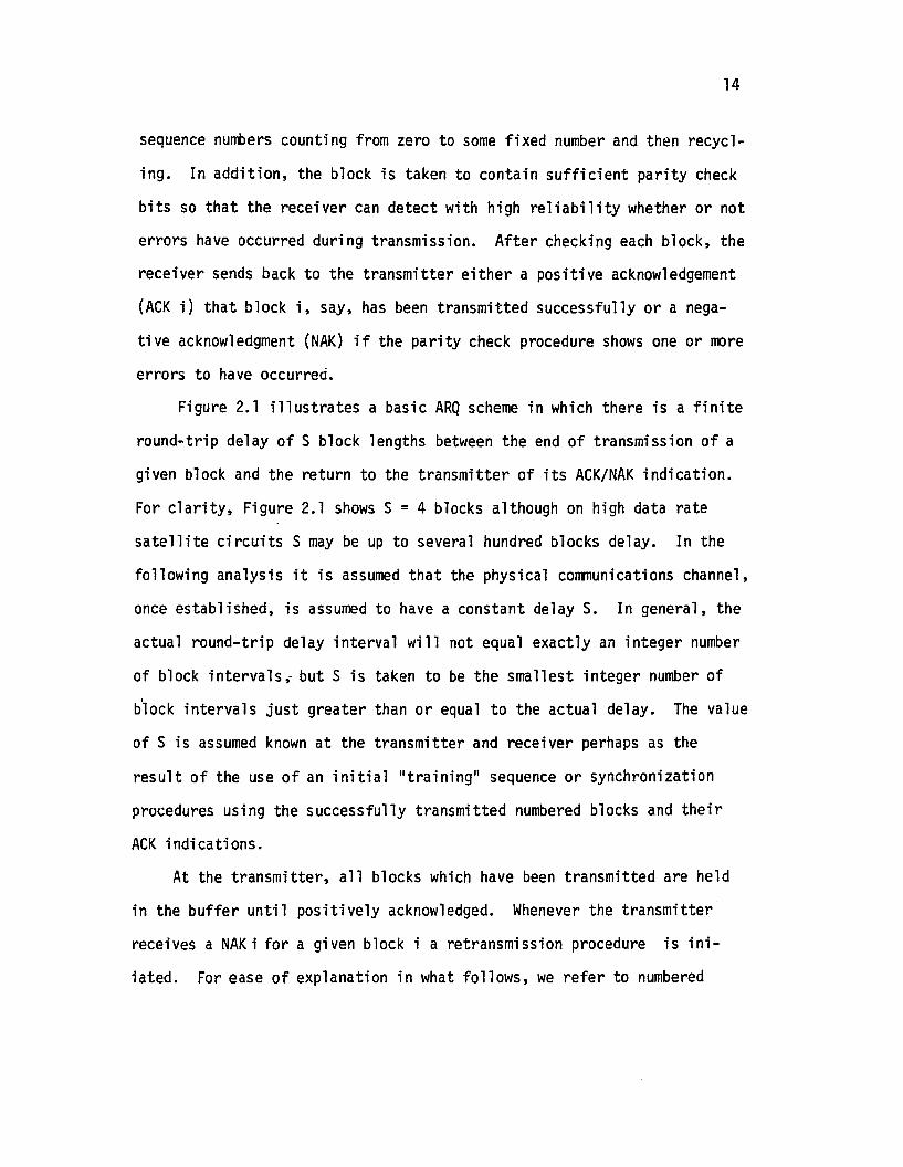
sequence numbers counting from zero to some fixed number and then recycl
ing. In addition, the block is taken to contain sufficient parity check
bits so that the receiver can detect with high reliability whether or not
errors have occurred during transmission. After checking each block, the
receiver sends back to the transmitter either a positive acknowledgement
(ACK i) that block i, say, has been transmitted successfully or a nega
tive acknowledgment (NAK) if the parity check procedure shows one or more
errors to have occurred.
Figure 2.1 illustrates a basic ARQ scheme in which there is a finite
round-trip delay of S block lengths between the end of transmission of a
given block and the return to the transmitter of its ACK/NAK indication.
For clarity, Figure 2.1 shows S = 4 blocks although on high data rate
satellite circuits S may be up to several hundred blocks delay. In the
following analysis it is assumed that the physical communications channel,
once established, is assumed to have a constant delay S. In general, the
actual round-trip delay interval will not equal exactly an integer number
of block intervals; but S is taken to be the smallest integer number of
block intervals just greater than or equal to the actual delay. The value
of S is assumed known at the transmitter and receiver perhaps as the
result of the use of an initial "training" sequence or synchronization
procedures using the successfully transmitted numbered blocks and their
ACK indications.
At the transmitter, all blocks which have been transmitted are held
in the buffer until positively acknowledged. Whenever the transmitter
receives a NAKi for a given block i a retransmission procedure is ini
iated. For ease of explanation in what follows, we refer to numbered

Transmitter
Receiver
Transmission
Round-TripDelay~s
tError
Figure 2.1
Basic ARQ Illustrated
Time
-l
0'1

16
NAK indications, NAK i being associated with block i; however, since S
is assumed fixed and known, the receiver is only required to send a
NAK after receipt of a faulty block. Assume initially that all blocks
previous to i having been sliccessfully transmitted. Then the following
types of so-called SR + ST retransmission schemes will be considered
here:
SR + ST Scheme 1. Consider the case where the number (v) of SR
type retransmissions is one. On the first receipt of a NAK i, the
transmitter retransmits block i as the next block and then continues
transmitting other new data blocks from the sequence nUlilber reached
when the NAK arrived at the transmitter. This is referred to as the
Selective-Repeat (SR) mode. If another NAK i is received indicating
the second transmission of block i was unsuccessful, the transmitter
then retransmits block i repetitively until an ACK i is received for
that block. This mode, called a Stutter (ST) mode after Towsley [28J
ensures that ultimately each block is transmitted correctly with a
finite receiver buffer size and block sequence number length. We assume
the parity check and ACK/NAK procedures function correctly. Figure 2.2
illustrates the procedure. Note that the maximum required receiver
buffer size is 2S blocks.
If a NAK j is received at the transmitter while it is in the ST
mode repetitively transmitting block i (j>i), then the transmitter stores
block j -until an ACK i is received to transfer operation back to the SR
mode. Then block j and any other NAK'ed blocks are transmitted, followed
by new data blocks from the sequence point reached when the transmitter
entered the ST mode.

Round-trip Delay (5) 5R 5R= 4 blocks mode
Tx
Rx
5T 5R ST
--....- Time
No. of blocksheld in Rxbuffer t
Rx Outputsblocks 5-10
tRx outputsblocks 11-16
Figure 2.2
SR + 5T Scheme 1 (v = l)
.......

18
In this scheme, it is necessary for the transmitter to keep a count
of the number of transmission attempts for each block in its buffer
store. When a NAK is received for any block, the transmitter will
retransmit it in the SR mode if there had been only one previous trans
mission of that block; otherwise, repetitive ST mode transmission is
required.
This scheme can be extended to allow for v > 1 SR mode retransmission
attempts for any block i, the failure of such attempts (and the first
transmission) causing the transmitter to revert to the ST mode and
repeating block i until successfully acknowledged. A receiver buffer
size of S(v+1) blocks would avoid overflow. Figure 2.3 illustrates such
a scheme for v = 2. Note that if a block sequence number scheme were
used, modu1o-S(v+2) sequence numbers would be required to avoid ambigui
ties.
SR + ST Scheme 2. This scheme is similar to the above but only
requires the transmitter to keep check on the number of transmission
attempts of the first NAK'ed block in its buffer. The transmitter and
receiver logic are somewhat simpler for this scheme in that all NAK'ed
blocks ~oncurrent1y in the transmitter buffer are treated in the same
retransmission mode (either SR or ST) whereas in the SR + ST scheme
1 a mixed retransmission strategy was provided depending on the NAK
count for each block. The SR + ST Scheme 2 is as follows.
In error-free operation the transmitter sends blocks continuously.
When the transmitter receives a NAK(i) indicating that block i is
received in error, the retransmission mode is chosen according to whether
the transmitter is in the Flag Set (FS) or Flat Not Set (FNS) state.
This is determined as follows:

Tx
Rx
Errors
No. of blocksin Rx buffer
Figure 2.3
SR + ST Scheme 1 Illustrated for v = 2
-'\0

20
• FS--Assuming the transmitter initially in the FNS state, then
it enters the FS mode immediately on the reception of two
successive NAK(i)'s for any given block i. That is, the
failure of two transmission attempts for any block causes
the transmitter to enter the FS mode.
• FNS--Once the transmitter enters the FS mode it remains there
until all NAKled blocks in the retransmission buffer have been
transmitted successfully and appropriate ACKls received back
at the transmitter. Once that occurs, the transmitter enters
the FNS condition.
When in t1e FS mode, the first NAK'ed block waiting for retrans
mission is transmitted continuously (Stutter mode) until an ACK is
received for that block. Then the process is repeated for the second
block (if there is one) waiting for retransmission and so on until all
NAK'ed blocks in the transmitter buffer have been sent successfully.
Upon entering the FNS mode, the transmitter sends new data blocks
unless a single NAK(i) is received for a block i in which case that
block will be immediately retransmitted ahead of subsequent new data
blocks. The procedure is illustrated in Figure 2.4. The maximum
receiver buffer size required is 2S blocks to avoid overflow, the same
requirement as for the previous scheme for v=l.
2.3 Analysis of SR + ST Schemes
The channel model. The analysis is based on a random error channel
model. Let
p = Pr {a transmitted bit is received in error}
Ps = Pr {a transmitted NS bit block is received in error}

Tx mode
Transmi tter
Transmission
Recei ver
No. of Blocksin Rx Buffer
Figure 2.4
SR + ST Scheme 2 Procedure
N....

22
Then
Ps = 1 - (1 - p)NB (2.1)
Let Ni = the total number of transmissions required for block i
to be successfully received without error (including the
first transmission).
Since the channel errors are assumed randomly distributed, then
the random variables Ni can be considered independent and identically
distributed with
PN(n) ~ Pr {N=n} = (l-PB)P~-l n = 1,2,... (2.2)
where the generic random variable Nis used to replace the Ni 's. The
analysis of ARQ throughput in the following sections assumes the model
of equation (2.2) which describes a system where there are no errors
in the parity detection of block errors and where there are no errors
in the ACK/NAK message fed back to the transmitter.
Should it be required, however, to take account of random errors on
the return channel, this could be done in a straight forward manner as
follows.
Let PR = Pr {a transmitted ACK/NAK is received in error}
Then assuming errors on the return channel are random and indepen-
dent of these on the forward channel, the random variable Ni can be
modelled [27] with probability generating function
(2.3)
Throughput for SR + ST Scheme 1. The analysis of each of the ARQ
schemes is facilitated by the use of random variables Ni (the number of
transmissions of block i) and Mi which is defined as

23
M. = the total number of block transmission intervals required1
for the successful transmis~ion of message block
For SR + ST scheme 1 if v = 1, possible Mi values are:
1 if block i is transmitted successfully on its first
transmission attempt
2 if block i is transmitted successfully only on its second
attempt (the latter being in the SR mode)
3+S if block i is transmitted successfully only on its third attempt
(the latter being in the ST mode and therefore followed by
S unused repetitions of block i)
4+S if block i is transmitted successfully only on its fourth
attempt (and followed by the unavoidable S unused repetitions
of block i), etc.
For the class of ARQ schemes analyzed in this section, the random
variables Mi can be assumed independent and identically distributed.
Furthermore, for the retransmission scheme, the total number of trans
mission intervals (in blocks) required to successfully transmit a given
number of message blocks is equal to the sum of the Mi 's.
For the SR + ST scheme 1 (v = 1)
for Ni = 1 or 2
for Ni = 3, 4, •••
no. of data blocks that could have been transmittedin the interval t if there were no errors
The throughput efficiency (n) is defined as follows:
average no. of data blocks received successfullyper time interval t
n =
Since the.number of transmission slots (Mi) counted for transmission
of anyone message i are disjoint from those from any other Mj for
message j (jt1). then n is given by

Ln = lim [L/E{ ~ Mi }] =
L-+oo i=l1
E{M}
24(2.4)
Using the above Ni~i mapping and the channel model (Equation 2.2)
this expected value can be readily evaluated as follows
P= 1 + B + SP v+1
l-PB B(2.5)
the first term being associated with the first transmission, the second
with the SR-type retransmission and the last with the ST-type retrans-
missions.
Hence, the throughput for the SR + ST scheme is obtained as•
1-PB1+SP v+1(l P )B - B
(2.6)
Throughput for SR + ST Scheme 2. Let the random variables N· and M·1 1
be defined as before. Note that if Ni=2 transmissions for error-free
reception of block i, then the total number (Mi) of transmission slots
needed depends on whether or not the transmitter is in the FNS or FS
modes when block i is transmitted for the second time. If there were
no previous un-ACK'ed blocks with two NAK's, then the transmitter would
be in the FNS condition and the second transmission of the block i would
be in the SR mode. This would be the normal situation unless the channel
is extremely noisy. If, however, one or more blocks previous to block i
remain in the transmitter buffer and have been unsuccessfully transmitted
(NAK1ed) twice, then the transmitter will be in the FS condition. In

25this case, the second transmission of block i will be in the ST mode and,
if successfully, M.=2+S since it includes S unused repetitions of block i.1
Clearly this will somewhat reduce the throughput over the 5R + 5T scheme 1.
Due to the round-trip delay, the first NAKi will be received at the
transntitter 5 blocks after block i was first transmitted. Furthermore s
the transmitter must be in the FN5 condition when block i was first
transmitted; no new blocks could have been sent unless the transmitter
was in the FNS state, in this case 5+1 biocks prior to NAKi being
received. Therefore, the problem is to find the probability (PNN) that
the transmitter will be in the FS state S+l time slots after transmission
of block i is commenced, given that the transmitter is in the FNS condi
tion at the time when block i is first transmitted.
The set of ACK/NAK signals that must be considered in the combina
torial analysis required to find"PNN can be illustrated by Figure 2.5.
It is necessary to consider all combinations of ACK/NAK indications
received back at the transmitter for the 2S+l occasions prior to the
time of receipt of the first NAKi for block i. PNN is the probability
of two NAK's being received exactly 5+1 time intervals apart, the first
NAK being one of the S ACK/NAK's prior to any block i being first trans
mitted and the second being one of S ACK/NAKls immediately following.
This can be seen from the following.
As shown in Figure 2.5, let the ACK/NAK indication received at the
transmitter 2S+1 block intervals before NAKi be designated ACK/NAKj .
Subsequent ACK/NAK signals are ACK/NAKj+l, ACK/NAKj+2 and so on up to
ACK/NAKj+2S• The next ACK/NAK is NAKi. Now if say ACK/NAKj and
ACK/NAKj+S+l were both NAK's then they must have related to the same
block sequence number since the first NAK would have resulted in the

~~.:".
~''':>$~~&
~
first Txd here
~.Yo ~.: ~~"
~ ~.Yo~ ":>
tBlock i
FSor
FNS FNS?
-----lJ r s j.. S
~":> "~ .» ~~ ~":>~:~~ ~ ~
~ ~~
Figure 2.5
ACK/NAK Sequence for Evaluation of PNN N0'1

27
immediate retransmission of the associated faulty block. Hence. two
NAK's received at times j and j+S+l would cause the FS condition to
be set at the transmitter and this condition would remain for at least
S+l block intervals. Such a condition would ensure that the FS condition
had already been set when NAKi is received. Likewise. when NAKi is
received a prior FS condition would be in operation if there had occurred
any pair of NAK's (due to faulty block transmissions) separated S+l units
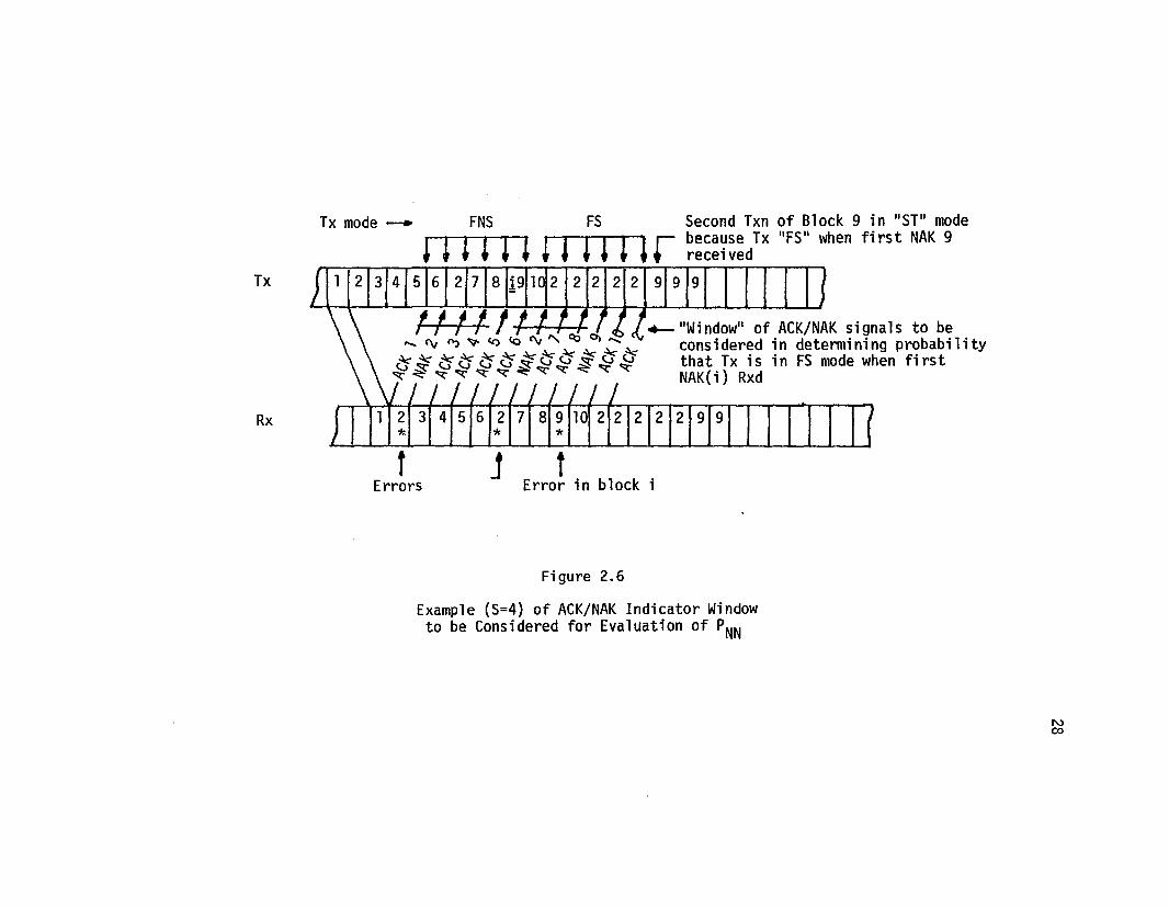
in time over the interval from ACK/NAKj to ACK/NAKj+2S'To illustrate, Figure 2.6 shows the ACK/NAK "window" to be consid
ered for the case where the round-trip delay is S=4 blocks. In this
example i=9 and the transmitter is in the FS condition when NAK i is
received at the transmitter, the FS condition resulting from two previous
NAK(2)'s in the "window" interva.l from ACK/NAKj (= ACK 1) to ACK/NAKj+2S(= ACK 8). Hence. in this case. block 9 would not receive an SR type
second transmission but would be held in the transmitter store until an
ACK 2 is received and then block 9 would be transmitted repetitively in
the ST mode.
Using the combinatorial principle of Inclusion and Exclusion one
can count the events and their probability values in the sampie space of
PNN resulting
S-l 2S-2P = I I
NN j=O k=2j(2S-2-2j)! p2+k(1_P )2S-2-k (2 7)
(k-2J) (2S-2-k)! B B •
Further details on the derivation of this expression are found in Appendix
A.
It is now possible to calculate the throughput(n) for the SR + ST
scheme 2. The expected value of the Mils can now be evaluated using (2.7)
and the channel model (2.2).
* I I 1*
Tx
Rx
Tx mode -....
tErrors
j tError in block i
Second Txn of Block 9 in "ST" modebecause Tx "FS" when first NAK 9received
Figure 2.6
Example (5=4) of ACK/NAK Indicator Windowto be Considered for Evaluation of PNN
'"co

29
Hence, the throughput (n) for this SR + ST scheme 2 becomes
(2.8)
Note that if PNN= 0, equation (2.8) reduces to (2.6) for the SR + ST
scheme 1 with v = 1. The term containing PNN therefore represents the
reduction in performance of scheme 2 over scheme 1, a trade off against
logic circuit complexity.
2.4 "Selective-Repeat Plus Go-Back-W Schemes
Essentially, this scheme provides for two modes of retransmission
of a block following an error in its previous transmission. The modes
are
• Selective-repeat type retransmission of the faulty block v
times after its first v consecutive faulty transmission attempts,
• Go-Back-N retransmission of the block for subsequent attempts
following Ni ~v + 1 consecutive failures in transmission attempts
for that block. That is, the transmitter stops sending new blocks,
backs up to the NAKled data block and resends that block and the
S succeeding blocks that were transmitted during the round-trip
delay.
Figure 2.7 illustrates the transmission/retransmission procedure for
the case v =1, namely one attempt at S-R retransmission and all subse
quently attempts being Go-Back-N. Following the second consecutive NAK
for a given block (e.g. block 7 in Figure 2.7) the receiver simply
discards all S subsequent blocks received until the successful reception
of the faulty block. In the transmitter and the receiver, provision

Tx sequence
Rx
No. of blocksheld in Rx buffer
SR GBN
Rx discardsthese blocks
Not countedas GBN
SR or SR GBN SR
--...... Time
Figure 2.7
SR + GBN Scheme for v =
wo

31
would be required for counters to keep check on the number of trans
mission attempts made for each block in order to determine whether
a SR or GBN type of retransmission mode was required.
If there are more than one block stored in the transmitter retrans
mission store such blocks having been transmitted twice unsuccessfully
then they must be queued f0r successive independent Go-Back-N type
retransmissions. The earliest doub1e-NAK 'ed block i say will be retrans
mitted in Go-Back-N mode that is followed by the S blocks which were
transmitted previously after block i and subsequently discarded by the
receiver. This will be repeated a sufficient number of times until an
ACK is received for block i. Then the same procedure is repeated for
any subsequent doub1e-NAK 'ed blocks in the retransmission queue. On
the second successive NAK for a given block the receiver discards all
S subsequent blocks received; and also the transmitter counters for those
blocks must be reduced by one. For example. in Figure 2.7, the first
transmission attempt of block 11 resulted in a discarding of the block
by the receiver because of a prior double error for block 7. The next
transmission attempt of block 11 resulted in an error so the next (third)
transmission attempt is in the SR mode. This also fails. so subsequent
blocks received (16. 13, 17, 18) are discarded and must be subsequently
retransmitted along with block 11. One of them (block 13) had previously
been NAK'ed, and was discarded following an attempt at SR retransmission.
Accordingly, the transmitter counter for retransmissions of that block
would be reset and the block subsequently given another SR retransmis
sion attempt. It should be mentioned that these procedures are not only
sensible from a practical point of view but also makes it possible to
carry out exact throughput analysis.

32
In principle, the scheme could be extended to allow for more than
one retransmission attempt in SR mode just as was described for the
previous SR + ST scheme. That is, values of v = 2,3, •.. could be used,
at the expense of complexity of transmitter and receiver logic and of
increased required receiver buffer store. The amount of receiver buffer
store required to avoid overflow in this scheme is equal to v(S+l)
blocks.
For small v, this represents a notable saving over the SR + ST
schemes which required S(v+l) blocks of buffer store. As will be seen,
the throughput performance of the SR + GBN is only slightly inferior to
the equivalent SR + ST scheme with the same value of v.
Analysis of SR + GBN Scheme. Consider first the case where v=l.
As in the analysis of the SR + ST scheme we use Ni and Mi to denote the
number of transmission attempts and slots respectively associated with
message block i. In this scheme, the value of Mi is taken to include
all S blocks following each GBN type retransmission of block i since
these blocks are discarded by the receiver while successful transmission
of block i is sought. The retransmission strategy ensures that the Mils
relate to disjoint sets of transmission intervals. To ensure this holds
for any error pattern, the transmitter count of the number of transmission
attempts for any block i must be reduced by one if any block in the S
blocks transmitted prior to block i is NAK'ed for the second successive
time. This is the case illustrated in Figure 2.7 for the third trans
mission attempt of block 13.
There is therefore a one-to-one correspondence between the Ni random
variable values and the associated Mi, the mapping being represented by

33
(2.9)
where U(·) is the unit step function.
Following the technique of the previous section, it is straight
forward to see that E{M} as a function of v is given by:
v+l 00
E{M} = I nPN(n) + L {(n-v-l) S + n}PN(n)n=l n=v+2
and hence, the throughput (n) follows as
l-PBn =l+SP \1+1B
2.5 Performance Calculations
(2.10)
(2.11 )
In this section some typical values for throughput (n) are calcu
lated and compared for each of the schemes outlined above. Table 2.1
summarizes the key parameters for each of the schemes. To provide
comparative performance bounds, the parameter values for conventional
Go-Back-N and Selective-Repeat schemes are also included.
The table shows clearly how the throughput efficiency values range
between values for the conventional Go-Back-N (worst case) and the
ideal Selective Repeat Scheme. In each case, the trade off between
throughput performance and provision for adequate receiver buffer store
is evident. As indicated, the complexity of the logic systems required
in transmitter and receiver would be greater for those schemes with
better throughput performance.
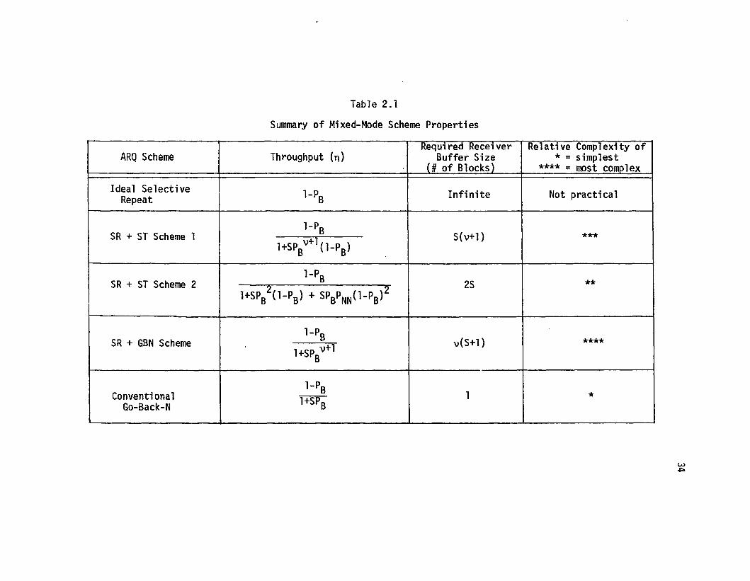
Table 2.1
Summary of Mixed-Mode Scheme Properties
Requlred Recelver Relative Complexity ofARQ Scheme Throughput (n) Buffer Size * = simplest
(# of Blocks) **** = most complex
Ideal Selective l-PB Infinite Not practicalRepeat
SR + ST Scheme 1l-PB S(v+l} ***
l+SPBv+1(l-PB)
SR + ST Scheme 2l-P B 2S **2 2l+SPB (l-PB) + SPBPNN(l-PB)
SR + GBN Schemel-P B v(S+l) ****
l+SP v+lB
Conventionall-P B 1 *
Go-Back-N l+SPB
w~

35
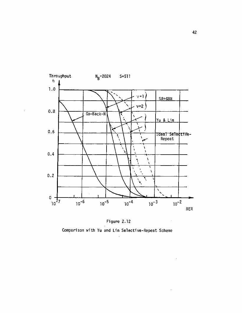
Figures 2.8-2.12 show for the various ARQ schemes how throughput
(n) varies as a function of
• Bit-error rate PBER
• Block size NB (bits)
• Round-trip delay S (blocks)
Figure 2.8 shows throughput values for SR + ST scheme 1 (v=l) for
various values of round-trip delay (S). Note that for negligible delay
(S=l) the performance approximates closely that of the ideal Selective-
Repeat scheme. For such channels, there is negligible advantage to be
gained by using the SR + ST scheme over the conventional Go-Back-N
scheme. However, as S increases (particularly, say for the satellite
channel) the SR + ST scheme 1 is markedly superior to the Go-Back-N ARQ
system.
Figure 2.9 shows how the throughput can be improved by allowing v>l
retransmissions in the SR mode. As v increases, the throughput (n)
approaches the ideal Selective-Repeat performance. The differences are
small for values of n ~ 0.6. However, as the bit-error rate deteriorates
further, the residual effect of the ST mode retransmissions becomes
significant.
SR + ST Scheme 2. Figure 2.10 shows values of throughput for N=524
and S=128 for the SR + ST scheme 2 in comparison with other ARQ schemes.
The SR + ST scheme 2 is significantly better than the Go-Back-N conven
tion especially for bit-error rates in the region 10-6 to 10-4•
SR + GBN Scheme. Figure 2.9 also demonstrates the throughput per-
formance of the SR + GBN scheme for various values of v in comparison
with the SR + ST scheme 1. Note that the latter scheme gives slightly

36
(5=1)
NB = 1024
\\
Go-13acl<';' "N -\--+--+l.-¥----f-----t-
(5=511)
\\
\
\
...<,
\
10-2
Bit-ErrorRate
o. 6 t-----+'-----+---+--f"'+-----:~I--~---__t-
o. 4 t-----+--'"""----+----+---t\---~~---__t-
, ,0.8 \
\
0.2 t-----+-----'H-----4---\----+\'-----1-
Th~oulhPut
1. 0 t-----.---~_=_--....,....-____:,.....,....__:_r~~':'""""""':':~____:_
Figure 2.8
5R + ST Scheme 1: Throughput for VariousRound Trip Delays .(5). NB=1024 Bits

37
10-2BER
SR+ST
\1=1
Ideal Seie t-
\\\
O-+-__....L---L__.....J...--L__.....L---JL...-~...:.:2::.:i1:11i.J::a_-...;:.;,I...-..I-_..
-10-7
O. 2 ~---l-----l--~.....---.j.-..;l~~f--.j.......4,----+--
0.4
Throughput $=127 NB=1024n
1.0--~- ......
" ... ... ,\ ..,...
0.8,
\\\
\
\
0.6\
\\
Figure 2.9
Throughput Performance for Various Valuesof \I (SR Mode Retransmission Attempts)

38
S=128
0 --........~ r-, ~SR+ST Scheme 2
\ \\. I
~SR+ST Scheme 18
\ \\6
\ \ ~»:
" \ \Go-Back-N
4 \ ''\\ 1\ \
\ '\ \\ ~ \ \
I I , ~\.I
O.
O.
o.
0.2
Throughputn
1.
10-2BER
Figure 2.10
Comparison of SR + ST Scheme 2 With Others
39
better performance than its SR + GBN counterpart. However, as pointed
out previously, this is at the expense of an increase in the required
receiver buffer store capacity and block sequence number length; the
latter requiring an extra overhead bit per block.
2.6 Comparison with ARQ Schemes by Other Authors
A number of other ARQ strategies have been suggested. These fall
into three classes: selective-repeat ARQ, Go-Back-N ARQ, and Stop
and-Wait ARQ. Because of its inherent idle time, the latter is unsuit
able for systems where the transmission rate is high or the round-trip
delay is long. It is, therefore, not considered further here.
Table 2.2 summarizes ARQ schemes suggested in the literature for
the other two ARQ categories. Where possible, the table lists expres
sions for the throughput (n) of each scheme.
Considering first the Go-Back-N (GBN) schemes, the first describes
a simple form of continuous ARQ based on CeITT Rec. V41. When an error
is indicated, the transmitter completes transmission of the current
block and then goes back two blocks and repeats. It is assumed that
the block lengths are large enough to allow for the round-trip trans
mission time. Sastry's scheme uses a stutter (ST) mode of retrans
mission for all NAK'ed blocks.
Morris· scheme uses the same ST mode of retransmission but a
buffer is provided at the receiver to store the good data blocks
following an erroneously received block.
The SETRAN scheme proposed by Lin and Yu also stores good data blocks
at the receiver following an error, but the scheme has a different

Table 2.2
ARQ Schemes by Other Authors
GO-BACK-N SCHEMES
Author Ref. No. Throughput Comments
Gatfield 1 - PBOnly useful if block lengthis longer than the equiva-
Go-Back-2 [14] n = lent round-trip time (low(CCITT Rec. V4l) 1 + PB data rates on satellite
channel)
Sastry [17]1 - PB n greater than conventional
n = 1+ 2SPB(l-PB)GBN only when PB~ 0.5.
Morris [21]1 - PB n approximately same as for
n =1 + SPB(l-PB} conventional GBN--slight
improvement for high PB.
Li nand Yu [31] lower bound given Outperforms first three(SETRAN) in reference [31] schemes. See Figure 2.11.
= 1 - PBn same as for conventional
Towsley [28] n GBN but input queue lengths(Stutter Go-Back-N) 1 + SPB decreased where system has
i d1e peri ods.
SELECTIVE REPEAT SCHEMES
Yu and Lin [32] n lower bounded in ISee Figure 2.12reference [31] .",.o

Throughputn
5=127
41
1.0t----~--_:::_r_---__r---__r---.......,.-
SR+GBN (v=l)
o~ 8 t------'t-~~--+--~...__::"..._F---__+---__f-
0.6
O. 4 t-----+----+--+\----~---__+---__f-
O.2 t-----+----~~~-+__\_\_--+_---+_-
BER
Figure 2.11
Comparison with Go-Back-N Schemes
Throughputn
1.0
0.8
0.6
0.4
0.2
5=511
v=1
\\
. \•\ \
\
\
SR+GBN
Yu & Lin
\
" ....
42
e-
BER
Figure 2.12
Comparison with Yu and Lin Selective-Repeat Scheme

43
retransmission strategy. Essentially, after an NAK has been received,
use is made of the transmission time slots corresponding to the success
fully received data blocks to repeat the first erroneously received
block.
The Towsley scheme is designed for use on systems which are not
heavily utilized so that the input queue has empty periods. During
these periods, the previously transmitted block is retransmitted in an
ST mode until either a new block arrives at the transmitter or an NAK
returns for an earlier block. Throughput calculations imply systems
have saturated inputs. In this case, Towsley's scheme becomes the con
ventional GBN.
The only Selective-Repeat scheme shown is that due to Yu and Lin for
which exact analysis is not available. However, a lower-bound provides
a useful basis for comparison. The scheme essentially provides for SR
mode retransmission with a strategy that avoids overflow of a receiver
buffer of size S+l blocks.
Figures 2.11 and 2.12 compare the throughput performance of the
above schemes with those described in Sections 2-5.
2.7 Summary
The class of mixed-mode ARQ models considered here has superior
throughput efficiency to that of Go-Back-N schemes such as those proposed
by Sastry [17], Morris [21], Towsley [28], or Lin and Yu [31].
The performance of the SR + ST and SR + GBN schemes demonstrates
the general proposition that for best ARQ performance, at least the first
retransmission of a block following an error should be in the selective-
repeat mode.

44
Providing this is done, markedly superior throughput performance is
achieved over Go-Back-N schemes for channels with high bit rate and
large round-trip delay. This improvement is at the expense of required
logic complexity and buffer storage provision in the transmitter and
receiver.
For related SR + 5T and 5R + GBN schemes (that is, those with the
same number v of SR retransmissions), the throughput performance is very
nearly the same indicating that the choice of the secondary retransmis
sion mode (ST vs GBN) does not have a significant bearing on the through
put. The SR + ST scheme does, however, require the provision of more
receiver buffer store than the SR + GBN.
An alterAative SR + ST scheme (2) has been shown to require simpler
tx/rx logic structure and provides useful performance up to bit-error
rates just above 10-4 (for NB=524 and 5=128). As illustrated in Figure
2.9, the other SR + ST and SR + GBN schemes for v = 1 are shown to have
a useful throughput up to bit-error-rates approximately twice as great
as the SR + ST scheme 2.
One feature of the method of analysis of these schemes is that it
provides results for evaluating the performance in cases where the
number of selective-repeat type retransmissions is greater than 1.
Results have shown how such schemes can be used to give performances
approaching the ideal selective-repeat scheme (infinite buffer) as the
number of SR-type retransmissions is increased.

45
3. PARITY RETRANSMISSION ARQ SCHEMES
3.1 Introduction
It is clear from the results of Section 2 that, among all ARQ
schemes, the Selective-Repeat ARQ protocol provides an upper bound
on the throughput efficiency performance that can be obtained in
the presence of channel errors and delays.
Mixed-mode and other ARQ schemes with initial retransmission
attempts in a selective-repeat mode provide a practical means of
obtaining throughput performance approaching the upper bound without
excessive receiver buffer size. While such schemes offer considerable
improvement over the conventional Go-Back-N ARQ, neverthe'less for bit
error-rates greater than 10-4, their throughput may falloff rapidly
on satellite or long terrestrial circuits as shown in Figures 2-8 to
2-12.
Hybrid schemes involving the use of forward-error correction (FEC)
as well as ARQ offer a potential means of obtaining throughput perfor
mance better than the selective-repeat upper bound for schemes using
ARQ alone. As pointed out in Section 1.1, Type-II hybrid ARQ schemes
in which parity bits for error correction are only transmitted when
they are needed seem to offer the best solution. In a sense these
schemes are adaptive. Their common feature is that when errors are
detected in a particular block, parity bits for forward-error correction
are transmitted rather than just retransmitting the original information
block. Hence, they are referred to as Parity Retransmission ARQ schemes.
46
In this section the principles of such schemes will be outlined.
Methods for representing them using state diagrams will be introduced.
Then an approach to throughput analysis will be outlined which is
intended to be sufficiently universal that it can be used for a number
of different combinations of parity retransmission schemes and ARQ
protocols.
To introduce the essential ideas, a Type-II hybrid scheme is first
described using a half-rate block code for error correction. Convolu
tional codes may, however, provide a ~ery competitive alternative to
the FEC problem for hybrid ARQ systems. Methods for implementing hybrid
schemes using convolutional codes are therefore emphasized in this and
the following sections.
3.2 Alternate Data-Parity Hybrid ARQ
A Type-II hybrid scheme suggested by Lin and Yu [37] provides for
alternate repetitions of data and correction parity based on a block
code. Particular attention is given in this dissertation to the use of
convolutional codes for forward-error correction. One possible Type-II
hybrid ,scheme can be illustrated as follows. If the first transmission
of a k-bit message u and n-k parity bits Po(u) (based on code Co) results
in detected errors, the receiver stores the received message bits uand
requests a retransmission. The transmitter does not retransmit the
message u but instead transmits k parity bits Pl(u) based on the message
u and a half-rate FEC code Cl.Additionally, the n-k parity detection bits Po(Pl(u)) based on the
code Co are transmitted. In this case, the receiver first uses the code
Co parity to determine whether this second transmission appears error

47-free. If so, then the receiver recovers the wanted message u from the
parity Pl (u) by inversion. In order to make this possible, the code
Cl must be "invertible" [34]; that is the k information digits can be
determined from knowledge of only the k parity check digits.
When errors are detected in the second transmission, the receiver
attempts error correction using the received parity Pl(u) and the pre-A A ....
viously stored message u. If the errors in {Pl(u),u} are correctible,
the estimated message u is delivered to the user. If not, the receiver
stores the parity word Pl(u) and requests a retransmission.
For the third and subsequent transmission attempts, alternate
repetitions of the information vector u and the parity vector Pl(u) are....
sent until one pair is correctible or no errors are detected in a u or
Pl(u).
This strategy can be incorporated with any of the basic forms of
ARQ (Go-Back-N, Selective-Repeat or Mixed-Mode ARQ). No extra overhead is
required. When the channel error rate is low, it has the same through
put efficiency as its corresponding ARQ scheme. With higher channel
error rates, the error correction provided by the half-rate code Cl will
provide higher throughput.
In this section, a unified method of analysis is presented which
facilitates the comparison of performance of convolutional or block
codes used for FEC with a number of different ARQ protocols. The
results of this analysis indicate that convolutional codes compare
favorably with block codes in this application. Furthermore, although
a Type-I hybrid scheme is appropriate for a Go-Back-N ARQ protocol,
Type-II hybrid schemes provide significantly better throughput perfor
mance with a 5elective-repeat type of ARQ protocol such as a Mixed-Mode
scheme.

48
The application of convolutional codes for FEC parity retransmis
sion perhaps needs further explanation. It is, of course, true that for
a (nc,kc) convolutional code, the nc and kc parameters are typically
small integers such as 1,2,3,or 4 (with k~ nc) but large encoder memory
order (m) ensures good error correction capability. Use of a (2,1) code,
say, in a Type-II hybrid scheme would envisage that the ARQ transmitter
would send an n-bit block {u, Po(u)} where u represents (k-m) data bits
followed by mzeros (or known bits) and Po(u) is the parity for u ba~ed
on a high rate block code Co as for the case previously described.
At the same time, the transmitter would compute and store the k
parity bits generated by the (k-m) data bits and a systematic (2,1)
convolutional code Cl. The use of a "tail" of m known bits at the end
of the data block is to ensure that the Cl encoder memory is allowed to
clear when generating the k parity bits.
These parity bits may now be used in a parity retransmission scheme
as described above using alternate repetitions of data and parity. If
the first transmission of a data block is received with detectable
errors, a retransmission is requested. The transmitter sends {Pl(u).
Po(Pl(u}} where the k parity bits Pl(u) are generated by the systematic
(2,1) convolutional code. The n-k bits Po(Pl(u)) are generated by the
high-rate block code Co. At the receiver the data may be recovered
from the received parity bits Pl(U) if the syndrome calculated using
code Co is zero. Codes for which the k data bits can be uniquely
determined from knowledge of only the k parity bits are said to be
"invertible". If the syndrome is non-zero, error-correction is attemptedA A
using the received data u and parity Pl(u). Fortunately, all systematic
(n,l) convolutional codes are invertible. Let u(X) represent in

49
polynomial form the input data sequence to a systematic (n,l) encoder.
The encoding can be described [2J in terms of a generator matrix G(X)
of the form
The n-tup1e of output sequences
y(X) = [y(l)(X), y(2)(X), ... y(n)(X)J
is obtained using
y(X) = u(X) G(X)
For the systematic (2,1) code described above, the parity bits
Pl(u) are given in polynomial form by
y(2)(X) = u(X) g(2)(X)
Hence, if we know Pl(u) and the code generator g(2)(X) it is possible
to obtain the data sequence u(X) since no two code words will have the
same parity check bits. Likewise for a (3,1) systematic code knowledge
of the set of parity bits.
can provide the original data u(X) by an inversion circuit. Other ARQ
schemes using related systematic (2,1) and (3,1) convolutional codes
have also been considered and will be discussed in the following sections.
The consideration of the use of convolutional codes in a Type-II
hybrid scheme is motivated by at least two factors. Ensemble error
rate bounds of the form
P < e-NE(R)E-
have been derived (see for example, Viterbi and Omura [38J) for which the
error exponent E(R) for memoryless channels is larger for convolutional

50
codes than for block codes. (Strictly, this is on the basis of maximum
likelihood decoding in each case, for which the computational complexity
would be slightly greater for convolutional codes.)
A second reason why convolutional codes might be preferred in hybrid
ARQ applications relates to the desirability of minimum complexity
encoders and decoders. Threshold decodable codes, while not providing
maximum error-correction efficiency, nevertheless, involve much simpler
decoding equipment and minimum decoding delays. Since in an ARQ appli
cation, a retransmission facility is always available it is sensible
from a practical point of view to choose the simpler threshold decoding
than the more efficient Viterbi or sequential decoding schemes with
considerable increase in complexity and decoding delays. Alternatively,
if codes with moderate values of memory order (m) are used, current
read-only-memory (ROM) technology development suggests that direct look
up decoding may be feasible. For example, there exists a rate one-half
convolutional code for which all incorrect paths are at distance 7 from
the correct path within 11 branches in the coding trellis. This offers
the possibility of correcting any error pattern of up to three errors
in any sequence of 22 symbols. This could be implemented in table look
up form by the use of currently available read-only-memories (ROM1s)
providing 211 bits of storage capacity.
3.3 Hybrid Schemes and Their State Diagrams
It is useful to' apply graphical procedures for representing succeed
ing events in ARQ schemes. The use of a state-diagram and probability
transition matrix representation assists in the analysis of performance
of a general class of ARQ schemes including the Type-II hybrid schemes

51
employing either block codes or convolutional codes for forward-error-
correction. It is also applicable to Type I schemes or to conventional
ARQ schemes without forward-error correction. This is illustrated for
several ARQ schemes.
Alternate data-parity hybrid ARQ. Consider an ARQ retransmission
procedure as described above in which
• The initial transmission of any block (u) of data consists
of the n vector {u, Po(u)} containing the original data
(k bits) and n-k parity check bits Po(u) generated by a
high rate block code Co used for forward error detection only•
• The first retransmission of that data block (initiated whenever
errors are detected in the initial transmission) consists of
the n-vector {Pl(u), Po(Pl(u))}. The first k bits Pl(u) are
the parity bits generated for the original data (u) by a one
half rate forward-error-correction code Cl. Cl may be either
an invertible block code or a systematic convolutional code.
The n-k bits Po(Pl(u)) are the parity bits computed when Pl(u)
is the encoder input for the forward error detection code Co.
The receiver attempts to recover the data u either by
inversion (if the first retransmission was received without
errors being detected) or by error-correction (if errors were
detected at the receiver). Otherwise, a further retransmission
is requested•
• The second retransmission consists of {u,Po(u)}, a repeat of
the first transmission. Again the receiver attempts to
recover u either directly (if no errors are detected in the

52
last received block) or by error correction based on the k bitsA A
Pl(u) received in the first retransmission and the k bits u
just received.
• Subsequent retransmissions of alternatively a parity block
{Pl(u), Po(Pl(u))} or a data block {u, Po(u)} are continued
until the receiver sends an ACK for the block. This will be'" A
done if a u, Pl(u) pair is correctible or the receiver detects
no errors in a ~ or a Pl(u). Then the receiver output is the
estimated message u. The State Transition diagram of Figure 3.1
describes the possible outcomes in the transmission/retransmission
and data recovery process.
All possible transitions are shown in Figure 3.1. States 1 and 2
represent the possible outcomes associated with the initial transmission
of any block i. If the process arrives at State 1, the data in block 1,
is successfully recovered and another initial transmission (of block i+l)
is initiated resulting in States 1 or 2. If the process arrives at
State 2 (block i+l is received with detectable errors) then that block
must be retransmitted so the process moves to one of the States 3, 4 or
5. Transition lines represent successive outcomes for a given block
number (irrespective of whether it is a "data" or "parity" transmission
of that block). Dotted transition lines represent cases where a new
block is transmitted. Solid lines represent "unsuccessful" transmissions.
If Co is chosen properly, the probability Pe of an error being
undetected is very small and is upper-bounded [2] by
(3.1)
In this section Pe is assumed to be negligible.

r./
--,;.:.-0
Parity retx<,
----Retxn 2
No errorsdetected
Data retx
~
Retxn 2Errors detectedNot correctable
Parity retx
- --. ---./
Initial txn \ J( Retxn 1No errorsdetected
........... <»:\ } I ............ -- ..:::::-<, ~ -'x"" -./' <, --I -/ ./ --:.
.- - ;:::2 I Initial txn
Errors detected
Data transmission (txn)
--~Initial transmissions
----~.~Retransmissions
Figure 3.1
State Transition Diagram for Alternate Data/Parity Hybrid ARQU1W

54
This method of representing possible outcomes has the advantage
that it is independent of the particular ARQ protocol being used,
whether it be Go-Back-N, mixed-mode or any other. It represents the
error mechanism or detection/correction process only. It will be shown
at a later stage how this can be combined with any particular ARQ proto
col description to provide an approach to a complete throughput analysis
of the whole ARQ system.
Transitions between the states in Figure 3.1 are labelled with
transition probabilities Pll' P12' P23"" where. Pj k =Pr {next outcome
is state k. previous outcome was state j}. For this alternate data
parity hybrid ARQ scheme the state transft.ton probabilities form a
semi-infinite matrix [n] of the form.
P11 P12 0 a aa a P23 P24 P25 a 0
P31 P32 0 0 0
[rr] = [P{Sk1Sj}] = P4l P42 0 0 0
0 0 0 0 0 PS6 PS7 P58 0
P61 P62 0 0 0
P71 Pn 0 0 0
0 0 0 0 0 0 0 0 0 P89
'"00
(3.2)
Conventional ARQ. To emphasize the generality of this approach.
Figure 3.2 shows the State Transition diagram for a conventional ARQ
scheme with no forward error correction.
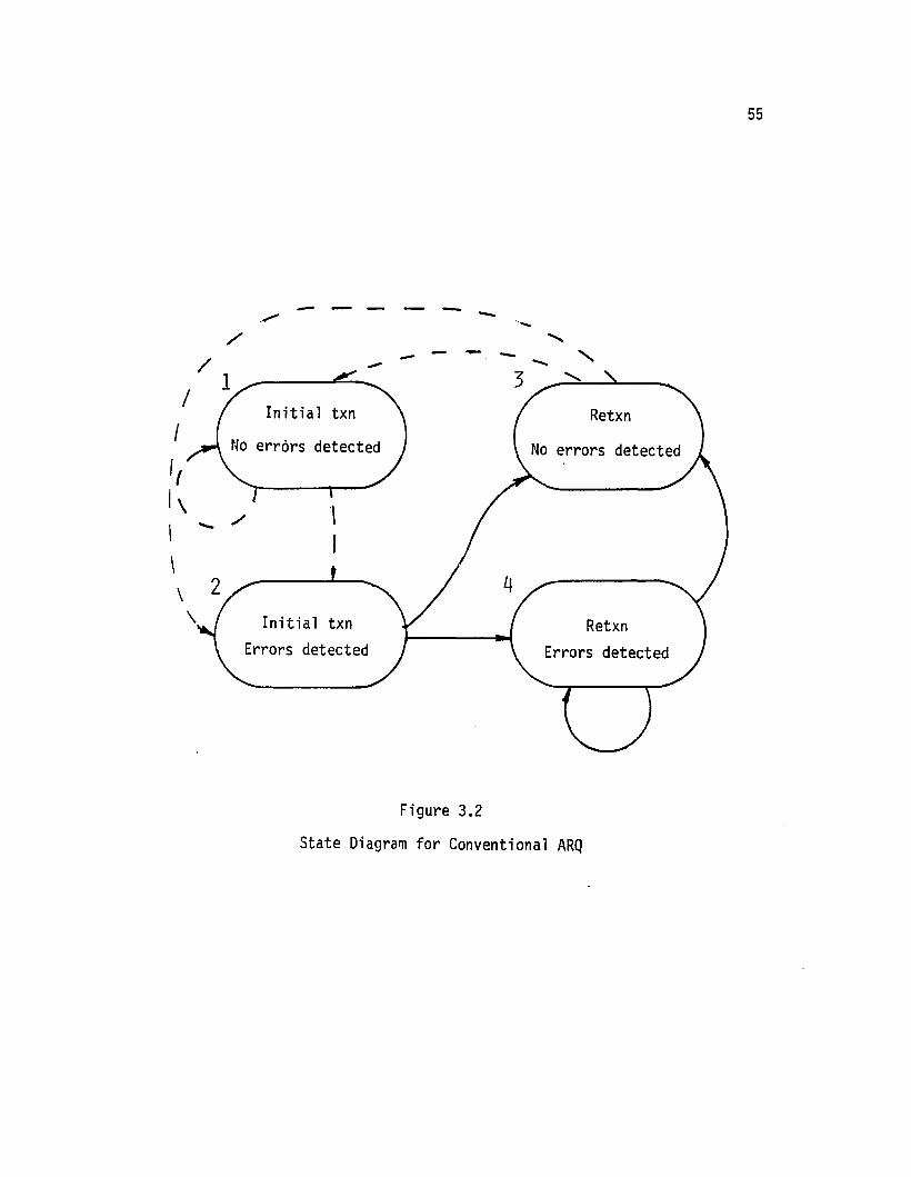
55
Initial txn
Errors detected
/....-
..... - ~ ...............-
\I
- --
Initial txn
."/
/
I
II1\\ .: >
\\
\
Figure 3.2
State Diagram for Conventional ARQ

56
The associated Probability Matrix for this case is of the form
Pll P12 0 0
a 0 P23 P24[II] = (3.3)
P31 P32 a 0
a 0 P43 P44
Type-I Hybrid ARQ. For Type-I hybrid schemes, forward-error correc
tion is incorporated into each transmission of a data block. The transi-
tion diagram is shown in Figure 3.3. Its probability matrix is of the
form
Pll P12 P13 0 a a
P21 P22 P23 a 0 0
err] = 0 0 a P34 P35 P36 (3.4)
P41 P42 P43 a a 0
PSl PS2 P53 a a 0
0 0 0 P64 P65 P66
Rate 1/2, 1/3 Type-II Hybrid ARQ. Another Type-II hybrid ARQ
scheme,is also proposed. It uses a 1/2 rate convolutional code Cl and
a rel ated 1/3 rate convol utional code C2 for forward error correction.
It is illustrated by Figure 3.4.
As in the previous case, the initial transmission of any block is
a conventional k-bit data block plus parity for error detection based
on a high rate code CO. If a retransmission of the block is required,
the first retransmission used is a "parity" retransmission based on the
k parity bits generated by a half rate code C1 as for the alternate
data/parity scheme of the previous section. If this retransmission

1 4
Initial txn -!:etxnno errors - -- No errors
r'\ ./
I I
I \
I 2I /" Initial
~errors detd. r 1,';{ errors detd.
I correctable correctableI I
I \ /- I l///I3~ 6,
Initial txn
'..-1 errors detd. y/ 4 errors detd.uncorrectable uncorrectable
Figure 3.3
State Diagram for Type-I Hybrid ARQU1"-J

Parity retxnR = 1/3s f 0
u not recoverabl
Parity retxnR = 1/2s :I 0
u not recoverabl
---------
Data txn l"drl Ly re t.xn 60arity retxnR = 1/2 R = 1/3
s=O 5=0 5=0
.( ..-'-../ . -- ..-"-
><..- -- --
2~~::: 4- Parity retxn / 7(parity retxnR = 1/2 R = 1/3sf 0 sf 0
s f 0 J, \ urecovered by FE urecovered by FE
--- Initial Transmissions
s = syndrome
------.. Retransmissions
Figure 3.4
State Diagram for ~/t Rate Hybrid ARQU1co

59
fails to recover the data successfully (either by inversion or decoding)
then for the next (third) transmission for that block, k parity bits
generated by a 1/3 rate code C2 are used. For this purpose a (3, 1)
Code C2 and a "related" (2, 1) code Cl must be available such that C2has generator po1ynomina1s closely related to that of C1• C1 and C2must be systematic codes related in such a way that for each information
bit, the first parity bit generated by C2 is the same as the first
parity bit generated by Cl•Construction procedures for finding such codes will be discussed
in a later section.
If the related half-rate code C1 and one-third rate code C2 are
used, the error-correction process could be as follows. After the first
transmission attempt the receiver computes the syndrome using code Co'
If the syndrome is zero, the data is assumed error-free and delivered
to the user. If not, a retransmission is requested. This will be a
"parity" transmission {P1(u), Po(Pl(u))} where the k parity bits Pl(u)
are generated using the systematic convolutional code C1. The n-k bits
Po(P1(u)) are derived from code Co' At the receiver, the syndrome for
the received block is computed using code Co' If it is zero, the...
received parity bits P1(u) are assumed error-free. An inversion circuit
is used to recover the data estimate ufrom Pl(u). If not, a decoder
based on code Cl is used to attempt to correct all the errors in the
first block data bits ~ using the 2k bits uand P1(u). If this fails,
a retransmission is again requested. For the third transmission, the
transmitter uses the one-third rate code C2 and sends n bits {P2(u),Po(P2(u))} where P2(u) is the set of second parity bits generated for
each data bit by the (3, 1) code C2. The n-k bits Po(P2(u)) are

generated using code Co. At the receiver, the process is similar to
that after the second transmission. If the syndrome using Co is zero,
the data u is obtained from P2(u) by inversion. If not, error
correction is attempted using a decoder for the (3, 1) code C2. TheA A A
inputs to the decoder are the bits u, Pl{u) and P2(u) respectively.A
If the decoder is unable to correct all the errors in u, the receiverA A A
discards u, Pl(u) and P2(u) and requests a retra~smission. The trans-
mitter sends a new data block of the form {u, Po(u)} as for the first
transmission and the process is repeated as for tr~nsmissions 1, 2, and
3 until the data estimate u is recovered.
This form of Type-II hybrid ARQ may lead to improved throughput
60
performance, when the channel bit-error rate is very high. Furthermore,
it will be shown in later sections that related codes Cl and C2 can be
found such that both are orthogonalizable. This offers the advantages
that a simple threshold decoding circuit could be used for both 1/2
and 1/3 rate decoding as will be discussed later.
Table 3:1 describes the parity retransmission procedure.
For this case the transition probability matrix is of the form
Pll P12 0 0 0 0 0 010 0 P23 P24 P2S 0 0 0
P31 P32 0 0 0 0 0 0
Err] P41 P42 0 0 0 0 0 0 (3.S)=0 0 0 0 0 PS6 PS7 PS8
P61 P62 0 0 0 0 0 0
P71 P72 0 0 0 0 0 0
P81 P82 0 0 0 0 0 0

Table 3.1
Rate 1/2, 1/3 Type-II Hybrid ARQ
Transmission Type
1. Initial txn {u,Po(u)} Data plus error detection parity (Co)
2. Retxn {P1(u),Po(P1(u»} 1/2 rate C1 parity plus Co detection parity
3. Retxn {P2(u),Po(P2(u»} 1/3 rate C2 parity plus Co detection parity
4. Retxn {u,Po(u)} Data plus error detection parity (Co)
5. Retxn {P1(u),Po(P1(u»} 1/2 rate Cl parity plus Co detection parity
6. Retxn {P2(u),Po(P2(u»} 1/3 rate C2 parity plus Co detection parity
7. Retxn {U,Po(u)} Data plus error d7tection parity (Co}. .
0\-'

62
As an alternative error recovery procedure using codes Cl and C2,a cyclic scheme could be used similar to the alternate data-parity
scheme of Section 3.3. Consider the event that after three transmissionA A
attempts the receiver can still not recover the data using u,Pl(u) and
"P2(u). A new data block is then requested. The receiver could then
retain Pl(U) and P2(u) and combine this with the new version of the
data u to attempt error correction. If uncorrectable error patterns
continue to require further retransmissions of new parity or data blocks,A " "the receiver could use the most recent versions of u, Pl(u) and P2(u)
if necessary to attempt error correction. This alternate error recovery
procedure is difficult to analyze. The performance of the scheme des
cribed in Equation (3.5) will provide a lower bound on throughput for
the alternative scheme.
3.4 Throughput Analysis Procedure
The state diagrams and transition probability matrix representation
of the previous section provide an orderly approach to the throughput
analysis of a wide range of ARQ schemes including Type-II ARQ. It was
shown in Section 2 that for the Go-Back-N scheme or the mixed-mode
schemes (SR + ST or SR + GBN) the throughput n can be computed using
_ 1n - HM
i}
wh~re Mi is a random variable representing the number of block trans
mission intervals required for any block i to be received succes~fully.
This includes intervals in which block i was sent and also intervals
when other blocks were sent but discarded by the receiver in the process
of recovering block i. In order to compute n for these ARQ schemes
over the random BSC, two steps are required, namely:

63Step 1. Error Process. Specify the distribution of the random
variable Ni where Ni is the number of transmissions required of block i
for the data to be recovered without detectable errors. For example,
for the sse with an error-free feedback channel, Ni is geometrically
distributed as
where
n.-lPN.(ni) = (l-Ps) Ps 1
1
PB
= 1- (l_p)n
(3.6)
with n the block length and p the bit error rate.
Step 2. ARQ Protocol. Specify the functional relationship between
the independent identically distributed Mils and the Nils. The func
tional relationship depends only on the particular ARQ protocol proposed.
For example, for the SR + ST ARQ scheme with v =1 selective-repeat
retransmissions and then subsequent retransmissions being "stutter"
repetition of the faulty block,
M i -Ni = 1,2
Ni = 3,4 •••(3.7)
where Sis the round-trip delay.
Once Steps 1 and 2 have been determined, it is a simple procedure
to determine E{Mi} and hence the throughput n.
In similar manner for a range of hybrid ARQ schemes, it is possible
to derive expressions for throughput n. Step 2 remains the same as for
conventional ARQ. However, Step 1 must be modified to provide infor
mation on the forward-error correction procedures as well as the channel
error process.

64
Step 1. Error Process for Type-II Hybrid ARQ. Let the random
variable Ni be defined as for the previous cases. Consider the alter
nate data-parity scheme described in Section 3.2 and illustrated by
the state diagram in Figure 3.1. We define the following conditional
probabilities:~
Let ql be the conditional probability that a message estimate u
without detectable errors is recovered from the first received parity
block Pl(u) (first retransmission) either by an inversion process (no
errors in parity) or by a decoding process based on the code Cl given
that errors are detected in the first received block {u, Po(u)}.
Let q2 be the conditional probability that a message estimate u is
successfully recovered from the second received information block
{u; ~o'(u)}(i.e. second retransmission) given that errors were detected
in the first received information word {u, Po(u)} and the subsequently
received parity word {Pl(u), Po(Pl(u)} and that the received parity word
failed to recover uby decoding.
In a similar fashion we can define conditional probabilities q3'
q4' •.. of successfully recovering u without error from the 3rd, 4th, ...
retransmissions respectively given that this was not possible after any
previous retransmission. In terms of the state-transition probabilities
of Equation (1) we can write
ql = P23 + P24
q2 = PS6 + P57
and so on for q3' q4' Q5'···
Now if we had Q2' Q3' Q4' .•. equal then the infinite chain of
Figure 3.1 could be collapsed into a finite-state first order Markov

65
chain. Unfortunately, this is not the case for the error correction/
detection procedures described.
We therefore analyze an inferior system as follows:
For the inferior system, the transmission/retransmission sequence
is the same. That is, first a data block is sent, then a parity block,
if required, then alternate data and parity transmissions until the data
estimate u is recovered without detectable errors. The error-control
process for the inferior system is different from that of the alternate
data-parity scheme of Section 3.2. For the inferior system the receiver
operations can be summarized as follows:
After transmission 1, data block {u,Po(u)}: Syndrome checking
error detection only;if errors detected, request a retransmission.
After transmission 2, parity block {Pl(u),Po(Pl(u)}: Check
detectable errors in Pl(u). If not, invert to obtain u. If necessary,A A
decode {u,Pl(u)} to correct errors in u. If unsuccessful, request a
retransmission.
After transmission 3, data block {u~P~(u)}: Check detectable errors
in u,. If necessary decode {u,Pl(u)} to correct errors in ~. IfA A A
unsuccessful discard lJ~Pl(u} and uland request a retransmission.
After transmission 4, parity block {P1(u),Po(P1(u)}}:. Syndrome
checking error detection only. If errors detected, request a retrans-
mission.
After transmission 5, data block {U",P~(U)}: Check detectable
errors in u". If necessary decode {~II,P~(U}} to correct errors in ~II.
If unsuccessful, request a retransmission.

66
After transmission 6, parity block {Pl'(u),P~(Pl'(u»)}: CheckA -
detectable errors in P1(u). If not, invert to obtain u. If necessary,A A A
decode {U" ,P1'(u)} to correct errors in u". If unsuccessful, discardA A A
P1(u),u ll and P11(u) and request a retransmission.
The process continues as above for transmissions 7, 8, ... until the
estimate of the data u is obtained without detectable errors. Note that
the inferior system, if u is not recovered ever three transmission
attempts, all three blocks are discarded. The receiver process reverts
to error detection only for the next block. It will provide inferior
throughput to the alternate data-parity scheme in which error correction
is available if required after every retransmission attempt.
Since the event that u is recovered error-free after transmissions
4, 7, 10, ••. is independent of the events that u was not recoverable
after preceding retransmissions, this inferior system can be modelled
as a Markov chain as shown in Figure 3.5. The transition probability
matrix is of the form:
Pll P12 0 0 0 0
0 0 P23 P24 0 a
P31 P32 a 0 a a[II] = (3.8)
a a a 0 P45 P46
P51 P52 0 0 a a
P61 P62 0 0 a 0
where Pil = l-PB and Pi2 = PB for i = 1, 3, 5 and 6.
P23 = ql P24 = l-ql
P45 = q2 P46 = l-q2

Initial transmissionor retransmissions 3,6,9, ...
Retransmissions1,4,7, ...
P61=1-PB
Retransmissions2,5,8, ...
Output u
errorserrors
P46=1-Q2
P51=1-P
P24=1-Ql
P52=PB
No errorsdetected
Output u
1_ <:»
Pll=l-PBP12=PB
Figure 3.5
State Transition Diagram for Inferior Alternate Data-Parity HybridARQ System (Markov Model)
O"l--..J

68
Expressions for the probabilities ql and q2 will be derived in a
subsequent section.
We can now proceed to complete step (1) by finding the probability
distribution for the identically distributed random variables Ni, i =1,
2, 3, •..
Consider those cases where the error generating/correcting mecha
nisms can be represented by a finite first-order f·1arkov chain. This
would include the hybrid schemes represented in Figures 3.4 and 3.5 but
not that of Figure 3.1. In the latter case, a lower bound on throughput
performance can be found using the inferior system represented in Figure
3.5.
Then the following procedure can be used to determine the probabil
ity distribution of the Nils taking into account a SSC and also the
error-correction performance of the FEC code used in the hybrid scheme.
Consider the state diagrams and transition matrices described in Section
3. Given that the system commences at state j, the probabilities of
reaching any state k after a specific number of steps r is given by
matrix multiplication as
~ j k(r] = rD(O)J~] r
where ~D(O~ is the initial probability matrix given
(3.9)
=
P(sl) a ao P(s2) aa a P(s3)
aoa
(3.10)
We now wish to use this approach to find the probability PNi(ni)
of reaching a final state (recover an estimate of a data block without

69detectable errors) in r = ni-l steps given that the system commenced
in an initial state (first transmission of the block).
Note that P(si) is the initial probability of being in state i.
To illustrate the method consider the inferior Type-II hybrid ARQ
scheme using alternative data/parity retransmission using an SR + ST
protocol. This scheme was descr-ibed in Section 3.3 and illustrated
in Figure 3.5.
For this case, the initial probability matrix [PD(O)] will be of
the form
(l-p)n 0 0 0 0 :l0 l-(l-p)n 0 0 0
~D (0)]0 0 0 0 0 0
= (3.11)0 0 0 0 0 0
0 0 0 0 0 0
0 0 0 0 0 0
since the first transmission of a block results in state 1 (no errors
detected) with probability (l_p)n or in state 2 (errors detected) with
probability l_(l_p)n. Note PB = l_(l_p)n.
Using Equations 3.9 and 3.11, we obtain the probabilities P{sk/Sj}(r)
of reaching sk from Sj in r steps for r = 1,2,3, ... as
(1)P{sk/sj} = P{Sj}P{Sk/Sj}
P{Sk/s.}(2) = P{s~} I P{s./s.}P{Sk/S'}J J i=l ' J ,
(3) 6 6P{sk/Sj} = P{Sj}i~l 9~1 P{si/Sj}P{Sg/Si}P{Sk/Sg}
and so on •
•
(3.12)

70
We can use these expressions to find the probability distribution
of the random variables Ni. For the hybrid ARQ schemes described, the
Ni's will be independent and identically distributed. Henceforth, the
generic random variable Nwill be used to denote the number of trans
missions for a block to be received without error.
We can find the probability PN(n) as follows:
PN(n) = I I P{Sk/Sj}(n-l)k j
(3.13)
where the sum is taken over all k for which sk represents a final state
and all j for which Sj represents an initial state. Also in evaluating
the terms P{sk/s.}(r) care must be taken to exclude these sequences ofJ •
states which include a final state (successful recovery of the infor-
mation without detected errors) in any part of the sequence except the
last. To explain further, consider as an example the problem of finding
the probability PN(4) for the case described by Equations 3.8 and 3.11.
This is done as follows
where
j, i, 9 ~ final state number.
In Markov chain theory, formal methods exist for calculating
the probability of first passage from state j to state k in n steps
see, for example, reference [50J). However, for the cases treated in

71
this dissertation, these probabilities can be easily obtained from the
state diagrams by inspection.
For this example, referring to Figure 3.5 , it is apparent that the
cases where j=2 and k=l are the only possible ones for N=4 (representing
successful transmission of a block after an initial transmission plus
three subsequent retransmissions). That is, s2 and sl are the only
possible initial and final states, respectively. Also, states s3 and
s5 are final states not allowed for N=4.
Thus, for this example, the only 4 state sequence allowed is
{s2' s4' s6' sl}
P (4) = P{s Is }(3)N 12.
Thus,
3.5 Summary
=P{s2} P{s4/s2}P{s6/s4}P{sl/s6}
PN(4) = PS(1-ql)(1-q2)(1-PS) (3.14)
It is possible to conceive of a large number of Type-II hybrid ARQ
schemes. In general, such variations represent different tradeoffs
between performance and complexity. In Section 3, a unified method of
representing different schemes has been presented. It has been demon
strated that it is important to distinguish between two different aspects
of any ARQ scheme. The first of these is the channel error and error
correction characteristics of the scheme. This includes a description
of the channel error process, for example, a random error model. It
also should include a description of the forward error correctionl
detection procedures. These factors when combined together lead to a
probability distribution PN(n) as described in Section 3.4. This process

72
is facilitated by the use of a state-diagram approach to the representa
tion of each particular error correction/detection scheme.
The second aspect of the ARQ scheme that must be specified is the
retransmission protocol. Possible retransmission protocols include the
Go-Back-N, Selective-Repeat or the mixed-mode schemes described in
Section 2. This second aspect can be characterized independent of the
error process and error recovery system. It provides for each protocol
a functional relationship between the generic random variables Mand N
as illustrated by Equation (3.7) for the SR + ST protocol.
The combination of these two aspects of any ARQ scheme (whether it
be a hybrid or not) leads to a general unified approach to analysis of
a wide variety of different systems. This will now be taken up in
subsequent sections.
The use of state diagrams as proposed to represent successive
outcome~ of various forms of ARQ systems has interesting parallels. For
example, directed graphs called Numerical Petri Nets (NPN's) have
recently been found useful for representing communication protocols
such as the CCITT Recommendation X.25 for packet switching networks [39].
The NPNs provide an orderly means of verification of the logical func
tioning of protocols, checking for deadlocks or loops and ensuring com
pleteness, that is, the provision of all possible input signals. It is
postulated that such state diagrams could be used in conjunction with
the methods of this section--to study throughput characteristics of such
systems and protocols.
State transmission diagrams similar in concept to those proposed in
this section have also been used to study the performance of frame

alignment systems to evaluate the relative performance of different
framing procedures (see, for example, reference [40]).
73

74
4. ANALYSIS OF TYPE-II HYBRID SCHEMES
In this section expressions for the throughput efficiency are
derived for a number of different Type-II hybrid ARQ schemes which were
described in Section 3. The results can be applied when either block
or convolutional codes are to be used for forward-error-correction.
4.1 Alternate Data Parity Scheme with SR + ST Protocol
The error detection/correction scheme is illustrated in Figure 3.1
and represented in Equation (3.2). Now we combine that error correction
procedure with an SR + ST (v=l) retransmission protocol as described in
Section 2.2. Consider that a data block i {u,Po(u)} is transmitted for
the first time. If errors are detected the transmitter stops transmit
ting new blocks and retransmits block i in the form of a parity block
{Pl(u),Po(Pl(u))} in a selective-repeat mode. That is, the parity block
is sent immediately following receipt at the transmitter of a NAK for
that block. The parity transmission is then followed by new blocks
(unless the next ACK/NAK indication received at the transmitter is a
NAK). Refer to Section 2.2 for details. If the parity block i also
contains errors and if the error correction procedure fails to correct
all errors in the data another NAK is sent. The transmitter again
stops sending new blocks and retransmits block i in a stutter mode.
That is, block i is retransmitted repectedly until an ACK is received
indicating the data in block i has been recovered without detectable
errors. The repetitive Y'etransmission of block i is in the form of
alternate data blocks of the form {u,Po(u)} or parity blocks

75
{Pl(u), po(P1(u))} respectively. As each retransmission of block i is
received, the receiver attempts to recover the data as described in
section 3.3: If a syndrome check indicates the received block is error
free the data estimate u is recovered either directly (if it was a "data"
transmission) or by inversion (for a "parity" transmission). If the
syndrome is non zero error correction is attempted using the most recently
received data uand parity P1(u) words for block i. If the most recent
retransmission of block i was a "data ll transmission, the decoder uses
the data bits II from that block and the parity bits Pl(u) from the pre
vious retransmission of block i. If the most recent transmission of
block i was a "parityll transmission, the decoder input is the parity
P1(u) from that transmission and the data word u from the previous
transmission attempt of block i. Unfortunately, because this scheme
cannot be represented by a finite Markov-chain, it is necessary to
analyze an inferior system as illustrated in Figure 3.5 and represented
in Equation (3.8). For this system the throughput will not be as high
because no error-correction is attempted after certain retransmissions.
The receiver recovers the data estimate u from transmissions 1, 4, 7,
only if a syndrome calculation indicates the block is error-free. No
error correction is performed. However for all other transmission
attempts of a given block the receiver attempts to recover the data
by error-correction if the syndrome is non zero. In the superior
scheme error correction is available if required for every retransmission.
We now proceed to find the probability distribution for the identically
distributed random variables Ni for the inferior system. As explained
in chapter 2, Ni is the number of transmissions of block i required to
recover the data estimate without detectable errors.

76
Given that the system initial state is state 1 or state 2, the
state sequences and associated probabilities shown in Table 4.1
represent the system operation for different values ni of transmissions
required to reach a final state (sl' s3 or s5) where uis recovered
without detectable errors. As explained in chapter 3, ql and q2 are
the conditional probabilities that an estimate u of the data is
recovered without detectable errors after the second and third trans--mission attempts respectively given that u could not be recovered after
earlier transmission attempts.
Hence we obtain the probability distribution PN(n) for the generic
random variable N for the inferior system assuming a random error forward
channel and error-free return ACK/NAK channel:
(l-PB)x(n-l)/3 n = 1, 4, 7, ...
PN(n) P q x(n-2)/3 n = 2, 5, 8, ... (4.1)B 1
PB(I-ql)q2 x(n-3)/3 n = 3, 6, 9, ...
where x = PB(I-ql)(I-q2)
This completes the description of the error mechanism and error
correction aspect of the ARQ scheme. Next we combine this with a
description of a particular ARQ protocol to find an expression for the
throughput n,
For the inferior Type-II hybrid scheme with SR + 5T protocol (v=l)
described in Sections 2 and 3 we have from Equations (3.7) and (4.1).

•
Table 4.1
Probability Distribution Values for Number of Required Transmissions
ni Sequence PNi(n i)
1 sl l-PB2 s2 s3 PB ql
3 s2 s4 s5 PB(l-ql )q2
4 s2 s4 s6 sl PB(1-Ql)(1-q2)(1-PB)5 s2 s4 s6 s2 s3 PB
2(1-Qj)(1-q2)ql
•
00 • 00 •
= 3(1-x) .l ix1 + {(l-x)(S+l) + PBql + 2PB(1-ql)Q2}.l Xl1=0 1=0
77
Since the throughput is the reciprocal of E{M}, by simplifying the
above expressions we obtain the throughput (n) for this hybrid ARQ scheme
as
(4.2)
Now Equation (4.2) for the inferior scheme provides a lower bound
on the throughput of the alternate data/parity hybrid scheme with
SR + ST protocol.
78It is an interesting check on this result to note that if no forward-
error correction is used, the scheme reverts to a simple SR + ST ARQ
scheme and it follows readily that
Substitution into Equation (4.2) leads to
(4.3)
which is the result previously obtained for the SR + ST scheme in Equation
(2.6).
Note also that this method of deriving an expression for throughput
n has the advantage that it applies to a Type-II hybrid scheme with block
or convolutional coding as the forward-error correction scheme. The
derivation of the conditional probabilities ql and q2 takes into account
the type of code and decoding scheme used. This will be dealt with in a
.subsequent section.
4.2 Alternate Data-Parity Scheme with SR + GBN Protocol
It is also possible to find a lower bound for the throughput for the
Alternate Data/Parity Type II hybrid scheme when combined with the
SR + GBN protocol. In this scheme, the first retransmission is in a
selective-repeat mode. Should the message ustill not be recovered,
further retransmissions are in the conventional Go-Back-N mode to avoid
receiver buffer overflow.
It was shown that this protocol when used in conventional ARQ
detection/retransmission scheme has only slightly inferior throughput
performance to the SR + ST scheme but requires less receiver buffer store.
A similar result could be predicted with Type-II hybrid operation.

79
For the SR + GBN scheme the number of transmission intervals Mi is
equal to the number of transmission attempts Ni if the first or second
transmissions are successful. Otherwise Mi is taken to include an addi
tional S intervals for each extra transmission attempt. This is because
on those occasions the receiver discards S other blocks each time to
avoid buffer overflow. Hence, we have
{N.
M. = 1
1 N. + S(N.-2),1 1
Ni
= 1, 2
Ni=3,4,
•..(4.4)
As before, combining this with the hybrid scheme PN(n) distribution
given by (4.1) we obtain a lower bound for the throughput n of the
SR + GBN protocol with the alternate data/parity retransmission scheme as
(4.5)
As a check, let
which is then equivalent to the conventional SR + GBN ARQ without forward-
error correction.
Then
as given previously in Equation (2.11) for the conventional SR + GBN
protocol.

80
4.3 Alternate Data-Parit Scheme with Selective-Re eat ProtocolInfinite BufferL
In each of the retransmission protocols (SR + ST and SR + GBN)
analyzed in the previous sections it was assumed that only the first
retransmission could be in the selective-repeat mode (i.e. v=l). Other
retransmissions if required, were assumed to be in the Stutter n~de or
Go-Back-N mode respectively. However as pointed out in section 2.4, the
number v of allowable selective~iepeat types of retransmissions can be
increased providing appropriate extra buffer store is available at the
receiver. As v is increased so will the throughput performance at high
bit-error rates.
In order to examine the limits to which the throughput might increase,
consider the calculation of throughput for a Type-II hybrid scheme using
a purely selective-repeat protocol with infinite receiver buffer to prevent
overflow. The error correction scheme analyzed here is the "inferior"
alternate data-parity scheme for error correction used in the previous two
cases and represented in Equation (3.8). Combining this with the fact
that for the selective-repeat protocol, the number of transmission
intervals Mi is equal to the number of transmission attempts Ni.
We obtain the throughput as
1 - PB(1-ql)(1-q2)n = 1 + PB + PB{l-ql) (4.6)
As a check, letting ql=q2=1-PB, we obtain the selective-repeat ARQ
scheme without FEC and Equation (4.6) becomes
n = 1 - Ps
as obtained in section 2 for the selective-repeat ARQ scheme.

814.4 Lin and Yu Hybrid ARQ Scheme
It is of interest to compare the throughput performance of the pre
vious schemes with the Type-II hybrid scheme proposed by lin and Yu [37J.
This scheme is more complex than the schemes presented so far. By more
efficient use of the storage capacity in the receiver buffer, the scheme
can provide a higher throughput.
In essence, the scheme works as follows. The retransmissions consist
of alternate repetitions of an "information block" {u,Po(u)} and "parity
block" {P1(u),Po(P1(u))} as for the alternate data parity scheme above.
However this retransmission scheme is combined with a selective-repeat
type of ARQ protocol proposed by Yu and Lin [34J. This protocol is similar
to the SR + GBN protocol described in section 2.3 except that it makes
better use of the receiver buffer store by a more complex set of retrans
mission protocols. Blocks are numbered with sequence numbers modulo-3N
where N is the number of blocks round-trip delay. Also the receiver buffer
is capable of storing N blocks. The protocol provides that when errors
occur on the channel, this receiver buffer is used to a maximum extent to
store those blocks that are successfully received without error but which
have higher sequence numbers than other blocks previously NAKled but not
yet received correctly. The transmitter keeps a running check on the
state of the receiver buffer and uses under/overflow information to deter
mine the retransmission mode for NAK'ed blocks.
When a NAK is received for a block j (or no ACK is received at the
expected time after one round-trip delay) the transmitter computes the for
ward index fT of the block as follows. Let Xo be the sequence number of
the earliest NAKled or unACKled information block in the retransmission
buffer (where all blocks are stored after transmission until ACK1ed). The

82
forward index fT of an information block with sequence number x in the
retransmission buffer (or in the input queue) with respect to the earliest
NAK'ed or unACK'ed information word in the retransmission buffer is
defined as
fT = x - xo(mod 3N)
Then for the NAK'ed or unACKled block j (known as the current time-out
word) the transmitter proceeds as follows.
• If block j has a forward index fT less than N, a selective-repeat
type of retransmission of block j is initiated (either "parity
block" or lIinformation blockll type of retransmission depending
on whether the previous attempt was of "fnformat ton" or "par i ty"
type respectively). All the information words in the retransmis
sion buffer with forward indices equal to or greater than Nare
moved back to the input queue for retransmission at a later time.
Those words have been transmitted but when they were received the
receiver buffer was full so buffer overflow occurred and the blocks
were discarded at the receiver.
• If block j has a forward index fT greater than or equal to N, then
'a type of Go-Back-N protocol is initiated. The first information
word in the input queue is the next transmitted, this word having
been moved back to the input queue from the retransmission buffer
due to receiver buffer overflow.
Further details are given in Reference [37J.
Although, the authors considered only the possibility of using a
block code for forward-error-correction, the methods of this section can
be used for a convolutional code application also. The methods outlined

83above are generally applicable to either form of forward-error correction
codes; the features of the particular coding scheme used must be taken into
account when computing the conditional probabilities q1 and q2 defined
above. The derivation of expressions for q1 and q2 for different coding
arrangements will be discussed in subsequent sections.
For the Lin and Yu scheme, it has been shown that for a receiver
buffer equal to one round trip delay N = S+l blocks, the throughput is
lower bounded as follows [37J:
E{M}Infn ~ E{V}
Inf
y[PS + (l-P S)-S)SSJwhere E{M}Inf = (l-S)P
S
and E{V}Inf = E{M}Inf + q1aS-1[1-Ps+Psq1 (S+l)J
+ Q2SS-1[a-q1+y(1-a) (S+l)J
+ (S-1)[2-ySS - Q1aSJ
(4.7)
The parameters Q1 and Q2 are defined as outlined earlier in this
section. It can be noted that for this scheme, a rather complicated lower
bound only is given compared to previous cases. This is because the par
ticular construction of the Lin and Yu scheme does not permit the use of
Equation (2.4) so that the lower bound has to be found by other ways.
Details are given in Reference [37J.

84
4.5 Rate 1/2 and 1/3 Parity Retransmission Scheme
The scheme represented in Figure 3.4 and described in section 3.3
utilizes parity retransmissions based on related 1/2 and 1/3 rate convo
lutional codes. In order to determine the throughput for this case, con
sider states 3 and 4 in Figure 3.4 being combined into one state, Also
combine states 6 and 7. As a result the state diagram becomes of the
same form as that shown in Figure 3.5. Hence the throughput expressions
given by Equations (4.2) and (4.5) apply respectively for the SR + ST
and SR + GBN protocols used with the 1/2/1/3 parity retransmission scheme.
The conditional probabilities q1 and q2 will of course differ from
the values for the alternate data-parity scheme. These parameters reflect
the effectiveness of the particular forward-error correction procedures
used. Expressions for them will be discussed in a later section.
4.6 Alternate Data-Parity with ST + GBN Protocol
An ARQ retransmission protocol suggested by Weldon [44] has some
similarity to the mixed-mode schemes described in section 2. When a NAK
is received after the first transmission of a block the transmitter stops
transmitting new blocks and re-sends the faulty block (stutter mode) a
specified number (n1) of times. Then the transmitter returns to trans
mitting other new blocks waiting in the transmit buffer. Should all n1transmission attempts of the faulty block be unsuccessful the transmitter
again stops transmitting new blocks and retransmits the faulty block n2times in stutter mode. As before the transmitter returns to continuous
transmission of new blocks. The process continues with the transmission of
ni copies of a faulty block if all ni_1 copies fail to be received without
error. The intention is to choose the values of n1, n2, ... to II mat chll the

85channel, that is to provide maximum throughput performance for given
error rate and delay.
It is necessary to provide receiver buffer with capacity sufficient
to hold blocks received error-free with higher sequence numbers than
the faulty block. Let the receiver buffer size be qS where S is the
round-trip delay as defined in section 2 and q may be 1, 2, 3, .... The
transmitter must revert to a Go-Back-N type of mode if receiver buffer
overflow occurs. Accordingly we can for convenience refer to this pro-
tocol as an ST + GBN protocol. The following summary of the protocol
explains the sequence of events:
Error free state. An ACK is received at the transmitter. A new
block is sent.
Stutter mode. If a NAK is received for a given block, the transmitter
next repeats the block n1 times. then continues with new blocks. If all
n1 repeats are received in error (n1 NAK's received) the transmitter
repeats the block n2 times, then continues with new blocks.
Go-Back-N mode. If all nq repeats are received in error, buffer
overflows will occur. The block is repeated nq times and then the trans
mitter repeats other blocks transmitted following the previous stutter
mode transmission. The system stays in this mode until the faulty block
is communicated.
Weldon [44] has derived an expression for throughput for this scheme.
For the case where a receiver buffer of just one round-trip delay is pro-
vided (q=l) the throughput becomes
(4.8)
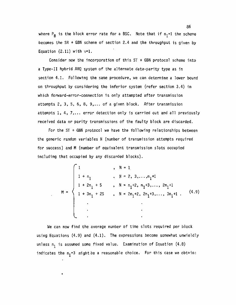
86
where PB is the block error rate for a BSC. Note that if n1=1 the scheme
becomes the 5R + GBN scheme of section 2.4 and the throughput is given by
Equation (2.11) with v=l.
Consider now the incorporation of this 5T + GBN protocol scheme into
a Type-II hybrid ARQ system of the alternate data-parity type as in
section 4.1. Following the same procedure, we can determine a lower bound
on throughput by considering the inferior system (refer section 3.4) in
which forward-error-connection is only attempted after transmission
attempts 2, 3, 5, 6,8, 9, ... of a given block. After transmission
attempts 1, 4, 7, ... error detection only is carried out and all previously
received data or parity transmissions of the faulty block are discarded.
For the 5T + GBN protocol we have the following relationships between
the generic random variables N (number of transmission attempts required
for success) and M (number of equivalent transmission slots occupied
including that occupied by any discarded blocks).
1 , N = 1
1 + n1 • N= 2, 3, ... ,n1+11 + 2n1 + S N = n1+2, n1+3,... , 2n1+1
M= 1 + 3n1 + 25 N = 2n1+2, 2n1+3,... , 3n1+1(4.9)
We can now find the average number of time slots required per block
using Equations (4.9) and (4.1). The expressions become somewhat unwieldly
unless n1 is assumed some fixed value. Examination of Equation (4.8)
indicates the n1=3 might be a reasonable choice. For this case we obte in:
•

(4.10)
87E{M} = (l-PS) + 4PBQ1 + 4 PB(1-Q1)q2 + 4x(1-PB)
+ (7+S) x PSq1 + (7+S) x PB(l-q1)q2 + (7+S) x2(1-PS)
+ (10+2S) X2PBQ1+ (10+2S) x2P
B(l- Q1)Q2 + (10+2S) X3(l - PS)
+
where x = PB(l-Q1)(l-q2)'
Taking the reciprocal after appropriate collection of terms we obtain
the throughput as
1-PS(l-Q1) (l-q2)T] - .....-:-:""'""~-,..;'----.-:;r-:-----,,..:r.,...---:-t""
- 1+3PB+PS(1-Q1)(1-Q2)(SPS-1)
4.7 Summary
In Chapter 4 a unified procedure has been used to obtain expressions•
for the throughput of a number of hybrid ARQ schemes involving
• different retransmission protocols
• different error detection/correction schemes
The results were presented in terms of conditional probabilities Q1
and Q2 which were defined in Chapter 3. The values of q1 and q2 depend on
the forward error correction/detection process being used, the properties
of the codes and the decoding procedures. In the next chapters, expres
sions for these parameters will be given for convolutional codes and block
codes.
In order to determine q1 and q2 for schemes using convolutional codes,
it will be shown in Chapter 7 that it is useful to first compute the block
error probability Ps after decoding. In Chapter 5, methods for computing
Pswill be given. Upper bounds are derived for certain classes of convolu
tional decoders. This will then permit a comparative assessment of the
different results of Chapter 4. The results of this chapter are not
exhaustive in that expressions for throughput were determined only for

88
selected combinations of retransmission protocols and detection/
correction schemes. However, it should be apparent that the analysis
procedure can be readily applied to other related Type-II hybrid ARQ
systems.

89
5. BLOCK ERROR RATE FOR CONVOLUTIONAL CODES
5.1 Introduction
We wish to determine the (average) probability Psof incorrectly
decoding the set of information symbols in a block. For a Type-II hybrid
ARQ scheme with alternative transmissions of data, (2,1) parity, data,
parity, etc ... the probability Pscan be defined using the following:
Consider a "data information" transmission block (v) n bits long
where
The k bits u are followed by (n-k) error detection parity bits Po(u)
associated with an (n,k) error detection block code Co as illustrated
in Figure 5.1(a).
Consider also the "parity" transmission block
where the first k digits PI(u) are the parity bits generated by encoding
u with a (2,1) convolutional code C1. The last (n-k) digits Po(P1(u))
are the parity bits resulting from encoding PI (u) with block error detec
tion code Co' This is illustrated in Figure 5.1(b).
Note that for PI(u) to provide a comp]ete set of parity bits for u
it is necessary to provide a "taiP of m zeros terminating u. That is
the total number of information bits in the transmission u is (k-m).
Normally m«k so this represents only a slight reduction in throughput
efficiency.

I- k -I n-k t-I I I
PO(u) Iu .00 .. 01I I
(a) Data Block~ m ~
(b) Parity Block
Fi gLire 5.1
Alternate Data and Parity Transmission Blocks
90

91We observe that other parity retransmission schemes are possible.
For example, the first transmission u could consist of k information bits
with no zero tail as illustrated in Figure 5.2. The parity retransmis
sion could consist of n symbols all of which are parity digits generated
by a convolutional code CI designed for error correction and detection.
This can be achieved providing that for the code CI, m~n-k. However, in
the following we consider the first parity retransmission scheme.~
Let the k data bits u of the received "data" block v be represented
"u = (uo'ul, •.. uk_ l) .
A "
Let the k parity bits PI (u) of the next received "parity" block v* be
represented
"Both u and PI(u) may contain errors. The decoder attempts to correct theA
errors and recover u. This may be preceded by a multiplexing of u and"PI (u) to form a sequence
which is NB=2k bits in length.
We define the block error probability (Ps) as:
Ps = Pr{one or more errors remain after decoding the NB bits}.
Obviously Pswill depend on the
• channel error pattern. before decoding
• the convolutional code used
• the decoding procedure

92
------~I n-k rIPO(U) I
k
u
,..
I~ ~__----J..~---'
(a) Data Block
(b) Parity Block
Figure 5.2
Another Possible Alternate Data/Parity Scheme

93We assume a randomly distributed error pattern with bit-error-rate
p. Further we assume that for the 1/2 rate convolutional code, the con
straint length (nA bits) or memory order (m) and the minimum free dis
tance (df ree) are known.
5.2 Decoder Characteristics
The choice of the error-correction decoder to be used in the hybrid
ARQ system would in practice depend on a compromise between performance
and complexity. Possible classes of decoders include the following
• Viterbi algorithm decoders
• Sequential decoders
• Sliding block feedback decoders including Threshold Decoders
and Table look-up.
Viterbi decoders and Sequential decoders can be classed in the high
performance, more complex end of the scale. The Viterbi algorithm is
a maximum likelihood decoding scheme. Its major drawback is that while
error probability decreases exponentially with constraint length, the cor
responding decoder complexity also grows exponentially.
Sequential decoders offer asymptotically the same error probability
as Viterbi decoders. The decoder is also reasonably complex but suffers
an additional disadvantage for ARQ usage in that it is necessary to incor
porate a considerable decoder buffer (typically of the order of 104_105
bits [38]) which results in undesirable delay. This is necessary because
the number of operations performed for each input bit to the Sequential
decoder is a random variable and a buffer must be provided to avoid lOss
of data.
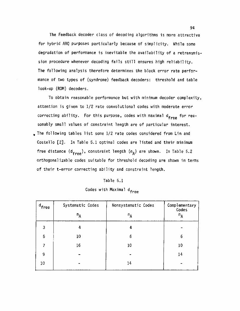
94The Feedback decoder class of decoding algorithms is more attractive
for hybrid ARQ purposes particularly because of simplicity. While some
degradation of performance is inevitable the availability of a retransmis
sion procedure whenever decoding fails still ensures high reliability.
The following analysis therefore determines the block error rate perfor
mance of two types of (syndrome) feedback decoders: threshold and table
look-up (ROM) decoders.
To obtain reasonable performance but with minimum decoder complexity,
attention is given to 1/2 rate convolutional codes with moderate error
correcting ability. For this purpose, codes with maximal df ree for rea
sonably small values of constraint length are of particular interest .
• The following tables list some 1/2 rate codes considered from Lin and
Costello [2]. In Table 5.1 optimal codes are listed and their minimum
free distance (df ree) , constraint length (nA) are shown. In Table 5.2
orthogonalizable codes suitable for threshold decoding are shown in terms
of their t-error correcting ability and constraint length.
Table 5.1
Codes with Maximal df ree
df ree Systematic Codes Nonsystematic Codes ComplementaryCodes
nA nA nA
3 4 4 -
5 10 6 6
7 16 10 10
9 - - 14
10 - 14 -I

95Table 5.2
Orthogonalizab1e Codes (1/2 rate)
t nA
1 4
2 12
3 24
4 44
As pointed out in Viterbi and Omura [38J the class of Feedback
decoders operates essentially as "s1 iding block decoder-s". The decoder
can correct any t-error pattern in a "s1iding window" of length nA bits
providing df ree is greater than or equal to 2t+1.
In the following sections, methods for computing the bound-distance
block-error probability performance after decoding are given. The results
provide upper bounds on Ps for all the above decoders being tightest for
the threshold and table look-up respectively. Two methods are presented,
namely
• Trellis algorithm approach
• Combinatorial pattern enumeration method.
I
5.3 Trellis Algorithm for PB Evaluation for Convolutional Codes
Consider the first received data block u of k bits"-
where u = (uo,u1, ... uk_ 1)and also the k received associated (2,1) convolutional code parity bits
"-
where P1(u) = (Po,P1, ... Pk-1).
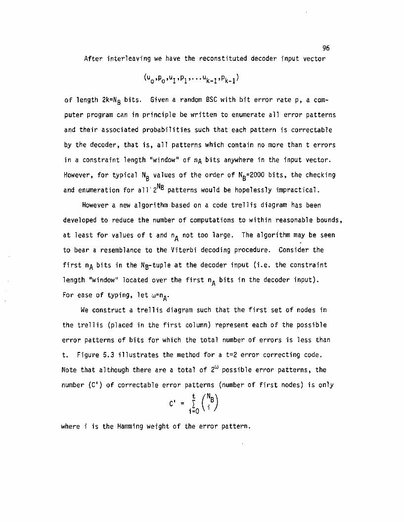
96After interleaving we have the reconstituted decoder input vector
of length 2k=NS bits. Given a random sse with bit error rate p, a com
puter program can in principle be written to enumerate all error patterns
and their associated probabilities such that each pattern is correctable
by the decoder, that is, all patterns which contain no more than terrors
in a constraint length "window" of nA bits anywhere in the input vector.
However, for typical NS values of the order of NS=2000 bits, the checking
and enumeration for all"2NS patterns would be hopelessly impractical.
However a new algorithm based on a code trellis diagram has been
developed to reduce the number of computations to within reasonable bounds,
at least for values of t and nA not too large. The algorithm may be seen
to bear a resemblance to the Viterbi decoding procedure. Consider the
first nA bits in the Ns-tuple at the decoder input (i.e. the constraint
length "window" located over the first nA bits in the decoder input).
For ease of typing, let w=nA.We construct a trellis diagram such that the first set of nodes in
the trellis (placed in the first column) represent each of the possible
error patterns of bits for which the total number of errors is less than
t. Figure 5.3 illustrates the method for a t=2 error correcting code.
Note that although there are a total of 2w possible error patterns, the
number (e') of correctable error patterns (number of first nodes) is only
e· = I (~s)i=O 1
where is the Hamming weight of the error pattern.
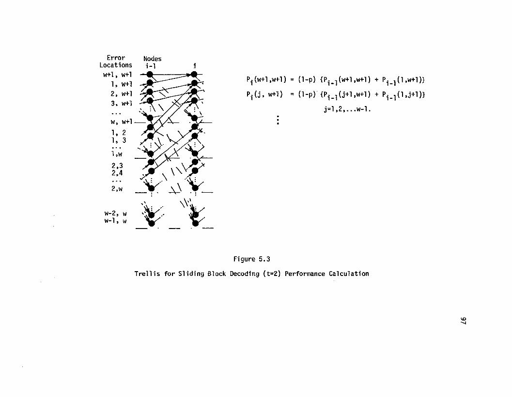
ErrorLocationsw+l, w+l
1, w+l2, w+l3. w+l
w, w+l
1, 21, 3
l,w
2,32.4
2.w
w-2, ww-l, w
i
Pi(w+l,w+l)
Pi(j, w+l)
·••
= (l-p) {po l(w+l,w+l) + P. l(l,w+l)}1- 1-
= (l-p) {Po l(j+l,w+l) + p. l(l,j+l)}1- 1-
j=l ,2, ...w-l.
Figure 5.3
Trellis for Sliding Block Decoding (t=2) Performance Calculation
W""-J
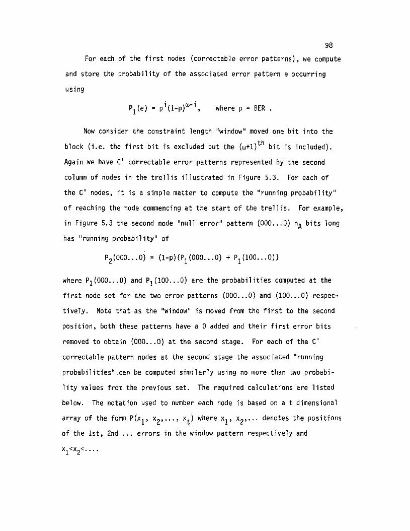
98
For each of the first nodes (correctable error patterns), we compute
and store the probability of the associated error pattern e occurring
using
where p = BER .
Now consider the constraint length "window" moved one bit into the
block (i.e. the first bit is excluded but the (w+l)th bit is included).
Again we have C' correctable error patterns represented by the second
column of nodes in the trellis illustrated in Figure 5.3. For each of
the C' nodes, it is a simple matter to compute the "running probability"
of reaching the node commencing at the start of the trellis. For example,
in Figure 5.3 the second node "null errorll pattern (000 ... 0) nA bits long
has II running probabilityll of
where Pl(OOO ... O) and PI (100 ... 0) are the probabilities computed at the
first node set for the two error patterns (000 ... 0) and (100 ... 0) respec
tively. Note that as the "window" is moved from the first to the second
position, both these patterns have a 0 added and their first error bits
removed to obtain (000... 0) at the second stage. For each of the C'
correctable pattern nodes at the second stage the associated II runni ng
probabilities" .can be computed similarly using no more than two probabi
lity values from the previous set. The required calculations are listed
below. The notation used to number each node is based on a t dimensional
array of the form P(x l, x2' ... , xt) where xl' x2' ••• denotes the positions
of the 1st, 2nd ... errors in the window pattern respectively and
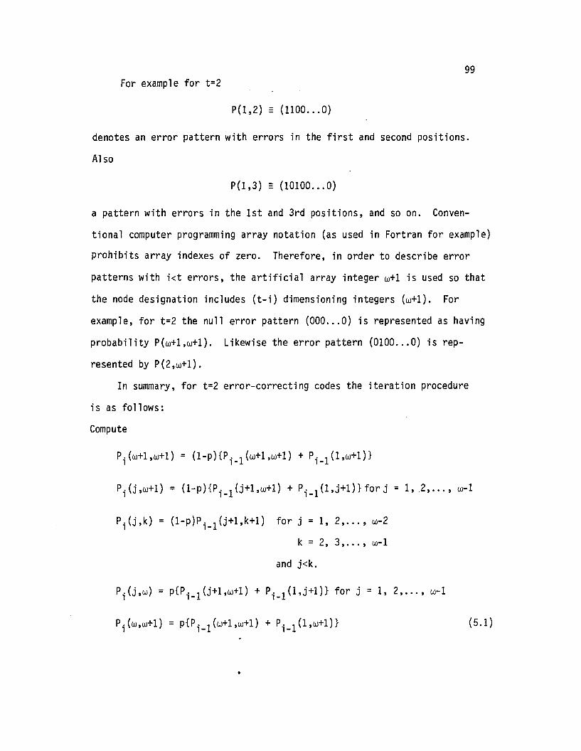
99For example for t=2
P(l,2) - (1100 ... 0)
denotes an error pattern with errors in the first and second positions.
Also
P(l,3) = (10100 ... 0)
a pattern with errors in the 1st and 3rd positions, and so on. Conven
tional computer programming array notation (as used in Fortran for example)
prohibits array indexes of zero. Therefore, in order to describe error
patterns with i<t errors, the artificial array integer w+1 is used so that
the node designation includes (t-i) dimensioning integers (w+1). For
example, for t=2 the null error pattern (000 ... 0) is represented as having
probability P(w+1,w+1). Likewise the error pattern (0100 ... 0) is rep
resented by P(2,w+1).
In summary, for t=2 error-correcting codes the iteration procedure
is as follows:
Compute
P.(w+1,w+1) = (l-p){P. 1(w+1,w+1) + P. 1(1,w+1)}1 1- 1-
Pi(j,w+1) = (1-p){Pi_1(j+1,w+1) + Pi_1(l,j+l)}forj = 1,2, ... , w-1
(l-p)P. 1(j+1,k+1)1-
for j = 1, 2, ... , w-2
k = 2,3, ... , w-1
and j<k.
Pi(j,w) = P{Pi-1(j+1,w+1) + Pi-1(l,j+1)} for j = 1, 2, ... , w-1
P1·(w,w+1)
= p{P. 1(w+1,w+1) + P. l(l,w+1)} (5.1)1- 1-
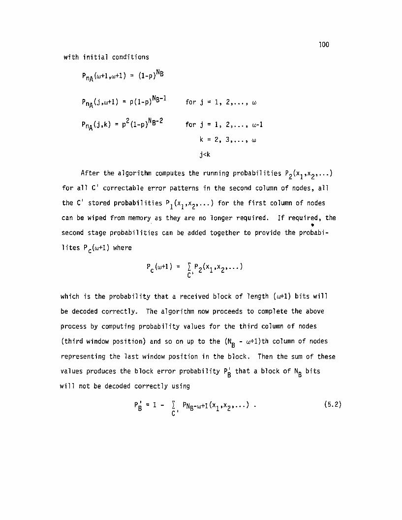
100
with initial conditions
PnA(j,w+l) = P(l_p)NB-l
PnA(j,k) = p2(1_p)NS-2
for j = 1, 2, ... , w
for j = 1, 2, ... , w-l
k=2,3, ... ,w
j<k
After the algorithm computes the running probabilities P2(x1,x2, ... )
for all C' correctable error patterns in the second column of nodes, all
the C' stored probabilities Pl(x1,x2, ... ) for the first column of nodes
can be wiped from memory as they are no longer required. If required, the•
second stage probabilities can be added together to provide the probabi-
lites Pc(w+l) where
which is the probability that a received block of length (w+l) bits will
be decoded correctly. The algorithm now proceeds to complete the above
process by computing probability values for the third column of nodes
(third window position) and so on up to the (NB - w+l)th column of nodes
representing the last window position in the block. Then the sum of these
values produces the block error probability Psthat a block of NB bits
will not be decoded correctly using
pi = 1 - L PNB-W+l(x1,x2, ... )SCi
(5.2)

101This provides a relatively simple method of computing exactly the bound
distance decoding block error probability Ps for any convolutional code
and associated decoder capable of correcting up to t errors in any con-
straint length of nA bits.
Figures 5.4 and 5.5 illustrate the trellis and associated calcula
tions for t=3 and t=4 correcting codes. A typical Fortran program used
to compute block-error probability (Ps) using the algorithm is listed in
Appendix B. In general, the computation requires two memory arrays of
maximum size (nA)t and approximately C' (NB-nA+l) computations.
In section 5.6 some computed results are provided for typical con
volutional codes. The above method appears to provide a general decoding
bound with wider application than the ARQ system analysis under study.
It also should provide an interesting means for making direct comparisons
between the decoding performance of block codes and convolutional codes
over the random BSC.
5.4 Combinatorial Approach to Ps Calculation
This section describes an alternative approach to computing a bound
distance decoder block error probability for convolutional codes. The
results provide a check on the trellis algorithm method of section 5.4.
Also they permit the estimation of block error probability for parameter
values of the code and its decoder where the trellis algorithm may prove
too time consuming. Methods for obtaining c"iosed form expressions for
enumerating the number N(j) of correctable error patterns of j errors in
a block of NB bits received at the input to an (n,k) convolutional code
decoder are presented. For each value of j, a difference equation

For computer program w+l =0
Pi(W.O.O) = p {Pi_1(O.O,O) + Pi_1(1.O.O)}
Pi(O,O,O) = (l-p) {Pi_l(O,O,O) + Pi_l(l,O,O)}
Pi(j·O,O) = (l-p) {Pi_1(j+l.O,O) + Pi_1(l,j+l,O)}j=1.2 •...•w-l.
i
--
~
·2 W°340350
·=L!i.°
·1 W°230240
Woo1 2 °1 3 °·
Error .Locations 1-1
°°° .. :::::::JJe1 °°2 °°
Figure 5.4
Trellis Diagram for t=3 Decoding
-'oN

··2 wOO
·w-2 wOOw-1 woo
1230·1 240
··1 2 w°13-4 0"
i-1 iPi(O,O,O,O) =.(l-p) {Pi_1(O,O,O,O) + Pi_1(l,O,O,O)}Pi(j,O,O,O) = (l-p)" {Pi_1(j+1,O,O,O) + Pi_1(l,j+1,O,O)}
j=1,2, .•. ,w-1
Note: °=w+1 for computer program
Fi gure 5.5
Trellis Diagram for t=4 Decoding ......ow

104
approach is used to find closed form expressions for N(j) for various
values of NB, nA, t and j.
In order to obtain values for block error probability Psfor a
convolutional code used in Type-II hybrid ARQ it is necessary to assume
the decoding type is known. As discussed previously, if we assume a
Majority logic decoding circuit will be used, then for a
J-orthogonalizable code, any pattern of t=LJ/2J or fewer errors in a
span of nA=n(m+1) positions can be corrected.
If we consider the 2k bit sequence made up of the information u and
C1 parity PI (u) then for a BSC with transmission error probability p
2k . 2k'Ps= 1 - L N(j) pJ(l_p) -J
j=O
where N(j) is the number of patterns of j bits in the 2k bit sequence
which can be corrected by C1. In general, N(j) will be a function of
the following
• the block length (2k)
• the code constraint length nA=n(m+1)
• the code error correction ability t.
(5.3)
Note that a majority logic decoder with feedback decoding may correct
some patterns with greater than t errors in a constraint length span so
Equation (5.3) provides a lower bound on PS'The approach used to evaluate N(j) is based on combinatorial enumera
tion techniques.
t = 1 Error Correcting Codes
Theorem 5.1. For single error t=l correcting codes, the number N(j)
of correctable patterns in an NB digit block is

and
(
NB - (j-l) (nA-l))N(j) =
j
= ENB - (j-l)(nA-l)]!j! [NS - (j-l)nA-l]!
r~ilPs= 1 - L: N(j) pj(l_p)NB-j
j=O
105
(5.4)
(5.5)
Proof. Consider j errors arranged in correctable patterns into the
NB digit block (represented by crosses in Figure 5.6(a)).
After each of the first j-l errors there must be at least nA-l error
free digits (positions in which error patterns are not allowed). There
are a total of (j-l)(nA-l) such positions. Therefore N(j) is the number
of ways in which j errors can be arranged to occur in NB-(j-l)(nA-l) bits.
The maximum number of errors that can conform to a correctable pat-
tern in the block is determined by considering how many constraint length
spans of length nA bits (each commencing with an error) can be accommo
dated in the block of NS bits. As shown in the Figure 5.6(b) it is
necessary to count those subblocks which span NB bits commencing at the
first position.
The last block to be counted is the one that begins within the NBbit block and ends with the NB
t h bit or beyond it. That is
the least integer greater than or equal to NB/nA· As a result PBfor t=l
is given by Equations (5.4) and (5.5). Note that the performance of the

(b) Typical Correctable Error PatternX represents an errorc-~ represents decoding constraint length (nA bits)
- --~~l:.::.Iio=-:I~L.:::lI..:...:I:..::l.=.l..::::l....=..I:~.=a.=;;;",.:;;;.",;:;,~.... - - - J
(a) Illustration of Procedure for Countingthe Maximum Number of Correctable Errors
Figure 5.6
Correctable Error Patterns for t=l Decoding
106

107code is independent of the actual decoding operation used providing the
decoder achieves the t-error correcting ability of the code. In that
sense it is a bound distance decoding perfonnance result.
t=2 Error-Correcting Codes
Consider the transmission of a binary data block of length NS bits
consisting of a segment of the output from a (2,1) convolutional encoder
using a code and associated decoder capable of correcting 2 errors in
any constraint length of nA bits.
Consider that the block has been transmitted through a random binary
symmetric channel with bit error rate p. Then the block error probabi
lity Psafter decoding can be determined by
•Ps= 1 - L N(j)pj(l_P)NS-j (5.6)
j=O,l, ...
where N(j) = the no. of patterns of j errors in the Ns-tuple which can
be corrected by the decoder.
Previously an expression for N(j) was found for a single error (t=l)
correcting code. The enumeration of N(j) for t=2 is a much more diffi
cult task. In general, N(j) can be represented by a polynomial in NB
of degree j.
The following enumerations of N(j) have been proven using difference
equations.
Theorem 5.2. For double error (t=2) correcting codes the number N(j)
of correctable error patterns of j errors in NB bits is given as follows:
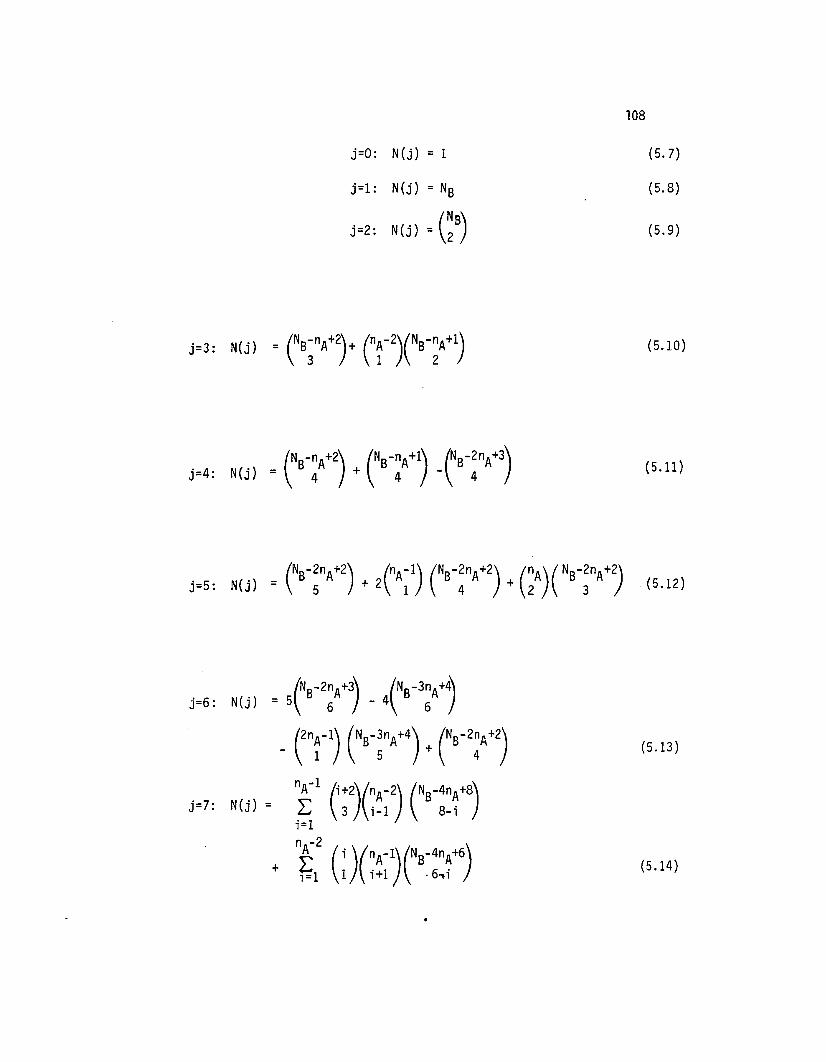
108
j=O: N(j) = 1 (5.7)
j=l : N(j) = NB (5.8)
j=2: N(j) = (~B) (5.9)
(5.10)
(5.11)
(5.12)
(5.13)
(5.14)

109
The above expressions for N(j) for j = 0, 1 and 2 are obvious since
all patterns are correctable for those values of j. The derivations of
the other expressions are discussed in Appendix C. A general expression
for all j values has not been found. However, the expressions found
so far provide a useful upper bound on Ps for typical values of block
length (Ns) and channel bit-error-rate (p). Also they have been found
in practice to provide an exact check on Psvalues computed by the
trellis algorithm of section 5.4 for parameter values such that
N(j)=O for j>7. This is true for relatively small block lengths.
Further details of computations are given in section 5.6. The
expressions given in Theorem 5.2 can be checked using Newton's back
ward differences formula as follows. Given a function f(x) the
collocation polynomial can be expressed in terms of the argument x at
values xo' xl' ... as
(5.15)
where f i = f(x i)
fa = f1-fo
and ~2f =6f - 6f010
For a polynomial f(x) of degree j there are j+l non-zero terms in the
equation requiring specification of f(x) at j+l points xo' xl' ... ' xj.
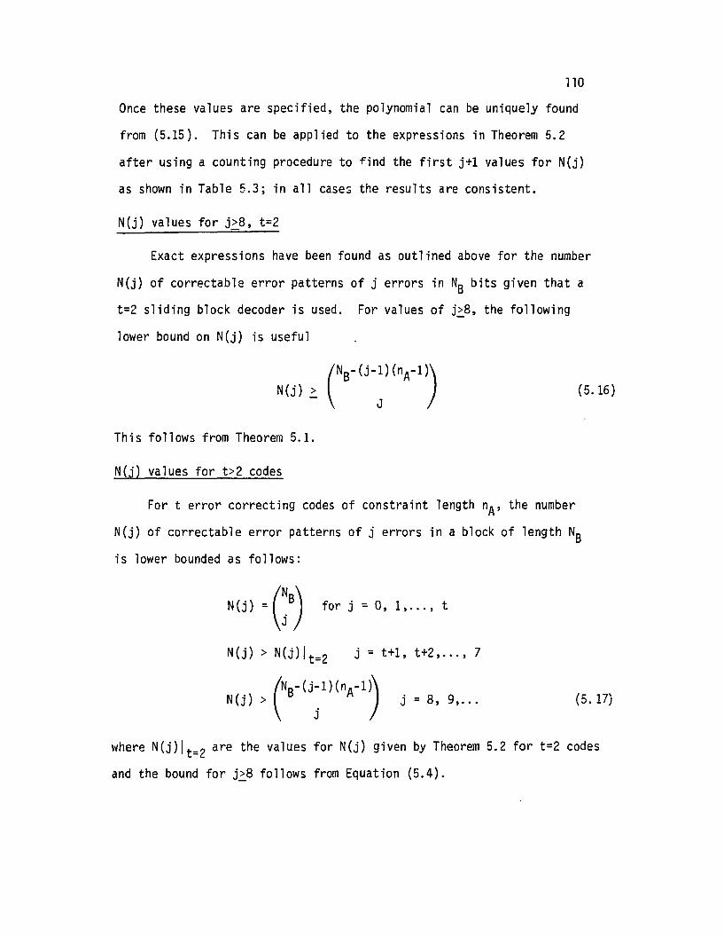
110
Once these values are specified, the polynomial can be uniquely found
from (5.15). This can be applied to the expressions in Theorem 5.2
after using a counting procedure to find the first j+l values for N(j)
as shown in Table 5.3; in all cases the results are consistent.
N(j) values for j>8, t=2
Exact expressions have been found as outlined above for the number
N(j) of correctable error patterns of j errors in NB bits given that a
t=2 sliding block decoder is used. For values of j~8, the following
lower bound on N(j) is useful
(5. 16)
This follows from Theorem 5.1.
N(j) values for t>2 codes
For t error correcting codes of constraint length nA, the number
N(j) of correctable error patterns of j errors in a block of length NBis lower bounded as follows:
N(J' ) = (NJ.B) for j = 0, 1, ... , t
N(j) > N(j)/t=2 j = t+1, t+2, ... , 7
. ~NB- (j-1) (nA-1) ._N(J) > J - 8, 9, ...
j(5. 17)
where N(j)l t=2 are the values for N(j) given by Theorem 5.2 for t=2 codes
and the bound for j~8 follows from Equation (5.4).

Table 5.3
Number of Correctable Error Patterns N(j.NB) of j Errors in NB Bits as a Function ofBlock Length NB and Constraint Length nA (t=2)
j=3 nA NB4 5 6 7 8 9 10 11 12 ...
3 2 7 16 30 50 77 112 ...4 3 10 22 40 65 98 1405 4 13 28 50 80 1196 5 16 34 60 95 140· .··
N(3.NB) values
j=4 nA NB4 5 6 7 8 9 10 11 12 13 14 ...
3 0 1 6 19 45 90 266 ...4 1 6 20 49 100 181 3015 1 6 20 50 104 191 3216 1 6 20 50 105 195 331· .· .· .
N(4.NB) values
j=5 nA NB4 5 6 7 8 9 10 11 12 13 14 15 16 17 18 ...
3 0 3 16 51 126 266 5044 0 6 30 91 216 441 8125 0 10 48 141 326 65 11766 0 15 70 201 456 896 1596· .· .· .
N(5.NB) values
--'--'--'

j=6
Table 5.3 (continued)
nA NB4 5 6 7 B 9 10 11 12 13 14 15 16 17 18 19 20 ...
3 0 1 10 45 141 357 784 1554 ...4 0 1 10 50 168 444 100 20165 0 1 10 50 176 481 1118 23036 0 1 10 50 175 490 1165 2450· .· .· .
N{6,N B) values
j=7 nA10
NB144 5 6 7 8 9 11 12 13 15 16 17 18 19 20 21 21 ...
3 0 4 30 126 393 1016 2304 4740 ...4 0 10 70 280 840 210 4628 92765 0 20 133 512 1486 3610 7750 15184· .· .· .
N{7,NB)values
--'--'N

1135.5 Computed Block Error Probability (Ps) values
Fortran programs based on the trellis algorithm of section .5.4 have
been used to compute exact values for the block error probability (Ps)for bound-distance (sliding block or syndrome-feedback) decoding.
Table 5.4 lists Ps values versus bit-error-rate before decoding for
selected 1/2 rate codes referred to in section 5.3. Values are given
in the table for "block" lengths NB of 1024 and 2000 bits respectively.
As pointed out in section 2.1 it is assumed that the last m information
bits are zero to clear the encoder for the last m parity bits in the
"block" (where m is the memory order of the code). Figure 5.7 shows
plots of Ps versus BER for selected codes for "block" sizes NB = 2000 bits.
It should be noted that Table 5.4 can be used to find Psvalues for
other values of NB with good accuracy for NB>100 bits. This can be found
using the P(N./N. 1) values given in the Table. Recall that the iteration1 1-
procedure computes Psfor a given block length, say Ni_1 bits. Then the
constraint length decoding window is moved forward one bit and a new value
of Ps is computed for block length of Ni bits and so on. Let
1· PBI(N,)-PB'(N. 1)( ) tm 1 1-
Poo Ni-Ni_1 = NB~ 1-PS(N i_
1)
where PS(N i)and ?S(N i-1)
= the Psvalue for block length of Ni= the Psvalue for block length of Ni-l.
Now P(N./N. l)=Pr {the block is not correctly decodable at length1 1-
Ni given that it was decodable at length Ni _1} i.e.
(5.18)
It has been found from the computatinns performed so far that, for the
codes examined, the ratio

Table 5.4
Block Error Rate Values versus BER for SelectedConvolutional Codes
114
t=l !'1A=4 Block Error Rate PBBER NB=100 NB=1024 NB=2000 P(N./N. 1)
1 1-
.1 .8911 1.0000 1.0000 .022056
.03 .2136 .91618 .9930 .0024006
.01 .2819x10-1 .25569 .44616 .2886x10-3
.003 .2639x10-2 .02693 .5315x10-1 .26681x10-4
.001 . 2958x10-3 .00305 .6098x10-2 .2988x10-5
.0003 . 2670x10-4 .2758x10-3 .5519x10-3 .26968x10-6
.0001 . 2969x10-5 .3068x10-4 .6138x10-4 .29988x10-7
.00001 .2970x10-7 .3069x10-6 .6141x10-6 -9.29999x10
.000001 . 2970x10-9 .3069xlO-8 .6141x10-8 .3x10-11
t=2 nA=lO Block Error Rate PBBER NB=100 NB=1024 NB=2000 P(N./N. 1)
1 1-
.1 .7462 1.0000
.03 .6497x10-1 .5167
.01 .3032x10-2 .3248x10-1 .6268x10-1 .3245x10-4
.003 .8801x10-4 .9582x10-3 . 1877x10-2 -6.9427x10
.001 . 3326x10-5 .7106x10-4 .3563x10-7
.0003 .9045x10-7 .1932x10-5 -9.9690x10
.0001 .3357x10-8 .7172x10-7 .3596x10-1O
.00001 .3688x10-11
.000001
•

Table 5.4 (continued)
t=2 nA=6PB Values
BER N =2000 P(N./N. 1)B 1 1-
.1
.03
.01 .1881x10-1 .9510x10-5
.003 .5310x10-3 .2660x10-6
.001 .1987x10-4 . 9950x10-8
.0003 . 5384x10-6 . 2696x10-9
.0001 .1996x10-7 .9995xlO-1
115

116
Throughput
n
1O-6+---L ..&.----L .L---'- L....-....J-__"--"~
10-1
10-1Block Length NB=2000 bits
t=l nA=4t=2 nA=12
10-2 t=2 nA=lOco
0.. t=2 nA=6~or- t=3 nA=lOr-or-..cta
..c0s;
10-30..
s,0s,s,
UJ
~
U0r-ca
10-4
Bit Error Rate
Figure 5.7
Block Error Rate After Sliding BlockDecoding for Various Convolutional Codes

117
becomes constant to within approximately 12 significant figures for NBvalues greater than 100 bits. Therefore it is possible to use the
P(N./N. 1) values from Table 5.4 to find PB for any block length greater1 1-
than 100 bits using a simple iteration procedure. This can be used to
considerably reduce the computation time required to find PB for large
block lengths.
The "b lock" error rate values for selected convolutional codes shown
in Figure 5.7 indicate the performance expected for a sliding block
decoding scheme such as Threshold Decoding using Orthogonalizable codes.
The best t=2 orthogalizable code has nA=12 (refer section 5.3). Such a
decoding procedure is simple to implement. However the performance is
inferior to either the Viterbi decoder or a Sequential Decoder so the
results in Figure 5.7 provide upper bounds on the IIblock ll error proba-
bility for these more efficient decoders.
It is believed that IIblock ll error rates after decoding have not
previously been available for any of the above classes of decoders.
5.6 Comparisons between Convolutional and Block Code Performance
The calculations of block-error-rate (PB) after decoding for selected
convolutional codes as described in the previous section seem to offer
a new means of comparing convolutional code and block code performance
for rate 1/2 and 1/3 codes with comparable block sizes on the random BSe.
For (n,k) block codes on the random BSe, an upper bound on block
error probability PB is given by (Viterbi and Omura [38J)

n
L:j=(d . +1)/2mln
n
~l j=d~/2dmin even
118
(5.19)
For "perfect" codes, such as the Hamming codes or the Golay code, the
above expressions are exact.
A comparison of block code versus convolutional code performance is
indicated in Figure 5.8 for NS=2000 bits. Values of t=5 and 10 are
shown for block codes using Equation (5.25) with
d. = 2t + 1mln
The results show that for bit-error rates greater than 10-3 before
decoding, the orthogonalizable convolutional code with :;hreshold decoding
could be expected to provide superior performance. It will be shown in
Section 7 that this might provide superior throughput performance in a
Type-II hybrid ARQ system over the results obtained using block codes
for forward error correction, assuming comparable decoder complexity.

119Throughput
n <,
-,\\
10-1 \
\
Convolutional Code\ t=2 n =12
10-2A
co \ Block Codec,
~t=lO "n=2000
.... \ Block Code,........ t=5 n=2000..cto \..c0 10-3s,c,
s, ~0s,s,
l.LJ
~
U0 \,....
10- 4co
\
\
\)0- 5
\
\
10- 6 \I I ..
10-1 10-2 10-3 1O~4 BER
Figure 5.8
One-Half Rate Block Codes Versus Convolutional Codes- Block Error Rate Versus Precoder BER

120
6. RELATED R =1/2 and R =1/3 ORTHOGONALIZABLE CODES
6.1 Introduction
The alternate data-parity hybrid ARQ scheme described in section 3.2
can be seen to perform in an error correction/retransmission mode which
in a sense is adaptive. That is, when the channel is error-free a high
rate code Co is used for error detection only. When channel errors
occur, a half-rate code C1 is introduced by way of a parity block
retransmission to attempt to correct the errors. If this is successful
then the number of retransmissions of blocks may be drastically reduced
so improving the throughput and minimizing delays.
It is also interesting to conjecture whether the adaptive character
istics of the above retransmission scheme could be improved upon. Consider
the case when the channel error characteristics are so bad that the
information cannot be recovered even after the first two transmission
attempts (data and parity types of transmissions respectively) and error
correction procedures based on a half-rate code have failed. An even
more powerful error correcting code namely a (3, 1) code may possibly
be applied to this situation by sending k extra parity bits in the third
transmission attempt so that the receiver can use the k information bits
and 2 k parity bits to attempt to correct all errors. This procedure will
only be feasible if codes with appropriate structure can be found.
As described in section 4.5, one possibility might be to look for a
class of related code pairs such that any related pair of codes C1 and C2have the following properties:

•
121
• C1 is a R = 1/2 convolutional code with generator polynomials
g(I)(x) =1 and g(2)(x).
and • C2 is a R =1/3 convolutional code with generator polynomials
g(I)(x) =1, g(2)(xj and g(3)(x) where g(I)(x) and g(2)(x)
generate C1.
In this chapter it is shown that new convolutional codes can be found
which satisfy those requirements. These codes provide related pairs of
(2, 1) and (3, 1) codes which are orthogonalizable. Since threshold
decoding is therefore possible, these codes may have desirable benefits
for use in type-II hybrid ARQ where decoder simplicity seems highly
desirable.
A retransmission scheme using related (2, 1) and (3, 1) codes is
described in Section 4.5. The sequence of transmissions of a given block
assuming the information is not recoverable without error after two
transmissions is as follows:
• Initial transmission (information) {u, Po(u)}
• Second transmission (2, 1) parity {P1(u), Po(P1(u))}• Third transmission (3, 1) parity {P2(u), Po(P2(u))}
The k bits P1(u) are found by encoding the information u with the
(2, 1) code C1. Let
Then assuming that u is encoded with a systematic (2, 1) code C1 we
obtain the code word
Y = (y(l) y(2) y(l) y(2) y(l) y(2) )200 '1 1 '22 , ... (6.1 )

122
where the information bits are
and the parity bits sent in the second transmission attempt are
(6.2)
Likewise after encoding the information with a (3, 1) systematic
code C2 we obtain the code word
Y(l ) y(2) y(3)'2 2 2 )
(6.3)
from which the parity bits P2(u) for the third transmission attempt are
(6.4)
Now the codes Cl and C2 must be related in such a way that the parity
bits Pl(u) from equation (6.2) are the same as the parity bits
y~2) y~2) y~2) ... from equation (6.3). Providing such codes can
be found then after the third transmission atte~pt, the receiver can
combine the 3k bits u, Pl(u) and P2(u) in a form similar to equation
(6.3) for decoding in an attempt to correct all errors. (It should be
noted that although for clarity it has been assumed in the above that
Cl and C2 are systematic, this restriction is not strictly necessary).
A description of procedures we have developed for designing appro
priate codes follows and related code pairs are tabulated for various
degrees of error correcting capability based on best known orthogonalizable
codes found by Massey [42]. At this stage procedures for finding related
(2, 1)(3, 1) code pairs for convolutional code classes other than the
orthogonalizable codes have not been found.

123
Practical aspects of encoder and decoder hardware are also discussed
to demonstrate that the proposed (2, 1)(3, 1) parity retransmission scheme
is not excessively complex to implement.
6.2. New orthogonalizable code design
6.2.1 Notation
In order to describe the procedures used to find related (2, 1)
(3, 1) code pairs, it is necessary to first summarize the notation
used. Typical encoders for (2, 1) and (3, 1) convol~tional codes
respectively are shown in figure 6.1. In each case the information
sequence enters the encoder one bit at a time. For the (2, 1) encoder
the output sequences are
Y( l )
, 1 Y( l )
, 2 , ... ) and y(2) = (y~2) Y(2)
, 1 Y(2)
, 2 ...)
obtained as the convolution of the input sequence u with the two encoder
impulse responses g(l) and g(2) more commonly known as the code generator
sequences. In polynomial form the encoding equations are conventionally
written [2]
y(l)(X) = u(X) g(l)(X)
y(2)(X) = u(X) g(2)(X)
For the (2, 1) encoder in figure 6.1 we have
g(l)(X) = 1 and g(2)(X) = 1 + X2 + X3 + X4 + X6
where the memory order (m) of the code is the highest degree of the g(2)(X)
polynomial.
It is convenient to describe convolutional codes in a more abbreviated
form by expressing the generator sequences in octal notation. For the above
(2, 1) code example, the generator sequences

U. --1.....__.------------------01
a. (2, 1) encoder
b. (3, 1) encoder
Fi gure 6. i
Typical Convolutional Encoders
124

125
g(i) = (g~i) g~i) g~i) g~i)) are
g(l) = (1000000) and g(2) = (1011101)
When expressed in octal form g(2) becomes (135)2. An alternative
notation used by Massey [42] for threshold decodab1e codes denotes the
generator polynomials in terms of the positions of the non-zero elements.
In Massey's notation the above (2, 1) code would be represented by (02346)2.
In similar manner for a (3, 1) systematic code, the generators g(2) and g(3)
specify the code. For example, the code represented in figure 6.1.(b) is
described using Massey notation in the form (0, 1, 7)2 (0 2 346)3. It is
also noted that one advantage of systematic codes is that they are always
non-catastrophic; actually the majority of non-systematic (n, 1) codes are
also non-catastrophic so it is not difficult to find codes for which error
propagation can be avoided.
The minimum free distance measure df ree for convolutional codes is a
most important distance measure [2] defined
dfree = min {d(y', y"): UI~U"} (6.5)
where u' and u" are the information sequences corresponding to the code
words y' and y" respectively. Tables of (2, 1) and (3, 1) codes with
maximum df ree have been found for different memory orders m by computer
search and are available in reference [2]. It should be noted that the
systematic code dfree values are less than or equal to those of non
systematic codes with a given rate and constraint length. For a (2, 1)
(3, 1) parity retransmission ARQ application, non-systematic codes could
possibly be used and provide better error-correction performances. However
an inverting circuit would be required at the receiver to recover the input
data from the first received sequence if recovered without detectable error.
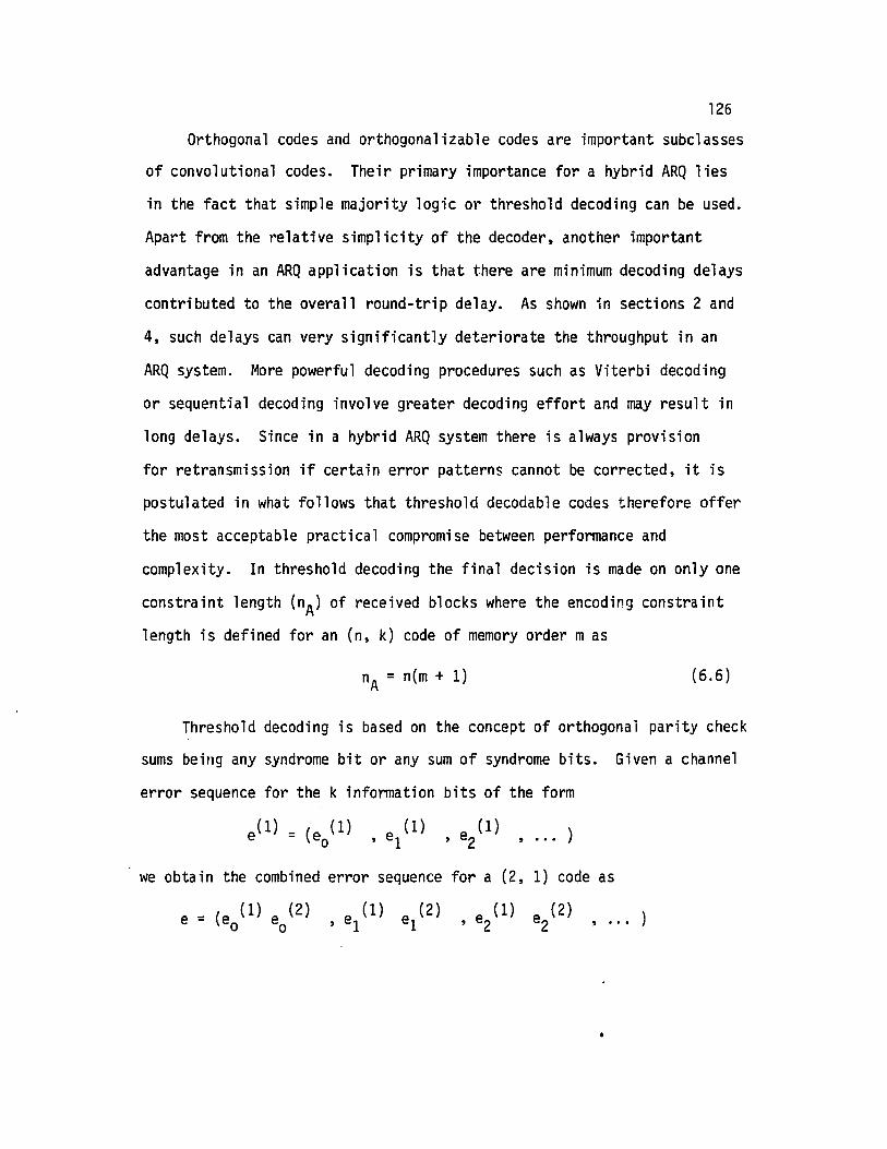
126
Orthogonal codes and orthogona1izab1e codes are important subclasses
of convolutional codes. Their primary importance for a hybrid ARQ lies
in the fact that simple majority logic or threshold decoding can be used.
Apart from the relative simplicity of the decoder, another important
advantage in an ARQ application is that there are minimum decoding delays
contributed to the overall round-trip delay. As shown in sections 2 and
4, such delays can very significantly deteriorate the throughput in an
ARQ system. More powerful decoding procedures such as Viterbi decoding
or sequential decoding involve greater decoding effort and may result in
long delays. Since in a hybrid ARQ system there is always provision
for retransmission if certain error patterns cannot be corrected, it is
postulated in what follows that threshold decodab1e codes therefore offer
the most acceptable practical compromise between performance and
complexity. In threshold decoding the final decision is made on only one
constraint length (nA) of received blocks where the encoding constraint
length is defined for an (n, k) code of memory order mas
nA = n(m + 1) (6.6)
Threshold decoding is based on the concept of orthogonal parity check
sums being any syndrome bit or any sum of syndrome bits. Given a channel
error sequence for the k information bits of the form
we obtain the combined error sequence for a (2, 1) code as
e = (e (1) e (2)o 0
e (1) e (2), 1 1 e (1) e (2)
, 2 2 , ...
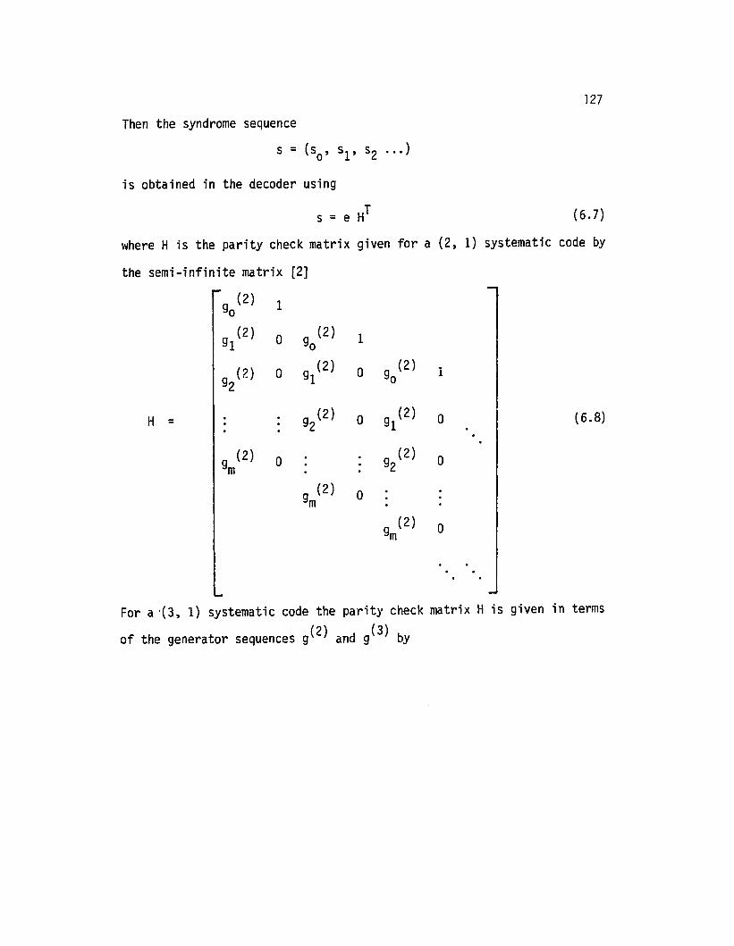
127
Then the syndrome sequence
s = (so' sl' s2 ... )
is obtained in the decoder usin9
(6.7)
where H is the parity check matrix given for a (2, 1) systematic code by
the semi-infinite matrix [2]
(2) 1go
(2)0 9 (2) 191 0
g2(2) 0 91(2) 0 9 (2) 10
H = 92(2) 0 91 (2)
9 (2) 0 92(2)m
9 (2) 0mg (2)m
o
o
o
(6.8)
For a '(3, 1) systematic code the parity check matrix H is given in terms
of the generator sequences 9(2) and g(3) by

128
(2) 190
9 (3) 0 10
91(2) 0 0(2) 190
91(3) 0 9 (3) 0 10
(2) 91 (2) 0 0(2)
92 90
H = (6.9)
92(3) (3 ) 0 9 (3)91 0
9 (2)m
9 (3) 0m
o
9 (2)m
9 (3) 0m
o

129
6.2.2. Design of related code pairs
Orthogona1izab1e codes have been found by Massey [42] using a trial
and error approach. A set of J check sums orthogonal on an error bit
ei is required such that
• each check sum checks ei, but
• no other error bit is checked by more than one check sum.
In the case of orthogona1izab1e codes, some of the orthogonal parity
checks are formed from sums of syndrome bits. (By contrast, for se1f
orthogonal codes, the parity checks used are individual syndrome bit checks.)
A t-error correcting code is one for which the error bits checked by the
J orthogonal check sums contain t or fewer errors with t = LJ/2J.
Consider a (2, 1) code of memory order m2 generated by
Consider also a (3, 1) code of memory order m3 with m3 ~ m2 generated by
g(2) = (g (2) g (2) g (2) )o ' 1 ' 2 ...
and
g(3) = (g (3) 9 (3) 9 (3) )o ' 1 '2 ...
then we seek related (2, 1) and (3, 1) code pairs for hybrid ARQ for which
9 = 9 (i)o 0
for i = 2 or 3.
9., 9 (t )
1 - 1 gm2
(6.10)

l~
Both codes must be self-orthogonal or orthogonalizable so that a
common majority logic decoder circuit can be used. New related
orthogonalizable code pairs have been found by considering optimum (3, 1)
orthogonalizable codes from Massey [42] and finding related orthogonalizable
(2, 1) codes for each. It has not been found possible to find related
pairs of self-orthogonal codes using parity-triangle design procedures
[2] although these were investigated.
The procedure used to find orthogonalizable related (2, 1) codes
was based on an exhaustive trial-and-error analysis of the parity check
matrix for each optimum (3, 1) code. This has been achieved for (3, 1)
codes with t-error correcting ability of t = 1, 2, 3, ..• ,8. To
illustrate the method, consider the optimum (3, 1) orthogonalizable code
with t = 4. It is the code described above by generators given in Massey
notation by
(0 1 7)2 =(1 1 0 0 0 0 0 1)
and (0 2 3 4 6)3 = (1 0 1 1 1 0 1 0)
for which the encoder is shown in figure 6.1. The parity ~heck matrix
for this code follows from (6.9) as

131
1 1
1 0
1 0 0 1
0 0 0 1
0 0 0 1 1
1 0 0 1 0 1
0 a 1 0 0.
1 0 . 0 1 0 1
0 a 0 0 0 1 1
H = 1 0 0 a (6.11)
a a 0 0 1 0
0 1 1 1 0
0 0 0 0
1 0 1
0 0 0 0 a
a 1
0 0 a 0
aa 0 0
o 0
where zeros are assumed unless otherwise stated.

132
Now two parity check matrices are studied. Both have the form of
Equation (6.8) for a (2,1) code. In one case the first column is that
represented by the generator (0 1 7)2, in the other case by the other
generator (0 2 3 4 6)3. For each case, a search is made for the maximum
number of check sums and sums of check sums which are orthogonal on the
first error bit (a 1 in the first column). In this example, the best
code was based on the generator (0 2 3 4 6)3 for which the parity check
matrix for the (2, 1) code is given by
(so) 1
I \ 0,. 1\51) \J
(s2) 1 0 0 0 1 1
(s3) 1 0 1 0 0 0 1
H = (s4) 1 0 1 0 1 0 a 0 1 1
(s5) 0 a 0 1 0 0 0 0
(56) 1 a 0 0 1 0 0 1 0 a a 1
(57) 0 0 0 0 0 0 1 0 1 0 0 a 1
(s8) 0 0 0 0 1 0 a 0 1 0 1 a 0 a 0 1 1
(6.12)where the symbols (s ) and (s1), ... (s8) are not to be included but
0
are shown in parenthesis for assistance in the exposition. Note
that only the first nine rows (check sums so' s1, ..• s8) are shown.because this is the maximum number for which orthogonal check sums could
be found. The orthogonal check sums are so' 52' 53 and (5,+54+58)

133
respectively providing a t=2 error correcting (2, 1) code with effective
constraint length nE
= 18 bits. That is the (2, 1) code is capable of
correcting up to 2 errors in an effective constraint length of 18 bits.
The check sums follow as
s = e (1) + e (2)o 0 0
+ e (1) + e (2)2 2
+ e (1) + e (1) + e (2)1 3 3
s2 = eo(1)
s = e (1)3 0
s +s +s = e (1)1 4 8 0
+e (2)1
+ e (2)4
+e (1) + e (1) +e (1) + e (1) + e (2)56788
(6.13)
Similar procedures were used for all other optimum orthogonalizab1e
(3, 1) codes for t=1 to 8. The results are given in Table 6.1 which
lists the generator for the (2, 1) codes found by the above procedure as
well as the rules for forming their orthogonal checks.

Table 6.1
Related Orthogona1izab1e Code PairsBest
New Orthogona1izab1e--Pair (2.1) Codes Ortho~ona1izab1e Massey's Orthogona1izab1e (3.1) Codes(2,1 Code fornE Rules for Forming
Comparisonn nEt - Gen r Sequence Check Sums t ..!. t - Generator Sequencesn n n1 2 (0,1)2 (0)(1) 1 2 2 3 (0,1)2(0,2)3
2 8 2 (0)(2)(1,3)(4,5,7) 3 2 3(0,2,3,4) 2 6 5 (0,1) (0,2,3,4,)
2 9 2 (0)(2)(3)( 1,4,8) 4 2 3(0,2,3,4,6) 2 6 8 (0,1,7) (0,2,3,4,6)
2 15 2 5 (O,l,9)2(O,l,2,3,5,8,9f(0,1,2,3~5,8,9) (0)(1)(5)(2,3,8,14) 2 6 11
2 7 2 (0)(4)(5)(1,6)(0,4,5,6)2 6 6 18 2or- (0,4,5,6,7,9,12,13,16)
(0,1,14,15,16)3
3 28 (0,4,5,6,7~9, (0)(4)(5)(16) 3 1212,13,16,) (2,9,20,21)(7,10,11,27)
2 7 2 (0)( 4)(5)( 1,6) 2 6 7 23 2(0,4,5,6) (O,4,5,6,7,j,12,13,16,19,20,21)(0,1,20,22)
2 7 2 (0)(4)(5)(1,6) 2 8 2(0,4,5,6) 6 36 (0,4,5,6,7,9,12,16,17,30,31)3or (0,1,22,25,35)
3 22 (0,4,5,6,7,9, (0)(4)(5)( 1,6) 3 1212,16,17)2 (2,9,21)(7,10,11)
-'w.p.

135Also shown in Table 6.1 for comparison are the optimum orthogona1izab1e
(2,1) codes from Massey [49]. It can be seen that the new (2,1) codes
found for related pairs are not as powerful as the optimum (2,1) codes.
However they do provide a means for implementing the adaptive
(2,1}(3,1) parity retransmission hybrid ARQ scheme.
6.3 Encoding and Decoding
We consider now typical encoder and decoder configurations for the
related half-rate and one-third rate codes. A typical encoder was
illustrated in Fig. 6.1(b}. It can be used to encode the related
orthogonalizab1e code pair given in Table 6.1 as follows
(2,1) code
(3,1) code
Generator (O,2,3,4,6}2
2 3Generator (O,l,?) (O,2,3,4,6)
Recall from section 6.1 that both codes are systematic. In a hybrid ARQ
system using these codes, the first block transmitted is a data block
{u,Po(u}}. The k bits u are available at the output terminal y~l) in
Fig. 6.l(a} and (b). The last m bits are taken to be zeros (m being the
code memory order). Then u must be encoded with a high-rate block code
Co to 'produce the n-k parity bits Po(u) for error detection.
The receiver computes the syndrome for the received data block~ ~
{u,Po(u}}. If it is non-zero, a NAK is sent back to the transmitter. The
transmitter then sends the parity block {Pl(u},Po(Pl(u}}}. The k bits
Pl(u} are obtained at, the output terminal marked y~3}, having been held
in the transmitter buffer until required. As before the k-n parity bits
Po(Pl(u}} are obtained by encoding Pl(u) with the high rate block code
Co' The 2k bits u and Pl(u} constitute a half-rate code word.

136
Corrected Data
uReceived Data
u
To A To BA FeedbackI---------I-----~I
-----.(+ + +.P2(u) s , (2) IRecei ved Pari ty 1 .
I,
II
B (1)si
~
P1(u)
Received Parity
Code Generators: C1 (02346)2C2 (017)2 (02346)2
sl+ s4+s8
Switching(2,1) (3,1)
Figure 6.2
Threshold Decoder for (2,1) Code C1or Related (3.1) Code C~c:

137The receiver attempts to recover the data error-free from the
received data and parity blocks as discussed in section 3.3. If this
is unsuccessful a NAK is again sent back to the transmitter. The trans-
mitter next sends the parity block {P2(u)Po(P2(u))} where P2(u) is
obtained from the terminal marked y~2) in Fig. 6.1(b). The 3k bits
u,Pl(u) and P2(u) constitute a one-third-rate code word with greater
error correcting capability. Should the receiver fail to recover the
data estimate u without detectable errors, the transmitter repeats the
data block {u,Po(u)}. When {u'~o(u)} is received, it is used together
with Pl(u) and P2(u) to recover U. The process continues until u is
recovered. When this has occurred the transmitter clears its encoder
and prepares for the next data block to be encoded.
It is also possible to use a single decoder circuit to decode the
half-rate and one-third-rate code words respectively. Figure 6.2 shows
a decoder suitable for decoding the (2,1) and (3,1) codes just described.
In order to explain its operation we consider first a conventional
threshold decoder for an (n,l) code of memory order m. The conventional
threshold feedback decoder (see for example reference [2]) first computesA
the sy~drome. This is done by passing the first m received data bits u
through an encoder circuit. The parity bits thus generated are added
modulo-2 to the received parity bits to produce the n-l syndrome
sequences, one corresponding to each parity error sequence. Each syndrome
sequence corresponding to one constraint length consists of m+l bits.
Next the decoder forms a set of orthogonal check sums on the first infor-
mation error bit. The set of check sums is formed from the syndrome bits
calculated above. Table 6.1 lists the check sums required for each of
•

138
the new (2,1) codes. The set of check sums is fed into a threshold gate
which produces an output of "1" if and only if more than one half of its
inputs a "lI SII. If this occurs the first data bit is assumed incorrect.
It is corrected by adding the output of the threshold gate to the first
received bit. The output of each threshold gate is also fed back and
subtracted from each syndrome it affects. The first estimated informa
tion bit is then shifted out of the encoder. The syndrome registers
are shifted one to the right. The next block of n received bits is
shifted into the decoder, and the process of computing the next set of
n-l syndrome bits is continued as explained above. They are then shifted
into the n-l left most stages of the syndrome registers wh1ch then hold
modified syndromes along with the new set of syndrome b~ts. The decoder
again uses the threshold decision procedures to estimate whether an error
has occurred in the second information bit. The process continues until
all information bits are decoded.
We now consider how the above procedure can be executed for either
the (2,1) code or the (3,1) code using the common circuit of Fig. 6.2.A A A
If the receiver wishes to decode u using the (2,1) code bits u and Pl(u)
the switches in Fig. 6.2 are left as shown. For the code with generator
(0,2,3,4,6)2, the check sums to be formed were specified in equation (6.13).
These four check sums are so' s2' s3 and (sl+s4+58) respectively. They
are shown in Fig. 6.2. A given information bit is assumed in error if the
threshold gate finds 3 or 4 of these are 111 S" and decoding proceeds are
described above. This code can correct up to 2 errors in a constraint
length of 18 bits. Methods for detecting whether u is decoded without
detectable errors are described in chapter 7.

139-If the receiver does not recover u successfully from Q and ~l(u},
the transmitter sends the additional parity bits P2(u}. As described,
~,Pl(u} and P2(u} constitute a (3,1) code word. The receiver is assumed
to hold Uand ~l(u} in a buffer until the data estimate u is recovered
successfully. The decoder in Fig. 6.2 is then cleared and the switches
changed over to the opposite positions to those shown. The new check
sums required for decoding were specified by Massey 49. They are
S( l } s(2} s(l) s(2) (s(2)+ s(2}} (s(l)+ s(2}} s(l} (s(l)+ s(l}0'0'1'2' 1 3' 24 '7' 35
+ s~l}+ s~2}}. This code can correct up to 4 errors in a constraint
length of 24 bits. As can be seen in Fig. 6.2 these check sums are
applied to the threshold gate. An error is assumed detected if more than
4 are found to be 1I1'sll. The decoder proceeds as described above.
The decoder illustrated in Fig. 6.2 is a relatively simple circuit.
It clearly illustrates the ease with which threshold decoding can be
accomplished. The decoder illustrated in Fig. 6.2 is a feedback decoder.
Past estimates of information bits are fed back and used to modify the
syndrome. If feedback is not used, the process is referred to as 'definite'
decoding. Feedback decoders can give rise to an error propagation
effect ·[2]. This may be undesirable in FEe systems without ARQ retrans-
mission facilities. However in an ARQ system, retransmission is requested
if one or more decoding errors occur. Therefore error propagation is not a
disadvantage. On the other hand definite decoding eliminates error
propagation but weakens the error-correction properties of the code. The
effective constraint length is always increased [2]. Also for codes
which are not self-orthogonal, the majority-logic error correcting capabil
ity t of the code may be reduced. In a Type-II hybrid ARQ system definite
decoding would reduce the throughput and is therefore undesirable.

140
7. PERFORMANCE OF HYBRID ARQ SCHEMES
7.1 Introduction
Expressions giving throughput efficiency for various ARQ protocols
in conjunction with hybrid schemes were derived in Chapter 4. Through
put was shown to be a function of channel bit error rate (p) and round
trip delay (5). For hybrid ARQ schemes, an additional effect on through
put was expressed in terms of probabilities (Ql,q2... ) that indicate the
effectiveness of the forward-error correction procedures being used.
For convenience, these probabilities are redefined here:
• ql is the conditional probability that a message u is recovered
successfully after the first retransmission given that errors
were detected in the initial transmission. (For a Type-II alter
nate data/parity hybrid scheme as described in section 3.2, ql
expresses the probabi 1ity that u will be recovered either by an
inversion process that is, no errors in the parity retransmission,
or by error correction decoding using a half-rate error correction
·code.)
• q2 is the. conditional probability that a message u is successfully
recovered from the third transmission (second retransmission)
given that u was not recovered without error after the first and
second transmission attempt of a given message (or its 1/2 rate
parity equivalent.)
For some hybrid schemes, it may be useful to define further prob
abilities Q3' Q4'··· in similar mode to the above. This would

141
apply for example to the alternate data/parity scheme referred
to in section 3.2 for which
ql # q2 # q3···
Let P(Ci/E1E2 ... Ei_l} represent the probability of recovering the
message u after the i t h transmission attempt (including data and parity
transmissions) given that uncorrectable errors remained after transmis-
sions 1, 2, ... ,i-l.
Then this can be related to the various error detection/correction
ARQ schemes described in sections 3 and 4 as follows:
• Alternate data/parity scheme (section 3.2)
i = 1
i=2,3, ...P(Ci/E1E2 ... Ei_l} = ~l - PB
{ qi
• Inferior data/parity scheme (section 3.4)
(7.l)
(7.2)
(7.3)
~l - PB i = 1, 4, 7, .
P(C;lE1E2... Ei_l} = ql i = 2, 5, 8, .
q2 i = 3,6, 9, .
• 1/2, 1/3 parity retransmission scheme (section 3.3)
~( l - PB) ~: 1, 4, 7, .
P(C;lE1E2... Ei_l} ql 1 - 2,5, 8, .
q2 i = 3, 6, 9, .
We now proceed to examine methods for evaluating the conditional
probabilities ql and q2 for different cases. The evaluation of q3' q4
etc. appears too complex for hybrid ARQ schemes of interest to warrant
the extensive work involved.

142The parameters ql and q2 will depend on the nature of the forward-
error correction coding procedures being used. Evaluations for block
codes will be compared with those using convolutional codes. This then
will permit evaluation of throughput efficiency for a large class of ARQ
systems. It has been explained previously that for convenient perfor
mance analysis, any ARQ system description should comprise a particular
combination of selected
• ARQ retransmission protocol
(e.g. Go-Back-N, SR + ST, SR + GBN, etc.)
• error detection/recovery scheme
(e.g. alternate data/parity retransmission, 1/2 1/3 parity
retransmission etc.)
• forward-error correction coding/decoding procedure
(e.g. (2000,1000) block code with 10 error correcting decoder,
(2,1) convolutional code with sliding block decoding, etc.)
7.2 Conditional Probabilities ql and q2 for block codes
Consider first a Type-II hybrid scheme in which a halt-rate block
code is used. The first transmission (the "information transmission")
{u,Po(u)} consists of k information bits plus n-k parity bits based on
an (n,k) high rate block code Co to be used for error detection only. If
errors are detected in the first received block, then the second transmis-
sion attempt (the "parity transmission") {Pl(u), Po(Pl(u))} consists of
n parity bits. The first k bits P1(u) are the parity bits generated by
a half-rate block code C, designed for error correction. The other n-k
bits Po(P1(u)) are generated by encoding P1(u) with code Co for error
detection.

143
On receipt of the parity transmission the receiver computes the
syndrome using code Co' If the syndrome is non-zero, errors are detected.
The receiver then attempts to correct the errors in the combined 2k bit
vector {U,Pl(u)} where u and Pl(u) are the received information and code
Cl parity respectively. It is assumed that a t-error correction decoder
is used. It should be noted here that practical considerations in respect
of decoder complexity may dictate that the decoder t parameter may be con
siderably less than the maximum error-correcting capability of the code.
For example a (1000,500) shortened BCH code is available which is capable
of correcting up to 50 errors. However the following analysis takes into
account the likelihood that a decoder with t-error correcting ability of
the order of 10 or less would be used. The parameter ql represents the
conditional probability of recovering the data u at this stage either by"-
inversion of Pl(u) if error-free or by correcting errors in {u,Pl(u)}.
Should the decoder fail to correct the errors, then the next trans-
mission of that block would be a repeated "information transmission".
The receiver carries ou~ the same procedure as described following the
"parity transmission". The parameter q2 represents the conditional prob
ability of successfully recovering u at this stage.
Consider therefore an error correction procedure such that for any
data/parity transmission pair, the decoder is capable of correcting up
to t errors. Then ql can be found (Lin [37J) as follows
(7.4)
where PB=l-(l-p)n, p=BER and n=block size.
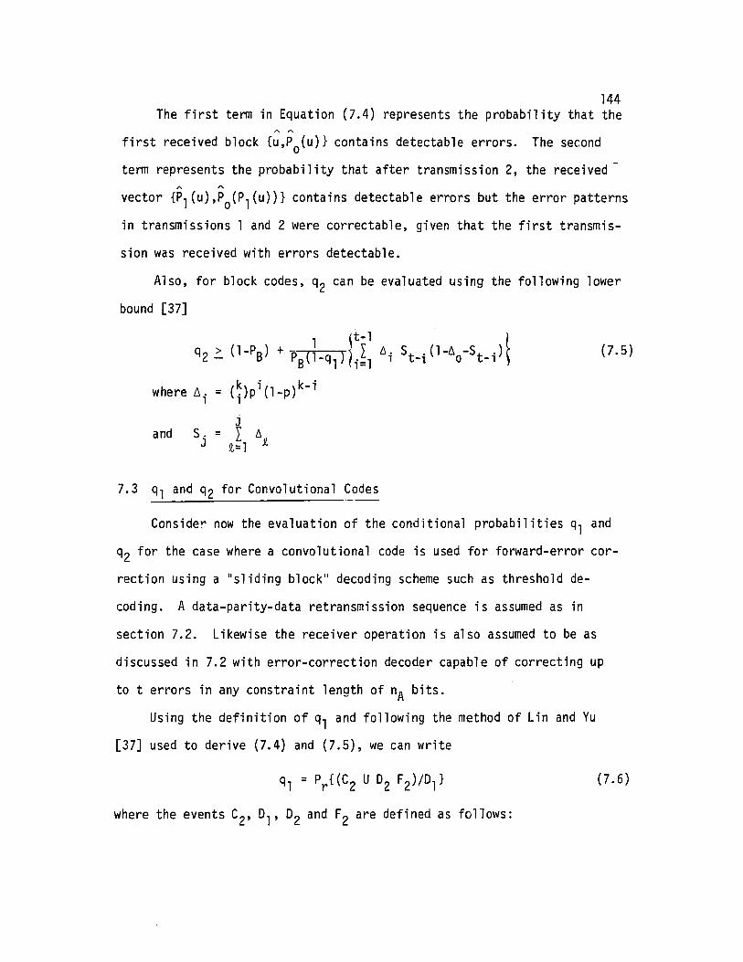
144The first term in Equation (7.4) represents the probability that the
first received block {u,Po(u)} contains detectable errors. The second
term represents the probability that after transmission 2, the received'" "vector {Pl(u),Po(Pl(u))} contains detectable errors but the error patterns
in transmissions 1 and 2 were correctable, given that the first transmis
sion was received with errors detectable.
Also, for block codes, q2 can be evaluated using the following lower
bound [37]
and
1 ~ t-l tq2 ~ (l-PB) + P
B(1-ql ) 1
iI
l~i St-i (l-~o-St_i)\
where 6i = (~)pi(l_P)k-i
JS. = I ~
J Q,= 1 ~
7.3 ql and q2 for Convolutional Codes
(7.5)
Conside~ now the evaluation of the conditional probabilities ql and
q2 for the case where a convolutional code is used for forward-error cor
rection using a "sliding block" decoding scheme such as threshold de
coding. A data-parity-data retransmission sequence is assumed as in
section 7.2. Likewise the receiver operation is also assumed to be as
discussed in 7.2 with error-correction decoder capable of correcting up
to t errors in any constraint length of nA bits.
Using the definition of ql and following the method of Lin and Yu
[37] used to derive (7.4) and (7.5), we can write
(7.6)
where the events C2, °1, 02 and F2 are defined as follows:

and
145
C2 is the event {the received parity block {Pl(u), Po(Pl(u))} at
the second transmission contains no detectable errors} 0i is the event
{the biock received at the i t h transmission/retransmission contains
detectable errors}
i.e. 01 is the event {{C,Po(u)} contains detectable errors}
and D2 is the event {{Pl(u),Po(u))} contains detectable errors}
F2 is the event {the error patterns in the received data/parity pair
{u,Pl(u)} are correctable by decoding}.
Note that • u is the received k-bit message block,
• Po(u) is the set of (n-k) parity detection bits computed
for u using a high rate block code Co'~
• Pl (u) represents the k parity bits generated by the
1/2 rate convolutional code Cl for the message bits u.~
• Po(Pl(u)) represents the n-k parity detection bits
generated by code Co for the bits Pl(u).~
(In each case, the symbol x represents a received vector x.) Now since
01 and C2 are independent events
Pr{D 102F2}
ql = Pr{C 2} + Pr{O,}
+Pr{0102F2}
= (l-PB) PB
(7.7)
Appelldix °shows how the joint probability Pr{01D 2F2} can be calcu
lated. As a result we obtain fOt' a convolutional code Cl capable of
correcting ~t errors in any constraint length of nA bits:
146
q = (l.;.P ) + _1 { I N(j) pj(1_p)2k-j1 S Ps j=2
00
- 2(1_p)k I Nl(j)pj(l_p)k- jj=2
00
+ 2(1_P)k[1_(1_p)n-kJ I Nl(j)pj(l_p)k-jj=l
+ (1_p)2k[1_(1_p)n-k12}
where
(7.8)
e N(j) is the number of correctable patterns of j errors in a block
of 2k bits such that no more than t errors occur in any span of
nA bits in the block
e Nl(j) is the number of correctable patterns of j errors in a block
of k bits such that no more than t errors occur in any span of
nA/ 2 bits in the block
and as before
e PS= l_(l_p)n
The similarities in form between Equations (7.8) and (7.4) for con
volutional and block codes should be noted. Methods for computing N(j)
and Nl(j) were discussed in Section 5,
Let PS(NS,nA) represent the block error probability after decoding
NS bits with a decoder capable of correcting up to t errors in any
"sliding window" span nA, Note that the symbol PS(NS,nA) has the same
meaning as the symbol Ps used to denote block error probability in sec
tion 5 but with the arguments NS and nA stated explicitly. Values for
PS(NS,nA) can therefore be computed using either the trellis algorithm
of section 5.3 or the Combinatorial approach of section 5.4. In practice

147
it was found convenient to combine elements of both methods. For example
considering the terms in Equation (7.8), use
{ }2k 2k-l= l-PS(2k,nA) - (l-p) - 2k p(l-p) (7.9)
where the term in brackets on the right hand side of (7.9) can be computed
using the trellis algorithm. Likewise,
(7.10)
(7.11)
•
Consider now the evaluation of the conditional probability q2 defined
in section 7.1. As shown in Appendix D, for the case where a 1/2 rate
convolutional code is used in a forward-error correction mode, we use
[1 - I Nl (j)pj(l_p)k-j]lj=O ~
where ~i=(~)pi(l_P)k-i as before in relation to (7.5) and Nl(j) is defined
as explained above in relation to Equation (7.8) for ql' N"(j) is defined
in the same way except that it refers to the number of correctable error
patterns in a block of length (k-inA/2)
bits as indicated by the power
of the associated (l-p) term in Equation (7.11).
Details are given in Appendix D.
7.4 Throughput for Type-II Hybrid ARQ Schemes
The computation of throughput can now be completed for various combi
nations of the following:
148• ARQ retransmission protocols (see sections 2 and 4)
• hybrid error correction scheme (see secti ons 3.2, 3.3 and 4)
and
• convolutional or block codes (as per sections 7.2 and 7.3).
Fortran programs have been used to evaluate the throughput for a
number of different hybrid ARQ combinations and the results are depicted
in Figures 7.1 to 7.4. In particular, the following schemes were
analyzed:
Scheme (f t )
Scheme (i i i)
Scheme (iv)
with
Scheme (i) Type-II hybrid scheme with
- SR+ST retransmission protocol
- alternate data/parity hybrid scheme
- various half-rate convolutional codes.
As above but using SR+GBN retransmission protocol
As above but using Lin and Yu retransmission protocol
Type-II hybrid scheme
as above but using the ideal selective-repeat retrans
mission protocol (requiring infinite receiver bUffer).
For scheme (i), the throughput is given by Equation (4.2) combined
with Equations (7.8) and (7.11).
For scheme (ii), Equation (4.5) replaces (4.2).
For scheme (iii), Equation (4.7) is used.
For scheme (iv), Equation (4.6) is used.
Figure 7.1 shows throughput plotted versus BER for a random error
channel for a round-trip delay S=1024 blocks. Throughput plots are shown
for the following FEC codes:
Code (a) - a convolutional code with minimum free distance df ree=5 and
constraint length nA=6 bits is assumed which implies a

149
nonsystematic code as set out in Table 5.1. For such a code, ROM
table lookup decoding would be desirable. There is no orthogonaliz
able code with such parameters so threshold decoding is not possible.
Since a nonsystematic code must be used, an inversion circuit will
be necessary to recover the message u after the first transmission
of any block if no errors are detected in the first transmission
attempt.
Code (b) - a convolutional code with df ree=5 and nA=12. As shown in
Table 5.1, a systematic orthogonalizable code exists with these
parameters. As a result, no inversion circuit is required at the
receive end to recover the data u if no errors are detected in the
first received transmission attempt. A very simple threshold
decoder can be used.
Throughput values are given in Figure 7.1 for v=l selective-repeat
retransmissions. As discussed in section 2, this means that after the
second attempt at transmission of a given data block, subsequent retrans
missions are made in the "stutter" mode (for the SR+ST scheme) or in the
Go-Back-N mode (for the SR+GBN scheme). This ensures that receiver
buffer overflow cannot occur providing that a receiver buffer store SR
is provided as follows:
{S(V+l ) blocks for the SR+ST scheme
SR = v(S+l) blocks for the SR+GBN scheme(7.12)
Figure 7.1 shows that the SR+ST scheme throughput is greater than
that of the SR+GBN for BER rates greater than p=lO-3. This shows the
benefit to be gained at the expense of increased buffer store. Figure 7.1
also shows the benefit to be gained by use of a nonsystematic code with

150
5=1024n=1024
SR + GBN (nA=12k------..,.
Go Back N(CClTT x .25) SR+GBN (nA=6)\~4-4~---~--+------~
SR + ST (nA=12) ~~~__+
5R + 5T (nA=6)00 buffer
t------>ol:t--- scheme (tv)
IoL----..L.-----:::::::::-....!----~--~~-~~"--~_+_
10-6
o.81------+-----I---.:~---I--------4----~
O.61-- +_
Throughput
;.orl-- ~----------------
o.21-----'r-+_
BER
Figure 7.1
Throughput of Alternate Data/Parity Hybrid ARQwith SR + 5T and SR + GBN Protocols (v=l)
FEC Codes Used: nA~6 df ree=5 (nonsystematic non-orthogonalizable)nA=12 df ree=5 (systematic orthogonalizab1e)

151appropriate inverter and decoder versus an orthogonalizab1e code with
very simple decoder circuit.
Figure 7.2 shows how throughput varies with BER for scheme (iii)
(i.e. Lin and Yu retransmission protocol). Results for both convolutional
and block codes are shown for comparison. As expected from the results
in Section 5, the simple convolutional codes out perform the t=10 block
code shown and also the "ideal" selective-repeat ARQ scheme with infinite
receiver buffer but no forward-error correction.
Both Figures 7.1 and 7.2 show how throughput varies for the infinite
receiver buffer hybrid selective-repeat scheme (iv) for a convolutional
code with df ree=5 and nA=6. This result also provides the throughput
values (With one percent accuracy) for a terrestrial circuit with say
S=l round-trip delay for either scheme (i) or (ii).
The use of a more powerful FEC convolutional code is illustrated in
Figure 7.3. Here the FEC code used is assumed to have df ree=7 with
nA=10 (refer Table 5.1). The results are shown for the alternate datal
parity schemes (i) and (ii).
Figure 7.4 illustrates the performance of the ST+GBN scheme described
in section 4.6. Throughput values are shown for cases with and without
forward-error correction. For comparison, plots of throughput are given
for the SR+GBN protocol and the 5T+GBN scheme. For the ST+GBN scheme
we have used n1=3 in Equation (4.8). The parameter n1 specifies the
number of "stutter" retransmissions sent following a NAK being received
at the transmitter (refer section 4.6). When no forward-error correction
is used, the optimum value of n1 is a function of the round-trip delay S
and block-error rate PB. Figure 7.4 is drawn for 5=1024 blocks. For
this case, n1=3 is a reasonable choice. However, it is not the best

152
Throughputn
S=1024, n=1024
Convolutional Code(t=2, nA=6)
Scheme (iv)infinite buffer
1.0 ~---~-----~---....-T----~---_._--~~~r-------+-: -----+-- -----I
i
0.8 ~-------~~~--+-----+-----i
O+--.L.-....L----I.:::::::b.._--.l.--I--I._-L---L::::.--_~....L_....
10-6
0.6
0.2
0.4
BER
Figure 7.2
Comparison of Performance of Block Codes and Convolutional CodesLin and Yu Retransmission Protocol (Scheme iii)

153
10-1
BER
•
S=1024, n=1024
Scheme 2
Scheme 3
Scheme 4
:"":. ---~
Selective
Go-Back-NScheme
-\\.-,
0.8 I----------""rt---+-----+-------l
0.6
0.4
o,10-6
0.2
Throughput
n1. 0 1-----.,.-........=---,------.,.-------.-------.
Scheme 1 - SR + ST protocol, alternate data/parityScheme 2 - SR + GBN protocol, alternate data/parityScheme 3 - Lin &Yu protocol, alternate data/parity,
Rx buffer = S blocksScheme 4 - Lin & Yu protocol, alternate data/pari ty ,
R buffer = 00x(Scheme 4 is equivalent to result for round trip delay S=l)
Figure 7.3
Type-II Hybrid ARQ Throughput for SchemesUsing Convolutional Code With dfree=7, nA=lO

154
Throughputn
S=1024, n=1024
10-2
BER
SR + GBN
ST + GBN(Weldon)ST + GBN(Hybri d)SR + GBN(Hybrid)
SR (InfiniteBuffer)
--
0.81--------
0.6
0.4 -
0+--.l....-...1---..L-l...-_--J..--l.--=:::::-.-l-.::::J"._--.::b:::::::b..-J~
. 10-7
0.2
Figure 7.4
Performance of SR + GBN and ST + GBN Compared

155choice for use in a Type-II hybrid scheme. In Figure 7.4 it can be seen
that the ST+GBN hybrid scheme (n 1=3) has significantly worse throughput
than the SR+GBN hybrid scheme except for BER<2xlO-3. In a properly
designed hybrid scheme there should be a high probability that the data
is recovered without errors after the second transmission. In that case
the optimum choice of n1 would be 1. For this value, the ST+GBN protocol
becomes the same as the SR+GBN.
7.5 Reliability
In evaluating the performance of ARQ schemes, two parameters of
primary importance are throughput and reliability. The previous sections
have been concerned with the throughput performance of various ARQ and
hybrid-ARQ procedures. In this section, consideration is given to reli
ability, that is the probability that blocks will be error-free when
they are delivered to the user. If the event E is the event that the
receiver accepts a received vector with undetected errors the reliability
R of the system is given as
R = 1 - Pr{E}
In conventional ARQ procedures such as the Go-Back-N a high rate
block code Co is used for error detection. The transmitter encodes each
message block of k bits into a code word {u,Po(u)} of n bits which is
then transmitted. In practice, the n-k parity bits Po(u) typically
represent a small fraction of the total n bits in the block. For example,
the CCITT Rec. X.25 packet switching link-level protocol recommends the
use of 16 parity bits based on a cyclic code. The information vector
u is typically 1024 bits in length. The receiver checks whether the
156received block {~,Po(u)} has detectable errors by computing the syndrome.
If this is zero the block is assumed error-free.
For the mixed-mode ARQ systems discussed in section 2, the same
error detection procedures would be appropriate. Accordingly the same
reliability performance can be expected. In the throughput analysis of
section 2 it was assumed that the code Co was chosen in such a way that
the probability of undetected errors is negligible.
Let E~ be the event that, after receiving the it h transmissicn of a
block, the receiver recovers the message u without errors.
Let E~ be the event that, after receiving the i t h transmission the
receiver makes a decoding error by accepting the message containing
undetected errors. Then it follows that for any ARQ scheme, the reliabi
lity is given by
(7.13)
For any ARQ system without forward-error correction over the BSC it followse ethat E1, E2, ••• are independent and that
E~ = P1 d
E: = p1 e
The reliability therefore becomes
R - Pc- Pc+Pe
where Pc = 1-Pd-Pe
= (l_p)n with p the BER.
Also if the error detection code Co is chosen properly, then an upper
bound on Pe is given [2] by
(7.14)

157
(7.15)
For Type-II hybrid ARQ schemes the above error detection procedure
(syndrome check) can be used after the initial transmission of a given
inforolation block. For all the hybrid schemes discussed in section 3,
whenever errors are detected in the initial transmission the second
transmission is a "parity" block represented by {Pl(u),Po(Pl(u))}. The
k bits Pl(u) are the parity bits generated by encoding the information
bits u with a half-rate systematic code Cl. Also the tr~nsmitter encodes
the k-tuple Pl(u) with the high rate code Co and produces n-k parity bits
Po(Pl(u)).
On receipt of the n bits {Pl(u),Po(Pl(u))} the receiver first com
putes the syndrome based on Co to determine whether errors are detectable
in the received parity block. This procedure is the same as that for
error detection for the initial transmission. If errors are detected in
the parity block the receiver uses the code Cl to attempt to correct the
errors in the 2k bits {U,Pl(u)}. If Cl is a block code (e.g. a (2000,1000)
shortened cyclic code) then the code can be used for error detection as
well as error correction. As discussed in section 5, decoder complexity
considerations would probably limit the choice of decoder error correc-
tion capability (t) to a maximum of about 10 errors. There exist half
rate codes of block size of the order of 2000 bits for which the minimum
distance dmi n far exceeds that required for t=lO error correction. For
example if Cl is a (iOOO,SOO) shortened BCH code with dmin=lll the code
can be used to correct 10 errors and also to detect up to 100 errors.
Such an error detection capability ensures that the Type-II hybrid ARQ
schemes using block codes maintain very high reliability even for high
channel error rate.
158
Lin and Yu [34J have shown that for this case the reliability is
lower bounded byp -0
R > C- P +pc e
(7.16)
where for a (2k,k) linear code Cl which is capable of correcting up to
t errors and simultaneously detecting up to d errors (d>t)
(7.17)
PcIf d is reasonably large, 0 can be made very small and R ~ ---+--- .
Pc Pe
7.6 Error Detection Procedures
In a Type-II hybrid scheme using convolutional codes it is necessary
to use a different procedure for error detection to that used for schemes
using block codes. In the block code hybrid scheme, not all the error
correction capabilities of the code are utilized for error correction.
This is to avoid the requirement for an excessively complex decoder.
As a result the code can also be utilized for error detection.
For the hybrid schemes considered in section 7 it was assumed that
the convolutional code Cl was utilized for error correction alone. As
expected the throughput performance results were superior to those for
the block code case when channel BER is high.
Consider the alternate data-parity scheme (see section 3.3) using a
convolutional code Cl for error correction. If errors are detected in
the first received data block {~,Po(u)} and in the next received parity
retransmission {Pl(u),Po(P l (u))} then an attempt is made to correct the
errors in {~,Pl(u)} using the half-rate convolutional code Cl. Sliding
block decoding is envisaged either by threshold decoding or by syndrome

159
look-up techniques. In order to determine whether errors still remain
after decoding, the decoded message block u could be combined with the
n-k parity bits Po(u) received in the first transmission. Then the syn
drome can be computed using code Co to determine whether {U,Po(u)} is a
code word. If the syndrome is zero u is assumed error-free. If the syn-
drome is non-zero, a NAK is sent back to the transmitter to initiate a
retransmission of the n-tuple {u,Po(u)}. If errors are detected in this
received block, error correction is again attempted using the 2kbitsA A
Pl(u) and u received in the second and third transmissions respectively.
The resultant information bits u are then combined with the n-k parity
bits Po(u) received in the third transmission attempt. The syndrome
check then proceeds as before and the process continues.
With this error detection procedure it may happen that even though
there are no errors remaining in the decoded information bits u it may
nevertheless be rejected. This would occur if a detectable pattern of
errors occurred in the n-k parity check bits Po(u). We next consider
alternative error detection procedures. They are more complex but offer
some advantages over the procedure described above. As before we assume
the alternate data-parity hybrid scheme is used with a convolutional code
Cl for forward-error correction. After the initial transmission {u,Po(u)}
of a given block, the high rate block code Co is used to compute the
syndrome. If it is zero, the data ia ssumed error-free. If the syndrome
is not zero, a "par ity" retransmission {Pl(u),Po(Pl(u))} is sent. Again
at the receiver the code Co is used to check whether the syndrome isA
zero. If it is zero, the received bits Pl(u) are assumed error-free and
the data u is recovered from Pl(u) by an inversion procedure. If the syn
drome is not zero, a convolutional decoder attempts to decode {u,Pl(u)}

160
to correct all the errors in the received data bits u. To this point the
procedure is identical to that described for the first error-detection
procedure.
Now consider two alternative procedures for checking whether errors
remain in the data u after decoding. For convenience we refer to them
as error detection procedures 2 and 3 respectively.-Error detection procedure 2. In this procedure the decoder output u
is checked by two steps. First the syndrome is computed for {u,Po(u)}
using the n-k parity bits Po(u) received in the first transmission. If
this syndrome is not zero u cannot be considered error-free. Next u is
fed into an encoding circuit identical to the encoder for the (2,1) con
volut~nal code Cl as used at the transmitter. Let the input u produce
the output parity bits Pl(u). Now the block code Co is used to compute
the syndrome for the n bits {Pl(u),Po(Pl(u)}. If the resultant syndrome
is zero the data u can be considered error-free. The n-k bits Po(u) can
be assumed to contain at least one error, the n-k bits Pl(u) to be error
free. It is easy to see how this procedure can be used after any subse-
quent retransmissions if earlier transmissions fail.
Error detection procedure 3. In this alternative procedure, the
convolutional code Cl is used to correct errors in the received parity
Po(u) as well as the received data u. If the initial transmission of a
block is unsuccessful, the transmitter generates a "par-ity" retransmis-
sion block as follows. The original k-m data bits u and the n-k parity
bits Po(u) are fed into the convolutional encoder followed by m encoder
clearing zeros. The encoder output Pl will consist of n bits. Let I(X)
represent in polynomial form the IIdata" transmission consisting of the
k-m data bits, the n-k parity bits generated by Co and m zeros. Let Pl(X)
161represent the n-bit "parity" transmission generated by the (2,1) code Clwith generators g(l)(X)=l and g(2)(X). Then
Pl (X) = I (X)g(2) (X)
On receipt of the "parity" transmission P1(X) the receiver first divides
P1(X) by g(2)(X). Let I1(X) and R1(X) be the quotient and remainder
respectively. The receiver first checks whether R1(X) is zero. If not
a NAK is sent. If R1(X)=O the receiver uses code Co for error detection
in Il(X). If no errors have occurred in transmission, Il(X) will consist
of the original k-m data bits and n-k parity bits generated by Co' The
receiver computes the syndrome of Il(X) using code Co' If the syndrome
is zero the receiver recovers the data estimate u and sends an ACK.
Otherwise a NAK is sent requesting another transmission.
It is readily observed that, of the three error detection
schemes discussed, the third is superior and likely to provide a slightly
higher block throughput. The probability of recovering the data u with-
out error~ after second and subsequent transmissions will be marginally
higher than for the other two error detection schemes.
In chapter 4 expressions for throughput for hybrid schemes were
derived (see for example Equations (4.2) and (4.5)). These assumed that
there was a negligible probability that the error-detection procedures
would fail to detect errors. The throughput expressions were functions
of conditional probabilities q1 and q2 which depended on the forward
error correction procedures to be used. In chapter 7, methods for com-
puting q1 and q2 were given for convolutional and block codes. For
hybrid ARQ using convolutional codes, q1 and q2 were expressed (Equations
(7.9) and (7.11)) in terms of the block error probability Psafter

162
decoding the 2k bits {u,Pl(u)}. In computing values for ql and q2 it
is a simple matter to take into account the slight reduction in block
throughput resulting from use of error detection procedure 3. In eval
uating the block error rate PBa block length of NB=2n bits should be
used, not NB=2k as discussed in section 7.3. Examination of Table 5.4 and
use of Equation (5.24) shows that for n»n-k the reduction in throughput
will be very small. For example if n=1024 and n-k=16 we can compare values
of PBfor length 2n=2048 and length 2k=2016 bits respectively. To illus
trate, we compute PB values for BER=lO-3 and using a convolutional code
capable of correcting up to 2 errors in a constraint length of 10 bits.
For length 2048 bits
For length 2016 bits
PB= 0.7263 x 10⁻⁴
Ps = 0.7163 x 10⁻⁴
It is clear that there will not be significant differences in throughput
values for these two cases.
The reliability of each of these error-detection schemes will be
very high providing the code Co is properly chosen. This is because con
ventional syndrome checking is used in each case as in conventional ARQ
systems. However it appears difficult to analyze the reliability per
formance for these three error-detection procedures. In order to do so
the joint probabilities in Equation (7.13) would have to be determined
and this appears excessively complex. When the error-correction decoder
makes an error, the resultant error pattern will no longer be randomly
distributed. As discussed in section 6.3, if feedback decoding is used,
error propagation may occur. This means that Equation (7.15) can no
longer be used to bound the syndrome check procedure for error detection.

163
8. SUMMARY AND CONCLUSIONS
8.1 Summary of Research
The key results of this dissertation can be summarized as follows:
ARQ Retransmission Schemes: (Chapter 2)
(i) A class of mixed-mode ARQ schemes has been found which are
selective-repeat types. They operate with finite receiver
buffer without overflow.
(ii) It is useful to conceptualize these ARQ schemes as operating in
one of two modes. The primary mode is selective-repeat (SR).
The secondary mode can be either a "stutter" repetition of a
faculty block (ST) or a Go-Back-N procedure (GBN). The purpose
of the secondary mode is to prevent receiver buffer overflow.
(iii) The mixed-mode schemes are amenable to exact throughput analysis
in terms of block length (n), round-trip delay (S) and bit-error
rate (p) for a BSC. The analysis results are summarized in
Table 2.1 for ARQ schemes labelled SR+ST scheme 1, SR+ST scheme
2 and SR+GBN respectively. Figures 2.9 and 2.10 show typical
values of throughput versus bit-error rate for selected block
sizes and round-trip delay.
(iv) The results show that for best ARQ performance, at least the
first retransmission of a block following an error should be in
the selective-repeat mode. Providing this is done, markedly
superior performance is achieved over conventional Go-Back-N
schemes for channels with high bit rates and large round-trip
delays.

164(v) For related SR+ST and SR+GBN schemes (that is, those with the
same number v of SR retransmissions), the throughput is very
nearly the same. This indicates that the choice of the sec
ondary mode does not have a significant bearing on the through
put but does have a bearing on complexity.
(vi) The results also illustrate the dependence of throughput on
receiver buffer size. Table 2.1 shows how the throughput and
receiver buffer requirements vary with the number (v) of
selective-repeat retransmissions allowed for any given block.
(vii) The mixed-mode schemes offer considerably better throughput
thanmostARQ schemes previously proposed (refer Figure 2.11).
A selective-repeat scheme by Yu and Lin provides superior.
throughput for some bit-error rates (refer Figure 2.12) but has
not been found amenable to exact analysis.
Type-II Hybrid ARQ: (Chapters 3 and 4)
(viii) Hybrid ARQ schemes are available in which retransmission of parity
bits is used rather than the original data. The parity block can
be generated using half-rate block or convolutional codes. By
this means, forward-error detection is made available at the re-
ceiver if required. In this sense the Type-II hybrid scheme
is "adaptive".
(tx) In order to completely specify any Type-II hybrid ARQ scheme it
is important to separately describe two aspects, namely
• the retransmission protocol (refer Chapter 2)
and • the error mechanism/correction procedures.
The separate consideration of these two aspects of any ARQ scheme
leads to a unified throughput analysis procedure applicable to a
wide variety of different schemes.

165(x) State diagrams are of assistance in representing the error
mechanism/correction procedures. Figures 3.1-3.5 illustrate
different schemes. Such representation is applicable to either
convolutional or block FEC codes.
(xi) Expressions for throughput have been derived for a selection of
different Type-II hybrid ARQ schemes (see Equations (4.2), (4.5),
(4.6) and (4.10)). They are presented as functions of block
error rate (PS)' round-trip delay (S) and conditional probabili
ties ql and q2' The latter two parameters depend on the nature
of the FEC code and decoding procedures to be used. They are a
function of the block error rate achievable after decoding.
Block-Error Rates for Convolutional Codes: (Chapter 5)
(xii) Modestly powerful half-rate convolutional codes with sliding block
decoders are proposed for forward-error correction in the Type-II
hybrid ARQ schemes. The decoder may be either a threshold decoder
or table-lockup decoder with feedback. This is suggested as a
reasonable compromise between complexity and performance.
(xiii) A "trellis~ algorithm is proposed as a means for computing the
block error rate (PB) after decoding a convolutional code. Table
5.4 and Figure 5.9 present typical values for selected codes. A
method is outlined (Equation (5.24)) for utilizing the table to
obtain Psvalues for other block sizes.
(xiv) An alternative approach to finding block error probability is
outlined. It is based on upper bounds on Psfound using combina
torial techniques. A method is presented for enumerating the
number of correctable patterns N(j) in a block of NS bits (infor
mation plus parity) for any single or double error correcting
•

166convolutional code. The decoder effective constraint length must
be specified. The results are presented in Equations (5.4) to
(5.14). The Ps values computed using these results are consis
tent with those using the trellis algorithm. The combinatorial
approach can be used when code constraint length or error correc-
ting ability are so large that the computing algorithm becomes
impractical.
(xv) Comparisons are made between the block error rate performance of
convolutional and block codes. Results are presented (Figure
5.10) for half-rate codes with block size of 2000 bits. Decoders
of approximately comparable complexity are assumed. A 10-error
correcting decoder is assumed for the block code, a sliding-block.
decoder for the convolutional codes. (The former does not uti
lize the whole error-correcting capability of the block code.)
The results show the advantage of using convolutional codes under
high bit-error rate conditions.
The Design of Related Codes with Rates 1/2 and 1/3: (Chapter 6)
(xvi) Codes are investigated for use in a parity transmission scheme
described in section 4.5. After the first retransmission, a
half-rate code is available at the receiver for error correction.
After the second retransmission a one-third rate code word is to
be available for more powerful error correction. Common decoder
circuitry is envisaged. The properties required of the "rel ated"
rate 1/2 and rate 1/3 codes are specified.
(xvii) Optimum orthogonalizable rate 1/3 codes are well-known. An ex-
haustive trial-and-error method is outlined for constructing
related rate 1/2 codes. New (2,1) codes were found as pairs to

167all the optimum orthogonalizable (3,1) codes for error-correcting
capability t=l to 8. The new orthogonalizable codes are shown
in Table 6.1. Also shown are the rules for forming parity check
sums for threshold decoding.
(xviii) The circuit schematic of a typical threshold decoder capable of
decoding either the (2,1) code or the (3,1) code in a related
pair is described. Alternatively a read-only-memory (ROM) cir
cuit could be used for table-iookup decoding. In either case,
the decoder is relatively simple.
Performance of Type-II Hybrid Schemes: (Chapter 7)
(xix) Methods for calculating the conditional probabilities ql and q2
(refer xi above) are presented for the alternate data-parity
schemes using convolutional codes (Equations (7.4) and (7.5)).
Values for block codes were previously available. For one of
the hybrid schemes (the rate 1/2, 1/3 scheme) no method has been
obtained for calculating q2.
(xx) Throughput is plotted versus bit-error rate for selected combina
tions of ARQ retransmission protocols, hybrid error-correction
schemes and forward-error-correcting codes (Figs. 7.1-7.4).
Values of block sizes of 1024 and round-trip delay of 1024 blocks
are used. The results show that Type-II hybrid schemes can
maintain in excess of 50% throughput even when bit error rates
exceed 3xlO-3 (for blocks of 1024 bits this represents a block
error rate of approximately 0.95). Throughput values are com
puted for hybrid ARQ schemes with infinite buffer. These results
indicate that the use of ARQ protocols with more than one
selective-repeat retransmission might enable hybrid ARQ systems

168to have acceptable throughput up to bit-error rates as high
as 10-2.
(xxi) The convolutional code schemes provide generally better perfor
mance than the block code schemes. One obvious reason for this
is that the whole error-correcting properties of the convolutional
codes are used. Decoder complexity prevents utilization of more
than a small part of the potential error correction capability
of the block codes.
(xxii) In Chapter 7 methods for ensuring high reliability are discussed
for hybrid schemes using convolutional codes. These use the
parity bits generated by a high-rate block code used for error
detection only. No procedure for analysis of reliability has
been obtained for the hybrid schemes using convolutional codes.
(xxiii) Type-II hybrid schemes can only be effective if a selective-repeat
type of retransmission protocol is used.
(xxiv) For throughput values between 0.5 and 1, the throughput versus
bit error rate curves of all hybrid schemes studied are rela
tively insensitive of the forward-error-correcting ability of
the codes. Therefore in any practical scheme, more powerful
codes can only be of benefit for throughput values less than
0.5. More efficient decoding schemes such as maximum likelihood
or probabilistic schemes may not justify the significant increase
in complexity.
8.2 Conclusions
ARQ schemes seem likely to remain the most popular approach to error
control for some time to come. This is because of their high reliability.

169
The use of digital transmission is rapidly increasing, particularly in
circuit-switched and packet-switched networks. As these networks expand,
it is to be expected that increasing utilization will be made of satel
lite and long terrestrial circuits with significant transmission delays.
In these circumstances it is to be hoped that this research will contri
bute towards future design of error-control procedures.
The study of ARQ retransmission procedures in Chapter 2 demonstrates
that the throughput performance of currently used ARQ protocols may be
considerably improved for circuits with delay and high bit-error rates.
The provision of receiver buffers for storing error-free blocks seems
desirable. This buffer size should be chosen in accordance with the re
quirements of a selective-repeat ARQ scheme such as one of the "mixed
mode" protocols. The results of Chapter 2 indicate the anticipated trade
offs between performance and complexity.
Further benefits in improved throughput can be achieved by an appro
priately designed hybrid ARQ scheme. This research has shown that con
volutional codes can provide an effective means of forwar.d-error-control
in an ARQ system. We have directed our attention to codes of modest
error correcting ability for which the encoder and decoder circuits are
not excessively complex. The results indicate that considerable benefits
are possible if such codes are combined with a Type-II hybrid ARQ scheme
using parity-retransmission. Type-II hybrid schemes can only be effective
if a selective-repeat type of retransmission protocol is used.
Of the mixed-mode schemes studied the SR+GBN protocol requires the
least receiver buffer provision, yet provides good throughput efficiency
performance. Error-correction using sliding-block decoding based on read
only-memory (ROM) syndrome look-up procedures also appears a reasonable

170choice from the decoding procedures discussed. Such a decoder would
avoid restricting the choice of codes to orthogonal or orthogonaiizabie
codes. Current developments in large-scale integration of multiple func
tions on a microcircuit suggest that the economic viability of hybrid
ARQ schemes may be well worth further investigation.
Certain simplifying assumptions have been made in this research to
facilitate the analytical procedures. Data has been assumed transmitted
in equal length blocks. Errors have been assumed randomly distributed.
Feedback channels were considered error-free. No consideration has been
given to the problems of timeouts, lost blocks or failure of frame syn
chronization. There are therefore a number of these practical matters
that would need to be considered before a working system design could be
considered complete. Nevertheless the results of this dissertation seem
to provide a useful information base for the ARQ system designers in the
future.

171
Appendix A
A NOTE ON THE DERIVATION OF EQUATION 2.7
Consider the number of combinations of the 2S distinct ACK/NAK
indications described in Section 2.3.3. We wish to find the probability
that at least one pair of NAK's will occur spaced 5 + 1 block intervals
apart.
Let N(k,j) denote the number of events such that
• There are k + 2 NAK's and 25 - k - 2 ACK's
• There are j + 1 pairs of NAK's such that for each pair
the NAK's are spaced 5 + 1 block intervals apart. For
convenience we denote such pairs 'double-NAK pairs '.
Case (a). Let j = O. N(k,O) is the number of ways of arranging
k+2 NAK's and 25 - k - 2 ACK's so that there is at least
one double-NAK pair. It follows that
N(k,0) = (i) (~~ : ~ _k) k= 0,1,2, ... , (25 - 2).
Case (b). Let j = 1. The number of ways of arrangi ng k+2 NAK I s so
that there are at least two double-NAK pairs is
In general.
_ (5) (25 - 4 )N(k,1) - 2 \25 - 2 - k
N(k,j) =(.5 )(25 - 2 - 2j)J+l 2S - 2 - k

172
where the non-zero k,j terms can be illustrated in the following array
.j = 0 1 2 3 4 ... 5-1
k
0 N(O,O) 0 0
1 NO ,0) 0 0
2 N(2,0) N(2,1) 0
3 N(3,0) N(3,1) 04 N(4,0) N(4,1) N(4,2) 05 N(5,0) N(5,1) N(5,2) 06 N(6,0) N(6,1) N(6,2) N(6,3) o ...
2S-2 N(2S-2,5-1)
The event {k+2 NAK's and 2S - k - 2 ACK's} occurs with probability
PBk+2 (l_PB)2S-2-k with PB defined in Section 3 above.
Following the principle of Inclusion and Exclusion the number ofsuch events is
S-l
N(k) = j~O (-l)j (j~l) (~~ : ~ : ~j)
Note that N(k,O) includes counts of 1,2, ... double-NAK pairs and N(k,l)
must be subtracted. Then the events denoted N(k,2) have been subtracted
twice and must be restored and so on. Finally by examination of the range
of non-zero values in the array shown above we obtain
25-2P = r
NN k=2jSfl (_I)j(.S )(2S - 2 - 2j) p2+k (l-P )2S - 2 - kj=O J+l 2S - 2 - k B B

173
Appendix B
TRELLIS ALGORITHM COMPUTER PRINTOUT
BER=',G10.5)
BLOCK ERROR PROB')
DO 259 J=1,W+1DO 259 K=l ,W+1•BP(J,K)=O259 AP(J,K)=OAP(W+1,W+1)=(1-BER)**WDO 260 I=l,WAP(I,W+1)=BER*((1-BER)**(W-1)}AP(W+1,I)=BER*((1-BER)**(W-1})260 CONTINUEDO 300 J=l,WDO 300 K=l,W300 AP(J,K)=(BER**2)*((1-BER)**(W-2»
PROGRAM ABMMINTEGER WREAL AP (40,40), BP(40,40)THIS PROG COMPUTES BLOCK ERROR PROB BOUND FOR T=2PRINT 150150 FORMAT ('INPUT NB,NA,BER ')READ *,NB,NA,BERW=NAPRINT 190,NA,BER190 FORMAT ('CONSTRAINT LENGTH=' ,14,'PRINT 220220 FORMAT ('BLOCK LENGTH
00100001100012000130C001400015000160001700018000190002100022000230C00240C INITIALIZE STATE PROBS FOR BL LENGTH=W00250C00252002540025500256002600027000280002900030000310003200033000340C00350C COMPUTE NEXT STATE PROBS00360C00370 ,DO 400 L=W+1,NB00380 BP(W+1,W+1)=(1-BER)*(AP(W+1,W+1)+AP(1,W+1»00390 DO 310 J=2,W00400 310 BP(J-1,W+1)=(1-BER)*(AP(J,W+1)+AP(1,J»00410 BP(W,W+l)=BER*(AP(W+1,W+1)+AP(1,W+1»00420 DO 360 KI=1,W-200430 DO 350 K=KI+1,W-100440 350 BP(KI,K)=(1-BER)*(AP(KI+1,K+1»00450 360 CONTINUE00460 DO 370 J=1,W-100470 370 BP(J,W)=BER*(AP(J+1,W+1)+AP(1,J+1})00480 SUMPC=O00510 DO 390 J=1,W+100520 DO 380 K=1,W+100530 AP(J,K)=BP(J,K)00540 380 SUMPC=SUMPC+AP(J,K)00550 390 CONTINUE

00555 SUMPE=l-SUMPC00560 400 CONTINUE00565 PRINT 450,L-l,SUMPE00570 450 FORMAT(I6,T20,G20.10)00580 STOP00590 END
174
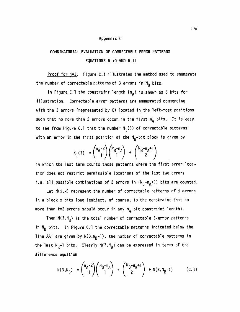
175
Appendix C
COMBINATORIAL EVALUATION OF CORRECTABLE ERROR PATTERNS
EQUATIONS 5.10 AND 5.11
Proof for j=3. Figure C.l illustrates the method used to enumerate
the number of correctable patterns of 3 errors in NB bits.
In Figure C.l the constraint length (nA) is shown as 6 bits for
illustration. Correctable error patterns are enumerated commencing
with the 3 errors (represented by X) located in the left-most positions
such that no more than 2 errors occur in the first nA bits. It is easy
to see from Figure C.l that the number Nl(3) of correctable patterns
with an error in the first position of the NB-bit block is given by
in which the last term counts those patterns where the first error loca
tion does not restrict permissible locations of the last two errors
i.e. all possible combinations of 2 errors in (NB-nA+l) bits are counted.
Let N(j,x) represent the number of correctable patterns of j errors
in a block x bits long (subject, of course, to the constraint that no
more than t=2 errors should occur in any nA bit constraint length).
Then N(3,NB) is the total number of correctable 3-error patterns
in NB bits. In Figure C.l the correctable patterns indicated below the
line AA ' are given by N(3,NB-l), the number of correctable patterns in
the last NB-l bits. Clearly N(3,NB) can be expressed in terms of the
difference equation
(C. 1)

176
Example. Consider the case where S = 4 illustrated in Figure 2.6.
There are 8 ACK/NAK signals to be considered, the 4 before block i is
first transmitted and the 4 following. We begin with N(O,O), that is
the number of ways of arranging 6 ACK's with 2 NAK's spaced 5 intervals
apart to form a double-NAK pair. There are 4 ways this can occur. Next
we find N(l,O), that is the number of ways of arranging 3 NAK's and
5 ACK's so that there is one double-NAK pair. There are 24 such arrange
ments. Likewise we can find N(2,0)=60 and so on as illustrated in the
following table.
N(k,j) values for S = 4j
= ° 1 2 3 N(k)k
° 4 41 24 242 60 6 543 80 24 564 60 36 4 285 24 24 8 86 4 6 4 1 1
Now consider the N(2,0) value, say, counting possible arrangements
of 4 NAK's and 4 ACK's. The total number of arrangements N(2,0) of double
NAK pairs i~ 60. But not all of these events are mutually exclusive since
N(2,0) includes 6 cases where the 4 NAK's form a pattern of two concurrent
double-NAK pairs. These N(2,1) cases must be subtracted from N(2,0) to
find the number of mutually exclusive arrangements for k = 2. The
remainder of the N(k,j) array should be self explanatory.

177
A convenient method to solve this equation is to note that because
the enumeration proceeds as illustrated in Figure C.l N(3,N B) will be
of the form
N(3,NS)
= (nA~2 )eB~nA) + (NS-;A+l)
+ (nr2) (NS-~A-l) + (Ns;nA)
+
+ (nf2)(~) + (~)
= NSi"A{("()(;) +C;l)}1=1
Hence
N(3,NS) = (nA~2) (NB-;A+l) + (NS-~A+2)
as given in Theorem 3.2, Equation (5.10).
Now, combinatorial identities expressed in terms of binomial coeffi
cients have notoriously a myriad of equivalent solutions. Other con
venient equivalent forms for N(3,NB) based on combinatorial identities
including the Vandermonde convolutional formula (Riordan [41])
or its variant
(C.2)
are as fo11 ows
L(_l)k (n) (P+k-l)k m-k k
(C.3)

A
x x :Xx x I X
II ...
x XI
XI
X X XIII ...
X I X XX X I X
II ...I X X,
No. of correctableerror patterns
}C-2
) CS~nA)1A' (NS-t)
} N(3,NS- l )
I = N(3,NB)
178
Figure C.l
Correctable Error Patterns N(3,NB)of 3 Errors in NB Bits t=2

179
N(3,NS) = (Ns;nA+l) + (nrl)(NB-~A+l)
= (NB-~A+2) ("A-2)L (_1); (NB-n~+2)
w /+ 1 i=O 2-1
min(nA-l,4) (;) (~A-2) (B-2nA+4) (C.4)= ~ 1 1-1 4-1
i=l
Proof for j=4. Let N(4,NB) denote the number of correctable patterns
of 4 errors in a block of length NB. Figure C.2 illustrates the enumera
tion method used to obtain a difference equation for N(4,NB).Hence the difference equation is
But from Equation (5.10)
N(3,NB-nA+l) = n-2)CB-~nA+2) +(B-2;A+3)
and since
n~-3 (NB-;A-i) = (NB-~A+l) _ (NB-2; A+3)
i=O
using
we obtain for the second term in Equation (C.5)
:r c)CB-~A-1-) = CB:nA) _CB-2:A+3)
_ (n~-3) (B-2~A+2)
(C.5)

180
,Pattern CountsL = N(4,NB)lID ,,- A.... _
x X jX XII ...
X X I X XIX X IX X
II ...I
X X I X XX X IX XI
II
...X X I X X
I •••
X X IX XIII
...X X I X XX XIX X,
I ...X
,X X X
X X I X XII ...I
X X X XI
}(\nA)
}CS-:A-1) + CS-~A-3)C )
}CS-;A-2) +CS-~A-3)G )
.}( Ns-:nA+3, (NS-2:A+2)C-3)
) N(3,NS-nA+1)
} N(4,NS-l)
Fi gure C.2
No. of Correctable Error Patterns N(4,NB)of 4 Errors in NB Bits t=2

181
Gathering terms, Equation (C.5) becomes
(C.6)
Hence, from the boundary conditions as discussed for j=3 we obtain the
solution
N(4,NB) = (B-:A+j +CB-:A+) _CB-2:A+3)
as given in Theorem 5.2, Equation (5.11).
Other useful variants for N(4,N B) are obtained using Equations (C.2)
and (C.3). For example
N(4,NB)
= CB-: nA+3) + miner ,4) {( n~-l)
+ C~-2)}C:~t)Proof for j=5, 6, 7. The procedure to obtain N(j,NB) for values
of j=5, 6, 7 is as set out for the previous cases j=3, 4 except for a
rapid increase in complexity.

182
Appendix °In this appendix, methods for evaluating the conditional
probabilities ql and q2 (defined in Section 6.2) are given. We have
from equation (6.5) reproduced here for convenience,
where the events 01, O2 and F2 are defined in Section 6.2. To
compute the joint probability Pr{0102F2}' consider Table 0.1 which
illustrates all 16 possible combinations of the presence or absenceA A A ,...
of detected errors in u, Po(u), Pl(u) and Po(Pl(u» respectively.
In the table, e represents a pattern of at least 1 error detected and
a represents no errors detected.
The error patterns to be included in the joint event {01D2F2}are indicated in Table 0.1. As indicated in the last column the joint
probability can be computed using
PrfD1D2F2} = ~l + ~2 + ~3 + ~4
where ~l = Pr{at least one error in ~, at least one error in Pl(U).... '"
and the error pattern in u &Pl(u) is correctable by the decoder
using Cl}'" A
~2 = Pr {No errors in u, at least 1 error in Po(u), at least 1 error'" A '"
in Pl(u) and the error pattern in u, Pl(u) is correctable
using Cl}....
~3 = Pr {at least 1 error in u, no error in Pl(u), at least 1 error""" "" "..,
in Po(Pl(u» and the error pattern in u, Pl(u) is correctable
using Cl}

183
Table 0.1
Error Patterns to be Consideredin Calculation of Pr{0102F2}
Pattern u Po(u} Pl(u} Po(Pl(u}} Pattern ProbabilityNo. Counted? term
a a a a No
2 a a a e No
3 a a e a No
4 a a e e No
5 a e a a No
6 a e a e Yes lP47 a e e a Yes lP2
8 a e e e Yes lP2
9 e a a a No
10 e a a e Yes lP3
11 e a e a Yes lPl
12 e a e e Yes lPl
13 e e a a No
14 e e a e Yes lP315 e e e a Yes lPl
16 e e e e Yes lPl

184A A
~4 =Pr {no error in u, at least 1 error in Po(u), no error inA A
Pl{u) and at least 1 error in Po(Pl(u»}
We assume that the error detection code Co is properly chosen so
that the probability of an undetected error is negligible.
Consider now a binary symmetric channel with independent bit errors
with bit-error-rate p. To evaluate ~l we note that the number ofA A
errors in the combined 2k-bit received vectors u &Pl(u) must be at
at least two. Hence
00
~l = j~2 N(j) pj{1_p)2k-j - Pr {(Errors detected in ~ only) U (errorsA
detected in Pl{u) only) n (Remaining error pattern correctable by Cl)}.Consider now the sliding block decoder performance for the case
A A
where u,Pl(u) are interleaved bit by bit before decoding. Consider alsoA
the case where there are no errors detected in u. Also note that the
constraint length nA of the codes of interest (see Table 5.1) are such
that nA is an even integer.
Then the sliding block decoder is capable of correcting all error
patterns of t or less errors in a 'sliding window' of nA bits, half of
which are error-free. The probability that the errors in the block will
be corrected is
00
L Nl(j) pj (l_p)k-jj=2
where Nl{j) is the number of correctable patterns of j errors in a
block of k bits (anyone of which may be in error with probability p)
such that no more than t errors occur in any span of nA/2 bits.
Nl(j) can therefore be computed using the methods of Section 5. It
fo11 ows that

185
By a similar argument it follows that
and also
(0.3)
Consider now the probability q2 that a message u is successfully
recovered from the second received information vector {~l, P~(u)}
(i.e. the third transmission attempt) given that u could not be" "recovered error-free after the first message block {u, Po(u)} and
" '"second parity block {Pl(u), Po(Pl(u»} were received. Following the
method of Lin & Yu [34] we define the foll owing events:
1. Let Hl be the event that errors are detected in the first
received information vector {~, Po(u)} and let H~ be the event that ~
contains at least one error;
2. Let H2 be the event that errors are detected in the received
parity retransmission vector {Pl(u), Po(Pl(U»} and let H~ be the event"that Pl(u) contains at least one error;
" "3. Let H3 be the event that the errors in {u, Pl(u)} form a
detectable but not correctable error pattern;
4. Let H4 be the event that errors are detected in the second
received information vector {~l, P~(u)} and let Hl be the event that"1u contains at least one error; and
5. Let H5 be the event that the errors in {~l, Pl(u)} form a
correctable error pattern.

'86Then it follows that
q2 = Pr{H4 U H4HS/H,H2H3}
=Pr{H4/H,H2H3} + Pr{H4HS/H,H2H3}
Pr {H1H2H3H4HS}= Pr{H4} + P
r{H
1H2H3}where
and
Since H~ ~ H~ and Hl are subsets of Hl~ H2 and H4
Pr {H1H2H3H4HS} ~·Pr{H~H~H3H1Hs}
(0.4)
(D.S)
(0.6)
(D.7)
which we use to derive a lower bound on q2 (which will be quite tight
for n»k). Let Mi be the event that Pl(u) contains i errors in one of
the l possible error patterns where
then
111 _ t 11Pr {H1H2H3H4HS} -.L Pr{Mi} Pr {H1H3H4HS/Mi}
1>1
Now the conditional probability Pr{H~H3H1H5/Mi} can be expressed in
the following terms1 1 "Pr{H1H3H4HS/Mi} = Pr {u contains an error pattern such that
" "{ u~ Pl(u)} is uncorrectable}
• Pr {~l contains an error pattern such that
{ ~l Pl(u)} is uncorrectable}

187
which can be lower bounded as
where the terms of the form PB(x, y) represent the probability of
incorrect decoding for a block of length x bits with a 1/2 rate code
decoder capable of correcting up to t errors in any 'sliding window'
span of y bits. Following the procedure of Section 7.3, Equation (0.8)n
tan be explained as follows. PB (k, ~) can be thought of as the
~ "probability that u contains an error pattern and Pl(u) contains no
~ "errors and the interleaved block {u, Pl(u)} is uncorrectable. Clearly,
~
for Pl(u) containing i errors (i ~ 1), the block error probability after
decoding would be greater.
Consider now the second term in (0.8) which provides a lower"1 "-bound on the probability that the interleaved vectors u , and Pl(u) are
"-
correctable given that Pl(u) contains i errors. This lower bound is
arrived at as follows."For every error location in Pl(U), assume the decoder cannot
correct errors in any nA bits either side of the error. So far as the
alternatively interleaved ~l bits are concerned, this is equivalent to
precluding the possibility of error correction nA bits either side of2"
the errors. There are i such errors and therefore inA bits affected in"1 ~ ~u. Outside these spans, there are no errors in Pl(u). The probability
of being unable to correct all errors in ~l outside the precluded spansin n
is given by PB (k - 2A, 2A) as explained in Section 7.3. Therefore
the probability of being able to correct all errors in {~l, Pl(u)} will
be greater than the second term in equation (0.8).

188
Bibliography
1. CCITT: Recommendation X.25 IIInterface between data terminal equipment(DTE) and data circuit-terminating equipment (DCE) for terminalsoperating in the packet mode on publ ic data networks, II VIIth PlanaryAssembly, Doc. No. 7, Geneva~ 1980.
2. S. Lin and D.J. Costello, Coding FundamentaZs and Error ControZTeahniques, Prentice Hall (to be published 1982).
3. M.J. Miller and S. Lin, "The analysis of some selective-repeat ARQschemes with finite receiver buffer,1I IEEE Trans. Corrun.,Vo1. COM-29,No.9, pp. 1307-1315, September 1981.
4. J.J. Metzner and K.C. Morgan, "Coded Binary Decision-FeedbackCommunication Systems," IRE Trans. Corrun. Syst., Vol. CS-8,pp. 101-113, June 1960.
5. B. Reiffen, vJ.G. Schmidt, H.L. Yudkin, "The Design of an Error-FreeData Transmission System for Telephone Circuit," AIEE Trans.Vol. 80, pp. 224-231, July 1961.
6. W.R. Cowell and H.O. Burton, "Computer Simulation of the Use of aGroup Code with Retransmission on a Gilbert Burst Channel,"AIEE Trans., pt. 1, No. 58, pp. 577-580, January 1962.
7. M. Horstein, "Sequential transmission using noiseless feedback,1IIEEE Trans. Info~. Th., IT-9, pp. 136-143, July 1963.
8. R.J. Benice and A.H. Frey, IIAn analysis of retransmission systems ,"IEEE Trans. Corrun. Teah., COM-12, pp. 135-145, December 1964.
9. R.J. Benice and A.H. Frey, IIComparison of error control techniques,1IIEEE Trans. Corrun. Teah., COM-12, pp. 146-154, December 1964.
10. A.J. Viterbi, liThe effect of sequential decision feedback oncommunication over the Gaussian channel, II Information and Contirol,Vol. 8, pp. 80-92, February 1965.
11. R.L. Kashyap, "Feedback coding schemes for an additive noise channelwith a noisy feedback l tnk," IEEE Trans. Inform. m., IT-14,pp. 471-480, May 1968.
12. E.Y. Rocher and R.L. Pickholtz, IIAn analysis of effectiveness ofhybrid transmission schemes,1I IBM J. Res. DeveZop., pp. 426-433~
July 1970.

189
13. H.O. Burton and D.O. Sullivan, "Errors and error contr01,"Proa. IEEE~ Vol. 60, pp. 1293-1301, November 1972.
14. A.G. Gatfield, "ARQ error control on the satellite channel ."ICCC '74 Conf. Rec., June 1974
15. D.M. Mandelbaum, "An Adaptive-Feedback Coding Scheme usingIncremental Redundance," IEEE Trans. Info. Thp.ory~ Vol. IT-20. No.3,pp. 388-389, May 1974.
16. J.R. Kersey, "Synchronous Data Link Control," Data Conmur.ieatiione,May/June 1974.
17. A.R.K. Sastry, "Improving ARQ performance on satellite channelsunder high error rate conditions, /I IEEE Trans. Con...n., COM-23,pp. 436-439, April 1975.
18. A.R.K. Sastry, "Performance of hybrid error control schemes onsatellite channels," IEEE Trans. Comm.~ COM-23, pp , 689-694,July 1975.
19. A.R.K. Sastry and L.N. Kana l , "Hybrid error control usingretransmission and generalized burst-trapping codes," IEEE Trans. Comm.~
COM-24, pp. 385-393, April 1976.
20. J.J. Metzner, "A study of an efficient retransmission strategy forData Links," NTC '77 Conf. Rec., pp. 3B: 1-1 to 3B: 1-5.
21. J.M. Morris, "On another Go-Back-N ARQ technique for high error rateconditions," IEEE Trans. Corrun.~ COM-26, pp. 187-189, January 1978.
22. A. Kaul, "Performance of High-Level Data Link control in SatelliteCommuni cations", COMSA:E Teehnical: Rev. ~ Vo1. 8, pp. 41-87,Spring 1978.
23. J.M. Morris, "Optimal Blocklengths of ARQ Error Control Schemes:'IEEE Trans. Comm., Vol. COM-27, pp. 488-493, February 1979.
24. J.J. Metzner, "Improvements in Block-Retransmission Schemes,"IEEE Trans. Comm.~ Vol. COM-27, No.2, pp. 525-532, February 1979.
25. M.C. Easton, "Efficient Transfer of Large Data Files over SatelliteLinks" Proc. 13th Hawaii International Conference on System Sciences,Honolulu, Hawaii, January 1979.
26. C. Fujiwara, M. Kasahara, K. Yamashita, and T. Namekawa,"Evaluation of error control techniques in both independent-error anddependent error channels," IEEE Trans. Comm.~ COM-26, pp. 785-793,June 1978.

190
27. D. Towsley and J.K. Wolf, liOn the statistical analysis of queuelength and waiting times for statistical multiplexers with ARQretransmission schemes,lI IEEE Trans. COrrDTI., COM-27, pp. 693-702,April 1979.
28. D. Towsley, liThe Stutter Go-Back-N ARQ Protoco1,11 IEEE Trans. Comm.,Vol. COM-27, pp. 869-875, June 1979.
29. T.C. Ancheta, IIConvo1utional Parity Check Automatic Repeat Request,lIpresented at the 1979 IEEE Internationa~ Symposium on InformationTheory, Grignano, Italy, June 25-29, 1979.
30. M.C. Easton, IIBatch Throughput Efficiency of ADCCP/HDLC/SKLCSelective-Repeat Protoco1s,1I IEEE Trans. Comm., Vol. COM-28,No.2, pp. 187-195, February 1980.
31. S. Lin and P.S. Yu, IIAn efficient error control scheme for satelliteCommunications,1I IEEE Trans. Comm., Vol. COM-28, pp. 396-401,March 1980.
32. P.S. Yu and S. Lin, IIAn efficient selective-repeat ARQ scheme forsatellite channels, II ICC '80 Conf. Rea., June 1980.
33. M.J. Mil1er and S. Lin, liThe Analysis of Some Selective-Repeat ARQSchemes with Finite Receiver Buffer,1I NTC '80 Conf. Proa., Houston,Texas, November 30-December 3, 1980
34. S. Lin and P.S. Yu, IIA Hybrid ARQ scheme with parity retransmissionfor error control of Satellite Channel s ." IEEE Trans. Comm.,Vol. COM-3D, June 1982.
35. A Drukarev and D.J. Costello, Jr., IIARQ error control using sequentialdecoding, II ICC '80 Conf. see., June 1980.
36. M.C. Easton, IIDesign Choices for Selective-Repeat RetransmissionProtoco1s,1I IEEE Trans. Comm., Vol. COM-29, No.7, pp. 944-953,July 1981.
37. D. Towsley, IIA Statistical Analysis of ARQ Protocols Operating in aNon-independent Error Environment,1I IEEE Trans. Comm., Vol. COM-29,No.7, pp. 971-982, July 1981.
38. A.J. Viterbi and J.K. Omura, PrincipLes of DigitaL Communiaation andCoding, McGraw-Hill, 1979.
39. F.J.W. Symons, liThe verification of COlTJ11unication Protocols usingNumerical Petrinets,1I AustraLian TeLecom Researah JournaL, Vol. 14,No.1, pp. 34-38, 1980.

191
40. P. Bylanski and O.G.W. Ingram, Digital Transmission Systems~
Peregrinus Ltd., U.K., 1976.
41. J. Riordan, Combinatorial Identities, Wiley, 1968.
42. S.S.L. Chang, "Theory of information feedback systems," IRE Trons.InfoPm. Th.~ Vol. IT-2, pp. 29-40, September 1956.
43. B. Harris and K.C. Morgan, "Binary symmetric decision-feedbacksystems," Trans. AIEE (conmun, and Blectronice) , Vol. 38, pp. 436-443,September 1958.
44. R.D. Stuart, "An insert system for use with feedback communicationlinks," IEEE Trans. Commun. Sys.~ Vol. CS-ll, pp, 142-143, March 1963.
45. J. Labetoul1e and G. Pujol1e, "HOLC Throughput and response timefor directional data flow with non uniform frame sizes," IEEE Trans.on Computers~ Vol. C-30, No.6, pp. 405-413, June 1981.
46. R.E. Kahn, et al., "Advances in packet radio technology" Proe, IEEE~
Vol. 66, pp. 1468-1496, November 1978.
47. H. Yamamoto and K. Itoh, "Viterbi decoding algorithm for convolutionalcodes with repeat request, II IEEE Trans. Inform, Th.~ Vol. IT-26, No.5,pp. 540-547, September 1980.
48. E.J. Weldon, Jr., "An Improved Selective-Repeat ARQ Strategy, II IEEETFans. Comm., Vol. COM-30, No.3, March 1982.
49. J.L. Massey, Threshold Deaoding~ Cambridge, Mass.: MIT Press, 1963.
50. E. Parzen, Stoahastia Pl'oaesses, Holden-Day, 1962.