microhawk mv-20 / mv-30 / mv-40 configuration …...microhawk mv-20 / mv-30 / mv-40 configuration...
TRANSCRIPT
Copyright ©2019 Omron Microscan Systems, Inc. 83-9217013-02 Rev G
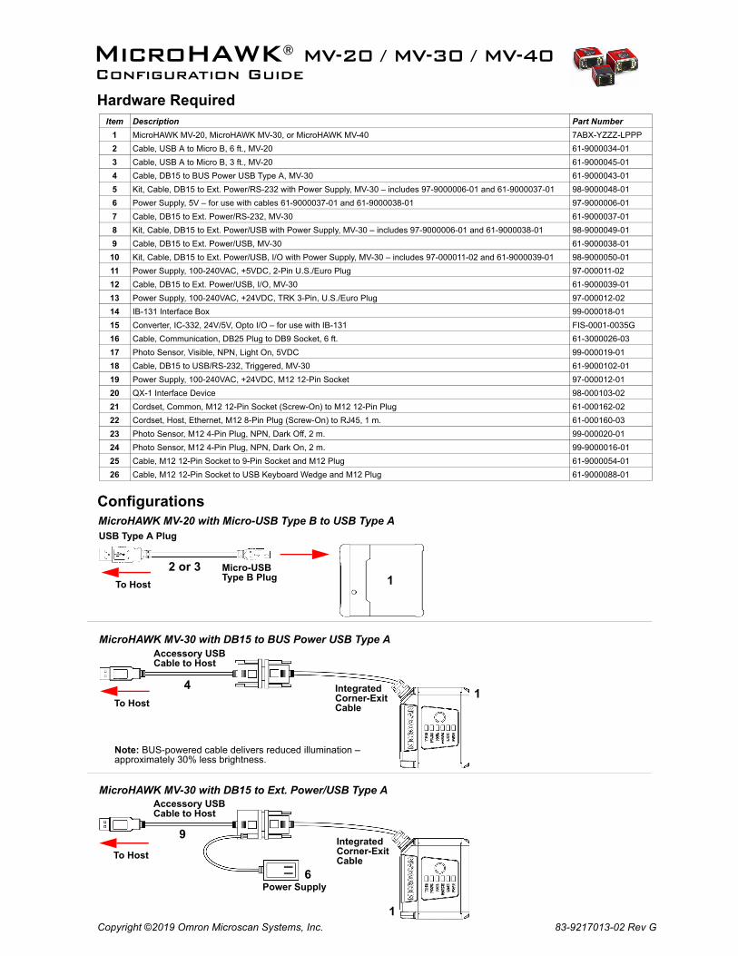
Configurations
Item Description Part Number
1 MicroHAWK MV-20, MicroHAWK MV-30, or MicroHAWK MV-40 7ABX-YZZZ-LPPP
2 Cable, USB A to Micro B, 6 ft., MV-20 61-9000034-01
3 Cable, USB A to Micro B, 3 ft., MV-20 61-9000045-01
4 Cable, DB15 to BUS Power USB Type A, MV-30 61-9000043-01
5 Kit, Cable, DB15 to Ext. Power/RS-232 with Power Supply, MV-30 – includes 97-9000006-01 and 61-9000037-01 98-9000048-01
6 Power Supply, 5V – for use with cables 61-9000037-01 and 61-9000038-01 97-9000006-01
7 Cable, DB15 to Ext. Power/RS-232, MV-30 61-9000037-01
8 Kit, Cable, DB15 to Ext. Power/USB with Power Supply, MV-30 – includes 97-9000006-01 and 61-9000038-01 98-9000049-01
9 Cable, DB15 to Ext. Power/USB, MV-30 61-9000038-01
10 Kit, Cable, DB15 to Ext. Power/USB, I/O with Power Supply, MV-30 – includes 97-000011-02 and 61-9000039-01 98-9000050-01
11 Power Supply, 100-240VAC, +5VDC, 2-Pin U.S./Euro Plug 97-000011-02
12 Cable, DB15 to Ext. Power/USB, I/O, MV-30 61-9000039-01
13 Power Supply, 100-240VAC, +24VDC, TRK 3-Pin, U.S./Euro Plug 97-000012-02
14 IB-131 Interface Box 99-000018-01
15 Converter, IC-332, 24V/5V, Opto I/O – for use with IB-131 FIS-0001-0035G
16 Cable, Communication, DB25 Plug to DB9 Socket, 6 ft. 61-3000026-03
17 Photo Sensor, Visible, NPN, Light On, 5VDC 99-000019-01
18 Cable, DB15 to USB/RS-232, Triggered, MV-30 61-9000102-01
19 Power Supply, 100-240VAC, +24VDC, M12 12-Pin Socket 97-000012-01
20 QX-1 Interface Device 98-000103-02
21 Cordset, Common, M12 12-Pin Socket (Screw-On) to M12 12-Pin Plug 61-000162-02
22 Cordset, Host, Ethernet, M12 8-Pin Plug (Screw-On) to RJ45, 1 m. 61-000160-03
23 Photo Sensor, M12 4-Pin Plug, NPN, Dark Off, 2 m. 99-000020-01
24 Photo Sensor, M12 4-Pin Plug, NPN, Dark On, 2 m. 99-9000016-0125 Cable, M12 12-Pin Socket to 9-Pin Socket and M12 Plug 61-9000054-01
26 Cable, M12 12-Pin Socket to USB Keyboard Wedge and M12 Plug 61-9000088-01
MicroHAWK® MV-20 / MV-30 / MV-40Configuration Guide
Hardware Required
USB Type A PlugMicroHAWK MV-20 with Micro-USB Type B to USB Type A
MicroHAWK MV-30 with DB15 to BUS Power USB Type A
1
MicroHAWK MV-30 with DB15 to Ext. Power/USB Type A
To Host
Micro-USB Type B Plug
2 or 3
1Integrated Corner-Exit Cable
Accessory USB Cable to Host
4To Host
To HostIntegrated Corner-Exit Cable
1
Accessory USB Cable to Host
Power Supply6
9
Note: BUS-powered cable delivers reduced illumination – approximately 30% less brightness.
MicroHAWK MV-20 / MV-30 / MV-40 Configuration
Copyright ©2019 Omron Microscan Systems, Inc.
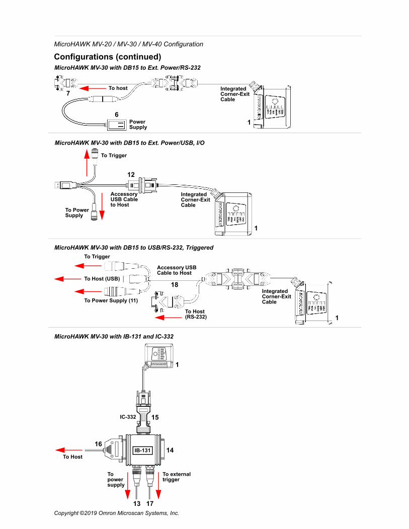
Configurations (continued)MicroHAWK MV-30 with DB15 to Ext. Power/RS-232
MicroHAWK MV-30 with DB15 to Ext. Power/USB, I/O
MicroHAWK MV-30 with IB-131 and IC-332
To power supply
IC-332
IB-131
To external trigger
1
1
1
15
1614
13 17
Power Supply
To host Integrated Corner-Exit Cable
6
7
To Trigger
Accessory USB Cable to Host
Integrated Corner-Exit Cable
To Power Supply
12
MicroHAWK MV-30 with DB15 to USB/RS-232, Triggered
To Host
1
18To Host (USB)
To Trigger
To Power Supply (11)
To Host (RS-232)
Integrated Corner-Exit Cable
Accessory USB Cable to Host
MicroHAWK MV-20 / MV-30 / MV-40 Configuration
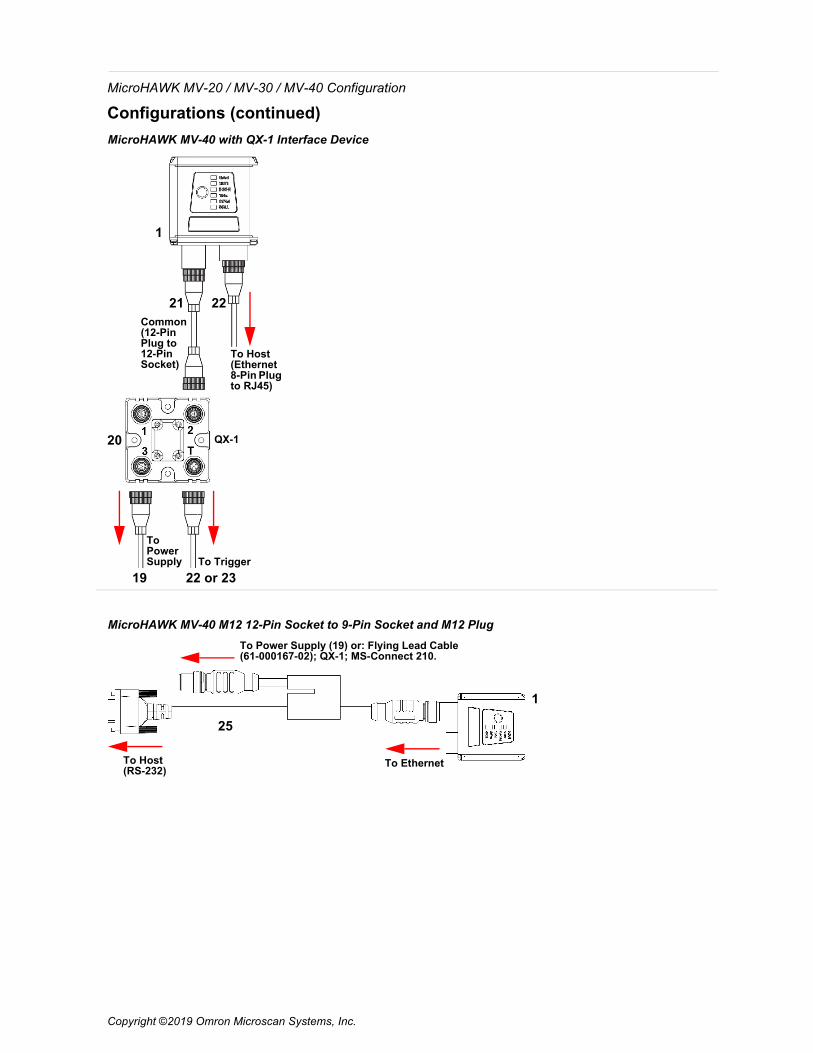
Configurations (continued)MicroHAWK MV-40 with QX-1 Interface Device
1
21 22
20
19 22 or 23
Common (12-Pin Plug to 12-PinSocket)
To Host (Ethernet 8-Pin Plugto RJ45)
QX-1
To Trigger
To Power Supply
MicroHAWK MV-40 M12 12-Pin Socket to 9-Pin Socket and M12 Plug
1
25
To Power Supply (19) or: Flying Lead Cable (61-000167-02); QX-1; MS-Connect 210.
To Host (RS-232)
To Ethernet
Copyright ©2019 Omron Microscan Systems, Inc.

MicroHAWK MV-20 / MV-30 / MV-40 Configuration
Copyright ©2019 Omron Microscan Systems, Inc.
Electrical SpecificationsMicroHAWK MV-20: 5VDC ± 5%, 350 mA at 5VDC (typ.) MicroHAWK MV-30: 5VDC ± 5%, 600 mA at 5VDC (typ.) MicroHAWK MV-40: 4.75 – 30VDC, 200 mV p-p max ripple, 150 mA at 24VDC (typ.)
Important: See the MicroHAWK MV-20 / MV-30 / MV-40 Smart Camera Guide for information about Omron Microscan’s Isolation Mounting Kit (P/N 98-9000064-01) to eliminate ground loops or other external electrical noise through your MicroHAWK MV-30 or MV-40 camera.
MicroHAWK MV-20 Micro-USB Type B Socket
Pin Function1 Vbus (5V)2 D–3 D+4 N/C5 Ground
MicroHAWK MV-30 High-Density 15-Pin Dsub USB/Serial Socket
Pin Function1 +5VDC2 TX2323 RX2324 GND5 D+6 N/C7 Output 1+8 Default+9 Trigger+
10 D–11 Output 3+12 New Master+13 N/C14 Output 2+15 Vbus
Note: An accessory cable is required between the MV-30’s 15-pin corner-exitcable and the host’s USB port.
MicroHAWK MV-40 M12 Connectors
Ground
Output 3
Output 1
Output 2
New MasterDefault
Power
Input CommonOutput Common
RS-232 (Host) RxD
Trigger
RS-232 (Host) TxD
M12 12-Pin Plug
TX (+)
RX (–)
RX (+)
TX (–)
V+
V–
M12 8-Pin Socket (Ethernet)
V+
V–
+10-28V
Trigger
Ground
Trigger/New Master / Input 1 Common
QX-1 Interface Device – for use with the MicroHAWK MV-40 (Top View)
QX-1 Trigger Connector (T) 4-pin Socket
Connector T on the QX-1 Interface Device is the trigger connector.Connectors 1, 2, and 3 can be used to bus power and data as required by the application.
P
T
MicroHAWK MV-20 / MV-30 / MV-40 Configuration
Copyright ©2019 Omron Microscan Systems, Inc.
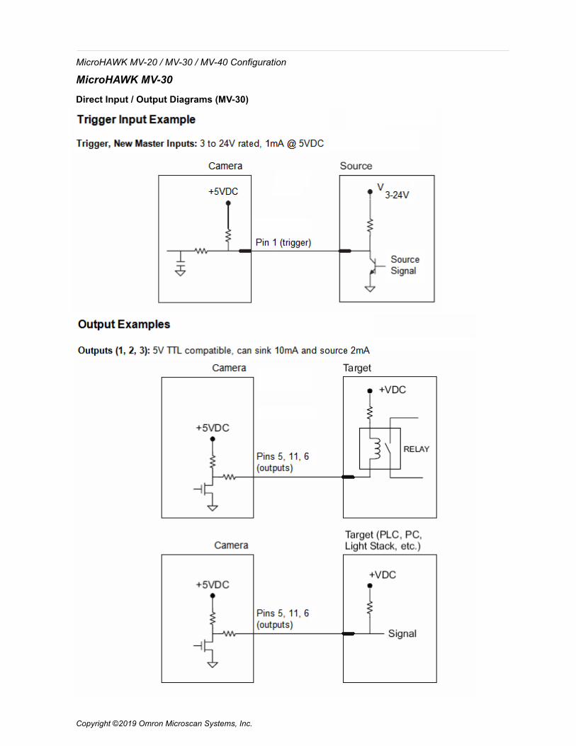
MicroHAWK MV-30
Direct Input / Output Diagrams (MV-30)
MicroHAWK MV-20 / MV-30 / MV-40 Configuration
Copyright ©2019 Omron Microscan Systems, Inc.
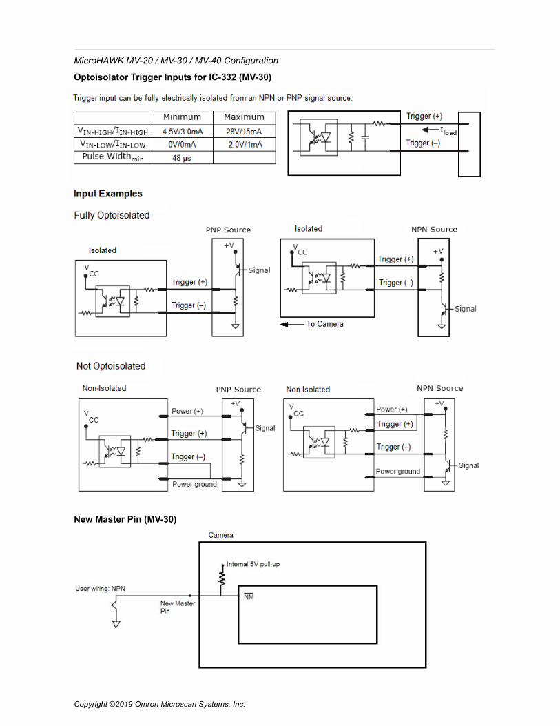
Optoisolator Trigger Inputs for IC-332 (MV-30)
New Master Pin (MV-30)
MicroHAWK MV-20 / MV-30 / MV-40 Configuration
MicroHAWK MV-40
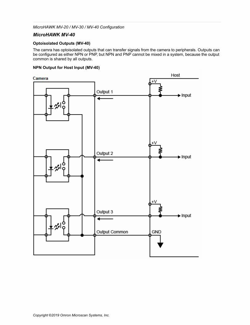
Optoisolated Outputs (MV-40)The camra has optoisolated outputs that can transfer signals from the camera to peripherals. Outputs can be configured as either NPN or PNP, but NPN and PNP cannot be mixed in a system, because the output common is shared by all outputs.
NPN Output for Host Input (MV-40)
Copyright ©2019 Omron Microscan Systems, Inc.

MicroHAWK MV-20 / MV-30 / MV-40 Configuration
NPN Output for External Load (MV-40)
Copyright ©2019 Omron Microscan Systems, Inc.
MicroHAWK MV-20 / MV-30 / MV-40 Configuration
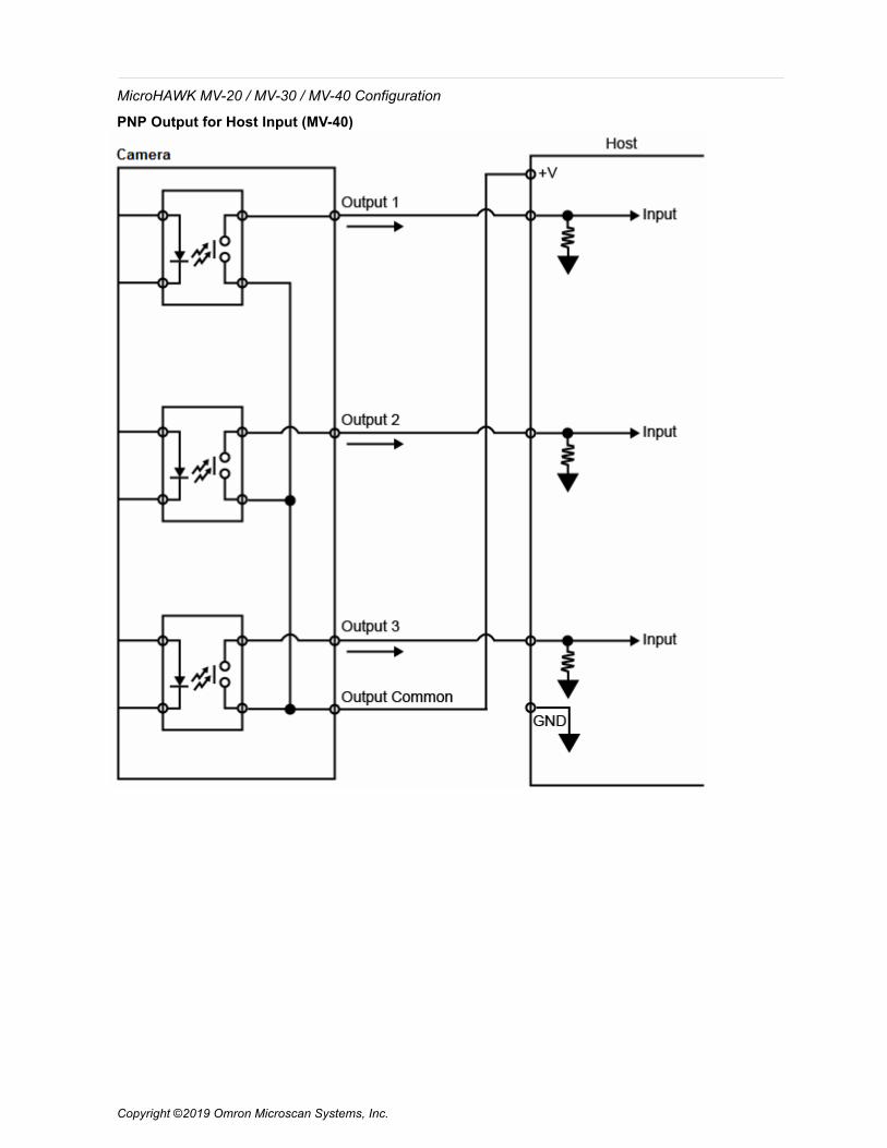
PNP Output for Host Input (MV-40)
Copyright ©2019 Omron Microscan Systems, Inc.
MicroHAWK MV-20 / MV-30 / MV-40 Configuration
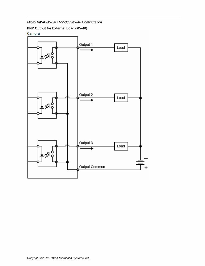
PNP Output for External Load (MV-40)
Copyright ©2019 Omron Microscan Systems, Inc.
MicroHAWK MV-20 / MV-30 / MV-40 Configuration
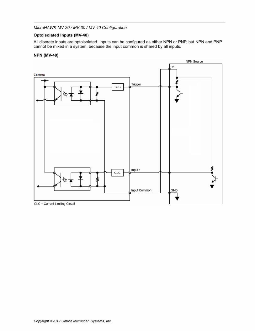
Optoisolated Inputs (MV-40)All discrete inputs are optoisolated. Inputs can be configured as either NPN or PNP, but NPN and PNP cannot be mixed in a system, because the input common is shared by all inputs.
NPN (MV-40)
Copyright ©2019 Omron Microscan Systems, Inc.

MicroHAWK MV-20 / MV-30 / MV-40 Configuration
Copyright ©2019 Omron Microscan Systems, Inc.
PNP (MV-40)
Input/Output Wiring (MV-40)
MicroHAWK MV-20 / MV-30 / MV-40 Configuration
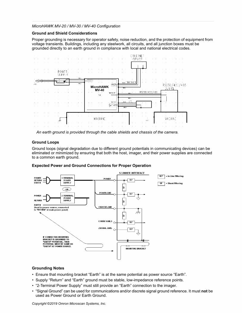
Ground and Shield ConsiderationsProper grounding is necessary for operator safety, noise reduction, and the protection of equipment from voltage transients. Buildings, including any steelwork, all circuits, and all junction boxes must be grounded directly to an earth ground in compliance with local and national electrical codes.
Ground LoopsGround loops (signal degradation due to different ground potentials in communicating devices) can be eliminated or minimized by ensuring that both the host, imager, and their power supplies are connected to a common earth ground.
Expected Power and Ground Connections for Proper Operation
Grounding Notes• Ensure that mounting bracket “Earth” is at the same potential as power source “Earth”.
• Supply “Return” and “Earth” ground must be stable, low-impedance reference points.
• “2-Terminal Power Supply” must still provide an “Earth” connection to the imager.
• “Signal Ground” can be used for communications and/or discrete signal ground reference. It must not beused as Power Ground or Earth Ground.
An earth ground is provided through the cable shields and chassis of the camera.
MicroHAWK MV-40
Copyright ©2019 Omron Microscan Systems, Inc.
MicroHAWK MV-20 / MV-30 / MV-40 Configuration
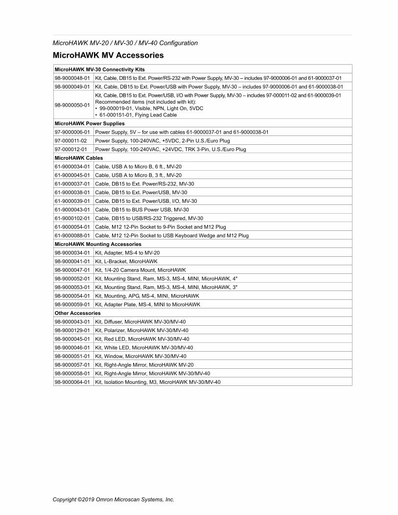
MicroHAWK MV AccessoriesMicroHAWK MV-30 Connectivity Kits98-9000048-01 Kit, Cable, DB15 to Ext. Power/RS-232 with Power Supply, MV-30 – includes 97-9000006-01 and 61-9000037-01
98-9000049-01 Kit, Cable, DB15 to Ext. Power/USB with Power Supply, MV-30 – includes 97-9000006-01 and 61-9000038-01
98-9000050-01
Kit, Cable, DB15 to Ext. Power/USB, I/O with Power Supply, MV-30 – includes 97-000011-02 and 61-9000039-01Recommended items (not included with kit): • 99-000019-01, Visible, NPN, Light On, 5VDC• 61-000151-01, Flying Lead Cable
MicroHAWK Power Supplies97-9000006-01 Power Supply, 5V – for use with cables 61-9000037-01 and 61-9000038-01
97-000011-02 Power Supply, 100-240VAC, +5VDC, 2-Pin U.S./Euro Plug
97-000012-01 Power Supply, 100-240VAC, +24VDC, TRK 3-Pin, U.S./Euro Plug
MicroHAWK Cables61-9000034-01 Cable, USB A to Micro B, 6 ft., MV-20
61-9000045-01 Cable, USB A to Micro B, 3 ft., MV-20
61-9000037-01 Cable, DB15 to Ext. Power/RS-232, MV-30
61-9000038-01 Cable, DB15 to Ext. Power/USB, MV-30
61-9000039-01 Cable, DB15 to Ext. Power/USB, I/O, MV-30
61-9000043-01 Cable, DB15 to BUS Power USB, MV-30
61-9000102-01 Cable, DB15 to USB/RS-232 Triggered, MV-30
61-9000054-01 Cable, M12 12-Pin Socket to 9-Pin Socket and M12 Plug
61-9000088-01 Cable, M12 12-Pin Socket to USB Keyboard Wedge and M12 Plug
MicroHAWK Mounting Accessories98-9000034-01 Kit, Adapter, MS-4 to MV-20
98-9000041-01 Kit, L-Bracket, MicroHAWK
98-9000047-01 Kit, 1/4-20 Camera Mount, MicroHAWK
98-9000052-01 Kit, Mounting Stand, Ram, MS-3, MS-4, MINI, MicroHAWK, 4"
98-9000053-01 Kit, Mounting Stand, Ram, MS-3, MS-4, MINI, MicroHAWK, 3"
98-9000054-01 Kit, Mounting, APG, MS-4, MINI, MicroHAWK
98-9000059-01 Kit, Adapter Plate, MS-4, MINI to MicroHAWK
Other Accessories98-9000043-01 Kit, Diffuser, MicroHAWK MV-30/MV-40
98-9000129-01 Kit, Polarizer, MicroHAWK MV-30/MV-40
98-9000045-01 Kit, Red LED, MicroHAWK MV-30/MV-40
98-9000046-01 Kit, White LED, MicroHAWK MV-30/MV-40
98-9000051-01 Kit, Window, MicroHAWK MV-30/MV-40
98-9000057-01 Kit, Right-Angle Mirror, MicroHAWK MV-20
98-9000058-01 Kit, Right-Angle Mirror, MicroHAWK MV-30/MV-40
98-9000064-01 Kit, Isolation Mounting, M3, MicroHAWK MV-30/MV-40
Copyright ©2019 Omron Microscan Systems, Inc.
MicroHAWK MV-20 / MV-30 / MV-40 Configuration
Copyright ©2019 Omron Microscan Systems, Inc.
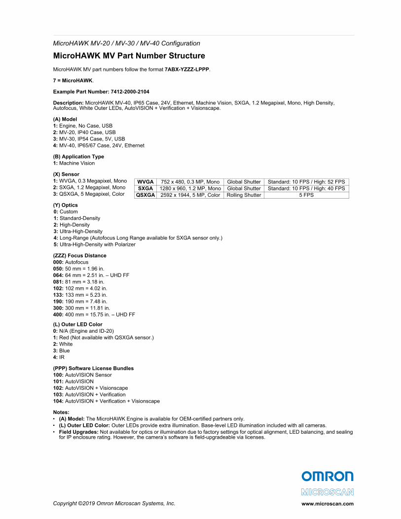
MicroHAWK MV Part Number Structure
MicroHAWK MV part numbers follow the format 7ABX-YZZZ-LPPP.
7 = MicroHAWK.
Example Part Number: 7412-2000-2104
Description: MicroHAWK MV-40, IP65 Case, 24V, Ethernet, Machine Vision, SXGA, 1.2 Megapixel, Mono, High Density, Autofocus, White Outer LEDs, AutoVISION + Verification + Visionscape.
(A) Model1: Engine, No Case, USB2: MV-20, IP40 Case, USB3: MV-30, IP54 Case, 5V, USB4: MV-40, IP65/67 Case, 24V, Ethernet
(B) Application Type1: Machine Vision
(X) Sensor1: WVGA, 0.3 Megapixel, Mono 2: SXGA, 1.2 Megapixel, Mono 3: QSXGA, 5 Megapixel, Color
(Y) Optics0: Custom1: Standard-Density2: High-Density3: Ultra-High-Density4: Long-Range (Autofocus Long Range available for SXGA sensor only.)5: Ultra-High-Density with Polarizer
(ZZZ) Focus Distance 000: Autofocus050: 50 mm = 1.96 in.064: 64 mm = 2.51 in. – UHD FF081: 81 mm = 3.18 in.102: 102 mm = 4.02 in.133: 133 mm = 5.23 in.190: 190 mm = 7.48 in.300: 300 mm = 11.81 in.400: 400 mm = 15.75 in. – UHD FF
(L) Outer LED Color0: N/A (Engine and ID-20)1: Red (Not available with QSXGA sensor.)2: White3: Blue4: IR
(PPP) Software License Bundles 100: AutoVISION Sensor101: AutoVISION102: AutoVISION + Visionscape103: AutoVISION + Verification104: AutoVISION + Verification + Visionscape
Notes:• (A) Model: The MicroHAWK Engine is available for OEM-certified partners only.• (L) Outer LED Color: Outer LEDs provide extra illumination. Base-level LED illumination included with all cameras.• Field Upgrades: Not available for optics or illumination due to factory settings for optical alignment, LED balancing, and sealing
for IP enclosure rating. However, the camera’s software is field-upgradeable via licenses.
www.microscan.com
WVGA 752 x 480, 0.3 MP, Mono Global Shutter Standard: 10 FPS / High: 52 FPSSXGA 1280 x 960, 1.2 MP, Mono Global Shutter Standard: 10 FPS / High: 40 FPS
QSXGA 2592 x 1944, 5 MP, Color Rolling Shutter 5 FPS