microlite 4000 series - twinslann0nas/manuals/onan/981-0154 onan ky (spec d-h... · microlite 4000...
TRANSCRIPT

Printed in U.S.A. 981−0154
7−97
MicroLite 4000 Series
KY
Safety PrecautionsBefore operating the generator set, read this manualand become familiar with it and the equipment. Safe andefficient operation can be achieved only if the unit isproperly operated and maintained. Many accidents arecaused by failure to follow fundamental rules and precau-tions.The following symbols, found throughout this manual,alert you to potentially dangerous conditions to the opera-tor, service personnel, or the equipment.
This symbol warns of immediate haz-ards which will result in severe personal injury ordeath.
This symbol refers to a hazard or unsafepractice which can result in severe personal injury ordeath.
This symbol refers to a hazard or unsafepractice which can result in personal injury or prod-uct or property damage.Read and observe each of the following safety precau-tions.
FUEL AND FUMES ARE FLAMMABLEFire, explosion, and personal injury can result from im-proper practices.• Do not smoke or allow an open flame or spark-produc-
ing equipment near the generator set or fuel tank.• Inspect the fuel lines and connections daily for leaks
per the maintenance schedule.EXHAUST GASES ARE DEADLY
• Never sleep in the vehicle with the generator set run-ning unless vehicle is equipped with an operating car-bon monoxide detector.
• Inspect exhaust system daily for leaks per the mainte-nance schedule. Do not use engine cooling air to heat acompartment.
• Never operate the generator set inside a building or inan area where exhaust gases could accumulate, suchas near a wall or snow bank, or in high grass. Whenparking, make sure the exhaust outlet is not ob-structed. Make sure the generator set is well ventilated.ELECTRICAL SHOCK CAN CAUSE SEVERE
PERSONAL INJURY OR DEATH• Disconnect the negative (-) cable at the starting battery
before removing protective shields or touching electri-cal equipment. Use rubber insulative mats placed ondry wood platforms on the ground or over floors that aremetal or concrete when around electrical equipment.Do not wear damp clothing (particularly wet shoes) orallow skin surfaces to be damp when handling electri-cal equipment.
• Use extreme caution when working on electrical com-ponents. High voltages can cause injury or death.
• Tag remote or open switches to avoid accidental clo-sure or starting.
• DO NOT CONNECT GENERATOR SET DIRECTLYTO ANY BUILDING ELECTRICAL SYSTEM. Hazard-ous voltages can flow from the generator set into theutility line. This creates a potential for electrocution orproperty damage. Connect only through an approveddevice and after building main switch is open. Consultan electrician in regard to emergency power use.
MOVING PARTS CAN CAUSE SEVEREPERSONAL INJURY OR DEATH
• Before starting work on the generator set, disconnectnegative (-) cable at the battery. This will prevent acci-dental arcing or starting.
• Keep your hands away from moving parts.• Make sure that fasteners on the generator set are se-
cure. Tighten supports and clamps, keep guards inposition over fans, etc.
• Do not wear loose clothing or jewelry while working ongenerator sets, because they can become caught inmoving parts. Jewelry can short out electrical contactsand cause shock or burning.
• If adjustment must be made while the unit is running,use extreme caution around hot manifolds, movingparts, etc.
GENERAL SAFETY PRECAUTIONS• Wear safety glasses and protective clothing when ser-
vicing batteries. DO NOT SMOKE while servicing bat-teries. Lead-acid batteries emit a highly explosive hy-drogen gas that can be ignited by electrical arcing or bysmoking.
• Have a fire extinguisher rated ABC nearby. Maintainextinguisher properly and become familiar with its use.
• Benzene and lead, found in some gasoline, have beenidentified by some state and federal agencies as caus-ing cancer or reproductive toxicity. When checking,draining or adding gasoline, take care not to ingest,breathe the fumes, or contact gasoline.
• Used engine oils have been identified by some state orfederal agencies as causing cancer or reproductivetoxicity. When checking or changing engine oil, takecare not to ingest, breathe the fumes, or contact usedoil.
• Remove all unnecessary grease and oil from the unit.Accumulated grease and oil can cause overheatingand engine damage, which presents a potential firehazard.
• Do not store anything in the generator set compartmentsuch as oil or gas cans, oily rags, chains, woodenblocks, portable propane cylinders, etc. A fire could re-sult or the generator set operation (cooling, noise andvibration) may be adversely affected. Keep thecompartment floor clean and dry.
• Do not work on this equipment when mentally or physi-cally fatigued, or after consuming any alcohol or drugthat makes the operation of equipment unsafe.
RGA-OP1
1
Table of ContentsSAFETY PRECAUTIONS Inside Front Cover. . . . . . . . . . . . . . . . . . . . . . . . . . . . . . . . . . . . . . . . . . . . . . INTRODUCTION 2. . . . . . . . . . . . . . . . . . . . . . . . . . . . . . . . . . . . . . . . . . . . . . . . . . . . . . . . . . . . . . . . . .
About This Manual 2. . . . . . . . . . . . . . . . . . . . . . . . . . . . . . . . . . . . . . . . . . . . . . . . . . . . . . . . . . Model Identification 2. . . . . . . . . . . . . . . . . . . . . . . . . . . . . . . . . . . . . . . . . . . . . . . . . . . . . . . . . Fuel Recommendations 3. . . . . . . . . . . . . . . . . . . . . . . . . . . . . . . . . . . . . . . . . . . . . . . . . . . . . Engine Oil Recommendations 3. . . . . . . . . . . . . . . . . . . . . . . . . . . . . . . . . . . . . . . . . . . . . . . . Starting Batteries 3. . . . . . . . . . . . . . . . . . . . . . . . . . . . . . . . . . . . . . . . . . . . . . . . . . . . . . . . . . .
COMPONENT LOCATIONS 4. . . . . . . . . . . . . . . . . . . . . . . . . . . . . . . . . . . . . . . . . . . . . . . . . . . . . . . . . Components Requiring Periodic Attention Or Maintenance 4. . . . . . . . . . . . . . . . . . . . . . . Genset Control Panel 5. . . . . . . . . . . . . . . . . . . . . . . . . . . . . . . . . . . . . . . . . . . . . . . . . . . . . . . Remote Control 5. . . . . . . . . . . . . . . . . . . . . . . . . . . . . . . . . . . . . . . . . . . . . . . . . . . . . . . . . . . . .
STARTING AND STOPPING 6. . . . . . . . . . . . . . . . . . . . . . . . . . . . . . . . . . . . . . . . . . . . . . . . . . . . . . . . Pre-start Checks 6. . . . . . . . . . . . . . . . . . . . . . . . . . . . . . . . . . . . . . . . . . . . . . . . . . . . . . . . . . . . Starting 6. . . . . . . . . . . . . . . . . . . . . . . . . . . . . . . . . . . . . . . . . . . . . . . . . . . . . . . . . . . . . . . . . . . . Stopping 6. . . . . . . . . . . . . . . . . . . . . . . . . . . . . . . . . . . . . . . . . . . . . . . . . . . . . . . . . . . . . . . . . . .
POWERING EQUIPMENT 7. . . . . . . . . . . . . . . . . . . . . . . . . . . . . . . . . . . . . . . . . . . . . . . . . . . . . . . . . . Genset Loading 7. . . . . . . . . . . . . . . . . . . . . . . . . . . . . . . . . . . . . . . . . . . . . . . . . . . . . . . . . . . . Restarting A Stalled Genset 7. . . . . . . . . . . . . . . . . . . . . . . . . . . . . . . . . . . . . . . . . . . . . . . . . . Resetting Circuit Breakers 8. . . . . . . . . . . . . . . . . . . . . . . . . . . . . . . . . . . . . . . . . . . . . . . . . . . Connecting The Vehicle To Utility Power 8. . . . . . . . . . . . . . . . . . . . . . . . . . . . . . . . . . . . . . .
VARYING OPERATING CONDITIONS 9. . . . . . . . . . . . . . . . . . . . . . . . . . . . . . . . . . . . . . . . . . . . . . . Cold Weather 9. . . . . . . . . . . . . . . . . . . . . . . . . . . . . . . . . . . . . . . . . . . . . . . . . . . . . . . . . . . . . . Hot Weather 9. . . . . . . . . . . . . . . . . . . . . . . . . . . . . . . . . . . . . . . . . . . . . . . . . . . . . . . . . . . . . . . High Altitude 9. . . . . . . . . . . . . . . . . . . . . . . . . . . . . . . . . . . . . . . . . . . . . . . . . . . . . . . . . . . . . . . Dusty Conditions 9. . . . . . . . . . . . . . . . . . . . . . . . . . . . . . . . . . . . . . . . . . . . . . . . . . . . . . . . . . .
PERIODIC MAINTENANCE 10. . . . . . . . . . . . . . . . . . . . . . . . . . . . . . . . . . . . . . . . . . . . . . . . . . . . . . . . . Oil Level Check And General Inspection 11. . . . . . . . . . . . . . . . . . . . . . . . . . . . . . . . . . . . . . . Checking Engine Oil Level 12. . . . . . . . . . . . . . . . . . . . . . . . . . . . . . . . . . . . . . . . . . . . . . . . . . . Changing Engine Oil 13. . . . . . . . . . . . . . . . . . . . . . . . . . . . . . . . . . . . . . . . . . . . . . . . . . . . . . . . Battery Care 14. . . . . . . . . . . . . . . . . . . . . . . . . . . . . . . . . . . . . . . . . . . . . . . . . . . . . . . . . . . . . . . Air Filter 15. . . . . . . . . . . . . . . . . . . . . . . . . . . . . . . . . . . . . . . . . . . . . . . . . . . . . . . . . . . . . . . . . . . Spark Plug 16. . . . . . . . . . . . . . . . . . . . . . . . . . . . . . . . . . . . . . . . . . . . . . . . . . . . . . . . . . . . . . . . . Spark Arrestor 16. . . . . . . . . . . . . . . . . . . . . . . . . . . . . . . . . . . . . . . . . . . . . . . . . . . . . . . . . . . . . .
GENSET BREAK-IN, EXERCISE AND STORAGE 17. . . . . . . . . . . . . . . . . . . . . . . . . . . . . . . . . . . . . Break-in 17. . . . . . . . . . . . . . . . . . . . . . . . . . . . . . . . . . . . . . . . . . . . . . . . . . . . . . . . . . . . . . . . . . . Exercise 17. . . . . . . . . . . . . . . . . . . . . . . . . . . . . . . . . . . . . . . . . . . . . . . . . . . . . . . . . . . . . . . . . . . Storage 18. . . . . . . . . . . . . . . . . . . . . . . . . . . . . . . . . . . . . . . . . . . . . . . . . . . . . . . . . . . . . . . . . . . .
TROUBLESHOOTING 19. . . . . . . . . . . . . . . . . . . . . . . . . . . . . . . . . . . . . . . . . . . . . . . . . . . . . . . . . . . . . SPECIFICATIONS 20. . . . . . . . . . . . . . . . . . . . . . . . . . . . . . . . . . . . . . . . . . . . . . . . . . . . . . . . . . . . . . . . . INFORMATION FOR CALIFORNIA GENSET USERS 21. . . . . . . . . . . . . . . . . . . . . . . . . . . . . . . . . . HOW TO OBTAIN SERVICE 22. . . . . . . . . . . . . . . . . . . . . . . . . . . . . . . . . . . . . . . . . . . . . . . . . . . . . . . . MAINTENANCE RECORD 23. . . . . . . . . . . . . . . . . . . . . . . . . . . . . . . . . . . . . . . . . . . . . . . . . . . . . . . . . .
The engine exhaust from this productcontains chemicals known to the State
of California to cause cancer, birth defects or other reproductive harm.
! !
2
IntroductionABOUT THIS MANUAL
This manual covers the operation and maintenanceof the MicroLite KY series of generator sets (gen-sets). Study this manual carefully and observe all ofits instructions and precautions.
Component Locations, Starting and Stopping, Pow-ering Equipment and Varying Operating Conditionscover basic operation of the genset. Periodic Main-tenance and Troubleshooting cover the mainte-nance and care necessary for top performance. Theowner is responsible for maintaining the genset ac-cording to the maintenance schedule (Table 4 onpage 10).
This manual also covers genset break-in, exerciseand storage, how to obtain service, genset specifi-cations and important information for Californiagenset users.
Each operator of the genset should become thor-oughly familiar with the information in this manual.Keep this manual and the genset Installation Manu-al with the other vehicle manuals.
MODEL IDENTIFICATION
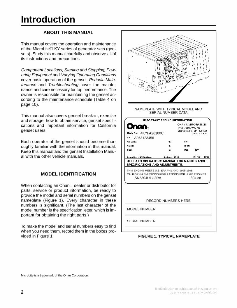
When contacting an Onan dealer or distributor forparts, service or product information, be ready toprovide the model and serial numbers on the gensetnameplate (Figure 1). Every character in thesenumbers is significant. (The last character of themodel number is the specification letter, which is im-portant for obtaining the right parts.)
To make the model and serial numbers easy to findwhen you need them, record them in the boxes pro-vided in Figure 1.
SN5304U1G2RA 304 cc
A953123456
RECORD NUMBERS HERE
MODEL NUMBER:
SERIAL NUMBER:
NAMEPLATE WITH TYPICAL MODEL ANDSERIAL NUMBER DATA
4KYFA26100C
THIS ENGINE MEETS U.S. EPA PH1 AND 1995-1998CALIFORNIA EMISSIONS REGULATIONS FOR ULGE ENGINES
FIGURE 1. TYPICAL NAMEPLATE
MicroLite is a trademark of the Onan Corporation.
3
FUEL RECOMMENDATIONS
WARNING Gasoline and LPG are highly flam-mable fuels and can cause severe personal inju-ry or death. Do not smoke if you smell gas orgasoline or are near fuel tanks or fuel-burningequipment or are in an area sharing ventilationwith such equipment. Keep flames, sparks, pilotlights, electrical arcs and arc-producing equip-ment and all other sources of ignition well away.Keep a type ABC fire extinguisher in the vehicle.
Gasoline Models
Use clean, fresh unleaded gasoline having a mini-mum octane rating (Anti-Knock Index) of 87.
During some times of the year only mandated “oxy-genated” gasolines may be available. These are ac-ceptable for use, but not preferable. Leaded gaso-line may be used but will result in the extra mainte-nance required for removing combustion chamberand spark plug deposits. Do not use gasoline orgasoline additives (de-icers) containing methanolbecause methanol can be corrosive to fuel systemcomponents.
CAUTION Do not use gasoline or gasoline ad-ditives containing methanol because methanolcan be corrosive to fuel system components.
Avoid using highly leaded gasolines and leadadditives because of the extra engine mainte-nance that will be required.
LPG Models
Use clean, fresh HD-5 grade liquified petroleum gas(LPG) or equivalent product consisting of at least 90percent propane. Commercial liquified petroleumgas fuels may contain more than 2.5 percent butanewhich can result in poor fuel vaporization and poorengine starting in low ambient temperatures (below32° F (0° C).
Satisfactory performance requires that the LPG va-por be supplied at a pressure within the range indi-cated in Specifications.
WARNING High LPG supply pressure cancause gas leaks which can lead to fire and se-vere personal injury or death. LPG supply pres-sure must be adjusted to Specifications by qual-ified personnel.
ENGINE OIL RECOMMENDATIONS
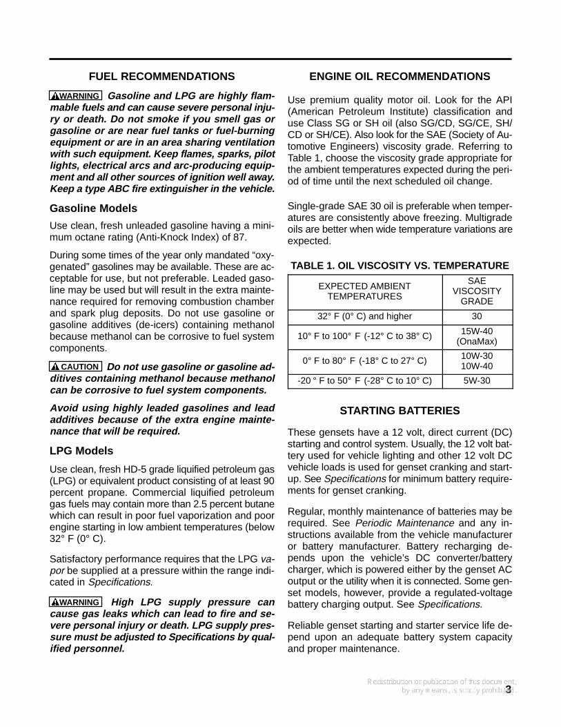
Use premium quality motor oil. Look for the API(American Petroleum Institute) classification anduse Class SG or SH oil (also SG/CD, SG/CE, SH/CD or SH/CE). Also look for the SAE (Society of Au-tomotive Engineers) viscosity grade. Referring toTable 1, choose the viscosity grade appropriate forthe ambient temperatures expected during the peri-od of time until the next scheduled oil change.
Single-grade SAE 30 oil is preferable when temper-atures are consistently above freezing. Multigradeoils are better when wide temperature variations areexpected.
TABLE 1. OIL VISCOSITY VS. TEMPERATURE
EXPECTED AMBIENTTEMPERATURES
SAEVISCOSITY
GRADE
32° F (0° C) and higher 30
10° F to 100° F (-12° C to 38° C) 15W-40(OnaMax)
0° F to 80° F (-18° C to 27° C) 10W-3010W-40
-20 ° F to 50° F (-28° C to 10° C) 5W-30
STARTING BATTERIES
These gensets have a 12 volt, direct current (DC)starting and control system. Usually, the 12 volt bat-tery used for vehicle lighting and other 12 volt DCvehicle loads is used for genset cranking and start-up. See Specifications for minimum battery require-ments for genset cranking.
Regular, monthly maintenance of batteries may berequired. See Periodic Maintenance and any in-structions available from the vehicle manufactureror battery manufacturer. Battery recharging de-pends upon the vehicle’s DC converter/batterycharger, which is powered either by the genset ACoutput or the utility when it is connected. Some gen-set models, however, provide a regulated-voltagebattery charging output. See Specifications.
Reliable genset starting and starter service life de-pend upon an adequate battery system capacityand proper maintenance.

4
Component LocationsCOMPONENTS REQUIRING PERIODIC
ATTENTION OR MAINTENANCE
The control panel and the components requiringattention during periodic maintenance (see PeriodicMaintenance) are located behind a removable ac-cess cover. See Figure 2.
Removing the access cover: Turn the two coverlatches counterclockwise to OPEN and pull the topof the cover outward.
Securing the access cover: Position the bottom ofthe cover so that its lip catches the top edge of thebase tray, rotate the top of the cover towards the
genset and turn the two cover latches clockwise toCLOSED, making sure the latches catch.
WARNING Operating the genset with the ac-cess cover removed can result in severe per-sonal injury or equipment damage. Hot compo-nents are exposed when the access cover is re-moved and genset cooling air does not circulateproperly. Do not operate the genset with the ac-cess cover removed.
The genset itself is usually located behind a door ina compartment somewhere around the perimeter ofthe vehicle.
REMOVABLEACCESS COVER
MUFFLER(inside cover)
CONTROL PANEL(See Figure 3 for details)
OIL DRAIN(bottom)
AIR FILTERCOVER
CARBURETOR ALTITUDEADJUST KNOB
(gasoline models only)
OIL FILL CAPAND DIPSTICK
SPARK PLUG(not visible)
FIGURE 2. COMPONENT LOCATIONS
5
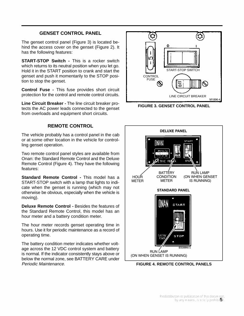
GENSET CONTROL PANEL
The genset control panel (Figure 3) is located be-hind the access cover on the genset (Figure 2). Ithas the following features:
START-STOP Switch - This is a rocker switchwhich returns to its neutral position when you let go.Hold it in the START position to crank and start thegenset and push it momentarily to the STOP posi-tion to stop the genset.
Control Fuse - This fuse provides short circuitprotection for the control and remote control circuits.
Line Circuit Breaker - The line circuit breaker pro-tects the AC power leads connected to the gensetfrom overloads and equipment short circuits.
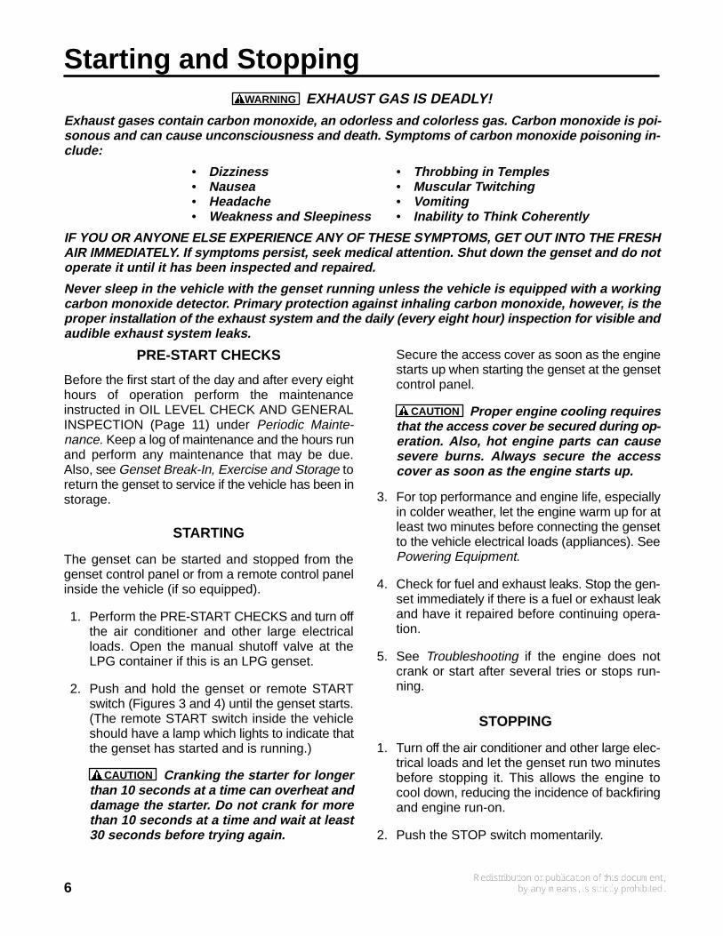
REMOTE CONTROL
The vehicle probably has a control panel in the cabor at some other location in the vehicle for control-ling genset operation.
Two remote control panel styles are available fromOnan: the Standard Remote Control and the DeluxeRemote Control (Figure 4). They have the followingfeatures:
Standard Remote Control - This model has aSTART-STOP switch with a lamp that lights to indi-cate when the genset is running (which may nototherwise be obvious, especially when the vehicle ismoving).
Deluxe Remote Control - Besides the features ofthe Standard Remote Control, this model has anhour meter and a battery condition meter.
The hour meter records genset operating time inhours. Use it for periodic maintenance as a record ofoperating time.
The battery condition meter indicates whether volt-age across the 12 VDC control system and batteryis normal. If the indicator consistently stays above orbelow the normal zone, see BATTERY CARE underPeriodic Maintenance.
M1896−4
CONTROLFUSE
START-STOP SWITCH
LINE CIRCUIT BREAKER
FIGURE 3. GENSET CONTROL PANEL
DELUXE PANEL
STANDARD PANEL
ES1684s-1
RUN LAMP(ON WHEN GENSET IS RUNNING)
RUN LAMP(ON WHEN GENSET
IS RUNNING)HOURMETER
BATTERYCONDITION
METER
FIGURE 4. REMOTE CONTROL PANELS
6
Starting and StoppingWARNING EXHAUST GAS IS DEADLY!
Exhaust gases contain carbon monoxide, an odorless and colorless gas. Carbon monoxide is poi-sonous and can cause unconsciousness and death. Symptoms of carbon monoxide poisoning in-clude:
• Dizziness • Throbbing in Temples• Nausea • Muscular Twitching• Headache • Vomiting• Weakness and Sleepiness • Inability to Think Coherently
IF YOU OR ANYONE ELSE EXPERIENCE ANY OF THESE SYMPTOMS, GET OUT INTO THE FRESHAIR IMMEDIATELY. If symptoms persist, seek medical attention. Shut down the genset and do notoperate it until it has been inspected and repaired.
Never sleep in the vehicle with the genset running unless the vehicle is equipped with a workingcarbon monoxide detector. Primary protection against inhaling carbon monoxide, however, is theproper installation of the exhaust system and the daily (every eight hour) inspection for visible andaudible exhaust system leaks.
PRE-START CHECKS
Before the first start of the day and after every eighthours of operation perform the maintenanceinstructed in OIL LEVEL CHECK AND GENERALINSPECTION (Page 11) under Periodic Mainte-nance. Keep a log of maintenance and the hours runand perform any maintenance that may be due.Also, see Genset Break-In, Exercise and Storage toreturn the genset to service if the vehicle has been instorage.
STARTING
The genset can be started and stopped from thegenset control panel or from a remote control panelinside the vehicle (if so equipped).
1. Perform the PRE-START CHECKS and turn offthe air conditioner and other large electricalloads. Open the manual shutoff valve at theLPG container if this is an LPG genset.
2. Push and hold the genset or remote STARTswitch (Figures 3 and 4) until the genset starts.(The remote START switch inside the vehicleshould have a lamp which lights to indicate thatthe genset has started and is running.)
CAUTION Cranking the starter for longerthan 10 seconds at a time can overheat anddamage the starter. Do not crank for morethan 10 seconds at a time and wait at least30 seconds before trying again.
Secure the access cover as soon as the enginestarts up when starting the genset at the gensetcontrol panel.
CAUTION Proper engine cooling requiresthat the access cover be secured during op-eration. Also, hot engine parts can causesevere burns. Always secure the accesscover as soon as the engine starts up.
3. For top performance and engine life, especiallyin colder weather, let the engine warm up for atleast two minutes before connecting the gensetto the vehicle electrical loads (appliances). SeePowering Equipment.
4. Check for fuel and exhaust leaks. Stop the gen-set immediately if there is a fuel or exhaust leakand have it repaired before continuing opera-tion.
5. See Troubleshooting if the engine does notcrank or start after several tries or stops run-ning.
STOPPING
1. Turn off the air conditioner and other large elec-trical loads and let the genset run two minutesbefore stopping it. This allows the engine tocool down, reducing the incidence of backfiringand engine run-on.
2. Push the STOP switch momentarily.
7
Powering EquipmentGENSET LOADING
The AC output of the genset powers the vehicle airconditioner, the DC converter/battery charger andthe appliances that may be plugged into the electri-cal outlets of the vehicle. How much electricalequipment (power consuming appliances) can beoperated at one time depends upon how much pow-er is available from the genset. If the genset is “over-loaded”, either the genset will stall or its circuitbreaker(s) will trip.
To get an idea of how much equipment can be oper-ated at one time add up the watt ratings of the indi-vidual appliances that are likely to be used at thesame time and compare the sum to the kW (kilo-watt) rating of the genset. Use Table 2 or the ratingson the appliances themselves (if so marked) to ob-tain the appliance watt values. Note that1 kW = 1000 watts. If power consumption, as to-taled up, exceeds genset power output, you mayhave to consider operating some appliances in se-quence, one after another, rather than all at thesame time.
Note that when the genset is loaded nearly to fullpower it is possible that it may stall when the air con-ditioner (or other large motor load) “cycles on”. Thereason for this is that for a brief moment at startup amotor draws up to three times the power stated onits nameplate. You may, therefore, have to consideroperating some appliances at times when the airconditioner or other large motor load is not “On”.
Note also that as altitude increases air density de-creases, causing genset engine power to decrease(even when the altitude adjust knob is set correct-ly—see Varying Operating Conditions). Power de-creases approximately 3.5 percent of rated powereach 1000 feet (305 m) of increase in elevationabove sea level. See Table 3 for the results of cal-culations for a typical genset. Therefore, at higheraltitudes consider operating fewer appliances at thesame time.
Electrical equipment and tools must be properlygrounded and in good working condition.
WARNING Electrical shock can cause severepersonal injury or death. Read and follow theequipment and tool manufacturer’s instruc-tions and warnings.
TABLE 2. TYPICAL APPLIANCE POWERCONSUMPTION
Appliance Power Consumption(watts)
Air Conditioner 1400-2000
Battery Charger Up to 800
DC Converter 300-500
Refrigerator 600-1000
Microwave Oven 1000-1500
Electric Frying Pan or Wok 1000-1500
Electric Stove Element 350-1000
Electric Water Heater 1000-1500
Electric Iron 500-1200
Electric Hair Dryer 800-1500
Coffee Percolator 550-750
Television 200-600
Radio 50-200
Electric Drill 250-750
Electric Broom 200-500
Electric Blanket 50-200
TABLE 3. POWER VS. ALTITUDE—4.0 KWGENSET
Elevation above SeaLevel
Maximum Genset PowerOutput*
at 500 feet (152 m)and below
4000 watts (rated)
at 2500 feet (762 m) 3720 watts
at 5500 feet (1676 m) 3300 watts
above5500 feet (1676 m)
3300 watts minus140 watts for each
additional 1000 feet (305 m)
* This table does not take into account the effectcircuit breakers may have in limiting maximumcontinuous power output.
RESTARTING A STALLED GENSET
If the genset stalls, disconnect or turn off as manyappliances as possible and try restarting the gensetas instructed under Starting and Stopping. Recon-nect the loads (appliances) one by one up to a totalload that does not overload the genset or cause thecircuit breaker to trip.
8
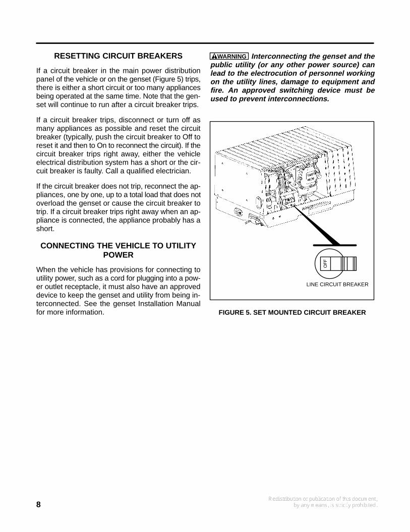
RESETTING CIRCUIT BREAKERS
If a circuit breaker in the main power distributionpanel of the vehicle or on the genset (Figure 5) trips,there is either a short circuit or too many appliancesbeing operated at the same time. Note that the gen-set will continue to run after a circuit breaker trips.
If a circuit breaker trips, disconnect or turn off asmany appliances as possible and reset the circuitbreaker (typically, push the circuit breaker to Off toreset it and then to On to reconnect the circuit). If thecircuit breaker trips right away, either the vehicleelectrical distribution system has a short or the cir-cuit breaker is faulty. Call a qualified electrician.
If the circuit breaker does not trip, reconnect the ap-pliances, one by one, up to a total load that does notoverload the genset or cause the circuit breaker totrip. If a circuit breaker trips right away when an ap-pliance is connected, the appliance probably has ashort.
CONNECTING THE VEHICLE TO UTILITYPOWER
When the vehicle has provisions for connecting toutility power, such as a cord for plugging into a pow-er outlet receptacle, it must also have an approveddevice to keep the genset and utility from being in-terconnected. See the genset Installation Manualfor more information.
WARNING Interconnecting the genset and thepublic utility (or any other power source) canlead to the electrocution of personnel workingon the utility lines, damage to equipment andfire. An approved switching device must beused to prevent interconnections.
LINE CIRCUIT BREAKER
FIGURE 5. SET MOUNTED CIRCUIT BREAKER
9
Varying Operating ConditionsCOLD WEATHER
Pay particular attention to the following items whenoperating the genset in cold weather:
1. Make sure the engine oil viscosity is appropri-ate for the cold weather temperatures. SeeTable 1. Be sure to change the oil if a suddendrop in temperature occurs.
2. Set the altitude adjust knob (Figure 6) for youraltitude (gasoline models only).
HOT WEATHER
Pay particular attention to the following items whenoperating the genset in hot weather:
1. Make sure nothing blocks the airflow to andfrom the set.
2. Make sure the engine oil viscosity is appropri-ate for the hot weather temperatures. SeeTable 1.
3. Keep the genset clean.
4. Perform maintenance due. See Periodic Main-tenance.
5. Set the altitude adjust knob (Figure 6) for youraltitude (gasoline models only).
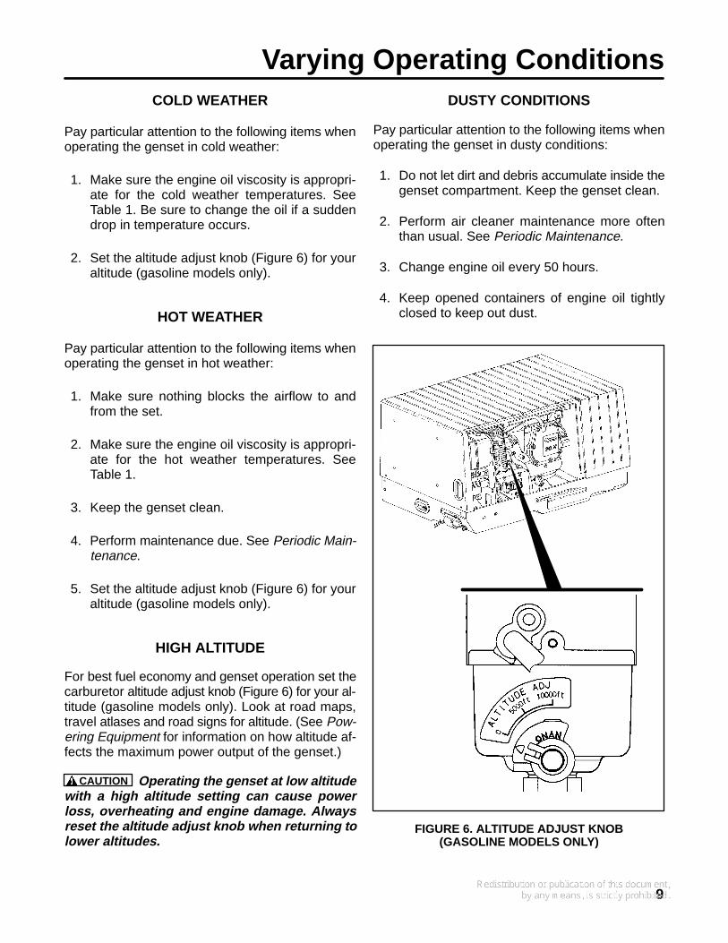
HIGH ALTITUDE
For best fuel economy and genset operation set thecarburetor altitude adjust knob (Figure 6) for your al-titude (gasoline models only). Look at road maps,travel atlases and road signs for altitude. (See Pow-ering Equipment for information on how altitude af-fects the maximum power output of the genset.)
CAUTION Operating the genset at low altitudewith a high altitude setting can cause powerloss, overheating and engine damage. Alwaysreset the altitude adjust knob when returning tolower altitudes.
DUSTY CONDITIONS
Pay particular attention to the following items whenoperating the genset in dusty conditions:
1. Do not let dirt and debris accumulate inside thegenset compartment. Keep the genset clean.
2. Perform air cleaner maintenance more oftenthan usual. See Periodic Maintenance.
3. Change engine oil every 50 hours.
4. Keep opened containers of engine oil tightlyclosed to keep out dust.
FIGURE 6. ALTITUDE ADJUST KNOB(GASOLINE MODELS ONLY)
10
Periodic MaintenancePeriodic maintenance is essential for top perfor-mance and long genset life. Use Table 4 as a guidefor normal periodic maintenance. Under hot or dustyoperating conditions some maintenance operationsshould be performed more frequently, as indicatedby the footnotes in the table. Keep a log of mainte-nance performed and the hours run. See Mainte-nance Record. Recording maintenance will help
you keep it regular and provide a basis for support-ing warranty claims.
Maintenance, replacement or repair of emissioncontrol devices and systems may be performed byany engine repair establishment or individual. How-ever, warranty work must be completed by an au-thorized Onan dealer or distributor.
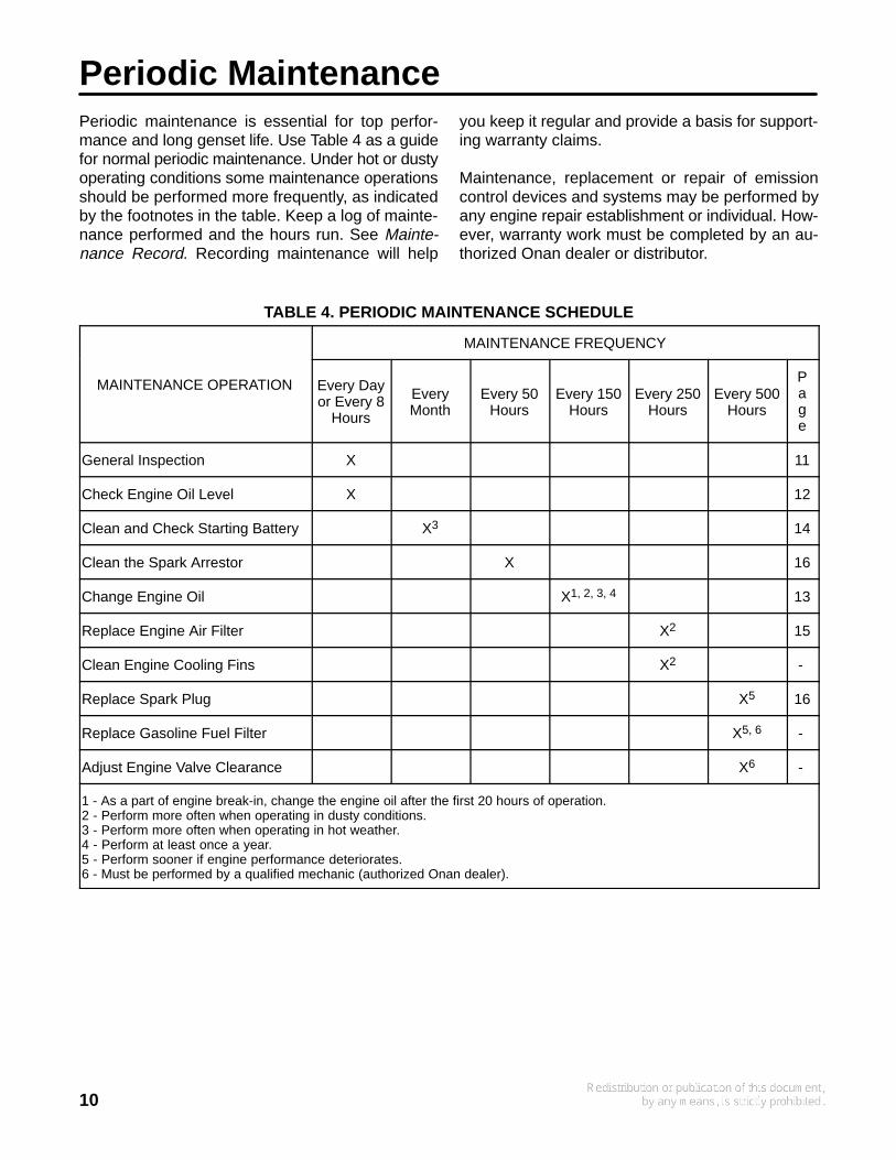
TABLE 4. PERIODIC MAINTENANCE SCHEDULE
MAINTENANCE FREQUENCY
MAINTENANCE OPERATION Every Dayor Every 8
Hours
EveryMonth
Every 50Hours
Every 150Hours
Every 250Hours
Every 500Hours
Page
General Inspection X 11
Check Engine Oil Level X 12
Clean and Check Starting Battery X3 14
Clean the Spark Arrestor X 16
Change Engine Oil X1, 2, 3, 4 13
Replace Engine Air Filter X2 15
Clean Engine Cooling Fins X2 -
Replace Spark Plug X5 16
Replace Gasoline Fuel Filter X5, 6 -
Adjust Engine Valve Clearance X6 -
1 - As a part of engine break-in, change the engine oil after the first 20 hours of operation.2 - Perform more often when operating in dusty conditions.3 - Perform more often when operating in hot weather.4 - Perform at least once a year.5 - Perform sooner if engine performance deteriorates.6 - Must be performed by a qualified mechanic (authorized Onan dealer).
11
OIL LEVEL CHECK AND GENERALINSPECTION
Inspect the genset before the first start of the dayand after every eight hours of operation.
Oil Level
Check the engine oil level as explained underCHECKING ENGINE OIL LEVEL in this section.
Exhaust System
Look and listen for exhaust system leaks while thegenset is running. Shut down the genset if a leak isfound and have it repaired before operating the gen-set.
Look for openings or holes between the gensetcompartment and vehicle cab or living space if thegenset engine sounds louder than usual. Have allsuch openings or holes closed off or sealed to pre-vent exhaust gases from entering the vehicle.
Replace dented, bent or severely rusted sections ofthe tailpipe and make sure the tailpipe extends atleast 1 inch (25.4 mm) beyond the perimeter of thevehicle.
Park the vehicle so that the genset exhaust gasescan disperse away from the vehicle. Barriers suchas walls, snow banks, high grass and brush and oth-er vehicles can cause exhaust gases to accumulatein and around the vehicle.
Do not operate power ventilators or exhaust fanswhile the vehicle is standing with the genset run-ning. The ventilator or fan can draw exhaust gasesinto the vehicle.
WARNING EXHAUST GAS IS DEADLY! Do notoperate the genset if there is an exhaust leak orany danger of exhaust gases entering or beingdrawn into the vehicle.
WARNING Do not park the vehicle in high grassor brush. Contact with the exhaust system cancause a fire.
Fuel System
Check for leaks at the hose, tube and pipe fittings inthe fuel supply system while the genset is runningand while it is stopped. Do not use a flame to checkfor LPG leaks. Check flexible fuel hose sections for
cuts, cracks, and abrasions. Make sure the fuel lineis not rubbing against other parts. Replace worn ordamaged fuel line parts before leaks occur.
If you smell gas, close the LPG container shutoffvalve and have the genset serviced before using itagain.
WARNING Gasoline and LPG are highly flam-mable fuels and can cause severe personal inju-ry or death. Repair leaks right away.
Battery Connections
Check the battery terminals for clean, tight connec-tions. Loose or corroded connections have highelectrical resistance which makes starting harder.Shut the genset off and disconnect corroded orloose battery cables (negative [- ] cable first) andclean and reconnect them as instructed under BAT-TERY CARE in this section.
WARNING Batteries give off explosive gasesthat can cause severe personal injury. Do notsmoke near batteries. Keep flames, sparks, pilotlights, electrical arcs and arc-producing equip-ment and all other ignition sources well away.
Do not disconnect the battery cables while thegenset is cranking or running: the arcing can ig-nite the explosive battery gases.
Mechanical
Look for mechanical damage. Start the genset andlook, listen and feel for any unusual noises andvibrations.
Check the genset mounting bolts to make sure theyare secure.
Check to see that the genset air inlet and outletopenings are not clogged with debris or blocked.
Clean accumulated dust and dirt from the genset.Do not clean the genset while it is running or still hot.Protect the generator, air cleaner, control panel, andelectrical connections from water, soap and clean-ing solvents. Always wear safety glasses when us-ing compressed air, a pressure washer or a steamcleaner.
WARNING Always wear safety glasses whenusing compressed air, a pressure washer or asteam cleaner to avoid severe eye damage.
12
CHECKING ENGINE OIL LEVEL
Park the vehicle on level ground and shut off thegenset before checking the engine oil level.
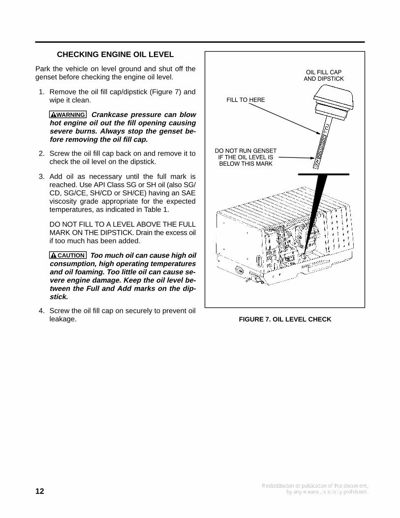
1. Remove the oil fill cap/dipstick (Figure 7) andwipe it clean.
WARNING Crankcase pressure can blowhot engine oil out the fill opening causingsevere burns. Always stop the genset be-fore removing the oil fill cap.
2. Screw the oil fill cap back on and remove it tocheck the oil level on the dipstick.
3. Add oil as necessary until the full mark isreached. Use API Class SG or SH oil (also SG/CD, SG/CE, SH/CD or SH/CE) having an SAEviscosity grade appropriate for the expectedtemperatures, as indicated in Table 1.
DO NOT FILL TO A LEVEL ABOVE THE FULLMARK ON THE DIPSTICK. Drain the excess oilif too much has been added.
CAUTION Too much oil can cause high oilconsumption, high operating temperaturesand oil foaming. Too little oil can cause se-vere engine damage. Keep the oil level be-tween the Full and Add marks on the dip-stick.
4. Screw the oil fill cap on securely to prevent oilleakage.
OIL FILL CAPAND DIPSTICK
FILL TO HERE
DO NOT RUN GENSETIF THE OIL LEVEL ISBELOW THIS MARK
FIGURE 7. OIL LEVEL CHECK
13
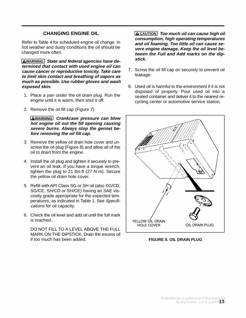
CHANGING ENGINE OIL
Refer to Table 4 for scheduled engine oil change. Inhot weather and dusty conditions the oil should bechanged more often.
WARNING State and federal agencies have de-termined that contact with used engine oil cancause cancer or reproductive toxicity. Take careto limit skin contact and breathing of vapors asmuch as possible. Use rubber gloves and washexposed skin.
1. Place a pan under the oil drain plug. Run theengine until it is warm, then shut it off.
2. Remove the oil fill cap (Figure 7).
WARNING Crankcase pressure can blowhot engine oil out the fill opening causingsevere burns. Always stop the genset be-fore removing the oil fill cap.
3. Remove the yellow oil drain hole cover and un-screw the oil plug (Figure 8) and allow all of theoil to drain from the engine.
4. Install the oil plug and tighten it securely to pre-vent an oil leak. If you have a torque wrench,tighten the plug to 21 lbs-ft (27 N-m). Securethe yellow oil drain hole cover.
5. Refill with API Class SG or SH oil (also SG/CD,SG/CE, SH/CD or SH/CE) having an SAE vis-cosity grade appropriate for the expected tem-peratures, as indicated in Table 1. See Specifi-cations for oil capacity.
6. Check the oil level and add oil until the full markis reached.
DO NOT FILL TO A LEVEL ABOVE THE FULLMARK ON THE DIPSTICK. Drain the excess oilif too much has been added.
CAUTION Too much oil can cause high oilconsumption, high operating temperaturesand oil foaming. Too little oil can cause se-vere engine damage. Keep the oil level be-tween the Full and Add marks on the dip-stick.
7. Screw the oil fill cap on securely to prevent oilleakage.
8. Used oil is harmful to the environment if it is notdisposed of properly. Pour used oil into asealed container and deliver it to the nearest re-cycling center or automotive service station.
OIL DRAIN PLUGYELLOW OIL DRAIN
HOLE COVER
FIGURE 8. OIL DRAIN PLUG
14
BATTERY CARE
Refer to Table 4 for scheduled battery maintenanceand to the battery manufacturer’s recommenda-tions and instructions for battery care. Check theelectrolyte level more frequently during hot weatheron batteries which are not of the “maintenance-free”type.
WARNING Batteries give off explosive gasesthat can cause severe personal injury. Do notsmoke near batteries. Keep flames, sparks, pilotlights, electrical arcs and arc-producing equip-ment and all other ignition sources well away.
Do not disconnect the battery cables while thegenset is cranking or running: the arcing can ig-nite the explosive battery gases.
WARNING Battery electrolyte can cause se-vere eye damage and skin burns. W ear goggles,rubber gloves and a protective apron whenworking with batteries.
Maintain the battery as follows unless the batterymanufacturer has other instructions and recom-mendations:
1. Keep the battery case clean and dry.
2. Make certain that the battery cable connectionsare clean and tight. Use a terminal puller tool toremove the battery cables.
3. Identify the cable as positive (+) or negative (- )before making the battery connections. Alwaysremove the negative (- ) cable first and connectit last, to reduce the risk of arcing.
4. To remove corrosion from the battery terminals,wash the terminals with an ammonia solution ora solution consisting of 1/4 pound (about 100grams) of baking soda in 1 quart (about 1 liter)of water. Be sure the vent plugs are tight to pre-vent cleaning solution from entering the cells.After cleaning, flush the outside of the batteryand the surrounding areas with clean water.
5. If the battery is not of the “maintenance-free”type, maintain the electrolyte level by addingdistilled water. Fill each cell to the split-levelmarker in the battery. The water component ofthe electrolyte evaporates, but the sulfuric acidcomponent remains. For this reason, add wa-ter, not electrolyte to the battery.
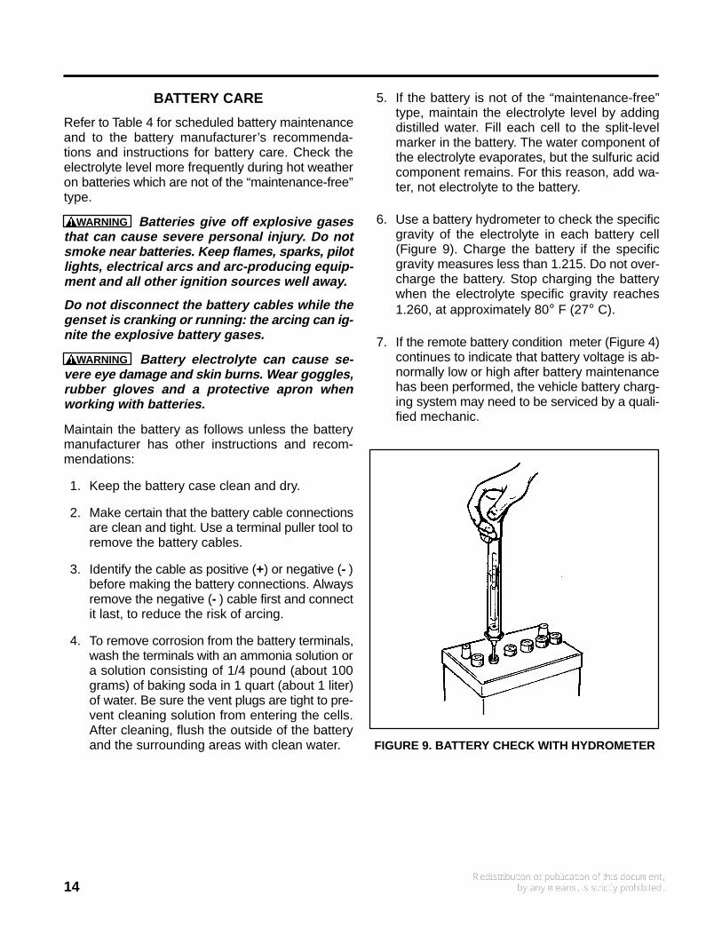
6. Use a battery hydrometer to check the specificgravity of the electrolyte in each battery cell(Figure 9). Charge the battery if the specificgravity measures less than 1.215. Do not over-charge the battery. Stop charging the batterywhen the electrolyte specific gravity reaches1.260, at approximately 80° F (27° C).
7. If the remote battery condition meter (Figure 4)continues to indicate that battery voltage is ab-normally low or high after battery maintenancehas been performed, the vehicle battery charg-ing system may need to be serviced by a quali-fied mechanic.
FIGURE 9. BATTERY CHECK WITH HYDROMETER
15
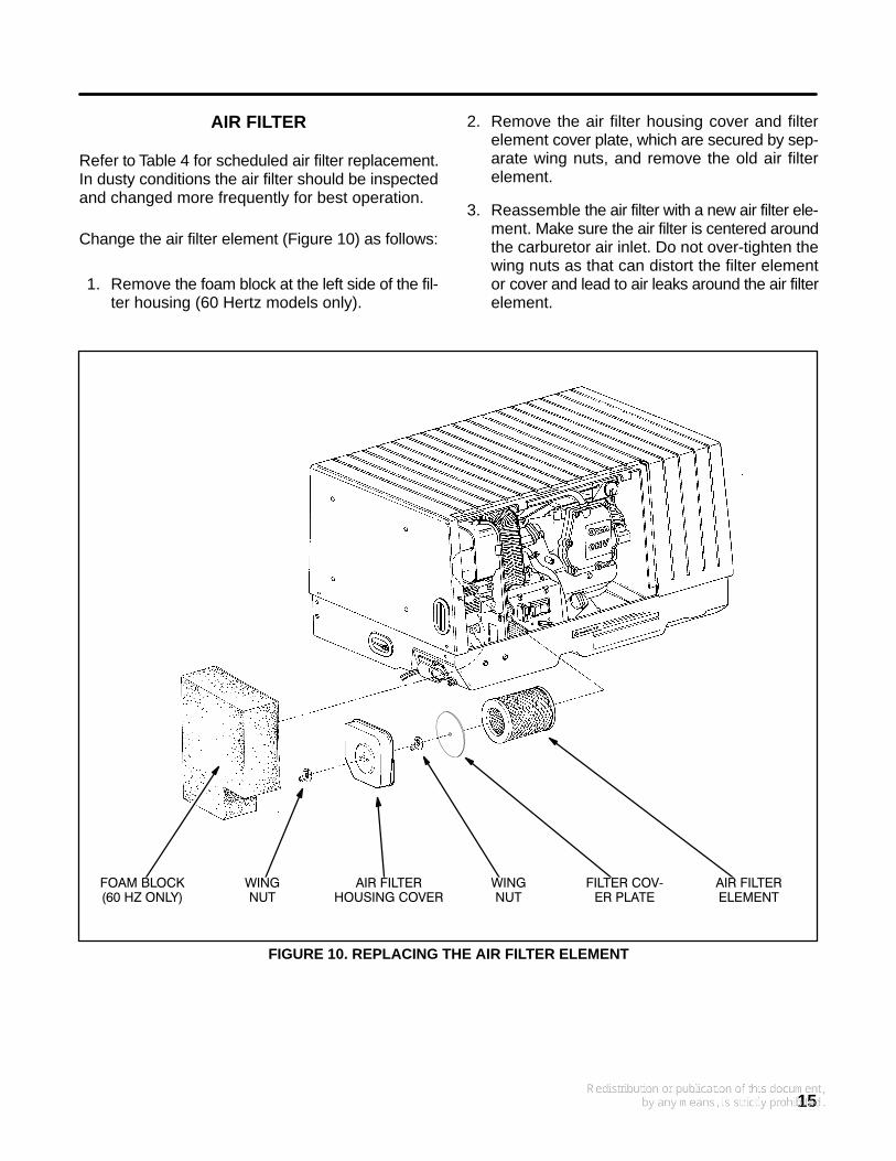
AIR FILTER
Refer to Table 4 for scheduled air filter replacement.In dusty conditions the air filter should be inspectedand changed more frequently for best operation.
Change the air filter element (Figure 10) as follows:
1. Remove the foam block at the left side of the fil-ter housing (60 Hertz models only).
2. Remove the air filter housing cover and filterelement cover plate, which are secured by sep-arate wing nuts, and remove the old air filterelement.
3. Reassemble the air filter with a new air filter ele-ment. Make sure the air filter is centered aroundthe carburetor air inlet. Do not over-tighten thewing nuts as that can distort the filter elementor cover and lead to air leaks around the air filterelement.
AIR FILTERELEMENT
AIR FILTERHOUSING COVER
FOAM BLOCK(60 HZ ONLY)
FILTER COV−ER PLATE
WINGNUT
WINGNUT
FIGURE 10. REPLACING THE AIR FILTER ELEMENT
16
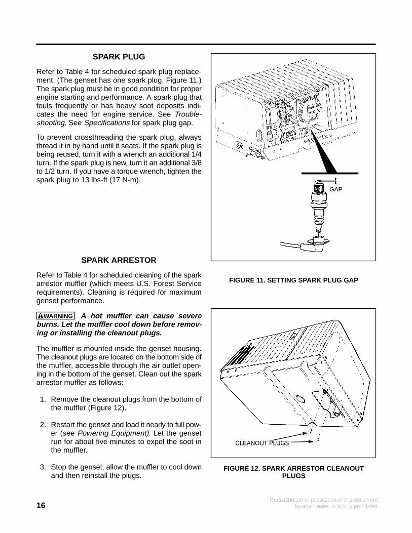
SPARK PLUG
Refer to Table 4 for scheduled spark plug replace-ment. (The genset has one spark plug, Figure 11.)The spark plug must be in good condition for properengine starting and performance. A spark plug thatfouls frequently or has heavy soot deposits indi-cates the need for engine service. See Trouble-shooting. See Specifications for spark plug gap.
To prevent crossthreading the spark plug, alwaysthread it in by hand until it seats. If the spark plug isbeing reused, turn it with a wrench an additional 1/4turn. If the spark plug is new, turn it an additional 3/8to 1/2 turn. If you have a torque wrench, tighten thespark plug to 13 lbs-ft (17 N-m).
SPARK ARRESTOR
Refer to Table 4 for scheduled cleaning of the sparkarrestor muffler (which meets U.S. Forest Servicerequirements). Cleaning is required for maximumgenset performance.
WARNING A hot muffler can cause severeburns. Let the muffler cool down before remov-ing or installing the cleanout plugs.
The muffler is mounted inside the genset housing.The cleanout plugs are located on the bottom side ofthe muffler, accessible through the air outlet open-ing in the bottom of the genset. Clean out the sparkarrestor muffler as follows:
1. Remove the cleanout plugs from the bottom ofthe muffler (Figure 12).
2. Restart the genset and load it nearly to full pow-er (see Powering Equipment). Let the gensetrun for about five minutes to expel the soot inthe muffler.
3. Stop the genset, allow the muffler to cool downand then reinstall the plugs.
GAP
FIGURE 11. SETTING SPARK PLUG GAP
CLEANOUT PLUGS
FIGURE 12. SPARK ARRESTOR CLEANOUTPLUGS
17
Genset Break-In, Exercise and StorageBREAK-IN
Proper engine break-in on a new genset or on onewith a rebuilt engine is essential for top engine per-formance and acceptable oil consumption.
For proper break-in, run the genset at approximate-ly 1/2 rated power for the first 2 hours and then at 3/4rated power for 2 more hours. See Powering Equip-ment.
Proper engine oil and oil level are especially criticalduring break-in because of the higher engine tem-peratures that can be expected. See REC-OMMENDED ENGINE OIL in Introduction. Changethe oil if its viscosity (Table 1) is not appropriate forthe ambient temperatures during break-in. Checkthe oil level twice a day or every 4 hours during the
first 20 hours of operation and change the oil afterthe first 20 hours of operation.
EXERCISE
If use is infrequent the genset should be exercisedat least 2 hours each month at approximately 1/2rated power. See Powering Equipment. Exercisingthe genset drives off moisture, re-lubricates the en-gine, replaces the stale fuel in the fuel lines and car-buretor with fresh fuel and removes oxide from elec-trical contacts and generator slip rings, thereby pro-moting better starting, more reliable operation andlonger engine life.
A single two hour exercise period is better than sev-eral shorter periods. See STORAGE as an alterna-tive if it is impractical to have someone exercise thegenset on a regular basis.
18
STORAGE
Proper storage is essential for preserving top gen-set performance and reliability when the gensetcannot be exercised regularly and will be idle formore than 120 days.
Storing the Genset
1. For gasoline models only, fill the fuel tank withfresh fuel and add a fuel preservative (Ona-FreshTM), following the instructions on the con-tainer label. Unless a preservative (stabilizer) isadded, the gasoline will deteriorate causingfuel system corrosion, gum formation and var-nish-like deposits which can lead to hard start-ing and rough operation.
WARNING Gasoline preservatives (stabil-izers) are toxic. Follow the instructions onthe container label. Avoid skin contact.Wash your hands with soap and water afterdispensing the fluid.
2. Run the genset (gasoline models only) forabout 10 minutes at approximately 1/2 ratedpower (see Powering Equipment) to fill the fuellines and carburetor with the fresh fuel and pre-servative and to bring the genset up to operat-ing temperatures. Then turn off the air condi-tioner and other large loads, push the gensetline circuit breaker to OFF (Figure 5) and stopthe genset.
3. Remove the air filter and restart the genset.While the genset is running, spray an enginefogger (OnaGardTM) into the carburetor, follow-ing the instructions on the container label, andthen stop the genset. (A fogger coats the in-take, cylinder and exhaust systems with a pro-tective coat of oil.)
4. Change the air filter element if it is dirty.
5. Change the engine oil and attach a tag indicat-ing its oil viscosity (Table 1).
6. Disconnect the battery cables (negative [- ]cable first) from the starting battery and storethe battery according to the battery manufac-turer’s recommendations.
7. Plug the exhaust tail pipe to keep out dirt, mois-ture, bugs, etc.
8. Close the fuel supply valve (if so equipped).
9. If the vehicle is to be garaged and is equippedwith an LPG genset, first check for local ordi-nances regarding the garaging of vehicles withLPG engine fuel systems. Generally, the ordi-nances require that the LPG system be leak-free, that the LPG container not be filled beyondspecified limits, that the container shutoff valvebe closed and that the vehicle not be parkednear sources of heat or ignition.
WARNING LPG leaks inside a garage orother inadequately ventilated space or neara pit or basement or other below-gradespace can lead to explosive accumulationsof gas because LPG “sinks” when it is re-leased into the air. Check for and complywith all local ordinances regarding the ga-raging of vehicles with LPG engine fuel sys-tems.
Returning The Genset To Service
1. Check the oil tag on the genset and change theoil if the viscosity indicated is not appropriate forthe temperatures expected (Table 1).
2. Reconnect the starting battery (negative [- ]cable last). See BATTERY CARE under Peri-odic Maintenance.
3. Remove the plug from the exhaust tailpipe.
4. Open the fuel supply valve (if so equipped).
5. Inspect the genset. See OIL LEVEL CHECKAND GENERAL INSPECTION under PeriodicMaintenance.
6. Start the genset at the genset control panel.The initial startup may be slow and there maybe smoke and rough operation for a few min-utes until the oil in the cylinder from the foggerburns off. If the engine does not start, clean orreplace the spark plug as it may have beenfouled by the fogger.
7. Push the genset line circuit breaker ON (Fig-ure 5) when the genset is ready to power ap-pliances.
OnaFresh and OnaGard are trademarks of the Onan Corporation.
19
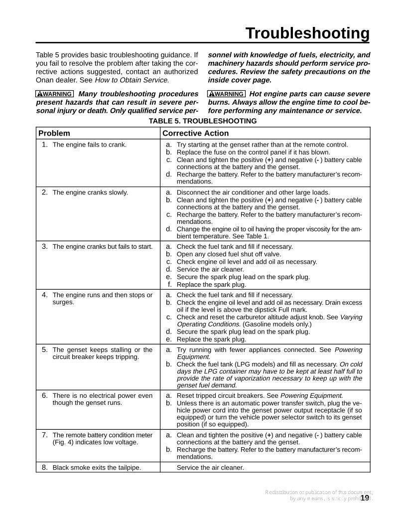
TroubleshootingTable 5 provides basic troubleshooting guidance. Ifyou fail to resolve the problem after taking the cor-rective actions suggested, contact an authorizedOnan dealer. See How to Obtain Service.
WARNING Many troubleshooting procedurespresent hazards that can result in severe per-sonal injury or death. Only qualified service per-
sonnel with knowledge of fuels, electricity, andmachinery hazards should perform service pro-cedures. Review the safety precautions on theinside cover page.
WARNING Hot engine parts can cause severeburns. Always allow the engine time to cool be-fore performing any maintenance or service.
TABLE 5. TROUBLESHOOTING
Problem Corrective Action1. The engine fails to crank. a. Try starting at the genset rather than at the remote control.
b. Replace the fuse on the control panel if it has blown.c. Clean and tighten the positive (+) and negative (- ) battery cable
connections at the battery and the genset.d. Recharge the battery. Refer to the battery manufacturer’s recom-
mendations.
2. The engine cranks slowly. a. Disconnect the air conditioner and other large loads.b. Clean and tighten the positive (+) and negative (- ) battery cable
connections at the battery and the genset.c. Recharge the battery. Refer to the battery manufacturer’s recom-
mendations.d. Change the engine oil to oil having the proper viscosity for the am-
bient temperature. See Table 1.
3. The engine cranks but fails to start. a. Check the fuel tank and fill if necessary.b. Open any closed fuel shut off valve.c. Check engine oil level and add oil as necessary.d. Service the air cleaner.e. Secure the spark plug lead on the spark plug.f. Replace the spark plug.
4. The engine runs and then stops orsurges.
a. Check the fuel tank and fill if necessary.b. Check the engine oil level and add oil as necessary. Drain excess
oil if the level is above the dipstick Full mark.c. Check and reset the carburetor altitude adjust knob. See Varying
Operating Conditions. (Gasoline models only.)d. Secure the spark plug lead on the spark plug.e. Replace the spark plug.
5. The genset keeps stalling or thecircuit breaker keeps tripping.
a. Try running with fewer appliances connected. See PoweringEquipment.
b. Check the fuel tank (LPG models) and fill as necessary. On colddays the LPG container may have to be kept at least half full toprovide the rate of vaporization necessary to keep up with thegenset fuel demand.
6. There is no electrical power eventhough the genset runs.
a. Reset tripped circuit breakers. See Powering Equipment.b. Unless there is an automatic power transfer switch, plug the ve-
hicle power cord into the genset power output receptacle (if soequipped) or turn the vehicle power selector switch to its gensetposition (if so equipped).
7. The remote battery condition meter(Fig. 4) indicates low voltage.
a. Clean and tighten the positive (+) and negative (- ) battery cableconnections at the battery and the genset.
b. Recharge the battery. Refer to the battery manufacturer’s recom-mendations.
8. Black smoke exits the tailpipe. Service the air cleaner.
20
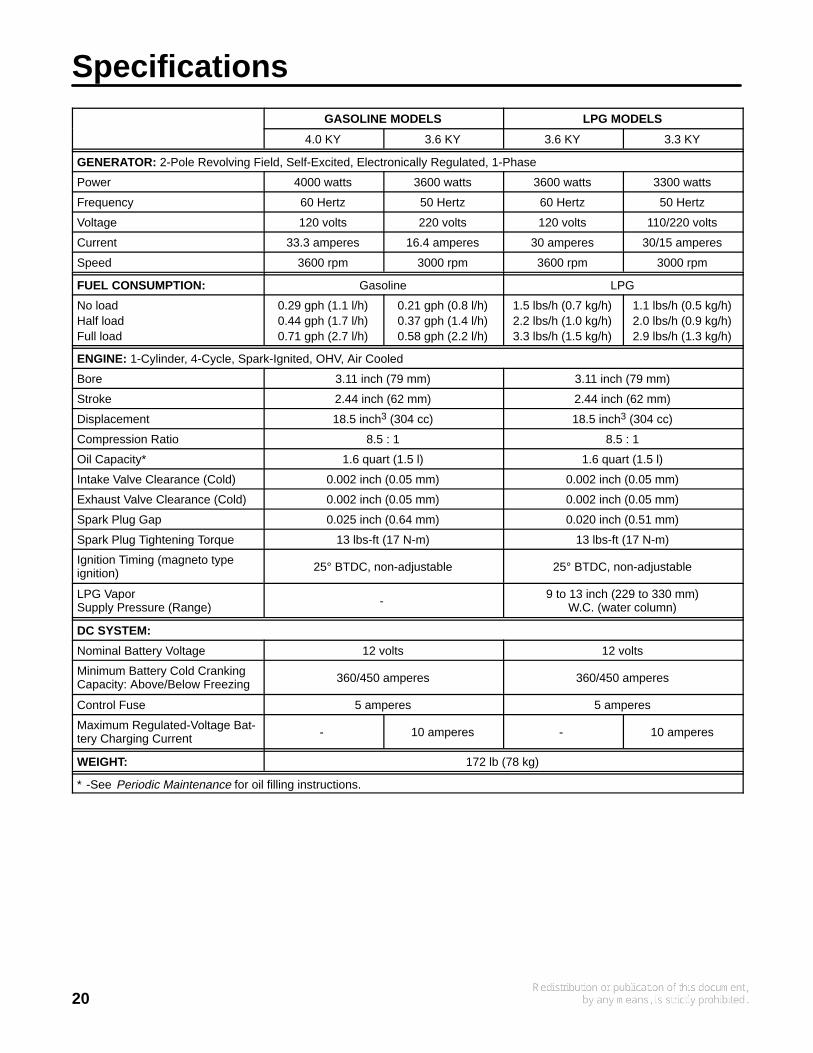
SpecificationsGASOLINE MODELS LPG MODELS
4.0 KY 3.6 KY 3.6 KY 3.3 KY
GENERATOR: 2-Pole Revolving Field, Self-Excited, Electronically Regulated, 1-Phase
Power 4000 watts 3600 watts 3600 watts 3300 watts
Frequency 60 Hertz 50 Hertz 60 Hertz 50 Hertz
Voltage 120 volts 220 volts 120 volts 110/220 volts
Current 33.3 amperes 16.4 amperes 30 amperes 30/15 amperes
Speed 3600 rpm 3000 rpm 3600 rpm 3000 rpm
FUEL CONSUMPTION: Gasoline LPG
No loadHalf loadFull load
0.29 gph (1.1 l/h)0.44 gph (1.7 l/h)0.71 gph (2.7 l/h)
0.21 gph (0.8 l/h)0.37 gph (1.4 l/h)0.58 gph (2.2 l/h)
1.5 lbs/h (0.7 kg/h)2.2 lbs/h (1.0 kg/h)3.3 lbs/h (1.5 kg/h)
1.1 lbs/h (0.5 kg/h)2.0 lbs/h (0.9 kg/h)2.9 lbs/h (1.3 kg/h)
ENGINE: 1-Cylinder, 4-Cycle, Spark-Ignited, OHV, Air Cooled
Bore 3.11 inch (79 mm) 3.11 inch (79 mm)
Stroke 2.44 inch (62 mm) 2.44 inch (62 mm)
Displacement 18.5 inch3 (304 cc) 18.5 inch3 (304 cc)
Compression Ratio 8.5 : 1 8.5 : 1
Oil Capacity* 1.6 quart (1.5 l) 1.6 quart (1.5 l)
Intake Valve Clearance (Cold) 0.002 inch (0.05 mm) 0.002 inch (0.05 mm)
Exhaust Valve Clearance (Cold) 0.002 inch (0.05 mm) 0.002 inch (0.05 mm)
Spark Plug Gap 0.025 inch (0.64 mm) 0.020 inch (0.51 mm)
Spark Plug Tightening Torque 13 lbs-ft (17 N-m) 13 lbs-ft (17 N-m)
Ignition Timing (magneto typeignition) 25° BTDC, non-adjustable 25° BTDC, non-adjustable
LPG VaporSupply Pressure (Range) -
9 to 13 inch (229 to 330 mm)W.C. (water column)
DC SYSTEM:
Nominal Battery Voltage 12 volts 12 volts
Minimum Battery Cold CrankingCapacity: Above/Below Freezing 360/450 amperes 360/450 amperes
Control Fuse 5 amperes 5 amperes
Maximum Regulated-Voltage Bat-tery Charging Current - 10 amperes - 10 amperes
WEIGHT: 172 lb (78 kg)
* -See Periodic Maintenance for oil filling instructions.
21
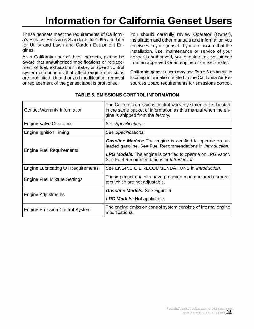
Information for California Genset UsersThese gensets meet the requirements of Californi-a’s Exhaust Emissions Standards for 1995 and laterfor Utility and Lawn and Garden Equipment En-gines.
As a California user of these gensets, please beaware that unauthorized modifications or replace-ment of fuel, exhaust, air intake, or speed controlsystem components that affect engine emissionsare prohibited. Unauthorized modification, removalor replacement of the genset label is prohibited.
You should carefully review Operator (Owner),Installation and other manuals and information youreceive with your genset. If you are unsure that theinstallation, use, maintenance or service of yourgenset is authorized, you should seek assistancefrom an approved Onan engine or genset dealer.
California genset users may use Table 6 as an aid inlocating information related to the California Air Re-sources Board requirements for emissions control.
TABLE 6. EMISSIONS CONTROL INFORMATION
Genset Warranty InformationThe California emissions control warranty statement is locatedin the same packet of information as this manual when the en-gine is shipped from the factory.
Engine Valve Clearance See Specifications.
Engine Ignition Timing See Specifications.
Engine Fuel Requirements
Gasoline Models: The engine is certified to operate on un-leaded gasoline. See Fuel Recommendations in Introduction.
LPG Models: The engine is certified to operate on LPG vapor.See Fuel Recommendations in Introduction.
Engine Lubricating Oil Requirements See ENGINE OIL RECOMMENDATIONS in Introduction.
Engine Fuel Mixture Settings These genset engines have precision-manufactured carbure-tors which are not adjustable.
Engine AdjustmentsGasoline Models: See Figure 6.
LPG Models: Not applicable.
Engine Emission Control System The engine emission control system consists of internal enginemodifications.
22
How to Obtain ServiceWhen you need parts or service for your genset con-tact the nearest authorized dealer or distributor.Onan has factory-trained representatives to handleyour needs for genset parts and service. To locatethe nearest authorized distributor:
1. Check the North American Sales and ServiceDirectory (F-118) and the International Salesand Service Directory (IN-1013) supplied withyour Onan genset. These directories list autho-rized distributors who will assist you in locatingthe nearest authorized dealer.
2. Consult the Yellow Pages. Typically, our distrib-utors are listed under:
GENERATORS - ELECTRIC,ENGINES - GASOLINE OR DIESEL, orRECREATIONAL VEHICLES - EQUIPMENT,PARTS AND SERVICE.
3. Call 1-800-888-ONAN for the name and tele-phone number of the nearest Cummins/Onanor Onan-only distributor in the United States orCanada. (This automated service utilizestouch-tone phones only). By calling this num-
ber you can also request a directory of autho-rized RV servicing dealers: RV Sales and Ser-vice Directory F-919.
To get service, contact the authorized dealer or dis-tributor nearest you, explain the problem and makean appointment. If you have difficulty in arrangingfor service or resolving a problem, please contactthe dealer coordinator or service manager at thenearest Cummins/Onan distributor for assistance.
Before calling for service, have the following infor-mation available:
1. The complete genset model number and serialnumber (see Model Identification on page 4)
2. The date of purchase
3. The nature of the problem (See Troubleshoot-ing)
WARNING Improper service or replacement ofparts can result in severe personal injury, death,and/or equipment damage. Service personnelmust be qualified to perform electrical and/ormechanical service.

23
Maintenance RecordUse the following table to keep a record of all periodic and unscheduled maintenance and service. SeePeriodic Maintenance.
DATEHOURMETER
READINGMAINTENANCE OR SERVICE PERFORMED
Record the name, address, and phone number of your authorized Onan service center.

Cummins Power Generation1400 73rd Avenue N.E.Minneapolis, MN 55432763-574-5000Fax: 763-528-7229
Cummins and Onan are registered trademarks of Cummins Inc.