microliterflowm.p.c modularpumpcomponent … manuals... · contact qualified service personnel to...
TRANSCRIPT

Microliter Flow M.P.C
Modular Pump Component
User’s Manual
5417-002-REV-D
Catalog # 70-2220 & 70-2225

EU Directives WEEE and RoHS
To Our Valued Customers:
We are committed to being a good corporate citizen. As part of that commitment,we strive to maintain an environmentally conscious manufacturing operation. TheEuropean Union (EU) has enacted two Directives, the first on product recycling(Waste Electrical and Electronic Equipment, WEEE) and the second limiting the useof certain substances (Restriction on the use of Hazardous Substances, RoHS).Over time, these Directives will be implemented in the national laws of each EUMember State.
Once the final national regulations have been put into place, recycling will be offeredfor our products which are within the scope of the WEEE Directive. Products fallingunder the scope of the WEEE Directive available for sale after August 13, 2005 willbe identified with a “wheelie bin” symbol.
Two Categories of products covered by the WEEE Directive are currently exemptfrom the RoHS Directive – Category 8, medical devices (with the exception ofimplanted or infected products) and Category 9, monitoring and control instruments.Most of our products fall into either Category 8 or 9 and are currently exempt fromthe RoHS Directive. We will continue to monitor the application of the RoHSDirective to its products and will comply with any changes as they apply.
• Do Not Dispose Product with Municipal Waste
• Special Collection/Disposal Required
WEEE/RoHS Compliance Statement

1H
arva
rdA
pp
ara
tus
Micro
liter
Flo
wM
od
ula
rP
um
pC
om
po
ne
nt
www.harvardapparatus.com
11
Table of Contents
Subject Page No.
General Information
Warranty and Repairs 2General Safety Summary ............................................3-4
IntroductionTheory of Operation ........................................................5Features ............................................................................5Input Connections............................................................6Packing List.......................................................................6
InstallationInitial Setup & Location Requirements ..........................7Loading the Syringe ........................................................7
OperationGetting Started ................................................................8Working with the pump ..................................................8Check Syringe ..................................................................8Maintenance ....................................................................8Protecting Small, Fragile Syringes ................................8Hyper-Terminal............................................................9-10AppendicesA. Specifications ............................................................11
Inputs......................................................................12Outputs ..................................................................12
B. Table of Popular Syringe Diameters........................13C. Flow Rates..................................................................14D. Serial Communications; Commands,
Queries and Responses ..................................15-17E. Optional - Daisy Chaining ........................................18F. Accessories ................................................................19

Serial NumberAll inquires concerning our product should refer to the serial number of theunit. Serial numbers are located on the underside of the mounting plate.
CalibrationAll syringe pumps are designed and manufactured to meet their perform-ance specifications at all rated voltages and frequencies.
WarrantyHarvard Apparatus warranties this instrument for a period of two yearsfrom date of purchase. At its option, Harvard Apparatus will repair orreplace the unit if it is found to be defective as to workmanship or material.
This warranty does not extend to damage resulting from misuse, neglect orabuse, normal wear and tear, or accident.
This warranty extends only to the original customer purchaser.
IN NO EVENT SHALL HARVARD APPARATUS BE LIABLE FOR INCIDENTALOR CONSEQUENTIAL DAMAGES. Some states do not allow exclusion orlimitation of incidental or consequential damages so the above limitation orexclusion may not apply to you. THERE ARE NO IMPLIED WARRANTIES OFMERCHANTABILITY, FITNESS FOR A PARTICULAR USE, OR OF ANY OTHERNATURE. Some states do not allow this limitation on an implied warranty,so the above limitation may not apply to you.
If a defect arises within the two-year warranty period, promptly contactHarvard Apparatus, Inc. 84 October Hill Road, Holliston, Massachusetts01746-1388 using our toll free number 1-800-272-2775. Outside the U.S.call 508-893-8999. Goods will not be accepted for return unless an RMA(returned materials authorization) number has been issued by our customerservice department. The customer is responsible for shipping charges.Please allow a reasonable period of time for completion of repairs,replacement and return. If the unit is replaced, the replacement unit iscovered only for the remainder of the original warranty period dating fromthe purchase of the original device.
This warranty gives you specific rights, and you may also have other rightswhich vary from state to state.
Repair Facilities and PartsHarvard Apparatus stocks replacement and repair parts. When ordering,please describe parts as completely as possible, preferably using our partnumbers. If practical, enclose a sample or drawing. We offer a completereconditioning service.
CAUTIONThis pump is not registered withthe FDA and is not for clinical useon human or veterinary patients.It is intended for research use only.
2H
arv
ard
Ap
pa
ratu
sM
icro
lite
rF
low
Mo
du
lar
Pu
mp
Co
mp
on
en
t
Publication 5417-002-REV-D www.harvardapparatus.com
22
General Information
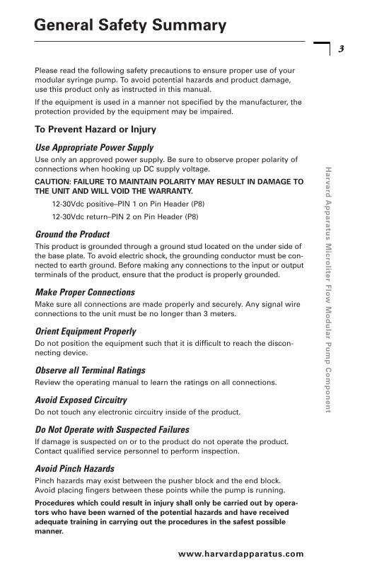
Please read the following safety precautions to ensure proper use of yourmodular syringe pump. To avoid potential hazards and product damage,use this product only as instructed in this manual.
If the equipment is used in a manner not specified by the manufacturer, theprotection provided by the equipment may be impaired.
To Prevent Hazard or Injury
Use Appropriate Power SupplyUse only an approved power supply. Be sure to observe proper polarity ofconnections when hooking up DC supply voltage.
CAUTION: FAILURE TO MAINTAIN POLARITY MAY RESULT IN DAMAGE TOTHE UNIT AND WILL VOID THE WARRANTY.
12-30Vdc positive–PIN 1 on Pin Header (P8)
12-30Vdc return–PIN 2 on Pin Header (P8)
Ground the ProductThis product is grounded through a ground stud located on the under side ofthe base plate. To avoid electric shock, the grounding conductor must be con-nected to earth ground. Before making any connections to the input or outputterminals of the product, ensure that the product is properly grounded.
Make Proper ConnectionsMake sure all connections are made properly and securely. Any signal wireconnections to the unit must be no longer than 3 meters.
Orient Equipment ProperlyDo not position the equipment such that it is difficult to reach the discon-necting device.
Observe all Terminal RatingsReview the operating manual to learn the ratings on all connections.
Avoid Exposed CircuitryDo not touch any electronic circuitry inside of the product.
Do Not Operate with Suspected FailuresIf damage is suspected on or to the product do not operate the product.Contact qualified service personnel to perform inspection.
Avoid Pinch HazardsPinch hazards may exist between the pusher block and the end block.Avoid placing fingers between these points while the pump is running.
Procedures which could result in injury shall only be carried out by opera-tors who have been warned of the potential hazards and have receivedadequate training in carrying out the procedures in the safest possiblemanner.
3H
arva
rdA
pp
ara
tus
Micro
liter
Flo
wM
od
ula
rP
um
pC
om
po
ne
nt
www.harvardapparatus.com
33
General Safety Summary
4H
arv
ard
Ap
pa
ratu
sM
icro
lite
rF
low
Mo
du
lar
Pu
mp
Co
mp
on
en
t
Publication 5417-002-REV-D www.harvardapparatus.com
44
General Safety Summary
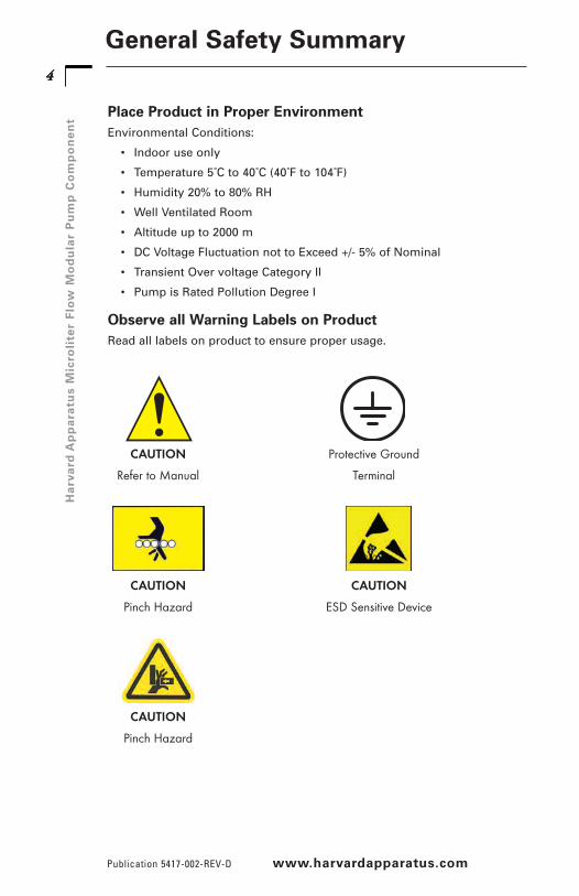
Place Product in Proper EnvironmentEnvironmental Conditions:
• Indoor use only
• Temperature 5˚C to 40˚C (40˚F to 104˚F)
• Humidity 20% to 80% RH
• Well Ventilated Room
• Altitude up to 2000 m
• DC Voltage Fluctuation not to Exceed +/- 5% of Nominal
• Transient Over voltage Category II
• Pump is Rated Pollution Degree I
Observe all Warning Labels on ProductRead all labels on product to ensure proper usage.
CAUTION
Refer to Manual
Protective Ground
Terminal
CAUTION
Pinch Hazard
CAUTION
ESD Sensitive Device
CAUTION
Pinch Hazard
5H
arva
rdA
pp
ara
tus
Micro
liter
Flo
wM
od
ula
rP
um
pC
om
po
ne
nt
Theory of OperationThe “µL” Modular Syringe Pump Component is designed as a highlyprecise, single-syringe infusion/withdrawal pump module capable oflow to moderate back pressures. The module includes a mechanism,hardware and software.
Typically, the “µL” Modular Syringe Pump Component holds one syringe ofmost makes, from 0.5 µl to 1ml. The diameter of the syringe is entered viayour PC or other controller, and the internal microprocessor drives a preci-sion stepper motor to produce accurate fluid flow. This unit is designed tooperate inside an appropriately rated fire/electrical/mechanical enclosureor cabinet.
Features: Two Modes of Operation
Constant Flow Rate and Volume DispenseThe “µL” Modular Syringe Pump Component will operate continuously inRATE mode, or accurately dispense a specific amount of fluid in VOLUMEmode. When starting the pump, RATE mode will be the default mode. Tooperate in Volume mode, set a target volume and the pump will changemodes to suit desired operation.
Infuse & Withdraw Limit SwitchesInfuse and withdraw limit switches are located on brackets attached to themain mounting plate. When the pusher block contacts either limit switch,pusher block movement is stopped. Take care in adjusting the infuse limitswitch position so that the syringe plunger does not bottom out in thesyringe.
55
www.harvardapparatus.com
Introduction

Connector Pin-outsInput Power Power P8-1Connection Return P8-2
Digital I/O Run IND P7-1Connection VCC P7-2
EXT ENABLE P7-3Ground P7-4Run/Stop P7-5Ground P7-6
Packing List
6H
arv
ard
Ap
pa
ratu
sM
icro
lite
rF
low
Mo
du
lar
Pu
mp
Co
mp
on
en
t
Publication 5417-002-REV-D www.harvardapparatus.com
Input Connections66
70-2220
1) Main Unit
2) RS-232 Communications cable
3) User documentation
4) 6 oz. tube of grease
70-2225
1) Main Unit
2) Universal inpu 100/250VAC,50/60 Hz, 18 watt power supply
3) Line Cord
4) RS-232 Communication cable
5) Power Connection Cable
6) User documentation
7) 6 oz. tube of grease

Location Requirements for the Syringe Pump
• A sturdy, level, clean anddry surface
• Minimum of one inch (2.5cm)clearance around the pump
• Appropriate environmentalconditions
• Mount into an appropriatelyrated enclosure or cabinet
• Required clearance belowmounting panel: 2.00” (5cm).
7H
arva
rdA
pp
ara
tus
Micro
liter
Flo
wM
od
ula
rP
um
pC
om
po
ne
nt
www.harvardapparatus.com
77
Installation
Loading the Syringe1. Release the syringe pusher (4) by pressing the bronze button (3) on the
side of the pusher.
2. While holding the bronze button ‘in’, slide the pusher to the right.
3. Raise the spring loaded syringe retainer (1) and swing it out of the way.
4. Lay the loaded syringe in the ‘V’ shaped holder.
5. Swing the retainer so it holds the syringe in place.
6. Move the pusher so it makes contact with the syringe plunger.
7. Adjust pusher block thumbscrews & bracket (2) until the Syringeplunger is completely captured.
8. The limit switches can be easily adjusted by loosening the #2 nuts(not shown), sliding the switch to the desired position, andretightening the nuts into place.
41
3
2

8H
arv
ard
Ap
pa
ratu
sM
icro
lite
rF
low
Mo
du
lar
Pu
mp
Co
mp
on
en
t
Publication 5417-002-REV-D www.harvardapparatus.com
88
Operation
Getting StartedPlug one end of the power cable into P8 connection on board. Connect theother end of the cable into your power supply / PC. Connect communica-tion cable from PC to J1 connector. Refer to page 8 of this manual to refer-ence the board connections.
Working With the PumpThe safest way to use the “µL” Modular Syringe Pump Component is in thevolume dispense mode. The pump will automatically stop when target vol-ume is dispensed. Enable must be tied to ground (Hardwire P7-3 to P7-4 orconnect through switch).
Check Syringe OftenThe “µL” Modular Syringe Pump Component will shut itself off when thesyringe is empty or is otherwise overloaded. Although this presents no haz-ard to the user or the pump, it is prudent to check the syringe from time totime.
MaintenanceKeep the “µL” Modular Syringe Pump Component clean and dry. Avoid liq-uid spills that may find their way into the electronics.
A small tube of grease is provided for periodic lubrication of the lead screw.It is important to keep the lead screw clean and lubricated.
To clean the exterior surfaces above the base plate, use a lint-free cloth toremove loose dust. For more efficient cleaning, use a soft cloth dampenedwith water or an aqueous solution of 75% isopropyl alcohol.
If the pump does not work properly, contact Harvard Apparatus forappropriate instructions.
Protecting Small, Fragile SyringesThe “µL” Modular Syringe Pump Component will hold micro liter sizesyringes down to 0.5µl size. These small syringes have fine wire plungersthat may be damaged if allowed to bottom out. The limit switches for the“µL” Modular Syringe Pump Component can be adjusted by loosening themounting hardware which attaches the switch to the base plate bracket,moving the switch to the desired location, and re-tightening the switchmounting hardware.

Remote Control via the RS-232 Interface UsingHYPERTERMINAL** Normally included with most Windows® operating systems.
Milliliter Modular Syringe Pump Component1. Connect the RS-232 cable between the “uL” Modular Syringe Pump
Component RS-232 IN port and a PC’s serial port.
2. On the PC (running a Microsoft Windows Operating System), selectSTART – PROGRAMS – ACCESSORIES – HYPERTERMINAL –HYPERTERMINAL to start the HyperTerminal application.If HyperTerminal is not available, install it from the Microsoft WindowsOperating System Install disks or CD ROM.
3. Set up the appropriate COMPORT for the following:
9H
arva
rdA
pp
ara
tus
Micro
liter
Flo
wM
od
ula
rP
um
pC
om
po
ne
nt
www.harvardapparatus.com
99
HYPER-TERMINAL: Terminal Emulation Software
ASCII Setup:
Echo typed characters locally
Line delay: 0
Character delay: 0
Wrap lines
Configure:
Baud Rate: 9600
Data Bits: 8
Parity: None
Stop Bits: 2
Flow Cntrl: None
Emulation: Auto Detect

10H
arv
ard
Ap
pa
ratu
sM
icro
lite
rF
low
Mo
du
lar
Pu
mp
Co
mp
on
en
t
Publication 5417-002-REV-D www.harvardapparatus.com
1010
HYPER-TERMINAL: Terminal Emulation Software
You may want to save the setup information under a descriptive filename.
4. At the PC, launch HyperTerminal with the above setup specifications(if it is not already running). Type VER at the PC keyboard and verifythat the pump module's version is displayed at the PC terminal.
5. Type RUN to start the pump; type STP to stop the pump. After startingthe pump, should be displayed, indicating pump is infusing. Afterstopping the pump, : should be displayed.

11H
arva
rdA
pp
ara
tus
Micro
liter
Flo
wM
od
ula
rP
um
pC
om
po
ne
nt
Appendix A: Specifications
www.harvardapparatus.com
11
Accuracy ±0.35%
Reproducibility ±0.1%
Number of Syringes One
Syringe Sizes 0.5µL (min), 1 mL (max)
Flow Rate:
Minimum 0.001 µL/hr for a 0.5mL syringe
Maximum 1330 µL/min for a 1mL syringe
Linear Force 7lbs (peak min.) Adjustable
Drive Motor: 0.9° Stepper
Control Constant Current Drive, 0.50A peak per phase 1/4, 1/16 stepping
Drive Ratio 1:1
Leadscrew Pitch 48 threads per inch (1/4-48)
Encode Optical, 100 line (for stall detection)
Step Rate:
Minimum 3.8 sec/step
Maximum 250 µLsec/step
Pusher Travel Rate:
Minimum 0.001 mm/min
Maximum 83mm/min
Display None
Keypad None
Interface RS-232
Connectors Power: 2 –pin Header, .1 centers
RS-232: RJ-11 Phone jack
Power +12 to +30VDC +/- 5%, 12W max.
Dimensions 7.25” X 3.625” X 4.50” (L X W X H)
18.41cm X 9.20cm X 11.43cm
Mounting Dimensions 6.875” X 3.25” (Mounting holes for (6) #6 screws)17.46cm X 8.25cm
Ground Stud #6-32 Stud
Weight 1.75 lbs (0.8kg)
Environmental Operating:
Temperature +5 to +40°C (natural convection cooling)
Humidity 20% to 80% RH non-condensing
Storage:
Temperature -30 to +45°C
Humidity 10% to 90% RH non-condensing
Pollution Degree Class I
Compliance Lead Free, RoHS Compliant

12H
arv
ard
Ap
pa
ratu
sM
icro
lite
rF
low
Mo
du
lar
Pu
mp
Co
mp
on
en
t
Publication 5417-002-REV-D www.harvardapparatus.com
1212
The pump is set to the following default parameters on power-up and afteran external enable command.
Default SettingsSyringe Diameter: 2.300 mm
Rate: 3.000 ul/min
Range: ul/min
Force: 100%
Address: 00
Baud Rate: 9600
I/O Specifications
InputsRUN/STOP
This is an active low, TTL level input, pulled up to +5V through a 10K ohmresistor. It is ESD protected through a TVS device and filtered with a 0.1uFcapacitor to ground. Each pulse to a logic low toggles the pump betweenthe RUN and STOP states.
EXT_ENABL/
This is an active low, TTL level input, pulled up to +5V through a 10K ohmresistor. It is ESD protected through a TVS device and filtered with a 0.1uFcapacitor to ground. A transition from logic high to logic low causes theprocessor to reset to its default state and enables the motor drive. A transi-tion from logic low to logic high disables the motor drive through hardware(independent of firmware). This input may be used for an emergency stopfunction.
**To enable pump, the unit or connector P7 pin 3, must be connected toground**
OutputsRUN_IND/
This is an active low output driven by two 74HCT14 inverters in parallel.An on-board resistor may be placed in series with this output to providecurrent limiting. The default resistor value is zero ohms. A logic lowindicates RUN. A logic high indicates STOP.
IndicatorsPower-on LED
When illuminated, indicates that board is powered on and +5VDC supply isoperating.
RUN LED
When illuminated, indicates that pump is running. When extinguished,indicates pump is stopped.
Appendix A: Specifications

13H
arva
rdA
pp
ara
tus
Micro
liter
Flo
wM
od
ula
rP
um
pC
om
po
ne
nt
www.harvardapparatus.com
1313
Appendix B: Syringe Inside Diameter
UnimetricsSeries 4000 & 5000
Size Diameter10 µl 0.46 mm25 0.72950 1.031100 1.460250 2.300500 3.2601000 4.610
SGEScientific Glass Engineering
Size Diameter25 µl 0.73 mm50 1.03100 1.46250 2.30500 3.261 ml 4.61
Hamilton–MicroliterSeries Gastight
Size Diameter.5 µl 0.103 mm1 0.14572 0.2065 0.325710 0.46025 0.72950 1.031100 1.46250 2.3500 3.261 mL 4.61
14H
arv
ard
Ap
pa
ratu
sM
icro
lite
rF
low
Mo
du
lar
Pu
mp
Co
mp
on
en
t
Publication 5417-002-REV-D www.harvardapparatus.com
1414
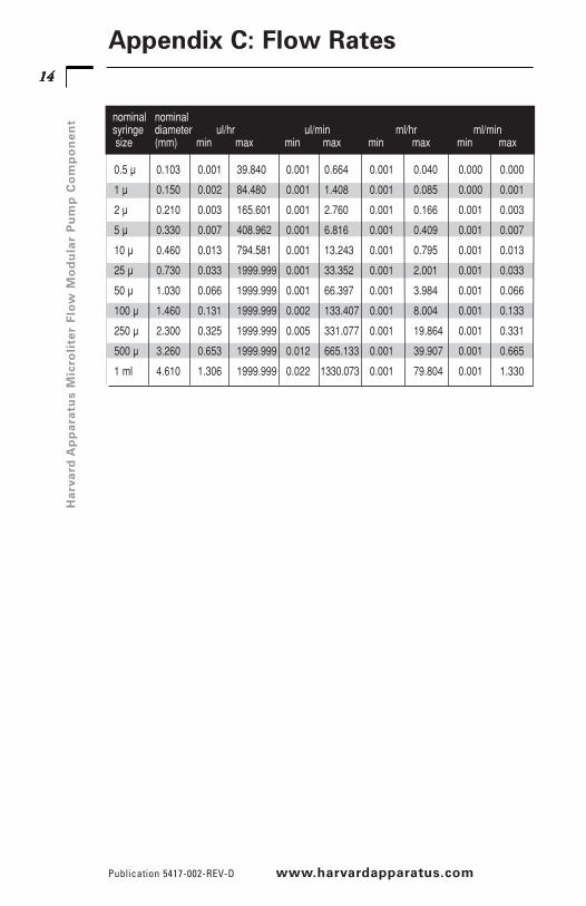
Appendix C: Flow Rates
0.5 µ 0.103 0.001 39.840 0.001 0.664 0.001 0.040 0.000 0.000
1 µ 0.150 0.002 84.480 0.001 1.408 0.001 0.085 0.000 0.001
2 µ 0.210 0.003 165.601 0.001 2.760 0.001 0.166 0.001 0.003
5 µ 0.330 0.007 408.962 0.001 6.816 0.001 0.409 0.001 0.007
10 µ 0.460 0.013 794.581 0.001 13.243 0.001 0.795 0.001 0.013
25 µ 0.730 0.033 1999.999 0.001 33.352 0.001 2.001 0.001 0.033
50 µ 1.030 0.066 1999.999 0.001 66.397 0.001 3.984 0.001 0.066
100 µ 1.460 0.131 1999.999 0.002 133.407 0.001 8.004 0.001 0.133
250 µ 2.300 0.325 1999.999 0.005 331.077 0.001 19.864 0.001 0.331
500 µ 3.260 0.653 1999.999 0.012 665.133 0.001 39.907 0.001 0.665
1 ml 4.610 1.306 1999.999 0.022 1330.073 0.001 79.804 0.001 1.330
nominal nominalsyringe diameter ul/hr ul/min ml/hr ml/minsize (mm) min max min max min max min max

15H
arva
rdA
pp
ara
tus
Micro
liter
Flo
wM
od
ula
rP
um
pC
om
po
ne
nt
15
www.harvardapparatus.com
Appendix D: Serial Communication
Commands, Queries and ResponsesAfter each transmission to the pump terminating with a CR character (ASCII13), the pump enters remote mode and responds with the character sequence:
CR LF promptThe prompt characters indicate the status of the pump as follows:
prompt meaning ASCII code
: Stopped (ASCII 58 decimal)
> Running forward (ASCII 62 decimal)
< Running reverse (ASCII 60 decimal)
* Stalled (ASCII 42 decimal)
*I Infuse limit switch actuated (ASCII 42 decimal + ASCII 73 decimal)
*W Withdraw limit switch actuated (ASCII 42 decimal + ASCII 87 decimal)
*D Disabled by emergency stop (ASCII 42 decimal + ASCII 68 decimal)
*T Target volume reached (ASCII 42 decimal + ASCII 68 decimal)
Serial Commands and Their MeaningsCommandsRUN Start infuse (forward direction)
RUNW Starts withdraw (reverse direction)
STP Stop motor
CLV Clears infuse volume accumulator to zero
CLVW Clears withdraw volume accumulatorto zero
CLT Clears target infuse volume to zero, dispense disabled
CLTW Clears target withdraw volume to zero
MAX Sets the pump to the maximum infuse flow rate
MAXW Sets the pump to the maximum withdraw flow rate
Commands with Numbers(Must have space before number)
MMD number Set syringe diameter, units are mm. Rate is set to zeroafter MMD command.
ULM number Set infuse flow rate and range, units are microlitersper minute.
ULMW number Set withdraw flow rate and range, units are microlitersper minute.
MLM number Set infuse flow rate and range, units are milliliters perminute.
MLMW number Set withdraw flow rate and range, units are millilitersper minute.
ULH number Set infuse flow rate and range, units are microlitersper hour.
ULHW number Set withdraw flow rate and range, units are microlitersper hour.
16H
arv
ard
Ap
pa
ratu
sM
icro
lite
rF
low
Mo
du
lar
Pu
mp
Co
mp
on
en
t
Publication 5417-002-REV-D www.harvardapparatus.com
1616
Appendix D: Serial Communication
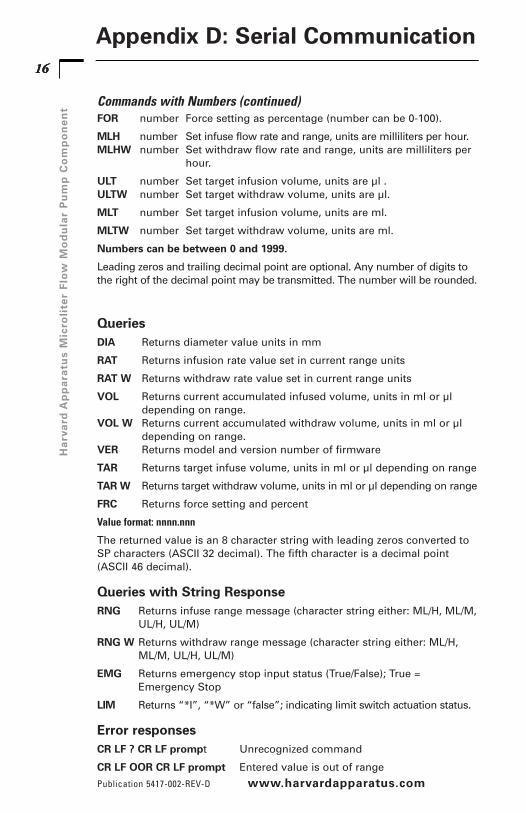
Commands with Numbers (continued)FOR number Force setting as percentage (number can be 0-100).
MLH number Set infuse flow rate and range, units are milliliters per hour.MLHW number Set withdraw flow rate and range, units are milliliters per
hour.
ULT number Set target infusion volume, units are µl .ULTW number Set target withdraw volume, units are µl.
MLT number Set target infusion volume, units are ml.
MLTW number Set target withdraw volume, units are ml.
Numbers can be between 0 and 1999.
Leading zeros and trailing decimal point are optional. Any number of digits tothe right of the decimal point may be transmitted. The number will be rounded.
QueriesDIA Returns diameter value units in mm
RAT Returns infusion rate value set in current range units
RAT W Returns withdraw rate value set in current range units
VOL Returns current accumulated infused volume, units in ml or µldepending on range.
VOL W Returns current accumulated withdraw volume, units in ml or µldepending on range.
VER Returns model and version number of firmware
TAR Returns target infuse volume, units in ml or µl depending on range
TARW Returns target withdraw volume, units in ml or µl depending on range
FRC Returns force setting and percent
Value format: nnnn.nnn
The returned value is an 8 character string with leading zeros converted toSP characters (ASCII 32 decimal). The fifth character is a decimal point(ASCII 46 decimal).
Queries with String ResponseRNG Returns infuse range message (character string either: ML/H, ML/M,
UL/H, UL/M)
RNG W Returns withdraw range message (character string either: ML/H,ML/M, UL/H, UL/M)
EMG Returns emergency stop input status (True/False); True =Emergency Stop
LIM Returns “*I”, “*W” or “false”; indicating limit switch actuation status.
Error responsesCR LF ? CR LF prompt Unrecognized command
CR LF OOR CR LF prompt Entered value is out of range

17H
arva
rdA
pp
ara
tus
Micro
liter
Flo
wM
od
ula
rP
um
pC
om
po
ne
nt
www.harvardapparatus.com
1717
Appendix D: Serial Communication
***Note: Adjustable force settings
0% 20% 40% 60% 80% 100%
7 lbs.min.
Force
Due to differences in mechanical drag forces, we do notrecommend operating the pump below 40% force level.
% Force (Current)
18H
arv
ard
Ap
pa
ratu
sM
icro
lite
rF
low
Mo
du
lar
Pu
mp
Co
mp
on
en
t
Publication 5417-002-REV-D www.harvardapparatus.com
1818
Appendix E: Optional-Daisy-Chaining
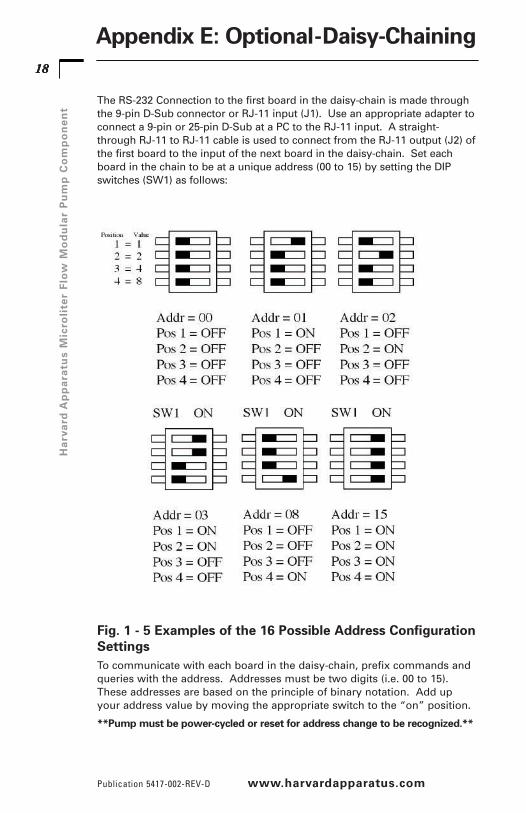
The RS-232 Connection to the first board in the daisy-chain is made throughthe 9-pin D-Sub connector or RJ-11 input (J1). Use an appropriate adapter toconnect a 9-pin or 25-pin D-Sub at a PC to the RJ-11 input. A straight-through RJ-11 to RJ-11 cable is used to connect from the RJ-11 output (J2) ofthe first board to the input of the next board in the daisy-chain. Set eachboard in the chain to be at a unique address (00 to 15) by setting the DIPswitches (SW1) as follows:
Fig. 1 - 5 Examples of the 16 Possible Address ConfigurationSettingsTo communicate with each board in the daisy-chain, prefix commands andqueries with the address. Addresses must be two digits (i.e. 00 to 15).These addresses are based on the principle of binary notation. Add upyour address value by moving the appropriate switch to the “on” position.
**Pump must be power-cycled or reset for address change to be recognized.**

19H
arva
rdA
pp
ara
tus
Micro
liter
Flo
wM
od
ula
rP
um
pC
om
po
ne
nt
Catalog No. Product70-2231 1.8m (6 ft) motor/encoder extension cable
70-2232 1.8m (6 ft) limit switch extension cable
55-7760 0.6m (2 ft) RJ11 daisy-chain cable
72-2478 1.8m (6 ft) RJ11 daisy-chain cable
1140-352 I/O & E-stop cable w/ LED
www.harvardapparatus.com
1919
Appendix F: Optional Accessories

Declaration of ConformityIn Accordance with ISO/IEC Guide 22 and EN 45014
Manufacturer: HarvardApparatus, Inc.84 October Hill Rd.Holliston, MA 01746-1388U.S.A.Phone: (508) 893-8999
We herewith declare that the following product:Product Name: Micro liter Flow Modular Pump ComponentModel No.: 70-2220 / 70-2225
To which this declaration relates, is in conformity with the applicableEC Directives, harmonized standards, and other normative requirements:
Application ofCouncil Directive(s): 89/336/EEC
Standard(s) to whichConformity is Declared:
Emissions/Immunity: EN 61326-1:2005EN 61000-4-2EN 61000-4-3EN 61000-4-4EN 61000-4-5EN 61000-4-6EN 61000-4-11C1SPR 11:2004 Class A
EMC and Safety compliance were evaluated by Intertek/ETL SemkoReference test report file numbers: 3125838LTT-001 and 3125828LTT-003
Beth Bauman
VP Engineering / Operations
(Signature)
(Full Name)
(Position)