micrologix 1200 controller - kvc industrial supplies sdn … · advantages for the micrologix 1200...
TRANSCRIPT
Publication 1761-SG001F-EN-P - March 2011
MicroLogix Programmable Controllers Overview 7
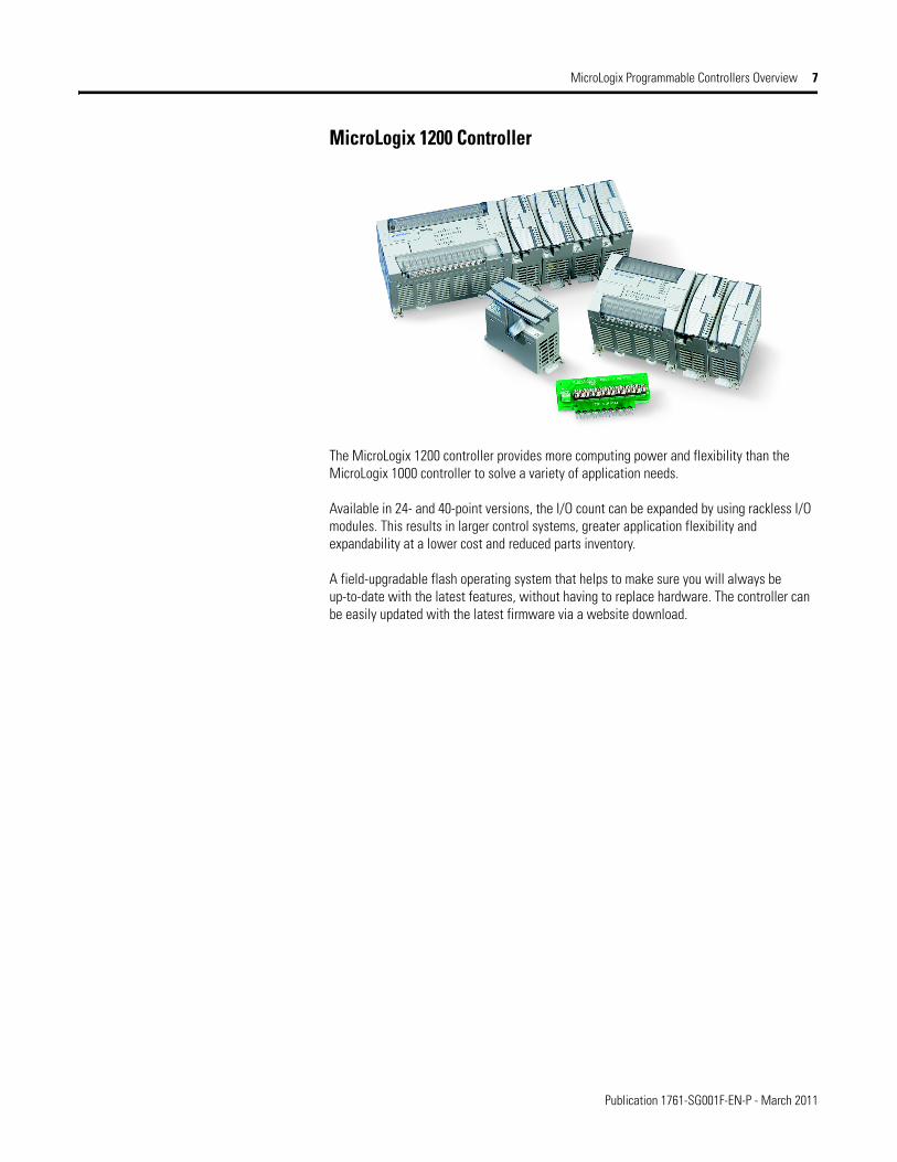
MicroLogix 1200 Controller
The MicroLogix 1200 controller provides more computing power and flexibility than the MicroLogix 1000 controller to solve a variety of application needs.
Available in 24- and 40-point versions, the I/O count can be expanded by using rackless I/O modules. This results in larger control systems, greater application flexibility and expandability at a lower cost and reduced parts inventory.
A field-upgradable flash operating system that helps to make sure you will always be up-to-date with the latest features, without having to replace hardware. The controller can be easily updated with the latest firmware via a website download.

Publication 1761-SG001F-EN-P - March 2011
8 MicroLogix Programmable Controllers Overview
Advantages for the MicroLogix 1200 Controller
• Large 6 KB memory (4 KB User Program with 2 KB User Data) to solve a variety of applications.
• High performance expansion I/O options (up to six modules depending on current/power budget).
• Four high-speed inputs (for controllers with 24V DC inputs) that can be used individually as latching (pulse-catch) inputs, event interrupts,or alternately combined as one 20 kHz high-speed counter featuring eight modes of operation.
• One high-speed output that can be configured as 20 kHz pulse train output (PTO) or as pulse width modulated (PWM) output (availableon controllers with embedded 24V DC outputs).
• One, 1 ms, selectable timed interrupt (STI).• High-resolution, 1 ms timers.• The same advanced communication options as the MicroLogix 1000 controller,
including peer-to-peer and SCADA/RTU networks, DF1 full-duplex, DF1 half-duplex slave, DH-485, DeviceNet and EtherNet/IP , plus DF1 half-duplex master, Modbus master and slave, and DF1 radio modem protocols.
• ASCII read/write capability.• An additional Programming/HMI Port, providing connectivity to a DF1 full-duplex
compatible device such as an operator interface or programming terminal (MicroLogix 1200R controllers only, catalog number 1762-LxxxxxR).
• Communication toggle pushbutton that allows the controller's Channel 0 port to toggle between user configured communication parameters and factory default settings for an easy means to switch from Modbus RTU or ASCII protocols (which do not support programming) to DF1 full-duplex (to upload/download, monitor, or edit your program), so a programming computer is able to connect to a controller with an unknown or incorrect communication parameter settings for troubleshooting.
• Optional real-time clock, to allow control to be based on actual time of day, day of week, or other calendar related timing.
• Optional memory module, for external program backup, transport and transfer to another controller. Control program and data are securely backed up to internal flash memory when power is not applied.
• Data file download protection prevents critical user data from being altered via program downloads from programming computers or memory modules.
• Two built-in analog trim potentiometers.• 32-bit signed integer math.• Floating-point and double integer data file support.• Built-in PID capabilities.• Finger-safe terminal blocks meet global safety standards.• Removable terminal blocks on 40-point controllers allow pre-wiring.• Regulatory agency certifications for world-wide market (CE, C-Tick, UL, c-UL,
including Class 1 Division 2 Hazardous Location).

Publication 1761-SG001F-EN-P - March 2011
Select Family: MicroLogix 1000, 1200 or 1500 Controller 17
Select Family: MicroLogix 1000, 1200 or 1500 Controller
Review the Features, Programming Instructions, Controller Specifications, and Controller Dimensions to determine which level of MicroLogix controller is required.
Features
Step 1 - Select:
• controller family - based on memory, I/O, added functionality, programming instructions and dimensions
• consider future expansion requirements• consider requirement for online editing• consider the need for networked
communication
MicroLogix Controllers Feature Comparison Chart
Controller MicroLogix 1000 MicroLogix 1200/1200R
MicroLogix 15001764-LSP, 1764-LRP
Bulletin Number 1761 1762 1764Memory (in user words) User Program/User DataUp to 1 KB 1 KB combined
(preconfigured)Up to 6 KB 4 KB/2 KB
Up to 7 KB 3.6 KB/4 KB 1764-LSP
Up to 8 KB
Up to 14 KB 10 KB/4 KB 1764-LRP
Online editing
Nonvolatile program and data EEPROM Flash Battery back-up static RAM
Memory Module (for program back-up and transport)
Through hand-held programmer
Optional Optional
I/OEmbedded Digital I/O, max 32 40 28
Embedded Analog I/O Two current and two voltage inputs with one current or voltage output on 20 pt. controllers
Local Expansion I/O, max None 96 512
Thermocouple/RTD None Expansion Expansion
Networked Expansion I/O, max None None DeviceNet network using 1769-SDN scanner can own 63 slave devices (such as a 1769-ADN adapter with up to 30 I/O modules per 1769-ADN adapter)
Added FunctionalityTrim Potentiometers 2 2
PID ✓ ✓
High Speed Counters (embedded)
One @ 6.6 kHz One @ 20 kHz Two @ 20 kHz
High Speed Counters (expansion)
with 1769-HSC counterWith two quadrature or four pulse/count @ 1 MHz
Real Time Clock Optional Optional
Motion: Pulse Width Modulated 1 @ 20 kHz 2 @ 20 kHz
Motion: Pulse Train Outputs 1 @ 20 kHz 2 @ 20 kHz
Data Access Tool Optional
Data Logging 48 KB
Recipe Storage Uses user program memory or 48 KB data logging memory
Floating Point Math ✓ ✓
ProgrammingWindows - RSLogix 500/Micro Software
✓ ✓ ✓
Hand-held Programmer ✓
Communication

Publication 1761-SG001F-EN-P - March 2011
18 Select Family: MicroLogix 1000, 1200 or 1500 Controller
Programming InstructionsMicroLogix controllers have the range of functionality necessary to address diverse applications. The controllers use the following types of instructions:
• Basic instructions (for example, Examine if On, Examine if Off)• Data Comparison instructions (for example, Equal, Greater than or Equal, Less than or
Equal)• Data Manipulation instructions (for example, Copy, Move)• Math instructions (for example, Add, Subtract, Multiply)• Program Flow Control instructions (for example, Jump, Subroutine)• Application Specific instructions (for example, Programmable Limit Switch,
Sequencer)• High-speed Counter instruction • High-speed pulse train output (PTO) and pulse width modulated (PWM) instructions
(for MicroLogix 1200 and 1500 controllers only)• Communication instruction (including ASCII for MicroLogix 1200 and 1500 controllers
only)• Recipe instruction (MicroLogix 1500 controllers only)• Data Logging instruction (MicroLogix 1500 1764-LRP processor only)
RS-232 Ports (1) 8-pin mini DIN (1) 8-pin mini DIN(1) 8-pin mini DIN Programming/HMI
(1) 8-pin mini DIN(1) 9-pin D-shell
DeviceNet Peer-to-Peer Messaging, slave I/O
With 1761-NET-DNI With 1761-NET-DNI With 1761-NET-DNIWith 1769-SDN
DeviceNet Scanner With 1769-SDN
EtherNet/IP With 1761-NET-ENI or 1761-NET-ENIW
With 1761-NET-ENI or 1761-NET-ENIW
With 1761-NET-ENI or 1761-NET-ENIW
Web Server Capabilities With 1761-NET-ENIW With 1761-NET-ENIW With 1761-NET-ENIW
DH-485 Network with 1761-NET-AIC
Network with 1761-NET-AIC
Network with 1761-NET-AIC
SCADA RTU - DF1 half-duplex slave
✓ ✓ ✓
SCADA RTU - DF1 radio modem ✓ ✓
SCADA RTU - Modbus RTU slave ✓ ✓
SCADA RTU - Modbus RTU master
✓ ✓
ASCII - Read/Write ✓ ✓
Operating Power120/240V AC ✓ ✓ ✓
24V DC ✓ ✓ ✓
12V DC
Agency CertificationsCE, C-Tick, UL, and C-UL (including Class I, Division 2 Hazardous Location)
✓ ✓ ✓
MicroLogix Controllers Feature Comparison Chart
Controller MicroLogix 1000 MicroLogix 1200/1200R
MicroLogix 15001764-LSP, 1764-LRP
Bulletin Number 1761 1762 1764
Publication 1761-SG001F-EN-P - March 2011
Select Family: MicroLogix 1000, 1200 or 1500 Controller 19
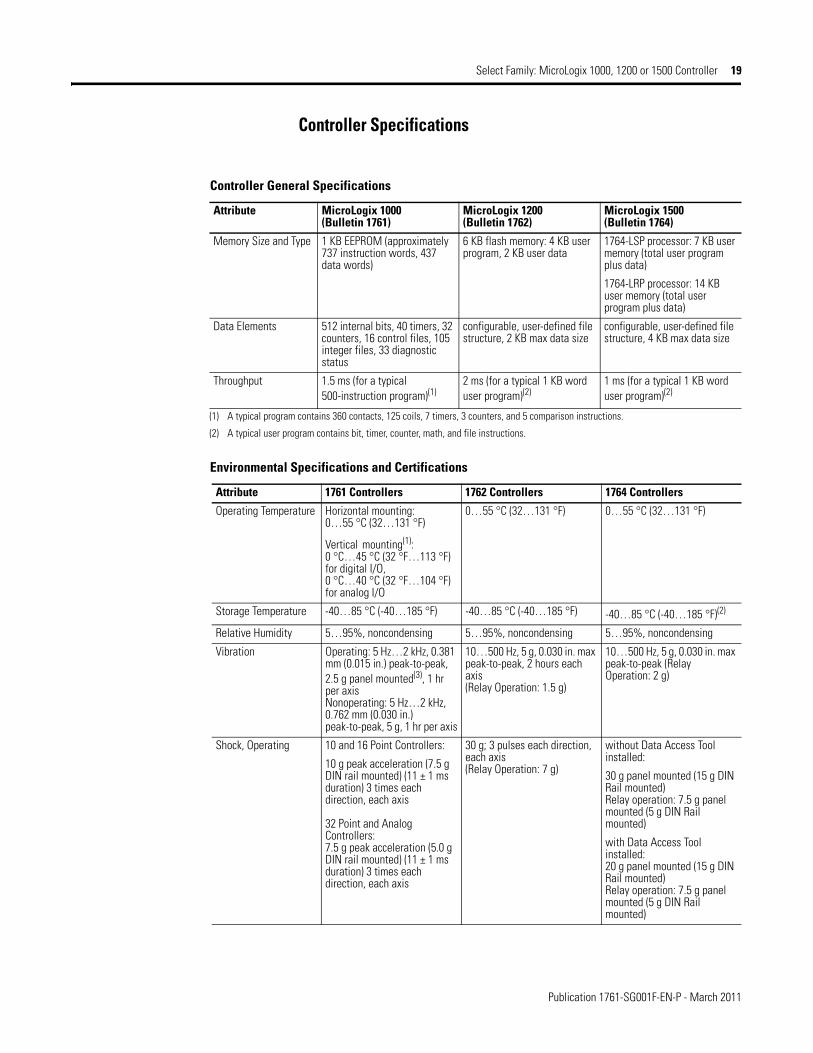
Controller Specifications
Controller General Specifications
Attribute MicroLogix 1000(Bulletin 1761)
MicroLogix 1200(Bulletin 1762)
MicroLogix 1500(Bulletin 1764)
Memory Size and Type 1 KB EEPROM (approximately 737 instruction words, 437 data words)
6 KB flash memory: 4 KB user program, 2 KB user data
1764-LSP processor: 7 KB user memory (total user program plus data)
1764-LRP processor: 14 KB user memory (total user program plus data)
Data Elements 512 internal bits, 40 timers, 32 counters, 16 control files, 105 integer files, 33 diagnostic status
configurable, user-defined file structure, 2 KB max data size
configurable, user-defined file structure, 4 KB max data size
Throughput 1.5 ms (for a typical 500-instruction program)(1)
2 ms (for a typical 1 KB word user program)(2)
1 ms (for a typical 1 KB word user program)(2)
(1) A typical program contains 360 contacts, 125 coils, 7 timers, 3 counters, and 5 comparison instructions.
(2) A typical user program contains bit, timer, counter, math, and file instructions.
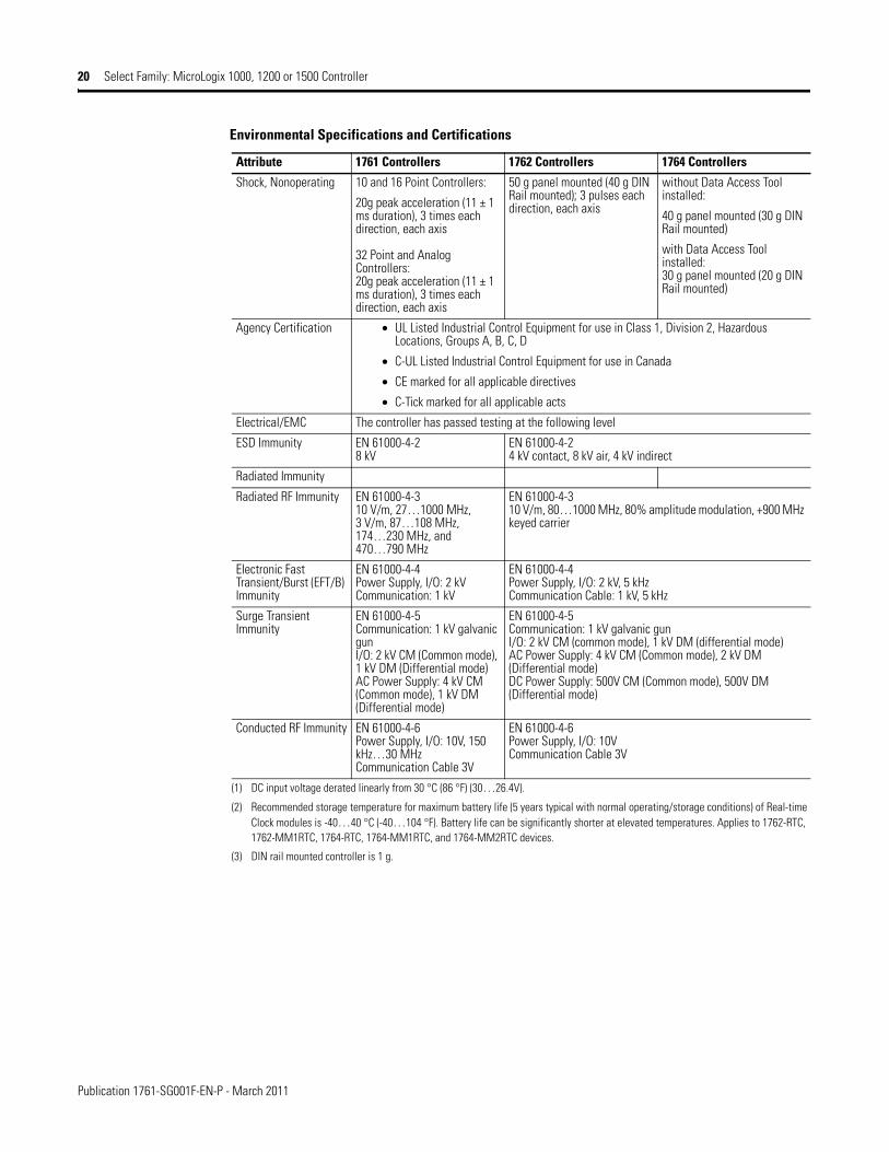
Environmental Specifications and Certifications
Attribute 1761 Controllers 1762 Controllers 1764 Controllers
Operating Temperature Horizontal mounting: 0…55 °C (32…131 °F)
Vertical mounting(1): 0 °C…45 °C (32 °F…113 °F) for digital I/O, 0 °C…40 °C (32 °F…104 °F) for analog I/O
0…55 °C (32…131 °F) 0…55 °C (32…131 °F)
Storage Temperature -40…85 °C (-40…185 °F) -40…85 °C (-40…185 °F) -40…85 °C (-40…185 °F)(2)
Relative Humidity 5…95%, noncondensing 5…95%, noncondensing 5…95%, noncondensing
Vibration Operating: 5 Hz…2 kHz, 0.381 mm (0.015 in.) peak-to-peak, 2.5 g panel mounted(3), 1 hr per axisNonoperating: 5 Hz…2 kHz, 0.762 mm (0.030 in.) peak-to-peak, 5 g, 1 hr per axis
10…500 Hz, 5 g, 0.030 in. max peak-to-peak, 2 hours each axis (Relay Operation: 1.5 g)
10…500 Hz, 5 g, 0.030 in. max peak-to-peak (Relay Operation: 2 g)
Shock, Operating 10 and 16 Point Controllers:
10 g peak acceleration (7.5 g DIN rail mounted) (11 ± 1 ms duration) 3 times each direction, each axis
32 Point and Analog Controllers:7.5 g peak acceleration (5.0 g DIN rail mounted) (11 ± 1 ms duration) 3 times each direction, each axis
30 g; 3 pulses each direction, each axis (Relay Operation: 7 g)
without Data Access Tool installed:
30 g panel mounted (15 g DIN Rail mounted)Relay operation: 7.5 g panel mounted (5 g DIN Rail mounted)
with Data Access Tool installed:20 g panel mounted (15 g DIN Rail mounted)Relay operation: 7.5 g panel mounted (5 g DIN Rail mounted)
Publication 1761-SG001F-EN-P - March 2011
20 Select Family: MicroLogix 1000, 1200 or 1500 Controller
Shock, Nonoperating 10 and 16 Point Controllers:
20g peak acceleration (11 ± 1 ms duration), 3 times each direction, each axis
32 Point and Analog Controllers:20g peak acceleration (11 ± 1 ms duration), 3 times each direction, each axis
50 g panel mounted (40 g DIN Rail mounted); 3 pulses each direction, each axis
without Data Access Tool installed:
40 g panel mounted (30 g DIN Rail mounted)
with Data Access Tool installed:30 g panel mounted (20 g DIN Rail mounted)
Agency Certification • UL Listed Industrial Control Equipment for use in Class 1, Division 2, Hazardous Locations, Groups A, B, C, D
• C-UL Listed Industrial Control Equipment for use in Canada
• CE marked for all applicable directives
• C-Tick marked for all applicable acts
Electrical/EMC The controller has passed testing at the following level
ESD Immunity EN 61000-4-28 kV
EN 61000-4-24 kV contact, 8 kV air, 4 kV indirect
Radiated Immunity
Radiated RF Immunity EN 61000-4-310 V/m, 27…1000 MHz, 3 V/m, 87…108 MHz, 174…230 MHz, and 470…790 MHz
EN 61000-4-310 V/m, 80…1000 MHz, 80% amplitude modulation, +900 MHz keyed carrier
Electronic Fast Transient/Burst (EFT/B) Immunity
EN 61000-4-4Power Supply, I/O: 2 kVCommunication: 1 kV
EN 61000-4-4Power Supply, I/O: 2 kV, 5 kHzCommunication Cable: 1 kV, 5 kHz
Surge Transient Immunity
EN 61000-4-5Communication: 1 kV galvanic gunI/O: 2 kV CM (Common mode), 1 kV DM (Differential mode)AC Power Supply: 4 kV CM (Common mode), 1 kV DM (Differential mode)
EN 61000-4-5Communication: 1 kV galvanic gunI/O: 2 kV CM (common mode), 1 kV DM (differential mode)AC Power Supply: 4 kV CM (Common mode), 2 kV DM (Differential mode)DC Power Supply: 500V CM (Common mode), 500V DM (Differential mode)
Conducted RF Immunity EN 61000-4-6Power Supply, I/O: 10V, 150 kHz…30 MHzCommunication Cable 3V
EN 61000-4-6Power Supply, I/O: 10VCommunication Cable 3V
(1) DC input voltage derated linearly from 30 °C (86 °F) (30…26.4V).
(2) Recommended storage temperature for maximum battery life (5 years typical with normal operating/storage conditions) of Real-time Clock modules is -40…40 °C (-40…104 °F). Battery life can be significantly shorter at elevated temperatures. Applies to 1762-RTC, 1762-MM1RTC, 1764-RTC, 1764-MM1RTC, and 1764-MM2RTC devices.
(3) DIN rail mounted controller is 1 g.
Environmental Specifications and Certifications
Attribute 1761 Controllers 1762 Controllers 1764 Controllers

Publication 1761-SG001F-EN-P - March 2011
58 Select MicroLogix 1200 Controllers
Select MicroLogix 1200 Controllers
MicroLogix 1200 Controllers Catalog Number Detail
Step 8 - Select:
• controller - review power and I/O configurations to select a controller catalog number; see power supply and I/O specifications for more detailed information
• accessories - memory and real-time clock modules
• record your selections in the Selection Record (start on page 86)
Power Supply A = 120/240V ACB = 24V DC
Output Type:W = RelayX = Relay/24V DC FET
Bulletin Number
Base Unit
Number of I/O
Input Type:A = 120V AC
B = 24V DC
Programming/HMI Port R = EquippedNone = Not Equipped
1762 - L 24 A W A R
MicroLogix 1200 Controller Power and I/O Configuration
Cat. No. Line Voltage Number of Inputs Number of Outputs High Speed I/O
1762-L24AWA, -L24AWAR 120/240V AC (14) 120V AC (10) Relay N/A
1762-L40AWA, -L40AWAR 120/240V AC (24) 120V AC (16) Relay N/A
1762-L24BWA, -L24BWAR 120/240V AC (10) Standard 24V DC(4) Fast 24V DC
(10) Relay (4) 20 kHz input
1762-L40BWA, -L40BWAR 120/240V AC (20) Standard 24V DC(4) Fast 24V DC
(16) Relay (4) 20 kHz input
1762-L24BXB, -L24BXBR 24V DC (10) Standard 24V DC(4) Fast 24V DC
(5) Relay(4) Standard 24V DC FET(1) Fast 24V DC FET
(4) 20 kHz input(1) 20 kHz output
1762-L40BXB, -L40BXBR 24V DC (20) Standard 24V DC(4) Fast 24V DC
(8) Relay(7) Standard 24V DC FET(1) Fast 24V DC FET
(4) 20 kHz input(1) 20 kHz output
MicroLogix 1200 Controller Power Supply Specifications
Attribute 1762-
L24AWA, L24AWAR
L40AWA, L40AWAR
L24BWA, L24BWAR
L40BWA,L40BWAR
L24BXB, L24BXBR
L40BXB, L40BXBR
Power Supply Voltage 85…265V AC @ 47…63 Hz 20.4…26.4V DC Class 2 SELV
Power Consumption 68 VA 80 VA 70 VA 82 VA 27 W 40 W
Power Supply Inrush Current, max
120V AC: 25 A for 8 ms240V AC: 40 A for 4 ms
24V DC: 15 A for 20 ms
24V DC:15 A for 30 ms
Load Current(1), max
5V DC 400 mA 600 mA 400 mA 600 mA 400 mA 600 mA
24V DC 350 mA 500 mA 350 mA 500 mA 350 mA 500 mA
Load Power, max 10.4 W 15 W 12 W 16 W 10.4 W 15 W
24V DC Sensor Power --- --- 250 mA, 400 µF capacitance, max
400 mA, 400 µF capacitance, max
--- ---
(1) See Perform MicroLogix 1200 Controller System Expansion Calculations on page 62 for an example system validation worksheet to calculate expansion I/O power usage.

Publication 1761-SG001F-EN-P - March 2011
Select MicroLogix 1200 Controllers 59
MicroLogix 1200 Controller DC Input Power Requirements for BXB Units
1762-L24BXB, 1762-L24BXBR Typical Power Requirements
0
5
10
15
20
0 2 4 6 8 10
Calculated Load Power (Watts)
Inpu
t Pow
er R
equi
red
at
24Vd
c (W
atts
)
1762-L40BXB, 1762-L40BXBR Typical Power Requirements
0
5
10
15
20
25
30
0 2 4 6 8 10 12 14
Calculated Load Power (Watts)
Inpu
t Pow
er R
equi
red
at
24Vd
c (W
atts
)
MicroLogix 1200 Controller Input Specifications
Attribute 1762-L24AWA, 1762-L24AWAR1762-L40AWA, 1762-L40AWAR
1762-L24BWA, 1762-L24BXB, 1762-L40BWA, 1762-L40BXB1762-L24BWAR, 1762-L24BXBR, 1762-L40BWAR, 1762-L40BXBR
Inputs 0 through 3 Inputs 4 and higher
On-state Voltage Range 79…132V AC @ 47 Hz…63 Hz 14…26.4V DC @ 55 °C (131 °F)14…30.0V DC @ 30 °C (86 °F)
10…26.4V DC @ 55 °C (131 °F)10…30.0V DC @ 30 °C (86 °F)
Off-state Voltage Range 0…20V AC 0…5V DC
Operating Frequency N/A 0 Hz…20 kHz 0 Hz…1 kHz(scan time dependent)
Signal Delay, max ON Delay = 20 msOFF Delay = 20 ms
Standard inputs: selectable from 0.5…16 mshigh-speed inputs: selectable from 0.025…16 ms
On-state Current:minnommax
5.0 mA @ 79V AC12 mA @ 120V AC16.0 mA @ 132V AC
2.5 mA @ 14V DC7.3 mA @ 24V DC12.0 mA @ 30V DC
2.0 mA @ 10V DC8.9 mA @ 24V DC12.0 mA @ 30V DC
Off-state Leakage Current, max 2.5 mA, max 1.5 mA, min
Impedance, nom 12 kΩ @ 50 Hz10 kΩ @ 60 Hz
3.3 kΩ 2.7 kΩ
Inrush Current, max 250 mA at 120V AC ---
Publication 1761-SG001F-EN-P - March 2011
60 Select MicroLogix 1200 Controllers
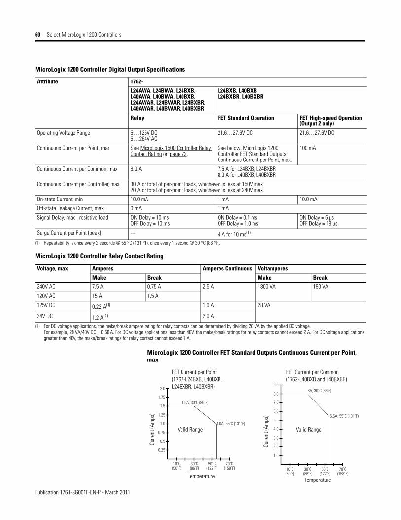
MicroLogix 1200 Controller FET Standard Outputs Continuous Current per Point, max
MicroLogix 1200 Controller Digital Output Specifications
Attribute 1762-
L24AWA, L24BWA, L24BXB,L40AWA, L40BWA, L40BXB,L24AWAR, L24BWAR, L24BXBR,L40AWAR, L40BWAR, L40BXBR
L24BXB, L40BXBL24BXBR, L40BXBR
Relay FET Standard Operation FET High-speed Operation (Output 2 only)
Operating Voltage Range 5…125V DC5…264V AC
21.6…27.6V DC 21.6…27.6V DC
Continuous Current per Point, max See MicroLogix 1500 Controller Relay Contact Rating on page 72.
See below, MicroLogix 1200 Controller FET Standard Outputs Continuous Current per Point, max.
100 mA
Continuous Current per Common, max 8.0 A 7.5 A for L24BXB, L24BXBR8.0 A for L40BXB, L40BXBR
Continuous Current per Controller, max 30 A or total of per-point loads, whichever is less at 150V max20 A or total of per-point loads, whichever is less at 240V max
On-state Current, min 10.0 mA 1 mA 10.0 mA
Off-state Leakage Current, max 0 mA 1 mA
Signal Delay, max - resistive load ON Delay = 10 msOFF Delay = 10 ms
ON Delay = 0.1 msOFF Delay = 1.0 ms
ON Delay = 6 µsOFF Delay = 18 µs
Surge Current per Point (peak) --- 4 A for 10 ms(1)
(1) Repeatability is once every 2 seconds @ 55 °C (131 °F), once every 1 second @ 30 °C (86 °F).
MicroLogix 1200 Controller Relay Contact Rating
Voltage, max Amperes Amperes Continuous Voltamperes
Make Break Make Break
240V AC 7.5 A 0.75 A 2.5 A 1800 VA 180 VA
120V AC 15 A 1.5 A
125V DC 0.22 A(1) 1.0 A 28 VA
24V DC 1.2 A(1) 2.0 A
(1) For DC voltage applications, the make/break ampere rating for relay contacts can be determined by dividing 28 VA by the applied DC voltage. For example, 28 VA/48V DC = 0.58 A. For DC voltage applications less than 48V, the make/break ratings for relay contacts cannot exceed 2 A. For DC voltage applications greater than 48V, the make/break ratings for relay contact cannot exceed 1 A.
0.25
10˚C(50˚F)
30˚C(86˚F)
50˚C(122˚F)
1.0A, 55˚C (131˚F)
1.5A, 30˚C (86˚F)
70˚C(158˚F)
0.5
0.75
1.0
1.25
1.5
1.75
2.0
1.0
10˚C(50˚F)
30˚C(86˚F)
50˚C(122˚F)
5.5A, 55˚C (131˚F)
8A, 30˚C (86˚F)
70˚C(158˚F)
2.0
3.0
4.0
5.0
6.0
7.0
8.0
9.0
FET Current per Common(1762-L40BXB and L40BXBR)
Curre
nt (A
mps
)
Curre
nt (A
mps
)
TemperatureTemperature
Valid Range Valid Range
FET Current per Point(1762-L24BXB, L40BXB, L24BXBR, L40BXBR)
Publication 1761-SG001F-EN-P - March 2011
Select MicroLogix 1200 Expansion I/O 61
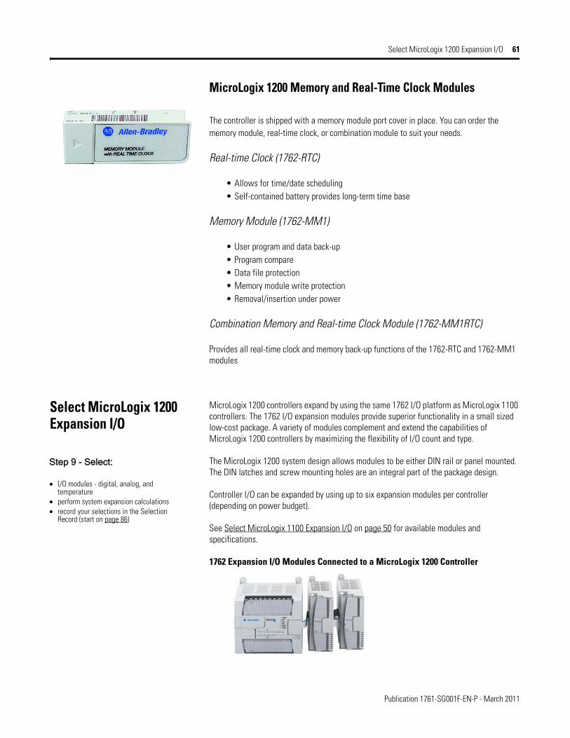
MicroLogix 1200 Memory and Real-Time Clock Modules
The controller is shipped with a memory module port cover in place. You can order the memory module, real-time clock, or combination module to suit your needs.
Real-time Clock (1762-RTC)
• Allows for time/date scheduling• Self-contained battery provides long-term time base
Memory Module (1762-MM1)
• User program and data back-up• Program compare• Data file protection• Memory module write protection• Removal/insertion under power
Combination Memory and Real-time Clock Module (1762-MM1RTC)
Provides all real-time clock and memory back-up functions of the 1762-RTC and 1762-MM1 modules
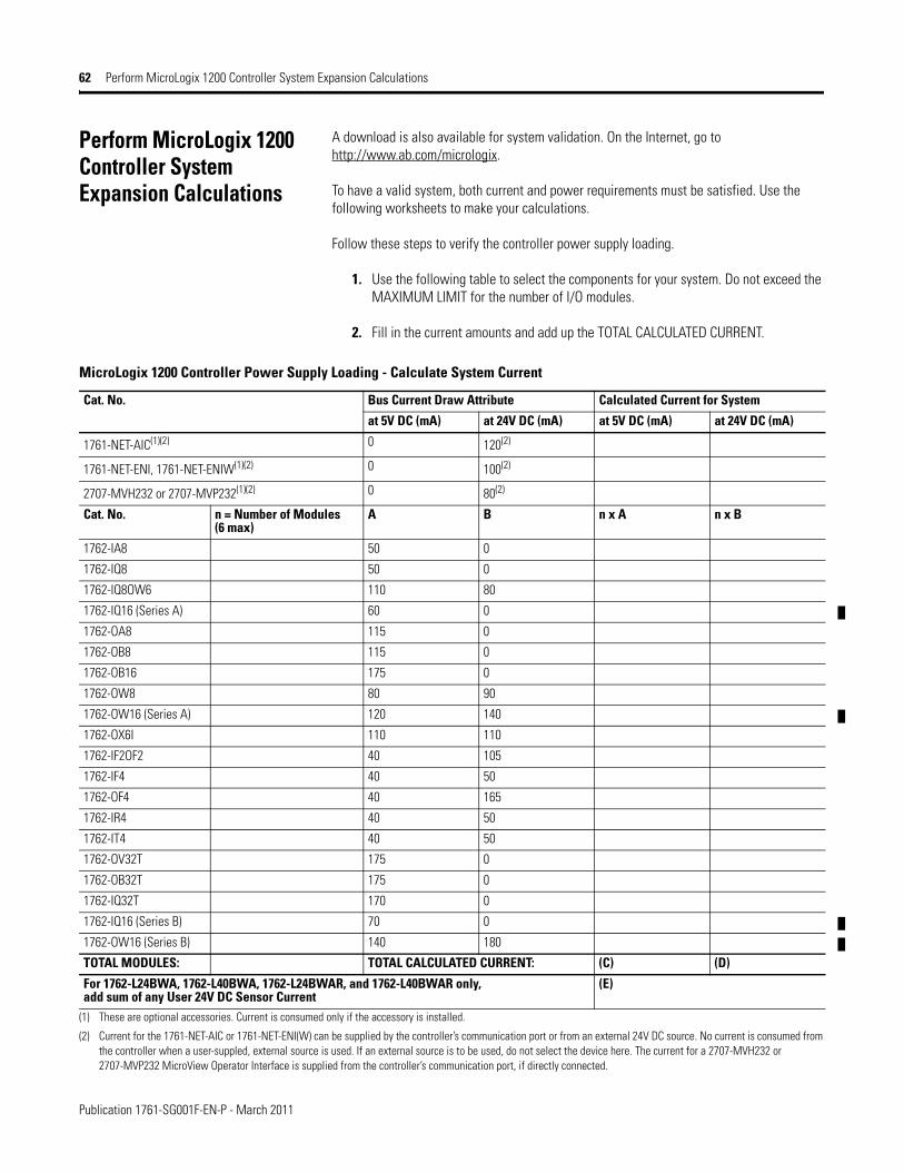
Select MicroLogix 1200 Expansion I/O
MicroLogix 1200 controllers expand by using the same 1762 I/O platform as MicroLogix 1100 controllers. The 1762 I/O expansion modules provide superior functionality in a small sized low-cost package. A variety of modules complement and extend the capabilities of MicroLogix 1200 controllers by maximizing the flexibility of I/O count and type.
The MicroLogix 1200 system design allows modules to be either DIN rail or panel mounted. The DIN latches and screw mounting holes are an integral part of the package design.
Controller I/O can be expanded by using up to six expansion modules per controller (depending on power budget).
See Select MicroLogix 1100 Expansion I/O on page 50 for available modules and specifications.
1762 Expansion I/O Modules Connected to a MicroLogix 1200 Controller
Step 9 - Select:
• I/O modules - digital, analog, and temperature
• perform system expansion calculations• record your selections in the Selection
Record (start on page 86)
Publication 1761-SG001F-EN-P - March 2011
62 Perform MicroLogix 1200 Controller System Expansion Calculations
Perform MicroLogix 1200 Controller System Expansion Calculations
A download is also available for system validation. On the Internet, go to http://www.ab.com/micrologix.
To have a valid system, both current and power requirements must be satisfied. Use the following worksheets to make your calculations.
Follow these steps to verify the controller power supply loading.
1. Use the following table to select the components for your system. Do not exceed the MAXIMUM LIMIT for the number of I/O modules.
2. Fill in the current amounts and add up the TOTAL CALCULATED CURRENT.
MicroLogix 1200 Controller Power Supply Loading - Calculate System Current
Cat. No. Bus Current Draw Attribute Calculated Current for System
at 5V DC (mA) at 24V DC (mA) at 5V DC (mA) at 24V DC (mA)
1761-NET-AIC(1)(2) 0 120(2)
1761-NET-ENI, 1761-NET-ENIW(1)(2) 0 100(2)
2707-MVH232 or 2707-MVP232(1)(2) 0 80(2)
Cat. No. n = Number of Modules(6 max)
A B n x A n x B
1762-IA8 50 0
1762-IQ8 50 0
1762-IQ8OW6 110 80
1762-IQ16 (Series A) 60 0
1762-OA8 115 0
1762-OB8 115 0
1762-OB16 175 0
1762-OW8 80 90
1762-OW16 (Series A) 120 140
1762-OX6I 110 110
1762-IF2OF2 40 105
1762-IF4 40 50
1762-OF4 40 165
1762-IR4 40 50
1762-IT4 40 50
1762-OV32T 175 0
1762-OB32T 175 0
1762-IQ32T 170 0
1762-IQ16 (Series B) 70 0
1762-OW16 (Series B) 140 180
TOTAL MODULES: TOTAL CALCULATED CURRENT: (C) (D)
For 1762-L24BWA, 1762-L40BWA, 1762-L24BWAR, and 1762-L40BWAR only, add sum of any User 24V DC Sensor Current
(E)
(1) These are optional accessories. Current is consumed only if the accessory is installed.
(2) Current for the 1761-NET-AIC or 1761-NET-ENI(W) can be supplied by the controller’s communication port or from an external 24V DC source. No current is consumed from the controller when a user-suppled, external source is used. If an external source is to be used, do not select the device here. The current for a 2707-MVH232 or 2707-MVP232 MicroView Operator Interface is supplied from the controller’s communication port, if directly connected.

Publication 1761-SG001F-EN-P - March 2011
Perform MicroLogix 1200 Controller System Expansion Calculations 63
3. Using the table below, verify that (C), (D), and (E) do not exceed the MAXIMUM LIMITS. If the MAXIMUM LIMIT is exceeded, you will need to adjust your selections.
4. Use the table below to verify that the system is within the power loading limits of the controller.
Fill in the (C), (D), and (E) values where indicated. Then calculate Watts and add up the Total Watts. Verify that Total Watts does not exceed the MAXIMUM POWER LIMIT. If the MAXIMUM POWER LIMIT is exceeded, you will need to adjust your selections.
MicroLogix 1200 Controller Maximum Load Current
Cat. No. Load Current 5V DC 24V DC User 24V DC Sensor Current
1762-L24AWA 1762-L24AWAR1762-L24BXB, 1762-L24BXBR
Calculated Value (C) (D) N/A
MAXIMUM LIMIT 400 mA 350 mA
1762-L24BWA1762-L24BWAR
Calculated Value (C) (D) (E)
MAXIMUM LIMIT 400 mA 350 mA 250 mA
1762-L40AWA1762-L40AWAR1762-L40BXB, 1762-L40BXBR
Calculated Value (C) (D) N/A
MAXIMUM LIMIT 600 mA 500 mA
1762-L40BWA1762-L40BWAR
Calculated Value (C) (D) (E)
MAXIMUM LIMIT 600 mA 500 mA 400 mA
MicroLogix 1200 Controller Maximum Load Power
Cat. No. 5V Power ConsumptionCalculated Watts
24V Power ConsumptionCalculated Watts
Calculated Watts(sum of 5V and 24V)
MAXIMUM POWER LIMIT
1762-L24AWA 1762-L24AWAR
(C) x 5V = W (D) x 24V = W W 10.4 W
1762-L24BXB1762-L24BXBR
(C) x 5V = W (D) x 24V = W W 10.4 W
1762-L24BWA 1762-L24BWAR
(C) x 5V = W (D)+(E) x 24V = W W 12 W
1762-L40AWA 1762-L40AWAR
(C) x 5V = W (D) x 24V = W W 15 W
1762-L40BXB 1762-L40BXBR
(C) x 5V = W (D) x 24V = W W 15 W
1762-L40BWA 1762-L40BWAR
(C) x 5V = W (D)+(E) x 24V = W W 16 W

Publication 1761-SG001F-EN-P - March 2011
84 Select Replacement Parts
Select Replacement Parts
MicroLogix 1000 Replacement Parts
Description Cat. No.
Terminal Cover Doors for 1761-L32AWA, -L32BWA, or -L32AAA (2 doors per package) 1761-RPL-T32X
Replacement Terminal Block — 6-position DH-485 plug/connector used with the 1761-NET-AIC. 1746-RT30
Replacement Terminal Block — 5-position DeviceNet plug/connector used with the 1761-NET-DNI. 1761-RPL-RT00
MicroLogix 1100 Replacement Part
Description Cat. No.
Replacement Battery 1763-BA
MicroLogix 1200 Replacement Parts
Description Cat. No.
Replacement Removable Terminal Block — (1) 25-pt double row, (1) 29-point double row for 1762-L40AWA and -L40BWA 1762-RPLRTB40
Step 14 - Select:
• replacement parts• record your selections in the Selection
Record (start on page 86)
MicroLogix 1400 Replacement Parts
Description Cat. No.
Replacement Battery 1747-BA
Replacement Removable Terminal Block — (1) 25-pt double row, (1) 29-point double row for all 1766-L32xxxx 1762-RPLRTB40
MicroLogix 1500 Replacement Parts
Description Cat. No.
Replacement Terminal Block — 17-pt for 1764-24AWA and 1764-24BWA inputs 1764-RPLTB1
Replacement Terminal Block — 21-pt for 1764-28BXB inputs and outputs for all base units 1764-RPLTB2
Replacement Battery 1747-BA