microphones* - cvut.czradio.feld.cvut.cz/~vlk/micp/bauer_cnt.pdf · action of pressure on a...
TRANSCRIPT

PROCEEDINGS OF THE IRE
Section 3
AUDIOOrganized with the assistance of the IRE Professional Group on Audio
A Century of Microphones by B. B. Bauer
Loudspeakers by Harry F. Olson
Disk Recording and Reproduction by W. S. Bachman, B. B. Bauer, and P. C. Goldmark
Film Recording and Reproduction by M. C. Batsel and G. L. Dimmick
Current Problems in Magnetic Recording by Marvin Camras
Electroacoustic Measuring Equipment and Techniques by Leo L. Beranek
Speech Communication Systems by Winston E. Kock
The History of Stereophonic Sound Reproduction by John K. Hilliard
A Century of Microphones*B. B. BAUERt, FELLOW, IRE
Summary-Of the various manifestations of a sound wave, theaction of pressure on a diaphragm still is the universal means fordetecting the presence of sound. The diaphragm actuates a trans-ducer converting its motions into equivalent electrical waves. Innu-
merable transducers have been tried, but five are pre-eminent:1) carbon, 2) condenser, 3) piezoelectric, 4) moving conductor,5) moving armature.
Important microphone improvements during the late twentiesand the thirties have come about as a result of application of equiva-lent circuit analysis to acoustical structures. The principle of pressuremicrophones, pressure gradient microphones, combination micro-phones and phase shift microphones are described. Each of these hasfound an important niche in modem microphone applications.
A small number of important applications require super-direc-tional microphones. Here three approaches are used: 1) reflectors,refractors and diffractors, 2) line microphones, 3) higher-order com-
bination microphones.In the future, improvements in design of directional microphones
will continue. Wireless microphones are bound to increase in popu-larity. New methods of transduction based upon solid-state tech-nology appear to be imminent. Unconventional methods of soundpickup may find wide use in space communication.
* Received by the IRE, January 2, 1962.t CBS Laboratories, Stamford, Conn.
INTRODUCTION
S A SENSOR which transforms sound into energy
form suitable for amplification and transmis-sion, a microphone is among the most commoni
and useful technological servants of mankind. At thiswriting, a century of effort has been devoted to invent-ing and perfecting the microphone. This paper is in-tended to provide a record of the basic contributionsmade during that time as well as to survey the engineer-ing principles employed in the present day microphones.A brief look into the future will also be attempted.
PLAN OF THIS PAPER
From the scientific point of view a microphone may
be designed to sense any of the manifestations of thesound wave and to convey it to a transducer which willtransform it into electrical energy. A sound wave isaccompanied by the presence of an alternating excess
pressure called the sound pressure p; the particles of airare subject to a to-and-fro motion which may be de-scribed by their velocity u and since the medium follows
1962 719
PROCEEDINGS OF THE IRE
the adiabatic law there exists an alternating change intemperature as well as corresponding changes in den-sity, dielectric constant, magnetic susceptibility andindex of refraction. This paper is confined to those mi-crophones in which the sound pressure or sound-pressuregradient are transformed into a force F by use of adiaphragm which, together with an associated electro-mechanical transducer, is set into motion resulting ingeneration of electricity. This is the method employedin earliest microphones, and it is virtually the universalmethod for microphone operation today. Because oftheir importance to proper understanding of micro-phones, brief descriptions of typical diaphragms andtheir interaction with the medium have been includedin this paper.Some of the other functions of a sound wave that have
found significant but limited application in microphonesare 1) the combined action of the particle velocity andthe alternating temperature upon a heated fine wire'and 2) the combined action of pressure and particlevelocity upon a cloud of ions.2'3 Other possibilities havebeen considered: the change in dielectric constant ormagnetic susceptibility of the air could be used to modu-late the frequency of an oscillator;4 the varying refrac-tive index may be caused to modulate a light beam,5for example. Some of these functions may hold a keyto microphone developments of the future.Every conceivable means of electro-mechanical
transduction has been combined with the vibratingdiaphragm in an effort to produce "new and better"microphones. In this paper five basic transducers aredescribed, any one of which will be found in virtuallyall of the present-day microphones: 1) Loose contact(carbon), 2) Electrostatic (condenser), 3) Piezoelectric(Rochelle Salt and Ceramic), 4) Moving conductor(moving coil dynamic and ribbon), 5) Moving armature(magnetic or reluctance). Many other means of trans-duction have been studied, tested and patented, suchas, variable fluid contact,6 movable vacuum tube ele-ments,7 piezoresistivity8 point-contact transistors,9 etc.To this date, these have not been widely adopted, butagain these and newer methods of transduction may be-come important in future microphones.
1 G. Forbes, "A tfiermal telephone transmitter," Proc. Roy. Soc.(London) A, vol. 42, pp. 141-142; February 24, 1889.
2 Early experiments are described in a paper by W. Duddel,"Rapid variations in the current through the direct-current arc,"The Electrician, p. 271; December 14, 1900. Duddel credits thediscovery to Simon whose experiments are recorded in Ann. derPhys., vol. LXIV, No. 2, pp. 233-239; 1898. Also see L. de Forest,Brit.-Patent 5258; 1906.
3 S. Klein's ionophone described by J. C. Axtell, "Ionic loudspeak-ers," IRE TRANS. ON AUDIO, Vol. AU-8, pp. 21-27; July, 1952.
4This possibility has come to the author's attention from time totime but it does not appear to have been explored.8 L. de Forest, U. S. Patent No. 1,726,299; 1924.
6 A. G. Bell, March 10, 1876. See H. A. Frederick, "The develop-ment of the microphone," J. Acoust. Soc. Am., vol. 3, pt. 2, p. 5;July, 1931.
7 H. F. Olson, "Mechani-electronic transducers," J. Acoust. Soc.Am., vol. 19, pp. 307-319; March, 1947.
8 F. P. Burns, "Piezoresistive semiconductor microphone," J.Acoust. Soc. Am., vol. 29, pp. 248-253; February, 1957.
9 R. L. Hanson, "Transistor microphone," U. S. Patent No.2,497,770; 1950.
Among the scientific tools of radio engineering, nonehas contributed as much to microphone development asthe application of electrical circuit analysis to electro-acoustical structures.'0 In employing the principles ofthis analysis, the operation of microphones is betterunderstood and the groundwork is laid for future de-velopments. It will be seen, for example, that some ofthe foregoing transducers are displacement responsiveand others are velocity responsive (these terms arisingfrom the generated voltage being dependent on theamplitude of displacement or the velocity of the dia-phragm). Equivalent circuit analysis shows how to pro-portion microphone structures best to utilize these char-acteristics.
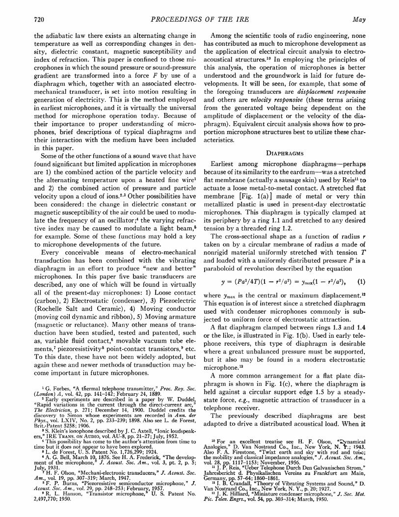
DIAPHRAGMSEarliest among microphone diaphragms-perhaps
because of its similarity to the eardrum-was a stretchedflat membrane (actually a sausage skin) used by Reis" toactuate a loose metal-to-metal contact. A stretched flatmembrane [Fig. 1 (a) ] made of metal or very thinmetallized plastic is used in present-day electrostaticmicrophones. This diaphragm is typically clamped atits periphery by a ring 1.1 and stretched to any desiredtension by a threaded ring 1.2.The cross-sectional shape as a function of radius r
taken on by a circular membrane of radius a made ofnonrigid material uniformly stretched with tension Tand loaded with a uniformly distributed pressure P is aparaboloid of revolution described by the equation
y = (Pa2/4T)(1 -r2/a2) = ymax(l - r2/a2), (1)
where Ymax is the central or maximum displacement.'2This equation is of interest since a stretched diaphragmused with condenser microphones commonly is sub-jected to uniform force of electrostatic attraction.A flat diaphragm clamped between rings 1.3 and 1.4
or the like, is illustrated in Fig. 1(b). Used in early tele-phone receivers, this type of diaphragm is desirablewhere a great unbalanced pressure must be supported,but it also may be found in a modern electrostaticmicrophone."3A more common arrangement for a flat plate dia-
phragm is shown in Fig. l(c), where the diaphragm isheld against a circular support edge 1.5 by a steady-state force, e.g., magnetic attraction of transducer in atelephone receiver.The previously described diaphragms are best
adapted to drive a distributed acoustical load. When it
10 For an excellent treatise see H. F. Olson, ";OvnamicalAnalogies," D. Van Nostrand Co., Inc., New York, N. &.; 1943.Also F. A. Firestone, "Twixt earth and sky with rod and tuiw,;the mobility and classical impedance analogies," J. Acoust. Soc. Am.,vol. 28, pp. 1117-1153; November, 1956.
1 J. P. Reis, aUeber Telephone Durch Den Galvanischen Strom,"Jahresbericht d. Physikalischen Vereins zu Frankfurt am Main,Germany, pp. 57-64; 1860-1861.
12 I. B. Crandall, "Theory of Vibrating Systems and Sound," D.Van Nostrand Co., Inc., New York, N. Y., p. 20; 1927.
13 J. K. Hilliard, "Miniature condenser microphone," J. Soc. Mot.Pic. Telev. Engrs., vol. 54, pp. 303-314; March, 1950.
720 May

Bauer: Microphones
I1.1 p v1 4
~1.2 A .3 K'11 , t(a) (b) (c)
i.6 2 1.7 hfg-
10
17.1 (e)
1.15
M M CmR
1i.141I P2
AlZAI A2 PA2(f)
(d) (g) (h)
Fig. 1-Various types of diaphragms used in microphones.
becomes necessary to actuate a mechanical system froma point or a line, the diaphragm usually takes on a dif-ferent shape so as to present an adequate driving-pointimpedance to the load.Very commonly used for a point-drive is a cone dia-
phragm shown in three versions in Fig. l(d). The edgeof the diaphragm is effectively clamped or cementedagainst some support 1.6 leaving an annular portion 1.7to flex in response to motions of the conical portion 1.8.The latter actuates a transducer through a drive-rod 1.9.The flat annulus gives way to a formed or corrugatedannulus 1.10 when linearity of motion and freedomfrom spurious resonances at high frequency is required.A major advance in annulus design was achieved byHarrison'4 who invented a tangentially-corrugated an-
nulus 1.11, shown at bottom of Fig. 1(d), and which isused at present in many moving-coil microphones andhorn loudspeaker drivers.A "curvilinear" diaphragm developed by the author
for use with piezoelectric microphones a quarter of a
century ago is now widely used with various point-drives. The goal is to provide a "nonbuckling" shape,that is, one that normally would be assumed by a pie-slice segment of a diaphragm supported at its apex andthe circumferential edge and subjected to uniform pres-
sure at one side. The desired shape may be defined ap-
proximately by the following equation:
y/h = (3/2)(x/a)l - (1/2)(x/a)', (2)
where the lowest point of the draw is at the origin o andh is the height at the apex 1.12. The contour may riseboth toward the apex and toward the edge of support1.13.A 'piston" diaphragm shown in Fig. 1(f) is practically
universally used with moving-coil microphones andother transducers where force is transmitted at the circu-lar line around the rim to a coil 1.14. The central portionof the "piston" 1.15 is of spherical shape. The annulus
14 J, P. Maxfield and H. C. Harrison, "Methods of high qualityrecording and reproduction of music and speech based on telephoneresearch," Trans. AIEE, vol. 45 (Commun. and Electronics, pp. 334-348; February, 1926.
1.16 commonly is tangentially corrugated after Harrison.A ribbon diaphragm which also is a transducer was
invented by Gerlach."5 As used in a pressure-gradientmicrophone invented by Olson,"6 this transducer ismade of corrugated aluminum ribbon 1.17 less than0.0001-inch thick which either floats freely or is slightlystretched between two pole pieces 1.18. Electrical con-nections are made at the supports 1.19 to a high turns-ratio transformer.From equivalent circuit point of view, the action of a
diaphragm may be represented by Fig. 1(h).17 Themechanical elements of the diaphragm, i.e., mass M,compliance Cm and internal damping resistance Rm ap-pear in the circuit as equivalent electrical elements towhich forces derived from acoustical pressures arecoupled by means of ideal 1:A transformers. The rela-tionships between the pressure p and the force F de-veloped upon an area A, and the volume velocity u andthe linear velocity V resulting therefrom are correctlyportrayed by the use of a transformer coupler, as mayreadily be verified from transformer equations. Nor-mally the net areas on both sides of the diaphragm areequal, so that only two transformers (one for each sideof the diaphragm) will be required. In the case of mov-ing coil microphones the two sub-areas of the diaphragmin l(f) separated by the coil from 1-14 are subjected todifferent pressures and are confronted by differentacoustical impedances. In this case each independentlyacting area must be represented by its own couplingtransformer. These transformers are merely aids to cor-rect circuit analysis representation. Usually they can bedeleted in the actual experimental circuit work.
LOOSE-CONTACT TRANSDUCERSAmong the earliest devices intended for converting
vibration into electrical impulses was Reis' loose metal-contact transducer1' which is reported to have trans-mitted tones of different frequencies, but not intelligiblespeech. This latter event seems first to have beenachieved by Bell, using a magnetic microphone, on June3, 1875.18 However, Bell's microphone proved not to besufficiently sensitive for telephone work, and the experi-ments of Berliner,'9 Edison,20 Hughes2' and others soonthereafter introduced a long era of dominance for theloose-contact carbon transducer. To Edison goes thecredit of being the first to design a transducer usinggranules of carbonized hard coal,22 still used in present-day microphones.
15 E. Gerlach, German Patent 421,038; 1925.16 H. F. Olson, U. S. Patent No. 1,885,001; 1932.17 B. B. Bauer, "Transformer analogs of diaphragms,' J. Acoust.
Soc. Am., vol. 23, pp. 680-683; November, 1951.18 See, for example, F. H. Frederick, "The development of the
microphone," J. Acoust. Soc. Am., vol. 3, pt. 2, p. 3; July, 1931.Also, Alexander Graham Bell, U. S. Patent No. 174,465; 1876.
19 E. Berliner, Caveat filed in U. S. Patent Off., April 14, 1877.20 T. A. Edison, U. S. Patent No. 474,230; filed April 27, 1877.
Also, U. S. Patent Nos. 474-231-2.21 D. E. Hughes, "On the action of sonorous vibrations in varying
the force of an electric current," Proc. Roy. Soc .(London) A, vol. 27,pp. 362-369; May 9, 1878.
22 T. A. Edison, U. S. Patent No. 406,567; July 19, 1889.
1962 721
PROCEEDINGS OF THE IRE
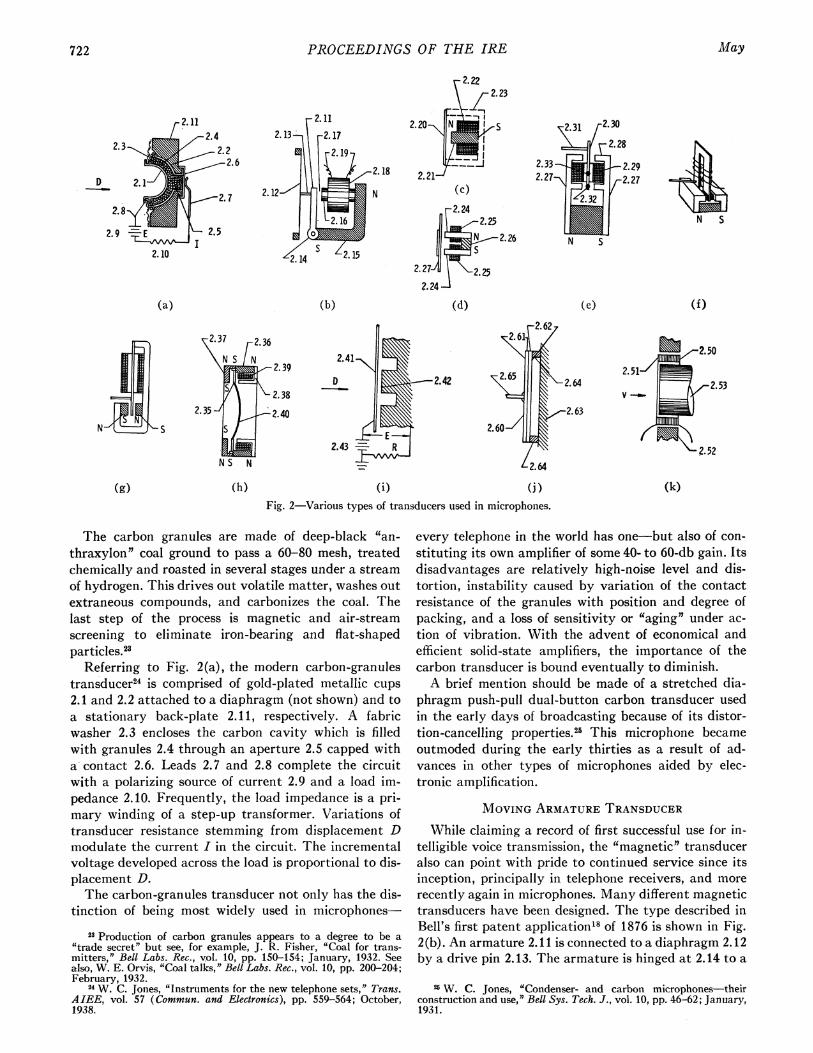
2.1124
2.22.6
D
(a) (b)
r222
12 7
1
2.21-
.25ItE 2.26
2.27 i2.25?.241
(d)
N 5
(e) (f)
2.37 2.36
. 2.39
2.382.35 2.40
NSN
2.50
2.51-,
v _-2.5~~2.3V -.
2.52
(i) (j) (k)Fig. 2-Variouis types of transducers used in microphones.
The carbon granules are made of deep-black "an-
thraxylon" coal ground to pass a 60-80 mesh, treatedchemically and roasted in several stages under a streamof hydrogen. This drives out volatile matter, washes outextraneous compounds, and carbonizes the coal. Thelast step of the process is magnetic and air-streamscreening to eliminate iron-bearing and flat-shapedparticles.23
Referring to Fig. 2(a), the modern carbon-granulestransducer24 is comprised of gold-plated metallic cups2.1 and 2.2 attached to a diaphragm (not shown) and toa stationary back-plate 2. 11, respectively. A fabricwasher 2.3 encloses the carbon cavity which is filledwith granules 2.4 through an aperture 2.5 capped witha contact 2.6. Leads 2.7 and 2.8 complete the circuitwith a polarizing source of current 2.9 and a load im-pedance 2.10. Frequently, the load impedance is a pri-mary winding of a step-up transformer. Variations oftransducer resistance stemming from displacement Dmodulate the current I in the circuit. The incrementalvoltage developed across the load is proportional to dis-placement D.The carbon-granules transducer not only has the dis-
tinction of being most widely used in microphones-
23 Production of carbon granules appears to a degree to be a"trade secret" but see, for example, J. R. Fisher, "Coal for trans-mitters," Bell Labs. Rec., vol. 10, pp. 150-154; January, 1932. Seealso, W. E. Orvis, "Coal talks," Bell Labs. Rec., vol. 10, pp. 200-204;February, 1932.
14 W. C. Jones, "Instruments for the new telephone sets," Trans.AIEE, vol. 57 (Commun. and Electronics), pp. 559-564; October,1938.
every telephone in the world has one-but also of con-
stituting its own amplifier of some 40- to 60-db gain. Itsdisadvantages are relatively high-noise level and dis-tortion, instability caused by variation of the contactresistance of the granules with position and degree ofpacking, and a loss of sensitivity or "aging" under ac-
tion of vibration. With the advent of economical andefficient solid-state amplifiers, the importance of thecarbon transducer is bound eventually to diminish.A brief mention should be made of a stretched dia-
phragm push-pull dual-button carbon transducer usedin the early days of broadcasting because of its distor-tion-cancelling properties.25 This microphone becameoutmoded during the early thirties as a result of ad-vances in other types of microphones aided by elec-tronic amplification.
MOVING ARMATURE TRANSDUCERWhile claiming a record of first successful use for in-
telligible voice transmission, the "magnetic" transduceralso can point with pride to continued service since itsinception, principally in telephone receivers, and more
recently again in microphones. Many different magnetictransducers have been designed. The type described inBell's first patent application'8 of 1876 is shown in Fig.2 (b). An armature 2. 11 is connected to a diaphragm 2.12by a drive pin 2.13. The armature is hinged at 2.14 to a
26 W. C. Jones, "Condenser- and carbon microphones-theirconstruction and use," Bell Sys. Tech. J., vol. 10, pp. 46-62; January,1931.
(g) (h)
May722
2 31 2.30
2. 28
2.33, 2.292.27-,,., 2.27

Bauer: Microphones
yoke 2.15. The yoke bears a pole-piece 2.16 forming anairgap 2.17 and carrying a coil 2.18 with terminals at2.19. Bell's original idea was to interconnect two suchtransducers by means of a transmission line and a bat-tery in the circuit which polarized the electro-magnetsof both transducers. The generated signal voltage isproportional to armature velocity.
In 1877 Bell patented a notable improvement to theabove structure in which he used a permanent magnetfor purposes of polarization.26The transducer of Bell is used to this day in tele-
phone receivers in two modified forms shown here forreference. The one in Fig. 2(c) employs a combinationdiaphragm-armature 2.20 and a permanent magnetpole-piece 2.21 surrounded by a coil 2.22. A magneticreturn cup 2.23 often is provided. A bi-polar form inFig. 2(d) employs two pole-pieces 2.24, each providedwith a coil 2.25 and a common permanent magnet 2.26.A Permindur pole-shoe 2.27 helps to carry the steady-state flux of the magnet. The above units have not beensuccessful as microphones because the moving memberrequires sufficient heft to carry unbalanced dc flux andto support the steady-state forces which it produces.A magnetically balanced-armature transducer, useful
in microphones, was suggested by Siemens27 and Wat-son,28 but more definitely projected by Capps.29 Shownin Fig. 2(e) an armature 2.30 within the coil carries thedifferential flux only stemming from motions impartedto it by the drive pin 2.31 connected to a diaphragm (notshown). The armature may be pivoted at a point 2.32which results in a mechaniically unbalanced structure,or at a point 2.33 which produces mechanical, as wellas magnetic, balance.
In an attempt to dissociate as much as possible thesteady state and the ac flux paths, the magnetic struc-ture and the armature may be deformed, topologicallyspeaking, until a straight-line pole-piece structure anda U-shaped armature form has been obtained, withgreat economy of dimensions.30 This structure shown inFig. 2(f) has found wide use in transistorized hearingaids in which miniaturization has become a most im-portant virtue. A variation is shown in Fig. 2(g).An improvement heretofore applied to a telephone
receiver but with possible use in microphones is shownin Fig. 2(h).31 In this arrangement, a ring armature2.35 is maintained in an unsaturated condition by tworing magnets 2.36 and 2.37. The circuit comprising thealternating flux path includes a circular pole-shoe 2.38and a circular coil 2.39. This transducer is well adaptedto being driven by a piston diaphragm 2.40.
Magnetic transducers are characterized by the pres-ence of a negative force-displacement function at the
26 A. G. Bell, U. S. Patent No. 186,787; 1877.27 E. W. Siemans, German Patent No. 2355; 1878.28 T. A. Watson, U. S. Patent No. 266, 567; 1882.29 F. L. Capps, U. S. Patent No. 441,396; 1890.30 B. B. Bauer, U. S. Patent No. 2,454,425; 1948.31 E. E. Mott and R. C. Miner, "The ring armature telephone
receiver," Bell Sys. Tech. J., vol. 30, pp. 110-140; January, 1951.
airgaps which has the dynamical form of negative stiff-ness. The magnetization and saturation properties ofthe armature must be proportioned in such manner thatthe mechanical restoring stiffness of the armature anddiaphragm are greater than the magnetic negative stiff-ness.32
ELECTROSTATIc TRANSDUCERSWhile Edison33 and Dolbear34 proposed the use of
electrostatic transducers very early in this history ofelectroacoustics, it remained for Wente35 to develop anelectrostatic microphone that was truly a precision in-strument. An electrostatic transducer is shown inschematic view in Fig. 2(i). A stretched flat conductivemembrane 2.41 is arranged at a distance x from a backplate 2.42 defining an active area A. This produces acapacitor having a capacitance C= kA /x, where k is thedielectric constant of air. A polarizing potential differ-ence E is provided from a source 2.43, connected to theelectrodes through a very high resistance R. Thus aquasi-constant charge Qo is established on the capacitorwhere Qo = CE = kAE/x. Solving for E,
E = (Qo/kA)x. (3)
Therefore the voltage across the condenser will varylinearly with the diaphragm displacement x. Because ofthe low-loss air dielectric, a capacitor transducer po-tentially is an extremely quiet, linear device.
In practice the spacing x is of the order of 0.001 inch,and the capacity of the microphone is around 25-50,ulAf. Therefore, a very high impedance preamplifier atthe transducer is required. The electrostatic transduceris most often used where highest quality is sought re-gardless of cost and inconvenience caused by the inte-gral preamplifiers such as in recording and calibrationswork. An electrostatic transducer also is characterizedby presence of negative stiffness.
MOVING COIL TRANSDUCERWhile the early efforts and concepts in connection
with moving-coil transducers are associated with thenames of Cuttriss, Redding36 and Siemens,37 the creditfor developing a wide-range practical moving-coil micro-phone goes to Wente and Thuras.38 Referring to Fig.
32 For example, see B. B. Bauer, "A miniature microphone fortransistorized amplifiers," J. Acoust. Soc. Am., vol. 25, pp. 867-869;September, 1953. In all transducers (other than loose-contact) anyutilization of the generated electrical energy causes a reaction uponlthe transducer's mechanical impedance. In microphones, this effectis usually small, and is beyond the scope of this paper.
33 Reported in G. B. Prescott, "The Speaking Telephone, TalkingPhonograph and Other Novelties," D. Appleton and Co., New York,N. Y.; 1878.
34 A. E. Dolbear, U. S. Patent Nos. 239,742 and 240,578; 1881.35 E. C. Wente, "A condenser transmitter as a uniformly sensitive
instrument for the absolute measurement of sound intensity," Phys.Rev., vol. 10, pp. 39-63; July, 1917.
36 C. Cuttriss and J. Redding, U. S. Patent No. 242,816; 1881.37 E. W. Siemens, German Patent No. 2355; 1878.38 E. C. Wente and A. L. Thuras, 'Moving coil telephone re-
ceivers and microphones," J. Acoust. Soc. Am., vol. 3, pp. 44-55;July, 1931.
1962 723
PROCEEDINGS OF THE IRE
2(k), the moving-coil is circular in shape and is attachedat the rim 2.51 to a diaphragm (not shown) being sup-ported and centered thereby in an air gap between pole-pieces 2.52 and 2.53. If the length of the conductor inthe air gap is I and the flux density is B, and the dia-phragm velocity is v, the voltage generated in the coilis
E=Blv (4)
and hence, a moving-coil transducer is a velocity-responsive device.Wente and Thuras based the development of their
microphone and receiver upon equivalent circuit analy-sis. It is interesting to note that the circuit developedby them for a moving-coil receiver (where the goal isconstant diaphragm displacement as a function of in-put voltage) is identical with the circuit to be used for adisplacement-responsive (e.g., ceramic) microphone.A moving coil transducer is sensitive, rugged, pro-
vides good frequency-response and low noise, and atpresent is the 'workhorse" among the microphones usedfor broadcasting and public-address applications. Thelow-coil impedance is suitable for operation with longcables, followed with a step-up transformer at the pre-amplifier, although in many microphones, a built-intransformer provides the proper impedance transforma-tion right at the microphone.
PIEZOELECTRIC TRANSDUCERIn 1820 Becquerel described and observed piezoelec-
tric effects39 although a systematic study leading tomodern understanding of these effects is credited to theCuries.40 Nevertheless, piezoelectric microphones hadnot become practical until the invention of the "bi-morph" Rochelle Salt transducer by Sawyer.4' The"bimorph" ushered a quarter of a century era of dom-inance for Rochelle Salt crystals in low cost micro-phones, which (because of relatively poor stability ofRochelle Salt in severe climates) subsequently was tobe challenged by polycrystalline Barium Titanateceramics of Gray42 and more recently by Lead Zirco-nium Titanate ceramics of Jaffe.43 The shapes taken onby these bodies is that of a sandwich.designated 2.60 inFig. 2(j) consisting of two slabs of piezoelectric material2.61 and 2.62 which are joined into an integral unit withappropriate electrodes. The element is attached to areference frame 2.63 by raised portions 2.64, and drivenby means of a drive-unit 2.65 which is connected to adiaphragm. The tension and compression in the beamcombine with the polarization mode of the individual
39 A. C. Becquerel, Bulletin des Sciences, par la Societe Philo-matique de Paris, France, vol. 7, pp. 149-155; March, 1820.
40 J. and P. Curie, Bulletin de la Societe Mineralogique de France,vol. 3, pp. 90-93; April, 1880.
41 C. B. Sawyer, "The use of Rochelle Salt crystals for electricalreproducers and microphones," PROC. IRE, vol. 19, pp. 2020-2029;November, 1931.
42 Grey, U. S. Patenit No. 2,486,560; 1949.43 Jaffe, U. S. Patent No. 2,708,244; 1955.
slabs to produce a potential difference in the electrodesas a function of displacement. Rochelle Salt bimorphsare available for actuation by torsion or bendingstresses, while the ceramic units are usually of the lattervariety.
MICROPHONE STRUCTURESHunt44 refers to the 1870's as "vintage years for elec-
troacoustics." The inventions of the telephone andphonograph together with innumerable transducers toimplement them occurred during those years. In thesame manner, the 1930's, having seen the developmentof many a modern microphone, may be thought of asvintage years for microphones.
In studying the historical development of micro-phones it becomes evident that control over their direc-tional capabilities has become increasingly importantwith time. In the following sections, we describe 1) pres-sure microphones which respond to sound pressure at oneexposed surface of the diaphragm and (because soundtravels around corners) are more or less equally sensi-tive from all directions; 2) gradient or pressure-differ-ence microphones in which the diaphragm is exposed fordifferential action by sound pressure equally at bothsurfaces to achieve a bi-directional operation; 3) com-bination microphones which unite pressure and gradientconcepts to achieve unidirectional action and 4) phase-shift microphones which achieve unidirectional actionwith a single transducer and acoustical phase-shiftnetworks. Diaphragms and transducers in endless com-binations have been brought together to produce a mul-titude of such microphones, but only a few basic exam-ples can be given here.
PRESSURE MICROPHONESThe electrostatic microphone of Wente35 is one of the
simplest, and, with modern refinements, one of the mosteffective of microphones. Its basic form is shown inFig. 3(a). The microphone is composed of a flat stretchedconductive diaphragm 3.1 attached to a box 3.2 so as toexpose one surface to the external sounds. A stationaryelectrode 3.3 inside the box, placed close to the dia-phragm, forms the electrostatic transducer.The equivalent network analogy of the electrostatic
microphone is shown in Fig. 3(b). Sound pressure actsupon the diaphragm through an air-load radiation im-pedance portrayed by an inductance La in parallel witha resistance Ra.45 Thin films of air between the dia-phragm and the electrode are squeezed in and out as thediaphragm vibrates to-and-fro resulting in damping ac-tion, the collective effect of which is represented by Rband Lb. The fluid motion finds its way into the volume
14 F. V. Huint, 'Electroacoustics, " Harvard University Press,Cambridge, Mass., p. 37; 1954.
45 Means of approximating air-load imipedance with fixed ele-ments is an important tool in the bag of tricks of the electroacous-tician. For example, see B. B. Bauer, "Notes on radiation impedance, "J. Acoust. Soc. Am., vol. 15, pp. 223-224; April, 1944; R. C.Jones, "A fifty horsepower siren," J. Acoust. Soc. Am., vol. 18, pp.371-387; October, 1946; F. B. Hunt, op. cit., p. 158.
724 May

Bauer: Microphones
of the recesses 3.4 which taken together define anacoustical compliance Cb.A simplified equivalent circuit is obtained by dividing
the mechanical impedance of the diaphragm by thesquare of the area A, which allows the elimination ofideal 1: A transformers [Fig. 3(c)]. The input voltageEp replaces the sound pressure p. Since diaphragm dis-placement D is equivalent to the charge on a condenserQ= CE, it is a requirement in the equivalent circuit thatthe voltage Eo remain invariant with frequency for con-stant E,. This result is achieved if the combined seriescompliance of the diaphragm (CGiA2) and of the volume3.4 (Cb) comprise the controlling circuit impedance. Inthe microphone of Wente this condition was obtained bystretching the diaphragm to a high resonance frequency.A similar effect may come about by reducing the dimen-sions of Cb until the spring of the air becomes the con-trolling factor.46 Rb and Lb are selected to damp the dia-
(a) (b) (c)
(d) (e) (f)Fig. 3-Pressure microphone with displacemenit responisiv-e transducer.
(b)
phragm resonance, to provide a "flat" response at highfrequency.A piezoelectric microphone4' in Fig. 3(d) is very sim-
ilar in its equivalent circuit to the electrostatic micro-phone, except that a damping screen defining an acousti-cal resistance R, and inertance L, are added in thestructure. The volume C8 between the screen and thediaphragm forms a part of the equivalent circuit meshin Figs. 3(e) and 3(f). The mass, compliance, and re-sistance of the piezoelectric element and the diaphragmare lumped together and represented as L., Cm, Rm,respectively. A damping element or screen may beplaced behind as well as in front of the diaphragm.A different approach is taken in designing pressure
microphones which use velocity-responsive transducers.Among the most elegant is the pressure-microphonie por-tion of a combination microphone described by Olsoniin 1932.47 In schematic cross section this microphone isshown in Fig. 4(a), its equivalent electrical network inFig. 4(b), and a simplified version in 4(c). Because it isa design objective to make the velocity of the transducerinvariant with frequency (and the electrical circuitcounterpart of velocity is the current I), the circuit mustbe resistance controlled. This is achieved by the expedi-ent of making all the mechanical and acoustical im-pedances small compared with the termination resist-ance Rb. The latter is obtained with a pipe or labyrinthfilled with tufts of felt.A more modern version of this microphone was de-
scribed by Olson and Preston in 1950.48 In this unit apickup probe in the form of a small horn was added tothe microphone to enhance its high-frequency response.A major advance in pressure microphone design was
I
(c)Lt Rt
(If Al: C R2 . 2bA2 Cj Rib Llb
(d) (e)Fig. 4-Pressure microphone with velocity responsive trandsucer.
(f)
46 The pressure-operated mode of Von Braunmiihl and Webermicrophone to be described is probably air-stiffness controlled, butalso see T. J. Schultz, "Air-stiffness controlled condenser micro-phone,' J. Acoust. Soc. Am., vol. 28, pp. 337-342; May, 1956.
47 H. F. Olson, "A unidirectional ribbon microphone," (abstractonly), J. Acoust. Soc. Am., vol. 3, p. 315; January, 1932.
48 H. F. Olson and J. Preston, "Unobtrusive pressure micro-phone," Audio Engrg., vol. 34, pp. 18-20; July, 1950.
1962 725

PROCEEDINGS OF THE IRE
achieved by Wente and Thuras'5 with the invention ofa moving-coil microphone shown in Fig. 4(d). Theequivalent circuit is given in Fig. 4(e), and a simpli-fied circuit in 4(f). It should be noted that the acousticalcompliances C1 and C2 confronting the two portions ofthe diaphragm are interconnected by the acousticimpedances Rlb, Llb, R2b, L2b defined by the circular slitsbetween the coil and the magnetic structure, whichform a resonant circuit capable of producing spuriousresponse. Wente and Thuras encountered this problemand solved it by addition of a separate internal circuitmesh. However, by choosing the acoustical constants inaccordance with equations at the bottom of Fig. 4(f),17the spurious resonance is prevented, and the simplifiedcircuit 4(f) then correctly portrays the operation of themicrophone.
GRADIENT MICROPHONESA number of illustrations and patent drawings of
early microphones show diaphragms open on bothsides for access to the sound waves, and in the early partof the century Pridham and Jensen49 and Meissner50invented noise-cancelling microphones in which accessat both sides of the diaphragm was provided for entryof noise, with preferential access on one side for speechsounds. Notwithstanding, the invention of a pressure-gradient ribbon microphone ("ribbon velocity micro-phone") by Olson"6 was an outstanding contribution tothe art. This microphone is shown in schematic eleva-tion in Fig. 5(a) and in plan cross section in Fig. 5(b).Olson designed the pole-pieces 5.1 and 5.2 to form asmall baffle with an effective front-to-back air path dequal to 2 the shortest wavelength of sound to be re-ceived. A ribbon transducer 5.3 was installed for freemotion therebetween. The resulting action is shown bythe phasor diagram in Fig. 5(e). The front and backpressures, designated as pi and P2 are displaced in phaseby an angle (wd/c) cos 0.The equivalent circuit of the ribbon microphone is
shown in Fig. 5(c), and a simplified circuit in 5(d). It isnoted that by making the mechanical compliance of theribbon sufficiently large, and the damping resistancesufficiently small, the inductive (mass) elements will be-come controlling. Lumping these elements into a singleconstant L, the acoustic impedance of the transducermay be expressed as jwL. Therefore, the velocity v (andconsequently the output voltage Eo) is expressed by:
v = j(wd/c)pA cos 0/jwL= (d/cL)pA cosO. (5)
The output of a ribbon microphone, therefore, is inphase with the sound pressure, invariant with frequency,and proportional to the cosine of the angle of sound in-
49 Personal communication from the late P. Jensen.60 B. F. Meissner, U. S. Patent No. 1,507,081 (1924), filed
March 12, 1919. In a recent personal communication, Meissnerrecounts attenmpts at intercommunication in open cockpit planesin 1916-17, leading to removal of back case from a Baldwin ear-phone (used as microphone) to provide equal noise access to bothsides of the diaphragm.
(f)Fig. 5-Pressure gradient microphones.
cidence. The polar response is the "cosine" patternP-Pmax cos 0 shown in Fig. 5(f). The power response torandom sounds for this pattern is 3 or the response of anomnidirectional (circular) pattern exhibited by pressuremicrophones.A piezoelectric pressure-gradient microphone also can
be constructed"i as shown in schematic cross section inFig. 5(g). A diaphragm 5.4 and a transducer 5.5 arehoused in a round casing 5.6 with access to the atmos-phere through damping screens 5.7 and 5.8. While thismicrophone had little commercial importance, it servedas a stepping stone in the discovery of phase-shift micro-phones, later to be described.
COMBINATION MICROPHONESThe invention of the ribbon gradient microphone pro-
vided the necessary tool for the creation of a unidirec-tional microphone.4752 Such a microphone is shown inschematic cross section in Fig. 6(a). Two ribbons areprovided with a common supporting frame 6.1. The rib-bon 6.2 is freely accessible on both sides to form a pres-sure-gradient element with directional pattern expressedby the equation p= cos 0. The ribbon 6.3 is terminatedby a damped pipe to form a nondirectional pressuremicrophone with directional pattern expressed by theequation p= 1. Adding the two in equal half-and-halfproportions produces a polar pattern p= 0.5+0.5 cos 0,which is a heart-shaped pattern or "cardioid." (The lat-ter is a special case of the more general limagon pat-tern p= (1 -k) +k cos 0. The resulting directional char-acteristics are shown in Fig. 6(b).A similar principle was employed by combining a
piezoelectric pressure-gradient microphone with apiezoelectric pressure microphone to produce a cardioidpattern.53 This latter unit incorporated a switch forselective choice of any of the three patterns. By com-bining a ribbon pressure-gradient with a moving coilpressure microphone, Marshall and Harry produced avery superior unidirectional microphone and endowed it
51 B. Baumzweiger (Bauer), U. S. Patent No. 2,198,424 (1940);filed November 4, 1937.
62 T. Weinberger, H. F. Olson and F. Massa, 'A unidirectionalribbon microphone," J. Acoust. Soc. Am., vol. 5, pp. 139-147;October, 1933-1934.
53 B. Baumzweiger (Bauer), U. S. Patent No. 2,184,247 (1939);filed December 20, 1937.
726 May

Bauer: Microphones
,O- .5+ .5cos o
P*Cos
.3 -
(b)d s
sX(d) (e)
S17- --S2
SI -S2-0
R96°
s
(f)S 1 ---S2
sl"-&- s2
RI80°
(h
Fig. 6-Combination unidirectional microphones
therefore only the front diaphragm c will move. By the+ .75 cose same token, for sounds arriving from 1800 direction
only the rear diaphragm will be set into motion asshown in Fig. 6(f). The polar pattern exhibited by thefront diaphragm, used by itself, will be a cardioid shownin solid lines in Fig. 6(g). If both diaphragms are con-nected in parallel, then the polar response of the com-bination will be omnidirectional or circular. While not so
l) stated by the inventors, it is almost axiomatic that therear diaphragm, by itself, will produce a reverse cardioidshown by the dotted line in Fig. 6(g); and if both dia-phragms are oppositely polarized and their ac outputssummed, then a cosine pattern will emerge. The princi-
_ ple of Von Braunmuhl and Weber is found to this dayin electrostatic microphones used for recording andother high quality applications.
(g) While Von Braunmuihl and Weber envisioned theoperation of their microphone as a combination of pres-sure and pressure-gradient functions, another way oflooking at it, within certain limitations, is as a specialcase of a phase-shift microphone to be described next.
with six directional patterns.54 It is to be noted that thepattern p=0.25+0.75 cos 0, shown in Fig. 6(h) pro-vides the lowest random energy pickup in the limaSonfamily: 1 that of an omnidirectional pattern, while thepattern p = 0.37+ 0.63 cos 0 provides the greatest front-to-total random ratio of 93 per cent.55The above microphones suffer from axial dissym-
metry and production difficulty in the matching of twodissimilar units. In the newer designs they have beenoutmoded by simpler and more effective "phase-shift"microphones, later to be described.A brilliant combination microphone based on the
electrostatic principle was described by Von Braunmuhland Weber.56 The principle of this microphone, accord-ing to the inventors, is as follows [Fig. 6(c)]: A brasscircular body member b is provided with a series ofholes a through the member and another series of holese part way through. Two diaphragms c and d are fastenedat the sides of the body, forming two electrostatictransducers. Assume first the condition of sound arriv-ing at 900. The sound pressure will merely push bothmembranes to-and-fro against the stiffness of the dia-phragms and the air trapped within the body openings,by equal amounts denoted by the arrows Si and S2 inFig. 6(e). Now, let the sound arrive from the 00 direc-tion; an additional pressure-gradient component will pushboth diaphragms and the air as a body (owing to the in-terconnection through the holes a) against the resistanceof the film of air trapped between the diaphragm andthe electrode faces. This latter effect is denoted byarrows si and S2. If the friction factor and the stiff-ness factors are suitably chosen, Si=si and S2 = s2 and
54W . R. Harry, "Six-way directional microphone," Bell Labs.Rec., vol. 19, pp. 10-14; September, 1940.
-55 R. P. Glover, "A review of cardioid type unidirectional micro-phones," J. Acoust. Soc. Am., vol. 11, pp. 296-32; January, 1940.
56 Von Braunmuhl and Weber, U. S. Patent No. 2,179,361(1939); filed March 30, 1936.
PHASE-SHIFT MICROPHONES
In attempting to balance the two danmping screens ofthe structure in Fig. 5(g), the author noted that certainconditions of screen unbalance produced a small butdecided unidirectional effect. In analyzing this phenom-enon by means of equivalent circuit analysis it becameapparent that acoustical phase-shift initroduced by thenetworks was responsible. Soon thereafter the condi-tions were formulated for producing any directionalpattern in the limagon family with any transducer anidan appropriate phase-shift network.The invention is described in a parenit patent57 and
four continuations-in-part.58 The former outlinies threedifferent phase-shift networks which are the basis ofpractically all phase-shift microphones currently in use,and which are summarized in Fig. 7.A piezoelectric phase-shift microphone is shown in
Fig. 7(a). The microphone consists of a circular mount-ing plate 7.1 upon which is fastened a diaphragm 7.2and a piezoelectric transducer 7.3. In the simplifiedequivalent circuit of Fig. 7(b) these are shown as defin-ing an impedance Zam which includes the air load.Sound waves for frontal (00 incidence) first impingeupon the diaphragm with a pressure pi traveling to therear of the microphone through a distance d with avelocity c. The rear pressure P2 lags behind pi by aphase angle q5 = wd/c. For any other angle of incidence6, 4)= (wd/c) cos 6. Air flow into the volume 7.5 whichdefines an acoustical compliance C2 is caused by pres-sure P2 acting through the circumferential entry-port7.4 which defines a resistance R2 and inertance L2. It isshown in the parent patent that regardless of the mag-nitude of Zam, a cardioid pattern will be obtained if the
57 B. B. Bauer, U. S. Patent No. 2,237,298 (1941); filed Sep-tember 29, 1938.
58 B. B. Bauer, U. S. Patents No. 2,305,596 to 599 (1942); filedApril 8, 1941.
6.1
(a)
rbe a
d
(C)
1962 727
Si -- --- S2S I - -4. -4. S2
1100
PROCEEDINGS OF THE IRE
/d 7.1
2'
LmCR
(a) (c)
(b) (d) (f)
od/ cos-e'P21 900 °= = . N 6~~~~~~-w X
P3, Pi-180 °-8 180
(g)Fig. 7-Phase-shift unidirectional microphones.
elements of the network R2, L2, and C2 are propor-tioned as follows:
R2=d/cC2 (6)L2= C2R22/2. (7)
In the above proportions, the elements R2, L2, and C2form a phase-shift network whereby the pressure P3within the microphone is equal to P2 but is shifted inphase by an angle 4'=wd/c. 4/ remains unaffected bydirection of arrival of sound. Referring to Fig. 7(g), andletting P2 and P3 remain stationary, as the source ofsound rotates from the front to the back of the micro-phone, the phasor PI will describe a path from Pioo, toPi-go, and then to P1_180o. The phasor connecting theends of P3 and Pi plotted as a function of the angle ewill be a cardioid of revolution. By choosing properlythe relative magnitudes of 4o and 4,', any desired memberof the limaSon family may be obtained. The aboveprinciple is employed in piezoelectric microphones in-tended for public address applications.A moving-coil phase-shift microphone exhibiting
cardioid operation is shown in Fig. 7(c), and its simpli-fied equivalent circuit in 7(d). Here the impedances ofthe moving coil and the air load again are lumped to-gether as Zam. The phase-shift network is composed ofthe rear port resistance R2 and inertance L2, complianceof the volume under the diaphragm C., and within themagnet Cb, and the impedance of the interconnectingscreen R3 and L3. Subsequently, Black59 and Wiggins60modified this structure by providing multiple rear entryports. This approach allows the use of stiffer diaphragmsuspension than that used with the microphone in Fig.7(d), and serves to improve sensitivity to mechanicallytransmitted noise.
69 Black, U. S. Patent No. 2,401,328 (1946); filed January 16,1943.
60 A. M. Wiggins, "Unidirectional microphone utilizing a variabledistance between the front and back of the diaphragm," J. Acoust.Soc. Am., vol. 26, pp. 687-692; September, 1954.
Practically all unidirectional moving-coil micro-phones built today use one of the principles described inthe preceding paragraph.A third phase-shift network to be found in the parent
patent is especially adapted for use with mass-con-trolled transducers, such as the ribbon transducer.Shown in Fig. 7(e) is a frame 7.9 and ribbon transducer7.10, and a phase-shift network comprised of the fol-lowing elements: entry port 7.11 which defines anacoustic inertance L3, a volume behind the ribbon 7.12which furnishes a compliance C3, and a damped pipewhich defines a resistance R3. The front-to-back dis-tance is again defined as d. This network can be solvedanalytically for the cardioid with the following result:5
L3 = dR3/CC3 = L3/2R32.
(8)
(9)An improved version of this microphone was de-
veloped by Olson6' in which the rear entry is adjustablefor selection of polar pattern. Subsequently, Olson,Preston and Bleazey reported achieving a further im-provement by taking a phase-shift ribbon microphonewith a limagon characteristic where p=0.3+0.7 cos aand providing a damped cavity in the vicinity of therear entry ports.62 The above microphones have foundwide use in public address and television broadcasting.
SUPER-DIRECTIONAL MICROPHONESThree approaches have been taken to provide micro-
phones with directional characteristics sharper thanthose possible with limagon patterns.
A., Reflectors, Refractors, DiffractorsFrom optical analogy, the idea of using a parabolic
mirror for improved directivity must have occurred tovarious investigators. The microphone is placed at ornear the focus of the reflector. The angular resolutionfor short wavelengths is given by Rayleigh's criterion,63as = 0.61 X/r radians, where X is the wavelength, r theradius, and 0 the resolution angle. The directional capa-bility is very high at high frequency and nil at low fre-quency. Hansen64 describes a parabolic reflector usedwith condenser microphones. Olson and Wolff65 pro-posed a concentrator consisting of parabolic and conicalsections arranged in the form of a horn. Aamodt andHarvey66 devised a wide area electrostatic microphonewhich attains notable directivity simply because of its
61 H. F. Olson, "Polydirectional microphone," PROC. IRE, vol.32, pp. 77-82; February, 1944.
62 H. F. Olson, J. Preston and J. C. Bleazey, "The uniaxial micro-phone," IRE TRANS. ON AUDIO, vol. AU-1, pp. 12-19; July-August,1953.
63 See, for example, G. S. Monk, "Light, Principles and Experi-ments," McGraw-Hill Book Co., Inc., New York, N. Y., p. 206; 1937.
64 0. B. Hanson, "Microphone technology in radio broadcasting,"J. Acoust. Soc. Am., vol. 3, pp. 81-93; July, 1931.
66 H. F. Olson and I. Wolff, "Sound concentrator for micro-phones," J. Acoust. Soc. Am., vol. 1, pp. 410-417; April, 1930.
66 T. Aamodt and F. K. Harvey, "A large area condenser type oftransducer," J. Acoust. Soc. Am., vol. 25, p. 825 (abstract only);July, 1953.
728 May
d 21.
7.' " 1 1-3 :
7. 10--, P3 1.p 7. 12, Cy1
7.13, F31
1
(e)

Bauer: Microphones
large size. Further improvements in performance can beobtained by combining an acoustical lens67 with a coni-cal horn.68
B. Line Microphones
In 1939, Mason and Marshall described a microphoneattachment consisting of 50 small tubes whose lengthsvary by equal increments from 3 cm to 150 cm. Theseare assembled into a circular bundle and coupled to thediaphragm of a pressure microphone.69 This microphoneis roughly equivalent in directional effects to a 3-footparabolic reflector, but with considerably less bulk andfrequency dependence. The same year Olson describedan improved line microphone in which directional char-acteristics were substantially independent of frequency,obtained by combining several multipipe units, eachdesigned for operation over a given frequency range.70
C. Higher-Order Combination MicrophonesIt has been seen that subtraction of pressures at two
points in space produces a gradient mode of operationdescribed by p = cos 0. Subtraction of two gradientmodes at two points in space will produce a second-order gradient, p = (cos 0) (cos 0) -cos2 0. By continuingthis process, in theory infinite improvement in direc-tivity could be obtained in theoretically infinitesimalspace.A microphone with higher mode of operation was de-
veloped in 1938 and described in the parent phase-shiftmicrophone case, U. S. Patent No. 2,237,298.67 By pro-viding an appropriate electrical network with twogradient transducers a polar pattern defined by equa-tion p= ( +cos 0) (cos 0) was obtained. The reissuepatent 2,305,59958 describes how the same effect may beachieved by subtraction of outputs of two spaced-apartcardioid microphones. Olson and Preston have carried outthis work further by combining two special phase-shiftmicrophones62 with electrical networks to obtain a polarpattern defined by p= (0.3+0.7 cos 0 cos 0/3) (cos 0).7A second-order gradient differential microphone em-
ploying a single diaphragm and a case of suitable con-figuration was developed by Wiggins, for speech trans-mission from noisy environment.72
FUTURE DEVELOPMENTS
The art of microphone design still taxes the ingenuityof the physicist and the radio scientist. Despite the cen-
67 W. E. Kock and F. K. Harvey, "Refracting sound waves," J.Acoust. Soc. Am., vol. 21, pp. 471-481; September, 1949.
68 M. A. Clark, "An acoustic lens as a directional microphone,"IRE TRANS. ON AUDIO, Vol. AU-2, pp. 5-7; January-February,1954.
69 W. P. Mason and R. N. Marshall, "A tubular directional micro-phone," J. Acoust. Soc. Am., vol. 10, pp. 206-215; January, 1939.
70 H. F. Olson, "Line microphones," PROC. IRE, vol. 27, pp. 438-446; July, 1939.
71 H. F. Olson and J. Preston, "Directional microphone," RCARev., vol. 10, pp. 339-347; September, 1949.
72 A. M. Wiggins, U. S. Patent No. 2,552,878 (1951), applica-tion September 24, 1947.
tury of progress many problems remain unsolved.Improved directional characteristics will continue to
receive considerable attention. A "zoom" microphone,in which directional pattern can be adjusted to conform,say, to the optical angle of a television camera may findimportant use in the broadcasting industry. Light andhighly effective directional microphones would aid withpicking out the desired sounds amidst crowd noise.The problem of an effective, reliable and inexpensive
multichannel wireless microphone is yet to be solved.Such a microphone would be a boon to broadcasting,entertainment and similar industries.One feels intuitively that we should be due for a
"breakthrough" in transducer technology. Microphonesespecially suitable for use with transistor amplifiers andwith sufficient sensitivity and low noise, figure to be use-ful in broadcasting recording and sound level meter ap-plications would be very welcome.
Unconventional methods of sound reception will befurther explored: Throat microphones already havebeen widely used in military actions, but they providepoor articulation. Microphones placed within themouth, attached to the teeth, inserted in the ear canaland otherwise coupled to the skeletal structure of thehead have already received considerable study.
Ultimately, lest we forget, speech is merely an end-product of the thought processes, and there is noreason why eventually these should not be directlypicked up without the intervening aerial vibrations.One should not be surprised to see an Astronaut, some-day, with a radio "thought" transmitter permanentlyimplanted in his cranium. But then, alas, all this micro-phone development would have been in vain.
ACKNOWLEDGMENT
A debt of gratitude is due to the writers and historianswho have documented the work of previous investi-gators well enough to allow this paper to be writtenwithout need of exhaustive original research. H. A.Frederick"8 and F. V. Hunt44 in their respective publi-cations have provided a wealth of historical material.Olson's encyclopaedic "Acoustical Engineering"73 de-scribes a great variety of microphones from the techno-logical point of view, and it was an invaluable reference.Back volumes of the Journal of the Acoustical Society
of America and the IRE TRANSACTIONS ON AUDIO havebeen most useful in reviewing modern developments.Friends and associates too numerous to mention havebeen helpful with the location of references. To those ofthem who are still young enough reasonably to expect tocelebrate the 100th Anniversary of the IRE, this articlewill hopefully be an acceptable starting point in apprais-ing the progress in microphones that will have takenplace during the next 50 years!
73 H. F. Olson, "Acoustical Enginieering," D. Van Nostrand Co.,Inc., Princeton, N. J.; 1957.
1962 729