microprocessors lab manual (10csl48)
TRANSCRIPT
D E P A R T M E N T O F C O M P U T E R S C I E N C E A N D E N G I N E E R I N G
2015-16
MICROPROCESSORS LAB
MANUAL (10CSL48) IV SEM CSE
BY: CHETAN BALAJI
ASSOCIATE PROFESSOR
DEPT OF CSE
CHANNABASAVESHWARA INSTITUTE OF TECHNOLOGY.
GUBBI

QMP 7.1 D/F
Channabasaveshwara Institute of Technology
(An ISO 9001:2008 Certified Institution)
NH 206 (B.H. Road), Gubbi, Tumkur – 572 216.Karnataka.
Department of Computer Science & Engineering
MICROPROCESSORS LAB
10CSL48
B.E - IV Semester
Lab Manual 2015-16
Name :_____________________________________
USN :_____________________________________
Batch : __________________ Section : ___________

Channabasaveshwara Institute of Technology
(An ISO 9001:2008 Certified Institution)
NH 206 (B.H. Road), Gubbi, Tumkur – 572 216.Karnataka.
Department of Computer Science & Engineering
MICROPROCESSORS LAB
Version 1.0
FEBRUARY 2016
Prepared by: Approved by:
Mr.ChetanBalaji Prof. Shantala C.P
ASSOCIATE PROFESSOR Professor and Head
DEPT OF CSE

QMP 7.1 D/D
Channabasaveshwara Institute of Technology
(An ISO 9001:2008 Certified Institution)
NH 206 (B.H. Road), Gubbi, Tumkur – 572 216.Karnataka.
SYLLABUS
MICROPROCESSORS LABORATORY
DEPARTMENT OF COMPUTER SCIENCE AND ENGINEERING
Subject Code : 10CSL48 I.A. Marks : 25 Hours/Week : 03 Exam Hours : 03 Total Hours : 42 Exam Marks : 50
PART – A Note:
Develop and execute the following programs using an 8086 Assembly Language. All the programs to be executed using an assembler like MASM, TASM etc.
Program should have suitable comments.
The board layout and the circuit diagram of the interface are to be provided to the student during the examination.
1. a) Search a key element in a list of ‘n’ 16-bit numbers using the Binary search algorithm. b) Read the status of eight input bits from the Logic Controller Interface and
display ‘FF’ if it is even parity bits otherwise display 00. Also display number of 1’s
in the input data.
2. a) Write two ALP modules stored in two different files; one module is to read a
characterfrom the keyboard and the other one is to display a character. Use the
above two modules to read a string of characters from the keyboard terminated
by the carriage return and print the string on the display in the next line.
b)Implement a BCD Up-Down Counter on the Logic Controller Interface.
3. a) Sort a given set of ‘n’ numbers in ascending order using the Bubble Sort algorithm. b) Read the status of two 8-bit inputs (X & Y) from the Logic Controller Interface
and display X*Y.

4. a) Read an alphanumeric character and display its equivalent ASCII code at the center ofthe screen. b) Display messages FIRE and HELP alternately with flickering effects on a 7-
segment display interface for a suitable period of time.Ensure a flashing rate that
makes it easy to read both the messages (Examiner does not specify these delay
values nor it is necessary for the student to compute these values).
5. a) Reverse a given string and check whether it is a palindrome or not. b) Assume any suitable message of 12 characters length and display it in the
rolling fashion on a 7-segment display interface for a suitable period of time.
Ensure a flashing rate that makes it easy to read both the messages. (Examiner
does not specify these delay values nor it is necessary for the student to compute
these values).
6. a) Read two strings, store them in locations STR1 and STR2. Check whether they are equal or not and display appropriated messages. Also display the length of the stored strings. b) Convert a 16-bit binary value (assumed to be an unsigned integer) to BCD and
display it from left to right and right to left for specified number of times on a 7-
segment display interface.
7. a) Read your name from the keyboard and display it at a specified location on the screen in front of the message what is your name? You must clear the entire screen before display.
b)Scan a 8 x 3 keypad for key closure and to store the code of the key pressed in
a memory location or display on screen. Alsodisplay row and column numbers
of the key pressed.
8. a) Compute the factorial of a positive integer ‘n’ using recursive procedure. b)Drive a Stepper Motor interface to rotate the motor in specifieddirection
(Clockwise or counter-clockwise) by N steps (Directionand N are specified by the
Examiner).Introduce suitable delaybetween successive steps. (Any arbitrary
value for the delay maybe assumed by the student).
9. a) Read the current time from the system and display it in the standard format on the screen. b) Generate the Sine Wave using DAC interface (The output of the DAC is to be
displayed on the CRO).

10. a) Write a program to simulate a Decimal Up-counter to display 00- 99.
b) Generate a Half Rectified Sine wave form using the DAC interface. (The output
of the DAC is to be displayed on the CRO).
11. a) Read a pair of input co-ordinates in BCD and move the cursor to the specified location on the screen. b) Generate a Fully Rectified Sine waveform using the DAC interface. (The output
of the DAC is to be displayed on the CRO).
12. a)Write a Program to create a file (input file) and to delete an existing file. b) Drive an elevator interface in the following way:
i. Initially the elevator should be in the ground floor, with all requests in OFF
state.
ii. When a request is made from a floor, the elevator should move to that floor,
wait there for a couple of seconds, and then come down to ground floor and
stop. If some requests occur during going up or coming down they should be
ignored.
Note: In the examination each student picks one question from a lot of all 12 questions

1. INDEX PAGE
Note: If the student fails to attend the regular lab, the experiment has to
be completed in the same week. Then the manual/observation and record
will be evaluated for 50% of maximum marks.
Sl.
No Name of the Experiment
Date
Man
ual
Marks
(M
ax .
25
)
Reco
rd
M
arks
(M
ax.
10
)
Sig
natu
re
(S
tud
en
t)
Sig
natu
re
(Facu
lty)
Conduction Repetition Submission
of Record
Average

INSTRUCTIONS TO THE CANDIDATES
1. Students should come with through preparation for the experiments to be conducted.
2. Students will not be permitted to attend the laboratory unless they bring the practical record fully completed in all respects pertaining to the experiment conducted in the previous class.
3. Experiment/Execution should be started only after the staff-in-charge has checked the circuit diagram/coding
4. All the calculations should be made in the observation book. Specimen calculations for one set of readings have to be shown in the practical record.
5. Wherever graphs are to be drawn, A-4 size graphs only should be used and the same should be firmly attached to the practical record.
6. Practical record should be neatly maintained.
7. They should obtain the signature of the staff-in-charge in the observation book after completing each experiment.
8. Theory regarding each experiment should be written in the practical record before procedure in your own words.

Channabasaveshwara Institute of Technology
(An ISO 9001:2008 Certified Institution)
NH 206 (B.H. Road), Gubbi, Tumkur – 572 216.Karnataka.
DEPARTMENT OF COMPUTER SCIENCE & ENGINEERING
CONTENTS
Masm Commands 01-02
Sample Programs 03-06
1 a. Binary Search 07-08
1.b. Logic controller- odd and even parity 09-10
2.a. Read and Write using Macros 11-12
2.b. Logic controller- BCD Up-Down Counter 13-14
3.a. Ascending order using Bubble Sort 15
3.b. Logic Controller- 8 bit Multiplication 16
4.a. Read alphanumeric character and display its ASCII code 17-18
4.b. 7-Segment display- FIRE and HELP. 19-20
5.a. Check a string for a Palindrome. 21-22
5.b. 7-segment Display- Rolling Fashion 23-24
6.a. Compare two strings for equality 25-27
6.b. 7-segmant Display – Binary to BCD conversion 28-30
7.a. Name Display 31-32
7.b. Matrix Keypad- Key Scan 33-35
8.a. Compute nCr using recursive procedure 36-37
8.b. Stepper Motor 38-39

9.a. Display the system time 40
9.b. Generate a SINE wave using DAC 41-42
10.a. To simulate a Decimal Up-counter to display 00- 99 43-44
10.b. Generate a half rectified SINE wave using DAC 45-46
11.a. Move the Cursor to specified Location on the screen. 47-48
11.b. Generate a fully rectified SINE wave using DAC 49-50
12.a. Program to create a file (input file) and to delete an existing file. 51-52
12.b. Elevator 53-56
REFERENCES 57
Annexure 58-79
Viva Questions 80-84

dept
D E P A R T M E N T O F C O M P U T E R S C I E N C E A N D E N G I N E E R I N G
2015-16
MICROPROCESSORS LAB MANUAL (10CSL48)
IV SEM CSE BY: CHETAN BALAJI
ASSOCIATE PROFESSOR
DEPT OF CSE
CHANNABASAVESHWARA INSTITUTE OF TECHNOLOGY.
GUBBI

10CSL48-MP-LAB IV Sem. CSE
Dept. of CSE, CIT, Gubbi- 572 216 Page No. - 1 -
MASM COMMANDS:
C :/>cd foldername
C:/foldername>edit filename.asm
After this command executed in command prompt an editor window will open.
Program should be typed in this window and saved. The program structure is given
below.
Structure of Program:
.model tiny/small/medium/large
.Stack <some number>
.data
; Initialize data
; which is used in program.
.code
; Program logic goes here.
;
end
To run the program, the following steps have to be followed:
C:/foldername>masm filename.asm
After this command is executed in command prompt if there are no errors in
program regarding to syntax the assembler will generates an object module as discuss
above.
C:/foldername>link filename.obj
After verifying the program for correct syntax and the generated object files
should be linked together. For this the above link command should be executed and it
will give an EXE file if the model directive is small as discuss above.
C:/foldername>debug filename.exe
After generating EXE file by the assembler it’s the time to check the output. For
this the above command is used and the execution of the program can be done in different
ways. It is as shown below:
__ g ; complete execution of program in single step.

10CSL48-MP-LAB IV Sem. CSE
Dept. of CSE, CIT, Gubbi- 572 216 Page No. - 2 -
__ t ; Stepwise execution.
__d ds: starting address or ending address ; To see data in memory locations
__p ; Used to execute interrupt or procedure during stepwise execution of
program
__ q ; To quit the execution.

10CSL48-MP-LAB IV Sem. CSE
Dept. of CSE, CIT, Gubbi- 572 216 Page No. - 3 -
SAMPLE PROGRAMS:
1. Write an ALP to move the data between the Registers.
.model tiny
.data
num1 db 50h
num2 dw 1234h
.code
mov ax,@data
mov ds,ax ;DATA SEGMENT INITIALIZATION
mov al,num1
mov ah,al
mov bh,ah
mov bl,al ;MOVES BYTE LENGTH OF DATA FROM REG.AL TO REG.BL
mov cx,num2
mov dx,cx
mov si,ax
mov di,si ;MOVES WORD LENGHT OF DATA FROM REG.CX TO REG.DX
int 3 ;TERMINATES THE PROGRAM EXECUTION
end
2. Write and ALP to move immediate data to Registers.
.model tiny
.code
mov al,10h
mov ah,10
mov cl,50h
mov ch,50 ;MOVES IMMEDIATE VALUE TO 8 BIT REGISTER
mov bx,1234h
mov dx,1234 ;MOVES IMMEDIATE VALUE TO 16 BIT REGISTER
mov si,4000h
mov di,2000h
int 3 ;TERMINATE THE PROGRAM EXECUTION
end

10CSL48-MP-LAB IV Sem. CSE
Dept. of CSE, CIT, Gubbi- 572 216 Page No. - 4 -
3. Write an ALP to add two numbers and to store the result in the specified
destination.
.model small
.data
num1 db 05h
num2 db 06h
num3 dw 1234h
num4 dw 0002h
sum db ?
sum2 dw ?
.code
mov ax,@data
mov ds,ax ;INITIALIZES DATA SEGMENT
mov al,num1
mov bl,num2
add al,bl ;ADD THE 2 BYTES
mov sum,al ;STORES THE RESULT IN MEMORY
mov cx,num3
add cx,num4 ;ADD THE 2 WORDS
mov sum2,cx ;STORES THE RESULT IN MEMORY
int 3 ;TERMINATE THE PROGRAM EXECUTION
align 16 ;DS STARTS FROM PAGE BOUNDARY
end
4. Write and ALP to multiply two 16-bit numbers and to store the result in the
specified location.
.model small
.data
num1 dw 1234h
num2 dw 0ffffh
res dw 5 dup(0)
.code
mov ax,@data
mov ds,ax ;INITIALIZATION OF DATA SEGMENT

10CSL48-MP-LAB IV Sem. CSE
Dept. of CSE, CIT, Gubbi- 572 216 Page No. - 5 -
mov ax,num1
mov dx,num2
mul dx ;MULTIPLIES 2 16-BIT NUMBERS
mov res,ax
mov res+2,dx ;STORES THE IN MEMORY
int 3 ;TERMINATE THE PROGRAM EXECUTION
align 16 ;DS STARTS FROM PAGE BOUNDARY
end
5. Write an ALP to divide a 32-bit Unsigned number by a 16-bit Unsigned number
and to store the quotient and remainder in the specified location.
.model small
.data
dvd dd 12345678h
dvr dw 0ffffh
quot dw ?
remd dw ?
.code
mov ax,@data
mov ds,ax ;INITIALIZATION OF DATA SEGMENT
mov si,offset dvd
mov ax,word ptr[si]
mov dx,word ptr[si+2]
mov cx,dvr
div cx
mov quot,ax
mov remd,dx
int 3 ;TERMINATES THE PROGRAM EXECUTION
align 16 ;DS STARTS FROM PAGE BOUNDARY
end
10CSL48-MP-LAB IV Sem. CSE
Dept. of CSE, CIT, Gubbi- 572 216 Page No. - 6 -
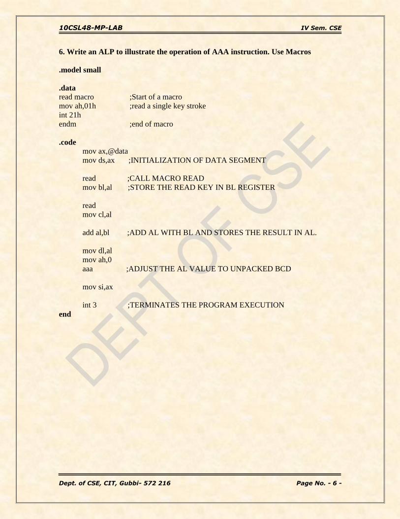
6. Write an ALP to illustrate the operation of AAA instruction. Use Macros
.model small
.data
read macro ;Start of a macro
mov ah,01h ;read a single key stroke
int 21h
endm ;end of macro
.code
mov ax,@data
mov ds,ax ;INITIALIZATION OF DATA SEGMENT
read ;CALL MACRO READ
mov bl,al ;STORE THE READ KEY IN BL REGISTER
read
mov cl,al
add al,bl ;ADD AL WITH BL AND STORES THE RESULT IN AL.
mov dl,al
mov ah,0
aaa ;ADJUST THE AL VALUE TO UNPACKED BCD
mov si,ax
int 3 ;TERMINATES THE PROGRAM EXECUTION
end
10CSL48-MP-LAB IV Sem. CSE
Dept. of CSE, CIT, Gubbi- 572 216 Page No. - 7 -
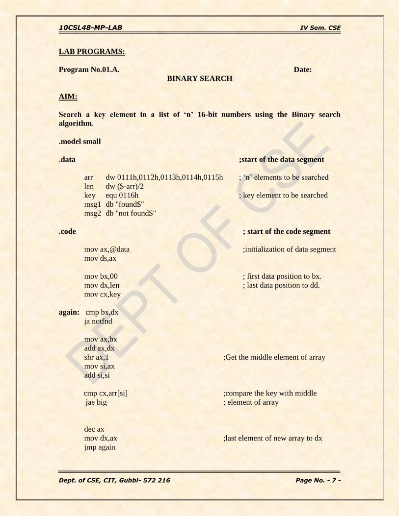
LAB PROGRAMS:
Program No.01.A. Date:
BINARY SEARCH
AIM:
Search a key element in a list of ‘n’ 16-bit numbers using the Binary search
algorithm.
.model small
.data ;start of the data segment
arr dw 0111h,0112h,0113h,0114h,0115h ; ‘n’ elements to be searched
len dw ($-arr)/2
key equ 0116h ; key element to be searched
msg1 db "found$"
msg2 db "not found$"
.code ; start of the code segment
mov ax,@data ;initialization of data segment
mov ds,ax
mov bx,00 ; first data position to bx.
mov dx,len ; last data position to dd.
mov cx,key
again: cmp bx,dx
ja notfnd
mov ax,bx
add ax,dx
shr ax,1 ;Get the middle element of array
mov si,ax
add si,si
cmp cx,arr[si] ;compare the key with middle
jae big ; element of array
dec ax
mov dx,ax ;last element of new array to dx
jmp again

10CSL48-MP-LAB IV Sem. CSE
Dept. of CSE, CIT, Gubbi- 572 216 Page No. - 8 -
big: je found
inc ax
mov bx,ax
jmp again
found: lea dx,msg1 ;content of the string to be displayed.
jmp displ
notfnd: lea dx,msg2 ;content of the string to be displayed.
displ : mov ah,09h
int 21h
int 3 ; Terminates the execution
end ;end of program
Conclusion:
This program performs a search for a key element in an array. If the search
element is found it will display a message ‘found’. As the search element (key element in
program) is not present in the given array it will display a message ‘not found’.
Date: Signature of the staff

10CSL48-MP-LAB IV Sem. CSE
Dept. of CSE, CIT, Gubbi- 572 216 Page No. - 9 -
Program No.01. B. Date:
LOGIC CONTROLLER-ODD AND EVEN PARITY
AIM:
Read the status of eight input bits from the Logic Controller Interface and display
FF if it is even parity bits otherwise display 00.
.model small
.data
pa equ 0d800h ; Port address
pb equ 0d801h
pc equ 0d802h
ctrl equ 0d803h ; control Register address
.code
start: mov ax, @data
mov ds, ax ; Initialization of data segment
mov dx, ctrl
mov al, 82h ; move the control word to ‘al’ register
out dx, al ; move the control word to control register
mov dx, pb ; Get the input data form ‘pb’
in al, dx ; Get the input data to AL register
mov bl, 00h
mov cx, 08 ; number of rotations
up: rcl al,1
jnc down ; after each rotation check for the carry flag
inc bl ; If there is a carry, increment the ‘BL’ register
down: loop up ; Repeat rotation for ‘08’ times
test bl,01h ; perform ‘AND’ operation to check for even or odd parity
jnz oddp ; If the result of the ‘AND’ is not zero, it is odd parity
mov al,0ffh ; If even parity display 0ffh
jmp next
oddp: mov al,00h ; If odd parity display 00h
next: mov dx,pa
out dx,al ; put the result to the ports
int 3
End start

10CSL48-MP-LAB IV Sem. CSE
Dept. of CSE, CIT, Gubbi- 572 216 Page No. - 10 -
Conclusion: The program reads port B of 82C55A which is an input port. If input
contains an odd number of 1’s (that is the number of LED’s at logic 1) then the output
will be 00 at port A, which is an output port, indicating input is odd parity and after some
delay the number of 1’s present in input will be displayed through port A on the output.
Similarly If input contains an even number of 1’s (that is the number of LED’s at logic 1)
then the output will be FF at port A, which is an output port, indicating input is even
parity and after some delay the number of 1’s present in input will be displayed through
port A on the output.
Date: Signature of the staff

10CSL48-MP-LAB IV Sem. CSE
Dept. of CSE, CIT, Gubbi- 572 216 Page No. - 11 -
Program No.02.A. Date:
Read and Write using Macros
AIM:
Write two ALP modules stored in two different files; one module is to read a
character from the keyboard and the other one is to display a character. Use
the above two modules to read a string of characters from the keyboard
terminated by the carriage return and print the string on the display in the
next line.
.model small
.data
String db 30 dup (?)
.code
include c:\masm\read.mac
include c:\masm\write.mac
start: mov ax, @data
mov ds, ax ; Initialization of data segment
mov si, 00h
again: read ; CALL MACRO READ
cmp al, 0dh ; compare the data in ‘AL’ reg with enter Key
je down
mov string[si], al ; Move the data in ‘AL’ reg to destination.
inc si
jmp again
down: mov cx, si
mov si, 00h
write 0dh ; ‘13’,’10’ , To go to next line
write 0ah
back: write string[si] ; Call write macro to write the data
inc si
loop back ; Repeat the writing
int 3 ; Termination of the program
end start

10CSL48-MP-LAB IV Sem. CSE
Dept. of CSE, CIT, Gubbi- 572 216 Page No. - 12 -
read.mac
read macro mov ah, 01h ; Dos command to read a data from keyboard
int 21h
endm
write.mac
write macro x
mov dl, x
mov ah, 02h ; Dos command to write a data to the O/P screen
int 21h
endm
Conclusion:
This program reads the character entered through the Key board and stores in
the consecutive specified memory locations. This process repeats till the ENTER Key
(carriage return) is pressed. Once the ENTER key (carriage return) is pressed the
character stored in the consecutive memory locations will be displayed on the next line.
Date: Signature of the staff
10CSL48-MP-LAB IV Sem. CSE
Dept. of CSE, CIT, Gubbi- 572 216 Page No. - 13 -
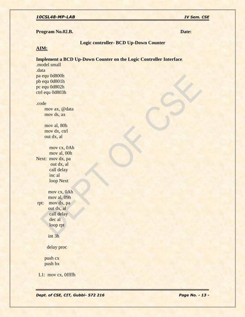
Program No.02.B. Date:
Logic controller- BCD Up-Down Counter
AIM:
Implement a BCD Up-Down Counter on the Logic Controller Interface.
.model small
.data
pa equ 0d800h
pb equ 0d801h
pc equ 0d802h
ctrl equ 0d803h
.code
mov ax, @data
mov ds, ax
mov al, 80h
mov dx, ctrl
out dx, al
mov cx, 0Ah
mov al, 00h
Next: mov dx, pa
out dx, al
call delay
inc al
loop Next
mov cx, 0Ah
mov al, 09h
rpt: mov dx, pa
out dx, al
call delay
dec al
loop rpt
int 3h
delay proc
push cx
push bx
L1: mov cx, 0ffffh

10CSL48-MP-LAB IV Sem. CSE
Dept. of CSE, CIT, Gubbi- 572 216 Page No. - 14 -
L2: mov bx, 8fffh
dec bx
jnz L2
loop L1
pop bx
pop cx
ret
delay endp
end
Conclusion:
The program performs the up-down counter based on the input data given
on logic controller read through port B. If the input is zero then it performs down counter
starting from 99 down to 00 and if other than zero is the input then it performs up counter
starting from 00 down to 99. And the counting will continue until a key ‘q’ is pressed in
the key board, after displaying the count on logic controller every time it checks whether
a key ‘q’ is pressed or not.
While observing the output of down counter or up counter if the input changes then from
that point the counting will also changes. Suppose if the input is zero then it perform
down counting from 99 to 00 after some time when the output is 50 then if we change the
input other than zero then from that point it will start up counting that is form 50, 51, 52.
and so on.
Date: Signature of the staff

10CSL48-MP-LAB IV Sem. CSE
Dept. of CSE, CIT, Gubbi- 572 216 Page No. - 15 -
Program No.03.A. Date:
Ascending order using Bubble Sort
AIM:
Sort a given set of ‘n’ numbers in ascending order using the Bubble Sort
algorithm.
.model small
.data
arr1 db 5h, 89h, 3h, 56h, 1h ; The numbers to be sorted
len1 equ $-arr1
.code
start: mov ax, @data
mov ds, ax
mov ch, len1-1 ; no of iterations
agn1: mov cl, ch ; no of comparisions
mov si, offset arr1
rept1: mov al, [si] ; Get the first data of the array
inc si ; Increment the array
cmp al, [si] ; Compare the first and second data
jbe next1 ; Check, if the 1st data is less than 2nd
xchg al, [si] ; If the 1st data is greater than the 2nd,
mov [si-1], al ; Swap the two data.
next1: dec cl ; dec the no of comparisons
jnz rept1 ; check for zero
dec ch ; dec the no of iterations
jnz agn1 ; check for zero
int 3 ; Terminate the program
end start
Conclusion:
This program will sort the given numbers in ascending order. The sorted numbers
will be stored directly in the data Segment. To view the data segment the following code
must be used.
-d ds: 0
Date: Signature of the staff

10CSL48-MP-LAB IV Sem. CSE
Dept. of CSE, CIT, Gubbi- 572 216 Page No. - 16 -
Program No.03.B. Date:
Logic Controller- 8 bit Multiplication
AIM:
Read the status of two 8-bit inputs (X & Y) from the Logical Controller
Interface and display X*Y.
.model small
.data
pa equ 0d800h
pb equ 0d801h
pc equ 0d802h
ctrl equ 0d803h
.code
mov ax,@data
mov ds,ax
mov al,82h ; Control word (PB as input port and PA as output port)
mov dx, ctrl
out dx, al
mov dx, pb
in al,dx ; Read the first 8 bit number
mov bl,al ; Store the first number
top: mov ah,1 ; Read a character from the key board
int 21h
cmp al,13 ; Compare the character with the "ENTER" key, cmp al,0dh
jnz top
mov dx, pb ; Read the Second 8 bit number
in al,dx ; Store the first number
mul bl ; Multiply bl*al
mov dx, pa
out dx, al ; Display the result
int 3
end
Conclusion:
The program performs the multiplication between two bytes and gives the
result. First byte is read from the port B of logic controller (user has to provide) and waits
for enter key to be pressed and once enter key is and it reads the Second byte and
multiplies and displays the result through Port A.
Date: Signature of the staff

10CSL48-MP-LAB IV Sem. CSE
Dept. of CSE, CIT, Gubbi- 572 216 Page No. - 17 -
Program No.04.A. Date:
Read alphanumeric character and display its ASCII code
AIM:
Read an alphanumeric character and displays its equivalent ASCII code at the
center of the screen.
.model small
.data
alpha db ?
ascii db ?, ?, "$"
.code
start: mov ax, @data
mov ds, ax ; Initialization of data segment
mov ah, 01h ; READ A CHARACTER FROM KEY BOARD
int 21h
mov alpha, al
mov cl, 04 ; Store the character in the memory
shr al, cl ; Shift right the data by 4 times
cmp al, 09h ;l compare the shifted data with 09h
jbe add30
add al, 07h
add30: add al, 30h
mov ascii, al
mov al, alpha ; Get back the character
and al, 0fh ; And ( to mask the higher nibble)
cmp al, 09h
jbe add30h
add al, 07h
add30h: add al, 30h
mov ascii+1, al
mov cx, 30h*90 ;CLEAR THE SCREEN
mov dl, ' '
mov ah, 02
back: int 21h
loop back
mov ah, 02h ;Set the cursor position
mov bh, 00 ; to desired location
mov dl, 30 ;column no.

10CSL48-MP-LAB IV Sem. CSE
Dept. of CSE, CIT, Gubbi- 572 216 Page No. - 18 -
mov dh, 15 ;row no.
int 10h
mov dx, offset ascii ; display the ascii code
mov ah, 09h
int 21h
mov ah, 01h ; PRESS ENTER KEY
int 21h
int 3
end start
Conclusion:
This program reads the character from key board by using the DOS function 01H
and finds its ASCII equivalent number.
First it clears the entire screen and places the cursor to the specified location using BIOS
function 02H. After, it will display the ASCII value where cursor is placed. In order to
observe the output on the screen the program is not been terminated until enter key is
pressed.
Date: Signature of the staff

10CSL48-MP-LAB IV Sem. CSE
Dept. of CSE, CIT, Gubbi- 572 216 Page No. - 19 -
Program No.04.B. Date:
7-Segment display- FIRE and HELP
AIM:
Display messages FIRE and HELP alternately with flickering effects on a 7-Segment
display interface for a suitable period of time. Ensure a flashing rate that makes it
easy to read both the messages.
.model small
.stack 100
.data
pa equ 0d800h ; Port address
pb equ 0d801h
pc equ 0d802h
ctrl equ 0d803h ; Control word address
str1 db 8eh, 0f9h, 88h, 86h ; Hexa values for “FIRE”
str2 db 89h, 86h, 0c7h, 8ch ; Hexa values for “HELP”
.code
start: mov ax, @data
mov ds, ax ; data segment Initialization
mov al, 80h ; control word
mov dx, ctrl
out dx, al
again: mov bx, offset str1
call display ; Jump to display procedure
call delay ; Jump to delay procedure
mov bx, offset str2
call display
call delay
mov ah, 06h ; direct console input or output
mov dl, 0ffh
int 21h ;get character from keyboard buffer (if any)
cmp al, 'q'
jne again
int 3 ; Terminate the program
display proc
mov si, 03h ; To get the last byte
up1: mov cl, 08h
mov ah, [bx+si] ; Load the data bit to ‘ah’

10CSL48-MP-LAB IV Sem. CSE
Dept. of CSE, CIT, Gubbi- 572 216 Page No. - 20 -
up: mov dx, pb
rol ah, 1 ;Rotate each bit in the data by one
mov al, ah
out dx, al ; Out the first bit
call clock
dec cl
jnz up ; repeat the steps ‘08’ times
dec si
cmp si, -1
jne up1
ret ; return back to main program
display endp
clock proc
mov dx, pc
mov al, 01h ; rising edge of clock pulse
out dx, al
mov al, 0 ; falling edge of the clock pulse
out dx, al
mov dx, pb
ret
clock endp
delay proc
push cx
push bx
mov cx, 0ffffh
d2: mov bx, 8fffh
d1: dec bx
jnz d1
loop d2
pop bx
pop cx
ret
delay endp
end start
Conclusion:
This program displays “FIRE” and “HELP” on seven segment display interface
recursively one after the other with some delay till key ‘q’ is pressed on key board. It’s
not going to read any data from interface device. The data which has to be displayed is
provided in the program itself.
Date: Signature of the staff
10CSL48-MP-LAB IV Sem. CSE
Dept. of CSE, CIT, Gubbi- 572 216 Page No. - 21 -
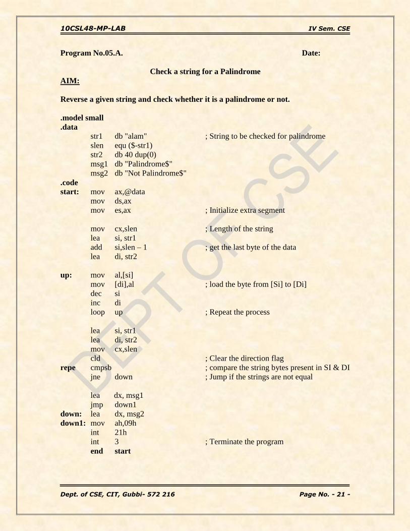
Program No.05.A. Date:
Check a string for a Palindrome
AIM:
Reverse a given string and check whether it is a palindrome or not.
.model small
.data
str1 db "alam" ; String to be checked for palindrome
slen equ ($-str1)
str2 db 40 dup(0)
msg1 db "Palindrome$"
msg2 db "Not Palindrome$"
.code
start: mov ax,@data
mov ds,ax
mov es,ax ; Initialize extra segment
mov cx,slen ; Length of the string
lea si, str1
add si,slen – 1 ; get the last byte of the data
lea di, str2
up: mov al,[si]
mov [di],al ; load the byte from [Si] to [Di]
dec si
inc di
loop up ; Repeat the process
lea si, str1
lea di, str2
mov cx,slen
cld ; Clear the direction flag
repe cmpsb ; compare the string bytes present in SI & DI
jne down ; Jump if the strings are not equal
lea dx, msg1
jmp down1
down: lea dx, msg2
down1: mov ah,09h
int 21h
int 3 ; Terminate the program
end start

10CSL48-MP-LAB IV Sem. CSE
Dept. of CSE, CIT, Gubbi- 572 216 Page No. - 22 -
Conclusion:
This program reverse the string provided in data segment by keeping the
original string as it is and compares both the strings. It will check each and every
character. If all the characters are same then the given string is said to be as palindrome
and it will display a message “palindrome” on screen otherwise the given string is not
palindrome and it will display a message “not palindrome” on screen.
Date: Signature of the staff

10CSL48-MP-LAB IV Sem. CSE
Dept. of CSE, CIT, Gubbi- 572 216 Page No. - 23 -
Program No.05.B. Date:
7-segment Display- Rolling Fashion
AIM:
Assume any suitable message of 12 characters length and display it in the
rolling fashion on a 7-Segment display Interface for a suitable period of time.
Ensure a flashing rate that makes it easy to read the message.
.model small
.stack 100
.data
pa equ 0d800h
pb equ 0d801h
pc equ 0d802h
ctrl equ 0d803h
str1 db 0c0h,0f9h,0a4h,0b0h,99h,92h,83h,0f8h,80h,98h,0c0h,0f9h
.code
start: mov dx, @data
mov ds, dx ; Initialize the data segment
mov al, 80h ; Control word
mov dx, ctrl
out dx, al
again: mov bx, offset str1 ; Get the offset address of the string
call display
call delay
mov ah, 06h ; direct console input or output
mov dl, 0ffh ; get the character for the key-board
int 21h
cmp al, 'q' ; compare the character with ‘q’
jnz again
int 3 ; terminate the program
display proc
mov si, 0bh ; Load [Si] with 12 (0dh)
up1: call delay
mov cl, 08h ; To get the last byte
mov ah, [bx+si] ; Load the data bit to ‘ah’
up: mov dx, pb
rol ah, 1 ; Rotate each bit in the data by one
mov al, ah

10CSL48-MP-LAB IV Sem. CSE
Dept. of CSE, CIT, Gubbi- 572 216 Page No. - 24 -
out dx, al ; Out the first bit
call clock
dec cl
jnz up ; repeat the steps ‘08’ times
dec si
cmp si, -1
jne up1 ; repeat the steps ‘12’ times
ret
display endp
clock proc
mov dx, pc
mov al, 01h ; Rising edge of the clock pulse
out dx, al
mov al, 0 ; Falling edge of the clock pulse
out dx, al
mov dx, pb
ret
clock endp
delay proc
push cx
push bx
mov cx, 0ffffh
d2: mov bx, 8fffh
d1: dec bx
jnz d1
loop d2
pop bx
pop cx
ret ; Return back to main program
delay endp
end start
Conclusion:
This program displays a message of 12 characters in rolling fashion on
seven segment display. The message is stored in data segment. It will continue of rolling
the message until ‘q’ is pressed in keyboard. But it will check for a key press event only
after displaying the complete string. Till then it will just keep on displaying the
characters.
Date: Signature of the staff

10CSL48-MP-LAB IV Sem. CSE
Dept. of CSE, CIT, Gubbi- 572 216 Page No. - 25 -
Program No.06.A. Date:
Compare two strings for equality
AIM:
Read two strings; store them in locations STR1 and STR2. Check whether they are
equal or not and display appropriated messages. Also display the length of the
stored strings.
.model small
.data
str1 db 30 dup(0)
str2 db 30 dup(0)
len1 dw 1 dup(0)
len2 dw 1 dup(0)
msg1 db 13,10, "Enter the 1st string : $"
msg2 db 13,10, "Enter the 2nd string : $"
msg3 db 13,10, "String are not equal $"
msg4 db 13,10, "Strings are equal $"
msg5 db 13,10, "The length of the first string is : "
slen1 db ?, ?
msg6 db 13,10,"The length of the second string is : "
slen2 db ?, ?,13,10,'$'
.code
read macro ; create a macro for read operation mov ah, 01
int 21h
endm
disp macro x ; create a macro for display the string
mov dx, offset x
mov ah, 09
int 21h
endm
start: mov ax,@data
mov ds,ax
mov es,ax ; Initialize Data and extra segment
disp msg1 ; READ FIRST STRING
mov si,0h
up1: read ; Read a character from Key-board
cmp al,0dh ; compare the key with Enter Key.
je down1

10CSL48-MP-LAB IV Sem. CSE
Dept. of CSE, CIT, Gubbi- 572 216 Page No. - 26 -
mov str1[si],al ; Store the key in the location
inc si
jmp up1
down1: mov len1,si
disp msg2 ; READ SECOND STRING
mov si,0h
up2: read ; Read a character from Key-board
cmp al,0dh ; compare the key with Enter Key.
je down2
mov str2[si],al ; Store the key in the location
inc si
jmp up2
down2: mov len2,si
mov cx,len1
cmp cx,len2 ; Check whether the strings are equal or not
jne noteq
mov si,offset str1
mov di,offset str2
cld ; Clear direction flag
repe cmpsb ; repeat the comparisons if
; the strings are equal
jne noteq
disp msg4
jmp next
noteq: disp msg3
next: mov al,byte ptr len1
aam
add ax, 3030h ; Display the length of the 1st String
mov slen1, ah
mov slen1+1, al
mov al,byte ptr len2
aam
add ax, 3030h ; Display the length of the 2nd String
mov slen2, ah
mov slen2+1, al
disp msg5
int 3 ; Terminate the program
end start

10CSL48-MP-LAB IV Sem. CSE
Dept. of CSE, CIT, Gubbi- 572 216 Page No. - 27 -
Conclusion:
This program reads two strings from user and compares both the strings. First it
checks the length of the strings and if lengths are equal then it will check each and every
character. If all the characters are same then the given strings are said to be equal and it
will display a message “strings are equal” along with length of both the strings on screen.
Else will display as “strings are not equal”.
Date: Signature of the staff

10CSL48-MP-LAB IV Sem. CSE
Dept. of CSE, CIT, Gubbi- 572 216 Page No. - 28 -
Program No.06.B. Date:
7-segment Display – Binary to BCD conversion
AIM:
Convert a 16-bit binary value(assumed to be an unsigned integer) to BCD and
display it form left to right and right to left for specified number of times on a 7-
Segment display Interface.
.model small
.data
pa equ 0d800h
pb equ 0d801h
pc equ 0d802h
ctrl equ 0d803h
bin dw 000Fh
bcd db 4 dup(0)
count db 02
disptbl db 0c0h, 0f9h, 0a4h, 0b0h, 99h,
db 92h, 82h, 0f8h, 80h, 98h ; Look up table
.code
start: mov ax, @data
mov ds, ax
mov al, 80h ; All ports are output ports
mov dx, ctrl
out dx, al
mov bx, 10 ; To perform BCD division
mov cx, 04 ; Divide 04 times
mov ax, bin ; Load the number to be divided
back: mov dx, 0
div bx
push dx ; store the result in the stack.
loop back ; Repeat the division
lea si, bcd
mov cx, 04
back1: pop dx
mov [si], dl ; Get the result from the stack
inc si
loop back1
mov bx, offset disptbl
disp: call display1

10CSL48-MP-LAB IV Sem. CSE
Dept. of CSE, CIT, Gubbi- 572 216 Page No. - 29 -
call delay
call display
call delay
dec count
jnz disp
int 3
display proc
mov si, 00
nxtchar: mov al, bcd[si]
xlat ; Translate a byte
mov ah, 8
nxtseg: mov dx, pb
rol al, 01
out dx, al
mov ch, al
call clock
mov al,ch
dec ah
jnz nxtseg
inc si
cmp si,4
jne nxtchar
ret
display endp
display1 proc
mov si, 03
nxtchar1: mov al, bcd[si]
xlat
mov ah, 8
nxtseg1: mov dx, pb
rol al, 01
out dx, al
mov ch, al
call clock
mov al,ch
dec ah
jnz nxtseg1
dec si

10CSL48-MP-LAB IV Sem. CSE
Dept. of CSE, CIT, Gubbi- 572 216 Page No. - 30 -
cmp si,-1
jne nxtchar1
ret
display1 endp
clock proc
mov dx, pc
mov al, 01h
out dx, al
mov al, 0
out dx, al
mov dx, pb
ret
clock endp
delay proc
push cx
push bx
mov cx, 0ffffh
d2: mov bx, 8fffh
d1: dec bx
jnz d1
loop d2
pop bx
pop cx
ret
delay endp
end start
Conclusion:
This program converts a 16-bit number provided in data segment into
BCD. Then it will displays the BCD number on seven segment display interface form left
to right and right to left for specified number of times.
Date: Signature of the staff

10CSL48-MP-LAB IV Sem. CSE
Dept. of CSE, CIT, Gubbi- 572 216 Page No. - 31 -
Program No.07.A. Date:
Name Display
AIM:
Read your name from the keyboard and displays it at a specified location on the
screen in front of the message “What is your name?” you must clear the entire
screen before display.
.model small
.data
msg1 db "Enter the name $"
x db 10
y db 20
msg2 db "What is your name ? "
str db 30 dup(0)
.code
disp macro z ; macro to display a string
mov dx, offset z
mov ah, 09
int 21h
endm
start: mov ax,@data
mov ds,ax
disp msg1
mov si,0h
up: mov ah, 01 ; read the character from the keyboard
int 21h
cmp al,0dh
je down
mov str[si],al
inc si
jmp up
down: mov str[si],'$'
mov cx, 29h*50h ; To clear the screen
mov dl, ' '
mov ah, 02
back: int 21h ; Get DOS functions
loop back
mov dl, x ; Row number
mov dh, y ; Column number
mov bh, 00h

10CSL48-MP-LAB IV Sem. CSE
Dept. of CSE, CIT, Gubbi- 572 216 Page No. - 32 -
mov ah, 02
int 10h ; To move the cursor to the location
disp msg2
mov ah,01
int 21h
int 3 ; Termination of the program
end start
Conclusion: This program will reads a string and displays the same string on the screen at the
desired position after clearing the screen.
Date: Signature of the staff

10CSL48-MP-LAB IV Sem. CSE
Dept. of CSE, CIT, Gubbi- 572 216 Page No. - 33 -
Program No.07.B. Date:
Matrix Keypad- Key Scan
AIM:
Scan a 8x3 keypad for key closure and to store the code of the key pressed in a
memory location and display on screen. Also display row and column numbers
of the key pressed.
.model small
.stack 100
.data
pa equ 0d800h
pb equ 0d801h
pc equ 0d802h
ctrl equ 0d803h
ASCIICODE db "0123456789.+-*/%ack=MRmn" ; look up table
str db 13,10,"press any key on the matrix keyboard$"
str1 db 13,10,"Press y to repeat and any key to exit $"
msg db 13, 10,"the code of the key pressed is :"
key db ?
msg1 db 13,10,"the row is "
row db ?
msg2 db 13,10,"the column is "
col db ?,13,10,’$’
.code
disp macro x ; Display a string
mov dx, offset x
mov ah, 09
int 21h
endm ; End of a macro
start: mov ax,@data
mov ds,ax
mov al,90h ; Port ‘A’ is input port
mov dx,ctrl
out dx,al
again1: disp str
mov si,0h
again: call scan
mov al,bh ; Row number
add al,31h

10CSL48-MP-LAB IV Sem. CSE
Dept. of CSE, CIT, Gubbi- 572 216 Page No. - 34 -
mov row,al
mov al,ah ; Column number
add al,31h
mov col,al
cmp si,00
je again
mov cl,03
rol bh,cl
mov cl,bh
mov al,ah
lea bx,ASCIICODE ; Address of the look up table
add bl,cl
xlat ; Translate a byte in AL
mov key,al
disp msg
disp str1
mov ah, 01 ; Read a string
int 21h
cmp al,'y'
je again1
int 3
scan proc
mov cx,03
mov bh,0
mov al,80h
nxtrow: rol al,1
mov bl,al
mov dx,pc
out dx,al
mov dx,pa
in al,dx
cmp al,0
jne keyid
mov al,bl
inc bh
loop nxtrow
ret
keyid: mov si,1
mov cx,8
mov ah,0

10CSL48-MP-LAB IV Sem. CSE
Dept. of CSE, CIT, Gubbi- 572 216 Page No. - 35 -
agn: ror al,1
jc skip ; check for the carry
inc ah
loop agn
skip: ret ; Return to main program
scan endp
end start
Conclusion: This program reads the data from the 8*3 key interface board. It will display its
value on the screen. It will also display the row number and column number of the key
pressed.
Date: Signature of the staff

10CSL48-MP-LAB IV Sem. CSE
Dept. of CSE, CIT, Gubbi- 572 216 Page No. - 36 -
Program No.08.A. Date:
Compute nCr using recursive procedure
AIM:
Compute nCr using recursive procedure. Assume that ‘n’ and ‘r’ are non-negative
integers.
.model small
.stack 20
.data
n db 08h
r db 05h
ncr db ?
.code
start: mov ax,@data
mov ds,ax
mov ncr,00h
mov al,n
mov bl,r
call encer
int 3
encer proc para1: cmp al,bl ; compare ‘n’,’r’ for equality
je para8
para2: cmp bl,00h ; compare ‘r’ with 00
je para8
para3: cmp bl,01h ; compare ‘r’ with 01h
je para10
para4: dec al ; decrement ‘n’
cmp bl,al
je para9
para5: push ax ; Push ‘n’ to the stack
push bx ; Push ‘r’ to the stack
call encer
para6: pop bx ; Get ‘r’ and ‘n’ from the stack
pop ax
dec bl
push ax
push bx
call encer
para7: pop bx
pop ax
ret
para8: inc ncr

10CSL48-MP-LAB IV Sem. CSE
Dept. of CSE, CIT, Gubbi- 572 216 Page No. - 37 -
ret
para9: inc ncr
para10: add ncr,al
ret
encer endp
end start
Conclusion:
This program performs nCr using recursive procedure. Output is stored in data
segment. To observe the output in data segment we have to search for our given ‘n’ and
‘r’ values as program is written to store the result after the given data in data segment.
Date: Signature of the staff

10CSL48-MP-LAB IV Sem. CSE
Dept. of CSE, CIT, Gubbi- 572 216 Page No. - 38 -
Program No.08.B. Date:
Stepper Motor
AIM:
Drive a Stepper Motor interface to rotate the motor in specified direction
(clockwise or counter-clockwise) by N steps (Direction and N are specified by
the examiner).Introduce suitable delay between successive steps. (Any arbitrary
value for the delay may be assumed by the student).
.model small
.data
pa equ 0d800h
pb equ 0d801h
pc equ 0d802h
ctrl equ 0d803h
nstep db 2
.code
start: mov ax, @data
mov ds, ax
mov al, 80h ; All ports are output ports
mov dx, ctrl
out dx, al
mov bh, nstep
mov al, 88h
again1: call step
rol al, 1 ; for counter-clock wise direction
; Replace rol al,1 with ror al,1 for clock wise direction
dec bh
jnz again1
int 3
step proc
mov dx, pa
out dx, al
push cx
push bx
mov cx, 0ffffh
d2: mov bx, 8fffh

10CSL48-MP-LAB IV Sem. CSE
Dept. of CSE, CIT, Gubbi- 572 216 Page No. - 39 -
d1: dec bx
jnz d1
loop d2
pop bx
pop cx
ret
step endp
end start
Conclusion:
This program drives a stepper motor interface to rotate by 8 steps in anti-
clockwise direction. After each rotation a delay is introduced to observe the rotation.
After completing the rotations the execution will get stopped.
Date: Signature of the staff

10CSL48-MP-LAB IV Sem. CSE
Dept. of CSE, CIT, Gubbi- 572 216 Page No. - 40 -
Program No.09.A. Date:
Display the system time
AIM:
Read the current time from the system and display it in the standard format on
the screen.
.model small
.data
msg db "The time is: "
hrs db ?,?,' : '
mins db ?,?,' (hh:mm) ',10,13,'$'
.code
start: mov ax,@data
mov ds,ax
mov ah,2ch ; DOS function to read system time
int 21h
mov al,ch ; load the hours to ‘al’
aam ; ASCII adjust after multiplication
add ax, 3030h
mov hrs, ah
mov hrs+1, al
mov al,cl ; load the seconds to ‘al’
aam
add ax, 3030h
mov mins, ah
mov mins+1,al
lea dx,msg ; Display the time
mov ah,09h
int 21h
int 3
end start
Conclusion:
This program displays the present system time. Our program displays only the
hours and minutes in the format HH: MM.By using the same DOS function we can also
display the seconds and milliseconds.
Date: Signature of the staff

10CSL48-MP-LAB IV Sem. CSE
Dept. of CSE, CIT, Gubbi- 572 216 Page No. - 41 -
Program No.09.B. Date:
Generate a SINE wave using DAC
AIM:
Generate a Sine Wave using the DAC interface. (The output of the
DAC is to be displayed on the CRO).
.model small
.data
pa equ 0c400h
pb equ 0c401h
pc equ 0c402h
ctrl equ 0c403h
table db 128,132,137,141,146,150,154,159,163,167,171,176,180,184,188
db 192,196,199,203,206,210,213,217,220,223,226,229,231,234,236
db 239,241,243,245,247,248,250,251,252,253,254,255
db 255,254,253,252,251,250,248,247,245,243,241,239,236,234,231
db 229,226,223,220,217,213,210,206,203,199,196,192,188,184,180
db 176,171,167,163,159,154,150,146,141,137,132,128
db 123,119,114,110,105,101,97,93,88,84,80,76,72,68,64,60,56,52,49
db 45,42,39,36,33,30,27,24,22,19,17,15,11,9,7,6,5,4,3,2,1,0
db 0,1,2,3,4,5,6,7,9,11,15,17,19,22,24,27,30,33,36,39,42,45,49,52,56
db 60,64,68,72,76,80,84,88,93,97,101,105,110,114,119,123
.code
start: mov ax,@data
mov ds,ax
mov al,80h ; All the ports are out put ports
mov dx,ctrl
out dx,al
again: mov bx,05h
up: mov cx,164 ; Load 164 values
mov si,00h
mov dx,pa
again1: mov al,table[si] ; Load each value from Look-up-table to al
out dx,al
inc si
loop again1
dec bx
cmp bx,00
jne up

10CSL48-MP-LAB IV Sem. CSE
Dept. of CSE, CIT, Gubbi- 572 216 Page No. - 42 -
mov ah,06h ; direct console input or output
mov dl,0ffh ; Read the character from the keyboard
int 21h
jz again
int 3
end start
Conclusion:
This program generates a sine wave of having amplitude of 5V. Output will be
seen in CRO. It will be continues wave. It stops execution as soon as any key is pressed
from the key board.
Date: Signature of the staff

10CSL48-MP-LAB IV Sem. CSE
Dept. of CSE, CIT, Gubbi- 572 216 Page No. - 43 -
Program No.10.A. Date:
To simulate a Decimal Up-counter to display 00- 99
AIM:
Write a program to simulate a Decimal Up-counter to display 00- 99.
.model small
.data
string db "the count is "
nors db ?,?,'$'
.code
start: mov ax,@data
mov ds,ax
mov ah,03h ; get cursor position and size.
mov bh,00h ; page number. int 10h
up: mov cl,00h
up1: mov al,cl
aam
add ax, 3030h
mov nors, ah
mov nors+1, al
push dx
mov ah,02h ; set cursor position
mov bh,00h ; page number
int 10h
mov dx,offset string ; Display the string
mov ah,09h
int 21h
inc cl
call delay
mov ah,06h ; direct console input or output. mov dl,0ffh ; get character from keyboard buffer
int 21h
cmp al,'q'
je exit
pop dx
cmp cl,100

10CSL48-MP-LAB IV Sem. CSE
Dept. of CSE, CIT, Gubbi- 572 216 Page No. - 44 -
je up
jmp up1
exit: int 3 ; Terminate the program
delay proc ; Delay procedure
push cx
push bx
mov cx, 0ffffh
d2: mov bx, 8fffh
d1: dec bx
jnz d1
loop d2
pop bx
pop cx
ret ; Return back to main program
delay endp
end start
Conclusion:
This program counts decimal values from 00 to 99. Count will continue until a
key is pressed in key board.
Date: Signature of the staff

10CSL48-MP-LAB IV Sem. CSE
Dept. of CSE, CIT, Gubbi- 572 216 Page No. - 45 -
Program No.10.B. Date:
Generate a half rectified SINE wave using DAC
AIM:
Generate a Half Rectified Sine wave form using the DAC interface. (The
output of the DAC is to be displayed on the CRO).
.model small
.data
pa equ 0c400h
pb equ 0c401h
pc equ 0c402h
ctrl equ 0c403h
table db 128,132,137,141,146,150,154,159,163,167,171,176,180,184,188
db 192,196,199,203,206,210,213,217,220,223,226,229,231,234,236
db 239,241,243,245,247,248,250,251,252,253,254,255,254,253,252
db 251,250,248,247,245,243,241,239,236,234,231,229,226,223,220
db 217,213,210,206,203,199,196,192,188,184,180,176,171,167,163
db 159,154,150,146,141,137,132,128 ; Look_up_table
.code
start: mov ax,@data
mov ds,ax
mov al,80h ; All the ports are out put ports
mov dx,ctrl
out dx,al
again3: mov bx,05h
up: mov cx,83 ; Load 83 values
mov si,00
again4: mov dx,pa
mov al,table[si] ; Load each value from Look-up-table to al
out dx,al
inc si
loop again4
mov cx,83
mov al,128
next: out dx,al
loop next
dec bx
cmp bx,00h
jnz up

10CSL48-MP-LAB IV Sem. CSE
Dept. of CSE, CIT, Gubbi- 572 216 Page No. - 46 -
mov ah,06h ; direct console input or output
mov dl,0ffh ; Read the character from the keyboard
int 21h
jz again3
int 3 ; Terminate the program
end start
Conclusion: This program generates a half - rectified sine wave of 5V amplitude. Output
will be seen in CRO. It stops execution as soon as any key is pressed from the key board.
Date: Signature of the staff

10CSL48-MP-LAB IV Sem. CSE
Dept. of CSE, CIT, Gubbi- 572 216 Page No. - 47 -
Program No.11.A. Date:
Move the Cursor to specified Location on the screen
AIM:
Read a pair of input co-ordinates in BCD and move the cursor to the specified
location on the screen.
.model small
.data
x db ?
y db ?
msg1 db 13, 10, "Enter the y co ordinate (00 - 19)$"
msg2 db 13, 10, "Enter the x co ordinate (00 - 50)$"
.code
read macro ; Macro to read the character mov ah, 01h
int 21h
endm ; End of Macro
start: mov ax,@data
mov ds,ax
mov dx,offset msg1 ; Display the first message
mov ah,09h
int 21h
read ; Read a character
mov cl, 04h
shl al, cl
mov bl,al
read ; Read a character
and al,0fh
or al,bl
mov y,al
mov dx,offset msg2 ; Display the first message
mov ah,09h
int 21h
read ; Read a character
mov cl,04h
shl al,cl
mov bl,al

10CSL48-MP-LAB IV Sem. CSE
Dept. of CSE, CIT, Gubbi- 572 216 Page No. - 48 -
read ; Read a character
and al,0fh
or al,bl
mov x,al
mov ah,02h ; Clear the screen
mov cx, 19h*50h
mov dl, ' '
back: int 21h
loop back
mov ah,02h ; Set the cursor to the specified location
mov bh,00h
mov dh,y
mov dl,x
int 10h
read
int 3
end start
Conclusion:
This program reads X and Y coordinates from key board and takes the cursor to
the specified location after clearing the screen and it will remains at the same position
until a key pressed.
Date: Signature of the staff

10CSL48-MP-LAB IV Sem. CSE
Dept. of CSE, CIT, Gubbi- 572 216 Page No. - 49 -
Program No.11.B. Date:
Generate a fully rectified SINE wave using DAC
AIM:
Generate a Fully Rectified Sine waveform using the DAC interface. (The
output of the DAC is to be displayed on the CRO).
.model small
.data
pa equ 0c400h
pb equ 0c401h
pc equ 0c402h
ctrl equ 0c403h
table db 128,132,137,141,146,150,154,159,163,167,171,176,180,184,188
db 192,196,199,203,206,210,213,217,220,223,217,220,223,226,229
db 231,234,236,239,241,243,245,247,248,250,251,252,253,254,255
db 254,253,252,251,250,248,247,245,243,241,239,236,234,231,229
db 226,223,220,217,213,210,206,203,199,196,192,188,184,180,176
db 171,167,163,159,154,180,146,141,137,132,128
count dw 83
.code
start: mov ax,@data
mov ds,ax
mov al,80h ; All the ports are out put ports
mov dx,ctrl
out dx,al
agn : mov bx,05
back1: mov cx,count ; Load 83 values
mov si,00h
back: mov al,table[si] ; Load each value from Look-up-table to al
mov dx,pa
out dx,al
inc si
loop back
dec bx
cmp bx,00
jnz back1
mov ah,06h ; direct console input or output
mov dl,0ffh ; Read the character from the keyboard

10CSL48-MP-LAB IV Sem. CSE
Dept. of CSE, CIT, Gubbi- 572 216 Page No. - 50 -
int 21h
jz agn
int 3
end start
Conclusion:
This program generates a fully rectified sine wave of 5V amplitude. Output will
be seen in CRO. It stops execution as soon as key is pressed from the key board.
Date: Signature of the staff

10CSL48-MP-LAB IV Sem. CSE
Dept. of CSE, CIT, Gubbi- 572 216 Page No. - 51 -
Program No.12.A. Date:
Program to create a file (input file) and to delete an existing file
AIM:
Program to create a file (input file) and to delete an existing file.
.model small
.data
string db "Enter the file name for the file to be created",13,10,'$'
msg1 db 13,10,"The file cannot be created",13,10,'$'
msg2 db 13,10,"File created successfully",13,10,'$'
str1 db 40 dup(0)
string1 db "Enter the file name to be deleted",13,10,'$'
msg3 db 13,10,"The file cannot be deleted",13,10,'$'
msg4 db 13,10,"File deleted successfully",13,10,'$'
str2 db 40 dup(0)
.code
disp macro x ; Display macro
lea dx, x
mov ah, 09h
int 21h
endm
start: mov ax,@data
mov ds,ax
disp string ; Display String
mov bx,00h
up: mov ah,01h ; Read the character from the keyboard
int 21h
cmp al,0dh
je exit
mov str1[bx],al
inc bx
jmp up
exit: mov str1[bx],'$'
mov ah,3ch ; Create or truncate file
mov cx,00h ; File Attributes
mov dx,offset str1
int 21h
jc down
disp msg2

10CSL48-MP-LAB IV Sem. CSE
Dept. of CSE, CIT, Gubbi- 572 216 Page No. - 52 -
jmp down1
down: disp msg1
down1: disp string1
mov bx,00h
up1: mov ah,01h
int 21h
cmp al,0dh
je exit1
mov str2[bx],al
inc bx
jmp up1
exit1: mov str2[bx],'$'
mov ah,41h ; delete file . mov dx,offset str2
int 21h
jc down2 ; CF set on error, AX = error code.
disp msg4 ; if successful, CF will be clear,
; and the value of AX is cleared
jmp down3
down2: disp msg3
down3: int 3
end start
Conclusion:
This program creates a file in current root directory. If creation of file success it
will display a message “file created successfully”. After that it will delete the file from
the current directory. If deletion of file is success then it will display a message “file
deleted successfully”.
Date: Signature of the staff

10CSL48-MP-LAB IV Sem. CSE
Dept. of CSE, CIT, Gubbi- 572 216 Page No. - 53 -
Program No.12.B. Date:
ELEVATOR
AIM:
Drive an elevator interface in the following way:
i. Initially the elevator should be in the ground floor, with all requests in OFF
state.
ii. When a request is made from a floor, the elevator should move to that floor,
wait there for a couple of seconds (approximately), and then come down to
ground floor and stop. If some requests occur during going up or coming
down they should be ignored.
.model small
.data
pa equ 0c800h ;define port addresses
pb equ 0c801h
pc equ 0c802h
ctrl equ 0c803h ;define control word address
.code
Start: mov ax, @data
mov ds, ax ;initialize data segment
mov al, 82h ;initialize port A as output and port B as input port
mov dx, ctrl
out dx, al
mov bl, 0 ; Initially display lift in ground floor
; PRESS ANY KEY TO EXIT
S1: call delay
mov ah, 06h
mov dl, 0ffh
int 21h
jz proceed ;if none of the key is pressed then jump to location proceed
int 3 ;else terminate program execution
; PLACE LIFT IN GROUND FLOOR
proceed:call delay
mov al, bl ;take floor number to AL
or al, 0f0h ;set upper nibble of the number
mov dx, pa
out dx, al
cmp bl, 0 ;check whether the lift is in ground floor or not
jnz down ;if not in then jump to location down to move lift to ground floor

10CSL48-MP-LAB IV Sem. CSE
Dept. of CSE, CIT, Gubbi- 572 216 Page No. - 54 -
jmp fchk ;else jump to location fchk to check the request from any floor
down: dec bl
jmp proceed
;CHECK REQUEST FROM ANY FLOOR
fchk: call chk ;call procedure chk to check is there request from any floor
shr al, 01 ;shift right the request by 1 position
jnc gfr ;if carry is not set then request will be from ground
; floor and jump to location gfr
shr al, 01 ;else shirt right the request by 1 more position
jnc ffr ;if carry is not set then request will be from 1st floor and
;jump to location ffr
shr al, 01 ;else shirt right the request by 1 more position
jnc sfr ;if carry is not set then request will be from 2nd floor
;and jump tp location sfr
shr al, 1 ;else shirt right the request by 1 more position
jnc tfr ;if carry is not set then request will be from 2nd floor
;and jump tp location sfr
jmp start ;else jump to start
gfr: call delay
mov al, 0e0h ;data to disable ground floor request
mov dx, pa ;load port A address to DX reg.
out dx, al ;send data to port A
jmp S1 ;to repeat the process jump to location start
ffr: call delay
mov bl, 3
call floor
mov al, 0d3h
mov dx, pa
out dx, al
jmp S1
sfr: call delay
mov bl, 6
call floor
mov al, 0b6h
mov dx, pa
out dx, al
jmp S1
tfr: call delay
mov bl, 9
call floor

10CSL48-MP-LAB IV Sem. CSE
Dept. of CSE, CIT, Gubbi- 572 216 Page No. - 55 -
mov al, 79h
mov dx, pa
out dx, al
jmp S1
chk proc
mov dx, pb
in al,dx ;read data from port b
or al,0f0h ;set upper nibble of the data
cmp al,0ffh ;check is there any request or not
jz chk ;if no request then jump to location chk
ret ;else return to main program
chk endp ;end of procedure
floor proc
mov cl, 0
floor1: inc cl
mov al, cl
or al, 0f0h
mov dx, pa
out dx, al
call delay
cmp cl, bl
jnz floor1
ret
floor endp
delay proc
delay proc
push cx
push bx
mov cx, 0ffffh
d2: mov bx, 8fffh
d1: dec bx
jnz d1
loop d2
pop bx
pop cx
ret
delay endp
end start
10CSL48-MP-LAB IV Sem. CSE
Dept. of CSE, CIT, Gubbi- 572 216 Page No. - 56 -
Conclusion:
This program does the operation of lift as follows: always the lift will be in ground floor.
When a request comes from any other floor then the lift will go to that floor and waits for
some time and returns to ground floor. While executing the first request, other requests
are not recognized
Date: Signature of the staff
10CSL48-MP-LAB IV Sem. CSE
Dept. of CSE, CIT, Gubbi- 572 216 Page No. - 57 -
References:
1. The Intel Microprocessors: Eighth Edition: Bary B. Brey.
2. Microprocessors and Interfacing: Second Edition: D V Hall.
3. Advanced Microprocessors and Peripherals: A K Ray.

10CSL48-MP-LAB IV Sem. CSE
Dept. of CSE, CIT, Gubbi- 572 216 Page No. - 58 -
ANNEXURES:
Instruction Set:
Instructions Operands Description
MOV
REG, memory
memory, REG
REG, REG
memory, immediate
REG, immediate
SREG, memory
memory, SREG
REG, SREG
SREG, REG
Copy operand2 to operand1.
The MOV instruction cannot:
Set the value of the CS and IP registers.
Copy value of one segment register to another segment
register (should copy to general register first).
Copy immediate value to segment register (should copy to
general register first).
Algorithm: operand1 = operand2
Ex:
Mov AX,BX ;Copy contents of BX to AX
Mov si,00h ;load Si with 00h
MUL
REG
Memory
Unsigned multiply. Multiply the contents of REG/Memory with contents of AL register. Algorithm:
When operand is a byte:
AX = AL * operand.
When operand is a word:
(DX: AX) = AX * operand.
CMP
REG, memory
memory, REG
REG, REG
memory, immediate
REG, immediate
Compare.
Algorithm: operand1 - operand2
Result is not stored anywhere, flags are set (OF, SF, ZF, AF, PF,
CF) according to result.
JMP
Label
Unconditional Jump.
Transfers control to another part of the program. 4-byte address may
be entered in this form: 1234h: 5678h, first value is a segment
second value is an offset.
Algorithm: always jump
JA
Label
Jump If Above.
Short Jump if first operand is Above second operand (as set by CMP
instruction). Unsigned.
Algorithm: if (CF = 0) and (ZF = 0) then jump

10CSL48-MP-LAB IV Sem. CSE
Dept. of CSE, CIT, Gubbi- 572 216 Page No. - 59 -
JAE
Label
Jump If Above Or Equal
Short Jump if first operand is Above or Equal to second operand (as
set by CMP instruction). Unsigned.
Algorithm:
if CF = 0 then jump
JB
Label
Jump If Below.
Short Jump if first operand is Below second operand (as set by CMP
instruction). Unsigned.
Algorithm:
if CF = 1 then jump
JBE
Label
Jump If Below Or Equal
Short Jump if first operand is Below second operand (as set by CMP
instruction). Unsigned.
Algorithm:
if CF = 1 then jump
JC
Label
Jump If Carry
Short Jump if Carry flag is set to 1.
Algorithm:
if CF = 1 then jump
JE
Label
Jump If Equal.
Short Jump if first operand is Equal to second operand (as set by
CMP instruction). Signed/Unsigned.
Algorithm:
if ZF = 1 then jump
JG
Label
Jump If Greater
Short Jump if first operand is Greater then second operand (as set by
CMP instruction). Signed.
Algorithm:
if (ZF = 0) and (SF = OF) then jump

10CSL48-MP-LAB IV Sem. CSE
Dept. of CSE, CIT, Gubbi- 572 216 Page No. - 60 -
JGE
Label
Jump If Greater Or Equal.
Short Jump if first operand is Greater or Equal to second operand (as
set by CMP instruction). Signed.
Algorithm:
if SF = OF then jump
JL
Label
Jump If Less than.
Short Jump if first operand is Less then second operand (as set by
CMP instruction). Signed.
Algorithm:
if SF <> OF then jump
JLE
Label
Jump If Less Or Equal.
Short Jump if first operand is Less or Equal to second operand (as
set by CMP instruction). Signed.
Algorithm:
if SF <> OF or ZF = 1 then jump
JNZ
Label
Jump If Non Zero.
Short Jump if Not Zero (not equal). Set by CMP, SUB, ADD, TEST,
AND, OR, XOR instructions.
Algorithm:
if ZF = 0 then jump
JZ
Label
Jump If Zero.
Short Jump if Zero (equal). Set by CMP, SUB, ADD, TEST, AND,
OR, XOR instructions.
Algorithm:
if ZF = 1 then jump
LEA
REG, memory
Load Effective Address.
Algorithm:
REG = address of memory (offset)
LOOP
Label
Decrease CX, jump to label if CX not zero.
Algorithm:
CX = CX - 1
if CX <> 0 then

10CSL48-MP-LAB IV Sem. CSE
Dept. of CSE, CIT, Gubbi- 572 216 Page No. - 61 -
o jump
else
o no jump, continue
ADD
REG, memory
memory, REG
REG, REG
memory, immediate
REG, immediate
Add.
Algorithm:
operand1 = operand1 + operand2
AND
REG, memory
memory, REG
REG, REG
memory, immediate
REG, immediate
Logical AND between all bits of two operands. Result is stored in
operand1.
These rules apply:
1 AND 1 = 1; 1 AND 0 = 0
0 AND 1 = 0; 0 AND 0 = 0
OR
REG, memory
memory, REG
REG, REG
memory, immediate
REG, immediate
Logical OR between all bits of two operands. Result is stored in first
operand.
These rules apply:
1 OR 1 = 1; 1 OR 0 = 1
0 OR 1 = 1; 0 OR 0 = 0
SUB
REG, memory
memory, REG
REG, REG
memory, immediate
REG, immediate
Subtract.
Algorithm:
operand1 = operand1 - operand2
DAA
No Operands
Decimal adjust After Addition. Corrects the result of addition of two packed BCD values.
Algorithm: if low nibble of AL > 9 or AF = 1 then:
AL = AL + 6
AF = 1
if AL > 9Fh or CF = 1 then:
AL = AL + 60h
CF = 1

10CSL48-MP-LAB IV Sem. CSE
Dept. of CSE, CIT, Gubbi- 572 216 Page No. - 62 -
DAS
No Operands
Decimal adjust After Subtraction.
Corrects the result of subtraction of two packed BCD values.
Algorithm: if low nibble of AL > 9 or AF = 1 then:
AL = AL - 6
AF = 1
if AL > 9Fh or CF = 1 then:
AL = AL - 60h
CF = 1
INC
REG
memory
Increment.
Algorithm: operand = operand + 1
DEC
REG
Memory
Decrement.
Algorithm: operand = operand – 1
DIV
REG
Memory
Unsigned divide.
Algorithm:
when operand is a byte:
AL = AX / operand
AH = remainder (modulus)
when operand is a word:
AX = (DX AX) / operand
DX = remainder (modulus)
SHL
memory, immediate
REG, immediate
memory, CL
REG, CL
Shift Left.
Shift operand1 Left. The number of shifts is set by operand2.
Algorithm:
Shift all bits left, the bit that goes off is set to CF.
Zero bit is inserted to the right-most position.
SHR
memory, immediate
REG, immediate
memory, CL
REG, CL
Shift Right.
Shift operand1 Right. The number of shifts is set by operand2.
Algorithm:
Shift all bits right, the bit that goes off is set to CF.
Zero bit is inserted to the left-most position.

10CSL48-MP-LAB IV Sem. CSE
Dept. of CSE, CIT, Gubbi- 572 216 Page No. - 63 -
ROL
memory, immediate
REG, immediate
memory, CL
REG, CL
Rotate Left.
Rotate operand1 left. The number of rotates is set by operand2.
Algorithm:
Shift all bits left, the bit that goes off is set to CF and the
same bit is inserted to the right-most position.
ROR
memory, immediate
REG, immediate
memory, CL
REG, CL
Rotate Right.
Rotate operand1 right. The number of rotates is set by operand2.
Algorithm:
Shift all bits right, the bit that goes off is set to CF and the
same bit is inserted to the left-most position.
RCL
memory, immediate
REG, immediate
memory, CL
REG, CL
Rotate operand1 left through Carry Flag. The number of rotates is
set by operand2.
Algorithm:
Shift all bits left, the bit that goes off is set to CF and
previous value of CF is inserted to the right-most position.
Example:
STC ; set carry (CF=1).
MOV AL, 1Ch ; AL = 00011100b
RCL AL, 1 ; AL = 00111001b, CF=0.
RET
C O
r r
OF=0 if first operand keeps original sign.
CALL
procedure name
label
Transfers control to procedure, return address is (IP) pushed to
stack.
RET
No operands
Or even immediate
date
Return from near procedure.
Algorithm:
Pop from stack:
o IP
if immediate operand is present: SP = SP + operand
IN
AL, im.byte
AL, DX
AX, im.byte
AX, DX
Input from port into AL or AX.
Second operand is a port number. If required to access port number
over 255 - DX register should be used.
OUT
AL, im.byte
AL, DX
AX, DX
Output from AL or AX to port.
First operand is a port number. If required to access port number
over 255 - DX register should be used.
10CSL48-MP-LAB IV Sem. CSE
Dept. of CSE, CIT, Gubbi- 572 216 Page No. - 64 -
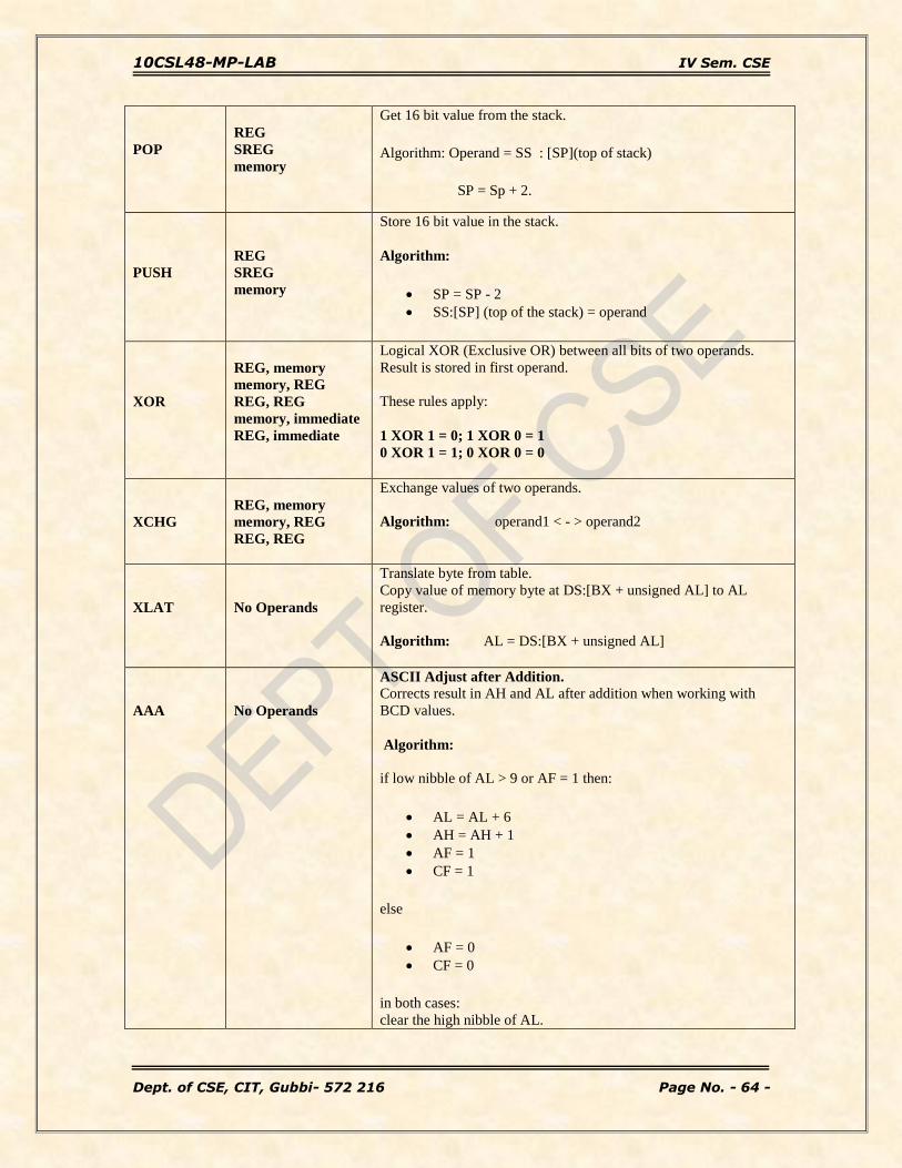
POP
REG
SREG
memory
Get 16 bit value from the stack.
Algorithm: Operand = SS : [SP](top of stack)
SP = Sp + 2.
PUSH
REG
SREG
memory
Store 16 bit value in the stack.
Algorithm:
SP = SP - 2
SS:[SP] (top of the stack) = operand
XOR
REG, memory
memory, REG
REG, REG
memory, immediate
REG, immediate
Logical XOR (Exclusive OR) between all bits of two operands.
Result is stored in first operand.
These rules apply:
1 XOR 1 = 0; 1 XOR 0 = 1
0 XOR 1 = 1; 0 XOR 0 = 0
XCHG
REG, memory
memory, REG
REG, REG
Exchange values of two operands.
Algorithm: operand1 < - > operand2
XLAT
No Operands
Translate byte from table.
Copy value of memory byte at DS:[BX + unsigned AL] to AL
register.
Algorithm: AL = DS:[BX + unsigned AL]
AAA
No Operands
ASCII Adjust after Addition. Corrects result in AH and AL after addition when working with
BCD values.
Algorithm:
if low nibble of AL > 9 or AF = 1 then:
AL = AL + 6
AH = AH + 1
AF = 1
CF = 1
else
AF = 0
CF = 0
in both cases:
clear the high nibble of AL.

10CSL48-MP-LAB IV Sem. CSE
Dept. of CSE, CIT, Gubbi- 572 216 Page No. - 65 -
Example:
MOV AX, 15 ; AH = 00, AL = 0Fh
AAA ; AH = 01, AL = 05
AAS
No Operands
ASCII Adjust after Subtraction. Corrects result in AH and AL after subtraction when working with
BCD values.
Algorithm:
if low nibble of AL > 9 or AF = 1 then:
AL = AL - 6
AH = AH - 1
AF = 1
CF = 1
else
AF = 0
CF = 0
in both cases:
clear the high nibble of AL.
Example:
MOV AX, 02FFh ; AH = 02, AL = 0FFh
AAS ; AH = 01, AL = 09
AAM
No Operands
ASCII Adjust after Multiplication. Corrects the result of multiplication of two BCD values.
Algorithm:
AH = AL / 10
AL = remainder
Example:
MOV AL, 15 ; AL = 0Fh
AAM ; AH = 01, AL = 05

10CSL48-MP-LAB IV Sem. CSE
Dept. of CSE, CIT, Gubbi- 572 216 Page No. - 66 -
INTERRUPTS:
Interrupt INT 21h: INT 21h calls DOS functions.
Function 01h - Read character from standard input, result is stored in AL. If there is
no character in the keyboard buffer, the function waits until any key is pressed.
Invoked by: AH = 01h
Returns: AL = character entered.
Example:
Mov AH, 01h
INT 21h
Function 02h - Write a character to standard output.
INT 21h Invoked by: DL = character to write.
AH =02h
After execution AL = DL.
Example: Mov AH, 02h
Mov DL, ’a’ ; Character to be displayed on screen must be stored in DL reg.
INT 21h
Function 02h- set cursor position.
INT 10h / AH = 2 - set cursor position.
input: DH = row.
DL = column. BH = page number (0..7).
Function 03h- get cursor position and size.
INT 10h / AH = 03h -
input: BH = page number.
return:
DH = row. DL = column.

10CSL48-MP-LAB IV Sem. CSE
Dept. of CSE, CIT, Gubbi- 572 216 Page No. - 67 -
CH = cursor start line.
CL = cursor bottom line.
Function 06h – Direct console for input/output. If DL = 0FFH on entry, then this
function reads the console. If DL = ASCII character, then this function displays the
ASCII character on the console video screen.
Invoked by: Parameters for O/P: DL = 0…255
Parameters for I/P: DL = 255.
Returns: for O/P: AL = DL.
For I/P: ZF set if no character available & AL = 0
ZF clear if character available & AL = character.
Example:
mov ah, 6
mov dl, 'a'
int 21h ; output character.
mov ah, 6
mov dl, 255
int 21h ; get character from keyboard buffer (if any) or set ZF=1.
Function 09h - Write a string to standard output at DS: DX.
String must be terminated by '$'. The string can be of any length and may contain control
characters such as carriage return (0DH) and line feed (0AH).
Invoked by: DS = string to write.
AH = 09h
Example:
Mov AH, 09h
Mov DX, offset str ; Address of the string to be displayed
INT 21h
Function 2Ch - Get system time.
Invoked by: AH =2Ch
Return: CH = hour. CL = minute. DH = second. DL = 1/100 seconds.
Example:
Mov AH, 2ch
INT 21h

10CSL48-MP-LAB IV Sem. CSE
Dept. of CSE, CIT, Gubbi- 572 216 Page No. - 68 -
Function 3Ch - Create or truncate file.
Invoked by: CX = file attributes:
mov cx, 0 ; normal - no attributes.
mov cx, 1 ; read-only.
mov cx, 2 ; hidden.
mov cx, 4 ; system
mov cx, 7 ; hidden, system and read-only!
mov cx, 16 ; archive
mov cx, 0BH ; Volume label
mov cx, 10H ; Subdirectory
DS: DX -> filename. ; AH =3Ch
Returns:
CF clear if successful, AX = file handle.
CF set on error AX = error code.
Example:
Mov AH, 3ch
Mov CX, 01
Mov DX, offset Filename
INT 21h
Function 41h - Delete file (unlink).
Invoked by: DS: DX -> ASCIZ filename (no wildcards, but see notes).
AH=41h
Return:
CF clear if successful, AX destroyed.
CF set on error AX = error code.
Example:
Mov AH, 41h
Mov DX, offset Filename
INT 21h
Function 4Ch – Terminate a process.
Invoked by: AH = 4ch
Return: returns control to the operating system.
Example:
Mov AH, 4Ch
INT 21h

10CSL48-MP-LAB IV Sem. CSE
Dept. of CSE, CIT, Gubbi- 572 216 Page No. - 69 -
Interrupt INT 10h:
INT 10h calls the BIOS functions. This interrupt often called the video services
interrupt as it directly controls the video display in a system.
Function 02h - Set cursor position.
Invoked by: DH = row; DL = column; BH = page number (0...7); AH=02h.
Example:
MOV AH, 02h
MOV BH, 00
MOV DH, 06
MOV DL, 10
INT 10h
Function 03h – Get cursor position.
Invoked by: BH = page number. (In general 0)
AH = 03h
Return: DH = row number; DL = column number; CH = cursor start line;
CL = cursor bottom line.
Example:
Mov BH, 0
Mov AH, 03h
INT 10h
Function 06h – Scroll up window
Invoked by: AL = number of lines by which to scroll. (00h = clear the entire screen.)
BH = attribute used to write blank lines at bottom of window.
CH, CL = row, column of window's upper left corner.
DH, DL = row, column of window's lower right corner.

10CSL48-MP-LAB IV Sem. CSE
Dept. of CSE, CIT, Gubbi- 572 216 Page No. - 70 -
Circuit diagrams of interfacing devices
1. Logic Controller Interface
Logic controllers find extensive application in industries for the programming of
processes. The nature of control would range from a simple ON/OFF type of control ro
complex systems implementing sophisticated control algorithms while accepting multiple
inputs and actuating multiple outputs. A controller would typically, accept a number of
inputs from transducers like sensors/limit switches, key inputs etc.. perform a sequence of
logical and arithmetic opertaions on them and use the result to maitain the process within
specified safe operating conditions while providing information on the status of the
process at any instant of time.The logic controller interface consits essentially of two 8
bit ports, an input and an output port. The inputs and outputs are connected to the user
systems. The logic state fo each input and output is indicated by LEDs and all signals are
TTL compatible. The input signals are connected to port B of 82C55A while output lines
are driven from port A.
Some of the cpabilities of theis interface are:
a. Programmable Counter b. Sequential Counter c. Combinational Controller.

10CSL48-MP-LAB IV Sem. CSE
Dept. of CSE, CIT, Gubbi- 572 216 Page No. - 71 -
2. Seven Segment Display

10CSL48-MP-LAB IV Sem. CSE
Dept. of CSE, CIT, Gubbi- 572 216 Page No. - 72 -
The hardware uses four shift register ICs 74164. 74164 is an 8-bit serial in-parallel out
shift register with asynchronous reset and two input pins. It requires 8 clock cycles at
“CLK” pin to shift the serial data from input to 8 parallel outputs. After 8 shifts, the first
serial bit will be in output QH, and only now the data at output is valid. To cascade more
74164 shift register IC need to connect the last output QH to the input of second shift
register.
The output is connected to the cathode of the LEDs in the 7 segment display and thus
common anode displays are used. The anode is connected to +Vcc. The last output of the
first sift register is connected to input of the 2nd shift register and the last output o f 2nd
shift register to input of 3rd and so on. Thus the shift register are serial in parallel out and
they are connected to displays, in such a way that output 0A is connected to display
segment ‘a’ and 0B to ‘b’ and so on up to 0H; through 330 ohm resistors.
The shifting of data bit takes place for each clock cycle. 7404 IC used provides isolation
and the interface board gets 5V through port bit.
Pin 1 is used as data pin and pin 2 is used as other input to Vcc. The clock signal is
generated at a port bit which will be connected to the clock of the shift register.
PB0 is used for data bit; and PC0 for clock through which a falling edge has to be sent.
The microprocessor stores the display information in a RAM. Each time a display has to
be updated the microprocessor fetches all bytes one by one from RAM and outputs
corresponding display codes serially that is bit by bit to display. Hexadecimal code is
stores in the RAM. The code conversion from hexa to 7 segment is done just before the
display is updated.
The 7 segment display is used as a numerical indicator on many types of test equipment.
It is an assembly of light emitting diodes which can be powered individually. There are
two important types of 7-segment LED display.
In a common cathode display, the cathodes of all the LEDs are joined together and the
individual segments are illuminated by HIGH voltages.
In a common anode display, the anodes of all the LEDs are joined together and the
individual segments are illuminated by connecting to a LOW voltage.
Display code
Since the outputs of shift registers are connected to cathode sides of displays, low input
must be given to segments for making them glow and high inputs for making them blank.
Each display has 8 segments (a, b, c, d, e, f, g, h) as shown. For displaying any character
the corresponding segment must be given low inputs.

10CSL48-MP-LAB IV Sem. CSE
Dept. of CSE, CIT, Gubbi- 572 216 Page No. - 73 -
The one shown above is a common anode display since all anodes are joined together and
go to the positive supply. The cathodes are connected individually to zero volts. Resistors
must be placed in series with each diode to limit the current through each diode to a safe
value. The d.p represents a decimal point.
The following table shows how to form characters: '0' means that pin is connected to
ground. '1' means that pin is connected to Vcc.
d.p g f e d c b a Hex. value
0 1 1 0 0 0 0 0 0 C0
1 1 1 1 1 1 0 0 1 F9
2 1 0 1 0 0 1 0 0 A4
3 1 0 1 1 0 0 0 0 B0
4 1 0 0 1 1 0 0 1 99
5 1 0 0 1 0 0 1 0 92
6 1 0 0 0 0 0 1 0 82
7 1 1 1 1 1 0 0 0 F8
8 1 0 0 0 0 0 0 0 80
9 1 0 0 1 1 0 0 0 98
F 1 0 0 0 1 1 1 0 8e
I 1 1 1 1 1 0 0 1 F9
R 1 0 0 0 1 0 0 0 88
E 1 0 0 0 0 1 1 0 86
3. Stepper Motor:
A stepper motor is a widely used device that translates electrical pulses into mechanical
movement. In applications such as disk drives, dot matrix printers, and robotics, the
stepper motor is used for Position control.
Every stepper motor has a permanent magnet rotor (also called the shaft.) surrounded by
a stator. The most common stepper motors have four common stator windings that are
pairs with a center-taped common. This type of stepper motor is commonly referred to as
a four-phase stepper motor.
A Stepper motor is stepped from one position to the next by changing the currents
through the fields in the motor. Common step sizes for stepper motors range from 0.9
degrees to 30 degrees.
82C55A is used to provide the drive signals that are used to rotate the armature of the
motor in either the right-hand or left-hand direction.

10CSL48-MP-LAB IV Sem. CSE
Dept. of CSE, CIT, Gubbi- 572 216 Page No. - 74 -
The power circuit for one winding of the stepper motor is as shown in figure above. It is
connected to the port A (PA0) of 82C55A. Similar circuits are connected to the remaining
lower bits of port A (PA1, PA2, PA3). One winding is energized at a time. The coils are
turned ON/OFF one at a time successively.
The stepper motor showing full-step operation is shown below.
(A) 45-degrees. (B) 135-degrees (C) 225-degrees (D) 315-degrees.

10CSL48-MP-LAB IV Sem. CSE
Dept. of CSE, CIT, Gubbi- 572 216 Page No. - 75 -
4. Matrix Keyboard Display:
The rows are connected to an output port and the columns are connected to an input port.
If no key has been pressed, reading the input port will yields 0s for all columns since they
are all connected to ground. If all the rows are high and a key is pressed, one of the
columns will have 1 since the key pressed provides the path to high. It is the function of

10CSL48-MP-LAB IV Sem. CSE
Dept. of CSE, CIT, Gubbi- 572 216 Page No. - 76 -
the microprocessor to scan the keyboard continuously to detect and identify the key
pressed.
Label on
the keytop
Hex code Label on
the key top
Hex code
0 0 - 0C
1 1 X 0D
2 2 / 0E
3 3 % 0F
4 4 AC 10
5 5 CE 11
6 6 CHK 12
7 7 = 13
8 8 MC 14
9 9 MR 15
. 0A M 16
+ 0B M+ 17
Process of identifying the key pressed:
To detect a pressed key, the micro processor set high all rows by providing 1 to the
output latch, then it reads the columns. If the data read from the columns is PA0-PA7 =
00000000, no key has been pressed and process continues until a key press is detected.
If one of the column bits has a high, this means that a key press has occurred.
For example, if PA0-PA7 = 00001000, this means that a key in the PA4 column has been
pressed.
After a key press is detected, the micro processor will go through the process of
identifying the key. Now micro processor sets each row to ground then it reads the
columns. If the data read is all 0s, no key in that row is activated and the process is
moved to next row. It grounds the next row, reads the columns, and checks for any 1.
This process continues until the row is identified. After identification of the row in which
the key has been pressed, the next task is to find out which column the pressed key
belongs to.
To identify the key press, it rotates the column bits, one bit at a time, into the carry flag
and checks to see if it is high. Upon finding the 1, it pulls out the ASCII code for that key
from the look-up table; otherwise, it increments the pointer to point to the next element of
the look-up table.

10CSL48-MP-LAB IV Sem. CSE
Dept. of CSE, CIT, Gubbi- 572 216 Page No. - 77 -
5. DAC INTERFACE
The pin details of DAC 0800 is given below and schematic diagram of the dual DAC
interface is given below.
The port A and port B of 82C55A peripheral are used as output ports. The digital inputs
to the DACs are porvided through these ports. The analog outputs of the DACs are
connected to the inverting inputs of OP-amps 741 which acts as current to voltage
converters. The outputs from the OP-amps are connected to points marked X out and Y
out at which the waveforms are observed on a CRO. The power supplies of +12 and -12
are regulated for this interface.
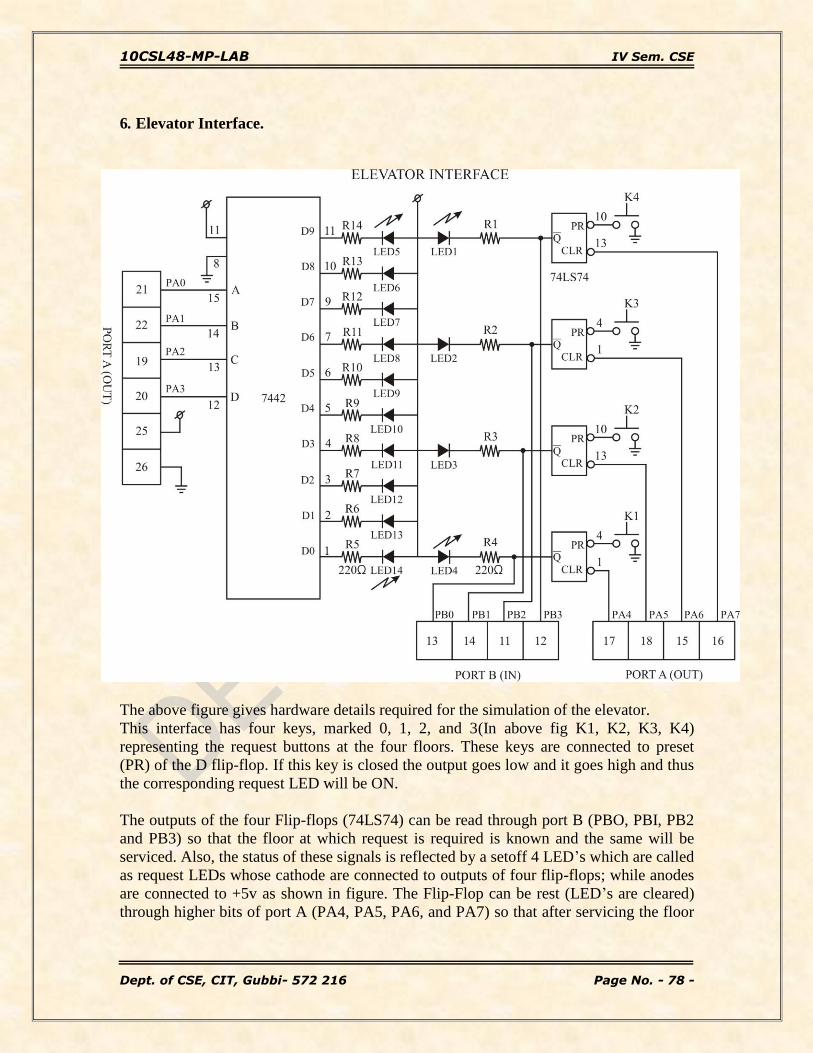
10CSL48-MP-LAB IV Sem. CSE
Dept. of CSE, CIT, Gubbi- 572 216 Page No. - 78 -
6. Elevator Interface.
The above figure gives hardware details required for the simulation of the elevator.
This interface has four keys, marked 0, 1, 2, and 3(In above fig K1, K2, K3, K4)
representing the request buttons at the four floors. These keys are connected to preset
(PR) of the D flip-flop. If this key is closed the output goes low and it goes high and thus
the corresponding request LED will be ON.
The outputs of the four Flip-flops (74LS74) can be read through port B (PBO, PBI, PB2
and PB3) so that the floor at which request is required is known and the same will be
serviced. Also, the status of these signals is reflected by a setoff 4 LED’s which are called
as request LEDs whose cathode are connected to outputs of four flip-flops; while anodes
are connected to +5v as shown in figure. The Flip-Flop can be rest (LED’s are cleared)
through higher bits of port A (PA4, PA5, PA6, and PA7) so that after servicing the floor

10CSL48-MP-LAB IV Sem. CSE
Dept. of CSE, CIT, Gubbi- 572 216 Page No. - 79 -
at which request was done the corresponding request LED is turned OFF, sending a low
to the flip-flop through port A.
A column of 10 LED’s, representing the elevator can be controlled through Port A (PA0,
PA1, PA2 and PA3). These port lines are fed to the inputs of the BCD to decimal decoder
IC7442 whose outputs are active-low used to control the on/off states of the LED’s which
simulate the motion of the elevator. These LEDS have their cathodes connected to the
outputs of the decoder through the resistors and the anodes are commonly connected to
the +5v supply as shown in the figure. As the output of BCD decoders are active low and
logic low on output causes the corresponding LED goes ON. For Example, If 0010 is the
input to the decoder then line 2 goes low and the third LED goes ON.
The motion of elevator can be simulated by turning on successive LED’s one at a time.
The delay between turning off one LED and turning on the next LED can simulate the
“speed” of the elevator.
10CSL48-MP-LAB IV Sem. CSE
Dept. of CSE, CIT, Gubbi- 572 216 Page No. - 80 -
Viva Questions and Answers
1. What is a Microprocessor?
ANS: Microprocessor is a program-controlled device, which fetches the instructions from
memory, decodes and executes the instructions. Most Micro Processor are single- chip
devices.
2. What is the difference between 8086 and 8088?
ANS: The BIU in 8088 is 8-bit data bus & 16- bit in 8086.Instruction queue is 4 byte
long in 8088and 6 byte in 8086.
3. what are the functional units in 8086?
ANS: 8086 has two independent functional units because of that the processor speed is
more. The Bus interface unit and Exectuion unit are the two functional units.
4. What are the flags in 8086?
ANS: In 8086 Carry flag, Parity flag, Auxiliary carry flag, Zero flag, Overflow flag,
Trace flag, Interrupt flag, Direction flag, and Sign flag.
5. What is the Maximum clock frequency in 8086?
ANS: 5 Mhz is the Maximum clock frequency in 8086.
6. What are the various segment registers in 8086?
ANS: Code, Data, Stack, Extra Segment registers in 8086.
7. Logic calculations are done in which type of registers?
ANS: Accumulator is the register in which Arithmetic and Logic calculations are done.
8. How 8086 is faster than 8085?
ANS: Because of pipelining concept. 8086 BIU fetches the next instruction when EU
busy in executing the anoter instruction.
9. What does EU do?
ANS: Execution Unit receives program instruction codes and data from BIU, executes
these instructions and store the result in general registers.

10CSL48-MP-LAB IV Sem. CSE
Dept. of CSE, CIT, Gubbi- 572 216 Page No. - 81 -
10. Which Segment is used to store interrupt and subroutine return address
registers?
ANS: Stack Segment in segment register is used to store interrupt and subroutine return
address registers.
11. What does microprocessor speed depend on?
ANS: The processing speed depends on DATA BUS WIDTH.
12. What is the size of data bus and address bus in 8086?
ANS: 8086 has 16-bit data bus and 20- bit address bus.
13. What is the maximun memory addressing capability of 8086?
ANS: The maximum memory capability of 8086 is 1MB.
14. What is flag?
ANS: Flag is a flip-flop used to store the information about the status of a processor and
the status of the instruction executed most recently.
15. Which Flags can be set or reset by the programmer and also used to control the
operation of the processor?
ANS: Trace Flag, Interrupt Flag, Direction Flag.
16. In how many modes 8086 can be opertaed and how?
ANS: 8086 can be opertaed in 2 modes. They are Minimum mode if MN/MX pin is
active high and Maximum mode if MN/MX pin is ground.
17. What is the difference between min mode and max mode of 8086?
ANS: Minimum mode operation is the least expensive way to operate the 8086
microprocessor because all the control signals for the memory and I/O are generated by
the micro processor. In Maximum mode some of the control signals must be externally
generatred. This requires the addition of an external bus controller. It used only when the
system contains external coprocessors such as 8087 arithmetic coprocessor.
18. Which bus controller used in maximum mode of 8086?
ANS: 8288 bus controller is used to provide the signals eliminated from the 8086 by the
maximum mode operation.

10CSL48-MP-LAB IV Sem. CSE
Dept. of CSE, CIT, Gubbi- 572 216 Page No. - 82 -
19. What is stack?
ANS: Stack is a portion of RAM used for saving the content of Program Counter and
general purpose registers.
20. Which Stack is used in 8086?
ANS: FIFO (First In First Out) stack is used in 8086.In this type of Stack the first stored
information is retrieved first.
21. What is the position of the Stack Pointer after the PUSH instruction?
ANS: The address line is 02 less than the earlier value.
22. What is the position of the Stack Pointer after the POP instruction?
ANS: The address line is 02 greater than the earlier value.
23. What is interrupt?
ANS: Interrupt is a signal send by external device to the processor so as to request the
processor to perform a particular work.
24. What are the various interrupts in 8086?
ANS: Maskable interrupts, Non-Maskable interrupts.
25. What is meant by Maskable interrupts?
ANS: An interrupt that can be turned off by the programmer is known as Maskable
interrupt.
26. What is Non-Maskable interrupts?
ANS: An interrupt which can be never be turned off (ie.disabled) is known as Non-
Maskable interrupt.
27. Which interrupts are generally used for critical events?
ANS: Non-Maskable interrupts are used in critical events. Such as Power failure,
Emergency, Shut off etc.,
28. Give example for Non-Maskable interrupts?
ANS: Trap is known as Non-Maskable interrupts, which is used in emergency condition.

10CSL48-MP-LAB IV Sem. CSE
Dept. of CSE, CIT, Gubbi- 572 216 Page No. - 83 -
29. Give examples for Maskable interrupts?
ANS: RST 7.5, RST6.5, RST5.5 are Maskable interrupts. When RST5.5 interrupt is
received the processor saves the contents of the PC register into stack and branches to
2Ch (hexadecimal) address.
When RST6.5 interrupt is received the processor saves the contents of the PC register
into stack and branches to 34h (hexadecimal) address.
When RST7.5 interrupt is received the processor saves the contents of the PC register
into stack and branches to 3Ch (hexadecimal) address.
30. What is SIM and RIM instructions?
ANS: SIM is Set Interrupt Mask. Used to mask the hardware interrupts. RIM is Read
Interrupt Mask. Used to check whether the interrupt is Masked or not.
31. What is macro?
ANS: Macro is a set of instructions that perform a task and all the isntructions defined in
it is inserted in the program at the point of usage.
32. What is the difference between Macro and Procedure?
ANS: A procedure is accessed via a CALL instruction and a macro will inserted in the
program at the point of execution.
33. What is meant by LATCH?
ANS: Latch is a D- type flip-flop used as a temporary storage device controlled by a
timing signal, which can store 0 or 1. The primary function of a Latch is data storage. It is
used in output devices such as LED, to hold the data for display
34. What is a compiler?
ANS: Compiler is used to translate the high-level language program into machine code
at a time. It doesn.t require special instruction to store in a memory, it stores
automatically. The Execution time is less compared to Interpreter.
35. What is the disadvantage of microprocessor?
ANS: It has limitations on the size of data. Most Microprocessor does not support
floating-point operations.
36. What is the 82C55A device?

10CSL48-MP-LAB IV Sem. CSE
Dept. of CSE, CIT, Gubbi- 572 216 Page No. - 84 -
ANS: The 8255A/82C55A interfaces peripheral I/O devices to the microcomputer system
bus. It is programmable by the system software. It has a 3-state bi-directional 8-bit buffer
which interfaces the 8255A/82C55A to the system data bus.
37. What kind of input/output interface dose a PPI implement?
ANS: It provides a parallel interface, which includes features such as single-bit, 4-bit, and
byte-wide input and output ports; level-sensitive inputs; latched outputs; strobed inputs or
outputs; and strobed bidirectional input/outputs.
38. How many I/O lines are available on the 82C55A?
ANS: 82C55A has a total of 24 I/O lines.
39. Describes the mode 0, mode 1, and mode 2 operations of the 82C55A?
ANS: MODE 0: Simple I/O mode. In this mode, any of the ports A, B, and C can be
programmed as input or output. In this mode, all the bits are out or in.
MODE 1: Ports A and B can be used as input or output ports with handshaking
capabilities. Handshaking signals are provided by the bits of port C.
MODE 2: Port A can be used as a bidirectional I/O port with handshaking capabilities
whose signals are provided by port C. Port B can be used either in simple I/O mode or
handshaking mode 1.
40. What is the mode and I/O configuration for ports A, B, and C of an 82C55A
after its control register is loaded with 82H?
ANS: If control register is loaded with 82H, then the port B is configured as an input
port, port A and port C are configured as output ports and in mode 0.