microquartz s manual - bodet time · 1.2 general recommendations - only skilled person is...
TRANSCRIPT
MICROQUARTZ S
Operating Manual

PROGRAMMABLE MASTER CLOCK
MICROQUARTZ S
1.5 VERSION
3
Ref : 604505 M

Contents
1- GENERAL PRESENTATION . . . . . . . . . . . . . . . . . . 5
1.1 Description . . . . . . . . . . . . . . . . . . . . . . . . . . . . . . . 5
1.2 General Recommendations . . . . . . . . . . . . . . . . . . . . . . 6
1.3 Description of the Microquartz S . . . . . . . . . . . . . . . . . . . . 7
1.4 Installation . . . . . . . . . . . . . . . . . . . . . . . . . . . . . . . 8
2 - TIME SETTING . . . . . . . . . . . . . . . . . . . . . . . . 11
3 - ACCESS TO THE PROGRAMMING MODE . . . . . . . . . 12
3.1- Remarks concerning Programming . . . . . . . . . . . . . . . . . 12
3.2- Start of Programming . . . . . . . . . . . . . . . . . . . . . . . . 13
4 - HOW TO SET UP THE MASTER CLOCK . . . . . . . . . . 14
4.1 Circuit Programming . . . . . . . . . . . . . . . . . . . . . . . . . 14
4.2 Summer/Winter Time Change . . . . . . . . . . . . . . . . . . . . 20
4.3 Time Setting of the Slave Clocks . . . . . . . . . . . . . . . . . . . 21
4.4 Time Distribution Setup . . . . . . . . . . . . . . . . . . . . . . . . 25
4.5 Minute Distribution Alarm . . . . . . . . . . . . . . . . . . . . . . . 28
4.6 Synchronization of the Clock via an External Source . . . . . . . . 29
4.7 Choice of Language . . . . . . . . . . . . . . . . . . . . . . . . . 31
4.8 Modification of the Access Code . . . . . . . . . . . . . . . . . . . 32
5 - TECHNICAL FEATURES . . . . . . . . . . . . . . . . . . . 33
6- APPENDICES . . . . . . . . . . . . . . . . . . . . . . . . . 34
6.1 Configuration of Series or Parallel Pulse Distribution . . . . . . . . 34
6.2 D1-D2 distribution : connections . . . . . . . . . . . . . . . . . . . 36
6.3 Examples of Programming . . . . . . . . . . . . . . . . . . . . . . 37
6.4 ASCII Line Card (RS232; RS422; CURRENT LOOP) . . . . . . . . 40
6.5 Connection of the IRIG-B AFNOR Synchro Card . . . . . . . . . . 46
6.6 IRIG-B AFNOR Signal Amplifier Card . . . . . . . . . . . . . . . . 46
6.7 Pulse 2 Card . . . . . . . . . . . . . . . . . . . . . . . . . . . . . 47
6.8 Autonomy . . . . . . . . . . . . . . . . . . . . . . . . . . . . . . 50
6.9 General Diagram of the Microquartz S plus Options . . . . . . . . 51
4

1- GENERAL PRESENTATION
1.1 Description
The Microquartz S exists in two versions :
- rack version : reference 927202
- wall version : reference 927201.
Microquartz S is a programmable master clock permitting the pulse and coded time
distribution networks to be controlled.
The standard version consists of the following outputs :
- 1 IRIG B-AFNOR norm NFS87500-A 0DB/6OOW coded time output.
- 1 minute or half-minute pulse output, in series or parallel (slow edge 5O
ms/24V), adjustable when installed.
- 4 x 240V 4A programming circuits, programmable to the nearest second
according to a weekly, annual or periodical mode.
- 1 TBT output 24VDC 1A.
The Microquartz S allows the addition of expansion cards which include :
- 4 IRIG B-AFNOR norm NFS87500-A ODB/600W coded time outputs.
- 1 additional output with 1 minute or half-minute pulses in series or parallel, or
second pulses.
- 1 ASCII RS 232, RS 422, BCL 20 mA input/output for communication with
computer systems.
The Microquartz S can be externally synchronized by :
- a France-Inter or DCF radio antenna.
- an IRIG B-AFNOR norm NFS87500-A signal.
- a 1 minute or half-minute, series or parallel pulse line.
The Microquartz S carries out winter/summer time changes automatically by internal
programming or radio reception.
5
1.2 General Recommendations
- Only skilled person is authorised for the maintenance service of this clock.
- The installation has to be close according to NF-C15 100 standard.
- A power off and differential disjunction circuits is required for a standard
installation.
- Cables have to be strongly fixed before being connected on the connection
terminal.
- The ground wire needs to be 2 or 3 cm longer than the wires for the live and the
neutral.
- All wires have to be attached together.
- The clock has to be switched on only after being fixed on the wall.
- Switched phases controlled by relay have to come from the same installation as
the one of Microquartz S (voltage lower or equal to 400V).
- Upon reception, check that the equipment has not been damaged during
transport.
- Before starting up, read the instructions for use and familiarize yourself with
equipment operating procedures.
- Once the operator has familiarized himself with the Microquartz S, the equipment
may be operated simply by using the running menus.
- Connect the cables BEFORE turning the power switch on. When the power is on
and the battery connected, avoid handling operations inside the equipment.
- Configure the pulse lines (parallel or series) and, where necessary, the
expansion cards BEFORE turning the power switch on (see Chapter 6).
6
1.3 Description of the Microquartz S
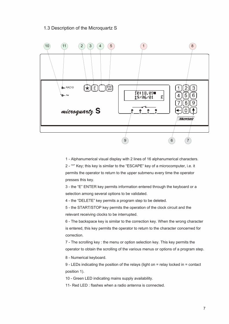
1 - Alphanumerical visual display with 2 lines of 16 alphanumerical characters.
2 - “*” Key; this key is similar to the “ESCAPE” key of a microcomputer, i.e. it
permits the operator to return to the upper submenu every time the operator
presses this key.
3 - the “E” ENTER key permits information entered through the keyboard or a
selection among several options to be validated.
4 - the “DELETE” key permits a program step to be deleted.
5 - the START/STOP key permits the operation of the clock circuit and the
relevant receiving clocks to be interrupted.
6 - The backspace key is similar to the correction key. When the wrong character
is entered, this key permits the operator to return to the character concerned for
correction.
7 - The scrolling key : the menu or option selection key. This key permits the
operator to obtain the scrolling of the various menus or options of a program step.
8 - Numerical keyboard.
9 - LEDs indicating the position of the relays (light on = relay locked in = contact
position 1).
10 - Green LED indicating mains supply availability.
11- Red LED : flashes when a radio antenna is connected.
7
32 4 5
6 7
8
9
10 11 1
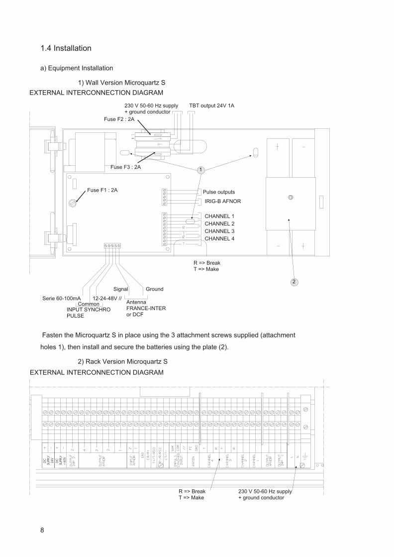
1.4 Installation
a) Equipment Installation
1) Wall Version Microquartz S
Fasten the Microquartz S in place using the 3 attachment screws supplied (attachment
holes 1), then install and secure the batteries using the plate (2).
2) Rack Version Microquartz S
8
Pulse outputs
EXTERNAL INTERCONNECTION DIAGRAM
230 V 50-60 Hz supply+ ground conductor
IRIG-B AFNOR
CHANNEL 3
CHANNEL 1
CHANNEL 4
CHANNEL 2
Signal Ground
CommonINPUT SYNCHROPULSE
AntennaFRANCE-INTERor DCF
Serie 60-100mA 12-24-48V //
R => BreakT => Make
2
1
Fuse F1 : 2A
Fuse F2 : 2A
TBT output 24V 1A
Fuse F3 : 2A
D
C
D
C
SUPPLY
SUPPLY
2
4V
<
60
V
230 V 50-60 Hz supply+ ground conductor
R => BreakT => Make
EXTERNAL INTERCONNECTION DIAGRAM

Fasten the Microquartz S in place.
Unscrew the 4 screws on the front panel of the Microquartz S, pull out the drawer,
install and secure the batteries using the plate (2).
b) Supply Connection
Battery : connect the black conductor to the “-” of the battery, the red conductor to
the “+” of the battery.
Mains supply :
- Cables have to be strongly fixed before being connected on the
connection terminal.
- The ground wire needs to be 2 or 3 cm longer than the wires for the
live and the neutral.
- All wires have to be attached together.
Wall version : connect the phase conductor to the connector equipped
with a fuse, the neutral conductor to the connector equipped with a
circuit-breaker, the ground conductor to the green-yellow connector.
Rack version : connect the phase, neutral and ground conductors to
their relevant connectors.
c) Output Connection
Connect the receivers, the outputs of the relays used and the antenna. Then close
the housing.
d) Installation of the Antenna (optional)
Position the antenna :
- as high as possible.
- away from walls made of steel or reinforced concrete.
- away from any source of interference.
- protected against lightning.
- outside if reception is poor.
Open the antenna housing.
The antenna should be perpendicular to the direction of the transmitter,
(ALLOUIS(18) for FRANCE-INTER), with the gland downwards.
The antenna is correctly orientated if :
- the indicators located inside the antenna and on the Microquartz S
flash once a second.
9

Fix the antenna onto its bracket.
Close the antenna housing, taking care to ensure that the case is airtight.
NOTE : The clock is automatically synchronized after 5 to 15 minutes; however in
difficult environmental conditions, synchronization may take up to 24 hours.
POWER SWITCH ON
When the power switch is on, the message “ Tester batterie” (“Test battery”) may
appear on the visual display. This occurs when the Microquartz S has been
battery-operated during a period longer than its stipulated period of autonomy or
when the battery has previously been disconnected. To delete this message,
press : , , and .
10
0 E

2 - TIME SETTING
- In order to set the clock, enter the access code (by default : 1 2 3 4) then press the
START/STOP key. The operation of the clock is interrupted, the distribution and the relay
controls are interrupted in their present position.
The visual display indicates :
The black square beside the seconds indicates that the operation of the clock is
interrupted.
When the cursor is fixed on the date, the latter may be modified via the keys of the
numerical keyboard.
Then press the START/STOP key or .
When the cursor is fixed on the time, the latter may also be modified via the keys
of the numerical keyboard.
Then press the START/STOP key or .
The VDU then indicates the time, the date, the day of the week corresponding to
the values entered (automatically assigned).
When the START/STOP key is pressed, the clock is reactivated at that second;
the distribution and the relay controls depend on the program steps entered and
on the actual point in time concerned (time and date).
11
E
E

3 - ACCESS TO THE PROGRAMMING MODE
3.1- Remarks concerning Programming
- No program step should be stored in the system’s memory when the system is switched on
for the first time, the times on the receiving clocks should be zero-preset and their operation
interrupted.
- When the equipment is in programming mode, if no operation is carried out for a period of 1
minute and 20 seconds, the Microquartz S returns to the upper submenu.
However there are 2 exceptions to this rule :
- when the equipment is in manual mode.
- when the time on the receiving clocks is displayed.
In such cases, only the key is to be used in order to return to the upper submenu.
12

3.2- Start of Programming
- In order to gain access to the parametering mode of the Microquartz S, enter the access code
via the numerical keyboard (this code is, by default, 1 2 3 4).
1) Enter 1 2 3 4 then validate with .
The visual display indicates :
The main menu is divided into 8 sections :
1/ Circuit programming
2/ Summer/winter time change
3/ Time setting of the receiving clocks
4/ Time distribution : how to parameter the outputs
5/ Alarm indication
6/ External synchronization
7/ Choice of language
8/ Modification of the access code.
2) Press or 1 in order to gain access to the first section.
The visual display indicates :
The other sections of the main menu can also be obtained either by pressing or via the
numerical keyboard.
13
E

4 - HOW TO SET UP THE MASTER CLOCK
4.1 Circuit Programming
4.1.1 Pre sen ta tion of the Pro gram mer
The Microquartz S comprises a 4 channel programmer : relays 1 and 2 operate as
one-position contacts, whereas relays 3 and 4 operate as break-make contacts.
The voltage and the current intensity applied to these relays should be less
than 240V 4A.
The 4 channels may be programmed in weekly, annual or periodical mode.
An “ON” programmed order means that the relay is locked in, and “OFF” means
that the relay is open.
Channels 1 and 2 may be used for D1/D2 type time distribution (230 V pulses). If
such is the case, channels 1 and 2 cannot be programmed.
When parametered in alarm mode, channel 4 cannot be programmed either.
In order to gain access to the program steps when you are in the main menu, press : or
.
The visual display indicates :
- Press
The visual display indicates :
Press in order to gain access to the circuit programming mode.
(see paragraph 4-12) or press .
When is pressed, the visual display indicates :
Press in order to gain access to the manual control of the circuits, so as to check that
these circuits are operating properly (see paragraph 4.1.3) or press .
14
E
E
E
1
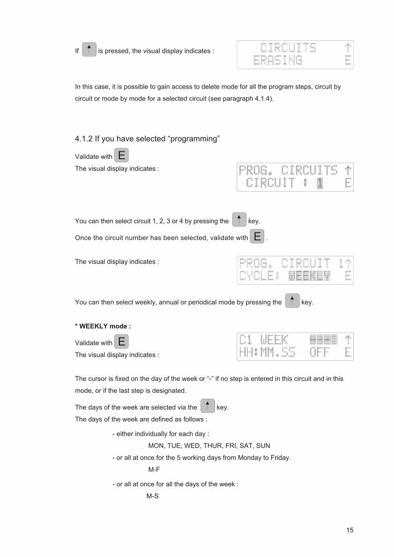
If is pressed, the visual display indicates :
In this case, it is possible to gain access to delete mode for all the program steps, circuit by
circuit or mode by mode for a selected circuit (see paragraph 4.1.4).
4.1.2 If you have se lected “pro gram ming”
Validate with
The visual display indicates :
You can then select circuit 1, 2, 3 or 4 by pressing the key.
Once the circuit number has been selected, validate with .
The visual display indicates :
You can then select weekly, annual or periodical mode by pressing the key.
* WEEKLY mode :
Validate with
The visual display indicates :
The cursor is fixed on the day of the week or “-” if no step is entered in this circuit and in this
mode, or if the last step is designated.
The days of the week are selected via the key.
The days of the week are defined as follows :
- either individually for each day :
MON, TUE, WED, THUR, FRI, SAT, SUN
- or all at once for the 5 working days from Monday to Friday.
M-F
- or all at once for all the days of the week :
M-S
15
E
E
E

- or all at once for Saturdays and Sundays
S-S
Validate with .
The cursor is fixed on the time, which may be adjusted via the numerical keyboard and the
key, which permits any wrong entry to be corrected.
Validate with .
The cursor is fixed on “OFF” : you can then choose to switch the circuit OFF, ON or lock the
circuit in for a period of between 1 and 60 seconds by pressing the key.
If the weekly programming mode is selected only, it is important to check that the memory of
the circuit concerned does not include any annual or periodical order.
* ANNUAL Mode
The annual mode is designed either to program an order executed only on one occasion on a
specified date, or to interrupt weekly or periodical programming during a specified period.
Validate with .
The visual display indicates :
The cursor is fixed on the date, which may be modified via the numerical keyboard and the
key, which permits any wrong entry to be corrected.
Validate with then follow the same procedure as for weekly mode in order to enter the
time and the position.
If the annual programming mode is selected only, it is important to check that the memory of
the circuit concerned does not include any weekly or periodical order.
* PERIODICAL Mode
The periodical mode is designed to program signals which are repeated every hour.
Validate with .
The visual display indicates :
The cursor is fixed on MM:SS. At this point, it is possible to enter a command which will be
executed every hour at the Mth minute and the Sth second.
You can also select the ON, OFF or period adjustment position.
If the periodical programming mode is selected only, it is important to check that the memory of
16
E
E
E
E
E

the circuit concerned does not include any annual or weekly order.
Note :
- “MEMORY” appears on the visual display every time you create a program step.
- if you create a program step, the program step concerned is re-designated after
validation.
- it is possible to re-read the program steps in a specified mode by pressing the
key repeatedly.
Every time the key is pressed, you move from one data item to another (time, date,
position). For instance, in order to read a weekly program step, it is necessary to press the
key three times.
There is one particular advantage to this procedure : if a day of the week is entered for a
weekly program step, several commands can be programmed at various times for this day.
For example :
- you enter Friday “VEN” (“FRI”) with the key and then validate with
- you enter an order for 15 h 00 m 00s and then validate with
- you enter a time period and then validate with
“MEMORY” is displayed.
It is possible to re-read the program step : the cursor is then fixed on “FRI”.
- you validate with
(In this case there is no need to seek “FRI”)
- you enter an order for 16 h 00m 00s and then validate with
- you enter a time period, then you validate with
“MEMORY” is displayed.
- If new data are entered in addition to those registered on the visual display, the existing
program step is not overwritten but a new step is created instead.
- It is possible to combine 2 or 3 modes.
An order of priority is defined between the modes :
Annual > Weekly > Periodical
If 2 orders in 2 different modes are given for the same instant, the priority mode command will
be executed. In the other cases, the command executed will depend upon the last command
received from the 2 or 3 modes used, but only in the ON position in the priority mode(s).
For instance, when using the 2 annual and weekly modes :
17
E
E
E
E
E
E
E
E
E

- if the last order is ON in annual mode and the last but one order is OFF in
weekly mode, in this case the order executed will be ON.
- if the last but one order is OFF in annual mode and the last order is ON in
weekly mode, in this case the order executed will be OFF.
- if the last but one order is ON in annual mode and the last order is OFF in
weekly mode, in this case the order executed will be OFF.
- if the last 2 annual and weekly orders correspond to the same point in time, then
the command executed will be the annual command.
Please refer to appendix 6-2 for further explanations regarding programming methods.
If time periods are programmed in the 2 modes and these time periods overlap for a few
seconds, the priority mode time period will be executed, unless, during this time period, a time
period command in a lesser priority mode interrupts the ON command at an earlier stage.
The position of the relays being OFF before and after this time period in the priority mode, the
commands given outside of this time period in the other modes will not be taken into account.
Note :
Program steps can be deleted by fixing the cursor on the program steps
concerned, by means of the delete key. After every delete, the next program step
is designated.
“DELETE” appears on the visual display every time a program step is deleted.
4.1.3 If you have se lected “man ual”
Validate with .
The visual display indicates :
You can then test the circuits via the numerical keys. The circuits only remain locked in when
the key is pressed.
To log off, press the key.
4.1.4 If you have se lected “de lete”
3 delete levels are available :
18
E

- general : general deletion on all circuits and in all modes.
- by cir cuit : de le tion of all the steps of a single cir cuit in all modes.
- by mo des in a single cir cuit.
To log off, press the key.
Validate with .
The visual display indicates :
If you have chosen to delete all the program steps, validate with .
The visual display indicates :
For this operation, it is necessary to select “yes” via the key then validate with
the key so as to avoid losing all the program steps in the event of an operating error.
If you have chosen to delete the program steps on a single circuit, move around using the
key then validate with .
The visual display indicates :
If you have chosen to delete all the program steps on a single circuit :
The visual display indicates :
Then simply validate with .
If you wish to delete steps in a weekly, annual or periodical mode only on the circuit selected,
simply move around using the key to select the mode required, then validate with .
19
E
E
E
E
E
E

4.2 Summer/Winter Time Change
In order to gain access to the summer/winter time change mode when you are in the main
menu, press 2 or move around using the key.
The visual display indicates :
Automatic summer/winter time change : yes / no.
If you select “no”, no summer/winter time change is made.
If you select “yes”, the clock time is automatically changed the last Sundays in March and
October; the dates concerned are calculated automatically and can be modified. Validate 4
times in order to scroll the dates and the times of the next summer/winter time changes.
20

4.3 Time Setting of the Slave Clocks
Important :
For the two pulse 1 or pulse 2 distributions, it is necessary to proceed as follows :
1 - Configure the power (pulse 1) or pulse 2 cards as per the instructions
contained in appendices 6.1. or 6.7.
In the case of a series distribution, 3 configurations are possible :
- 60 mA. Regulation
- 80 mA. Regulation
- 100 mA. regulation
In the case of a parallel distribution, 2 current limitations are available :
- 1A on the “power” card.
- 500 mA on the “pulse 2" card.
In the parallel mode, the voltage on the loads is constant : V = 20 V.
2 - Once the cards are configured, it is necessary to assign the specified
parameters to the distribution using menu 4 “time distribution”.
It is important that the choice of parameters (series or parallel) and the
configuration of the dips are consistent as Microquartz S pilots the system alarms
(open circuit, series saturation, parallel overload) in accordance with these
parameters.
3 - Then set the receiving clocks using menu 3 “SLAVE CLOCKS, SET TO TIME”.
From the main menu, select SLAVE CLOCKS, SET TO TIME :
The display indicates :
In this menu, it is possible to interrupt, set and restart the 1 minute, half-minute receiving clocks
of the pulse generator of the power card, the D1/D2 receiving clocks and the 1 minute,
half-minute or second receiving clocks of the “pulse 2" card.
21
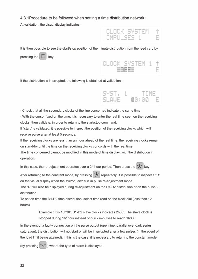
4.3.1Procedure to be fol lowed when set ting a time dis tri bu tion net work :
At validation, the visual display indicates :
It is then possible to see the start/stop position of the minute distribution from the feed card by
pressing the key.
It the distribution is interrupted, the following is obtained at validation :
- Check that all the secondary clocks of the line concerned indicate the same time.
- With the cursor fixed on the time, it is necessary to enter the real time seen on the receiving
clocks, then validate, in order to return to the start/stop command.
If “start” is validated, it is possible to inspect the position of the receiving clocks which will
receive pulse after at least 5 seconds.
If the receiving clocks are less than an hour ahead of the real time, the receiving clocks remain
on stand-by until the time on the receiving clocks concords with the real time.
The time concerned cannot be modified in this mode of time display, with the distribution in
operation.
In this case, the re-adjustment operates over a 24 hour period. Then press the key.
After returning to the constant mode, by pressing repeatedly, it is possible to inspect a “R”
on the visual display when the Microquartz S is in pulse re-adjustment mode.
The “R” will also be displayed during re-adjustment on the D1/D2 distribution or on the pulse 2
distribution.
To set on time the D1-D2 time distribution, select time read on the clock dial (less than 12
hours).
Example : it is 13h30’, D1-D2 slave clocks indicates 2h00’. The slave clock is
stopped during 1/2 hour instead of quick impulses to reach 1h30’.
In the event of a faulty connection on the pulse output (open line, parallel overload, series
saturation), the distribution will not start or will be interrupted after a few pulses (in the event of
the load limit being attained). If this is the case, it is necessary to return to the constant mode
(by pressing ) where the type of alarm is displayed.
22
E
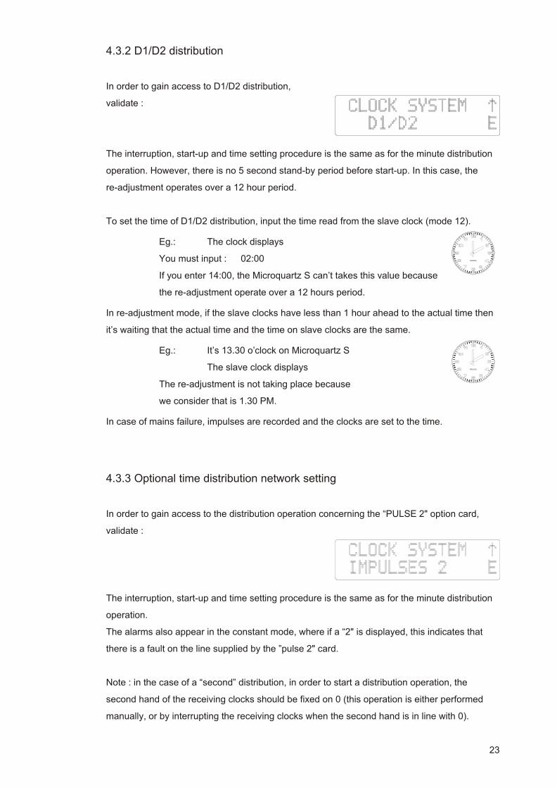
4.3.2 D1/D2 dis tri bu tion
In order to gain access to D1/D2 distribution,
validate :
The interruption, start-up and time setting procedure is the same as for the minute distribution
operation. However, there is no 5 second stand-by period before start-up. In this case, the
re-adjustment operates over a 12 hour period.
To set the time of D1/D2 distribution, input the time read from the slave clock (mode 12).
Eg.: The clock displays
You must input : 02:00
If you enter 14:00, the Microquartz S can’t takes this value because
the re-adjustment operate over a 12 hours period.
In re-adjustment mode, if the slave clocks have less than 1 hour ahead to the actual time then
it’s waiting that the actual time and the time on slave clocks are the same.
Eg.: It’s 13.30 o’clock on Microquartz S
The slave clock displays
The re-adjustment is not taking place because
we consider that is 1.30 PM.
In case of mains failure, impulses are recorded and the clocks are set to the time.
4.3.3 Op tional time dis tri bu tion net work set ting
In order to gain access to the distribution operation concerning the “PULSE 2" option card,
validate :
The interruption, start-up and time setting procedure is the same as for the minute distribution
operation.
The alarms also appear in the constant mode, where if a “2" is displayed, this indicates that
there is a fault on the line supplied by the ”pulse 2" card.
Note : in the case of a “second” distribution, in order to start a distribution operation, the
second hand of the receiving clocks should be fixed on 0 (this operation is either performed
manually, or by interrupting the receiving clocks when the second hand is in line with 0).
23

Re-adjustment will only occur if the receiving clocks are less than 6 hours behind the real time.
4.3.4 Alarms
If the card is configured in series distribution mode and the Microquartz S is configured in 1
minute or half-minute series distribution mode and :
1st case - in the event of overload : the visual display indicates every two
seconds :
2nd case : in the event of an open line : the visual display indicates every two
seconds :
The “1" signifies that the problem is with the pulse line located on the power card.
3rd case - in the event of a fault in the dips configuration on the pulse 2 line
(500mA instead of 60, 80 or 100 mA), the display indicates :
If the card is configured in 1A limitation mode and the Microquartz S is configured in 1 minute
or half-minute parallel distribution mode and there is an overload situation, the visual display
indicates every two seconds :
When the time on the slave clocks is displayed, it is possible to visualize the time on which the
distribution has stopped. After mending, the impulses distribution has takes “ON”. The
Microquartz S automatically performs the re-adjustment required in order to reset the
secondary clocks.
24

4.4 Time Distribution Setup
From the main menu, select the visual display which indicates :
4.4.1 Pulse dis tri bu tion setup (power card)
At validation, the visual display indicates :
After validation, it is then possible to parameter the distribution operation by using the same
programming procedure :
- the distribution type (1 minute or half-minute, series or parallel); these data can
be used for piloting the alarms.
- the pulse time period (values between 0.1 seconds and 2.9 seconds), the
standard value available being 1.2 seconds. The time period is adjustable to the
nearest tenth of a second.
4.4.2 Ac cess to IRIG-B/AFNOR norm dis tri bu tion op er at ing mode
is not required, as the message delivered is a set message providing the following information :
second, minute, hour, day of the year, year, month, day of the month.
4.4.3 To setup the ASCII dis tri bu tion
Validate :
If you do not wish to emit, validate with “NO EMISSION”; otherwise, select :
25
- the “INTERRO” mode : emission of the time and the date at every reception of
the ASCII “T” character; the message starts the next second;
- the “SEC. IMPULSE” mode : the Microquartz S sends a message which
automatically indicates the time and the date every second.
- the “MIN. IMPULSE” mode : Microquartz S sends a message which
automatically indicates the time and the date every minute.
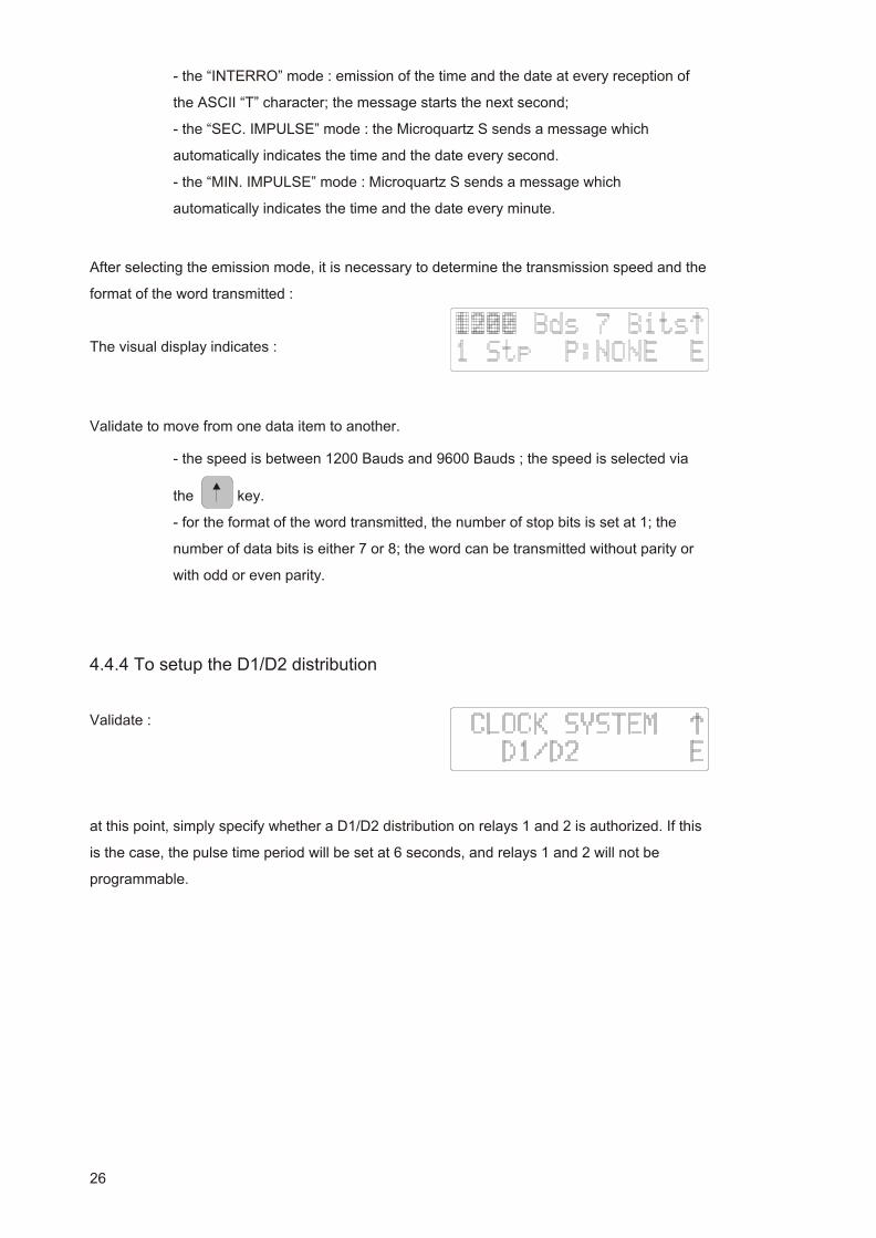
After selecting the emission mode, it is necessary to determine the transmission speed and the
format of the word transmitted :
The visual display indicates :
Validate to move from one data item to another.
- the speed is between 1200 Bauds and 9600 Bauds ; the speed is selected via
the key.
- for the format of the word transmitted, the number of stop bits is set at 1; the
number of data bits is either 7 or 8; the word can be transmitted without parity or
with odd or even parity.
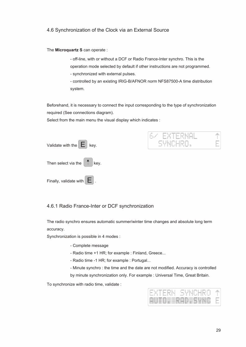
4.4.4 To setup the D1/D2 dis tri bu tion
Validate :
at this point, simply specify whether a D1/D2 distribution on relays 1 and 2 is authorized. If this
is the case, the pulse time period will be set at 6 seconds, and relays 1 and 2 will not be
programmable.
26

4.4.5 “Pulse 2" dis tri bu tion setup
Validate :
As with the “power” card, it is also possible to parameter :
- the distribution type (1 minute, half-minute, series or parallel)
At this point, it is possible to select a second distribution by validating :
- the pulse time period :
. values between 0.1 and 2.9 seconds for a 1 minute or half-minute
distribution;
. or set at 0.3 seconds (with no modification) for a parallel second
distribution.
27

4.5 Minute Distribution Alarm
Select, from the main menu, the display indicates :
Confirm with , display indicates :
Press on , display indicates :
Confirm with .
If this is the case, relay 4 will no longer be programmable.
28
E
E
4.6 Synchronization of the Clock via an External Source
The Microquartz S can operate :
- off-line, with or without a DCF or Radio France-Inter synchro. This is the
operation mode selected by default if other instructions are not programmed.
- synchronized with external pulses.
- controlled by an existing IRIG-B/AFNOR norm NFS87500-A time distribution
system.
Beforehand, it is necessary to connect the input corresponding to the type of synchronization
required (See connections diagram).
Select from the main menu the visual display which indicates :
Validate with the key.
Then select via the key.
Finally, validate with .
4.6.1 Ra dio France-Inter or DCF syn chro ni za tion
The radio synchro ensures automatic summer/winter time changes and absolute long term
accuracy.
Synchronization is possible in 4 modes :
- Complete message
- Radio time +1 HR; for example : Finland, Greece...
- Radio time -1 HR; for example : Portugal...
- Minute synchro : the time and the date are not modified. Accuracy is controlled
by minute synchronization only. For example : Universal Time, Great Britain.
To synchronize with radio time, validate :
29
E
E
For the complete message (time, date, summer/winter time change),
validate :
- If you wish to obtain the complete message while at the same time taking a time difference
into account (+ or -1 hour), validate :
or
- If you wish to obtain a very high standard of accuracy, but the time difference is greater than
one hour or you do not want an automatic summer/winter time change, validate :
The clock will ensure radio minute accuracy.
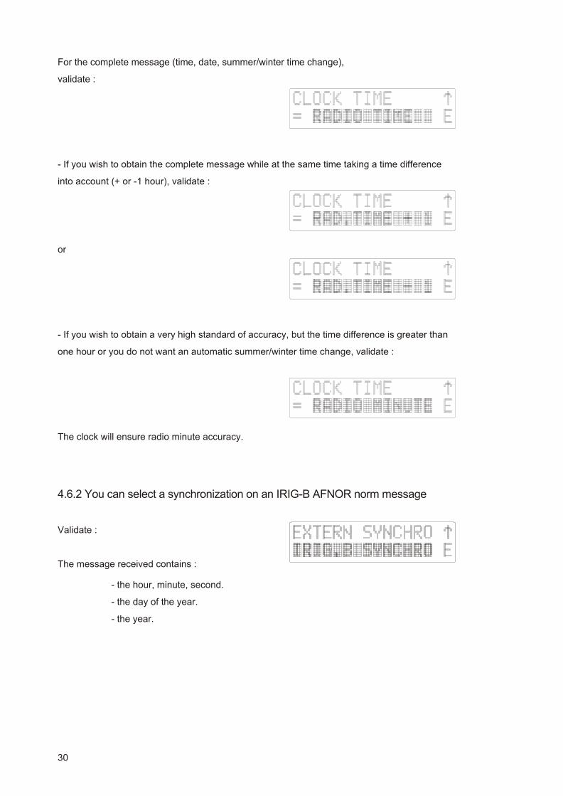
4.6.2 You can se lect a syn chro ni za tion on an IRIG-B AFNOR norm mes sage
Validate :
The message received contains :
- the hour, minute, second.
- the day of the year.
- the year.
30

4.6.3 You can se lect a syn chro ni za tion on po lar ized pulses
Validate :
or :
according to the type of synchro available connected to the power card.
The Microquartz s is synchronized by setting the seconds to 0 on every pulse received (in
minute synchro) or on the even pulses received (in half-minute synchro).
4.6.4 Alarms for prob lems of syn chro ni za tion
If the device is in IRIG-B AFNOR synchronization and the signal is absent more than 1 hour, a
warning message is blinking once per second on the second line of the display : “NO
SYNCHRO IRIG”. Moreover if the relay 4 is used for the alarm, it will be active until a correct
signal is detected by the Microquartz S.
If the device is in radio synchronization and the Microquartz S can’t decode a signal during
more than 24 hours, a warning message is blinking once per second on the second line of the
display : “NO RADIO SYNCHRO”. Moreover if the relay 4 is used for the alarm, it will be active
until the Microquartz S can decode the radio signal.
4.7 Choice of Language
Select, from the main menu, the visual display which indicates :
Validate with : .
Select with the key, then with .
31
E
E
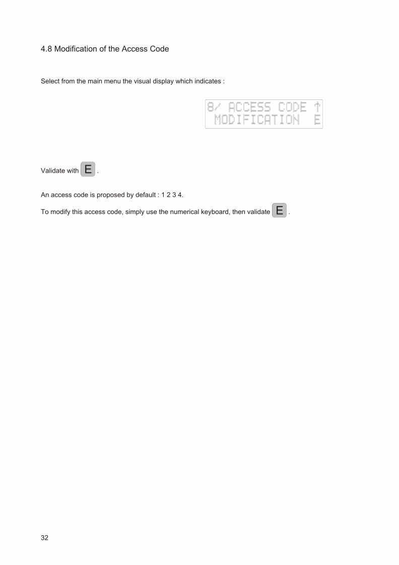
4.8 Modification of the Access Code
Select from the main menu the visual display which indicates :
Validate with .
An access code is proposed by default : 1 2 3 4.
To modify this access code, simply use the numerical keyboard, then validate .
32
E
E
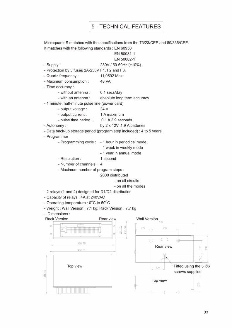
5 - TECHNICAL FEATURES
Microquartz S matches with the specifications from the 73/23/CEE and 89/336/CEE.
It matches with the following standards : EN 60950
EN 50081-1
EN 50082-1
- Supply : 230V / 50-60Hz (±10%)
- Protection by 3 fuses 2A-250V F1, F2 and F3.
- Quartz frequency : 11,0592 Mhz
- Maximum consumption : 48 VA
- Time accuracy :
- without antenna : 0.1 secs/day
- with an antenna : absolute long term accuracy
- 1 minute, half-minute pulse line (power card)
- output voltage : 24 V
- output current : 1 A maximum
- pulse time period : 0,1 à 2,9 seconds
- Autonomy : by 2 x 12V, 1.9 A batteries
- Data back-up storage period (program step included) : 4 to 5 years.
- Programmer
- Programming cycle : - 1 hour in periodical mode
- 1 week in weekly mode
- 1 year in annual mode
- Resolution : 1 second
- Number of channels : 4
- Maximum number of program steps :
2000 distributed
- on all circuits
- on all the modes
- 2 relays (1 and 2) designed for D1/D2 distribution
- Capacity of relays : 4A at 240VAC
- Operating temperature : 0oC to 50oC
- Weight : Wall Version : 7.1 kg; Rack Version : 7.7 kg
- Dimensions :
33
Fitted using the 3 Ø6
screws supplied
Rear view
Rear view
Top view
Rack Version Wall Version
Top view

6- APPENDICES
6.1 Configuration of Series or Parallel Pulse Distribution
6.1.1 Par al lel Dis tri bu tion
Maximum load for pulse 1 : 1A
SWITCH 24V // 1A
DIP 1 0
DIP 2 0
DIP 3 X
DIP 4 X
X = immaterial
34
Position 0
Position 1
1
1
0
0

6.1.2 Se ries Dis tri bu tion
SWITCH serie 60 mA serie 80 mA serie 100 mA
DIP 1 1 1 1
DIP 2 1 1 1
DIP 3 X 1 0
DIP 4 1 0 0
X = immaterial
35
serie 100mA
serie 60mA serie 80mAPosition 0
Position 1
1
1
0
0

6.2 D1-D2 distribution : connections
D1-D2 distribution uses relays 1 and 2
(these 2 relays cannot be used to another purpose).
Connections :
36
“POWER SUPPLY” card
Relay 4
Relay 3
Relay 2
Relay 1
D2
D1
Neutral
Phase230 VAC 50Hz
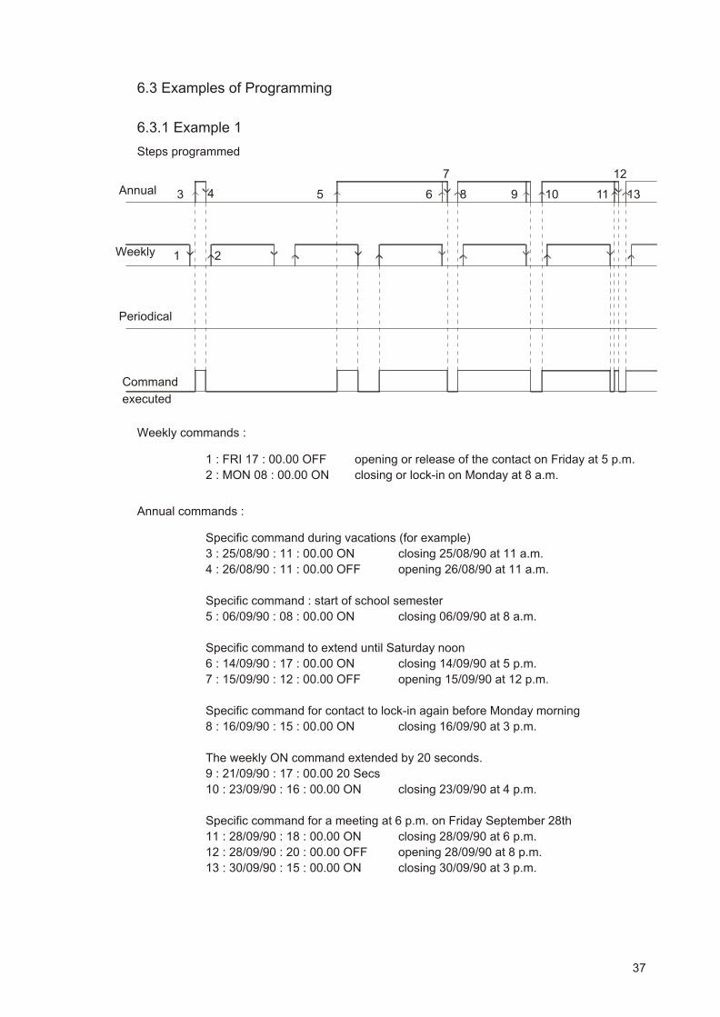
6.3 Examples of Programming
6.3.1 Ex am ple 1
Steps programmed
Weekly commands :
1 : FRI 17 : 00.00 OFF opening or release of the contact on Friday at 5 p.m.
2 : MON 08 : 00.00 ON closing or lock-in on Monday at 8 a.m.
Annual commands :
Specific command during vacations (for example)
3 : 25/08/90 : 11 : 00.00 ON closing 25/08/90 at 11 a.m.
4 : 26/08/90 : 11 : 00.00 OFF opening 26/08/90 at 11 a.m.
Specific command : start of school semester
5 : 06/09/90 : 08 : 00.00 ON closing 06/09/90 at 8 a.m.
Specific command to extend until Saturday noon
6 : 14/09/90 : 17 : 00.00 ON closing 14/09/90 at 5 p.m.
7 : 15/09/90 : 12 : 00.00 OFF opening 15/09/90 at 12 p.m.
Specific command for contact to lock-in again before Monday morning
8 : 16/09/90 : 15 : 00.00 ON closing 16/09/90 at 3 p.m.
The weekly ON command extended by 20 seconds.
9 : 21/09/90 : 17 : 00.00 20 Secs
10 : 23/09/90 : 16 : 00.00 ON closing 23/09/90 at 4 p.m.
Specific command for a meeting at 6 p.m. on Friday September 28th
11 : 28/09/90 : 18 : 00.00 ON closing 28/09/90 at 6 p.m.
12 : 28/09/90 : 20 : 00.00 OFF opening 28/09/90 at 8 p.m.
13 : 30/09/90 : 15 : 00.00 ON closing 30/09/90 at 3 p.m.
37
Periodical
4 5 6
7
8 93 10 11 13
12
21
Command
executed
Annual
Weekly
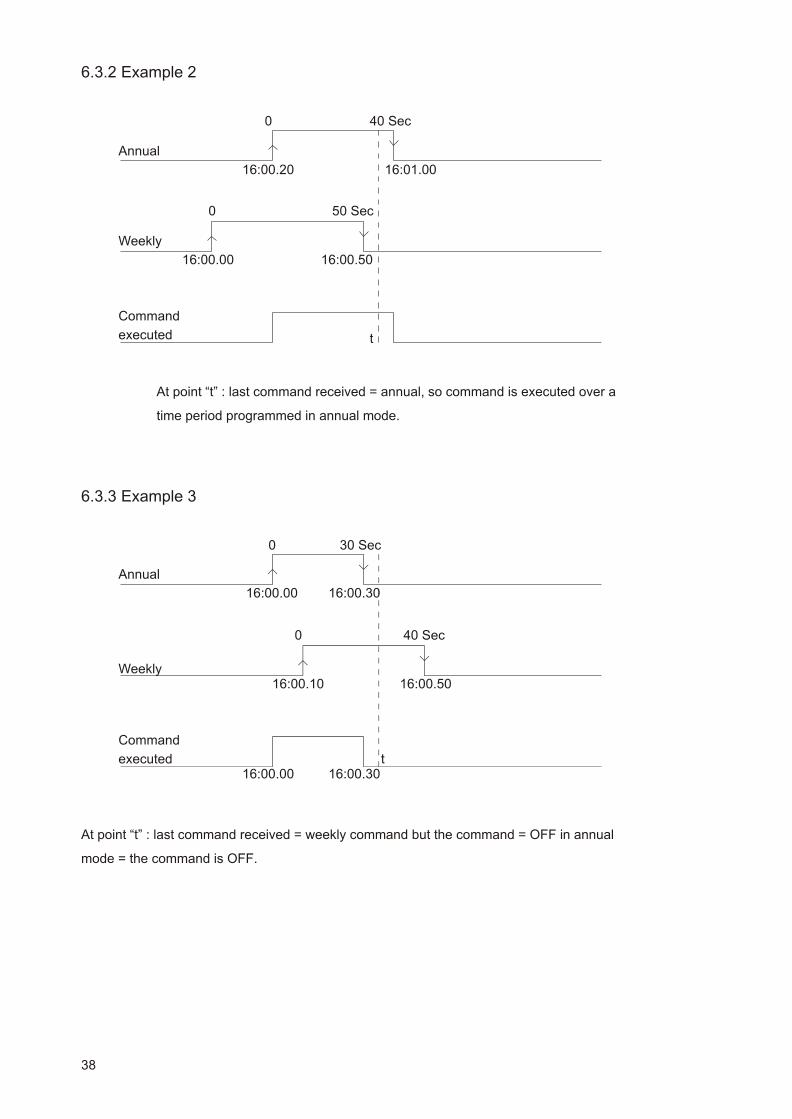
6.3.2 Ex am ple 2
At point “t” : last command received = annual, so command is executed over a
time period programmed in annual mode.
6.3.3 Ex am ple 3
At point “t” : last command received = weekly command but the command = OFF in annual
mode = the command is OFF.
38
Command
executed
Annual
Weekly
0
0 50 Sec
40 Sec
t
16:00.00
16:00.20
16:00.50
16:01.00
Command
executed
Annual
Weekly
0
0 40 Sec
30 Sec
t16:00.3016:00.00
16:00.5016:00.10
16:00.3016:00.00
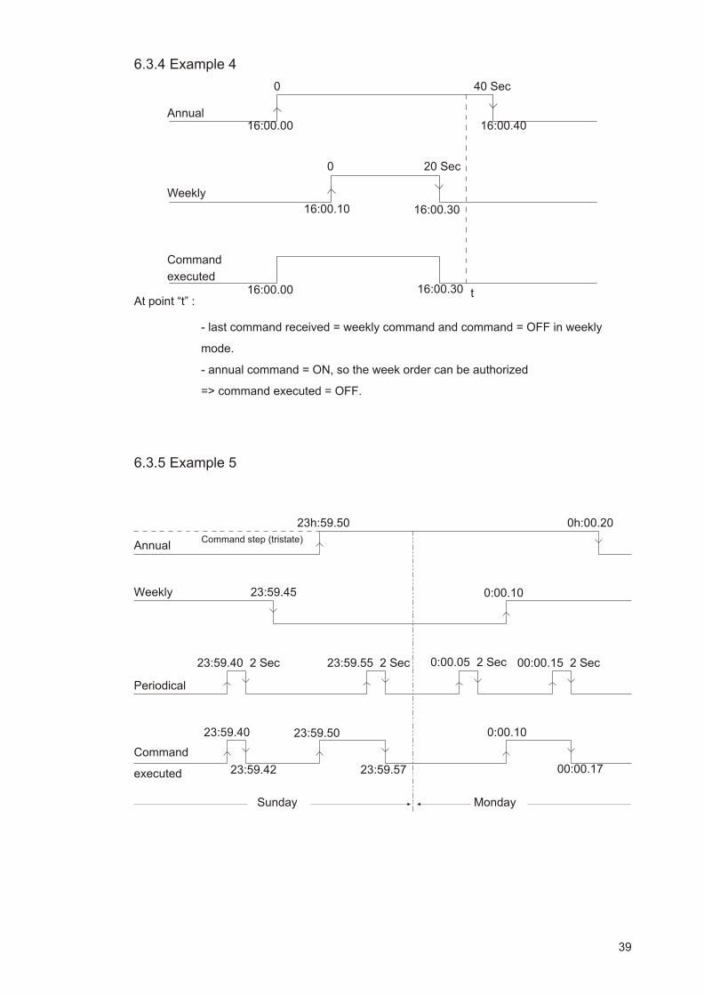
6.3.4 Ex am ple 4
At point “t” :
- last command received = weekly command and command = OFF in weekly
mode.
- annual command = ON, so the week order can be authorized
=> command executed = OFF.
6.3.5 Ex am ple 5
39
Command
executed
Annual
Weekly
0
0
20 Sec
40 Sec
t16:00.3016:00.00
16:00.4016:00.00
16:00.3016:00.10
Command
executed
Annual
Weekly
23:59.42
Command step (tristate)
23:59.5023:59.40
Sunday
23:59.57
0h:00.2023h:59.50
0:00.1023:59.45
Periodical
23:59.55 2 Sec 0:00.05 2 Sec23:59.40 2 Sec 00:00.15 2 Sec
Monday
0:00.10
00:00.17

6.4 ASCII Line Card (RS232; RS422; CURRENT LOOP)
6.4.1 Func tions and fea tures
Functions :
- this card enables data to be transmitted between Microquartz S and equipment with the same
interface system (RS232 for a direct connection with a P.C., current loop for a connection with
a 917 10 digit card, etc.).
Features :
1 - Possible selection of one interface from among 3 different interfaces by configuring 12 dips.
2 - RS232 Interface :
- 3 conductor interface : ground conductor, RS232 input and RS232 output.
- 6V < V(RS232 input) - V(RS232 output) < 24V
- Possible transmission from 1200 to 9600 Bauds.
- Transmission length : 15 meters (at 1200 Bauds).
3 - RS422 Interface :
- 4 conductor interface : T+, T-, R+ and R-
- Transmission of data through symmetrical interface circuits : the signal is not
tagged to the ground conductor, but presented as a differential signal to the
transmitter outputs and the receiver input.
- 1V < (VT+) - (VT-) < 6V (on open output)
- Possible transmission from 1200 to 9600 Bauds
- Transmission length : approximately 1,2 km.
4 - Current loop interface :
a- Passive current loop :
- 4 conductor interface : T, CT, R and CR
- The interface receives a 20 mA current via the ligne
- Possible transmission from 1200 to 4800 Bauds.
- Transmission length : 300 meters (at 1200 Bauds)
- ‘1’ break or ‘0’ break (selection by dips).
b - Active current loop :
- 3 conductor interface : CT, CR and GND
- The interface injects a 20 mA current in the ligne
- Possible transmission from 1200 to 9600 Bauds
40

- Transmission length : 300 meters (at 1200 Bauds)
- ‘1’ break or ‘0’ break (selection by dips).
5 - External connection :
- 9 pin socket connector as per standardized pin coupling (appendix 3)
- 5 pin Phoenix connector (on a “line” card) connectable to an interface (for
example : MA21; MA45)
- after configuration of the dips.
6.4.2 Time trans mis sion pro to col
* Transmission speed : 1200, 2400, 4800 or 9600 Bauds.
* Word transmitted : 1 start bit
7 or 8 data bits
1 stop bit without parity or with odd or even parity.
* Transmission mode :
- single transmission every time the receiving clock produces an ASCII “T”
character. The message starts the next second.
- or transmission every second.
- or transmission every minute.
* Format of the message :
Byte n° Information Character
1 Character start “T”
2 Separating character “:”
3 - 4 Year 00 - 99
5 Separating character “:”
6 - 7 Month 01 - 12
8 Separating character “:”
9 -10 Day of the month 01 - 31
11 Separating character “:”
12-13 Day of the week 01 - 07
14 Separating character “:”
15-16 Hour 00 - 23
17 Separating character “:”
18-19 Minute 00 - 59
20 Separating character “:”
21-22 Second 00 - 59
23 carriage return (CR)
24 Ligne feed (LF)
41

6.4.3 Con nec tions
6.4.3.1 ASCII line card con nec tion : <-> MA 21 <-> P.C.
* Microquartz S passive input and output
After wiring the connection between the Microquartz S interface card, the MA21 interface and
the P.C., position the dips so as to configure the output type of the Microquartz S ASCII line
card as per the table in paragraph 6.4.4.
* Microquartz S ac tive in put and output
After wiring the connection between the Microquartz S interface card, the MA21 interface and
the P.C., position the dips so as to configure the output type of the Microquartz S ASCII line
card as per the table in paragraph 6.4.4.
42
INTERFACE CARD
INTERFACE
MA21Active inputand output Jumpers
X4 : 2-3X5 : 2-3X6 : 2-3X7 : 2-3
9 PIN
CONNECTOR OF
THE PC
CURRENT LOOP
RS232
INTERFACE CARD
INTERFACE
MA21Active inputand outputJumpers
X4 : 1-2X5 : 1-2X6 : 1-2X7 : 1-2
9 PIN
CONNECTOR OF
THE PC
CURRENT LOOP
RS232

6.4.3.2 ASCII line card con nec tion : <-> MA 45 <-> P.C.
After wiring the connection between the Microquartz S interface card, the MA45 interface and
the P.C., position the dips so as to configure the output type of the Microquartz S ASCII line
card as per the table in paragraph 6.4.4.
6.4.3.3 ASCII line card connec tion <-> P.C.
After wiring the connection between the Microquartz S interface card and the P.C., position
the dips so as to configure the output type of the Microquartz S ASCII line card as per the
table in paragraph 6.4.4.
43
INTERFACE CARD
INTERFACE
MA45
9 PIN
CONNECTOR OF
THE P.C.
RS422
RS232
INTERFACE CARD
9 or 25 pin
connector of the
P.C.
RS232
S2
S3
ON
ON
DIP setting of MA45
interface

6.4.4 Con fi gu ra tion of the dips on the ASCII in ter face card
The position of the dips on the ASCII interface card is given in the table below :
\ Mode
DIP \
Current Loop
passive I/O
Current Loop
active I/O RS 422 RS 232
1 1 1 0 X
2 X X 1 0
3 1 1 0 0
4 1 1 0 X
5 1 1 0 0
6 X X 1 0
7 1 1 X X
8 0 0 1 1
9 X X 0 1
10 0 0 X X
11 0 1 0 0
12 0 1 0 0
44

6.4.5 Pin cou pling of the 9 pin connec tor
A ) 9 pin connector pin coupling : RS232 mode
Pin number Signal
1
2 RXD
3 TXD
4
5 GROUND
6
7
8
9
B ) 9 pin connector pin coupling : RS422 mode
Pin number Signal
1 T-
2
3
4 R+
5
6 T+
7
8 R-
9
C ) 9 pin connector pin coupling : current loop mode
Pin number Signal
1 CT
2 R
3 T
4 CR
5 GROUND
6
7
8
9 GROUND
45

6.5 Connection of the IRIG-B AFNOR Synchro Card
- The synchro card must be installed on top, on the right hand side of the C.P.U.; the OPTION
card should be in place.
- Connect the 2 outside conductors to the Phoenix B3 terminal strip (OPTION card). Connect
L1 (4 pin connector) of the OPTION card to the IRIG-B AFNOR synchro card.
- Connect the 6 pin connector to the L4 pin connector of the C.P.U. card (L4 is located beside
the 20 pin flat connector). The polarization of this connector prevents the connection being
inverted.
6.6 IRIG-B AFNOR Signal Amplifier Card
- Function of the card :
To separate several lines of IRIG B receiving clocks so as to facilitate network maintenance.
To increase the power of the signal generator in order to increase the size of the network.
For these two reasons, these 4 amplifiers should be installed by adding an additional card.
- Installation of this card :
Position this card on the attachments located on the right hand side of the C.P.U. card.
Connect the 20 pin flat connector to this card, then connect this card to the OPTION card by
means of the 8 pin connector (HE14 connectors).
- Connection of the network :
It is then possible to connect the 5 lines of IRIG-B receiving clocks. 4 can be connected
separately to the OPTION card on the connectors where OUTPUT AFNOR 1, 2 3 or 4 is
indicated. The 5th output is located on the power card.
46

6.7 Pulse 2 Card
FUNCTION :
- This card permits the distribution of 1 minute, half-minute series or parallel
polarized pulses distribution and second pulse distribution.
- The card is controlled by the C.P.U. Card.
- Power can be supplied to the pulse generator either by the voltage supplied by
the battery or through a 48V or 60V external supply.
- The card is equipped with circuits which permit an open circuit, output saturation
(series distribution) or parallel distribution overload to be detected. A faulty
configuration of dips can also be detected, for example if the Microquartz S is
parametered in “minute series” mode and the card is configured for 500mA
regulation.
TECHNICAL DATA :
- Slow edge pulses (50ms) at 24V
- Pulse opto-electrically insulated from the rest of the equipment.
- External power supply voltage limited to 65V.
- Series distribution :
- 60, 80 or 100 mA regulation (selection by dips)
- Maximum output voltage : power supply voltage -2V
- Parallel distribution :
- Limited to 500mA (depending on the position of dips 1 and 2)
- Output voltage : power supply voltage -2V
- Installation adapted to the power supply voltage via dip 5.
INSTALLATION :
- Place the card near the transformer on the sliding part of the cabinet.
- Connect the supply of the amplifier either to the 26V supply of the battery
(Phoenix connector on the “power” card) or to the 48V external supply.
- The external supply should also be connected to the 48V input of the power
card.
- Connect L3 of the C.P.U. card to the L3 connector of the pulse 2 card.
- Connect L4 (OPTION card) to the L4 connector of the pulse 2 card.
- Connect the network of receiving clocks to the B1 terminal strip of the OPTION
card (B1).
47

6.7.1 - Par al lel pulse dis tri bu tion con fig u ra tion
SWITCH // 500 mA
DIP 1 1
DIP 2 1
DIP 3 X
DIP 4 X
X = immaterial
48
Ext. supply >40V
Supply
Pulse 2

6.7.2 - Se ries pulse dis tri bu tion con fig u ra tion
SWITCH serie 60 mA serie 80 mA serie 100 mA
DIP 1 0 0 0
DIP 2 0 0 0
DIP 3 X 0 1
DIP 4 0 1 1
X = immaterial
49
serie 100mA
serie 60mA serie 80mA
24V Internal
Supply
24V Internal
Supply
Ext. supply >40V
Supply Supply
Supply
Pulse 2 Pulse 2
Pulse 2

6.8 Autonomy
In the absence of a mains mains power supply, 2 lead batteries guarantee a period of
autonomous operation which varies depending on the load and the number of cards added.
The various periods of autonomous operation for possible installations and under unfavourable
conditions (2.9 second pulse time, half-minute pulse, 1A distribution, ASCII card in current loop
mode) are indicated in the table below.
Power card
+ C.P.U. card
(standard 75mA)
4 Relays ON
(Direct current 190mA)
1 x 1A distribution //
(without re-adjustment,
half-min., 2.9s 100mA
pulse)
4 IRIG B / AFNOR
amplifiers (44mA)
ASCII card current
loop mode (110 mA)
IRIG B synchro card
(26mA)
Dist. 500mA half-min.
pulse 2 card (without
re-adjustment, 2.9s
pulse, 55mA)
Period of battery
operated autonomous
operation (in hours)
25 10.30 8 7.20 6 7.45 5.20 6.20 13 8.15 3
50
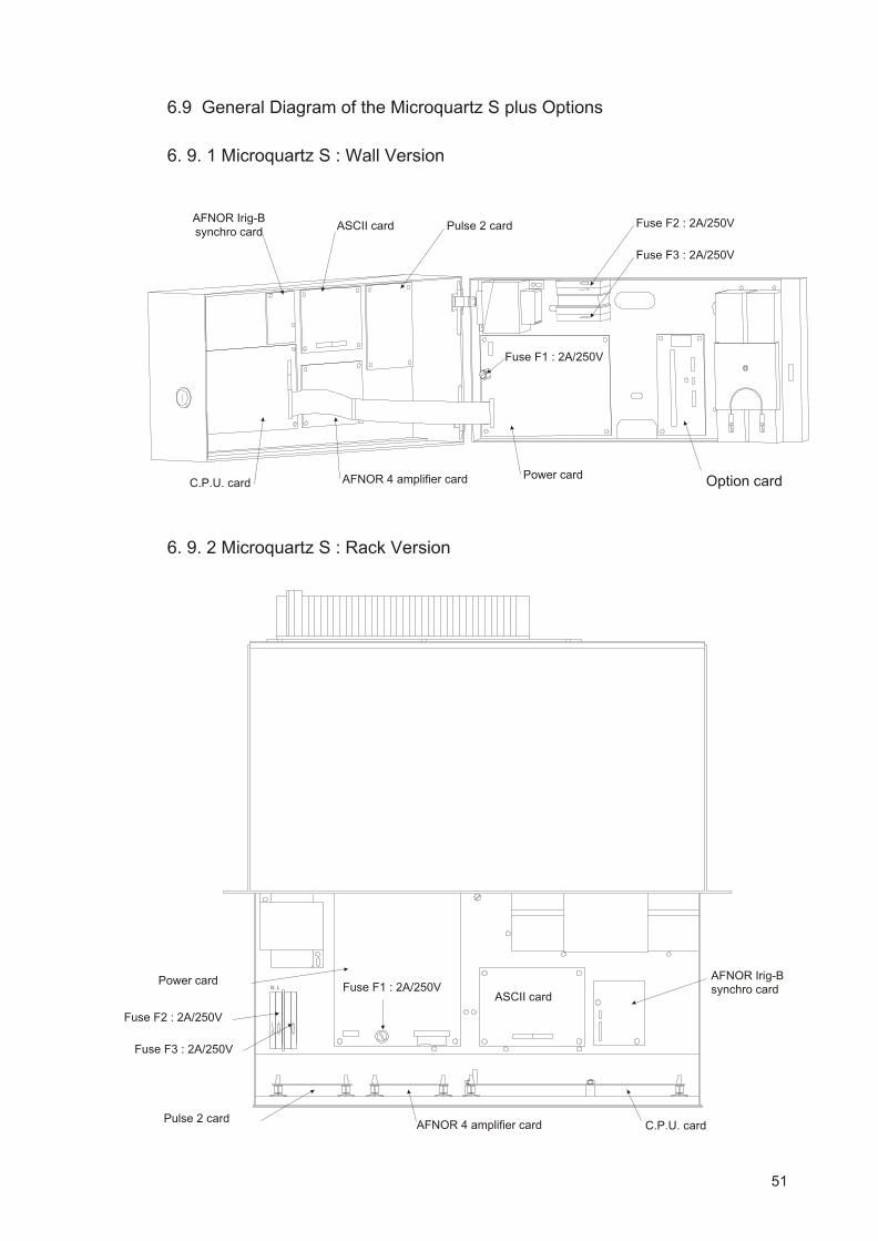
6.9 General Diagram of the Microquartz S plus Options
6. 9. 1 Microquartz S : Wall Ver sion
6. 9. 2 Microquartz S : Rack Ver sion
51
AFNOR Irig-Bsynchro card
Option cardPower card
ASCII card
AFNOR 4 amplifier cardC.P.U. card
Pulse 2 card Fuse F2 : 2A/250V
Fuse F1 : 2A/250V
Fuse F3 : 2A/250V
N L
AFNOR Irig-Bsynchro card
Power card
ASCII card
AFNOR 4 amplifier card C.P.U. cardPulse 2 card
Fuse F2 : 2A/250V
Fuse F1 : 2A/250V
Fuse F3 : 2A/250V

52