microsoft lync 2013 skype for business 2015 skype online ... · 5555 skype for business online...
TRANSCRIPT
© Copyright Equant 1 of 59
Microsoft Lync 2013Microsoft Lync 2013Microsoft Lync 2013Microsoft Lync 2013
Skype for Business 2015Skype for Business 2015Skype for Business 2015Skype for Business 2015
Skype Online Skype Online Skype Online Skype Online ----AudioCodes AudioCodes AudioCodes AudioCodes Cloud Cloud Cloud Cloud Connector EditionConnector EditionConnector EditionConnector Edition
Configuration Checklists for BTIP and Business Talk SIP services
23 january 2018
Lync 2013 Checklist version 1.6
Skype for Business 2015 Checklist version 1.10
Cloud Connector Edition Checklist 2.0
© Copyright Equant 2 of 59
Contents
1111 Main certified architecturesMain certified architecturesMain certified architecturesMain certified architectures ........................................................................................................................................................................................................................................................................................................................................................................................................ 3333
1.1 Lync 2013 & Skype for Business 2015 on premises .......................................................................... 3
1.1.1 Centralized architecture ..................................................................................................... 3
1.1.2 Remote site “SBA” ............................................................................................................ 3
1.1.3 “Cascaded” remote site .................................................................................................... 4
1.1.4 Remote site “GW” ............................................................................................................. 5
1.1.5 Centralized architecture with central SBC ......................................................................... 5
1.1.6 Remote site “SBA” and central site with central SBC ....................................................... 6
1.1.7 Remote site “GW” and central site with central SBC ........................................................ 6
1.1.8 2-pool centralized architecture .......................................................................................... 7
1.1.9 2-pool architecture with central SBC (Customer specific) ................................................ 7
1.2 Skype for Business Online .................................................................................................................. 8
1.2.1 Standalone mode .............................................................................................................. 8
1.2.2 Redundant architectures ................................................................................................... 9
2222 Parameters for connection to BTIPParameters for connection to BTIPParameters for connection to BTIPParameters for connection to BTIP ................................................................................................................................................................................................................................................................................................................................................ 10101010
2.1 On-premise architectures .................................................................................................................. 10
2.2 Online architectures .......................................................................................................................... 11
3333 Lync 2013 Configuration ChecklistLync 2013 Configuration ChecklistLync 2013 Configuration ChecklistLync 2013 Configuration Checklist .................................................................................................................................................................................................................................................................................................................................................... 12121212
4444 Skype for Business 2015 Configuration ChecklistSkype for Business 2015 Configuration ChecklistSkype for Business 2015 Configuration ChecklistSkype for Business 2015 Configuration Checklist ........................................................................................................................................................................................................................................................ 26262626
5555 Skype for Business Online Skype for Business Online Skype for Business Online Skype for Business Online –––– AudioCodes Cloud Connector Edition configuration AudioCodes Cloud Connector Edition configuration AudioCodes Cloud Connector Edition configuration AudioCodes Cloud Connector Edition configuration
checklistchecklistchecklistchecklist ........................................................................................................................................................................................................................................................................................................................................................................................................................................................................................................................ 50505050
5.1 Generic configuration ........................................................................................................................ 50
5.2 Standalone specific configuration ..................................................................................................... 51
5.3 High availability specific configuration ............................................................................................... 53
5.4 Nominal/backup mode specific configuration................................................................................... 56
5.5 Round-Robin mode specific configuration ....................................................................................... 58
© Copyright Equant 3 of 59
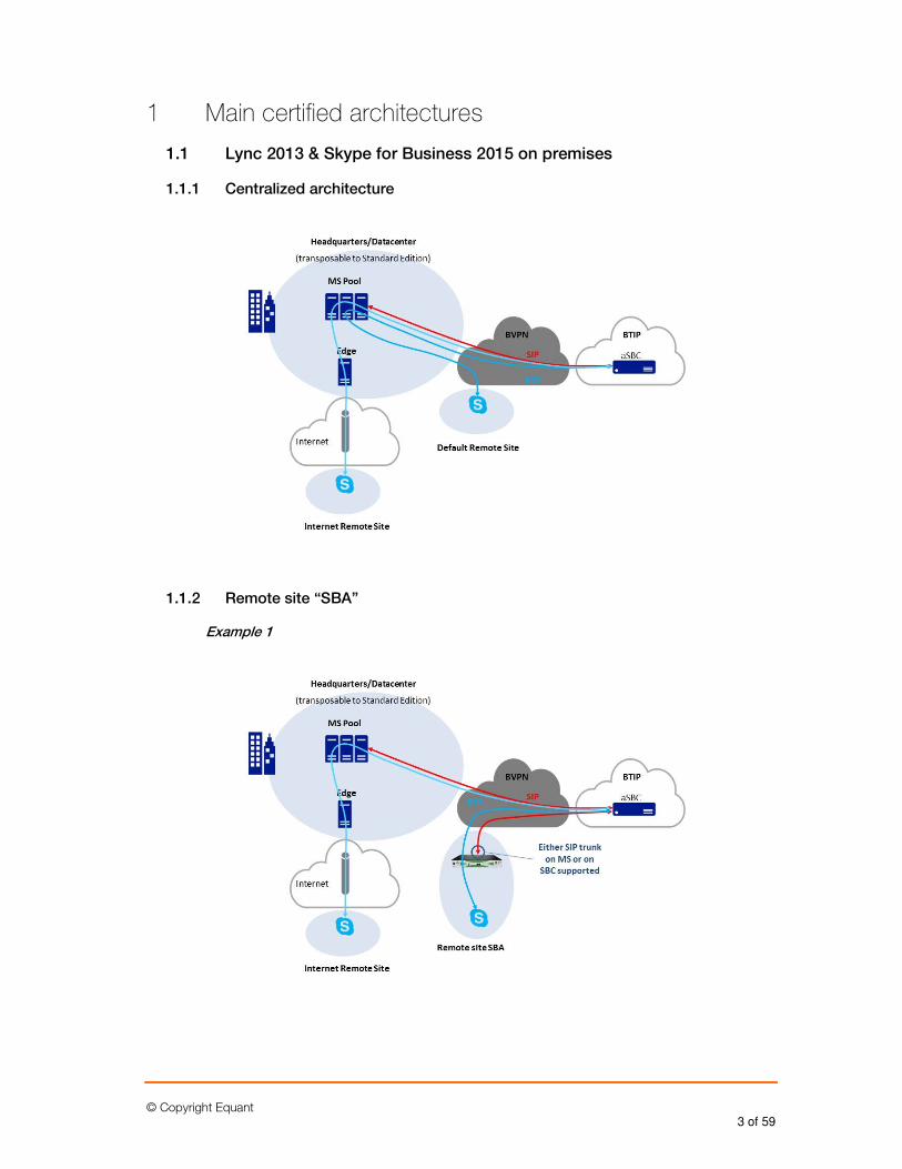
1 Main certified architectures
1.1 Lync 2013 & Skype for Business 2015 on premises
1.1.1 Centralized architecture
1.1.2 Remote site “SBA”
Example 1
© Copyright Equant 4 of 59
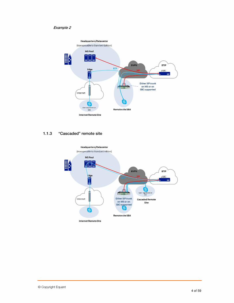
Example 2
1.1.3 “Cascaded” remote site
© Copyright Equant 5 of 59
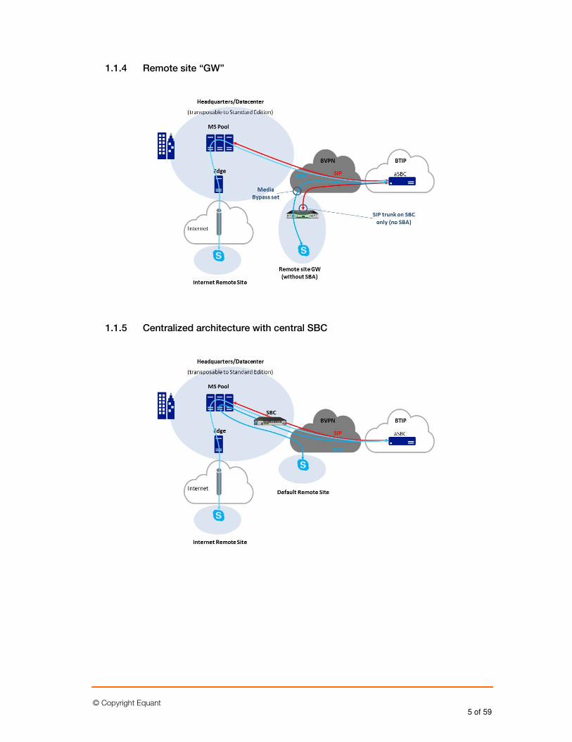
1.1.4 Remote site “GW”
1.1.5 Centralized architecture with central SBC
© Copyright Equant 6 of 59
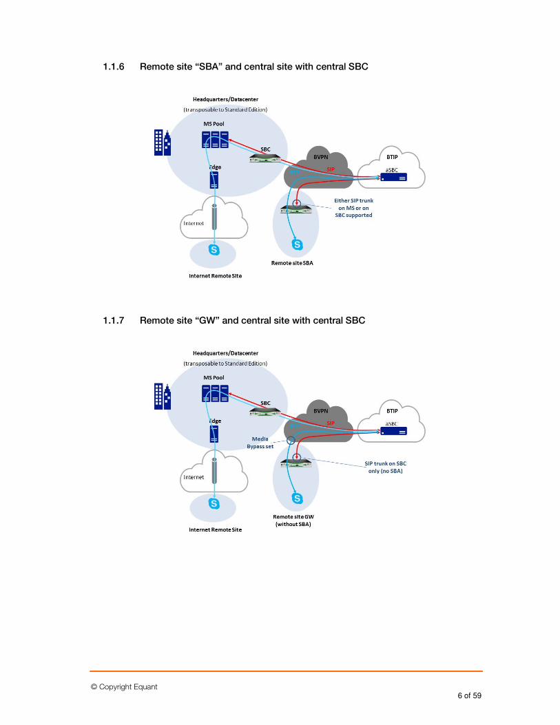
1.1.6 Remote site “SBA” and central site with central SBC
1.1.7 Remote site “GW” and central site with central SBC
© Copyright Equant 7 of 59
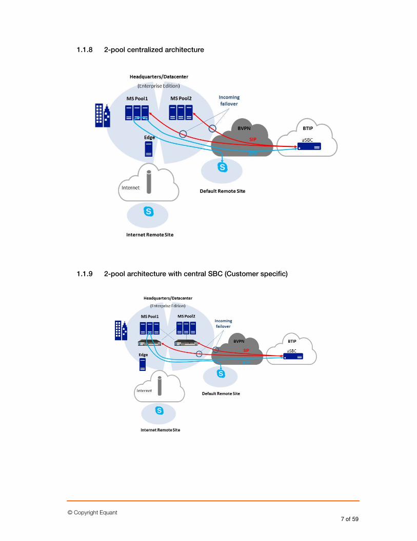
1.1.8 2-pool centralized architecture
1.1.9 2-pool architecture with central SBC (Customer specific)
© Copyright Equant 8 of 59
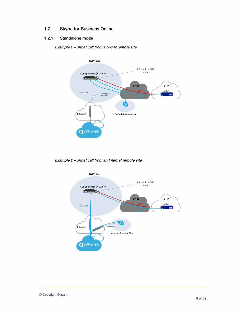
1.2 Skype for Business Online
1.2.1 Standalone mode
Example 1 – offnet call from a BVPN remote site
Example 2 – offnet call from an Internet remote site
© Copyright Equant 9 of 59
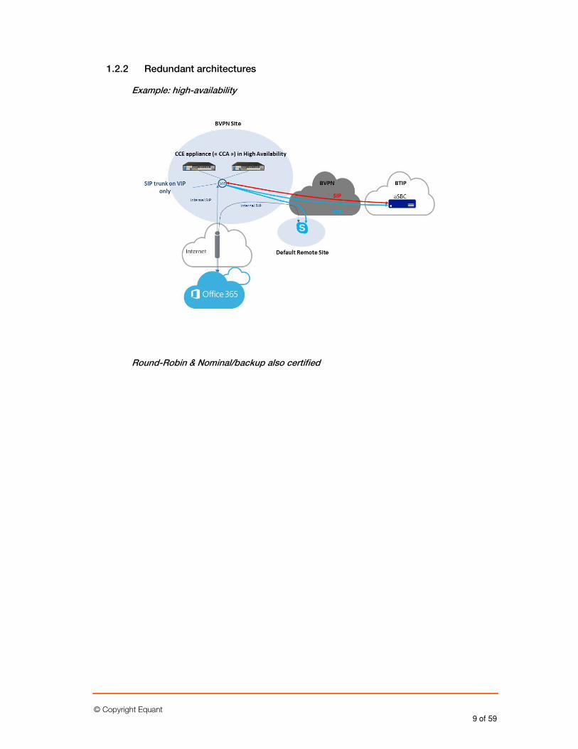
1.2.2 Redundant architectures
Example: high-availability
Round-Robin & Nominal/backup also certified
© Copyright Equant 10 of 59
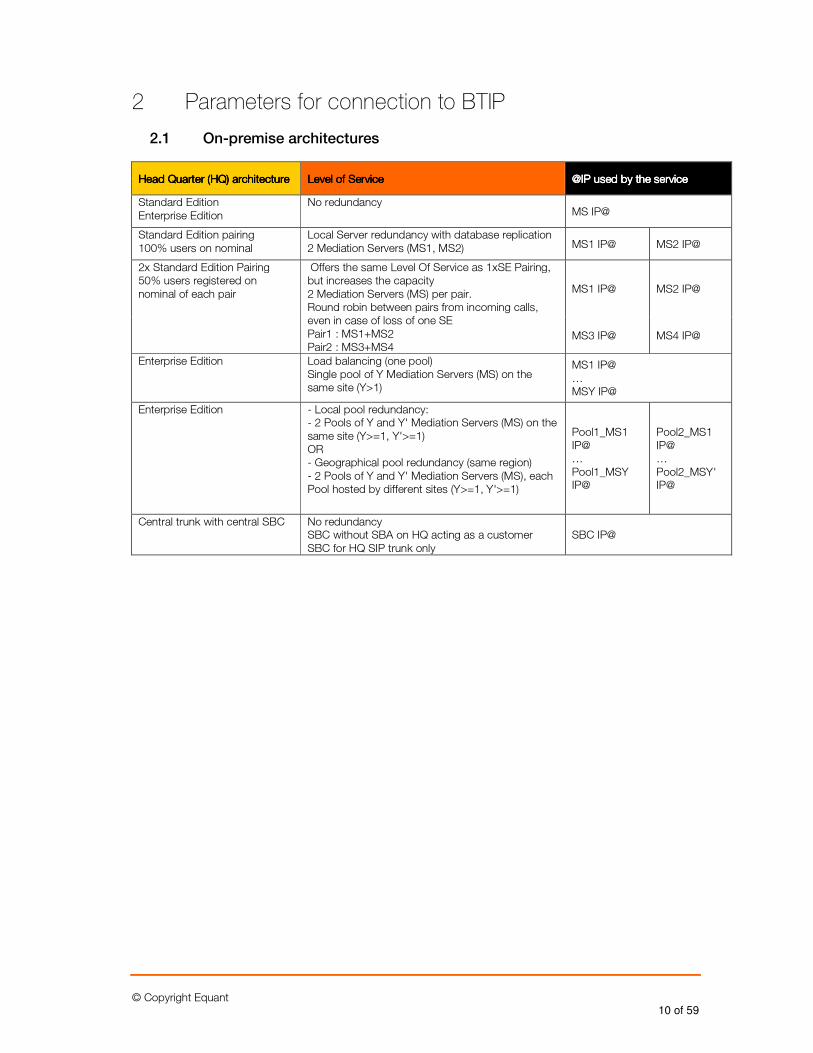
2 Parameters for connection to BTIP
2.1 On-premise architectures
Head Quarter (HQ) architectureHead Quarter (HQ) architectureHead Quarter (HQ) architectureHead Quarter (HQ) architecture Level of ServiceLevel of ServiceLevel of ServiceLevel of Service @IP used by the service@IP used by the service@IP used by the service@IP used by the service
Standard Edition Enterprise Edition
No redundancy MS IP@
Standard Edition pairing 100% users on nominal
Local Server redundancy with database replication 2 Mediation Servers (MS1, MS2) MS1 IP@ MS2 IP@
2x Standard Edition Pairing 50% users registered on nominal of each pair
Offers the same Level Of Service as 1xSE Pairing, but increases the capacity 2 Mediation Servers (MS) per pair. Round robin between pairs from incoming calls, even in case of loss of one SE Pair1 : MS1+MS2 Pair2 : MS3+MS4
MS1 IP@ MS2 IP@
MS3 IP@ MS4 IP@
Enterprise Edition Load balancing (one pool) Single pool of Y Mediation Servers (MS) on the same site (Y>1)
MS1 IP@ … MSY IP@
Enterprise Edition - Local pool redundancy: - 2 Pools of Y and Y' Mediation Servers (MS) on the same site (Y>=1, Y'>=1) OR - Geographical pool redundancy (same region) - 2 Pools of Y and Y' Mediation Servers (MS), each Pool hosted by different sites (Y>=1, Y'>=1)
Pool1_MS1 IP@ … Pool1_MSY IP@
Pool2_MS1 IP@ … Pool2_MSY' IP@
Central trunk with central SBC
No redundancy SBC without SBA on HQ acting as a customer SBC for HQ SIP trunk only
SBC IP@
© Copyright Equant 11 of 59
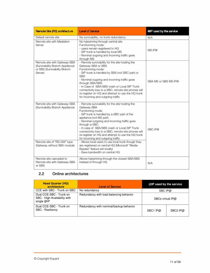
Remote Site (RS) architectureRemote Site (RS) architectureRemote Site (RS) architectureRemote Site (RS) architecture Level of ServiceLevel of ServiceLevel of ServiceLevel of Service @IP used by the service@IP used by the service@IP used by the service@IP used by the service
Default remote site No survivability, no trunk redundancy N/A
Remote site with Mediation Server
No hairpinning through central site Functionning mode: - users remain registered to HQ - SIP trunk is handled by local MS - Nominal ougoing and incoming traffic goes through MS
MS IP@
Remote site with Gateway-SBA (Survivability Branch Appliance) or SBS (Survivability Branch Server)
- Remote survivability for the site hosting the Gateway-SBA or SBS Functionning mode: - SIP trunk is handled by SBA (not SBC part) or SBS - Nominal ougoing and incoming traffic goes through SBA/SBS - In Case of SBA/SBS crash or Local SIP Trunk connectivity loss to a-SBC, remote site phones will re-register on HQ and attempt to use the HQ trunk for incoming and outgoing traffic
SBA MS or SBS MS IP@
Remote site with Gateway-SBA (Survivability Branch Appliance)
- Remote survivability for the site hosting the Gateway-SBA Functioning mode: - SIP trunk is handled by a-SBC part of the appliance (not MS part) - Nominal outgoing and incoming traffic goes through a-SBC - In case of SBA/SBS crash or Local SIP Trunk connectivity loss to a-SBC, remote site phones will re-register on HQ and attempt to use the HQ trunk for incoming and outgoing traffic
SBC IP@
Remote site of "RS-GW" type (Gateway without SBA module)
- Allows local users to use local trunk though they are registered on central HQ (Microsoft "Media-Bypass" feature set locally) - Save bandwidth on central HQ
Remote site cascaded to Remote site with Gateway-SBA or SBS
Allows hairpinning through the closest SBA/SBS instead of through HQ N/A
2.2 Online architectures
Head Quarter (HQ) architecture Level of Service
@IP used by the service
CCE with SBC - Trunk on SBC No redundancy SBC IP@
Dual CCE-SBC - Trunk on SBC - High Availability with single @IP
Redundancy with load balancing behavior
SBCs virtual IP@
Dual CCE-SBC - Trunk on SBC - Resiliency
Redundancy with nominal/backup behavior
SBC1 IP@ SBC2 IP@
© Copyright Equant 12 of 59
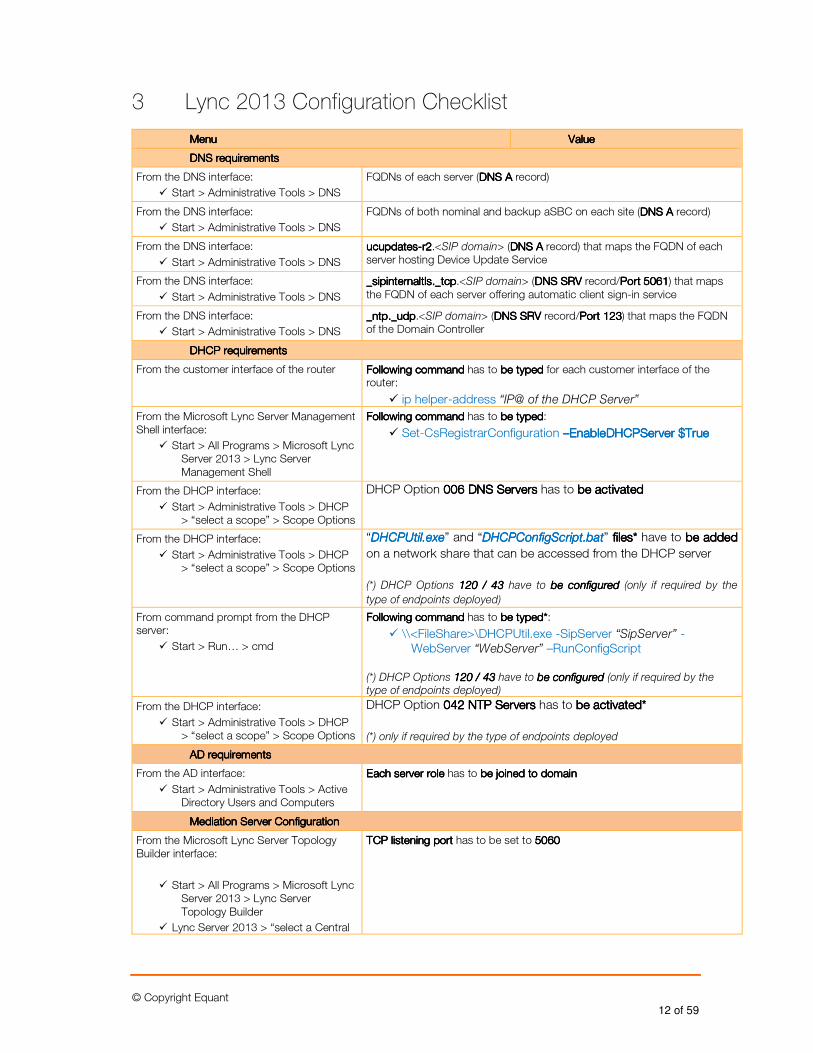
3 Lync 2013 Configuration Checklist
MenuMenuMenuMenu ValueValueValueValue
DNS requirementsDNS requirementsDNS requirementsDNS requirements
From the DNS interface:
� Start > Administrative Tools > DNS
FQDNs of each server (DNS ADNS ADNS ADNS A record)
From the DNS interface:
� Start > Administrative Tools > DNS
FQDNs of both nominal and backup aSBC on each site (DNS ADNS ADNS ADNS A record)
From the DNS interface:
� Start > Administrative Tools > DNS
uuuucupdatescupdatescupdatescupdates----r2r2r2r2.<SIP domain> (DNS ADNS ADNS ADNS A record) that maps the FQDN of each server hosting Device Update Service
From the DNS interface:
� Start > Administrative Tools > DNS
_sipinternaltls._tcp_sipinternaltls._tcp_sipinternaltls._tcp_sipinternaltls._tcp.<SIP domain> (DNS SRVDNS SRVDNS SRVDNS SRV record/Port 5061Port 5061Port 5061Port 5061) that maps the FQDN of each server offering automatic client sign-in service
From the DNS interface:
� Start > Administrative Tools > DNS
_ntp._udp_ntp._udp_ntp._udp_ntp._udp.<SIP domain> (DNS SRVDNS SRVDNS SRVDNS SRV record/Port 123Port 123Port 123Port 123) that maps the FQDN of the Domain Controller
DHCP requirementsDHCP requirementsDHCP requirementsDHCP requirements
From the customer interface of the router Following commandFollowing commandFollowing commandFollowing command has to be typed be typed be typed be typed for each customer interface of the router:
� ip helper-address “IP@ of the DHCP Server”
From the Microsoft Lync Server Management Shell interface:
� Start > All Programs > Microsoft Lync Server 2013 > Lync Server Management Shell
Following commandFollowing commandFollowing commandFollowing command has to be typedbe typedbe typedbe typed:
� Set-CsRegistrarConfiguration ––––EnableDHCPServer EnableDHCPServer EnableDHCPServer EnableDHCPServer $True$True$True$True
From the DHCP interface:
� Start > Administrative Tools > DHCP > “select a scope” > Scope Options
DHCP Option 006 DNS Servers006 DNS Servers006 DNS Servers006 DNS Servers has to be activatedbe activatedbe activatedbe activated
From the DHCP interface:
� Start > Administrative Tools > DHCP > “select a scope” > Scope Options
“DHCPUtiDHCPUtiDHCPUtiDHCPUtil.exel.exel.exel.exe” and “DHCPConfigScript.batDHCPConfigScript.batDHCPConfigScript.batDHCPConfigScript.bat” filesfilesfilesfiles**** have to be addedbe addedbe addedbe added
on a network share that can be accessed from the DHCP server
(*) DHCP Options 120 / 43120 / 43120 / 43120 / 43 have to be configuredbe configuredbe configuredbe configured (only if required by the
type of endpoints deployed)
From command prompt from the DHCP server:
� Start > Run… > cmd
Following commandFollowing commandFollowing commandFollowing command has to be typedbe typedbe typedbe typed****:
� \\<FileShare>\DHCPUtil.exe -SipServer “SipServer” -WebServer “WebServer” –RunConfigScript
(*) DHCP Options 120 / 43120 / 43120 / 43120 / 43 have to be configuredbe configuredbe configuredbe configured (only if required by the type of endpoints deployed)
From the DHCP interface:
� Start > Administrative Tools > DHCP > “select a scope” > Scope Options
DHCP Option 000042424242 NTP NTP NTP NTP ServersServersServersServers has to be activatedbe activatedbe activatedbe activated****
(*) only if required by the type of endpoints deployed
AD requiAD requiAD requiAD requirementsrementsrementsrements
From the AD interface:
� Start > Administrative Tools > Active Directory Users and Computers
Each server roleEach server roleEach server roleEach server role has to be joined to domainbe joined to domainbe joined to domainbe joined to domain
Mediation Server ConfigurationMediation Server ConfigurationMediation Server ConfigurationMediation Server Configuration
From the Microsoft Lync Server Topology Builder interface:
� Start > All Programs > Microsoft Lync Server 2013 > Lync Server Topology Builder
� Lync Server 2013 > “select a Central
TCP listening port TCP listening port TCP listening port TCP listening port has to be set to 5060506050605060
© Copyright Equant 13 of 59
MenuMenuMenuMenu ValueValueValueValue
Site” > Mediation pools > “select a Mediation Server”
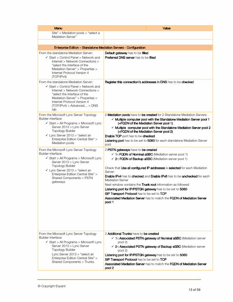
Enterprise Edition Enterprise Edition Enterprise Edition Enterprise Edition –––– Standalone Mediation Servers Standalone Mediation Servers Standalone Mediation Servers Standalone Mediation Servers ---- ConfigConfigConfigConfigurationurationurationuration
From the standalone Mediation Server:
� Start > Control Panel > Network and Internet > Network Connections > “select the interface of the Mediation Server” > Properties > Internet Protocol Version 4 (TCP/IPv4)
Default gateway Default gateway Default gateway Default gateway has to be filledfilledfilledfilled
PreferPreferPreferPreferred DNS server red DNS server red DNS server red DNS server has to be filledfilledfilledfilled
From the standalone Mediation Server:
� Start > Control Panel > Network and Internet > Network Connections > “select the interface of the Mediation Server” > Properties > Internet Protocol Version 4 (TCP/IPv4) > Advanced… > DNS tab
Register this connection’s addresses in DNS Register this connection’s addresses in DNS Register this connection’s addresses in DNS Register this connection’s addresses in DNS has to be checkedcheckedcheckedchecked
From the Microsoft Lync Server Topology Builder interface:
� Start > All Programs > Microsoft Lync Server 2013 > Lync Server Topology Builder
� Lync Server 2013 > “select an Enterprise Edition Central Site” > Mediation pools
2 Mediation poolsMediation poolsMediation poolsMediation pools have to be createdbe createdbe createdbe created for 2 Standalone Mediation Servers:
� MultipleMultipleMultipleMultiple computer pool with the Standalone Mediation Servercomputer pool with the Standalone Mediation Servercomputer pool with the Standalone Mediation Servercomputer pool with the Standalone Mediation Server poolpoolpoolpool 1 1 1 1 (=FQDN of the Mediation Server(=FQDN of the Mediation Server(=FQDN of the Mediation Server(=FQDN of the Mediation Server poolpoolpoolpool 1)1)1)1)
� Multiple Multiple Multiple Multiple computer pool with the Standaloncomputer pool with the Standaloncomputer pool with the Standaloncomputer pool with the Standalone Mediation Servere Mediation Servere Mediation Servere Mediation Server poolpoolpoolpool 2 2 2 2 (=FQDN of the Mediation Server (=FQDN of the Mediation Server (=FQDN of the Mediation Server (=FQDN of the Mediation Server pool pool pool pool 2)2)2)2)
Enable TCP Enable TCP Enable TCP Enable TCP port has to be checkedcheckedcheckedchecked
Listening portListening portListening portListening port has to be set to 5060506050605060 for each standalone Mediation Server pool
From the Microsoft Lync Server Topology Builder interface:
� Start > All Programs > Microsoft Lync Server 2013 > Lync Server Topology Builder
� Lync Server 2013 > “select an Enterprise Edition Central Site” > Shared Components > PSTN gateways
2 PSTN gatewaysPSTN gatewaysPSTN gatewaysPSTN gateways have to be createdbe createdbe createdbe created
� 1111 stststst: FQDN of Nominal aSBC : FQDN of Nominal aSBC : FQDN of Nominal aSBC : FQDN of Nominal aSBC (Mediation server pool 1)
� 2222 ndndndnd: FQDN of Backup aSBC : FQDN of Backup aSBC : FQDN of Backup aSBC : FQDN of Backup aSBC (Mediation server pool 1)
Check that Use all configured IP addresses Use all configured IP addresses Use all configured IP addresses Use all configured IP addresses is selectedselectedselectedselected for each Mediation Server:
Enable IPv4Enable IPv4Enable IPv4Enable IPv4 has to checkedcheckedcheckedchecked and Enable IPv6Enable IPv6Enable IPv6Enable IPv6 has to be uncheckeduncheckeduncheckedunchecked for each Mediation Server
Next window contains the TTTTrunk rootrunk rootrunk rootrunk root information as followed
Listening port for IP/PSTGN gateway Listening port for IP/PSTGN gateway Listening port for IP/PSTGN gateway Listening port for IP/PSTGN gateway has to be set to 5060506050605060
SIP Transport Protocol SIP Transport Protocol SIP Transport Protocol SIP Transport Protocol has to be set to TCPTCPTCPTCP
Associated Mediation Server Associated Mediation Server Associated Mediation Server Associated Mediation Server has to match the FQDN of Mediation Server FQDN of Mediation Server FQDN of Mediation Server FQDN of Mediation Server pool 1pool 1pool 1pool 1
From the Microsoft Lync Server Topology Builder interface:
� Start > All Programs > Microsoft Lync Server 2013 > Lync Server Topology Builder
Lync Server 2013 > “select an Enterprise Edition Central Site” > Shared Components > Trunks
2 Additional Trunks Additional Trunks Additional Trunks Additional Trunks have to be createdbe createdbe createdbe created
� 1111 stststst: Associated PSTN ga: Associated PSTN ga: Associated PSTN ga: Associated PSTN gateway of Nominal aSBC teway of Nominal aSBC teway of Nominal aSBC teway of Nominal aSBC (Mediation server pool 2)
� 2222 ndndndnd: Associated PSTN gateway of Backup aSBC : Associated PSTN gateway of Backup aSBC : Associated PSTN gateway of Backup aSBC : Associated PSTN gateway of Backup aSBC (Mediation server pool 2)
Listening port for IP/PSTGN gateway Listening port for IP/PSTGN gateway Listening port for IP/PSTGN gateway Listening port for IP/PSTGN gateway has to be set to 5060506050605060
SIP Transport Protocol SIP Transport Protocol SIP Transport Protocol SIP Transport Protocol has to be set to TCPTCPTCPTCP
Associated Mediation Server Associated Mediation Server Associated Mediation Server Associated Mediation Server has to match the FQDN of Mediation Server FQDN of Mediation Server FQDN of Mediation Server FQDN of Mediation Server pool 2pool 2pool 2pool 2
© Copyright Equant 14 of 59
MenuMenuMenuMenu ValueValueValueValue
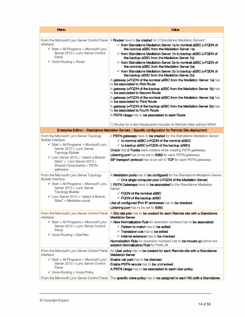
From the Microsoft Lync Server Control Panel interface:
� Start > All Programs > Microsoft Lync Server 2013 > Lync Server Control Panel
� Voice Routing > Route
4 RoutesRoutesRoutesRoutes have to be createdbe createdbe createdbe created for 2 Standalone Mediation Servers*:
� from Standalone Mediation Server 1from Standalone Mediation Server 1from Standalone Mediation Server 1from Standalone Mediation Server 1aaaa to nominal aSBC (=FQDN of to nominal aSBC (=FQDN of to nominal aSBC (=FQDN of to nominal aSBC (=FQDN of the nominal aSBC from the Mediation Server 1the nominal aSBC from the Mediation Server 1the nominal aSBC from the Mediation Server 1the nominal aSBC from the Mediation Server 1aaaa))))
� from Standalone Mediation Server 1from Standalone Mediation Server 1from Standalone Mediation Server 1from Standalone Mediation Server 1bbbb to backup aSBC (=FQDN of to backup aSBC (=FQDN of to backup aSBC (=FQDN of to backup aSBC (=FQDN of the backup aSBC from the Mediation Server 1the backup aSBC from the Mediation Server 1the backup aSBC from the Mediation Server 1the backup aSBC from the Mediation Server 1bbbb))))
� from Standalone Mediation Serverfrom Standalone Mediation Serverfrom Standalone Mediation Serverfrom Standalone Mediation Server 2222aaaa to nominal aSBC (=FQDN of to nominal aSBC (=FQDN of to nominal aSBC (=FQDN of to nominal aSBC (=FQDN of the nominal aSBC from the Mediation Server 2the nominal aSBC from the Mediation Server 2the nominal aSBC from the Mediation Server 2the nominal aSBC from the Mediation Server 2aaaa))))
� from Standalone Mediation Server 2from Standalone Mediation Server 2from Standalone Mediation Server 2from Standalone Mediation Server 2bbbb to backup aSBC (=FQDN of to backup aSBC (=FQDN of to backup aSBC (=FQDN of to backup aSBC (=FQDN of the backup aSBC from the Mediation Server 2the backup aSBC from the Mediation Server 2the backup aSBC from the Mediation Server 2the backup aSBC from the Mediation Server 2bbbb))))
A gateway gateway gateway gateway (=FQDN of the nominal aSBC from the Mediation Server 1(=FQDN of the nominal aSBC from the Mediation Server 1(=FQDN of the nominal aSBC from the Mediation Server 1(=FQDN of the nominal aSBC from the Mediation Server 1aaaa)))) has to be associated to First Routebe associated to First Routebe associated to First Routebe associated to First Route
A gateway gateway gateway gateway (=FQDN of the backup aSBC from the Mediation Server 1(=FQDN of the backup aSBC from the Mediation Server 1(=FQDN of the backup aSBC from the Mediation Server 1(=FQDN of the backup aSBC from the Mediation Server 1bbbb) ) ) ) has to be associated to Second Routebe associated to Second Routebe associated to Second Routebe associated to Second Route
A gateway gateway gateway gateway (=FQDN of the nominal aSBC from the Mediation Server 2(=FQDN of the nominal aSBC from the Mediation Server 2(=FQDN of the nominal aSBC from the Mediation Server 2(=FQDN of the nominal aSBC from the Mediation Server 2aaaa)))) has to be associated to be associated to be associated to be associated to ThirdThirdThirdThird RouteRouteRouteRoute
A gateway gateway gateway gateway (=FQDN of(=FQDN of(=FQDN of(=FQDN of the backup aSBC from the Mediation Server 2the backup aSBC from the Mediation Server 2the backup aSBC from the Mediation Server 2the backup aSBC from the Mediation Server 2bbbb) ) ) ) has to be associated to be associated to be associated to be associated to FourthFourthFourthFourth RouteRouteRouteRoute
A PSTN UsagePSTN UsagePSTN UsagePSTN Usage has to be associated to be associated to be associated to be associated to each Routeeach Routeeach Routeeach Route
(*) Routes for a site Headquarter includes its Remote Sites without MGW
Enterprise Edition Enterprise Edition Enterprise Edition Enterprise Edition –––– Standalone Mediation ServersStandalone Mediation ServersStandalone Mediation ServersStandalone Mediation Servers –––– Specific configuration for Remote Site deploymentSpecific configuration for Remote Site deploymentSpecific configuration for Remote Site deploymentSpecific configuration for Remote Site deployment
From the Microsoft Lync Server Topology Builder interface:
� Start > All Programs > Microsoft Lync Server 2013 > Lync Server Topology Builder
� Lync Server 2013 > “select a Branch Sites” > Lync Server 2013 > Shared Components > PSTN gateways
2 PSTN gatewaysPSTN gatewaysPSTN gatewaysPSTN gateways have to be createdbe createdbe createdbe created for the Standalone Mediation Server:
� to nominal aSBC (=FQDN of the nominal aSBC)to nominal aSBC (=FQDN of the nominal aSBC)to nominal aSBC (=FQDN of the nominal aSBC)to nominal aSBC (=FQDN of the nominal aSBC)
� to backup aSBC (=FQDN of the backup aSBC)to backup aSBC (=FQDN of the backup aSBC)to backup aSBC (=FQDN of the backup aSBC)to backup aSBC (=FQDN of the backup aSBC)
Check Check Check Check that 2 Trunks2 Trunks2 Trunks2 Trunks were created while creating PSTN gateways
Listening portListening portListening portListening port has to be set to 5060506050605060 for each PSTN gateways
SIP transport protocolSIP transport protocolSIP transport protocolSIP transport protocol has to be set to TCPTCPTCPTCP for each PSTN gateways
From the Microsoft Lync Server Topology Builder interface:
� Start > All Programs > Microsoft Lync Server 2013 > Lync Server Topology Builder
� Lync Server 2013 > “select a Branch Sites” > Mediation pools
A Mediation poolsMediation poolsMediation poolsMediation pools has to be configured be configured be configured be configured for the Standalone Mediation Server:
� One single computer pool (=FQDN of the Mediation Server)One single computer pool (=FQDN of the Mediation Server)One single computer pool (=FQDN of the Mediation Server)One single computer pool (=FQDN of the Mediation Server)
2 PSTN GatewaysPSTN GatewaysPSTN GatewaysPSTN Gateways have to be be be be associated associated associated associated to the Standalone Mediation Server:
� FQDN of the nominal aSBC FQDN of the nominal aSBC FQDN of the nominal aSBC FQDN of the nominal aSBC
� FQDN of the backup aSBC FQDN of the backup aSBC FQDN of the backup aSBC FQDN of the backup aSBC
Use all configured IPv4 IP addresses Use all configured IPv4 IP addresses Use all configured IPv4 IP addresses Use all configured IPv4 IP addresses has to be checkedbe checkedbe checkedbe checked:
Listening portListening portListening portListening port has to be set to 5060506050605060
From the Microsoft Lync Server Control Panel interface:
� Start > All Programs > Microsoft Lync Server 2013 > Lync Server Control Panel
� Voice Routing > Dial Plan
A Site dial planSite dial planSite dial planSite dial plan has to be created for each be created for each be created for each be created for each Remote Remote Remote Remote sitesitesitesite with a Standalone with a Standalone with a Standalone with a Standalone Mediation ServerMediation ServerMediation ServerMediation Server
A New Normalization RuleNew Normalization RuleNew Normalization RuleNew Normalization Rule for extension numbers has to be associatedbe associatedbe associatedbe associated:
� Pattern to match Pattern to match Pattern to match Pattern to match has to be editedbe editedbe editedbe edited
� Translation rule Translation rule Translation rule Translation rule has to be editedbe editedbe editedbe edited
� Internal extension Internal extension Internal extension Internal extension has to be checkedbe checkedbe checkedbe checked
Normalization Rule Normalization Rule Normalization Rule Normalization Rule for extension numbers has to be moved up be moved up be moved up be moved up before the existent Normalization Rule existent Normalization Rule existent Normalization Rule existent Normalization Rule for Prefix All
From the Microsoft Lync Server Control Panel interface:
� Start > All Programs > Microsoft Lync Server 2013 > Lync Server Control Panel
� Voice Routing > Voice Policy
An UserUserUserUser policypolicypolicypolicy has to be created for each be created for each be created for each be created for each Remote Remote Remote Remote sitesitesitesite with a Standalone with a Standalone with a Standalone with a Standalone Mediation ServerMediation ServerMediation ServerMediation Server
Enable call parkEnable call parkEnable call parkEnable call park has to be checkedbe checkedbe checkedbe checked
Enable PSTN reroute Enable PSTN reroute Enable PSTN reroute Enable PSTN reroute has to be uncheckedbe uncheckedbe uncheckedbe unchecked
AAAA PSTN UsagePSTN UsagePSTN UsagePSTN Usage has to be associated to be associated to be associated to be associated to each each each each UserUserUserUser policypolicypolicypolicy
From the Microsoft Lync Server Control Panel The specific voice policyspecific voice policyspecific voice policyspecific voice policy has to be assigned be assigned be assigned be assigned to to to to each each each each RS (with a Standalone RS (with a Standalone RS (with a Standalone RS (with a Standalone
© Copyright Equant 15 of 59
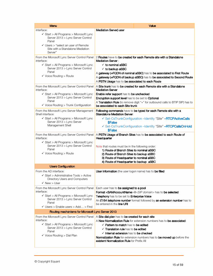
MenuMenuMenuMenu ValueValueValueValue
interface:
� Start > All Programs > Microsoft Lync Server 2013 > Lync Server Control Panel
� Users > “select an user of Remote Site with a Standalone Mediation Server”
Mediation Server)Mediation Server)Mediation Server)Mediation Server) useruseruseruser
From the Microsoft Lync Server Control Panel interface:
� Start > All Programs > Microsoft Lync Server 2013 > Lync Server Control Panel
� Voice Routing > Route
2 RoutesRoutesRoutesRoutes have to be created for each be created for each be created for each be created for each Remote Remote Remote Remote sitesitesitesite with a Standalone with a Standalone with a Standalone with a Standalone Mediation ServerMediation ServerMediation ServerMediation Server :
� to nominal aSBCto nominal aSBCto nominal aSBCto nominal aSBC
� to backup aSBCto backup aSBCto backup aSBCto backup aSBC
A gateway (=FQDN of nominal aSBC)gateway (=FQDN of nominal aSBC)gateway (=FQDN of nominal aSBC)gateway (=FQDN of nominal aSBC) has to be associated to First Routebe associated to First Routebe associated to First Routebe associated to First Route
A gateway (=FQDN of backup aSBC) gateway (=FQDN of backup aSBC) gateway (=FQDN of backup aSBC) gateway (=FQDN of backup aSBC) has to be assbe assbe assbe associated to Second Routeociated to Second Routeociated to Second Routeociated to Second Route
A PSTN UsagePSTN UsagePSTN UsagePSTN Usage has to be associated to be associated to be associated to be associated to each Routeeach Routeeach Routeeach Route
From the Microsoft Lync Server Control Panel interface:
� Start > All Programs > Microsoft Lync Server 2013 > Lync Server Control Panel
� Voice Routing > Trunk Configuration
A Site trunkSite trunkSite trunkSite trunk has to be created for each be created for each be created for each be created for each Remote Remote Remote Remote sitesitesitesite with a Standalone with a Standalone with a Standalone with a Standalone Mediation ServerMediation ServerMediation ServerMediation Server
Enable refer supportEnable refer supportEnable refer supportEnable refer support has to be uncheckedbe uncheckedbe uncheckedbe unchecked
Encryption support level Encryption support level Encryption support level Encryption support level has to be set to OptionalOptionalOptionalOptional
A Translation RuleTranslation RuleTranslation RuleTranslation Rule (to remove digit “+” for outbound calls to BTIP SIP) has to be associatbe associatbe associatbe associated ed ed ed to each Site trunkto each Site trunkto each Site trunkto each Site trunk
From the Microsoft Lync Server Management Shell interface:
� Start > All Programs > Microsoft Lync Server 2013 > Lync Server Management Shell
Following commandsFollowing commandsFollowing commandsFollowing commands have to be typed for each be typed for each be typed for each be typed for each Remote Remote Remote Remote sitesitesitesite with a with a with a with a Standalone Mediation ServerStandalone Mediation ServerStandalone Mediation ServerStandalone Mediation Server:
� Set-CsTrunkConfiguration –Identity “Site” ––––RTCPActiveCalls RTCPActiveCalls RTCPActiveCalls RTCPActiveCalls $False$False$False$False
� Set-CsTrunkConfiguration –Identity “Site” ––––RTCPCallsOnHold RTCPCallsOnHold RTCPCallsOnHold RTCPCallsOnHold $False$False$False$False
From the Microsoft Lync Server Control Panel interface:
� Start > All Programs > Microsoft Lync Server 2013 > Lync Server Control Panel
� Voice Routing > Route
A PSTN Usage of Branch SitesPSTN Usage of Branch SitesPSTN Usage of Branch SitesPSTN Usage of Branch Sites has to be associated to be associated to be associated to be associated to each Route of each Route of each Route of each Route of HeadquarterHeadquarterHeadquarterHeadquarter
Note that routes must be in the following order:
1)1)1)1) Route of Branch Sites to nominal aSBCRoute of Branch Sites to nominal aSBCRoute of Branch Sites to nominal aSBCRoute of Branch Sites to nominal aSBC
2)2)2)2) Route of Branch Sites to backup Route of Branch Sites to backup Route of Branch Sites to backup Route of Branch Sites to backup aSBCaSBCaSBCaSBC
3)3)3)3) Route of HeadquartRoute of HeadquartRoute of HeadquartRoute of Headquarter to nominal aSBCer to nominal aSBCer to nominal aSBCer to nominal aSBC
4)4)4)4) Route of Headquarter to backup Route of Headquarter to backup Route of Headquarter to backup Route of Headquarter to backup aSBCaSBCaSBCaSBC
Users ConfigurationUsers ConfigurationUsers ConfigurationUsers Configuration
From the AD interface:
� Start > Administrative Tools > Active Directory Users and Computers
� New > User
User informationUser informationUser informationUser information (the user logon name) has to be filledbe filledbe filledbe filled
From the Microsoft Lync Server Control Panel interface:
� Start > All Programs > Microsoft Lync Server 2013 > Lync Server Control Panel
� Users > Enable users > Add… > Find
Each user has to be assigned to a poolbe assigned to a poolbe assigned to a poolbe assigned to a pool
FormatFormatFormatFormat <SAMAccountName<SAMAccountName<SAMAccountName<SAMAccountName>@<SIP domain> has to be selectedbe selectedbe selectedbe selected
TelephonyTelephonyTelephonyTelephony has to be set to Enterprise VoiceEnterprise VoiceEnterprise VoiceEnterprise Voice
An E164 telephone numberE164 telephone numberE164 telephone numberE164 telephone number format followed by an extension numberan extension numberan extension numberan extension number has to be entered in the line URIline URIline URIline URI
Routing mechanisms for Microsoft Lync Server 2013Routing mechanisms for Microsoft Lync Server 2013Routing mechanisms for Microsoft Lync Server 2013Routing mechanisms for Microsoft Lync Server 2013
From the Microsoft Lync Server Control Panel interface:
� Start > All Programs > Microsoft Lync Server 2013 > Lync Server Control Panel
� Voice Routing > Dial Plan
A Site dial planSite dial planSite dial planSite dial plan has to be created for each sitebe created for each sitebe created for each sitebe created for each site
A New Normalization RuleNew Normalization RuleNew Normalization RuleNew Normalization Rule for extension numbers has to be associatedbe associatedbe associatedbe associated:
� Pattern to match Pattern to match Pattern to match Pattern to match has to be editedbe editedbe editedbe edited
� Translation ruleTranslation ruleTranslation ruleTranslation rule has to be editedbe editedbe editedbe edited
� Internal extension Internal extension Internal extension Internal extension has to be checkedbe checkedbe checkedbe checked
Normalization Rule Normalization Rule Normalization Rule Normalization Rule for extension numbers has to be moved up be moved up be moved up be moved up before the existent Normalization Rule existent Normalization Rule existent Normalization Rule existent Normalization Rule for Prefix All
© Copyright Equant 16 of 59
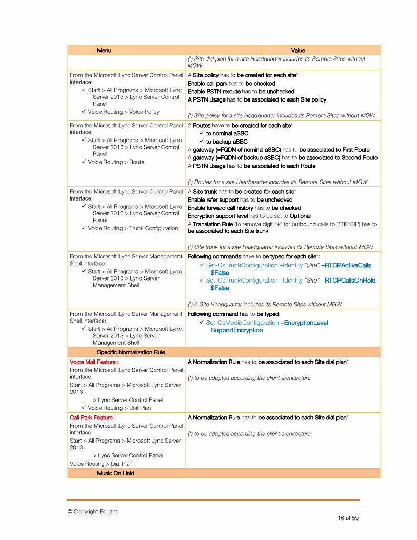
MenuMenuMenuMenu ValueValueValueValue
(*) Site dial plan for a site Headquarter includes its Remote Sites without MGW
From the Microsoft Lync Server Control Panel interface:
� Start > All Programs > Microsoft Lync Server 2013 > Lync Server Control Panel
� Voice Routing > Voice Policy
A Site policySite policySite policySite policy has to be created for each sitebe created for each sitebe created for each sitebe created for each site*
Enable call parkEnable call parkEnable call parkEnable call park has to be checkedbe checkedbe checkedbe checked
Enable PSTN reroEnable PSTN reroEnable PSTN reroEnable PSTN reroute ute ute ute has to be uncheckedbe uncheckedbe uncheckedbe unchecked
AAAA PSTN UsagePSTN UsagePSTN UsagePSTN Usage has to be associated to be associated to be associated to be associated to each Site policyeach Site policyeach Site policyeach Site policy
(*) Site policy for a site Headquarter includes its Remote Sites without MGW
From the Microsoft Lync Server Control Panel interface:
� Start > All Programs > Microsoft Lync Server 2013 > Lync Server Control Panel
� Voice Routing > Route
2 RoutesRoutesRoutesRoutes have to be created for each sitebe created for each sitebe created for each sitebe created for each site* :
� to nominal aSBCto nominal aSBCto nominal aSBCto nominal aSBC
� to backup aSBCto backup aSBCto backup aSBCto backup aSBC
A gateway (=FQDN of nominal aSBC)gateway (=FQDN of nominal aSBC)gateway (=FQDN of nominal aSBC)gateway (=FQDN of nominal aSBC) has to be associated to First Routebe associated to First Routebe associated to First Routebe associated to First Route
A gateway (=FQDN of backup aSBC) gateway (=FQDN of backup aSBC) gateway (=FQDN of backup aSBC) gateway (=FQDN of backup aSBC) has to be associatebe associatebe associatebe associated to Second Routed to Second Routed to Second Routed to Second Route
A PSTN UsagePSTN UsagePSTN UsagePSTN Usage has to be associated to be associated to be associated to be associated to each Routeeach Routeeach Routeeach Route
(*) Routes for a site Headquarter includes its Remote Sites without MGW
From the Microsoft Lync Server Control Panel interface:
� Start > All Programs > Microsoft Lync Server 2013 > Lync Server Control Panel
� Voice Routing > Trunk Configuration
A Site trunkSite trunkSite trunkSite trunk has to be created for each sitebe created for each sitebe created for each sitebe created for each site*
Enable refer supportEnable refer supportEnable refer supportEnable refer support has to be uncheckedbe uncheckedbe uncheckedbe unchecked
Enable forward call history Enable forward call history Enable forward call history Enable forward call history has to be checkedbe checkedbe checkedbe checked
Encryption support level Encryption support level Encryption support level Encryption support level has to be set to OptionalOptionalOptionalOptional
A Translation RulTranslation RulTranslation RulTranslation Ruleeee (to remove digit “+” for outbound calls to BTIP SIP) has to be associated be associated be associated be associated to each Site trunkto each Site trunkto each Site trunkto each Site trunk
(*) Site trunk for a site Headquarter includes its Remote Sites without MGW
From the Microsoft Lync Server Management Shell interface:
� Start > All Programs > Microsoft Lync Server 2013 > Lync Server Management Shell
Following commandsFollowing commandsFollowing commandsFollowing commands have to be typed for each sitebe typed for each sitebe typed for each sitebe typed for each site*:
� Set-CsTrunkConfiguration –Identity “Site” ––––RTCPActiveCalls RTCPActiveCalls RTCPActiveCalls RTCPActiveCalls $False$False$False$False
� Set-CsTrunkConfiguration –Identity “Site” ––––RTCPCallsOnHold RTCPCallsOnHold RTCPCallsOnHold RTCPCallsOnHold $False$False$False$False
(*) A Site Headquarter includes its Remote Sites without MGW
From the Microsoft Lync Server Management Shell interface:
� Start > All Programs > Microsoft Lync Server 2013 > Lync Server Management Shell
Following commandFollowing commandFollowing commandFollowing command has to be typedbe typedbe typedbe typed:
� Set-CsMediaConfiguration ––––EncrypEncrypEncrypEncryptionLeveltionLeveltionLeveltionLevel SupportEncryptionSupportEncryptionSupportEncryptionSupportEncryption
Specific Normalization Rule Specific Normalization Rule Specific Normalization Rule Specific Normalization Rule
Voice Mail Feature :Voice Mail Feature :Voice Mail Feature :Voice Mail Feature :
From the Microsoft Lync Server Control Panel interface:
Start > All Programs > Microsoft Lync Server 2013
> Lync Server Control Panel
� Voice Routing > Dial Plan
AAAA Normalization Normalization Normalization Normalization RuleRuleRuleRule has to be associated be associated be associated be associated to each Site dial planto each Site dial planto each Site dial planto each Site dial plan*
(*) to be adapted according the client architecture
Call Park Feature :Call Park Feature :Call Park Feature :Call Park Feature :
From the Microsoft Lync Server Control Panel interface:
Start > All Programs > Microsoft Lync Server 2013
> Lync Server Control Panel
Voice Routing > Dial Plan
AAAA Normalization RuleNormalization RuleNormalization RuleNormalization Rule has to be associated be associated be associated be associated to each Site dial planto each Site dial planto each Site dial planto each Site dial plan*
(*) to be adapted according the client architecture
Music On HoldMusic On HoldMusic On HoldMusic On Hold
© Copyright Equant 17 of 59
MenuMenuMenuMenu ValueValueValueValue
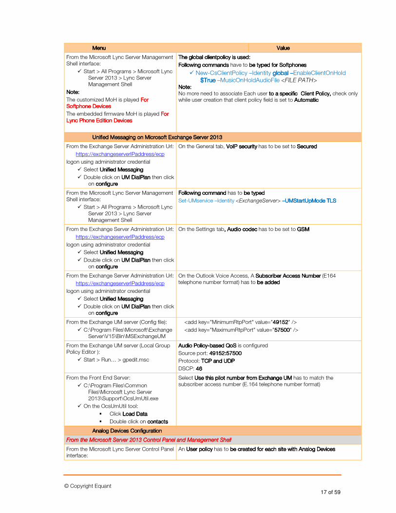
From the Microsoft Lync Server Management Shell interface:
� Start > All Programs > Microsoft Lync Server 2013 > Lync Server Management Shell
Note:Note:Note:Note:
The customized MoH is played For For For For Softphone DevicesSoftphone DevicesSoftphone DevicesSoftphone Devices
The embedded firmware MoH is played For For For For Lync Phone Edition Devices Lync Phone Edition Devices Lync Phone Edition Devices Lync Phone Edition Devices
The global clientpolicy is used:The global clientpolicy is used:The global clientpolicy is used:The global clientpolicy is used:
Following commandsFollowing commandsFollowing commandsFollowing commands have to be typed for be typed for be typed for be typed for SoftphoSoftphoSoftphoSoftphonesnesnesnes
� New-CsClientPolicy –Identity global global global global ––––EnableClientOnHold $True$True$True$True –MusicOnHoldAudioFile <FILE PATH>
Note:Note:Note:Note: No more need to associate Each user to to to to a specific a specific a specific a specific ClienClienClienClientttt PolicyPolicyPolicyPolicy, , , , check only while user creation that client policy field is set to Automatic Automatic Automatic Automatic
UnifieUnifieUnifieUnified Messaging on Microsoft Exchange Server 2013d Messaging on Microsoft Exchange Server 2013d Messaging on Microsoft Exchange Server 2013d Messaging on Microsoft Exchange Server 2013
From the Exchange Server Administration Url:
https://exchangeserverIPaddress/ecp
logon using administrator credential
� Select Unified MessagingUnified MessagingUnified MessagingUnified Messaging
� Double click on UM DialPlanUM DialPlanUM DialPlanUM DialPlan then click on configure configure configure configure
On the General tab, VoIP securityVoIP securityVoIP securityVoIP security has to be set to Secured Secured Secured Secured
From the Microsoft Lync Server Management Shell interface:
� Start > All Programs > Microsoft Lync Server 2013 > Lync Server Management Shell
Following commFollowing commFollowing commFollowing commandandandand has to be typed be typed be typed be typed
Set-UMservice –Identity <ExchangeServer> ––––UMStartUpMode TLSUMStartUpMode TLSUMStartUpMode TLSUMStartUpMode TLS
From the Exchange Server Administration Url:
https://exchangeserverIPaddress/ecp
logon using administrator credential
� Select Unified MessagingUnified MessagingUnified MessagingUnified Messaging
� Double click on UM DialPlanUM DialPlanUM DialPlanUM DialPlan then click on configureconfigureconfigureconfigure
On the Settings tab, Audio codec, Audio codec, Audio codec, Audio codec has to be set to GSMGSMGSMGSM
From the Exchange Server Administration Url:
https://exchangeserverIPaddress/ecp
logon using administrator credential
� Select Unified MessagingUnified MessagingUnified MessagingUnified Messaging
� Double click on UM DialPlanUM DialPlanUM DialPlanUM DialPlan then click on configureconfigureconfigureconfigure
On the Outlook Voice Access, A Subscriber Access NumberSubscriber Access NumberSubscriber Access NumberSubscriber Access Number (E164 telephone number format) has to be addedbe addedbe addedbe added
From the Exchange UM server (Config file):
� C:\Program Files\Microsoft\Exchange Server\V15\Bin\MSExchangeUM
<add key="MinimumRtpPort" value="49152491524915249152" />
<add key="MaximumRtpPort" value="57500575005750057500" />
From the Exchange UM server (Local Group Policy Editor ):
� Start > Run… > gpedit.msc
Audio PolicyAudio PolicyAudio PolicyAudio Policy----based QoSbased QoSbased QoSbased QoS is configured
Source port: 49152:5750049152:5750049152:5750049152:57500
Protocol: TCP and UDPTCP and UDPTCP and UDPTCP and UDP
DSCP: 46464646
From the Front End Server:
� C:\Program Files\Common Files\Microosft Lync Server 2013\Support\OcsUmUtil.exe
� On the OcsUmUtil tool:
� Click Load DataLoad DataLoad DataLoad Data
� Double click on contactscontactscontactscontacts
Select Use this pilot number from Exchange UMUse this pilot number from Exchange UMUse this pilot number from Exchange UMUse this pilot number from Exchange UM has to match the subscriber access number (E.164 telephone number format)
Analog Devices ConfigurationAnalog Devices ConfigurationAnalog Devices ConfigurationAnalog Devices Configuration
From the Microsoft Server 2013 Control Panel and Management ShellFrom the Microsoft Server 2013 Control Panel and Management ShellFrom the Microsoft Server 2013 Control Panel and Management ShellFrom the Microsoft Server 2013 Control Panel and Management Shell
From the Microsoft Lync Server Control Panel interface:
An UserUserUserUser policypolicypolicypolicy has to be created for each site with be created for each site with be created for each site with be created for each site with Analog DevicesAnalog DevicesAnalog DevicesAnalog Devices
© Copyright Equant 18 of 59
MenuMenuMenuMenu ValueValueValueValue
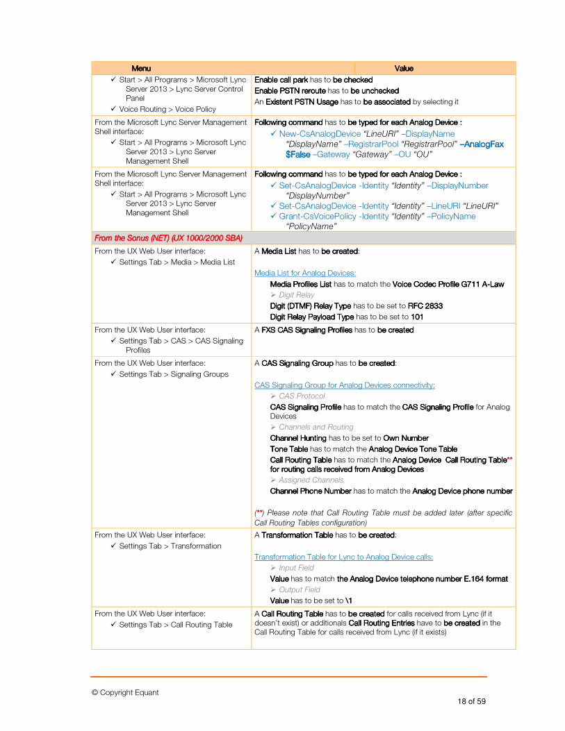
� Start > All Programs > Microsoft Lync Server 2013 > Lync Server Control Panel
� Voice Routing > Voice Policy
Enable call parkEnable call parkEnable call parkEnable call park has to be checkedbe checkedbe checkedbe checked
Enable PSTN reroutEnable PSTN reroutEnable PSTN reroutEnable PSTN reroute e e e has to be uncheckedbe uncheckedbe uncheckedbe unchecked
An EEEExistentxistentxistentxistent PSTN UsagePSTN UsagePSTN UsagePSTN Usage has to be associated be associated be associated be associated by selecting it
From the Microsoft Lync Server Management Shell interface:
� Start > All Programs > Microsoft Lync Server 2013 > Lync Server Management Shell
Following commandFollowing commandFollowing commandFollowing command has to be typedbe typedbe typedbe typed for each Afor each Afor each Afor each Analog Devicenalog Devicenalog Devicenalog Device ::::
� New-CsAnalogDevice “LineURI” –DisplayName “DisplayName” –RegistrarPool “RegistrarPool” ––––AnalogFax AnalogFax AnalogFax AnalogFax $False$False$False$False –Gateway “Gateway” –OU “OU”
From the Microsoft Lync Server Management Shell interface:
� Start > All Programs > Microsoft Lync Server 2013 > Lync Server Management Shell
Following commandFollowing commandFollowing commandFollowing command has to be typed for each Abe typed for each Abe typed for each Abe typed for each Analog Devicenalog Devicenalog Devicenalog Device ::::
� Set-CsAnalogDevice -Identity “Identity” –DisplayNumber “DisplayNumber”
� Set-CsAnalogDevice -Identity “Identity” –LineURI “LineURI” � Grant-CsVoicePolicy -Identity “Identity” –PolicyName
“PolicyName”
From the Sonus (NET) (UX 1000/2000 SBA)From the Sonus (NET) (UX 1000/2000 SBA)From the Sonus (NET) (UX 1000/2000 SBA)From the Sonus (NET) (UX 1000/2000 SBA)
From the UX Web User interface:
� Settings Tab > Media > Media List
A Media ListMedia ListMedia ListMedia List has to be createdbe createdbe createdbe created:
Media List for Analog Devices:
Media Profiles ListMedia Profiles ListMedia Profiles ListMedia Profiles List has to match the VVVVoice Codec Profile G711 Aoice Codec Profile G711 Aoice Codec Profile G711 Aoice Codec Profile G711 A----LawLawLawLaw
� Digit Relay
Digit (DTMF) Relay Type Digit (DTMF) Relay Type Digit (DTMF) Relay Type Digit (DTMF) Relay Type has to be set to RFC 2833RFC 2833RFC 2833RFC 2833
Digit Relay Payload Type Digit Relay Payload Type Digit Relay Payload Type Digit Relay Payload Type has to be set to 101101101101
From the UX Web User interface:
� Settings Tab > CAS > CAS Signaling Profiles
A FXS CAS Signaling ProfilesFXS CAS Signaling ProfilesFXS CAS Signaling ProfilesFXS CAS Signaling Profiles has to be cbe cbe cbe createdreatedreatedreated
From the UX Web User interface:
� Settings Tab > Signaling Groups
A CASCASCASCAS Signaling GroupSignaling GroupSignaling GroupSignaling Group has to be createdbe createdbe createdbe created:
CAS Signaling Group for Analog Devices connectivity:
� CAS Protocol
CCCCAS Signaling ProfileAS Signaling ProfileAS Signaling ProfileAS Signaling Profile has to match the CCCCAS Signaling Profile AS Signaling Profile AS Signaling Profile AS Signaling Profile for Analog Devices
� Channels and Routing
Channel Hunting Channel Hunting Channel Hunting Channel Hunting has to be set to Own NumberOwn NumberOwn NumberOwn Number
Tone TableTone TableTone TableTone Table has to match the Analog DeviceAnalog DeviceAnalog DeviceAnalog Device Tone TableTone TableTone TableTone Table
Call Routing TableCall Routing TableCall Routing TableCall Routing Table has to match the Analog Device Analog Device Analog Device Analog Device Call Routing TableCall Routing TableCall Routing TableCall Routing Table******** for routing calls rfor routing calls rfor routing calls rfor routing calls received from Analog Deviceseceived from Analog Deviceseceived from Analog Deviceseceived from Analog Devices
� Assigned Channels
Channel Phone Number Channel Phone Number Channel Phone Number Channel Phone Number has to match the Analog Device phone numberAnalog Device phone numberAnalog Device phone numberAnalog Device phone number
(********) Please note that Call Routing Table must be added later (after specific
Call Routing Tables configuration)
From the UX Web User interface:
� Settings Tab > Transformation
A TransTransTransTransformaformaformaformationtiontiontion TableTableTableTable has to be createdbe createdbe createdbe created:
Transformation Table for Lync to Analog Device calls:
� Input Field
ValueValueValueValue has to match the Analog Device the Analog Device the Analog Device the Analog Device telephone number telephone number telephone number telephone number E.164 format E.164 format E.164 format E.164 format
� Output Field
ValueValueValueValue has to be set to \\\\1111
From the UX Web User interface:
� Settings Tab > Call Routing Table
A Call Routing TableCall Routing TableCall Routing TableCall Routing Table has to be createdbe createdbe createdbe created for calls received from Lync (if it doesn’t exist) or additionals Call Routing EntrCall Routing EntrCall Routing EntrCall Routing Entriesiesiesies have to be createdbe createdbe createdbe created in the Call Routing Table for calls received from Lync (if it exists)
© Copyright Equant 19 of 59
MenuMenuMenuMenu ValueValueValueValue
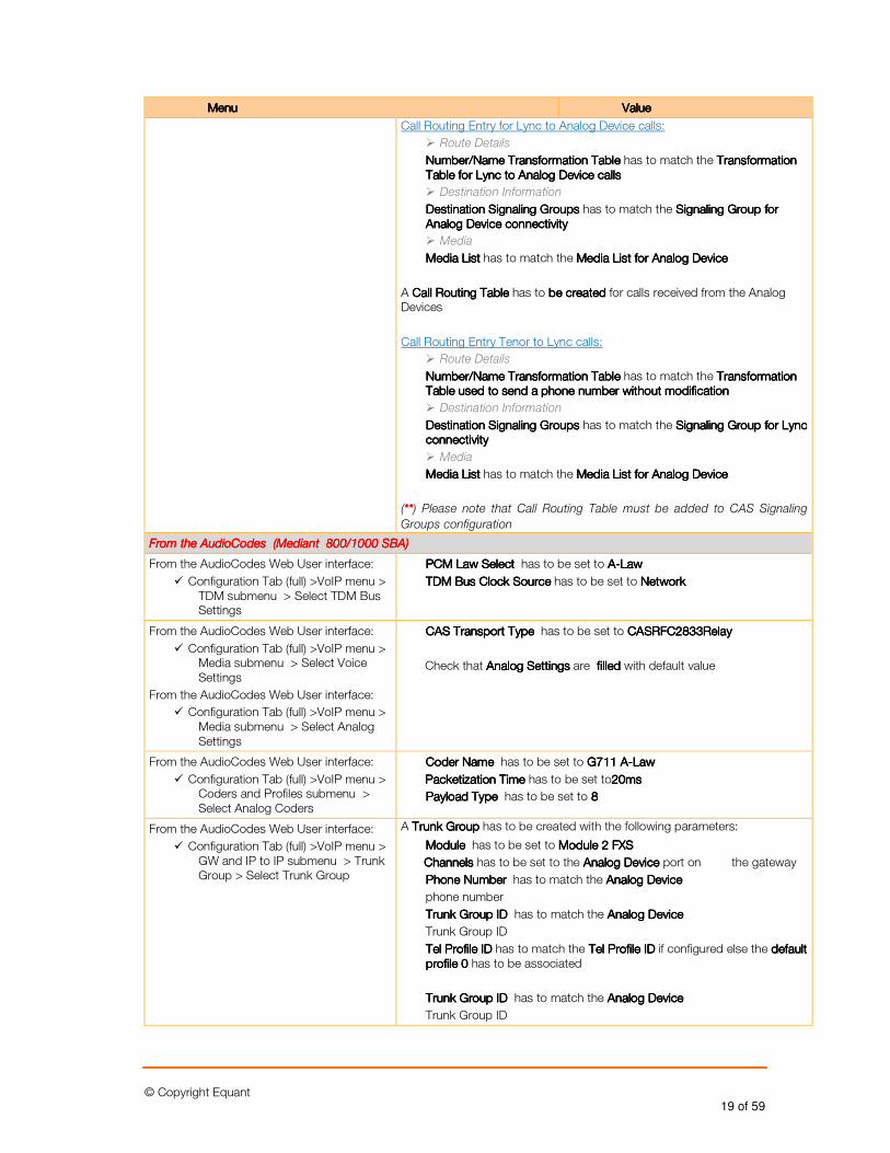
Call Routing Entry for Lync to Analog Device calls:
� Route Details
Number/Name TransNumber/Name TransNumber/Name TransNumber/Name Transformationformationformationformation TableTableTableTable has to match the TranTranTranTransformationsformationsformationsformation Table Table Table Table for Lync to Analog Device callsfor Lync to Analog Device callsfor Lync to Analog Device callsfor Lync to Analog Device calls
� Destination Information
DesDesDesDestinationtinationtinationtination Signaling GroupSignaling GroupSignaling GroupSignaling Groupssss has to match the Signaling Group for Signaling Group for Signaling Group for Signaling Group for Analog Device Analog Device Analog Device Analog Device connectconnectconnectconnectivityivityivityivity
� Media
Media ListMedia ListMedia ListMedia List has to match the Media List for Media List for Media List for Media List for Analog DeviceAnalog DeviceAnalog DeviceAnalog Device
A Call Routing Call Routing Call Routing Call Routing TableTableTableTable has to be createdbe createdbe createdbe created for calls received from the Analog Devices
Call Routing Entry Tenor to Lync calls:
� Route Details
Number/Name TransNumber/Name TransNumber/Name TransNumber/Name Transformationformationformationformation TableTableTableTable has to match the TranTranTranTransformationsformationsformationsformation Table used to send a phone number without modificationTable used to send a phone number without modificationTable used to send a phone number without modificationTable used to send a phone number without modification
� Destination Information
DesDesDesDestinationtinationtinationtination Signaling GroupSignaling GroupSignaling GroupSignaling Groupssss has to match the Signaling Group for Signaling Group for Signaling Group for Signaling Group for Lync Lync Lync Lync connectivityconnectivityconnectivityconnectivity
� Media
Media ListMedia ListMedia ListMedia List has to match the Media List forMedia List forMedia List forMedia List for Analog DeviceAnalog DeviceAnalog DeviceAnalog Device
(********) Please note that Call Routing Table must be added to CAS Signaling
Groups configuration
From the AudioCodes (Mediant 800/1000 SBA)From the AudioCodes (Mediant 800/1000 SBA)From the AudioCodes (Mediant 800/1000 SBA)From the AudioCodes (Mediant 800/1000 SBA)
From the AudioCodes Web User interface:
� Configuration Tab (full) >VoIP menu > TDM submenu > Select TDM Bus Settings
PCM Law SePCM Law SePCM Law SePCM Law Select lect lect lect has to be set to AAAA----LawLawLawLaw
TDM Bus Clock SourceTDM Bus Clock SourceTDM Bus Clock SourceTDM Bus Clock Source has to be set to NetworkNetworkNetworkNetwork
From the AudioCodes Web User interface:
� Configuration Tab (full) >VoIP menu > Media submenu > Select Voice Settings
From the AudioCodes Web User interface:
� Configuration Tab (full) >VoIP menu > Media submenu > Select Analog Settings
CAS Transport Type CAS Transport Type CAS Transport Type CAS Transport Type has to be set to CASRFC2833RelayCASRFC2833RelayCASRFC2833RelayCASRFC2833Relay
Check that Analog SettingsAnalog SettingsAnalog SettingsAnalog Settings are filled filled filled filled with default value
From the AudioCodes Web User interface:
� Configuration Tab (full) >VoIP menu > Coders and Profiles submenu > Select Analog Coders
Coder Name Coder Name Coder Name Coder Name has to be set to G711 AG711 AG711 AG711 A----LawLawLawLaw
Packetization TimePacketization TimePacketization TimePacketization Time has to be set to20ms20ms20ms20ms
Payload Type Payload Type Payload Type Payload Type has to be set to 8888
From the AudioCodes Web User interface:
� Configuration Tab (full) >VoIP menu > GW and IP to IP submenu > Trunk Group > Select Trunk Group
A Trunk GroupTrunk GroupTrunk GroupTrunk Group has to be created with the following parameters:
Module Module Module Module has to be set to Module 2 FXSModule 2 FXSModule 2 FXSModule 2 FXS
ChannelsChannelsChannelsChannels has to be set to the Analog Device Analog Device Analog Device Analog Device port on the gateway
Phone Number Phone Number Phone Number Phone Number has to match the Analog DeviceAnalog DeviceAnalog DeviceAnalog Device
phone number
Trunk Group ID Trunk Group ID Trunk Group ID Trunk Group ID has to match the Analog DeviceAnalog DeviceAnalog DeviceAnalog Device
Trunk Group ID
TeTeTeTel Profile IDl Profile IDl Profile IDl Profile ID has to match the Tel Profile IDTel Profile IDTel Profile IDTel Profile ID if configured else the default default default default profile 0profile 0profile 0profile 0 has to be associated
Trunk Group ID Trunk Group ID Trunk Group ID Trunk Group ID has to match the Analog DeviceAnalog DeviceAnalog DeviceAnalog Device
Trunk Group ID
© Copyright Equant 20 of 59
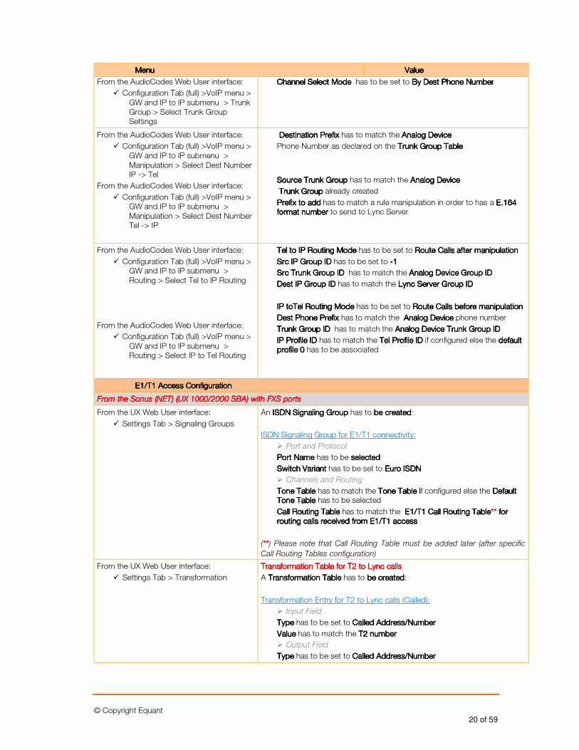
MenuMenuMenuMenu ValueValueValueValue
From the AudioCodes Web User interface:
� Configuration Tab (full) >VoIP menu > GW and IP to IP submenu > Trunk Group > Select Trunk Group Settings
Channel Select Mode Channel Select Mode Channel Select Mode Channel Select Mode has to be set to By Dest Phone NumberBy Dest Phone NumberBy Dest Phone NumberBy Dest Phone Number
From the AudioCodes Web User interface:
� Configuration Tab (full) >VoIP menu > GW and IP to IP submenu > Manipulation > Select Dest Number IP -> Tel
From the AudioCodes Web User interface:
� Configuration Tab (full) >VoIP menu > GW and IP to IP submenu > Manipulation > Select Dest Number Tel -> IP
Destination PrefixDestination PrefixDestination PrefixDestination Prefix has to match the Analog DeviceAnalog DeviceAnalog DeviceAnalog Device
Phone Number as declared on the Trunk Group TableTrunk Group TableTrunk Group TableTrunk Group Table
Source Trunk GroupSource Trunk GroupSource Trunk GroupSource Trunk Group has to match the Analog DeviceAnalog DeviceAnalog DeviceAnalog Device
Trunk Group Trunk Group Trunk Group Trunk Group already created
Prefix to addPrefix to addPrefix to addPrefix to add has to match a rule manipulation in order to has a E.164 E.164 E.164 E.164 format numberformat numberformat numberformat number to send to Lync Server
From the AudioCodes Web User interface:
� Configuration Tab (full) >VoIP menu > GW and IP to IP submenu > Routing > Select Tel to IP Routing
From the AudioCodes Web User interface:
� Configuration Tab (full) >VoIP menu > GW and IP to IP submenu > Routing > Select IP to Tel Routing
Tel to IP Routing Mode Tel to IP Routing Mode Tel to IP Routing Mode Tel to IP Routing Mode has to be set to Route Calls after manipulationRoute Calls after manipulationRoute Calls after manipulationRoute Calls after manipulation
Src IP Group ID Src IP Group ID Src IP Group ID Src IP Group ID has to be set to ----1 1 1 1
Src Trunk Group ID Src Trunk Group ID Src Trunk Group ID Src Trunk Group ID has to match the Analog Device Group IDAnalog Device Group IDAnalog Device Group IDAnalog Device Group ID
DesDesDesDest IP Group ID t IP Group ID t IP Group ID t IP Group ID has to match the Lync Server Group IDLync Server Group IDLync Server Group IDLync Server Group ID
IP toTel Routing Mode IP toTel Routing Mode IP toTel Routing Mode IP toTel Routing Mode has to be set to Route Calls before manipulationRoute Calls before manipulationRoute Calls before manipulationRoute Calls before manipulation
Dest Phone Prefix Dest Phone Prefix Dest Phone Prefix Dest Phone Prefix has to match the Analog Device Analog Device Analog Device Analog Device phone number
Trunk Group ID Trunk Group ID Trunk Group ID Trunk Group ID has to match the Analog Device Analog Device Analog Device Analog Device Trunk Trunk Trunk Trunk Group IDGroup IDGroup IDGroup ID
IP ProIP ProIP ProIP Profile ID file ID file ID file ID has to match the Tel Profile IDTel Profile IDTel Profile IDTel Profile ID if configured else the default default default default profile 0profile 0profile 0profile 0 has to be associated
E1/T1 AccessE1/T1 AccessE1/T1 AccessE1/T1 Access ConfigurationConfigurationConfigurationConfiguration
From the Sonus (NET) (UX 1000/2000 SBA) with FXS portsFrom the Sonus (NET) (UX 1000/2000 SBA) with FXS portsFrom the Sonus (NET) (UX 1000/2000 SBA) with FXS portsFrom the Sonus (NET) (UX 1000/2000 SBA) with FXS ports
From the UX Web User interface:
� Settings Tab > Signaling Groups
An ISDNISDNISDNISDN Signaling GroupSignaling GroupSignaling GroupSignaling Group has to be createdbe createdbe createdbe created:
ISDN Signaling Group for E1/T1 connectivity:
� Port and Protocol
Port NamePort NamePort NamePort Name has to be selectedselectedselectedselected
Switch VariantSwitch VariantSwitch VariantSwitch Variant has to be set to Euro ISDNEuro ISDNEuro ISDNEuro ISDN
� Channels and Routing
Tone TableTone TableTone TableTone Table has to match the Tone TableTone TableTone TableTone Table iiiif configured else the Default Default Default Default Tone Table Tone Table Tone Table Tone Table has to be selected
Call Routing TableCall Routing TableCall Routing TableCall Routing Table has to match the E1/T1E1/T1E1/T1E1/T1 Call Routing TableCall Routing TableCall Routing TableCall Routing Table******** for for for for routing calls rrouting calls rrouting calls rrouting calls received from E1/T1 accesseceived from E1/T1 accesseceived from E1/T1 accesseceived from E1/T1 access
(********) Please note that Call Routing Table must be added later (after specific
Call Routing Tables configuration)
From the UX Web User interface:
� Settings Tab > Transformation
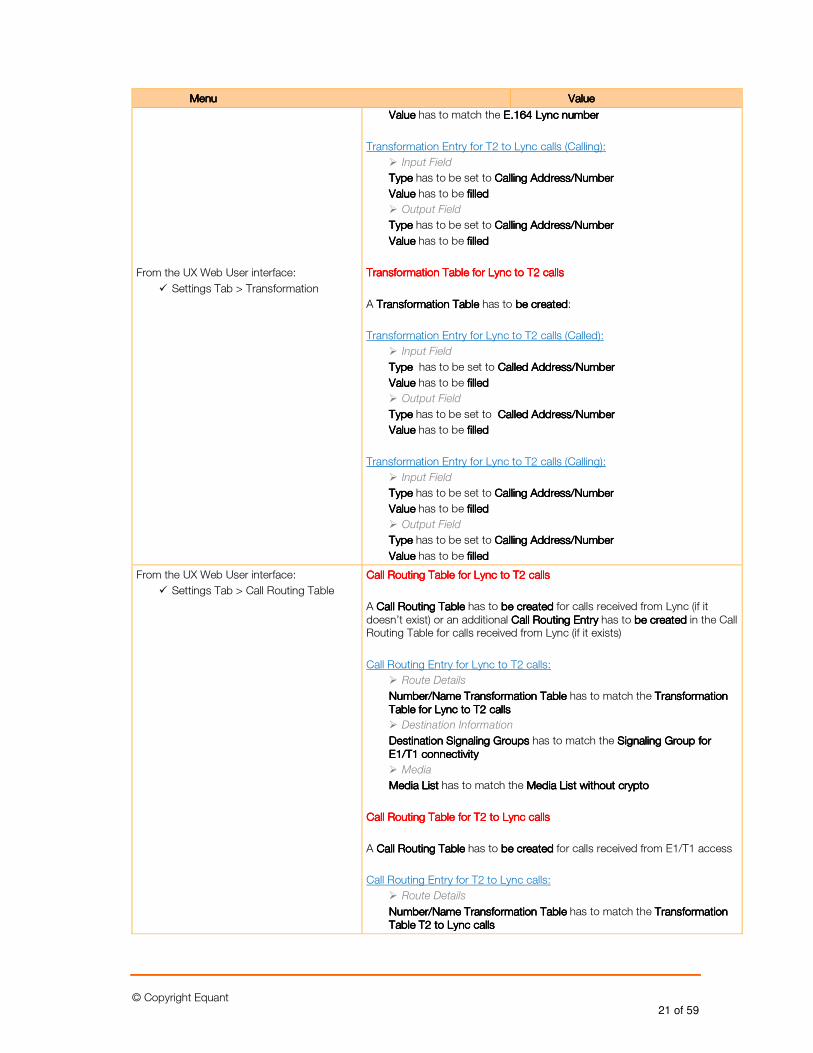
Transformation Table for T2 to Lync callsTransformation Table for T2 to Lync callsTransformation Table for T2 to Lync callsTransformation Table for T2 to Lync calls
A TransTransTransTransformationformationformationformation TableTableTableTable has to be createdbe createdbe createdbe created:
Transformation Entry for T2 to Lync calls (Called):
� Input Field
TypeTypeTypeType has to be set to Called Address/NumberCalled Address/NumberCalled Address/NumberCalled Address/Number
Value Value Value Value has to match the T2T2T2T2 numbernumbernumbernumber
� Output Field
TypeTypeTypeType has to be set to Called Address/NumberCalled Address/NumberCalled Address/NumberCalled Address/Number
© Copyright Equant 21 of 59
MenuMenuMenuMenu ValueValueValueValue
From the UX Web User interface:
� Settings Tab > Transformation
Value Value Value Value has to match the E.164 Lync numberE.164 Lync numberE.164 Lync numberE.164 Lync number
Transformation Entry for T2 to Lync calls (Calling):
� Input Field
TypeTypeTypeType has to be set to Calling Address/NumberCalling Address/NumberCalling Address/NumberCalling Address/Number
ValueValueValueValue has to be filled filled filled filled
� Output Field
TypeTypeTypeType has to be set to Calling Address/NumberCalling Address/NumberCalling Address/NumberCalling Address/Number
ValueValueValueValue has to be filled filled filled filled
TransformaTransformaTransformaTransformation Table for Lynction Table for Lynction Table for Lynction Table for Lync to to to to T2T2T2T2 callscallscallscalls
A TransTransTransTransformationformationformationformation TableTableTableTable has to bbbbe createde createde createde created:
Transformation Entry for Lync to T2 calls (Called):
� Input Field
Type Type Type Type has to be set to Called Address/NumberCalled Address/NumberCalled Address/NumberCalled Address/Number
Value Value Value Value has to be filledfilledfilledfilled
� Output Field
TypeTypeTypeType has to be set to Called Address/NumberCalled Address/NumberCalled Address/NumberCalled Address/Number
Value Value Value Value has to be filledfilledfilledfilled
Transformation Entry for Lync to T2 calls (Calling):
� Input Field
TypeTypeTypeType has to be set to Calling Address/NumberCalling Address/NumberCalling Address/NumberCalling Address/Number
ValueValueValueValue has to be filled filled filled filled
� Output Field
TypeTypeTypeType has to be set to Calling Address/NumberCalling Address/NumberCalling Address/NumberCalling Address/Number
ValueValueValueValue has to be filledfilledfilledfilled
From the UX Web User interface:
� Settings Tab > Call Routing Table
Call Routing Table for LyncCall Routing Table for LyncCall Routing Table for LyncCall Routing Table for Lync to to to to T2T2T2T2 callscallscallscalls
A Call Routing TableCall Routing TableCall Routing TableCall Routing Table has to be createdbe createdbe createdbe created for calls received from Lync (if it doesn’t exist) or an additional Call Routing EntryCall Routing EntryCall Routing EntryCall Routing Entry has to be createdbe createdbe createdbe created in the Call Routing Table for calls received from Lync (if it exists)
Call Routing Entry for Lync to T2 calls:
� Route Details
Number/Name Transformation TableNumber/Name Transformation TableNumber/Name Transformation TableNumber/Name Transformation Table has to match the Transformation Transformation Transformation Transformation Table for Lync to T2 callsTable for Lync to T2 callsTable for Lync to T2 callsTable for Lync to T2 calls
� Destination Information
Destination Signaling GroupsDestination Signaling GroupsDestination Signaling GroupsDestination Signaling Groups has to match the Signaling Group for Signaling Group for Signaling Group for Signaling Group for E1/T1 connectivityE1/T1 connectivityE1/T1 connectivityE1/T1 connectivity
� Media
Media ListMedia ListMedia ListMedia List has to match the Media List without cryptoMedia List without cryptoMedia List without cryptoMedia List without crypto
Call RoutingCall RoutingCall RoutingCall Routing Table for T2 to Lync callsTable for T2 to Lync callsTable for T2 to Lync callsTable for T2 to Lync calls
A Call Routing Call Routing Call Routing Call Routing TableTableTableTable has to be createdbe createdbe createdbe created for calls received from E1/T1 access
Call Routing Entry for T2 to Lync calls:
� Route Details
Number/Name TransNumber/Name TransNumber/Name TransNumber/Name Transfofofoformationrmationrmationrmation TableTableTableTable has to match the TranTranTranTransformationsformationsformationsformation Table Table Table Table T2 to Lync callsT2 to Lync callsT2 to Lync callsT2 to Lync calls
© Copyright Equant 22 of 59
MenuMenuMenuMenu ValueValueValueValue
� Destination Information
DesDesDesDestinationtinationtinationtination Signaling GroupSignaling GroupSignaling GroupSignaling Groupssss has to match the Signaling Group for Signaling Group for Signaling Group for Signaling Group for Lync Lync Lync Lync connectivityconnectivityconnectivityconnectivity
� Media
Media ListMedia ListMedia ListMedia List has to match the MMMMedia List without cryptoedia List without cryptoedia List without cryptoedia List without crypto
(********) Please note that Call Routing Table must be added to ISDN/SIP
Signaling Groups configuration
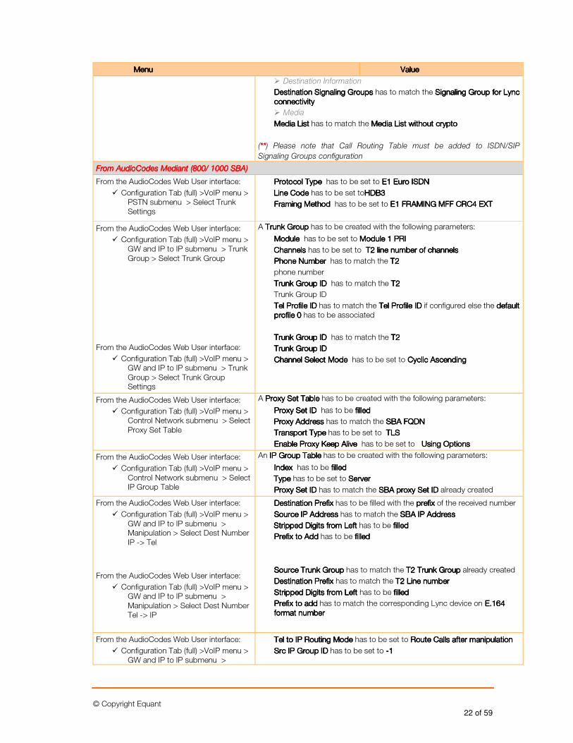
From AudioCodes Mediant (800/ 1000 SBA) From AudioCodes Mediant (800/ 1000 SBA) From AudioCodes Mediant (800/ 1000 SBA) From AudioCodes Mediant (800/ 1000 SBA)
From the AudioCodes Web User interface:
� Configuration Tab (full) >VoIP menu > PSTN submenu > Select Trunk Settings
Protocol Type Protocol Type Protocol Type Protocol Type has to be set to E1 Euro ISDNE1 Euro ISDNE1 Euro ISDNE1 Euro ISDN
Line CodeLine CodeLine CodeLine Code has to be set toHDB3HDB3HDB3HDB3
Framing Method Framing Method Framing Method Framing Method has to be set to E1 FRAMING MFF CRC4 EXTE1 FRAMING MFF CRC4 EXTE1 FRAMING MFF CRC4 EXTE1 FRAMING MFF CRC4 EXT
From the AudioCodes Web User interface:
� Configuration Tab (full) >VoIP menu > GW and IP to IP submenu > Trunk Group > Select Trunk Group
From the AudioCodes Web User interface:
� Configuration Tab (full) >VoIP menu > GW and IP to IP submenu > Trunk Group > Select Trunk Group Settings
A Trunk GroupTrunk GroupTrunk GroupTrunk Group has to be created with the following parameters:
Module Module Module Module has to be set to ModulModulModulModule 1 PRIe 1 PRIe 1 PRIe 1 PRI
ChannelsChannelsChannelsChannels has to be set to T2 line number of channels T2 line number of channels T2 line number of channels T2 line number of channels
Phone Number Phone Number Phone Number Phone Number has to match the T2T2T2T2
phone number
Trunk Group ID Trunk Group ID Trunk Group ID Trunk Group ID has to match the T2T2T2T2
Trunk Group ID
Tel Profile IDTel Profile IDTel Profile IDTel Profile ID has to match the Tel Profile IDTel Profile IDTel Profile IDTel Profile ID if configured else the default default default default profile 0profile 0profile 0profile 0 has to be associated
Trunk Group ID Trunk Group ID Trunk Group ID Trunk Group ID has to match the T2 T2 T2 T2
Trunk Group IDTrunk Group IDTrunk Group IDTrunk Group ID
Channel Select Mode Channel Select Mode Channel Select Mode Channel Select Mode has to be set to Cyclic AscendingCyclic AscendingCyclic AscendingCyclic Ascending
From the AudioCodes Web User interface:
� Configuration Tab (full) >VoIP menu > Control Network submenu > Select Proxy Set Table
A PPPProxy Set Tableroxy Set Tableroxy Set Tableroxy Set Table has to be created with the following parameters:
Proxy Set ID Proxy Set ID Proxy Set ID Proxy Set ID has to be filledfilledfilledfilled
Proxy AddressProxy AddressProxy AddressProxy Address has to match the SBA FQDNSBA FQDNSBA FQDNSBA FQDN
Transport TypeTransport TypeTransport TypeTransport Type has to be set to TTTTLSLSLSLS
Enable Proxy Keep Alive Enable Proxy Keep Alive Enable Proxy Keep Alive Enable Proxy Keep Alive has to be set to Using OptionsUsing OptionsUsing OptionsUsing Options
From the AudioCodes Web User interface:
� Configuration Tab (full) >VoIP menu > Control Network submenu > Select IP Group Table
An IP Group TableIP Group TableIP Group TableIP Group Table has to be created with the following parameters:
Index Index Index Index has to be filledfilledfilledfilled
TypeTypeTypeType has to be set to ServerServerServerServer
Proxy Set IDProxy Set IDProxy Set IDProxy Set ID has to match the SBA SBA SBA SBA proxy Set IDproxy Set IDproxy Set IDproxy Set ID already created
From the AudioCodes Web User interface:
� Configuration Tab (full) >VoIP menu > GW and IP to IP submenu > Manipulation > Select Dest Number IP -> Tel
From the AudioCodes Web User interface:
� Configuration Tab (full) >VoIP menu > GW and IP to IP submenu > Manipulation > Select Dest Number Tel -> IP
Destination PrefixDestination PrefixDestination PrefixDestination Prefix has to be filled with the prefixprefixprefixprefix of the received number
Source IP AddressSource IP AddressSource IP AddressSource IP Address has to match the SBA IP AddressSBA IP AddressSBA IP AddressSBA IP Address
Stripped Digits from Left Stripped Digits from Left Stripped Digits from Left Stripped Digits from Left has to be filledfilledfilledfilled
PrePrePrePrefix to Addfix to Addfix to Addfix to Add has to be filled filled filled filled
Source Trunk GroupSource Trunk GroupSource Trunk GroupSource Trunk Group has to match the T2T2T2T2 Trunk Group Trunk Group Trunk Group Trunk Group already created
Destination Prefix Destination Prefix Destination Prefix Destination Prefix has to match the T2 Line numberT2 Line numberT2 Line numberT2 Line number
Stripped Digits from Left Stripped Digits from Left Stripped Digits from Left Stripped Digits from Left has to be filledfilledfilledfilled
Prefix to addPrefix to addPrefix to addPrefix to add has to match the corresponding Lync device on E.16E.16E.16E.164 4 4 4 format numberformat numberformat numberformat number
From the AudioCodes Web User interface:
� Configuration Tab (full) >VoIP menu > GW and IP to IP submenu >
Tel to IP Routing Mode Tel to IP Routing Mode Tel to IP Routing Mode Tel to IP Routing Mode has to be set to Route Calls after manipulationRoute Calls after manipulationRoute Calls after manipulationRoute Calls after manipulation
Src IP Group ID Src IP Group ID Src IP Group ID Src IP Group ID has to be set to ----1 1 1 1
© Copyright Equant 23 of 59
MenuMenuMenuMenu ValueValueValueValue
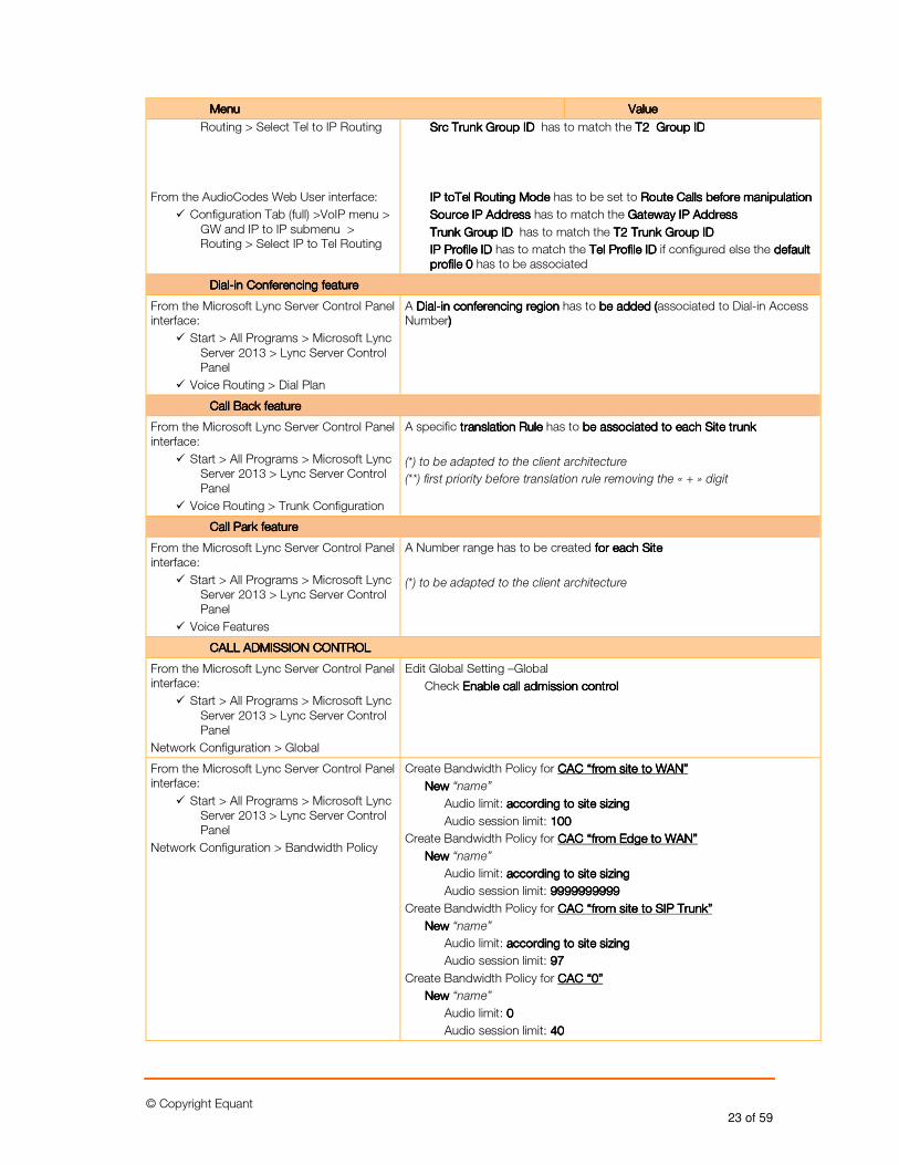
Routing > Select Tel to IP Routing
From the AudioCodes Web User interface:
� Configuration Tab (full) >VoIP menu > GW and IP to IP submenu > Routing > Select IP to Tel Routing
Src Trunk Group ID Src Trunk Group ID Src Trunk Group ID Src Trunk Group ID has to match the T2T2T2T2 Group IDGroup IDGroup IDGroup ID
IP toTel Routing Mode IP toTel Routing Mode IP toTel Routing Mode IP toTel Routing Mode has to be set to Route CallRoute CallRoute CallRoute Calls before manipulations before manipulations before manipulations before manipulation
Source IP Address Source IP Address Source IP Address Source IP Address has to match the Gateway IP AddressGateway IP AddressGateway IP AddressGateway IP Address
Trunk Group ID Trunk Group ID Trunk Group ID Trunk Group ID has to match the T2T2T2T2 Trunk Trunk Trunk Trunk Group IDGroup IDGroup IDGroup ID
IP Profile ID IP Profile ID IP Profile ID IP Profile ID has to match the Tel Profile IDTel Profile IDTel Profile IDTel Profile ID if configured else the default default default default profile 0profile 0profile 0profile 0 has to be associated
DialDialDialDial----in Conferencingin Conferencingin Conferencingin Conferencing featurefeaturefeaturefeature
From the Microsoft Lync Server Control Panel interface:
� Start > All Programs > Microsoft Lync Server 2013 > Lync Server Control Panel
� Voice Routing > Dial Plan
A DialDialDialDial----in conferencing regionin conferencing regionin conferencing regionin conferencing region has to be added (be added (be added (be added (associated to Dial-in Access Number) ) ) )
Call Back featureCall Back featureCall Back featureCall Back feature
From the Microsoft Lync Server Control Panel interface:
� Start > All Programs > Microsoft Lync Server 2013 > Lync Server Control Panel
� Voice Routing > Trunk Configuration
A specific translation Ruletranslation Ruletranslation Ruletranslation Rule has to be associated be associated be associated be associated totototo each Site truneach Site truneach Site truneach Site trunkkkk
(*) to be adapted to the client architecture
(**) first priority before translation rule removing the « + » digit
Call Park featureCall Park featureCall Park featureCall Park feature
From the Microsoft Lync Server Control Panel interface:
� Start > All Programs > Microsoft Lync Server 2013 > Lync Server Control Panel
� Voice Features
A Number range has to be created forforforfor each Site each Site each Site each Site
(*) to be adapted to the client architecture
CALL ADMISSION CONTROLCALL ADMISSION CONTROLCALL ADMISSION CONTROLCALL ADMISSION CONTROL
From the Microsoft Lync Server Control Panel interface:
� Start > All Programs > Microsoft Lync Server 2013 > Lync Server Control Panel
Network Configuration > Global
Edit Global Setting –Global
Check Enable call admission controlEnable call admission controlEnable call admission controlEnable call admission control
From the Microsoft Lync Server Control Panel interface:
� Start > All Programs > Microsoft Lync Server 2013 > Lync Server Control Panel
Network Configuration > Bandwidth Policy
Create Bandwidth Policy for CAC “from site to WAN”CAC “from site to WAN”CAC “from site to WAN”CAC “from site to WAN”
NewNewNewNew “name”
Audio limit: according to site sizingaccording to site sizingaccording to site sizingaccording to site sizing
Audio session limit: 100100100100
Create Bandwidth Policy for CAC “from CAC “from CAC “from CAC “from EdgeEdgeEdgeEdge to WAN”to WAN”to WAN”to WAN”
NewNewNewNew “name”
Audio limit: according toaccording toaccording toaccording to site sizingsite sizingsite sizingsite sizing
Audio session limit: 9999999999999999999999999999999999999999
Create Bandwidth Policy for CAC “from site to CAC “from site to CAC “from site to CAC “from site to SIP TrunkSIP TrunkSIP TrunkSIP Trunk””””
NewNewNewNew “name”
Audio limit: according to site sizingaccording to site sizingaccording to site sizingaccording to site sizing
Audio session limit: 97979797
Create Bandwidth Policy for CAC “CAC “CAC “CAC “0000””””
NewNewNewNew “name”
Audio limit: 0000
Audio session limit: 40404040
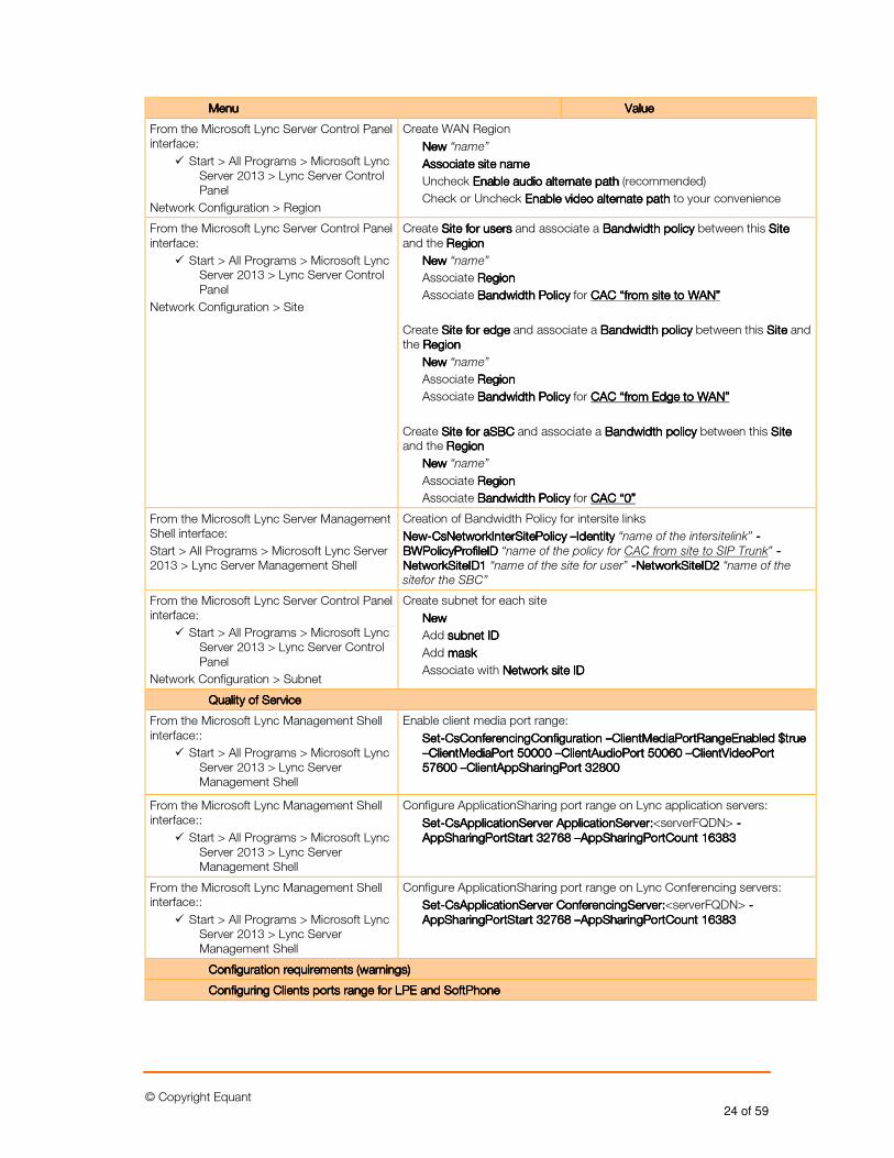
© Copyright Equant 24 of 59
MenuMenuMenuMenu ValueValueValueValue
From the Microsoft Lync Server Control Panel interface:
� Start > All Programs > Microsoft Lync Server 2013 > Lync Server Control Panel
Network Configuration > Region
Create WAN Region
NewNewNewNew “name”
Associate site nameAssociate site nameAssociate site nameAssociate site name
Uncheck Enable Enable Enable Enable audio alternate pathaudio alternate pathaudio alternate pathaudio alternate path (recommended)
Check or Uncheck Enable Enable Enable Enable video alternate pathvideo alternate pathvideo alternate pathvideo alternate path to your convenience
From the Microsoft Lync Server Control Panel interface:
� Start > All Programs > Microsoft Lync Server 2013 > Lync Server Control Panel
Network Configuration > Site
Create Site fSite fSite fSite for usersor usersor usersor users and associate a Bandwidth policyBandwidth policyBandwidth policyBandwidth policy between this SSSSiteiteiteite and the RegionRegionRegionRegion
NewNewNewNew “name”
Associate RegionRegionRegionRegion
Associate Bandwidth Policy Bandwidth Policy Bandwidth Policy Bandwidth Policy for CAC “from site to WAN”CAC “from site to WAN”CAC “from site to WAN”CAC “from site to WAN”
Create Site for Site for Site for Site for edgeedgeedgeedge and associate a Bandwidth policyBandwidth policyBandwidth policyBandwidth policy between this SSSSiteiteiteite and the RegionRegionRegionRegion
NewNewNewNew “name”
Associate RegionRegionRegionRegion
Associate Bandwidth Policy Bandwidth Policy Bandwidth Policy Bandwidth Policy for CAC “from CAC “from CAC “from CAC “from EdgeEdgeEdgeEdge to WAN”to WAN”to WAN”to WAN”
Create Site for aSBCSite for aSBCSite for aSBCSite for aSBC and associate a Bandwidth policyBandwidth policyBandwidth policyBandwidth policy between this SSSSiteiteiteite and the RegionRegionRegionRegion
NewNewNewNew “name”
Associate RegionRegionRegionRegion
Associate Bandwidth Policy Bandwidth Policy Bandwidth Policy Bandwidth Policy for CAC “CAC “CAC “CAC “0000””””
From the Microsoft Lync Server Management Shell interface:
Start > All Programs > Microsoft Lync Server 2013 > Lync Server Management Shell
Creation of Bandwidth Policy for intersite links
NewNewNewNew----CsNetworkInterSitePolicy CsNetworkInterSitePolicy CsNetworkInterSitePolicy CsNetworkInterSitePolicy ––––Identity Identity Identity Identity “name of the intersitelink” ----BWPolicyProfileID BWPolicyProfileID BWPolicyProfileID BWPolicyProfileID “name of the policy for CAC from site to SIP Trunk” ----NetworkSiteID1 NetworkSiteID1 NetworkSiteID1 NetworkSiteID1 “name of the site for user” ----NetworkSiteID2 NetworkSiteID2 NetworkSiteID2 NetworkSiteID2 “name of the
sitefor the SBC”
From the Microsoft Lync Server Control Panel interface:
� Start > All Programs > Microsoft Lync Server 2013 > Lync Server Control Panel
Network Configuration > Subnet
Create subnet for each site
NewNewNewNew
Add subnetsubnetsubnetsubnet IDIDIDID
Add maskmaskmaskmask
Associate with Network site IDNetwork site IDNetwork site IDNetwork site ID
Quality of ServiceQuality of ServiceQuality of ServiceQuality of Service
From the Microsoft Lync Management Shell interface::
� Start > All Programs > Microsoft Lync Server 2013 > Lync Server Management Shell
Enable client media port range:
SetSetSetSet----CsConferencingConfiguration CsConferencingConfiguration CsConferencingConfiguration CsConferencingConfiguration ––––ClientMediaPortRangeEnabled $true ClientMediaPortRangeEnabled $true ClientMediaPortRangeEnabled $true ClientMediaPortRangeEnabled $true ––––ClientMediaPort 50000 ClientMediaPort 50000 ClientMediaPort 50000 ClientMediaPort 50000 ––––ClientAudioPort 50060 ClientAudioPort 50060 ClientAudioPort 50060 ClientAudioPort 50060 ––––ClientVideoPort ClientVideoPort ClientVideoPort ClientVideoPort 57600 57600 57600 57600 ––––ClientAppSharingPort 32800ClientAppSharingPort 32800ClientAppSharingPort 32800ClientAppSharingPort 32800
From the Microsoft Lync Management Shell interface::
� Start > All Programs > Microsoft Lync Server 2013 > Lync Server Management Shell
Configure ApplicationSharing port range on Lync application servers:
SetSetSetSet----CsApplicationServer ApplicationServer:CsApplicationServer ApplicationServer:CsApplicationServer ApplicationServer:CsApplicationServer ApplicationServer:<serverFQDN> ----AppSharingPortStart 32768 AppSharingPortStart 32768 AppSharingPortStart 32768 AppSharingPortStart 32768 ––––AAAAppSharingPortCount 16383ppSharingPortCount 16383ppSharingPortCount 16383ppSharingPortCount 16383
From the Microsoft Lync Management Shell interface::
� Start > All Programs > Microsoft Lync Server 2013 > Lync Server Management Shell
Configure ApplicationSharing port range on Lync Conferencing servers:
SetSetSetSet----CsApplicationServer CsApplicationServer CsApplicationServer CsApplicationServer CoCoCoConferencingServernferencingServernferencingServernferencingServer::::<serverFQDN> ----AppSharingPortStart 32768 AppSharingPortStart 32768 AppSharingPortStart 32768 AppSharingPortStart 32768 ––––AppSharingPortCount 16383AppSharingPortCount 16383AppSharingPortCount 16383AppSharingPortCount 16383
Configuration requirements (warnings)Configuration requirements (warnings)Configuration requirements (warnings)Configuration requirements (warnings)
Configuring Clients ports range for LPE and SoftPhoneConfiguring Clients ports range for LPE and SoftPhoneConfiguring Clients ports range for LPE and SoftPhoneConfiguring Clients ports range for LPE and SoftPhone
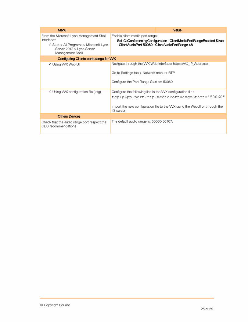
© Copyright Equant 25 of 59
MenuMenuMenuMenu ValueValueValueValue
From the Microsoft Lync Management Shell interface::
� Start > All Programs > Microsoft Lync Server 2013 > Lync Server Management Shell
Enable client media port range:
SetSetSetSet----CsConferencingConfiguration CsConferencingConfiguration CsConferencingConfiguration CsConferencingConfiguration ––––ClientMediaPortRangeEnabled $true ClientMediaPortRangeEnabled $true ClientMediaPortRangeEnabled $true ClientMediaPortRangeEnabled $true ––––ClientAudioPort 50060 ClientAudioPort 50060 ClientAudioPort 50060 ClientAudioPort 50060 ––––ClientAudioPortRange 48lientAudioPortRange 48lientAudioPortRange 48lientAudioPortRange 48
Configuring Clients ports range for VVXConfiguring Clients ports range for VVXConfiguring Clients ports range for VVXConfiguring Clients ports range for VVX
� Using VVX Web UI Navigate through the VVX Web Interface: http:<VVX_IP_Address>
Go to Settings tab > Network menu > RTP
Configure the Port Range Start to: 50060
� Using VVX configuration file (.cfg) Configure the following line in the VVX configuration file :
tcpIpApp.port.rtp.mediaPortRangeStart="50060"
Import the new configuration file to the VVX using the WebUI or through the IIS server
Others DevicesOthers DevicesOthers DevicesOthers Devices
Check that the audio range port respect the OBS recommendations
The default audio range is: 50060-50107.
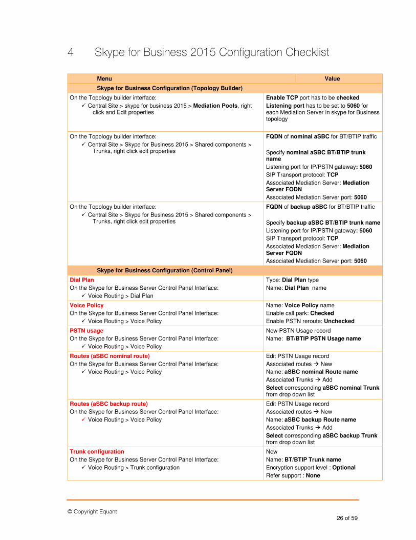
© Copyright Equant 26 of 59
4 Skype for Business 2015 Configuration Checklist
Menu Value
Skype for Business Configuration (Topology Builder)
On the Topology builder interface:
� Central Site > skype for business 2015 > Mediation Pools, right click and Edit properties
Enable TCP port has to be checked
Listening port has to be set to 5060 for each Mediation Server in skype for Business topology
On the Topology builder interface:
� Central Site > Skype for Business 2015 > Shared components > Trunks, right click edit properties
FQDN of nominal aSBC for BT/BTIP traffic
Specify nominal aSBC BT/BTIP trunk name
Listening port for IP/PSTN gateway: 5060
SIP Transport protocol: TCP
Associated Mediation Server: Mediation Server FQDN
Associated Mediation Server port: 5060
On the Topology builder interface:
� Central Site > Skype for Business 2015 > Shared components > Trunks, right click edit properties
FQDN of backup aSBC for BT/BTIP traffic
Specify backup aSBC BT/BTIP trunk name
Listening port for IP/PSTN gateway: 5060
SIP Transport protocol: TCP
Associated Mediation Server: Mediation Server FQDN
Associated Mediation Server port: 5060
Skype for Business Configuration (Control Panel)
Dial Plan
On the Skype for Business Server Control Panel Interface:
� Voice Routing > Dial Plan
Type: Dial Plan type
Name: Dial Plan name
Voice Policy
On the Skype for Business Server Control Panel Interface:
� Voice Routing > Voice Policy
Name: Voice Policy name
Enable call park: Checked
Enable PSTN reroute: Unchecked
PSTN usage
On the Skype for Business Server Control Panel Interface:
� Voice Routing > Voice Policy
New PSTN Usage record
Name: BT/BTIP PSTN Usage name
Routes (aSBC nominal route)
On the Skype for Business Server Control Panel Interface:
� Voice Routing > Voice Policy
Edit PSTN Usage record
Associated routes � New
Name: aSBC nominal Route name
Associated Trunks � Add
Select corresponding aSBC nominal Trunk from drop down list
Routes (aSBC backup route)
On the Skype for Business Server Control Panel Interface:
� Voice Routing > Voice Policy
Edit PSTN Usage record
Associated routes � New
Name: aSBC backup Route name
Associated Trunks � Add
Select corresponding aSBC backup Trunk from drop down list
Trunk configuration
On the Skype for Business Server Control Panel Interface:
� Voice Routing > Trunk configuration
New
Name: BT/BTIP Trunk name
Encryption support level : Optional
Refer support : None
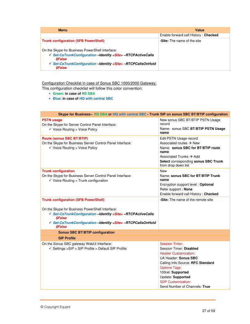
© Copyright Equant 27 of 59
Menu Value
Enable forward call History : Checked
Trunk configuration (SFB PowerShell)
On the Skype for Business PowerShell Interface:
� Set-CsTrunkConfiguration –Identity <Site> –RTCPActiveCalls $False
� Set-CsTrunkConfiguration –Identity <Site> –RTCPCallsOnHold $False
-Site: The name of the site
Configuration Checklist in case of Sonus SBC 1000/2000 Gateway:
This configuration checklist will follow this color convention:
• Green: in case of RS SBA
• Blue: in case of HQ with central SBC
Skype for Business– RS SBA or HQ with central SBC - Trunk SIP on sonus SBC BT/BTIP configuration
PSTN usage
On the Skype for Server Control Panel Interface:
� Voice Routing > Voice Policy
New sonus SBC BT/BTIP PSTN Usage record
Name: sonus SBC BT/BTIP PSTN Usage name
Route (sonus SBC BT/BTIP)
On the Skype for Business Server Control Panel Interface:
� Voice Routing > Voice Policy
Edit PSTN Usage record
Associated routes � New
Name: sonus SBC for BT/BTIP route name
Associated Trunks � Add
Select corresponding sonus SBC Trunk from drop down list
Trunk configuration
On the Skype for Business Server Control Panel Interface:
� Voice Routing > Trunk configuration
New
Name: sonus SBC for BT/BTIP Trunk name
Encryption support level : Optional
Refer support : None
Enable forward call History : Checked
Trunk configuration (SFB PowerShell)
On the Skype for Business PowerShell Interface:
� Set-CsTrunkConfiguration –Identity <Site> –RTCPActiveCalls $False
� Set-CsTrunkConfiguration –Identity <Site> –RTCPCallsOnHold $False
-Site: The name of the remote site
Sonus SBC BT/BTIP configuration
SIP Profile
On the Sonus SBC gateway WebUi Interface:
� Settings >SIP > SIP Profile > Default SIP Profile
Session Timer:
Session Timer: Disabled
Header Customization:
UA Header: Sonus SBC
Calling Info Source: RFC Standard
Options Tags:
100rel: Supported
Update: Supported
SDP Customization:
Send Number of Channels: True
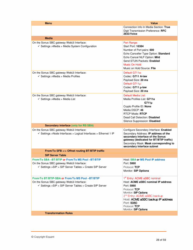
© Copyright Equant 28 of 59
Menu Value
Connection Info In Media Section: True
Digit Transmission Preference: RFC 2833/Voice
Media
On the Sonus SBC gateway WebUi Interface:
� Settings >Media > Media System Configuration
Port Range:
Start Port: 16384
Number of Port pairs: 600
Echo Canceller Type Option: Standard
Echo Cancel NLP Option: Mild
Send STUN Packets: Enabled
Music On Hold:
Music on Hold Source: File
On the Sonus SBC gateway WebUi Interface:
� Settings >Media > Media Profiles
Default G711a:
Codec: G711 A-law
Payload Size: 20 ms
Default G711µ:
Codec: G711 µ-law
Payload Size: 20 ms
On the Sonus SBC gateway WebUi Interface:
� Settings >Media > Media List
Default Media List:
Media Profiles List: G711a
G711µ
Crypto Profile ID: None
Media DSCP: 46
RTCP Mode: RTCP
Dead Call Detection: Disabled
Silence Suppression: Disabled
Secondary interface (only for RS SBA)
On the Sonus SBC gateway WebUi Interface:
� Settings >Node Interfaces > Logical Interfaces > Ethernet 1 IP
Configure Secondary Interface: Enabled
Secondary Address: IP address of the secondary interface of the Sonus gateway (dedicated for BT/BTIP traffic)
Secondary Mask: Mask corresponding to secondary interface subnet
From/To SFB <-> Offnet routing BT/BTIP traffic
SIP Server Table
From/To SBA –BT/BTIP or From/To MS Pool –BT/BTIP
On the Sonus SBC gateway WebUi Interface:
� Settings >SIP > SIP Server Tables > Create SIP Server
Host: SBA or MS Pool IP address
Port: 5060
Protocol: TTTTCPCPCPCP
Monitor: SIP Options
From/To BT/BTIP-SBA or From/To MS Pool –BT/BTIP
On the Sonus SBC gateway WebUi Interface:
� Settings >SIP > SIP Server Tables > Create SIP Server
1st Entry: ACME aSBC nominal
Host: ACME aSBC nominal IP address
Port: 5060
Protocol: TCPTCPTCPTCP Monitor: SIP OptionsSIP OptionsSIP OptionsSIP Options 2nd Entry: ACME aSBC backup Host: ACME aSBC backup IP addressACME aSBC backup IP addressACME aSBC backup IP addressACME aSBC backup IP address Port: 5060506050605060 Protocol: TCPTCPTCPTCP Monitor: SIP OptionsSIP OptionsSIP OptionsSIP Options
Transformation Rules
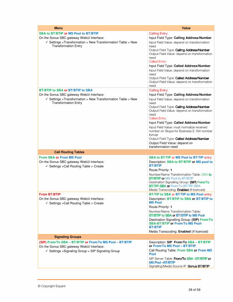
© Copyright Equant 29 of 59
Menu Value
SBA to BT/BTIP or MS Pool to BT/BTIP
On the Sonus SBC gateway WebUi Interface:
� Settings >Transformation > New Transformation Table > New Transformation Entry
Calling Entry:
Input Field Type: Calling Address/Number
Input Field Value: depend on transformation need Output Field Type: Calling Address/NumberCalling Address/NumberCalling Address/NumberCalling Address/Number Output Field Value: depend on transformation need Called Entry:
Input Field Type: Called Address/Number
Input Field Value: depend on transformation need Output Field Type: CalledCalledCalledCalled AddresAddresAddresAddress/Numbers/Numbers/Numbers/Number Output Field Value: depend on transformation need
BT/BTIP to SBA or BT/BTIP to SBA
On the Sonus SBC gateway WebUi Interface:
� Settings >Transformation > New Transformation Table > New Transformation Entry
Calling Entry:
Input Field Type: Calling Address/Number
Input Field Value: depend on transformation need Output Field Type: Calling Address/NumberCalling Address/NumberCalling Address/NumberCalling Address/Number Output Field Value: depend on transformation need Called Entry:
Input Field Type: Called Address/Number
Input Field Value: must normalize received number on Skype for Business E.164 number format Output Field Type: CalledCalledCalledCalled Address/NumberAddress/NumberAddress/NumberAddress/Number
Output Field Value: depend on transformation need
Call Routing Tables
From SBA or From MS Pool
On the Sonus SBC gateway WebUi Interface:
� Settings >Call Routing Table > Create
SBA to BT/TIP or MS Pool to BT/TIP entry:
Description: SBA to BT/BTIP or MS pool to BT/BTIP
Route Priority: 1
Number/Name Transformation Table: SBA to to to to BT/BTIPBT/BTIPBT/BTIPBT/BTIP or or or or MS Pool to BT/BTIP Destination Signalling Group: ((((SIPSIPSIPSIP)))) From/To From/To From/To From/To BT/TIPBT/TIPBT/TIPBT/TIP----SBASBASBASBA or or or or From/To BT/TIP-SBA Media Transcoding: EnabledEnabledEnabledEnabled (If licenced)
From BT/BTIP
On the Sonus SBC gateway WebUi Interface:
� Settings >Call Routing Table > Create
BT/TIP to SBA or BT/TIP to MS Pool entry:
Description: BT/BTIP to SBA or BT/BTIP to MS Pool
Route Priority: 1
Number/Name Transformation Table: BT/BTIP to SBABT/BTIP to SBABT/BTIP to SBABT/BTIP to SBA or or or or BT/BTIP to MS PoolBT/BTIP to MS PoolBT/BTIP to MS PoolBT/BTIP to MS Pool
Destination Signalling Group: (SIP) From/To SBA-BT/BTIP or From/To MS Pool-BT/BTIP
Media Transcoding: Enabled (If licenced)
Signaling Groups
(SIP) From/To SBA – BT/BTIP or From/To MS Pool – BT/BTIP
On the Sonus SBC gateway WebUi Interface:
� Settings >Signaling Group > SIP Signaling Group
Description: SIP From/To SBA – BT/BTIP or From/To MS Pool – BT/BTIP
Call Routing Table: From SBA or From MS Pool
SIP Server Table: From/To From/To From/To From/To SBA SBA SBA SBA ––––BTBTBTBT/BTIP /BTIP /BTIP /BTIP or or or or MS Pool MS Pool MS Pool MS Pool ––––BT/BTIPBT/BTIPBT/BTIPBT/BTIP Signalling/Media Source IP :Sonus Sonus Sonus Sonus BT/BTIPBT/BTIPBT/BTIPBT/BTIP
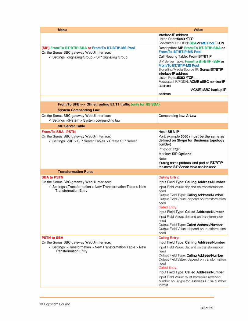
© Copyright Equant 30 of 59
Menu Value
interface IP addressinterface IP addressinterface IP addressinterface IP address Listen Ports:5065065065060000 /T/T/T/TCPCPCPCP Federated IP/FQDN: SBASBASBASBA orororor MS MS MS MS PoolPoolPoolPool FQDNFQDNFQDNFQDN
(SIP) From/To BT/BTIP-SBA or From/To BT/BTIP-MS Pool
On the Sonus SBC gateway WebUi Interface:
� Settings >Signaling Group > SIP Signaling Group
Description: SIP From/To BT/BTIP-SBA or From/To BT/BTIP-MS Pool
Call Routing Table: From BT/BTIP
SIP Server Table: From/To BT/BTIP From/To BT/BTIP From/To BT/BTIP From/To BT/BTIP ----SBASBASBASBA or or or or From/To BT/BTIPFrom/To BT/BTIPFrom/To BT/BTIPFrom/To BT/BTIP----MS PoolMS PoolMS PoolMS Pool Signalling/Media Source IP: Sonus Sonus Sonus Sonus BT/BTIPBT/BTIPBT/BTIPBT/BTIP interfaceinterfaceinterfaceinterface IP addressIP addressIP addressIP address Listen Ports:5065065065060000 /T/T/T/TCPCPCPCP Federated IP/FQDN: ACME aSBC nominal IP ACME aSBC nominal IP ACME aSBC nominal IP ACME aSBC nominal IP addressaddressaddressaddress ACME aSBC backup IP ACME aSBC backup IP ACME aSBC backup IP ACME aSBC backup IP addressaddressaddressaddress
From/To SFB <-> Offnet routing E1/T1 traffic (only for RS SBA)
System Companding Law
On the Sonus SBC gateway WebUi Interface:
� Settings >System > System companding law
Companding law: A-Law
SIP Server Table
From/To SBA –PSTN
On the Sonus SBC gateway WebUi Interface:
� Settings >SIP > SIP Server Tables > Create SIP Server
Host: SBA IP
Port: example 5060 (must be the same as defined on Skype for Business topology builder)
Protocol: TTTTCPCPCPCP
Monitor: SIP Options
Note: If using same protocol and port as BT/BTIP If using same protocol and port as BT/BTIP If using same protocol and port as BT/BTIP If using same protocol and port as BT/BTIP the same SIP Server table can be usedthe same SIP Server table can be usedthe same SIP Server table can be usedthe same SIP Server table can be used
Transformation Rules
SBA to PSTN
On the Sonus SBC gateway WebUi Interface:
� Settings >Transformation > New Transformation Table > New Transformation Entry
Calling Entry:
Input Field Type: Calling Address/Number
Input Field Value: depend on transformation need Output Field Type: Calling Address/NumberCalling Address/NumberCalling Address/NumberCalling Address/Number Output Field Value: depend on transformation need Called Entry:
Input Field Type: Called Address/Number
Input Field Value: depend on transformation need Output Field Type: CalledCalledCalledCalled Address/NumberAddress/NumberAddress/NumberAddress/Number Output Field Value: depend on transformation need
PSTN to SBA
On the Sonus SBC gateway WebUi Interface:
� Settings >Transformation > New Transformation Table > New Transformation Entry
Calling Entry:
Input Field Type: Calling Address/Number
Input Field Value: depend on transformation need Output Field Type: Calling Address/NumberCalling Address/NumberCalling Address/NumberCalling Address/Number Output Field Value: depend on transformation need Called Entry:
Input Field Type: Called Address/Number
Input Field Value: must normalize received number on Skype for Business E.164 number format
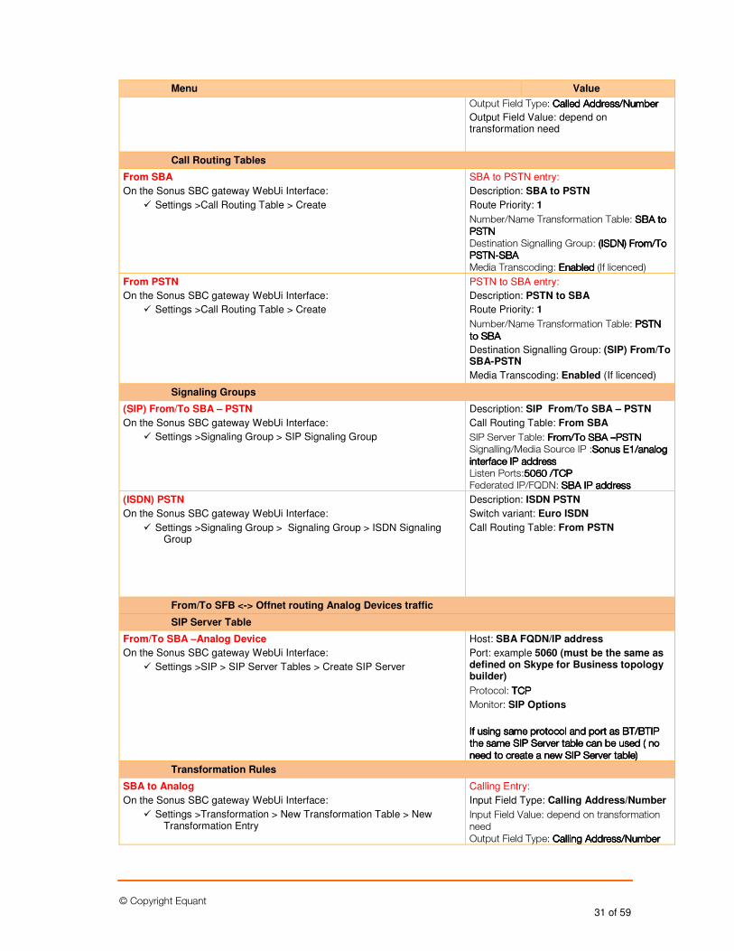
© Copyright Equant 31 of 59
Menu Value
Output Field Type: CalledCalledCalledCalled Address/NumberAddress/NumberAddress/NumberAddress/Number
Output Field Value: depend on transformation need
Call Routing Tables
From SBA
On the Sonus SBC gateway WebUi Interface:
� Settings >Call Routing Table > Create
SBA to PSTN entry:
Description: SBA to PSTN
Route Priority: 1
Number/Name Transformation Table: SBASBASBASBA to to to to PSTNPSTNPSTNPSTN Destination Signalling Group: ((((ISDNISDNISDNISDN)))) From/To From/To From/To From/To PSTNPSTNPSTNPSTN----SBASBASBASBA Media Transcoding: EnabledEnabledEnabledEnabled (If licenced)
From PSTN
On the Sonus SBC gateway WebUi Interface:
� Settings >Call Routing Table > Create
PSTN to SBA entry:
Description: PSTN to SBA
Route Priority: 1
Number/Name Transformation Table: PSTNPSTNPSTNPSTN to to to to SBASBASBASBA
Destination Signalling Group: (SIP) From/To SBA-PSTN
Media Transcoding: Enabled (If licenced)
Signaling Groups
(SIP) From/To SBA – PSTN
On the Sonus SBC gateway WebUi Interface:
� Settings >Signaling Group > SIP Signaling Group
Description: SIP From/To SBA – PSTN
Call Routing Table: From SBA
SIP Server Table: From/To From/To From/To From/To SBA SBA SBA SBA ––––PSTNPSTNPSTNPSTN Signalling/Media Source IP :Sonus Sonus Sonus Sonus E1/analogE1/analogE1/analogE1/analog interface IP addressinterface IP addressinterface IP addressinterface IP address Listen Ports:5065065065060 /TCP0 /TCP0 /TCP0 /TCP Federated IP/FQDN: SBA IP addressSBA IP addressSBA IP addressSBA IP address
(ISDN) PSTN
On the Sonus SBC gateway WebUi Interface:
� Settings >Signaling Group > Signaling Group > ISDN Signaling Group
Description: ISDN PSTN
Switch variant: Euro ISDN
Call Routing Table: From PSTN
From/To SFB <-> Offnet routing Analog Devices traffic
SIP Server Table
From/To SBA –Analog Device
On the Sonus SBC gateway WebUi Interface:
� Settings >SIP > SIP Server Tables > Create SIP Server
Host: SBA FQDN/IP address
Port: example 5060 (must be the same as defined on Skype for Business topology builder)
Protocol: TCPTCPTCPTCP
Monitor: SIP Options
If using same protocol and port as BT/BTIP If using same protocol and port as BT/BTIP If using same protocol and port as BT/BTIP If using same protocol and port as BT/BTIP the same SIP Server table can be usedthe same SIP Server table can be usedthe same SIP Server table can be usedthe same SIP Server table can be used ( no ( no ( no ( no need to create a new SIP Server table)need to create a new SIP Server table)need to create a new SIP Server table)need to create a new SIP Server table)
Transformation Rules
SBA to Analog
On the Sonus SBC gateway WebUi Interface:
� Settings >Transformation > New Transformation Table > New Transformation Entry
Calling Entry:
Input Field Type: Calling Address/Number
Input Field Value: depend on transformation need Output Field Type: Calling Address/NumberCalling Address/NumberCalling Address/NumberCalling Address/Number
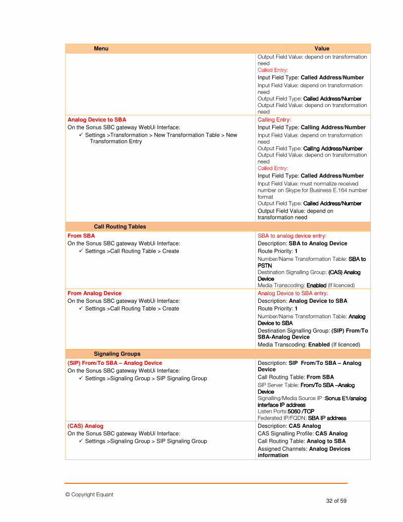
© Copyright Equant 32 of 59
Menu Value
Output Field Value: depend on transformation need Called Entry:
Input Field Type: Called Address/Number
Input Field Value: depend on transformation need Output Field Type: CalledCalledCalledCalled Address/NumberAddress/NumberAddress/NumberAddress/Number Output Field Value: depend on transformation need
Analog Device to SBA
On the Sonus SBC gateway WebUi Interface:
� Settings >Transformation > New Transformation Table > New Transformation Entry
Calling Entry:
Input Field Type: Calling Address/Number
Input Field Value: depend on transformation need Output Field Type: Calling Address/NumberCalling Address/NumberCalling Address/NumberCalling Address/Number Output Field Value: depend on transformation need Called Entry:
Input Field Type: Called Address/Number
Input Field Value: must normalize received number on Skype for Business E.164 number format Output Field Type: CalledCalledCalledCalled Address/NumberAddress/NumberAddress/NumberAddress/Number
Output Field Value: depend on transformation need
Call Routing Tables
From SBA
On the Sonus SBC gateway WebUi Interface:
� Settings >Call Routing Table > Create
SBA to analog device entry:
Description: SBA to Analog Device
Route Priority: 1
Number/Name Transformation Table: SBASBASBASBA to to to to PSTNPSTNPSTNPSTN Destination Signalling Group: ((((CASCASCASCAS)))) Analog Analog Analog Analog DeviceDeviceDeviceDevice Media Transcoding: EnabledEnabledEnabledEnabled (If licenced)
From Analog Device
On the Sonus SBC gateway WebUi Interface:
� Settings >Call Routing Table > Create
Analog Device to SBA entry:
Description: Analog Device to SBA
Route Priority: 1
Number/Name Transformation Table: Analog Analog Analog Analog DeviceDeviceDeviceDevice to to to to SBASBASBASBA
Destination Signalling Group: (SIP) From/To SBA-Analog Device
Media Transcoding: Enabled (If licenced)
Signaling Groups
(SIP) From/To SBA – Analog Device
On the Sonus SBC gateway WebUi Interface:
� Settings >Signaling Group > SIP Signaling Group
Description: SIP From/To SBA – Analog Device
Call Routing Table: From SBA
SIP Server Table: From/To From/To From/To From/To SBA SBA SBA SBA ––––Analog Analog Analog Analog DeviceDeviceDeviceDevice Signalling/Media Source IP :Sonus Sonus Sonus Sonus E1/analogE1/analogE1/analogE1/analog interface IP addressinterface IP addressinterface IP addressinterface IP address Listen Ports:5060 /TCP5060 /TCP5060 /TCP5060 /TCP Federated IP/FQDN: SBA SBA SBA SBA IP addressIP addressIP addressIP address
(CAS) Analog
On the Sonus SBC gateway WebUi Interface:
� Settings >Signaling Group > SIP Signaling Group
Description: CAS Analog
CAS Signalling Profile: CAS Analog
Call Routing Table: Analog to SBA
Assigned Channels: Analog Devices information
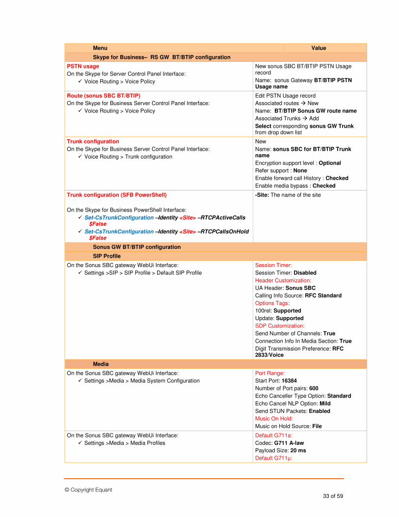
© Copyright Equant 33 of 59
Menu Value
Skype for Business– RS GW BT/BTIP configuration
PSTN usage
On the Skype for Server Control Panel Interface:
� Voice Routing > Voice Policy
New sonus SBC BT/BTIP PSTN Usage record
Name: sonus Gateway BT/BTIP PSTN Usage name
Route (sonus SBC BT/BTIP)
On the Skype for Business Server Control Panel Interface:
� Voice Routing > Voice Policy
Edit PSTN Usage record
Associated routes � New
Name: BT/BTIP Sonus GW route name
Associated Trunks � Add
Select corresponding sonus GW Trunk from drop down list
Trunk configuration
On the Skype for Business Server Control Panel Interface:
� Voice Routing > Trunk configuration
New
Name: sonus SBC for BT/BTIP Trunk name
Encryption support level : Optional
Refer support : None
Enable forward call History : Checked
Enable media bypass : Checked
Trunk configuration (SFB PowerShell)
On the Skype for Business PowerShell Interface:
� Set-CsTrunkConfiguration –Identity <Site> –RTCPActiveCalls $False
� Set-CsTrunkConfiguration –Identity <Site> –RTCPCallsOnHold $False
-Site: The name of the site
Sonus GW BT/BTIP configuration
SIP Profile
On the Sonus SBC gateway WebUi Interface:
� Settings >SIP > SIP Profile > Default SIP Profile
Session Timer:
Session Timer: Disabled
Header Customization:
UA Header: Sonus SBC
Calling Info Source: RFC Standard
Options Tags:
100rel: Supported
Update: Supported
SDP Customization:
Send Number of Channels: True
Connection Info In Media Section: True
Digit Transmission Preference: RFC 2833/Voice
Media
On the Sonus SBC gateway WebUi Interface:
� Settings >Media > Media System Configuration
Port Range:
Start Port: 16384
Number of Port pairs: 600
Echo Canceller Type Option: Standard
Echo Cancel NLP Option: Mild
Send STUN Packets: Enabled
Music On Hold:
Music on Hold Source: File
On the Sonus SBC gateway WebUi Interface:
� Settings >Media > Media Profiles
Default G711a:
Codec: G711 A-law
Payload Size: 20 ms
Default G711µ:
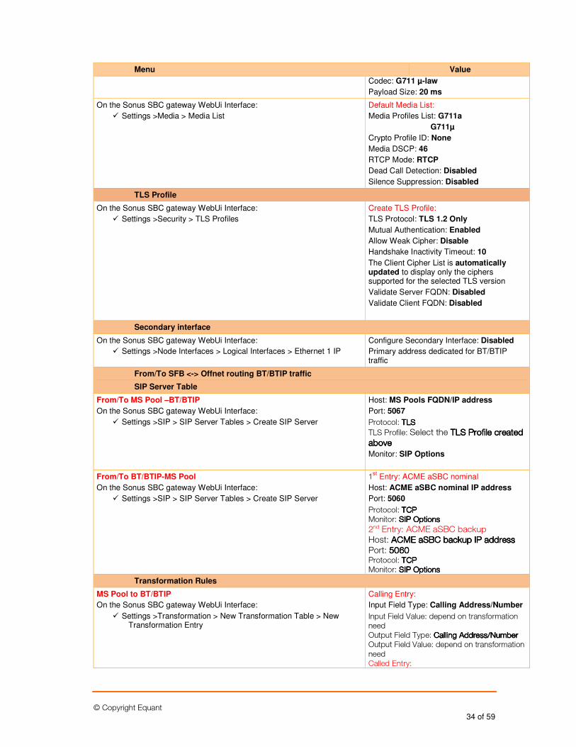
© Copyright Equant 34 of 59
Menu Value
Codec: G711 µ-law
Payload Size: 20 ms
On the Sonus SBC gateway WebUi Interface:
� Settings >Media > Media List
Default Media List:
Media Profiles List: G711a
G711µ
Crypto Profile ID: None
Media DSCP: 46
RTCP Mode: RTCP
Dead Call Detection: Disabled
Silence Suppression: Disabled
TLS Profile
On the Sonus SBC gateway WebUi Interface:
� Settings >Security > TLS Profiles
Create TLS Profile:
TLS Protocol: TLS 1.2 Only
Mutual Authentication: Enabled
Allow Weak Cipher: Disable
Handshake Inactivity Timeout: 10
The Client Cipher List is automatically updated to display only the ciphers supported for the selected TLS version
Validate Server FQDN: Disabled
Validate Client FQDN: Disabled
Secondary interface
On the Sonus SBC gateway WebUi Interface:
� Settings >Node Interfaces > Logical Interfaces > Ethernet 1 IP
Configure Secondary Interface: Disabled
Primary address dedicated for BT/BTIP traffic
From/To SFB <-> Offnet routing BT/BTIP traffic
SIP Server Table
From/To MS Pool –BT/BTIP
On the Sonus SBC gateway WebUi Interface:
� Settings >SIP > SIP Server Tables > Create SIP Server
Host: MS Pools FQDN/IP address
Port: 5067
Protocol: TTTTLSLSLSLS
TLS Profile: Select the TLS Profile created TLS Profile created TLS Profile created TLS Profile created aboveaboveaboveabove
Monitor: SIP Options
From/To BT/BTIP-MS Pool
On the Sonus SBC gateway WebUi Interface:
� Settings >SIP > SIP Server Tables > Create SIP Server
1st Entry: ACME aSBC nominal
Host: ACME aSBC nominal IP address
Port: 5060
Protocol: TCPTCPTCPTCP Monitor: SIP OptionsSIP OptionsSIP OptionsSIP Options 2nd Entry: ACME aSBC backup Host: ACME aSBC backup IP addressACME aSBC backup IP addressACME aSBC backup IP addressACME aSBC backup IP address Port: 5060506050605060 Protocol: TCPTCPTCPTCP Monitor: SIP OptionsSIP OptionsSIP OptionsSIP Options
Transformation Rules
MS Pool to BT/BTIP
On the Sonus SBC gateway WebUi Interface:
� Settings >Transformation > New Transformation Table > New Transformation Entry
Calling Entry:
Input Field Type: Calling Address/Number
Input Field Value: depend on transformation need Output Field Type: Calling Address/NumberCalling Address/NumberCalling Address/NumberCalling Address/Number Output Field Value: depend on transformation need Called Entry:
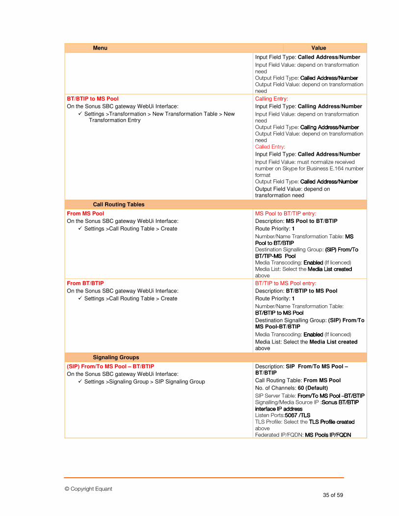
© Copyright Equant 35 of 59
Menu Value
Input Field Type: Called Address/Number
Input Field Value: depend on transformation need Output Field Type: CalledCalledCalledCalled Address/NumberAddress/NumberAddress/NumberAddress/Number Output Field Value: depend on transformation need
BT/BTIP to MS Pool
On the Sonus SBC gateway WebUi Interface:
� Settings >Transformation > New Transformation Table > New Transformation Entry
Calling Entry:
Input Field Type: Calling Address/Number
Input Field Value: depend on transformation need Output Field Type: CallingCallingCallingCalling Address/NumberAddress/NumberAddress/NumberAddress/Number Output Field Value: depend on transformation need Called Entry:
Input Field Type: Called Address/Number
Input Field Value: must normalize received number on Skype for Business E.164 number format Output Field Type: CalledCalledCalledCalled Address/NumberAddress/NumberAddress/NumberAddress/Number
Output Field Value: depend on transformation need
Call Routing Tables
From MS Pool
On the Sonus SBC gateway WebUi Interface:
� Settings >Call Routing Table > Create
MS Pool to BT/TIP entry:
Description: MS Pool to BT/BTIP
Route Priority: 1
Number/Name Transformation Table: MS MS MS MS PoolPoolPoolPool to to to to BT/BTIPBT/BTIPBT/BTIPBT/BTIP Destination Signalling Group: ((((SIPSIPSIPSIP)))) From/To From/To From/To From/To BT/TIPBT/TIPBT/TIPBT/TIP----MS PoolMS PoolMS PoolMS Pool Media Transcoding: EnabledEnabledEnabledEnabled (If licenced) Media List: Select the Media List createdMedia List createdMedia List createdMedia List created above
From BT/BTIP
On the Sonus SBC gateway WebUi Interface:
� Settings >Call Routing Table > Create
BT/TIP to MS Pool entry:
Description: BT/BTIP to MS Pool
Route Priority: 1
Number/Name Transformation Table: BT/BTIPBT/BTIPBT/BTIPBT/BTIP to to to to MS PoolMS PoolMS PoolMS Pool
Destination Signalling Group: (SIP) From/To MS Pool-BT/BTIP
Media Transcoding: EnabledEnabledEnabledEnabled (If licenced)
Media List: Select the Media List created above
Signaling Groups
(SIP) From/To MS Pool – BT/BTIP
On the Sonus SBC gateway WebUi Interface:
� Settings >Signaling Group > SIP Signaling Group
Description: SIP From/To MS Pool – BT/BTIP
Call Routing Table: From MS Pool
No. of Channels: 60 (Default)
SIP Server Table: From/To MS PoolFrom/To MS PoolFrom/To MS PoolFrom/To MS Pool ––––BT/BTIPBT/BTIPBT/BTIPBT/BTIP Signalling/Media Source IP :Sonus Sonus Sonus Sonus BT/BTIPBT/BTIPBT/BTIPBT/BTIP interface IP addressinterface IP addressinterface IP addressinterface IP address Listen Ports:5065065065067777 /T/T/T/TLSLSLSLS TLS Profile: Select the TLS Profile created TLS Profile created TLS Profile created TLS Profile created above Federated IP/FQDN: MS PoolsMS PoolsMS PoolsMS Pools IP/IP/IP/IP/FQDNFQDNFQDNFQDN
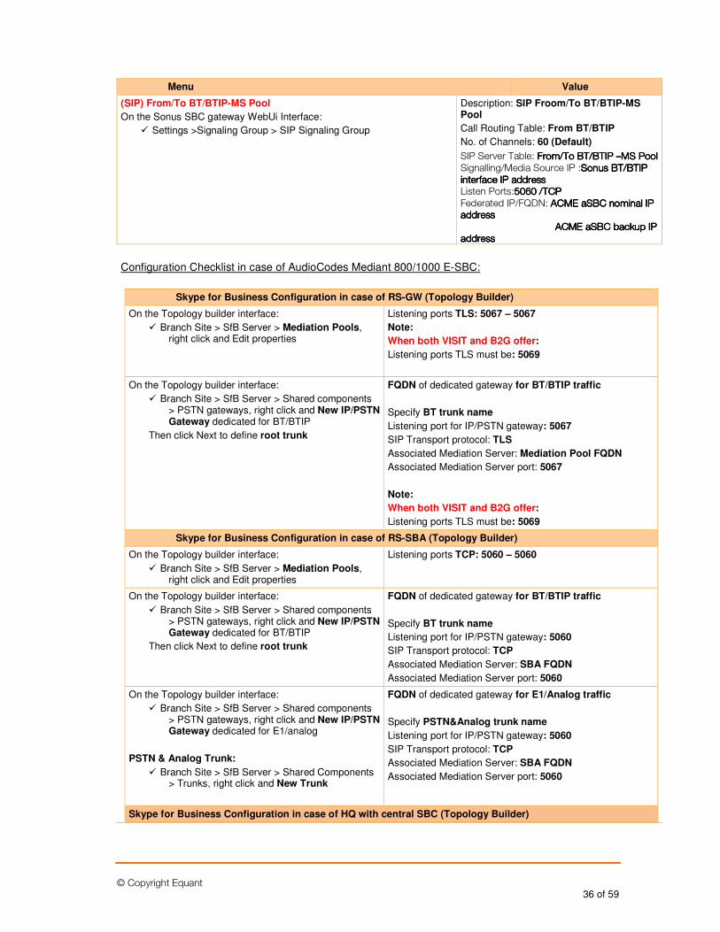
© Copyright Equant 36 of 59
Menu Value
(SIP) From/To BT/BTIP-MS Pool
On the Sonus SBC gateway WebUi Interface:
� Settings >Signaling Group > SIP Signaling Group
Description: SIP Froom/To BT/BTIP-MS Pool
Call Routing Table: From BT/BTIP
No. of Channels: 60 (Default)
SIP Server Table: From/To BTFrom/To BTFrom/To BTFrom/To BT/BTIP /BTIP /BTIP /BTIP ––––MS PoolMS PoolMS PoolMS Pool Signalling/Media Source IP :Sonus Sonus Sonus Sonus BT/BTIPBT/BTIPBT/BTIPBT/BTIP interface IP addressinterface IP addressinterface IP addressinterface IP address Listen Ports:5065065065060000 /T/T/T/TCPCPCPCP Federated IP/FQDN: ACME aSBC nominal IP ACME aSBC nominal IP ACME aSBC nominal IP ACME aSBC nominal IP addressaddressaddressaddress ACME aSBC backup IP ACME aSBC backup IP ACME aSBC backup IP ACME aSBC backup IP addressaddressaddressaddress
Configuration Checklist in case of AudioCodes Mediant 800/1000 E-SBC:
Skype for Business Configuration in case of RS-GW (Topology Builder)
On the Topology builder interface:
� Branch Site > SfB Server > Mediation Pools, right click and Edit properties
Listening ports TLS: 5067 – 5067
Note:
When both VISIT and B2G offer:
Listening ports TLS must be: 5069
On the Topology builder interface:
� Branch Site > SfB Server > Shared components > PSTN gateways, right click and New IP/PSTN Gateway dedicated for BT/BTIP
Then click Next to define root trunk
FQDN of dedicated gateway for BT/BTIP traffic
Specify BT trunk name
Listening port for IP/PSTN gateway: 5067
SIP Transport protocol: TLS
Associated Mediation Server: Mediation Pool FQDN
Associated Mediation Server port: 5067
Note:
When both VISIT and B2G offer:
Listening ports TLS must be: 5069
Skype for Business Configuration in case of RS-SBA (Topology Builder)
On the Topology builder interface:
� Branch Site > SfB Server > Mediation Pools, right click and Edit properties
Listening ports TCP: 5060 – 5060
On the Topology builder interface:
� Branch Site > SfB Server > Shared components > PSTN gateways, right click and New IP/PSTN Gateway dedicated for BT/BTIP
Then click Next to define root trunk
FQDN of dedicated gateway for BT/BTIP traffic
Specify BT trunk name
Listening port for IP/PSTN gateway: 5060
SIP Transport protocol: TCP
Associated Mediation Server: SBA FQDN
Associated Mediation Server port: 5060
On the Topology builder interface:
� Branch Site > SfB Server > Shared components > PSTN gateways, right click and New IP/PSTN Gateway dedicated for E1/analog
PSTN & Analog Trunk:
� Branch Site > SfB Server > Shared Components > Trunks, right click and New Trunk
FQDN of dedicated gateway for E1/Analog traffic
Specify PSTN&Analog trunk name
Listening port for IP/PSTN gateway: 5060
SIP Transport protocol: TCP
Associated Mediation Server: SBA FQDN
Associated Mediation Server port: 5060
Skype for Business Configuration in case of HQ with central SBC (Topology Builder)
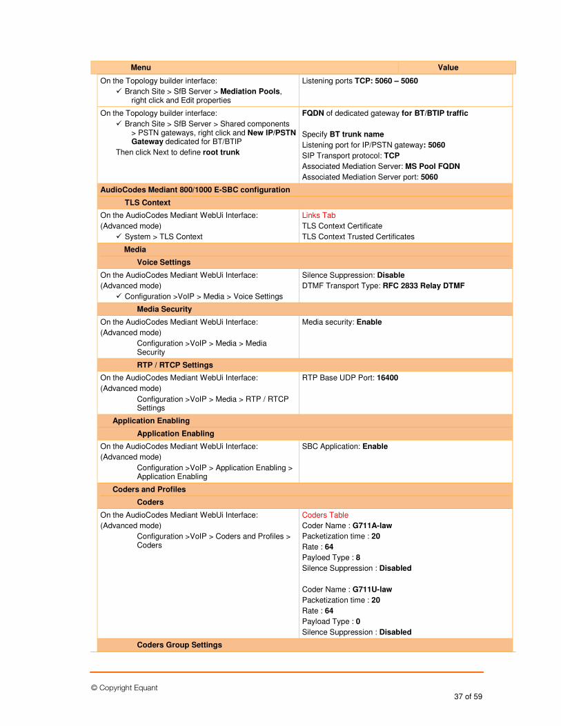
© Copyright Equant 37 of 59
Menu Value
On the Topology builder interface:
� Branch Site > SfB Server > Mediation Pools, right click and Edit properties
Listening ports TCP: 5060 – 5060
On the Topology builder interface:
� Branch Site > SfB Server > Shared components > PSTN gateways, right click and New IP/PSTN Gateway dedicated for BT/BTIP
Then click Next to define root trunk
FQDN of dedicated gateway for BT/BTIP traffic
Specify BT trunk name
Listening port for IP/PSTN gateway: 5060
SIP Transport protocol: TCP
Associated Mediation Server: MS Pool FQDN
Associated Mediation Server port: 5060
AudioCodes Mediant 800/1000 E-SBC configuration
TLS Context
On the AudioCodes Mediant WebUi Interface:
(Advanced mode)
� System > TLS Context
Links Tab
TLS Context Certificate
TLS Context Trusted Certificates
Media
Voice Settings
On the AudioCodes Mediant WebUi Interface:
(Advanced mode)
� Configuration >VoIP > Media > Voice Settings
Silence Suppression: Disable
DTMF Transport Type: RFC 2833 Relay DTMF
Media Security
On the AudioCodes Mediant WebUi Interface:
(Advanced mode)
Configuration >VoIP > Media > Media Security
Media security: Enable
RTP / RTCP Settings
On the AudioCodes Mediant WebUi Interface:
(Advanced mode)
Configuration >VoIP > Media > RTP / RTCP Settings
RTP Base UDP Port: 16400
Application Enabling
Application Enabling
On the AudioCodes Mediant WebUi Interface:
(Advanced mode)
Configuration >VoIP > Application Enabling > Application Enabling
SBC Application: Enable
Coders and Profiles
Coders
On the AudioCodes Mediant WebUi Interface:
(Advanced mode)
Configuration >VoIP > Coders and Profiles > Coders
Coders Table
Coder Name : G711A-law
Packetization time : 20
Rate : 64
Payloed Type : 8
Silence Suppression : Disabled
Coder Name : G711U-law
Packetization time : 20
Rate : 64
Payload Type : 0
Silence Suppression : Disabled
Coders Group Settings
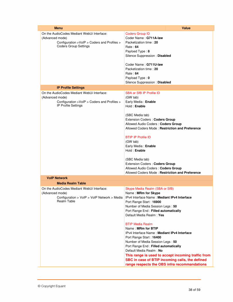
© Copyright Equant 38 of 59
Menu Value
On the AudioCodes Mediant WebUi Interface:
(Advanced mode)
Configuration >VoIP > Coders and Profiles > Coders Group Settings
Coders Group ID
Coder Name : G711A-law
Packetization time : 20
Rate : 64
Payloed Type : 8
Silence Suppression : Disabled
Coder Name : G711U-law
Packetization time : 20
Rate : 64
Payload Type : 0
Silence Suppression : Disabled
IP Profile Settings
On the AudioCodes Mediant WebUi Interface:
(Advanced mode)
Configuration >VoIP > Coders and Profiles > IP Profile Settings
SBA or SfB IP Profile ID
(GW tab)
Early Media : Enable
Hold : Enable
(SBC Media tab)
Extension Coders : Coders Group
Allowed Audio Coders : Coders Group
Allowed Coders Mode : Restriction and Preference
BTIP IP Profile ID
(GW tab)
Early Media : Enable
Hold : Enable
(SBC Media tab)
Extension Coders : Coders Group
Allowed Audio Coders : Coders Group
Allowed Coders Mode : Restriction and Preference
VoIP Network
Media Realm Table
On the AudioCodes Mediant WebUi Interface:
(Advanced mode)
Configuration > VoIP > VoIP Network > Media Realm Table
Skype Media Realm (SBA or SfB)
Name : MRm for Skype
IPv4 Interface Name : Mediant IPv4 Interface
Port Range Start : 16900
Number of Media Session Legs : 50
Port Range End : Filled automatically
Default Media Realm : Yes
BTIP Media Realm
Name : MRm for BTIP
IPv4 Interface Name : Mediant IPv4 Interface
Port Range Start : 16400
Number of Media Session Legs : 50
Port Range End : Filled automatically
Default Media Realm : No
This range is used to accept incoming traffic from
SBC in case of BTIP incoming calls, the defined
range respects the OBS infra recommandations
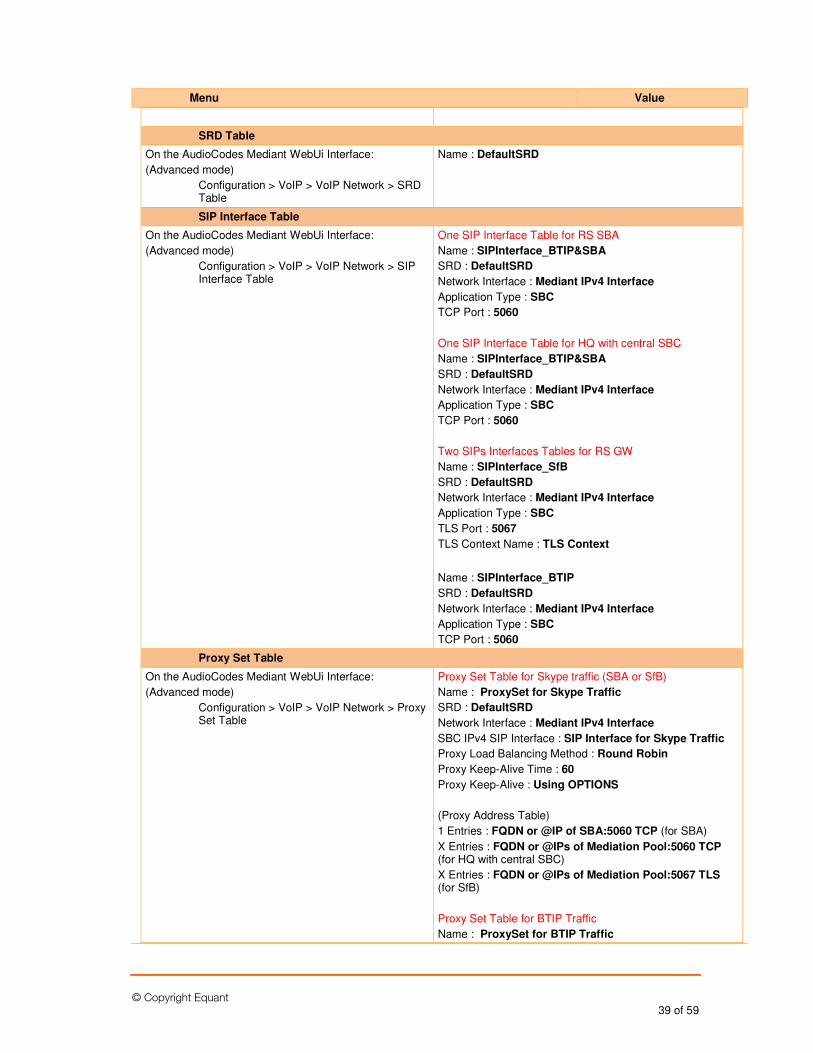
© Copyright Equant 39 of 59
Menu Value
SRD Table
On the AudioCodes Mediant WebUi Interface:
(Advanced mode)
Configuration > VoIP > VoIP Network > SRD Table
Name : DefaultSRD
SIP Interface Table
On the AudioCodes Mediant WebUi Interface:
(Advanced mode)
Configuration > VoIP > VoIP Network > SIP Interface Table
One SIP Interface Table for RS SBA
Name : SIPInterface_BTIP&SBA
SRD : DefaultSRD
Network Interface : Mediant IPv4 Interface
Application Type : SBC
TCP Port : 5060
One SIP Interface Table for HQ with central SBC
Name : SIPInterface_BTIP&SBA
SRD : DefaultSRD
Network Interface : Mediant IPv4 Interface
Application Type : SBC
TCP Port : 5060
Two SIPs Interfaces Tables for RS GW
Name : SIPInterface_SfB
SRD : DefaultSRD
Network Interface : Mediant IPv4 Interface
Application Type : SBC
TLS Port : 5067
TLS Context Name : TLS Context
Name : SIPInterface_BTIP
SRD : DefaultSRD
Network Interface : Mediant IPv4 Interface
Application Type : SBC
TCP Port : 5060
Proxy Set Table
On the AudioCodes Mediant WebUi Interface:
(Advanced mode)
Configuration > VoIP > VoIP Network > Proxy Set Table
Proxy Set Table for Skype traffic (SBA or SfB)
Name : ProxySet for Skype Traffic
SRD : DefaultSRD
Network Interface : Mediant IPv4 Interface
SBC IPv4 SIP Interface : SIP Interface for Skype Traffic
Proxy Load Balancing Method : Round Robin
Proxy Keep-Alive Time : 60
Proxy Keep-Alive : Using OPTIONS
(Proxy Address Table)
1 Entries : FQDN or @IP of SBA:5060 TCP (for SBA)
X Entries : FQDN or @IPs of Mediation Pool:5060 TCP (for HQ with central SBC)
X Entries : FQDN or @IPs of Mediation Pool:5067 TLS (for SfB)
Proxy Set Table for BTIP Traffic
Name : ProxySet for BTIP Traffic
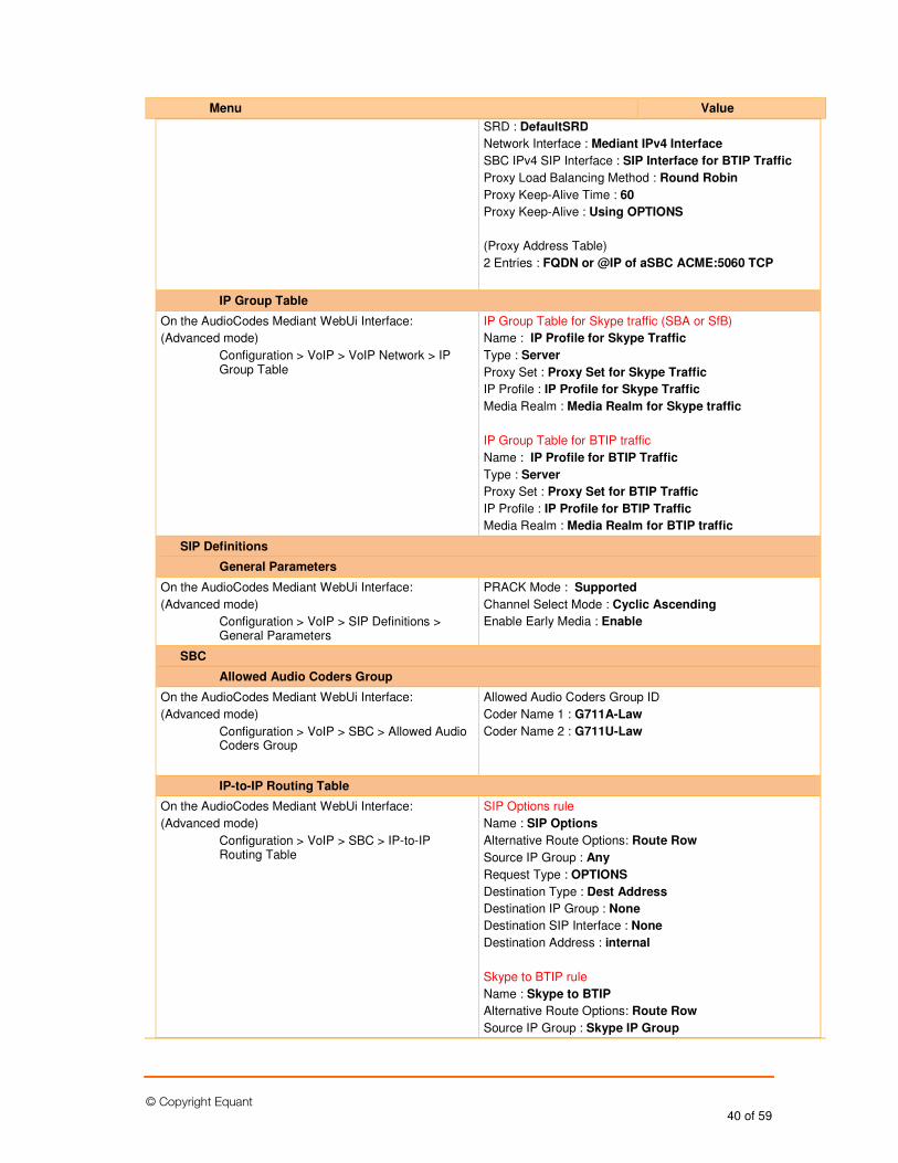
© Copyright Equant 40 of 59
Menu Value
SRD : DefaultSRD
Network Interface : Mediant IPv4 Interface
SBC IPv4 SIP Interface : SIP Interface for BTIP Traffic
Proxy Load Balancing Method : Round Robin
Proxy Keep-Alive Time : 60
Proxy Keep-Alive : Using OPTIONS
(Proxy Address Table)
2 Entries : FQDN or @IP of aSBC ACME:5060 TCP
IP Group Table
On the AudioCodes Mediant WebUi Interface:
(Advanced mode)
Configuration > VoIP > VoIP Network > IP Group Table
IP Group Table for Skype traffic (SBA or SfB)
Name : IP Profile for Skype Traffic
Type : Server
Proxy Set : Proxy Set for Skype Traffic
IP Profile : IP Profile for Skype Traffic
Media Realm : Media Realm for Skype traffic
IP Group Table for BTIP traffic
Name : IP Profile for BTIP Traffic
Type : Server
Proxy Set : Proxy Set for BTIP Traffic
IP Profile : IP Profile for BTIP Traffic
Media Realm : Media Realm for BTIP traffic
SIP Definitions
General Parameters
On the AudioCodes Mediant WebUi Interface:
(Advanced mode)
Configuration > VoIP > SIP Definitions > General Parameters
PRACK Mode : Supported
Channel Select Mode : Cyclic Ascending
Enable Early Media : Enable
SBC
Allowed Audio Coders Group
On the AudioCodes Mediant WebUi Interface:
(Advanced mode)
Configuration > VoIP > SBC > Allowed Audio Coders Group
Allowed Audio Coders Group ID
Coder Name 1 : G711A-Law
Coder Name 2 : G711U-Law
IP-to-IP Routing Table
On the AudioCodes Mediant WebUi Interface:
(Advanced mode)
Configuration > VoIP > SBC > IP-to-IP Routing Table
SIP Options rule
Name : SIP Options
Alternative Route Options: Route Row
Source IP Group : Any
Request Type : OPTIONS
Destination Type : Dest Address
Destination IP Group : None
Destination SIP Interface : None
Destination Address : internal
Skype to BTIP rule
Name : Skype to BTIP
Alternative Route Options: Route Row
Source IP Group : Skype IP Group
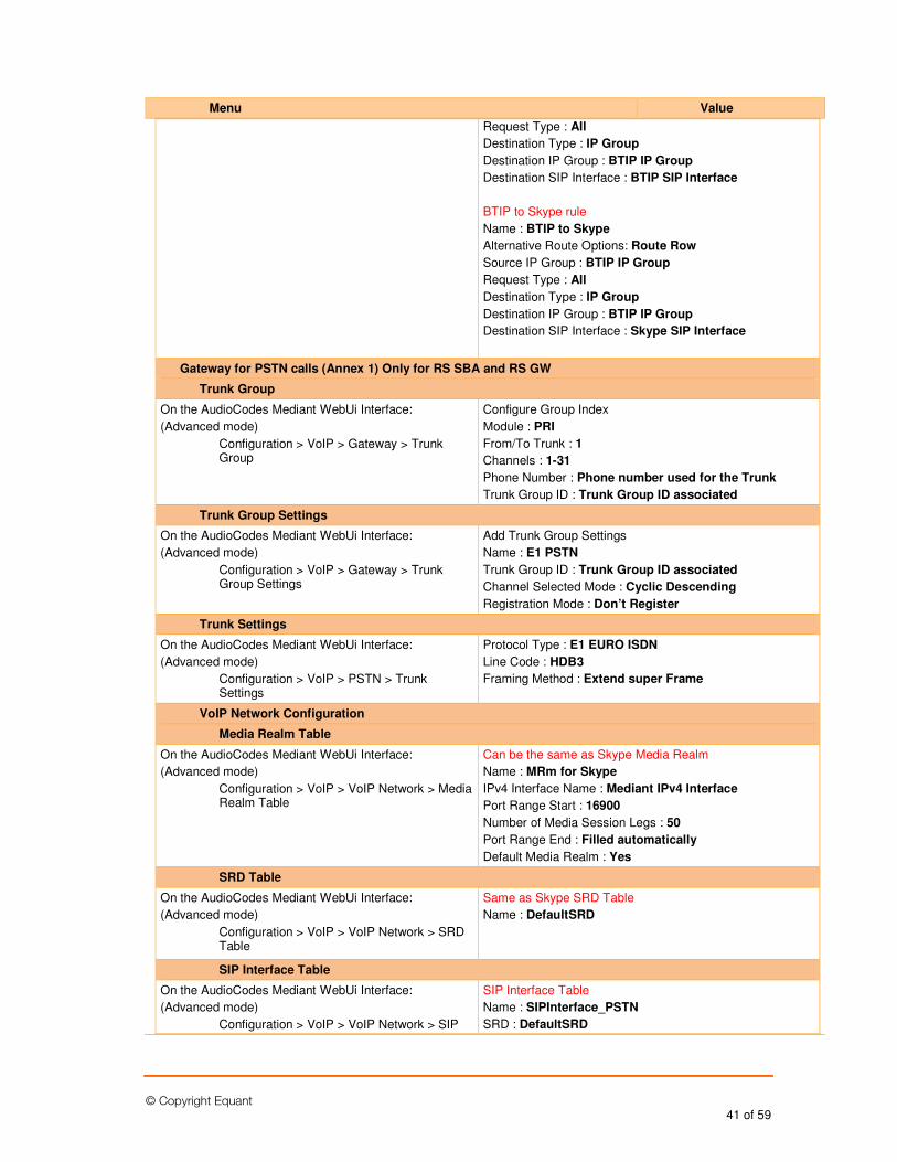
© Copyright Equant 41 of 59
Menu Value
Request Type : All
Destination Type : IP Group
Destination IP Group : BTIP IP Group
Destination SIP Interface : BTIP SIP Interface
BTIP to Skype rule
Name : BTIP to Skype
Alternative Route Options: Route Row
Source IP Group : BTIP IP Group
Request Type : All
Destination Type : IP Group
Destination IP Group : BTIP IP Group
Destination SIP Interface : Skype SIP Interface
Gateway for PSTN calls (Annex 1) Only for RS SBA and RS GW
Trunk Group
On the AudioCodes Mediant WebUi Interface:
(Advanced mode)
Configuration > VoIP > Gateway > Trunk Group
Configure Group Index
Module : PRI
From/To Trunk : 1
Channels : 1-31
Phone Number : Phone number used for the Trunk
Trunk Group ID : Trunk Group ID associated
Trunk Group Settings
On the AudioCodes Mediant WebUi Interface:
(Advanced mode)
Configuration > VoIP > Gateway > Trunk Group Settings
Add Trunk Group Settings
Name : E1 PSTN
Trunk Group ID : Trunk Group ID associated
Channel Selected Mode : Cyclic Descending
Registration Mode : Don’t Register
Trunk Settings
On the AudioCodes Mediant WebUi Interface:
(Advanced mode)
Configuration > VoIP > PSTN > Trunk Settings
Protocol Type : E1 EURO ISDN
Line Code : HDB3
Framing Method : Extend super Frame
VoIP Network Configuration
Media Realm Table
On the AudioCodes Mediant WebUi Interface:
(Advanced mode)
Configuration > VoIP > VoIP Network > Media Realm Table
Can be the same as Skype Media Realm
Name : MRm for Skype
IPv4 Interface Name : Mediant IPv4 Interface
Port Range Start : 16900
Number of Media Session Legs : 50
Port Range End : Filled automatically
Default Media Realm : Yes
SRD Table
On the AudioCodes Mediant WebUi Interface:
(Advanced mode)
Configuration > VoIP > VoIP Network > SRD Table
Same as Skype SRD Table
Name : DefaultSRD
SIP Interface Table
On the AudioCodes Mediant WebUi Interface:
(Advanced mode)
Configuration > VoIP > VoIP Network > SIP
SIP Interface Table
Name : SIPInterface_PSTN
SRD : DefaultSRD
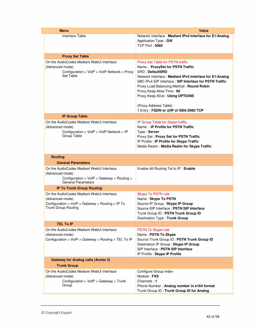
© Copyright Equant 42 of 59
Menu Value
Interface Table Network Interface : Mediant IPv4 Interface for E1/Analog
Application Type : GW
TCP Port : 5060
Proxy Set Table
On the AudioCodes Mediant WebUi Interface:
(Advanced mode)
Configuration > VoIP > VoIP Network > Proxy Set Table
Proxy Set Table for PSTN traffic
Name : ProxySet for PSTN Traffic
SRD : DefaultSRD
Network Interface : Mediant IPv4 Interface for E1/Analog
SBC IPv4 SIP Interface : SIP Interface for PSTN Traffic
Proxy Load Balancing Method : Round Robin
Proxy Keep-Alive Time : 60
Proxy Keep-Alive : Using OPTIONS
(Proxy Address Table)
1 Entry : FQDN or @IP of SBA:5060 TCP
IP Group Table
On the AudioCodes Mediant WebUi Interface:
(Advanced mode)
Configuration > VoIP > VoIP Network > IP Group Table
IP Group Table for Skype traffic
Name : IP Profile for PSTN Traffic
Type : Server
Proxy Set : Proxy Set for PSTN Traffic
IP Profile : IP Profile for Skype Traffic
Media Realm : Media Realm for Skype Traffic
Routing
General Parameters
On the AudioCodes Mediant WebUi Interface:
(Advanced mode)
Configuration > VoIP > Gateway > Routing > General Parameters
Enable Alt Routing Tel to IP : Enable
IP To Trunk Group Routing
On the AudioCodes Mediant WebUi Interface:
(Advanced mode)
Configuration > VoIP > Gateway > Routing > IP To Trunk Group Routing
Skype To PSTN rule
Name : Skype To PSTN
Source IP Group : Skype IP Group
Source SIP Interface : PSTN SIP Interface
Trunk Group ID : PSTN Trunk Group ID
Destination Type : Trunk Group
TEL To IP
On the AudioCodes Mediant WebUi Interface:
(Advanced mode)
Configuration > VoIP > Gateway > Routing > TEL To IP
PSTN To Skype rule
Name : PSTN To Skype
Source Trunk Group ID : PSTN Trunk Group ID
Destination IP Group : Skype IP Group
SIP Interface : PSTN SIP Interface
IP Profile : Skype IP Profile
Gateway for Analog calls (Annex 2)
Trunk Group
On the AudioCodes Mediant WebUi Interface:
(Advanced mode)
Configuration > VoIP > Gateway > Trunk Group
Configure Group Index
Module : FXS
Channels : 1
Phone Number : Analog number in e164 format
Trunk Group ID : Trunk Group ID for Analog
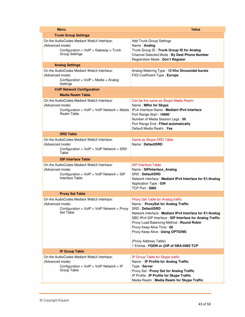
© Copyright Equant 43 of 59
Menu Value
Trunk Group Settings
On the AudioCodes Mediant WebUi Interface:
(Advanced mode)
Configuration > VoIP > Gateway > Trunk Group Settings
Add Trunk Group Settings
Name : Analog
Trunk Group ID : Trunk Group ID for Analog
Channel Selected Mode : By Dest Phone Number
Registration Mode : Don’t Register
Analog Settings
On the AudioCodes Mediant WebUi Interface:
(Advanced mode)
Configuration > VoIP > Media > Analog Settings
Analog Metering Type : 12 Khz Sinusoidal bursts
FXS Coefficient Type : Europe
VoIP Network Configuration
Media Realm Table
On the AudioCodes Mediant WebUi Interface:
(Advanced mode)
Configuration > VoIP > VoIP Network > Media Realm Table
Can be the same as Skype Media Realm
Name : MRm for Skype
IPv4 Interface Name : Mediant IPv4 Interface
Port Range Start : 16900
Number of Media Session Legs : 50
Port Range End : Filled automatically
Default Media Realm : Yes
SRD Table
On the AudioCodes Mediant WebUi Interface:
(Advanced mode)
Configuration > VoIP > VoIP Network > SRD Table
Same as Skype SRD Table
Name : DefaultSRD
SIP Interface Table
On the AudioCodes Mediant WebUi Interface:
(Advanced mode)
Configuration > VoIP > VoIP Network > SIP Interface Table
SIP Interface Table
Name : SIPInterface_Analog
SRD : DefaultSRD
Network Interface : Mediant IPv4 Interface for E1/Analog
Application Type : GW
TCP Port : 5060
Proxy Set Table
On the AudioCodes Mediant WebUi Interface:
(Advanced mode)
Configuration > VoIP > VoIP Network > Proxy Set Table
Proxy Set Table for Analog traffic
Name : ProxySet for Analog Traffic
SRD : DefaultSRD
Network Interface : Mediant IPv4 Interface for E1/Analog
SBC IPv4 SIP Interface : SIP Interface for Analog Traffic
Proxy Load Balancing Method : Round Robin
Proxy Keep-Alive Time : 60
Proxy Keep-Alive : Using OPTIONS
(Proxy Address Table)
1 Entries : FQDN or @IP of SBA:5060 TCP
IP Group Table
On the AudioCodes Mediant WebUi Interface:
(Advanced mode)
Configuration > VoIP > VoIP Network > IP Group Table
IP Group Table for Skype traffic
Name : IP Profile for Analog Traffic
Type : Server
Proxy Set : Proxy Set for Analog Traffic
IP Profile : IP Profile for Skype Traffic
Media Realm : Media Realm for Skype Traffic
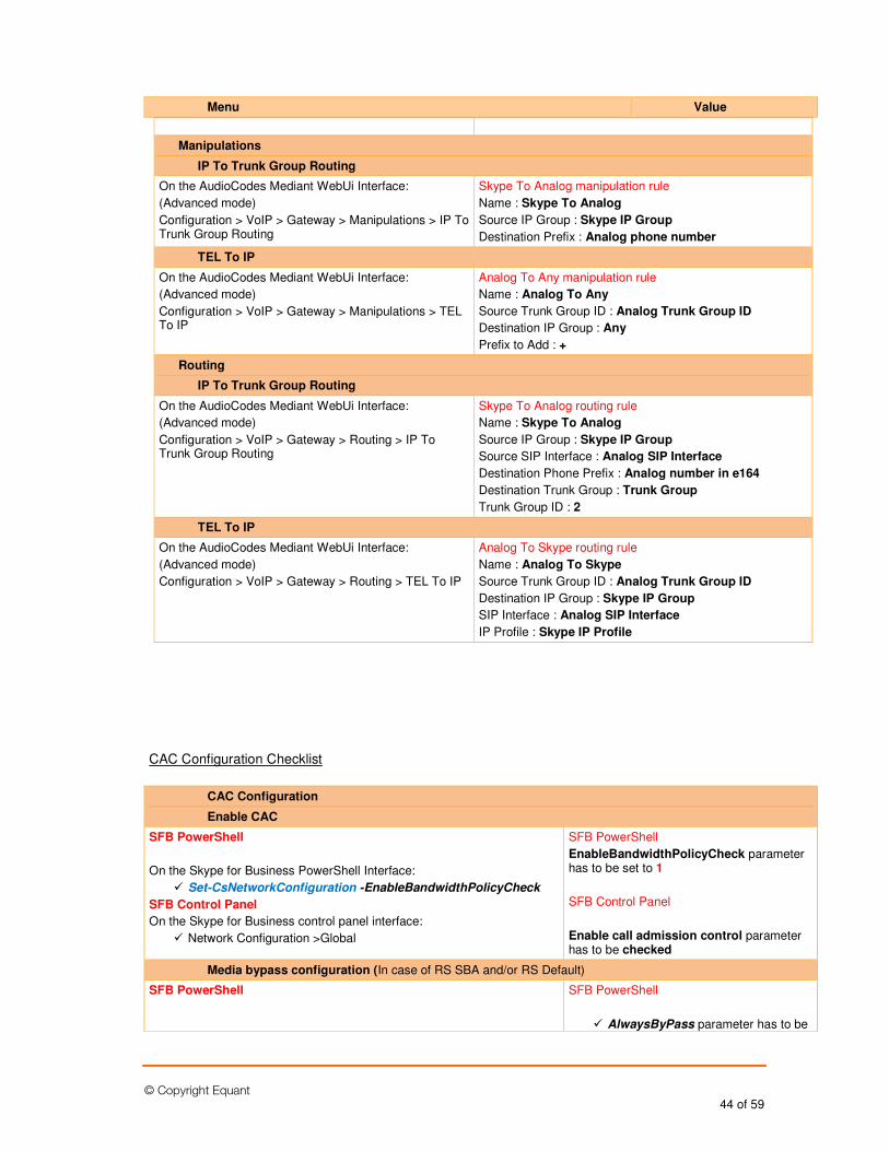
© Copyright Equant 44 of 59
Menu Value
Manipulations
IP To Trunk Group Routing
On the AudioCodes Mediant WebUi Interface:
(Advanced mode)
Configuration > VoIP > Gateway > Manipulations > IP To Trunk Group Routing
Skype To Analog manipulation rule
Name : Skype To Analog
Source IP Group : Skype IP Group
Destination Prefix : Analog phone number
TEL To IP
On the AudioCodes Mediant WebUi Interface:
(Advanced mode)
Configuration > VoIP > Gateway > Manipulations > TEL To IP
Analog To Any manipulation rule
Name : Analog To Any
Source Trunk Group ID : Analog Trunk Group ID
Destination IP Group : Any
Prefix to Add : +
Routing
IP To Trunk Group Routing
On the AudioCodes Mediant WebUi Interface:
(Advanced mode)
Configuration > VoIP > Gateway > Routing > IP To Trunk Group Routing
Skype To Analog routing rule
Name : Skype To Analog
Source IP Group : Skype IP Group
Source SIP Interface : Analog SIP Interface
Destination Phone Prefix : Analog number in e164
Destination Trunk Group : Trunk Group
Trunk Group ID : 2
TEL To IP
On the AudioCodes Mediant WebUi Interface:
(Advanced mode)
Configuration > VoIP > Gateway > Routing > TEL To IP
Analog To Skype routing rule
Name : Analog To Skype
Source Trunk Group ID : Analog Trunk Group ID
Destination IP Group : Skype IP Group
SIP Interface : Analog SIP Interface
IP Profile : Skype IP Profile
CAC Configuration Checklist
CAC Configuration
Enable CAC
SFB PowerShell
On the Skype for Business PowerShell Interface:
� Set-CsNetworkConfiguration -EnableBandwidthPolicyCheck
SFB Control Panel
On the Skype for Business control panel interface:
� Network Configuration >Global
SFB PowerShell
EnableBandwidthPolicyCheck parameter has to be set to 1
SFB Control Panel
Enable call admission control parameter has to be checked
Media bypass configuration (In case of RS SBA and/or RS Default)
SFB PowerShell
SFB PowerShell
� AlwaysByPass parameter has to be
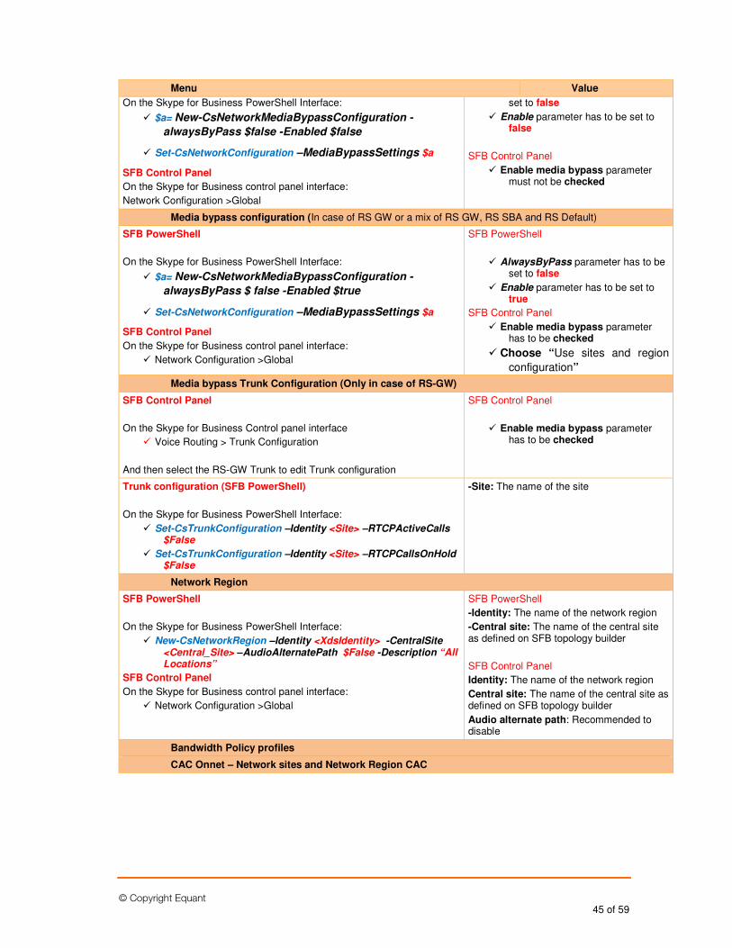
© Copyright Equant 45 of 59
Menu Value
On the Skype for Business PowerShell Interface:
� $a= New-CsNetworkMediaBypassConfiguration -
alwaysByPass $false -Enabled $false
� Set-CsNetworkConfiguration –MediaBypassSettings $a
SFB Control Panel
On the Skype for Business control panel interface:
Network Configuration >Global
set to false
� Enable parameter has to be set to false
SFB Control Panel
� Enable media bypass parameter must not be checked
Media bypass configuration (In case of RS GW or a mix of RS GW, RS SBA and RS Default)
SFB PowerShell
On the Skype for Business PowerShell Interface:
� $a= New-CsNetworkMediaBypassConfiguration -
alwaysByPass $ false -Enabled $true
� Set-CsNetworkConfiguration –MediaBypassSettings $a
SFB Control Panel
On the Skype for Business control panel interface:
� Network Configuration >Global
SFB PowerShell
� AlwaysByPass parameter has to be set to false
� Enable parameter has to be set to true
SFB Control Panel
� Enable media bypass parameter has to be checked
� Choose “Use sites and region
configuration”
Media bypass Trunk Configuration (Only in case of RS-GW)
SFB Control Panel
On the Skype for Business Control panel interface
� Voice Routing > Trunk Configuration
And then select the RS-GW Trunk to edit Trunk configuration
SFB Control Panel
� Enable media bypass parameter has to be checked
Trunk configuration (SFB PowerShell)
On the Skype for Business PowerShell Interface:
� Set-CsTrunkConfiguration –Identity <Site> –RTCPActiveCalls $False
� Set-CsTrunkConfiguration –Identity <Site> –RTCPCallsOnHold $False
-Site: The name of the site
Network Region
SFB PowerShell
On the Skype for Business PowerShell Interface:
� New-CsNetworkRegion –Identity <XdsIdentity> -CentralSite <Central_Site> –AudioAlternatePath $False -Description “All Locations”
SFB Control Panel
On the Skype for Business control panel interface:
� Network Configuration >Global
SFB PowerShell
-Identity: The name of the network region
-Central site: The name of the central site as defined on SFB topology builder
SFB Control Panel
Identity: The name of the network region
Central site: The name of the central site as defined on SFB topology builder
Audio alternate path: Recommended to disable
Bandwidth Policy profiles
CAC Onnet – Network sites and Network Region CAC
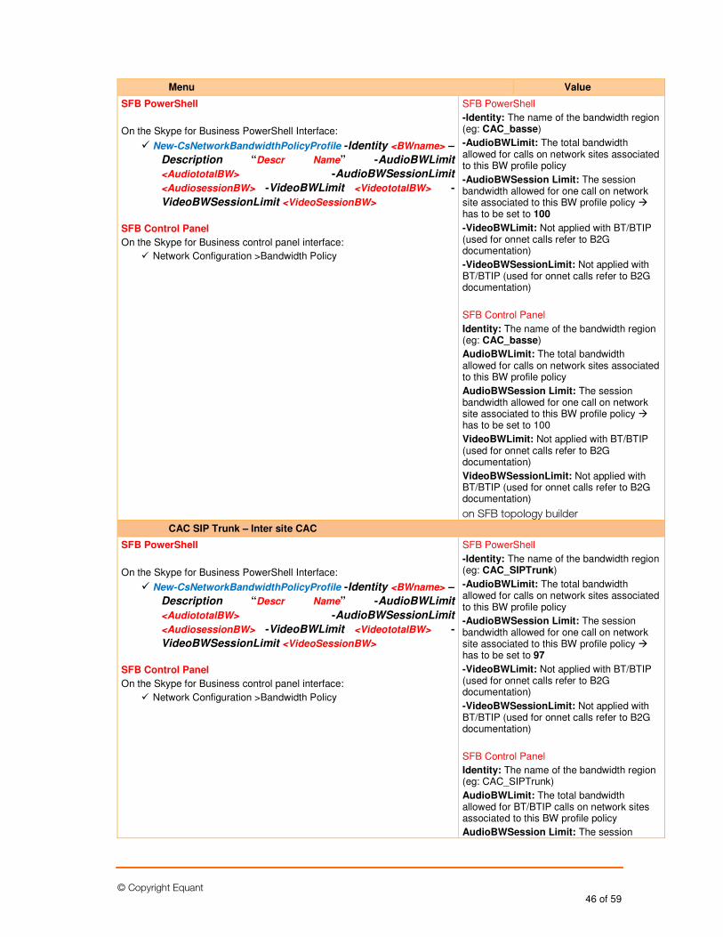
© Copyright Equant 46 of 59
Menu Value
SFB PowerShell
On the Skype for Business PowerShell Interface:
� New-CsNetworkBandwidthPolicyProfile -Identity <BWname> –
Description “Descr Name” -AudioBWLimit
<AudiototalBW> -AudioBWSessionLimit
<AudiosessionBW> -VideoBWLimit <VideototalBW> -
VideoBWSessionLimit <VideoSessionBW>
SFB Control Panel
On the Skype for Business control panel interface:
� Network Configuration >Bandwidth Policy
SFB PowerShell
-Identity: The name of the bandwidth region (eg: CAC_basse)
-AudioBWLimit: The total bandwidth allowed for calls on network sites associated to this BW profile policy
-AudioBWSession Limit: The session bandwidth allowed for one call on network site associated to this BW profile policy � has to be set to 100
-VideoBWLimit: Not applied with BT/BTIP (used for onnet calls refer to B2G documentation)
-VideoBWSessionLimit: Not applied with BT/BTIP (used for onnet calls refer to B2G documentation)
SFB Control Panel
Identity: The name of the bandwidth region (eg: CAC_basse)
AudioBWLimit: The total bandwidth allowed for calls on network sites associated to this BW profile policy
AudioBWSession Limit: The session bandwidth allowed for one call on network site associated to this BW profile policy � has to be set to 100
VideoBWLimit: Not applied with BT/BTIP (used for onnet calls refer to B2G documentation)
VideoBWSessionLimit: Not applied with BT/BTIP (used for onnet calls refer to B2G documentation)
on SFB topology builder
CAC SIP Trunk – Inter site CAC
SFB PowerShell
On the Skype for Business PowerShell Interface:
� New-CsNetworkBandwidthPolicyProfile -Identity <BWname> –
Description “Descr Name” -AudioBWLimit
<AudiototalBW> -AudioBWSessionLimit
<AudiosessionBW> -VideoBWLimit <VideototalBW> -
VideoBWSessionLimit <VideoSessionBW>
SFB Control Panel
On the Skype for Business control panel interface:
� Network Configuration >Bandwidth Policy
SFB PowerShell
-Identity: The name of the bandwidth region (eg: CAC_SIPTrunk)
-AudioBWLimit: The total bandwidth allowed for calls on network sites associated to this BW profile policy
-AudioBWSession Limit: The session bandwidth allowed for one call on network site associated to this BW profile policy � has to be set to 97
-VideoBWLimit: Not applied with BT/BTIP (used for onnet calls refer to B2G documentation)
-VideoBWSessionLimit: Not applied with BT/BTIP (used for onnet calls refer to B2G documentation)
SFB Control Panel
Identity: The name of the bandwidth region (eg: CAC_SIPTrunk)
AudioBWLimit: The total bandwidth allowed for BT/BTIP calls on network sites associated to this BW profile policy
AudioBWSession Limit: The session
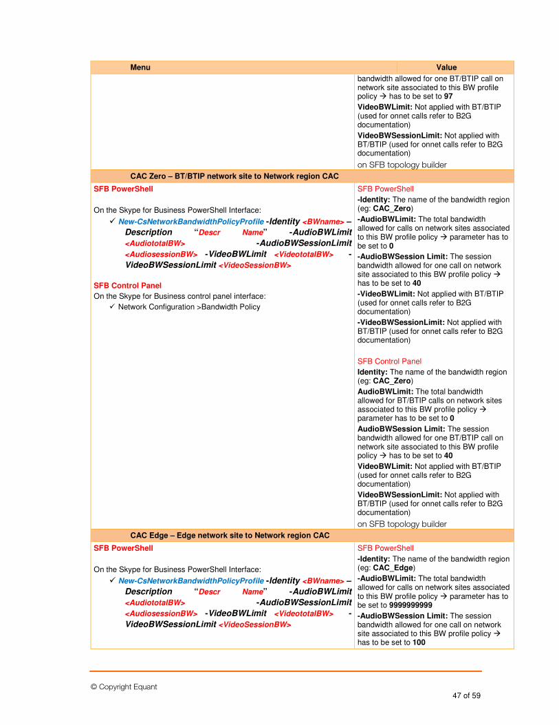
© Copyright Equant 47 of 59
Menu Value
bandwidth allowed for one BT/BTIP call on network site associated to this BW profile policy � has to be set to 97
VideoBWLimit: Not applied with BT/BTIP (used for onnet calls refer to B2G documentation)
VideoBWSessionLimit: Not applied with BT/BTIP (used for onnet calls refer to B2G documentation)
on SFB topology builder
CAC Zero – BT/BTIP network site to Network region CAC
SFB PowerShell
On the Skype for Business PowerShell Interface:
� New-CsNetworkBandwidthPolicyProfile -Identity <BWname> –
Description “Descr Name” -AudioBWLimit
<AudiototalBW> -AudioBWSessionLimit
<AudiosessionBW> -VideoBWLimit <VideototalBW> -
VideoBWSessionLimit <VideoSessionBW>
SFB Control Panel
On the Skype for Business control panel interface:
� Network Configuration >Bandwidth Policy
SFB PowerShell
-Identity: The name of the bandwidth region (eg: CAC_Zero)
-AudioBWLimit: The total bandwidth allowed for calls on network sites associated to this BW profile policy � parameter has to be set to 0
-AudioBWSession Limit: The session bandwidth allowed for one call on network site associated to this BW profile policy � has to be set to 40
-VideoBWLimit: Not applied with BT/BTIP (used for onnet calls refer to B2G documentation)
-VideoBWSessionLimit: Not applied with BT/BTIP (used for onnet calls refer to B2G documentation)
SFB Control Panel
Identity: The name of the bandwidth region (eg: CAC_Zero)
AudioBWLimit: The total bandwidth allowed for BT/BTIP calls on network sites associated to this BW profile policy � parameter has to be set to 0
AudioBWSession Limit: The session bandwidth allowed for one BT/BTIP call on network site associated to this BW profile policy � has to be set to 40
VideoBWLimit: Not applied with BT/BTIP (used for onnet calls refer to B2G documentation)
VideoBWSessionLimit: Not applied with BT/BTIP (used for onnet calls refer to B2G documentation)
on SFB topology builder
CAC Edge – Edge network site to Network region CAC
SFB PowerShell
On the Skype for Business PowerShell Interface:
� New-CsNetworkBandwidthPolicyProfile -Identity <BWname> –
Description “Descr Name” -AudioBWLimit
<AudiototalBW> -AudioBWSessionLimit
<AudiosessionBW> -VideoBWLimit <VideototalBW> -
VideoBWSessionLimit <VideoSessionBW>
SFB PowerShell
-Identity: The name of the bandwidth region (eg: CAC_Edge)
-AudioBWLimit: The total bandwidth allowed for calls on network sites associated to this BW profile policy � parameter has to be set to 9999999999
-AudioBWSession Limit: The session bandwidth allowed for one call on network site associated to this BW profile policy � has to be set to 100
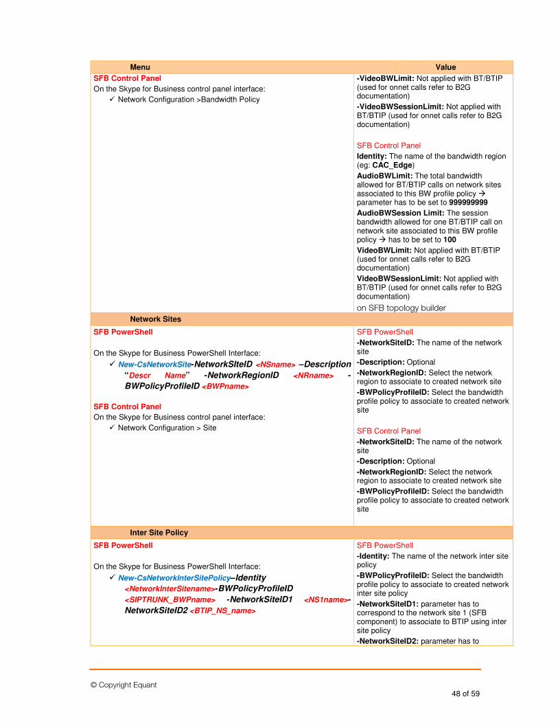
© Copyright Equant 48 of 59
Menu Value
SFB Control Panel
On the Skype for Business control panel interface:
� Network Configuration >Bandwidth Policy
-VideoBWLimit: Not applied with BT/BTIP (used for onnet calls refer to B2G documentation)
-VideoBWSessionLimit: Not applied with BT/BTIP (used for onnet calls refer to B2G documentation)
SFB Control Panel
Identity: The name of the bandwidth region (eg: CAC_Edge)
AudioBWLimit: The total bandwidth allowed for BT/BTIP calls on network sites associated to this BW profile policy � parameter has to be set to 999999999
AudioBWSession Limit: The session bandwidth allowed for one BT/BTIP call on network site associated to this BW profile policy � has to be set to 100
VideoBWLimit: Not applied with BT/BTIP (used for onnet calls refer to B2G documentation)
VideoBWSessionLimit: Not applied with BT/BTIP (used for onnet calls refer to B2G documentation)
on SFB topology builder
Network Sites
SFB PowerShell
On the Skype for Business PowerShell Interface:
� New-CsNetworkSite-NetworkSIteID <NSname> –Description
“Descr Name” -NetworkRegionID <NRname> -
BWPolicyProfileID <BWPname>
SFB Control Panel
On the Skype for Business control panel interface:
� Network Configuration > Site
SFB PowerShell
-NetworkSiteID: The name of the network site
-Description: Optional
-NetworkRegionID: Select the network region to associate to created network site
-BWPolicyProfileID: Select the bandwidth profile policy to associate to created network site
SFB Control Panel
-NetworkSiteID: The name of the network site
-Description: Optional
-NetworkRegionID: Select the network region to associate to created network site
-BWPolicyProfileID: Select the bandwidth profile policy to associate to created network site
Inter Site Policy
SFB PowerShell
On the Skype for Business PowerShell Interface:
� New-CsNetworkInterSitePolicy–Identity
<NetworkInterSitename>-BWPolicyProfileID
<SIPTRUNK_BWPname> -NetworkSiteID1 <NS1name>-
NetworkSiteID2 <BTIP_NS_name>
SFB PowerShell
-Identity: The name of the network inter site policy
-BWPolicyProfileID: Select the bandwidth profile policy to associate to created network inter site policy
-NetworkSiteID1: parameter has to correspond to the network site 1 (SFB component) to associate to BTIP using inter site policy
-NetworkSiteID2: parameter has to
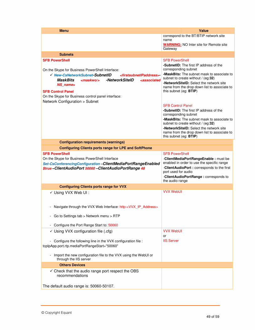
© Copyright Equant 49 of 59
Menu Value
correspond to the BT/BTIP network site name
WARNING: NO Inter site for Remote site Gateway
Subnets
SFB PowerShell
On the Skype for Business PowerShell Interface:
� New-CsNetworkSubnet-SubnetID <firstsubnetIPaddress>-
MaskBits <maskwo/> -NetworkSiteID <associated
NS_name>
SFB Control Panel
On the Skype for Business control panel interface:
Network Configuration > Subnet
SFB PowerShell
-SubnetID: The first IP address of the corresponding subnet
-MaskBits: The subnet mask to associate to subnet to create without / (eg:32)
-NetworkSiteID: Select the network site name from the drop down list to associate to this subnet (eg: BTIP)
SFB Control Panel
-SubnetID: The first IP address of the corresponding subnet
-MaskBits: The subnet mask to associate to subnet to create without / (eg:32)
-NetworkSiteID: Select the network site name from the drop down list to associate to this subnet (eg: BTIP)
Configuration requirements (warnings)
Configuring Clients ports range for LPE and SoftPhone
SFB PowerShell
On the Skype for Business PowerShell Interface
Set-CsConferencingConfiguration ––––ClientMediaPortRangeEnabled
$true ––––ClientAudioPort 50060 –ClientAudioPortRange 48
SFB PowerShell
-ClientMediaPortRangeEnable : must be enabled in order to use the specific range
-ClientAudioPort : corresponds to the first port used for audio
-ClientAudioPortRange : corresponds to the audio range
Configuring Clients ports range for VVX
� Using VVX Web UI :
- Navigate through the VVX Web Interface: http:<VVX_IP_Address>
- Go to Settings tab > Network menu > RTP
- Configure the Port Range Start to: 50060
VVX WebUI
� Using VVX configuration file (.cfg)
- Configure the following line in the VVX configuration file :
tcpIpApp.port.rtp.mediaPortRangeStart="50060"
- Import the new configuration file to the VVX using the WebUI or through the IIS server
VVX WebUI
or
IIS Server
Others Devices
� Check that the audio range port respect the OBS recommendations
The default audio range is: 50060-50107.
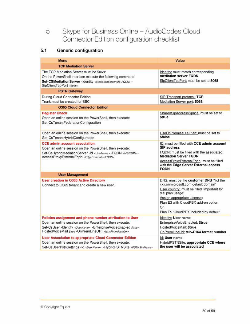
© Copyright Equant 50 of 59
5 Skype for Business Online – AudioCodes Cloud Connector Edition configuration checklist
5.1 Generic configuration
Menu Value
TCP Mediation Server
The TCP Mediation Server must be 5068:
On the PowerShell interface execute the following command:
Set-CSMediationServer -Identity <MediationServer:MS-FQDN> -SipClientTcpPort <5068>
Identity: must match corresponding mediation server FQDN
SipClientTcpPort: must be set to 5068
PSTN Gateway
During Cloud Connector Edition
Trunk must be created for SBC
SIP Transport protocol: TCP
Mediation Server port: 5068
O365 Cloud Connector Edition
Register Check
Open an online session on the PowerShell, then execute:
Get-CsTenantFederationConfiguration
SharedSipAddressSpace: must be set to $true
Open an online session on the PowerShell, then execute:
Get-CsTenantHybridConfiguration
UseOnPremiseDialPlan: must be set to $false
CCE admin account association
Open an online session on the PowerShell, then execute:
Set-CsHybridMediationServer -Id <UserName> -FQDN <MSFQDN> -AccessProxyExternalFqdn <EdgeExternationFQDN>
ID: must be filled with CCE admin account SIP address
FQDN: must be filled with the associated Mediation Server FQDN
AccessProxyExternalFqdn: must be filled with the Edge Server External access FQDN
User Management
User creation in O365 Active Directory
Connect to O365 tenant and create a new user.
DNS: must be the customer DNS ‘Not the xxx.onmicrosoft.com default domain’
User country: must be filled ‘important for dial plan usage’
Assign appropriate License:
Plan E3 with CloudPBX add-on option
Or
Plan E5 ‘CloudPBX included by default’
Policies assignment and phone number attribution to User
Open an online session on the PowerShell, then execute:
Set-CsUser -Identity <UserName> -EnterpriseVoiceEnabled $true -HostedVoiceMail $true -OnPremLineURI <tel:+PhoneNumber>
Identity: User name
EnterpriseVoiceEnabled: $true
HostedVoiceMail: $true
OnPremLineUri: tel:+E164 format number
User Association to appropriate Cloud Connector Edition
Open an online session on the PowerShell, then execute:
Set-CsUserPstnSettings -Id <UserName> -HybridPSTNSite <PSTNSiteName>
Id: User name
HybridPSTNSite: appropriate CCE where the user will be associated
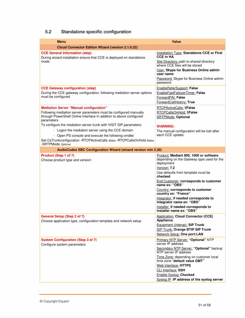
© Copyright Equant 51 of 59
5.2 Standalone specific configuration
Menu Value
Cloud Connector Edition Wizard (version 2.1.0.22)
CCE General Information (step)
During wizard installation ensure that CCE is deployed on standalone mode
Installation Type: Standalone CCE or First CCE in HA
Site Directory: path to shared directory where CCE files will be stored
User: Skype for Business Online admin user name
Password: Skype for Business Online admin password
CCE Gateway configuration (step)
During the CCE gateway configuration, following mediation server options must be configured
EnableReferSupport: False
EnableFastFailoverTimer: False
ForwardPAI: False
ForwardCallHistory: True
Mediation Server “Manual configuration”
Following mediation server parameters must be configured manually through PowerShell Online Interface In addition to above configured parameters
To configure the mediation server trunk with VISIT SIP parameters:
- Logon the mediation server using the CCE domain
- Open PS console and execute the following cmdlet
Set-CsTrunkconfiguration -RTCPActiveCalls $false -RTCPCallsOnHold $false -SRTPMode Optional
RTCPActiveCalls: $False
RTCPCallsOnHold: $False
SRTPMode: Optional
WARNING:
The manual configuration will be lost after each CCE update.
AudioCodes SBC Configuration Wizard (wizard version min 2.20)
Product (Step 1 of 7)
Choose product type and version:
Product: Mediant 800, 1000 or software depending on the Gateway type used for the deployment
Version: 7.2
Use defaults from template must be checked
End Customer: corresponds to customer name ex: “OBS”
Country: corresponds to customer country ex: “France”
Integrator: if needed corresponds to integrator name ex: “OBS”
Installer: if needed corresponds to installer name ex: “OBS”
General Setup (Step 2 of 7)
Choose application type, configuration template and network setup
Application: Cloud Connector (CCE) Appliance
Equipment (interop): SIP Trunk
SIP Trunk: Orange BTIP SIP Trunk
Network Setup: One port:LAN
System Configuration (Step 3 of 7)
Configure system parameters
Primary NTP Server: “Optional” NTP server IP address
Secondary NTP Server: “Optional” backup NTP server IP address
Time Zone: depending on customer local time zone “default value GMT”
Web Interface: HTTPS
CLI Interface: SSH
Enable Syslog: Checked
Syslog IP: IP address of the syslog server
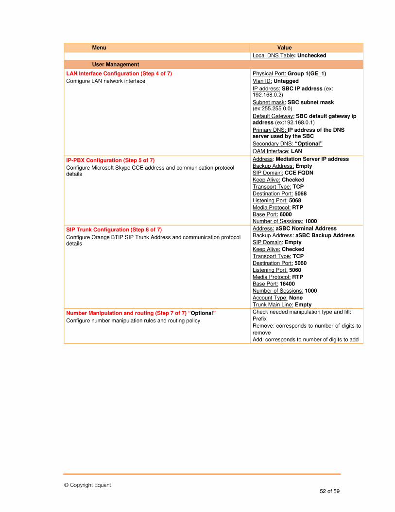
© Copyright Equant 52 of 59
Menu Value
Local DNS Table: Unchecked
User Management
LAN Interface Configuration (Step 4 of 7)
Configure LAN network interface
Physical Port: Group 1(GE_1)
Vlan ID: Untagged
IP address: SBC IP address (ex: 192.168.0.2)
Subnet mask: SBC subnet mask (ex:255.255.0.0)
Default Gateway: SBC default gateway ip address (ex:192.168.0.1)
Primary DNS: IP address of the DNS server used by the SBC
Secondary DNS: “Optional”
OAM Interface: LAN
IP-PBX Configuration (Step 5 of 7)
Configure Microsoft Skype CCE address and communication protocol details
Address: Mediation Server IP address
Backup Address: Empty
SIP Domain: CCE FQDN
Keep Alive: Checked
Transport Type: TCP
Destination Port: 5068
Listening Port: 5068
Media Protocol: RTP
Base Port: 6000
Number of Sessions: 1000
SIP Trunk Configuration (Step 6 of 7)
Configure Orange BTIP SIP Trunk Address and communication protocol details
Address: aSBC Nominal Address
Backup Address: aSBC Backup Address
SIP Domain: Empty
Keep Alive: Checked
Transport Type: TCP
Destination Port: 5060
Listening Port: 5060
Media Protocol: RTP
Base Port: 16400
Number of Sessions: 1000
Account Type: None
Trunk Main Line: Empty
Number Manipulation and routing (Step 7 of 7) “Optional”
Configure number manipulation rules and routing policy
Check needed manipulation type and fill:
Prefix
Remove: corresponds to number of digits to
remove
Add: corresponds to number of digits to add
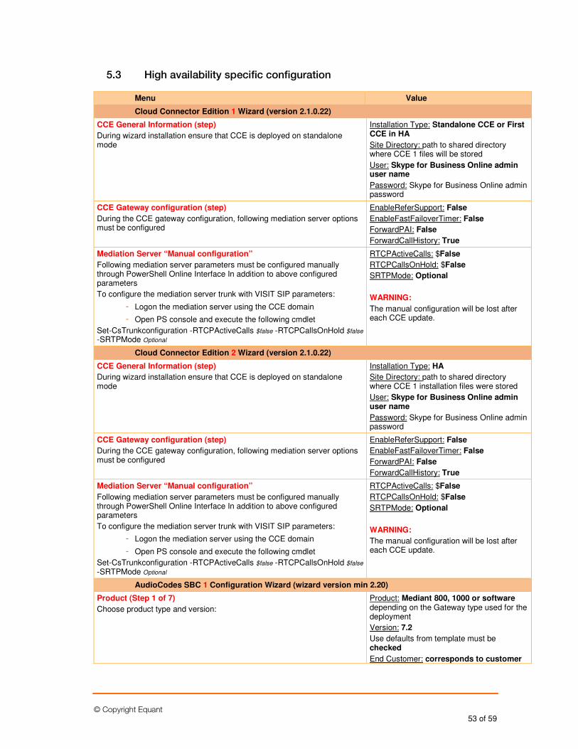
© Copyright Equant 53 of 59
5.3 High availability specific configuration
Menu Value
Cloud Connector Edition 1 Wizard (version 2.1.0.22)
CCE General Information (step)
During wizard installation ensure that CCE is deployed on standalone mode
Installation Type: Standalone CCE or First CCE in HA
Site Directory: path to shared directory where CCE 1 files will be stored
User: Skype for Business Online admin user name
Password: Skype for Business Online admin password
CCE Gateway configuration (step)
During the CCE gateway configuration, following mediation server options must be configured
EnableReferSupport: False
EnableFastFailoverTimer: False
ForwardPAI: False
ForwardCallHistory: True
Mediation Server “Manual configuration”
Following mediation server parameters must be configured manually through PowerShell Online Interface In addition to above configured parameters
To configure the mediation server trunk with VISIT SIP parameters:
- Logon the mediation server using the CCE domain
- Open PS console and execute the following cmdlet
Set-CsTrunkconfiguration -RTCPActiveCalls $false -RTCPCallsOnHold $false -SRTPMode Optional
RTCPActiveCalls: $False
RTCPCallsOnHold: $False
SRTPMode: Optional
WARNING:
The manual configuration will be lost after each CCE update.
Cloud Connector Edition 2 Wizard (version 2.1.0.22)
CCE General Information (step)
During wizard installation ensure that CCE is deployed on standalone mode
Installation Type: HA
Site Directory: path to shared directory where CCE 1 installation files were stored
User: Skype for Business Online admin user name
Password: Skype for Business Online admin password
CCE Gateway configuration (step)
During the CCE gateway configuration, following mediation server options must be configured
EnableReferSupport: False
EnableFastFailoverTimer: False
ForwardPAI: False
ForwardCallHistory: True
Mediation Server “Manual configuration”
Following mediation server parameters must be configured manually through PowerShell Online Interface In addition to above configured parameters
To configure the mediation server trunk with VISIT SIP parameters:
- Logon the mediation server using the CCE domain
- Open PS console and execute the following cmdlet
Set-CsTrunkconfiguration -RTCPActiveCalls $false -RTCPCallsOnHold $false -SRTPMode Optional
RTCPActiveCalls: $False
RTCPCallsOnHold: $False
SRTPMode: Optional
WARNING:
The manual configuration will be lost after each CCE update.
AudioCodes SBC 1 Configuration Wizard (wizard version min 2.20)
Product (Step 1 of 7)
Choose product type and version:
Product: Mediant 800, 1000 or software depending on the Gateway type used for the deployment
Version: 7.2
Use defaults from template must be checked
End Customer: corresponds to customer
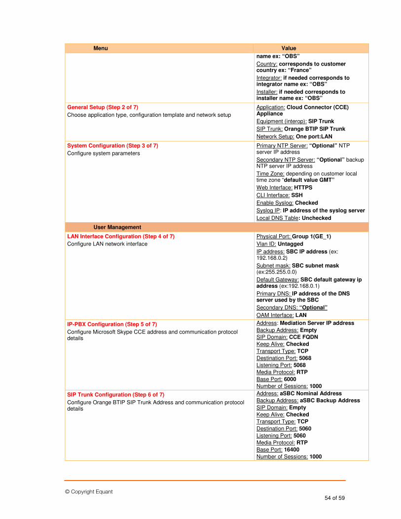
© Copyright Equant 54 of 59
Menu Value
name ex: “OBS”
Country: corresponds to customer country ex: “France”
Integrator: if needed corresponds to integrator name ex: “OBS”
Installer: if needed corresponds to installer name ex: “OBS”
General Setup (Step 2 of 7)
Choose application type, configuration template and network setup
Application: Cloud Connector (CCE) Appliance
Equipment (interop): SIP Trunk
SIP Trunk: Orange BTIP SIP Trunk
Network Setup: One port:LAN
System Configuration (Step 3 of 7)
Configure system parameters
Primary NTP Server: “Optional” NTP server IP address
Secondary NTP Server: “Optional” backup NTP server IP address
Time Zone: depending on customer local time zone “default value GMT”
Web Interface: HTTPS
CLI Interface: SSH
Enable Syslog: Checked
Syslog IP: IP address of the syslog server
Local DNS Table: Unchecked
User Management
LAN Interface Configuration (Step 4 of 7)
Configure LAN network interface
Physical Port: Group 1(GE_1)
Vlan ID: Untagged
IP address: SBC IP address (ex: 192.168.0.2)
Subnet mask: SBC subnet mask (ex:255.255.0.0)
Default Gateway: SBC default gateway ip address (ex:192.168.0.1)
Primary DNS: IP address of the DNS server used by the SBC
Secondary DNS: “Optional”
OAM Interface: LAN
IP-PBX Configuration (Step 5 of 7)
Configure Microsoft Skype CCE address and communication protocol details
Address: Mediation Server IP address
Backup Address: Empty
SIP Domain: CCE FQDN
Keep Alive: Checked
Transport Type: TCP
Destination Port: 5068
Listening Port: 5068
Media Protocol: RTP
Base Port: 6000
Number of Sessions: 1000
SIP Trunk Configuration (Step 6 of 7)
Configure Orange BTIP SIP Trunk Address and communication protocol details
Address: aSBC Nominal Address
Backup Address: aSBC Backup Address
SIP Domain: Empty
Keep Alive: Checked
Transport Type: TCP
Destination Port: 5060
Listening Port: 5060
Media Protocol: RTP
Base Port: 16400
Number of Sessions: 1000
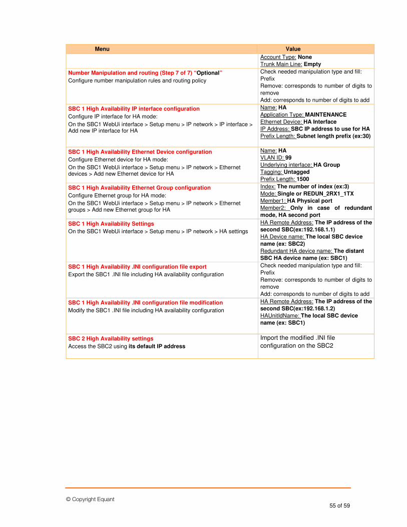
© Copyright Equant 55 of 59
Menu Value
Account Type: None
Trunk Main Line: Empty
Number Manipulation and routing (Step 7 of 7) “Optional”
Configure number manipulation rules and routing policy
Check needed manipulation type and fill:
Prefix
Remove: corresponds to number of digits to
remove
Add: corresponds to number of digits to add
SBC 1 High Availability IP interface configuration
Configure IP interface for HA mode:
On the SBC1 WebUi interface > Setup menu > IP network > IP interface > Add new IP interface for HA
Name: HA
Application Type: MAINTENANCE
Ethernet Device: HA Interface
IP Address: SBC IP address to use for HA
Prefix Length: Subnet length prefix (ex:30)
SBC 1 High Availability Ethernet Device configuration
Configure Ethernet device for HA mode:
On the SBC1 WebUi interface > Setup menu > IP network > Ethernet devices > Add new Ethernet device for HA
Name: HA
VLAN ID: 99
Underlying interface: HA Group
Tagging: Untagged
Prefix Length: 1500
SBC 1 High Availability Ethernet Group configuration
Configure Ethernet group for HA mode:
On the SBC1 WebUi interface > Setup menu > IP network > Ethernet groups > Add new Ethernet group for HA
Index: The number of index (ex:3)
Mode: Single or REDUN_2RX1_1TX
Member1: HA Physical port
Member2: Only in case of redundant
mode, HA second port
SBC 1 High Availability Settings
On the SBC1 WebUi interface > Setup menu > IP network > HA settings
HA Remote Address: The IP address of the
second SBC(ex:192.168.1.1)
HA Device name: The local SBC device
name (ex: SBC2)
Redundant HA device name: The distant
SBC HA device name (ex: SBC1)
SBC 1 High Availability .INI configuration file export
Export the SBC1 .INI file including HA availability configuration
Check needed manipulation type and fill:
Prefix
Remove: corresponds to number of digits to
remove
Add: corresponds to number of digits to add
SBC 1 High Availability .INI configuration file modification
Modify the SBC1 .INI file including HA availability configuration
HA Remote Address: The IP address of the
second SBC(ex:192.168.1.2)
HAUnitIdName: The local SBC device
name (ex: SBC1)
SBC 2 High Availability settings
Access the SBC2 using its default IP address
Import the modified .INI file
configuration on the SBC2

© Copyright Equant 56 of 59
5.4 Nominal/backup mode specific configuration
Menu Value
Cloud Connector Edition Wizard (version 2.1.0.22)
CCE General Information (step)
During wizard installation ensure that CCE is deployed on standalone mode
Installation Type: Standalone CCE or First CCE in HA
Site Directory: path to shared directory where CCE files will be stored
User: Skype for Business Online admin user name
Password: Skype for Business Online admin password
CCE Gateway configuration (step)
During the CCE gateway configuration, following mediation server options must be configured
EnableReferSupport: False
EnableFastFailoverTimer: False
ForwardPAI: False
ForwardCallHistory: True
Mediation Server “Manual configuration”
Following mediation server parameters must be configured manually through PowerShell Online Interface In addition to above configured parameters
To configure the mediation server trunk with VISIT SIP parameters:
- Logon the mediation server using the CCE domain
- Open PS console and execute the following cmdlet
Set-CsTrunkconfiguration -RTCPActiveCalls $false -RTCPCallsOnHold $false -SRTPMode Optional
RTCPActiveCalls: $False
RTCPCallsOnHold: $False
SRTPMode: Optional
WARNING:
The manual configuration will be lost after each CCE update.
Same configuration steps must be performed on All needed CCEs
AudioCodes SBC Configuration Wizard (wizard version min 2.20)
Product (Step 1 of 7)
Choose product type and version:
Product: Mediant 800, 1000 or software depending on the Gateway type used for the deployment
Version: 7.2
Use defaults from template must be checked
End Customer: corresponds to customer name ex: “OBS”
Country: corresponds to customer country ex: “France”
Integrator: if needed corresponds to integrator name ex: “OBS”
Installer: if needed corresponds to installer name ex: “OBS”
General Setup (Step 2 of 7)
Choose application type, configuration template and network setup
Application: Cloud Connector (CCE) Appliance
Equipment (interop): SIP Trunk
SIP Trunk: Orange BTIP SIP Trunk
Network Setup: One port:LAN
System Configuration (Step 3 of 7)
Configure system parameters
Primary NTP Server: “Optional” NTP server IP address
Secondary NTP Server: “Optional” backup NTP server IP address
Time Zone: depending on customer local time zone “default value GMT”
Web Interface: HTTPS
CLI Interface: SSH
Enable Syslog: Checked
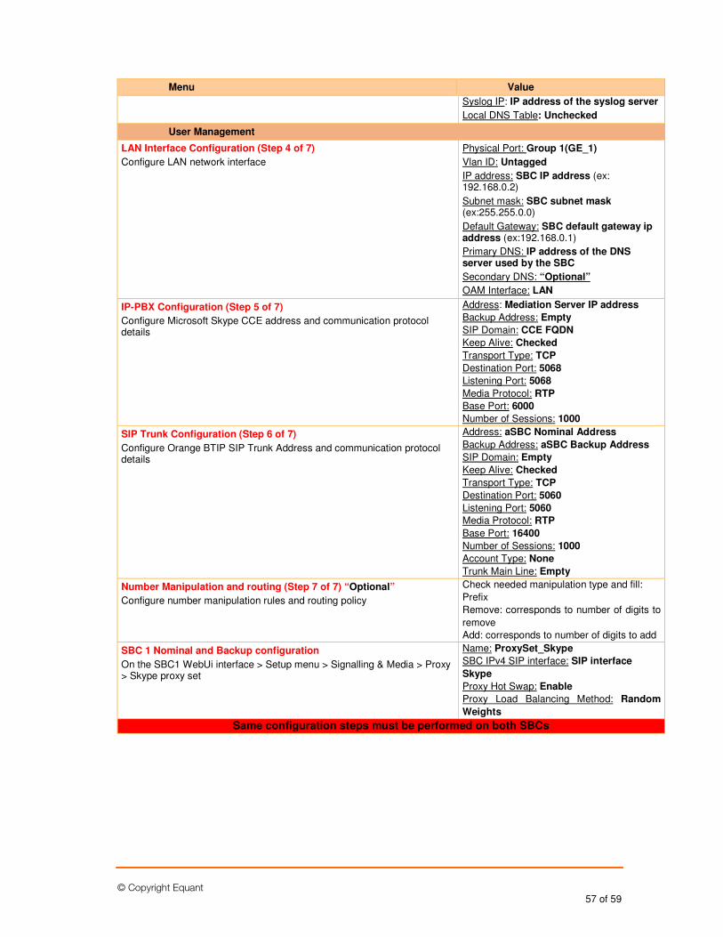
© Copyright Equant 57 of 59
Menu Value
Syslog IP: IP address of the syslog server
Local DNS Table: Unchecked
User Management
LAN Interface Configuration (Step 4 of 7)
Configure LAN network interface
Physical Port: Group 1(GE_1)
Vlan ID: Untagged
IP address: SBC IP address (ex: 192.168.0.2)
Subnet mask: SBC subnet mask (ex:255.255.0.0)
Default Gateway: SBC default gateway ip address (ex:192.168.0.1)
Primary DNS: IP address of the DNS server used by the SBC
Secondary DNS: “Optional”
OAM Interface: LAN
IP-PBX Configuration (Step 5 of 7)
Configure Microsoft Skype CCE address and communication protocol details
Address: Mediation Server IP address
Backup Address: Empty
SIP Domain: CCE FQDN
Keep Alive: Checked
Transport Type: TCP
Destination Port: 5068
Listening Port: 5068
Media Protocol: RTP
Base Port: 6000
Number of Sessions: 1000
SIP Trunk Configuration (Step 6 of 7)
Configure Orange BTIP SIP Trunk Address and communication protocol details
Address: aSBC Nominal Address
Backup Address: aSBC Backup Address
SIP Domain: Empty
Keep Alive: Checked
Transport Type: TCP
Destination Port: 5060
Listening Port: 5060
Media Protocol: RTP
Base Port: 16400
Number of Sessions: 1000
Account Type: None
Trunk Main Line: Empty
Number Manipulation and routing (Step 7 of 7) “Optional”
Configure number manipulation rules and routing policy
Check needed manipulation type and fill:
Prefix
Remove: corresponds to number of digits to
remove
Add: corresponds to number of digits to add
SBC 1 Nominal and Backup configuration
On the SBC1 WebUi interface > Setup menu > Signalling & Media > Proxy > Skype proxy set
Name: ProxySet_Skype
SBC IPv4 SIP interface: SIP interface
Skype
Proxy Hot Swap: Enable
Proxy Load Balancing Method: Random
Weights
Same configuration steps must be performed on both SBCs
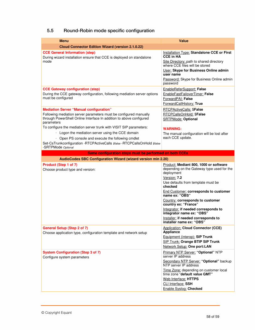
© Copyright Equant 58 of 59
5.5 Round-Robin mode specific configuration
Menu Value
Cloud Connector Edition Wizard (version 2.1.0.22)
CCE General Information (step)
During wizard installation ensure that CCE is deployed on standalone mode
Installation Type: Standalone CCE or First CCE in HA
Site Directory: path to shared directory where CCE files will be stored
User: Skype for Business Online admin user name
Password: Skype for Business Online admin password
CCE Gateway configuration (step)
During the CCE gateway configuration, following mediation server options must be configured
EnableReferSupport: False
EnableFastFailoverTimer: False
ForwardPAI: False
ForwardCallHistory: True
Mediation Server “Manual configuration”
Following mediation server parameters must be configured manually through PowerShell Online Interface In addition to above configured parameters
To configure the mediation server trunk with VISIT SIP parameters:
- Logon the mediation server using the CCE domain
- Open PS console and execute the following cmdlet
Set-CsTrunkconfiguration -RTCPActiveCalls $false -RTCPCallsOnHold $false -SRTPMode Optional
RTCPActiveCalls: $False
RTCPCallsOnHold: $False
SRTPMode: Optional
WARNING:
The manual configuration will be lost after each CCE update.
Same configuration steps must be performed on both CCEs
AudioCodes SBC Configuration Wizard (wizard version min 2.20)
Product (Step 1 of 7)
Choose product type and version:
Product: Mediant 800, 1000 or software depending on the Gateway type used for the deployment
Version: 7.2
Use defaults from template must be checked
End Customer: corresponds to customer name ex: “OBS”
Country: corresponds to customer country ex: “France”
Integrator: if needed corresponds to integrator name ex: “OBS”
Installer: if needed corresponds to installer name ex: “OBS”
General Setup (Step 2 of 7)
Choose application type, configuration template and network setup
Application: Cloud Connector (CCE) Appliance
Equipment (interop): SIP Trunk
SIP Trunk: Orange BTIP SIP Trunk
Network Setup: One port:LAN
System Configuration (Step 3 of 7)
Configure system parameters
Primary NTP Server: “Optional” NTP server IP address
Secondary NTP Server: “Optional” backup NTP server IP address
Time Zone: depending on customer local time zone “default value GMT”
Web Interface: HTTPS
CLI Interface: SSH
Enable Syslog: Checked
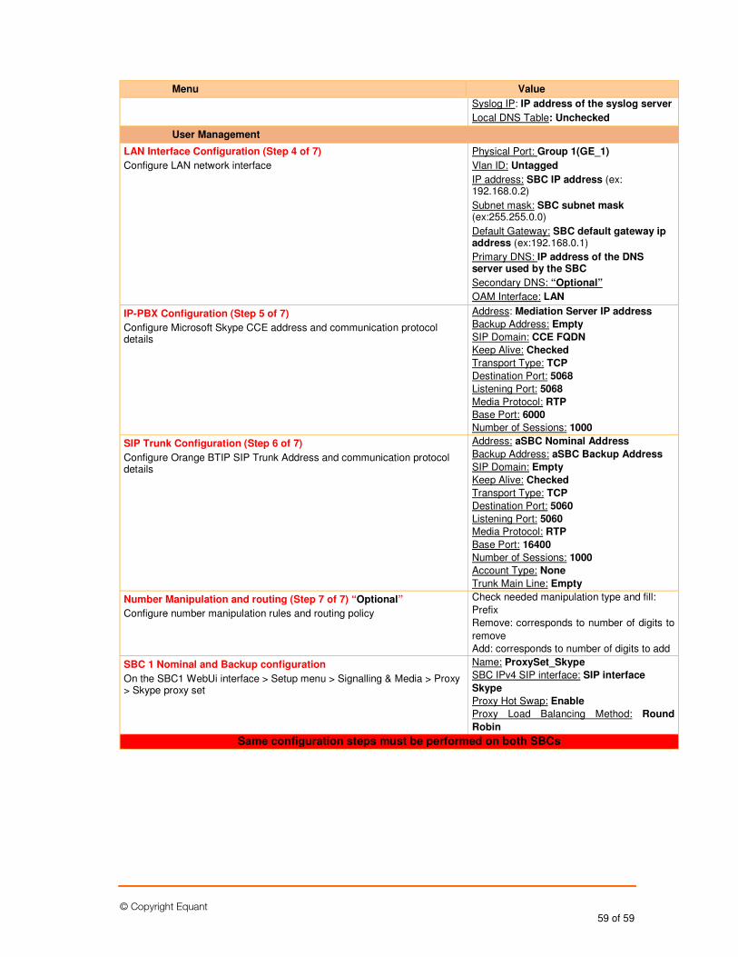
© Copyright Equant 59 of 59
Menu Value
Syslog IP: IP address of the syslog server
Local DNS Table: Unchecked
User Management
LAN Interface Configuration (Step 4 of 7)
Configure LAN network interface
Physical Port: Group 1(GE_1)
Vlan ID: Untagged
IP address: SBC IP address (ex: 192.168.0.2)
Subnet mask: SBC subnet mask (ex:255.255.0.0)
Default Gateway: SBC default gateway ip address (ex:192.168.0.1)
Primary DNS: IP address of the DNS server used by the SBC
Secondary DNS: “Optional”
OAM Interface: LAN
IP-PBX Configuration (Step 5 of 7)
Configure Microsoft Skype CCE address and communication protocol details
Address: Mediation Server IP address
Backup Address: Empty
SIP Domain: CCE FQDN
Keep Alive: Checked
Transport Type: TCP
Destination Port: 5068
Listening Port: 5068
Media Protocol: RTP
Base Port: 6000
Number of Sessions: 1000
SIP Trunk Configuration (Step 6 of 7)
Configure Orange BTIP SIP Trunk Address and communication protocol details
Address: aSBC Nominal Address
Backup Address: aSBC Backup Address
SIP Domain: Empty
Keep Alive: Checked
Transport Type: TCP
Destination Port: 5060
Listening Port: 5060
Media Protocol: RTP
Base Port: 16400
Number of Sessions: 1000
Account Type: None
Trunk Main Line: Empty
Number Manipulation and routing (Step 7 of 7) “Optional”
Configure number manipulation rules and routing policy
Check needed manipulation type and fill:
Prefix
Remove: corresponds to number of digits to
remove
Add: corresponds to number of digits to add
SBC 1 Nominal and Backup configuration
On the SBC1 WebUi interface > Setup menu > Signalling & Media > Proxy > Skype proxy set
Name: ProxySet_Skype
SBC IPv4 SIP interface: SIP interface
Skype
Proxy Hot Swap: Enable
Proxy Load Balancing Method: Round
Robin
Same configuration steps must be performed on both SBCs