microsoft lync client/server in a cisco wireless lan · revised: september 9, 2016, microsoft lync...
TRANSCRIPT
Microsoft Lync Client/Server in a Cisco Wireless LAN
Microsoft Lync Client/Server in a Cisco Wireless LAN 2
Scope 2
Background 2
Quality of Service Configuration 3
The QoS Behavior with AVC between AP, WLC, and Infrastructure 6
Cisco Switch Port Configuration for APs and WLCs 7
Recommended WLC Configuration for Lync Clients 7
Overview of the Suggested AVC Configuration for the Lync Application 9
Recommended AVC Configuration for Lync Audio and Video 9
Lync SDN Introduction 11
Summary 17
For More Information 17

Revised: September 9, 2016,
Microsoft Lync Client/Server in a Cisco Wireless LAN
ScopeUsing Cisco Application Visibility and Control (AVC) technology, Cisco WLAN infrastructure and routers accurately classify andprioritize thousands of applications, including commonly deployed business applications such as Cisco Jabber, CiscoWebEx,MicrosoftOffice 365, Microsoft Lync 2013, and Skype. These business applications are supported with AVC protocol pack 6.4 and above,operating with next-generation Network-Based Application Recognition (NBAR2) engine 13 and above. With this capability, youcan identify Lync version 2013 and also sub-classify howmuch of your traffic is data (desktop share), audio, video, and apply differentpolicies on those. Cisco has also passed Microsoft’s Lync certification testing for quality voice-over-wireless-LAN (VoWLAN)performance. This white paper provides Cisco network design considerations for Microsoft’s Lync client and Lync server whenfunctioning over a Cisco wireless LAN (WLAN) infrastructure. It also provides the steps for WLAN configuration and best practicesfor quality of service (QoS).
BackgroundMicrosoft and Cisco have a history of collaboration in the development of Wi-Fi security and QoS. Cisco Unified CommunicationsManager (UCM) already supportsMicrosoft softphone clients andMicrosoft call management servers. In continuation to this support,the Microsoft Lync client can register directly to UCM. The documents supporting overall network design, including security, QoS,
2
Session Initiation Protocol (SIP) Trunks, and collaboration services, are listed in the For More Information, on page 17 section. Thisdocument focuses on a Wi-Fi design that best provides high-quality calls for the users of the Microsoft Lync client with Lync server.
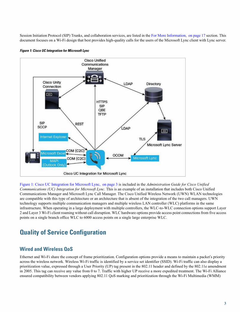
Figure 1: Cisco UC Integration for Microsoft Lync
Figure 1: Cisco UC Integration for Microsoft Lync, on page 3 is included in the Administration Guide for Cisco UnifiedCommunications (UC) Integration for Microsoft Lync. This is an example of an installation that includes both Cisco UnifiedCommunications Manager and Microsoft Lync Call Manager. The Cisco Unified Wireless Network (UWN) WLAN technologiesare compatible with this type of architecture or an architecture that is absent of the integration of the two call managers. UWNtechnology supports multiple communication managers and multiple wireless LAN controller (WLC) platforms in the sameinfrastructure. When operating in a large deployment with multiple controllers, the WLC-to-WLC connection options support Layer2 and Layer 3Wi-Fi client roaming without call disruption. WLC hardware options provide access point connections from five accesspoints on a single branch office WLC to 6000 access points on a single large enterprise WLC.
Quality of Service Configuration
Wired and Wireless QoSEthernet and Wi-Fi share the concept of frame prioritization. Configuration options provide a means to maintain a packet’s priorityacross the wireless network. Wireless Wi-Fi traffic is identified by a service set identifier (SSID). Wi-Fi traffic can also display aprioritization value, expressed through a User Priority (UP) tag present in the 802.11 header and defined by the 802.11e amendmentin 2005. This tag can receive any value from 0 to 7. Traffic with higher UP receive a more expedited treatment. The Wi-Fi Allianceensured compatibility between vendors applying 802.11 QoS marking and prioritization through the Wi-Fi Multimedia (WMM)
3
certification. The SSID configuration on the WLC defines the highest priority on which traffic will be forwarded and what VLANwill be mapped to what WLAN.
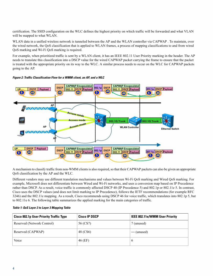
WLAN data in a unified wireless network is tunneled between the AP and the WLAN controller via CAPWAP . To maintain, overthe wired network, the QoS classification that is applied to WLAN frames, a process of mapping classifications to and from wiredQoS marking and Wi-Fi QoS marking is required.
For example, when prioritized traffic is sent by a WLAN client, it has an IEEE 802.11 User Priority marking in the header. The APneeds to translate this classification into a DSCP value for the wired CAPWAP packet carrying the frame to ensure that the packetis treated with the appropriate priority on its way to the WLC. A similar process needs to occur on the WLC for CAPWAP packetsgoing to the AP.
Figure 2: Traffic Classification Flow for a WMM client, an AP, and a WLC
Amechanism to classify traffic from non-WMMclients is also required, so that their CAPWAP packets can also be given an appropriateQoS classification by the AP and the WLC.
Different vendors may use different translation mechanisms and values between Wi-Fi QoS marking and Wired QoS marking. Forexample, Microsoft does not differentiate between Wired and Wi-Fi networks, and uses a conversion map based on IP Precedencerather than DSCP. As a result, voice traffic is commonly affected DSCP 40 (IP Precedence 5) and 802.1p or 802.11e 5. In contrast,Cisco uses the DSCP values (and does not limit marking to IP Precedence), follows the IETF recommendations (for example RFC3246) and the 802.11e mapping. As a result, Cisco recommends using DSCP 46 for voice traffic, which translates into 802.1p 5, butto 802.11e 6. The following table summarizes the applied marking for the main categories of traffic.
Table 1: QoS Layer 2 to Layer 3 Mapping Table
IEEE 802.11e/WMM User PriorityCisco IP DSCPCisco 802.1p User Priority Traffic Type
7 (unused)56 (CS7)Reserved (Network Control)
— (unused)48 (CS6)Reserved (CAPWAP)
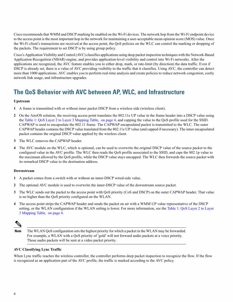
646 (EF)Voice
4
IEEE 802.11e/WMM User PriorityCisco IP DSCPCisco 802.1p User Priority Traffic Type
534 (AF41)Video
424 (CS3)Voice Control (Signaling)
318, 20, 22 (AF2x)Background (Transactional/Interactive Data)
210, 12, 14 (AF1x)Background (Bulk Data)
00 (BE)Best Effort
12, 4, 6Background
D >> 3DUnknown DSCP from Wired
WLAN QoSWLAN QoS is the result of joint effort between Microsoft, Cisco, and IEEE to bring QoS to Wi-Fi channels. The IEEE ratified theWi-Fi QoS specification, 802.11e, in 2005, which was updated in 2012. The Wi-Fi Alliance certifies access point and client QoSinteroperability with a subset of the 802.11e specification known as Wi-Fi Multi-Media (WMM). WMM was also the result of theMicrosoft QoS effort. All Wi-Fi data traffic with QoS capabilities has a WMMQoS priority field in the Wi-Fi packet header. Accesspoints advertise their QoS capabilities in the same manner as they advertise their security capabilities, that is by Wi-Fi beacons andprobe response frames. The QoS parameters for an SSID are contained in information elements of those frames. The QoS informationelements are identified by the Microsoft OID value “00:50:F2”.You can assign to each SSID a QoS profile. This profile determines the highest QoS level expected and allowed to transit to and fromthis SSID. The profile also determines what marking behavior should be used for incoming unmarked traffic, and for multicast traffic.When incoming traffic exceeds the maximum QoS value of the profile, the traffic is remarked to match the maximum QoS valueassigned to the profile. The available profiles are Platinum, Gold, Silver, and Bronze.
Platinum is adapted to all traffic including real time Voice traffic. The maximum expected QoS level for this profile is DSCP 46, andUP 6.
Gold is adapted to all traffic including real time video traffic, but is not intended for real time voice traffic. The maximum expectedQoS level for this profile is DSCP 34, and UP 5.
Silver is adapted to all transactional and data traffic, but is not intended for real time applications such as real time voice or real timevideo. The maximum expected QoS level for this profile is DSCP 18, and UP 3.
Bronze is adapted to background traffic. The maximum expected QoS level for this profile is DSCP 10, and UP 1.
Microsoft Lync includes services ranging from file transfer and application sharing to real audio and video communications. Realtime audio communication traffic is very sensitive to delays and losses, and is typically assigned a higher priority than other traffic.As a result, the Wi-Fi WLAN QoS level recommended for Lync clients is a QoS level of Platinum. The Platinum QoS priority levelallows forwarding of all prioritized traffic up to the Voice category.
The recommended WMM setting is Required. This keeps non-WMM clients from connecting to the SSID. WMM/802.11e wasratified in 2005. Legacy clients such as handheld data transaction computers and old laptop computers can be allowed, but use lowerlevel QoS. Smartphones, tablets, and devices that are 802.11n/ac areWMM compliant. Their applications may not be marking DSCP,and the operating system may not allow WMM QoS marking. But, the devices still use the WMM/802.11e header format whentransmitting or receiving Wi-Fi packets. Various policies on the WLC can be established to define the handling of QoS markings atthe WLC.
5
Cisco recommends thatWMM and DSCPmarking be enabled on theWi-Fi devices. The network hop from theWi-Fi endpoint deviceto the access point is the most important hop in the network for maintaining a user-acceptable mean opinion score (MOS) value. Oncethe Wi-Fi client’s transactions are received at the access point, the QoS policies on the WLC can control the marking or dropping ofthe packets. The requirement to set DSCP is by using group policy.
Cisco’s ApplicationVisibility and Control (AVC) classifies applications using deep packet inspection techniqueswith the Network-BasedApplication Recognition (NBAR) engine, and provides application-level visibility and control into Wi-Fi networks. After theapplications are recognized, the AVC feature enables you to either drop, mark, or rate-limit (by direction) the data traffic. Even ifDSCP is already set, there is a value of AVC providing visibility to the traffic that it classifies. Using AVC, the controller can detectmore than 1000 applications. AVC enables you to perform real-time analysis and create policies to reduce network congestion, costlynetwork link usage, and infrastructure upgrades.
The QoS Behavior with AVC between AP, WLC, and InfrastructureUpstream
1 A frame is transmitted with or without inner packet DSCP from a wireless side (wireless client).
2 On the AireOS solution, the receiving access point translates the 802.11e UP value in the frame header into a DSCP value usingthe Table 1: QoS Layer 2 to Layer 3 Mapping Table, on page 4, and capping the value to the QoS profile used for the SSID.CAPWAP is used to encapsulate the 802.11 frame. The CAPWAP encapsulated packet is transmitted to the WLC. The outerCAPWAP header contains the DSCP value translated from the 802.11e UP value (and capped if necessary). The inner encapsulatedpacket contains the original DSCP value applied by the wireless client.
3 The WLC removes the CAPWAP header.
4 The AVC module on the WLC, which is optional, can be used to overwrite the original DSCP value of the source packet to theconfigured value in the AVC profile. The WLC then reads the QoS profile associated to the SSID, and caps the 802.1p value tothe maximum allowed by the QoS profile, while the DSCP value stays uncapped. The WLC then forwards the source packet withits remarked DSCP value to the destination address.
Downstream
1 A packet comes from a switch with or without an inner-DSCP wired-side value.
2 The optional AVC module is used to overwrite the inner-DSCP value of the downstream source packet.
3 The WLC sends out the packet to the access point with QoS priority (CoS and DSCP) on the outer CAPWAP header. That valueis no higher than the QoS priority configured on the WLAN.
4 The access point strips the CAPWAP header and sends the packet on air with a WMM UP value representative of the DSCPsetting, or the WLAN configuration if the WLAN setting is lower. For more information, see the Table 1: QoS Layer 2 to Layer3 Mapping Table, on page 4.
TheWLANQoS configuration sets the highest priority for which a packet in theWLANmay be forwarded.For example, a WLAN with a QoS priority of ‘gold’ will not forward audio packets at a voice priority.Those audio packets will be sent at a video packet priority.
Note
AVC Classifying Lync Traffic
When Lync traffic reaches the wireless controller, the controller performs deep packet inspection to recognize the flow. If the flowis recognized as an application part of the AVC profile, the traffic is marked according to the AVC policy.
6
For example, when Lync voice traffic, which is unmarked reaches the wireless LAN controller, the NBAR engine on the WLC wouldrecognize this traffic and mark the traffic according to the AVC profile. If the AVC profile was set to UP mark with DSCP value 46,the flows would be as in the following figure.
Cisco Switch Port Configuration for APs and WLCsThe QoS configuration of the switch port connecting the access point should trust the DSCP of the CAPWAP packets that are passedto it from the access point. There is no class-of-service (CoS) marking on the CAPWAP frames coming from the access point. Thefollowing is an example of the switchport configuration. Note that this configuration addresses only the classification and queuingcommands that can be added depending on local QoS policy.
Check on the command requirement for various platforms, for example, MLS, MQC, and so on.Note
interface GigabitEthernet1/0/1switchport access vlan 100switchport mode accessmls qos trust dscpspanning-tree portfastendIn trusting the access point DSCP values, the access switch trusts the policy set for that access point by the WLC. The maximumDSCP value assigned to client traffic is based on the QoS policy applied to the WLAN on that access point.
Recommended WLC Configuration for Lync ClientsCisco recommends constant monitoring of Wi-Fi channel conditions to avoid interference, disruptions caused by rogue devices, andspectrum issues. The overall WLAN design should consider configuration of multicast direct as well as Wi-Fi call admission controlfor voice and video.
7
To provide an enterprise solution and a high-quality user experience for Lync users, Cisco recommends that the WLAN be createdwith the following options:
•WLAN QoS equal to platinum, which allows the clients to use any QoS tag/class:
◦Adding QoS service profiles when appropriate
◦Adding QoS service roles when appropriate
•WLAN band select to push clients to the 5 GHz band, where coverage design supports voice and VoWLAN
•WLAN 802.1x security:
◦Adding fast transition (11r) when appropriate to improve re-authentication roams
• 802.11k to provide access point neighbor lists based on client location for network-assisted roaming
• Disabled access point load balance
• Enabled channel scan at defaults
• Set WMM policy on the WLAN to Allowed. This permits a mix of QoS capable and non-QoS capable clients on the sameWLAN
There are two methods of classifying and prioritizing MS Lync on the wireless network:
• Application Visibility and Control (AVC): AVC operates with NBAR2 engine and Deep Packet Inspection (DPI) to prioritizeLync traffic on a wireless network.
• Lync SDN API: This method requires a Lync SDN API running on a front end Lync server (On-Prem) to provide the WLCwith Lync diagnostic data every time a Lync call is placed on the network. This method can be installed on Lync 2010 or Lync2013 server.
The Lync SDN API takes precedence over AVC policies for QoS on the Cisco WLC.Note
Lync SDN feature not supported for Local switching scenario.Note
Lync SDN APIAVCFeature
YesYesClassifying and prioritizing Lync audioand video flows independently
YesNoClassification of Lync desktop sharingand file transfer
YesNoLync call quality records at the end ofcall
YesNoAdvanced Lync troubleshooting with callstatistics
8

Lync SDN APIAVCFeature
NoYesSupport for Office 365 (Lync Online)
Overview of the Suggested AVC Configuration for the Lync ApplicationCheck the latest WLC configuration guide at http://www.cisco.com/c/en/us/support/wireless/5508-wireless-controller/model.htmlfor commands on AVC configuration.
Recommended AVC Configuration for Lync Audio and VideoMicrosoft Lync offers several types of services: File transfer, application sharing, SIP signaling, real time audio, and real time videocommunications. Microsoft commonly recommends DSCP 40 or 46 for real time voice, DSCP 34 for video, and 24 for the otherservices. This section focuses on configuring AVC for Lync audio and video. To configure AVC for Lync audio and video, performthe following steps:
Procedure
Step 1 Add a specific Lync application packet type for remarking the DSCP value for that packet type.Step 2 Configure an AVC profile for use in a WLAN as shown in the following figure.
9
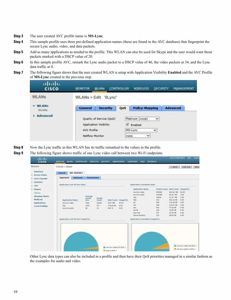
Step 3 The user created AVC profile name isMS-Lync.Step 4 This sample profile uses three pre-defined application names (these are found in the AVC database) that fingerprint the
secure Lync audio, video, and data packets.Step 5 Add as many applications as needed to the profile. This WLAN can also be used for Skype and the user would want those
packets marked with a DSCP value of 20.Step 6 In this sample profile AVC, remark the Lync audio packet to a DSCP value of 46, the video packets at 34, and the Lync
data traffic at 0.Step 7 The following figure shows that the user createdWLAN is setup with Application Visibility Enabled and the AVC Profile
ofMS-Lync created in the previous step.
Step 8 Now the Lync traffic in this WLAN has its traffic remarked to the values in the profile.Step 9 The following figure shows traffic of one Lync video call between two Wi-Fi endpoints.
Other Lync data types can also be included in a profile and then have their QoS priorities managed in a similar fashion asthe examples for audio and video.
10
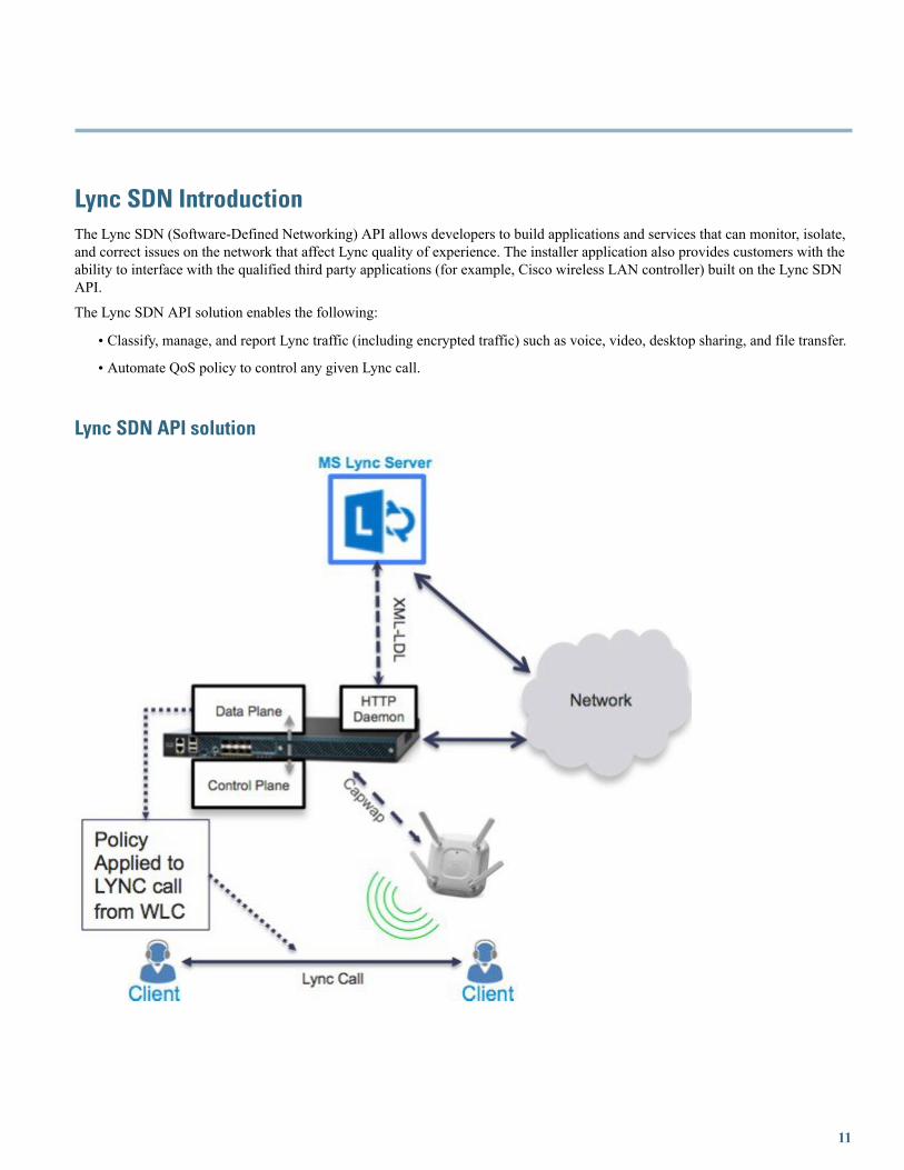
Lync SDN IntroductionThe Lync SDN (Software-Defined Networking) API allows developers to build applications and services that can monitor, isolate,and correct issues on the network that affect Lync quality of experience. The installer application also provides customers with theability to interface with the qualified third party applications (for example, Cisco wireless LAN controller) built on the Lync SDNAPI.
The Lync SDN API solution enables the following:
• Classify, manage, and report Lync traffic (including encrypted traffic) such as voice, video, desktop sharing, and file transfer.
• Automate QoS policy to control any given Lync call.
Lync SDN API solution
11
Lync SDN ConfigurationYou can configure Lync SDN API using both GUI and CLI. It is recommended to use the GUI wherever applicable, with CLI tosupplement as reference.
Cisco WLC is compatible with Lync SDN API 2.0 only. The Lync SDN API software can be downloaded at:http://www.microsoft.com/en-us/download/details.aspx?id=39714.
For Microsft Lync SDN API documentation, including setup of Lync SDN Manager, Lync Dialog Listener, refer to the followingdocumentation on Microsoft web page:
http://msdn.microsoft.com/en-us/library/office/dn439303(v=office.15).aspxFor integrating the Lync SDN API 2.0 with the Cisco WLC, the backward compatibility flag must be set to “true". You can do thisby modifying the SDNManager.exe.config file as follows and restarting the SDN manager service.
...<errors switchValue="All" name="Logging Errors & Warnings">
<listeners><add name="LNEAppLog"/>
</listeners></errors>
</specialSources></loggingConfiguration><appSettings><add key="submituri" value="http://WLC-ip:port"/><add key="backwardcompatibility" value="true"/>...
Procedure
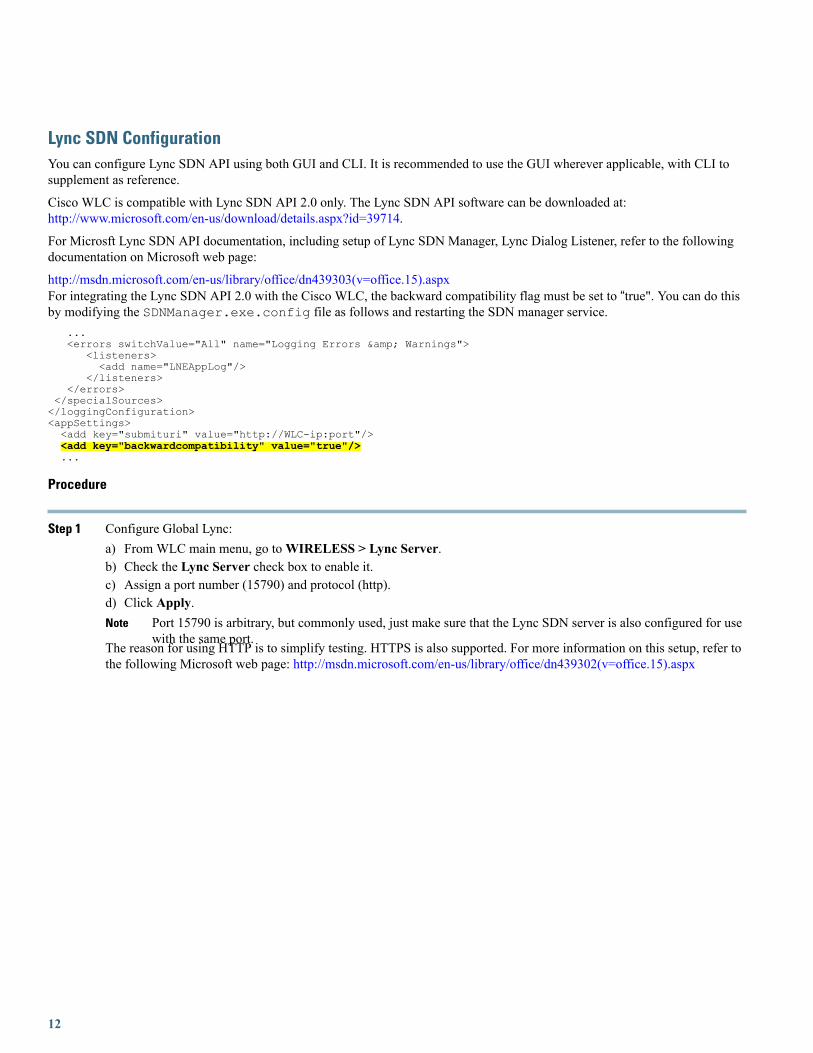
Step 1 Configure Global Lync:a) From WLC main menu, go toWIRELESS > Lync Server.b) Check the Lync Server check box to enable it.c) Assign a port number (15790) and protocol (http).d) Click Apply.
Port 15790 is arbitrary, but commonly used, just make sure that the Lync SDN server is also configured for usewith the same port.
Note
The reason for using HTTP is to simplify testing. HTTPS is also supported. For more information on this setup, refer tothe following Microsoft web page: http://msdn.microsoft.com/en-us/library/office/dn439302(v=office.15).aspx
12
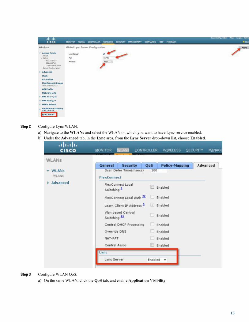
Step 2 Configure Lync WLAN:a) Navigate to theWLANs and select the WLAN on which you want to have Lync service enabled.b) Under the Advanced tab, in the Lync area, from the Lync Server drop-down list, choose Enabled.
Step 3 Configure WLAN QoS:a) On the same WLAN, click the QoS tab, and enable Application Visibility.
13
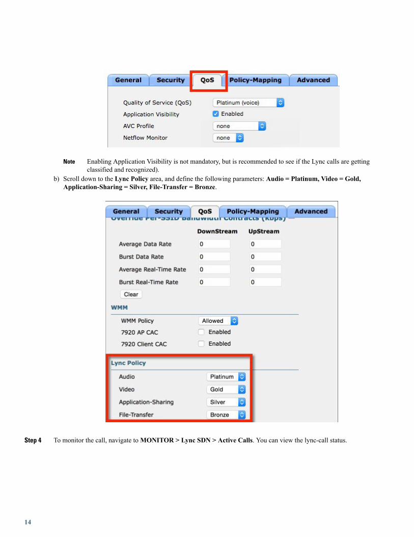
Enabling Application Visibility is not mandatory, but is recommended to see if the Lync calls are gettingclassified and recognized).
Note
b) Scroll down to the Lync Policy area, and define the following parameters: Audio = Platinum, Video = Gold,Application-Sharing = Silver, File-Transfer = Bronze.
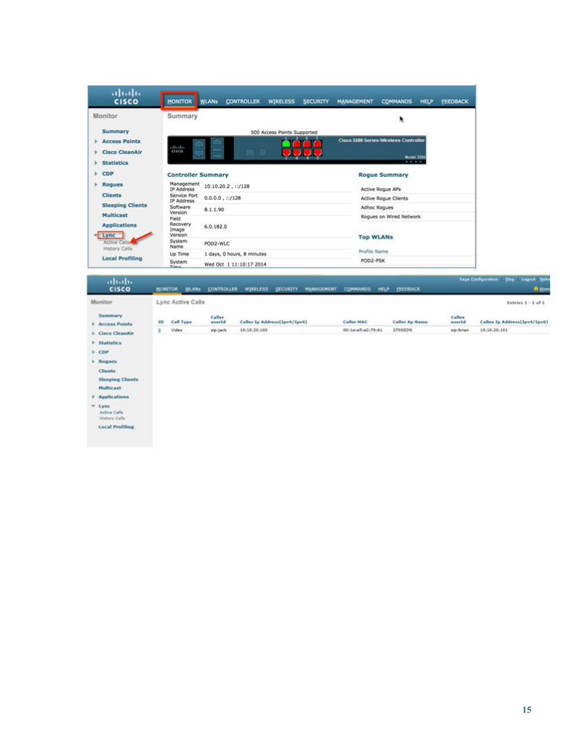
Step 4 To monitor the call, navigate toMONITOR > Lync SDN > Active Calls. You can view the lync-call status.
14
15
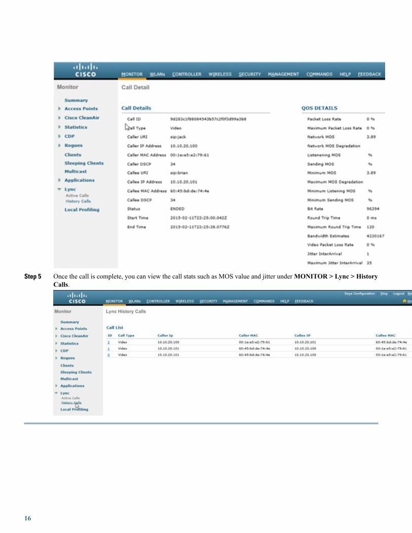
Step 5 Once the call is complete, you can view the call stats such as MOS value and jitter underMONITOR > Lync > HistoryCalls.
16
SummaryWireless is the primary mode for access-layer deployment and customers expect to complete support of collaboration applicationsover WLAN. The best practice for WLANs continues to be to deploy highly-available WLCs, in conjunction with high-density ofaccess points to promote always-available WLAN infrastructure.
In addition, technologies such as Cisco CleanAir, ClientLink, and radio resource management (RRM) allow you to optimize yournetwork performance while simultaneously reducing coverage holes and bypassing interference.
Finally, this white paper shows you how Cisco AVC / Lync SDN API classify Lync 2013 and allow customers to prioritize audioand video using the appropriate QoS treatments. The Microsoft Lync certification is the proof-point that Cisco WLAN providesindustry-leading support for collaboration and business applications.
For More InformationRefer to the following Cisco and Microsoft online references for more information:
Cisco Validated Designs and Solution Reference Network Design (SRND)• The Cisco Design Zone website contains the primary library of solution guides for Collaboration, Enterprise Networks, Mobility,and technologies.
http://www.cisco.com/c/en/us/solutions/enterprise/unified-communication-system/index.html
◦The Cisco Real-Time over Wireless LAN Design Guide is listed under Collaboration.
◦The Overall Mobility Design is listed under Design Zone for Mobility.
• Cisco Collaboration 9.x SRND
◦This document provides design considerations and guidelines for deploying Cisco Unified Communications andCollaboration solutions, including: CiscoUnified CommunicationsManager 9.x (offers design for integrationwithMicrosoftLync.
http://www.cisco.com/c/en/us/td/docs/voice_ip_comm/cucm/srnd/collab09/clb09.html
http://www.cisco.com/c/en/us/td/docs/voice_ip_comm/cucm/srnd/collab09/clb09/collabor.html
AVC – Application Visibility and Control• Cisco Application Visibility and Control (AVC) Q&Ahttp://www.cisco.com/c/en/us/products/collateral/wireless/8500-series-wireless-controllers/qa_c67-722538.html
• Configuring Application Visibility and Control (WLC 7.6 or later)
http://www.cisco.com/c/en/us/support/wireless/5508-wireless-controller/model.html
17
Microsoft Lync• Deploying Lync Clients: Lync Tech Centerhttp://technet.microsoft.com/en-us/lync/fp123621.aspx
• Lync Online Wiki Portal
http://community.office365.com/en-us/wikis/lync/default.aspx
Cisco Unified Communications• Support forum: Cisco Support Community for IP Telephony, Voice, and Video Collaborationhttps://supportforums.cisco.com/community/netpro/collaboration-voice-video/ip-telephony
• Cisco Communities: Unified Communicationshttps://communities.cisco.com/community/technology/collaboration/uc
18

© 2015 Cisco Systems, Inc. All rights reserved.

Europe HeadquartersAsia Pacific HeadquartersAmericas HeadquartersCisco Systems International BVAmsterdam, The Netherlands
Cisco Systems (USA) Pte. Ltd.Singapore
Cisco Systems, Inc.San Jose, CA 95134-1706USA
Cisco has more than 200 offices worldwide. Addresses, phone numbers, and fax numbers are listed on theCisco Website at www.cisco.com/go/offices.