microsoft word - vehicle standards bulletin 7a title page.doc€¦ · web viewthe length of the...
TRANSCRIPT

Category: National Code of Practice
Initiated by: Administrator, Motor Vehicle Standards
Date of Issue: May 1992
Replaces Bulletin 7 Part A, Issued December 1991
Date of Effect: Immediate
National Code of Practice
Design Parameters Necessary for Compliance with ADR 59/00 Omnibus Rollover Strength.
-Part A
THIS CODE OF PRACTICE SETS DOWN A SIMPLE SET OF RULES FOR CONSTRUCTION OF A LIMITED RANGE OF BUS STRUCTURES, WHICH ALLOW SUCH STRUCTURES TO BE DEEMED TO COMPLY WITH AUSTRALIAN DESIGN RULE 59/00 “OMNIBUS ROLLOVER STRENGHT”.
PART B, being issued separately, provides a more complex set of rules to allow a larger range of structures deemed to comply with ADR 59/00.
The Vehicle Standards Bulletin provides information for those associated with the design, manufacture, sale, maintenance or repairs of motor vehicles and trailers.
The series is a major channel for communication from the Vehicle Safety Standards Branch in the case of matters relating to new vehicles, and from the Australian Transport Advisory Council and its committees in the case of vehicles in service.
The series: Gives advance notice of matters of concern; Sets out codes and other standards which supplement the ADRs and AIRs;
and Provides advice concerning vehicle design, safety and operation.
Department of Infrastructure and Transport - Vehicle Safety Standards GPO Box 594 Canberra ACT 2601
Telephone (02) 6274 6838 Fax (02) 6274 7477
Bulletin No.7
Part A Issue 2
Vehicle
StandardsBulletin
7A

NATIONAL CODE OF PRACTICE
DESIGN PARAMETERS NECESSARY FOR COMPLIANCE WITH ADR 59/00 OMNIBUS
ROLLOVER STRENGTH
Part AADR59/00 ROLL OVER CODE OF PRACTICE - PART A
CONTENTS
FOREWORD....................................................................................................................................................................................41 SCOPE AND GENERAL.............................................................................................................................................................6
1.1 Scope.................................................................................................................................................................................61.2 Definitions..........................................................................................................................................................................61.3 Design and Supervision...................................................................................................................................................10
1.3.1 Design....................................................................................................................................................................101.3.2 Supervision.............................................................................................................................................................10
1.4 Australian Standards........................................................................................................................................................102 QUALITY ASSURANCE...........................................................................................................................................................10
2.2 General............................................................................................................................................................................102.3 Quality Control Audits.......................................................................................................................................................10
3 MATERIAL SPECIFICATION....................................................................................................................................................113.2 Specifications...................................................................................................................................................................11
4 GENERAL DESIGN REQUIREMENTS.....................................................................................................................................114.1 Part A - Simple Design Method........................................................................................................................................11
5 ROLL CAGE DESIGN • SIMPLE DESIGN METHOD................................................................................................................125.1 General............................................................................................................................................................................125.2 Base Dimensions.............................................................................................................................................................12
5.2.1 Passenger Compartment Cross Section................................................................................................................125.2.2 Allowable Overall Vehicle Parameters....................................................................................................................175.2.3 Longitudinal Location Centre of Mass. (CoM).........................................................................................................17
5.3 Roll Cage Structure..........................................................................................................................................................175.3.1 General..................................................................................................................................................................175.3.2 Standard Hoop.......................................................................................................................................................175.3.3 Curtailed Hoop.......................................................................................................................................................195.3.4 Front Hoop.............................................................................................................................................................19
Federal Office of Road Safety
Issued by theAdministrator, Motor Vehicle Standards In consultation with theAustralian Bus and Coach Association

5.3.5 Rear Hoop..............................................................................................................................................................195.3.6 Stub Pillar...............................................................................................................................................................215.3.7 Bearer Stub Pillar...................................................................................................................................................215.3.8 Sill Rail...................................................................................................................................................................215.3.9 Waist Rails.............................................................................................................................................................215.3.10 Side Wall Truss Bracing.........................................................................................................................................215.3.11 Cant Rail................................................................................................................................................................215.3.12 Floor Bearer...........................................................................................................................................................215.3.13 Under Floor Structure.............................................................................................................................................235.3.14 Roof Construction...................................................................................................................................................235.3.15 Floor Over Engine Bay...........................................................................................................................................23
5.4 Service Strength Modifications.........................................................................................................................................235.4.1 General..................................................................................................................................................................235.4.2 Door Openings.......................................................................................................................................................235.4.3 Additional Requests...............................................................................................................................................23
6 FABRICATION..........................................................................................................................................................................236.2 General............................................................................................................................................................................246.3 Manufacturing Standards.................................................................................................................................................246.4 Cutting and Materials Handling........................................................................................................................................246.5 Setup Dimensions - Tolerances - Surface Finishes..........................................................................................................246.6 Welder Certification..........................................................................................................................................................256.7 Welding Procedures.........................................................................................................................................................256.8 Weld Inspection................................................................................................................................................................276.9 Assembly of Fabrication...................................................................................................................................................29
APPENDIX A.......................................................................................................................................................................................29APPENDIX B.......................................................................................................................................................................................31GENERAL TOLERANCES FOR WELDED STRUCTURES................................................................................................................311 General.....................................................................................................................................................................................312 Limit Deviations for Angular Dimensions...................................................................................................................................31APPENDIX C.......................................................................................................................................................................................32TYPICAL WELDING PROCEDURES GUIDE LINES..........................................................................................................................321 General.....................................................................................................................................................................................322 Mill Finish of Cold Formed Tube...............................................................................................................................................323 Welding Process - Plain and Galvanised Tube.........................................................................................................................324 Welding Modes - Plain and Galvanised Tube...........................................................................................................................335 Electrical Stick Out (ESO) and Polarity - Plain and Galvanised Tube.......................................................................................336 Welding Consumables. GMAW (Wire) - Plain and Galvanised Tube........................................................................................347 GMAW Shielding Gas - C450....................................................................................................................................................34
7.2 Plain Tube........................................................................................................................................................................347.3 Galvanised Tube..............................................................................................................................................................34
8 Other Welding Data GMAW......................................................................................................................................................349 Variations and Quality Assurance.............................................................................................................................................3610 Shop Testing.............................................................................................................................................................................3611 Ventilation.................................................................................................................................................................................36
ADR59/00 ROLL OVER CODE OF PRACTICEFOREWORD
ADR 59/00 comes into force on 1 July 1992 for category ME buses, having a GVM of in excess of 5 tonnes. It requires that manufacturers shall demonstrate that buses have sufficient strength to withstand a specified sideways rollover, without deforming to the extent that a specified "residual space" is intruded upon by any part of the bus structure or fittings. The Design Rule offers four possible ways in which compliance may be demonstrated, viz
Test by rolling a complete bus.
Test by rolling a section or sections.
Test by imposing a pendulum load to a section or section Verify by an approved calculation method
To assist bus manufacturers, and in particular the smaller manufacturers, the Federal Office of Road Safety (FORS) agreed in discussion with the Australian Bus and Coach Manufacturers Association (ABCA), to undertake a programme of investigation and testing, aimed at developing a National Code of Practice. It was agreed that manufacturers who could demonstrate that they had followed the code of practice in the construction of particular buses, would have such vehicles accepted by FORS as complying with the requirements of ADR 59/00, without the need for further testing or analysis as outlined above.
Department of Infrastructure and Transport - Vehicle Safety Standards GPO Box 594 Canberra ACT 2601
Telephone (02) 6274 6838 Fax (02) 6274 7477

A sub-committee of ABCA was formed to provide guidance to FORS on omnibus construction. At its first meeting it was agreed that, to form a basis for the code, FORS would carry out the following:
Build a generic two axle, approximately 9 tonne tare mass, bus having a frame that included a rollover protection cage, generally in a manner (outlined by FORS) as having been found satisfactory in the United Kingdom.
Carry out a computer analysis of the test bus frame, using a suitable programme.
Roll the test bus in accordance with ADR 59/00.
Compare the observed results of the roll test with those predicted by computer analysis, so that the application of the proposed code could be made sufficiently wide to be suitable for a reasonably wide range of buses.
Clearly it was unlikely that one configuration of bus could be made to truly represent all the possibilities in category ME buses. However, it was decided that the configuration chosen represents a significant proportion of the 50 to 58 seating position buses that are used for:
School runs.
Local and district route runs in suburbs and country towns. Charter and tourist work other than long distance work.
Some city route runs.
The sub committee has considered the proposed frame drawings submitted to them and accepted them as a reasonable basis for the construction of buses to withstand service requirements.
A bus body frame of the type outlined above has now been built and roll tested. The bus met the requirements of ADR 59/00 successfully; an initial computer analysis of the frame is in progress at December 1991. Comparisons will be drawn with the measured results of the test.
Because of time constraints, it has been decided to issue the code in two parts:-
Part A, which is this document, sets down rules for construction, based on a fairly narrow interpretation of the results so far of testing and analysis. The rules set down in this document are closely based on the structure of the test bus and are therefore prescriptive. However, Part A requires almost no design testing and, as bus structures built to it will be deemed to comply with ADR 59/00, it provides an easy method by which manufacturers can attain compliance of the buses they build.
Part B. This part of the code allows for the wider application of the code to different bus shapes, sizes and configurations. Part B of the code, also allows for manufacturers to make suitable, relatively inexpensive tests, in order to validate such variants of the roll cage beyond those defined in Part A, for acceptance as complying with ADR 59/00.
It will be appreciated that this part A of the code, is directed primarily at the design and construction requirements of a bus that will be acceptable under ADR 59/00.
Manufacturers will need to take care in construction, for example, of joints in the roll cage which may be subject also to fluctuating stress conditions in ordinary service loading.
Manufacturers intending to meet ADR59/00 by means of the Part A Code of Practice will be subject to Conformity of Production assessment for Quality Assurance. The Code outlines the procedures necessary to meet Quality Assurance requirements.
Federal Office of Road Safety
Issued by theAdministrator, Motor Vehicle Standards In consultation with theAustralian Bus and Coach Association

1 SCOPE AND GENERAL1.1 Scope
This Part A code applies to single deck vehicles of heavy omnibus category ME, with tare masses ranging from 6.00 to 10.5 tonnes.
Part A of the Code is a simplified and restrictive set of design requirements, applicable to the design of the roll cage for a limited number of nominated bus chassis. Bus structures built to the requirements of Part A will be deemed to comply with ADR59/00.
Part B provides a generalised set of design requirements and guidance notes, to cover the design of roll cages of various configurations for a range of less restricted chassis, for certification under ADR 59/00.
1.2 Definitions
The definitions given below are applicable to this Code and associated documents only.
STANDARD HOOP PROFILE. The standard profile is that which lies within the envelope of profiles acceptable under the Code.
STANDARD SECTIONS. The specific geometric shape and material strength of the component members used to construct the Roll Cage Structure.
STANDARD CONNECTIONS. Those conforming to the detail design and manufacturing methods to be used in the joint construction for the members of the Roll Cage Structure and its connection to the other chassis components of the vehicle.
ROLL CAGE STRUCTURE. This is the whole skeleton of the body consisting of the following members; hoop pillars and roof bows, cant rails, waist rails, sill rails, stub pillars and floor bearers, all assembled to form an integral structure. Typical roll cage components are illustrated in Figure 1.02.1.
STANDARD HOOP. A hoop of standard profile with vertical pillars running between the floor bearer and the roof bow, which in conjunction with the floor bearer forms a complete closed hoop structure as shown in Figure 1.02.2 (a).
CURTAILED HOOP. A standard hoop which does not connect to a floor bearer, but ends in a connection to a sill rail only as shown in Figure 1.02.2 lb).
FRONT HOOP. A hoop of generally standard profile with vertical pillars running between the floor bearer and roof bow, which in conjunction with a transverse rail and floor bearer forms a complete closed hoop structure as shown in Figure 1.02.2 (c). It is seen that the height from floor to top of hoop may be 300mm higher than that of a standard hoop.
Department of Infrastructure and Transport - Vehicle Safety Standards GPO Box 594
Canberra ACT 2601Telephone (02) 6274 6838 Fax (02)
6274 7477

ROLL CAGE COMPONENTS -
NOMENCLATURE FIG. 1.
02 .1
SIDE WALL TRUSS
SIDE WALL ASSEMBLY
VSB7 PART A
DESIGN PARAMETERS NECESSARY FOR COMPLIANCE WITH ADR 59/00 OMNIBUS ROLLOVER STRENGTH

REAR HOOP. A hoop of standard profile with vertical pillars running between the floor bearer and roof bow, transverse rails at the cant and waist rail levels in conjunction with floor bearer forms a complete closed hoop structure as shown in Figure 1.02.2 (d).
STUB PILLAR. A member running vertically between the sill and waist rails connecting the two together as part of the triangulated side wall truss.
BEARER STUB PILLAR. A member running between the floor bearer and the waist rail, and having the sill rails framed into it.
FLOOR BEARER. A transverse member of the floor structure, connected by supporting steelwork to the vehicle chassis and supporting hoops or bearer stub pillars.
CANT RAIL. The cant rail is a member running between the hoops at top of window height.
WAIST RAIL. The waist rail is a horizontal member running between the hoops, immediately beneath the windows and forming the top cord of a side wall truss.
SILL RAIL. The sill rail is a member running between the hoops at the level of the floor bearers and forming the bottom chord of a side wall truss.
SIDE WALL ASSEMBLY. A fabrication consisting of hoop pillars, stub pillars, waist rails, sill rails and diagonal bracing that is prefabricated and then welded to the floor bearers.
SIDE WALL TRUSS. The trussed lower part of a fabricated side wall assembly.
FLOOR HEIGHT. The height from the ground to top of the finished main floor for a bus at tare mass. In Part A the floor is horizontal with a finished thickness, above the floor bearers, of 10 to 20mm.
PASSENGER COMPARTMENT. The space intended for passengers' use excluding any space occupied by fixed appliances such as bars, kitchenettes or toilets.
LOWERED ROOF LINE. Describes a bus having uniform height above the floor having hoops conforming to the standard hoop profile with the exception that the front hoop is up to 300mm lower as indicated in Fig 1.02.2 (c).
Department of Infrastructure and Transport - Vehicle Safety Standards GPO Box 594
Canberra ACT 2601Telephone (02) 6274 6838 Fax (02)
6274 7477

DESIGN PARAMETERS NECESSARY FOR COMPLIANCE WITH ADR 59/00 OMNIBUS ROLLOVER STRENGTH
VSB7 PART A
ISSUE 2 Page | 8 MAY1992

1.3 Design and Supervision.
1.3.1 Design.
The interpretation of the design requirements in this code shall be the responsibility of a 'designer' experienced in the design of such structures. For the purpose of this code, the term •designer' shall mean the engineer responsible for the interpretation and shall include his representative.
1.3.2 Supervision.
All stages of the roll cage structure manufacture shall be adequately supervised to ensure that all requirements of the design and fabrication are satisfied in the completed structure. The supervision shall be in accordance with the manufacturer's quality assurance plan as nominated elsewhere in this Code. The supervision shall be the responsibility of either,
(a) the designer, or
(b) the person experienced in such supervision, who reports to and is approved by the designer.
1.4 Australian Standards.
Unless otherwise noted standards referred to in this code, shall mean the current edition of the Australian Standard.
2 QUALITY ASSURANCE.
2.2 General.
Manufacturers who build buses to this Code shall have a Quality Assurance Plan meeting the requirements of AS.3902. In addition they shall maintain engineering records to document their compliance with the design requirements section 5.00 of this Code.
Manufacturers who have not provided a Quality Manual to the Administrator, Motor Vehicle Standards in accordance with Administrator's Circular 0-3-4 are required to do so before commencement of manufacture of vehicles to this Code.
2.3 Quality Control Audits.
Quality audits will be performed by officers of the Department of Transport and Communications or their agents using Administrator's Circular 0-13-1 "Conformity of Production•.
ISSUE 2 Page | 9 MAY1992
VSB7 PART A
DESIGN PARAMETERS NECESSARY FOR COMPLIANCE WITH ADR 59/00 OMNIBUS ROLLOVER STRENGTH

3 MATERIAL SPECIFICATION.
3.2 Specifications.
Materials to be used shall comply with the following specifications:
(i) Steel Plate and Rolled Steel Sections.
This material shall comply with AS.3678 Grade 250 and have the following minimum mechanical properties:-
Ultimate strength - 410 MPa
Yield Stress - 250 MPa
Elongation - 22%
(ii) Hollow Steel Sections.
This material shall comply with AS. 1163-1991 and have the following minimum mechanical properties:-
Grade C450Ultimate strength - 500 MPa
Yield Stress - 450 MPa
Elongation - 14%
Grade C350Ultimate strength - 430 MPa
Yield Stress - 350 MPa
Elongation - 16%
Records shall be maintained that show the materials used meet with these requirements.
4 GENERAL DESIGN REQUIREMENTS
4.1 Part A - Simple Design Method.
The method specified under this Part A is limited to the use of a roll cage structure as specified in this Code and applied to a limited range of vehicles.
ISSUE 2 Page | 10 MAY1992
VSB7 PART A
DESIGN PARAMETERS NECESSARY FOR COMPLIANCE WITH ADR 59/00 OMNIBUS ROLLOVER STRENGTH

The design method involves the implementation of a roll cage structure design for roll over impact energy absorption. It requires the vehicle to conform to the dimensional limitations imposed by the roll cage structure and the use of the standard sections, section connections and materials as documented in Section 5.00 of this Code.
The longitudinal and cross sectional profile of the passenger compartment must lie within the limits nominated in paragraph 5.02 of this Code.
The construction of the vehicle shall be carried out using the quality assurance procedures documented in sections 2.00 and 6.00 of this Code.
The records of implementation of all of these requirements shall be validated in writing or by signature of the 'designer'.
5 ROLL CAGE DESIGN • SIMPLE DESIGN METHOD.
5.1 General.
The Code Roll Cage Structure has been designed to suit two axle omnibuses with maximum axle centres of 7.Om with ladder frame chassis construction of which the following are typical examples.
Isuzu LT1 - 11P Hino RG 197
Scania 193
Mercedes 1418
A typical roll cage arrangement as defined below in paragraph 5.02 is shown in one mounting configuration on a composite drawing of the above chassis. Refer drawing no. VSB 7-03.
5.2 Base Dimensions.
5.2.1 Passenger Compartment Cross Section.
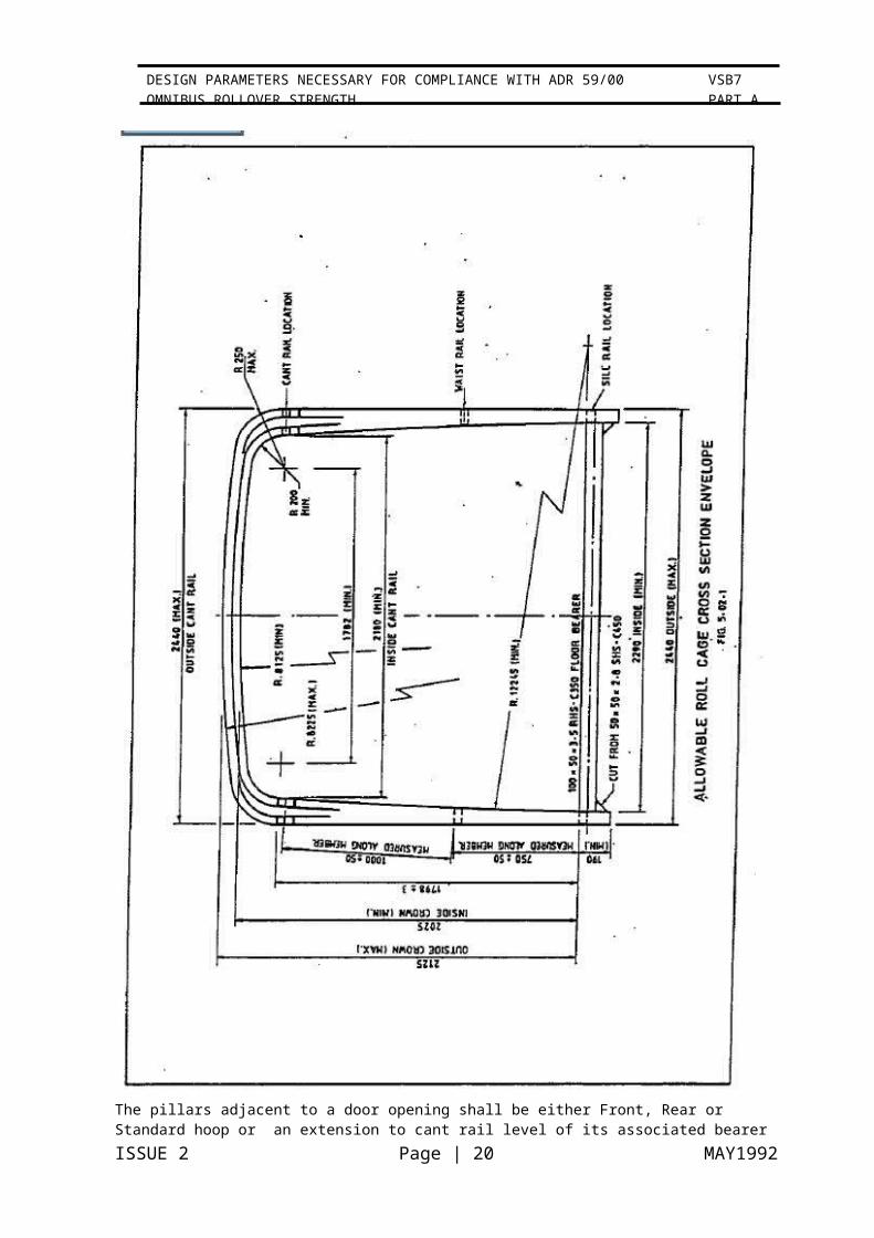
The roll over impact absorption capacity of the roll cage is directly related to its geometric configuration, and hence the cross sectional profile of the roll cage is constrained within specific limits.
An allowable roll cage hoop profile is one that fits within the envelope shown in:
Figure 5.02.1 All roll cage members must lie within the defined envelope
Figure 5.02.2 Overall Vehicle Length, Hoop Numbers & Spacing.
This Code is prepared to cover a vehicle with a maximum axle spacing of 7.0m, an overall length of 12.2m and the following requirements.
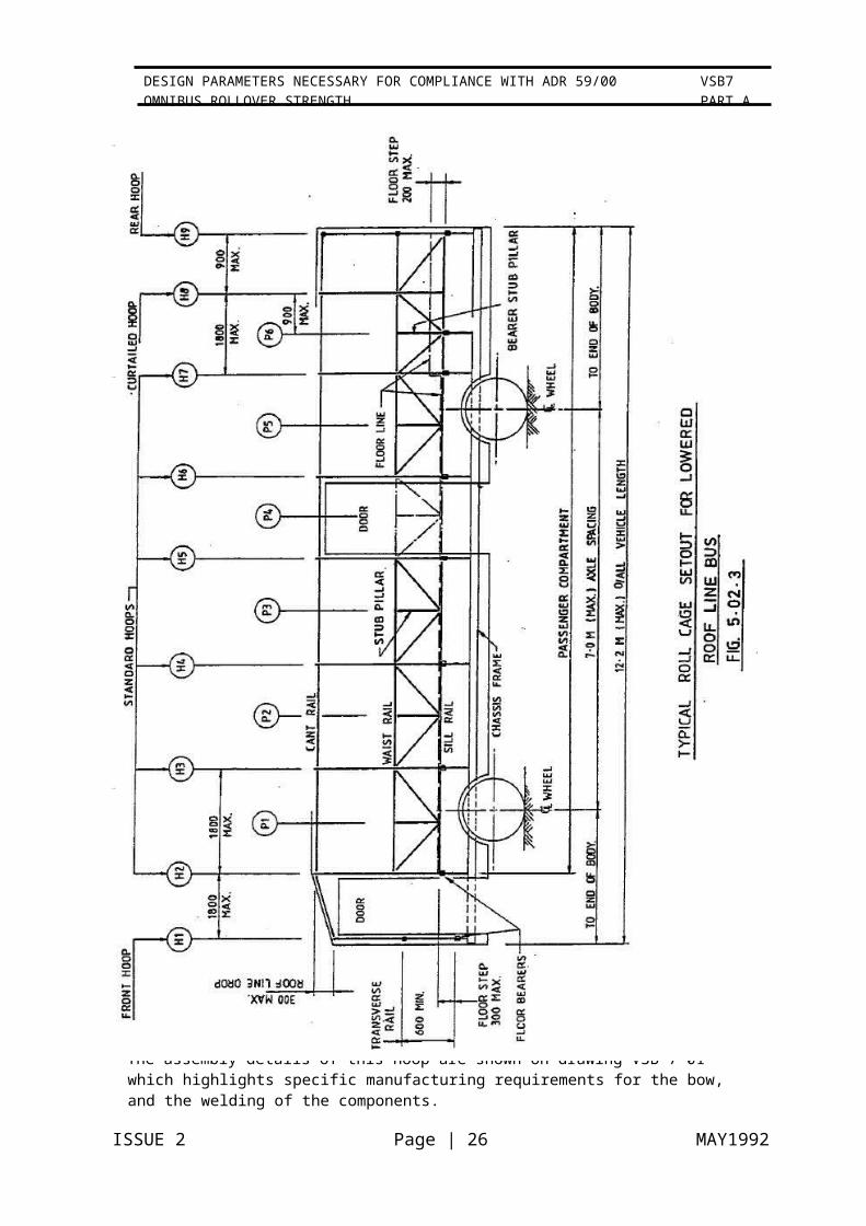
The arrangement of hoops throughout the length of the bus shall be as illustrated in Figure 5.02.2 for the standard bus and Figure 5.02.3 for a bus with a lowered roof line.
The number of hoops required for any specific vehicle is dependent upon:
Vehicle Tare Mass Floor Height
Overall Vehicle Length
ISSUE 2 Page | 11 MAY1992
VSB7 PART A
DESIGN PARAMETERS NECESSARY FOR COMPLIANCE WITH ADR 59/00 OMNIBUS ROLLOVER STRENGTH
Determine the minimum number of hoops, as described in para 5.02.3, from :-
i. Figure 5.02.4 for the standard bus.
ii. Figure 5.02.5 for the lowered roof line bus.
The number of hoops so determined shall be not less than that required by the overall length and the maximum hoop spacing limits. There shall be an equal number of hoops disposed about the centre of mass (CoM) of the vehicle. The construction of the roll cage shall be such that there shall be not more than one curtailed hoop fore and aft of the CoM.
The hoops shall be spaced throughout the length of the vehicle with the centre to centre spacing of the hoops being a maximum of 1800mm.
ISSUE 2 Page | 12 MAY1992
VSB7 PART A
DESIGN PARAMETERS NECESSARY FOR COMPLIANCE WITH ADR 59/00 OMNIBUS ROLLOVER STRENGTH

The pillars adjacent to a door opening shall be either Front, Rear or Standard hoop or an extension to cant rail level of its associated bearer stub pillar as illustrated in Figure 5.02.2 & 5.02.3.
ISSUE 2 Page | 13 MAY1992
VSB7 PART A
DESIGN PARAMETERS NECESSARY FOR COMPLIANCE WITH ADR 59/00 OMNIBUS ROLLOVER STRENGTH

A curtailed hoop shall not be used adjacent to any opening that extends below waist rail level.
The floor bearers shall be spaced throughout the length of the bus to suit the standard hoop or bearer stub pillar spacings and at a maximum centre to centre distance of 1800 mm.
ISSUE 2 Page | 14 MAY1992
VSB7 PART A
DESIGN PARAMETERS NECESSARY FOR COMPLIANCE WITH ADR 59/00 OMNIBUS ROLLOVER STRENGTH

ISSUE 2 Page | 15 MAY1992
VSB7 PART A
DESIGN PARAMETERS NECESSARY FOR COMPLIANCE WITH ADR 59/00 OMNIBUS ROLLOVER STRENGTH

5.2.2 Allowable Overall Vehicle Parameters
Different combinations of floor height, overall height and tare mass of two axle give rise to different roll over energies and hence the number of hoops required in any specific roll cage. The required number of hoops is derived from Figure 5.02.4 or 5.02.5 dependent upon the type of vehicle.
The figures are used in the following manner.
Enter the diagram at the desired vehicle tare mass and move vertically upwards until the floor height line is encountered. Move horizontally to the vertical scale on the left and read off the minimum number of hoops required.
Intermediate floor heights may be interpolated between the nominated floor height lines.
5.2.3 Longitudinal Location Centre of Mass. (CoM)
To ensure compliance with paragraphs 5.02.2, the CoM. location for a finished vehicle shall be determined from weigh bridge figures.
The centre of mass location expressed as a percentage of the wheel base from the rear axle is given by the following equation:
X% = FA x 100I[FA + RA J.
Where: FA is the front axle load. RA is the rear axle load.
Retain the weigh bridge dockets for quality assurance documentation.
5.3 Roll Cage Structure.
5.3.1 General.
The design of the roll cage structure has been made to suit a typical body construction used for route, school or charter bus services as normally supplied to a bus operator.
5.3.2 Standard Hoop.
A Standard Hoop shall be constructed from 50 x 50 x 2.Smm thick SHS Grade C450 to AS. 1163. It has four components; a roof bow, two side pillars and a floor bearer,
which together form a closed hoop as illustrated in Figure 1.02.2 (a). The pillar shall be reinforced with 40 x 40 x 2.3mm SHS between the underside of the floor bearer and the waist rail.
The assembly of this hoop is shown on drawing VSB 7-01 which highlights specific manufacturing requirements for the bow, and the welding of the components.
ISSUE 2 Page | 16 MAY1992
VSB7 PART A
DESIGN PARAMETERS NECESSARY FOR COMPLIANCE WITH ADR 59/00 OMNIBUS ROLLOVER STRENGTH

ISSUE 2 Page | 17 MAY1992
VSB7 PART A
DESIGN PARAMETERS NECESSARY FOR COMPLIANCE WITH ADR 59/00 OMNIBUS ROLLOVER STRENGTH
5.3.3 Curtailed Hoop.
A Curtailed Hoop is a hoop section manufactured in the same manner as the standard hoop with the exception that it is not connected to a floor bearer but to a sill rail. It is located within 900mm of a standard hoop on one side and within 900mm maximum of a bearer stub pillar on the other side or within 900mm of a bearer stub pillar on each side of the curtailed hoop. Figure 1.02.2 (bl illustrates a curtailed hoop.
The hoop to sill rail joint is detailed as connection 06 on drawing VSB 7-02.
5.3.4 Front Hoop.
A Front Hoop shall be constructed from 50 x 50 x 2.Smm SHS grade C450 to AS. 1163. It has five components; a roof bow, two side pillars, transverse rail anda floor bearer, which form a closed hoop as illustrated in Figure 1.02.2 (c). The pillars shall be reinforced with 40 x 40 x 2.3mm SHS grade C450 between the underside of the floor bearer and the waist rail level.
The floor bearer of a front hoop may be upto 300mm below the floor of the passenger compartment.
A front hoop for a bus having a lowered roof line is constructed in the same way but its roof bow may be up to 300mm below the remainder Cf the hoops in the bus. This is illustrated by the dashed outline in Fig 1.02.2(cJ.
Assembly details of this hoop are shown on drawing VSB 7-01 which highlights specific manufacturing requirements for the bow, and the welding of the components.
5.3.5 Rear Hoop.
A Rear Hoop shall be constructed from 50 x 50 x 2.Smm SHS grade C450 to AS. 1163. It has six components; a roof bow, two side pillars, transverse rails at the cant and waist rail levels which together with the floor bearer forms a closed hoop as illustrated on
Figure 1.02.2 (d). The pillars shall be reinforced with 40 x 40 x 2.3mm SHS grade C450 between the underside of the floor bearer and the waist rail level.
The floor bearer of the rear hoop shall be at the passenger compartment floor level refer Figure 5.02.2 & 5.02.3.
The assembly details of this hoop are shown on drawing VSB 7-01 which highlights specific manufacturing requirements for the bow, and the welding of the components.
ISSUE 2 Page | 18 MAY1992
VSB7 PART A
DESIGN PARAMETERS NECESSARY FOR COMPLIANCE WITH ADR 59/00 OMNIBUS ROLLOVER STRENGTH

ISSUE 2 Page | 19 MAY1992
VSB7 PART A
DESIGN PARAMETERS NECESSARY FOR COMPLIANCE WITH ADR 59/00 OMNIBUS ROLLOVER STRENGTH
5.3.6 Stub Pillar.
A stub pillar is a 50 x 50 x 2.8 SHS C450 section that runs between the sill and waist rails and located midway between the hoops or at maximum of 900mm from a standard hoop. It is a vertical member of the triangulated side wall truss. A stub pillar is not required when the hoop spacing is less than 900mm. Connection of the pillar to the sill rail is detailed as Connection 04 and that to the waist rail as Connection 05 on drawing VSB 7-02.
5.3.7 Bearer Stub Pillar.
A bearer stub pillar is a 50 x 50 x 2.8 SHS-C450 section, which runs from a floor bearer to waist rail and is reinforced with 40 x 40 x 2.3 mm SHS C450 section. The bearer stub pillar is always located adjacent to a curtailed hoop, and within 900 mm of this hoop.
The joint between the bearer stub pillar and the floor bearer is Connection 01, as for standard hoops, and the connection between bearer stub pillar and waist rail is Connection 05 on drawing VSB7-02.
5.3.8 Sill Rail.
A sill rail is a 50 x 50 x 2.8mm SHS-C450 section that runs between standard hoop and standard hoop or stub pillar. The joint between sill rail and hoop is shown as Connection 02 on drawing VSB 7-02.
5.3.9 Waist Rails.
A waist rail is a 50 x 50 x 2.8mm SHS-C450 section that runs between hoops, both standard hoops and curtailed hoops. The joint between the waist rail and the hoops is Connection 02 on drawing VSB 7-02.
5.3.10 Side Wall Truss Bracing.
The side wall truss bracing running between the sill and waist rails shall be 50 x 25 x 2.0mm RHS Grade C350 to AS. 1163. Connection details between the braces and sill and waist rails is shown on drawing VSB 7-02.
5.3.11 Cant Rail.
A cant rail is a 50 x 50 x 2.3mm SHS-C450 section that runs between the hoops and is connected to these hoops using Connection 03 detailed on drawing VSB 7-02.
5.3.12 Floor Bearer.
A floor bearer is a 100 x 50 x 3.5mm RHS-C350 section.
ISSUE 2 Page | 20 MAY1992
VSB7 PART A
DESIGN PARAMETERS NECESSARY FOR COMPLIANCE WITH ADR 59/00 OMNIBUS ROLLOVER STRENGTH

ISSUE 2 Page | 21 MAY1992
VSB7 PART A
DESIGN PARAMETERS NECESSARY FOR COMPLIANCE WITH ADR 59/00 OMNIBUS ROLLOVER STRENGTH

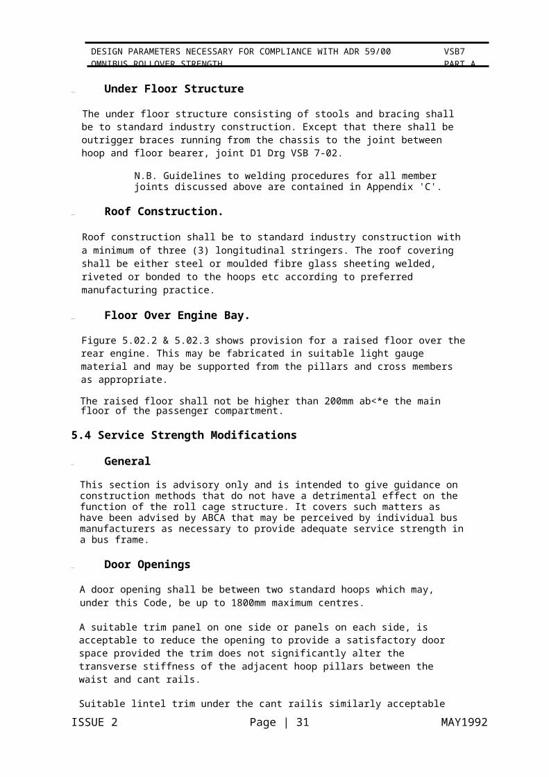
5.3.13 Under Floor Structure
The under floor structure consisting of stools and bracing shall be to standard industry construction. Except that there shall be outrigger braces running from the chassis to the joint between hoop and floor bearer, joint D1 Drg VSB 7-02.
N.B. Guidelines to welding procedures for all member joints discussed above are contained in Appendix 'C'.
5.3.14 Roof Construction.
Roof construction shall be to standard industry construction with a minimum of three (3) longitudinal stringers. The roof covering shall be either steel or moulded fibre glass sheeting welded, riveted or bonded to the hoops etc according to preferred manufacturing practice.
5.3.15 Floor Over Engine Bay.
Figure 5.02.2 & 5.02.3 shows provision for a raised floor over the rear engine. This may be fabricated in suitable light gauge material and may be supported from the pillars and cross members as appropriate.
The raised floor shall not be higher than 200mm ab<*e the main floor of the passenger compartment.
5.4 Service Strength Modifications
5.4.1 General
This section is advisory only and is intended to give guidance on construction methods that do not have a detrimental effect on the function of the roll cage structure. It covers such matters as have been advised by ABCA that may be perceived by individual bus manufacturers as necessary to provide adequate service strength in a bus frame.
5.4.2 Door Openings
A door opening shall be between two standard hoops which may, under this Code, be up to 1800mm maximum centres.
A suitable trim panel on one side or panels on each side, is acceptable to reduce the opening to provide a satisfactory door space provided the trim does not significantly alter the transverse stiffness of the adjacent hoop pillars between the waist and cant rails.
Suitable lintel trim under the cant railis similarly acceptable provided the trim does not significantly alter the transverse stiffness of the adjacent hoop pillars.
5.4.3 Additional Requests.
Manufacturers may request further advice on the acceptability of modifications or additions to assist them in providing adequate service strength. It would be preferred if these were passed through ABCA. It is expected that the above guidance will be updated as requests are received and responses provided.
6 FABRICATION
ISSUE 2 Page | 22 MAY1992
VSB7 PART A
DESIGN PARAMETERS NECESSARY FOR COMPLIANCE WITH ADR 59/00 OMNIBUS ROLLOVER STRENGTH

6.2 General
Fabrication shall be carried out in a manner approved by the designer and shall comply with the requirements of the Code and such sections of the Australian Standards, referred to below, that are determined by the designer as appropriate.
Testing and inspection of the works shall be carried out under the requirements of AS.3990 and AS. 1554. The requirements of AS.1554 shall take precedence.
NOTE: All references to AS.1250 in the nominated codes shall be read as referring to AS.3990.
6.3 Manufacturing Standards.
The vehicle is to be manufactured in accordance with the manufacturer's quality assurance manual and the applicable sections of the relevant Australian Standards in particular:-
AS. 1163AS. 1554 AS.3990
Structural Steel Hollow Sections SAA Welding CodeSteelwork for Engineering Applications
The manufacturers standards are to be documented in a quality procedures manual conforming to AS.3902 as outlined in section 2.00.
6.4 Cutting and Materials Handling
All materials shall be cut in a manner that does not impair their chemical and/or mechanical properties.
All material shall be handled carefully. No material shall be allowed to deflect - under any loading conditions - by more than one (1Ifive hundredth (1:5001 of the distance between support points. ·
6.5 Setup Dimensions - Tolerances - Surface Finishes
The requirements of Appendix 'B' General Tolerances for Welded Structures shall be complied with.
Machine finish tolerances are given in Ra roughness values in micrometer units in accordance with AS.2536.
Material surfaces which have been specified to be ground smooth shall have a surface finish of 6.3 Ra or better.
ISSUE 2 Page | 23 MAY1992
VSB7 PART A
DESIGN PARAMETERS NECESSARY FOR COMPLIANCE WITH ADR 59/00 OMNIBUS ROLLOVER STRENGTH

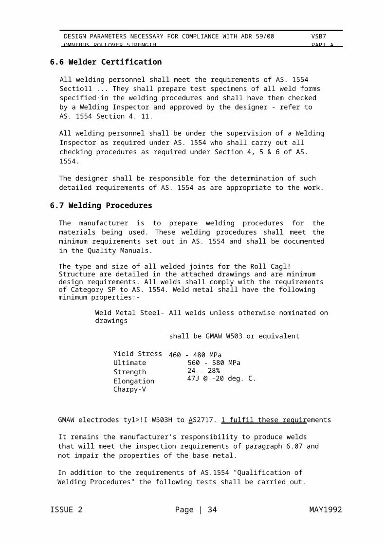
6.6 Welder Certification
All welding personnel shall meet the requirements of AS. 1554 Sectio11 ... They shall prepare test specimens of all weld forms specified·in the welding procedures and shall have them checked by a Welding Inspector and approved by the designer - refer to AS. 1554 Section 4. 11.
All welding personnel shall be under the supervision of a Welding Inspector as required under AS. 1554 who shall carry out all checking procedures as required under Section 4, 5 & 6 of AS. 1554.
The designer shall be responsible for the determination of such detailed requirements of AS. 1554 as are appropriate to the work.
6.7 Welding Procedures
The manufacturer is to prepare welding procedures for the materials being used. These welding procedures shall meet the minimum requirements set out in AS. 1554 and shall be documented in the Quality Manuals.
The type and size of all welded joints for the Roll Cagl! Structure are detailed in the attached drawings and are minimum design requirements. All welds shall comply with the requirements of Category SP to AS. 1554. Weld metal shall have the following minimum properties:-
Weld Metal Steel- All welds unless otherwise nominated on drawings
shall be GMAW W503 or equivalent
Yield Stress Ultimate Strength ElongationCharpy-V
460 - 480 MPa560 - 580 MPa24 - 28%47J @ -20 deg. C.
GMAW electrodes tyl>!I W503H to AS2717. 1 fulfil these requirements
It remains the manufacturer's responsibility to produce welds that will meet the inspection requirements of paragraph 6.07 and not impair the properties of the base metal.
In addition to the requirements of AS.1554 "Qualification of Welding Procedures" the following tests shall be carried out.
ISSUE 2 Page | 24 MAY1992
VSB7 PART A
DESIGN PARAMETERS NECESSARY FOR COMPLIANCE WITH ADR 59/00 OMNIBUS ROLLOVER STRENGTH

ISSUE 2 Page | 25 MAY1992
VSB7 PART A
DESIGN PARAMETERS NECESSARY FOR COMPLIANCE WITH ADR 59/00 OMNIBUS ROLLOVER STRENGTH
Test specimens ISSUE 2 Page | 26 MAY1992
VSB7 PART A
DESIGN PARAMETERS NECESSARY FOR COMPLIANCE WITH ADR 59/00 OMNIBUS ROLLOVER STRENGTH

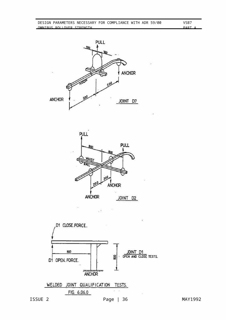
shall be made for representative welded joints in the roll cage structure as shown on drawing VSB 7.02 for example:
(a) Joint between a hoop pillar and a floor bearer opening force - connection D1
(b) Joint between a hoop pillar and a floor bearer closing force - connection D1
(cl Joint between a hoop pillar and waist rails
- connection 02
(di Butt joint between a hoop pillar & roof bow
- connection 07
The specimens shall be tested by bending the members or members making the welded joints through an angle of at least twenty (20°1 degrees without failure of any part of the weld. Failure in the parent material remote from the weld is permitted in this test.
The sketches in fig. 6.06 show the direction of test loading for the specimen joints nominated above.
Additional weld qualification tests shall be made on other joints or in other directions to ensure satisfactory qualification of welds for expected vehicle service loads, at the discretion of the designer.
6.8 Weld Inspection
All weld inspection shall be carried out by the manufacturer in accordance with AS. 1554 Section 6 using any of ·the methods documented in the Standard.
All welds shall be examined for their compliance with Category SP weld acceptance levels for each weld configuration, parent metal and weld metal type specified.
All defective welds shall be repaired in an approved manner.All welds on the Roll Cage Structure, other than the hoop pillar butt welds, shall be subjected to the following examination in accordance with AS.1554 .
Visual Scanning 100% (Clause 7.3)
Visual Examination 50% (Table 6.2)
Magnetic Particle Examination 10% (table 6.2)
ISSUE 2 Page | 27 MAY1992
VSB7 PART A
DESIGN PARAMETERS NECESSARY FOR COMPLIANCE WITH ADR 59/00 OMNIBUS ROLLOVER STRENGTH

Hoop Pillar butt welds, noted on the drawings by 'NOE' being included in the weld symbol, shall either be subjected to the following examination in accordance with AS. 1554.
Visual Scanning 100% (clause 7.3 )
Visual Examination 100% (Table 6.2)
Ultrasonic Examination 100% (Table 6.3)
or be signed off as satisfactory Y an engineer meeting the requirements for sign off of vehicles under Administrator's Circular 0-4-5.
The following definitions are those given in Appendix •F" of AS.1554. 1 and AWRA TECHNICAL NOTE 11:
Visual Scanning:- To determine that no welds called for in the contract documents are omitted and to detect gross defects.
Visual Examination:- To examine the nominated percentage of welds to determine whether the required weld quality - refer table 6.2 of AS. 1554.1
- has been achieved.
The use of magnetic particle inspection methods is acceptable as an adjunct to or in lieu of visual examination provided the same level of acceptance criteria is maintained.
Ultrasonic testing shall be carried out by a person of sufficient experience to ensure a valid result. Bus manufacturers who do not have suitable personnel should contract such services. However it will be acceptable for manufacturers to use their own personnel after they have been trained to conduct these examinations. Further it is expected that both means of inspection will be augmented by using the macro test specimen from the procedure qualification where appropriate.
For guidance to the acceptable methods and procedures for inspection reference may be made to Section B7 of AWRA TECHNICAL NOTE 11. Additional guidance for quality assurance in welded fabrication may be obtained from wtlA TECHNICAL NOTE 19; the Appendix of which sets out a typical Quality Assurance Manual which may be of assistance to the manufacturer in implementing a Quality ·Manual.
Refer also to Appendix 'C' of this Code for:-
Guidance on welding procedures generally for C450 tube
An example of simplified inspection check sheet for welds IAS. 1554 Section 6.2 J.
An example of weld procedure sheets using the format of WTIA publication: Technical Note 19.
Footnote:
ISSUE 2 Page | 28 MAY1992
VSB7 PART A
DESIGN PARAMETERS NECESSARY FOR COMPLIANCE WITH ADR 59/00 OMNIBUS ROLLOVER STRENGTH

AWRA - Australian Welding Research Association. WTIA - Welding Technology Institute of Australia.
6.9 Assembly of Fabrication.
One method of constructing the assembly of the roll cage structure, on a one off basis, is as follows.
(al Fabricate standard floor assembly on vehicle chassis, including floor bearer but not the bearer outrigger bracing.
(b) Fabricate two side wall frames with hoop pillars to the pillar to bow butt weld by:
prepare hoop pillars by tacking in place the appropriate backing blocks using a simple jig
assemble hoop pillars with waist and sill rail, using the backing blocks as locators.
Assemble standard and bearer stub pillars. Add diagonal side wall bracing.
By the suitable choice of sequence, all welds can be made in the flat (downhandl position.
(c) Assemble two side walls to the floor bearers and hold with temporary bracing. Complete joints 01 as indicated in the weld procedures shown in Appendix C.
(d) Assemble roof bows to hoop pillars with backing blocks for joints 07 and install one or more roof stringers to provide longitudinal bracing.
(e) Fit framing for the raised floor over the engine bay.
(f) Install transverse members to hoops H1 & H9 as specified in 5.03.4.and 5.03.5.
APPENDIX ASCHEDULE OF CODE DOCUMENTS
Code Number Document Description Issue Number Date
Fig 1.02.1 Roll Cage Components Nomenclature
Fig 1.02.2 Typical Hoop Configurations
Fig 5.02.1 Allowable Roll Cage Cross Section Envelope
Fig 5.02.2 Typical Roll Cage set out for Standard Bus
Fig 5.02.3 Typical Roll Cage set out for Lowered Roof
Line Bus
Fig 5.02.4 Standard Bus Hoop Requirements
ISSUE 2 Page | 29 MAY1992
VSB7 PART A
DESIGN PARAMETERS NECESSARY FOR COMPLIANCE WITH ADR 59/00 OMNIBUS ROLLOVER STRENGTH

Fig 5.02.5 Lowered Roof Line Bus Hoop Requirements
Fig 6.06.0 Welded Joint Qualification Tests
Drg VSB 7.01
Standard Hoop Fabrication Requirements 2 5/92
Drg VSB 7.02
Roll Cage Fabrication Requirements 2 5/92
Drg VSB 7.03
Roll Cage Arrangement on Typical Chassis 1 12/91
ISSUE 2 Page | 30 MAY1992
VSB7 PART A
DESIGN PARAMETERS NECESSARY FOR COMPLIANCE WITH ADR 59/00 OMNIBUS ROLLOVER STRENGTH
APPENDIX B
GENERAL TOLERANCES FOR WELDED STRUCTURES
1 GeneralGeneral tolerances for linear and angular dimensions as specified in this appendix apply for weldments, welding assemblies and welded structures.
The general tolerances apply for linear dimensions, e.g. external dimensions, internal dimensions, offset dimension, centre line distances, and for angular dimensions, in the latter case applying both for those that have been indicated in the manufacturing
drawings and those that are generally not thus indicated, e.g. right angles, or the angles of regular polygons. Special provisions may be needed for the linear dimensions of welded structures composed of a number of welding assemblies.
Where, in manufacturing documentation, reference is made to different standards covering general tolerances, the general tolerances as specified in this appendix shall apply for dimensions produced by welding.
TABLE 1 Limit deviations for linear dimensions.Tolerance Class A
Range of Nominal Sizes mm
Over
Up to
2
30
30
120
120
400
400
100
1000
2000
2000
4000
4000
8000
8000
1200
1200
1600
Limit Deviation in mm ± 1 1 1 2 3 4 5 6 7
2 Limit Deviations for Angular Dimensions.The length of the shorter angle leg shall be used to determine in accordance with table 2 which limit deviations are to apply. The length of the leg may also be assumed to extend to a specific reference point. In this case, the reference point concerned shall be indicated on the drawing. See Table 2 for the relevant deviations.
TABLE 2 Limit deviations for angular dimensions.Tolerance Class A
Range of Nominal Sizes, in mm (length
of Shorter Leg)
Over
Up to 400
400
1000
1000
Umit Deviations. inminutes
± 20' 15' 10'
Celculatad and rounded deviations,
in mm/m•± 6 4.5 3
(*) The value indicated in mm/m corresponds to the tangent value of the general tolerance. It is to be multiplied by the length, in m, of the shorter leg.
ISSUE 2 Page | 31 MAY1992
VSB7 PART A
DESIGN PARAMETERS NECESSARY FOR COMPLIANCE WITH ADR 59/00 OMNIBUS ROLLOVER STRENGTH

APPENDIX C
TYPICAL WELDING PROCEDURES GUIDE LINES
1 GeneralThis section provides one set of guidance data and procedures for welding C450 RHS thin walled tubing, ie wall thickness 3 mm or less, as used for the fabrication of the roll cage structure.
Paragraph 6.05.0 requires that manufacturers employ suitably experienced welders for the fabrication of the roll cage and indeed for all other parts of the bus structure.
It is emphasised that the welding of C450 grade tubing is no more difficult than for other low carbon steels. However, because a bus may be subjected to a roll over at any time in its service life, manufacturers are required to take particular care with those joints in the roll cage framing that are perceived by them to be subject to fluctuating (fatigue) stresses in ordinary service.
The procedures outlined below have been demonstrated to be generally satisfactory for roll cage framing, by physical testing.
The procedures are specific for the C450 grade tube in two conditions of finish, and are preferred for welding C450 to C450 or for welding C450 to C350 tube joints, but are also generally applicable to making joints between C350 tubes.
2 Mill Finish of Cold Formed Tube.C450 is available from manufacturers' mills in several different surface finish conditions. Because welding procedures vary slightly with different finishes, the following recommendations cover two categories:-
Plain The mill finish is black and may be lightly coated with oil. Alternatively the mill finish is a light paint coating only which provides some rust protection during storage and handling of the product.
Galvanised. This is a light, 100 gsm surface coating of hot dipped zinc on the external surface of the tube (eg Tubemakers "Duragal" or Palmer Tube "Supagal", which is also galvanised on the internal surface).
As will be seen below, the only significant difference in welding tubes with these two alternative finishes is in the choice of gas for GMAW processes. See below.
3 Welding Process - Plain and Galvanised Tube.The guidance procedures apply to gas metal arc welding (GMAWI, which is the process most used by bus manufacturers for frame construction.
ISSUE 2 Page | 32 MAY1992
VSB7 PART A
DESIGN PARAMETERS NECESSARY FOR COMPLIANCE WITH ADR 59/00 OMNIBUS ROLLOVER STRENGTH

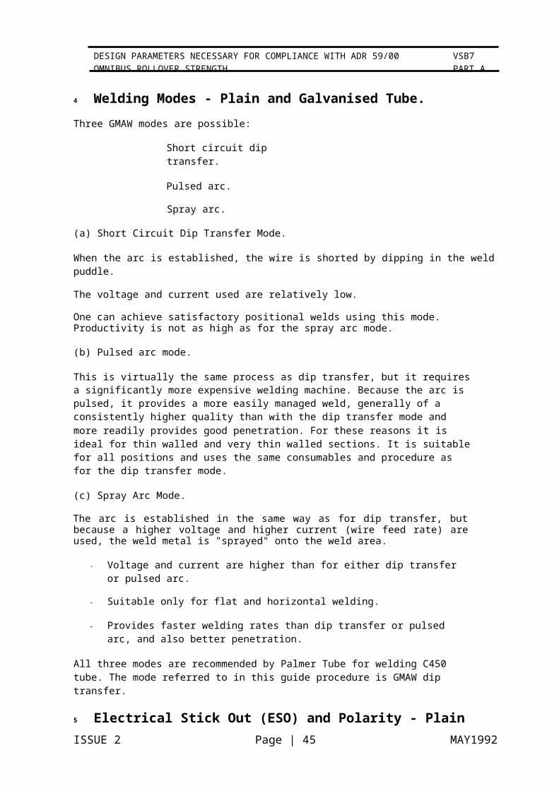
4 Welding Modes - Plain and Galvanised Tube.Three GMAW modes are possible:
Short circuit dip transfer.
Pulsed arc.
Spray arc.
(a) Short Circuit Dip Transfer Mode.
When the arc is established, the wire is shorted by dipping in the weld puddle.
The voltage and current used are relatively low.
One can achieve satisfactory positional welds using this mode. Productivity is not as high as for the spray arc mode.
(b) Pulsed arc mode.
This is virtually the same process as dip transfer, but it requires a significantly more expensive welding machine. Because the arc is pulsed, it provides a more easily managed weld, generally of a consistently higher quality than with the dip transfer mode and more readily provides good penetration. For these reasons it is ideal for thin walled and very thin walled sections. It is suitable for all positions and uses the same consumables and procedure as for the dip transfer mode.
(c) Spray Arc Mode.
The arc is established in the same way as for dip transfer, but because a higher voltage and higher current (wire feed rate) are used, the weld metal is "sprayed" onto the weld area.
Voltage and current are higher than for either dip transfer or pulsed arc.
Suitable only for flat and horizontal welding.
Provides faster welding rates than dip transfer or pulsed arc, and also better penetration.
All three modes are recommended by Palmer Tube for welding C450 tube. The mode referred to in this guide procedure is GMAW dip transfer.
5 Electrical Stick Out (ESO) and Polarity - Plain and Galvanised Tube.
The recommended ESO for all GMAW modes is 10 mm. If this has to be increased for space considerations eg tight corners, it is probably necessary to increase the voltage. The usual polarity is electrode +.
ISSUE 2 Page | 33 MAY1992
VSB7 PART A
DESIGN PARAMETERS NECESSARY FOR COMPLIANCE WITH ADR 59/00 OMNIBUS ROLLOVER STRENGTH
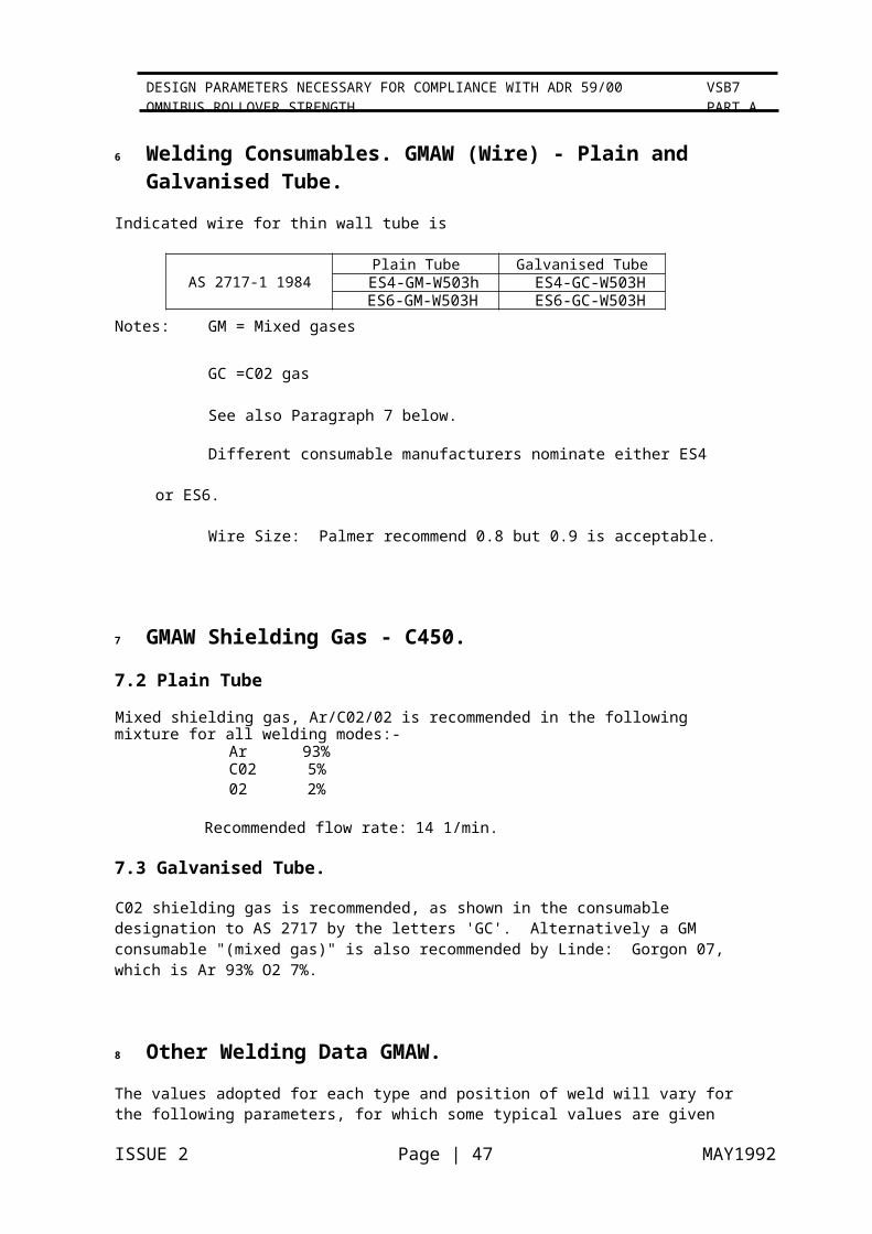
6 Welding Consumables. GMAW (Wire) - Plain and Galvanised Tube.
Indicated wire for thin wall tube is
AS 2717-1 1984Plain Tube Galvanised Tube
ES4-GM-W503h ES4-GC-W503HES6-GM-W503H ES6-GC-W503H
Notes: GM = Mixed gases
GC =C02 gas
See also Paragraph 7 below.
Different consumable manufacturers nominate either ES4 or ES6.
Wire Size: Palmer recommend 0.8 but 0.9 is acceptable.
7 GMAW Shielding Gas - C450.
7.2 Plain Tube
Mixed shielding gas, Ar/C02/02 is recommended in the following mixture for all welding modes:-
Ar 93%C02 5%02 2%
Recommended flow rate: 14 1/min.
7.3 Galvanised Tube.
C02 shielding gas is recommended, as shown in the consumable designation to AS 2717 by the letters 'GC'. Alternatively a GM consumable "(mixed gas)" is also recommended by Linde: Gorgon 07, which is Ar 93% O2 7%.
8 Other Welding Data GMAW.The values adopted for each type and position of weld will vary for the following parameters, for which some typical values are given for C450, 2.8 wall thickness, in down hand position for full penetration butt joints with backing blocks.
Voltage: 19v Current: 150 amps.
Weld Speed: 3.5 mm/sec.
Heat Input: 0.8 kJ/mm ie [ 19 x 150 ][ 3.5 x 10L3 ]
ISSUE 2 Page | 34 MAY1992
VSB7 PART A
DESIGN PARAMETERS NECESSARY FOR COMPLIANCE WITH ADR 59/00 OMNIBUS ROLLOVER STRENGTH

9 Variations and Quality AssuranceThe recommendations above cover one only set of welding parameters that comprise a welding procedure. They will vary according to the type of joint being made and
individual manufacturer's production methods. For more detailed information manufacturers are referred to the welding procedures document produced by Palmer Tube Mills (Austl Pty Ltd.
As is required by FORS for quality assurance, the actual welding procedures adopted for each joint shall include the following in the manufacturer's Quality Assurance documents:-
Welding process and mode
Position, eg Flat (down hand), vertical up, etc Weld Current
Weld Voltage .
Wire quality and size
Gas mixture and flow rate
Speed of welding and hence kJ/mm of heat input
.·
10 Shop Testing.Weld testing is discussed more fully in paragraph 6.06 as part of the weld qualification procedure for Quality Assurance. With reasonable experience, breaking a trial weld will indicate its quality.
11 Ventilation.Attention is drawn to the need for good ventilation practice, particularly when welding galvanised tube. Manufacturers should follow the recommendations given in WTIA Technical Note 7.
ISSUE 2 Page | 35 MAY1992
VSB7 PART A
DESIGN PARAMETERS NECESSARY FOR COMPLIANCE WITH ADR 59/00 OMNIBUS ROLLOVER STRENGTH
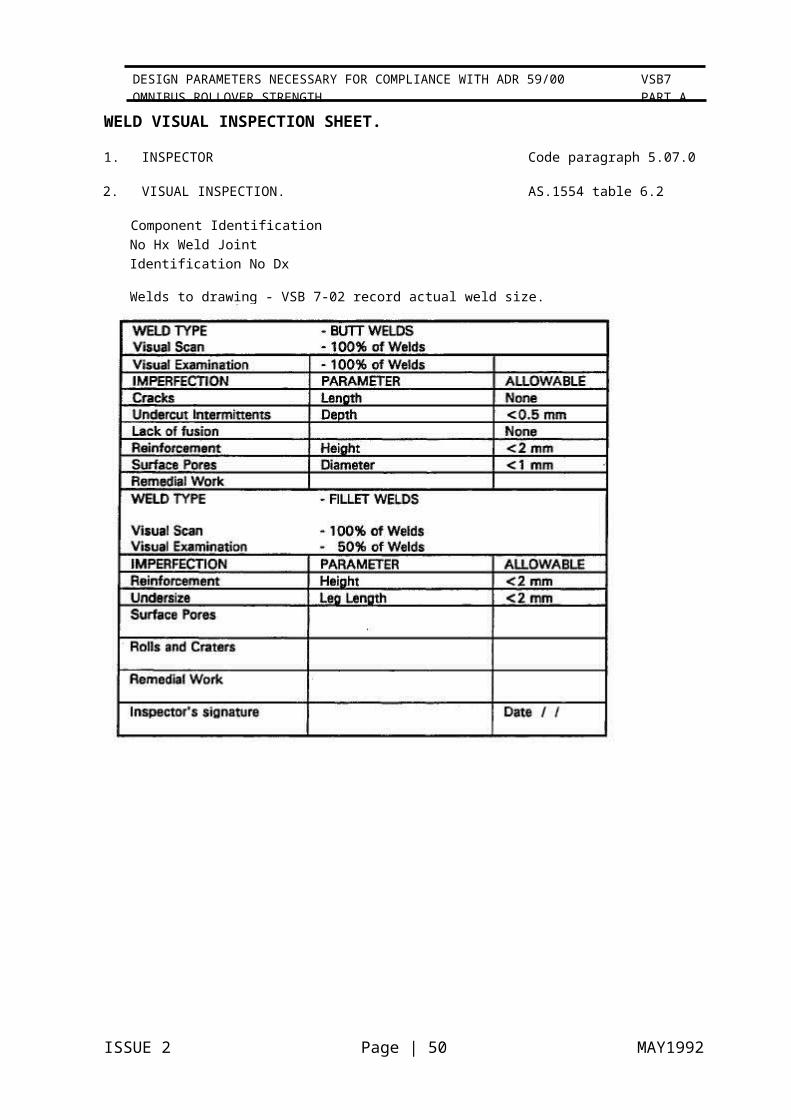
WELD VISUAL INSPECTION SHEET.
1. INSPECTOR Code paragraph 5.07.0
2. VISUAL INSPECTION. AS.1554 table 6.2
Component Identification No Hx Weld Joint Identification No Dx
Welds to drawing - VSB 7-02 record actual weld size.
ISSUE 2 Page | 36 MAY1992
VSB7 PART A
DESIGN PARAMETERS NECESSARY FOR COMPLIANCE WITH ADR 59/00 OMNIBUS ROLLOVER STRENGTH

ISSUE 2 Page | 37 MAY1992
VSB7 PART A
DESIGN PARAMETERS NECESSARY FOR COMPLIANCE WITH ADR 59/00 OMNIBUS ROLLOVER STRENGTH

ISSUE 2 Page | 38 MAY1992

ISSUE 2 Page | 39 MAY1992
VSB7 PART A
DESIGN PARAMETERS NECESSARY FOR COMPLIANCE WITH ADR 59/00 OMNIBUS ROLLOVER STRENGTH

ISSUE 2 Page | 40 MAY1992

ISSUE 2 Page | 41 MAY1992
VSB7 PART A
DESIGN PARAMETERS NECESSARY FOR COMPLIANCE WITH ADR 59/00 OMNIBUS ROLLOVER STRENGTH

ISSUE 2 Page | 42 MAY1992
ISSUE 2 Page | 43 MAY1992
VSB7 PART A
DESIGN PARAMETERS NECESSARY FOR COMPLIANCE WITH ADR 59/00 OMNIBUS ROLLOVER STRENGTH

ISSUE 2 Page | 44 MAY1992
ISSUE 2 Page | 45 MAY1992
VSB7 PART A
DESIGN PARAMETERS NECESSARY FOR COMPLIANCE WITH ADR 59/00 OMNIBUS ROLLOVER STRENGTH
DESIGN PARAMETERS NECESSARY FOR COMPLIANCE WITH ADR 59/00 VSB7
ISSUE 2 PAGE D 1
MAY 1992
APPENDIX DLIST OF AUSTRALIAN STANDARDS REFERRED TO IN THIS CODE.
AS 1163 1981 Structural Steel Hollow Sections
AS.1554-1 1985 Welding of Steel Structures
AS.2717-1 1984 Ferritic Steel Electrodes GMAW
AS.2536 1982 Surface Testure
AS.3902 1987 Quality Systems for Production and Installation
AS.3990 1991 Steelwork for Engineering Applications
AS.1250 1981The Use of Steel in Structures
(AS. 1250 replaced bv AS3990)
ISSUE 2 Page | 47 MAY1992
VSB7 PART A
DESIGN PARAMETERS NECESSARY FOR COMPLIANCE WITH ADR 59/00 OMNIBUS ROLLOVER STRENGTH

ISSUE 2 Page | 48 MAY1992
VSB7 PART A
DESIGN PARAMETERS NECESSARY FOR COMPLIANCE WITH ADR 59/00 OMNIBUS ROLLOVER STRENGTH

ISSUE 2 Page | 49 MAY1992
VSB7 PART A
DESIGN PARAMETERS NECESSARY FOR COMPLIANCE WITH ADR 59/00 OMNIBUS ROLLOVER STRENGTH
ISSUE 2 Page | 50 MAY1992
VSB7 PART A
DESIGN PARAMETERS NECESSARY FOR COMPLIANCE WITH ADR 59/00 OMNIBUS ROLLOVER STRENGTH