microstructural evidence for seismic and aseismic slip ... article has been accepted for publication...
TRANSCRIPT

This article has been accepted for publication and undergone full peer review but has not been through the copyediting, typesetting, pagination and proofreading process which may lead to differences between this version and the Version of Record. Please cite this article as doi: 10.1002/2017JB014042
© 2017 American Geophysical Union. All rights reserved.
Microstructural evidence for seismic and aseismic slip along clay-
bearing, carbonate faults
Luca Smeraglia1, Andrea Bettucci
2, Andrea Billi
3, Eugenio Carminati
1,3, Andrea
Cavallo4, Giulio Di Toro
5,6,7, Marco Natali
2, Daniele Passeri
2, Marco Rossi
2,8, and Elena
Spagnuolo6
1Dipartimento di Scienze della Terra, Sapienza University of Rome, P.le Aldo Moro 5, 00185
Roma, Italy
2Dipartimento di Scienze di base e applicate, Sapienza University of Rome, Via A. Scarpa 14,
00161 Rome, Italy
3Consiglio delle Nazionale Ricerche, IGAG, P.le Aldo Moro 5, 00185 Roma, Italy
4CERTEMA, Multidisciplinary technology laboratory, Strada del Cipressino, Cinigiano,
58044 Grosseto, Italy
5School of Earth and Environmental Sciences, The University of Manchester, Oxford Road,
M13 9PL Manchester, United Kingdom
6INGV, Istituto Nazionale di Geofisica e Vulcanologia, Via di Vigna Murata 605, 00143
Rome, Italy
7Dipartimento di Geoscienze, Padova University, Via G. Gradenigo, 6, 35131 Padova, Italy
8CNIS, Research Center for Nanotechnology applied to Engineering, SAPIENZA University
of Rome, P.le Aldo Moro 5, 00185 Roma, Italy
Corresponding author: Luca Smeraglia [email protected]
Key points
Fault microstructures record fast (seismic) to slow (aseismic) deformation stages
consistent with some geophysical observations
A few % of clays in natural fault gouge may strongly affect frictional behavior
Shear experiments suggest that clay-bearing layers have shorter weakening distance
than carbonate-pure gouges during seismic slip.

© 2017 American Geophysical Union. All rights reserved.
Abstract: In this multi-methodological study, microstructural observations of fault rocks are
combined with micromechanical property analyses (Contact Resonance Atomic Force
Microscopy, CR-AFM) and with rotary friction experiments (SHIVA apparatus) to find
evidence of seismic to aseismic slip and understand the nanoscale rheology of clay-bearing,
carbonate-hosted faults. Fluidized structures, truncated clasts, pores and vesicles, and
phyllosilicate nano-sized spherules and tubes suggest fast deformation events occurred during
seismic slip, whereas clay-assisted pressure-solution processes, clumped clasts, foliation
surfaces, and mantled clasts indicate slow deformation events occurred during
postseismic/interseismic periods. CR-AFM measurements show that the occurrence of ~5
wt.% of clay within the carbonate-hosted gouges can significantly reduce the fault core
stiffness at nanoscale. In addition, during high-velocity friction experiments simulating
seismic slip conditions, the presence of ultra-thin phyllosilicate-bearing (≤ 3 wt.%) layers
within calcite gouges, as those observed in the natural fault, show faster dynamic weakening
than that of pure calcite gouges. The weak behavior of such layers could facilitate the upward
propagation of seismic slip during earthquakes, thus possibly enhancing surface faulting.
Microstructural observations and experimental evidence fit some well-known geophysical
and geodetic observations on the short- to long-term mechanical behavior of faults such as
post-seismic/interseismic aseismic creep, interseismic fault locking, and seismic slip
propagation up to the Earth’s surface.
1. Introduction
Understanding the short and long-term mechanical behavior and deformation
mechanisms of seismogenic faults is the prerequisite to properly model seismic cycles of
active faults and eventually contribute to physically-based probabilistic earthquake
forecasting [e.g., Dieterich et al., 1994; Hainzl et al., 2010]. Detailed fault mechanical

© 2017 American Geophysical Union. All rights reserved.
models require indeed, among other parameters, the complete understanding of rheology,
frictional behaviors, fluid pressure fluctuations, and deformation mechanisms acting along
faults during the seismic cycle [e.g., Li et al., 2011; Hadizadeh et al., 2012; Ben-Zion and
Sammis, 2013; Tesei et al., 2014].
Crustal deformation related to seismic cycles has been recorded and studied with
paleoseismological, geophysical, and geodetic techniques (GPS and InSAR; e.g., Harris,
2017 and reference therein); however, the short-term records of instrumental seismology (less
than one century) and geodesy (about 25 years), as well as the non-continuous record of
paleoseismology have limited the long-term understanding of the seismic cycle. For these
reasons, the direct study (in situ) of the geological record preserved within fault zones is still
fundamental to understand the spectrum of deformation mechanisms and mechanical
parameters that can be useful to better model the long-term behavior of active faults during
the seismic cycle [e.g., Siman-Tov et al., 2013; Bullock et al., 2015; Boulton et al., 2017].
Results from these studies are complementary to and consistent with some geophysical and
geodetic observations [e.g., Smith et al., 2011; Fondriest et al., 2015; Demurtas et al., 2016]
and can be accomplished studying seismogenic faults through deep boreholes [e.g., Solum et
al., 2006; Gratier et al., 2011] or through the analysis of exhumed faults [e.g., Balsamo et al.,
2013; Tesei et al., 2014].
In this paper, we present a multi-methodological research starting from the natural case
of the exposed extensional seismically-active Tre Monti Fault (TMF) within the carbonate-
dominated seismic domain of the central Apennines, Italy [Smith et al., 2011; Benedetti et al.,
2013; Smeraglia et al., 2016a]. The TMF has been exhumed from shallow depths [≤ 3 km;
Smeraglia et al., 2016a] and can hence be considered as an exposed analogue for shallow
seismogenic faults. In particular, we focus our study on the ~1 m thick clay bearing,
carbonate-hosted Tre Monti principal fault core, which accommodated up to ~2 km of total

© 2017 American Geophysical Union. All rights reserved.
displacement [Smeraglia et al. 2016a]. To do so, microstructural, chemical, and
mineralogical analyses with laboratory micromechanical analyses were combined with low-
to high-velocity rotary shear experiments that simulate the natural setting under laboratory-
controlled conditions [Di Toro et al., 2010]. New results are integrated with those from
previous studies on this fault [Smith et al., 2011; Benedetti et al., 2013; Smeraglia et al.,
2016a] to elaborate a synthetic model of deformation mechanisms acting during seismic
cycles. Fault rock microstructures from this study recorded indeed evidence of both seismic
and aseismic slip events. In particular, ≤ 5 wt.% of clay within a carbonate-hosted fault zone
can strongly affect fault rheology at the nanoscale, thus influencing fault rock stiffness and
deformation mechanisms during the co-seismic and postseismic/interseismic phases. These
results fit some well-known geophysical and geodetic observations on the short- to long-term
mechanical behavior of faults such as post-seismic/interseismic creep, interseismic fault
locking, and seismic slip propagation up to the Earth’s surface.
2. Geological setting
The Central Apennines are a Late Oligocene to Present fold-and-thrust belt related to the
westward directed subduction and eastward rollback of the Adriatic plate under the European
plate [e.g., Doglioni, 1991]. Shortening was characterized by the northeastward migration of
NW-SE-oriented thrust faults, which scraped off and piled-up the sedimentary succession of
the Adriatic plate [e.g., Cosentino et al., 2010]. Thrust faults juxtaposed 4-5 km thick Late
Triassic-Middle Miocene shallow-water carbonate rocks above ~2 km thick Late Miocene
syn-orogenic deposits (hemipelagic marls and siliciclastic sandstones with clayey and marly
interbeds; Fig. 1a; Cosentino et al., 2010). Seismic reflection profiles show that imbricated
carbonate deposits occur from the surface down to a depth of ~7-8 km [e.g., Billi et al., 2006].

© 2017 American Geophysical Union. All rights reserved.
Since Early Pliocene time, the axial part of the Central Apennines belt experienced uplift
and extensional tectonics in connection with the development of the Tyrrhenian backarc basin
[Doglioni, 1991]. This process is still active and has generated intra-mountain grabens
bounded by NW-SE-oriented extensional faults and less frequent ENE-WSW-oriented strike-
to oblique-slip transfer faults (Fig. 1a). This fault network has produced large historical and
instrumental earthquakes up to Mw 7 (Fig. 1a; e.g., Avezzano, 1915, Mw 7.0 earthquake, Galli
et al., 2008; L’Aquila, 2009, Mw 6.3 earthquake, Valoroso et al., 2013; Amatrice, 2016, Mw
6.0 and Norcia, 2016, Mw 6.5 earthquakes, Anzidei and Pondrelli, 2016]. The TMF belongs
to this active tectonic setting representing an extensional-to-transtensional transfer fault
between two NW-SE-oriented extensional faults [e.g., Morewood and Roberts, 2000].
Although in the Central Apennines several seismic mainshocks nucleated at depths < 10
km, probably in crystalline rocks, it is well documented that many foreshocks and aftershocks
as well as some mainshocks nucleated in and propagated upward through the carbonate
sedimentary succession [e.g., Valoroso et al., 2013]. In particular, seismic slip often
propagate up to the surface, causing ground displacements and surface faulting, as
documented for the recent cases of the 2009 L’Aquila and 2016 Amatrice-Norcia earthquakes
[e.g., Anzidei and Pondrelli, 2016; Pucci et al., 2017] and as shown by paleoseismological
observations [e.g., Galli et al., 2008]. For instance, during the 2016 Amatrice-Norcia seismic
sequence, two mainshocks (Mw 6.0 and Mw 6.5) nucleated at ~7-8 km depth and seismic slip
propagated upward through carbonate rocks causing a ~15 km long and up to ~60 cm high
surface rupture [Chiaraluce et al., 2017]. Moreover, many aftershocks of the 2016 Amatrice-
Norcia mainshocks nucleated at shallow depths (< 5 km) along carbonate-hosted faults and
also the maximum slip patches (up to ~2.5 m) of the mainshocks were located at ~3-5 km
depth [Anzidei and Pondrelli, 2016; Tinti et al., 2016; Liu et al., 2017] probably within
carbonate rocks. This evidence suggests that is likely that the shallow fault zone modulated

© 2017 American Geophysical Union. All rights reserved.
the observed earthquake-related deformation processes and slip recorded at shallow depths
and at the surface.
The TMF is a SSE-dipping and ~8 km long extensional/transtensional fault, which
delimits the north-western boundary of the Fucino basin, an intramountain half-graben filled
by Late Pliocene–Quaternary continental deposits [Fig. 1b; Morewood and Roberts, 2000;
Cavinato et al., 2002; Smith et al., 2011; Smeraglia et al., 2016a]. Paleoseismological
investigations suggest that the TMF has been active between Early Pliocene and recent-
present times [Benedetti et al., 2013]. The TMF has been exhumed from depths ≤ 3 km
accumulating up to ~2 km of cumulative displacement along the principal fault [Cavinato et
al., 2002; Smith et al., 2011; Smeraglia et al., 2016a]. This displacement is at least in part
transferred from the NW-striking extensional Venere Fault that is longer (i.e., ~20 km) than
the TMF [e.g., Cavinato et al., 2002]. The principal surface of the TMF is exposed along the
foothills of the Tre Monti Hills and juxtaposes carbonate deposits in the footwall with both
syn-orogenic clay-rich deposits and post-orogenic continental sediments (i.e., lacustrine,
fluvial, and slope debris deposits) in the hangingwall along a series of ENE-WSW-oriented
fault scarps in Mesozoic limestones [Fig. 1c; Benedetti et al., 2013; Smeraglia et al., 2016a].
Synthetic secondary faults are hosted within the carbonate bedrock of the footwall and
juxtapose Mesozoic carbonates and Plio-Quaternary continental deposits in the hangingwall
with Mesozoic carbonates in the footwall [Smith et al., 2011; Smeraglia et al., 2016a].
Using carbon and oxygen stable isotopes, Smeraglia et al. [2016a] showed that the
cataclastic rocks of the TMF principal fault developed at ~2-3 km depth. Therefore, in this
work, the inferred deformation mechanisms acted along the TMF principal surface at depths
≤ 3 km.
© 2017 American Geophysical Union. All rights reserved.
3. Methods
(1) Rock slabs were cut perpendicular to the fault surface and parallel to the slip
direction from oriented samples collected in the field. The slabs were then impregnated with
a low-viscosity epoxy resin (PEC 1 Logitech) and 15 thin sections were produced by thinning
the slabs down to ~30 μm in thickness using an Al-free abrasive paste and a diamond-bearing
1 μm-thick powder for polishing. Al-free abrasive paste was used to avoid Al contamination
and to better detect the presence of phyllosilicates.
(2) Optical and electron microscopy (FE-SEM Zeiss Auriga at the CNIS Laboratory,
Sapienza University, Rome, and FE-SEM Zeiss Merlin at the CERTEMA Multidisciplinary
Laboratory, Grosseto) was used to investigate micro- and nano-deformation mechanisms on
twenty oriented thin sections of fault rocks.
(3) X-ray powder diffraction (XRPD, at the Padova University laboratory) and Energy
Dispersive X-ray analysis (EDS, using FE-SEM Zeiss Auriga at the CNIS Laboratory,
Sapienza University, Rome, and FE-SEM Zeiss Merlin at the CERTEMA Multidisciplinary
Laboratory, Grosseto) were used to investigate both natural and experimental fault rock
mineralogy and chemistry.
(4) Contact Resonance Atomic force measurements (CR-AFM; Passeri et al., 2013;
Text S1 of SI) on a ~30-µm-thick thin-section were realized to measure in situ mechanical
properties (Young’s modulus and viscoelasticity) within natural samples (at the CNIS
Laboratory, Sapienza University, Rome). For these measurements, one thin section was
prepared without epoxy impregnation and was analyzed after removal of abrasive paste and
powder to perform a realistic analysis of mechanical properties of rocks without
contamination. In CR-AFM, the sample is coupled with a piezoelectric transducer, which
excites the sample surface through out-of-plane oscillations. A cantilever records these
oscillations through a tip that is in contact with the sample surface. The contact resonance

© 2017 American Geophysical Union. All rights reserved.
frequencies (CRFs) of the tip-sample system are measured and used to calculate the
indentation modulus, which is proportional to the Young’s modulus, of an elastic material
[e.g., Passeri et al., 2007; 2013]. In addition, if a material is viscoelastic, CR-AFM
measurements can be used to calculate the elastic part (i.e., the storage modulus, E’) and the
viscous part (i.e., the loss modulus, E’’) of the elastic modulus. The ratio between the elastic
and viscous moduli E’’/E’ (namely the loss tangent, tanδ impact of
the viscous behavior, which promote energy dissipation during mechanical deformation [e.g.,
Meyers and Chawla, 2009].
(5) Pulse-echo ultrasonic technique (at the CNIS Laboratory, Sapienza University,
Rome; Text S2 of SI) to measure the elastic properties (i.e., Young’s modulus and Poisson
ratio) of host carbonate rock and to calibrate the CR-AFM measurements.
(6) Low to high velocity friction experiments using SHIVA (Slow- to High-Velocity
rotary-shear friction Apparatus, at INGV HP-HT Laboratory, Rome; Di Toro et al., 2010;
Smith et al., 2013; Text S3 of SI) to investigate frictional properties of natural fault rocks.
During these experiments we recorded also gas emission through a mass spectrometer.
Moreover, to quantitatively constrain the behavior of shear and normal stress, we performed a
zero-lag cross-correlation analysis to quantify the correlation between the imposed normal
stress and the recorded shear stress.
4. Field- to nano-scale observations on the Tre Monti principal fault
The architecture of the Tre Monti principal fault has been partially documented in
previous studies [Smith et al., 2011; Smeraglia et al., 2016a]. In particular, Smith et al.,
[2011] and Smeraglia et al., [2016a] showed that the principal fault (Fig. 2a) accommodated
tectonic deformation across a ~1 m thick fault core. Such fault core consists of two different
fault rocks: ultracataclasite and foliated cataclasite [Figs. 2b and 2c; Smeraglia et al., 2016a].

© 2017 American Geophysical Union. All rights reserved.
Smeraglia et al., [2016a] showed that the ultracataclasite consists of calcite (~98.5 wt.%) and
phyllosilicates (~1.5 wt.%, mainly illite/smectite and kaolinite) and that the foliated
cataclasite consists solely of calcite (Table S1). In addition, Smeraglia et al., [2016b] showed
that phyllosilicates between the ultracataclasite are mainly derived from incorporation,
smearing and mixing along the principal fault of phyllosilicate-rich syn-orogenic deposits in
the hangingwall (Fig. 1c).
Hereafter, we describe new field and microstructural observations (i.e., fluid-like
structures, Figs. 2d and 2e; ultra-thin phyllosilicate-bearing layers, Figs. 2c and 2f; pressure-
solution features, Figs. 2h, 2i, and 3b; foliation surfaces Figs. 2g and 2i; mantled clasts, Fig.
2i; clumped clasts, Figs. 3a and 3g; pores and vesicles, Figs. 3c and 3h; and phyllosilicate
nano-size spherules and tubes, Fig. 3i) within the Tre Monti principal fault (Fig. 1c) and then
discuss such observations in terms of seismic/aseismic deformation mechanisms.
The ultracataclasite forms patches and plagues, up to ~10 cm thick, above the foliated
cataclasite (Fig. 2b). The boundary between these two fault rocks is often sharp and
continuous (Fig. 2c); however, in places, the two fault rocks are mixed together showing
fluid-like structures at the centimeter scale (Figs. 2d and 2e). These structures show
irregular/convolute margins with load-like or intruded/injected structures and bulbous
protrusion of the ultracataclasite into the foliated cataclasite. Moreover, fragments from the
foliated cataclasite are, in places, completely enclosed within the ultracataclasite (Fig. 2d).
These fluidized structures develop at distances up to 10 cm from the principal slip surface
(Figs. 2d and 2e). Similar fluid-like structures have been previously documented along the
TMF only at the millimeter-scale [Smith et al., 2011]. In this latter case, the micrometer-thick
bulbous protrusions were intruded only for small distances (i.e., a few microns) between the
different cataclastic layers [Smith et al., 2011].
© 2017 American Geophysical Union. All rights reserved.
The foliated cataclasite (100 wt.% calcite) is characterized by calcite clasts derived
from the host rock (Mesozoic limestones; Fig. 2g). The foliation is defined by slip-parallel
shear surfaces bounding relative intact host rocks sigmoids (Fig. 2g). The ultracataclasite
(~98.5 wt.% calcite and ~1.5 wt.% phyllosilicates) consists of large calcite clasts (centimeter
to hundreds of micrometer in size, Figs. 2c, 2f, 2h, and 2i) derived from the underlying
foliated cataclasite, scattered within an ultra-fine matrix (Fig. 3a). Clasts are sub-angular to
well-rounded and, in places, are in reciprocal contact showing indented and teeth-shaped
margins (Figs. 2h and 2i). Such margins do not show any preferred orientation with respect to
the Tre Monti principal fault. The ultracataclasite is characterized, in places, by foliation
surfaces roughly parallel to the slip direction (Fig. 2i). Within these foliation surfaces, large
calcite clasts are characterized by mantled-like structures [e.g., Passchier and Trouw, 2005]
showing elongate trails of smaller calcite clasts aggregates, stretched parallel to the foliation
(Fig. 2i). These small calcite clasts are in reciprocal contact showing indented and teeth-
shaped margins roughly parallel to the Tre Monti principal fault (Fig. 2i).
The ultra-fine matrix consists of micro- to nano-meter-thick sub-angular to well-
rounded calcite clasts and phyllosilicates (~1.5 wt.% of the bulk ultracataclasite; Figs. 3a and
3b). Contacts between calcite clasts show indented and teeth-shaped geometries down to the
microscale, defining a highly compact and low-porosity texture, also due to ultra-thin
phyllosilicate lamellae (a few hundreds of nm thick) often interposed between clast margins
(Fig. 3b). Such teeth-shaped margins do not show any preferred orientation with respect to
the Tre Monti principal fault. In places, clumps of small calcite clasts are compacted together
to form larger and distinct clasts (Figs. 3a and 3b). In places, calcite clasts are affected by
microdefects such as twinning and microfractures (Fig. 3c).
Field and microstructural observations show that phyllosilicates concentrate within
ultra-thin (up to ~1 mm-thick) and localized layers (hereafter “phyllosilicate-bearing layers”,

© 2017 American Geophysical Union. All rights reserved.
Figs. 2c, 2f, and 3d-f). Quantitative XRPD analyses (sampling sites in Fig. 2c) show that the
average phyllosilicate content within these layers is ~5 wt.% (Table S1 in SI), thus higher
than the phyllosilicate content within the ultracataclasite (~1.5 wt.%). Phyllosilicate-bearing
layers occur along the sharp boundaries between the ultracataclasite and the foliated
cataclasite (Figs. 2c, 3e, and 3f), along some riedel-shear surfaces cutting across the
ultracataclasite (Fig. 3d) or, in places, cutting across fluid-like structures (Fig. 2f), delineating,
at least in the study outcrop, a pervasive network within the Tre Monti principal fault-zone.
Phyllosilicate-bearing layer margins are sharp and continuous, truncating calcite clasts
(Figs. 3d-f). In these layers, carbonate clasts are well rounded and scattered within a
phyllosilicate-bearing matrix. Calcite clasts that are in reciprocal contact show indented and
teeth-shaped margins (Fig. 3g) and, in places, form clumped clasts (Fig. 3g). Calcite clasts
show pores and vesicles (dark rounded features) arranged, in places, in linear arrays probably
along clast microdefects such as twinning and cleavage planes (Fig. 3h). Down to the
nanoscale, phyllosilicates are characterized by fibrous or massive morphologies, which, in
detail, consist of 50 nm-thick clumped and chained nano-sized spherules and tubes (Fig. 3i).
We found these peculiar phyllosilicate nanostructures only within the phyllosilicate-bearing
layers.
5. Micromeasurements of elastic property
Measurements of elastic property (i.e., Young’s modulus) of fault rocks are important
to understand fault rock stiffness, which can influence fault rock deformation mechanisms
and the capability of a rock to store or release the energy during seismic cycles [e.g.,
Gudmundsson 2004; Fondriest et al., 2017]. Moreover, recent studies showed that
rheological heterogeneity and fault morphology, at nanoscale, could strongly affect the bulk
fault zone rheology and nanoscale frictional processes [e.g., Chen et al., 2013; Omori et al.,
© 2017 American Geophysical Union. All rights reserved.
2015; Gerbi et al., 2016]. In this section, we provide micromeasurements of elastic property
(i.e., indentation modulus and viscoelasticity) and then we discuss how such measurements
can impact fault rock stiffness at the nanoscale and associated deformation mechanisms.
Figures 4a and 5a are topographic CR-AFM maps of two areas (16 μm2 and ~2 μm
2,
respectively) within the phyllosilicate-bearing layer (Fig. 3g). In these maps, several calcite
clasts (few microns to some tens of nanometers in size) are scattered within a phyllosilicate-
bearing matrix. Phyllosilicates are characterized by first contact resonance frequency (f1) and
by first quality factor (Q1) values lower than those of calcite clasts (Figs. 4b, 4c, 5b, and 5c).
This setting is confirmed by second contact resonance frequency (f2) and by second quality
factor (Q2) values (Figs. 4d, 4e, 5d and 5e). From these values, the indentation modulus,
which is proportional to the Young’s modulus of the material (see Text S1 in SI), was
calculated.
Quantitative maps of indentation modulus (i.e., Young’s modulus; Figs. 4f, and 5f) at
ambient pressure show that calcite clasts and phyllosilicates are characterized by indentation
moduli of 498 GPa and 73 GPa, respectively. The indentation modulus of phyllosilicates is
consistent with that previously calculated with Atomic Force Acoustic Microscopy [Prasad
et al., 2002]. On the contrary, the indentation modulus of calcite clast is smaller than Young’s
modulus of the TMF carbonate host rock (805 GPa; Text S2 in SI) and of other intact
carbonate rocks (757 GPa; e.g., Ciccotti et al., 2004). Any effect of phyllosilicates (i.e.,
wrapping the calcite clasts) in lowering the indentation modulus of calcite clasts is excluded
as the indentation modulus of clasts has been measured within clasts larger than the CR-AFM
tip in order to avoid potential buffering effect of phyllosilicates.
Calcite clasts are characterized by loss tangent and loss modulus values of 0.010.002
and 450150 MPa, respectively (Figs. 4g, 4h, 5g, and 5h). The same maps show that
phyllosilicates are characterized by a loss tangent and loss modulus values of 0.0230.004

© 2017 American Geophysical Union. All rights reserved.
and 16030 MPa, respectively. In particular, the higher is the loss tangent value the more
viscous is the sample behavior. Therefore, phyllosilicates are characterized by a more viscous
behavior (i.e., capacity to dissipate energy during deformation; e.g., Meyers and Chawla,
2009) than calcite clasts, which are characterized by a more elastic behavior (i.e., capacity to
store energy during deformation; e.g., Meyers and Chawla, 2009).
Overall, the analyzed areas from the phyllosilicate-bearing layers can be considered as
a two-phase composite, within which phyllosilicates roughly represent ~50% of the total
volume (Figs. 4a and 5a). Thus, the effective composite modulus (i.e., indentation modulus of
phyllosilicates together with calcite clasts) of these areas calculated using the Voight Model
[e.g., Hua et al., 2010] is about 28 GPa.
6. Low to high velocity friction experiments
6.1. Experimental procedure
Field and microstructural observations show the occurrence of low percentage (~5
wt.%) of phyllosilicates concentrated along ultra-thin and discrete layers. Therefore, rotary-
shear experiments reproducing the natural setting observed in nature were conducted to
understand the frictional behavior and unravel the origin of such layers within calcite-bearing
fault rocks.
The starting gouge material was made from rocks collected in the field that were
crushed and sieved (<125 μm). Pure calcite powder was made from foliated cataclasite
(100% calcite, Table S1 in SI), and phyllosilicate-rich powder from the syn-orogenic deposits
(~38% of phyllosilicates content; Table S1 in SI). 4.5 g of gouge were used for each
experiment creating ring-shaped layers with 35/55 mm external/internal diameter and initial
thicknesses of ~3 mm (Fig. 6b; e.g., Smith et al., 2013).
© 2017 American Geophysical Union. All rights reserved.
Starting gouge material was prepared using natural rocks collected in the field. The
foliated cataclasite (100% calcite, Table S1 in SI) and the syn-orogenic deposits (~38% of
phyllosilicates content; Table S1 in SI) were both crushed and sieved (<125 µm) to obtain a
pure calcite powder and a phyllosilicate-rich powder, respectively. For each experiment was
used 4.5 g of gouge and was created a ring-shaped gouge layer with initial thickness of ~3
mm (Fig. 6b; e.g., Smith et al., 2013).
Experiments were carried out using three different gouge settings (Fig. 6b). Mixed
gouge (Fig. 6b, left panel) consists of 10% of phyllosilicate-rich powder mixed with 90% of
pure calcite powder (total phyllosilicates content of ≤ 3 wt.%). Layered gouge (Fig. 6b,
middle panel) consists of a ~1 mm-thick layer made of 10% of phyllosilicate-rich powder
mixed with 90% of calcite powder overlain by a ~2 mm-thick layer of pure calcite powder.
This configuration simulates the ultra-thin phyllosilicate-bearing layers observed along the
TMF (Figs. 2c, 2f, 3f, and 3g). Calcite gouge (Fig. 6b, right panel) consists of pure calcite
powder used as an end member and representing the bulk composition of the TMF.
Experiments were performed at 0.001 ms-1
(i.e., almost subseismic slip velocity) and 1
ms-1
(i.e., typical average seismic slip velocity, Heaton, 1990) slip-rates under water-damped
(hereafter wet) and room-humidity (hereafter dry) conditions. Water-damped gouges were
saturated with 0.5 ml (i.e., 10 wt.%) of distilled water. Gouges were sheared holding the
normal stress constant at 8.5 MPa and 5 MPa for dry and wet experiments, respectively, for a
total displacement of 0.5 meter. For the high-velocity experiments, these conditions crudely
represent the expected seismic slip occurring along a shallow-seated (depth <0.5 km) fault
patches during the Mw 6.0-6.5 earthquakes [e.g., Anzidei and Pondrelli, 2016].
The experimental procedure consists of the following steps: (1) samples were initially
pre-sheared at 1 cms-1
for 10 cm of slip at 1 MPa of normal load, both in dry and in wet
conditions. Gouges were pre-sheared to properly simulate our natural analogues, within

© 2017 American Geophysical Union. All rights reserved.
which the fault rocks are naturally pre-sheared due to fault displacement accumulation; (2)
samples were loaded to the target normal stress and were then sheared with acceleration and
deceleration rates of 24 ms-2
, up to the total displacement; (3) during the experiment, gas
emission was measured with a Pfeiffer Quadstar quadrupole mass spectrometer (see Text S3
in SI); (4) after experiments, compact fragments of sheared samples were collected and
impregnated under vacuum using low-viscosity epoxy. The impregnated gouges were cut
perpendicularly to the surface and approximately parallel to slip direction. Then, petrographic
thin sections ~30 µm thick were prepared for microstructural observations.
6.2. Results
At 0.001 ms-1
, both in dry and in wet conditions, the effective friction coefficient (i.e.,
note that, in the wet experiments, the pore fluid pressure cannot be measured; hence the term
"effective"; e.g., Chen et al., 2017) achieves a peak of ~0.6 at slip initiation and then
increases almost monotonically towards a constant value of 0.7-0.8 that is eventually
achieved after ~0.5 m of slip (Fig. 6c). At seismic slip rates (1 ms-1
), gouges in the three
configurations (both in dry and in wet conditions) show a strong dynamic weakening (i.e.,
friction drop) after a strengthening phase, which is defined here as the distance to the onset of
dynamic weakening, Dow (Figs. 6d and 6e; Smith et al., 2015). Overall, both in dry and in wet
conditions, a general trend was recognized: layered gouges weaken faster than mixed gouges,
which, in turn, weaken faster than calcite pure gouges (Fig. 6d).
To test the reproducibility of this trend, high velocity experiments (with layered, mixed,
and calcite gouges) were replicated both in dry and in wet conditions. The major relevant
difference from the previous experiments is observed in the weakening stage of wet
experiments, which can suffer from slightly different ambient conditions, sample saturation,
and holding time. However, despite the large heterogeneity of natural materials used for

© 2017 American Geophysical Union. All rights reserved.
gouges, the replicated experiments are in good agreement with the previously observed
mechanical trends: layered gouges weaken faster than mixed gouges, which, in turn, weaken
faster than calcite pure gouges (Fig. 6e).
During high velocity dry experiments, a normal stress increase was observed in
correspondence with the shear stress increase (i.e., during the strengthening phase; Fig. 7a),
showing a positive correlation with zero-lag cross-correlation analyses (Fig. 7e, S1, and S2 in
SI). Such stress increase can be considered as an apparatus artifact (i.e., due to a slightly
misalignment between the rotary and the stationary columns), unrelated to gouge behavior.
In contrast, high velocity wet experiments displayed an increase in the normal stress in
correspondence with the shear stress decrease (i.e., during the weakening phase; Fig 7b). This
negative correlation in the zero-lag cross-correlation analyses (Fig. 7f, S1, and S2 in SI) is
relevant for the experiment mechanics and is further explained in the discussion section.
Low velocity experiments under dry conditions are characterized by normal stress
oscillations in phase with shear stress oscillations (Fig. 8a), whereas low velocity experiments
under wet conditions show a constant normal stress (Fig. 8b).
Significant gas emissions (CO2) were detected only during high velocity experiments
under dry conditions (compare Fig. 7c with Fig 7d) and in correspondence with the
weakening phase (Fig. 7c). Instead, gas emissions were not detected (i.e., or gas emissions
were below the instrumental detection limit) in the low velocity experiments performed both
under dry and under wet conditions (Figs. 8c and 8d).
6.3. Experimental microstructures
Overall, gouge microstructures are characterized by grain comminution towards the
principal slip surface regardless of the gouge configuration (i.e., layered and mixed), slip
velocity, and saturation conditions (Figs. 9a-h). However, the ~200 µm-thick principal slip
© 2017 American Geophysical Union. All rights reserved.
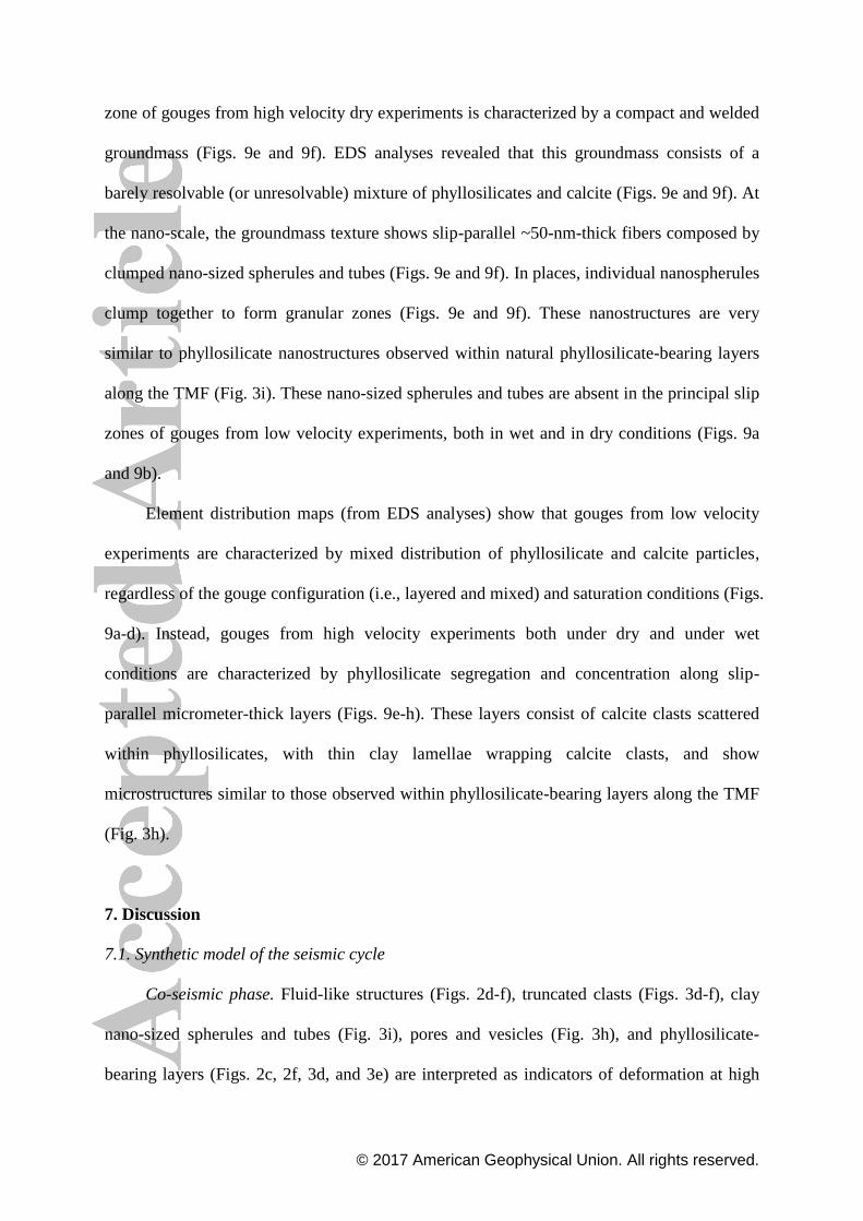
zone of gouges from high velocity dry experiments is characterized by a compact and welded
groundmass (Figs. 9e and 9f). EDS analyses revealed that this groundmass consists of a
barely resolvable (or unresolvable) mixture of phyllosilicates and calcite (Figs. 9e and 9f). At
the nano-scale, the groundmass texture shows slip-parallel ~50-nm-thick fibers composed by
clumped nano-sized spherules and tubes (Figs. 9e and 9f). In places, individual nanospherules
clump together to form granular zones (Figs. 9e and 9f). These nanostructures are very
similar to phyllosilicate nanostructures observed within natural phyllosilicate-bearing layers
along the TMF (Fig. 3i). These nano-sized spherules and tubes are absent in the principal slip
zones of gouges from low velocity experiments, both in wet and in dry conditions (Figs. 9a
and 9b).
Element distribution maps (from EDS analyses) show that gouges from low velocity
experiments are characterized by mixed distribution of phyllosilicate and calcite particles,
regardless of the gouge configuration (i.e., layered and mixed) and saturation conditions (Figs.
9a-d). Instead, gouges from high velocity experiments both under dry and under wet
conditions are characterized by phyllosilicate segregation and concentration along slip-
parallel micrometer-thick layers (Figs. 9e-h). These layers consist of calcite clasts scattered
within phyllosilicates, with thin clay lamellae wrapping calcite clasts, and show
microstructures similar to those observed within phyllosilicate-bearing layers along the TMF
(Fig. 3h).
7. Discussion
7.1. Synthetic model of the seismic cycle
Co-seismic phase. Fluid-like structures (Figs. 2d-f), truncated clasts (Figs. 3d-f), clay
nano-sized spherules and tubes (Fig. 3i), pores and vesicles (Fig. 3h), and phyllosilicate-
bearing layers (Figs. 2c, 2f, 3d, and 3e) are interpreted as indicators of deformation at high
© 2017 American Geophysical Union. All rights reserved.
strain-rate and high temperature owing to seismic slip occurring during co-seismic phase (Fig.
10a).
(1) Fluid-like structures (Figs. 2d-f) suggest that both the ultracataclasite and the
foliated cataclasite behaved, in part, as a mobile, cohesionless, and fluidized granular material.
Such fluid structures have been previously documented within the TMF [Smith et al., 2011;
Smeraglia et al., 2016a] and in other carbonate-hosted faults [e.g., Fondriest et al., 2012;
Demurtas et al., 2016] and are interpreted as the result of fast and instantaneous fluidization
of granular materials triggered by pressurized fluids trapped or injected within the fault gouge
[e.g., Fondriest et al., 2012; Rowe et al., 2012] during seismic slip. Therefore, we suggest
that fluid-like structures within the TMF are consistent with seismic-related fluid thermal
pressurization [e.g., Rice, 2006; Chen et al., 2017].
Overpressured fluids may have occurred within water-saturated fault gouges as
suggested by experimental data. High velocity wet experiments are characterized by negative
correlation of normal/shear stress (i.e., increase in normal stress during coeval decrease of
shear stress) during the weakening phase. The increase in normal stress would result from the
contribution of the normal stress applied by the piston, on one side of the load cell, and from
a spurious pressure occurring within the gouge and exerted on the other side of the load cell
(Fig. 6a; i.e., contrasting the normal stress applied on gouge; see discussion in Ferri et al,
2010). We propose that such spurious pressure can be related to fluid (i.e., water) pressure
increase due to water thermal expansion [e.g., Wibberley and Shimamoto, 2005; Chen et al.,
2017] or to impulsive and confined fluid pressurization related to rapid undrained gouge
compaction [e.g., Kameda et al., 2010]. Fluid pressure increase would indeed expand the
slipping zone generating gouge dilatancy. However, in our high-velocity experiments, both in
dry and in wet conditions, we did not record any gouge dilatancy (Fig. S3 in SI). This
© 2017 American Geophysical Union. All rights reserved.
evidence can be explained by the occurrence of a slight gouge extrusion during experiments
(i.e., and consequently gouge compaction), thus buffering the gouge dilatancy.
(2) Truncated clasts along ultra-thin phyllosilicate-bearing layer margins (Figs. 3d-f)
suggest high strain-rate and fast (i.e., seismic) slip localization along layer margins. The
presence of truncated clasts, to our knowledge, are indeed a peculiar microstructure observed
along sharp slip surfaces only during experiments conducted at seismic slip rates [~1 ms-1
;
Fondriest et al., 2013] and are not observed within experiments conducted at sub-seismic slip
rates, at least in carbonate-hosted gouges [e.g., Fondriest et al., 2015].
(3) Separation of phyllosilicates from the calcite and their segregation into distinct
layers formed only during high velocity experiments both under dry and under wet conditions
(Figs. 9e-h). Moreover, microstructures of experimental phyllosilicate-bearing layers (Figs.
9e-h) are very similar to natural phyllosilicate-bearing layers within the TMF (Fig. 3g). This
evidence suggests that the natural phyllosilicate-bearing layers observed in nature probably
formed at seismic slip rates. Phyllosilicate-bearing layers cutting through fluidized structures
(Fig. 2f) and ultracataclasite (Fig. 3d) indicate multiple events of cataclasis, fluidization, and
slip localization affecting, in alternating moments, the TMF principal surface during
subsequent seismic cycles.
(4) Pores and vesicles found in calcite clasts within phyllosilicate-bearing layers (Fig.
3h) suggest the occurrence of thermo-chemical processes, such as calcite decarbonation,
activated at high friction temperatures during seismic slip [e.g., De Paola et al., 2011]. In fact,
these features are similar to those documented within other carbonate-bearing fault [e.g.,
Bullock et al., 2014; Collettini et al., 2013, 2014] and during high velocity rotary shear
experiments on carbonate-bearing gouges [e.g., Violay et al., 2013; Bullock et al., 2015] and
interpreted as the results of calcite thermal decomposition at temperature above 600 °C,
developed during seismic slip [e.g., Collettini et al., 2013].

© 2017 American Geophysical Union. All rights reserved.
(5) Nano-sized spherules and tubes observed within the TMF are similar to those
observed only within the principal slip zone of other phyllosilicate-rich seismogenic faults
(i.e., the Chelungpu Fault, Chi-Chi earthquake, Hirono et al., 2014, Fig. S4c in SI) and differ
markedly from the typical nanostructures of detrital phyllosilicates (e.g., Setti et al., 2009; Fig.
S4f in SI). In addition, nano-sized spherules and tubes are similar to those observed within
phyllosilicates affected by hydrothermal processes at high temperatures (at ~200-250 °C,
Fiore et al., 1995; Setti et al., 2009; Figs. S4d and S4e in SI) and to those observed within
phyllosilicate-bearing gouges after experimental deformation at seismic slip velocities (≥ 1
ms-1
) and at high temperatures (up to ~250-570 °C, Ujiie et al., 2011; Fig. S4b in SI). In this
study, nano-sized spherules and tubes along the TMF (Figs. 3i and S4a in SI) are similar to
those developed during high velocity experiments only in dry conditions (Figs. 9e-f). In
particular, during high velocity experiments under dry condition, CO2 emission (Fig. 7b)
occurred. CO2 emission can be related to high friction temperatures that activated thermo-
chemical processes within the gouge, such as calcite decarbonation [e.g., De Paola et al.,
2011]. Moreover, nano-sized spherules and tubes along the TMF occur together with calcite
clasts characterized by pores and vesicles, which suggest high temperatures developed during
seismic slip (i.e., see the above point 4).
These evidence suggest that the observed nano-sized spherules and tubes within the
TMF probably developed by both seismic shear heating [e.g., Rice, 2006] and grain
comminution [e.g., Hirono et al., 2014] associated with seismic slip along the phyllosilicate-
bearing layers.
Postseismic/interseismic phase. Teeth-shaped clasts margins (Figs. 3a-c and 3g),
clumped clasts (Figs. 3a, 3b, and 3g), foliation surfaces (Figs. 2g and 2i), and mantled clasts
(Fig. 2i) imply deformation at low strain-rate owing to aseismic slip occurring during
postseismic/interseismic phases (Fig. 10b).
© 2017 American Geophysical Union. All rights reserved.
(1) Teeth-shaped clast margins are identical to those produced by intergranular pressure
solution of carbonate grains during slow compaction experiments [e.g., Zhang et al., 2010].
Moreover, intergranular pressure solution has been widely documented within other
carbonate-hosted faults exhumed from depths < 3 km [e.g., Billi, 2003; Agosta and Aydin
2006] and interpreted as the product of deformation at low strain-rate occurring during
postseismic/interseismic phases [e.g. Renard et al., 2000; Gratier et al., 2014]. Pressure
solution processes may be enhanced by the occurrence of phyllosilicates between clast
contacts (Fig. 3b; e.g., Renard et al., 2001; Aharonov and Katsman, 2009).
(2) We propose that foliated cataclasite (Fig. 2g) and foliation surfaces within the
ultracataclasite (Fig. 2i) were generated through slow and permanent (i.e., aseismic) fault
creep along the TMF during postseismic/interseismic phases. Slow and permanent fault creep
is also consistent with mantled structures of calcite clasts (Fig. 2i), which are similar to those
observed in mylonitic rocks deformed at low strain-rate within the lower crust [e.g.,
Passchier and Trouw, 2005]. In particular, mantled structures roughly parallel to the Tre
Monti principal fault and teeth-shaped margins within trails of small calcite clasts aggregates
(Fig. 2i) are consistent with the interplay of fault creep along the Tre Monti principal fault
contemporaneously with pressure solution processes acting perpendicularly to the normal
stress applied on the fault surface. The above inferences are consistent with geological
evidence and laboratory investigations showing that foliated fault rocks typically develop
along faults through slow and stable slip [i.e., aseismic creep; e.g., Collettini et al., 2009;
Tesei et al., 2014]. However, recent experimental investigations showed that foliated
carbonate fault rocks could form also at seismic slip rates [Smith et al., 2016]. In this case,
foliation surfaces are often associated with sharp slip zones. In our case, in contrast, the lack
of any sharp slip surface along or near the foliation surfaces (Fig. 2g) or mantled clasts (Fig.
2i) suggests aseismic slip along such features.

© 2017 American Geophysical Union. All rights reserved.
7.2 Implications
Microstructural evidence of seismic and aseismic microstructures together with the
support of mechanical data and microstructures fits several geophysical and geodetic
observations.
(1) The occurrence of fluidized fault rock textures preserved along the TMF (Figs. 2d-
e), probably testifying for episodic and impulsive fault rock fluidization during seismic slip,
is consistent with the evidence of fluid overpressures at hypocentral depths in the Italian
Central Apennines based on focal mechanism tomography [Terakawa et al., 2010]. In fact,
seismic slip under these fluid-rich conditions would result in the possible activation of
seismic-related fluid thermal pressurization [e.g., Rice, 2006; Chen et al., 2017].
(2) Slow and continuous deformation along foliation surfaces (Fig. 2g) and mantled
clasts (Fig. 2i) can promote tectonic elastic strain energy dissipation during interseismic
phases through permanent aseismic creep [e.g., Collettini et al., 2009]. In addition, CR-AFM
measurements show that phyllosilicates behave more viscously (i.e., higher loss tangent and
lower loss modulus values, Figs. 4 and 5) than calcite clasts. The viscous behavior of
phyllosilicates within the phyllosilicate-bearing layers can enhance energy dissipation during
inelastic mechanical deformation [e.g., Meyers and Chawla, 2009] within the interseismic
phase. On the contrary, clay-assisted intergranular pressure solution processes, such as those
observed within the ultracataclasite (Figs. 2h, 3a, and 3b), can promote transient aseismic
creep during the postseismic phase [e.g., Gratier et al., 2014] and fault healing during the
interseismic phase (i.e., by dissolution contacts flattening and gouge
compaction/cementation; e.g., Renard et al., 2000). In particular, fault healing is responsible
for strength recovery, fault locking, and tectonic elastic strain energy accumulation.

© 2017 American Geophysical Union. All rights reserved.
These deformation mechanisms are consistent with geodetic observations suggesting
that active faults can move slowly (i.e., dissipating elastic strain energy) through dominant
aseismic creep during the postseismic/interseismic phase [e.g., Wilkinson et al., 2010; Harris
et al., 2017 and reference therein] or can be locked (i.e., storing elastic strain energy) between
two earthquakes [e.g., Johanson and Burgman, 2005; Harris et al., 2017]. Moreover, the
interplay between frictional sliding through foliation surfaces and intergranular pressure
solution processes occurring within the same fault segment, as observed along the TMF fault
core, is consistent with geodetic observations of both locked and creeping portions being
present along the same fault segment [e.g., Johanson and Burgman, 2005; Tong et al., 2013;
Harris et al., 2017].
Although active especially within principal fault cores, the above-mentioned frictional-
viscous deformation mechanisms can occur also in the damage zones of carbonate-hosted
faults [e.g., Salvini et al., 1999; Agosta and Aydin, 2006; Hausegger et al., 2010]. Therefore,
further contribution to the total displacements observed by geodesy due to the same
deformation mechanisms but acting within the damage zone cannot be excluded.
(3) Our experimental results show that calcite gouges with ≤ 3 wt.% of clay content
localized in ultra-thin layers weaken faster than mixed and calcite gouges. Therefore, we
propose that the occurrence of such peculiar phyllosilicate-bearing layers within calcite
gouges, as observed in nature (Figs. 2c, 2f, and 3d-f), could facilitate seismic slip propagation
through the shallow part of fault zones (depths < 0.5 km; Figs. 6d-e; Smeraglia et al., 2017).
This inference is consistent with paleoseismological and direct observations in the Italian
Central Apennines, showing that moderate to large earthquakes can easily propagate up to the
Earth’s surface causing surface faulting [e.g., Galli et al., 2008; Anzidei and Pondrelli, 2016].
(4) The occurrence of ~5 wt.% of clay content, as observed within ultra-thin
phyllosilicate-bearing layers (Table S1 in SI), is sufficient to strongly reduce the fault rock
© 2017 American Geophysical Union. All rights reserved.
stiffness at the nanoscale. The indentation moduli (i.e., Young’s modulus) of phyllosilicates
(73 GPa) and of the whole phyllosilicate-bearing layers (28 GPa) are indeed far lower than
Young’s modulus of the comminuted calcite clasts (498 GPa) and of the carbonate host rock
(805 GPa). The different indentation moduli of calcite clasts and intact calcite host rock can
be due to the development of very comminuted clasts characterized by microfractures,
junctions between clumped clasts (Figs. 3a, 3b, 3g, and 5), and/or by nanodefects (i.e.,
nanoscale grain/crystal boundaries, pores/vesicles, twinning and cleavage planes, Figs. 3c and
3h) developed during faulting [e.g., Siman-Tov et al., 2013; Collettini et al., 2014]. This is
consistent with CR-AFM measurements showing softening of nanoscale mechanical
properties in presence of nano-size grain boundaries, fractures, dislocations, and voids [e.g.,
Yamanaka, 1996; Parlak et al. 2008; Hurley et al., 2006; Passeri et al., 2016] and with
measurements on macroscopic samples of brecciated and fractured fault rocks, which are
characterized by Young’s moduli smaller than intact rocks [e.g., Kahraman and Alber, 2006].
The strong decrease of the bulk fault rock stiffness (down to 28 GPa) due to only ~5
wt.% of clay content indicates the occurrence of a more compliant fault core that can
facilitate tectonic elastic strain energy dissipation due the onset of ductile and permanent
deformation within phyllosilicates [i.e., due to their viscous behavior; e.g., Meyers and
Chawla, 2009] preventing elastic strain energy storage.
8. Conclusions
The study of the clay-bearing, carbonate-hosted Tre Monti Fault, exhumed from depths
< 3 km, allowed us to:
(1) Document microstructures developed during different stages of the seismic cycle. In
particular, fluidized fault rocks, truncated calcite clasts, pores/vesicles in calcite clasts, and
ultra-thin phyllosilicate-bearing layers are interpreted as the result of seismic deformation. On
© 2017 American Geophysical Union. All rights reserved.
the contrary, clay assisted intergranular pressure solution processes and mantled
clasts/foliation surfaces are interpreted as the result of slow transient creep and permanent
creep, respectively, during postseismic/interseismic phases;
(2) Link microstructures and micromechanical properties to geophysical and geodetic
observations. In particular, fluidized fault rocks are consistent with seismic-related fluid
thermal pressurization. Clay content ≤ 3 wt.% (i.e., as that used in some of our high velocity
rotary shear experiments) localized along ultra-thin layers could facilitate earthquake slip
propagation up to the Earth’s surface, consistently with surface displacement observations
from both direct and paleoseismological studies. Clay assisted intergranular pressure solution
and foliation surfaces can contribute to fault locking/re-strengthening and aseismic sliding,
respectively, consistently with geodetic observations on active faults showing locked patches
and/or transient/permanent aseismic creep along fault segments;
(3) Constrain fault rock stiffness heterogeneity at nanoscale and unravel the contrasting
mechanical behavior of phyllosilicates. In particular, phyllosilicates can facilitate both (a)
aseismic creep by dissipation of elastic strain energy and/or fault healing and re-strengthening
by enhancing pressure solution processes within calcite clasts during the post/seismic
interseismic phase and (b) seismic slip propagation if sheared at seismic slip velocity.
Acknowledgements
This work has been funded by an European Research Council Consolidator Grant
(614705) to G. Di Toro and by PRIN2010/11 (Project 20107ESMX9), by Progetti di Ateneo
Sapienza 2014 to E. Carminati, by PRIN 2015 to C. Doglioni, and by Progetti di Ateneo
Sapienza 2015 to C. Collettini. We thank D. Mannetta for exceptional thin sections, S. Sarto
and F. Mura for help and access to CNIS (Center for Nanotechnologies Applied to

© 2017 American Geophysical Union. All rights reserved.
Engineering, Sapienza University) laboratory, CERTEMA (Multidisciplinary technology
laboratory, Grosseto, Italy) staff for electron microscopy analyses, L.-W. Kuo for help during
experiments, L. Aldega, S. Aretusini, C. Collettini, M. Fondriest, and T. Tesei for
constructive discussions, and C. Doglioni for initiating and encouraging this research.
Thoughtful reviews and comments by Y. Ben-Zion, Associate Editor, Z. Reches, and an
anonymous reviewer significantly improved the paper. All data can be requested to the
corresponding author.
References
Agosta, F., and Aydin, A. (2006), Architecture and deformation mechanism of a basin-
bounding normal fault in Mesozoic platform carbonates, central Italy. J. Struct. Geol.,
28, 1445-1467.
Aharonov, E., and Katsman, R. (2009), Interaction between pressure solution and clays in
stylolite development: Insights from modeling. American Journal of Science, 309, 607-
632.
Anzidei, M., and S. Pondrelli (Eds.), (2016), The Amatrice seismic sequence: preliminary
data and results, Annals of Geophysics, 59.
Balsamo, F., L. Aldega, N. De Paola, I. Faoro, and F. Storti (2014), The signature and
mechanics of earthquake ruptures along shallow creeping faults in poorly lithified
sediments, Geology, 42, 435–438. doi:10.1130/G35272.1.
Benedetti, L., I. Manighetti, Y. Gaudemer, R. Finkel, J. Malavieille, K. Pou, M. Arnold, D.
Aumaître, G. Bourlès, and K. Keddadouche (2013), Earthquake synchrony and
clustering on Fucino faults (central Italy) as revealed from in situ 36
Cl exposure dating,
J. Geophys. Res. Solid Earth, 118, 4948–4974. doi:10.1002/jgrb.50299.

© 2017 American Geophysical Union. All rights reserved.
Ben-Zion, Y., and C. G. Sammis (2013), Shear heating during distributed fracturing and
pulverization of rocks, Geology, 41, 139-142.
Billi, A. (2003), Solution slip and separations on strike-slip fault zones: theory and
application to the Mattinata Fault, Italy, J. Struct. Geol., 25, 703-715.
Billi, A., M. M. Tiberti, G. P. Cavinato, D. Cosentino, E. Di Luzio, J. V. A. Keller, C. Kluth,
L. Orlando, M. Parotto, A. Praturlon, M. Romanelli, F. Storti, and N. Wardell (2006),
First results from the CROP-11 deep seismic profile, central Apennines, Italy: evidence
of mid-crustal folding, J. Geol. Soc. London., 163, 583–586. doi:10.1144/0016-764920-
002.
Boulton, C., Yao, L., Faulkner, D. R., Townend, J., Toy, V. G., Sutherland, R., Ma, S., and
Shimamoto, T. (2017), High-velocity frictional properties of Alpine Fault rocks:
Mechanical data, microstructural analysis, and implications for rupture propagation.
Journal of Structural Geology, doi: 10.1016/j.jsg.2017.02.003.
Bullock, R. J., De Paola, N., Holdsworth, R. E., and Trabucho-Alexandre, J. (2014),
Lithological controls on the deformation mechanisms operating within carbonate-
hosted faults during the seismic cycle. Journal of Structural Geology, 58, 22-42.
Bullock, R.J., N. De Paola, and R.E. Holdsworth (2015), An experimental investigation into
the role of phyllosilicate content on earthquake propagation during seismic slip in
carbonate faults, J. Geophys. Res., 120, 3187–3207. doi:10.1002/2015JB011914.
Burchfield, B.C., L.H. Royden, R.D. van der Hilst, and B.H. Heger (2008), A geological and
geophysical context for the Wenchuan earthquake of 12 May 2008, Sichuan, People's
Republic of China, Geol. Soc. Am., 18, 4-11.
Cavinato, G.P., C. Carusi, M. Dall’asta, E. Miccadei, and T. Piacentini (2002), Sedimentary
and tectonic evolution of Plio-Pleistocene alluvial and lacustrine deposits of Fucino

© 2017 American Geophysical Union. All rights reserved.
Basin (central Italy), Sediment. Geol., 148, 29–59. doi:10.1016/S0037-0738(01)00209-
3.
Chen, X., Madden, A.S., Bickmore, B.R., and Reches, Z.E. (2013), Dynamic weakening by
nanoscale smoothing during high-velocity fault slip. Geology, 41, 739-742.
Chen, J., Niemeijer, A., Yao, L., and Ma, S. (2017), Water vaporization promotes coseismic
fluid pressurization and buffers temperature rise. Geophysical Research Letters.
Chiaraluce, L., Di Stefano, R., Tinti, E., Scognamiglio, L., Michele, M., Casarotti, E.,
Cattaneo, P., De Gori, P., Chiarabba, C., Lombardi, A., Valoroso, L., Latorre, D., and
Marzorati, S. (2017), The 2016 Central Italy Seismic Sequence: A First Look at the
Mainshocks, Aftershocks, and Source Models. Seism. Res. Lett., doi:
10.1785/0220160221
Ciccotti, M., Almagro, R., and Mulargia, F. (2004), Static and dynamic moduli of the
seismogenic layer in Italy. Rock Mechanics and Rock Engineering, 37, 229-238.
Collettini, C., Niemeijer, A., Viti, C., and Marone, C. (2009), Fault zone fabric and fault
weakness. Nature, 462, 907-910.
Collettini, C., Viti, C., Tesei, T., and Mollo, S. (2013), Thermal decomposition along natural
carbonate faults during earthquakes. Geology, 41, 927-930.
Collettini, C., B.M. Carpenter, C. Viti, F. Cruciani, S. Mollo, T. Tesei, F. Trippetta, L.
Valoroso, and L. Chiaraluce (2014), Fault structure and slip localization in carbonate-
bearing normal faults: An example from the Northern Apennines of Italy, J. Struct.
Geol., 67, 154-166, doi: 10.1016/j.jsg.2014.07.017.
Cosentino, D., P. Cipollari, P. Marsili, and D. Scrocca (2010), Geology of the central
Apennines; a regional review, J. Virtual Explor., 36.
http://dx.doi.org/10.3809/jvirtex.2010.00223.
© 2017 American Geophysical Union. All rights reserved.
De Paola, N., N. Hirose, T. Mitchell, G. Di Toro, C. Viti, and T. Shimamoto (2011), Fault
lubrication and earthquake propagation in thermally unstable rocks, Geology, 39, 35–38,
doi: 10.1130/G31398.1.
Demurtas, M., M. Fondriest, F. Balsamo, L. Clemenzi, F. Storti, A. Bistacchi, and G. Di Toro
(2016), Structure of a normal seismogenic fault zone in carbonates: The Vado di Corno
Fault, Campo Imperatore, Central Apennines (Italy), J. Struct. Geol., 90, 185-206, doi:
org/10.1016/j.jsg.2016.08.004.
Dieterich, J. (1994), A constitutive law for rate of earthquake production and its application
to earthquake clustering, J. Geophys. Res., 99, 2601-2618.
Di Toro, G., A. Niemeijer, A. Tripoli, S. Nielsen, F. Di Felice, P. Scarlato, G. Spada, R.
Alessandroni, G. Romeo, G. Di Stefano, S. Smith, E. Spagnuolo, and S. Marisano
(2010), From field geology to earthquake simulation: a new state-of-the-art tool to
investigate rock friction during the seismic cycle (SHIVA), Rendiconti dei Lincei, 21,
95-114, doi:10.1007/s12210-010-0097-x.
Doglioni, C. (1991), A proposal of kinematic modelling for W-dipping subductions - Possible
applications to the Tyrrhenian - Apennines system, Terra Nova, 3/4, 423–434.
Ferri, F., G. Di Toro, T. Hirose, and T. Shimamoto (2010), Evidence of thermal
pressurization in high‐ velocity friction experiments on smectite‐ rich gouges, Terra
Nova, 22, 347-353.
Fiore, S., F. J. Huertas, F. Huertas, and J. Linares (1995), Morphology of kaolinite crystals
synthesized under hydrothermal conditions, Clays and Clay Minerals, 43, 353-360.
Fondriest, M., S. A. F. Smith, G. Di Toro, D. Zampieri, S. Mittempergher (2012), Fault zone
structure and seismic slip localization in dolostones, an example from the Southern
Alps, Italy, J. Struct. Geol., 45, 52–67. doi:10.1016/j.jsg.2012.06.014.
© 2017 American Geophysical Union. All rights reserved.
Fondriest, M., S. A. F. Smith, T. Candela, S. B. Nielsen, K. Mair, and G. Di Toro (2013),
Mirror-like faults and power dissipation during earthquakes, Geology, 41, 1175–1178.
doi:10.1130/G34641.1.
Galli, P., F. Galadini, and D. Pantosti (2008), Twenty years of paleoseismology in Italy,
Earth-Science Rev., 88, 89–117. doi:10.1016/j.earscirev.2008.01.001.
Gerbi, C., S. E. Johnson, D. Shulman, and K. Klepeis (2016), Influence of microscale weak
zones on bulk strength, Geoch. Geophys. Geosys., 17, 4064-4077,
doi:10.1002/2016GC006551.
Gratier, J.P., J. Richard, F. Renard, S., Mittempergher, M.L. Doan, G. Di Toro, J. Hadizadeh,
and A.M. Boullier (2011), Aseismic sliding of active faults by pressure solution creep:
Evidence from the San Andreas Fault Observatory at Depth, Geology, 39, 1131-1134,
doi:10.1130/G32073.
Gudmundsson, A. (2004), Effects of Young's modulus on fault displacement, C. R.
Geoscience, 336, 85-92, doi:10.1016/j.crte.2003.09.018.
Hadizadeh, J., S. Mittempergher, J.P. Gratier, F. Renard, G. Di Toro, J. Richard, and H.A.
Babaie (2012), A microstructural study of fault rocks from the SAFOD: implications
for the deformation mechanisms and strength of the creeping segment of the San
Andreas Fault, J. Struct. Geol., 42, 246–260, doi:org/10.1016/j.jsg.2012.01.011.
Hainzl, S., G.B. Brietzke, and G. Zöller (2010), Quantitative earthquake forecasts resulting
from static stress triggering, J. Geophys. Res., 115, B11311,
doi:10.1029/2010JB007473.
Harris, R. A. (2017), Large earthquakes and creeping faults. Reviews of Geophysics, doi:
10.1002/2016RG000539
© 2017 American Geophysical Union. All rights reserved.
Hausegger, S., Kurz, W., Rabitsch, R., Kiechl, E., and Brosch, F. J. (2010), Analysis of the
internal structure of a carbonate damage zone: Implications for the mechanisms of fault
breccia formation and fluid flow. J. Struct. Geol., 32, 1349-1362.
Hearn, E.H., and W.R. Thatcher (2015), Reconciling viscoelastic models of postseismic and
interseismic deformation: Effects of viscous shear zones and finite length ruptures, J.
Geophys. Res., 120, 2794-2819, doi:10.1002/2014JB011361.
Heaton, T.H. (1990), Evidence for and implications of self healing pulses of slip in
earthquake rupture, Phys. Earth Planet. Int., 64, 1-20, 1990.
Hua, H., L. Onyebueke, and A. Abatan (2010), Characterizing and Modeling Mechanical
Properties of Nanocomposites Review and Evaluation. Journal of Minerals &
Materials Characterization & Engineering, 9, 275-319.
Hurley, D.C., M. Kopycinska-Müller, E.D. Langlois, and N. Barbosa III (2006), Mapping
substrate/film adhesion with contact-resonance-frequency atomic force microscopy.
Applied Physics Letters, 89, 021911.
Johanson, I.A., and R. Bürgmann (2005), Creep and quakes on the northern transition zone of
the San Andreas fault from GPS and InSAR data, Geophys. Res. Lett., 32, L14306,
doi:10.1029/2005GL023150.
Kahraman, S., and M. Alber (2006), Estimating unconfined compressive strength and elastic
modulus of a fault breccia mixture of weak blocks and strong matrix. International
journal of rock mechanics and mining sciences, 43, 1277-1287.
Kameda, J., Y. Yamamoto, and G. Kimura (2010), Smectite swelling in the Miura–Boso
accretionary prism: Possible cause for incipient décollement zone formation,
Tectonophysics, 494, 75-84.
Laurich, B., J. Urai, G. Desbois, C. Vollmer, and C. Nussbaum (2014), Microstructural
evolution of an incipient fault zone in Opalinus Clay: Insights from an optical and
© 2017 American Geophysical Union. All rights reserved.
electron microscopic study of ion-beam polished samples from the Main Fault in the
Mt-Terri Underground Research Laboratory, J. Struct. Geol., 67, 107-128.
Li, Q., T.E. Tullis, D. Goldsby, and R.W. Carpick (2011), Frictional ageing from interfacial
bonding and the origins of rate and state friction, Nature, 480, 233-236, doi:
10.1038/nature10589.
Liu, C., Zheng, Y., Xie, Z., and Xiong, X. (2017), Rupture features of the 2016 Mw 6.2
Norcia earthquake and its possible relationship with strong seismic hazards.
Geophysical Research Letters, 44, 1320-1328.
Meyers, M.A., and K.K. Chawla (2009), Mechanical behavior of materials, Vol. 2.
Cambridge University Press, Cambridge, 1-851.
Milliner, C. W. D., C. Sammis, A. A. Allam, J. F. Dolan, J. Hollingsworth, S. Leprince, and F.
Ayoub, (2016), Resolving fine-scale heterogeneity of co-seismic slip and the relation to
fault structure, Scientific reports, 6, 27201.
Morewood, N. C., and G. P. Roberts (2000), The geometry, kinematics and rates of
deformation within an en echelon normal fault segment boundary, central Italy, J.
Struct. Geol., 22, 1027–1047. doi:10.1016/S0191-8141(00)00030-4.
Omori, Y., Ikei, H., Kugimiya, Y., and Masuda, T. (2015), Nanometre-scale faulting in
quartz under an atomic force microscope. Journal of Structural Geology, 79, 75-79.
Parlak, Z. and F.L. Degertekin (2008), Contact stiffness of finite size subsurface defects for
atomic force microscopy: Three-dimensional finite element modeling and experimental
verification, J. Appl. Phys., 103, 114910.
Passchier, C.W., and R. A. J. Trouw (2005), Microtectonics. Springer.
Passeri, D., A. Bettucci, M. Germano, M. Rossi, A. Alippi, S. Orlanducci, M.L. Terranova,
and M. Ciavarella (2005), Effect of tip geometry on local indentation modulus

© 2017 American Geophysical Union. All rights reserved.
measurement via atomic force acoustic microscopy technique. Review of Scientific
Instruments, 76, 093904.
Passeri, D., A. Bettucci, M. Germano, M. Rossi, A. Alippi, A. Fiori, E. Tamburri, S.
Orlanducci, M.L. Terranova, and J.J. Vlassak (2007), Local indentation modulus
characterization via two contact resonance frequencies atomic force acoustic
microscopy, Microelectronic Engineering, 84, 490-494.
Passeri, D., M. Rossi, J.J. Vlassak (2013), On the tip calibration for accurate modulus
measurement by contact resonance atomic force microscopy, Ultramicroscopy, 128,
32-41, doi: org/10.1016/j.ultramic.2013.02.003.
Passeri, D., M. Reggente, M. Rossi, S. Nunziante Cesaro, V. Guglielmotti, J.J. Vlassak, A.M.
De Francesco, R. Scarpelli, M. Hatipoglu, and D. Ajò (2016), Contact resonance atomic
force microscopy (CR-AFM) in applied mineralogy: the case of natural and thermally
treated diaspore, European Journal of Mineralogy, 28, 273.
Peltzer, G., F. Crampé, and G. King (1999), Evidence of nonlinear elasticity of the crust from
the Mw7.6 Manyi (Tibet) earthquake, Science, 286, 272-276.
Prasad, M., M. Kopycinska, U. Rabe, W. Arnold (2002), Measurement of Young’s modulus
of clay minerals using atomic force acoustic microscopy, Geophys. Res. Lett., 29, 131-
134, doi: 10.1029/2001GL014054.
Pucci, S., De Martini, P. M., Civico, R., Villani, F., Nappi, R., Ricci, T., Azzaro, R., Brunori,
C. A., Caciagli, M., Cinti, F. R., Sapia, V., De Ritis, R., Mazzarini, F., Tarquini, S.,
Gaudiosi, G., Nave, R., Alessio, G., Smedile A., Alfonsi L., Cucci L., and Pantosti D.
(2017), Coseismic ruptures of the 24 August 2016, Mw 6.0 Amatrice earthquake
(central Italy). Geophysical Research Letters, 44, doi: 10.1002/2016GL071859.
Renard, F., Gratier, J. P., and Jamtveit, B. (2000), Kinetics of crack-sealing, intergranular
pressure solution, and compaction around active faults. J. Struct. Geol., 22, 1395-1407.

© 2017 American Geophysical Union. All rights reserved.
Renard, F., D. Dysthe, J. Feder, K. Bjørlikke, and B. Jamtveit (2001), Enhanced pressure
solution creep rates induced by clay particles: experimental evidence in salt aggregates,
Geophys. Res. Lett., 28, 1295-1298, doi: 10.1029/2000GL012394.
Salvini, F., Billi, A., and Wise, D. U. (1999), Strike-slip fault-propagation cleavage in
carbonate rocks: the Mattinata Fault Zone, Southern Apennines, Italy. J. Struct. Geol.,
21, 1731-1749.
Setti, M., L. Marinoni, and A. Lopez-Galindo (2009), Clay mineral assemblage as indicator
of hydrothermalism in the basal part of the CP-3 core (Victoria Land Basin, Antartica),
Clay Minerals, 44, 389-404.
Siman-Tov, S., Aharonov, E., Sagy, A., and Emmanuel, S. (2013), Nanograins form
carbonate fault mirrors. Geology, 41, 703-706.
Smeraglia, L., F. Berra, A. Billi, C. Boschi, E. Carminati, and C. Doglioni (2016a), Origin
and role of fluids involved in the seismic cycle of extensional faults in carbonate rocks,
Earth Planet. Sci. Lett., 450, 292-305, doi: 10.1016/j.epsl.2016.06.042.
Smeraglia, L., L. Aldega, A. Billi, C. Carminati, and C. Doglioni (2016b), Phyllosilicate
injection along extensional carbonate-hosted faults and implications for co-seismic slip
propagation: Case studies from the central Apennines, Italy, J. Struct. Geol., 93, 29-50,
doi: 10.1016/j.jsg.2016.10.003.
Smeraglia, L., Billi, A., Carminati, E., Cavallo, A., Di Toro, G., Spagnuolo, E., and F. Zorzi
(2017). Ultra-thin clay layers facilitate seismic slip in carbonate faults. Scientific
Reports, 7, 664.
Smith, S. A. F., A. Billi, G. Di Toro, and R. Spiess (2011), Microstructures of Principal Slip
Zones in Limestones, and Implications for the Seismic Cycle (Tre Monti fault, central
Appennines, Italy), Pure and App. Geophys., 168, 2365-2393, doi: 10.1007/s00024-
011-0301-7.
© 2017 American Geophysical Union. All rights reserved.
Smith, S.A.F., Di Toro, G., Kim, S., Ree, J.H., Nielsen, S., Billi, A., and Spiess, R. (2013),
Coseismic recrystallization during shallow earthquake slip. Geology, 41, 63-66.
Smith, S. A. F., S. Nielsen, G. Di Toro (2015), Strain localization and the onset of dynamic
weakening in calcite fault gouge, Earth and Plan. Sci. Lett., 413, 25-36.
Smith, S. A. F., J. Griffiths, M. Fondriest, G. Di Toro, and M. Demurtas (2016), “Coseismic
foliations” in gouge and cataclasite: experimental observations and consequences for
interpreting the fault rock record, Paper presented at EGU General Assembly
Conference, Vienna, Abstract 18, 2531.
Solum, J. G., S. H. Hickman, D. A. Lockner, D. E. Moore, B. A. van der Pluijm, A. M.
Schleicher, and J. P. Evans (2006), Mineralogical characterization of protolith and fault
rocks from the SAFOD main hole, Geophys. Res. Lett., 33, L21314,
doi:10.1029/2006GL027285.
Terakawa, T., A. Zoporowski, B. Galvan, and S. A. Miller (2010), High-pressure fluid at
hypocentral depths in the L'Aquila region inferred from earthquake focal mechanisms,
Geology, 38, 995-998.
Tesei, T., C. Collettini, M. R. Barchi, B. M. Carpenter, and G. Di Stefano (2014),
Heterogeneous strength and fault zone complexity of carbonate-bearing thrusts with
possible implications for seismicity, Earth Planet. Sci. Lett., 408, 307–318.
Doi:10.1016/j.epsl.2014.10.021.
Tinti, E., Scognamiglio, L., Michelini, A., and Cocco, M. (2016), Slip heterogeneity and
directivity of the ML 6.0, 2016, Amatrice earthquake estimated with rapid finite‐ fault
inversion. Geophys. Res. Lett., 43.
Tong, X., D. T. Sandwell, and B. Smith-Konter (2013), High-resolution interseismic velocity
data along the San Andreas fault from GPS and InSAR, J. Geophys. Res., 118, 369-389,
doi: 10.1029/2012JB009442.

© 2017 American Geophysical Union. All rights reserved.
Ujiie, K., A. Tsutsumi, and J. Kameda (2011), Reproduction of thermal pressurization and
fluidization of clay-rich fault gouges by high-velocity friction experiments and
implications for seismic slip in natural faults, Geol. Soc. London, Spec. Publ., 359,
267–285. doi:10.1144/SP359.15.
Valoroso, L., L. Chiaraluce, D. Piccinini, R. Di Stefano, D. Schaff, and F. Waldhauser (2013),
Radiography of a normal fault system by 64,000 high-precision earthquake locations:
The 2009 L’Aquila (central Italy) case study, J. Geophys. Res., 118, 1156–1176.
doi:10.1002/jgrb.50130.
Wibberley, C. A., and Shimamoto, T. (2005), Earthquake slip weakening and asperities
explained by thermal pressurization. Nature, 436, 689-692.
Violay, M., S., Nielsen, E., Spagnuolo, D., Cinti, G., Di Toro, and Di G. Stefano (2013), Pore
fluid in experimental calcite-bearing faults: Abrupt weakening and geochemical
signature of co-seismic processes. Earth and Plan. Sci. Lett., 361, 74-84.
Wilkinson, M., K. J. W. McCaffrey, G. P. Roberts, P. A. Cowie, R. J. Phillips, A. M.
Michetti, E. Vittori, L. Guerrieri, A.M. Blumetti, A. Bubeck, A. Yates, and G. Sileo
(2010), Partitioned postseismic deformation associated with the 2009 Mw 6.3 L'Aquila
earthquake surface rupture measured using a terrestrial laser scanner, Geophys. Res.
Lett., 37, 10, doi: 10.1029/2010GL043099.
Yamanaka, K. (1996), UFM observation of lattice defects in highly oriented pyrolytic
graphite, Thin Solid Films, 273, 116.
Zhang, X., C. J. Spiers, C. J. Peach (2010), Compaction creep of wet granular calcite by
pressure solution at 28°C to 150°C, J. Geophys. Res., 115, B09217, doi:
10.1029/2008JB005853.

© 2017 American Geophysical Union. All rights reserved.
Figure captions
Figure 1. Geological setting and structure of the Tre Monti Fault. (a) Geological map of the
central Apennines, Italy, showing active faults. Stars indicate the epicenters of the 1915, Mw
7.0, Avezzano, 2009, Mw 6.3, L’Aquila, and 2016, Mw 6.0, Amatrice earthquakes. (b)
Geological map of the northern boundary of the Fucino basin, including the Tre Monti Fault
(TMF) that is studied in this paper. (c) Geological map of the TMF showing principal and
secondary faults and sampling location (42° 4'33"N, 13°29'57"E from Google Earth).
Simplified cross-section (inset) through the TMF, showing the principal fault outcrop.
© 2017 American Geophysical Union. All rights reserved.
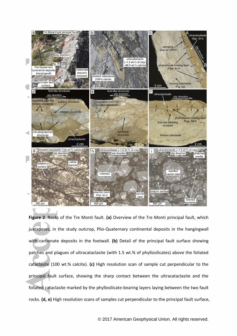
Figure 2. Rocks of the Tre Monti fault. (a) Overview of the Tre Monti principal fault, which
juxtaposes, in the study outcrop, Plio-Quaternary continental deposits in the hangingwall
with carbonate deposits in the footwall. (b) Detail of the principal fault surface showing
patches and plagues of ultracataclasite (with 1.5 wt.% of phyllosilicates) above the foliated
cataclasite (100 wt.% calcite). (c) High resolution scan of sample cut perpendicular to the
principal fault surface, showing the sharp contact between the ultracataclasite and the
foliated cataclasite marked by the phyllosilicate-bearing layers laying between the two fault
rocks. (d, e) High resolution scans of samples cut perpendicular to the principal fault surface,

© 2017 American Geophysical Union. All rights reserved.
showing fluid-like structures characterized by irregular margins and bulbous/convolute
structures with injection of the ultracataclasite into the foliated cataclasite. (f) High
resolution scan of sample cut perpendicular to the principal fault surface showing a fluid-like
injection of the ultracataclasite into the foliated cataclasite cut by the phyllosilicate-bearing
layer. (g) Texture of the foliated cataclasite showing foliation surfaces defined by cataclastic
shear zones encasing host rock sigmoids. (h) Texture of the ultracataclasite showing calcite
clasts scattered within an ultra-fine reddish phyllosilicate-bearing matrix. Clasts that are in
contact with one another show indented and teeth-shaped margins. (i) Texture of the
ultracataclasite showing foliation surfaces defined by shear zones rich in ultra-fine reddish
phyllosilicate-bearing matrix. Large clasts in these foliation surfaces are characterized by
mantled structures showing an elongate trail of smaller calcite clasts.

© 2017 American Geophysical Union. All rights reserved.
Figure 3. Microphotographs of thin sections showing representative fault rock textures
along the TMF under optical and field emission scanning electron microscope. (a, b) FESEM
images of the texture of the ultra-fine matrix from the ultracataclasite. Calcite clasts that are
in contact with one another show indented and teeth-shaped margins. In places, an ultra-
thin phyllosilicate film is interposed between clasts. Small calcite clasts are welded together
to form larger clasts. (c) Detail of calcite clasts within the ultra-fine matrix showing serrated
grain boundaries, twinning and nanofractures. (d) High resolution scan of a sample cut
perpendicular to the TMF, showing phyllosilicate-bearing layers along a riedel shear surfaces

© 2017 American Geophysical Union. All rights reserved.
and the boundary between the ultracataclasite and the foliated cataclasite. Inset shows a
FESEM image of the sharp boundary with truncated clasts between the phyllosilicate-
bearing layer (i.e., along the riedel shear surfaces) and the ultracataclasite. (e, f) FESEM
image of the phyllosilicate-bearing layer between the ultracataclasite and the foliated
cataclasite showing a sharp boundary, which truncates calcite clasts. (g) Detail of the
phyllosilicate-bearing layer showing calcite clasts scattered within phyllosilicate layers.
Calcite clasts that are in contact show indented and teeth-shaped margins. (h) Detail of
calcite clasts within phyllosilicate-bearing layers showing pores and vesicles (dark rounded
features), in places arranged in linear arrays probably along clasts microdefects such as
twinning and cleavage planes. (i) Detail of phyllosilicate nanostructures (i.e., nano-sized
spherules and tubes) within the phyllosilicate-bearing layer.

© 2017 American Geophysical Union. All rights reserved.
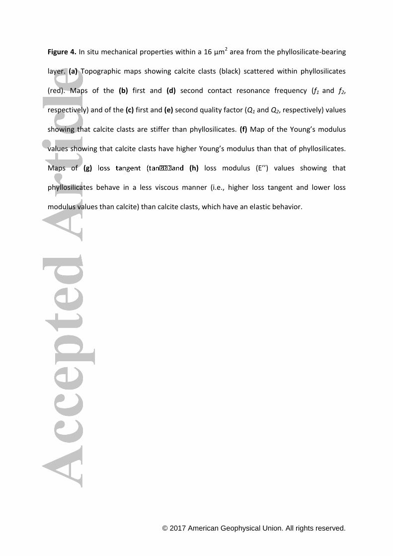
© 2017 American Geophysical Union. All rights reserved.
Figure 4. In situ mechanical properties within a 16 μm2 area from the phyllosilicate-bearing
layer. (a) Topographic maps showing calcite clasts (black) scattered within phyllosilicates
(red). Maps of the (b) first and (d) second contact resonance frequency (f1 and f2,
respectively) and of the (c) first and (e) second quality factor (Q1 and Q2, respectively) values
showing that calcite clasts are stiffer than phyllosilicates. (f) Map of the Young’s modulus
values showing that calcite clasts have higher Young’s modulus than that of phyllosilicates.
Maps of (g) (h) loss modulus (E’’) values showing that
phyllosilicates behave in a less viscous manner (i.e., higher loss tangent and lower loss
modulus values than calcite) than calcite clasts, which have an elastic behavior.
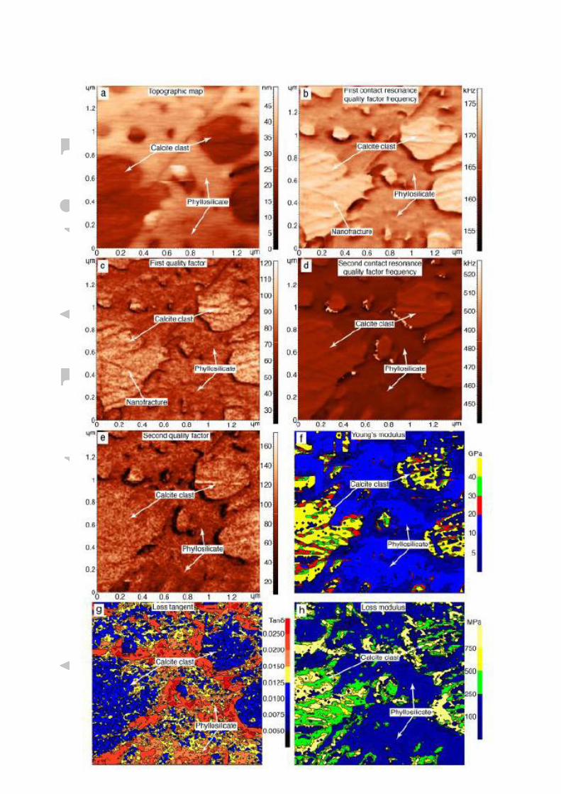
© 2017 American Geophysical Union. All rights reserved.

© 2017 American Geophysical Union. All rights reserved.
Figure 5. In situ mechanical properties within a ~2 μm2 area from the phyllosilicate-bearing
layer. (a) Topographic maps showing calcite clasts (black) scattered within phyllosilicates
(red). Maps of the (b) first and (d) second contact resonance frequency (f1 and f2,
respectively) and of the (c) first and (e) second quality factor (Q1 and Q2, respectively) values
showing that calcite clasts are stiffer than phyllosilicates. (f) Map of the Young’s modulus
values showing that calcite clasts have higher Young’s modulus than that of phyllosilicates.
Maps of (g) (h) loss modulus (E’’) values showing that
phyllosilicates behave in a more viscoelastic manner (i.e., higher loss tangent and lower loss
modulus values than calcite) than calcite clasts, which show an elastic behavior.

© 2017 American Geophysical Union. All rights reserved.
Figure 6. Experimental apparatus, gouge configurations, and mechanical results (evolution
of friction coefficient versus slip) of low to high velocity shear experiments (the list of
experiments presented in this study can be found in Table S2 in SI). Note that all the data
are characterized by a wavy pattern of the friction coefficient. This is commonly expected
due to wobble of a rotary system in the case of the not perfect alignment of the so-called
stationary and rotary columns [e.g., Di Toro et al., 2010; Smith et al., 2013]. (a) SHIVA
apparatus with main components labeled (modified from Smith et al., 2015). (b) Gouge
configurations showing the three different setups: mixed, layered, and pure calcite gouges.
(c) Evolution of friction coefficient versus slip during experiments at subseismic (0.001 ms-1)
slip rate. Friction coefficient reached the 0.7-0.8 values and remained stable during all
experiments. (d, e) Evolution of friction coefficient versus slip during experiments at seismic
(1 ms-1) slip rate. Layered gouges are weaker (i.e., they have a lower distance to the onset of
dynamic weakening, Dow) than mixed gouges, which are, in turn, weaker than pure clacite
gouges, both in dry and in wet conditions.

© 2017 American Geophysical Union. All rights reserved.
Figure 7. Mechanical and mass spectrometer data for high velocity experiments both in dry
(red curves, left column) and in wet (blue curves, right column) conditions. (a, b) Evolution
of shear stress versus normal stress. Wet experiments show an increase in the normal stress
in correspondence of friction drop (i.e., during the weakening phase). On the contrary, dry
experiments show an increase in the normal stress in correspondence of the strengthening

© 2017 American Geophysical Union. All rights reserved.
phase. (c, d) CO2 emissions were recorded only during dry experiments. (e, f) Evolution of
cross-correlation (Lag0) coefficient. Dry experiments show a positive correlation during
most experiments, indicating an in-phase oscillation between normal and shear stress. On
the contrary, wet experiments show a negative correlation during the central part of the
experiment (i.e., the weakening phase), indicating an increase of normal stress during a
decrease in shear stress (i.e., out of phase oscillation).

© 2017 American Geophysical Union. All rights reserved.
Figure 8. Mechanical and mass spectrometer data for low velocity experiments both in dry
(red curves, left column) and in wet (blue curves, right column) conditions. (a, b) Evolution
of shear stress versus normal stress. Wet experiments show constant normal stress,
whereas dry experiments show normal stress oscillations, which are in phase with shear
stress oscillations. (c, d) No CO2 emissions were recorded both in dry and in wet conditions.
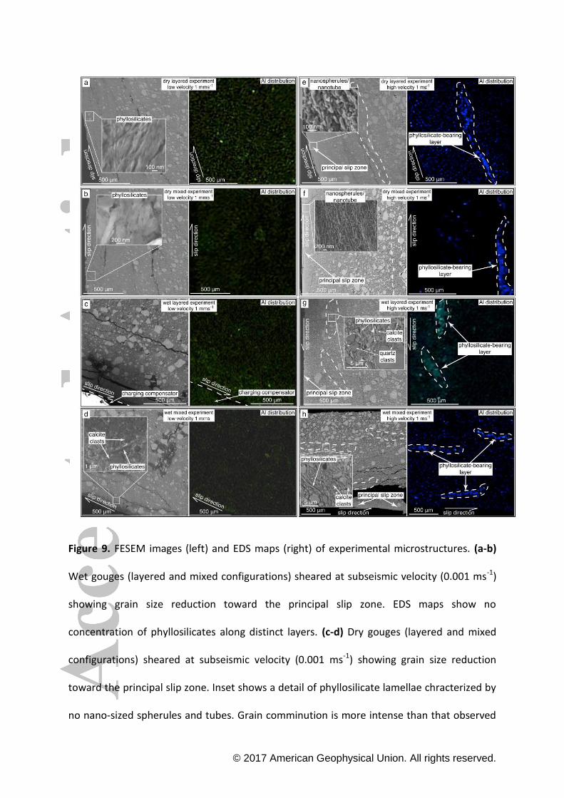
© 2017 American Geophysical Union. All rights reserved.
Figure 9. FESEM images (left) and EDS maps (right) of experimental microstructures. (a-b)
Wet gouges (layered and mixed configurations) sheared at subseismic velocity (0.001 ms-1)
showing grain size reduction toward the principal slip zone. EDS maps show no
concentration of phyllosilicates along distinct layers. (c-d) Dry gouges (layered and mixed
configurations) sheared at subseismic velocity (0.001 ms-1) showing grain size reduction
toward the principal slip zone. Inset shows a detail of phyllosilicate lamellae chracterized by
no nano-sized spherules and tubes. Grain comminution is more intense than that observed

© 2017 American Geophysical Union. All rights reserved.
within wet gouges. EDS maps show no segregation and concentration of phyllosilicates
along distinct layers. (e, f) Wet gouges (layered and mixed configurations) sheared at
seismic velocity (1 ms-1) showing grain size reduction toward the principal slip zone. EDS
map shows segregation and concentration of phyllosilicates along micrometer-thick layers
both for layered and for mixed configurations. Insets show calcite clasts within
phyllosilicate-bearing layers scattered within phyllosilicates. These microstructures are
identical to those observed along the Tre Monti Fault (Fig. 3h). (g, h) Dry gouges (layered
and mixed configurations) sheared at seismic velocity (1 ms-1) showing grain size reduction
toward the principal slip zone. Grain comminution is more intense than that observed
within wet gouges. Inset shows the nanostructures from the principal slip zone both for
layered and for mixed configurations. These structures consist of clumped and chained
nano-sized spherules and tubes similar to those observed within phyllosilicate layers along
the TMF (Fig. 3i).
© 2017 American Geophysical Union. All rights reserved.
Figure 10. Synthetic model for the seismic cycle within clay-bearing, carbonate-hosted fault
cores in the brittle upper crust (depths < 2-3 km). (a) During the co-seismic phase,
earthquake-related slip is facilitated along phyllosilicate-bearing layers, which can promote
seismic clip propagation up to the Earth’s surface, possibly enhancing surface faulting.
Seismic slip can also be assisted by overpressured fluids as testified by fluid-like fault rock
structures. (b) During the interseismic phase, slow deformation processes are
accommodated by transient creep and/or fault healing and re-strengthening through clay-
assisted pressure-solution processes and by permanent creep through slow sliding along
foliation surfaces and phyllosilicates (i.e., promoting tectonic elastic strain energy
dissipation).