microvector multirotor/fixed wing flight controller + osd ... · microvector multirotor/fixed wing...
TRANSCRIPT
USER GUIDE
1
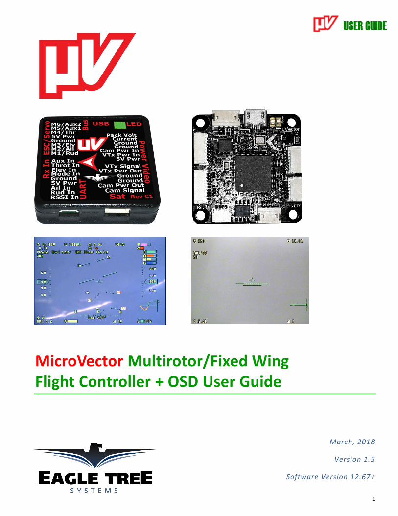
MicroVector Multirotor/Fixed Wing Flight Controller + OSD User Guide
March, 2018
Version 1.5
Software Version 12.67+
USER GUIDE
2
Table of Contents
Contents
1 Safety ............................................................................................................................................................................. 8
1.1 .... Read the Manual!................................................................................................................................................................8
1.2 .... Special Symbols used in the Manual ..........................................................................................................................8
1.3 .... General Safety Precautions ............................................................................................................................................8
2 Overview ................................................................................................................................................................... 10
2.1 .... Introduction ....................................................................................................................................................................... 10
2.2 .... Packing List ........................................................................................................................................................................ 10
2.3 .... Specifications ..................................................................................................................................................................... 11
2.4 .... How to Get Help and Request New Features ...................................................................................................... 11
2.5 .... Installing the Software, and Updating the Firmware .................................................................................... 12
2.5.1 Software Compatibility .......................................................................................................................................................... 12
2.5.2 Downloading the Latest Software .................................................................................................................................... 12
2.6 .... Getting Notified about Important MicroVector Updates .............................................................................. 13
2.7 .... Glossary of Terms used in the Manual ................................................................................................................... 14
3 Hooking Up the MicroVector ............................................................................................................................ 16
3.1 .... MicroVector Controller Connections ...................................................................................................................... 16
3.1.1 Connection Overview ............................................................................................................................................................. 16
3.1.2 Plugging in the Connectors Properly .............................................................................................................................. 16
4 MicroVector Wiring Harnesses ........................................................................................................................ 17
4.1 .... Included Wire Harnesses .............................................................................................................................................. 17
4.1.1 Wire Harness Overview ........................................................................................................................................................ 17
4.1.2 Harness Color Coding ............................................................................................................................................................. 17
4.2 .... The Power Connector .................................................................................................................................................... 18
4.2.1 Purpose of Power Connector .............................................................................................................................................. 18
4.2.2 Power Connector Pinout ....................................................................................................................................................... 18
4.2.3 Providing power to your Video Transmitter and Camera ..................................................................................... 18
4.3 .... Using the Optional Eagle Tree Current Sensor/PSU (ET PSU) ................................................................... 19
4.3.1 ETS PSU to MicroVector Cable ........................................................................................................................................... 19
4.3.2 ET PSU Outputs ......................................................................................................................................................................... 19
4.3.3 ET PSU Current Sensor Maximum Continuous Current, and Load Testing ................................................... 20
4.4 .... Connecting your Video Camera and Video Transmitter ............................................................................... 21
4.4.1 The MicroVector Video Connector ................................................................................................................................... 21
4.4.2 Video Connector Pinout ........................................................................................................................................................ 21

USER GUIDE
3
4.4.3 Connecting to your Camera and Video Transmitter ................................................................................................ 21
4.5 .... Connecting the MicroVector to a Standalone Receiver ................................................................................. 22
4.5.1 Connecting to a Standalone Receiver via the Rx In Connector ............................................................................ 22
4.5.2 Rx In Connector Pinout ......................................................................................................................................................... 22
4.5.3 Powering your Standalone Receiver on Multirotors................................................................................................ 23
4.5.4 Powering the MicroVector from your Standalone Receiver on Fixed Wing .................................................. 23
4.6 .... Using a Spektrum™ Satellite Receiver with the MicroVector ...................................................................... 24
4.6.1 Range Limitations with Satellites ..................................................................................................................................... 24
4.6.2 Satellite Connector Pinout ................................................................................................................................................... 24
4.6.3 Satellite Binding........................................................................................................................................................................ 24
4.7 .... Connecting Servos/ESCs to the MicroVector ...................................................................................................... 26
4.7.1 The ESC/Servo Connector .................................................................................................................................................... 26
4.7.2 ESC/Servo Connector Pinout .............................................................................................................................................. 26
4.7.3 Correct Hookup of your ESC and/or Servo Signal Lines ........................................................................................ 26
4.8 .... Connecting the Optional GPS/Mag and other Accessories ........................................................................... 30
5 Mounting the MicroVector and Accessories ............................................................................................... 31
5.1 .... Mounting the MicroVector .......................................................................................................................................... 31
5.1.1 Mounting Location and Orientation ................................................................................................................................ 31
5.1.2 Mounting Technique............................................................................................................................................................... 31
5.2 .... Mounting the Optional GPS/MAG Sensor ............................................................................................................. 33
5.2.1 GPS Signal Interference ......................................................................................................................................................... 33
5.2.2 Magnetometer Interference ................................................................................................................................................ 33
5.2.3 GPS/MAG Mounting Orientation ....................................................................................................................................... 33
5.2.4 The Optional GPS Stand and Clip ...................................................................................................................................... 34
5.3 .... Mounting the Optional ET PSU ................................................................................................................................. 35
5.4 .... Mounting the Optional Pitot Tube ........................................................................................................................... 35
5.5 .... Controlling the MicroVector ....................................................................................................................................... 36
5.5.1 The Mode Switch ...................................................................................................................................................................... 36
5.5.2 The Submode Switch .............................................................................................................................................................. 36
5.5.3 The Gain Knob ........................................................................................................................................................................... 36
5.5.4 The Kill Switch (for Multirotors Only) ............................................................................................................................ 36
6 Configuring the MicroVector ............................................................................................................................ 38
6.1 .... Configuration Overview ................................................................................................................................................ 38
6.2 .... Using the Automatic On-screen Setup Wizards ................................................................................................. 38
6.3 .... Transmitter Channel Mixing ...................................................................................................................................... 39
6.4 .... Configuring with the Windows Software ............................................................................................................. 39
6.5 .... Configuring the MicroVector via Stick Menus or InfoPanel ........................................................................ 41
USER GUIDE
4
6.5.1 Teaching the MicroVector about Spektrum™ Satellite, SPPM or S.BUS™ Radio Channel Mappings ... 41
6.5.2 Navigating the Stick Menus ................................................................................................................................................. 43
6.5.3 Exiting Menu Mode ................................................................................................................................................................. 43
6.5.4 Accessing Menus during Flight .......................................................................................................................................... 43
6.6 .... Selecting the Airframe type ........................................................................................................................................ 44
6.6.1 Special Notes on the “High Perf Mini Quad” Airframe Type ................................................................................. 44
6.7 .... Accepting the Airframe Type ..................................................................................................................................... 45
6.8 .... Telling the MicroVector about Transmitter Dual Surface Mixing ............................................................ 45
6.9 .... Running the Receiver Analysis Wizard .................................................................................................................. 46
6.10 . Configuring Auxiliary Receiver Inputs and Servo Outputs ........................................................................... 48
6.10.1 Configuring the Auxiliary Input Channel (for non-serial Rx inputs) ......................................................... 48
6.10.2 Configuring the MicroVector Auxiliary Output Channels (Fixed wing only) ......................................... 48
6.11 . Flight Modes, and Configuring the Mode/Submode Switches .................................................................... 49
6.11.1 Flight Mode Description ................................................................................................................................................ 49
6.11.2 Control Stick Function in Multirotor Modes ......................................................................................................... 51
6.11.3 2D Hold Flight Mode Information for Fixed Wing ............................................................................................. 51
6.11.4 Programming the Mode Switch .................................................................................................................................. 51
6.11.5 Programming the Optional Submode Switch ....................................................................................................... 53
6.12 . Configuring the Flight Controller/Stabilizer ...................................................................................................... 54
6.12.1 Setting Controller Gains ................................................................................................................................................. 54
6.12.2 Verifying Correct Control Surfaces Movement (Fixed Wing) ....................................................................... 57
6.12.3 Confirming ESC Endpoints are set Correctly (Multirotor only) ................................................................... 58
6.12.4 Arming and Disarming your Multirotor (Multirotor only) ............................................................................ 58
6.12.5 Setting Idle Throttle (Multirotor only) ................................................................................................................... 60
6.12.6 Confirming Correct Motor Order and Direction (Multirotor only) ............................................................ 60
6.12.7 Configuring BLHeliTM ESCs using BLHeliSuite ..................................................................................................... 61
6.12.8 Configuring Low Battery Autoland (Current Sensor Required) .................................................................. 61
6.12.9 Setting Flat Level Mounting ......................................................................................................................................... 62
6.12.10 Rezeroing Gyros.............................................................................................................................................................. 62
6.13 . Configuring Return to Home and other Safety Modes ................................................................................... 63
6.13.1 Selecting the Failsafe Detection Method ................................................................................................................ 63
6.13.2 Configuring RTH/Safety Mode ................................................................................................................................... 65
6.13.3 Configuring Maximum Altitude and Maximum Distance ................................................................................ 66
6.14 . The MicroVector’s LED Indicator ............................................................................................................................. 67
If you see this during boot on your multirotor, get away!!! ............................................................................................ 67
6.15 . Configuring the OSD ....................................................................................................................................................... 68
6.15.1 Adjusting the Display ...................................................................................................................................................... 68
USER GUIDE
5
6.15.2 Setting Display Units (English or Metric) .............................................................................................................. 68
6.15.3 Choosing what to Display on the OSD Screen ...................................................................................................... 69
6.15.4 Basic Numeric Readouts ................................................................................................................................................ 69
6.15.5 Advanced Numeric Readouts ...................................................................................................................................... 70
6.15.6 Graphics and Indicator Readouts .............................................................................................................................. 71
6.15.7 Setting OSD Alarms .......................................................................................................................................................... 73
6.16 . Configuring the Video Power Switches .................................................................................................................. 74
6.16.1 Video Power Switch Overview ................................................................................................................................... 74
6.16.2 Video Power Switch Configuration ........................................................................................................................... 74
6.17 . Configuring/Calibrating the Magnetic Compass (GPS Required) ............................................................ 75
6.17.1 Using the Compass with Fixed Wing Airframes .................................................................................................. 75
6.17.2 Calibrating the Compass ................................................................................................................................................ 75
6.17.3 Testing the Compass ....................................................................................................................................................... 76
6.18 . Configuring the Optional EagleEyes™ FPV Station.......................................................................................... 78
6.19 . Configuring and Using the Alerter Buzzer/LCD ................................................................................................ 79
6.19.1 Configuring the Alerter .................................................................................................................................................. 79
6.19.2 The Alerter LEDs ............................................................................................................................................................... 80
0 Satellites are in view ..................................................................................................................................................................... 80
The Receiver Analysis Wizard needs to be run..................................................................................................................... 80
7 First Flights .............................................................................................................................................................. 82
7.1 .... Preflight Checklist ........................................................................................................................................................... 82
7.1.1 Resetting Home Position (GPS Required) ..................................................................................................................... 82
7.2 .... First Flight Recommendations .................................................................................................................................. 83
7.2.1 Ground Tests before First Flight ....................................................................................................................................... 83
7.2.2 Flight Mode for Takeoffs ....................................................................................................................................................... 83
7.2.3 Fixed Wing Stalls ...................................................................................................................................................................... 83
7.3 .... In-air Leveling ................................................................................................................................................................... 84
7.3.1 Multirotor in-air leveling ...................................................................................................................................................... 84
7.3.2 Fixed Wing in-air leveling .................................................................................................................................................... 84
7.3.3 Optimal Fixed Wing leveling ............................................................................................................................................... 84
7.4 .... Return to Home Testing and Operation (GPS Required) .............................................................................. 85
7.4.1 RTH Behavior and Limitations ........................................................................................................................................... 85
7.4.2 RTH Ground Testing ............................................................................................................................................................... 85
7.4.3 In-air RTH Testing ................................................................................................................................................................... 86
8 Advanced MicroVector Setup and Calibration........................................................................................... 87
8.1 .... Getting the Most out of your High Performance Mini Quad ........................................................................ 87
8.1.1 Starting with Good Hardware ............................................................................................................................................ 87
USER GUIDE
6
8.1.2 Initial Tuning ............................................................................................................................................................................. 87
8.1.3 PID Tuning .................................................................................................................................................................................. 88
8.1.4 Other Pro Tips ........................................................................................................................................................................... 91
8.1.5 Glossary of Other Advanced Features............................................................................................................................. 93
8.2 .... Advanced OSD Setup ...................................................................................................................................................... 95
8.2.1 The Advanced Numeric Readouts Menu ....................................................................................................................... 95
8.2.2 Gauges and Swatches ............................................................................................................................................................. 96
8.2.3 The Advanced Graphics/Indicators Menu .................................................................................................................... 97
8.3 .... Data Logging ..................................................................................................................................................................... 98
8.3.1 Configuring Data Logging ..................................................................................................................................................... 98
8.3.2 Downloading, Viewing and Saving Logged Flight Information ........................................................................... 98
8.3.3 Additional Data Logging and Telemetry Features .................................................................................................... 99
8.4 .... Advanced RTH Setup ................................................................................................................................................... 100
8.4.1 Home Altitude Mode ............................................................................................................................................................ 100
8.4.2 Other Advanced RTH Settings ......................................................................................................................................... 101
8.5 .... MicroVector Calibration ............................................................................................................................................ 103
8.5.1 Electrical Calibration ........................................................................................................................................................... 103
8.5.2 Altimeter Calibration........................................................................................................................................................... 103
8.5.3 Pitot Airspeed Calibration ................................................................................................................................................. 104
8.6 .... GPS Configuration ........................................................................................................................................................ 105
8.6.1 Choosing the GPS Position Display Format ............................................................................................................... 105
8.6.2 Changing the GPS Fix Quality Settings ......................................................................................................................... 105
9 Setting up Receiver RSSI .................................................................................................................................. 106
9.1 .... Connecting your Receiver’s RSSI Output (if applicable)............................................................................. 106
9.2 .... Configuring SPPM Based RSSI and Link Quality ............................................................................................ 106
10 Using the UART Connector for Telemetry ................................................................................................ 107
10.1 . UART Connector Pinout ............................................................................................................................................. 107
10.2 . MicroVector Telemetry Output for Radios and LRS Links ......................................................................... 107
10.2.1 Taranis™ Telemetry ..................................................................................................................................................... 107
10.2.2 MicroVector Open Telemetry and DragonLink Advanced .......................................................................... 107
11 SkyGates Virtual Racing (GPS Required) .................................................................................................. 108
12 Waypoints .............................................................................................................................................................. 109
12.1 . Safety .................................................................................................................................................................................. 109
12.2 . Terminology .................................................................................................................................................................... 109
12.3 . Limitations....................................................................................................................................................................... 109
12.4 . Waypoint Setup ............................................................................................................................................................. 109
12.4.1 Waypoint Related Settings on the Waypoint/Nav Setup Tab .................................................................... 109
USER GUIDE
7
12.4.2 The Waypoint Setup Tab ............................................................................................................................................ 111
12.4.3 Using the Waypoint Map ............................................................................................................................................ 112
12.4.4 Waypoint Command Navigation Behavior ......................................................................................................... 112
12.4.5 The Command Table .................................................................................................................................................... 114
12.4.6 Command and Parameter Reference .................................................................................................................... 114
12.5 . Flying Waypoints .......................................................................................................................................................... 118
12.5.1 Setting up your Mode/Submode Switch ............................................................................................................. 118
12.5.2 Waypoint Display on the OSD .................................................................................................................................. 118
12.5.3 Starting a Waypoint Session ..................................................................................................................................... 119
12.5.4 Pausing and Aborting Waypoint Navigation ..................................................................................................... 119
13 Closed Loop Speed Control (Fixed Wing) ................................................................................................. 121
13.1 . Overview ........................................................................................................................................................................... 121
13.2 . Pitot Tube Support ....................................................................................................................................................... 121
13.2.1 Pitot Tube vs GPS Speed ............................................................................................................................................. 121
13.2.2 Pitot Tube Safety Checks ............................................................................................................................................ 121
13.3 . Closed Loop Speed Control Related Settings .................................................................................................... 122
13.3.1 OSD Stick Menu Setup ................................................................................................................................................. 122
13.3.2 GUI Setup ........................................................................................................................................................................... 123
13.4 . Configuring Closed Loop with Waypoint, RTH and Loiter Modes .......................................................... 123
13.5 . Closed Loop “Cruise Control” Flight Modes ...................................................................................................... 124
13.5.1 Overview ........................................................................................................................................................................... 124
13.5.2 Available Modes ............................................................................................................................................................. 124
13.5.3 Configuration ................................................................................................................................................................... 124
13.5.4 Closed Loop Flight Mode Behavior ........................................................................................................................ 124
14 Troubleshooting .................................................................................................................................................. 126
15 Notification Messages ....................................................................................................................................... 130
16 Description of Numeric Readouts ................................................................................................................ 136
17 Limited Warranty ............................................................................................................................................... 139
USER GUIDE
8
1 Safety The MicroVector is intended to be used exclusively for recreational purposes in model aircraft. Using the
MicroVector for other purposes is not supported. Further, using the MicroVector in situations where its use or
failure could result in loss of life, bodily injury or property damage is expressly prohibited.
Eagle Tree Systems, LLC, is not responsible for your use of this product, or for any damages or injuries
you may cause or sustain as a result of its usage.
1.1 Read the Manual!
This manual contains important instructions related to safety. Read the entire manual before proceeding, to become familiar with the features and operation of the MicroVector. Failure to correctly configure or operate the MicroVector could cause damage to personal property or serious injury!
The latest version of this manual is available in the Product Manuals section of the Support tab on http://www.eagletreesystems.com.
If, after you read the manual, you have further questions or problems, see the 2.4 - 'How to Get Help and Request New Features’ section below.
Reading this manual is probably more enjoyable, and will probably take less time, than rebuilding your model!
All technical information in this manual is subject to change without notice. All non Eagle Tree brand and product names referenced in this manual are trademarks of their respective holders.
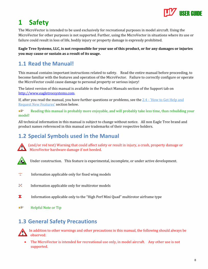
1.2 Special Symbols used in the Manual
(and/or red text) Warning that could affect safety or result in injury, a crash, property damage or MicroVector hardware damage if not heeded.
Under construction. This feature is experimental, incomplete, or under active development.
Information applicable only for fixed wing models
Information applicable only for multirotor models
Information applicable only to the “High Perf Mini Quad” multirotor airframe type
Helpful Note or Tip
1.3 General Safety Precautions
In addition to other warnings and other precautions in this manual, the following should always be observed:
• The MicroVector is intended for recreational use only, in model aircraft. Any other use is not supported.
USER GUIDE
9
• Never connect ESCs or servos to the MicroVector until you have verified the airframe type is correctly selected! Doing so can cause multirotor propellers to spin at high speed, or can destroy fixed wing servos.
• Always remove propeller(s) or otherwise disable motor(s) when configuring the MicroVector!
• Always move a safe distance away from the model before starting the motor(s), and never approach the model with the propeller(s) spinning! Never approach a multirotor when it is armed!
• Always wear eye protection when operating models with propellers!
• RC models and accessories are not toys! The MicroVector should not be used by children.
• You should always use a spotter if your eyes are not on your model. For USA customers, please refer to the Academy of Model Aeronautics Safety Code at http://www.modelaircraft.org/files/105.PDF and FPV related code at http://www.modelaircraft.org/files/550.pdf
• Always obey the law when flying.
• Most video transmitters used for FPV flying require an amateur radio license to operate legally.
• If you have never set up or operated an RC model before, you will need help from an experienced modeler. Local RC clubs are great ways to meet experienced modelers, and receive the required training. This requirement is especially true for FPV flying, which can be more challenging.
• Never operate your model aircraft near or over buildings, power/telephone lines, or other obstacles. Never operate your model aircraft near or over people or animals! Never operate your model after consuming drugs or alcohol!
• Never operate your model within 5 miles of airports, without permission from the airport!
• Never operate the MicroVector in a situation where it may get wet, such as on a rainy day.
• Do not change wiring in your model when any power is applied.
USER GUIDE
10
2 Overview
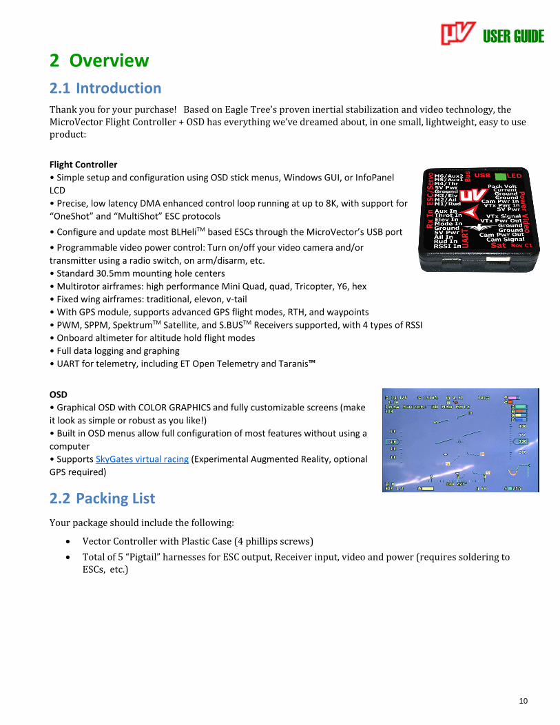
2.1 Introduction Thank you for your purchase! Based on Eagle Tree's proven inertial stabilization and video technology, the MicroVector Flight Controller + OSD has everything we’ve dreamed about, in one small, lightweight, easy to use product:
Flight Controller
• Simple setup and configuration using OSD stick menus, Windows GUI, or InfoPanel
LCD
• Precise, low latency DMA enhanced control loop running at up to 8K, with support for
“OneShot” and “MultiShot” ESC protocols
• Configure and update most BLHeliTM based ESCs through the MicroVector’s USB port
• Programmable video power control: Turn on/off your video camera and/or
transmitter using a radio switch, on arm/disarm, etc.
• Standard 30.5mm mounting hole centers
• Multirotor airframes: high performance Mini Quad, quad, Tricopter, Y6, hex
• Fixed wing airframes: traditional, elevon, v-tail
• With GPS module, supports advanced GPS flight modes, RTH, and waypoints
• PWM, SPPM, SpektrumTM Satellite, and S.BUSTM Receivers supported, with 4 types of RSSI
• Onboard altimeter for altitude hold flight modes
• Full data logging and graphing
• UART for telemetry, including ET Open Telemetry and Taranis™
OSD
• Graphical OSD with COLOR GRAPHICS and fully customizable screens (make
it look as simple or robust as you like!)
• Built in OSD menus allow full configuration of most features without using a
computer
• Supports SkyGates virtual racing (Experimental Augmented Reality, optional
GPS required)
2.2 Packing List
Your package should include the following:
• Vector Controller with Plastic Case (4 phillips screws)
• Total of 5 “Pigtail” harnesses for ESC output, Receiver input, video and power (requires soldering to ESCs, etc.)
USER GUIDE
11
2.3 Specifications • Supported Airframes:
o High Perf Mini Quad, Quadcopter, Tricopter, and Hexacopter multirotors
o Traditional fixed wing, Elevon, and V-tail planes
• Recommended Airframes: The MicroVector is recommended for small/light airframes only:
o 300mm (12”) or smaller multirotors
o 800mm (32”) or smaller wingspan planes.
Consider using the Vector for larger models.
The MicroVector is not recommended for large or heavy airframes, due to no or limited testing on these types of models at this time.
• Video formats: composite NTSC and PAL (autodetect)
• Servo/ESC Output framerate:
o Multirotor: up to 8KHz with MultiShot capable ESCs
o Fixed wing: adjustable up to 400Hz
• Controller Dimensions (L x W x H, approximate):
o 38 X 38 X 10 mm with case
o 36 x 36 x 7 mm without case
• Controller Mass (approximate):
o 13 grams with case
o 7 grams without case
2.4 How to Get Help and Request New Features
Eagle Tree is committed to providing great customer service. Once you’ve read the manual, if something is not clear, just ask. We’d much prefer to take the time to answer your questions, rather than having you waste your valuable time struggling with an issue.
To get help 24/7, visit the Eagle Tree MicroVector support thread on RCGroups:
http://www.rcgroups.com/forums/showthread.php?t=2668425
Or, visit the thread on FPVLab:
http://fpvlab.com/forums/showthread.php?47856
Chances are someone has posted a solution to your problem already. If not, posting your problem on the forum will get a very quick response from the Eagle Tree community. If you prefer to not post on the forum, or you feel there is a problem with your Eagle Tree hardware, please open a support ticket with us at http://ticket.eagletreesystems.com and we will respond to your support ticket as soon as we can – normally within a few business hours. Note that when you create a support ticket, you will be emailed a link that will let you check the status of the ticket. If you do not receive the email, most likely a spam filter is intercepting emails from Eagle Tree.
Also, Eagle Tree greatly values your feedback on how we can improve our products. To leave us feedback for a new feature request or improvement, post the feedback on our support threads above, create a support ticket with your feedback, or just email us at [email protected].
USER GUIDE
12
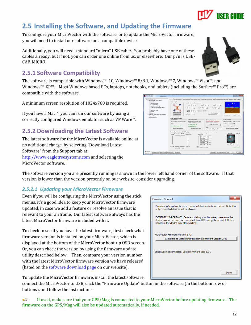
2.5 Installing the Software, and Updating the Firmware To configure your MicroVector with the software, or to update the MicroVector firmware,
you will need to install our software on a compatible device.
Additionally, you will need a standard “micro” USB cable. You probably have one of these cables already, but if not, you can order one online from us, or elsewhere. Our p/n is USB-CAB-MICRO.
2.5.1 Software Compatibility The software is compatible with Windows™ 10, Windows™ 8/8.1, Windows™ 7, Windows™ Vista™, and
Windows™ XP™. Most Windows based PCs, laptops, notebooks, and tablets (including the Surface™ Pro™) are
compatible with the software.
A minimum screen resolution of 1024x768 is required.
If you have a Mac™, you can run our software by using a
correctly configured Windows emulator such as VMWare™.
2.5.2 Downloading the Latest Software The latest software for the MicroVector is available online at
no additional charge, by selecting “Download Latest
Software” from the Support tab at
http://www.eagletreesystems.com and selecting the
MicroVector software.
The software version you are presently running is shown in the lower left hand corner of the software. If that version is lower than the version presently on our website, consider upgrading.
2.5.2.1 Updating your MicroVector Firmware
Even if you will be configuring the MicroVector using the stick
menus, it’s a good idea to keep your MicroVector firmware
updated, in case we add a feature or resolve an issue that is
relevant to your airframe. Our latest software always has the
latest MicroVector firmware included with it.
To check to see if you have the latest firmware, first check what
firmware version is installed on your MicroVector, which is
displayed at the bottom of the MicroVector boot-up OSD screen.
Or, you can check the version by using the firmware update
utility described below. Then, compare your version number
with the latest MicroVector firmware version we have released
(listed on the software download page on our website).
To update the MicroVector firmware, install the latest software,
connect the MicroVector to USB, click the “Firmware Update” button in the software (in the bottom row of
buttons), and follow the instructions.
If used, make sure that your GPS/Mag is connected to your MicroVector before updating firmware. The firmware on the GPS/Mag will also be updated automatically, if needed.

USER GUIDE
13
Also, note that if you install new software and it detects that the MicroVector’s firmware needs an update, it
will automatically run the firmware update utility.
2.6 Getting Notified about Important MicroVector Updates Eagle Tree updates the MicroVector firmware and software periodically to add new features or to address
issues that may arise, and will issue important hardware information bulletins as needed. There are two ways
to get notified about these:
1) Subscribe to the Vector/MicroVector update notification thread on RCGroups™. Whenever we update the
software or release a hardware bulletin, we will post a note to this thread, and subscribing to it should
result in you receiving an email. Note that this thread will normally be closed, so only we can post to it,
reducing the number of emails you will receive.
http://www.rcgroups.com/forums/showthread.php?t=2159747
2) Follow us or like us on Facebook™. We will post a note on Facebook™ indicating that new software or
important hardware information has been posted, and you should see that on your Facebook page.
http://www.facebook.com/eagletreesystems
USER GUIDE
14
2.7 Glossary of Terms used in the Manual Here are definitions for some of the terms used throughout the manual.
FPV – FPV stands for First Person View. If you are not familiar with FPV, there are many websites devoted to it. Our FPV overview web page at http://www.eagletreesystems.com/OSD has a brief tutorial on FPV, which is a good place to start.
OSD – OSD stands for On Screen Display. The OSD shows flight information, overlaid on the video camera image.
RTH – Return to Home. The MicroVector can optionally return your model to the home point if R/C link is lost.
Software – the term “software” in the manual refers to our Windows PC software application.
Firmware – the firmware is the code that runs on the MicroVector itself. The latest MicroVector firmware is included with the software.
Flight Controller or Stabilizer – the aspect of the MicroVector that stabilizes your model during flight
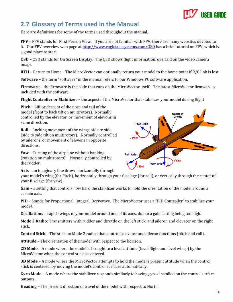
Pitch – Lift or descent of the nose and tail of the model (front to back tilt on multirotors). Normally controlled by the elevator, or movement of elevons in same direction.
Roll – Rocking movement of the wings, side to side (side to side tilt on multirotors). Normally controlled by ailerons, or movement of elevons in opposite directions.
Yaw – Turning of the airplane without banking (rotation on multirotors). Normally controlled by the rudder.
Axis – an imaginary line drawn horizontally through your model’s wing (for Pitch), horizontally through your fuselage (for roll), or vertically through the center of your fuselage (for yaw).
Gain – a setting that controls how hard the stabilizer works to hold the orientation of the model around a certain axis.
PID – Stands for Proportional, Integral, Derivative. The MicroVector uses a “PID Controller” to stabilize your model.
Oscillations – rapid swings of your model around one of its axes, due to a gain setting being too high.
Mode 2 Radio: Transmitters with rudder and throttle on the left stick, and aileron and elevator on the right stick.
Control Stick – The stick on Mode 2 radios that controls elevator and aileron functions (pitch and roll).
Attitude – The orientation of the model with respect to the horizon.
2D Mode – A mode where the model is brought to a level attitude (level flight and level wings) by the MicroVector when the control stick is centered.
3D Mode – A mode where the MicroVector attempts to hold the model’s present attitude when the control stick is centered, by moving the model’s control surfaces automatically.
Gyro Mode – A mode where the stabilizer responds similarly to having gyros installed on the control surface outputs.
Heading – The present direction of travel of the model with respect to North.
USER GUIDE
15
Control Surfaces – Your model’s elevator, ailerons (or elevons), flaperons, and/or rudder (if equipped).
Mode Switch – A two or three position switch on your radio transmitter which you have configured to control the “Mod” input on the MicroVector’s Receiver Connection Harness.
Toggle – One fairly rapid movement the Mode Switch between its extents. (UP/DOWN or DOWN/UP)
Configuration Gestures – A series of toggles of the Mode Switch. The number of times you toggle the switch determines which configuration step is performed.
PDB - Power Distribution Board. This refers the commonly available (typically 35mm x 35mm) power supply/current sensing boards for small quadcopters.
PSU – Power Supply Unit. This refers to the Eagle Tree Current Sensor/PSU.
BEC – Battery Eliminator Circuit. This refers to a 5-6V output regulator that is either integrated into your ESC, or is a separate module. Toilet Bowl – When a multirotor is hovering, the condition of orbiting around the desired hover point, sometimes in an ever increasing diameter, due to compass error or other issues. Expo – (short for “exponential”) a setting that provides an increase in stick sensitivity as the stick is moved from the center position.
USER GUIDE
16
3 Hooking Up the MicroVector This section describes the MicroVector’s cabling and connections, and how to connect the MicroVector to your RC receiver, your servos or ESCs, and your FPV video transmitter and camera.
3.1 MicroVector Controller Connections
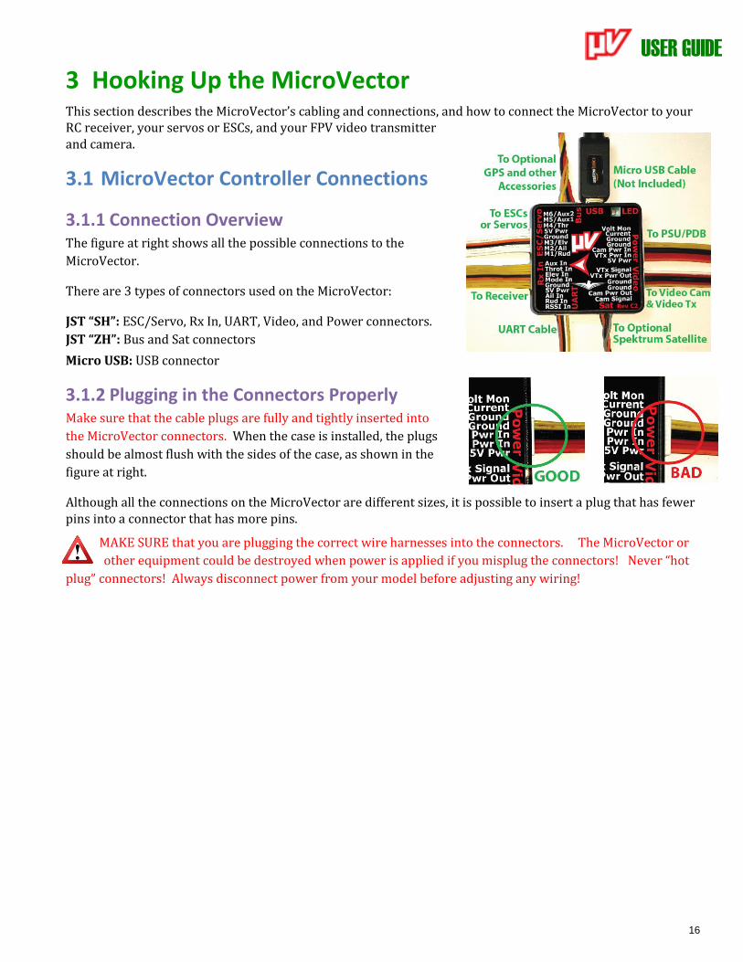
3.1.1 Connection Overview The figure at right shows all the possible connections to the
MicroVector.
There are 3 types of connectors used on the MicroVector:
JST “SH”: ESC/Servo, Rx In, UART, Video, and Power connectors.
JST “ZH”: Bus and Sat connectors
Micro USB: USB connector
3.1.2 Plugging in the Connectors Properly Make sure that the cable plugs are fully and tightly inserted into
the MicroVector connectors. When the case is installed, the plugs
should be almost flush with the sides of the case, as shown in the
figure at right.
Although all the connections on the MicroVector are different sizes, it is possible to insert a plug that has fewer pins into a connector that has more pins.
MAKE SURE that you are plugging the correct wire harnesses into the connectors. The MicroVector or
other equipment could be destroyed when power is applied if you misplug the connectors! Never “hot
plug” connectors! Always disconnect power from your model before adjusting any wiring!
USER GUIDE
17
4 MicroVector Wiring Harnesses The MicroVector’s wire harnesses are shown below. Note that a set of replacement wire harnesses is available
(p/n VEC-CAB-SET). Having additional sets make it easier to move your MicroVector from model to model.
4.1 Included Wire Harnesses
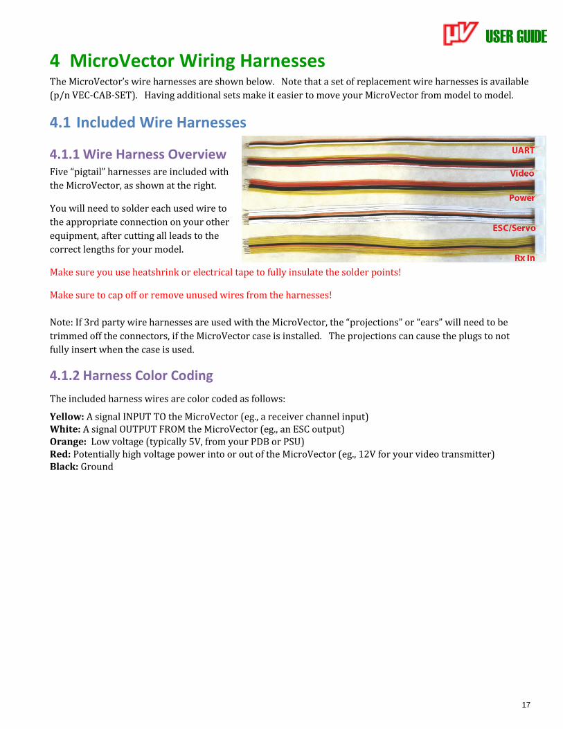
4.1.1 Wire Harness Overview Five “pigtail” harnesses are included with
the MicroVector, as shown at the right.
You will need to solder each used wire to
the appropriate connection on your other
equipment, after cutting all leads to the
correct lengths for your model.
Make sure you use heatshrink or electrical tape to fully insulate the solder points!
Make sure to cap off or remove unused wires from the harnesses!
Note: If 3rd party wire harnesses are used with the MicroVector, the “projections” or “ears” will need to be
trimmed off the connectors, if the MicroVector case is installed. The projections can cause the plugs to not
fully insert when the case is used.
4.1.2 Harness Color Coding
The included harness wires are color coded as follows:
Yellow: A signal INPUT TO the MicroVector (eg., a receiver channel input) White: A signal OUTPUT FROM the MicroVector (eg., an ESC output) Orange: Low voltage (typically 5V, from your PDB or PSU) Red: Potentially high voltage power into or out of the MicroVector (eg., 12V for your video transmitter) Black: Ground
USER GUIDE
18
4.2 The Power Connector
4.2.1 Purpose of Power Connector
For both fixed wing and multirotor types, the Power connector lets you provide power to your video equipment, and additionally lets you monitor your flight battery, and provide 5V power to the MicroVector.
The Power connector typically connects to a PDB, or the Eagle Tree PSU.
4.2.2 Power Connector Pinout
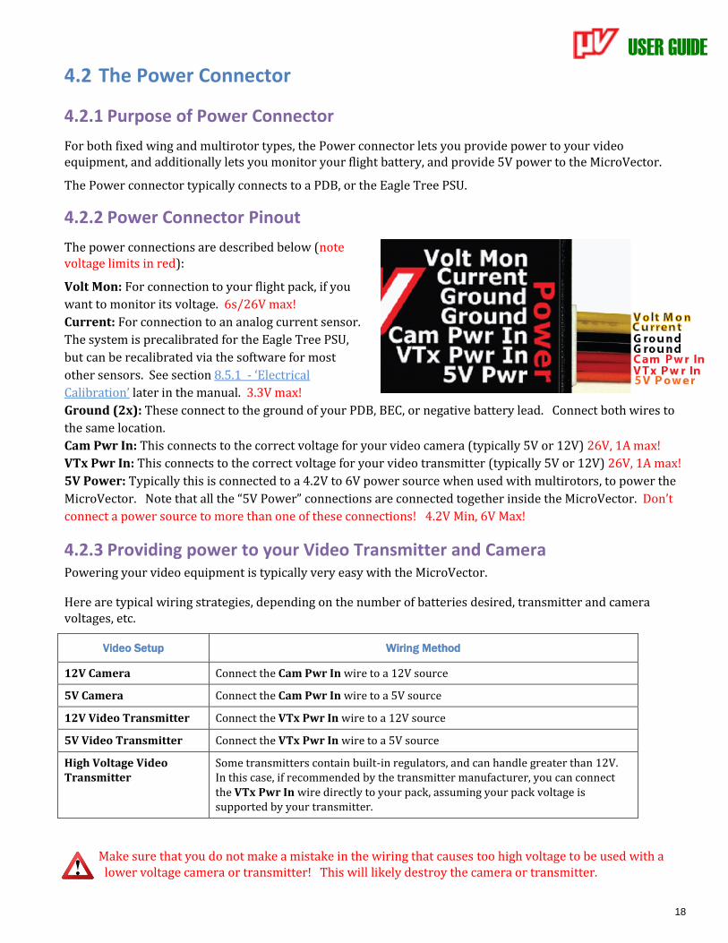
The power connections are described below (note voltage limits in red):
Volt Mon: For connection to your flight pack, if you
want to monitor its voltage. 6s/26V max!
Current: For connection to an analog current sensor.
The system is precalibrated for the Eagle Tree PSU,
but can be recalibrated via the software for most
other sensors. See section 8.5.1 - ‘Electrical
Calibration’ later in the manual. 3.3V max!
Ground (2x): These connect to the ground of your PDB, BEC, or negative battery lead. Connect both wires to
the same location.
Cam Pwr In: This connects to the correct voltage for your video camera (typically 5V or 12V) 26V, 1A max!
VTx Pwr In: This connects to the correct voltage for your video transmitter (typically 5V or 12V) 26V, 1A max!
5V Power: Typically this is connected to a 4.2V to 6V power source when used with multirotors, to power the
MicroVector. Note that all the “5V Power” connections are connected together inside the MicroVector. Don’t
connect a power source to more than one of these connections! 4.2V Min, 6V Max!
4.2.3 Providing power to your Video Transmitter and Camera Powering your video equipment is typically very easy with the MicroVector.
Here are typical wiring strategies, depending on the number of batteries desired, transmitter and camera voltages, etc.
Video Setup Wiring Method
12V Camera Connect the Cam Pwr In wire to a 12V source
5V Camera Connect the Cam Pwr In wire to a 5V source
12V Video Transmitter Connect the VTx Pwr In wire to a 12V source
5V Video Transmitter Connect the VTx Pwr In wire to a 5V source
High Voltage Video Transmitter
Some transmitters contain built-in regulators, and can handle greater than 12V. In this case, if recommended by the transmitter manufacturer, you can connect the VTx Pwr In wire directly to your pack, assuming your pack voltage is supported by your transmitter.
Make sure that you do not make a mistake in the wiring that causes too high voltage to be used with a lower voltage camera or transmitter! This will likely destroy the camera or transmitter.
USER GUIDE
19
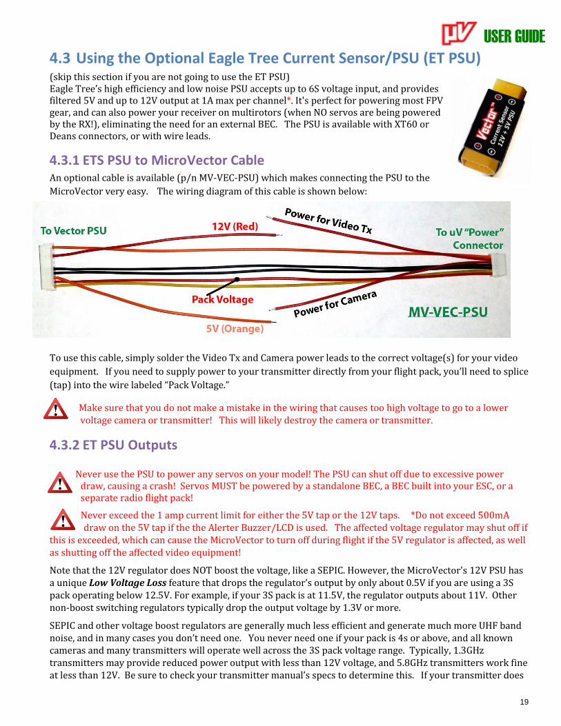
4.3 Using the Optional Eagle Tree Current Sensor/PSU (ET PSU) (skip this section if you are not going to use the ET PSU) Eagle Tree’s high efficiency and low noise PSU accepts up to 6S voltage input, and provides filtered 5V and up to 12V output at 1A max per channel*. It's perfect for powering most FPV gear, and can also power your receiver on multirotors (when NO servos are being powered by the RX!), eliminating the need for an external BEC. The PSU is available with XT60 or Deans connectors, or with wire leads.
4.3.1 ETS PSU to MicroVector Cable An optional cable is available (p/n MV-VEC-PSU) which makes connecting the PSU to the
MicroVector very easy. The wiring diagram of this cable is shown below:
To use this cable, simply solder the Video Tx and Camera power leads to the correct voltage(s) for your video
equipment. If you need to supply power to your transmitter directly from your flight pack, you’ll need to splice
(tap) into the wire labeled “Pack Voltage.”
Make sure that you do not make a mistake in the wiring that causes too high voltage to go to a lower voltage camera or transmitter! This will likely destroy the camera or transmitter.
4.3.2 ET PSU Outputs
Never use the PSU to power any servos on your model! The PSU can shut off due to excessive power draw, causing a crash! Servos MUST be powered by a standalone BEC, a BEC built into your ESC, or a separate radio flight pack!
Never exceed the 1 amp current limit for either the 5V tap or the 12V taps. *Do not exceed 500mA draw on the 5V tap if the the Alerter Buzzer/LCD is used. The affected voltage regulator may shut off if
this is exceeded, which can cause the MicroVector to turn off during flight if the 5V regulator is affected, as well as shutting off the affected video equipment!
Note that the 12V regulator does NOT boost the voltage, like a SEPIC. However, the MicroVector's 12V PSU has a unique Low Voltage Loss feature that drops the regulator’s output by only about 0.5V if you are using a 3S pack operating below 12.5V. For example, if your 3S pack is at 11.5V, the regulator outputs about 11V. Other non-boost switching regulators typically drop the output voltage by 1.3V or more.
SEPIC and other voltage boost regulators are generally much less efficient and generate much more UHF band noise, and in many cases you don’t need one. You never need one if your pack is 4s or above, and all known cameras and many transmitters will operate well across the 3S pack voltage range. Typically, 1.3GHz transmitters may provide reduced power output with less than 12V voltage, and 5.8GHz transmitters work fine at less than 12V. Be sure to check your transmitter manual’s specs to determine this. If your transmitter does

USER GUIDE
20
need a boost when operating at the lower end of 3S, a boost regulator can easily be spliced into the MicroVector's video harness.
4.3.3 ET PSU Current Sensor Maximum Continuous Current, and Load Testing
The PSU current sensor’s continuous current capability depends on the type of connectors/wires you are using, and other factors.
If your model draws a large amount of current (greater than approximately 60 amps continuous) make sure you verify that your power system, including the current sensor, can handle your worst case continuous current load.
In high current applications it is recommended (if you can do so safely) that you run your model in an extended stationary “bench” test, similar in duration and power usage to your most aggressive piloting, to ensure there are no problems with any connections, wiring doesn’t get too hot, etc. DO NOT OPERATE YOUR MODEL IF YOU HAVE PROBLEMS DURING THIS EXTENDED STATIONARY TEST!
It is also recommended that the current sensor be mounted so that airflow is directed through one of the openings of the sensor.
Never exceed the manufacturer’s continuous current rating for the types of connectors installed on your current sensor! If the current sensor or wiring becomes too hot during flight due to too much current,
the connectors can fail, or the PSU can shut off, causing a crash!
Make sure that the connector contacts on your current sensor and mating connectors are not damaged or weakened. A damaged or weakened contact can potentially fold over and short when connected, or cause intermittent in-flight failures!
USER GUIDE
21
4.4 Connecting your Video Camera and Video Transmitter
4.4.1 The MicroVector Video Connector The Video connector supplies power and signal to/from your video transmitter and camera.
Note that the camera and video transmitter voltages supplied to the Power connector are output through the
Video connector. Make sure that these power sources are adequate and correct for your video equipment.
Note also that the power to the camera and/or video transmitter can be switched on and off remotely. See section 6.16 – ‘Configuring the Video Power Switches’ in the manual for more information on how to set this up.
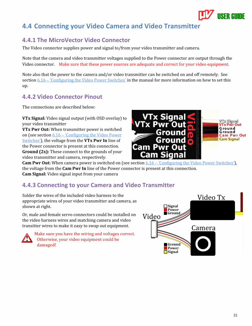
4.4.2 Video Connector Pinout
The connections are described below: VTx Signal: Video signal output (with OSD overlay) to your video transmitter VTx Pwr Out: When transmitter power is switched on (see section 6.16 – ‘Configuring the Video Power Switches’), the voltage from the VTx Pwr In line of the Power connector is present at this connection. Ground (2x): These connect to the grounds of your video transmitter and camera, respectively. Cam Pwr Out: When camera power is switched on (see section 6.16 – ‘Configuring the Video Power Switches’), the voltage from the Cam Pwr In line of the Power connector is present at this connection. Cam Signal: Video signal input from your camera
4.4.3 Connecting to your Camera and Video Transmitter
Solder the wires of the included video harness to the appropriate wires of your video transmitter and camera, as shown at right.
Or, male and female servo connectors could be installed on the video harness wires and matching camera and video transitter wires to make it easy to swap out equipment.
Make sure you have the wiring and voltages correct. Otherwise, your video equipment could be damaged!
USER GUIDE
22
4.5 Connecting the MicroVector to a Standalone Receiver This section describes how to connect your MicroVector to a standalone receiver (skip this section if you are
using a Spektrum™ satellite receiver).
4.5.1 Connecting to a Standalone Receiver via the Rx In Connector Use the included Rx In harness to connect to your standalone receiver. Three types of standalone receiver
modes are supported:
Traditional (parallel): Each of the relevant harness connections needs to be connected to the appropriate
output port on the receiver.
Serial PPM (SPPM) and S.BUS™ (serial modes): Only the “Ail” wire of the receiver harness should be
connected to the SPPM or S.BUS™ output of your receiver. Your receiver’s outputs are programmed in the
MicroVector, as described later.
S.BUSTM or SPPM receiver modes are generally higher performance than traditional mode, as well as being easier to wire up and configure.
Note: Connect only the “Ail” wire to your receiver when using a serial mode. Never connect other signal wires from the Rx In harness to your receiver if you are using a serial mode! Also, make sure you cut and cap the extra wires if using a serial mode.
Typically, you will want to crimp or solder ‘JR’ style connector(s) on the Rx In harness, shortening
the wires as necessary for your installation.
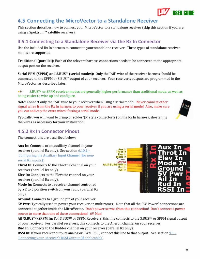
4.5.2 Rx In Connector Pinout The connections are described below:
Aux In: Connects to an auxiliary channel on your
receiver (parallel Rx only). See section 6.10.1 –
‘Configuring the Auxiliary Input Channel (for non-
serial Rx inputs)’.
Throt In: Connects to the Throttle channel on your
receiver (parallel Rx only).
Elev In: Connects to the Elevator channel on your
receiver (parallel Rx only).
Mode In: Connects to a receiver channel controlled
by a 2 to 5 position switch on your radio (parallel Rx
only).
Ground: Connects to a ground pin of your receiver.
5V Pwr: Typically used to power your receiver on multirotors. Note that all the “5V Power” connections are
connected together inside the MicroVector. Don’t power servos from this connection! Don’t connect a power
source to more than one of these connections! 6V Max!
Ail/S.BUSTM/SPPM In: For S.BUSTM or SPPM Receivers, this line connects to the S.BUSTM or SPPM signal output
of your receiver. For parallel receivers, this connects to the Aileron channel on your receiver.
Rud In: Connects to the Rudder channel on your receiver (parallel Rx only).
RSSI In: If your receiver outputs analog or PWM RSSI, connect this line to that output. See section 9.1 –
‘Connecting your Receiver’s RSSI Output (if applicable)’.
USER GUIDE
23
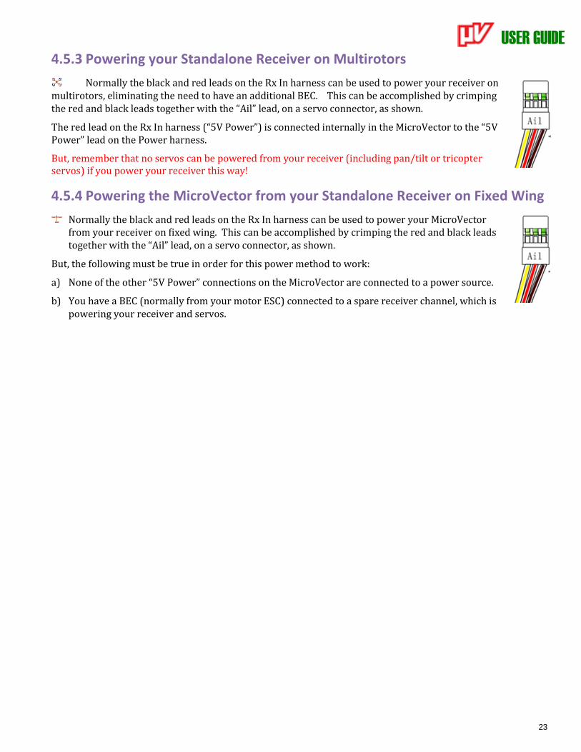
4.5.3 Powering your Standalone Receiver on Multirotors
Normally the black and red leads on the Rx In harness can be used to power your receiver on multirotors, eliminating the need to have an additional BEC. This can be accomplished by crimping the red and black leads together with the “Ail” lead, on a servo connector, as shown.
The red lead on the Rx In harness (“5V Power”) is connected internally in the MicroVector to the “5V Power” lead on the Power harness.
But, remember that no servos can be powered from your receiver (including pan/tilt or tricopter servos) if you power your receiver this way!
4.5.4 Powering the MicroVector from your Standalone Receiver on Fixed Wing
Normally the black and red leads on the Rx In harness can be used to power your MicroVector from your receiver on fixed wing. This can be accomplished by crimping the red and black leads together with the “Ail” lead, on a servo connector, as shown.
But, the following must be true in order for this power method to work:
a) None of the other “5V Power” connections on the MicroVector are connected to a power source.
b) You have a BEC (normally from your motor ESC) connected to a spare receiver channel, which is powering your receiver and servos.
USER GUIDE
24
4.6 Using a Spektrum™ Satellite Receiver with the MicroVector
Using a Spektrum™ compatible satellite receiver is quite simple with the MicroVector.
The MicroVector will power the satellite, and has built-in “bind plug” and GUI binding capability, so you normally don’t need a standalone Spektrum™ receiver to bind the satellite. See section 4.6.3 – ‘Satellite Binding’.
Also, built in wizards make it easy to teach the MicroVector about your satellite channel assignments.
Satellites are considered to have low latency compared to parrallel-type standalone receiver configurations, which can improve performance.
4.6.1 Range Limitations with Satellites Single satellites typically have much shorter ranges than standalone receivers. So, only use a single satellite for
short range flying. See your satellite’s manual for expected ranges.
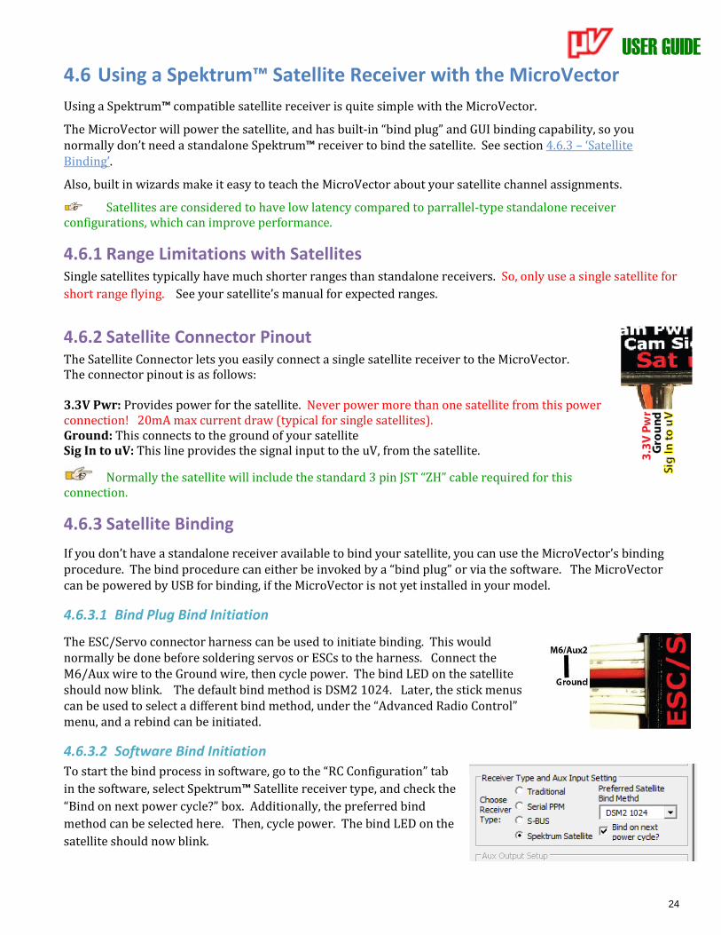
4.6.2 Satellite Connector Pinout The Satellite Connector lets you easily connect a single satellite receiver to the MicroVector. The connector pinout is as follows: 3.3V Pwr: Provides power for the satellite. Never power more than one satellite from this power connection! 20mA max current draw (typical for single satellites). Ground: This connects to the ground of your satellite Sig In to uV: This line provides the signal input to the uV, from the satellite.
Normally the satellite will include the standard 3 pin JST “ZH” cable required for this connection.
4.6.3 Satellite Binding
If you don’t have a standalone receiver available to bind your satellite, you can use the MicroVector’s binding procedure. The bind procedure can either be invoked by a “bind plug” or via the software. The MicroVector can be powered by USB for binding, if the MicroVector is not yet installed in your model.
4.6.3.1 Bind Plug Bind Initiation
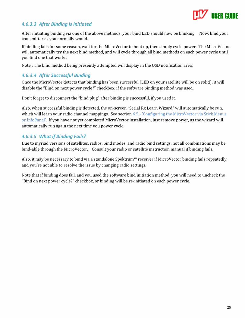
The ESC/Servo connector harness can be used to initiate binding. This would normally be done before soldering servos or ESCs to the harness. Connect the M6/Aux wire to the Ground wire, then cycle power. The bind LED on the satellite should now blink. The default bind method is DSM2 1024. Later, the stick menus can be used to select a different bind method, under the “Advanced Radio Control” menu, and a rebind can be initiated.
4.6.3.2 Software Bind Initiation
To start the bind process in software, go to the “RC Configuration” tab
in the software, select Spektrum™ Satellite receiver type, and check the
“Bind on next power cycle?” box. Additionally, the preferred bind
method can be selected here. Then, cycle power. The bind LED on the
satellite should now blink.
USER GUIDE
25
4.6.3.3 After Binding is Initiated
After initiating binding via one of the above methods, your bind LED should now be blinking. Now, bind your transmitter as you normally would.
If binding fails for some reason, wait for the MicroVector to boot up, then simply cycle power. The MicroVector will automatically try the next bind method, and will cycle through all bind methods on each power cycle until you find one that works.
Note : The bind method being presently attempted will display in the OSD notification area.
4.6.3.4 After Successful Binding
Once the MicroVector detects that binding has been successful (LED on your satellite will be on solid), it will
disable the “Bind on next power cycle?” checkbox, if the software binding method was used.
Don’t forget to disconnect the “bind plug” after binding is successful, if you used it.
Also, when successful binding is detected, the on-screen “Serial Rx Learn Wizard” will automatically be run,
which will learn your radio channel mappings. See section 6.5 - 'Configuring the MicroVector via Stick Menus
or InfoPanel’. If you have not yet completed MicroVector installation, just remove power, as the wizard will
automatically run again the next time you power cycle.
4.6.3.5 What if Binding Fails?
Due to myriad versions of satellites, radios, bind modes, and radio bind settings, not all combinations may be
bind-able through the MicroVector. Consult your radio or satellite instruction manual if binding fails.
Also, it may be necessary to bind via a standalone Spektrum™ receiver if MicroVector binding fails repeatedly,
and you’re not able to resolve the issue by changing radio settings.
Note that if binding does fail, and you used the software bind initiation method, you will need to uncheck the
“Bind on next power cycle?” checkbox, or binding will be re-initiated on each power cycle.
USER GUIDE
26
4.7 Connecting Servos/ESCs to the MicroVector
4.7.1 The ESC/Servo Connector The ESC/Servo connector provides signal outputs to your ESC(s), and/or servos. Do not power your servos
via this connector! Servos must be powered by direct connection to the +/- terminals of your BEC, PDB,
battery, or other appropriate power source!
Normally the signal lines of your ESCs or servos will be soldered directly to the ESC/Servo connector lines, after determining which connections go to which ESC or servo, and after cutting the lines to the correct lengths.
After soldering the connections, make sure you disconnect the ESC/Servo harness from the MicroVector before proceeding to the configuration section.
Never connect the ESC/Servo harness to the MicroVector until you have verified the MicroVector airframe type is correctly selected! If a fixed wing airframe type is selected with a multirotor, the
propellers can spin uncontrollably at high speed at power-up! Likewise, if a multrotor airframe type is selected with fixed wing, the servos can be pushed beyond their endpoints and be destroyed!
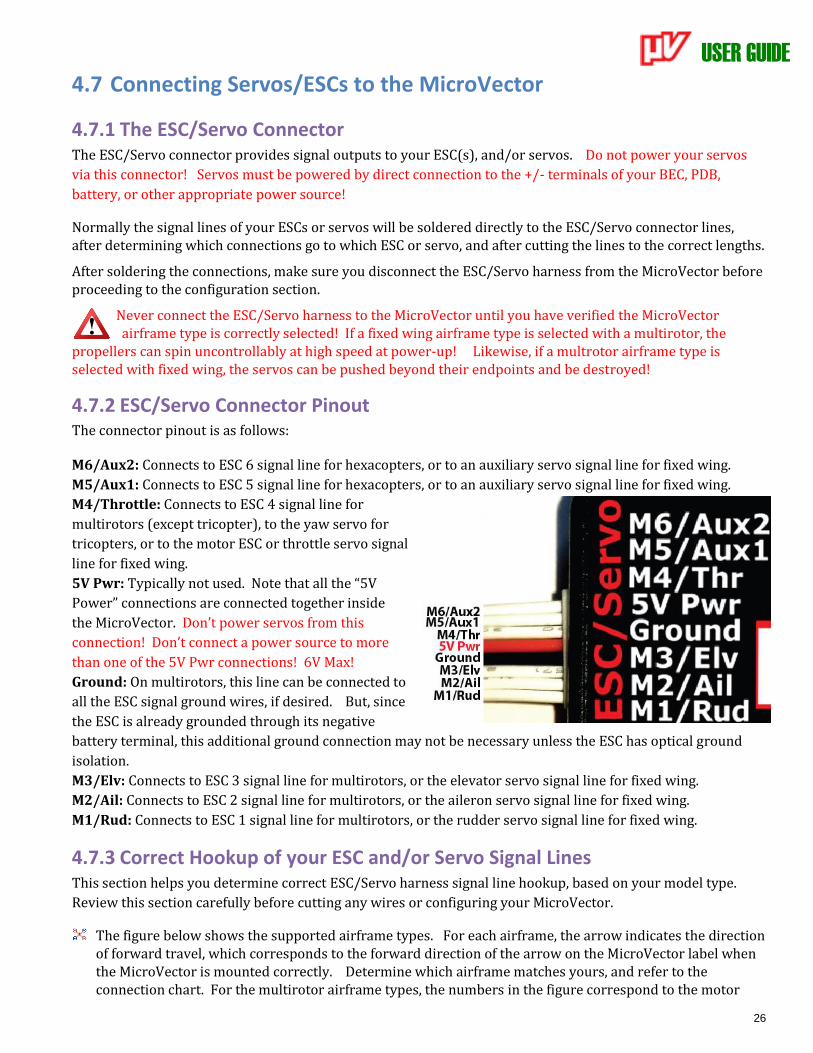
4.7.2 ESC/Servo Connector Pinout The connector pinout is as follows: M6/Aux2: Connects to ESC 6 signal line for hexacopters, or to an auxiliary servo signal line for fixed wing.
M5/Aux1: Connects to ESC 5 signal line for hexacopters, or to an auxiliary servo signal line for fixed wing.
M4/Throttle: Connects to ESC 4 signal line for
multirotors (except tricopter), to the yaw servo for
tricopters, or to the motor ESC or throttle servo signal
line for fixed wing.
5V Pwr: Typically not used. Note that all the “5V
Power” connections are connected together inside
the MicroVector. Don’t power servos from this
connection! Don’t connect a power source to more
than one of the 5V Pwr connections! 6V Max!
Ground: On multirotors, this line can be connected to
all the ESC signal ground wires, if desired. But, since
the ESC is already grounded through its negative
battery terminal, this additional ground connection may not be necessary unless the ESC has optical ground
isolation.
M3/Elv: Connects to ESC 3 signal line for multirotors, or the elevator servo signal line for fixed wing.
M2/Ail: Connects to ESC 2 signal line for multirotors, or the aileron servo signal line for fixed wing.
M1/Rud: Connects to ESC 1 signal line for multirotors, or the rudder servo signal line for fixed wing.
4.7.3 Correct Hookup of your ESC and/or Servo Signal Lines This section helps you determine correct ESC/Servo harness signal line hookup, based on your model type.
Review this section carefully before cutting any wires or configuring your MicroVector.
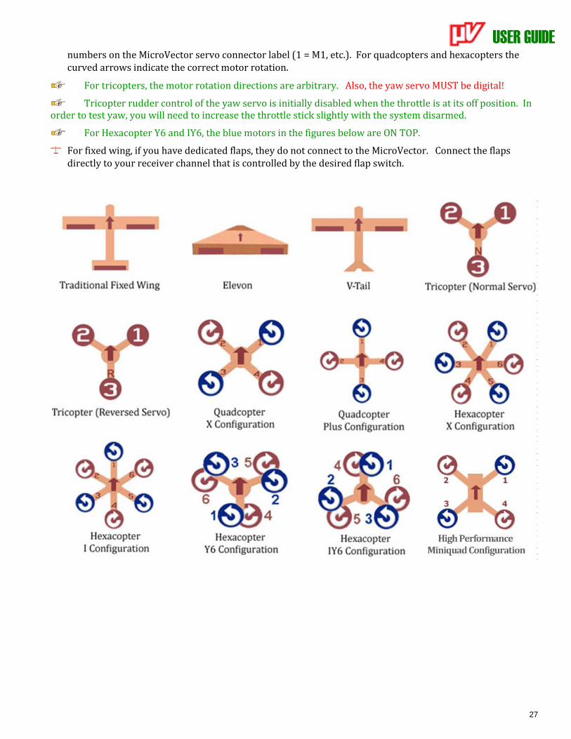
The figure below shows the supported airframe types. For each airframe, the arrow indicates the direction of forward travel, which corresponds to the forward direction of the arrow on the MicroVector label when the MicroVector is mounted correctly. Determine which airframe matches yours, and refer to the connection chart. For the multirotor airframe types, the numbers in the figure correspond to the motor
USER GUIDE
27
numbers on the MicroVector servo connector label (1 = M1, etc.). For quadcopters and hexacopters the curved arrows indicate the correct motor rotation.
For tricopters, the motor rotation directions are arbitrary. Also, the yaw servo MUST be digital!
Tricopter rudder control of the yaw servo is initially disabled when the throttle is at its off position. In order to test yaw, you will need to increase the throttle stick slightly with the system disarmed.
For Hexacopter Y6 and IY6, the blue motors in the figures below are ON TOP.
For fixed wing, if you have dedicated flaps, they do not connect to the MicroVector. Connect the flaps directly to your receiver channel that is controlled by the desired flap switch.
USER GUIDE
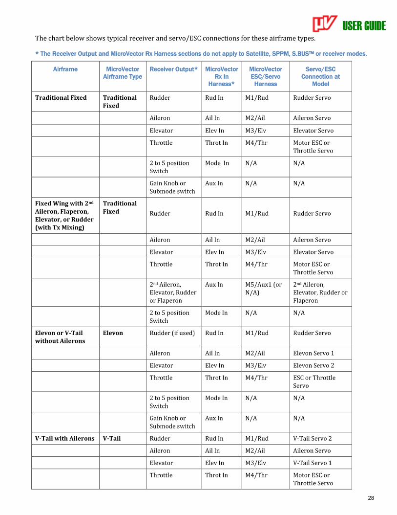
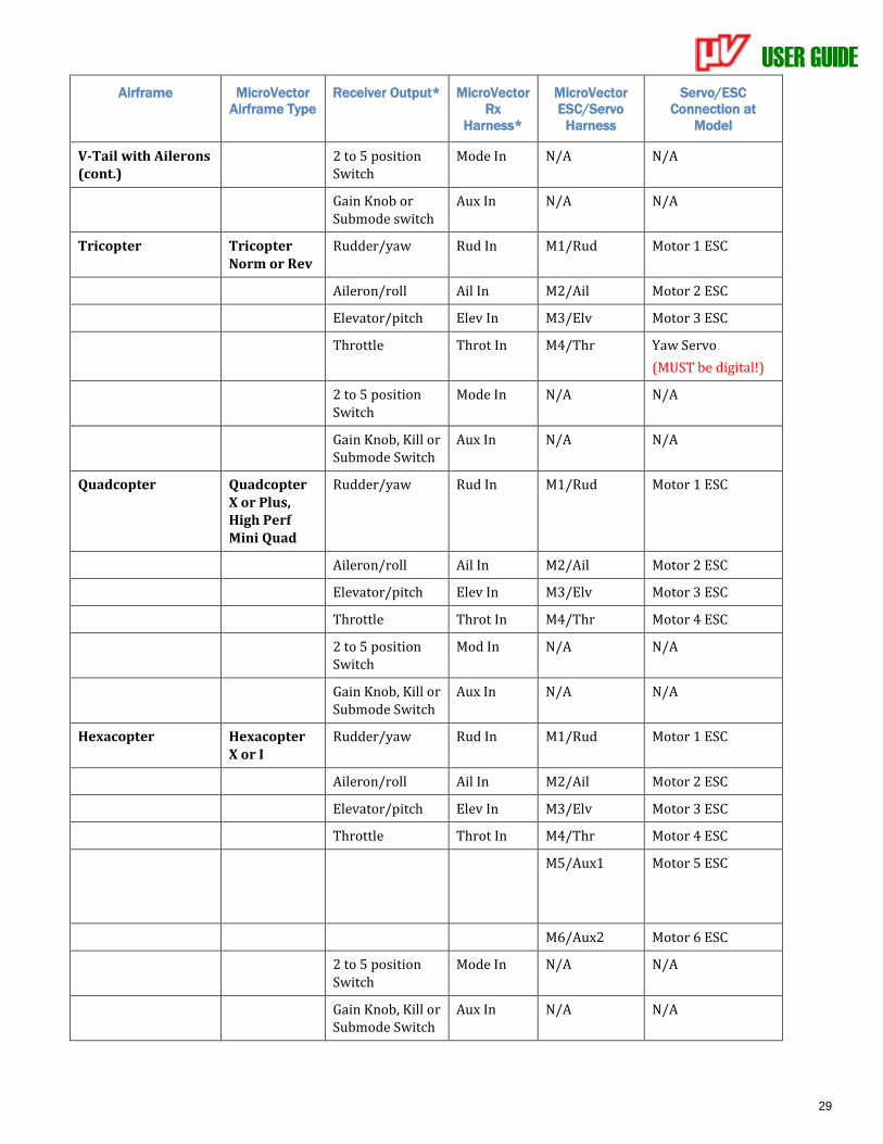
28
The chart below shows typical receiver and servo/ESC connections for these airframe types.
* The Receiver Output and MicroVector Rx Harness sections do not apply to Satellite, SPPM, S.BUS™ or receiver modes.
Airframe MicroVector
Airframe Type
Receiver Output* MicroVector
Rx In
Harness*
MicroVector
ESC/Servo
Harness
Servo/ESC
Connection at
Model
Traditional Fixed Traditional Fixed
Rudder Rud In M1/Rud Rudder Servo
Aileron Ail In M2/Ail Aileron Servo
Elevator Elev In M3/Elv Elevator Servo
Throttle Throt In M4/Thr Motor ESC or Throttle Servo
2 to 5 position Switch
Mode In N/A N/A
Gain Knob or Submode switch
Aux In N/A N/A
Fixed Wing with 2nd Aileron, Flaperon, Elevator, or Rudder (with Tx Mixing)
Traditional Fixed
Rudder
Rud In
M1/Rud
Rudder Servo
Aileron Ail In M2/Ail Aileron Servo
Elevator Elev In M3/Elv Elevator Servo
Throttle Throt In M4/Thr Motor ESC or Throttle Servo
2nd Aileron, Elevator, Rudder or Flaperon
Aux In M5/Aux1 (or N/A)
2nd Aileron, Elevator, Rudder or Flaperon
2 to 5 position Switch
Mode In N/A N/A
Elevon or V-Tail without Ailerons
Elevon Rudder (if used) Rud In M1/Rud Rudder Servo
Aileron Ail In M2/Ail Elevon Servo 1
Elevator Elev In M3/Elv Elevon Servo 2
Throttle Throt In M4/Thr ESC or Throttle Servo
2 to 5 position Switch
Mode In N/A N/A
Gain Knob or Submode switch
Aux In N/A N/A
V-Tail with Ailerons V-Tail Rudder Rud In M1/Rud V-Tail Servo 2
Aileron Ail In M2/Ail Aileron Servo
Elevator Elev In M3/Elv V-Tail Servo 1
Throttle Throt In M4/Thr Motor ESC or Throttle Servo
USER GUIDE
29
Airframe MicroVector
Airframe Type
Receiver Output* MicroVector
Rx
Harness*
MicroVector
ESC/Servo
Harness
Servo/ESC
Connection at
Model
V-Tail with Ailerons (cont.)
2 to 5 position Switch
Mode In N/A N/A
Gain Knob or Submode switch
Aux In N/A N/A
Tricopter Tricopter Norm or Rev
Rudder/yaw Rud In M1/Rud Motor 1 ESC
Aileron/roll Ail In M2/Ail Motor 2 ESC
Elevator/pitch Elev In M3/Elv Motor 3 ESC
Throttle Throt In M4/Thr Yaw Servo
(MUST be digital!)
2 to 5 position Switch
Mode In N/A N/A
Gain Knob, Kill or Submode Switch
Aux In N/A N/A
Quadcopter Quadcopter X or Plus, High Perf Mini Quad
Rudder/yaw Rud In M1/Rud Motor 1 ESC
Aileron/roll Ail In M2/Ail Motor 2 ESC
Elevator/pitch Elev In M3/Elv Motor 3 ESC
Throttle Throt In M4/Thr Motor 4 ESC
2 to 5 position Switch
Mod In N/A N/A
Gain Knob, Kill or Submode Switch
Aux In N/A N/A
Hexacopter Hexacopter X or I
Rudder/yaw Rud In M1/Rud Motor 1 ESC
Aileron/roll Ail In M2/Ail Motor 2 ESC
Elevator/pitch Elev In M3/Elv Motor 3 ESC
Throttle Throt In M4/Thr Motor 4 ESC
M5/Aux1 Motor 5 ESC
M6/Aux2 Motor 6 ESC
2 to 5 position Switch
Mode In N/A N/A
Gain Knob, Kill or Submode Switch
Aux In N/A N/A
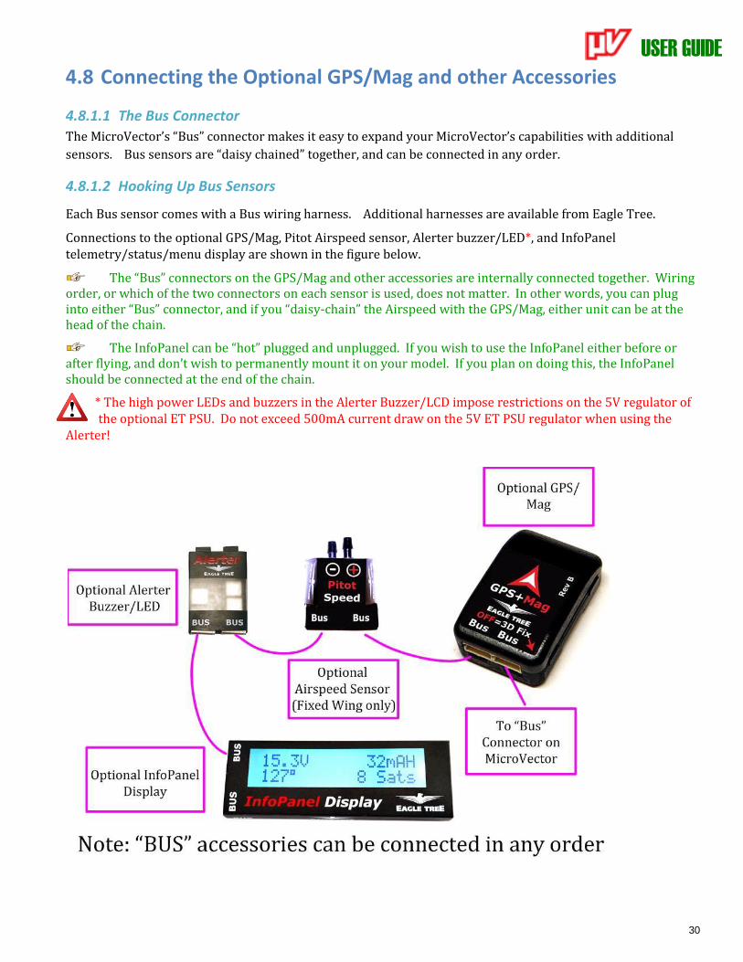
USER GUIDE
30
4.8 Connecting the Optional GPS/Mag and other Accessories
4.8.1.1 The Bus Connector
The MicroVector’s “Bus” connector makes it easy to expand your MicroVector’s capabilities with additional
sensors. Bus sensors are “daisy chained” together, and can be connected in any order.
4.8.1.2 Hooking Up Bus Sensors
Each Bus sensor comes with a Bus wiring harness. Additional harnesses are available from Eagle Tree.
Connections to the optional GPS/Mag, Pitot Airspeed sensor, Alerter buzzer/LED*, and InfoPanel telemetry/status/menu display are shown in the figure below.
The “Bus” connectors on the GPS/Mag and other accessories are internally connected together. Wiring order, or which of the two connectors on each sensor is used, does not matter. In other words, you can plug into either “Bus” connector, and if you “daisy-chain” the Airspeed with the GPS/Mag, either unit can be at the head of the chain.
The InfoPanel can be “hot” plugged and unplugged. If you wish to use the InfoPanel either before or after flying, and don’t wish to permanently mount it on your model. If you plan on doing this, the InfoPanel should be connected at the end of the chain.
* The high power LEDs and buzzers in the Alerter Buzzer/LCD impose restrictions on the 5V regulator of the optional ET PSU. Do not exceed 500mA current draw on the 5V ET PSU regulator when using the
Alerter!
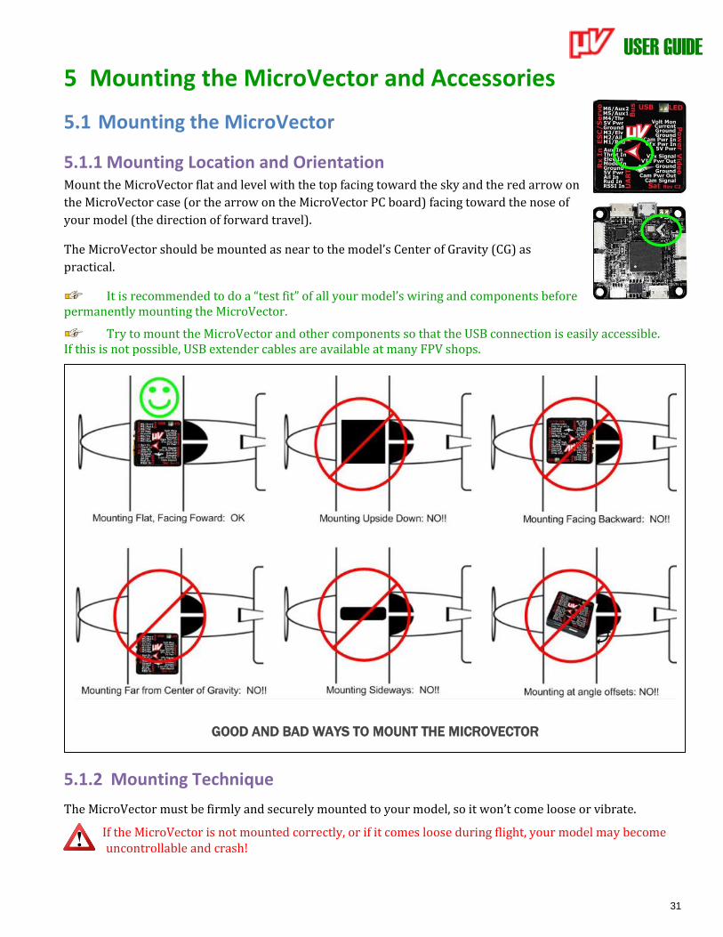
USER GUIDE
31
5 Mounting the MicroVector and Accessories
5.1 Mounting the MicroVector
5.1.1 Mounting Location and Orientation Mount the MicroVector flat and level with the top facing toward the sky and the red arrow on
the MicroVector case (or the arrow on the MicroVector PC board) facing toward the nose of
your model (the direction of forward travel).
The MicroVector should be mounted as near to the model’s Center of Gravity (CG) as
practical.
It is recommended to do a “test fit” of all your model’s wiring and components before permanently mounting the MicroVector.
Try to mount the MicroVector and other components so that the USB connection is easily accessible. If this is not possible, USB extender cables are available at many FPV shops.
5.1.2 Mounting Technique
The MicroVector must be firmly and securely mounted to your model, so it won’t come loose or vibrate.
If the MicroVector is not mounted correctly, or if it comes loose during flight, your model may become uncontrollable and crash!
GOOD AND BAD WAYS TO MOUNT THE MICROVECTOR
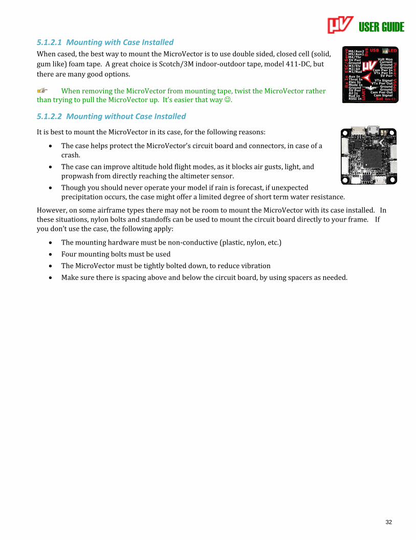
USER GUIDE
32
5.1.2.1 Mounting with Case Installed
When cased, the best way to mount the MicroVector is to use double sided, closed cell (solid,
gum like) foam tape. A great choice is Scotch/3M indoor-outdoor tape, model 411-DC, but
there are many good options.
When removing the MicroVector from mounting tape, twist the MicroVector rather than trying to pull the MicroVector up. It’s easier that way ☺.
5.1.2.2 Mounting without Case Installed
It is best to mount the MicroVector in its case, for the following reasons:
• The case helps protect the MicroVector’s circuit board and connectors, in case of a crash.
• The case can improve altitude hold flight modes, as it blocks air gusts, light, and propwash from directly reaching the altimeter sensor.
• Though you should never operate your model if rain is forecast, if unexpected precipitation occurs, the case might offer a limited degree of short term water resistance.
However, on some airframe types there may not be room to mount the MicroVector with its case installed. In these situations, nylon bolts and standoffs can be used to mount the circuit board directly to your frame. If you don’t use the case, the following apply:
• The mounting hardware must be non-conductive (plastic, nylon, etc.)
• Four mounting bolts must be used
• The MicroVector must be tightly bolted down, to reduce vibration
• Make sure there is spacing above and below the circuit board, by using spacers as needed.
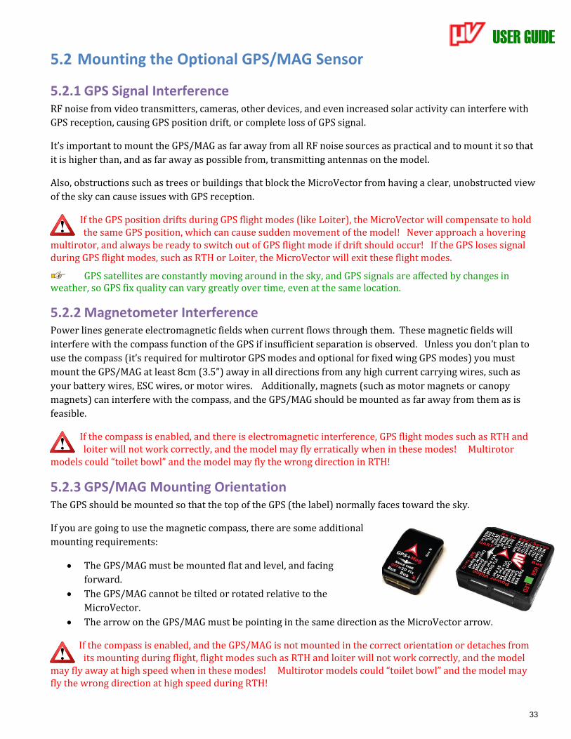
USER GUIDE
33
5.2 Mounting the Optional GPS/MAG Sensor
5.2.1 GPS Signal Interference RF noise from video transmitters, cameras, other devices, and even increased solar activity can interfere with
GPS reception, causing GPS position drift, or complete loss of GPS signal.
It’s important to mount the GPS/MAG as far away from all RF noise sources as practical and to mount it so that
it is higher than, and as far away as possible from, transmitting antennas on the model.
Also, obstructions such as trees or buildings that block the MicroVector from having a clear, unobstructed view
of the sky can cause issues with GPS reception.
If the GPS position drifts during GPS flight modes (like Loiter), the MicroVector will compensate to hold the same GPS position, which can cause sudden movement of the model! Never approach a hovering
multirotor, and always be ready to switch out of GPS flight mode if drift should occur! If the GPS loses signal during GPS flight modes, such as RTH or Loiter, the MicroVector will exit these flight modes.
GPS satellites are constantly moving around in the sky, and GPS signals are affected by changes in weather, so GPS fix quality can vary greatly over time, even at the same location.
5.2.2 Magnetometer Interference Power lines generate electromagnetic fields when current flows through them. These magnetic fields will
interfere with the compass function of the GPS if insufficient separation is observed. Unless you don’t plan to
use the compass (it’s required for multirotor GPS modes and optional for fixed wing GPS modes) you must
mount the GPS/MAG at least 8cm (3.5”) away in all directions from any high current carrying wires, such as
your battery wires, ESC wires, or motor wires. Additionally, magnets (such as motor magnets or canopy
magnets) can interfere with the compass, and the GPS/MAG should be mounted as far away from them as is
feasible.
If the compass is enabled, and there is electromagnetic interference, GPS flight modes such as RTH and loiter will not work correctly, and the model may fly erratically when in these modes! Multirotor
models could “toilet bowl” and the model may fly the wrong direction in RTH!
5.2.3 GPS/MAG Mounting Orientation The GPS should be mounted so that the top of the GPS (the label) normally faces toward the sky.
If you are going to use the magnetic compass, there are some additional
mounting requirements:
• The GPS/MAG must be mounted flat and level, and facing
forward.
• The GPS/MAG cannot be tilted or rotated relative to the
MicroVector.
• The arrow on the GPS/MAG must be pointing in the same direction as the MicroVector arrow.
If the compass is enabled, and the GPS/MAG is not mounted in the correct orientation or detaches from its mounting during flight, flight modes such as RTH and loiter will not work correctly, and the model
may fly away at high speed when in these modes! Multirotor models could “toilet bowl” and the model may fly the wrong direction at high speed during RTH!
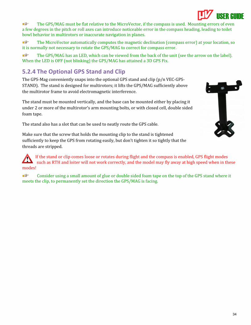
USER GUIDE
34
The GPS/MAG must be flat relative to the MicroVector, if the compass is used. Mounting errors of even a few degrees in the pitch or roll axes can introduce noticeable error in the compass heading, leading to toilet bowl behavior in multirotors or inaccurate navigation in planes.
The MicroVector automatically computes the magnetic declination (compass error) at your location, so it is normally not necessary to rotate the GPS/MAG to correct for compass error.
The GPS/MAG has an LED, which can be viewed from the back of the unit (see the arrow on the label). When the LED is OFF (not blinking) the GPS/MAG has attained a 3D GPS Fix.
5.2.4 The Optional GPS Stand and Clip The GPS-Mag conveniently snaps into the optional GPS stand and clip (p/n VEC-GPS-
STAND). The stand is designed for multirotors; it lifts the GPS/MAG sufficiently above
the multirotor frame to avoid electromagnetic interference.
The stand must be mounted vertically, and the base can be mounted either by placing it
under 2 or more of the multirotor’s arm mounting bolts, or with closed cell, double sided
foam tape.
The stand also has a slot that can be used to neatly route the GPS cable.
Make sure that the screw that holds the mounting clip to the stand is tightened
sufficiently to keep the GPS from rotating easily, but don’t tighten it so tightly that the
threads are stripped.
If the stand or clip comes loose or rotates during flight and the compass is enabled, GPS flight modes such as RTH and loiter will not work correctly, and the model may fly away at high speed when in these
modes!
Consider using a small amount of glue or double sided foam tape on the top of the GPS stand where it meets the clip, to permanently set the direction the GPS/MAG is facing.
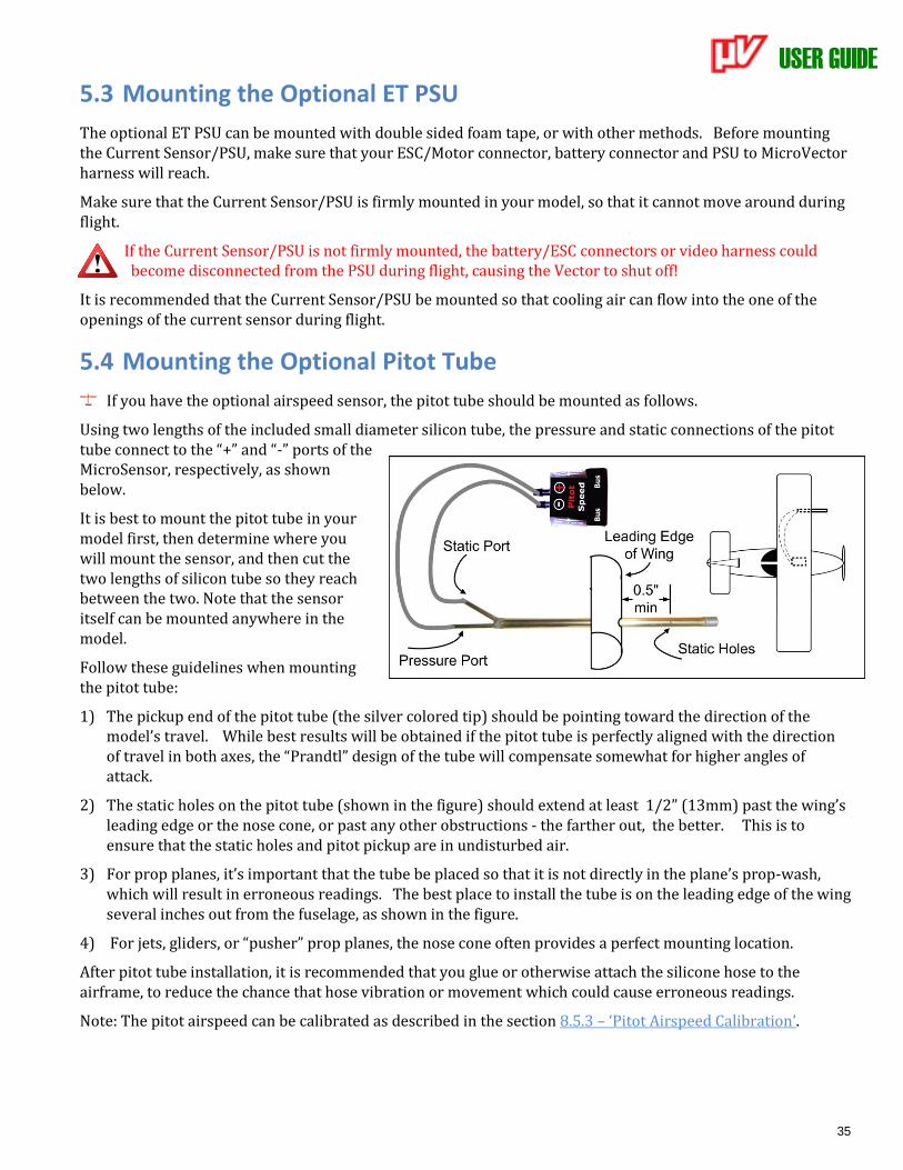
USER GUIDE
35
5.3 Mounting the Optional ET PSU
The optional ET PSU can be mounted with double sided foam tape, or with other methods. Before mounting the Current Sensor/PSU, make sure that your ESC/Motor connector, battery connector and PSU to MicroVector harness will reach.
Make sure that the Current Sensor/PSU is firmly mounted in your model, so that it cannot move around during flight.
If the Current Sensor/PSU is not firmly mounted, the battery/ESC connectors or video harness could become disconnected from the PSU during flight, causing the Vector to shut off!
It is recommended that the Current Sensor/PSU be mounted so that cooling air can flow into the one of the openings of the current sensor during flight.
5.4 Mounting the Optional Pitot Tube
If you have the optional airspeed sensor, the pitot tube should be mounted as follows.
Using two lengths of the included small diameter silicon tube, the pressure and static connections of the pitot tube connect to the “+” and “-” ports of the MicroSensor, respectively, as shown below.
It is best to mount the pitot tube in your model first, then determine where you will mount the sensor, and then cut the two lengths of silicon tube so they reach between the two. Note that the sensor itself can be mounted anywhere in the model.
Follow these guidelines when mounting the pitot tube:
1) The pickup end of the pitot tube (the silver colored tip) should be pointing toward the direction of the model’s travel. While best results will be obtained if the pitot tube is perfectly aligned with the direction of travel in both axes, the “Prandtl” design of the tube will compensate somewhat for higher angles of attack.
2) The static holes on the pitot tube (shown in the figure) should extend at least 1/2” (13mm) past the wing’s leading edge or the nose cone, or past any other obstructions - the farther out, the better. This is to ensure that the static holes and pitot pickup are in undisturbed air.
3) For prop planes, it’s important that the tube be placed so that it is not directly in the plane’s prop-wash, which will result in erroneous readings. The best place to install the tube is on the leading edge of the wing several inches out from the fuselage, as shown in the figure.
4) For jets, gliders, or “pusher” prop planes, the nose cone often provides a perfect mounting location.
After pitot tube installation, it is recommended that you glue or otherwise attach the silicone hose to the airframe, to reduce the chance that hose vibration or movement which could cause erroneous readings.
Note: The pitot airspeed can be calibrated as described in the section 8.5.3 – ‘Pitot Airspeed Calibration’.
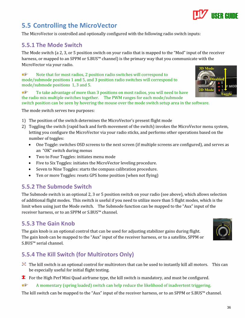
USER GUIDE
36
5.5 Controlling the MicroVector The MicroVector is controlled and optionally configured with the following radio switch inputs:
5.5.1 The Mode Switch The Mode switch (a 2, 3, or 5 position switch on your radio that is mapped to the “Mod” input of the receiver
harness, or mapped to an SPPM or S.BUS™ channel) is the primary way that you communicate with the
MicroVector via your radio.
Note that for most radios, 2 position radio switches will correspond to mode/submode positions 1 and 5, and 3 position radio switches will correspond to mode/submode positions 1, 3 and 5.
To take advantage of more than 3 positions on most radios, you will need to have the radio mix multiple switches together. The PWM ranges for each mode/submode switch position can be seen by hovering the mouse over the mode switch setup area in the software.
The mode switch serves two purposes:
1) The position of the switch determines the MicroVector’s present flight mode
2) Toggling the switch (rapid back and forth movement of the switch) invokes the MicroVector menu system,
letting you configure the MicroVector via your radio sticks, and performs other operations based on the
number of toggles:
• One Toggle: switches OSD screens to the next screen (if multiple screens are configured), and serves as
an “OK” switch during menus
• Two to Four Toggles: initiates menu mode
• Five to Six Toggles: initiates the MicroVector leveling procedure.
• Seven to Nine Toggles: starts the compass calibration procedure.
• Ten or more Toggles: resets GPS home position (when not flying)
5.5.2 The Submode Switch The Submode switch is an optional 2, 3 or 5 position switch on your radio (see above), which allows selection
of additional flight modes. This switch is useful if you need to utilize more than 5 flight modes, which is the
limit when using just the Mode switch. The Submode function can be mapped to the “Aux” input of the
receiver harness, or to an SPPM or S.BUS™ channel.
5.5.3 The Gain Knob The gain knob is an optional control that can be used for adjusting stabilizer gains during flight.
The gain knob can be mapped to the “Aux” input of the receiver harness, or to a satellite, SPPM or
S.BUS™ serial channel.
5.5.4 The Kill Switch (for Multirotors Only)
The kill switch is an optional control for multirotors that can be used to instantly kill all motors. This can be especially useful for initial flight testing.
For the High Perf Mini Quad airframe type, the kill switch is mandatory, and must be configured.
A momentary (spring loaded) switch can help reduce the likelihood of inadvertent triggering.
The kill switch can be mapped to the “Aux” input of the receiver harness, or to an SPPM or S.BUS™ channel.

USER GUIDE
37
Note that the multirotor will rearm instantly when the kill switch is disengaged, until about 3 seconds after it’s engaged (in case the kill was accidental). Once 3 seconds have elapsed with the Kill Switch set,
the multirotor is permanently disarmed until you rearm it.
During RTH (including RTH test modes) the Gain Knob and Kill Switch inputs are disabled, to prevent inadvertant changes in these inputs due to loss of reliable Rx signal.
Make sure that your radio does not trigger the kill switch during failsafe! If it does, the multirotor will shut off, and not rearm until RTH engages (if at all)!
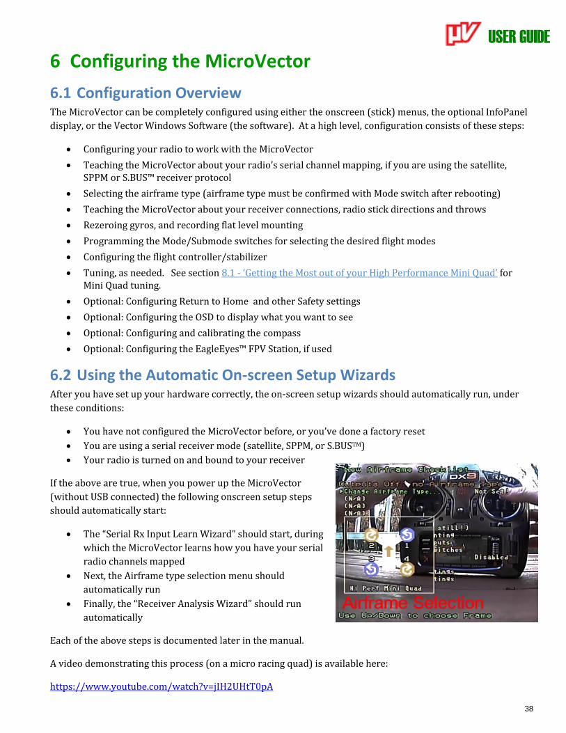
USER GUIDE
38
6 Configuring the MicroVector
6.1 Configuration Overview The MicroVector can be completely configured using either the onscreen (stick) menus, the optional InfoPanel
display, or the Vector Windows Software (the software). At a high level, configuration consists of these steps:
• Configuring your radio to work with the MicroVector
• Teaching the MicroVector about your radio’s serial channel mapping, if you are using the satellite, SPPM or S.BUS™ receiver protocol
• Selecting the airframe type (airframe type must be confirmed with Mode switch after rebooting)
• Teaching the MicroVector about your receiver connections, radio stick directions and throws
• Rezeroing gyros, and recording flat level mounting
• Programming the Mode/Submode switches for selecting the desired flight modes
• Configuring the flight controller/stabilizer
• Tuning, as needed. See section 8.1 - ‘Getting the Most out of your High Performance Mini Quad’ for Mini Quad tuning.
• Optional: Configuring Return to Home and other Safety settings
• Optional: Configuring the OSD to display what you want to see
• Optional: Configuring and calibrating the compass
• Optional: Configuring the EagleEyes™ FPV Station, if used
6.2 Using the Automatic On-screen Setup Wizards After you have set up your hardware correctly, the on-screen setup wizards should automatically run, under
these conditions:
• You have not configured the MicroVector before, or you’ve done a factory reset
• You are using a serial receiver mode (satellite, SPPM, or S.BUSTM)
• Your radio is turned on and bound to your receiver
If the above are true, when you power up the MicroVector
(without USB connected) the following onscreen setup steps
should automatically start:
• The “Serial Rx Input Learn Wizard” should start, during
which the MicroVector learns how you have your serial
radio channels mapped
• Next, the Airframe type selection menu should
automatically run
• Finally, the “Receiver Analysis Wizard” should run
automatically
Each of the above steps is documented later in the manual.
A video demonstrating this process (on a micro racing quad) is available here:
https://www.youtube.com/watch?v=jIH2UHtT0pA
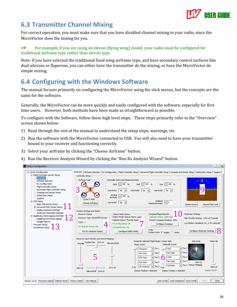
USER GUIDE
39
6.3 Transmitter Channel Mixing For correct operation, you must make sure that you have disabled channel mixing in your radio, since the
MicroVector does the mixing for you.
For example, if you are using an elevon (flying wing) model, your radio must be configured for traditional airframe type rather than elevon type.
Note: If you have selected the traditional fixed wing airframe type, and have secondary control surfaces like dual ailerons or flaperons, you can either have the transmitter do the mixing, or have the MicroVector do simple mixing.
6.4 Configuring with the Windows Software The manual focuses primarily on configuring the MicroVector using the stick menus, but the concepts are the
same for the software.
Generally, the MicroVector can be more quickly and easily configured with the software, especially for first time users. However, both methods have been made as straightforward as possible.
To configure with the Software, follow these high level steps. These steps primarily refer to the “Overview” screen shown below:
1) Read through the rest of the manual to understand the setup steps, warnings, etc.
2) Run the software with the MicroVector connected to USB. You will also need to have your transmitter bound to your receiver and functioning correctly.
3) Select your airframe by clicking the “Choose Airframe” button.
4) Run the Receiver Analysis Wizard by clicking the “Run Rx Analysis Wizard” button.

USER GUIDE
40
5) Make sure that the graphical indicators in the “Receiver Input Monitor and Switch Mapping” section move
correctly as you move your radio sticks, switches, and/or knobs. The sliders representing the control
surfaces should move proportionally with your control stick, and in the same direction. If they don’t,
something is wrong – DON’T FLY until the issue is resolved!
6) Program the desired functions of your mode/submode switches using the dropdown menu items in the
input monitor section. After completing this step, hit “Apply”, then make sure that as you move your
switches, the “Presently Selected Flight Mode” displays the correct mode for the switch positions.
7) Assuming you will be using Safety Mode/RTH features, verify that receiver failsafe detection is working
correctly by turning off your radio, and making sure that “In Failsafe Now: Yes!” appears. Configure Safety
Mode options by clicking the “Configure Safety Mode” button.
8) Configure the controller gains, multirotor settings (if applicable) and other controller settings on the Flight
Controller Settings tab, by clicking on that tab, or clicking the “Configure Multirotor Settings” button.
9) A) With the model completely still, rezero the gyros by clicking “Rezero Gyros.”
B) With the MicroVector and the model perfectly level, record flat level mounting by clicking the “Record
Flat Level” button. Now, the artificial horizon (AHI) display should show level, and should closely follow
your movements as you pitch and roll the model. If the AHI is moving sluggishly and not keeping up with
your movements, or is rotating on its own, DON’T FLY and contact support.
10) Configure sensors and the compass by clicking the “Configure Compass” button. Note that, if used, the
compass must be calibrated at the field, via the described methods.
11) Configure the OSD display by selecting the OSD Setup item in the “tree view” on the left side of the software.
12) Configure data logging and the EagleEyes (if desired) from the “EagleEyes, Data Logging and Flight Map”
tree.
13) If desired, configure waypoints from the Waypoints Setup tab.
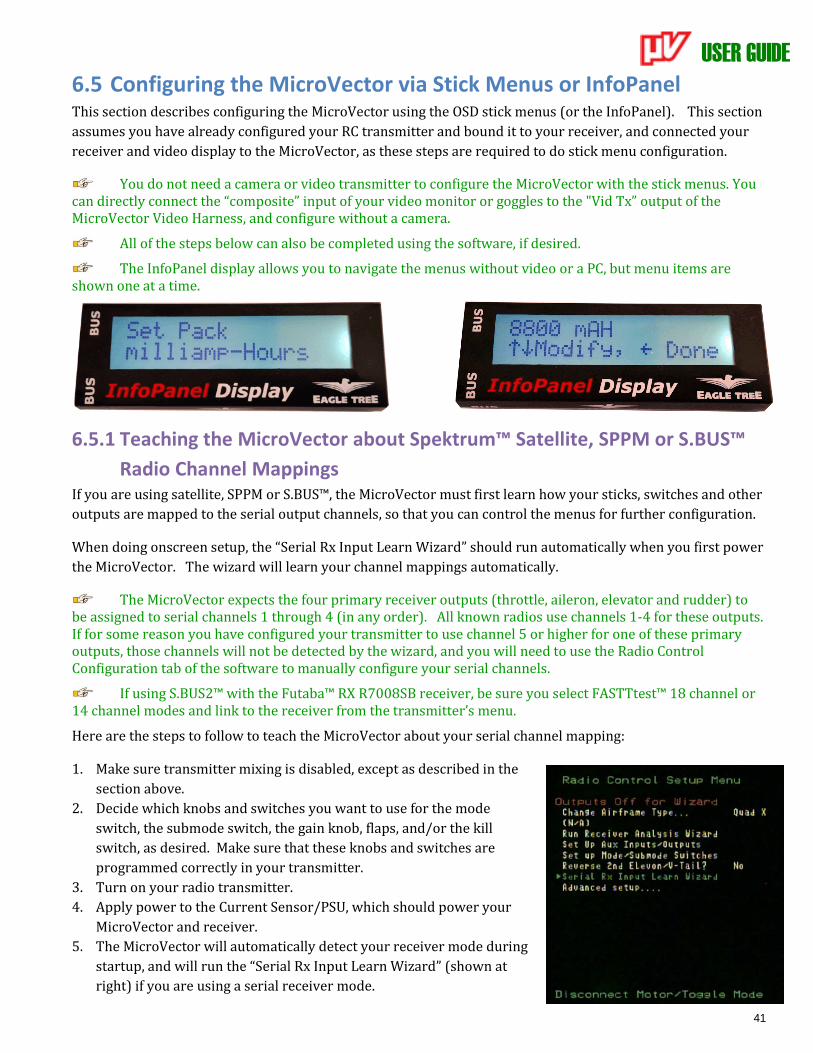
USER GUIDE
41
6.5 Configuring the MicroVector via Stick Menus or InfoPanel This section describes configuring the MicroVector using the OSD stick menus (or the InfoPanel). This section
assumes you have already configured your RC transmitter and bound it to your receiver, and connected your
receiver and video display to the MicroVector, as these steps are required to do stick menu configuration.
You do not need a camera or video transmitter to configure the MicroVector with the stick menus. You can directly connect the “composite” input of your video monitor or goggles to the "Vid Tx” output of the MicroVector Video Harness, and configure without a camera.
All of the steps below can also be completed using the software, if desired.
The InfoPanel display allows you to navigate the menus without video or a PC, but menu items are shown one at a time.
6.5.1 Teaching the MicroVector about Spektrum™ Satellite, SPPM or S.BUS™
Radio Channel Mappings If you are using satellite, SPPM or S.BUS™, the MicroVector must first learn how your sticks, switches and other
outputs are mapped to the serial output channels, so that you can control the menus for further configuration.
When doing onscreen setup, the “Serial Rx Input Learn Wizard” should run automatically when you first power
the MicroVector. The wizard will learn your channel mappings automatically.
The MicroVector expects the four primary receiver outputs (throttle, aileron, elevator and rudder) to be assigned to serial channels 1 through 4 (in any order). All known radios use channels 1-4 for these outputs. If for some reason you have configured your transmitter to use channel 5 or higher for one of these primary outputs, those channels will not be detected by the wizard, and you will need to use the Radio Control Configuration tab of the software to manually configure your serial channels.
If using S.BUS2™ with the Futaba™ RX R7008SB receiver, be sure you select FASTTtest™ 18 channel or 14 channel modes and link to the receiver from the transmitter’s menu.
Here are the steps to follow to teach the MicroVector about your serial channel mapping:
1. Make sure transmitter mixing is disabled, except as described in the
section above.
2. Decide which knobs and switches you want to use for the mode
switch, the submode switch, the gain knob, flaps, and/or the kill
switch, as desired. Make sure that these knobs and switches are
programmed correctly in your transmitter.
3. Turn on your radio transmitter.
4. Apply power to the Current Sensor/PSU, which should power your
MicroVector and receiver.
5. The MicroVector will automatically detect your receiver mode during
startup, and will run the “Serial Rx Input Learn Wizard” (shown at
right) if you are using a serial receiver mode.
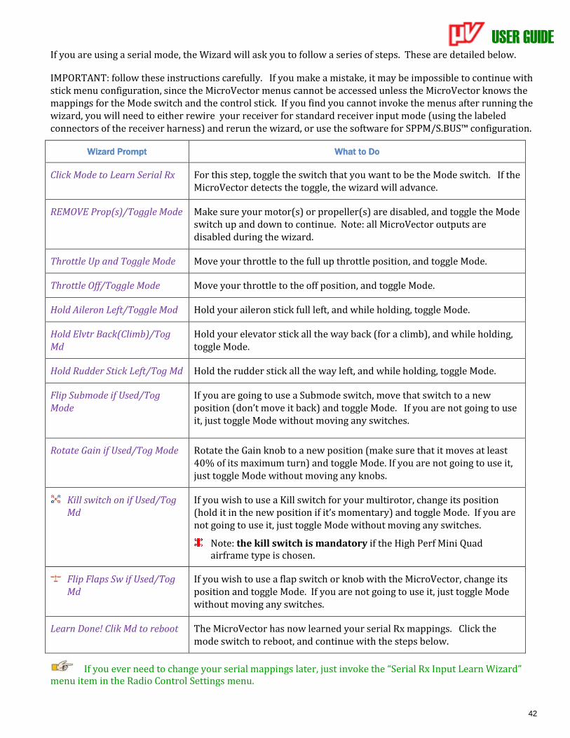
USER GUIDE
42
If you are using a serial mode, the Wizard will ask you to follow a series of steps. These are detailed below.
IMPORTANT: follow these instructions carefully. If you make a mistake, it may be impossible to continue with stick menu configuration, since the MicroVector menus cannot be accessed unless the MicroVector knows the mappings for the Mode switch and the control stick. If you find you cannot invoke the menus after running the wizard, you will need to either rewire your receiver for standard receiver input mode (using the labeled connectors of the receiver harness) and rerun the wizard, or use the software for SPPM/S.BUS™ configuration.
Wizard Prompt What to Do
Click Mode to Learn Serial Rx For this step, toggle the switch that you want to be the Mode switch. If the MicroVector detects the toggle, the wizard will advance.
REMOVE Prop(s)/Toggle Mode Make sure your motor(s) or propeller(s) are disabled, and toggle the Mode switch up and down to continue. Note: all MicroVector outputs are disabled during the wizard.
Throttle Up and Toggle Mode Move your throttle to the full up throttle position, and toggle Mode.
Throttle Off/Toggle Mode Move your throttle to the off position, and toggle Mode.
Hold Aileron Left/Toggle Mod Hold your aileron stick full left, and while holding, toggle Mode.
Hold Elvtr Back(Climb)/Tog Md
Hold your elevator stick all the way back (for a climb), and while holding, toggle Mode.
Hold Rudder Stick Left/Tog Md Hold the rudder stick all the way left, and while holding, toggle Mode.
Flip Submode if Used/Tog Mode
If you are going to use a Submode switch, move that switch to a new position (don’t move it back) and toggle Mode. If you are not going to use it, just toggle Mode without moving any switches.
Rotate Gain if Used/Tog Mode
Rotate the Gain knob to a new position (make sure that it moves at least 40% of its maximum turn) and toggle Mode. If you are not going to use it, just toggle Mode without moving any knobs.
Kill switch on if Used/Tog Md
If you wish to use a Kill switch for your multirotor, change its position (hold it in the new position if it’s momentary) and toggle Mode. If you are not going to use it, just toggle Mode without moving any switches.
Note: the kill switch is mandatory if the High Perf Mini Quad airframe type is chosen.
Flip Flaps Sw if Used/Tog Md
If you wish to use a flap switch or knob with the MicroVector, change its position and toggle Mode. If you are not going to use it, just toggle Mode without moving any switches.
Learn Done! Clik Md to reboot The MicroVector has now learned your serial Rx mappings. Click the mode switch to reboot, and continue with the steps below.
If you ever need to change your serial mappings later, just invoke the “Serial Rx Input Learn Wizard” menu item in the Radio Control Settings menu.
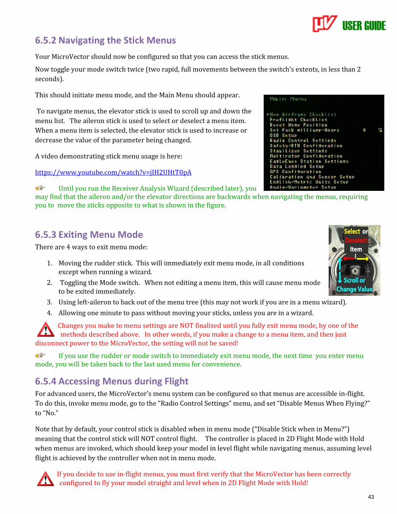
USER GUIDE
43
6.5.2 Navigating the Stick Menus
Your MicroVector should now be configured so that you can access the stick menus.
Now toggle your mode switch twice (two rapid, full movements between the switch’s extents, in less than 2
seconds).
This should initiate menu mode, and the Main Menu should appear.
To navigate menus, the elevator stick is used to scroll up and down the
menu list. The aileron stick is used to select or deselect a menu item.
When a menu item is selected, the elevator stick is used to increase or
decrease the value of the parameter being changed.
A video demonstrating stick menu usage is here:
https://www.youtube.com/watch?v=jIH2UHtT0pA
Until you run the Receiver Analysis Wizard (described later), you may find that the aileron and/or the elevator directions are backwards when navigating the menus, requiring you to move the sticks opposite to what is shown in the figure.
6.5.3 Exiting Menu Mode There are 4 ways to exit menu mode:
1. Moving the rudder stick. This will immediately exit menu mode, in all conditions except when running a wizard.
2. Toggling the Mode switch. When not editing a menu item, this will cause menu mode to be exited immediately.
3. Using left-aileron to back out of the menu tree (this may not work if you are in a menu wizard).
4. Allowing one minute to pass without moving your sticks, unless you are in a wizard.
Changes you make to menu settings are NOT finalized until you fully exit menu mode, by one of the methods described above. In other words, if you make a change to a menu item, and then just
disconnect power to the MicroVector, the setting will not be saved!
If you use the rudder or mode switch to immediately exit menu mode, the next time you enter menu mode, you will be taken back to the last used menu for convenience.
6.5.4 Accessing Menus during Flight For advanced users, the MicroVector’s menu system can be configured so that menus are accessible in-flight.
To do this, invoke menu mode, go to the “Radio Control Settings” menu, and set “Disable Menus When Flying?”
to “No.”
Note that by default, your control stick is disabled when in menu mode (“Disable Stick when in Menu?”)
meaning that the control stick will NOT control flight. The controller is placed in 2D Flight Mode with Hold
when menus are invoked, which should keep your model in level flight while navigating menus, assuming level
flight is achieved by the controller when not in menu mode.
If you decide to use in-flight menus, you must first verify that the MicroVector has been correctly configured to fly your model straight and level when in 2D Flight Mode with Hold!
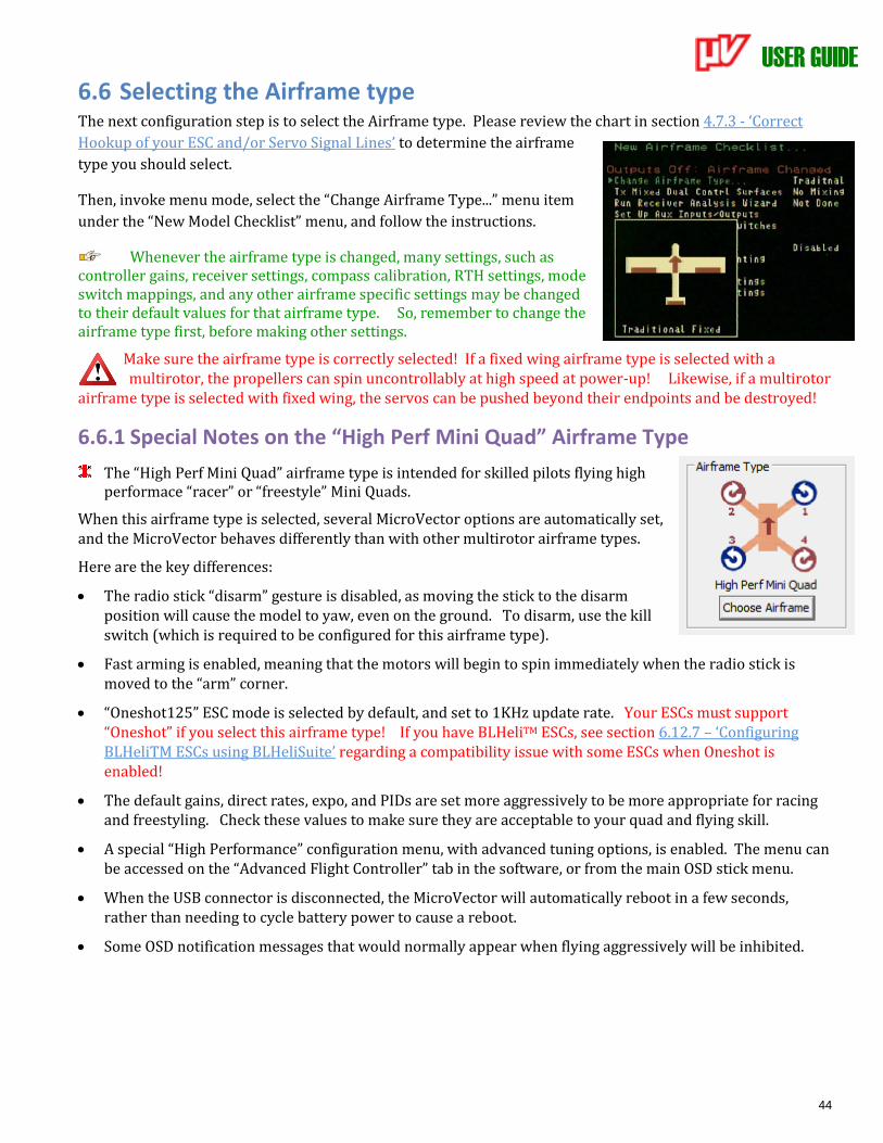
USER GUIDE
44
6.6 Selecting the Airframe type The next configuration step is to select the Airframe type. Please review the chart in section 4.7.3 - ‘Correct
Hookup of your ESC and/or Servo Signal Lines’ to determine the airframe
type you should select.
Then, invoke menu mode, select the “Change Airframe Type...” menu item
under the “New Model Checklist” menu, and follow the instructions.
Whenever the airframe type is changed, many settings, such as controller gains, receiver settings, compass calibration, RTH settings, mode switch mappings, and any other airframe specific settings may be changed to their default values for that airframe type. So, remember to change the airframe type first, before making other settings.
Make sure the airframe type is correctly selected! If a fixed wing airframe type is selected with a multirotor, the propellers can spin uncontrollably at high speed at power-up! Likewise, if a multirotor
airframe type is selected with fixed wing, the servos can be pushed beyond their endpoints and be destroyed!
6.6.1 Special Notes on the “High Perf Mini Quad” Airframe Type
The “High Perf Mini Quad” airframe type is intended for skilled pilots flying high performace “racer” or “freestyle” Mini Quads.
When this airframe type is selected, several MicroVector options are automatically set, and the MicroVector behaves differently than with other multirotor airframe types.
Here are the key differences:
• The radio stick “disarm” gesture is disabled, as moving the stick to the disarm position will cause the model to yaw, even on the ground. To disarm, use the kill switch (which is required to be configured for this airframe type).
• Fast arming is enabled, meaning that the motors will begin to spin immediately when the radio stick is moved to the “arm” corner.
• “Oneshot125” ESC mode is selected by default, and set to 1KHz update rate. Your ESCs must support “Oneshot” if you select this airframe type! If you have BLHeliTM ESCs, see section 6.12.7 – ‘Configuring BLHeliTM ESCs using BLHeliSuite’ regarding a compatibility issue with some ESCs when Oneshot is enabled!
• The default gains, direct rates, expo, and PIDs are set more aggressively to be more appropriate for racing and freestyling. Check these values to make sure they are acceptable to your quad and flying skill.
• A special “High Performance” configuration menu, with advanced tuning options, is enabled. The menu can be accessed on the “Advanced Flight Controller” tab in the software, or from the main OSD stick menu.
• When the USB connector is disconnected, the MicroVector will automatically reboot in a few seconds, rather than needing to cycle battery power to cause a reboot.
• Some OSD notification messages that would normally appear when flying aggressively will be inhibited.
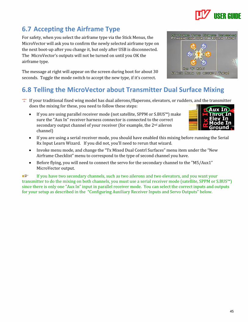
USER GUIDE
45
6.7 Accepting the Airframe Type For safety, when you select the airframe type via the Stick Menus, the
MicroVector will ask you to confirm the newly selected airframe type on
the next boot-up after you change it, but only after USB is disconnected.
The MicroVector’s outputs will not be turned on until you OK the
airframe type.
The message at right will appear on the screen during boot for about 30
seconds. Toggle the mode switch to accept the new type, if it’s correct.
6.8 Telling the MicroVector about Transmitter Dual Surface Mixing
If your traditional fixed wing model has dual ailerons/flaperons, elevators, or rudders, and the transmitter does the mixing for these, you need to follow these steps:
• If you are using parallel receiver mode (not satellite, SPPM or S.BUS™) make sure the “Aux In” receiver harness connector is connected to the correct secondary output channel of your receiver (for example, the 2nd aileron channel)
• If you are using a serial receiver mode, you should have enabled this mixing before running the Serial Rx Input Learn Wizard. If you did not, you’ll need to rerun that wizard.
• Invoke menu mode, and change the “Tx Mixed Dual Contrl Surfaces” menu item under the “New Airframe Checklist” menu to correspond to the type of second channel you have.
• Before flying, you will need to connect the servo for the secondary channel to the "M5/Aux1” MicroVector output.
If you have two secondary channels, such as two ailerons and two elevators, and you want your transmitter to do the mixing on both channels, you must use a serial receiver mode (satellite, SPPM or S.BUS™) since there is only one “Aux In” input in parallel receiver mode. You can select the correct inputs and outputs for your setup as described in the “Configuring Auxiliary Receiver Inputs and Servo Outputs” below.
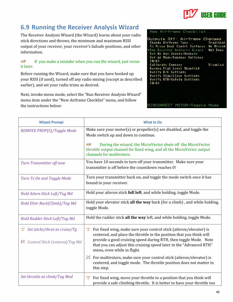
USER GUIDE
46
6.9 Running the Receiver Analysis Wizard The Receiver Analysis Wizard (the Wizard) learns about your radio
stick directions and throws, the minimum and maximum RSSI
output of your receiver, your receiver’s failsafe positions, and other
information.
If you make a mistake when you run the wizard, just rerun it later.
Before running the Wizard, make sure that you have hooked up
your RSSI (if used), turned off any radio mixing (except as described
earlier), and set your radio trims as desired.
Next, invoke menu mode, select the “Run Receiver Analysis Wizard”
menu item under the “New Airframe Checklist” menu, and follow
the instructions below:
Wizard Prompt What to Do
REMOVE PROP(S)/Toggle Mode Make sure your motor(s) or propeller(s) are disabled, and toggle the
Mode switch up and down to continue.
During the wizard, the MicroVector shuts off the MicroVector throttle output channel for fixed wing, and all the MicroVector output channels for multirotors.
Turn Transmitter off now You have 10 seconds to turn off your transmitter. Make sure your
transmitter is off before the countdown reaches 0!
Turn Tx On and Toggle Mode
Turn your transmitter back on, and toggle the mode switch once it has
bound to your receiver.
Hold Ailern Stick Left/Tog Md Hold your aileron stick full left, and while holding, toggle Mode.
Hold Elvtr Back(Climb)/Tog Md Hold your elevator stick all the way back (for a climb) , and while holding,
toggle Mode.
Hold Rudder Stick Left/Tog Md Hold the rudder stick all the way left, and while holding, toggle Mode.
Set sticks/throt at cruise/Tg
Control Stick Centered/Tog Md
For fixed wing, make sure your control stick (aileron/elevator) is centered, and place the throttle in the position that you think will provide a good cruising speed during RTH, then toggle Mode. Note that you can adjust this cruising speed later in the “Advanced RTH” menu, even while in flight.
For multirotors, make sure your control stick (aileron/elevator) is centered, and toggle mode. The throttle position does not matter in this step.
Set throttle at climb/Tog Mod For fixed wing, move your throttle to a position that you think will provide a safe climbing throttle. It is better to have your throttle too
USER GUIDE
47
high here than too low. This throttle setting will be used to gain altitude, compensate for high wind, or attempt to recover from a stall during RTH.
For multirotors, move your throttle stick all the way up, and toggle Mode.
Set throttle off/Toggle Mode Move your throttle stick all the way off, and toggle Mode.
Wizard Done-Tog Mod to reboot The MicroVector has now learned your receiver settings. Once you click Mode, the MicroVector will reboot, and the MicroVector’s servo outputs will be enabled (assuming everything was done correctly).
The MicroVector will enable its outputs channels after you reboot. MAKE SURE that your airframe type is correct before rebooting!
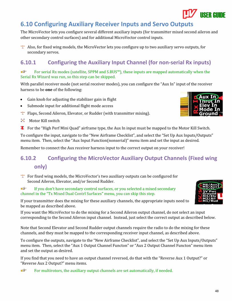
USER GUIDE
48
6.10 Configuring Auxiliary Receiver Inputs and Servo Outputs The MicroVector lets you configure several different auxiliary inputs (for transmitter mixed second aileron and
other secondary control surfaces) and for additional MicroVector control inputs.
Also, for fixed wing models, the MicroVector lets you configure up to two auxiliary servo outputs, for secondary servos.
6.10.1 Configuring the Auxiliary Input Channel (for non-serial Rx inputs)
For serial Rx modes (satellite, SPPM and S.BUS™), these inputs are mapped automatically when the Serial Rx Wizard was run, so this step can be skipped.
With parallel receiver mode (not serial receiver modes), you can configure the “Aux In” input of the receiver
harness to be one of the following:
• Gain knob for adjusting the stabilizer gain in flight
• Submode input for additional flight mode access
Flaps, Second Aileron, Elevator, or Rudder (with transmitter mixing).
Motor Kill switch
For the “High Perf Mini Quad” airframe type, the Aux In input must be mapped to the Motor Kill Switch.
To configure the input, navigate to the “New Airframe Checklist”, and select the “Set Up Aux Inputs/Outputs” menu item. Then, select the “Aux Input Function(nonserial)” menu item and set the input as desired.
Remember to connect the Aux receiver harness input to the correct output on your receiver!
6.10.2 Configuring the MicroVector Auxiliary Output Channels (Fixed wing
only)
For fixed wing models, the MicroVector’s two auxiliary outputs can be configured for Second Aileron, Elevator, and/or Second Rudder.
If you don’t have secondary control surfaces, or you selected a mixed secondary channel in the “Tx Mixed Dual Contrl Surfaces” menu, you can skip this step.
If your transmitter does the mixing for these auxiliary channels, the appropriate inputs need to be mapped as described above.
If you want the MicroVector to do the mixing for a Second Aileron output channel, do not select an input corresponding to the Second Aileron input channel. Instead, just select the correct output as described below. Note that Second Elevator and Second Rudder output channels require the radio to do the mixing for these channels, and they must be mapped to the corresponding receiver input channel, as described above.
To configure the outputs, navigate to the “New Airframe Checklist”, and select the “Set Up Aux Inputs/Outputs” menu item. Then, select the “Aux 1 Output Channel Functon” or “Aux 2 Output Channel Functon” menu item and set the output as desired.
If you find that you need to have an output channel reversed, do that with the “Reverse Aux 1 Output?” or “Reverse Aux 2 Output?” menu items.
For multirotors, the auxiliary output channels are set automatically, if needed.
USER GUIDE
49
6.11 Flight Modes, and Configuring the Mode/Submode Switches
6.11.1 Flight Mode Description The MicroVector supports a wide variety of flight modes, which you can select in flight using your Mode switch,
and optionally a Submode switch. The table below describes these modes, and also indicates whether the GPS
(with a good 3D fix) and the magnetic compass are required. The fallback flight mode is listed for when either
the GPS or Compass is deemed untrustworthy.
Flight Mode Flight
Mode
Indicator
Description for Multirotors Description for Fixed Wing
2D Mode (No Hold)
2D Control stick sets the amount of pitch or roll. Returns to level flight when control stick is released. No altitude hold.
Same
2D Mode with Hold
2DH Same as 2D Mode, except that altitude hold is enabled. When in altitude hold mode, the throttle works as follows:
• Throttle centered: present altitude is held
• Above or below center: multirotor climbs or descends, at a rate determined by the position of the throttle.
Same as 2D Mode, except that altitude and heading hold are enabled. Heading hold uses the ailerons or elevons to hold the present heading, and altitude hold uses the elevator.
The altitude hold's lock is reset every time the Elevator stick is moved.
See section 7.2.2 - ‘Flight
Mode for Takeoffs’ for
important details about
altitude hold for fixed wing!
Loiter Loi Similar to 2D Mode with Hold. Offers wind rejection during flight, and holds horizontal position using GPS when control stick is centered. (GPS and compass required)
Fallback: 2D Mode with Hold
Model circles around the present GPS position, with altitude hold, when Loiter is triggered. (GPS required, compass optional)
Fallback: 2D Mode w/ Hold
3D with Heading Hold (Direct Rate)
3DH Advanced Pilots Only! The multirotor’s present orientation (attitude) is held when the control stick is centered. The multirotor rotates about each axis, at the Direct Rate specified, when the stick controlling that axis is fully deflected. No Altitude Hold or leveling.
Same
Gyro Stabilize Gyr N/A Selects ”gyro” stabilization mode
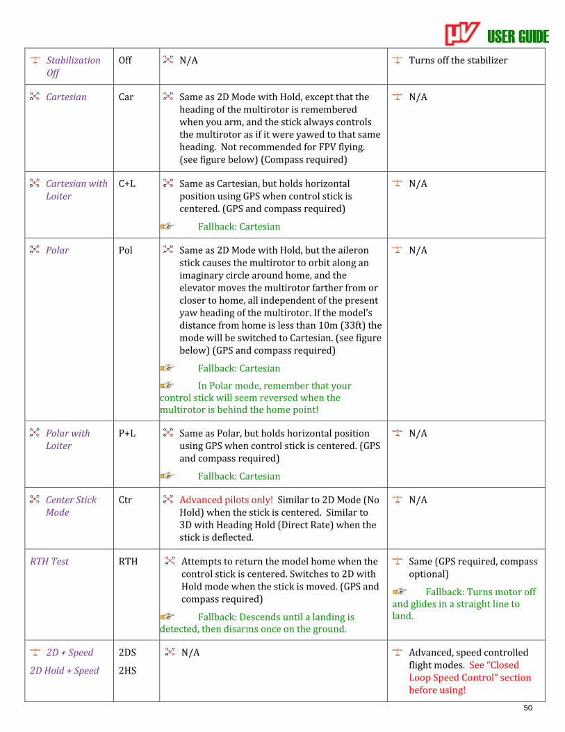
USER GUIDE
50
Stabilization Off
Off N/A Turns off the stabilizer
Cartesian Car Same as 2D Mode with Hold, except that the heading of the multirotor is remembered when you arm, and the stick always controls the multirotor as if it were yawed to that same heading. Not recommended for FPV flying. (see figure below) (Compass required)
N/A
Cartesian with Loiter
C+L Same as Cartesian, but holds horizontal position using GPS when control stick is centered. (GPS and compass required)
Fallback: Cartesian
N/A
Polar Pol Same as 2D Mode with Hold, but the aileron stick causes the multirotor to orbit along an imaginary circle around home, and the elevator moves the multirotor farther from or closer to home, all independent of the present yaw heading of the multirotor. If the model’s distance from home is less than 10m (33ft) the mode will be switched to Cartesian. (see figure below) (GPS and compass required)
Fallback: Cartesian
In Polar mode, remember that your control stick will seem reversed when the multirotor is behind the home point!
N/A
Polar with Loiter
P+L Same as Polar, but holds horizontal position using GPS when control stick is centered. (GPS and compass required)
Fallback: Cartesian
N/A
Center Stick Mode
Ctr Advanced pilots only! Similar to 2D Mode (No Hold) when the stick is centered. Similar to 3D with Heading Hold (Direct Rate) when the stick is deflected.
N/A
RTH Test RTH Attempts to return the model home when the control stick is centered. Switches to 2D with Hold mode when the stick is moved. (GPS and compass required)
Fallback: Descends until a landing is detected, then disarms once on the ground.
Same (GPS required, compass optional)
Fallback: Turns motor off and glides in a straight line to land.
2D + Speed
2D Hold + Speed
2DS
2HS
N/A Advanced, speed controlled flight modes. See “Closed Loop Speed Control” section before using!
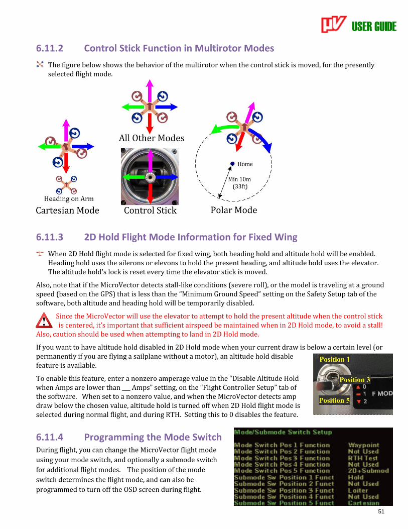
USER GUIDE
51
6.11.2 Control Stick Function in Multirotor Modes
The figure below shows the behavior of the multirotor when the control stick is moved, for the presently selected flight mode.
6.11.3 2D Hold Flight Mode Information for Fixed Wing
When 2D Hold flight mode is selected for fixed wing, both heading hold and altitude hold will be enabled. Heading hold uses the ailerons or elevons to hold the present heading, and altitude hold uses the elevator. The altitude hold's lock is reset every time the elevator stick is moved.
Also, note that if the MicroVector detects stall-like conditions (severe roll), or the model is traveling at a ground speed (based on the GPS) that is less than the “Minimum Ground Speed” setting on the Safety Setup tab of the software, both altitude and heading hold will be temporarily disabled.
Since the MicroVector will use the elevator to attempt to hold the present altitude when the control stick is centered, it’s important that sufficient airspeed be maintained when in 2D Hold mode, to avoid a stall!
Also, caution should be used when attempting to land in 2D Hold mode.
If you want to have altitude hold disabled in 2D Hold mode when your current draw is below a certain level (or permanently if you are flying a sailplane without a motor), an altitude hold disable feature is available.
To enable this feature, enter a nonzero amperage value in the “Disable Altitude Hold when Amps are lower than ___ Amps” setting, on the “Flight Controller Setup” tab of the software. When set to a nonzero value, and when the MicroVector detects amp draw below the chosen value, altitude hold is turned off when 2D Hold flight mode is selected during normal flight, and during RTH. Setting this to 0 disables the feature.
6.11.4 Programming the Mode Switch During flight, you can change the MicroVector flight mode
using your mode switch, and optionally a submode switch
for additional flight modes. The position of the mode
switch determines the flight mode, and can also be
programmed to turn off the OSD screen during flight.
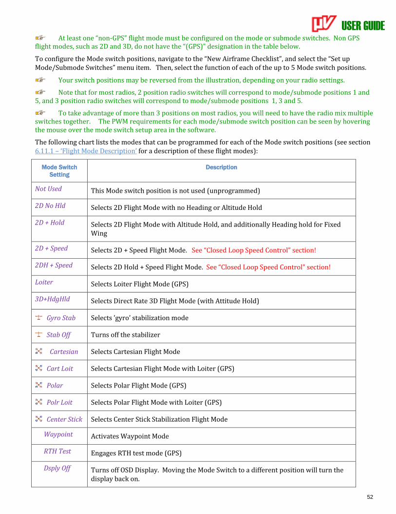
USER GUIDE
52
At least one “non-GPS” flight mode must be configured on the mode or submode switches. Non GPS flight modes, such as 2D and 3D, do not have the “(GPS)” designation in the table below.
To configure the Mode switch positions, navigate to the “New Airframe Checklist”, and select the “Set up Mode/Submode Switches” menu item. Then, select the function of each of the up to 5 Mode switch positions.
Your switch positions may be reversed from the illustration, depending on your radio settings.
Note that for most radios, 2 position radio switches will correspond to mode/submode positions 1 and 5, and 3 position radio switches will correspond to mode/submode positions 1, 3 and 5.
To take advantage of more than 3 positions on most radios, you will need to have the radio mix multiple switches together. The PWM requirements for each mode/submode switch position can be seen by hovering the mouse over the mode switch setup area in the software.
The following chart lists the modes that can be programmed for each of the Mode switch positions (see section 6.11.1 – ‘Flight Mode Description’ for a description of these flight modes):
Mode Switch
Setting
Description
Not Used This Mode switch position is not used (unprogrammed)
2D No Hld Selects 2D Flight Mode with no Heading or Altitude Hold
2D + Hold Selects 2D Flight Mode with Altitude Hold, and additionally Heading hold for Fixed Wing
2D + Speed Selects 2D + Speed Flight Mode. See “Closed Loop Speed Control” section!
2DH + Speed Selects 2D Hold + Speed Flight Mode. See “Closed Loop Speed Control” section!
Loiter Selects Loiter Flight Mode (GPS)
3D+HdgHld Selects Direct Rate 3D Flight Mode (with Attitude Hold)
Gyro Stab Selects ’gyro’ stabilization mode
Stab Off Turns off the stabilizer
Cartesian Selects Cartesian Flight Mode
Cart Loit Selects Cartesian Flight Mode with Loiter (GPS)
Polar Selects Polar Flight Mode (GPS)
Polr Loit Selects Polar Flight Mode with Loiter (GPS)
Center Stick Selects Center Stick Stabilization Flight Mode
Waypoint Activates Waypoint Mode
RTH Test Engages RTH test mode (GPS)
Dsply Off Turns off OSD Display. Moving the Mode Switch to a different position will turn the display back on.
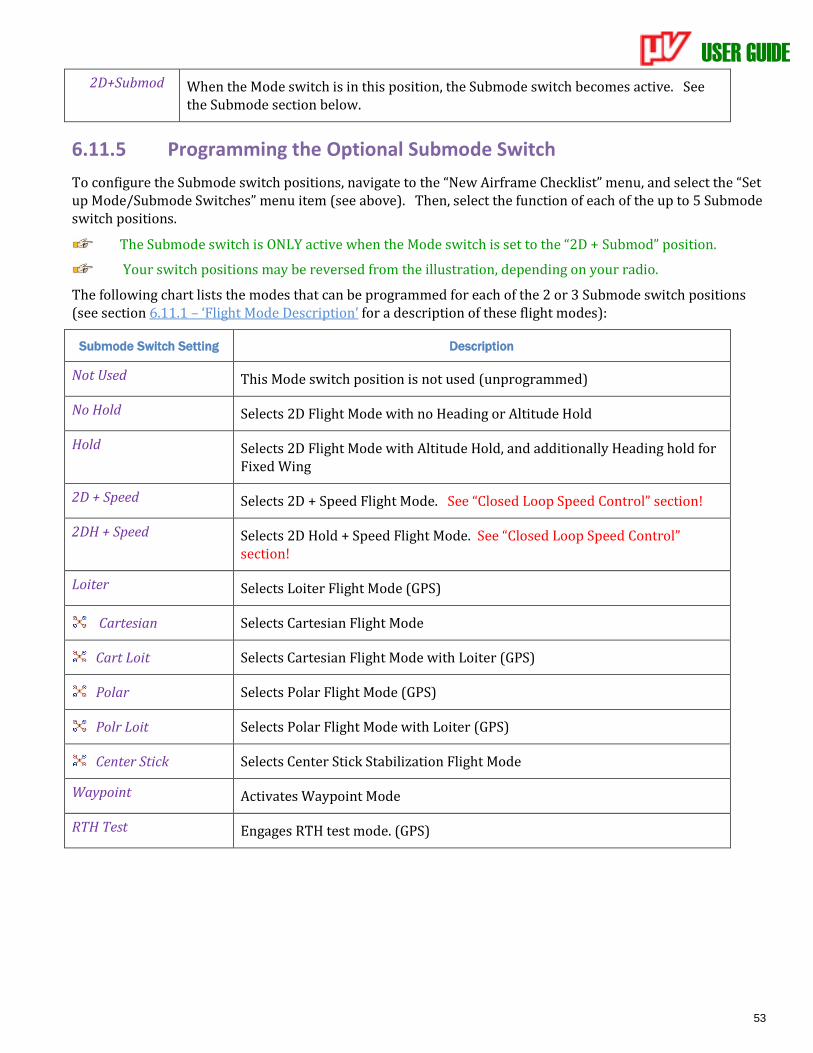
USER GUIDE
53
2D+Submod When the Mode switch is in this position, the Submode switch becomes active. See the Submode section below.
6.11.5 Programming the Optional Submode Switch
To configure the Submode switch positions, navigate to the “New Airframe Checklist” menu, and select the “Set up Mode/Submode Switches” menu item (see above). Then, select the function of each of the up to 5 Submode switch positions.
The Submode switch is ONLY active when the Mode switch is set to the “2D + Submod” position.
Your switch positions may be reversed from the illustration, depending on your radio.
The following chart lists the modes that can be programmed for each of the 2 or 3 Submode switch positions (see section 6.11.1 – ‘Flight Mode Description’ for a description of these flight modes):
Submode Switch Setting Description
Not Used This Mode switch position is not used (unprogrammed)
No Hold Selects 2D Flight Mode with no Heading or Altitude Hold
Hold Selects 2D Flight Mode with Altitude Hold, and additionally Heading hold for Fixed Wing
2D + Speed Selects 2D + Speed Flight Mode. See “Closed Loop Speed Control” section!
2DH + Speed Selects 2D Hold + Speed Flight Mode. See “Closed Loop Speed Control” section!
Loiter Selects Loiter Flight Mode (GPS)
Cartesian Selects Cartesian Flight Mode
Cart Loit Selects Cartesian Flight Mode with Loiter (GPS)
Polar Selects Polar Flight Mode (GPS)
Polr Loit Selects Polar Flight Mode with Loiter (GPS)
Center Stick Selects Center Stick Stabilization Flight Mode
Waypoint Activates Waypoint Mode
RTH Test Engages RTH test mode. (GPS)
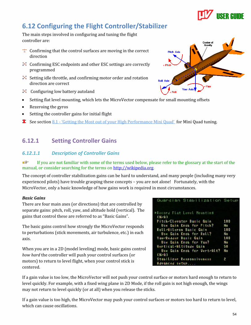
USER GUIDE
54
6.12 Configuring the Flight Controller/Stabilizer The main steps involved in configuring and tuning the flight
controller are:
Confirming that the control surfaces are moving in the correct direction
Confirming ESC endpoints and other ESC settings are correctly programmed
Setting idle throttle, and confirming motor order and rotation direction are correct
Configuring low battery autoland
• Setting flat level mounting, which lets the MicroVector compensate for small mounting offsets
• Rezeroing the gyros
• Setting the controller gains for initial flight
See section 8.1 - ‘Getting the Most out of your High Performance Mini Quad’ for Mini Quad tuning.
6.12.1 Setting Controller Gains
6.12.1.1 Description of Controller Gains
If you are not familiar with some of the terms used below, please refer to the glossary at the start of the manual, or consider searching for the terms on http://wikipedia.org.
The concept of controller stabilization gains can be hard to understand, and many people (including many very
experienced pilots) have trouble grasping these concepts – you are not alone! Fortunately, with the
MicroVector, only a basic knowledge of how gains work is required in most circumstances.
Basic Gains
There are four main axes (or directions) that are controlled by
separate gains: pitch, roll, yaw, and altitude hold (vertical). The
gains that control these are referred to as “Basic Gains”.
The basic gains control how strongly the MicroVector responds
to perturbations (stick movements, air turbulence, etc.) in each
axis.
When you are in a 2D (model leveling) mode, basic gains control
how hard the controller will push your control surfaces (or
motors) to return to level flight, when your control stick is
centered.
If a gain value is too low, the MicroVector will not push your control surface or motors hard enough to return to
level quickly. For example, with a fixed wing plane in 2D Mode, if the roll gain is not high enough, the wings
may not return to level quickly (or at all) when you release the sticks.
If a gain value is too high, the MicroVector may push your control surfaces or motors too hard to return to level,
which can cause oscillations.
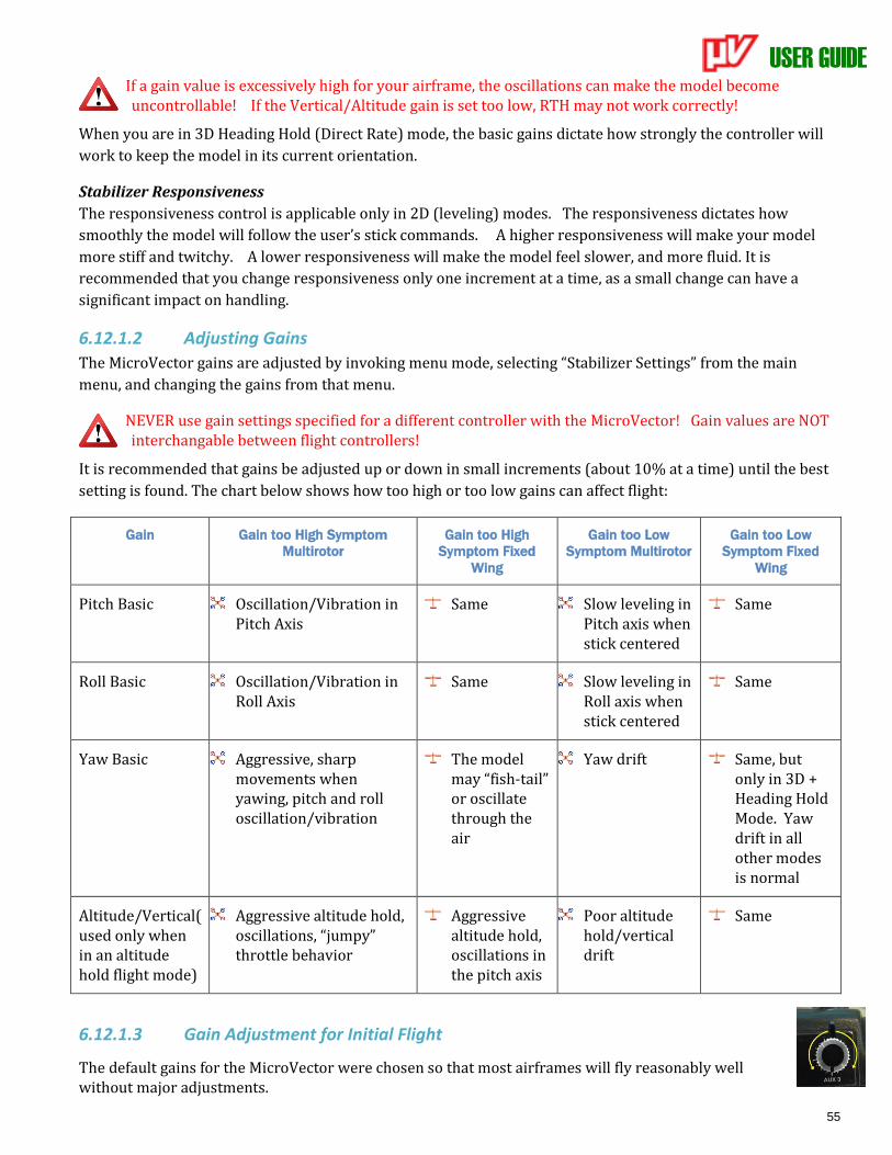
USER GUIDE
55
If a gain value is excessively high for your airframe, the oscillations can make the model become uncontrollable! If the Vertical/Altitude gain is set too low, RTH may not work correctly!
When you are in 3D Heading Hold (Direct Rate) mode, the basic gains dictate how strongly the controller will
work to keep the model in its current orientation.
Stabilizer Responsiveness
The responsiveness control is applicable only in 2D (leveling) modes. The responsiveness dictates how
smoothly the model will follow the user’s stick commands. A higher responsiveness will make your model
more stiff and twitchy. A lower responsiveness will make the model feel slower, and more fluid. It is
recommended that you change responsiveness only one increment at a time, as a small change can have a
significant impact on handling.
6.12.1.2 Adjusting Gains
The MicroVector gains are adjusted by invoking menu mode, selecting “Stabilizer Settings” from the main
menu, and changing the gains from that menu.
NEVER use gain settings specified for a different controller with the MicroVector! Gain values are NOT interchangable between flight controllers!
It is recommended that gains be adjusted up or down in small increments (about 10% at a time) until the best
setting is found. The chart below shows how too high or too low gains can affect flight:
Gain Gain too High Symptom
Multirotor
Gain too High
Symptom Fixed
Wing
Gain too Low
Symptom Multirotor
Gain too Low
Symptom Fixed
Wing
Pitch Basic Oscillation/Vibration in Pitch Axis
Same Slow leveling in Pitch axis when stick centered
Same
Roll Basic Oscillation/Vibration in Roll Axis
Same Slow leveling in Roll axis when stick centered
Same
Yaw Basic Aggressive, sharp movements when yawing, pitch and roll oscillation/vibration
The model may “fish-tail” or oscillate through the air
Yaw drift Same, but only in 3D + Heading Hold Mode. Yaw drift in all other modes is normal
Altitude/Vertical( used only when in an altitude hold flight mode)
Aggressive altitude hold, oscillations, “jumpy” throttle behavior
Aggressive altitude hold, oscillations in the pitch axis
Poor altitude hold/vertical drift
Same
6.12.1.3 Gain Adjustment for Initial Flight
The default gains for the MicroVector were chosen so that most airframes will fly reasonably well without major adjustments.
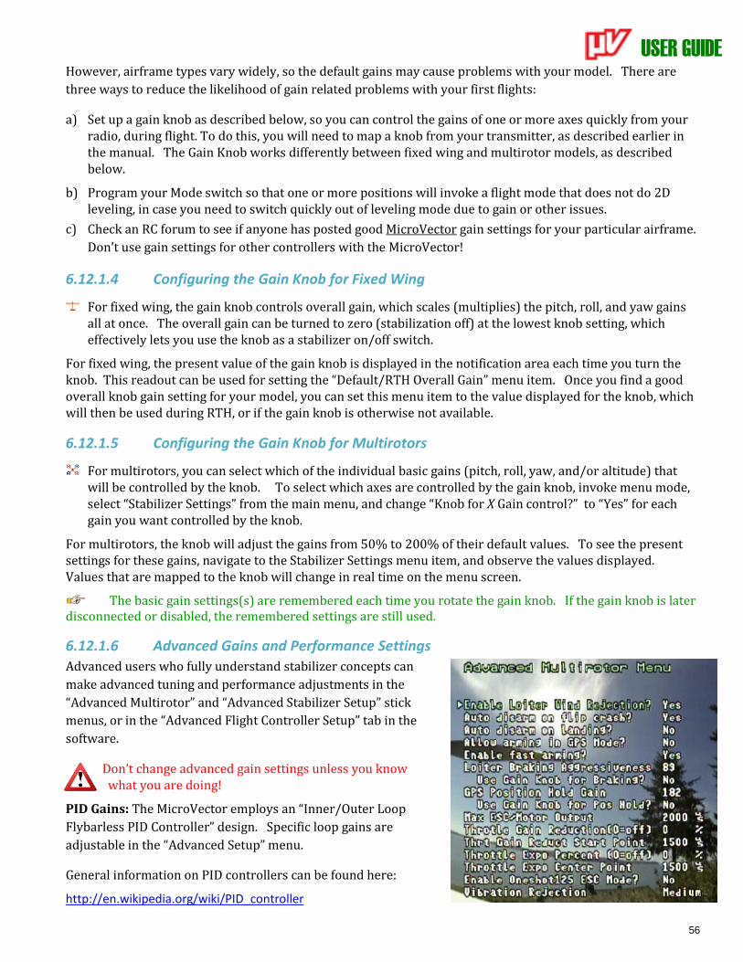
USER GUIDE
56
However, airframe types vary widely, so the default gains may cause problems with your model. There are
three ways to reduce the likelihood of gain related problems with your first flights:
a) Set up a gain knob as described below, so you can control the gains of one or more axes quickly from your radio, during flight. To do this, you will need to map a knob from your transmitter, as described earlier in the manual. The Gain Knob works differently between fixed wing and multirotor models, as described below.
b) Program your Mode switch so that one or more positions will invoke a flight mode that does not do 2D leveling, in case you need to switch quickly out of leveling mode due to gain or other issues.
c) Check an RC forum to see if anyone has posted good MicroVector gain settings for your particular airframe.
Don’t use gain settings for other controllers with the MicroVector!
6.12.1.4 Configuring the Gain Knob for Fixed Wing
For fixed wing, the gain knob controls overall gain, which scales (multiplies) the pitch, roll, and yaw gains all at once. The overall gain can be turned to zero (stabilization off) at the lowest knob setting, which effectively lets you use the knob as a stabilizer on/off switch.
For fixed wing, the present value of the gain knob is displayed in the notification area each time you turn the knob. This readout can be used for setting the “Default/RTH Overall Gain” menu item. Once you find a good overall knob gain setting for your model, you can set this menu item to the value displayed for the knob, which will then be used during RTH, or if the gain knob is otherwise not available.
6.12.1.5 Configuring the Gain Knob for Multirotors
For multirotors, you can select which of the individual basic gains (pitch, roll, yaw, and/or altitude) that will be controlled by the knob. To select which axes are controlled by the gain knob, invoke menu mode, select “Stabilizer Settings” from the main menu, and change “Knob for X Gain control?” to “Yes” for each gain you want controlled by the knob.
For multirotors, the knob will adjust the gains from 50% to 200% of their default values. To see the present settings for these gains, navigate to the Stabilizer Settings menu item, and observe the values displayed. Values that are mapped to the knob will change in real time on the menu screen.
The basic gain settings(s) are remembered each time you rotate the gain knob. If the gain knob is later disconnected or disabled, the remembered settings are still used.
6.12.1.6 Advanced Gains and Performance Settings
Advanced users who fully understand stabilizer concepts can
make advanced tuning and performance adjustments in the
“Advanced Multirotor” and “Advanced Stabilizer Setup” stick
menus, or in the “Advanced Flight Controller Setup” tab in the
software.
Don’t change advanced gain settings unless you know what you are doing!
PID Gains: The MicroVector employs an “Inner/Outer Loop
Flybarless PID Controller” design. Specific loop gains are
adjustable in the “Advanced Setup” menu.
General information on PID controllers can be found here:
http://en.wikipedia.org/wiki/PID_controller
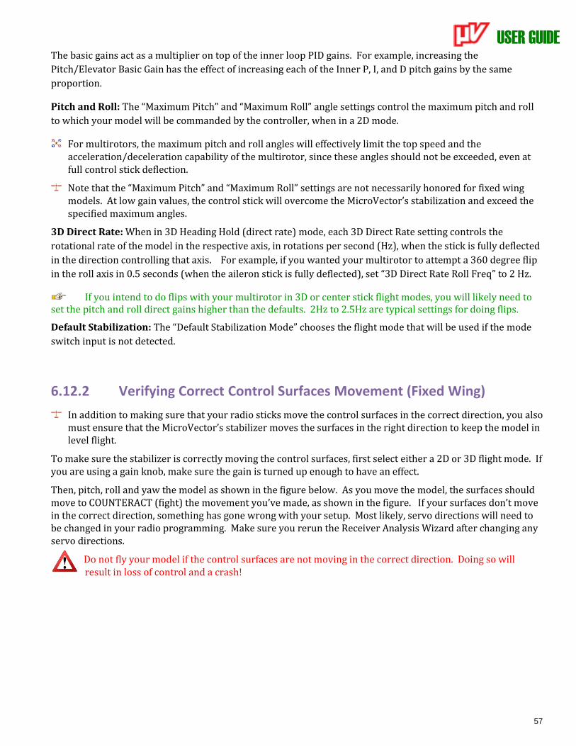
USER GUIDE
57
The basic gains act as a multiplier on top of the inner loop PID gains. For example, increasing the
Pitch/Elevator Basic Gain has the effect of increasing each of the Inner P, I, and D pitch gains by the same
proportion.
Pitch and Roll: The “Maximum Pitch” and “Maximum Roll” angle settings control the maximum pitch and roll
to which your model will be commanded by the controller, when in a 2D mode.
For multirotors, the maximum pitch and roll angles will effectively limit the top speed and the acceleration/deceleration capability of the multirotor, since these angles should not be exceeded, even at full control stick deflection.
Note that the “Maximum Pitch” and “Maximum Roll” settings are not necessarily honored for fixed wing models. At low gain values, the control stick will overcome the MicroVector’s stabilization and exceed the specified maximum angles.
3D Direct Rate: When in 3D Heading Hold (direct rate) mode, each 3D Direct Rate setting controls the
rotational rate of the model in the respective axis, in rotations per second (Hz), when the stick is fully deflected
in the direction controlling that axis. For example, if you wanted your multirotor to attempt a 360 degree flip
in the roll axis in 0.5 seconds (when the aileron stick is fully deflected), set “3D Direct Rate Roll Freq” to 2 Hz.
If you intend to do flips with your multirotor in 3D or center stick flight modes, you will likely need to set the pitch and roll direct gains higher than the defaults. 2Hz to 2.5Hz are typical settings for doing flips.
Default Stabilization: The “Default Stabilization Mode” chooses the flight mode that will be used if the mode
switch input is not detected.
6.12.2 Verifying Correct Control Surfaces Movement (Fixed Wing)
In addition to making sure that your radio sticks move the control surfaces in the correct direction, you also must ensure that the MicroVector’s stabilizer moves the surfaces in the right direction to keep the model in level flight.
To make sure the stabilizer is correctly moving the control surfaces, first select either a 2D or 3D flight mode. If you are using a gain knob, make sure the gain is turned up enough to have an effect.
Then, pitch, roll and yaw the model as shown in the figure below. As you move the model, the surfaces should move to COUNTERACT (fight) the movement you’ve made, as shown in the figure. If your surfaces don’t move in the correct direction, something has gone wrong with your setup. Most likely, servo directions will need to be changed in your radio programming. Make sure you rerun the Receiver Analysis Wizard after changing any servo directions.
Do not fly your model if the control surfaces are not moving in the correct direction. Doing so will result in loss of control and a crash!
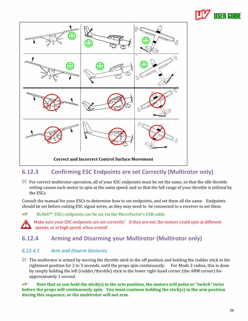
USER GUIDE
58
Correct and Incorrect Control Surface Movement
6.12.3 Confirming ESC Endpoints are set Correctly (Multirotor only)
For correct multirotor operation, all of your ESC endpoints must be set the same, so that the idle throttle setting causes each motor to spin at the same speed, and so that the full range of your throttle is utilized by the ESCs.
Consult the manual for your ESCs to determine how to set endpoints, and set them all the same. Endpoints should be set before cutting ESC signal wires, as they may need to be connected to a receiver to set them.
BLHeli™ ESCs endpoints can be set via the MicroVector’s USB cable.
Make sure your ESC endpoints are set correctly! If they are not, the motors could spin at different speeds, or at high speed, when armed!
6.12.4 Arming and Disarming your Multirotor (Multirotor only)
6.12.4.1 Arm and Disarm Gestures
The multirotor is armed by moving the throttle stick to the off position and holding the rudder stick in the rightmost position for 2 to 3 seconds, until the props spin continuously. For Mode 2 radios, this is done by simply holding the left (rudder/throttle) stick in the lower right-hand corner (the ARM corner) for approximately 1 second.
Note that as you hold the stick(s) in the arm position, the motors will pulse or “twitch” twice before the props will continuously spin. You must continue holding the stick(s) in the arm position during this sequence, or the multirotor will not arm.
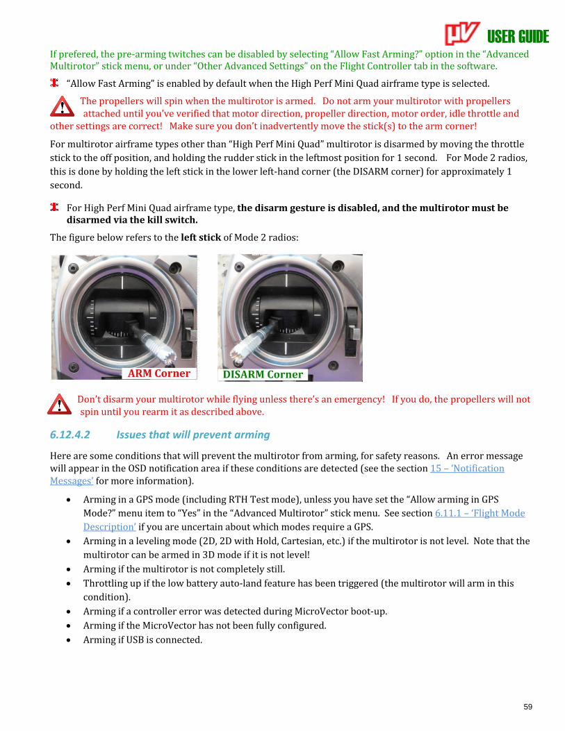
USER GUIDE
59
If prefered, the pre-arming twitches can be disabled by selecting “Allow Fast Arming?” option in the “Advanced Multirotor” stick menu, or under “Other Advanced Settings” on the Flight Controller tab in the software.
“Allow Fast Arming” is enabled by default when the High Perf Mini Quad airframe type is selected.
The propellers will spin when the multirotor is armed. Do not arm your multirotor with propellers attached until you’ve verified that motor direction, propeller direction, motor order, idle throttle and
other settings are correct! Make sure you don’t inadvertently move the stick(s) to the arm corner!
For multirotor airframe types other than “High Perf Mini Quad” multirotor is disarmed by moving the throttle
stick to the off position, and holding the rudder stick in the leftmost position for 1 second. For Mode 2 radios,
this is done by holding the left stick in the lower left-hand corner (the DISARM corner) for approximately 1
second.
For High Perf Mini Quad airframe type, the disarm gesture is disabled, and the multirotor must be disarmed via the kill switch.
The figure below refers to the left stick of Mode 2 radios:
Don’t disarm your multirotor while flying unless there’s an emergency! If you do, the propellers will not spin until you rearm it as described above.
6.12.4.2 Issues that will prevent arming
Here are some conditions that will prevent the multirotor from arming, for safety reasons. An error message will appear in the OSD notification area if these conditions are detected (see the section 15 – ‘Notification Messages’ for more information).
• Arming in a GPS mode (including RTH Test mode), unless you have set the “Allow arming in GPS
Mode?” menu item to “Yes” in the “Advanced Multirotor” stick menu. See section 6.11.1 – ‘Flight Mode
Description’ if you are uncertain about which modes require a GPS.
• Arming in a leveling mode (2D, 2D with Hold, Cartesian, etc.) if the multirotor is not level. Note that the
multirotor can be armed in 3D mode if it is not level!
• Arming if the multirotor is not completely still.
• Throttling up if the low battery auto-land feature has been triggered (the multirotor will arm in this
condition).
• Arming if a controller error was detected during MicroVector boot-up.
• Arming if the MicroVector has not been fully configured.
• Arming if USB is connected.
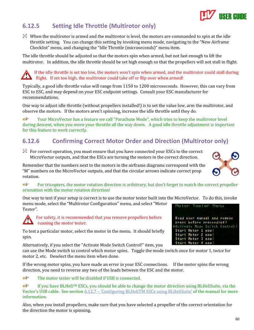
USER GUIDE
60
6.12.5 Setting Idle Throttle (Multirotor only)
When the multirotor is armed and the multirotor is level, the motors are commanded to spin at the idle throttle setting. You can change this setting by invoking menu mode, navigating to the “New Airframe Checklist” menu, and changing the “Idle Throttle (microseconds)” menu item.
The idle throttle should be adjusted so that the motors spin when armed, but not fast enough to lift the
multirotor. In addition, the idle throttle should be set high enough so that the propellers will not stall in flight.
If the idle throttle is set too low, the motors won’t spin when armed, and the multirotor could stall during flight. If set too high, the multirotor could take off or flip over when armed!
Typically, a good idle throttle value will range from 1150 to 1200 microseconds. However, this can vary from ESC to ESC, and may depend on your ESC endpoint settings. Consult your ESC manufacturer for recommendations.
One way to adjust idle throttle (without propellers installed!) is to set the value low, arm the multirotor, and observe the motors. If the motors aren’t spinning, increase the idle throttle until they do.
Your MicroVector has a feature we call “Parachute Mode”, which tries to keep the multirotor level during descent, when you move your throttle all the way down. A good idle throttle adjustment is important for this feature to work correctly.
6.12.6 Confirming Correct Motor Order and Direction (Multirotor only)
For correct operation, you must ensure that you have connected your ESCs to the correct MicroVector outputs, and that the ESCs are turning the motors in the correct direction.
Remember that the numbers next to the motors in the airframe diagrams correspond with the “M” numbers on the MicroVector outputs, and that the circular arrows indicate correct prop rotation.
For tricopters, the motor rotation direction is aribitrary, but don’t forget to match the correct propeller orienation with the motor rotation direction!
One way to test if your setup is correct is to use the motor tester built into the MicroVector. To do this, invoke menu mode, select the “Multirotor Configuration” menu, and select “Motor Tester”.
For safety, it is recommended that you remove propellers before running the motor tester.
To test a particular motor, select the motor in the menu. It should briefly spin.
Alternatively, if you select the “Activate Mode Switch Control!” item, you can use the Mode switch to control which motor spins. Toggle the mode switch once for motor 1, twice for motor 2, etc. Deselect the menu item when done.
If the wrong motor spins, you have made an error in your ESC connections. If the motor spins the wrong direction, you need to reverse any two of the leads between the ESC and the motor.
The motor tester will be disabled if USB is connected.
If you have BLHeliTM ESCs, you should be able to change the motor direction using BLHeliSuite, via the Vector’s USB cable. See section 6.12.7 – ‘Configuring BLHeliTM ESCs using BLHeliSuite’ of the manual for more information.
Also, when you install propellers, make sure that you have selected a propeller of the correct orientation for the direction the motor is spinning.
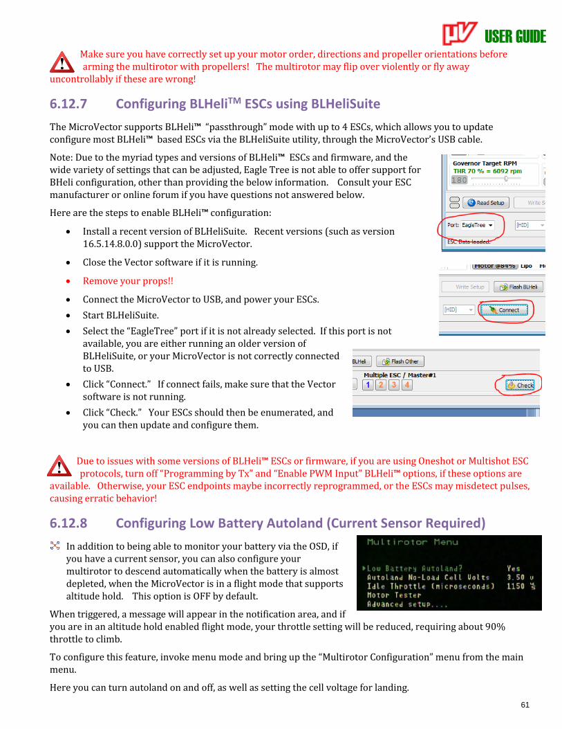
USER GUIDE
61
Make sure you have correctly set up your motor order, directions and propeller orientations before arming the multirotor with propellers! The multirotor may flip over violently or fly away
uncontrollably if these are wrong!
6.12.7 Configuring BLHeliTM ESCs using BLHeliSuite
The MicroVector supports BLHeli™ “passthrough” mode with up to 4 ESCs, which allows you to update configure most BLHeli™ based ESCs via the BLHeliSuite utility, through the MicroVector’s USB cable.
Note: Due to the myriad types and versions of BLHeli™ ESCs and firmware, and the wide variety of settings that can be adjusted, Eagle Tree is not able to offer support for BHeli configuration, other than providing the below information. Consult your ESC manufacturer or online forum if you have questions not answered below.
Here are the steps to enable BLHeli™ configuration:
• Install a recent version of BLHeliSuite. Recent versions (such as version 16.5.14.8.0.0) support the MicroVector.
• Close the Vector software if it is running.
• Remove your props!!
• Connect the MicroVector to USB, and power your ESCs.
• Start BLHeliSuite.
• Select the “EagleTree” port if it is not already selected. If this port is not available, you are either running an older version of BLHeliSuite, or your MicroVector is not correctly connected to USB.
• Click “Connect.” If connect fails, make sure that the Vector software is not running.
• Click “Check.” Your ESCs should then be enumerated, and you can then update and configure them.
Due to issues with some versions of BLHeli™ ESCs or firmware, if you are using Oneshot or Multishot ESC protocols, turn off “Programming by Tx” and “Enable PWM Input” BLHeli™ options, if these options are
available. Otherwise, your ESC endpoints maybe incorrectly reprogrammed, or the ESCs may misdetect pulses, causing erratic behavior!
6.12.8 Configuring Low Battery Autoland (Current Sensor Required)
In addition to being able to monitor your battery via the OSD, if you have a current sensor, you can also configure your multirotor to descend automatically when the battery is almost depleted, when the MicroVector is in a flight mode that supports altitude hold. This option is OFF by default.
When triggered, a message will appear in the notification area, and if you are in an altitude hold enabled flight mode, your throttle setting will be reduced, requiring about 90% throttle to climb.
To configure this feature, invoke menu mode and bring up the “Multirotor Configuration” menu from the main menu.
Here you can turn autoland on and off, as well as setting the cell voltage for landing.
USER GUIDE
62
Never enable low battery autoland unless you have a correctly calibrated current sensor connected to the MicroVector!
If you are in a non-altitude hold flight mode, the low battery alert will appear, but the throttle will not be affected.Since the MicroVector knows both the present voltage and present current provided by the battery, it is able to approximately determine the “no load” battery voltage even when the battery is under load, so you only need to enter the desired no load per-cell voltage for landing, rather than trying to estimate the voltage under load.
The MicroVector automatically calculates the cell count, by default. If you wish to manually enter the cell count, you can do this under the Calibration menu described later.
6.12.9 Setting Flat Level Mounting
Before flying, the MicroVector needs to correct for any controller mounting offsets that could affect level flight. To do this, place the model so that it is perfectly level (on a level counter or floor), invoke menu mode, and select “Record Flat Level Mounting” from the “New Airframe Checklist” menu.
6.12.10 Rezeroing Gyros The MicroVector gyros are factory zeroed, but it never hurts to rezero them occasionally, as this can potentially
improve stabilizer performance. The MicroVector does not need to be perfectly level to rezero gyros, but it
must remain COMPLETELY STILL during the rezeroing process. To rezero, select the "Rezero Gyros (must be
still!)” menu item under the “Preflight Checklist” menu.
It’s best to rezero the gyros after the model has adjusted to the temperature at your flying location.
Never try to rezero gyros with a fixed wing model in the wind, as the wind can buffet the model, which could cause a rezeroing error.
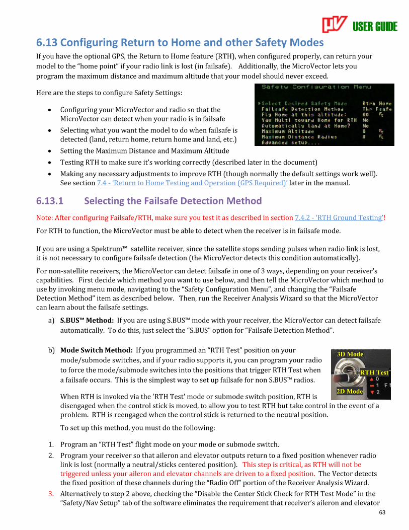
USER GUIDE
63
6.13 Configuring Return to Home and other Safety Modes If you have the optional GPS, the Return to Home feature (RTH), when configured properly, can return your
model to the “home point” if your radio link is lost (in failsafe). Additionally, the MicroVector lets you
program the maximum distance and maximum altitude that your model should never exceed.
Here are the steps to configure Safety Settings:
• Configuring your MicroVector and radio so that the MicroVector can detect when your radio is in failsafe
• Selecting what you want the model to do when failsafe is detected (land, return home, return home and land, etc.)
• Setting the Maximum Distance and Maximum Altitude
• Testing RTH to make sure it’s working correctly (described later in the document)
• Making any necessary adjustments to improve RTH (though normally the default settings work well). See section 7.4 - ‘Return to Home Testing and Operation (GPS Required)’ later in the manual.
6.13.1 Selecting the Failsafe Detection Method
Note: After configuring Failsafe/RTH, make sure you test it as described in section 7.4.2 - ‘RTH Ground Testing’!
For RTH to function, the MicroVector must be able to detect when the receiver is in failsafe mode. If you are using a Spektrum™ satellite receiver, since the satellite stops sending pulses when radio link is lost, it is not necessary to configure failsafe detection (the MicroVector detects this condition automatically).
For non-satellite receivers, the MicroVector can detect failsafe in one of 3 ways, depending on your receiver’s capabilities. First decide which method you want to use below, and then tell the MicroVector which method to use by invoking menu mode, navigating to the “Safety Configuration Menu”, and changing the “Failsafe Detection Method” item as described below. Then, run the Receiver Analysis Wizard so that the MicroVector can learn about the failsafe settings.
a) S.BUS™ Method: If you are using S.BUS™ mode with your receiver, the MicroVector can detect failsafe
automatically. To do this, just select the “S.BUS” option for “Failsafe Detection Method”.
b) Mode Switch Method: If you programmed an “RTH Test” position on your
mode/submode switches, and if your radio supports it, you can program your radio
to force the mode/submode switches into the positions that trigger RTH Test when
a failsafe occurs. This is the simplest way to set up failsafe for non S.BUS™ radios.
When RTH is invoked via the 'RTH Test' mode or submode switch position, RTH is disengaged when the control stick is moved, to allow you to test RTH but take control in the event of a problem. RTH is reengaged when the control stick is returned to the neutral position.
To set up this method, you must do the following:
1. Program an “RTH Test” flight mode on your mode or submode switch.
2. Program your receiver so that aileron and elevator outputs return to a fixed position whenever radio link is lost (normally a neutral/sticks centered position). This step is critical, as RTH will not be triggered unless your aileron and elevator channels are driven to a fixed position. The Vector detects the fixed position of these channels during the “Radio Off” portion of the Receiver Analysis Wizard.
3. Alternatively to step 2 above, checking the “Disable the Center Stick Check for RTH Test Mode” in the “Safety/Nav Setup” tab of the software eliminates the requirement that receiver’s aileron and elevator
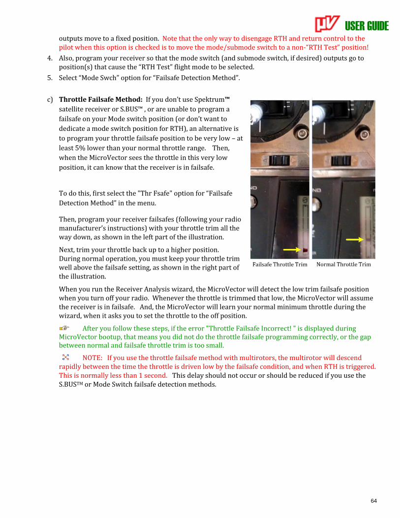
USER GUIDE
64
outputs move to a fixed position. Note that the only way to disengage RTH and return control to the pilot when this option is checked is to move the mode/submode switch to a non-“RTH Test” position!
4. Also, program your receiver so that the mode switch (and submode switch, if desired) outputs go to position(s) that cause the “RTH Test” flight mode to be selected.
5. Select “Mode Swch” option for “Failsafe Detection Method”.
c) Throttle Failsafe Method: If you don’t use Spektrum™
satellite receiver or S.BUS™ , or are unable to program a
failsafe on your Mode switch position (or don’t want to
dedicate a mode switch position for RTH), an alternative is
to program your throttle failsafe position to be very low – at
least 5% lower than your normal throttle range. Then,
when the MicroVector sees the throttle in this very low
position, it can know that the receiver is in failsafe.
To do this, first select the "Thr Fsafe" option for “Failsafe
Detection Method” in the menu.
Then, program your receiver failsafes (following your radio manufacturer’s instructions) with your throttle trim all the way down, as shown in the left part of the illustration.
Next, trim your throttle back up to a higher position. During normal operation, you must keep your throttle trim well above the failsafe setting, as shown in the right part of the illustration.
When you run the Receiver Analysis wizard, the MicroVector will detect the low trim failsafe position when you turn off your radio. Whenever the throttle is trimmed that low, the MicroVector will assume the receiver is in failsafe. And, the MicroVector will learn your normal minimum throttle during the wizard, when it asks you to set the throttle to the off position.
After you follow these steps, if the error "Throttle Failsafe Incorrect! " is displayed during MicroVector bootup, that means you did not do the throttle failsafe programming correctly, or the gap between normal and failsafe throttle trim is too small.
NOTE: If you use the throttle failsafe method with multirotors, the multirotor will descend rapidly between the time the throttle is driven low by the failsafe condition, and when RTH is triggered. This is normally less than 1 second. This delay should not occur or should be reduced if you use the S.BUSTM or Mode Switch failsafe detection methods.
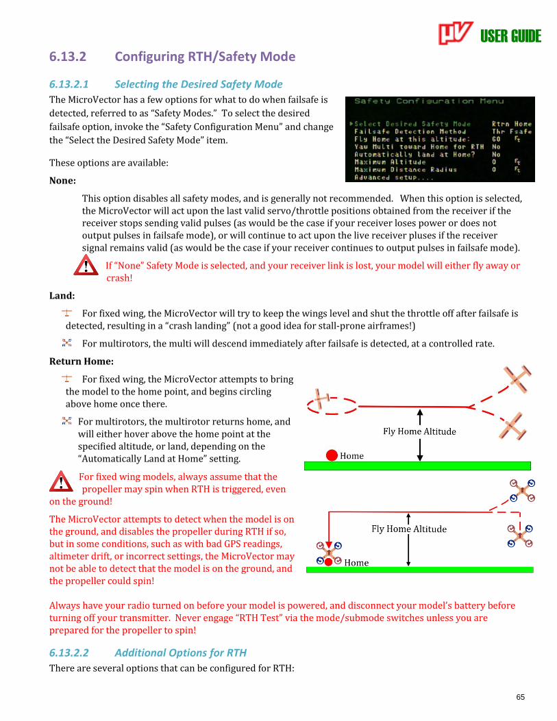
USER GUIDE
65
6.13.2 Configuring RTH/Safety Mode
6.13.2.1 Selecting the Desired Safety Mode
The MicroVector has a few options for what to do when failsafe is
detected, referred to as “Safety Modes.” To select the desired
failsafe option, invoke the “Safety Configuration Menu” and change
the “Select the Desired Safety Mode” item.
These options are available:
None:
This option disables all safety modes, and is generally not recommended. When this option is selected, the MicroVector will act upon the last valid servo/throttle positions obtained from the receiver if the receiver stops sending valid pulses (as would be the case if your receiver loses power or does not output pulses in failsafe mode), or will continue to act upon the live receiver pluses if the receiver signal remains valid (as would be the case if your receiver continues to output pulses in failsafe mode).
If “None” Safety Mode is selected, and your receiver link is lost, your model will either fly away or crash!
Land:
For fixed wing, the MicroVector will try to keep the wings level and shut the throttle off after failsafe is detected, resulting in a “crash landing” (not a good idea for stall-prone airframes!)
For multirotors, the multi will descend immediately after failsafe is detected, at a controlled rate.
Return Home:
For fixed wing, the MicroVector attempts to bring the model to the home point, and begins circling above home once there.
For multirotors, the multirotor returns home, and will either hover above the home point at the specified altitude, or land, depending on the “Automatically Land at Home” setting.
For fixed wing models, always assume that the propeller may spin when RTH is triggered, even
on the ground!
The MicroVector attempts to detect when the model is on the ground, and disables the propeller during RTH if so, but in some conditions, such as with bad GPS readings, altimeter drift, or incorrect settings, the MicroVector may not be able to detect that the model is on the ground, and the propeller could spin! Always have your radio turned on before your model is powered, and disconnect your model’s battery before turning off your transmitter. Never engage “RTH Test” via the mode/submode switches unless you are prepared for the propeller to spin!
6.13.2.2 Additional Options for RTH
There are several options that can be configured for RTH:
USER GUIDE
66
Fly home altitude: the altitude to ascend or descend to when returning to home, and to maintain once the model has returned. This is chosen with the “Fly home at this altitude:” setting.
If the altimeter drifts due to changes in barometric pressure or other causes, the fly home altitude will be higher or lower than the actual altitude by the amount of the drift. A very large decrease in
barometric pressure, such as can occur if a storm is moving in, might result in the model descending into the ground when RTH is triggered, if your Fly Home Altitude is set too low!
Yawing toward home: If you would like the multirotor to turn (yaw) towards home before returning to home, set the “Yaw multi toward home for RTH” to “Yes”.
This is not recommended for line of sight flying, since the multirotor will likely be pointing in a different direction than when you last had control over it, which can be confusing for line of sight.
Advanced Return to Home Options: There are several advanced options that can be configured for RTH, under the “Advanced Setup…” menu. These are described in section 8.4 - 'Advanced RTH Setup’.
6.13.3 Configuring Maximum Altitude and Maximum Distance These settings, found under the “Safety Configuration Menu,” set a virtual boundary that limits how far your
model can travel from the home point. This can be helpful to ensure that the model doesn’t fly away
unintentionally.
Maximum Altitude: If this setting is nonzero, the MicroVector will take over control whenever the model exceeds this limit, and attempt to return the model to the home point.
Maximum Distance Radius: If this setting is nonzero, the MicroVector will take over control whenever the distance from the home point exceeds this setting, and attempt to return the model to the home point.
The maximum distance feature will not function if the GPS does not have an adequate signal.
The maximum altitude and distance overrides can be canceled by moving the control stick. If either of the maximum limits continue to be exceeded, the MicroVector will continue to take over control as soon as the stick is centered. Once the model is back within the set maximum distance and altitude, the control stick can be centered without the MicroVector taking over control.
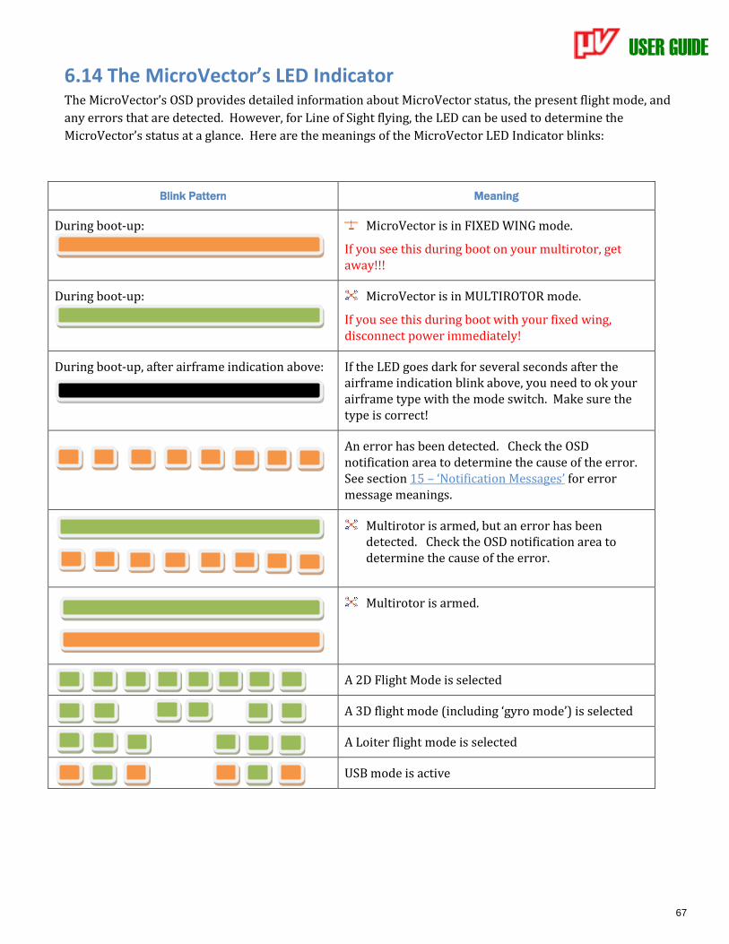
USER GUIDE
67
6.14 The MicroVector’s LED Indicator The MicroVector’s OSD provides detailed information about MicroVector status, the present flight mode, and
any errors that are detected. However, for Line of Sight flying, the LED can be used to determine the
MicroVector’s status at a glance. Here are the meanings of the MicroVector LED Indicator blinks:
Blink Pattern Meaning
During boot-up:
MicroVector is in FIXED WING mode.
If you see this during boot on your multirotor, get away!!!
During boot-up:
MicroVector is in MULTIROTOR mode.
If you see this during boot with your fixed wing, disconnect power immediately!
During boot-up, after airframe indication above: If the LED goes dark for several seconds after the airframe indication blink above, you need to ok your airframe type with the mode switch. Make sure the type is correct!
An error has been detected. Check the OSD notification area to determine the cause of the error. See section 15 – ‘Notification Messages’ for error message meanings.
Multirotor is armed, but an error has been detected. Check the OSD notification area to determine the cause of the error.
Multirotor is armed.
A 2D Flight Mode is selected
A 3D flight mode (including ‘gyro mode’) is selected
A Loiter flight mode is selected
USB mode is active
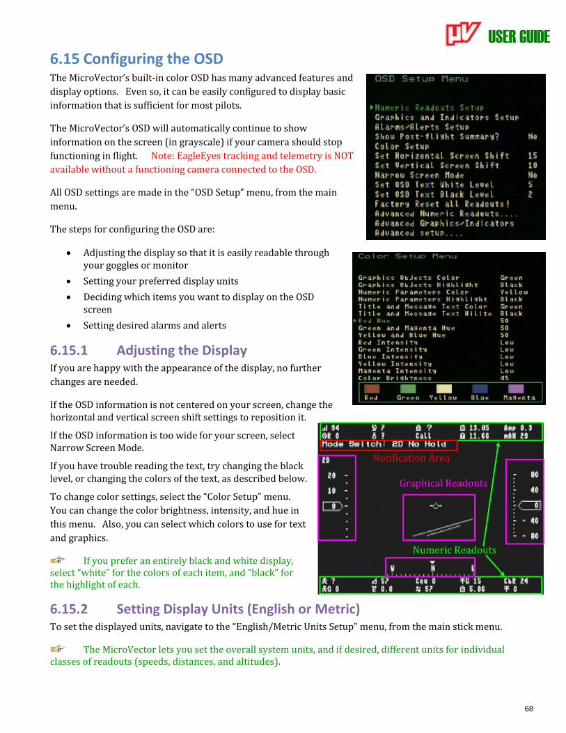
USER GUIDE
68
6.15 Configuring the OSD The MicroVector’s built-in color OSD has many advanced features and
display options. Even so, it can be easily configured to display basic
information that is sufficient for most pilots.
The MicroVector’s OSD will automatically continue to show
information on the screen (in grayscale) if your camera should stop
functioning in flight. Note: EagleEyes tracking and telemetry is NOT
available without a functioning camera connected to the OSD.
All OSD settings are made in the “OSD Setup” menu, from the main
menu.
The steps for configuring the OSD are:
• Adjusting the display so that it is easily readable through your goggles or monitor
• Setting your preferred display units
• Deciding which items you want to display on the OSD screen
• Setting desired alarms and alerts
6.15.1 Adjusting the Display If you are happy with the appearance of the display, no further
changes are needed.
If the OSD information is not centered on your screen, change the horizontal and vertical screen shift settings to reposition it.
If the OSD information is too wide for your screen, select Narrow Screen Mode.
If you have trouble reading the text, try changing the black level, or changing the colors of the text, as described below.
To change color settings, select the “Color Setup” menu.
You can change the color brightness, intensity, and hue in
this menu. Also, you can select which colors to use for text
and graphics.
If you prefer an entirely black and white display, select “white” for the colors of each item, and “black” for the highlight of each.
6.15.2 Setting Display Units (English or Metric) To set the displayed units, navigate to the “English/Metric Units Setup” menu, from the main stick menu.
The MicroVector lets you set the overall system units, and if desired, different units for individual classes of readouts (speeds, distances, and altitudes).
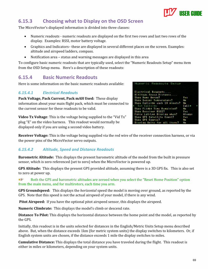
USER GUIDE
69
6.15.3 Choosing what to Display on the OSD Screen The MicroVector’s displayed information is divided into three classes:
• Numeric readouts - numeric readouts are displayed on the first two rows and last two rows of the display. Examples: RSSI, motor battery voltage.
• Graphics and Indicators– these are displayed in several different places on the screen. Examples: altitude and airspeed ladders, compass.
• Notification area – status and warning messages are displayed in this area
To configure basic numeric readouts that are typically used, select the “Numeric Readouts Setup” menu item
from the OSD Setup menu. Here’s a description of these readouts:
6.15.4 Basic Numeric Readouts Here is some information on the basic numeric readouts available:
6.15.4.1 Electrical Readouts
Pack Voltage, Pack Current, Pack mAH Used: These display
information about your main flight pack, which must be connected to
the current sensor for these readouts to be valid.
Video Tx Voltage: This is the voltage being supplied to the “Vid Tx”
plug “E” on the video harness. This readout would normally be
displayed only if you are using a second video battery.
Receiver Voltage: This is the voltage being supplied via the red wire of the receiver connection harness, or via
the power pins of the MicroVector servo outputs.
6.15.4.2 Altitude, Speed and Distance Readouts
Barometric Altitude: This displays the present barometric altitude of the model from the built in pressure sensor, which is zero referenced (set to zero) when the MicroVector is powered up.
GPS Altitude: This displays the present GPS provided altitude, assuming there is a 3D GPS fix. This is also set to zero at power up.
Both the GPS and barometric altitudes are zeroed when you select the “Reset Home Position” option from the main menu, and for multirotors, each time you arm.
GPS Groundspeed: This displays the horizontal speed the model is moving over ground, as reported by the GPS. Note that this speed is not the actual airspeed of your model, if there is any wind.
Pitot Airspeed: If you have the optional pitot airspeed sensor, this displays the airspeed.
Numeric Climbrate: This displays the model’s climb or descend rate.
Distance To Pilot: This displays the horizontal distance between the home point and the model, as reported by the GPS.
Initially, this readout is in the units selected for distances in the English/Metric Units Setup menu described above. But, when the distance exceeds 1km (for metric system units) the display switches to kilometers. Or, if English system units are chosen, if the distance exceeds 1 mile the display switches to miles.
Cumulative Distance: This displays the total distance you have traveled during the flight. This readout is either in miles or kilometers, depending on your system units.
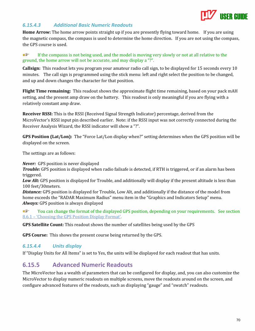
USER GUIDE
70
6.15.4.3 Additional Basic Numeric Readouts
Home Arrow: The home arrow points straight up if you are presently flying toward home. If you are using
the magnetic compass, the compass is used to determine the home direction. If you are not using the compass,
the GPS course is used.
If the compasss is not being used, and the model is moving very slowly or not at all relative to the ground, the home arrow will not be accurate, and may display a “?”.
Callsign: This readout lets you program your amateur radio call sign, to be displayed for 15 seconds every 10
minutes. The call sign is programmed using the stick menu: left and right select the position to be changed,
and up and down changes the character for that position.
Flight Time remaining: This readout shows the approximate flight time remaining, based on your pack mAH
setting, and the present amp draw on the battery. This readout is only meaningful if you are flying with a
relatively constant amp draw.
Receiver RSSI: This is the RSSI (Received Signal Strength Indicator) percentage, derived from the
MicroVector’s RSSI input pin described earlier. Note: if the RSSI input was not correctly connected during the
Receiver Analysis Wizard, the RSSI indicator will show a “?”.
GPS Position (Lat/Lon): The “Force Lat/Lon display when?” setting determines when the GPS position will be
displayed on the screen.
The settings are as follows:
Never: GPS position is never displayed Trouble: GPS position is displayed when radio failsafe is detected, if RTH is triggered, or if an alarm has been triggered. Low Alt: GPS position is displayed for Trouble, and additionally will display if the present altitude is less than 100 feet/30meters. Distance: GPS position is displayed for Trouble, Low Alt, and additionally if the distance of the model from home exceeds the “RADAR Maximum Radius” menu item in the “Graphics and Indicators Setup” menu. Always: GPS position is always displayed
You can change the format of the displayed GPS position, depending on your requirements. See section 8.6.1 – ‘Choosing the GPS Position Display Format’.
GPS Satellite Count: This readout shows the number of satellites being used by the GPS
GPS Course: This shows the present course being returned by the GPS.
6.15.4.4 Units display
If “Display Units for All Items” is set to Yes, the units will be displayed for each readout that has units.
6.15.5 Advanced Numeric Readouts The MicroVector has a wealth of parameters that can be configured for display, and, you can also customize the
MicroVector to display numeric readouts on multiple screens, move the readouts around on the screen, and
configure advanced features of the readouts, such as displaying “gauge” and “swatch” readouts.
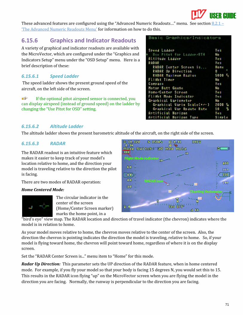
USER GUIDE
71
These advanced features are configured using the “Advanced Numeric Readouts…” menu. See section 8.2.1 –
‘The Advanced Numeric Readouts Menu’ for information on how to do this.
6.15.6 Graphics and Indicator Readouts A variety of graphical and indicator readouts are available with
the MicroVector, which are configured under the “Graphics and
Indicators Setup” menu under the “OSD Setup” menu. Here is a
brief description of these:
6.15.6.1 Speed Ladder
The speed ladder shows the present ground speed of the
aircraft, on the left side of the screen.
If the optional pitot airspeed sensor is connected, you can display airspeed (instead of ground speed) on the ladder by changing the “Use Pitot for OSD” setting.
6.15.6.2 Altitude Ladder
The altitude ladder shows the present barometric altitude of the aircraft, on the right side of the screen.
6.15.6.3 RADAR
The RADAR readout is an intuitive feature which makes it easier to keep track of your model’s location relative to home, and the direction your model is traveling relative to the direction the pilot is facing.
There are two modes of RADAR operation:
Home Centered Mode:
The circular indicator in the center of the screen (Home/Center Screen marker) marks the home point, in a
"bird's eye" view map. The RADAR location and direction of travel indicator (the chevron) indicates where the model is in relation to home.
As your model moves relative to home, the chevron moves relative to the center of the screen. Also, the direction the chevron is pointing indicates the direction the model is traveling, relative to home. So, if your model is flying toward home, the chevron will point toward home, regardless of where it is on the display screen.
Set the “RADAR Center Screen is...” menu item to “Home” for this mode.
Radar Up Direction: This parameter sets the UP direction of the RADAR feature, when in home centered
mode. For example, if you fly your model so that your body is facing 15 degrees N, you would set this to 15.
This results in the RADAR icon flying “up” on the MicroVector screen when you are flying the model in the
direction you are facing. Normally, the runway is perpendicular to the direction you are facing.
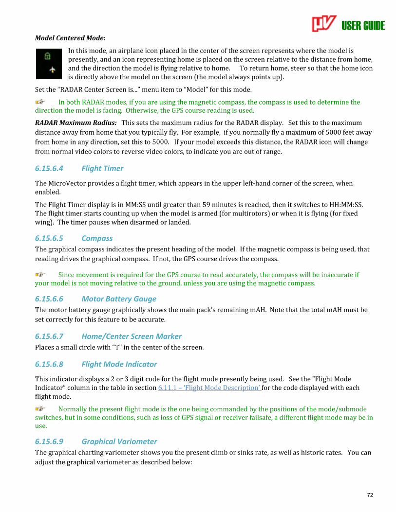
USER GUIDE
72
Model Centered Mode:
In this mode, an airplane icon placed in the center of the screen represents where the model is presently, and an icon representing home is placed on the screen relative to the distance from home, and the direction the model is flying relative to home. To return home, steer so that the home icon is directly above the model on the screen (the model always points up).
Set the “RADAR Center Screen is...” menu item to “Model” for this mode.
In both RADAR modes, if you are using the magnetic compass, the compass is used to determine the direction the model is facing. Otherwise, the GPS course reading is used.
RADAR Maximum Radius: This sets the maximum radius for the RADAR display. Set this to the maximum
distance away from home that you typically fly. For example, if you normally fly a maximum of 5000 feet away
from home in any direction, set this to 5000. If your model exceeds this distance, the RADAR icon will change
from normal video colors to reverse video colors, to indicate you are out of range.
6.15.6.4 Flight Timer
The MicroVector provides a flight timer, which appears in the upper left-hand corner of the screen, when enabled.
The Flight Timer display is in MM:SS until greater than 59 minutes is reached, then it switches to HH:MM:SS. The flight timer starts counting up when the model is armed (for multirotors) or when it is flying (for fixed wing). The timer pauses when disarmed or landed.
6.15.6.5 Compass
The graphical compass indicates the present heading of the model. If the magnetic compass is being used, that
reading drives the graphical compass. If not, the GPS course drives the compass.
Since movement is required for the GPS course to read accurately, the compass will be inaccurate if your model is not moving relative to the ground, unless you are using the magnetic compass.
6.15.6.6 Motor Battery Gauge
The motor battery gauge graphically shows the main pack’s remaining mAH. Note that the total mAH must be
set correctly for this feature to be accurate.
6.15.6.7 Home/Center Screen Marker
Places a small circle with “T” in the center of the screen.
6.15.6.8 Flight Mode Indicator
This indicator displays a 2 or 3 digit code for the flight mode presently being used. See the “Flight Mode Indicator” column in the table in section 6.11.1 – ‘Flight Mode Description’ for the code displayed with each flight mode.
Normally the present flight mode is the one being commanded by the positions of the mode/submode switches, but in some conditions, such as loss of GPS signal or receiver failsafe, a different flight mode may be in use.
6.15.6.9 Graphical Variometer
The graphical charting variometer shows you the present climb or sinks rate, as well as historic rates. You can
adjust the graphical variometer as described below:
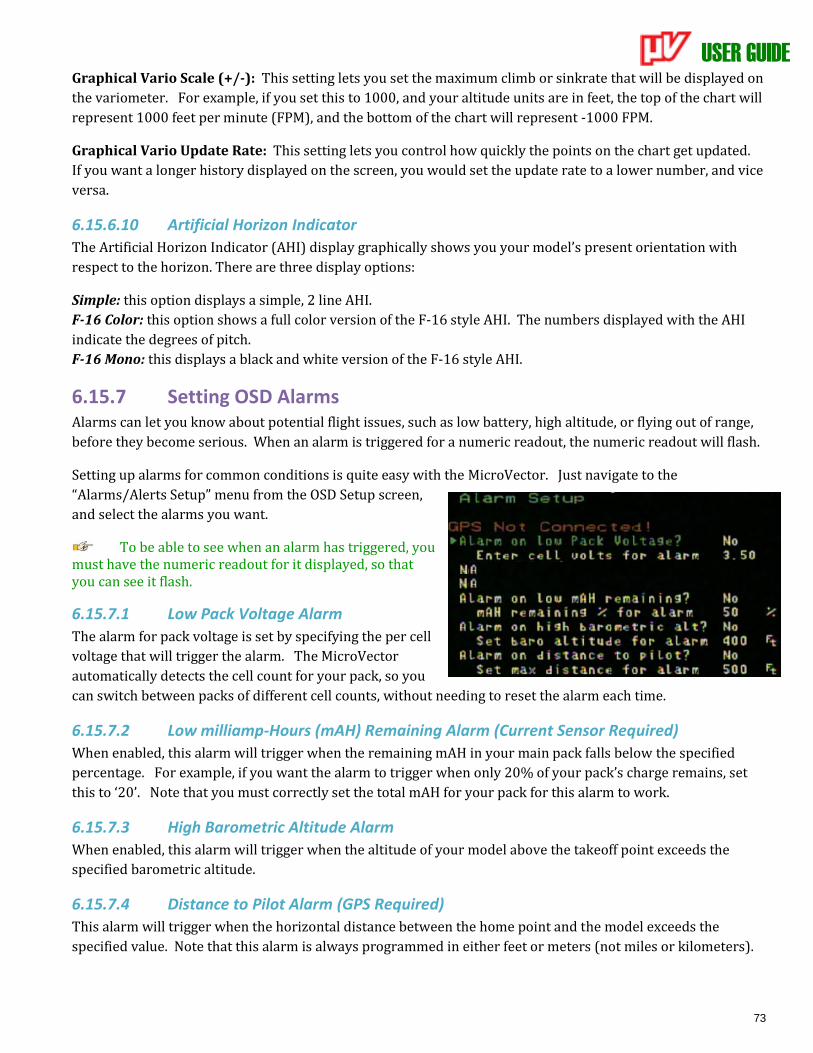
USER GUIDE
73
Graphical Vario Scale (+/-): This setting lets you set the maximum climb or sinkrate that will be displayed on
the variometer. For example, if you set this to 1000, and your altitude units are in feet, the top of the chart will
represent 1000 feet per minute (FPM), and the bottom of the chart will represent -1000 FPM.
Graphical Vario Update Rate: This setting lets you control how quickly the points on the chart get updated.
If you want a longer history displayed on the screen, you would set the update rate to a lower number, and vice
versa.
6.15.6.10 Artificial Horizon Indicator
The Artificial Horizon Indicator (AHI) display graphically shows you your model’s present orientation with
respect to the horizon. There are three display options:
Simple: this option displays a simple, 2 line AHI.
F-16 Color: this option shows a full color version of the F-16 style AHI. The numbers displayed with the AHI
indicate the degrees of pitch.
F-16 Mono: this displays a black and white version of the F-16 style AHI.
6.15.7 Setting OSD Alarms Alarms can let you know about potential flight issues, such as low battery, high altitude, or flying out of range,
before they become serious. When an alarm is triggered for a numeric readout, the numeric readout will flash.
Setting up alarms for common conditions is quite easy with the MicroVector. Just navigate to the
“Alarms/Alerts Setup” menu from the OSD Setup screen,
and select the alarms you want.
To be able to see when an alarm has triggered, you must have the numeric readout for it displayed, so that you can see it flash.
6.15.7.1 Low Pack Voltage Alarm
The alarm for pack voltage is set by specifying the per cell
voltage that will trigger the alarm. The MicroVector
automatically detects the cell count for your pack, so you
can switch between packs of different cell counts, without needing to reset the alarm each time.
6.15.7.2 Low milliamp-Hours (mAH) Remaining Alarm (Current Sensor Required)
When enabled, this alarm will trigger when the remaining mAH in your main pack falls below the specified
percentage. For example, if you want the alarm to trigger when only 20% of your pack’s charge remains, set
this to ‘20’. Note that you must correctly set the total mAH for your pack for this alarm to work.
6.15.7.3 High Barometric Altitude Alarm
When enabled, this alarm will trigger when the altitude of your model above the takeoff point exceeds the
specified barometric altitude.
6.15.7.4 Distance to Pilot Alarm (GPS Required)
This alarm will trigger when the horizontal distance between the home point and the model exceeds the
specified value. Note that this alarm is always programmed in either feet or meters (not miles or kilometers).
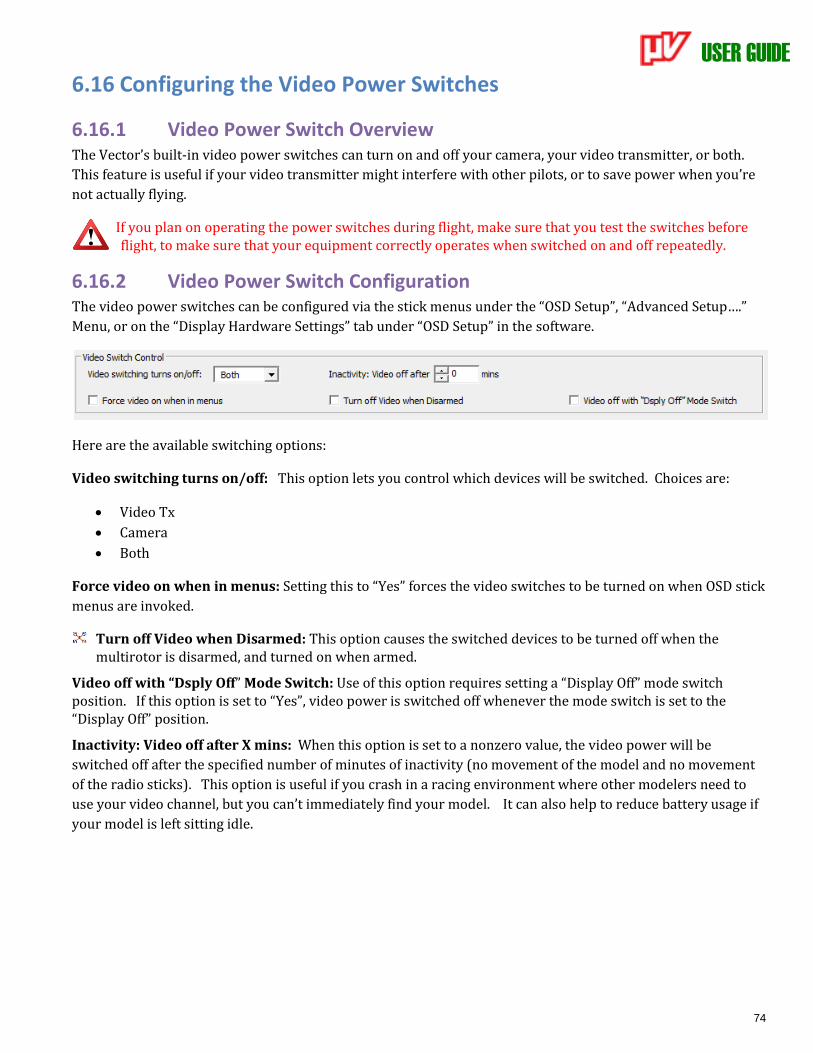
USER GUIDE
74
6.16 Configuring the Video Power Switches
6.16.1 Video Power Switch Overview The Vector’s built-in video power switches can turn on and off your camera, your video transmitter, or both.
This feature is useful if your video transmitter might interfere with other pilots, or to save power when you’re
not actually flying.
If you plan on operating the power switches during flight, make sure that you test the switches before flight, to make sure that your equipment correctly operates when switched on and off repeatedly.
6.16.2 Video Power Switch Configuration The video power switches can be configured via the stick menus under the “OSD Setup”, “Advanced Setup….”
Menu, or on the “Display Hardware Settings” tab under “OSD Setup” in the software.
Here are the available switching options:
Video switching turns on/off: This option lets you control which devices will be switched. Choices are:
• Video Tx
• Camera
• Both
Force video on when in menus: Setting this to “Yes” forces the video switches to be turned on when OSD stick
menus are invoked.
Turn off Video when Disarmed: This option causes the switched devices to be turned off when the multirotor is disarmed, and turned on when armed.
Video off with “Dsply Off” Mode Switch: Use of this option requires setting a “Display Off” mode switch position. If this option is set to “Yes”, video power is switched off whenever the mode switch is set to the “Display Off” position.
Inactivity: Video off after X mins: When this option is set to a nonzero value, the video power will be
switched off after the specified number of minutes of inactivity (no movement of the model and no movement
of the radio sticks). This option is useful if you crash in a racing environment where other modelers need to
use your video channel, but you can’t immediately find your model. It can also help to reduce battery usage if
your model is left sitting idle.

USER GUIDE
75
6.17 Configuring/Calibrating the Magnetic Compass (GPS Required)
6.17.1 Using the Compass with Fixed Wing Airframes
The magnetic compass built into the GPS/Mag is automatically disabled for fixed wing airframes, and automatically enabled for multirotors.
For fixed wing airframes, using the compass offers these benefits:
• The magnetic compass operates even if the model is moving slowly, or not at all. If RTH is triggered
downwind, and the wind is so strong that the model is moving very slowly toward home, or even losing
ground, the GPS course readout may not be accurate, which could cause the RTH system to not be able to
identify the direction to home without the compass.
• Loiter and RTH circling modes may be more precise
• The compass reading can be used for easy determination of the “RADAR Up Direction” or the EagleEyes
tracker’s “0 degree pan” settings.
However, if you decide to use the compass with fixed wing, it’s very important that the mounting, installation
and calibration guidelines for the GPS/Mag are followed, or the compass can make things much worse!
To enable the compass for fixed wing, navigate to the “Calibration and Sensor Setup” menu from the main menu, and change “Enable Compass/Magnetometer” to “Yes”.
6.17.2 Calibrating the Compass Compass calibration should be done with the model away from electrical fields and metal objects. The best
place to calibrate the compass is outdoors, at the field where you will be flying.
6.17.2.1 Steps before Calibrating
Before calibrating the compass, make sure that the compass is installed correctly, and that all equipment you plan to fly with, including cameras, canopies, etc., are fully installed on the model, and turned on. Adding equipment later can impact the compass calibration!
6.17.2.2 Calibrating using the Stick Menus
To calibrate the compass using the stick menus, follow the steps
below. If you get errors when calibrating, make note of the error
number in the OSD notification message, and see the description
of that message in section 15 – ‘Notification Messages’ of the
manual.
1) Invoke Compass Calibration mode by selecting the “Compass Working ok (if used)?” menu item under
the “Preflight Checklist” menu.
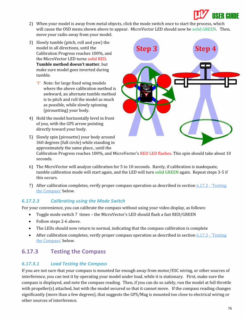
USER GUIDE
76
2) When your model is away from metal objects, click the mode switch once to start the process, which will cause the OSD menu shown above to appear. MicroVector LED should now be solid GREEN. Then, move your radio away from your model.
3) Slowly tumble (pitch, roll and yaw) the model in all directions, until the Calibration Progress reaches 100%, and the MicroVector LED turns solid RED. Tumble method doesn’t matter, but make sure model goes inverted during tumble.
Note: for large fixed wing models where the above calibration method is awkward, an alternate tumble method is to pitch and roll the model as much as possible, while slowly spinning (pirouetting) your body.
4) Hold the model horizontally level in front of you, with the GPS arrow pointing directly toward your body.
5) Slowly spin (pirouette) your body around 360 degrees (full circle) while standing in approximately the same place., until the Calibration Progress reaches 100%, and MicroVector’s RED LED flashes. This spin should take about 10 seconds.
6) The MicroVector will analyze calibration for 5 to 10 seconds. Rarely, if calibration is inadequate, tumble calibration mode will start again, and the LED will turn solid GREEN again. Repeat steps 3-5 if this occurs.
7) After calibration completes, verify proper compass operation as described in section 6.17.3 - ‘Testing the Compass' below.
6.17.2.3 Calibrating using the Mode Switch
For your convenience, you can calibrate the compass without using your video display, as follows:
• Toggle mode switch 7 times – the MicroVector’s LED should flash a fast RED/GREEN
• Follow steps 2-6 above.
• The LEDs should now return to normal, indicating that the compass calibration is complete
• After calibration completes, verify proper compass operation as described in section 6.17.3 - ‘Testing the Compass' below.
6.17.3 Testing the Compass
6.17.3.1 Load Testing the Compass
If you are not sure that your compass is mounted far enough away from motor/ESC wiring, or other sources of
interference, you can test it by operating your model under load, while it is stationary. First, make sure the
compass is displayed, and note the compass reading. Then, if you can do so safely, run the model at full throttle
with propeller(s) attached, but with the model secured so that it cannot move. If the compass reading changes
significantly (more than a few degrees), that suggests the GPS/Mag is mounted too close to electrical wiring or
other sources of interference.

USER GUIDE
77
6.17.3.2 Field Testing the Compass
It’s a good idea to do a quick check of compass function before each day of flying. Display the compass (either on the Preflight Checklist menu or the main OSD screen) and make sure the compass is pointing in the correct direction.
If you don’t know what direction North is at your field and don’t have a mechanical compass, most mobile phones have apps available that will let you use your phone as a compass.
Next, rotate the model slowly 360 degrees (full circle) and make sure the compass smoothly follows your rotation.
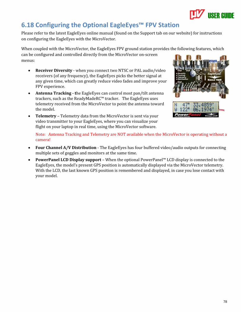
USER GUIDE
78
6.18 Configuring the Optional EagleEyes™ FPV Station Please refer to the latest EagleEyes online manual (found on the Support tab on our website) for instructions
on configuring the EagleEyes with the MicroVector.
When coupled with the MicroVector, the EagleEyes FPV ground station provides the following features, which
can be configured and controlled directly from the MicroVector on-screen
menus:
• Receiver Diversity - when you connect two NTSC or PAL audio/video receivers (of any frequency), the EagleEyes picks the better signal at any given time, which can greatly reduce video fades and improve your FPV experience.
• Antenna Tracking - the EagleEyes can control most pan/tilt antenna trackers, such as the ReadyMadeRC™ tracker. The EagleEyes uses telemetry received from the MicroVector to point the antenna toward the model.
• Telemetry – Telemetry data from the MicroVector is sent via your video transmitter to your EagleEyes, where you can visualize your flight on your laptop in real time, using the MicroVector software.
Note: Antenna Tracking and Telemetry are NOT available when the MicroVector is operating without a camera!
• Four Channel A/V Distribution - The EagleEyes has four buffered video/audio outputs for connecting multiple sets of goggles and monitors at the same time.
• PowerPanel LCD Display support – When the optional PowerPanel™ LCD display is connected to the EagleEyes, the model’s present GPS position is automatically displayed via the MicroVector telemetry. With the LCD, the last known GPS position is remembered and displayed, in case you lose contact with your model.
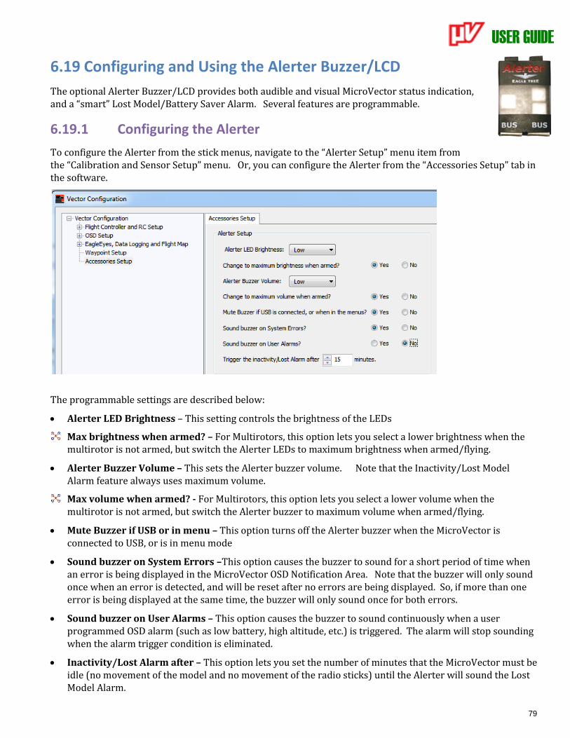
USER GUIDE
79
6.19 Configuring and Using the Alerter Buzzer/LCD
The optional Alerter Buzzer/LCD provides both audible and visual MicroVector status indication, and a “smart” Lost Model/Battery Saver Alarm. Several features are programmable.
6.19.1 Configuring the Alerter
To configure the Alerter from the stick menus, navigate to the “Alerter Setup” menu item from the “Calibration and Sensor Setup” menu. Or, you can configure the Alerter from the “Accessories Setup” tab in the software.
The programmable settings are described below:
• Alerter LED Brightness – This setting controls the brightness of the LEDs
Max brightness when armed? – For Multirotors, this option lets you select a lower brightness when the multirotor is not armed, but switch the Alerter LEDs to maximum brightness when armed/flying.
• Alerter Buzzer Volume – This sets the Alerter buzzer volume. Note that the Inactivity/Lost Model Alarm feature always uses maximum volume.
Max volume when armed? - For Multirotors, this option lets you select a lower volume when the multirotor is not armed, but switch the Alerter buzzer to maximum volume when armed/flying.
• Mute Buzzer if USB or in menu – This option turns off the Alerter buzzer when the MicroVector is connected to USB, or is in menu mode
• Sound buzzer on System Errors –This option causes the buzzer to sound for a short period of time when an error is being displayed in the MicroVector OSD Notification Area. Note that the buzzer will only sound once when an error is detected, and will be reset after no errors are being displayed. So, if more than one error is being displayed at the same time, the buzzer will only sound once for both errors.
• Sound buzzer on User Alarms – This option causes the buzzer to sound continuously when a user programmed OSD alarm (such as low battery, high altitude, etc.) is triggered. The alarm will stop sounding when the alarm trigger condition is eliminated.
• Inactivity/Lost Alarm after – This option lets you set the number of minutes that the MicroVector must be idle (no movement of the model and no movement of the radio sticks) until the Alerter will sound the Lost Model Alarm.
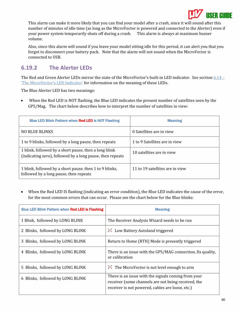
USER GUIDE
80
This alarm can make it more likely that you can find your model after a crash, since it will sound after this number of minutes of idle time (as long as the MicroVector is powered and connected to the Alerter) even if your power system temporarily shuts off during a crash. This alarm is always at maximum buzzer volume.
Also, since this alarm will sound if you leave your model sitting idle for this period, it can alert you that you forgot to disconnect your battery pack. Note that the alarm will not sound when the MicroVector is connected to USB.
6.19.2 The Alerter LEDs
The Red and Green Alerter LEDs mirror the state of the MicroVector’s built-in LED indicator. See section 6.14 – ‘The MicroVector’s LED Indicator’ for information on the meaning of these LEDs.
The Blue Alerter LED has two meanings:
• When the Red LED is NOT flashing, the Blue LED indicates the present number of satellites seen by the
GPS/Mag. The chart below describes how to interpret the number of satellites in view:
• When the Red LED IS flashing (indicating an error condition), the Blue LED indicates the cause of the error,
for the most common errors that can occur. Please see the chart below for the Blue blinks:
Blue LED Blink Pattern when Red LED is Flashing Meaning
1 Blink, followed by LONG BLINK The Receiver Analysis Wizard needs to be run
2 Blinks, followed by LONG BLINK Low Battery Autoland triggered
3 Blinks, followed by LONG BLINK Return to Home (RTH) Mode is presently triggered
4 Blinks, followed by LONG BLINK There is an issue with the GPS/MAG connection, fix quality, or calibration
5 Blinks, followed by LONG BLINK The MicroVector is not level enough to arm
6 Blinks, followed by LONG BLINK There is an issue with the signals coming from your
receiver (some channels are not being received, the
receiver is not powered, cables are loose, etc.)
Blue LED Blink Pattern when Red LED is NOT Flashing Meaning
NO BLUE BLINKS 0 Satellites are in view
1 to 9 blinks, followed by a long pause, then repeats 1 to 9 Satellites are in view
1 blink, followed by a short pause, then a long blink
(indicating zero), followed by a long pause, then repeats 10 satellites are in view
1 blink, followed by a short pause, then 1 to 9 blinks, followed by a long pause, then repeats
11 to 19 satellites are in view

USER GUIDE
81
7 Blinks, followed by LONG BLINK There is a problem with your RTH configuration
8 Blinks, followed by LONG BLINK You are trying to arm in a GPS flight mode
NO BLUE BLINKS This indicates that it’s necessary to either look at the OSD screen, the InfoPanel LCD, or the data log (any one of these) to see what error condition is occurring.
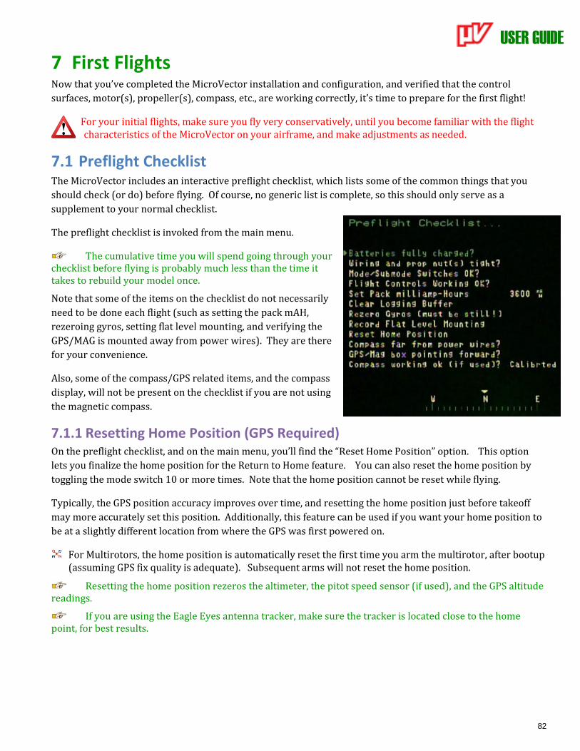
USER GUIDE
82
7 First Flights Now that you’ve completed the MicroVector installation and configuration, and verified that the control
surfaces, motor(s), propeller(s), compass, etc., are working correctly, it’s time to prepare for the first flight!
For your initial flights, make sure you fly very conservatively, until you become familiar with the flight characteristics of the MicroVector on your airframe, and make adjustments as needed.
7.1 Preflight Checklist The MicroVector includes an interactive preflight checklist, which lists some of the common things that you
should check (or do) before flying. Of course, no generic list is complete, so this should only serve as a
supplement to your normal checklist.
The preflight checklist is invoked from the main menu.
The cumulative time you will spend going through your checklist before flying is probably much less than the time it takes to rebuild your model once.
Note that some of the items on the checklist do not necessarily
need to be done each flight (such as setting the pack mAH,
rezeroing gyros, setting flat level mounting, and verifying the
GPS/MAG is mounted away from power wires). They are there
for your convenience.
Also, some of the compass/GPS related items, and the compass
display, will not be present on the checklist if you are not using
the magnetic compass.
7.1.1 Resetting Home Position (GPS Required) On the preflight checklist, and on the main menu, you’ll find the “Reset Home Position” option. This option
lets you finalize the home position for the Return to Home feature. You can also reset the home position by
toggling the mode switch 10 or more times. Note that the home position cannot be reset while flying.
Typically, the GPS position accuracy improves over time, and resetting the home position just before takeoff
may more accurately set this position. Additionally, this feature can be used if you want your home position to
be at a slightly different location from where the GPS was first powered on.
For Multirotors, the home position is automatically reset the first time you arm the multirotor, after bootup (assuming GPS fix quality is adequate). Subsequent arms will not reset the home position.
Resetting the home position rezeros the altimeter, the pitot speed sensor (if used), and the GPS altitude readings.
If you are using the Eagle Eyes antenna tracker, make sure the tracker is located close to the home point, for best results.
USER GUIDE
83
7.2 First Flight Recommendations
7.2.1 Ground Tests before First Flight
7.2.1.1 Vibration Check for Fixed Wing
If you can do so safely, it is recommended that you perform a prop-on engine run-up on the ground with 2D stabilization enabled (and the gain knob at midpoint or higher, if used), while watching your control surfaces for drift. This is especially important to do if you have a nitro, gas, or other high vibration motor.
Don’t fly your model if your control surfaces are moving unexpectedly during engine run-up! You’ll need to find ways of further isolating the MicroVector, or your airframe, from motor vibration, such as using
a cushioned motor mount.
7.2.1.2 Control Direction check for Multirotors
If you have not done so already, use the Motor Test stick menu (described earlier) to verify the correct rotation direction and motor wiring order.
7.2.2 Flight Mode for Takeoffs
For fixed wing models, it is recommended that you take off either in a non 2D stabilized mode (3D mode, ‘Gyro’ mode, or Stabilization Off mode), or in 2D mode WITHOUT Hold with your gain knob turned low, until you are sure that your gain and other settings are correct for your model. Once you take off, you can turn the gain up or switch into a 2D stabilized mode, but be prepared to exit that mode if there are problems.
In general, if you take off in 2D WITH Hold mode, note that the model will hold whatever heading it was last pointing to UNTIL you unlock heading hold by moving the aileron or rudder stick. Make sure that you move one of these sticks after you have the model pointing in the takeoff direction, but before taking off!
For Multirotors, you should always take off in a non-GPS mode (2D, 2D with Heading Hold, Cartesian, 3D with Hold, or Center Stick mode). Once in the air, you can switch to a GPS mode as desired. Also, at least for your first flights it is recommended that a non-altitude hold flight mode (2D, 3D with Heading Hold, or Center Stick mode) be available on your mode/submode switches, in case excessive vibration causes issues with altitude hold.
Excessive frame vibration in altitude hold flight modes (2DH, Loiter, etc.) can cause altitude hold to fail. If this happens, the multirotor can suddenly climb very rapidly! Be prepared to switch out of altitude
hold mode and land, if this condition occurs. Also, the MicroVector attempts to detect this condition and switch out of altitude hold mode after a few seconds, each time the condition occurs.
7.2.3 Fixed Wing Stalls
With fixed wing models, it’s critical to maintain enough airspeed to avoid a stall. If a stall should occur, however, correct stall recovery techniques must be used to avoid a crash. These are documented on the web and elsewhere, and may vary from airframe to airframe.
Maintain sufficient airspeed to avoid stalling, and if a stall occurs, make sure you are familiar with correct stall recovery techniques for your airframe!
USER GUIDE
84
7.3 In-air Leveling If you find that your model is not flying or hovering level in “2D” flight modes after you have performed the
“Record Flat Level Mounting” procedure as described earlier, you can reset level flight while in the air. The
procedure is as follows:
7.3.1 Multirotor in-air leveling
Slight adjustments to multirotor level offset can be corrected as follows: while hovering in a non-GPS 2D flight mode (2D or 2D with Altitude Hold, but NOT Center Stick mode), and when there is no wind, adjust your aileron and elevator radio trims so that the multirotor is hovering in a stationary position.
Then, land the multirotor, disarm, and toggle the mode switch 5 times. At this point your level trims have been saved. DO NOT undo the changes to your radio trims after doing these steps.
In-air leveling does not work with Center Stick flight mode.
7.3.2 Fixed Wing in-air leveling
If your model is not flying straight and level in 2D Mode WITHOUT Hold, first level out the model with your control stick, then (while keeping the model level with the stick) toggle the mode switch 5 times. This records the level flight orientation for your model.
The MicroVector remembers your model’s current orientation the moment you first start to move the mode switch. So, you don’t need to worry about keeping the model perfectly level while you toggle the switch 5 times. It only needs to be level at the start of the toggle sequence.
7.3.3 Optimal Fixed Wing leveling
If you want to tune your model for more efficient flight, it is recommended that you follow these steps:
• First fly your model with stabilization off (or with overall gain turned off with the gain knob) and adjust your radio trims for level flight.
• Land, and either rerun the Receiver Analysis Wizard, or use the “Incorporate Trims” menu option under the Stabilizer Settings OSD stick menu, so that the MicroVector can learn about the new radio trim settings.
• Perform the “Fixed Wing in-air leveling” procedure described above, if needed.
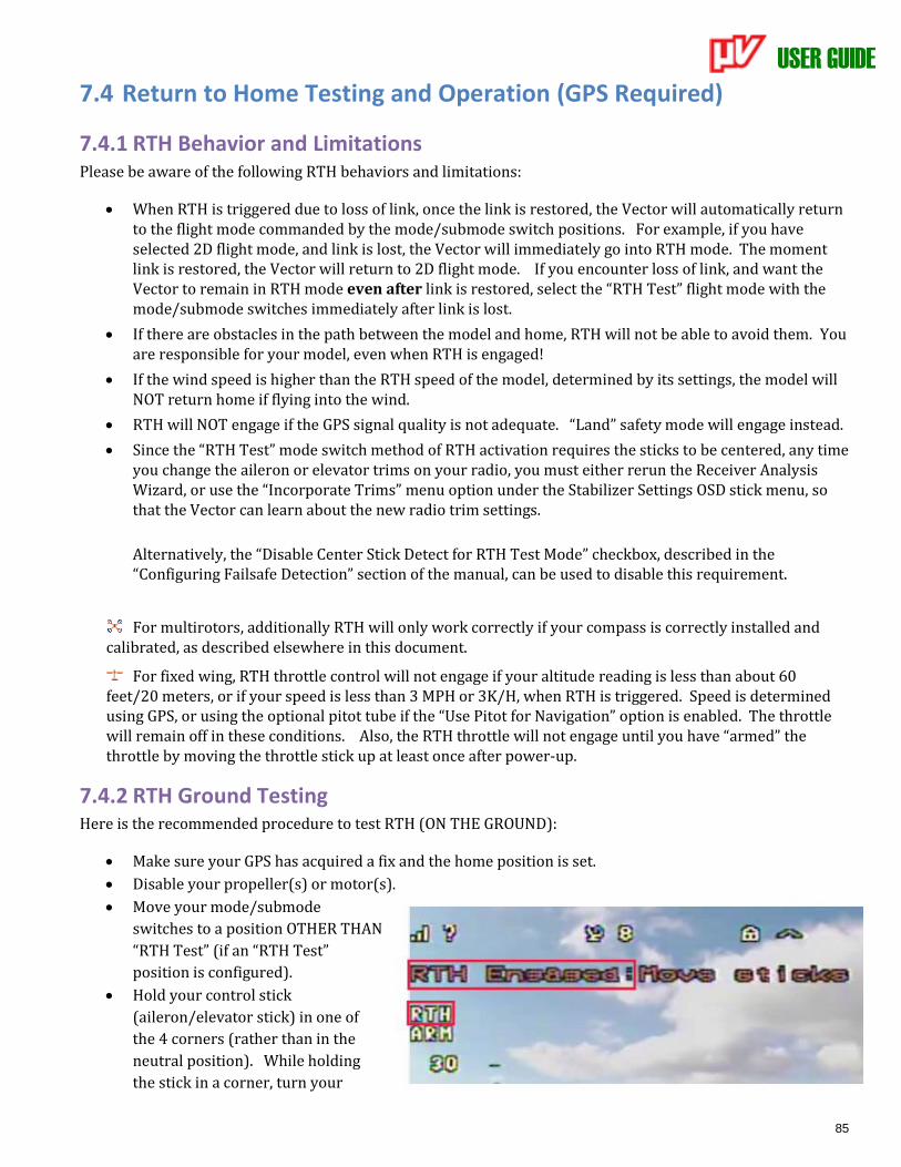
USER GUIDE
85
7.4 Return to Home Testing and Operation (GPS Required)
7.4.1 RTH Behavior and Limitations Please be aware of the following RTH behaviors and limitations:
• When RTH is triggered due to loss of link, once the link is restored, the Vector will automatically return to the flight mode commanded by the mode/submode switch positions. For example, if you have selected 2D flight mode, and link is lost, the Vector will immediately go into RTH mode. The moment link is restored, the Vector will return to 2D flight mode. If you encounter loss of link, and want the Vector to remain in RTH mode even after link is restored, select the “RTH Test” flight mode with the mode/submode switches immediately after link is lost.
• If there are obstacles in the path between the model and home, RTH will not be able to avoid them. You are responsible for your model, even when RTH is engaged!
• If the wind speed is higher than the RTH speed of the model, determined by its settings, the model will NOT return home if flying into the wind.
• RTH will NOT engage if the GPS signal quality is not adequate. “Land” safety mode will engage instead.
• Since the “RTH Test” mode switch method of RTH activation requires the sticks to be centered, any time you change the aileron or elevator trims on your radio, you must either rerun the Receiver Analysis Wizard, or use the “Incorporate Trims” menu option under the Stabilizer Settings OSD stick menu, so that the Vector can learn about the new radio trim settings.
Alternatively, the “Disable Center Stick Detect for RTH Test Mode” checkbox, described in the “Configuring Failsafe Detection” section of the manual, can be used to disable this requirement.
For multirotors, additionally RTH will only work correctly if your compass is correctly installed and calibrated, as described elsewhere in this document.
For fixed wing, RTH throttle control will not engage if your altitude reading is less than about 60 feet/20 meters, or if your speed is less than 3 MPH or 3K/H, when RTH is triggered. Speed is determined using GPS, or using the optional pitot tube if the “Use Pitot for Navigation” option is enabled. The throttle will remain off in these conditions. Also, the RTH throttle will not engage until you have “armed” the throttle by moving the throttle stick up at least once after power-up.
7.4.2 RTH Ground Testing Here is the recommended procedure to test RTH (ON THE GROUND):
• Make sure your GPS has acquired a fix and the home position is set.
• Disable your propeller(s) or motor(s).
• Move your mode/submode
switches to a position OTHER THAN
“RTH Test” (if an “RTH Test”
position is configured).
• Hold your control stick
(aileron/elevator stick) in one of
the 4 corners (rather than in the
neutral position). While holding
the stick in a corner, turn your
USER GUIDE
86
transmitter off.
If RTH is configured correctly, after following the above steps the message “RTH Engaged…” should appear in
the OSD notification area of the video screen. Note also that if the message “…release sticks to test” appears,
RTH is NOT engaging correctly.
Additionally, the Flight Mode Indicator on the video screen should change to “RTH”.
If you don’t see BOTH these notifications, RTH will not activate in the event of a receiver failsafe. Please refer
back to the RTH configuration section if RTH does not trigger correctly.
For fixed wing models, don’t forget that your propeller may spin at any time when RTH is triggered, even on the ground!
7.4.3 In-air RTH Testing The simplest way to test RTH in the air is to program a mode/submode switch position to “RTH Test”. When
this switch position is selected, RTH should engage, and your model should fly toward the home point.
Never intentionally turn off your radio to test RTH in the air. There is a chance that your receiver will not link back up with your radio, which could result in a crash!
When in RTH test mode, moving the control stick causes RTH to disengage, and the model switches to 2D with Hold flight mode, unless the “Disable Center Stick Detect for RTH Test Mode” option was selected.
Note that for proper operation of RTH Test mode (unless the “Disable Center Stick Detect for RTH Test Mode” option was selected), your trim settings must have been recorded during the Radio Control Wizard, unless the “Disable Center Stick Detect for RTH Test Mode” option was selected. If you have made significant changes to your trim settings since you ran the Wizard, the message “RTH Engaged: Release Sticks for Test” may appear when RTH is activated, and RTH will not engage.
Note: if your multirotor is in Polar or Cartesian flight mode and RTH Test is triggered, remember that it will switch to 2D with Hold flight mode during the RTH testing, so the control stick will control the multirotor differently during RTH testing!
If you find that your model returns home correctly, no further adjustments should be necessary. If problems
occur, refer to the Troubleshooting chart later in the document.
Don’t forget to switch out of RTH Test mode before landing!
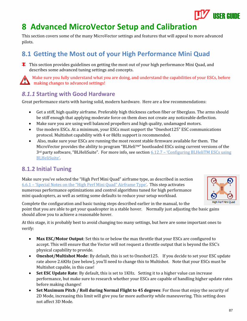
USER GUIDE
87
8 Advanced MicroVector Setup and Calibration This section covers some of the many MicroVector settings and features that will appeal to more advanced
pilots.
8.1 Getting the Most out of your High Performance Mini Quad
This section provides guidelines on getting the most out of your high performance Mini Quad, and describes some advanced tuning settings and concepts.
Make sure you fully understand what you are doing, and understand the capabilities of your ESCs, before making changes to advanced settings!
8.1.1 Starting with Good Hardware Great performance starts with having solid, modern hardware. Here are a few recommendations:
• Get a stiff, high quality airframe. Preferably high thickness carbon fiber or fiberglass. The arms should
be stiff enough that applying moderate force on them does not create any noticeable deflection.
• Make sure you are using well balanced propellers and high quality, undamaged motors.
• Use modern ESCs. At a minimum, your ESCs must support the “Oneshot125” ESC communications
protocol. Multishot capability with 4 or 8kHz support is recommended.
• Also, make sure your ESCs are running the most recent stable firmware available for them. The
MicroVector provides the ability to program “BLHeliTM” bootloaded ESCs using current versions of the
3rd party software, “BLHeliSuite”. For more info, see section 6.12.7 – ‘Configuring BLHeliTM ESCs using
BLHeliSuite’.
8.1.2 Initial Tuning
Make sure you’ve selected the “High Perf Mini Quad” airframe type, as described in section 6.6.1 – ‘Special Notes on the “High Perf Mini Quad” Airframe Type’. This step activates numerous performance optimizations and control algorithms tuned for high performance mini quadcopters, as well as setting some defaults to reduce your setup workload.
Complete the configuration and basic tuning steps described earlier in the manual, to the point that you are able to get your quadcopter in a stable hover. Normally just adjusting the basic gains should allow you to achieve a reasonable hover.
At this stage, it is probably best to avoid changing too many settings, but here are some important ones to
verify:
• Max ESC/Motor Output: Set this to or below the max throttle that your ESCs are configured to
accept. This will ensure that the Vector will not request a throttle output that is beyond the ESC’s
physical capability to provide.
• Oneshot/Multishot Mode: By default, this is set to Oneshot125. If you decide to set your ESC update
rate above 2.6KHz (see below), you’ll need to change this to Multishot. Note that your ESCs must be
Multishot capable, in this case!
• Set ESC Update Rate: By default, this is set to 1KHz. Setting it to a higher value can increase
performance, but make sure to research whether your ESCs are capable of handling higher update rates
before making changes!
• Set Maximum Pitch / Roll during Normal Flight to 45 degrees: For those that enjoy the security of
2D Mode, increasing this limit will give you far more authority while maneuvering. This setting does
not affect 3D Mode.
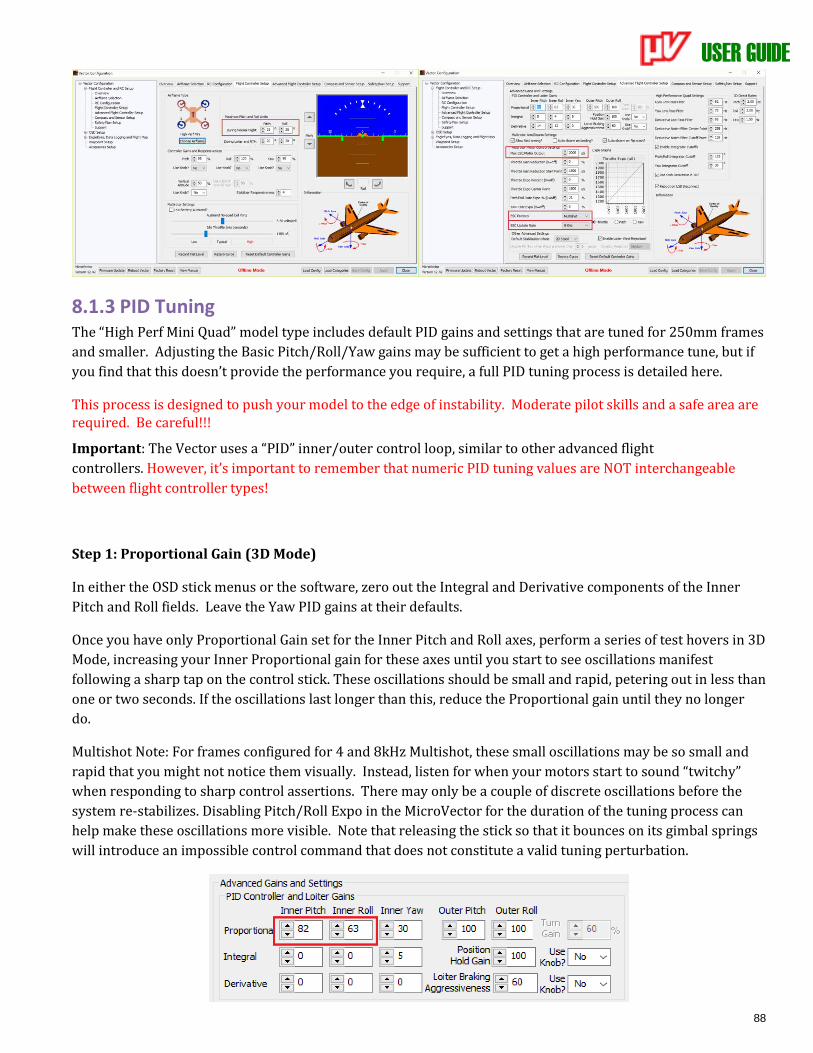
USER GUIDE
88
8.1.3 PID Tuning The “High Perf Mini Quad” model type includes default PID gains and settings that are tuned for 250mm frames
and smaller. Adjusting the Basic Pitch/Roll/Yaw gains may be sufficient to get a high performance tune, but if
you find that this doesn’t provide the performance you require, a full PID tuning process is detailed here.
This process is designed to push your model to the edge of instability. Moderate pilot skills and a safe area are required. Be careful!!!
Important: The Vector uses a “PID” inner/outer control loop, similar to other advanced flight
controllers. However, it’s important to remember that numeric PID tuning values are NOT interchangeable
between flight controller types!
Step 1: Proportional Gain (3D Mode)
In either the OSD stick menus or the software, zero out the Integral and Derivative components of the Inner
Pitch and Roll fields. Leave the Yaw PID gains at their defaults.
Once you have only Proportional Gain set for the Inner Pitch and Roll axes, perform a series of test hovers in 3D
Mode, increasing your Inner Proportional gain for these axes until you start to see oscillations manifest
following a sharp tap on the control stick. These oscillations should be small and rapid, petering out in less than
one or two seconds. If the oscillations last longer than this, reduce the Proportional gain until they no longer
do.
Multishot Note: For frames configured for 4 and 8kHz Multishot, these small oscillations may be so small and
rapid that you might not notice them visually. Instead, listen for when your motors start to sound “twitchy”
when responding to sharp control assertions. There may only be a couple of discrete oscillations before the
system re-stabilizes. Disabling Pitch/Roll Expo in the MicroVector for the duration of the tuning process can
help make these oscillations more visible. Note that releasing the stick so that it bounces on its gimbal springs
will introduce an impossible control command that does not constitute a valid tuning perturbation.
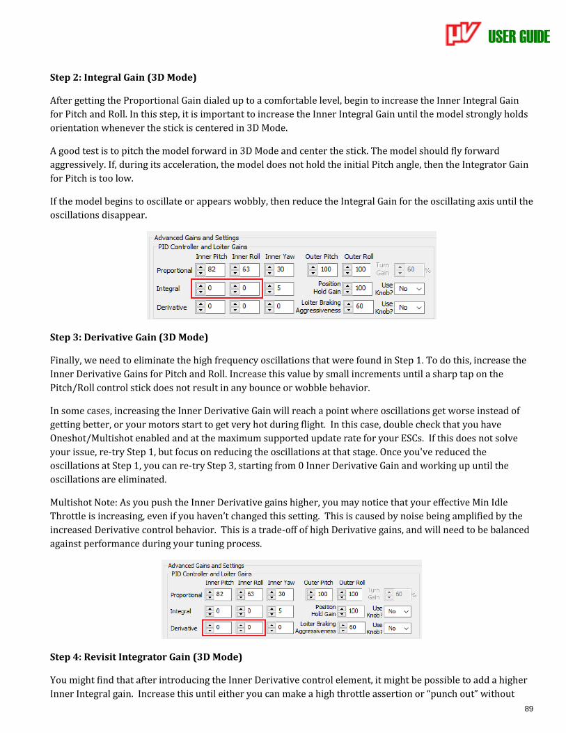
USER GUIDE
89
Step 2: Integral Gain (3D Mode)
After getting the Proportional Gain dialed up to a comfortable level, begin to increase the Inner Integral Gain
for Pitch and Roll. In this step, it is important to increase the Inner Integral Gain until the model strongly holds
orientation whenever the stick is centered in 3D Mode.
A good test is to pitch the model forward in 3D Mode and center the stick. The model should fly forward
aggressively. If, during its acceleration, the model does not hold the initial Pitch angle, then the Integrator Gain
for Pitch is too low.
If the model begins to oscillate or appears wobbly, then reduce the Integral Gain for the oscillating axis until the
oscillations disappear.
Step 3: Derivative Gain (3D Mode)
Finally, we need to eliminate the high frequency oscillations that were found in Step 1. To do this, increase the
Inner Derivative Gains for Pitch and Roll. Increase this value by small increments until a sharp tap on the
Pitch/Roll control stick does not result in any bounce or wobble behavior.
In some cases, increasing the Inner Derivative Gain will reach a point where oscillations get worse instead of
getting better, or your motors start to get very hot during flight. In this case, double check that you have
Oneshot/Multishot enabled and at the maximum supported update rate for your ESCs. If this does not solve
your issue, re-try Step 1, but focus on reducing the oscillations at that stage. Once you've reduced the
oscillations at Step 1, you can re-try Step 3, starting from 0 Inner Derivative Gain and working up until the
oscillations are eliminated.
Multishot Note: As you push the Inner Derivative gains higher, you may notice that your effective Min Idle
Throttle is increasing, even if you haven’t changed this setting. This is caused by noise being amplified by the
increased Derivative control behavior. This is a trade-off of high Derivative gains, and will need to be balanced
against performance during your tuning process.
Step 4: Revisit Integrator Gain (3D Mode)
You might find that after introducing the Inner Derivative control element, it might be possible to add a higher
Inner Integral gain. Increase this until either you can make a high throttle assertion or “punch out” without
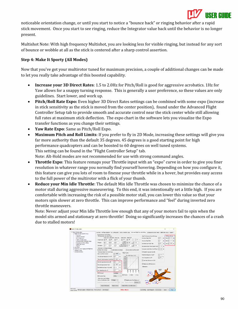
USER GUIDE
90
noticeable orientation change, or until you start to notice a “bounce back” or ringing behavior after a rapid
stick movement. Once you start to see ringing, reduce the Integrator value back until the behavior is no longer
present.
Multishot Note: With high frequency Multishot, you are looking less for visible ringing, but instead for any sort
of bounce or wobble at all as the stick is centered after a sharp control assertion.
Step 4: Make It Sporty (All Modes)
Now that you've got your multirotor tuned for maximum precision, a couple of additional changes can be made
to let you really take advantage of this boosted capability.
• Increase your 3D Direct Rates: 1.5 to 2.0Hz for Pitch/Roll is good for aggressive acrobatics. 1Hz for
Yaw allows for a snappy turning response. This is generally a user preference, so these values are only
guidelines. Start lower, and work up.
• Pitch/Roll Rate Expo: Even higher 3D Direct Rates settings can be combined with some expo (increase
in stick sensitivity as the stick is moved from the center position), found under the Advanced Flight
Controller Setup tab to provide smooth and accurate control near the stick center while still allowing
full rates at maximum stick deflection. The expo chart in the software lets you visualize the Expo
transfer functions as you change their settings.
• Yaw Rate Expo: Same as Pitch/Roll Expo.
• Maximum Pitch and Roll Limits: If you prefer to fly in 2D Mode, increasing these settings will give you
far more authority than the default 35 degrees. 45 degrees is a good starting point for high
performance quadcopters and can be boosted to 60 degrees on well tuned systems.
This setting can be found in the “Flight Controller Setup” tab.
Note: Alt-Hold modes are not recommended for use with strong command angles.
• Throttle Expo: This feature remaps your Throttle input with an “expo” curve in order to give you finer
resolution in whatever range you normally find yourself hovering. Depending on how you configure it,
this feature can give you lots of room to finesse your throttle while in a hover, but provides easy access
to the full power of the multirotor with a flick of your thumb.
• Reduce your Min Idle Throttle: The default Min Idle Throttle was chosen to minimize the chance of a
motor stall during aggressive maneuvering. To this end, it was intentionally set a little high. If you are
comfortable with increasing the risk of a possible motor stall, you can lower this value so that your
motors spin slower at zero throttle. This can improve performance and “feel” during inverted zero
throttle maneuvers.
Note: Never adjust your Min Idle Throttle low enough that any of your motors fail to spin when the
model sits armed and stationary at zero throttle! Doing so significantly increases the chances of a crash
due to stalled motors!
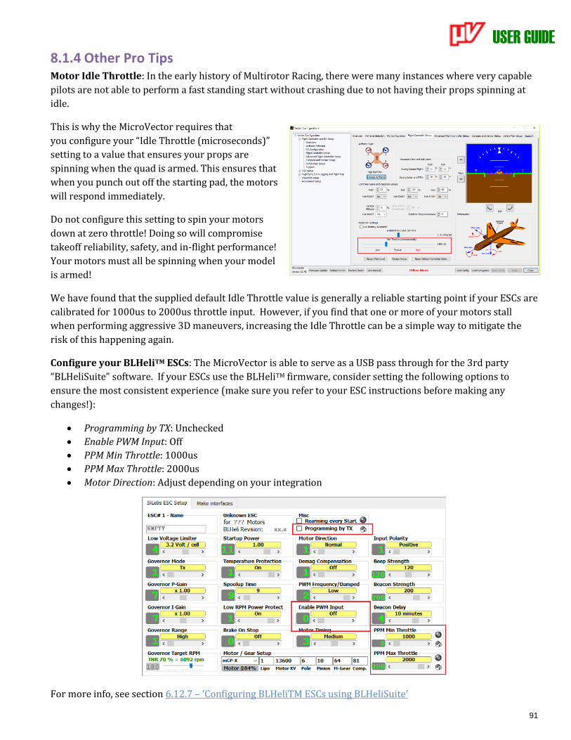
USER GUIDE
91
8.1.4 Other Pro Tips Motor Idle Throttle: In the early history of Multirotor Racing, there were many instances where very capable
pilots are not able to perform a fast standing start without crashing due to not having their props spinning at
idle.
This is why the MicroVector requires that
you configure your “Idle Throttle (microseconds)”
setting to a value that ensures your props are
spinning when the quad is armed. This ensures that
when you punch out off the starting pad, the motors
will respond immediately.
Do not configure this setting to spin your motors
down at zero throttle! Doing so will compromise
takeoff reliability, safety, and in-flight performance!
Your motors must all be spinning when your model
is armed!
We have found that the supplied default Idle Throttle value is generally a reliable starting point if your ESCs are
calibrated for 1000us to 2000us throttle input. However, if you find that one or more of your motors stall
when performing aggressive 3D maneuvers, increasing the Idle Throttle can be a simple way to mitigate the
risk of this happening again.
Configure your BLHeliTM ESCs: The MicroVector is able to serve as a USB pass through for the 3rd party
“BLHeliSuite” software. If your ESCs use the BLHeliTM firmware, consider setting the following options to
ensure the most consistent experience (make sure you refer to your ESC instructions before making any
changes!):
• Programming by TX: Unchecked
• Enable PWM Input: Off
• PPM Min Throttle: 1000us
• PPM Max Throttle: 2000us
• Motor Direction: Adjust depending on your integration
For more info, see section 6.12.7 – ‘Configuring BLHeliTM ESCs using BLHeliSuite’

USER GUIDE
92
Throttle Gain Reduction: If you find yourself with oscillations at very high throttle levels while
experiencing stable flight at hover power, you may want to try this feature. It works by scaling all Inner PID
gains by a factor that is linearly mapped from 0% reduction starting at the “Throttle Gain Reduction Start
Point” to whatever percentage reduction is set in the “Throttle Gain Reduction” field as the average throttle
output reaches the “Max ESC/Motor Output”.
Note: With newer ESCs and Multishot 4kHz and above, this setting is often not needed.
Vibration is Key: If you follow the prescribed steps above and still cannot get good performance, one possible
culprit could be excess vibrations.
Always be sure that your motors and props are balanced. A good way to check if you have too much vibrations
is to mount a HD video recorder on your frame with minimal vibration isolation and check if your recordings
contain “jello".
The presence of “jello", or wobbling lines in your recording, usually indicates that your frame has an
imbalanced motor or insufficient vibration rejection. This can be caused by poor build quality in either your
frame, motors, or propellers. In addition, even a small crash can deform a motor shaft enough to introduce
significant vibrations.
It is critically important to be sure your motors and props are in as good condition as possible during your
initial tuning session. For example, if you have a small nick in an otherwise flyable prop, put it aside and replace
it with a new one during your tuning session. The same goes for a questionable motor. You need all of your
components as close to perfect as possible during tuning.
Be Conservative with Derivative Gain: It’s easy to push your derivative gains too high, particularly on higher
rate Multishot systems, where it’s hard to perceive overdriven gain conditions. If you find that during inverted
maneuvers your motors are spinning too much, and you’ve already reduced your Motor Idle Throttle, reducing
your Inner Loop Derivative values can help.
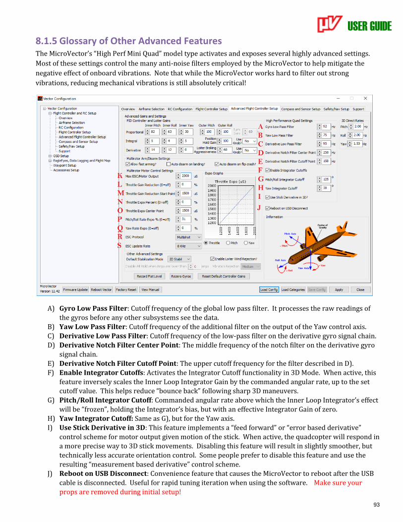
USER GUIDE
93
8.1.5 Glossary of Other Advanced Features The MicroVector’s “High Perf Mini Quad” model type activates and exposes several highly advanced settings.
Most of these settings control the many anti-noise filters employed by the MicroVector to help mitigate the
negative effect of onboard vibrations. Note that while the MicroVector works hard to filter out strong
vibrations, reducing mechanical vibrations is still absolutely critical!
A) Gyro Low Pass Filter: Cutoff frequency of the global low pass filter. It processes the raw readings of
the gyros before any other subsystems see the data.
B) Yaw Low Pass Filter: Cutoff frequency of the additional filter on the output of the Yaw control axis.
C) Derivative Low Pass Filter: Cutoff frequency of the low-pass filter on the derivative gyro signal chain.
D) Derivative Notch Filter Center Point: The middle frequency of the notch filter on the derivative gyro
signal chain.
E) Derivative Notch Filter Cutoff Point: The upper cutoff frequency for the filter described in D).
F) Enable Integrator Cutoffs: Activates the Integrator Cutoff functionality in 3D Mode. When active, this
feature inversely scales the Inner Loop Integrator Gain by the commanded angular rate, up to the set cutoff value. This helps reduce “bounce back” following sharp 3D maneuvers.
G) Pitch/Roll Integrator Cutoff: Commanded angular rate above which the Inner Loop Integrator’s effect
will be “frozen”, holding the Integrator’s bias, but with an effective Integrator Gain of zero.
H) Yaw Integrator Cutoff: Same as G), but for the Yaw axis.
I) Use Stick Derivative in 3D: This feature implements a “feed forward” or “error based derivative”
control scheme for motor output given motion of the stick. When active, the quadcopter will respond in
a more precise way to 3D stick movements. Disabling this feature will result in slightly smoother, but
technically less accurate orientation control. Some people prefer to disable this feature and use the
resulting “measurement based derivative” control scheme.
J) Reboot on USB Disconnect: Convenience feature that causes the MicroVector to reboot after the USB
cable is disconnected. Useful for rapid tuning iteration when using the software. Make sure your
props are removed during initial setup!
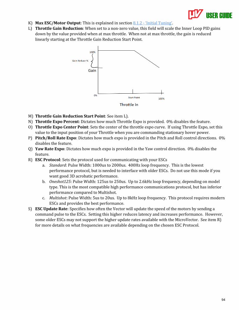
USER GUIDE
94
K) Max ESC/Motor Output: This is explained in section 8.1.2 - ‘Initial Tuning’.
L) Throttle Gain Reduction: When set to a non-zero value, this field will scale the Inner Loop PID gains
down by the value provided when at max throttle. When not at max throttle, the gain is reduced
linearly starting at the Throttle Gain Reduction Start Point.
M) Throttle Gain Reduction Start Point: See item L).
N) Throttle Expo Percent: Dictates how much Throttle Expo is provided. 0% disables the feature.
O) Throttle Expo Center Point: Sets the center of the throttle expo curve. If using Throttle Expo, set this
value to the input position of your Throttle when you are commanding stationary hover power.
P) Pitch/Roll Rate Expo: Dictates how much expo is provided in the Pitch and Roll control directions. 0%
disables the feature.
Q) Yaw Rate Expo: Dictates how much expo is provided in the Yaw control direction. 0% disables the
feature.
R) ESC Protocol: Sets the protocol used for communicating with your ESCs
a. Standard: Pulse Width: 1000us to 2000us. 400Hz loop frequency. This is the lowest
performance protocol, but is needed to interface with older ESCs. Do not use this mode if you
want good 3D acrobatic performance.
b. Oneshot125: Pulse Width: 125us to 250us. Up to 2.6kHz loop frequency, depending on model
type. This is the most compatible high performance communications protocol, but has inferior
performance compared to Multishot.
c. Multishot: Pulse Width: 5us to 20us. Up to 8kHz loop frequency. This protocol requires modern
ESCs and provides the best performance.
S) ESC Update Rate: Specifies how often the Vector will update the speed of the motors by sending a
command pulse to the ESCs. Setting this higher reduces latency and increases performance. However,
some older ESCs may not support the higher update rates available with the MicroVector. See item R)
for more details on what frequencies are available depending on the chosen ESC Protocol.
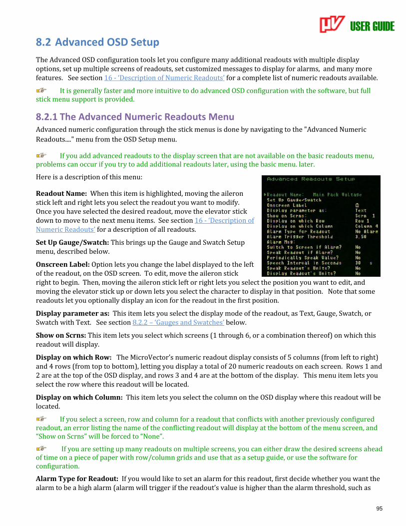
USER GUIDE
95
8.2 Advanced OSD Setup
The Advanced OSD configuration tools let you configure many additional readouts with multiple display options, set up multiple screens of readouts, set customized messages to display for alarms, and many more features. See section 16 - ‘Description of Numeric Readouts’ for a complete list of numeric readouts available.
It is generally faster and more intuitive to do advanced OSD configuration with the software, but full stick menu support is provided.
8.2.1 The Advanced Numeric Readouts Menu Advanced numeric configuration through the stick menus is done by navigating to the "Advanced Numeric
Readouts...." menu from the OSD Setup menu.
If you add advanced readouts to the display screen that are not available on the basic readouts menu, problems can occur if you try to add additional readouts later, using the basic menu. later.
Here is a description of this menu:
Readout Name: When this item is highlighted, moving the aileron stick left and right lets you select the readout you want to modify. Once you have selected the desired readout, move the elevator stick down to move to the next menu items. See section 16 - ‘Description of Numeric Readouts’ for a description of all readouts.
Set Up Gauge/Swatch: This brings up the Gauge and Swatch Setup menu, described below.
Onscreen Label: Option lets you change the label displayed to the left of the readout, on the OSD screen. To edit, move the aileron stick right to begin. Then, moving the aileron stick left or right lets you select the position you want to edit, and moving the elevator stick up or down lets you select the character to display in that position. Note that some readouts let you optionally display an icon for the readout in the first position.
Display parameter as: This item lets you select the display mode of the readout, as Text, Gauge, Swatch, or Swatch with Text. See section 8.2.2 – ‘Gauges and Swatches’ below.
Show on Scrns: This item lets you select which screens (1 through 6, or a combination thereof) on which this readout will display.
Display on which Row: The MicroVector’s numeric readout display consists of 5 columns (from left to right) and 4 rows (from top to bottom), letting you display a total of 20 numeric readouts on each screen. Rows 1 and 2 are at the top of the OSD display, and rows 3 and 4 are at the bottom of the display. This menu item lets you select the row where this readout will be located.
Display on which Column: This item lets you select the column on the OSD display where this readout will be located.
If you select a screen, row and column for a readout that conflicts with another previously configured readout, an error listing the name of the conflicting readout will display at the bottom of the menu screen, and “Show on Scrns” will be forced to “None”.
If you are setting up many readouts on multiple screens, you can either draw the desired screens ahead of time on a piece of paper with row/column grids and use that as a setup guide, or use the software for configuration.
Alarm Type for Readout: If you would like to set an alarm for this readout, first decide whether you want the alarm to be a high alarm (alarm will trigger if the readout’s value is higher than the alarm threshold, such as
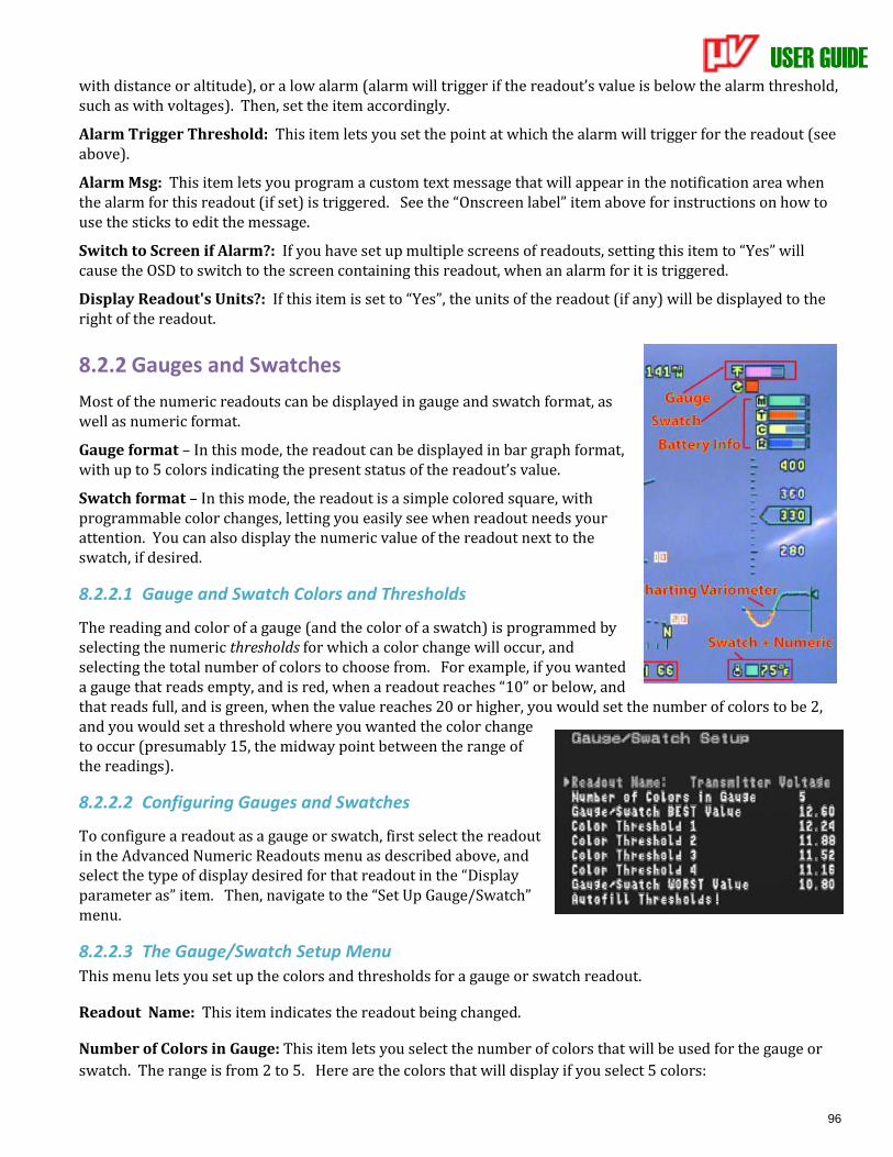
USER GUIDE
96
with distance or altitude), or a low alarm (alarm will trigger if the readout’s value is below the alarm threshold, such as with voltages). Then, set the item accordingly.
Alarm Trigger Threshold: This item lets you set the point at which the alarm will trigger for the readout (see above).
Alarm Msg: This item lets you program a custom text message that will appear in the notification area when the alarm for this readout (if set) is triggered. See the “Onscreen label” item above for instructions on how to use the sticks to edit the message.
Switch to Screen if Alarm?: If you have set up multiple screens of readouts, setting this item to “Yes” will cause the OSD to switch to the screen containing this readout, when an alarm for it is triggered.
Display Readout's Units?: If this item is set to “Yes”, the units of the readout (if any) will be displayed to the right of the readout.
8.2.2 Gauges and Swatches
Most of the numeric readouts can be displayed in gauge and swatch format, as well as numeric format.
Gauge format – In this mode, the readout can be displayed in bar graph format, with up to 5 colors indicating the present status of the readout’s value.
Swatch format – In this mode, the readout is a simple colored square, with programmable color changes, letting you easily see when readout needs your attention. You can also display the numeric value of the readout next to the swatch, if desired.
8.2.2.1 Gauge and Swatch Colors and Thresholds
The reading and color of a gauge (and the color of a swatch) is programmed by selecting the numeric thresholds for which a color change will occur, and selecting the total number of colors to choose from. For example, if you wanted a gauge that reads empty, and is red, when a readout reaches “10” or below, and that reads full, and is green, when the value reaches 20 or higher, you would set the number of colors to be 2, and you would set a threshold where you wanted the color change to occur (presumably 15, the midway point between the range of the readings).
8.2.2.2 Configuring Gauges and Swatches
To configure a readout as a gauge or swatch, first select the readout in the Advanced Numeric Readouts menu as described above, and select the type of display desired for that readout in the “Display parameter as” item. Then, navigate to the “Set Up Gauge/Swatch” menu.
8.2.2.3 The Gauge/Swatch Setup Menu
This menu lets you set up the colors and thresholds for a gauge or swatch readout.
Readout Name: This item indicates the readout being changed.
Number of Colors in Gauge: This item lets you select the number of colors that will be used for the gauge or
swatch. The range is from 2 to 5. Here are the colors that will display if you select 5 colors:
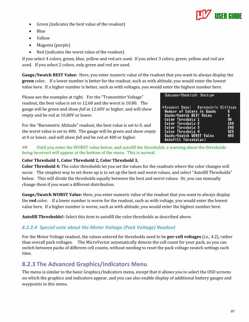
USER GUIDE
97
• Green (indicates the best value of the readout)
• Blue
• Yellow
• Magenta (purple)
• Red (indicates the worst value of the readout)
If you select 4 colors, green, blue, yellow and red are used. If you select 3 colors, green, yellow and red are
used. If you select 2 colors, only green and red are used.
Gauge/Swatch BEST Value: Here, you enter numeric value of the readout that you want to always display the
green color. If a lower number is better for the readout, such as with altitude, you would enter the lowest
value here. If a higher number is better, such as with voltages, you would enter the highest number here.
Please see the examples at right. For the “Transmitter Voltage”
readout, the best value is set to 12.60 and the worst is 10.80. The
gauge will be green and show full at 12.60V or higher, and will show
empty and be red at 10.80V or lower.
For the “Barometric Altitude” readout, the best value is set to 0, and
the worst value is set to 400. The gauge will be green and show empty
at 0 or lower, and will show full and be red at 400 or higher.
Until you enter the WORST value below, and autofill the thresholds, a warning about the thresholds being incorrect will appear at the bottom of the menu. This is normal.
Color Threshold 1, Color Threshold 2, Color Threshold 3,
Color Threshold 4: The color thresholds let you set the values for the readouts where the color changes will
occur. The simplest way to set these up is to set up the best and worst values, and select “Autofill Thresholds”
below. This will divide the thresholds equally between the best and worst values. Or, you can manually
change them if you want a different distribution.
Gauge/Swatch WORST Value: Here, you enter numeric value of the readout that you want to always display
the red color. If a lower number is worse for the readout, such as with voltage, you would enter the lowest
value here. If a higher number is worse, such as with altitude, you would enter the highest number here.
Autofill Thresholds!: Select this item to autofill the color thresholds as described above.
8.2.2.4 Special note about the Motor Voltage (Pack Voltage) Readout
For the Motor Voltage readout, the values entered for thresholds need to be per-cell voltages (i.e., 4.2), rather than overall pack voltages. The MicroVector automatically detects the cell count for your pack, so you can switch between packs of different cell counts, without needing to reset the pack voltage swatch settings each time.
8.2.3 The Advanced Graphics/Indicators Menu The menu is similar to the basic Graphics/Indicators menu, except that it allows you to select the OSD screens
on which the graphics and indicators appear, and you can also enable display of additional battery gauges and
waypoints in this menu.

USER GUIDE
98
8.3 Data Logging Your MicroVector has a powerful built in Flight Data Recorder, which logs a large number of flight parameters
and notification messages. Having data from your flight can take the guesswork out of troubleshooting in-flight
issues, as well as keeping a record of your flights for later enjoyment. The logged data can be downloaded with
the software, and viewed with our charting utility or with
Google Maps.
8.3.1 Configuring Data Logging
By default, data logging is configured to log only when the model is flying (or armed), and the logged data will automatically be cleared to make room for new data when the logging buffer fills. These settings increase the likelihood that logged data will be available for analysis if something goes wrong with your flight.
Several additional options are available for choosing when to log data, which data to log, and how often to log data. These options can be configured under the “Data Logging Setup” menu.
If you choose to have data logging stop when the buffer is full, don’t forget to clear the logging buffer before each flight, from the Preflight menu.
8.3.2 Downloading, Viewing and Saving Logged Flight Information With the software, you can download flight information from the MicroVector, view the data, and save it for
later retrieval.
8.3.2.1 Downloading Data
To download and view logged data, connect the MicroVector to USB, and select the “EagleEyes and Data
Logging” tab under the ”EagleEyes, Data Logging and Flight Map” branch in the tree view, and click the
“Download from MicroVector” button.
8.3.2.2 Viewing Data
To view logged data on a chart, click the “Display Chart of Logged Data” button.
To view logged GPS Data with Google Maps™, navigate to the “Google Flight Map” tab.
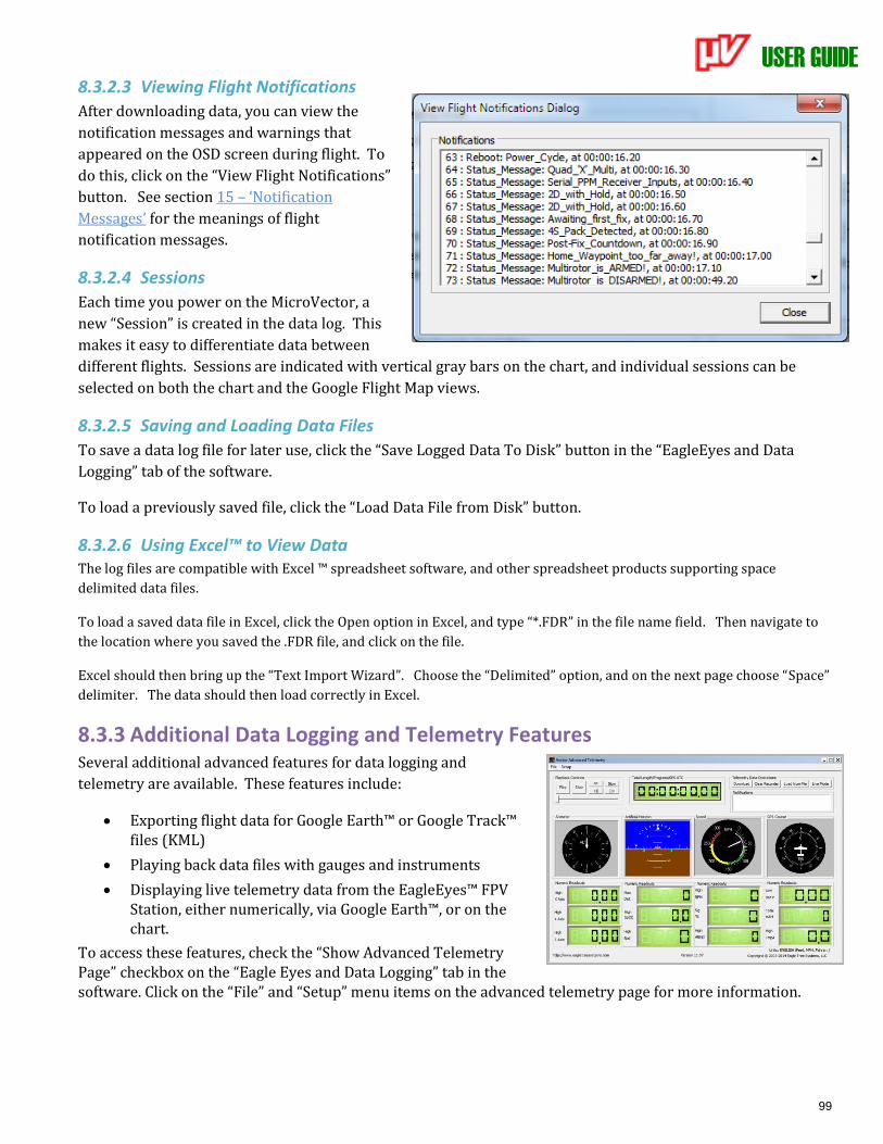
USER GUIDE
99
8.3.2.3 Viewing Flight Notifications
After downloading data, you can view the
notification messages and warnings that
appeared on the OSD screen during flight. To
do this, click on the “View Flight Notifications”
button. See section 15 – ‘Notification
Messages’ for the meanings of flight
notification messages.
8.3.2.4 Sessions
Each time you power on the MicroVector, a
new “Session” is created in the data log. This
makes it easy to differentiate data between
different flights. Sessions are indicated with vertical gray bars on the chart, and individual sessions can be
selected on both the chart and the Google Flight Map views.
8.3.2.5 Saving and Loading Data Files
To save a data log file for later use, click the “Save Logged Data To Disk” button in the “EagleEyes and Data
Logging” tab of the software.
To load a previously saved file, click the “Load Data File from Disk” button.
8.3.2.6 Using Excel™ to View Data The log files are compatible with Excel ™ spreadsheet software, and other spreadsheet products supporting space
delimited data files.
To load a saved data file in Excel, click the Open option in Excel, and type “*.FDR” in the file name field. Then navigate to
the location where you saved the .FDR file, and click on the file.
Excel should then bring up the “Text Import Wizard”. Choose the “Delimited” option, and on the next page choose “Space”
delimiter. The data should then load correctly in Excel.
8.3.3 Additional Data Logging and Telemetry Features Several additional advanced features for data logging and
telemetry are available. These features include:
• Exporting flight data for Google Earth™ or Google Track™ files (KML)
• Playing back data files with gauges and instruments
• Displaying live telemetry data from the EagleEyes™ FPV Station, either numerically, via Google Earth™, or on the chart.
To access these features, check the “Show Advanced Telemetry Page” checkbox on the “Eagle Eyes and Data Logging” tab in the software. Click on the “File” and “Setup” menu items on the advanced telemetry page for more information.
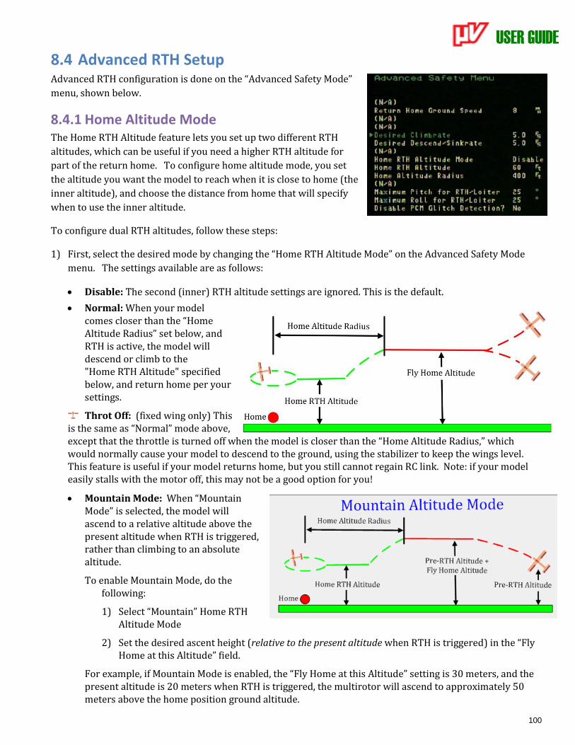
USER GUIDE
100
8.4 Advanced RTH Setup Advanced RTH configuration is done on the “Advanced Safety Mode”
menu, shown below.
8.4.1 Home Altitude Mode The Home RTH Altitude feature lets you set up two different RTH
altitudes, which can be useful if you need a higher RTH altitude for
part of the return home. To configure home altitude mode, you set
the altitude you want the model to reach when it is close to home (the
inner altitude), and choose the distance from home that will specify
when to use the inner altitude.
To configure dual RTH altitudes, follow these steps:
1) First, select the desired mode by changing the “Home RTH Altitude Mode” on the Advanced Safety Mode
menu. The settings available are as follows:
• Disable: The second (inner) RTH altitude settings are ignored. This is the default.
• Normal: When your model comes closer than the “Home Altitude Radius” set below, and RTH is active, the model will descend or climb to the "Home RTH Altitude" specified below, and return home per your settings.
Throt Off: (fixed wing only) This is the same as “Normal” mode above, except that the throttle is turned off when the model is closer than the “Home Altitude Radius,” which would normally cause your model to descend to the ground, using the stabilizer to keep the wings level. This feature is useful if your model returns home, but you still cannot regain RC link. Note: if your model easily stalls with the motor off, this may not be a good option for you!
• Mountain Mode: When “Mountain Mode” is selected, the model will ascend to a relative altitude above the present altitude when RTH is triggered, rather than climbing to an absolute altitude.
To enable Mountain Mode, do the following:
1) Select “Mountain” Home RTH Altitude Mode
2) Set the desired ascent height (relative to the present altitude when RTH is triggered) in the “Fly Home at this Altitude” field.
For example, if Mountain Mode is enabled, the “Fly Home at this Altitude” setting is 30 meters, and the present altitude is 20 meters when RTH is triggered, the multirotor will ascend to approximately 50 meters above the home position ground altitude.
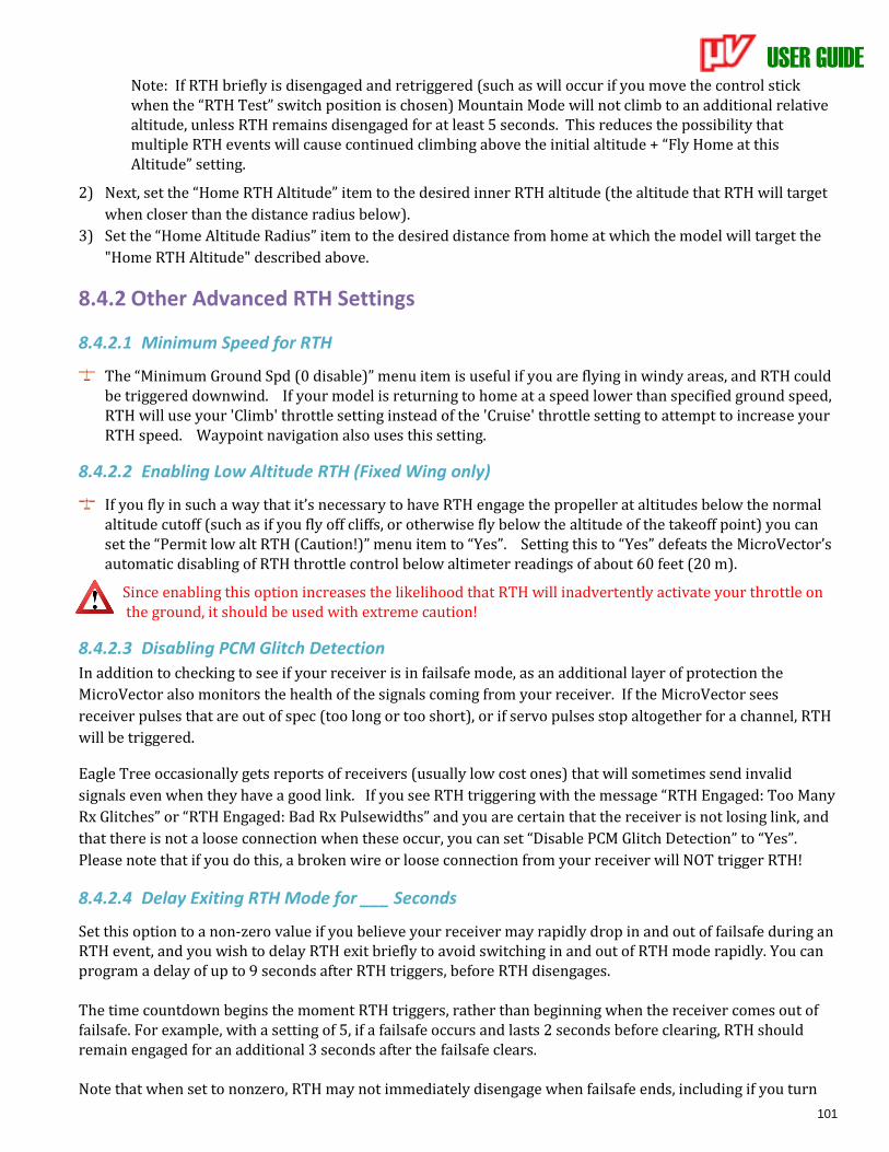
USER GUIDE
101
Note: If RTH briefly is disengaged and retriggered (such as will occur if you move the control stick when the “RTH Test” switch position is chosen) Mountain Mode will not climb to an additional relative altitude, unless RTH remains disengaged for at least 5 seconds. This reduces the possibility that multiple RTH events will cause continued climbing above the initial altitude + “Fly Home at this Altitude” setting.
2) Next, set the “Home RTH Altitude” item to the desired inner RTH altitude (the altitude that RTH will target
when closer than the distance radius below).
3) Set the “Home Altitude Radius” item to the desired distance from home at which the model will target the
"Home RTH Altitude" described above.
8.4.2 Other Advanced RTH Settings
8.4.2.1 Minimum Speed for RTH
The “Minimum Ground Spd (0 disable)” menu item is useful if you are flying in windy areas, and RTH could be triggered downwind. If your model is returning to home at a speed lower than specified ground speed, RTH will use your 'Climb' throttle setting instead of the 'Cruise' throttle setting to attempt to increase your RTH speed. Waypoint navigation also uses this setting.
8.4.2.2 Enabling Low Altitude RTH (Fixed Wing only)
If you fly in such a way that it’s necessary to have RTH engage the propeller at altitudes below the normal altitude cutoff (such as if you fly off cliffs, or otherwise fly below the altitude of the takeoff point) you can set the “Permit low alt RTH (Caution!)” menu item to “Yes”. Setting this to “Yes” defeats the MicroVector’s automatic disabling of RTH throttle control below altimeter readings of about 60 feet (20 m).
Since enabling this option increases the likelihood that RTH will inadvertently activate your throttle on the ground, it should be used with extreme caution!
8.4.2.3 Disabling PCM Glitch Detection
In addition to checking to see if your receiver is in failsafe mode, as an additional layer of protection the
MicroVector also monitors the health of the signals coming from your receiver. If the MicroVector sees
receiver pulses that are out of spec (too long or too short), or if servo pulses stop altogether for a channel, RTH
will be triggered.
Eagle Tree occasionally gets reports of receivers (usually low cost ones) that will sometimes send invalid
signals even when they have a good link. If you see RTH triggering with the message “RTH Engaged: Too Many
Rx Glitches” or “RTH Engaged: Bad Rx Pulsewidths” and you are certain that the receiver is not losing link, and
that there is not a loose connection when these occur, you can set “Disable PCM Glitch Detection” to “Yes”.
Please note that if you do this, a broken wire or loose connection from your receiver will NOT trigger RTH!
8.4.2.4 Delay Exiting RTH Mode for ___ Seconds
Set this option to a non-zero value if you believe your receiver may rapidly drop in and out of failsafe during an RTH event, and you wish to delay RTH exit briefly to avoid switching in and out of RTH mode rapidly. You can program a delay of up to 9 seconds after RTH triggers, before RTH disengages. The time countdown begins the moment RTH triggers, rather than beginning when the receiver comes out of failsafe. For example, with a setting of 5, if a failsafe occurs and lasts 2 seconds before clearing, RTH should remain engaged for an additional 3 seconds after the failsafe clears. Note that when set to nonzero, RTH may not immediately disengage when failsafe ends, including if you turn

USER GUIDE
102
off and on your transmitter! Note also that this delay does not affect RTH triggered by the mode/submode switch.
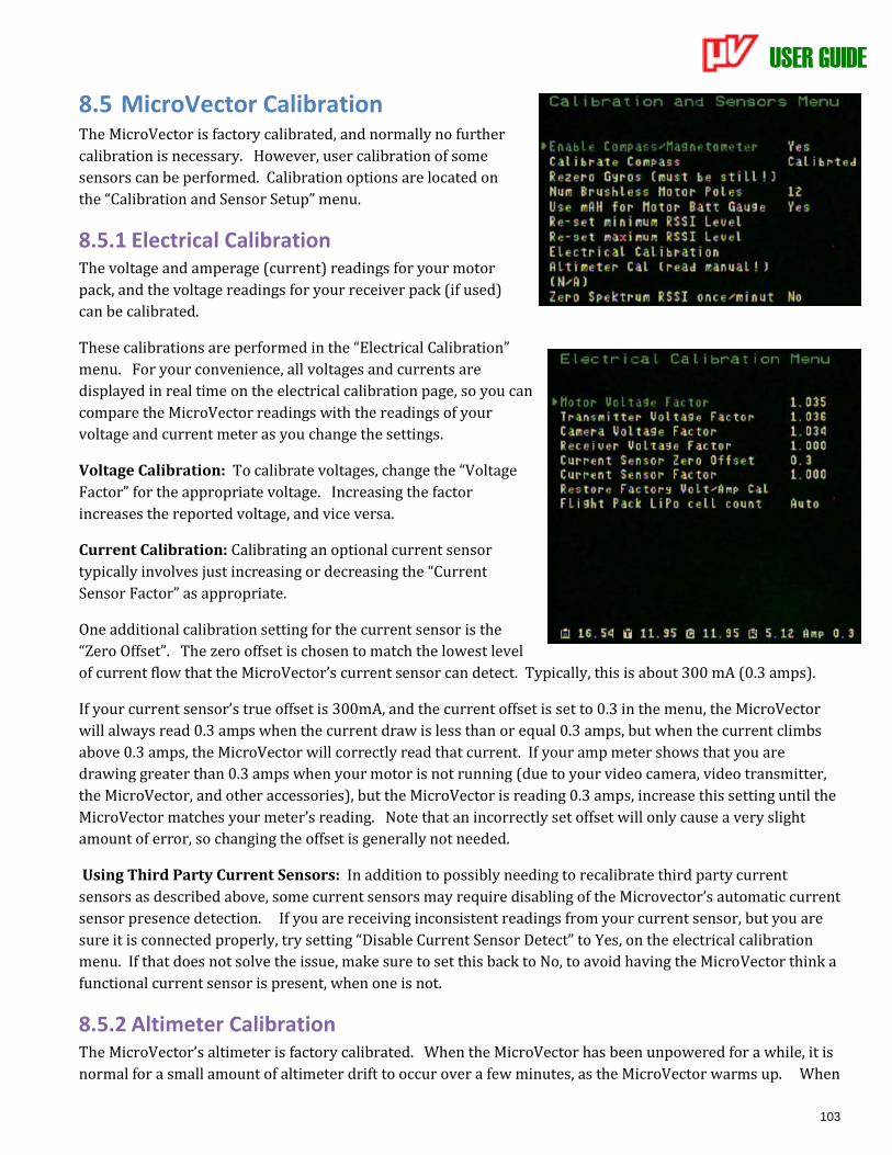
USER GUIDE
103
8.5 MicroVector Calibration The MicroVector is factory calibrated, and normally no further
calibration is necessary. However, user calibration of some
sensors can be performed. Calibration options are located on
the “Calibration and Sensor Setup” menu.
8.5.1 Electrical Calibration The voltage and amperage (current) readings for your motor
pack, and the voltage readings for your receiver pack (if used)
can be calibrated.
These calibrations are performed in the “Electrical Calibration”
menu. For your convenience, all voltages and currents are
displayed in real time on the electrical calibration page, so you can
compare the MicroVector readings with the readings of your
voltage and current meter as you change the settings.
Voltage Calibration: To calibrate voltages, change the “Voltage
Factor” for the appropriate voltage. Increasing the factor
increases the reported voltage, and vice versa.
Current Calibration: Calibrating an optional current sensor
typically involves just increasing or decreasing the “Current
Sensor Factor” as appropriate.
One additional calibration setting for the current sensor is the
“Zero Offset”. The zero offset is chosen to match the lowest level
of current flow that the MicroVector’s current sensor can detect. Typically, this is about 300 mA (0.3 amps).
If your current sensor’s true offset is 300mA, and the current offset is set to 0.3 in the menu, the MicroVector
will always read 0.3 amps when the current draw is less than or equal 0.3 amps, but when the current climbs
above 0.3 amps, the MicroVector will correctly read that current. If your amp meter shows that you are
drawing greater than 0.3 amps when your motor is not running (due to your video camera, video transmitter,
the MicroVector, and other accessories), but the MicroVector is reading 0.3 amps, increase this setting until the
MicroVector matches your meter’s reading. Note that an incorrectly set offset will only cause a very slight
amount of error, so changing the offset is generally not needed.
Using Third Party Current Sensors: In addition to possibly needing to recalibrate third party current
sensors as described above, some current sensors may require disabling of the Microvector’s automatic current
sensor presence detection. If you are receiving inconsistent readings from your current sensor, but you are
sure it is connected properly, try setting “Disable Current Sensor Detect” to Yes, on the electrical calibration
menu. If that does not solve the issue, make sure to set this back to No, to avoid having the MicroVector think a
functional current sensor is present, when one is not.
8.5.2 Altimeter Calibration The MicroVector’s altimeter is factory calibrated. When the MicroVector has been unpowered for a while, it is
normal for a small amount of altimeter drift to occur over a few minutes, as the MicroVector warms up. When

USER GUIDE
104
you reset the home position, or when you arm your multirotor, the MicroVector’s altimeter is automatically
rezeroed, erasing any drift.
But, if you see your MicroVector’s altimeter drifting more than a few feet (1-2meters) during warmup, and that
is causing issues for you, you can calibrate it as follows:
1) Make sure that the weather is not changing, which can cause significant barometric pressure
differences in a short period of time.
2) Leave the MicroVector completely unpowered for at least 30 minutes.
3) Have your transmitter ready, and apply power to the MicroVector (do this indoors).
4) Within 1 minute (the quicker the better) navigate to the Calibration and Sensors menu, select the
“Altimeter cal (read manual)” item, and click the mode switch.
5) Don’t move the MicroVector until the calibration process completes (about 3 minutes).
6) The calibration result (pass or fail) will remain in the notification area after the process completes.
8.5.3 Pitot Airspeed Calibration
If the optional pitot tube airspeed sensor is being used, and you find that the airspeed readings are too high or low, the "Airspeed Sensor Factor” on the Calibration screen can be used to adjust it. Increase this value if your pitot speed is too low, and vice versa.
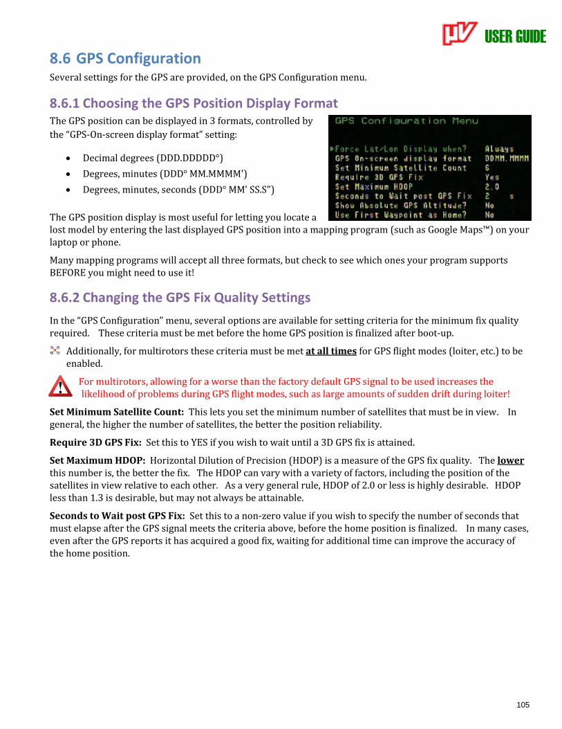
USER GUIDE
105
8.6 GPS Configuration Several settings for the GPS are provided, on the GPS Configuration menu.
8.6.1 Choosing the GPS Position Display Format The GPS position can be displayed in 3 formats, controlled by
the “GPS-On-screen display format” setting:
• Decimal degrees (DDD.DDDDD°)
• Degrees, minutes (DDD° MM.MMMM')
• Degrees, minutes, seconds (DDD° MM' SS.S")
The GPS position display is most useful for letting you locate a lost model by entering the last displayed GPS position into a mapping program (such as Google Maps™) on your laptop or phone.
Many mapping programs will accept all three formats, but check to see which ones your program supports BEFORE you might need to use it!
8.6.2 Changing the GPS Fix Quality Settings
In the “GPS Configuration” menu, several options are available for setting criteria for the minimum fix quality required. These criteria must be met before the home GPS position is finalized after boot-up.
Additionally, for multirotors these criteria must be met at all times for GPS flight modes (loiter, etc.) to be enabled.
For multirotors, allowing for a worse than the factory default GPS signal to be used increases the likelihood of problems during GPS flight modes, such as large amounts of sudden drift during loiter!
Set Minimum Satellite Count: This lets you set the minimum number of satellites that must be in view. In general, the higher the number of satellites, the better the position reliability.
Require 3D GPS Fix: Set this to YES if you wish to wait until a 3D GPS fix is attained.
Set Maximum HDOP: Horizontal Dilution of Precision (HDOP) is a measure of the GPS fix quality. The lower this number is, the better the fix. The HDOP can vary with a variety of factors, including the position of the satellites in view relative to each other. As a very general rule, HDOP of 2.0 or less is highly desirable. HDOP less than 1.3 is desirable, but may not always be attainable.
Seconds to Wait post GPS Fix: Set this to a non-zero value if you wish to specify the number of seconds that must elapse after the GPS signal meets the criteria above, before the home position is finalized. In many cases, even after the GPS reports it has acquired a good fix, waiting for additional time can improve the accuracy of the home position.
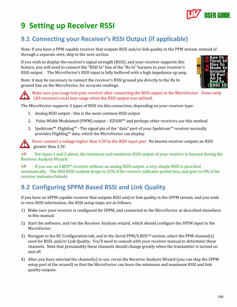
USER GUIDE
106
9 Setting up Receiver RSSI
9.1 Connecting your Receiver’s RSSI Output (if applicable)
Note: If you have a PPM capable receiver that outputs RSSI and/or link quality in the PPM stream, instead of through a separate wire, skip to the next section.
If you wish to display the receiver’s signal strength (RSSI), and your receiver supports this feature, you will need to connect the “RSSI In” line of the “Rx In” harness to your receiver’s RSSI output. The MicroVector’s RSSI input is fully buffered with a high impedance op amp.
Note: it may be necessary to connect the receiver’s RSSI ground pin directly to the Rx In ground line on the MicroVector, for accurate readings.
Make sure you range test your receiver after connecting the RSSI output to the MicroVector. Some early LRS receivers could lose range when the RSSI output was utilized.
The MicroVector supports 3 types of RSSI via this connection, depending on your receiver type:
1. Analog RSSI output - this is the most common RSSI output
2. Pulse Width Modulated (PWM) output – EZUHF™ and perhaps other receivers use this method.
3. Spektrum™ Flightlog™ - The signal pin of the “data” port of your Spektrum™ receiver normally provides Flightlog™ data, which the MicroVector can display.
Never connect a voltage higher than 3.3V to the RSSI input pin! No known receiver outputs an RSSI greater than 3.3V.
For types 1 and 2 above, the minimum and maximum RSSI output of your receiver is learned during the Receiver Analysis Wizard.
If you use an S.BUS™ receiver without an analog RSSI output, a very simple RSSI is provided automatically. The OSD RSSI readout drops to 25% if the receiver indicates packet loss, and goes to 0% if the recevier indicates failsafe.
9.2 Configuring SPPM Based RSSI and Link Quality
If you have an SPPM capable receiver that outputs RSSI and/or link quality in the SPPM stream, and you wish to view RSSI information, the RSSI setup steps are as follows:
1) Make sure your receiver is configured for SPPM, and connected to the MicroVector as described elsewhere in this manual.
2) Start the software, and run the Receiver Analysis wizard, which should configure the SPPM input to the MicroVector.
3) Navigate to the RC Configuration tab, and in the Serial PPM/S.BUSTM section, select the PPM channel(s) used for RSSI, and/or Link Quality. You’ll need to consult with your receiver manual to determine these channels. Note that presumably these channels should change greatly when the transmitter is turned on and off.
4) After you have selected the channel(s) to use, rerun the Receiver Analysis Wizard (you can skip the SPPM setup part of the wizard) so that the MicroVector can learn the minimum and maximum RSSI and link quality outputs.

USER GUIDE
107
10 Using the UART Connector for Telemetry Via the UART connector, the MicroVector can output a rich set of flight data information to recent Taranis™,
DragonLink Advanced™ and potentially other radios and LRS systems. Also, with our Open Telemetry UART
protocol, it’s easy to incorporate Vector information into your own projects.
10.1 UART Connector Pinout The UART pinout is as follows:
5V Pwr: Typically not needed for UART connection, assuming the peripheral is powered
otherwise. 100mA max current draw. Note that all the “5V Power” connections are
connected together inside the MicroVector. Don’t connect a power source to more than one of
these connections! 6V Max!
Ground: This connects to the ground of your peripheral (if needed).
Sig Out from uV: This line provides the signal output from the uV, to the peripheral.
Sig In to uV: This line provides the signal input to the uV, from the peripheral.
10.2 MicroVector Telemetry Output for Radios and LRS
Links The MicroVector can output a rich set of flight data information to recent Taranis™,
DragonLink Advanced™ and potentially other radios and LRS systems. Also, with our Open
Telemetry UART protocol, it’s easy to incorporate MicroVector information into your own projects.
10.2.1 Taranis™ Telemetry To configure the MicroVector for use with Taranis™ telemetry, refer to the forum thread below:
http://www.rcgroups.com/forums/showthread.php?t=2346243#post30770731
10.2.2 MicroVector Open Telemetry and DragonLink Advanced To configure the MicroVector for Open Telemetry (used by DragonLink Advanced), refer to the forum thread
below:
http://www.rcgroups.com/forums/showthread.php?t=2585582#post33766705
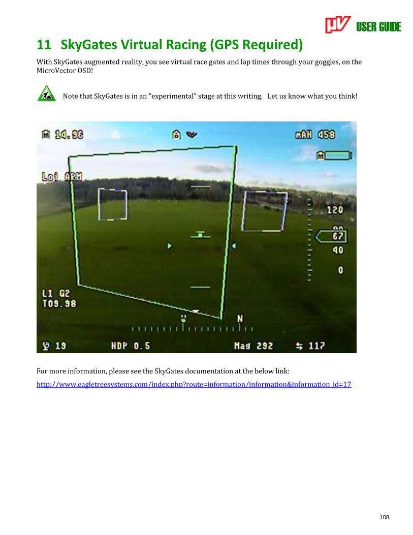
USER GUIDE
108
11 SkyGates Virtual Racing (GPS Required) With SkyGates augmented reality, you see virtual race gates and lap times through your goggles, on the MicroVector OSD!
Note that SkyGates is in an “experimental” stage at this writing. Let us know what you think!
For more information, please see the SkyGates documentation at the below link:
http://www.eagletreesystems.com/index.php?route=information/information&information_id=17
USER GUIDE
109
12 Waypoints
12.1 Safety
Waypoints are an advanced MicroVector feature, intended for skilled and knowledgeable pilots.
Use the waypoint feature ONLY if you understand and agree to the below:
- You are fully responsible for your model, even when it is flying in waypoint mode.
- You are responsible for determining whether an area is safe and legal for model flight. If you are not sure, don't fly there!
- Never program waypoints that could cause your model to fly near other aircraft or airports, over people, or
anywhere else that could cause a hazard!
- Assume that your prop(s) can spin at any time, when waypoint mode is engaged!
- If lost radio link is detected, waypoint navigation will stop and RTH will be activated, if RTH is configured correctly. Configure and test RTH before activating waypoints! Ensure there is a clear path to home from any point in the waypoint sequence!
- During waypoint flight, if a problem related to GPS or compass is detected, or if you lower your throttle or move your control stick, the MicroVector will at least temporarily switch to a manual flight mode, requiring immediate pilot interaction.
12.2 Terminology
Command – an instruction that causes the MicroVector’s waypoint controller to perform a specific action.
Session – a set of commands comprising a waypoint flight.
Click and drag – left clicking with the mouse, and moving the mouse pointer while continuing to hold down the left button.
12.3 Limitations By default, waypoints are limited as follows:
• Distance – the maximum distance allowed between the first waypoint and any other waypoint is approximately 1 mile (1.6 km). This limitation also applies to the distance between the home position and all waypoints.
• Altitude – altitude is limited to under 400 feet (122 m) above the home position ground level.
12.4 Waypoint Setup
Waypoint commands are set up by navigating to the “Safety/Nav Setup” and “Waypoint Setup” tabs in the software.
12.4.1 Waypoint Related Settings on the Waypoint/Nav Setup Tab Refer to the lettered indications on the diagram below:
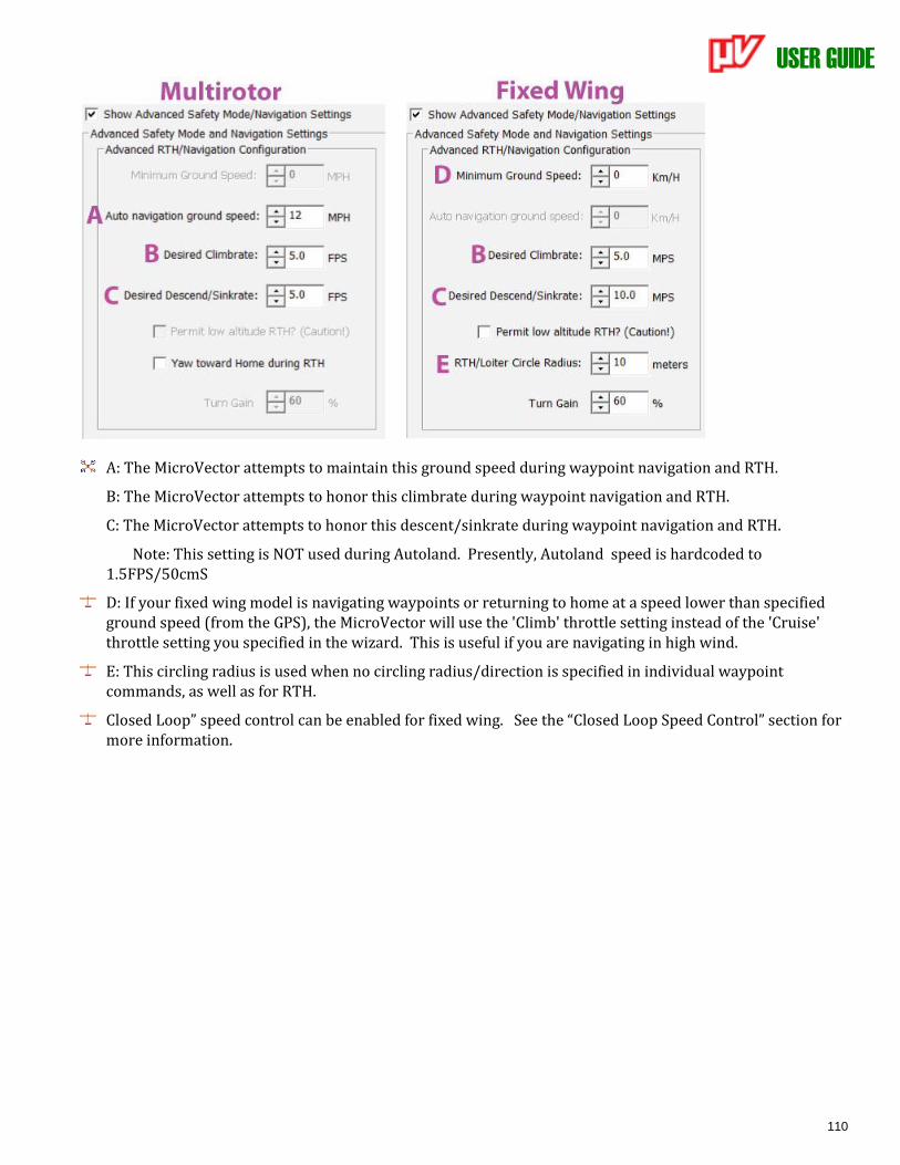
USER GUIDE
110
A: The MicroVector attempts to maintain this ground speed during waypoint navigation and RTH.
B: The MicroVector attempts to honor this climbrate during waypoint navigation and RTH.
C: The MicroVector attempts to honor this descent/sinkrate during waypoint navigation and RTH.
Note: This setting is NOT used during Autoland. Presently, Autoland speed is hardcoded to 1.5FPS/50cmS
D: If your fixed wing model is navigating waypoints or returning to home at a speed lower than specified ground speed (from the GPS), the MicroVector will use the 'Climb' throttle setting instead of the 'Cruise' throttle setting you specified in the wizard. This is useful if you are navigating in high wind.
E: This circling radius is used when no circling radius/direction is specified in individual waypoint commands, as well as for RTH.
Closed Loop” speed control can be enabled for fixed wing. See the “Closed Loop Speed Control” section for more information.
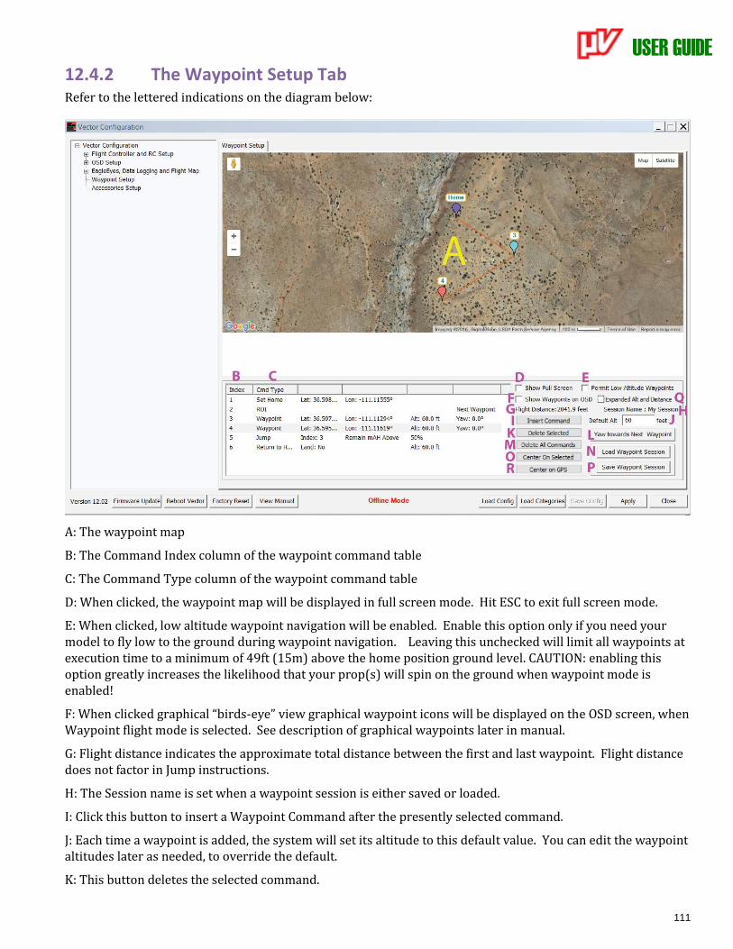
USER GUIDE
111
12.4.2 The Waypoint Setup Tab Refer to the lettered indications on the diagram below:
A: The waypoint map
B: The Command Index column of the waypoint command table
C: The Command Type column of the waypoint command table
D: When clicked, the waypoint map will be displayed in full screen mode. Hit ESC to exit full screen mode.
E: When clicked, low altitude waypoint navigation will be enabled. Enable this option only if you need your model to fly low to the ground during waypoint navigation. Leaving this unchecked will limit all waypoints at execution time to a minimum of 49ft (15m) above the home position ground level. CAUTION: enabling this option greatly increases the likelihood that your prop(s) will spin on the ground when waypoint mode is enabled!
F: When clicked graphical “birds-eye” view graphical waypoint icons will be displayed on the OSD screen, when Waypoint flight mode is selected. See description of graphical waypoints later in manual.
G: Flight distance indicates the approximate total distance between the first and last waypoint. Flight distance does not factor in Jump instructions.
H: The Session name is set when a waypoint session is either saved or loaded.
I: Click this button to insert a Waypoint Command after the presently selected command.
J: Each time a waypoint is added, the system will set its altitude to this default value. You can edit the waypoint altitudes later as needed, to override the default.
K: This button deletes the selected command.
USER GUIDE
112
L: (multirotor only) This button inserts a Yaw To Next Waypoint ROI command, which causes the multirotor to always point to the next waypoint in the sequence. This can be overridden with another ROI command in another command slot. The ROI behavior is changed at the time that the given ROI command gets executed.
M: This button deletes all commands.
N: Click this button to load a previously saved waypoint session from disk.
O: Clicking this button causes the map to be centered on the selected Waypoint Command.
P: Click this button to save the present waypoint session to disk.
Q: Click this button to expand the altitude and distance ranges on waypoints. Don't enable this option unless you really need to fly with the greater ranges. Note that even with expanded ranges, if lost radio link is detected, waypoint navigation will stop and RTH will be activated, if RTH is configured correctly.
R: Click this button to center the map on the present GPS position. Note that the GPS must have a fix, for this feature to work.
12.4.3 Using the Waypoint Map
12.4.3.1 Adding Commands via the Map
Clicking on the map adds a new command, of type Waypoint. The commands can then be moved by click and
drag.
Note: A maximum of 50 commands are allowed in a single MicroVector Waypoint session.
12.4.3.2 Commands shown on the Map
The Waypoint Map shows only those commands that have a latitude and longitude. Additionally, if the
command is a navigation type (Waypoint, Take Off, Land/Disarm, etc.) the command will be linked to other
navigation commands, via lines, in the order they appear in the table. Waypoints that are not navigated to (like
Set Home and ROI) are not linked.
12.4.4 Waypoint Command Navigation Behavior This section describes specific behaviors of the MicroVector’s waypoint controller.
12.4.4.1 GPS Fix Requirements
During waypoint navigation, the GPS fix quality must be at least as good as specified in the “GPS Fix Quality”
settings on the Compass and Sensor Setup tab in the software.
If the fix quality falls below the specified requirements at any time, the following occurs:
• If there is still a fix, waypoint navigation will continue for up to 5 seconds, waiting for the fix to improve to the specified quality. If it does not improve after 5 seconds, RTH Safety mode will be invoked, until the user switches into a non-Waypoint Mode.
• If there is no GPS fix at all, waypoint navigation will pause (initiating 2DH flight mode) up to 2.5 seconds, waiting for the fix to return, and improve to the specified quality. If it does not return after 2.5 seconds, Land Safety Mode will be invoked. If the GPS subsequently reacquires a fix, RTH Safety Mode will be invoked, until the user switches into a non-Waypoint Mode.
When GPS quality issues occur, the appropriate error message(s) will appear in the OSD notification area.
USER GUIDE
113
12.4.4.2 Loiter Circle Radius
For fixed wing operations involving loiter, the circle radius used is specified in one of two ways:
1. The circle radius/direction specified in the “Radius” waypoint command field is always used, if one has been specified. Clockwise is positive.
2. The “RTH/Loiter Circled Radius” setting on the Safety/Nav Setup tab is used, if no loiter radius has been specified in the waypoint and a climb, descent, or delay action is required. If no loiter radius is specified and the model would reach the specified altitude before reaching the specified location and no Delay command follows the current one, the aircraft will fly straight through the target location before loading the next command.
12.4.4.3 Fixed Wing Speed and Altitude Control during Waypoint Navigation
For fixed wing, when flying to a waypoint, the MicroVector will attempt to reach the altitude specified in the waypoint while in transit, but will be limited by the “Desired Climbrate” and “Desired Sinkrate” settings on the “Safety/Nav Setup” tab in the software. Note that these settings also control the speeds used during RTH.
If the plane reaches the specified latitude and longitude before reaching the specified altitude, the MicroVector will loiter (circle) the plane while ascending or descending, as needed. See the section above for information on the circle radius used.
By default, the Vector uses the “Cruise” throttle setting you specified during the Receiver Analysis Wizard, and will also attempt to honor the “Minimum Ground Speed” setting on the “Safety/Nav Setup” tab in the software.
“Closed Loop” speed control can also be enabled. See the “Closed Loop Speed Control” section for more information.
12.4.4.4 Multirotor Speed and Altitude Control during Waypoint Navigation
For multirotors, the MicroVector will attempt to honor the horizontal and vertical speeds specified in the “Auto navigation ground speed”, “Desired Climbrate”, and “Desired Descend/Sinkrate” settings on the “Safety/Nav Setup” tab in the software. Note that these settings also control the speeds used during RTH.
However, the MicroVector will limit the horizontal or vertical speed, as necessary, so that it arrives at the specified altitude when it reaches the specified latitude and longitude. For example, when flying between two waypoints, if the climbrate is set too low for the multirotor to reach the specified altitude when traveling at the specified ground speed, it will fly at a slower ground speed.
12.4.4.5 Waypoint Arrival Detection
The MicroVector will consider a waypoint arrival to have occurred whenever the model is either 33 feet/10 meters from the waypoint, or within 2 seconds of estimated arrival at the waypoint. Note that wind opposing the direction of travel could cause aircraft to never reach its waypoint if your speed settings are too low. In this case, the MicroVector will continue to attempt to reach the waypoint, unless the user takes action, or an issue occurs.
12.4.4.6 Behavior at Final Waypoint
When the model reaches the final waypoint in the session, the MicroVector will loiter at that location, until the user takes action.
The message “Loitering at last waypoint” will appear briefly in the OSD notification area.
USER GUIDE
114
12.4.4.7 Low Battery Autoland
The Low Battery Autoland feature is not active during waypoint navigation, except when the multirotor is loitering on the final waypoint. In this situation, the MicroVector will attempt to land the multirotor.
12.4.5 The Command Table
12.4.5.1 Adding Commands to the Table
Waypoint commands are added to the command table clicking the “Insert Command” button, or clicking on the
map. To add a command at a specific point in the table, click the Index field of the waypoint preceding the
insertion point, then click the “Insert Command” button.
12.4.5.2 Changing the Command Type
Click on the “Cmd Type” table column for the new command, to change the command type, if necessary.
Commands are added initially as type “Waypoint.”
12.4.5.3 Changing Command Order in the Table
Commands can be reordered in the table by clicking and dragging the Command Index number.
12.4.6 Command and Parameter Reference The information below describes the available commands, and available options for each supported command.
Note that most navigation commands will result in both horizontal and vertical navigation, which will occur even at ground level if the “Permit Low Altitude Waypoints” option is enabled!
12.4.6.1 Waypoint Command
The Waypoint command causes the system to navigate to the specified position (latitude, longitude and
altitude).
When the MicroVector begins navigation to a waypoint, the message “Navigating to Waypoint X” will appear
briefly in the OSD notification area, where X represents the waypoint index.
Parameters:
• Lat: The Lat field specifies the target latitude for the command, in DDD.DDDDD format. A positive value represents North, and negative represents South.
• Lon: The Lon field specifies the target longitude for the command, in DDD.DDDDD format. A positive value represents East, and negative represents West.
• Alt: The Alt field specifies the target altitude for the command. The target altitude must be above about 60 feet (18 meters), unless the 'Permit Low Altitude Waypoints' is enabled.
Yaw: (multirotor) The Yaw field specifies the direction the multirotor should face when navigating to the specified location. This field is ignored if there is an active ROI command. Values are in degrees, clockwise is positive. (East = 90.0, West = 270.0, etc)
Radius: (fixed wing) The Radius field specifies the circling radius to use, if loitering is necessary. If set to “0,” and loitering is not necessary, the model will fly straight through the target point before loading the next waypoint command. If set to “0” and loitering is necessary, the “RTH/Loiter Circle Radius” will be used instead. A positive radius indicates clockwise rotation, and a negative radius indicates a counter-clockwise rotation.
USER GUIDE
115
12.4.6.2 Delay Command
The Delay command causes the model to loiter at its present position, for the specified number of seconds. Normally, Delay commands are added immediately after waypoint commands, to cause the model to loiter at that waypoint’s position. When the MicroVector begins executing a delay, the message “Waypoint delay secs: X” will appear briefly in the OSD notification area, where X represents the specified delay time in seconds.
Fixed wing models will loiter at the radius and direction specified in the last executed waypoint command.
If the radius of the previous waypoint command was 0, the “RTH/Loiter Circle” setting on the Safety/Nav Setup tab is used.
Parameters:
• Time: The Time parameter specifies the length of time, in seconds, to delay.
12.4.6.3 Jump Command
The Jump command results in command execution continuing at the specified command index, if the specified condition is TRUE. If the condition is FALSE, the Jump command has no effect and the next command will immediately be executed.
When the MicroVector begins executes a Jump command, the message “Jumping to waypoint X” will appear briefly in the OSD notification area, where X represents the specified jump index.
Parameters:
• Index: The Jump Index specifies the next command to execute, if the specified condition is TRUE.
The following conditions can be programmed to trigger a jump:
• Loop Count: The Loop Count condition specifies the number of times the jump will occur. Once the jump command has been executed more times than specified, the jump will no longer occur. The counter is cleared when waypoint execution is (re)started. Note: Only three (3) Loop Count type Jump commands can be inserted into a Waypoint Session.
• Remain mAH Above: The jump will occur if the remaining mAH percentage is ABOVE the specified value. Total pack mAH must be set correctly for proper operation!
• Cell Volts Above: The jump will occur if the present pack PER-CELL voltage is ABOVE the specified value. The system divides the present voltage by the number of cells to determine cell voltage.
• Remain mAH Below: The jump will occur if the remaining mAH percentage is BELOW the specified value. Total pack mAH must be set correctly for proper operation.
• Cell Volts Below: The jump will occur if the present pack PER-CELL voltage is BELOW the specified value. The system divides the present voltage by the number of cells to determine cell voltage.
12.4.6.4 Return to Home Command
The Return to Home command causes the model to fly to the home position, at the specified altitude. Note that the Return to Home command is different than the Return to Home safety feature, and does not honor the altitude or RTH mode related settings on “Safety/Nav Setup” tab in the software.
When the MicroVector begins executes an RTH command, the message “Returning to Launch” or “Returning to
Launch and Land” will appear briefly in the OSD notification area.
Parameters:
USER GUIDE
116
• Alt: The Alt field specifies the fly-home altitude to use during RTH. The altitude must at least 60ft (about 15 meters), unless the 'Permit Low Altitude Waypoints' checkbox is checked.
• Land (multirotor only) – Set this to Yes to have the multirotor land and disarm when home is reached.
12.4.6.5 Set Home Command
The Set Home command causes the GPS home latitude and longitude to be set to the specified location, so long as the specified location is within approximately 500 feet/152 meters of the actual location where the GPS gets its first good fix.
At the field, if the Set Home command executes successfully, the message “Using Waypoint 1 as Home” will appear briefly in the OSD notification area. If the specified home location is too far from the actual GPS location of the aircraft when a fix is first acquired, the home location will be set to the current GPS location.
Note 1: The altitude is zeroed when the Set Home command is executed.
Note 2: The Set Home command must be the first command in the sequence.
Note 3: The Set Home command is executed upon first GPS fix, and is not executed again at the beginning of waypoint navigation. The home position is not set each time the waypoint mission is started.
Parameters:
• Lat: The Lat field specifies the target latitude for the command, in DDD.DDDDD format. A positive value represents North, and negative represents South.
• Lon: The Lon field specifies the target longitude for the command, in DDD.DDDDD format. A positive value represents East, and negative represents West.
12.4.6.6 ROI Command
The Region of Interest (ROI) command causes the multirotor to yaw toward the specified region (either a specific location, or the next waypoint). The ROI command remains in effect until another ROI command is executed.
When the MicroVector executes an ROI command, the message “Region of Interest set” will appear briefly
in the OSD notification area.
Parameters:
• An ROI command of type Next Waypoint causes the model to yaw toward the next waypoint. The model will continue to yaw toward the next waypoint as waypoints are navigated, until another ROI command is executed.
• An ROI command of type Location causes the multirotor to yaw toward the specified position, throughout waypoint navigation, until another ROI command is executed. The Lat and Lon parameters specify the location position.
• An ROI command of type None cancels the last ROI command. Until another ROI command is executed, the Yaw field of all position type waypoint commands will be honored while navigating.
12.4.6.7 Takeoff Command
The Takeoff command causes the model to leave the ground and navigate to the specified position. This command allows waypoint navigation to start at ground level, even if “Permit Low Altitude Waypoints” is left unchecked.
If you plan to start waypoint navigation near the ground, add the Takeoff command before any other navigation commands in the session, since the Takeoff command should cause the multirotor to climb vertically before horizontal navigation occurs.
USER GUIDE
117
If you initiate waypoint mode with the multirotor on the ground and do not have a Takeoff command as the first navigational command, the multirotor may start lateral movement before gaining
sufficient altitude! This may cause your multirotor to "skip" or bounce on the ground and possibly flip over!
The multirotor must be armed, and the throttle moved to at least 33% up, before the Takeoff command will execute.
The multirotor will first ascend vertically to about 49 feet (15 meters). Then, it will begin both horizontal and vertical flight to the commanded position. Note: If “Permit Low Altitude Waypoints” is checked, the climb-out height will be either 49 feet (15 meters) or the commanded target altitude of the Takeoff command (whichever is less).
When the MicroVector begins executing a Takeoff command, the message “Navigating to Waypoint X” will appear briefly in the OSD notification area, where X represents the Takeoff command index (normally 1).
• Lat: The Lat field specifies the target latitude for the command, in DDD.DDDDD format. A positive value represents North, and negative represents South.
• Lon: The Lon field specifies the target longitude for the command, in DDD.DDDDD format. A positive value represents East, and negative represents West.
• Alt: The Alt field specifies the target altitude for the command. The target altitude must be above about 60 feet (18 meters), unless the 'Permit Low Altitude Waypoints' checkbox is checked.
• Yaw: (multirotor) The Yaw field specifies the direction the multirotor should face when navigating to the specified location. This field is ignored if there is an active ROI command.
12.4.6.8 Land/Disarm Command
The Land/Disarm command causes the model to land and disarm, after reaching the specified position (latitude, longitude, and altitude).
When the MicroVector executes a Land/Disarm command, the message “Landing” will appear briefly in the OSD notification area.
The Land/Disarm command will cause the model to descend from its specified position, even if “Permit Low Altitude Waypoints” is not enabled, allowing for automatic landing regardless of this setting.
• Lat: The Lat field specifies the target latitude for the command, in DDD.DDDDD format. A positive value represents North, and negative represents South.
• Lon: The Lon field specifies the target longitude for the command, in DDD.DDDDD format. A positive value represents East, and negative represents West.
• Alt: The Alt field specifies the target altitude for the command. The target altitude must be above about 60 feet (18 meters), unless the 'Permit Low Altitude Waypoints' checkbox is checked.
• Yaw: (multirotor) The Yaw field specifies the direction the multirotor should face when navigating to the specified location. This field is ignored if there is an active ROI command.
12.4.6.9 Change Speed Command
The Change Speed waypoint command can be added to the waypoint command list to set a new target speed
for subsequent waypoints.
Multiple “Change Speed” waypoint commands can be added to the command list. Note that the “Auto
Navigation Speed” (or throttle based speed control if this setting is 0 for fixed wing) is used for waypoints until
the first “Change Speed” waypoint command is encountered.
For fixed wing, see the “Closed Loop Speed Control” section before using this command.
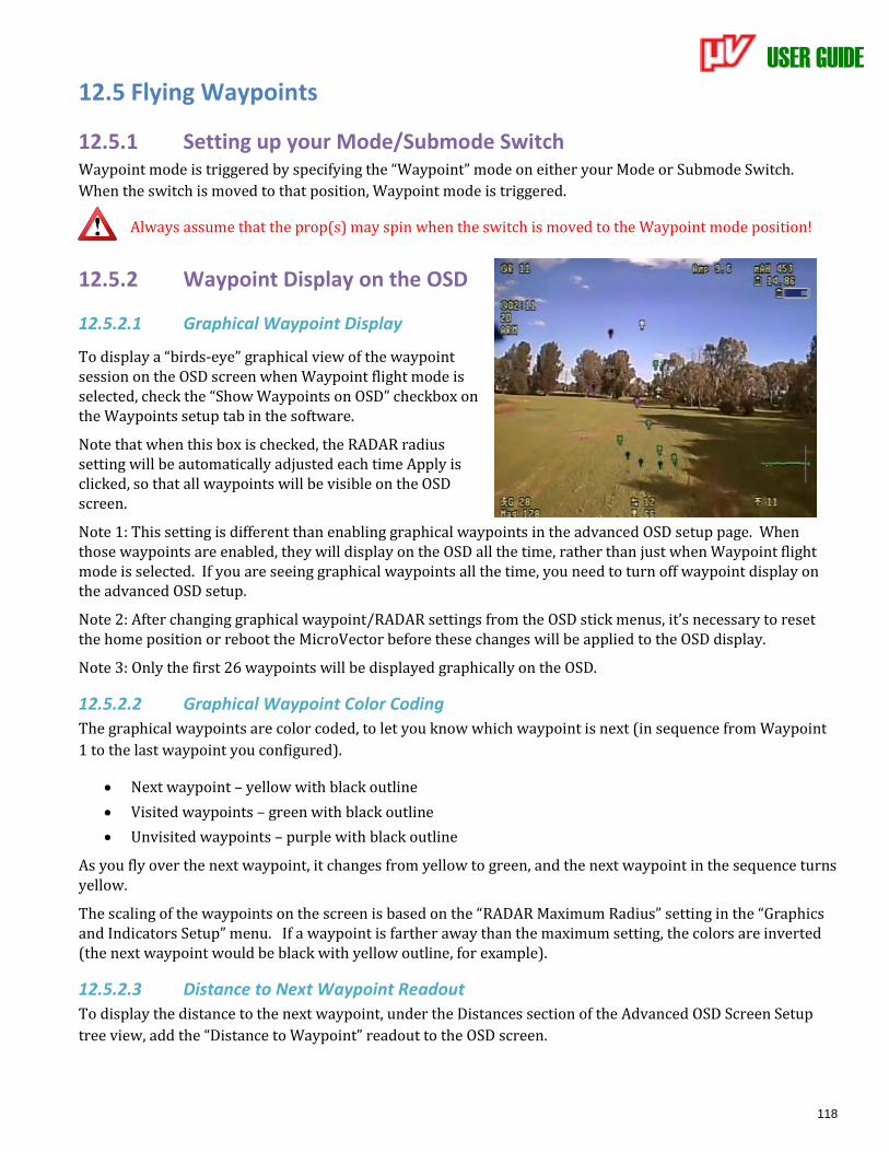
USER GUIDE
118
12.5 Flying Waypoints
12.5.1 Setting up your Mode/Submode Switch Waypoint mode is triggered by specifying the “Waypoint” mode on either your Mode or Submode Switch.
When the switch is moved to that position, Waypoint mode is triggered.
Always assume that the prop(s) may spin when the switch is moved to the Waypoint mode position!
12.5.2 Waypoint Display on the OSD
12.5.2.1 Graphical Waypoint Display
To display a “birds-eye” graphical view of the waypoint session on the OSD screen when Waypoint flight mode is selected, check the “Show Waypoints on OSD” checkbox on the Waypoints setup tab in the software.
Note that when this box is checked, the RADAR radius setting will be automatically adjusted each time Apply is clicked, so that all waypoints will be visible on the OSD screen.
Note 1: This setting is different than enabling graphical waypoints in the advanced OSD setup page. When those waypoints are enabled, they will display on the OSD all the time, rather than just when Waypoint flight mode is selected. If you are seeing graphical waypoints all the time, you need to turn off waypoint display on the advanced OSD setup.
Note 2: After changing graphical waypoint/RADAR settings from the OSD stick menus, it’s necessary to reset the home position or reboot the MicroVector before these changes will be applied to the OSD display.
Note 3: Only the first 26 waypoints will be displayed graphically on the OSD.
12.5.2.2 Graphical Waypoint Color Coding
The graphical waypoints are color coded, to let you know which waypoint is next (in sequence from Waypoint
1 to the last waypoint you configured).
• Next waypoint – yellow with black outline
• Visited waypoints – green with black outline
• Unvisited waypoints – purple with black outline
As you fly over the next waypoint, it changes from yellow to green, and the next waypoint in the sequence turns yellow.
The scaling of the waypoints on the screen is based on the “RADAR Maximum Radius” setting in the “Graphics and Indicators Setup” menu. If a waypoint is farther away than the maximum setting, the colors are inverted (the next waypoint would be black with yellow outline, for example).
12.5.2.3 Distance to Next Waypoint Readout
To display the distance to the next waypoint, under the Distances section of the Advanced OSD Screen Setup
tree view, add the “Distance to Waypoint” readout to the OSD screen.

USER GUIDE
119
12.5.3 Starting a Waypoint Session
12.5.3.1 Throttle Position
When flying waypoints, if a problem related to GPS or compass is detected, the MicroVector will at least temporarily switch to 2D With Hold flight mode. So, it’s strongly recommended that your throttle be left in an appropriate “Cruise” position while the Waypoint session is executing.
For multirotors, since rapid descent could occur if the throttle is below the midpoint when not in Waypoint mode, it is recommended to keep the throttle at its midpoint during waypoint navigation.
If, during waypoint navigation, your throttle position is moved to below about 33% up, Waypoint mode will pause, returning control to the pilot and placing the MicroVector in Loiter Mode temporarily.
For fixed wing, if the throttle position is reduced to below about 15% up, the waypoint navigation will continue but, for safety, the MicroVector will command the throttle to be at its “throttle off” position. This should normally stop the propeller from spinning. So, the model will ultimately crash land unless throttle is increased! The message “Safety check fail, throtle off” will appear in the OSD notification area if this event occurs.
12.5.3.2 Initiating Waypoint Mode
When your model is flying at a safe altitude, with the throttle stick moved to at least 15% up, move the Mode Switch to the “Waypoint” position to begin waypoint navigation.
Note that if “Permit Low Altitude Waypoints” was NOT checked when waypoints were configured, the following may cause the throttle to shut off during Waypoint mode:
• Waypoint mode is triggered below about 32 feet (10 meters).
• During waypoint navigation, the plane descends below about 32 feet (10 meters).
Also, note that if your airspeed (or ground speed, if the pitot tube is not in use) is less than 3MPH/5KPH during Waypoint mode, the throttle will shut off. The message “Safety check fail,throtle off” will appear in the OSD notification area if any of these conditions is detected.
When your multirotor is armed and at a safe altitude, and the throttle is moved to above 33% up, moving the Mode Switch to the “Waypoint” position will trigger waypoint navigation. If a ground takeoff is desired, make sure your first navigational command is the “Takeoff” command. Then arm the multirotor, switch to Waypoint Mode, and move the throttle at least 33% up to start the waypoint sequence.
When Waypoint mode is triggered, the message “Waypoint navigation started” will appear briefly in the OSD notification area.
12.5.4 Pausing and Aborting Waypoint Navigation
12.5.4.1 Pausing Waypoint Navigation
Waypoint navigation will pause if one of the following events occurs:
• The MicroVector detects a problem with the GPS or compass. 2D with Hold flight mode will be entered, and waypoint navigation will resume at the current command if the GPS issue quickly corrects itself (see section 12.4.4.1 – ‘GPS Fix Requirements’).
USER GUIDE
120
For fixed wing, if the control stick is moved (excluding rudder and throttle). 2D with Hold flight mode will be entered, and waypoint navigation will resume at the current command once the control stick is released.
For multirotors, if the control stick is moved (excluding rudder), or the throttle is reduced to below 33% up. 2D with Hold flight mode will be entered, and waypoint navigation will resume at the current command once the control stick is released, and the throttle is moved to above 33% up. Note that if this movement occurs during a Land/Disarm command, waypoint mode will be aborted, and the flight mode must be changed from Waypoint mode to another mode, then back to Waypoint mode, in order to restart the Waypoint mission.
• The flight mode is changed to a GPS Mode (such as Loiter) via the Mode or Submode Switch. Waypoint navigation will resume at the current command if the mode is switched back to type Waypoint, so long as the current command was not of the Land / Disarm type
When Waypoint mode is paused, the message “Pausing waypoint navigation” will appear briefly in the OSD notification area.
When Waypoint mode is resumed, the message “Resuming waypoint navigation” will appear briefly in the OSD notification area.
12.5.4.2 Aborting Waypoint Navigation
Waypoint navigation will be aborted if one of the following events occurs. Once waypoint navigation is
aborted, retriggering waypoints with the Mode or Submode Switch will result in waypoint navigation
restarting at the first waypoint command.
• The MicroVector detects a problem with the GPS or compass, which continues longer than described in section 12.4.4.1 – ‘GPS Fix Requirements’.
• The flight mode is changed to a non-GPS Mode (such as 2D with Hold) via the Mode or Submode Switch.
• RTH or Failsafe Safety mode is triggered for any reason. Note that this does not apply to the Return to Home waypoint command.
• Other MicroVector detected problems may abort waypoint navigation.
When Waypoint mode is aborted, the message “Waypoint navigation aborted” will appear briefly in the OSD notification area.
12.5.4.3 Landing
Never attempt to manually land your model in Waypoint Mode! Always switch to a different mode before landing, or use the Land / Disarm command, set for a safe location.
USER GUIDE
121
13 Closed Loop Speed Control (Fixed Wing)
13.1 Overview
“Closed Loop” speed control refers to using the model’s present speed to control the ESC/propeller RPM, rather than just directly controlling the RPM with the throttle stick position.
When closed loop is not enabled, the “Cruise,” “Climb” and “Off” throttle settings that are learned during the Receiver Analysis Wizard are used to control the speed of the model, in autonomous modes. When closed loop is enabled and functioning, the Vector uses the present speed of the model (either from GPS or a pitot tube) to adjust the speed, based on user settings.
Closed loop is available during the following flight operations:
• Return to Home (RTH)
• Loiter
• Waypoints
• “2D + Speed” and “2D Hold + Speed” “Cruise Control” flight modes, as described below.
Note that the model’s actual speed will vary from the specified speed, due to a variety of factors. For example, if a model is in a dive, it cannot be slowed down much by reducing RPM, and in a climb, the model will not go faster than the speed obtainable at maximum RPM.
13.2 Pitot Tube Support
13.2.1 Pitot Tube vs GPS Speed
Both GPS speed and pitot airspeed closed loop support is provided. Using a pitot tube for speed control results in control of airspeed, rather than ground speed. Using a pitot tube has advantages and disadvantages:
Advantages:
• The model will travel at a fixed speed relative to the wind. So, in a strong tailwind, for example, the model is less likely to stall due to slow airspeed.
• Battery life can be more accurately predicted, since the model is traveling at a relatively constant speed through the air, meaning that the propeller RPM and air resistance remain relatively constant.
• With the pitot tube, if the GPS signal should be lost or if no GPS is used, closed loop speed control is still available.
Disadvantages:
• A pitot tube adds another failure point.
If the pitot tube should become clogged or otherwise fail during flight, speed control would become erratic, possibly resulting in a crash!
• Since airspeed is being measured, in a high headwind the model may make no forward progress or actually move backwards relative to the ground. The “Minimum Groundspeed” setting can help mitigate this issue, however.
13.2.2 Pitot Tube Safety Checks If pitot tube speed control is enabled, the following checks are done to help ensure that the pitot tube is
working correctly.
USER GUIDE
122
• If the pitot sensor is not detected by the controller during startup, the system will fall back to GPS speed.
• Until the measured pitot speed reaches about 10MPH (16KPH), GPS speed will be used. This check helps to ensure that the pitot tube is connected and not clogged. Note that if the pitot tube hoses become disconnected or if the tube becomes clogged during flight, this condition will NOT be detected, and closed loop speed control will become erratic, possibly resulting in a crash!
• If the pitot sensor becomes electrically disconnected from the MicroVector during flight, the system will fall back to GPS speed.
Note that if GPS signal is inadequate AND a pitot failure is detected, closed loop speed control will be disabled.
13.3 Closed Loop Speed Control Related Settings The following settings are used to configure closed loop, in both the OSD “stick menus” and the GUI.
13.3.1 OSD Stick Menu Setup
The settings are available by navigating to the “Closed Loop Speed Cntrl Setup” and “Advanced Setup….” menu pages, listed on the “Safety/RTH/Nav Configuration” page, in the stick menus.
On the “Closed Loop Speed Cntrl Setup” OSD Stick Menu page:
• Auto Navigation Speed: this setting lets you set the desired closed loop speed for RTH, loiter and waypoint modes. This speed must be well above your model’s stall speed, or a stall will likely occur!
• Min Speed for 2D+Speed Modes: this setting controls the speed corresponding to the 15% throttle stick throw position when using a 2D+Speed flight mode. This speed must be well above your model’s stall speed, or a stall will likely occur!
• Max Speed for 2D+Speed Modes: this setting controls the speed corresponding to the “Climb” throttle stick position learned during the wizard, when using a 2D+Speed flight mode. This speed must be greater than the Min Speed described above.
• Speed Ctrl Throt Gain Proport: this setting allows adjustment of the proportional term of the speed control “PI” controller. If the controller compensates too aggressively to speed errors, causing rapid speed variation, try reducing this setting. Likewise, if the controller responds too sluggishly to speed errors, try increasing it.
• Speed Ctrl Throt Gain Integrl: this setting allows adjustment of the integral term of the speed control “PI” controller. If the controller never quite reaches the commanded speed, try increasing this setting.
• Minimum Closed Loop Throttle: when in closed loop mode, depending on closed loop throttle gain settings and the difference between the model’s speed and the desired speed, the throttle output to the motor can range between the “Climb” and “Off” throttle settings that you specified during the Receiver Analysis Wizard. So, if the model is going considerably faster than the desired speed, the throttle could be set to off. If your plane has a tendency to stall at low throttle, or you otherwise don’t want to the throttle to go this low, change this value to set an alternative minimum throttle position. Note that this value is reset to the “Off” throttle setting each time the Wizard is run, so remember to change this setting again each time you run the Wizard.
• Loiter Speed (0=Use Auto Spd): this setting lets you specify the closed loop speed during loiter flight mode. Note that if this setting is 0, the “Auto Navigation Speed” setting is used for loiter mode. Note that the “Auto Navigation Speed” setting MUST be nonzero for closed loop speed control to function in loiter. This speed must be well above your model’s stall speed, or a stall will likely occur!
On the “Advanced” menu, under the “Safety/RTH/Nav Configuration” OSD Stick Menu:
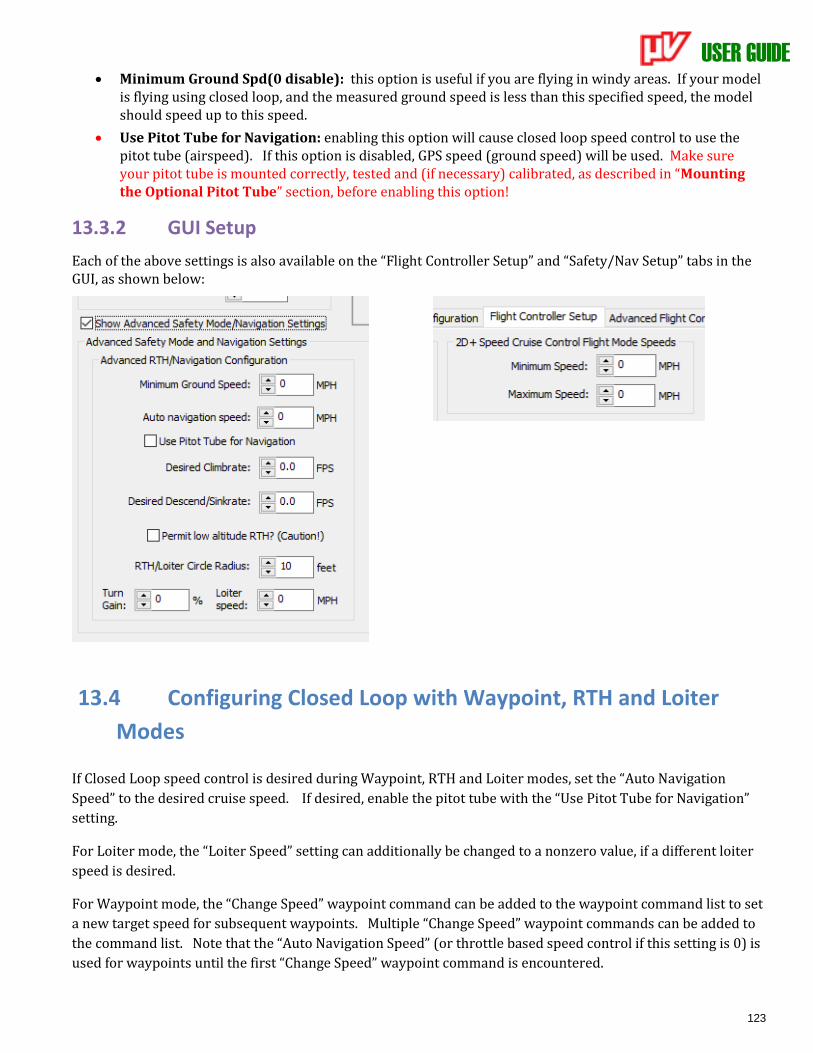
USER GUIDE
123
• Minimum Ground Spd(0 disable): this option is useful if you are flying in windy areas. If your model is flying using closed loop, and the measured ground speed is less than this specified speed, the model should speed up to this speed.
• Use Pitot Tube for Navigation: enabling this option will cause closed loop speed control to use the pitot tube (airspeed). If this option is disabled, GPS speed (ground speed) will be used. Make sure your pitot tube is mounted correctly, tested and (if necessary) calibrated, as described in “Mounting the Optional Pitot Tube” section, before enabling this option!
13.3.2 GUI Setup
Each of the above settings is also available on the “Flight Controller Setup” and “Safety/Nav Setup” tabs in the GUI, as shown below:
13.4 Configuring Closed Loop with Waypoint, RTH and Loiter
Modes
If Closed Loop speed control is desired during Waypoint, RTH and Loiter modes, set the “Auto Navigation
Speed” to the desired cruise speed. If desired, enable the pitot tube with the “Use Pitot Tube for Navigation”
setting.
For Loiter mode, the “Loiter Speed” setting can additionally be changed to a nonzero value, if a different loiter
speed is desired.
For Waypoint mode, the “Change Speed” waypoint command can be added to the waypoint command list to set
a new target speed for subsequent waypoints. Multiple “Change Speed” waypoint commands can be added to
the command list. Note that the “Auto Navigation Speed” (or throttle based speed control if this setting is 0) is
used for waypoints until the first “Change Speed” waypoint command is encountered.
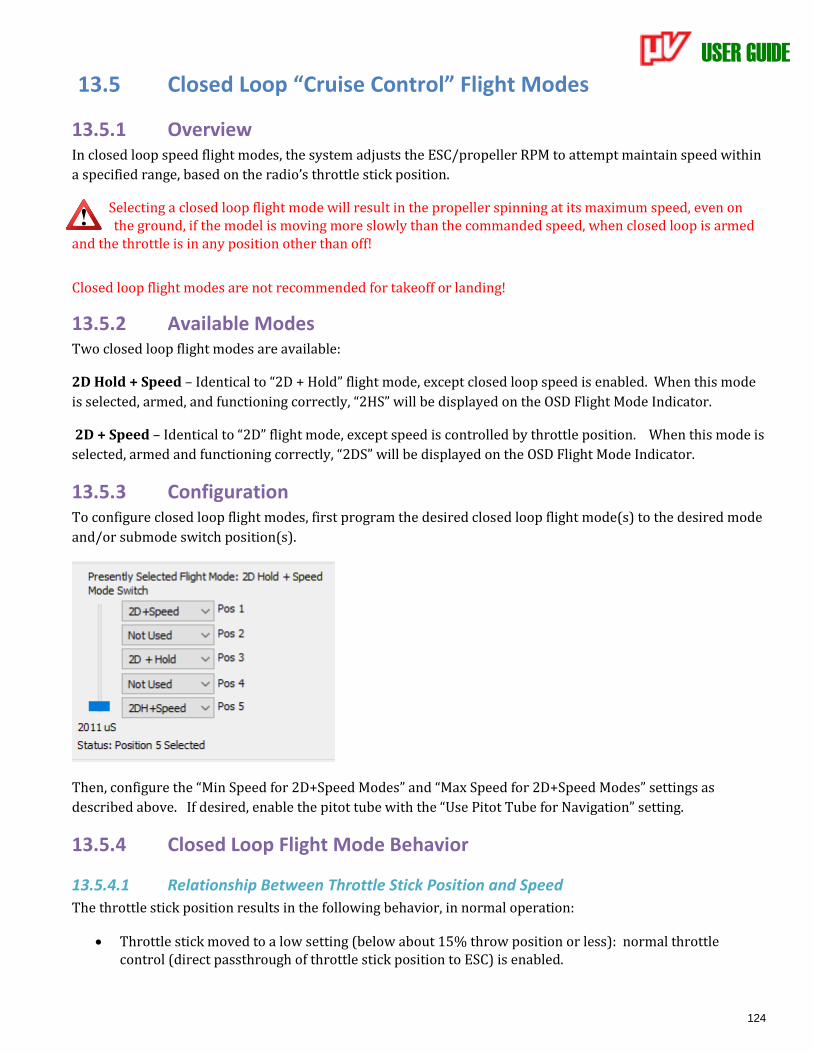
USER GUIDE
124
13.5 Closed Loop “Cruise Control” Flight Modes
13.5.1 Overview In closed loop speed flight modes, the system adjusts the ESC/propeller RPM to attempt maintain speed within
a specified range, based on the radio’s throttle stick position.
Selecting a closed loop flight mode will result in the propeller spinning at its maximum speed, even on the ground, if the model is moving more slowly than the commanded speed, when closed loop is armed
and the throttle is in any position other than off!
Closed loop flight modes are not recommended for takeoff or landing!
13.5.2 Available Modes Two closed loop flight modes are available:
2D Hold + Speed – Identical to “2D + Hold” flight mode, except closed loop speed is enabled. When this mode
is selected, armed, and functioning correctly, “2HS” will be displayed on the OSD Flight Mode Indicator.
2D + Speed – Identical to “2D” flight mode, except speed is controlled by throttle position. When this mode is
selected, armed and functioning correctly, “2DS” will be displayed on the OSD Flight Mode Indicator.
13.5.3 Configuration To configure closed loop flight modes, first program the desired closed loop flight mode(s) to the desired mode
and/or submode switch position(s).
Then, configure the “Min Speed for 2D+Speed Modes” and “Max Speed for 2D+Speed Modes” settings as
described above. If desired, enable the pitot tube with the “Use Pitot Tube for Navigation” setting.
13.5.4 Closed Loop Flight Mode Behavior
13.5.4.1 Relationship Between Throttle Stick Position and Speed
The throttle stick position results in the following behavior, in normal operation:
• Throttle stick moved to a low setting (below about 15% throw position or less): normal throttle control (direct passthrough of throttle stick position to ESC) is enabled.
USER GUIDE
125
• Throttle stick moved between about 15% and the “Climb” throttle position learned during the Receiver Analysis Wizard: commanded speed is proportionally scaled between the “Min Speed for 2D+Speed Modes” and “Max Speed for 2D+Speed Modes” settings.
• Throttle stick moved above the “Climb” throttle position: commanded speed is limited to “Max Speed for 2D+Speed Modes” setting.
Note that as you move the throttle, the commanded target speed will briefly display in the OSD notification window.
13.5.4.2 Initial Speed Requirement to Arm Closed Loop Mode
When a closed loop flight mode is selected via the mode or submode switch, normal throttle control (direct
passthrough of throttle stick position to ESC) is utilized until and unless the model has reached a trigger speed
of about 10MPH (16KPH), which arms closed loop mode.
Note that the minimum speed requirement is disabled once the trigger speed is reached. In other words, if the
model reaches the trigger speed, then decelerates below that speed, closed loop speed control will remain
active under normal operation, as long as the throttle stick position remains above about 15% throw.
Closed loop mode is disarmed, requiring the trigger speed to be exceeded again for closed loop control,
whenever the throttle is brought below about 15% throw.
13.5.4.3 Closed Loop Flight Mode Fallback
Closed loop flight mode will be disabled (and direct throttle stick passthrough to ESC will be enabled) when
one of these events occur:
• If the GPS fix quality is inadequate, and closed loop is not using the pitot tube.
• If pitot tube navigation is enabled, and a problem is detected with the pitot tube, and GPS fix quality is inadequate.
• When the throttle stick position is brought below about 15%. This also disarms closed loop mode.
• Until the initial speed reaches about 10MPH (16KPH), which arms closed loop mode if not presently armed.
When closed loop flight mode is disabled, either standard “2D + Hold” or “2D” flight mode will be engaged, and the OSD Flight Mode Indicator will show either “2DH’ or “2D” flight mode, depending on which closed loop flight mode is presently selected.
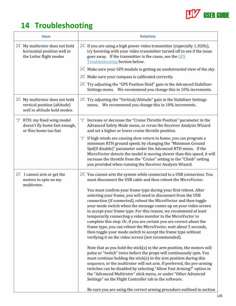
USER GUIDE
126
14 Troubleshooting Issue Solutions
My multirotor does not hold horizontal position well in the Loiter flight modes
If you are using a high power video transmitter (especially 1.3GHz), try hovering with your video transmitter turned off to see if the issue goes away. If the transmitter is the cause, see the GPS Troubleshooting Section below.
Make sure your GPS module is getting an unobstructed view of the sky.
Make sure your compass is calibrated correctly.
Try adjusting the “GPS Position Hold” gain in the Advanced Stabilizer Settings menu. We recommend you change this in 10% increments.
My multirotor does not hold vertical position (altitude) well in altitude hold modes.
Try adjusting the “Vertical/Altitude” gain in the Stabilizer Settings menu. We recommend you change this in 10% increments.
RTH: my fixed wing model doesn’t fly home fast enough, or flies home too fast
Increase or decrease the “Cruise Throttle Position” parameter in the Advanced Safety Mode menu, or rerun the Receiver Analysis Wizard and set a higher or lower cruise throttle position.
If high winds are causing slow return to home, you can program a minimum RTH ground speed, by changing the “Minimum Ground Spd(0 disable)” parameter under the Advanced RTH menu. If the MicroVector detects the model is moving slower than this speed, it will increase the throttle from the “Cruise” setting to the “Climb” setting you provided when running the Receiver Analysis Wizard.
I cannot arm or get the motors to spin on my multirotor.
You cannot arm the system while connected to a USB connection. You must disconnect the USB cable and then reboot the MicroVector. You must confirm your frame type during your first reboot. After selecting your frame, you will need to disconnect from the USB connection (if connected), reboot the MicroVector and then toggle your mode switch when the message comes up on your video screen to accept your frame type. For this reason, we recommend at least temporarily connecting a video monitor to the MicroVector to complete this step. Or, if you are certain you are correct about the frame type, you can reboot the MicroVector, wait about 5 seconds, then toggle your mode switch to accept the frame type without verifying it on the video screen (not recommended). Note that as you hold the stick(s) in the arm position, the motors will pulse or “twitch” twice before the props will continuously spin. You must continue holding the stick(s) in the arm position during this sequence, or the multirotor will not arm. If preferred, the pre-arming twitches can be disabled by selecting “Allow Fast Arming?” option in the “Advanced Multirotor” stick menu, or under “Other Advanced Settings” on the Flight Controller tab in the software. Be sure you are using the correct arming procedure outlined in section
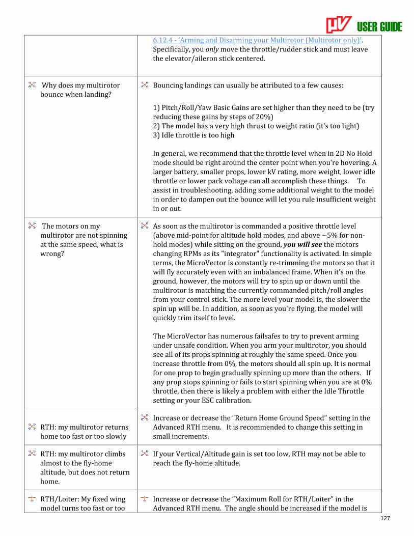
USER GUIDE
127
6.12.4 - ‘Arming and Disarming your Multirotor (Multirotor only)’. Specifically, you only move the throttle/rudder stick and must leave the elevator/aileron stick centered.
Why does my multirotor bounce when landing?
Bouncing landings can usually be attributed to a few causes:
1) Pitch/Roll/Yaw Basic Gains are set higher than they need to be (try reducing these gains by steps of 20%) 2) The model has a very high thrust to weight ratio (it's too light) 3) Idle throttle is too high In general, we recommend that the throttle level when in 2D No Hold mode should be right around the center point when you're hovering. A larger battery, smaller props, lower kV rating, more weight, lower idle throttle or lower pack voltage can all accomplish these things. To assist in troubleshooting, adding some additional weight to the model in order to dampen out the bounce will let you rule insufficient weight in or out.
The motors on my multirotor are not spinning at the same speed, what is wrong?
As soon as the multirotor is commanded a positive throttle level (above mid-point for altitude hold modes, and above ~5% for non-hold modes) while sitting on the ground, you will see the motors changing RPMs as its "integrator" functionality is activated. In simple terms, the MicroVector is constantly re-trimming the motors so that it will fly accurately even with an imbalanced frame. When it's on the ground, however, the motors will try to spin up or down until the multirotor is matching the currently commanded pitch/roll angles from your control stick. The more level your model is, the slower the spin up will be. In addition, as soon as you're flying, the model will quickly trim itself to level. The MicroVector has numerous failsafes to try to prevent arming under unsafe condition. When you arm your multirotor, you should see all of its props spinning at roughly the same speed. Once you increase throttle from 0%, the motors should all spin up. It is normal for one prop to begin gradually spinning up more than the others. If any prop stops spinning or fails to start spinning when you are at 0% throttle, then there is likely a problem with either the Idle Throttle setting or your ESC calibration.
RTH: my multirotor returns home too fast or too slowly
Increase or decrease the “Return Home Ground Speed” setting in the Advanced RTH menu. It is recommended to change this setting in small increments.
RTH: my multirotor climbs almost to the fly-home altitude, but does not return home.
If your Vertical/Altitude gain is set too low, RTH may not be able to reach the fly-home altitude.
RTH/Loiter: My fixed wing model turns too fast or too
Increase or decrease the “Maximum Roll for RTH/Loiter” in the Advanced RTH menu. The angle should be increased if the model is
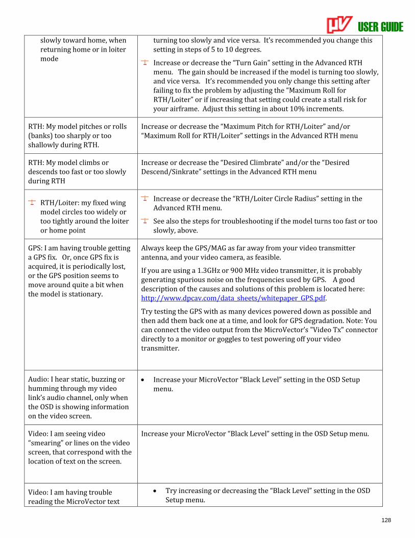
USER GUIDE
128
slowly toward home, when returning home or in loiter mode
turning too slowly and vice versa. It’s recommended you change this setting in steps of 5 to 10 degrees.
Increase or decrease the “Turn Gain” setting in the Advanced RTH menu. The gain should be increased if the model is turning too slowly, and vice versa. It’s recommended you only change this setting after failing to fix the problem by adjusting the “Maximum Roll for RTH/Loiter” or if increasing that setting could create a stall risk for your airframe. Adjust this setting in about 10% increments.
RTH: My model pitches or rolls (banks) too sharply or too shallowly during RTH.
Increase or decrease the “Maximum Pitch for RTH/Loiter” and/or “Maximum Roll for RTH/Loiter” settings in the Advanced RTH menu
RTH: My model climbs or descends too fast or too slowly during RTH
Increase or decrease the “Desired Climbrate” and/or the “Desired Descend/Sinkrate” settings in the Advanced RTH menu
RTH/Loiter: my fixed wing model circles too widely or too tightly around the loiter or home point
Increase or decrease the “RTH/Loiter Circle Radius” setting in the Advanced RTH menu.
See also the steps for troubleshooting if the model turns too fast or too slowly, above.
GPS: I am having trouble getting a GPS fix. Or, once GPS fix is acquired, it is periodically lost, or the GPS position seems to move around quite a bit when the model is stationary.
Always keep the GPS/MAG as far away from your video transmitter antenna, and your video camera, as feasible.
If you are using a 1.3GHz or 900 MHz video transmitter, it is probably generating spurious noise on the frequencies used by GPS. A good description of the causes and solutions of this problem is located here: http://www.dpcav.com/data_sheets/whitepaper_GPS.pdf.
Try testing the GPS with as many devices powered down as possible and then add them back one at a time, and look for GPS degradation. Note: You can connect the video output from the MicroVector’s "Video Tx" connector directly to a monitor or goggles to test powering off your video transmitter.
Audio: I hear static, buzzing or humming through my video link’s audio channel, only when the OSD is showing information on the video screen.
• Increase your MicroVector “Black Level” setting in the OSD Setup menu.
Video: I am seeing video “smearing” or lines on the video screen, that correspond with the location of text on the screen.
Increase your MicroVector “Black Level” setting in the OSD Setup menu.
Video: I am having trouble reading the MicroVector text
• Try increasing or decreasing the “Black Level” setting in the OSD Setup menu.
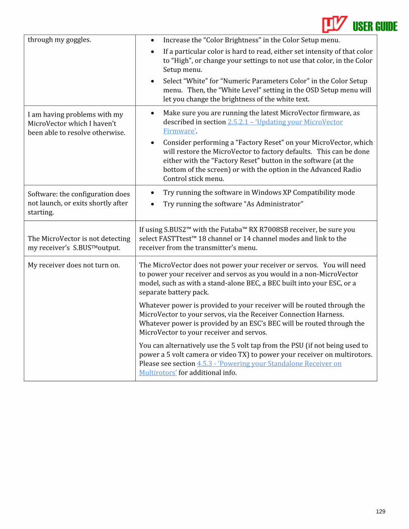
USER GUIDE
129
through my goggles. • Increase the “Color Brightness” in the Color Setup menu.
• If a particular color is hard to read, either set intensity of that color to “High”, or change your settings to not use that color, in the Color Setup menu.
• Select “White” for “Numeric Parameters Color” in the Color Setup menu. Then, the “White Level” setting in the OSD Setup menu will let you change the brightness of the white text.
I am having problems with my MicroVector which I haven’t been able to resolve otherwise.
• Make sure you are running the latest MicroVector firmware, as described in section 2.5.2.1 – ‘Updating your MicroVector Firmware’.
• Consider performing a “Factory Reset” on your MicroVector, which will restore the MicroVector to factory defaults. This can be done either with the “Factory Reset” button in the software (at the bottom of the screen) or with the option in the Advanced Radio Control stick menu.
Software: the configuration does not launch, or exits shortly after starting.
• Try running the software in Windows XP Compatibility mode
• Try running the software “As Administrator”
The MicroVector is not detecting my receiver’s S.BUSTMoutput.
If using S.BUS2™ with the Futaba™ RX R7008SB receiver, be sure you select FASTTtest™ 18 channel or 14 channel modes and link to the receiver from the transmitter’s menu.
My receiver does not turn on. The MicroVector does not power your receiver or servos. You will need to power your receiver and servos as you would in a non-MicroVector model, such as with a stand-alone BEC, a BEC built into your ESC, or a separate battery pack.
Whatever power is provided to your receiver will be routed through the MicroVector to your servos, via the Receiver Connection Harness. Whatever power is provided by an ESC’s BEC will be routed through the MicroVector to your receiver and servos.
You can alternatively use the 5 volt tap from the PSU (if not being used to power a 5 volt camera or video TX) to power your receiver on multirotors. Please see section 4.5.3 - ‘Powering your Standalone Receiver on Multirotors’ for additional info.
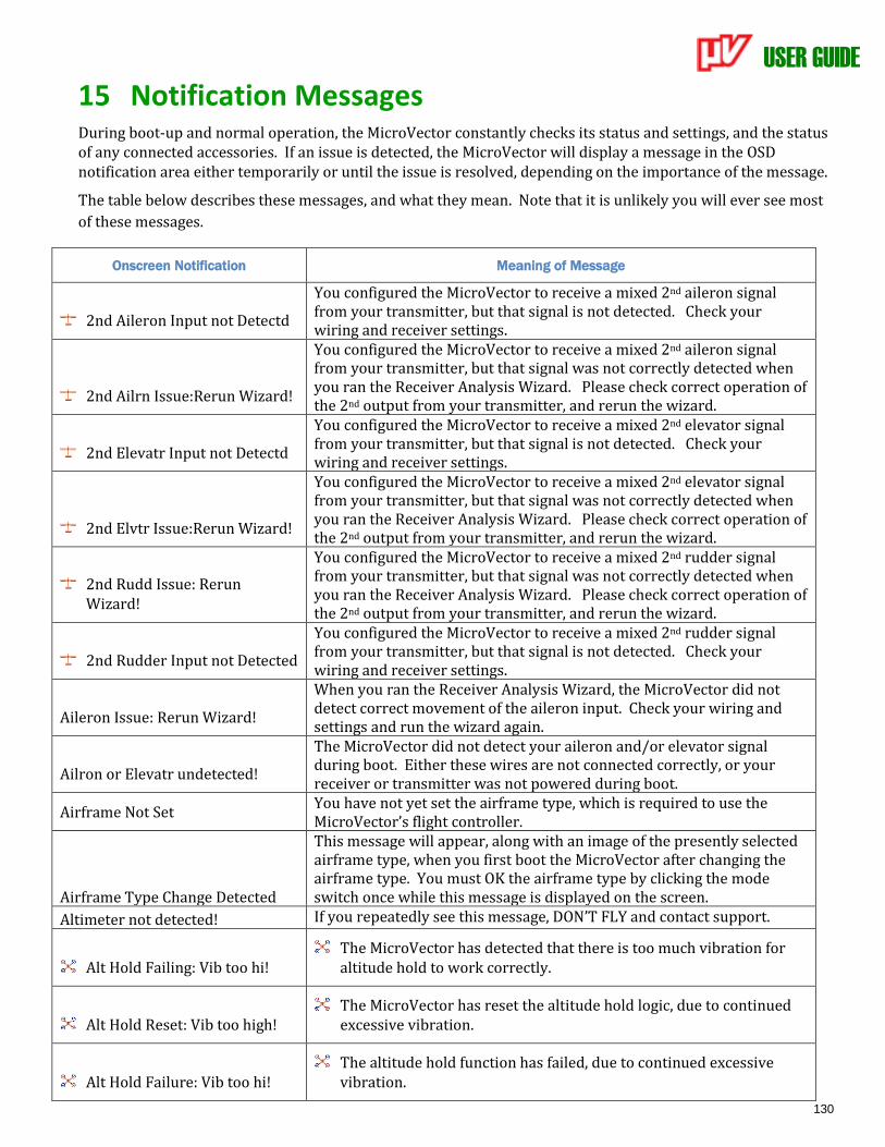
USER GUIDE
130
15 Notification Messages During boot-up and normal operation, the MicroVector constantly checks its status and settings, and the status of any connected accessories. If an issue is detected, the MicroVector will display a message in the OSD notification area either temporarily or until the issue is resolved, depending on the importance of the message.
The table below describes these messages, and what they mean. Note that it is unlikely you will ever see most
of these messages.
Onscreen Notification Meaning of Message
2nd Aileron Input not Detectd
You configured the MicroVector to receive a mixed 2nd aileron signal from your transmitter, but that signal is not detected. Check your wiring and receiver settings.
2nd Ailrn Issue:Rerun Wizard!
You configured the MicroVector to receive a mixed 2nd aileron signal from your transmitter, but that signal was not correctly detected when you ran the Receiver Analysis Wizard. Please check correct operation of the 2nd output from your transmitter, and rerun the wizard.
2nd Elevatr Input not Detectd
You configured the MicroVector to receive a mixed 2nd elevator signal from your transmitter, but that signal is not detected. Check your wiring and receiver settings.
2nd Elvtr Issue:Rerun Wizard!
You configured the MicroVector to receive a mixed 2nd elevator signal from your transmitter, but that signal was not correctly detected when you ran the Receiver Analysis Wizard. Please check correct operation of the 2nd output from your transmitter, and rerun the wizard.
2nd Rudd Issue: Rerun Wizard!
You configured the MicroVector to receive a mixed 2nd rudder signal from your transmitter, but that signal was not correctly detected when you ran the Receiver Analysis Wizard. Please check correct operation of the 2nd output from your transmitter, and rerun the wizard.
2nd Rudder Input not Detected
You configured the MicroVector to receive a mixed 2nd rudder signal from your transmitter, but that signal is not detected. Check your wiring and receiver settings.
Aileron Issue: Rerun Wizard!
When you ran the Receiver Analysis Wizard, the MicroVector did not detect correct movement of the aileron input. Check your wiring and settings and run the wizard again.
Ailron or Elevatr undetected!
The MicroVector did not detect your aileron and/or elevator signal during boot. Either these wires are not connected correctly, or your receiver or transmitter was not powered during boot.
Airframe Not Set You have not yet set the airframe type, which is required to use the MicroVector’s flight controller.
Airframe Type Change Detected
This message will appear, along with an image of the presently selected airframe type, when you first boot the MicroVector after changing the airframe type. You must OK the airframe type by clicking the mode switch once while this message is displayed on the screen.
Altimeter not detected! If you repeatedly see this message, DON’T FLY and contact support.
Alt Hold Failing: Vib too hi! The MicroVector has detected that there is too much vibration for
altitude hold to work correctly.
Alt Hold Reset: Vib too high! The MicroVector has reset the altitude hold logic, due to continued
excessive vibration.
Alt Hold Failure: Vib too hi! The altitude hold function has failed, due to continued excessive
vibration.
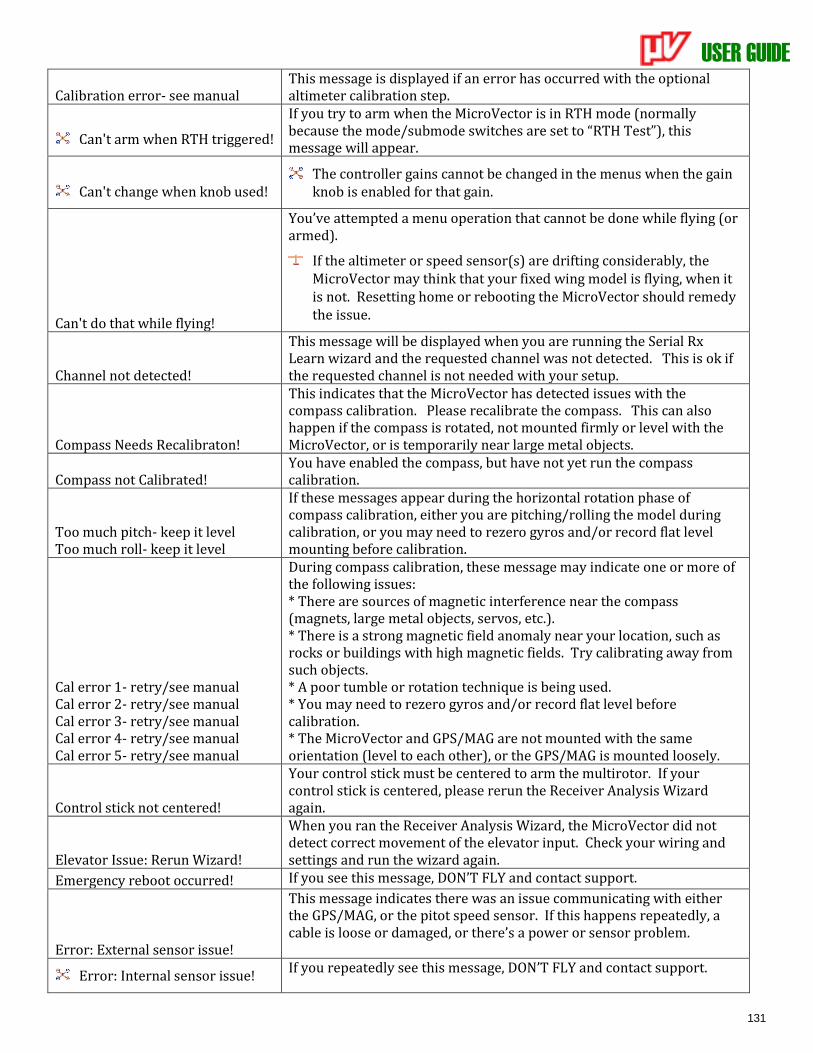
USER GUIDE
131
Calibration error- see manual This message is displayed if an error has occurred with the optional altimeter calibration step.
Can't arm when RTH triggered!
If you try to arm when the MicroVector is in RTH mode (normally because the mode/submode switches are set to “RTH Test”), this message will appear.
Can't change when knob used! The controller gains cannot be changed in the menus when the gain
knob is enabled for that gain.
Can't do that while flying!
You’ve attempted a menu operation that cannot be done while flying (or armed).
If the altimeter or speed sensor(s) are drifting considerably, the MicroVector may think that your fixed wing model is flying, when it is not. Resetting home or rebooting the MicroVector should remedy the issue.
Channel not detected!
This message will be displayed when you are running the Serial Rx Learn wizard and the requested channel was not detected. This is ok if the requested channel is not needed with your setup.
Compass Needs Recalibraton!
This indicates that the MicroVector has detected issues with the compass calibration. Please recalibrate the compass. This can also happen if the compass is rotated, not mounted firmly or level with the MicroVector, or is temporarily near large metal objects.
Compass not Calibrated! You have enabled the compass, but have not yet run the compass calibration.
Too much pitch- keep it level Too much roll- keep it level
If these messages appear during the horizontal rotation phase of compass calibration, either you are pitching/rolling the model during calibration, or you may need to rezero gyros and/or record flat level mounting before calibration.
Cal error 1- retry/see manual Cal error 2- retry/see manual Cal error 3- retry/see manual Cal error 4- retry/see manual Cal error 5- retry/see manual
During compass calibration, these message may indicate one or more of the following issues: * There are sources of magnetic interference near the compass (magnets, large metal objects, servos, etc.). * There is a strong magnetic field anomaly near your location, such as rocks or buildings with high magnetic fields. Try calibrating away from such objects. * A poor tumble or rotation technique is being used. * You may need to rezero gyros and/or record flat level before calibration. * The MicroVector and GPS/MAG are not mounted with the same orientation (level to each other), or the GPS/MAG is mounted loosely.
Control stick not centered!
Your control stick must be centered to arm the multirotor. If your control stick is centered, please rerun the Receiver Analysis Wizard again.
Elevator Issue: Rerun Wizard!
When you ran the Receiver Analysis Wizard, the MicroVector did not detect correct movement of the elevator input. Check your wiring and settings and run the wizard again.
Emergency reboot occurred! If you see this message, DON’T FLY and contact support.
Error: External sensor issue!
This message indicates there was an issue communicating with either the GPS/MAG, or the pitot speed sensor. If this happens repeatedly, a cable is loose or damaged, or there’s a power or sensor problem.
Error: Internal sensor issue! If you repeatedly see this message, DON’T FLY and contact support.
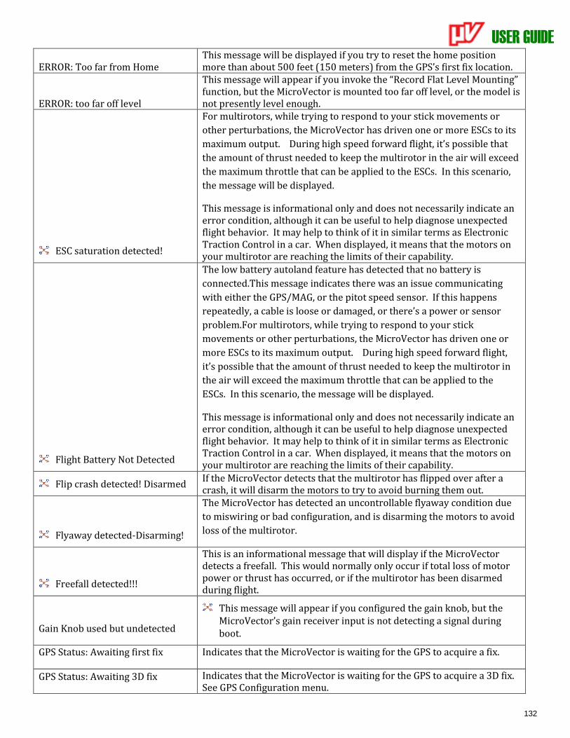
USER GUIDE
132
ERROR: Too far from Home This message will be displayed if you try to reset the home position more than about 500 feet (150 meters) from the GPS’s first fix location.
ERROR: too far off level
This message will appear if you invoke the “Record Flat Level Mounting” function, but the MicroVector is mounted too far off level, or the model is not presently level enough.
ESC saturation detected!
For multirotors, while trying to respond to your stick movements or
other perturbations, the MicroVector has driven one or more ESCs to its
maximum output. During high speed forward flight, it’s possible that
the amount of thrust needed to keep the multirotor in the air will exceed
the maximum throttle that can be applied to the ESCs. In this scenario,
the message will be displayed.
This message is informational only and does not necessarily indicate an error condition, although it can be useful to help diagnose unexpected flight behavior. It may help to think of it in similar terms as Electronic Traction Control in a car. When displayed, it means that the motors on your multirotor are reaching the limits of their capability.
Flight Battery Not Detected
The low battery autoland feature has detected that no battery is
connected.This message indicates there was an issue communicating
with either the GPS/MAG, or the pitot speed sensor. If this happens
repeatedly, a cable is loose or damaged, or there’s a power or sensor
problem.For multirotors, while trying to respond to your stick
movements or other perturbations, the MicroVector has driven one or
more ESCs to its maximum output. During high speed forward flight,
it’s possible that the amount of thrust needed to keep the multirotor in
the air will exceed the maximum throttle that can be applied to the
ESCs. In this scenario, the message will be displayed.
This message is informational only and does not necessarily indicate an error condition, although it can be useful to help diagnose unexpected flight behavior. It may help to think of it in similar terms as Electronic Traction Control in a car. When displayed, it means that the motors on your multirotor are reaching the limits of their capability.
Flip crash detected! Disarmed If the MicroVector detects that the multirotor has flipped over after a crash, it will disarm the motors to try to avoid burning them out.
Flyaway detected-Disarming!
The MicroVector has detected an uncontrollable flyaway condition due
to miswiring or bad configuration, and is disarming the motors to avoid
loss of the multirotor.
Freefall detected!!!
This is an informational message that will display if the MicroVector detects a freefall. This would normally only occur if total loss of motor power or thrust has occurred, or if the multirotor has been disarmed during flight.
Gain Knob used but undetected
This message will appear if you configured the gain knob, but the MicroVector’s gain receiver input is not detecting a signal during boot.
GPS Status: Awaiting first fix Indicates that the MicroVector is waiting for the GPS to acquire a fix.
GPS Status: Awaiting 3D fix Indicates that the MicroVector is waiting for the GPS to acquire a 3D fix. See GPS Configuration menu.
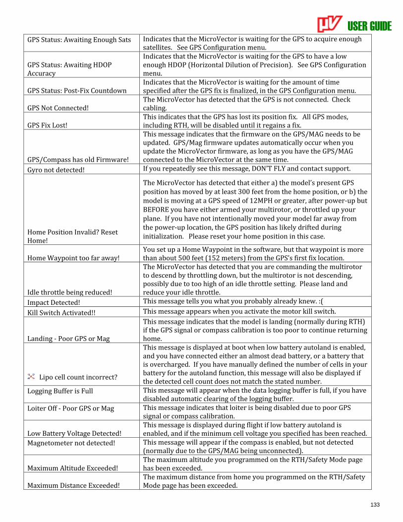
USER GUIDE
133
GPS Status: Awaiting Enough Sats Indicates that the MicroVector is waiting for the GPS to acquire enough satellites. See GPS Configuration menu.
GPS Status: Awaiting HDOP Accuracy
Indicates that the MicroVector is waiting for the GPS to have a low enough HDOP (Horizontal Dilution of Precision). See GPS Configuration menu.
GPS Status: Post-Fix Countdown Indicates that the MicroVector is waiting for the amount of time specified after the GPS fix is finalized, in the GPS Configuration menu.
GPS Not Connected! The MicroVector has detected that the GPS is not connected. Check cabling.
GPS Fix Lost! This indicates that the GPS has lost its position fix. All GPS modes, including RTH, will be disabled until it regains a fix.
GPS/Compass has old Firmware!
This message indicates that the firmware on the GPS/MAG needs to be updated. GPS/Mag firmware updates automatically occur when you update the MicroVector firmware, as long as you have the GPS/MAG connected to the MicroVector at the same time.
Gyro not detected! If you repeatedly see this message, DON’T FLY and contact support.
Home Position Invalid? Reset Home!
The MicroVector has detected that either a) the model’s present GPS position has moved by at least 300 feet from the home position, or b) the model is moving at a GPS speed of 12MPH or greater, after power-up but BEFORE you have either armed your multirotor, or throttled up your plane. If you have not intentionally moved your model far away from the power-up location, the GPS position has likely drifted during initialization. Please reset your home position in this case.
Home Waypoint too far away! You set up a Home Waypoint in the software, but that waypoint is more than about 500 feet (152 meters) from the GPS’s first fix location.
Idle throttle being reduced!
The MicroVector has detected that you are commanding the multirotor to descend by throttling down, but the multirotor is not descending, possibly due to too high of an idle throttle setting. Please land and reduce your idle throttle.
Impact Detected! This message tells you what you probably already knew. :(
Kill Switch Activated!! This message appears when you activate the motor kill switch.
Landing - Poor GPS or Mag
This message indicates that the model is landing (normally during RTH) if the GPS signal or compass calibration is too poor to continue returning home.
Lipo cell count incorrect?
This message is displayed at boot when low battery autoland is enabled, and you have connected either an almost dead battery, or a battery that is overcharged. If you have manually defined the number of cells in your battery for the autoland function, this message will also be displayed if the detected cell count does not match the stated number.
Logging Buffer is Full This message will appear when the data logging buffer is full, if you have disabled automatic clearing of the logging buffer.
Loiter Off - Poor GPS or Mag This message indicates that loiter is being disabled due to poor GPS signal or compass calibration.
Low Battery Voltage Detected! This message is displayed during flight if low battery autoland is enabled, and if the minimum cell voltage you specified has been reached.
Magnetometer not detected! This message will appear if the compass is enabled, but not detected (normally due to the GPS/MAG being unconnected).
Maximum Altitude Exceeded! The maximum altitude you programmed on the RTH/Safety Mode page has been exceeded.
Maximum Distance Exceeded! The maximum distance from home you programmed on the RTH/Safety Mode page has been exceeded.
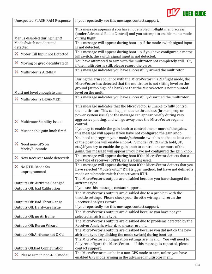
USER GUIDE
134
Unexpected FLASH RAM Response If you repeatedly see this message, contact support.
Menus disabled during flight!
This message appears if you have not enabled in-flight menu access (under Advanced Radio Control) and you attempt to enable menu mode during flight.
Mode Switch not detected detected!
This message will appear during boot-up if the mode switch signal input is not detected.
Motor Kill Input not Detected This message will appear during boot-up if you have configured a motor kill switch, the switch signal input is not detected.
Moving or gyro decalibrated! You have attempted to arm with the multirotor not completely still. Or, if the multirotor is still, please rezero the gyros.
Multirotor is ARMED! This message indicates you have successfully armed the multirotor.
Multi not level enough to arm
During the arm sequence with the MicroVector in a 2D flight mode, the MicroVector has detected that the multirotor is not sitting level on the ground (at too high of a bank) or that the MicroVector is not mounted level on the multi.
Multirotor is DISARMED! This message indicates you have successfully disarmed the multirotor.
Multirotor Stability Issue!
This message indicates that the MicroVector is unable to fully control the multirotor. This can happen due to thrust loss (broken prop or power system issue) or the message can appear briefly during very aggressive piloting, and will go away once the MicroVector regains control.
Must enable gain knob first! If you try to enable the gain knob to control one or more of the gains, this message will appear if you have not configured the gain knob.
Need non-GPS on Mode/Submode
You need to program your mode/submode switches so that at least one of the positions will enable a non-GPS mode (2D, 2D with hold, 3D, etc.).If you try to enable the gain knob to control one or more of the gains, this message will appear if you have not configured the gain knob.
New Receiver Mode detected! This message will appear during boot if the MicroVector detects that a new type of receiver (SPPM, etc.) is being used.
No RTH! Mode Sw unprogrammed
This message will appear during boot if the MicroVector detects that you have selected “Mode Switch” RTH trigger method, but have not defined a mode or submode switch that activates RTH.
Outputs Off: Airframe Changed The MicroVector’s outputs are disabled because you have changed the airframe type.
Outputs Off: bad Calibration If you see this message, contact support.
Outputs Off: Bad Throt Range
The MicroVector’s outputs are disabled due to a problem with the throttle settings. Please check your throttle wiring and rerun the Receiver Analysis Wizard.
Outputs Off: Hardware Issue If you repeatedly see this message, contact support.
Outputs Off: no Airframe The MicroVector’s outputs are disabled because you have not yet selected an airframe type.
Outputs Off: Rerun Wizard The MicroVector’s outputs are disabled due to problems detected by the Receiver Analysis wizard, so please rerun it.
Outputs Off:Airframe not OK'd The MicroVector’s outputs are disabled because you did not ok the new airframe type (by clicking the mode switch) during boot-up.
Outputs Off:bad Configuration
The MicroVector’s configuration settings are invalid. You will need to fully reconfigure the MicroVector. If this message is repeated, please contact support.
Please arm in non-GPS mode! The MicroVector must be in a non-GPS mode to arm, unless you have enabled GPS mode arming in the advanced multirotor menu.
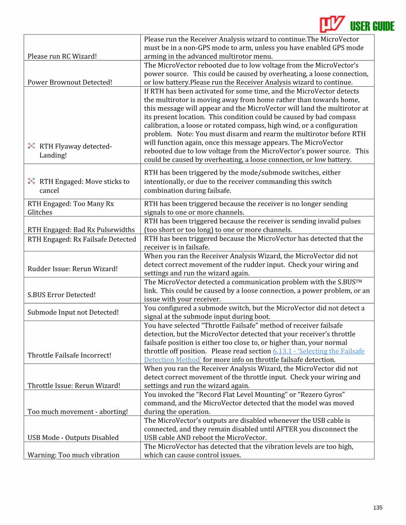
USER GUIDE
135
Please run RC Wizard!
Please run the Receiver Analysis wizard to continue.The MicroVector must be in a non-GPS mode to arm, unless you have enabled GPS mode arming in the advanced multirotor menu.
Power Brownout Detected!
The MicroVector rebooted due to low voltage from the MicroVector’s power source. This could be caused by overheating, a loose connection, or low battery.Please run the Receiver Analysis wizard to continue.
RTH Flyaway detected-Landing!
If RTH has been activated for some time, and the MicroVector detects the multirotor is moving away from home rather than towards home, this message will appear and the MicroVector will land the multirotor at its present location. This condition could be caused by bad compass calibration, a loose or rotated compass, high wind, or a configuration problem. Note: You must disarm and rearm the multirotor before RTH will function again, once this message appears. The MicroVector rebooted due to low voltage from the MicroVector’s power source. This could be caused by overheating, a loose connection, or low battery.
RTH Engaged: Move sticks to cancel
RTH has been triggered by the mode/submode switches, either intentionally, or due to the receiver commanding this switch combination during failsafe.
RTH Engaged: Too Many Rx Glitches
RTH has been triggered because the receiver is no longer sending signals to one or more channels.
RTH Engaged: Bad Rx Pulsewidths RTH has been triggered because the receiver is sending invalid pulses (too short or too long) to one or more channels.
RTH Engaged: Rx Failsafe Detected RTH has been triggered because the MicroVector has detected that the receiver is in failsafe.
Rudder Issue: Rerun Wizard!
When you ran the Receiver Analysis Wizard, the MicroVector did not detect correct movement of the rudder input. Check your wiring and settings and run the wizard again.
S.BUS Error Detected!
The MicroVector detected a communication problem with the S.BUSTM link. This could be caused by a loose connection, a power problem, or an issue with your receiver.
Submode Input not Detected! You configured a submode switch, but the MicroVector did not detect a signal at the submode input during boot.
Throttle Failsafe Incorrect!
You have selected “Throttle Failsafe” method of receiver failsafe detection, but the MicroVector detected that your receiver’s throttle failsafe position is either too close to, or higher than, your normal throttle off position. Please read section 6.13.1 - ‘Selecting the Failsafe Detection Method’ for more info on throttle failsafe detection.
Throttle Issue: Rerun Wizard!
When you ran the Receiver Analysis Wizard, the MicroVector did not detect correct movement of the throttle input. Check your wiring and settings and run the wizard again.
Too much movement - aborting!
You invoked the “Record Flat Level Mounting” or “Rezero Gyros” command, and the MicroVector detected that the model was moved during the operation.
USB Mode - Outputs Disabled
The MicroVector’s outputs are disabled whenever the USB cable is connected, and they remain disabled until AFTER you disconnect the USB cable AND reboot the MicroVector.
Warning: Too much vibration The MicroVector has detected that the vibration levels are too high, which can cause control issues.
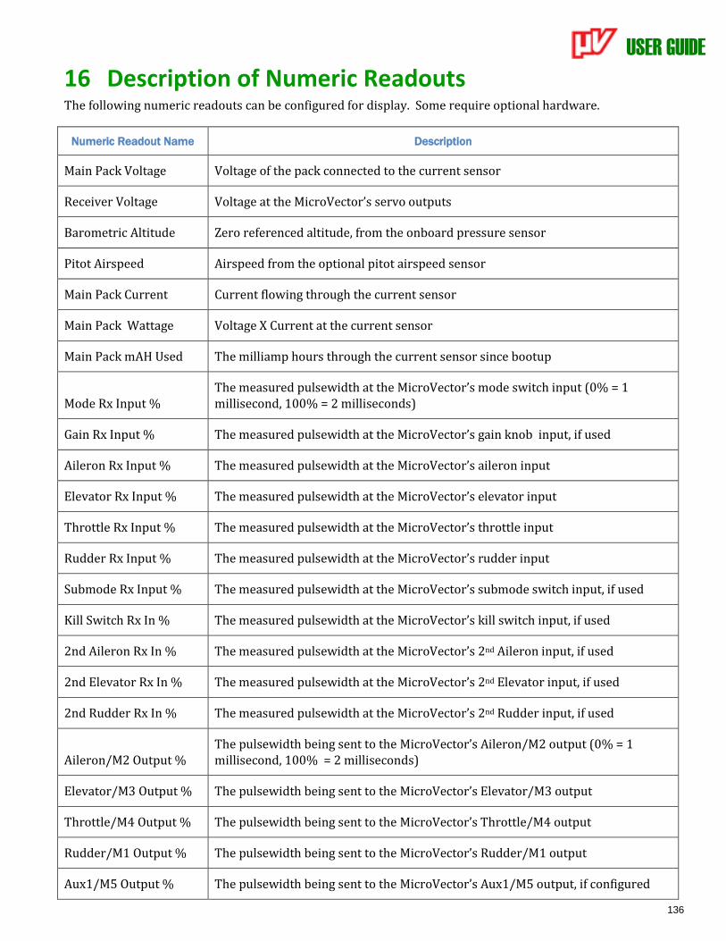
USER GUIDE
136
16 Description of Numeric Readouts The following numeric readouts can be configured for display. Some require optional hardware.
Numeric Readout Name Description
Main Pack Voltage Voltage of the pack connected to the current sensor
Receiver Voltage Voltage at the MicroVector’s servo outputs
Barometric Altitude Zero referenced altitude, from the onboard pressure sensor
Pitot Airspeed Airspeed from the optional pitot airspeed sensor
Main Pack Current Current flowing through the current sensor
Main Pack Wattage Voltage X Current at the current sensor
Main Pack mAH Used The milliamp hours through the current sensor since bootup
Mode Rx Input % The measured pulsewidth at the MicroVector’s mode switch input (0% = 1 millisecond, 100% = 2 milliseconds)
Gain Rx Input % The measured pulsewidth at the MicroVector’s gain knob input, if used
Aileron Rx Input % The measured pulsewidth at the MicroVector’s aileron input
Elevator Rx Input % The measured pulsewidth at the MicroVector’s elevator input
Throttle Rx Input % The measured pulsewidth at the MicroVector’s throttle input
Rudder Rx Input % The measured pulsewidth at the MicroVector’s rudder input
Submode Rx Input % The measured pulsewidth at the MicroVector’s submode switch input, if used
Kill Switch Rx In % The measured pulsewidth at the MicroVector’s kill switch input, if used
2nd Aileron Rx In % The measured pulsewidth at the MicroVector’s 2nd Aileron input, if used
2nd Elevator Rx In % The measured pulsewidth at the MicroVector’s 2nd Elevator input, if used
2nd Rudder Rx In % The measured pulsewidth at the MicroVector’s 2nd Rudder input, if used
Aileron/M2 Output % The pulsewidth being sent to the MicroVector’s Aileron/M2 output (0% = 1 millisecond, 100% = 2 milliseconds)
Elevator/M3 Output % The pulsewidth being sent to the MicroVector’s Elevator/M3 output
Throttle/M4 Output % The pulsewidth being sent to the MicroVector’s Throttle/M4 output
Rudder/M1 Output % The pulsewidth being sent to the MicroVector’s Rudder/M1 output
Aux1/M5 Output % The pulsewidth being sent to the MicroVector’s Aux1/M5 output, if configured
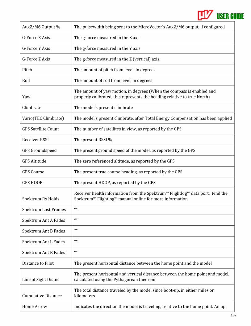
USER GUIDE
137
Aux2/M6 Output % The pulsewidth being sent to the MicroVector’s Aux2/M6 output, if configured
G-Force X Axis The g-force measured in the X axis
G-Force Y Axis The g-force measured in the Y axis
G-Force Z Axis The g-force measured in the Z (vertical) axis
Pitch The amount of pitch from level, in degrees
Roll The amount of roll from level, in degrees
Yaw The amount of yaw motion, in degrees (When the compass is enabled and properly calibrated, this represents the heading relative to true North)
Climbrate The model’s present climbrate
Vario(TEC Climbrate) The model’s present climbrate, after Total Energy Compensation has been applied
GPS Satellite Count The number of satellites in view, as reported by the GPS
Receiver RSSI The present RSSI %
GPS Groundspeed The present ground speed of the model, as reported by the GPS
GPS Altitude The zero referenced altitude, as reported by the GPS
GPS Course The present true course heading, as reported by the GPS
GPS HDOP The present HDOP, as reported by the GPS
Spektrum Rx Holds Receiver health information from the Spektrum™ Flightlog™ data port. Find the Spektrum™ Flightlog™ manual online for more information
Spektrum Lost Frames “”
Spektrum Ant A Fades “”
Spektrum Ant B Fades “”
Spektrum Ant L Fades “”
Spektrum Ant R Fades “”
Distance to Pilot The present horizontal distance between the home point and the model
Line of Sight Distnc The present horizontal and vertical distance between the home point and model, calculated using the Pythagorean theorem
Cumulative Distance The total distance traveled by the model since boot-up, in either miles or kilometers
Home Arrow Indicates the direction the model is traveling, relative to the home point. An up
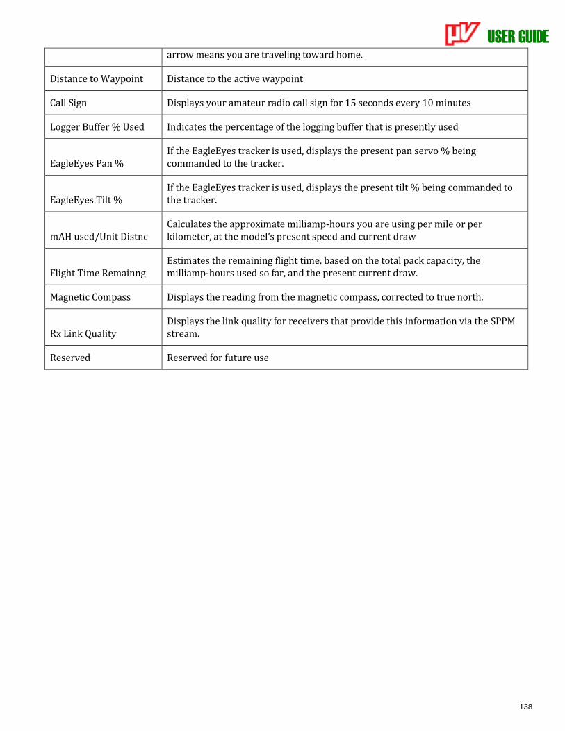
USER GUIDE
138
arrow means you are traveling toward home.
Distance to Waypoint Distance to the active waypoint
Call Sign Displays your amateur radio call sign for 15 seconds every 10 minutes
Logger Buffer % Used Indicates the percentage of the logging buffer that is presently used
EagleEyes Pan % If the EagleEyes tracker is used, displays the present pan servo % being commanded to the tracker.
EagleEyes Tilt % If the EagleEyes tracker is used, displays the present tilt % being commanded to the tracker.
mAH used/Unit Distnc Calculates the approximate milliamp-hours you are using per mile or per kilometer, at the model’s present speed and current draw
Flight Time Remainng Estimates the remaining flight time, based on the total pack capacity, the milliamp-hours used so far, and the present current draw.
Magnetic Compass Displays the reading from the magnetic compass, corrected to true north.
Rx Link Quality Displays the link quality for receivers that provide this information via the SPPM stream.
Reserved Reserved for future use
USER GUIDE
139
17 Limited Warranty Eagle Tree Systems, LLC, (ET) warrants to the original purchaser (the Purchaser) that the purchased product (the Product) will be free from defects in materials and workmanship for a period of one (1) year from the date of original purchase. This limited warranty is nontransferable.
This limited warranty does not cover problems that result from:
• External causes such as accident, abuse, misuse, or problems with electrical power
• Acts of God
• Commercial use
• Servicing not authorized by ET
• Product not purchased from an ET authorized dealer
• Usage that is not in accordance with the Product instructions
• Failure to follow the Product instructions
OTHER THAN THE EXPRESS WARRANTY DESCRIBED ABOVE, ET MAKES NO OTHER WARRANTY OR REPRESENTATION OF ANY KIND, AND HEREBY DISCLAIMS ANY AND ALL IMPLIED WARRANTIES, INCLUDING, WITHOUT LIMITATION, THE IMPLIED WARRANTIES OF NON-INFRINGEMENT, MERCHANTABILITY AND FITNESS FOR A PARTICULAR PURPOSE. THE PURCHASER ACKNOWLEDGES THAT HE OR SHE HAS DETERMINED THAT THE PRODUCT WILL SUITABLY MEET THE REQUIREMENTS OF THE PURCHASER’S INTENDED USE. Remedy of Purchaser ET’s sole obligation and purchaser’s sole and exclusive remedy shall be that ET will replace or repair the Product, at our option. REPAIR OR REPLACEMENT AS PROVIDED UNDER THIS WARRANTY IS THE PURCHASER’S SOLE AND EXCLUSIVE REMEDY. Limitation of Liability ET SHALL NOT BE LIABLE FOR SPECIAL, INDIRECT, INCIDENTAL OR CONSEQUENTIAL DAMAGES, LOSS OF PROFITS OR PRODUCTION OR COMMERCIAL LOSS IN ANY WAY, REGARDLESS OF WHETHER SUCH CLAIM IS BASED IN WARRANTY, CONTRACT, NEGLIGENCE, TORT, STRICT LIABILITY OR ANY OTHER THEORY OF LIABILITY, EVEN IF ET HAS BEEN ADVISED OF THE POSSIBILITY OF SUCH DAMAGES. Further, in no event shall the ET’s liability exceed the retail sales price of the Product on which liability is asserted.
As ET has no control over setup, use, assembly, modification or misuse of the Product, no liability shall be assumed nor accepted for any resulting damage or injury. By the act of setup, use, or assembly, the user accepts all resulting liability. If the purchaser or user is not prepared to accept the liability associated with the use of the Product, the purchaser is advised to return the Product immediately in new condition to the place of purchase.
Obtaining Warranty Service If the Product requires warranty service during this period, please email us at [email protected] or open a support ticket with us at http://ticket.eagletreesystems.com for further instructions.