microwave-assisted cu-catalyzed ullmann ether synthesis in a
TRANSCRIPT

Chemical Engineering Journal xxx (2012) xxx–xxx
Contents lists available at SciVerse ScienceDirect
Chemical Engineering Journal
journal homepage: www.elsevier .com/locate /cej
Microwave-assisted Cu-catalyzed Ullmann ether synthesis in acontinuous-flow milli-plant
F. Benaskar a, N.G. Patil a, V. Engels b, E.V. Rebrov c, J. Meuldijk a, L.A. Hulshof a, V. Hessel a,A.E.H. Wheatley b, J.C. Schouten a,⇑a Laboratory of Chemical Reactor Engineering, Department of Chemical Engineering and Chemistry, Eindhoven University of Technology, P.O. Box 513, 5600 MB, Eindhoven,The Netherlandsb Department of Chemistry, University of Cambridge, Lensfield Road, Cambridge CB2 1EW, UKc School of Chemistry and Chemical Engineering, Queen’s University Belfast, Stranmillis Road, Belfast BT9 5AG, UK
h i g h l i g h t s
" Active Cu nanocatalyst was applied in the microwave flow-type Ullmann CAO coupling." Added value of single-mode over multi-mode microwaves is investigated and discussed." We propose nano-Cu stable against arcing for sustainable microwave applications." We investigate the major causes and solution in destructive microwave metal arcing.
a r t i c l e i n f o
Article history:Available online xxxx
Keywords:Process intensificationFlow-chemistryFine-chemicalsMicro fixed-bed reactorsWall-coated reactorsUllmann-type coupling reaction
1385-8947/$ - see front matter � 2012 Elsevier B.V. Ahttp://dx.doi.org/10.1016/j.cej.2012.06.147
⇑ Corresponding author. Tel.: +31 (0)40 247 2850;E-mail address: [email protected] (J.C. Schouten)
Please cite this article in press as: F. Benaskar etJ. (2012), http://dx.doi.org/10.1016/j.cej.2012.06
a b s t r a c t
The combination of milli-scale processing and microwave heating has been investigated for the Cu-cat-alyzed Ullmann etherification in fine-chemical synthesis, providing improved catalytic activity and selec-tive catalyst heating. Wall-coated and fixed-bed milli-reactors were designed and applied in the Cu-catalyzed Ullmann-type CAO coupling of phenol and 4-chloropyridine. In a batch reactor the resultsshow clearly increased yields for the microwave heated process at low microwave powers, whereas highpowers and catalyst loadings reduced the benefits of microwave heating. Slightly higher yields werefound in the Cu/ZnO wall-coated as compared to the Cu/TiO2 fixed-bed flow-reactor. The benefit hereis that the reaction occurs at the surface of the metal nanoparticles confined within a support film makingthe nano-copper equally accessible. Catalyst deactivation was mainly caused by Cu oxidation and cokeformation; however, at longer process times leaching played a significant role. Catalyst activity could par-tially be recovered by removal of deposited by-product by means of calcination. After 6 h on-stream thereactor productivities were 28.3 and 55:1 kgprod=ðm3
R hÞ for the fresh Cu/ZnO wall-coated and Cu/TiO2
fixed-bed reactor, respectively. Comparison of single- and multimode microwaves showed a threefoldyield increase for single-mode microwaves. Control of nanoparticles size and loading allows to avoid hightemperatures in a single-mode microwave field and provides a novel solution to a major problem forcombining metal catalysis and microwave heating. Catalyst stability appeared to be more importantand provided twofold yield increase for the CuZn/TiO2 catalyst as compared to the Cu/TiO2 catalystdue to stabilized copper by preferential oxidation of the zinc. For this catalyst a threefold yield increasewas observed in single-mode microwaves which, to the best of our knowledge, led to a not yet reportedproductivity of 172 kgprod=ðm3
R hÞ for the microwave and flow Ullmann CAO coupling.� 2012 Elsevier B.V. All rights reserved.
1. Introduction of complex organic molecules [1–6]. Pd and Cu-catalyzed CAC,
1.1. Microwave and micro-processing in flow systems
Flow-chemistry in organic synthesis using micro-processing isnow well-established as a technology for continuous production
ll rights reserved.
fax: +31 (0)40 244 6653..
al., Microwave-assisted Cu-cata.147
CAN, CAS and CAO coupling reactions and Cu-catalyzed Sim-mons–Smith cyclopropanation reactions have been widely devel-oped and applied in flow processes [7]. Moreover, combiningmilli-reactor operation and microwave heating as an alternativeenergy source, allows the accurate control of temperatures andresidence times in chemical processes. This consequently enhancescontrol of reactor performance in terms of conversion and productselectivity [8–10]. In particular, regarding the twelve principles of
lyzed Ullmann ether synthesis in a continuous-flow milli-plant, Chem. Eng.

2 F. Benaskar et al. / Chemical Engineering Journal xxx (2012) xxx–xxx
green chemistry, process intensification and novel process win-dows provide many options by which to meet sustainable process-ing criteria [11–15].
The concept of combining microwave and flow-chemistry toconduct novel process operations in organic synthesis has recentlyattracted interest from a wide spectrum of research disciplines inboth industry and academia [16–20]. Kappe et al. reported workon combined microwaves and flow systems using meso-scale reac-tors and microwave heating [21]. The authors employed the con-cepts of ‘‘Novel Process Windows’’, as introduced by Hessel et al.,and discussed the multiple opportunities for operating and con-trolling organic reactions at elevated temperatures and pressures[22,23]. Organ and co-workers also contributed to state-of-artmicrowave-assisted capillary-type flow-reactors for metal-cata-lyzed organic reactions [24,25]. Many examples have been re-ported of dedicated flow systems being used in combination withmicrowave heating for large-scale synthesis and industrial applica-tions [26]. AstraZeneca studied various examples of microwave-as-sisted flow-synthesis for pharmaceuticals, leading to rather highproductivities [27]. Earlier, Moseley et al. developed automatedmicrowave ‘‘stop-flow’’ reactors that provided competitive produc-tivities as compared to typical batch-scale reactions [28,29]. Thecurrent successes in combining microwave heating and flow sys-tems, however, have mainly been achieved using multimodemicrowave cavities. These suffer from a non-uniform microwavefield and a limited microwave penetration depth, resulting in aninhomogeneous temperature distribution. The use of single-modemicrowave cavities in flow-chemistry, which provide a highly uni-form microwave field, is currently an emerging field of investiga-tion for efficient reaction operation [30–32]. Since for mostorganic solvents the penetration depth of microwaves is of the or-der of centimeters the optimum microwave-assisted reactor for or-ganic reactions is characterized by reactors with the same orsmaller dimensions [33,34]. At these reactor sizes microwaves, act-ing as a volumetric heating source, do not suffer from heat-transferresistance and, combined with a proper reaction medium, provideopportunities to heat the reaction mixture rapidly and efficiently(Fig. 1a). Meanwhile, micro- and milli-reactors themselves arecharacterized by their low resistance to heat transfer. Taken to-gether, these observations suggest the potential for highly efficientmicrowave assisted reactions using combined microwave milli-reactors that are optimized with respect to heat supply and release(Fig. 1b).
Recently, Patil et al. have demonstrated the effect of shape anddimensions of a milli-reactor setup on controlled and efficientmicrowave heating in a single-mode cavity [31]. The results pro-vided experimental evidence of complete microwave penetration
Ri=0.25
Temperature
Reactor radiusTC
TH
Surface versus Microwave heating
t0
t0
tend
Microwave heating
Surface heating
tend
MW-power
Reactor radius (~mm)
MW Penetration depth ~5-10 cm
TH
reactor wall (~µm)(a)
Fig. 1. Temperature profiles for conventional (surface) and microwave (volumetric) heatbalance must be struck between fast energy supply by the microwaves and fast heat re
Please cite this article in press as: F. Benaskar et al., Microwave-assisted Cu-cataJ. (2012), http://dx.doi.org/10.1016/j.cej.2012.06.147
in a milli-sized tubular reactor in the direction perpendicular tothe fluid flow. This resulted in rapid and controlled heating with-out the development of significant radial temperature gradientsin the milli-sized flow-reactors used. Nevertheless, unresolveddrawbacks, such as (a) limited microwave penetration depth, (b)high equipment costs, (c) difficult temperature measurement andcontrol and (d) restriction to the use of polar solvents/reactantsspecific to each process, still hamper applications in industrialpractice. The penetration depth limitations and the restriction tothe use only of polar solvents can be circumvented in metal-cata-lyzed reactions where microwave heating occurs via interaction ofthe electric/magnetic component of the microwaves with the met-als. This resultant selective metal heating provides a unique oppor-tunity to address these limitations in microwave heated reactors[35].
1.2. Cu-catalyzed coupling reactions in flow-processing
In 2010 the Nobel Prize for Chemistry was awarded to the pio-neers of heterogeneously catalyzed cross-coupling reactions thathave been key to organic synthesis during the last half century[36–42]. However, the Ullmann-type coupling reaction using aCu catalyst provides significant economic advantages over Pd-cat-alyzed cross-coupling processes due to the much lower catalystprice and scarcity of Cu (see Scheme 1) [43].
The Ullmann-type CAC, CAO and CAN coupling reactions, dis-covered more than a century ago by Ullmann and Goldberg, haverecently encountered a renaissance, mainly as a result of theexploitation of highly efficient copper-based catalysts [44–52].However, these Ullmann-type coupling reactions still suffer fromthe need for harsh reaction conditions, the use of high levels of cat-alyst (50–100 mol%) and also the need to use relatively reactiveand expensive aryl halides. Reaction intensification, improvementof selectivity and the development of more stable catalysts repre-sent the current challenges, and catalytic milli-reactors promise toaddress these challenges. In flow-processing, the major issue is toavoid the use of catalyst slurries by supporting catalysts on thereactor wall or by employing micro-structured fixed-beds [53].Moreover, stable catalyst performance in terms of activity andselectivity in a heterogeneously catalyzed flow process brings amajor cost benefit in comparison to the use of homogeneous orslurry catalysts, which require expensive catalyst recovery proce-dures [43].
When providing a catalyst for reaction, it is necessary also toconsider how energy is supplied to the catalyst surface, in particu-lar because the efficiency of this process is governed by classicalheat-transfer limitations. However, metal catalysts are known to
Ri=0.25
Temperature
Reactor radiusTC
TH t0
tend
MicrowaveHeat-input
Microreactors“Heat-release”
MW-power
t0
tendTC
Milli reactors versus Microwave heating
Reactor radius (~mm)
(b)
ing (a) shows major benefits at mm-to-cm scale reactors. Nevertheless an importantlease owing to the micro- and milli-reactor dimensions (b).
lyzed Ullmann ether synthesis in a continuous-flow milli-plant, Chem. Eng.

N
ClOK
N
OCu-catalyzed
+Ullmann-type C-Ocoupling
Scheme 1. The Cu-catalyzed Ullmann-type coupling reaction towards 4-phenoxypyridine.
F. Benaskar et al. / Chemical Engineering Journal xxx (2012) xxx–xxx 3
absorb energy rapidly under microwave irradiation and, as a result,to couple the microwave energy selectively to the catalyst parti-cles, leaving the surrounding environment less or even unheated[54–57]. In this way, microwaves selectively heat the reaction sys-tem at the locus of the reaction and so enhance efficiency as well asactivity and conversion. A fast rise in the temperature of the nano-catalyst combined with a relatively low solvent bulk temperatureleads to highly advantageous reaction conditions. This is especiallytrue when the active copper catalyst, e.g. in Ullmann coupling, issupported by a non-magnetic matrix, such as TiO2, SiO2 or ZnO,as described by Walton et al. [58–60]. In metals with magneticcharacter, rapid microwave absorption results from so-called eddycurrents and magnetic reversal loss mechanisms when micron-sized particles are present [61,62]. In addition, the strong couplingof these metals with the microwave field has been reported, pro-viding very fast heating but, dependent on particle size, unfortu-nately also arcing [62,63]. As a result, it is of importance, notonly for sustainable use of the catalyst, but also for selective micro-wave absorption, to synthesize active Cu particles of the desirednano-size and with a uniform size distribution. We have recentlyreported on the development of monometallic and bimetallic Cu-based nanoparticles with a narrow size-distribution and a highresistance to oxidation during Ullmann-type reaction [64]. Addi-tionally, the use of microwave energy in the Ullmann-type reactionwas reported for these nano-catalysts. These results have nowbeen developed in terms of flow-chemistry [65].
We propose here an integrated system which synergizes thebenefits of microwave systems (as a novel heating technology)and milli-processing (as a novel reactor technology) in flow-syn-thesis. A tubular milli-reactor was designed, where the catalystand support were coated either onto the reactor wall or onto apacking material composed of spherical glass beads, leading to awall-coated or a fixed-bed milli-reactor, respectively. More impor-tant, however, was the use of heterogeneous copper which, as a‘‘metallic microwave-absorber’’, permitted selective heating ofthe catalyst surface and thus provided improved activity.
2. Materials and methods
2.1. Chemical protocol
2.1.1. Ullmann CAO coupling reactions4-Chloropyridine was prepared from 4-chloropyridine HCl salt
(Sigma–Aldrich, 99%) by neutralization using a 2.5 M aqueous solu-tion of K2CO3, followed by filtration, extraction with diethyl ether(Sigma–Aldrich, anhydrous >99%), solvent evaporation and drying.Potassium phenolate was synthesized by reacting phenol withpotassium tert-butoxide (Sigma–Aldrich, reagent grade 95%) inTHF (Sigma–Aldrich, inhibitor-free and anhydrous, P99.9%) at60 �C. After solvent evaporation and vacuum drying, potassiumphenolate was obtained quantitatively as a yellowish powder.For the activity experiments 20 g (0.15 mol) of potassium pheno-late and 0.40 g (0.0015 mol) of 18-crown-6 (Aldrich >99.0%) weredissolved in 80 mL N,N-dimethylacetamide (DMA, Sigma–Aldrich,CHROMASOLV� Plus, for HPLC, P99.9%) in a continuously stirredvessel at 50–60 �C. After a solution was obtained, 11.4 g (0.1 mol)of 4-chloropyridine and 1.9 g (0.01 mol) of tetradecane as internalstandard (Fluka, analytical standard) were mixed separately with20 mL DMA and slowly fed to the storage vessel. The reactants
Please cite this article in press as: F. Benaskar et al., Microwave-assisted Cu-cataJ. (2012), http://dx.doi.org/10.1016/j.cej.2012.06.147
were pumped into the flow-through reactor (see Supporting Infor-mation). For batch experiments, the reactants were mechanicallymixed at 500 rpm in the abovementioned concentrations, heateduntil the reaction temperature was reached and then the copperpowder (99 wt.%, Aldrich) was added as the catalyst (10 mol% withrespect to 4-chloropyridine).
2.2. Catalyst synthesis
2.2.1. Copper nanoparticlesCu nanoparticles were synthesized as previously reported from
copper(II) sulfate pentahydrate, sodium hypophosphite monohy-drate and PVP (M(average) = 40,000) [64,66]. The synthesis ofbimetallic CuZn nanoparticles was based on the use of copper sul-fate pentahydrate and zinc(II) chloride following our previouswork [52].
2.2.2. TiO2 based fixed-bed catalystSupport synthesis employed titanium(IV) ethoxide (99.99%),
isopropanol (anhydrous, 99.5%), hexamethylenetetramine (HMTA,puriss. p.a., P99.5%). 250 ± 12 lm spherical SiO2-beads (E&RChemicals & Equipment B.V.) were used as support carriers [67].These beads were first coated with mesoporous TiO2 by dip-coat-ing, after which the Cu nanoparticles were coated by wet impreg-nation (see Supporting Information). A total of 0.75 g (3.29 mmol)titanium(IV) ethoxide (Ti(OEt)4,) was added to 20 g of glass beads,followed by vacuum solvent removal at 60 �C, overnight drying at80 �C and calcination at 120–350 �C for 12 h (heating/cooling rate:10 �C/min) (see Supporting Information).
2.2.3. ZnO based wall-coated catalystFor the growth of ZnO nanowires on the internal reactor wall, a
seed layer of ZnO nanoparticles (mean size �100 nm) was depos-ited by circulation of a nanoparticle suspension in iPrOH for 48 h(flow speed 1.5 mL/min). Subsequently, the system was flushedwith pure iPrOH for 30 min. After drying, an equimolar aqueoussolution of HMTA and Zn(NO3)2 (0.025 M) was pre-heated to90 �C and circulated through the system for 5 h, followed by flush-ing with iPrOH for 1 h (0.5 mL/min). The tube was pre-dried andheated in a muffle furnace (80 �C) for 1 h. The reactor was coatedwith copper nanoparticles by flowing 50 mL of a Cu nanoparticlesuspension in anhydrous methanol (metal mass concentration:0.25 mg/mL) through the reactor tube at a flow speed of 1 mL/min. After solvent evaporation, the reactor was calcined at 350 �Cfor 12 h (heating/cooling rate: 10 �C/min).
2.3. Wall-coated and fixed-bed tubular reactors in oil-bath andmicrowave heating experiments
Quartz-glass tubular milli-reactors (L = 1.2–1.5 m, din = 1–3 mmand dout = 5 mm) were either packed with catalyst coated glassbeads or wall-coated with the catalyst. Fig. 2 shows the design pro-cedure for both (wall-coated and fixed) reactor configurations.
Reactor inlet and outlet were extended to enable an easy con-nection and disconnection to the pump head, sampler and outletvalve. The flowrate was varied (Fv = 5–80 mL/h) to obtain desiredresidence times. Fixed-bed systems were prepared by packingthe coated beads into the tube (Vtotal = 10.10 mL) to mimic a mi-cro-fixed-bed reactor with a bead interstitial spacing in the range10–50 lm. The resulting bed void provided an experimentallydetermined liquid volume of Vliq = 3.34 mL with a catalyst loadingof 2.5 mg/mLliq, which was comparable to a batch reactor catalystloading of 2.7 mg/mLliq. As shown in Fig. 3, the reactor was placedeither vertically in an oil-bath (Lauda Ecoline Staredition 012, typeE312, 2.3 kW with a half-synthetic oil medium) or horizontally in amultimode microwave cavity (Milestone Multimode Microwave,
lyzed Ullmann ether synthesis in a continuous-flow milli-plant, Chem. Eng.

Flow outFlow in
Glass beads packing
Cu-NPs coating on TiO2 film
Packing of Cu/SiO2beads tubular
reactorFlow-reactor testing
Cu/ZnO wall-coated reactor Cu/TiO2 fixed-bed reactor
ZnO-nanowiregrowth
Cu-NPs coated on ZnO wall
ZnO-seeding on reactor wallTubular
reactor
TiO2coating on glass beads
Fig. 2. The catalyst coating procedure for fixed-bed and wall-coated catalytic reactors. Cu nanoparticles were deposited on a ZnO nanowire support in the wall-coated reactor,and on a TiO2 support in the fixed-bed reactor.
4 F. Benaskar et al. / Chemical Engineering Journal xxx (2012) xxx–xxx
type ETHOS 2.45 GHz, 2.5 kW). The pre-mixed (mechanical) andpre-heated (50 �C) reactant solution was fed into the reactorthrough a syringe pump (1000D; Teledyne ISCO Inc., Lincoln, NE/USA), which could be operated at pressures from 1 to 40 bar (seeFig. 2, left). An argon injector was placed in the supply vessel tomaintain inert atmosphere. At the reactor outlet, a T-splitter (T-junction, Swagelok, 1/8 in.) was connected to the sampler.
For the oil-bath reactions, temperatures were measured usingK-type thermocouples (Voltcraft K204 data logger) placed insidethe oil-bath and at the outlet of the catalyst bed. For the micro-wave experiments, a fiber-optic probe (ATC-FO sensor, Milestones)was inserted at the inlet and outlet of the reactor inside the micro-wave oven. To avoid bead floating, the catalyst (coated glass beads)bed was fixed to the lower reactor part by glass filters. Constantpressure was maintained in the reactor using a syringe valve toavoid solvent boiling and bubble formation in the catalyst bed.The inlet and outlet of the quartz-glass reactor were connectedusing Swagelok Ultra-Torr (stainless steel, S.S. 316; inner diameter1.6 mm) connections with chemically resistant sealing rings. Forthe single-mode microwave experiments, a microwave (Fricke
Fig. 3. A schematic process flow diagram of the oil-bath heated and multimodeheated microwave setups.
Please cite this article in press as: F. Benaskar et al., Microwave-assisted Cu-cataJ. (2012), http://dx.doi.org/10.1016/j.cej.2012.06.147
und Mallah GmbH) setup consisting of a single-mode microwavecavity and operating at a frequency of 2.45 GHz with adjustablepower settings up to 2 kW was utilized (see Supporting Informa-tion). Maximum microwave absorption was assured throughfocusing the resonant microwaves in the cavity by using stub-tun-ers and short-circuits. The reflected power was measured using adetector diode over the isolator. A LABVIEW interface programwas used to control the temperature and power input in the reac-tor, using OPSENS fiber-optic sensors in the center of the fixed-bed.The reference case batch experiments were carried out in amechanically stirred (500 rpm) 100 mL jacketed batch-reactor.Identical setups were used for the batch experiments with oil-bathand microwave heating (see Supporting Information). All reactionswere carried out in an argon atmosphere.
2.4. Product analysis and catalyst characterization
2.4.1. Product yield analysesSamples were taken at the outlet of the reactor and diluted with
dimethyl sulfoxide-d6 (DMSO-d6, Cambridge Isotope LaboratoriesInc., D 99.9%) for 1H-NMR spectroscopic analyses. 1H NMR datawere collected using a Varian 400 NMR spectrometer (400 MHz).The chemical shifts (in d ppm) were based on TMS (tetramethylsil-ane) at 27 �C as internal reference and peak integrations were con-verted to concentrations by using tetradecane (C14H30) as internalstandard. The productivity and product yield were obtained bycomparing the reactants (phenoxide and 4-chloropyridine) andthe product (4-phenoxypyridine) signals corrected for the internalstandard. The 1H NMR of the spectra (CDCl3; 8.4–8.6 ppm) of thereactants and product after full conversion are shown in the Sup-porting Information. The 1H NMR assignments for the product ind (ppm, CDCl3) are: 8.48 (d, J = 4.0 Hz, 2H), 7.44 (t, J = 8.0 Hz, 2H),7.29–7.25 (m, 1H), 7.11 (d, J = 8.0 Hz, 2H), 6.85 (d, J = 8.0 Hz, 2H).The 1H NMR data was additionally compared with GC–MS datato confirm product formation.
2.4.2. Inductively coupled plasma (ICP) measurementsThe losses of catalyst and support were analyzed using induc-
tively coupled plasma measurements, combined with optical emis-sion spectroscopy. A Spectro CirosCCD spectrometer was used todetermine the amounts of copper catalyst and titania and zinc-oxide supports at 1400 W. Sample injection used a nebulizer in adouble-pass spray chamber with a sample uptake frequency of2 mL/min. For the fixed-bed reactor, the catalyst packing was used
lyzed Ullmann ether synthesis in a continuous-flow milli-plant, Chem. Eng.
F. Benaskar et al. / Chemical Engineering Journal xxx (2012) xxx–xxx 5
as sample material and for the wall-coated reactor, the reactor wasdried and ca. 2 mm of the reactor was cut off for analysis. The sam-ples were treated in H2SO4 (5 M) for 24 h before being taken foranalysis. In addition, reactions were sampled by collecting an accu-rate amount of reaction mixture and dissolving it in H2SO4 (10 mL,5 M). The resulting aqueous layer was diluted with 10 mL milli-pore water and separated off by milli-extraction. To avoid an abun-dance of protonated amide signals, the sample was diluted usingan additional 20 mL volume of milli-pore water. Calibration lineswere freshly prepared and inserted prior to the catalyst samples.
2.4.3. X-ray Photoelectron Spectroscopy (XPS) analysesXPS was used to analyze the catalyst surface and establish the
oxidation state of the copper. Various XPS samples were analyzedeither using known amounts (in mg) of the wall-coated tubularreactor or by measuring exact quantities of catalyst beads depositedon a carbon holey film in a glove-box (<10 ppm O2). The sampleswere transported in a closed holder for oxygen-free analysis. XPSdata was obtained with a Kratos AXIS Ultra spectrometer equippedwith a monochromatic Al Ka X-ray source (1486.6 eV at 150 W)using a delay-line detector (DLD). Constant pass energies of160 eV and 40 eV were applied for survey and region scans, respec-tively, at a background pressure of 2 � 10�9 mbar. Based on thespectral intensities of the Cu, conclusions were drawn with respectto losses observed by ICP analysis and the recorded drops in activity.
2.4.4. Electron microscopy analysesScanning electron microscopy (SEM) images were obtained
using a FEI Quanta series (FEG 3D G2 SEM) with an accelerationvoltage of 5 kV and magnifications in the range 5–100 � 103. Theimages were used to determine the surface morphology and coat-ing thickness of the wall-coating and the catalyst support beads ata lateral resolution of 50 nm2. Simultaneously, surface elementalcomposition analysis was carried out using energy-dispersive X-ray (EDX) spectroscopy at an image spot size of 50 nm2 and aninteraction-volume of 100 lm (all EDX spectra are provided inthe Supplementary Information). Leaching of the catalytic layerwas surveyed by comparing the coating thickness and the Cu, Tiand Zn signals in the EDX spectra. Both the fresh and spentcatalysts were analyzed using SEM. The surface structure of spent
5 µm
50 µm
(a)
(c)
Fresh
Spent 12h on-stream
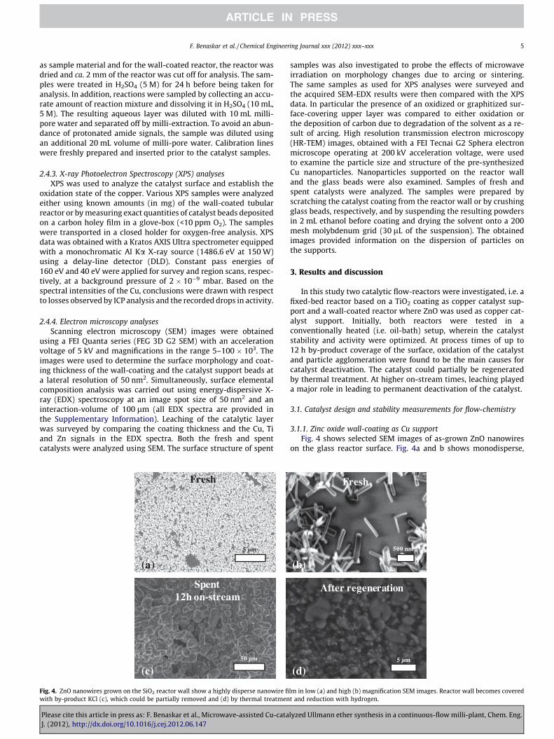
Fig. 4. ZnO nanowires grown on the SiO2 reactor wall show a highly disperse nanowire fiwith by-product KCl (c), which could be partially removed and (d) by thermal treatmen
Please cite this article in press as: F. Benaskar et al., Microwave-assisted Cu-cataJ. (2012), http://dx.doi.org/10.1016/j.cej.2012.06.147
samples was also investigated to probe the effects of microwaveirradiation on morphology changes due to arcing or sintering.The same samples as used for XPS analyses were surveyed andthe acquired SEM-EDX results were then compared with the XPSdata. In particular the presence of an oxidized or graphitized sur-face-covering upper layer was compared to either oxidation orthe deposition of carbon due to degradation of the solvent as a re-sult of arcing. High resolution transmission electron microscopy(HR-TEM) images, obtained with a FEI Tecnai G2 Sphera electronmicroscope operating at 200 kV acceleration voltage, were usedto examine the particle size and structure of the pre-synthesizedCu nanoparticles. Nanoparticles supported on the reactor walland the glass beads were also examined. Samples of fresh andspent catalysts were analyzed. The samples were prepared byscratching the catalyst coating from the reactor wall or by crushingglass beads, respectively, and by suspending the resulting powdersin 2 mL ethanol before coating and drying the solvent onto a 200mesh molybdenum grid (30 lL of the suspension). The obtainedimages provided information on the dispersion of particles onthe supports.
3. Results and discussion
In this study two catalytic flow-reactors were investigated, i.e. afixed-bed reactor based on a TiO2 coating as copper catalyst sup-port and a wall-coated reactor where ZnO was used as copper cat-alyst support. Initially, both reactors were tested in aconventionally heated (i.e. oil-bath) setup, wherein the catalyststability and activity were optimized. At process times of up to12 h by-product coverage of the surface, oxidation of the catalystand particle agglomeration were found to be the main causes forcatalyst deactivation. The catalyst could partially be regeneratedby thermal treatment. At higher on-stream times, leaching playeda major role in leading to permanent deactivation of the catalyst.
3.1. Catalyst design and stability measurements for flow-chemistry
3.1.1. Zinc oxide wall-coating as Cu supportFig. 4 shows selected SEM images of as-grown ZnO nanowires
on the glass reactor surface. Fig. 4a and b shows monodisperse,
500 nm
5 µm
(b)
(d)
Fresh
After regeneration
lm in low (a) and high (b) magnification SEM images. Reactor wall becomes coveredt and reduction with hydrogen.
lyzed Ullmann ether synthesis in a continuous-flow milli-plant, Chem. Eng.

250 µm
500 nm
250 µm
(c)
(b)(a) SpentFresh
Fresh
Fig. 5. SEM images of the fresh (a) and spent (b) Cu/TiO2-coated glass beads, demonstrating considerable deposition of KCl by-product. Catalyst deposition (c) also showsrelatively low catalyst density for the Cu/TiO2 when compared to that of the Cu/ZnO system.
6 F. Benaskar et al. / Chemical Engineering Journal xxx (2012) xxx–xxx
rod-like crystals (lav = 500 nm, dav = 20 nm) with a high surface dis-persion. However, after 12 h on-stream (Fig. 4c) the catalytic wallappeared to be covered with a substance, which, after EDX analy-sis, was confirmed to be KCl formed as by-product during the reac-tion. Treatment with DMA, drying, calcination (at 350 �C) andreduction with a hydrogen flow at 200 �C removed most of this saltfrom the surface as can be seen in Fig. 4d (EDX spectra are providedin the Supporting Information). At higher processing times (>24 h)ICP analysis confirmed a considerable decrease in the levels of bothCu catalyst and ZnO support due to irreversible leaching.
ZnO nanowires grown on the internal wall of a tubular glassreactor provided catalyst loadings similar to those for TiO2 on theglass-bead packing, i.e. 1.26 and 1.38 mgCu/mLreactor for the wall-coated and the fixed-bed reactors, respectively. Although for thewall-coated reactor the overall available reaction surface wasmuch lower than for the fixed-bed reactor, similar Cu loadingson ZnO and TiO2 were achieved during catalyst deposition ontothe supports.
3.1.2. Titania bead-coating as Cu supportRelatively low absolute amounts of both support (TiO2) and cat-
alyst (Cu nanoparticles) were deposited on the titania-coated glassbeads (dP � 250 lm). As described in Section 2.2 the catalyst wasprepared using a TiO2 support matrix and the metallic nanoparti-cles were impregnated after the support was deposited onto silicabeads. In this way, the catalyst loading (1.38 ± 0.15 mgCu/mLreactor)could be accurately controlled in order to obtain a loading thatapproximated to that of the wall-coated reactor. Fig. 5a–c showsthe coated beads before and after reaction. The effect of by-productformation, i.e. surface coverage by KCl, is clearly visible also in thiscase. SEM-EDX analysis further confirmed the abundant presenceof KCl salt crystals.
3.1.3. Copper nanoparticle deposition and stabilityIn Fig. 6, representative TEM images of the nanoparticles are
shown for both the fresh and spent Cu catalysts.Fig. 6a and c shows the fresh and spent catalyst of the fixed-bed
Cu/TiO2 system, respectively. The fresh catalyst clearly demon-strates uniformly dispersed Cu nanoparticles in the titania matrix.
Please cite this article in press as: F. Benaskar et al., Microwave-assisted Cu-cataJ. (2012), http://dx.doi.org/10.1016/j.cej.2012.06.147
The particle size was found to be 7.6 ± 0.8 nm based on measure-ments for 200 particles in various TEM images. However, after12 h on-stream in the fixed-bed reactor, the catalyst particles havesignificantly agglomerated. Fig. 6b and d shows TEM images of thefresh and spent wall-coated Cu/ZnO catalyst. Clearly, the fresh Cu/ZnO wall-coated coated catalyst demonstrates a much higher par-ticle density than does the fresh Cu/TiO2 catalyst (Fig. 6a and b).The higher copper loading in the wall-coated reactor was preparedin order to compensate for the lower macroscopic reaction surfacein that system. Fig. 6b however shows partial nanoparticle agglom-eration already occurring in the fresh catalyst. After 12 hon-stream the Cu/ZnO wall-coated catalyst showed higher nano-particle agglomerates up to sizes of ca. 150 nm (see Fig. 6d).
3.1.4. Catalyst and support leachingThe catalyst and support losses are shown in Fig. 7. ICP mea-
surements provided the amounts of Cu, Zn (from ZnO) and Ti (fromTiO2) for samples taken during the total process time.
For the ICP analyses, multiple catalyst samples were taken fromthe fixed-bed reactor or from the wall-coated reactor as describedin Section 2.4. Neither Cu/TiO2 nor Cu/ZnO catalysts leached morethan 10% after 12 h of run. Fig. 7a shows a significant drop of ca.30 wt.% of the Cu signal in the Cu/TiO2 system after only 24 h on-stream, whereas ca. 10 wt.% of the TiO2 support was lost. However,after 48 h on-stream roughly 60 wt.% of the copper was lost whileonly 20 wt.% of the Ti had leached. After 72 h on-stream, both cat-alyst and support had completely leached from the glass beads.Generally, however, for the TiO2-based fixed-bed reactor, the Cunanoparticles appeared to leach prior to the TiO2 support. Theopposite was observed for the ZnO-supported system (Fig. 7b),where after 48 h ca. 60 wt.% of the ZnO nanowires were removedwhile only 40 wt.% of the Cu nano-catalyst was lost. This observa-tion could only be explained by the fact that although the ZnOlayer was uniformly distributed, the Cu nanoparticles formed is-lands that stabilized the ZnO-glass interface. As a result, a muchhigher ZnO fraction leached. After 72 h, about 22 wt.% of ZnO and36 wt.% of Cu remained, showing that much less shearing occurredin the wall-coated reactor as compared to the fixed-bed reactor.Overall, at higher process times, adhesion appears to be weak at
lyzed Ullmann ether synthesis in a continuous-flow milli-plant, Chem. Eng.

40 nm 40 nm
40 nm 400 nm
(a) (b)
(c) (d)
Fig. 6. Representative TEM images of fresh (a) and spent (c) catalysts used in the Cu/TiO2 fixed-bed reactor and the fresh (b) and spent (d) catalyst used in the Cu/ZnO wall-coated reactor.
0
0.2
0.4
0.6
0.8
1
0 20 40 60 80
cata
lyst
/sup
port
fra
ctio
n(w
t%)
time on process (h)
Δ wt% TiO2
wt% Cu
0
0.2
0.4
0.6
0.8
1
0 20 40 60 80
cata
lyst
/sup
port
fra
ctio
n( w
t%)
time on process (h)
Δ wt% ZnO wt% Cu
(a) (b)
Fig. 7. Losses of Cu catalyst and TiO2 support for the fixed-bed reactor (a) and of Cu catalyst and ZnO support for the wall-coated reactor (b) during time-on processing.
F. Benaskar et al. / Chemical Engineering Journal xxx (2012) xxx–xxx 7
the Cu/TiO2-glass interface for the fixed-bed catalyst system and atthe ZnO-glass surface for the wall-coated catalyst system. As a re-sult, the subsequent activity experiments were only done usingprocessing times lower than 12 h, after which a fresh batch of cat-alyst was used.
3.2. Activity experiments
Initially, the influence of multimode microwave heating andconventional oil-bath heating on catalyst productivity was com-pared using a continuously stirred batch reactor and a commercialcopper catalyst. In the next step, activity measurements on a sup-ported Cu catalyst were done in an oil-bath using a fixed bed reac-tor and a wall-coated reactor as examples of flow-type reactorsbased on titania and zinc oxide support materials, respectively. Fi-nally, microwave flow-experiments were carried out in both amultimode and a single-mode microwave cavity.
3.2.1. Batch experiments using conventional and microwave heatingThermal effects that are caused by microwaves in liquids are
straightforwardly stemming from the fact the liquid molecules
Please cite this article in press as: F. Benaskar et al., Microwave-assisted Cu-cataJ. (2012), http://dx.doi.org/10.1016/j.cej.2012.06.147
posses a dipole, which, in an alternating microwave field, wouldlead to movement, friction and consequently to heating. In the firstplace the solvent dimethylacetamide and the potassium phenolatepossess a dipole-moment and lead to dipolar movement and ionictranslation, respectively [68]. Conversely, ‘‘non-thermal effects’’(e.g. entropic effects) are related to the orientation of the reactingmolecules to the electric field and consequently facilitate the reac-tion pathway. These latter ‘‘microwave effects’’ have been a topicof debate where many authors in the mid-90s argued that the pres-ence of an electric field leads to orientation effects of dipolar mol-ecules to influence the pre-exponential factor [69] or activationenergy [70] in the rate coefficient. However, we believe that these‘‘special effects’’ are difficult, if not impossible, to prove and ap-peared in many cases to be incorrectly interpreted due to inaccu-rate temperature measurements [71,72]. In case of solids heatingthe microwave effect could not be attributed to the entropic effect,due to their condensed structure, but only to thermal effects stem-ming both from eddy current loss (in alternating magnetic-field)and magnetic reversal loss (in alternating electric-field) mecha-nisms in metals [61]. The influence of microwave heating and con-ductive heating on product yield was investigated at three
lyzed Ullmann ether synthesis in a continuous-flow milli-plant, Chem. Eng.

0
0.2
0.4
0.6
0.8
1
0 30 60 90
yiel
d (-
)
time (min)
Δ MicrowaveOil-bath
(a)
T = 110 oC PMW = 140 W
0
0.2
0.4
0.6
0.8
1
0 30 60 90
yiel
d (-
)
time (min)
Δ MicrowaveOil-bath
(c)
T = 140 oC PMW = 300 W
0
0.2
0.4
0.6
0.8
1
0 30 60 90
yiel
d (-
)
time (min)
Δ MicrowaveOil-bath
(b)
T = 120 oC PMW = 200 W
Fig. 8. Yield versus time for batch-type experiments using microwave heating and oil-bath heating at (a) 110 �C, (b) 120 �C and (c) 140 �C. At lower powers, microwaveheating has the benefit of selectively heating the metal catalyst. At higher powers, microwave absorption by the solvent removes this advantage.
8 F. Benaskar et al. / Chemical Engineering Journal xxx (2012) xxx–xxx
different reaction temperatures. Fig. 8 shows the results of exper-iments conducted at 110, 120 and 140 �C for both heating methods,where a clear trend can be observed in yields with respect to time.Fig. 8a demonstrates that the use of microwave irradiation insteadof oil-bath heating gives an average yield increase of 20% at 110 �C.At 120 �C (Fig. 8b) the discrepancy between microwave and oil-bath heating is far less than at 110 �C, and it disappears completelyat 140 �C (Fig. 8c).
The difference in yield between microwave and conductiveheating experiments can be attributed to the differential absorp-tion of energy by the catalyst and liquid reaction mixture [54].Thus, better yields are recorded for microwave heated experimentsbecause higher temperatures are obtained at the locus of the reac-tion (i.e. catalyst surface) due to selective heating of the catalyst[59–61,73]. This trend vanishes at higher reaction temperatureprobably on account of now being a low temperature differencebetween the catalyst surface and the bulk liquid [74–77]. Fig. 9ashows the temperature time histories for a microwave power of120 W and various Cu catalyst loadings in a batch reactor. The ini-tial heating rates (in �C/min) obtained from microwave irradiationappeared to be strongly dependant on the amount of copper cata-lyst used in a 30 mL batch reactor, demonstrating an optimumheating rate for low amounts of metallic copper. The decay in
25
50
75
100
125
150
0 0.5 1 1.5 2
tem
pera
ture
( o C
)
time (min)
temperature profiles of Cu (45 μ) at 120 W
* no catalys20 mg Cu40 mg Cu
Δ 80 mg Cu100 mg C
a)
Fig. 9. Temperature profiles (a) and initial heating rates/arcing frequencies (b) at varioulow Cu levels. Decay in heating rates is mainly due to arcing effects at increased Cu loa
Please cite this article in press as: F. Benaskar et al., Microwave-assisted Cu-cataJ. (2012), http://dx.doi.org/10.1016/j.cej.2012.06.147
heating rate at increased Cu loadings, shown in Fig. 9b, is mostlydue to arcing effects.
Although it is difficult, if not impossible, to quantify the energyabsorption by copper, the heating rates of the liquid in the pres-ence and absence of the catalyst provide an insight into the ther-mal contribution of microwave absorption by the metal [78].Based on the heating profiles, the microwave heating efficiency[79] has been determined to the work of Komorowska et al. [80].For these experiments a jacketed and insulated mechanically stir-red batch reactor was used (see Supporting Information), allowingenergy losses to the environment to be neglected. Additionally, themicrowave heating calculations were based on a cavity-to-reactorpower input that ignored losses from the grid to the magnetron.Fig. 9b shows the heating rate as a function of the amount of cat-alyst in the reactor and indicates that the use of 20 mg Cu catalystincreased the heating rate from 67 to 87 �C/min relative to theheating rate obtained in the absence of catalyst. However, the heat-ing rate stabilizes at higher catalyst loadings, reaching ca. 71 �C/min for 100 mg catalyst. While heating efficiency decayed, an al-most linear increase in the frequency of arcing was observed, indi-cating a breakdown in microwave energy accumulation in thecatalyst particles, but not necessarily an increase in thermal energyor conversion [56]. This also explains why in Fig. 8 better yields
t
u0
5
10
15
20
25
0
20
40
60
80
100
0 20 40 60 80 100
arci
ng f
requ
ency
(m
in-1
)
init
ial h
eati
ng r
ate
( o C
/min
)
Cu amount (mg)
initial heating rate
arcing frequency
b)
s powdered Cu loadings, demonstrating increased initial heating rates (for 1 min) atdings.
lyzed Ullmann ether synthesis in a continuous-flow milli-plant, Chem. Eng.

0
0.1
0.2
0.3
0.4
0.5
0 5 10 15 20 25 30
yiel
d (-
)
residence time (min)
Fresh catalyst (no treatment) Fresh catalyst calcined at 350 oC, 12 h
Fig. 11. Cu/TiO2 fixed-bed catalytic performance for a fresh catalyst (non-calcined(h) and calcined (e) at 350 �C for 12 h).
F. Benaskar et al. / Chemical Engineering Journal xxx (2012) xxx–xxx 9
were observed for microwave heating at lower powers than for oil-bath heating; microwave energy heated the catalyst surface atlower powers (without arcing), leading to higher yields than ex-pected from the measured temperatures in the bulk liquid.
3.2.2. Batch versus continuous reactors with oil-bath heatingHeterogeneously catalyzed flow-reactors have been developed
with the intention both of increasing process productivity and easeof catalyst regeneration in comparison to what is achievable withconventional batch-type reactors. For this reason, different flowparameters have received special attention in this study. Firstly,the performance of the catalyst carrier (ZnO wall coating versusTiO2 fixed-bed coating) in a tubular reactor was investigated to im-prove the productivity per unit catalyst mass as compared to tradi-tional batch reactors for fine-chemical operations. Secondly, theinfluence of mixing was investigated by comparing a fixed-bed(disturbed-flow) with a wall-coated (laminar-flow) continuousreactor. The results for these continuous systems were also com-pared with those obtained using a mechanically stirred and jack-et-heated batch reactor, as described in the previous section.Fig. 10 shows the product yields as a function of residence timeat 130 �C for a continuous fixed-bed, wall-coated and slurry-typecontinuous reactor in comparison with those of a slurry-type batchreactor containing metallic copper powder as catalyst.
Compared to the 58% (±2) yield obtained after 30 min using thebatch reactor, the yield stagnates at ca. 18% after 10 min (at flow-rates of 5–80 mL/h) for both the fixed-bed and the wall-coatedbatch-loop flow-reactors. In these cases the highest turnovers areachieved in the first two cycles, while further recycling of the reac-tion mixture did not lead to a significant yield increase. This flat-tening of the yield, after only the second cycle, was clearlycaused by catalyst deactivation due to oxidation and coke deposi-tion. For these reactor types, catalyst deactivation and regenerationwere evaluated through variation of the pre-treatment and post-treatment methods.
3.2.3. Fixed-bed and wall-coated continuous reactors with oil-bathheating3.2.3.1. Cu/TiO2 fixed-bed flow reactor. In most heterogeneous cata-lyst systems, the conversion drops noticeably when the catalyst
0
0.2
0.4
0.6
0.8
1
0 5 10 15 20 25 30
yiel
d (-
)
residence time (min)
130 oCBatch reactor (500 rpm) Fixed-bed reactor (40 mL/h)
Δ Wall-coated reactor (40 mL/h)
Slurry continuous reactor (40 mL/h)
Fig. 10. Performance as a function of residence time for continuous fixed-bed (e),wall-coated (M) and slurry-type continuous reactors (s) shown with reference tothe slurry-type batch reactor (h). The 4-chloropyridine and potassium phenolateconcentrations were kept at 1.0 and 1.5 mol/L at 130 �C for all experiments. Forbatch operation, the catalyst loading was 2.5 mg/mLreactor and the stirring rate was500 rpm. For continuous operations, a catalyst loading of 1.2 mg/mLreactor and aflow rate of 10–40 mL/h were applied.
Please cite this article in press as: F. Benaskar et al., Microwave-assisted Cu-cataJ. (2012), http://dx.doi.org/10.1016/j.cej.2012.06.147
surface is subjected to a fluid flow that leads to catalyst oxidationor deactivation due to coke deposition. Catalyst leaching also re-sults from the high shear forces applied to the catalyst surface bythe flow. Moreover, catalyst deactivation by surface oxidation oc-curs when the chemical components possess oxidative properties.This causes physicochemical changes to the active metal and leadsto CuI or CuII species which have an increased solubility in theamide-containing solvent, facilitating catalyst leaching from thesupport. To avoid leaching, catalyst regeneration is usually per-formed by slow heating (to >200 �C) until all surface contaminantshave been removed through evaporation and, finally, bycombustion of adsorbed organic compounds. Parameters such ascalcinations temperature and time have to be optimized for regen-eration of the deactivated catalyst. The effect of a calcination pro-cedure (at 350 �C for 12 h) on the product yield was investigatedfor a fresh-catalyst with reference to a non-calcined fresh catalystsample. Fig. 11 demonstrates clearly enhanced yields and thenecessity of catalyst calcination at 350 �C.
These results show clearly that catalyst stability was improvedby an optimized calcination during catalyst synthesis. Enhancedcatalyst activity was found to result in a yield increase of roughly10% after 30 min on-stream (see Fig. 11). Lastly spent catalyst(on-stream for ca. 8 h) was regenerated at 350 �C and its
0
0.1
0.2
0.3
0.4
0.5
0 30 60 90 120
yiel
d (-
)
residence time (min)
Fresh catalyst calcined at 350 oC Regenerated catalyst at 350 oC
Fig. 12. Catalytic performance of fresh Cu/TiO2 fixed-bed catalyst calcined at 350 oC(h) and regenerated catalyst calcined at 350 �C (e) for 12 h.
lyzed Ullmann ether synthesis in a continuous-flow milli-plant, Chem. Eng.

0
0.2
0.4
0.6
0.8
1
0 30 60 90 120
yiel
d (-
)
residence time (min)
Fresh calcined at 350 oC for 12 hSpent calcined at 350 oC for 12 h
Δ Fresh calcined at 350 oC for 24 hSpent calcined at 350 oC for 24 h
Fig. 13. Performance of the Cu/ZnO wall-coated reactor after calcination of freshcatalyst (h) and regeneration of spent catalyst (e) at 350 �C for 12 h. Calcination offresh catalyst for 24 h at 350 �C showed an impressive yield increase to 61% (M) andregeneration of spent catalyst under similar conditions provided a yield of 57% (s),demonstrating the importance of the calcination time.
0.4
0.6
0.8
1
yiel
d (-
)
Δ Wall-coated reactor calcined at 200 oC for 24 hFixed-bed reactor calcined at 200 oC for 24 h
10 F. Benaskar et al. / Chemical Engineering Journal xxx (2012) xxx–xxx
performance was compared with that of fresh catalyst calcined at350 �C (Fig. 12). The regenerated catalyst now showed a yield dropof ca. 8% in comparison to the fresh catalyst. This shows that thehigh-temperature calcination was necessary to retain catalystactivity in the flow-through reactor. However, at longer reactiontimes catalyst regeneration by calcination permitted only the par-tial retention of activity. Therefore, the main limitation in process-ing this fixed-bed reactor would be catalyst deactivation andleaching.
3.2.3.2. Cu/ZnO wall-coated flow-reactor. Yields obtained using theZnO wall-coated reactor were comparable to those seen with thefixed-bed type reactor up to 60-min operation (Fig. 13). Moreimportantly, the ZnO-supported catalyst appears to retain its activ-ity for operation times longer than those for the TiO2-supportedfixed-bed systems, leading to yields up to 40% (±2%) after ca.90 min on-stream.
Similar to the fixed-bed system (Fig. 12), regenerated wall-coated catalyst demonstrated a slight drop in activity comparableto the analogous fresh catalyst. A steady state product yield of30% (±3%) instead of 39% (±2%) was maintained until 124 min(Fig. 13). Catalyst regeneration could also be improved by extend-ing the 350 �C calcination step to 24 h. This led to a yield of 61%(±1%) after 71 min using a fresh catalyst (Fig. 13, D) and of 57%(±1%) after a further 71 min if the spent catalyst was regeneratedby calcination at 350 �C for 24 h (Fig. 13, s). These values representyield increases of ca. 50% with respect to those obtained whenfresh and spent catalysts were calcined for only 12 h. Table 1 com-pares the productivities of fresh and regenerated catalysts for bothreactor types.
Table 1Reactor productivity for catalysts calcined at 350 �C for 12 h.
Average productivity (kgprod/(mR3 h))b
Cu/ZnO wall-coated reactor Cu/TiO2 fixed-bed reactor
Fresha 28.3 ± 1.9 55.1 ± 2.4Regenerateda 20.1 ± 2.2 ±1.2
a 6 h Time-on-process for both fresh and regenerated catalyst.b Referring to the volume of empty tubes for both reactors.
Please cite this article in press as: F. Benaskar et al., Microwave-assisted Cu-cataJ. (2012), http://dx.doi.org/10.1016/j.cej.2012.06.147
Although the yields obtained from the Cu/ZnO wall-coated cat-alyst was slightly higher than the Cu/TiO2 fixed-bed catalyst, thereactor productivities, however, showed higher performance forthe latter. While the catalyst loading per volume reactor was com-parable for both reactors, unequal reactor to liquid volume frac-tions (VL/VR) led to different overall reactor productivities. Forboth reactors, however, a productivity decrease around 30% wasobserved for a total time on process of 12 h.
Calcination of both the Cu/TiO2 fixed-bed and Cu/ZnO wall-coated reactors at 200 �C resulted in an obvious drop in yield,although a 24 h calcination treatment at 200 �C led to stable cata-lyst activities for four consecutive runs with a residence time of70 min. However, much higher yields were obtained for the latter(Fig. 14).
Figs. 12–14 show that the sustainability of both Cu/ZnO and Cu/TiO2 catalysts are mainly governed by the duration, rather than thetemperature, of the calcination procedure. The first part of theregeneration process (80 �C, 10 mbar) was mainly done to evapo-rate all components of the reaction mixture. In a second step, resid-ual coke was burned (at 350 �C) in an air-flow (22% O2 in N2). In thefinal step, a stable catalyst-support matrix was achieved by a slowcooling trajectory (see the Supporting Information for a detailedscheme).
3.3. Multimode versus single-mode microwave heating in continuousprocessesing
Although the Cu/ZnO-based wall-coated reactor showed a bet-ter catalyst performance in terms of yields, its application in micro-wave heating may still be limited of their being large temperaturegradients between the center of the reactor and the wall. In such acase, a fixed-bed reactor would provide a more uniform heatingprofile due to internal mixing and the presence of highly dispersedcopper microwave absorber. Therefore, a fixed-bed reactor wastested in both a single-mode and in a multimode cavity micro-wave-heated flow system. The reactor inlet and outlet wereslightly modified to fit the microwave cavity dimensions. Fig. 15ashows the temperature-time and power-time histories for theuse of multimode microwave cavity. In Fig. 15b temperature-timeand power-time histories for the single-mode microwave cavitysetup are given. The microwave power requirements for a multi-mode microwave experiment were found to be 10 times more(300 W) due to the non-uniform and low-density microwave irra-diation in comparison to the monomode microwave experiment
0
0.2
0 1 2 3 4 run τ = 71 min/run
Fig. 14. Catalytic performance of the Cu/TiO2 fixed-bed (s) and the Cu/ZnO wall-coated (M) reactors for four consecutive runs with a residence time (s) of 71 min(calcination: 24 h, 200 �C).
lyzed Ullmann ether synthesis in a continuous-flow milli-plant, Chem. Eng.
1500160
W)
200160
ut (
W
o C) 150 (W
)
C)
1000140r
inpu
ure
(
100
140
nput
ure
(o C
500120 pow
er
pera
tu 100
120
wer
i
erat
u
500120
vity
p
tem
p
50120
ity
po
tem
p
0100
ca
0100
cavi
01000 500 1000 1500 2000
time (sec)
01000 500 1000 1500 2000
i ( )t me sec
(a) (b)
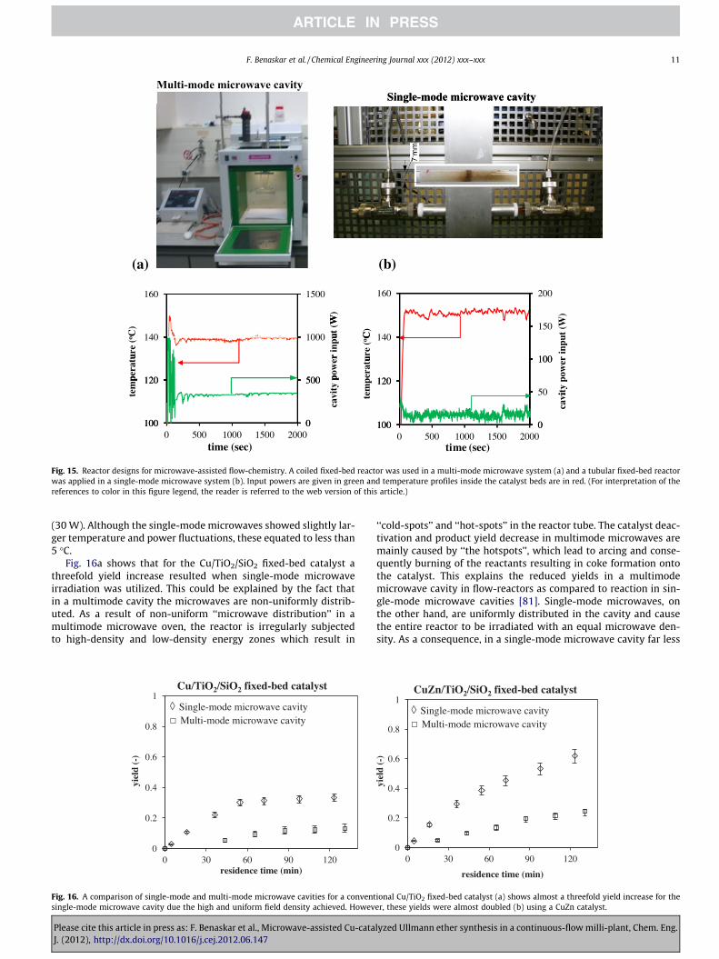
Fig. 15. Reactor designs for microwave-assisted flow-chemistry. A coiled fixed-bed reactor was used in a multi-mode microwave system (a) and a tubular fixed-bed reactorwas applied in a single-mode microwave system (b). Input powers are given in green and temperature profiles inside the catalyst beds are in red. (For interpretation of thereferences to color in this figure legend, the reader is referred to the web version of this article.)
F. Benaskar et al. / Chemical Engineering Journal xxx (2012) xxx–xxx 11
(30 W). Although the single-mode microwaves showed slightly lar-ger temperature and power fluctuations, these equated to less than5 �C.
Fig. 16a shows that for the Cu/TiO2/SiO2 fixed-bed catalyst athreefold yield increase resulted when single-mode microwaveirradiation was utilized. This could be explained by the fact thatin a multimode cavity the microwaves are non-uniformly distrib-uted. As a result of non-uniform ‘‘microwave distribution’’ in amultimode microwave oven, the reactor is irregularly subjectedto high-density and low-density energy zones which result in
0
0.2
0.4
0.6
0.8
1
0 30 60 90 120
yiel
d (-
)
residence time (min)
Cu/TiO2/SiO2 fixed-bed catalyst
Single-mode microwave cavityMulti-mode microwave cavity
Fig. 16. A comparison of single-mode and multi-mode microwave cavities for a conventsingle-mode microwave cavity due the high and uniform field density achieved. Howev
Please cite this article in press as: F. Benaskar et al., Microwave-assisted Cu-cataJ. (2012), http://dx.doi.org/10.1016/j.cej.2012.06.147
‘‘cold-spots’’ and ‘‘hot-spots’’ in the reactor tube. The catalyst deac-tivation and product yield decrease in multimode microwaves aremainly caused by ‘‘the hotspots’’, which lead to arcing and conse-quently burning of the reactants resulting in coke formation ontothe catalyst. This explains the reduced yields in a multimodemicrowave cavity in flow-reactors as compared to reaction in sin-gle-mode microwave cavities [81]. Single-mode microwaves, onthe other hand, are uniformly distributed in the cavity and causethe entire reactor to be irradiated with an equal microwave den-sity. As a consequence, in a single-mode microwave cavity far less
0
0.2
0.4
0.6
0.8
1
0 30 60 90 120
yiel
d ( -
)
residence time (min)
CuZn/TiO2/SiO2 fixed-bed catalyst
Single-mode microwave cavityMulti-mode microwave cavity
ional Cu/TiO2 fixed-bed catalyst (a) shows almost a threefold yield increase for theer, these yields were almost doubled (b) using a CuZn catalyst.
lyzed Ullmann ether synthesis in a continuous-flow milli-plant, Chem. Eng.

12 F. Benaskar et al. / Chemical Engineering Journal xxx (2012) xxx–xxx
energy input is required to attain the reaction temperature as com-pared to multimode microwave cavities leading to sufficient en-ergy to heat the catalyst. In this way destructive arcing andreactants decomposition is avoided. This effect has been confirmedrecently by Chen et al. who showed that at excessive microwavepowers subjected to diamagnetic and paramagnetic metallic parti-cles leads to complete discharges and destructive arcing [75]. Con-versely, at lower microwave power input the particles would heatup very fast but would not lead to arcing and, dependent on thetype of metal and the reaction medium, leads to desirable catalysttemperatures. The use of lower power in case of multimode micro-waves could not attain the desired reaction temperatures, whilst athigher powers (>300 W) arcing limits the productivity. Also clearlyvisible is the yield flattening at around 35% yield, which, as dis-cussed in Section 3.2.3, was mainly due to oxidation and poisoningof the catalyst.
Previously, it has been reported that the Cu catalyst could beprotected against oxidation and that leaching could be minimizedby adding 50 wt.% of Zn to the catalyst as a sacrificial reducingagent [53,82,83]. Consistent with this view, Fig. 16b shows that aconsiderable yield increase was achieved when a CuZn-based het-erogeneous catalyst was used in the fixed-bed reactor. Althoughfor low residence times (<60 min) no major improvement was ob-tained, at longer residence times twofold yield increases wereachieved for both single-mode and multimode systems. ComparingFig. 16b with Fig. 11 signifies that the main reason for thisimprovement is indeed that, regardless of the heating method, cat-alyst deactivation is retarded when a CuZn catalyst is used. Fig. 15demonstrates that the energy efficiency achieved using the single-mode microwave cavity of the Fricke-Mallah instrument reached82% (±4%) with an average power input of 16 W, while the multi-mode cavity system could at best be operated with an energy effi-ciency of only 8.2% (±0.8%) (following notes [73] and [74]). Use ofthe single-mode microwave cavity for a Cu-based heterogeneouscatalyst gave a yield of 33% (±1%) for a residence time of ca.120 min with a productivity of 130 kgprod/(mR
3 h). Only 37 kgprod/(mR
3 h) was obtained in the case of the multimode cavity system.However, a highest yield of 62% (±3%) and a productivity of172 kgprod/(mR
3 h) could be achieved using a CuZn-based catalystin combination with single-mode microwave heating. These highspace–time yields have, to the best of our knowledge, not yet beenreported for Ullmann-type coupling reactions using flow-processing.
4. Conclusions
In this work two flow milli-reactors for microwave-assisted Ull-mann-type CAO coupling reaction are presented. A wall-coated(ZnO support) and a fixed-bed (TiO2 support) milli-reactor weredeveloped and impregnated with Cu nanoparticles as active cata-lyst. These catalytic reactors allowed feasible catalyst regenerationby repetition of oxidation and reduction cycles and shows novelty,in particular, as it is able to deal with development of well-definedsupported catalysts. Copper catalyst leaching for both reactors ap-peared to be only significant after 24 h on-stream and this couldpartially be avoided by thermal treatment of the reactor after eachcycle. Up to 60% yield could be obtained using the Cu/ZnO wall-coated reactor for two consecutive runs without there being a sig-nificant activity drop if a thermal pre-treatment of the reactor(350 �C for 24 h) was undertaken prior to testing. The Cu/TiO2
fixed-bed reactor showed lower yields due to catalyst leaching,however reactor productivities of up to 55 kgprod/(mR
3 h) suggesteda better performance than the Cu/ZnO wall-coated reactor. Micro-waves were therefore applied to the Cu/TiO2 fixed-bed reactor asan alternative energy source for liquid and selective catalyst
Please cite this article in press as: F. Benaskar et al., Microwave-assisted Cu-cataJ. (2012), http://dx.doi.org/10.1016/j.cej.2012.06.147
heating. The use of high density single-mode microwaves showeda threefold yield increase in the Cu/TiO2 fixed-bed reactor relativeto the use of multimode microwaves. Furthermore, the use ofmetallic copper in the microwave cavities appeared to be onlyadvantageous at low microwave powers and catalyst loadings; athigher powers and catalyst loadings arcing was observed, leadingto rapid catalyst deactivation and inefficient heating. A linear rela-tion between the arcing frequency and the catalyst loading wasfound. It was demonstrated that yields obtained using microwaveheating at 140 W were almost 30% higher than those achievedusing oil-bath heating, whereas no significant yield increase wasobserved at 300 W. More important was the use of CuZn/TiO2
based catalyst, where the Zn acted as a sacrificial anode againstCu oxidation. In this case a threefold yield increase could be dem-onstrated in highly dense single-mode microwave cavity which, tothe best of our knowledge, resulted to not yet reported productiv-ity of up to 172 kgprod/(mR
3 h) for microwave-assisted flow synthe-sis in the Ullmann CAO coupling.
Acknowledgements
The authors would like to thank the Dutch Technology Founda-tion STW (Project MEMFiCS GSPT-07974), DSM Research, FrieslandCampina, LioniX, Institut Für Mikrotechnik Mainz (IMM, Germany),Milestone s.r.l. (Italy) as well as The Royal Society (InternationalJoint Project 2008/R4 ‘‘Smart Structured Multiphase Reactors forProcess Intensification’’) for financial and in-kind support.
Appendix A. Supplementary data
Supplementary data associated with this article can be found, inthe online version, at http://dx.doi.org/10.1016/j.cej.2012.06.147.
References
[1] T. Brodmann, P. Koos, A. Metzger, P. Knochel, S.V. Ley, Continuous preparationof arylmagnesium reagents in flow with inline IR monitoring, Organic ProcessResearch & Development (2011).
[2] T. Fukuyama, M.T. Rahman, I. Ryu, I.R. Baxendale, J.J. Hayward, S. Lanners, S.V.Ley, C.D. Smith, B. Ahmed-Omer, T. Wirth, V. Hessel, P. Löb, H. Löwe, K. Koch,F.P.J.T. Rutjes, J.C.M. van Hest, Organic chemistry in microreactors, in:Microreactors in Organic Synthesis and Catalysis, Wiley-VCH Verlag GmbH &Co. KGaA, 2008, pp. 59–209.
[3] T. Illg, P. Loeb, V. Hessel, Flow chemistry using milli- and micro-structuredreactors-from conventional to novel process windows, Bioorganic & MedicinalChemistry 18 (2010) 3707–3719.
[4] K. Jähnisch, V. Hessel, H. Löwe, M. Baerns, Chemistry in microstructuredreactors, Angewandte Chemie International Edition 43 (2004) 406–446.
[5] G.S. Kumar, B. Pieber, K.R. Reddy, C.O. Kappe, Copper-catalyzed formation ofCAO bonds by direct a-CAH bond activation of ethers using stoichiometricamounts of peroxide in batch and continuous-flow formats, Chemistry – AEuropean Journal 18 (2012) 6124–6128.
[6] N.G. Anderson, Using continuous processes to increase production, OrganicProcess Research & Development 5 (2012) 852–869.
[7] V. Hessel, P. Löb, H. Löwe, Industrial microreactor process development up toproduction, in: Microreactors in Organic Synthesis and Catalysis, Wiley-VCHVerlag GmbH & Co. KGaA, 2008, p. 240.
[8] C.O. Kappe, D. Dallinger, S.S. Murphree, Practical Microwave Synthesis forOrganic Chemists, vol. 1, Wiley-VCH, Weinheim, 2009.
[9] T. Wirth, Microreactors in Organic Synthesis and Catalysis, Wiley-VCH, 2008.[10] V. Hessel, A. Renken, J.C. Schouten, J. Yoshida, Micro Process Engineering: A
Comprehensive Handbook, Wiley-VCH, 2009.[11] J.D. Moseley, C.O. Kappe, A critical assessment of the greenness and energy
efficiency of microwave-assisted organic synthesis, Green Chemistry 13 (2011)794–806.
[12] V. Hessel, Novel process windows – gate to maximizing process intensificationvia flow chemistry, Chemical Engineering & Technology 32 (2009) 1655–1681.
[13] M. Hempel, Novel process windows – a contribution to more sustainablechemistry?, Chemical Engineering & Technology 32 (2009) 1651–1654
[14] V. Hessel, D. Kralisch, U. Krtschil, Sustainability through green processing –novel process windows intensify micro- and milli-process technologies,Energy & Environmental Science 1 (2008) 467–478.
[15] A. Stankiewicz, On the applications of alternative energy forms and transfermechanisms in microprocessing systems, Industrial & Engineering ChemistryResearch 46 (2007) 4232–4235.
lyzed Ullmann ether synthesis in a continuous-flow milli-plant, Chem. Eng.

F. Benaskar et al. / Chemical Engineering Journal xxx (2012) xxx–xxx 13
[16] C.O. Kappe, Aqueous microwave-assisted chemistry, ChemSusChem 3 (2010)1085.
[17] M.H.C.L. Dressen, B.H.P. van de Kruijs, J. Meuldijk, J.A.J.M. Vekemans, L.A.Hulshof, Flow processing of microwave-assisted (Heterogeneous) organicreactions, Organic Process Research & Development 14 (2010) 351–361.
[18] J.D. Moseley, Microwave synthesis in process chemistry, Method, Scale andScope Chimica Oggi 27 (2009) 6–10.
[19] T.N. Glasnov, C.O. Kappe, Microwave-assisted synthesis under continuous-flow conditions, Macromolecular Rapid Communications 28 (2007) 395–410.
[20] G. Shore, S. Morin, M.G. Organ, Catalysis in capillaries by Pd thin films usingmicrowave-assisted continuous-flow organic synthesis (MACOS), AngewandteChemie International Edition 45 (2006) 2761–2766.
[21] D. Dallinger, H.R. Lehmann, J.D. Moseley, A. Stadler, C.O. Kappe, Scale-up ofmicrowave-assisted reactions in a multimode bench-top reactor, OrganicProcess Research & Development 15 (2011) 841–854.
[22] V. Hessel, B. Cortese, M.H.J.M. de Croon, Novel process windows – concept,proposition and evaluation methodology, and intensified superheatedprocessing, Chemical Engineering Science 66 (2011) 1426–1448.
[23] F. Benaskar, V. Hessel, U. Krtschil, P. Löb, A. Stark, Intensification of thecapillary-based Kolbe�Schmitt synthesis from resorcinol by reactive ionicliquids, microwave heating, or a combination thereof, Organic ProcessResearch & Development 13 (2009) 970–982.
[24] G. Shore, W.-J. Yoo, C.-J. Li, M.G. Organ, Propargyl amine synthesis catalysed bygold and copper thin films by using microwave-assisted continuous-floworganic synthesis (MACOS), Chemistry – A European Journal 16 (2010) 126–133.
[25] E. Comer, M.G. Organ, A microreactor for microwave-assisted capillary(continuous flow) organic synthesis, Journal of the American ChemicalSociety 127 (2005) 8160–8167.
[26] G. Cravotto, M. Beggiato, A. Penoni, G. Palmisano, S. Tollari, J.-M. Lévêque, W.Bonrath, High-intensity ultrasound and microwave, alone or combined,promote Pd/C-catalyzed arylAaryl couplings, Tetrahedron Letters 46 (2005)2267–2271.
[27] F. Bergamelli, M. Iannelli, J.A. Marafie, J.D.A. Moseley, A commercialcontinuous flow microwave reactor evaluated for scale-up, Organic ProcessResearch & Development 14 (2010) 926–930.
[28] J.D. Moseley, E.K. Woodman, Scaling-out pharmaceutical reactions in anautomated stop-flow microwave reactor, Organic Process Research &Development 12 (2008) 967–981.
[29] J.D. Moseley, P. Lenden, M. Lockwood, K. Ruda, J.-P. Sherlock, A.D. Thomson, J.P.Gilday, A comparison of commercial microwave reactors for scale-upwithin process chemistry, Organic Process Research & Development 12(2007) 30–40.
[30] P. Öhrngren, A. Fardost, F. Russo, J.-S. Schanche, M. Fagrell, M. Larhed,Evaluation of a nonresonant microwave applicator for continuous-flowchemistry applications, Organic Process Research & Development 5 (2012)1053–1063.
[31] N.G. Patil, A.I.G. Hermans, F. Benaskar, J. Meuldijk, L.A. Hulshof, V. Hessel, J.C.Schouten, E.V. Rebrov, Energy efficient and controlled flow processing undermicrowave heating by using a millireactor–heat exchanger, AIChE Journal(2011).
[32] U. Schön, J. Messinger, S. Eichner, A. Kirschning, Comparison of monomode andmultimode microwave equipment in Suzuki-Miyaura reactions-en route tohigh throughput parallel synthesis under microwave conditions, TetrahedronLetters 49 (2008) 3204–3207.
[33] C.O. Kappe, A. Stadler, Microwave theory, in: Microwaves in Organic andMedicinal Chemistry, Wiley-VCH Verlag GmbH & Co. KGaA, 2006, pp. 9–28.
[34] C.O. Kappe, A. Stadler, Introduction: microwave synthesis in perspective, in:Microwaves in Organic and Medicinal Chemistry, Wiley-VCH Verlag GmbH &Co. KGaA, 2006, pp. 1–7.
[35] M. Gupta, E.W. Wai Leong, Index, in: Microwaves and Metals, John Wiley &Sons (Asia) Pte Ltd, 2007, pp. 223–228.
[36] K. Olofsson, A. Hallberg, M. Larhed, Transition metal catalysis and microwaveflash heating in organic chemistry, in: Microwaves in Organic Synthesis,Wiley-VCH Verlag GmbH & Co. KGaA, 2004, pp. 379–403.
[37] A.R. Muci, S.L. Buchwald, Practical palladium catalysts for CAN and CAO bondformation, Cross-Coupling Reactions 219 (2002) 131–209.
[38] A.F. Littke, G.C. Fu, Palladium-catalyzed coupling reactions of aryl chlorides,Angewandte Chemie-International Edition 41 (2002) 4176–4211.
[39] J. Hassan, M. Sevignon, C. Gozzi, E. Schulz, M. Lemaire, ArylAaryl bondformation one century after the discovery of the Ullmann reaction, ChemicalReviews 102 (2002) 1359–1469.
[40] J.P. Finet, A.Y. Fedorov, S. Combes, G. Boyer, Recent advances in Ullmannreaction: copper(II) diacetate catalysed NA, OA and S-arylation involvingpolycoordinate heteroatomic derivatives, Current Organic Chemistry 6 (2002)597–626.
[41] B.H. Yang, S.L. Buchwald, Palladium-catalyzed amination of aryl halides andsulfonates, Journal of Organometallic Chemistry 576 (1999) 125–146.
[42] J.F. Hartwig, Transition metal catalyzed synthesis of arylamines and aryl ethersfrom aryl halides and triflates: scope and mechanism, Angewandte Chemie-International Edition 37 (1998) 2047–2067.
[43] F. Benaskar, A. Ben-Abdelmoumen, N.G. Patil, E.V. Rebrov, J. Meuldijk, L.A.Hulshof, V. Hessel, U. Krtschil, J.C. Schouten, Cost analysis for a continuouslyoperated fine chemicals production plant at 10 Kg/day using a combination ofmicroprocessing and microwave heating, Journal of Flow Chemistry 1 (2011)74–89.
Please cite this article in press as: F. Benaskar et al., Microwave-assisted Cu-cataJ. (2012), http://dx.doi.org/10.1016/j.cej.2012.06.147
[44] F. Monnier, M. Taillefer, Catalytic CAC, CAN, and CAO Ullmann-type couplingreactions, Angewandte Chemie International Edition 48 (2009) 6954–6971.
[45] J.Y. Kim, J.C. Park, A. Kim, A.Y. Kim, H.J. Lee, H. Song, K.H. Park, Cu2O nanocube-catalyzed cross-coupling of aryl halides with phenols via Ullmann coupling,European Journal of Inorganic Chemistry (2009) 4219–4223.
[46] J. Niu, H. Zhou, Z. Li, J. Xu, S. Hu, An efficient Ullmann-type CAO bondformation catalyzed by an air-stable copper(I)-bipyridyl complex, Journal ofOrganic Chemistry 73 (2008) 7814–7817.
[47] F. Monnier, M. Taillefer, Catalytic CAC, CAN, and CAO Ullmann-type couplingreactions: copper makes a difference, Angewandte Chemie InternationalEdition 47 (2008) 3096–3099.
[48] G. Evano, N. Blanchard, M. Toumi, Copper-mediated coupling reactions andtheir applications in natural products and designed biomolecules synthesis,Chemical Reviews 108 (2008) 3054–3131.
[49] M. Kidwai, N.K. Mishra, V. Bansal, A. Kumar, S. Mozumdar, Cu-nanoparticlecatalyzed O-arylation of phenols with aryl halides via Ullmann coupling,Tetrahedron Letters 48 (2007) 8883–8887.
[50] K. Kunz, U. Scholz, D. Ganzer, Renaissance of Ullmann and Goldberg reactions –progress in copper catalyzed CAN, CAOA and CASAcoupling, Synlett 2003(2003) 2428–2439.
[51] M. Taillefer, H.-J. Cristau, P.P. Cellier, J.-F. Spindler, A. Ouali, Fr 2840303-WO03101966 (Pr. Nb. Fr 2002 06717), (2002).
[52] V. Engels, F. Benaskar, N. Patil, E.V. Rebrov, V. Hessel, L.A. Hulshof, D.A.Jefferson, J.A.J.M. Vekemans, S. Karwal, J.C. Schouten, A.E.H. Wheatley, Cu-based nanoalloys in the base-free Ullmann heterocyle-aryl ether synthesis,Organic Process Research & Development 14 (2010) 644–649.
[53] F. Benaskar, V. Engels, E.V. Rebrov, N.G. Patil, J. Meuldijk, P.C. Thüne, P.C.M.M.Magusin, B. Mezari, V. Hessel, L.A. Hulshof, E.J.M. Hensen, A.E.H. Wheatley, J.C.Schouten, New Cu-based catalysts supported on TiO2 films for Ullmann SNAr-type CAO coupling reactions, Chemistry – A European Journal 18 (2012) 1800–1810.
[54] A. Mondal, D. Agrawal, A. Upadhyaya, Microwave heating of pure copperpowder with varying particle size and porosity, International MicrowavePower Institute 43 (2009) 5–10.
[55] X. Zhang, D.O. Hayward, D.M.P. Mingos, Effects of microwave dielectric heatingon heterogeneous catalysis, Catalysis Letters 88 (2003) 33–38.
[56] A.G. Whittaker, D.M.P. Mingos, Synthetic reactions using metal powders undermicrowave irradiation, Journal of the Chemical Society Dalton Transactions(2002) 3967–3970.
[57] G. Bond, R.B. Moyes, D.A. Whan, Recent applications of microwave heating incatalysis, Catalysis Today 17 (1993) 427–437.
[58] W.L. Perry, D.W. Cooke, J.D. Katz, A.K. Datye, On the possibility of a significanttemperature gradient in supported metal catalysts subjected to microwaveheating, Catalysis Letters 47 (1997) 1–4.
[59] D. Walton, H. Boehnel, D.J. Dunlop, Response of magnetic nanoparticles tomicrowaves, Applied Physics Letters 85 (2004) 5367–5369.
[60] D. Walton, Resetting the magnetization of assemblies of nanoparticles withmicrowaves, Journal of Applied Physics 95 (2004) 5247–5248.
[61] V.D. Buchelnikov, D.V. Louzguine-Luzgin, G. Xie, S. Li, N. Yoshikawa, M. Sato,A.P. Anzulevich, I.V. Bychkov, A. Inoue, Heating of metallic powders bymicrowaves: experiment and theory, Journal of Applied Physics 104 (2008)113505.
[62] A.G. Whittaker, D.M.P. Mingos, Arcing and other microwave characteristics ofmetal powders in liquid systems, Journal of the Chemical Society DaltonTransactions (2000) 1521–1526.
[63] J.R. Thomas, Particle size effect in microwave-enhanced catalysis, CatalysisLetters 49 (1997) 137–141.
[64] V. Engels, F. Benaskar, D.A. Jefferson, B.F.G. Johnson, A.E.H. Wheatley,Nanoparticulate copper – routes towards oxidative stability, Dalton T 39(2010) 6496–6502.
[65] F. Benaskar, V. Engels, N. Patil, E.V. Rebrov, J. Meuldijk, V. Hessel, L.A. Hulshof,D.A. Jefferson, J.C. Schouten, A.E.H. Wheatley, Copper(0) in the Ullmannheterocycle-aryl ether synthesis of 4-phenoxypyridine using multimodemicrowave heating, Tetrahedron Letters 51 (2010) 248–251.
[66] F. Benaskar, V. Engels, N. Patil, E.V. Rebrov, J. Meuldijk, V. Hessel, L.A. Hulshof,D.A. Jefferson, J.C. Schouten, A.E.H. Wheatley, Copper(0) in the Ullmannheterocycle-aryl ether synthesis of 4-phenoxypyridine using multimodemicrowave heating, Tetrahedron Lett. 51 (2010) 248–251.
[67] G. Piperata, J.M. Meichtry, M.I. Litter, Photocatalytic reactions over TiO2
supported on porcelain spheres, in: F. Galembeck (Ed.), Progress in Colloid andPolymer Science – Surface and colloid science, Springer, Berlin, 2004, pp. 303–308.
[68] C.O. Kappe, A. Stadler, Microwave theory, in: Microwaves in Organic andMedicinal Chemistry, Wiley-VCH Verlag GmbH & Co. KGaA, 2006, pp. 9–28(Chapter 2).
[69] J. Jacob, L.H.L. Chia, F.Y.C. Boey, Thermal and non-thermal interaction ofmicrowave radiation with materials, Journal of Materials Science 30 (1995)5321–5327.
[70] D.A. Lewis, J.D. Summers, T.C. Ward, J.E. McGrath, Accelerated imidizationreactions using microwave radiation, Journal of Polymer Science Part A:Polymer Chemistry 30 (1992) 1647–1653.
[71] M.H.C.L. Dressen, B.H.P. van de Kruijs, J. Meuldijk, J.A.J.M. Vekemans, L.A.Hulshof, Vanishing microwave effects: influence of heterogeneity, OrganicProcess Research & Development 5 (2007) 865–869.
[72] C.O. Kappe, Controlled microwave heating in modern organic synthesis,Angewandte Chemie International Edition 43 (2004) 6250–6284.
lyzed Ullmann ether synthesis in a continuous-flow milli-plant, Chem. Eng.

14 F. Benaskar et al. / Chemical Engineering Journal xxx (2012) xxx–xxx
[73] V.F. Meshcheryakov, Y.K. Fetisov, A.A. Stashkevich, G. Viau, Magnetic andmicrowave properties of nanocomposite films on the basis of Fe–Co–Niparticles of various shapes, Journal of Applied Physics 104 (2008) 063910.
[74] D. Stuerga, M. Delmotte, Wave–material interactions, microwave technologyand equipment, in: Microwaves in Organic Synthesis, Wiley-VCH VerlagGmbH & Co. KGaA, 2004, pp. 1–33.
[75] W. Chen, B. Gutmann, C.O. Kappe, Characterization of microwave-inducedelectric discharge phenomena in metal–solvent mixtures, ChemistryOpen 1(2012) 39–48.
[76] A.G. Whittaker, D.M.P. Mingos, Microwave-assisted solid-state reactionsinvolving metal powders, Journal of the Chemical Society DaltonTransactions (1995) 2073–2079.
[77] N.G. Patil, E.V. Rebrov, K. Eränen, F. Benaskar, J. Meuldijk, J.-P. Mikkola, V.Hessel, L.A. Hulshof, D.Y. Murzin, J.C. Schouten, Effect of the load size on theefficiency of microwave heating under stop-flow and continuous-flowconditions, Journal of the Microwave Power and Electromagnetic Energy 46(2012) 83–92.
[78] The presence of copper also shows heating rates higher compared to those inthe absence of copper, which indicates an additional solids absorption term inthe overall microwave energy absorption. The following equation hasbeen applied to demonstrate a global energy balance.Q(MW) = Q(liquid) + Q(solid) = {m�Cp�(DT/Dt)}(DMA) + Q(Cu). Where Q(MW)
Please cite this article in press as: F. Benaskar et al., Microwave-assisted Cu-cataJ. (2012), http://dx.doi.org/10.1016/j.cej.2012.06.147
is the microwave power input (120 W), m the total liquid mass (0.025–0.035 kg), Cp(DMA) the specific heat capacity of the solvent,dimethylacetamide, (2.01 kJ/kg/K), DT/Dt the temperature increase over theheating time (in K/s) and Q(Cu) the microwave energy absorption by thecopper.
[79] g_MW = (Q_thermal, sample)/(Q_MW, cavity). Where ‘‘Q_thermal, sample’’ isthe overall energy gained by the sample (contributed by liquid and solidabsorption) and ‘‘Q_MW, cavity’’ is the total microwave power input to thecavity.
[80] M. Komorowska, G.D. Stefanidis, T. Van Gerven, A.I. Stankiewicz, Influence ofmicrowave irradiation on a polyesterification reaction, Chemical EngineeringJournal 155 (2009) 859–866.
[81] A.C. Metaxas, R.J. Meredith, in: P. Peregrinus (Ed.) Industrial microwaveheating, 1993, p. 296 (Chapter 12).
[82] D. Grandjean, V. Pelipenko, E.D. Batyrev, J.C. van den Heuvel, A.A. Khassin, T.M.Yurieva, B.M. Weckhuysen, Dynamic Cu/Zn interaction in SiO2 supportedmethanol synthesis catalysts unraveled by in situ XAFS, The Journal of PhysicalChemistry C 115 (2011) 20175–20191.
[83] J.D. Grunwaldt, A.M. Molenbroek, N.Y. Topsøe, H. Topsøe, B.S. Clausen, In situinvestigations of structural changes in Cu/ZnO catalysts, Journal of Catalysis194 (2000) 452–460.
lyzed Ullmann ether synthesis in a continuous-flow milli-plant, Chem. Eng.