microwave readout techniques for very large arrays of ... reports/fy 2013/13-4835 neup... ·...
TRANSCRIPT

Microwave Readout Techniques for Very Large Arrays of Nuclear
Sensors
Fuel Cycle Research and Development Joel Ullom
University of Colorado, Boulder
Dan Vega, Federal POC Mike Miller, Technical POC
Project No. 13-4835

1
FinalReportforDE-NE0000716001Recipient: UniversityofColorado,Boulder Boulder,CO80303ProposalTitle:MicrowavereadouttechniquesforverylargearraysofnuclearsensorsPI:JoelUllom,Lecturer,DepartmentofPhysics,[email protected],303-497-4408SubmittingOfficial:JoelUllom(seeabove)ProjectPeriod:Jan1,2014–Dec31,2016ReportSubmissionDate:May11,2017
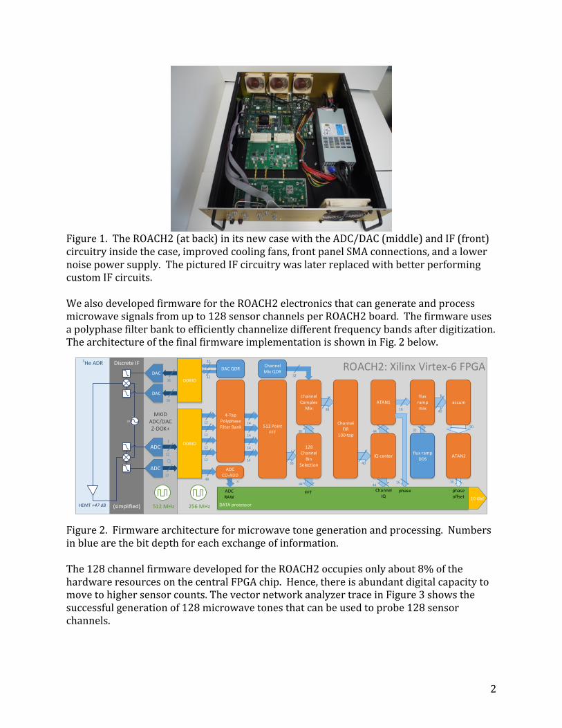
ExecutiveSummaryDuringthisproject,wetransformedtheuseofmicrowavereadouttechniquesfornuclearsensorsfromaspeculativeideatoreality.Thecoreoftheprojectconsistedofthedevelopmentofasetofmicrowaveelectronicsabletogenerateandprocesslargenumbersofmicrowavetones.Thetonescanbeusedtoprobeacircuitcontainingaseriesofelectricalresonanceswhosefrequencylocationsandwidthsdependonthestateofanetworkofsensors,withonesensorperresonance.Theamplitudeandphaseofthetonesemergingfromthecircuitareprocessedbythesameelectronicsandarereducedtothesensorsignalsaftertwodemodulationsteps.Thisapproachallowsalargenumberofsensorstobeinterrogatedusingasinglepairofcoaxialcables.Wesuccessfullydevelopedhardware,firmware,andsoftwaretocompleteascalableimplementationofthesemicrowavecontrolelectronicsanddemonstratedtheiruseintwoareas.First,weshowedthattheelectronicscanbeusedatroomtemperaturetoreadoutanetworkofdiversesensortypesrelevanttosafeguardsorprocessmonitoring.Second,weshowedthattheelectronicscanbeusedtomeasurelargenumbersofultrasensitivecryogenicsensorssuchasgamma-raymicrocalorimeters.Inparticular,wedemonstratedtheundegradedreadoutofupto128channelsandestablishedapathtoevenhighermultiplexingfactors.Theseresultshavetransformedtheprospectsforgamma-rayspectrometersbasedoncryogenicmicrocalorimeterarraysbyenablingspectrometerswhosecollectingareasandcountratescanbecompetitivewithhighpuritygermaniumbutwith10xbetterspectralresolution.TechnicalResults–MicrowaveElectronics128ChannelMicrowaveElectronicsAphotographoftheelectronicshardwaredevelopedforthisprojectisshowninFig.1.TonegenerationandprocessingareperformedusingaVirtex6FieldProgrammableGateArray(FPGA)chip.Thischipispartoftheso-calledROACH2electronicsdevelopedbytheCASPERradioastronomyconsortiumandadaptedtothisproject.InadditiontopackagingtheROACH2anditsassociatedanalog-to-digital/digital-to-analog(ADC/DAC)daughtercardinaneasy-to-use,low-noiseenclosure,wedevelopedcustomintermediatefrequency(IF)circuitrytomixtonesgeneratedatbasebanduptoGHzfrequenciesandthenmixthembackdownagainafterprobingthesensors.
2
Figure1.TheROACH2(atback)initsnewcasewiththeADC/DAC(middle)andIF(front)circuitryinsidethecase,improvedcoolingfans,frontpanelSMAconnections,andalowernoisepowersupply.ThepicturedIFcircuitrywaslaterreplacedwithbetterperformingcustomIFcircuits.WealsodevelopedfirmwarefortheROACH2electronicsthatcangenerateandprocessmicrowavesignalsfromupto128sensorchannelsperROACH2board.Thefirmwareusesapolyphasefilterbanktoefficientlychannelizedifferentfrequencybandsafterdigitization.ThearchitectureofthefinalfirmwareimplementationisshowninFig.2below.
Figure2.Firmwarearchitectureformicrowavetonegenerationandprocessing.Numbersinbluearethebitdepthforeachexchangeofinformation.The128channelfirmwaredevelopedfortheROACH2occupiesonlyabout8%ofthehardwareresourcesonthecentralFPGAchip.Hence,thereisabundantdigitalcapacitytomovetohighersensorcounts.ThevectornetworkanalyzertraceinFigure3showsthesuccessfulgenerationof128microwavetonesthatcanbeusedtoprobe128sensorchannels.
MKIDADC/DACZ-DOK+
ROACH2: Xilinx Virtex-6 FPGA
DAC
DAC
ADC
256 MHz
12
ADC
12
12
12
12
512 MHz
Q12
I
DATA processor
10 GbE
ADCRAW
32
ChannelIQ
phase phaseoffset
Discrete IF
(simplified)
3He ADR
HEMT +47 dB
40
44
44
ATAN1flux
rampmix
accum
ATAN2flux ramp
DDSIQ center
16 40
16
LO
16
16
32
32
DDRIO
ADC CO-ADD
DAC QDR
Channel FIR
100-tap
Channel Mix QDR
Channel Complex
Mix
128 Channel
Bin Selection
512 Point FFT
14
14
14
4-Tap Polyphase Filter Bank
32
48
FFT
36
36
38
14
32
44
DDRIO
16

3
Figure3.128microwavetonescenteredon5.5GHzproducedbytheROACH2electronics.Themicrowavetonesaretransmittedonasinglesharedcoaxialcableandusedtoprobe128sensorchannels.Thefunctionalityprovidedbythehardwareandfirmwaredevelopedforthisprojectincludes:
• GenerationandsummationoftonesinMHzregime• Up-mixingofsummedtonesto~6GHzregime• Deliveryofsummedtonestoresonatorsthatcanbecoupledtosensors.• Lownoisemeasurementofsummedtonesemergingfrommicrowaveresonators• Down-mixingofsummedtonesfromGHztoMHzregime• DigitizationofsummedanalogMHztones• Channelizationoftones,meaningseparationintofrequencybandsthatisolate
eachcarrierfrequencyalongwithanysignalembeddedasperturbationstothecarrier
• Extractionofsensorsignalsfromthechannelizedtonesusingfluxrampdemodulation.
AllthisfunctionalityisperformedinrealtimethankstotheprocessingpoweroftheVirtex6FPGAchip.Presently,the128tonesmustresidewithina500MHzbandduetothelimitsoftheROACH2ADC/DAChardware,butmoremodernADC/DAChardwarewillovercomethislimit.Inadditiontohardwareandfirmwaredevelopment,wealsowrotesoftwaretocommandtheROACH2electronicsandtomakesenseofanddisplaytheinformationreturnedfromit.Oneexampletaskperformedbythesoftwareistodeterminethefrequenciesforthe

4
microwavetonesgeneratedbytheROACH2;thecorrectfrequenciescorrespondtotheresonancefrequenciesofthethin-filmresonatorsonthemultiplexerchipsinthecryostat.AscreenshotfromthesoftwarecontrolenvironmentisshowninFigure4.
Figure4.Screenshotofsoftwarecontrolenvironmentformicrowavereadoutexperiments.Theplotsatbottomarevisualizationsoftherealandimaginarypartsofthemicrowavetransmissionthroughthesharedfeedlineformanysensorchannels.Thesesignalschangeinresponsetothestateofthesensors.TechnicalResults–ConventionalSensorNetworksAnimportantgoalofthisprojectwastoshowthatmicrowavereadoutcanbeusedatroomtemperaturetomonitornetworksofdiversesensortypes.Theuseofmicrowavereadouttomonitorasensornetworkhasseveralattractions.Networkcomplexityistransferredfromthesensorstothecentralcontrolelectronicswhichcouldbeadvantageousinnuclearfacilitieswhereaccesstosensorsaftertheirinstallationmaybeverylimited.Allsignalsarecarriedonasingle,simplecoaxialcablesocomplexandexpensiverewiringofanuclearfacilityisnotneededintheeventofachangetothesensornetwork.Further,allsensorsaremonitoredcontinuouslyusinganalogsignalsthathaveaclearconnectiontothephysicalstateofthesensors.Suchanarchitecturemaybemorerobusttotamperingthanconventionaldigitalnetworking.

5
Figure5.(Topleft)Printedcircuitboard(PCB)containingmicrowavefeedlineandmicrowaveresonators(labeledf1,f2,andf3).Voltagesignalsfromeachelementofasensornetworkconnecttothemicrowaveresonators.Eachvoltagesignalisconnectedtoavoltage-controlledcapacitororvaractor.TheformfactorofthePCBisnotrepresentativeofhowasensornetworkforsafeguardswouldbeconnected;itwaschosentobeconvenientforlaboratorytesting.(Topright)Commercialresistancebridgefortemperaturemeasurementusedinthemodelsensornetwork.(Bottomleft)Commercialpressuresensorusedinthenetwork.(Bottomright)Commercialvoltagesupplywhoseoutputwasmonitoredusingmicrowavereadout.Ourkeyresultinthistechnicalareawasdemonstratingtheuseofmicrowavereadouttomonitorthestateofasmallnetworkcontainingthreeverydifferentpiecesofelectronics.Thesewere(1)acommercialresistancebridge,(2)acommercialpressuresensor,and(3)acommercialvoltagesource(seeFig.5).Inallthreecases,thestateoftheinstrumentisindicatedbyavoltageoutputwhichistransducedtoacapacitancebymeansofaninexpensive,commercialvaractor.Thevaractorsareeachembeddedinroomtemperaturemicrowaveresonancecircuitsassembledfrominductorsandcapacitors.Eachresonancecircuithasauniqueidentifyingfrequencyandthethreeresonancecircuitsaremonitored
f1
f2 f3
to thermometer
to power supply
to pressure sesnor
ground connecitons
feed line

6
continuouslyusingmicrowavetonesfromtheROACH2electronicsdevelopedforthisproject.
Figure6.Electricalcircuitforonemicrowaveresonator.TheinputsignalofinterestisV1.Thevaractor(D1)isshownasacompositediodeandcapacitor.ThecapacitorC3isusedtokeepthechangeofresonancefrequencyduetochangingV1towithinahalfbandwidthoftheresonance.R1isusedforisolationofthesignalvoltageV1.C1stopsthecurrentbiasingthediodefrombeingshortedtoground.C2mostlycontrolstheinputcouplingoftheresonancecircuitandlimitsthechangeinqualityfactor.L1helpstocreateacircuitresonanceatthetargetfrequencyandfrequencywidth.AdetailedelectricalcircuitforonemicrowaveresonatorisshowninFigure6.Thiscircuitisreplicatedforeachsensorinthenetworkbutwithslightlydifferentcircuitvaluessothattheresonancefrequenciesarenonoverlapping.AlltheresonatorsareconnectedtoasinglemicrowavefeedlinethatisconnectedtotheROACH2electronics.Microwavetonesareinjectedatoneendofthefeedlineandmonitoredattheother.Forthepresentdemonstration,thefeedlinewasatraceonaPCBbutinanactualsafeguardsscenariothefeedlinewouldbeacoaxialcableorcables.
D1
2-12pF
C1
C2
L1R1
TL1 TL2
V1
Port2Port1GND
Network
Analyzer
Ch1 Ch2
Ch3 Ch4
Mea-
s ureFormat
S cale/
Ref
Dis play Avg Cal
MarkerMarker
S earch
Marker
Func
S tart S top Power
Center S pan S weep
Return
S ys tem Local Pres et
VideoS ave/
RecallS eq
S timulus Ins trumentS tateRChannel
LineOn/Off
8 9
4 5 6
1 2 3
GHz
MHz
kHz
Hz0 key'trans lation:.(en)'returneda objectins teadofs tring.-
> <
<Entry
Off
C3
7
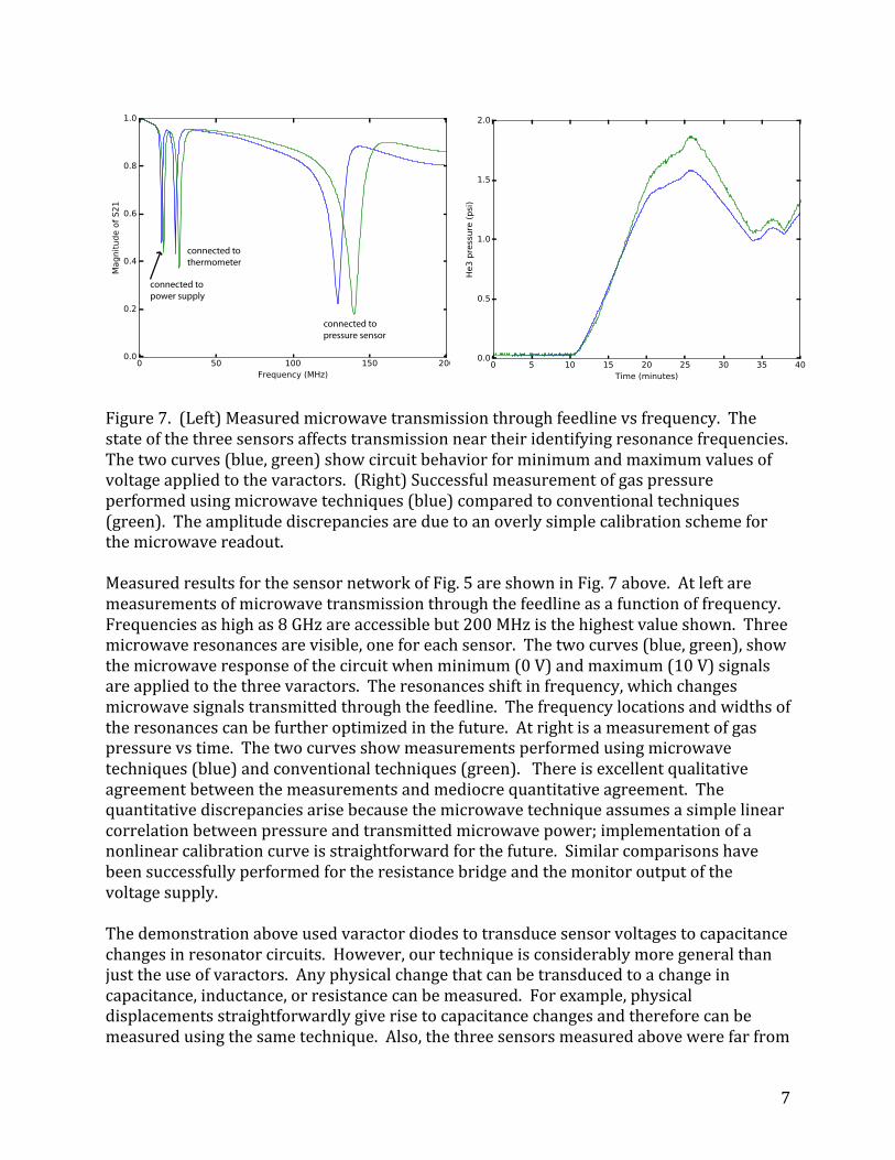
Figure7.(Left)Measuredmicrowavetransmissionthroughfeedlinevsfrequency.Thestateofthethreesensorsaffectstransmissionneartheiridentifyingresonancefrequencies.Thetwocurves(blue,green)showcircuitbehaviorforminimumandmaximumvaluesofvoltageappliedtothevaractors.(Right)Successfulmeasurementofgaspressureperformedusingmicrowavetechniques(blue)comparedtoconventionaltechniques(green).Theamplitudediscrepanciesareduetoanoverlysimplecalibrationschemeforthemicrowavereadout.
MeasuredresultsforthesensornetworkofFig.5areshowninFig.7above.Atleftaremeasurementsofmicrowavetransmissionthroughthefeedlineasafunctionoffrequency.Frequenciesashighas8GHzareaccessiblebut200MHzisthehighestvalueshown.Threemicrowaveresonancesarevisible,oneforeachsensor.Thetwocurves(blue,green),showthemicrowaveresponseofthecircuitwhenminimum(0V)andmaximum(10V)signalsareappliedtothethreevaractors.Theresonancesshiftinfrequency,whichchangesmicrowavesignalstransmittedthroughthefeedline.Thefrequencylocationsandwidthsoftheresonancescanbefurtheroptimizedinthefuture.Atrightisameasurementofgaspressurevstime.Thetwocurvesshowmeasurementsperformedusingmicrowavetechniques(blue)andconventionaltechniques(green).Thereisexcellentqualitativeagreementbetweenthemeasurementsandmediocrequantitativeagreement.Thequantitativediscrepanciesarisebecausethemicrowavetechniqueassumesasimplelinearcorrelationbetweenpressureandtransmittedmicrowavepower;implementationofanonlinearcalibrationcurveisstraightforwardforthefuture.Similarcomparisonshavebeensuccessfullyperformedfortheresistancebridgeandthemonitoroutputofthevoltagesupply.
Thedemonstrationaboveusedvaractordiodestotransducesensorvoltagestocapacitancechangesinresonatorcircuits.However,ourtechniqueisconsiderablymoregeneralthanjusttheuseofvaractors.Anyphysicalchangethatcanbetransducedtoachangeincapacitance,inductance,orresistancecanbemeasured.Forexample,physicaldisplacementsstraightforwardlygiverisetocapacitancechangesandthereforecanbemeasuredusingthesametechnique.Also,thethreesensorsmeasuredabovewerefarfrom
connected to pressure sensor
connected to thermometer
connected to power supply

8
exhaustingthe500MHzofbandwidthavailableperROACH2unitsomuchlargernetworksofsensorsarepossible.ThisworkcompletedaM3milestonescheduledfor9/30/2016andfulfillsoneofthebroadvisionsoutlinedintheoriginalproposal.TechnicalResults–OperationofMicrocalorimeterSensorsAsecondkeygoalforthisprojectwastousemicrowavereadouttomeasuresignalsfromanarrayofgamma-raymicrocalorimetersensors.Toreview,thesecryogenicsensorsprovideresolvingpowers5-10xbetterthanhighpuritygermaniumbutthesmallsizeandslowresponseofindividualdevicesnecessitatestheuseofsensorarraysinpracticalapplications.Thelargestarrayachievedbeforethisworkwas256sensorsmeasuredusing8amplifierchannels,sothateachamplifierwasmeasuringthemultiplexedsignalsfrom32sensors.Thismultiplexingwasperformedinthetimedomainandthebandwidthavailableperamplifierwasonly5-10MHz(D.Bennettetal,ReviewofScientificInstruments,2012).Inwhatfollows,weshowthattheseearlierresultshavebeendecisivelysurpassedusingmicrowavereadout.Toreadoutmicrocalorimetersensors,thecurrentpulsesfromthesedevicesaretransducedtoaninductancechangeusingaspecializedthin-filmcircuitcalledaRF-SQUID.EachRF-SQUIDisembeddedinathin-filmresonatorthatcouplestoasharedmicrowavefeedline.WedesignedandfabricatedthesecircuitsasshowninFig.8.Animportantresultwasreducingthecurrentnoiseofthesecircuitsbyafactorcloseto4comparedtoourproof-of-principledemonstrationbeforethisNEUPproject.Wesuccessfullyreducedthecurrentnoisetoabout20pA/rt(Hz)whichislowenoughtohavenegligibleimpactontheresolutionofmostmicrocalorimetersensors.
Figure8.(left)Photographof33channelRF-SQUIDcircuitwithpennyforscale.Thesharedfeedlinerunsthelengthofthechip.Thethin-filmresonatorscanbeseenasfainttrombone-shapedstructuresspanningthewidthofthechip.(right)MeasurednoisespectraldensityfromnewRF-SQUIDamplifiers.Thenoiseismeasuredafterfluxrampdemodulationandisthereforerepresentativeofthenoisethatwillbeencounteredbysensorscoupledtotheamplifierchips.
9
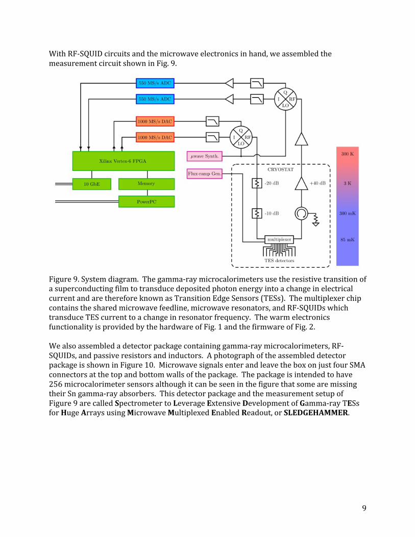
WithRF-SQUIDcircuitsandthemicrowaveelectronicsinhand,weassembledthemeasurementcircuitshowninFig.9.
Figure9.Systemdiagram.Thegamma-raymicrocalorimetersusetheresistivetransitionofasuperconductingfilmtotransducedepositedphotonenergyintoachangeinelectricalcurrentandarethereforeknownasTransitionEdgeSensors(TESs).Themultiplexerchipcontainsthesharedmicrowavefeedline,microwaveresonators,andRF-SQUIDswhichtransduceTEScurrenttoachangeinresonatorfrequency.ThewarmelectronicsfunctionalityisprovidedbythehardwareofFig.1andthefirmwareofFig.2.Wealsoassembledadetectorpackagecontaininggamma-raymicrocalorimeters,RF-SQUIDs,andpassiveresistorsandinductors.AphotographoftheassembleddetectorpackageisshowninFigure10.MicrowavesignalsenterandleavetheboxonjustfourSMAconnectorsatthetopandbottomwallsofthepackage.Thepackageisintendedtohave256microcalorimetersensorsalthoughitcanbeseeninthefigurethatsomearemissingtheirSngamma-rayabsorbers.ThisdetectorpackageandthemeasurementsetupofFigure9arecalledSpectrometertoLeverageExtensiveDevelopmentofGamma-rayTESsforHugeArraysusingMicrowaveMultiplexedEnabledReadout,orSLEDGEHAMMER.
10
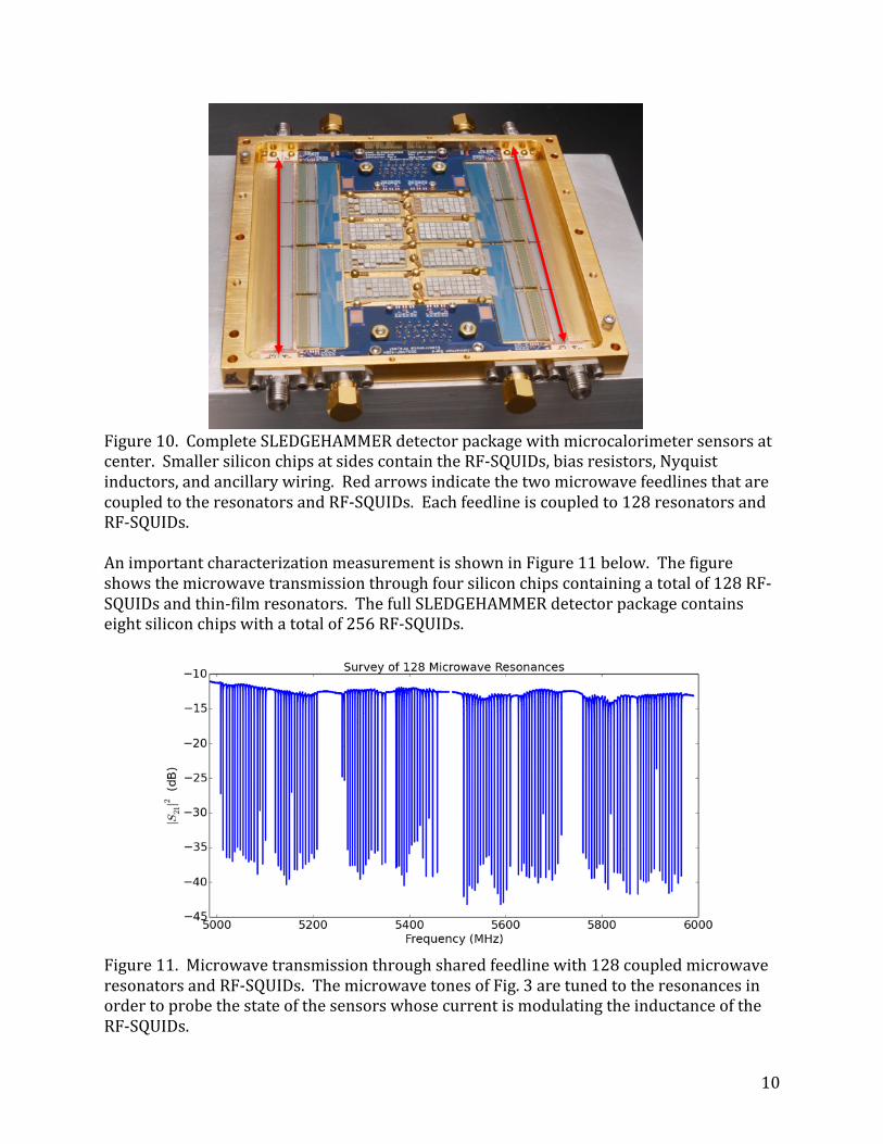
Figure10.CompleteSLEDGEHAMMERdetectorpackagewithmicrocalorimetersensorsatcenter.SmallersiliconchipsatsidescontaintheRF-SQUIDs,biasresistors,Nyquistinductors,andancillarywiring.RedarrowsindicatethetwomicrowavefeedlinesthatarecoupledtotheresonatorsandRF-SQUIDs.Eachfeedlineiscoupledto128resonatorsandRF-SQUIDs.AnimportantcharacterizationmeasurementisshowninFigure11below.Thefigureshowsthemicrowavetransmissionthroughfoursiliconchipscontainingatotalof128RF-SQUIDsandthin-filmresonators.ThefullSLEDGEHAMMERdetectorpackagecontainseightsiliconchipswithatotalof256RF-SQUIDs.
Figure11.Microwavetransmissionthroughsharedfeedlinewith128coupledmicrowaveresonatorsandRF-SQUIDs.ThemicrowavetonesofFig.3aretunedtotheresonancesinordertoprobethestateofthesensorswhosecurrentismodulatingtheinductanceoftheRF-SQUIDs.

11
WesuccessfullycooledandoperatedtheSLEDGEHAMMERinstrumentusingourmicrowavereadoutelectronics.Acrucialmetricformicrowavereadoutisthatthenoisefromthetechniquebemuchsmallerthantheintrinsicnoiseofthesensorsunderstudy.Whenthisconditionismet,energyresolutionduringgamma-rayspectroscopywillbesetbythesensors,andnotthereadout.Wemeasuredthereadoutnoiseinallofthe256sensorchannelsofthefirstSLEDGEHAMMERdetectorpackage.Thenoisedatawasacquiredintwoseparatemeasurementsof128channelsbutsimilardatawillbeacquiredsimultaneouslyinthefuture.HistogramsoftheaveragereadoutnoiseinthefourquadrantsofthedetectorpackageareshowninFigure12.Whilethisfigureisratherundramatic,ittellsacrucialstory:thatmicrowavetechniquesareenablingtheundegradedreadoutofmoresensorchannelsperamplifier(128)thaneverbefore.
Figure12.Histogramsofaveragereadoutnoisein256sensorchannelsdividedintofourquadrants.Typicalvaluesofsensornoisefromagamma-raymicrocalorimeterare100pA/Hz1/2,substantiallylargerthanthevaluesinthefigure(intheseunits,noisetermsaddinquadrature).TheaveragenoiseinquadrantAB-34ishigherthantheotherquadrants.ThisisduetolessmicrowavepowerreachingthesharedHEMTamplifierfromtheRF-SQUIDsinthisquadrant.ThenoisevaluesinFigure12aremostlycenteredaround40pA/Hz1/2.Insubsequentwork,wedeterminedthatinsufficientmicrowavepowerwasreachingalltheresonators.Afterremedyingthisproblem,weobtainednoisehistogramscenteredaround20pA/Hz1/2,consistentwithourexpectationsbasedonearlyresultssuchasFig.8.Whilethisadditionalnoisemarginisn’tneededforgamma-raysensors,itisdesirableforothersensortypes.Havingdemonstratedfullfunctionalityofthereadoutsystem,weproceededtoacquiregamma-rayspectrafroma153GdradioisotopesourceusingthefirstSLEDGEHAMMERdetectorpackage.Thepackagecontains256gamma-raymicrocalorimeterson8separatesiliconchipssuppliedbyourcollaboratorsattheNISTBoulderLaboratories.Unfortunately,morethanhalfofthesensorscontaineddefects.Intotal,only89sensorsweresufficientlydefect-freetobeusefulforhighperformancespectroscopy.Figure13
12
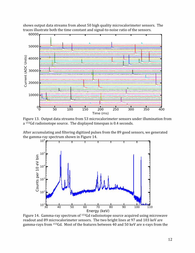
showsoutputdatastreamsfromabout50highqualitymicrocalorimetersensors.Thetracesillustrateboththetimeconstantandsignal-to-noiseratioofthesensors.
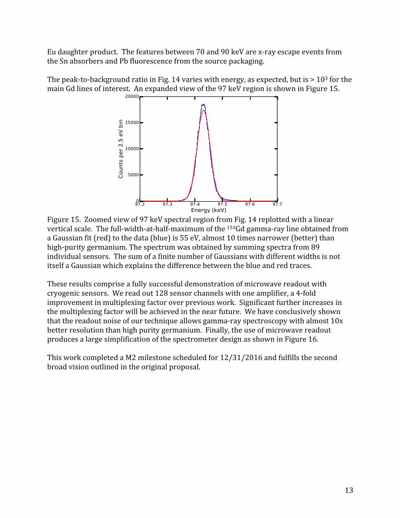
Figure13.Outputdatastreamsfrom53microcalorimetersensorsunderilluminationfroma153Gdradioisotopesource.Thedisplayedtimespanis0.4seconds.Afteraccumulatingandfilteringdigitizedpulsesfromthe89goodsensors,wegeneratedthegamma-rayspectrumshowninFigure14.
Figure14.Gamma-rayspectrumof153Gdradioisotopesourceacquiredusingmicrowavereadoutand89microcalorimetersensors.Thetwobrightlinesat97and103keVaregamma-raysfrom153Gd.Mostofthefeaturesbetween40and50keVarex-raysfromthe
13
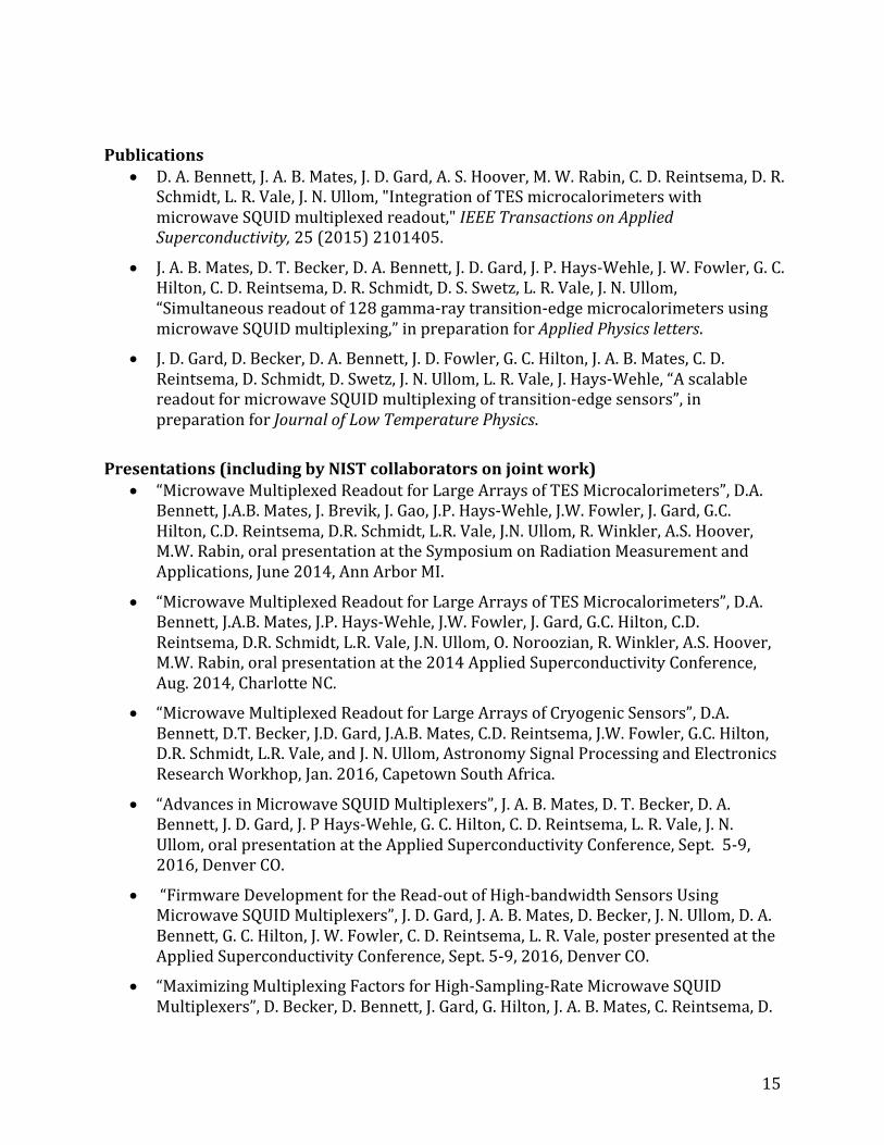
Eudaughterproduct.Thefeaturesbetween70and90keVarex-rayescapeeventsfromtheSnabsorbersandPbfluorescencefromthesourcepackaging.Thepeak-to-backgroundratioinFig.14varieswithenergy,asexpected,butis>103forthemainGdlinesofinterest.Anexpandedviewofthe97keVregionisshowninFigure15.
Figure15.Zoomedviewof97keVspectralregionfromFig.14replottedwithalinearverticalscale.Thefull-width-at-half-maximumofthe153Gdgamma-raylineobtainedfromaGaussianfit(red)tothedata(blue)is55eV,almost10timesnarrower(better)thanhigh-puritygermanium.Thespectrumwasobtainedbysummingspectrafrom89individualsensors.ThesumofafinitenumberofGaussianswithdifferentwidthsisnotitselfaGaussianwhichexplainsthedifferencebetweentheblueandredtraces.Theseresultscompriseafullysuccessfuldemonstrationofmicrowavereadoutwithcryogenicsensors.Wereadout128sensorchannelswithoneamplifier,a4-foldimprovementinmultiplexingfactoroverpreviouswork.Significantfurtherincreasesinthemultiplexingfactorwillbeachievedinthenearfuture.Wehaveconclusivelyshownthatthereadoutnoiseofourtechniqueallowsgamma-rayspectroscopywithalmost10xbetterresolutionthanhighpuritygermanium.Finally,theuseofmicrowavereadoutproducesalargesimplificationofthespectrometerdesignasshowninFigure16.ThisworkcompletedaM2milestonescheduledfor12/31/2016andfulfillsthesecondbroadvisionoutlinedintheoriginalproposal.

14
Figure16.ProjectresearchersBenMates(left)andJohnGard(right)standingbytheSLEDGEHAMMERspectrometer.Theredarrowatleftindicatestwobluecoaxialcablesthatcarryallthesignalsusedtoreadout128sensors.Previousreadoutschemesrequiredmany10sofcables.Theredarrowatrightshowsmeasuredmicrowavetransmissionthroughthereadoutcircuit.PreviewofFutureResultsTremendousperformancegainsarenowwithinreach.EachROACH2unitofourmicrowaveelectronicscanmanipulate500MHzandourbudgetallowedustopurchase2ROACH2unitscorrespondingto1GHzofactivebandwidth.However,theHEMTamplifierthatweareusingprovides4GHzofpotentialbandwidth.ThereisnotechnicalobstacletobuyingmoreROACH2unitstousethefull4GHz.Inaddition,wearenowdiscussingyetmorecapableelectronicswithacommercialsupplierwhereinasingleunitcanmanipulate4GHz.Wehaveusedresonatorswith6MHzspacingsofarbuthavealreadydemonstratedthat3MHzspacingsarerealistic.With4GHzofbandwidthand3MHzresonatorspacings,1300sensorchannelscanbemeasuredusingasingleamplifier.Forcomparison,previous,non-microwavetechniquesonlyallowed32gamma-raysensorsperamplifier.Theresultsobtainedduringthisprojecthavetransformedthepotentialforlargearraysofcryogenicsensors.Thisadvancehasresultedinconsiderablerecognition.Dr.BenMateshasbeeninvitedtospeakatanupcominginternationalconferenceandsimilarreadoutworkhasbeeninitiatedatLosAlamos,Argonne,NASAGoddard,andSLAClaboratories.AlltheseprogramsareusingRF-SQUIDsdesignedbyourteamattheUniversityofColorado.SummaryWesuccessfullydevelopedhardware,firmware,andsoftwarethatenabledthefulldemonstrationofmicrowavereadouttechniques.Wedemonstratedthatthesetechniquescanbeusedtomeasuresignalsfromnetworksofdiverseconventionalsensorsasmightbeusedforsafeguardsorprocessmonitoringinalargenuclearfacility.Wealsodemonstratedthatmicrowavereadouttechniquescanenableasubstantialincreaseinthesizeofarraysofcryogenicsensors.Wehaveassembledauniquegamma-rayspectrometerbasedoncryogenicmicrocalorimeterswithmicrowavereadoutanddemonstrated10xbetterenergyresolutionthanpossiblewithhighpuritygermaniumsensors.
15
Publications
• D.A.Bennett,J.A.B.Mates,J.D.Gard,A.S.Hoover,M.W.Rabin,C.D.Reintsema,D.R.Schmidt,L.R.Vale,J.N.Ullom,"IntegrationofTESmicrocalorimeterswithmicrowaveSQUIDmultiplexedreadout,"IEEETransactionsonAppliedSuperconductivity,25(2015)2101405.
• J.A.B.Mates,D.T.Becker,D.A.Bennett,J.D.Gard,J.P.Hays-Wehle,J.W.Fowler,G.C.Hilton,C.D.Reintsema,D.R.Schmidt,D.S.Swetz,L.R.Vale,J.N.Ullom,“Simultaneousreadoutof128gamma-raytransition-edgemicrocalorimetersusingmicrowaveSQUIDmultiplexing,”inpreparationforAppliedPhysicsletters.
• J.D.Gard,D.Becker,D.A.Bennett,J.D.Fowler,G.C.Hilton,J.A.B.Mates,C.D.Reintsema,D.Schmidt,D.Swetz,J.N.Ullom,L.R.Vale,J.Hays-Wehle,“AscalablereadoutformicrowaveSQUIDmultiplexingoftransition-edgesensors”,inpreparationforJournalofLowTemperaturePhysics.
Presentations(includingbyNISTcollaboratorsonjointwork)
• “MicrowaveMultiplexedReadoutforLargeArraysofTESMicrocalorimeters”,D.A.Bennett,J.A.B.Mates,J.Brevik,J.Gao,J.P.Hays-Wehle,J.W.Fowler,J.Gard,G.C.Hilton,C.D.Reintsema,D.R.Schmidt,L.R.Vale,J.N.Ullom,R.Winkler,A.S.Hoover,M.W.Rabin,oralpresentationattheSymposiumonRadiationMeasurementandApplications,June2014,AnnArborMI.
• “MicrowaveMultiplexedReadoutforLargeArraysofTESMicrocalorimeters”,D.A.Bennett,J.A.B.Mates,J.P.Hays-Wehle,J.W.Fowler,J.Gard,G.C.Hilton,C.D.Reintsema,D.R.Schmidt,L.R.Vale,J.N.Ullom,O.Noroozian,R.Winkler,A.S.Hoover,M.W.Rabin,oralpresentationatthe2014AppliedSuperconductivityConference,Aug.2014,CharlotteNC.
• “MicrowaveMultiplexedReadoutforLargeArraysofCryogenicSensors”,D.A.Bennett,D.T.Becker,J.D.Gard,J.A.B.Mates,C.D.Reintsema,J.W.Fowler,G.C.Hilton,D.R.Schmidt,L.R.Vale,andJ.N.Ullom,AstronomySignalProcessingandElectronicsResearchWorkhop,Jan.2016,CapetownSouthAfrica.
• “AdvancesinMicrowaveSQUIDMultiplexers”,J.A.B.Mates,D.T.Becker,D.A.Bennett,J.D.Gard,J.PHays-Wehle,G.C.Hilton,C.D.Reintsema,L.R.Vale,J.N.Ullom,oralpresentationattheAppliedSuperconductivityConference,Sept.5-9,2016,DenverCO.
• “FirmwareDevelopmentfortheRead-outofHigh-bandwidthSensorsUsingMicrowaveSQUIDMultiplexers”,J.D.Gard,J.A.B.Mates,D.Becker,J.N.Ullom,D.A.Bennett,G.C.Hilton,J.W.Fowler,C.D.Reintsema,L.R.Vale,posterpresentedattheAppliedSuperconductivityConference,Sept.5-9,2016,DenverCO.
• “MaximizingMultiplexingFactorsforHigh-Sampling-RateMicrowaveSQUIDMultiplexers”,D.Becker,D.Bennett,J.Gard,G.Hilton,J.A.B.Mates,C.Reintsema,D.

16
Schmidt,D.Swetz,J.Ullom,L.Vale,posterpresentedattheAppliedSuperconductivityConference,Sept.5-9,2016,DenverCO.
• “SLEDGEHAMMER:amicrowavemultiplexedtransitionedgesensorarrayfornuclearnon-proliferationapplications”,D.Schmidt,D.Bennett,D.Becker,J.Gard,G.Hilton,V.Kotsubo,J.A.B.Mates,C.Reintsema,D.Swetz,L.Vale,J.Ullom,M.Croce,A.Hoover,M.Rabin,L.Sexton,J.Wilson,oralpresentationattheAppliedSuperconductivityConference,Sept.5-9,2016,DenverCO.
• “MicrowaveSQUIDmultiplexerdevelopment”,J.A.B.Mates,invitedoralpresentationatthe17thInternationalWorkshoponLowTemperatureDetectors,July17-21,2017,KurumeJapan.
• “FirmwareDevelopmentforMicrowaveSQUIDMultiplexerReadout”,J.D.Gard,D.Becker,D.A.Bennett,J.D.Fowler,G.C.Hilton,J.A.B.Mates,C.D.Reintsema,D.Schmidt,D.Swetz,J.N.Ullom,L.R.Vale,J.Hays-Wehle,posterpresentationrequestedatthe17thInternationalWorkshoponLowTemperatureDetectors,July17-21,2017,KurumeJapan.
• “Alarge-scaledemonstrationofmicrowaveSQUIDmultiplexing:theSLEDGEHAMMERTESgamma-raymicrocalorimeterinstrument”,D.Becker,D.A.Bennett,J.D.Gard,J.P.Hays-Wehle,J.D.Fowler,G.C.Hilton,J.A.B.Mates,C.D.Reintsema,D.R.Schmidt,D.S.Swetz,L.R.Vale,andJ.N.Ullom,oralpresentationrequestedatthe17thInternationalWorkshoponLowTemperatureDetectors,July17-21,2017,KurumeJapan.