midyear door insides rebuild
TRANSCRIPT

Overview of some Corvette (mid-year) door anatomy
Dave Zuberer, 2004
Note: The materials here were all derived using the doors of my 1965 Coupe as the subject. I believe the doors are similar across the mid-years but you should check the Service Manuals and the Assembly Instruction Manual (AIM) for your particular year and model (coupe vs. convertible) for details not shown here. The comments here are made based on the experience of my wife, Karen, and I disassembling the vent-window assemblies to replace the vent-window rubber seals., replace a broken T-post, etc. We hope you find the materials of use in your own repairs. Special thanks to Lou Rocha (Mass.) for the tip on removing the rear window channel to accomplish removal and re-insertion of the vent-window assembly!
Corvette Doors: An overview of the 1965 coupe door is shown in Figure 1 A and B. Figure 1A shows the complete door panel and locates various components that must be removed in order to remove the panel from the door. Figure 1B shows the door with the door panel removed and illustrates positions of various components. Door panel removal: • Remove window crank handles using the clip removal tool (Figure 2; available at most auto-parts stores,
Sears, etc.). Clips are usually installed with the open end toward the handle. . If you have standard windows, remove the crank as you would for the vent window crank handle.
• Remove the lock knob using the same tool • Unscrew the door opener knob from the shaft. • Remove the two screws from the top and bottom of the door pull • Remove the two large screws from under the armrest. • Remove the 5 door-panel clips (Figure 3). At this point you should be able to pull out the bottom of the
panel and raise it from the top support of the door. Window removal: Once the door panel is removed, remove the large access panel toward the rear of the door (Figure 1B). There are 3 screws and the panel is tucked into the door at the bottom of the access hole. If you are going to remove the Vent Window Regulator (see Figure 5, lower panels) remove the forward access panel, remove the 3 screws holding the regulator to the bracket, remove the 3 hex head bolts holding the bracket to the door and remove the Hex bolt that holds the T-post of the vent window in the regulator pivoting gear. Regulator should slide off the T-post. Check back plate of the regulators for looseness. This is a source of play in the cranking mechanism (Figures 5 and 6). The method described here for removal of the side window without having to remove the Vent Window Assembly is based on a description given by Lou Rocha (Mass.) in the NCRS Archives. With door panel off and access covers removed as above, raise the window partially and add some duct tape “handles” to the front and rear top of the window glass (Figure 9). Then raise the window to the full up most position. Locate the small screw in the bottom of the window channel liner (see Figure 7) and remove it. Pop the channel liner from the channel by loosening the two “bubble” clips holding it to the lower rear window channel. It may be necessary to remove the two channel mounting screws from the rear of the door (Figure 8). Once the channel is removed, carefully raise the window to where you can access the nuts on the studs on the window sash (Figure 9 and see figure 1B). Remove the nuts and push the studs out of the holes in the sash. Hold the tape handles (better yet, have a helper hold them) while you carefully lower the window lever mechanism to its lowest position. Now lower the window into the door pocket and rotate it slightly so the rear comes up a bit. You should be able to turn the window enough to bring it up through the gap in the top of the door. Vent Window Removal: With the side window out, removal of the vent-window assembly (Fig. 10) is much easier. Remove the nut from the stud at the bottom front of the door (Figure 1B and Figure 10) and carefully push the stud back into the door pocket. Remove the screw holding the assembly at the top of the door (just below the vent window (Figure 1B).
Peel back the weather stripping along the leading edge of the door to reveal four small Phillips-head screws (two near the top curve, one in the middle and one near the bottom (Figure 11). Remove these screws. With these screws removed, the lower stud pushed inside the door and the larger screw removed from near the top of the door, the assembly should move backward fairly easily and you can raise it out of the door taking care not to hang up the bottom stud as you bring it out. You need to have the window channel liner disengaged from the upper front of the doorframe (see Figure 7) so you can bring the vent assembly back. At this point, you may already have it out of the doorframe. Installation of Vent window assembly and side window glass: The installation is essentially the reverse of the steps above. After you have made any repairs / restorations of the vent window assembly, window channel liner, etc., place the vent assembly back in the door pocket and guide the lower stud back through the hole in the bottom of the door (Fig. 1B). (You can remove the stud during this operation if need be. You can reach in through the access panel to reattach the stud). You can leave the vent assembly loose at this point so long as it fits snug against the front of the upper frame. The window channel liner (one-piece upper and lower rear) should have been replaced earlier. Leave upper front bubble clips detached so you can get the vent assembly into place (see Figure 7). It will be helpful to slightly squeeze the two bubble clips that go into the rear lower window channel (still unattached at this point). It makes them easier to insert into or and remove from the channel if need be (Fig. 7 lower right). Reinsert the side window glass by lowering it, front edge first, into the door pocket. Rotate it into position. Engage the front edge of the window into the front channel (back of the vent assembly) and raise it up into the upper rear channel using the tape handles. Have a helper hold it up (or tape it) while you slide the lower channel (removed earlier) up behind the dangling channel liner and into position. The upper bubble clip (of the two lower ones) can be difficult to engage here. That is why squeezing it earlier might be helpful. Once the two lower clips are engaged in the lower channel, replace the small screw at the very bottom of the channel liner (can probably be left out without hurting anything). Reattach the channel using the two screws removed from the rear of the door earlier (Fig. 8). Carefully raise the window mechanism to align the holes for the roller track so the sash studs can be reattached to the track roller. Replace nuts with star washers on the sash studs. Carefully lower the window for a test run. If everything works, you can replace the screws (4) in the vent window frame (Fig.11). Replace the large screw securing the vent window channel to the door (Fig. 1B). Replace nut on lower stud and adjust in or out as necessary (Fig. 1B and Fig. 10) Replace vent window regulator on T post. Replace regulator-mounting bracket with the 3 screws removed earlier (Fig. 5 bottom panels). If everything works, replace access panels, door liner and door panels.

Vent WindowCrank
Door open knobLock Knob
Door pull screws
Armrest screws
“Race track”This is a PW car:No window cranks.
Vent window crank access cover
Stud w/ nut on bottom of vent-window assembly
Window access panel. 3 screws. Tucks into hole at bottom
Screws retaining bottom window roller channel
Lock shaft
Screw holding vent window assembly
Access holes to remove nuts from studs on window sash
Access holes to remove nuts from studs on window sash
Door latch mechw/covered rod.
Screws holding PW regulator/motor assembly
Figure 1: Overview of coupe door
A
BNote: This is a power window car so no window crank is shown.
D. A. Zuberer, 2003

Tool for removing window handle/lock retainer clips.
Clip is usually removed in this direction
“Horseshoe” shaped clip is usually installed facing the handle.
Clip-Install Aid: Here is a tool that I made to assist in installing the horseshoe clips. It’s made from 1/8th by ¾” aluminum bar tapered by sanding both sides. The groove was cut in with a hacksaw. We “pre-staged” the clip onto the window crank and with the tool engaged as seen at lower right, slid the handle onto the shaft and pushed the clip into place.
Figure 2: Crank and lock clip removal
Groove in tip
D. A. Zuberer, 2003

Door-panel clippositions (5)
Door panel clips. These clips slide into the rectangular holes on the back of the door panel. We made some “butterfly” reinforcements out of the metal strapping you can find at any lumber yard. The reinforcement is slid between the foam and the pressed cardboard of the panel and centered by pulling on the small hole with an awl (see next figure. We only had to remove on staple on one panel. This could vary.
Slides into hole in reverse side of panel.
2.5 inches long
Small hole for positioning
Installed panel clip
“Butterfly” reinforcement for door-panel clip holes.
Figure 3:Door-panel clips: removal and installation
D. A. Zuberer, 2003

--
-
-
Slide metal between foam and board
Push in until metal fits inside of hole.
Push right side down between board and foam and slide to center using the hole and awl.
Slide metal back to center and then down so that it cannot be seen
Inserting :”butterfly” reinforcements.
Holes obviously not to scale!
Board
Foam
Figure 4: Door-panel clips con’t.
Door panel
D. A. Zuberer, 2003

Repaired regulatorNote screws (arrows)
Regulator showing the normal “peened” pot-metal studs holding the backing plate.
“Front” view of vent-window regulator
Components of a vent-window regulator Large pot metal pivot gear.Prone to stripping if forced.
Vent-window regulator attached to bracket that attaches it to the door. T-post from vent window shown for reference.
Vent-window regulator installed in door
Figure 5: Vent-Window regulators
T-post inserted
D. A. Zuberer, 2003

Worm gear and shaft
Body
Backing plateTapped holes for attaching backing plate
Large pot-metal pivot” gear
Washers:1 flat1 spring
Figure 6: Components of a vent-window regulator:
Peened pot metal ground to be flush with surface of backing plate and drilled to accept screws to attach the plate as below.
Repaired regulatorNormal regulator
D. A. Zuberer, 2003
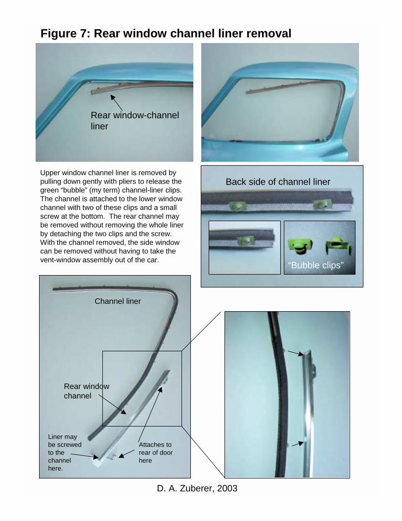
Upper window channel liner is removed by pulling down gently with pliers to release the green “bubble” (my term) channel-liner clips. The channel is attached to the lower window channel with two of these clips and a small screw at the bottom. The rear channel may be removed without removing the whole liner by detaching the two clips and the screw. With the channel removed, the side window can be removed without having to take the vent-window assembly out of the car.
Liner may be screwed to the channel here.
Attaches to rear of door here
“Bubble clips”
Back side of channel liner
Figure 7: Rear window channel liner removal
Rear window-channelliner
Rear window channel
Channel liner
D. A. Zuberer, 2003
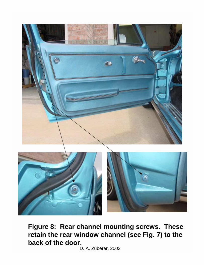
Figure 8: Rear channel mounting screws. These retain the rear window channel (see Fig. 7) to the back of the door.
D. A. Zuberer, 2003
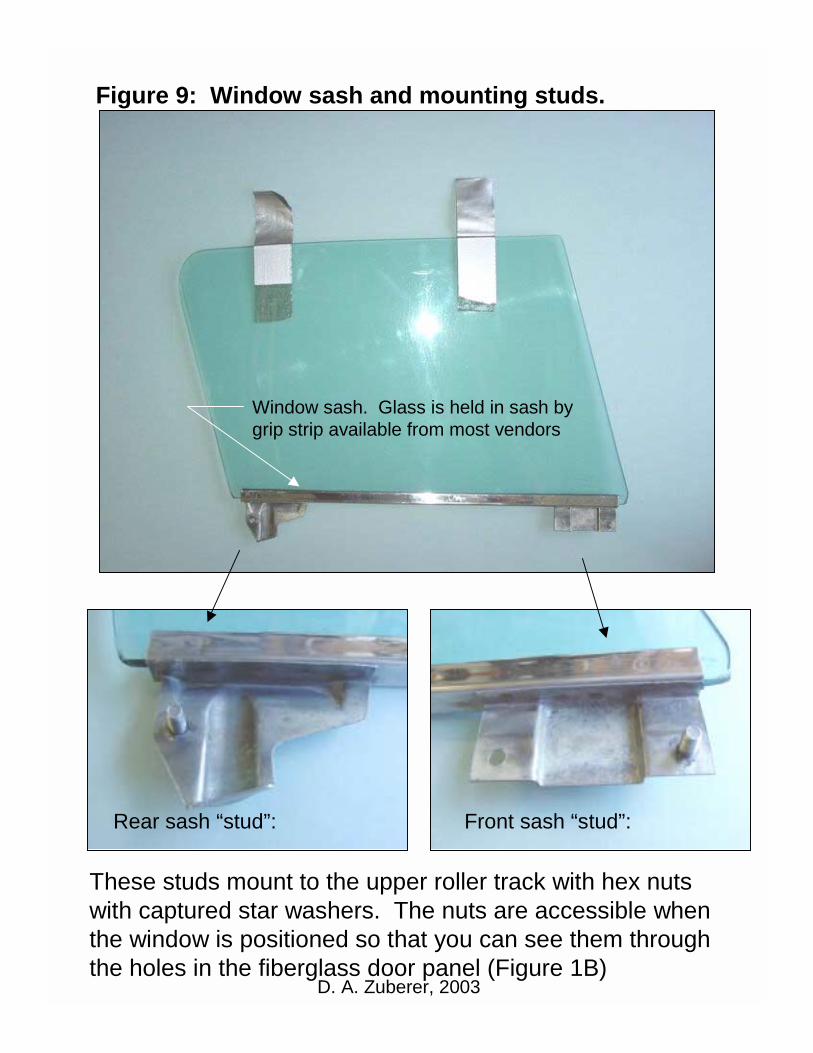
Window sash. Glass is held in sash by grip strip available from most vendors
Rear sash “stud”: Front sash “stud”:
These studs mount to the upper roller track with hex nuts with captured star washers. The nuts are accessible when the window is positioned so that you can see them through the holes in the fiberglass door panel (Figure 1B)
Figure 9: Window sash and mounting studs.
D. A. Zuberer, 2003

T-post
Hinge pivot rivet peened with hammer and punches while vent assembly was out of car.
This is a vent window pivot hinge that has been replaced earlier. Note poor welding.
New rubber in place
Stud on bottom of vent window assembly (see Fig.1B)
Front window-channel liner is mounted in this channelIf replacing this, be sure to buy the pre-curved pieces.
Front channel liner
(see Fig. 5)
Figure 10: Vent-window assembly
D. A. Zuberer, 2003

Vent-window mounting screws (4)
Peel back door weather strip to reveal the 4 small screws retaining the vent-window assembly to the door frame.
Figure 11: Vent window screw locations
Large screw found in small pocket at inside top of door in this location.
D. A. Zuberer, 2003