m.i.e.t. engineering college/ dept. of mechanical ... · diagram - actual and theoretical p-v...
TRANSCRIPT

M.I.E.T. ENGINEERING COLLEGE/ DEPT. of Mechanical Engineering
M.I.E.T. /Mech. / II /TE
M.I.E.T. ENGINEERING COLLEGE
(Approved by AICTE and Affiliated to Anna University Chennai)
TRICHY – PUDUKKOTTAI ROAD, TIRUCHIRAPPALLI – 620 007
DEPARTMENT OF MECHANICAL ENGINEERING
COURSE MATERIAL
ME8494 THERMAL ENGINEERING
II YEAR - IV SEMESTER

M.I.E.T. ENGINEERING COLLEGE/ DEPT. of Mechanical Engineering
M.I.E.T. /Mech. / II /TE
M.I.E.T. ENGINEERING COLLEGE
(Approved by AICTE and Affiliated to Anna University Chennai)
TRICHY – PUDUKKOTTAI ROAD, TIRUCHIRAPPALLI – 620 007
DEPARTMENT OF MECHANICAL ENGINEERING
SYLLABUS (THEORY)
Sub. Code : ME8494 Branch / Year / Sem: MECH/II/IV Sub. Name : THERMAL ENGINEERING Staff Name : PANDIARAJ.V
L T P C 3 0 0 3
UNIT I GAS POWER CYCLES 8
Otto, Diesel, Dual, Brayton cycles, Calculation of mean effective pressure, and air standard efficiency- Comparison of cycles.
UNIT II INTERNAL COMBUSTION ENGINES 10 Classification - Components and their function. Valve timing diagram and port timing
diagram - actual and theoretical p-V diagram of four stroke and two stroke engines. Simple and complete Carburetor. MPFI, Diesel pump and injector system. Battery and Magneto Ignition System - Principles of Combustion and knocking in SI and CI Engines. Lubrication and Cooling systems. Performance calculation.
UNIT III STEAM NOZZLES AND TURBINES 9 Flow of steam through nozzles, shapes of nozzles, effect of friction, critical pressure
ratio, supersaturated flow. Impulse and Reaction principles, compounding, velocity diagram for
simple and multi-stage turbines, speed regulations –Governors.
UNIT IV AIR COMPRESSOR 9 Classification and working principle of various types of compressors, work of compression with and without clearance, Volumetric efficiency, Isothermal efficiency and Isentropic efficiency of reciprocating compressors, Multistage air compressor and inter cooling –work of multistage air compressor
UNIT V REFRIGERATION AND AIR CONDITIONING 9 Refrigerants - Vapour compression refrigeration cycle- super heat, sub cooling –
Performance calculations - working principle of vapour absorption system, Ammonia –Water, Lithium bromide – water systems (Description only) . Air conditioning system - Processes, Types and Working Principles. - Concept of RSHF, GSHF, ESHF- Cooling Load calculations. TEXT BOOKS:
1. Rajput. R. K., ╉Thermal Engineering╊ S.Chand Publishers, 2000
2. Kothandaraman.C.P., Domkundwar. S,Domkundwar. A.V., ╉A course in thermal Engineering", Fifth Edition, ╊Dhanpat Rai & sons , 2002
REFERENCES:
1. Sarkar, B.K,╊Thermal Engineering╊ Tata McGraw-Hill Publishers, 2007
2. Arora.C.P, ╊Refrigeration and Air Conditioning ,╊ Tata McGraw-Hill Publishers 1994
3. Ganesan V..╊ Internal Combustion Engines╊ , Third Edition, Tata Mcgraw -Hill 2007
4. Rudramoorthy, R, ╉Thermal Engineering ╉,Tata McGraw-Hill, New Delhi,2003
5. Ramalingam. K.K., "Thermal Engineering", SCITECH Publications (India) Pvt. Ltd., 2009.
SUBJECT IN-CHARGE HOD

M.I.E.T. ENGINEERING COLLEGE/ DEPT. of Mechanical Engineering
M.I.E.T. /Mech. / II /TE
M.I.E.T. ENGINEERING COLLEGE
(Approved by AICTE and Affiliated to Anna University Chennai)
TRICHY – PUDUKKOTTAI ROAD, TIRUCHIRAPPALLI – 620 007
DEPARTMENT OF MECHANICAL ENGINEERING
COURSE OBJECTIVE 1.To integrate the concepts, laws and methodologies from the first course in
thermodynamics into analysis of cyclic processes
2.To apply the thermodynamic concepts into various thermal application like IC engines,
Steam.
3.Turbines, Compressors and Refrigeration and Air conditioning systems
(Use of standard refrigerant property data book, Steam Tables, Mollier diagram and
Psychrometric chart permitted)
COURSE OUTCOMES 1.Calculate the efficiency of various gas power cycles.
2.Compute the performance test on IC engines
3.Estimate the concert of single and multi stage steam turbines
4.Apply the thermodynamic concepts in various thermal systems.
5.Calculate the properties of air vapor mixtures using psychrometrics
6.Explain the importance of efficient energy utilisation in engineering practices and its
impact on the environment
Prepared by Verified By
V.PANDIARAJ HOD AP/MECH
Approved by
PRINCIPAL
Sub. Code : ME8494 Branch/Year/Sem : MECH/II/IV Sub Name : THERMAL ENGINEERING Staff Name : PANDIARAJ.V

M.I.E.T. ENGINEERING COLLEGE/ DEPT. of Mechanical Engineering
M.I.E.T. /Mech. / II /TE
M.I.E.T. ENGINEERING COLLEGE
(Approved by AICTE and Affiliated to Anna University Chennai)
TRICHY – PUDUKKOTTAI ROAD, TIRUCHIRAPPALLI – 620 007
TECHNICAL TERMS:
1. Gas Power Cycles:
Working fluid remains in the gaseous state through the cycle. Sometimes useful to study
an idealised cycle in which internal irreversibilities and complexities are removed Such
cycles are called Air Standard Cycles
2. The mean effective pressure (MEP)
A fictitious pressure that, if it were applied to the piston during the power stroke, would
produce the same amount of net work as that produced during the actual cycle.
3. Thermodynamics:
is the science of the relations between heat ,work a d the properties of system
4. Boundary:
System is a fixed and identifiable collection of matter enclosed by a real or imaginary
surface which is impermeable to matter but w ich may change its shape or volume. The
surface is called the boundary
5. Surroundings:
Everything outside the syst m which has a direct bearing on the system's behaviour.
6. ExtensivePropety:
Extensive properties are those whose value is the sum of the values for each subdivision
of the system, eg mass, volume.
7. IntensivePropety:
Properties are those which have a finite value as the size of the system approaches
zero, eg pressure, temperature, etc.
8. Equilibrium:
A system is in thermodynamic equilibrium if no tendency towards spontaneous change
M.I.E.T. ENGINEERING COLLEGE/ DEPT. of Mechanical Engineering
M.I.E.T. /Mech. / II /TE
exists within the system. Energy transfers across the system disturb the equilibrium state
of the system but may not shift the system significantly from its equilibrium state f
carried out at low rates of change. I mentioned earlier that to define the properties of a
system, they have to be uniform throughout the system.
Therefore to define the state of system, the system must be in equilibrium.
(Inequilibrium of course implies non-uniformity of one or more properties).
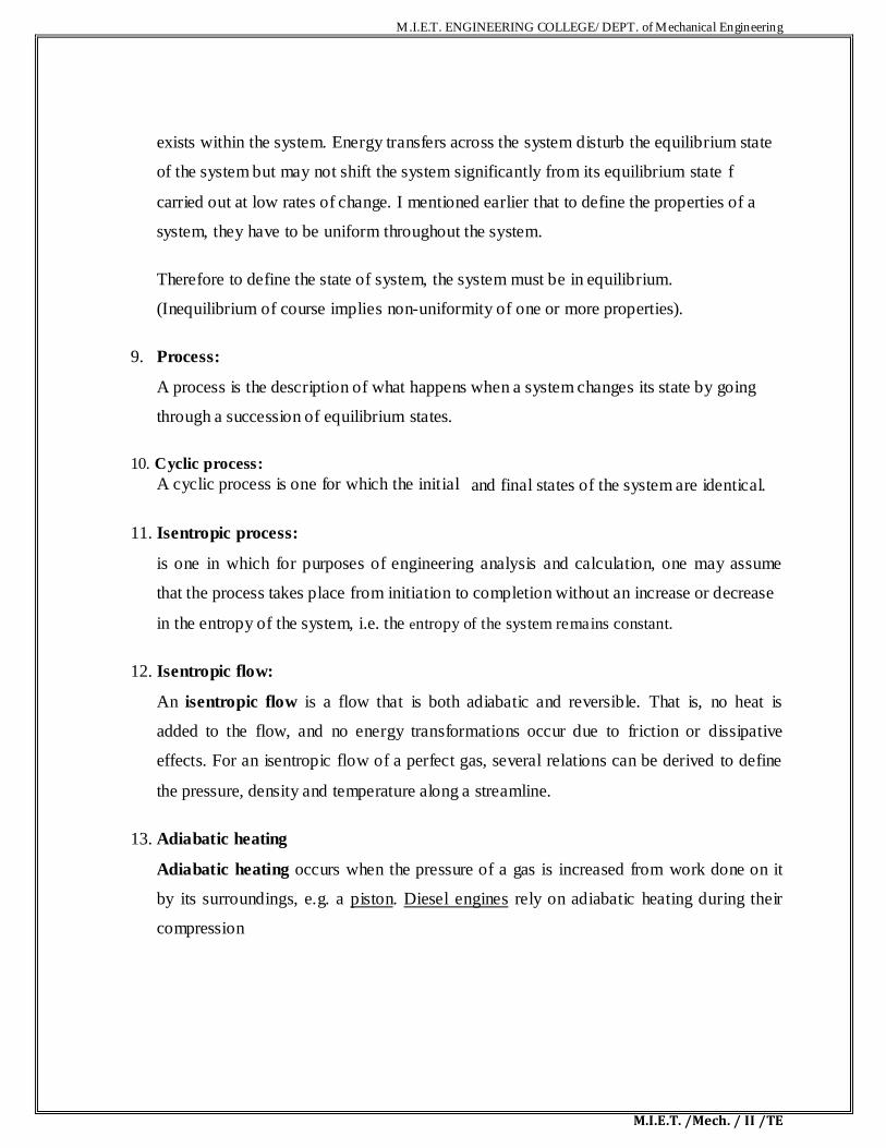
9. Process:
A process is the description of what happens when a system changes its state by going
through a succession of equilibrium states.
10. Cyclic process:
A cyclic process is one for which the initial and final states of the system are identical.
11. Isentropic process:
is one in which for purposes of engineering analysis and calculation, one may assume
that the process takes place from initiation to completion without an increase or decrease
in the entropy of the system, i.e. the entropy of the system remains constant.
12. Isentropic flow:
An isentropic flow is a flow that is both adiabatic and reversible. That is, no heat is
added to the flow, and no energy transformations occur due to friction or dissipative
effects. For an isentropic flow of a perfect gas, several relations can be derived to define
the pressure, density and temperature along a streamline.
13. Adiabatic heating
Adiabatic heating occurs when the pressure of a gas is increased from work done on it
by its surroundings, e.g. a piston. Diesel engines rely on adiabatic heating during their
compression
M.I.E.T. ENGINEERING COLLEGE/ DEPT. of Mechanical Engineering
M.I.E.T. /Mech. / II /TE
14. Adiabatic cooling:
Adiabatic cooling occurs when the pressure of a substance is decreased as t does work
on its surroundings. Adiabatic cooling occurs in the Earth's atmosphere with corograph
lifting and lee waves, When the pressure applied on a parcel of air decreases, the air in
the parcel is allowed to expand; as the volume increases, the temperature and internal
energy decreases

M.I.E.T. ENGINEERING COLLEGE/ DEPT. of Mechanical Engineering
M.I.E.T. /Mech. / II /TE
UNIT-I
GAS POWER CYCLES 1.1.Introduction to gas power cycles 1.2.1 Derivation of Air Standard efficiency of the Otto Cycle The Otto cycle, which was first proposed by a Frenchman, Beau de Rochas in 1862, was first
used on an engine built by a German, Nicholas A. Otto, in 1876. The cycle is a so ca led a
constant volume or explosion cycle. This is the equivalent air cycle for reciprocating piston
engines using spark ignition. Figures 1 and 2 show the P-V and T-s diagrams respectively.
At the start of the cycle, the cylinder contains a mass M of air at the pressure and volume indicated at point 1 The piston is at its lowest position. It moves upward and the gas is
compressed isentropic ally to point 2. At this point, heat is added at constant volume which
raises the pressure to point 3. The high pressure charge now expands isentropic ally, pushing the
piston down on its expansion stroke to point 4 where the charge rejects heat at constant volume
to the initial state, point. The isothermal heat addition and rejection of the Carnot cycle are replaced by the constant volume processes which are, theoretically more plausible, although in practice, even these
Processes are not practicable.

M.I.E.T. ENGINEERING COLLEGE/ DEPT. of Mechanical Engineering
M.I.E.T. /Mech. / II /TE
The heat supplied, Qs, per unit mass of charge, is given
by cv(T3 - T2)
The heat rejected, Qr per unit mass of charge is given
by cv(T4 - T1)
and the thermal efficiency is given by Hence, substituting in Eq 3, we get, assuming that r is the compression ratio V1/V2
M.I.E.T. ENGINEERING COLLEGE/ DEPT. of Mechanical Engineering
M.I.E.T. /Mech. / II /TE
In a true thermodynamic cycle, the term expansion ratio and compression ratio are
synonymous. However, in a real engine, these two ratios need not be equal because of the
valve timing and therefore the term expansion ratio is preferred sometimes.
Equation 4 shows that the thermal efficiency of the theoretical Otto cycle increases with increase
in compression ratio and specific heat ratio but is independent of the heat added (independent of
load) and initial conditions of pressure, volume and temper ture.
1.2.2 Derivation of Mean effective pressure and air standard efficiency
It is seen that the air standard efficiency of the Otto cycle depends only on the compression ratio.
However, the pressures and temperatures at the various poi ts in the cycle and the net work done,
all depend upon the initial pressure and temperature a d the heat i put from point 2 to point 3,
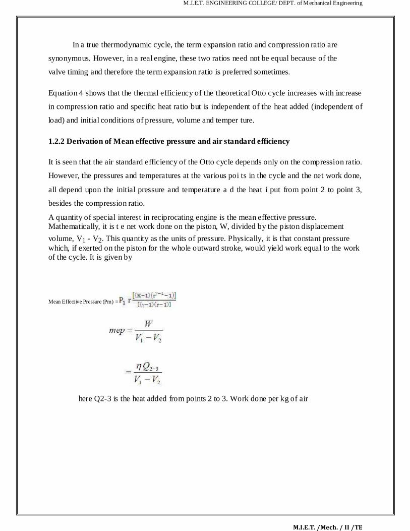
besides the compression ratio. A quantity of special interest in reciprocating engine is the mean effective pressure. Mathematically, it is t e net work done on the piston, W, divided by the piston displacement
volume, V1 - V2. This quantity as the units of pressure. Physically, it is that constant pressure which, if exerted on the piston for the whole outward stroke, would yield work equal to the work of the cycle. It is given by Mean Effective Pressure (Pm) =
here Q2-3 is the heat added from points 2 to 3. Work done per kg of air
M.I.E.T. ENGINEERING COLLEGE/ DEPT. of Mechanical Engineering
M.I.E.T. /Mech. / II /TE
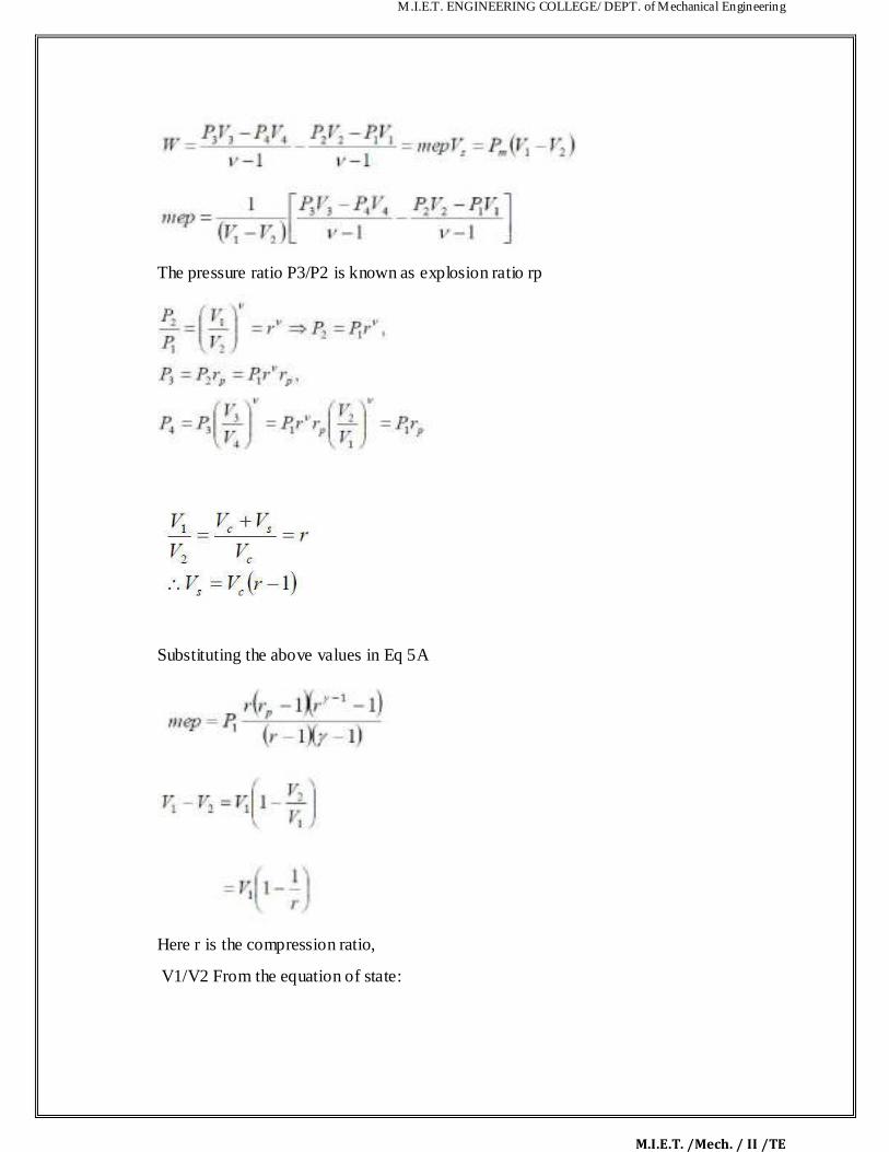
The pressure ratio P3/P2 is known as explosion ratio rp
Substituting the above values in Eq 5A
Here r is the compression ratio,
V1/V2 From the equation of state:

M.I.E.T. ENGINEERING COLLEGE/ DEPT. of Mechanical Engineering
M.I.E.T. /Mech. / II /TE
R0 is the universal gas constant Substituting for V1 and for V1 – V2 ,
The quantity Q2-3/M is the heat added between points 2 and 3 per un t mass of air (M is the
mass of air and m is the molecular weight of air); and is denoted by Q‟ , thus
We can non-dimensionalise the mep by dividing it by p1 so that we can obtain the following
equation
The dimensionless quantity mep/p1 is a function of the heat added, initial temperature,
compression ratio and the properties of air, namely, cv and γ. We see that the mean effective
pressure is directly proportional to the heat added and inversely proportional to the initial (or
ambient) temperature. We can substitute the value of η from Eq. 8 in Eq. 14 and obtain the value

M.I.E.T. ENGINEERING COLLEGE/ DEPT. of Mechanical Engineering
M.I.E.T. /Mech. / II /TE
of mep/p1 for the Otto cycle in terms of the compression ratio and heat added. In terms of the
pressure ratio, p3/p2 denoted by rp we could obtain the value of mep/p1 as follows: We can obtain a value of rp in terms of Q‟ as follows:
Choice of Q’ We have said that,
M is the mass of charge (air) per cycle, kg. Now, in an actual engine
Mf is the mass of fuel supplied per cycle, kg
Qc is the heating value of the fuel, Kj/kg
Ma is the mass of air taken in per cycle
F is the fuel air ratio = Mf/Ma
Substituting,
M.I.E.T. ENGINEERING COLLEGE/ DEPT. of Mechanical Engineering
M.I.E.T. /Mech. / II /TE
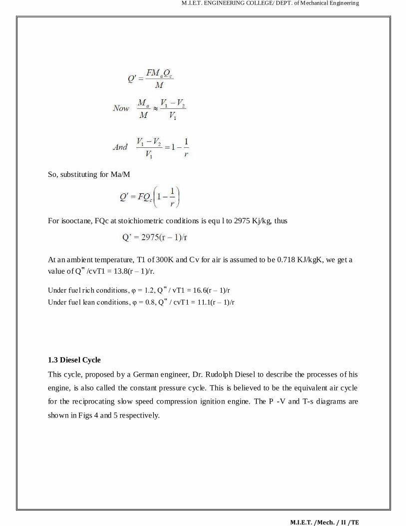
So, substituting for Ma/M
For isooctane, FQc at stoichiometric conditions is equ l to 2975 Kj/kg, thus
At an ambient temperature, T1 of 300K and Cv for air is assumed to be 0.718 KJ/kgK, we get a
value of Q‟ /cvT1 = 13.8(r – 1)/r.
Under fuel rich conditions, φ = 1.2, Q‟ / vT1 = 16.6(r – 1)/r
Under fuel lean conditions, φ = 0.8, Q‟ / cvT1 = 11.1(r – 1)/r 1.3 Diesel Cycle This cycle, proposed by a German engineer, Dr. Rudolph Diesel to describe the processes of his
engine, is also called the constant pressure cycle. This is believed to be the equivalent air cycle
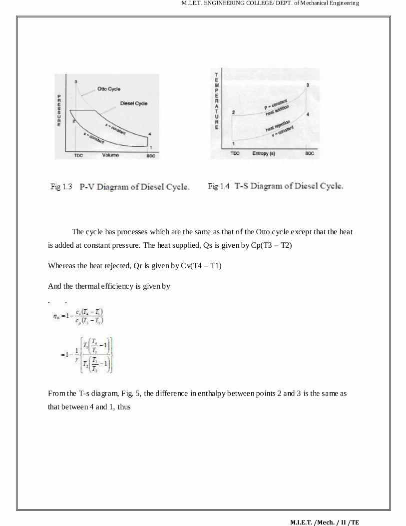
for the reciprocating slow speed compression ignition engine. The P -V and T-s diagrams are
shown in Figs 4 and 5 respectively.
M.I.E.T. ENGINEERING COLLEGE/ DEPT. of Mechanical Engineering
M.I.E.T. /Mech. / II /TE
The cycle has processes which are the same as that of the Otto cycle except that the heat
is added at constant pressure. The heat supplied, Qs is given by Cp(T3 – T2)
Whereas the heat rejected, Qr is given by Cv(T4 – T1)
And the thermal efficiency is given by
From the T-s diagram, Fig. 5, the difference in enthalpy between points 2 and 3 is the same as
that between 4 and 1, thus

M.I.E.T. ENGINEERING COLLEGE/ DEPT. of Mechanical Engineering
M.I.E.T. /Mech. / II /TE
Substituting in eq.
When Eq. 26 is compared with Eq. 8, it is seen that the expressions are similar except for the
term in the parentheses for the Diesel cycle. It can be shown that this term is always greater than
unity.
Thus, the thermal efficiency of the Diesel cycle can be written as

M.I.E.T. ENGINEERING COLLEGE/ DEPT. of Mechanical Engineering
M.I.E.T. /Mech. / II /TE
Let re = r – since r is greater than re. Here, is a small quantity. We therefore
We can expand the last term binomially so that
Since the coefficients of etc are greater than unity, the quantity in the brackets in Eq.
28 will be greater than unity. Hence, for the Diesel cycle, we subtract times a quantity greater
than unity from one, hence for the same r, the Otto cycle effic iency is greater than that for a
Diesel cycle.
M.I.E.T. ENGINEERING COLLEGE/ DEPT. of Mechanical Engineering
M.I.E.T. /Mech. / II /TE
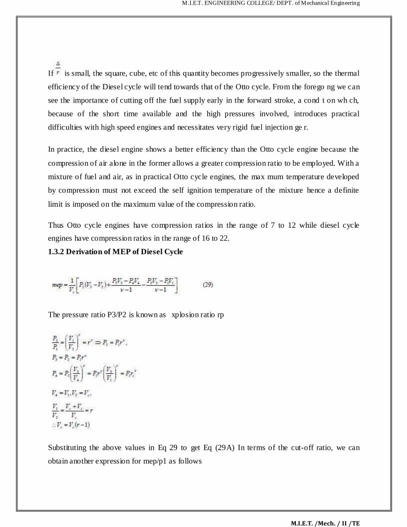
If is small, the square, cube, etc of this quantity becomes progressively smaller, so the thermal
efficiency of the Diesel cycle will tend towards that of the Otto cycle. From the forego ng we can
see the importance of cutting off the fuel supply early in the forward stroke, a cond t on wh ch,
because of the short time available and the high pressures involved, introduces practical
difficulties with high speed engines and necessitates very rigid fuel injection ge r.
In practice, the diesel engine shows a better efficiency than the Otto cycle engine because the
compression of air alone in the former allows a greater compression ratio to be employed. With a
mixture of fuel and air, as in practical Otto cycle engines, the max mum temperature developed
by compression must not exceed the self ignition temperature of the mixture hence a definite
limit is imposed on the maximum value of the compression ratio.
Thus Otto cycle engines have compression ratios in the range of 7 to 12 while diesel cycle
engines have compression ratios in the range of 16 to 22.
1.3.2 Derivation of MEP of Diesel Cycle The pressure ratio P3/P2 is known as xplosion ratio rp
Substituting the above values in Eq 29 to get Eq (29A) In terms of the cut-off ratio, we can
obtain another expression for mep/p1 as follows
M.I.E.T. ENGINEERING COLLEGE/ DEPT. of Mechanical Engineering
M.I.E.T. /Mech. / II /TE
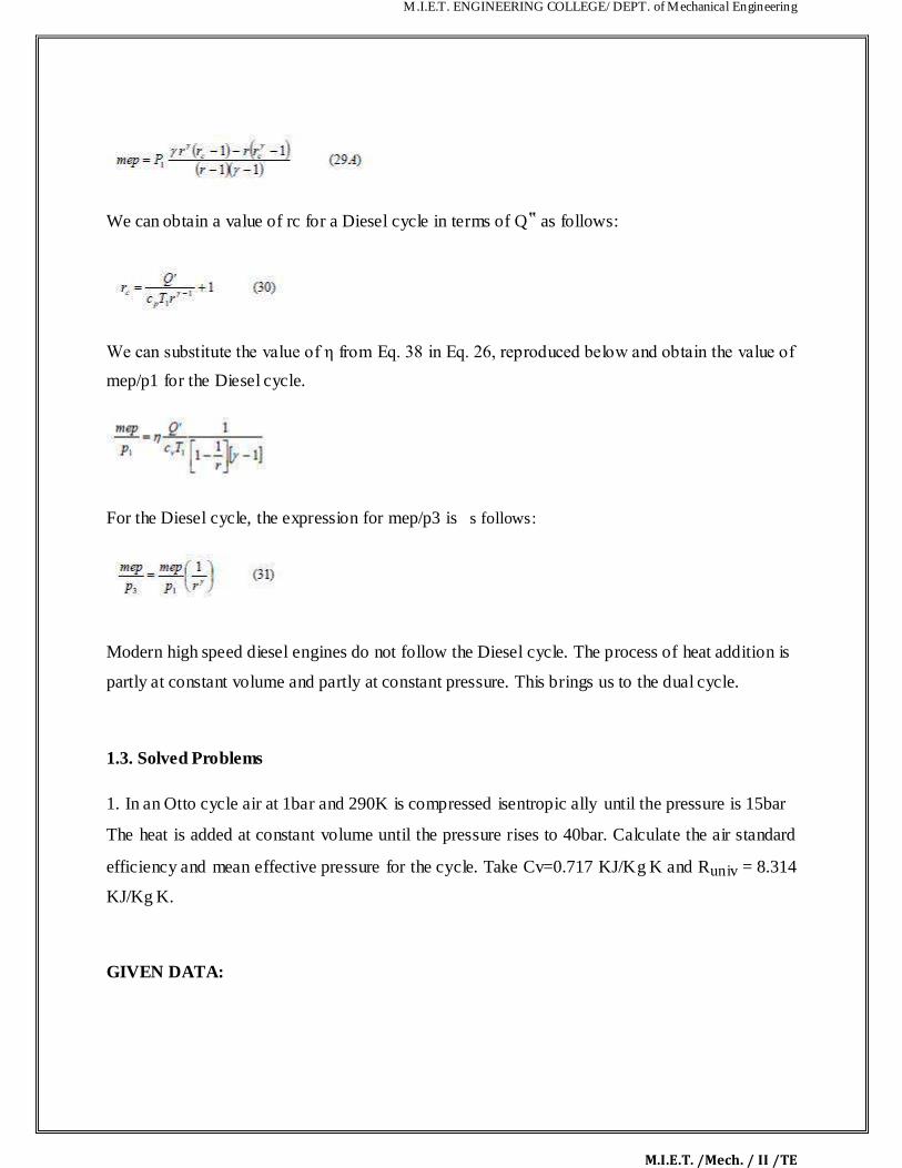
We can obtain a value of rc for a Diesel cycle in terms of Q‟ as follows: We can substitute the value of η from Eq. 38 in Eq. 26, reproduced below and obtain the value of mep/p1 for the Diesel cycle. For the Diesel cycle, the expression for mep/p3 is s follows:
Modern high speed diesel engines do not follow the Diesel cycle. The process of heat addition is
partly at constant volume and partly at constant pressure. This brings us to the dual cycle.
1.3. Solved Problems
1. In an Otto cycle air at 1bar and 290K is compressed isentropic ally until the pressure is 15bar The heat is added at constant volume until the pressure rises to 40bar. Calculate the air standard
efficiency and mean effective pressure for the cycle. Take Cv=0.717 KJ/Kg K and Runiv = 8.314
KJ/Kg K. GIVEN DATA:

M.I.E.T. ENGINEERING COLLEGE/ DEPT. of Mechanical Engineering
M.I.E.T. /Mech. / II /TE
Pressure (P1) = 1bar = 100KN/m2
Temperature(T1) = 290K
Pressure (P2) = 15bar = 1500KN/m2
Pressure (P3) = 40bar = 4000KN/m2
Cv = 0.717 KJ/KgK
Runiv = 8.314 KJ/Kg K
TO FIND:
i) Air Standard Efficiency (ηotto) ii) Mean Effective Pressure (Pm)
SOLUTION:
Here it is given Runiv = 8.314 KJ/Kg K
We know that,
(Here Cp is unknown)
Runiv = M R
Since For air (O2) molecular w ight (M) = 28.97
8.314=28.97 R ∴ R = 0.2869
(Since gas constant R = Cp-Cv )
0.2869 = Cp – 0.717

M.I.E.T. ENGINEERING COLLEGE/ DEPT. of Mechanical Engineering
M.I.E.T. /Mech. / II /TE
η
Here „r‟ is unknown.
We know that,
∴ r = 6.919
ηotto ∴ ηotto = 53.87%
Mean Effective Pressure (Pm) =
Pm =
2 Pm = 569.92 KN/m
M.I.E.T. ENGINEERING COLLEGE/ DEPT. of Mechanical Engineering
M.I.E.T. /Mech. / II /TE
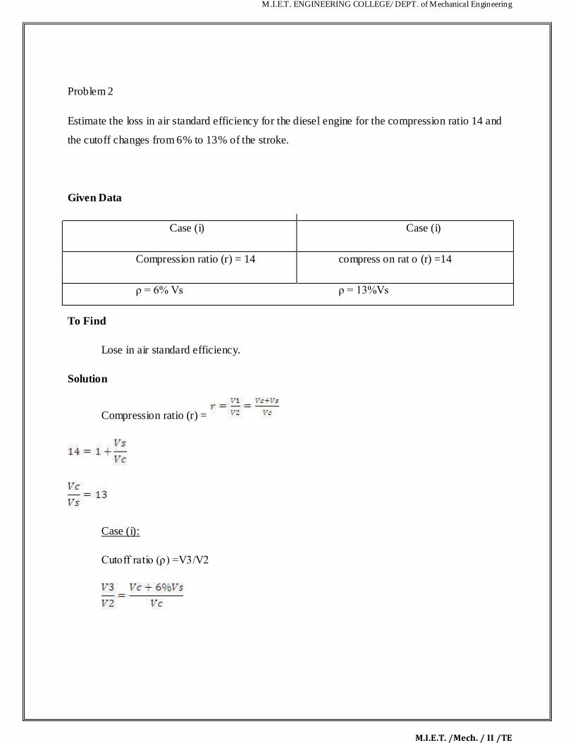
Problem 2
Estimate the loss in air standard efficiency for the diesel engine for the compression ratio 14 and
the cutoff changes from 6% to 13% of the stroke.
Given Data
Case (i) Case (i)
Compression ratio (r) = 14 compress on rat o (r) =14
ρ = 6% Vs ρ = 13%Vs
To Find
Lose in air standard efficiency.
Solution
Compression ratio (r) =
Case (i):
Cutoff ratio (ρ) =V3/V2

M.I.E.T. ENGINEERING COLLEGE/ DEPT. of Mechanical Engineering
M.I.E.T. /Mech. / II /TE
ρ =
ρ = 1.78
We know that,
ηdiesel
= 0.6043
ηdiesel = 60.43%
case (ii):
cutoff ratio (ρ)
=1+(0.13) (13)
ρ = 2.69
ηdiesel
= 1- (0.24855) (1.7729)
M.I.E.T. ENGINEERING COLLEGE/ DEPT. of Mechanical Engineering
M.I.E.T. /Mech. / II /TE
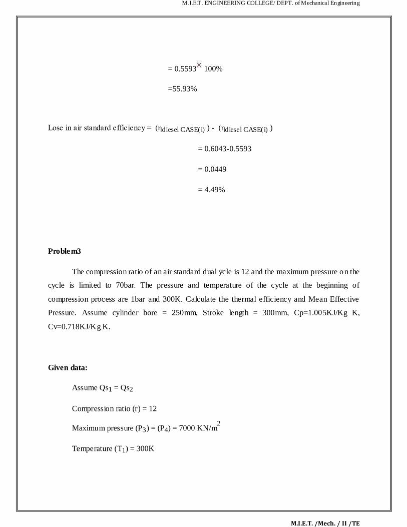
= 0.5593 100%
=55.93%
Lose in air standard efficiency = (ηdiesel CASE(i) ) - (ηdiesel CASE(i) )
= 0.6043-0.5593
= 0.0449
= 4.49%
Problem3
The compression ratio of an air standard dual ycle is 12 and the maximum pressure on the
cycle is limited to 70bar. The pressure and temperature of the cycle at the beginning of
compression process are 1bar and 300K. Calculate the thermal efficiency and Mean Effective
Pressure. Assume cylinder bore = 250mm, Stroke length = 300mm, Cp=1.005KJ/Kg K,
Cv=0.718KJ/Kg K.
Given data:
Assume Qs1 = Qs2
Compression ratio (r) = 12
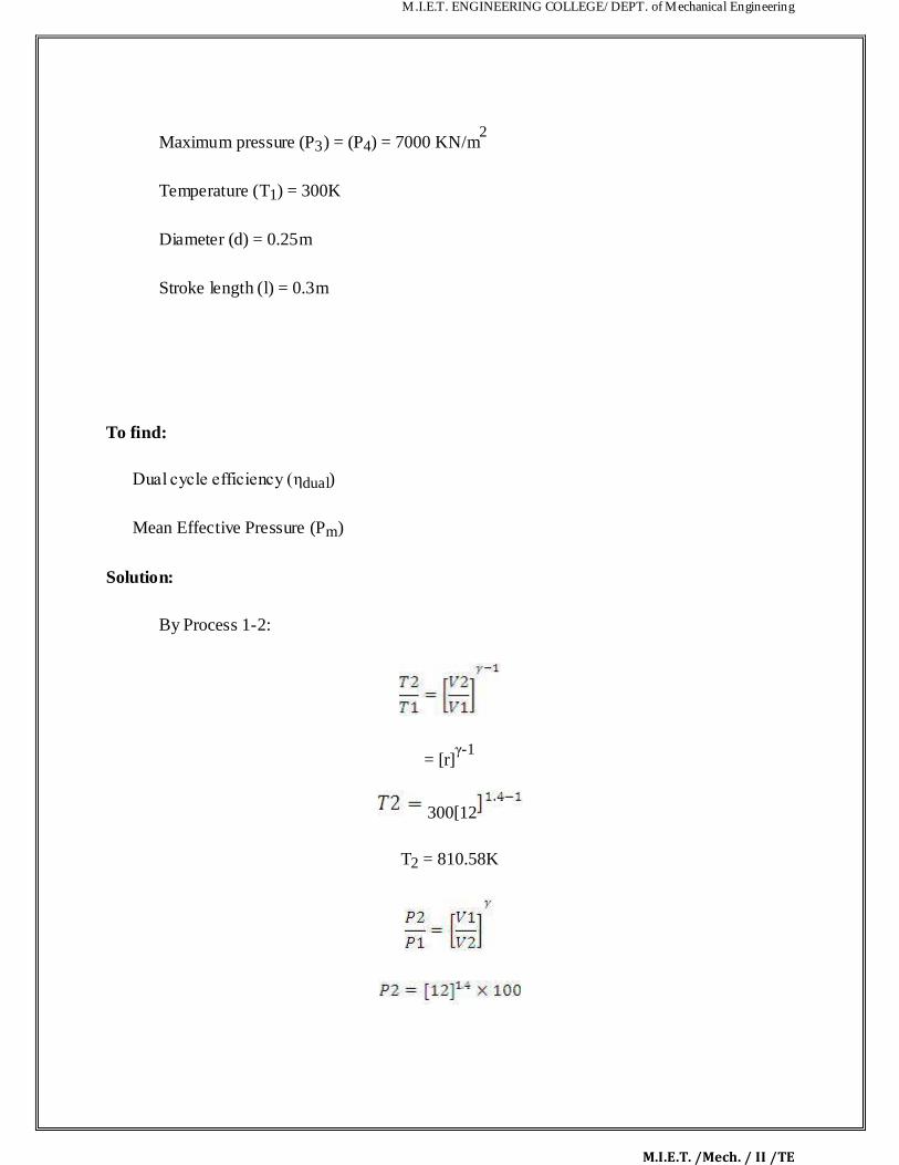
Maximum pressure (P3) = (P4) = 7000 KN/m2
Temperature (T1) = 300K

M.I.E.T. ENGINEERING COLLEGE/ DEPT. of Mechanical Engineering
M.I.E.T. /Mech. / II /TE
Diameter (d) = 0.25m
Stroke length (l) = 0.3m
To find:
(i) Dual cycle efficiency (ηdual) (ii) Mean Effective Pressure (Pm)
Solution:
By Process 1-2:
= [r]γ-1
300[12
T2 = 810.58K
P2 = 3242.3KN/m2
By process 2-3:
M.I.E.T. ENGINEERING COLLEGE/ DEPT. of Mechanical Engineering
M.I.E.T. /Mech. / II /TE
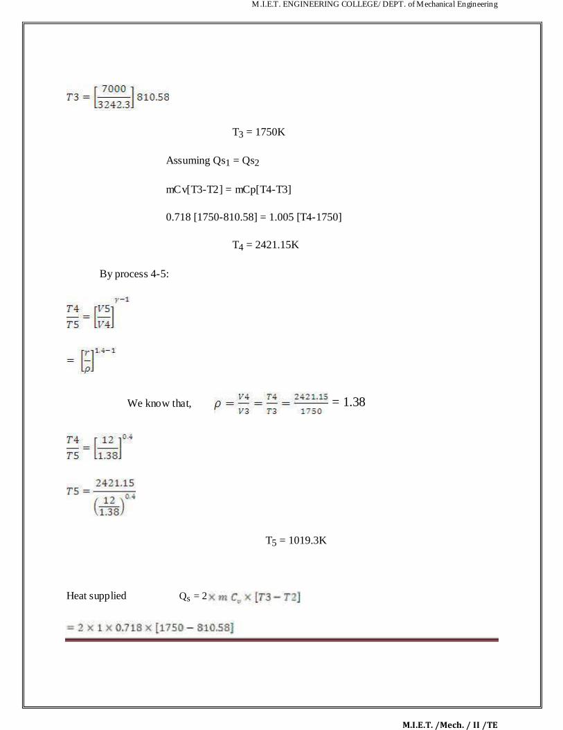
T3 = 1750K
Assuming Qs1 = Qs2
mCv[T3-T2] = mCp[T4-T3]
0.718 [1750-810.58] = 1.005 [T4-1750]
T4 = 2421.15K
By process 4-5:
We know that, = 1.38
T5 = 1019.3K
Heat supplied Qs = 2

M.I.E.T. ENGINEERING COLLEGE/ DEPT. of Mechanical Engineering
M.I.E.T. /Mech. / II /TE
Qs = 1349KJ/Kg
Heat rejected
T1]
Qr = 516.45 KJ/Kg
ηdual
ηdual
= 61.72%
Stroke volume
(Vs) =
Vs = 0.0147m3
Mean effective pressure ( pm)
= 832.58/0.0147
Pm = 56535 KN/m2

M.I.E.T. ENGINEERING COLLEGE/ DEPT. of Mechanical Engineering
M.I.E.T. /Mech. / II /TE
1.4 Dual Cycle
P-V Diagram of Dual Cycle.
Process 1-2: Reversible adiabatic compression. Process 2-3: Constant volume heat addition. Process 3-4: Constant pressure heat addition. Process 4-5: Reversible adiabatic expansion. Process 5-1: Constant volume heat reject
T-S Diagram of Dual Combustion Cycle.

M.I.E.T. ENGINEERING COLLEGE/ DEPT. of Mechanical Engineering
M.I.E.T. /Mech. / II /TE
1.4.1 Derivation of Dual Combustion Cycle
The cycle is the equivalent air cycle for reciprocating igh speed compression ignition engines.
The P-V and T-s diagrams are shown in Figs.6 and 7. In the cycle, compression and expansion
processes are isentropic; heat addition is partly at onstant volume and partly at constant pressure
while heat rejection is at constant volume as in the case of the Otto and Diesel cycles.
The heat supplied, Qs per unit ass of charge is given by cv(T3 – T2) + cp(T3‟ – T2) (32)
whereas the heat rejected, Qr per unit of
mass of charge is given
cv(T4 – T1)
and the thermal efficiency is given by
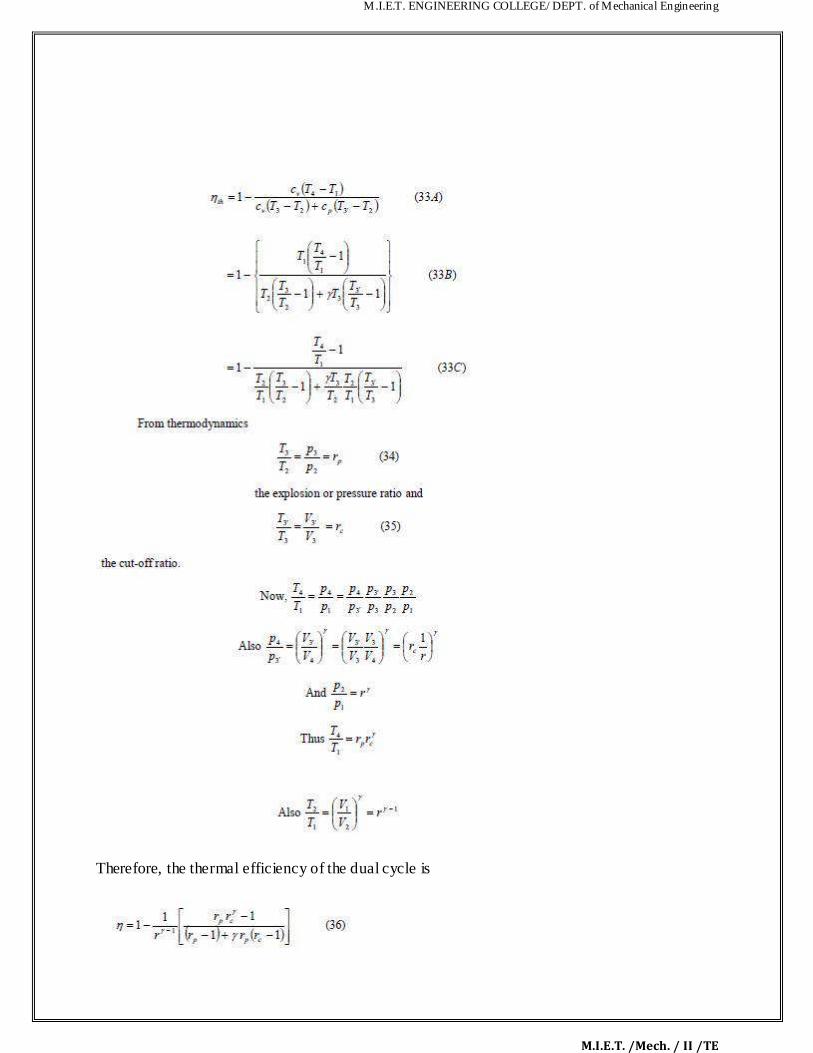
M.I.E.T. ENGINEERING COLLEGE/ DEPT. of Mechanical Engineering
M.I.E.T. /Mech. / II /TE
Therefore, the thermal efficiency of the dual cycle is

M.I.E.T. ENGINEERING COLLEGE/ DEPT. of Mechanical Engineering
M.I.E.T. /Mech. / II /TE
We can substitute the value of η from Eq. 36 in Eq. 14 and obtain the value of mep/p1 for the
dual cycle.
In terms of the cut-off ratio and pressure ratio, we can obtain another expression for mep/p1 as
follows:
For the dual cycle, the expression for mep/p3 is as follows: Since the dual cycle is also called the limited pressure cycle, the peak pressure, p3, is usually
specified. Since the initial pressure, p1, is known, t e ratio p3/p1 is known. We can correlate rp
with this ratio as follows: We can obtain an expression for rc in t rms of Q‟ and rp and other known quantities as follows:
We can also obtain an expression for rp in terms of Q‟ and rc and other known quantities as
follows:

M.I.E.T. ENGINEERING COLLEGE/ DEPT. of Mechanical Engineering
M.I.E.T. /Mech. / II /TE
1.5 The Brayton Cycle
The Brayton cycle is also referred to as the Joule cycle or the gas turbine air cycle
because all modern gas turbines work on this cycle. However, f the Brayton cycle is to be used
for reciprocating piston engines, it requires two cylinders, o e for compression and the other for
expansion. Heat addition may be carried out separately in a heat exchanger or within the
expander itself.
The pressure-volume and the corresponding temperature-entropy diagrams are shown in
Figs 10 and 11 respectively.

M.I.E.T. ENGINEERING COLLEGE/ DEPT. of Mechanical Engineering
M.I.E.T. /Mech. / II /TE
The cycle consists of an isentropic compression process, constant pressure heat addition
process, an isentropic expansion process and a constant pressure heat rejection process.
Expansion is carried out till the pressure drops to t e initial (atmospheric ) value.
Heat supplied in the cycle, Qs, is given by Cp (T3 – T2)
Heat rejected in the cycle, Qs, is giv n by Cp (T4 – T1)
Hence the thermal efficiency of the cycle is given by
M.I.E.T. ENGINEERING COLLEGE/ DEPT. of Mechanical Engineering
M.I.E.T. /Mech. / II /TE
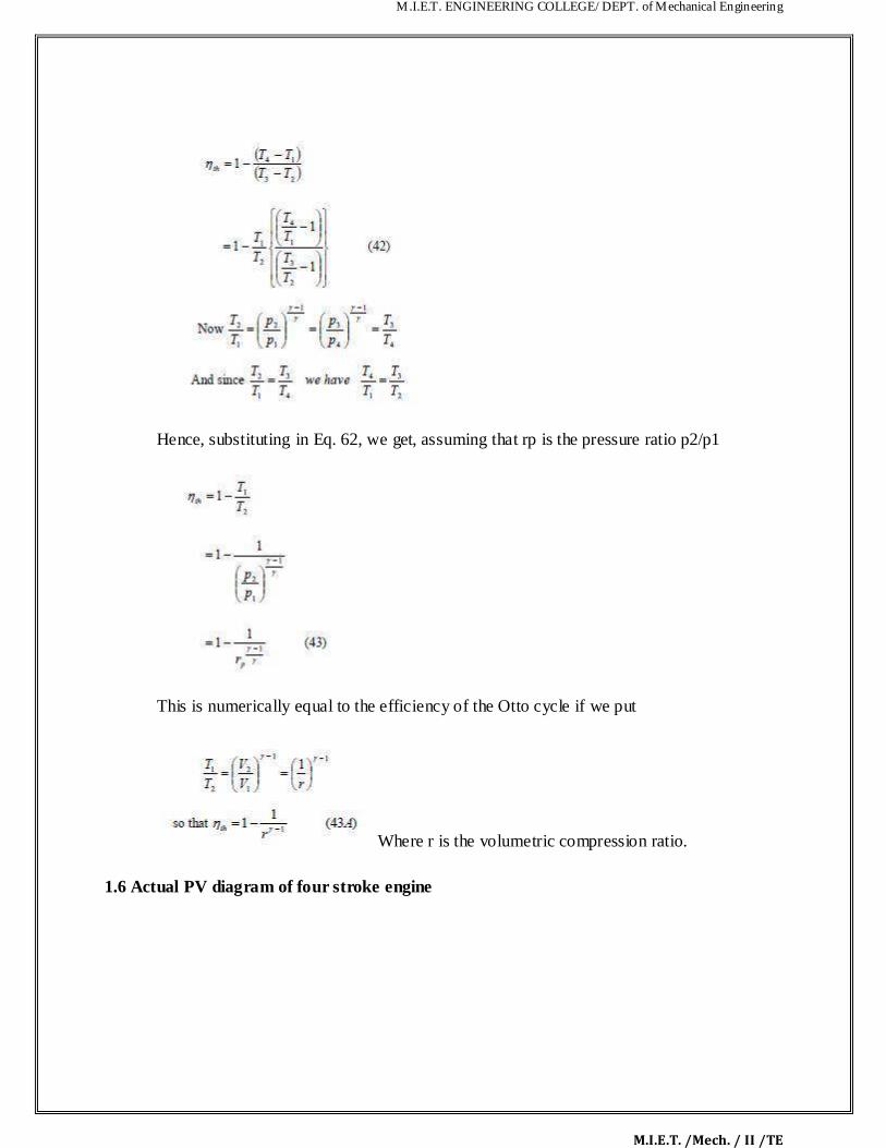
Hence, substituting in Eq. 62, we get, assuming that rp is the pressure ratio p2/p1
This is numerically equal to the efficiency of the Otto cycle if we put
Where r is the volumetric compression ratio.
1.6 Actual PV diagram of four stroke engine

M.I.E.T. ENGINEERING COLLEGE/ DEPT. of Mechanical Engineering
M.I.E.T. /Mech. / II /TE
1.9 Actual PV diagram of four stroke engine
Fig 1.10Theoretical PV diagram for four stroke engine

M.I.E.T. ENGINEERING COLLEGE/ DEPT. of Mechanical Engineering
M.I.E.T. /Mech. / II /TE
Fig 1.11 Theoretical and Actual PV diagram of two strokes Petrol Engine:
Solved Problems
4. The compression ratio of an air standard dual cycle is 12 and the maximum pressure
on the cycle is limited to 70bar. The pressure and temperature of the cycle at the beginning of
compression process are 1bar and 300K. Calculate the thermal efficiency and Mean Effective
Pressure. Assume cylinder bore = 250mm, Stroke length = 300mm, Cp=1.005KJ/Kg K,
Cv=0.718KJ/Kg K.
Given data:
Assume Qs1 = Qs2
Compression ratio (r) = 12
M.I.E.T. ENGINEERING COLLEGE/ DEPT. of Mechanical Engineering
M.I.E.T. /Mech. / II /TE
Maximum pressure (P3) = (P4) = 7000 KN/m2
Temperature (T1) = 300K
Diameter (d) = 0.25m
Stroke length (l) = 0.3m
To find:
Dual cycle efficiency (ηdual)
Mean Effective Pressure (Pm)
Solution:
By Process 1-2:
= [r]γ-1
300[12
T2 = 810.58K

M.I.E.T. ENGINEERING COLLEGE/ DEPT. of Mechanical Engineering
M.I.E.T. /Mech. / II /TE
P2 = 3242.3KN/m2
By process 2-3:
T3 = 1750K
Assuming Qs1 = Qs2
mCv[T3-T2] = mCp[T4-T3]
0.718 [1750-810.58] = 1.005 [T4-1750]
T4 = 2421.15K
By process 4-5:
We know that, = 1.38

M.I.E.T. ENGINEERING COLLEGE/ DEPT. of Mechanical Engineering
M.I.E.T. /Mech. / II /TE
T5 = 1019.3K
Heat supplied Qs = 2
Qs = 1349KJ/Kg
Heat rejected T1]
Qr = 516.45 KJ/Kg
ηdual
ηdual
= 61.72%
Stroke volume
(Vs) =
Vs = 0.0147m3

M.I.E.T. ENGINEERING COLLEGE/ DEPT. of Mechanical Engineering
M.I.E.T. /Mech. / II /TE
Mean effective pressure (pm)
= 832.58/0.0147
Pm = 56535 KN/m2
5. A diesel engine operating an air standard diesel cycle has 20 m bore nd 30cmstroke.the
clearance volume is 420cm3.if the fuel is injected at 5% of the stroke,f nd the air standard
efficiency. Given Data:-
Bore diameter (d) =20cm=0.2mk
Stroke, (l) =30cm=0.3m
Clearance volume, (v2 ) =420cm3=420/100
3= m
3
To Find:-
Air standard efficiency, (di s l)
Solution:-
Compression ratio, r = v1/v2
= (vc+vs)/vc
We know that,
Stroke volume, vs=area*length
=
M.I.E.T. ENGINEERING COLLEGE/ DEPT. of Mechanical Engineering
M.I.E.T. /Mech. / II /TE
= )
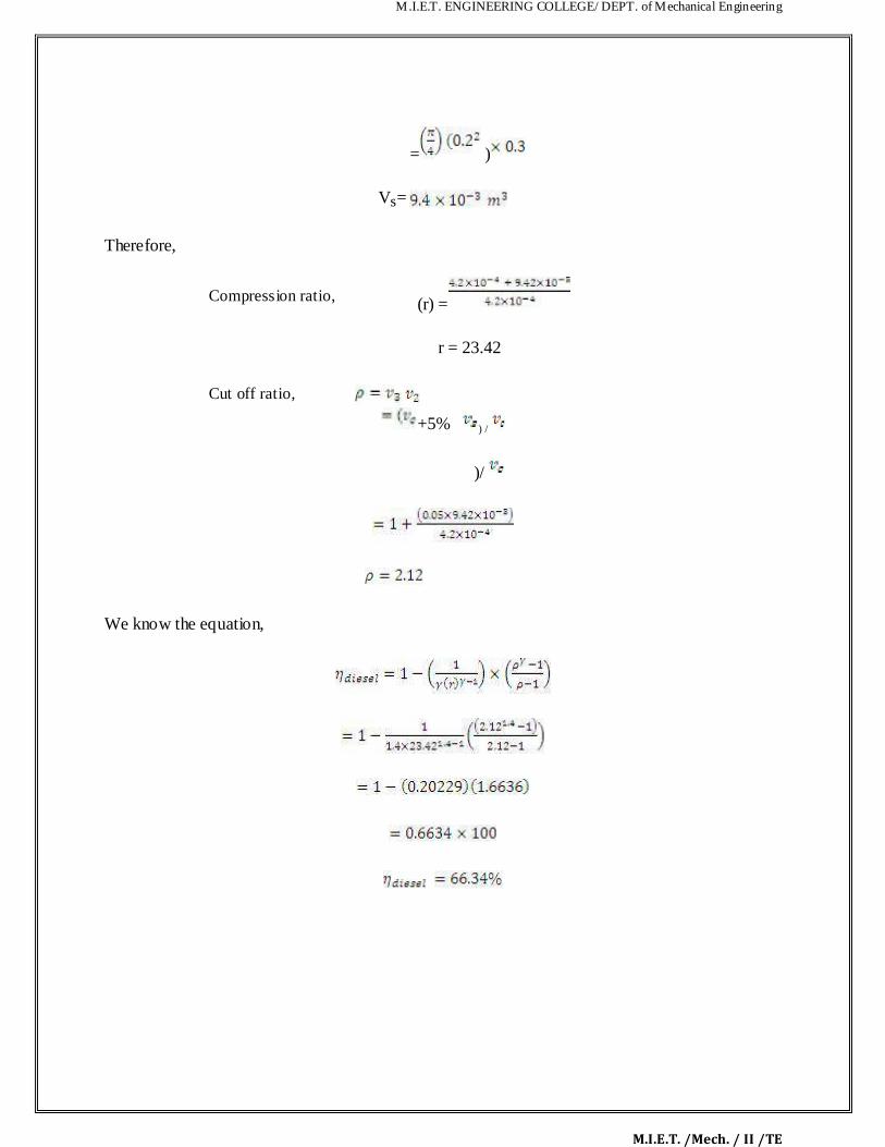
Vs=
Therefore,
Compression ratio,
(r) =
r = 23.42
Cut off ratio,
/
+5%
) /
)/
We know the equation,

M.I.E.T. ENGINEERING COLLEGE/ DEPT. of Mechanical Engineering
M.I.E.T. /Mech. / II /TE
TWO MARK UNIVERSITY QUESTIONS: 1. What is a thermodynamic cycle?
2. What is meant by air standard cycle?
3. Name the various “gas power cycles". 4. What are the assumptions made for air standard cycle analys s
5. Mention the various processes of the Otto cycle.
6. Mention the various processes of diesel cycle. 7. Mention the various processes of dual cycle.
9. Define air standard cycle efficiency.
10. Define mean effective pressure as applied to gas power cycles. How it is related to
indicate power of an I.C engine?
11. Define the following ter s. (i) Co pression ratio (ii) Cut off ratio, (iii) .Expansion ratio

M.I.E.T. ENGINEERING COLLEGE/ DEPT. of Mechanical Engineering
M.I.E.T. /Mech. / II /TE
UNIVERSITY ESSAY QUESTIONS:
1. Derive and expression for the air standard efficiency of Otto cycle n terms of volume
ratio. (16)
2. Drive an expression for the air standard efficiency of Diesel cycle. . (16)
3. Drive an expression for the air standard efficiency of Dual cycle. . (16)
4. Explain the working of 4 stroke cy le Diesel engine. Draw the theoretical and actual PV
diagram.
5. Drive the expression for air standard ffici ncy of Brayton cycle in terms of pressure ratio.
6. A Dual combustion air standard cycle has a compression ratio of 10. The constant pressure
part of combustion takes place at 40 bar. The highest and the lowest temperature of the cycle are
1725degree C and 27 0 C respectively. The pressure at the beginning of compression is 1 bar. Calculate (i) the pressure and temperature at‟ key points of the cycle. (ii) The heat supplied at
constant volume, (iii) the heat supplied at constant pressure. (iv) The heat rejected. (v) The work
output. (vi) The efficiency and (vii) mep. (16)
7. An Engine- orking on Otto cycle has a volume of 0.45 m3 , pressure 1 bar and temperature
30o,Cat the beginning of compression stroke. At the end of compression stroke, the pressure is 11 barand 210 KJ of heat is added at constant volume. Determine (i) Pressure, temperature and
volumes at salient points in the cycle.' (ii) Efficiency.

M.I.E.T. ENGINEERING COLLEGE/ DEPT. of Mechanical Engineering
M.I.E.T. /Mech. / II /TE
8. Explain the working of 4-stroke cycle Diesel engine. Draw the theoretical and actual valve-
timing diagram for the engine. Explain the reasons for the difference.
9. Air enters the compressor of a gas turbine at 100 KPa and 25 o C. For a pressure rat o of 5
and a maximum temperature of 850°C. Determine the thermal efficiency using the Brayton
cycle. (16)
10. The following data in referred for an air standard diesel cycle compression r tio = 15 heat
added= 200 Kj/Kg- minimum temperature in the cycle = 25°C Suction pressure = 1 bar Calculate 1. Pressure and temperature at the Salient point. 2. Thermal eff c ency 3. Mean effective
pressure, 4. Power output of the cycle, if flow rate 'of air is 2 Kg/s (16) Sample Problems
1. A Dual combustion air standard cycle has a compression r tio of 10. The constant pressure
part of combustion takes place at 40 bar. The highest nd the lowest temperature of the cycle are 1727° C and 27° C respectivety.The pressure at t e beginning of compression is 1 bar. Calculate-
(i) The pressure and temperature at key points of t e ycle. (ii) The heat supplied at constant volume, (iii) The heat supplied at constant pressure (iv) The heat rejected (v) The Work output,
(vi) The efficiency and (vii) Mean ff ctive pr ssure.
2. An Engine working on Otto cycle has a volume of 0.45 m3, pressure 1 bar and
Temperature 30Oc, at the beginning of compression stroke. At the end of Compression
stroke, the pressure is 11 bar and 210 KJ of heat is added at constant Volume. Determine i. Pressure, temperature and volumes at salient points in the cycle. ii. Efficiency.

M.I.E.T. ENGINEERING COLLEGE/ DEPT. of Mechanical Engineering
M.I.E.T. /Mech. / II /TE
ME6404 THERMAL ENGINEERING
UNIT II
INTERNAL COMBUTION ENGINES
M.I.E.T. ENGINEERING COLLEGE/ DEPT. of Mechanical Engineering
M.I.E.T. /Mech. / II /TE
CONTENTS
TECHNICAL TERMS
2.1 Classification of IC engine
2.2 Components of I.C engine 1.Cylinder block
2.3 Theoretical valve timing diagram of four stroke engine
2.4 Comparison of two stroke and four stroke engines
2.6 Simple Carburetor
2.7 Diesel Pump and Injector system
2.8 Diesel knocking and detonation
2.9 Ignition System
2.10 Comparison between Battery and Magneto Ig ition System
2.11 Lubrication System
2.12 Cooling System
2.12.1 Air Cooled System
2.12.2 Water Cooling System
2.13 Emission Formation in C.I. Engine
2.14 Principle C.I. Engine Exhaust Constituents
2.15 Sample problems
2.16 Solved Proble s
2.17 Two Marks University Questions
2.18 University Essay Questions
M.I.E.T. ENGINEERING COLLEGE/ DEPT. of Mechanical Engineering
M.I.E.T. /Mech. / II /TE
TECHNICAL TERMS
1. IC Engines: Air and fuel mixture flows through inlet valve and exhaust leaves through
exhaust valve Converts reciprocating motion to rotary motion using piston and crank
shaft
2. TDC: Top Dead Center: Position of the piston where it forms the sm est vo ume\
3. BDC: Bottom Dead Center: Position of the piston where it forms the l rgest volume
4. Stroke: Stroke means Distance between TDC and BDC
5. Bore: Bore Diameter of the piston (internal diameter of the yl nder)
6. Clearance volume: The clearance volume means m n mum volume formed is called the
clearance
7. Compression ratio: The compression ratio mea s ratio of total cylinder volume to
clearance volume.
8. MEP: Mean effective pressure: A const. theoretic l pressure that if acts on piston
produces work same as that during an actual cycle Wnet = MEP x Piston area x Stroke
9. Common layouts of engines are:
Reciprocating: Two-stroke engine Four-stroke engine (Otto cycle) Six-stroke engine Diesel engine Atkinson cycle Miller cycle
10. Two-Stroke Engine:
Engines based on the two-stroke cycle use two strokes (one up, one down) for every po
er stroke. Since there are no dedicated intake or exhaust strokes
4. Cylinder: A cylindrical vessel in which a piston makes an up and down motion.

M.I.E.T. ENGINEERING COLLEGE/ DEPT. of Mechanical Engineering
M.I.E.T. /Mech. / II /TE
7. Piston: A cylindrical component making an up and down movement in the cyli der
8. Combustion chamber: A portion above the cylinder in which the combust on of the
fuel-air mixture takes place
9. Intake and exhaust ports: Ports that carry fresh fuel-air mixture into the combustion
chamber and products of combustion away
10. Crankshaft: A shaft that converts reciprocating motion of the piston into rot ry motion
11. Connecting rod: A rod that connects the piston to the crankshaft
12. Spark plug: An ignition-source in the cylinder head that initiates the combustion process
13. Four stroke engine: Engines based on the four-stroke ("Otto cycle") have one power
stroke for every four strokes (up-down-up-dow ) a d employ sparkplug ignition.
Combustion occurs rapidly, and during combustion the volume varies little ("constant
volume") They are used in cars, larger boats, some motorcycles, and many light aircraft.
They are generally quieter, more efficient, and larger than their two-stroke counterparts.
14. AFR: Air–fuel ratio is the mass ratio of air to fuel present in an internal combustion
engine. If exactly enough air is provided to ompletely burn all of the fuel, the ratio is
known as the stoichiometric mixtur , often abbreviated to stoich. AFR is an important
measure for anti-pollution and p rformance-tuning reasons

M.I.E.T. ENGINEERING COLLEGE/ DEPT. of Mechanical Engineering
M.I.E.T. /Mech. / II /TE
UNIT-II
INTERNAL COMBUTION ENGINES 2.1.1 Classification of IC engine:
Normally IC engines are classified into
1.C.I engines and
2.S.I engines
Some of the important classifications are given below,
8. Number of strokes -two stroke and four stroke
Working Cycles -Otto, Diesel, Dual cycle
9. Cylinder arrangement -In-line, V-type, Opposed, Radial
10. Valve Arrangement -T-head, F-head, L-he d, I-he d
11. Fuel Used -Petrol, Diesel, Gas
Combustion chamber design -Open, divided
10. Cooling System -Water and air cooling
11. According to the number of ylinders -Single and Multi
12. According to the speed -Slow, m dium, and high speed engines
According to the application -Stationary, Automotive, Marine, Locomotive, Aircraft
etc.,
2.1.2 Components of I C engine 1.Cylinder block:
The cylinder block is the main body of the engine, the structure that supports
all the other components of the engine. In the case of the single cylinder engine the
cylinder block houses the cylinder, while in the case of multi-cylinder engine the number
of cylinders are cast together to form the cylinder block. The cylinder head is mounted at
the top of the cylinder block.
M.I.E.T. ENGINEERING COLLEGE/ DEPT. of Mechanical Engineering
M.I.E.T. /Mech. / II /TE
When the vehicle runs, large amounts of heat are generated within the cyli der
block. To remove this heat the cylinder block and the cylinder head are cooled by water
flowing through the water jackets within larger engines such as those found n cars and
trucks. For smaller vehicles like motorcycles, fins are provided on the cy inder b ock and
on the cylinder head to cool them. The bottom portion of the cylinder b ock is ca led a
crankcase. Within the crankcase is where lubricating oil, which is used for lubricating
various moving parts of the engine, is stored.
Cylinder:
As the name suggests it is a cylindrical shaped vessel fitted in the cylinder
block. This cylinder can be removed from the cylinder block and machined whenever
required to. It is also called a liner or sleeve. Inside the cylinder the piston moves up and
down, which is called the reciprocating motion of t e piston. Burning of fuel occurs at the
top of the cylinder, due to which t e reciprocating motion of the piston is produced. The
surface of the cylinder is finished to a high finish, so that there is minimal friction
between the piston and the cylind r.
Piston:
The piston is the round cylindrical component that performs a reciprocating
motion inside the cylinder. While the cylinder itself is the female part, the piston is the
male part. The piston fits perfectly inside the cylinder. Piston rings are fitted over the
piston. The gap between the piston and the cylinder is filled by the piston rings and
lubricating oil. The piston is usually made up of aluminum
. Piston rings:
The piston rings are thin rings fitted in the slots made along the surface of the
piston. It provides a tight seal between the piston and the cylinder walls that prevents

M.I.E.T. ENGINEERING COLLEGE/ DEPT. of Mechanical Engineering
M.I.E.T. /Mech. / II /TE
leaking of the combustion gases from one side to the other. This ensures that that motion
of the piston produces as close as to the power generated from inside the cylinder.
Combustion chamber:
It is in the combustion chamber where the actual burning of fuel occurs It is the
uppermost portion of the cylinder enclosed by the cylinder head and the piston. When the
fuel is burnt, much thermal energy is produced which gener tes excessively high
pressures causing the reciprocating motion of the piston.
Inlet manifold:
Through the inlet manifold the air or air-fuel mixture s drawn into the cylinder.
Exhaust manifold:
All the exhaust gases generated inside the cylinder after burning of fuel are
discharged through the exhaust manifold into t e atmosphere.
Inlet and exhaust valves:
The inlet and the exhaust valves are placed at the top of the cylinder in the
cylinder head. The inlet valve allows the intake of the fuel during suction stroke of the
piston and to close thereaft r. During the exhaust stroke of the piston the exhaust valves
open allowing the exhaust gases to release to the atmosphere. Both these valves allow the
flow of fuel and gases in single direction only.
Spark plug:
The spark plug is a device that produces a small spark that causes the instant
burning of the pressurized fuel.
Connecting rod:
It is the connecting link between the piston and the crankshaft that performs the
rotary motion. There are two ends of the connecting rod called the small end and big end.
M.I.E.T. ENGINEERING COLLEGE/ DEPT. of Mechanical Engineering
M.I.E.T. /Mech. / II /TE
The small end of the connecting rod is connected to the piston by gudgeon pin, while the
big end is connected to crankshaft by crank pin .
Crankshaft:
The crankshaft performs the rotary motion. It is connected to the ax e of the
wheels which move as the crankshaft rotates. The reciprocating motion of the piston is
converted into the rotary motion of the crankshaft with the help of connecting rod. The
crankshaft is located in the crankcase and it rotates in the bushings.
Camshaft:
It takes driving force from crankshaft through gear tra n or chain and operates the
inlet valve as well as exhaust valve with the help of cam followers, push rod and rocker
arms.
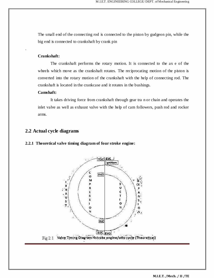
2.2 Actual cycle diagrams 2.2.1 Theoretical valve timing diagram of four stroke engine:

M.I.E.T. ENGINEERING COLLEGE/ DEPT. of Mechanical Engineering
M.I.E.T. /Mech. / II /TE
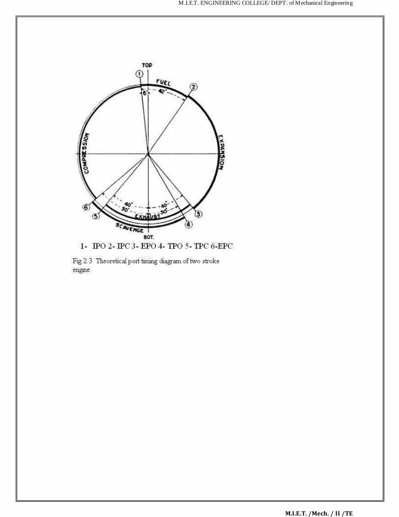
2.2.1 Actual valve timing diagram of four stroke engine: 2.2.2 Theoretical port timing diagram of two stroke engine:
M.I.E.T. ENGINEERING COLLEGE/ DEPT. of Mechanical Engineering
M.I.E.T. /Mech. / II /TE

M.I.E.T. ENGINEERING COLLEGE/ DEPT. of Mechanical Engineering
M.I.E.T. /Mech. / II /TE
Comparison of two stroke and four stroke engines:
Table 2.1 Comparison of two stroke and four stroke engines

M.I.E.T. ENGINEERING COLLEGE/ DEPT. of Mechanical Engineering
M.I.E.T. /Mech. / II /TE

M.I.E.T. ENGINEERING COLLEGE/ DEPT. of Mechanical Engineering
M.I.E.T. /Mech. / II /TE

M.I.E.T. ENGINEERING COLLEGE/ DEPT. of Mechanical Engineering
M.I.E.T. /Mech. / II /TE
M.I.E.T. ENGINEERING COLLEGE/ DEPT. of Mechanical Engineering
M.I.E.T. /Mech. / II /TE
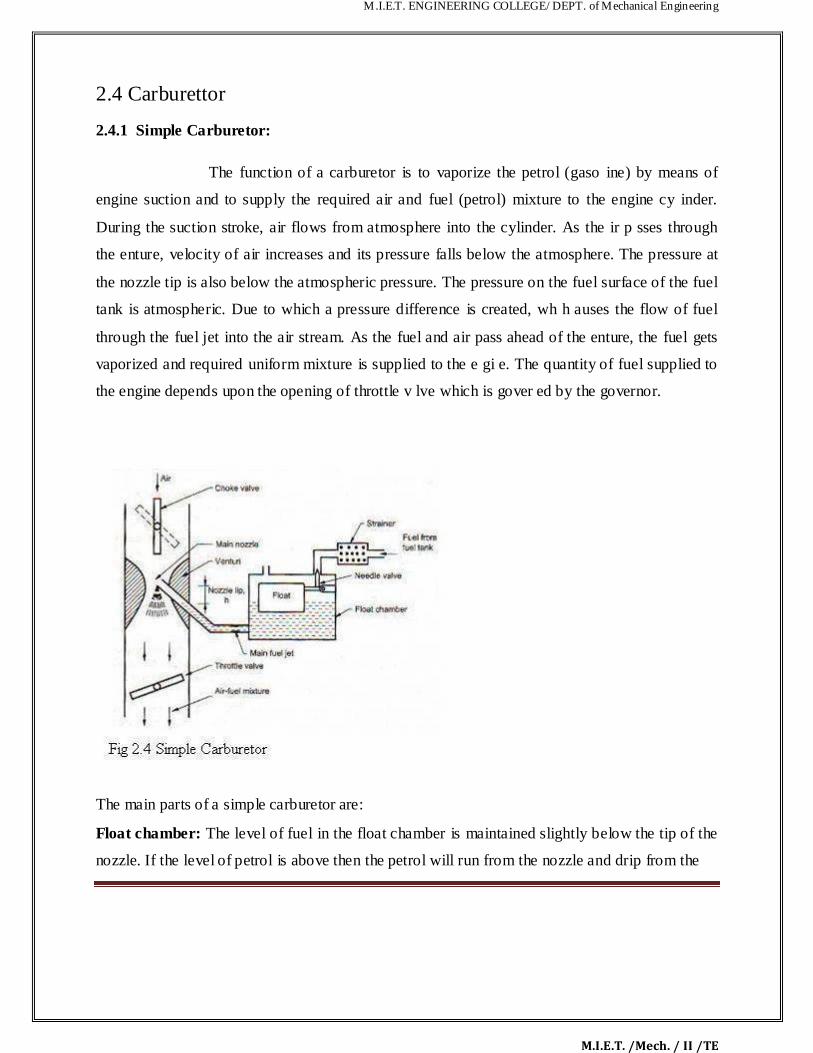
2.4 Carburettor 2.4.1 Simple Carburetor:
The function of a carburetor is to vaporize the petrol (gaso ine) by means of
engine suction and to supply the required air and fuel (petrol) mixture to the engine cy inder.
During the suction stroke, air flows from atmosphere into the cylinder. As the ir p sses through
the enture, velocity of air increases and its pressure falls below the atmosphere. The pressure at
the nozzle tip is also below the atmospheric pressure. The pressure on the fuel surface of the fuel
tank is atmospheric. Due to which a pressure difference is created, wh h auses the flow of fuel
through the fuel jet into the air stream. As the fuel and air pass ahead of the enture, the fuel gets
vaporized and required uniform mixture is supplied to the e gi e. The quantity of fuel supplied to
the engine depends upon the opening of throttle v lve which is gover ed by the governor.
The main parts of a simple carburetor are: Float chamber: The level of fuel in the float chamber is maintained slightly below the tip of the
nozzle. If the level of petrol is above then the petrol will run from the nozzle and drip from the

M.I.E.T. ENGINEERING COLLEGE/ DEPT. of Mechanical Engineering
M.I.E.T. /Mech. / II /TE
carburetor. If the petrol level is kept low than the tip of the nozzle then part of pressure head is
lost in lifting the petrol up to the tip of nozzle. Generally it is kept at 5mm from the level of
petrol in the float chamber. The level of the fuel is kept constant with the help of float and needle
valve. The needle valve closes the inlet supply from main tank if the level rises above the
required level. If the level of fuel decreases then the needle valve opens the supp y. Genera y the
fuel level is kept 5mm below the nozzle tip.
Venturi: When the mixture passes through the narrowest section its velo ity increases and
pressure falls below the atmospheric. As it passes through the d vergent se tion, pressure
increases again.
Throttle valve: It controls the quantity of air and fuel mixture supplied to the engine through
intake manifold and also the head under which the fuel flows.
Choke: It provides an extra rich mixture during to the engine starting and in cold weather to
warm up the engine. The choke valve is nearly closed during clod starting and warming. It
creates a high vacuum near the fuel jet which causes flow of more fuel from the jet.
2.5.2 Diesel Pump and Injector system:

M.I.E.T. ENGINEERING COLLEGE/ DEPT. of Mechanical Engineering
M.I.E.T. /Mech. / II /TE

M.I.E.T. ENGINEERING COLLEGE/ DEPT. of Mechanical Engineering
M.I.E.T. /Mech. / II /TE

M.I.E.T. ENGINEERING COLLEGE/ DEPT. of Mechanical Engineering
M.I.E.T. /Mech. / II /TE
2.6 Diesel knocking and detonation:
We already know that if the delay period is long, l rge mount of fuel will be injected and
accumulated in the chamber. The auto ignition of this l rge mount of fuel may cause high rate of pressure rise and high maximum pressure w ich may cause knocking in diesel engines. A
long delay period not only increases the amount of fuel injected by the moment of ignition, but
also improve the homogeneity of the fuel air mixture and its chemical preparedness for explosion
type self ignition similar to detonation in SI engines. It is very instructive to compare the
phenomenon of detonation is SI nsu s with that of knocking in CI engines. There is no doubt that these two phenomena are fundamentally similar. Both are processes of auto ignition subject
to the ignition time lag characteristic of the fuel air mixture. However, differences in the
knocking phenomena of the SI engine and the CI engine should also be care fully be noted: 1. In
the SI engine, the detonation occurs near the end of combustion where as in the CI engine
detonation occurs near the beginning of combustion as shown in fig. 6.10. 2. The detonation in
the SI engine is of a homogeneous charge causing very high rate of pressure rise and very high
maximum pressure. In the CI engine the fuel and air are in perfectly mixed and hence the rate of
pressure rise is normally lower than that in the detonating part of the charge in the SI engine. 3.
Since in the CI engine the fuel is injected in to the cylinder only at the end of the compression
stroke there is no question of pre ignition or pre mature ignition as in the SI engine. 4. In the SI
engine it is relatively easy to distinguish between knocking and non- knocking operation as the
M.I.E.T. ENGINEERING COLLEGE/ DEPT. of Mechanical Engineering
M.I.E.T. /Mech. / II /TE
human ear easily find the distinction. However, in the case of the CI engine the normal ig ition is
itself by auto ignition and hence no CI engines have a sufficiently high rate of pressure r se per
degree crank angle to cause audible noise. When such noise becomes excessive or there s
excessive vibration in engine structure, in the opinion of the observer, the engine is sending to
knock. It is clear that personal judgment is involved here. Thus in the CI engine there is no
definite distinction between normal and knocking combustion. The m ximum r te of pressure rise
in the CI engine may reach as high as 10bar per crank degree angle. It is most important to note that factors that tend to reduce detonation in the SI engine increase
knocking in CI engine and vice versa because of the follow ng reason. The detonation of
knocking in the SI engine is due to simultaneous auto ignition of the last part of the charge. To
eliminate detonation in the SI engine we want to prevent all together the auto ignition of the last
part of the charge and therefore desire a long delay period d high self ignition temperature of the
fuel. To eliminate knocking the CI engine we w nt to chieve uto ignitions early as possible
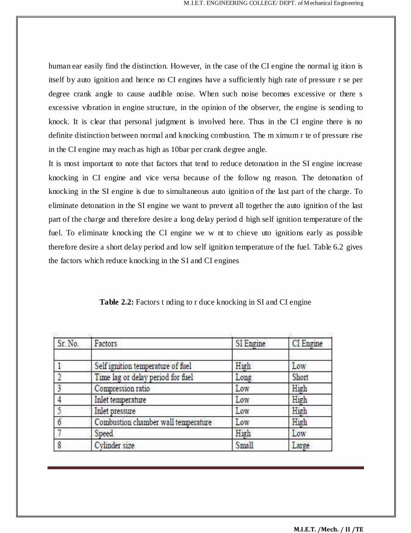
therefore desire a short delay period and low self ignition temperature of the fuel. Table 6.2 gives
the factors which reduce knocking in the SI and CI engines
Table 2.2: Factors t nding to r duce knocking in SI and CI engine
M.I.E.T. ENGINEERING COLLEGE/ DEPT. of Mechanical Engineering
M.I.E.T. /Mech. / II /TE
It is also clear from the table and discussion that a good CI engine fuel is a bad SI eng e fuel and
a good SI engine is bad CI engine fuel. In other words diesel oil has low self gn t on temperature
and short time lag where as petrol have high self ignition temperature and a long ignition lag. In
terms of fuel rating diesel oil has high cetane number (40 – 60) and ow octane number (about 30)
and petrol has high octane number (80 – 90) and low cet ne number (18).
2.5.2 Ignition System:
Basically Convectional Ignition systems are of 2 types : (a) Battery or Coil
Ignition System, and (b) Magneto Ignition System. Both these co ve tional, ignition systems
work on mutual electromagnetic induction principle. B ttery ignition system was generally used
in 4-wheelers, but now-a-days it is more commonly used in 2-wheelers also (i.e. Button start, 2-
wheelers like Pulsar, Kinetic Honda; Honda-Activa, Scooty, Fiero, etc.). In this case 6 V or 12 V
batteries will supply necessary current in the primary winding. Magneto ignition system is
mainly used in 2-wheelers, kick start engines. (Example, Bajaj Scooters, Boxer, Victor,
Splendor, Passion, etc.). In this case magn to will produce and supply current to the primary
winding. So in magneto ignition syst m magn to replaces the battery. Battery or Coil Ignition
System Figure shows line diagram of battery ignition system for a 4-cylinder petrol engine. It
mainly consists of a 6 or 12 volt battery, ammeter, ignition switch, auto-transformer (step up
transformer), contact breaker, capacitor, distributor rotor, distributor contact points, spark plugs,
etc. Note that the Figure 4 1 shows the ignition system for 4-cylinder petrol engine, here there
are 4-spark plugs and contact breaker cam has 4-corners. (If it is for 6-cylinder engine it will
have 6-spark plugs and contact breaker cam will be a hexagon).
The ignition system is divided into 2-circuits:
12. Primary Circuit :

M.I.E.T. ENGINEERING COLLEGE/ DEPT. of Mechanical Engineering
M.I.E.T. /Mech. / II /TE
14. It consists of 6 or 12 V battery, ammeter, ignition switch, primary windi g it has
200-300 turns of 20 SWG (Sharps Wire Gauge) gauge wire, contact breaker,
capacitor.
15. Secondary Circuit:
It consists of secondary winding. Secondary Ignition Systems winding
consists of about 21000 turns of 40 (S WG) gauge wire. Bottom end of which is connected to
bottom end of primary and top end of secondary winding is connected to centre of distributor
rotor. Distributor rotors rotate and make contacts with contact points and are connected to spark
plugs hich are fitted in cylinder heads (engine earth). (iii) Working : When the ignition switch is
closed and engine in cranked, as soon as the contact breaker closes, a low voltage current will
flow through the primary winding. It is also to be noted that the contact beaker cam opens and

M.I.E.T. ENGINEERING COLLEGE/ DEPT. of Mechanical Engineering
M.I.E.T. /Mech. / II /TE
closes the circuit 4-times (for 4 cylinders) in one revolution. When the contact breaker ope s the
contact, the magnetic field begins to collapse. Because of this collapsing magnetic f eld, curre t
will be induced in the secondary winding. And because of more turns (@ 21000 turns) of
secondary, voltage goes unto 28000-30000 volts. This high voltage current is brought to centre
of the distributor rotor. Distributor rotor rotates and supplies this high voltage current to proper
stark plug depending upon the engine firing order. When the high volt ge current jumps the spark
plug gap, it produces the spark and the charge is ignited-combustion st rts-products of
combustion expand and produce power. Magneto Ignition System In this ase magneto will
produce and supply the required current to the primary winding. In th s ase as shown, we can
have rotating magneto with fixed coil or rotating coil with f xed magneto for producing and
supplying current to primary, remaining arrangement is same as that of a battery ignition system.
2.10 Comparison between Battery and Magneto Ignition System:
Table 2.3 Comparison between Battery and Magneto Ignition System

M.I.E.T. ENGINEERING COLLEGE/ DEPT. of Mechanical Engineering
M.I.E.T. /Mech. / II /TE
2.7 Lubrication System:
2.7.1 Splash:

M.I.E.T. ENGINEERING COLLEGE/ DEPT. of Mechanical Engineering
M.I.E.T. /Mech. / II /TE
The splash system is no longer used in utomotive engines. It is widely used in
small four-cycle engines for lawn mowers, outboard marine operation, and so on. In the splash
lubricating system , oil is splashed up from t e oil pan or oil trays in the lower part of the
crankcase. The oil is thrown upward as droplets or fine mist and provides adequate lubrication to
valve mechanisms, piston pins, cylinder walls, and piston rings. In the engine, dippers on the
connecting-rod bearing caps enter the oil pan with each crankshaft revolution to produce the oil
splash. A passage is drilled in ach conn cting rod from the dipper to the bearing to ensure
lubrication. This system is too uncertain for automotive applications. One reason is that the level
of oil in the crankcase will vary greatly the amount of lubrication received by the engine. A high
level results in excess lubrication and oil consumption and a slightly low level results in
inadequate lubrication and failure of the engine.
M.I.E.T. ENGINEERING COLLEGE/ DEPT. of Mechanical Engineering
M.I.E.T. /Mech. / II /TE
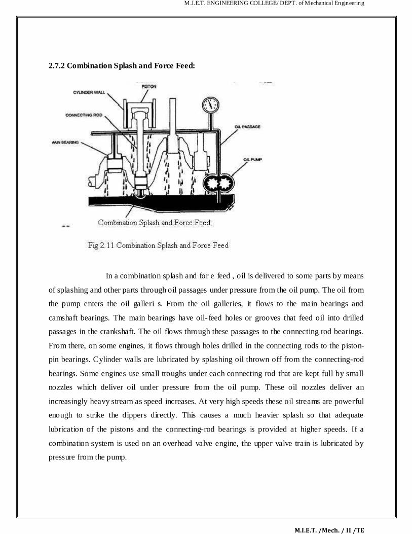
2.7.2 Combination Splash and Force Feed:
In a combination splash and for e feed , oil is delivered to some parts by means
of splashing and other parts through oil passages under pressure from the oil pump. The oil from
the pump enters the oil galleri s. From the oil galleries, it flows to the main bearings and
camshaft bearings. The main bearings have oil- feed holes or grooves that feed oil into drilled
passages in the crankshaft. The oil flows through these passages to the connecting rod bearings.
From there, on some engines, it flows through holes drilled in the connecting rods to the piston-
pin bearings. Cylinder walls are lubricated by splashing oil thrown off from the connecting-rod
bearings. Some engines use small troughs under each connecting rod that are kept full by small
nozzles which deliver oil under pressure from the oil pump. These oil nozzles deliver an
increasingly heavy stream as speed increases. At very high speeds these oil streams are powerful
enough to strike the dippers directly. This causes a much heavier splash so that adequate
lubrication of the pistons and the connecting-rod bearings is provided at higher speeds. If a
combination system is used on an overhead valve engine, the upper valve train is lubricated by
pressure from the pump.

M.I.E.T. ENGINEERING COLLEGE/ DEPT. of Mechanical Engineering
M.I.E.T. /Mech. / II /TE
2.7.3 Force Feed :
A somewhat more compl te pr ssurization of lubrication is achieved in the force- feed
lubrication system. Oil is forced by the oil pump from the crankcase to the main bearings and the
camshaft bearings. Unlike the co bination system the connecting-rod bearings are also fed oil
under pressure from the pu p Oil passages are drilled in the crankshaft to lead oil to the connecting-rod bearings. The passages
deliver oil from the main bearing journals to the rod bearing journals. In some engines, these
opening are holes that line up once for every crankshaft revolution. In other engines, there are
annular grooves in the main bearings through which oil can feed constantly into the hole in the
crankshaft. The pressurized oil that lubricates the connecting-rod bearings goes on to lubricate
the pistons and alls by squirting out through strategically drilled holes. This lubrication system is
used in virtually all engines that are equipped with semi floating piston pins.

M.I.E.T. ENGINEERING COLLEGE/ DEPT. of Mechanical Engineering
M.I.E.T. /Mech. / II /TE
2.7.4 Full Force Feed:
In a full force-feed lubrication system, the main bearings, rod bearings, camshaft
bearings, and the complete valve mechanism are lubricated by oil under pressure In add t on, the
full force- feed lubrication system provides lubrication under pressure to the pistons and the
piston pins. This is accomplished by holes drilled the length of the connecting rod, creating an oil
passage from the connecting rod bearing to the piston pin bearing. This p ss ge not only feeds the
piston pin bearings but also provides lubrication for the pistons nd cylinder w lls. This system is
used in virtually all engines that are equipped with full- floating piston pins.
2.8 Cooling System:
2.8.1 Air Cooled System:
Air cooled system is generally used in sm ll engines s y up to 15-20 Kw and in aero
plane engines. In this system fins or extended surfaces are provided on the cylinder walls,
cylinder head, etc. Heat generated due to combustion in t e engine cylinder will be conducted to
the fins and when the air flows over the fins, heat will be dissipated to air. The amount of heat
dissipated to air depends upon : (a) Amount of air flowing through the fins. (b) Fin surface area. I
Thermal conductivity of metal us d for fins.
M.I.E.T. ENGINEERING COLLEGE/ DEPT. of Mechanical Engineering
M.I.E.T. /Mech. / II /TE
Advantages of Air Cooled System Following are the advantages of air cooled system: (a)
Radiator/pump is absent hence the system is light. (b) In case of water cooling system there are
leakages, but in this case there are no leakages. I Coolant and antifreeze solut ons are not
required. (d) This system can be used in cold climates, where if water is used it may freeze.
Disadvantages of Air Cooled System (a) Comparatively it is less efficient. (b) It is used only in
aero planes and motorcycle engines where the engines are exposed to air directly.
2.8.2 Water Cooling System:
In this method, cooling water jackets re provided arou d the cylinder, cylinder
head, valve seats etc. The water when circulated through the jackets, it absorbs heat of
combustion. This hot water will then be cooling in t e radiator partially by a fan and partially by
the flow developed by the forward motion of t e ve icle. T e cooled water is again recirculated
through the water jackets
Thermo Siphon System: In this syst m the circulation of water is due to difference in
temperature (i.e. difference in d nsiti s) of wat r. So in this system pump is not required but water
is circulated because of density difference only.

M.I.E.T. ENGINEERING COLLEGE/ DEPT. of Mechanical Engineering
M.I.E.T. /Mech. / II /TE
Pump Circulation System: In this system circulation of water is obtained by a pump. This
pump is driven by means of engine output s aft t rough V-belts. Performance Calculation: Engine performance is an indication of the degree of success of the
engine performs its assigned task, i.e. the conversion of the chemical energy contained in the fuel
into the useful mechanical work. The performance of an engine is evaluated on the basis of the

M.I.E.T. ENGINEERING COLLEGE/ DEPT. of Mechanical Engineering
M.I.E.T. /Mech. / II /TE
following : (a) Specific Fuel Consumption. (b) Brake Mean Effective Pressure. I Specific Power
Output. (d) Specific Weight. (e) Exhaust Smoke and Other Emissions. The particular appl cat on
of the engine decides the relative importance of these performance parameters For Example : For
an aircraft engine specific weight is more important whereas for an industrial engine specific fuel
consumption is more important. For the evaluation of an engine performance few more
parameters are chosen and the effect of various operating conditions, design concepts and
modifications on these parameters are studied. The basic perform nce p r meters are the
following : (a) Power and Mechanical Efficiency. (b) Mean Effe tive Pressure and Torque. I Specific Output. (d) Volumetric Efficiency. (e) Fuel-air Ratio. (f) Spe f Fuel Consumption. (g)
Thermal Efficiency and Heat Balance. (h) Exhaust Smoke and Other Emissions. (i) Specific
Weight. Power and Mechanical Efficiency The main purpose of ru i g an engine is to obtain mechanical power. • Power is defined as the rate of doi g work a d is equal to the product of
force and linear velocity or the product of torque nd ngul r velocity. • Thus, the measurement of
power involves the measurement of force (or torque) as well as speed. The force or torque is
measured with the help of a dynamometer and t e speed by a tachometer. The power developed
by an engine and measured at the output shaft is alled the brake power (bp) and is given by
bp=2Πnt/60 where, T is torque in N-m and N is the rotational speed in revolutions per minute.
The total power developed by combustion of fu l in the combustion chamber is, however, more
than the bp and is called indicat d pow r (ip). Of the power developed by the engine, i.e. ip, some
power is consumed in overco ing the friction between moving parts, some in the process of
inducting the air and re oving the products of combustion from the engine combustion chamber.
Indicated Po er: It is the power developed in the cylinder and thus, forms the basis of evaluation
of combustion efficiency or the heat release in the cylinder. Where, I.P= PmLANK/60 pm =
Mean effective pressure, N/m2, L = Length of the stroke, m, A = Area of the piston, m2, N =
Rotational speed of the engine, rpm (It is N/2 for four stroke engine), and k = Number of
cylinders. Thus, e see that for a given engine the power output can be measured in terms of mean
effective pressure. The difference between the ip and bp is the indication of the power lost

M.I.E.T. ENGINEERING COLLEGE/ DEPT. of Mechanical Engineering
M.I.E.T. /Mech. / II /TE
in the mechanical components of the engine (due to friction) and forms the basis of mecha ical
efficiency; which is defined as follows : Mechanical efficiency=bp/ip The difference between p
and bp is called friction power (fp). Fp = ip − bp Mechanical efficiency= b.p/(bp+fp)
Mean Effective Pressure and Torque: Mean effective pressure is defined as a
hypothetical/average pressure which is assumed to be acting on the piston throughout the power
stroke. Therefore, Pm=60Xi.P/LANk where, Pm = Mean effective pressure, N/m2, Ip =
Indicated power, Watt, L = Length of the stroke, m, A = Area of the piston, m2, N = Rotational
speed of the engine, rpm (It is N/2 for four stroke engine), and k = Number of ylinders. If the
mean effective pressure is based on bp it is called the brake mean effect ve pressure( Pm), and if
based on ihp it is called indicated mean effective pressure (imep). Similarly, the friction mean
effective pressure (fmep) can be defined as, fmep = imep – bmep
The torque is related to mean effective pressure by the rel tion B.P=2Πnt/60 I.P=PmLANk/60
2Πnt/60=[bmep.A.L.(Nk/60)] or, T=(bmep.A.L.k)/2π
Thus, the torque and the mean effective pressure are related by the engine size. A large engine
produces more torque for the same m an ff ctive pressure. For this reason, torque is not the
measure of the ability of an engine to utilize its displacement for producing power from fuel. It is
the mean effective pressure which gives an indication of engine displacement utilization for this
conversion. Higher the ean effective pressure, higher will be the power developed by the engine
for a given displace ent Again we see that the power of an engine is dependent on its size and
speed. Therefore, it is not possible to compare engines on the basis of either power or torque.
Mean effective pressure is the true indication of the relative performance of different engines.
Specific Output: Specific output of an engine is defined as the brake power (output) per unit of
piston displacement and is given by, Specific output=B.P/A.L Constant = bmep × rpm • The
specific output consists of two elements – the bmep (force) available to work and the speed with

M.I.E.T. ENGINEERING COLLEGE/ DEPT. of Mechanical Engineering
M.I.E.T. /Mech. / II /TE
which it is working. • Therefore, for the same piston displacement and bmep an engine operati g
at higher speed will give more output. • It is clear that the output of an engine can be creased by
increasing either speed or bmep. Increasing speed involves increase in the mechan cal stress of
various engine parts whereas increasing bmep requires better heat release and more oad on
engine cylinder.
Volumetric Efficiency: Volumetric efficiency of an engine is an indication of the me sure of the
degree to which the engine fills its swept volume. It is defined as the ratio of the mass of air
inducted into the engine cylinder during the suction stroke to the mass of the air orresponding to
the swept volume of the engine at atmospheric pressure and temperature. Alternatively, it can be
defined as the ratio of the actual volume inhaled duri g suction stroke measured at intake
conditions to the swept volume of the piston. Volumetric efficie cy, hv = Mass of charge actually
sucked in Mass of charge corresponding to the cylinder intake The amount of air taken inside the
cylinder is dependent on the volumetric efficiency of n engine and hence puts a limit on the
amount of fuel which can be efficiently burned and the power output. For supercharged engine
the volumetric efficiency has no meaning as it comes out to be more than unity.
Fuel-Air Ratio (F/A): Fuel-air ratio (F/A) is the ratio of the mass of fuel to the mass of air in the
fuel-air mixture. Air- fuel ratio (A/F) is r ciprocal of fuel-air ratio. Fuel-air ratio of the mixture
affects the combustion phenomenon in that it d termines the flame propagation velocity, the heat
release in the combustion cha ber, the aximum temperature and the completeness of
combustion. Relative fuel-air ratio is defined as the ratio of the actual fuel-air ratio to that of
the stoichiometric fuel-air ratio required to burn the fuel supplied. Stoichiometric fuel-air ratio
is the ratio of fuel to air is one in which case fuel is completely burned due to minimum
quantity of air supplied. Relative fuel-air ratio, =(Actual Fuel- Air ratio)/(Stoichiometric fuel-Air
ratio)
Brake Specific Fuel Consumption: Specific fuel consumption is defined as the amount of fuel
consumed for each unit of brake power developed per hour. It is a clear indication of the
efficiency ith hich the engine develops power from fuel. B.S.F.C= Relative fuel-air ratio,
=(Actual Fuel- Air ratio)/(Stoichiometric fuel-Air ratio) This parameter is widely used to
compare the performance of different engines.

M.I.E.T. ENGINEERING COLLEGE/ DEPT. of Mechanical Engineering
M.I.E.T. /Mech. / II /TE
Thermal Efficiency and Heat Balance: Thermal efficiency of an engine is defined as the ratio
of the output to that of the chemical energy input in the form of fuel supply. It may be based on
brake or indicated output. It is the true indication of the efficiency with which the chem cal
energy of fuel (input) is converted into mechanical work. Thermal efficiency a so accounts for
combustion efficiency, i.e., for the fact that whole of the chemical energy of the fuel is not
converted into heat energy during combustion. Brake thermal efficiency = B.P/mf* Cv where,
Cv = Calorific value of fuel, Kj/kg, and mf = Mass of fuel supplied, kg/sec. • The energy input to
the engine goes out in various forms – a part is in the form of brake output, a part into exhaust,
and the rest is taken by cooling water and the lubricating oil. • The break-up of the total energy
input into these different parts is called the heat balance. • The ma n components in a heat
balance are brake output, coolant losses, heat going to exhaust, radiation and other losses. •
Preparation of heat balance sheet gives us an idea bout the mou t of energy wasted in various
parts and allows us to think of methods to reduce the losses so incurred. Exhaust Smoke and Other Emissions: Smoke and ot er exhaust emissions such as oxides of
nitrogen, unburned hydrocarbons, etc. are nuisance for t e public environment. With increasing
emphasis on air pollution control all efforts are being made to keep them as minimum as it could
be. Smoke is an indication of incomplete ombustion. It limits the output of an engine if air
pollution control is the consideration. Emission Formation Mechanisms: (S.I) This s ction discusses the formation of HC, CO, Nox,
CO2, and aldehydes and explains the effects of design parameters. Hydrocarbon Emissions:
HC e issions are various compounds of hydrogen, carbon, and sometimes
oxygen. They are burned or partially burned fuel and/or oil. HC emissions contribute to
photochemical smog, ozone, and eye irritation. There are several formation mechanisms for HC,
and it is convenient to think about ways HC can avoid combustion and ways HC can be removed; e ill discuss each below. Of course, most of the HC input is fuel, and most of it is
burned during “normal” combustion. However, some HC avoids oxidation during this process. The processes by hich fuel compounds escape burning during normal S.I. combustion are:
M.I.E.T. ENGINEERING COLLEGE/ DEPT. of Mechanical Engineering
M.I.E.T. /Mech. / II /TE
2. Fuel vapor-air mixture is compressed into the combustion chamber crevice volumes. 2. Fuel
compounds are absorbed into oil layers on the cylinder liner. 3. Fuel is absorbed by a d/or
contained within deposits on the piston head and piston crown. 4. Quench layers on the
combustion chamber wall are left as the flame extinguishes close to the wal s. 5 Fuel vapor-air
mixture can be left unburned if the flame extinguishes before reaching the wa s. 6. Liquid fuel
within the cylinder may not evaporate and mix with sufficient air to burn prior to the end of
combustion. 7. The mixture may leak through the exhaust valve seat. (ii) C rbon Monoxide Formation of CO is well established. Under some conditions, there is not enough O2 available
for complete oxidation and some of the carbon in the fuel ends up as CO. The amount of CO, for
a range of fuel composition and C/H ratios, is a function of the relat ve a r- fuel ratio. Even when
enough oxygen is present, high peak temperatures can cause dissociation – chemical combustion
reactions in which carbon dioxide and water vapor sep r te i to CO, H2, and O2. Conversion of
CO to CO2 is governed by reaction CO + OH ↔ CO2 + H Dissociated CO may freeze during
the expansion stroke. (iii) Oxides of Nitrogen Nox is a generic term for the compounds NO and
NO2. Both are present to some degree in t e ex aust, and NO oxidizes to NO2 in the atmosphere.
Nox contributes to acid rain and photo hemical smog; it is also thought to cause respiratory
health problems at atmospheric on entrations found in some parts of the world. To understand
Nox formation, we must r cognize several factors that affect Nox equilibrium. Remember that all
chemical r actions proc d toward equilibrium at some reaction rate. Equilibrium NO (which co
prises ost of the Nox formation) is formed at a rate that varies strongly with temperature and equivalence ratio. (iv) Carbon Dioxide While not normally
considered a pollutant, CO2 ay contribute to the greenhouse effect. Proposals to reduce CO2
emissions have been made CO2 controls strongly influence fuel economy requirements. (v) Aldehydes Aldehydes are the result of partial oxidation of alcohols. They are not usually present
in significant quantities in gasoline- fueled engines, but they are an issue when alcohol fuels are
used. Aldehydes are thought to cause lung problems. So far, little information of engine
calibration effects on aldehyde formation is available.

M.I.E.T. ENGINEERING COLLEGE/ DEPT. of Mechanical Engineering
M.I.E.T. /Mech. / II /TE
Emission Formation in C.I. Engine:
For many years, diesel engines have had a reputation of giving poor
performance and producing black smoke, an unpleasant odor, and considerab e noise. However,
it would find it difficult to distinguish today‟ s modern diesel car from its g soline counterpart.
For diesel engines the emphasis is to reduce emissions of Nox and p rticul tes, where these
emissions are typically higher than those from equivalent port inje ted gasoline engines equipped
with three-way catalysts. Catalyst of diesel exhaust remains a problem nsofar as researchhas not
yet been able to come up with an effective converter that eliminates both particulate matter (PM)
and oxide of nitrogen (Nox).
Principle C.I. Engine Exhaust Constituents: For m ny ye rs, diesel engines have had a
reputation of giving poor performance and producing black smoke, an unpleasant odor, and
considerable noise. However, it would find it difficult to distinguish today‟ s modern diesel car
from its gasoline counterpart. Concerning CO and HC emissions, diesel engines have an inherent
advantages, therefore the emphasis is to r duce emissions of Nox and particulates, where these
emissions are typically higher than those from quivalent port injected gasoline engines equipped
with three-way catalysts. Catalyst of diesel exhaust remains a problem insofar as research has not
yet been able to come up with an effective converter that eliminates both particulate matter (PM)
and oxide of nitrogen (Nox) In the sa e manner as with SI engines, the air/fuel ratio of the diesel
engine has a significant impact on the level of pollutant concentrations but this parameter is not
freely available for minimizing pollution. Problems: To determine Brake power, Indicated
Power, Frictional Po er, Brake Thermal Efficiency, Indicated Thermal Efficiency, Mechanical
Efficiency, Relative Efficiency, Volumetric Efficiency, Brake Specific Fuel Consumption,
Indicated Specific Fuel Consumption, Indicated mean effective pressure, Brake mean effective
pressure.

M.I.E.T. ENGINEERING COLLEGE/ DEPT. of Mechanical Engineering
M.I.E.T. /Mech. / II /TE
Sample problems: iii) Following data relates to 4 cylinder, single stroke petrol engine. A/F r tio by weight 16:1.
Calorific value of the fuel= 45200 Kj/kg, mechanical effi ien y=82%.Air standard
efficiency=52%, relative efficiency=70%, volumetric effic en y=78%, L/D=1.25, suction
condition=1 bar,250C. Speed=2400 rpm and power at brakes=72kw. Calculate ∴ Compression ratio ∴ Indicated Thermal Efficiency ∴ Brake specific fuel consumption ∴ Bore and Stroke.
∴ A six cylinder, 4 stroke SI engine having a piston displacement of 700cm3 per cylinder
developed 78Kw at 3200 rpm and consumed 27 kg of petrol per hour. The calorific value of the fuel is 44MJ/kg. Estimate 1.The volum tric fficiency of the engine if the air- fuel ratio is 12 and
intake air is at 0.9bar, 32oC. 2. Brake thermal efficiency and brake torque. For air R=0.287
KJkgK.

M.I.E.T. ENGINEERING COLLEGE/ DEPT. of Mechanical Engineering
M.I.E.T. /Mech. / II /TE
2.16 Solved Problems:
∴ A trial carried out in a four stroke single cylinder gas engine gave the following results.
Cylinder dia=300mm, Engine stroke=500mm, Clearance volume=6750cc, Explosions per
minute=100 Net work load on the br ke=190kg Brake dia=1.5m Rope
dia=25mm, Speed of the engine=240rpm, Gas used=30 , Calorific value of
gas=20515 KJ/ . Determine compression ratio,mechanical efficiency,indicated thermal
efficiency,air standard efficiency,relative efficiency,assume
GIVEN DATA:-
Dia of cylinder (d)=300mm=0.3m
Engine stroke(l)=500 =0.5m
Clearance volu e(vc)=6750/1003=6.75 m
3
Explosions per minute(n)=100/minute=i.67/sec
Pmin=765 KN/m2
Brake drum dia(D1)=1.5m
Rope dia(d1)=0.025m
Work load on the brake(w)=190kg=1.86KN
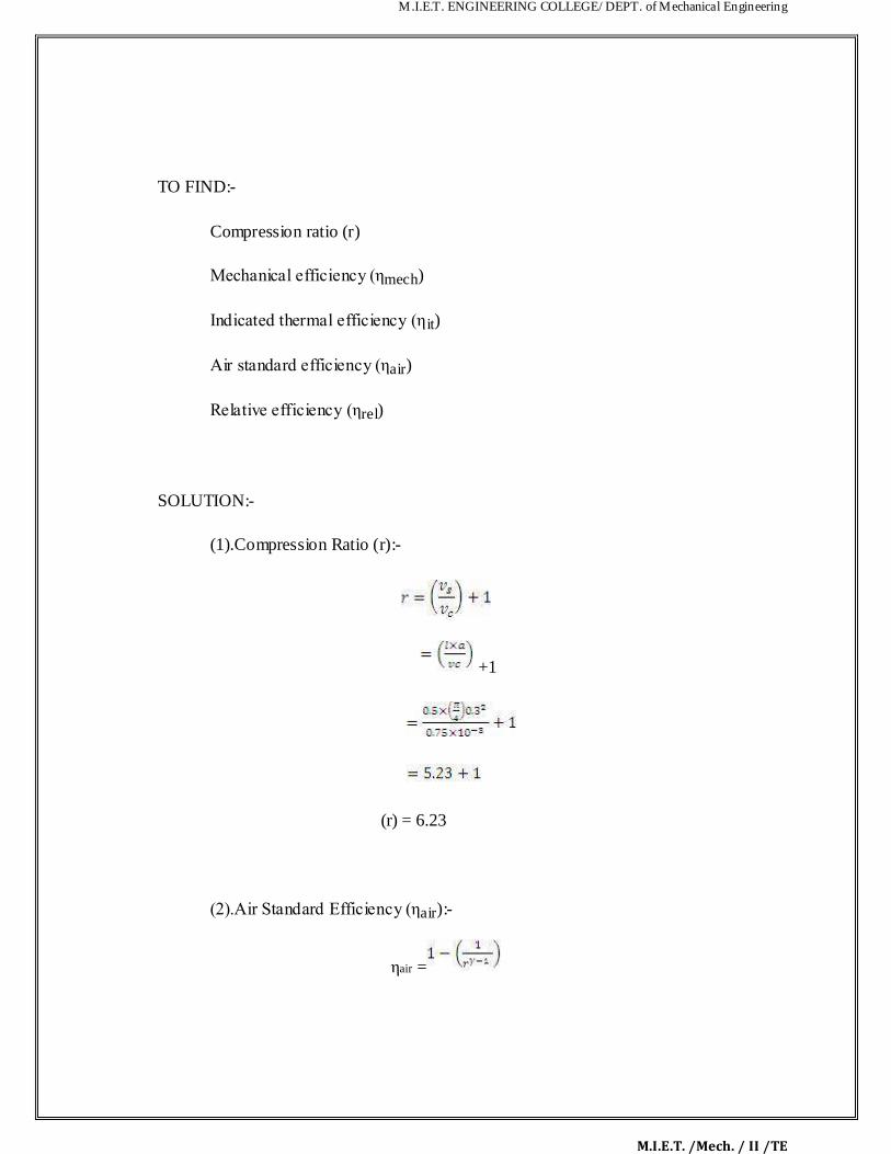
M.I.E.T. ENGINEERING COLLEGE/ DEPT. of Mechanical Engineering
M.I.E.T. /Mech. / II /TE
TO FIND:-
Compression ratio (r)
Mechanical efficiency (ηmech)
Indicated thermal efficiency (η it)
Air standard efficiency (ηair)
Relative efficiency (ηrel)
SOLUTION:-
(1).Compression Ratio (r):-
+1
(r) = 6.23
(2).Air Standard Efficiency (ηair):-
ηair =

M.I.E.T. ENGINEERING COLLEGE/ DEPT. of Mechanical Engineering
M.I.E.T. /Mech. / II /TE
=51.89%
(3).Indicated Thermal Efficiency (ηit):-
(ηit)=
Here, indicated power
(IP)=
=765
=45.09KW
Therefore,
=24.03%
(4).Relative Efficiency (ηrel):-
(ηr l)=
=
=46.30%
(5).Mechanical Efficiency (ηmech):-
(ηmech)=
=
=79.02%

M.I.E.T. ENGINEERING COLLEGE/ DEPT. of Mechanical Engineering
M.I.E.T. /Mech. / II /TE
∴ The following observations are recorded during a test on a four-stroke petrol engi e, F.C =
3000 of fuel in 12sec, speed of the engine is 2500rpm, B.P = 20KW, Air intake orif ce d ameter
= 35mm,Pressure across the orifice = 140mm of water coefficient of discharge of or f ce = 0 6,
piston diameter = 150mm, stroke length = 100mm, Density of the fuel = 0.85gm/cc , r=6 5, Cv of
fuel = 42000KJ/Kg, Barometric pressure = 760mm of Hg , Room temperature = 24oc
Determine:
ρ Volumetric efficiency on the air basis alone
ρ Air- fuel ratio
ρ The brake mean effective pressure
ρ The relative efficiency on the brake thermal efficie cy
Given data:
Fuel consumption = 30cc in 12sec =
Speed (N) = 2500/60 rps
Brake power = 20KW
Orifice diam t r (do) = 0.035m
Pressure across the orifice (Po) = 140mm of water
Coefficient of discharge (Cd) = 0.6
Piston dia eter (d) = 150mm = 0.15m
Stroke length (l) = 0.1m
Density of fuel (ρ) = 0.85gm/cc
Compression ratio (r) = 6.5
Room temperature (Ta) = 297K
Barometric pressure = 760mm of Hg = 101.325KK/m2= 10.34m of water
To find:
ρ Volumetric efficiency on the air basis alone
ρ Air- fuel ratio
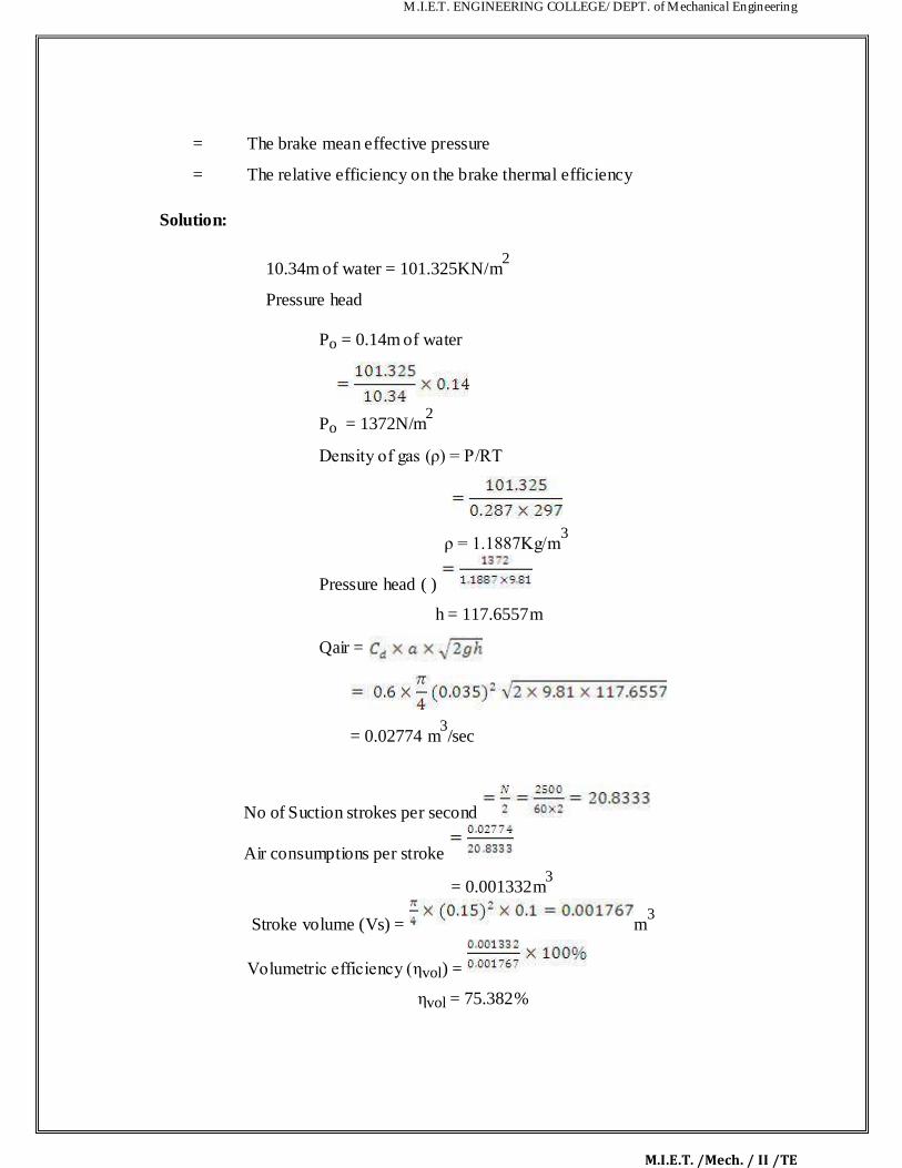
M.I.E.T. ENGINEERING COLLEGE/ DEPT. of Mechanical Engineering
M.I.E.T. /Mech. / II /TE
= The brake mean effective pressure
= The relative efficiency on the brake thermal efficiency
Solution:
10.34m of water = 101.325KN/m2
Pressure head
Po = 0.14m of water
Po = 1372N/m2
Density of gas (ρ) = P/RT
ρ = 1.1887Kg/m3
Pressure head ( )
h = 117.6557m
Qair =
= 0.02774 m3/sec
No of Suction strokes per second
Air consumptions per stroke
= 0.001332m3
Stroke volume (Vs) = m3
Volumetric efficiency (ηvol) =
ηvol = 75.382%
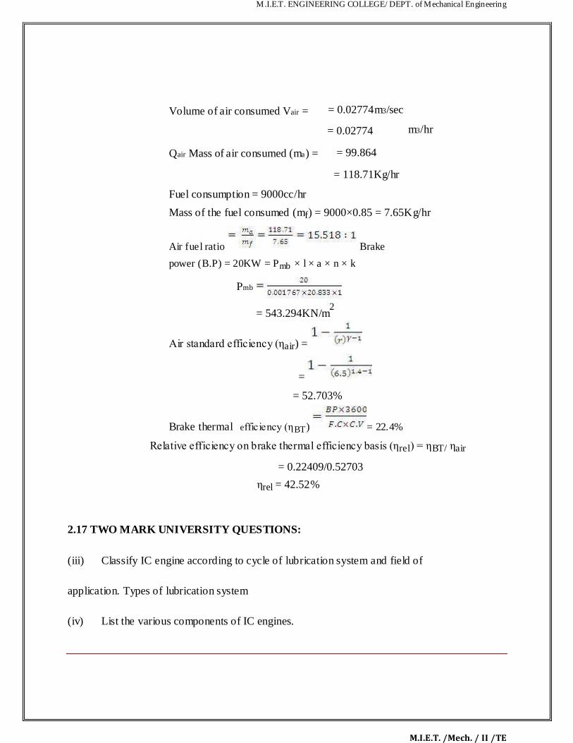
M.I.E.T. ENGINEERING COLLEGE/ DEPT. of Mechanical Engineering
M.I.E.T. /Mech. / II /TE
Volume of air consumed Vair =
Qair Mass of air consumed (ma) =
= 0.02774m3/sec = 0.02774
= 99.864
= 118.71Kg/hr
m3/hr
Fuel consumption = 9000cc/hr
Mass of the fuel consumed (mf) = 9000×0.85 = 7.65Kg/hr
Air fuel ratio Brake
power (B.P) = 20KW = Pmb × l × a × n × k
Pmb
= 543.294KN/m2
Air standard efficiency (ηair) =
=
= 52.703%
Brake thermal efficiency (ηBT) = 22.4%
Relative efficiency on brake thermal efficiency basis (ηrel) = ηBT/ ηair
= 0.22409/0.52703
ηrel = 42.52% 2.17 TWO MARK UNIVERSITY QUESTIONS:
(iii) Classify IC engine according to cycle of lubrication system and field of
application. Types of lubrication system
(iv) List the various components of IC engines.
M.I.E.T. ENGINEERING COLLEGE/ DEPT. of Mechanical Engineering
M.I.E.T. /Mech. / II /TE
5. Name the basic thermodynamic cycles of the two types of internal combustion reciprocati g
engines.
6. Mention the important requites of liner material.
7. State the purpose of providing piston in IC engines.
8. Define the terms as applied to reciprocating I.C. engines "Mean effective pressure" and “Compression ratio".
8. What is meant by highest useful compression ratio?
9. What are the types of piston rings?
10. What is the use of connecting rod?
11. What is the use of flywheel? 2.18 UNIVERSITY ESSAY QUESTIONS
1. Explain full pressure lubrication system I.C Engine. (16) 11. Explain the water cooling system in I.C Engine. (16)
12. Explain the 2 types of Ignition system In 5.1 Engine. (16)
13. Draw and explain the valve timing diagram of 4 strokes Diesel Engine. (16)
14. Draw and explain the port timing diagram of 2stroke Petrol Engine. (16)
15. Explain with neat sketch the exhaust gas analysis. (16)
M.I.E.T. ENGINEERING COLLEGE/ DEPT. of Mechanical Engineering
M.I.E.T. /Mech. / II /TE
16. The following results refer to a test on a petrol engine Indicated power = 30 Kw, Brake
power
26 Kw, Engine speed = 1000 rpm Fuel brake power/ hour = 0.35 kg Calorific value of fuel
43900kj/kg .Calculate the indicated Thermal efficie cy, the brake Thermal efficiency and
Mechanical efficiency (16)
17. A four cylinder 2 stroke cycle petrol engine develops 23.5 kw brake power at 2500 rpm.
The mean effective pressure on each piston in 8. 5 bar and mechanical efficiency in 85%
Calculate the diameter and stroke of each cylinder assuming t e length of stroke equal to 1.5
times the diameter of cylinder. (16)
18. The following data to a particular twin cylinder two stroke diesel engine. Bore 15 cm
stroke. 20 cm. speed 400 rpm. Indicat d m an ff ctive pressure 4 bar, dead weight on the brake
drum 650 N. spring balance reading 25 N Diameter of the brake drum 1 m .Fuel consumption
0.075 kg/min and calorific value of the fuel is 44500 KJ/kg. Determine 1. Indicated Power 2.
Brake Power 3. Mechanical efficiency 4. Indicated thermal efficiency and 5. Brake thermal
efficiency (16)

M.I.E.T. ENGINEERING COLLEGE/ DEPT. of Mechanical Engineering
M.I.E.T. /Mech. / II /TE
ME6404 THERMAL ENGINEERING
UNIT III
NOZZLES, TURBINES & STEAM POWER CYCLES

M.I.E.T. ENGINEERING COLLEGE/ DEPT. of Mechanical Engineering
M.I.E.T. /Mech. / II /TE
CONTENTS
3.1 Flow of steam through nozzles:
3.2 Continuity and steady flow energy equations
3.3 Types of Nozzles
3.3.1 Convergent Nozzle
3.3.2 Divergent Nozzle
3.3.4 Convergent-Divergent Nozzle
3.4 Supersaturated flow or Meta stable flow in Nozzles
3.5 Mass of steam discharged through nozzle
3.6 Steam Turbines
3.6.1 Impulse Turbines
3.6.2 Reaction Turbines
3.7 Compounding of impulse turbine
3.7.1. Velocity Compounding
3.7. 2. Pressure Compounding
3.7. 3. Pressure-Velocity Compounding
3.8 Velocity diagram of an impulse turbine
3.9 Velocity diagram of the v locity compounded turbines
3.10 Governing of Steam Turbine
3.10.1. Throttle Governing
3.10.2. Nozzle Governing
3.11 Solved Problems
3.12 T o Marks University Questions
3.13 University Essay Questions
M.I.E.T. ENGINEERING COLLEGE/ DEPT. of Mechanical Engineering
M.I.E.T. /Mech. / II /TE
TECHNICAL TERMS:
1. Wet steam: The steam which contains some water particles in superposition
2. Dry steam / dry saturated steam:
When whole mass of steam is converted into steam then it is called as dry steam.
3. Super heated steam: When the dry steam is further heated at const nt pressure, the
temperature increases the above saturation temperature. The steam h s obt ined is called
super heated steam.
4. Degree of super heat: The difference between the temperature of saturated steam
and saturated temperature is called degree of superheat.
5. Nozzle:It is a duct of varying cross section l rea in which the velocity increases with the
corresponding drop in pressure.
6. Coefficient of nozzle: It is the ratio of actual ent alpy drop to isentropic enthalpy drop.
7. Critical pressure ratio: There is only one value of ratio (P2/P1) which produces
maximum discharge from the nozzle . then the ratio is called critical pressure ratio.
8. Degree of reaction: It is d fin d as the ratio of isentropic heat drop in the moving blade
to isentrpic heat drop in the entire stages of the reaction turbine.
9. Compounding: It is the ethod of absorbing the jet velocity in stages when the steam
flows over moving blades (i)Velocity compounding (ii)Pressure compounding and (iii)
Velocity-pressure compounding
10. Enthalpy: It is the combination of the internal energy and the flow energy.
11. Entropy: It is the function of quantity of heat with respective to the temperature.
12. Convergent nozzle: The crossectional area of the duct decreases from inlet to the
outlet side then it is called as convergent nozzle.

M.I.E.T. ENGINEERING COLLEGE/ DEPT. of Mechanical Engineering
M.I.E.T. /Mech. / II /TE
13. Divergent nozzle: The crossectional area of the duct increases from inlet to the
outlet then it is called as divergent nozzle.
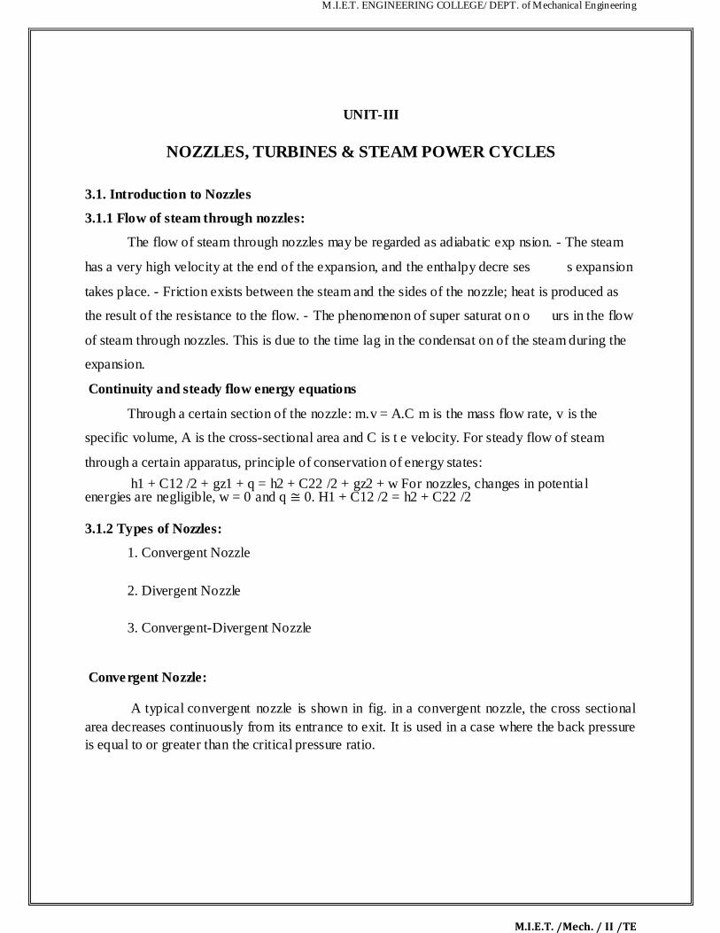
M.I.E.T. ENGINEERING COLLEGE/ DEPT. of Mechanical Engineering
M.I.E.T. /Mech. / II /TE
UNIT-III
NOZZLES, TURBINES & STEAM POWER CYCLES 3.1. Introduction to Nozzles
3.1.1 Flow of steam through nozzles:
The flow of steam through nozzles may be regarded as adiabatic exp nsion. - The steam has a very high velocity at the end of the expansion, and the enthalpy decre ses s expansion takes place. - Friction exists between the steam and the sides of the nozzle; heat is produced as the result of the resistance to the flow. - The phenomenon of super saturat on o urs in the flow of steam through nozzles. This is due to the time lag in the condensat on of the steam during the expansion. Continuity and steady flow energy equations
Through a certain section of the nozzle: m.v = A.C m is the mass flow rate, v is the specific volume, A is the cross-sectional area and C is t e velocity. For steady flow of steam through a certain apparatus, principle of conservation of energy states:
h1 + C12 /2 + gz1 + q = h2 + C22 /2 + gz2 + w For nozzles, changes in potential energies are negligible, w = 0 and q ≅ 0. H1 + C12 /2 = h2 + C22 /2 3.1.2 Types of Nozzles:
1. Convergent Nozzle
2. Divergent Nozzle
3. Convergent-Divergent Nozzle
Convergent Nozzle:
A typical convergent nozzle is shown in fig. in a convergent nozzle, the cross sectional area decreases continuously from its entrance to exit. It is used in a case where the back pressure is equal to or greater than the critical pressure ratio.
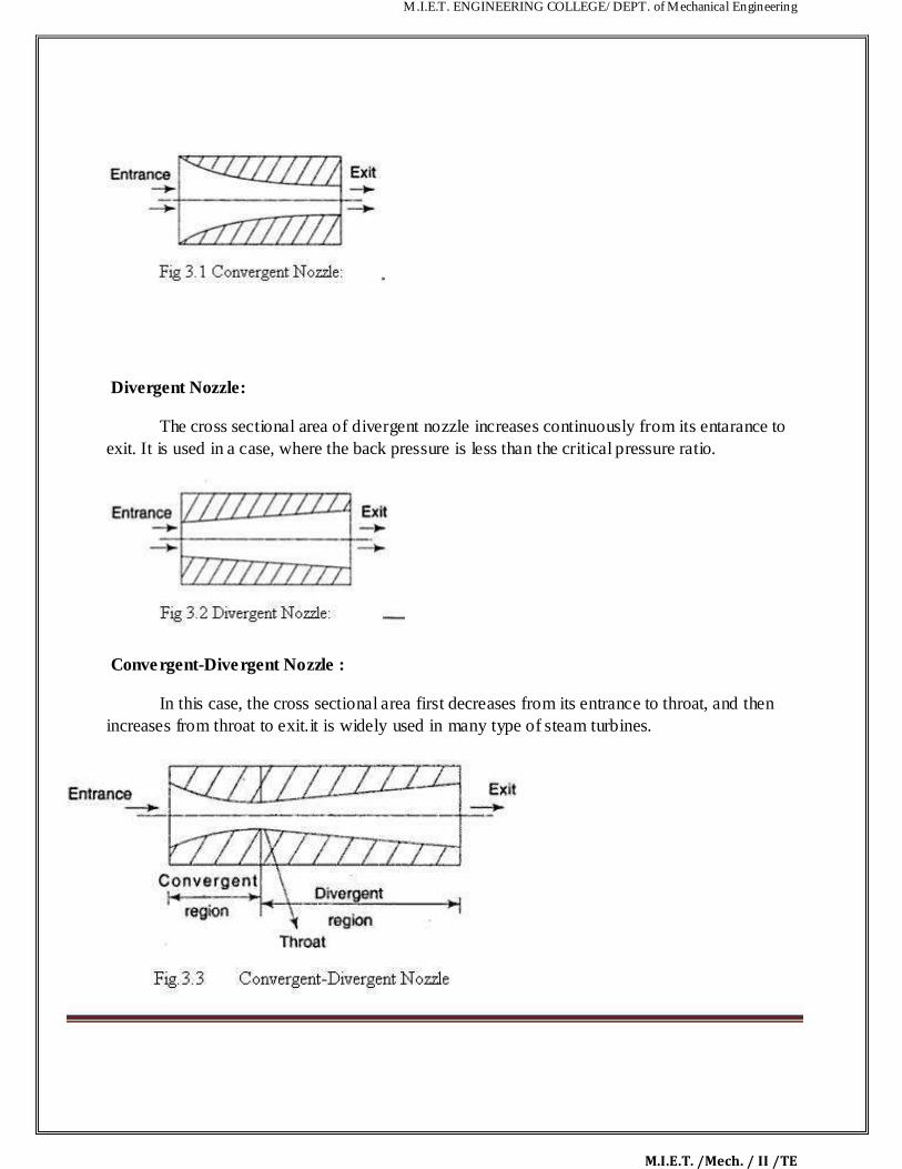
M.I.E.T. ENGINEERING COLLEGE/ DEPT. of Mechanical Engineering
M.I.E.T. /Mech. / II /TE
Divergent Nozzle:
The cross sectional area of divergent nozzle increases continuously from its entarance to exit. It is used in a case, where the back pressure is less than the critical pressure ratio. Convergent-Divergent Nozzle :
In this case, the cross sectional area first decreases from its entrance to throat, and then increases from throat to exit.it is widely used in many type of steam turbines.
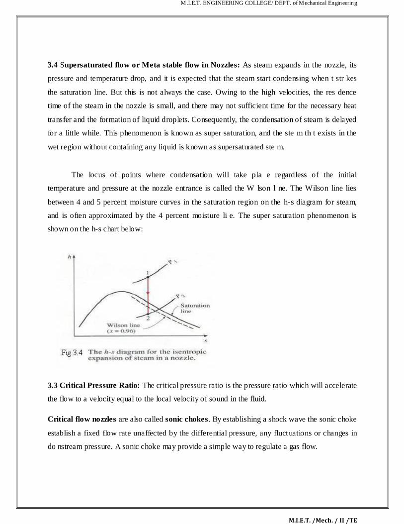
M.I.E.T. ENGINEERING COLLEGE/ DEPT. of Mechanical Engineering
M.I.E.T. /Mech. / II /TE
3.4 Supersaturated flow or Meta stable flow in Nozzles: As steam expands in the nozzle, its
pressure and temperature drop, and it is expected that the steam start condensing when t str kes
the saturation line. But this is not always the case. Owing to the high velocities, the res dence
time of the steam in the nozzle is small, and there may not sufficient time for the necessary heat
transfer and the formation of liquid droplets. Consequently, the condensation of steam is delayed
for a little while. This phenomenon is known as super saturation, and the ste m th t exists in the
wet region without containing any liquid is known as supersaturated ste m.
The locus of points where condensation will take pla e regardless of the initial
temperature and pressure at the nozzle entrance is called the W lson l ne. The Wilson line lies
between 4 and 5 percent moisture curves in the saturation region on the h-s diagram for steam,
and is often approximated by the 4 percent moisture li e. The super saturation phenomenon is
shown on the h-s chart below:
3.3 Critical Pressure Ratio: The critical pressure ratio is the pressure ratio which will accelerate
the flow to a velocity equal to the local velocity of sound in the fluid.
Critical flow nozzles are also called sonic chokes. By establishing a shock wave the sonic choke
establish a fixed flow rate unaffected by the differential pressure, any fluctuations or changes in
do nstream pressure. A sonic choke may provide a simple way to regulate a gas flow.
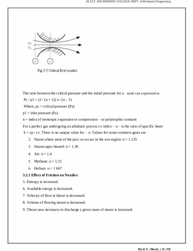
M.I.E.T. ENGINEERING COLLEGE/ DEPT. of Mechanical Engineering
M.I.E.T. /Mech. / II /TE
The ratio between the critical pressure and the initial pressure for a ozzle can expressed as Pc / p1 = (2 / (n + 1)) n / (n – 1)
Where, pc = critical pressure (Pa)
p1 = inlet pressure (Pa) n = index of isentropic expansion or compression – or polytrophic constant For a perfect gas undergoing an adiabatic process t e index – n – is the ratio of specific heats
k = cp / cv. There is no unique value for – n. Values for some common gases are Steam where most of the proc ss occurs in the wet region: n = 1.135 Steam super-heated: n = 1.30 Air: n = 1.4 Methane: n = 1.31 Helium: n = 1 667 3.2.1 Effect of Friction on Nozzles: 5. Entropy is increased. 6. Available energy is decreased. 7. Velocity of flow at throat is decreased. 8. Volume of flowing steam is decreased. 9. Throat area necessary to discharge a given mass of steam is increased.

M.I.E.T. ENGINEERING COLLEGE/ DEPT. of Mechanical Engineering
M.I.E.T. /Mech. / II /TE
Most of the friction occurs in the diverging part of a convergent-divergent nozzle as the le gth of
the converging part is very small. The effect of friction is to reduce the available enthalpy drop
by about 10 to 15%. The velocity of steam will be then
Where, k is the co-efficient which allows for friction loss. It is also known s nozzle efficiency.
Velocity of Steam at Nozzle Exit:
Mass of steam discharged through nozzle: Condition for maximum discharge through nozzle: The nozzle is always designed for
maximum discharge

M.I.E.T. ENGINEERING COLLEGE/ DEPT. of Mechanical Engineering
M.I.E.T. /Mech. / II /TE
Values for maximum discharge:

M.I.E.T. ENGINEERING COLLEGE/ DEPT. of Mechanical Engineering
M.I.E.T. /Mech. / II /TE
Where P1 is the initial pressure of the steam in kpa and v1 is the specific volume of the steam in
m3/kg at the initial pressure.

M.I.E.T. ENGINEERING COLLEGE/ DEPT. of Mechanical Engineering
M.I.E.T. /Mech. / II /TE
3.5 STEAM TURBINES: Normally the turbines are classified into types, 11. Impulse Turbine 12. Reaction Turbine 3.5.1Impulse and Reaction Turbines:
3.5.1 Impulse Turbines: The steam jets are directed at the turbines bucket shaped rotor blades where the pressure exerted
by the jets causes the rotor to rotate and the velocity of the steam to reduce as it imparts its
kinetic energy to the blades. The blades in turn change the direction of flow of the steam ho ever
its pressure remains constant as it passes through the rotor blades since the cross section
M.I.E.T. ENGINEERING COLLEGE/ DEPT. of Mechanical Engineering
M.I.E.T. /Mech. / II /TE
of the chamber between the blades is constant. Impulse turbines are therefore also k own as
constant pressure turbines. The next series of fixed blades reverses the direction of the steam
before it passes to the second row of moving blades.
Reaction Turbines The rotor blades of the reaction turbine are shaped more like aero fo ls, arranged such that the
cross section of the chambers formed between the fixed blades d m n shes from the inlet side
towards the exhaust side of the blades. The chambers between the rotor blades essentially form
nozzles so that as the steam progresses through the ch mbers its velocity increases while at the
same time its pressure decreases, just as in the nozzles formed by the fixed blades. Thus the
pressure decreases in both the fixed and moving blades. As the steam emerges in a jet from
between the rotor blades, it creates a reactive force on t e blades which in turn creates the turning
moment on the turbine rotor, just as in Hero‟s steam engine. (Newton‟s Third Law – For every
action there is an equal and opposite rea tion).
3.5.2 Compounding of impulse turbine : 5. This is done to reduce the rotational speed of the impulse turbine to practical limits. (A
rotor speed of 30,000 rpm is possible, which is pretty high for practical uses.) - Compounding is
achieved by using more than one set of nozzles, blades, rotors, in a series, keyed to a common
shaft; so that either the steam pressure or the jet velocity is absorbed by the turbine in stages. -
Three main types of compounded impulse turbines are: a) Pressure compounded, b) velocity
compounded and c) pressure and velocity compounded impulse turbines.
Velocity Compounding:

M.I.E.T. ENGINEERING COLLEGE/ DEPT. of Mechanical Engineering
M.I.E.T. /Mech. / II /TE
Pi = Inlet Pressure, Pe= Exit Pressure, Vi =Inlet Velocity, Ve=Exit Velocity.
The velocity-compounded impulse turbine was first proposed by C.G. Curtis to solve the
problems of a single-stage impulse turbine for use with high pressure and temperature steam.
The Curtis stage turbine, as it came to be called, is composed of one stage of nozzles as the
single-stage turbine, followed by two rows of moving blades instead of one. These two rows are
separated by one row of fixed blades atta hed to the turbine stator, which has the function of
redirecting the steam leaving the first row of moving blades to the second row of moving blades.
A Curtis stage impulse turbine is shown in Fig. with schematic pressure and absolute steam-
velocity changes through the stage. In the Curtis stage, the total enthalpy drop and hence
pressure drop occur in the nozzles so that the pressure remains constant in all three rows of
blades.
Pressure Compounding:
-This involves splitting up of the whole pressure drop from the steam chest pressure to the
condenser pressure into a series of smaller pressure drops across several stages of impulse
turbine. -The nozzles are fitted into a diaphragm locked in the casing. This diaphragm separates
one heel chamber from another. All rotors are mounted on the same shaft and the blades are
attached on the rotor.
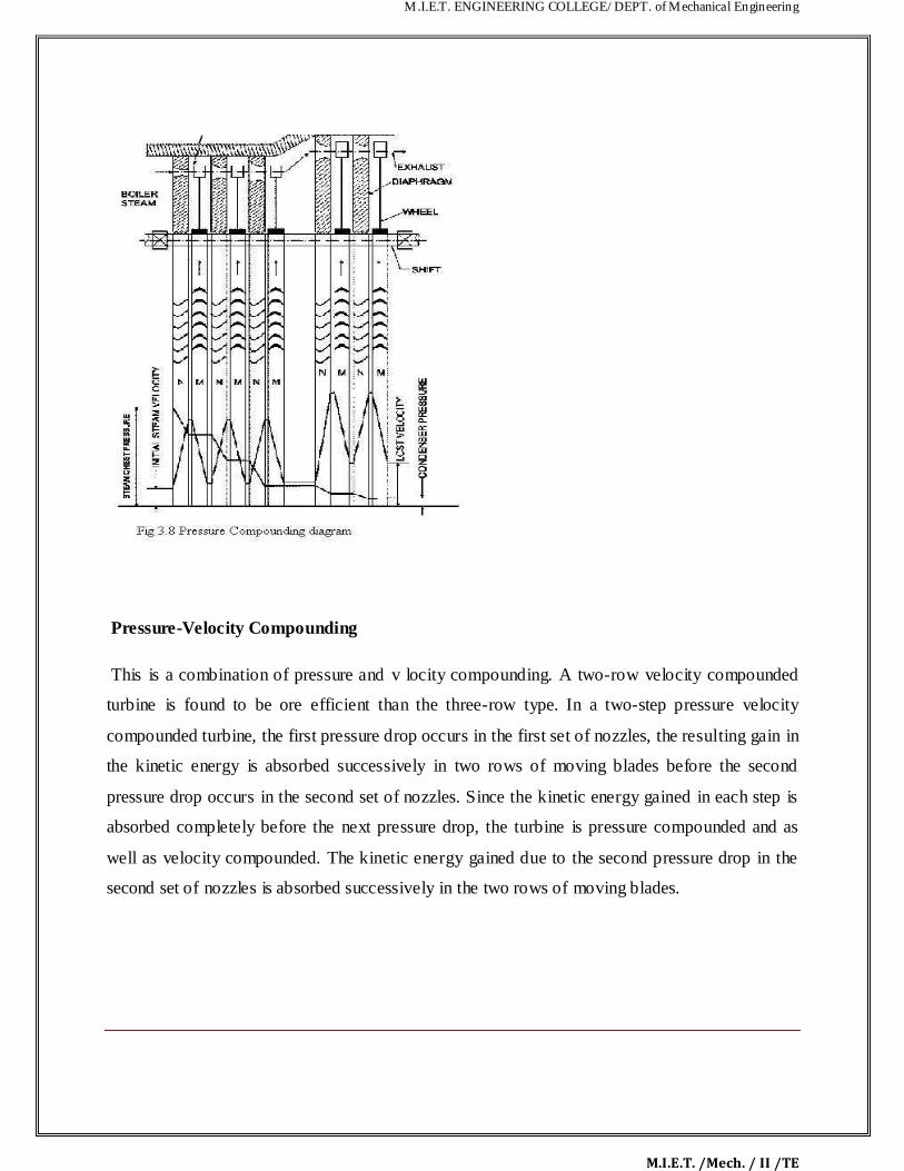
M.I.E.T. ENGINEERING COLLEGE/ DEPT. of Mechanical Engineering
M.I.E.T. /Mech. / II /TE
Pressure-Velocity Compounding
This is a combination of pressure and v locity compounding. A two-row velocity compounded
turbine is found to be ore efficient than the three-row type. In a two-step pressure velocity
compounded turbine, the first pressure drop occurs in the first set of nozzles, the resulting gain in
the kinetic energy is absorbed successively in two rows of moving blades before the second
pressure drop occurs in the second set of nozzles. Since the kinetic energy gained in each step is
absorbed completely before the next pressure drop, the turbine is pressure compounded and as
well as velocity compounded. The kinetic energy gained due to the second pressure drop in the
second set of nozzles is absorbed successively in the two rows of moving blades.

M.I.E.T. ENGINEERING COLLEGE/ DEPT. of Mechanical Engineering
M.I.E.T. /Mech. / II /TE
The pressure velocity compound d st am turbine is comparatively simple in construction and is
much more compact than the pressure compound d turbine.
3.6 Velocity diagram of an impulse turbine:

M.I.E.T. ENGINEERING COLLEGE/ DEPT. of Mechanical Engineering
M.I.E.T. /Mech. / II /TE

M.I.E.T. ENGINEERING COLLEGE/ DEPT. of Mechanical Engineering
M.I.E.T. /Mech. / II /TE

M.I.E.T. ENGINEERING COLLEGE/ DEPT. of Mechanical Engineering
M.I.E.T. /Mech. / II /TE
3. 19
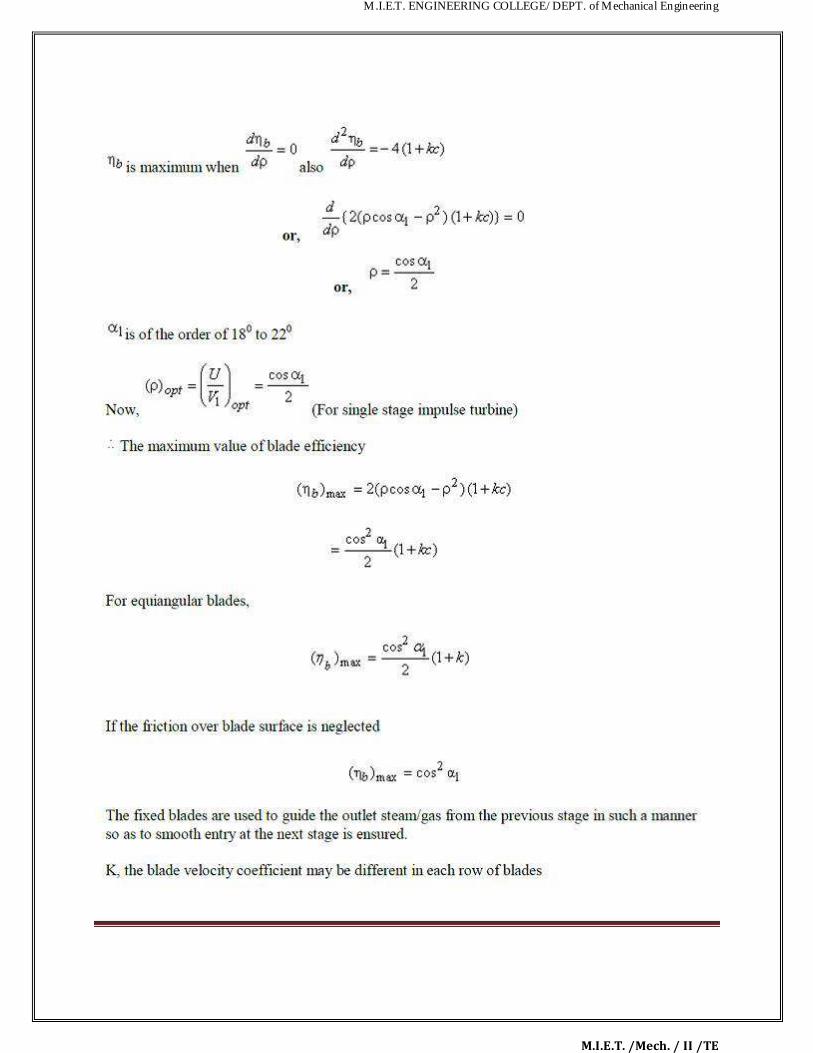
M.I.E.T. ENGINEERING COLLEGE/ DEPT. of Mechanical Engineering
M.I.E.T. /Mech. / II /TE

M.I.E.T. ENGINEERING COLLEGE/ DEPT. of Mechanical Engineering
M.I.E.T. /Mech. / II /TE
3.6.1 Velocity diagram of the velocity compounded turbines:
Reaction Turbine:

M.I.E.T. ENGINEERING COLLEGE/ DEPT. of Mechanical Engineering
M.I.E.T. /Mech. / II /TE
A reaction turbine, therefore, is one that is constructed of rows of fixed and rows of movi g
blades. The fixed blades act as nozzles. The moving blades move as a result of the mpulse of
steam received (caused by change in momentum) and also as a result of expans on and
acceleration of the steam relative to them. In other words, they also act as nozz es The enthalpy
drop per stage of one row fixed and one row moving blades is divided among them, often
equally. Thus a blade with a 50 percent degree of reaction, or a 50 percent re ction st ge, is one in
which half the enthalpy drop of the stage occurs in the fixed blades nd h lf in the moving blades.
The pressure drops will not be equal, however. They are greater for the fixed blades and greater
for the high-pressure than the low-pressure stages. The mov ng blades of a reaction turbine are
easily distinguishable from those of an impulse turb ne n that they are not symmetrical and,
because they act partly as nozzles, have a shape similar to that of the fixed blades, although
curved in the opposite direction. The schem tic pressure line in figure shows that pressure
continuously drops through all rows of bl des, fixed and moving. The absolute steam velocity
changes within each stage as s own and repeats from stage to stage. The second figure shows a
typical velocity diagram for t e reaction stage.

M.I.E.T. ENGINEERING COLLEGE/ DEPT. of Mechanical Engineering
M.I.E.T. /Mech. / II /TE
Pressure and enthalpy drop both in the fixed blade or stator and in the moving blade or Rotor

M.I.E.T. ENGINEERING COLLEGE/ DEPT. of Mechanical Engineering
M.I.E.T. /Mech. / II /TE

M.I.E.T. ENGINEERING COLLEGE/ DEPT. of Mechanical Engineering
M.I.E.T. /Mech. / II /TE
Therefore, the blade efficiency

M.I.E.T. ENGINEERING COLLEGE/ DEPT. of Mechanical Engineering
M.I.E.T. /Mech. / II /TE
3.8 Governing of Steam Turbine: The method of maintaining the turbine speed co sta t
irrespective of the load is known as governing of turbines. The device used for gover g of
turbines is called Governor. There are 3 types of governors in steam turbine, 15. Throttle governing 16. Nozzle governing 17. By-pass governing
3.8.1. Throttle Governing:
Let us consider an instant hen the load on the turbine increases, as a result the speed of the
turbine decreases. The fly balls of the governor will come down. The fly balls bring down the
sleeve. The do n ard movement of the sleeve will raise the control valve rod. The mouth of the pipe AA ill open. Now the oil under pressure will rush from the control valve to right side of
piston in the rely cylinder through the pipe AA. This will move the piston and spear towards the

M.I.E.T. ENGINEERING COLLEGE/ DEPT. of Mechanical Engineering
M.I.E.T. /Mech. / II /TE
left which will open more area of nozzle. As a result steam flow rate into the turbine i creases,
which in turn brings the speed of the turbine to the normal range.
3.8.2. Nozzle Governing: A dynamic arrangement of nozzle control governing is shown in fig.
In this nozzles are grouped in 3 to 5 or more groups and each group of nozzle is supplied steam
controlled by valves. The arc of admission is limited to 180º or less. The nozzle controlled
governing is restricted to the first stage of the turbine, the nozzle area in other stages remaining
constant. It is suitable for the simple turbine and for larger units which have an impulse stage
followed by an impulse reaction turbine.
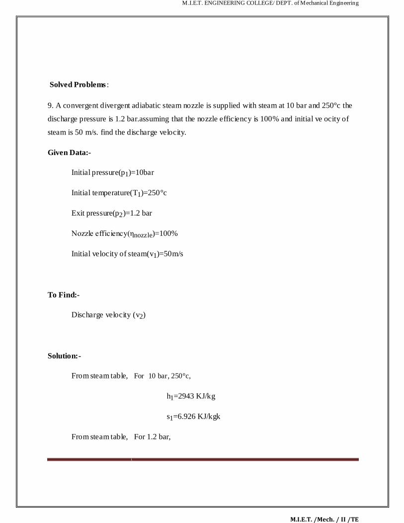
M.I.E.T. ENGINEERING COLLEGE/ DEPT. of Mechanical Engineering
M.I.E.T. /Mech. / II /TE
Solved Problems :
9. A convergent divergent adiabatic steam nozzle is supplied with steam at 10 bar and 250°c the
discharge pressure is 1.2 bar.assuming that the nozzle efficiency is 100% and initial ve ocity of
steam is 50 m/s. find the discharge velocity.
Given Data:-
Initial pressure(p1)=10bar
Initial temperature(T1)=250°c
Exit pressure(p2)=1.2 bar
Nozzle efficiency(ηnozzle)=100%
Initial velocity of steam(v1)=50m/s
To Find:-
Discharge velocity (v2)
Solution:-
From steam table, For 10 bar, 250°c,
h1=2943 KJ/kg
s1=6.926 KJ/kgk
From steam table, For 1.2 bar,
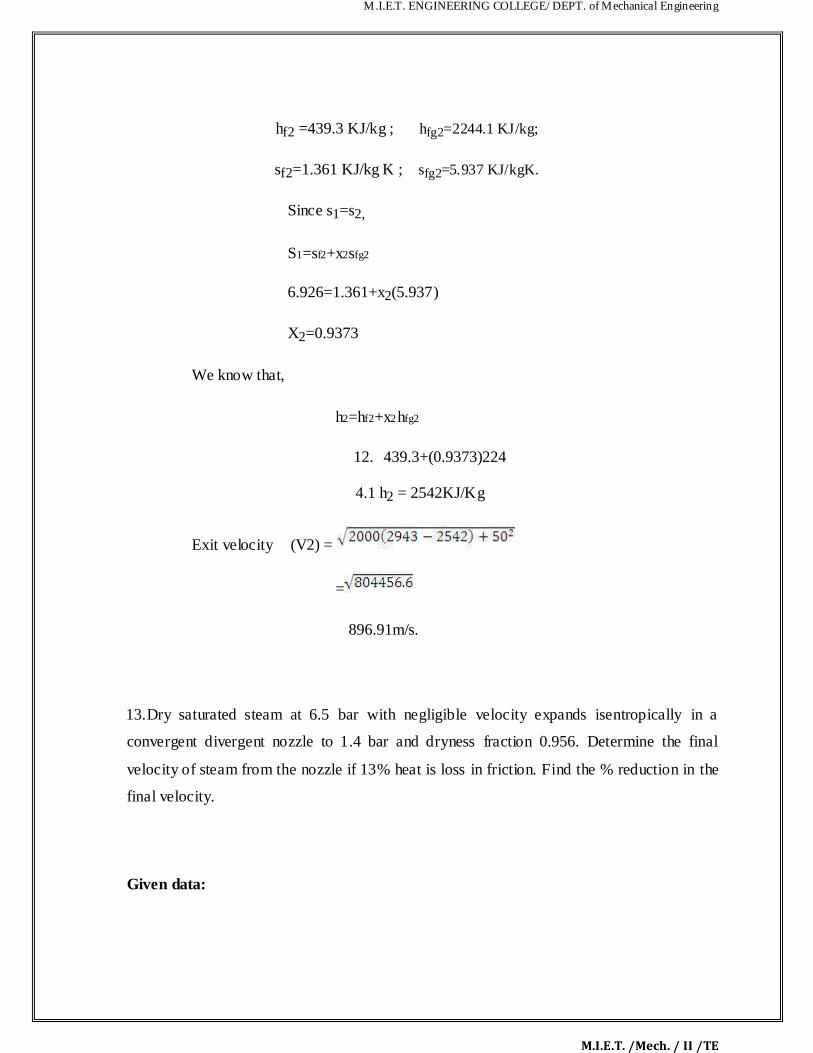
M.I.E.T. ENGINEERING COLLEGE/ DEPT. of Mechanical Engineering
M.I.E.T. /Mech. / II /TE
hf2 =439.3 KJ/kg ; hfg2=2244.1 KJ/kg;
sf2=1.361 KJ/kg K ; sfg2=5.937 KJ/kgK.
Since s1=s2,
S1=sf2+x2sfg2
6.926=1.361+x2(5.937)
X2=0.9373
We know that,
h2=hf2+x2hfg2
12. 439.3+(0.9373)224
4.1 h2 = 2542KJ/Kg
Exit velocity (V2) =
=
896.91m/s.
13. Dry saturated steam at 6.5 bar with negligible velocity expands isentropically in a
convergent divergent nozzle to 1.4 bar and dryness fraction 0.956. Determine the final
velocity of steam from the nozzle if 13% heat is loss in friction. Find the % reduction in the
final velocity.
Given data:
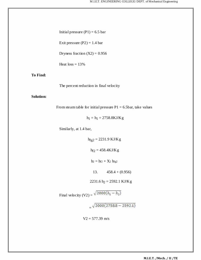
M.I.E.T. ENGINEERING COLLEGE/ DEPT. of Mechanical Engineering
M.I.E.T. /Mech. / II /TE
Initial pressure (P1) = 6.5 bar
Exit pressure (P2) = 1.4 bar
Dryness fraction (X2) = 0.956
Heat loss = 13%
To Find:
The percent reduction in final velocity
Solution:
From steam table for initial pressure P1 = 6.5bar, take values
h1 = h1 = 2758.8KJ/Kg
Similarly, at 1.4 bar,
hfg2 = 2231.9 KJ/Kg
hf2 = 458.4KJ/Kg
h2 = hf2 + X2 hfg2
13. 458.4 + (0.956)
2231.6 h2 = 2592.1 KJ/Kg
Final velocity (V2) =
=
V2 = 577.39 m/s
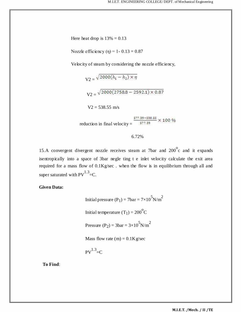
M.I.E.T. ENGINEERING COLLEGE/ DEPT. of Mechanical Engineering
M.I.E.T. /Mech. / II /TE
Here heat drop is 13% = 0.13
Nozzle efficiency (η) = 1- 0.13 = 0.87
Velocity of steam by considering the nozzle efficiency,
V2 =
V2 =
V2 = 538.55 m/s
reduction in final velocity =
6.72%
15. A convergent divergent nozzle receives steam at 7bar and 200oc and it expands
isentropically into a space of 3bar negle ting t e inlet velocity calculate the exit area
required for a mass flow of 0.1Kg/sec . when the flow is in equilibrium through all and
super saturated with PV1.3
=C.
Given Data:
Initial pressure (P1) = 7bar = 7×10⁵N/m
2
Initial temperature (T1) = 200oC
Pressure (P2) = 3bar = 3×10⁵N/m
2
Mass flow rate (m) = 0.1Kg/sec
PV1.3
=C
To Find:

M.I.E.T. ENGINEERING COLLEGE/ DEPT. of Mechanical Engineering
M.I.E.T. /Mech. / II /TE
Area of the nozzle at exit
Solution:
From steam table for P1 = 7bar and T1 = 200oC
V1 = 0.2999
h1 = 2844.2
S1 = 6.886
Similarly for P2 = 3bar
V f2 = 0.001074 Vg2 = 0.60553
hf2 = 561.5 hfg2 = 2163.2
Sf2 = 1.672 Sfg2 = 5.319
We know that, S1 = S2 = St
S1 = Sf2 + X2 Sfg2
6.886 = 1.672 + X2 (5.319)
X2 = 0.98
Similarly,
h2 = hf2 + X2 hfg2
h2 = 561.5 + 0.98 (2163.2)
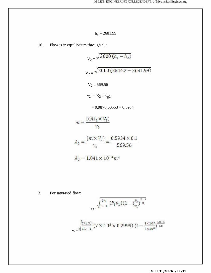
M.I.E.T. ENGINEERING COLLEGE/ DEPT. of Mechanical Engineering
M.I.E.T. /Mech. / II /TE
h2 = 2681.99
16. Flow is in equilibrium through all:
V2 =
V2 =
V2 = 569.56
ν2 = X2 × νg2
= 0.98×0.60553 = 0.5934
3. For saturated flow:
ν2 =
ν2 =

M.I.E.T. ENGINEERING COLLEGE/ DEPT. of Mechanical Engineering
M.I.E.T. /Mech. / II /TE
ν2 = 568.69 m/s
specific volume of steam at exit. For super saturated flow,
P1 = P2 3.12. TWO MARKS UNIVERSITY QUESTIONS:
Part-A (2 Marks)

M.I.E.T. ENGINEERING COLLEGE/ DEPT. of Mechanical Engineering
M.I.E.T. /Mech. / II /TE
iv) What are the various types of nozzles and their functions?
v) Define nozzle efficiency and critical pressure ratio.
vi) Explain the phenomenon of super saturated expansion in steam nozzle. Or what is
metastable flow?
vii) State the function of fixed blades.
viii) Classify steam turbines.
ix) How does impulse work?
x) What is meant by carry over loss?
xi) State the function of moving blades...."
xii) What is the fundamental difference between t e operation of impulse and reaction steam
turbines?
xiii) What are the different methods of governing steam turbines?
xiv) How is throttle governing done ?
xv) Where nozzle control governing is used?
13. Whereby - pass governing is ore suitable?
14. What a re the dif fere nt losses in stea m turbines?
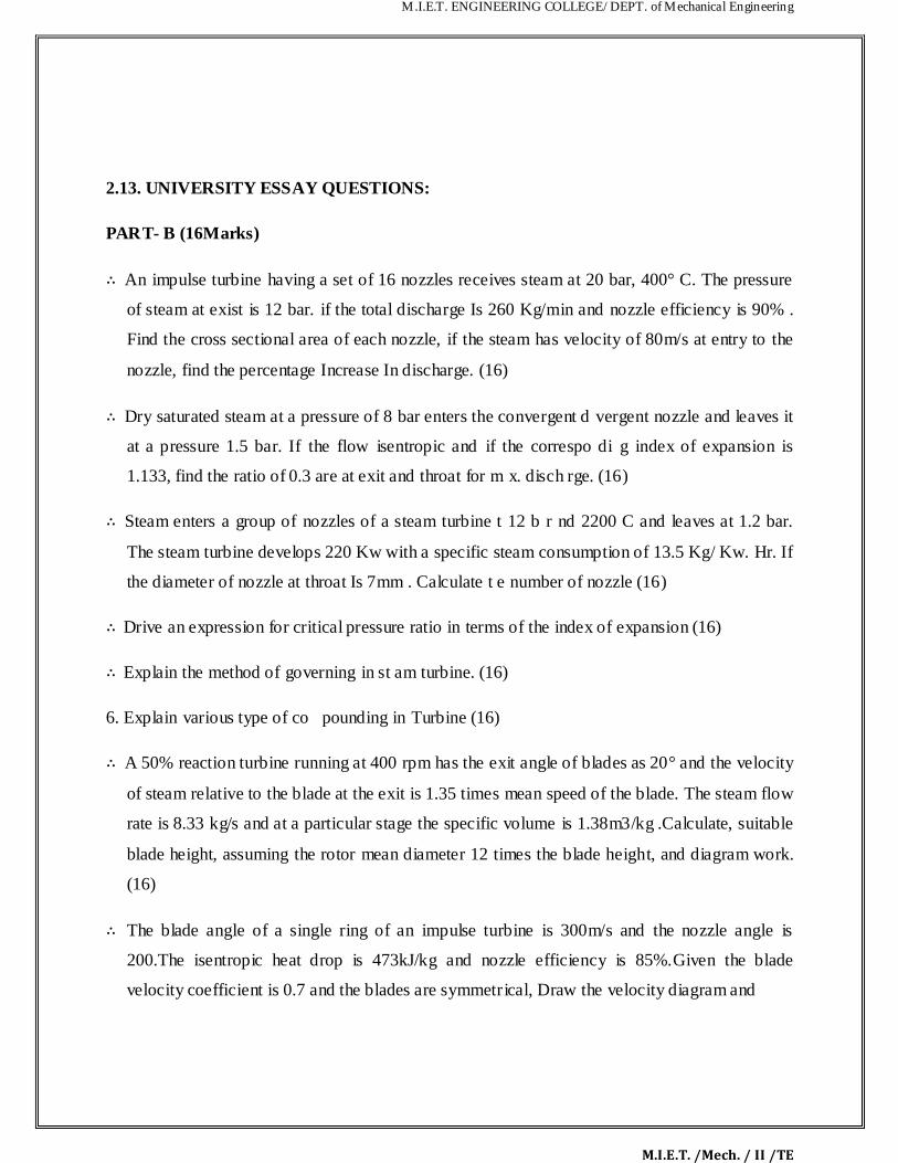
M.I.E.T. ENGINEERING COLLEGE/ DEPT. of Mechanical Engineering
M.I.E.T. /Mech. / II /TE
2.13. UNIVERSITY ESSAY QUESTIONS:
PART- B (16Marks)
∴ An impulse turbine having a set of 16 nozzles receives steam at 20 bar, 400° C. The pressure
of steam at exist is 12 bar. if the total discharge Is 260 Kg/min and nozzle efficiency is 90% .
Find the cross sectional area of each nozzle, if the steam has velocity of 80m/s at entry to the
nozzle, find the percentage Increase In discharge. (16)
∴ Dry saturated steam at a pressure of 8 bar enters the convergent d vergent nozzle and leaves it
at a pressure 1.5 bar. If the flow isentropic and if the correspo di g index of expansion is
1.133, find the ratio of 0.3 are at exit and throat for m x. disch rge. (16)
∴ Steam enters a group of nozzles of a steam turbine t 12 b r nd 2200 C and leaves at 1.2 bar.
The steam turbine develops 220 Kw with a specific steam consumption of 13.5 Kg/ Kw. Hr. If
the diameter of nozzle at throat Is 7mm . Calculate t e number of nozzle (16)
∴ Drive an expression for critical pressure ratio in terms of the index of expansion (16) ∴ Explain the method of governing in st am turbine. (16)
6. Explain various type of co pounding in Turbine (16)
∴ A 50% reaction turbine running at 400 rpm has the exit angle of blades as 20° and the velocity
of steam relative to the blade at the exit is 1.35 times mean speed of the blade. The steam flow
rate is 8.33 kg/s and at a particular stage the specific volume is 1.38m3/kg .Calculate, suitable
blade height, assuming the rotor mean diameter 12 times the blade height, and diagram work.
(16)
∴ The blade angle of a single ring of an impulse turbine is 300m/s and the nozzle angle is
200.The isentropic heat drop is 473kJ/kg and nozzle efficiency is 85%.Given the blade
velocity coefficient is 0.7 and the blades are symmetrical, Draw the velocity diagram and

M.I.E.T. ENGINEERING COLLEGE/ DEPT. of Mechanical Engineering
M.I.E.T. /Mech. / II /TE
calculate for a mass flow of 1 kg/s i) axial thrust on balding ii) steam consumption per BP
hour if the mechanical efficiency is 90% iii) blade efficiency and stage efficiency. (16)

M.I.E.T. ENGINEERING COLLEGE/ DEPT. of Mechanical Engineering
M.I.E.T. /Mech. / II /TE
ME6404 THERMAL ENGINEERING
UNIT IV
AIR COMPRESSORS

M.I.E.T. ENGINEERING COLLEGE/ DEPT. of Mechanical Engineering
M.I.E.T. /Mech. / II /TE
CONTENTS
TECHNICAL TERMS
4.1 Classification of compressors
4.2 Positive Displacement compressors
4.2.1 Double acting compressor
4.2.2 Diaphragm Compressors
4.3 Rotary compressors
4.3.1 Lobe compressor
4.3.2 Liquid ring compressor
4.3.3 Vane Type compressor:
4.3.4 Screw Type compressor
4.3.5 Scroll Type Compressor
4.4 Non-Positive displacement compressors
4.4.1 Centrifugal Compressor
4.4.2 Axial Compressor
4.4.3 Roots Blower Compressor
4.5 Multistage Compression
4.5.1 Advantages of Multi-stage compression
4.6 Work done in a single stage reciprocating compressor without clearance volume
4.6.1 Work done in a single stage reciprocating compressor with clearance
Volume
4.7 Volumetric Efficiency
4.7.1 Mathematical analysis of multistage compressor is done with following
assumptions
4.8 Solved Problems
4.9 T o Marks University Questions
4.10 University Essay Questions

M.I.E.T. ENGINEERING COLLEGE/ DEPT. of Mechanical Engineering
M.I.E.T. /Mech. / II /TE
TECHNICAL TERMS
1. Volumetric Efficiency of the Compressor It is the ratio of actual volume of air drawn in the compressor to the stroke volume of the compressor. 2. Mechanical efficiency It is the ratio of indicated power to shaft power or brake power of motor. 3. Isentropic efficiency It is the ratio of the isentropic power to the brake power required to dr ve the compressor. 4. Centrifugal compressor The flow of air is perpendicular to the axis of compressor 5. Axial flow compressor The flow of air is parallel to the axis of compressor 6. Compression:
The process of increasing the pressure of air, gas and vapour by reducing its volume is called as
compression.
7. Single acting compressor:
The suction, compression and the delivery of air takes on the one side of piston 8. Double acting compressor: The suction, compresstion end the delivery of air takes place on both sides of the piston.
9. Multi stage compressor:
The compression of air from initial pressure to the final pressure is carried out in more than one
cylinder.

M.I.E.T. ENGINEERING COLLEGE/ DEPT. of Mechanical Engineering
M.I.E.T. /Mech. / II /TE
10. Application of compressed air:
Pneumatic brakes, drills, jacks, lifts, spray of paintings, shop cleaning, injecting the fuel d esel
engine, supercharging, refrigeration and in air conditioning systems.
11. Inter cooler:
It is a simple heat exchanger, exchanges the heat of compressed air from low pressure
compressor to circulating water before the air enters to high pressure ompressor. The purpose
of intercooling is to minimize the work of compression.
12. Isentropic efficiency:
It is the ratio of isentropic power to the brake power required to drive the compressor.
13. Clearance ratio:
It is the ratio of clearance volume to the swept volume or stroke volume is called as
clearance ratio.
14. Isothermal efficiency:
It is the ratio between isothermal work to the actual work of the compressor.
15. Compression ratio:
The ratio between total volu e and the clearance volume of the cylinder is called compression
ratio.
16. Perfect intercooling:
When the temperature of the air leaving the intercooler is equal to the original atmospheric
air temperature, then the inter cooling is called perfect intercooling.

M.I.E.T. ENGINEERING COLLEGE/ DEPT. of Mechanical Engineering
M.I.E.T. /Mech. / II /TE
UNIT-IV
AIR COMPRESSORS
4.1.1 Classification of compressors: The compressors are also classified based on other aspects like 1. Number of stages (single-stage, 2-stage and multi-stage), 2. Cooling method and medium (Air cooled, water cooled and oil-cooled), 3. Drive types ( Engine driven, Motor driven, Turbine driven, Belt, chain, gear or direct coupling
drives), 4. Lubrication method (Splash lubricated or forced lubrication or oil- free compressors). 5. Service Pressure (Lo , Medium, High) Positive Displacement compressors: Reciprocating Compressor: Single-Acting
4.2.1Reciprocating compressor: These are usually reciprocating compressors, which has piston working on air only in one
direction. The other end of the piston is often free or open which does not perform any work. The

M.I.E.T. ENGINEERING COLLEGE/ DEPT. of Mechanical Engineering
M.I.E.T. /Mech. / II /TE
air is compressed only on the top part of the piston. The bottom of the piston is open to cra kcase
and not utilized for the compression of air. 4.2.1 Double acting compressor: These compressors are having two sets of suction/intake and delivery valves on both sides of the
piston. As the piston moves up and down, both sides of the piston is utilized in compressing the
air. The intake and delivery valves operate orresponding to the stroke of the compressor. The
compressed air delivery is comparativ ly continuous when compared to a single-acting air
compressor. Thus both sides of the pistons are ffectively used in compressing the air.

M.I.E.T. ENGINEERING COLLEGE/ DEPT. of Mechanical Engineering
M.I.E.T. /Mech. / II /TE
4.2.2 Diaphragm Compressors: In the diaphragm compressor, the piston pushes against a
diaphragm, so the air does not come in contact with the reciprocating parts. This type compressor
is preferred for food preparation, pharmaceutical, and chemical industries, because no effluent
from the compressor enters the fluid.

M.I.E.T. ENGINEERING COLLEGE/ DEPT. of Mechanical Engineering
M.I.E.T. /Mech. / II /TE
4.2.2 Rotary compressors: Lobe compressor: The Lobe type air compressor is very simpler type with no complicated moving parts. There are
single or twin lobes attached to the drive shaft driven by the prime mover. The lobes are
displaced by 90 degrees. Thus if one of the lobes is in horizontal position, the other at that
particular instant will be in vertical position. Thus the air gets trapped in between these lobes and
as they rotate they get co pressed and delivered to the delivery line.
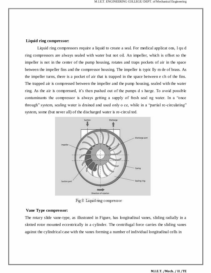
M.I.E.T. ENGINEERING COLLEGE/ DEPT. of Mechanical Engineering
M.I.E.T. /Mech. / II /TE
Liquid ring compressor:
Liquid ring compressors require a liquid to create a seal. For medical applicat ons, l qu d
ring compressors are always sealed with water but not oil. An impeller, which is offset so the
impeller is not in the center of the pump housing, rotates and traps pockets of air in the space
between the impeller fins and the compressor housing. The impeller is typic lly m de of brass. As
the impeller turns, there is a pocket of air that is trapped in the space between e ch of the fins.
The trapped air is compressed between the impeller and the pump housing, sealed with the water
ring. As the air is compressed, it‟s then pushed out of the pumps d s harge. To avoid possible
contaminants the compressor is always getting a supply of fresh seal ng water. In a “once
through” system, sealing water is drained and used only o ce, while in a “partial re-circulating”
system, some (but never all) of the discharged water is re-circul ted. Vane Type compressor: The rotary slide vane-type, as illustrated in Figure, has longitudinal vanes, sliding radially in a
slotted rotor mounted eccentrically in a cylinder. The centrifugal force carries the sliding vanes
against the cylindrical case with the vanes forming a number of individual longitudinal cells in

M.I.E.T. ENGINEERING COLLEGE/ DEPT. of Mechanical Engineering
M.I.E.T. /Mech. / II /TE
the eccentric annulus between the case and rotor. The suction port is located where the
longitudinal cells are largest. The size of each cell is reduced by the eccentricity of the rotor as
the vanes approach the discharge port, thus compressing the air. This type of compressor, looks
and functions like a vane type hydraulic pump. An eccentr ically mounted rotor turns in a
cylindrical housing having an inlet and outlet. Vanes slide back and forth in grooves in the rotor.
Air pressure or spring force keeps the tip of these vanes in contact with the housing. Air is
trapped in the compartments formed by the vanes and housing and is compressed s the rotor
turns. Screw Type compressor:
The screw compressors are efficient in low air pressure requirements. Two screws rotate
intermeshing with each other, thus trapping air between the screws and the compressor casing,
forming pockets which progressively travel and gets squeezed and delivering it at a higher
pressure which opens the delivery valve. The compressed air delivery is continuous and quiet in
operation than a reciprocating compressor. Rotary air compressors are positive displacement
compressors. The most common rotary air compressor is the single stage helical or spiral lobe oil
flooded screw air compressor. These compressors consist of two rotors within a casing where the
rotors compress the air internally. There are no valves. These units are basically oil cooled (with
air cooled or ater cooled oil coolers) where the oil seals the internal clearances. Since the cooling
takes place right inside the compressor, the working parts never experience extreme
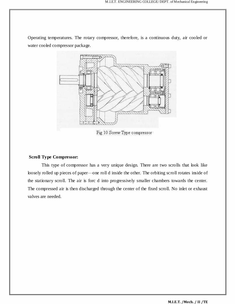
M.I.E.T. ENGINEERING COLLEGE/ DEPT. of Mechanical Engineering
M.I.E.T. /Mech. / II /TE
Operating temperatures. The rotary compressor, therefore, is a continuous duty, air cooled or
water cooled compressor package.
Scroll Type Compressor:
This type of compressor has a very unique design. There are two scrolls that look like
loosely rolled up pieces of paper––one roll d inside the other. The orbiting scroll rotates inside of
the stationary scroll. The air is forc d into progressively smaller chambers towards the center.
The compressed air is then discharged through the center of the fixed scroll. No inlet or exhaust
valves are needed.
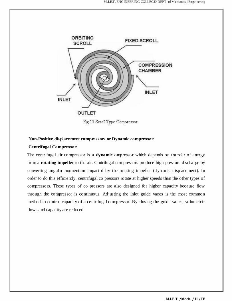
M.I.E.T. ENGINEERING COLLEGE/ DEPT. of Mechanical Engineering
M.I.E.T. /Mech. / II /TE
Non-Positive displacement compressors or Dynamic compressor: Centrifugal Compressor: The centrifugal air compressor is a dynamic ompressor which depends on transfer of energy
from a rotating impeller to the air. C ntrifugal compressors produce high-pressure discharge by
converting angular momentum impart d by the rotating impeller (dynamic displacement). In
order to do this efficiently, centrifugal co pressors rotate at higher speeds than the other types of
compressors. These types of co pressors are also designed for higher capacity because flow
through the compressor is continuous. Adjusting the inlet guide vanes is the most common
method to control capacity of a centrifugal compressor. By closing the guide vanes, volumetric
flows and capacity are reduced.

M.I.E.T. ENGINEERING COLLEGE/ DEPT. of Mechanical Engineering
M.I.E.T. /Mech. / II /TE
The centrifugal air compressor is an oil free compressor by des gn. The o l lubricated running
gear is separated from the air by shaft seals and atmospheric ve ts. The centrifugal air
compressor is a dynamic compressor which depends on a rotati g impeller to compress the air. In
order to do this efficiently, centrifugal compressors must rot te t higher speeds than the other
types of compressors. These types of compressors re designed for higher capacity because flow
through the compressor is continuous and oil free by design. Axial Compressor: These are similar to centrifugal compressors ex ept the direction of air flow is axial. The blades
of the compressor are mounted onto the hub and in turn onto the shaft. As the shaft rotates at a
high speed, the ambient air is suck d into the compressor and then gets compressed (high speed
of rotation of the blades i part energy to the air) and directed axially for further usage. An axial
flow compressor, in its very si ple form is called as axial flow fan, which is commonly used for
domestic purposes. The pressure built depends on the number of stages. These are commonly
used as vent fans in enclosed spaces, blower ducts, etc. One can find its main application in the
aerospace industry, here the gas turbines drive the axial flow air compressors. Roots Blower Compressor: This type is generally called as blower. The discharge air pressure obtained from this type of
machine is very low. The Discharge Pressure of 1 bar can be obtained in Single Stage and
pressure of 2.2 bar is obtained from Stage. The discharge pressure achieved by two rotors which
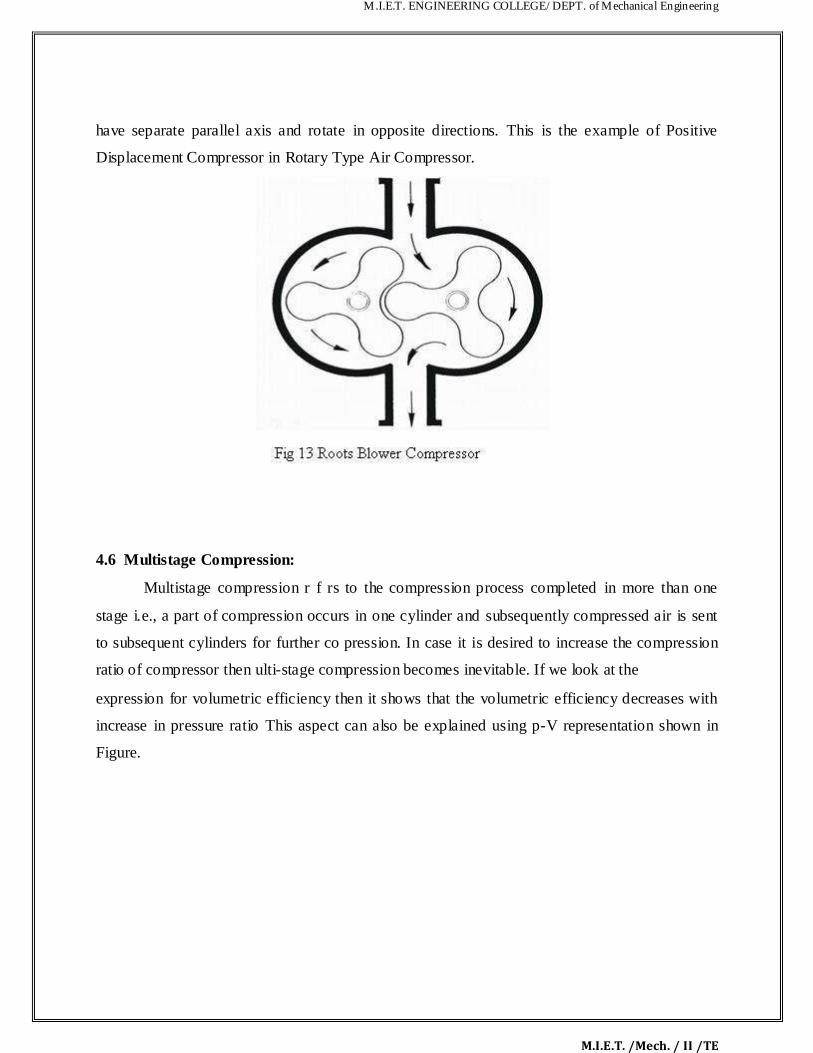
M.I.E.T. ENGINEERING COLLEGE/ DEPT. of Mechanical Engineering
M.I.E.T. /Mech. / II /TE
have separate parallel axis and rotate in opposite directions. This is the example of Positive
Displacement Compressor in Rotary Type Air Compressor. 4.6 Multistage Compression:
Multistage compression r f rs to the compression process completed in more than one
stage i.e., a part of compression occurs in one cylinder and subsequently compressed air is sent
to subsequent cylinders for further co pression. In case it is desired to increase the compression
ratio of compressor then ulti-stage compression becomes inevitable. If we look at the expression for volumetric efficiency then it shows that the volumetric efficiency decreases with
increase in pressure ratio This aspect can also be explained using p-V representation shown in
Figure.

M.I.E.T. ENGINEERING COLLEGE/ DEPT. of Mechanical Engineering
M.I.E.T. /Mech. / II /TE
A multi-stage compressor is one in which there are sever l cylinders of different diameters. The
intake of air in the first stage gets compressed and then it is p ssed over a cooler to achieve a
temperature very close to ambient air. This cooled air is passed to the intermediate stage where it
is again getting compressed and heated. T is air is again passed over a cooler to achieve a
temperature as close to ambient as possible. Then this ompressed air is passed to the final or the
third stage of the air compressor wh re it is compressed to the required pressure and delivered to
the air receiver after cooling suffici ntly in an aft r-cooler. 4.6.1 Advantages of Multi-stage co pression: 1. The work done in co pressing the air is reduced, thus power can be saved
2. Prevents mechanical proble s as the air temperature is controlled 3. The suction and delivery valves remain in cleaner condition as the temperature and
vaporization of lubricating oil is less 4. The machine is smaller and better balanced 5. Effects from moisture can be handled better, by draining at each stage 6. Compression approaches near isothermal 7. Compression ratio at each stage is lower when compared to a single-stage machine

M.I.E.T. ENGINEERING COLLEGE/ DEPT. of Mechanical Engineering
M.I.E.T. /Mech. / II /TE
4.4 Work done in a single stage reciprocating compressor without clearance volume:
Air enters compressor at pr ssure p1 and is compressed upto p2. Compression work
requirement can be estimated from the ar a b low the each compression process. Area on p-V
diagram shows that work require ent shall be minimum with isothermal process 1-2”. Work
requirement is maximum with process 1-2 ie., adiabatic process. As a designer one shall be
interested in a compressor having ini um compression work requirement. Therefore, ideally
compression should occur isothermally for minimum work input. In practice it is not possible to
have isothermal compression because constancy of temperature during compression can not be
realized. Generally, compressors run at substantially high speed while isothermal compression
requires compressor to run at very slow speed so that heat evolved during compression is
dissipated out and temperature remains constant. Actually due to high speed running of
compressor the compression process may be assumed to be near adiabatic or polytrophic process
M.I.E.T. ENGINEERING COLLEGE/ DEPT. of Mechanical Engineering
M.I.E.T. /Mech. / II /TE
following law of compression as with of „n‟ varying between 1.25 to 1.35 for air. Compression process following three processes is also shown on T-s diagram. It is thus obvious that actual compression process should be compared with sothermal
compression process. A mathematical parameter called isothermal efficiency is defined for
quantifying the degree of deviation of actual compression process from ideal compression
process. Isothermal efficiency is defined by the ratio is isothermal work nd ctu l indicated work
in reciprocating compressor.
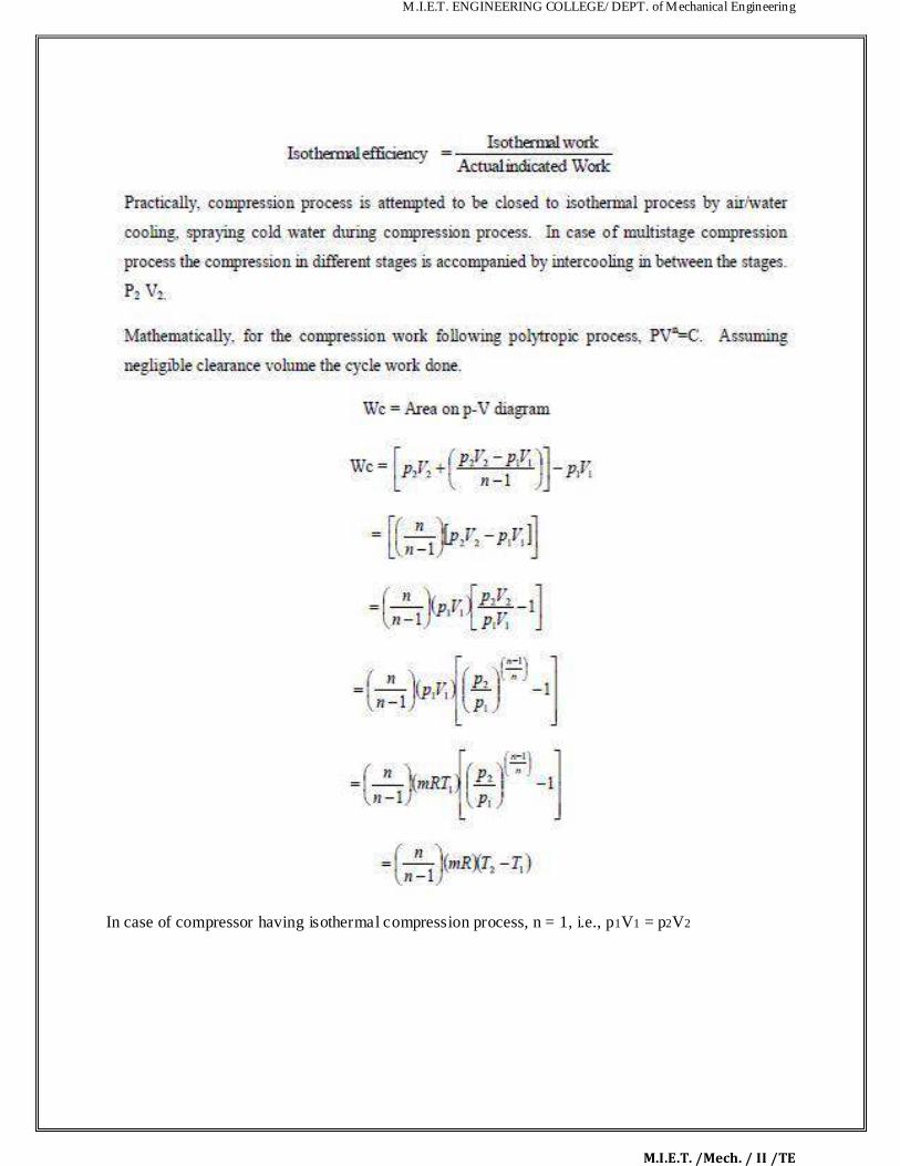
M.I.E.T. ENGINEERING COLLEGE/ DEPT. of Mechanical Engineering
M.I.E.T. /Mech. / II /TE
In case of compressor having isothermal compression process, n = 1, i.e., p1V1 = p2V2

M.I.E.T. ENGINEERING COLLEGE/ DEPT. of Mechanical Engineering
M.I.E.T. /Mech. / II /TE
The isothermal efficiency of a compressor should be close to 100% which means that actual
compression should occur following a pro ss lose to isothermal process. For this the mechanism
be derived to maintain constant t mperature during compression process. Different arrangements
which can be used are: (i) Faster heat dissipation from inside of compressor to outside by use of fins over cylinder. Fins
facilitate quick heat transfer from air being compressed to atmosphere so that temperature rise
during compression can be minimized.
(ii) Water jacket may be provided around compressor cylinder so that heat can be picked by
cooling water circulating through water jacket. Cooling water circulation around compressor
regulates rise in temperature to great extent.
(iii) The ater may also be injected at the end of compression process in order to cool the air being
compressed. This water injection near the end of compression process requires special
arrangement in compressor and also the air gets mixed with water and needs to be separated out

M.I.E.T. ENGINEERING COLLEGE/ DEPT. of Mechanical Engineering
M.I.E.T. /Mech. / II /TE
before being used. Water injection also contaminates the lubricant film inner surface of cyli der
and may initiate corrosion etc, the water injection is not popularly used.
(iv) In case of multistage compression in different compressors operating serially, the a r leav ng
one compressor may be cooled up to ambient state or somewhat high temperature before being
injected into subsequent compressor. This cooling of fluid being compressed between two
consecutive compressors is called inter cooling and is frequently used in c se of multistage
compressors.
4.3 Work done in a single stage reciprocating compressor with clearance volume: Considering clearance volume: With clearance volume the cycle is represented on Figure. The
work done for compression of air polytropically c n be given by the are a enclosed in cycle 1-2-
3-4. Clearance volume in compressors varies from 1.5% to 35% depending upon type of
compressor.

M.I.E.T. ENGINEERING COLLEGE/ DEPT. of Mechanical Engineering
M.I.E.T. /Mech. / II /TE
In the cylinder of reciprocating compressor (V1-V4) sh ll be the ctual volume of air delivered
per cycle. Vd = V1 – V4. This (V1 – V4) is actually the volume of air in hated in the cycle and
delivered subsequently.
If air is considered to behave as p rf ct gas th n pressure, temperature, volume and mass can be
inter related using perfect gas equation. The mass at state 1 may be given as m1 mass at state 2
shall be m1, but at state 3 after delivery ass reduces to m2 and at state 4 it shall be m2.
Ideally there shall be no change in temperature during suction and delivery
i.e., T4 = T1 and T2 = T3 from earlier equation

M.I.E.T. ENGINEERING COLLEGE/ DEPT. of Mechanical Engineering
M.I.E.T. /Mech. / II /TE
Thus (m1-m2) denotes the mass of air su ked or delivered. For unit mass of air delivered the work
done per kg of air can be given as, Thus from above expressions it is obvious that the clearance volume reduces the effective swept
volume i.e., the mass of air handled but the work done per kg of air delivered remains
unaffected. From the cycle work estimated as above the theoretical power required for running
compressor shall be, For single acting compressor running with N rpm, power input required, assuming clearance volume.

M.I.E.T. ENGINEERING COLLEGE/ DEPT. of Mechanical Engineering
M.I.E.T. /Mech. / II /TE
4.5.1 Volumetric Efficiency: Volumetric efficiency of compressor is the measure of the dev at on from volume handling
capacity of compressor. Mathematically, the volumetric efficiency s g ven by the ratio of actual
volume of air sucked and swept volume of cylinder. Ideally the volume of air sucked should be
equal to the swept volume of cylinder, but it is not so in ctu l c se. Practically the volumetric
efficiency lies between 60 to 90%. Volumetric efficiency c n be overall volumetric efficiency
and absolute volumetric efficiency as given below.
Here free air condition refers to the standard conditions. Free air condition may be taken as 1 atm
or 1.01325 bar and 15oC or 288K. consideration for free air is necessary as otherwise the
different compressors can not be compared using volumetric efficiency because specific volume
or density of air varies ith altitude. It may be seen that a compressor at datum level (sea level)
shall deliver large mass than the same compressor at high altitude.
This concept is used for giving the capacity of compressor in terms of „free air delivery‟ (FAD).
“Free air delivery is the volume of air delivered being reduced to free air conditions”. In case of air the free air delivery can be obtained using perfect gas equation as,

M.I.E.T. ENGINEERING COLLEGE/ DEPT. of Mechanical Engineering
M.I.E.T. /Mech. / II /TE
Where subscript a or pa, Va, Ta denote properties at free air conditions
This volume Va gives „free air delivered‟ per cycle by the compressor. Absolute volumetric
efficiency can be defined, using NTP conditions in place of free a r ond t ons.
Here Vs is the swept volume = V1 – V3 and Vc is t e clearance volume = V3 Volumetric efficiency depends on ambient pressure and temperature, suction pressure and
temperature, ratio of clearance to swept volume, and pressure limits. Volumetric efficiency
increases ith decrease in pressure ratio in compressor.

M.I.E.T. ENGINEERING COLLEGE/ DEPT. of Mechanical Engineering
M.I.E.T. /Mech. / II /TE
Mathematical analysis of multistage compressor is done with following assumptions: (i) Compression in all the stages is done following same index of compression and there s o
pressure drop in suction and delivery pressures in each stage. Suction and delivery pressure
remains constant in the stages. (ii) There is perfect inter cooling between compression stages. (iii) Mass handled in different stages is same i.e., mass of air in LP and HP st ges re s me.
(iv) Air behaves as perfect gas during compression. From combined p-V diagram the compressor work requirement can be g ven as,

M.I.E.T. ENGINEERING COLLEGE/ DEPT. of Mechanical Engineering
M.I.E.T. /Mech. / II /TE
It also shows that for optimum pressure ratio the work required in different stages remains same
for the assumptions made for pres nt analysis. Due to pressure ration being equal in all stages the
temperature ratios and maximum t mp rature in each stage remains same for perfect inter
cooling. If the actual volu e sucked during suction stroke is V1, V2, and V3. . . For different
stages they by perfect gas law, P1 V1 = RT1, P2 V2 = RT2, Pc, V3 = RT3 For perfect inter
cooling P1 V1 = RT1, p2 V2 = RT1, p3, V3 = RT1 P1 V1 = P2 V2 = RT2, P3, V3 = . . . . .

M.I.E.T. ENGINEERING COLLEGE/ DEPT. of Mechanical Engineering
M.I.E.T. /Mech. / II /TE
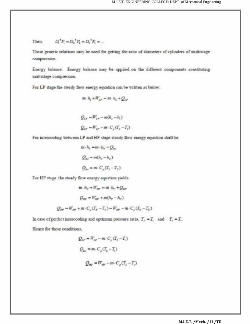
M.I.E.T. ENGINEERING COLLEGE/ DEPT. of Mechanical Engineering
M.I.E.T. /Mech. / II /TE

M.I.E.T. ENGINEERING COLLEGE/ DEPT. of Mechanical Engineering
M.I.E.T. /Mech. / II /TE
Total heat rejected during compression shall be the sum of heat rejected during compression a d
heat extracted in intercooler for perfect inter cooling. Heat rejected during compress on for
polytrophic process Solved Problems
1. A single stage double acting air compressor of 150KW power takes air in at 16 bar & delivers at 6 bar. The compression follows the law PV
1.35 = C. the compressor runs at 160rpm
with average piston speed of 150 m/min. Determine the size of the cyl nder.
GIVEN DATA
Power (P) = 150KW
Piston speed (2lN) = 150m/min
Speed (N) = 160rpm 160/60 = 2.7rps
Pressure (P1) = 1bar = 100KN/m2
Pressure (P2) = 6bar = 600KN/m2
PV1.35
= C, n = 1 35
Hence it is a polytropic process.
TO FIND
Size of the cylinder (d)?
SOLUTION

M.I.E.T. ENGINEERING COLLEGE/ DEPT. of Mechanical Engineering
M.I.E.T. /Mech. / II /TE
It is given that,
2lN = 2.5m/s
l =
l = 0.4629m
since V1 = Vs =
V1 = Vs =
V1 = 0.3635d2
We know that,
Power (P) = 2×W×N (for double act ing)
For polytropic process, work done (W) is
W = 82.899 d2
Power (P) = 2×W×N
150 = 2 × 82.899 d2 × 2.7
d2 = 0.3350
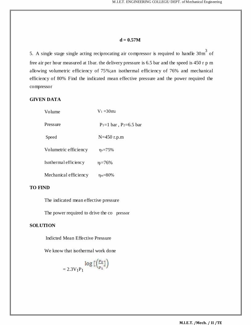
M.I.E.T. ENGINEERING COLLEGE/ DEPT. of Mechanical Engineering
M.I.E.T. /Mech. / II /TE
d = 0.57M
5. A single stage single acting reciprocating air compressor is required to handle 30m3 of
free air per hour measured at 1bar. the delivery pressure is 6.5 bar and the speed is 450 r p m
allowing volumetric efficiency of 75%;an isothermal efficiency of 76% and mechanical
efficiency of 80% Find the indicated mean effective pressure and the power required the
compressor
GIVEN DATA
Volume
V1 =30m2
Pressure
P1=1 bar , P2=6.5 bar
Speed
N=450 r.p.m
Volumetric efficiency
ηv=75%
Isothermal efficiency
ηi=76%
Mechanical efficiency
ηm=80%
TO FIND
The indicated mean effective pressure
The power required to drive the co pressor
SOLUTION
Indicted Mean Effective Pressure
We know that isothermal work done
= 2.3V1P1

M.I.E.T. ENGINEERING COLLEGE/ DEPT. of Mechanical Engineering
M.I.E.T. /Mech. / II /TE
=2.3×105 ×30
=5609×103J/h
And indicated work done=
= =7380KJ/h
We know that swept volume of the piston
Vs= =
=40m3/h
Indicated mean effective pressure pm= =
= 184.5kJ/m3
=184.5KN/m2
The power required to drive the co pressor
We know that work done by the co pressor =
=
=9225KJ/h
Therefore the po er required to drive the compressor =

M.I.E.T. ENGINEERING COLLEGE/ DEPT. of Mechanical Engineering
M.I.E.T. /Mech. / II /TE
=2.56KW
RESULT
Indicated mean effective pressure pm=184.5KN/m2
The power required to drive the compressor =2.56KW
9. A two stages, single acting air compressor compresses air to 20bar. The a r enters the L.P cylinder at 1bar and 27
oc and leaves it at 4.7bar. The air enters the H.P. cyl nder at 4.5bar and
27oc. the size of the L.P cylinder is 400mm diameter and 500mm stroke. The clearance volume In
both cylinder is 4% of the respective stroke volume. The compressor runs at 200rpm, taking index of compression and expansion in the two cylinders s 1.3, estimate 1. The indicated power
required to run the compressor; and 2. The heat rejected in the intercooler per minute.
GIVEN DATA
Pressure (P4)= 20bar
Pressure (P1) = 1bar = 1×10⁵ N/m
2
Temperature (T1) = 27oC = 27+273 = 300K
Pressure (P2) = 4.7bar
Pressure (P3) = 4 5bar
Temperature (T3) = 27oC = 27+273 = 300K
Diameter (D1) = 400mm 0.4m
Stroke (L1) = 500mm = 0.5m
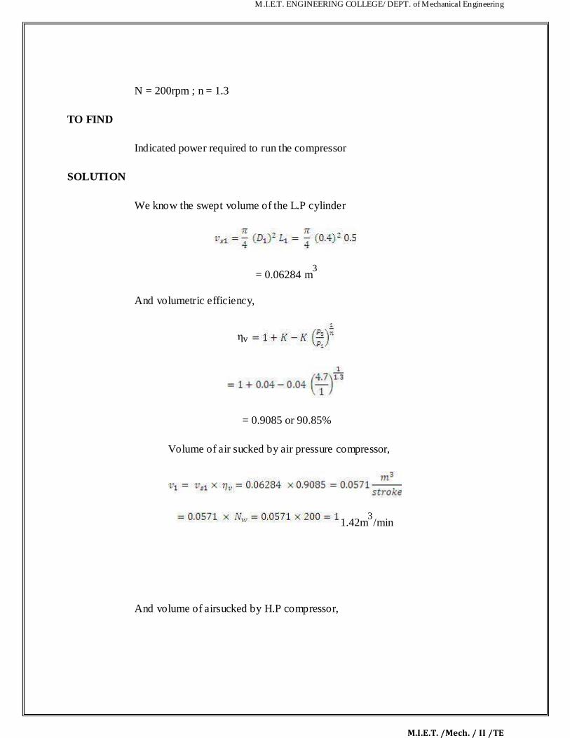
M.I.E.T. ENGINEERING COLLEGE/ DEPT. of Mechanical Engineering
M.I.E.T. /Mech. / II /TE
N = 200rpm ; n = 1.3
TO FIND
Indicated power required to run the compressor
SOLUTION
We know the swept volume of the L.P cylinder
= 0.06284 m3
And volumetric efficiency,
ηv
= 0.9085 or 90.85%
Volume of air sucked by air pressure compressor,
1.42m3/min
And volume of airsucked by H.P compressor,

M.I.E.T. ENGINEERING COLLEGE/ DEPT. of Mechanical Engineering
M.I.E.T. /Mech. / II /TE
We know that indicated worrk done by L.P compressor,
13. 2123.3×103 J/min = 2123.3 KJ/min
And indicated workdone by H.P compressor,
14. 2043.5×103 J/min = 2034.5 KJ/min
Total indicated work done by the compressor,
W = WL + WH = 2123.3 + 2034.5 = 4157.8 KJ/min
Indicated power required to run the compressor
= 4157.8 / 60 = 69.3KW
M.I.E.T. ENGINEERING COLLEGE/ DEPT. of Mechanical Engineering
M.I.E.T. /Mech. / II /TE
4.9 TWO MARK UNIVERSITY QUESTIONS: Part-A (2 Marks) 4. What is meant by single acting compressor?
5. What is meant by double acting compressor?
6. What is meant by single stage compressor?
7. What is meant by multistage compressor?
8. Define isentropic efficiency
9. Define mean effective pressure. How is it related to in power of an I.C engine. 10. What is meant by free air delivered? 11. Explain how flow of air is controlled in a re ipro ating compressor? 12. What factors limit the delivery pr ssure in r ciprocating compressor?
13. Name the methods adopted for increasing isothermal efficiency of reciprocating air
compressor.
14. Why clearance is necessary and what is its effect on the performance of reciprocating
compressor?
15. What is compression ratio? 16. What is meant by inter cooler?
M.I.E.T. ENGINEERING COLLEGE/ DEPT. of Mechanical Engineering
M.I.E.T. /Mech. / II /TE
4.10 UNIVERSITY ESSAY QUESTIONS: Part-B (16 Marks)
7. Drive an expression for the work done by single stage si gle acting reciprocating air
compressor. (16)
8. Drive an expression for the volumetric efficiency of reciproc ting air compressors (16) 9. Explain the construction and working of a root blower (16) 10. Explain the construction and working of a entrifugal compressor (16)
11. Explain the construction and working of a sliding vane compressor and axial flow
compressor.(16)
6. A single stage single acting air co pressor is used to compress air from 1 bar and 22° C to 6
bar according to the law PV1 25 = C. The compressor runs at 125 rpm and the ratio of stroke
length to bore of a cylinder is 1.5. If the power required by the compressor is 20 kW,
determine the size of the cylinder. (16)
10. A single stage single acting air compressor is used to compress air from 1.013 bar and
25° C to 7 bar according to law PV 1.3 = C.The bore and stroke of a cylinder are 120mm and
150mm respectively. The compressor runs at 250 rpm .If clearance volume of the cylinder is
5% of stroke volume and the mechanical efficiency of the compressor is 85%, determine
volumetric efficiency, power, and mass of air delivered per minute. (16)

M.I.E.T. ENGINEERING COLLEGE/ DEPT. of Mechanical Engineering
M.I.E.T. /Mech. / II /TE
13. A two stage singe acting air compressor compresses 2m3 airs from 1 bar and 20° C to 15
bar. The air from the low pressure compressor is cooled to 25° C in the intercooler. Calculate
the minimum power required to run the compressor if the compression follows PV1 25=C and
the compressor runs at 400 rpm. (16)

M.I.E.T. ENGINEERING COLLEGE/ DEPT. of Mechanical Engineering
M.I.E.T. /Mech. / II /TE
ME6404 THERMAL ENGINEERING
UNIT V
REFRIGERATION AND AIR CONDITIONING
M.I.E.T. ENGINEERING COLLEGE/ DEPT. of Mechanical Engineering
M.I.E.T. /Mech. / II /TE
CONTENTS
TECHNICAL TERMS
5.1 Fundamentals of refrigeration
5.2 Common Refrigerants
5.3 Required Properties of Ideal Refrigerant
5.4 Coefficient of Performance (COP)
5.5 Vapour Compression Refrigeration
5.5.1 Schematic of a Basic Vapor Compression Refr gerat on System
5.5.2 Alternative Refrigerants for Vapour Compress on Systems
5.6 Vapour Absorption Refrigeration
5.7 Comparison between Vapor Compression and Absorption System
5.8 Ton of refrigeration
5.9 Air- Conditioning System
5.9.1. Zoned Systems
5.9.2 Unitary Systems
5.10 Window Air-conditioning System
5.10.1 Blower
5.10.2 Propeller fan or the cond nser fan
5.11.3 Fan otor
5.11 Split Air-conditioning System
5.11.1 Evaporator Coil or the Cooling Coil
5.11.2 Air Filter
5.11.3 Cooling Fan or Blower
5.11.4 Drain Pipe
5.11.5 Louvers or Fins
5.12 Solved Problems
5.13 T o Marks University Questions
5.14 University Essay Questions

M.I.E.T. ENGINEERING COLLEGE/ DEPT. of Mechanical Engineering
M.I.E.T. /Mech. / II /TE
TECHNICAL TERMS 1. SPECIFIC HEAT
It is the ratio between the quantities of heat required to change the temperature of 1
pound of any substance 1°F, as compared to the quantity of heat required to change 1 pound of
water 1°F. Specific heat is equal to the number of Btu required to raise the temperature of 1
pound of a substance 1°F. For example, the specific heat of milk is .92, which me ns that 92 Btu
will be needed to raise 100 pounds of milk 1° F. The specific heat of w ter is 1, by doption as a
standard, and specific heat of another substance (solid, liquid, or gas) is determined
experimentally by comparing it to water. Specific heat also expresses the heat-holding capacity
of a substance compared to that of water. 2. SENSIBLE HEAT
Heat that is added to, or subtracted from, a substa ce that cha ges its temperature but not
its physical state is called sensible heat. It is the he t th t c n be indicated on a thermometer. This
is the heat human senses also can react to, at le st within certain ranges. For example, if a person
put their finger into a cup of water, t e senses readily tell that person whether it is cold, cool,
tepid, hot, or very hot. Sensible heat is applied to a solid, a liquid, or a gas/vapor as indicated on
a thermometer. The term sensible heat does not apply to the process of conversion from one
physical state to another. 3. LATENT HEAT
It is the term used for the heat absorbed or given off by a substance while it is changing
its physical state. When this occurs, the heat given off or absorbed does NOT cause a
temperature change in the substance. In other words, sensible heat is the term for heat that affects
the temperature of things; latent heat is the term for heat that affects the physical state of things. To understand the concept of latent heat, you must realize that many substances may exist as
solids, as liquids, or as gases, depending primarily upon the temperatures and pressure to which
they are subjected. 4. SUPERHEAT
It is a very important term in the terminology of refrigeration - but it is unfortunately used
in different ays. It can be used to describe a process where refrigerant vapour is heated from its

M.I.E.T. ENGINEERING COLLEGE/ DEPT. of Mechanical Engineering
M.I.E.T. /Mech. / II /TE
saturated condition to a condition at higher temperature. The term superheat can also be used to
describe - or quantify - the end condition of the before-mentioned process. 5. PRESSURE
It is defined as a force per unit area. It is usually measured in pounds per square nch (psi).
Pressure may be in one direction, several directions, or in all directions. The ice (solid) exerts
pressure downward. The water (fluid) exerts pressure on all wetted surf ces of the container.
Gases exert pressure on al I inside surfaces of their containers. 6. VAPORIZATION
It is the process of changing a liquid to vapor, either by evaporat on or boiling. When a
glass is filled with water, as shown in figure 6-10, and exposed to the rays of the sun for a day or
two, you should note that the water level drops gradually. The loss of water is due to
evaporation. Evaporation, in this case, takes place only at the surface of the liquid. It is gradual,
but the evaporation of the water can be speeded up if ddition l heat is applied to it. In this case,
the boiling of the water takes place throughout the interior of the liquid. Thus the absorption of
heat by a liquid causes it to boil and evaporate. 7. CONDENSATION
It is the process of changing a vapor into a liquid. For example, in figure 6-12, a warm
atmosphere gives up heat to a cold glass of water, causing moisture to condense out of the air
and form on the outside surface of the glass. Thus the removal of heat from a vapor causes the
vapor to condense. 8. COP of REFRIGERATION
The COP of a refrigeration system is the ratio of net refrigeration effect to the work required to produce the effect 9. UNIT OF REFRIGERATION
The capacity of refrigeration is expressed in tonnes of refrigeration
(TOR). 1 tones of refrigeration = 210 kJ/min (or) = 3.5 kJ/sec (kW) A tone of refrigeration is defined as the quantity of heat to be removed in order to form one
tone of ice at 0oC in 24 hours.
10. REFRIGERATION EFFECT

M.I.E.T. ENGINEERING COLLEGE/ DEPT. of Mechanical Engineering
M.I.E.T. /Mech. / II /TE
The amount of heat extracted in a given time is known as refrigeration effect.
11. EFFECTS OF UNDER COOLING
It increases the refrigeration effect therefore the COP increases. The mass f ow rate of the refrigeration is less than that for the simple saturated cycle. The reduced mass f ow rate reduces the piston displacement per minute. Power per tones of refrigeration losses due to reduction in mass flow rate. The increased efficiency may be offering some extent by the rise in the condenser pressure. Work input almost remains same. The heat reje tion apacity of the condenser increases.
12. EFFECTS OF SUPER HEATING
Supper heating increases the net refrigeration effect, but super heating requires more work input therefore super heating reduces the COP. No moisture contents in the refrigerant therefore no corrosion in the machines part. 13. PROPERTIES OF IDEAL REFRIGERANT
It should have low boiling point and low freezing point.
It must have low specific h at and high latent heat.
It should have high ther al conductivity to reduce the heat transfer in evaporator and condenser.
It should have low specific volu e to reduce the size of the compressor.
It should be non-flammable, non-expensive, non-toxic and non-corrosive.
It should have high critical pressure and temperature to avoid large power requirements.
It should give high COP to reduce the running cost of the system.
It must be cheap and must be readily available 14. RSHF

M.I.E.T. ENGINEERING COLLEGE/ DEPT. of Mechanical Engineering
M.I.E.T. /Mech. / II /TE
Room sensible heat factor is defined as the ratio of room sensible heat load to the room total heat load. 15. RELATIVE HUMIDITY
It is defined as the ratio of partial pressure of water vapour (pw) in a mixture to
the saturation pressure (ps) of pure water at the same temperature of mixture. 16. SPECIFIC HUMIDITY
It is defined as the ratio of the mass of water vapour (ms) in a given volume to the
mass of dry air in a given volume (ma). 17. DEGREE OF SATURATION
It is the ratio of the actual specific humidity and the saturated specific humidity at the same temperature of the mixture. 18. DEW POINT TEMPERATURE
The temperature at which the vapour starts condensing is called dew point temperature. It is also equal to the saturation temperature at t e partial pressure of water vapour in the mixture. The dew point temperature is an indi ation of specific humidity. 19. SENSIBLE HEAT AND LATENT HEAT
Sensible heat is the heat that chang s the temperature of the substance when added to it or when abstracted from it. Latent h at is the h at that does not affect the temperature but change of state occurred by adding the heat or by abstracting the heat. 20. PSYCHOMETRIC PROCESSES
1. Sensible heating and sensible cooling, 2. Cooling and dehumidification, 3. Heating and humidification, 4 Mixing of air streams, 5. Chemical dehumidification, 6. Adiabatic evaporative cooling.
21. ADIABATIC MIXING
The process of mixing two or more stream of air without any heat transfer to the surrounding is kno n as adiabatic mixing. It is happened in air conditioning system.
22. DRY BULB TEMPERATURE (DBT)

M.I.E.T. ENGINEERING COLLEGE/ DEPT. of Mechanical Engineering
M.I.E.T. /Mech. / II /TE
The temperature recorded by the thermometer with a dry bulb. The dry bulb thermometer cannot affected by the moisture present in the air. It is the measure of sensible heat of the air. 23. WET BULB TEMPERATURE (WBT)
It is the temperature recorded by a thermometer whose bulb is covered with cotton wick (wet) saturated with water. The wet bulb temperature may be the measure of enth lpy of air. WBT is the lowest temperature recorded by moistened bulb. 24. DEW POINT DEPRESSION
It is the difference between dry bulb temperature and dew po nt temperature of air vapour mixture.

M.I.E.T. ENGINEERING COLLEGE/ DEPT. of Mechanical Engineering
M.I.E.T. /Mech. / II /TE
UNIT V
REFRIGERATION AND AIR CONDITIONING 5.1 Fundamentals of refrigeration The first mechanical refrigerators for the production of ice appeared round the ye r 1860. In 1880
the first ammonia compressors and insulated cold stores were put into use in the USA. Electricity
began to play a part at the beginning of this century and me hani al refrigeration plants became
common in some fields: e.g. breweries, slaughter-houses, f shery, ice production, for example.
After the Second World War the development of small hermetic refrigeration compressors
evolved and refrigerators and freezers began to take their place in the home. Today, these
appliances are regarded as normal household necessities. Refrigeration is the process of removing heat from n rea or substance and is usually done by an
artificial means of lowering the temperature, such s the use of ice or mechanical refrigeration.
Mechanical Refrigeration is defined as a me hani al system or apparatus so designed and
constructed that, through its function, heat is transferred from one substance to another. Since
refrigeration deals entirely with the r moval or transfer of heat, some knowledge of the nature
and effects of heat is necessary for a cl ar und rstanding of the subject. 5.1.2 Common Refrigerants
Today, there are three specific types of refrigerants used in refrigeration and air-conditioning
systems:
(iii)Chlorofluorocarbons or CFCs, such as R-11, R-12, and R-114
(iv) Hydro chlorofluorocarbons or HCFCs, such as R-22 or R-123
(v) Hydro fluorocarbons or HFCs, such as R-134a. All these refrigerants are "halogenated,"
hich means they contain chlorine, fluorine, bromine, astatine, or iodine.

M.I.E.T. ENGINEERING COLLEGE/ DEPT. of Mechanical Engineering
M.I.E.T. /Mech. / II /TE
Refrigerants, such as Dichlorodifluoromethane (R-12), Mono chloro difluoromethane (R-22),
and Refrigerant 502 (R-502), are called primary refrigerants because each one changes ts state
upon the application or absorption of heat, and, in this act of change, absorbs and extracts heat
from the area or substance.
The primary refrigerant is so termed because it acts directly upon the area or subst nce, a though
it may be enclosed within a system. For a primary refrigerant to cool, it must be pl ced in a
closed system in which it can be controlled by the pressure imposed upon it. The refrigerant can
then absorb at the temperature ranges desired. If a primary refr gerant were used without being
controlled, it would absorb heat from most perishables and freeze them sol d.
Secondary Refrigerants are substances, such as air, water, or bri e. Though hot refrigerants in
themselves, they have been cooled by the prim ry refriger tion system; they pass over and around
the areas and substances to be cooled; and they re returned with their heat load to the primary
refrigeration system. Secondary refrigerants pay off where the cooling effect must be moved
over a long distance and gastight lines cost too much.
Refrigerants are classified into groups. The National Refrigeration Safety Code catalogs all refrigerants into three groups:
Group I – safest of the refrig rants, such as R-12, R-22, and R-502 Group II – toxic and so ewhat flammable, such as R-40 (Methyl chloride) and R-764
(Sulfur dioxide) Group III – flam able refrigerants, such as R-170 (Ethane) and R-290 (Propane).
R-12 Dichlorodifluoromethane (CC12 F2) Dichlorodifluoromethane, commonly referred to as R-
12, is colorless and odorless in concentrations of less than 20 percent by volume in air. In higher
concentrations, its odor resembles that of carbon tetrachloride. It is nontoxic, noncorrosive,
nonflammable, and has a boiling point of -21.7°F (-29°C) at atmospheric pressure.
Required Properties of Ideal Refrigerant
1) The refrigerant should have low boiling point and low freezing point.

M.I.E.T. ENGINEERING COLLEGE/ DEPT. of Mechanical Engineering
M.I.E.T. /Mech. / II /TE
6. It must have low specific heat and high latent heat. Because high specific heat decreases the
refrigerating effect per kg of refrigerant and high latent heat at low temperature ncreases the
refrigerating effect per kg of refrigerant. 7. The pressures required to be maintained in the evaporator and condenser shou d be low
enough to reduce the material cost and must be positive to avoid leakage of air into the system. 8. It must have high critical pressure and temperature to avoid large power requirements. 9. It should have low specific volume to reduce the size of the compressor. 10. It must have high thermal conductivity to reduce the area of heat transfer in evaporator
and condenser. 11. It should be non-flammable, non-explosive, non-toxic and non-corros ve. 12. It should not have any bad effects on the stored material or food, when any leak develops
in the system. 9) It must have high miscibility with lubricating oil nd it should not have reacting properly with
lubricating oil in the temperature range of the system. 10. It should give high COP in the working temperature range. This is necessary to reduce the
running cost of the system. Coefficient of Performance (COP) The performance of refrigerators and h at pumps is expressed in terms of coefficient of
performance (COP), defined as
5.2 Vapour Compression Refrigeration
Heat flo s naturally from a hot to a colder body. In refrigeration system the opposite must
occur i.e. heat flows from a cold to a hotter body. This is achieved by using a substance called a
refrigerant, hich absorbs heat and hence boils or evaporates at a low pressure to form a gas. This
gas is then compressed to a higher pressure, such that it transfers the heat it has gained

M.I.E.T. ENGINEERING COLLEGE/ DEPT. of Mechanical Engineering
M.I.E.T. /Mech. / II /TE
to ambient air or water and turns back (condenses) into a liquid. In this way heat is absorbed, or
removed, from a low temperature source and transferred to a higher temperature source.
The refrigeration cycle can be broken down into the following stages
1 - 2 Low pressure liquid refrig rant in the vaporator absorbs heat from its surroundings, usually
air, water or some other proc ss liquid. During this process it changes its state from a liquid to a
gas, and at the evaporator exit is slightly superheated.
2 - 3 The superheated vapour enters the compressor where its pressure is raised. There will also
be a big increase in temperature, because a proportion of the energy input into the compression
process is transferred to the refrigerant.
3 - 4 The high pressure superheated gas passes from the compressor into the condenser. The
initial part of the cooling process (3 - 3a) desuperheats the gas before it is then turned back into
liquid (3a - 3b). The cooling for this process is usually achieved by using air or water. A further
reduction in temperature happens in the pipe work and liquid receiver (3b - 4), so that the
refrigerant liquid is sub-cooled as it enters the expansion device.

M.I.E.T. ENGINEERING COLLEGE/ DEPT. of Mechanical Engineering
M.I.E.T. /Mech. / II /TE
4 - 1 The high-pressure sub-cooled liquid passes through the expansion device, which both
reduces its pressure and controls the flow into the evaporator.

M.I.E.T. ENGINEERING COLLEGE/ DEPT. of Mechanical Engineering
M.I.E.T. /Mech. / II /TE
It can be seen that the condenser has to be capable of rejecting the combined heat inputs of the
evaporator and the compressor; i.e. (1 - 2) + (2 - 3) has to be the same as (3 - 4). There is no heat
loss or gain through the expansion device.

M.I.E.T. ENGINEERING COLLEGE/ DEPT. of Mechanical Engineering
M.I.E.T. /Mech. / II /TE
5.2.1 Schematic of a Basic Vapor Compression Refrigeration System Advantages of Vapour compression refrigeration system over air refrigeration system:
• Since the orking cycle approaches closer to carnot cycle, the C.O.P is quite high.
14. Operational cost of vapour compression system is just above 1/4th of air refrigeration

M.I.E.T. ENGINEERING COLLEGE/ DEPT. of Mechanical Engineering
M.I.E.T. /Mech. / II /TE
system.
15. Since the heat removed consists of the latent heat of vapour, the amount of liqu d
circulated is less and as a result the size of the evaporator is smaller.
16. Any desired temperature of the evaporator can be achieved just by adjusting the
throttle valve. Disadvantages of Vapour compression refrigeration system over air refriger tion system
17. Initial investment is high
18. Prevention of leakage of refrigerant is a major problem Alternative Refrigerants for Vapour Compression Systems
The use of CFCs is now beginning to be phased out due to their damaging impact on the
protective tropospheric ozone layer around the e rth. The Montreal Protocol of 1987 and the
subsequent Copenhagen agreement of 1992 mand te reduction in the production of ozone
depleting Chlorinated Fluorocarbon (CFC) refrigerants in a phased manner, with an eventual
stop to all production by the year 1996. In response, t e refrigeration industry has developed two
alternative refrigerants; one based on Hydro hloro Fluorocarbon (HCFC), and another based on
Hydro Fluorocarbon (HFC). The HCFCs have a 2 to 10% ozone depleting potential as compared
to CFCs and also, they have an atmosph ric lif time between 2 to 25 years as compared to 100 or
more years for CFCs (Brandt, 1992). However, even HCFCs are mandated to be phased out by
2005, and only the chlorine free (zero ozone depletion) HFCs would be acceptable.
Until now, only one HFC based refrigerant, HFC 134a, has been developed. HCFCs are
comparatively simpler to produce and the three refrigerants 22, 123, and 124 have been
developed. The use of HFCs and HCFCs results in slightly lower efficiencies as compared to
CFCs, but this may change ith increasing efforts being made to replace CFCs.
5.3 Vapour Absorption Refrigeration

M.I.E.T. ENGINEERING COLLEGE/ DEPT. of Mechanical Engineering
M.I.E.T. /Mech. / II /TE
In the absorption refrigeration system, refrigeration effect is produced mainly by the use
of energy as heat. In such a system, the refrigerant is usually dissolved in a l qu d. A
concentrated solution of ammonia is boiled in a vapour generator producing ammon a vapour at
high pressure. The high pressure ammonia vapour is fed to a condenser where it is condensed to
liquid ammonia by rejecting energy as heat to the surroundings. Then, the iquid ammonia is
throttled through a valve to a low pressure. During throttling, ammonia is p rti lly v pourized and
its temperature decreases.
This low temperature ammonia is fed to an evaporator where t s vapour zed removing energy
from the evaporator. Then this low-pressure ammonia vapour s absorbed n the weak solution of
ammonia. The resulting strong ammonia solution is pumped back to the vapour generator and the
cycle is completed. The COP of the absorption system can be evaluated by considering it as a
combination of a heat pump and a heat engine Comparison between Vapor Compression and Absorption System
Table 1 Vapor Compression and Absorption System

M.I.E.T. ENGINEERING COLLEGE/ DEPT. of Mechanical Engineering
M.I.E.T. /Mech. / II /TE
Ton of refrigeration: Amount of heat required to elt a Ton of Ice in a 24/h Period One ton of refrigeration is the heat required to melt 1 ton of ice in 24 hrs. That is, a refrigeration
machine rated at 1 ton cools as much in 24 hrs. as 1 ton of ice would by melting in the same
period. The heat required is the product of the latent heat of fusion and the mass in
kg. Q = mH, 1 ton = 907 kg Latent heat of fusion: H = 340 kJ/kg Q = 907*340 = 308380 kJ

M.I.E.T. ENGINEERING COLLEGE/ DEPT. of Mechanical Engineering
M.I.E.T. /Mech. / II /TE
P = E/t = Q/t = 308380 kJ/24 hr = 308380/(24*3600) = 3.57 kw Note: 1 watt = 1 J/s So that 1 kw = 1 kJ/s
5.6 Air- Conditioning Systems: The central air conditioning system is used for cooling big buildings, houses, offices, entire
hotels, gyms, movie theaters, factories etc. If the whole building is to be ir conditioned, HVAC
engineers find that putting individual units in each of the rooms is very expensive initially as
well in the long run. The central air conditioning system is compr sed of a huge ompressor that
has the capacity to produce hundreds of tons of air conditioning. Cool ng b g halls, malls, huge
spaces, galleries etc is usually only feasible with central co ditio i g u its. Zoned Systems

M.I.E.T. ENGINEERING COLLEGE/ DEPT. of Mechanical Engineering
M.I.E.T. /Mech. / II /TE
A zoned air conditioning system using a room ir termin l which has the same horizontal
dimensions as a floor tile of a raised tile floor such t at t e terminal may replace one tile in such a
floor. The terminal includes a cool air inlet below t e floor for drawing in cooling air circulated
in the under floor space and a return air inlet in the top surface of the terminal. The cool air and
return air is mixed in a mixing chamb r and drawn from the mixing chamber by a fan and
returned to the room through an outl t v nt. The ratio of cool air to return air mixed in the mixing
chamber is controlled by a odulating damper which is controlled in response to the temperature
of the return air in order to control the room temperature in the region of the terminal in
accordance with an adjustable set point. A heater is also provided in the terminal for those
occasions where the return air is cooler than the set point.
Unitary Systems:
A unitary air conditioning system comprises an outdoor unit including a compressor for
compressing a refrigerant, an outdoor heat exchanger for heat exchange of the refrigerant and an
expander connected to the outdoor heat exchanger, for expanding the refrigerant; a duct installed
inside a zone of a building; a central blower unit having a heat exchanger connected to the

M.I.E.T. ENGINEERING COLLEGE/ DEPT. of Mechanical Engineering
M.I.E.T. /Mech. / II /TE
outdoor unit through a first refrigerant pipe and a blower for supplying the air heat-excha ged by
the heat exchanger to the duct; and an individual blower unit including a heat excha ger
connected to the outdoor unit through a second refrigerant pipe and a fan for sending the a r heat
exchanged by the heat exchanger and disposed in a zone in the building, for individua y cooling
or heating the zone. Accordingly, cooling or heating operation is performed on each zone of the
building, and simultaneously, additional individual heating or cooling oper tion can be performed
on a specific space, so that a cost can be reduced and cooling or he ting in the building can be
efficiently performed.
5.6.3 Window Air-conditioning System:
It is the most commonly used air conditioner for single rooms. In this air conditioner all
the components, namely the compressor, condenser, expansion valve or coil, evaporator and
cooling coil are enclosed in a single box. This unit is fitted in a slot made in the wall of the room,
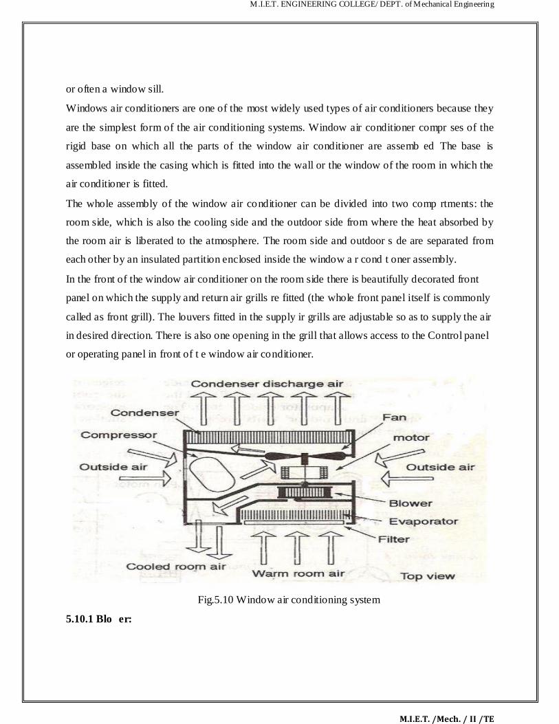
M.I.E.T. ENGINEERING COLLEGE/ DEPT. of Mechanical Engineering
M.I.E.T. /Mech. / II /TE
or often a window sill. Windows air conditioners are one of the most widely used types of air conditioners because they
are the simplest form of the air conditioning systems. Window air conditioner compr ses of the
rigid base on which all the parts of the window air conditioner are assemb ed The base is
assembled inside the casing which is fitted into the wall or the window of the room in which the
air conditioner is fitted. The whole assembly of the window air conditioner can be divided into two comp rtments: the
room side, which is also the cooling side and the outdoor side from where the heat absorbed by
the room air is liberated to the atmosphere. The room side and outdoor s de are separated from
each other by an insulated partition enclosed inside the window a r cond t oner assembly. In the front of the window air conditioner on the room side there is beautifully decorated front
panel on which the supply and return air grills re fitted (the whole front panel itself is commonly
called as front grill). The louvers fitted in the supply ir grills are adjustable so as to supply the air
in desired direction. There is also one opening in the grill that allows access to the Control panel
or operating panel in front of t e window air conditioner.
Fig.5.10 Window air conditioning system
5.10.1 Blo er:

M.I.E.T. ENGINEERING COLLEGE/ DEPT. of Mechanical Engineering
M.I.E.T. /Mech. / II /TE
This is the small blower that is fitted behind the evaporator or cooling coil i side the
assembly of the window air conditioner system. The blower sucks the air from the room wh ch
first passes over the air filter and gets filtered. The air then passes over the cooling co l and gets
chilled. The blower then blows this filtered and chilled air, which passes through the supply air
compartment inside the window air conditioner assembly. This air is then de ivered into the room
from the supply air grill of the front panel.
Propeller fan or the condenser fan:
The condenser fan is the forced draft type of propeller fan that su ks the atmospheric air
and blows it over the condenser. The hot refrigerant inside the condenser g ves up the heat to the
atmospheric air and its temperature reduces.
Fan motor:
The motor inside the window air conditioner assembly is located between the condenser
and the evaporator coil. It has double shaft on one side of which the blower is fitted and on the
other side the condenser fan is fitted. This makes the whole assembly of the blower, the
condenser fan and the motor highly compact.
5.6.2 Split Air-conditioning System
:
The split air conditioner co prises of two parts: the outdoor unit and the indoor unit. The outdoor unit, fitted outside the room, houses components like the compressor, condenser and
expansion valve. The indoor unit comprises the evaporator or cooling coil and the cooling fan.
For this unit you don't have to make any slot in the wall of the room. Further, the present day
split units have aesthetic looks and add to the beauty of the room. The split air conditioner can be
used to cool one or t o rooms.
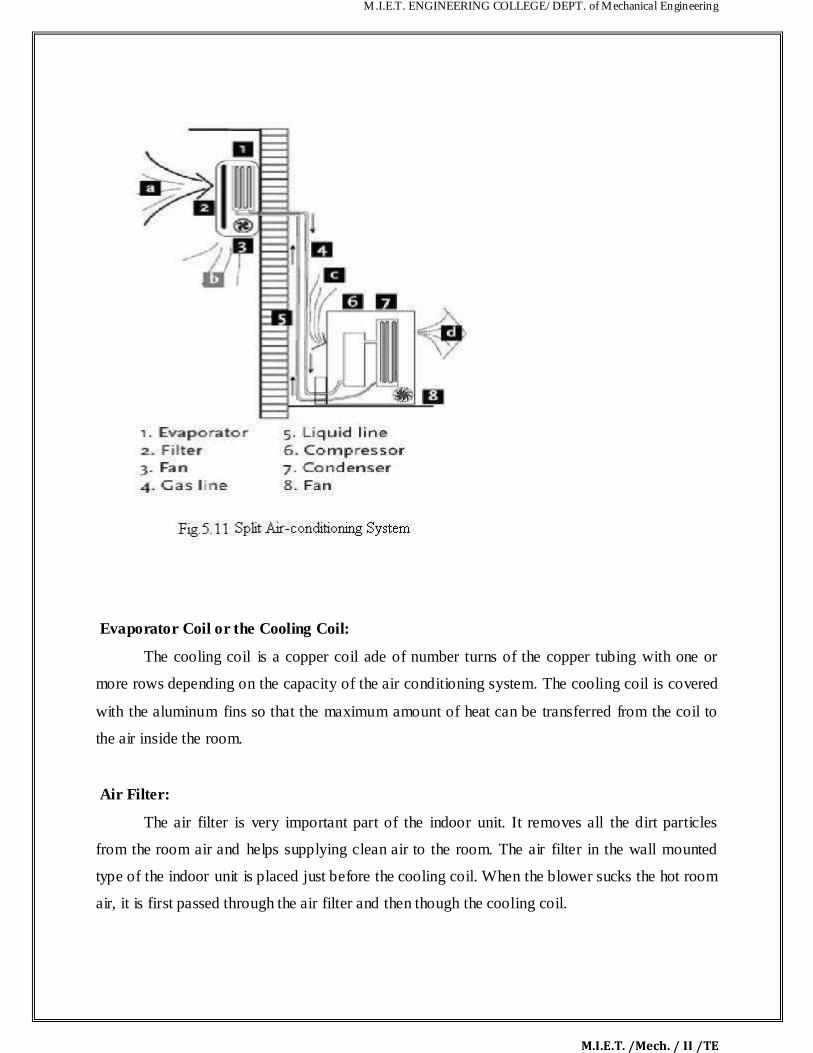
M.I.E.T. ENGINEERING COLLEGE/ DEPT. of Mechanical Engineering
M.I.E.T. /Mech. / II /TE
Evaporator Coil or the Cooling Coil:
The cooling coil is a copper coil ade of number turns of the copper tubing with one or
more rows depending on the capacity of the air conditioning system. The cooling coil is covered
with the aluminum fins so that the maximum amount of heat can be transferred from the coil to
the air inside the room.
Air Filter:
The air filter is very important part of the indoor unit. It removes all the dirt particles
from the room air and helps supplying clean air to the room. The air filter in the wall mounted
type of the indoor unit is placed just before the cooling coil. When the blower sucks the hot room
air, it is first passed through the air filter and then though the cooling coil.

M.I.E.T. ENGINEERING COLLEGE/ DEPT. of Mechanical Engineering
M.I.E.T. /Mech. / II /TE
Cooling Fan or Blower:
Inside the indoor unit there is also a long blower that sucks the room a r or the
atmospheric air. It is an induced type of blower and while is sucks the room air it is passed over
the cooling coil and the filter due to which the temperature of the air reduces and a the dirt from
it is removed. The blower sucks the hot and unclean air from the room and supp ies cool and
clean air back. The shaft of the blower rotates inside the bushes and it is connected to a small
multiple speed motor, thus the speed of the blower can be changed. When the fan speed is
changed with the remote it is the speed of the blower that changes.
Drain Pipe:
Due to the low temperature refrigerant inside the cooli g coil, its temperature is very low,
usually much below the dew point temperature of the room ir. When the room air is passed over
the cooling due the suction force of the blower, the temper ture of the air becomes very low and
reaches levels below its dew point temperature. Due to t is t e water vapor present in the air gets
condensed and dew or water drops are formed on t e surface of the cooling coil. These water
drops fall off the cooling coil and are colle ted in a small space inside the indoor unit. To remove
the water from this space the drain pipe is onne ted from this space extending to the some
external place outside the room wh re wat r can be disposed off. Thus the drain pipe helps
removing dew water collected inside the indoor unit.
Louvers or Fins:
The cool air supplied by the blower is passed into the room through louvers. The louvers
help changing the angle or direction in which the air needs to be supplied into the room as per
the requirements. With louvers one easily Change the direction in which the maximum amount
of the cooled air has to be passed. There are two types of louvers: horizontal and vertical. The
horizontal louvers are connected to a small motor and there position can set by the remote
control. Once can set a fixed position for the horizontal louvers so that chilled air is passed in a

M.I.E.T. ENGINEERING COLLEGE/ DEPT. of Mechanical Engineering
M.I.E.T. /Mech. / II /TE
particular direction only or one can keep it in rotation mode so that the fresh air is supplied
throughout the room. The vertical louvers are operated manually and one can easily cha ge the r
position as per the requirements. The horizontal louvers control flow of air in upper and
downward directions of the room, while vertical louvers control movement of air in eft and right
directions.
5.12 SOLVEDE PROBLEMS

M.I.E.T. ENGINEERING COLLEGE/ DEPT. of Mechanical Engineering
M.I.E.T. /Mech. / II /TE
12. A sling psychrometer gives reading of 250c dry bulb temperature 15
0c wet bulb
temperature. The barometer indicates 760 mm of hg assuming partial pressure of the vapour as 10 mm of Hg. Determine 1. Specific humidity 2. Saturation ratio.
Given Data:
Dry bulb temperature td =250c
Wet bulb temperature tw=150c
Barometer pressure pb=760mm of Hg
Partial pressure pv= 10mm of Hg
To Find:
Specific humidity
Saturation ratio.
Solution:
Specific humidity:
We know that Specific humidity
W =
0.0083 kg/kg of dry air
Saturation ratio:
From steam table corresponding to dry bulb temperature td =250c
We find the partial pressure ps=0.03166 bar
=
=23.8 mm of Hg
We know that Saturation ratio.

M.I.E.T. ENGINEERING COLLEGE/ DEPT. of Mechanical Engineering
M.I.E.T. /Mech. / II /TE
µ=
= = 0.41
RESULT:
Specific humidity 0.0083 kg/kg of dry air
Saturation ratio. =0.41
14. A two stages, single acting air compressor compresses a r to 20bar. The air enters the
L.P cylinder at 1bar and 27
oc and leaves it at 4.7bar. the air e ters the H.P. cylinder at
4.5bar and 27oc. the size of the L.P cylinder is 400mm di meter and 500mm stroke. The
clearance volume In both cylinder is 4% of the respective stroke volume. The compressor
runs at 200rpm, taking index of compression and expansion in the two cylinders as 1.3,
estimate 1. The indicated power required to run t e compressor; and 2. The heat rejected
in the intercooler per minute.
GIVEN DATA:
Pressure (P4)= 20bar
Pressure (P1) = 1bar = 1×10⁵ N/m
2
Temperature (T1) = 27oC = 27+273 = 300K
Pressure (P2) = 4.7bar
Pressure (P3) = 4.5bar
Temperature (T3) = 27oC = 27+273 = 300K
Diameter (D1) = 400mm 0.4m

M.I.E.T. ENGINEERING COLLEGE/ DEPT. of Mechanical Engineering
M.I.E.T. /Mech. / II /TE
Stroke (L1) = 500mm = 0.5m
N = 200rpm ; n = 1.3
To Find:
Indicated power required to run the compressor
Solution :
We know the swept volume of the L.P cylinder
= 0.06284 m3
And volumetric effici ncy,
ηv
6. 0.9085 or 90.85%
Volume of air sucked by air pressure compressor,

M.I.E.T. ENGINEERING COLLEGE/ DEPT. of Mechanical Engineering
M.I.E.T. /Mech. / II /TE
1.42m3/min
And volume of air sucked by H.P compressor,
We know that indicated work done by L.P compressor,
18. 2123.3×103 J/min = 2123.3 KJ/min
And indicated workdone by H.P ompressor,
10. 2043.5×103 J/min = 2034.5 KJ/min
Total indicated work done by the compressor,
W = WL + WH = 2123.3 + 2034.5 = 4157.8
KJ/min Indicated power required to run the compressor

M.I.E.T. ENGINEERING COLLEGE/ DEPT. of Mechanical Engineering
M.I.E.T. /Mech. / II /TE
4157.8 / 60 = 69.3KW
13. In an oil gas turbine installation , air is taken as 1 bar and 30oC . The air is
compressed to 4bar and then heated by burning the oil to a temperature of 500
oC . If the a r flows at
the rate of 90Kg/min . Find the power developed by the plant take γ for air as 1 4 Cp as
1KJ/KgK . If 2.4Kg of oil having calorific value of 40,000 KJ/Kg if burned in the
combustion chamber per minute. Find the overall efficiency of the pl nt.
Given Data:
Pressure (P4 = P3) = 1bar
Pressure (P1 = P2) = 4bar
Temperature (T2) = 500oC = 500+273 = 773K
Mass flow rate of air(ma) = 90Kg/min = 1.5Kg/sec
Mass flow rate of fuel (mf) = 2.4Kg/min = 0.04Kg/sec
Temperature (T4) = 30oC = 30+273 = 303K
14. = 1.4 ; Cp = 1KJ/KgK ; Cv= 40,000 KJ/Kg
To Find:
Power developed by the plant
Performance of the gas turbine
Overall efficiency of the plant
Solution:
Po er developed by the plant:
Let T1,T3 = temperature of air at points 1 and3
Weknow that isentropic expansion 2-3,

M.I.E.T. ENGINEERING COLLEGE/ DEPT. of Mechanical Engineering
M.I.E.T. /Mech. / II /TE
T3 = T2× 0.673 = 773×0.673 = 520K
Similarly for isentropic compression 4-1:
T1 = T4/ 0.673 = 303/0.673 = 450K
Performance of the gas turbine:
We know that work developed by the turbine,
= 379.5KJ/s
And work developed by the ompressor,
= 220.5/s
Net ork or po er of the turbine,
P = WT - Wc = 379.5 – 220.5 = 159KJ/s = 159KW
Overall efficiency of the plant:
We know that the heat supplied per second

M.I.E.T. ENGINEERING COLLEGE/ DEPT. of Mechanical Engineering
M.I.E.T. /Mech. / II /TE
14. mf × C = 0.04× 40,000 = 1600 KJ/s
Therefore, overall efficiency of the plant,
ηo = 159/1600 = 0.099 or 9.99% 5.13 TWO MARK UNIVERSITY QUESTIONS:

M.I.E.T. ENGINEERING COLLEGE/ DEPT. of Mechanical Engineering
M.I.E.T. /Mech. / II /TE
Part-A (2 Marks) 16. Name four important properties of a good refrigerant
17. What is the difference between air conditioning and refrigeration? 18. What is the function of the throttling valve in vapour compression refrigeration system? 19. In a vapour compression refrigeration system, where the highest temper ture will occur? 20. The vapour absorption system can use low-grade heat energy n the generator. Is true of
false?
21. Name any four commonly used refrigerants.
22. Explain unit of Refrigeration.
23. Why throttle valve is used in place of expansion cylinder for v pour compression
refrigerant machine.
24. What are the effect pf super heat and suhcooling on .t e vapour compression cycle?
25. What are the properties of good refrigerant?
26. How are air-conditioning syst ms classifi d?
27. How does humidity affect hu an co fort?
28. What are the various sources of heat gain of an air-conditioned space? 29. What do you mean by the term infiltration in heat load calculations?

M.I.E.T. ENGINEERING COLLEGE/ DEPT. of Mechanical Engineering
M.I.E.T. /Mech. / II /TE
5.14 UNIVERSITY ESSAY QUESTIONS:
Part-B (16 Marks)
17. Draw neat sketch of simple vapor compression refrigeration system and explain. (16)
18. Explain with sketch the working principle of aqua Ammonia refrigeration system.
(16)
19. Explain with sketch the working principle of water-Lithium bromide refrigeration
system. (16)
20. Briefly explain the cooling load calculation in air conditioning system. (16)
21. Explain winter, summer, and year round Alc system. (16)
22. Explain unitary Alc and central Alc system. (16)
23. Explain any four psychometric processes with sketch. (16)
24. A refrigeration system of 10.5 tonn capacity at an evaporator temperature of -12°C
and a condenser temperature of 27°C is needed in a food storage locker. The refrigerant
Ammonia is sub cooled by 6°C before entering the expansion valve. The compression in the
compressor is of adiabatic type. Find 1 Condition of vapor at outlet of the compressor.2.
Condition of vapor at the entrance of the Evaporator 3 COP &power required. (16)
25. A sling psychomotor in a lab test recorded the following readings DBT=35°C,
WBT=25°CCalculate the following 1. Specific humidity 2. Relative humidity 3. Vapor
density in air 4. Dew point temperature 5. Enthalpy of mixing per kg of air .take atmospheric
pressure=1.0132 bar. (16)