mig/mag welding torch - ewm group · pdf fileoperating instructions mig/mag welding torch gb...
TRANSCRIPT

Operating instructions
MIG/MAG welding torch
GB
AMT301G AMT451W AMT551W
099-500061-EW501 Observe additional system documents! 13.02.2012
Register now!For your benefitJetzt Registrierenund Profitieren!
www.ewm-group.com
*Det
ails
for e
wm
-war
rant
yw
ww
.ew
m-g
roup
.com
*

General instructions
CAUTION
Read the operating instructions! The operating instructions provide an introduction to the safe use of the products. • Read the operating instructions for all system components! • Observe accident prevention regulations! • Observe all local regulations! • Confirm with a signature where appropriate.
NOTE
In the event of queries on installation, commissioning, operation or special conditions at the installation site, or on usage, please contact your sales partner or our customer service department on +49 2680 181-0. A list of authorised sales partners can be found at www.ewm-group.com.
Liability relating to the operation of this equipment is restricted solely to the function of the equipment. No other form of liability, regardless of type, shall be accepted. This exclusion of liability shall be deemed accepted by the user on commissioning the equipment. The manufacturer is unable to monitor whether or not these instructions or the conditions and methods are observed during installation, operation, usage and maintenance of the equipment. An incorrectly performed installation can result in material damage and injure persons as a result. For this reason, we do not accept any responsibility or liability for losses, damages or costs arising from incorrect installation, improper operation or incorrect usage and maintenance or any actions connected to this in any way.
© EWM HIGHTEC WELDING GmbH · Dr. Günter-Henle-Str. 8 · D-56271 Mündersbach, Germany The copyright to this document remains the property of the manufacturer. Reprinting, including extracts, only permitted with written approval. Subject to technical amendments.

Contents
Notes on the use of these operating instructions
099-500061-EW501 13.02.2012
3
1 Contents 1 Contents..................................................................................................................................................3 2 Safety instructions.................................................................................................................................5
2.1 Notes on the use of these operating instructions ..........................................................................5 2.2 Explanation of icons.......................................................................................................................6 2.3 General ..........................................................................................................................................7 2.4 Transport........................................................................................................................................9
2.4.1 Scope of delivery ............................................................................................................9 2.5 Ambient conditions.........................................................................................................................9
2.5.1 In operation.....................................................................................................................9 2.5.2 Transport and storage ....................................................................................................9
3 Intended use .........................................................................................................................................10 3.1 General ........................................................................................................................................10 3.2 Applications..................................................................................................................................10
3.2.1 MIG/MAG standard welding .........................................................................................10 3.2.2 MIG/MAG pulse welding...............................................................................................10 3.2.3 MIG/MAG cored wire welding.......................................................................................10
3.3 Machine variants..........................................................................................................................10 3.4 Documents which also apply .......................................................................................................11
3.4.1 Warranty .......................................................................................................................11 3.4.2 Declaration of Conformity.............................................................................................11 3.4.3 Welding in environments with increased electrical hazards.........................................11 3.4.4 Service documents (spare parts) .................................................................................11
4 Machine description – quick overview ..............................................................................................12 4.1 AMT301G.....................................................................................................................................12 4.2 AMT451W ....................................................................................................................................13 4.3 AMT551W ....................................................................................................................................14 4.4 Equipment recommendations ......................................................................................................15
5 Design and function.............................................................................................................................16 5.1 General ........................................................................................................................................16 5.2 Vent coolant circuit.......................................................................................................................17 5.3 Configure welding torch ...............................................................................................................18 5.4 Assemble the wire guide..............................................................................................................19
5.4.1 Plastic core ...................................................................................................................19 5.4.2 Guide spiral ..................................................................................................................22
5.5 Adjusting the welding machine central connector .......................................................................26 5.5.1 Preparation work on the central connector to connect welding torches with plastic
cores.............................................................................................................................26 5.5.2 Preparation work on the central connector to connect welding torches with spiral
guides ...........................................................................................................................26 6 Maintenance, care and disposal.........................................................................................................27
6.1 Daily maintenance tasks..............................................................................................................27 6.2 Monthly maintenance tasks .........................................................................................................27 6.3 Maintenance work........................................................................................................................28 6.4 Disposing of equipment ...............................................................................................................28
6.4.1 Manufacturer's declaration to the end user ..................................................................28 6.5 Meeting the requirements of RoHS .............................................................................................28
7 Rectifying faults ...................................................................................................................................29 7.1 Checklist for rectifying faults ........................................................................................................29 7.2 Vent coolant circuit.......................................................................................................................31

Contents Notes on the use of these operating instructions
4 099-500061-EW50113.02.2012
8 Technical data.......................................................................................................................................32 8.1 AMT301G.....................................................................................................................................32 8.2 AMT451W, AMT551W .................................................................................................................33
9 Replaceable parts.................................................................................................................................34 9.1 General.........................................................................................................................................34
9.1.1 AMT301G .....................................................................................................................35 9.1.1.1 Status on delivery..........................................................................................35 9.1.1.2 Complete list..................................................................................................35
9.1.2 AMT451W.....................................................................................................................36 9.1.2.1 Status on delivery..........................................................................................36 9.1.2.2 Complete list..................................................................................................36
9.1.3 AMT551W.....................................................................................................................37 9.1.3.1 Status on delivery..........................................................................................37 9.1.3.2 Complete list..................................................................................................37
9.2 General.........................................................................................................................................38 10 Appendix A............................................................................................................................................41
10.1 Overview of EWM branches.........................................................................................................41

Safety instructions
Notes on the use of these operating instructions
099-500061-EW501 13.02.2012
5
2 Safety instructions 2.1 Notes on the use of these operating instructions
DANGER
Working or operating procedures which must be closely observed to prevent imminent serious and even fatal injuries. • Safety notes include the "DANGER" keyword in the heading with a general warning symbol. • The hazard is also highlighted using a symbol on the edge of the page.
WARNING
Working or operating procedures which must be closely observed to prevent serious and even fatal injuries. • Safety notes include the "WARNING" keyword in the heading with a general warning
symbol. • The hazard is also highlighted using a symbol in the page margin.
CAUTION
Working or operating procedures which must be closely observed to prevent possible minor personal injury. • The safety information includes the "CAUTION" keyword in its heading with a general
warning symbol. • The risk is explained using a symbol on the edge of the page.
CAUTION
Working and operating procedures which must be followed precisely to avoid damaging or destroying the product. • The safety information includes the "CAUTION" keyword in its heading without a general
warning symbol. • The hazard is explained using a symbol at the edge of the page.
NOTE
Special technical points which users must observe. • Notes include the "NOTE" keyword in the heading without a general warning symbol.
Instructions and lists detailing step-by-step actions for given situations can be recognised via bullet points, e.g.: • Insert the welding current lead socket into the relevant socket and lock.

Safety instructions Explanation of icons
6 099-500061-EW50113.02.2012
2.2 Explanation of icons
Symbol Description
Press
Do not press
Turn
Switch
l
0
Switch off machine
l
0
Switch on machine
ENTER (enter the menu)
NAVIGATION (Navigating in the menu)
EXIT (Exit the menu)
Time display (example: wait 4s/press)
Interruption in the menu display (other setting options possible)
Tool not required/do not use
Tool required/use

Safety instructions
General
099-500061-EW501 13.02.2012
7
2.3 General
DANGER
Electric shock! Welding machines use high voltages which can result in potentially fatal electric shocks and burns on contact. Even low voltages can cause you to get a shock and lead to accidents. • Do not touch any live parts in or on the machine! • Connection cables and leads must be free of faults! • Switching off alone is not sufficient! • Place welding torch and stick electrode holder on an insulated surface! • The unit should only be opened by specialist staff after the mains plug has been unplugged!• Only wear dry protective clothing! • Wait for 4 minutes until the capacitors have discharged!
Electromagnetic fields! The power source may cause electrical or electromagnetic fields to be produced which could affect the correct functioning of electronic equipment such as IT or CNC devices, telecommunication lines, power cables, signal lines and pacemakers. • Observe the maintenance instructions! (see Maintenance and Testing chapter) • Unwind welding leads completely! • Shield devices or equipment sensitive to radiation accordingly! • The correct functioning of pacemakers may be affected (obtain advice from a doctor if
necessary).
Validity of this document! This document describes an accessory and is only valid in combination with the operating instructions for the power source being used (welding machine)! • Read the operating instructions, in particular the safety instructions for the power source
(welding machine)!
WARNING
Risk of accidents if these safety instructions are not observed! Non-observance of these safety instructions is potentially fatal! • Carefully read the safety information in this manual! • Observe the accident prevention regulations in your country. • Inform persons in the working area that they must observe the regulations!
Fire hazard! Flames may arise as a result of the high temperatures, stray sparks, glowing-hot parts and hot slag produced during the welding process. Stray welding currents can also result in flames forming! • Check for fire hazards in the working area! • Do not carry any easily flammable objects such as matches or lighters. • Keep appropriate fire extinguishing equipment to hand in the working area! • Thoroughly remove any residue of flammable substances from the workpiece before
starting welding. • Only continue work on welded workpieces once they have cooled down.
Do not allow to come into contact with flammable material! • Connect welding leads correctly!

Safety instructions General
8 099-500061-EW50113.02.2012
WARNING
Risk of injury due to radiation or heat! Arc radiation results in injury to skin and eyes. Contact with hot workpieces and sparks results in burns. • Use welding shield or welding helmet with the appropriate safety level (depending on the
application)! • Wear dry protective clothing (e.g. welding shield, gloves, etc.) according to the relevant
regulations in the country in question! • Protect persons not involved in the work against arc beams and the risk of glare using
safety curtains!
Hazards due to improper usage! Hazards may arise for persons, animals and material objects if the equipment is not used correctly. No liability is accepted for any damages arising from improper usage! • The equipment must only be used in line with proper usage and by trained or expert staff! • Do not modify or convert the equipment improperly!
CAUTION
Noise exposure! Noise exceeding 70 dBA can cause permanent hearing damage! • Wear suitable ear protection! • Persons located within the working area must wear suitable ear protection!
CAUTION
Obligations of the operator! The respective national directives and laws must be observed for operation of the machine! • National implementation of the framework directive (89/391/EWG), as well as the
associated individual directives. • In particular, directive (89/655/EWG), on the minimum regulations for safety and health
protection when staff members use equipment during work. • The regulations regarding work safety and accident prevention for the respective country. • Setting up and operating the machine according to IEC 60974-9. • Check at regular intervals that users are working in a safety-conscious way. • Regular checks of the machine according to IEC 60974-4.
Damage due to the use of non-genuine parts! The manufacturer's warranty becomes void if non-genuine parts are used! • Only use system components and options (power sources, welding torches, electrode
holders, remote controls, spare parts and replacement parts, etc.) from our range of products!
• Only insert and lock accessory components into the relevant connection socket when the machine is switched off.
Trained personnel! Commissioning is reserved for persons who have the relevant expertise of working with arc welding machines.

Safety instructions
Transport
099-500061-EW501 13.02.2012
9
2.4 Transport
CAUTION
Damage due to supply lines not being disconnected! During transport, supply lines which have not been disconnected (mains supply leads, control leads, etc.) may cause hazards such as connected equipment tipping over and injuring persons! • Disconnect supply lines!
2.4.1 Scope of delivery The delivery is checked and packaged carefully before dispatch, however it is not possible to exclude the possibility of damage during transit. Receiving inspection • Check that the delivery is complete using the delivery note! In the event of damage to the packaging • Check the delivery for damage (visual inspection)! In the event of complaints If the delivery has been damaged during transport: • Please contact the last haulier immediately! • Keep the packaging (for possible checking by the haulier or for the return shipment). Packaging for returns If possible, please use the original packaging and the original packaging material. If you have any queries on packaging and protection during transport, please contact your supplier.
2.5 Ambient conditions
CAUTION
Equipment damage due to dirt accumulation! Unusually high quantities of dust, acid, corrosive gases or substances may damage the equipment. • Avoid high volumes of smoke, vapour, oil vapour and grinding dust! • Avoid ambient air containing salt (sea air)!
2.5.1 In operation Temperature range of the ambient air: • -10 °C to +40 °C Relative air humidity: • Up to 50% at 40 °C • Up to 90% at 20 °C
2.5.2 Transport and storage Storage in an enclosed space, temperature range of the ambient air: • -25 °C to +55 °C Relative air humidity • Up to 90% at 20 °C
Intended use General
10 099-500061-EW50113.02.2012
3 Intended use 3.1 General
A MIG/MAG welding torch ready for operation consists of: hose package, handle and torch neck, including all necessary accessories and wearing parts. All elements together form a functional unit which, supplied with the relevant operating materials, generates an arc for welding. For welding, a wire electrode is fed through the hose package and the welding torch. The arc and molten pool are shielded using inert gas (MIG) or active gas (MAG). The wire electrode is a melting solid or cored wire which is fed through the contact tip. The contact tip transfers the welding current to the wire electrode. The arc is formed between the wire electrode and workpiece. This machine has been manufactured according to the latest developments in technology and current regulations and standards. It must only be operated in line with the instructions on correct usage.
WARNING
Hazards due to improper usage! Hazards may arise for persons, animals and material objects if the equipment is not used correctly. No liability is accepted for any damages arising from improper usage! • The equipment must only be used in line with proper usage and by trained or expert staff! • Do not modify or convert the equipment improperly!
3.2 Applications 3.2.1 MIG/MAG standard welding
Metal arc welding using a wire electrode whereby gas from an external source surrounds the arc and the molten pool to protect them from the atmosphere.
3.2.2 MIG/MAG pulse welding Welding process for optimum welding results when joining stainless steel and aluminium thanks to controlled drop transfer and targeted, adapted heat input.
3.2.3 MIG/MAG cored wire welding Welding with cored wire electrodes consisting of a metal casing and a powder core. As with MIG/MAG standard welding, the arc is protected from the atmosphere by shielding gas. The gas is supplied either externally (gas shielded cored wires) or produced in the arc by means of the powder core (self-shielding cored wires).
3.3 Machine variants Type Functions Version
AMT301 Gas cooled G AMT451 Water-cooled W AMT551 Water-cooled W

Intended use
Documents which also apply
099-500061-EW501 13.02.2012
11
3.4 Documents which also apply 3.4.1 Warranty
NOTE
For further information, please see the accompanying supplementary sheets "Machine and Company Data, Maintenance and Testing, Warranty"!
3.4.2 Declaration of Conformity
The designated machine conforms to EC Directives and standards in terms of its design and construction: • EC Low Voltage Directive (2006/95/EC), • EC EMC Directive (2004/108/EC),
This declaration shall become null and void in the event of unauthorised modifications, improperly conducted repairs, non-observance of the deadlines for the repetition test and / or non-permitted conversion work not specifically authorised by the manufacturer. The original copy of the declaration of conformity is enclosed with the unit.
3.4.3 Welding in environments with increased electrical hazards
In compliance with IEC / DIN EN 60974, VDE 0544 the machines can be used in environments with an increased electrical hazard.
3.4.4 Service documents (spare parts)
DANGER
Do not carry out any unauthorised repairs or modifications! To avoid injury and equipment damage, the unit must only be repaired or modified by specialist, skilled persons! The warranty becomes null and void in the event of unauthorised interference. • Appoint only skilled persons for repair work (trained service personnel)!
Spare parts can be obtained from the relevant authorised dealer.

Machine description – quick overview AMT301G
12 099-500061-EW50113.02.2012
4 Machine description – quick overview
NOTE
The welding torches are available with angles of 0°, 22°, 36° and 45°!
4.1 AMT301G
Figure 4-1
Item Symbol Description 0 1 Gas nozzle
2 Torch neck 45°
3 Welding torch casing (chucking capacity q 38 mm)
4 Anti-kink spring

Machine description – quick overview
AMT451W
099-500061-EW501 13.02.2012
13
4.2 AMT451W
Figure 4-2
Item Symbol Description 0 1 Gas nozzle
2 Torch neck 45°
3 Welding torch casing (chucking capacity q 38 mm)
4 Anti-kink spring

Machine description – quick overview AMT551W
14 099-500061-EW50113.02.2012
4.3 AMT551W
Figure 4-3
Item Symbol Description 0 1 Gas nozzle
2 Torch neck 45°
3 Welding torch casing (chucking capacity q 38 mm)
4 Anti-kink spring

Machine description – quick overview
Equipment recommendations
099-500061-EW501 13.02.2012
15
4.4 Equipment recommendations
1
2
Material
Dia-
meter
wire
Contact tipDimension
linerLiner
Length
brass
spiral
Wire guide
equipment
Tip
holder
Wire
feed
roller
0,8 1,5 x 4,0
1,0 1,5 x 4,0
1,2 2,0 x 4,0
1,6 2,4 x 4,5
0,8 1,5 x 4,0
1,0 1,5 x 4,0
1,2 2,0 x 4,0
1,6 2,3 x 4,7
0,8 1,5 x 4,0
1,0 1,5 x 4,0
1,2 2,0 x 4,0
1,6 2,3 x 4,7
0,8 1,5 x 4,0
1,0 1,5 x 4,0
1,2 2,0 x 4,0
1,6 2,3 x 4,7
0,8 1,5 x 4,0
1,0 1,5 x 4,0
1,2 2,0 x 4,0
1,6 2,3 x 4,7
0,8 1,5 x 4,0
1,0 1,5 x 4,0
1,2 2,0 x 4,0
1,6 2,3 x 4,7
0,8 1,5 x 4,0
1,0 1,5 x 4,0
1,2 2,0 x 4,0
1,6 2,4 x 4,5
0,8 1,5 x 4,0
1,0 1,5 x 4,0
1,2 2,0 x 4,0
1,6 2,3 x 4,7
EWM
CuCrZr
Steel liner
insulated
Euro torch
connectorshort V groove
capillary
tube
shortknurled U
groove
knurled U
groove
Euro torch
connector
Euro torch
connector
short
Euro torch
connector
Euro torch
connector
guide
tube
long V groove
long V groove
long V grooveguide
tube
guide
tube
long U grooveguide
tube
long V groove
30 mm
EWM
CuCrZr
capillary
tube
Torch neck
Euro torch
connector
Euro torch
connector
CopperEWM
CuCrZrPA combi liner 200 mm
Stainless SteelEWM
CuCrZrPA combi liner
EWM Alu
E-CuPA combi liner
EWM
CuCrZrPA combi liner 200 mm
200 mm
200 mmEWM
CuCrZrPA combi liner
GM
AW
Solid
Wire
Un-alloyed
Stainless Steel
FC
AW
Flu
xC
ore
d
Wire
Medium-alloyed
Hardfacing
Alumininium
Un-alloyed
EWM
CuCrZr
Steel liner
insulated
PA combi liner 200 mmguide
tube
guide
tube
1
2
cba
a - contact tipb - tip holderc - gas nozzle
long
short
2.
1.
1. capillary tube2. guide tube
U-Nut knurled U grooveV groove
Figure 4-4

Design and function General
16 099-500061-EW50113.02.2012
5 Design and function 5.1 General
WARNING
Risk of injury from electric shock! Contact with live parts, e.g. welding current sockets, is potentially fatal! • Follow safety instructions on the opening pages of the operating instructions. • Commissioning may only be carried out by persons who have the relevant expertise of
working with arc welding machines! • Connection and welding leads (e.g. electrode holder, welding torch, workpiece lead,
interfaces) may only be connected when the machine is switched off!
CAUTION
Risk of burns on the welding current connection! If the welding current connections are not locked, connections and leads heat up and can cause burns, if touched! • Check the welding current connections every day and lock by turning in clockwise direction,
if necessary.
Risk of injury due to moving parts! The wire feed units are equipped with moving parts, which can trap hands, hair, clothing or tools and thus injure persons! • Do not reach into rotating or moving parts or drive components! • Keep casing covers closed during operation!
Risk of injury due to welding wire escaping in an unpredictable manner! Welding wire can be conveyed at very high speeds and, if conveyed incorrectly, may escape in an uncontrolled manner and injure persons! • Before mains connection, set up the complete wire guide system from the wire spool to the
welding torch! • Remove the pressure rollers from the wire feed unit if no welding torch is fitted! • Check wire guide at regular intervals! • Keep all casing covers closed during operation!
Risk from electrical current! If welding is carried out alternately using different methods and if a welding torch and an electrode holder remain connected to the machine, the open-circuit/welding voltage is applied simultaneously on all cables. • The torch and the electrode holder should therefore always be placed on an insulated
surface before starting work and during breaks.
Design and function
Vent coolant circuit
099-500061-EW501 13.02.2012
17
CAUTION
Damage due to incorrect connection! Accessory components and the power source itself can be damaged by incorrect connection! • Only insert and lock accessory components into the relevant connection socket when the
machine is switched off. • Comprehensive descriptions can be found in the operating instructions for the relevant
accessory components. • Accessory components are detected automatically after the power source is switched on.
Using protective dust caps! Protective dust caps protect the connection sockets and therefore the machine against dirt and damage. • The protective dust cap must be fitted if there is no accessory component being operated
on that connection. • The cap must be replaced if faulty or if lost!
5.2 Vent coolant circuit
NOTE
After the initial filling, wait for at least one minute when the machine is switched on so that the tube package is filled with coolant completely and without bubbles. With frequent changes of torch and during the initial filling process, the cooling unit tank should be topped up as necessary.
If there is less coolant in the coolant tank than the minimum required you may need to vent the coolant circuit. In this case the welding machine will automatically shut down the coolant pump and signal an error, see chapter "Rectifying faults".

Design and function Configure welding torch
18 099-500061-EW50113.02.2012
5.3 Configure welding torch
WARNING
Electric shock! When cleaning or when replacing worn parts on the welding torch, there is a risk of coming into contact with fatal levels of live current or hot components. • Switch off the power source! • When assembling or disassembling the welding torch, switch off the power source and
unplug the mains plug! • For all other maintenance work, unscrew the welding torch from the system! • Allow the welding torch to cool down before carrying out any maintenance work!
6
7
4321
5
Figure 5-1
Item Symbol Description 0 1 Gas nozzle
2 Contact tip
3 Contact tip holder
4 Gas distributor
5 Torch neck 45°
6 Welding torch casing (chucking capacity q 38 mm)
7 Anti-kink spring

Design and function
Assemble the wire guide
099-500061-EW501 13.02.2012
19
5.4 Assemble the wire guide Depending on the wire electrode diameter or type, either a spiral guide or plastic core with the correct inner diameter has to be inserted in the torch! Recommendation: • Use a spiral guide to weld hard, unalloyed wire electrodes (steel). • Use a plastic core to weld or braze soft, high-alloy wire electrodes or aluminium materials.
5.4.1 Plastic core
Figure 5-2
NOTE
Always make sure the the hose package is straight when replacing the wire guide.

Design and function Assemble the wire guide
20 099-500061-EW50113.02.2012
Figure 5-3
45B
Figure 5-4
4
3
5
C
Figure 5-5
67 4
3
1
D
Figure 5-6
4
3
8E
Figure 5-7

Design and function
Assemble the wire guide
099-500061-EW501 13.02.2012
21
Item Symbol Description 0 1 Crown nut
2 Plastic core
3
Central connection for welding torch (Euro) Integrated welding current, shielding gas and torch trigger
4 new plastic core
5 Torch neck spiral (brass)
6 O-ring
7 Collet
8 Guiding tube for welding torch central connector
• Cut off the Teflon core using a sharp knife 5mm after the end of the guide tube
NOTE
The distance between the Teflon core and drive rollers should be as short as possible. Use only sharp, stable knives or special tongs for cutting to ensure that the Teflon core does not become misshapen!

Design and function Assemble the wire guide
22 099-500061-EW50113.02.2012
5.4.2 Guide spiral
Figure 5-8
3
21A
Figure 5-9
5
6
4
B
Figure 5-10

Design and function
Assemble the wire guide
099-500061-EW501 13.02.2012
23
8
7
6
4
C
Figure 5-11
Figure 5-12
8
6
47
E
Figure 5-13

Design and function Assemble the wire guide
24 099-500061-EW50113.02.2012
8
40
°
F
Figure 5-14
8
7
6
4
G
Figure 5-15
321H
Figure 5-16
Design and function
Assemble the wire guide
099-500061-EW501 13.02.2012
25
I
9
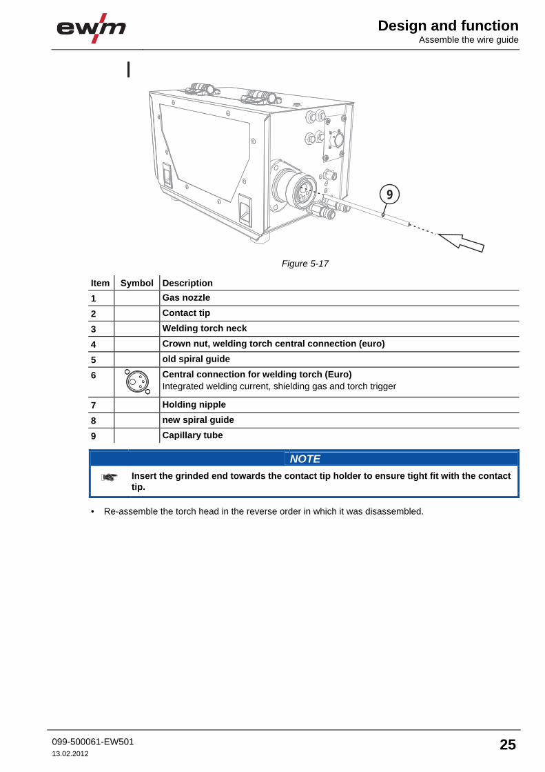
Figure 5-17
Item Symbol Description 0 1 Gas nozzle
2 Contact tip
3 Welding torch neck
4 Crown nut, welding torch central connection (euro)
5 old spiral guide
6
Central connection for welding torch (Euro) Integrated welding current, shielding gas and torch trigger
7 Holding nipple
8 new spiral guide
9 Capillary tube
NOTE
Insert the grinded end towards the contact tip holder to ensure tight fit with the contact tip.
• Re-assemble the torch head in the reverse order in which it was disassembled.

Design and function Adjusting the welding machine central connector
26 099-500061-EW50113.02.2012
5.5 Adjusting the welding machine central connector
NOTE
On delivery, the central connector (Euro) is fitted with a capillary tube for welding torches with spiral guides!
5.5.1 Preparation work on the central connector to connect welding torches with plastic cores • Push forward the capillary tube on the wire feed side in the direction of the central connector and
remove at that point. • Push on the guide pipe from the central connector. • Carefully insert the central plug for the welding torch, with the still oversized plastic core, into the
central connector and screw together with crown nut. • Use a special cutter or sharp knife to cut off the plastic core shortly before the wire feed roller, making
sure not to pinch it. • Unfasten and remove the central plug on the welding torch. • Cleanly remove the burr from the separated end of the plastic core!
5.5.2 Preparation work on the central connector to connect welding torches with spiral guides • Check that the capillary tube is correctly positioned in relation to the central connector! • Insert the central plug for the welding torch into the central connector and screw together with crown
nut.

Maintenance, care and disposal
Daily maintenance tasks
099-500061-EW501 13.02.2012
27
6 Maintenance, care and disposal
CAUTION
Electrical current! The following work must always be carried out with the power source switched off.
6.1 Daily maintenance tasks • Blow compressed air through the wire feed from the direction of the welding torch central connector. • Check that coolant connections are tight. • Check that the welding torch, and where applicable the power source cooling, are functioning
correctly. • Check the coolant level. • Check torch, hose package and power connections for exterior damage and replace or have repaired
by specialist staff as necessary! • Check the wearing parts in the torch. • Spray the gas nozzle with a splash protection agent.
6.2 Monthly maintenance tasks • Check the coolant container for sludge deposits and check the coolant for cloudiness.
Clean the coolant container if contaminated, and change the coolant. • If the coolant is dirty, rinse through the welding torch alternately several times with fresh coolant using
the coolant return and supply. • Check that all connections and wearing parts are hand-tight and tighten if necessary. • Check the wire guide. • Check and clean the welding torch. Deposits in the torch can cause short circuits and have a negative
impact on the welding result, ultimately causing damage to the torch. • Check that all screw and plug connections and replaceable parts are secured correctly, tighten if
necessary.

Maintenance, care and disposal Maintenance work
28 099-500061-EW50113.02.2012
6.3 Maintenance work
CAUTION
Electric current! Repairs may only be carried out by authorised specialist staff! • Do not remove the torch from the tube package! • Never clamp the torch body in a vice or similar, as this can cause the torch to be irreparably
destroyed! • If damage occurs to the torch or to the tube package which cannot be corrected as part of
the maintenance work, the entire torch must be returned to the manufacturer
6.4 Disposing of equipment
NOTE
Proper disposal! The machine contains valuable raw materials, which should be recycled, and electronic components, which must be disposed of. • Do not dispose of in household waste! • Observe the local regulations regarding disposal!
6.4.1 Manufacturer's declaration to the end user • According to European provisions (guideline 2002/96/EG of the European Parliament and the Council
of January, 27th 2003), used electric and electronic equipment may no longer be placed in unsorted municipal waste. It must be collected separately. The symbol depicting a waste container on wheels indicates that the equipment must be collected separately. This machine is to be placed for disposal or recycling in the waste separation systems provided for this purpose.
• According to German law (law governing the distribution, taking back and environmentally correct disposal of electric and electronic equipment (ElektroG) from 16.03.2005), used machines are to be placed in a collection system separate from unsorted municipal waste. The public waste management utilities (communities) have created collection points at which used equipment from private households can be disposed of free of charge.
• Information about giving back used equipment or about collections can be obtained from the respective municipal administration office.
• EWM participates in an approved waste disposal and recycling system and is registered in the Used Electrical Equipment Register (EAR) under number WEEE DE 57686922.
• In addition to this, returns are also possible throughout Europe via EWM sales partners.
6.5 Meeting the requirements of RoHS We, EWM HIGHTEC Welding GmbH Mündersbach, hereby confirm that all products supplied by us which are affected by the RoHS Directive, meet the requirements of the RoHS (Directive 2002/95/EC).

Rectifying faultsChecklist for rectifying faults
099-500061-EW501 13.02.2012
29
7 Rectifying faults All products are subject to rigorous production checks and final checks. If, despite this, something fails to work at any time, please check the product using the following flowchart. If none of the fault rectification procedures described leads to the correct functioning of the product, please inform your authorised dealer.
7.1 Checklist for rectifying faults
NOTE
The correct machine equipment for the material and process gas in use is a fundamental requirement for perfect operation!
Legend Symbol Description Fault/Cause Remedy
Welding torch overheated Insufficient coolant flow
Check coolant level and refill if necessary Eliminate kinks in conduit system (hose packages) see chapter "Vent coolant circuit"
Loose welding current connections Tighten power connections on the torch and/or on the workpiece Tighten contact tip correctly
Overload Check and correct welding current setting Use a more powerful welding torch
Functional error with the welding torch operating elements Connection problems
Make control lead connections and check that they are fitted correctly.
Wire feed problems Unsuitable or worn welding torch equipment
Adjust contact tip to wire diameter and -material and replace if necessary Adjust wire guide to material in use, blow through and replace if necessary
Kinked hose packages Extend and lay out the torch hose package
Incompatible parameter settings Check settings and correct if necessary
Overheating of the welding torch

Rectifying faults Checklist for rectifying faults
30 099-500061-EW50113.02.2012
Unstable arc Unsuitable or worn welding torch equipment
Adjust contact tip to wire diameter and -material and replace if necessary Adjust wire guide to material in use, blow through and replace if necessary
Incompatible parameter settings Check settings and correct if necessary
Pore formation Inadequate or missing gas shielding
Check shielding gas setting and replace shielding gas cylinder if necessary Shield welding site with protective screens (draughts affect the welding result)
Unsuitable or worn welding torch equipment Check size of gas nozzle and replace if necessary
Condensation (hydrogen) in the gas tube Rinse hose package with gas or replace
Splashes in the gas nozzle Gas distributor out of order or missing

Rectifying faults
Vent coolant circuit
099-500061-EW501 13.02.2012
31
7.2 Vent coolant circuit
NOTE
If there is less coolant in the coolant tank than the minimum required you may need to vent the coolant circuit. In this case the welding machine will automatically shut down the coolant pump and signal an error, see chapter "Rectifying faults".
To vent the cooling system always use the blue coolant connection, which is located as deep as possible inside the system (close to the coolant tank)!
Figure 7-1

Technical data AMT301G
32 099-500061-EW50113.02.2012
8 Technical data
NOTE
Performance specifications and guarantee only in connection with original spare and replacement parts!
8.1 AMT301G Welding torch polarity Usually positive Guide type Machine-operated Voltage type DC Shielding gas CO2 or mixed gas M21 according to EN 439 Duty cycle 35/60% Maximum welding current, M21
330 A/300 A
Maximum welding current, pulse M21
220 A/200 A
Maximum welding current, CO2 380 A/330 A Wire types Standard round wires Wire diameter 0.8–1.6 mm Ambient temperature -10 °C to +40 °C Voltage measurement, manual operation
113 V (peak value)
Protection rating for the machine connections (EN 60529)
IP3X
Gas flow 10 to 25 l/min Hose package length 1.5 m/3 m/4 m/5 m Connection Euro torch connector Constructed to standard IEC 60974-7

Technical data
AMT451W, AMT551W
099-500061-EW501 13.02.2012
33
8.2 AMT451W, AMT551W Type AMT451W AMT551W Welding torch polarity Usually positive Guide type Machine-operated Voltage type DC Shielding gas CO2 or mixed gas M21 according to EN 439 Duty cycle 100% Maximum welding current, M21
450 A 550 A
Maximum welding current, pulse M21
350 A 500 A
Maximum welding current, CO2 550 A 650 A Required cooling capacity min. 800 W Torch input pressure for coolant (min.–max.)
3 to 6 bar
Wire types Standard round wires Wire diameter 0.8 to 1.6 mm 0.8 to 2.0 mm Ambient temperature -10 °C to +40 °C Voltage measurement, manual operation
113 V (peak value)
Protection rating for the machine connections (EN 60529)
IP3X
Gas flow 10 to 25 l/min Hose package length 1.5 m/3 m/4 m/5 m Connection Euro torch connector Constructed to standard IEC 60974-7
Replaceable parts General
34 099-500061-EW50113.02.2012
9 Replaceable parts 9.1 General
CAUTION
Damage due to the use of non-genuine parts! The manufacturer's warranty becomes void if non-genuine parts are used! • Only use system components and options (power sources, welding torches, electrode
holders, remote controls, spare parts and replacement parts, etc.) from our range of products!
• Only insert and lock accessory components into the relevant connection socket when the machine is switched off.
NOTE
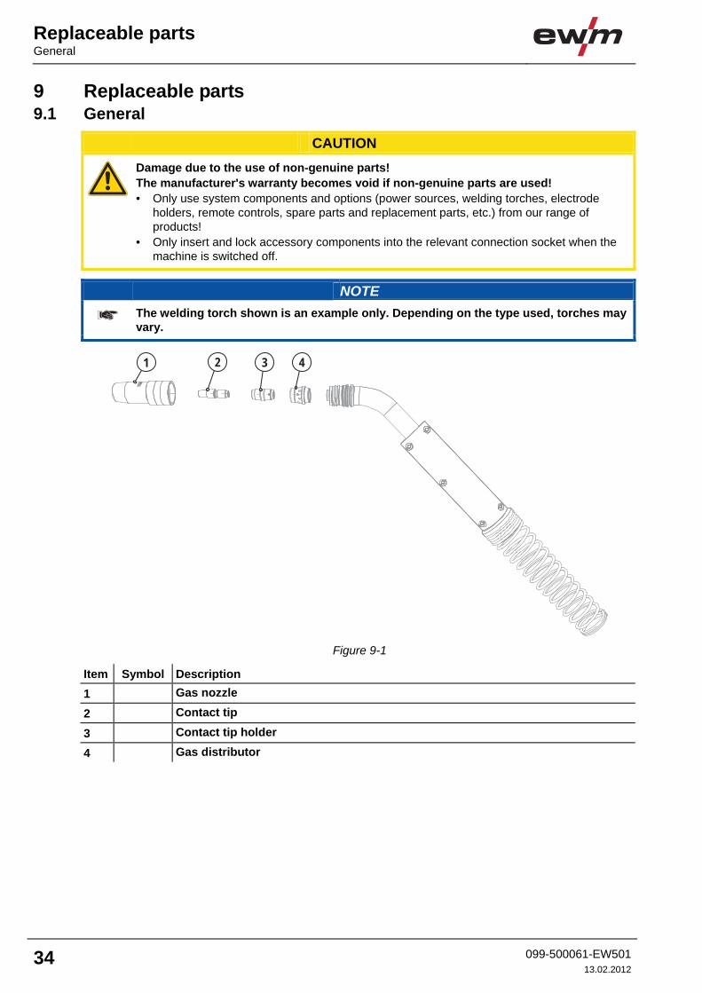
The welding torch shown is an example only. Depending on the type used, torches may vary.
4321
Figure 9-1
Item Symbol Description 0 1 Gas nozzle
2 Contact tip
3 Contact tip holder
4 Gas distributor

Replaceable parts
General
099-500061-EW501 13.02.2012
35
9.1.1 AMT301G 9.1.1.1 Status on delivery
Type Designation Item no. CTH CUCRZR M9 L=40.5MM Contact tip holder 094-013539-90002CT CUCRZR M9X35MM D=1.0MM
Contact tip 094-013530-90005
LSTC D=1.5X4.0MM L=1.5M Spiral guide, insulated, blue 094-017080-00000LSTC D=1.5X4.0MM L=3M Spiral guide, insulated, blue 094-013074-00000LSTC D=1.5X4.0MM L=4M Spiral guide, insulated, blue 094-013075-00000LSTC D=1.5X4.0MM L=5M Spiral guide, insulated, blue 094-014221-00000GN D=15MM L=71MM Gas nozzle 094-013106-90002GD D=17MM L=14MM Gas distributor 094-013096-90002
9.1.1.2 Complete list Type Designation Item no. CTH CUCRZR M9 L=40.5MM Contact tip holder 094-013539-90002CTH CUCRZR M9 L=43.5MM Contact tip holder 094-013540-90002GN D=13MM L=71MM Gas nozzle 094-013105-90002GN D=15MM L=71MM Gas nozzle 094-013106-90002GN D=18MM L=71MM Gas nozzle 094-013107-90002GD D=17MM L=14MM Gas distributor 094-013096-90002CT CUCRZR M9X35MM D=0.8MM
Contact tip 094-013528-90005
CT CUCRZR M9X35MM D=0.9MM
Contact tip 094-013529-90005
CT CUCRZR M9X35MM D=1.0MM
Contact tip 094-013530-90005
CT CUCRZR M9X35MM D=1.2MM
Contact tip 094-013531-90005
CT CUCRZR M9X35MM D=1.4MM
Contact tip 094-013532-90005
CT CUCRZR M9X35MM D=1.6MM
Contact tip 094-013533-90005
CTAL E-CU M9X35MM D=0.8MM
Contact tip, aluminium 094-013543-90005
CTAL E-CU M9X35MM D=0.9MM
Contact tip, aluminium 094-013544-90005
CTAL E-CU M9X35MM D=1.0MM
Contact tip, aluminium 094-013545-90005
CTAL E-CU M9X35MM D=1.2MM
Contact tip, aluminium 094-013546-90005
CTAL E-CU M9X35MM D=1.4MM
Contact tip, aluminium 094-013547-90005
CTAL E-CU M9X35MM D=1.6MM
Contact tip, aluminium 094-013548-90005

Replaceable parts General
36 099-500061-EW50113.02.2012
9.1.2 AMT451W 9.1.2.1 Status on delivery
Type Designation Item no. CTH CUCRZR M9 L=40.5MM Contact tip holder 094-013539-90002CT CUCRZR M9X35MM D=1.2MM
Contact tip 094-013531-90005
LSTC D=2.0X4.0MM L=1.5M Spiral guide, insulated, red 094-016191-00000LSTC D=2.0X4.0MM L=3M Spiral guide, insulated, red 094-007239-00000LSTC D=2.0X4.0MM L=4M Spiral guide, insulated, red 094-014223-00000LSTC D=2.0X4.0MM L=5M Spiral guide, insulated, red 094-014224-00000GN D=15MM L=71MM Gas nozzle 094-013106-90002GD D=17MM L=14MM Gas distributor 094-013096-90002
9.1.2.2 Complete list Type Designation Item no. CTH CUCRZR M9 L=40.5MM Contact tip holder 094-013539-90002CTH CUCRZR M9 L=43.5MM Contact tip holder 094-013540-90002GN D=13MM L=71MM Gas nozzle 094-013105-90002GN D=15MM L=71MM Gas nozzle 094-013106-90002GN D=18MM L=71MM Gas nozzle 094-013107-90002GD D=17MM L=14MM Gas distributor 094-013096-90002CT CUCRZR M9X35MM D=0.8MM
Contact tip 094-013528-90005
CT CUCRZR M9X35MM D=0.9MM
Contact tip 094-013529-90005
CT CUCRZR M9X35MM D=1.0MM
Contact tip 094-013530-90005
CT CUCRZR M9X35MM D=1.2MM
Contact tip 094-013531-90005
CT CUCRZR M9X35MM D=1.4MM
Contact tip 094-013532-90005
CT CUCRZR M9X35MM D=1.6MM
Contact tip 094-013533-90005
CTAL E-CU M9X35MM D=0.8MM
Contact tip, aluminium 094-013543-90005
CTAL E-CU M9X35MM D=0.9MM
Contact tip, aluminium 094-013544-90005
CTAL E-CU M9X35MM D=1.0MM
Contact tip, aluminium 094-013545-90005
CTAL E-CU M9X35MM D=1.2MM
Contact tip, aluminium 094-013546-90005
CTAL E-CU M9X35MM D=1.4MM
Contact tip, aluminium 094-013547-90005
CTAL E-CU M9X35MM D=1.6MM
Contact tip, aluminium 094-013548-90005

Replaceable parts
General
099-500061-EW501 13.02.2012
37
9.1.3 AMT551W 9.1.3.1 Status on delivery
Type Designation Item no. CTH CUCRZR M9 L=35MM Contact tip holder 094-013856-90002CT CUCRZR M9X35MM D=1.2MM
Contact tip 094-013531-90005
LSTC D=2.0X4.0MM L=1.5M Spiral guide, insulated, red 094-016191-00000LSTC D=2.0X4.0MM L=3M Spiral guide, insulated, red 094-007239-00000LSTC D=2.0X4.0MM L=4M Spiral guide, insulated, red 094-014223-00000LSTC D=2.0X4.0MM L=5M Spiral guide, insulated, red 094-014224-00000GN D=17MM L=66MM Gas nozzle 094-014180-90002GD D=20MM L=21.5MM Gas distributor 094-013111-90002
9.1.3.2 Complete list Type Designation Item no. CTH CUCRZR M9 L=35MM Contact tip holder 094-013856-90002CTH CUCRZR M9 L=38MM Contact tip holder 094-016425-90002GN D=15MM L=63MM Gas nozzle 094-014177-90002GN D=15MM L=66MM Gas nozzle 094-014178-90002GN D=17MM L=63MM Gas nozzle 094-014179-90002GN D=17MM L=66MM Gas nozzle 094-014180-90002GN D=19MM L=63MM Gas nozzle 094-014181-90002GN D=19MM L=66MM Gas nozzle 094-014182-90002GD D=20MM L=21.5MM Gas distributor 094-013111-90002CT CUCRZR M9X35MM D=0.8MM
Contact tip 094-013528-90005
CT CUCRZR M9X35MM D=0.9MM
Contact tip 094-013529-90005
CT CUCRZR M9X35MM D=1.0MM
Contact tip 094-013530-90005
CT CUCRZR M9X35MM D=1.2MM
Contact tip 094-013531-90005
CT CUCRZR M9X35MM D=1.4MM
Contact tip 094-013532-90005
CT CUCRZR M9X35MM D=1.6MM
Contact tip 094-013533-90005
CT CUCRZR M9X35MM D=2.0MM
Contact tip 094-013534-90005
CTAL E-CU M9X35MM D=0.8MM
Contact tip, aluminium 094-013543-90005
CTAL E-CU M9X35MM D=0.9MM
Contact tip, aluminium 094-013544-90005
CTAL E-CU M9X35MM D=1.0MM
Contact tip, aluminium 094-013545-90005
CTAL E-CU M9X35MM D=1.2MM
Contact tip, aluminium 094-013546-90005
CTAL E-CU M9X35MM D=1.4MM
Contact tip, aluminium 094-013547-90005
CTAL E-CU M9X35MM D=1.6MM
Contact tip, aluminium 094-013548-90005
CTAL E-CU M9X35MM D=2.0MM
Contact tip, aluminium 094-013549-90005

Replaceable parts General
38 099-500061-EW50113.02.2012
9.2 General Type Designation Item no. SW5-SW12MM Torch key 094-016038-00001LSTC D=1.5X4.0MM L=1.5M Spiral guide, insulated, blue 094-017080-00000LSTC D=1.5X4.0MM L=3M Spiral guide, insulated, blue 094-013074-00000LSTC D=1.5X4.0MM L=4M Spiral guide, insulated, blue 094-013075-00000LSTC D=1.5X4.0MM L=5M Spiral guide, insulated, blue 094-014221-00000LSTC D=2.4X4.5MM L=1.5M Spiral guide, insulated, grey 094-017081-00000LTSC D=2.4X4.5MM L=3M Spiral guide, insulated, grey 094-013662-00000LTSC D=2.4X4.5MM L=4M Spiral guide, insulated, grey 094-013663-00000LTSC D=2.4X4.5MM L=5M Spiral guide, insulated, grey 094-013664-00000LSTC D=2.0X4.0MM L=1.5M Spiral guide, insulated, red 094-016191-00000LSTC D=2.0X4.0MM L=3M Spiral guide, insulated, red 094-007239-00000LSTC D=2.0X4.0MM L=4M Spiral guide, insulated, red 094-014223-00000LSTC D=2.0X4.0MM L=5M Spiral guide, insulated, red 094-014224-00000LCPTFE COMBI D=1.5x4.0MM L=1.5
Combined core, carbon/tefl. 094-013871-00015
LCPTFE COMBI D=1.5X4.0MM L=3M
Combined core, carbon/tefl. 094-013871-00000
LCPTFE COMBI D=1.5X4.0MM L=4M
Combined core, carbon/tefl. 094-013871-00004
LCPTFE COMBI D=1.5X4.0MM L=5M
Combined core, carbon/tefl. 094-013871-00005
LCPTFE COMBI D=2.0X4.0MM L=1.5
Combined core, carbon/tefl. 094-013828-00015
LCPTFE COMBI D=2.0X4.0MM L=3M
Combined core, carbon Teflon 094-013828-00000
LCPTFE COMBI D=2.0X4.0MM L=4M
Combined core, carbon Teflon 094-013828-00004
LCPTFE COMBI D=2.0X4.0MM L=5M
Combined core, carbon/Teflon 094-013828-00005
LCPTFE COMBI D=2.7X4.7MM L=1.5
Combined core, carbon/tefl. 094-013829-00015
LCPTFE COMBI D=2.7X4.7MM L=3M
Combined core, carbon Teflon 094-013829-00000
LCPTFE COMBI D=2.7X4.7MM L=4M
Combined core, carbon Teflon 094-013829-00004
LCPTFE COMBI D=2.7X4.7MM L=5M
Combined core, carbon/Teflon 094-013829-00005
LPA COMBI D=1.5X4.0MM L=1.5M
Combined core, PA 094-013687-00015
LPA COMBI D=1.5X4.0MM L=3M
Combined core, PA 094-013687-00000
LPA COMBI D=1.5X4.0MM L=4M
Combined core, PA 094-013687-00004
LPA COMBI D=1.5X4.0MM L=5M
Combined core, PA 094-013687-00005
LPA COMBI D=2.0x4.0MM L=1.5M
Combined core, PA 094-017078-00000
LPA COMBI D=2.0X4.0MM L=3M
Combined core, PA 094-013076-00000

Replaceable parts
General
099-500061-EW501 13.02.2012
39
Type Designation Item no. LPA COMBI D=2.0X4.0MM L=4M
Combined core, PA 094-013077-00000
LPA COMBI D=2.0X4.0MM L=5M
Combined core, PA 094-013565-00000
LPA COMBI D=2.3X4.7MM L=1.5M
Combined core, PA 094-017079-00000
LPA COMBI D=2.3X4.7MM L=3M
Combined core, PA 094-013665-00000
LPA COMBI D=2.3X4.7MM L=4M
Combined core, PA 094-013666-00000
LPA COMBI D=2.3X4.7MM L=5M
Combined core, PA 094-013667-00000
LPTFE COMBI D=1.5X4.0MM L=1.5M
Combined core, Teflon, blue 094-013800-00015
LPTFE COMBI D=1.5X4.0MM L=3M
Combined core, Teflon, blue 094-013800-00000
LPTFE COMBI D=1.5X4.0MM L=4M
Combined core, Teflon, blue 094-013800-00004
LPTFE COMBI D=1.5X4.0MM L=5M
Combined core, Teflon, blue 094-013800-00005
LPTFE COMBI D=2.7X4.7MM L=1.5M
Combined core, Teflon, yellow 094-013802-00015
LPTFE COMBI D=2.7X4.7MM L=3M
Combined core, Teflon, yellow 094-013802-00000
LPTFE COMBI D=2.7X4.7MM L=4M
Combined core, Teflon, yellow 094-013802-00004
LPTFE COMBI D=2.7X4.7MM L=5M
Combined core, Teflon, yellow 094-013802-00005
LPTFE COMBI D=2.0X4.0MM L=1.5M
Combined core, Teflon, red 094-013801-00015
LPTFE COMBI D=2.0X4.0MM L=3M
Combined core, Teflon, red 094-013801-00000
LPTFE COMBI D=2.0X4.0MM L=4M
Combined core, Teflon, red 094-013801-00004
LPTFE COMBI D=2.0X4.0MM L=5M
Combined core, Teflon, red 094-013801-00005

Replaceable parts General
40 099-500061-EW50113.02.2012
Type Designation Item no. LBRA D=2.0MM L=300MM Brass spiral 094-013078-90002LBRA D=2.7MM L=300MM Brass spiral 094-013872-90002LCPTFE 1.5X4.0MM L=100M Carbon/teflon core 094-013870-00100LCPTFE 2.0X4.0MM L=100M Carbon/Teflon core 094-013524-00100LCPTFE 2.7X4.7MM L=100M Carbon/Teflon core 094-013525-00100LPA 1.4X4.0MM L=200M PA core 094-013781-00200LPA 2.0X4.0MM L=200M PA core 094-013782-00200LPA 2.3X4.7MM L=200M PA core 094-013783-00200LPTFE 1.5X4.0MM L=100M Teflon core, blue 094-013487-00100LPTFE 2.7X4.7MM L=100M Teflon core, yellow 094-013523-00100LPTFE 2.0X4.0MM L=100M Teflon core, red 094-013490-00100OR 3.5X1.5MM O-ring 094-001249-00000CO LINER D=4.0MM Clamping sleeve 094-001082-90005CO LINER D=4.7MM Clamping sleeve 094-001291-90005CB D=4.0MM Connecting sleeve 094-013757-90005CB D=4.7MM Connecting sleeve 094-013758-90005

Appendix A
Overview of EWM branches
099-500061-EW501 13.02.2012
41
10 Appendix A 10.1 Overview of EWM branches