migrating to arcgis™ and the internet - southwest
TRANSCRIPT

United States Department of Agriculture
AGWA Design Documentation:Migrating to ArcGIS™ and the Internet
R E S E A R C H A N D D E V E L O P M E N T


EPA/600/R-05/056ARS/181027
April 2005 http://www.epa.gov/nerlesd1/land-sci/agwa/pdf/agwa_design.pdf
AGWA Design Documentation:Migrating to ArcGIS™ and the Internet
by
Averill J. Cate, Jr. Darius J. Semmens
Ian S. Burns David C. Goodrich William G. Kepner
USDA/Agricultural Research Service, Southwest Watershed Research Center, Tucson, AZ U.S. Environmental Protection Agency, Landscape Ecology Branch, Las Vegas, NV
Notice: Although this work was reviewed by EPA and USDA and approved for publication, it may not necessarily reflect official Agency policy. Mention of trade names and commercial products does not constitute endorsement or recommendation for use.
U.S. Environmental Protection Agency Office of Research and Development
Washington, DC 20460 154leb05.rpt

ii

Table of Contents
Section 1 Introduction ........................................................................................................................... 1
Section 2 Objectives .............................................................................................................................. 5
Section 3 Approach ................................................................................................................................ 7
Section 4 Justification ........................................................................................................................... 9
Section 5 Design and Development ................................................................................................. 11 5.1 Application Requirements .............................................................................................................. 12
5.1.1 Target Audience ................................................................................................................ 12 5.1.2 Requirements..................................................................................................................... 13
5.2 Refine Requirements ...................................................................................................................... 15 5.3 Access Paths ................................................................................................................................... 16 5.4 Action Mappings ............................................................................................................................ 16 5.5 Action Forms.................................................................................................................................. 16 5.6 Actions............................................................................................................................................ 17 5.7 Business Logic ............................................................................................................................... 17 5.8 Presentation Pages .......................................................................................................................... 18 5.9 Configuration Files......................................................................................................................... 18
5.10 Build, Test, Deploy ........................................................................................................................ 18
Section 6 Domain Constraints........................................................................................................... 21 6.1 GIS Software .................................................................................................................................. 21 6.2 Commercial Database Application................................................................................................. 21 6.3 Internet and Server Resources ........................................................................................................ 21 6.4 Internet Web Server........................................................................................................................ 22 6.5 Programming Languages................................................................................................................ 22 6.6 Data Sources................................................................................................................................... 22 6.7 Documentation and Training.......................................................................................................... 23
Section 7 Timeline ................................................................................................................................ 25
Section 8 Summary and Conclusions ............................................................................................. 27
Section 9 Uncertainties ....................................................................................................................... 29
Appendix A UML Diagrams ................................................................................................................ 31 A.1 DotAGWA...................................................................................................................................... 33
A.1.1 Use Cases .......................................................................................................................... 33 A.1.2 Activity Diagrams ............................................................................................................. 34 A.1.3 Static Structure Diagrams.................................................................................................. 41
A.2 AGWA 2.0...................................................................................................................................... 49 A.2.1 Use Cases .......................................................................................................................... 49 A.2.2 Activity Diagrams ............................................................................................................. 50 A.2.3 Static Structure Diagrams.................................................................................................. 56
Appendix B Acronyms......................................................................................................................... 63
Appendix C References....................................................................................................................... 65
iii

iv
List of Figures
Figure 1. Flow chart showing the general framework for using KINEROS and SWAT in AGWA ........... 2
Figure 2. Conceptual model of DotAGWA illustrating the included components ...................................... 3
Figure 3. Conceptualization of the MVC design pattern used in AGWA 2.0 and DotAGWA (Panchel, 2003)........................................................................................................................... 12
v

vi

List of Tables
Table 1. Users ........................................................................................................................................... 13
Table 2. Requirements Analysis ............................................................................................................... 14
Table 3. User Requirements Breakdown .................................................................................................. 15
Table 4. Access Paths ............................................................................................................................... 16
Table 5. Action Forms .............................................................................................................................. 17
Table 6. DotAGWA Example Actions ..................................................................................................... 17
Table 7. Development Tools..................................................................................................................... 19
Table 8. Estimated Timeline..................................................................................................................... 25
vii

viii

Section 1
Introduction
Planning and assessment in land- and water-resource management are evolving from simple, local-scale problems toward complex, spatially explicit regional ones. Such problems have to be addressed with distributed models that can compute runoff and erosion at different spatial and temporal scales. The extensive data requirements and the difficult task of building input parameter files, however, have long represented an obstacle to the timely and cost-effective use of such complex models by resource managers. In addition, to evaluate management practices and their impacts on water quality, land and resource managers need to describe and simulate the impacts of land use and best management practices (BMPs) on watershed response.
The United States Department of Agriculture (USDA)-Agricultural Research Service (ARS) and the Southwest Watershed Research Center (SWRC), in cooperation with the U.S. Environmental Protection Agency (EPA)-Office of Research and Development (ORD), and the University of Arizona (UA), have developed the Automated Geospatial Watershed Assessment (AGWA) Geographic Information System (GIS) tool (Miller et al., 2002; http://www.tucson.ars.ag.gov/agwa) to facilitate the distributed hydrological modeling process as outlined in the EPA Research Plan by Goodrich et al., (2000 - EPA/600-00/042). The quality assurance and quality control measures used in the development of AGWA are described in Hernandez et al. (2002 – EPA/600/R-02/046).
AGWA uses widely available standardized spatial data sets that can be obtained via the Internet. The required data sets include topography (DEM data), soils, and land-cover data. These data are used to develop input parameter files for two USDA-ARS watershed runoff and erosion models: the Kinematic Runoff and Erosion Model (KINEROS2) (Smith et al., 1995; http://www.tucson.ars.ag.gov/kineros) and the Soil and Water Assessment Tool (SWAT) (Arnold et al., 1994; http://www.brc.tamus.edu/swat/). AGWA is currently packaged as an extension for the Environmental Systems Research Institute’s (ESRI) ArcView 3.x GIS software and has recently been incorporated into version 3.1 of the EPA’s Better Assessment Science Integrating Point and Nonpoint Sources (BASINS) multipurpose environmental analysis system (http://www.epa.gov/docs/ostwater/BASINS/). In addition, a variety of studies and watershed assessments in a number of different geographies have been conducted using AGWA (Hernandez et al., 2000 and 2002; Miller et al., 2002; Kepner et al., 2004). A schematic of the procedure for utilizing the KINEROS and SWAT models within AGWA is presented in Figure 1.
1
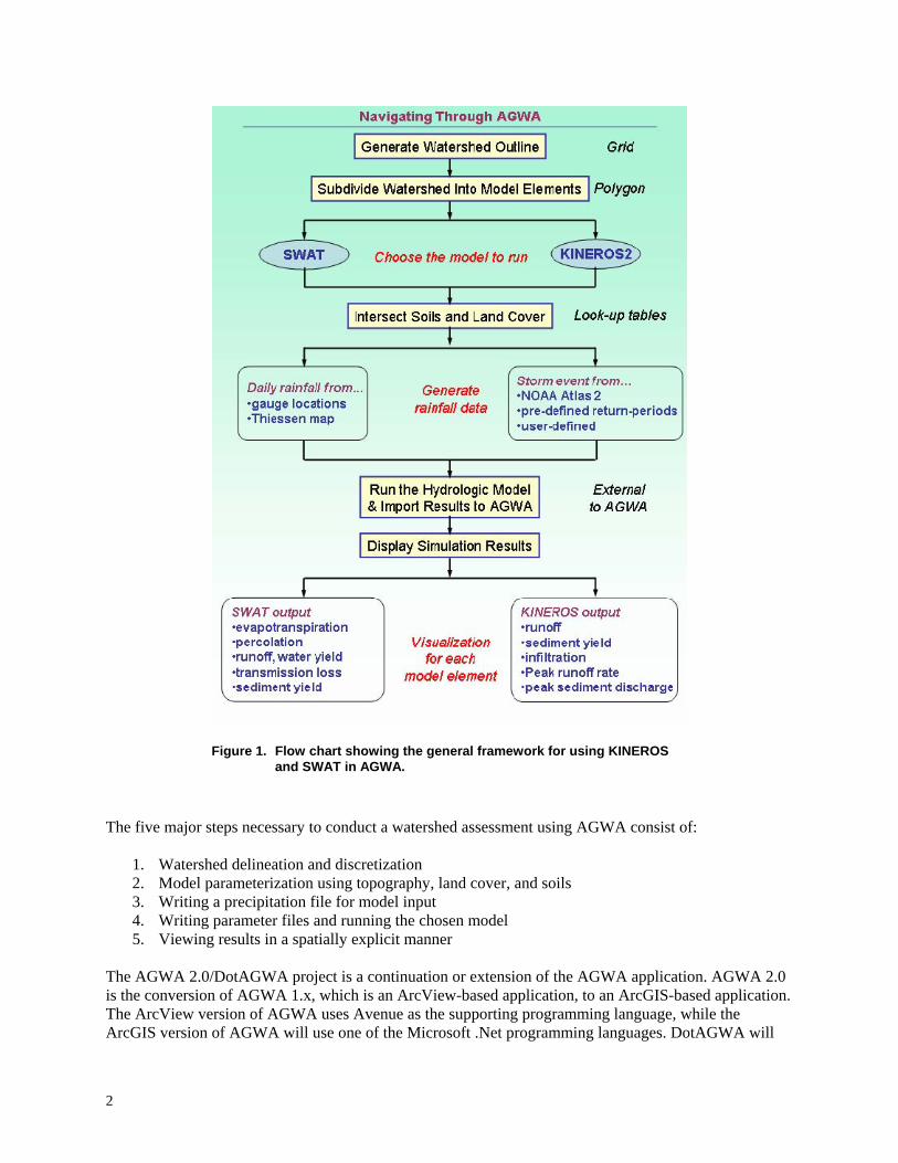
Figure 1. Flow chart showing the general framework for using KINEROS and SWAT in AGWA.
The five major steps necessary to conduct a watershed assessment using AGWA consist of:
1. Watershed delineation and discretization 2. Model parameterization using topography, land cover, and soils 3. Writing a precipitation file for model input 4. Writing parameter files and running the chosen model 5. Viewing results in a spatially explicit manner
The AGWA 2.0/DotAGWA project is a continuation or extension of the AGWA application. AGWA 2.0 is the conversion of AGWA 1.x, which is an ArcView-based application, to an ArcGIS-based application. The ArcView version of AGWA uses Avenue as the supporting programming language, while the ArcGIS version of AGWA will use one of the Microsoft .Net programming languages. DotAGWA will
2

be constructed to make most of the features and functions in AGWA 2.0 available through a web-based interface. DotAGWA will be the web-based version of AGWA. DotAGWA will also leverage many of the tools and modules developed in the Spatial Decision Support System (SDSS) project developed at the ARS. The SDSS project is a web-based application that allows users to delineate a watershed at any point, define management plans in the watershed, parameterize watershed models (KINEROS and SWAT) and run those models for the parameterized watershed and management plan. In addition, AGWA 2.0 and DotAGWA will incorporate added user control capability that will allow users to modify land use and land cover for developing and evaluating future management scenarios and their impacts on watershed response. For example, in a rangeland setting, various management plans for grazing could be evaluated by allowing users to add features such as fence lines, pastures, and water points to an area of interest. The user can then select and run models and/or simulations that account for the management activities. The end result is a management plan with simulation results that estimate the water quantity/quality impacts of the newly added features on the area of interest. Users will be able to save multiple management plans that can be compared in other types of analyses (e.g., sensitivity, economic, etc.). A conceptual design of implementing DotAGWA is presented in Figure 2.
Web
Ser
ver
Figure 2. Conceptual model of DotAGWA illustrating the included components.
3

4

Section 2
Objectives
The second generation AGWA interface will remain largely founded on the same objective that led to the development of the original AGWA tool: to develop methods and provide operational hydrologic modeling tools for determining the vulnerability of arid and semi-arid landscapes to natural and human induced landscape-pattern changes across multiple scale domains. However, in the second generation our focus of landscape applicability will be broadened beyond arid and semi-arid landscapes. Our specific goals in the development of the next AGWA interface and its web equivalent are: (1) to design it in such a way as to maximize its capacity to incorporate different types of models, (2) to facilitate interaction between observed and modeled information at multiple scales, (3) to make the interface as user friendly and transparent as possible, (4) to maximize the potential user audience, (5) to separate GIS and non-GIS functionality to the greatest extent possible so that the same GIS functionality can be called from both the desktop and Internet versions of the interface, and (6) to enable straightforward transferability of AGWA functionality into a future version of BASINS as it migrates to ArcGIS and Internet options. Objectives for AGWA 2.0 (desktop version) are slightly different from those for DotAGWA (Internet version), and these are outlined separately below.
The desktop version of AGWA is still the most widely used and needed. Also, not all users have Internet access and rely on the desktop application. The desktop interface will be the most powerful and versatile version of the AGWA software to date. It is intended for advanced users and researchers who are interested in detailed model applications, model calibration, exploring new ways of improving model parameterization, integrating models, and utilizing modeled and observed information to facilitate environmental decision-making. As such, the desktop interface design will include all available model functionality, the greatest amount of flexibility to incorporate user-provided/defined information, and the most powerful tools for scenario development and the analysis and visualization of model results.
The DotAGWA Internet interface will have a more streamlined design that is intended to accommodate limited management and educational uses for those who do not have access to expensive GIS software. It will be automated to the greatest extent possible to make it relatively simple to use, as well as easier to develop in the more complex web environment. As such, functionality will be selectively implemented to maximize versatility and model performance, but at the expense of user interaction with the data, models, and look-up tables.
This design document is intended to serve as a blueprint that will guide our development of AGWA 2.0 and DotAGWA, and guide others who seek to add new models or functionality in the future. By recording our detailed design of the application, we also intend it to serve as a vehicle for generating comments and contributions from a wider audience, some of whom may have important ideas for improving it. Specific objectives of the design document thus include:
• Clearly stating the objectives of the design. • Defining and justifying the approach we intend to take to meet our objectives. • Illustrating the specific design features and their expected benefits.
5

These objectives will be addressed separately for AGWA 2.0 and DotAGWA, but our final objective will be to illustrate how their designs will overlap to minimize development requirements, and maximize the flexibility to accommodate alternative GIS software and/or additional models and tools.
6

Section 3
Approach
Our general approach to developing the second-generation AGWA interfaces has been to utilize ESRI’s ArcGIS 9.0 GIS software. The AGWA 2.0 (desktop) and DotAGWA (Internet) interfaces will be developed in parallel, with both versions accessing the same GIS functionality (e.g., watershed delineation, discretization, model parameterization, and results visualization). Input data and associated look-up tables for both versions will be stored in a geodatabase, with standardized protocols for incorporating related tables.
7

8
Section 4
Justification
The migration of AGWA from its original form as an extension for ArcView 3.x to one for ArcGIS 9.0 is designed as a means to keep pace with rapidly evolving GIS technologies while accommodating the largest potential user audience. Although we do not explicitly endorse particular trade names or products, the fact remains that most U.S. Federal and state agencies involved in land- and water-resources management have negotiated license agreements with ESRI for the use of ArcView and/or ArcGIS software. In addition, a recent market analysis showed that ESRI products command 35% of the global GIS software market, which is almost three times that of the closest competitor (Daratech, 2002). Academic research institutions are also heavily invested in ESRI software, with many U.S. universities owning campus-wide site licenses (ESRI, 2004). The stated target audience of AGWA coincides perfectly with these user groups (land- and water-resource managers and scientists), so our continued use of ESRI products is intended to accommodate our core users as well as maximizing exposure to other audiences worldwide.
The development of DotAGWA is intended to broaden AGWA’s potential user base to include anyone with a connection to the Internet. Specially designed components will enable local managers to evaluate the potential costs and benefits associated with management strategies and best management practices, and foster community involvement in environmental management. Relatively little scientific training and no specialized software will be required to make scientifically sound management decisions regarding complex spatially-dependent management activities such as livestock fencing strategies, locating watering points, the use of vegetative buffers around streams, and other common best management practices (BMPs). For the same reason it is also anticipated that DotAGWA will serve as an invaluable learning tool for students around the world.
Parallel development of web- and desktop-based versions of AGWA is being implemented to minimize the duplication of effort associated with developing the tools independently. Specific GIS functionality of AGWA is being packaged into reusable components. These components can then be called from either tool to perform each task associated with conducting a watershed assessment. In addition to minimizing the cost associated with developing both versions of AGWA, this strategy has the enormous advantage of facilitating the subsequent addition of any number of other models and/or tools. Essentially, the next generation of AGWA products is being designed to serve as a foundation, or platform, for the integration of additional models, modeling tools, and data sources, and to facilitate ongoing Federal and academic research in earth surface processes (ecology, hydrology, and geomorphology).
To address the challenge of managing growing Federal acquisitions of information technology, the U.S. Government passed Information Technology Management Reform Act, otherwise known as the Klinger-Cohen Act, in 1996. An Interagency Steering Committee on Multimedia Environmental Models (ISCMEM) was subsequently formed to address requirements of the Klinger-Cohen Act relating for model research and development in the environmental sciences. The committee developed a Memorandum of Understanding (MOU) among eight Federal Agencies in 2001 with the purpose of establishing “a framework for facilitating cooperation and coordination in research and development (R&D) of multimedia environmental models, software and related databases, including development, enhancements, applications and assessments of site-specific, generic, and process-oriented multimedia environmental models as they pertain to human and environmental health risk assessment” (ISCMEM, 2004). In the MOU, participating Federal Agencies agreed to establish procedures for sharing multimedia
9

environmental models, software, related databases and supporting scientific information with the other cooperating Federal Agencies.
Our integrated design for the next generation of AGWA products is compatible with this agreement on several levels. First, it is designed to utilize standardized data sources compiled by a variety of Federal agencies, as well as the tools and/or services for accessing that data. Second, it is the product of a cooperative effort between two Federal Agencies (U.S. EPA and USDA) and two academic institutions (University of Arizona and University of Wyoming) and is specifically designed to facilitate the integration of many different types of environmental models. Third, the products of this effort will be open source, well documented, and available for download on the Internet free of charge. Finally, the proposed design is intended to facilitate the development of multiple user interfaces (i.e., vehicles for technology transfer) by packaging core GIS functionality into shared modules that can be called individually by any application.
Our design also builds and draws on previous efforts to develop GIS tools and decision support systems. In particular, we have and continue to work closely with the developers of SWAT and BASINS as we all move to develop versions compatible with ArcGIS 9.0. Where possible, the SWAT and AGWA developers have agreed that code common to both applications, such as the watershed delineation and soil parameterization routines, will be traded to minimize development efforts/costs. Similarly, the design of AGWA 2.0 has been carefully planned to maximize its compatibility with BASINS 4.0, which will have a stand-alone interface that calls GIS functionality from either ArcView 3.X or ArcGIS 9.0. This has factored into our selection of programming language, as well as our separation of spatial and nonspatial tasks. Previous work has also been leveraged in our design plan. The alpha version of the USDA-ARS spatial DSS serves as the foundation from which we have developed the DotAGWA design. Both the conceptual design and code from the alpha version have been utilized to the greatest extent possible, with modifications only where necessary to improve compatibility with AGWA 2.0 and longevity in the face of changing technology.
10
Section 5
Design and Development
We have identified a simple ten-step plan for the development of the AGWA 2.0 and DotAGWA application (Spielman, 2003).
1. Application Requirements – Gather and define the application requirements.
2. Refine Requirements – Define and develop requirements for each interface in terms of the data to be collected and/or displayed.
3. Access Paths – Determine all the access paths for each interface.
4. Action Mappings – Define the action mappings that correlate to the application business logic.
5. Action Forms – Create action forms with defined properties from the interface requirements (can include validation).
6. Actions – Develop actions to be called by the action mappings that, in turn, call the appropriate helpers and forward to the appropriate pages.
7. Business Logic – Develop the application “business logic”.
8. Presentation Pages – Create pages to match the workflows using action mappings.
9. Configuration Files – Build the appropriate configuration files for the selected supporting technologies.
10. Build, test, deploy.
These steps will be incorporated into a spiral model of application development. The spiral model is characterized by an iterative process of prototyping with controlled and systematic aspects of sequential steps (above). This type of model provides the potential for rapid development of incremental versions of the software (Pressman, 2001). The goal of using this development plan is to create an application that uses the Model View Controller (MVC) design pattern. MVC is an application development methodology used to efficiently relate the user interface to underlying data models. The MVC design pattern divides an application into three components: model, view, and controller. The model manages the data and the functions that operate on it, and is typified by a database and a geo-processing library for DotAGWA and by ArcGIS and the same library for AGWA 2.0. The view is typically the interface presented to the user and represents the current state of the model, typified by a web page for DotAGWA and by ArcGIS for AGWA 2.0. The controller serves as a bridge between the model and view and commands the view in response to changes in the model and commands the model in response to user input from the view. The MVC pattern also helps promote flexibility in application development and implementation. For example, if the chosen database technology needs to be replaced, it can be done with minimal impact on the view and controller components of the application. The MVC pattern requires standardized communication mechanisms between application components encapsulated by the model, a web browser and/or ArcGIS encapsulated by the view, and the controller. A diagram illustrating the MVC design is presented in Figure 3.
11

Figure 3. Conceptualization of the MVC design pattern used in AGWA 2.0 and DotAGWA (Panchel, 2003).
One of the primary objectives during application development is to develop a reusable library of core GIS features. These GIS features will handle the application’s geo-processing requirements. Since desktop and web-based applications are providing the same essential features, the code developed for the GIS processing will only be coded once and shared between applications. The geo-processing library will be incorporated into the desktop and web applications as part of the model connected to their respective interfaces by customized application code. Subsequent changes to any one of the MVC components will not cause programming problems in the other parts of the application and will facilitate the reuse of geo-processing tools.
The following sections describe the work involved at each step of the development for both AGWA 2.0 and DotAGWA. Differences between AGWA 2.0 and DotAGWA will be highlighted as development strategies diverge. Please see the appendices for a more detailed and comprehensive look at what each step entails.
5.1 Application Requirements
5.1.1 Target Audience Anticipated application users and their organizational relationships are described in Table 1. This information is based on feedback provided by existing AGWA users and feedback obtained while developing the SDSS (Miller, 2004).
12

Table 1. Users.
Person/Role Organizational Bias
Watershed Research Scientist Interested in physical process models and facilitating model parameterization.
Interested in running multiple simulations for research projects.
Interested in running physical process models and using model results to analyze natural resources.
Natural Resource Research Scientist
Natural Resource Conservation Service Specialist/Scientist
Interested in running physical process models and analyzing impacts of model results on natural resources.
Interested in running multiple simulations for research projects.
Interested in running physical process models and using model results to analyze natural resources.
Consultant Interested in running physical process models and analyzing impacts of model results on natural resources.
Interested in running physical process models and using model results to analyze natural resources.
Government Planner Interested in viewing analysis results generated by research scientists or consultants.
Interested in running simple, one-time simulations.
Interested in running physical process models and using model results to analyze natural resources.
General Public Interested in viewing analysis results generated by research scientists or consultants.
Interested in running simple, one-time simulations.
Interested in running physical process models and using model results to analyze natural resources.
Programmer/Analyst This person views the system from the designer programmer point of view. He/she has strong interests in successfully integrating all tools using a clear and manageable design.
Also, sees operation of application after development as a support person who will be fixing program bugs and administering application resources.
Rancher End users interested in using the application on a day-to-day basis as a tool to assist in operations planning and resource management.
5.1.2 Requirements The information in Table 2 is based on feedback provided by existing AGWA users and feedback obtained while developing the SDSS project. As part of the development life cycle, this table may change based on the needs of future users and unforeseen user requirements, but changes will be unlikely to influence the overarching design.
13

Table 2. Requirements Analysis.
Requirement Priority
StatusDotAGWA AGWA 2.0 General Application Requirements Create user account High N/A TBD Browse spatial data High High TBD Spatially locate area of interest High High TBD Create GIS Shape files High High TBD Import user specific spatial data Low High TBD Create user specific spatial data High High TBD Catalog view of existing user projects Medium Medium TBD Develop and run management scenarios High High TBD Save current management project High High TBD Export simulation results to spreadsheet files High High TBD Export spatial data to be used in AGWA 2.0 Medium N/A TBD User login High N/A TBD User logout High N/A TBD Save user scenario or management plan High N/A TBD Save user scenario or management plan High N/A TBD Modify user scenario or management plan High N/A TBD Mapping Interface Requirements Map zoom High High TBD Map pan High High TBD Toggle map layer visibility High High TBD Map feature identification High High TBD Include maps in output High High TBD Spatial Data Requirements Incorporate elevation data in mapping component of application High N/A TBD Incorporate vegetation data in mapping component High N/A TBD Incorporate soils data in mapping component High N/A TBD Incorporate street/roads/highways data in mapping component High N/A TBD Include census data in mapping component Medium N/A TBD Include hydrologic features in mapping component High N/A TBD Other Data Requirements
Include mechanism to associate tabular and nonspatial data with spatial data Low High TBD Include mechanism to visualize time-series data spatially Low High TBD Include mechanism to associate observed data with modeled data Low High TBD Include mechanism to calibrate modeled data with observed data Low High TBD Simulation Model Requirements Include KINEROS surface water model High High TBD Include RangeMap range management application High High TBD Include SWAT surface water model High High TBD Simplification of model parameterization processes High High TBD
14

5.2 Refine Requirements
Refining requirements ensures requirements identified by users and user surveys are manageable and within the scope of the project. A breakdown of user requirements and the specific needs of each requirement are provided in Table 3.
Table 3. User Requirements Breakdown.
Requirement Inputs Outputs General Application Requirements Create user account First name, Last name, Email
address None
Browse spatial data Spatial data sets Requested spatial data set
Spatially locate area of interest Point, Line, Polygon, Possible text description
Point, Line Polygon
Create GIS Shape Files TBD TDB Import spatial data Spatial data set Spatial data set Create spatial data Spatial data set Spatial data set Catalog view of existing projects User (user id) List of projects Develop and run management scenarios Points, lines, polygons, simulation
outputs Management scenario
Save current management project Management scenario Confirmation message
Export simulation results to spreadsheet files Simulation results Spreadsheet Export spatial data Spatial data set Spatial data set Spatial Data Requirements Incorporate elevation data in mapping component of application
DEM, Elevation data, (x,y,z) Relief map layer
Incorporate vegetation data in mapping component
Vegetation data, Shape file, Coverage
Vegetation map layer
Incorporate soils data in mapping component Soils data, Shape file, Coverage Soils map layer Incorporate street/roads/highways data in mapping component
Streets data, Shape file, Coverage Streets map layer
Include census data in mapping component Census data, Shape file, Coverage Census map layer Include hydrologic features in mapping component
Points, lines, polygons Hydrologic features map layer
Other Data Requirements Include mechanism to associate tabular and nonspatial data with spatial data
Table, dbf, graph Spatial data set
Include mechanism to visualize time-series data spatially
Table, dbf, graph Spatial data set
Include mechanism to associate observed data with modeled data
Table, dbf, graph Spatial data set
Include mechanism to calibrate modeled data with observed data
N/A N/A
Simulation Model Requirements Include KINEROS surface water model KINEROS simulation model N/A Include RangeMap range management application
RANGEMAP management tool N/A
Include SWAT surface water model SWAT simulation model N/A Simplification of model parameterization processes
Soils, Vegetation, DEM, Precipitation Model specific input data sets
15

5.3 Access Paths
Access paths show how each interface in the application will be accessed. Apart from minor differences, such as the login and logout interfaces, access paths will be the same for DotAGWA and AGWA 2.0. Access paths help present the flow of the application. The Unified Modeling Language (UML) diagrams illustrate access paths defined in the application. The currently identified access paths are outlined in Table 4. The “from” column identifies the starting point of an interface. The “to” columns show the destination interfaces for the choices available in the “from” interface.
Table 4. Access Paths.
From To To
Login Screen Main menu Main Menu Delineate Watershed Interface Main Menu Main Menu Parameterize Land Cover
Interface Main Menu
Main Menu Parameterize Soils Interface Main Menu Main Menu Advanced Options Interface Main Menu Main Menu Scenario/Plan Manager Main Menu Main Menu Logoff Screen Login Screen Advanced Options Land-Cover Modification Interface Main Menu Advanced Options Hydraulic Geometry Relations Main Menu Advanced Options Other Main Menu
5.4 Action Mappings
Action mappings help identify the intricacies of how each action path will be followed. Action mapping will be extrapolated from the action forms and implemented in the application code developed for AGWA 2.0 and DotAGWA. Finally, action mappings will be dependent on the chosen technology or technologies used to implement AGWA 2.0 and DotAGWA. The activity diagrams found in the UML appendix lists the starting and end points for each path. These paths will then be implemented in the application code usually as function, procedure, or method calls. For example, the code supporting the login interface might have a method that verifies a user. A method that verifies the user is called after a user submits login information. The result of the method call determines whether the application continues down the action path leading to the main menu or back to the login screen.
5.5 Action Forms
Action forms are objects used in DotAGWA and AGWA 2.0 for storing information gathered from the user. Implementations will be slightly different, but functionality will essentially remain the same. They are developed in the chosen application to track current user interactions. For example, DotAGWA will have a feature that allows a user to define one or more water points in an area. Each point will be drawn on the screen by using the mouse to click on a point. The point’s X and Y coordinates will be stored in a form. Action forms allow the application to transfer data between the user’s current session and a database that can be used to develop scenarios for the user. Table 5 describes action forms and data associated with each form. For further information, please refer to the static structure and UML diagrams in the appendices.
16
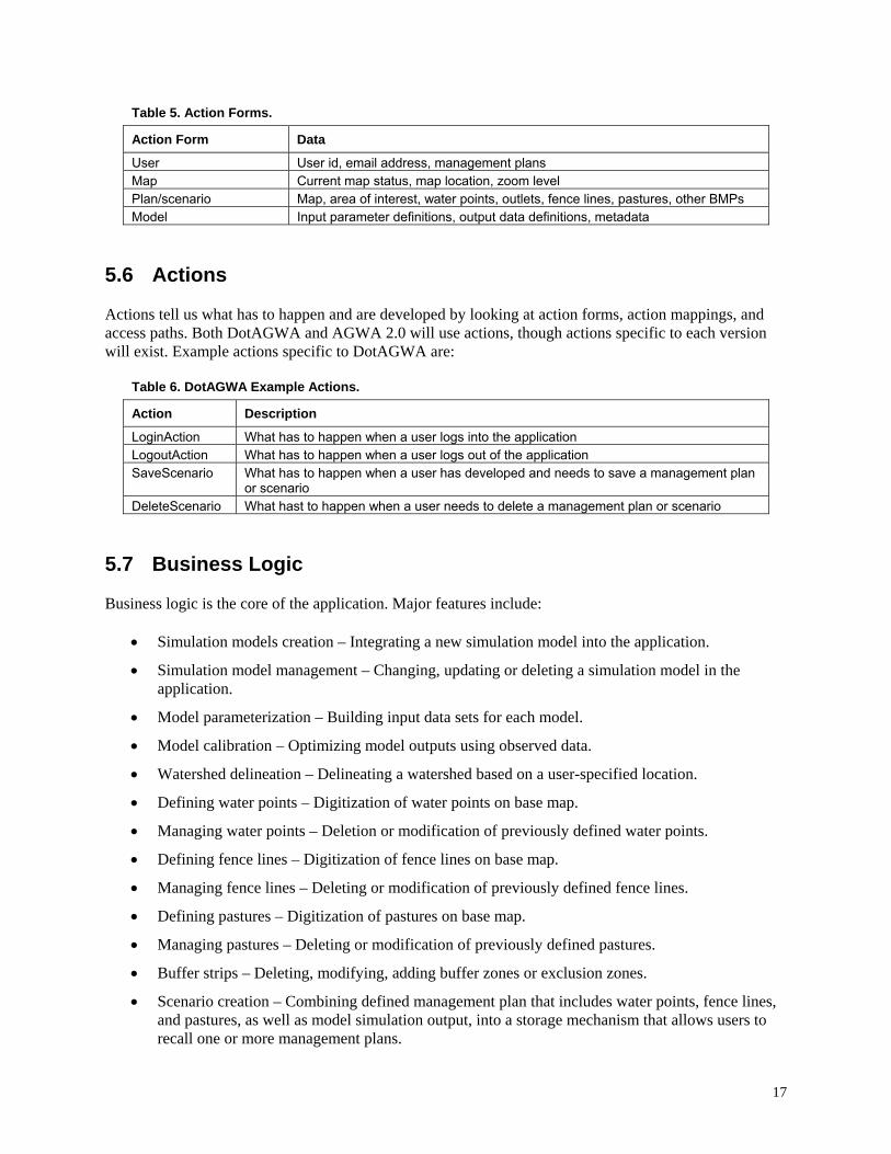
Table 5. Action Forms.
Action Form Data
User User id, email address, management plans Map Current map status, map location, zoom level Plan/scenario Map, area of interest, water points, outlets, fence lines, pastures, other BMPs Model Input parameter definitions, output data definitions, metadata
5.6 Actions
Actions tell us what has to happen and are developed by looking at action forms, action mappings, and access paths. Both DotAGWA and AGWA 2.0 will use actions, though actions specific to each version will exist. Example actions specific to DotAGWA are:
Table 6. DotAGWA Example Actions.
Action Description
LoginAction What has to happen when a user logs into the application LogoutAction What has to happen when a user logs out of the application SaveScenario What has to happen when a user has developed and needs to save a management plan
or scenario DeleteScenario What hast to happen when a user needs to delete a management plan or scenario
5.7 Business Logic
Business logic is the core of the application. Major features include:
• Simulation models creation – Integrating a new simulation model into the application.
• Simulation model management – Changing, updating or deleting a simulation model in the application.
• Model parameterization – Building input data sets for each model.
• Model calibration – Optimizing model outputs using observed data.
• Watershed delineation – Delineating a watershed based on a user-specified location.
• Defining water points – Digitization of water points on base map.
• Managing water points – Deletion or modification of previously defined water points.
• Defining fence lines – Digitization of fence lines on base map.
• Managing fence lines – Deleting or modification of previously defined fence lines.
• Defining pastures – Digitization of pastures on base map.
• Managing pastures – Deleting or modification of previously defined pastures.
• Buffer strips – Deleting, modifying, adding buffer zones or exclusion zones.
• Scenario creation – Combining defined management plan that includes water points, fence lines, and pastures, as well as model simulation output, into a storage mechanism that allows users to recall one or more management plans.
17

• Scenario management – Modifying or deleting previously defined management plans (scenarios).
• Output creation – Stores scenarios or management plans into reports that can be recalled for later use.
• Output management – Permits modification and deletion of existing output reports.
• User creation – Allows the application administrator to add new users.
• User management – Allows the application administrator to modify or delete existing users.
5.8 Presentation Pages
Presentation pages are the actual web pages that will be presented to the application user. They are unnecessary for AGWA 2.0, but requisite for the proper functioning of DotAGWA. Prototype web pages will be developed during this process to convey information to the user and capture information provided by the user. The captured information will be transferred to the components that make up the business logic and possibly into the application databases or the model layer.
5.9 Configuration Files
Configuration files will be necessary to tie the pieces of DotAGWA together. AGWA 2.0, however, will be contained within ArcGIS, thus Configuration files will be unnecessary. For example, the web server (i.e., Apache Tomcat) will need to know how and where to connect to the database server. Also, web server specific configuration files can be used to store information about where application components are located. This implementation is useful when components are constructed independently but need to know how to communicate with each other. For example, web pages can be developed using straight Hyper Text Markup Language (HTML), and business objects can look at configuration files to find those HTML pages and pass information to those pages, which will then be conveyed to the user.
5.10 Build, Test, Deploy
Finally, application development will require the work of more than one person. Each person will be assigned parts of the application to build. Each part will have to be tested by the respective developer, and possibly by non-developers. Once a component has passed the testing phase, the component will be incorporated into the application package. After a package is completed, it will be deployed as a fully functioning application. This collaborative development environment will require developers to agree on a specific set of development protocols, as described below.
The items in Table 7 will serve as the tools to build a development environment that minimizes potential conflicts. The Microsoft Visual Studio .Net IDE will provide the foundation for all developers to use the same programming framework for developing the GIS functionality. The Concurrent Versioning System (CVS) system will back up application code and allow users to develop their respective components independently. The ArcGIS interface is the targeted interface for developing and testing DotAGWA components. Tomcat is the web server that allows development of and testing of web application components. Finally, Ant provides a reliable tool for managing the web interface programming.
18

Table 7. Development Tools.
Tool Description
Microsoft Visual Studio .Net Used to program GIS functionality. Concurrent Versioning System (CVS)
Used for backing up application code.
ESRI™ ArcGIS Encapsulates AGWA 2.0 application. Apache Jakarta Tomcat Web application server used to encapsulate DotAGWA. Jakarta Ant Application development tool used to compile and manage web
applications. Java Sun’s Java programming language. Integrated Development Environments (IDEs)
Other than .NET, programmers can use any IDE he/she is comfortable with as long as the IDE does not cause adverse issues with existing management tools.
19

20

Section 6
Domain Constraints
Domain constraints are the characteristics of the business environment unique to the ARS, the EPA, and other user groups associated with identified users that influence the functionality of the system.
6.1 GIS Software
The application must use Geographic Information Systems (GIS) software to display map-based data over the Internet and to process spatial data. There are two sources for GIS software. The first source is open-source GIS tools that are freely available over the Internet. These open-source tools tend to be platform independent. However, open-source tools often lack adequate documentation and do not always have software support groups that are dedicated to dealing with end-user problems. The second source of GIS software is ESRI, which produces software that is currently considered the industry standard. ESRI has a very large user base and online help resources that can be used to support the project development. The USDA and the U.S. EPA have site licenses with ESRI, so the software is currently available for use in the project and does not require extra fees or software licenses. The University of Arizona also has an ESRI site license that provides access to the necessary GIS software at no cost. Consequently, ESRI’s software is the least expensive option. Furthermore, ESRI’s software has been selected for this project. The ESRI software chosen for the project includes ArcGIS 9 for AGWA 2.0 and ArcIMS, ArcGIS Server and ArcSDE for DotAGWA. The GIS functionality will be developed using the Microsoft Visual Studio .Net application development environment.
6.2 Commercial Database Application
The DotAGWA application requires a relational database management system (RDBMS) to support the application. ArcGIS will handle the spatial data management for AGWA 2.0; thus an RDBMS is unnecessary. The commercial database package must be able to support spatial data storage. There are both open source and proprietary database management systems that store spatial data. However, the proprietary database systems have proven track records, making them more appealing. Also, many of the open source database systems (e.g., MySQL, PostgreSQL) have not implemented as much functionality in their database systems as Oracle or Microsoft’s SQL Server. Of the two commercial systems, Oracle’s RDBMS has the longer history of being able to support spatial data. Also, the University of Arizona has a site license contract with Oracle. The site license minimizes the costs associated with implementing the RDBMS. A downside is that Oracle’s RDBMS tends to be more difficult to administer compared to Microsoft’s SQL server. Consequently, database maintenance costs (i.e., time, money, user skill) may be higher with the chosen database management system, Oracle’s RDBMS, than with Microsoft’s SQL server. However, given the University’s Oracle site license, a significant resource for help and training exists in the people and groups at the University of Arizona already using Oracle’s RDBMS.
6.3 Internet and Server Resources
The DotAGWA application is temporarily hosted on a server located in The University of Arizona’s Advanced Resource Technology (ART) Lab. AGWA 2.0 will be hosted as a set of downloadable files from the current AGWA home page (http://www.tucson.ars.ag.gov/agwa). The ART lab provides a significant amount of the GIS-related resources and services for the University of Arizona. The server
21
was purchased through a grant funded by the USDA. The server is a Dell PowerEdge 2500, with a Pentium III processor, and four RAID drives. The server was purchased before the application design and did not require any cost or performance comparisons in the application design. It is anticipated that this hardware will be sufficient to carry DotAGWA through the development and Beta-testing period, but deployment will require additional resources.
6.4 Internet Web Server
The primary interface for the DotAGWA application will be hosted by Apache Software Foundation’s Tomcat web server (http://jakarta.apache.org/). This application server was selected because it supports Java 2 Enterprise Edition (J2EE) technology, which promotes component-based application development and simplifies enterprise application development. The J2EE architecture promotes platform independence, so if need be the application can be moved to any server running Apache Tomcat. Finally, ESRI’s GIS applications primarily run on the Windows Operating System. Because DotAGWA requires geospatial data processing that will be handled by ESRI’s GIS software, the underlying operating system chosen was Windows XP Professional.
6.5 Programming Languages
Both DotAGWA and AGWA 2.0 will utilize the same programming languages wherever development overlaps, but may also use different programming languages when development diverges. Currently, ESRI provides programming access to ArcObjects through the Microsoft Component Object Model (COM), the Microsoft .Net Framework, Java, and C++ application program interfaces (API). The majority of ESRI’s customer base uses COM (including Visual Basic 6 and Visual C++) or .Net (including Visual Basic .Net and C#). The selected API will either be Java or .Net because of existing knowledge and experience using these technologies. Though the development team also has experience with COM, .Net is becoming more popular as a replacement for COM.
6.6 Data Sources
The AGWA applications require different types of data. The mapping components of the application require geospatial data. Some of the data required by the simulation components are soils, precipitation, and vegetation. Application users may also provide project-specific data. The user-provided data will have to be imported into the application. The interface will have tools making this easy to do. However, since it is impossible to plan for all types of data formats the users may have to restructure data sets to be compatible with the application. Both applications will have pre-compiled data and both applications may have some dependency on that data. However, as time progresses more data sources will become available. Tools can be built for Internet-available data to automate retrieval and importation. This data gathering will exist as web service clients or consumers. Web service clients are small applications that know about the location of a data source and know how to request data from the source. Once the data has been retrieved, it can be saved in almost any format suitable to the application. Because of hardware and data transfer speed limitations, the DotAGWA application will not support users uploading their own data sets. However, if an organization is interested in implementing the DotAGWA application, the system has enough flexibility to allow new installations to use custom data sets. For example, if agency ABC wanted to serve DotAGWA over its own Intranet it could download DotAGWA, configure it to use a local database and to use local spatial data sets, and start the application without having to write application code.
Finally, because one of the goals of the DotAGWA application is to incorporate watershed simulations and spatial data in and integrated web environment as a proof-of-concept application, we are currently not
22

designing the application’s data sources to be all encompassing. The spatial data for DotAGWA will have a limited number of data sets (i.e., Walnut Gulch Experimental Watershed, Santa Rita Experimental Range, etc.) connected to the application. We are trying to build a solid yet manageable application and leaving the design open so that larger data sets can be incorporated later on.
6.7 Documentation and Training
User documentation will be developed for this application. User documentation will consist of a manual and online help files. The format of help files may be text files, HTML files, or compiled help files. Training may be available in the future if user demand requires it and resources are available to make the training possible.
23

24

Section 7
Timeline
The release of the beta versions of the ArcGIS AGWA and DotAGWA are scheduled for September 2005. The beta AGWA 2 will be available to current AGWA users. DotAGWA will be available to current AGWA users as well as a small group of beta testers that will be determined at a future date. The development of AGWA 2 and DotAGWA will occur simultaneously. The GIS components will be shared between the two applications. Simply stated, the one set of GIS components will be developed while two different interfaces are developed. The AGWA application, which is a desktop-based application, will be delivered to users with the GIS processing components packaged together with the user interface. Since the DotAGWA application is Internet-based, the interface is accessed through a web browser and the GIS processing components are accessed through the application server that makes the web interface available. An estimated timeline is shown in Table 8.
Table 8. Estimated Timeline.
Task Estimated Start Date Estimated Completion Date
Complete design document November 2004 GIS Component Development November 2004 April 2005 AGWA Interface Development April 2005 July 2005 DotAGWA Interface Development April 2005 July 2005 Testing and Debugging July 2005 September 2005
25

26

Section 8
Summary and Conclusions
This document serves as primary guide in the development of AGWA 2.0 and DotAGWA. If new technologies or requirements come to light in the near-term, this document will evolve and it should be treated as a living document during the development phase of the project. Our specific goals in the development of the next AGWA interface and its web equivalent are: (1) to design it in such a way as to maximize its capacity to incorporate different types of models, (2) to facilitate interaction between observed and modeled information at multiple scales, (3) to make the interface as user friendly and transparent as possible, (4) to maximize the potential user audience, (5) to separate GIS and non-GIS functionality to the greatest extent possible so that the same GIS functionality can be called from both the desktop and Internet versions of the interface, and (6) to enable straightforward transferability of AGWA functionality into a future version of BASINS as it migrates to ArcGIS and Internet options. As noted throughout the document, choices have been made in our design approach based on primary AGWA users and their access to GIS software. Resource limitations do not allow AGWA to be a general watershed assessment tool to all potential users with any investments in GIS resources. A major assumption, which again arises from resource limitations, is that DotAGWA will not act as a server of all the climatic and geospatial data that may be required to run the application anywhere in the United States or the world. While pointers to data sources will likely be identified, assembly of that data into a coherent project database will have to be done by the user. However, it is our intention to continue to enhance the overall usability and functionality of AGWA for watershed assessments as we move forward to AGWA 2.0 and DotAGWA.
27

28

Section 9
Uncertainties
Systems of this nature inevitably become obsolete. New technology is constantly being created that performs faster and more efficiently. Also, data sets can become obsolete over time. By promoting flexibility in the system design, software components that become obsolete can be substituted with minimal disruption. Data sets can be removed if they become obsolete or updated if more current versions become available. If the technology that stores and serves the data sets changes significantly, then the application design will allow us to alter the data connection layer with minimal impact on the overall application. Although the system may eventually become obsolete, it is quite likely its components may be used to augment the new technology and increase the return on investment.
29

30

Appendix A
UML Diagrams
31

32

A.1 DotAGWA
A.1.1 Use Cases The DotAGWA Use Case shows the stick figures as actors (users) and the ovals represent uses. Uses can also be thought of as interfaces or features provided by the application.
DotAGWA Use Case
«uses»
«uses»
AddUser
WriteKINEROS PrecipFile
«extends» Login
Administrator
«uses»
RunKINEROS
«uses»
«uses»
ModifyUser
DeleteUser
ViewSWATResults
«uses»
WriteSWAT PrecipFile
ViewKINEROSResults
WriteKINEROS OutputFile
«extends» «extends» MainMenu
WebUser
LandCover Parameterization
WriteSWAT OutputFile
RunSWAT
Soils Parameterization
DelineateWatershed
«uses»
«uses»
«uses»
«uses»
«uses»
«uses»
«uses»
«uses»
«uses»
33

A.1.2 Activity Diagrams The activity diagram shows where the user enters the application and what paths are available to the different components.
DotAGWA Activity Diagram
Start/Entry Point
WriteKINEROSPrecipitationFile
User validated?
YesNo
End
MainMenu
Logon
Welcome
Parameterize LandCover
Parameterize Soils
KINEROS
Logoff
ViewKINEROSResults
WriteKINEROSOutputFile
Delineate Watershed
AdvancedOptions
ViewSWATResults
WriteSWATOutputFile
SWAT
WriteSWATPrecipitationFile
34
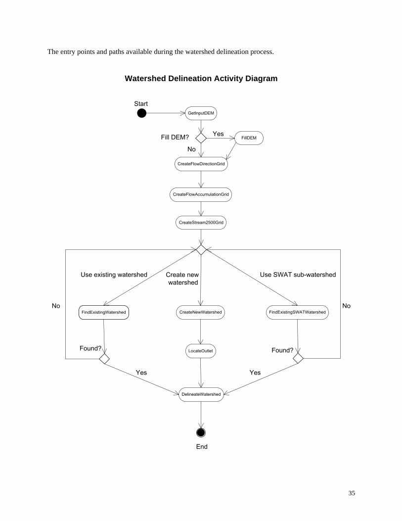
The entry points and paths available during the watershed delineation process.
Watershed Delineation Activity Diagram
Start
Fill DEM?
Use existing watershed Use SWAT sub-watershed
Found?
End
FillDEM
CreateFlowAccumulationGrid
CreateFlowDirectionGrid
GetInputDEM
FindExistingSWATWatershed FindExistingWatershed
LocateOutlet
CreateNewWatershed
DelineateWatershed
Yes
No
Yes
CreateStream2500Grid
Create new watershed
Yes
Found?
No No
35

The activity diagram for the models’ execution process shows a precipitation file is written first. Next, an output file is created. The model is then run and the results are displayed.
SWAT Activity Diagram
Start
RunSWAT
ViewSWATResults
WriteSWATOutputFile
WriteSWATPrecipitationFile
End
KINEROS Activity Diagram
Start
RunKINEROS
ViewKINEROSResults
WriteKINEROSOutputFile
WriteKINEROSPrecipitationFile
End
36

The activity diagram shows the option paths available while a user is interacting with the advanced options features in the AGWA application.
Advanced Options Activity Diagram
Start
ReWriteGeometry
Other
SetGeometry
HydraulicGeometryRelations LandCoverModification SWATMessages
KINEROSMessages UseBaseFlow
End
37

Logon Activity Diagram
LogonPrompt
Start
End
ValidateUser
Valid User?
ValidateUser
No
Yes
38

Basic activity of the mapping component of the application. The application relies on a spatial data server. The server handles map requests and either displays the appropriate map or displays an error message.
Map Server Activity Diagram
DisplayMap
End
Yes
Start
AcceptMapRequest
ProcessMapRequest
Valid Map Request? MapErrorMessage No
39

Activity diagram depicting activities available so the user can interact with plans or scenarios created during the session. The user can create new plans, save the current plan, modify existing plans, or delete existing plans.
Plan Activity Diagram
Start CheckUserPlans
Create new plan?
End
Delete plan
User has existing plans?
ShowPlans
Yes
Save current plan?
Yes
SavePlan
No
Modify plan
ModifyPlanDeletePlan
No Yes
CreatePlan
No
40

A.1.3 Static Structure Diagrams
Web Package Static Structure
11 1
1 1
1 1 1
web: user
web: admin web: map web: user web: utils
The web package is made up of the following components:
admin - used to administer the web application and its components map - a collection of objects that stores information related to the map display and interaction user - a collection of objects containing user information utils - a collection of utility objects
Admin Static Structure
+addUser() +deleteUser() +modifyUser() +listUsers()
Basic management tools for interacting with user accounts.
Basic management tools for interacting with simulations
connected to the application.
ManageUsers
+addSimulation() +deleteSimulation() +listSimulations() +modifySimulation()
ManageSimulations
41
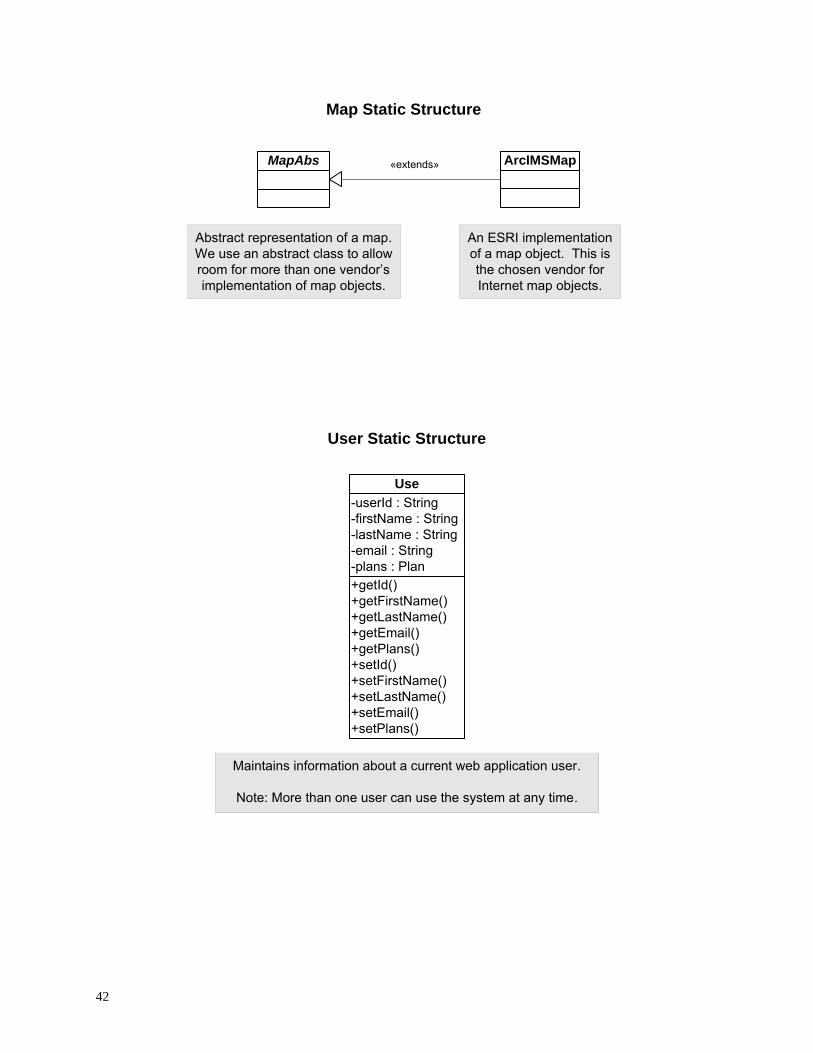
Map Static Structure
MapAbs «extends» ArcIMSMap
Abstract representation of a map. We use an abstract class to allow room for more than one vendor’s implementation of map objects.
An ESRI implementation of a map object. This is the chosen vendor for Internet map objects.
User Static Structure
Use -userId : String -firstName : String -lastName : String -email : String -plans : Plan +getId() +getFirstName() +getLastName() +getEmail() +getPlans() +setId() +setFirstName() +setLastName() +setEmail() +setPlans()
Maintains information about a current web application user.
Note: More than one user can use the system at any time.
42
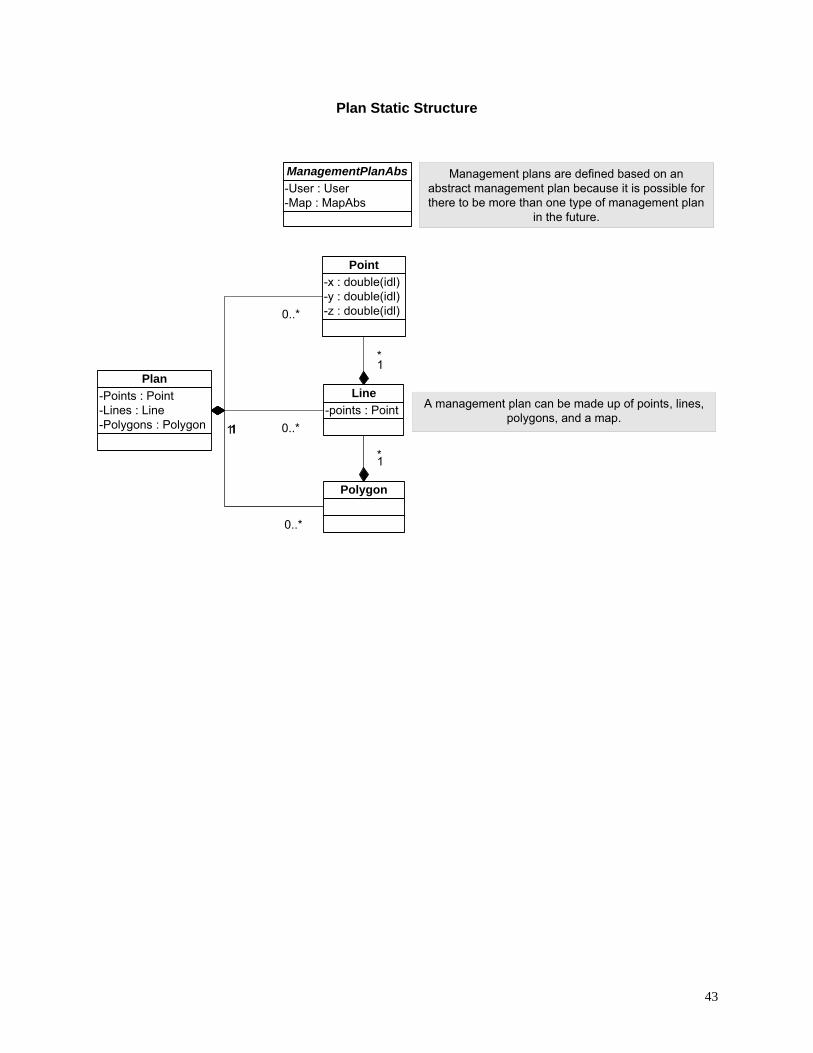
Plan Static Structure
-points : Point Line
-User : User -Map : MapAbs
ManagementPlanAbs
-Points : Point -Lines : Line -Polygons : Polygon
Plan
-x : double(idl) -y : double(idl) -z : double(idl)
Point
Polygon
A management plan can be made up of points, lines, polygons, and a map.
1 *
1 *
1
0..*
1 0..*1
0..*
Management plans are defined based on an abstract management plan because it is possible for there to be more than one type of management plan
in the future.
43

Simulation Static Structure
parameterizers The simulation package contains simulation models or interfaces to those models as well
as parameterizers for those simulations.
SimulationARDBSN
+run() +parameterize()
SimulationAbs
SimulationSWAT SimulationKINEROS
«extends»
«extends»
«extends»
Simulations are based on one abstract class because they have similar features (i.e., parameterize, run). Also, a management plan can be run in more than one simulation.
Parameterizer Static Structure
Parameterizers are based on an abstract class because there can be more than one parameterizer and the parameterizers have similar methods (i.e., initialize, parameterize).
ParameterizerAbs
ParameterizerARDBSN ParameterizerKINEROS ParameterizerSWAT
44

Spatial Static Structure
hydro
landcover
precip
processing
soils
DigitalElevationModel
The hydro package contains objects that store information and provide methods related to the features in watersheds.
The landcover package contains objects that store information and provide methods related to vegetation cover on a watershed.
The precip package contains objects that store information and provide methods related to precipitation data.
The processing package contains geo-processing objects. The geo-processing objects interact with spatial data and simulations.
The soils package contains objects that store information and provide methods related to soils cover on a watershed.
The digital elevation model used to define the watershed or area of interest.
45

Hydro Static Structure
WatershedAbs Channel
1 *
A watershed can have one or more channels.
A watershed consists of many features and watershed may be defined differently by different simulations. An abstract representation is needed to account for as many
different definitions as possible.
Landcover Static Structure
An abstract representation of landcover data types.
«extends»
LandCoverAbs
«extends» «extends»
LandCoverAbs::LandCoverNALC LandCoverAbs::LandCoverUserDefined LandCoverAbs::LandCoverMRLC
An NALC representation of landcover data types.
An MRLC representation of landcover data types.
A user defined representation of landcover data types.
46
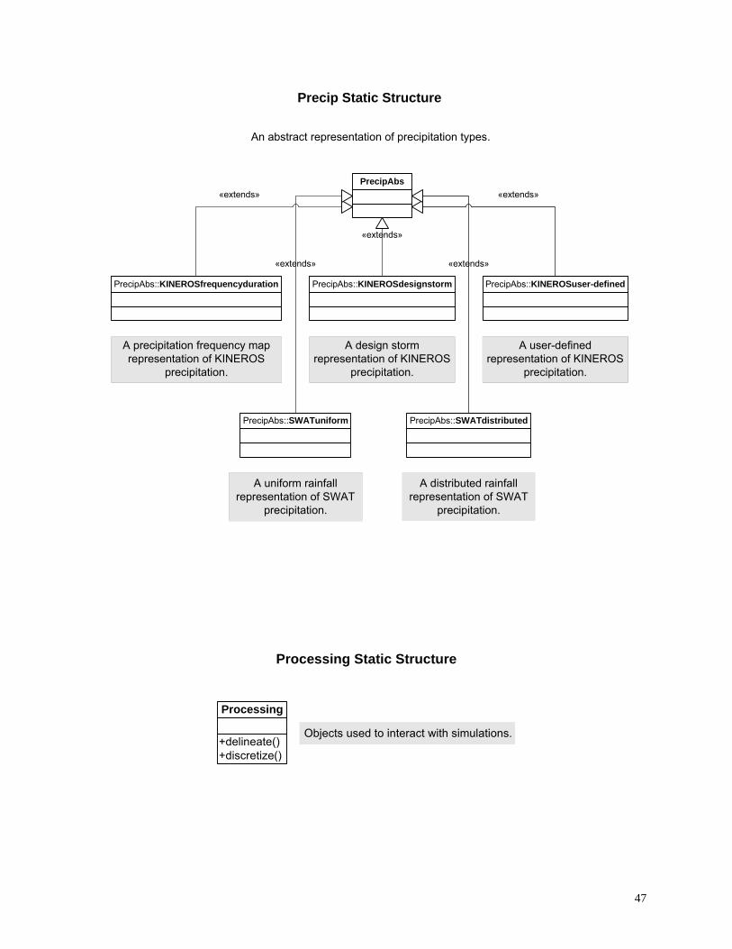
Precip Static Structure
An abstract representation of precipitation types.
PrecipAbs «extends»
«extends»
«extends»
«extends» «extends»
PrecipAbs::KINEROSfrequencyduration
A precipitation frequency map representation of KINEROS
precipitation.
PrecipAbs::KINEROSdesignstorm
A design storm representation of KINEROS
precipitation.
PrecipAbs::KINEROSuser-defined
A user-defined representation of KINEROS
precipitation.
PrecipAbs::SWATdistributed PrecipAbs::SWATuniform
A uniform rainfall representation of SWAT
precipitation.
A distributed rainfall representation of SWAT
precipitation.
Processing Static Structure
+delineate() +discretize()
Processing
Objects used to interact with simulations.
47

Soils Static Structure
Abstract representation of soils data.
SoilsAbs
SoilsAbs::SoilsFAO SoilsAbs::SoilsSSURGO
«extends»
«extends»
«extends»
FAO implementation of
soils data.
SSURGO implementation of soils
data.
SoilsAbs::SoilsSTATSGO
STATSGO implementation of soils
data.
48
A.2 AGWA 2.0
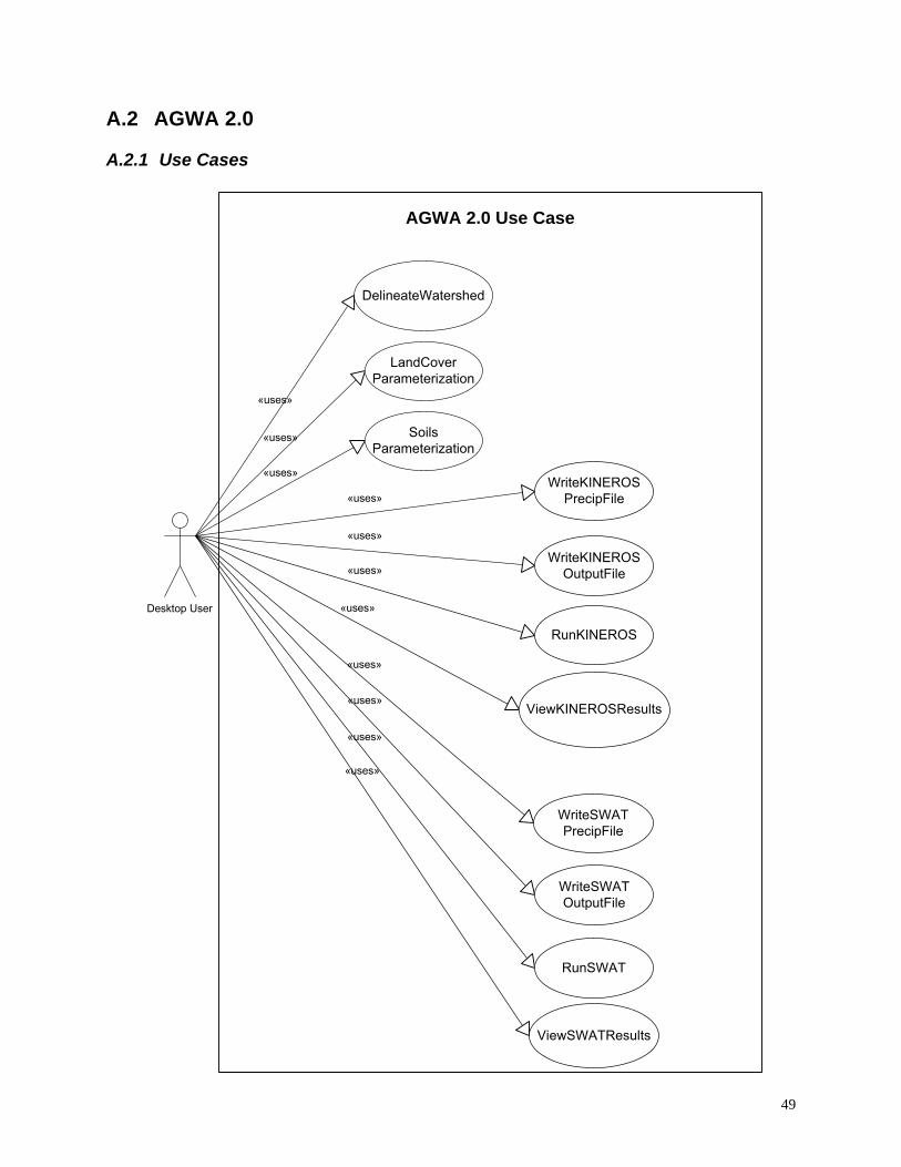
A.2.1 Use Cases
AGWA 2.0 Use Case
Desktop User
«uses»
«uses»
«uses»
«uses»
«uses»
«uses»
«uses»
«uses»
«uses»
«uses»
DelineateWatershed
LandCover Parameterization
Soils Parameterization
WriteKINEROS PrecipFile
WriteKINEROS OutputFile
RunKINEROS
ViewKINEROSResults
WriteSWAT PrecipFile
WriteSWAT OutputFile
RunSWAT
ViewSWATResults
«uses»
49
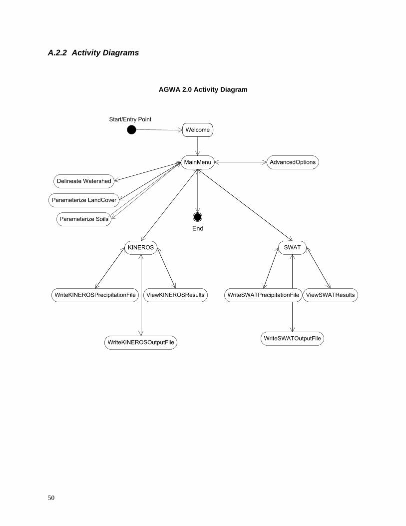
A.2.2 Activity Diagrams
AGWA 2.0 Activity Diagram
Start/Entry Point
End
MainMenu
Welcome
Parameterize LandCover
Parameterize Soils
KINEROS
WriteKINEROSPrecipitationFile ViewKINEROSResults
WriteKINEROSOutputFile
Delineate Watershed
AdvancedOptions
ViewSWATResults
WriteSWATOutputFile
SWAT
WriteSWATPrecipitationFile
50
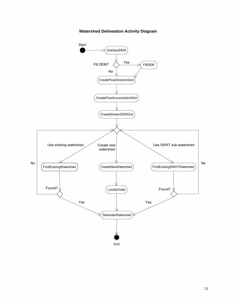
Watershed Delineation Activity Diagram
Start
End
Fill DEM?
Use existing watershed Use SWAT sub-watershed
Found?
FillDEM
CreateFlowAccumulationGrid
CreateFlowDirectionGrid
GetInputDEM
FindExistingSWATWatershed FindExistingWatershed
LocateOutlet
CreateNewWatershed
DelineateWatershed
Yes
No
Yes
CreateStream2500Grid
Create new watershed
Yes
Found?
No No
51

The activity diagram for the models’ execution process shows a precipitation file is written first. Next, an output file is created. The model is then run and the results are displayed.
SWAT Activity Diagram KINEROS Activity Diagram
Start Start
RunSWAT
ViewSWATResults
WriteSWATOutputFile
WriteSWATPrecipitationFile
RunKINEROS
ViewKINEROSResults
WriteKINEROSOutputFile
WriteKINEROSPrecipitationFile
End End
52

Advanced Options Activity Diagram
Start
ReWriteGeometry
Other
SetGeometry
HydraulicGeometryRelations LandCoverModification SWATMessages
KINEROSMessages UseBaseFlow
End
53
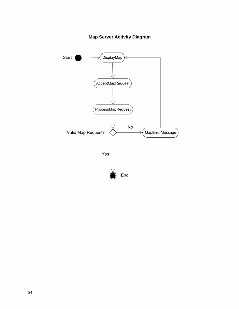
Map Server Activity Diagram
DisplayMap
End
Yes
Start
AcceptMapRequest
ProcessMapRequest
Valid Map Request? MapErrorMessage No
54
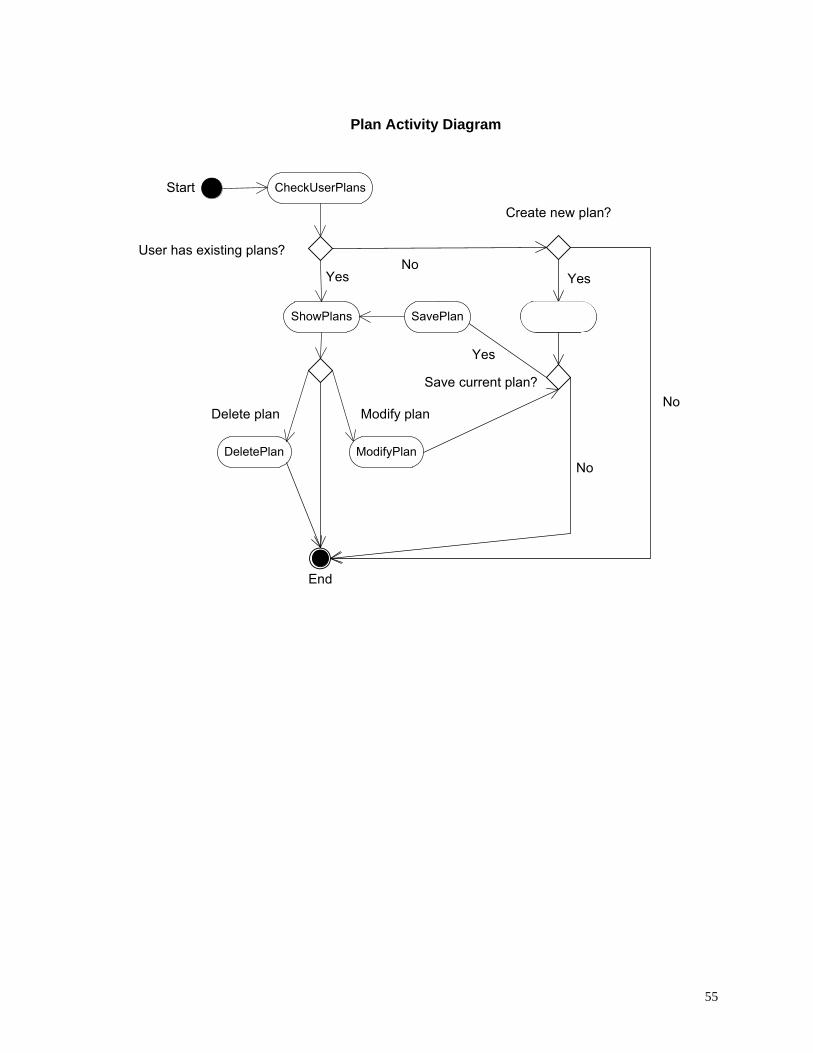
Plan Activity Diagram
Start CheckUserPlans
Create new plan?
User has existing plans?
End
Delete plan
ShowPlans
Yes
Save current plan?
Yes
SavePlan
No
Modify plan
ModifyPlan DeletePlan
No Yes
CreatePlan
No
55

A.2.3 Static Structure Diagrams
Map Static Structure
MapAbs «extends» ArcGISMap
Abstract representation of a map. An ESRI implementation We use an abstract class to allow of a map object. This is room for more than one vendor’s the chosen vendor for implementation of map objects. desktop map objects.
Plan Static Structure
-Map : MapAbs ManagementPlanAbs Management plans are defined based on
an abstract management plan because it is possible for there to be more than one type of management plan in the future.
-Points : Point -Lines : Line -Polygons : Polygon
Plan
0..*
* 1
-points : Point Line
-x : double(idl) -y : double(idl) -z : double(idl)
Point
A management plan can be made up of points, lines, polygons, and a map.
111 0..*
*1
0..*
Polygon
56

Simulation Static Structure
parameterizers The simulation package contains simulation models or interfaces to those models as well
as parameterizers for those simulations.
SimulationARDBSN
+run() +parameterize()
SimulationAbs
SimulationSWAT SimulationKINEROS
«extends»
«extends»
«extends»
Simulations are based on one abstract class because they have similar features (i.e., parameterize, run). Also, a management plan can be run in more than one simulation.
Parameterizer Static Structure
ParameterizerARDBSN
ParameterizerAbs
ParameterizerKINEROS ParameterizerSWAT
Parameterizers are based on an abstract class because there can be more than one parameterizer and the parameterizers have similar methods (i.e., initialize, parameterize).
57

Spatial Static Structure
hydro
landcover
precip
processing
soils
DigitalElevationModel
The hydro package contains objects that store information and provide methods related to the features in watersheds.
The landcover package contains objects that store information and provide methods related to vegetation cover on a watershed.
The precip package contains objects that store information and provide methods related to precipitation data.
The processing package contains geo-processing objects. The geoprocessing objects interact with spatial data and simulations.
The soils package contains objects that store information and provide methods related to soils cover on a watershed.
The digital elevation model used to define the watershed or area of interest.
58

Hydro Static Structure
WatershedAbs Channel A watershed can have one
or more channels. 1 *
A watershed consists of many features and watershed may be defined differently by different simulations. An abstract representation is needed to account for as
many different definitions as possible.
Landcover Static Structure
An abstract representation of landcover data types.
LandCoverAbs
LandCoverAbs::LandCoverMRLC LandCoverAbs::LandCoverNALC
A user defined representation of landcover data types.
An MRLC representation of landcover data types.
An NALC representation of landcover data types.
«extends» «extends»
«extends»
LandCoverAbs::LandCoverUserDefined
59

Precip Static Structure
An abstract representation of precipitation types.
«extends»
PrecipAbs
PrecipAbs::SWATuniform PrecipAbs::SWATdistributed
PrecipAbs::KINEROSdesignstorm PrecipAbs::KINEROSuser-defined PrecipAbs::KINEROSfrequencyduration
A precipitation frequency map representation of KINEROS
precipitation.
A design storm representation of KINEROS
precipitation.
A user-defined representation of KINEROS
precipitation.
A uniform rainfall representation of SWAT
precipitation.
A distributed rainfall representation of SWAT
precipitation.
«extends»
«extends»
«extends»
«extends»
Processing Static Structure
+delineate() +discretize()
Processing
Objects used to interact with simulations.
60

Soils Static Structure
Abstract representation of soils data.
«extends» SoilsAbs
«extends»
SoilsAbs::SoilsFAO SoilsAbs::SoilsSSURGO
«extends»
SoilsAbs::SoilsSTATSGO
FAO implementation of
soils data.
SSURGO implementation of
soils data.
STATSGO implementation of
soils data.
61

62
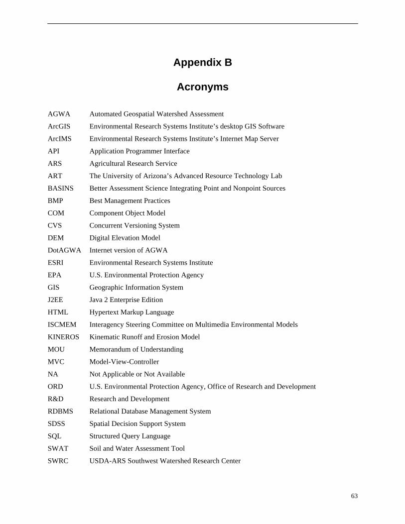
Appendix B
Acronyms
AGWA Automated Geospatial Watershed Assessment
ArcGIS Environmental Research Systems Institute’s desktop GIS Software
ArcIMS Environmental Research Systems Institute’s Internet Map Server
API Application Programmer Interface
ARS Agricultural Research Service
ART The University of Arizona’s Advanced Resource Technology Lab
BASINS Better Assessment Science Integrating Point and Nonpoint Sources
BMP Best Management Practices
COM Component Object Model
CVS Concurrent Versioning System
DEM Digital Elevation Model
DotAGWA Internet version of AGWA
ESRI Environmental Research Systems Institute
EPA U.S. Environmental Protection Agency
GIS Geographic Information System
J2EE Java 2 Enterprise Edition
HTML Hypertext Markup Language
ISCMEM Interagency Steering Committee on Multimedia Environmental Models
KINEROS Kinematic Runoff and Erosion Model
MOU Memorandum of Understanding
MVC Model-View-Controller
NA Not Applicable or Not Available
ORD U.S. Environmental Protection Agency, Office of Research and Development
R&D Research and Development
RDBMS Relational Database Management System
SDSS Spatial Decision Support System
SQL Structured Query Language
SWAT Soil and Water Assessment Tool
SWRC USDA-ARS Southwest Watershed Research Center
63

TBD To Be Determined
USDA United States Department of Agriculture
UA University of Arizona
UML Unified Modeling Language
64

Appendix C
References
Arnold, J.G., J.R. Williams, R. Srinivasan, K.W. King, and R.H. Griggs. 1994. SWAT: Soil Water Assessment Tool. U.S. Department of Agriculture, Agricultural Research Service, Grassland, Soil and Water Research Laboratory, Temple, TX.
Daratech. Daratech 2001 GIS Market Share Numbers. 11/7/2002. <http://www.gismonitor.com/news/pr/110702_Daratech.pdf> (9/1/2004).
ESRI. Universities with ESRI Campus-Wide Site Licenses. 2004. <http://www.esri.com/industries/university/education/site_license.html> (11/29/2004).
Goodrich, D.C., M. Hernandez, S.N. Miller, B.F. Goff, W.G. Kepner, K.B. Jones, C.M. Edmunds, T. Wade, D.W. Ebert, and D. Heggem. 2000. Landscape Indicator Interface with Hydrologic Models: Research Plan. EPA/600/R-00/042, 37 p.
Hernandez, M., S.N. Miller, D.C. Goodrich, B.F. Goff, W.G. Kepner, C.M. Edmonds, and K.B. Jones. 2000. “Modeling Runoff Response to Land Cover and Rainfall Spatial Variability in Semi-arid Watersheds”. Journal of Environmental Monitoring and Assessment, 64: pp. 285-298.
Hernandez, M., S.N. Miller, D.J. Semmens, D.C. Goodrich, W.P. Miller, and W.G. Kepner. 2002. Quality Assurance and Quality Control in the Development of the Automated Geospatial Watershed Assessment (AGWA) Tool. EPA/600/R-02/046, 40 p.
Hernandez, M., W.G. Kepner, D.J. Semmens, D.W. Ebert, D.C. Goodrich, and S.N. Miller. 2003. “Integrating a Landscape/Hydrologic Analysis for Watershed Assessment.” In Renard, K.G., S.A. McElroy, W.J. Gburek, E.H. Canfield, and R.L. Scott, eds. Proceedings of the First Interagency Conference on Research in the Watersheds, October 27-30, 2003, Benson, AZ, pp. 461-466.
ISCMEM. Interagency Steering Committee on Multimedia Environmental Models. 7/5/2001. <http://iscmem.org/> (11/15/2004).
Kepner, W.G., D.J. Semmens, S.D. Bassett, D.A. Mouat, and D.C. Goodrich. 2004. “Scenario Analysis for the San Pedro River, Analyzing Hydrological Consequences of a Future Environment [PDF, 13 pp., 2.6 MB]”. Journal of Environmental Monitoring and Assessment. 94: 115-127. Kluwer Academic Publishers.
Miller, S.N., D.J. Semmens, R.C. Miller, M. Hernandez, D.C. Goodrich, W.P. Miller, W.G. Kepner, and D.W. Ebert. 2002. “GIS-Based Hydrologic Modeling: The Automated Geospatial Watershed Assessment Tool”. In Proceedings of Second Federal Interagency Hydrologic Modeling Conference, July 28 - August 1, 2002, Las Vegas NV, CD-ROM, 12 p.
65

Miller, R.C., 2004. A Rangeland Watershed Management Spatial Decision Support System: Design, Implementation, and Sensitivity Analysis. Ph.D. Dissertation. University of Arizona. 2004.
Panchel, N. Implementing MVC Design Pattern in .NET. 2/25/2003. <http://www.c-sharpcorner.com/Code/2003/Feb/MVCDesign.asp> (11/6/2004).
Pressman, Roger S. 2001. Software Engineering; A Practitioner’s Approach, McGraw-Hill.
Spielman, S. 2003. The Struts Framework, Practical Guide for Java Programmers, Elsevier Science.
Smith, R.E., D.C. Goodrich, D.A. Woolhiser, and C.L. Unkrich. 1995. “KINEROS: A kinematic runoff and erosion model”. Pages 697-732 in V.P. Singh, editor. Computer Models of Watershed Hydrology. Water Resources Publications, Highlands Ranch, Colorado.
66

Office of Research and Development (8101R) Washington, DC 20460
Official Business Penalty for Private Use $300
EPA/600/R-05/056 ARS/181027 April 2005 www.epa.gov
Please make all necessary changes on the below label, detach or copy, and return to the address in the upper left-hand corner.
If you do not wish to receive these reports CHECK HERE
□; detach, or copy this cover, and return to the address in the upper left-hand corner
PRESORTED STANDARD POSTAGE & FEES PAID
EPA PERMIT No. G-35
Recycled/Recyclable
Printed with vegetable-based ink on paper that contains a minimum of 50% post-consumer fiber content v processed chlorine free