mil-dtl-32267a(ar) w/amendment 1 superseding...
TRANSCRIPT
MIL-DTL-32267A(AR) w/AMENDMENT 1 30 April 2012 SUPERSEDING MIL-DTL-32267A(AR) 11 JULY 2008
DETAIL SPECIFICATION
FUZE, POINT DETONATING - M739A1
This specification is approved for use by the U.S. Army Armament Research, Development and Engineering Center (ARDEC), and is available for use by all Departments and Agencies of the Department of Defense.
1. SCOPE
1.1 This specification covers the fabrication of parts, assembling and loading for the Fuze, Point Detonating - M739A1 Artillery Ammunition Fuze with Booster Pellet. Comments, suggestions, or questions on this document should be addressed to the commander, U.S. Army ARDEC, ATTN: RDAR-QES-E, Picatinny, NJ 07806-5000 or emailed to [email protected]. Since contact information can change, you may want to verify the currency of this address information using the ASSIST online database at https://assist.daps.dla.mil. AMSC N/A FSC 1315 DISTRIBUTION STATEMENT A. Approved for public release; Distribution is unlimited.
INCH-POUND
Inactive for new design after 30 September 2007
Downloaded from http://www.everyspec.com

MIL-DTL-32267A(AR) w/AMENDMENT 1
2
2. Applicable documents 2.1 General. The documents listed in this section are specified in sections 3 and 4 of this specification. This section does not include documents in other sections of this specification or recommended for additional information or as examples. While every effort has been made to ensure the completeness of this list, document users are cautioned that they must meet all requirements documents cited in sections 3 and 4 of this specification, whether or not they are listed. 2.2 Government documents. 2.2.1 Specifications, standards, and handbooks. The following specifications, standards, and handbooks form a part of this document to the extent specified herein. Unless otherwise specified, the issues of these documents are those cited in the solicitation or contract. DEPARTMENT OF DEFENSE SPECIFICATIONS
MIL-D-14978 – Detonator, Stab, M55 Loading, Assembling and Packing
MIL-D-48025 – Detonator, Stab, M99, Loading, Assembling and Packing
DEPARTMENT OF DEFENSE STANDARDS MIL-STD-331 – Fuze and Fuze Components, Environmental and Performance Tests for MIL-STD-1168 – Ammunition Lot Numbering and Ammunition Data Card
MIL-STD-1916 – DOD Preferred Methods for Acceptance of Product
(Unless otherwise indicated, copies of these documents are available online at https://assist.daps.dla.mil/quicksearch/ or from the Standardization Document Order Desk, 700 Robbins Avenue, Bldg. 4D Philadelphia, PA 19111-5094.)
Downloaded from http://www.everyspec.com

MIL-DTL-32267A(AR) w/AMENDMENT 1
3
2.2.2 Other Government documents, drawings, and publications. The following other Government documents, drawings and publications form a part of this document to the extent specified herein. Unless otherwise specified, the issues are those cited in the solicitation. U.S. ARMY ARMAMENT RESEARCH, DEVELOPMENT AND ENGINEERING CENTER (ARDEC) DRAWINGS 7548099 – Box, Packing, Ammunition for Lead Cup Assembly or Explosive Lead PA510 7548103 – Box, Set-up, Packing, Ammunition, Outer 7548104 – Box, Set-up, Packing, Ammunition, Inner 12992295 – Lead, Explosive 9255166 – Cup, Lead 9255167 – Disc, Lead 12992294 – Pellet, Booster 9258607 – Cup, Booster 9258609 – Body, Fuze 9258611 – Screw, Closing 9258613 – Firing Pin Housing and Detonator Assembly 9258614 – Support, Firing Pin 9258617 – Housing, Detonator 9258618 – Firing Pin Assembly 9258619 – Pin, Firing 9258620 – Retainer, Safing and Arming 9258622 – Crossbar and Holder Assembly 9258624 – Holder, Crossbar 9258625 – Setting Sleeve Assembly 9258626 – Retainer Interrupter 9258628 – Sleeve, Setting 9258629 – Interrupter 9258630 – Safing and Arming Module Assembly 11720309 – Pallet 9258632 – Plate, Gear, Upper 9258634 – Pin, Setback 9258636 – Spring Pin, Setback 12973181 – Spinlock 9258639 – Rotor Assembly 9258640 – Body, Rotor 9258641 – Shaft, Rotor 9258642 – Gear, Rotor 9258643 – Plate and Spacer Assembly 9258644 – Plate, Bottom 9258646 – Spacer, Plate, Gear 9258647 – Spring, Pin, Lock 9258650 – Lower Plate and Shaft Assembly 9258651 – Plate, Gear, Lower
Downloaded from http://www.everyspec.com
MIL-DTL-32267A(AR) w/AMENDMENT 1
4
9258652 – Shaft, Pallet 9258653 – Gear and Pinion Assembly 9258655 – Escape Wheel and Pinion Assembly 9258682 – Seal Disc 9282958 – Safing and Arming Module and Retainer Assembly 9294595 – Fuze Body and Setting Sleeve Assembly 9294606 – Firing Pin and Housing Assembly 9294833 – Safing and Arming Module Subassembly 9294992 – Plug, Test 9294993 – Disk, Test 9298909 – Cap, Nose 9333937 – Pin, Firing 9343014 – Pin, Lock, Rotor 9345331 – Fuze Body Assembly M739A1 9345332 – Fuze, PD, M739A1 11836270 – Delay Module, Impact 11836271 – Plunger Assembly 11836272 – Plunger 11836273 – Detent, Spin 11836274 – Spring Detent 11836275 – Retainer, Detent 11836276 – Lock, Detent 11836277 – Pin, Pivot 11836278 – Firing Pin Holder Assembly 11836279 – Holder, Firing Pin 11836281 – Pin, Firing Pin 11836282 – Slider 11836283 – Spring, Firing Pin 11836284 – Spring, Slider 11836285 – Retainer, Slider Spring 11836286 – Housing 11836287 – Spring, Plunger 11836288 – Cover, Housing 12998402 – Witness Block (Copies of these documents may be requested from US Army ARDEC, RDAR-EIS-PE, Picatinny, NJ 07806-5000, or email [email protected]) 2.2.3 Order of precedence. Unless otherwise noted herein or in the contract, in the event of a conflict between the text of this document and the references cited herein, the text of this document takes precedence. Nothing in this document, however, supersedes applicable laws and regulations unless a specific exemption has been obtained.
Downloaded from http://www.everyspec.com

MIL-DTL-32267A(AR) w/AMENDMENT 1
5
3. REQUIREMENTS
3.1 First article. When specified, a sample shall be subjected to first article inspection in
accordance 4.2.
3.2 Lot acceptance. A sample shall be subjected to lot acceptance verification in accordance with 4.3.
3.3 Components and assemblies. The materials, components, and assemblies shall
comply with all applicable drawings listed in 4.4.1.1 to 4.4.1.83.
3.4 Ammunition lot numbering. Fuze lot numbering shall be in accordance with MIL-STD-1168 and applicable drawings.
3.5 Inspection lot formation. Inspection lots shall comply with the lot formation
requirements of MIL-STD-1916. 3.6 Fuze not armed. The ballistic sample fuzes shall not be shipped or stored without the
S&A device in the safe condition.
3.7 Propagation. The fuze assemblies with test disk, test plug and booster cups shall arm and function high order as evidenced by a minimum .170 inch diameter hole in the test disk.
3.8 Lead assembly output . The lead assembly shall function high order as evidenced by
a 0.0239 inch dent in a steel witness block as per 4.5.31. 3.9 Boostering. When booster is installed into fuze, the fuze shall function for all
approved 155mm and 105mm artillery projectiles. Deliverable fuzes shall be boostered after LAT using the same manufacturer and process used for LAT samples.
3.10 Ballistic requirements. The fuze shall function when used on all approved 155mm
and 105mm artillery projectiles. 3.11 Premature bursts. There shall be no premature bursts. 3.12 Early Burst. There shall be no early bursts. 3.13 Non-function. The fuze shall not function upon impact with target, when subjected
to this test. 3.14 Superquick (SQ). The fuze shall cause the projectile to function high order, and the
fuze shall show no evidence of reverse functioning (see 6.6.5).
3.15 Delay (DLY). The fuze shall cause the projectile to function high order 3-6 milliseconds after target impact.
Downloaded from http://www.everyspec.com

MIL-DTL-32267A(AR) w/AMENDMENT 1
6
3.16 S&A in safe condition. The S&A shall be in the safe condition prior to insertion
into the fuze body. 3.17 Impact delay drop. The Impact Delay Module (dwg. 11836270) shall function
satisfactorily as evidenced by the complete firing of the assembly. 3.18 Jolt and jumble. The fuze assemblies with inert boosters and booster cups shall
comply with the requirement of MIL-STD-331, Tests A1 and A2.1. 3.19 Transportation vibration. The S&A and fuze assemblies less booster pellet and
booster cup shall comply with the requirements of MIL-STD-331, Test B1.1, section B1.6.3.2, Sweep Method of procedure II.
3.20 Leakage. The fuze assemblies, less booster pellet and booster cup, shall comply with MIL-STD-331, Test. C4 except that the duration of immersion shall be five (5 plus or minus 0.5) minutes and the pressure shall be three (3 plus or minus 0.5) psi gauge.
3.21 S&A functional. The S&A Module shall arm within the time specified in 4.5.13.2 and temperature specified in 4.5.33. The module shall not arm as per test described in 4.5.14.
3.22 Die cast and molded components. Cast and molded components shall be of uniform quality, free of cold shuts, blowholes, defects, voids, cracks, and foreign inclusions. Castings must be dry, clean, and free of chips. All unfilled castings shall be rejected. Cast and molded plastic parts are permitted to display surface color variations due to flow patterns and filler content.
3.23 Bottom plate, surface porosity. No voids greater than .005” X .005” shall be
permitted in the ramp surface of the setback pin hole. 3.24 Gear plate spacer, surface porosity No voids greater than .005” X .005” shall be
permitted in either spinlock bearing surface. 3.25 Rotor body, surface porosity No voids greater than .005” X .005” shall be
permitted in the upper plate bearing surface. 3.26 Gears, surface porosity. No voids greater than .005” X .005” shall be permitted in
any of the tooth profiles. No voids greater than .005” X .005” shall be permitted in the pinion flange upper bearing surface or in the gear flange lower bearing surface of the gear and pinion assembly. No voids greater than .005” X .005” shall be permitted in the escape wheel flange upper bearing surface or in the pinion flange lower bearing surface of the escape wheel pinion assembly.
3.27 The Plunger shall meet the requirements of Drawing # 11836272. 3.28 The Firing Pin Holder shall meet the requirements of drawing # 11836279.
Downloaded from http://www.everyspec.com
MIL-DTL-32267A(AR) w/AMENDMENT 1
7
3.29 Workmanship. The parts shall be clean and free of burrs, sharp edges, unblended radii, surface defects, cracks, chips, dirt, grease, and oil (except where specifically required), rust and foreign matter. The cleaning method used shall not be injurious to any part, nor shall the parts be contaminated by the cleaning agent. All required markings shall be neat, legible and sharply defined.
Downloaded from http://www.everyspec.com

MIL-DTL-32267A(AR) w/AMENDMENT 1
8
4. Verification TABLE I. Requirements/verification cross reference matrix
METHODS OF VERIFICATION CLASSES OF VERIFICATION
N/A - Not Applicable 1 - Analysis A - First Article Verification 2 - Demonstration B - Conformance Inspection 3 - Examination 4 – Test
Section
Verification methods Verification Class Section 4 1 2 3 4 A B 3.1 First article X X X 4.2 3.2 Lot acceptance X X X 4.3 3.3 Components & assy’s X X X X 4.4.1.1, 4.4.1.83 3.4 Ammo lot numbering X X 4.4.1.53 3.5 Inspection lot formation X X 4.3.1 3.6 Fuze not armed X X X X 4.2.3.6, 4.3.2.1.1
4.3.3.1.1 3.7 Propagation X X X 4.2.3.4, 4.4.1.53 3.8 Lead assy output X X X 4.4.1.79 3.9 Boostering X X X 4.4.1.75 3.10 Ballistic requirements X X X 4.4.1.53 3.11 Premature bursts X X X 4.2.3.5, 4.3.4.1 3.12 Early burst X X X 4.2.3.5, 4.3.4.1 3.13 Non-Function X X X note 1 4.2.3.5, 4.3.4.1 3.14 Superquick X X X 4.2.3.5,4.3.4.1 3.15 Delay X X X 4.2.3.5, 4.3.4.1 3.16 S&A safe X X X X 4.4.1.51, 4.4.1.53 3.17 Impact delay drop X X X 4.4.1.73 3.18 Jolt and jumble X X 4.2.3.1 3.19 Transportation vibration X X X 4.2.3.2, 4.3.4.1 3.20 Leakage X X 4.2.3.3, 4.4.1.52 3.21 S&A functional X X X X 4.2.3.7 3.22 Die cast & molded parts X X X X 4.4.1 3.23 Bottom plate X X X 4.4.1.22, 4.4.1.23 3.24 Gear plate spacer X X X 4.4.1.24, 4.4.1.25 3.25 Rotor body X X X 4.4.1.28, 4.4.1.29 3.26 Gears X X X 4.4.1 3.27 Plunger X X X 4.4.1.71 3.28 Holder, firing pin X X X 4.4.1.64 3.29 Workmanship X X X 4.4.1
Note 1) First three production lots only
Downloaded from http://www.everyspec.com
MIL-DTL-32267A(AR) w/AMENDMENT 1
9
4.1 Classification of verification. The verification requirements are specified herein as follows:
a. First article verification (see 4.2). b. Conformance inspection (see 4.3) 4.2 First article verification. When required, a first article sample shall be verified in
accordance with 4.2.2 4.2.1 First article quantity.
4.2.1.1 Components and assemblies. Ten (10) each of every component, subassembly,
and assembly listed in 4.4.1 through 4.4.1.83, except that for molded and stamped components five each shall be submitted from every die/mold cavity or stamping tool to be used in production.
4.2.2 First article inspections to be performed. The first article quantity specified in
4.2.1 is subjected to inspection in accordance with tests or examinations listed in the Classification of Characteristics paragraphs 4.4.1.1 through 4.4.1.83. The first article fuze listed in 4.4.1.1 through 4.4.1.83 shall be subjected to the testing of 4.2.3.
4.2.3 First article tests
4.2.3.1 Jolt and jumble test. Nine (9) fuze assemblies loaded with inert boosters and booster cups will be subjected to jolt and jumble testing per 4.5.1 and Figure 1.
4.2.3.2 Transportation vibration test. Fuze shall be subjected to vibration testing per
4.5.2, and Figure 1. After examination per 4.2.3.6, the fuze shall be ballistically tested per Table II.
4.2.3.3 Leak test. Forty eight (48) fuzes shall be randomly selected and subjected to the
leak test per 4.5.8, and Figure 1. Any assembly that does not comply with 3.20 shall be classed as defective. As an option an alternative leak test may be performed per 4.5.8.1. Any assembly with a continuous stream of bubbles in excess of one bubble per second shall be classed defective. Assemblies which pass this test may also be used to satisfy the sample requirements for jolt and jumble or for propagation testing.
4.2.3.4 Propagation test. Propagation shall be verified per 4.5.17, and Figure 1.
4.2.3.5 Ballistic tests. Fuzes shall be conditioned and ballistically tested in accordance with Table II and 4.2.4.3.
Downloaded from http://www.everyspec.com
MIL-DTL-32267A(AR) w/AMENDMENT 1
10
4.2.3.6 Fuze not armed. All fuzes for test shall be X-rayed to verify S&A is not armed and is in the safe condition and is safe to transport and fire.
4.2.3.7 S&A functional test. S&A samples shall be tested in accordance with 4.4.1.42
and Figure 1. 4.2.4 First article rejection.
4.2.4.1. Examinations and static tests. If any component, subassembly or assembly fails to comply with any of the applicable requirements, the first article sample shall be rejected. 4.2.4.2 Functioning performance tests. Defect categories and rejection criteria for these tests are as follows: 4.2.4.2.1 Reliability and sequential operational tests. a. Safe condition (see 6.6.2) - Any fuze found with the S&A module not in the safe condition after any environmental testing or prior to gunfire shall be cause for rejection.
4.2.4.2.1.1 Jolt and jumble. Any fuze which fails to meet the criteria of 4.5.1 shall be
cause for rejection. 4.2.4.2.1.2 Transportation vibration. Any fuze which fails to meet the criteria of 4.5.2
shall be cause for rejection. 4.2.4.2.1.3 Leak test. Any fuze which fails to meet the criteria of 4.5.8 or 4.5.8.1 shall
be cause for rejection. 4.2.4.2.1.4 Propagation test. Any fuze which fails to meet the criteria of 4.5.17 shall be
cause for rejection. 4.2.4.2.1.5 S&A functional tests. Any safety failure shall be cause for rejection. More
than two reliability failures shall be cause for rejection. Safety failures are defined as an S&A which arms faster than acceptable arm times. Reliability failures are defined as those failures which are not safety failures.
4.2.4.3 Ballistic testing. 4.2.4.3.1 S&A fails X-ray. Any S&A module found not in the full safe condition shall
be cause for rejection. This is a critical defect. 4.2.4.3.2 Premature burst. Any premature burst shall be cause for rejection. This is a
critical defect. 4.2.4.3.3 Non-Functioning. Any function in a non-function test shall be cause for
rejection (see 6.11.3). This is a critical defect.
Downloaded from http://www.everyspec.com

MIL-DTL-32267A(AR) w/AMENDMENT 1
11
4.2.4.3.4 Point detonating dud. More than two PD dud (see 6.6.6) for all PD functioning ballistic test phases shall be cause for rejection. This is a major defect. 4.2.4.3.5 Delay dud. More than two Delay dud (see 6.6.6) for all Delay functioning ballistic test phases shall be cause for rejection. This is a major defect. 4.2.4.3.6 Total duds. For the sample, shown in Table II, more than three duds total shall be cause for rejection.
4.2.4.3.7 Reverse functioning. More than one reverse functioning shall be cause for
rejection. This is a major defect. 4.3 Conformance verification. 4.3.1 Inspection lot formation. The lot formation shall be in accordance with the lot formation requirements of MIL-STD-1916. Fuze lot numbering shall be in accordance with MIL-STD-1168. Fuze nomenclature shall be in accordance with drawing number 9345331.
a. M55 Detonator same interfix from one manufacturer b. M99 Detonator same interfix from one manufacturer c. Lead assemblies same interfix from one manufacturer d. S&A assemblies same interfix from one manufacturer e. Booster pellet same interfix from one manufacturer f. Fuze Body & Setting Sleeve Assembly from one manufacturer. g. Delay Module from one manufacturer. h. Firing Pin, Housing & Detonator Assembly from one manufacturer. i. Cross Bar & holder Assembly from one manufacturer. j. Nose Cap from one manufacturer. k. Closing Screw from one manufacturer.
4.3.2 Lot acceptance A sample of fuzes shall be subjected to lot acceptance verification in accordance with the Requirements/Verification Cross Reference Matrix, requirements cited in this section and Table II and Table III.
4.3.2.1 Lot rejection (full sample). 4.3.2.1.1 S&A fails X-ray. All fuzes for test shall be x-rayed. Any S&A module found
not in the safe condition shall be cause for rejection. This is a critical defect. 4.3.2.1.2 Premature burst. Any premature burst shall be cause for rejection. This is a
critical defect. 4.3.2.1.3 Non-Functioning. Any function in a non-function test shall be cause for
rejection. This is a critical defect.
Downloaded from http://www.everyspec.com

MIL-DTL-32267A(AR) w/AMENDMENT 1
12
4.3.2.1.4 Point detonating dud. More than two PD dud (see 6.6.6) for all PD functioning ballistic test phases shall be cause for rejection. This is a major defect. 4.3.2.1.5 Delay dud. More than two Delay dud (see 6.6.6) for all Delay functioning ballistic test phases shall be cause for rejection. This is a major defect.
4.3.2.1.6 Reverse functioning. For either large or reduced sample, more than one reverse functioning shall be cause for rejection. This is a major defect.
4.3.2.1.7 Total duds. For the sample, shown in Table II, more than three duds total shall be cause for rejection.
4.3.2.1.8 S&A functional tests. Any safety failure shall be cause for rejection. More than two reliability failures shall be cause for rejection. Safety failures are defined as an S&A which arms faster than acceptable arm times. Reliability failures are defined as those failures which are not safety failures. 4.3.3. Switching criteria for ballistic test sample. After three consecutive lots are passed the sample may be reduced to 60 fuzes and tested per Table III. If any lot fails to meet the requirements, the sample shall revert to the full 120 fuze sample of Table II. 4.3.3.1 Lot rejection (reduced sample). 4.3.3.1.1 S&A fails X-ray. All fuzes for test shall be x-rayed. Any S&A module found not in the safe condition shall be cause for rejection. This is a critical defect.
4.3.3.1.2 Premature burst. Any premature burst shall be cause for rejection. This is a
critical defect. 4.3.3.1.3 Non-Functioning. Any function in a non-function test shall be cause for rejection. This is a critical defect.
4.3.3.1.4 Point detonating dud. More than two PD dud (see 6.6.6) for all PD functioning ballistic test phases shall be cause for rejection. This is a major defect. 4.3.3.1.5 Delay dud. More than two Delay dud (see 6.6.6) for all Delay functioning ballistic test phases shall be cause for rejection. This is a major defect.
4.3.3.1.6 Reverse functioning. For either large or reduced sample, more than one reverse functioning shall be cause for rejection. This is a major defect. 4.3.3.1.7 Total duds. For the reduced sample, more than two duds total shall be cause for rejection.
Downloaded from http://www.everyspec.com
MIL-DTL-32267A(AR) w/AMENDMENT 1
13
4.3.3.1.8 S&A functional tests. Any safety failure shall be cause for rejection. More than two reliability failures shall be cause for rejection. Safety failures are defined as an S&A which arms faster than acceptable arm times. Reliability failures are defined as those failures which are not safety failures. 4.3.4 Lot acceptance inspections to be performed.
4.3.4.1 Ballistic tests Fuze shall be conditioned and ballistically tested in accordance with Table II and 4.3.2.1 or Table III and 4.3.3.1. 4.4 Examinations and tests. Conformance examination and tests are specified in the requirements/cross reference matrix Table I and 4.4.1.1 through 4.4.1.83. Sampling shall be in accordance with MIL-STD-1916 unless otherwise specified herein. (See 6.5).
4.4.1 Classification of characteristics a. Sampling requirements. Inspection sampling requirements for Critical, Major and
Minor characteristics are defined in MIL-STD-1916. Unless specified otherwise, Inspection Level IV shall be used for all characteristics defined as Majors and Inspection Level II for all Minor characteristics; Critical characteristics shall be addressed in accordance with MIL-STD-1916.
b. Conformance inspection. Conformance inspection shall be performed in accordance with 4.4.1.1 to 4.4.1.83.
Downloaded from http://www.everyspec.com
MIL-DTL-32267A(AR) w/AMENDMENT 1
14
Conformance inspection by classification of characteristics
PARAGRAPH TITLE DRAWING NUMBER 4.4.1.1 Pin, Firing SHEET 1 OF 1 9258619
CONFORMANCE
REQUIREMENT
NEXT HIGHER ASSEMBLY
9258618 CLASSIFICATION EXAMINATION OR TEST CRITERIA PARAGRAPH INSPECTION METHOD
REFERENCE
Critical None defined
Major 101 Diameter of shaft and profile of point Level IV 3.3 Gage
Minor 201 Evidence of poor workmanship Level II 3.29 Visual
NOTES:
Conformance inspection by classification of characteristics
PARAGRAPH TITLE DRAWING NUMBER 4.4.1.2 Firing Pin Assembly SHEET 1 OF 1 9258618
CONFORMANCE
REQUIREMENT
NEXT HIGHER ASSEMBLY
9294606 CLASSIFICATION EXAMINATION OR TEST CRITERIA PARAGRAPH INSPECTION METHOD
REFERENCE
Critical None defined
Major 101 Pull Test (80) 3.3 Visual/Gage 4.5.3
Minor 201 Evidence of poor workmanship Level II 3.29 Visual
NOTES: ( ) - Quantity
Downloaded from http://www.everyspec.com

MIL-DTL-32267A(AR) w/AMENDMENT 1
15
Conformance inspection by classification of characteristics
PARAGRAPH TITLE DRAWING NUMBER 4.4.1.3 Pin, Firing SHEET 1 OF 1 9333937
CONFORMANCE
REQUIREMENT
NEXT HIGHER ASSEMBLY
9294606 CLASSIFICATION EXAMINATION OR TEST CRITERIA PARAGRAPH INSPECTION METHOD
REFERENCE
Critical None defined
Major 101 Diameter of shaft and profile of point Level IV 3.3 Gage 102 Unit weight, max Level IV 3.3 Gage 103 Pull test (80) 3.3 Gage 4.5.3
Minor 201 Evidence of poor workmanship Level II 3.29 Visual
NOTES: ( ) - Quantity
Conformance inspection by classification of characteristics
PARAGRAPH TITLE DRAWING NUMBER 4.4.1.4 Support, Firing Pin SHEET 1 OF 1 9258614
CONFORMANCE
REQUIREMENT
NEXT HIGHER ASSEMBLY
9294606 CLASSIFICATION EXAMINATION OR TEST CRITERIA PARAGRAPH INSPECTION METHOD
REFERENCE
Critical None defined
Major 101 Load test (80) 3.3 4.5.4
Minor 201 Evidence of poor workmanship Level II 3.29 Visual
NOTES: ( ) - Quantity
Downloaded from http://www.everyspec.com

MIL-DTL-32267A(AR) w/AMENDMENT 1
16
Conformance inspection by classification of characteristics
PARAGRAPH TITLE DRAWING NUMBER 4.4.1.5 Housing, Detonator SHEET 1 OF 1 9258617
CONFORMANCE
REQUIREMENT
NEXT HIGHER ASSEMBLY
9294606 CLASSIFICATION EXAMINATION OR TEST CRITERIA PARAGRAPH INSPECTION METHOD
REFERENCE
Critical None defined Major 101 Depth of detonator cavity Level IV 3.3 Gage 102 Shrinkage defects, unfilled or
incomplete note 1 3.3 Visual
103 Presence of flash or gates note 1 3.5 Visual
Minor 201 True position of detonator cavity With
outside diameter Level II 3.3 Gage
202 Cavity identification missing or improper
note 1 3.3 Visual
203 Evidence of poor workmanship Level II 3.29 Visual
NOTES: Note 1. This inspection applies only when molded, plastic component is produced. For qualification of a mold, inspect three (3) consecutive samples from each mold cavity. During normal production, inspect one (1) sample each from beginning and end of each production run (See 4.5.28).
Conformance inspection by classification of characteristics
PARAGRAPH TITLE DRAWING NUMBER
4.4.1.6 Firing Pin and Housing Assembly SHEET 1 OF 1 9294606
CONFORMANCE
REQUIREMENT
NEXT HIGHER ASSEMBLY
9258613 CLASSIFICATION EXAMINATION OR TEST CRITERIA PARAGRAPH INSPECTION METHOD
REFERENCE
Critical None defined
Major 101 Load test Level IV 3.3 4.5.20 102 Inward buckling of firing pin tube Level IV 3.3 Visual 103 Distance from bottom detonator cavity
to firing pin point 100% 3.3 Gage
104 Outside diameter, max Level IV 3.3 Gage
Minor 201 Evidence of poor workmanship Level II 3.29 Visual
NOTES:
Downloaded from http://www.everyspec.com
MIL-DTL-32267A(AR) w/AMENDMENT 1
17
Conformance inspection by classification of characteristics
PARAGRAPH TITLE DRAWING NUMBER 4.4.1.7 Firing Pin Housing and Detonator
Assembly SHEET 1 OF 1 9258613
CONFORMANCE
REQUIREMENT
NEXT HIGHER ASSEMBLY
9345331 CLASSIFICATION EXAMINATION OR TEST CRITERIA PARAGRAPH INSPECTION METHOD
REFERENCE
Critical None defined
Major 101 Detonator inverted or missing prior to
application of seal tape 100% 3.3 Gage
102 Overall length, max Level IV 3.3 Gage
Minor 201 Evidence of poor workmanship Level II 3.29 Visual
NOTES:
Conformance inspection by classification of characteristics
PARAGRAPH TITLE DRAWING NUMBER 4.4.1.8 Holder, Crossbar SHEET 1 OF 1 9258624
CONFORMANCE
REQUIREMENT
NEXT HIGHER ASSEMBLY
9258622 CLASSIFICATION EXAMINATION OR TEST CRITERIA PARAGRAPH INSPECTION METHOD
REFERENCE
Critical None defined
Major 101 Presence of four rain holes note 1 3.3 Visual/4.5.7 102 Presence of four dimples note 1 3.3 Visual/4.5.7 103 Presence of longitudinal separation note 1 3.3 Visual/4.5.7
Minor 201 Evidence of poor workmanship Level II 3.29 Visual/4.5.7
NOTES: Note 1 Five (5) parts per punch per day
Downloaded from http://www.everyspec.com

MIL-DTL-32267A(AR) w/AMENDMENT 1
18
Conformance inspection by classification of characteristics
PARAGRAPH
TITLE DRAWING NUMBER 4.4.1.9 Cup, Booster SHEET 1 OF 1 9258607
CONFORMANCE
REQUIREMENT
NEXT HIGHER ASSEMBLY
9345331 CLASSIFICATION EXAMINATION OR TEST CRITERIA PARAGRAPH INSPECTION METHOD
REFERENCE
Critical None defined
Major 101 Thickness of bottom of cup Level IV 3.3 Gage 102 Depth of wrench holes Level IV 3.3 Gage 103 Inside diameter of cup Level IV 3.3 Gage 104 Depth of cup Level IV 3.3 Gage 105 Thread length, min Level IV 3.3 Gage 106 Pitch diameter of thread Level IV 3.3 Gage 107 Major diameter of thread Level IV 3.3 Gage
Minor 201 Location of wrench holes Level II 3.3 Gage 202 Evidence of poor workmanship Level II 3.29 Visual
NOTES:
Conformance inspection by classification of characteristics
PARAGRAPH TITLE DRAWING NUMBER 4.4.1.10 Interrupter SHEET 1 OF 1 9258629
CONFORMANCE
REQUIREMENT
NEXT HIGHER ASSEMBLY
9258625 CLASSIFICATION EXAMINATION OR TEST CRITERIA PARAGRAPH INSPECTION METHOD
REFERENCE
Critical None defined
Major 101 Large diameter, min Level IV 3.3 Gage
Minor 201 Evidence of poor workmanship Level II 3.29 Visual
NOTES:
Downloaded from http://www.everyspec.com

MIL-DTL-32267A(AR) w/AMENDMENT 1
19
Conformance inspection by classification of characteristics
PARAGRAPH TITLE DRAWING NUMBER 4.4.1.11 Sleeve, Setting (die check) SHEET 1 OF 2 9258628
CONFORMANCE
REQUIREMENT
NEXT HIGHER ASSEMBLY
9258625 CLASSIFICATION EXAMINATION OR TEST CRITERIA PARAGRAPH INSPECTION METHOD
REFERENCE
Critical None defined
Major 101 Body diameter, min note 1 3.3 Gage/4.5.23 102 Interrupter diameter, max. note 1 3.3 Gage/4.5.23 103 O-ring diameter, min note 1 3.3 Gage/4.5.23 104 True position of small slot with
retainer seating diameter note 1 3.3 Gage/4.5.23
105 True position of large slot with retainer seating diameter
note 1 3.3 Gage/4.5.23
106 True position of screwdriver slot with retainer seating diameter
note 1 3.3 Gage/4.5.23
107 Interrupter diameter, min note 1 3.3 Gage/4.5.23 108 Width of screwdriver slot note 1 3.3 Gage/4.5.23 109 Radial length of stop note 1 3.3 Gage/4.5.23 110 Location of stop note 1 3.3 Gage/4.5.23 111 Large outside diameter note 1 3.3 Gage/4.5.23 112 Length of O-ring diameter note 1 3.3 Gage/4.5.23
NOTES: Note 1. Three (3) parts per cavity.
Downloaded from http://www.everyspec.com

MIL-DTL-32267A(AR) w/AMENDMENT 1
20
Conformance inspection by classification of characteristics
PARAGRAPH TITLE DRAWING NUMBER 4.4.1.11 Sleeve, Setting (die
check) SHEET 2 OF 2 9258628
CONFORMANCE
REQUIREMENT
NEXT HIGHER ASSEMBLY
9258625 CLASSIFICATION EXAMINATION OR TEST CRITERIA PARAGRAPH INSPECTION METHOD REFERENCE
Major 113 True position of large
outside diameter with body diameter
note 1 3.3 Gage/4.5.23
114 Distance from retainer to top of outside diameter
note 1 3.3 Gage/4.5.23
115 True position of O-ring diameter with body diameter
note 1 3.3 Gage/4.5.23
116 Depth of retainer seating diameter
note 1 3.3 Gage/4.5.23
117 Length of large outside diameter
note 1 3.3 Gage/4.5.23
118 Retainer seating diameter note 1 3.3 Gage/4.5.23
Minor 201 Depth of small slot note 1 3.3 Gage/4.5.23 202 Depth of large slot note 1 3.3 Gage/4.5.23 203 Depth of interrupter
cavity note 1 3.3 Gage/4.5.23
204 Width of large slot note 1 3.3 Gage/4.5.23 205 Width of small slot note 1 3.3 Gage/4.5.23 206 Thickness of stop note 1 3.3 Gage/4.5.23 207 Evidence of poor
workmanship note 1 3.29 Visual/4.5.23
NOTES: Note 1. Three (3) parts per cavity.
Downloaded from http://www.everyspec.com

MIL-DTL-32267A(AR) w/AMENDMENT 1
21
Conformance inspection by classification of characteristics
PARAGRAPH TITLE DRAWING NUMBER 4.4.1.12 Sleeve, Setting SHEET 1 OF 1 9258628
CONFORMANCE
REQUIREMENT
NEXT HIGHER ASSEMBLY
9258625 CLASSIFICATION EXAMINATION OR TEST CRITERIA PARAGRAPH INSPECTION METHOD
REFERENCE
Critical None defined
Major 101 Body diameter, min note 1 3.3 Gage/4.5.27 102 Interrupter diameter, max. note 1 3.3 Gage/4.5.27 103 O-ring diameter note 1 3.3 Gage/4.5.27 104 Retainer seating diameter note 1 3.3 Gage/4.5.27 105 Length of large outside diameter note 1 3.3 Gage/4.5.27
Minor 201 Width of large slot note 1 3.3 Gage/4.5.27 202 Width of small slot note 1 3.3 Gage/4.5.27 203 Evidence of poor workmanship Level II 3.29 Visual/4.5.27
NOTES: Note 1. Three (3) parts per 50,000 pieces per cavity. Sample size increases for larger production run (see 4.5.34)
Downloaded from http://www.everyspec.com

MIL-DTL-32267A(AR) w/AMENDMENT 1
22
Conformance inspection by classification of characteristics
PARAGRAPH TITLE DRAWING NUMBER 4.4.1.13 Retainer Interrupter (die
check) SHEET 1 OF 2 9258626
CONFORMANCE
REQUIREMENT
NEXT HIGHER ASSEMBLY
9258625 CLASSIFICATION EXAMINATION OR TEST CRITERIA PARAGRAPH INSPECTION METHOD
REFERENCE
Critical None defined
Major 101 Width of large tab note 1 3.3 Gage/4.5.23 102 Width of small tab note 1 3.3 Gage/4.5.23 103 True position of small tab
with body diameter note 1 3.3 Gage/4.5.23
104 True position of large tab with body diameter
note 1 3.3 Gage/4.5.23
105 Interrupter diameter note 1 3.3 Gage/4.5.23 106 Depth of smallest inside
diameter, min note 1 3.3 Gage/4.5.23
107 Body diameter note 1 3.3 Gage/4.5.23 108 Distance from bottom to
top of body diameter note 1 3.3 Gage/4.5.23
Minor 201 Smallest inside diameter note 1 3.3 Gage/4.5.23 202 Depth of interrupter
diameter note 1 3.3 Gage/4.5.23
203 True position of interrupter diameter with body diameter
note 1 3.3 Gage/4.5.23
NOTES: Note 1. Three (3) parts per cavity.
Downloaded from http://www.everyspec.com

MIL-DTL-32267A(AR) w/AMENDMENT 1
23
Conformance inspection by classification of characteristics
PARAGRAPH TITLE DRAWING NUMBER 4.4.1.13 Retainer Interrupter (die
check) SHEET 2 OF 2 9258626
CONFORMANCE
REQUIREMENT
NEXT HIGHER ASSEMBLY
9258625 CLASSIFICATION EXAMINATION OR TEST CRITERIA PARAGRAPH INSPECTION METHOD
REFERENCE
Minor 204 Diameter over tabs note 1 3.3 Gage/4.5.23 205 Thickness of large tab note 1 3.3 Gage/4.5.23 206 Thickness of base note 1 3.3 Gage/4.5.23 207 Evidence of poor
workmanship Level II 3.29 Visual/4.5.23
NOTES: Note 1. Three (3) parts per cavity.
Conformance inspection by classification of characteristics
PARAGRAPH TITLE DRAWING NUMBER 4.4.1.14 Retainer Interrupter SHEET 1 OF 1 9258626
CONFORMANCE
REQUIREMENT
NEXT HIGHER ASSEMBLY
9258625 CLASSIFICATION EXAMINATION OR TEST CRITERIA PARAGRAPH INSPECTION METHOD
REFERENCE
Critical None defined
Major 101 Interrupter diameter note 1 3.3 Gage/4.5.27 102 Depth of smallest inside
diameter, min note 1 3.3 Gage/4.5.27
103 Distance from bottom to top of body diameter
note 1 3.3 Gage/4.5.27
Minor 201 Thickness of base note 1 3.3 Gage/4.5.27 202 Evidence of poor
workmanship Level II 3.29 Visual
NOTES: Note 1. Three (3) parts per 50,000 pieces per cavity. Sample size increases for larger production run (see 4.5.34).
Downloaded from http://www.everyspec.com
MIL-DTL-32267A(AR) w/AMENDMENT 1
24
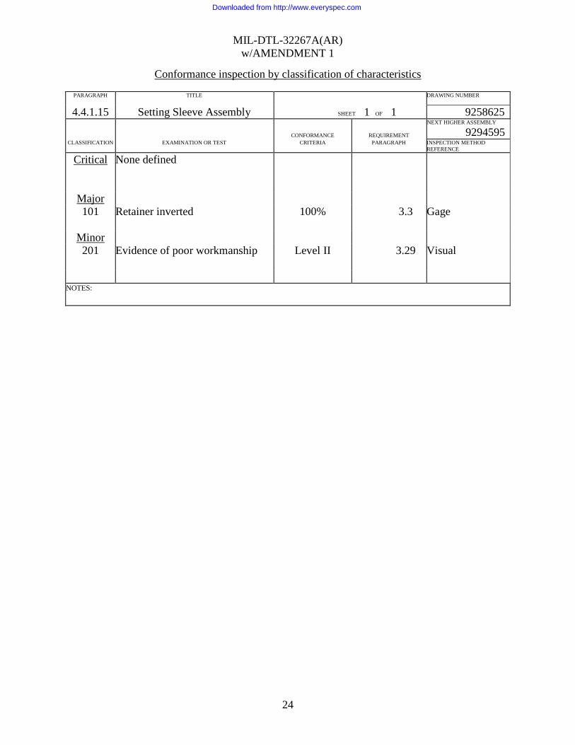
Conformance inspection by classification of characteristics
PARAGRAPH TITLE DRAWING NUMBER 4.4.1.15 Setting Sleeve Assembly SHEET 1 OF 1 9258625
CONFORMANCE
REQUIREMENT
NEXT HIGHER ASSEMBLY
9294595 CLASSIFICATION EXAMINATION OR TEST CRITERIA PARAGRAPH INSPECTION METHOD
REFERENCE
Critical None defined
Major 101 Retainer inverted 100% 3.3 Gage
Minor 201 Evidence of poor workmanship Level II 3.29 Visual
NOTES:
Downloaded from http://www.everyspec.com
MIL-DTL-32267A(AR) w/AMENDMENT 1
25
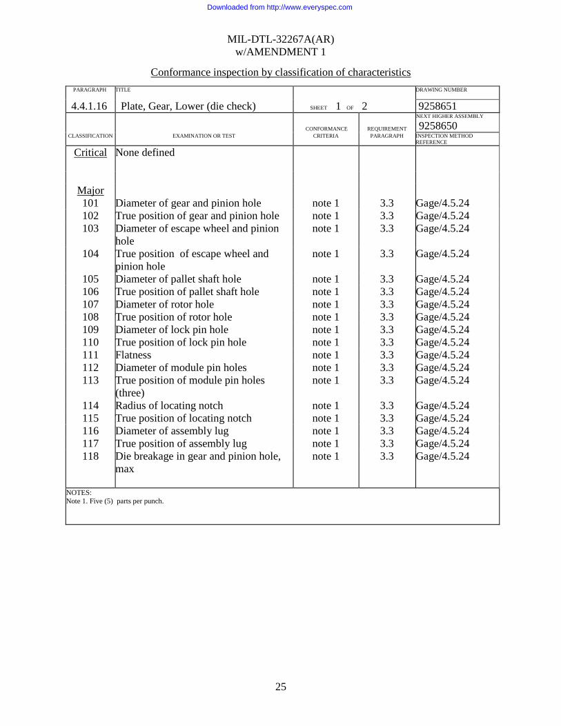
Conformance inspection by classification of characteristics
PARAGRAPH TITLE DRAWING NUMBER 4.4.1.16 Plate, Gear, Lower (die check) SHEET 1 OF 2 9258651
CONFORMANCE
REQUIREMENT
NEXT HIGHER ASSEMBLY
9258650 CLASSIFICATION EXAMINATION OR TEST CRITERIA PARAGRAPH INSPECTION METHOD
REFERENCE
Critical None defined
Major 101 Diameter of gear and pinion hole note 1 3.3 Gage/4.5.24 102 True position of gear and pinion hole note 1 3.3 Gage/4.5.24 103 Diameter of escape wheel and pinion
hole note 1 3.3 Gage/4.5.24
104 True position of escape wheel and pinion hole
note 1 3.3 Gage/4.5.24
105 Diameter of pallet shaft hole note 1 3.3 Gage/4.5.24 106 True position of pallet shaft hole note 1 3.3 Gage/4.5.24 107 Diameter of rotor hole note 1 3.3 Gage/4.5.24 108 True position of rotor hole note 1 3.3 Gage/4.5.24 109 Diameter of lock pin hole note 1 3.3 Gage/4.5.24 110 True position of lock pin hole note 1 3.3 Gage/4.5.24 111 Flatness note 1 3.3 Gage/4.5.24 112 Diameter of module pin holes note 1 3.3 Gage/4.5.24 113 True position of module pin holes
(three) note 1 3.3 Gage/4.5.24
114 Radius of locating notch note 1 3.3 Gage/4.5.24 115 True position of locating notch note 1 3.3 Gage/4.5.24 116 Diameter of assembly lug note 1 3.3 Gage/4.5.24 117 True position of assembly lug note 1 3.3 Gage/4.5.24 118 Die breakage in gear and pinion hole,
max note 1 3.3 Gage/4.5.24
NOTES: Note 1. Five (5) parts per punch.
Downloaded from http://www.everyspec.com
MIL-DTL-32267A(AR) w/AMENDMENT 1
26
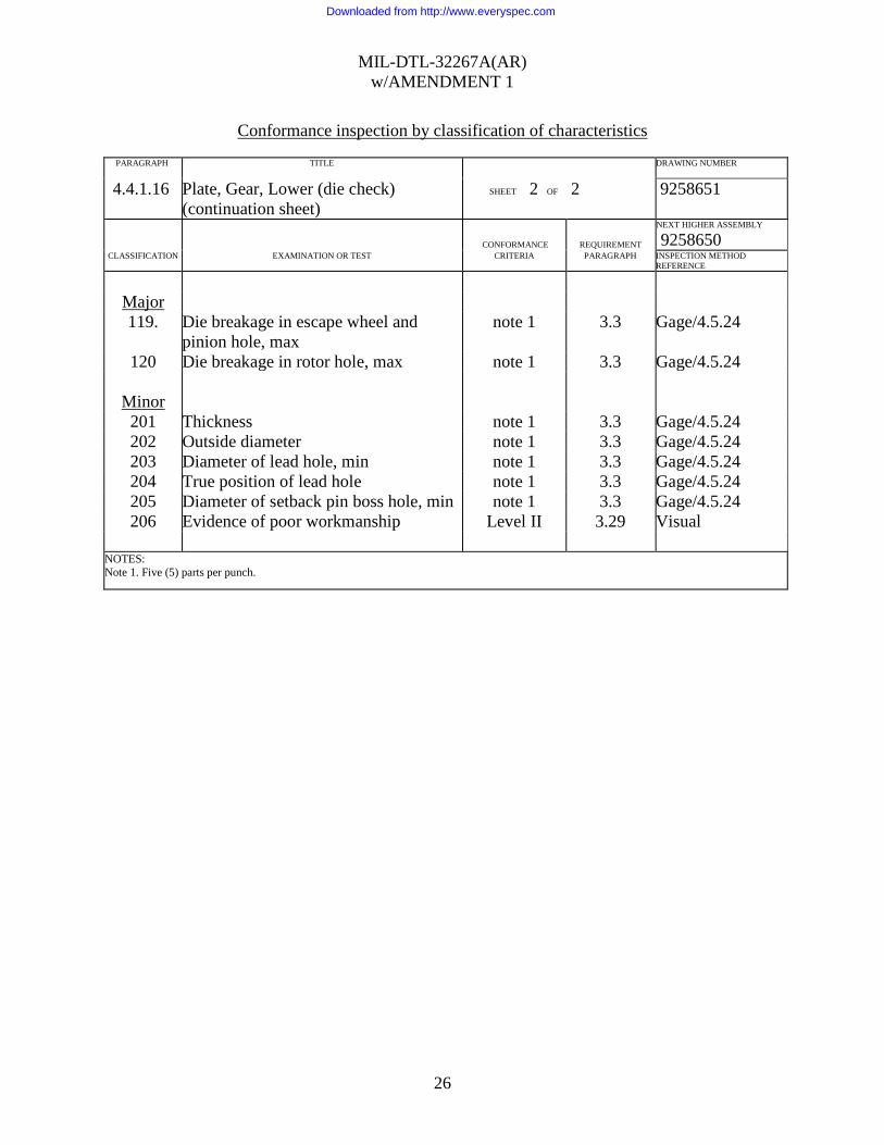
Conformance inspection by classification of characteristics
PARAGRAPH TITLE DRAWING NUMBER 4.4.1.16 Plate, Gear, Lower (die check)
(continuation sheet) SHEET 2 OF 2 9258651
CONFORMANCE
REQUIREMENT
NEXT HIGHER ASSEMBLY
9258650 CLASSIFICATION EXAMINATION OR TEST CRITERIA PARAGRAPH INSPECTION METHOD
REFERENCE
Major 119. Die breakage in escape wheel and
pinion hole, max note 1 3.3 Gage/4.5.24
120 Die breakage in rotor hole, max note 1 3.3 Gage/4.5.24
Minor 201 Thickness note 1 3.3 Gage/4.5.24 202 Outside diameter note 1 3.3 Gage/4.5.24 203 Diameter of lead hole, min note 1 3.3 Gage/4.5.24 204 True position of lead hole note 1 3.3 Gage/4.5.24 205 Diameter of setback pin boss hole, min note 1 3.3 Gage/4.5.24 206 Evidence of poor workmanship Level II 3.29 Visual
NOTES: Note 1. Five (5) parts per punch.
Downloaded from http://www.everyspec.com
MIL-DTL-32267A(AR) w/AMENDMENT 1
27
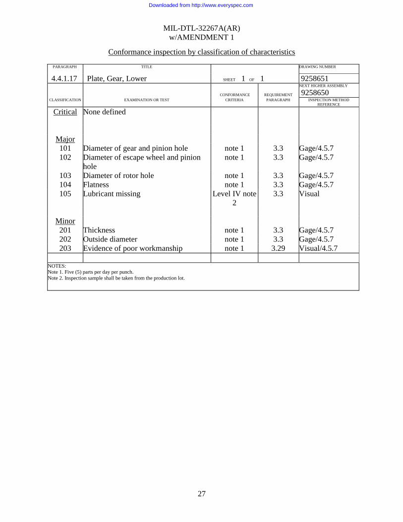
Conformance inspection by classification of characteristics
PARAGRAPH TITLE DRAWING NUMBER 4.4.1.17 Plate, Gear, Lower SHEET 1 OF 1 9258651
CONFORMANCE
REQUIREMENT
NEXT HIGHER ASSEMBLY
9258650 CLASSIFICATION EXAMINATION OR TEST CRITERIA PARAGRAPH INSPECTION METHOD
REFERENCE
Critical None defined
Major 101 Diameter of gear and pinion hole note 1 3.3 Gage/4.5.7 102 Diameter of escape wheel and pinion
hole note 1 3.3 Gage/4.5.7
103 Diameter of rotor hole note 1 3.3 Gage/4.5.7 104 Flatness note 1 3.3 Gage/4.5.7 105 Lubricant missing Level IV note
2 3.3 Visual
Minor 201 Thickness note 1 3.3 Gage/4.5.7 202 Outside diameter note 1 3.3 Gage/4.5.7 203 Evidence of poor workmanship note 1 3.29 Visual/4.5.7
NOTES: Note 1. Five (5) parts per day per punch. Note 2. Inspection sample shall be taken from the production lot.
Downloaded from http://www.everyspec.com
MIL-DTL-32267A(AR) w/AMENDMENT 1
28
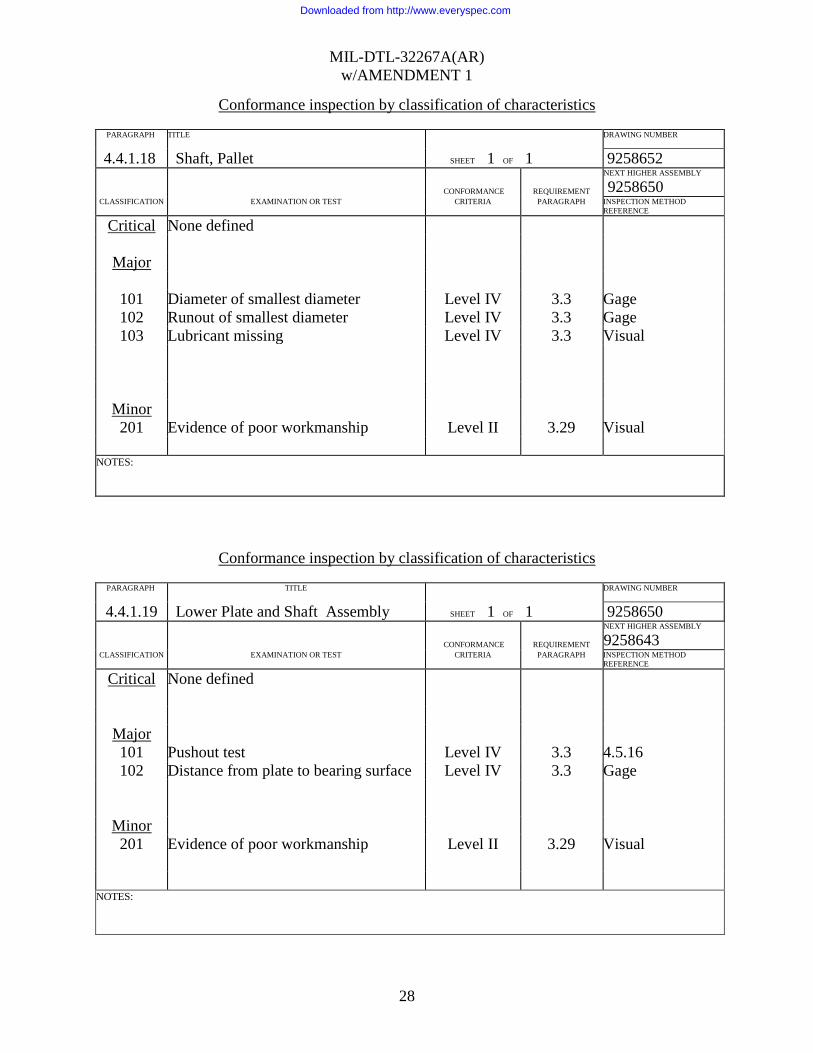
Conformance inspection by classification of characteristics
PARAGRAPH TITLE DRAWING NUMBER 4.4.1.18 Shaft, Pallet SHEET 1 OF 1 9258652
CONFORMANCE
REQUIREMENT
NEXT HIGHER ASSEMBLY
9258650 CLASSIFICATION EXAMINATION OR TEST CRITERIA PARAGRAPH INSPECTION METHOD
REFERENCE
Critical None defined
Major
101 Diameter of smallest diameter Level IV 3.3 Gage 102 Runout of smallest diameter Level IV 3.3 Gage 103 Lubricant missing Level IV 3.3 Visual
Minor 201 Evidence of poor workmanship Level II 3.29 Visual
NOTES:
Conformance inspection by classification of characteristics
PARAGRAPH TITLE DRAWING NUMBER 4.4.1.19 Lower Plate and Shaft Assembly SHEET 1 OF 1 9258650
CONFORMANCE
REQUIREMENT
NEXT HIGHER ASSEMBLY
9258643 CLASSIFICATION EXAMINATION OR TEST CRITERIA PARAGRAPH INSPECTION METHOD
REFERENCE
Critical None defined
Major 101 Pushout test Level IV 3.3 4.5.16 102 Distance from plate to bearing surface Level IV 3.3 Gage
Minor 201 Evidence of poor workmanship Level II 3.29 Visual
NOTES:
Downloaded from http://www.everyspec.com
MIL-DTL-32267A(AR) w/AMENDMENT 1
29
Conformance inspection by classification of characteristics
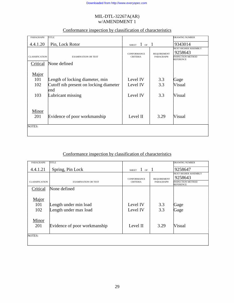
Conformance inspection by classification of characteristics
PARAGRAPH TITLE DRAWING NUMBER 4.4.1.21 Spring, Pin Lock SHEET 1 OF 1 9258647
CONFORMANCE
REQUIREMENT
NEXT HIGHER ASSEMBLY
9258643 CLASSIFICATION EXAMINATION OR TEST CRITERIA PARAGRAPH INSPECTION METHOD
REFERENCE
Critical None defined
Major 101 Length under min load Level IV 3.3 Gage 102 Length under max load Level IV 3.3 Gage
Minor 201 Evidence of poor workmanship Level II 3.29 Visual
NOTES:
PARAGRAPH TITLE DRAWING NUMBER
4.4.1.20 Pin, Lock Rotor SHEET 1 OF 1 9343014
CONFORMANCE
REQUIREMENT
NEXT HIGHER ASSEMBLY
9258643 CLASSIFICATION EXAMINATION OR TEST CRITERIA PARAGRAPH INSPECTION METHOD
REFERENCE
Critical None defined
Major 101 Length of locking diameter, min Level IV 3.3 Gage 102 Cutoff nib present on locking diameter
end Level IV 3.3 Visual
103 Lubricant missing Level IV 3.3 Visual
Minor 201 Evidence of poor workmanship Level II 3.29 Visual
NOTES:
Downloaded from http://www.everyspec.com

MIL-DTL-32267A(AR) w/AMENDMENT 1
30
Conformance inspection by classification of characteristics
PARAGRAPH TITLE DRAWING NUMBER 4.4.1.22 Plate, Bottom (die check) SHEET 1 OF 3 9258644
CONFORMANCE
REQUIREMENT
NEXT HIGHER ASSEMBLY
9258643 CLASSIFICATION EXAMINATION OR TEST CRITERIA PARAGRAPH INSPECTION METHOD
REFERENCE
Critical None defined
Major 101 True position of lead hole note 1 3.3 Gage/ 4.5.23 102 Diameter of large setback pin hole. note 1 3.3 Gage/ 4.5.23 103 True position of large setback pin hole. note 1 3.3 Gage/ 4.5.23 104 Diameter of small setback pin hole. note 1 3.3 Gage/ 4.5.23 105 True position of small setback pin hole note 1 3.3 Gage/ 4.5.23 106 Diameter of locking pin hole note 1 3.3 Gage/ 4.5.23 107 True position of locking pin hole note 1 3.3 Gage/ 4.5.23 108 Angle of top of setback pin hole note 1 3.3 Gage/ 4.5.23 109 Depth of large setback pin hole note 1 3.3 Gage/ 4.5.23 110 Surface porosity note 1 3.23 Visual/Gage/
4.5.23/ and 4.5.25 NOTES: Note 1. Three (3) parts per cavity.
Conformance inspection by classification of characteristics
PARAGRAPH TITLE DRAWING NUMBER 4.4.1.22 Plate, Bottom (continuation sheet) SHEET 2 OF 3 9258644
CONFORMANCE
REQUIREMENT
NEXT HIGHER ASSEMBLY
9258643 CLASSIFICATION EXAMINATION OR TEST CRITERIA PARAGRAPH INSPECTION METHOD
REFERENCE
Major 111 Outside diameter note 1 3.3 Gage/ 4.5.23 112 Diameter of module pin holes (four) note 1 3.3 Gage/ 4.5.23 113 True position module pin holes (three) note 1 3.3 Gage/ 4.5.23 114 Distance from bottom of plate to top of
setback pin boss. note 1 3.3 Gage/ 4.5.23
115 Depth of locking pin disc hole note 1 3.3 Gage/ 4.5.23 116 Radius of locating notch note 1 3.3 Gage/ 4.5.23 117 True position of locating notch note 1 3.3 Gage/ 4.5.23 118 Diameter of spacer tab hole note 1 3.3 Gage/ 4.5.23 119 True position of spacer tab hole, min. note 1 3.3 Gage/ 4.5.23 120 Depth of spacer tab hole, min note 1 3.3 Gage/ 4.5.23 121 Diameter of lead hole. note 1 3.3 Gage/ 4.5.23 122 Diameter of rotor hole note 1 3.3 Gage/ 4.5.23 123 True position of rotor hole note 1 3.3 Gage/ 4.5.23
NOTES: Note 1. Three (3) parts per cavity.
Downloaded from http://www.everyspec.com

MIL-DTL-32267A(AR) w/AMENDMENT 1
31
Conformance inspection by classification of characteristics
PARAGRAPH TITLE DRAWING NUMBER 4.4.1.22 Plate, Bottom (continuation sheet) SHEET 3 OF 3 9258644
CONFORMANCE
REQUIREMENT
NEXT HIGHER ASSEMBLY
9258643 CLASSIFICATION EXAMINATION OR TEST CRITERIA PARAGRAPH INSPECTION METHOD
REFERENCE
Minor
201 Distance from bottom plate to bottom of setback pin and lead holes
note 1 3.3 Gage/ 4.5.23
202 Thickness from top plate to bottom of plate
note 1 3.3 Gage/ 4.5.23
203 Thickness of thick portion of plate note 1 3.3 Gage/ 4.5.23 204 Thickness of thin portion of plate note 1 3.3 Gage/ 4.5.23 205 Depth of rotor hole note 1 3.3 Gage/ 4.5.23 206 Diameter of top of setback pin boss note 1 3.3 Gage/ 4.5.23 207 True position of top of setback pin boss note 1 3.3 Gage/ 4.5.23 208 True position of outside diameter note 1 3.3 Gage/ 4.5.23 209 Diameter of two assembly holes note 1 3.3 Gage/ 4.5.23 210 True position of assembly holes. note 1 3.3 Gage/ 4.5.23 211 Evidence of poor workmanship Level II 3.29 Gage/ 4.5.23
NOTES: Note 1. Three (3) parts per cavity.
Downloaded from http://www.everyspec.com

MIL-DTL-32267A(AR) w/AMENDMENT 1
32
Conformance inspection by classification of characteristics
PARAGRAPH TITLE DRAWING NUMBER 4.4.1.23 Plate, Bottom SHEET 1 OF 1 9258644
CONFORMANCE
REQUIREMENT
NEXT HIGHER ASSEMBLY
9258643 CLASSIFICATION EXAMINATION OR TEST CRITERIA PARAGRAPH INSPECTION METHOD
REFERENCE
Critical None defined
Major 101 Diameter of large setback pin hole note 1 3.3 Gage/ 4.5.27 102 Depth of setback pin hole note 1 3.3 Gage/ 4.5.27 103 Surface porosity note 1 3.23 Visual/Gage/
4.5.25/4.5.27 104 Diameter of lead hole note 1 3.3 Gage/ 4.5.27 105 Lubricant missing Level IV note
2 3.3 Visual
Minor 201 Thickness from top of plate to bottom
of plate. note 1 3.3 Gage/ 4.5.27
202 Thickness of thin portion of plate note 1 3.3 Gage/ 4.5.27 203 Evidence of poor workmanship note 1 3.29 Visual/4.5.27
NOTES: Note 1. Three (3) parts per 50,000 pieces per cavity. Sample size increases for larger production (see 4.5.34) Note 2. Inspection sample shall be taken from a production lot.
Downloaded from http://www.everyspec.com
MIL-DTL-32267A(AR) w/AMENDMENT 1
33
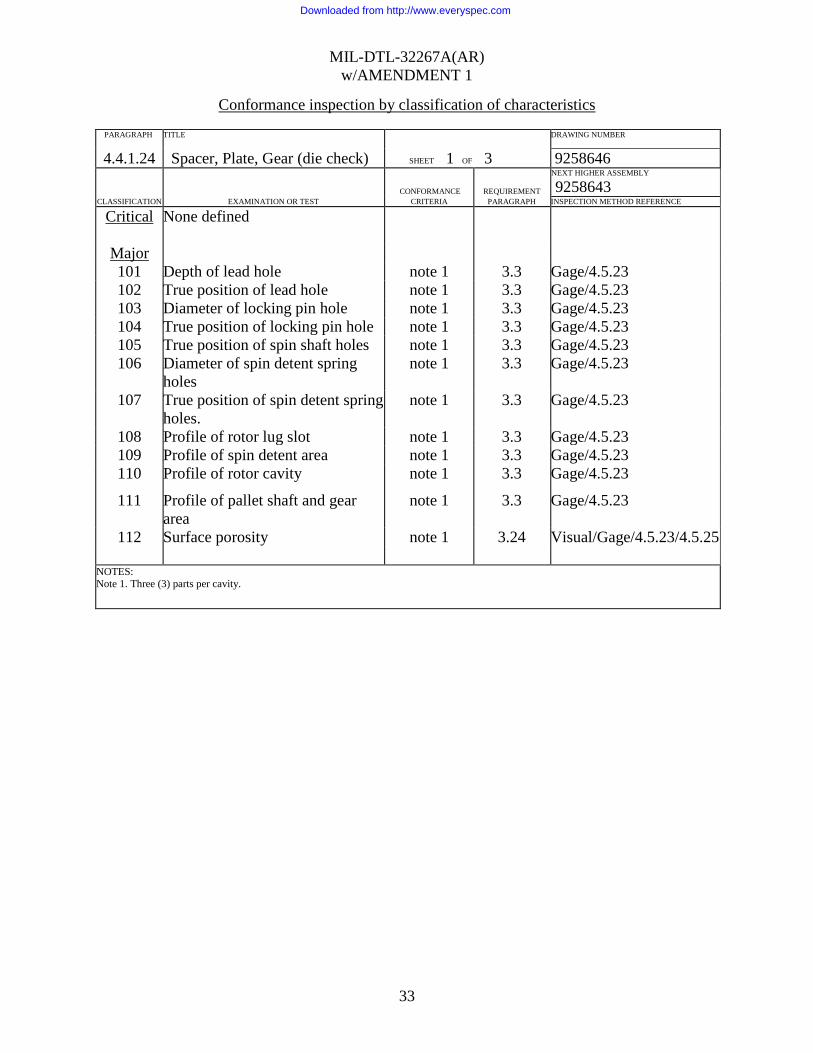
Conformance inspection by classification of characteristics
PARAGRAPH TITLE DRAWING NUMBER 4.4.1.24 Spacer, Plate, Gear (die check) SHEET 1 OF 3 9258646
CONFORMANCE
REQUIREMENT
NEXT HIGHER ASSEMBLY
9258643 CLASSIFICATION EXAMINATION OR TEST CRITERIA PARAGRAPH INSPECTION METHOD REFERENCE
Critical None defined
Major 101 Depth of lead hole note 1 3.3 Gage/4.5.23 102 True position of lead hole note 1 3.3 Gage/4.5.23 103 Diameter of locking pin hole note 1 3.3 Gage/4.5.23 104 True position of locking pin hole note 1 3.3 Gage/4.5.23 105 True position of spin shaft holes note 1 3.3 Gage/4.5.23 106 Diameter of spin detent spring
holes note 1 3.3 Gage/4.5.23
107 True position of spin detent spring holes.
note 1 3.3 Gage/4.5.23
108 Profile of rotor lug slot note 1 3.3 Gage/4.5.23 109 Profile of spin detent area note 1 3.3 Gage/4.5.23 110 Profile of rotor cavity note 1 3.3 Gage/4.5.23
111 Profile of pallet shaft and gear area
note 1 3.3 Gage/4.5.23
112 Surface porosity note 1 3.24 Visual/Gage/4.5.23/4.5.25
NOTES: Note 1. Three (3) parts per cavity.
Downloaded from http://www.everyspec.com

MIL-DTL-32267A(AR) w/AMENDMENT 1
34
Conformance inspection by classification of characteristics
PARAGRAPH TITLE DRAWING NUMBER 4.4.1.24 Spacer, Plate, Gear (die check)
(continuation sheet) SHEET 2 OF 3 9258646
CONFORMANCE
REQUIREMENT
NEXT HIGHER ASSEMBLY
9258643 CLASSIFICATION EXAMINATION OR TEST CRITERIA PARAGRAPH INSPECTION METHOD
REFERENCE
Major 113 Outside diameter note 1 3.3 Gage/4.5.23 114 Radius of locating notch note 1 3.3 Gage/4.5.23 115 True position of locating notch note 1 3.3 Gage/4.5.23 116 Diameter of tab note 1 3.3 Gage/4.5.23 117 True position of tab note 1 3.3 Gage/4.5.23 118 Thickness of bottom note 1 3.3 Gage/4.5.23 119 Diameter of module holes (four) note 1 3.3 Gage/4.5.23 120 True position of module holes (three) note 1 3.3 Gage/4.5.23 121 Diameter of upper plate tab hole note 1 3.3 Gage/4.5.23 122 True position of upper plate tab hole note 1 3.3 Gage/4.5.23 123 Depth of upper plate tab hole, min. note 1 3.3 Gage/4.5.23 124 Profile of gear slot note 1 3.3 Gage/4.5.23 125 Diameter of lead hole note 1 3.3 Gage/4.5.23 126 Diameter of spin shaft holes note 1 3.3 Gage/4.5.23 127 Width of spin tabs slots note 1 3.3 Gage/4.5.23 128 True position of spin tab slots note 1 3.3 Gage/4.5.23
NOTES: Note 1. Three (3) parts per cavity.
Downloaded from http://www.everyspec.com

MIL-DTL-32267A(AR) w/AMENDMENT 1
35
Conformance inspection by classification of characteristics
PARAGRAPH TITLE DRAWING NUMBER 4.4.1.24 Spacer, Plate, Gear (die check)
(continuation sheet) SHEET 3 OF 3 9258646
CONFORMANCE
REQUIREMENT
NEXT HIGHER ASSEMBLY
9258643 CLASSIFICATION EXAMINATION OR TEST CRITERIA PARAGRAPH INSPECTION METHOD
REFERENCE
Minor 201 Thickness note 1 3.3 Gage/4.5.23 202 True position of outside diameter note 1 3.3 Gage/4.5.23 203 Diameter of rotor hole note 1 3.3 Gage/4.5.23 204 True position of rotor hole note 1 3.3 Gage/4.5.23 205 Diameter of pallet shaft hole note 1 3.3 Gage/4.5.23 206 True position of pallet shaft hole note 1 3.3 Gage/4.5.23 207 Depth of spin shaft holes note 1 3.3 Gage/4.5.23 208 Any chamfer missing note 1 3.3 Visual/4.5.23 209 Evidence of poor workmanship Level II 3.29 Visual/4.5.23
NOTES: Note 1. Three (3) parts per cavity.
Conformance inspection by classification of characteristics
PARAGRAPH TITLE DRAWING NUMBER 4.4.1.25 Spacer, Plate, Gear SHEET 1 OF 1 9258646
CONFORMANCE
REQUIREMENT
NEXT HIGHER ASSEMBLY
9258643 CLASSIFICATION EXAMINATION OR TEST CRITERIA PARAGRAPH INSPECTION METHOD REFERENCE
Critical None defined
Major 101 Diameter of locking pin hole note 1 3.3 Gage/4.5.27 102 Surface porosity note 1 3.24 Visual/Gage/4.5.25/4.5.27 103 Diameter of spin shaft holes note 1 3.3 Gage/4.5.27 104 Thickness of bottom note 1 3.3 Gage/4.5.27 105 Width of spin tab slots note 1 3.3 Gage/4.5.27
Minor 201 Evidence of poor workmanship Level II 3.29 Visual/4.5.27
NOTES: Note 1. Three (3) parts per 50,000 pieces per cavity. Sample size increases for larger production (see 4.5.34).
Downloaded from http://www.everyspec.com

MIL-DTL-32267A(AR) w/AMENDMENT 1
36
Conformance inspection by classification of characteristics
PARAGRAH TITLE DRAWING NUMBER 4.4.1.26 Plate and Spacer Assembly SHEET 1 OF 1 9258643
CONFORMANCE
REQUIREMENT
NEXT HIGHER ASSEMBLY
9294833 CLASSIFICATION EXAMINATION OR TEST CRITERIA PARAGRAPH INSPECTION METHOD
REFERENCE
Critical None defined
Major 101 Presence of lock pin disk stake Level IV 3.3 Visual
Minor 201 Evidence of poor workmanship Level II 3.29 Visual
NOTES
Conformance inspection by classification of characteristics
PARAGRAPH TITLE DRAWING NUMBER
4.4.1.27 Shaft, Rotor SHEET 1 OF 1 9258641
CONFORMANCE
REQUIREMENT
NEXT HIGHER ASSEMBLY
9258639 CLASSIFICATION EXAMINATION OR TEST CRITERIA PARAGRAPH INSPECTION METHOD
REFERENCE
Critical None defined
Major 101 Diameter of bearing diameters Level IV 3.3 Gage 102 Lubricant missing Level IV 3.3 Visual
Minor 201 Evidence of poor workmanship Level II 3.29 Visual
NOTES:
Downloaded from http://www.everyspec.com

MIL-DTL-32267A(AR) w/AMENDMENT 1
37
Conformance inspection by classification of characteristics
PARAGRAPH TITLE DRAWING NUMBER 4.4.1.28 Body, Rotor (die check) SHEET 1 OF 3 9258640
CONFORMANCE
REQUIREMENT
NEXT HIGHER ASSEMBLY
9258639 CLASSIFICATION EXAMINATION OR TEST CRITERIA PARAGRAPH INSPECTION METHOD REFERENCE
Critical None defined
Major 101 Weight, min. note 1 3.3 Gage/4.5.23 102 Angularity of spin detent holding
surfaces. note 1 3.3 Gage/4.5.23
103 Diameter of locking pin hole note 1 3.3 Gage/4.5.23 104 True position of locking pin hole note 1 3.3 Gage/4.5.23 105 Diameter of setback pin hole note 1 3.3 Gage/4.5.23 106 True position of setback pin hole note 1 3.3 Gage/4.5.23 107 Finish on bearing surface note 1 3.3 Gage/4.5.23 108 Surface porosity note 1 3.25 Visual/Gage/4.5.23/4.5.25 109 Diameter of rotor shaft hole note 1 3.3 Gage/4.5.23 110 True position of rotor gear lugs note 1 3.3 Gage/4.5.23 111 Diameter of large detonator hole,
min note 1 3.3 Gage/4.5.23
112 True position of large detonator hole
note 1 3.3 Gage/4.5.23
113
Depth of detonator hole note 1 3.3 Gage/4.5.23
NOTES: Note 1. Three (3) parts per cavity.
Downloaded from http://www.everyspec.com

MIL-DTL-32267A(AR) w/AMENDMENT 1
38
Conformance inspection by classification of characteristics
PARAGRAPH TITLE DRAWING NUMBER 4.4.1.28 Body, Rotor (die check) (continuation
sheet) SHEET 2 OF 3 9258640
CONFORMANCE
REQUIREMENT
NEXT HIGHER ASSEMBLY
9258639 CLASSIFICATION EXAMINATION OR TEST CRITERIA PARAGRAPH INSPECTION METHOD
REFERENCE
Major 114 Protrusion of rotor gear lugs, min note 1 3.3 Gage/4.5.23 115 Thickness of rotor at detonator hole note 1 3.3 Gage/4.5.23 116 Thickness from bearing surface to
bottom of flange note 1 3.3 Gage/4.5.23
117 Thickness of rotor at flange note 1 3.3 Gage/4.5.23 118 Outside diameter note 1 3.3 Gage/4.5.23 119 True position of outside diameter note 1 3.3 Gage/4.5.23 120 Profile of locking pin notch note 1 3.3 Gage/4.5.23
Minor 201 Diameter of rotor gear tab hole note 1 3.3 Gage/4.5.23 202 Depth of rotor gear tab hole note 1 3.3 Gage/4.5.23 203 Diameter of rotor gear lugs note 1 3.3 Gage/4.5.23 204 Diameter of large detonator hole, max. note 1 3.3 Gage/4.5.23
NOTES: Note 1. Three (3) parts per cavity.
Conformance inspection by classification of characteristics
PARAGRAPH TITLE DRAWING NUMBER 4.4.1.28 Body, Rotor (Die check) (continuation
sheet) SHEET 3 OF 3 9258640
CONFORMANCE
REQUIREMENT
NEXT HIGHER ASSEMBLY
9258639 CLASSIFICATION EXAMINATION OR TEST CRITERIA PARAGRAPH INSPECTION METHOD
REFERENCE
Minor 205 Diameter of small detonator hole note 1 3.3 Gage/4.5.23 206 Protrusion of rotor gear lugs, max. note 1 3.3 Gage/4.5.23 207 Radius from center to detonator boss note 1 3.3 Gage/4.5.23 208 Profile of large irregular slot note 1 3.3 Gage/4.5.23 209 Diameter of bearing surface note 1 3.3 Gage/4.5.23 210 Profile of flange note 1 3.3 Gage/4.5.23 211 Evidence of poor workmanship Level II 3.29 Visual
NOTES: Note 1. Three (3) parts per cavity.
Downloaded from http://www.everyspec.com

MIL-DTL-32267A(AR) w/AMENDMENT 1
39
Conformance inspection by classification of characteristics
PARAGRAPH TITLE DRAWING NUMBER 4.4.1.29 Body, Rotor SHEET 1 OF 1 9258640
CONFORMANCE
REQUIREMENT
NEXT HIGHER ASSEMBLY
9258639 CLASSIFICATION EXAMINATION OR TEST CRITERIA PARAGRAPH INSPECTION METHOD
REFERENCE
Critical None defined
Major 101 Weight, min. note 1 3.3 Gage/4.5.27 102 Surface porosity note 1 3.25 Visual/Gage
4.5.25/4.5.27 103 Diameter of rotor shaft hole note 1 3.3 Gage/4.5.27 104 Thickness of rotor at detonator hole note 1 3.3 Gage/4.5.27 105 Thickness of rotor at flange note 1 3.3 Gage/4.5.27 106 Lubricant missing Level IV note 2 3.3 Visual
Minor 201 Evidence of poor workmanship Level II 3.29 Visual/4.5.27
NOTES: Note 1. Three (3) parts per 50,000 pieces per cavity. Sample size increases for larger production (see 4.5.34) Note 2. Inspection sample shall be taken from a production lot.
Conformance inspection by classification of characteristics
PARAGRAPH TITLE DRAWING NUMBER 4.4.1.30 Gear, Rotor (die check) SHEET 1 OF 2 9258642
CONFORMANCE
REQUIREMENT
NEXT HIGHER ASSEMBLY
9258639 CLASSIFICATION EXAMINATION OR TEST CRITERIA PARAGRAPH INSPECTION METHOD
REFERENCE
Major 101 Tooth to tooth composite error note 1 3.3 Gage/4.5.24 102 Diameter of rotor shaft hole note 1 3.3 Gage/4.5.24 103 Diameter of assembly tab note 1 3.3 Gage/4.5.24 104 True position of assembly tab note 1 3.3 Gage/4.5.24 105 Diameter of small rotor lug hole note 1 3.3 Gage/4.5.24 106 True position of small rotor lug holes note 1 3.3 Gage/4.5.24 107 Profile around rotor shaft hole note 1 3.3 Gage/4.5.24 108 Thickness note 1 3.3 Gage/4.5.24
NOTES: Note 1. Five (5) parts per punch.
Downloaded from http://www.everyspec.com

MIL-DTL-32267A(AR) w/AMENDMENT 1
40
Conformance inspection by classification of characteristics
PARAGRAPH TITLE DRAWING NUMBER 4.4.1.30 Gear, Rotor (die check) continuation
sheet SHEET 2 OF 2 9258642
CONFORMANCE
REQUIREMENT
NEXT HIGHER ASSEMBLY
9258639 CLASSIFICATION EXAMINATION OR TEST CRITERIA PARAGRAPH INSPECTION METHOD
REFERENCE
Minor 201 Diameter of large rotor lug hole note 1 3.3 Gage/4.5.24 202 True position of large rotor lug holes note 1 3.3 Gage/4.5.24 203 Diameter of setback pin hole note 1 3.3 Gage/4.5.24 204 True position of setback pin hole note 1 3.3 Gage/4.5.24 205 Profile of rotor flange notch note 1 3.3 Gage/4.5.24 206 Large radius note 1 3.3 Gage/4.5.24 207 Evidence of poor workmanship note 1 3.29 Visual/4.5.24
NOTES: Note 1. Five (5) parts per punch.
Conformance inspection by classification of characteristics
PARAGRAPH TITLE DRAWING NUMBER 4.4.1.31 Gear, Rotor SHEET 1 OF 1 9258642
CONFORMANCE
REQUIREMENT
NEXT HIGHER ASSEMBLY
9258639 CLASSIFICATION EXAMINATION OR TEST CRITERIA PARAGRAPH INSPECTION METHOD
REFERENCE
Major 101 Diameter of rotor shaft hole note 1 3.3 Gage/4.5.7 102 Tooth to tooth composite error note 1 3.3 Gage/4.5.7 103 Thickness note 1 3.3 Gage/4.5.7 104 Lubricant missing Level IV note
2 3.3 Visual
Minor 201 Evidence of poor workmanship note 1 3.29 Visual/4.5.7
NOTES: Note 1. Five (5) parts per punch per day Note 2. Inspection sample shall be taken from a production lot.
Downloaded from http://www.everyspec.com

MIL-DTL-32267A(AR) w/AMENDMENT 1
41
Conformance inspection by classification of characteristics
PARAGRAPH TITLE DRAWING NUMBER 4.4.1.32 Rotor Assembly SHEET 1 OF 1 9258639
CONFORMANCE
REQUIREMENT
NEXT HIGHER ASSEMBLY
9294833 CLASSIFICATION EXAMINATION OR TEST CRITERIA PARAGRAPH INSPECTION METHOD
REFERENCE
Critical None defined
Major 101 Detonator inverted or missing 100% 3.3 Gage/Visual 102 Distance between bearing surface,
max.. Level IV 3.3 Gage
103 Detonator push out test Level IV 3.3 4.5.11 104 Sensitive end not flush or below flush Level IV 3.3 Gage/Visual 105 Rotor gear stake incomplete or missing Level IV 3.3 Visual
Minor 201 Evidence of poor workmanship Level II 3.29 Visual
NOTES:
Conformance inspection by classification of characteristics
PARAGRAPH TITLE DRAWING NUMBER 4.4.1.33 Spinlock SHEET 1 OF 1 12973181
CONFORMANCE
REQUIREMENT
NEXT HIGHER ASSEMBLY
9294833 CLASSIFICATION EXAMINATION OR TEST CRITERIA PARAGRAPH INSPECTION METHOD
REFERENCE
Critical None defined
Major 101 Weight (80) 3.3 4.5.26 102 Load test (80) 3.3 4.5.22 103 Profile of holding surfaces Level IV 3.3 Gage 104 Lubricant missing Level IV 3.3 Visual 105 Length of malassembly tab (long) Level V 3.3 Gage 106 Length of malassembly tab (short) Level V 3.3 Gage
Minor 201 Evidence of poor workmanship Level II 3.29 Visual
NOTES: ( ) - Quantity
Downloaded from http://www.everyspec.com

MIL-DTL-32267A(AR) w/AMENDMENT 1
42
Conformance inspection by classification of characteristics
PARAGRAPH TITLE DRAWING NUMBER 4.4.1.34 Gear and Pinion Assembly (die
check) SHEET 1 OF 2 9258653
CONFORMANCE
REQUIREMENT
NEXT HIGHER ASSEMBLY
9294833 CLASSIFICATION EXAMINATION OR TEST CRITERIA PARAGRAPH INSPECTION METHOD REFERENCE
Critical None defined
Major 101 Diameter of small diameters note 1 3.3 Gage/4.5.23 102 Tooth to tooth composite error of
large gear note 1 3.3 Gage/4.5.23
103 Tooth to tooth composite error of pinion
note 1 3.3 Gage/4.5.23
104 Distance between bearing surfaces note 1 3.3 Gage/4.5.23 105 Surface porosity note 1 3.26 Visual/Gage/4.5.23/4.5.25 106 Gate above flush, max. note 1 3.3 Gage/4.5.23 107 Flash in chamfer areas (not firm) note 1 3.3 Manual/4.5.23 108 Thickness of gears note 1 3.3 Gage/4.5.23 109 Distance from lower bearing
surface to top of pinion. note 1 3.3 Gage/4.5.23
110 Distance from hub diameter to end
note 1 3.3 Gage/4.5.23
NOTES: Note 1. Three (3) parts per cavity.
Downloaded from http://www.everyspec.com

MIL-DTL-32267A(AR) w/AMENDMENT 1
43
Conformance inspection by classification of characteristics
PARAGRAPH TITLE DRAWING NUMBER 4.4.1.34 Gear and Pinion Assembly (die check)
(continuation sheet) SHEET 2 OF 2 9258653
CONFORMANCE
REQUIREMENT
NEXT HIGHER ASSEMBLY
9294833 CLASSIFICATION EXAMINATION OR TEST CRITERIA PARAGRAPH INSPECTION METHOD
REFERENCE
Minor 201 Hub diameter note 1 3.2 Gage/4.5.23 202 True position of hub diameter note 1 3.2 Gage/4.5.23 203 Bearing diameter note 1 3.2 Gage/4.5.23 204 True position of bearing diameter note 1 3.2 Gage/4.5.23 205 Evidence of poor workmanship note 1 3.29 Visual/4.5.23
NOTES: Note 1. Three (3) parts per cavity.
Conformance inspection by classification of characteristics
PARAGRAPH TITLE DRAWING NUMBER 4.4.1.35 Gear and Pinion Assembly SHEET 1 OF 1 9258653
CONFORMANCE
REQUIREMENT
NEXT HIGHER ASSEMBLY
9294833 CLASSIFICATION EXAMINATION OR TEST CRITERIA PARAGRAPH INSPECTION METHOD REFERENCE
Critical None defined
Major 101 Diameter of small diameters note 1 3.3 Gage/4.5.27 102 Tooth to tooth composite error of
large gear note 1 3.3 Gage/4.5.27
103 Tooth to tooth composite error of pinion.
note 1 3.3 Gage/4.5.27
104 Surface porosity note 1 3.26 Visual/Gage/4.5.25/4.5.27 105 Gate above flush, max. note 1 3.3 Gage/4.5.27 106 Flash in chamfer areas (not firm) note 1 3.3 Manual/4.5.27 107 Thickness of gear note 1 3.3 Gage/4.5.27 108 Lubricant missing Level IV
note 2 3.3 Visual
Minor 201 Evidence of poor workmanship note 1 3.29 Visual
NOTES: Note 1. Three (3) parts per 50,000 pieces per cavity. Sample size increases for larger production runs (see 4.5.34) Note 2. Inspection sample shall be taken from a production lot.
Downloaded from http://www.everyspec.com

MIL-DTL-32267A(AR) w/AMENDMENT 1
44
Conformance inspection by classification of characteristics
PARAGRAPH TITLE DRAWING NUMBER 4.4.1.36 Escape Wheel and Pinion
Assembly (die check) SHEET 1 OF 2 9258655
CONFORMANCE
REQUIREMENT
NEXT HIGHER ASSEMBLY
9294833 CLASSIFICATION EXAMINATION OR TEST CRITERIA PARAGRAPH INSPECTION METHOD REFERENCE
Critical None defined
Major 101 Diameter of small diameters note 1 3.3 Gage/4.5.23 102 Tooth to tooth composite error on
pinion note 1 3.3 Gage/4.5.23
103 Distance between bearing surfaces note 1 3.3 Gage/4.5.23 104 Surface porosity note 1 3.26 Visual/Gage/4.5.23/4.5.25 105 Gate above flush, max. note 1 3.3 Gage/4.5.23 106 Flash in chamfer areas (not firm) note 1 3.3 Manual/4.5.23 107 Thickness of escape wheel note 1 3.3 Gage/4.5.23 108 Distance from bearing surface to
end of pinion note 1 3.3 Gage/4.5.23
109 Distance from bearing surface to end
note 1 3.3 Gage/4.5.23
NOTES: Note 1. Three (3) parts per cavity.
Conformance inspection by classification of characteristics
PARAGRAPH TITLE DRAWING NUMBER
4.4.1.36 Escape Wheel and Pinion Assembly (die check) (continuation sheet)
SHEET 2 OF 2 9258655
CONFORMANCE
REQUIREMENT
NEXT HIGHER ASSEMBLY
9294833 CLASSIFICATION EXAMINATION OR TEST CRITERIA PARAGRAPH INSPECTION METHOD
REFERENCE
Minor 201 Small bearing surface diameter note 1 3.3 Gage/4.5.23 202 True position of small bearing surface
diameter note 1 3.3 Gage/4.5.23
203 Large bearing surface diameter note 1 3.3 Gage/4.5.23 204 True position of large bearing surface
diameter note 1 3.3 Gage/4.5.23
205 Evidence of poor workmanship note 1 3.29 Visual/4.5.23
NOTES: Note 1. Three (3) parts per cavity.
Downloaded from http://www.everyspec.com
MIL-DTL-32267A(AR) w/AMENDMENT 1
45
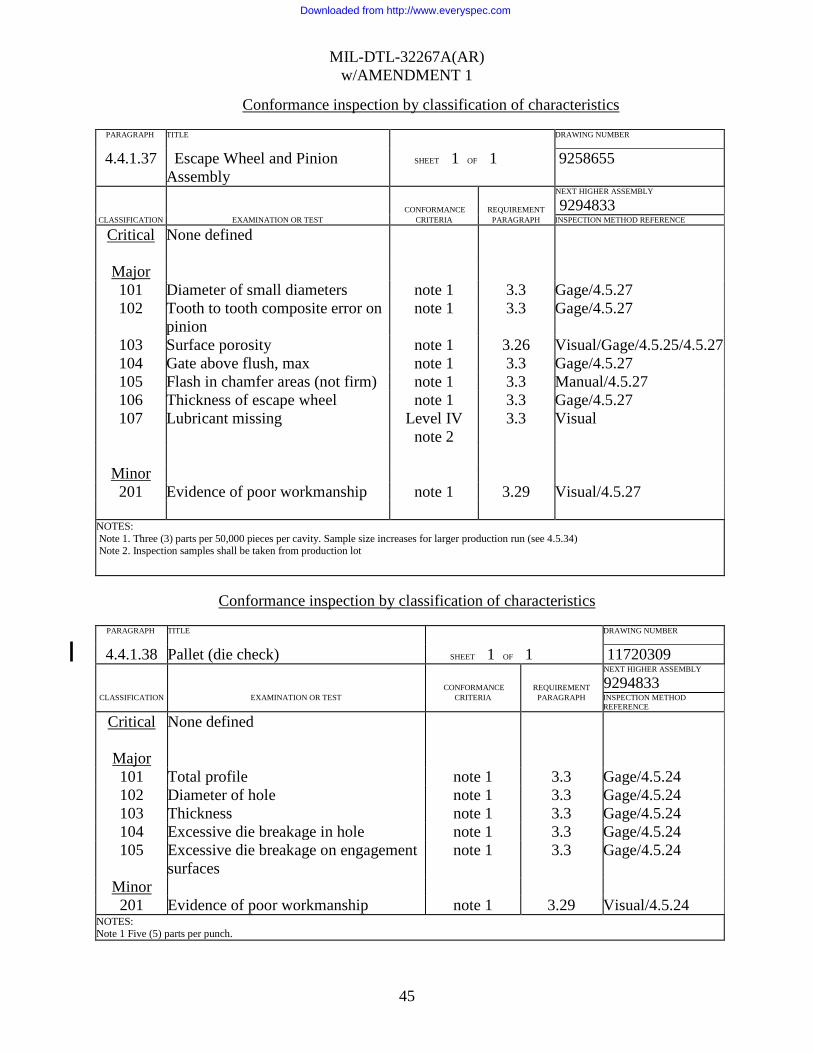
Conformance inspection by classification of characteristics
PARAGRAPH TITLE DRAWING NUMBER 4.4.1.37 Escape Wheel and Pinion
Assembly SHEET 1 OF 1 9258655
CONFORMANCE
REQUIREMENT
NEXT HIGHER ASSEMBLY
9294833 CLASSIFICATION EXAMINATION OR TEST CRITERIA PARAGRAPH INSPECTION METHOD REFERENCE
Critical None defined
Major 101 Diameter of small diameters note 1 3.3 Gage/4.5.27 102 Tooth to tooth composite error on
pinion note 1 3.3 Gage/4.5.27
103 Surface porosity note 1 3.26 Visual/Gage/4.5.25/4.5.27 104 Gate above flush, max note 1 3.3 Gage/4.5.27 105 Flash in chamfer areas (not firm) note 1 3.3 Manual/4.5.27 106 Thickness of escape wheel note 1 3.3 Gage/4.5.27 107 Lubricant missing Level IV
note 2 3.3 Visual
Minor 201 Evidence of poor workmanship note 1 3.29 Visual/4.5.27
NOTES: Note 1. Three (3) parts per 50,000 pieces per cavity. Sample size increases for larger production run (see 4.5.34) Note 2. Inspection samples shall be taken from production lot
Conformance inspection by classification of characteristics
PARAGRAPH TITLE DRAWING NUMBER 4.4.1.38 Pallet (die check) SHEET 1 OF 1 11720309
CONFORMANCE
REQUIREMENT
NEXT HIGHER ASSEMBLY
9294833 CLASSIFICATION EXAMINATION OR TEST CRITERIA PARAGRAPH INSPECTION METHOD
REFERENCE
Critical None defined
Major 101 Total profile note 1 3.3 Gage/4.5.24 102 Diameter of hole note 1 3.3 Gage/4.5.24 103 Thickness note 1 3.3 Gage/4.5.24 104 Excessive die breakage in hole note 1 3.3 Gage/4.5.24 105 Excessive die breakage on engagement
surfaces note 1 3.3 Gage/4.5.24
Minor 201 Evidence of poor workmanship note 1 3.29 Visual/4.5.24
NOTES: Note 1 Five (5) parts per punch.
Downloaded from http://www.everyspec.com

MIL-DTL-32267A(AR) w/AMENDMENT 1
46
Conformance inspection by classification of characteristics
PARAGRAPH TITLE DRAWING NUMBER 4.4.1.39 Pallet SHEET 1 OF 1 11720309
CONFORMANCE
REQUIREMENT
NEXT HIGHER ASSEMBLY
9294833 CLASSIFICATION EXAMINATION OR TEST CRITERIA PARAGRAPH INSPECTION METHOD
REFERENCE
Critical None defined
Major 101 Profile of engagement surfaces (2
places) note 1 3.3 Gage/4.5.7
102 Diameter of hole note 1 3.3 Gage/4.5.7 103 Thickness note 1 3.3 Gage/4.5.7 104 Lubricant missing Level IV
note 2 3.3 Visual
Minor 201 Evidence of poor workmanship note 1 3.29 Visual/4.5.7
NOTES: Note 1. Five (5) parts per day per punch. Note 2. Inspection sample shall be taken from a production lot.
Downloaded from http://www.everyspec.com

MIL-DTL-32267A(AR) w/AMENDMENT 1
47
Conformance inspection by classification of characteristics
PARAGRAPH TITLE DRAWING NUMBER 4.4.1.40 Plate, Gear, Upper (die check) SHEET 1 OF 2 9258632
CONFORMANCE
REQUIREMENT
NEXT HIGHER ASSEMBLY
9294833 CLASSIFICATION EXAMINATION OR TEST CRITERIA PARAGRAPH INSPECTION METHOD
REFERENCE
Critical None defined
Major 101 Diameter of gear and pinion hole note 1 3.3 Gage/4.5.24 102 True position of gear and pinion hole note 1 3.3 Gage/4.5.24 103 Diameter of escape wheel and pinion
hole note 1 3.3 Gage/4.5.24
104 True position of escape wheel and pinion hole
note 1 3.3 Gage/4.5.24
105 Diameter of pallet shaft hole note 1 3.3 Gage/4.5.24 106 True position of pallet shaft hole note 1 3.3 Gage/4.5.24 107 Diameter of rotor hole note 1 3.3 Gage/4.5.24 108 True position of rotor hole note 1 3.3 Gage/4.5.24 109 Flatness note 1 3.3 Gage/4.5.24 110 Diameter of module pin holes (three) note 1 3.3 Gage/4.5.24 111 True position of module pin
holes(three) note 1 3.3 Gage/4.5.24
112 Radius of locating notch note 1 3.3 Gage/4.5.24 113 True position of locating notch note 1 3.3 Gage/4.5.24 114 Diameter of assembly lug note 1 3.3 Gage/4.5.24
NOTES: Note 1. Five (5) parts per punch.
Downloaded from http://www.everyspec.com
MIL-DTL-32267A(AR) w/AMENDMENT 1
48
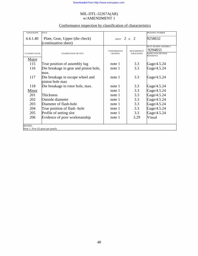
Conformance inspection by classification of characteristics
PARAGRAPH TITLE DRAWING NUMBER 4.4.1.40 Plate, Gear, Upper (die check)
(continuation sheet) SHEET 2 OF 2 9258632
CONFORMANCE
REQUIREMENT
NEXT HIGHER ASSEMBLY
9294833 CLASSIFICATION EXAMINATION OR TEST CRITERIA PARAGRAPH INSPECTION METHOD
REFERENCE
Major 115 True position of assembly lug note 1 3.3 Gage/4.5.24 116 Die breakage in gear and pinion hole,
max. note 1 3.3 Gage/4.5.24
117 Die breakage in escape wheel and pinion hole max
note 1 3.3 Gage/4.5.24
118 Die breakage in rotor hole, max. note 1 3.3 Gage/4.5.24 Minor note 1 3.3 Gage/4.5.24 201 Thickness note 1 3.3 Gage/4.5.24 202 Outside diameter note 1 3.3 Gage/4.5.24 203 Diameter of flash-hole note 1 3.3 Gage/4.5.24 204 True position of flash -hole note 1 3.3 Gage/4.5.24 205 Profile of setting slot note 1 3.3 Gage/4.5.24 206 Evidence of poor workmanship note 1 3.29 Visual
NOTES: Note 1. Five (5) parts per punch.
Downloaded from http://www.everyspec.com

MIL-DTL-32267A(AR) w/AMENDMENT 1
49
Conformance inspection by classification of characteristics
PARAGRAPH TITLE DRAWING NUMBER 4.4.1.41 Plate, Gear, Upper SHEET 1 OF 1 9258632
CONFORMANCE
REQUIREMENT
NEXT HIGHER ASSEMBLY
9294833 CLASSIFICATION EXAMINATION OR TEST CRITERIA PARAGRAPH INSPECTION METHOD
REFERENCE
Critical None defined Major 101 Diameter of gear and pinion hole note 1 3.3 Gage/4.5.7 102 Diameter of escape wheel and pinion
hole note 1 3.3 Gage/4.5.7
103 Diameter of rotor hole note 1 3.3 Gage/4.5.7 104 Flatness note 1 3.3 Gage/4.5.7 105 Lubricant missing Level IV note 2 3.3 Visual
Minor 201 Thickness note 1 3.3 Gage/4.5.7 202 Outside diameter note 1 3.3 Gage/4.5.7 203 Evidence of poor workmanship note 1 3.29 Visual/4.5.7
NOTES: Note 1. Five (5) parts per day per punch. Note 2. Inspection sample shall be taken from a production lot.
Downloaded from http://www.everyspec.com

MIL-DTL-32267A(AR) w/AMENDMENT 1
50
Conformance inspection by classification of characteristics PARAGRAPH TITLE DRAWING NUMBER 4.4.1.42 Safing and Arming Module
Subassembly SHEET 1 OF 1 9294833
CONFORMANCE
REQUIREMENT
NEXT HIGHER ASSEMBLY
9258630 CLASSIFICATION EXAMINATION OR TEST CRITERIA PARAGRAPH INSPECTION METHOD
REFERENCE
Critical 1 Arming time, below 850ms 100% 3.3 4.5.13.2 2 Rotor not locked by the spin detents
after non-arming test, spin lock 100% 3.3 4.5.14
Major 101 Presence of spinlock springs 100% 3.3 Gage 102 Arming test 100% 3.3 4.5.13.1 103 Arming time 100% 3.3 4.5.13.2 104 Locking of rotor 100% 3.3 4.5.13.3 105 Lead assembly push out test Level IV 3.3 4.5.12 106 Lead cup stake not flush or below flush Level IV 3.3 Gage/Visual 107 Lead improperly assembled or missing Level IV 3.3 Gage/Visual 108 Protrusion of pins Level IV 3.3 Visual 109 Lubricant missing Level IV 3.3 Visual 110 Outside diameter, max Level IV 3.3 Gage 111 Height, max Level IV 3.3 Gage 112 S&A arming test at 2500 ± 100 RPM
cold (-45 F) (20) 3.21 4.5.33
113 S&A arming test at 1700 ± 100 RPM hot (+145 F)
(20) 3.21 4.5.33
114 S&A arming test at 1700 ± 100 RPM ambient (+70 F)
(20) 3.21 4.5.33
115 S&A non-arming test at 1100 ± 50 RPM at ambient and hot.
/1 3.21 4.5.14
116 S&A jolt and jumble test (20), /2 3.18 4.5.1
Minor 201 Evidence of poor workmanship Level II 3.29 Visual
NOTES: /1 Twenty samples each shall be used for arming and non-arming tests. See figure 1 for testing sequence. /2 This test is waived if prime contractor makes full-up fuze; however, test is required if S&A purchased from sub-vendor. ( ) Denotes sample size.
Downloaded from http://www.everyspec.com
MIL-DTL-32267A(AR) w/AMENDMENT 1
51
Conformance inspection by classification of characteristics
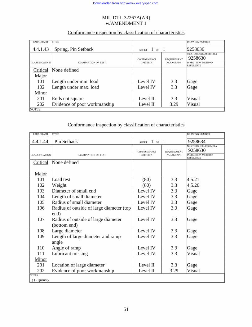
PARAGRAPH TITLE DRAWING NUMBER 4.4.1.43 Spring, Pin Setback SHEET 1 OF 1 9258636
CONFORMANCE
REQUIREMENT
NEXT HIGHER ASSEMBLY
9258630 CLASSIFICATION EXAMINATION OR TEST CRITERIA PARAGRAPH INSPECTION METHOD
REFERENCE
Critical None defined Major 101 Length under min. load Level IV 3.3 Gage 102 Length under max. load Level IV 3.3 Gage
Minor 201 Ends not square Level II 3.3 Visual 202 Evidence of poor workmanship Level II 3.29 Visual
NOTES:
Conformance inspection by classification of characteristics
PARAGRAPH TITLE DRAWING NUMBER
4.4.1.44 Pin Setback SHEET 1 OF 1 9258634
CONFORMANCE
REQUIREMENT
NEXT HIGHER ASSEMBLY
9258630 CLASSIFICATION EXAMINATION OR TEST CRITERIA PARAGRAPH INSPECTION METHOD
REFERENCE
Critical None defined
Major 101 Load test (80) 3.3 4.5.21 102 Weight (80) 3.3 4.5.26 103 Diameter of small end Level IV 3.3 Gage 104 Length of small diameter Level IV 3.3 Gage 105 Radius of small diameter Level IV 3.3 Gage 106 Radius of outside of large diameter (top
end) Level IV 3.3 Gage
107 Radius of outside of large diameter (bottom end)
Level IV 3.3 Gage
108 Large diameter Level IV 3.3 Gage 109 Length of large diameter and ramp
angle Level IV 3.3 Gage
110 Angle of ramp Level IV 3.3 Gage 111 Lubricant missing Level IV 3.3 Visual
Minor 201 Location of large diameter Level II 3.3 Gage 202 Evidence of poor workmanship Level II 3.29 Visual
NOTES:
( ) - Quantity
Downloaded from http://www.everyspec.com
MIL-DTL-32267A(AR) w/AMENDMENT 1
52
Conformance inspection by classification of characteristics
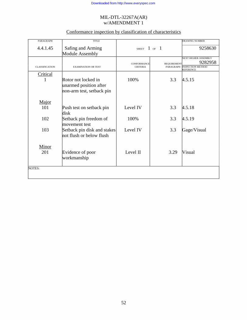
PARAGRAPH TITLE DRAWING NUMBER 4.4.1.45 Safing and Arming
Module Assembly SHEET 1 OF 1 9258630
CONFORMANCE
REQUIREMENT
NEXT HIGHER ASSEMBLY
9282958 CLASSIFICATION EXAMINATION OR TEST CRITERIA PARAGRAPH INSPECTION METHOD
REFERENCE
Critical 1 Rotor not locked in
unarmed position after non-arm test, setback pin
100% 3.3 4.5.15
Major 101 Push test on setback pin
disk Level IV 3.3 4.5.18
102 Setback pin freedom of movement test
100% 3.3 4.5.19
103 Setback pin disk and stakes not flush or below flush
Level IV 3.3 Gage/Visual
Minor 201 Evidence of poor
workmanship Level II 3.29 Visual
NOTES:
Downloaded from http://www.everyspec.com
MIL-DTL-32267A(AR) w/AMENDMENT 1
53
Conformance inspection by classification of characteristics
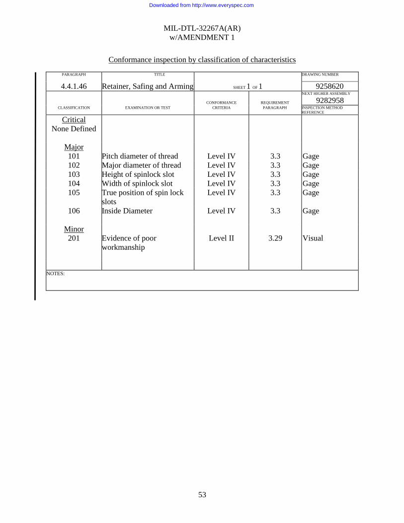
PARAGRAPH TITLE DRAWING NUMBER 4.4.1.46 Retainer, Safing and Arming SHEET 1 OF 1 9258620
CONFORMANCE
REQUIREMENT
NEXT HIGHER ASSEMBLY
9282958 CLASSIFICATION EXAMINATION OR TEST CRITERIA PARAGRAPH INSPECTION METHOD
REFERENCE
Critical None Defined
Major 101 Pitch diameter of thread Level IV 3.3 Gage 102 Major diameter of thread Level IV 3.3 Gage 103 Height of spinlock slot Level IV 3.3 Gage 104 Width of spinlock slot Level IV 3.3 Gage 105 True position of spin lock
slots Level IV 3.3 Gage
106
Inside Diameter Level IV 3.3 Gage
Minor 201 Evidence of poor
workmanship Level II 3.29 Visual
NOTES:
Downloaded from http://www.everyspec.com

MIL-DTL-32267A(AR) w/AMENDMENT 1
54
Conformance inspection by classification of characteristics
PARAGRAPH TITLE DRAWING NUMBER 4.4.1.47 Safing and Arming
Module and Retainer Assembly
SHEET 1 OF 1 9282958
CONFORMANCE
REQUIREMENT
NEXT HIGHER ASSEMBLY
9345331 CLASSIFICATION EXAMINATION OR TEST CRITERIA PARAGRAPH INSPECTION METHOD
REFERENCE
Critical None defined
Major 101 Overall height, max Level IV 3.3 Gage 102 S&A Transportation
vibration test (20) 3.19 4.5.2
Minor 201 Evidence of poor
workmanship Level II 3.29 Visual
NOTES:
Downloaded from http://www.everyspec.com
MIL-DTL-32267A(AR) w/AMENDMENT 1
55
Conformance inspection by classification of characteristics
PARAGRAPH TITLE DRAWING NUMBER 4.4.1.48 Body, Fuze SHEET 1 OF 2 9258609
CONFORMANCE
REQUIREMENT
NEXT HIGHER ASSEMBLY
9294595 CLASSIFICATION EXAMINATION OR TEST CRITERIA PARAGRAPH INSPECTION METHOD
REFERENCE
Critical None defined
Major 101 True position of flash hole
with delay module cavity Level IV 3.3 Gage
102 Diameter of flash hole Level IV 3.3 Gage 103 True position of firing pin
housing and detonator cavity with delay module cavity
Level IV 3.3 Gage
104 Diameter of setting sleeve cavity, max.
Level IV 3.3 Gage
105 Pitch diameter of external thread
Level IV 3.3 Gage
106 Pitch diameter of S&A retainer thread
Level IV 3.3 Gage
107 Minor diameter of S&A retainer thread
Level IV 3.3 Gage
108 Diameter of delay module cavity
Level IV 3.3 Gage
109 Diameter of setting sleeve retaining ring groove
Level IV 3.3 Gage
110 Profile of ogive Level IV 3.3 Gage 111 Length from nose to base of
wrench slot flange Level IV 3.3 Gage
NOTES:
Downloaded from http://www.everyspec.com

MIL-DTL-32267A(AR) w/AMENDMENT 1
56
Conformance inspection by classification of characteristics
PARAGRAPH TITLE DRAWING NUMBER 4.4.1.48 Body, Fuze (continued) SHEET 2 OF 2 9258609
CONFORMANCE
REQUIREMENT
NEXT HIGHER ASSEMBLY
9294595 CLASSIFICATION EXAMINATION OR TEST CRITERIA PARAGRAPH INSPECTION METHOD
REFERENCE
Major 112 Width of wrench slots Level IV 3.3 Gage 113 Outside diameter at base,
max. Level IV 3.3 Gage
114 SQ and/or delay nomenclature missing or improperly located
Level IV 3.3 Gage
115 Length from flange to bottom of nose cap groove
Level IV 3.3 Gage
116 Diameter of nose cap groove Level IV 3.3 Gage 117 Undercut for nose cap Level IV 3.3 Gage
Minor 201 True position of outside
diameter at base with major diameter of external thread
Level II 3.3 Gage
202 Depth of automation wrench hole, max. (as applicable)
Level II 3.3 Gage
203 Distance from base of fuze to base of wrench slot flange, min.
Level II 3.3 Gage
204 Evidence of poor workmanship
Level II 3.29 Visual
NOTES:
Downloaded from http://www.everyspec.com

MIL-DTL-32267A(AR) w/AMENDMENT 1
57
Conformance inspection by classification of characteristics
PARAGRAPH TITLE DRAWING NUMBER 4.4.1.49 Fuze Body and Setting Sleeve
Assembly SHEET 1 OF 1 9294595
CONFORMANCE
REQUIREMENT
NEXT HIGHER ASSEMBLY
9345331 CLASSIFICATION EXAMINATION OR TEST CRITERIA PARAGRAPH INSPECTION METHOD
REFERENCE
Critical None defined
Major 101 Interrupter non-arming test 100% 3.3 4.5.10 102 Interrupter arming test 100% 3.3 4.5.9 103 Setting sleeve assembly torque
test (80) 3.3 4.5.5
104 Setting sleeve retaining ring stake test
(80) 3.3 4.5.6
105 Retaining ring stake missing Level IV 3.3 Visual Minor 201 Evidence of poor workmanship Level II 3.29 Visual
NOTES: ( ) - Quantity
Conformance inspection by classification of characteristics
PARAGRAPH TITLE DRAWING NUMBER 4.4.1.50 Screw, Closing SHEET 1 OF 1 9258611
CONFORMANCE
REQUIREMENT
NEXT HIGHER ASSEMBLY
9345331 CLASSIFICATION EXAMINATION OR TEST CRITERIA PARAGRAPH INSPECTION METHOD
REFERENCE
Critical None defined
Major 101 Pitch diameter of thread Level IV 3.3 Gage 102 Height of undercut, max. Level IV 3.3 Gage
Minor 201 Base thickness Level II 3.3 Gage 202 Evidence of poor workmanship Level II 3.29 Visual
NOTES:
Downloaded from http://www.everyspec.com

MIL-DTL-32267A(AR) w/AMENDMENT 1
58
Conformance inspection by classification of characteristics
PARAGRAPH TITLE DRAWING NUMBER 4.4.1.51 Fuze Body Assembly, prior to
assembling Safing and Arming Module and Retainer Assembly
SHEET 1 OF 1 9345331
CONFORMANCE
REQUIREMENT
NEXT HIGHER ASSEMBLY
9345331 CLASSIFICATION EXAMINATION OR TEST CRITERIA PARAGRAPH
INSPECTION METHOD REFERENCE
Critical 1 S&A module not in the unarmed
position 100% 3.3 Gage 4.5.30
Major 101 Delay module spinlocks not in
unarmed position 100% 3.3 Gage/Visual
102 Delay module missing or inverted 100% 3.3 Gage/Visual 103 Step height between body and
nose cap and completeness of crimp
Level IV 3.3 Gage/Visual
104 Safety plug(when used) not removed
100% 3.3 Visual
Minor 201 Evidence of poor workmanship Level II 3.29 Visual
NOTES:
Downloaded from http://www.everyspec.com

MIL-DTL-32267A(AR) w/AMENDMENT 1
59
Conformance inspection by classification of characteristics
PARAGRAPH TITLE DRAWING NUMBER 4.4.1.52 Fuze Body Assembly SHEET 1 OF 1 9345331
CONFORMANCE
REQUIREMENT
NEXT HIGHER ASSEMBLY
9345332 CLASSIFICATION EXAMINATION OR TEST CRITERIA PARAGRAPH INSPECTION METHOD
REFERENCE
Critical 1 Dimension from external
flange to bottom of S&A module retainer
100% 3.3 Gage
Major 101 Dimension from external
flange to bottom of closing screw
Level IV 3.3 Gage
102 Leak test (48) note 1
3.3 4.5.8 or 4.5.8.1
103 Length from tip of nose cap to flange, max.
Level IV 3.3 Gage
104 Fuze not set super quick Level IV 3.3 Visual
Minor 201 Lot identification
nomenclature missing or inadequate
Level II 3.4 Visual
202 Evidence of poor workmanship
Level II 3.29 Visual
NOTES: ( ) - Quantity Note 1 - Leak test is for first article verification only
Downloaded from http://www.everyspec.com

MIL-DTL-32267A(AR) w/AMENDMENT 1
60
Conformance inspection by classification of characteristics
PARAGRAPH TITLE DRAWING NUMBER 4.4.1.53 Fuze, PD, M739A1.
Destructive Test SHEET 1 OF 2 9345332
CONFORMANCE
REQUIREMENT
NEXT HIGHER ASSEMBLY
CLASSIFICATION EXAMINATION OR TEST CRITERIA PARAGRAPH INSPECTION METHOD REFERENCE
Critical
1 Premature Burst note 1 3.11 4.2.3.5 or 4.3.4.1 2 Non-functioning test note 2 3.13 4.2.3.5 or 4.3.4.1 3 S&A not in safe
condition note 1 3.3 4.5.35
Major 101 Initiation of M99
detonator during Jolt and Jumble Test
(9)
3.18 4.5.1
102 Delay module armed or functioned during jolt and jumble test
(9)
3.18 4.5.1
103 Setting sleeve assembly interrupter not fully seated after jolt and Jumble test
(9)
3.18 4.5.1
104 Functioning SQ note 2 3.14 4.2.3.5 or 4.3.4.1 105 Reverse Functioning note 2 3.14 4.2.3.5 or 4.3.4.1 106 Early burst note 1 3.12 4.2.3.5 or 4.3.4.1
NOTES: ( ) – Quantity. Note 1 - 100% of ballistic samples. Note 2 - See Table II and Table III
Downloaded from http://www.everyspec.com
MIL-DTL-32267A(AR) w/AMENDMENT 1
61
Conformance inspection by classification of characteristics
PARAGRAPH TITLE DRAWING NUMBER 4.4.1.53 Fuze, PD, M739A1.
Destructive Test SHEET 2 OF 2 9345332
CONFORMANCE
REQUIREMENT
NEXT HIGHER ASSEMBLY
CLASSIFICATION EXAMINATION OR TEST CRITERIA PARAGRAPH INSPECTION METHOD
REFERENCE
Major 107 Functioning delay Note 2 3.15 4.2.3.5 or 4.3.4.1 108 Propagation Test
functioning (50) 3.7 4.5.17
109 Parts damaged, broken or disassembled during Jolt and Jumble
(9)
3.29 4.5.1
110 Examination for proper application of sealant and lubrication after Jolt and Jumble test
(9)
3.29 4.5.1
111 Parts damaged Note 1 3.29 Visual
Minor 201 Lot identification
nomenclature missing or inadequate
Level II 3.4 Visual
202 Evidence of poor workmanship
Level II 3.29 Visual
NOTES: ( ) – Quantity. Note 1 - 100% of ballistic samples. Note 2 - See Table II and Table III
Downloaded from http://www.everyspec.com

MIL-DTL-32267A(AR) w/AMENDMENT 1
62
Conformance inspection by classification of characteristics
PARAGRAPH TITLE DRAWING NUMBER 4.4.1.54 Cap, Nose SHEET 1 OF 1 9298909
CONFORMANCE
REQUIREMENT
NEXT HIGHER ASSEMBLY
9345331 CLASSIFICATION EXAMINATION OR TEST CRITERIA PARAGRAPH INSPECTION METHOD
REFERENCE
Critical None defined
Major 101 Presence of scoring (4 places) Level IV 3.3 Visual 102 Thickness Level IV 3.3 Gage
Minor 201 Evidence of poor workmanship Level II 3.29 Visual
NOTES:
Conformance inspection by classification of characteristics
PARAGRAPH TITLE DRAWING NUMBER 4.4.1.55 Fuze Body Assembly, prior to
assembling Nose Cap SHEET 1 OF 1 9345331
CONFORMANCE
REQUIREMENT
NEXT HIGHER ASSEMBLY
CLASSIFICATION EXAMINATION OR TEST CRITERIA PARAGRAPH INSPECTION METHOD
REFERENCE
Critical None defined
Major 101 Firing pin and detonator assembly
missing or inverted 100% 3.3 Gage
102 One or more crossbar (s) missing Level IV 3.3 Gage 103 Crossbar holder assembly stake
missing Level IV 3.3 Visual
Minor 201 Evidence of poor workmanship Level II 3.29 Visual
NOTES:
Downloaded from http://www.everyspec.com
MIL-DTL-32267A(AR) w/AMENDMENT 1
63
Conformance inspection by classification of characteristics
PARAGRAPH TITLE DRAWING NUMBER 4.4.1.56 Cover, Housing SHEET 1 OF 1 11836288
CONFORMANCE
REQUIREMENT
NEXT HIGHER ASSEMBLY
11836270 CLASSIFICATION EXAMINATION OR TEST CRITERIA PARAGRAPH INSPECTION METHOD
REFERENCE
Critical None defined
Major 101 Diameter of center hole,
min note 1 3.3 Gage
102 True position of center hole note 1 3.3 Gage 103 Outside diameter, max note 1 3.3 Gage
Minor 201 Evidence of poor
workmanship note 1 3.29 Visual
NOTES: Note 1 Five (5) parts per punch per day see (4.5.7 & 4.5.24)
Conformance inspection by classification of characteristics
PARAGRAPH TITLE DRAWING NUMBER 4.4.1.57 Spring, Plunger SHEET 1 OF 1 11836287
CONFORMANCE
REQUIREMENT
NEXT HIGHER ASSEMBLY
11836270 CLASSIFICATION EXAMINATION OR TEST CRITERIA PARAGRAPH INSPECTION METHOD
REFERENCE
Critical None defined
Major 101 Load P1 or P2 does not comply with
drawing requirements Level IV 3.3 Gage
102 Does not work freely in a dia. bore at an installed height
Level IV 3.3 Gage
103 Does not work freely over a dia. rod at an installed height
Level IV 3.3 Gage
Minor 201 Solid height, max Level II 3.3 Gage 202 Evidence of poor workmanship Level II 3.29 Visual
NOTES:
Downloaded from http://www.everyspec.com

MIL-DTL-32267A(AR) w/AMENDMENT 1
64
Conformance inspection by classification of characteristics
PARAGRAPH TITLE DRAWING NUMBER 4.4.1.58 Housing SHEET 1 OF 1 11836286
CONFORMANCE
REQUIREMENT
NEXT HIGHER ASSEMBLY
11836270 CLASSIFICATION EXAMINATION OR TEST CRITERIA PARAGRAPH INSPECTION METHOD
REFERENCE
Critical None defined
Major 101 Diameter of center hole, min note 1 3.3 Gage 102 Location of center hole note 1 3.3 Gage 103 Inside diameter, min note 1 3.3 Gage 104 Outside diameter, min. note 1 3.3 Gage 105 Inside length note 1 3.3 Gage
Minor 201 Evidence of poor
workmanship Level II 3.29 Visual
NOTES: 1. Five parts per punch per day see (4.5.7 & 4.5.24)
Conformance inspection by classification of characteristics
PARAGRAPH TITLE DRAWING NUMBER 4.4.1.59 Retainer, Slider Spring SHEET 1 OF 1 11836285
CONFORMANCE
REQUIREMENT
NEXT HIGHER ASSEMBLY
11836278 CLASSIFICATION EXAMINATION OR TEST CRITERIA PARAGRAPH INSPECTION METHOD
REFERENCE
Critical None defined
Major None defined
Minor 201 Presence of slots Level II 3.3 Visual 202 Outside diameter Level II 3.3 Gage 203 Evidence of poor workmanship Level II 3.29 Visual
NOTES:
Downloaded from http://www.everyspec.com

MIL-DTL-32267A(AR) w/AMENDMENT 1
65
Conformance inspection by classification of characteristics
PARAGRAPH TITLE DRAWING NUMBER 4.4.1.60 Spring, Slider SHEET 1 OF 1 11836284
CONFORMANCE
REQUIREMENT
NEXT HIGHER ASSEMBLY
11836278 CLASSIFICATION EXAMINATION OR TEST CRITERIA PARAGRAPH INSPECTION METHOD
REFERENCE
Critical None defined
Major 101 Load P1 or P2 does not comply
with drawing requirements Level IV 3.3 Gage
102 Does not work freely in a diameter bore at an installed height
Level IV 3.3 Gage
103 Does not work freely over a diameter rod at an installed height
Level IV 3.3 Gage
Minor 201 Solid height, max. Level II 3.3 Gage 202 Evidence of poor workmanship Level II 3.29 Visual
NOTES:
Conformance inspection by classification of characteristics
PARAGRAPH TITLE DRAWING NUMBER 4.4.1.61 Spring, Firing Pin SHEET 1 OF 1 11836283
CONFORMANCE
REQUIREMENT
NEXT HIGHER ASSEMBLY
11836278 CLASSIFICATION EXAMINATION OR TEST CRITERIA PARAGRAPH INSPECTION METHOD
REFERENCE
Critical None defined
Major 101 Load P1 or P2 does not
comply with drawing requirements.
Level IV 3.3 Gage
102 Does not work freely in a diameter bore at an installed height.
Level IV 3.3 Gage
Minor 201 Solid height, max. Level II 3.3 Gage 202 Evidence of poor
workmanship Level II 3.29 Visual
NOTES:
Downloaded from http://www.everyspec.com
MIL-DTL-32267A(AR) w/AMENDMENT 1
66
Conformance inspection by classification of characteristics
PARAGRAPH TITLE DRAWING NUMBER 4.4.1.62 Slider SHEET 1 OF 1 11836282
CONFORMANCE
REQUIREMENT
NEXT HIGHER ASSEMBLY
11836278 CLASSIFICATION EXAMINATION OR TEST CRITERIA PARAGRAPH INSPECTION METHOD
REFERENCE
Critical None defined
Major 101 Outside diameter of spring mating
surface, max. Level IV 3.3 Gage
102 Inside diameter, min Level IV 3.3 Gage 103 Inside diameter (ball locking),
min. Level IV 3.3 Gage
104 Length of undercut, min. (12) note 1
3.3 Gage
105 Length of locking surface, min (12) note 1
3.3 Gage
106 Length to slider ball mating surface
Level IV 3.3 Gage
Minor 201 Outside diameter, max. Level II 3.3 Gage 202 Evidence of poor workmanship Level II 3.29 Visual
NOTES: ( ) - Quantity Note 1 Destructive testing. Reject the lot if one or more defects in the sample.
Downloaded from http://www.everyspec.com

MIL-DTL-32267A(AR) w/AMENDMENT 1
67
Conformance inspection by classification of characteristics
PARAGRAPH TITLE DRAWING NUMBER 4.4.1.63 Pin, Firing SHEET 1 OF 1 11836281
CONFORMANCE
REQUIREMENT
NEXT HIGHER ASSEMBLY
11836278 CLASSIFICATION EXAMINATION OR TEST CRITERIA PARAGRAPH INSPECTION METHOD
REFERENCE
Critical None defined
Major 101 Width of tip, max Level IV 3.3 Gage 102 Depth of cavity, min Level IV 3.3 Gage 103 Location of notch Level IV 3.3 Gage 104 Diameter of notch, max Level IV 3.3 Gage 105 Outside diameter, max Level IV 3.3 Gage 106 Diameter of cavity, min Level IV 3.3 Gage
Minor 201 Profile of point Level II 3.3 Gage 202 Evidence of poor workmanship Level II 3.29 Visual
NOTES:
Downloaded from http://www.everyspec.com
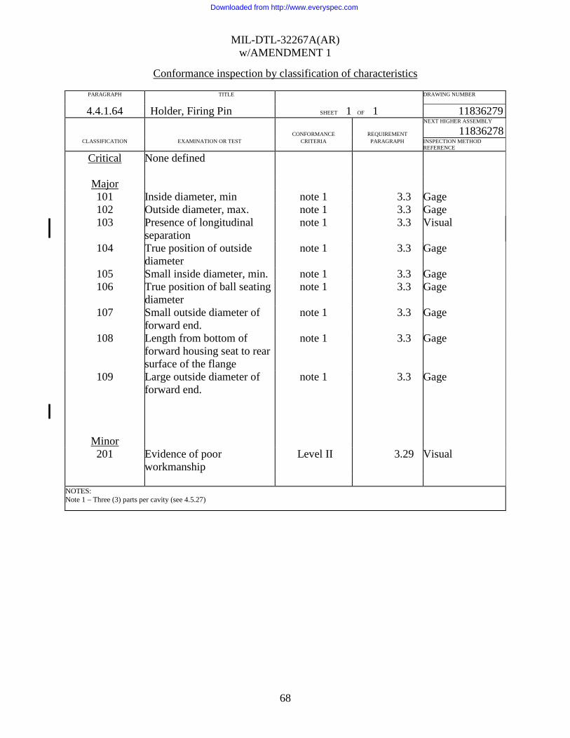
MIL-DTL-32267A(AR) w/AMENDMENT 1
68
Conformance inspection by classification of characteristics
PARAGRAPH TITLE DRAWING NUMBER 4.4.1.64 Holder, Firing Pin SHEET 1 OF 1 11836279
CONFORMANCE
REQUIREMENT
NEXT HIGHER ASSEMBLY
11836278 CLASSIFICATION EXAMINATION OR TEST CRITERIA PARAGRAPH INSPECTION METHOD
REFERENCE
Critical None defined
Major 101 Inside diameter, min note 1 3.3 Gage 102 Outside diameter, max. note 1 3.3 Gage 103 Presence of longitudinal
separation note 1 3.3 Visual
104 True position of outside diameter
note 1 3.3 Gage
105 Small inside diameter, min. note 1 3.3 Gage 106 True position of ball seating
diameter note 1 3.3 Gage
107 Small outside diameter of forward end.
note 1 3.3 Gage
108 Length from bottom of forward housing seat to rear surface of the flange
note 1 3.3 Gage
109 Large outside diameter of forward end.
note 1 3.3 Gage
Minor
201 Evidence of poor workmanship
Level II 3.29 Visual
NOTES: Note 1 – Three (3) parts per cavity (see 4.5.27)
Downloaded from http://www.everyspec.com

MIL-DTL-32267A(AR) w/AMENDMENT 1
69
Conformance inspection by classification of characteristics
PARAGRAPH TITLE DRAWING NUMBER 4.4.1.65 Firing Pin Holder Assembly SHEET 1 OF 1 11836278
CONFORMANCE
REQUIREMENT
NEXT HIGHER ASSEMBLY
11836270 CLASSIFICATION EXAMINATION OR TEST CRITERIA PARAGRAPH INSPECTION METHOD
REFERENCE
Critical None defined
Major 101 Push off force does not
withstand 5 lbs (5) 3.3 4.5.29.2
102 Missing firing pin Level IV 3.3 Visual 103 Either ball missing Level IV 3.3 Visual
Minor 201 Evidence of poor
workmanship Level II 3.3 Visual
NOTES: ( ) Denotes sample size.
Conformance inspection by classification of characteristics
PARAGRAPH TITLE DRAWING NUMBER 4.4.1.66 Pin, Pivot SHEET 1 OF 1 11836277
CONFORMANCE
REQUIREMENT
NEXT HIGHER ASSEMBLY
11836271 CLASSIFICATION EXAMINATION OR TEST CRITERIA PARAGRAPH INSPECTION METHOD
REFERENCE
Critical None defined
Major 101 Outside diameter, max. Level IV 3.3 Gage
Minor 201 Overall length, max. Level II 3.3 Gage 202 Evidence of poor workmanship Level II 3.29 Visual
NOTES:
Downloaded from http://www.everyspec.com
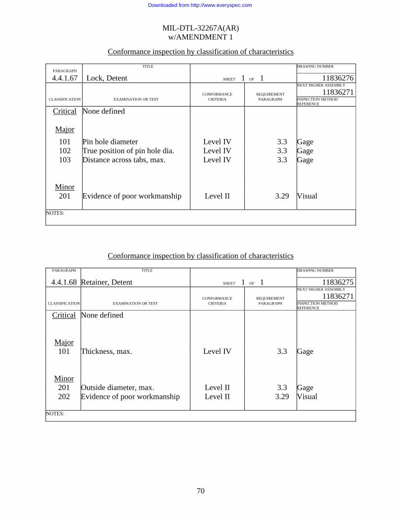
MIL-DTL-32267A(AR) w/AMENDMENT 1
70
Conformance inspection by classification of characteristics
PARAGRAPH
TITLE DRAWING NUMBER 4.4.1.67 Lock, Detent SHEET 1 OF 1 11836276
CONFORMANCE
REQUIREMENT
NEXT HIGHER ASSEMBLY
11836271 CLASSIFICATION EXAMINATION OR TEST CRITERIA PARAGRAPH INSPECTION METHOD
REFERENCE
Critical None defined
Major 101 Pin hole diameter Level IV 3.3 Gage 102 True position of pin hole dia. Level IV 3.3 Gage 103 Distance across tabs, max. Level IV 3.3 Gage
Minor 201 Evidence of poor workmanship Level II 3.29 Visual
NOTES:
Conformance inspection by classification of characteristics
PARAGRAPH TITLE DRAWING NUMBER 4.4.1.68 Retainer, Detent SHEET 1 OF 1 11836275
CONFORMANCE
REQUIREMENT
NEXT HIGHER ASSEMBLY
11836271 CLASSIFICATION EXAMINATION OR TEST CRITERIA PARAGRAPH INSPECTION METHOD
REFERENCE
Critical None defined
Major 101 Thickness, max. Level IV 3.3 Gage
Minor 201 Outside diameter, max. Level II 3.3 Gage 202 Evidence of poor workmanship Level II 3.29 Visual
NOTES:
Downloaded from http://www.everyspec.com

MIL-DTL-32267A(AR) w/AMENDMENT 1
71
Conformance inspection by classification of characteristics
PARAGRAPH TITLE DRAWING NUMBER 4.4.1.69 Spring Detents SHEET 1 OF 1 11836274
CONFORMANCE
REQUIREMENT
NEXT HIGHER ASSEMBLY
11836271 CLASSIFICATION EXAMINATION OR TEST CRITERIA PARAGRAPH INSPECTION METHOD
REFERENCE
Critical None defined
Major 101 Load P1 or P2 does not comply
with drawing requirements Level IV 3.3 Gage
102 Does not work freely in diameter bore at an installed height.
Level IV 3.3 Gage
103 Does not work freely over a diameter rod at installed height.
Level IV 3.3 Gage
Minor 201 Solid height, max. Level II 3.3 Gage 202 Evidence of poor workmanship Level II 3.29 Visual
NOTES:
Conformance inspection by classification of characteristics
PARAGRAPH TITLE DRAWING NUMBER 4.4.1.70 Detent, Spin SHEET 1 OF 1 11836273
CONFORMANCE
REQUIREMENT
NEXT HIGHER ASSEMBLY
11836271 CLASSIFICATION EXAMINATION OR TEST CRITERIA PARAGRAPH INSPECTION METHOD
REFERENCE
Critical None defined
Major 101 Diameter of spring cavity,
minimum Level IV 3.3 Gage
102 Overall length Level IV 3.3 Gage 103 Diameter of mating surface
for firing pin holder Level IV 3.3 Gage
104 Height maximum from inside of spring cavity.
Level IV 3.3 Gage
105 Large outside diameter Level IV 3.3 Gage Minor 201 Evidence of poor
workmanship Level II 3.29 Visual
NOTES:
Downloaded from http://www.everyspec.com
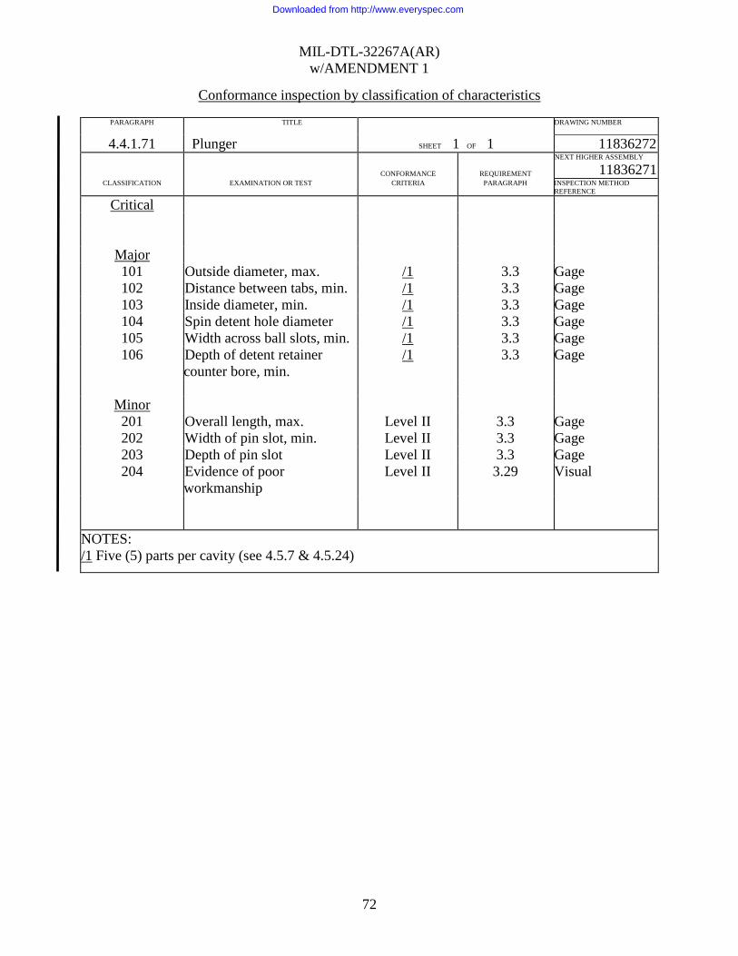
MIL-DTL-32267A(AR) w/AMENDMENT 1
72
Conformance inspection by classification of characteristics
PARAGRAPH TITLE DRAWING NUMBER 4.4.1.71 Plunger SHEET 1 OF 1 11836272
CONFORMANCE
REQUIREMENT
NEXT HIGHER ASSEMBLY
11836271 CLASSIFICATION EXAMINATION OR TEST CRITERIA PARAGRAPH INSPECTION METHOD
REFERENCE
Critical
Major 101 Outside diameter, max. /1 3.3 Gage 102 Distance between tabs, min. /1 3.3 Gage 103 Inside diameter, min. /1 3.3 Gage 104 Spin detent hole diameter /1 3.3 Gage 105 Width across ball slots, min. /1 3.3 Gage 106 Depth of detent retainer
counter bore, min. /1 3.3 Gage
Minor 201 Overall length, max. Level II 3.3 Gage 202 Width of pin slot, min. Level II 3.3 Gage 203 Depth of pin slot Level II 3.3 Gage 204 Evidence of poor
workmanship Level II 3.29 Visual
NOTES: /1 Five (5) parts per cavity (see 4.5.7 & 4.5.24)
Downloaded from http://www.everyspec.com

MIL-DTL-32267A(AR) w/AMENDMENT 1
73
Conformance inspection by classification of characteristics
PARAGRAPH TITLE DRAWING NUMBER 4.4.1.72 Plunger Assembly SHEET 1 OF 1 11836271
CONFORMANCE
REQUIREMENT
NEXT HIGHER ASSEMBLY
11836270 CLASSIFICATION EXAMINATION OR TEST CRITERIA PARAGRAPH INSPECTION METHOD
REFERENCE
Critical None defined
Major 101 Pin fails to withstand pullout force (5) 3.3 4.5.29.2 102 Detent retainer fails to withstand
push out force (5) 3.3 4.5.29.2
Minor 201 Evidence of poor workmanship Level II 3.29 Visual
NOTES: ( ) - Quantity
Conformance inspection by classification of characteristics
PARAGRAPH TITLE DRAWING NUMBER 4.4.1.73 Delay Module, Impact SHEET 1 OF 1 11836270
CONFORMANCE
REQUIREMENT
NEXT HIGHER ASSEMBLY
9345331 CLASSIFICATION EXAMINATION OR TEST CRITERIA PARAGRAPH INSPECTION METHOD
REFERENCE
Critical None defined
Major 101 Height of protrusion, max. Level IV 3.3 Gage 102 Outside diameter, max Level IV 3.3 Gage 103 Height from top of housing to the
bottom housing cover, max. Level IV 3.3 Gage
104 Non-arming test 100% note 1 3.3 4.5.29.1 105 Arming test 100% note 1 3.3 4 .5.29.3 106 Drop test Level IV 3.3 4.5.29.4 107 Cover fails to withstand push out force. (5) 3.3 4.5.29.2
Minor 201 Evidence of poor workmanship Level II 3.29 Visual
NOTES: ( ) - Quantity Note 1 Arming shall be performed before non-arming.
Downloaded from http://www.everyspec.com
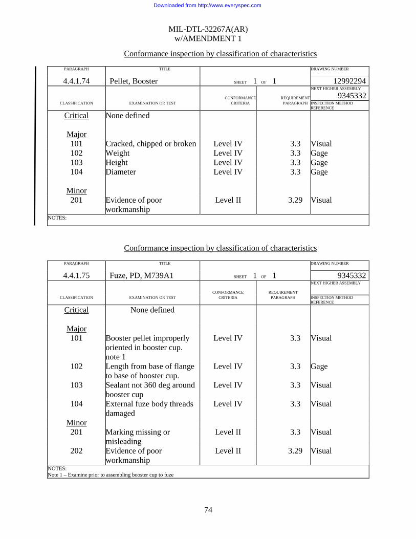
MIL-DTL-32267A(AR) w/AMENDMENT 1
74
Conformance inspection by classification of characteristics
PARAGRAPH TITLE DRAWING NUMBER 4.4.1.74 Pellet, Booster SHEET 1 OF 1 12992294
CONFORMANCE
REQUIREMENT
NEXT HIGHER ASSEMBLY
9345332 CLASSIFICATION EXAMINATION OR TEST CRITERIA PARAGRAPH INSPECTION METHOD
REFERENCE
Critical None defined
Major 101 Cracked, chipped or broken Level IV 3.3 Visual 102 Weight Level IV 3.3 Gage 103 Height Level IV 3.3 Gage 104 Diameter Level IV 3.3 Gage
Minor 201 Evidence of poor
workmanship Level II 3.29 Visual
NOTES:
Conformance inspection by classification of characteristics
PARAGRAPH TITLE DRAWING NUMBER 4.4.1.75 Fuze, PD, M739A1 SHEET 1 OF 1 9345332
CONFORMANCE
REQUIREMENT
NEXT HIGHER ASSEMBLY
CLASSIFICATION EXAMINATION OR TEST CRITERIA PARAGRAPH INSPECTION METHOD
REFERENCE
Critical None defined
Major 101 Booster pellet improperly
oriented in booster cup. note 1
Level IV 3.3 Visual
102 Length from base of flange to base of booster cup.
Level IV 3.3 Gage
103 Sealant not 360 deg around booster cup
Level IV 3.3 Visual
104 External fuze body threads damaged
Level IV 3.3 Visual
Minor 201 Marking missing or
misleading Level II 3.3 Visual
202 Evidence of poor workmanship
Level II 3.29 Visual
NOTES: Note 1 – Examine prior to assembling booster cup to fuze
Downloaded from http://www.everyspec.com

MIL-DTL-32267A(AR) w/AMENDMENT 1
75
Conformance inspection by classification of characteristics
PARAGRAPH TITLE DRAWING NUMBER 4.4.1.76 Disc, Lead SHEET 1 OF 1 9255167
CONFORMANCE
REQUIREMENT
NEXT HIGHER ASSEMBLY
12992295 CLASSIFICATION EXAMINATION OR TEST CRITERIA PARAGRAPH INSPECTION METHOD
REFERENCE
Critical None defined
Major 101 Thickness Level IV 3.3 Gage 102 Diameter, minimum Level IV 3.3 Gage
Minor 201 Evidence of poor workmanship Level II 3.29 Visual
NOTES:
Conformance inspection by classification of characteristics
PARAGRAPH TITLE DRAWING NUMBER
4.4.1.77 Lead, Explosive SHEET 1 OF 1 12992295
CONFORMANCE
REQUIREMENT
NEXT HIGHER ASSEMBLY
9294833 CLASSIFICATION EXAMINATION OR TEST CRITERIA PARAGRAPH INSPECTION METHOD
REFERENCE
Critical 1 Cracks or splits /1 3.3 Visual
Major 101 Weight of Composition Level IV 3.3 Gage 102 Identification missing or
color incorrect Level IV 3.3 Visual
103 Assembly distorted or damaged to the extent that functioning may be improper
Level IV 3.3 Visual
104 Diameter maximum Level IV 3.3 Gage 105 Overall length, max. Level IV 3.3 Gage
Minor 201 Evidence of poor
workmanship Level II 3.29 Visual
NOTES: /1 Conformance inspection of any of the critical defects listed above shall apply 100% plus VL-VII sampling to verify the performance of the screening operation in accordance with MIL-STD-1916.
Downloaded from http://www.everyspec.com

MIL-DTL-32267A(AR) w/AMENDMENT 1
76
Conformance inspection by classification of characteristics
PARAGRAPH TITLE DRAWING NUMBER 4.4.1.78 Lead Explosive
(Prior to disc ass’y) SHEET 1 OF 1 12992295
CONFORMANCE
REQUIREMENT
NEXT HIGHER ASSEMBLY
9294833 CLASSIFICATION EXAMINATION OR TEST CRITERIA PARAGRAPH INSPECTION METHOD
REFERENCE
Critical None defined
Major 101 Density of explosive in lead cup /1 3.3 4.5.32
Minor 201 Evidence of poor workmanship Level II 3.29 Visual
NOTES: /1 Sample production at a rate of 5 every 4 hours as described in paragraph 4.5.32. This paragraph applies only when alternative method of loading is used (see drawing 12992295).
Conformance inspection by classification of characteristics
PARAGRAPH TITLE DRAWING NUMBER
4.4.1.79 Lead Assembly, destructive lot acceptance test
SHEET 1 OF 1 12992295
CONFORMANCE
REQUIREMENT
NEXT HIGHER ASSEMBLY
9294833 CLASSIFICATION EXAMINATION OR TEST CRITERIA PARAGRAPH INSPECTION METHOD
REFERENCE
Critical None defined
Major 101 Output test (150) 3.8 4.5.31
NOTES: ( ) Denotes sample size.
Downloaded from http://www.everyspec.com

MIL-DTL-32267A(AR) w/AMENDMENT 1
77
Conformance inspection by classification of characteristics
PARAGRAPH TITLE DRAWING NUMBER 4.4.1.80 Cup, Lead
SHEET 1 OF 1 9255166
CONFORMANCE
REQUIREMENT
NEXT HIGHER ASSEMBLY
9255165 CLASSIFICATION EXAMINATION OR TEST CRITERIA PARAGRAPH INSPECTION METHOD
REFERENCE
Critical None defined
Major 101 102 103
Thickness of bottom of cup Length Inside diameter
Level IV Level IV Level IV
3.3 3.3 3.3
Gage Gage Gage
Minor 201 Evidence of poor workmanship Level II 3.29 Visual
NOTES:
Conformance inspection by classification of characteristics
PARAGRAPH TITLE DRAWING NUMBER 4.4.1.81 Box, Set-up, Packing,
Ammunition, Inner
SHEET 1 OF 1 7548104
CONFORMANCE
REQUIREMENT
NEXT HIGHER ASSEMBLY
7548103 CLASSIFICATION EXAMINATION OR TEST CRITERIA PARAGRAPH INSPECTION METHOD
REFERENCE
Critical None defined
Major 101 102
Box damaged exposing contents Label missing or incorrect
Level IV Level IV
3.3 3.3
Visual Visual
Minor 201 Evidence of poor workmanship Level II 3.29 Visual
NOTES:
Downloaded from http://www.everyspec.com

MIL-DTL-32267A(AR) w/AMENDMENT 1
78
Conformance inspection by classification of characteristics
PARAGRAPH TITLE DRAWING NUMBER 4.4.1.82 Box, Set-up, Marking,
Ammunition, Outer
SHEET 1 OF 1 7548103
CONFORMANCE
REQUIREMENT
NEXT HIGHER ASSEMBLY
7548099 CLASSIFICATION EXAMINATION OR TEST CRITERIA PARAGRAPH INSPECTION METHOD
REFERENCE
Critical None defined
Major 101 Barrier bag damaged Level IV 3.3 Visual 102 Label missing or incorrect Level IV 3.3 Visual
Minor 201 Evidence of poor workmanship Level II 3.29 Visual
NOTES:
Conformance inspection by classification of characteristics
PARAGRAPH TITLE DRAWING NUMBER 4.4.1.83 Box, Packing, Ammunition
SHEET 1 OF 1 7548099
CONFORMANCE
REQUIREMENT
NEXT HIGHER ASSEMBLY
CLASSIFICATION EXAMINATION OR TEST CRITERIA PARAGRAPH INSPECTION METHOD
REFERENCE
Critical None defined
Major 101 102
Box damaged exposing contents Label missing or incorrect
Level IV Level IV
3.3 3.3
Visual Visual
103 Strap missing or loose Level IV 3.3 Visual 104 Marking incomplete, misleading or
unidentifiable Level IV 3.3 Visual
Minor 201 Evidence of poor workmanship Level II 3.29 Visual
NOTES:
Downloaded from http://www.everyspec.com

MIL-DTL-32267A(AR) w/AMENDMENT 1
79
4.5 Methods of inspection. 4.5.1 Jolt and jumble test. The S&A with test vehicle assemblies or retainers, as well as the loaded fuze assemblies with inert boosters and booster cups, shall be subjected to the jolt test as specified in MIL-STD-331, Test A1. After completion of the jolt test, the fuze shall not be disassembled, but shall be radiographically inspected in two planes to determine the proper safe condition of the setback pin, rotor, interrupter and firing pin assemblies and then shall be subjected to the jumble test in accordance with MIL-STD-331, Test A2.1. At the conclusion of the Jumble Test, the fuzes shall be x-rayed to assure safe disassembly. The fuzes shall then be disassembled to determine compliance with the requirements of the test. As a minimum inspection requirement for Critical Defects, no S&A explosive element shall be initiated nor shall any S&A be in the armed or partially armed condition. The partially armed condition of the S&A is the condition where the rotor is not locked by both spin locks and setback pin. As a minimum inspection for Major defects, examine the fuze internally for migration of sealant past the area of application and examine the S&A internally for flaking of Emralon as an indication of excessive application. As a minimum inspection requirement for the Impact Delay Module, the firing pin shall be in the safe position and the spin detents shall be in the un-armed position. 4.5.2 Transportation vibration test. The S&A with test vehicle assemblies or retainers, as well as loaded fuze assemblies with inert boosters, shall be subjected to the transportation vibration test in accordance with MIL-STD-331, Test No. B1.1, Section B1.6.3.2, Procedure II. 4.5.3 Firing pin/assembly pull test. The firing pin (dwg. 9333937) or firing pin assembly (dwg. 9258618), whichever is applicable, shall be assembled to an applicable test fixture and an axial pull load of 80 pounds shall be applied to the firing pin shaft. If two or more firing pin shafts, during the testing of the firing pin assemblies (9258618), come loose or separate, the lot of firing pin assemblies shall be rejected. If two or more firing pins (9333937), show evidence of deformation, i.e., the final over-all length exceeds the drawing requirement, the lot of firing pins shall be rejected. Any item subjected to the pull test shall not be returned to the lot. 4.5.4 Support, firing pin, load test. The firing pin support shall be assembled to an applicable test fixture and the required load shall be applied in an axial direction at a uniform rate. The results of the test shall be recorded to determine compliance with the requirements. If one or more parts fail to meet the requirements of the 100-pound load test, the lot shall be rejected. If two or more parts fail to meet the requirements of the 140-pound test, the lot shall be rejected. Parts subjected to this test shall not be returned to the lot. 4.5.5 Setting sleeve assembly torque test. The torque required to rotate the setting sleeve assembly shall be applied to the screw driver slot in the setting sleeve while holding the fuze body in such a manner as to avoid damage. If two or more assemblies fail to meet the requirements of the test, the lot shall be rejected. Assemblies subjected to this test may be returned to the lot. 4.5.6 Setting sleeve retaining ring stake test. The torque shall be applied to the screwdriver slot while holding the fuze body in such a manner as to avoid damage. Starting with the sleeve set in the SQ position apply a 10-in. lb. torque in the clockwise direction and inspect
Downloaded from http://www.everyspec.com
MIL-DTL-32267A(AR) w/AMENDMENT 1
80
visually for ring movement when the sleeve rotates to the Delay retaining ring stop. Then apply the 10-in. lb. torque in a counterclockwise direction and inspect visually for ring movement when the sleeve rotates to the SQ retaining ring stop. If any rotation of the retaining ring is observed, in either SQ or Delay position, check the flash hole opening of the slot. If it is less than 0.120 inches diameter, when the sleeve is against the SQ stop, the assembly shall be classed defective. If two or more defectives are found, the lot shall be rejected. Assemblies subjected to this test may be returned to the lot. 4.5.7 Dimensional control of stamped parts. As a control of the punch during production, five (5) parts from each punch shall be selected for inspection. The five parts are to be selected from the end of the day’s production. As a control of each punch for production, the parts shall be inspected to the requirements listed on the applicable Classification of Defects . If any defective parts are found when inspection is performed for control of the tool, the tool producing the defective part shall be removed from production. Further, that portion of production since the last tool check shall be rejected. 4.5.8 Leak test. The test shall be performed in accordance with the procedure specified in MIL-STD-331, Test No. C4, except as provided in 3.20. When immersing the test assemblies in the water solution, care should be taken to displace all externally entrapped air. The test assemblies should be submerged in a horizontal position for testing. After completion of the test and drying of the samples, the assemblies shall be sectioned to reveal all cavities internal to the various seals. Examine all external and internal surfaces of parts for evidence of water entry using ultra-violet light. Any assembly that does not comply with the requirements of 3.20 shall be classed defective. The accept/reject criteria shall be in accordance with paragraph 4.2.4.2.1.3. Fuzes subject to the test in 4.5.8 are sectioned for evaluation. 4.5.8.1 Alternative leak test. The following optional method may be used to perform the water proofness test required by 3.20. This method required pressurizing the test assemblies in air prior to submersion in water and does not require the use of any additive to the water. In an approved test apparatus, pressurize the test assemblies in air at 3 + 0.5 psi for 5 + 0.5 minutes. Then lower the assemblies into water while maintaining the required air pressure above the water. The assemblies, in a horizontal orientation, shall be agitated while submerged to remove surface-entrapped air. After the assemblies have been agitated and there is a minimum of 3 inches of water above the assemblies (remaining in horizontal orientation), release the air pressure above the water and observe the test assemblies for the presence of bubbles for a minimum of 30 seconds. Any assembly with a continuous stream of bubbles in excess of one bubble per second shall be classed defective. The accept/reject criteria shall be in accordance with paragraph 4.2.4.2.1.3. Assemblies which pass this test may also be used to satisfy the sample requirements for Jolt and Jumble testing (see 4.5.1) or for Propagation testing (see 4.5.17). 4.5.9 Interrupter arming test. The unarmed assembly shall be subjected to this test by approved equipment. The setting sleeve shall be rotated at 1700 revolutions per minute (RPM’s) maximum. Any assembly which has a flash hole opening of less than 0.078 inch shall be rejected and removed from the lot.
Downloaded from http://www.everyspec.com

MIL-DTL-32267A(AR) w/AMENDMENT 1
81
4.5.10 Interrupter non-arming test. The unarmed assembly shall be subjected to this test by approved equipment. The setting sleeve shall be rotated until it comes to rest against the SQ stop. The assemblies shall be rotated at 1100 RPM’s minimum. Any assembly which has greater than .005 inch gap between the flash hole and the interrupter shall be rejected and removed from the lot. 4.5.11 Push test of detonator in rotor assembly. The rotor assembly shall be assembled to an applicable test fixture and the required load shall be applied to the insensitive end of the detonator in an axial direction. Any assembly in which the detonator does not remain flush or below flush under the applied loads shall be classed defective. 4.5.12 Lead assembly push out test. The safing and arming module subassembly shall be disassembled and assembled to the applicable test fixture and the required load shall be applied to the lead cup assembly from a direction opposite the green end. Sampling shall be in accordance with MIL-STD-1916. If one or more lead cup assemblies or displaced material do not remain flush or below flush with the bottom plate, the lot shall be rejected. A dummy lead may be used for test purposes. Assemblies subjected to this test shall not be returned to the lot. This test may be performed on safing and arming module (9294833) after completion of the push test on the setback pin disk provided the subassembly has not been damaged by the test (see 4.5.18). 4.5.13 Arming test 4.5.13.1 Arming. The unarmed safing and arming module subassembly shall be subjected to this test by approved non-operator-dependent equipment. The safing and arming module subassembly shall be assembled to the applicable rotation holding fixture and rotated about its central axis in the counterclockwise direction when viewed from the top at both 1700 ± 100 Revolutions Per Minute (RPM) and 2500 ± 100 RPM. Any assembly that fails to arm shall be rejected. 4.5.13.2 Arming time. The unarmed safing and arming module assembly while being tested as specified in 4.5.13.1 shall be automatically tested for the arming time. The time required for each module to reach the armed position shall be automatically determined and recorded by applicable test equipment. The acceptance or rejection shall be automatic. The rotor shall be restrained from movement until the required RPM is achieved and the arming time count shall begin automatically with the removal of the restraint. Any unit that fails to arm between 850ms to 1200ms when spun at 1700 ± 100 RPM shall be rejected. Any unit that arms in less than 850ms when spun at 1700 ± 100 RPM is considered a critical defect and the lot is automatically rejected. Any unit that fails to arm between 850ms to 1200ms when spun at 1700 ± 100 RPM and conditioned hot shall be rejected. Any unit that fails to arm between 578ms to 3s when spun at 2500 ± 100 RPM and conditioned cold shall be rejected. 4.5.13.3 Locking. The armed safing and arming module subassembly subjected to the arming test in 4.5.13.1 shall be examined for the rotor being locked by the rotor lock pin. Any assembly that is not in the locked position after the arming test shall be rejected.
Downloaded from http://www.everyspec.com

MIL-DTL-32267A(AR) w/AMENDMENT 1
82
4.5.13.4 Qualification test. The Acceptance Inspection Equipment must pass a dynamic qualification test to demonstrate its reliability prior to its introduction into the production process for each contract (see 4.5.30.3). 4.5.14 Non-arming test, spin lock. The unarmed safing and arming module subassembly after successful completion of the arming test shall be assembled to the applicable test fixture and subjected to this test in rotation-approved equipment. The assembly shall be rotated about its central axis in a counterclockwise direction when viewed from the top at 1100+50 RPM’s. Any assembly which is not in the full safe position (rotor locked by both spinlocks) after being spun at 1100+50 RPM’s for a minimum of 1.5 seconds shall be classed defective and removed from the lot. 4.5.15 Non-arming test, setback pin. The unarmed safing and arming module assembly shall be assembled to the applicable test fixture and subjected to this test by rotation-approved equipment. The assembly shall be rotated about its central axis in a counterclockwise direction when viewed from the top at 4000 RPM’s minimum. Any assembly which is not in the safe, out-of-line position after being spun at 4000 RPM’s minimum for a minimum of 0.5 seconds, shall be classed defective and removed from the lot. The spinlocks may retract during this test and the rotor may move to a partially armed position provided the setback pin prevents arming. The rotor assemblies of all units that successfully pass this test must be returned to the fully safe position. 4.5.16 Push test on pallet shaft. The lower plate and shaft assembly after staking or pressing shall be held in an appropriate test fixture and the required push-out force shall be applied axially to the pallet shaft from the staked or press-fit side of the plate. Sampling shall be conducted in accordance with MIL-STD-1916. If one or more assemblies fail to withstand the two-pound push-out force, the lot shall be rejected. Assemblies subjected to this test may be returned to the lot. 4.5.17 Propagation test. Fuze body assemblies (Dwg. 9345331) shall be assembled with test disk (Dwg. 9294993), test plug (Dwg. 9294992) and booster cup (Dwg. 9258607). The S&A module assemblies (Dwg. 9258630) shall have setback pin removed so that the pin is not locking the rotor. The fuze assembly shall be spun about its central axis at a spin rate not exceeding 3400 RPM to arm the fuze. The assembly shall then be dropped, nose down, while spinning, a sufficient height onto a hard surface, to initiate the explosive train. The fuze assemblies shall then be disassembled and determination made of high-order functioning, which is defined as a minimum 0.170-inch hole in the test disk. The sample of fuze assemblies shall be tested with half set super-quick (SQ) and half set delay. Identify reverse functioning (see 6.6.5) for information only. Note: Determination of reverse functioning may be accomplished by examination of the Seal Disc (Dwg. 9258682). The accept/reject criteria shall be in accordance with 4.2.4.2.1.4. First article samples used for the propagation test may be selected prior to the application of RTV to the S&A Module and Retainer Assembly (see Dwg. 9345331) so as to facilitate disassembly following the test. 4.5.18 Push test on setback pin disk. The safing and arming module assemblies shall be disassembled and assembled to the applicable test fixture and the required load shall be applied through the setback pin to the setback pin disk. Sampling shall be conducted in accordance with
Downloaded from http://www.everyspec.com

MIL-DTL-32267A(AR) w/AMENDMENT 1
83
MIL-STD-1916,. If one ore more setback pin disks do not remain flush or below flush with the bottom plate under the applied load, the lot shall be rejected. Assemblies subjected to this test shall not be returned to the lot. Note: This test may be followed by a lead assembly push-out test (see 4.5.12). 4.5.19 Setback pin freedom of movement test. The safing and arming module assembly shall be assembled to an applicable test fixture and the setback pin shall be depressed such that a minimum distance of .350 inches shall be obtained from the top of the upper gear plate to the top of the setback pin. After release, the setback pin must return to the locking position. The test method shall cause the setback pin, after being depressed the minimum distance, to contact the ramp surface before returning to its original position. Any setback pin that does not depress to the required height shall be rejected and removed from the lot. In addition, any setback pin that does not return to the locking position shall be rejected and removed from the lot. 4.5.20 Firing pin and housing assembly load test. The firing pin and housing assembly shall be assembled to an applicable test fixture and the required load shall be applied in an axial direction at a uniform rate. When the applied load reaches one hundred (100) pounds, the maximum deflection shall not exceed .035 inches. Sampling shall be conducted in accordance with MIL-STD-1916. If one or more assemblies exceed the maximum deflection of .035 inches, the lot shall be rejected. Assemblies subjected to this test shall not be returned to the lot. 4.5.21 Setback pin load test. The setback pin shall be assembled to an appropriate test fixture that allows a minimum of .060 inch protrusion of the small diameter. The fixture shall provide support on the large diameter and the chamfer. The required load shall be applied perpendicular to the longitudinal axis at a uniform rate. If two or more setback pins are deformed or fractured, the lot shall be rejected. Setback pins subjected to this test shall not be returned to the lot. 4.5.22 Spinlock load test. The spinlock shall be assembled to an appropriate test fixture that holds the spinlock by the shaft hole. The load shall be applied perpendicular to the indicated surface at a uniform rate. If two or more spinlocks are fractured or deformed, the lot shall be rejected. Spinlocks subjected to this test shall not be returned to the lot. 4.5.23 Die check for cast parts. A sample of at least three (3) parts from each cavity shall be inspected in accordance with the applicable die check classification of defects and tests paragraph to qualify a new or reworked cavity for use in the production. Individual cavity identification must be provided. If any defective parts are found during qualification of the cavity, the cavity producing the defective part shall not be used in production. All cavities formerly removed from production because of some fault may, after reworking, be returned to production providing they pass the qualification test. When production from a cavity reaches 100,000 pieces since the last qualification test, a sample of three (3) parts from that cavity shall be subjected to the qualification test. 4.5.24 Die check for stamped parts. A sample of at least five (5) parts from each punch shall be inspected in accordance with the applicable die check classification of defects and tests paragraph to qualify a new or reworked tool for use in the production. If any defective parts are
Downloaded from http://www.everyspec.com
MIL-DTL-32267A(AR) w/AMENDMENT 1
84
found during qualification of the tool, the tool producing the defective part shall not be used in production. All tools removed from production because of some fault may, after reworking, be returned to production providing they pass the qualification test above. When production reaches 100,000 pieces since the last qualification test, a sample of five (5) parts shall be subjected to the qualification test. 4.5.25 Surface porosity. Preliminary inspection for surface porosity shall be performed using Government approved sample display boards. If no suspect defects are found when comparing lot samples with display board samples, the lot shall be accepted without further inspection for surface porosity. Suspect defects shall be examined using appropriate magnification, e.g., toolmaker’s microscope, to determine compliance with the applicable requirements. Any void which exceeds either the length or width requirement dimension shall be classed as a defect. Any sample that exceeds the applicable maximum number of surface porosity defects shall be cause for rejection of the lot. If a suspect defect is found on an inside surface, such as the inside diameter of a hole, the part shall be sectioned prior to examination under magnification, taking care to avoid cutting into the suspect area. 4.5.26 Weight test. The parts shall be weighed on a balance capable of reading grams to three decimal places. If two or more samples fail to meet the weight requirements, the lot shall be rejected. Parts subjected to this test may be returned to the lot. 4.5.27 Dimensional control of cast parts. As a control of the cavity during production, three (3) or more parts from each cavity shall be inspected during the production run. The production run is defined as that period of operation of the die from the time the die has reached proper operating temperature until the die is cooled below that temperature. Of the three (3) or more samples to be inspected, one shall be selected at the start, one at the end and the others during the production run. As a control of each cavity during production, the parts shall be inspected to the requirements listed on the applicable Classification of Defects and Test charts. If any defective part is found when inspection is performed for control of the cavity, the cavity producing the defective part shall be removed from production and that portion of production since the last previous check shall be rejected. 4.5.28 Production verification of mold. The first component from each cavity produced during a production run and the last component from each cavity produced during the same production run shall be examined. A production run is defined as the continuous forming of consecutive components by a mold or die which has been prepared in accordance with its operating specifications, and maintained in the same operating condition between the first and last samples which represent that production run. The production run represent be the two samples shall be rejected if either of the samples are found to be defective. Samples shall be permitted to cool to room temperature (80 + 20F) prior to examination for compliance with dimensional requirements.
Downloaded from http://www.everyspec.com

MIL-DTL-32267A(AR) w/AMENDMENT 1
85
4.5.29 Impact delay module tests. 4.5.29.1 Non-arming. The unarmed delay module, impact shall be rotated, in a vertical position with the firing pin pointing up, at a speed of 1,075 rpm min. for 3 seconds min. After the test, the module shall be examined for the safe, unarmed position, i.e., firing pin safe and spin detents in unarmed position per Dwg. 11836270. Any module which has armed shall be classed defective and removed from the lot. 4.5.29.2 Load test. The specified load shall be applied in the direction specified on the applicable drawing using a suitable test fixture. Any assembly in which any part moves, deforms, becomes loose or detaches shall be classed defective and the lot shall be rejected. Assemblies subjected to this test shall not be returned to the lot. Note: For the load test on the pivot pin, detent retainer and slider spring retainer, some deformation of the part is permitted, provided the part does not detach from any staked area. 4.5.29.3 Arming. The unarmed delay module, impact shall be rotated, in a vertical position with the firing pin pointing up, at a speed of 2,025 rpm max. for 5 seconds max. After the test, the module shall be examined for proper arming, i.e., detent lock in armed position as shown in Dwg. 11836270. Any module which does not arm shall be classed defective and removed from the lot. Following inspection, the module shall be restored to the unarmed position. 4.5.29.4 Drop test. Use accepted modules from the arming test (see 4.5.29.3) the armed module shall be dropped, forward end down, from a maximum height of sixteen (16) inches, onto a steel plate. The module may be guided, initially, to maintain proper orientation. Any module in which the firing pin has not been released shall be classed defective and the lot shall be rejected. Modules subjected to this test shall not be returned to the lot. 4.5.30 S&A Module not in unarmed position. The gage shall be capable of detecting the following conditions. a. The rotor is in the safe position b. The setback pin and spring are present. c. The setback pin is engaged in and locking the rotor. d. Both spinlocks are present and engaged in the rotor. 4.5.30.1 S&A gage. Of primary importance is that the gage, whether semi-automatic or fully automatic, shall make the decision for safety of the rotor is not to be at the discretion of the operator/inspector. The use of or operation of the gage should be such that the rejected S&A is controlled so that it cannot be inadvertently added to the accepted product. A rigid procedure for material handling of critical defects shall be part of the operation/use of any gage inspecting for such a defect. 4.5.30.2 S&A/Fuze assembly. The inspection shall be the last operation prior to assembling the S&A retainer assembly into the body of the fuze. This means there is a smooth, continuous flow of accepted product between the gaging station and the assembly operation. It is desirable that accepted units be automatically marked for identification.
Downloaded from http://www.everyspec.com

MIL-DTL-32267A(AR) w/AMENDMENT 1
86
4.5.30.3 Gage reliability/Safety qualification. The gage shall pass a qualification test to demonstrate its reliability prior to its introduction into the production process. One thousand (1000) S&A/retainer assemblies shall be used for this purpose and they shall be of the following description. When tested with all 1000 of the below masters, the gage shall pass the test with no incorrect decisions (see 6.7). a. 300 properly assembled, fully safe. b. 175 with both spinlocks missing (independent detection of each). c. 175 with setback pin missing. d. 175 with setback pin and both spinlocks missing. e. 175 with rotor, setback pin, and both spinlocks missing. 4.5.31 Lead assembly output test. The lead assembly output test shall be performed in accordance with 4.4.1.79 by holding a lead charge on a 1018 cold finish witness block (Drawing # 12998402). The gap between the M55, which is used for initiation of the lead shall be no less than 0.1145 inches. High order functioning shall be evidenced by a minimum dent depth in the witness block of 0.0239 inches. If two (2) or more lead assemblies fail to meet the requirement, the lot shall be rejected. 4.5.32 Density of explosive in lead cup (when loaded by alternate method) A minimum of five (5) assemblies, representative of the explosive of the explosive leads being processed, shall be loaded and densities determined to qualify each press prior to its use in production. In addition, a sample of five (5) leads shall be processed during the last portion of each four (4) hour’s production from each press and density determined as a control of each press during production. If any defective lead is found when inspection is performed for control of a press, the press producing the defective leads shall be removed from production. Further, that portion of production since the last control check shall be returned for corrective action. All presses removed from production because of some fault, may after corrective action be returned to production providing they pass qualification tests above. The samples shall be selected prior to assembly of the lead disc and crimping and the following procedure used to determine the density of the explosive charge.
a. Measure and record height (h) from base of cup to top of explosive column to 0.001 cm.
b. Weigh and record weight of loaded cup to 0.001 grams. c. Remove explosive from cup. d. Weight empty cup to 0.001 grams.
Downloaded from http://www.everyspec.com

MIL-DTL-32267A(AR) w/AMENDMENT 1
87
e. Measure inside diameter (d) of empty cup to .001 cm. f. Measure end thickness of empty cup to 0.001 cm.
g. Calculate weight of explosive by subtracting the value obtained in (4) above from the value obtained in (2) above.
h. Calculate the explosive column height by subcontracting the cup thickness measured in (6) above from the total height (h) measured in (1) above.
i. Calculate the explosive volume using the formula V = Πxr2 (h) (h is the value obtained in (8) above and r = d/2 from (5) above).
j. Calculate the density by dividing the weight obtained in (7) above by the volume obtained in (9) above.
4.5.33 S&A functional test. Sixty (60) S&A samples shall be provided and tested IAW figure 1. Twenty (20) samples conditioned ambient (+70F) and subjected to transportation vibration shall be tested in sequence starting with setback freedom of movement testing, followed by non-arming testing at 1100 RPM, and completed with arming test at 1700 RPM. Twenty (20) samples conditioned at cold (-45F) temperature shall be tested for arming spun at 2500 RPM. Twenty (20) samples conditioned at hot (+145F) shall be tested for non-arming at 1100 RPM and arming at 1700 RPM. The samples shall be tested as described in paragraph 4.5.13.2 and 4.5.14. Testing shall be within 30 seconds of chamber exit, and the duration of the test shall not exceed 10 seconds. Units are to be considered destructively tested. 4.5.34. Dimensional control of die cast parts. The sample quantities for this test shall be three (3) for production runs up to fifty thousand (50,000) pieces. When a production run exceeds 50,000 pieces, the sample quantity shall be increased by one (1) for each twenty-thousand (20,000) pieces or portion thereof in excess of 50,000. The number of samples selected and the total number of pieces refer to each cavity of the die. Criteria for selection of the first and last pieces shall be as specified in 4.5.27. If any defective parts are found when inspection is performed for control of the cavity, the cavity producing the defective part shall be removed from production. Further, that portion of production since the last control check shall be rejected. 4.5.35 Radiographic examination (X-ray). The sample shall be radio graphically inspected in two planes as follows to determine compliance with the safety aspects of the test:
a. Horizontal Plane – Screwdriver slot facing viewer. b. Horizontal Plane – Screwdriver slot at left.
As a minimum inspection requirement for Critical Defects, no S&A shall be in an armed or partially armed (setback pin not locking rotor) condition. As a minimum inspection requirement for Major Defects, the x-ray shall indicate that no metal parts components are broken and that the screwdriver slot is in proper alignment.
Downloaded from http://www.everyspec.com

MIL-DTL-32267A(AR) w/AMENDMENT 1
88
5 PACKAGING 5.1 Packaging. For acquisition purposes, the packaging requirements shall be as specified in the contract or order (see 6.2). When packaging of materiel is to be performed by DOD personnel or in-house personnel, these personnel need to contact the responsible packaging activity to ascertain requisite packaging requirements. Packaging requirements are maintained by the Inventory Control Point's packaging activity within the Military Department or Defense Agency, or within the Military Department's or Defense Agency's automated packaging files, CD-ROM products, or by contacting the responsible packaging activity. 6. NOTES (This section contains information of a general or explanatory nature that may be helpful, but is not mandatory.) 6.1 Intended use. The M739A1 PD/DLY Fuze is the Army’s primary fuze for 105mm and 155mm bursting projectiles for point detonating and delay fuze functions. The M739A1 PD/DLY fuze contains an Impact Delay Module (IDM) assembly. The IDM provides fuze initiation delay based upon the completion of mechanical actions caused by projectile deceleration and will function at 3 – 6 milliseconds after target impact. There is no known commercial user or application. 6.2 Acquisition requirements. Acquisition documents must specify the following:
a. Title, number and date of this specification.
b. Packaging requirements (see 5.1 and 6.10)
c. Requirements for submission of first article sample.
d. Requirements for submission of inspection equipment designs.
e. Certificate of conformance for each lot or shipment of product.
f. Applicable stock number.
6.3 Submission of contractor inspection equipment design for approval. Submit copies of designs as required to: Commander, US Army ARDEC, ATTN: RDAR-QEM-A, Picatinny Arsenal, New Jersey 07806-5000.
6.4 Drawings. Drawings listed in Section 2 of this specification under the heading U.S.
Army Armament Research, Development, and Engineering Center (ARDEC) may also include drawings prepared by, and identified as U.S Army Armament, Research and Development Command (ARRADCOM), Rock Island Arsenal or Picatinny Arsenal drawings. Technical data originally prepared by these activities is now under the cognizance of ARDEC.
Downloaded from http://www.everyspec.com

MIL-DTL-32267A(AR) w/AMENDMENT 1
89
6.5 Submission of alternative quality conformance provisions. Alternative conformance procedures may be proposed by the contractor. All contractor proposed alternative quality conformance provisions will be submitted to the Government for evaluation/approval as directed by the contracting activities.
6.6 Definitions. 6.6.1 Delay (DLY). A high-order function 3 – 6 milliseconds after target impact by
penetrating (8-inch thick plywood) and functioning .5 to 35 feet behind the target rear face.
6.6.2 Safe condition. The safe condition of an S&A consists of the rotor located in the safe position with the spin locks and setback pin locking the rotor.
6.6.3 Premature burst. A malfunction in which a fuze functions before arming time. This
includes functions in handling, loading and inside the barrel. 6.6.4. Early burst. A malfunction in which a fuze functions after arming time and before
impact.
6.6.5. Reverse function. Reverse functioning is defined as delay functioning of the fuze when set in the Superquick (SQ) position.
6.6.6 Dud. Fuzes which fail to function where intended should be classified as duds. For Superquick (SQ) firings into a plywood target at 600 feet, intended functioning of the fuze is on impact with the target (on the target). For Delay (DLY) firings into a plywood target at 600 feet, intended functioning of the fuze is behind the target and before subsequent impact with the ground. 6.6.7 Superquick (SQ). The fuze should be capable of functioning on the target upon impact.
6.7 Time limit qualification requirement test. It is in the contractor’s interest to prepare assemblies as close to the product time limit requirements as practicable. The tolerance of the test samples is optional for the contractor provided that the 850 millisecond minimum time tolerance is in the plus direction (increasing time) and the 1200 millisecond (maximum time) is in the minus direction (for example: 850 + 50 and 1200 – 50). Once established the proven test limits are to be considered the machine not-go reject limits for production and SPC.
6.8 Calibration and verification standards. The calibration and verification standards to be used in production should be selected by the contractor and approved by the government. The time limits should be within the product drawing limits and within the proven capability of the machine during the qualification test.
Downloaded from http://www.everyspec.com

MIL-DTL-32267A(AR) w/AMENDMENT 1
90
6.9 Check test for deterioration of detonator. If the total elapsed time between the acceptance of any detonator lot and assembly of that lot into fuze lots exceeds two (2) years, or if the detonators have been subjected to adverse conditions, however brief, at any time since previous tests, test the detonator lot as specified in MIL-D-14978 and MIL-D-48025 immediately prior to detonator assembly into fuzes. Conduct this test at Government expense without cost to the supplier who loaded the detonator or the supplier assembling the detonator into the fuze. This does not constitute a basis for rejection against either supplier, except where deterioration has occurred as a direct result of carelessness in handling, storage, etc., while the detonator lot is under the jurisdiction of either contractor. 6.10 Performance Oriented Packaging (POP). Prior to shipment, the manufacturer will make sure the container has been tested by a government approved Performance Oriented Packaging (POP) test Laboratory for compliance with POP requirements in accordance with Title 49 Code of Federal Regulations. Test will be to a weight at least 10% greater than the actual gross weight to be marked on the tested container. POP marking will not be applied to the container until verified by the government. The POP test report will be generated by the Manufacturer/Laboratory in accordance with DI-PACK-81059 (Data Item Description) following the test. The report must be kept on file by the contractor and must also be submitted in accordance DI-PACK-81059 to the U.S. Army Tank-automotive and Armaments Command – Armament Research, Development and Engineering Center, ATTN: RDAR-EIL-P, Picatinny Arsenal, New Jersey, 07806-5000. For multi-year contracts, the contractor will re-perform POP testing at a certified test laboratory if: (a) the initial POP test report expires before the end of the contract or (b) there is a change in container manufacturer or design of the exterior shipping container. No re-test is needed if all packaging is purchased while under an unexpired POP test. 6.11 Justification for critical characteristics. 6.11.1 S&A arming time. Proper arm time is essential to ensure fuze function is away from gun and at intended impact area. A short or instantaneous arming time can cause an in bore or close function resulting in injury or death. Verification paragraph 4.4.1.42(C1). 6.11.2 Rotor not locked / S&A not safe. When S&A locks are not engaged in the rotor, an inadvertent arming and detonation could occur. This is critical to ensure safety during handling, shipping and use. Verification paragraph 4.2.4.3.1, 4.4.1.42 (C2), 4.4.1.45 (C1), 4.4.1.48(C1), 4.4.1.51 (C1),4.4.1.52(C1), 4.4.1.53 (C3). 6.11.3 Non-Function. The S&A must not Arm in or close to the gun. Non-function testing demonstrates the fuze does not function when fired against targets within the safe distance away from the gun. This is critical to prevent functioning in-bore or near the gun crew. This is verified by design, in-process arming time testing, first article, and for the first three production lots. Verification paragraph 4.2.4.3.3, 4.4.1.53 (C2). 6.11.4 Premature burst. A premature burst can cause an in-bore or near-by projectile function. This check is needed to prevent a defective fuze lot from being fielded. Verification paragraph 4,2,4,3,2, 4.4.1.53 (C1 and C2).
Downloaded from http://www.everyspec.com

MIL-DTL-32267A(AR) w/AMENDMENT 1
91
6.11.5 Lead cup cracked or split. Unintentional detonation of the lead which is in line with main explosive would cause detonation of round. Verification paragraph 4.4.1.77 (C1). 6.11.6 Stab detonators. Certain characteristics, as called out in the appropriate specification, will not be considered critical/special inspections when delivered in a complete fuze. These characteristics should be inspected as 100% majors. These characteristics if discrepant could result in hazardous or unsafe conditions only during the processing of explosive loaded components, but would not present a safety hazard in a safed final fuze assembly. See MIL-D-14978 paragraphs 4.3.2.2 & 4.3.2.3 and MIL-D-48025 paragraphs 4.4.2.5, 4.4.2.6, & 4.4.2.7.
6.12 Amendment Notations The margins of this specification are marked with vertical
bars to indicate where changes from the previous issue were made. This was done as a convenience only and the Government assumes no liability whatsoever for any inaccuracies in these notations. Bidders and contractors are cautioned to evaluate the requirements of this document based on the entire content irrespective of the marginal notations and relationship to the last previous issue. 6.13 Subject term (key word) listing.
Ballistic Function Dud Early Burst Lost Time Off Time Premature Burst Safe Position Safe Separation Distance
Downloaded from http://www.everyspec.com
MIL-DTL-32267A(AR) w/AMENDMENT 1
92
TABLE II. Ballistic test first article and first three lots
# TEST / TARGET SET CALIBER ZONE CHARGE WEAPON QE PROJECTILE TEMP QTY 1 NONFUNCTION -
1 INCH PLYWOOD 115 FT FROM MUZZLE EXIT
SQ 105MM 7 M67 M102
N/A M1 inert note 2 AMB 10
2 FUNCTION - 1 INCH PLYWOOD 600 FT FROM MUZZLE EXIT
SQ 105MM 7 M67 M102 N/A M1 inert note 2 AMB 10
3 FUNCTION -2 INCH PLYWOOD 600 FT FROM MUZZLE EXIT
SQ 105MM 1 M67 M102 N/A M1 inert note 2 AMB 5
4 FUNCTION - 8 INCH PLYWOOD 600 FT FROM MUZZLE EXIT
DLY 105MM 7 M67 M102 N/A M1 inert note 2 AMB 5 note 1 10
5 FUNCTION - 8 INCH PLYWOOD 600 FT FROM MUZZLE EXIT
DLY 155MM Charge 1 M231 M109A5/A6 N/A M107 inert note 2 AMB 10
6 FUNCTION - 8 IN PLYWOOD 600 FT FROM MUZZLE EXIT
DLY 105MM 1 M67 M102 N/A M1 inert note 2 AMB 10
7 FUNCTION - GROUND SQ 105MM 7 M67 M102
N/A M1 AMB 5 note 1 5
8 FUNCTION - GROUND SQ 155MM Charge 1 M231 M109A5/A6 N/A M107 AMB 20 9 FUNCTION - GROUND SQ 155MM Charge 5 M232A1 M109A5/A6 N/A M795 AMB 10 10 FUNCTION - GROUND SQ 105MM 7 M67 M102 N/A M1 -45F 10 11 FUNCTION - GROUND SQ 105MM 7 M67 M102 N/A M1 +145F 10
TOTAL 120 Note 1 – Vibration condition per 4.5.2 2. With inert projectiles use spotting charge
Downloaded from http://www.everyspec.com
MIL-DTL-32267A(AR) w/AMENDMENT 1
93
TABLE III. Reduced sample lot verification ballistic testing
# TEST / TARGET SET CALIBER ZONE CHARGE WEAPON QE PROJECTILE TEMP QTY 1 FUNCTION - 1 INCH
PLYWOOD AT 600FT FROM MUZZLE EXIT
SQ 105MM 7 M67 M102
N/A M1 inert note 2
+70 10
2 FUNCTION - 2 INCH PLYWOOD AT 600FT FROM MUZZLE EXIT
SQ 155MM Charge 1 M231 M109A5/A6 N/A M107 inert note 2
+70 5
3 FUNCTION - 8 INCH PLYWOOD AT 600FT FROM MUZZLE EXIT
DLY 105MM 7 M67 M102 N/A M1 inert note 2
+70 10
4 FUNCTION - 8 INCH PLYWOOD AT 600FT FROM MUZZLE EXIT
DLY 155MM Charge 1 M231 M109A5/A6 N/A M107 inert note 2
+70 10
5 FUNCTION - 8 INCH PLYWOOD AT 600FT FROM MUZZLE EXIT
DLY 105MM 1 M67 M102 N/A M1 inert note 2
+70 5
6 FUNCTION - GROUND IMPACT
SQ 105MM 3 M67 M102 N/A M1 +70 10 note 1
7 FUNCTION - GROUND IMPACT
SQ 155MM Charge 1 M231 M109A5/A6
N/A M107
+70 10
TOTAL 60 Notes 1. Vibration condition per 4.5.2 2. With inert projectiles use spotting charge
Downloaded from http://www.everyspec.com

MIL-DTL-32267A(AR) w/AMENDMENT 1
94
Figure 1. First article flow chart
Downloaded from http://www.everyspec.com

MIL-DTL-32267A(AR) w/AMENDMENT 1
95
Preparing activity: Army–AR
(Project 1315-2011-005.) NOTE: The activities listed above were interested in this document as of the date of this document. Since organizations and responsibilities can change, you should verify the currency of the information above using the ASSIST Online database at https://assist.daps.dla.mil
Downloaded from http://www.everyspec.com