mil-hdbk-1013/8 combination locks - wbdg · mil-hdbk-1013/8 31 december 1989 military handbook...
TRANSCRIPT

MIL-HDBK-1013/831 DECEMBER 1989
MILITARY HANDBOOK
COMBINATION LOCKS
AMSC N/A
DISTRIBUTION STATEMENT A. APPROVED FOR PUBLIC RELEASE: DISTRIBUTION ISUNLIMITED
AREA FACR

CCB APPLICATION NOTES
1. Information contained within square brackets [ ] usuallyrefers to internal CCB formatting or database-buildinginformation, and may be ignored or eliminated whenformatting for printing.
2. IMPORTANT:ASCII format does not support superscript or subscriptformats. Any super- or subscripted characters which are notincluded as graphic images are coded as follows:
character(s) contained within paired BACKslashes areSuperscripted;character(s) contained within paired slashes areSubscripted.
EXAMPLES: 42m 42 cubic metersCO carbon dioxide
CCB CHANGE INFORMATION
ii

ABSTRACT
This military handbook provides current information and guidance on correctprocedures to follow for the installation, operation, and maintenance ofmounted combination locks and combination padlocks. This handbook addressesboth key-change and hand-change locks.
iii

THIS PAGE IS INTENTIONALLY BLANK
iv

FOREWORD
This handbook has been developed from an evaluation of facilities in the shoreestablishment, from surveys of the availability of new materials and construc-tion methods, and from selection of the best design practices of the NavalFacilities Engineering Command (NAVFACENGCOM), other Government agencies, andthe private sector. This handbook was prepared using, to the maximum extentfeasible, national professional society, association, and institute standards.Deviations from these criteria in the planning, engineering, design, andconstruction of Naval shore facilities cannot be made without prior approvalof NAVFACENGCOM HQ Code 04.
Design cannot remain static any more than can the functions it serves or thetechnologies it uses. Accordingly, recommendations for improvement areencouraged and should be furnished to Commanding Officer, Naval CivilEngineering Laboratory, Code L30, Port Hueneme, CA 93043; telephone (850) 982-1693.
THIS HANDBOOK SHALL NOT BE USED AS A REFERENCE DOCUMENT FOR PROCUREMENT OFFACILITIES CONSTRUCTION. IT IS TO BE USED IN THE PURCHASE OF FACILITIESENGINEERING STUDIES AND DESIGN (FINAL PLANS, SPECIFICATIONS, AND COSTESTIMATES). DO NOT REFERENCE IT IN MILITARY OR FEDERAL SPECIFICATIONS OR OTHERPROCUREMENT DOCUMENTS.
v

PHYSICAL SECURITY CRITERIA MANUALS
CriteriaManual
MIL-HDBK-1013/1
DM-13.02LANTDIV
MIL-HDBK-1013/3
MIL-HDBK-1013/4
MIL-HDBK-1013/5
Title
Physical Security of Fixed Land-BasedFacilities
PA
NCEL
Commercial Intrusion Detection Systems (IDS)
Bolt-On Installation and Checkout Procedures NCELFor The High-Security Hasp With Or WithoutAnti-Intrusion Bar Cover
Instruction for Design, Fabrication, and NCELConstruction/Installation of SecureEnclosures
Steel-Ply Wall Hardening Selection and NCELInstallation Guide
vi

Page
. . 1
. . 1
. . 1
Section 11.11.2
Section 22.12.1.12.1.22.1.32.22.2.12.2.2
Section 33.13.23.2.1
3.2.23.2.2.13.2.2.23.2.2.33.2.2.43.2.2.53.2.2.63.2.33.2.3.13.2.3.23.2.3.33.2.3.43.2.3.53.2.3.63.2.43.2.4.13.2.4.23.2.4.33.2.4.43.2.4.53.2.4.63.2.53.2.5.13.2.5.23.2.5.3
INTRODUCTION .Scope . . . .Purpose . . .
COMBINATION LOCKS
CONTENTS
. . . . . . . . . .
. . . . . . . . . .
. . . . . . . . . .
GENERAL. . . . . . . . . . .Combination Locks . . . . . .Group 1 and 1R Locks. . . . .Mounted Combination Locks . .General Operating Guidelines.Classification. . . . . . . .Mounted Combination Locks . .Combination Padlocks. . . . .
.
.
.
.
.
.
.
.
.
.
.
.
.
.
.
.
.
.
.
.
.
.
.
.
.
.
.
.
.
.
. . . . . . . . . . . . . . 3
. . . . . . . . . . . . . . 3
. . . . . . . . . . . . . . 3
. . . . . . . . . . . . . . 3
. . . . . . . . . . . . . . 3
. . . . . . . . . . . . . . 4
. . . . . . . . . . . . . . 4
. . . . . . . . . . . . . . 4
KEY-CHANGE LOCKS. . . . . . . . . . . . . . 5General. . . . . . . . . . . . . . . . . 5Sargent Greenleaf Mounted Combination Locks . . . .5Combination Change Keys for the R6700, 8400, and8500 Series, as well as the 8470MP. . . . . . . . . 58400 Series. . . . . . . . . . . . . . . . . 7Opening Procedure. . . . . . . . . . . . . . . . . 9Securing Procedure. . . . . . . . . . . . . . . . 9Combination Changing Procedure. . . . . . . . . . 9Installation Procedure. . . . . . . . . . . . . . . 10Torque Adjustment. . . . . . . . . . . . . . . . . 12Maintenance Recommendations . . . . . . . . . . . . 138500 Series. . . . . . . . . . . . . . . . . 13Opening Procedure. . . . . . . . . . . . . . . . . 13Securing Procedure. . . . . . . . . . . . . . . . . . 14Combination Changing Procedure. . . . . . . . . . 14Installation Procedure. . . . . . . . . . . . . . .16Torque Adjustment. . . . . . . . . . . . . . . . . . 21Maintenance Recommendations . . . . . . . . . . . . 21R6700 Series. . . . . . . . . . . . . . . . . 21Opening Procedure. . . . . . . . . . . . . . . . . 22Securing Procedure. . . . . . . . . . . . . . . . . . 22Combination Changing Procedure. . . . . . . . . . 24Installation Procedure. . . . . . . . . . . . . . 25Torque Adjustment. . . . . . . . . . . . . . . 26Maintenance Recommendations . . . . . . . . . . . . . .268470MP Deadbolt With Combination Lock . . . . . . . . . 27Opening Procedure (8400 and 8500 Series). . . . . . . 28Securing Procedure. . . . . . . . . . . . . . . . . . . 28Combination Changing Procedure. . . . . . . . . . . . 31
vii

Page
3.2.5.4 Strike Installation . . . . . . . . . . . . . . . . . . .323.2.5.5 Lock Installation Procedure (8400 Series) . . . . . . . .323.2.5.6 Lock Installation Procedure (8500 Series) . . . . . . . .333.2.5.73.2.5.83.33.3.13.3.1.13.3.1.23.3.1.33.3.1.43.43.4.13.4.1.13.4.1.23.4.1.33.4.1.43.4.1.53.4.1.63.53.5.13.5.1.13.5.1.23.5.1.33.5.1.43.5.1.53.5.23.5.2.13.5.2.23.5.2.33.5.2.43.5.2.5
Torque Adjustment. . . . . . . . . . . . . . . . . . . .36Maintenance Recommendations . . . . . . . . . . . . . . .36Sargent & Greenleaf Combination Padlocks. . . . . . . . .368077AB. . . . . . . . . . . . . . . . . . . . . . 36Opening Procedure. . . . . . . . . . . . . . . . . . . .38Securing Procedure. . . . . . . . . . . . . . . . . . . . 38Combination Changing Procedure. . . . . . . . . . . . . .38Maintenance Recommendations . . . . . . . . . . . . . . .40La Gard Mounted Combination Locks . . . . . . . . . . . .401980-A RL . . . . . . . . . . . . . . . . . . 40Opening Procedure - Factory-Set Combination . . . . . . . 40Opening Procedure - Previously Set Combination. . . . . .42Securing Procedure. . . . . . . . . . . . . . . . . . . 42Combination Changing Procedure. . . . . . . . . . . . . .42Installation Procedure. . . . . . . . . . . . . . . . . .44Maintenance Recommendations . . . . . . . . . . . . . . .45Mosler Mounted Combination Locks. . . . . . . . . . . . .45MRK 120. . . . . . . . . . . . . . 45Opening Procedure. . . . . . . . . . . . . . . . . . 45Securing Procedure. . . . . . . . . . . . . . . . . 46Combination Changing Procedure. . . . . . . . . . . . . .46Installation Procedure. . . . . . . . . . . . . . . . . 49Maintenance Recommendations . . . . . . . . . . . . . . .50MRK 302-402. . . . . . . . . . . . . . . . . 50Opening Procedure. . . . . . . . . . . . . . . . . . 51Securing Procedure. . . . . . . . . . . . . . . . . . . . 53Combination Changing Procedure. . . . . . . . . . . . . .53Installation Procedure. . . . . . . . . . . . . . . . . .54Maintenance Recommendations . . . . . . . . . . . . . . .55
Section 4 HAND-CHANGE LOCKS. . . . . . . . . . . . . . . . . 564.1 General. . . . . . . . . . . . . . . . . . . . 564.2 Mosler Mounted Combination Locks. . . . . . . . . . . . .564.2.1 MR 302-402. . . . . . . . . . . . . . . . . . . 564.2.1.1 Opening Procedure . . . . . . . . . . . . . . . . . . . .584.2.1.2 Securing Procedure. . . . . . . . . . . . . . . . . . . .584.2.1.3 Combination Changing Procedure. . . . . . . . . . . . . .584.2.1.4 Installation Procedure. . . . . . . . . . . . . . . . . .594.2.1.5 Maintenance Recommendations . . . . . . . . . . . . . . .61
viii
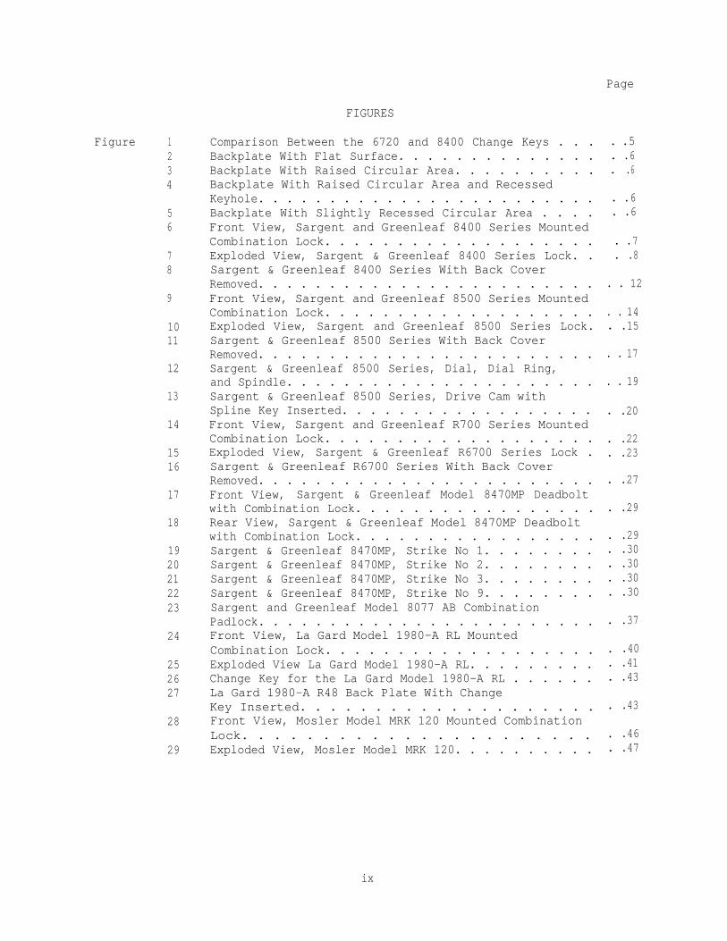
FIGURES
Page
Figure 1234
56
78
9
1011
12
13
14
1516
17
18
1920212223
24
252627
28
29
Comparison Between the 6720 and 8400 Change Keys . . .Backplate With Flat Surface. . . . . . . . . . . . . .Backplate With Raised Circular Area. . . . . . . . . .Backplate With Raised Circular Area and RecessedKeyhole. . . . . . . . . . . . . . . . . . . . . . . .Backplate With Slightly Recessed Circular Area . . . .Front View, Sargent and Greenleaf 8400 Series MountedCombination Lock. . . . . . . . . . . . . . . . . . .Exploded View, Sargent & Greenleaf 8400 Series Lock. .Sargent & Greenleaf 8400 Series With Back CoverRemoved. . . . . . . . . . . . . . . . . . . . . . . .Front View, Sargent and Greenleaf 8500 Series MountedCombination Lock. . . . . . . . . . . . . . . . . . .Exploded View, Sargent and Greenleaf 8500 Series Lock.Sargent & Greenleaf 8500 Series With Back CoverRemoved. . . . . . . . . . . . . . . . . . . . . . . .Sargent & Greenleaf 8500 Series, Dial, Dial Ring,and Spindle. . . . . . . . . . . . . . . . . . . . . .Sargent & Greenleaf 8500 Series, Drive Cam withSpline Key Inserted. . . . . . . . . . . . . . . . . .Front View, Sargent and Greenleaf R700 Series MountedCombination Lock. . . . . . . . . . . . . . . . . . .Exploded View, Sargent & Greenleaf R6700 Series Lock .Sargent & Greenleaf R6700 Series With Back CoverRemoved. . . . . . . . . . . . . . . . . . . . . . . .Front View, Sargent & Greenleaf Model 8470MP Deadboltwith Combination Lock. . . . . . . . . . . . . . . . .Rear View, Sargent & Greenleaf Model 8470MP Deadboltwith Combination Lock. . . . . . . . . . . . . . . . .Sargent & Greenleaf 8470MP, Strike No 1. . . . . . . .Sargent & Greenleaf 8470MP, Strike No 2. . . . . . . .Sargent & Greenleaf 8470MP, Strike No 3. . . . . . . .Sargent & Greenleaf 8470MP, Strike No 9. . . . . . . .Sargent and Greenleaf Model 8077 AB CombinationPadlock. . . . . . . . . . . . . . . . . . . . . . . .Front View, La Gard Model 1980-A RL MountedCombination Lock. . . . . . . . . . . . . . . . . . .Exploded View La Gard Model 1980-A RL. . . . . . . . .Change Key for the La Gard Model 1980-A RL . . . . . .La Gard 1980-A R48 Back Plate With ChangeKey Inserted. . . . . . . . . . . . . . . . . . . .Front View, Mosler Model MRK 120 Mounted CombinationLock. . . . . . . . . . . . . . . . . . . . . .Exploded View, Mosler Model MRK 120. . . . . . . . . .
. .5.6.
. .6
. .6
. .6
. .7
. .8
. . 12
. . 14
. .15
. . 17
. . 19
. .20
. .22
. .23
. .27
. .29
. .29
. .30
. .30
. .30
. .30
. .37
. .40
. .41
. .43
. .43
. .46
. .47
ix

Page
3031
32
333435
36
3738
Table 1
Change Key for the Mosler Model MRK 120 . . . . .Mosler Model MRK 120 Backplate With Change Key inInserted Position . . . . . . . . . . . . . . . .Front View, Mosler Model MRK 302-402 MountedCombination Lock. . . . . . . . . . . . . . . . .Exploded View, Mosler Model MRK 302-402 . . . . .Change Key for the Mosler Model MRK 302-402 . . .Mosler MRK 302-402 Backplate With Change Key inInserted Position . . . . . . . . . . . . . . . .Front View, Mosler Model MR 302-402 MountedCombination Lock. . . . . . . . . . . . . . . . .Exploded View, Mosler Model MR 302-402. . . . . .Mosler MR 302, Wheels . . . . . . . . . . . . . .
. . . . .49
. . . . .49
. . . . .51
. . . . .52
. . . . .55
. . . . .55
. . . . .56
. . . . .57
. . . . .60
TABLE
Types of Combination Locks. . . . . . . . . . . . . . . . .2
REFERENCES. . . . . . . . . . . . .. . . . . . . . . . . . . . . . . . . . .63
x

Section 1: INTRODUCTION
1.1 Scope. This handbook provides basic instructions for theinstallation, operation, and maintenance of various mounted combination locksand combination padlocks. Also included are detailed instructions for chang-ing and setting combinations for hand-change and key-change combination locksand combination padlocks. A list of locks included in this handbook is foundin Table 1, along with other pertinent information.
As noted in Table 1, not all of the locks are currently availablefrom the Defense Industrial Supply Center (DISC). However, those no longerstocked were at one time procured in large quantities, and are included inthis military handbook. While the Sargent & Greenleaf 8500 Series and theMosler Models MRK 302-402 and MRK 120 were not distributed by DISC, they wereprocured in large numbers direct from the manufacturers.
1.2 Purpose. This military handbook is for use by all personnelresponsible for the installation, operation, and maintenance of mountedcombination locks and combination padlocks.
1

Table 1Types of Combination Locks
National Stock CombinationLock Number (NSN) Change Type Description
Sargent & Greenleaf Available from Key-change Mounted lock,R6700 Series local S&G Group 2
distributers
Sargent & Greenleaf Key-change Mounted lock,8400 Series 5340-00-264-7592 Group lR
Sargent & Greenleaf Available from Key-change Mounted lock,8500 Series (Note 2) local S&G Group 1R
distributors
Sargent & Greenleaf 5340-00-671-6607 Key-change Mounted lock,8470MP 5340-01-183-5952 Group 1R,
Deadbolt withCombination Lock
Mosler Available from Key-change Mounted lock,MR(K) 302-402 manufacturer and hand- Group 1R
(Note 1) change
Mosler MRK 120 Available from Key-change Mounted lock,manufacturer Group 1(Note 1)
La Gard Model Key-change Mounted lock,1980A RL 5340-00-905-4953 Group 1R
Sargent & Greenleaf Padlock Provides8077AB Steel Shackle 5340-00-285-6523 Key-change low level of8077AB Brass Shackle 5340-00-285-6524 Security
Notes:1. Locks, dials, and dial rings must be ordered separately.
2. The 8500 Series locks are available from Sargent & Greenleaf withgroup 1 wheels, but these locks are not to be used on securitycontainers due to possibility of radiological attack.
2

Section 2: GENERAL
2.1 Combination Locks. A combination lock is any lock that requires theuse of one or more movable lettered or numbered dials to align the lockcomponents to open the lock. Mounted combination locks are those attachedwith screws or bolts to the container, door, or equipment that the lockssecure. Combination padlocks are removable from the container or equipmentthat the locks secure.
Combination locks have many components that interrelate with eachother. The wheels are the components inside the lock that must be alignedcorrectly to open the lock. On mounted combination locks and many combinationpadlocks, the dial is the movable metal or plastic part on the front of thelock used to turn the wheels. The wheels, spacers, and washers constitute thewheel pack. The internal components of the lock are housed in the lock case.On a mounted lock, a dial ring and dial are on the front of the door or drawerhead between the dial and the lock case. The bolt projects from the case andprevents the door or drawer from opening.
2.1.1 Group 1 and 1R Locks. The Group 1 and 1R locks addressed in thishandbook meet the requirements of MIL-L-15596 Series, Locks, Combination (Safeand Safe Locker). Group 1 locks have brass wheels, whereas Group 1R lockshave X-ray proof (Delrin) wheels. Each lock has a thermal relock device forprotection against forced entry using thermal devices. These locks, alongwith the Sargent & Greenleaf R6700 Series (Group 2), have a special relockingtrigger for protection against punching of the spindle. If an attempt atpenetration is made through either of the above-mentioned means, the triggerwill automatically deadlock the unit.
2.1.2 Mounted Combination Locks. Each mounted combination lock isavailable with either a front-reading dial or top-reading (“spy proof”) dial.The top-reading dial permits only the person dialing the combination to seethe numbers involved. Each lock is furnished with a spindle that can be cutto suit varying thicknesses of doors or drawers. The spindles and drive camsare designed to allow the locks to be mounted in the right-hand, left-hand,vertical-up, or vertical-down positions.
2.1.3 General Operating Guidelines. When operating combination locks orsetting combinations, always observe the following rules:
a) Never spin or jerk the dial. Always turn the dial slowly andevenly, stopping exactly on each number of the combination.
b) Passing a combination number requires restarting the entirecombination sequence from the beginning.
c) Never use force. If a lock fails to operate or operates withdifficulty, request assistance from a qualified locksmith.
3

d) Never close a door or drawer after setting a new combinationuntil the new combination is worked at least three times and is recorded inaccordance with security directives.
e) On a mounted three-wheel lock, there are 1,000,000 possiblecombinations. Some combination padlocks have as many as 125,000 possiblesettings. However, because of mechanical and psychological factors, not allof these combinations are valid. Specifically, follow these guidelines:
(1) No two numbers should be closer than exactly five digitsapart, or multiples of ten.
(2) The third number should not range from O toto 100.
(3) Do not use straight ascending or descendingExamples: 41-56-71, 81-58-30. It is better to use a sequenceLOW-HIGH or LOW-HIGH-LOW. Examples: 72-23-81, 33-67-38.
(4) All three numbers should not be even.
(5) All three numbers should not be odd.
20 or from 85
combinations.that is HIGH-
(6) Never set a 50-25-50 combination (the standard factorycombination sequence) on the lock of a container that holds classifiedmaterial. When removing a container from service, set combination to50-25-50.
(7) Do not use significant dates (birthdays, anniversaries,etc.), street addresses, telephone numbers, etc., as the basis forcombinations.
(8) When locking a safe, door, or cabinet, turn the dial atleast four full revolutions in one direction.
2.2 Classification
2.2.1 Mounted Combination Locks. Underwriters Laboratories’ Standard UL768, Standard for Combination Locks, classifies mounted combination locks aseither Group 1, Group 1R, or Group 2. To qualify for a Group 1R rating, alock must be manipulation, radiographic, and thermal resistant. Group 2combination locks must be reasonably resistant to unauthorized opening.
2.2.2 Combination Padlocks. Combination padlocks are classified accordingto Federal Specification FF-P-110 (Series), Padlock, Changeable Combination(Resistant to Opening By Manipulation and Surreptitious Attack).
4

Section 3: KEY-CHANGE LOCKS
3.1 General. Key-change locks require no disassembly to set new combi-nations. To change the combination, the change key provided with the lock isinserted into a keyhole in the back coverplate. Some key-change locks havetwo reference marks on the dial ring. At the top of the dial ring is theopening index. A changing index may be either slightly to the left or to theright of the opening index, depending on the model. When a key-change lockhas only one reference mark, the single mark is used as both the changing andopening indexes. Before the combination of any lock is changed, read theentire change procedure carefully. Read installation instructions thoroughlybefore beginning an installation procedure.
3.2 Sargent & Greenleaf Mounted Combination Locks
3.2.1 Combination Change Keys for the R6700, 8400, and 8500 Series, aswell as the 8470MP. To change the combination, these locks require one of twodifferent change keys (see Figure 1). For the four different backplate (backcover) styles, see Figures 2 through 5. The installed backplate style on aparticular lock will determine the required change key. The first style, asshown in Figure 2, has a flat backplate. The second, shown in Figure 3, has araised circular area. As depicted in Figure 4, the third has a raisedcircular area with a recessed keyhole. The fourth, shown in Figure 5, has aslightly recessed circular area.
The backplanes shown in Figures 2, 4, and 5 use the 6720 change key.The 6720 key measures approximately 1-3/16 inches (30 mm) from the tip of thekey to the shoulder. The backplate shown in Figure 3 uses the 8400 changekey. The 8400 change key measures approximately 1-7/16 inches (36 mm) fromthe tip to the shoulder. Figure 1 illustrates the difference in lengthbetween the 6720 and 8400 change keys. Using the incorrect key will cause thelock to malfunction, requiring the repair services of a locksmith.
INSERT FIGURE
Figure 1Comparison Between the 6720 and 8400 Change Keys
5

INSERT FIGURE
Figure 2Backplate With Flat Surface
INSERT FIGURE
Figure 4Backplate With Raised Circular
Area and Recessed Keyhole
Figure 3Backplate With Raised Circular Area
Figure 5Backplate With SlightlyRecessed Circular Area
6

3.2.2 8400 Series. These combination locks are Group 1 or 1R locksdesigned to provide resistance against surreptitious opening by manipulationthrough the sense of touch, sound, ‘reading,” electronic listening, and onGroup 1R models, radiological attack. These locks are equipped with theuniversal "centi-spline” dial. This dial has a removable spindle that can bepositioned to any one of 100 settings that correspond with the dial gradua-tions. This permits the spline to be positioned to any hand condition. Eachmodel is available with or without a metal tube that is secured to the lockcase and simplifies installation by accurately aligning the dial ring indexwith the lock. It also protects the spindle from door insulation.
Some 8400 Series locks have a torque adjustment feature that appliesprecise pressure to the wheel pack to guard against vibrating or "walking" thewheels into alignment. The torque adjustment allows the dial torque to beadjusted to individual touch. An 8400 Series lock is illustrated in Figures 6and 7.
INSERT FIGURE
Figure 6Front View, Sargent & Greenleaf 8400 Series Mounted
Combination Lock
7

INSERT FIGURE
Figure 7Exploded View, Sargent & Greenleaf 8400 Series Mounted Combination Lock
8

3.2.2.1 Opening Procedure. To open a Sargent & Greenleaf 8400 SeriesCombination Lock, proceed as follows:
a) Turn the dial LEFT, stopping when the first number of thecombination is aligned with the OPENING index the fourth time.
b) Turn the dial RIGHT, stopping when the second number is alignedthe third time.
c) Turn the dial LEFT, stopping when the third number is alignedthe second time.
d) Turn the dial RIGHT to O. Hold the dial in this position.
e) Turn the arrow knob (butterfly) in the center of the dial RIGHTas far as it will go.
CAUTION
Ensure that the dial is held at O when turningthe arrow knob during opening and closing.Internal spring damage can occur, requiringlock to be replaced.
f) Turn the dial to the RIGHT until it stops. The bolt is nowfully retracted.
3.2.2.2 Securing Procedure. To secure the 8400 Series lock, release thearrow knob by turning it to the LEFT, then turn the dial to the LEFT at leastfour complete revolutions.
3.2.2.3 Combination Changing Procedure. To change a combination setting,begin by selecting a new three-number sequence based on the rules presented inparagraph 2.1.3e. Record the new combination in accordance with securitydirectives and proceed as follows:
a) Open the lock as described in paragraph 3.2.2.1.
b) With the door or container open, throw the door/drawer bolt tothe locked position. If the container has a bolt interlock, it will benecessary to depress the interlock plunger before the bolt can be thrown whilethe unit is open. Use the procedure recommended by the unit’s manufacturer.
c) Throw the locking bolt by using the procedure in paragraph3.2.2.2.
d) Using the CHANGING index and the old combination, turn the dialLEFT, stopping when the first number is aligned the fourth time.
9

e) Turn the dial RIGHT, stopping when the second number is alignedthe third time.
f) Turn the dial LEFT, stopping when the third number is alignedthe second time. Hold the dial in this position.
g) Fully insert the appropriate change key in the keyhole in theback of the lock (reference paragraph 3.2.1). Rotate the key one quarter turnLEFT . This will unlock the wheels. Do not force the key.
NOTE
On some containers, it may be necessary toremove a cover or door panel to expose theback of the lock.
h) With the key in this position, turn the dial at least fourcomplete revolutions to erase the old combination.
i) To set the new combination, turn the dial LEFT, stopping whenthe first number of the new combination is aligned with the CHANGING index thefourth time.
j) Turn the dial RIGHT, stopping when the second number is alignedwith the CHANGING index the third time.
k) Turn the dial LEFT, stopping when the third number is alignedwith the CHANGING index the second time. Hold the dial in this position.
1) Turn the change key RIGHT and remove it from the lock. The newcombination is now set.
m) Work the new combination at least three times with the door orcontainer open. If the lock cannot be opened using the new combination, itcan be assumed that the new numbers were not set correctly. If this is thecase, call a qualified locksmith.
3.2.2.4 Installation Procedure. To install a Sargent & Greenleaf 8400Series Combination Lock, proceed as follows:
a) Using the template (provided with lock), position lock indesired location.
b) Using the template, drill and tap four holes in mounting platefor the lock-attaching screws (1/4-20). Drill hole in mounting plate for thespindle shaft (0.813-inch (21-mm) diameter if lock has a tube, 0.625-inch(16-mm) diameter if it does not).
10

c) Make sure the bolt is in the locked or engaged position. Toaccomplish is, rotate the dial left to O. Turn the arrow knob in the centerdial to O, and rotate the dial left four revolutions, stop at a randomposition.
d) Remove the back cover of the lock.
If your lock is equipped with a tube, proceed with step e) below. If not,proceed to step i).
e) Insert tube and hold lock against mounting plate. Place dialring on tube and lightly tighten tube nut.
f) Measure tube excess leaving 1/16 inch (2 mm) above tube nut.
g) Remove lock and cut off excess tube.
h) File end of tube smooth.
i) Securely fasten lock to mounting plate by installing the fourlock-attaching screws and tightening.
j) While aligning hole through door, fasten dial ring to door usingscrews and tighten tube nut (if present on lock).
k) Insert dial into dial ring and hold snug.
1) Measure and cut off excess spindle from the wheel post, leaving1/16 inch (2 mm) above the wheel post. Remove burrs.
m) Screw the drive cam on spindle until snug, then back off untilkeyway lines up. Insert the spline key with the key handle pointing away fromthe center of the cam (see Figure 8). Drive the spline key in carefully. Ifthe spline key becomes loose, the lock will not function properly. Makecertain that the spline key is tight.
NOTE
Before screwing dial/spindle into the drive camfor the final time, lubricate the dial, dialring, and drive cam bearing surfaces. Sargent& Greenleaf recommends G-322L lubricantmanufactured by General Electric. NEVER useoil- or petroleum-based lubricants.
n) Cut off amount from inner spindle equal to the amount removedfrom the spindle. Spindle excess can be inserted over inner spindle for easeof measurement.
11
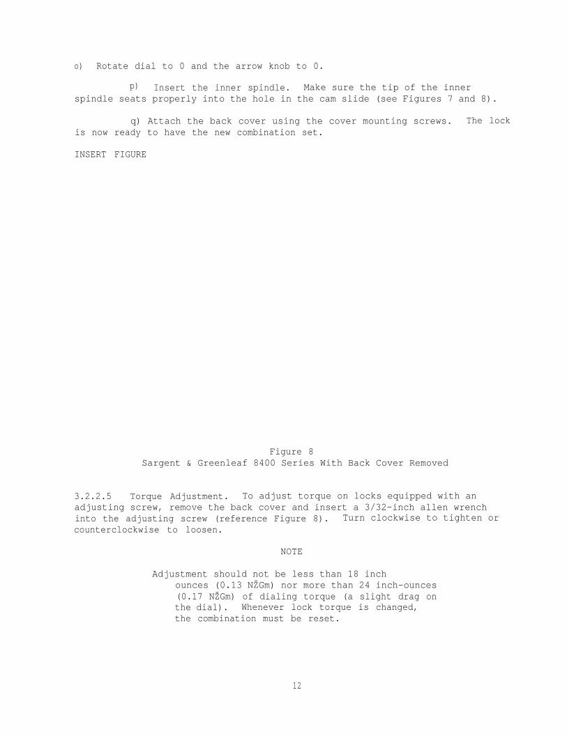
o) Rotate dial to 0 and the arrow knob to 0.
p) Insert the inner spindle. Make sure the tip of the innerspindle seats properly into the hole in the cam slide (see Figures 7 and 8).
q) Attach the back cover using the cover mounting screws. The lockis now ready to have the new combination set.
INSERT FIGURE
Figure 8Sargent & Greenleaf 8400 Series With Back Cover Removed
3.2.2.5 Torque Adjustment. To adjust torque on locks equipped with anadjusting screw, remove the back cover and insert a 3/32-inch allen wrenchinto the adjusting screw (reference Figure 8). Turn clockwise to tighten orcounterclockwise to loosen.
NOTE
Adjustment should not be less than 18 inchounces (0.13 NŽGm) nor more than 24 inch-ounces(0.17 NŽGm) of dialing torque (a slight drag onthe dial). Whenever lock torque is changed,the combination must be reset.
12

3.2.2.6 Maintenance Recommendations. Periodic servicing will extend thelife of the lock and is essential for maintaining proper security. Each timethe combination is changed, inspect the lock for wear, metal filings, drilledholes, cracks, or any other visual signs of attempts to defeat the lock byforced entry techniques. The inspection process should entail removal of theback cover of the lock, and visual examination of each wheel part, as well asthe cam and lever assembly, to make sure nothing is worn or damaged. Iflubrication is required, use molybdenum-disulfide (powder). NEVER use oil- orpetroleum-based lubricants on combination locks.
NOTE
For Sargent & Greenleaf Combination Locks, themanufacturer recommends using GE-322L lubricantmanufactured by General Electric.
Each time the back cover is removed, the combination should bereset. Remember to check the combination at least three times before lockingthe container.
Any maintenance other than changing the combination and inspectingthe lock should be referred to a qualified locksmith.
3.2.3 8500 Series. These combination locks are Group 1 or 1R locksdesigned for added protection against most modern methods of attack, whilealso providing simplicity and ease of operation. Each model is available withor without a metal tube that is secured to the lock case and simplifiesinstallation by accurately aligning the dial ring index with the lock. Italso protects the spindle from door insulation.
Some 8500 Series locks have a torque adjustment feature that appliesprecise pressure to the wheel pack to guard against vibrating or ‘walking” thewheels into alignment. The torque adjustment allows the dial torque to beadjusted to individual touch. An 8500 Series lock is illustrated in Figures 9and 10.
3.2.3.1 Opening Procedure. To open a Sargent & Greenleaf 8500 SeriesCombination Lock, proceed as follows:
a) Turn the dial LEFT, stopping when the first number of thecombination is aligned with the OPENING index the fourth time.
b) Turn the dial RIGHT, stopping when the second number is alignedthe third time.
c) Turn the dial LEFT, stopping when the third number is alignedthe second time.
d) Turn the dial RIGHT to O.
13

INSERT FIGURE
Figure 9Front View, Sargent & Greenleaf 8500 Series Mounted
Combination Lock
e) With zero aligned with the OPENING index, push the dial IN toactivate the lever assembly, release dial.
f) Turn the dial RIGHT until the bolt is fully retracted.
3.2.3.2 Securing Procedure. To secure the 8500 Series lock, turn the dialto the LEFT at least four complete revolutions.
3.2.3.3 Combination Changing Procedure. To change a combination setting,begin by selecting a new three-number sequence based on the rules presented inparagraph 2.1.3e. Record the new combination in accordance with securitydirectives and proceed as follows:
a) Open the lock as described in paragraph 3.2.3.1.
b) With the door or container open, throw the door/drawer bolt tothe locked position. If the container has a bolt interlock, it will benecessary to depress the interlock plunger before the bolt can be thrown whilethe unit is open. Use the procedure recommended by the unit’s manufacturer.
14

INSERT FIGURE
Figure 10Exploded View, Sargent & Greenleaf 8500 Series Lock
15

c) Throw the locking bolt by using the procedure in paragraph 3.2.3.2.
d) Using the CHANGING index and the old combination, turn the dialLEFT, stopping when the first number is aligned the fourth time.
e) Turn the dial RIGHT, stopping when the second number is alignedthe third time.
f) Turn the dial LEFT, stopping when the third number is alignedthe second time. Hold the dial in this position.
g) Fully insert the appropriate change key in the keyhole in theback of the lock (reference paragraph 3.2.1). Rotate the key one quarter turnLEFT. This will unlock the wheels. Do not force the key.
NOTE
On some containers, it may be necessary toremove a cover or door panel to expose theback of the lock.
h) With the key in this position, turn the dial at least fourcomplete revolutions to erase the old combination.
i) To set the new combination, turn the dial LEFT, stopping whenthe first number of the new combination is aligned with the CHANGING index thefourth time.
j) Turn the dial RIGHT, stopping when the second number is alignedwith the CHANGING index the third time.
k) Turn the dial LEFT, stopping when the third number is alignedwith the CHANGING index the second time. Hold the dial in this position.
1) Turn the change key RIGHT and remove it from the lock. The newcombination is now set.
m) Work the new combination at least three times with the door orcontainer open. If the lock cannot be opened using the new combination, itcan be assumed that the new numbers were not set correctly. If this is thecase, call for a qualified locksmith.
3.2.3.4 Installation Procedure. To install a Sargent & Greenleaf 8500Series Combination Lock, proceed as follows:
a) Using the template (provided with lock), position lock indesired location.
16
b) Using the template, drill and tap four holes in mounting platefor the lock-attaching screws (1/4-20). Drill hole in mounting plate for thespindle shaft (0.813-inch (21-mm) diameter if lock has a tube, 0.625-inch(16-mm) diameter if it does not).
c) Remove the back cover of the lock.
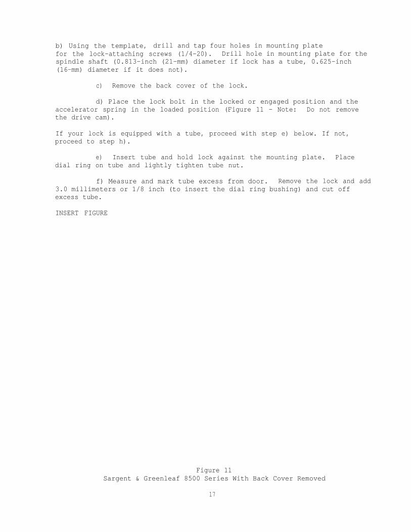
d) Place the lock bolt in the locked or engaged position and theaccelerator spring in the loaded position (Figure 11 - Note: Do not removethe drive cam).
If your lock is equipped with a tube, proceed with step e) below. If not,proceed to step h).
e) Insert tube and hold lock against the mounting plate. Placedial ring on tube and lightly tighten tube nut.
f) Measure and mark tube excess from door. Remove the lock and add3.0 millimeters or 1/8 inch (to insert the dial ring bushing) and cut offexcess tube.
INSERT FIGURE
Figure 11Sargent & Greenleaf 8500 Series With Back Cover Removed
17

g) Remove any burrs from the end of the tube.
h) Securely fasten the lock to mounting plate with four attachingscrews and tighten.
i) While aligning with hole in the door, lightly fasten dial ringto door using screws, and tighten tube nut (if present on lock). Dial ringopening index should be at 12 o’clock center position. Before installation ofthe dial ring, press the plastic bearing insert (Figure 12) into the openingin the back of the dial ring. The insert must fit flush with the dial ring.
j) To install dial, hold the drive cam in place with one hand andthread the dial into the cam until the dial comes to a stop against thesurface of the dial ring.
CAUTION
When threading dial into cam, do not allow camto slide outward against the accelerator spring.Accelerator spring can be easily damaged in thismarine r.
k) The alignment of the dial and dial ring is critical to theoperation of the lock. Perfect alignment is necessary. The dial should beflush and centered with the surface of the dial ring, for true center.
1) Measure the excess spindle that projects beyond the drive cam.
m) Remove the dial, cut off excess spindle
n) Tighten the dial ring screws.
o) Place a washer, compression spring, and(Figure 12).
p) Insert dial into the lock (observe step
and remove burrs.
washer on hub of dial
j) (CAUTION). Hold thedrive cam in place to receive nose of the drop lever and thread dial into camuntil the dial stops.
q) Rotate the dial counterclockwise a MINIMUM of one full turnuntil the spline in the spindle is aligned with the proper spline in the cam,the cam is positioned to receive the nose of the drop lever, a d the dial ison O.
18

INSERT FIGURE
Figure 12Sargent & Greenleaf 8500 Series, Dial, Dial Ring, and Spindle
NOTE
If the lock is mounted in the vertical-up orvertical-down position, the properly alignedspline should be marked VU/VD on the drivecam. For right- or left-hand mounting, RH/LHshould be aligned (reference Figure 13).
r) Insert the spline key with the lip toward edge of cam. Tap inlightly. The dial must turn freely with no rubbing or interference.
NOTE
Before attaching cover to lock, check forproper in and out travel of dial foroperation of accelerator spring.
19

INSERT FIGURE
Figure 13Sargent & Greenleaf 8500 Series, Drive Cam with
Spline Key Inserted
s) Rotate the dial at least one complete revolution and stop at O.The accelerator spring should now be in the loaded position.
t) Hold the cover in place on the lock and push the dial in at O.Release the dial. Remove the cover and check the position of the acceleratorspring (spring should be in the released position). (If the acceleratorspring is not in the released position, the dial has not been backed out ofthe cam far enough and the condition must be corrected. Remove spline key,hold cam and rotate dial one additional full turn counterclockwise. Reinstallthe spline key and repeat steps.)
u) Rotate the dial at least one complete revolution and stop at 50.The accelerator spring should now be in the loaded position.
v) Hold the back cover in place on the lock and push the dial in at50. The accelerator spring should not release. (If the accelerator springdoes release, the spindle must be turned clockwise into the cam one completerevolution and this step must be repeated.)
w) Dial the set combination (50-25-50) on the lock and observe thedrop lever falling into the drive cam. Repeat this step at least three times.
20
x) accelerator spring is operating properly, the cover may beattached to the lock and the new combination set.
3.2.3.5 Torque Adjustment. To adjust torque on locks equipped with anadjusting screw, remove the back cover and insert a 3/32-inch allen wrenchinto the adjusting screw (see Figure 11). Turn clockwise to tighten orcounterclockwise to loosen.
NOTE
Adjustment should not be less than 18 inch-ounces(0.13 N•Gm) nor more than 24 inch-ounces (0.17 N•Gm)of dialing torque (a slight drag on the dial).Whenever lock torque is changed, the combinationmust be reset.
3.2.3.6 Maintenance Recommendations. Periodic servicing will extend thelife of the lock and is essential for maintaining proper security. Each timethe combination is changed, inspect the lock for wear, metal filings, drilledholes, cracks, or any other visual signs of attempts to defeat the lock byforced-entry techniques. The inspection process should include removal of theback cover of the lock, and visual examination of each wheel part, as well asthe cam and lever assembly, to make sure nothing is worn or damaged. Iflubrication is required, use molybdenum-disulfide (powder). NEVER use oil- orpetroleum-based lubricants on combination locks.
NOTE
For Sargent & Greenleaf Combination Locks, themanufacturer recommends using GE-322L lubricantmanufactured by General Electric.
Each time the back cover is removed, the combination should bereset. Remember to check the combination at least three times before lockingthe container.
the lock,
3.2.4a Group 2
Any maintenance, other than changing the combination and inspectingshould be referred to a qualified locksmith.
R6700 Series. These locks, commonly referred to as “R-Locks,” carryrating from Underwriters Laboratories. They are used only on money
chests. The R6700 Series Locks have a torque adjustment feature that appliesprecise pressure to the wheel pack to guard against vibrating or “walking” thewheels into alignment. The torque adjustment allows the dial torque to beadjusted to individual touch. The R6700 Series is available with or without ametal tube that is secured to the lock case and
21

simplifies installation by accurately aligning the dial ring index with thelock. It also protects the spindle from door insulation. A R6700 Series lockis illustrated in Figures 14 and 15.
INSERT FIGURE
Figure 14Front View, Sargent & Greenleaf R6700 Series Mounted
Combination Lock
3.2.4.1 Opening Procedure. To open a Sargent & Greenleaf R6700 SeriesCombination Lock, proceed as follows:
a) Turn the dialcombination is aligned with
b) Turn the dialthe third time.
c) Turn the dialthe second time.
d) Turn the dial
LEFT, stopping when the first number of thethe OPENING index the fourth time.
RIGHT, stopping when the second number is aligned
LEFT, stopping when the third number is aligned
RIGHT pausing momentarily at O, and continueturning until it stops. This retracts the locking bolt.
3.2.4.2 Securing Procedure. To secure the 6700 Series lock, turn the dialto the LEFT at least four complete revolutions.
22

INSERT FIGURE
Figure 15Exploded View, Sargent & Greenleaf R6700 Series Lock
23

3.2.4.3 Combination Changing Procedure. To change a combination setting,begin by selecting a new three-number sequence based on the rules presented inparagraph 2.1.3e. Record the new combination in accordance with securitydirectives and proceed as follows:
a) Open the lock as described in paragraph 3.2.4.1.
b) With the door or container open, throw the door/drawer bolt tothe locked position. If the container has a bolt interlock, it will benecessary to depress the interlock plunger before the bolt can be thrown whilethe unit is open. Use the procedure recommended by the unit’s manufacturer.
c) Throw the locking bolt by using the procedure in paragraph3.2.4.2
d) Using the CHANGING index and the old combination, turn the dialLEFT, stopping when the first number is aligned the fourth time.
e) Turn the dial RIGHT, stopping when the second number is alignedthe third time.
f) Turn the dial LEFT, stopping when the third number is alignedthe second time. Hold the dial in this position.
g) Fully insert the appropriate change key in the keyhole in theback of the lock (reference paragraph 3.2.1 ). Rotate the key one quarterturn LEFT. This will unlock the wheels. Do not force the key.
NOTE
On some containers, it may be necessary toremove a cover or door panel to expose the backof the lock.
h) With the key in this position, turn the dial at least fourcomplete revolutions to erase the old combination.
i) To set the new combination, turn the dial LEFT, stopping whenthe first number of the new combination is aligned with the CHANGING index thefourth time.
j) Turn the dial RIGHT, stopping when the second number is alignedwith the CHANGING index the third time.
k) Turn the dial LEFT, stopping when the third number is alignedwith the CHANGING index the second time. Hold the dial in this position.
24

1) Turn the change key RIGHT and remove it from the lock. The newcombination is now set.
m) Work the new combination at least three times with the door orcontainer open. If the lock cannot be opened using the new combination, itcan be assumed that the new numbers were not set correctly. If this is thecase, call for a qualified locksmith.
3.2.4.4 Installation Procedure. To install a Sargent & Greenleaf R6700Series Combination Lock, proceed as follows:
a) Using the template (provided with lock), position lock indesired location.
b) Using the template, drill and tap four holes in mounting platefor the lock-attaching screws (1/4-20). Drill hole in mounting plate for thespindle shaft (0.813-inch (21-mm) diameter if lock has a tube, 0.625-inch(16-mm) diameter if it does not).
c) Make sure the bolt is in the locked or engaged position.Depending on the model of your lock, this can be done by pulling the bolt outwith your fingers or by rotating the dial to the left four completerevolutions, and stopping at random.
d) Remove the back cover of the lock.
If your lock is equipped with a tube, proceed with step e). If not, proceedto step i).
e) Insert tube and hold lock against mounting plate. Place dialring on tube and lightly tighten tube nut.
f) Measure tube excess, leaving 7/64 inch (3 mm) above tube nut.
g) Remove lock and cut off excess tube.
h) File end of tube smooth.
i) Securely fasten lock to mounting plate by installing the fourlock-attaching screws and tightening.
j) While aligning hole through door, fasten dial ring to door usingscrews and tighten tube nut (if present on lock).
k) Insert dial into dial ring and hold snug.
25

1) Measure and cut off excess spindle from the wheel post, leaving1/16 inch 2 mm) above the wheel post. Remove burrs.
m) Screw the drive cam onto spindle until snug, then back off untilthe appropriate slot in the drive cam lines up with the keyway of the spindle.
Drive cam slots are labeled RH (right-hand), LH (left-hand), W (vertical-up),and VD (vertical-down) for the four different mounting positions (referenceFigures 15 and 16).
n) Insert the spline key with the key handle pointing away from thecenter of the cam. Drive the spline key in carefully. If the spline keybecomes loose, the lock will not function properly. Make certain that thespline key is tight.
NOTE
Before screwing dial/spindle into the drive camfor the final time, lubricate the dial, dialring, and drive cam bearing surfaces. Sargent& Greenleaf recommends G-322L lubricantmanufactured by General Electric. NEVER useoil- or petroleum-based lubricants.
o) Attach the back cover using the cover mounting screws. The lockis now ready to have the new combination set.
3.2.4.5 Torque Adjustment. To adjust torque, remove the back cover andinsert a 3/32-inch allen wrench into the adjusting screw (see Figure 16).Turn clockwise to tighten or counterclockwise to loosen.
NOTE
Adjustment should not be less than 18 inchounces (0.13 N•Gm) nor more than 24 inch-ounces(0.17 N•Gm) of dialing torque (a slight dragon the dial). Whenever lock torque is changed,the combination must be reset.
3.2.4.6 Maintenance Recommendations. Periodic servicing will extend thelife of the lock and is essential for maintaining proper security. Each timethe combination is changed, inspect the lock for wear, metal filings, drilledholes, cracks, or any other visual signs of attempts to defeat the lock byforced entry techniques. The inspection process should include removal of theback cover of the lock, and visual examination of each wheel part, as well asthe cam and lever assembly, to make sure nothing is worn or damaged. Iflubrication is required, use molybdenum-disulfide (powder). NEVER use oil- orpetroleum-based lubricants on combination locks.
26

INSERT FIGURE
Figure 16Sargent & Greenleaf R6700 Series With Back Cover Removed
NOTE
For Sargent & Greenleaf Combination Locks,the manufacturer recommends using GE-322Llubricant manufactured by General Electric.
Each time the back cover is removed, the combination should bereset. Remember to check the combination at least three times before lockingthe container.
Any maintenance other than changing the combination and inspectingthe lock should be referred to a qualified locksmith.
3.2.5 8470MP Deadbolt with Combination Lock. The 8470 is a reversible,surface-mounted lock recommended for use on doors in high-security areas. Itis really two locks in one: a deadbolt and a combination lock. The deadboltsection of the 8470 includes hardened steel pins and an interlocking strikeand frame to prevent jamming or spreading of the door frame. The lock has anautomatic deadbolt trigger and an inside release knob that allows opening thedoor from the inside. A l/8-inch (3.2-mm) drill-resistant hard plate isavailable for installation between the Sargent & Greenleaf 8470 and the door.The 8470 is designed for use with the Sargent & Greenleaf 8400 and 8500 SeriesCombination Locks. The 8470 is equipped with a lock-open latch. This latchallows the dial to be “locked”
3
27

in the unlocked position. This is a standard feature on the newer 8470s.Existing locks can be retrofitted for this latch. The 8470 is illustrated inFigures 17 and 18. Strikes authorized for use with the Sargent & Greenleaf8470 are illustrated in Figures 19 through 22.
3.2.5.1 Opening Procedure (8400 and 8500 Series). To open a Sargent &Greenleaf 8470MP Lock, proceed as follows:
a) Turn the dial LEFT, stopping when the first number of thecombination is aligned with the OPENING index the fourth time.
b) Turn the dial RIGHT, stopping when the second number is alignedthe third time.
c) Turn the dial LEFT, stopping when the third number is alignedthe second time.
d) Turn the dial RIGHT to O. Hold the dial in this position.
If the 8470MP has an 8400 Series Combination Lock:
e) Turn the arrow knob (butterfly) in the center of the dial RIGHTas far as it will go.
CAUTION
Ensure the dial is held at zero when turning thearrow knob during opening and closing. Internalspring damage can occur, requiring lock to bereplaced.
f) Turn the dial to the RIGHT until it stops. The bolt is nowfully retracted.
If the 8470MP has an 8500 Series Combination Lock, do the following:
e) With zero aligned with the OPENING index, push the dial in toactivate the lever assembly, release dial.
f) Turn the dial RIGHT until the bolt is fully retracted.
3.2.5.2 Securing Procedure. To secure the 8470MP lock, turn the dial to theLEFT at least four complete revolutions.
28

INSERT FIGURE
Figure 17Front View, Sargent & Greenleaf 8470MP Deadbolt with
Combination Lock
INSERT FIGURE
Figure 18Rear View, Sargent & Greenleaf 8470MP Deadbolt with
Combination Lock
29

INSERT FIGURE
Figure 19Sargent & Greenleaf 8470MP,
Strike No. 1
INSERT FIGURE
Figure 21Sargent & Greenleaf 8470MP,
Strike No. 3
Figure 20Sargent & Greenleaf 8470MP,
Strike No. 2
Figure 22Sargent & Greenleaf 8470MP,
Strike No. 9
30

3.2.5.3 Combination Changing Procedure. To change a combination setting,begin by selecting a new three-number sequence based on the rules presented inparagraph 2.1.3e. Record the new combination in accordance with securitydirectives and proceed as follows:
a) Open the lock as described in paragraph 3.2.5.1.
b) With the door or container open, throw the door/drawer bolt tothe locked position. If the container has a bolt interlock, it will benecessary to depress the interlock plunger before the bolt can be thrown whilethe unit is open. Use the procedure recommended by the unit’s manufacturer.
c) Throwparagraph 3.2.5.2.
d) UsingLEFT, stopping when
the
thethe
locking bolt by using the procedure stated in
CHANGING index and the old combination, turn the dialfirst number is aligned the fourth time.
e) Turn the dial RIGHT, stopping when the second number is alignedthe third time.
f) Turn the dial LEFT, stopping when the third number is alignedthe second time. Hold the dial in this position.
g) Fully insert the appropriate change key in the keyhole in theback of the lock (reference paragraph 3.2.1). Rotate the key one quarter turnLEFT . This will unlock the wheels. Do not force the key.
NOTE
On some containers, it may be necessary toremove a cover or door panel to expose theback of the lock.
h) With the key in this position, turn the dial at least fourcomplete revolutions to erase the old combination.
i) To set the new combination, turn the dial LEFT, stopping whenthe first number of the newfourth time.
with the
with the
j) Turn the dialCHANGING index the
k) Turn the dialCHANGING index the
combination is aligned with the CHANGING index the
RIGHT, stopping when the second number is alignedthird time.
LEFT, stopping when the third number is alignedsecond time. Hold the dial in this position.
31

1) Turn he change key RIGHT and remove it from the lock. The newcombinaton is now set.
m) Work the new combination at least three times with the door orcontainer open. If the lock cannot be opened using the new combination, itcan be assumed that the new numbers were not set correctly. If this is thecase, call for a qualified locksmith.
3.2.5.4 Strike Installation. Strikes designed for use with the Sargent &Greenleaf 8470MP are illustrated in Figures 19 through 22.
a) Using the template provided with the strike, position the strikeon door jamb or inactive leaf of double door configuration (depending on whichstrike is being used).
b) Drill holes for attaching the strike using No. 25 drill bit(0.149-inch (4-mm) diameter).
c) Using No. 10 flat head machine screws, install the strike on thedoor jamb (for strike No. 1, 2, or 3), or on the inactive leaf of the doubledoor configuration (for strike No. 9).
3.2.5.5 Lock Installation Procedure (8400 Series). The Sargent & Greenleaf8470MP is designed for use with the Sargent & Greenleaf 8400 and 8500 SeriesCombination Locks. If the 8470 is equipped with an 8400 Series lock, proceedwith step a) below. If it has an 8500 Series lock, refer to the procedure inparagraph 3.2.5.6.
a) Use the center of the strike as a reference to position the locktemplate on the door.
b) Using the template (provided with lock), drill the six 8470deadbolt base-attaching screw holes (0.149-inch (4-mm) diameter for self-tapping screws). Drill the hole for the spindle shaft (0.813-inch (21-mm)diameter if lock has a tube, 0.625-inch (16-mm) diameter if lock does not).
c) Securely fasten the 8470 deadbolt base and drill resistant hardplate to the door by tightening the attaching screws.
If the lock has a tube, proceed with step d). If not, go to step j).
d) Make sure bolt is in the locked or engaged position. Toaccomplish this, rotate the dial left to O. Turn the arrow knob in the centerdial to O, and rotate the dial left four revolutions, stop at random.
e) Remove back cover of the lock.
f) Insert tube and hold lock against the 8470 deadbolt base. Placedial ring on tube and tighten tube nut.
32

g) Measure tube excess, leaving 1/16 inch (2 mm) above tube nut.
h) Remove lock and cut off excess tube.
i) File end of tube smooth.
j) Securely fasten lock to the 8470 deadbolt base by installing thefour lock-attaching screws and tightening.
k) Fasten dial ring to door using screws and tighten tube nut (ifpresent on lock) and align with hole through door.
1) Insert dial into dial ring and hold snug.
m) Measure and cut off excess spindle from the wheel post, leaving1/16 inch (2 mm) above the wheel post. Remove burrs.
n) Screw the drive cam on spindle until snug, then back off untilthe keyway lines up. Insert the spline key with the key handle pointing awayfrom the center of the cam. Drive the spline key in carefully. If the splinekey becomes loose, the lock will not function properly. Make certain that thespline key is tight.
NOTE
Before screwing dial/spindle into the drive camfor the final time, lubricate the dial, dialring, and drive cam bearing surfaces. Sargent& Greenleaf recommends G-322L lubricantmanufactured by General Electric. NEVER useoil- or petroleum-based lubricants.
o) Cut off amount from inner spindle equal to the amount removedfrom the spindle. Spindle excess can be inserted over inner spindle for easeof measurement.
p) Rotate dial to O and the arrow knob to 0.
q) Insert the inner spindle. Make sure the tip of the inner spindleseats properly into the hole in the cam slide (see Figures 7 and 8).
r) Attach the back cover using the cover mounting screws.
3.2.5.6 Lock Installation Procedure (8500 Series). The following procedureis for an 8470MP lock equipped with an 8500 Series combination lock.
a) Use the center of the strike as a reference to position the locktemplate on the door.
33

b) Using the template (provided with lock), drill the six 8470deadbolt base-attaching screw holes (0.149-inch (4-mm) diameter for selftapping screws). Drill the hole for the spindle shaft (0.813-inch (21-mm)diameter if lock has a tube, 0.625-inch (16-mm) diameter if lock does not).
c) Securely fasten the 8470 deadbolt base and drill resistant hardplate to the door by tightening the screws.
If the lock has a tube proceed with step d) below. If not, go to step i).
d) Remove the back cover of the lock.
e) Place the lock bolt in the locked or engaged position and theaccelerator spring in the loaded position. (Figure 11 - Note: Do not removethe drive cam.)
f) Insert tube and hold lock againstdial ring on tube and lightly tighten tube nut.
g) Measure and mark tube excess from3.0 millimeters or 1/8 inch (to insert the dialexcess tube.
the 8470 deadbolt base. Place
door. Remove the lock and addring bushing) and cut off
h) Remove any burrs from the end of the tube.
i) Securely fasten the lock to deadbolt base with four attachingscrews and tighten.
j) Fasten dial ring to door using screws and tighten tube nut (ifpresent on lock) and align with hole through door.
k) To install dial, hold the drive cam in place with one hand andthread the dial into the camsurface of the dial ring.
When threading
until the dial comes to a stop against the
CAUTION
dial into cam, do not allowcam to slide outward against the acceleratorspring. Accelerator spring can be easilydamaged in this manner.
1) The alignment of the dial and dial ring is critical to theoperation of the lock. Perfect alignment is necessary. The dial should beflush and centered with the surface of the dial ring for true center.
m) Measure the excess spindle that projects beyond the drive cam,
n) Remove the dial, cut off excess spindle and remove burrs.
34

o) Tighten the dial ring screws.
p) Place a washer, compression spring, and washer on hub of dial(Figure 12).
q) Insert dial into the lock (observe step k) CAUTION). Hold thedrive cam in place to receive nose of the drop lever and thread dial into camuntil the dial stops.
r) Rotate the dial counterclockwise a MINIMUM of one full turnuntil the spline in the spindle is aligned with the proper spline in the cam,the cam is positioned to receive the nose of the drop lever, and the dial ison O.
NOTE
If the lock is mounted in the right- orleft-hand position, the properly alignedspline should be marked RH/LH on thedrive cam (reference Figure 13).
s) Insert the spline key with the lip toward edge of cam. Tap inlightly. The dial must turn freely with no rubbing or interference.
NOTE
Before attaching cover to lock, check forproper in and out travel of dial foroperation of accelerator spring.
t) Rotate the dial at least one complete revolution and stop at 0.The accelerator spring should now be in the loaded position.
u) Hold the cover in place on the lock and push the dial in at 0.Release the dial. Remove the cover and check the position of the acceleratorspring (spring should be in the released position). If the accelerator springis not in the released position, the dial has not been backed out of the camfar enough and the condition must be corrected. Remove spline key, hold cam,and rotate dial one additional full turn counterclockwise. Reinstall thespline key and repeat step s).
v) Rotate the dial at least one complete revolution and stop at 50.
The accelerator spring should now be in the loaded position.
w) Hold the back cover in place on the lock and push the dial in at50. The accelerator spring should not release. (If the accelerator springdoes release, the spindle must be turned clockwise into the cam one completerevolution and this step must be repeated.)
35

x) Dial the set combination (50-25-50) on the lock and observe thedrop lever falling into the drive cam. Repeat this step at least three times.
y) When the accelerator spring is operating properly, the cover maybe attached to the lock and the new combination set.
3.2.5.7 Torque Adjustment. To adjust torque on locks equipped with anadjusting screw, remove the back cover and insert a 3/32-inch allen wrenchinto the adjusting screw (see Figure 11). Turn clockwise to tighten orcounterclockwise to loosen.
NOTE
Adjustment should not be less than 18 inch-ounces(0.13 N•Gm) nor more than 24 inch-ounces (0.17 N•Gm)of dialing torque (a slight drag on The dial).Whenever lock torque is changed, the combinationmust be reset.
3.2.5.8 Maintenance Recommendations. Periodic servicing will extend thelife of the lock and is essential for maintaining proper security. Each timethe combination is changed, inspect the lock for wear, metal filings, drilledholes, cracks, or any other visual signs of attempts to defeat the lock byforced entry techniques. The inspection process should include removal of theback cover of the lock, and visual examination of each wheel part as well asthe cam and lever assembly to make sure nothing is worn or damaged. Iflubrication is required, use molybdenum-disulfide (powder). NEVER use oil- orpetroleum-based lubricants on combination locks.
NOTE
For Sargent & Greenleaf Combination Locks, themanufacturer recommends using GE-322L lubricantmanufactured by General Electric.
Each time the back cover is removed, the combination should bereset. Remember to check the combination at least three times before lockingthe container.
Any maintenance other than changing the combination and inspectingthe lock should be referred to a qualified locksmith.
3.3 Sargent & Greenleaf Combination Padlocks.
3.3.1 8077AB. The 8077AB is a front-reading, dial-type, three-number,open-shackle padlock with a capacity of 125,000 combination variations. Itsdesign will resist most modern methods of surreptitious entry. The 8077AB isfor indoor applications only and offers protection against manipulation.
36

It has a 5/16-inch (8-mm) shackle made of either steel or brass. The brassshackle is for use in explosive environments. The Model 8077AB with changekey is illustrated in Figure 23.
INSERT FIGURE
Figure 23Sargent & Greenleaf Model 8077AB Combination Padlock
37

3.3. 1.1 Opening Procedure. To unlock the Sargent & Greenleaf 8077AB,proceed as follows:
a) Turn the dial LEFT, stopping when the first number of thecombination is aligned with the OPENING index the fourth time.
b) Turn the dial RIGHT, stopping when the second number is alignedthe third time.
c) Turn the dial LEFT, stopping when the third number is alignedthe second time.
d) Turn the dial RIGHT, and stop at O.
e) Pull the shackle out.
3.3.1.2 Securing Procedure. To secure the lock, push in the shackle andturn the dial at least five complete revolutions in one direction.
3.3.1.3 Combination Changing Procedure. To change the combination on theModel 8077AB refer to Figure 23 and proceed as follows:
a) Select a new three-number sequence based on the rules presentedin paragraph 2.1.3e. Due to the mechanics of this combination padlock, therestrictions placed on the selection of the third number do not apply.
b) Do not use straight ascending or descending numbers for thecombination. It is better to use a sequence that is HIGH-LOW-HIGH orLOW-HIGH-LOW.
c) Open the lock as described in paragraph 3.3.1.1.
d) Pull the shackle out. Use the screwdriver end of the change keyand turn cover locking screw to the RIGHT until it comes to a stop. If thechange key does not have a screwdriver, use a small common screwdriver.
e) Remove the lock cover plate by sliding it upward.
f) Retract the cover locking screw by turning it LEFT, and thenrelock the shackle.
g) You may cover the opening index mark with a small piece ofmasking tape to prevent misdialing on the opening index.
h) Dial the present (old) combination on the CHANGING index. Allnumbers of the combination, including the last number (0), are used in thecombination changing procedure. Do not pull the shackle out.
38

i) Using the elbow of the changing key (Figure 23), turn thekeyhole button on the back of the lock to the RIGHT to the open position. Ifthe button will not turn, repeat the procedure in step i).
j) Insert the change key tip first. The change key is properlyseated when the tab on the key is fully inside the lock back. Turn the key tothe right one-quarter turn.
k) Turn the dial to the LEFT five revolutions to erase the oldcombination.
1) Dial the new combination, including the O, on the CHANGINGindex. Use the procedure presented in paragraph 3.3.1.1, steps a) through d).
m) Once the new combination is set, and O is aligned with theCHANGING index, turn the change key to the LEFT one-quarter turn and removeit. DO NOT reset keyhole button.
NOTE
To ensure that the combination is correctly set,completely redial the new combination as directedin step m). Reinsert the change key fully intothe lock, but do not turn. If the key will fullyinsert, the combination is set correctly. Removethe change key. Failure to relock the combinationby this procedure may result in an unusable lock.
n) Dial the new combination, including the O on the changing index.Using the change key elbow, turn the keyhole button to the closed position.
o) If the keyhole button will not return to the closed position,the combination is incorrectly dialed. Redial.
p) Remove the masking tape from the opening index (if tape wasused). Dial the new combination, using the OPENING index, and follow theprocedure presented in paragraph 3.3.1.1. Pull out the shackle.
q) Turn cover locking screw to the RIGHT until it comes to acomplete stop.
r) Slide the rear cover into place.
s) Turn cover locking screw out to the LEFT until it comes to acomplete stop. Relock the lock.
39

t) Work the new combination at least three times before placing thepadlock in service. In accordance with security directives, record the newcombination to ensure that it will not be forgotten or lost.
3.3.1.4 Maintenance Recommendations. There are no routine maintenancerequirements for the Sargeant & Greenleaf 8077AB combination padlock.
3.4 La Gard Mounted Combination Locks
3.4.1 1980-A RL. The 1980-A RL is a Group 1R mounted combination lockintended for use on safes and vaults. It has an antimanipulation device in-side the lock. This device is operated with each revolution of the dial anddoes not affect operating conditions. This lock is illustrated in Figures 24and 25.
3.4.1.1 Opening Procedure - Factory-Set Combination. To open a La GardModel 1980-A RL Combination Lock with a factory-set combination at 50, proceedas follows:
a) Turn the dial LEFT and pass the number 50 four times, stoppingwith 50 lined up on the OPENING index the fifth time.
b) Turn the dial RIGHT until the dial stops. The combination lockbolt will retract and the safe or vault may be opened.
INSERT FIGURE
Figure 24Front View, La Gard Model 1980-A RL Mounted
Combination Lock
40

INSERT FIGURE
Figure 25Exploded View, La Gard Model 1980-A-RL
41

3.4.1.2 Opening Procedure - Previously Set Combination. To open a La GardModel 1980-A RL Combination Lock using a previously set combination, proceedas follows:
a) Turn the dial to the LEFT at least four complete revolutions toclear the combination lock.
b) Using the OPENING index, turn the dial to the LEFT, stoppingwhen the first number of the combination is aligned the fourth time.
c) Turn the dial to the RIGHT, stopping when the second number ofthe combination is aligned with the OPENING index the third time.
d) Turn the dial to the LEFT, stopping when the third number of thecombination is aligned with the OPENING index the second time.
e) Turn the dial to the RIGHT. When the lock is open, the dialwill not continue to turn to the right.
3.4.1.3 Securing Procedure. To lock the La Gard Model 1980-A RL CombinationLock, turn the dial four complete revolutions to the LEFT.
3.4.1.4 Combination Changing Procedure. Changing the combination requiresaccess to the existing combination and a La Gard Group 1R change key (seeFigures 26 and 27). To change the combination, the lock must first be openedusing the present combination. With the bolt fully retracted (lock open),verify that the dial stops between 90 and 100 on the OPENING index, and thenproceed as follows:
a) With the door or drawer open, throw the bolt(s) to the closedposition. If the unit has a bolt interlock, it will be necessary to depressthe interlock plunger before the bolt(s) can be thrown while the unit is open.
b) Throw the locking bolt by turning the dial at least four revolu-tions in one direction.
c) Using the CHANGING index, turn the dial LEFT, stopping when thefirst number of the old combination is aligned with the index the fourth time.
d) Turn the dial RIGHT, stopping when the second number of the oldcombination is aligned with the CHANGING index the third time.
e) Turn the dial LEFT, stopping when the third number of the oldcombination is aligned with the CHANGING index the second time. Hold the dialfixed at this position.
42

INSERT FIGURE
Figure 26 Figure 27Change Key for the La Gard La Gard 1980-A RL with ChangeModel 1980-A RL Position Key Inserted
f) Insert the change key and turn it to the LEFT until it stops(approximately one-quarter turn). Leave the key in the lock and select a newcombination.
NOTE
On some units, it may be necessary to removea cover or door panel to expose the back ofthe lock.
Never select a number between O and 20 asthe last number of the combination.
g) Using the CHANGING index, turn the dial LEFT, stopping when thefirst number of the new combination is aligned the fourth time.
h) Turn the dial RIGHT, stopping when the second number of the newcombination is aligned with the CHANGING index the third time.
43

i) Turn the dial LEFT, stopping when the third number of the newis aligned with the CHANGING index the second time. Hold the dialfixed at this position.
j) Turn the change key to the RIGHT until it stops and remove thekey.
k) Work the new combination on the OPENING index at least threetimes with the door or container open. Record the new combination inaccordance with security directives. If the new combination fails to operate,call a qualified locksmith.
3.4.1.5 Installation Procedure. To install the La Gard 1980-A RLcombination lock, proceed as follows (reference Figure 25):
a) Using template (provided with lock), position lock in desiredlocation.
b) Using template, drill and tap four holes in the mounting platefor the lock-mounting screws (1/4-20, item 4). Drill hole in mounting platefor the spindle shaft (0.625-inch (16-mm) diameter).
c) Install a dial ring assembly with the mounting screws provided.
d) Remove the combination lock Cover Screws (16) and Back Cover(14).
e) Lift off, BUT DO NOT DISCONNECT, the Lever Trigger (23) andTrigger Spring (24).
f) Remove the Drive Cam (11).
g) Carefully thread the dial spindle onto the drive cam until snug.
DO NOT FORCE DIAL. Measure the excess spindle length, unscrew, remove, andcarefully cut off the excess. Remove burrs.
h) Rethread the dial spindle onto the drive cam until snug and backoff to the appropriate slot in the drive cam, either RH (right-hand), LH(left-hand), W (vertical-up), or VD (vertical-down).
To determine the “hand” of the lock: observe the back of the lock. If thecombination lock bolt is pointing to the right, the correct spline position ofthe drive cam is right-hand or “RH.” If the bolt points vertical-up, thedrive cam should be splined “VU,” etc.
i) Insert the Spline Key (12) into the correct slot.
44

j) With h Back Cover (14) removed, dial the combination on theChanging Index, and observe that the change key holes in the wheels arealigned properly to accept the Change Key (15).
k) Reinstall the Lever Trigger (23) and Trigger Spring (24).
1) Install the Back Cover (14) and Cover Mounting Screws.
IMPORTANT
Reinstall the back cover before inserting thechange key, then follow the combination changingprocedure.
3.4.1.6 Maintenance Recommendations. Periodic servicing will extend thelife of the lock and is essential for maintaining proper security. Each timethe combination is changed, inspect the lock for wear, metal filings, drilledholes, cracks, or any other visual signs of attempts to defeat the lock byforced entry techniques. The inspection process should include removal of theback cover of the lock, and visual examination of each wheel part as well asthe cam and lever assembly to make sure nothing is worn or damaged. Iflubrication is required, use molybdenum-disulfide (powder). NEVER use oil- orpetroleum-based lubricants on combination locks.
Each time the back cover is removed, the combination should bereset. Remember to check the combination at least three times before lockingthe container.
Any maintenance other than changing the combination and inspectingthe lock should be referred to a qualified locksmith.
3.5 Mosler Mounted Combination Locks
3.5.1 MRK 120. The Mosler MRK 120 is a Group 1 combination lock. It hasan index on the face of the lock which is used for both dialing and changingthe combination. There is no dial torque adjustment on this lock. Dialresistance is held within the allowable range (MIL-L-15596 Series) by thefriction plug and spring. This lock is illustrated in Figures 28 and 29.
3.5.1.1 Opening Procedure. To open the Mosler MRK 120 Combination Lock,proceed as follows:
a) Turn the dial to the LEFT, stopping when the first number of thecombination is aligned with the index the fourth time.
b) Turn the dial to the RIGHT, stopping when the second number ofthe combination is aligned the third time.
45

INSERT FIGURE
Figure 28Front View, Mosler Model MRK 120 Mounted
Combination Lock
c) Turn the dial to the LEFT, stopping when the third number of thecombination is aligned the second time.
continue
3.5.1.2at least
3.5.1.3MRK 120,
d) Turn the dial to the RIGHT, pausing momentarily at zero, andturning until it stops. This retracts the locking bolt.
Securing Procedure. To lock the MRK 120, turn the dial to the LEFTfour complete revolutions.
Combination Changing Procedure. To change the combination on theproceed as follows:
a) Use the guidelines in paragraph 2.1.3e. to make up a new combination.Record the new combination in accordance with local security directives.
46

INSERT FIGURE
Figure 29Exploded View, Mosler Model MRK 120
47

b) Open the door or container as outlined in paragraph 3.5.1.1.
c) With the door or container open, throw the locking bolt(s) tothe locked position. If the unit has a bolt interlock, it will be necessaryto depress the interlock plunger before the bolt(s) can be thrown to a lockedposition.
d) With the locking bolt in the locked position, turn the dial atleast four revolutions in one direction.
e) Add 10 to each number of the old combination. Proceed to openthe lock as directed in paragraph 3.5.1.1, steps a) through c). Do notexecute step d). For example, if the old combination is 20-71-31, adding 10will yield 30-81-41. The dial is stopped and held in place after the lastnumber, 41, is dialed.
f) Insert the change key into the keyhole in the back of the lock(refer to Figures 30 and 31). The key is fully inserted when the bend in thekey reaches the cover plate. Turn the key in the direction indicated on theback of the lock until it will not turn any farther. Do not force the key.
NOTE
On some units, it may be necessary to remove acover or door panel to expose the back of thelock.
g) Add 10 to each number of the new combination.
h) Turn the dial LEFT, stopping when the first number of the newcombination plus IO aligns with the index the fourth time.
i) Turn the dial RIGHT, stopping when the second number plus 10aligns the third time.
j) Turn the dial LEFT, stopping when the third number plus 10 isaligned the second time. Hold the dial in this position.
k) Turn the change key in the direction opposite to the arrow onthe lock and remove the key.
1) Work the new combination at least three times with the door orcontainer open to verify that the combination is properly set and the lock isoperating smoothly. If the new combination fails to operate, call for aqualified locksmith.
48

INSERT FIGURE
Figure 30 Figure 31Change Key for the Mosler Mosler Model MRK 120 Backplate
Model MRK 120 with Change Key in InsertedPosition
3.5.1.4 Installation Procedure. To install a Mosler MRK 120 CombinationLock, proceed as follows:
a) Using template (provided with lock), position lock in desiredlocation.
b) Using template, drill and tap four holes in the mounting platefor the lock-attaching screws (1/4-20). Drill hole in mounting plate for thespindle shaft (0.625-inch (16-MM) diameter).
c) Make sure bolt is in the locked or engaged position by pullingthe bolt out with fingers.
d) Remove back cover of the lock.
e) Securely fasten lock to mounting plate by installing the fourlock-attaching screws and tightening.
f) Fasten dial ring to door using screws and tighten tube nut (ifpresent on lock) and align with hole through door.
49

g) Insert dial into dial ring and hold snug.
h) Carefully thread the dial spindle onto the drive cam until snug.
DO NOT FORCE DIAL.
i) Measure the excess spindle length, unscrew, remove, andcarefully cut off excess, leaving 1/16 inch (2 mm) above drive cam. Removeburrs.
j) Rethread the dial spindle onto the drive cam until snug and backoff until the keyways in the spindle and drive cam line up.
k) Insert the spline key. Drive the spline key in carefully. Ifthe spline key becomes loose, the lock will not function properly. Makecertain that the spline key is tight.
1) Attach the back cover using the cover mounting screws. The lockis now ready to have the new combination set.
3.5.1.5 Maintenance Recommendations. Periodic servicing will extend thelife of the lock and is essential for maintaining proper security. Each timethe combination is changed, inspect the lock for wear, metal filings, drilledholes, cracks, or any other visual signs of attempts to defeat the lock byforced entry techniques. The inspection process should include removal of theback cover of the lock, and visual examination of each wheel part as well asthe cam and lever assembly to make sure nothing is worn or damaged. Iflubrication is required, use molybdenum-disulfide (powder). NEVER use oil- orpetroleum-based lubricants on combination locks.
Each time the back cover is removed, the combination should bereset. Remember to check the combination at least three times before lockingthe container.
Any maintenance other than changing the combination and inspectingthe lock should be referred to a qualified locksmith.
3.5.2 MRK 302-402. The Mosler MRK 302-402 Groups 1 and 1R combinationlocks have a unique manipulation-resistant cam mechanism. Two audible im-pulses can be heard when the dial is turned past the zero area. The purposeof this feature is to defeat manipulation by the use of audio instruments.When the MRK 302-402 was first introduced, the dial and dial ring remained thesame as the MR 302-402 Hand-Change lock (i.e., one index on the face of thelock used for opening the lock and changing the combination). If your MRK302-402 has only one index, refer to paragraphs 3.2.1.1 and 3.2.1.3 of thishandbook for opening and combination changing procedures. The more recent MRK302-402 has both an opening index and a changing index on the face of thelock. The difference between the MRK 302 and the MRK 402 is that the 302 hasthree wheels and a three-number combination whereas the 402 has four wheelsand a four-number combination. There is no dial torque
50

adjustment on these locks. Dial resistance is held within the allowable range(MIL-L-15596F) by the friction plug and spring. The MRK 302-402 isillustrated in Figures 32 and 33.
3.5.2.1 Opening Procedure. To open the Mosler MRK 302-402 Combination Lock,proceed as follows:
a) Turn the dial to the LEFT, stopping when the first number of thecombination is aligned with the OPENING index the fourth time.
b) Turn the dial to the RIGHT, stopping when the second number ofthe combination is aligned with the OPENING index the third time.
c) Turn the dial to the LEFT, stopping when the third number of thecombination is aligned with the OPENING index the second time.
INSERT FIGURE
Figure 32Front View, Mosler Model MRK 302-402 Mounted
Combination Lock
51

INSERT FIGURE
Figure 33Exploded View, Mosler Model MRK 302-402
52

d) Turn the dial to the RIGHT, pausing momentarily at zero, andcontinue turning until it stops. This retracts the locking bolt.
3.5.2.2 Securing Procedure. To lock the MRK 302-402, turn the dial to theLEFT at least four complete revolutions.
3.5.2.3 Combination Changing Procedure. If there is both an opening andchanging index on the face of the MRK 302-402, proceed with step a) to changethe combination. If the lock has only an opening index, the combinationchanging procedure is identical to that of the Mosler MRK 120. Use theprocedure in paragraph 3.5.2.1, and 3.5.1.3, steps c) through k).
a) Use the guidelines in paragraph 2.1.3e to make up a newcombination. Record the new combination in accordance with securitydirections.
b) Open the door or container as outlined in paragraph 3.5.2.1.
c) With the door or container open, throw the locking bolt to thelocked position. If the unit has a bolt interlock, it will be necessary todepress the interlock plunger before the bolt can be thrown to a lockedposition.
d) With the locking bolt in the locked position, turn the dial atleast four revolutions in one direction.
e) With the present (old) combination, use the same procedure aswhen opening the unit except work the combination to the CHANGE index insteadof the OPENING index. On reaching the last number, stop and hold the dial inplace.
f) Insert the change key (see Figure 34) into the change key holein the back cover. Turn the key in the direction indicated by the arrow untilit stops. Leave the change key in this position (see Figure 35).
NOTE
On some units, it may be necessary to remove acover or door panel tolock.
g) Turn the dial at leastwill erase the old combination.
expose the-back of the
four revolutions in one direction. This
h) With the new combination, turn the dial to the LEFT, stoppingwhen the first number aligns with the CHANGING index the fourth time.
i) Turn the dial to the RIGHT, stopping when the second number isaligned with the CHANGING index the third time.
53

j) Turn the dial to the LEFT, stopping when the third number isaligned with the CHANGING index the second time. Stop and hold the dial inthis position.
k) Turn the change key in the opposite direction indicated on thelock and remove the change key.
1) Work the new combination at least three times with the door orcontainer open to verify the combination is properly set and the lock isoperating smoothly. If the new combination fails to operate, call for aqualified locksmith.
3.5.2.4 Installation Procedure. To install a Mosler MRK 302-402 CombinationLock, proceed as follows:
a) Using template (provided with lock), position lock in desiredlocation.
b) Using template, drill and tap four holes in the mounting platefor the lock-attaching screws (1/4-20). Drill hole in mounting plate for thespindle shaft (0.625-inch (16-MM) diameter).
INSERT FIGURE
Figure 34Change key for the Mosler
Model MRK 302-402
Figure 35Mosler MRK 302-402 Backplatewith Change Key in Inserted
Position
54

c) Make sure bolt is in the locked or engaged position by pullingthe bolt o with fingers.
d) Remove back cover of the lock.
e) Securely fasten lock to mounting plate by installing the fourlock-attaching screws and tightening.
f) Fasten dial ring to door using screws and tighten tube nut (ifpresent on lock) and align with hole through door).
g) Insert dial into dial ring and hold snug.
h) Carefully thread the dial spindle onto the drive cam until snug.
Do not force dial.
i) Measure the excess spindle length, unscrew, remove, andcarefully cut off excess, leaving 1/16 inch (2 mm) above drive cam. Removeburrs.
j) Rethread the dial spindle onto the drive cam until snug and backoff until the keyways in the spindle and drive cam line up.
k) Insert the spline key. Drive the spline key in carefully. Ifthe spline key becomes loose, the lock will not function properly. Makecertain that the spline key is tight.
1) Attach the back cover using the cover mounting screws. The lockis now ready to have the new combination set.
3.5.2.5 Maintenance Recommendations. Periodic servicing will extend thelife of the lock and is essential for maintaining proper security. Each timethe combination is changed, inspect the lock for wear, metal filings, drilledholes, cracks, or any other visual signs of attempts to defeat the lock byforced entry techniques. The inspection process should include removal of theback cover of the lock, and visual examination of each wheel part as well asthe cam and lever assembly to make sure nothing is worn or damaged. Iflubrication is required, use molybdenum-disulfide (powder). NEVER use oil- orpetroleum-based lubricants on combination locks.
Each time the back cover is removed, the combination should bereset. Remember to check the combination at least three times before lockingthe container.
Any other maintenance other than changing the combination andinspecting the lock should be referred to a qualified locksmith.
55

Section 4: HAND-CHANGE LOCKS
4.1 General. Hand-change locks require disassembly before newcombinations can be set. The wheels inside the lock have graduations from Oto 100 on their outer ring and a removable serrated-edge disk in the center.The position of the center disk determines the combination setting. Beforechanging the combination of any lock, read the entire change procedurecarefully. Read installation instructions thoroughly before beginning aninstallation procedure.
4.2 Mosler Mounted Combination Locks
4.2.1 MR 302-402. The Mosler MR 302-402 Groups 1 and 1R combination lockshave a unique manipulation-resistant cam mechanism. Two audible impulses canbe heard when the dial is turned past the O area. The purpose of this designfeature is to defeat manipulation by the use of audio instruments. Thedifference between the MR 302 and the MR 402 is that the 302 has three wheelsand a three-number combination, whereas the 402 has four wheels and a four--number combination. There is no dial torque adjustment on these locks. Dialresistance is held within the allowable range (MIL-L-15596 Series) by thefriction plug and spring. The MR 302 is illustrated in Figures 36 and 37.
INSERT FIGURE
Figure 36Front View, Mosler Model MR 302-402 Mounted
Combination Lock
56

INSERT FIGURE
Figure 37Exploded View, Mosler Model MR 302-402
57

4.2.1.1 Opening Procedure. To open the Mosler MR 302-402 Combination Lock,proceed as follows:
a) Turn the dial LEFT, stopping when the first number of thecombination is aligned with the OPENING index the fourth time.
b) Turn the dial RIGHT, stopping when the second number is alignedwith the OPENING index the third time.
c) Turn the dial LEFT, stopping when the third number is alignedwith the OPENING index the second time.
d) Turn the dial RIGHT, pausing momentarily at O, and then continueturning until the locking bolt is retracted.
4.2.1.2 Securing Procedure. To lock the MR 302-402, turn the dial LEFT atleast four full revolutions.
4.2.1.3 Combination Changing Procedure. To change the combination on the MR302-402, proceed as follows:
a) Select a new three-number sequence based on the rules inparagraph 2.1.3e. Record the new combination in accordance with securitydirectives.
b) With the old combination, open the lock as described above.
c) With the door or drawer open, throw the bolt(s) to the closedposition. If the unit has a bolt interlock, it will be necessary to depressthis interlock plunger before the bolt(s) can be thrown while the unit isopen. Use the procedure recommended by the unit’s manufacturer.
d) Throw the locking bolt by turning the dial LEFT.
e) Remove the two back cover screws in the back of the lock.Remove the cover. This will expose the wheel pack.
NOTE
On some units, it may be necessary to remove apanel or small circular cover to expose the backof the lock.
CAUTION
Whenever disassembling the wheel pack in orderto change the combination, the components MUSTbe reassembled in the same sequence as they wereremoved from the wheel post.
58

f) Remove the retaining ring from the wheel post.
g) Remove the wheels and spacers. The wheels are numberedsequentially on the outer plastic ring (reference Figure 38). Wheel number 1is set at the first number of the combination and is the wheel adjacent to theback cover plate.
h) Hold the number 1 wheel assembly with the numbers facing upwardand push the center disk up until it is removed from the outer ring. Rotatecenter disk until the setting index is aligned with the desired number on thering (Figure 38). Press the center disk back into position until it is flushwith the outer plastic ring. Observe that numbers increase counterclockwiseon the wheels. Change the combination settings on the remaining wheels in thesame manner.
i) Replace the parts on the post in the proper sequence. To helpidentify wheels for proper reassembly, each Mosler wheel has a number 1, 2, or3 molded next to one side of the gate (reference Figure 38). Further con-firmation is gained by observing that the gate (cutout) of the middle wheel(wheel No. 2) is 180 degrees opposite O. There may be more than one tensionwasher at the base of the wheel post. The numbered sides of the wheels faceupward. When the retaining ring is replaced, check to ensure that it isproperly seated in the groove on the post and that all wheels and spacers areproperly mounted on the wheel post.
j) After making sure that the dial is not set at zero, replace thecover and screws. Tighten screws firmly.
k) Try the new combination at least three times with the door orcontainer open. If the new combination does not work properly, remove thewheel assembly and check the combination setting.
4.2.1.4 Installation Procedure. To install a Mosler MR 302-402 CombinationLock, proceed as follows:
a) Using template (provided with lock), position lock in desiredlocation.
b) Using template, drill and tap four holes in the mounting platefor the lock-attaching screws (1/4-20). Drill hole in mounting plate for thespindle shaft (0.625-inch (16-mm) diameter).
c) Make sure bolt is in the locked or engaged position by pullingthe bolt out with fingers.
d) Remove back cover of the lock.
e) Securely fasten lock to mounting plate by installing the fourlock-attaching screws and tightening.
59

INSERT FIGURE
Figure 38Mosler MR 302, Wheels
f) While aligning hole through door, fasten dial ring to door usingscrews.
g) Insert dial into dial ring and hold snug.
h) Carefully thread the dial spindle onto the drive cam until snug.DO NOT FORCE DIAL.
i) Measure the excess spindle length, unscrew, remove, andcarefully cut off excess leaving 1/16 inch (2 mm) above drive cam. Removeburrs.
j) Rethread the dial spindle onto the drive cam until snug and backoff until the keyways in the spindle and drive cam line up.
60

k) Insert the spline key. Drive the spline key in carefully. Ifthe spline key becomes loose, the lock will not function properly. Makecertain that the spline key is tight.
1) Attach the back cover using the cover mounting screws. The lockis now ready to have the new combination set.
4.2.1.5 Maintenance Recommendations. Periodic servicing will extend thelife of the lock and is essential for maintaining proper security. Each timethe combination is changed, inspect the lock for wear, metal filings, drilledholes, cracks, or any other visual signs of attempts to defeat the lock byforced entry techniques. The inspection process should include removal of theback cover of the lock, and visual examination of each wheel part as well asthe cam and lever assembly to make sure nothing is worn or damaged. Iflubrication is required, use molybdenum-disulfide (powder). NEVER use oil- orpetroleum-based lubricants on combination locks.
Each time the back cover is removed, the combination should bereset. Remember to check the combination at least three times before lockingthe container.
Any maintenance other than changing the combination and inspectingthe lock should be referred to a qualified locksmith.
61

THIS PAGE IS INTENTIONALLY BLANK
62

REFERENCES
NOTE : Unless otherwise specified in the text,users of this handbook should utilize the latestrevisions of the documents cited herein.
FEDERAL/MILITARY SPECIFICATIONS, STANDARDS, BULLETINS, HANDBOOKS, AND NAVFACGUIDE SPECIFICATIONS:
The following specifications and standards form a part of this document to theextent specified herein. Unless otherwise indicated, copies are availablefrom Commanding Officer, Naval Publications and Forms Center, ATTENTION:NPODS, 5801 Tabor Avenue, Philadelphia, PA 19120-5099.
SPECIFICATIONS
FED-SPEC FF-P-110 Padlock, Changeable Combination(Resistant to Opening By Manipulationand Surreptitious Attack)
STANDARDS
MIL-L-15596 Locks, Combination (Safe and SafeLocker)
NON-GOVERNMENT PUBLICATIONS:
The following publications form a part of this document to the extentspecified herein. Unless otherwise indicated, copies are available fromUnderwriters Laboratories, 333 Pfingsten Road, Northbrook, Illinois 60062:
UL-768 Standard for Combination Locks
CUSTODIANNAVY - YD
PREPARING ACTIVITYNAVY - YD
PROJECT NO.FACR-0313
63