mil -prf -20042e superseding performance...
TRANSCRIPT
AMSC N/A FSC 4730DISTRIBUTION STATEMENT A. Approved for public release; distribution is unlimited.
INCH-POUND
MIL-PRF-20042E16 September 1999SUPERSEDINGMIL-F-20042D30 March 1984
PERFORMANCE SPECIFICATION
FLANGES, PIPE,BRONZE (SILVER BRAZING)
This specification is approved for use by all Departments and Agenciesof the Department of Defense.
1. SCOPE
1.1 Scope. This specification covers 50, 100, 150, 250, and 400 poundsilver brazing bronze pipe flanges for use with water, oil, gas,or steam service not to exceed 425 degrees Fahrenheit (oF).
1.2 Classification. The flanges will be of the following types,classes, sizes, and ratings as specified (see 6.2).
1.2.1 Types. Flanges are of the following types:
Type PR - With groove for preinserted rings of silver brazing alloy.
Type EF - Without preinserted rings (end or face feed type).
1.2.2 Classes, sizes, and ratings. Flanges are of the classes, sizes,and ratings as specified in table I.
Beneficial comments (recommendations, additions, deletions) and anypertinent data which may be of use in improving this document should beaddressed to: Commander, SEA 03Q, Naval Sea Systems Command, 2531Jefferson Davis Hwy, Arlington, VA 22242-5160 by using the StandardizationDocument Improvement Proposal (DD Form 1426) appearing at the end of thisdocument or by letter.
Downloaded from http://www.everyspec.com

MIL-PRF-20042E
2
TABLE I. Classes, sizes, and ratings.
Classes NPS(inches)
Ratings Applicable tables
Plain: 50 pounds 150 pounds
250 pounds
400 pounds
Brazing rings: 50 pounds 100, 150, 250, and 400 pounds
14 to 40, inclusive1/4 to 12, inclusive
1/4 to 12, inclusive
1/4 to 10, inclusive
14 to 40, inclusive1/4 to 12, inclusive
50 lb/in2 at 150oF150 lb/in2 at 150oF100 lb/in2 at 425oF250 lb/in2 at 150oF150 lb/in2 at 450oF400 lb/in2 at 150oF200 lb/in2 at 425oF
- - - -- - - -
VI, X, XIIVII, XI, XIIIXIIIVIII, XIXIVIX, XIXV
XVIXVII
2. APPLICABLE DOCUMENTS
2.1 General. The documents listed in this section are specified insections 3 and 4 of this specification. This section does not includedocuments cited in other sections of this specification or recommended foradditional information or as examples. While every effort has been made toensure the completeness of this list, document users are cautioned that theymust meet all specified requirements documents cited in sections 3 and 4 ofthis specification, whether or not they are listed.
2.2 Government documents.
2.2.1 Specifications, standards, and handbooks. The followingspecifications, standards, and handbooks form a part of this document to theextent specified herein. Unless otherwise specified, the issues of thesedocuments are those listed in the issue of the Department of Defense Index ofSpecifications and Standards (DoDISS) and supplement thereto, cited in thesolicitation (see 6.2).
SPECIFICATIONS
FEDERALQQ-B-654 - Brazing Alloys, Silver.
(Unless otherwise indicated, copies of the above specifications,standards, and handbooks are available from the Defense Automated PrintingService, 700 Robbins Avenue, Building 4D, Philadelphia, PA 19111-5094.)
2.3 Non-Government publications. The following document(s) form a partof this document to the extent specified herein. Unless otherwise specified,the issues of the documents which are DoD adopted are those listed in theissue of the DoDISS cited in the solicitation. Unless otherwise specified,the issues of documents not listed in the DoDISS are the issues of thedocuments cited in the solicitation (see 6.2).
AMERICAN SOCIETY OF MECHANICAL ENGINEERS (ASME)ASME B46.1 - Surface Texture (Surface Roughness, Waviness,
and Lay). (DoD adopted)
(Application for copies should be addressed to the American Society ofMechanical Engineers, 345 East 47th Street, New York, NY 10017.)
Downloaded from http://www.everyspec.com

MIL-PRF-20042E
3
AMERICAN SOCIETY FOR TESTING AND MATERIALS (ASTM)ASTM B61 - Standard Specification for Steam or Valve
Bronze Castings. (DoD adopted)ASTM B271 - Standard Specification for Copper-Base Alloy
Centrifugal Castings.ASTM B505 - Standard Specification for Copper-Base Alloy
Continuous Castings.ASTM B584 - Standard Specification for Copper Alloy Sand
Castings for General Applications.ASTM E172 - Standard Practice for Describing and
Specifying the Excitation Source in Emission Spectrochemical Analysis.
ASTM E1282 - Standard Guide for Specifying the Chemical Compositions and Selecting Sampling Practices and Quantitative Analysis Methods for Metals and Alloys.
(Application for copies should be addressed to the American Society forTesting and Materials, 100 Barr Harbor Drive, West Conshohocken, PA 19428-2959.)
MANUFACTURERS STANDARDIZATION SOCIETY (MSS)MSS SP-9 - Spot Facing for Bronze, Iron and Steel Flanges.
(Application for copies should be addressed to the ManufacturersStandardization Society, 127 Park Street, NE, Vienna, VA 22180-4602.)
2.4 Order of precedence. In the event of a conflict between the textof this document and the references cited herein, (except for relatedassociated specifications or specification sheets), the text of this documenttakes precedence. Nothing in this document, however, supersedes applicablelaws and regulations unless a specific exemption has been obtained.
3. REQUIREMENTS
3.1 Chemical composition. Unless otherwise specified (see 6.2), thechemical composition of flanges shall be as specified in ASTM B61, or alloysC92200 or C90300 in accordance with ASTM B271, B505, orB584.
3.2 Recycled/recovered materials. Unless otherwise specified herein,all equipment, material, and articles incorporated in the products covered bythis specification shall be new and shall be fabricated using materialsproduced from recycled/recovered materials to the maximum extent practicablewithout jeopardizing the intended use. The term "recycled/recoveredmaterials" means materials which have been collected or recovered from solidwaste and reprocessed to become a source of raw materials, as opposed tovirgin raw materials. None of the above shall be interpreted to mean that theuse of used or rebuilt products is allowed under this specification unlessotherwise specifically specified.
3.3 Type PR, with groove for preinserted rings of silver brazing alloy.
3.3.1 Type PR flanges are grooved for preinsert rings of silver brazingalloy. The insert rings shall not be installed in the flange groove by thecontractor. These flanges may be supplied without the silver brazing rings,in which case they shall be ordered separately, or with the rings separatelypackaged and furnished with the parent component for installation in thegroove prior to brazing (see 6.2). The preinserted silver brazing rings shallbe of a design to fill the groove shown on figure 1, the minimum internal
Downloaded from http://www.everyspec.com

MIL-PRF-20042E
4
diameter of which shall be not less than the bore of the hub shown as diameter"S" on figure 2. Unless otherwise specified (see 6.2), the silver brazingalloy used shall conform to BCuP-5 of QQ-B-654. Machining details shall be asspecified in tables XVI and XVII. Dimensions noted on figures 1 and 2 shallbe as specified in tables VI through XV.
3.4 Type EF, without preinserted rings (end or face feed type). TypeEF flanges shall be chamfered at the outer end of socket a distance of 0.031inch and at an angle of about 45 degrees with the axis at the socket.
3.5 Machining.
3.5.1 Flange finish. The machined surface finish of gasket matingsurfaces on the flanges shall be in accordance with ASME B46.1 and as follows:
(a) For flanges of a nominal size of 12 inches or less, a finishwith a circular lay (concentric) of 500 to 1000or (spiral) 125 to 250 roughness average (Ra) producedby machining 30 to 80 serrations of uniform depth per inchof flange face width.
(b) For flanges over a nominal size of 12 inches, the require-requirements shall be the same except that 21 to 80serrations per inch of flange face width may be used.
Unless otherwise specified (see 6.2), flanges shall have the bore of the huband the waterway (diameters "S" and "T" as shown on figure 2) machined with afinish of 125 or better. Flanges need not be finished on the rim, providedthey are cast smooth and true. The remaining external surfaces shall not befinished except for bolt hole spot facing.
FIGURE 1. Detail dimensions of groove for preinserted ringof silver brazing alloy.
Downloaded from http://www.everyspec.com

MIL-PRF-20042E
5
FIGURE 2. Detail dimensions of plain flanges.
3.5.2 Flange drilling. Unless otherwise specified (see 6.2), flangesshall be drilled. Flanges shall be spot faced in accordance with MSS SP-9. The number and size of holes shall conform to tables XII through XV accordingto the classification of the flanges furnished.
3.6 Dimensions.
3.6.1 Socket. In measuring the depth of the socket in all theapplicable tables specified herein, the chamfer shall be included.
3.6.2 Flange. Flange dimensions shall be as specified in theapplicable figures and tables.
3.6.3 Tolerances. Tolerances shall be plus or minus 0.010 inch fordecimal dimensions, unless otherwise specified herein or as shown in table II.
TABLE II. Tolerances.
NPS D O S W
1-1/4 and under
1-1/2 to 2
2-1/2 to 12
14 and over
Inch
+ 0.125- 0.000+ .125- .000+ .188- .000+ .250- .000
Inch
+ 0.000- .031+ .000- .031+ .000- .047+ .000- .047
Inch
+ 0.003- .000+ .005- .000+ .007- .000+ .010- .000
Inch
+ 0.063
+ .063
+ .063
+ .063
3.7 Marking. The size, pressure rating ("50", "100", "150", "250", or"400"), and "WOG" shall be legibly and permanently marked on the rim or backface of all flanges for identification.
3.8 Workmanship. Flanges shall be sound, smoothly cored, true to form,uniform in texture, and free of adhering sand, hard spots, cold shuts,porosity, or any other defects which may affect serviceability. They shall bethoroughly cleaned, inside and outside, and all fins and roughness that are
Downloaded from http://www.everyspec.com

MIL-PRF-20042E
6
not well rounded shall be blended.
4. VERIFICATION
4.1 Conformance inspection. Conformance inspection shall consist of theexamination and tests as specified in 4.2 and 4.3.
4.1.1 Lot. Flanges of the same type, class, size, and rating presentedat one time shall be considered a lot for purposes of sampling and inspection.
4.1.2 Sampling for visual and dimensional examination. As a minimum,the contractor shall randomly select a sample quantity of completed flanges asspecified in table III and examine them as specified in 4.2 (see 6.3.1).
TABLE III. Sampling for visual and dimensional examination.
Sample size
Lot size 2 to 8 9 to 25 26 to 50 51 to 90 91 to 150 151 to 280 281 to 500 501 to 1,200 1,201 to 3,200 3,201 to 10,000
Major defectsAll 8 8 8121921273538
Minor defects 3 3 5 6 71011151822
4.1.3 Sampling for hydrostatic pressure leakage test. As a minimum, thecontractor shall randomly select a sample quantity of completed flanges asspecified in table IV and test them as specified in 4.3.1 (see 6.3.2).
TABLE IV. Sampling for hydrostatic pressure leakage test.
Lot size Sample size
2 to 8 9 to 151 151 to 280 281 to 500 501 to 1,200 1,201 to 3,200 3,201 to 10,000
All132029345060
4.1.4 Sampling for chemical analysis. Samples for chemical analysisshall be taken from one or more flanges selected from each melt from which thelot offered was cast, for the analysis specified in 4.3.3.
4.2 Examination. Each of the sample flanges selected as specified in4.1.2 shall be examined to verify compliance with all the requirements of thisspecification not involving tests. Examination shall be conducted for defectslisted in table V.
Downloaded from http://www.everyspec.com

MIL-PRF-20042E
7
TABLE V. Classification of defects.
Categories Defects
Critical
Major:
101
102
103
104
105
106
107
108
Minor:
201
202
None defined.
Type, class, size and rating not as specified.
Material not as specified.
Flanges not sound, smoothly corded, true to form, uniform in texture, not free from cold shuts and porosity.
Flanges surface (internal and external) not thoroughly cleaned, fins and roughness not removed.
Brazing ring (if specified) missing or not as specified.
Socket not smooth.
Socket dimensions not as specified.
Flange dimensions not within tolerance specified.
Ends (other than preinserted ring type) not chamfered as specified.
Marking not cast, or stamped incorrect, or illegible.
4.3 Test methods.
4.3.1 Hydrostatic pressure leakage test. Each sample flange selectedas specified in 4.1.3 shall be subjected to a hydrostatic pressure 1-1/2 timesthe rated pressure for 1 minute. Under the hydrostatic pressure, the fittingshall not leak water or sweat at any part of the surface.
4.3.2 Air pressure leakage test. Each flange shall be tested underwater or with soapsuds at 100 pounds per square inch (lb/in2) (nominal) airpressure (85 lb/in2 minimum) for 5 to 10 seconds. No leakage is allowed.
4.3.3 Chemical analysis. Each sample flange selected as specified in4.1.4 for chemical analysis shall be tested in accordance with ASTM E172 orASTM E1282 to determine conformance to 3.1.
5. PACKAGING
5.1 Packaging. For acquisition purposes, the packaging requirementsshall be as specified in the contract or order (see 6.2). When actualpackaging of material is to be performed by DoD personnel, these personnelneed to contact the responsible packaging activity to ascertain requisitepackaging requirements. Packaging requirements are maintained by theInventory Control Point’s packaging activity within the Military Department orDefense Agency, or within the Military Department’s System Command. Packagingdata retrieval is available from the managing military Department’s or DefenseAgency’s automated packaging files, CD-ROM products, or by contacting theresponsible packaging activity.
Downloaded from http://www.everyspec.com

MIL-PRF-20042E
8
6. NOTES
(This section contains information of a general or explanatory naturewhich may be helpful, but is not mandatory.)
6.1 Intended use. The installation of these flanges is intended to beaccomplished by silver brazing without exceeding a temperature of 1500oF. Thefittings are intended for use with the following or their equivalentcommercial pipe standards:
Material SpecificationCopper tube MIL-T-24107Copper-nickel alloy tube MIL-T-16420Brass tube MIL-T-20168Nickel-copper alloy tube MIL-T-1368
6.2 Acquisition requirements. Acquisition documents must specify thefollowing:
(a) Title, number, and date of the specification.(b) Type, class, size, and rating required (see 1.2).(c) Issue of the DODISS to be cited in the solicitation, and
if required, the specific issue of individual documentsreferenced (see 2.2.1 and 2.3).
(d) Chemical composition if other than as specified (see3.1).
(e) When brazing rings are to be furnished with the flanges(see 3.3.1).
(f) If silver brazing rings are other than as specified (see3.3.1).
(g) If flange finish is other than as specified (see 3.5.1).(h) When flanges are to be undrilled (see 3.5.2).(i) Packaging requirements (see 5.1).(j) Bore diameters when 400 lb/in2 flanges are ordered (see
table IX).
6.3 Lot acceptance and rejection criteria.
6.3.1 Visual and dimensional examination. If one or more defects arefound in any sample, the entire lot represented by the sample should berejected. If a lot is rejected, the contractor has the option of screening100 percent of the lot for the defective characteristic(s) or providing a newlot which should be examined as specified in 4.2.
6.3.2 Hydrostatic pressure leakage test. If one or more defects arefound in the sample, the entire lot represented by the sample should berejected. If the lot is rejected, the contractor has the option of screening100 percent of the lot for the defective characteristic(s) or providing a newlot which should be tested as specified in 4.3.1.
6.4 Subject term (key word) listing.
Brazing rings Gas service Oil service Pipe standards Steam service Water service
Downloaded from http://www.everyspec.com
MIL-PRF-20042E
9
6.5 Changes from previous issue. Marginal notations are not used inthis revision to identify changes with respect to the previous issue due tothe extent of the changes.
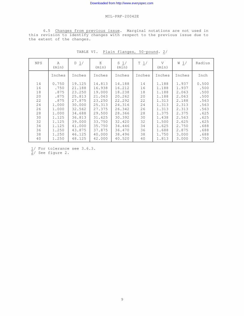
TABLE VI. Plain flanges, 50-pound. 2/
NPS A(min)
D 1/ E(min)
S 1/(min)
T 1/ V(min)
W 1/ Radius
1416182022242628303234363840
Inches
0.750 .750 .875 .875 .8751.0001.0001.0001.1251.1251.1251.2501.2501.250
Inches
19.12521.18823.25025.81327.87530.00032.56234.68836.81339.00041.00043.87546.12548.125
Inches
14.81316.93819.00021.06323.25025.31327.37529.50031.62533.75035.75037.87540.00042.000
Inches
14.18816.21218.23820.26222.29224.31626.34228.36630.39232.42034.44636.47038.49640.520
Inches
1416182022242628303234363840
Inches
1.1881.1881.1881.1881.3131.3131.3131.3751.4381.5001.6251.6881.7501.813
Inches
1.9371.9372.0632.0632.1882.3132.3132.3752.5632.6252.7502.8753.0003.000
Inch
0.500 .500 .500 .500 .563 .563 .563 .625 .625 .625 .688 .688 .688 .750
1/ For tolerance see 3.6.3. 2/ See figure 2.
Downloaded from http://www.everyspec.com

MIL-PRF-20042E
10
TABLE VII. Plain flanges, 150-pound, standard sizes. 4/
NPS O.D. A(min)
C(min)
D 2/ E(min)
S 2/3/ T 2/3/ V(min)
W 2/ Radius P
1/ 1/43/81/23/4
1 1-1/41-1/22
2-1/23
3-1/24
4-1/25
5-1/26 7 8 9
10
12
Inches
0.540.675.840
1.0501.3151.6601.9002.3752.8753.5004.0004.5005.0005.5636.1256.6257.6258.6259.625
10.750
12.750
Inch
0.375.375.375.438438
.438
.438
.438
.500
.500
.500
.500
.500
.563
.563
.563
.563
.625
.688
.688
.750
Degree
---------------------------------------
2222222
2
Inches
3.2503.3753.5633.8134.2504.2505.0635.5636.1256.6257.1887.6888.1889.0639.563
10.12511.31312.37513.93815.000
17.625
Inches
0.8131.0001.1631.3441.6252.0002.2502.7503.2503.8754.3884.9385.4386.0006.5007.0638.0639.125
10.18811.313
13.438
Inches
0.540.675.840
1.0501.3151.6601.9002.3752.8753.5004.0004.5005.0005.5636.1256.6257.6258.6259.625
10.750
12.750
Inches
0.40.54.71.92
1.181.531.772.242.713.313.814.284.765.325.886.367.368.339.25
10.38
12.25
Inches
0.266.313.375.406.438.500.625.656.625.625.688.688.688.688.750.750.813.938
1.0001.063
1.250
Inches
0.875.938
1.0001.0631.1251.2501.3751.3751.3751.3751.4381.4381.5001.5631.6881.6881.8132.0002.1882.250
2.500
Inch
0.250.250.250.250.250.313.313.313.313.313.313.375.375.375.438.438.438.438.500.500
.500
Inch
0.008.008.008.008.016.016.016.016.031.031.031.031.031.047.047.047.047.063.063.063
.063
1/ For flanged gauge connections with 0.250 inch O.D. or 0.500 inch O.D. tube, “S” becomes 0.250 + 0.003 or 0.500 + 0.003 respectively “T” becomes 0.12 or 0.38 respectively. - .000 - .0002/ For tolerance see 3.6.3.3/ The eccentricity of bores “S” and “T” shall be not greater than that shown in column P where measured.4/ See figure 2.
Downloaded from http://www.everyspec.com

MIL-PRF-20042E
11
TABLE VIII. Plain flanges, 250-pound, standard sizes. 3/
NPS O.D. A(min)
C(min)
D 1/ E(min)
S 2/1/ T 2/1/ V(min)
W 1/ Radius P
1/4 3/8 1/2 3/4 1 1-1/4 1-1/2 2 2-1/2 3 3-1/2 4 5 6 8 10 12
Inches
0.540 .675 .840 1.050 1.315 1.660 1.900 2.375 2.875 3.500 4.000 4.500 5.563 6.625 8.62510.75012.750
Inches
0.688 .688 .688 .688 .750 .813 .813 .813 .938 .9381.0001.0001.0631.1881.3131.4381.500
Degree
------------------------------------22222
Inches
3.250 3.375 3.563 3.813 4.250 4.500 5.063 5.563 6.125 6.625 7.188 7.688 9.06310.12512.37515.00017.625
Inches
0.813 1.000 1.156 1.344 1.625 2.000 2.250 2.750 3.250 3.875 4.375 4.938 6.000 7.063 9.12511.31313.438
Inches
0.540.675840
1.0501.3151.6601.9002.3752.8753.5004.0004.5005.5636.6258.625
10.75012.750
Inches
0.398.532.697.907
1.1711.5021.7422.1862.6863.2863.7864.2525.2786.3218.286
10.32512.322
Inches
0.266.313.375.406.438.500.625.656.625.625.688.688.688.750.938
1.0631.250
Inches
1.1881.2501.3131.3131.4381.6251.7501.7501.8131.8131.9381.9382.0632.3132.6883.0003.250
Inch
0.250 .250 .250 .250 .250 .313 .313 .313 .313 .313 .375 .375 .375 .438 .438 .500 .500
Inch
0.008 .008 .008 .008 .016 .016 .016 .016 .031 .031 .031 .031 .047 .047 .063 .063 .063
1/ For tolerance see 3.6.3. 2/ The eccentricity of bores “S” and “T” shall be not greater than that shown in column P where measured. 3/ See figure 2.
Downloaded from http://www.everyspec.com

MIL-PRF-20042E
12
TABLE IX. Plain flanges, 400-pound, standard sizes. 5/
NPS O.D. A(min)
C(min)
D 3/ E(min)
S 3/4/ T 3/4/ V(min)
W 3/ Radius P
1/ 1/43/81/23/4
1 1-1/41-1/22
2-1/23
3-1/24
4-1/25
5-1/26 7 8 9
10
Inches
0.540.675.840
1.0501.3151.6601.9002.3752.8753.5004.0004.5005.0005.5636.1256.6257.6258.6259.625
10.750
Inches
0.688.688.688.688750
.813
.813
.813
.938
.9381.0001.0001.0001.0631.1251.1881.2501.3131.3751.438
Degree
---------------------------------------
2222222
Inches
3.7503.8754.0004.3135.0635.3755.9386.5007.5638.1258.6889.2506.688
10.37511.37511.93813.12514.75015.87517.000
Inches
0.8751.0631.2501.4381.7502.1252.3752.8753.3754.0004.5005.0005.6256.1886.7507.3138.3759.375
10.50011.625
Inches
0.540.675.840
1.0501.3151.6601.9002.3752.8753.5004.0004.5005.0005.5636.1256.6257.6258.6259.625
10.750
Inches
0.41.54.71.92
1.181.531.772.24
2/2/2/2/2/2/2/2/2/2/2/2/
Inches
0.266.313.375.406.438.500.625.656
1.0001.0001.0001.1251.1251.2501.2501.3751.3751.5001.6251.750
Inches
1.1881.2501.3131.3131.4381.6251.7501.7502.3132.3752.4382.6252.6252.8132.9383.1253.2503.5003.7504.000
Inch
0.250.250.250.250.250.313.313.313.500.500.500.563.563.563.625.625.688.688.750.750
Inch
0.008.008.008.008.016.016.016.016.031.031.031.031.031.047.047.047.047.063.063.063
1/ For flanged gauge connections with 0.250 inch O.D. or 0.500 inch O.D. tube, “S” becomes 0.250 + 0.003 or 0.500 + 0.003 respectively and “T” becomes 0.12 and 0.38 respectively. - .000 - .0002/ Bore to suit inside diameter of tube (see 6.2).3/ For tolerance see 3.6.3.4/ The eccentricity of bores “S” and “T” shall be not greater than that shown in column P where measured.5/ See figure 2.
Downloaded from http://www.everyspec.com

MIL-PRF-20042E
13
TABLE X. Machining details for type PR, 50-pound flanges,standard sizes. 2/
N MNPS O 1/
Minimum Maximum Minimum Maximum
1416182022242628303234363840
Inch
0.395 .395 .395 .395 .457 .457 .457 .488 .520 .551 .613 .645 .676 .707
Inch
0.398 .398 .398 .398 .398 .398 .398 .398 .398 .398 .398 .398 .398 .398
Inch
0.408 .408 .408 .408 .408 .408 .408 .408 .408 .408 .408 .408 .408 .408
Inches
14.36616.39018.41620.44022.50634.53026.55628.58030.60632.63434.66036.68438.71040.734
Inches
14.38616.41018.43620.46022.52624.55026.57628.60030.62632.65434.68036.70438.73040.754
1/ For tolerance see 3.6.32/ See figure 1.
Downloaded from http://www.everyspec.com

MIL-PRF-20042E
14
TABLE XI. Machining details for type PR, 100-, 150-, 250- and 400-pound flanges, standard size. 4/
N MNPS O.D. O 1/
Minimum Minimum Minimum Minimum
1/4 3/8 1/2 3/4 1 1-1/4 1-1/2 2 2-1/2 3 3-1/2 4 2/ 4-1/2 5 2/ 5-1/2 6 2/ 7 8 2/ 9 102/3/ 113/ 12
Inches
0.540 .675 .8401.0501.3151.6601.9002.3752.8753.5004.0004.5005.0005.5636.1256.6257.6258.6259.62510.75011.75012.750
Inch
0.100 .117 .149 .154 .154 .185 .217 .232 .217 .185 .217 .217 .217 .217 .248 .248 .247 .270 .301 .333 .364 .426
Inch
0.068 .083 .083 .099 .130 .130 .192 .192 .192 .255 .255 .255 .255 .255 .255 .255 .320 .398 .398 .398 .398 .398
Inch
0.078 .093 .093 .109 .140 .140 .202 .202 .202 .265 .265 .265 .265 .265 .265 .265 .330 .408 .408 .408 .408 .408
Inches
0.614 .764 .9291.1591.4241.7692.0112.4862.9883.6134.1134.6735.1735.7366.2986.7987.7988.7989.79810.92311.96312.963
Inches
0.639 .784 .9491.1791.4441.7892.0312.5063.0083.6334.1334.6935.1935.7566.3186.8187.8188.8189.81810.94311.98312.983
1/ For tolerance see 3.6.3. 2/ Not for 250-pound flange. 3/ Not for 400-pound flange. 4/ See figure 1.
Downloaded from http://www.everyspec.com

MIL-PRF-20042E
15
TABLE XII. Drilling dimensions, 50-pound flanges. 1/
Flange jointNPS
Number ofholes
Diameter ofholes
Pitch circleP.C.
Pitchcord
1416182022242628303234363840
1920222426283032353636363636
Inches
0.938 .938 .9381.0631.0631.0631.1881.1881.1881.1881.1881.3131.3131.313
Inches
17.37519.43821.50023.81325.87528.00030.31332.43834.56336.75038.75041.37543.62545.625
Inches
2.863.043.063.113.123.133.173.183.103.203.383.613.803.98
1/ See figure 2.
Downloaded from http://www.everyspec.com
MIL-PRF-20042E
16
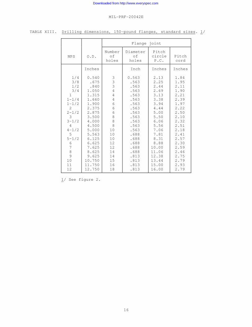
TABLE XIII. Drilling dimensions, 150-pound flanges, standard sizes. 1/
Flange joint
NPS O.D.Number
ofholes
Diameterof
holes
PitchcircleP.C.
Pitchcord
1/43/81/23/4
1 1-1/41-1/22
2-1/23
3-1/24
4-1/25
5-1/26 7 8 9
10 11 12
Inches
0.540.675.840
1.0501.3151.6601.9002.3752.8753.5004.0004.5005.0005.5636.1256.6257.6258.6259.625
10.75011.75012.750
3 3 3 4 4 4 6 6 6 8 8 810101012121414151618
Inch
0.563 .563 .563 .563 .563 .563 .563 .563 .563 .563 .563 .563 .563 .688 .688 .688 .688 .688 .813 .813 .813 .813
Inches
2.13 2.25 2.44 2.69 3.13 3.38 3.94 4.44 5.00 5.50 6.06 5.56 7.06 7.81 8.31 8.8810.0011.0612.3813.4415.0016.00
Inches
1.84 1.95 2.11 1.90 2.21 2.39 1.97 2.22 2.50 2.10 2.32 2.51 2.18 2.41 2.57 2.30 2.59 2.46 2.75 2.79 2.93 2.79
1/ See figure 2.
Downloaded from http://www.everyspec.com

MIL-PRF-20042E
17
TABLE XIV. Drilling dimensions, 250-pound flanges, standard sizes. 1/
Flange joint
NPS O.D. Numberof
holes
Diameterof
holes
PitchcircleP.C.
1/4 3/8 1/2 3/41 1-1/41-1/22 2-1/23 3-1/24 5 6 8 10 12
Inches
0.540 .675 .8401.0501.3151.6601.9002.3752.8753.5004.0004.5005.5636.6258.62510.75012.750
3334446668881012141518
Inch
0.563 .563 .563 .563 .563 .563 .563 .688 .688 .688 .688 .688 .688 .688 .688 .813 .813
Inches
2.132.252.442.693.133.383.944.445.005.506.066.567.818.8811.0613.4416.06
1/ See figure 2.
Downloaded from http://www.everyspec.com

MIL-PRF-20042E
18
TABLE XV. Drilling dimensions, 400-pound flanges, standard sizes. 1/
Flange joint
NPS O.D.Number
ofholes
Diameterof
holes
PitchcircleP.C.
Pitchcord
1/43/81/23/4
1 1-1/41-1/22
2-1/23
3-1/24
4-1/25
5-1/26 7 8 9 10
Inches
0.540.675.840
1.0501.3151.6601.9002.3752.8753.5004.0004.5005.0005.5636.1256.6257.6258.6259.625
10.750
3444556788991011111212131415
Inches
0.563 .563 .563 .563 .688 .688 .688 .688 .813 .813 .813 .813 .813 .813 .938 .938 .9381.0631.0631.063
Inches
2.63 2.75 2.88 2.19 3.75 4.06 4.63 5.19 6.00 6.56 7.13 7.69 8.25 8.81 9.6310.1911.3812.7513.8815.00
Inches
2.27 1.94 2.03 2.25 2.20 2.39 2.31 2.25 2.30 2.51 2.44 2.63 2.55 2.48 2.71 2.64 2.94 3.05 3.09 3.12
1/ See figure 2.
Downloaded from http://www.everyspec.com

MIL-PRF-20042E
19
TABLE XVI. Dimensions of silver brazing ring for 50-pound flanges.
FNominalpipesize
Q+ 0.003
K+ 0.003
H
Minimum Maximum
1416182022242628303234363840
Inch
0.0960.0960.0960.0960.1150.1150.1150.1150.1150.1150.1150.1150.1150.115
Inch
0.3910.3910.3910.3910.3910.3910.3910.3910.3910.3910.3910.3910.3910.391
Inches
14.38616.41018.43620.46022.52624.55026.57828.60030.62632.65434.68036.70438.73040.754
Inch
0.0730.0730.0730.0730.0730.0730.0730.0730.0730.0730.0730.0730.0730.073
Inch
0.2660.2660.2660.2660.3020.3020.3020.3020.3020.3020.3020.3020.3020.302
Downloaded from http://www.everyspec.com

MIL-PRF-20042E
20
TABLE XVII. Dimensions of silver-brazing ring for 100-, 150-,250-, and 400-pound flanges.
FNominalpipesize
Q+ 0.003
K+ 0.003
H
Minimum Maximum
1/43/81/23/4
1 1-1/41-1/22
2-1/23
3-1/24 5 6 7 8 9
10 12
Inch
0.035 .040 .040 .050 .050 .050 .050 .050 .050 .050 .050 .080 .080 .080 .080 .080 .080 .080 .096
Inch
0.063 .078 .078 .094 .125 .125 .188 .188 .188 .250 .250 .250 .250 .250 .391 .391 .391 .391 .391
Inches
0.639 .784 .949 1.179 1.444 1.789 2.031 2.506 3.008 3.633 4.133 4.693 5.756 6.818 7.818 8.818 9.81810.94312.983
Inch
0.073 .073 .073 .073 .073 .073 .073 .073 .073 .073 .073 .073 .073 .073 .073 .073 .073 .073 .073
Inch
0.130 .130 .130 .130 .135 .135 .135 .135 .135 .167 .167 .229 .229 .261 .261 .261 .261 .261 .261
Downloaded from http://www.everyspec.com

MIL-PRF-20042E
21
CONCLUDING MATERIAL
Custodians: Preparing activity: Army - CR4 Navy - SH Navy – SH (Project 4730-0672) Air Force - 99
Review activities: DLA - CC Navy - OS Navy - YD2 Air Force - 82
Downloaded from http://www.everyspec.com

STANDARDIZATION DOCUMENT IMPROVEMENT PROPOSAL
INSTRUCTIONS
1. The preparing activity must complete blocks 1, 2, 3, and 8. In block 1, both the document number and revision lettershould be given.
2. The submitter of this form must complete blocks 4,5,6, and 7 and send to preparing activity.
3. The preparing activity must provide a reply within 30 days from receipt of the form.
NOTE: This form may not be used to request copies of documents, nor to request waivers, or clarification ofrequirements on current contracts. Comments submitted on this form do not constitute or imply authorization to waiveany portion of the referenced document(s) or to amend contractual requirements.
I RECOMMEND A CHANGE:1. DOCUMENT NUMBER
MIL-PRF-20042E2. DOCUMENT DATE (YYYYMMDD)
1999/09/163. DOCUMENT TITLE
FLANGES, PIPE BRONZE (SILVER BRAZING)4. NATURE OF CHANGE (Identify paragraph number and include proposed rewrite, if possible. Attach extra sheets as needed)
5. REASON FOR RECOMMENDATION
6. SUBMITTERa. NAME (Last, First, Middle Initial) b. ORGANIZATION
c. ADDRESS (Include Zip Code) d. TELEPHONE (Include Area Code)
(1) Commercial
(2) DSN (if applicable)
7. DATE SUBMITTED (YYYYMMDD)
8. PREPARING ACTIVITYa. NAMESEA O3Q
b. TELEPHONE (Include Area Code)(1) Commercial (2) DSN
(703) 602-1828x114 332-1828
c. ADDRESS (Include Zip Code)Commander, Naval Sea Systems CommandATTN: SEA 03Q, 2531 Jefferson Davis HwyArlington, VA 22242-5160
IF YOU DO NOT RECEIVE A REPLY WITHIN 45 DAYS, CONTACT:Defense Standardization Program Office (DLSC-LM)8725 John J. Kingman Road, Suite 2533,Fort Belvoir, VA 22060-6221Telephone (703) 767-6888 DSN 427-6888
DD Form 1426, FEB 1999 (EG) PREVIOUS EDITION IS OBSOLETE WHS/DIDR, Feb 99
Downloaded from http://www.everyspec.com