mil std 331 amend
TRANSCRIPT

7/18/2019 Mil Std 331 Amend
http://slidepdf.com/reader/full/mil-std-331-amend 1/286
MIL-STD-331C
w/CHANGE 122 June 2009
SUPERSEDINGMIL-STD-331C5 JANUARY 2005
DEPARTMENT OF DEFENSETEST METHOD STANDARD
FUZE AND FUZE COMPONENTS,ENVIRONMENTAL AND PERFORMANCE TESTS FOR
AMSC N/A FSG 13GP
DISTRIBUTION STATEMENT A. Approved for public release; distribution is unlimited.
NOT MEASUREMENT
SENSITIVE
Source: https://assist.dla.mil -- Downloaded: 2014-08-10T15:17ZCheck the source to verify that this is the current version before use.

7/18/2019 Mil Std 331 Amend
http://slidepdf.com/reader/full/mil-std-331-amend 2/286
7/18/2019 Mil Std 331 Amend
http://slidepdf.com/reader/full/mil-std-331-amend 3/286
MIL-STD-331Cw/CHANGE 1
iii
Engineering Center, ATTN: RDAR-QES-E, Picatinny Arsenal, NJ 07806-5000 or emailed [email protected]. Since contact information can change, you may want to verify thecurrency of this address information using the ASSIST Online data base athttp://assist.daps.dla.mil.
Source: https://assist.dla.mil -- Downloaded: 2014-08-10T15:17ZCheck the source to verify that this is the current version before use.
7/18/2019 Mil Std 331 Amend
http://slidepdf.com/reader/full/mil-std-331-amend 4/286
MIL-STD-331Cw/CHANGE 1
iv
SUMMARY OF CHANGE 1 MODIFICATIONS
1. Test C1 - Temperature and Humidity, TABLE C1-1 and TABLE C1- II: the start and stop times
on two-cycle days were corrected.
2. Test D1 - Primary Explosive Component Safety Test: a second part was added to determinethe numerical effectiveness of the interrupter.
3. Test D1 - Primary Explosive Component Safety Test, section D1.6 - Alternate and OptionalTests: the Missing Barrier Test was added; the paragraphs for the cookoff test for projectile fuzesand the fast cookoff test for fuzes were deleted.
4. Test D1 - Primary Explosive Component Safety Test, section D1.7.2 - Bibliography: thebibliography was updated.
5. Test D2 - Arming Distance Test, section D2.5.1 - Arming procedure: the four statisticalmethods listed were removed and transferred to Appendix G.
6. Test D-8 - Progressive Arm Test: the use of this test to determine the numerical effectivenessof the interrupter was addressed. Definitions and procedures for testing pyrotechnic trains wereadded.
7. Appendix G - Statistical Methods to Determine the Initiation Probability of One-Shot Devices:this is a new Appendix to the document. The four statistical methods removed from Test D2 areincluded in this Appendix while the Neyer D-Optimal method was added as a fifth method.
8. Typographical and formatting errors were corrected throughout the document.
Source: https://assist.dla.mil -- Downloaded: 2014-08-10T15:17ZCheck the source to verify that this is the current version before use.

7/18/2019 Mil Std 331 Amend
http://slidepdf.com/reader/full/mil-std-331-amend 5/286
MIL-STD-331Cw/CHANGE 1
v
CONTENTS
Section Page
1 SCOPE 1
1.1 Scope 11.2 Safety and Suitability for Service Assessment of Fuzing Systems 11.2.1 NATO 11.2.1.1 STANAG 4157 11.3 Application 31.4 Test identification 31.5 Method of revision 31.6 Method of reference 3
2 APPLICABLE DOCUMENTS 3
2.1 Government documents 32.1.1 Specifications, standards and handbooks 32.1.2 Other Government documents, drawings and publications 42.2 Non-Government publications 52.3 Order of precedence 6
3 DEFINITIONS 6
4 GENERAL REQUIREMENTS 8
4.1 Test usage 84.2 Test compliance 84.3 Selection and specification of tests 84.4 Test equipment 84.4.1 Capability 84.4.2 Accuracy 84.5 Test conditions 94.5.1 Installation of test item 94.5.2 Tolerance of test conditions 94.5.2.1 Temperature 94.5.2.2 Pressure 9
4.5.2.3 Relative humidity 94.5.2.4 Vibration amplitude 94.5.3 Preconditioning and stabilization 94.6 Examination and test criteria 94.6.1 Visual examination 94.6.2 Criteria for passing tests 104.6.2.1 Safe 104.6.2.2 Operable 10
Source: https://assist.dla.mil -- Downloaded: 2014-08-10T15:17ZCheck the source to verify that this is the current version before use.

7/18/2019 Mil Std 331 Amend
http://slidepdf.com/reader/full/mil-std-331-amend 6/286
MIL-STD-331Cw/CHANGE 1
vi
4.7 Safety condition 104.8 Test documentation 104.8.1 Test directive 104.8.2 Test item record 11
4.8.2.1 Condition before test 114.8.2.2 Condition during test 114.8.2.3 Condition after test 114.8.3 Test equipment 114.8.4 Test conditions 114.8.5 Test results 12
5 DETAILED REQUIREMENTS 12
5.1 Individual tests 125.2 Test classification 125.2.1 Group A - Mechanical Shock Tests 12
5.2.2 Group B - Vibration Tests 125.2.3 Group C - Climatic Tests 125.2.4 Group D - Safety, Arming and Functioning Tests 125.2.5 Group E - Aircraft Munition Tests 125.2.6 Group F - Electric and Magnetic Influence Tests 125.3 Test number conversion 125.4 Invoking tests 135.4.1 Alternate and optional tests 135.4.2 Test parameters 13
6 NOTES 13
6.1 Background information 136.1.1 Safety 136.1.2 Short operational time 136.1.3 One-time operation 136.2 Test content and format 146.2.1 Purpose 146.2.1.1 Location 146.2.1.2 Safety, reliability or performance 146.2.1.3 Life cycle phase 146.2.1.4 Environment or performance measurement 146.2.2 Description 14
6.2.2.1 General 146.2.2.2 Fuze configuration 146.2.2.3 Variations 146.2.2.4 Applicable publications 146.2.2.5 Test documentation 156.2.3 Criteria for passing test 156.2.3.1 Fuze condition 156.2.3.2 Decision basis 156.2.4 Equipment 15
Source: https://assist.dla.mil -- Downloaded: 2014-08-10T15:17ZCheck the source to verify that this is the current version before use.

7/18/2019 Mil Std 331 Amend
http://slidepdf.com/reader/full/mil-std-331-amend 7/286
MIL-STD-331Cw/CHANGE 1
vii
6.2.5 Procedure 156.2.6 Alternate and optional tests 156.2.7 Related information 156.2.8 Illustrations and tables 16
6.3 Units of measure 166.4 Test characteristics 176.5 Subject term (key word) listing 176.6 Changes from previous issue 176.7 Useful references 17
Appendix A - Mechanical Shock Tests
A1 Jolt 28 A2.1 Jumble 33 A3 Twelve-meter (40-Foot) Drop 37 A4.1 One and One-half Meter (Five-Foot) Drop 40 A5 Transportation Handling (Packaged Fuzes) 43
Appendix B - Vibrat ion Tests
B1.1 Transportation Vibration (Bare and Packaged Fuzes) 54B2 (Requirement are now in Test B1.1) 98B3 Tactical Vibration 99
Appendix C - Climatic Tests
C1 Temperature & Humidity 118C2 Vacuum-Steam-Pressure 124C3 Salt Fog 128
C4 Waterproofness 133C5 Fungus 135C6 Extreme Temperature 139C7 Thermal Shock 142C8 Leak Detection 146C9 Dust 152C10 Solar Radiation 155
Appendix D - Safety, Arming and Functioning Tests
D1 Primary Explosive Component Safety 163D2 Projectile Fuze Arming Distance 171
D3 Time to Air Burst 174D4 Explosive Component Output 181D5 Rain Impact 192D6 Brush Impact No-Fire 195D7 Mortar Ammunition Fuze Double Loading 204D8 Progressive Arming Test 207
Appendix E - Aircraft Munit ion Tests
E1 Jettison 210
Source: https://assist.dla.mil -- Downloaded: 2014-08-10T15:17ZCheck the source to verify that this is the current version before use.

7/18/2019 Mil Std 331 Amend
http://slidepdf.com/reader/full/mil-std-331-amend 8/286
MIL-STD-331Cw/CHANGE 1
viii
E2 Low Altitude Accidental Release 213E3 Arrested Landing Munition Pull-off 215E4 Catapult and Arrested Landing Forces 218E5 Simulated Parachute Air Delivery 221
Appendix F - Electric and Magnetic Inf luence Tests
F1 Electrostatic Discharge (ESD) 225F2 High-Altitude Electromagnetic Pulse 235F3 Electromagnetic Radiation Hazards(HERO) 245F4 Electromagnetic Radiation, Operational preparation(EMRO) 251
Appendix G - Stat istical Methods to Determine the Initiation Probabil ity of One-Shot Devices
G1 Purpose 260G2 Description 260G3 Methods 260G3.1 Probit Method 260G3.2 Langlie Method 262G3.3 OSTR Method 264G3.4 Bruceton Method 267G3.5 Neyer D-Optimal Method 268G4 Related Information 271G5 Bibliography 272G6 Glossary 272
Source: https://assist.dla.mil -- Downloaded: 2014-08-10T15:17ZCheck the source to verify that this is the current version before use.
7/18/2019 Mil Std 331 Amend
http://slidepdf.com/reader/full/mil-std-331-amend 9/286
MIL-STD-331Cw/CHANGE 1
1
1. SCOPE
1.1 Scope. This standard describes tests used by the Department of Defense (DoD) to
determine the safety, reliability and performance characteristics of weapon system fuzes and fuzecomponents at any stage in their life cycle.
1.2 Safety and Suitability for Service Assessment of Fuzing Systems. The centralobjective of Safety and Suitability for Service (S3) of Fuzing Systems is to confirm and documentthat the fuzing system is safe and performs as intended in all expected service environments. Inthe U.S., each service has a Board that reviews the compliance of fuzing systems with therequirements of MIL-STD-1316 and the result of fuzing tests conducted in accordance with theprocedures described in MIL-STD-331.
1.2.1 NATO. A similar process has been agreed by NATO’s AC/326 SG2, with the designsafety requirements standards being STANAG 4187 and the fuze procedures document being Allied Ordnance Publication 20 (AOP-20). In addition, SG2 has agreed on STANAG 4157, Edition2, S3, Fuzing Systems: Test Requirements for Assessment of Safety and Suitability for Service,which is based on the principles of AOP-15, Safety and Suitability for Service of Munitions andExplosives. Both NATO and the DoD Fuze Engineering Standardization Working Group (FESWG)have agreed that, given their similar objectives, MIL-STD-331 and AOP-20 will be published asone document. Background information on the objectives and requirements of STANAG 4157 isprovided below to allow MIL-STD-331 users to understand and apply the principles of S3assessment in their use of this publication.
1.2.1.1 STANAG 4157. The primary intent of STANAG 4157 is to require NATO nationsconduct S3 assessments of all new fuzing systems, and maintain on-file for provision (upon justified request) to other nations a Fuzing System S3 Assessment file containing all designreviews, test results, and the overall national assessment. Table 1 of STANAG 4157 lists theNational Fuze S3 Assessment Authorities for NATO nations which have agreed to the provisions.This includes the separate agencies for the U.S. Air Force, Army and Navy.
STANAG 4157 requires that nations conduct tests in accordance with test proceduresdescribed in AOP-20, selected from Tables 2 and 3 in accordance with an agreed methodologydescribed as follows:
a. Table 2 lists the tests that have been agreed by NATO as being mandatory for conduct of astandardized S3 assessment of a fuzing system. It is important to note that these are notnecessarily all of the tests that will be required for national qualification of a fuzing system,as specifying qualification requirements is a national responsibility. Also, nations may waiveone or more of the tests listed in Table 2, if they can justify why conduct of the test is notrequired.
b. Table 3 lists the fuzing system tests that nations should consider including in theirqualification test programs. While not mandatory for standardized S3 assessments of fuzing
Source: https://assist.dla.mil -- Downloaded: 2014-08-10T15:17ZCheck the source to verify that this is the current version before use.

7/18/2019 Mil Std 331 Amend
http://slidepdf.com/reader/full/mil-std-331-amend 10/286
MIL-STD-331Cw/CHANGE 1
2
systems, conduct of a number of these tests will generally be required for qualifying aspecific fuzing system. As for the tests listed in Table 2, the test procedures for the Table 2tests are provided in AOP-20.
STANAG 4157, includes general provisions for selecting test quantities and pass/fail criteria, aswell as tailoring test procedures:
a. Tailoring of Environmental Test Procedures: The standardized tests described in AOP-20may be tailored in accordance with the following general principles:
(1) the environment to be simulated should be at least as severe as the expected serviceenvironment for the fuze;
(2) given their generally greater sensitivity to the service environment, fuzes warrant testingin more severe environments than the munitions in which they are installed;
(3) the rationale used in tailoring the standard environmental tests should be documented
and retained as part of the S3 assessment file; the rationale could include avoidingduplication of tests conducted to meet national fuze standards.
b. Electromagnetic Environment Testing: Testing of fuzes in service electromagnetic (EM)environments is conducted with two primary objectives:
(1) confirming that the fuze electronics will remain suitable for sevice after exposure toworst-case environments; and
(2) confirming that fuze safety is not degraded for fuzes employing electric detonators, orfuzes employing electronic circuits controlling all or part of the safety-and-arming
system.
c. The safety and suitability test requirements for fuzes should be based on all scenariosexamined in the Fuze Design Safety Hazard Assessment (conducted in accordance withSTANAG 4187 (or MIL-STD-1316), and must include confirmation that:
(1) the energy passed through the initiating element of the fuze explosive train produced bya service EM environment will not exceed the factored no-fire safety threshold, asdefined in STANAG 4187 (or MIL-DTL-23659); and
(2) the service EM environment will not degrade safety or suitability by damaging or
upsetting the electronic circuitry controlling the safety-and arming and initiation systems,respectively.
d. Quantities: Quantities should be selected so as to provide statistically meaningful resultsand should reflect the quantities used in previous assessments of similar fuzes whichsubsequently entered into service. The overall objective should be to both meet nationalrequirements and provide a convincing demonstration of fuze safety and suitability forservice to other participating nations. The approval of the quantities of fuzes to be
Source: https://assist.dla.mil -- Downloaded: 2014-08-10T15:17ZCheck the source to verify that this is the current version before use.

7/18/2019 Mil Std 331 Amend
http://slidepdf.com/reader/full/mil-std-331-amend 11/286
MIL-STD-331Cw/CHANGE 1
3
subjected to the mandatory and recommended tests is the responsibility of the NationalSafety Approving Authority (normally, the agencies listed in Table 1).
e. Pass/Fail Criteria: The general criterion for passing any of the mandatory and
recommended tests is that an unsafe condition not be observed during the test or uponexamination of the fuze after the test. Given the relatively small sample sizes generallyemployed, one observed unsafe condition generally constitutes a failure. Depending uponthe fuze or system design requirement, a small decrease in fuze performance may beacceptable if safety is not affected; large degradations in fuze performance indicate that thefuze is not acceptable for service use. Pass/fail criteria are provided in the test procedures,where appropriate.
1.3 Application. This standard generally applies to all fuzes, as well as components ofweapon systems serving a fuze function, such as torpedo exploders and underwater mine firingmechanisms.
1.4 Test identification. The detailed requirements are documented as individual tests andcontained as appendices to this standard. Each test is identified by an alpha-numeric sequencewhich begins with a letter indicating the test group. This is followed by a sequentially-assignednumber.
1.5 Method of revision. Tests are revised on an individual basis and issued as changenotices when required. Revised tests are identified by a decimal number after the test number.Revised test parameters affecting test results apply to fuzes developed subsequent to the changenotice. All current test requirements are described in the first five sections of the test. Superseded
test requirements with applicable dates are located in Section 6 of the test and identified asalternate tests for older fuzes.
1.6 Method of reference. Specific tests or test sequences may be invoked by thedeveloping or procuring agency within a formal engineering development test plan or procurementspecification. Additionally, many tests permit variations which should be selected at the time thetest is invoked. Variations may include test configuration, materials, methods, sample size orpass/fail criteria. Decimal number revisions are not to be referenced.
2. APPLICABLE DOCUMENTS
2.1 Government documents.
2.1.1 Specifications, standards, and handbooks. The following specifications,standards, and handbooks form a part of this document to the extent specified herein. Unlessotherwise specified, the issues of these documents are those cited in the solicitation or contract.
FEDERAL SPECIFICATIONS
QQ-L-201 Lead Sheet
Source: https://assist.dla.mil -- Downloaded: 2014-08-10T15:17ZCheck the source to verify that this is the current version before use.
7/18/2019 Mil Std 331 Amend
http://slidepdf.com/reader/full/mil-std-331-amend 12/286
MIL-STD-331Cw/CHANGE 1
4
DEPARTMENT OF DEFENSE SPECIFICATIONS
MIL-T-18404 Torpedoes, Environmental Requirements, GeneralSpecifications for
MIL-DTL-23659 Initiators, Electric, General Design Specifications for
DEPARTMENT OF DEFENSE STANDARDS
MIL-STD-167-1 Mechanical Vibrations of Shipboard Equipment (Type I -Environmental and Type II - Internally Excited)
MIL-STD-167-2 Mechanical Vibrations of Shipboard Equipment(Reciprocating Machinery and Propulsion System and
Shaft, Types III, IV and V)MIL-STD-202 Test Methods for Electronic and Electrical Component
PartsMIL-STD-322 Explosive Components, Electrically Initiated, Basic
Evaluation Tests forMIL-STD-461 Requirements for the Control of Electromagnetic
Interference Characteristics of Subsystems andEquipment
MIL-STD-464 Electromagnetic Environmental Effects Requirements forSystems
MIL-STD-810 Environmental Engineering Considerations and
Laboratory TestsMIL-STD-1316 Fuze Design, Safety Criteria for
DEPARTMENT OF DEFENSE HANDBOOKS
MIL-HDBK-310 Global Climatic Data for Developing Military ProductsMIL-HDBK-1512 Electroexplosive, Subsystems, Electrically Initated,
Design Requirements and Test Methods
(Copies of these documents are available online at http://assist.dla.mil/quicksearch/ orhttp://assist.daps.dla.mil or from the Standardization Document Order Desk, 700 Robbins Avenue,
Building 4D, Philadelphia PA 19111-5094.)
2.1.2 Other Government documents, drawings and publ ications. The following otherGovernment documents, drawings and publications form a part of this standard to the extentspecified herein. Unless otherwise specified, the issues are those cited in the solicitation.
DRAWINGS
81-3-35 (Army) Machine, Jumble Testing, Assembly
Source: https://assist.dla.mil -- Downloaded: 2014-08-10T15:17ZCheck the source to verify that this is the current version before use.

7/18/2019 Mil Std 331 Amend
http://slidepdf.com/reader/full/mil-std-331-amend 13/286
MIL-STD-331Cw/CHANGE 1
5
81-3-37 (Army) Machine, Jumble Testing, Assembly9 255 299 (Army) Jolt Machine40 897 (Navy) Drop Tower ConstructionQEL 1386-1 to -45 (Navy) Jumble Machine
QEL 1387-1 (Navy) Jumble Machine ModificationOS 6341 (Navy) General Ordnance Design Requirements
TECHNICAL MANUALS
OD 7547 (Navy) Vacuum-Steam-Pressure Accelerated Aging Chamber
ARMY REGULATIONS
AR 70-38 Research, Development, Test and Evaluation of Materielfor Extreme Climatic Conditions
AR 700-15 Packaging of Materiel
(Copies of drawings and publications required by contractors for specific acquisitions should beobtained from the contracting activity.)
2.2 Non-Government publications. The following documents form a part of thisdocument to the extent specified herein. Unless otherwise specified, the issues of the documentsare those specified in the solicitation or contract.
AMERICAN SOCIETY FOR TESTING MATERIALS (ASTM)
ASTM-A108 Steel Bars, Carbon, Cold-Finished, Standard Quality ASTM-A109/A109M Steel, Strip, Carbon, (0.25 Maximum Percent) Cold-
Rolled ASTM-C208 Board Insulating Cellulosic Fiber ASTM-D880 Impact Testing for Shipping Containers and Systems,
Standard Test Method For ASTM-D6199 Wood Members of Containers and Pallets, Quality of ASTM-G21 Materials to Fungi, Synthetic Polymeric, Determining
Resistance of ASTM-G22 Bacteria, Determining Resistance of Plastics to
(Application for copies are available from www.astm.org or ASTM International, 100 Barr HarborDrive, West Conshohocken, PA 19428-2959.)
SOCIETY OF AUTOMOTIVE ENGINEERS
SAE-AMS-QQ-A-225 Aluminum Alloy, 2024, Bar, Rod, and Wire; Rolled,Drawn, or Cold Finished
SAE-AS8660 Silicone Compound NATO Code Number S-736
Source: https://assist.dla.mil -- Downloaded: 2014-08-10T15:17ZCheck the source to verify that this is the current version before use.

7/18/2019 Mil Std 331 Amend
http://slidepdf.com/reader/full/mil-std-331-amend 14/286
MIL-STD-331Cw/CHANGE 1
6
(Copies of these documents are available from www.sae.org or Society of Automotive Engineers,400 Commonwealth Drive, Warrendale, PA 15096-0001.)
2.3 Order of precedence. In the event of a conflict between the text of this document and
the references cited herein, the text of this document takes precedence. Nothing in this document,however, supersedes applicable laws and regulations unless a specific exemption has beenobtained.
3. DEFINITIONS
The following definitions of terms used within this standard are intended to provide betterapplication of this standard to all elements of fuzing.
3.1 Al ternate test. A method applied to older fuzes designed before adoption of thecurrent standard test (Section 6 of each test).
3.2 Armed. A fuze is considered armed when any firing stimulus can produce fuzefunction.
a. A fuze employing explosive train interruption is considered armed when the interrupter(s)position is ineffective in preventing propagation of the explosive train at a rate equal to orexceeding 0.5 percent at a confidence level of 95 percent.
b. A fuze employing a non-interrupted explosive train is considered armed when the stimulusavailable for delivery to the initiator equals or exceeds the initiator's maximum no-firestimulus (MNFS).
3.3 Arming delay. The time elapsed, or distance traveled by the munition, from launch toarming.
3.4 Assembled fuze. The completed fuze with all component parts put together; a fuzerequiring no added components or parts to prepare it for installation into the munition in which it isto function. Assembling the fuze is the process of putting the parts and components together.
3.5.1 Booster and lead explosives. Booster and lead explosives are compounds orformulations which are used to transmit and augment the detonation reaction.
3.6 Enabling. The act of removing or activating one or more safety features designed toprevent arming, thus permitting arming to occur subsequently.
3.7 Environment. A specific physical condition to which the fuze may be exposed.
3.8 Explosive ordnance disposal. The detection, identification, field evaluation, renderingsafe, recovery and final disposal of unexploded explosive ordnance.
Source: https://assist.dla.mil -- Downloaded: 2014-08-10T15:17ZCheck the source to verify that this is the current version before use.

7/18/2019 Mil Std 331 Amend
http://slidepdf.com/reader/full/mil-std-331-amend 15/286
MIL-STD-331Cw/CHANGE 1
7
3.9 Explosive train. The detonation or deflagration train (that is, transfer mechanism),beginning with the first explosive element (for example, primer or detonator) and terminating in themain charge (for example, munition functional mechanism, high explosive or pyrotechniccompound).
3.10 Function. A fuze functions when it produces an output capable of initiating a train offire or detonation in an associated munition.
3.11 Fuze (Fuzing System). A physical system designed to sense a target or respond toone or more prescribed conditions, such as elapsed time, pressure or command, and initiate atrain of fire or detonation in a munition. Safety and arming are primary roles performed by a fuze topreclude ignition of the munition before the desired position or time.
3.12 Fuze safety system. The aggregate of devices (for example, environment sensors,launch event sensors, command functioned devices, removable critical items, or logic networks,
plus the initiation or explosive train interrupter, if applicable) included in the fuze to prevent armingand functioning of the fuze until a valid launch environment has been sensed and the arming delayhas been achieved.
3.13 Independent safety feature. A safety feature is independent if its integrity is notaffected by the function or malfunction of other safety features.
3.14 Initiator. A device capable of directly causing functioning of the fuze explosive train.
3.15 Interrupted explosive train. An explosive train in which the explosive path betweenthe primary explosives and the lead and booster (secondary) explosives is functionally separated
until arming.
3.16 Invalid test. A test whose procedure has been compromised in a way which rendersthe results inconclusive. An invalid test is not counted as a failure of the test article.
3.17 Optional test. Additional or more severe criteria not required by the standard test.Optional tests are usually performed during fuze development and intended to determine themargin of safety or reliability in the design (Section 6 of each test).
3.18 Performance. The quantitative measurement of an operational characteristic orrange, such as arming time, functioning time, explosive output or leak rate.
3.19 Premature function. A fuze function before completion of the arming delay.
3.20 Primary explosives. Primary explosives are sensitive materials, such as lead azideor lead styphnate, which are used to initiate detonation. They are used in primers or detonators,are sensitive to heat, impact or friction and undergo a rapid reaction upon initiation.
3.21 Reliability. The ability of a fuze to operate or successfully perform all of its functionsafter exposure to an adverse environment.
Source: https://assist.dla.mil -- Downloaded: 2014-08-10T15:17ZCheck the source to verify that this is the current version before use.

7/18/2019 Mil Std 331 Amend
http://slidepdf.com/reader/full/mil-std-331-amend 16/286
MIL-STD-331Cw/CHANGE 1
8
3.22 Safety feature. An element or combination of elements that prevents unintentional
arming or functioning.
3.23 Standard test. The current, commonly accepted method for evaluating fuze safety,performance or reliability (Sections 1 through 5 of each test).
3.24 Test directive. A formal test plan, procurement specification, or other documentwhich specifies environmental or performance testing in accordance with MIL-STD-331.
3.25 Test parameter. A property which permits variation of the test configuration orprocedure. Since selection of test parameters can change the controlled environment orotherwise affect results, each variation must be specified in the test directive.
4. GENERAL REQUIREMENTS
4.1 Test usage. The selection of tests for use shall be made within the application statedin Section 1.5. Tests may be used individually, or in any sequence desired.
4.2 Test compliance. Each individual test shall be performed in the manner specifiedtherein. The standardized structure of each test is described in Section 6.2. The test reportshall indicate if a test is not performed as specified and document the differences.
4.3 Selection and specification of tests. A test directive shall be used to invoke the useof each test or sequence of tests described in this standard. Specification of tests shall bemade in accordance with 4.8.1 and 5.4.
4.4 Test equipment.
4.4.1 Capability. All equipment required for the test shall provide or meet the conditionsrequired.
4.4.2 Accuracy. The accuracy of instruments and test equipment used to control ormonitor the test parameters shall be verified periodically to the satisfaction of the procuringactivity. This shall be at least every 12 months, preferably once every 6 months. All instrumentsand test equipment used in conducting the tests specified herein shall:
a. Conform to laboratory standards whose calibration is traceable to the U.S. National Instituteof Standards and Technology.
b. Have a measurement error less than one-fourth the tolerance for the variable to bemeasured. In the event of conflict between this requirement and any accuracy requirementin any one of the tests of this standard, the accuracy requirement of the test being usedshall be used.
c. Be appropriate for measuring the conditions concerned.
Source: https://assist.dla.mil -- Downloaded: 2014-08-10T15:17ZCheck the source to verify that this is the current version before use.

7/18/2019 Mil Std 331 Amend
http://slidepdf.com/reader/full/mil-std-331-amend 17/286
MIL-STD-331Cw/CHANGE 1
9
4.5 Test conditions. Unless otherwise specified herein, all measurements and tests shall
be performed at ambient temperature, pressure, and relative humidity. Whenever these conditionsmust be controlled in order to obtain reproducible results, a reference temperature of 23ºC (73ºF),
an atmospheric pressure of 760 millimeters of mercury, and a relative humidity of 50 percent shallbe used together with whatever tolerances are required to obtain the desired precision ofmeasurement. Actual test conditions shall be recorded during the test period, whether controlledor not.
4.5.1 Installation of test item. Unless otherwise specified, the test item shall be installed,mounted, attached to or placed in the test equipment in a manner that will simulate service use. Iffixtures or adapters are required, they shall be designed to provide the same simulation. Plugs,covers, plates, cables, and accessory items used in service shall remain in place. Whenmechanical or electrical connections on the test item are not used, the connections shall beprovided the same amount of protection normally given during service use.
4.5.2 Tolerance of test conditions. The maximum allowable tolerances of test conditions,excluding the accuracy of instruments, unless otherwise specified shall be as follows:
4.5.2.1 Temperature. Plus or minus 2ºC (3.6ºF).
4.5.2.2 Pressure. When measured by devices such as a manometer, plus or minus 5percent or 1.3 mm (0.05 in) of mercury, whichever provides the greater accuracy. When measuredby devices such as ion gauges, plus or minus 10 percent to 1 x 10 -5 torr.
4.5.2.3 Relative humidi ty. Plus 5 percent, minus 0 percent RH.
4.5.2.4 Vibration ampli tude. Sinusoidal, plus or minus 10 percent; random, plus or minus30 percent.
4.5.3 Precondi tioning and stabilization. Unless otherwise specified, no preconditioning orstabilization shall be required. When preconditioning is required, the conditions shall be institutedand brought to the level and for the time specified, at which point the test shall begin. Whenstabilization is required, the conditions shall be held at the level and for the time specified.Checking operation of or adjusting test equipment with the test item installed or exposed, at anytime (pre-test, during test, post-test) shall be kept at a minimum. Such time shall be considered apart of the test time if time is a factor of test item performance or life.
4.6 Examination and test criteria.
4.6.1 Visual examination. At the beginning or completion of any test herein, or when testexposure is considered to have affected the test item, a visual examination shall be made of theitem and any damage observed shall be recorded in the test item record. The extent of the visualexamination shall be governed by the nature of the test item and the damage suspected orincurred. The examination shall not be performed in a manner which interferes with anysubsequent performance or operational test which is necessary to determine conformance with the
Source: https://assist.dla.mil -- Downloaded: 2014-08-10T15:17ZCheck the source to verify that this is the current version before use.
7/18/2019 Mil Std 331 Amend
http://slidepdf.com/reader/full/mil-std-331-amend 18/286
MIL-STD-331Cw/CHANGE 1
10
criteria for passing the test.
4.6.2 Criteria for passing tests. Fuzes shall be evaluated by standards given in Section 3of each test at the completion of the procedure. These criteria are determined by the purpose of
each test. For performance tests, the criteria are established by the design or procuring agencyand are stated in the appropriate test directive. For environmental safety and reliability tests, thecriteria are generally characterized by the permissible fuze deterioration or damage sustainedduring the environmental simulation. Basically, the test item shall remain either safe or both safeand operable during and following the test as described below. Additional criteria further definingor clarifying these standards may be specified in individual tests.
4.6.2.1 Safe. Fuzes usually contain explosive materials and directly affect explosives in theweapon. Therefore, determination of the safety condition of a fuze is vital in establishing itsperformance adequacy. Usable fuzes shall be safe to handle, transport, store and install.Unusable fuzes shall be safe for disposal consistent with the hazard level of the situation and in
accordance with established regulations.
a. Safe for use. The fuze shall maintain its safety features in a condition which will not createa hazard for personnel or cause any subsequent action which will compromise the safetyconditions required during handling, transportation, storage and use. Fuze use includesinstallation and firing or release of the weapon where damage or irregularity does notprevent assembly of the fuze to the weapon or loading.
b. Safe for disposal. If the fuze is unusable, it shall maintain its safety features, includingExplosive Ordnance Disposal (EOD) features, in a condition which will permit its disposalwithout injury to personnel using the applicable handling and disposal regulations and
procedures.
4.6.2.2 Operable. When the fuze is provided its required inputs, it shall perform to completionof its function and sequence producing all required outputs within the operating period or at thespecified time. Determination of operability may require firing the fuze using a procedure adaptedto the type of fuze being tested and its associated munition.
4.7 Safety condi tion. When the test item contains explosive material or components, safetyprocedures and equipment consistent with the hazard level shall be used to ensure adequateprotection for personnel and equipment in case of an explosion.
4.8 Test documentation. A complete record of test conduct, conditions, data, and so forthshall be kept to provide a proper analysis of the technical effort and results. Formal reporting shallbe done only as required by the contract or work assignment. To assure a proper record, thefollowing major items of the test effort shall be documented for any test performed. This listing isgeneral in nature and is applicable to all tests of the standard. Individual tests may call outadditional data items.
4.8.1 Test directive. The test directive, is used to invoke standard tests and provide allnecessary details as to their conduct. The test directive may be incorporated into a procurement
Source: https://assist.dla.mil -- Downloaded: 2014-08-10T15:17ZCheck the source to verify that this is the current version before use.
7/18/2019 Mil Std 331 Amend
http://slidepdf.com/reader/full/mil-std-331-amend 19/286
MIL-STD-331Cw/CHANGE 1
11
specification or prepared as a separate development test plan and shall include:
a. the test number and title,b. the quantity of fuzes to be tested,
c. the test sequence,d. inspections, measurements, data gathering and data analysis methods to be performed,e. modifications or waivers of standard test requirements (refer to 4.2),f. applicable alternate tests, optional tests or parameters (refer to 5.4), andg. procedures to verify fuze operation following completion of each test.
4.8.2 Test item record. A test item record is used to document the identity, features,condition and performance of the test article before, during and after each test or test sequence.
4.8.2.1 Condit ion before test. Prior to conducting the tests, the condition of each test itemshall be established by methods such as visual inspection, X-rays, leak test or special performance
tests. The following shall be recorded:
a. serial number or other identifier,b. unique identifying characteristics,c. missing components,d. presence or absence of explosive components,e. modifications to facilitate testing or instrumentation, andf. if required, the performance level shall be established using appropriate tests identified by
the test directive and a record made of compliance with performance specifications.
4.8.2.2 Condit ion during test. Significant observations of the test article or
instrumentation shall be recorded. If the test article must be operated during the test, a recordshall be kept of the data for comparison with pre-test or post-test performance.
4.8.2.3 Condit ion after test. Following the environmental test:
a. Applicable procedures such as breakdown, visual inspection, X-ray or leak test shall beperformed and the observations or results recorded.
b. If test article performance must be demonstrated, the record shall include a description ofeach operational test performed, its specification and relative performance of the test article.
c. Analysis, conclusions (pass/fail determination), and any corrective action shall be recordedbased on the results of post-test examination and performance tests, a. and b., above.
4.8.3 Test equipment. A listing of all equipment used during the test effort as described inSection 4.4, Test equipment.
4.8.4 Test conditions. The conditions of test, as applicable to the test requirements, asdescribed in 4.5, Test conditions.
Source: https://assist.dla.mil -- Downloaded: 2014-08-10T15:17ZCheck the source to verify that this is the current version before use.

7/18/2019 Mil Std 331 Amend
http://slidepdf.com/reader/full/mil-std-331-amend 20/286
MIL-STD-331Cw/CHANGE 1
12
4.8.5 Test resul ts. The test data analysis and the technical conclusions made from thedata analysis. The data analysis may be represented by examples, dependent upon the natureand extent of the data to be analyzed and the methods used. Any deviations or waivers on theoriginal test plan or the procedures of the standard shall be documented, along with the technical
reasons for the changes.
5. DETAILED REQUIREMENTS
5.1 Individual tests. Detailed requirements are specified in individual tests appearing asappendices to this standard. The format for each test is standardized and is explained in Section6.2, below. Each test is composed of seven sections. Sections 1 through 5 are mandatory forcompliance with MIL-STD-331. Alternate procedures which may be applicable to older fuzes andoptional procedures which are recommended for further testing are contained in Section 6 of theindividual test. Section 7 of each test contains background or additional sources of informationand is not necessary for compliance.
5.2 Test classification. Tests are grouped by the environment to which the fuze isexposed or by the test purpose. Certain tests combine two or more environments; for example,vibration under exposure to extreme temperature. In these cases the test is grouped by theprimary environment being evaluated.
5.2.1 Group A - Mechanical Shock Tests. Fuzes are subjected to single or repeatedimpacts which generally simulate mishandling that might occur during the logistical or operationalcycles.
5.2.2 Group B - Vibration Tests. Fuzes are subjected to vibrations of specified frequency,
amplitude and duration simulating conditions which are anticipated during transport or tactical use.
5.2.3 Group C - Climatic Test. Fuzes are exposed to realistic extreme climatic conditionsfor specified periods of time.
5.2.4 Group D - Safety, Arming and Functioning Tests. These tests measureperformance characteristics of fuzes, such as, explosive safety, arming distance or time andoutput.
5.2.5 Group E - Aircraft Munit ion Tests. Fuzes associated with airborne munitions aresubjected to impacts or forces which might be encountered in takeoff and landing, accidental
separation of the munition from the aircraft, or intentional safe jettison.
5.2.6 Group F - Electric and Magnetic Influence Tests. Fuzes are subjected toenvironments such as electrostatic discharge (ESD), electromagnetic pulse (EMP),electromagnetic radiation (EMR), lightning, and so forth.
5.3 Test number conversion. Previous editions of this standard used a three digitnumeric to identify each test. Where existing product specifications refer to these test numbers,refer to Table I to find the current test.
Source: https://assist.dla.mil -- Downloaded: 2014-08-10T15:17ZCheck the source to verify that this is the current version before use.
7/18/2019 Mil Std 331 Amend
http://slidepdf.com/reader/full/mil-std-331-amend 21/286
MIL-STD-331Cw/CHANGE 1
13
5.4 Invoking tests. In addition to the requirements of 4.8.1, the test directive shall specify
applicable alternate or optional tests, as well as various test parameters described in this standard.These are identified in Table II.
5.4.1 Alternate and optional tests. Alternate tests apply to older fuzes developed prior toadoption of the current standard test (Sections 1 through 5 of each test). Optional tests may bespecified to determine the safety or reliability design margin during fuze development. Alternateand optional test procedures are described in Section 6 of each test.
5.4.2 Test parameters. Many tests contained in this standard may be performed in variousways, depending on the fuze design or other factors. Some variations change the controlledenvironment or affect the results of the test. As a minimum, the test directive shall identify therequired variation for each parameter listed in Table II. In addition, each test should be reviewedto determine if further clarification is necessary. Additional detail is recommended for:
a. explosive loading of the test article and associated munition,b. modification of the test article, andc. specifications for test fixtures.
6. NOTES
(This section contains information of a general or explanatory nature that may be helpful, but isnot mandatory.)
6.1 Background information. The tests contained in this standard have been developed
over a period of years by designers and users of fuzes. Although they were developed based onfunctional aspects unique to fuzes, many of the tests have been specified in the development andprocurement of other ordnance components and test equipment. Application of many testsappears to be limited only by the physical capacity of the test facilities; however, carefulconsideration should be given to various aspects of these tests before they are specified.
6.1.1 Safety. The first aspect is the requirement of safety, due to the direct presence ofexplosives in the fuze or in the concommitant effect of the fuze on associated explosives in theoperational sequence of the weapon. The tests must reflect complete safety in test conduct, aswell as establish that the fuze design achieves the safety attributes which are required for serviceuse.
6.1.2 Short operational time. The second functional aspect is the short operational timeof a fuze in relation to the comparatively longer operational time and service life of the completeweapon. Each test must be devised to provide the full extraction of information on fuzeperformance under such restrictive operational conditions.
6.1.3 One-time operation. The third functional aspect is the one-time life of a fuze, acondition which is coincident with the previously stated aspect of short operational time. The one-time performance tests in many instances cause destruction of the test item or components of the
Source: https://assist.dla.mil -- Downloaded: 2014-08-10T15:17ZCheck the source to verify that this is the current version before use.

7/18/2019 Mil Std 331 Amend
http://slidepdf.com/reader/full/mil-std-331-amend 22/286
MIL-STD-331Cw/CHANGE 1
14
test item, thus restricting subsequent analysis. The test design must anticipate and provide for themaximum return of information under such conditions.
6.2 Test content and format. Each test is prepared in a standardized format divided into
seven sections: purpose, description, criteria for passing test, equipment, procedure, alternate oroptional tests, and related information. The first five sections contain all essential information forsetting up and conducting the test and are mandatory for compliance with this standard. Alternateor optional tests in Section 6 may be specified by the test directive. Related information is notmandatory; it is intended to provide background to the test. The content of each test section isdescribed below.
6.2.1 Purpose. The purpose of each test must contain the following information:
6.2.1.1 Location. The test must be identified as a laboratory test or field test.
6.2.1.2 Safety, reliabi lity or performance. Tests which determine if the fuze is safe foruse or disposal must be identified as safety tests. If fuze arming or functioning is required either byprocedures within the test or by conducting a separate test, the test must be regarded as areliability test. If the test quantitatively measures the operational parameters of the fuze, it must beidentified as a performance test.
6.2.1.3 Life cycle phase. Identify the fuze life cycle phase which is the subject of the test.These include storage, handling, transportation, preparation for use or any combination of these.
6.2.1.4 Environment or performance measurement. State the specific conditions of thetest such as exposure to extreme temperature, vibration, and so forth, the performance
characteristic being measured such as arming distance.
6.2.2 Description.
6.2.2.1 General. This is a general description of the test procedure, expanding on thepurpose stated above.
6.2.2.2 Fuze configuration. State the physical configuration of the fuze during testing,whether or not explosive components are installed, whether or not the fuze is packaged, orwhether the fuze is installed in a live or inert munition or munition simulator.
6.2.2.3 Variations. Description of any variations in test configuration, procedure, or criteriafor passing the test. A statement is included that appropriate variations will be selected in the testdirective when the test is invoked.
6.2.2.4 Applicable publications. A standardized statement identifying other publicationsforming a part of this test. Complete bibliographical references are contained in the basicstandard."All standards, specifications, drawings, procedures and manuals which form a part of this test arelisted in Section 2 of the introduction to this standard. Special attention is directed to (listing of any
Source: https://assist.dla.mil -- Downloaded: 2014-08-10T15:17ZCheck the source to verify that this is the current version before use.

7/18/2019 Mil Std 331 Amend
http://slidepdf.com/reader/full/mil-std-331-amend 23/286
MIL-STD-331Cw/CHANGE 1
15
unique requirements)."
6.2.2.5 Test documentation. A reference to the introduction of the standard containinggeneral requirements for documentation of all tests. Unique documentation is identified within the
test."Test plans, performance records, equipment, conditions, results and analysis must bedocumented in accordance with 4.8 of the general requirements to this standard."
6.2.3 Criteria for passing test. For most performance tests, the criteria for passing thetest must be stated in the development test plan or production specification. For safety andreliability tests, the following standardized statements must be applied.
6.2.3.1 Fuze condit ion. List one of three standardized statements identifying the conditionof the fuze following the test.
"At the completion of this test, the fuze must be safe for transportaion, handling and use, aswell as operable in accordance with 4.6.2.1a and 4.6.2.2 of the general requirements to thisstandard."
"At the completion of this test, the fuze must be safe for transportation, storage, handling anduse in accordance with 4.6.2.1a of the general requirements to this standard. The fuze doesnot have to be operable.
"At the completion of this test, the fuze must be safe for disposal in accordance with 4.6.2.1b ofthe general requirements to this standard."
6.2.3.2 Decis ion basis. The following statement is applied.
"Breakdown, inspection, other appropriate tests and engineering judgment will form the basis forthe decision that fuzes have passed or failed the test."
6.2.4 Equipment. This section contains specifications for all support equipment necessaryto conduct the test.
6.2.5 Procedure. This is the step-by-step procedure for conducting the test.
6.2.6 Alternate and optional tests. This section may contain alternate procedures or
equipment specified prior to issuance of the current information contained in sections 1 through 5of the test. Alternate procedures may apply to older fuze designs for which the current testrequirements are not intended. In addition, optional test requirements may be specified in thissection. These include more severe conditions, such as longer test duration, higher temperatures,and so forth. Optional tests are typically performed during fuze development to determine themargin of safety or physical limitations of the design. If required, compliance with this section ofthe test will be stated in the test directive.
6.2.7 Related information. This section may include the rationale or background
Source: https://assist.dla.mil -- Downloaded: 2014-08-10T15:17ZCheck the source to verify that this is the current version before use.

7/18/2019 Mil Std 331 Amend
http://slidepdf.com/reader/full/mil-std-331-amend 24/286
MIL-STD-331Cw/CHANGE 1
16
information for any particular aspect of the test. This section may also contain a bibliographyreferring to background information in other publications. It may not contain references todocuments such as standards and specifications which form a part of the test. Completereferences to these documents are contained in Section 2 of the introduction to the standard and
may be referenced by number in Section 2 of each test. Material contained in this section is notmandatory.
6.2.8 Illustrations and tables. Illustrations and tables requiring a full page will normallyappear after the last page of text.
6.3 Units of measure. Units of measure are expressed in metric or SI (SystemeInternational d'Unites) wherever applicable. The corresponding English equivalent normallyfollows in parentheses. Standard abbreviations commonly used throughout this document are asfollows:
Metric (SI) Englishmm - millimeters in - inches
m - meters ft - feet
km - kilometers mi - miles
mg - milligrams oz - ounces
g - grams
kg - kilograms lb - pounds
l - liter cu ft - cubic feet
ºC - degrees Celsius ºF - degrees Fahrenheit
MPa - MegaPascal (gage) psig - pounds/square inch(gage)
cal - calorie BTU - British Thermal Unit
cc - cubic centimeter
ml - milliliter
Standard Other
hr - hours kn - knots
s - seconds rpm - revolutions per minute
min - minute rps - revolutions per second
g - gravity units
o - degrees
Source: https://assist.dla.mil -- Downloaded: 2014-08-10T15:17ZCheck the source to verify that this is the current version before use.
7/18/2019 Mil Std 331 Amend
http://slidepdf.com/reader/full/mil-std-331-amend 25/286
MIL-STD-331Cw/CHANGE 1
17
Standard caliber sizes or other units of measure normally specified in English or metric have notbeen converted. Examples include 5-in or 76-mm guns and pressure expressed in millimeters of
mercury.
6.4 Test characteristics. Table III provides a summary of test characteristics for MIL-STD-331. These include the purpose of the tests, environments investigated, criteria for passing thetests, configuration of the fuze or fuzed munition, location, and whether or not the test is normallyperformed during development or production.
6.5 Subject term (key word) l isting.
Aircraft munitions
Arming
Climatic
Drop
Electric influence
Functioning
Jolt
Jumble
Magnetic influence
Safety
Shock
Transportation
Vibration
6.6 Changes from previous issue. The margins of this standard are marked withvertical lines to indicate where changes from the previous issue were made. This was done as aconvenience only and the Government assumes no liability whatsoever for any inaccuracies inthese notations. Bidders and contractors are cautioned to evaluate the requirements of thisdocument based on the entire content irrespective of the marginal notations and relationship tothe last previous issue.
6.7 Useful references. MIL-Q-9858, Quality Program Requirements (canceled).
Source: https://assist.dla.mil -- Downloaded: 2014-08-10T15:17ZCheck the source to verify that this is the current version before use.

7/18/2019 Mil Std 331 Amend
http://slidepdf.com/reader/full/mil-std-331-amend 26/286
MIL-STD-331Cw/CHANGE 1
18
TABLE I. Test Number Conversion
If specificationreferences the test
indicated below, ...
then use sections 1 thru5 of the test indicated
below unless otherwisespecified.
If specificationreferences the test
indicated below, ...
then use sections 1 thru5 of the test indicated
below unless otherwisespecified.
101.3 A1 120 or 403 B1.1, Section B1.6.5
102.2 A2.1 121 Deleted
103.2 A3 122 B3
104 or 401 B1.1, Section B1.6.3 123 B1.1, Section B1.6.2
105.1 C1 124 B1.1, Section B1.6.2
106.1 C2 125.1 A5
107.1 C3 126 F1.2
108 C4 201 thru 205 E1109.1 Deleted 206 E2
110.1 C5 207 D2, Section 5.2
111.1 A4.1 208.2 D2
112.1 C6 209 E3
113.1 C7 210.1 D3
114 or 402 B1.1, Section B1.6.4 211 or 406 Deleted (Replaced byU.S.
115.3 D1 Army TOP 7-2-506 and509)
116.1 C9 212 E4117 E5 213 or 405 Deleted (Replace by
U.S.
118 C8 Army TOP 7-2-506 and509)
119 or 404 B1.1, Section B1.6.2 301 thru 303 D4
Source: https://assist.dla.mil -- Downloaded: 2014-08-10T15:17ZCheck the source to verify that this is the current version before use.

7/18/2019 Mil Std 331 Amend
http://slidepdf.com/reader/full/mil-std-331-amend 27/286
MIL-STD-331Cw/CHANGE 1
19
TABLE II. Test ParametersTest Specification
Parameter Variable Para.
A1 Jolt Test fixture a. Government jolt machineb. Commercial shock machine
A1.4.1 A1.4.2
Optional tests a. Subject fuzes to two cyclesb. Perform test until fuze fails
A1.6
A2.1 Jumble No variations
A3 Twelve-meter (40foot) Drop
Test articleconfiguration
a. Unpackaged, fuzed munitionb. Packaged, fuzed munitionc. Packaged fuze1. All explosive loaded fuzes2. Dummy fuzes at interior package
positions
A3.2.2
Booster a. Explosive loadedb. Inert A3.5.2.1
Pass/fail criteria a. No detonation permittedb. Detonator may fire
A3.3.2
Temperature a. Ambient onlyb. Ambient and extreme (specify)
A3.5.3
Optional test Different test height A3.6
A4.1 One and One-halfMeter (five foot)Drop
Procedure a. Two-drop scheduleb. One-drop schedule
A4.2.1
Test article
configuration
a. Unpackaged, fuzed munition
b. Unpackaged fuzec. Both a. and b. if shipped both ways
A4.2.3
Booster a. Explosive loadedb. Inert
A4.2.2
Pass/fail criteria a. Safe for useb. Safe for use and operable
A4.3.1
Optional tests* a. Extreme temperatureb. Different impact surfacesc. Larger drop heightd. Alternately disabled safety features
A4.6
5 Trans-portation
Handling (PackagedFuzes)
Test article
configuration
a. Complete fuzes in package
1. All explosive loaded fuzes2. Dummy fuzes at interior package
positionsb. Packaged, fuzed, explosive loaded
munitionc. Packaged, fuzed, inert munition
A5.2.2
Temperature Specify optional temperatures A5.2.4.1
Source: https://assist.dla.mil -- Downloaded: 2014-08-10T15:17ZCheck the source to verify that this is the current version before use.

7/18/2019 Mil Std 331 Amend
http://slidepdf.com/reader/full/mil-std-331-amend 28/286
MIL-STD-331Cw/CHANGE 1
20
Pass/fail criteria Define acceptable minor damage A5.2.4.2
Alternate tests a. Specification for fuzes developedbefore 18 May 82 apply.
b. Specifications for Army fuzesdeveloped between 15 Oct 76 and18 May 82 apply.
A5.6
B1.1 Trans-portationVibration (Bareand PackagedFuzes)
Test articleconfiguration
a. Complete bare fuzesb. Bare, fuzed, inert munitionc. Complete, packaged fuzes
B1.2.3
Transportationconveyancescenario
Commercial vehicle, military vehicle, jet aircraft, turboprop aircraft,helicopter, cargo ship, combat ship, orunspecified.
B1.2.2.1
Alternate tests a. Bare and packaged fuzes designedbetween 5/18/82 and 1/1/97; barefuzes designed between 11/1/73and 5/18/82
B1.6.2
b. Bare fuzes designed before 11/1/73 B1.6.3
c. Packaged fuzes designed before5/18/82
B1.6.4
d. Pachaged fuzes designed between10/15/76 and 5/18/82 (Army only)
B1.6.5
B3 Tactical Vibration Applicableprocedure
a. Air-launched munitionb. Ground-launched munition
c. Ship-launched munitiond. Underwater-launched munition
B3.2.1
Booster & lead a. Explosive loadedb. Inert
B3.2.2
C1 Temp-erature andHumidity
No variations
C2 Vacuum-Steam-Pressure
No variations
C3 Salt Fog Test duration a. 48 hoursb. 96 hours
C3.2.1,C3.6.1
C4 Water-proofness Test articleconfiguration
With or without explosive components C4.2.2
C5 Fungus Optional test Additional fungi types (specify) C5.6
C6 ExtremeTemperature
Temperature a. Extreme low and highb. Extreme lowc. Extreme high
C6.2.1
C7 Thermal Shock No variations
Source: https://assist.dla.mil -- Downloaded: 2014-08-10T15:17ZCheck the source to verify that this is the current version before use.

7/18/2019 Mil Std 331 Amend
http://slidepdf.com/reader/full/mil-std-331-amend 29/286
MIL-STD-331Cw/CHANGE 1
21
C8 Leak Detection Pass/fail criteria Specify leak rate C8.3
Test method a. Halogen gas methodb. Helium gas method
c. Bubble methodd. Volume-sharing method
C8.5
Alternate test Lower pressure C8.6
C9 Dust No variations
C10 Solar Radiation Method a. Solar radiation and heat cyclingb. Solar radiation only
C10.2.1
Test articleconfiguration
a. Unpackaged, fuze munitionb. Fuzed munitionc. Packaged fuzes
C10.2.2
Booster & lead a. Explosive loaded
b. Inert
C10.2.3
D1 Primary Explosive Test fixture As appropriate ** D1.4.1
Component Safety Fragmentation box As appropriate ** D1.4.2
Firing mechanism As appropriate ** D1.4.3
Test articleconfiguration
As appropriate ** D1.4.4
Fuze modification As appropriate ** D1.5.1
Worst casesimulation
Sequential or simultaneous initiation ofexplosive components **
D1.5.2
Optional tests * a. Possible failure pathsb. Progressive armingc. Barrier thicknessd. Increased outpute. Increased sensitivityf. Cookoff
D1.6.2D1.6.3D1.6.4D1.6.5D1.6.6
D1.6.7 &D1.6.8
D2 Projectile Fuze Arming Distance
Munition a. Explosive loadedb. Inert round
c. Spotting charge
D2.2.2
Test method a. Probitb. Langliec. Weibull one-shot transformed
response (OSTR)d. Bruceton
D2.5.1
Optional test Muzzle arming D2.5.2
Source: https://assist.dla.mil -- Downloaded: 2014-08-10T15:17ZCheck the source to verify that this is the current version before use.

7/18/2019 Mil Std 331 Amend
http://slidepdf.com/reader/full/mil-std-331-amend 30/286
MIL-STD-331Cw/CHANGE 1
22
D3 Time to Air Burst Pass/fail criteria Must be specified in test directive D3.3.1
Test weapon As appropriate D3.4.1
Munition a. Explosive loaded
b. Inert with spotting charge
D3.4.2
Temperature a. Ambientb. Must be specified in test directive
D3.5.3
D4 ExplosiveComponent
Test method a. Dent blockb. Disc perforation
D4.2.1.1D4.2.1.2
Output Pass/fail criteria Must be specified in test directive D4.3
Initiation device As appropriate ** D4.4.1
Witness device As appropriate ** D4.4.2 &D4.4.3
Test fixture As appropriate ** D4.4.4
Measuring device As appropriate ** D4.4.5
D5 Rain Impact Temperature Any other than ambient must bespecified in test directive
D5.2.5
Target Must be specified in test directive D5.2.9
Optional test Increased test article velocity D5.6
D6 BrushImpact no-Fire Test
TemperatureIntercept conditions
Ambient unless otherwise specified intest planThe intended incept conditions must
be specified in the test plan
D6.2.3D6.2.8.1
D7 Mortar AmmunitionFuze DoubleLoading Test
Temperature Ambient unless otherwise specified intest plan
D7.5.4
D8 Progressive Arming Test
Test methodology Will be consistent with those given insection D2.5 of test method D2
D8.5.1
E1 Jettison Test method a. Air dropb. Ground launcher
E1.2.1.1E1.2.1.2
Test article
configuration
Use of a scavenger fuze E1.4.2
Target a. Soilb. Waterc. Sand
E1.4.3.1E1.4.3.2E1.4.3.3
Instrumentation Must be specified in test directive E1.4.4
E2 Low-altitude Accidental
No variations
Source: https://assist.dla.mil -- Downloaded: 2014-08-10T15:17ZCheck the source to verify that this is the current version before use.
7/18/2019 Mil Std 331 Amend
http://slidepdf.com/reader/full/mil-std-331-amend 31/286
MIL-STD-331Cw/CHANGE 1
23
Release
E3 Arrested Landing
Munition Pull-off
No variations
E4 Catapult and Arrested LandingForces
No variations
E5 SimulatedParachute AirDelivery
Optional tests * a. System without energy absorbersb. High-velocity test
E5.6.1E5.6.2
F1.1 Electro-staticDischarge (ESD)
Lead & Booster a. Explosive loadedb. Inert
F1.2.4
Location ofdischarge points
Must be specified in test directive F1.2.6
Number ofdischarges per fuze
Must be specified in test directive F1.2.6
Type of electrodecontrol
Must be specified in test directive F1.2.6
Discharge gap Must be specified in test directive F1.2.6
Test sequence Must be specified in test directive F1.2.6
F2.1 High-altitudeElectromag-neticPulse
Test articleconfiguration
a. Lead and boosterb. Inert munitionc. Standard fuze package
F2.2.2
Number of testitems
a. Instrumented (one item per testmode)
b. Uninstrumented (ten items per testmode)
F.2.2.4
Optional tests Tactical conditions F2.6
F3.1 Electro-magneticRadiation Hazards
(HERO)
Test articleconfiguration
Lead and booster F3.2.3
F4.1 Electro-magneticRadiation Opera-tional (EMRO)
Test articleconfiguration
Lead and booster F4.2.3
Source: https://assist.dla.mil -- Downloaded: 2014-08-10T15:17ZCheck the source to verify that this is the current version before use.

7/18/2019 Mil Std 331 Amend
http://slidepdf.com/reader/full/mil-std-331-amend 32/286
MIL-STD-331Cw/CHANGE 1
24
* Select as many as apply.
** Although some guidance is given, specific detail should be contained in the test directive
TABLE III. Test Characteris tics
Group Test Purp-ose
Environ-ment
Criteria forPassing
Test
Muni-tion
Pack-aged
Loca-tion
Use
MechanicalShock
A1 Jolt S T Safe foruse1
None No Lab D,P
A2.1 Jumble S T Safe foruse1
None No Lab D,P
A3 12-m Drop S H Safe fordisposal
None,I,L 2 3 D,P
A4.1 1.5-m Drop S,R,P H,U Safe foruse4
None,I,L No 3 D,P
A5TransportationHandling
S,R,P H,U Operable None,I,L Yes Lab D,P
Vibration B1.1TransportationVibration
S,R T Operable None 2 Lab D,P
B3 TacticalVibration
S,R U Operable None No Lab D,P
Climatic C1 Temperature& Humidity
S,R S Operable None No Lab D,P
C2 Vacuum-Steam-Pressure
S,R S Operable None No Lab D
C3 Salt Fog S,R S Operable None No Lab D
C4Waterproofness
S,R S,H Operable None No Lab D,P
C5 Fungus S,R S Operable None No Lab D
C6 ExtremeTemperature
S,R S Operable None No Lab D,P
C7 ThermalShock
S,R S Operable None No Lab D,P
C8 LeakDetection
P S 7 None No Lab D,P
Source: https://assist.dla.mil -- Downloaded: 2014-08-10T15:17ZCheck the source to verify that this is the current version before use.

7/18/2019 Mil Std 331 Amend
http://slidepdf.com/reader/full/mil-std-331-amend 33/286
MIL-STD-331Cw/CHANGE 1
25
C9 Dust S,R S,H,U Operable None No Lab D
C10 SolarRadiation
S,R S Operable None,I 2 Lab D
Safety, Arming &Functioning
D1 PrimaryExplosiveComponentSafety
S S,H,T,U 9 None No Lab D,P
D2 ProjectileFuze ArmingDistance
S,P U 7,10 I,L No Field D,P
D3 Time to AirBurst
P U 7 I,L No Field D,P
D4 ExplosiveComponent
Output
P U 7 None No Lab D,P
D5 Rain Impact S,P U 11 I No Field D
D6 Brush ImpactNo-Fire Test
S,P U Safe,Operable
I No Field D
D7 Mortar Ammunition FuzeDouble LoadingTest
S H,U Safe I No Field D
D8 Progressive Arming Test
S S,H,T,U 1 None No Lab D
AircraftMunition E1 Jettison S U Safe fordisposal12 L No Field D
E2 Low Altitude AccidentalRelease
S U Safe fordisposal12
L No Field D
E3 ArrestedLanding Pull-off
S U Safe fordisposal
12
L No Field D
E4 Catapult & Arrested LandingForces
S,R U Operable l No Field D
E5 SimulatedParachute AirDelivery
S,R H,T,U Operable None,I Yes Field D
Electric &Magnetic
F1.1 ElectrostaticDischarge
S,R H,T,U Safe foruse14
None 2 Lab D,P
Influence F2.1ElectromagneticPulse
S,R S,H,T,U Operable I No Lab D
Source: https://assist.dla.mil -- Downloaded: 2014-08-10T15:17ZCheck the source to verify that this is the current version before use.

7/18/2019 Mil Std 331 Amend
http://slidepdf.com/reader/full/mil-std-331-amend 34/286
MIL-STD-331Cw/CHANGE 1
26
F3.1 EMRHazards(HERO)
S,R S,H,T,U Operable None 2 Lab D
F4.1 EMR,
Operational(EMRO)
S,R S,H,T,U Operable None No Lab D
Legend: Purpose S = safety; R = reliability; P = performance.Environment: S = storage; T = transportation; H = handling; U = use.Munition: None = test conducted without munition; I = inert round or spotting charge;L = live round.Use: D = development; P = production.
Notes: 1. No detonation of explosive components.
2. Test contains requirements for both bare and packaged fuzes.3. Drop facility may be located in a laboratory or at an outdoor field test site.4. Test directive may optionally specify that the fuze be operable.5. The fuze is not required to operate after a 96-hour test.6. No evidence that water has entered fuze.7. Specified in the test directive.8. Inspection ports and labels must be clear when dust is wiped away.9. No detonation beyond interrupter. No ejection of parts. No other hazards.
10. In muzzle safety test, no detonation permitted beyond last safety device.11. Fuze functions on target, not in rain field.12. No detonation of warhead attributed to fuze.
13. At completion of the malfunctioning test, the fuze must be safe for disposal.14. Fuze must also be operable after human body discharge and air replenishment
discharge (packaged) tests.
Source: https://assist.dla.mil -- Downloaded: 2014-08-10T15:17ZCheck the source to verify that this is the current version before use.

7/18/2019 Mil Std 331 Amend
http://slidepdf.com/reader/full/mil-std-331-amend 35/286
MIL-STD-331CW/CHANGE 1 APPENDIX A
27
APPENDIX AMECHANICAL SHOCK TESTS
Source: https://assist.dla.mil -- Downloaded: 2014-08-10T15:17ZCheck the source to verify that this is the current version before use.
7/18/2019 Mil Std 331 Amend
http://slidepdf.com/reader/full/mil-std-331-amend 36/286
MIL-STD-331Cw/CHANGE 1 APPENDIX A
28
TEST A1
JOLT
A1.1 PURPOSE
This is a laboratory safety test simulating ground transportation conditions. The fuze mustwithstand a series of impacts applied in a controlled direction and amplitude.
A1.2 DESCRIPTION
A1.2.1 General . Fuzes are subjected to 1750 impacts in three orientations: majoraxis horizontal and major axis vertical both nose up and nose down.
A1.2.1.1 Jolt machine method. This method shalll be used for fuzes and any required
mounting adapters having a combined weight of 3.6 kg (8 lb) or less and having a configurationpermitting simultaneous testing of three fuzes on one jolt arm. If fewer than three fuzes are to betested, dummy loads, equivalent in mass to the test fuze and fixture, shall be assembled to theunused jolt arm sockets.
A1.2.1.2 Commercial shock machine method. This method shall be used for fuzes andany required mounting adapters having a combined weight of more than 3.6 kg (8 lb) or having aconfiguration which does not permit simultaneous mounting and testing on one arm of the joltmachine.
A1.2.2 Fuze Configurat ion. Only bare, unpackaged fuzes shalll be used in this test. Eachfuze shalll be completely assembled, containing all explosive elements which are a part of the fuzedesign.
A1.2.3 Appl icable publ ications. All standards, specifications, drawings, procedures andmanuals which form a part of this test are listed in Section 2 of the introduction to this standard.Special attention is directed to Dept. of the Army Ordnance Corps Drawing 9 255 299 for the joltmachine.
A1.2.4 Test documentat ion. Test plans, performance records, equipment, conditions,results and analysis shalll be documented in accordance with Section 4.8 of the generalrequirements to this standard.
A1.3. CRITERIA FOR PASSING TEST
A1.3.1 Fuze condit ion. At the completion of this test, the fuze shall be safe fortransportation, storage, handling and use in accordance with 4.6.2.1a of the general requirementsto this standard. No explosive component shalll have initiated. The fuze does not have to be
operable. A1.3.2 Loose fuzes. A test is invalid if the fuze or any required mounting adapter becomes
loose while the machine is operating. A1.3.3 Decision basis. Breakdown, inspection, other appropriate tests and engineering
judgment shall form the basis for the decision that fuzes have passed or failed the test.
A1.4. EQUIPMENT
A1.4.1 Jolt machine method. Equipment for this method shall conform to Department ofthe Army, Ordnance Corps Drawing 9 255 299. The equipment consists of a jolt machine, shown
Source: https://assist.dla.mil -- Downloaded: 2014-08-10T15:17ZCheck the source to verify that this is the current version before use.

7/18/2019 Mil Std 331 Amend
http://slidepdf.com/reader/full/mil-std-331-amend 37/286
MIL-STD-331Cw/CHANGE 1 APPENDIX A
29
in Figure A1-1, either mounted on a base of welded steel plate or set in a concrete foundation. Itsfour arms are pivoted side by side on a common shaft. The free ends of the arms are alternatelyelevated to a height of 102 mm (4 in) by cam action and then allowed to fall freely on a paddedanvil. The cams are adjusted on the cam shaft so that only one arm at a time is jolted.
A1.4.1.1 Sockets and adapters or fixtures. The free end of each arm is provided with
three threaded sockets (2-in-12UN-1B thread), located so that fuzes can be jolted in the threedifferent orientations as specified in A1.2.1. Usually, the manner in which each fuze is assembledto the socket shalll depend on the design of the munition in which the fuze is to be used. In mostcases, it is only necessary to thread the test fuzes directly into the sockets. In other cases, specialadapters or fixtures may be required. Unique fuze-to-munition mounting requirements should beduplicated in this test.
A1.4.1.2 Shock parameters. Although the basic impact pattern imparted to the test fuzeby the jolt machine is largely fixed by the machine's design, the two adjustable parameters shall beset as follows:
a. Jolt arm drop height of 102±5 mm (4±0.2 in).b. Pulse rate of 35±5 impacts per minute.
A1.4.2 Commercial shock machine. A commercial shock machine may be used if it canimpart the characteristic shocks specified in A1.5.2.1 to larger fuzes which cannot be tested withthe jolt machine. It shall be possible for the shock machine to test the fuze in any one of the threeorientations specified in A1.2.1. Requirements covering mounting sockets, adapters, orduplication, shalll be as in A1.4.1.1 for the jolt machine.
A1.5. PROCEDURE
A1.5.1 Jolt machine method. A1.5.1.1 Inspection of equipment. Verify that the equipment is in good operating
condition.a. The drop height of each arm is calibrated by a gage to 102±5 mm (4±0.2 in).
b. The arms are structurally sound, that is, there is no evidence of breaks or cracks.c. All screw and bolt connections are tight.d. The pad is in good working order; that is, it has no tears, no missing pieces, and is not brittle.e. The machine, including the fuze sockets, is electrically grounded.
A1.5.1.2 Mount fuzes to jol t arms. Mount a fuze in each of three orientations of each joltarm used. If the number of fuzes available for testing is less than three per active arm, dummyloads as specified in A1.2.1.1 shalll be used to make up the difference. When tested in thehorizontal position, the fuze shalll be rotationally oriented to receive the jolts on its critical plane ofweakness, if known. Fuzes assembled to the sockets shalll be tightened using torque valuesappropriate for the type of fuze being tested, or as specified in the test directive or productspecification.
A1.5.1.3 Operate machine. Operate the machine through 1750±10 drops. A1.5.1.4 Interim removal. The fuzes shalll be removed from the sockets and inspected for
any degradation that would affect their performance or safety, without further fuze disassembly. A1.5.1.5 Test at other orientations. Repeat the above three steps twice so that at the
conclusion of the test each fuze shalll have received 1750 jolts in each of the three testorientations.
A1.5.1.6 Compl iance. Remove the fuzes from the machine. Analyze the test results anddetermine whether or not the test article meets the pass/fail criteria in Section A1.3. Continuetesting the specified number of items.
Source: https://assist.dla.mil -- Downloaded: 2014-08-10T15:17ZCheck the source to verify that this is the current version before use.
7/18/2019 Mil Std 331 Amend
http://slidepdf.com/reader/full/mil-std-331-amend 38/286
MIL-STD-331Cw/CHANGE 1 APPENDIX A
30
A1.5.2 Commercial shock machine method. A1.5.2.1 Calibration of machine. Prior to use, calibrate the machine with an equivalent
test load to ensure that the fuze shalll be subjected to a half-sine wave pulse, shown in Figure A1-2, having 230±34.5 g peak acceleration for 2.0±0.2 milliseconds duration. The pulse rate for the
jolt machine is 35±5 impacts per minute.
A1.5.2.2 Mount fuze to shock table. Rigidly attach the fuze to the shock table in any ofthree test orientations by the method which the fuze is normally attached to its munition. Torqueshall be appropriate for the type of fuze being tested, or as specified in the test directive or productspecification. When tested in the horizontal position, the fuze shall be rotationally oriented toreceive the shocks on its critical plane of weakness, if known.
A1.5.2.3 Operate machine. Shock the fuze 1750±10 times in the initial orientation. A1.5.2.4 Interim removal. Remove the fuze from shock table and inspect fuze without
further fuze disassembly. A1.5.2.5 Test at other orientations. Repeat the above three steps twice, so that at the
conclusion of the test, the fuze shall have received 1750 shocks in each of the three testorientations. Initial shock positions for the other test fuzes shall be rotated among the three given
positions: horizontal, nose up, and nose down. A1.5.2.6 Compl iance. Remove the fuzes from the machine. Analyze the test results and
determine whether or not the test article meets the pass/fail criteria in Section A1.3. Continuetesting the specified number of items.
A1.6 ALTERNATE AND OPTIONAL TESTS
Additional fuzes may be subjected to two cycles of 1750 jolts in each of the three positions, or untilevidence is obtained that the fuzes have failed, whichever occurs first. The test may also beperformed with each safety feature alternately disabled to demonstrate the ability of the remainingsafety features to provide independent safety.
A1.7 RELATED INFORMATION
A1.7.1 Jolt test background. The jolt test has been used for many years to establish thesafety and general ruggedness of fuze designs under severe conditions of transportation.Transport vehicles have changed in nature since the test was first devised; however, the roughenvironment of transportation is considered to be essentially the same. This test thereforecontinues to be used as a safety and ruggedness test of fuze designs.
A1.7.2 Limi tat ions, jolt machine. When the jolt machine was designed, it was intendedfor projectile fuzes which could be either mounted directly to the sockets or readily adapted to fitthe sockets. As new and larger bomb and missile fuzes of various geometric configurationsevolved, the jolt machine was still used as a test platform, though the fixturing was often verycomplex. It is recognized by test engineers that the jolt machine is not appropriate for some testitems.
A1.7.3 Commercial machine and material substi tution. The revision of 15 October1976 introduced a method using commercial shock machines to test larger fuzes. Also permittedby that revision, were material substitutions of cast nylon in place of wood for the jolt arms andpolyurethane in lieu of leather for the shock pads. The changes were intended to achieve moreuniform testing, facilitate procurement, and to provide longer life for these components withoutsignificantly changing the jolt environment. Mixed substitution of components shall not be allowedas it could result in an entirely different jolt test environment.
A1.7.4 Monitor ing basis. Although the jolt machine is a qualitative type of testing tool, its
Source: https://assist.dla.mil -- Downloaded: 2014-08-10T15:17ZCheck the source to verify that this is the current version before use.

7/18/2019 Mil Std 331 Amend
http://slidepdf.com/reader/full/mil-std-331-amend 39/286
MIL-STD-331Cw/CHANGE 1 APPENDIX A
31
calibration is defined quantitatively in terms of the drop height, number of drops, and drops perminute. The shock spectrum signature derived may be used to monitor the stability of operationand to compare the operating characteristics of different machines.
A1.7.5 Bibl iography. Frankford Arsenal Technical Report 75077, Improvements to Fuze Test Methods and Development
of New Monitoring Techniques, National Technical Information Service (NTIS) No. AD-A024032,5285 Port Royal Road, Springfield, VA 22161.
FIGURE A1-1. Jolt machine.
Source: https://assist.dla.mil -- Downloaded: 2014-08-10T15:17ZCheck the source to verify that this is the current version before use.

7/18/2019 Mil Std 331 Amend
http://slidepdf.com/reader/full/mil-std-331-amend 40/286
MIL-STD-331Cw/CHANGE 1 APPENDIX A
32
FIGURE A1-2. Half-Sine Shock Pulse and Tolerance
Source: https://assist.dla.mil -- Downloaded: 2014-08-10T15:17ZCheck the source to verify that this is the current version before use.
7/18/2019 Mil Std 331 Amend
http://slidepdf.com/reader/full/mil-std-331-amend 41/286
MIL-STD-331Cw/CHANGE 1 APPENDIX A
33
TEST A2.1
JUMBLE
A2.1 PURPOSE.
This is a laboratory safety test simulating repeated impacts that may occur in the transportationenvironment. The fuze must withstand random impacts imparted by free-fall inside a rotating,closed, lined box.
A2.2 DESCRIPTION
A2.2.1 General . The test box containing a loose fuze is rotated at a speed of 30 +/-2revolutions per minute for a total of 3600 +/-10 revolutions. The inside dimensions of the box aresufficiently larger than the external fuze dimensions so that the fuze can tumble freely. During box
rotation, the fuze impacts the interior surfaces at random. Three different size boxes are requiredto accommodate testing of the size range of fuzes not to exceed 381 mm (15 in) maximumdimension.
A2.2.2 Fuze configurat ion. The fuzes shall be completely assembled, including allexplosive elements which are a part of the fuze design.
A2.2.3 Appl icable publ ications. All standards, specifications, drawings, procedures andmanuals which form a part of this test are listed in Section 2 of the introduction to this standard.Special attention is directed to Army drawing 81-3-35 and Navy drawings QEL 1386-1 through -45and QEL 1387-1 which provide details of the jumble machine.
A2.2.4 Test documentat ion. Test plans, performance records, equipment, conditions,results and analysis shall be documented in accordance with 4.8 of the general requirements to
this standard.
A2.3 CRITERIA FOR PASSING TEST
A2.3.1 Fuze condit ion. At the completion of this test, the fuze shall be safe fortransportation, storage, handling and use in accordance with 4.6.2.1a of the general requirementsto this standard. The fuze does not have to be operable.
A2.3.2 Decision basis. Breakdown, inspection, other appropriate tests and engineering judgment shall form the basis for the decision that fuzes have passed or failed the test.
A2.4 EQUIPMENT
A2.4.1 Test equipment design. The test equipment shall conform to Naval SurfaceWarfare Center, Crane Division drawings QEL 1386-1 through -45. It consists of three sizes ofwood-lined metal boxes and the necessary structure and drive mechanism to support and rotateone or more of the boxes on the axis indicated in the drawings. Refer to Figure A2-1.
A2.4.2 Box sizes. The size of box required for a test shall depend on the size of the fuzebeing tested. Three test box sizes have been standardized to test fuzes having a maximumdimension of 381 mm (15 in). The requirements to test fuzes having a maximum dimensiongreater than 381 mm (15 in) was not considered to occur often enough to economically warrantrequiring an additional box as part of the standard equipment. However, when such fuzes are tobe tested, it is necessary that the proper size and type of test box is used. For fuzes having a
Source: https://assist.dla.mil -- Downloaded: 2014-08-10T15:17ZCheck the source to verify that this is the current version before use.

7/18/2019 Mil Std 331 Amend
http://slidepdf.com/reader/full/mil-std-331-amend 42/286
MIL-STD-331Cw/CHANGE 1 APPENDIX A
34
maximum dimension greater than 381 mm (15 in) and up to and including 508 mm (20 in), the testbox shall be identical to the other three boxes in materials, construction, axis of revolution, andmounting position. For fuzes with a maximum dimension exceeding 508 mm (20 in), it isrecommended that other methods of testing to this type of environment, such as the loose cargotransport test of MIL-STD-810, be devised.
A2.4.3 Material substi tution. Polyethylene sheet having the properties shown in Table A2-I may be substituted for the maple wood box liner specified in Drawing QEL 1386.
TABLE A2-I. Physical Properties of Polyethylene Sheet High Molecular Weight
Properties ASTM Test Method Value
1. Hardness: RockwellShore
D785D2240
R64R67
2. Specific gravity D792 0.940
3. Shear strength, psi D732 3,500
4. Bend creep modulus, psi NA 110,000
5. Impact strength, ft-lb/in of notch (BarIzod Test) @ +23oC and @ -140oC
D256A No break
Note: Allowable tolerances are ±10 percent of the listed value.
A2.5 PROCEDURE A2.5.1 Select test box. Determine the maximum dimension of the fuze being tested
(usually a diagonal measurement) and using this dimension, select the applicable box for use fromTable A2-II.
TABLE A2-II. Selection of Test Boxes.
Maximum FuzeDimension, Box
Designation
Test Box Inside Reference Dimensionwithout Liner,
mm (in)Drawing
mm (in) Height Width Length
Less than 127 (5) A 165(6.5)
318 (12.5) 445 (17.5) QEL1386-4
127 to 254 (5 to 10) B 292 (11.5) 394 (15.5) 546 (21.5) QEL1386-5
254 to 381 (10 to 15) C 445 (17.5) 495 (19.5) 648 (25.5) QEL1386-6
Source: https://assist.dla.mil -- Downloaded: 2014-08-10T15:17ZCheck the source to verify that this is the current version before use.
7/18/2019 Mil Std 331 Amend
http://slidepdf.com/reader/full/mil-std-331-amend 43/286
MIL-STD-331Cw/CHANGE 1 APPENDIX A
35
Greater than 381(15)
See A2.4.2
A2.5.2 Inspect Equipment. Verify that the equipment is in good operating condition:
a. All working parts are structurally sound and all screw and bolt connections are tight.b. The liner of the test box is in good condition, having a required thickness of 6.35 mm (1/4 in)
minimum in the impact areas.c. The machine, including the test box, is electrically grounded.
A2.5.3 Place fuze in box. Place one bare fuze in the box and secure the cover. No morethan one fuze per box is permitted even if more than one fuze is to be tested.
A2.5.4 Operate machine. Rotate the box through 3600+/-10 revolutions at a speed of 30+/-2 rpm, 2 hours nominal run time.
A2.5.5 Compliance. At the completion of the required revolutions, remove fuze from testbox. Analyze the test results and determine whether or not the test article meets the pass/failcriteria in Section A2.3. Continue testing the specified number of items.
A2.6 ALTERNATE AND OPTIONAL TESTS
None.
A2.7 RELATED INFORMATION
A2.7.1 Jumble test background. The jumble test has been used for many years toestablish the safety and ruggedness of fuze designs under severe conditions of transportation.
Although transport vehicles have changed in nature since the test was first devised, theoccurrence of a "rough environment" of transportation is considered to have remained essentiallyof the same severity. This test therefore continues to be used as a ruggedness test of fuzedesigns.
A2.7.2 Protective f ix tures. Historically, certain types of fuzes have been tested in
protective fixtures. This practice was a deviation from the test intent and should not have beenapplied to fuzes which entered development phase testing after 15 April 1974. Accordingly, on 30June 1976, a revision to Jumble Test 102.1 deleted the reference to the "Fixture for JumblingFuzes", which is drawing 81-3-37.
A2.7.3 Jumble box dimensions. Table A2-II has been revised to make the dimensionsconsistent with those of Drawings QEL 1386-4, -5 and -6. The revised dimensions do not includethe liner.
A2.7.4 Liner material subst itut ion. Substitution of polyethylene sheet for maple wood asthe jumble box liner material provides a similar test environment and offers significant advantages.It wears about six times more slowly. Consequently, the use of polyethylene shall be more uniformand consistent with time, from piece to piece, and among different test facilities. Experience has
shown that the procurement cycle for polyethylene is significantly shorter than that for wood. Referto Frankford Arsenal Technical Report 75077 (Paragraph A2.7.5, b.) for more information.
A2.7.5 Bibl iography. a. JANAF Fuze Committee Journal Article No. 28, Jumble Test History, September 1963.b. Frankford Arsenal Technical Report 75077, Improvements to Fuze Test Methods and
Development of New Monitoring Techniques, National Technical Information Service (NTIS)No. AD-A024032, 5285 Port Royal Road, Springfield, VA 22161.
Source: https://assist.dla.mil -- Downloaded: 2014-08-10T15:17ZCheck the source to verify that this is the current version before use.
7/18/2019 Mil Std 331 Amend
http://slidepdf.com/reader/full/mil-std-331-amend 44/286
MIL-STD-331Cw/CHANGE 1 APPENDIX A
36
Figure A2-1. Jumble Box.
Source: https://assist.dla.mil -- Downloaded: 2014-08-10T15:17ZCheck the source to verify that this is the current version before use.
7/18/2019 Mil Std 331 Amend
http://slidepdf.com/reader/full/mil-std-331-amend 45/286
MIL-STD-331Cw/CHANGE 1 APPENDIX A
37
TEST A3
TWELVE METER (40-FOOT) DROP
A3.1. PURPOSE
This is a laboratory or field safety test simulating loading and unloading ammunition on ships. Thefuze or fuzed munition must withstand a 12 m (40 ft) free-fall drop.
A3.2. DESCRIPTION
A3.2.1 General . The test item is dropped onto a steel plate from a height of 12 m (40 ft)measured from the lowest point of the test item to the plate. The complete test consists of a seriesof five drops at different impact orientations. Each fuze is dropped only once.
A3.2.2 Fuze/munit ion configurat ion. The test item configuration depends on how the
fuze or fuzed munition is delivered for service use. A3.2.2.1 Unpackaged, fuzed munit ion. The fuze is assembled to the munition and theassembly is shipped unpackaged.
A3.2.2.2 Packaged, fuzed munit ion. The fuze is assembled to the inert munition and theassembly is shipped in a service package.
A3.2.2.3 Packaged fuze. The fuze is shipped separately from the munition in the servicepackage. When the exterior pack is a bulk pack and the number of explosive-loaded fuzesavailable for this test is not sufficient to provide a complete pack, dummies (or inert fuzes) ofsimilar exterior configuration and mass may be used to fill out the pack. When dummies (or inertfuzes) are used as filler, the explosive-loaded fuzes shall be located in positions where they shalllbe subjected to the most severe test conditions. Engineering judgement may be required todetermine these locations. If such a determination cannot be made, distribute the fuzes uniformlywithin the pack.
A3.2.3 Appl icable publ ications. All standards, specifications, drawings, procedures andmanuals which form a part of this test are listed in Section 2 of the introduction to this standard.
A3.2.4 Test documentat ion. Test plans, performance records, equipment, conditions,results, and analysis shall be documented in accordance with Section 4.8 of the generalrequirements to this standard. In addition, test plans shall specify: (a) type and weight ofexplosives, (b) fuze orientation or position within the package, and (c) filler (inert items or material)used to obtain proper shipping weight and configuration.
A3.3. CRITERIA FOR PASSING TEST
A3.3.1 Fuze condit ion. At the completion of this test, the fuze shall be safe for disposal in
accordance with 4.6.2.1b of the general requirements to this standard. A3.3.2 Al lowable detonations. As a result of design characteristics, some explosive
elements of certain point-detonating or base-detonating types of fuzes shall function on noseimpact, but these fuzes shalll pass this test if no explosive element beyond the safety interrupter isburned or detonated.
A3.3.3 Decision basis. Breakdown, inspection, other appropriate tests and engineering judgment shall form the basis for the decision that fuzes have passed or failed the test.
A3.4 EQUIPMENT
Source: https://assist.dla.mil -- Downloaded: 2014-08-10T15:17ZCheck the source to verify that this is the current version before use.

7/18/2019 Mil Std 331 Amend
http://slidepdf.com/reader/full/mil-std-331-amend 46/286
MIL-STD-331Cw/CHANGE 1 APPENDIX A
38
A3.4.1 Drop tower. The 12 m (40 ft) height necessary to perform this test can be obtainedby using any tower, derrick, or boom arrangement, provided the conditions of free-fall and impactare met.
A3.4.2 Impact surface. The impact surface shall be steel plate having a minimumthickness of 75 mm (3 in) and a Brinell hardness of not less that 200. It shall be solidly supported
in a horizontal plane over its entire bearing area by a minimum of 460 mm (18 in) of reinforcedconcrete or crushed rocks. The plate shall have a flat surface (not deformed from previous testimpacts to the point where further proper angular impacts are prevented), and shall have a lengthand width of at least 2 times the maximum dimension of the test item. The plate may besurrounded by a suitable enclosure in order to contain the rebounding test item.
A3.4.3 Guide. A guidance system may be employed to ensure the proper impact angle.For example, a vertical steel tube may be used for nose or tail impacts; however, the guidancesystem shall be disengaged at a sufficient height above the impact plate to permit unimpeded free-fall and rebound to occur. The guidance shall not reduce the impact velocity of the item beingdropped by more than 2 percent of the velocity the item would have achieved in a 12 meter (40 ft)free-fall.
A3.4.4 Auxi liary equipment. Equipment such as an electric hoist, a remotely- controlledmagnetic release, and a work bench is recommended.
A3.5. PROCEDURE
A3.5.1 Impact plate inspection. Examine the impact plate for defects such as dishing,pockmarking, spalling, and so forth which would reduce the anvil effect or the actual angle ofcontact between the drop vehicle and the plate to such an extent that the test would be invalid.Replacement of the plate shalll be determined by engineering judgement.
A3.5.2 Fuze/munit ion preparation. Determine the service issue configuration for the fuzeor fuzed munition being tested and prepare the test items as described below.
A3.5.2.1 Fuze and booster conf iguration. The fuzes shall be completely assembled,
unarmed and include all explosive elements. An inert booster may be substituted for a livebooster: (a) during production acceptance testing, (b) when permitted by the item specification,or (c) when a live booster presents an excessive hazard. The inert booster shall be the sameweight and size as the live booster.
A3.5.2.2 Munit ion. For fuzed munitions, the fuze shall be assembled to the inert-loadedversion of the munition. The inert load of the test munition shall simulate closely the weight,consistency, and compressive strength of the replaced explosives. If the munition (projectile,bomb, rocket, and so forth) exceeds either 230 kg (500 lb) or 155 mm caliber, its fuze shall beattached to a test vehicle which weighs 230 + 20 kg (500 + 44 lb). The test vehicle shall be 1.5 m(5 ft) in length and its impacting surfaces shall simulate closely the contour, hardness, and rigidityof the corresponding surfaces of the service munition.
A3.5.3 Temperature. A complete series of tests shall be conducted with the test items atambient temperature. The test directive may specify additional testing at extreme temperatureswhen materials or components are suspected of being vulnerable to these conditions.
A3.5.4 Drop i tem. Conduct one drop each with the longitudinal axis of the test itemorientated within ±10 degrees of:
a. vertical with nose down,b. vertical with nose up,c. horizontal,d. 45 degrees from vertical with nose down, and
Source: https://assist.dla.mil -- Downloaded: 2014-08-10T15:17ZCheck the source to verify that this is the current version before use.

7/18/2019 Mil Std 331 Amend
http://slidepdf.com/reader/full/mil-std-331-amend 47/286
MIL-STD-331Cw/CHANGE 1 APPENDIX A
39
e. 45 degrees from vertical with nose up. A3.5.4.1 Longitudinal axis. The longitudinal axis of the test item is parallel to the line of
flight axis of the weapon. In the case of packaged fuzes, the longitudinal axis of the test item is thenose-to-base axis of the fuze.
A3.5.4.2 Package orientation. If the test item is a tactical or overseas package, one
package shall be dropped in such a manner to assure fuze impact at each of the orientations asspecified above.
A3.5.4.3 Radial orientation. For drops other than vertical with nose down and vertical withnose up, the radial orientation of the test fuze shall expose the most critical or vulnerable plane ofthe fuze to impact as determined by engineering judgement or past experience with the design.
A3.5.4.4 Veloci ty. The technique for obtaining impact velocity shall be as specified inSection A3.4.3.
A3.5.4.5 Reuse of material. Each fuze and package may only be dropped once. Theinert munition or test vehicle may be reused in subsequent drop tests if damage previouslyincurred shalll not affect ensuing test results.
A3.5.5 Compliance. Analyze the test results and determine whether or not the test article
meets the pass/fail criteria in Section A3.3. Continue testing the specified number of items.
A3.6. ALTERNATE AND OPTIONAL TESTS
Other drop heights or impact surfaces. The 12 m (40 ft) drop test has been used for many years infuze safety tests. Although the test is not a direct simulation of field or fleet conditions, itrepresents free-fall possibilities of a fuze, projectile, bomb, missile or other munition duringhandling from dock to ship, or the possibility of falls between-decks onboard ship. If other dropheights or impact media are considered possible in service use and the fuze is vulnerable to theseconditions, fuzes should also be tested in these conditions.
A3.7. RELATED INFORMATION
Bibliography.
Frankford Arsenal Technical Report 75077, Improvements to Fuze Test Methods and Developmentof New Monitoring Techniques, National Technical Information Service (NTIS) No. AD-A024032,5285 Port Royal Road, Springfield, VA 22161.
Source: https://assist.dla.mil -- Downloaded: 2014-08-10T15:17ZCheck the source to verify that this is the current version before use.

7/18/2019 Mil Std 331 Amend
http://slidepdf.com/reader/full/mil-std-331-amend 48/286
MIL-STD-331Cw/CHANGE 1 APPENDIX A
40
TEST A4.1
ONE AND ONE-HALF METER (FIVE-FOOT) DROP
A4.1. PURPOSEThis is a laboratory safety and reliability test simulating handling and tactical conditions. Each
unpackaged fuze or fuzed munition must be able to withstand the required number of 1.5 m (5 ft)drops onto a steel plate.
A4.2. DESCRIPTION OF TEST
A4.2.1 General . This test simulates severe shocks encountered during accidentalmishandling in manufacture, transportation, or service use of fuzes. As examples, fuzes or fuzedmunitions may fall off a conveyor belt or truck or be dropped during weapon loading. Either barefuzes or fuzes mounted in a suitable, inert-loaded munition are dropped 1.5 m (5 ft) onto a steelplate which is solidly supported by gravel or concrete. The equipment shall provide an unimpeded
free-fall drop of 1.5 m (5 ft), or a velocity of 5.5 m/s (18 ft/s) prior to the fuze striking the plate andrebounding. There are five required impact orientations: (1) nose down, (2) base down, (3)horizontal, (4) 45 degrees nose down, and (5) 45 degrees base down. The test directive shallspecify which of the following procedures shall be used.
A4.2.1.1 Two-drop procedure. The fuzes are dropped at least twice so that allcombinations identified in Table A4-I are tested. The developer, tester or evaluator and servicereview authority may consider a single drop in one or more orientations adequate to meet therequirements of this test provided an in-depth safety analysis or preliminary test results showconclusively that, after one drop in some orientation, the fuze is obviously damaged beyond useand the safety features have not been compromised. Two drops are required in all other cases.
Table A4-I. Two-Drop Test Schedule
Drop Sample No.
1 thru 5 6 thru 10 11 thru 15 16 thru 20 21 thru 25
First AAAAA BBBBB CCCCC DDDDD EEEEE
Second ABCDE ABCDE ABCDE ABCDE ABCDE
Legend: A - nose down; B - base down; C - horizontal; D - 45 degrees nose down; E - 45 degreesbase down.
A4.2.1.2 Single-drop procedure. For those test items whose cost or availability precludetesting 25 items, such as some missile fuzes and safety and arming devices, a minimum of fivefuzes or inert fuzed munitions shall be dropped once each, one at each orientation describedabove. A second drop shall be optional.
A4.2.2 Fuze configurat ion. Fuzes shall be tested at ambient temperature. All fuzeexplosive components shall be present and fuze safety features in use during the test. An inert
Source: https://assist.dla.mil -- Downloaded: 2014-08-10T15:17ZCheck the source to verify that this is the current version before use.

7/18/2019 Mil Std 331 Amend
http://slidepdf.com/reader/full/mil-std-331-amend 49/286
MIL-STD-331Cw/CHANGE 1 APPENDIX A
41
lead and booster may be substituted for live components during production acceptance testing,when permitted by the item specification, or when use of a live booster constitutes an excessivehazard. The inert lead and booster components shall have an equivalent weight and configuration.
A4.2.3 Use of a munit ion. The fuze shall be tested as a separate item or attached to theinert munition for which it is intended, depending on the normal method of shipment. If the fuze is
shipped both separately and attached to its munition, it shall be tested both ways. For testsinvolving the use of an inert projectile, rocket, bomb and so forth, the munition shall closelysimulate the weight, consistency and weight distribution of the replaced explosives. When amunition exceeds 250 kg (550 lb), the fuze may be attached to a test vehicle which weighs at least250 kg (550 lb). For rockets or guided missiles more than 1.5 m (5 ft) in length, use an inert testvehicle at least 1.5 m (5 ft) long. Fuzes that could be used in a variety of munitions should bemounted on the munition which shalll provide the most severe environment based on the safetyanalysis or preliminary testing.
A4.2.2 Appl icable publ ications. All standards, specifications, drawings, procedures andmanuals which form a part of this test are listed in Section 2 of the introduction to this standard.Special attention is directed to Navy Bureau of Yards and Docks Drawing No. 40897, Drop Tower
Construction, which describes an optional test fixture. A4.2.3 Test documentat ion. Test plans, performance records, equipment, conditions,
results, and analysis shall be documented in accordance with Section 4.8 of the generalrequirements to this standard.
A4.3. CRITERIA FOR PASSING TEST
A4.3.1 Fuze condit ion. The development test plan or product specification shall specifyone of the pass/fail criteria stated below. In general, nose-mounted fuzes dropped in any of thenose down positions, and protruding base fuzes dropped in any of the base down positions mustbe safe to use, but are not required to be operable.
A4.3.1.1 Safe to use. At the completion of this test, the fuze shall be safe for
transportation, storage, handling and use in accordance with 4.6.2.1a of the general requirementsto this standard. The fuze does not have to be operable. A4.3.1.2 Safe to use and operable. At the completion of this test, the fuze shall be safe
for transportation, storage, handling and use, as well as operable in accordance with 4.6.2.1a and4.6.2.2 of the general requirements to this standard.
A4.3.2 Decision basis. Breakdown, inspection, other appropriate tests and engineering judgment shall form the basis for the decision that fuzes have passed or failed the test.
A4.4. EQUIPMENT
A4.4.1 Drop f ix ture. The l.5 m (5 ft) height required for this test can be obtained by usinga steel tower, derrick or a horizontal beam extending from an existing structure. Navy Bureau ofYards and docks Drawing No. 40897, shows the construction of a typical drop tower. The fixture
should allow a quick release which does not disturb the orientation of the item at the moment ofdrop.
A4.4.2 Impact plate. The steel plate upon which impact occurs shall have a minimumthickness of 75 mm (3 in), a Brinell hardness of 200 or greater, and shall be solidly supported in ahorizontal plane over its entire bearing area by a minimum thickness of 0.6 m (2 ft) of gravel orconcrete. The surface of the impact plate shall be flat having length and width at least one andone-half (1 ½) times the maximum dimension of the test item being dropped. The plate shall besurrounded on all four sides by an enclosure of sufficient height and strength to contain the
Source: https://assist.dla.mil -- Downloaded: 2014-08-10T15:17ZCheck the source to verify that this is the current version before use.
7/18/2019 Mil Std 331 Amend
http://slidepdf.com/reader/full/mil-std-331-amend 50/286
MIL-STD-331Cw/CHANGE 1 APPENDIX A
42
rebounding test item. A4.4.3 Guidance system. Various guidance systems may be employed to ensure the
correct impact angle. For example, a vertical steel tube may be used for guiding nose or baseimpact. However, any guidance shall be positioned high enough above the striking plate to allowunimpeded fall and rebounding.
A4.4.4 Other equipment. Other supporting equipment, such as temperature conditioningequipment, an electric hoist, a remotely controlled release, and a fuze recovery work table arerecommended.
A4.5 PROCEDURE
A4.5.1 Test setup. Prepare the test equipment as described in A4.2 and A4.4. Refer tothe test directive and configure the test items using live or inert boosters and bare fuzes or fuzesmounted to an appropriate munition.
A4.5.2 Fuze or ientat ion. The test item shall be oriented to impact: (1) nose down, (2)base down, (3) horizontal, (4) 45 degrees nose down, and (5) 45 degrees base down. Thetolerance from the required orientations shall be ±10 degrees. For drops other than nose or base
down, orient the test item to expose the most critical or vulnerable plane of the fuze to impact. Thisis determined by engineering judgment or past experience with the design. The orientations of thetest item shall be recorded.
A4.5.3 Drop. Drop the test item 1.5 m (5 ft) (lowest point of the test item to point of impact)or achieve an impact velocity of 5.5 m/s (18 ft/s) ±5%. Each test item shall be dropped twice inaccordance with Table A4-I unless the single-drop test described in A4.2.1.2 has been specified inthe test directive.
A4.5.4 Recovery. Before handling, examine the dropped assembly for visible evidence ofunsafe conditions. Recover the fuze using approved recovery methods.
A4.5.5 Safety compl iance. Inspect each fuze to determine that it is safe to use inaccordance with Paragraph 4.6.2.1a of the general requirements to this standard.
A4.5.6 Continue testing. Continue testing the specified number of items. The testmunition and steel impact plate may be reused as long as they are not damaged or work hardenedto the extent that they influence further tests.
A4.5.7 Operational compliance. If operation of the fuze is specified by the test directive,perform appropriate additional tests and evaluate the results in accordance with 4.6.2.2 of thegeneral requirements to this standard.
A4.6. ALTERNATE AND OPTIONAL TESTS
A4.6.1 Extreme temperature. Preconditioning fuzes to extreme temperatures such as+71ºC (+160ºF) and -54ºC (-65ºF) may be specified as additional requirements.
A4.6.2 Impact surface. Soft earth, water, fiberboards, or similar substances may bespecified during fuze development, if the fuze is considered to be more vulnerable to a shock of
low peak acceleration and long duration. A4.6.3 Drop height . Drop testing at different heights, such as, 2.1, 3.0, 3.7, and 4.5 m (7,
10, 12, and 15 ft) may be specified as additional requirements. A4.6.4 Fuze safety features. The test may be performed with each safety feature
alternately disabled to demonstrate the ability of remaining safety features to provide independentsafety.
A4.7 RELATED INFORMATION
None.
Source: https://assist.dla.mil -- Downloaded: 2014-08-10T15:17ZCheck the source to verify that this is the current version before use.

7/18/2019 Mil Std 331 Amend
http://slidepdf.com/reader/full/mil-std-331-amend 51/286
MIL-STD-331Cw/CHANGE 1 APPENDIX A
43
TEST A5
TRANSPORTATION HANDLING (Packaged Fuzes)
A5.1 PURPOSE
This is a laboratory safety and reliability test simulating handling conditions. Packaged fuzes orfuzed munitions are preconditioned to specified temperatures and subjected to controlled drops,rollovers, and impacts.
A5.2 DESCRIPTION
A5.2.1 General. Fuzes or fuzed munitions in the standard package are preconditioned toambient and extreme temperatures and subjected to a series of free-fall, edgewise and cornerwisedrops, rollover and pendulum impacts. This test applies to fuzes packaged for Level A, maximum
military protection, in accordance with AR 700-15 (See Section A5.7.7), and which are shipped asspares inventory or to a weapon or munitions assembly point. A package shall be subjected to allof its tests without being repaired or reworked. Separate procedures are provided for testing smalland large packages. Sections A5.2 thru A5.5 of this test generally apply to fuzes developed since18 May 1982. Alternate procedures which may be specified in production specifications for olderfuzes are included in Section A5.6.
A5.2.1.1 Small packages. This procedure applies to standard packages having a grossmass of 68 kg (150 lb) or less and having no dimension greater than 1.5 m (5 ft).
A5.2.1.1.1 Fuzes not issued to ground troops. Fuzes are subjected to six 0.9 m (3 ft)free-fall drops onto a rigid horizontal surface.
A5.2.1.1.2 Fuzes issued to ground troops. Fuzes are subjected to six 0.9 m (3 ft) dropsfollowed by one 2 m (7 ft) free-fall drop onto a rigid horizontal surface.
A5.2.1.2 Large packages. This procedure applies to standard packages having a grossmass more than 68 kg (150 lb) or having any dimension greater than 1.5 m (5 ft). The packagedfuzes are subjected to rollover, edgewise and cornerwise drops and pendulum impact.
A5.2.2 Fuze and munition conf iguration. The fuzes shall be completely assembled,including all explosive elements which are part of the fuze design. Fuzes that are normallyshipped as part of the round shall be tested assembled to the associated live or inert-loaded(equivalent mass and configuration) munition in the packaged configuration. “Fuze” as usedthroughout this test shall refer to the fuze or a fuzed munition as applicable.
A5.2.2.1 Use of dummy or inert fuzes. When the exterior package is a bulk package(more than one fuze) and the quantity of explosive-loaded fuzes is not sufficient to provide acomplete package, dummy or inert fuzes of similar exterior configuration and mass may be used tofill out the package. When dummy or inert fuzes are used as fillers, explosive-loaded fuzes shallbe located so as to be subjected to the most severe test conditions.
A5.2.2.2 Combined tests. This test is intended to be performed in conjunction with TestB2, Transportation Vibration (Packaged Fuzes). The two tests constitute a total vibration-handling-temperature test. When Tests A5 and B2 are conducted sequentially on the same package anddummy or inert fuzes are used as fillers, the orientation of the available explosive-loaded fuzes(ELF) within the package shall take into consideration both the transportation-vibration andhandling shock environments. Engineering judgment shall be used in selecting a compromise
Source: https://assist.dla.mil -- Downloaded: 2014-08-10T15:17ZCheck the source to verify that this is the current version before use.

7/18/2019 Mil Std 331 Amend
http://slidepdf.com/reader/full/mil-std-331-amend 52/286
MIL-STD-331Cw/CHANGE 1 APPENDIX A
44
between uniform distribution of ELF for vibration testing and specific orientation of ELF for handlingshock testing. The consideration should place a strong emphasis on testing to the shockenvironment, that is, placing fuzes at corners for rectangular packages and at edges for cylindricalpackages, since the shock transmission is usually the most severe at these locations. Typicalsequences of tests for standard packages are shown in Figures A5-4 and A5-5 respectively.
A5.2.2.3 Sample size. Table A5-I shows the minimum number of packages which shall betested at each temperature.
TABLE A5-I. Minimum Number of Test Packages
Package SizeTest Temperature
(ºC)Total
PackagesRequired
+71 +23 -54
Small packages (fuzes not issued to ground troops) 1 1 1 3
Small packages (fuzes issued to ground troops)(If each package contains more than 6 fuzes and therequired fuzes are not available)
6(2)
6(2)
6(2)
18(6)
Large packages (bulk fuzes) 1 1 1 3
A5.2.3 Appl icable publ ications. All standards, specifications, drawings, procedures andmanuals which form a part of this test are listed in Section 2 of the introduction to this standard.Special attention is directed to MIL-HDBK-310, ASTM-D6199, MIL-STD-810, AR 70-38, AR 700-15, TOP 4-2-601, TOP 4-2-602 and ASTM-D-880.
A5.2.4 Test documentat ion. Test plans, performance records, equipment, conditions,results, and analysis shall be documented in accordance with Section 4.8 of the generalrequirements to this standard. Additional documentation requirements are as follows.
A5.2.4.1 Optional temperature levels. Specify the temperature level if other than thosegiven by this test.
A5.2.4.2 Acceptable minor damage. Define “minor damage” acceptable to exteriorpackage.
A5.3 CRITERIA FOR PASSING TEST
A5.3.1 Fuze condition. At the completion of this test, the fuze shall be safe fortransportation, storage, handling and use, as well as operable in accordance with 4.6.2.1a and4.6.2.2 of the general requirements to this standard. See A5.7.3 and A5.7.5.
A5.3.2 Package condi tion. Minor damage to the standard package, for example, loosenails, split wood, bent box hardware, dents in fiber container/metal cans, and so forth, that shall notaffect the intended continued use of the package is permissible. However, the package must notspill its contents, must be capable of being handled, stacked, and stored and must not compromisefuze protection.
Source: https://assist.dla.mil -- Downloaded: 2014-08-10T15:17ZCheck the source to verify that this is the current version before use.
7/18/2019 Mil Std 331 Amend
http://slidepdf.com/reader/full/mil-std-331-amend 53/286
MIL-STD-331Cw/CHANGE 1 APPENDIX A
45
A5.3.3 Decision basis. Breakdown, inspection, other appropriate tests and engineering judgment shall form the basis for the decision that fuzes have passed or failed the test. See A5.7.4.
A5.4 EQUIPMENT
A5.4.1 Temperature condit ioning equipment. Equipment shall be capable ofestablishing and maintaining the packaged fuzes at specified temperatures in the range of +71ºC(+160ºF) and -54ºC (-65ºF).
A5.4.2 Free-fall drop equipment. This is required for small and large package tests. A5.4.2.1 Rigid horizontal impact surface. Equipment shall consist of a 75 mm (3 in)
minimum thick steel plate with a minimum Brinell hardness of 200 Bh supported by a minimum of460 mm (18 in) of concrete or crushed rocks. Refer to US Army TOP-4-2-601.
A5.4.2.2 Lift ing mechanism. A5.4.2.3 Quick-release device. A5.4.2.4 Instrumentation. Not required unless otherwise specified. A5.4.3 Edge and corner drop equipment. In addition to equipment specified in
Paragraph A5.4.2, support blocks are required for large package tests. Refer to A5.5.3.1 and A5.5.3.2 for sizes. A5.4.4 Pendulum impact equipment. This is required for large package tests. A5.4.4.1 Vertical impact surface. A flat, rigid concrete or masonry wall, or other equally
unyielding flat barrier high and wide enough to make full contact with the container end. A5.4.4.2 Four ropes, chains or cables. These shall be capable of suspending the
packages at least 5 m (16 ft) above the ground. A5.4.4.3 Instrumentation. A transducer capable of measuring the impact velocity. A5.4.5 Incline impact equipment. This equipment is used when the incline impact test is
performed as an alternate to the pendulum impact test. A5.4.5.1 Two-rail s teel track. This shall be inclined 10 degrees from the horizontal.
A5.4.5.2 Rolling carriage dol ly. A5.4.5.3 A r igid backstop (barr ier). This shall have a face made of Group 4 woods (hard)IAW ASTM D6199 of sufficient size to permit full contact with the container end. The backstopshall be perpendicular to the track.
A5.4.5.4 Instrumentation. A transducer capable of measuring impact velocity.
A5.5 PROCEDURE
A5.5.1 General requirements. The requirements below shall apply to both small and largepackage tests.
A5.5.1.1 Tolerances. The maximum allowable tolerances of test conditions (exclusive ofaccuracy of instruments) not specified in 4.5.2 of the introduction to this standard or materialspecifications shall be as follows:
Temperature ±10ºC (±18ºF) at +23ºC (+73ºF)±2ºC (±4ºF) at +71ºC (+160ºF)±2ºC (±4ºF) at -54ºC (-65ºF)
Distance ±5%
Time ±3%
Source: https://assist.dla.mil -- Downloaded: 2014-08-10T15:17ZCheck the source to verify that this is the current version before use.
7/18/2019 Mil Std 331 Amend
http://slidepdf.com/reader/full/mil-std-331-amend 54/286
MIL-STD-331Cw/CHANGE 1 APPENDIX A
46
Velocity ±5%
A5.5.1.2 Drop and impact condit ions. The heights as specified in subsequentparagraphs refer to the distance from the rigid surface to the nearest corner, edge or flat surface of
the fuze package (container). A5.5.1.3 Temperature condit ioning. See A5.7.2. Precondition the number of packages
specified in Table A5-1 to -54ºC (-65ºF), +23ºC (+73ºF) and +71ºC (+160ºF) for 16 hoursminimum. Immediately after the appropriate number of test articles have been preconditioned,perform the test in accordance with Sect A5.5.2 or A5.5.3 depending on the size of the package orcontainer. No more than 2 to 3 minutes shall elapse before the first drop or impact is conductedwith no more than 8 to 10 minutes elapsed time before drops are completed for a given testsequence, that is, six 0.9 m (3 ft) drops.
A5.5.2 Small Packages (68 kg (150 lb) or less). A5.5.2.1 Test setup. Prepare the test equipment listed in A5.4.2 for free-fall drops. A5.5.2.2 One-meter (3 ft) drop. Drop each package free-fall a total of six times from a
height of 0.9 m (3 ft). Observe the orientations described below. Refer to Figure A5-1. A5.5.2.2.1 Rectangular packages. Conduct the first four drops with the package
impacting once each on its bottom, side, top and left end. The order of flat drop orientations isoptional. Conduct the last two drops with the package impacting on the top left end corner andbottom right end edge at a 45 degree angle.
A5.5.2.2.2 Cylindr ical packages. Conduct the first four drops with the package impactingonce each on the top and bottom and twice on the side at 90 degree intervals. The order of the flatdrop orientations is optional. Conduct the last two drops with the package impacting on the topedge (locking ring lug, when applicable) and the bottom edge at 45 degree angles. The order ofthe edge drops is optional.
A5.5.2.3 Two-meter (7 ft) drop. This drop applies only to small fuze packages issued to
ground troops. Following the six 0.9 m (3 ft) drops described in 5.2.2, each package shall bedropped once from a height of 2 m (7 ft). See A5.7.6. Each of the six packages shall impact in adifferent orientation. See Figure A5-1. If only two packages per temperature are being tested, thetest shall be conducted as described in A5.5.2.3.1 and A5.5.2.3.2, except that the six orientationsof 2 m (7 ft) drops shall be reduced to two orientations, each different, per temperature. This shalllprovide a total of six different orientations of 2 m (7ft) drops over 3 temperatures.
A5.5.2.3.1 Rectangular package. Each package shall be dropped once, free-fall from aheight of 2 m (7 ft) onto the impact surface. The impact orientation shall be bottom, side, top, leftend, top left end corner at 45 degrees and bottom right end edge at 45 degrees. The order of flatand edge drops is optional.
A5.5.2.3.2 Cylindr ical package. Each package shall be dropped once, free-fall from a
height of 2 m (7 ft) onto the impact surface. The impact orientation shall be top, bottom, twice onthe side at 90 degree intervals, top edge (locking ring lug, when applicable) at 45 degrees and thebottom edge at 45 degrees.
A5.5.3 Large packages (greater than 68 kg (150 lb)). Each of the three containers shallbe subjected to six edgewise drops, six cornerwise drops, one rollover, and two pendulum impactsas described in A5.5.3.1 thru A5.5.3.4. The incline impact test described in A5.5.3.5 is an option tothe pendulum test.
A5.5.3.1 Edgewise drop. The container shall be supported on one end of its base on a
Source: https://assist.dla.mil -- Downloaded: 2014-08-10T15:17ZCheck the source to verify that this is the current version before use.
7/18/2019 Mil Std 331 Amend
http://slidepdf.com/reader/full/mil-std-331-amend 55/286
MIL-STD-331Cw/CHANGE 1 APPENDIX A
47
block approximately 130 mm (5 in) high. The opposite end of the container shall be raised andallowed to drop freely from heights of 0.3, 0.6 and 0.9 m (1, 2 and 3 ft) onto the impact surface.Three drops from the same heights shall be applied to each end of the container for a total of sixdrops. The order of drops is shown on Figure A5-2. If there is no specific skid orientation asshown on Figure A5-2, apply the test to two container surfaces. One container surface is
perpendicular to the longitudinal axis of the container and the other container surface is parallel tothe longitudinal axis of the container.
A5.5.3.2 Cornerwise drop. The container shall be supported at the corner of its base on ablock 130 mm (5 in) high. A block 0.3 m (1 ft) high shall be placed under the other corner of thesame end of the container. The opposite end of the container shall be raised and allowed to fallfreely from heights of 0.3, 0.6 and 0.9 m (1, 2 and 3 ft) onto the impact surface. Three drops fromthe same height shall be applied to diagonally opposed corners of the container base for a total ofsix drops. The order of tests is shown in Figure A5-3. If there is no specific skid orientation asshown in Figure A5-3, apply the test to two container surfaces. One container surface isperpendicular to the longitudinal axis of the container and the other container surface is parallel tothe longitudinal axis of the container.
A5.5.3.3 Rollover. The container shall be set on its base on the impact surface and tippedslowly sidewise until it falls by its own weight from the base to the side, side to the top, top to theother side and from the other side to the base, thus completing one revolution.
A5.5.3.4 Pendulum impact. The container shall be freely suspended by ropes, chains orcables and swung as a pendulum against the rigid, flat and vertical barrier. The longitudinal axis ofthe container shall be perpendicular to the barrier and the end shall rest lightly against it. Thecontainer shall be pulled back from the barrier until the center of gravity is raised 520 mm (20.5 in)or to the required pendulum angle, so that an impact velocity equal to 3.2 m/s (10.5 ft/s) shalll beattained. The container is then released and allowed to swing freely against the barrier. This testshall also be applied to a container surface parallel to the longitudinal axis of the container.
A5.5.3.5 Incline impact test. This test is an alternate to the Pendulum Impact Test. The
test shall be conducted in accordance with Procedure A, ASTM-D-880, Incline Impact Test forShipping Containers, and the container shall project beyond the dolly by a minimum of 50 mm (2in). The container shall strike the rigid back stop at a velocity of 3.2 m/s (10.5 ft/s). This test shallbe applied once each to a container surface perpendicular to the container longitudinal axis and toa container surface parallel to the longitudinal axis.
A5.5.4 Compl iance. At the completion of each test procedure at one temperature, removethe fuzes from the package and inspect the fuze and the package for compliance with criteria forpassing the test. See A5.3.
A5.6 ALTERNATE AND OPTIONAL TESTS
A5.6.1 Fuzes developed before 18 May 1982. Production specifications for Air Force,Marine Corps or Navy fuzes developed before 18 May 1982 and Army fuzes developed before 15October 1976 may specify performance of Test 114, later redesignated Test 402. This was acombined vibration and rough handling test.
A5.6.1.1 Vibrat ion. The vibration portion of this test is described as an alternate procedurein Test B1, B1.6.4 and shall be performed in sequence before the drop procedures described in
A5.6.1.2. A5.6.1.2 Free-fall drop. The heights as specified in A5.6.1.2.1 and A5.6.1.2.2 refer to the
distance from the concrete surface to the nearest corner. The drop shall be a free fall in that noropes, cables, guided clamps or cables attached to the lifting crane shall be used to guide the item
Source: https://assist.dla.mil -- Downloaded: 2014-08-10T15:17ZCheck the source to verify that this is the current version before use.

7/18/2019 Mil Std 331 Amend
http://slidepdf.com/reader/full/mil-std-331-amend 56/286
MIL-STD-331Cw/CHANGE 1 APPENDIX A
48
during the fall. A5.6.1.2.1 Packages less than 68 kg (150 lb) total weight wi th no dimension greater
than 1.5 m (60 in). The package shall be dropped free fall 0.9 m (3 ft) onto the rigid horizontalconcrete surface 6 times, 1 drop on each of 4 diagonally opposed corners, plus 1 flat drop onbottom, plus 1 flat drop on one end. If the container is cylindrical, the top and bottom is quartered
and the above test shall be applied to each of the quartered sections. The sequence of drops shallbe as indicated in Figure A5-4.
A5.6.1.2.2 Packages more than 68 kg (150 lb) total weight or having any dimensiongreater than 1.5 m (60 in). If the physical dimensions of the package preclude the performance ofthis test as written, the test should be conducted utilizing parameters as close to those specified aspossible. The sequence of drops shall be as indicated in Figure A5-5.
a. Edgewise drop. The package shall be supported at one edge of its base on blocks 127 mm(5 in) high and 203 mm by 203 mm (8 in by 8 in) at the base (±12.7 mm (±½ in)). Theopposite end of the package shall be raised and allowed to drop freely from heights of 0.3,0.6 and 0.9 m (1, 2 and 3 ft) onto a concrete surface. This test shall be applied to each endof the container. See Figure A5-2.
b. Corner drop. The package shall be supported at one corner of its base on a block 127 mm(5 in) high and 203 mm by 203 mm (8 in by 8 in) at the base (±12.7 mm (±½ in)). A block0.3 m (1 ft) high and 203 mm by 203 mm (8 in by 8 in) at the base (±12.7 mm (±½ in)) shallbe placed under the other corner of the same end of the package. The opposite end of thepackage shall be raised and allowed to fall freely from heights of 0.3, 0.6 and 0.9 m (1, 2,and 3 ft) onto a concrete surface. The test shall be repeated on the diagonally oppositecorner of the base of the container. See Figure A5-3.
c. Rollover. The package, erect on its base on a hard level floor, shall be tipped slowlysideways until it falls freely, by its own weight from the base to the side, side to the top, topto the other side and from the other side to the base, thus completing one revolution.
A5.6.1.3 Recurr ing impact. The package shall be vibrated in accordance with Test B1,
B1.6.4.3. A5.6.2 Army fuzes developed between 15 October 1976 and 18 May 1982. Production
specifications for Army fuzes developed between these dates may specify performance of TestT120, later redesignated Test 403. This was a combined vibration and rough handling testconsisting of a secured vibration test, a rough handling test identical to Test A5 and a loose cargovibration test. The sequence for compliance with Test T120 is described in Test B1, B1.6.5.
A5.7 RELATED INFORMATION
A5.7.1 Handling shock conditions. This is based on measurements of shock conditionsexperienced in handling situations throughout the logistical and tactical movement of the packagedfuze from manufacturer to user. Packaged fuzes which are manhandled at load plants, depots andammunition supply points can result in a number of low energy shocks from drops as high as 0.9 m(3 ft) and, when transferred to ground troops by truck or helicopter, can be dropped from the sideof a truck or low hovering helicopter from heights up to 2 m (7 ft).
A5.7.2 Temperature condit ions. Temperature conditions are combined with the handlingshock conditions to simulate the service use environment. Refer to US Army Regulation 70-38.The temperature levels of -54ºC (-65ºF) and +71ºC (+160ºF) are the nominal end valuesencountered and thus used to evaluate the suitability of fuzes to withstand the extremes. Theambient temperature of +23ºC (+73ºF) is considered to be the most probable level of occurrencefor the midpoint value.
Source: https://assist.dla.mil -- Downloaded: 2014-08-10T15:17ZCheck the source to verify that this is the current version before use.

7/18/2019 Mil Std 331 Amend
http://slidepdf.com/reader/full/mil-std-331-amend 57/286
MIL-STD-331Cw/CHANGE 1 APPENDIX A
49
A5.7.3 Packaged fuzes. This test is an interface test which is made to assure both thedesigner of the fuze and the designer of the package that the fuze is protected under the specifiedenvironmental conditions of shock and temperature. The test may be performed by the packagingagency or the fuze agency; however, since the fuze is the controlling item, the fuze agency has thefinal decision of suitability.
A5.7.4 Mechanical shock effects. If the safety condition of the fuzes after the test is in doubt,inspection by radiography is recommended prior to disassembly and inspection. In general, theshock tests can result in internal or external damage to fuzes and damage to packaging material.Distinction between reasonable wear and borderline or serious damage, significant in terms ofsafety or operability may include studies under dynamic operating conditions where practicable.
A5.7.5 Test severi ty . Even though the various environmental conditions of this test representnormal handling conditions, the majority of fuzes shalll not experience the severity of thesecombinations. If the container and fuzes pass the tests herein, it is likely that they would survivethe logistical and tactical environment.
A5.7.6 Two-meter (7 ft ) drop. In general, a single 2 m (7 ft) free-fall drop environment at onetemperature is considered within the normal handling conditions for a fuze package issued to
ground troops during its life cycle. A5.7.7 Packaging approved for service use. US Army Regulation 700-15 specifies the
service requirements for packaging material. Level A, Maximum Military Protection, is the degreeof preservation or packing required for protection of material against the most severe conditionsknown or anticipated to be encountered during shipment, handling, and storage. Preservation andpacking designated Level A is designed to protect material against direct exposure to extremes ofclimate, terrain, operational and transportation environments. The conditions to be consideredinclude, but are not limited to: (1) multiple handling during transportation and in transit storage frompoint of origin to ultimate user, (2) shock, vibration and static loading during shipment, (3) loadingon shipdeck, transfer at sea, helicopter delivery and offshore or over-the-beach discharge toultimate user, (4) environmental exposure during shipment or during in-transit operations where
port and warehouse facilities are limited or nonexistent, (5) extended open storage in all climaticzones and (6) static loads imposed by stacking.
A5.7.8 Bibl iography. A5.7.8.1 AR 70-38, Research, Development, Test and Evaluation of Materiel for Extreme
Climatic Conditions. A5.7.8.2 ITOP 4-2-601, Drop Tests for Munitions. A5.7.8.3 ITOP 4-2-602, Rough Handling Tests.
Source: https://assist.dla.mil -- Downloaded: 2014-08-10T15:17ZCheck the source to verify that this is the current version before use.

7/18/2019 Mil Std 331 Amend
http://slidepdf.com/reader/full/mil-std-331-amend 58/286
MIL-STD-331Cw/CHANGE 1 APPENDIX A
50
FIGURE A5-1. Free-fall Orientations for 0.9 m (3 ft) and 2 m (7 ft) Drops
FIGURE A5-2. Edgewise Drop
Source: https://assist.dla.mil -- Downloaded: 2014-08-10T15:17ZCheck the source to verify that this is the current version before use.

7/18/2019 Mil Std 331 Amend
http://slidepdf.com/reader/full/mil-std-331-amend 59/286
MIL-STD-331Cw/CHANGE 1 APPENDIX A
51
FIGURE A5-3. Cornerwise Drop
FIGURE A5-4. Typical Sequential Vibration-Handling (Packaged Fuzes) Test For Arti llery, Mortar And Recoi lless Rif le Ammuni tion, Cartr idges And Fuzes
(for exterio r packages 68 kg (150 lb) or less)
Source: https://assist.dla.mil -- Downloaded: 2014-08-10T15:17ZCheck the source to verify that this is the current version before use.

7/18/2019 Mil Std 331 Amend
http://slidepdf.com/reader/full/mil-std-331-amend 60/286
MIL-STD-331Cw/CHANGE 1 APPENDIX A
52
FIGURE A5-5. Typical Sequential Vibration-Handling (Packaged Fuzes) Test For
Arti llery, Mortar And Recoi lless Rif le Ammunit ion, Cart ridges And Fuzes (for exter ior packages more than 68kg (150 lb))
Source: https://assist.dla.mil -- Downloaded: 2014-08-10T15:17ZCheck the source to verify that this is the current version before use.
7/18/2019 Mil Std 331 Amend
http://slidepdf.com/reader/full/mil-std-331-amend 61/286
MIL-STD-331Cw/CHANGE 1 APPENDIX B
53
APPENDIX B
VIBRATION TESTS
Source: https://assist.dla.mil -- Downloaded: 2014-08-10T15:17ZCheck the source to verify that this is the current version before use.
7/18/2019 Mil Std 331 Amend
http://slidepdf.com/reader/full/mil-std-331-amend 62/286
MIL-STD-331Cw/CHANGE 1 APPENDIX B
54
TEST B1.1
TRANSPORTATION VIBRATION (Bare and Packaged Fuzes)
B1.1. PURPOSE
The Transportation Vibration test is used during development and production to determine thesafety and operability of bare or packaged fuzes. The fuzes are subjected to combined vibration-temperature environments anticipated during their logistical movement by land, air and seaconveyances.
B1.2. DESCRIPTION
B1.2.1 General. The logistical phase of the transportation vibration and counterpartenvironments begins where the fuzes are manufactured and continues through variousintermediate storage and transfer points, terminating with the delivery of the fuzes to the using unit
in the field. Vibration testing for the tactical phase simulates environments imposed by the userand is covered by Test B3.During the transportation phase, fuzes are moved as secured cargo; that is, the fuzes, are packedseparately or assembled to ammunition (for example, a mortar round), in the appropriate shippingcontainer and the container is restrained or secured to move with the cargo bed. Figure B1-1shows a typical logistical scenario for fuzes leaving the point of manufacture and transported to theuser.In this test, fuzes are subjected to combined vibration and temperature conditions for specifiedperiods of time simulating conditions and effects encountered during logistic transportation. Mostsecured cargo vibration procedures apply random frequency stimuli to the fuzes. Measurementshave shown that motion produced by the various transportation platforms encountered throughoutthe logistic chain is characterized as predominantly random vibration (see B1.7.9).
B1.2.1.1 Bare and packaged fuze tests. This test includes requirements for both bareand packaged fuzes. Vibration tests of bare fuzes is recommended to qualify them prior to theselection or availability of the shipping container, or whenever it is desirable to qualify the fuzesindependently of its packaging (see B1.7.2). For the packaged test, fuzes or fuzed rounds in thestandard package approved for service are subjected to combined vibration and temperatureconditions and effects for specified periods of time. The test applies to packaged fuzes meetingLevel A (maximum military protection) packaging classification (see B1.7.3). Test levels anddurations for bare and packaged fuzes are identical.
B1.2.1.2 Definitions. The following definitions apply to this test.
Bare Fuze – A fuze, or fuzed test item, without any logistical transportation and/or tacticalpackaging. MIL-STD-331 defines any fuze individually or instated on the intended unpackagedtest item to be a bare fuze.Packaged Fuze – A fuze, or a fuzed test item, with a transporation package and/or a tacticalservice package. The package may contain multiple fuzes or test items with installed fuzes.Mode - The medium of travel; that is, air, land or sea.Procedure - The set of actions or steps performed to test a fuze delivered by a specificconveyance; for example, the commercial vehicle procedure.Scenario - The sequence of conveyances used and corresponding typical distances traveled in the
Source: https://assist.dla.mil -- Downloaded: 2014-08-10T15:17ZCheck the source to verify that this is the current version before use.

7/18/2019 Mil Std 331 Amend
http://slidepdf.com/reader/full/mil-std-331-amend 63/286
MIL-STD-331Cw/CHANGE 1 APPENDIX B
55
logistical transportation of fuzes. A test scenario consists of one or more procedures.Test - The procedure or set of procedures forming a complete scenario for either bare or packagedfuzes.
B1.2.2 Secured and loose cargo tests. For packaged fuzes, this test is performed in two
parts, as a secured cargo test and as a loose cargo test (see B1.2.2.1 and B1.2.2.2 respectively).For bare fuzes, only the secured cargo test is required.
B1.2.2.1 Secured cargo test. The secured cargo test is required for both bare andpackaged fuzes. An important goal for the test activity should be to match the applied vibrationstimuli with a given ordnance type and the anticipated transportation scenario. Appropriatevibration schedules are selected from a matrix of procedures which correspond to the ordnancetype and the conveyances used to transport the fuzes to the user. This matrix is shown in TableB1-I. There are eight different procedures which cover specific vibration-temperature conditionsthat could be encountered by the fuzes throughout the logistic phase of a typical, one-timeshipment scenario (Figure B1-1).Figure B1-2 shows the process for selecting secured cargo test procedures. Seven of the eight
procedures correspond to different specified land, air and sea conveyances. When the testdirective specifies the conveyances and corresponding one-time distances for the fuze, properselection of these procedures shalll avoid overtesting. A typical scenario for Army fuzes wouldcommence with the land mode (Commercial Vehicle Procedure), followed by a sea mode (CargoShip Procedure), and terminate with the remaining portions of the land mode (Military VehicleProcedures). Table B1-II provides the vibration duration and amplitude requirements for theprocedures. The test duration for the land transportation mode only (commercial and militaryvehicles) may be tailored (shortened or lengthened) if the actual transportation distances for thefuzes are specified. The time and distance criteria for tailoring are outlined in B1.5.1.1.3.The unspecified conveyance procedure (the eighth procedure), provides the most severe vibrationtest and must be used whenever the transportation scenario is not specified in the test directive or
is not known. This special stockpile-to-user test procedure is provided in Table B1-III. Theprocedures involve the highest vibration amplitudes expected in the logistic phase for a one-wayshipment of fuzes.The eight secured cargo procedures are as follows (refer to Figure B1-1 for further clarification):
a) Commercial vehicle procedure. This procedure applies to the movement of fuzes bycommercial land vehicles from the manufacturer's plant to any continental United States(CONUS) storage or user installation. This procedure applies to the transportation of fuzesby rail, truck, trailer and semi-trailer over improved roads.
b) Military vehicle procedures. These procedures apply to the movement of fuzes by militaryland utility and tactical vehicles from the port staging area or main staging area, through theforward supply area, terminating with the using unit (including the forward unit). There are
three procedures to be performed for military vehicles. The procedures apply to thetransportation of fuzes by truck, semi-trailer, two-wheeled trailer, and tracked vehicle, overimproved and unimproved roads. The tracked vehicle procedure is conducted in fivephases.
c) Jet aircraft procedure. This procedure applies to the movement of fuzes by military jetaircraft from any CONUS source to the main staging area outside the continental UnitedStates (OCONUS).
d) Turboprop aircraft procedure. This procedure applies to the movement of fuzes by militaryturboprop aircraft from the main staging area (OCONUS) to the advanced using unit
Source: https://assist.dla.mil -- Downloaded: 2014-08-10T15:17ZCheck the source to verify that this is the current version before use.

7/18/2019 Mil Std 331 Amend
http://slidepdf.com/reader/full/mil-std-331-amend 64/286
MIL-STD-331Cw/CHANGE 1 APPENDIX B
56
(furthest forward unit reachable by turboprop aircraft).e) Helicopter procedure. This procedure applies to the movement of fuzes by military
helicopters from the forward supply area (OCONUS) to the advanced using unit (furthestforward unit reachable by helicopter). This procedure applies to the transportation of fuzes
by general purpose and/or utility helicopter (tactical helicopter excluded).f) Cargo ship procedure. This procedure applies to the movement of fuzes by naval cargo
vessels from any CONUS source to any OCONUS source including the port staging area.g) Combat ship procedure. This procedure applies to the movement of fuzes by naval
combat vessels from any CONUS source to any OCONUS source, including the portstaging area.
h) Unspecified conveyance procedure. This procedure applies to the overall movement offuzes from the stockpile or the manufacturer's plant to the advanced user unit OCONUS byconveyances described in B1.2.2.1 (a) through (g). Since the types of conveyances areunknown or undefined, this procedure subjects fuzes to the most severe vibration levelsanticipated throughout the logistic phase of transportation.
B1.2.2.2 Loose cargo test. This part of the test only applies to packaged fuzes. The fuzepackage is placed on the vibration table and is restrained only by a fence which prevents thepackage from falling off the table.
B1.2.3 Test articles.B1.2.3.1 Fuzes. The fuzes shall be completely assembled, including all explosive
elements which are part of the fuze design. However, inert elements may be substituted for theexplosive elements when the presence of explosive elements may pose an excessive hazard toequipment or personnel. The inert elements shall have an equivalent weight and configuration asthe elements being replaced. When inert elements are used, the explosive elements shall beseparately qualified in the fuze to the vibration requirement.
B1.2.3.2 Fuzed rounds. Fuzes that are normally shipped assembled to the rounds shall
be tested assembled to the associated inert loaded rounds (equivalent mass and configuration) ormunitions in the packaged configuration. Where applicable, the word “fuze” used throughout thistest shall mean "fuzed round”.
B1.2.3.3 Packaging. For the packaged fuze test, the standard exterior pack shall be used.When the exterior pack is a bulk pack (more than one fuze) and the quantity of explosive loadedfuzes (ELF) is not sufficient to provide a complete pack, dummy (or inert) fuzes of similar exteriorconfiguration and mass may be used to fill the pack. When dummy (or inert) fuzes are used asfillers, the ELF shall be located so as to be subjected to the most severe test conditions (seeB1.7.4 and B1.7.5).
B1.2.4 Documentation. The following details shall be specified in the test directive whichuses this vibration test and shall also form a part of the final test report.
B1.2.4.1 Test number and opt ions. Specify this test (B1.1), as well as all of the optionsunder which this test may be performed, including whether the bare or packaged fuzerequirements of this test apply. Whenever possible the test directive shall specify the conveyancesused to transport the fuzes and the maximum distance traveled in each conveyance.
B1.2.4.2 Fuze operating requirements. Specify fuze performance requirements,parameters, and data, including pre-test data, necessary to conduct a proper evaluation of thecompliance of the fuzes with test requirements. In some cases, it may be necessary to validatefuze operating requirements during this test.
B1.2.4.3 Changes. Specify any deviation and rationale in test conditions, procedures, or
Source: https://assist.dla.mil -- Downloaded: 2014-08-10T15:17ZCheck the source to verify that this is the current version before use.

7/18/2019 Mil Std 331 Amend
http://slidepdf.com/reader/full/mil-std-331-amend 65/286
MIL-STD-331Cw/CHANGE 1 APPENDIX B
57
fuze configuration. A tailored Commercial Vehicle Procedure or Military Vehicle Procedures (TableB1-I) shall be labeled "Tailored Procedure(s) X" where the symbol X defines the procedure(s) typebeing tailored; for example, “Tailored Military Vehicle Procedures, Military Tracked Vehicle - Phase3”.
B1.2.4.4 Test records. Specify provisions for recording the required test data (both writtenand pictorial) to show how this test was performed and the response of the fuze to the testconditions. The required data consists of any information necessary to demonstrate compliancewith this test. This information may entail any pertinent combination of structural, mechanical,electrical, chemical, safety, or operational characteristics of the fuze generated in response to thetest requirements and conditions.
B1.3. CRITERIA FOR PASSING TEST
B1.3.1 Safe and operable. At the completion of this test, the fuze shall be safe fortransportation, storage, handling and use, as well as operable in accordance with 4.6.2.1a and4.6.2.2 of the general requirements of this standard.
B1.3.2 Decision basis. The decision that the fuze has met or has failed to meet the safetyand operability requirements is based upon breakdown, inspection, and completion of theappropriate tests, together with engineering judgment (see B1.7.8).
B1.3.3 Exterior pack damage. Minor damage to the exterior pack or unit package isacceptable. Such damage may include loose nails, split wood, bent box hardware, dents in fibercontainers or metal cans, and so forth. The damage resulting from the test must not affect theintended continued use of the packaging. The package must not spill its contents, must becapable of being handled, stacked, and stored as intended, and must not compromise fuzeprotection. If the package is so damaged, the test must be considered a failure, that is, thepackage has failed the test.
B1.4. EQUIPMENT
B1.4.1 Equipment for secured cargo test. B1.4.1.1 Vibration equipment. The vibration equipment shall be capable of producing the
tests specified in Table B1-II. Frequency control shall be continuous over the test range. Thefollowing frequency and time accuracies shall be applied to control sinusoidal motion: Sweeptime3% (of the specified duration); frequency ±0.5 Hz from 5 Hz to 50 Hz and ±2 Hz from 50 Hz to 500Hz. Frequency accuracy for control of random vibration shall be maintained to one-half theallowed filter (line) resolution (for example, 5 Hz for a 10-Hz line resolution) from 5 Hz to 2000 Hz.Unless otherwise specified, the duration of the random vibration test shall be limited to ±1% of thespecified period. Refer to B1.5.1.5, B1.5.1.6 and Figure B1-3 for control, analysis and furthertolerance requirements of sinusoidal and random vibration tests.
B1.4.1.2 Instrumentation. Instrumentation shall be capable of measuring within the
prescribed accuracies the frequency, amplitude, and duration of the applied random and sinusoidalvibration and the conditions of temperature specified (see B1.7.6). Fuze vibration responseinstrumentation shall be used if fuze resonance data or correlation data (between bare andpackaged fuze testing) are required. Instrumentation used to acquire fuze performance data shallbe capable of measuring parameters within the prescribed amplitudes and accuracies stated in thetest plan.
B1.4.1.3 Temperature condit ioning equipment. Temperature conditioning equipmentshall maintain the packaged fuzes at the specified temperature levels of +71±2°C (+160±4°F),
Source: https://assist.dla.mil -- Downloaded: 2014-08-10T15:17ZCheck the source to verify that this is the current version before use.

7/18/2019 Mil Std 331 Amend
http://slidepdf.com/reader/full/mil-std-331-amend 66/286
MIL-STD-331Cw/CHANGE 1 APPENDIX B
58
+23±10°C (+73±18°F), and -54 ±2°C (-65±4°F) during the test.B1.4.1.4 Mounting f ixture and cont rol accelerometer.B1.4.1.4.1 Bare fuze tests. Fixtures which simulate the means of attachment of the fuze
to the munition shall be used to mount the fuze to the vibration table. The control accelerometer,
or accelerometers, shall be mounted as closely as possible to the locations on the fixture wheremotion is imparted to the fuze (generally the fuze/fixture interface). The fixture shall be designedsuch that the response motion at any point on the fixture shall be less than twice the input motionmeasured at the control point; that is, amplification < 2.0. If more than one control accelerometeris used, the amplitude shall be represented by the linear average of the accelerometers involved.The transverse motion at any control point shall be less than 100 percent of the input motion. Thefixture shall be evaluated for amplification (response with respect to input at the point of control)and transverse motion, while loaded with fuzes or dummy fuzes of the same configuration andmass, through the range of test frequencies, 5 Hz to F
max, where F
max represents the highest test
frequency (Hz).B1.4.1.4.2 Packaged fuze tests. The control accelerometer, or accelerometers, shall be
mounted as closely as possible to the locations on the test table where controlled motion isimparted to the fuze package (fuze exterior pack). The transverse motion at any input controlpoints shall be less than 100 percent of the input motion over the frequency range of the test. Thefuze package shall be securely fastened to the vibration table with caution taken not to damage thepackage through the fastening mechanism.
B1.4.2 Loose cargo test equipment. B1.4.2.1 Vibration equipment. The vibration equipment required to conduct this
procedure may be the same as that for the secured cargo test, or equivalently may consist of aspecial loose cargo vibration apparatus that imparts rectilinear harmonic motion, and shall providethe required vibratory input to the fuze exterior pack in accordance with B1.5.2, subject to thefollowing conditions.
B1.4.2.2 Vibration table surface. The mounting surface of the vibration table shall befaced with steel, carbon, cold-rolled, Temper 3 per ASTM-A109, a minimum of 0.06 in (1.5 mm)thick, securely fastened to the vibration table mounting surface. A fence shall be attached to themounting surface to prevent the fuze exterior pack from falling off the mounting surface. The totalfree space between the exterior pack and adjacent sides of the fence shall not exceed 2 in (51mm). Otherwise, the fuze exterior pack shall not be restrained during the test.
B1.4.2.3 Instrumentation. Instrumentation shall be capable of measuring within theprescribed accuracies the frequency and amplitude of the applied sinusoidal vibration and theconditions of temperature specified (see B1.7.6). The fuze may be instrumented if fuze responsedata or correlation data (comparing fuze response between the secured cargo and loose cargotest) are required.
B1.4.2.4 Temperature condit ioning equipment. Same as B1.4.1.3.
B1.5. PROCEDURE
This test consists of a secured cargo vibration (B1.5.1) test and a loose cargo vibration test(B1.5.2). The loose cargo vibration test is only required for packaged fuzes.
B1.5.1 Secured cargo test. The secured cargo vibration test is required for both bare andpackaged fuzes.
B1.5.1.1 Procedure selection. Secured cargo vibration procedures, if not specified by thetest directive shall be determined from Table B1-I. Selection depends on the type of fuze, and the
Source: https://assist.dla.mil -- Downloaded: 2014-08-10T15:17ZCheck the source to verify that this is the current version before use.
7/18/2019 Mil Std 331 Amend
http://slidepdf.com/reader/full/mil-std-331-amend 67/286
MIL-STD-331Cw/CHANGE 1 APPENDIX B
59
transportation modes for that fuze assuming a typical distance traveled in each mode. Fuzes aregrouped by their ordnance type. These are listed in the left-hand column of Table B1-I. Theremaining columns cover seven specified transportation procedures and an UnspecifiedConveyance Procedure, or all-mode case. Use the Unspecified Conveyance Procedure when the
transportation modes and distances are not known or have not been specified in the test directive.The Unspecified Conveyance Procedure provides the most severe test. “Yes” or “No” in the tablecells indicates whether a given transportation mode is likely to be used for a given ordnance type.
A scenario describes transportation modes and associated distances.Procedures correspond to the one-time, one-way scenario depicted in Figure B1-1 for a typicallogistic conveyance. Depending on the specified scenario, more than one test procedure may berequired to fully qualify the fuze to meet the requirements, and any procedure may invoke morethan one test. Because the individual procedures produce different levels of test severity in thefuze, it is possible to select a set of procedures, including a single procedure, which best qualifiesthe fuze to the requirement, thereby avoiding irrelevant procedures whose severity isunnecessarily high as compared to the application. For example, a torpedo fuze is not expected to
be qualified to track-vehicle vibration.Select the secured cargo test procedures based on the specified transportation scenario. FigureB1-2 illustrates this selection process. Table B1-II lists the test profile, the test duration andamplitude for each procedure. The vibration test profile for each procedure is described in FiguresB1-4 through B1-16.
B1.5.1.1.1 Unspecif ied conveyance procedure. If the typical one-time transportationscenario is not specified in the test directive, or if the fuze must be qualified to the most severevibrations that it could encounter during a one-time transportation from the stockpile to the user,the Unspecified Conveyance Procedure shall be selected. The applicable tests and the individualordnance type are presented in Table B1-III, and the corresponding test requirements arepresented in Table B1-II.
B1.5.1.1.2 Specified transportation scenario. If the test directive provides sufficientinformation to establish the one-time transportation conveyance and distance, the applicable testprocedures may be selected using Table B1-II. The more specific the scenario of the test directive,the fewer test procedures that may have to be selected to satisfy test requirements. If the testdirective states that the fuze would be transported in all conveyance modes, then all test-procedures applicable to these modes must be selected. For example, an artillery fuze shalllgenerally invoke all land, sea and air procedures. For this condition, the unspecified conveyanceprocedure must be selected. However, if the test directive of the artillery fuze describes thetransportation scenario as consisting of transportation by a commercial vehicle, followed by acargo-ship, followed by a military tracked vehicle, only those corresponding procedures would beperformed in the sequence specified.
It is not necessary to specify or know the actual one-time transportation distance for the individualtransportation mode if the typical modes and distances described in Table B-1 and Figure B1-1satisfy fuze requirements. Note that the test for military tracked vehicles is performed in fivephases. All phases must be performed to complete the procedure unless otherwise specified.Table B1-IV provides narrow-band random-on-random test specifications for military trackedvehicles and is used in conjunction with Table B1-II.
B1.5.1.1.3 Tailored transportation scenario. If the test directive specifies non-typical(shorter or longer) transportation distances for the Commercial Vehicle or Military VehicleProcedures, a tailored test procedure may be performed with a duration corresponding to the
Source: https://assist.dla.mil -- Downloaded: 2014-08-10T15:17ZCheck the source to verify that this is the current version before use.

7/18/2019 Mil Std 331 Amend
http://slidepdf.com/reader/full/mil-std-331-amend 68/286
MIL-STD-331Cw/CHANGE 1 APPENDIX B
60
specified distance. The tailored procedure shall only affect duration, not the test profile shown inFigures B1-4 through B1-11. For this case, the distance and corresponding test time specified inTable B1-II shall provide minutes-per-mile criteria on the basis of which the test time for the tailoredprocedure may be shortened or extended. For example, a 1500 mile transportation distance shalll
result in a 90 minute per axis test for the Commercial Vehicle Procedure. A shortened testduration for the tracked Military Vehicle Procedure shall not result in a duration where the numberof sweep cycles in any sub-bands is less than one, and for which the number of sweep cycles isnot an integer number (partial sweeps not permitted).
B1.5.1.2 Test sample quantit ies and temperatures. Each test procedure shall beconducted at three temperature levels: +71±2°C (+160±4°F), +23±10°C (+73±18°F), and -54±2°C (-65±4°F). Unless otherwise specified, the fuze or fuze package shall be preconditioned for aminimum of 16 hours to ensure that the entire fuze has reached the specified test temperaturelevel, or until the internal temperature of the fuze has stabilized at the specified level. This can bedetermined by monitoring interior portions of the fuze or by using predetermined testing orcalculation of the thermal response. If monitoring or calculation is used, the fuze temperature shall
not vary by more than ±2°C (±4°F) for 30 minutes prior to the commencement of one test. Thetemperature of the air or other medium surrounding the fuze or fuze package shall be maintainedat the required temperature level to comply with the specified temperature in the fuze for the periodof the test.
a) Bare fuze test. Ten (10) fuzes shall be tested at each temperature, requiring a minimum ofthirty (30) fuzes.
b) Packaged fuze test. The minimum number of packages which shall be tested at eachtemperature are as follows:
Test Temperature Total
Package Size +160°F
(+71°C)
+73±18°F
(+23°C)
65±4°F
(-54°C)
Packages
Required(*)
Small packages (fuzes not issued toground troops)
1 1 1 3
Small packages (fuzes issued to groundtroops)
6 6 6 18
(If package contains more than 6 fuzesand the required fuzes are not available)
(2) (2) (2) (6)
Large packages (bulk fuzes) 1 1 1 3
(*) each package shall contain at least one (1) fuze which reflects the configuration described inB1.2.3.1.
B1.5.1.3 Vibration levels. Table B1-II describes different levels of vibration for theapplicable random, sinusoidal, combined narrow-band random with wide-band random, andcombined sinusoidal-with-random vibration tests. The specified level shall be imparted to the bare
Source: https://assist.dla.mil -- Downloaded: 2014-08-10T15:17ZCheck the source to verify that this is the current version before use.
7/18/2019 Mil Std 331 Amend
http://slidepdf.com/reader/full/mil-std-331-amend 69/286
MIL-STD-331Cw/CHANGE 1 APPENDIX B
61
fuze through its attachment points to the test fixture (B1.4.1.4.1). For the packaged fuze test,special care must be exercised at the attachment points to assure effective coupling between thepackage and the test fixture so that the required vibration level is transmitted to the package overthe test frequency range (B1.4.1.4.2).
B1.5.1.4 Test fuze orientation. B1.5.1.4.1 Uniaxis method. The vibration levels specified for the individual test profile in
Table B1-II shall be applied to each of the three mutually perpendicular axes of the test fuze orfuze package in turn, unless otherwise specified. These axes shall be established in accordancewith the test directive. B1.5.1.5 through B1.5.1.7 apply to the uniaxis method.
B1.5.1.4.2 Triaxis method. The triaxis test method which imparts vibration to the fuze orfuze package in three mutually perpendicular axes simultaneously, is an acceptable alternative tothe uniaxis method. The triaxis method reduces test time by 67% and is considered morerepresentative of the fuze or fuze package service environments. The enhanced test may lead toimproved fuzed reliability and safety because of the methods' ability to excite potential damagemechanisms in the fuze that may not induced by the uniaxial method. This alternative applies only
to random vibration test requirements. Paragraph B1.5.1.8 applies to the triaxis random vibrationmethod.
B1.5.1.5 Sinusoidal vibration (combat ship procedure only). The test requirements inTable B1-II apply. The acceleration levels or displacement amplitudes for the given test profileshall be maintained as vibratory input to the test item through the test item mounting points. Whenthe input vibration is measured at more than one control point, the control signal shall be theaverage of all the control accelerometers' amplitudes unless otherwise specified. For massive testitems and fixtures and for all large-force exciters, it is recommended that the input control level bethe average of at least three inputs.
Amplitude control of sinusoidal vibration shall be in accordance with the specification for theapplicable test-profile.
WARNING: Resonance search and dwell operations prescribed for the Combat Ship Procedure(B1.5.1.5.1 and B1.5.1.5.2) may cause a buildup of energy within the fuze sufficient to create ahazard of initiation with some explosive components. If the required test level will cause initiation,the fuze shall be considered as having failed this procedure.
B1.5.1.5.1 Resonance search (Combat Ship Procedure only). To determine thepresence of resonances in the fuze or fuze package under test, the fuze or fuze package shall besecured to the test fixture and vibrated at frequencies from 5 Hz (or lowest attainable frequency) to33 Hz, at a table vibratory single amplitude of 0.010±0.0002 inch. For frequencies from 34 Hz to50 Hz, a table amplitude of 0.003 plus zero, minus 0.0001 inch shall be used. The change infrequency shall be made in discrete frequency intervals of 1 Hz and maintained at each frequencyfor about 15 seconds. The frequencies and locations at which resonances occur shall be noted.
Generally a gain higher than 200 percent (with respect to input motion) constitutes a resonancecondition.
B1.5.1.5.2 Resonance dwell (Combat Ship Procedure only). The fuze or fuze packageshall be vibrated along each of its test axes at the most severe resonance frequencies establishedin B1.5.1.5.1 as determined by the test engineer. Test levels, frequency ranges, and test timeshall be in accordance with the dwell requirement for the Combat Ship procedure (Table B1-II). Ifmore than four significant resonance frequencies are found for any one axis, the four most severepoints (usually those with highest amplification of input) shall be chosen for the dwell test. If noresonance is observed, the test shall be performed at 50 Hz. If a change in the resonance
Source: https://assist.dla.mil -- Downloaded: 2014-08-10T15:17ZCheck the source to verify that this is the current version before use.
7/18/2019 Mil Std 331 Amend
http://slidepdf.com/reader/full/mil-std-331-amend 70/286
MIL-STD-331Cw/CHANGE 1 APPENDIX B
62
frequency point occurs during the test, its time of occurrence shall be recorded immediately andthe frequency shall be adjusted to maintain the peak resonance condition. The final resonancefrequency shall be recorded.NOTE: A change in resonance frequency may indicate a damaged test item. Before adjusting the
resonance frequency, it may be prudent to investigate the condition of the test item.B1.5.1.6 Random vibration (commercial vehicles, military vehicles, jet aircraft,
turboprop aircraft and cargo ship procedures). The vibration shall be applied sequentiallyalong each of the three mutually perpendicular axes of the fuze or fuze package. Alternatively, atriaxis test may be performed per B1.5.1.8. The test profile and test time applicable to the givenprocedure are listed in Table B1-II. The instantaneous random vibration acceleration peaks maybe limited to three times the rms acceleration level. The power spectral density of the test controlspectrum shall not deviate from the specified requirement by more than +100, -50 percent (±3 dB)over the entire test frequency range except that deviations as large as +300, -75 percent (±6 dB)may be allowed over a cumulative bandwidth of 100 Hz maximum, between 500 Hz and 2000 Hz(Figure B1-3).
Tolerance levels in terms of dB are defined as:
where W1 is the measured acceleration power spectral density profile expressed in units of G
2
/Hz,
and W0 is the specified power spectral density profile also expressed in units of G
2
/Hz.
Confirmation of these tolerances shall be made by use of any analysis system providing statisticalaccuracies corresponding to a bandwidth-time constant product, BT = 50, minimum (100 statisticaldegrees of freedom). Specific analyzer characteristics shall be as specified below or equivalent,subject to the BT = 50, T = 1 minimum limitation (shortest true averaging time of 1 second).
a. On-line contiguous filter, equalization/analysis system having a bandwidth as follows:(1) B = 25 Hz, maximum between 20 Hz to 200 Hz(2) B = 50 Hz, maximum between 200 Hz to 1000 Hz(3) B = 100 Hz, maximum between 1000 Hz to 2000 Hz
b. Swept frequency analysis systems characterized as follows:(1) Constant bandwidth analyzer.
(a) Filter bandwidth as follows:1 B = 25 Hz, maximum between 20 Hz to 200 Hz2 B = 50 Hz, maximum between 200 Hz to 1000 Hz3 B = 100 Hz, maximum between 1000 Hz to 2000 Hz
(b) Analyzer averaging time = T = 2 RC = 1 second, minimum, where T = True
averaging time and RC = analyzer time constant.
(c) Analysis sweep rate (linear) = SRL = B/4RC or B
2
/8 (Hz/second) maximum,
whichever is smaller.(2) Constant percentage bandwidth analyzer.
(a) Filter bandwidth = pf c = one-tenth of center frequency maximum (0.1 f
c), where p =
percentage and f c = analyzer center frequency.
(b) Analyzer averaging time = T = 50/pf c minimum.
Source: https://assist.dla.mil -- Downloaded: 2014-08-10T15:17ZCheck the source to verify that this is the current version before use.
7/18/2019 Mil Std 331 Amend
http://slidepdf.com/reader/full/mil-std-331-amend 71/286
MIL-STD-331Cw/CHANGE 1 APPENDIX B
63
(c) Analysis sweep rate (logarithmic) = SRG = pf
c/4RC or (pf
c)2
/8(Hz/second) maximum,
whichever is smaller.c. The digital power spectral density analysis system employs quantization techniques
providing accuracies equal to or higher than those obtained from the above techniques.Digital analysis of random vibration is preferred over analog results. Digital techniques usedin this test shall have filter resolution less than or equal to 10 Hz over the entire testfrequency range. Accelerometers employed for test level control shall be mounted inaccordance with B1.4.1.4. Where more than one accelerometer is employed for test levelcontrol, the arithmetic average of the power spectral densities indicated by the controlaccelerometers shall be used for control of the test level.B1.5.1.7 Combined sinusoidal and random vibration (Helicopter procedure only).
This is a special test which combines broadband random vibrations with superimposed dominantsinusoidal vibration peaks to simulate helicopter vibration environments. The broadband spectrumis principally generated from the helicopters' powerplant machinery whereas the rotating
components, such as the main and rear rotors, generate the fundamental frequency and itsharmonics. Different helicopter platforms, fuze stowing locations, and flight profiles will producedifferent spectra and harmonic components. The Helicopter procedure provides worst casevibration for a utility helicopter likely to be used to transport fuzes. The random vibration spectrumof the test is treated as any other random vibration test per B1.5.1.6, whereas the sinusoidalcomponents are individually controlled to ±10% of the specified amplitude at the designatedfrequency. The overall rms acceleration is obtained from the superposition of the random andsinusoidal root-mean-square amplitudes.
B1.5.1.8 Specification of Triaxis Random Vibration Test. Let: X, Y, Z describe a right-handed mutually perpendicular coordinate system that may be used to represent the fuze or fuzepackage axes. For an artillery fuze it is convenient to select the Z-axis as the longitudinal axis of
the fuze (axis pointed from base to ogive or nose). Vibration energy is imparted simultaneously tothe fuze along the X, Y, Z axis via the fixture that is mounted on the test platform. The test-platform integrates the uniaxial motions into a spatial motion. This spatial motion is characterizedby a resultant vector who's magnitude and direction (with respect to the defined coordinate system)may vary continually as a function of test time for all frequencies specified in the test-spectrum.These variations are dictated by the relative amplitudes and phases among the input axes (X, Y,Z). The resultant vector is bounded by a solid envelope (for example sphere, ellipsoid, etc.) whichdescribes the vector's trajectory. Thus vibration energy may be imparted to the fuze in a mannerrepresentative of its service vibrations which is generally multiaxial.The triaxis test may be specified on the basis of the measured service vibration representative ofthe specific application, or by invoking the conventional uniaxis acceleration power spectral densityterms with additional parameters to affect simultaneity as described below. Let
Wxx
(f) - auto power spectral density (PSD) profile for the X axis, expressed in units of G2
/Hz.
This is a real term.
Wyy
(f) - auto power spectral density (PSD) profile for the Y axis, expressed in units of G2
/Hz.
This is a real term.W
zz (f) - auto power spectral density (PSD) profile for the Z axis, expressed in the units of
G2
/Hz. This is a real term.
Source: https://assist.dla.mil -- Downloaded: 2014-08-10T15:17ZCheck the source to verify that this is the current version before use.
7/18/2019 Mil Std 331 Amend
http://slidepdf.com/reader/full/mil-std-331-amend 72/286
MIL-STD-331Cw/CHANGE 1 APPENDIX B
64
Wxy
(f) - cross power spectral density (cross-spectrum) profile between the X and Y axes. This
is a complex term (contains complex numbers).W
yz (f) - cross power spectral density (cross-spectrum) profile between the Y and Z axes. This
is a complex term (contains complex numbers).W
xz (f) - cross power spectral density (cross-spectrum) profile between the X and Z axes. This
is a complex term (contains complex numbers).F - test frequency in units of Hertz.
For control simplicity and to facilitate implementation on existing digital control systems, thecomplex terms (cross-power spectral density profiles) may be considered complex-conjugate ofeach other, denoted by (*). Expressing any such term as function of frequency yields
Wxy
(f) = | Wxy
(f) | exp [ j¤xy
(f) ], and
Wyx
(f)= Wxy
*
(f) = | Wxy
(f) | exp [ -j¤xy
( f) ]
Where:exp = based of Napier logarithm, equals to 2.3036
j =¤
xy = inter axis phase angle (between x and y axis in example); expressed in radians; the range
of the angle is between 0o
and 180o
.| W
xy(f) | = absolute value (magnitude) of W
xy(f), obtained from the knowledge of the axial
acceleration power spectral density profiles and the coherence relationships, Υ2
involving the test axes of interest. For the example shown above this magnitude isgiven as;
| Wxy
(f) | = Υ xy
(f) ,
0.0 <Υxy
< 1.0
Using the terms described above it is now possible to specify the spatial power-spectral-density-matrix, W
xyz(f), which defines and controls the triaxis test. Note that W
xyz(f) is a Hermitian matrix,
as the off diagonal terms represent complex congugate pairs.
Though this procedure seems somewhat involved, in reality all test parameters are known or canbe calculated by the test engineer prior to the test. So programming the test equipment to performa triaxis test is a similar procedure to that which governs the uniaxial test except for the limitednumber of additional test parameters that shalll be furnished by the test-engineer. Theprogramming session is done interactively with the control system which would not allow invalidentries. The required test parameters are extracted from the test data (field measurements). Dataanalysis is performed in a manner similar to that used to extract the acceleration power spectraldensity profiles for the uniaxis test. The additional parameters necessary to define the triaxis test,such as cross spectral density profiles and phases information, are calculated from the same raw
Source: https://assist.dla.mil -- Downloaded: 2014-08-10T15:17ZCheck the source to verify that this is the current version before use.
7/18/2019 Mil Std 331 Amend
http://slidepdf.com/reader/full/mil-std-331-amend 73/286
MIL-STD-331Cw/CHANGE 1 APPENDIX B
65
data set from which the auto-spectral density profiles (uniaxis PSDs) are derived. In the absenceof field measurements and given the acceleration power spectral density profiles for the uniaxistest, a triaxis test can be defined by setting the coherence value equal to zero. This condition willresult in random interaxis phases at all frequencies. For this test condition the fuzes or fuze
package would be subjected to a uniform distribution of random vibration amplitudes for all testfrequencies in all possible directions with respect to the origin of the coordinate system selected forthe test (usually coincidental with the control accelerometers). The resulting spatial vibration wouldbe similar to that experienced by the fuzes in the actual transportation platform for which nocorrelations exists between the individual axes that provide excitation to the fuzes. Tolerances forthe auto power spectral density (PSD) profiles, when used in a triaxis test, are the same as thosespecified for the uniaxis method (see B1.5.1.5 through B1.5.1.7). No tolerances are placed on thespatial power spectral density matrix [W
xyz(f)], the cross spectrum, and the coherence terms.
NOTE: Generally, phase and coherence values can not be specified independently so as not tocreate a physically unrealizable test condition. The spatial power spectral density matrix, W
xyz(f),
needs to be a Hermitian and positive semi-definite quantity if it were to represent a physical triaxisstochastic process. This constraint implies that;
(a) Wyx
(f) = Wxy
*
(f),
det [Wxyz
(f)] ] > and
(b) resulting in the following interdependent relationships between phase and coherence afterproper substitutions;
det [Wxyz
(f)] = Wxx
(f) Wyy
(f) Wzz
(f) {(1- ϒ2
yz - ϒ
2
xy - ϒ
2
xz
+ 2
ϒ
xy(f)
ϒ
yz(f)
ϒ
xz(f) • cos[
¤
xy (f) +
¤
yz (f) -
¤
xz (f)]} > 0
For a fully coherent case (ϒs = 1), this constraint imposes restriction on the phase relationship;¤
xy(f) + ¤
yz(f) - ¤
xz(f) = 0
that is, any one phase would depend on the other two.
For a fully non-coherent case (ϒs = 0) the phase can assume any value. This condition allows forrandom interaxis phase to exist, leading to variation of magnitude and spacial direction of theresultant vector. As a result, uniformly distributed spatial vibratory energy would be imparted to thefuze.
B1.5.1.9 Fuze and package inspection. Upon completion of the vibration testprocedures, the fuzes and fuze packages shall be removed from the fixture and examined for
conformance with the criteria for passing the test (see B1.3).B1.5.2 Loose cargo vibration. This procedure is only required for packaged fuzes.B1.5.2.1 Test sample quantit ies and temperatures. Three temperature conditions are
required for the complete test: +71±2°C (+160±4°F), +23±10°C (+73±18°F), and -54±2°C(-65±4°F). Unless otherwise specified, three packages (or eighteen, see B1.5.1.2) of fuzes arerequired as a minimum, one (or six) for each temperature condition. Each fuze package shall betemperature conditioned for either a minimum of 16 hours or until the temperature of the fuze hasstabilized at the specified level. The packaged fuzes shall be maintained at that temperature level
Source: https://assist.dla.mil -- Downloaded: 2014-08-10T15:17ZCheck the source to verify that this is the current version before use.
7/18/2019 Mil Std 331 Amend
http://slidepdf.com/reader/full/mil-std-331-amend 74/286
MIL-STD-331Cw/CHANGE 1 APPENDIX B
66
for the duration of the test. Temperature stabilization shall be in accordance with the provisionsdescribed in B1.5.1.2.
B1.5.2.2 Sinusoidal vibration. The fuze package shall be placed on the steel mountingsurface (table) of the vibration equipment. The fuze package shall not be restrained during
vibration, except by a fence attached to the test surface. The fence shall prevent the package fromfalling off the table. Rectangular packages shall be tested for 15 minutes +1 minute on each of themost vulnerable horizontal and vertical faces on the same package (two faces total). Cylindrical-type containers shall be tested for 15 minutes +1 minute on the bottom face (or top, if morevulnerable) and 15 minutes +1 minute at the most vulnerable circumferential position. Thecylindrical container shall be allowed to rotate circumferentially during the test. The vibratoryfrequency shall be 5 Hz and the vibratory surface shall have a 25-mm (+1-in) +2.5-mm (+0.1-in)vertical displacement (peak to peak). Total test time shall be 30 minutes for each type package.
B1.5.2.3 Fuze inspection. Upon completion of the vibration test procedure, the fuzes(removed from the package) and the packages shall be inspected for conformance to the criteriafor passing the test (see B1.3).
B1.6 ALTERNATE AND OPTIONAL TESTS
B1.6.1 General information.B1.6.1.1 Application. B1.1 through B1.5 constitute the standard transportation vibration
test for all fuzes. Since older fuzes which were formerly tested to sinusoidal schedules are nowsubjected to transportation environments represented by the standard test, they are consideredqualified to the standard random vibration test. Requirements in effect at the time older fuzes weredeveloped may be applied as an alternate test. Determine the period of development for the fuzeor the MIL-STD-331 test number called out in the test directive, and perform procedures as follows.
Fuze Develop-ment Period
Fuze Config. Former TestNo.
Test B1Procedure
Remarks
5/18/82 - 1/1/97 Bare andpackaged
123, 124, B1,B2
B1.6.2
11/1/73 - 5/18/82 Bare 119-II, 404 B1.6.2 Rm. temp. only
Before 11/1/73 Bare 104, 401 B1.6.3
Before 5/18/82 Packaged 114, 402 B1.6.4 Includes roughhandling
10/15/76 - 5/18/82(Army only)
Packaged T120, 403 B1.6.5 Includes roughhandling
B1.6.1.2 Compliance. Upon completion of the appropriate alternate test, the fuzes shallcomply with the requirements of B1.3.
B1.6.1.3 Equipment. Specifications for vibration equipment, temperature conditioningequipment and test instrumentation are given in Section B1.4.
Source: https://assist.dla.mil -- Downloaded: 2014-08-10T15:17ZCheck the source to verify that this is the current version before use.
7/18/2019 Mil Std 331 Amend
http://slidepdf.com/reader/full/mil-std-331-amend 75/286
MIL-STD-331Cw/CHANGE 1 APPENDIX B
67
B1.6.2 Former Test 119 (404), 123, 124, B1 and B2 procedure. Note: Test 119,Procedure I was intended for fuzes in development. Essentially, it doubled the test duration andprovided for testing fuzes at extreme temperatures. Test 119, Procedure II is identical with Tests123 and 124 (secured vibration), except it is only performed at room temperature.
B1.6.2.1 Secured cargo vibration. This test is required for bare and packaged fuzes.a. Temperature conditioning. Precondition the number of bare or packaged fuzes specified byB1.5.1.2 to -54°C (-65°F), +23°C (+73°F) and +71°C (+160°F) for 16 hours minimum.Immediately after the appropriate number of test articles have been preconditioned, perform thetest described below. The test articles shall be maintained at the temperature level for the durationof the test. Bare fuzes complying with former Test 119 (404) shall only be vibrated at roomtemperature.
Frequency (Hz) Displacement and Acceleration Levels
5 - 11 10 mm (0.39 in) displacement,peak-to-peak
11 - 37 2.5 g acceleration, peak
37 - 52 0.9 mm (0.04 in) displacement,peak-to-peak
52 - 500 5.0 g acceleration, peak
B1.6.2.2 Loose cargo vibration. This test is only performed on packaged fuzes.a. Temperature condit ions. The requirements of B1.6.2.1a. shall apply except, perform
the test described in B1.6.2.2b.b. Vibration conditions. The fuze package shall be placed on the steel mounting surface
(table) of the vibration equipment. The fuze package shall not be restrained during vibration.Rectangular packages shall be tested for 15±1 minutes on each of the most vulnerable horizontaland vertical faces on the same package (two faces total). Cylindrical type containers shall betested for 15±1 minutes on the bottom face (or top, if more vulnerable) and 15±1 minutes on themost vulnerable circumferential position. The cylindrical container shall be allowed to shiftcircumferentially during the test. The vibratory frequency shall be 5 Hz, and the vibratory surfaceshall have a 25 mm (1 in) vertical displacement (peak-to-peak). Total test time shall be 30 minutesfor each type of package.
B1.6.3 Former Test 104 (401) procedure. Procedure I (B1.6.3.1, below) provides a
vibration schedule of 10 Hz to 500 Hz for 24 hours; and Procedure II (B1.6.3.2) a vibrationschedule of 10 Hz to 60 Hz for a total test duration of 12 hours. Effective procurementspecifications should be consulted to determine the appropriate procedure for specific fuzes. Eachof these procedures provides a sweep method and discrete step method. The bare fuze shall besecurely fastened to the vibration table and excitation applied parallel to each of three major axesin turn,
a. the longitudinal axis (line of flight),b. a first transverse orthogonal axis, andc. a second transverse orthogonal axis.
Source: https://assist.dla.mil -- Downloaded: 2014-08-10T15:17ZCheck the source to verify that this is the current version before use.

7/18/2019 Mil Std 331 Amend
http://slidepdf.com/reader/full/mil-std-331-amend 76/286
MIL-STD-331Cw/CHANGE 1 APPENDIX B
68
The two transverse axes and the sense of the vibration (nose up or down) along the longitudinalaxis shall be chosen to expose the most critical or vulnerable positions of the fuze to the vibration.
B1.6.3.1 Procedure I – 10 Hz to 500 Hz – 24-hour schedule. This test was formerly Test104, Procedure I, later redesignated Test 401. A minimum of three fuzes are required; one fuze
each shall be preconditioned to -54±2°C (-65±4°F), +30±10°C (+86±18°F) and +71±2°C(+160±4°F) and vibrated at one temperature only.
B1.6.3.1.1 Sweep method. Frequency shall be controlled by logarithmic sweep. Total testduration shall be 24 hours plus the time spent at resonant frequencies. Determine the resonantfrequencies during the first cycling period for each axis position. When resonant conditions are notobserved within the specified vibration schedule given in the table below, perform four additionalsweeps, two over the 10 Hz to 60 Hz to 10 Hz range and two over the 60 Hz to 500 Hz to 60 Hzrange, 15 minutes each, totaling 60 minutes. Duration at each sweep cycle and at the resonantfrequency shall be 20 minutes. The total cycling test time in each axis shall be 8 hours and thetest time at resonant points shall be 20 minutes times the number of resonant frequencies.
Type Frequency (Hz) Input Amplitude Cycles
Sweep 10 to 60 to 10 2.54±0.254 mm(0.10±0.01 in) doubleamplitude or 2±0.2 g
peak, whichever is less
10
Sweep 60 to 500 to 60 5±0.5 g peak 14
Resonance Single frequencypoints determinedfrom first sweep
As indicated above inspecific frequency range
Dependson thenumber ofresonantpoints
B1.6.3.1.2 Discrete step method. The vibration schedule below shall be used. Total testduration shall be 24 hours plus the time spent at resonant frequencies. The resonant frequenciesmay occur between the frequency steps and additional investigation will be necessary to determinewhether resonant conditions exist. Intermediate frequency points may be studied to identify eitherresonant points or resonant bands. The fuze shall then be vibrated at each fixed point or withineach resonant band for 15 minutes. When resonant conditions are not observed within thediscrete frequency vibration schedule, the resonant vibration shall consist of repeating vibration atfour frequency steps, 10 Hz, 46 Hz, 152 Hz, and 500 Hz for 15 minutes at each frequency.
a. Vibration Amplitude.1. Input amplitude shall be 2.54±0.254 mm (0.10±0.01 in) double amplitude or 2±0.2 g peak,
whichever is lesser, for frequencies below 60 Hz.
Source: https://assist.dla.mil -- Downloaded: 2014-08-10T15:17ZCheck the source to verify that this is the current version before use.

7/18/2019 Mil Std 331 Amend
http://slidepdf.com/reader/full/mil-std-331-amend 77/286

7/18/2019 Mil Std 331 Amend
http://slidepdf.com/reader/full/mil-std-331-amend 78/286
MIL-STD-331Cw/CHANGE 1 APPENDIX B
70
7 16 15 30 23 55
8 17 16 32 24 60
B1.6.4 Former Test 114 (402) procedure. Production specifications for Air Force, MarineCorps or Navy fuzes developed before 18 May 1982 and Army fuzes developed before 15 October1976 may specify performance of Test 114, later redesignated Test 402. This was a combinedvibration and rough handling test. The free fall drop and recurring impact portions of this test aredescribed in B1.6.4.2 and B1.6.4.3 respectively, and shall be performed in sequence following thevibration procedure described in B1.6.4. 1. Any vibration testing machine capable of meeting theconditions specified below may be used. Unless otherwise specified by the test directive, the testshall only be conducted at ambient temperature and the sequence of testing shall be vibration,free-fall drop and recurring impact respectively.
B1.6.4.1 Vibration 5 Hz thru 500 Hz. The package shall be securely fastened to thevibration table. Vibratory excitation shall be applied parallel to each of three orthogonal axes of thecontainer for equal periods of time using the method of B1.6.4.1.1 or B1.6.4.1.2, depending uponthe equipment type. The axes shall be selected to simulate the orientations of normaltransportation. Monitor or observe for resonant frequencies. When resonance is not observed, theportion of the test from 5 Hz to 60 Hz shall be performed two additional times.
B1.6.4.1.1 Cycling method. The vibration schedule below shall be used. The specifieddurations refer to one axis of vibration. Frequency shall be varied by logarithmic sweep.
Type Frequency (Hz) Input Amplitude (peak-to-peak) Duration(min)
Cycling 5-10-5 3.3 mm (0.13 in) 11
Cycling 11-20-11 2.3 mm (.09in) 11Cycling 21-60-21 1.5 mm (0.06 in) 18
Cycling 61-500-61 ±10 g peak (vector) 34
Resonance As determined As indicated above 15
B1.6.4.1.2 Discrete step method. The vibration schedule below shall be used. Thespecified duration refers to one axis of vibration. The major resonant frequency may occur
between the frequency steps and additional investigation will be necessary in order to determinethis. Intermediate frequency points may be studied to identify either resonant points or resonantbands.
Step Frequency (Hz) Input Amplitude (min) Duration
1 5 3.3 mm (0.13 in) peak-to-peak 2 min 22 s
Source: https://assist.dla.mil -- Downloaded: 2014-08-10T15:17ZCheck the source to verify that this is the current version before use.
7/18/2019 Mil Std 331 Amend
http://slidepdf.com/reader/full/mil-std-331-amend 79/286
MIL-STD-331Cw/CHANGE 1 APPENDIX B
71
2 6 3.3 mm (0.13 in) peak-to-peak 2 min 22 s
3 8 3.3 mm (0.13 in) peak-to-peak 2 min 22 s
4 10 3.3 mm (0.13 in) peak-to-peak 2 min 22 s5 12 2.3 mm (0.09 in) peak-to-peak 2 min 22 s
6 14 2.3 mm (0.09 in) peak-to-peak 2 min 22 s
7 17 2.3 mm (0.09 in) peak-to-peak 2 min 22 s
8 20 2.3 mm (0.09 in) peak-to-peak 2 min 22 s
9 24 1.5 mm (0.06 in) peak-to-peak 2 min 22 s
10 28 1.5 mm (0.06 in) peak-to-peak 2 min 22 s
11 33 1.5 mm (0.06 in) peak-to-peak 2 min 22 s
12 39 1.5 mm (0.06 in) peak-to-peak 2 min 22 s
13 46 1.5 mm (0.06 in) peak-to-peak 2 min 22 s
14 54 1.5 mm (0.06 in) peak-to-peak 2 min 22 s
15 65 ± 10 g peak 2 min 22 s
16 76 ± 10 g peak 2 min 22 s
17 91 ± 10 g peak 2 min 22 s
18 107 ± 10 g peak 2 min 22 s
19 128 ± 10 g peak 2 min 22 s
20 152 ± 10 g peak 2 min 22 s
21 178 ± 10 g peak 2 min 22 s
22 212 ± 10 g peak 2 min 22 s
23 250 ± 10 g peak 2 min 22 s
24 297 ± 10 g peak 2 min 22 s
25 350 ± 10 g peak 2 min 22 s
26 417 ± 10 g peak 2 min 22 s
27 500 ± 10 g peak 2 min 22 s
Source: https://assist.dla.mil -- Downloaded: 2014-08-10T15:17ZCheck the source to verify that this is the current version before use.
7/18/2019 Mil Std 331 Amend
http://slidepdf.com/reader/full/mil-std-331-amend 80/286
MIL-STD-331Cw/CHANGE 1 APPENDIX B
72
28 Resonant frequency As indicated above 15 min
B1.6.4.2 Drop tests. Drop tests shall be performed as described in Test A5, A5.6.1.B1.6.4.3 Recurring impact. The package shall be placed on the mounting surface of the
vibration machine. If this surface is not wood, a wooden platform shall be rigidly attached to themounting surface. A fence may be attached to the test table to prevent the item from falling off thetable, otherwise the package is not restrained. Oblong packages shall be tested for five minuteson each of the six faces. Drum type containers shall be tested for 5 minutes each on the top andbottom and for 20 minutes circumferentially. If the cylinder does not shift circumferentially duringthe test, it shall be shifted manually. If the cylinder is so loaded that it continually returns to thesame circumferential position, the test shall be run to its completion in that position. Total timerequired to perform test is 30 minutes. The mounting platform shall have essentially circularmotion in the vertical plane of 25.4 mm (1 in) peak-to-peak. The frequency shall be varied until the
package separates from the table by 4.8 mm (3/16 in) measured on any edge at or near the top ofthe stroke of the table.B1.6.5 Former Test T120 (403) procedure. Production specifications for Army fuzes may
specify performance of Test T120, later redesignated Test 403. This is a combined vibration andrough handling test consisting of a secured vibration test, a rough handling test identical to Test A5and a loose cargo vibration test. Any vibration testing machine capable of meeting the conditionsspecified in Figure B1-17 may be used.
B1.6.5.1 Temperature Condit ions. The sequential tests require two temperatureconditions +71ºC and -54ºC (+160ºF and -65ºF) with one half the fuzes being subjected to eachtemperature. Note that there is no requirement to test fuzes at room temperature. Twelvepackages are required as a minimum, six for each temperature, for packages 68 kg (150 lb) or less
to fulfill the complete test procedure. Two packages as a minimum, one for each temperature, arerequired to fulfill the complete test procedure for packages more than 68 kg (150 lb). Each unitpackage shall be subjected to only one temperature. The packaged fuze shall be temperatureconditioned for a minimum of 24 hours immediately prior to each test. The ambient air shalll bemaintained at the specified temperature level for the duration of the loose cargo and vibrationtests. For all other packaged shock tests, the tests shall be conducted immediately aftertemperature conditioning, and as quickly as possible to maintain the specified temperature level.
B1.6.5.2 Secured vibration. Unless otherwise specified, the unit package shall besecurely fastened to the vibration table. Vibratory excitation shall be applied along each of threemutually perpendicular axes of the package in turn. The vibration curves specified on Figure B1-17 shall be used. The frequency range shall be swept logarithmically from 5.5 Hz to 200 Hz to 5.5
Hz (curve AW of Figure B1-17) for 78 minutes (6 1/2 cycles at 12 minutes/cycle) and 5.5 Hz to 200Hz (curve AX of Figure B1-17) for 6 minutes (1/2 cycles at 12 minutes/cycle). Sweep cycle may bestarted at 200 Hz if required by equipment limitation. Total test time for 3 axes shall be 4.2 hours.
B1.6.5.3 Rough handling for packages 68 kg (150 lb) or less. Perform Test A5, smallpackages (fuzes issued to ground troops), substituting the temperature requirements of B1.6.5.1
B1.6.5.4 Loose cargo vibration for unit packages 68 kg (150 lb) or less. Conduct thevibration in accordance with A5.5.2.2.
B1.6.5.5 Rough handling for packages greater than 68 kg (150 lb). Perform Test A5,large packages (bulk packages), substituting the temperature requirements of B1.6.5.1
Source: https://assist.dla.mil -- Downloaded: 2014-08-10T15:17ZCheck the source to verify that this is the current version before use.
7/18/2019 Mil Std 331 Amend
http://slidepdf.com/reader/full/mil-std-331-amend 81/286
MIL-STD-331Cw/CHANGE 1 APPENDIX B
73
B1.6.5.6 Loose cargo vibration for packages greater than 68 kg (150 lb). Conduct thevibration in accordance with A5.5.2.2, except that the package shall be tested 30 min in the normalshipping position (usually on skids).
B1.7 RELATED INFORMATION
B1.7.1 Vibration test parameters. The test procedures are based on measurements ofvibrations experienced in the variety of commonly used transporting vehicles and platformscovering land, sea, and air transportation methods used throughout the logistical movement of thepackaged fuze from manufacturer to user. Fuzes may be transported as individually packageditems or assembled to the ordnance and transported in the ammunition shipping container. TheBibliography in B1.7.10 offers additional information for unusual vehicles and for extremeoperational environments. Vibration procedures devised for this test were selected from datapresented in MIL-STD-810 and references B1.7.10.1, B1.7.10.2, and B1.7.10.4. Future revisionsto this test may be affected as newer and more relevant data becomes available.
B1.7.2 Bare and packaged fuzes. Fuzes are almost always transported in the packaged
state or assembled to the parent ammunition, which is then transported in the packaged state.However, it is sometimes necessary to determine whether a fuze design will survive transportationconditions early in the development schedule. Testing bare fuzes will provide an early look atresponses to these conditions. When approved packaging is available, the fuze should be testedas a packaged item. At that time, by monitoring fuze reactions, comparisons between the barestate responses and the packaged state responses can be determined. In some instances, thepackage could produce a greater response in the fuze than is observed in the bare state test.Testing in the packaging is considered necessary as a qualification test to assure both thedesigner of the fuze and the designer of the package that the fuze is fully protected under thespecific service use of combined vibration and temperature conditions. The transportationvibration test for packaged fuzes may be performed by the fuze agency or the package agency.
However, since the fuze is the controlling item, the fuze agency makes the final decisions onpackaging suitability and relevant test.The vibration procedures specified for secured cargo bare fuzes and packaged fuzes are identicalin frequency range and acceleration levels. Packaging normally provides a damping of higherfrequencies and reduced transmissibility of acceleration-induced forces. Thus, the fuze itselfshould experience a lesser degree of vibration-induced damage potential when packaged.However, low frequency amplification of package vibration can occur.
B1.7.3 Packaging approved for service use. Reference B1.7.10.4 specifies the servicerequirements for packaging of materiel. Level A, Maximum Military Protection, is the degree ofpreservation or packing required for protection of materiel against the most severe conditionsknown or anticipated to be encountered during shipment, handling and storage. Preservation andpacking designated Level A will be designed to protect materiel against direct exposure toextremes of climate, terrain, operational, and transportation environments without protection otherthan that provided by the pack. The conditions to be considered include, but are not limited to, (1)multiple handling during transportation and in-transit storage from point of origin to ultimate user,(2) shock, vibration and static loading during shipment, (3) loading on ship deck, transfer at sea,helicopter delivery and off-shore or over-the-beach discharge to ultimate user, (4) environmentalexposure during shipment or during in- transit operations where port and warehouse facilities arelimited or nonexistent, (5) extended open storage in all climatic zones, and (6) static loads imposedby stacking.
Source: https://assist.dla.mil -- Downloaded: 2014-08-10T15:17ZCheck the source to verify that this is the current version before use.

7/18/2019 Mil Std 331 Amend
http://slidepdf.com/reader/full/mil-std-331-amend 82/286
MIL-STD-331Cw/CHANGE 1 APPENDIX B
74
B1.7.4 Sequential transportation vibration and handling tests. This transportationvibration test for packaged fuzes, when combined with Test A5, Transportation Handling,constitutes the spectrum of vibration, handling, temperature environments encountered duringtransportation. When Test B1.1 and Test A5 are to be conducted sequentially on the same pack,
and dummy (or inert) fuzes are used as fillers, the orientation of the available explosive-loadedfuzes (ELF) within the pack shall take into consideration both the transportation vibration andhandling shock environments. Engineering judgment shall be used in selecting a compromisebetween uniform distribution of ELF for vibration testing and specific orientation of ELF for handlingshock testing. This consideration should place a strong emphasis on testing to the shockenvironment, that is, placing ELF at the corners for rectangular packs or at the edges for cylindricalpacks, since usually the shock transmission is the most severe at those locations.
B1.7.5 Most severe test condi tions. Engineering judgment may be required to determinewhich locations within the pack will subject the ELF to the most severe vibration-temperatureconditions. The conditions most damaging would be those combinations of amplitude and relatedbandwidth which affect fuze safety or operability through functional, overstress, or fatigue-related
failure. However, from the standpoint of test severity, the stockpile-to-user test procedure, invokedas Unspecified Conveyance Procedure of the Secured Cargo Test, will subject the bare fuzes andpackaged fuzes to the highest vibratory level that could be experienced anywhere in the logistictransportation chain (Figure B1-1).
B1.7.6 Temperature conditions. Temperature conditions are combined with the vibrationconditions to simulate the service use environment. The temperature levels of -54°C (-65°F) and+71°C (+160°F) are the nominal extremes encountered and are thus used to evaluate thesuitability of fuzes to withstand the extremes. The ambient temperature of +23°C (+73°F) isconsidered to be the most probable level of occurrence for the mid-range.
B1.7.7 Fuze resonance condit ions. If fuze resonance is suspected within the frequencyrange of the vibration schedule, then suitable instrumentation to obtain amplification data may be
devised and used as part of the test. This is especially important if the fuze experiencesdegradation of safety or reliability as a result of the test, and further diagnostic information isneeded. Additionally, instrumentation should be used to provide data for use when correlationbetween bare and packaged fuze testing is required.
B1.7.8 Mechanical vibration effects. If the safety condition of the fuzes after test is indoubt, inspection by radiography is recommended prior to disassembly and inspection. If thesafety condition is in doubt, only specially trained explosive-ordnance handling personnel shouldbe authorized to handle and/or dispose of the fuze. In general, the results of vibration tests aremanifest in varying degrees of abrasion, loosening of components, and so forth. Distinctionbetween reasonable wear and borderline or serious damage, significant in terms of safety oroperability, shall be made on the basis of engineering judgment, including studies under dynamic
operating conditions where practical.B1.7.9 Rationale for revision. This revision is made necessary by the preponderance of
data indicating that the various land-air-sea vehicles and platforms used to transport fuzes frommanufacturing plant to the user in the field (Figure B1-1), with few exceptions, transmit randomvibrations to the fuzes. Sinusoidal vibration, which previously constituted the standard test, hasbeen designated an alternate test for older fuzes and is now described in B1.6. Extensive datarecords, such as at TECOM/CSTA (ITOP 1-2-601, reports, etc.) and other DoD test standards,such as MIL-STD-810, provide ample justification for the changing trend wherein sinusoidalvibration is replaced by random vibration. Because random vibrations provide a greater degree of
Source: https://assist.dla.mil -- Downloaded: 2014-08-10T15:17ZCheck the source to verify that this is the current version before use.

7/18/2019 Mil Std 331 Amend
http://slidepdf.com/reader/full/mil-std-331-amend 83/286
MIL-STD-331Cw/CHANGE 1 APPENDIX B
75
test realism and are capable of producing damage mechanisms not induced by sinusoidalvibration, it is necessary to revise this test. The few instances where sinusoidal vibration wasretained correspond to situations that include propeller vibrations of combat ships (thus retainingconsistency with MIL-STD-167) and main-shaft harmonics produced by utility and combat
helicopters.B1.7.10 Bibliography B1.7.10.1 ITOP 1-2-601, Laboratory Vibration Schedules, U.S. Army Test and Evaluation
Command, Combat-Systems Test Activity, Aberdeen Proving Ground, MD 21005-5059.B1.7.10.2 AR 70-38, Research, Development, Test and Evaluation of Material for Extreme
Climatic Conditions.B1.7.10.3 AR 700-15, NAVSUPINST 4030.28A, AFR 716-6, MCO 4030.33A, Packaging of
Material.B1.7.10.4 Vibration Criteria for C-130 (C-130A through C-130J), J. A. Bair, WPAFB,
Structures Division Dir of Flight Systems Engr., FAX communication, 1 August 1996.
Source: https://assist.dla.mil -- Downloaded: 2014-08-10T15:17ZCheck the source to verify that this is the current version before use.

7/18/2019 Mil Std 331 Amend
http://slidepdf.com/reader/full/mil-std-331-amend 84/286
MIL-STD-331Cw/CHANGE 1 APPENDIX B
76
Source: https://assist.dla.mil -- Downloaded: 2014-08-10T15:17ZCheck the source to verify that this is the current version before use.
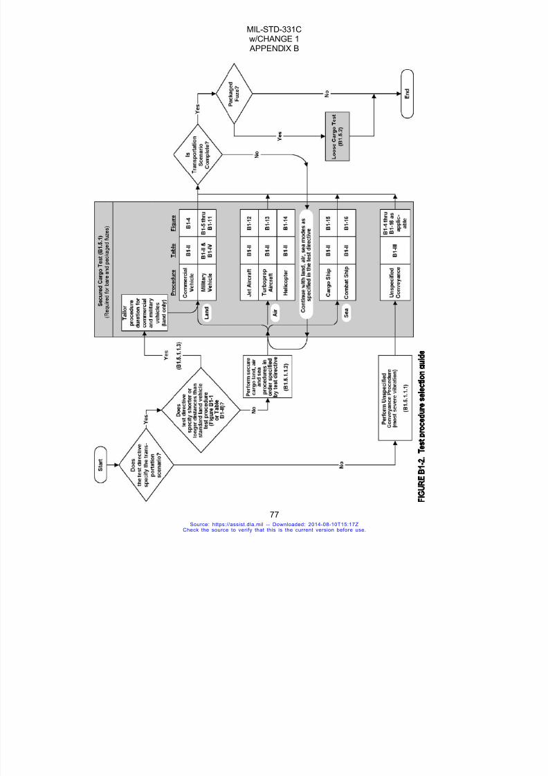
7/18/2019 Mil Std 331 Amend
http://slidepdf.com/reader/full/mil-std-331-amend 85/286
MIL-STD-331Cw/CHANGE 1 APPENDIX B
77
Source: https://assist.dla.mil -- Downloaded: 2014-08-10T15:17ZCheck the source to verify that this is the current version before use.

7/18/2019 Mil Std 331 Amend
http://slidepdf.com/reader/full/mil-std-331-amend 86/286
MIL-STD-331Cw/CHANGE 1 APPENDIX B
78
Source: https://assist.dla.mil -- Downloaded: 2014-08-10T15:17ZCheck the source to verify that this is the current version before use.

7/18/2019 Mil Std 331 Amend
http://slidepdf.com/reader/full/mil-std-331-amend 87/286
MIL-STD-331Cw/CHANGE 1 APPENDIX B
79
Source: https://assist.dla.mil -- Downloaded: 2014-08-10T15:17ZCheck the source to verify that this is the current version before use.

7/18/2019 Mil Std 331 Amend
http://slidepdf.com/reader/full/mil-std-331-amend 88/286
MIL-STD-331Cw/CHANGE 1 APPENDIX B
80
Source: https://assist.dla.mil -- Downloaded: 2014-08-10T15:17ZCheck the source to verify that this is the current version before use.
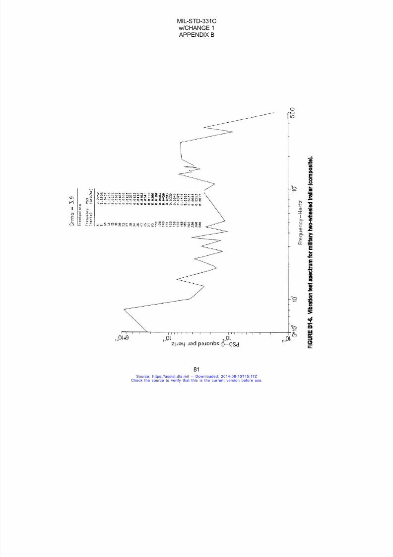
7/18/2019 Mil Std 331 Amend
http://slidepdf.com/reader/full/mil-std-331-amend 89/286
MIL-STD-331Cw/CHANGE 1 APPENDIX B
81
Source: https://assist.dla.mil -- Downloaded: 2014-08-10T15:17ZCheck the source to verify that this is the current version before use.

7/18/2019 Mil Std 331 Amend
http://slidepdf.com/reader/full/mil-std-331-amend 90/286
MIL-STD-331Cw/CHANGE 1 APPENDIX B
82
Source: https://assist.dla.mil -- Downloaded: 2014-08-10T15:17ZCheck the source to verify that this is the current version before use.
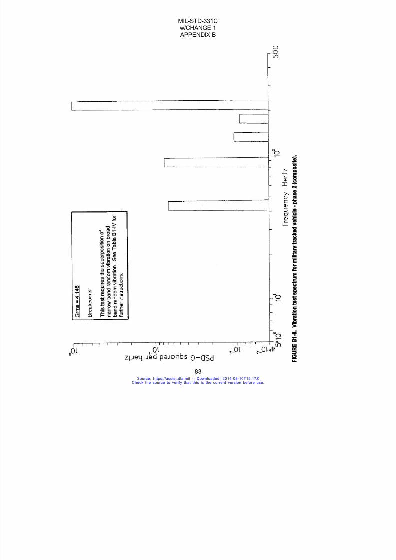
7/18/2019 Mil Std 331 Amend
http://slidepdf.com/reader/full/mil-std-331-amend 91/286
MIL-STD-331Cw/CHANGE 1 APPENDIX B
83
Source: https://assist.dla.mil -- Downloaded: 2014-08-10T15:17ZCheck the source to verify that this is the current version before use.
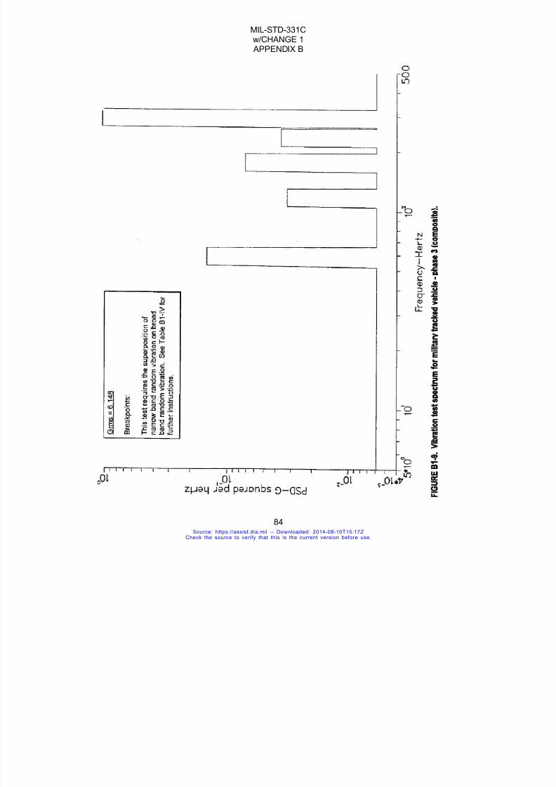
7/18/2019 Mil Std 331 Amend
http://slidepdf.com/reader/full/mil-std-331-amend 92/286
MIL-STD-331Cw/CHANGE 1 APPENDIX B
84
Source: https://assist.dla.mil -- Downloaded: 2014-08-10T15:17ZCheck the source to verify that this is the current version before use.

7/18/2019 Mil Std 331 Amend
http://slidepdf.com/reader/full/mil-std-331-amend 93/286
MIL-STD-331Cw/CHANGE 1 APPENDIX B
85
Source: https://assist.dla.mil -- Downloaded: 2014-08-10T15:17ZCheck the source to verify that this is the current version before use.

7/18/2019 Mil Std 331 Amend
http://slidepdf.com/reader/full/mil-std-331-amend 94/286
MIL-STD-331Cw/CHANGE 1 APPENDIX B
86
Source: https://assist.dla.mil -- Downloaded: 2014-08-10T15:17ZCheck the source to verify that this is the current version before use.
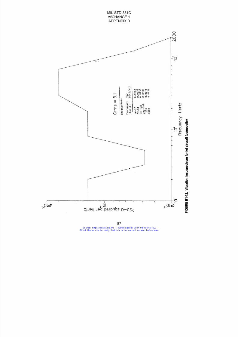
7/18/2019 Mil Std 331 Amend
http://slidepdf.com/reader/full/mil-std-331-amend 95/286
MIL-STD-331Cw/CHANGE 1 APPENDIX B
87
Source: https://assist.dla.mil -- Downloaded: 2014-08-10T15:17ZCheck the source to verify that this is the current version before use.

7/18/2019 Mil Std 331 Amend
http://slidepdf.com/reader/full/mil-std-331-amend 96/286
MIL-STD-331Cw/CHANGE 1 APPENDIX B
88
Criteria Curve Break Points
Freq.(Hz)
Ampl.(g2/Hz)
Freq.(Hz)
Ampl.(g2/Hz)
Freq.(Hz)
Ampl.(g2/Hz)
Freq.(Hz)
Ampl.(g2/Hz)
15.0 0.01 104.5 0.30 173.3 0.01 290.7 0.01
52.3 0.01 104.5 0.08 193.8 0.01 290.7 0.03
52.3 0.30 115.5 0.08 193.8 0.03 321.3 0.03
57.8 0.30 115.5 0.01 214.2 0.03 321.3 0.01
57.8 0.01 129.2 0.01 214.2 0.02 387.6 0.01
64.6 0.01 129.2 0.08 231.0 0.02 387.6 0.02
64.6 0.30 142.8 0.08 231.0 0.01 428.4 0.02
71.4 0.30 142.8 0.01 258.4 0.01 428.4 0.0171.4 0.01 156.8 0.01 258.4 0.02 2000 0.01
96.9 0.01 156.8 0.03 285.6 0.02
96.9 0.30 173.3 0.03 285.6 0.01 5.44 g rms
FIGURE B1-13. Vibration Test Spectrum for Turboprop Aircraft (composite)
Source: https://assist.dla.mil -- Downloaded: 2014-08-10T15:17ZCheck the source to verify that this is the current version before use.

7/18/2019 Mil Std 331 Amend
http://slidepdf.com/reader/full/mil-std-331-amend 97/286
MIL-STD-331Cw/CHANGE 1 APPENDIX B
89
Source: https://assist.dla.mil -- Downloaded: 2014-08-10T15:17ZCheck the source to verify that this is the current version before use.
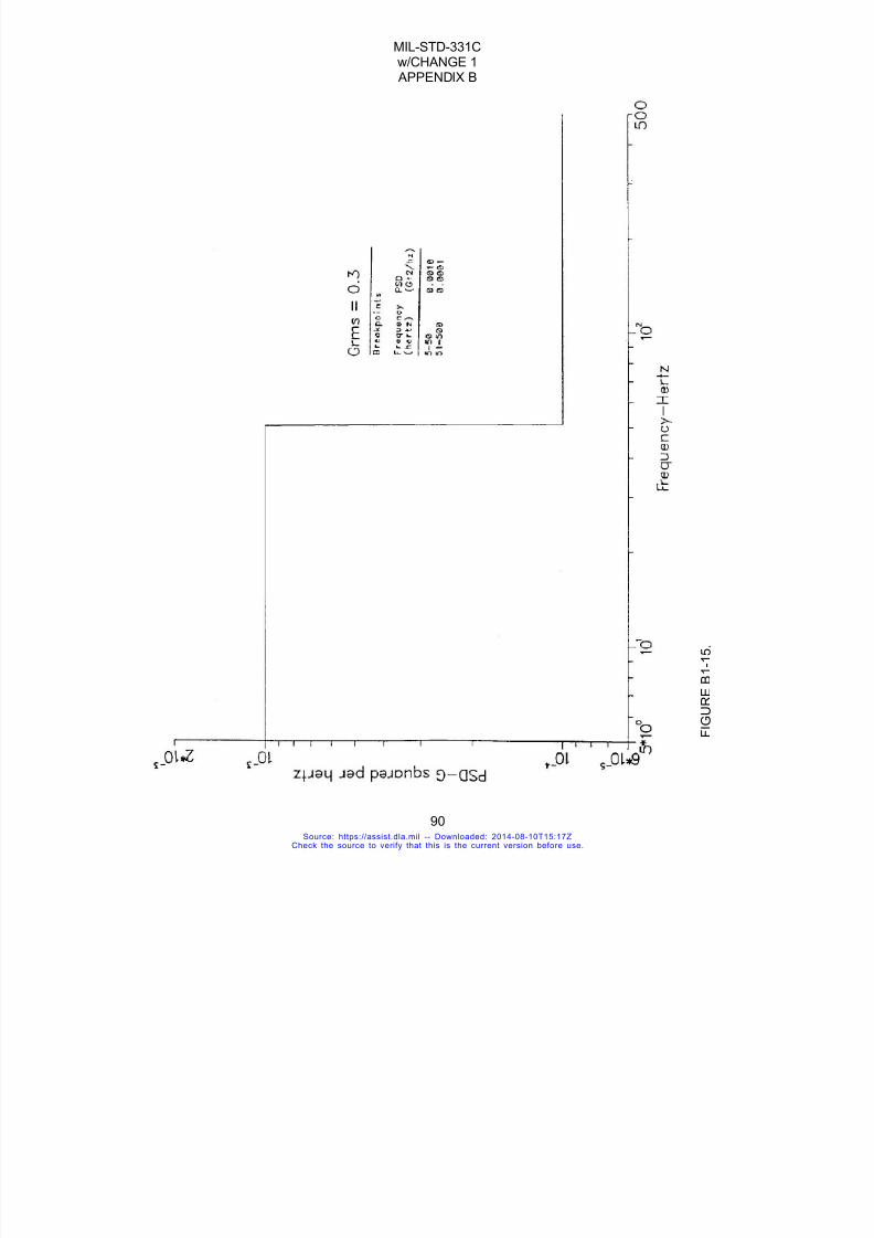
7/18/2019 Mil Std 331 Amend
http://slidepdf.com/reader/full/mil-std-331-amend 98/286
MIL-STD-331Cw/CHANGE 1 APPENDIX B
90
F I G U R E
B 1 - 1 5 .
Source: https://assist.dla.mil -- Downloaded: 2014-08-10T15:17ZCheck the source to verify that this is the current version before use.

7/18/2019 Mil Std 331 Amend
http://slidepdf.com/reader/full/mil-std-331-amend 99/286
MIL-STD-331Cw/CHANGE 1 APPENDIX B
91
Source: https://assist.dla.mil -- Downloaded: 2014-08-10T15:17ZCheck the source to verify that this is the current version before use.

7/18/2019 Mil Std 331 Amend
http://slidepdf.com/reader/full/mil-std-331-amend 100/286
MIL-STD-331Cw/CHANGE 1 APPENDIX B
92
FIGURE B1-17. Vibration Test Curve for Equipment Transported as Secured Cargo(Alternate test for older Army fuzes. See Section B1.6.5)
Source: https://assist.dla.mil -- Downloaded: 2014-08-10T15:17ZCheck the source to verify that this is the current version before use.
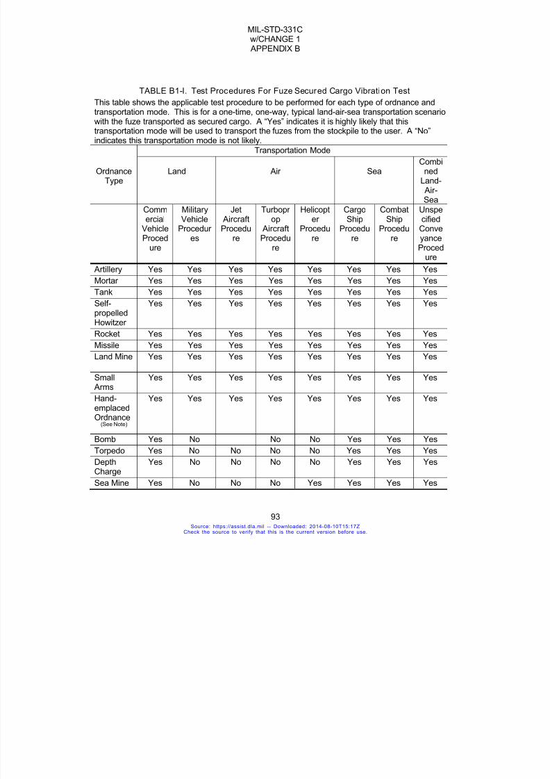
7/18/2019 Mil Std 331 Amend
http://slidepdf.com/reader/full/mil-std-331-amend 101/286
MIL-STD-331Cw/CHANGE 1 APPENDIX B
93
TABLE B1-I. Test Procedures For Fuze Secured Cargo Vibration Test
This table shows the applicable test procedure to be performed for each type of ordnance andtransportation mode. This is for a one-time, one-way, typical land-air-sea transportation scenariowith the fuze transported as secured cargo. A “Yes” indicates it is highly likely that thistransportation mode will be used to transport the fuzes from the stockpile to the user. A “No”indicates this transportation mode is not likely.
Transportation Mode
OrdnanceType
Land Air SeaCombi
nedLand- Air-Sea
Commercial
VehicleProced
ure
MilitaryVehicle
Procedur es
Jet AircraftProcedu
re
Turbopr op
AircraftProcedu
re
Helicopter
Procedure
CargoShip
Procedure
CombatShip
Procedure
Unspecified
ConveyanceProced
ure
Artillery Yes Yes Yes Yes Yes Yes Yes Yes
Mortar Yes Yes Yes Yes Yes Yes Yes Yes
Tank Yes Yes Yes Yes Yes Yes Yes Yes
Self-
propelledHowitzer
Yes Yes Yes Yes Yes Yes Yes Yes
Rocket Yes Yes Yes Yes Yes Yes Yes Yes
Missile Yes Yes Yes Yes Yes Yes Yes Yes
Land Mine Yes Yes Yes Yes Yes Yes Yes Yes
Small Arms
Yes Yes Yes Yes Yes Yes Yes Yes
Hand-emplaced
Ordnance(See Note)
Yes Yes Yes Yes Yes Yes Yes Yes
Bomb Yes No No No Yes Yes Yes
Torpedo Yes No No No No Yes Yes Yes
DepthCharge
Yes No No No No Yes Yes Yes
Sea Mine Yes No No No Yes Yes Yes Yes
Source: https://assist.dla.mil -- Downloaded: 2014-08-10T15:17ZCheck the source to verify that this is the current version before use.

7/18/2019 Mil Std 331 Amend
http://slidepdf.com/reader/full/mil-std-331-amend 102/286
MIL-STD-331Cw/CHANGE 1 APPENDIX B
94
TestRequire-ment
TableB1-II
TableB1-II
TableB1-II
TableB1-II
TableB1-II
TableB1-II
TableB1-II
TableB1-III
Note: This category includes hand-thrown munitions, such as hand grenades and fuzed demolitiondevices.
TABLE B1-II. Test Requirements For Specified Transportation Scenario (Note 4)
This table contains test requirements where the transportation modes and one-way distances arespecified by the test directive. Requirements for unspecified scenarios are listed in Table B1-III.
Transport Test Requirements
Test Procedure Distance(mi (km))
Test ProfileFigure
Test Duration Per Axis (minutes)
Test Level
(Grms)Note 2
Commercial VehicleProcedure
3000 (4800) B1-4 180 1.1
Military VehicleProcedures
Military WheeledVehicle Procedure
500 (800) B1-5 40 2.7
Military Two-wheeledVehicle Procedure
32 (50) B1-6 32 3.9
Military Tracked Vehicle
Procedure Note 1
16 (25) Five figuresas follows:
60; subdivided asfollows:
As follows foreach phase:
Phase 1 B1-7 12 4.252
Phase 2 B1-8 12 4.148
Phase 3 B1-9 12 6.148
Phase 4 B1-10 12 4.263
Phase 5 B1-11 12 5.847
Jet Aircraft Procedure 15,000(24,000)
B1-12 1 5.1
Turboprop AircraftProcedure
1,000(1,600)
B1-13 120 5.44
Helicopter Procedure 250 (400) B1-14 604.5/2.8
o e
Cargo Ship Procedure 15,000(24,000)
B1-15 120 0.3
Combat Ship Procedure 15,000(24,000)
B1-16 235(sine sweep)
120(sine) sweep
1.3g peak at 25Hz
Notes:1. Phases correspond to a total distance of 25 km at 5 different vehicle speeds. This test requires
Source: https://assist.dla.mil -- Downloaded: 2014-08-10T15:17ZCheck the source to verify that this is the current version before use.

7/18/2019 Mil Std 331 Amend
http://slidepdf.com/reader/full/mil-std-331-amend 103/286
MIL-STD-331Cw/CHANGE 1 APPENDIX B
95
the superposition of narrow band random vibration on broadband random vibration. Refer toTable B1-IV for further instructions.
2. Grms = root mean squared acceleration for broadband random vibration, unless otherwiseindicated.
3. Grms = 2.8 (broadband random); Grms = 4.5 (broadband random plus harmonic components.4. All test profiles listed in this table call for random vibration input to the fuze, except for B1-16,
which calls for sinusoidal input.
TABLE B1-III. Test Requirements For Unspecified Transportation Scenario
This table shall be used when the transportation modes and one-way distances are not specifiedby the test directive
Ordnance Type Refer to Table B1-II for Test Requirement of Procedures Cited Below
Artillery
MortarTank
Self-propelled Howitzer Military Wheeled Vehicle, Military Two-wheeled Vehicle,
Rocket Military Tracked Vehicle, Turboprop Aircraft and
Missile Helicopter
Land Mine
Small Arms
Hand-emplaced Ordnance
Bomb Commercial Vehicle, Jet Aircraft and Combat Ship
Torpedo Commercial Vehicle and Combat shipDepth Charge
Sea Mine Commercial Vehicle, Helicopter, Cargo Ship and Combat Ship
Source: https://assist.dla.mil -- Downloaded: 2014-08-10T15:17ZCheck the source to verify that this is the current version before use.
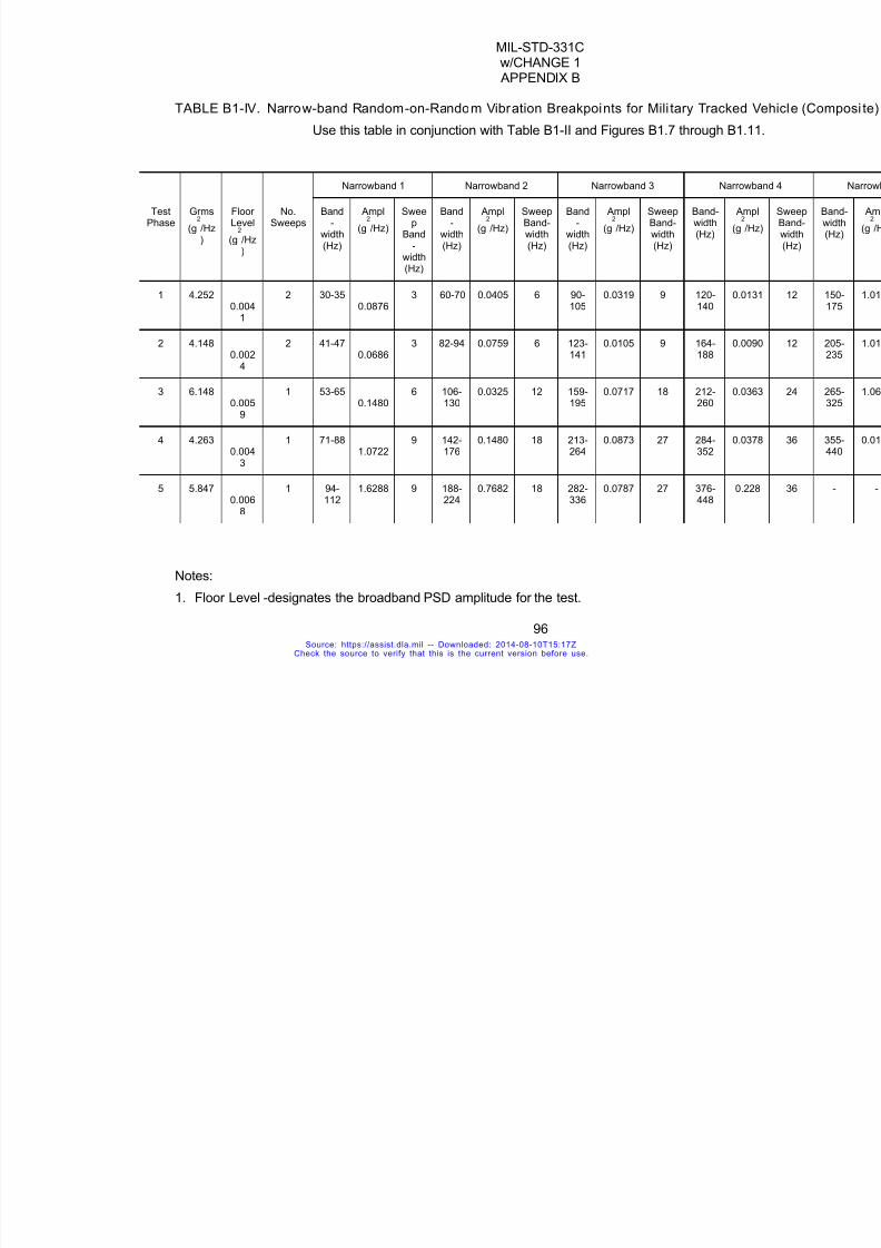
7/18/2019 Mil Std 331 Amend
http://slidepdf.com/reader/full/mil-std-331-amend 104/286
MIL-STD-331Cw/CHANGE 1 APPENDIX B
96
TABLE B1-IV. Narrow-band Random-on-Random Vibration Breakpoints for Mili tary Tracke
Use this table in conjunction with Table B1-II and Figures B1.7 through B
Narrowband 1 Narrowband 2 Narrowband 3 Narr
TestPhase
Grms
(g2
/Hz)
FloorLevel
(g2
/Hz)
No.Sweeps
Band-
width(Hz)
Ampl
(g2
/Hz)
Sweep
Band-
width(Hz)
Band-
width(Hz)
Ampl
(g2
/Hz)
SweepBand-width(Hz)
Band-
width(Hz)
Ampl
(g2
/Hz)
SweepBand-width(Hz)
Band-width(Hz)
(
1 4.2520.004
1
2 30-350.0876
3 60-70 0.0405 6 90-105
0.0319 9 120-140
0
2 4.1480.002
4
2 41-470.0686
3 82-94 0.0759 6 123-141
0.0105 9 164-188
0
3 6.1480.005
9
1 53-650.1480
6 106-130
0.0325 12 159-195
0.0717 18 212-260
0
4 4.2630.004
3
1 71-881.0722
9 142-176
0.1480 18 213-264
0.0873 27 284-352
0
5 5.847
0.0068
1 94-
112
1.6288 9 188-
224
0.7682 18 282-
336
0.0787 27 376-
448
0
Notes:
1. Floor Level -designates the broadband PSD amplitude for the test.
Source: https://assist.dla.mil -- Downloaded: 2014-08-10T15:17ZCheck the source to verify that this is the current version before use.
7/18/2019 Mil Std 331 Amend
http://slidepdf.com/reader/full/mil-std-331-amend 105/286
MIL-STD-331Cw/CHANGE 1 APPENDIX B
97
2. Bandwidth - designates the narrow bandwidth for which the (PSD) amplitude exceeds the flo
3. Sweep Bandwidth - designates the swept bandwidth within the corresponding narrow bandwsmaller than the corresponding bandwidth.
4. No. Sweeps indicates the number of cycles the sweep bandwidth is swept across the correspthe test. A cycle is completed when the frequency is swept from its lowest value to the highelowest value. This process is maintained for the entire test duration.
5. Narrowband Random-on-Random - The five narrowbands are superimposed on the floor leveThus the Grms represents the total contributed from the coexisting narrowband and broadbanvibrations.
6. Certain digital control systems by nature of their design, might produce a total number of swefrom the specified value. This is an acceptable deviation as long as the total number of sweepercent of the specified value.
Source: https://assist.dla.mil -- Downloaded: 2014-08-10T15:17ZCheck the source to verify that this is the current version before use.

7/18/2019 Mil Std 331 Amend
http://slidepdf.com/reader/full/mil-std-331-amend 106/286
MIL-STD-331Cw/CHANGE 1 APPENDIX B
98
TEST B2
Requirements for t ransportation v ibration tests of packaged fuzeshave been combined with those for bare fuzes.
Refer to Test B1.1.
Source: https://assist.dla.mil -- Downloaded: 2014-08-10T15:17ZCheck the source to verify that this is the current version before use.

7/18/2019 Mil Std 331 Amend
http://slidepdf.com/reader/full/mil-std-331-amend 107/286
MIL-STD-331Cw/CHANGE 1 APPENDIX B
99
TEST B3
TACTICAL VIBRATION
B3.1 PURPOSEThis is a laboratory safety and reliability test simulating tactical conditions. The fuze ispreconditioned to specified temperatures and vibrated on a schedule of controlled frequencies andamplitudes.
B3.2. DESCRIPTION
B3.2.1 General description. Bare fuzes are subjected to combined vibration-temperatureconditions which are defined by the service application of the fuze, that is, the type of munition,weapon or tactical launch vehicle. Four different test procedures are provided to cover mostapplications. Exclusions are described in more detail in B3.7. Each procedure is devised to cover
the vibration-temperature environment of the tactical pre-launch period (fuze is assembled toparent weapon or vehicle as a “ready to use” store), and the launch and post-launch period (parentweapon or vehicle during launch or in free flight) up to the fuze initiation at the desired target point.The test fuze will be in a non-operating or operating state, as required, by each application andprocedure.
B3.2.1.1 Air-launched munit ions. This procedure (B3.5.3) is for fuzes designed for use inmunitions air-launched from an external-carry position. Helicopter-launched items are excluded.See B3.7.3.
B3.2.1.2 Ground-launched munitions. This procedure (B3.5.4) is for fuzes designed foruse in munitions launched from fixed or moving ground launchers. Artillery fuzes are excluded.See B3.7.4.
B3.2.1.3 Ship-launched munitions. This procedure (B3.5.5) is for fuzes designed for usein munitions launched from ships. See B3.7.5.
B3.2.1.4 Underwater-launched munitions. This procedure (B3.5.6) is for fuzes designedfor use in munitions launched from underwater vehicles or carriers.
B3.2.2 Fuze configuration. The fuzes for this test shall be completely assembled,including all explosive elements which are a part of the fuze design. Inert lead and boosterelements may be substituted when the use of live elements present an excessive hazard. Theinert elements shall have an equivalent weight and configuration. When inert elements are used,the live elements and their interface with the fuze shall be separately qualified to the tacticalvibration environment.
B3.2.3 Applicable publications. All standards, specifications, drawings, procedures and
manuals which form a part of this test are listed in Section 2 of the introduction to this standard.Special attention is directed to MIL-STD-167, MIL-HDBK-310, MIL-STD-810, and MIL-T-18404.
B3.2.4 Test documentation. Test plans, performance records, equipment, conditions,results and analysis shall be documented in accordance with 4.8 of the general requirements tothis standard.
B3.3. CRITERIA FOR PASSING TEST
B3.3.1 Fuze condition. At the completion of this test, the fuze shall be safe fortransportation, storage, handling and use, as well as operable in accordance with 4.6.2.1 and
Source: https://assist.dla.mil -- Downloaded: 2014-08-10T15:17ZCheck the source to verify that this is the current version before use.

7/18/2019 Mil Std 331 Amend
http://slidepdf.com/reader/full/mil-std-331-amend 108/286
MIL-STD-331Cw/CHANGE 1 APPENDIX B
100
4.6.2.2a of the general requirements to this standard.B3.3.2 Decision basis. Breakdown, inspection, other appropriate tests and engineering
judgment shall form the bases of the decision that fuzes have passed or failed the test.
B3.4. EQUIPMENT
B3.4.1 Vibration equipment. The equipment shall be capable of covering the frequencyranges and acceleration levels specified in B3.5. Frequency sweeping shall be at a logarithmicrate over the range, or at a linear rate over the range when the range is divided into logarithmicincrements.
B3.4.2 Temperature equipment. The equipment shall be capable of establishing andmaintaining the temperature levels specified for the time durations required. Tolerances are asspecified in each procedure, or as specified in 4.5.2.
B3.4.3 Instrumentation. The instrumentation shall be capable of measuring, within theprescribed limits, the frequency and amplitude of the vibration conditions and the temperatureconditions specified. When it is necessary to monitor fuze operation, instrumentation shall be used
which is capable of measuring the necessary functions within the limits prescribed. Vibrationamplitudes and frequencies shall be measured by techniques that will not significantly affect testitem control or response. The input control sensing devices shall be rigidly attached to thevibration table, or to the intermediate structure, if used, at or as near as possible to the attachmentpoints of the test fuze. The transverse motion shall be minimized and should be limited to thetolerances specified in Table B3-V.
B3.4.4 Vibration fixtures. Fixtures shall be designed to the criteria chart given in TableB3-V. The fixtures shall simulate the mounting of the fuze in its weapon, munition or munitionsitem. Equipment rigidly mounted in service shall be rigidly mounted to the test fixture. Equipmentisolated in service shall use service isolators when mounted on the test fixture. If service isolatorsare not available during the qualification test, isolators shall be provided with characteristics such
that the isolator/equipment resonant frequencies shall be between 20 Hz and 45 Hz with resonantamplification ratio between 3 and 5. The number of fuzes to be mounted on one fixture shall be afunction of test management as long as the technical requirements of the fixture design andenvironmental conditions are maintained. Precautions shall be taken in the establishment ofmechanical interfaces to minimize the introduction of undesirable responses in the test setup. Thetest load should be distributed uniformly on the vibration exciter table in order to minimize effects ofunbalanced loads.
B3.5. PROCEDURE
B3.5.1 Introduction. Determine the test parameters as follows.B3.5.1.1 Test procedure. This test includes four procedures, B3.5.3 through B3.5.6,
corresponding to the four launch platforms described in B3.2.1. A complete test shall consist of
performance of B3.5.1 and B3.5.2, as well as the applicable B3.5.3 through B3.5.6, in its entirety.B3.5.1.2 Time schedule. Time schedules for each procedure shall be indicated in the
applicable tables and figures.B3.5.1.3 Selection of vibration test curves. Applicable vibration curves shall be selected
from each procedure for the individual parts when the procedure is divided into parts. Selection ofthe curves shall be made to simulate the expected vibration environment for the particular vehicleor fuze involved.
B3.5.1.4 Fuze operation. Pre-test operation shall be in accordance with 4.3 in the General
Source: https://assist.dla.mil -- Downloaded: 2014-08-10T15:17ZCheck the source to verify that this is the current version before use.
7/18/2019 Mil Std 331 Amend
http://slidepdf.com/reader/full/mil-std-331-amend 109/286
MIL-STD-331Cw/CHANGE 1 APPENDIX B
101
Requirements Section of this Standard, or as required by the test plan or procurementspecification. Operation during and after the test shall be as required by the test plan orprocurement specification.
B3.5.1.5 Temperature levels. At least three temperature levels shall be specified over the
range, reflecting the two range extremes and an intermediate level. At least one fuze shall betested at each level, requiring, therefore, a minimum of three fuzes. When temperature limits arenot called out in the following procedures or in the test plan or procurement specification, then+71±2ºC, +23±10ºC and -54±2ºC (+160±4ºF, ±73±18ºF and -65±4ºF) shall be used for the threelevels.
B3.5.2 Test Techniques.B3.5.2.1 Vibration levels. The test levels specified herein (sinusoidal or random) shall be
imparted to the fuze at its attachment points to the test fixture.B3.5.2.2 Test fuze orientation. The vibration environment, specified by the curve selected
from applicable tables in accordance with B3.5.1, shall be applied to each of the three mutuallyperpendicular axes of the test fuze in turn, unless otherwise specified. These axes shall be
identified by the test plan or procurement specification.B3.5.2.3 Sinusoidal vibration. The vibration shall be applied sequentially along each of
the three mutually perpendicular axes of the fuze. The vibratory schedules and test times shall beaccording to the applicable figures and tables per the fuze application. The vibratory accelerationlevels, or double amplitudes of the specified test curves, shall be maintained as vibratory inputs tothe test item at the test item mounting points. When the input vibration is measured at more thanone control point, the control signal shall be the average of all the control accelerometers' signals(see also B3.5.2.4c), unless otherwise specified. For massive test items, fixtures and all largeforce exciters, it is recommended that the input control level be an average of at least three inputs.
B3.5.2.3.1 Resonance search. This is applicable to Tables B3-III and B3-IV. Resonantfrequencies of the fuze shall be determined by varying the frequency of applied vibration slowly
through the specified range at reduced test levels, but, with sufficient amplitude to excite the fuze.Sinusodial resonance search may be performed using the test level and cycling time specified forsinusodial cycling tests, provided the resonance search time is included in the required cycling testtime of B3.5.2.3.3.
B3.5.2.3.2 Resonance dwell. This is applicable to Tables B3-III and B3-IV. The fuze shallbe vibrated along each axis at the most severe resonant points determined in B3.5.2.3.1. Testlevels, frequency ranges, and test time shall be in accordance with the applicable conditions fromthe tables and figures for each fuze category. If more than four significant resonance points arefound for any one axis, the four most severe points (usually those with highest amplification ofinput) shall be chosen for the dwell test. If a change in the resonant point occurs during the test,its time of occurrence shall be recorded, and, immediately, the frequency shall be adjusted to
maintain the peak resonance condition. The final resonant frequency shall be recorded.B3.5.2.3.3 Cycling. The fuze shall be vibrated along each axis in accordance with the test
levels, frequency ranges, and times from the applicable tables and figures. The frequency ofapplied vibration shall be swept over the specified range in accordance with Figure B3-5. Thespecified sweep time is that of an ascending plus a descending sweep, and is twice the timeshown on Figure B3-5 for the specified range. Linear sweep rates may be substituted for thelogarithmic sweep rate. When linear sweep rates are used, the total frequency range shall bedivided into logarithmic frequency bands with equal time intervals. Each time interval is the time ofan ascending, plus a descending sweep for the band. The sum of these time intervals shall equal
Source: https://assist.dla.mil -- Downloaded: 2014-08-10T15:17ZCheck the source to verify that this is the current version before use.

7/18/2019 Mil Std 331 Amend
http://slidepdf.com/reader/full/mil-std-331-amend 110/286
MIL-STD-331Cw/CHANGE 1 APPENDIX B
102
the sweep time specified for the applicable frequency range. The linear sweep rate for each bandis then determined by dividing each bandwidth in Hz by one-half the sweep time in minutes foreach band. The logarithmic frequency bands may be readily determined from Figure B3-5. Thefrequency bands and linear sweep rates shown in Table B3-VI shall be used for the 2 (or 5) to 500
Hz and 5 to 2,000 Hz frequency ranges. For test frequency ranges of 100 Hz or less, no correctionof the linear sweep rate is required.
B3.5.2.4 Random vibration. The vibration shall be applied sequentially along each of thethree mutually perpendicular axes of the fuze. The vibratory schedules and test times shall beaccording to the curves and schedules from the applicable figures and tables by fuze application.The instantaneous random vibration acceleration peaks may be limited to three times the rmsacceleration level. The power spectral density of the test control signal shall not deviate from thespecified requirements by more than +100, -30 percent (+3, -1.5 dB) below 500 Hz and +100, -50percent (±3dB) between 500 Hz and 2,000 Hz, except that deviations as large as +400, -75percent (±6 dB) shall be allowed over a cumulative bandwidth of 100 Hz maximum, between 500and 2,000 Hz.
Tolerance levels in terms of dB are defined as:
where W1= measured acceleration power spectral density in g2/Hz units and W0 defines thespecified level in g
2/Hz units. Confirmation of these tolerances shall be made by use of any
analysis system providing statistical accuracies corresponding to a bandwidth-time constantproduct, BT = 50, minimum. Specific analyzer characteristics shall be as specified below orequivalent, subject to the BT = 50, T- 1 minimum limitation.
a. On-line continuous filter, equalization/analysis system having a bandwidth as follows:1. B = 25 Hz, maximum between 20 to 200 Hz;
2. B = 50 Hz, maximum between 200 to 1,000 Hz;3. B = 100 Hz, maximum between 1,000 to 2,000 Hz.
b. Swept frequency analysis systems characterized as follows:1. Constant bandwidth analyzer
a) Filter bandwidth as follows:1) B = 25 Hz, maximum between 20 to 200 Hz;2) B = 50 Hz, maximum between 200 to 1,000 Hz;3) B = 100 Hz, maximum between 1,000 to 2,000 Hz;
b) Analyzer averaging time = T = 2 RC = 1 second minimum, where T = True averagingtime and RC = analyzer time constant;
c) Analyzer sweep rate (linear) = B/4RC or B2
/8 (Hz/second) maximum, whichever is
smaller;2. Constant percentage bandwidth analyzer
a) Filter bandwidth = pf c = one tenth of center frequency maximum (0.1 f
c), where p =
percentage and f c = analyzer center frequency;
b) Analyzer averaging time = T = 50/pf c minimum;
c) Analysis sweep rate (logarithmic) = pf c/4RC or (pfc)
2
/8 (Hz/second), maximum,
whichever is smaller.
Source: https://assist.dla.mil -- Downloaded: 2014-08-10T15:17ZCheck the source to verify that this is the current version before use.
7/18/2019 Mil Std 331 Amend
http://slidepdf.com/reader/full/mil-std-331-amend 111/286
MIL-STD-331Cw/CHANGE 1 APPENDIX B
103
c. Digital power spectral density analysis system. This system shall employ quantizationtechniques providing accuracies commensurate with the above approach. Accelerometersemployed for test level control shall be mounted in accordance with B3.4.3. Where morethan one accelerometer is employed for test level control, the arithmetical average of the
power spectral densities indicated by the control accelerometers shall be used for control ofthe test level.B3.5.2.5 Temperature conditioning. Unless directed otherwise, the fuze shall be
preconditioned a sufficient length of time to ensure that the entire fuze has reached the testtemperature level. This can be determined by monitoring interior portions of the fuze, or by usingpredetermined testing or calculation of the thermal response. Once the temperature level hasbeen reached, the temperature of air, or medium surrounding the fuze, shall be maintained at thespecified test temperature level for the period of the test. For tests which are to simulate shortperiods of temperature gradient conditions of the ambient air or the fuze surface, temperaturemonitoring shall be established to ensure that the gradient is achieved by the temperatureconditioning equipment.
B3.5.2.6 Fuze assembly to fix ture. In the assembly of fuzes to the test fixture, care shalllbe given to utilizing proper procedures. The fuze shalll remain tight in the fixture in order to receivea valid test, since the shock imparted to a loose fuze may be significantly magnified. If a fuzebecomes loose during a test, it should be ruled invalid.
B3.5.3 Air-launched munitions. This includes external-carry applications, excludinghelicopters.
B3.5.3.1 Part A. Pre-launch (captive flight) vibration- temperature. The fuze shall beattached to the vibration exciter according to B3.4.4, and shall be subjected to broadband randomvibration excitation in the manner prescribed in B3.5.2.4. The power spectal density tolerances ofapplied vibration shall be as indicated therein. Two test levels are specified: an endurance testlevel, and a functional test level for those fuzes which are required to be operating during a captive
flight condition. For each axis, the endurance test shall be conducted first, followed by thefunctional test where applicable. The fuze shall be operated during the functional test and shallperform according to the test plan or procurement specification. The applied vibration shall beaccording to the test conditions of Table B3-I and the curve of Figure B3-1. The time durationsand other test conditions shall be determined from the test level equations and other parametervalues from Table B3-I. If the computed functional and endurance (T=1) test levels (W2) are lessthan 0.04 G2/Hz, use W2 = 0.04 G2/Hz, and T = 1 for the endurance test.
B3.5.3.2 Part B. Free-flight vibration-temperature. For weapons that are deployed byseparation from the aircraft (free-flight) such as bombs and missiles, a free-flight functional testshall be conducted in addition to the captive flight test of B3.5.3.1. The fuze shall be attached tothe vibration exciter according to Section B3.4.4, and shall be subjected to the broadband random
vibration excitation in the manner prescribed in B3.5.2.2. The applied vibration shall be accordingto the functional test conditions of Table B3-I and the curve of Figure B3-1. the time durations andother test conditions shall be determined from the test level equations and other parameter valuesin Table B3-I, except: (a) factors A
1, A
2, and (N/3T) shall be set equal to one, (b) the value of q
shall be the maximum value attainable during free-flight, and (c) the duration of this test, per axis,shall equal the maximum free-flight time expected at maximum q, but not less than 30 seconds.The fuze shall be energized and operated according to the test plan or procurement specificationwhile under vibration to determine conformance to the criteria of B3.3. In the event that all free-
Source: https://assist.dla.mil -- Downloaded: 2014-08-10T15:17ZCheck the source to verify that this is the current version before use.

7/18/2019 Mil Std 331 Amend
http://slidepdf.com/reader/full/mil-std-331-amend 112/286
MIL-STD-331Cw/CHANGE 1 APPENDIX B
104
flight functional checks are made during the captive functional test, and the captive functional testlevels are larger or equal to those derived here, no free-flight functional test is required.
B3.5.4 Ground-launched munit ions. Artillery fuzes are excluded.B3.5.4.1 Part A. Pre-launch vibration-temperature. The fuze shall be attached to the
vibration exciter according to B3.4.4, and shall be subjected to sinusoidal vibration excitation in themanner prescribed in B3.5.2.3. The acceleration or displacement of the applied vibration shall beaccording to one specified curve P through U of Figure B3-2, with the selection of subpart 1, 2, 3,or 4 in Table B3-II, depending on whether the fuze is installed with or without vibration isolators.The curve selections, time durations and other test conditions shall be determined from Table B3-II. Those fuzes which are required to be operating prior to launch shall be energized and operatedaccording to the test plan or procurement specification while under vibration.
B3.5.4.2 Part B. Free-flight vibration-temperature. The fuze shall be attached to thevibration exciter according to B3.4.4, and shall be subjected to broadband random vibrationexcitation in the manner prescribed in B3.5.2.4. The applied vibration shall be according to onespecified curve AE through AP from Figure B3-2, with the selection of subpart 1, 2 or 3 in Table
B3-II, depending on whether the fuze is installed with or without vibration isolators. The curveselections, time duration and other test conditions shall be determined from Table B3-II. The fuzeshall be energized and operated according to the test plan or procurement specification whileunder vibration to determine conformance to the criteria of B3.3.
B3.5.5 Ship-launched munitions. B3.5.5.1 Part A. Pre-launch vibration-temperature. The fuze shall be attached to the
vibration exciter according to B3.4.4, and shall be subjected to sinusoidal vibration excitation in themanner prescribed in B3.5.2.3. The acceleration (or displacement) and test levels and duration ofthe applied vibration shall be according to Table B3-III. Those fuzes which are required to beoperating prior to launch shall be energized and operated according to the test plan orprocurement specification while under vibration.
B3.5.5.2 Part B. Free-flight vibration-temperature. The fuze shall be attached to thevibration exciter according to B3.4.4, and shall be subjected to broadband random vibrationexcitation as directed in B3.5.2.4. The applied vibration shall be according to one specified curve
AE through AP from Figure B3-3. The time durations and other test conditions shall be determinedfrom the Tables of Figure B3-3. The fuze shall be energized and operated while under vibrationaccording to the test plan or procurement specification to determine conformance to the criteria ofB3.3.
B3.5.6 Underwater-launched munitions. B3.5.6.1 Part A. Pre-launch vibration temperature. The fuze shall be attached to the
vibration exciter as directed in B3.4.4, and shall be subjected to sinusoidal vibration excitation inthe manner prescribed in B3.5.2.1. The frequency ranges, acceleration (or displacement) test
levels and duration of the applied vibration shall be according to Table B3-IV, Part A. Thetemperature levels of the fuze while under vibration shall be +35±2ºC, +23±10ºC and -3±1ºC(+95±4ºF, +73±18ºF and +27±2ºF). Those fuzes which are required to be operating prior to launchshall be energized and operated according to the test plan or procurement specification whileunder vibration to determine conformance to the criteria of B3.3.
B3.5.6.2 Part B. Post-launch vibration-temperature for underwater-launched missilesthat complete their free-flight mission in air. This test simulates the mission period from launchtube exit to the sea surface. The fuze shall be attached to the vibration exciter as directed inB3.4.4, and shall be subjected to vibration levels and duration as determined by the parent
Source: https://assist.dla.mil -- Downloaded: 2014-08-10T15:17ZCheck the source to verify that this is the current version before use.

7/18/2019 Mil Std 331 Amend
http://slidepdf.com/reader/full/mil-std-331-amend 113/286
MIL-STD-331Cw/CHANGE 1 APPENDIX B
105
weapon's test plan or procurement specification. If test plan or procurement specification are notspecified, subject the fuze to sinusoidal vibration excitation in the manner prescribed in B3.5.2.1.In this case the frequency ranges, acceleration (or displacement) test levels and duration ofapplied vibration shall be according to Figure B3-4A. The temperature levels of the fuzes while
under vibration shall be +35±2ºC, +23±10ºC and -3±1ºC (+95±4ºF, +73±18ºF and +27±2ºF).Those fuzes which are required to be operated while under these launch conditions shall beenergized and operated while under vibration to determine conformance to the criteria of B3.3.
B3.5.6.3 Part C. Free-flight vibration-temperature for weapons whose free-flight is inwater only. The fuze shall be attached to the vibrator exciter according to Paragraph B3.4.4. Forbattery propulsion type weapons, the fuze shall be subjected to sinusoidal vibration excitation inthe manner prescribed in B3.5.2.1. The frequency ranges, acceleration (or displacement) testlevels and duration of the applied vibration shall be according to Table B3-IV, Part B. For othertype propulsion the fuze shall be subjected to broadband random vibration excitation in the mannerprescribed in B3.5.2.2. The applied vibration shall be according to the specified curve from FigureB3-4B. The fuze shall be energized and operated while under vibration according to test plan or
procurement specification to determine conformance to the criteria of B3.3.B3.5.6.4 Part D. Free-flight vibration-temperature for weapons whose free-flight is in
air only. The fuze shall be attached to the vibration exciter according to B3.4.4, and shall besubjected to broadband random vibration excitation as directed in B3.5.2.2. The applied vibrationshall be according to one specified curve AC through AP from Figure B3-3. The time durationsand other test conditions shall be determined from the tables of Figure B3-3. The fuze shall beenergized and operated while under vibration according to the test plan or procurementspecification to determine conformance to the criteria of B3.3.
B3.6. ALTERNATE AND OPTIONAL TESTS
None.
B3.7. RELATED INFORMATIONB3.7.1 Tactical simulation. The vibration-temperature conditions of this test represent
service conditions in tactical usage as monitored in a variety of geographical locations and weaponor munition types. As a standard test, it is considered to provide simulation of tactical service useconditions for qualification of fuze designs under the vibration-temperature environment. There willbe exceptions to this among fuze designs; therefore, usage of each fuze shalll be carefullyinvestigated to determine whether this standard applies.
B3.7.2 Compatib ili ty with MIL-STD-810. This test is equivalent, in most parameters, toTest Method 514 of MIL-STD-810, Environmental Test Methods, for the tactical vibrationenvironment of air-launched and certain ground-launched, and underwater-launched fuzeapplications. Additionally, by combining temperature with the vibration environment, the test
provides the opportunity to assess the effects of two environments, often critical to the operation offuzes during their tactical life.
B3.7.3 Helicopter vibration. At the present, there is insufficient data to establish astandard vibration schedule.
B3.7.4 Artillery fuzes. For artillery fuzes, the pre-launch vibration environment is generallyinsignificant. At present, there is insufficient data to establish a standard vibration test for the post-launch condition.
B3.7.5 Ship-launched applications. The vibration conditions for Section B3.5.5 are taken
Source: https://assist.dla.mil -- Downloaded: 2014-08-10T15:17ZCheck the source to verify that this is the current version before use.
7/18/2019 Mil Std 331 Amend
http://slidepdf.com/reader/full/mil-std-331-amend 114/286
MIL-STD-331Cw/CHANGE 1 APPENDIX B
106
from the conditions specified in MIL-STD-167-1 for Type I vibrations. These conditions apply to “allequipment intended for shipboard use or be capable of withstanding the environmental vibrationconditions which may be encountered aboard naval ships (B3.1.3).” Thus, ship-mounted and ship-carried munitions items will encounter the same driving conditions of vibration forces, but may
react differently as a function of the transmissibility of the “mounting” or attachment structure. Forfuzes, assembled to a parent vehicle or munitions, this will be a function of mounting racks, loadingmachinery and launching equipment installations.
B3.7.6 Tank vibration. Tank and similar weapon system vibration schedules are includedin transportation type testing. It has generally been noted that the vibration levels and frequenciesare more severe on cartridge interfaces than fuze components.
B3.7.7 Internally-carried aircraft munit ions. This test does not cover fuzes for this typeof munitions.
B3.7.8 Bibliography. AFFDL-TR-71-158, Vibration and Acoustic Test Criteria for Captive Flight of Externally Carried Aircraft Stores, December 1971.
TABLE B3-1. Vibration Criteria for Externally-Carried, Air -Launched Ordnance(Excluding Helicopter Ordnance)
Parametric Equations for Figure B3-1
Eq (1)1,2
: W1 = (5)(10
-3
)(N/3T)1/4
(A1)(B
1)(C
1)(D
1)(E
1)g
2
Hz
Eq (2)1,2
: W2 = (5)(10
-5
)(q/ρ)2
(N/3T)1/4
(A2)(B
2)(C
2)(D
2)(E
2)g
2Hz
Eq (3)3,4
: f 1 = 10
5
(t/R2
)Hz
Eq (4)3,4
: f 2 = f
1 + 1000 Hz
Source: https://assist.dla.mil -- Downloaded: 2014-08-10T15:17ZCheck the source to verify that this is the current version before use.
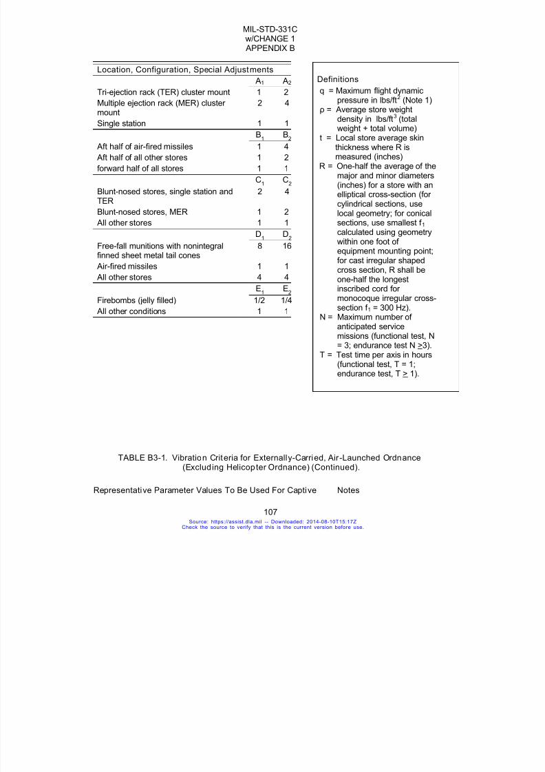
7/18/2019 Mil Std 331 Amend
http://slidepdf.com/reader/full/mil-std-331-amend 115/286
MIL-STD-331Cw/CHANGE 1 APPENDIX B
107
Location, Configuration, Special Adjustments
A1 A2
Tri-ejection rack (TER) cluster mount 1 2
Multiple ejection rack (MER) clustermount
2 4
Single station 1 1
B1 B
2
Aft half of air-fired missiles 1 4
Aft half of all other stores 1 2
forward half of all stores 1 1
C1 C
2
Blunt-nosed stores, single station andTER
2 4
Blunt-nosed stores, MER 1 2
All other stores 1 1
D1 D
2
Free-fall munitions with nonintegralfinned sheet metal tail cones
8 16
Air-fired missiles 1 1
All other stores 4 4
E1 E
2
Firebombs (jelly filled) 1/2 1/4
All other conditions 1 1
Definitions
q = Maximum flight dynamic
pressure in lbs/ft
2
(Note 1)ρ = Average store weightdensity in lbs/ft3 (totalweight + total volume)
t = Local store average skinthickness where R ismeasured (inches)
R = One-half the average of themajor and minor diameters(inches) for a store with anelliptical cross-section (forcylindrical sections, uselocal geometry; for conicalsections, use smallest f 1 calculated using geometrywithin one foot ofequipment mounting point;for cast irregular shapedcross section, R shall beone-half the longestinscribed cord formonocoque irregular cross-section f 1 = 300 Hz).
N = Maximum number ofanticipated servicemissions (functional test, N= 3; endurance test N >3).
T = Test time per axis in hours(functional test, T = 1;endurance test, T > 1).
TABLE B3-1. Vibration Criteria for Externally-Carried, Air -Launched Ordnance(Excluding Helicopter Ordnance) (Continued).
Representative Parameter Values To Be Used For Captive Notes
Source: https://assist.dla.mil -- Downloaded: 2014-08-10T15:17ZCheck the source to verify that this is the current version before use.

7/18/2019 Mil Std 331 Amend
http://slidepdf.com/reader/full/mil-std-331-amend 116/286
MIL-STD-331Cw/CHANGE 1 APPENDIX B
108
Flight When Specific Parameters Are Not Available
Store Type Maxq
ρ Nendur-ance
Tendur -ance
f 1
(Hz)
f 2
(Hz)
Missile, airto ground
1600 100 3 none 500 1500
Missile, airto air
1600 100 100 1 500 1500
Instrumentpod
1800 50 500 1 500 1500
Dispenser(reusable)
1200 50 50 1 200 1200
Demolitionbomb
1200 120 3 none 125 2000
Fire bomb 1200 40 3 none 100 1100
1. For endurance test, q =1200 PSF or maximumq, whichever is less. Forfunctional test, q = 1800
lbs/ft2 or maximum q,whichever is less.
2. If functional test level isequal to or larger thanthe endurance test levelwhen T = 1, noendurance test isrequired, except asnoted in B3.5.3.1.
3. Free-fall stores with tailfins, used f 1 = 125 Hz; F2
= 105 (t/R2) + 1000 Hz.4. For general use fuzeswhich can be used inseveral stores; use W1 =0.04g2/Hz; W2 = 0.15g2/Hz; f 1 = 100 Hz; f 2 =1000 Hz; T = 20min/axis.
5. Acceptance range forparameter values: 40 < ρ > 150 0.001 t/R2 < .02 Ifcalculated values fall
outside these limits, usethese limit values.
Source: https://assist.dla.mil -- Downloaded: 2014-08-10T15:17ZCheck the source to verify that this is the current version before use.

7/18/2019 Mil Std 331 Amend
http://slidepdf.com/reader/full/mil-std-331-amend 117/286
MIL-STD-331Cw/CHANGE 1 APPENDIX B
109
TABLE B3-II. Vibration Test Schedules For Ground-Launched Muni tion Fuzes (excludingartillery).
A. Test Parts, Sub-Parts And SchedulesTest Time Per Axis
Vibration isolatorsUsed in Mounting
Configuration
ParaB3.5.4.1
Part
ParaB3.5.4.1Sub-part
SinusoidalCycling Time
(Para.B3.5.4.1)
SweepTime 5 to2000 to 5
cps
Random Time(Note 3)
(Para B3.5.4.2)
Curve(Note 1)
No A 1 30 min 20 min One of P thru U
No B 1 30 min One of AE thru AP
Yes (Note 2) A 2 30 min 20 min One of P thru U
Yes (Note 2) A 3 30 min 20 min N
Yes (Note 2) B 2 30 min One of AE thru AP
Normally yes,but tested without
A 4 30 min 20 min N
Normally yes,but tested without
B 3 30 min AE
Notes:1. For sinusoidal vibration, resonance tests and cycling tests of items mounted in missiles and
weighing more than 80 lbs, the vibrator accelerations shall be reduced by ±1g for each 20-pound increment of weight over 80 lb. However, the vibratory acceleration shall in no case beless than 50 percent of the specified curve level.
2. Test items of equipment normally provided with vibration isolators first shall be tested with the
isolators in place (Part A). The isolators then shall be removed and the test item rigidlymounted and subjected to the test level indicated (Part A3). Isolators shall be replaced withthe test item subjected to the test level indicated for Part B2.
3. When flight distances of missiles are less than 100 miles, the test time is reduced to 5 min.For rockets, projectiles and free-fall weapons, the test time is reduced to 3 min.
B. Curve Selection Chart
Equipment Approximate Thrust to Weight Vibration Test Curves
by Vehicle Section Ratio or Thrust in Pounds Sinusoidal Random
All except booster All P or Q AE, AF or AG
250,000 lbs or less Q or R AH, AJ or AK
By individual booster state 250,000 lbs to 500,000 lbs R or S AK, AL or AM
Over 500,000 lbs T or U AM, AN or AP
Source: https://assist.dla.mil -- Downloaded: 2014-08-10T15:17ZCheck the source to verify that this is the current version before use.

7/18/2019 Mil Std 331 Amend
http://slidepdf.com/reader/full/mil-std-331-amend 118/286
MIL-STD-331Cw/CHANGE 1 APPENDIX B
110
TABLE B3-III. Sinusoidal Vibration Frequencies, TABLE B3-IV. SinusoidalVibration
Levels And Test Times For Fuzes Installed In Ship Frequencies, Levels And TestTime
-Launched Munitions For Fuzes Installed InUnderwater-
Launched Munitions
A. Pre-Launch Vibrat ion Condit ions
FrequencyRange(Hz)
Displacement (Inchespeak to peak)
5 to 15 0.060±0.012
16 to 25 0.040±0.00426 to 33 0.020±0.004
34 to 40 0.010±0.002
41 to 50 0.005±0.001
B. Free-Flight Vibration Conditions
Frequency Range (Hz) Displacement(Inches peak to
peak)
5 to 15 0.060±0.012
16 to 25 0.040±0.008
26 to 33 0.020±0.00434 to 40 0.010±0.002
41 to 50 0.005±0.001
NOTES: (App ly to Tables B3-III and B3-IV)1. Vibrate 5 minutes per axis at each
discrete frequency in the range.2. Vibrate 2 hours per axis at the resonant
frequency with the highest
transmissibility or at 50 Hz if noresonant frequency is observed at theamplitudes shown.
FrequencyRange (Hz)
Amplitude(g)
Duration(min)
10 to 60 1±0.1 15
61 to 150 1±0.1 15
Source: https://assist.dla.mil -- Downloaded: 2014-08-10T15:17ZCheck the source to verify that this is the current version before use.
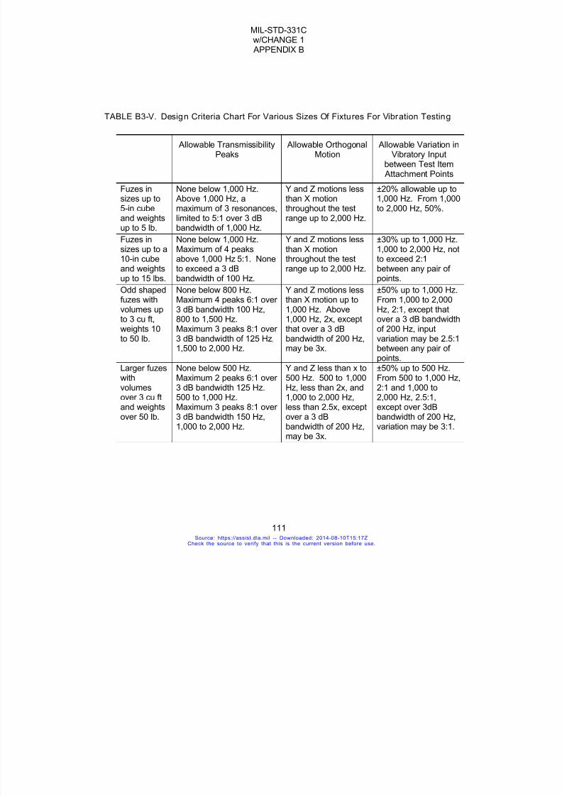
7/18/2019 Mil Std 331 Amend
http://slidepdf.com/reader/full/mil-std-331-amend 119/286
MIL-STD-331Cw/CHANGE 1 APPENDIX B
111
TABLE B3-V. Design Criteria Chart For Various Sizes Of Fixtures For Vibration Testing
Allowable TransmissibilityPeaks
Allowable OrthogonalMotion
Allowable Variation inVibratory Input
between Test Item Attachment Points
Fuzes insizes up to5-in cube
and weightsup to 5 lb.
None below 1,000 Hz. Above 1,000 Hz, amaximum of 3 resonances,
limited to 5:1 over 3 dBbandwidth of 1,000 Hz.
Y and Z motions lessthan X motionthroughout the test
range up to 2,000 Hz.
±20% allowable up to1,000 Hz. From 1,000to 2,000 Hz, 50%.
Fuzes insizes up to a10-in cubeand weightsup to 15 lbs.
None below 1,000 Hz.Maximum of 4 peaksabove 1,000 Hz 5:1. Noneto exceed a 3 dBbandwidth of 100 Hz.
Y and Z motions lessthan X motionthroughout the testrange up to 2,000 Hz.
±30% up to 1,000 Hz.1,000 to 2,000 Hz, notto exceed 2:1between any pair ofpoints.
Odd shapedfuzes withvolumes up
to 3 cu ft,weights 10to 50 lb.
None below 800 Hz.Maximum 4 peaks 6:1 over3 dB bandwidth 100 Hz,
800 to 1,500 Hz.Maximum 3 peaks 8:1 over3 dB bandwidth of 125 Hz,1,500 to 2,000 Hz.
Y and Z motions lessthan X motion up to1,000 Hz. Above
1,000 Hz, 2x, exceptthat over a 3 dBbandwidth of 200 Hz,may be 3x.
±50% up to 1,000 Hz.From 1,000 to 2,000Hz, 2:1, except that
over a 3 dB bandwidthof 200 Hz, inputvariation may be 2.5:1between any pair ofpoints.
Larger fuzeswithvolumesover 3 cu ftand weightsover 50 lb.
None below 500 Hz.Maximum 2 peaks 6:1 over3 dB bandwidth 125 Hz.500 to 1,000 Hz.Maximum 3 peaks 8:1 over3 dB bandwidth 150 Hz,
1,000 to 2,000 Hz.
Y and Z less than x to500 Hz. 500 to 1,000Hz, less than 2x, and1,000 to 2,000 Hz,less than 2.5x, exceptover a 3 dB
bandwidth of 200 Hz,may be 3x.
±50% up to 500 Hz.From 500 to 1,000 Hz,2:1 and 1,000 to2,000 Hz, 2.5:1,except over 3dBbandwidth of 200 Hz,
variation may be 3:1.
Source: https://assist.dla.mil -- Downloaded: 2014-08-10T15:17ZCheck the source to verify that this is the current version before use.

7/18/2019 Mil Std 331 Amend
http://slidepdf.com/reader/full/mil-std-331-amend 120/286
MIL-STD-331Cw/CHANGE 1 APPENDIX B
112
FIGURE B3-1. Vibration Test Levels For Externally-Carried, Air-Launched Muni tion(excluding helicopters)
TABLE B3-VI. Linear Cycling Rates
Total FrequencyRange (Hz)
Frequency Band(Hz)
Sweep Time inMinutes
Linear Cycling Rate(Hz/min)
2 to 500 or 2 to 5 3 2
5 to 500 5 to 22.5 6 5.8
as applicable 22.5 to 110 5 35
110 to 500 4 195
5 to 22.5 6 5.8
22.5 to 110 5 35
5 to 2,000 110 to 500 4 195500 to 900 3 267
900 to 2,000 2 1,000
Source: https://assist.dla.mil -- Downloaded: 2014-08-10T15:17ZCheck the source to verify that this is the current version before use.
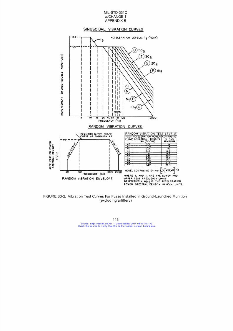
7/18/2019 Mil Std 331 Amend
http://slidepdf.com/reader/full/mil-std-331-amend 121/286
MIL-STD-331Cw/CHANGE 1 APPENDIX B
113
FIGURE B3-2. Vibration Test Curves For Fuzes Installed In Ground-Launched Munit ion(excluding artillery)
Source: https://assist.dla.mil -- Downloaded: 2014-08-10T15:17ZCheck the source to verify that this is the current version before use.
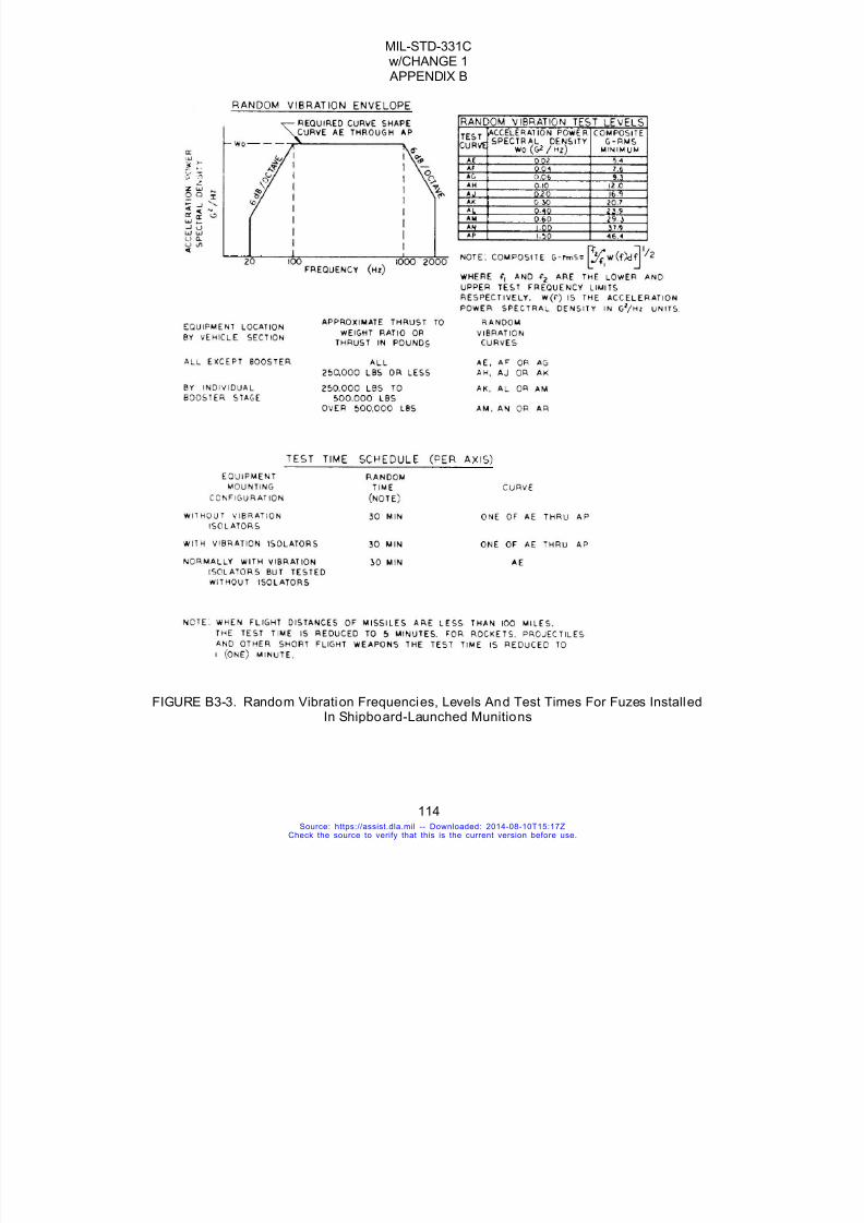
7/18/2019 Mil Std 331 Amend
http://slidepdf.com/reader/full/mil-std-331-amend 122/286
MIL-STD-331Cw/CHANGE 1 APPENDIX B
114
FIGURE B3-3. Random Vibration Frequencies, Levels And Test Times For Fuzes InstalledIn Shipboard-Launched Munitions
Source: https://assist.dla.mil -- Downloaded: 2014-08-10T15:17ZCheck the source to verify that this is the current version before use.
7/18/2019 Mil Std 331 Amend
http://slidepdf.com/reader/full/mil-std-331-amend 123/286
MIL-STD-331Cw/CHANGE 1 APPENDIX B
115
FIGURE B3-4A. Submarine-To-Surface Induced Sinusoidal Vibration
FIGURE B3-4B. Random Vibration Frequencies, Levels And Test Times For Fuzes
Source: https://assist.dla.mil -- Downloaded: 2014-08-10T15:17ZCheck the source to verify that this is the current version before use.

7/18/2019 Mil Std 331 Amend
http://slidepdf.com/reader/full/mil-std-331-amend 124/286
MIL-STD-331Cw/CHANGE 1 APPENDIX B
116
Installed In Underwater-Launched Munitions
FIGURE B3-5. Logarithmic Frequency Sweep
Source: https://assist.dla.mil -- Downloaded: 2014-08-10T15:17ZCheck the source to verify that this is the current version before use.

7/18/2019 Mil Std 331 Amend
http://slidepdf.com/reader/full/mil-std-331-amend 125/286
MIL-STD-331Cw/CHANGE 1 APPENDIX C
117
APPENDIX CCLIMATIC TESTS
Source: https://assist.dla.mil -- Downloaded: 2014-08-10T15:17ZCheck the source to verify that this is the current version before use.
7/18/2019 Mil Std 331 Amend
http://slidepdf.com/reader/full/mil-std-331-amend 126/286
MIL-STD-331Cw/CHANGE 1 APPENDIX C
118
TEST C1
TEMPERATURE AND HUMIDITY
C1.1 PURPOSEThis is a laboratory safety and reliability test simulating storage conditions. The fuze mustwithstand exposure to repeated cycles of extreme temperatures and humidity.
C1.2 DESCRIPTION
C1.2.1 General. Bare fuzes are exposed to a 28-day schedule (two 14-daycycles) of temperature and humidity variations. Fuzes are alternately exposed toextremes of +71°C and -54°C (+160°F and -65°F) with additional storage periods at+71°C and -62°C (+160°C and -80°F). The test chamber is maintained at 95 percent
relative humidity during the +71°C (+160°F) periods. There are two methods forperforming this test using either one or two test chambers. In the two-chamber method,fuzes are moved from a cold to a hot chamber and back. In the single-chamber method,the temperature within the chamber is changed nine times, exposing the fuzes to a similarschedule of temperatures.
C1.2.2 Test fuzes. All explosive elements shall be present in the fuze during thetest.
C1.2.3 Applicable publications. All standards, specifications, drawings,procedures and manuals which form a part of this test are listed in Section C1.2 of theintroduction to this standard. Special attention is directed to Army Regulation 70-38regarding material testing for extreme climatic conditions.
C1.2.4 Test documentation. Test plans, performance records, equipment,conditions, results and analysis shall be documented in accordance with 4.8 of thegeneral requirements to this standard.
C1.3. CRITERIA FOR PASSING TEST
C1.3.1 Fuze condi tion. At the completion of this test, the fuze shall be safe fortransportation, storage, handling and use, as well as operable in accordance with 4.6.2.1aand 4.6.2.2 of the general requirements to this standard.
C1.3.2 Decis ion basis. Breakdown, inspection, other appropriate tests andengineering judgment shall form the basis for the decision that fuzes have passed orfailed the test. Fuzes may be subjected to operational tests under simulated fieldconditions.
C1.4 EQUIPMENT
C1.4.1 Test chambers. Commercial temperature-humidity chambers or cabinetsare used for this test. The humidity chamber and accessories shall be constructed toavoid condensate dripping on the test items and to prevent the build-up of total pressure.The flow of air throughout the internal test chamber area shall not exceed 45.7 meters perminute (150 feet per minute). No rust or corrosive contaminants shall be imposed on thetest items by the test facility.
Source: https://assist.dla.mil -- Downloaded: 2014-08-10T15:17ZCheck the source to verify that this is the current version before use.

7/18/2019 Mil Std 331 Amend
http://slidepdf.com/reader/full/mil-std-331-amend 127/286
MIL-STD-331Cw/CHANGE 1 APPENDIX C
119
C1.4.2 Fixtures. If fixtures are used to hold the fuzes in particular orientations,they must not impede the entrance of moisture and interference with the attainment ofequilibrium shall be minimized.
C1.4.3 Temperature. The term "temperature" used throughout this test is definedas the temperature of the air immediately surrounding the control sensing elements.
Continuous records of temperature and humidity or wet bulb are required. When thesingle-chamber method is used, the continuous recording requirement for humidity or wetbulb shall apply only to those portions of the test schedule that are above roomtemperature. A sampling type of recording system, such as a multi-point recorder, shallbe considered as providing a continuous record if each variable is recorded not less thanonce every two minutes.
C1.5. PROCEDURE
C1.5.1 Schedule. Perform this test in accordance with the schedule in Table C1-Ifor the two-chamber method or Table C1-II for the single-chamber method, whichever isappropriate, observing the indicated temperature sequence and duration of each event.
Changes must be made within 15 minutes of the times indicated. The tables show theday count and time of day when it should be most convenient to run each event. FigureC1-1 is a graphic representation of the test schedule.
C1.5.2 Return to ambient temperature. At the end of 28 days (two complete 14-day cycles) allow the fuzes to return to room ambient conditions. Room temperature is+23°F±10°C (+73°F±18°F).
C1.5.3 Compliance. Analyze the test results and determine whether or not thetest article meets the pass/fail criteria in Section C1.3. Continue testing the specifiednumber of items.
C1.6. ALTERNATE AND OPTIONAL TESTS
None.
C1.7. RELATED INFORMATION
C1.7.1 Background of 14-day cycle. Various temperature and humidity cycleshave been in use for many years with the result that no real correlation between testconditions and actual storage conditions can be drawn. The basic 14-day unit of this test,referred to as the "temperature and humidity cycle", may be useful for many otherapplications as well as for fuze testing. The 14-day cycle was originally chosen becausethis period is a little shorter than that required to cause failure of mercury fulminatedetonators, which are no longer authorized for use. Current fuze designs shouldwithstand two temperature and humidity cycles (28 days).
C1.7.2 Accelerated conditions. A relative humidity of 95% at the high
temperature is used because damage to certain elements is accelerated in the presenceof moisture. It has been found through experiment that, in the case of ordinary threadseals and other similar closures, moisture is transported into the interior of fuzes primarilythrough diffusion rather than through a "breathing process", although both occur.However, there have been instances where moisture entry could have occurred onlyduring the cooling period. For instance, in one assembly, utilizing an "O" ring, a partialrelief of the pressure difference (developed during cycling) occurred, a pressuredifferential being maintained after attainment of thermal equilibrium. In this situation,diffusion would be excluded as the process for moisture transport, and moisture entry
Source: https://assist.dla.mil -- Downloaded: 2014-08-10T15:17ZCheck the source to verify that this is the current version before use.

7/18/2019 Mil Std 331 Amend
http://slidepdf.com/reader/full/mil-std-331-amend 128/286
MIL-STD-331Cw/CHANGE 1 APPENDIX C
120
would occur only during the cooling period. Thus, the results obtained by imposing a slowcooling period with maintenance of high relative humidity would differ from those obtainedwhen fuzes are allowed to cool at ambient humidity. Therefore, if a fuze has such seals,the designer should consider this point in running this test.
C1.7.3 Obtaining humidity. It is recommended that the specified humidity be
obtained through the use of steam or by vaporizing distilled, demineralized or deionizedwater. The pH of a condensed sample of vapor from the test chamber is expected to bebetween 6.0 and 7.3 at +23°C (+73°F).
C1.7.4 Bibliography.C1.7.4.1 Picatinny Arsenal Technical Report No. 1800, Temperature and Humidity
Test.C1.7.4.2 AR 70-38, Research, Development, Test and Evaluation of Materiel for
Extreme Climatic Conditions.
Source: https://assist.dla.mil -- Downloaded: 2014-08-10T15:17ZCheck the source to verify that this is the current version before use.

7/18/2019 Mil Std 331 Amend
http://slidepdf.com/reader/full/mil-std-331-amend 129/286
MIL-STD-331Cw/CHANGE 1 APPENDIX C
121
TABLE C1- I. Two-chamber Method Test Schedule
Day Time
Temperature(degrees C)
RelativeHumidity
Day Time
Temperature(degrees C)
RelativeHumidity
Cycle1
Cycle2
Start StopCycle
1Cycle
2Start Stop
115 0800 0900 Room 8 22 0900 1500 -54
115 0900 1500 -54 8 22 1500 1600 Room
115 1500 1600 Room 8-9 22-23 1600 0800 +71 95%
1-215-16 1600 0800 +71 95% 9 23 0800 0900 Room
216 0800 0900 Room 9 23 0900 1500 -54
216 0900 1500 -54 9 23 1500 1600 Room
216 1500 1600 Room 9-10 23-24 1600 0800 +71 95%
2-316-17 1600 0800 +71 95% 10 24 0800 0900 Room
317 0800 0900 Room 10 24 0900 1500 -54
317 0900 1500 -54 10 24 1500 1600 Room
317 1500 1600 Room 10-11 24-25 1600 0800 +71 95%
3-417-18 1600 0800 +71 95% 11 25 0800 0900 Room
418 0800 0900 Room 11 25 0900 1500 -54
418 0900 1500 -54 11 25 1500 1600 Room
418 1500 1600 Room 11-12 25-26 1600 0800 +71 95%
4-518-19 1600 0800 +71 95% 12 26 0800 0900 Room
519 0800 0900 Room 12 26 0900 1500 -54
5-819-22 0900 0900 -62 12 26 1500 1600 Room
12-15 26-29 1600 0800 +71 95%
Source: https://assist.dla.mil -- Downloaded: 2014-08-10T15:17ZCheck the source to verify that this is the current version before use.
7/18/2019 Mil Std 331 Amend
http://slidepdf.com/reader/full/mil-std-331-amend 130/286
MIL-STD-331Cw/CHANGE 1 APPENDIX C
122
TABLE C1- II. Single-chamber Method Test Schedule Day Time Temperature
(degrees C)RelativeHumidity
Cycle 1 Cycle 2 Start Stop
1 15 0800 0900 Room
1 15 0900 1100 Transition
1 15 1100 1600 -54
1 15 1600 1900 Transition
1-2 15-16 1900 0800 +71 95%
2 16 0800 1100 Transition
2 16 1100 1600 -54
2 16 1600 1900 Transition
2-3 16-17 1900 0800 +71 95%
3 17 0800 1100 Transition
3 17 1100 1600 -54
3 17 1600 1900 Transition
3-4 17-18 1900 0800 +71 95%
4 18 0800 1100 Transition
4 18 1100 1600 -54
4 18 1600 1900 Transition
4-5 18-19 1900 0800 +71 95%
5 19 0800 1100 Transition
5-8 19-22 1100 0800 -62
8 22 0800 1600 -54
8 22 1600 1900 Transition8-9 22-23 1900 0800 +71 95%
9 23 0800 1100 Transition
9 23 1100 1600 -54
9 23 1600 1900 Transition
9-10 23-24 1900 0800 +71 95%
10 24 0800 1100 Transition
10 24 1100 1600 -54
10 24 1600 1900 Transition
10-11 24-25 1900 0800 +71 95%
11 25 0800 1100 Transition11 25 1100 1600 -54
11 25 1600 1900 Transition
11-12 25-26 1900 0800 +71
12 26 0800 1100 Transition
12 26 1100 1600 -54
12 26 1600 1900 Transition
12-15 26-29 1900 0800 +71 95%
Source: https://assist.dla.mil -- Downloaded: 2014-08-10T15:17ZCheck the source to verify that this is the current version before use.

7/18/2019 Mil Std 331 Amend
http://slidepdf.com/reader/full/mil-std-331-amend 131/286
MIL-STD-331Cw/CHANGE 1 APPENDIX C
123
Figure C1-1 Temperature and Hmidity Cycle
Source: https://assist.dla.mil -- Downloaded: 2014-08-10T15:17ZCheck the source to verify that this is the current version before use.
7/18/2019 Mil Std 331 Amend
http://slidepdf.com/reader/full/mil-std-331-amend 132/286
MIL-STD-331Cw/CHANGE 1 APPENDIX C
124
TEST C2
VACUUM-STEAM-PRESSURE
C2.1 PURPOSE
This is a laboratory safety and reliability test simulating storage or ready use conditions. The fuzemust withstand exposure to a series of fifteen-minute vacuum-steam-pressure cycles.
C2.2 DESCRIPTION
C2.2.1 General. Experience has shown that fuzes which survive this test are likely tosurvive at least six months of tropical exposure. It evaluates the effects of these conditions onfuzes with non-breathing seals. Bare fuzes are subjected to 1000 consecutive fifteen-minutecycles in a vacuum-steam-pressure environment. The 1000 cycles take about 10 days ofcontinuous running time. The basic cycle consists of temperature-humidity cycling superimposed
on pressure cycling in a test chamber with a salt-laden atmosphere. Representative curves oftemperature and pressure versus time are shown in Figure C2-1. This test is designed toaccelerate the aging and failure-mode processes of bare fuzes by (1) using increased levels ofpressure and vacuum beyond those encountered in normal service use, and (2) decreasing thetime elements by using an environmental cycle of fifteen minutes, continuous to a total of 1000cycles. This accelerated test achieves the same end-failure-modes (for certain types of sealedfuzes) which are experienced in the normal 6 months of tropical storage or ready use conditions.
C2.2.2 Fuze application and configuration. The types of fuzes for which this test isapplicable are bonded, non-breathing-seal designs (soldered, welded, brazed, adhesive-sealed)whose case and seal materials have yield strengths beyond the stress levels exerted by thevacuum-pressure test range. All fuze explosive elements shall be present in the fuze duringtesting.
C2.2.3 Applicable publications. All standards, specifications, drawings, procedures andmanuals which form a part of this test are listed in Section 2 of the introduction to this standard.Special attention is directed to NAVSEA OD 7547.
C2.2.4 Test documentation. Test plans, performance records, equipment, conditions,results, and analysis shall be documented in accordance with 4.8 of the general requirements tothis standard.
C2.3 CRITERIA FOR PASSING TEST
C2.3.1 Fuze condition. At the completion of this test, the fuze shall be safe fortransportation, storage, handling and use, as well as operable in accordance with 4.6.2.1a and4.6.2.2 of the general requirements to this standard.
C2.3.2 Decis ion basis. Breakdown, inspection, other appropriate tests and engineering judgment shall form the basis for the decision that fuzes have passed or failed the test.
C2.4 EQUIPMENT
The equipment consists of an insulated chamber with a hinged door for accessibility. The chamberhas a circulation fan and is fitted with the necessary piping and valves to control the flow of air,steam, and salt solution. Also included are shelves or baskets to hold the test items and thenecessary electronics and monitoring equipment to automatically control the system. Refer toNAVSEA OD 7547.
Source: https://assist.dla.mil -- Downloaded: 2014-08-10T15:17ZCheck the source to verify that this is the current version before use.

7/18/2019 Mil Std 331 Amend
http://slidepdf.com/reader/full/mil-std-331-amend 133/286
MIL-STD-331Cw/CHANGE 1 APPENDIX C
125
C2.5. PROCEDURE
C2.5.1 Equipment check. Determine that the equipment is in proper operating condition.C2.5.2 Testing. Place the items in the chamber and subject them to 1000±10 continuous
cycles of 15±1 minutes per cycle as described in 5.2.1 thru 5.2.4, below.C2.5.2.1 Chamber evacuation. Evacuate the chamber from atmospheric pressure to
700±50 mm Hg (28±2 in Hg) below atmospheric pressure. Evacuation of the chamber shall beaccomplished within six minutes.
C2.5.2.2 Steam application. Admit steam into the chamber until the chamber reaches apredetermined temperature. Then pressurize the chamber with air to 0.172± 0.013 MPa (25±2psig), thus obtaining a final temperature of +66±1.7°C (+151±3°F). During the admission of air,40±2 grams (1.41±0.07 oz) of sodium chloride dissolved in one to 57 liters (one quart to 15gallons) of distilled water shall be dispersed in the chamber at a uniform rate over 1000±10 cycles.NOTE: The predetermined temperature at which steam flow is shut off will be a function of theparticular chamber design. The major variables which affect the steam shut-off temperature arethe effective thermal mass of the chamber, thermal mass of the test item, chamber volume, andrate of heat input. The set point for steam shut-off must be adjusted to give the specified
temperature after pressurization.C2.5.2.3 Pressure maintenance. The chamber pressure is maintained at 0.172±0.013
MPa (25±2 psig) for 4±0.25 minutes.C2.5.2.4 Venting. Vent the chamber, allow the moisture to drain off, and allow the chamber
to return to atmospheric pressure.C2.5.3 Maintaining the test schedule. The test should be continuous but may be
interrupted for a maximum of five days. The test items must be stored at ambient conditions duringthe interruptions. During startup and after periodic inspection, the system may require a few cyclesto stabilize conditions. These cycles should not be included or counted as part of the 1000 cycletest.
C2.5.4 Compliance. Analyze the test results and determine whether or not the test article
meets the pass/fail criteria in Section 3. Continue testing the specified number of items.
C2.6. ALTERNATE AND OPTIONAL PROCEDURES
None.
C2.7 RELATED INFORMATION
C2.7.1 Background. This ten day test of 1000 cycles has been found to be the equivalentof at least six months Pacific Fleet life for World War II VT Fuzes. These fuzes were waterproofedexternally by using lacquer sealants on exposed components. They also contained metal-cased,solder-sealed components. The test was designed to give, on an accelerated basis, the same endfailure-modes as had been experienced by the fuze components at the end of 6 to 8 months offuze storage (in unsealed packages) or ready use (assembled to weapons, with weapons on readyuse status). The test has continued in use since then (approximately 1948) as applicable toexternally-sealed fuzes with metal-to-metal, metal-to-glass, or other material-to-material bondsgiving either fusion or adhesion conditions. It is very important that this test not be used on fuzeswhich have other types of sealing (O-ring, metal interlocking, breathing-type, and so forth) or thosewhich have case materials which cannot survive, on a yield strength or fatigue basis, the force-loading conditions which pertain under vacuum-pressure range of the test. To do so is to misusethe test and invite automatic failure of the fuze under the test conditions. The primary function ofthis accelerated test is to estimate the term capability of fuze and/or component moisture seals of
Source: https://assist.dla.mil -- Downloaded: 2014-08-10T15:17ZCheck the source to verify that this is the current version before use.

7/18/2019 Mil Std 331 Amend
http://slidepdf.com/reader/full/mil-std-331-amend 134/286
MIL-STD-331Cw/CHANGE 1 APPENDIX C
126
the specified type after at least 6 months of tropical storage.C2.7.2 Revisions. Test 106.1, redesignated Test C2, was written to correct thermodynamic
discrepancies in the requirements of Test 106, to clarify the procedure, and to establish tolerancesfor a more reliable and repeatable test.Figure C2-1. Typical Test Curves of Pressure and Temperature Versus Time.
Source: https://assist.dla.mil -- Downloaded: 2014-08-10T15:17ZCheck the source to verify that this is the current version before use.

7/18/2019 Mil Std 331 Amend
http://slidepdf.com/reader/full/mil-std-331-amend 135/286
MIL-STD-331Cw/CHANGE 1 APPENDIX C
127
FIGURE C2-1. Typical Test Curves of Pressure and Temperature Versus Time.
Source: https://assist.dla.mil -- Downloaded: 2014-08-10T15:17ZCheck the source to verify that this is the current version before use.

7/18/2019 Mil Std 331 Amend
http://slidepdf.com/reader/full/mil-std-331-amend 136/286
MIL-STD-331Cw/CHANGE 1 APPENDIX C
128
TEST C3
SALT FOG
C3.1 PURPOSE. This is a laboratory safety and reliability test simulating bare fuzeexposure to a moist, salty atmosphere.
C3.2 DESCRIPTION
C3.2.1 General. Bare fuzes are exposed to a salt fog atmosphere. The test directive shallspecify one of two test durations. Fuzes subjected to the test for 48 hours are checked for safetyand operability; fuzes tested for 96 hours are checked for safety only. At least eight fuzes arerequired for each test. Two fuzes are tested in each of four orientations. One fuze from eachorientation is then evaluated immediately after the test while still wet. The remaining four fuzes arefirst dried and then evaluated.
C3.2.2 Fuze configuration. All fuze explosive elements shall be present in the fuze duringthe test.
C3.2.3 Applicable publications. All standards, specifications, drawings, procedures andmanuals which form a part of this test are listed in Section 2 of the introduction to this standard.
C3.2.4 Test documentation. Test plans, performance records, equipment, conditions,results, and analysis shall be documented in accordance with 4.8 of the general requirements tothis standard.
C3.3 CRITERIA FOR PASSING TEST
C3.3.1 Fuze condit ion. At the completion of a 48-hour test, the fuze shall be safe fortransportation, storage, handling and use, as well as operable in accordance with 4.6.2.1a and4.6.2.2 of the general requirements to this standard. At the completion of a 96-hour test, the fuzeshall be safe for transportation, storage, handling and use in accordance with 4.6.2.2a of thegeneral requirements to this standard. In 96-hour tests, the fuze does not have to be operable.
C3.3.2 Decision basis. Breakdown, inspection, other appropriate tests and engineering judgment shall form the basis for the decision that fuzes have passed or failed the test.
C3.4 EQUIPMENT
C3.4.1 General. The equipment shall include an exposure chamber with a salt solutionreservoir, sufficient atomizing or spray nozzles, test specimen supports, a chamber heating and
temperature control system, a source of compressed air, a pressure regulator, and a compressedair humidifying system.C3.4.2 Test chamber. The chamber and accessories shall be constructed of materials
which do not react with, and are not affected by, the corrosiveness of the salt fog, and do not reactwith or affect the test specimens. Suitable materials for construction of the chamber are rubber"Alberene Stone", chemical stoneware, plate glass, slate or stainless steel. Suitable materials forthe construction or coating of racks and supports are glass, rubber, plastic or suitably coatedwood; bare metal (even stainless steel) should not be used. The chamber shall be of adequatesize, with respect to the test specimens, to provide circulation about all specimens to the same
Source: https://assist.dla.mil -- Downloaded: 2014-08-10T15:17ZCheck the source to verify that this is the current version before use.
7/18/2019 Mil Std 331 Amend
http://slidepdf.com/reader/full/mil-std-331-amend 137/286
MIL-STD-331Cw/CHANGE 1 APPENDIX C
129
degree. The top of the chamber shall be inclined to prevent dripping of condensed liquid upon thespecimens. Provision shall be made to seal the door opening of the chamber against the loss offog when the chamber is in operation. A drain shall be provided at the low point in the chamber toremove condensed salt fog from the chamber, and also prevent its return to the salt solutionreservoir. A vent shall be located in the wall of the chamber as far from the atomizer as
practicable. A salt solution reservoir (internal or external) shall be adequately covered to preventcontamination of condensed fog returning to the reservoir. The reservoir should hold at least a 24hour supply of salt solution.
C3.4.3 Climate control equipment.C3.4.3.1 Temperature. The air temperature in the chamber shall be controlled between
32ºC and 36ºC (90ºF and 97ºF) by heating the wall and floor surfaces. This can be obtained bywater jacketing, or the chamber may be placed in a room with the room temperature controlled tomaintain a chamber temperature within the previously specified limits. A suitable method ofrecording temperature is by a continuous recording device, or by a thermometer which can be readfrom outside the closed cabinet. The recorded temperature must be obtained with the salt fogchamber closed to avoid a false low reading due to wet-bulb effect when the chamber is open.
C3.4.3.2 Air flow. The salt fog shall be produced by blowing humidified air through anozzle to atomize the salt solution to produce a fine mist. The nozzles shall be located or baffledto prevent direct impingement on test specimens.
C3.4.3.3 Air purity. Compressed air used for the fog nozzles shall be reasonably free fromdust, oil, or excessive liquid water particles, and any foreign gases.
C3.4.3.4 Water vapor. The air shall contain sufficient water vapor to be in equilibrium withthe atmosphere in the chamber which has at least 84% relative humidity at a temperature of 36ºC(95ºF). It may be pre-conditioned by passing through a saturator. The size of the air bubbles andthe water temperature are the most important controlling factors to condition the air properly. Thisor any other system may be used provided the compressed air has a relative humidity of 84% to90% at a temperature of 36ºC (95ºF) when released inside the chamber. The compressed air
should be saturated with water vapor as follows:
Air Pressure [MPa (psig)] Water Temperature [ºC (ºF)]
0.082 (12) 43 (110)
0.096 (14) 44 (112)
0.110 (16) 46 (115)
0.124 (18) 47 (117)
C3.5. PROCEDURE
C3.5.1 Test setup. The fuzes shall be placed in the exposure chamber as far away fromthe fog nozzles as practicable, and in the four positions which are illustrated by Figure C3-1.
C3.5.1.1 Fuze support. Preferably, fuzes shall be supported from the bottom or side.Suspension from glass hooks or waxed string may be used as long as the specified position of thefuzes is obtained. If necessary, a secondary support at the bottom of the fuzes may be used. Inall cases, holding devices (supports and suspensions) shall be of inert, non-metallic materialswhich will not create electrolytic action.
C3.5.1.2 Fuze orientation. Radial orientation of the test fuzes shall be such as to expose
Source: https://assist.dla.mil -- Downloaded: 2014-08-10T15:17ZCheck the source to verify that this is the current version before use.
7/18/2019 Mil Std 331 Amend
http://slidepdf.com/reader/full/mil-std-331-amend 138/286
MIL-STD-331Cw/CHANGE 1 APPENDIX C
130
the most critical or vulnerable parts of the fuzes to the salt fog as determined by engineering judgment or past experience.
C3.5.1.3 Fuze isolation. The fuzes shall not contact each other or any material capable ofacting as a wick. Each fuze shall be so placed as to permit free settling of fog on all fuzes beingtested. Salt solution shall not be permitted to drip on the test specimens and flow of salt solution
from holding devices to the fuzes shall be reduced to a practicable minimum.C3.5.2 Preparation of salt solut ion. The salt solution shall be prepared by dissolving 5±1
parts by weight of salt in 95 parts by weight of distilled water or water containing not more than 200parts per million of total solids. In addition, before the solution is atomized, it shall be free ofsuspended solids before it is placed in the chamber reservoir. This may be done by filtering,decanting or covering the end of the tube leading from the solution reservoir to the atomizer. Usea double layer of white cloth having a mesh which will permit an adequate flow of solution andwhich will prevent clogging of the nozzles. The salt used shall be sodium chloride containing, on adry bases, not more than 0.1 percent of sodium iodide and not more than 0.2 percent of totalimpurities.
C3.5.2.1 pH. The pH of the solution shall be maintained at 6.5 to 7.2, when measured at a
temperature of 32o
to 36ºC (90o
to 97ºF). The pH measurement shall be made electrometrically(using a glass electrode with a saturated potassium chloride bridge) or colorimetrically (providedthe results obtained compare with the electrometric method). The pH of the salt solution can beadjusted by additions of small quantities of diluted c.p. sodium hydroxide solutions. Bromthymolblue has proved a satisfactory indicator for the colorimetric pH measurement of the salt solution.
C3.5.2.2 Salt concentration. A salt solution having a specific gravity of from 1.025 to1.037, when measured at a temperature of 33ºC to 36ºC (92ºF to 97ºF), will meet theconcentration requirement of 5±1 percent by weight. To determine the sodium concentration bymeasuring the specific gravity, at least two clean fog collectors shall be placed within the exposurezone so that no drops or flow of solution from the test fuzes, or any other source, are collected.The collectors shall be placed in the proximity of the test fuzes, one nearest to any nozzle, and the
other farthest from all nozzles. Suitable collecting devices for checking fog concentration are glassfunnels with the stems inserted through stoppers into graduated cylinders or crystallizing dishes.The fog shall be such that for each 80 sq cm (12.4 sq in) of horizontal collecting area, there will becollected in each collector from 0.5 to 3.0 cc (0.017 to 0.101 oz) of solution per hour based on theaverage of a run of at least 16 hours.
C3.5.3 Temperature control. The exposure zone of the salt fog chamber shall bemaintained at 35 +1 to –2ºC (95 +2 to –3ºF) except during those periods when the test isinterrupted for exposing, rearranging, or removing test fuzes, or checking or replenishing thesolution in the reservoir. The temperature within the exposure zone of the closed cabinet shall berecorded at least twice a day, approximately 7 hours apart.
C3.5.4 Maintenance of the test schedule. The test shall be continuous for the duration of
the entire test period. Continuous operation implies that the chamber be closed and the fogoperating continuously except for the short daily interruptions necessary to inspect, rearrange, orremove test fuzes, and to check and replenish the solution in the reservoir. Operations shall be soscheduled that these interruptions are held to a maximum of l hour (total) in any 48 hour period.
C3.5.5 Evaluation. The fuzes shall be carefully removed from the chamber at thecompletion of the test with no attempt being made to remove salt deposits. One fuze from each ofthe four test orientations shall be evaluated after drying, and the other half shall be evaluated whilestill wet.
C3.5.5.1 Wet fuzes. The wet fuzes shall be evaluated immediately; that is, before the
Source: https://assist.dla.mil -- Downloaded: 2014-08-10T15:17ZCheck the source to verify that this is the current version before use.

7/18/2019 Mil Std 331 Amend
http://slidepdf.com/reader/full/mil-std-331-amend 139/286
MIL-STD-331Cw/CHANGE 1 APPENDIX C
131
surface moisture has evaporated.C3.5.5.2 Drying procedure. The fuzes which are to be dried shall be subjected to
circulating air at a temperature of 43ºC to 49ºC (110ºF to 120ºF) for a period of 23 to 25 hours, andevaluated as soon as possible thereafter.
C3.5.6 Compliance. Analyze the test results and determine whether or not the test articles
meet the pass/fail criteria in Section 3.
C3.6 ALTERNATE AND OPTIONAL TESTS
C3.6.1 Test duration. The test directive shall specify whether the test shall be conductedfor 48 or 96 hours. Test results shall be evaluated in accordance with applicable criteria of Section3.
C3.6.2 Operational tests. The fuzes should be further evaluated at conditions which areconsidered the most severe for the particular type fuze being tested. For example, mechanicalfuzes having rotors, sliders, detents, arming vanes, and so forth, should be subjected to armingtests. In the case of electrical fuzes, circuit breakdown due to leakage of capacitors, and so forth,should be checked while the fuze is wet.
C3.6.3 Low temperature test. This salt fog test is used to determine the resistance offuzes to a moist, salt-laden atmosphere. It is an accelerated test that cannot necessarily becorrelated to marine or service conditions. For some applications, the fuze should be subjected tolow temperature tests immediately following the salt fog test. In this case, the fuze should beexposed to the low temperatures while it is still wet.
C3.7 RELATED INFORMATION
C3.7.1 Test effects. The following damage or malfunctions may result from this test:a. Rust or corrosion of metals,b. Binding or non-operation of moving parts due to salt deposits,c. Obscuring of windows or markings due to salt deposits,d. Surface electrical leakage,
e. Electrical arcing,f. Short circuiting of electrical components,g. Development of potential breakage lines in metals and plastics, andh. Electrochemical decomposition in areas having dissimilar materials in close proximity.
C3.7.2 Limitations of test. In using this salt fog test, it should be recognized:a. Withstanding this test does not guarantee that the fuzes will survive other corrosive, marine
or service environments.b. Failing this test does not necessarily mean that the fuzes would fail other corrosive, marine
or service environments.c. Although this test may prove useful for comparing the corrosion resistance of materials and
coating under accelerated conditions, it is generally unreliable for predicting their
comparative service life.d. The salt fog test is generally acceptable for evaluating the uniformity (that is, thickness and
degree of porosity) of protective coatings, metallic and non-metallic, of different lots or thesame product once some standard level of performance has been established. (When usedto check the porosity of metallic coatings, the test is more dependable when applied tocoatings which are cathodic rather than anodic in reference to the base metal.)
e. The test can also be used to detect the presence of free iron contaminating the surface ofanother metal by inspection of the corrosion products.
Source: https://assist.dla.mil -- Downloaded: 2014-08-10T15:17ZCheck the source to verify that this is the current version before use.
7/18/2019 Mil Std 331 Amend
http://slidepdf.com/reader/full/mil-std-331-amend 140/286
MIL-STD-331Cw/CHANGE 1 APPENDIX C
132
C3.7.3 Bibliography.C3.7.3.1 Memorandum Report M60-22-1, Standardization of Salt Spray Testing Chambers
and Techniques, Frankford Arsenal, February 1960.C3.7.3.2 Final Report No. NADC-EL-59101, Investigation and Development of a Salt Spray
Test Procedure, U.S. Naval Air Development Center, 6 January 1960.
FIGURE C3-1. Salt Fog Test Setup
Source: https://assist.dla.mil -- Downloaded: 2014-08-10T15:17ZCheck the source to verify that this is the current version before use.
7/18/2019 Mil Std 331 Amend
http://slidepdf.com/reader/full/mil-std-331-amend 141/286
MIL-STD-331Cw/CHANGE 1 APPENDIX C
133
TEST C4
WATERPROOFNESS
C4.1. PURPOSE
This is a laboratory safety and reliability test which subjects the fuze to submersion in water. Thefuze must remain free of leaks when submerged to a depth of 10.7 m (35 ft) of water.
C4.2. DESCRIPTION
C4.2.1 General. This test consists of subjecting bare fuzes to immersion for one hour in awater solution of sodium fluoresceinate (uranin) under a pressure of approximately oneatmosphere (0.100 MPa (15 psig) at 21ºC (70ºF)), and subsequently examining the disassembledfuzes for evidence of water entry.
C4.2.2 Fuze configuration. When specified by the design agency, all fuze explosiveelements shall be present in the fuze during the test.C4.2.3 Applicable publications. All standards, specifications, drawings, procedures and
manuals which form a part of this test are listed in Section 2 of the introduction to this standard.C4.2.4 Test documentation. Test plans, performance records, equipment, conditions,
results, and analysis shall be documented in accordance with 4.8 of the general requirements tothis standard.
C4.3. CRITERIA FOR PASSING TEST
C4.3.1 Fuze condit ion. There shall be no evidence that any water has entered the fuze. At the completion of this test, the fuze shall be safe for transportation, storage, handling and use,as well as operable in accordance with 4.6.2.1a and 4.6.2.2 of the general requirements to this
standard.C4.3.2 Decision basis. Breakdown, inspection, other appropriate tests and engineering
judgment shall form the basis for the decision that fuzes have passed or failed the test.
C4.4. EQUIPMENT
C4.4.1 Pressure vessel. The equipment required to conduct this test includes a pressurevessel capable of withstanding the applied pressure safely, and of sufficient size to accommodateenough water to completely cover all types of fuzes to be tested.
C4.4.2 Fixtures. If fixtures are used in the vessel to hold the fuzes in particularorientations, the design of the fixtures shall be such that entrance of the water solution into thefuzes will not be impeded, and that the fuzes will be completely submerged.
C4.4.3 Pressurized air or water. A source of pressurized air, water, or similar mediumconnected to the pressure vessel and controlled to raise the pressure at the fuzes to 0.100±0.007MPa (15±1 psig) is required.
C4.4.4 Instrumentation. Suitable instrumentation, such as a pressure gauge ormanometer, shall be connected to the vessel to indicate the pressure acting on the fuzes. Atemperature indicator shall be provided.
C4.4.5 Water solution. A water solution of 0.2±0.1 percent sodium fluoresceinate (uranin)by weight is required.
C4.4.6 Ultraviolet light. An ultraviolet light is required to examine the disassembled fuze.
Source: https://assist.dla.mil -- Downloaded: 2014-08-10T15:17ZCheck the source to verify that this is the current version before use.
7/18/2019 Mil Std 331 Amend
http://slidepdf.com/reader/full/mil-std-331-amend 142/286
MIL-STD-331Cw/CHANGE 1 APPENDIX C
134
C4.5. PROCEDURE
C4.5.1 Temperature. The temperature of the fuzes and water solution shall be stabilizedat 21±6ºC (70±10ºF) prior to the start of this test and maintained within this temperature rangethroughout the test. Place the bare fuzes and water solution in the vessel so that the fuzes arecompletely surrounded by, and in intimate contact with, the water solution. To aid in the
elimination of entrapped air, fixtures may be used.C4.5.2 Pressure. Increase the pressure inside the vessel until the pressure at the fuzes is
0.100±0.007 MPa (15±1 psig). Maintain this pressure for 60±5 minutes.C4.5.3 Pressure release. At the end of the immersion period, release the pressure within
the vessel and remove the fuzes. Wash the exterior of the fuzes thoroughly in clear running waterfor about two minutes. Then dry the fuzes with a clean dry cloth.
C4.5.4 Compliance. Disassemble each fuze and inspect the components. Analyze thetest results and determine whether or not the test article meets the pass/fail criteria in C4.3.Continue testing the specified number of items.
C4.6. ALTERNATE OR OPTIONAL TESTS
None.C4.7. RELATED INFORMATION
C4.7.1 Application. This waterproofness test is effective in determining whether the designof the fuze is adequate to withstand conditions of submersion which might be encountered, forinstance, in a flooded magazine or a beach operation.
C4.7.2 Use of ultraviolet light . The characteristic color of a wet fluorescein stain underultraviolet light is a bright yellow. Care must be exercised not to confuse this stain with many oilswhich also appear yellow under ultraviolet light. Most metals have a bluish cast under ultravioletlight. Plastic materials under ultraviolet light vary in color but have little or no tendency to appearyellow. Examination of the disassembled fuze under ultraviolet light is improved when other light isexcluded. The salt stain is persistent but must be moist when examined. If the components havedried, a water atomizer may be used to moisten salt deposits which may be present.
Source: https://assist.dla.mil -- Downloaded: 2014-08-10T15:17ZCheck the source to verify that this is the current version before use.
7/18/2019 Mil Std 331 Amend
http://slidepdf.com/reader/full/mil-std-331-amend 143/286
MIL-STD-331Cw/CHANGE 1 APPENDIX C
135
TEST C5
FUNGUS
C5.1. PURPOSE
This is a laboratory safety and reliability test simulating adverse storage conditions. The fuze mustwithstand the effects of fungus growth.
C5.2. DESCRIPTION
C5.2.1 General. Bare fuzes are inoculated with fungi and exposed for a 28-day incubationperiod to conditions of temperature and humidity conducive to the growth of fungi.
C5.2.2 Test fuzes. All explosive elements shall be present in the fuze during the test.C5.2.3 Applicable publications. All standards, specifications, drawings, procedures and
manuals which form a part of this test are listed in Section 2 of the introduction to this standard.
Special attention is directed to ASTM-G21 and ASTM-G22 which have specific applications.C5.2.4 Test documentation. Test plans, performance records, equipment, conditions,results and analysis shall be documented in accordance with Section 4.8 of the generalrequirements to this standard.
C5.3. CRITERIA FOR PASSING TEST
C5.3.1 Fuze condition. At the completion of this test, the fuze shall be safe fortransportation, storage, handling and use, as well as operable in accordance with 4.6.2.1a and4.6.2.2 of the general requirements to this standard.
C5.3.2 Appearance. The appearance of fungi on the fuze may not be cause for rejection,unless the growth or utilization of substrate (fungal deterioration of fuze materials) interferes withthe safety and operabilty of the fuze. In this respect, this test differs from fungus tests designed to
evaluate the fungus resistance properties of materials. The magnitude of the fungus growth maybe less important than the effect of the growth on fuze function. This statement does not contradictthe requirement of C5.5.6.2, which calls for an abundant growth on the control item, since theobjective there is to insure that the fungus is viable and that the chamber conditions are conduciveto fungal growth.
C5.3.3 Decis ion basis. Breakdown, inspection, other appropriate tests and engineering judgment shall form the basis for the decision that fuzes have passed or failed the test.
C5.4. EQUIPMENT
C5.4.1 Test chamber. The equipment required to conduct this test consists of chambersor cabinets in addition to auxiliary instrumentation capable of establishing and maintaining the
specified conditions of temperature and humidity. Provisions must be made in the design of thetest chamber to prevent condensation from dripping on the fuzes.C5.4.2 Chamber environment. The interior of the chamber and fixtures which hold the
fuzes shall be made of materials inert to high humidity and fungal attack (for example, stainlesssteel). The design of the fixture shall be such to allow free circulation of air around the fuzes, andthe surface area of the fixtures in contact with the fuzes shall be kept to a minimum. When forcedair is employed, the flow should not exceed one meter per second (3.3 ft/s) over the surface of thetest fuzes.
Source: https://assist.dla.mil -- Downloaded: 2014-08-10T15:17ZCheck the source to verify that this is the current version before use.
7/18/2019 Mil Std 331 Amend
http://slidepdf.com/reader/full/mil-std-331-amend 144/286
MIL-STD-331Cw/CHANGE 1 APPENDIX C
136
C5.5. PROCEDURE
C5.5.1 Preparation of mineral-salts solution. The solution shall contain the following:
Potassium dihydrogen orthophosphate (KH2PO4) 0.7 g
Potassium monohydrogen orthophosphate (K2HPO4) 0.7 g
Magnesium sulfate heptahydrate[MgSO4(H2O)7] 0.7 g
Ammonium nitrate (NH4NO3) 1.0 g
Sodium chloride (NaCl) 0.005 g
Ferrous sulfate heptahydrate[FeSO4(H2O)7] 0.002 g
Zinc sulfate heptahydrate [ZnSO4(H2O)7] 0.002 g
Manganous sulfate monohydrate [MnSO4(H2O)] 0.001 g
Distilled water 1000 ml
Sterilize the mineral salts solution by autoclaving at 121ºC (250ºF) for 20 minutes. Adjust the pHof the solution by the addition of 0.01 normal solution of NaOH so that after sterilization, the pH isbetween 6.0 and 6.5. Prepare sufficient salts solution for the required tests.
C5.5.1.1 Purity of reagents. Reagent grade chemicals shall be used in all tests. Unlessotherwise specified, it is intended that all reagents shall conform to the specification of theCommittee on Analytical Reagents of the American Chemical Society, where such specifications
are available.C5.5.1.2 Purity of water. Unless otherwise specified, reference to water shall be
understood to mean distilled water or water of equal purity.C5.5.2 Preparation of mixed spore suspension. The following test fungi shall be used:
Fungi ATCC No. * QM No. **
Aspergillus niger 9642 386
Aspergillus flavus 9643 380
Aspergillus versicolor 11730 432
Penicillium funiculosum 11797 474
Chaetomium globosum 6205 459
* American Type Culture Collection, 12301 Parklawn Drive, Rockville, Maryland 20852.** U.S. Dept. of Agriculture (SEA/FR), Northern Region Research Center, ARS Culture Collection,
1815 North University St. Peoria, IL 60604.
Source: https://assist.dla.mil -- Downloaded: 2014-08-10T15:17ZCheck the source to verify that this is the current version before use.

7/18/2019 Mil Std 331 Amend
http://slidepdf.com/reader/full/mil-std-331-amend 145/286
MIL-STD-331Cw/CHANGE 1 APPENDIX C
137
Maintain cultures of these fungi separately on an appropriate medium such as a potato dextroseagar. However, the culture of chaetomium globosum shall be cultured on strips of filter paper onthe surface of mineral salts agar. (Mineral salts agar is identical to mineral salts solution describedin 5.1, but contains, in addition, 15.0g of agar per liter.) The stock cultures may be kept for not
more than 4 months at 6±4ºC (43±7ºF) at which time subcultures shall be made and new stocksshall be selected from the subcultures. If genetic or physiological changes occur, obtain newcultures as specified above. Subcultures used for preparing new stock cultures, or the sporesuspension, shall be incubated at 30ºC (86ºF) for 7 to 10 days. Prepare a spore suspension ofeach of the five fungi by pouring into one subculture of each fungus, a 10-ml portion of a sterilesolution containing 0.05g per liter of a non-toxic wetting agent, such as sodium dioctylsulfosuccinate or sodium lauryl sulfate. Use a sterile platinum or nichrome inoculating needle togently scrape the surface growth from the culture of the test organism. Pour the spore charge intoa sterile 125 ml glass-stoppered Erlenmeyer flask containing 45 ml of sterile water and 50 to 75solid glass beads, 5mm in diameter. Shake the flask vigorously to liberate the spores from thefruiting bodies, and to break the spore clumps. Filter the dispersed fungal spore suspension,
through a 6mm layer of glass wool contained in a glass funnel, into a sterile flask. This processshould remove mycelial fragments. Centrifuge the filtered spore suspension aseptically, anddiscard the supernatant liquid. Resuspend the residue in 50 ml of sterile water and centrifuge.Wash the spores obtained from each of the fungi in this manner 3 times. Dilute the final washedresidue with sterile mineral-salts solution in such a manner that the resultant spore suspensionshall contain 1,000,000±200,000 spores per ml as determined with a counting chamber. Repeatthis operation for each organism used in the test, and blend equal volumes of the resultant sporesuspension to obtain the final mixed spore suspension. The spore suspension may be preparedfresh each day or may be held at 6±4ºC (43±7ºF) for no more than 4 days.
C5.5.3 Viabilty of inoculum control. With each daily group of tests, place each of 3pieces of sterilized filter paper, l inch square, on hardened mineral salts agar in separate Petri
dishes. Inoculate these with the spore suspension by spraying the suspension from a sterilizedatomizer (De Vilbiss No. 154 atomizer has been found satisfactory) until initiation of dropletcoalescence. Incubate these at 30ºC (86ºF) at a relative humidity not less than 85 percent, andexamine them after 7 days of incubation. There shall be copius growth on all 3 of the filter papercontrol specimens. Absence of such growth shall require repetition of the test.
C5.5.4 Control items. In addition to the viability of inoculum control, known susceptiblesubstrates shall be inoculated along with the test item to insure that proper conditions are presentin the incubation chamber to promote fungi growth. The control items shall consist of 234 g (8.25ounce) cotton duck strips that are 32 mm (1.25 in) wide, that have been dipped into a solutioncontaining 10 percent glycerol, 0.1 percent potassium dihydrogen orthophosphate (KH2PO4), 0.1percent ammonium nitrate (NH4NO3), 0.025 percent magnesium sulfate [MgSO4(H2O)7], and
0.05 percent yeast extract (pH 5.3), and from which the excess liquid has been removed. Thestrips should be hung to air dry before being inoculated and placed into the chamber.
C5.5.5 Inoculation of test and control items. C5.5.5.1 Mounting. Mount the test and control items on suitable fixtures or suspended
from hangers.C5.5.5.2 Chamber preconditioning. Precondition the chamber and its contents at: 30ºC
(86ºF) and 97+2/-0% relative humidity for at least 4 hours.C5.5.5.3 Inoculation. Inoculate the test and control items with the mixed fungus spore
suspension (5.2) by spraying it on the test and control items in the form of a fine mist from a
Source: https://assist.dla.mil -- Downloaded: 2014-08-10T15:17ZCheck the source to verify that this is the current version before use.
7/18/2019 Mil Std 331 Amend
http://slidepdf.com/reader/full/mil-std-331-amend 146/286
MIL-STD-331Cw/CHANGE 1 APPENDIX C
138
previously sterilized atomizer or nebulizer. In spraying the test and control items, care should betaken to cover all surfaces. If the surfaces are non-wetting, spray until initiation of dropletcoalescence. Incubation is to be started immediately following the inoculation.
C5.5.6 Incubation. C5.5.6.1 Chamber environment. Maintain the test chamber at 30ºC (86ºF) and 97 + 2
percent relative humidity for the duration of the test. Keep the test chamber closed during theincubation period, except during inspection, or for addition of other test items.
C5.5.6.2 7th day inspection. After 7 days, inspect the growth on the control items to beassured that the environmental conditions are suitable for growth. If inspection reveals that theenvironmental conditions are not suitable for growth, the entire test must be repeated. If thecontrol items show satisfactory fungal growth, continue the test for a period of 28 days from thetime of inoculation.
C5.5.7 Final inspection. After completion of the 28 day incubation period, half of the testfuzes shall be removed from the test chamber and checked as soon as practicable for compliancewith 3.1. The remaining half of the fuzes shall be stored for 24 hours at 24±6ºC (75.2±10.8ºF), anda maximum relative humidity of 40%, after which the fuzes shall be checked as soon as practicable
for compliance with C5.3.1. In the case of hermetically sealed fuzes, they shall be opened and theinterior examined for evidence of fungus growth or damage.NOTE: Conductive solutions used as a spore media and growth accelerator may affectoperational tests.
C5.5.8 Compliance. Analyze the test results and determine whether or not the test articlemeets the pass/fail criteria in Section C5.3. Continue testing the specified number of items.
C5.6. ALTERNATE AND OPTIONAL TESTS
Other fungi. The successful completion of this test does not necessarily insure that the item willnot be affected by other strains of fungi. The number of strains is too great for inclusion of allfungi, either individually or by groups, in a test such as this one. Therefore, engineering judgment
must be relied upon in the application of this test and the decision of whether more extensivetesting is required.
C5.7. RELATED INFORMATION
C5.7.1 Effects of fungus. Fungus frequently causes malfunctions of electrical items dueto open or short circuits, depending upon the humidity of the surrounding air. These conditions area result of the chemical action of fungal secretions on metal parts forming salts which may holdrelay points open if dry, and shorting the points if humid. Shorts are often caused by "livingbridges" of fungi directly between contacts, wires or to ground which can result in a "hot" chassis.On mechanical fuzes, this accumulation of salts and fungal growth could prevent the detonatorrotor from moving to the "in line" position. Also, the fungi produce compounds, such as acids,during metabolism which can cause corrosion, glass etching, changes in grease, and other
physical and chemical reactions.C5.7.2 Test Background. The fungus test was revised primarily to require the use of more
typical and stable fungi as determined by the U.S. Army Natick Laboratories. This revisionincludes refined technique definitions, an additional purpose that the test is not performed underfield conditions, but under conditions conducive to fungus growth, and incorporates accept/rejectcriteria.
C5.7.3 Bibliography.Cyclopedia of Chemistry, Clark and Hawley, "Fungi", pp. 428-429.
Source: https://assist.dla.mil -- Downloaded: 2014-08-10T15:17ZCheck the source to verify that this is the current version before use.

7/18/2019 Mil Std 331 Amend
http://slidepdf.com/reader/full/mil-std-331-amend 147/286
MIL-STD-331Cw/CHANGE 1 APPENDIX C
139
TEST C6
EXTREME TEMPERATURE
C6.1. PURPOSE
This is a laboratory safety and reliability test simulating storage conditions. The fuze mustwithstand continuous exposure to extreme low and high temperatures.
C6.2. DESCRIPTION
C6.2.1 General. Enclosed chambers are used to subject fuzes to extreme low and hightemperatures for specified periods. The extreme temperature exposure procedure provides threeoptions, one of which (C6.2.1.1, C6.2.1.2 or C6.2.1.3) must be specified in the test directive.
C6.2.1.1 Extreme low and high temperature exposure. The bare, unpackaged fuzes areconditioned at -54ºC (-65ºF) for 28 days followed by exposure at +71ºC (+160ºF) for an additional28 days.
C6.2.1.2 Extreme low temperature exposure. The bare, unpackaged fuzes areconditioned at -54ºC (-65ºF) for 28 days.
C6.2.1.3 Extreme high temperature exposure. The bare, unpackaged fuzes areconditioned at +71ºC (+160ºF) for 28 days.
C6.2.2 Fuze configuration. The fuzes shall be completely assembled, including allexplosive elements which are a part of the fuze design.
C6.2.3 Applicable publications. All standards, specifications, drawings, procedures andmanuals which form a part of this test are listed in Section 2 of the introduction to this standard.Special attention is directed to MIL-HDBK-310, NAVSEA OS 6341 and AR 705-15, which havespecific applications.
C6.2.4 Test documentation. Test plans, performance records, equipment, conditions,results, and analysis shall be documented in accordance with 4.8 of the general requirements tothis standard.
C6.3. CRITERIA FOR PASSING TEST
C6.3.1 Fuze condition. At the completion of this test, the fuze shall be safe fortransportation, storage, handling and use, as well as operable in accordance with 4.6.2.1a and4.6.2.2 of the general requirements to this standard.
C.6.3.2 Decis ion basis. Breakdown, inspection, other appropriate tests and engineering judgment shall form the basis for the decision that fuzes have passed or failed the test.
C6.4. EQUIPMENT
C6.4.1 Chamber. The equipment required to conduct this test consists of chambersdesigned to control the temperature. Single-purpose chambers which will maintain only onetemperature, one type for +71ºC (+160ºF), and another type for -54ºC (-65ºF), may be used. Moreversatile equipment which will provide both temperatures is also satisfactory. The +71ºC (+160ºF)chamber must maintain a relative humidity of less than 20 percent.
C6.4.2 Fan. Fans must be used to circulate the air in the test chambers. They must becapable of moving air at a rate such that the chamber temperature as measured anywhere, using a
Source: https://assist.dla.mil -- Downloaded: 2014-08-10T15:17ZCheck the source to verify that this is the current version before use.

7/18/2019 Mil Std 331 Amend
http://slidepdf.com/reader/full/mil-std-331-amend 148/286
MIL-STD-331Cw/CHANGE 1 APPENDIX C
140
bare 30-gauge thermocouple or equal, within two inches of the fuzes and the chamber walls, floor,and ceilings, is within 2.2ºC (4ºF) of the chamber set point within four hours after the fuzes havebeen placed in the chamber.
C6.4.3 Humidity. There is no requirement for humidity control of the +71ºC (+160ºF)chamber if the room ambient air, which is heated, is less than +38ºC (+100ºF) with a relative
humidity below 95 percent, and no water is added within the chamber during the test cycle. Ifthese conditions cannot be met, the test chamber must be controlled to insure that the relativehumidity is maintained below 20 percent.
C6.4.4 Instrumentation. Continuous records of temperature are required. A samplingtype of recording system, such as a multi-point recorder, shall be considered as providing acontinuous record if the temperature of the test chamber is measured and recorded not less thanonce every two minutes. Wet-bulb temperature of the test chamber operating at +71ºC (+160ºF)does not have to be recorded if the heated room air is below plus +38ºC (100ºF) with a relativehumidity below 95 percent.
C6.4.5 Fuze support. The chamber shall utilize a shelf, rack, grating, or suspensionsystem, composed of material which will not act as a heat conductor to retard or accelerate the
temperature change of the test item. The material used to support the fuzes shall have a thermalconductivity equal to or less than 21.3 cal/s/m2/ºC/m thickness at a mean temperature of 21.1ºC(0.4 BTU)/hour/ft2/ºF/inch of thickness at a mean temperature of 70ºF). The material in contactwith the fuze shall be at least 12.7 mm (1/2 in) thick and shall have a maximum cross sectionalarea of 645 mm2 (1 in2) for each 0.91 kg (2 lb) of weight of the fuze.
C6.5. PROCEDURE
C6.5.1 Precondition. Precondition the fuzes at +21±6ºC (+70±10ºF) for 12 hoursminimum prior to the start of the test.
C6.5.2 Fuze orientation. The fuzes may be placed in any position, but they must beadequately spaced from each other, and from the chamber walls, so that the specified air
temperature will be maintained. The test item shall be supported in the chamber on a shelf, rack,grating, or suspension system made of materials which will not act as a heat conductor to retard oraccelerate the temperature change of the test item.
C6.5.3 Testing. Perform C6.5.3.1, C6.5.3.2 or C6.5.3.3 as specified by the test directive.C6.5.3.1 Low and high temperatures.
a. Place the fuzes in a chamber in operation at -54ºC (-65ºF).b. After 28 days exposure, the fuzes shall be removed from the chamber and placed in a room
or conditioning space at +21±6ºC (+70±10ºF) for one hour, and then transferred to achamber at +71ºC (+160ºF) with a relative humidity of less than 20 percent for 28 days.
c. As an alternate method, the original chamber may be used without moving the fuzes. In thiscase, the temperature of the chamber shall be raised at the rate of +21±11ºC (+70±20ºF)per hour until the temperature is +71ºC (+160ºF). The relative humidity shall be maintainedat less than 20 percent when the temperature is +71ºC (+160ºF). The test at this conditionshall continue for 28 days.C6.5.3.2 Low temperature. Place the fuzes in a chamber in operation at -54ºC (-65ºF) for
28 days.C6.5.3.3 High temperature. Place the fuzes in a chamber in operation at +71ºC (+160ºF),
with a relative humidity below 20 percent for 28 days.C6.5.4 Examination. At the end of the test, the fuzes shall be removed from the
temperature chamber and placed in a room or conditioning space at +21±6ºC (+70±10ºF) for at
Source: https://assist.dla.mil -- Downloaded: 2014-08-10T15:17ZCheck the source to verify that this is the current version before use.
7/18/2019 Mil Std 331 Amend
http://slidepdf.com/reader/full/mil-std-331-amend 149/286
MIL-STD-331Cw/CHANGE 1 APPENDIX C
141
least 16 hours and then examined. Analyze the test results and determine whether or not the testarticle meets the pass/fail criteria in C6.3.
C6.6. ALTERNATE AND OPTIONAL TESTS
None.
C6.7. RELATED INFORMATION
C6.7.1 Low temperature storage. The low temperature employed in this test might beencountered in regions of extreme cold. There is reason to believe that there are changes inmolecular orientation in some materials which occur over a long period of time at low temperature.Therefore, such a test is desirable when nonmetallic materials are under investigation.
C6.7.2 High temperature storage. The high temperature employed in this test may beencountered in tropical and some temperate zone areas. The time has been selected on the basis
that deterioration, if it occurs, will be more easily detected as a result of the long exposure.C6.7.3 Reliability. Frequently, a fuze may be "operable" in a strict sense afterconditioning. However, changes may have occurred in materials (such as changed molecularstructure in some plastics) which might cause failure in subsequent conditionings, or which mightbe judged to affect the inherent reliability of the fuze. Such changes indicate weaknesses in thedesign which, although not immediately disabling to the tested fuze, should be carefully examined.Physical tests of the materials involved are useful in estimating the extent of the damage.
C6.7.4 Fuze placement. The spacing between fuzes is important only with respect tomaintaining the temperature. Experience indicates that the fuzes should be about 102 mm (4 in)from the walls, floor, and ceiling of the chamber, and the spacing between fuzes should be aboutone radius or one inch, whichever is smaller. Some chambers will maintain the temperature with amore dense loading, in which case there is no objection.
C6.7.5 Atmosphere pollution. No provision has been made for determining the effects offoreign gases in the atmosphere, such as carbon dioxide in large concentrations, which may resultfrom using dry ice as the refrigerant. Gases released from the fuze may also be a source ofcontamination of the air. If the fuzes under test are not sealed, special care should be exercised toavoid effects of contaminated air on the fuzes. Special care should be exercised in the selection oftest equipment, the cleanliness of the chamber test space, and the ventilation of the chamberatmosphere to avoid pollution.
C6.7.6 Supporting structure. The requirement for supporting the fuzes (4.5) can be metby using a nonmetallic material such as glass, cork, rubber, or plastic in a sheet or panel form atleast 12.7 mm (1/2 in) thick. If necessary to reduce the area in contact with the fuzes, grooves orserrations may be cut in the surface of the material. Another method is to use cord to suspend thefuzes. Still another is to construct a grid-type shelf using nonmetallic material. The grids may beany practical shape or size to provide physical support except that the area of contact with thefuzes must be below the specified limit.
C6.7.7 Bibliography. C6.7.7.1 "Conditioning and Weathering of Adhesives and Plastics," Reinhard, F.W.,
American Society for Testing Materials, Special Technical Publications, No. 132, 1952.C6.7.7.2 AR 705-15, Research and Development of Materiel.
Source: https://assist.dla.mil -- Downloaded: 2014-08-10T15:17ZCheck the source to verify that this is the current version before use.
7/18/2019 Mil Std 331 Amend
http://slidepdf.com/reader/full/mil-std-331-amend 150/286
MIL-STD-331Cw/CHANGE 1 APPENDIX C
142
TEST C7
THERMAL SHOCK
C7.1. PURPOSE
This is a laboratory safety and reliability test simulating storage or tactical conditions. The fuzemust withstand sudden transitions in extreme low and high temperatures.
C7.2. DESCRIPTION
C7.2.1 General. Enclosed chambers are used to subject fuzes to extreme low and hightemperatures for specified periods. Fuzes are subjected to thermal shocks between thetemperatures of -54 and +71ºC (-65 and +160ºF).
C7.2.2 Fuze configuration. The fuzes shall be completely assembled, including allexplosive elements which are a part of the fuze design.C7.2.3 Applicable publications. All standards, specifications, drawings, procedures and
manuals which form a part of this test are listed in Section 2 of the introduction to this standard.Special attention is directed to MIL-HDBK-310, NAVSEA OS 6341, and AR 705-15 which havespecific applications.
C7.2.4 Test documentation. Test plans, performance records, equipment, conditions,results, and analysis shall be documented in accordance with Section 4.8 of the generalrequirements to this standard.
C7.3. CRITERIA FOR PASSING TEST
C7.3.1 Fuze condition. At the completion of this test, the fuze shall be safe for
transportation, storage, handling and use, as well as operable in accordance with 4.6.2.1a and4.6.2.2 of the general requirements to this standard.
C7.3.2 Decis ion basis. Breakdown, inspection, other appropriate tests and engineering judgment shall form the basis for the decision that fuzes have passed or failed the test.
C7.4. EQUIPMENT
C7.4.1 Chamber. The equipment required to conduct this test consists of chambersdesigned to control the temperature. Single-purpose chambers which will maintain only onetemperature, one type for +71ºC (+160ºF), and another type for -54ºC (-65ºF), may be used. Moreversatile equipment which will provide both temperatures is also satisfactory. The +71ºC (+160ºF)chamber must maintain a relative humidity of less than 20 percent.
C7.4.2 Fan. Fans must be used to circulate the air in the test chambers. They must becapable of moving air at a rate such that the chamber temperature as measured anywhere, using abare 30-gauge thermocouple or equal, within two inches of the fuzes and the chamber walls, floor,and ceilings, is within 2.2ºC (4ºF) of the chamber set point within four hours after the fuzes havebeen placed in the chamber.
C7.4.3 Humidity. There is no requirement for humidity control of the +71ºC (+160ºF)chamber if the room ambient air, which is heated, is less than +38ºC (+100ºF) with a relativehumidity below 95 percent, and no water is added within the chamber during the test cycle. Ifthese conditions cannot be met, the test chamber must be controlled to insure that the relative
Source: https://assist.dla.mil -- Downloaded: 2014-08-10T15:17ZCheck the source to verify that this is the current version before use.

7/18/2019 Mil Std 331 Amend
http://slidepdf.com/reader/full/mil-std-331-amend 151/286
MIL-STD-331Cw/CHANGE 1 APPENDIX C
143
humidity is maintained below 20 percent.
C7.4.4 Instrumentation. Continuous records of temperature are required. A samplingtype of recording system, such as a multi-point recorder, shall be considered as providing acontinuous record if the temperature of the test chamber is measured and recorded not less than
once every two minutes. Wet-bulb temperature of the test chamber operating at +71ºC (+160ºF)does not have to be recorded if the heated room air is below plus +38ºC (100ºF) with a relativehumidity below 95 percent.
C7.4.5 Fuze support. The chamber shall utilize a shelf, rack, grating, or suspensionsystem, composed of material which will not act as a heat conductor to retard or accelerate thetemperature change of the test item. The material used to support the fuzes shall have a thermalconductivity equal to or less than 21.3 cal/s/m2/ºC/m thickness at a mean temperature of 21.1ºC(0.4 BTU) /hour/ft
2/ºF/inch of thickness at a mean temperature of 70ºF). The material in contact
with the fuze shall be at least 12.7 mm (1/2 in) thick and shall have a maximum cross sectionalarea of 645 mm2 (1 in2) for each 0.91 kg (2 lb) of weight of the fuze.
C7.5. PROCEDURE
C7.5.1 Thermal shock test. The fuze will be placed in the chamber preconditioned at-54ºC (-65ºF). After a minimum of four hours, the fuze is removed and, within one minute, placedin a chamber preconditioned at +71ºC (+160ºF) and less than 20 percent relative humidity. After aminimum of four hours, the fuze is removed and, within one minute, placed in the chamberpreconditioned at -54ºC (-65ºF). This process is repeated until the fuze has been exposed to thelow temperature and the high temperature three times as illustrated in Figure C7-1. In order forthis test to be continued during off duty hours, the 4 hour soaking periods may be extended to amaximum of 65 hours at any point in the cycle.
C7.5.2 Examination. At the end of the test, the fuzes shall be removed from thetemperature chamber and placed in a room or conditioning space at +21±6ºC (+70±10ºF) for at
least 16 hours and then examined. Analyze the test results and determine whether or not the testarticle meets the pass/fail criteria in C7.3.
C7.6. ALTERNATE AND OPTIONAL TESTS
None.
C7.7. RELATED INFORMATION
C7.7.1 Thermal shock. The temperatures used in this test are related to those that mightbe encountered in the natural environment and some induced environments. The rapid rate ofchange is useful for investigating certain fuze mechanical constructions that are sensitive totemperature gradients; for example, press-fit assemblies having different materials. The durationemployed is considered a safe margin for thorough saturation of most fuzes. If the test item is
large and contains considerable amounts of plastic potting or other insulating materials,temperature saturation characteristics should be determined prior to the test to determine whetherthe four-hour test time should be increased to insure that the test fuzes reach temperatureequilibrium during the soak periods. Experience indicates that in some component parts,particularly those molded of plastics, that stresses are incurred from the molding operation, andwhen these parts are subjected to sudden changes in temperature, ruptures may result. There areother instances where these stress conditions are increased because of metal inserts in plasticmaterial which have different coefficients of expansion and contraction.
Source: https://assist.dla.mil -- Downloaded: 2014-08-10T15:17ZCheck the source to verify that this is the current version before use.

7/18/2019 Mil Std 331 Amend
http://slidepdf.com/reader/full/mil-std-331-amend 152/286
MIL-STD-331Cw/CHANGE 1 APPENDIX C
144
C7.7.2 Reliability. Frequently, a fuze may be “operable” in a strict sense afterconditioning. However, changes may have occurred in materials (such as changed molecularstructure in some plastics) which might cause failure in subsequent conditionings, or which mightbe judged to affect the inherent reliability of the fuze. Such changes indicate weaknesses in thedesign which, although not immediately disabling to the tested fuze, should be carefully examined.
Physical tests of the materials involved are useful in estimating the extent of the damage.C7.7.3 Fuze placement. The spacing between fuzes is important only with respect to
maintaining the temperature. Experience indicates that the fuzes should be about 102 mm (4 in)from the walls, floor, and ceiling of the chamber, and the spacing between fuzes should be aboutone radius or one inch, whichever is smaller. Some chambers will maintain the temperature with amore dense loading, in which case there is no objection.
C7.7.4 Atmosphere pollution. No provision has been made for determining the effects offoreign gases in the atmosphere, such as carbon dioxide in large concentrations, which may resultfrom using dry ice as the refrigerant. Gases released from the fuze may also be a source ofcontamination of the air. If the fuzes under test are not sealed, special care should be exercised toavoid effects of contaminated air on the fuzes. Special care should be exercised in the selection of
test equipment, the cleanliness of the chamber test space, and the ventilation of the chamberatmosphere to avoid pollution.
C7.7.5 Supporting structure. The requirement for supporting the fuzes (C7.4.5) can bemet by using a nonmetallic material such as glass, cork, rubber, or plastic in a sheet or panel format least 12.7 mm (1/2 in) thick. If necessary to reduce the area in contact with the fuzes, groovesor serrations may be cut in the surface of the material. Another method is to use cord to suspendthe fuzes. Still another is to construct a grid-type shelf using nonmetallic material. The grids maybe any practical shape or size to provide physical support except that the area of contact with thefuzes must be below the specified limit.
C7.7.6 Bibliography.Thermal Shock and Fatigue, Office of Ordnance Research, Project No. 1230, Contract DA-01-009-
ORD-454, Technical Report No. 1, September 1956.
Source: https://assist.dla.mil -- Downloaded: 2014-08-10T15:17ZCheck the source to verify that this is the current version before use.

7/18/2019 Mil Std 331 Amend
http://slidepdf.com/reader/full/mil-std-331-amend 153/286
MIL-STD-331Cw/CHANGE 1 APPENDIX C
145
FIGURE C7-1. Thermal Shock Cycle
Source: https://assist.dla.mil -- Downloaded: 2014-08-10T15:17ZCheck the source to verify that this is the current version before use.
7/18/2019 Mil Std 331 Amend
http://slidepdf.com/reader/full/mil-std-331-amend 154/286
MIL-STD-331Cw/CHANGE 1 APPENDIX C
146
TEST C8
LEAK DETECTION
C8.1. PURPOSE
This is a laboratory performance test to measure the fuze leak rate. Fuzes must exhibit a rate ofleakage of a tracer gas or air below the specified limit.
C8.2. DESCRIPTION
C8.2.1 Methods. This test consists of halogen and helium gas methods, each with sub-procedures for determining fine rates of leakage, and the bubble and volume-sharing methods fordetermining gross rates of leakage of the fuze. The halogen and helium gas methods are used todetect leaks with rates greater than 1 x 10⁻⁶ atmosphere cubic centimeters per second (atm cc/s)(fine rates of leakage). The bubble method is used to detect leaks with rates greater than 1 x 10⁻⁴
atm cc/s (gross rates of leakage). An optional method for detecting gross leaks, the volume-sharing test, is referred to in Section C8.5.2.2. If no leak rate is specified, the halogen or heliumgas method shall be selected.
C8.2.2 Standard leak rate unit. The standard unit of leak rate for this test is the volumeper second in cc's of air, at a temperature of 25ºC (77ºF) and a pressure of one atmosphere.Tracer gas leak rates may have to be converted to standard units of leak rate. While indicatedleak rates for halogen gases R-12, R-14, and R-114 are essentially the same as for air, indicatedleak rates for helium are 2.7 times as great as for air. More detailed conversion information isgiven in the references.
C8.2.3 Selection of test method. The selection of a particular leak test method, describedin C8.5, is based upon fuze requirements and whether the fuze, at the time of the test, has: 1) atest port usable for tracer gas filling; 2) no test port and is filled with a tracer gas; 3) no test portand is not filled with a tracer gas. When leak rates of 1 x 10⁻⁴ atm cc/s or greater are specified inthe individual fuze requirements, only a gross leak test need be performed. The gross leak testmay be either the bubble method or the optional volume-sharing method.
C8.2.4 Tracer gas-fil led fuzes. When testing tracer gas-filled fuzes using fine leak ratemethods, a very large leak (gross leak) may yield the same test instrument scale reading as a verysmall leak, if the leak is sufficiently large to have allowed the tracer gas to escape. Consequently,fuzes that are apparently acceptable as a result of a fine leak test method must be subjected to agross leak test to establish that the fuze does not exceed the allowable rate. The sequence ofgross leak before fine leak test, or fine leak before gross leak test, is based on judgment. Ingeneral, the bubble method (gross leak) should follow the halogen or helium methods (fine leak).Surface liquid on the test item during either of the latter tests may affect the test sensitivity. Thevolume-sharing method of C8.6.1, if used for gross leak, must be closely tailored to the particularfuze configuration and is not detailed herein. The sensitivity of the volume-sharing method mustbe sufficient to detect leaks equal to or greater than 1 x 10
-3 atm cc/s when used as a
supplementary gross leak test, or must match the sensitivity required in the individual fuzespecification. The volume-sharing method can precede or follow the halogen or helium methods.
C8.2.5 Fuze configuration. During the leak test, the fuzes shall be completely assembled,including all explosive elements that are a part of the fuze design.
C8.2.6 Applicable publications. All standards, specifications, drawings, procedures and
Source: https://assist.dla.mil -- Downloaded: 2014-08-10T15:17ZCheck the source to verify that this is the current version before use.
7/18/2019 Mil Std 331 Amend
http://slidepdf.com/reader/full/mil-std-331-amend 155/286
MIL-STD-331Cw/CHANGE 1 APPENDIX C
147
manuals which form a part of this test are listed in C8.2 of the introduction to this standard.C8.2.7 Test documentation. Test plans, performance records, equipment, conditions,
results, and analysis shall be documented in accordance with 4.8 of the general requirements tothis standard. The following details should be specified for this test:
a. Special safety considerations,
b. Fuze configuration,c. Whether gross leak procedure only or fine leak - gross leak procedure is required, and exact
method and procedures required,d. Fuze orientation for bubble test if critical,e. Approximate fuze internal free gas volume and resulting trace gas pressure duration
required for C8.5.1.3.1, andf. Actual leak test fluid required for bubble method (C8.5.2.1), if critical.
C8.3. CRITERIA FOR PASSING TEST
The fuzes must meet the leak rate requirement established in the individual fuze specification. Ifno rate has been stated, the leak rate shall not exceed 1 x 10 -6 atm cc/s.
C8.4. EQUIPMENTC8.4.1 Halogen gas method. A halogen leak detector, a halogen leak standard, a
halogen gas, necessary valves and fittings, a low-pressure (0.2 MPa) (30 psig) vessel, and avacuum pump are required. The halogen leak standard is required for calibration of the leakdetector before use in the halogen gas test procedures.
C8.4.2 Helium gas method. A mass spectrometer, sensitivity calibrator, helium gas,necessary valves and fittings, a low-pressure (0.2 MPa) (30 psig) vessel, and a vacuum pump arerequired. The sensitivity calibrator (calibrated leak) is required for calibration of the massspectrometer before use in the helium gas test procedures.
C8.4.3 Bubble method. A transparent-wall vacuum vessel large enough to hold the testfuze; a system for partially filling the vessel with an appropriate test liquid (for example, water
containing a wetting agent) to cover the fuze; vacuum equipment for evacuating the space abovethe liquid to a pressure of 250 mm of mercury (mm Hg); a gage to indicate the vacuum during thetest; and equipment for lowering and raising the fuze into and out of the test liquid. See C8.6.5 forrecommendations.
C8.4.4 Safety equipment. Safety features and precautions must be established whichconsider the possibility of failure of the pressure vessel or a sudden structural failure of the fuzewith release of pressure and violent expulsion of fuze parts or inadvertent initiation of explosiveswhich may be in the fuze.
C8.5. PROCEDURE
C8.5.1 Fine Leak Test.
C8.5.1.1 Fuze with test port-fil led or not fi lled. Either the halogen or helium gas methodmay be used depending on equipment availability or the individual fuze specification. Theequipment used must be calibrated with the appropriate leak standard before performing the test.
C8.5.1.1.1 Halogen gas method. If the fuze is or is not filled with a tracer gas, and has atest port or tube leading to the internal cavity, connect the test port or tube to a source of halogengas. Pressurize the fuze cavity to 0.1 MPa (15 psig) with a halogen gas. Use the probe of thehalogen leak detector, with the instrument set on its highest sensitivity scale to inspect all surfaces,
joints and seals of the fuze. If leakage is observed, the sensitivity range must be varied until therate of leakage is determined.
Source: https://assist.dla.mil -- Downloaded: 2014-08-10T15:17ZCheck the source to verify that this is the current version before use.

7/18/2019 Mil Std 331 Amend
http://slidepdf.com/reader/full/mil-std-331-amend 156/286
MIL-STD-331Cw/CHANGE 1 APPENDIX C
148
C8.5.1.1.2 Helium gas method. If the fuze is or is not filled with a tracer gas and has atest port or tube leading to the internal cavity, place the fuze in the vacuum test chamber of themass spectrometer leak detector. Connect the test port or tube to a vacuum pump and a source ofhelium. Evacuate the fuze to a pressure of 50±10 mm Hg absolute, and then close the valve to thepump. Pressurize the fuze cavity to 0.1 MPa (15 psig) with helium. Operate the leak detector and
observe for leakage.C8.5.1.2 Fuze with no test port - tracer or gas-filled. Either the halogen or helium gas
method may be used depending on equipment availability or the individual fuze specification. Theequipment used must be calibrated with the appropriate leak standard before performing the test.
C8.5.1.2.1 Halogen gas method. If the fuze is filled with a halogen tracer gas, the fuzeshall be inspected over its surfaces, joints, and seals using the probe of a halogen leak detector.The instrument shall be set on a sensitivity scale to indicate a leak rate of 1 x 10 -7 atm cc/s.Unless the concentration of the halogen gas is known, any indication of leakage is unacceptable.
A supplementary gross leak test shall be performed if an acceptable leak rate is indicated duringthis gas test.
C8.5.1.2.2 Helium gas method. If the fuze is filled with helium as a tracer gas, place the
fuze in the mass spectrometer leak detector test chamber. Operate the equipment to evacuate thetest chamber and observe for leakage. A supplementary gross leak test shall be performed if anacceptable leak rate is indicated during this gas test.
C8.5.1.3 Fuze with no test port - not filled. The mass spectrometer used must becalibrated with the appropriate leak standard before performing the test.
C8.5.1.3.1 Helium gas method. If the fuze is sealed without a trace gas, and neither a testport nor an entrance tube is provided, place the fuze in a pressure vessel. Close the vessel anddecrease the pressure to less than 50 mm Hg absolute to remove air from the vessel. No holdingtime is required. Increase the pressure to 0.100±0.003 MPa (15±0.5 psig) using helium. Maintainthe pressure for 4±0.1 hr. Reduce the pressure to atmospheric conditions, open the vessel andremove the fuze. Flush the exterior of the fuze with compressed air. Within 15 minutes after
reduction of the pressure from 0.1 MPa (15 psig), place the fuze in the mass spectrometer testchamber and observe for leakage. The internal free gas volume or cavity of the fuze has a directeffect on the attainable sensitivity of this procedure because of the variability of the resultinghelium concentration inside the fuze. The duration of pressurization given is for a fuze with aninternal free air volume of about one cc (0.06 cu in). The mass spectrometer leak test shall beoperated on a scale setting sensitive enough to detect leak rates of 1 x 10 -8 atm cc/s. Theprocedure then will detect a leak rate of approximately 1 x 10⁻⁶ atm cc/s. The pressurizationduration shall be increased to 12 hours for fuze internal free gas volumes between 1 and 5 cc, andto 24 hours for gas volumes between 5 and 10 cc. Larger internal gas volumes will require longerpressurization durations which may not be practical. See C8.6.3 and C8.7.3 for furtherinformation. Any indication of leakage is unacceptable. A supplementary gross leak test shall be
performed if an acceptable leak rate is indicated during this test.C8.5.2 Gross leak test. C8.5.2.1 Bubble method. Place the fuze in a transparent wall pressure vessel containing
a suitable leak test liquid. There should be sufficient test liquid in the vacuum vessel so that whenimmersed, the fuze will be at least 25.4 mm (1 in) below the liquid level. Place the fuze on theelevating platform in the raised position. Buoyant fuzes shall be secured to the platform. Closethe vessel and reduce the pressure in the air space above the liquid surface to a value dependenton the subsequent depth of the test fuze. The air pressure value is chosen so that when the fuzeis immersed, the total external pressure on the fuze resulting from the air space pressure, and the
Source: https://assist.dla.mil -- Downloaded: 2014-08-10T15:17ZCheck the source to verify that this is the current version before use.

7/18/2019 Mil Std 331 Amend
http://slidepdf.com/reader/full/mil-std-331-amend 157/286
MIL-STD-331Cw/CHANGE 1 APPENDIX C
149
pressure from the test liquid head is less than prevailing ambient pressure. If the depth of water onthe fuze is less than 127 mm (5 in) at it deepest, then a reduction in air pressure of 10 mm Hg(0.39 in Hg) is sufficient. Ten mm of mercury is equal to 137 mm (5.4 in) of water. Then quicklyand completely immerse the fuze in the test liquid by lowering the platform. Reduce the pressureof the air space above the liquid to 600±10 mm Hg (23.6±0.39 in Hg) absolute, and hold constant
during the observation period of two minutes. A steady stream or recurring succession of smallbubbles from the fuze indicates leakage. If large bubbles are observed at any time, the test mustbe immediately concluded. After the observation period, lift the fuze clear of the test liquid, andthen allow the air pressure above the liquid to return to atmospheric. Retrieve the fuze from thevessel, and remove its surface liquid by blowing, blotting, or air drying.
C8.5.2.2 Volume-sharing method. The volume-sharing leak test method may beappropriate for testing fuzes when some question of test liquid compatibility with the fuze makesthe bubble method inadvisable. The volume-sharing method consists of surrounding the test fuzewith a fixture of a fixed volume and known characteristics. The pertinent characteristics to beestablished are maximum leak rate of the fixture-volume, and minimum clearance volume aroundthe fuze plus the inside gas volume of the fuze. The pressure in a reservoir of the system is raised
or lowered to a fixed value. The closed clearance volume of the fixture around the fuze is thenopened to the reservoir of the system. When the pressure in the total system is equalized, it isnoted and compared with the value obtained with a non-leaking or dummy fuze. Leakage isindicated when the test pressure is appreciably different. The detail construction of the testequipment too closely depends on the geometry of the fuze to be tested to require the method inthis standard. It can, however, be used as an optional method. When so used, the sensitivity ofthe pressure measuring devices, the sizes of the system volume and clearance volume, and othermethod details must be chosen so that the method can detect leaks greater than 1 x 10 -3 atm cc/s.Reference given in Section C8.7 may help in establishing the test equipment and procedures for aparticular fuze.
C8.5.3 Compliance. Analyze the test results and determine whether or not the test article
meets the pass/fail criteria in Section C8.3. Continue testing the specified number of items.C8.6. ALTERNATE AND OPTIONAL TESTS
Several leak tests are contained in other military standards under the title of “seal”, “immersion”and so forth. Basic agreement exists between these standards and the test methods of thisstandard. The differences lie in the test techniques. The test may be conducted at pressureslower than those given above if it is determined that the greater pressures will cause damage topressure sensitive components or cause seals to become tighter than they ordinarily would be atlow temperature differentials. In those cases, it should be determined that the test equipment iscapable of giving correct leak rates. If not, proper corrections shall be applied.
C8.7. RELATED INFORMATION
C8.7.1 Purpose. The design purpose in sealing a fuze is to protect the internal parts,mechanisms, circuitry, and so forth, from external contaminants which might affect the fuze'ssafety and operability during its service life. The logistical portion of the service life may includelong periods of storage under a variety of environments, with possible periodic handling forcheckout or surveillance, and shipment to and from various depots or service units until assignedto tactical use. During these periods, the protection of the fuze by the fuze packaging may or maynot be afforded. The tactical portion of the service life also includes a variety of environments andhandling up to and including that of terminal usage. In all of this, the seal which has been devised
Source: https://assist.dla.mil -- Downloaded: 2014-08-10T15:17ZCheck the source to verify that this is the current version before use.

7/18/2019 Mil Std 331 Amend
http://slidepdf.com/reader/full/mil-std-331-amend 158/286
MIL-STD-331Cw/CHANGE 1 APPENDIX C
150
as a barrier to protect the internal portions of the fuze against contaminants, must maintain thatbarrier condition without loss of quality below a chosen level. The actual design method ofachieving a seal of the fuze envelope will take many forms, too numerous to discuss in thisstandard, but all result in a “sealed cavity.” Additionally, the resultant sealed cavity may bepressurized to a selected level, usually dependent on the length of service life and external
pressure levels expected. The internal pressurization acts as an additional barrier in that itprovides an “outflow” of the pressurizing gas through leaks in the seal at laminar or transition flowlevel (down to 10-6
atm cc/s). Any leakage will ultimately result in loss of this internalpressurization and of the “outflow” protection it affords. Steps must be taken to maintain theinternal pressurization. Molecular flow is generally considered to occur below the 10-6 atm cc/slevel; therefore, internal pressurization does not provide an effective additional barrier to leaks inthis lower range. Here, the quality of seal becomes the only effective method of protection againstin-migration of contaminants. Internal pressurization is usually accomplished using dried air,nitrogen, helium, or a variety of other gasses, all dependent on being chemically inert to theinternal materials of the fuze. As in any design effort, a method for testing the design adequacy ofthe seal under use conditions must then be devised. The test procedures contained herein
present some of the more standardized methods of those which are in use. Reference is provided(see C8.7) to some of the more specialized and sophisticated techniques for testing seals.Equipment limitations, test costs and non-standardization limit usage of many of the referencedmethods. Those methods required herein utilize the most common approach. “Tracer gases”, forwhich detection equipment has been designed, are included in the pressurizing gas, and are usedto “indicate” the presence of leaks in the fuze seal. Also, these methods are supplemented by thewell-known bubble method for use when 1) larger leak rates must be investigated, 2) the sealquality level is only required to be measured to that indicative level, or 3) tracer gas methodscannot be used. If the fuze seal cannot be tested using any of the methods required herein, then itis recommended that a usable method from those described in the articles of the bibliography bechosen, or an appropriate method be devised from the principles discussed therein.
C8.7.2 Safety when testing fuzes containing explosive components. In thedevelopment of many fuze designs, it may not be necessary to include explosive elements in orderto determine the adequacy of the seals. To do so requires additional precautions to meet thehazards involved. Exceptions to C8.2.5 may be made except for tests for final release of the fuzedesign and production quality assurance provisions.
C8.7.3 Test ports. The mass spectrometer leak detector, using helium as the trace gas, isused in most fuze laboratories. Testing procedures are usually simplified if the fuze has a test portor connecting tube. Thus, designers should be encouraged to include a test port in the fuze designof hermetically-sealed fuzes if a leak test is required. This allows convenient filling of the fuzecavity with a trace gas. Upon completion of the leak test, the test port can be hermetically sealed.For a sealed fuze without a test port, a small leak is difficult to find because saturating the interior
with a trace gas is a slow process. For example, if a fuze has a 1 cc cavity and a leak of 1 x 10⁻⁶
atm cc/s, it may be tested by the method in C8.5.1.2.2. However, the rate shown on the massspectrometer will be approximately 1 x 10⁻⁸ atm cc/s. See the reference given in Section 7 for adiscussion of this effect. When a fuze internal free gas volume is greater than 10 cc, the requiredpressurization duration becomes impractical, for example, 50 hours for 20 cc (1.2 cu in). For suchfuzes, the incorporation of a test port in the fuze design is strongly recommended.
C8.7.4 Bubble test safety. Bubble leak test equipment with all the desirable features isnot a standard commercial item. A primary requirement is the safety protection for the operator incase of failure of the vacuum chamber or inadvertent initiation of explosives. Additional safety
Source: https://assist.dla.mil -- Downloaded: 2014-08-10T15:17ZCheck the source to verify that this is the current version before use.

7/18/2019 Mil Std 331 Amend
http://slidepdf.com/reader/full/mil-std-331-amend 159/286
MIL-STD-331Cw/CHANGE 1 APPENDIX C
151
shields may have to be added to the commercial equipment used.C8.7.5 Bubble test equipment. The bubble test method requires equipment for raising
and lowering the fuze into and out of the test liquid. A platform must be installed in the chamberabove the liquid on which the fuzes may be placed. After the pressure is reduced, the platformand fuzes can be lowered into the liquid. Care must be exercised so that the chamber pressure,
plus the head of liquid, will not exceed the gas pressure in the fuze. However, immersion shouldbe accomplished as soon as possible to observe large leaks before all air has been exhaustedfrom the fuze. Upon completion of the observation, the platform is raised above the liquid beforethe chamber pressure is returned to atmospheric pressure. This procedure will avoid flooding aleaky fuze. The bubble leak test may be a destructive test for some fuzes that have parts externalto the sealed envelope that are susceptible to liquid. Also, leaky fuzes may be destroyed by theentry of the liquid if the raising and lowering procedures are not followed or if a very large leak ispresent. The choice of leak test liquids must be based on engineering judgment and must bespecified in the individual fuze specification. Selection of the proper liquid may eliminate thedestructive aspects of the test. Suggested leak test liquids are water with a wetting agent added,mineral or silicone oil as used in Method 112, MIL-STD-202, or commercial liquid fluorocarbon
ethers.C8.7.6 Use of waterproofness test. Test C4 (Waterproofness) is a specialized application
of leak testing to determine that a fuze will withstand submersion in 10.7 m (35 ft) of water withoutleaking. Although the procedures of the Leak Detection Test (Test C4) provide a differentialpressure on the fuze seals, there may be special applications for which Test C4 is preferred. Theengineer responsible for designating the tests should specify the most appropriate test method.
C8.7.7 Halogen gases. Any halogen gas may be used in the halogen method; however,sensitivity of the detector varies with different halogen compounds. For quantitativemeasurements, proper corrections must be made. Refrigerant R-12 is commonly used because itscost is nominal and its pressure-temperature property is in a convenient range, and it is readilyavailable in many container sizes from one pound up. To avoid false readings, the operator must
ventilate the test area to eliminate refrigerant that may have escaped during the filling process orleaked from equipment in the area. Measurements must be made in a clean atmosphere sinceeven cigarette smoke may affect the detector.
C8.7.8 Bibliography. C8.7.8.1 “Sealed Cavity (Fuze) Leakage Detection and Measurement,” Serial No. 37.0,
prepared by V. Quail, The Journal of the JANAF Fuze Committee. Defense Technical InformationCenter, Cameron Station, Alexandria, VA 22314.
C8.7.8.2 Leakage Testing Handbook, NASA CR-952, by J. William Marr, prepared byGeneral Electric, Schenectady, New York.
C8.7.8.3 “The Back-Pressurizing Technique of Leak-Testing,” Howl, D. A. and Mann, C. A.,Vacuum, , Vol. 15, No. 7. Pergamon Press Ltd., UK.
C8.7.8.4 “Practical Application of Leak Detection Methods,” by H. McKinny, presented atthe 14th Annual Institute of Environmental Sciences Technical Meeting, St. Louis, MO, 29 April - 1May 1968.
Source: https://assist.dla.mil -- Downloaded: 2014-08-10T15:17ZCheck the source to verify that this is the current version before use.

7/18/2019 Mil Std 331 Amend
http://slidepdf.com/reader/full/mil-std-331-amend 160/286
MIL-STD-331Cw/CHANGE 1 APPENDIX C
152
TEST C9
DUST
C9.1. PURPOSE
This is a laboratory safety and reliability test simulating adverse storage, handling, transportationand tactical conditions. The fuze must function properly following exposure to a dustyenvironment.
C9.2. DESCRIPTION
C9.2.1 General. This test consists of exposing bare fuzes to a turbulent dust atmosphereat specified temperatures and humidity for a period of 12 hours minimum. At least four fuzes arerequired for the test.
C9.2.2 Fuze configuration. All fuze explosive elements shall be present in the fuze duringthe test.C9.2.3 Applicable publications. All standards, specifications, drawings, procedures and
manuals which form a part of this test are listed in Section 2 of the introduction to this standard.Special attention is directed to MIL-STD-810 which has/have specific applications.
C9.2.4 Test documentation. Test plans, performance records, equipment, conditions,results, and analysis shall be documented in accordance with 4.8 of the general requirements tothis standard.
C9.3. CRITERIA FOR PASSING TEST
C9.3.1 Fuze condition. At the completion of this test, the fuze shall be safe fortransportation, storage, handling and use, as well as operable in accordance with 4.6.2.1a and
4.6.2.2 of the general requirements to this standard. Inspection ports must be clear andinformation labels must be readable after any surface dust is wiped away.
C9.3.2 Decis ion basis. Breakdown, inspection, other appropriate tests and engineering judgment shall form the basis for the decision that fuzes have passed or failed the test.
C9.4. EQUIPMENT
C9.4.1 Chamber. The equipment required to conduct this test consists of a chamber andaccessories to control dust concentration, air velocity, temperature and humidity.
C9.4.2 Free air space. The free air space in the chamber must be sufficient to provideadequate circulation of the dust. Not over 15% of the cross sectional area and 20% of the volumeof the chamber should be occupied by the test samples.
C9.4.3 Dust. The dust used in this test shall be of angular structure, shall be at least 97%SiO2, and shall have the following size distribution as determined by weight, using U.S. StandardSieve Series:
a. 100% of the dust shall pass through a 100-mesh screen,b. 98±2% of the dust shall pass through a 140-mesh screen,c. 90±2% of the dust shall pass through a 200-mesh screen,d. 75±2% of the dust shall pass through a 325-mesh screen.
C9.5. PROCEDURE
Source: https://assist.dla.mil -- Downloaded: 2014-08-10T15:17ZCheck the source to verify that this is the current version before use.

7/18/2019 Mil Std 331 Amend
http://slidepdf.com/reader/full/mil-std-331-amend 161/286
MIL-STD-331Cw/CHANGE 1 APPENDIX C
153
C9.5.1 Room Temperature Phase. C9.5.1.1 Mounting. Mount the fuzes as near to the center of the chamber as practicable
without having the fuzes contact each other or being shielded from the airborne dust. Thereshould be a minimum of 101.6 mm (4 in) between fuzes, and between fuzes and chamber walls.
C9.5.1.2 Orientation. Orient the fuzes to expose the most critical or vulnerable parts of the
fuze to the dust stream.C9.5.1.3 Exposure. Expose the fuzes to an airborne stream of dust for six hours
continuously under the following test conditions:a. velocity of air: 533±76 m/min (1750±250 ft/min),b. air temperature: 23±10ºC (73±18ºF),c relative humidity not greater than 22%, andd. density of dust: 10.6 + 7.1 mg/l (0.3 + 0.2 g/cu ft).
C9.5.2 Transition phase. Stop the dust feed; reduce the air velocity to 91± 61 m/min(300±200 ft/min). Raise the internal chamber air temperature to 63±1.4ºC (145±2.5ºF), and adjusthumidity control to maintain a relative humidity of less than 10%. Hold these conditions a fewhours following temperature stabilization to allow possible penetration. When work schedules
permit, the High-Temperature Phase may be conducted upon reaching a stabilized temperature of63±1.4ºC (145±2.5ºF).
C9.5.3 High-temperature phase. While holding chamber temperature at 63±1.4ºC (145±2.5ºF), expose the fuzes to an airborne stream of dust for six hours continuously under thefollowing test conditions:
a. velocity of air: 533±76 m/min (1750±250 ft/min),b. air temperature: 63±1.4ºC (145±2.5ºF),c. relative humidity not greater than 10%, andd. density of dust: 10.6±7.1 mg/l (0.3±0.2 g/cu ft).
C9.5.4 Cooling. At the completion of the High Temperature Phase, remove the fuzes fromthe test chamber and allow them to cool to room temperature.
C9.5.5 Compliance. Analyze the test results and determine whether or not the test articlemeets the pass/fail criteria in Section C9.3. Continue testing the specified number of items.
C9.6. ALTERNATE AND OPTIONAL TESTS
None
C9.7. RELATED INFORMATION
C9.7.1 Dust as an environment. Fuzes must be able to withstand the dust environment characteristic of the arid areas of the worldwithout adverse effects on their operating characteristics.In the field, a fuze may be exposed to the sand and dust environment under conditions rangingfrom unpacked storage on the ground to being airborne as a component assembled to a missile
suspended from the wings of an aircraft.Dust can be responsible, directly or indirectly, for electrical, mechanical or chemical defects thatmay result in degraded performance or complete failure.Some of the types of defects that can result in fuzes from exposure to such an environment are asfollows:
a. Surface electrical leakage,b. Inoperative relays,c. Electrical arcing in high voltage circuits,
Source: https://assist.dla.mil -- Downloaded: 2014-08-10T15:17ZCheck the source to verify that this is the current version before use.
7/18/2019 Mil Std 331 Amend
http://slidepdf.com/reader/full/mil-std-331-amend 162/286
MIL-STD-331Cw/CHANGE 1 APPENDIX C
154
d. Short circuiting of components,e. Changes in oscillator frequency,f. Increased mechanical friction or lockup of moving parts, for example, ball bearings, gears
and slides,g. Development of potential breakage lines in plastic along scratches produced by scouring
action of sand,h. Obscuring safety or operational information normally visible through transparent windows,I. Removal of protective coating by scouring action,
j. Corrosion by chemical action after removal of the protective coating,k. Corrosion of internal components due to water entrapped by dust which penetrates interior
of the fuze,l. Condensation of moisture on surface and in the interior by small particles acting as nuclei
for condensation, andm. Scouring away fuze identification or other information imprinted on fuze.
C9.7.2 Background information.This test is the outgrowth of field and laboratory studies directed at providing a basis for a practical
stimulation of a dust environment.Fine sand samples were procured from many sections of the world. These samples were analyzedfor grain size and chemical composition. From these tests, it was determined that foundry sand, ofthe chemical content and grain size described in C9.4.3, could be used to simulate the effects ofblowing dust encountered anywhere in the arid regions of the earth. This foundry sand, high insilica content, is completely non-combustible, and stands relatively high on Moh's scale ofhardness. It is 140-mesh silica flour, produced by the Fenton Foundry Supply Co., Dayton, Ohioand Ottawa Silica Co., Ottawa, Illinois.The overnight low velocity, when used, simulates lightly falling dust. The high velocity representsblowing dust due to high winds, aircraft propellers, and high speed vehicular traffic.The upper limit of 22% relative humidity corresponds to the highest rh that normally is encountered
in an area when dust would be a problem.Test temperatures of 23ºC and 63ºC (73ºF and 145ºF) were chosen to correspond to a nominalambient and an upper limit that would be experienced in the desert. The 63ºC (145ºF) is based onan air temperature of 52ºC (125ºF) plus solar radiation effects, considering the cooling effects ofthe air velocity.
C9.7.3 Bibliography. C9.7.3.1 Physics of Blown Sand in Desert Dunes, R. A. Bagnold, Dover Publishing
Company, 1941.C9.7.3.2 Micromeritics - The Technology of Fine Particles, J. M. Dalla-Valle, Pitman
Publishing Company, 1948.C9.7.3.3 “Air Force Investigates Sand and Dust Testing,” Environmental Quarterly, 4th
Quarter, 1956.C9.7.3.4 “Sand and Dust Testing,” Environmental Quarterly, 2nd Quarter, 1957.
Source: https://assist.dla.mil -- Downloaded: 2014-08-10T15:17ZCheck the source to verify that this is the current version before use.
7/18/2019 Mil Std 331 Amend
http://slidepdf.com/reader/full/mil-std-331-amend 163/286
MIL-STD-331Cw/CHANGE 1 APPENDIX C
155
TEST C10
SOLAR RADIATION
C10.1 PURPOSE
This is a laboratory safety and reliability test to determine the effects of solar radiation onpackaged or unpackaged fuzes or fuzed munitions that may be exposed to sunshine duringoperation or unsheltered storage.
C10.2 DESCRIPTION
C10.2.1 General. A solar radiation chamber is used to subject fuzes or fuzed munitions tohigh temperatures and solar radiation for specified periods. The solar radiation exposureprocedure provides two options, one of which (C10.2.1.1 or C10.2.1.2) must be specified in the
test directive. MlL-STD-810, Method 505 provides expanded discussion/rationale.C10.2.1.1 Cycling for heat effects. This option is used if the fuze or fuzed munition isexpected to withstand the heat from exposure in the open in hot climates and still be able toperform without degradation both during and after exposure. (See C10.7.5.)
C10.2.1.2 Steady state for actinic/photo degradation effects. This option is used if thefuze or fuzed munition is expected to withstand the actinic effects of long periods of exposure tosunshine and still be able to perform without degradation both during and after exposure. (SeeC10.7.3 and C10.7.6.)
C10.2.2 Fuze/munition configuration. The test item configuration depends on how thefuze or fuzed munition is delivered and used. “Fuze” as used throughout this test shall refer to thefuze or a fuzed munition as applicable.
C10.2.2.1 Unpackaged, fuzed munition. The fuze is assembled to the munition and theassembly is shipped unpackaged, or is unpackaged and subjected to unsheltered storage prior toits use.
C10.2.2.2 Packaged, fuzed munition. The fuze is assembled to the munition and theassembly is shipped in a service package.
C10. 2.2.3 Packaged fuze. The fuze is shipped separately from the munition in the servicepackage.
C10.2.2.4 Bare fuze. The fuze is shipped separately from the munition in the servicepackage, and is removed and subjected to unsheltered storage prior to its usage.
C10.2.3 Explosive components. Warheads are to be inertly loaded. The fuze maycontain an inert lead and booster during production acceptance testing, when permitted by the itemspecification, or when use of a live booster constitutes an excessive hazard.
C10.2.4 Applicable publications. All standards, specifications, drawings, procedures andmanuals which form a part of this test are listed in Section 2 of the introduction to this standard.Special attention is directed to MIL-HDBK-310 and Army Regulation 70-38 (see C10.7.6), whichgive climatic data.
C10.2.5 Test documentation. Test plans, performance records, equipment, conditions,results, and analysis shall be documented in accordance with 4.8 of the general requirements tothis standard.
Source: https://assist.dla.mil -- Downloaded: 2014-08-10T15:17ZCheck the source to verify that this is the current version before use.

7/18/2019 Mil Std 331 Amend
http://slidepdf.com/reader/full/mil-std-331-amend 164/286
MIL-STD-331Cw/CHANGE 1 APPENDIX C
156
C10.3 CRITERIA FOR PASSING TEST
C10.3.1 Fuze condit ion. At the completion of this test, the fuze shall be safe fortransportation, storage, handling and use, as well as operable in accordance with 4.6.2.1a and4.6.2.2 of the general requirements to this standard.
C10.3.2 Steady state test . Failure of the steady state test requires further investigation to
determine the failure mechanism. If the failure is due to photo degradation effects, the fuze hasfailed the test; if the failure is due to exaggerated heating effects, the fuze has not failed.
C10.3.3 Decision basis. Breakdown, inspection, other appropriate tests and engineering judgment shall form the basis for the decision that fuzes have passed or failed the test.
C10.4 EQUIPMENT
C10.4.1 Chamber. The equipment required to conduct this test consists of a chambertogether with auxiliary instrumentation capable of maintaining and continuously monitoring therequired conditions of temperature and solar radiation throughout an envelope of air surroundingthe test item. The test chamber and solar radiation sources shall conform to the criteria of MlL-STD-810, Method 505. The floor of the chamber will be covered with light-colored desert sand, or
other material that is realistic to produce the severest condition. (See C10.7.7.)C10.4.2 Temperature control. The term “temperature” used throughout this test is defined
unless otherwise specifically stated, as the temperature of the air surrounding the test item.Continuous records of chamber temperature are required. The sensors should be shielded toprevent the direct impingement of radiation and conditioned air. It is essential to control andmeasure the rate of chamber airflow to preclude the cooling effects of airflow over the test items(s).The air velocity shall be maintained between 0.25 and 1.5 m/s (50 to 300 ft/min). Specificinformation regarding temperature maintenance and measurement is provided in MlLSTD-810,Method 505.
C10.4.3 Instrumentation. Instrumentation shall be installed to measure the following asapplicable:
a. Total irradiance at the test item upper surface or at the level of the most critical location,before and after test.
b. Temperature of critical parts or components.c. Air temperature in the vicinity of the test item (sensor protected as in C10.4.2).
Refer to MlL-STD-810 for more detailed information.
C10.5 PROCEDURE
C10.5.1 Selecting the test opt ions and related conditions. C10.7.4 provides factors toconsider with respect to the choice of test option and conditions. Choose the test option, testduration, fuze configuration, and any additional relevant conditions at which to conduct the test.
C10.5.2 Posit ioning the test items. Place the test item(s) in the chamber at roomtemperature and in a manner that will simulate service usage, unless the storage configuration isspecified in the test directive. As appropriate, the test items shall be positioned in accordance withthe following:
a. As near the center of the test chamber as practical and so that the surface of the test item isno closer than 0.3 m (1 ft) to any wall or 0.76 m (2.5 ft) to the radiation source.
b. Oriented to expose, within the confines of realistic orientations, its most vulnerable parts tothe solar radiation unless a prescribed orientation sequence is to be followed.
c. Separated from other items that are being tested simultaneously to ensure that there is noshading of each other or blocking of air flow.
Source: https://assist.dla.mil -- Downloaded: 2014-08-10T15:17ZCheck the source to verify that this is the current version before use.
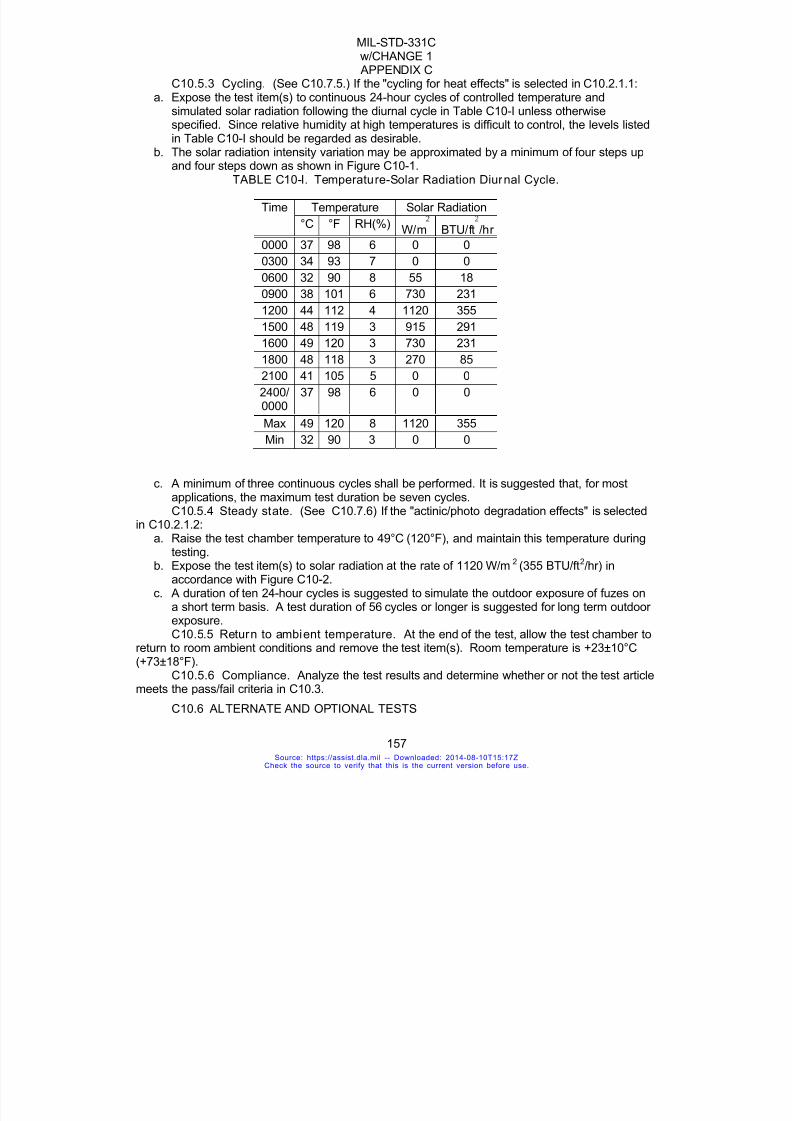
7/18/2019 Mil Std 331 Amend
http://slidepdf.com/reader/full/mil-std-331-amend 165/286
MIL-STD-331Cw/CHANGE 1 APPENDIX C
157
C10.5.3 Cycling. (See C10.7.5.) If the "cycling for heat effects" is selected in C10.2.1.1:a. Expose the test item(s) to continuous 24-hour cycles of controlled temperature and
simulated solar radiation following the diurnal cycle in Table C10-I unless otherwisespecified. Since relative humidity at high temperatures is difficult to control, the levels listedin Table C10-I should be regarded as desirable.
b. The solar radiation intensity variation may be approximated by a minimum of four steps upand four steps down as shown in Figure C10-1.
TABLE C10-I. Temperature-Solar Radiation Diurnal Cycle.
Time Temperature Solar Radiation
°C °F RH(%)W/m BTU/ft /hr
0000 37 98 6 0 0
0300 34 93 7 0 0
0600 32 90 8 55 18
0900 38 101 6 730 231
1200 44 112 4 1120 355
1500 48 119 3 915 291
1600 49 120 3 730 231
1800 48 118 3 270 85
2100 41 105 5 0 0
2400/0000
37 98 6 0 0
Max 49 120 8 1120 355
Min 32 90 3 0 0
c. A minimum of three continuous cycles shall be performed. It is suggested that, for mostapplications, the maximum test duration be seven cycles.C10.5.4 Steady state. (See C10.7.6) If the "actinic/photo degradation effects" is selected
in C10.2.1.2:a. Raise the test chamber temperature to 49°C (120°F), and maintain this temperature during
testing.b. Expose the test item(s) to solar radiation at the rate of 1120 W/m2
(355 BTU/ft2/hr) inaccordance with Figure C10-2.
c. A duration of ten 24-hour cycles is suggested to simulate the outdoor exposure of fuzes on
a short term basis. A test duration of 56 cycles or longer is suggested for long term outdoorexposure.C10.5.5 Return to ambient temperature. At the end of the test, allow the test chamber to
return to room ambient conditions and remove the test item(s). Room temperature is +23±10°C(+73±18°F).
C10.5.6 Compliance. Analyze the test results and determine whether or not the test articlemeets the pass/fail criteria in C10.3.
C10.6 ALTERNATE AND OPTIONAL TESTS
Source: https://assist.dla.mil -- Downloaded: 2014-08-10T15:17ZCheck the source to verify that this is the current version before use.

7/18/2019 Mil Std 331 Amend
http://slidepdf.com/reader/full/mil-std-331-amend 166/286
MIL-STD-331Cw/CHANGE 1 APPENDIX C
158
None.
C10.7 RELATED INFORMATION
C10.7.1 Basis of test. This adaptation to fuzes of the MlL-STD-810 solar radiation testoriginated from the concerns with the impact of high temperature and solar radiation on the
functioning and safety of weapons and ammunition which occurred during Operation Desert Storm(ODS). Weather data available for various locations within the ODS region indicated that airtemperature often exceeded 46°C (115°F). This is air temperature only and is not indicative of thetemperature of the internal components of ammunition items due to solar radiation. Solar loadingmay cause the internal temperature of exposed materiel to be significantly higher than the ambientair temperature. Available desert test data from an Australian study conducted in 1983 show that,due to solar radiation, temperatures can be as much as 33°C (60°F) higher than the ambient airtemperature when materiel is exposed to the sun, 35°C (63°F) higher when materiel is coveredwith tarpaulins in contact with the ammunition, and 10°C (18°F) higher when materiel is shaded.
C10.7.2 Heating effects. The heating effects of solar radiation differ from those of high airtemperature alone in that the amount of heat absorbed or reflected depends on the roughness,
color, and reflectivity of the surface on which the radiation is incident. Also, directional heatinginduces temperature gradients across materiel. In addition to the differential expansion betweendissimilar materials, changes in the intensity of solar radiation may cause components to expandor contract at different rates, which can lead to severe stresses and loss of structural integrity.Possible heating effects of solar radiation include:
a. Mechanical - Expansion may cause jamming or loosening of moving parts. Soldered seamsmay weaken. Lubricants may evaporate or migrate.
b. Electronic/electrical - Resistance, inductance and capacitance parameters may change.Contacts may open or close by warping under expansion.
c. Lenses - Lenses or glass covers may become opaque.d. Explosives - Explosive material may exude.
C10.7.3 Actinic effects. While heating effects are caused by the infrared portion of thesolar spectrum, physical degradation from solar energy can also occur from the ultraviolet or eventhe visible portions of the spectrum. Possible actinic effects of solar radiation include deteriorationof natural and synthetic elastomers and polymers through photochemical reactions. Photodegradation can cause fading of paints which, in turn, can cause increased heating.
C10.7.4 Selection of test options and conditions. C10.7.4.1 Options. The choice of test procedures is based on the following:
a. The anticipated exposure circumstances.b. The expected problem areas within the test item.c. The duration of exposure to solar radiation.
C10.7.4.2 Condit ions. The related test conditions that are used during the test aredetermined by:
a. The anticipated areas of deployment.b. The test item configuration.
C10.7.5 Diurnal cycle. The diurnal cycle is used to determine realistic responsetemperatures and limited actinic effects. It has a peak temperature of 49°C (120°F) and a solarradiation intensity of 1120 W/m2 (355 BTU/ft2/hr), and represents the hottest conditions exceedednot more than one percent of the hours in the most extreme month at the most severe locations inthose portions of the earth identified in Army Regulation (AR) 70-38, STANAG 2895, and MIL-HDBK-310. They are primarily low latitude deserts, which in addition to very high temperatures,
Source: https://assist.dla.mil -- Downloaded: 2014-08-10T15:17ZCheck the source to verify that this is the current version before use.
7/18/2019 Mil Std 331 Amend
http://slidepdf.com/reader/full/mil-std-331-amend 167/286
MIL-STD-331Cw/CHANGE 1 APPENDIX C
159
concurrently experience very low relative humidities and intense solar radiation. These conditionsare found seasonally in the deserts of northern Africa, the Middle East, Pakistan and India,southwestern United States, and northern Mexico.
C10.7.6 Steady state option. This procedure is used to determine possible actinic(photochemical) effects of long term exposure to sunshine due primarily to the ultraviolet and
sometimes, the visible portions of the solar spectrum. When simulating such effects, it is inefficientto use the cycling option since this could take months to conduct. The approach, therefore, is touse an accelerated test which is designed to reduce the time to reproduce the integrated effects oflong periods of exposure. This method will give an acceleration factor of 2.5 as far as the totalenergy received by the test item is concerned. One 24-hour cycle as shown in Figure C10-2provides approximately 2.5 times the solar energy experienced in one 24 hour diurnal cycle plus a4-hour light off period to allow alternating thermal stressing and for the so-called "dark" processesto occur. To simulate 25 days of natural exposure, for instance, perform ten cycles as shown inFigure C10-2. The cycles mentioned in paragraph C10.5.4c (ten and 56) would simulate 25 and140 days, respectively. Increasing irradiance above the specified level is not recommendedbecause of the danger of overheating, and there is presently no indication that attempting to
accelerate the test in this way gives results that correlate with equipment response under naturalsolar radiation conditions. Sufficient cooling air should be maintained to prevent the test item fromexceeding temperatures that would be attained under natural conditions (such as the cyclingoption simulates), so that this will not be an exaggerated test which unfairly penalizes the test item.Care must be taken to assure that the air flow is not high enough to cause unnatural cooling.Temperature sensors immediately adjacent to the test item (but far enough away not to be affectedby thermal radiation from the test item) and properly shaded to negate direct solar loading effects,can be used to ensure the ambient air temperature is as required. Since the effects of ultravioletradiation are highly dependent upon the solar radiation spectrum (as well as intensity andduration), the spectrum must be as close as possible to that of natural sunlight. The 4-hour "lights-off" period of each 24 hour cycle allows for test item conditions (physical and chemical) to return
toward "normal" and provide some degree of thermal stress exercising.C10.7.7 Depth of sand. A depth of sand of two inches is recommended. This is not a firm
requirement, but is based on the judgment that portions of the test item should not be able topenetrate the sand layer to contact the chamber floor and thus permit heat transfer. Testsconducted at US Army ARDEC in 1995 showed that, with the required air flow, the air temperatureone inch above the sand remained within 3°C of the bulk air temperature, the temperature of thesand one inch below the surface had no discernible effect on air temperature, and that the sandsurface and air temperatures responded very quickly to changes in incident radiation. Theprinciple effect of the sand appears to be reflection of radiation and the creation of a verticaltemperature gradient in the air near the sand. The gradient is influenced strongly by air velocity.These observations apply to both steady state and diurnal variation tests.
C10.7.8 Bibliography. C10.7.8.1 AR70-38, Research, Development, Test and Evaluation of Materiel for Extreme
Climatic Conditions. 1 August 1979.C10.7.8.2 MlL-STD-210, Climatic Information to Determine Design and Test Requirements
for Military Systems and Equipment. 9 January 1987.C10.7.8.3 MIL-STD-810, Environmental Test Methods and Engineering Guidelines. 14 July
1989.C10.7.8.4 NATO STANAG 2895, Extreme Climatic Conditions and Derived Conditions for
Use in Defining Design/Test Criteria for NATO Forces Materiel.
Source: https://assist.dla.mil -- Downloaded: 2014-08-10T15:17ZCheck the source to verify that this is the current version before use.

7/18/2019 Mil Std 331 Amend
http://slidepdf.com/reader/full/mil-std-331-amend 168/286
MIL-STD-331Cw/CHANGE 1 APPENDIX C
160
C10.7.8.5 Department of Defence, Australian Ordnance Council, Proceeding 14/83, Effectsof Solar Radiation on Ammunition. 12 July 1983.
FIGURE C10-1. Simulated Solar Radiation Cycle
Source: https://assist.dla.mil -- Downloaded: 2014-08-10T15:17ZCheck the source to verify that this is the current version before use.

7/18/2019 Mil Std 331 Amend
http://slidepdf.com/reader/full/mil-std-331-amend 169/286
MIL-STD-331Cw/CHANGE 1 APPENDIX C
161
FIGURE C10-2. Two Steady State Cycles
Source: https://assist.dla.mil -- Downloaded: 2014-08-10T15:17ZCheck the source to verify that this is the current version before use.

7/18/2019 Mil Std 331 Amend
http://slidepdf.com/reader/full/mil-std-331-amend 170/286
MIL-STD-331Cw/CHANGE 1 APPENDIX D
162
APPENDIX D
SAFETY, ARMING AND FUNCTIONING TESTS
Source: https://assist.dla.mil -- Downloaded: 2014-08-10T15:17ZCheck the source to verify that this is the current version before use.
7/18/2019 Mil Std 331 Amend
http://slidepdf.com/reader/full/mil-std-331-amend 171/286
MIL-STD-331Cw/CHANGE 1 APPENDIX D
163
TEST D1
PRIMARY EXPLOSIVE COMPONENT SAFETY
D1.1. PURPOSEThis is a laboratory safety test simulating inadvertent initiation of fuze primary explosives.Explosive components beyond the explosive train interrupter must not be initiated to a highdegree of reliability nor should the fuze produce a hazardous release.
D1.2. DESCRIPTION
D1.2.1 General. This test consists of two parts: the out-of-line safety test and thenumerical determination of interrupter effectiveness.
D1.2.1.1 Out-of-line test. A modified fuze is mounted to a test fixture and theassembly placed in a fragmentation box. See Figure D1-1. Each sensitive explosivecomponent in the sample fuze is fired. The effectiveness of the explosive train interrupter or
any permanent barrier is then evaluated by determining whether or not there was initiation orincipient initiation of lead or booster explosives or ejection of parts, deformation, or shatteringwhich might result in unsafe conditions. All primary explosive components, regardless oflocation within the fuze, shall be considered. Generally, such components are located in theexplosive train before the interrupter. However, some primary explosive components may belocated outside of the explosive train to serve a purpose other than initiation of the lead orbooster charge.
D1.2.1.2 Interrupter effectiveness test . The numerical effectiveness of theinterrupter is determined using one of the alternate and optional tests of D1.6 or using theProgressive Arm Test of D8. The choice of test must be made with regard to the fuze designand function.
D1.2.2 Fuze configuration. All fuze explosive elements shall be present in the fuzeduring the test.
D1.2.3 Applicable publications. All standards, specifications, drawings, proceduresand manuals, which form a part of this test, are listed in Section 2 of the introduction to thisstandard.
D1.2.4 Test documentation. Test plans, performance records, equipment, conditions,results, and analysis shall be documented in accordance with 4.8 of the general requirementsto this standard.
D1.3. CRITERIA FOR PASSING OUT-OF-LINE SAFETY TEST
D1.3.1 Fuze condition. There shall be no detonation, fragment penetration, perforation,burning, charring, scorching, or melting of any explosive component after the explosive train
interruption. There shall be no ejecta which could cause serious personnel injury or initiationof adjacent fuzes. Smudging of the surfaces by soot is acceptable. Indentation of theexplosive components after the interrupter is not in itself, a sufficient cause for stating that thefuze has failed. For such an occurrence, an increased sensitivity test such as those describedin D1.6 must be performed.
D1.3.2 Evaluation of fragmentation box. During the test there shall be nohazardous ejection of parts or hazardous fragmentation of the confining structure as evidentfrom the perforation of the paper liner or fiberboard. The following criteria provide a
Source: https://assist.dla.mil -- Downloaded: 2014-08-10T15:17ZCheck the source to verify that this is the current version before use.

7/18/2019 Mil Std 331 Amend
http://slidepdf.com/reader/full/mil-std-331-amend 172/286
MIL-STD-331Cw/CHANGE 1 APPENDIX D
164
quantitative method for determining the likelihood of injury to personnel resulting from fuzebreakup or ejected fragments.
D1.3.2.1 Paper liner. Any perforation of the bond paper liner indicates possible eyedamage.
D1.3.2.2 Fiberboard penetration. Any penetration of the fiberboard should be
measured for hole diameter and depth. If penetration depth of any fragment, including steel,aluminum, plastic and so forth, is greater than the values shown in Table D1-I, then theprobability of incapacitation, exclusive of eye damage, is greater than zero. PK, the probabilityof incapacitation, is defined as the probability that personnel performing supply duties will beincapable of fully performing those duties. Values given in the table are for PK = 0. Thedimension (diameter and penetration) of the hole should be used to enter into the table. Agraphic representation of this data is shown in Figure D1-2.
TABLE D1-I. Penetration In Fiberboard vs. Hole Size Diameter - PK = 0.
Hole diameterin mm (in) - Note a
MaximumPenetration
In mm (in) - Note b
0.94 (0.037) 23.6 (0.929)
2.00 (0.079) 13.2 (0.518)
4.37 (0.172) 7.26 (0.286)
9.40 (0.370) 4.04 (0.159)
20.2 (0.796) 2.24 (0.088)
Notes:a. Assumes a cubical steel fragment.b. Maximum penetration of fiberboard for PK = 0 for 1/2 day supply, lightly clothed casualty
criterion given in BRL Report 1269 (S). The report explains this criterion as follows: “1/2-day” indicates that the personnel will seek medical attention for the wound within 12 hours.“Supply” describes “person standing in an ammunition line receiving light loads from hisright and passing them on to the man on his left;” that is, a man, standing, using his arms,but not engaged in any sort of locomotion. “Lightly clothed” indicates that the person'sclothing offers him no protection against fragments of any size.
D1.3.3 Decision basis. Breakdown, inspection, other appropriate tests andengineering judgment shall form the basis for the decision that fuzes have passed or failed thetest.
D1.4. EQUIPMENTD1.4.1 Test f ixture. A fixture designed to hold the test fuze and to permit firing of the
primary explosive components inside the fuze will be required. The fixture shall hold the testfuze in a manner to retain, as nearly as practical, the same confinement for the expandinggases and fragments as exists in the unmodified fuze.
D1.4.2 Fragmentation box. A suitable box shall be made from cellulosic fiberboardconforming to the specifications for single-ply, 12.7 mm (1/2 in) thick building board given in
ASTM-C-208, or equivalent. The box shall be lined with standard 20 lb, white, spot-free, bond
Source: https://assist.dla.mil -- Downloaded: 2014-08-10T15:17ZCheck the source to verify that this is the current version before use.

7/18/2019 Mil Std 331 Amend
http://slidepdf.com/reader/full/mil-std-331-amend 173/286
MIL-STD-331Cw/CHANGE 1 APPENDIX D
165
paper. Paper sheet size shall be 0.43 m (17 in) x 0.56 m (22 in). The box shall have a meansto secure the test fixture at its center, holding the fuze as shown in Figure D1-1. At no pointinside the box shall the liner paper be more that 0.6 m (23.6 in) or less than 0.15 m (5.9 in)away from any point of the fuze.
D1.4.3 Firing mechanism. Initiation of the test fuze shall be performed by an
appropriate means to retain, as nearly as possible, the explosive confinement normally presentin the fuze (see Section D1.5.1).
D1.4.4 Inert rounds. Simulations of the munitions (projectiles, bombs, rockets, and soforth) for which the fuze is designed shall be provided if additional assembled round tests usingsuch simulations are called for at the end of the fuze test (see Section 5.6). The simulatorsshall be loaded with an inert filler approximating the mechanical strength of the explosive. If amore searching test is required, the simulators may be partially loaded with an explosive filler,holding the amount to a minimum. In either case, the fuze cavities shall be duplicated toaccommodate the test fuze.
D1.5. PROCEDURE
D1.5.1 Modification of test fuzes. Modification of the test fuzes is generally requiredin order to fire their initiators in the fully assembled out-of-line position. The type ofmodification required varies with the fuze. In the case of stab or electric initiation, drilling awell-placed test hole as shown in Figures D1-3 and D1-4 may be all that is necessary. Inanother design, an entirely different approach may be needed; but in no case shall themodification significantly weaken the fuze body’s ability to withstand shock waves or to containthe expanding gases or fragments.
D1.5.2 Preparation for worst -case simulation. If the fuze contains more than onecomponent containing primary explosive, it shall be tested by functioning either simultaneouslyor sequentially all such components in the train, as well as the other sensitive explosives.When the fuze design permits simultaneous functioning of primary explosive components, the
test shall consist of simultaneous initiation of these components if this is the worst case.D1.5.3 Sample size and temperature conditioningD1.5.3.1 Out-of-line test. A minimum of 15 modified and prepared fuzes shall be
temperature conditioned for the test, at least five fuzes at each of the following temperatures:+71±3ºC (+160±5.4ºF), +23±10ºC (+73±18ºF), and -54±4ºC (-65±4ºF).
D1.5.3.2 Interrupter effectiveness test. The number of fuzes will be determined by thetest procedure. There is no specific requirement for the pre-test conditioning of the fuzesamples and the testing conditions. However, the temperature and other pertinentenvironmental conditioning of the samples before and during the testing shall be recorded.
D1.5.4 Initiation in fragmentation box. Secure the test fuze and mounting fixture inthe center of the fragmentation box. Fire the primary explosive component along with any
other such components in the fuze by an applicable mechanism and in the manner described.Depending on the explosive content of the fuze, the use of barricades and remote control maybe required for operating safety.
D1.5.5 Compliance. Remove the test fuze and witness paper from the test setup.Examine the fuze, paper and fiberboard and determine whether or not the test article meetsthe pass/fail criteria in Section D1.3. Continue testing the specified number of items.
D1.5.6 Fuze assembled to round. If there is any question arising from the results thatthere might be additional hazard with the fuze assembled to the round, the complete test
Source: https://assist.dla.mil -- Downloaded: 2014-08-10T15:17ZCheck the source to verify that this is the current version before use.
7/18/2019 Mil Std 331 Amend
http://slidepdf.com/reader/full/mil-std-331-amend 174/286
MIL-STD-331Cw/CHANGE 1 APPENDIX D
166
sequence shall be repeated with the fuze assembled to a test fixture, which simulates theround.
D1.6. ALTERNATE AND OPTIONAL TESTS
D1.6.1 Introduction. After the fuze design has met the specified requirements, it is
recommended that additional fuzes be tested under more searching conditions to examine theeffects of the explosion of the elements before the interrupter, both in the explosive train and atother locations in the fuze. The design of the explosive train interrupter should include aninvestigation of possible failure paths. Tests may be run with the interrupter in intermediatepositions between unarmed and armed; for example, at a first-stage armed or stop position;with fuzes having extreme tolerances in critical components of the explosive train safetydevice; with explosive components varying in sensitivity and output from standard; or withfuzes subjected to slow or fast cook-off. All these changes should be made in such a way asto increase the probability of defeating the fuze safety barrier. Methods for doing this aredescribed below.
D1.6.2 Possible failure paths. Figure D1-5 shows the major components of a typical
explosive train. The first element is a detonator, or primer, which is responsive to either anelectrical or a mechanical input. The second element is the interrupter (rotor or slider), whichhouses the detonator and keeps it in the out-of-line position until the proper stimulus isreceived, and then moves the detonator to the in-line position. The third element is the barrierbetween the detonator and the booster when the rotor is in the out-of-line position. The fourthelement is the output lead. The output lead, booster, and warhead must contain onlysecondary explosives. To design tests, which will be used to evaluate an explosive train, thefirst step is to search out the possible failure paths by which the sensitive elements in the trainmight directly initiate the output lead, booster, or warhead. Figure D1-5 indicates three (3)possible failure paths, each of which may be investigated by one or more of the followingtechniques.
D1.6.3 Barrier thickness test. The purpose of the barrier thickness test is to establisha barrier thickness that will contain the output of the sensitive elements. If the barrier wasevaluated at standard barrier thicknesses, the number of tests required would be prohibitive.To reduce the number of tests required, the test may be performed by progressivelydegrading, or thinning, the barriers. If the barriers are reduced by proper increments, thestatistical evaluation described in Appendix G can be used to obtain a numerical effectivenessof the barrier. In Figure D1-5, the possible failure path B would be explored by progressivelyreducing the thickness of the barrier between the detonator and the booster. Other paths suchas C, which go directly from the detonator to the warhead, would also be investigated byprogressively thinning the thickness of the mechanism case, the warhead liner, or othermaterials between the detonator and the warhead.
D1.6.4 Increased output test. The objectives of the increased output test are (1) toprovide greater confidence in the results of the barrier thickness tests, and (2) to explore theeffects of the detonator variability on the safety of an explosive train. It is possible that thedetonator used in the barrier thickness tests did not provide the maximum output that could beencountered. For example, the Mk 71 Detonator may have been used in these tests. Thisdetonator, when confined in brass, has an output which results in an average dent of 0.38 mm(0.015 in) in a steel dent block. The specification for this detonator (as for most detonators)provides no maximum output requirement (that is, no specific upper limit on the explosive
Source: https://assist.dla.mil -- Downloaded: 2014-08-10T15:17ZCheck the source to verify that this is the current version before use.
7/18/2019 Mil Std 331 Amend
http://slidepdf.com/reader/full/mil-std-331-amend 175/286
MIL-STD-331Cw/CHANGE 1 APPENDIX D
167
capability of the detonator). Test data from production lots of the Mk 71 Detonator show dentvalues ranging through 0.48 mm (0.019 in). To assure that the explosive train is safe when adetonator with a maximum output is encountered, tests should be conducted with a substitutedetonator whose minimum output is higher than the output of the detonators which are to beused. In case the Mk 71 Detonator is specified, a Mk 70 Detonator, which has a specific
average dent capability of 0.48 mm (0.019 in), could not be used for test purposes. Adetonator with a minimum output greater than 0.48 mm (0.019 in) should be used.
D1.6.5 Increased sensitivity test. The objectives of the increased sensitivity test, likethe increased output test, are (1) to provide greater confidence in barrier thickness test, (2) toexplore the effects of variability in the sensitivity of the acceptor explosive and (3) determine anumerical effectiveness of the barrier or interrupter. To check any of the possible failure pathsindicated in Figure D1-5, it would be necessary to use explosives of increased sensitivity in theacceptors (lead, booster, or warhead). In some cases it would be impractical to duplicate thecomplete acceptor with more sensitive explosives. At such times, thin layers of sensitiveexplosive might be used to simulate the acceptor charge. A useful explosive for this test isPETN. The ratio of the sensitivity of PETN to that of other common secondary explosives,
including CH-6, RDX, and some typical warhead explosives, is known. Further information onthe ratios of sensitivity of various explosives, and on using the VARICOMP method todetermine numerical value for explosive propagation, is contained in D1.7.2.2, D1.7.2.3 andD1.7.2.4.
D1.6.6 Cookoff test for projectile fuzes. DELETED. D1.6.7 Fast cookoff test for fuzes. DELETED.D1.6.8 Missing barr ier test. When the presence of the interrupter acts as a barrier to
the transfer of detonation, whether the interrupter contains a transfer detonator or not, and it isphysically possible to assemble the device without the barrier, the probability of transfer withthe barrier missing should be explored to provide confidence that malassembly will not presenta significant safety hazard.
D1.7. RELATED INFORMATION
D1.7.1 Use of dimple motors. Dimple motors provide a simple means of initiating out-of-line stab primers and detonators. Electrically initiated M4 or M5 dimple-motors can bemodified by attaching a striker-pin in the concave part of the metal container. When thedimple-motor is inverted by firing, the striker will impact on the stab detonator and set it off. Anadvantage of this approach is the small size of the motor, which can be accommodated withoutseriously changing the internal configuration of the fuze. Wires for firing the motor can beinstalled with no more difficulty than in the case of electrically initiated detonators. Actually,such a dimple-motor striker can be made even smaller than the M4 or M5, thereby reducingstill further any modifications to the internal fuze geometry. The force of the striker is notcritical for this test, as long as it is sufficient to reliably initiate the stab-detonator.
D1.7.2 Bibliography.D1.7.2.1 Ballistics Research Laboratory Report 1269 (S).D1.7.2.2 NAVWEPS Report 7411, VARICOMP, A Method for Determining Detonation-
Transfer Probabilities (U), Naval Ordnance Laboratory, White Oak, Maryland, 30 June 1961.D1.7.2.3 NWC TP 5789, An Expanded VARICOMP Method for Determining Detonation
Transfer Probabilities, James E. Means, Naval Weapons Center, China Lake, CA, December1975.
Source: https://assist.dla.mil -- Downloaded: 2014-08-10T15:17ZCheck the source to verify that this is the current version before use.

7/18/2019 Mil Std 331 Amend
http://slidepdf.com/reader/full/mil-std-331-amend 176/286
MIL-STD-331Cw/CHANGE 1 APPENDIX D
168
D1.7.2.4 RSLR 78-4, Safety and Reliability Testing of Fuze Explosive Trains, D. H.Chamberlain, R. Stresau Laboratories, Inc., Spooner WI, March 1978.
FIGURE D1-1. Fuze Installation in Test Fixture and Fiberboard Box
Source: https://assist.dla.mil -- Downloaded: 2014-08-10T15:17ZCheck the source to verify that this is the current version before use.

7/18/2019 Mil Std 331 Amend
http://slidepdf.com/reader/full/mil-std-331-amend 177/286
MIL-STD-331Cw/CHANGE 1 APPENDIX D
169
FIGURE D1-2. Penetration in Fiberboard Vs. Fragment Hole Size
FIGURE D1-3. Typical Test Arrangement for Stab Detonator Ini tiation
Source: https://assist.dla.mil -- Downloaded: 2014-08-10T15:17ZCheck the source to verify that this is the current version before use.
7/18/2019 Mil Std 331 Amend
http://slidepdf.com/reader/full/mil-std-331-amend 178/286
MIL-STD-331Cw/CHANGE 1 APPENDIX D
170
FIGURE D1-4. Typical Test Arrangement for Electr ic Primer Initiation
FIGURE D1-5. Typical Components of a Fuze Explosive Train
Source: https://assist.dla.mil -- Downloaded: 2014-08-10T15:17ZCheck the source to verify that this is the current version before use.

7/18/2019 Mil Std 331 Amend
http://slidepdf.com/reader/full/mil-std-331-amend 179/286
MIL-STD-331Cw/CHANGE 1 APPENDIX D
171
TEST D2
PROJECTILE FUZE ARMING DISTANCE
D2.1. PURPOSE
This is a field performance test used to determine the no-arm, mean-arm and all-arm distancesfor impact detonating projectile fuzes. An optional field safety test is included whichdetermines whether or not the fuze is armed at the muzzle of the gun.
D2.2. DESCRIPTION
D2.2.1 General. The fuze is assembled to the specified projectile and the round firedfrom a weapon against a target designed to cause an armed fuze to function. Thedetermination of the no arm distance will help establish in-bore and close-to-muzzle impactsafety. The test will also provide a reliable estimate of the maximum distance from the weaponat which the fuze will not function as a result of impact.
D2.2.2 Test configuration. The projectiles may be fully loaded or inert and, ifnecessary, may contain an auxiliary spotting charge to determine functioning. All of the fuzeexplosive elements are present in the fuze during the test.
D2.2.2.1 Arming procedure (mandatory). Target position depends on the test methodselected. Fuze response is determined at each position.
D2.2.2.2 Muzzle safety procedure (opt ional). The target is located as closely aspossible to the front of the weapon and the round fired to determine whether or not the fuze isarmed when it leaves the muzzle.
D2.2.3 Applicable publications. All standards, specifications, drawings, proceduresand manuals which form a part of this test are listed in Section 2 of the introduction to thisstandard.
D2.2.4 Test documentation. Test plans, performance records, equipment, conditions,results, and analysis shall be documented in accordance with 4.8 of the general requirementsto this standard.
D2.3. CRITERIA FOR PASSING TEST
D2.3.1 Arming procedure. The resulting arming distances (no arm to all arm) shall bein accordance with the design requirements specified in the test plan.
D2.3.2 Muzzle safety procedure. No explosive elements beyond the last safety device
of the fuze shall function before or as a result of impact with the target.
D2.4. EQUIPMENT
D2.4.1 Test weapons and rounds. A weapon equivalent standard test barrel andround, for which the fuze is designed, shall be used. In the case of a fuze which is standardfor several rounds or weapons, a round and weapon combination shall be selected whichproduces the shortest no-arm distance or the longest all-arm distance, depending on theobjective of the test. Other rounds and weapons may be specified in the test plan.
Source: https://assist.dla.mil -- Downloaded: 2014-08-10T15:17ZCheck the source to verify that this is the current version before use.
7/18/2019 Mil Std 331 Amend
http://slidepdf.com/reader/full/mil-std-331-amend 180/286
MIL-STD-331Cw/CHANGE 1 APPENDIX D
172
D2.4.2 Critical conditions and parameters of test equipment. When evaluating theno arm or all arm distance, the operation of the test fuze should be reviewed to determinecritical conditions and parameters, such as temperature and barrel wear. That set ofconditions and parameters, or as near as practical, shall be used which produces the shortestno arm distance or the longest all arm distance depending on the objective of the test.
D2.4.3 Target design. A target shall be used which is just thick enough to reliablyinitiate the armed fuze, or target requirements may be specified in the test plan. Excessivetarget robustness may produce fuze initiation without the fuze having fully armed.
D2.4.4 Test recorder. Photographic or other equipment capable of determining fuzefunctioning shall be provided.
D2.5. PROCEDURE
D2.5.1 Arming procedure. Conduct and analyze the arming test according to Appendix G. The stimulus may be the distance from a weapon muzzle to a target and theconcomitant response or nonresponse may be the functioning or nonfunctioning of a fuze. Thestimulus also may be the striking velocity of a projectile and the response or nonresponse, a
penetration or nonpenetration, and so on.D2.5.1.1 Probit Method. DELETED (covered in Appendix G).D2.5.1.2 Langlie Method. DELETED (covered in Appendix G).D2.5.1.3 OSTR Method. DELETED (covered in Appendix G). D2.5.1.4 Bruceton Method. DELETED (covered in Appendix G).D2.5.2 Muzzle safety procedure. D2.5.2.1 Location of target. Set up the target as close as feasible in the front of the
weapon.D2.5.2.2 Fire and observe. Fire the round and observe whether or not the fuze
functions when it strikes the target.D2.5.2.3 Recover and examine. Recover and examine fuzes, if feasible, for
adherence to D2.3.2.D2.6. ALTERNATE AND OPTIONAL TESTS
None.
D2.7. RELATED INFORMATION
D2.7.1 Projectile Safe Separation. The need for this test arises from the fact thatbursts of the projectile within and close to the weapon are dangerous to equipment andpersonnel.
D2.7.2 Target material. Typical targets used in this test might include wood or metalpanels of various thickness and transversely or axially placed metal rods.
D2.7.3 Deflagration. This test is performed with targets which are thick enough to
cause the fuze to function reliably, but not so thick as to cause an unarmed or partially-armedfuze to fire or deflagration of the filler-charge in the projectile or detonation/deflagration of thefuze booster. It should be noted that the values of no arm/all arm distance obtained in this testare applicable to the fuze alone. This overall round, even when unfuzed, may deflagrate atmuch smaller distance if the target is sufficiently thick. A fuze function plate should be used ator beyond the expected arming distance to confirm the proper operation of the fuze.
D2.7.4 Target posi tion. It is necessary that the target remain in place until impact.The position of the target should be positively confirmed by using suitable instrumentation such
Source: https://assist.dla.mil -- Downloaded: 2014-08-10T15:17ZCheck the source to verify that this is the current version before use.
7/18/2019 Mil Std 331 Amend
http://slidepdf.com/reader/full/mil-std-331-amend 181/286
MIL-STD-331Cw/CHANGE 1 APPENDIX D
173
as high-speed photography or flash radiography, since previous experience has shown thatmuzzle targets can be broken or displaced by a rush of air preceding the projectile.
D2.7.5 Weapon accessor ies. When feasible, automatic loading mechanisms, trays orother equipment used in servicing the gun should be utilized to subject fuzes to conditionsnormally encountered before firing.
D2.7.6 Arming distance versus impact safe distance. Historically, the armingprocedure has often been performed under the title of “impact safe distance test.” This isbecause, for simple point detonating fuzes, the “impact-safe distance” is equivalent to the so-called “arming distance” of the fuze, that is, the distance beyond the muzzle at which the fuzebecomes capable of functioning on the type of firing signal for which it was designed. Formore complicated fuzes, especially those designed to operate on some triggering signal otherthan linear acceleration, the “impact-safe distance” may be appreciably smaller than the“arming distance,” measured from the muzzle to the point in the trajectory where the fuze is“armed” both mechanically and electrically. Internal breakage, deformation of componentsunder the strain of impact, or initiation of explosive components by the collapsing fuze may bein part responsible for this behavior. It is usually found that an explosive train can propagate
an explosion wave through a fuze even though the interrupter of the train (out-of-line safetydevice) has not yet reached its “fully armed” position. Hence, numerical values for “impactsafe distance” obtained by striking targets at various points along the trajectory (where the fuzeis in a state of partial arming) will, in general, tend to be somewhat smaller than thecorresponding measurements of distance to the point along the trajectory where the out-of-linesafety device moves into its “fully armed” position. It is to preserve this distinction that this testwas called an “impact-safe distance test” in the previous version of this test.
D2.7.7 Environmental parameters. DELETED (covered in Appendix G).
D2.7.8 References. DELETED (covered in Appendix G).
D2.7.9 Suggestions for efficient use of samples. DELETED (covered in Appendix G).
D2.7.10 Bibliography. DELETED (covered in Appendix G).D2.7.11 Glossary . DELETED (covered in Appendix G).TABLE D2-I. Lower tail percentiles estimated by OSTR strategies. DELETED
(covered in Appendix G).TABLE D2-II. Upper tail percenti les estimated by OSTR strategies. DELETED
(covered in Appendix G).FIGURE D2-1. Estimated Probabili ty of Arming Versus Distance from Muzzle
(Probit). DELETED (covered in Appendix G). FIGURE D2-2. Estimated probability of arming versus distance from muzzle
(Langlie). DELETED (covered in Appendix G).FIGURE D2-3. Estimated Probabili ty of Arming Versus Distance from Muzzle
(OSTR). DELETED (covered in Appendix G).FIGURE D2-4. Estimated probability of arming versus distance from muzzle(Bruceton). DELETED (covered in Appendix G).
Source: https://assist.dla.mil -- Downloaded: 2014-08-10T15:17ZCheck the source to verify that this is the current version before use.

7/18/2019 Mil Std 331 Amend
http://slidepdf.com/reader/full/mil-std-331-amend 182/286
MIL-STD-331Cw/CHANGE 1 APPENDIX D
174
TEST D3
TIME TO AIR BURST
D3.1. PURPOSE
This is a field performance test used to determine functional accuracy of mechanical andelectronic projectile time fuzes.
D3.2. DESCRIPTION
D3.2.1 General. The fuze is mounted to a projectile, set to function at a predeterminedtime and fired on the test range. Time is measured as the interval between detection of firingand detection of functioning. Data can be used to specify single fuze limitations or group datadistributions.
D3.2.2 Fuze configuration. All explosive elements shall be in the fuze during the test.D3.2.3 Applicable publications. All standards, specifications, drawings, procedures
and manuals which form a part of this test are listed in section 2 of the introduction to this
standard.D3.2.4 Test documentation. Test plans, performance records, equipment, conditions,results, and analysis shall be documented in accordance with 4.8 of the general requirementsto this standard. Test plans shall include requirements for gun tube wear, elevation angle,temperature conditioning for the cartridge and fuze, and so forth, as required.
D3.3. CRITERIA FOR PASSING TEST
The criteria for passing the test shall be compliance with requirements specified in accordancewith the test directive.
D3.4. EQUIPMENT
D3.4.1 Gun. A gun or mortar appropriate for the fuzed projectile and in accordance with
the stage of wear specified in the test directive. See D3.7.4.D3.4.2 Projectile. Proper explosive-loaded projectile or inert-loaded projectile with
spotting charge to emit a signature at the time of fuze function and with the test fuze attached.If an inert-loaded projectile with spotting charge is used, determine by field test timemeasurements of the burst, that sufficient accuracy exists compared to the explosive-loadedprojectile burst time.
D3.4.3 Fuze setter. An appropriate fuze setter. See D3.7.6.D3.4.4 Instrumentation. Appropriate instrumentation to measure the time to burst.
The instrumentation must be capable of measuring a time interval one-tenth (1/10) that of thesmallest increment it is desired to detect. Events prior to the first movement of the projectile,including detonation of the expelling charge, and events subsequent to the projectile exiting
the gun tube muzzle shall not be used to start counters or record zero time. See D3.7.1.Ensure that the time interval between first movement of the projectile and emergence of theprojectile from the gun does not materially detract from the accuracy of the time to burst.
D3.4.5 Temperature conditioning equipment. Temperature conditioning equipmentrequired by the test directive. See D3.7.2.
D3.5. PROCEDURE
D3.5.1 Instrumentation setup. Set up a minimum of three comparable instrumentationsystems.
Source: https://assist.dla.mil -- Downloaded: 2014-08-10T15:17ZCheck the source to verify that this is the current version before use.

7/18/2019 Mil Std 331 Amend
http://slidepdf.com/reader/full/mil-std-331-amend 183/286
MIL-STD-331Cw/CHANGE 1 APPENDIX D
175
D3.5.1.1 Sensor setup. Obtain detonation or burst signature data prior to the fuze test.The rise time of visible and infrared emissions may vary considerably between explosiveconfigurations before reaching the instrumentation sensitivity level. Aim the sensors at thefunction zone and adjust the sensitivity in accordance with the signature data andenvironmental conditions. Excessively high sensitivity results in readings from spurious
emissions rather than the fuze function. Excessively low sensitivity can result in lost readingsor delayed recording.
D3.5.1.2 Adjust recording apparatus. D3.5.2 Weapon assembly. Assemble complete fuze to the appropriate projectile.D3.5.3 Temperature conditioning. Perform the test with the fuze and other projectile
and propellant charge components at ambient temperature unless otherwise specified in thetest directive.
D3.5.4 Adjust elevation angle. Adjust the gun's quadrant elevation angle to thatvalue specified in the test directive. The elevation, along with the combined gun and projectileballistic characteristic, should yield an approximation of the function zone. Record theelevation.
D3.5.5 Remove safety equipment. Remove shipping safety wires, pins, and so forth.D3.5.6 Set fuze. Set the fuze to the time setting specified in the test directive using a
hand wrench or appropriate fuze setter.D3.5.7 Fire adjustment round. Fire a minimum of one round to check the adjustments
on all instrumentation and the location of the function zone. The gun's angle of elevation shallnot be adjusted to position the air burst within view of the sensor. When adjustments arerequired, the sensor shall be adjusted to accommodate the specified gun elevation. Ifadjustments to the instrumentation are necessary, additional rounds will be fired as required. Ifreadings cannot be obtained after testing all combinations of explosives, instrumentationadjustments and no more than a 10% elevation variation, then approval for deviations from thetest directive must be obtained. Record all adjustments.
D3.5.8 Fire test rounds. Measure and record the fuze function times in seconds asindicated by the instrumentation to four decimal places or as many as applicable. Record thefuze serial number (if any) and the tube round number.
D3.5.9 Data reduction. The following procedure shall be used for data reduction.D3.5.9.1 Averaging. The readings from the instrumentation system shall be averaged.
Readings which are inaccurate due to a positive cause shall be deemed lost. Any reading,attributable to one fuze, that disagrees with all other readings for that fuze by more than twomilliseconds without a justifiable positive cause shall be deemed lost. Where no two readingsfor one fuze agree within the two-millisecond limit, and no positive cause is found to eliminateall but one, then all readings for that fuze shall be deemed lost. The averaged reading inseconds will become the fuze function time.
D3.5.9.2 Mean and standard deviation. Where group data distributions are required,the fuze function times shall be used to arrive at a mean ( X ) and standard deviation (S) inseconds. See D3.7.7.
D3.5.10 Compliance. Analyze the test results and determine whether or not the testarticle meets the pass/fail criteria in D3.3.
D3.6. ALTERNATE AND OPTIONAL TESTS
None.
Source: https://assist.dla.mil -- Downloaded: 2014-08-10T15:17ZCheck the source to verify that this is the current version before use.
7/18/2019 Mil Std 331 Amend
http://slidepdf.com/reader/full/mil-std-331-amend 184/286
MIL-STD-331Cw/CHANGE 1 APPENDIX D
176
D3.7. RELATED INFORMATION
D3.7.1 Typical time measuring systems. Stop watches, electric clocks and fuzechronographs are generally used at ordnance proving grounds for measuring the time of flightof projectiles from the gun to the point of burst. Fuze chronographs provide the most precisemeasurement of the three. Electric clocks offer a lower degree of precision than that of the
fuze chronograph but higher than that of stop watches. Stop watches are used whenconvenience, rather than precision, governs the choice of a chronometer.
D3.7.1.1 Stop watches. The watches are started simultaneously when the gun is fired.Experience has shown that visual observation of a burst may involve a delay (especially atlong ranges in daylight) for the burst to develop to visible size. This delay is estimated to be onthe order of 0.1 second. Where this has been determined by experiment, it should be applied.Generally, two or more observers with stop watches are employed for a given time to burstmeasurement. An individual observer operates each stop watch. One stop watch observationshould be used only when an approximate value is required during preliminary tests. Whentwo or more observers are timing, the average time is calculated. Before averaging the timevalues obtained for each round, discard all values known to be in error. The allowable
deviation between any two observed time values is 0.1 second. When the deviation isconstantly greater than this value, the cause should be determined and corrected.
D3.7.1.2 Electr ic clocks. Three or four clocks are usually employed for a given time offlight measurement. The clock motors are simultaneously started by making an electricalcontact when the gun is fired. For this purpose, a mercury switch or a mechanical type inertiaswitch attached to one of the recoiling parts may be used. For a non-recoiling type of gun,such as a mortar, a circuit employing a coil at the muzzle of the gun is satisfactory. In usingthe latter method, the projectile is usually magnetized. The operation of each clock is stoppedby an individual observer who trips a microswitch when he sees the burst of the projectile. Thetime increment shown on the dial of each clock is recorded by the clock operator, and thepointers are reset at zero for the next round. A constant frequency power source is necessary
to ensure uniform timing by the clock. In averaging the time observations, readings differing0.06 second or more from the shortest time will be discarded. This is based on the assumptionthat the observer having the quickest reflex action normally records the shortest time. Sincethe clocks are set automatically and stopped manually, a correction must be applied to thetime obtained by this method. Experience has shown the average correction to be minus 0.2second. This correction includes human reaction time and the time required for the burst tobecome visible.
D3.7.1.3 Fuze chronograph systems. A fuze chronograph system consists of fourelements. There are: (1) a starting switch used to identify projectile launch time (consideredfuze start time); (2) a sensor or detector capable of identifying fuze functioning; (3) pre-amplifiers and amplifiers used to increase the output signal from the sensor; and (4) some type
of timing device. The fuze chronograph is an electrical system designed to automaticallymeasure the time between fuze launch and fuze function. The system may be subject to grosserror due to spurious emissions and some method of verifying the function or nonfunction isrecommended. This may be accomplished by close agreement of times from two or moreindependent chronograph systems confirmed by observers with manual timers. Anothermethod would use magnetic tape records of the gun firing events; the incoming burstsignature, and the amplifier output pulse. Analysis of these records could serve to confirmfunctioning.
Source: https://assist.dla.mil -- Downloaded: 2014-08-10T15:17ZCheck the source to verify that this is the current version before use.

7/18/2019 Mil Std 331 Amend
http://slidepdf.com/reader/full/mil-std-331-amend 185/286
MIL-STD-331Cw/CHANGE 1 APPENDIX D
177
D3.7.1.3.1 U.S. Army Test and Evaluation Command fuze chronograph. Thechronograph is capable of measuring the time to burst of existing MT fuzes within 0.01 second.The chronograph, however, does not have uniform precision when testing all types of fuzes.Under ideal conditions, the degree of precision depends upon many variables such as theexplosive train of the fuze. For example, a precision of 0.6 millisecond (one standard
deviation) is obtainable when measuring time to burst for a Fuze, MTSQ, and M564. The U.S. Army Test and Evaluation Command Fuze Chronograph System consists of the following:
a. Starting switch. The most common method of identifying the instant of projectilelaunch is the use of an inertia switch mounted on the gun tube. Upon gun recoil, theswitch through appropriate circuitry identifies time “zero” by starting the electroniccounter or otherwise manifesting zero time on a timing device. The present microswitchused is a heavy duty, general purpose, and precision snap switch. It is leaf-activated,requires a maximum force of 71 g (2.5 oz) to operate and a minimum force of 14.2 g(0.5 oz) to release, has 12 mm (15/32 in) maximum pre-travel and 4.2 mm (1/6 in)minimum over travel and a maximum movement differential of 2.2 mm (0.085 in). Thepre-travel has been reduced to about 4.2 mm (1/6 in) by a mechanical stop on the
mounting bracket which prevents the actuation leaf from returning to its normal restposition. The actuating leaf and roller provide a mass for the inertial actuation of theswitch. Other devices such as coils, blast switches or photocells could be used toperform the starting function.
b. Sensor. - An infrared INFRATRON lead sulfide detector with a sensitive area of 8 mm(0.315 in) square and a long pass optical filter (Lambda c = 1.8 micrometers) ismounted in a specially fabricated telescope housing. This uses a reflector mounted in arearward end of the telescope housing instead of a lens. The reflector is a 114.3 mm(4.5 in) diameter parabolic type with a focal length of 50.8 mm (2 in). Opticalcharacteristics of the system limit the field of view to approximately 7 degrees. A sketchof the infrared telescope assembly is shown in Figure D3-1.
c. Ampl if ier. A transistorized condenser coupled amplifier; input impedance of one megaohm; overall voltage gain of 2000 maximum; frequency response of 2 Hz to 5000 Hz athalf power points; output of 15 V positive pulse, 200 s duration increases the outputsignal from the sensor and provides a “stop” signal. The input circuitry consists of afield effect transistor to match the detector impedance.
d. Timing device. Any standard electronic timer and printer with an input impedance of200,000 ohms or greater and a printing rate of three (3) lines per second with a six (6)to eight (8) digit readout or similar characteristics can be used with the unit.
e. APG spot ting charge. The APG spotting charge was developed for use with thissystem. It consists of a 70/30 mix (by weight) of 77.8 g (1200 grains) of propellant, M9composition, 0.76 mm (0.0030 in) web, flaked for 60 mm mortar and 32.4 g (500 grains)
of aluminum powder, atomized Type C, Class D, loaded into a modified 88.9 mm (3.5in) long aluminum liner for deep cavity loaded projectiles. The aluminum liner is cappedwith an 1 mm (0.040 in) hole in the center. A special onionskin paper covers the hole toprevent the powder from escaping. A 24.8 g (382 grain) black powder pellet, GradeFFFG, 38.1 mm (1.5 in) diameter, 12.7 mm (0.5 in) thick (black powder mixed with 2%powdered graphite for binder) is placed on top of the charge after inserting it into theshell cavity. See Figure D3-2.
Source: https://assist.dla.mil -- Downloaded: 2014-08-10T15:17ZCheck the source to verify that this is the current version before use.

7/18/2019 Mil Std 331 Amend
http://slidepdf.com/reader/full/mil-std-331-amend 186/286
MIL-STD-331Cw/CHANGE 1 APPENDIX D
178
D3.7.1.3.2 Naval Surface Warfare Center burst time indicator.
a. Instrumentation. (1) Sensors
(a) Ten degree field of view Cassegrain Systems with lead sulfide detectors (Barnes
Radiometers Model R8T-1A).(b) Sixty degree field of view refractors with lead sulfide detectors and germanium
lenses (Barnes special order - no model number).(2) Time Interval Counters (Darcy Company Model 361-R).(3) Printer (Franklin Electronics, Incorporated Model 220D-19-2B22F).(4) Magnetic Tape Recorders (Sangamo Models 4700/3600).(5) Instrumentation Amplifiers (INCOR Model 110A).(6) Oscillograph (Honeywell Model 1508).(7) Calibrated Standard Time Mark Generator (Tektronics Model 184).
b. Procedure. The procedure used to measure time-to-air burst is to record close of firingkey, muzzle flash (using a refractor) timing pulses and radiometer and/or refractor signal
on magnetic tape. Simultaneously, the time interval counters are triggered and thetime-to-air burst is displayed and printed. This same information is then recorded on theoscillograph for a visual record which may be used for comparison and verification. Thetiming accuracy of the system is +/- one (1) millisecond.D3.7.2 Temperature. The time to air burst may be affected by the temperature of the
fuzes at the time of the test. The rate powder trains burn, the viscosity of lubricants and theperformance of electrical components are typical factors which may be affected. Therefore,complete rounds may require temperature conditioning prior to test firing. Temperatureconditioning time varies considerably with the size of ammunition and characteristics ofconditioning equipment. The time chosen should ensure that all components are attemperature equilibrium. The round should be fired as quickly as possible (5 minutes
maximum) after removal from conditioning and the time interval recorded. Reconditioning afterfive minutes have been exceeded is specifically prohibited unless waived by the procuringagency.
D3.7.3 Varying round parameters. Air burst tests should, at a minimum, includefirings at maximum and minimum acceleration conditions and at maximum, intermediate andminimum fuze time settings. Additionally, firings at intermediate accelerations and extremetemperatures have, in the past, pointed to problems in fuzes and thus may also be desirable.
D3.7.4 Tube wear. A worn tube (last one-third of life) is frequently used with maximumand minimum service charges to subject the fuzes to maximum and minimum accelerationconditions under the worst conditions of balloting of the shell.
D3.7.5 Gun elevation angles. The gun elevation angles prescribed in the test directive
must be strictly adhered to in testing powder train fuzes, since the burning rate of the powdertrain is affected by the variation in air density. The effect of air density on the functioning ofmechanical time fuzes is not so pronounced; therefore, the gun elevation angles may be variedseveral degrees to suit weather conditions. Deviation from the prescribed elevation angleshould be held to a minimum, since the timing of the mechanical time fuze may be affected bydecay in spin, which varies with the air density. The gun elevations should be chosen to beconsistent with field usage.
D3.7.6 Automatic loading and setting equipment. If automatic loading and setting
Source: https://assist.dla.mil -- Downloaded: 2014-08-10T15:17ZCheck the source to verify that this is the current version before use.
7/18/2019 Mil Std 331 Amend
http://slidepdf.com/reader/full/mil-std-331-amend 187/286
MIL-STD-331Cw/CHANGE 1 APPENDIX D
179
equipment is used to service the gun, it should be used in firing a portion of the fuzessubmitted for the test. If the results obtained with hand set and automatically set fuzes are notin agreement, the error of the automatic setter should be investigated before it is concludedthat the fuze is affected by the operation of the automatic equipment.
D3.7.7 Data reduction. In reducing data to a form comparable to the requirements in
the test directive, care must be used to avoid statistical errors. In many cases, the dataaccumulated by utilizing the method presented in Section D3.5 will conform to the normaldistribution. This can be assumed but the data must be checked to determine the validity ofsuch an assumption. If the distribution is assumed to be normal, the following formula may beused to determine the mean ( X ) and standard deviation (S).
Mean: X X
n=∑
Standard deviation: S n X X
n n=
− ∑∑
−
2 2
1
( )
( )
where: X = arithmetic average of all values in milliseconds,X = a measured burst time in milliseconds,s = standard deviation, andn = number of functioning times used.
D3.7.7.1 Sample size. The number of functioning times used to obtain the X and Scan affect the confidence in the calculations. Care must be exercised in determining the initialsample size to assure that the calculated values are not biased because the sample size is toosmall. The recommended sample size for a normal distribution is 20 samples. Where thenumber of statistically normal time values obtained for a particular test phase is less thanrequired because of the elimination of values due to duds, lost times, outliers or other
discrepancies, additional samples should be tested.D3.7.7.2 Outlier data. Where a particular functioning time in a test appears not to
belong to the rest of the test population, and no apparent positive cause exists, a test foroutliers may be applied to the value. Since outliers are nebulous in nature, and since there arevarious methods and justifications for those methods, the outlier procedure and criteria shouldbe specified in the test directive. Where no method and/or criteria are specified in the testdirective, the method described in AMCP 706-113, 17-3.1.1 shall be used for Alpha = 0.10.
D3.7.8 Defin itions. D3.7.8.1 Signature data. The level of emissions from the detonation of the fuze and
projectile train, that is higher than the environmental emissions, and significantly sufficient tocause triggering of the counter with a minimal time delay.
D3.7.8.2 Accuracy. The fuze timing requirements specified in the test directive, andthe measured and calculated values for the fuze sample arrived at by use of this test.
D3.7.8.3 Precision. The ability of the equipment to measure the fuze functioning timesto the required degree of accuracy.
D3.7.9 Photographs. It may be desirable to document the time setting prior to firingusing photographs. In cases of extraordinary function times, the photographs could bedeveloped and determine if the fuzes were set improperly.
D3.7.10 Bibliography. AMCP 706-113.
Source: https://assist.dla.mil -- Downloaded: 2014-08-10T15:17ZCheck the source to verify that this is the current version before use.
7/18/2019 Mil Std 331 Amend
http://slidepdf.com/reader/full/mil-std-331-amend 188/286
MIL-STD-331Cw/CHANGE 1 APPENDIX D
180
FIGURE D3-1. Infrared Detector Assembly
FIGURE D3-2. Spotting Charge, Model APG-2
Source: https://assist.dla.mil -- Downloaded: 2014-08-10T15:17ZCheck the source to verify that this is the current version before use.

7/18/2019 Mil Std 331 Amend
http://slidepdf.com/reader/full/mil-std-331-amend 189/286
MIL-STD-331Cw/CHANGE 1 APPENDIX D
181
TEST D4
EXPLOSIVE COMPONENT OUTPUT
D4.1. PURPOSE
This is a laboratory performance test used to determine explosive component performanceand uniformity.
D4.2. DESCRIPTION
D4.2.1 Methods. A fuze explosive component is initiated in contact with metal stock ofknown uniformity and consistency. The resulting dent or perforation in the adjoining metal ismeasured. Statistical procedures, such as calculation of the mean and standard deviation, areperformed following the completion of the specified number of tests. As an option, the testplan shall specify whether or not the explosive component must be confined to the spaceallocated in the intended fuze. When required, confinement is generally provided by an
appropriate sleeve, but the actual fuze body may also be specified. This test provides twomethods to record and measure the output.
D4.2.1.1 Dent block method. The explosion produces a measurable dent in a steel oraluminum block. Selection of either steel or aluminum depends on the output level of theexplosive component. In order to ensure the most accurate measurement, steel blocks shallbe used for testing components which generally produce dents less than 25.4 mm (1.0 in) butgreater than 0.13 mm (0.005 in) in steel. Aluminum blocks shall be used for smallercomponents generally producing dents less than 0.13 mm (0.005 in) in steel and greater than0.13 mm (0.005 in) in aluminum. The disk perforation method shall be used if the componentcannot produce a 0.13 mm (0.005 in) dent in aluminum. This test is not suitable forcomponents that produce irregular or asymmetrical dents. Best results are obtained from
components that produce essentially smooth, flat-to-slightly curved dents.D4.2.1.2 Disc perforation method. The explosion produces a hole or perforation in a
thin metal disc. The diameter of the hole is then measured. Lead and aluminum are presentlyused as material for the discs. For explosive components with low output, the discs may becoined.
D4.2.2 Multiple-element tests. In addition to measuring the output of separateexplosive components, the dent block method is useful in evaluating the performance of two ormore components which must function together in a fuze. In these cases, unique test fixturesor the use of the actual fuze body must be specified in the test plan.
D4.2.3 Applicable publications. All standards, specifications, drawings, proceduresand manuals which form a part of this test are listed in Section 2 of the introduction to this
standard. Special attention is directed to D4.4 of this test which recommends materials to beused for dent blocks, perforation discs and confinements.
D4.2.4 Test documentation. Test plans, performance records, equipment, conditions,results and analysis shall be documented in accordance with 4.8 of the general requirementsto this standard. A notation shall be made on the test report as to the confinement used, thatis, air, brass, polystyrene, steel, aluminum, and so forth.
D4.3. CRITERIA FOR PASSING TEST
Source: https://assist.dla.mil -- Downloaded: 2014-08-10T15:17ZCheck the source to verify that this is the current version before use.
7/18/2019 Mil Std 331 Amend
http://slidepdf.com/reader/full/mil-std-331-amend 190/286
MIL-STD-331Cw/CHANGE 1 APPENDIX D
182
The criteria for an acceptable explosive component in a particular application will be specifiedin the test plan. For the dent block method, this is usually stated as minimum depth, averagedepth, or depth with tolerances. For the disc perforation method, output is typically stated as aminimum or average diameter hole in the disc.
D4.4. EQUIPMENT
Equipment required for this test consists of an initiation device for the explosive component, atest fixture to hold the dent block or disk and component in place, the dent block or disc and asuitable instrument to measure the depth of the dent or diameter of the perforation. Table D4-Ilists numerous initiating devices, test fixtures, dent blocks, perforation discs and measurementequipment which have been developed and used over the years and are suitable for testing awide variety of small explosive components. The use of appropriate parts listed in this table orother suitable material shall be specified in the test plan. Some typical test arrangements areshown in Figures D4-1 and D4-2.
D4.4.1 Init iation device. Selection of an initiation device depends on the type ofexplosive component being tested. In any case, the initiator must produce sufficient output to
ensure reliable detonation of the component being tested.D4.4.1.1 Ball drop tester. A ball drop tester is used for stab- and flash-initiatedexplosive components. Typically, a steel ball is dropped from a specified height, impacts afiring pin which in turn is driven into the explosive component with sufficient force to initiate theexplosive. In the case of a flash-initiated device, the required flash is produced by firstinitiating a suitable stab primer which in turn produces a flash to initiate the component undertest.
D4.4.1.2 Electric circuits. Suitable current sources are used to initiate electricexplosive components. The circuits shall contain a shunt switch to maintain a shortedcondition across the test component leads while the test is being set up.
D4.4.2 Dent block. When using the dent block method, a new dent block must be used
for each test firing. The block shall be clean and free from rust and burrs. Size of the dentblock depends on the test configuration. It shall conform to one of the following specifications.D4.4.2.1 Steel. The steel block is cut from cold-finished (cold-drawn or cold-rolled) bars
in accordance with ASTM-A-108 No. C1018 or C1020 having a hardness of Rockwell B70 toB95. Hardness shall be measured on the rolled or drawn surface. A light film of machine oilmay be used as a preservative.
D4.4.2.2 Aluminum. The aluminum block shall be cut from aluminum alloy barconforming to either Federal Specification SAE-AMS-QQ-A-225 and ASTM-B211 for 2024T351 material having a hardness of 120 to 130 Bh 10/500/30, or Federal Specification SAE-
AMS-QQ-A-225 and ASTM-B211 for 6061 annealed material having a hardness of 30 to 35 Bh10/500/30. Hardness shall be measured on the surface as rolled or drawn.
D4.4.3 Perforation disc. When using the disc perforation method, a new disc isrequired for each test. The disc may be chosen from Table D4-I.
D4.4.4 Test f ixture. The test fixture is an assembly of parts used to hold the explosivecomponent and the dent block or perforation disc in proper position. Selection of partsdepends on the size and shape of the explosive component being tested, as well as thepurpose of the test. Refer to Table D4-I.
D4.4.4.1 Confinement device. The fixture may include a separate confinement devicesuch as a sleeve or the actual fuze body. The minimum length of each sleeve shall equal the
Source: https://assist.dla.mil -- Downloaded: 2014-08-10T15:17ZCheck the source to verify that this is the current version before use.

7/18/2019 Mil Std 331 Amend
http://slidepdf.com/reader/full/mil-std-331-amend 191/286
MIL-STD-331Cw/CHANGE 1 APPENDIX D
183
length of the component. The inside diameter of the sleeve shall not be more than 0.05 mm(0.002 in) greater for metal or 0.13 mm (0.005 in) greater for plastic than the maximumallowable diameter of the component. Engineering judgment shall be used to determineconfinement for odd-shaped components. Sleeves may include provisions for the simulation ofthe explosive train, for example, metal barriers, air gap, and so forth, or an in-line system.
D4.4.4.2 Adhesive. For the dent block method, silicone compound, SAE-AS8660 ordouble-stick tape shall be applied between the explosive component and the dent block.
D4.4.5 Measurement devices. Depending on the test method, one of the followingshall be used to measure the dent or perforation:
D4.4.5.1 Height gage. A dial indicator or equivalent height gage, graduated in at least0.03 mm (0.001 in) units and accurate to at least 0.013 mm (0.0005 in), shall be used formeasuring the depth of the dent. The gage probe shall have the point shown in Figure D4-3.
D4.4.5.2 Conical plug gage. A conical plug gage may be used as an option to TestSet Mk 170 Mod 0 for measurement of disc perforations. It shall have a taper which does notexceed 1.02 mm (0.030 in) change in diameter per 25.4 mm (1 in) of length. SeeFigure D4-1 (E).
D4.4.5.3 Test Set Mk 170 Mod 1. This test set may be used as an option to the conicalplug gage to optically measure the hole diameter. See Figure D4-2 (D).
D4.5. PROCEDURE
D4.5.1 Safety precautions. Since this test is conducted with explosive material,adequate safety precautions must be taken during handling and testing.
D4.5.1.1 Barricades. Suitable barricades must be used to protect personnel fromfragmentation.
D4.5.1.2 Ventilation. The area shall be well ventilated or a fume hood must be used, toprevent the test operator from inhaling toxic fumes.
D4.5.1.3 Delay t ime. In case of a test malfunction of long delay explosive components,
adequate time shall be allowed before approaching the test setup.D4.5.1.4 Removal, breakdown and inspection. Removal of the explosive componentor fuze from the test setup at the end of the test and any subsequent breakdown or inspectionshall be done in such a manner as to protect personnel from injury if accidental detonationoccurs. Safety shall be established prior to direct handling, breakdown and inspection. If thecondition of the test material is in doubt, safety shall be established by radiographic inspectionor other non-destructive and non-hazardous methods.
D4.5.2 Test setup. Assemble the initiation device, test fixture, explosive component,and dent block or perforation disk. The detonator should be located approximately in thecenter of the dent block or perforation disk.
D4.5.2.1 Adhesive. In the dent block method, apply a thin coat of silicone compound,SAE-AS8660 or a piece of double-stick tape between the explosive component and the dentblock. This does not influence the depth of dent. It will ensure good contact between the twopieces and prevent the bottom of the explosive component from embedding in the dent block.
D4.5.2.2 Ball drop tester alignment. When a ball drop tester is used for stab-initiateddevices, it must be aligned with the firing pin. This is most easily done by placing a small pieceof carbon paper on top of the firing pin which is supported in the assembled position by an inertprimer or detonator. If dropping the ball on the firing pin produces a mark which is not centrallylocated on the top of the firing pin, the position of the drop magnet must be adjusted through
Source: https://assist.dla.mil -- Downloaded: 2014-08-10T15:17ZCheck the source to verify that this is the current version before use.

7/18/2019 Mil Std 331 Amend
http://slidepdf.com/reader/full/mil-std-331-amend 192/286
MIL-STD-331Cw/CHANGE 1 APPENDIX D
184
means provided in the testing fixture.D4.5.3 Firing. After proper steps have been taken to assure personnel safety, fire the
initiating component.D4.5.4 Measurement. Disassemble the test fixture and remove the dent block or
perforated disk.
D4.5.4.1 Dent block. Before measurement, remove any foreign deposits from the dentand burrs from the block. Refer to Figure D4-3. Zero the indicator with the point of the probein the deepest part of the dent. Remove the point of the probe from the dent and take readingsat two or four points on opposite sides of the dent block. These points shall be outside of thedent and a minimum of 3.2 mm (1/8 in) away from the cut face edges of the dented surface,approximately equally spaced from the center of the dent. The average of the readings is thedepth of the dent.
D4.5.4.2 Perforation disc. If a conical feeler gage is used, place the concave side ofthe disc on the gage using fingertip pressure. The gage is read from the convex side. If anoptical measurement device is used, follow the instructions supplied with the machine.
D4.5.5 Analysis. After the specified number of components has been tested, perform
the required statistical analysis such as calculation of the mean and standard deviation.D4.5.6 Compliance. Analyze the test results and determine whether or not the test
article meets the pass/fail criteria in D4.3.
D4.6 ALTERNATE AND OPTIONAL TESTS
None.
D4.7 RELATED INFORMATION
D4.7.1 Limitations. Explosive propagation depends on the characteristics of thecomponent under test, as well as its intended application. Terms such as output, impulse,energy, brisance, strength, and power are used in a general sense when applied to this test.This test involves deformation or perforation of material which can be uniformly controlled in
manufacture. In practice, this test is only useful to determine explosive component uniformitywithin samples. If a satisfactory correlation between the results of this test and functioning inthe intended application has been established, the results of this test may be extended topredict operational functioning or failure.
D4.7.2 Accuracy range for dent block test. Experience has shown that dent blocktests are usable for dents between 0.03 mm and 2.54 mm (0.001 and 0.100 in) deep, but veryaccurate depth measuring instruments are needed to obtain useful results in the lower depthrange. That is why this test applies only to components producing dents greater than 0.13 mm(0.005 in) and less than 2.54 mm (0.100 in) in depth.
D4.7.3 Application of disc test. The lead disc test has been used for many years.Much information has been accumulated regarding the behavior of a wide variety of explosive
components. In its present application, the test is not intended as a substitute for explosivetrain tests, but may permit the designer to determine a suitable output range before theexplosive train design has progressed to a point where major changes introduce substantialcosts.
D4.7.4 Use of Grade B lead. Federal Specification QQ-L-201, Grade B lead maycontain 0.50% maximum foreign material in any proportion. Grade C lead permits only 0.10%maximum foreign material, and these are limited in concentration. Comparison tests wereconducted to determine the effects of each type lead on the perforations produced by a
Source: https://assist.dla.mil -- Downloaded: 2014-08-10T15:17ZCheck the source to verify that this is the current version before use.

7/18/2019 Mil Std 331 Amend
http://slidepdf.com/reader/full/mil-std-331-amend 193/286
MIL-STD-331Cw/CHANGE 1 APPENDIX D
185
standard explosive component. Results of these tests have shown that the perforation isunaffected by the use of either grade of lead as long as the prescribed disc thickness is used.The use of discs which do not fall within the required thickness 3.416±0.0254 mm(0.1345±0.0010 in) may result in errors in the determination of the output of the explosivecomponent. Cost considerations were used as the basis for the selection of Grade B lead for
use with this standard. However, it should be noted that this selection does not preclude theuse of Grade C lead.
D4.7.5 Variation of confinement sleeves. Plastic or metal may be used forconfinement sleeves. See Table D4-I. Experience has shown that with two confinements, oneweak and one strong, it is possible to detect changes in variables that may not be revealedusing only one confinement. Such variables include loading pressure and column length of theexplosives.
D4.7.6 Testing percussion-initiated explosive components. Percussion-initiatedexplosive components may be tested using fixtures similar to those shown for stab-initiatedcomponents. The firing pins used in the fixtures should be modified to have hemisphericalends instead of a point. A typical pin end would have a radius of 2.36 mm (0.093 in).
D4.7.7 Bibliography. D4.7.7.1 Navy Ordnance Report 2422, Small Scale Plate Dent Test for Confined
Charges, Naval Sea Systems Command, Washington, DC, 1952.D4.7.7.2 Navy Ordnance Report 3879, Application of the Small Scale Plate Dent Test to
the Quality Control of the Mk 63 Detonator , Naval Sea Systems Command, Washington, DC,1955.
D4.7.7.3 Condition Behind the Reaction Zone of Confined Columns of Explosive.Notions Derived from Plate Dent Experiments. Slie - Second ONR Detonation Symposium, 8,9, 10 February 1955 (CONFIDENTIAL).
D4.7.7.4 Naval Ordnance Report 2932, Investigation of Mark 18 Torpedo Failures,Naval Sea Systems Command, Washington, DC, 25 August 1953.
D4.7.7.5 Naval Ordnance Report 2815, Direct Initiation of Booster by Electric Initiators,Naval Sea Systems Command, Washington, DC, 13 March 1953.
TABLE D4-I. Optional Test Equipment
User Dwg/Spec Part Descript ion
Initiating Devices
Army 81-3-150 Ball Drop Tester Stab- and flash-initiated tests.
Navy LD 166 538 Mk 136-0 Test Set(ball drop)
Stab- and flash-initiated tests.
LD 166 539 Magnet Adjusting Unit
553 491 Test Ball 57, 113 & 454 g (2, 4 & 16 oz) sizes. Army 9 218 452 M55 Stab Primer Provides flash initiation of component under test.
Navy 959 218 Mk 102-1 Stab Primer Provides flash initiation of component under test.
Army 8 797 250-I Firing Circuit Consists of two parts listed below.
8 797 250-9 Block Insulated wire subassembly for initiation of electric
8 797 250-13
Contact Strip components
Source: https://assist.dla.mil -- Downloaded: 2014-08-10T15:17ZCheck the source to verify that this is the current version before use.
7/18/2019 Mil Std 331 Amend
http://slidepdf.com/reader/full/mil-std-331-amend 194/286
MIL-STD-331Cw/CHANGE 1 APPENDIX D
186
Test Fixtures
Army 81-3-56-G4 Test Holder
Army 8 797 250-1 Firing Pin Holder Stab and flash disk tests.
Army 8 797 250-2 Primer Holder For flash-initiated components.
Army 8 797 250-3 Sleeve For electric wire-initiated components.
Army 8 797-250-5 Firing Pin Stab and flash disk tests.
Army 8 797 250-6 Anvil
Navy 553 333
Army 8 797 250-7 Bushing Stab and flash disk tests.
Army 8 797 250-10
Sleeve
Army 8 797 250-14
Retainer Disc Electric-initiated disc tests.
Navy 399 475 Firing Pin & DetonatorHolder
Nine sizes available for different sized explosivecomponents
553 331 Firing PinNavy 2 499 436 Output Test Fixture Assy.
Consists of parts listed below. Includes dent block.
2 496 616 Sleeve
2 499 437 Cap
2 499 439 Base
Navy 2 512 817 Functioning & OutputTest Fixture
Assembly
Consists of parts listed below.
2 512 825 Firing Pin
2 512 826 Firing Pin Holder
2 512 827 Primer Holder2 512 828 Detonator Holder
2 512 829 Spacer
2 512 830 Dent Block
2 512 831 Anvil
TABLE D4-I. Optional Test Equipment (continued)
User Dwg/Spec Part Descript ion
Test Fixtures (continued)
Navy 2 512 818 Functioning & Output
Test Fixture Assembly
Consists of parts listed below.
2 512 823 Perforation Disc
2 512 824 Primer Sleeve
2 512 825 Firing Pin
2 512 840 Clamp Plate
2 512 841 Firing Pin Holder
Source: https://assist.dla.mil -- Downloaded: 2014-08-10T15:17ZCheck the source to verify that this is the current version before use.
7/18/2019 Mil Std 331 Amend
http://slidepdf.com/reader/full/mil-std-331-amend 195/286
MIL-STD-331Cw/CHANGE 1 APPENDIX D
187
2 512 842 Primer Holder
2 512 843 Anvil
2 512 844 Base
2 512 845 Rod
Confinement Materials
ASTM-D-4549
Polystyrene Type 1.
ASTM-B121 ASTM-B36 ASTM-B16/16M
ASTM-B124
Brass Half-hard, Composition 22.
SAE-AMS-QQ-A-225
ASTM-B211
Aluminum T-4 Condition.
ASTM-A-108
Steel C1018 or C1020.
Adhesive
SAE-AS-8660
Silicone Compound
None Tape Double-stick 0.254 mm (0.001 in) thick
Dent Blocks
Navy 2 499 439 Dent Block Steel, SAE 1020, cold rolled, Rockwell hardness B70to B95. 32 mm sq x 16 mm (1 1/4 in sq x 5/8 in) thick.Part of 2 499 436 assembly.
Navy 2 512 830 Dent Block Aluminum alloy, QQ-A-225/6, Temper T4 or T351,Rockwell hardness B70 to B76. 22 mm sq x 16 mm(7/8 in sq x 5/8 in) thick.
Perforation Disks
Army 8 797 250-4 Lead Disc QQ-L-201, Grade B.
Army 8 797 250-15
Coined Lead Disc QQ-L-201, Grade B. Use when explosivecomponent will not perforate disc with a thickness of3.416±0.254 mm (0.1345±0.0010 in).
Navy 553 332 Lead Disc Same as 8 797 250-4, except Grade A.
Navy 1 388 809 Lead Disc Same as 553 332, except 3.0 mm (.120 in) thickinstead of 3.4 mm (.1345 in).
Navy 2 512 823 Aluminum Disc Aluminum alloy, 1100-0. 31 mm (1.216 in) diameter x3 mm (.125 in) thick. Used with 2 512 818 assembly.
Measurement Devices
Army 8 797 250-8 Plug Gage Feeler gage for measuring diameter of disc.
8 797 250-11
Stand
8 797 250-12
Screw
Source: https://assist.dla.mil -- Downloaded: 2014-08-10T15:17ZCheck the source to verify that this is the current version before use.

7/18/2019 Mil Std 331 Amend
http://slidepdf.com/reader/full/mil-std-331-amend 196/286
MIL-STD-331Cw/CHANGE 1 APPENDIX D
188
Navy 1 208 185 Mk 170-1 Test Set Optically (light) measures size of perforation in disc.
Source: https://assist.dla.mil -- Downloaded: 2014-08-10T15:17ZCheck the source to verify that this is the current version before use.

7/18/2019 Mil Std 331 Amend
http://slidepdf.com/reader/full/mil-std-331-amend 197/286
MIL-STD-331Cw/CHANGE 1 APPENDIX D
189
Note: Numbers above indicate part of drawing 8 797 250 and are identified in Table D4-I.
* Use sleeve, drawing 8 797 250-10, as necessary to center detonator.
FIGURE D4-1. Typical Test Fixtures (Army)
Source: https://assist.dla.mil -- Downloaded: 2014-08-10T15:17ZCheck the source to verify that this is the current version before use.

7/18/2019 Mil Std 331 Amend
http://slidepdf.com/reader/full/mil-std-331-amend 198/286
MIL-STD-331Cw/CHANGE 1 APPENDIX D
190
FIGURE D4-2. Typical Test Fixtures (Navy)
Source: https://assist.dla.mil -- Downloaded: 2014-08-10T15:17ZCheck the source to verify that this is the current version before use.
7/18/2019 Mil Std 331 Amend
http://slidepdf.com/reader/full/mil-std-331-amend 199/286
MIL-STD-331Cw/CHANGE 1 APPENDIX D
191
FIGURE D4-3. Depth of Dent Measured wi th Height Gage
Source: https://assist.dla.mil -- Downloaded: 2014-08-10T15:17ZCheck the source to verify that this is the current version before use.

7/18/2019 Mil Std 331 Amend
http://slidepdf.com/reader/full/mil-std-331-amend 200/286
MIL-STD-331Cw/CHANGE 1 APPENDIX D
192
TEST D5
RAIN IMPACT
D5.1. PURPOSEThis is a safety and performance test used during fuze development to demonstrate that theimpact sensing element will not function as a result of traversing a specified rain environmentand will then function reliably on impact with the test target.
D5.2 DESCRIPTION OF TEST
D5.2.1 General. The test applies to all fuzes with an impact sensing element located inthe nose of the fuze.
D5.2.2 Number of fuzes to be tested. The number of fuzes shall be at least theminimum required to demonstrate the specified system safety or reliability at the minimumdesired confidence level for this test and shall be stated in the test plan.
D5.2.3 System configuration. The fuze is assembled to a specified munition which isfired from a selected launcher through a simulated rain environment to impact on a target ofappropriate material and size.
D5.2.4 Explosive components. The test shall be conducted with the minimum numberof explosive components in the fuze and to reduce the risk of damage to the test facility. Thefuze booster shall be replaced by an auxiliary spotting charge. The auxiliary charge must be ofsufficient size to reliably identify the fuze functioning either in the rain curtain or on the target.Inert munitions shall be used as test vehicles. Whenever possible, the munitions should bevented to allow the spotting charge gasses to exit the munition and minimize munitionfragmentation.
D5.2.5 Temperature. The test shall be performed with the fuzed munition at ambienttemperature, unless some other temperature is considered more severe with respect to safetyor reliability and is specified in the test plan.
D5.2.6 Launcher orientation. The launcher shall be oriented to produce the optimumtrajectory through the rain field to minimize changes in the rain drop size distribution.
D5.2.7 Rain field location. For fuzes with arming delays, the distance between themuzzle and the rain environment shall be greater than the arming distance of the fuze. Forfuzes without arming delays, the rain field should begin as close to the muzzle as practical andsafe.
D5.2.8 Rain field specification. The fuze shall be fired through 305 m (1,000 ft) ofsimulated rain that has an accumulated rain rate of 711 mm (28 in)/hr as measure by astandard rain gauge and a liquid water content (LWC) of 24.4 grams per cubic meter. The rainrate and LWC tolerance shall be plus or minus 35 percent. The resulting drop size distributionshall conform to Table D5-I.
TABLE D5-I. Drop Size Distr ibution.
Drop SizeGroup
Minimumpercent of LWC
contributed
Maximumpercent of LWC
contributed
0.0 to 1.0mm
0 5
Source: https://assist.dla.mil -- Downloaded: 2014-08-10T15:17ZCheck the source to verify that this is the current version before use.
7/18/2019 Mil Std 331 Amend
http://slidepdf.com/reader/full/mil-std-331-amend 201/286
MIL-STD-331Cw/CHANGE 1 APPENDIX D
193
1.1 to 2.0mm
17 27
2.1 to 3.0mm
24 44
3.1 to 4.0
mm
18 32
4.1 to 5.0mm
9 14
5.1 mm andup
2 7
D5.2.9 Target. The target size, material and location shall be specified in the test plan.D5.2.10 Determination of response. Functional responses will be determined by
visual observation, photography, telemetry, a combination of these or any other methoddetermined suitable.
D5.2.11 Test documentation. Test documentation shall conform with 4.8 of the
general requirements to this standard. The following specific data shall be recorded for eachtest:
a. Launch velocityb. recording of the selected measurable rain facility parameters (nozzle exit pressure,
water flow rate, and so forth)c pre- or post-test measurement of rain rate or droplet size distribution as a function of the
measurable rain facility parameter selected in b., aboved. wind speed and directione. measured range to an early fuze functionf. fuze functioning on targetg. ambient air pressure and temperature.
D5.3. CRITERIA FOR PASSING TEST
A fuze passes the test if it does not function while traversing the simulated rain and thenfunctions as expected on the target located beyond the rain curtain. A fuze fails the test if iteither functions while within the simulated rain or it fails to function on the target due to rain-caused damage to the fuze.
D5.4. EQUIPMENT
D5.4.1 Test weapon and munitions. A weapon and inert munitions for which the fuzeis standard shall be used. If the fuze is standard for several munitions, weapons, or both, theweapon-munition combination shall be the one that produces the maximum launch velocityand minimum angular velocity (spin) about the munition's longitudinal axis as the munitiontraverses the rain environment.
D5.4.2 Rain environment. The firing range shall provide a simulated rain environmentin the flight path of the munition which meets the requirement of D5.2.8.
D5.4.3 Target. The target size, material and location shall be specified in the test plan.
D5.5. PROCEDURE
D5.5.1 Compliance with operational procedures. The tests shall be performed inaccordance with established operational, safety and countdown procedures of the test facility.
Source: https://assist.dla.mil -- Downloaded: 2014-08-10T15:17ZCheck the source to verify that this is the current version before use.

7/18/2019 Mil Std 331 Amend
http://slidepdf.com/reader/full/mil-std-331-amend 202/286
MIL-STD-331Cw/CHANGE 1 APPENDIX D
194
D5.5.2 Wind data. Wind measurement instruments will be observed and datarecorded.
D5.5.3 Launch velocity. The fuze munition, when fired at the selected temperature,shall use the maximum service charge or an augmented service charge to produce themaximum launch velocity associated with the weapon at maximum operating temperature.
Launch velocity shall be measured on five test items to confirm service charge velocity prior totest.
D5.5.4 Projectile trajectory. The test munition shall be fired through the 305 m (1,000ft) rain curtain specified in D5.2.8 at a quadrant elevation and height to ensure the projectileremains within the rain curtain for the full 305 m (1,000 ft). After passing through the curtain,the munition shall impact the intended target. Location of all fuze functioning shall berecorded, no matter where it occurs, whether on the intended target, behind the target, or as aresult of traversing the rain field.
D5.6. ALTERNATE AND OPTIONAL TESTS
D5.6.1 Over test. Tests of intensified severity performed by increasing the munition
velocity above the maximum tactical velocity may provide information on the reliability of thefuze impact element in rain. If the functioning velocity can be bracketed, the sensitivity test of Appendix G may provide useful information regarding the confidence level and reliability forany given velocity.
D5.7. RELATED INFORMATION
D5.7.1 Background. The need for this test arises from the fact that functioning of theprojectile due to rain impact within and close to the weapon is hazardous to equipment andpersonnel. In addition, a launched munition loses its combat effectiveness when it detonatesprematurely or duds on target impact.
D5.7.2 Rain rate. The rain rate of 711 mm (28 in)/hr was determined experimentally asthat rain rate which produced the malfunction rate of the M557 PD Fuze when fired in heavy
rain in Vietnam. Additional information on this subject can be found in Technical Report 3966.See D5.7.11.1.
D5.7.3 Rain drop size distribution. The drop size distribution specified in D5.2.8 isbased on the Tattelman/Willis Formula described in AFGL-TR-85-0200. See D5.7.11.2.
D5.7.4 Limitation. A test such as this can be a useful development tool, but it can berelated only in a general manner to performance in natural rains. It is very impractical, if notimpossible, to set up a general field type test that will supply precise information about theconditional functioning probability of the fuze. The information obtained, therefore, is anestimate or an indication of the safety and operability of the fuze when fired through naturalrains. Initiation of the fuze may occur only on impact with very large drops. The prediction ofthe number of drops impacted in any trajectory is statistical.
D5.7.5 Failure modes. As noted in D5.7.4, the failure mode addressed by this test isinitiation of the fuze due to a collision with large raindrops. Erosion cannot be evaluated bythis technique and the effect of multiple drop collision or cumulative water ingestion effectswould be very difficult to compare to a single, long-range firing through rain.
D5.7.6 Sample size. A minimum sample size of 30 fuzes is recommended. Except forthe effects of multiple drop collisions and the cumulative effects of water ingestion on a givensample, this is similar to firing one munition along a 9,150 m (30,000 ft) (30 munitions x 305 m(1,000 ft) range) trajectory at essentially maximum velocity through an intense tropical rain or
Source: https://assist.dla.mil -- Downloaded: 2014-08-10T15:17ZCheck the source to verify that this is the current version before use.
7/18/2019 Mil Std 331 Amend
http://slidepdf.com/reader/full/mil-std-331-amend 203/286
MIL-STD-331Cw/CHANGE 1 APPENDIX D
195
thundershower. A sample size of 50 or more is preferred to attain a higher confidence in fuzesafety and operability.
D5.7.7 Munition trajectory. In an artificial rain field, the height of the rain curtain abovethe ground is limited and the rain density changes with elevation above the ground. Therefore,the test customer should provide the test facility with a detailed definition of the munition
trajectory to ensure the elevation of the munition above ground is known along its 305 m(1,000 ft) path through the simulated rain curtain and to define required test target size.
D5.7.8 Other appl ications. While the test principally applies to munition fuzes havingan impact sensing element situated in the nose of the fuze, it can optionally be used to conducttests on those items where the impact element is not contained at that location.
D5.7.9 Proximity and time fuzes. The rain sensitivity characteristics of impact sensingelements in proximity and time fuzes can also be tested.
D5.7.10 Rain test faci lity at Holloman AFB, New Mexico. The test track at Holloman AFB, New Mexico, (commercial telephone (505) 679-2133, DSN 349-2133) operates two rainsimulation facilities that generate artificial rain environments in support of erosion and fuzesensitivity testing. One facility is set up along the track to support rain testing by means of
rocket sleds. The other facility is a ballistic rain test facility for firing artillery munitions fromfield weapons through simulated rain. The ballistic rain test facility not only produces rainmeeting the conditions described in Section 2, but others as well. The wind restriction for the711 mm (28 in)/hr rain rate at this facility is 1.5 knots cross range and 5.0 knots down range.
D5.7.11 Bibliography. D5.7.11.1 Rain Sensitivity Tests on M557 and M557E1 (XM712E2) Point Detonating
Fuzes, by Eugene M. Ivankoe, Technical Report 3966, U. S. Army Armament Research,Development and Engineering Center, Picatinny Arsenal, New Jersey, 1969.
D5.7.11.2 Model Vertical Profiles of Extreme Rainfall Rate, Liquid Water Content, andDrop-Size Distribution, P. Tattleman and P. T. Willis, Technical Report 85-0200, U. S. AirForce Geophysics Laboratory, 1985.
Source: https://assist.dla.mil -- Downloaded: 2014-08-10T15:17ZCheck the source to verify that this is the current version before use.

7/18/2019 Mil Std 331 Amend
http://slidepdf.com/reader/full/mil-std-331-amend 204/286
MIL-STD-331Cw/CHANGE 1 APPENDIX D
196
TEST D6
BRUSH IMPACT NO-FIRE TEST
D6.1 PURPOSE
The primary purpose of this test is to verify the performance of an armed anti-armor munitiondemonstrating it will penetrate light foliage such as brush near a target without functioning andthen will function properly upon impact against the fire target. The test procedure and no-firetarget simulant can be tailored to test proximity fuzes or guidance sensors for brushinsensitivity and by changing the no-fire target’s simulant, the test can also be used to assessa munitions performance against specific counter-measures such as camouflage netting.
D6.2 DESCRIPTION
D6.2.1 General. The test applies to all fuzes with an impact sensing element that couldbe damaged by the passage of the munition through brush or foliage.
D6.2.2 Test quanti ty. The number of fuzes tested shall be at least the minimumnumber required to demonstrate the system developer’s requirements.D6.2.3 Temperature. If no environmental conditions are specified in the test plan, the
test shall be performed at ambient temperature.D6.2.4 Intercept conditions. The munition velocity shall be at its maximum expected
tactical brush impact velocity. The munition shall intercept the no-fire simulant normal to theplane of the no-fire target then impact the fire target at a typical tactical impact angle (usuallynot perpendicular to the flight path). No part of the munition should strike or come within 3 ½inches of the frame supporting the dowels in the no-fire target panels.
D6.2.5 Target. The target consists of two sections, a no-fire dowel target simulatingbrush, followed by a fire target simulating a hard target.
D6.2.5.1 No-fire dowel target. The no-fire brush simulation target shall be three ormore dowel panels, each containing a plane of dowels as shown in the example in figures D6-1 to D6-3. Each panel is made using 8 mm (5/16 inch) diameter hardwood dowels spaced 47mm (1 7/8 inches) apart forming a flat plane. The panels shall be large enough to assure ahigh probability that no part of the munition passes within 3.5 inches of the no-fire target framebefore the munition is past the point of intended function. Each dowel is mounted in flexiblepolyurethane form. The panels are attached as shown, out of alignment by 15.7 mm (5/8inch).
D6.2.5.2 Fire target description. The fire target should represent a likely tactical targetsurface and impact angle. The fire target must be large enough to assure a high probabilitythat the entire munition fuze sensor impacts on the target surface. The fire target should be
mounted behind the no-fire target so that intended fuze function occurs at least five munitiondiameters behind the no-fire dowel target; a minimum distance of 1.5 meters is recommended(see section D6.6.2) as in the example fire target shown in figure D6-3.
D6.2.5.3 Workmanship. Details of workmanship shall be subject to the inspection andapproval of the procuring activity.
D6.2.6 Munition configuration description. The recommended test configuration is acomplete munition, however tailoring is acceptable.
Source: https://assist.dla.mil -- Downloaded: 2014-08-10T15:17ZCheck the source to verify that this is the current version before use.
7/18/2019 Mil Std 331 Amend
http://slidepdf.com/reader/full/mil-std-331-amend 205/286
MIL-STD-331Cw/CHANGE 1 APPENDIX D
197
a. Any variations must include the entire fuze system as defined by MIL-STD-1316,including the safety and arming device, the target detection sensor, and signalprocessing electronics or logic required to either arm the fuzing system or develop a firesignal – whether or not the hardware is located in the portion of the munition titled fuze
or safety and arming device.b. Additionally all structural elements of the munition shall be included or accurately
simulated that can directly or indirectly influence the fuze target detection response.c. Only those explosive components that are required to detect fuze function must be used
(see D6.3).d. For a reverse ballistics test the munition shall be mounted in a manner that prevents
any mounting hardware – brackets, etc. – from impacting the no-fire target before themunition impacts the fire target.
e. The fuze must either fly far enough to arm in the normal manner prior to intercept of theno-fire target or must be armed prior to test.D6.2.7 Determination of response. The test shall detect both proper fuze and
explosive transfer function at the proper standoff distance. Suitable instrumentation shall beused such as high speed photography, video, and telemetry.
D6.2.8 Test documentation. Test plans, performance records, equipment, conditions,results, and analysis shall be documented in accordance with 4.8 of the general requirementsto this standard.
D6.2.8.1 Test plan. The test plan shall include: the intended intercept conditions (seeD6.2.4), proper fuze function characteristics including standoff distance, a description of thetest munition configuration, the means of detecting fuze function, and test objectives.Variations from the test requirements must be reported in the test documentation to assure theintent of the test is being met.
D6.2.8.2 Reported data. Reported data should include as a minimum:
a. Impact velocity at the no-fire dowel and fire target.b. Munition position relative to the fire target when the fuze functioned.c. Details for any test failures/anomalies supported by photographic and other direct data
records.d. The configuration of the no-fire and fire targets including the number of dowel arrays,
distance between the arrays and the fire target, angle of the fire target, materials anddimensions.
e. Temperature at which the test was conducted.f. Deviations from the test requirements.
D6.3 CRITERIA FOR PASSING THE TEST
A fuze passes the test if it does not function either before or while penetrating the no-fire
target or while in the distance between the no-fire and fire targets, and then functions at theproper standoff distance upon impact with the fire target.
D6.4 EQUIPMENT
D6.4.1 Instrumentation. Instrumentation must record data to satisfy all of the pass-failcriteria and required test report date. The sensing and recording equipment must be capableof discriminating between a munition function on fire target impact that occurs at normal fuzefunction position or time, and an explosive function that occurs when the explosives impact thefire target.
Source: https://assist.dla.mil -- Downloaded: 2014-08-10T15:17ZCheck the source to verify that this is the current version before use.

7/18/2019 Mil Std 331 Amend
http://slidepdf.com/reader/full/mil-std-331-amend 206/286
MIL-STD-331Cw/CHANGE 1 APPENDIX D
198
D6.4.2 Targets. See Figures D6-1 to D6-3 and D6.2.5.D6.5 TEST PROCEDURED6.5.1 Forward ballistics test. The munition is either launched at close range or,
guided with sufficient accuracy to ensure impact on the center of the no-fire target matrix.
Camera coverage is used to detect the munition velocity and position at impact bothhorizontally and vertically.
D6.5.2 Reverse ball ist ics test. With a reverse ballistic test the no-fire target ispropelled (usually by a sled) guided to the stationary munition. Both camera andinstrumentation of the munition fuze are commonly used to detect fuze function.
D.6.6 RELATED INFORMATION (non mandatory)D6.6.1 Background.D6.6.1.1 Historical. Historically the no-fire test required a munition to penetrate 1/8-
inch plywood without functioning, often at varied impact angles. This was replaced in someEuropean programs by a dowel test reportedly based on Swiss test data. ARDEC alsoconducted some dowels tests but to simulate mid-flight cannon projectile brush penetration.
Beginning in the 1990’s, programs began to use varying alternates to the 1/8-inch plywoodtest. The purpose of this test is to standardize the procedure and assure comparable munitionno-fire performance data for brush insensitivity.
D6.6.1.2 Reasons for a no-fire test. There have been several reasons for no-fire teststhat have created confusion in preparing some test plans. The most common misconception isthe test is primarily for safety. The reason for this test is described in subparagraph d below,although the test procedure could be tailored to be used for any of the purposes listed below.
a. Safety – test for fuzing insensitivity from accidental impact on brush within safeseparation distance of the gunner. This is an old rationale; modern munitions employinsensitive explosives and design the S&A to prevent inadvertent arming or functioningprior to safe separation; a test on brush is not normally required. For select munitions
approved to arm prior to safe separation, failure of a tailored version of this test couldhave safety implications. If this test procedure is used for such safety purposes, the no-fire target should be reviewed for changes, such as adding a window pane to the brushmatrix.
b. Munition performance – verify the functional performance of the munition after itpenetrates brush or other defilade either near the gunner or in mid flight. The purposeis to assure the survival of the seeker or a fuzing sensor. The dowels are a brushsimulant that could be used for this purpose.
c. Lethality after countermeasures – verify fuzing lethality after penetrating knownintentional target cover such as camouflage netting, tank skirts, or other planned cover.
d. Insensitivity to impacting brush near the target. It’s common for armored targets to park
behind a bush, under a tree, or even place brush on the vehicle. The munition and fuzemust penetrate the brush, and then function on the target.D6.6.2 Characteristics considered in the development of this test/configuration.
The following characteristics were considered in the development of this test:a. Brush has the characteristics of twigs – concentrated impact along lines rather than
across an area, as plywood would provide. The Europeans reportedly simulated brushby hardwood dowels 8 mm in diameter. While at first this may appear to be large, the
Source: https://assist.dla.mil -- Downloaded: 2014-08-10T15:17ZCheck the source to verify that this is the current version before use.

7/18/2019 Mil Std 331 Amend
http://slidepdf.com/reader/full/mil-std-331-amend 207/286
MIL-STD-331Cw/CHANGE 1 APPENDIX D
199
density of cured wood is lower than living materials which include water. Dowelssmaller than 8 mm in diameter are not recommended.
b. Brush is flexible and can bend when impacted. However the influence of the flexibilitywill vary; at high speeds flexible objects behave more as a rigid body. The
recommended dowel length, and foam mounts are intended to simulate the flexibility ofbrush for low speed munitions.
c. Brush has depth; it is not in a single plane. Therefore it is recommenced that at leastthree dowel panels are used for the brush simulant.
d. Living brush is relatively soft to the touch, compared to dowels. For example, the barkof a twig is softer than the surface of a dowel. The test plan did not consider thissignificant.
e. Maintain the insensitivity of munitions to brush similar to older munitions developedusing plywood no-fire targets. 1/8-inch hardwood plywood was selected to representthe total mass to penetrate because munitions have been tested against this target foryears. It is considered a practical performance requirement based on historical
precedence. The test specifies sufficient dowels in three panels to equal the mass of1/8-inch plywood.
f. A tactical target could be several meters behind brush, or under forest cover. Munitionstructural damage caused by the brush impact may not influence fuze performance untilthe munition has flown some distance. To simulate this it is recommended that theintended fuzing point be located behind the no-fire target by 1.5 meters and not lessthan five munition diameters to allow structural munition or fuze component vibrations tooccur that could influence fuzing or safety and arming.
g. Typical targets identified in contracts for all-fire testing are 6mm mild steel, and 1”plywood, and these are suggested as practical fire targets. Note the term used in thistest is “fire target”, not “all-fire target”; the fire target need not be the same as an all-fire
target.D6.6.3 Tailor ing. Potential variations from this test include the following areas:
a. Warhead: Testing with a tactical warhead is desirable, however, it is only important toknow if the fuze functions normally. The explosives can be limited to the booster; aspotting charge or even no explosives can be substituted as long as fuze explosivefunction is accurately sensed.
b. Fuze function detection: To prevent controversy whether the munition impacted thebrush simulant framing or experienced other test errors, high speed motionphotographic camera coverage is recommended recording the X and Y plane of thetarget. If an explosive event is used to indicate fuze function, one high speed camerausing mirrors to provide both X and Y plane viewing can be sufficient to record munition
velocity and explosive event timing.c. Combined no-fire & all-fire test: It’s tempting to combine the fuzing no-fire and all-fire
test. The all-fire test usually requires a greater quantity of tests than a no-fire test toexamine varying impact angles and at the lowest expected intercept velocities. The no-fire test on the other hand should be performed at the highest expected impactvelocities and can be performed with only one impact angle.
Source: https://assist.dla.mil -- Downloaded: 2014-08-10T15:17ZCheck the source to verify that this is the current version before use.

7/18/2019 Mil Std 331 Amend
http://slidepdf.com/reader/full/mil-std-331-amend 208/286
MIL-STD-331Cw/CHANGE 1 APPENDIX D
200
d. Camouflage netting test: By substituting system specific camouflage netting for thedefined dowel arrays, the test procedure can be used to acceptably test munitionscapability to penetrate camouflage and still function acceptably on the target.
e. Flexible brush can behave as a rigid body with high speed munitons. This simplifies the
simulant allowing rigid short dowels without foam mounts to be substituted for thespecified long dowels. Munition impact on the dowels still should be at least 1.5 inchesfrom the no-fire target frame, however.D6.6.4 Reverse ballis tics test.
a. An example reverse ballistics no-fire target for a seven inch diameter munition that fliesat a velocity exceeding Mach one, is a long hollow plastic tube about 12 inches insidediameter with dowels mounted inside the tube positioned as they would be in the normalno-fire target. A rolled homogeneous armor, RHA, target is also inside the tube at ashallow angle to the axis of the tube 1.5 meters distance behind the dowel matrix. Themunition simulant is cantilever mounted to allow the munition to impact the fuzingsensor before the no-fire target tube impacted the munition mounting structure.
b. Less than a complete munition with simulations for some of the munition is acceptablein a reverse ballistics test as long as munition fuze critical features are present includingconsideration of any munition electrical or structural features that could either dud orcreate an unintended fuze function – such as secondary structural damage fromdamage to fins or wings.
Source: https://assist.dla.mil -- Downloaded: 2014-08-10T15:17ZCheck the source to verify that this is the current version before use.

7/18/2019 Mil Std 331 Amend
http://slidepdf.com/reader/full/mil-std-331-amend 209/286
MIL-STD-331Cw/CHANGE 1 APPENDIX D
201
Source: https://assist.dla.mil -- Downloaded: 2014-08-10T15:17ZCheck the source to verify that this is the current version before use.

7/18/2019 Mil Std 331 Amend
http://slidepdf.com/reader/full/mil-std-331-amend 210/286
MIL-STD-331Cw/CHANGE 1 APPENDIX D
202
Source: https://assist.dla.mil -- Downloaded: 2014-08-10T15:17ZCheck the source to verify that this is the current version before use.
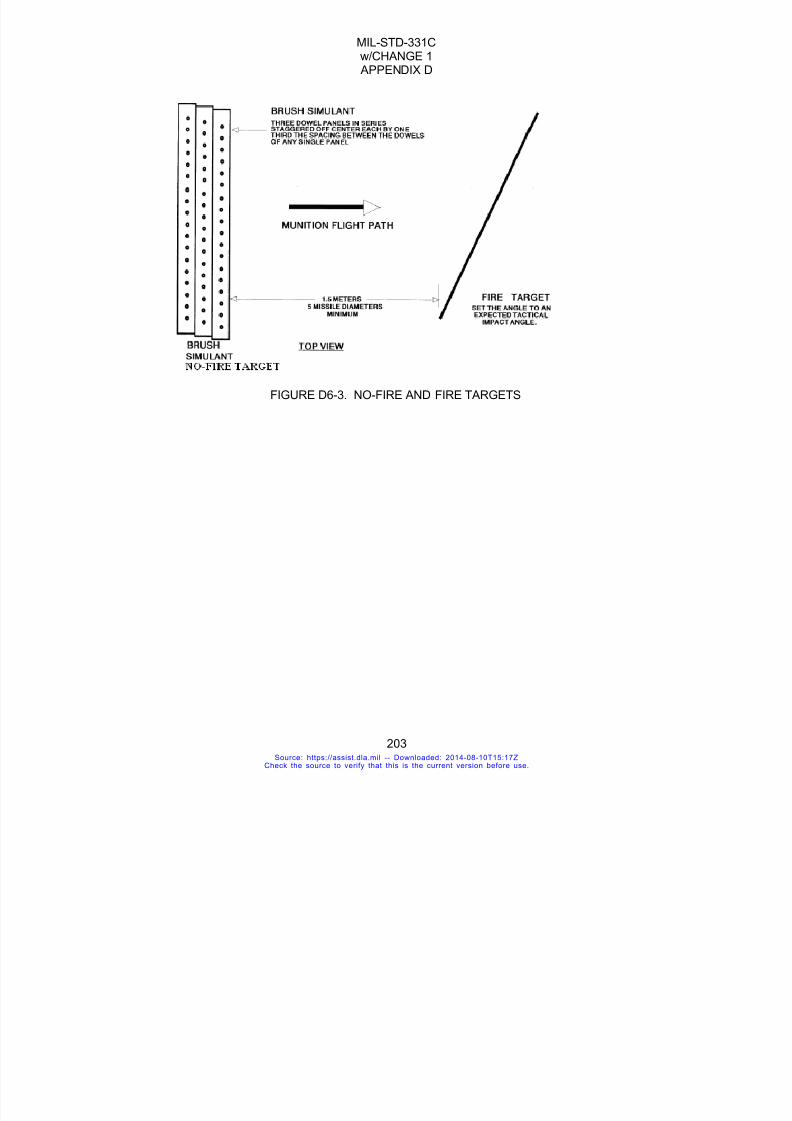
7/18/2019 Mil Std 331 Amend
http://slidepdf.com/reader/full/mil-std-331-amend 211/286
MIL-STD-331Cw/CHANGE 1 APPENDIX D
203
FIGURE D6-3. NO-FIRE AND FIRE TARGETS
Source: https://assist.dla.mil -- Downloaded: 2014-08-10T15:17ZCheck the source to verify that this is the current version before use.

7/18/2019 Mil Std 331 Amend
http://slidepdf.com/reader/full/mil-std-331-amend 212/286
MIL-STD-331Cw/CHANGE 1 APPENDIX D
204
TEST D7MORTAR AMMUNITION FUZE DOUBLE LOADING TEST
D7.1 PURPOSE
This is a field safety test used to determine, in the event of double loading, whether thecontour of the ogive of the projectile fuze can initiate the round dropped on it. A second objective
is to determine if the bottom fuze can be initiated by the impact of the second round. In addition, athird test is used to determine if the fuze under test is susceptible to initiation by hot propellantgases. This test is distinct from the mortar double loading test which is used to determine barrelstrength or the potential of the high explosive filling of the rounds contributing to effects of anincident. This test is a fuze-oriented test, and is distinct from mortar double loading tests found inother test documents (e.g. STANAG 4225).
D7.2 DESCRIPTION
D7.2.1 General. The fuzes shall be mounted to inert projectiles, with live fuzes set tofunction in the point detonating, superquick, or equivalent setting. Proximity or time settings shouldnot be used for this test. Cartridges with tactical primers and propellant will be used during the test
as outlined below. This test consists of double loading a mortar tube under varying conditions toestablish that the fuze does not contribute to pre-ignition of the propellant or to a high orderdetonation. In addition, the test determines whether the contour of the fuze nose can initiate adouble loaded cartridge.
D7.2.2 Fuze conf iguration. Fuzes should be in the tactical configuration, and all explosiveelements shall be in the fuze during the test. Inert fuzes shall conform to the external configurationof the live fuzes undergoing testing, and shall be ready to fire.
D7.2.3 Applicable publications. All standards, specifications, drawings, procedures, andmanuals that form a part of this test are listed in Section 2 of the introduction to this standard.
D7.2.4 Test documentation. Test plans, performance records, equipment, conditions,results, and analysis shall be documented in accordance with Section 4.8 of the general
requirements to this standard. Test plans shall include requirements for tube wear, elevationangle, temperature conditioning for the cartridge and fuze, and so forth, as required.
In addition, specification of round components (tube, propelling charge, primer, projectile,and fuze) in the configuration specified by the test procedure shall be documented.
D7.3 CRITERIA FOR PASSING TEST
D7.3.1 the criteria for passing the test shall be that, as outlined in section D7.5 of this test:
a. The primer of the second cartridge shall not be initiated by the nose of the fuze it impactsagainst.
b. The fuze of the bottom cartridge is not initiated by impacting the second cartridge.
c. The fuze is not susceptible to initiation of its explosive components by the action of hotpropellant gases, while the fuze is still in the barrel.
d. There is no structural failure of the fuze in such a manner as to expose the high explosivefilling of the cartridge to hot propellant gases.
D7.3.2 The fuze under test must be safe to handle and to dispose of following this test andno initiation of the fuze explosive train beyond the interrupter and booster shall have occurred. Inorder to determine if this criteria is met, there shall be no detonation, deformation, burning,charring, scorching, or melting of the fuze explosive elements beyond the interrupter for the fuzeunder test.
Source: https://assist.dla.mil -- Downloaded: 2014-08-10T15:17ZCheck the source to verify that this is the current version before use.

7/18/2019 Mil Std 331 Amend
http://slidepdf.com/reader/full/mil-std-331-amend 213/286
MIL-STD-331Cw/CHANGE 1 APPENDIX D
205
D.7.4 Equipment
D7.4.1 Barrel. A mortar barrel appropriate for the fuzed projectiles and in accordance withthe stage of wear specified in the test directive. It should be noted that ostensibly, barrel wearshould not have any influence in the outcome of this test. The barrel should be capable of beingloaded remotely in order to drop an inert projectile with a live fuze into it. The test weapon shall be
properly barricaded to confine any possible fragmentation for subsequent analysis, and to protecttest operators and observers. Barrels used for this test will be within the maximum permissibleinner diameter allowed for that system. The barrel should be monitored to obtain time traces oftemperature, pressure, etc., from both the base end of the tube and forward of the first projectile, todetermine if conditions behind and between the cartridges can contribute to or be the cause of afailure.
D7.4.2 Projecti le. Inert filled mortar projectiles should be used which are assembled inaccordance with the technical specification. Projectiles are to be fitted with live, tactical fuzes. Theinert charges inside the projectiles must simulate the weight, density, and mechanical properties ofthe explosives they replace. It is essential that the locking torque of the screwed assemblies andthe seals be to specification. No round or fuze should be subjected to more than one test. Theprojectiles should be capable of being remotely loaded into the test barrel. No charges should beused for conducting this test.
D7.4.3 Instrumentation. No special instrumentation is required for this test, unlessspecified in the test directive. Photographic or other equipment capable of determining fuzefunction and propellant ignition may be used.
D7.4.4 Temperature conditioning equipment. As required by the test directive.
D7.4.5 No round or fuze shall be subjected to more than one test.
D7.5 PROCEDURE
D7.5.1 Procedure Number 1: The contour of fuze on Round No. 1 will not ignite primer orpropellant charge of Round No. 2.
D7.5.1.1 Round No. 1 is inserted into the bottom of the tube, which is set at an elevationspecified by the test directive. Round No. 1 shall consist of all inert components (primer, propellantcharge, projectile and fuze). Round No. 2 will be inert except for the primer and propellant charge.The propellant shall be at maximum charge.
D7.5.1.2 Round No. 2 is suspended at the muzzle utilizing a mechanism allowing for theremote release of the round. Round No. 2 is released and allowed to slide down the barrel andimpinge on the inert fuze of Round No. 1.
D7.5.1.3 If Round No.2 is ejected from the barrel, then the fuze of Round No. 1 has ignitedthe round, and has failed the criteria of the test. If there is no ejection, allow fifteen minutes beforeremoving rounds and inspect to determine if the criteria of paragraph 3 have been met.
D7.5.2 Procedure Number 2: The fuze on Round No. 1 will not ignite primer or propellantcharge of Round No. 2, by ramming at mortar barrel muzzle. This test simulates a double loadingcondition where the first round has been dropped down the barrel, but is not immediately fired.Due to cook-off or other phenomena, it is fired at the time a second round is dropped down thebarrel.
D7.5.2.1 Round No. 1 is inserted into the bottom of the tube, which is set at an elevationspecified by the test directive. For this test, use a triggered-fired barrel or equivalent. Round No. 1shall consist of a live primer and fuze, with an inert projectile. The propellant shall be at maximum
Source: https://assist.dla.mil -- Downloaded: 2014-08-10T15:17ZCheck the source to verify that this is the current version before use.
7/18/2019 Mil Std 331 Amend
http://slidepdf.com/reader/full/mil-std-331-amend 214/286
MIL-STD-331Cw/CHANGE 1 APPENDIX D
206
charge. The fuze shall be set in the point detonating, super quick, or equivalent setting. Proximityor time settings should not be used for this test. Round No. 2 will be all inert except for the primerand propellant charge. The propellant shall be at maximum charge.
D7.5.2.2 Round No. 2 is suspended at or near the muzzle of the barrel. Round No. 1 isthen remotely initiated so that the fuze of Round No. 1 impacts on the primer of Round No. 2 at or
near the muzzle.
D7.5.2.3 Both rounds are recovered. Round No. 2 is inspected for any evidence of ignitionof the primer and/or propellant. Round No. 1 is inspected for evidence that the fuze explosiveelements have been initiated or the fuze structurally damaged.
D7.5.3 Procedure Number 3: The explosive components of the fuze on Round No. 1 willnot be initiated by the action of hot gases as a result of ignition of the propellant and primer ofeither or both rounds. This test simulates a double loading condition where the first round has beendropped down the barrel, but is not immediately fired. The second round also sticks in the barrel.Due to cook-off or other phenomena, one or both rounds then ignite, and it is desired that thebottom fuze explosive train will not be initiated to cause a high order functioning of the projectile in
the barrel.D7.5.3.1 Round No. 1 is inserted into the bottom of the tube, which is set at an elevation
specified by the test directive. For this test, use a triggered-fired barrel or equivalent. Round No. 1shall consist of an inert projectile, inert primer and propellant, and a live, unarmed fuze. The fuzeshall be set in the point detonating, superquick, or equivalent setting. Proximity or time settingsshould not be used for this test. Round No. 2 shall consist of an inert fuze, inert projectile, and liveprimer with a device to initiate the primer remotely. The propellant shall be at maximum charge.
D7.5.3.2 The fuze on Round No. 1 must be in the ready to fire mode (i.e. remove any pullwires or pins). Round No. 2 is placed in the barrel, and in contact with Round No. 1. Round No. 2is then remotely initiated.
D7.5.3.3 Both round are recovered. The fuze of Round No. 1 is inspected to assure that all
explosive elements beyond the interrupter meet the criteria of paragraph 3.2, and that there is noindication of hot propellant gases reaching the high explosive cavity of the projectile through thefuze or fuze well.
D7.5.3.4 In a second iteration of this test, repeat the procedures of D7.5.3.1 throughD7.5.3.3, with both rounds having live primers and propellants.
D7.5.4 Temperature conditioning. Perform the test with the fuzes and projectiles andother components at ambient temperature, unless otherwise specified in the test directive.
D7.5.5 Elevation angle. Adjust the barrel's quadrant elevation angle to that value specifiedin the test directive. If none is specified, perform the test at the maximum angle allowed by theweapon system.
D7.6 ALTERNATE AND OPTIONAL TESTSNone.
D7.7 RELATED INFORMATION
D7.7.1 Information for NATO users. NATO users should review Annex E of STANAG4225 "The Safety Evaluation of Mortar Bombs", which gives details of a non-mandatory doubleloading test. Consideration should be given to supplying details of the results of this doubleloading test, for information, to any potential user of STANAG 4225.
Source: https://assist.dla.mil -- Downloaded: 2014-08-10T15:17ZCheck the source to verify that this is the current version before use.

7/18/2019 Mil Std 331 Amend
http://slidepdf.com/reader/full/mil-std-331-amend 215/286
MIL-STD-331Cw/CHANGE 1 APPENDIX D
207
TEST D8
PROGRESSIVE ARMING TEST
D8.1 PURPOSE
This is a laboratory test to determine the correlation between the position of the explosivetrain interrupter and the probability of explosive transfer. It is a means to determine the interrupterposition at which the fuze is armed for the purpose of safety assessment, and it can be used, insome cases, to predict the numerical effectiveness of the interrupter at other positions.
D8.2 DESCRIPTION
D8.2.1 General. The test consists of repeated firings of the initiator with the explosive traininterrupter, or out-of-line element, incrementally located either closer to, or further from, the armedposition. The goal is to determine the point at which the sensitive elements will transfer the
detonation to the next explosive element(s) in the train. The chosen test strategy and results shallbe presented and justified to the appropriate service safety authority.
D8.2.2 Test Item configuration. The explosive train of the fuzes shall be completelyassembled. If the booster charge is not the next explosive element after the interrupter, it may beomitted if considered to be unsafe to test in a laboratory environment. Fuzes may requiremodification to locate and hold the interrupter in progressively incremental positions of arming, butcare should be taken to preserve, as nearly as practical, the same confinement and structuralintegrity for the expanding gases. Each test item, including explosive components, shall besubjected to the test conditions and tested only once. Recycling of any of the explosivecomponents for the testing is not permitted.
D8.2.3 Interrupter positions. Test positions shall be defined by an appropriate parameterthat is varied from test-to-test. Usually this parameter will be the shortest distance between thesensitive element and the next explosive element, measured from edge-to-edge or center-to-center. This parameter is reported as the out-of-line distance. The parameter shall be variedfollowing one of the statistical methods of Appendix G.
D8.2.4 Interpretation of results. There will only be two test outcomes: ‘'transfer" and"non-transfer”.
D8.2.4.1 Detonation train. For a detonation train, transfer is defined as having occurredwhen there is detonation transfer to an explosive component after the explosive train interrupteras evidenced by a dent in the witness plate. Non-transfer is defined as having occurred whenthere is no dent in the witness plate. Any charring, scorching, melting, perforation, or deformation
of any explosive component after the explosive train interrupter will be reported for informationpurposes only, but will not be considered as a “transfer”.
D8.2.4.2 Pyrotechnic train. For a pyrotechnic train, transfer is defined as having occurredwhen there is any reactive consumption in any pyrotechnic element after the interrupter. Non-transfer is defined as having occurred when there is no consumption. Any charring, scorching,melting, perforation, or deformation of any component after the interrupter will not be consideredas a “transfer”.
D8.2.5 Interpretation of results. DELETED.
Source: https://assist.dla.mil -- Downloaded: 2014-08-10T15:17ZCheck the source to verify that this is the current version before use.

7/18/2019 Mil Std 331 Amend
http://slidepdf.com/reader/full/mil-std-331-amend 216/286
MIL-STD-331Cw/CHANGE 1 APPENDIX D
208
D8.2.6 Applicable publications. All standards, specifications, drawings, procedures andmanuals that form a part of this test are listed in Section 2 of the introduction to this standard.
D8.2.7 Test documentation. Test plans, performance records, equipment, test conditions,test results, and analysis shall be documented in accordance with Section 4.8 of the generalrequirements to this standard.
D8.3 INFORMATION TO BE DETERMINED
D8.3.1 Armed Posi tion. The Armed position, identified per MIL-STD-1316 to be the pointat which the probability of propagation (i.e. transfer) of detonation to an explosive component(s) onthe barrier side opposite that of the sensitive explosive component(s) equals .005, at a confidencelevel of 95%, will be determined from this test. The upper single-sided confidence level shall beused.
D8.3.2 Effectiveness of the interrupter. The probability of propagation in the full out-of-line position may be calculated from the data. Caution should be taken to be sure that theextrapolation of the data is valid. A change in geometry of the explosive interface should be causefor examination of the validity of the extrapolation.
D8.4 EQUIPMENTD8.4.1 Test f ixture. Any fixture that may be required to hold/restrain the test item shall not
influence the test results.
D8.4.2 Firing mechanism. Initiation of the test fuze shall be performed by means toreplicate as closely as possible, the ignition stimulus seen by the sensitive component in actualuse. Further, confinement effects on all explosive components must be kept as close as possibleto those which normally exist in the fuze.
D8.4.3 Interrupter position. An appropriate means to fix the interrupter, at positionsrequired by the selected test methodology with the necessary accuracy, is required. Care must betaken to preserve the fuze configuration.
D8.5 PROCEDURED8.5.1 Test methodology. A method (test and subsequent analysis) that will furnish
statistically significant results for the design configuration shall be used. Refer to Appendix G, Analytical Methods to Determine the Reliability of One-Shot Devices.
D8.5.2 Test conditions. There is no specific requirement for the pre-test conditioning ofthe fuze samples and the testing conditions. However, the temperature and other pertinentenvironmental conditioning of the samples before and during the testing shall be recorded.
D8.6 RELATED INFORMATIOND8.6.1 Assumptions. Generally it is assumed that the probability of initiating the out-of-line
component can be expressed as a function of the distance between the two explosivecomponents, and the function is continuous and smoothly decreasing throughout the range ofseparation from the “in-line” position to the “out-of-line” position. Then ordinary methods ofanalysis apply. There may occur situations where the probability function is not smoothlydecreasing because of peculiarities in design. When this situation occurs, case specific specialanalysis may be needed to guarantee that the data to be determined (section 3) meet the requiredconfidence level.
Source: https://assist.dla.mil -- Downloaded: 2014-08-10T15:17ZCheck the source to verify that this is the current version before use.
7/18/2019 Mil Std 331 Amend
http://slidepdf.com/reader/full/mil-std-331-amend 217/286
MIL-STD-331Cw/CHANGE 1 APPENDIX E
209
APPENDIX E
AIRCRAFT MUNITION TESTS
Source: https://assist.dla.mil -- Downloaded: 2014-08-10T15:17ZCheck the source to verify that this is the current version before use.

7/18/2019 Mil Std 331 Amend
http://slidepdf.com/reader/full/mil-std-331-amend 218/286
MIL-STD-331Cw/CHANGE 1 APPENDIX E
210
TEST E1
JETTISON
E1.1. PURPOSE
This is a field safety test for fuzes with flight-selectable safe jettison capability. When jettisonedsafe, the fuze must not contribute to high-order detonation of the warhead on earth or waterimpact.
E1.2. DESCRIPTION
E1.2.1 General. This test applies to air launched bombs, rockets or missiles having aflight-selectable safe jettison option. It excludes munitions such as rail-launched missiles orrockets fired from tubes, but includes systems which can be safely jettisoned by free-fall release ofweapon pods. This test provides an air drop method and an optional simulation using a groundlauncher. The desired method shall be stated in the test plan. The fuze is assembled to theexplosive-loaded munition and dropped or launched against the target. The release altitude or
acceleration provided by the ground launcher system shall be great enough to ensure that themunition reaches terminal velocity before impact. Terminal velocity is the constant velocity of afalling body attained when the resistance of air is equal to the force of gravity acting on the body.The impact is observed and recorded.
E1.2.1.1 Air drop method. The fuzed munition is loaded on the aircraft, all othercomponents in the fuzing system are installed or connected in the normal manner and the aircraftarming system is set for safe (unarmed) release. The munition is dropped against a target ofnormal soil or water, as specified by the test plan.
E1.2.1.2 Ground launcher method. The fuzed munition is loaded on a ground launchersystem capable of accelerating it to a speed simulating terminal velocity. The munition is propelledalong the launcher and allowed to impact a sand-filled bin.
E1.2.2 Applicable publications. All standards, specifications, drawings, procedures andmanuals which form a part of this test are listed in Section 2 of the introduction to this standard.
E1.2.3 Test documentation. Test plans, performance records, equipment, conditions,results, and analysis shall be documented in accordance with 4.8 of the general requirements tothis standard.
E1.3. CRITERIA FOR PASSING TEST
E1.3.1 Warhead function. There shall be no warhead function attributable to the fuze.E1.3.2 Fuze condit ion. At the completion of this test, the fuze shall be safe for disposal in
accordance with Paragraph 4.6.2.1b of the general requirements to this standard.E1.3.3 Decis ion basis. Absence of a warhead function signifies that the fuze has passed
this test. Where test data are inconclusive, breakdown, inspection, other appropriate tests andengineering judgment shall form the basis for the decision that fuzes have passed or failed thetest.
E1.4. EQUIPMENT
E1.4.1 Launch platform. A suitable aircraft or ground launcher simulating the jettison shallbe used.
E1.4.1.1 Aircraft. The aircraft shall be one of the type which would normally be used tolaunch the munition in service use. It must be equipped with a fire control system sufficiently
Source: https://assist.dla.mil -- Downloaded: 2014-08-10T15:17ZCheck the source to verify that this is the current version before use.

7/18/2019 Mil Std 331 Amend
http://slidepdf.com/reader/full/mil-std-331-amend 219/286
MIL-STD-331Cw/CHANGE 1 APPENDIX E
211
accurate to provide impacts within the areas covered by surface instrumentation.E1.4.1.2 Ground launcher. The ground launcher and associated accelerator rocket motor
must be capable of accelerating the munition to the specified impact velocity. The accelerationforce must be minimized so that the fuze is not adversely influenced in the simulation. Theaccelerator must separate from the munition before impact, and must not contact the munition
again. This may require deflector plates or retro rockets.E1.4.2 Scavenger fuze. In performing jettison tests with munitions that can accommodate
two fuzes, and which are not to be recovered, a second scavenger fuze may be used to dispose ofthe ordnance. Although the use of a scavenger fuze could jeopardize test results, it is permissibleprovided the following conditions are satisfied: a. the scavenger fuze will not be destroyed onimpact; b. its minimum functioning time is sufficiently long so that detonation of the scavenger fuzemay be distinguished from possible detonation of the fuze being tested; and c. it will not produce apremature explosion.
E1.4.3 Target area. Soil or water targets shall be specified in the test plan for jettison fromaircraft. A sand-filled bin is used for ground launcher simulations.
E1.4.3.1 Soil. Any land surface that is not marshy, does not contain a large proportion of
rock, has not been artificially packed or hardened, or is suitable for cultivation including desertareas which could be cultivated if properly irrigated.
E1.4.3.2 Water. Not less than 6 m (20 ft) deep.E1.4.3.3 Sand. A sand-filled bin with a vertical entrance face made of nominal 2 in lumber.
The entrance face is a plane normal to the line of fire. The cross section of the bin normal to theline of fire must be large enough to contain the missile. The minimum length shall be 125% of themaximum expected penetration distance. The bin shall be located so it can be adequatelyphotographed.
E1.4.4 Instrumentation and recording devices. Appropriate recording equipment andrange instrumentation shall be specified in the test plan.
E1.4.4.1 Video recording. There shall be video recording of the impact area. Exposure
rate shall not be less than 64 frames/second.E1.4.4.2 Geophone. Geophone or other microphonic equipment coupled with suitable
recorders may be specified in the test directive to obtain additional evidence of detonation,particularly when delay fuzing is involved in the test.
E1.4.4.3 Range instrumentation. Suitable range instrumentation specified by the testdirective may include velocity and acceleration measuring equipment, position trackers, on-boardsensors and telemetry, and the digital or analog recording devices associated with eachinstrument.
E1.4.5 Recovery facil ities. Facilities for recovery and examination of the munition may berequired when other evidence is inconclusive.
E1.5. PROCEDURE
E1.5.1 General. The test shall be conducted at ambient temperature using an explosive-loaded warhead intended for the test fuze. The fuze service configuration shall be duplicatedincluding all explosive components and accessories normally associated with it.
E1.5.2 Scavenger fuze installation. Install a scavenger fuze system if required by the testdirective.
E1.5.3 Rocket or missi le motors. For the ground launcher method, test munition rocketor missile motors shall be inert to avoid confusion which may arise due to motor blow-up onimpact.
Source: https://assist.dla.mil -- Downloaded: 2014-08-10T15:17ZCheck the source to verify that this is the current version before use.

7/18/2019 Mil Std 331 Amend
http://slidepdf.com/reader/full/mil-std-331-amend 220/286
MIL-STD-331Cw/CHANGE 1 APPENDIX E
212
E1.5.4 Instrumentation. Operate the test instrumentation in accordance with the test plan.Photographic, sound, or other recordings shall be made of the impact beginning shortly beforeimpact and continuing past the longest fuze delay time.
E1.5.5 Aircraft jettison. Drop the ordnance in the condition in which it normally would besafely jettisoned in flight so as to strike in the impact area. Jettison altitude shall be sufficient to
approximate terminal velocity at impact.E1.5.6 Ground launch. Launch the munition to ensure it will impact at approximately
terminal velocity. Measure the velocity immediately before impact.E1.5.7 Compliance. Analyze the test results and determine whether or not the test article
meets the pass/fail criteria in E1.3. In case of instrument failure or conflicting evidence, recoverand examine the munition, or repeat the test. Observe and record deformation of the fuze, anyfunctioning of the fuze, and degree of arming, if any.
E1.6. ALTERNATE AND OPTIONAL TESTS
None.
E1.7. RELATED INFORMATION
E1.7.1 Need. The need for a jettison test arises from the possible necessity for releasingmunitions over friendly territory in case of an accident to the aircraft or munition, cancellation of themission or the need to jettison weight. In each case, an explosion could result in death or injury tofriendly ground forces or the flight crew and serious damage to the aircraft or ground installationsand equipment.
E1.7.2 Launch platform. The procedures in this test are performed with either an aircraftor ground launcher. The use of a ground launcher to simulate the air-jettison or separation hasadvantages of better impact containment, better instrumentation, all-weather firing, andreproducibility of test conditions. Restrictions include prohibition of testing fuzes which could armor be otherwise adversely influenced by launcher acceleration forces.
Source: https://assist.dla.mil -- Downloaded: 2014-08-10T15:17ZCheck the source to verify that this is the current version before use.

7/18/2019 Mil Std 331 Amend
http://slidepdf.com/reader/full/mil-std-331-amend 221/286
MIL-STD-331Cw/CHANGE 1 APPENDIX E
213
TEST E2
LOW-ALTITUDE ACCIDENTAL RELEASE
E2.1. PURPOSE
This is a field safety test simulating accidental release of airborne munitions on takeoff or landing.The fuze must not contribute to high-order detonation when the munition impacts a hard surface.
E2.2. DESCRIPTION
E2.2.1 General. A malfunction of an aircraft or its release equipment occurring during take-off or landing could accidentally release munitions. This test is designed to determine the effect ofsuch occurrences on the fuze. An inert munition equipped with a live fuze and inert booster is
dropped from a low-flying aircraft onto a hard surface. The fuze is released safe or prevented fromarming by the service safety feature.
E2.2.2 Applicable publications. All standards, specifications, drawings, procedures andmanuals which form a part of this test are listed in Section 2 of the introduction to this standard.
E2.2.3 Test documentation. Test plans, performance records, equipment, conditions,results, and analysis shall be documented in accordance with 4.8 of the general requirements tothis standard.
E2.3. CRITERIA FOR PASSING TEST
E2.3.1 Weapon function. There shall be no warhead function attributable to the fuze.
E2.3.2 Fuze condit ion. At the completion of this test, the fuze shall be safe for disposal inaccordance with 4.6.2.1b of the general requirements to this standard.
E2.3.3 Decis ion basis. Breakdown, inspection, other appropriate tests and engineering judgment shall form the basis for the decision that fuzes have passed or failed the test.
E2.4. EQUIPMENT
E2.4.1 Aircraft. Use an aircraft having the necessary equipment for carrying and droppingthe munition.
E2.4.2 Target. Use a suitable hard surface area to simulate a runway.
E2.4.3 Recovery facil ities. If the condition of the fuze cannot be determined without itsremoval from the munition, special equipment will be necessary to remove the fuze with safety.
E2.5. PROCEDURE
E2.5.1 Temperature. Perform the test with munition at ambient temperature.
E2.5.2 Assembly. Assemble the fuze with all of its explosive components for properfunctioning, less booster, to the inert munition of the type with which it is intended to be used.Ensure a safe release to every extent possible by selecting optimum fuze settings and control of
Source: https://assist.dla.mil -- Downloaded: 2014-08-10T15:17ZCheck the source to verify that this is the current version before use.
7/18/2019 Mil Std 331 Amend
http://slidepdf.com/reader/full/mil-std-331-amend 222/286
MIL-STD-331Cw/CHANGE 1 APPENDIX E
214
the munition and aircraft interface.
E2.5.3 Launch. Drop the fuzed munition onto a hard surface from an aircraft flying at analtitude of 61 m (200 ft), at 370 km/hr (200 knots) true airspeed. The minimum release altitudeshall be sufficient to prevent damage to the aircraft in the event of munition ricochet.
E2.5.4 Recovery. Recover the munition after impact. Observe and record deformation ofthe fuze, any functioning of the fuze, and degree of arming, if any.
E2.5.5 Compliance. Analyze the test results and determine whether or not the test articlemeets the pass/fail criteria in E2.3. Continue testing the specified number of items.
E2.6. ALTERNATE AND OPTIONAL TESTS
None.
E2.7. RELATED INFORMATION
None.
Source: https://assist.dla.mil -- Downloaded: 2014-08-10T15:17ZCheck the source to verify that this is the current version before use.
7/18/2019 Mil Std 331 Amend
http://slidepdf.com/reader/full/mil-std-331-amend 223/286
MIL-STD-331Cw/CHANGE 1 APPENDIX E
215
TEST E3
ARRESTED LANDING MUNITION PULL-OFF
E3.1. PURPOSE
This is a field safety test simulating accidental release of an airborne weapon upon arrestedlanding aboard an aircraft carrier. The fuze must not contribute to high-order detonation onmunition impact.
E3.2. DESCRIPTION OF TEST
E3.2.1 General. The safety of personnel and equipment aboard an aircraft carrier requiresthat a munition which comes loose from an aircraft during an arrested landing resist detonation anddeflagration on impact with the deck or bulkhead. An inert munition equipped with a live fuze andinert booster is propelled from a ground launcher with the fuze in the unarmed condition, just as itwould be if carried on an aircraft. After leaving the launcher, the test munition impacts a horizontalsteel deck simulating the flight deck of an aircraft carrier. See Figure E3-1. At 12 to 18 m (40 to 60ft) beyond the initial point of impact on the deck, the test munition impacts a vertical steel targetnormal to the line of flight. This test applies to all externally-mounted, aircraft-launched bomb,rocket and guided missile fuzes which are not adversely affected by acceleration force appliedduring the simulation.
E3.2.2 Applicable publications. All standards, specifications, drawings, procedures andmanuals which form a part of this test are listed in Section 2 of the introduction to this standard.
E3.2.3 Test documentation. Test plans, performance records, equipment, conditions,results, and analysis shall be documented in accordance with 4.8 of the general requirements tothis standard.
E3.3. CRITERIA FOR PASSING TEST
E3.3.1 Warhead function. There shall be no warhead function attributable to the fuze.
E3.3.2 Fuze condit ion. At the completion of this test, the fuze shall be safe for disposal inaccordance with 4.6.2.1b of the general requirements to this standard.
E3.3.3 Decis ion basis. Breakdown, inspection, other appropriate tests and engineering judgment shall form the basis for the decision that fuzes have passed or failed the test.
E3.4. EQUIPMENT
E3.4.1 Ground launcher. Use a ground launcher of sufficient length to permit the munition
to obtain a striking velocity of approximately 45.7 m/s (150 ft/s) on the deck. See Figure E3-1.
E3.4.2 Rocket motor. Use a rocket motor or other suitable means capable of boosting thetest munition to the required velocity for impact. If a separate booster motor is used, it should beseparated from the munition being propelled before impact and should not again contact themunition. This may entail the use of retro-rockets or some means of deflecting the booster motoras it leaves the launcher.
E3.4.3 Target. Use an appropriate deck and vertical bulkhead. Refer to Figure E3-1. The
Source: https://assist.dla.mil -- Downloaded: 2014-08-10T15:17ZCheck the source to verify that this is the current version before use.
7/18/2019 Mil Std 331 Amend
http://slidepdf.com/reader/full/mil-std-331-amend 224/286
MIL-STD-331Cw/CHANGE 1 APPENDIX E
216
deck target area shall be large enough to ensure that all impacts are on the deck before strikingthe vertical target. The vertical bulkhead shall be thick enough to deflect the munition.
E3.4.4 Recording equipment. Use a motion picture camera operating at a minimum of 64frames per second, covering both the deck and vertical targets, and the intervening flight of themunition. Visual observation is also required.
E3.4.5 Velocity measuring instrumentation. Velocity measuring instrumentation is usedto measure the speed of the munition prior to impact.
E3.4.6 Recovery equipment. If the condition of the fuze cannot be determined withoutremoval from the munition, special equipment will be necessary to remove the fuze with safety.
E3.5. PROCEDURE
E3.5.1 Temperature. Perform the test with the munition at ambient temperature.
E3.5.2 Munit ion assembly. Assemble the fuze with all of its explosive components, withthe exception of an inert booster, to the inert munition of the type with which it is intended to be
used. If a round accidentally pulls off the aircraft, the fuze would normally be in the unarmed orsafe condition. Make the fuze safe or prevent it from arming by the safety feature that is usedwhile it is being carried on the aircraft. If pull-off compromises a safety feature, such as removal ofan arming wire, this condition should be duplicated for the test.
E3.5.3 Rocket motors. If the test munition is normally propelled by a rocket motor, themotor attached to the warhead shall be inert, or if designed to carry a sub-caliber rocket motor forthe purpose of this test, the motor shall be burned out before striking the target. This is done toassure that there shall be no confusion between fuze detonation and motor deflagration.
E3.5.4 Launcher orientation. The launcher shall be oriented to give an angle of impactsuch as that obtained with a munition breaking loose from a landing aircraft.
E3.5.5 Launch. The test munition shall be accelerated to a velocity of approximately 45.7m/s (150 ft/s) by suitable means, such as a rocket motor, before striking the target. Engineering
judgment shall be exercised in attaining desired acceleration. If the fuze is acceleration sensitive,the test acceleration shall be safely below the normal arming acceleration so that the results of thistest are not invalidated by improper simulation of actual pull-off conditions.
E3.5.6 Recovery. Recover the munition after impact. Observe and record deformation ofthe fuze, any functioning of the fuze, and degree of arming, if any.
E3.5.7 Compliance. Analyze the test results and determine whether or not the test articlemeets the pass/fail criteria in E3.3. Functioning of the fuze would indicate: (a) the mechanismintended to prevent arming failed either during or after initial impact and permitted arming to
proceed, or (b) the fuze functioned on severe impact, even though actually held in the safecondition. Continue testing the specified number of items.
E3.6. ALTERNATE AND OPTIONAL TESTS
None.
E3.7. RELATED INFORMATION
None.
Source: https://assist.dla.mil -- Downloaded: 2014-08-10T15:17ZCheck the source to verify that this is the current version before use.

7/18/2019 Mil Std 331 Amend
http://slidepdf.com/reader/full/mil-std-331-amend 225/286
MIL-STD-331Cw/CHANGE 1 APPENDIX E
217
FIGURE E3-1. Arrested Landing Pull-off Test Set-up
Source: https://assist.dla.mil -- Downloaded: 2014-08-10T15:17ZCheck the source to verify that this is the current version before use.

7/18/2019 Mil Std 331 Amend
http://slidepdf.com/reader/full/mil-std-331-amend 226/286
MIL-STD-331Cw/CHANGE 1 APPENDIX E
218
TEST E4
CATAPULT AND ARRESTED LANDING FORCES
E4.1 PURPOSE
This is a field safety and reliability test. The fuze must withstand forces encountered on catapulttakeoff and arrested landing aboard an aircraft carrier.
E4.2 DESCRIPTION
E4.2.1 General. A complete fuze with all explosive components installed is catapulted oraccelerated to obtain the acceleration-time patterns which could be encountered during catapulttakeoff or arrested landing aboard an aircraft carrier. Each accelerated fuze is examined forevidence of unsafe conditions. Some of the fuzes are disassembled for more detailed
examination. The others are tested for functioning.
E4.2.2 Applicable publications. All standards, specifications, drawings, procedures andmanuals which form a part of this test are listed in Section 2 of the introduction to this standard.
E4.2.3 Test documentation. Test plans, performance records, equipment, conditions,results, and analysis shall be documented in accordance with 4.8 of the general requirements tothis standard.
E4.3 CRITERIA FOR PASSING TEST
E4.3.1 Fuze condit ion. At the completion of this test, the fuze shall be safe fortransportation, storage, handling and use, as well as operable in accordance with 4.6.2.1a and
4.6.2.2 of the general requirements to this standard.E4.3.2 Decis ion basis. Breakdown, inspection, other appropriate tests and engineering
judgment shall form the basis for the decision that fuzes have passed or failed the test.
E4.4 EQUIPMENT
E4.4.1 Acceleration device. Use shipboard catapults, land based catapults, rocketlaunchers, rocket sleds, or other devices which can produce the required acceleration-timepatterns may be employed.
E4.4.2 Munition mount ing. Aircraft, test carriage, or other device suitable for mountingthe munition for acceleration.
E4.4.3 Munition. Inert munitions or test fixtures as required. The inert-loaded munition ortest fixture shall be dynamically equivalent to the explosive-loaded munition.
E4.4.4 Accelerometer. Several types of piezoelectric accelerometers are commerciallyavailable which will yield very accurate acceleration-time histories. The type of accelerometerused and its placement will depend upon the environment and configuration of the item beingtested.
E4.4.5 Fuze disassembly, inspection and test equipment.
Source: https://assist.dla.mil -- Downloaded: 2014-08-10T15:17ZCheck the source to verify that this is the current version before use.

7/18/2019 Mil Std 331 Amend
http://slidepdf.com/reader/full/mil-std-331-amend 227/286
MIL-STD-331Cw/CHANGE 1 APPENDIX E
219
E4.5 PROCEDURE
E4.5.1 Temperature. The test shall be performed with the fuze at ambient temperature. An estimate of the temperature of the fuze at the time of test shall be recorded.
E4.5.2 Fuze inspection. When specified in the test directive, inspect each fuze prior to the
test to ensure that it is properly assembled in the unarmed condition.E4.5.3 Fuze mounting. Assemble the fuze to the inert bomb, rocket, or guided missile for
which it was designed or to a suitable test fixture.
E4.5.4 Accelerometers. Accelerometers shall be placed near the center of gravity of thefuze to measure the acceleration.
E4.5.5 Munition mounting. The munition shall be mounted on aircraft suspensionequipment on the aircraft, test carriages, or other devices suitable for the acceleration tests.
E4.5.6 Acceleration. A minimum of three fuzes shall be accelerated. Each fuze shall beaccelerated three times in each of three orientations. The orientations shall be nose forward, tailforward, and side forward. The side forward orientation shall be such as to expose what isconsidered to be the most vulnerable plane of weakness. The magnitude and duration of theaccelerations shall over-simulate those conditions that the fuzes would experience when attachedto a munition and carried on an aircraft that is catapulted or subjected to arrested landings.
E4.5.6.1 Magnitude. The magnitude of the accelerations shall be 150 percent of themaximum accelerations to be expected in service use. Figure E4-1 provides profiles of the forcesto be met.
E4.5.6.2 Duration. The acceleration rise and dwell time shall approximate those expectedin service use.
E4.5.7 Interim inspection. After each acceleration and before handling, examine the
accelerated fuze, munition and test fixture for any evidence of unsafe conditions.E4.5.8 Final inspection. After completion of the test (9 accelerations per fuze), examine
the fuzes for apparent safety defects. Particular attention shall be given to possible movement dueto acceleration of fuze parts or components which could cause unsafe conditions or render thefuze inoperable. Where necessary, disassemble the fuze for a more detailed examination.
E4.5.9 Function test. Perform complete functioning tests on those fuzes notdisassembled.
E4.5.10 Compliance. Analyze the test results and determine whether or not the test articlemeets the pass/fail criteria in Section 3. Continue testing the specified number of items.
E4.6 ALTERNATE AND OPTIONAL TESTSNone.
E4.7 RELATED INFORMATION
E4.7.1 Test conditions. Safety requirements for the fuze shall dictate the selection of thetest conditions and munitions for this test. For example, the same fuze may be used in munitionswhich are mounted in widely different locations and retention mechanisms and which are carriedby different aircraft. The types of munitions in which the fuze will be assembled, the suspension
Source: https://assist.dla.mil -- Downloaded: 2014-08-10T15:17ZCheck the source to verify that this is the current version before use.

7/18/2019 Mil Std 331 Amend
http://slidepdf.com/reader/full/mil-std-331-amend 228/286
MIL-STD-331Cw/CHANGE 1 APPENDIX E
220
method and location, and the catapults and arresting gear characteristics should be given carefulconsideration in planning the test. Reasonable and compatible test conditions which are likely toproduce the most critical loading conditions should be chosen.
E4.7.2 Bibliography.
DP-75-27, Mk 82 Bomb Dud Investigation, R.L Russakov, Pacific Missile Test Center, 1 July 1975.
FIGURE E4-1. Design Limi t Load Factors for Wing-mounted Stores
Source: https://assist.dla.mil -- Downloaded: 2014-08-10T15:17ZCheck the source to verify that this is the current version before use.
7/18/2019 Mil Std 331 Amend
http://slidepdf.com/reader/full/mil-std-331-amend 229/286
MIL-STD-331Cw/CHANGE 1 APPENDIX E
221
TEST E5
SIMULATED PARACHUTE AIR DELIVERY
E5.1 PURPOSE
This is a field safety and reliability test simulating air delivery of packaged fuzes or fuzed munitions.The fuzes must withstand the forces encountered in low-velocity, high-velocity (if required) andmalfunctioning air delivery drops.
E5.2 DESCRIPTION
E5.2.1 General. In this test, packaged fuzes and those assembled to warheads orcomplete rounds are subjected to impacts encountered in low-velocity, high-velocity andmalfunctioning parachute delivery.
E5.2.1.1 Low-velocity simulation. Fuzes are subjected to an impact velocity of 8.7 m/s(28.5 ft/s).E5.2.1.2 Malfunctioning drop simulation. Fuzes are subjected to an impact velocity of
45.7 m/s (150 ft/s).E5.2.1.3 High-velocity drop s imulation (if required). Fuzes are subjected to an impact
velocity of 27.4 m/s (90 ft/s).E5.2.2 Fuze configuration. The fuzes are tested in their standard package, unit or bulk, or
assembled to associated munitions. All explosive elements are present in the fuze during the test.Warheads and other components may be inertly loaded.
E5.2.3 Number of drops. Each test article is dropped once per impact orientation of noseup, nose down and sideways.
E5.2.4 Applicable publications. All standards, specifications, drawings, procedures andmanuals which form a part of this test are listed in Section 2 of the introduction to this standard.
E5.2.5 Test documentation. Test plans, performance records, equipment, conditions,results, and analysis shall be documented in accordance with 4.8 of the general requirements tothis standard.
E5.3 CRITERIA FOR PASSING TEST
E5.3.1 Low-velocity and high-velocity test. At the completion of this test, the fuzes shallbe safe for transportation, storage, handling and use, as well as operable in accordance with4.6.2.1a and 4.6.2.2 of the general requirements to this standard.
E5.3.2 Malfunctioning test. At the completion of this test, the fuzes shall be safe fordisposal in accordance with 4.6.2.1b of the general requirements to this standard.
E5.3.3 Decis ion basis. Breakdown, inspection, other appropriate tests and engineering judgment shall form the basis for the decision that fuzes have passed or failed the test.
E5.4 EQUIPMENT
E5.4.1 Drop tower. A suitable drop tower, boom arrangement or crane with quick-releasemechanism may be used for free fall drops.
E5.4.2 Acceleration device. A suitable acceleration device may be used to achieve thespecified impact velocity in the malfunctioning drop.
E5.4.3 Impact surface. An impact area of compact soil or level hard surface shall be used.
Source: https://assist.dla.mil -- Downloaded: 2014-08-10T15:17ZCheck the source to verify that this is the current version before use.
7/18/2019 Mil Std 331 Amend
http://slidepdf.com/reader/full/mil-std-331-amend 230/286
MIL-STD-331Cw/CHANGE 1 APPENDIX E
222
E5.4.4 Test artic les. Fuzes, warheads, or complete rounds in packaged condition shall beused in quantities specified by the test directive.
E5.4.5 Rigging. Standard air delivery rigging equipment, including containers, platforms,and energy absorbers shall be used as required. Retardation devices such as a pilot parachutemay be used to ensure the item will impact at the desired orientation and at the required impact
velocity.E5.4.6 Anci llary equipment. Photographic, radiographic, telemetry and disassembly
equipment shall be used as required.
E5.5 PROCEDURE
Note: An acceleration device may be used in lieu of free fall to obtain the impact velocity.E5.5.1 Rigging test artic les. Prepare the air delivery system to be dropped by stacking
packaged fuzes or fuzes assembled to warheads or complete rounds in the normally shippedorientation. Stacking shall be in accordance with the test directive. Dummy components may beused as partial loading to simulate fuzes or other ammunition components. The rigginginstructions shall be specified in the test directive. An example is shown in Figure E5-1.
E5.5.2 Low-velocity test. Release the air delivery system to impact at a minimum velocityof 8.7 m/s (28.5 ft/s) on compact soil or a level hard surface and impacting with the energyabsorber on the underside of the load to simulate a low-velocity parachute delivery.
E5.5.3 Malfunctioning test. Release the air delivery system to impact at a minimumvelocity of 45.7 m/s (150 ft/s) onto compact soil or a level hard surface to simulate the malfunctionvelocity in the parachute delivery.
E5.5.4 High-velocity test. See E5.6.2.E5.5.5 Disassembly. Disassemble the air delivery system. Determine by means of
radiographic examination and disassembly or other appropriate methods whether the fuzes havebeen armed or functioned and are safe to handle. For fuzes subjected to the low-velocity drop,use suitable tests to determine operability.
E5.6 ALTERNATE AND OPTIONAL TESTSE5.6.1 System without energy absorbers. Alternatively, drop an air delivery system
without energy absorbers and without stabilization to impact at a velocity between 24.4 m/s (80ft/s) and 30.5 m/s (100 ft/s) in the most vulnerable attitude onto a hard surface, such as steel orconcrete as a means of determining minimum damage and hazards to be expected in amalfunctioning parachute delivery.
E5.6.2 High-velocity test. Although no formal requirement exists for high impact velocitiesin the range of 21 to 27.4 m/s (70 to 90 ft/s), it is tactically desirable to deliver fuzes andammunition in this range of vertical impact velocities. If fuzes and components are satisfactory astested in E5.5.2 and E5.5.3, above, it is suggested that a system drop be made to impact at high-velocity using rigging instructions specified in the test directive. Fuzes and components should be
safe to handle and use and be operable in accordance with E5.3.1.
E5.7. RELATED INFORMATION
E5.7.1 Journal Article Serial Number 40 of the JANAF Fuze Committee, "Air Delivery of Ammunition and Explosives by Parachute," 1 September 1965.
E5.7.2 AR 705-35, Criteria for Air Portability and Air Drop of Materiel, 20 October 1967.
Source: https://assist.dla.mil -- Downloaded: 2014-08-10T15:17ZCheck the source to verify that this is the current version before use.

7/18/2019 Mil Std 331 Amend
http://slidepdf.com/reader/full/mil-std-331-amend 231/286
MIL-STD-331Cw/CHANGE 1 APPENDIX E
223
FIGURE E5-1. Example of Simulated Load
\
Source: https://assist.dla.mil -- Downloaded: 2014-08-10T15:17ZCheck the source to verify that this is the current version before use.

7/18/2019 Mil Std 331 Amend
http://slidepdf.com/reader/full/mil-std-331-amend 232/286
MIL-STD-331Cw/CHANGE 1 APPENDIX F
224
APPENDFIX FELECTRIC AND MAGNETIC INFLUENCE TESTS
Source: https://assist.dla.mil -- Downloaded: 2014-08-10T15:17ZCheck the source to verify that this is the current version before use.
7/18/2019 Mil Std 331 Amend
http://slidepdf.com/reader/full/mil-std-331-amend 233/286
MIL-STD-331Cw/CHANGE 1 APPENDIX F
225
TEST F1
ELECTROSTATIC DISCHARGE (ESD)
F1.1 PURPOSE
This is a laboratory safety and reliability test simulating possible handling and transportationconditions. The fuze must withstand high-potential electrostatic discharge (lightning environmentis excluded).
F1.2 DESCRIPTION
F1.2.1 General. Bare and packaged unarmed fuzes are subjected to discharges ofelectrostatic energy at selected exterior points. Each fuze shall be subjected to three tests. The
first test, personnel-borne ESD, simulates the maximum electrostatic discharge from the humanbody and is performed at two different test conditions representative of such discharges. The finaltwo tests, helicopter-borne ESD, performed on packaged and bare fuzes, simulate the maximumexpected electrostatic discharge during vertical replenishment by hovering aircraft.
F1.2.1.1 Personnel-borne ESD (bare). This test shall be conducted on bare fuzes toevaluate their safety and operability.
F1.2.1.2 Helicopter-borne ESD (packaged). This test shall be conducted on fuzes in theirstandard packaged configuration (unit or bulk packaging and shipping container) to evaluate theirsafety and operability.
F1.2.1.3 Helicopter-borne ESD (bare). This test shall be conducted on bare fuzes toevaluate their safety only.
F1.2.2 Selection of test points. Selection of test points for the fuze or container shall bebased on the item's particular points deemed by engineering judgment to be the most susceptibleto direct penetration or to excitation of the structure and subsequent internal distribution of theelectromagnetic energy from the discharge.
F1.2.2.1 Bare fuzes. Fuzes shall be tested in all expected electrostatically-significanthandling configurations, both with and without caps, covers and protective devices, to insureevaluation of realistic worst-case conditions. When selecting test points on a fuze, specialattention and consideration shall be given to connectors, pins, apertures, slots, joints and otherdiscontinuities that may transfer energy by electric (E-field) or magnetic (H-field) coupling.
F1.2.2.2 Packaged fuzes. Fuzes shall be in their shipping containers in their normalshipping configurations (for example, intact solder-seal lids or metal foil tapes or wraps). Whenselecting test points on a container, special attention shall be given to joints and otherdiscontinuities that may transfer energy by electric (E-field) or magnetic (H-field) coupling.
F1.2.3 Environmental conditions. The test shall be conducted on fuzes at an ambienttemperature of +23ºC±10ºC (+73ºF±18ºF). Relative humidity of the ambient atmosphere shall beno greater than 50%. The fuze shall be preconditioned at +23ºC±10ºC (+73ºF±18ºF), relativehumidity no greater than 50% for no less than 24 hours prior to this test.
F1.2.4 Fuze configuration. The fuzes shall be completely assembled except that lead andbooster charges, if considered to be insensitive or inaccessible to electrostatic discharge, may beomitted to facilitate testing. If any explosive elements are removed, care should be exercised to
Source: https://assist.dla.mil -- Downloaded: 2014-08-10T15:17ZCheck the source to verify that this is the current version before use.

7/18/2019 Mil Std 331 Amend
http://slidepdf.com/reader/full/mil-std-331-amend 234/286
MIL-STD-331Cw/CHANGE 1 APPENDIX F
226
preserve electromagnetic equivalency of the resulting configuration. F1.2.5 Applicable publications. All standards, specifications, drawings, procedures and
manuals which form a part of this test are listed in Section 2 of the introduction to this standard.Special attention is directed to MIL-HDBK-1512, MIL-STD-322 and MIL-I-23659 which havespecific applications.
F1.2.6 Test documentation. Test plans, performance records, equipment, conditions,results, and analysis shall be documented in accordance with 4.8 of the general requirements tothis standard. The test plan shall also specify:
a. The number and configuration of fuzes for each discharge; the location of discharge points;the number of times each fuze may be subjected to discharge; the type of electrode to beused (see F1.4.4); the discharge gap or description of the mechanism utilized to move theelectrode toward the test item (see F1.4.5); and the test sequence (see F1.5.2).
b. The performance requirements, pre-test data (for example, electroexplosive device (EED)bridge resistance and thermal time constants) and parameters for determining properevaluation of the fuze during and after test, including how cumulative damage, if any is to beassessed.
F1.3 CRITERIA FOR PASSING TEST
F1.3.1 Fuze condition after personnel-borne ESD (bare) and helicopter-borne ESD(packaged) tests. At the completion of these tests, the fuze shall be safe for transportation,storage, handling and use, as well as operable in accordance with 4.6.2.1a and 4.6.2.2 of thegeneral requirements to this standard.
F1.3.2 Fuze condit ion after helicopter-borne ESD (bare) test. At the completion of thistest, the fuze shall be safe for transportation, storage, handling and use in accordance with 4.6.2.2of the general requirements to this standard. The fuze does not have to be operable.
F1.3.3 Decision basis. Breakdown, inspection, other appropriate tests and engineering judgment shall form the basis for the decision that fuzes have passed or failed the test.
F1.4. EQUIPMENTF1.4.1 Test apparatus. The functional electrical schematic for the test apparatus is shown
in Figure F1-1.F1.4.2 Energy delivery capabil ity. The energy delivery capability of the test apparatus
shall be verified and recorded on a daily basis. If a salient is used on the test item, it shall beconsidered part of the discharge circuit.
F1.4.2.1 Personnel-borne ESD test . The energy delivered to each of the calibration testloads given in Table F1-1 shall be between 0.18% and 0.22% (when using a 500 ohm seriesresistance) or between 0.018% and 0.022% (when using a 5000 ohm series resistance) of theenergy stored on capacitor C. F1.7.3.2.1 provides a description of the threat to fuzes or theirsubsystems caused by an electrostatic discharge from a human body. F1.7.4 provides a
description of the required instrumentation and a procedure for measuring the energy delivered bythe test apparatus used to simulate the threat. Calibration test waveforms should fall within thebounds specified in Figures F1-2 through F1-5, as applicable.
F1.4.2.2 Helicopter-borne ESD test. The energy delivered to the calibration test loadgiven in Table F1-I shall be between 80% and 100% of the energy stored on capacitor C.
F1.4.3 Circuit component characteristics. F1.4.3.1 Power supply. The power supply shall provide both positive and negative test
voltages with respect to ground.
Source: https://assist.dla.mil -- Downloaded: 2014-08-10T15:17ZCheck the source to verify that this is the current version before use.

7/18/2019 Mil Std 331 Amend
http://slidepdf.com/reader/full/mil-std-331-amend 235/286
MIL-STD-331Cw/CHANGE 1 APPENDIX F
227
F1.4.3.2 Isolation circuitry. Isolation circuitry shall isolate the test item from the chargingcircuit during charging of capacitor C and shall isolate the power supply from the discharge circuitduring discharge to the test item.
F1.4.3.3 Series resistance. The series resistance R shall be non-inductive. For the airreplenishment test, R represents the allowable total discharge circuit resistance, excluding the test
item (see F1.4.1).F1.4.3.4 Capacitor. Capacitor C shall be chosen to minimize inductance and leakage.F1.4.3.5 Storage Scope. To properly record test waveforms, a oscilloscope is required
having at least a DC to 100 MHz frequency response, 50-ohm input impedance, and both storageand hard-copy capability.
F1.4.3.6 Test parameters. The voltage, capacitance, resistance, discharge circuitinductance, and calibration test load for each test procedure, including the inductance of thecapacitor and wiring to the probes shall be in accordance with the values in Table F1-I. Inductanceshall be measured at a nominal 1 kHz frequency.
F1.4.4 Electrode characteristics. The test electrode shall be metal and have a size andshape that minimize corona. The electrode surface shall be maintained smooth, clean and shiny
to insure high electrical conductivity and uniformity of discharge.F1.4.5 Electrode control. A mechanism shall be provided to cause the test electrode
either to discharge to the test item through a previously specified fixed gap (see Section F1.2.6a)or to move toward the test item at the speed at which it was calibrated. The electrode may besnubbed to prevent hitting the test item. Where it is desired to insure that the discharge is directedto a particular point on the test item or to assure contact by the electrode without mechanicalshock, an electrically conductive salient may be attached to the test item. In this case, it shall beestablished that the salient can withstand the discharge arc and that the integument of the testitem with salient omitted can also withstand a direct discharge arc. The salient shall be included inenergy delivery calibration tests (see F1.4.2).
F1.4.6 Safety considerations. Proper safety interlocks, switches, grounds and
procedures shall be used to protect test personnel from electrical and explosive hazards. Agrounding rod with insulated handle (or equivalent) shall be provided to short circuit the testelectrode to test-circuit ground while test personnel are setting up for the next discharge.
F1.5 PROCEDURE
F1.5.1 Test. Perform the human body discharge test and the two air replenishment tests inaccordance with the test plan. Test details, for example, configurations, order of trials, inspectionand number of trials, shall be at the discretion of the test designer and shall be documented in thetest plan.
F1.5.2 Test sequence. Items shall be tested as follows:a. The test item shall be positioned such that the test electrode can discharge to the first
designated test point on the item.b. Capacitor C shall be charged to the chosen voltage and polarity. After C is fully charged
and has been isolated from the power supply, the test electrode is allowed to discharge tothe test point.
c. The capacitor discharge energy shall be applied sequentially to each of the designated testpoints. The capacitor shall be fully recharged for each point.
d. The test sequence shall be stopped if the test item at any time gives an indication of failureto pass the test, or at the discretion of the test activity. After removal of residual electricalenergy, the fuze shall be inspected for compliance with F1.3. Otherwise, sequential
Source: https://assist.dla.mil -- Downloaded: 2014-08-10T15:17ZCheck the source to verify that this is the current version before use.

7/18/2019 Mil Std 331 Amend
http://slidepdf.com/reader/full/mil-std-331-amend 236/286
MIL-STD-331Cw/CHANGE 1 APPENDIX F
228
application of capacitor discharge energy to all selected test item points shall be continued.e. The above sequence shall be repeated with opposite polarity voltage.f. Steps a through e shall be performed for the remaining test items.
F1.5.3 Number of test sequences. A minimum of 22 test sequences shall be conductedwhen testing to the personnel-borne ESD threat in order to demonstrate 90% reliability with 90%
confidence. This minimum number of sequences may be reduced to 10 (80% reliability, 85%confidence) when testing to the helicopter-borne ESD threat. For the purposes of this standard, atest sequence is defined as a series of discharges to the equipment-under-test at the test pointsidentified in the pre-test assessment. Subsequent sequences may be conducted by using differentitems/munitions or on the same item/munition with a different set of EED's and electronic/electricalsubsystems. The confidence level and reliability of test data versus the number of test sequencesshall be considered when determining the number of test sequences.
F1.5.4 Compliance. Analyze the test results and determine whether or not the test articlemeets the pass/fail criteria in F1.3.
F1.6. ALTERNATE AND OPTIONAL TESTS
F1.6.1 Information testing. Testing at intermediate voltages between zero and 300kilovolts should also be conducted to identify voltage breakdown paths which may not be observedat the voltages given in Table F1-1 and which may have an adverse effect on the test item.Parameters that should be considered for additional tests are provided in Table F1-II.
F1.6.2 Test to determine response of an armed fuze to electrostatic discharge. Fuzedevelopment testing or operational conditions may require that an armed fuze be handled. Forthese cases, it is recommended that the human body discharge test be conducted on armed fuzesto establish if they are sensitive to electrostatic discharges up to 25 kilovolts. The results of thistest will also be helpful in establishing procedures for disposing of the fuze or rendering it safe byExplosive Ordnance Disposal personnel.
F1.7. RELATED INFORMATION
F1.7.1 Relation to other environmental tests. Electrostatic discharge tests should beconducted either singly or as part of a sequence after other environmental tests have beencompleted on the fuze. It is suggested that fuzes be evaluated for susceptibility to electrostaticdischarge after they have been attached to their associated weapons, if practical.
F1.7.2 Number of tests per fuze. The number of capacitor discharges to a particular fuze,bare or packaged, has not been specified and is at the discretion of the test activity. Thedetermination of the permissible number of discharges should be based in part on whethercumulative damage should be counted in assessing whether the fuze meets the passing criteria ofF1.3.
F1.7.3 Background.
F1.7.3.1 Nature of the problem. Many modern weapons contain EED's which are used toinitiate a variety of functions such as rocket motor ignition, fuze and warhead detonation, powercartridge and fuze actuation, stores ejection, and many others. Many fuzes have electronic partswhich include transistors, integrated circuits and various other solid-state devices related to timing,arming or firing functions. Through a normal logistic cycle, weapons undergo various phases ofhandling such as crating, uncrating, wrapping in protective plastics, removal from barrier bags,assembling, and transferring. These processes may result in the development of an electrostaticcharge on the handler, transfer equipment, shipping containers, munitions or any other
Source: https://assist.dla.mil -- Downloaded: 2014-08-10T15:17ZCheck the source to verify that this is the current version before use.

7/18/2019 Mil Std 331 Amend
http://slidepdf.com/reader/full/mil-std-331-amend 237/286
MIL-STD-331Cw/CHANGE 1 APPENDIX F
229
ungrounded object. The clothing worn by handling personnel, if made from a synthetic fiber, isespecially prone to producing high levels of electrostatic charge. Hovering aircraft used in verticalreplenishment also develop a significant electrostatic charge. This may be discharged to anexposed lead of an EED or into an electronic circuit upon contact between the handler orassociated equipment and the munition. If the charge is of sufficient magnitude, so that the energy
dissipated exceeds the initiation threshold for the EED, an accidental initiation of the device willoccur, resulting in either a serious hazard or dud weapon, depending on the function of theaffected EED. If an electronic component is overloaded by excessive voltage, parametric or grosschanges may occur that are detrimental to electronic functions such as signal processing, timing,arming and firing.
F1.7.3.2 Electrostatic environment. F1.7.3.2.1 Personnel-borne. The physiological characteristics which affect the
electrostatic hazard vary over a wide range. The degree of the hazard also depends on the type ofclothing worn and the relative humidity of the ambient air. In most cases the upper-bound hazardmay be represented by charging a low-loss, low-inductance 500-picofarad capacitor to 25 kilovoltsand discharging it through a resistor with not more than 5 microhenries of total circuit inductance.
F1.7.3.2.2 Helicopter-borne. Helicopters and other hovering aircraft becomeelectrostatically charged by ion emission from the engines and by the triboelectric chargeseparation on airfoils. Their characteristics vary over a wide range, but a typical upper bound maybe represented by a 1000-picofarad capacitor charged to 300 kilovolts.
F1.7.4 Waveform characterization of the personnel-borne ESD threat. The heavycurves in Figures F1-2 and F1-3 represent typical 25 kilovolt pulses for the 500 ohm and 5000 ohmseries resistances respectively. Risetimes are approximately 15 nanoseconds (10% to 90% ofpeak value). The range of waveforms for equipment used to simulate the personnel-borne ESDthreat should fall within the bounds of the curves given in those figures. Figures F1-4 and F1-5represent typical and boundaries for voltage waveforms as measured on a storage scope using thecalibration circuit presented in Figure F1-6. The 1-ohm resistor should be coaxial in order to
ensure the proper frequency response. Note that the test circuit in Figure F1-6 is commerciallyavailable. If possible, the probe should be touching the resistor contact when the discharge istriggered. This will produce the most consistent waveforms. Waveforms should be characterizedbefore and after testing and included in the test report.
F1.7.5 Bibliography. F1.7.5.1 Technical Report 62-72, Helicopter Static-Electricity Measurements, by James M.
Seibert, US Army Transportation Research Center, June 1962.F1.7.5.2. Technical Report 69-90, Investigation of CH-54A Electrostatric Charging and of
Active Electrostatic Discharge Capabilities, by M. C. Becher, US Army Aviation MaterialLaboratories, January 1970.
F1.7.5.3 Technical Report TR-2207, Evaluation of Dynasciences Model D-04E Active
Electrostatic Discharge System Mounted on the CH-46A Helicopter , by Charles L. Berkey, NavalWeapons Laboratory, September 1968.
F1.7.5.4 Electromagnetic Criteria for US Army Missile Systems: EMC, EMR, EM, EMP,ESD, and Lightning, by Charles D. Ponds, Colsa, Inc., February 1987.
F1.7.5.5 UK Ministry of Aviation - Explosives Research and Development EstablishmentReport No. 18/R/62, Measurement of Human Capacitance and Resistance in Relation toElectrostatic Hazards with Primary Explosives, 17 August 1962.
F1.7.5.6 NATO STANAG 4235, Electrostatic Environmental Conditions Affecting the Designof Materiel for Use by NATO Forces.
Source: https://assist.dla.mil -- Downloaded: 2014-08-10T15:17ZCheck the source to verify that this is the current version before use.

7/18/2019 Mil Std 331 Amend
http://slidepdf.com/reader/full/mil-std-331-amend 238/286
MIL-STD-331Cw/CHANGE 1 APPENDIX F
230
F1.7.5.7 NATO STANAG 4239, Electrostatic Discharge Testing of Munitions ContainingElectroexplosive Devices.
F1.7.5.8 NATO AOP 24, Assessment and Testing of Munitions Containing ElectroexplosiveDevices to the Requirements of STANAG 4239.
TABLE F1-I. Test Parameters.
DischargeProcedure
Voltage onC (kilovolts)
Capacitor C(picofarads)
Resistance R(ohms)
DischargeInductance
(microhenries)
CalibrationTest Load
(ohms)
Personnel +25±5% 500±5% 5000±5% < 5 1±5%
Personnel -25±5% 500±5% 5000±5% < 5 1±5%
Personnel +25±5% 500±5% 500±5% < 5 1±5%
Personnel -25±5% 500±5% 500±5% < 5 1±5%Helicopter +300±5% 1000±10% 1 max * < 20 100±5%
Helicopter -300±5% 1000±10% 1 max * < 20 100±5%
* Total distributed discharge circuit resistance.
Source: https://assist.dla.mil -- Downloaded: 2014-08-10T15:17ZCheck the source to verify that this is the current version before use.
7/18/2019 Mil Std 331 Amend
http://slidepdf.com/reader/full/mil-std-331-amend 239/286
MIL-STD-331Cw/CHANGE 1 APPENDIX F
231
TABLE F1-II. Suggested Informational Test Parameters
DischargeProcedure Voltage on C(kilovolts) Capacitor C(picofarads) Resistance R(ohms)
Discharge
Inductance(microhenries)
Calibration
Test Load(ohms)
Personnel +5±5% 500±5% 5000±5% < 5 1±5%
Personnel -5±5% 500±5% 5000±5% < 5 1±5%
Personnel +5±5% 500±5% 500±5% < 5 1±5%
Personnel -5±5% 500±5% 500±5% < 5 1±5%
Personnel +10±5% 500±5% 5000±5% < 5 1±5%
Personnel -10±5% 500±5% 5000±5% < 5 1±5%
Personnel +10±5% 500±5% 500±5% < 5 1±5%
Personnel -10±5% 500±5% 500±5% < 5 1±5%Personnel +15±5% 500±5% 5000±5% < 5 1±5%
Personnel -15±5% 500±5% 5000±5% < 5 1±5%
Personnel +15±5% 500±5% 500±5% < 5 1±5%
Personnel -15±5% 500±5% 500±5% < 5 1±5%
Personnel +20±5% 500±5% 5000±5% < 5 1±5%
Personnel -20±5% 500±5% 5000±5% < 5 1±5%
Personnel +20±5% 500±5% 500±5% < 5 1±5%
Personnel -20±5% 500±5% 500±5% < 5 1±5%
Helicopter +25±5% 1000±10% 1 max * < 20 100±5%
Helicopter -25±5% 1000±10% 1 max * < 20 100±5%
Helicopter +50±5% 1000±10% 1 max * < 20 100±5%
Helicopter -50±5% 1000±10% 1 max * < 20 100±5%
Helicopter +100±5% 1000±10% 1 max * < 20 100±5%
Helicopter -100±5% 1000±10% 1 max * < 20 100±5%
Helicopter +150±5% 1000±10% 1 max * < 20 100±5%
Helicopter -150±5% 1000±10% 1 max * < 20 100±5%
Helicopter +200±5% 1000±10% 1 max * < 20 100±5%
Helicopter -200±5% 1000±10% 1 max * < 20 100±5%
Helicopter +250±5% 1000±10% 1 max * < 20 100±5%
Helicopter -250±5% 1000±10% 1 max * < 20 100±5%
* Total distributed discharge circuit resistance.
Source: https://assist.dla.mil -- Downloaded: 2014-08-10T15:17ZCheck the source to verify that this is the current version before use.
7/18/2019 Mil Std 331 Amend
http://slidepdf.com/reader/full/mil-std-331-amend 240/286
MIL-STD-331Cw/CHANGE 1 APPENDIX F
232
FIGURE F1-1. Functional Electr ical Schematic for Electrostatic Discharge Apparatus
FIGURE F1-2. ESD Waveform (500 ohm series resistance)
Source: https://assist.dla.mil -- Downloaded: 2014-08-10T15:17ZCheck the source to verify that this is the current version before use.
7/18/2019 Mil Std 331 Amend
http://slidepdf.com/reader/full/mil-std-331-amend 241/286
MIL-STD-331Cw/CHANGE 1 APPENDIX F
233
FIGURE F1-3. ESD Waveform (5000 ohm series resistance)
FIGURE F1-4. ESD Waveform on Oscil loscope (500 ohm series resistance)
Source: https://assist.dla.mil -- Downloaded: 2014-08-10T15:17ZCheck the source to verify that this is the current version before use.

7/18/2019 Mil Std 331 Amend
http://slidepdf.com/reader/full/mil-std-331-amend 242/286
MIL-STD-331Cw/CHANGE 1 APPENDIX F
234
FIGURE F1-5. ESD Waveform on Osci lloscope (5000 ohm series resistance)
FIGURE F1-6. Personnel-borne ESD Waveform Calibration Circuit
Source: https://assist.dla.mil -- Downloaded: 2014-08-10T15:17ZCheck the source to verify that this is the current version before use.

7/18/2019 Mil Std 331 Amend
http://slidepdf.com/reader/full/mil-std-331-amend 243/286
MIL-STD-331Cw/CHANGE 1 APPENDIX F
235
TEST F2
HIGH ALTITUDE ELECTROMAGNETIC PULSE
F2.1 PURPOSEThis is a laboratory test which determines fuze ability to satisfy safety and reliability requirementswhen exposed to a simulated high-altitude electromagnetic pulse (HEMP) environment. ThisHEMP potentially could initiate or alter electro-explosive devices (EEDs) and destroy or damagevulnerable electronic components in the fuze.
F2.2 DESCRIPTION:
F2.2.1 General. This test is intended to evaluate fuzes in their storage, transportation andhandling configurations. Testing of fuzes with munitions in their tactical configurations is discussedunder F2.6. Fuzes shall be subjected to one of the simulated electromagnetic pulse environmentsdescribed below. Where the test capability is available, the classified HEMP environment shall be
utilized. These environments are applicable to altitudes less than 20,000 meters.F2.2.1.1 Unclassified HEMP. The unclassified HEMP (see F2.7.6.1) is defined as:
and
Where:
T= time in seconds;z = 377 ohms, the characteristic impedance of free space;
E= is the electric field in volts/meter; and
H= is the magnetic field in amperes/meter.
The above equation has a pulse wave shape with time, with a peak field strength (Ep) of 50kilovolts per meter, a 10 to 90 percent rise time of 4.15 nanoseconds, a time to half-value of 185.5nanoseconds and a time duration between 0.1 Ep values of 587.8 nanoseconds. The minimumrequirements for the simulation of this waveform for the purpose of this test are presented in Figure2-2.
F2.2.1.2 Unclassified HEMP. The unclassified HEMP environment is defined in MIL-STD-461, Figure RS105-1, and in MIL-STD-464, Figure 2-2..
F2.2.2 Fuze configuration. The fuze shall be completely assembled, including all electroniccircuits and electroexplosive devices that are a part of the fuze design. Lead and booster chargesmay be omitted to facilitate testing, if considered insensitive or inaccessible to HEMP, orsubstituted with appropriate inert explosive component simulant provided that the electromagneticconfiguration of the munition is maintained. If the fuze is normally shipped or stored on a munition,then the test shall be conducted with the fuze assembled in an inert test munition that provides the
Source: https://assist.dla.mil -- Downloaded: 2014-08-10T15:17ZCheck the source to verify that this is the current version before use.
7/18/2019 Mil Std 331 Amend
http://slidepdf.com/reader/full/mil-std-331-amend 244/286
MIL-STD-331Cw/CHANGE 1 APPENDIX F
236
same electromagnetic characteristics, such as conductivity, shielding, internal and external wiringof the operational munition. If the fuze is used in multiple munitions, the test shall be conducted ineach munition or the munition in which the fuze is considered to be the most susceptible to HEMP.If the fuze is not normally installed in a munition for shipping or storage, then the fuze in itsstandard packaged configuration shall be tested. If the fuze is normally shipped or stored
unpackaged, it shall be tested in the unpackaged configuration. The fuze configurations chosenfor the test shall be based on all known transportation, storage and handling configurations and thesusceptibility analyses as described in F2.2.5.1 of this test; see also F2.7.4.3.
F2.2.3 Applicable publications. All standards, specifications, procedures and manualswhich form a part of this test are listed in Section 2 of this standard.
F2.2.4 Number of test items.
a. If the item is to be instrumented, a single test item is sufficient for each individual testsequence (i.e., operational mode, test configuration and orientation).
b. If the item is not to be instrumented, a minimum of 10 items is required for each individualtest. Each individual test will include exposure to at least 10 HEMP pulses. For tests where
10 items are not available, see F2.3.2.2.F2.2.5 Documentation. Test plans, performance records, equipment, conditions, results,
and analyses shall be documented in accordance with section 4.8 of the general requirements ofthis standard. The following unique requirements also apply.
F2.2.5.1 Analyses. The HEMP coupling analyses shall be conducted for all knowntransportation, storage and handling configurations for the fuze. The analyses should determineand provide the most significant system configurations, test configurations and orientations;whether the fuze is to be instrumented for test; the determination of the parameters to bemonitored; the expected stress levels; the component thresholds for upset and permanentdamage; prioritization of likely failure modes and rationale for the components to be instrumented;etc.
F2.2.5.2 Test plan. The formulation of an appropriate test plan shall be based on theanalyses of F2.2.5.1. The test plan shall include:
a. Identification of the fuze items to be tested at the applicable level of component integration(i.e., system, munition, fuze, subsystem, assembly, circuit, individual component, etc.), andthe following pertinent data and information:
1. The tests and parameters to be measured before, during and after the HEMPenvironment is applied. The test record data sheet format shall be included.
2. The test points and supporting rationale for choices.
3. Instrumentation employed for the response measurements.
4. Ambient conditions.
5. Functional modes to be evaluated and supporting rationale for choices.
6. Number of test items and controls:
i. See F2.2.4 and F2.3.2.2.
ii. The time between pulses shall be greater than 5 Times the thermal time constant ofthe components of concern.
7. Physical configuration of the test items and any ancillary equipment when exposed tothe test environment, and the number of test items for each configuration, operational
Source: https://assist.dla.mil -- Downloaded: 2014-08-10T15:17ZCheck the source to verify that this is the current version before use.

7/18/2019 Mil Std 331 Amend
http://slidepdf.com/reader/full/mil-std-331-amend 245/286
MIL-STD-331Cw/CHANGE 1 APPENDIX F
237
mode and orientation.
8. The number and kinds of spare parts required.
9. The data to be recorded.
10. The specified HEMP free field test waveforms and frequency spectra.
11. The method of operation and monitoring of the equipment.b. A description of the test facilities to be employed to include instrumentation and
simulator characteristics, environment measurement techniques, and calibrationprocedures. Also the justification for choosing the simulator or simulationtechniques, including the pertinent simulator characteristics needed.
c. A description of how the chosen simulator environments resemble and differ from the threatenvironment and the methodology for extrapolating the test results to those that would resultby exposing the system to the threat environment.
d. A statement of the specific test levels and test sequences and the survivability requirementsto be assigned to each test.
e. The controls to protect personnel and equipment in event the fuze functions during test.F2.2.5.3 Test report. The test report shall contain the test plan, all the data and the
conclusions resulting from the tests delineated in the test plan. In particular the test report shallprovide:
a. The transient responses of the sensor outputs, starting with time zero, as well as that of thesimulated HEMP field.
b. A statement of how the simulated environments were measured; where with respect to thesample the measurements were made; and what device or instruments were used.
c. A detailed description of the instrumentation calibration procedures.d. A description of the operational steps used to set up the fuze for tests.
e. A description of how the actual test procedure differed from the test plan.
f. Details of the fuze post-exposure status.
g. A detailed description of how the response information on components, subassemblies andassemblies are analyzed to arrive at an evaluation of the system survivability. This analysisshould relate measured data to the components' failure levels.
h. A statement of whether the fuze has met the criteria for passing the test (Section F2.3) andthe rationale for this conclusion including assumptions and engineering judgments made tosupport the conclusions.
F2.3 CRITERIA FOR PASSING TEST:
F2.3.1 Fuze condit ion. At the completion of this test, the fuze shall be safe fortransportation, storage, handling and use, as well as operable in accordance with 4.6.2.1 and4.6.2.2a of the general requirements to this standard. The fuze shall perform in accordance withits performance specifications.
F2.3.2 Decis ion basis. Breakdown, inspection, other appropriate tests and engineering judgment shall form the basis for the decision that fuzes have passed or failed the test.
F2.3.2.1 Instrumented fuzes. For electroexplosive devices, the maximum pin-to-pin andpin-to-case no-fire criteria establish the baseline. For electronic components, threshold damage
Source: https://assist.dla.mil -- Downloaded: 2014-08-10T15:17ZCheck the source to verify that this is the current version before use.
7/18/2019 Mil Std 331 Amend
http://slidepdf.com/reader/full/mil-std-331-amend 246/286
MIL-STD-331Cw/CHANGE 1 APPENDIX F
238
data based on actual tests or analyses may be used; in their absence, Wunsch damage criteriaapply. See references F2.7.6.3 and F2.7.6.4. For all components for which a failure represents asafety hazard, a 20-dB safety factor shall be applied to induced power, energy, voltage and/orcurrent, depending on the damage characteristics of the component. For all other components, a10 dB safety factor shall be applied.
F2.3.2.2 Non-instrumented fuzes. For tests that have used at least 10 items exposed 10times for each individual test, a test stimulus amplitude of at least threat level is required. For teststhat have used less than 10 items, but at least two, a test stimulus amplitude of at least 6dB abovethreat level is required.
F2.4. TEST EQUIPMENT:
F2.4.1 HEMP simulator. A HEMP simulator such as operated by the Army, Navy or AirForce may be used. The services have used bounded wave simulators as shown in Figure F2-1,large enough to accommodate a large airplane and others small enough to sit on a laboratory workbench. Other simulators meeting the specifications below may also be used. (see F2.7.3).
F2.4.1.1 Field intensity uniformity. With the test munition outside the test area, the field
intensity in the test area shall be measured at 6 equally spaced points on the surface that would begenerated by rotating the test munition about its center in all directions; the center of rotation willbe at the center of the test area. The position of test points shall insure that only one lineconnected between opposite points will be parallel to the E-field. The field intensities measured onthe surface shall not differ by more than 10% from those measured at the center of rotation.
F2.4.1.2 Field intensity loading. To ensure that the test munition does not excessively loadthe test fields, a dipole cut to the largest dimension of the test munition shall be placed in thecenter of the test area, parallel to the E-field. Two more identical dipoles are to be placed in thecenter of the test area so that all three are mutually orthogonal. The current induced in the centerof the dipole parallel to the E-field shall be 100 +/- 10% of the current induced by a prior to loadingequal intensity radiated plane wave in space. For a bounded wave simulator, this requires that the
ratio of the largest dimension of the test munition to the plates' separation distance be 0.6 or less.F2.4.1.3 Secret HEMP. The equipment shall provide HEMP fields as specified in MIL-STD-
461E, Figure RS105-1.
F2.4.2 Fuze instrumentation. The fuze may be instrumented to measure induced currentsand/or voltages at the critical circuit locations determined by the analyses of F2.2.5.1. For EEDs,both pin-to-pin currents and pin-to-case voltages shall be monitored. Fuze instrumentation shallnot excessively distort the incident field, induce spurious signals in the fuze or alter the data. Thismay be accomplished with fiber optics or microwaves to transmit data between the fuze under testand the remotely positioned recording instrumentation. Alternately, data can be brought out viawell-shielded coaxial lines with connectors in the fuze skin. The lines should be routedperpendicular to the E-field using appropriate RF-absorbent material to minimize electromagnetic
coupling. Tests should be performed to insure there are no instrumentation-induced errors.
F2.5 PROCEDURES:
The fuze in its most vulnerable configurations, as described in F2.2.2, shall be exposed to thesimulated HEMP. For all test configurations, the fuze shall be so oriented with reference to theincident E-field and H-field as to ensure maximum coupling of energy to all components of concern.If maximum coupling to different components requires different orientations, or if worst case couplingcannot be determined a priority, various orientations shall be used to assure testing in the worst case
Source: https://assist.dla.mil -- Downloaded: 2014-08-10T15:17ZCheck the source to verify that this is the current version before use.

7/18/2019 Mil Std 331 Amend
http://slidepdf.com/reader/full/mil-std-331-amend 247/286
MIL-STD-331Cw/CHANGE 1 APPENDIX F
239
conditions.
F2.5.1 Test arrangements. The arrangement that gives maximum coupling shall be used ifknown; otherwise, both of the following arrangements shall be used.
F2.5.1.1 Monopole. The fuze under test shall be supported by a dielectric structure. Oneend of the munition shall be grounded, thereby simulating a monopole antenna. The major axis ofthis arrangement shall be oriented parallel to the electric field.
F2.5.1.2 Dipole. The fuze under test shall be supported by a dielectric structure andisolated from ground, thereby simulating a dipole antenna. The major axis of this arrangementshall be oriented parallel to the electric field.
F2.5.2 Compliance. The fuze shall be tested according to the test plan and the resultsanalyzed to determine whether the fuze meets the pass/fall criteria in F2.3.
F2.6 ALTERNATE AND OPTIONAL TESTS: For those instances where the fuzedeveloper must evaluate the fuze vulnerability to HEMP under tactical conditions, tests shall beperformed with the fuzes and munitions in their launch preparation, launch, and flightconfigurations as applicable. All fuze modifications, instrumentation, analyses, and documentation
requirements are identical to those for tests performed in the transportation, storage and handlingconfigurations.
F2.7 RELATED INFORMATION.
F2.7.1 HEMP generation. A nuclear detonation creates an intense electromagnetic Pulse(EMP) in addition to the shock, blast, ionizing radiation, and thermal effects. Although EMP isgenerated by surface, air, and high altitude nuclear bursts, it is the primary weapons effect of ahigh-altitude (exoatmospheric) burst and illuminates the largest area on the earth' s surface,thousands of square miles. In addition, at distances great enough for the other effects to becomesmall, the high-altitude burst generates the most severe EMP (HEMP) threat. For a high-altitudenuclear burst occurring at altitudes above 40 km, gamma rays collide with air molecules (Comptoncollisions), causing electrons to be ejected. These Compton recoil electrons spiral under theinfluence of the earth's magnetic (geomagnetic) field. Spiraling causes them to accelerate, andhence radiate, thereby producing the electromagnetic pulse.
F2.7.2 HEMP Characteristics.
F2.7.2.1 Origin of the unclassified HEMP. High-altitude EMP develops significant fieldstrength over a wide area of coverage. However, its amplitude-time history and polarization arenot uniform over this area, and depend primarily on the orientation of the geomagnetic field and theobserver's location in comparison to the burst. A double exponential generalized wave shape,independent of observer location, has been developed by the EMP community, and is used as aworking characterization (see F2.2.1.1 and Figure F2-2). This constructed waveform represents acomposite of extremes that occur in different regions within the area of coverage, combining the
shortest rise time, maximum peak amplitude and longest fall time. Because of the geomagneticdip angle, over the United States, the HEMP is primarily horizontally polarized with a peak electricfield amplitude of 50,000 v/m, with a vertical component of 15,000 v/m. This represents theincident fields. The total fields at any point also include reflection of these fields from the groundplane. The total fields can be larger or smaller than the incident fields, depending on polarization.These characteristics are the basis of worst case evaluation of HEMP interaction with fuzes.
F2.7.2.2 Comparison with other EM fields. HEMP is similar to the radiatedelectromagnetic pulse produced by a lightning strike. However, it has a faster rise time and
Source: https://assist.dla.mil -- Downloaded: 2014-08-10T15:17ZCheck the source to verify that this is the current version before use.
7/18/2019 Mil Std 331 Amend
http://slidepdf.com/reader/full/mil-std-331-amend 248/286
MIL-STD-331Cw/CHANGE 1 APPENDIX F
240
illuminates a much larger area with an intense field. The HEMP electric field intensity rises to levelsas high 50kv/m in less than ten nanoseconds, and then decays to an insignificant value in lessthan 1.0 microsecond. Although this time span is very short, the pulse amplitude is much largerthan ordinary radio signals. When HEMP is coupled into an object, the object "rings" at one ormore resonant frequencies. The current or voltage waveforms induced are thus usually a
superposition of damped sinusoids. The ability of HEMP to couple energy to an object oftendepends strongly on its spectral amplitude at these resonances. In addition to direct excitation ofsystem elements, HEMP energy can be transferred to a munition system by the interconnectingcables which act as receiving antennas and transmission lines.
F2.7.3 Simulation techniques.
F2.7.3.1 Use of HEMP simulators. It is not feasible to explode a nuclear bomb wheneverthe need to assess the susceptibility of a weapon to HEMP arises. Hence HEMP simulators havebeen developed to simulate the HEMP environment. As with most environmental simulators, eachHEMP simulator has particular strengths and weaknesses with regard to simulating the actualHEMP, depending on the test conditions and the weapon to be tested. Extensive knowledge aboutthe system to be tested and effects to be examined are necessary for selecting a HEMP simulator.
F2.7.3.2 Types of HEMP simulators. Many kinds of HEMP simulators have beendeveloped and are in the process of being developed. Simulation test techniques are similarly intheir evolutionary phases. Recent concerns of the Environmental Protection Agency (EPA) aboutHEMP simulators polluting the environment with their fields has stimulated interest in those whichhave minimum radiated fields. Also, simulators that cost less to purchase, operate and maintainhave become more widely used, adding to their consideration for use as a standard. Theequipment and techniques given below are discussed in greater detail in references F2.7.6.5 andF2.7.6.6.
F2.7.3.2.1 Pulse radiation simulators. Biconic Dipole and Resistive Loaded HorizontalDipole (both horizontally polarized), and Inverted Conical Monopole (vertically polarized) are all
classified as pulse radiation simulators. The intensity of the useful test fields that can be radiatedby these devices is limited because of the following factors:
a. Test field intensity falls off inversely with distance.
b. Test object must be positioned a sufficient distance from the antenna to assure far-fieldconditions.
c. Maximum field intensity that can be generated is limited by the state-of-the-art in the designand manufacture of high voltage generators and switches and by their high cost to purchaseand maintain.
d. Field intensity uniformity cannot be maintained across large systems.
F2.7.3.2.2 Bounded wave transmission line s imulators. These simulators can be used to
establish plane waves within the two plates of a transmission line as depicted in Figure F2-1; thisprovides vertically polarized fields. Another type makes use of two vertically positioned platespositioned above ground, thereby, providing balanced lines. This type is horizontally polarized andhas the advantage of minimum radiated fields, with the external fields at a distance 100 feet fromthe chamber being down more than 60 dB from those inside the chamber. A third type, called theCrawford cell, was developed by W. Crawford, National Institute of Standards and Technology.This has a three-dimensional shape similar to the parallel plate lines, except it is a coaxial systemenclosed on all sides. This cell has the advantage of radiating even less than the balanced line,but for a given size has less test area available. Because the energy delivered to these
Source: https://assist.dla.mil -- Downloaded: 2014-08-10T15:17ZCheck the source to verify that this is the current version before use.
7/18/2019 Mil Std 331 Amend
http://slidepdf.com/reader/full/mil-std-331-amend 249/286
MIL-STD-331Cw/CHANGE 1 APPENDIX F
241
transmission lines is more confined than from radiating antennas, the same intensity energysource can establish much higher intensity fields. Where the plates are closer together, the fieldscan be proportionately higher. It is possible to design a chamber to provide the choice of a377ohm field, a low impedance field or a high impedance field. This allows simulation of areflected field that adds or subtracts from the E-field component. These chambers can be used to
establish either HEMP fields or CW fields. The maximum HEMP field available from an existingchamber is 125 kv/m; in this case the separation distance between plates is 40 feet. Moving theplates closer increases field intensity; increased field intensity for smaller objects can be obtainedin the transition section of this chamber.
F2.7.3.3 Low intensity test fields. Low intensity test fields can be useful in thedevelopmental stage of an item to evaluate weaknesses in the system and to aid in design.However, it is not possible to extrapolate low intensity field effects up to threat levels because ofweapon component non-linearities at those levels. Final evaluation of the system is necessary atthreat level fields or their equivalents.
F2.7.4 Reasons for HEMP concern. The increasing dependence of military operations onsensitive and sophisticated electronic equipment and the large-scale introduction of semi-conductor devices have significantly increased the possibility of collateral damage and degradationof mission performance due to HEMP. An area of particular concern is the HEMP vulnerability ofordnance. Potential exists for sufficient HEMP energy to be coupled to munitions to initiate EEDs.Fuzes having electronic safety and arming devices with in-line explosive trains are a more serioussafety concern than those having conventional, interrupted explosive trains; for the latter, reliabilityis the primary concern. Furthermore, with the advent of smart weapons, much of the electronics,especially digital logic circuits responsible for propulsion control, arming, and fusing and guidancesubsystems, are potentially susceptible to HEMP-induced damage or upset.
F2.7.4.1 EED initiation. In the case of ordnance containing sensitive EEDs, the HEMPenergy could cause initiation. The initiation of EEDs could cause a safety hazard for ships, aircraft,
weapon systems and personnel by directly functioning the fuze or its safety features or cause thedudding of ordnance. The mechanisms for initiation of the EED could include electrical breakdownthrough the explosive material between the pin and case as well as pin-to-pin current. Even whenthe heat generated by the single pulse of energy may be insufficient to initiate an EED, the EEDmay become permanently desensitized as a result of this thermal influence and fail to functionproperly at a later time. This latter case presents a reliability problem as the ordnance is effectivelydudded.
F2.7.4.2 Electronic system damage or upset. Induced HEMP transients can produce twotypes of detrimental responses in electrical/electronic equipment: upset and permanent damage.Upset is the temporary generation of false signals that cause the system to take undesired actions.Damage refers to the degradation of a component to the point where it can not perform its design
function. Both safety and reliability problems can result from either type of response.F2.7.4.3 Other areas of concern. As subsystems are assembled into a complete operating
system, their susceptibility to HEMP can change dramatically due to changes in effective shieldingand size of the inadvertent antenna system exposed to HEMP. HEMP tests should, therefore,include evaluation of the vulnerability of the fuze in all of its significant system configurations.Where called for, tests should include munition operational environments before, during, and afterlaunch.
F2.7.5 Test applicabil ity. Applicabilty is as follows:
Source: https://assist.dla.mil -- Downloaded: 2014-08-10T15:17ZCheck the source to verify that this is the current version before use.

7/18/2019 Mil Std 331 Amend
http://slidepdf.com/reader/full/mil-std-331-amend 250/286
MIL-STD-331Cw/CHANGE 1 APPENDIX F
242
a. The HEMP test is primarily a fuze test and need only be applied to those fuzes that containelectroexplosive devices or other electrical/electronic components. All fuzes should be safeand reliable following exposure to HEMP while they are in their storage and transportationconfigurations to ensure against a complete loss of capability of the stockpile in case of anHEMP event. If the fuze is also stored or transported while mounted on one or more munitions
or outside its storage container, then these are appropriate test configurations. These tests willnot evaluate electronic system upset, since this normally requires the electronic circuits to beactivated, a condition that will not exist in transportation and storage configurations. All thesetests are the responsibility of the fuze developer.
b. A statement, similar to a. above, can be made for the munition without fuze attached. Although these tests are normally the responsibility of the munition developers, test F2 may beused in the absence of a specific HEMP test for unfuzed munitions.
c. In general, for a munition, the configuration most susceptible to HEMP occurs duringpreparations for launch. At this time, cables entering the munition, create antennas capable ofcapturing energy from electromagnetic fields. Also, the electronics and guidance system areactivated. The second most susceptible configuration is the munition in flight, again becausethe electronics are activated, the fuze may be armed, and there may be an electricallyconductive exhaust plume adding to the inadvertent antenna systems and increasing thechances for a fuze premature or malfunction. Not all munitions are required to be safe fromHEMP under these conditions, because of practicality limitations.
d. For those munitions or weapon systems for which HEMP survivability is essential to missionsuccess or platform safety, HEMP vulnerability tests are required. These tests should beconducted in all significant munition/weapon systems handling configurations to evaluateeffects on EEDs, electronic system damage and upset on all components in the system,including those in the fuze. Test F2 does not necessarily apply to complete system tests andresponsibility normally lies with the munition weapon developer.
F2.7.6 Bibliography.F2.7.6.1 Defense Nuclear Agency EMP Handbook.
F2.7.6.1.1 DNA 2114H-1 (DDC AD 520718), Volume 1, Design Principles, November 1971(CONFIDENTIAL).
F2.7.6.1.2 DNA 2114H-2 (DDC AD 520943), Volume 2, Analysis and Testing, November1971 (CONFIDENTIAL).
F2.7.6.1.3 DNA 2114H-3, Volume 3, Environment and Application, May 1972 (SECRET-RESTRICTED DATA).
F2.7.6.1.4 DNA 2114H-4 (DDC AD 522310), Volume 4, Resources, November 1971(CONFIDENTIAL).
F2.7.6.2 EMP, Engineering and Design Principles by R. Sherman, R. A. DeMoss, W. C.Freeman, G. J. Greco, D. G. Larson, L. Levy, and D. 5. Wilson, Bell Telephone Laboratories, 1975.
F2.7.6.3 Semiconductor and Non-conductor Damage Study, by D. C. Wunsch and L.Marsitelli. Braddock, Dunn and McDonald (EMD) Final Report, Vol. 1, April 1969.
F2.7.6.4 Determination of Threshold Failure Levels of Semiconductor Diodes andTransistors Due to Pulse Voltage, by D. C. Wunsch and R. R. Bell, IEEE Transactions on NuclearScience, Vol. NS-15, December 1968, pp 244-259.
F2.7.6.5 DNA 2772T (ADA058367) DNA EMP Awareness Course Notes, Third Edition, Oct
Source: https://assist.dla.mil -- Downloaded: 2014-08-10T15:17ZCheck the source to verify that this is the current version before use.
7/18/2019 Mil Std 331 Amend
http://slidepdf.com/reader/full/mil-std-331-amend 251/286
MIL-STD-331Cw/CHANGE 1 APPENDIX F
243
1977, by I. N. Mindel, lIT Research Institute.
F2.7.6.6 DNA-H-86-68V2 (Contract No. DNA 001-81-C-0252) DNA EMP Course StudyGuide, Volume II, May 1986, (Restricted) by P. Dittmar, et. al., BDM Corporation.
Figure F2-1. Bounded Wave Simulator
Source: https://assist.dla.mil -- Downloaded: 2014-08-10T15:17ZCheck the source to verify that this is the current version before use.

7/18/2019 Mil Std 331 Amend
http://slidepdf.com/reader/full/mil-std-331-amend 252/286
MIL-STD-331Cw/CHANGE 1 APPENDIX F
244
FIGURE F2-2. Characteris tics of UNCLASSIFIED HEMP SIMULATOR
Source: https://assist.dla.mil -- Downloaded: 2014-08-10T15:17ZCheck the source to verify that this is the current version before use.

7/18/2019 Mil Std 331 Amend
http://slidepdf.com/reader/full/mil-std-331-amend 253/286
MIL-STD-331Cw/CHANGE 1 APPENDIX F
245
TEST F3
ELECTROMAGNETIC RADIATION HAZARDS (HERO)
F3.1 PURPOSE
This is a laboratory safety and reliability test simulating Electromagnetic Radiation (EMR) whichmay impinge upon the fuzes containing Electro-explosive Devices (EED’s) during their life cycle.Fuze EED’s must withstand the high levels of electromagnetic radiation which may beencountered during storage, transportation, handling, loading and launching.
F3.2.1 General. This test evaluates the effect of subjecting bare and packaged unarmedfuzes to high EMR environments. Bare fuzes are exposed to the EMR environment which they areexpected to encounter during handling, loading and launching. Packaged fuzes are exposed tothe EMR environment which they are expected to encounter during storage and transportation.
F3.2.1.1 Storage and transportation HERO test. This test shall be conducted onpackaged fuzes to evaluate their safety and reliability during and after exposure to a high EMRenvironment while in storage and transportation.
F3.2.1.2 Handl ing, loading and launching HERO test. This test shall be conducted onbare fuzes to evaluate their safety and reliability when exposed to a high EMR field duringhandling, loading and launching.
F3.2.2 Storage and transportation EMR environment. Service requirements for storageand transportation EMR environments vary somewhat though MIL-STD-464 is generally accepted.
Army procured items have an additional requirement to withstand a minimum of 200 Vrms/m at allfrequencies.
F3.2.3 Fuze configuration. The fuzes shall be completely assembled except that lead andbooster charges may be omitted to facilitate testing. If any explosive elements are removed, careshould be exercised to preserve electromagnetic equivalency of the resulting configuration. AllEED’s shall be replaced with appropriate instrumentation to measure the effect of the EMRenvironment on the EED.
F3.2.4 Applicable publications. All standards, specifications, drawings, procedures andmanuals which form a part of this test are listed in Section 2 of the introduction to this standard.Special attention is directed to MIL-HDBK-1512, MIL-STD-464, MIL-I-23659, TOP1-2-511, and
ADS-37 which have specific applications.F3.2.5 Number of test items. A single test item is sufficient for an instrumented HERO
test. However, more than one may be required to facilitate instrumentation.F3.2.6 Test documentation. Test plans, performance records, equipment, conditions,
results, and analysis shall be documented in accordance with 4.8 of the general requirements tothis standard. The following unique requirements also apply.
F3.2.6.1 Analyses. EMR coupling analyses shall be performed for all known storage,transportation, handling, loading and launch configurations for the fuze. The analyses shoulddetermine and provide the most significant life cycle configurations, test configurations andorientations; the type of fuze instrumentation to be used for the test; the determination of theparameters to be monitored; the expected stress levels and the 0.1% probability 95% confidenceno-fire characteristics of all EED’s.
F3.2.6.2 Test plan. The formulation of an appropriate test plan shall be based on the
Source: https://assist.dla.mil -- Downloaded: 2014-08-10T15:17ZCheck the source to verify that this is the current version before use.

7/18/2019 Mil Std 331 Amend
http://slidepdf.com/reader/full/mil-std-331-amend 254/286
MIL-STD-331Cw/CHANGE 1 APPENDIX F
246
analysis of F3.2.6.1. The test plan shall include:a. Identification of the fuze items to be tested at the applicable level of component integration
(i.e., system, munition, fuze, subsystem, etc.), and the following pertinent information:1) The physical condition of the fuze items to be tested.2) The test points and supporting rationale for choices.
3) A description of the instrumentation installed in the fuze for response measurements andthe minimum sensitivity requirements to ensure the appropriate safety factors can bedemonstrated in the test EMR environment.
4) The specific data to be recorded.5) The method of operation and monitoring of the equipment.
b. A description of the test facilities to be employed to include instrumentation and transmittercharacteristics, environment measurement techniques, and calibration procedures.
c. A description of the test environment including field intensity, polarization, frequency range,number of test frequencies, rationale for frequency selection, and any modulationcharacteristics employed.
d. A description of how the test environment differs from the threat environment and the
methodology for extrapolating the test results to those that would result by exposing thesystem to the threat environment.
e. A description of the specific procedures to be utilized during the test including theconfiguration of the test items, their orientation(s) with respect to the test field, the length oftime of each exposure to an EMR environment and the data recording procedure.F3.2.6.3 Test report. The test report shall contain the analyses of F3.2.6.1; the test plan;
and all the raw data, reduced data, results and conclusions resulting from the tests delineated inthe test plan. In particular the test report shall provide:
a. The responses of the EED instrumentation to the EMR environment.b. A statement of how the test environments were measured including the type of field probes
used and placement of the probes with respect to the fuze tested.
c. A detailed description of the instrumentation calibration procedures and complete calibrationdata for all sensors used to monitor EED responses.
d. A description of how the actual test procedures differ from those in the test plan.e. A detailed description of how the raw data was analyzed and compared with EMR
environment characteristics and EED no-fire characteristics to determine what safety factorswere achieved.
f. A summary of results to include a presentation of the worst case safety factors for eachconfiguration tested. Graphical representation of the data is encouraged to increase theclarity of results.
g. A statement of what conclusions can be drawn from the results regarding the safety andreliability of the fuze when exposed to the EMR environments to be encountered during its
life cycle.F3.3 CRITERIA FOR PASSING TEST
F3.3.1 Fuze condition. The fuze EED’s must remain safe and reliable when exposed tothe appropriate EMR environments to be encountered during storage, transportation, handling,loading, and launching.
F3.3.2 Decision basis. An analysis of the test data will form the basis for determining ifthe fuze has passed or failed this test. Data shall be analyzed for each configuration to determineif the following criteria is met:
Source: https://assist.dla.mil -- Downloaded: 2014-08-10T15:17ZCheck the source to verify that this is the current version before use.
7/18/2019 Mil Std 331 Amend
http://slidepdf.com/reader/full/mil-std-331-amend 255/286
MIL-STD-331Cw/CHANGE 1 APPENDIX F
247
a. For EED’s within fuzes configured in a manner that their premature function will cause theinitiation of a main charge or removal of a safety feature, no more than the no-firecharacteristics of that EED reduced by 16.5 dB shall be induced in it due to exposure to thespecified EMR environment.
b. For EED’s within fuzes configured in a manner that their premature function will cause the
munition to fail to function reliably, no more than the no-fire characteristics of that EEDreduced by 6.9 dB shall be induced in it due to exposure to the specified EMR environment.
F3.4 EQUIPMENT
F3.4.1 Transmitter. The transmitting equipment used for the test must have sufficientstable power output over the EMR environment frequency range to ensure that appropriate safetyfactors can be verified. Frequency output should be controllable to within a nominal 2% of eachdesired test frequency. Laboratory transmitting equipment normally consists of a series of RFsignal generators and wideband power amplifiers which amplify the output of the signal source tohundreds or thousands of watts. Some U.S. military test facilities have transmitting equipment witha peak power capability exceeding 100,000 watts.
F3.4.2 Antennas. Antennas used to perform EMRH testing must convert the output of thetransmitting equipment to an electromagnetic field which is repeatable and reasonably uniformover the test volume. As a rule, at frequencies below 1 GHz, the field intensity over the test itemvolume should not vary by more than 6 dB. At frequencies over 1 GHz, this is commonly notpractical and the item must be moved in the field to ensure that all cracks, seams, and otherpenetrations are fully illuminated with the specified EMR environment.
F3.4.3 Field measurements. The field intensity must be measured using appropriate fieldmeasurement techniques. Field measurements should be made using equipment with an absoluteaccuracy of at least 2 dB. Either of the following techniques may be used to ensure a calibratedfield measurement.
F3.4.3.1 Direct field measurement prior to test. One method of measuring the field
intensity applied to a test item is to measure the applied field at the test location with the test itemabsent. With a field meter at the test location, raise the transmitter output until the desired testfield level is reached. Measure the actual power output of the transmitter using a directionalcoupler and power meter or some other technique capable of measuring high power level.
Annotate the transmitter power which produces this field intensity at the test volume. For testobjects of significant size, the field should be measured at various points within the test volume toassess the field uniformity. Continue this process for each frequency and polarization to be tested.During the test, set the transmitter output power to that level annotated during the calibrationprocedure.
F3.4.3.2 Relative field measurement prior to test. The field intensity applied to a testitem may be determined based upon field intensity measurements made in the empty test volumeprior to the test. With a field meter at the test location, raise the transmitter output until apredetermined field level is reached. Measure the actual power output of the transmitter using adirectional coupler and power meter or some other technique capable of measuring high powerlevel. Annotate the transmitter power which produces this field intensity at the test volume andcalculate and record the total transmission system gain. For test objects of significant size, thefield should be measured at various points within the test volume to assess the field uniformity.Continue this process for each frequency and polarization to be tested. During the test, the testfield intensity can be calculated using the transmitter output power and the system gain. If usingthis method, care must be taken to ensure that all power measurement equipment is linear from
Source: https://assist.dla.mil -- Downloaded: 2014-08-10T15:17ZCheck the source to verify that this is the current version before use.

7/18/2019 Mil Std 331 Amend
http://slidepdf.com/reader/full/mil-std-331-amend 256/286
MIL-STD-331Cw/CHANGE 1 APPENDIX F
248
the calibration level through the test power level.F3.4.3.3 Direct field measurement during test. The most direct approach to determining
the field intensity on a fuze item is by placing field probes in the test volume during the test. In thisway, field intensity can be measured directly during the test. If this method is used, care must betaken to ensure that the field measurement equipment does not interfere with the field significantly,
the field probes are not interfered with by the test item (for example, there is an apparent fieldintensification near the ends of cylindrical objects), and that the field probes are close enough tothe test item to closely approximate the field on the test item. As the requirements are somewhatconflicting, this method requires technical judgments to be made.
F3.4.4.1 Vacuum thermocouple instrumentation. This type of instrumentation utilizes athermocouple mounted in close proximity to a bridgewire. The bridgewire and thermocouple aresuspended in a vacuum to maintain temperature stability. The thermocouple, which is closeenough to the bridgewire to respond to changes in its temperature, outputs a DC voltageproportional to the amount of energy dissipated in the bridgewire. These devices can be calibratedusing DC current to determine the response to the rms current induced by RF. The technicalchallenge to be overcome with this type of instrumentation is to mount the sensor in place of the
EED and get its DC output out of the fuze in a way that will not disturb the EMR characteristics ofthe fuze. The preferred method is through the use of fiber optics. The output of the thermocouplecan be amplified and used to drive a Voltage Controlled Oscillator (VCO). The VCO output canthen drive an LED which feeds the fiber optic output. In some instances, this instrumentation maynot fit inside the fuze or munition. In those instances, the DC output of the thermocouples may bebrought out of the fuze or munition to an instrumentation package using filtered feed throughconnectors and shielded twisted pair. Tests should be accomplished to ensure that theinstrumentation external to the munition is not being interfered with by the EMR environment norproviding a significant additional antenna for the fuze.
F3.4.4.2 Fiber optic sensor instrumentation. There are some commercially availableinstruments designed specifically to overcome some of the pitfalls of EMRH testing of munitions.
These make use of small current sensors with a direct fiber optic output. One technology makesuse of a small dot of phosphor on the bridgewire. The decay time of the phosphor is proportionalto its temperature. A fiber optic line is mounted in close proximity in order to illuminate thephosphor and subsequently to measure its decay time. The sensor can be calibrated fortemperature rise vs. temperature. Another technology uses a small semiconductor device whichresponds to current. Bridgewire is run from the posts of an EED to this semiconductor circuit. Afiber optic is mounted to monitor the status of the semiconductor. A choice of fiber optic sensortechnology will depend on the parameters being measured and the instrumentation sensitivityrequirement for the test.
F3.5 PROCEDURE
The specifics of the test procedure will vary from test to test due to the uniqueness of the fuzesbeing tested. However, the basic procedure should closely resemble the following:
a. Place the instrumented fuze in the test area in the configuration to be tested.b. Orient the fuze to the source antenna as prescribed in the test plan.c. Turn on the transmitter tuned to the frequency specified for test.d. Gradually increase the field intensity until either the specified EMR environment is reached
or the instrumentation shows a response approaching its damage level.e. When applicable, perform any necessary actions on the test items (attaching cables in
preparation for launch, etc.).
Source: https://assist.dla.mil -- Downloaded: 2014-08-10T15:17ZCheck the source to verify that this is the current version before use.

7/18/2019 Mil Std 331 Amend
http://slidepdf.com/reader/full/mil-std-331-amend 257/286
MIL-STD-331Cw/CHANGE 1 APPENDIX F
249
f. Record the field level, frequency, polarization, test item orientation, configuration, andinstrumentation response. If no response is detected by the instrumentation, record theminimum detectable level.
g. Repeat steps a through f for all configurations, orientations, polarizations, and frequenciesin the test plan.
F3.6 ALTERNATE AND OPTIONAL TESTSNone.
F3.7 RELATED INFORMATIONF3.7.1 Data analys is. F3.7.1.1 Extrapolation. In many test facilities the fuze's EMR environment requirements
cannot be generated over all frequency ranges. A commonly accepted practice is to measure theresponse of the EED’s at the maximum field capability of the test facility and extrapolate thosemeasurements to the specified field intensity. In order for this extrapolation to be valid thefollowing requirements apply:
a. The instrumentation must be sensitive enough so that its minimum detectable level whenincreased by the ratio of the required field to the test field is still less than the no-fire
characteristics of the EED reduced by the appropriate safety factor from F3.3.2.b. There must be some reasonable evidence that the response of the system is linear in the
region between that at which the measurements are made and that to which they are to beextrapolated.
If these two conditions are met, HERO test data can be gathered at levels readily available at mosttest facilities and extrapolated to high EMR specification levels.
F3.7.1.2 Data presentation format. There are two main methods of reducing,extrapolating, and presenting the results of EMRH tests. One involves the calculation of thehighest field level at which the required safety factor (see F3.3.2) is maintained and comparing it tothe EMR environment specification (see F3.2.2) for the item tested. The other method is used tocalculate the safety factor obtained at the specified EMR environment and compare it to the
required safety factor from F3.3.2.F3.7.1.2.1 No-fire field intensi ty (NFFI) format. When data is calculated and presented in
this format, the environment in which the item is safe and reliable is readily apparent. The No-firefield intensity is a calculated field intensity at which the current induced in the EED is equal to theno-fire characteristic of that EED reduced by the appropriate safety factor. The NFFI is calculatedusing the following equation:
NFFI = TFI x SF x NFL / ML where:NFFI = No-fire Field IntensityTFI = Test Field IntensitySF = Safety Factor (from F3.3.2) expressed as a decimal ratio
NFL = EED 0.1%, 95% confidence no-fire level (current or voltage)ML = measured level (current or voltage). If no response is measured during testing use
the minimum detectable level as MLThis method would be useful for a quick evaluation of a system if the required EMR environmentswere to change. It also lends itself extremely well to a graphical presentation of the data whichshows the systems response with respect to frequency and with respect to the EMR environmentspecification in a manner clearly understandable by persons not familiar with this type of testing.
F3.7.1.2.2 Safety factor format. When data is calculated and presented in this format, thelevel of safety afforded at the EMR environment specification is readily apparent. The safety factor
Source: https://assist.dla.mil -- Downloaded: 2014-08-10T15:17ZCheck the source to verify that this is the current version before use.
7/18/2019 Mil Std 331 Amend
http://slidepdf.com/reader/full/mil-std-331-amend 258/286
MIL-STD-331Cw/CHANGE 1 APPENDIX F
250
afforded at the EMR environment specified is calculated using the following equation:SF = (RFI x ML) / (TFI x NFL)where:SF = safety factor at the EMR environment specifiedRFI = required field intensity
ML = measured level (current or voltage). If no response is measured during testing usethe minimum detectable level as ML
NFL = EED 0.1%, 95% confidence no-fire level (current or voltage)This method would be useful for a quick evaluation of a system if the safety factor requirementswere to change for an EED for some reason. This method does not, however, lend itself to agraphical presentation of the data in a meaningful way.
F3.7.2 Electroexplosive devices (EED’s). In order to perform an HERO test on a fuze, abasic understanding of different types of EED’s is required so that instrumentation can be usedwhich will measure the appropriate parameters and also so that data can be analyzed correctly.The following basic types of EED’s are often found in fuzes and their peculiar characteristicsshould be understood by the test designer.
F3.7.2.1 Hot bridgewire devices. Perhaps the most common type of EED’s in fuzes is thehot bridgewire. Most piston actuators and microdetonators are of this type. This type of EED hasa small explosive charge mounted on a thin resistive bridgewire. When sufficient current passesthrough the bridgewire (either intentionally or unintentionally), the joule heating effect causes thecharge to ignite. This, in turn, ignites the rest of the energetic materiel in the EED. These devicesare normally initiated by a small voltage on a relatively large capacitor. For pulse modulated fieldshot bridgewire devices respond to the average current level as opposed to the peak level unlesssufficient energy is contained in a single pulse to initiate the device. The thermal time constant ofthe device should be considered with respect to the duty cycle and pulse repetition rate whenevaluating a hot bridgewire device against a specific threat environment.
Source: https://assist.dla.mil -- Downloaded: 2014-08-10T15:17ZCheck the source to verify that this is the current version before use.
7/18/2019 Mil Std 331 Amend
http://slidepdf.com/reader/full/mil-std-331-amend 259/286
MIL-STD-331Cw/CHANGE 1 APPENDIX F
251
TEST F4
ELECTROMAGNETIC RADIATION, OPERATIONAL (EMRO)
F4.1 PURPOSE
This is a laboratory safety and reliability test simulating Electromagnetic Radiation (EMR) whichmay impinge upon the fuzes containing Electro-explosive Devices (EEDs) and electronics duringtheir life cycle. Fuze electronics must withstand the high levels of electromagnetic radiation whichmay be encountered during storage, transportation, handling, loading, launching and travel totarget.
F4.2 DESCRIPTION
F4.2.1 General. This test evaluates the effect of high EMR environments on theelectronics of bare, operating fuzes. Bare fuzes are exposed to the tactical EMR environmentwhich they are expected to encounter from the time power is normally applied to the point of
function. Bare fuzes with non-interrupted explosive trains are additionally exposed to the EMRenvironment which they are expected to encounter during storage and transportation withinadvertent power applied.
F4.2.1.1 Handl ing, loading and launching EMRO test. This test shall be conducted onall bare fuzes to evaluate their safety and reliability when exposed to a high EMR field duringhandling, loading, launching and functioning.
F4.2.1.2 Storage and transportation EMRO test. This test shall be conducted on fuzeswith non-interrupted explosive trains to evaluate their safety and reliability during and afterexposure to a high EMR environment associated with storage and transportation. Power is appliedto simulate the inadvertent application of power while in this environment. This test is performedwithout protective packaging as a worst-case test of the robustness of the electronics.
F4.2.2 Electromagnetic environments.F4.2.2.1 Handl ing, loading and launching EMR environment. The handling, loading and
launching EMR environments are considered to be those which are defined in the specification forthe munition. See Table F4-I.
F4.2.2.2 Storage and transportation EMR environment. The minimum storage andtransportation test environment is considered to be 200 Vrms/m from 100 kHz to 40 GHz.
F4.2.3 Fuze configuration. The fuzes shall be completely assembled except that lead andbooster charges may be omitted to facilitate testing. If any explosive elements are removed, care
Source: https://assist.dla.mil -- Downloaded: 2014-08-10T15:17ZCheck the source to verify that this is the current version before use.
7/18/2019 Mil Std 331 Amend
http://slidepdf.com/reader/full/mil-std-331-amend 260/286
MIL-STD-331Cw/CHANGE 1 APPENDIX F
252
should be exercised to preserve electromagnetic equivalency of the resulting configuration. AllEEDs shall be replaced with appropriate instrumentation to monitor the functioning of the electronicsubsystems. For fuzes with non-interrupted explosive trains, instrumentation shall be installed tomeasure the voltage generated on firing capacitors during the test. For fuzes with non-interruptedexplosive trains, testing shall be performed with tactical cables/lengths, representative grounding,
and simulated loads at cable end. System level tests shall include the full up system with allcables and other electronics.
F4.2.4 Applicable publications. All standards, specifications, drawings, procedures andmanuals which form a part of this test are listed in Section 2 of the introduction to this standard.Special attention is directed to MIL-STD-464, MIL-I-23659, TOP 1-2-511 and ADS-37 which havespecific applications.
F4.2.5 Number of test items. A single test item is sufficient for an instrumented EMROtest. However, more than one may be required to facilitate instrumentation or to gain knowledge ofround to round variations in hardness levels.
F4.2.6 Test documentation. Test plans, performance records, equipment, conditions,results, and analysis shall be documented in accordance with 4.8 of the general requirements to
this standard. The following unique requirements also apply:F4.2.6.1 Analyses. EMR coupling analyses shall be performed for all known storage,
transportation, and handling configurations for the fuze. The analyses should determine andidentify the most significant life cycle configurations, test configurations and orientations; the typeof fuze instrumentation to be used for the test and the parameters to be monitored. The analysesshould also determine what specific modulation types and frequencies are most likely to have anadverse effect on the fuze electronics and must include pulse modulation at the transformercharging frequency for fuzes with non-interrupted explosive trains (see F4.7.2).
F4.2.6.2 Test plan. The formulation of an appropriate test plan shall be based on theanalyses of F4.2.6.1. The test plan shall include:
a. Identification of the fuze items to be tested at the applicable level of component integration
(i.e., system, munition, fuze, subsystem, etc), and the following pertinent information:(1) The physical condition of the fuze items to be tested.(2) The test points and supporting rationale for choices.(3) A description of the instrumentation installed in the fuze for response measurements and
the minimum sensitivity requirements to ensure the appropriate safety factors can be demonstratedin the test EMR environment when applicable.
(4) The specific data to be recorded.b. A description of the test facilities to be employed to include instrumentation and transmitter
characteristics, environment measurement techniques, and calibration procedures.c. A description of the test environment including field intensity, polarization, frequency range,
number of test frequencies, rationale for frequency selection, and any modulation
characteristics employed. Swept frequency testing is encouraged to identify resonancepoints for follow-on discrete frequency testing. Note that for discrete frequency tests, nofewer than the minimum number of frequencies per band specified in Table F4-II should beselected. Testing should be accomplished from the frequency at which the maximumdimension of the test item (i.e., launcher including host vehicle, munition, fuze, subsystem,etc.) is 1/4 wavelength to 40 GHz (or the maximum available at the test facility, if at least 18GHz).
Source: https://assist.dla.mil -- Downloaded: 2014-08-10T15:17ZCheck the source to verify that this is the current version before use.

7/18/2019 Mil Std 331 Amend
http://slidepdf.com/reader/full/mil-std-331-amend 261/286
MIL-STD-331Cw/CHANGE 1 APPENDIX F
253
Table F4-II. Minimum Number of Test Frequencies for Discrete Frequency Testing
Frequency Range(MHz)
Minimum Numberof Test Frequencies
0.01 - 2 10
2 - 32 20
32 - 100 20
100 - 1,000 10
1,000 - 18,000 20
18,000 - 40,000 5
d. A description of how the test environment differs from the threat environment and themethodology for extrapolating the test results to those that would result by exposing thesystem to the threat environment.
e. A description of the specific procedures to be utilized during the test including theconfiguration of the test items, their orientation(s) with respect to the test field, the detailedprocedure used to operate the fuze, the length of time of each exposure to an EMRenvironment and the data recording procedure.F4.2.6.3 Test report. The test report shall contain the analyses of F4.2.6.1; the test plan;
and all the raw data, reduced data, results and conclusions resulting from the tests delineated inthe test plan. In particular the test report shall provide:
a. For fuzes with non-interrupted explosive trains:(1) A detailed description of the instrumentation calibration procedures and completecalibration data for all sensors used to monitor current and voltage levels.(2) A detailed description of how the raw data was analyzed and compared with EMRenvironment characteristics and firing capacitor voltage limits to determine what safetyfactors were achieved.
b. For all fuzes:(1) The responses of the instrumentation with the fuze in the EMR environment.(2) A statement of how the test environments were measured including the type of field
probes used and placement of the probes with respect to the fuze tested.(3) A description of how the actual test procedures differed from those in the test plan.(4) A statement of what conclusions can be drawn from the results regarding the safety and
reliability of the fuze when exposed to the EMR environments to be encountered during
its life cycle.F4.3 CRITERIA FOR PASSING TESTF4.3.1 Fuze condition. Fuzes with non-interrupted explosive trains must remain in a safe
condition when exposed to worst-case storage and transportation EMR environments with powerapplied to electronics. All fuzes must operate reliably in their tactical EMR environment.
F4.3.2 Decision basis. An analysis of the test data will form the basis for determining ifthe fuze has passed or failed this test. Data shall be analyzed for each configuration to determineif the following criteria are met:
Source: https://assist.dla.mil -- Downloaded: 2014-08-10T15:17ZCheck the source to verify that this is the current version before use.
7/18/2019 Mil Std 331 Amend
http://slidepdf.com/reader/full/mil-std-331-amend 262/286
MIL-STD-331Cw/CHANGE 1 APPENDIX F
254
a. For fuzes with non-interrupted explosive trains, no more than 75 Volts (after extrapolationfrom the test field intensity levels to the levels specified in MIL-STD-464) is permitted to begenerated on the firing capacitors prior to the point of intentional charging.
b. The electronics of all fuzes must operate reliably and function normally when exposed to thetactical EMR environment specified for the system.
F4.4 EQUIPMENTF4.4.1 Transmitter. The transmitting equipment used for the test must have sufficient
stable power output over the EMR environment frequency range to ensure that tactical field levelscan be maintained for the duration of the test. Transmitting equipment used for testing fuzes withnon-interrupted explosive trains should be able to generate 200 V/m rms over the test frequencyrange. Frequency output should be controllable to within a nominal 2% of each desired testfrequency. Laboratory transmitting equipment normally consists of a series of RF signalgenerators and wideband power amplifiers which amplify the output of the signal source tohundreds or thousands of watts. Some U.S. military test facilities have transmitting equipment witha peak power capability exceeding 100,000 watts.
F4.4.2 Antennas. Antennas used to perform EMRO testing must convert the output of the
transmitting equipment to an electromagnetic field which is repeatable and reasonably uniformover the test volume. As a rule, at frequencies below 1 GHz, the field intensity over the test itemvolume should not vary by more than 6 dB. At frequencies over 1 GHz, this is commonly notpractical and the item must be moved in the field to ensure that all cracks, seams, and otherpenetrations are fully illuminated with the specified EMR environment.
F4.4.3 Field measurements. The field intensity must be measured using appropriate fieldmeasurement techniques. Field measurements should be made using equipment with an absoluteaccuracy of at least 2 dB. Any of the following techniques may be used to ensure a calibrated fieldmeasurement.
F4.4.3.1 Direct field measurement prior to test. One method of measuring the fieldintensity applied to a test item is to measure the applied field at the test location with the test item
absent. With a field meter at the test location, raise the transmitter output until the desired testfield level is reached. Measure the actual power output of the transmitter using a directionalcoupler and power meter or some other technique capable of measuring high power level.
Annotate the transmitter power which produces this field intensity at the test volume. For testobjects of significant size, the field should be measured at various points within the test volume toassess the field uniformity. Continue this process for each frequency and polarization to be tested.During the test, set the transmitter output power to that level annotated during the calibrationprocedure.
F4.4.3.2 Relative field measurement prior to test. This method is generally used whentesting is to be accomplished at more than one field intensity level or when the test field level isbeyond the dynamic range of the field measurement equipment. The field intensity applied to a
test item may be determined based upon field intensity measurements made in the empty testvolume prior to the test. With a field meter at the test location, raise the transmitter output until apredetermined field level is reached. Measure the actual power output of the transmitter using adirectional coupler and power meter or some other technique capable of measuring high powerlevel. Annotate the transmitter power which produces this field intensity at the test volume andcalculate and record the total transmission system gain. For test objects of significant size, thefield should be measured at various points within the test volume to assess the field uniformity.Continue this process for each frequency and polarization to be tested. During the test, the test
Source: https://assist.dla.mil -- Downloaded: 2014-08-10T15:17ZCheck the source to verify that this is the current version before use.

7/18/2019 Mil Std 331 Amend
http://slidepdf.com/reader/full/mil-std-331-amend 263/286
MIL-STD-331Cw/CHANGE 1 APPENDIX F
255
field intensity can be calculated using the transmitter output power and the system gain. If usingthis method, care must be taken to ensure that all power measurement equipment is linear fromthe calibration level through the test power level.
F4.4.3.3 Direct field measurement during test. The most direct approach to determiningthe field intensity on a fuze item is by placing field probes in the test volume during the test. In this
way, field intensity can be measured directly during the test. If this method is used, care must betaken to ensure that the field measurement equipment does not interfere with the field significantly,the field probes are not interfered with by the test item (for example, there is an apparent fieldintensification near the ends of cylindrical objects), and that the field probes are close enough tothe test item to closely approximate the field on the test item. As the requirements are somewhatconflicting, this method requires technical judgments to be made. Due to the difficulty in obtainingrepeatable, accurate measurements with this method, it should be avoided if at all possible.
F4.4.4 Fuze instrumentation. The fuze being tested must be instrumented to monitor thefunctioning of the electronics during the test. Additionally, fuzes with non-interrupted explosivetrains must have instrumentation to measure the voltage buildup on the firing capacitors during thetest. Care must be taken when instrumenting a fuze so that the instrumentation provides an
accurate measure of voltage or other response without significantly affecting the result. Theprimary concerns are that the shielding integrity of the fuze not be altered by the instrumentationand that the instrumentation not form an additional inadvertent antenna with differentcharacteristics than that of the fuze electronic circuits. Some method of monitoring the electricalsignals within the fuze/munition using fiber optics is used almost exclusively in order to achievethese goals. Some acceptable instrumentation methods which can be used to monitor currentpulses are explained in Test F3.1 of this standard. Specific instrumentation for any fuze EMROtest will by nature be quite unique.
F4.4.5 Anci llary equipment. Almost always, some additional electronic equipment will berequired in order to test the functioning of the fuze in operational configurations. Many fuzesrequire a switch closure (accomplished tactically by launch-related setback or spin forces) and/or
other physical/electrical/electromagnetic stimuli to simulate the normal operation of the fuze fromlaunch to the point of intended function during testing. Care should be taken in the design of thisspecial purpose circuitry that the electromagnetic properties of the fuze are not altered.
F4.5 PROCEDURE
The specifics of the test procedure will vary from test to test due to the uniqueness of the fuzesbeing tested. However, the basic procedures should closely resemble the following:
a. Place the instrumented fuze in the test area in the configuration to be tested.b. Orient the fuze to the source antenna as prescribed in the test plan.c. Turn on the transmitter tuned to the frequency and modulation specified for test.d. Gradually increase the field intensity until either the specified EMR environment is reached
or the fuze demonstrates an undesirable response.
e. When applicable, perform any necessary actions on the test items (apply power, close spinswitch, close crush switch, apply acceleration profile, etc.).
f. Record the field level, frequency, polarization, test item orientation, configuration, andwhether the fuze operated properly. For non-interrupted explosive trains, record the highestvoltage measured on the firing capacitors prior to intentional charging. If no voltage isdetected by the instrumentation, record the minimum detectable level.
g. Repeat steps a through f for all configurations, orientations, polarizations, and frequenciesin the test plan.
Source: https://assist.dla.mil -- Downloaded: 2014-08-10T15:17ZCheck the source to verify that this is the current version before use.

7/18/2019 Mil Std 331 Amend
http://slidepdf.com/reader/full/mil-std-331-amend 264/286
MIL-STD-331Cw/CHANGE 1 APPENDIX F
256
Note that for testing non-interrupted explosive trains in the shipping and storage configuration withpower applied to the electronics, the fuze should be exposed to the field during each trial for atleast 30 seconds. Alternately, if swept frequency testing is used, the sweep rate should notexceed 120 seconds per octave. If there is a measurable system response that continues toincrease during field exposure, the exposure time should be increased (or the sweep rate
decreased, as appropriate) until the maximum system response has been obtained.F4.6 ALTERNATE AND OPTIONAL TESTS
NoneF4.7 RELATED INFORMATION
F4.7.1 Data analys is F4.7.1.1 Handling, loading and launching testing of all fuzes. Fuze functioning
information when exposed to the specified EMR environment should be recorded and comparedwith the fuze's normal functioning to determine if safety and reliability have been affected.
F4.7.1.2 Shipping and storage testing of fuzes with non-interrupted explosive trains. Voltages measured on the firing capacitors when exposed to the 200 V/m test environment shouldbe extrapolated to the MIL-STD-464 field levels. The fuze is considered safe if less than 75 volts isobtained under these circumstances. See F4.7.3 for a discussion of the validity of thisextrapolation.
F4.7.2 Background for non-interrupted explosive train test requirements.Traditionally, fuzes have contained a physical barrier between the primary and secondaryexplosives. The intent of the barrier was to prevent an inadvertent functioning of the initiator frompropagating to the main charge. This was proven out through a series of explosive tests whichdemonstrate the effectiveness of the barrier to interrupt the explosive train with a high degree ofconfidence. In general, this physical barrier, together with two independent locks on the barrierprovided a level of safety of better than one in a million.
F4.7.2.1 More recently a new concept in fuzing has emerged which holds promise togreatly improve the operational effectiveness and reliability of many weapons systems. Fuzes withnon-interrupted explosive trains typically contain few or no moving parts and, as a rule, nophysical barrier in the explosive train between the initiator and the main charge. This is madepossible through the use of initiators that contain only secondary explosives. Specific controlshave been written into the fuze safety design standard, MIL-STD-1316, which if adhered to shouldprovide at least the same degree of safety as traditional S&As which incorporate explosive traininterruption. The key safety concern of fuzes with non-interrupted explosive trains is thatunintended functioning of the initiator would cause the main charge to detonate. The safety offuzes with non-interrupted explosive trains rests on a very high degree of confidence that theinitiator will not function except when intended as opposed to the traditional S&A where the safetyis based on the effectiveness of a mechanical interrupter and its locks.
F4.7.2.2 Certain design principles help to ensure that the initiator will not fire inadvertently
in fuzes with non-interrupted explosive trains. Firstly, the initiator must not be capable of beingfired with less than 500 Volts. This, in itself, makes it unlikely that the initiator would function dueto stray electrical signals. Secondly, there are requirements for the design to incorporateinterrupters to the electrical energy which could arm and fire the fuze. Additionally, it is requiredthat one of these interrupters be dynamic in nature so that no combination of static failures couldcause the fuze to fail into an unsafe state. For example, Figure F4-1 shows two static switches(closed when launch acceleration has been sensed and when the flight motor ignition has beensensed respectively) and one dynamic switch (activated upon determining that safe separation
Source: https://assist.dla.mil -- Downloaded: 2014-08-10T15:17ZCheck the source to verify that this is the current version before use.

7/18/2019 Mil Std 331 Amend
http://slidepdf.com/reader/full/mil-std-331-amend 265/286
MIL-STD-331Cw/CHANGE 1 APPENDIX F
257
distance has been achieved) which are all required to be enabled in order for electrical energy toaccumulate in the firing capacitor.
F4.7.2.3 Electronic controls have increased vulnerability to electrical environments duringan operational state. Weapons are operated today in uniquely hazardous electromagneticenvironments. Typically, the worst electrical environment is shipboard, but experience with aircraft
such as helicopters have shown the importance of designing to the severe EMR environments formany applications. Munitions that are operated on the deck of a ship; fired, dispensed, orlaunched from aircraft; or used in close support of sites with radar or other EMR sources typicallyhave a need to be safe and reliable within the very high EMR environments.
F4.7.2.4 In a mechanical S&A, the safety system failure mechanisms are closely related tothe effectiveness of the barrier and the reliability of its locks preventing the barrier from beingremoved prior to intentional arming. In fuzes with non-interrupted explosive trains, the failuremechanisms are related to the effectiveness of the electrical energy interrupters in preventing firingenergy from being produced in the firing capacitor. In the example diagram, the chief concernswould be that the static and dynamic switches controlled by flight motor initiation, launchacceleration, and achievement of safe separation distance could be inadvertently controlled by
some other influence. Also of concern is whether high voltage and/or current levels can beachieved at the firing capacitor or initiator regardless of the operation of the switches. The mostlikely environments to cause any of these failure mechanisms are Electromagnetic EnvironmentalEffects (E3). It is critical that Fuzes with non-interrupted explosive trains be designed to beimmune to unsafe upset due to E3 just as mechanical S&As are designed to withstand jolt, jumble,drop, etc.
F4.7.2.5 Tests are routinely done on a mechanical S&A which prove out its effectivenesswith one of its safety features subverted in the presence of credible harsh mechanical andenvironmental stimuli. In the same way, ESAD’s must be tested with applicable harshenvironments with subverted safety features. As stated earlier, the most significant environmentsfor fuzes with non-interrupted explosive trains are E3(e.g., ESD, EMR, Lightning...). It must be
assumed for the purpose of safety analysis that power will be inadvertently applied to fuzes withnon-interrupted explosive trains during shipping and storage or some other time prior to intentionalfunctioning of the fuze. This may be considered either a subverted safety or a credibleenvironment but it must be considered and incorporated into the fuze’s Safety test program. Theunique test requirements for non-interrupted explosive trains are intended to address these issues.
F4.7.2.6 The requirement for no more than 75 Volts on the capacitor was derived from 15%(the MIL-STD-464 safety factor) of the 500 Volts minimum firing voltage required by MIL-STD-1316. It is understood that this is very conservative for many initiators which have no-fire valuessignificantly in excess of the 500 Volt minimum requirement. However as the 75 Volt requirementis readily achievable, it was chosen as a consistent requirement, avoiding the potential confusionassociated with setting different requirements for each fuze.
F4.7.3 Valid ity of extrapolated EMRO data. EMRH data (see test F3) is normallyextrapolated from a lower test field level to a higher criterion field level. This is quite valid in mostinstances provided that the instrumentation used had sufficient sensitivity and the measured datacan be reasonably expected to be linear over the extrapolated frequency range. EMRO data,however, is normally never extrapolated. The primary reason is that EMRO tests are run on activeelectronics circuits which are, by their very nature, non-linear, thus invalidating the extrapolationprocess. For this reason, all EMRO tests must be done at the tactical field levels.
F4.7.3.1 Limited extrapolation is permitted for the shipping and storage EMRO test of fuzeswith non-interrupted explosive trains for the following reasons: 1) The MIL-STD-464 field levels are
Source: https://assist.dla.mil -- Downloaded: 2014-08-10T15:17ZCheck the source to verify that this is the current version before use.
7/18/2019 Mil Std 331 Amend
http://slidepdf.com/reader/full/mil-std-331-amend 266/286
MIL-STD-331Cw/CHANGE 1 APPENDIX F
258
considered a credible but improbable environment to be encountered during a munition's life cycle,2) Most test facilities cannot generate the field levels specified by MIL-STD-464, and 3) Althoughthis extrapolation is not entirely technically correct, the net effect is to further limit the voltage levelpermitted on the firing capacitors at the test field level thus adding some additional measure ofsafety.
FIGURE F4-1. Simplif ied Block Diagram of a Fuze With a Non-Interrupted Explosive Train
Source: https://assist.dla.mil -- Downloaded: 2014-08-10T15:17ZCheck the source to verify that this is the current version before use.

7/18/2019 Mil Std 331 Amend
http://slidepdf.com/reader/full/mil-std-331-amend 267/286
MIL-STD-331Cw/CHANGE 1
APPENDIX G
259
APPENDIX G
STATISTICAL METHODS TO DETERMINE THE INITIATION PROBABILITY OFONE-SHOT DEVICES
Source: https://assist.dla.mil -- Downloaded: 2014-08-10T15:17ZCheck the source to verify that this is the current version before use.

7/18/2019 Mil Std 331 Amend
http://slidepdf.com/reader/full/mil-std-331-amend 268/286
MIL-STD-331Cw/CHANGE 1
APPENDIX G
260
G1 PURPOSE
The purpose of this Appendix is to provide statistical methods that can be used to determinethe activation probability of a one-shot device as a function of an applied stimulus. Testing usingthese methods is often called sensitivity testing.
G2 DESCRIPTION
G2.1 General. A number of different sensitivity test methods have been proposed over theyears. All of the methods are based on the assumption that the underlying population wasdistributed normally. All of the methods have been designed to estimate the normal distributionparameters (mean and standard deviation), and then to use these estimates to determine otherpopulation parameters, such as the level at which 99.9% or 1 in one million of the devices willfunction. All of these methods are capable of generating reliable estimates of the populationparameters, although the efficiency of the methods varies widely. There are five methodspresented: Probit, Langlie, One-shot transformed response (OSTR), Bruceton, and Neyer D-Optimal.
These sensitivity test methods all entail subjecting a sample of items to various stimuluslevels, one at a time, with the stimulus levels selected based on experimental parameters and theresults of items previously tested. For each test, the outcome is limited to one of two results, eithera response (e.g. fuze armed, explosive transfer, detonation) or no response. These stimuluslevels are chosen in the region of mixed response, i.e. the stimulus levels that have non-negligibleprobability of both responding and not responding. It is important to choose the stimulus levels withcare. Tests conducted at stimulus levels that have essentially zero probability of responding or notresponding contribute little knowledge about the device characteristics.
These methods can be used to determine the required barrier thickness as specified in testD1, to determine the fuze arming distance as specified in test D2, the rain impact sensitivity asspecified in test D5, and the position of the explosive train interrupter as specified in test D8. These
methods can also be used to determine the threshold current or voltage for detonator functioningor other similar characteristics.
If the response of the device (output, time to function, etc.) depends in a well characterizedfunction on the initiation stimulus, then this test should not be used. In such cases, the devicecould be better characterized by measuring the responses of a sample, and using the responsemeasurement to determine the threshold initiation stimulus.
G2.2 Documentation. In addition to the general requirements for test documentationspecified in 4.8 of this standard, the raw test data (response or nonresponse and the stimulus levelfor each test) shall be reported along with the analyzed results (mean, standard deviation, no-fire
or all-fire levels) to provide for independent analysis.
G3 METHODS
G3.1 Probit Method. Refer to G5.1, G5.2, G5.7 and G5.8 for background on this method.G3.1.1 Probit features.
a. Designed to estimate the entire response curve or any portion thereof.b. It is assumed that the probability of a response versus stimulus level is described by a
cumulative, normal distribution.
Source: https://assist.dla.mil -- Downloaded: 2014-08-10T15:17ZCheck the source to verify that this is the current version before use.

7/18/2019 Mil Std 331 Amend
http://slidepdf.com/reader/full/mil-std-331-amend 269/286
MIL-STD-331Cw/CHANGE 1
APPENDIX G
261
c. Stimulus levels are normally chosen in advance. Therefore, subsequent trials do notdepend on previous results, and no constant step size is required. Test levels can beadded or deleted if previous results are so indicated.
d. Deviations about any given stimulus level must be held within a tight range.e. The number of trials required is usually larger than that of the other methods.
f. The test method is less complex than that of the other methods.g. The quality of the fit between the observed results and the assumed distribution can be
readily illustrated in the vicinity of the mean.h. The estimate of the mean is unbiased for practical purposes.i. The estimate of the standard deviation is biased to the low side.
j. The need to use a computer program to implement the analysis calculations will depend onthe type of analysis procedure selected. If the commonly used maximum likelihoodestimates, for example, are employed, a computer program would be necessary.
G3.1.2 Probi t procedure. a. Select the stimulus levels and the number of trials to be conducted at each stimulus level.
The same number of trials at each stimulus level is not necessary. The stimulus levelschosen should concentrate about the percentile being estimated and cover the range ofstimuli giving approximately 0 to 0.5 probability when estimating a low percentile, 0.5 toapproximately 1.0 probability when estimating a high percentile, or approximately 0.25 to0.75 probability when estimating the mean.
b. At each stimulus level, conduct the required number of trials and record the results.
Example: The specification for a fuze under development states that the safe arming distanceshall be no less than 10 meters. Fifty fuzes are available for this test. Chosen distances frommuzzle to target at which to fire are 8, 10, 12, 15, and 20 meters, firing 10 rounds at each distance.
StimulusLevel (m)
Number ofTrials
Resulting Numberof Functions on
Plate
8 10 0
10 10 1
12 10 2
15 10 6
20 10 5
The region of interest in this example is the lower tail of the response distribution (i.e., below themean). The test produced 28 that armed (out of 100 tested), so the test was conducted (to some
extent) in the region of interest. As a general rule, probability estimates will be most reliable overthe region where the test was actually conducted, and will be less reliable elsewhere. However, forextreme probabilities it is not practical to test in the region of interest.
G3.1.3 Probit analysis. The stimuli and results are used to calculate maximum likelihoodestimates of the mean and standard deviation of a normal distribution. It is assumed that theprobability of response versus stimulus is described by a cumulative, normal distribution. Acomputer program is necessary to implement the computations. For the example problem
Source: https://assist.dla.mil -- Downloaded: 2014-08-10T15:17ZCheck the source to verify that this is the current version before use.
7/18/2019 Mil Std 331 Amend
http://slidepdf.com/reader/full/mil-std-331-amend 270/286
MIL-STD-331Cw/CHANGE 1
APPENDIX G
262
presented, the resulting estimates and probability of arming graph are given by Figure G9-1.G3.2 Langl ie Method. Refer to G5.3 for background information.G3.2.1 Langl ie features.
a. Designed to estimate the stimulus for which there is a 0.5 probability of response.b. Because of concentration of testing at the mean, this technique is not effective at estimating
probabilities at either extreme of the stimulus/response curve and should not be used forthat purpose if other methods are useable.
c. It is assumed that the probability of a response versus stimulus level is described by acumulative normal distribution.
d. Subsequent stimulus levels depend on previous test results.e. Step sizes are variable.f. Number of trials required is usually smaller than that of Probit, OSTR, and Bruceton tests.g. Test method is more complex than Probit and Bruceton tests.h. The estimate of the mean is unbiased for practical purposes.i. The estimate of the standard deviation is biased, but a bias correction can be applied if the
Langlie method is rigorously followed.
j. The need to use a computer program to implement the analysis calculations depend on thetype of analysis procedure selected. If the commonly used maximum likelihood estimates,for example, are employed, a computer program would be necessary.
k. The test equipment must be capable of covering the entire, continuous range of stimuli.l. Upper and lower test limits must be chosen prior to testing.m. If the time or effort required to obtain the information from the previous trial is excessive, this
method may not be appropriate.n. Once the next stimulus level is determined, if the method requires too much time and
difficulty to prepare the test item/apparatus for that trial, the method may not be appropriate.o. A stopping rule is required.
G3.2.2 Langlie procedure. a. Select the upper and lower test limits so that it is certain that there will be all nonresponses
at the lower limit and all responses at the upper limit. Setting the limits to be approximatelyfour standard deviations from the mean produces the best results. Call these stimuli U andL.
b. A stopping rule is selected. It is recommended that at least 20 trials or 5 reversals with azone of mixed results be used unless an alternate stopping rule was previously agreed to bythe sponsoring activity.
c. The first trial is conducted at a stimulus equal to the average of U and L.d. For the remaining trials the general rule is: The (K+1)st stimulus is equal to the average of
the Kth stimulus and, counting backwards through the results, the stimulus whose result was
such that there is an equal number of responses and nonresponses over that interval oftrials. If this is not possible, average the Kth stimulus and U or L, as appropriate. Use U ifthe Kth result was a nonresponse and L if the Kth result was a response.
Example: A test to estimate the probability of arming versus distance from muzzle to target is to beconducted for Fuze XMPDQ. The developer claims that the fuze will be armed at 80 meters fromthe muzzle.
Step 1. Choose the test limits. Let U = 100 meters (in case 80 meters is optimistic). Let L =0 meters for the purpose of this example.
Source: https://assist.dla.mil -- Downloaded: 2014-08-10T15:17ZCheck the source to verify that this is the current version before use.

7/18/2019 Mil Std 331 Amend
http://slidepdf.com/reader/full/mil-std-331-amend 271/286
MIL-STD-331Cw/CHANGE 1
APPENDIX G
263
Step 2. Choose the stopping rule. Conduct 20 trials.Step 3. Conduct the first trial at (U+L)/2 = 50 meters.Step 4. Select the remaining trials.
Trial No.
(K)
Distance (Meters) Result* Remarks
1 1/2(100+0)=50 NF For next stimulus, must average upperlimit and 50 because there was not anequal number of responses andnonresponses.
2 1/2(50+100)=75 F Stimuli for trials l and 2 can be averagedbecause there was reversal.
3 1/2(75+50)=62.5 F Must average 62.5 with lower limitbecause there was not an equal number ofresponses and nonresponses.
4 1/2(62.5+0)=31.25 NF Reversal, therefore, must average last twostimuli.
5 1/2(31.25+62.5)=46.88 F Reversal, therefore, average last twostimuli.
6 1/2(46.88+31.25)=39.06
F Must average 39.06 with lower limitbecause there was not an equal number ofresponses and nonresponses.
7 1/2(39.06+0)=19.53 NF Reversal, therefore, average last twostimuli.
8 1/2(19.53+39.06)=29.30
NF The 5th through 8th trials gave tworesponses and two nonresponses.Therefore, average 5th and 8th trails.
9 1/2(29.30+46.88)=38.09
NF The 2nd through 9th trials gave fourresponses and four nonresponses.
10 1/2(38.09+75.00)=56.54
F Reversal, therefore, average last twostimuli.
11 1/2(56.54+38.09)=47.32
F The 8th through 11th trials gave tworesponses and two nonresponses.Therefore, average 8th and 11th trials.
12 1/2(47.32+29.30)=38.31
NF
* F = Function; NF = Nonfunction
The remaining eight trials are determined in a similar manner.Note, at any stage, the most recent stimulus is always used in averaging. Finding the stimuluswith which the most recent stimulus is averaged is the only tricky part of the strategy.
Source: https://assist.dla.mil -- Downloaded: 2014-08-10T15:17ZCheck the source to verify that this is the current version before use.
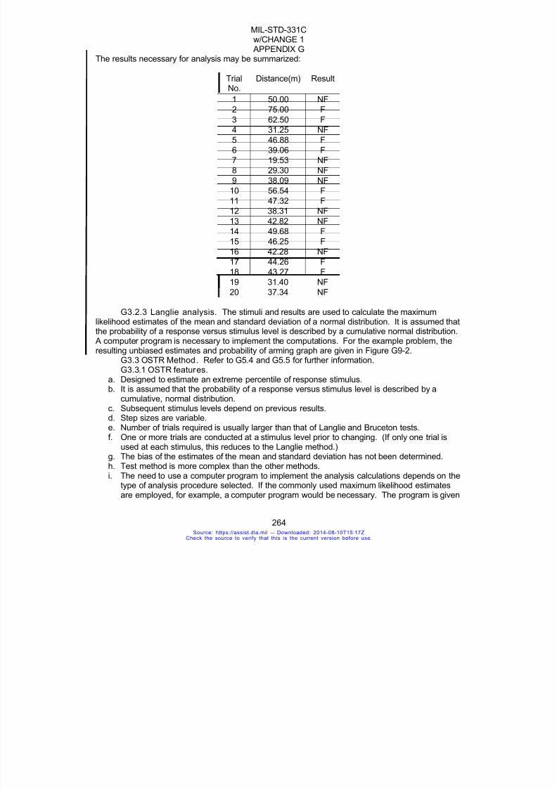
7/18/2019 Mil Std 331 Amend
http://slidepdf.com/reader/full/mil-std-331-amend 272/286
MIL-STD-331Cw/CHANGE 1
APPENDIX G
264
The results necessary for analysis may be summarized:
TrialNo.
Distance(m) Result
1 50.00 NF
2 75.00 F
3 62.50 F
4 31.25 NF
5 46.88 F
6 39.06 F
7 19.53 NF
8 29.30 NF
9 38.09 NF
10 56.54 F
11 47.32 F
12 38.31 NF13 42.82 NF
14 49.68 F
15 46.25 F
16 42.28 NF
17 44.26 F
18 43.27 F
19 31.40 NF
20 37.34 NF
G3.2.3 Langlie analysis. The stimuli and results are used to calculate the maximum
likelihood estimates of the mean and standard deviation of a normal distribution. It is assumed thatthe probability of a response versus stimulus level is described by a cumulative normal distribution.
A computer program is necessary to implement the computations. For the example problem, theresulting unbiased estimates and probability of arming graph are given in Figure G9-2.
G3.3 OSTR Method. Refer to G5.4 and G5.5 for further information.G3.3.1 OSTR features.
a. Designed to estimate an extreme percentile of response stimulus.b. It is assumed that the probability of a response versus stimulus level is described by a
cumulative, normal distribution.c. Subsequent stimulus levels depend on previous results.d. Step sizes are variable.
e. Number of trials required is usually larger than that of Langlie and Bruceton tests.f. One or more trials are conducted at a stimulus level prior to changing. (If only one trial is
used at each stimulus, this reduces to the Langlie method.)g. The bias of the estimates of the mean and standard deviation has not been determined.h. Test method is more complex than the other methods.i. The need to use a computer program to implement the analysis calculations depends on the
type of analysis procedure selected. If the commonly used maximum likelihood estimatesare employed, for example, a computer program would be necessary. The program is given
Source: https://assist.dla.mil -- Downloaded: 2014-08-10T15:17ZCheck the source to verify that this is the current version before use.

7/18/2019 Mil Std 331 Amend
http://slidepdf.com/reader/full/mil-std-331-amend 273/286
MIL-STD-331Cw/CHANGE 1
APPENDIX G
265
in DARCOM-P706-103, Appendix 9B. Refer to G5.6. j. If obtaining the information from the previous trial requires too much effort and cost in order
to determine the next stimulus level, this method may not be appropriate.k. Once the next stimulus is determined, if the method requires too much time and difficulty to
prepare the test item/apparatus for that trial, the method may not be appropriate.
l. Upper and lower test limits must be chosen prior to test.m. A stopping rule is required.n. The test equipment must be capable of covering the entire, continuous range of stimuli.
G3.3.2 OSTR procedure. a. Select the upper and lower test limits so that it is virtually certain that there will be all
nonresponses at the lower limit and all responses at the upper limit. Call these stimuli Uand L. Setting the limits to be approximately four standard deviations from the mean isexpected to provide the best results.
b. Select the percentage point to be estimated. See Tables G9-I and G9-II for upper and lowertails, respectively. Then use the corresponding maximum number of trials to be conducted
at a given stimulus level prior to applying a change in stimulus level. The number of trials ata particular stimulus level depends upon the percentile estimated; further into the tail of thedistribution will require more trials. For planning purposes, the expected number of totaltrials actually required is approximately three-fourths of the maximum number of trials ateach stimulus level times the number of stimulus level.
c. Establish the rule for increasing or decreasing the stimulus level. For example, suppose alower-tail percentile with a corresponding maximum of three trials per stimulus level ischosen. The rule would be: Increase stimulus level if all three results in nonfunctioning;otherwise, decrease the stimulus level.
d. Select a stopping rule. At least 5 reversals with a zone of mixed results, or at least 10 levelsof stimuli, shall be used unless an alternate stopping rule was previously approved by the
sponsoring activity. Occasionally, peculiar sequences of outcomes occur, that is, no zone ofmixed results, which provide little or no information about the response distribution. Thiscondition is minimized by using the change of response stopping rule rather than a fixednumber of levels of stimuli. If upon stopping on number of reversals, a zone of mixedresults has not occurred, the test procedures and goals should be examined to determinethe possible cause of this anomaly. Additional trials will be required until a zone of mixedresults is obtained.
e. The first trial is conducted at the stimulus level equal to the average of U and L.f. Now follow the Langlie method of G3.2, except that more than one trial (up to the number
selected in b above) will be conducted at a particular stimulus level. Note: When n = 1, theOSTR method becomes the Langlie.
Example: An arming distance test is to be conducted using a certain fuze. Thirty fuzes areavailable. Probability of arming versus distance from muzzle to target is assumed to be describedby a cumulative, normal distribution. The no arm distance is to be estimated for safety reasons.The fuze is supposedly not armed at 10 meters.
Source: https://assist.dla.mil -- Downloaded: 2014-08-10T15:17ZCheck the source to verify that this is the current version before use.

7/18/2019 Mil Std 331 Amend
http://slidepdf.com/reader/full/mil-std-331-amend 274/286
MIL-STD-331Cw/CHANGE 1
APPENDIX G
266
An OSTR method plan is chosen: A test is to be designed to determine the distance at which there is 0.21 probability of fuzefunction. Refer to Table G9-I. The corresponding maximum number of trials per stimulus level isthree. The lower limit is chosen as 0 meters, and the upper limit is chosen as 40 meters. Rule: Ifthree consecutive nonfunctions occur, increase the distance; if two consecutive nonfunctions
followed by a function (NF, NF, F), or a nonfunction followed by a function (NF, F), or a function(F), decrease the distance. (It is assumed that if the fuze functioned, it was armed.)
Stimulus/TrialLevel/No. Distance Meters Result*
Remarks
1 / 1 (0+40)/2 = 20 F Decrease distance
2 / 1 (20+0)/2 = 10 NF2 / 2 10 NF Decrease distance
2 / 3 10 F3 / 1 (10+0)/2 = 5 NF3 / 2 5 NF Increase distance3 / 3 5 NF
4 / 1 (5+10)/2 = 7.5 NF4 / 2 7.5 NF Increase distance4 / 3 7.5 NF
5 / 1 (7.5+20)/2 = 13.75 F Decrease distance
6 / 1 (13.75+7.5)/2 = 10.625 NF Decrease distance6 / 2 10.625 F
7 / 1 (10.625+5)/2 = 7.812 NF
7 / 2 7.812 NF Increase distance7 / 3 7.812 NF
8 / 1 (7.812+10.625)/2
= 9.219 NF
8 / 2 9.219 NF Increase distance8 / 3 9.219 NF
9 / 1 (9.219+13.75)/2
= 11.484 F Decrease distance
10 / 1 (11.484+9.219)/2
=10.352 F Stopped on 10levels
* F = Function; NF = Nonfunction
G3.3.3 OSTR analysis. The stimuli and results are used to calculate maximum likelihoodestimates of the mean and standard deviation of a normal distribution. These estimates can beused to predict functioning probabilities at other distances. It is assumed that the probability of aresponse versus stimulus is described by a cumulative, normal distribution. A computer program isnecessary to implement the computations. For the example presented, the resulting estimates andprobability of arming graph are given in Figure G9-3.
Source: https://assist.dla.mil -- Downloaded: 2014-08-10T15:17ZCheck the source to verify that this is the current version before use.

7/18/2019 Mil Std 331 Amend
http://slidepdf.com/reader/full/mil-std-331-amend 275/286
MIL-STD-331Cw/CHANGE 1
APPENDIX G
267
G3.4 Bruceton Method. Refer to G5.9, G5.10 and G5.11 for further information.G3.4.1 Bruceton features.
a. Designed to estimate the stimulus at which there is a 0.5 probability of response.b. Because of concentration of testing at the mean, this technique is not effective at estimating
probabilities at either extreme of the stimulus/response curve and should not be used forthat purpose if other methods are useable.
c. It is assumed that the probability of a response versus stimulus level is described by acumulative, normal distribution.
d. Step size is fixed and chosen in advance.e. Test method is more complex than that of Probit test and less complex than that of Langlie,
OSTR, and Neyer D-Optimal tests.f. The estimate of the mean is unbiased for practical purposes.g. The estimate of the standard deviation is biased to the low side.h. A stopping rule is required.i. Computations are much simpler than for the other analysis and can be done by hand;
however, a computer program is recommended. j. The number of trials required is usually fewer than that of Probit test and more than that of
Langlie, OSTR, and Neyer D-Optimal tests.k. If obtaining the information from the previous trial requires too much effort and cost in order
to determine the next stimulus level, this method may not be appropriate.l. Once the next stimulus is determined, if the method requires too much time and difficulty to
prepare the test item/apparatus for that trial, the method may not be appropriate.
G3.4.2 Bruceton procedure. a. Choose the step size for the stimulus. Ideally, it should be equal to the standard deviation
(often unknown) of the underlying, normal distribution; if within about 0.5 to 2.0 times the
true value, it should be adequate. If the step size is chosen too large, analysis may not bepossible; if too small, the analysis may look acceptable but yield a seriously inaccurateestimate of the response versus stimulus curve.
b. Choose a stopping rule. At least 10 reversals with a zone of mixed results or the maximumnumber of trials (at least 45 is recommended) shall be used unless otherwise approved inthe test plan.
c. Select a starting point. The starting point should be close to the estimate of the mean value.d. Select subsequent stimulus levels one step size above or below the preceding level,
depending on whether the last trial resulted in a nonfunction or a function, respectively.Decrease the stimulus level after a function, and increase the stimulus level after anonfunction.
Source: https://assist.dla.mil -- Downloaded: 2014-08-10T15:17ZCheck the source to verify that this is the current version before use.

7/18/2019 Mil Std 331 Amend
http://slidepdf.com/reader/full/mil-std-331-amend 276/286
MIL-STD-331Cw/CHANGE 1
APPENDIX G
268
Example: A fuze arming test is to be conducted, and 25 fuzes are available. The sample size of 25is for illustrative purposes only. Normally, a sample size of 45 would be required. It was estimatedthat approximately half of the fuzes would function at a distance of 120 meters. It is assumed thatif a fuze functioned, it was armed. The step size was chosen as 20 meters.
Trial No. Distance, Meters Results*1 120 NF
2 140 F
3 120 NF
4 140 F
5 120 F
6 100 F
7 80 F
8 60 NF
9 80 NF
10 100 NF11 120 F
12 100 NF
13 120 F
14 100 NF
15 120 NF
16 140 F
17 120 F
18 100 F
19 80 NF
20 100 F
21 80 NF22 100 F
23 80 NF
24 100 NF
25 120 F
* F = Function; NF = Nonfunction
G3.4.3 Bruceton analysis. The stimuli (distances) and results (function or nonfunction) areused to calculate the maximum likelihood estimates of the mean and standard deviation of anormal distribution. It is assumed that the probability of a response versus stimulus is described bya cumulative, normal distribution. For the example presented, the resulting estimates andprobability of arming graph are given by Figure G9-4.
G3.5 Neyer D-Optimal Method. Refer to G5.12 and G5.13 for further information.G3.5.1 Neyer D-Optimal features.
a. Designed to estimate both population parameters.b. Because of concentration of testing at the D-Optimal points, this technique is the most
effective at estimating probabilities at the extreme of the stimulus/response curve.c. It is assumed that the probability of a response versus stimulus level is described by a
cumulative, normal distribution.
Source: https://assist.dla.mil -- Downloaded: 2014-08-10T15:17ZCheck the source to verify that this is the current version before use.

7/18/2019 Mil Std 331 Amend
http://slidepdf.com/reader/full/mil-std-331-amend 277/286
MIL-STD-331Cw/CHANGE 1
APPENDIX G
269
d. The stimulus levels vary depending of the initial test parameters as well as all previous testinformation.
e. Deviations about any given stimulus level can vary without effecting the validity of the test.f. Test method is more complex than all other methods. A computer program is required to
calculate the stimulus levels and to perform the analysis.
g. The estimate of the mean is unbiased for practical purposes.h. The estimate of the standard deviation is biased to the low side, but a bias correction (small
compared with the variation of the estimate) can be applied.i. A stopping rule is required.
j. The number of trials required is fewer than for any of the other methods.k. Because the initial test parameters are only used for the first few tests, the dependence on
the initial test parameters is less than for any of the other methods.l. If obtaining the information from the previous trial requires too much effort and cost in order
to determine the next stimulus level, this method may not be appropriate. A generalizationof the test method can be used to test several units at the same time.
m. Once the next stimulus is determined, if the method requires too much time and difficulty to
prepare the test item/apparatus for that trial, the method may not be appropriate. Ageneralization of the test method can be used to test several units at the same time.
n. The same software can be used to conduct a C-Optimal test that will concentrate thestimulus levels near any desired extreme probability level if concentrated knowledge of oneextreme level is desired.
G3.5.2 Neyer D-Optimal procedure. a. Provide a guess for upper and lower estimates of the mean, call these MuMin and MuMax.
It is not required that all devices function at MuMax or that no devices function as MuMin.Rather these levels should be chosen based on engineering judgment of the mean. Themethod will test outside of the MuMin to MuMax range if the true mean lies outside of the
range. Also provide a guess for the standard deviation, called SigmaGuess. If an inaccurateguess is chosen, the method will adapt to find a better guess. Start the computer programand enter these values as directed.
b. Conduct each trial at the stimulus level given by the program. Enter the test results (either aresponse or a nonresponse) as directed. If the test was conducted at a different test levelthan specified, then enter the actual stimulus level. The program will calculate the nextstimulus level.
c. The Neyer D-Optimal method uses a multi-phase approach when picking the test levels.c.1 The initial phase consists of finding the region of interest (i.e. a region where some devicesrespond and some do not.) The first level will be mid way between the upper and lower estimatedMuMin and MuMax. The initial step size is the maximum of SigmaGuess and ¼(MuMax – MuMin).
If the first device responds (does not respond), then conduct the next test at a level one step sizebelow (above) the previous level. Double the step size after each test. The first phase ends whenthere is at least one device responding and one that does not respond. The first phase will usuallyend after two devices have been tested if the test parameters are optimized to the population.c.2 The second phase consists of a binary search to “home in” on the 50% point. Test each devicemid way between the highest level at which a device fails to respond and the lowest level at whicha device responds. End this phase when the difference between these two levels is less than orequal to SigmaGuess.c.3 The final phase consists of determining the 2 D-Optimal points (roughly the 15% and 85%
Source: https://assist.dla.mil -- Downloaded: 2014-08-10T15:17ZCheck the source to verify that this is the current version before use.
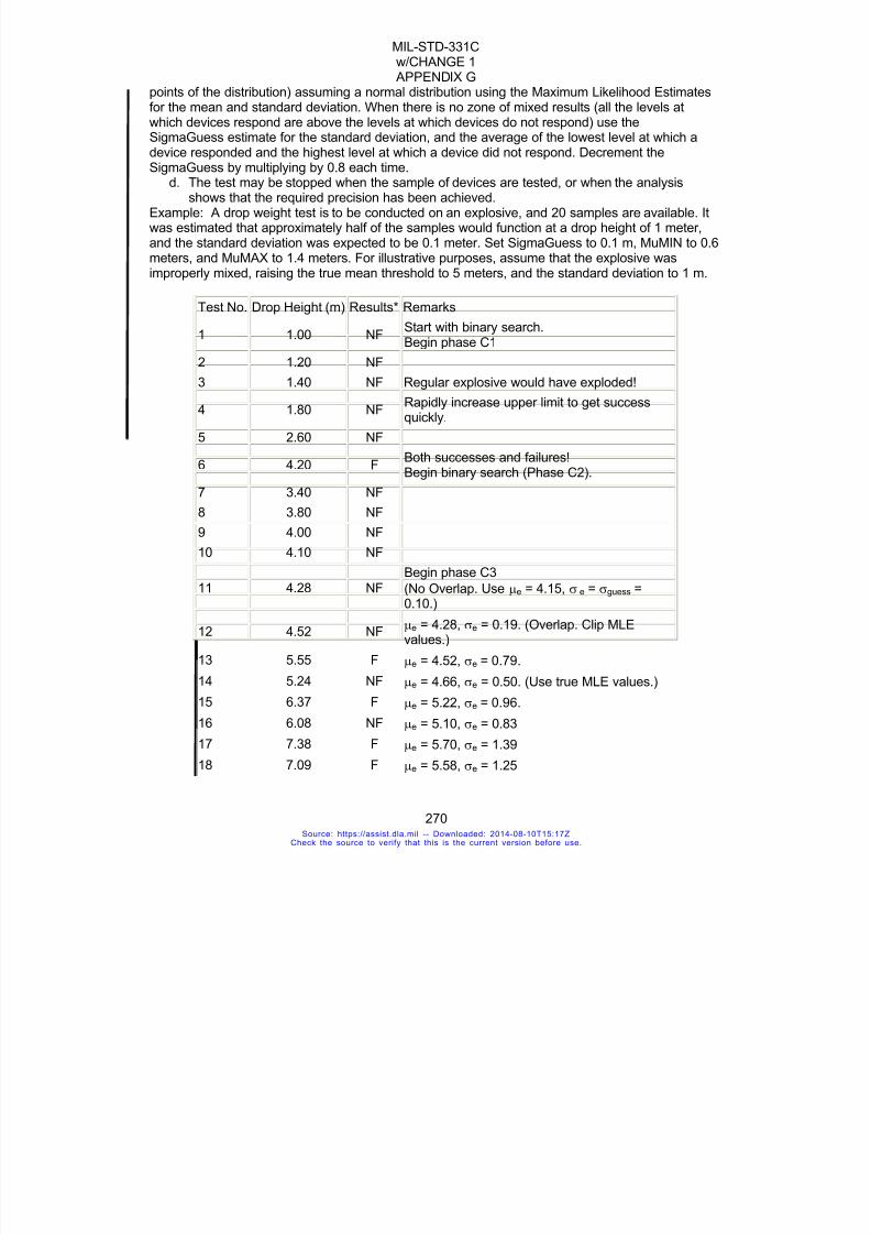
7/18/2019 Mil Std 331 Amend
http://slidepdf.com/reader/full/mil-std-331-amend 278/286
MIL-STD-331Cw/CHANGE 1
APPENDIX G
270
points of the distribution) assuming a normal distribution using the Maximum Likelihood Estimatesfor the mean and standard deviation. When there is no zone of mixed results (all the levels atwhich devices respond are above the levels at which devices do not respond) use theSigmaGuess estimate for the standard deviation, and the average of the lowest level at which adevice responded and the highest level at which a device did not respond. Decrement the
SigmaGuess by multiplying by 0.8 each time.d. The test may be stopped when the sample of devices are tested, or when the analysis
shows that the required precision has been achieved.Example: A drop weight test is to be conducted on an explosive, and 20 samples are available. Itwas estimated that approximately half of the samples would function at a drop height of 1 meter,and the standard deviation was expected to be 0.1 meter. Set SigmaGuess to 0.1 m, MuMIN to 0.6meters, and MuMAX to 1.4 meters. For illustrative purposes, assume that the explosive wasimproperly mixed, raising the true mean threshold to 5 meters, and the standard deviation to 1 m.
Test No. Drop Height (m) Results* Remarks
1 1.00 NF Start with binary search.Begin phase C1
2 1.20 NF
3 1.40 NF Regular explosive would have exploded!
4 1.80 NFRapidly increase upper limit to get successquickly.
5 2.60 NF
6 4.20 FBoth successes and failures!Begin binary search (Phase C2).
7 3.40 NF
8 3.80 NF
9 4.00 NF
10 4.10 NF
11 4.28 NF
Begin phase C3
(No Overlap. Use μe = 4.15, σ e = σguess =0.10.)
12 4.52 NFμe = 4.28, σe = 0.19. (Overlap. Clip MLEvalues.)
13 5.55 Fμe = 4.52, σe = 0.79.
14 5.24 NF μe = 4.66, σe = 0.50. (Use true MLE values.)
15 6.37 F μe = 5.22, σe = 0.96.
16 6.08 NF μe = 5.10, σe = 0.83
17 7.38 F μe = 5.70, σe = 1.39
18 7.09 F μe = 5.58, σe = 1.25
Source: https://assist.dla.mil -- Downloaded: 2014-08-10T15:17ZCheck the source to verify that this is the current version before use.

7/18/2019 Mil Std 331 Amend
http://slidepdf.com/reader/full/mil-std-331-amend 279/286
MIL-STD-331Cw/CHANGE 1
APPENDIX G
271
19 6.89 F μe = 5.50, σe = 1.16
20 6.74 F μe = 5.44, σe = 1.09.
* F = Function; NF = Nonfunction
e. For further details on how the strategy proceeds, see Figure G9-5.G3.5.3 Neyer D-Optimal analysis. The stimuli and results are used to calculate the
maximum likelihood estimates of the mean and standard deviation of a normal distribution. It isassumed that the probability of a response versus stimulus is described by a cumulative, normaldistribution. Various probability estimates are computed using these population parameters. Forthe example presented, the resulting estimates and probability of reaction graph are given byFigure G9-5. For an example of a test and the analysis see G5.12.
G3.5.4 Conducting the test. G3.5.5 Setting the stimulus level. Set the stimulus level (distance to the target, firing
voltage, barrier thickness, etc.) selected by the test method. It is important to set the stimulus as
close as possible to the value specified by the method for all methods but the Neyer D-Optimalmethod.
G3.5.6 Test and observe. Test the device and observe whether or not the device responds(arms, functions, etc.).
G4 RELATED INFORMATIONG4.1 References. Greatest economy in expenditure of devices and in analysis of results
will be achieved by following the procedures of sensitivity analysis, descriptions of which are to befound in appropriate handbooks and papers.
G4.2 Suggestions for efficient use of samples. G4.3 Stimulus and response. The five test methods presented in G3 are “sensitivity
tests,” a term used in statistical literature to denote an experiment from which quantal responsedata are observed as the intensity of a stimulus is varied. There are variations of the Probit, whichdo not require stimulus levels fixed and selected in advance. The stimulus may be the distancefrom a weapon muzzle to a target and the concomitant response or nonresponse may be thefunctioning or nonfunctioning of a fuze. The stimulus also may be the striking velocity of aprojectile and the response or nonresponse, a penetration or nonpenetration. The stimulus alsomay be the voltage on a capacitive discharge unit and the response or nonresponse a function orno function, and so on. All applications of these type tests are characterized by the quantal resultof a go/no-go, yes/no, success/failure, and so forth. The probability of a response mustmonotonically increase with increasing stimulus level.
G4.4 Zone of mixed resul ts. Another important characteristic of all sensitivity tests is
called a zone of mixed results. If this zone does not occur, the population parameter estimates willnot be unique. A zone of mixed results occurs if the largest non-response stimulus level exceedsat least the minimum stimulus level for a response. The chance of not getting a zone of mixedresults increases with diminishing sample size.
G4.5 Stopping rule. When conducting one of the test strategies of Section G3, or anysensitivity test, there must be a stopping rule. The most common is to fix the maximum number oftrials in advance. Another strategy gaining favor is selecting in advance the number of reversals ofresponse. Detailed stopping rules are discussed under each test strategy described in Section G3.
G4.5 Changing stimulus level. Common test strategies, including those employed here,
Source: https://assist.dla.mil -- Downloaded: 2014-08-10T15:17ZCheck the source to verify that this is the current version before use.

7/18/2019 Mil Std 331 Amend
http://slidepdf.com/reader/full/mil-std-331-amend 280/286
MIL-STD-331Cw/CHANGE 1
APPENDIX G
272
are of three types with regard to how the stimulus level is changed: (1) stimulus levels are fixedand selected in advance, for example the Probit method; (2) stimulus levels are of fixed step size,for example the Bruceton method; and (3) stimulus levels are of variable step size, for example theLanglie, OSTR, and Neyer D-Optimal test methods.
G5 BIBLIOGRAPHY G5.1 NAVORD Report 2879, A General Test Plan for the Collection of Data Which Are to
Be Analyzed by the Probit Method, by P. B. Morgan.G5.2 Ordnance Corps Pamphlet, ORDP 20-111, Ordnance Engineering Design Handbook,
Experimental Statistics, Section 2--Analysis of Enumerative andClassificatory Data, June 1962.
G5.3 Langlie, H. J., A Reliability Test Method for One-Shot Items, Aeronutronic Division,Ford Motor Company, Publication No. U-1792, August 1962.
G5.4 Einbinder, S. K., One-Shot Sensitivity Test for Extreme Percentage Points,Proceedings of the Nineteenth Conference on the Design of Experiments in Army Research,Development and Testing, ARO-D Report 74-1, pp. 369-386, 1974.
G5.5 Einbinder, S. K., A Sequential Sensitivity Test for Extreme Percentage Point andEstimation Using a Weibull Response Model, 17th U.S. Army Operations Research Symposium,Fort Lee, VA, 6-9 Nov 1978.
G5.6 DARCOM P706-103, Engineering Design Handbook, Selected Topics in ExperimentalStatistics with Army Applications, Chapter 9, 1983.
G5.7 Finney, D. J., Probit Analysis, 2nd Edition, Cambridge University Press, Cambridge,England, 1952.
G5.8 National Bureau of Standards, Experimental Statistics, Handbook 91, 1966.G5.9 Dixon, W. J., and Massey, F. J., Jr., Introduction to Statistical Analysis, Chapter 19,
McGraw-Hill Book Co., Inc.G5.10 Dixon, W. J., and Mood, A. M., “A Method for Obtaining and Analyzing Sensitivity
Data,” Journal of American Statistical Association , Vol. 43, 1948.G5.11 Statistical Research Group, Princeton University, Statistical Analysis for a New
Procedure in Sensitivity Experiments, AMP Report 101.1R, SRG-P No. 4 (OSDR Report 4040),July 1944.
G5.12 Neyer, B. T, “A D-Optimality Based Sensitivity Test,” Technometrics, Vol 36, 1994.G5.13 Neyer, B. T., Analysis of Sensitivity Tests, EG&G Mound Applied Technologies,
Miamisburg, Ohio, Publication No. MLM-3736, March 1992.G6 GLOSSARY
all-arm distance - minimum distance from the gun muzzle at which all fuzes will arm, at aspecified probability level.all-fire level – the minimum level that will result in the device functioning, at a specified probability
level.biased estimate - a statistic whose average in the long run differs from the true value of theparameter it is intended to estimate.cumulative distribution function - a mathematical expression which provides the probability thata random variable is less than or equal to any given value.extreme percentile - a value of a random variable (whose range is 0 to 1) for which the cumulativedistribution function is either close to 0 or close to 1, that is, a value in the lower or upper tail of thedistribution.monotonicity - the characteristic of a quantity or function to remain at its current direction of
Source: https://assist.dla.mil -- Downloaded: 2014-08-10T15:17ZCheck the source to verify that this is the current version before use.

7/18/2019 Mil Std 331 Amend
http://slidepdf.com/reader/full/mil-std-331-amend 281/286
MIL-STD-331Cw/CHANGE 1
APPENDIX G
273
growth. A monotonic increasing function or event is one that never decreases as the abscissaincreases; likewise, a monotonic decreasing function is one that never increases as the abscissaincreases.no-arm distance - maximum distance from the gun muzzle at which no fuze will arm at a specifiedprobability level.
quantal response - an observation that can only fall into one or the other of two qualitativecategories, for example, response/nonresponse, go/no-go, success/failure, open/closed, and soforth.quantile - values obtained by equal subdivisions of the data, for example, quartiles, deciles, andpercentiles.response - an observed reaction of a test unit to the imparted stimulus level, for example, fracture,detonation, deformation, penetration, arming, and so forth. The absence of an observed reactionis referred to as a nonresponse.reversal - a change in results from function to nonfunction or vice versa.stimulus level - that value of the test variable imparted to an individual test unit, for example,voltage, pressure, temperature, time, drop height, dose, distance, and so forth.
strategy - a well-defined plan or structured approach to choice of stimulus levels for a sensitivitytest. The sequence of levels may or may not depend on the set of prior responses.unbiased estimate - a statistic whose average in the long run is the true value of the parameter itis intended to estimate.zone of mixed results - a function occurring at a lower stimulus level than some nonfunction.
TABLE G9-I. Lower Tail Percentiles Estimated by OSTR Strategies
n If FollowingOccurs,
Increase StimuliLevel (*)
If Following Occurs,Decrease Stimuli Level
PercentagePoint
Estimated
2 00 0X, X .2929
3 000 00X, 0X, X .2063
3a 000, 00X0 00XX, 0X, X .2664
4 0000 000X, 00X, 0X, X .1591
4a 0000, 000X0 000XX, 00X, 0X, X .l959
5 00000 0000X, 000X, 00X, 0X, X .1294
5a 00000, 0000X0 0000XX, 000X, 00X, 0X, X .1540
6 000000 00000X, etc. .1091
7 0000000 000000X, etc. .0943
8 00000000 0000000X, etc. .0830
9 000000000 00000000X, etc. .0741
10 0000000000 000000000X, etc. .0670
14 00000000000000 0000000000000, etc. .0483
* 0 = Nonfunction and X = Function
Source: https://assist.dla.mil -- Downloaded: 2014-08-10T15:17ZCheck the source to verify that this is the current version before use.

7/18/2019 Mil Std 331 Amend
http://slidepdf.com/reader/full/mil-std-331-amend 282/286
MIL-STD-331Cw/CHANGE 1
APPENDIX G
274
TABLE G9-II. Upper Tail Percenti les Estimated by OSTR Strategies
n If Following Occurs,Decrease Stimuli Level
(*)
If Following Occurs,Increase Stimuli Level
PercentagePoint
Estimated
2 XX X0, 0 .70713 XXX XX0, X0, 0 .7937
3a XXX, XX0X XXX0, X0, 0 .7336
4 XXXX XXX0, XX0, X0, 0 .8409
4a XXXX, XXX0X XXX00, XX0, X0, 0 .8041
5 XXXXX XXXX0, XXX0, XX0, X0, 0 .8706
5a XXXXX, XXXX0X XXXX00, XXX0, XX0, X0, 0 .8460
6 XXXXXX XXXXX0, etc. .8909
7 XXXXXXX XXXXXX0, etc. .9057
8 XXXXXXXX XXXXXXX0, etc. .9170
9 XXXXXXXXX XXXXXXXX0, etc. .925910 XXXXXXXXXX XXXXXXXXX0, etc. .9330
14 XXXXXXXXXXXXXX XXXXXXXXXXXXX0, etc. .9517
* X = Function and 0 = Nonfunction
Source: https://assist.dla.mil -- Downloaded: 2014-08-10T15:17ZCheck the source to verify that this is the current version before use.
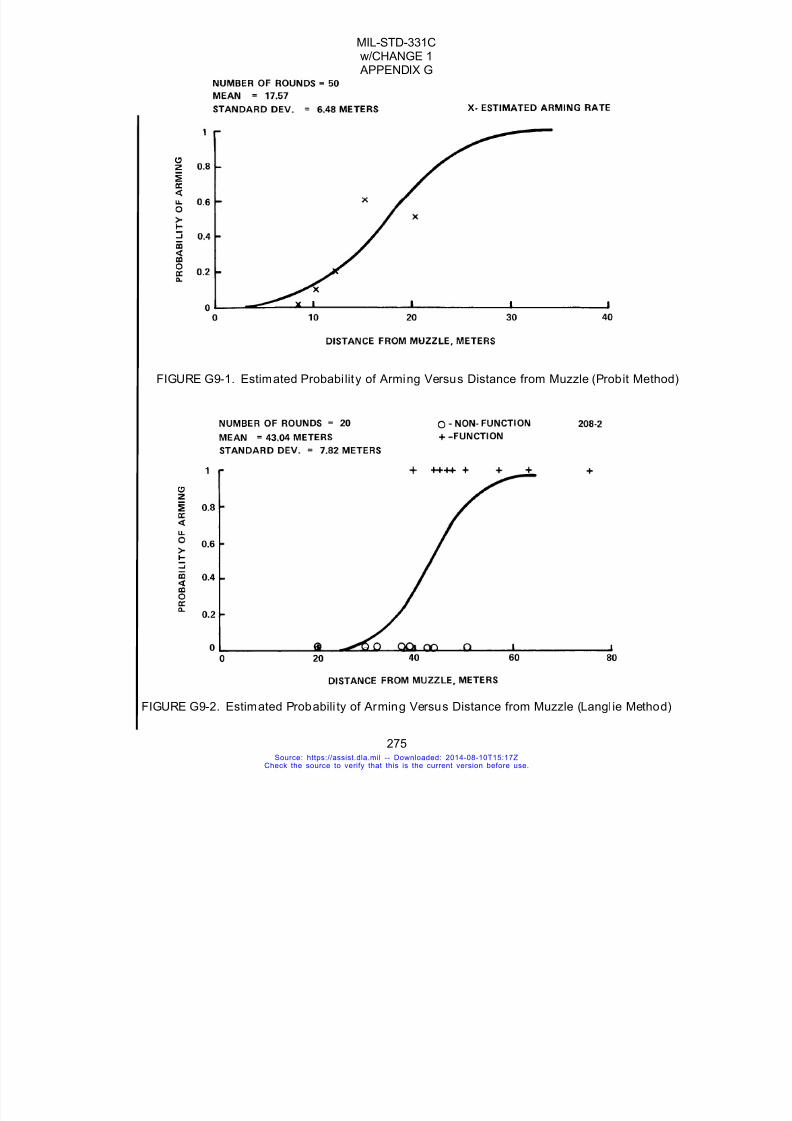
7/18/2019 Mil Std 331 Amend
http://slidepdf.com/reader/full/mil-std-331-amend 283/286
MIL-STD-331Cw/CHANGE 1
APPENDIX G
275
FIGURE G9-1. Estimated Probabi lity of Arming Versus Distance from Muzzle (Probit Meth
FIGURE G9-2. Estimated Probabili ty of Arming Versus Distance from Muzzle (Langl ie Metho
Source: https://assist.dla.mil -- Downloaded: 2014-08-10T15:17ZCheck the source to verify that this is the current version before use.

7/18/2019 Mil Std 331 Amend
http://slidepdf.com/reader/full/mil-std-331-amend 284/286
MIL-STD-331Cw/CHANGE 1
APPENDIX G
276
FIGURE G9-3. Estimated Probabili ty of Arming Versus Distance from Muzzle (OSTR Meth
FIGURE G9-4. Estimated Probabi lity of Arming Versus Distance from Muzzle (Bruceton Meth
Source: https://assist.dla.mil -- Downloaded: 2014-08-10T15:17ZCheck the source to verify that this is the current version before use.

7/18/2019 Mil Std 331 Amend
http://slidepdf.com/reader/full/mil-std-331-amend 285/286
MIL-STD-331Cw/CHANGE 1
APPENDIX G
277
Sample Size = 20Mean = 5.39 metersStandard Dev. = 1.04 meters
FIGURE G9-5. Estimated Probability of Reaction Versus Weight Drop Height (Neyer D-OptimalMethod)
Source: https://assist.dla.mil -- Downloaded: 2014-08-10T15:17ZCheck the source to verify that this is the current version before use.

7/18/2019 Mil Std 331 Amend
http://slidepdf.com/reader/full/mil-std-331-amend 286/286
MIL-STD-331Cw/CHANGE 1