miles vf - internet archive · december, 1931 radio -craft coyne students get- film actual experi-...
TRANSCRIPT

1
RADIO'S LIVEST MAGAZINE
December. 25 Cents
HUGO CEPNSL3ACK Editor
Vf
0
1 Lb. Radio Transmitter Ascends 10 Miles
See Page 333
The Thyratron Inverter - An AC -DC Midget Set - An Electronic. Batteryless "PE" Cell
Servicing All -Wave Superhets - A New Electrolytic Condenser -Rectifier Power Pack
www.americanradiohistory.com

SPE D RADIO TUBES
FOR ALL NEW RECEIVERS
EVER ABREAST OF THE RADIO TIMts
SPE E D has achieved tremendous success with these NEW tubes. The reason
is obvious -QUALITY
247 New power amplifier Pentode, for use in the output stage of AC receivers.
Here They Are! No. 235
New screen grid tube designed to reduce cross modulation and similar distortion.
No. 551 New screen grid tube-designed for sanie purpose as type 235, although having ,lightly different characteristics.
No. 230 New general purpose tube, operating eco- nomically at 2 volts, giving unusual servi... though using very little power.
No. 231 New amplifier using 2 volts and extremel. low current consumption in same group a. types 230 and 232.
No. 232 New screen grid tube -for use as radio frequency amplifier, operating at 2 volt..
No. 233 New power amplifier in the Pentode group, operating on 2 volts with low current Lon sumption.
No. 236 New screen grid tube used mainly as R.I. amplifier or detector in automobile .
ln same group as type 237 and 258. :1.0 for use in D.C. sets.
No. 237 New general purpose tube - especia ll. adapted to automobile use. Can be use.] either as a detector or amplifier. Also for use in D.C. sets.
No. 238 New power amplifier Pentode for use in automobile receivers designed for it. Gives unusual volume for small input signal strength.
No. S 84 Developed expressly for replacement of type C 484 in Sparton sets. Somewhat similar in characteristics to the type 227.
No. S 82 B Developed expressly for replacement of th, the C 183 in Sparton sets, possessing all peculiar characteristics necessary for thus purpose.
No. S 83 Developed expressly for replacement of the C 183 in Sparton sets, possession all the peculiar characteristics necessary for this purpose.
SPIID Quality is Making Today. [l'rite for Complete Details.
Still another addition to a big family. SPI B D FOTO- LECTRIC TUBES. Standard gas -filled type, red sensitive, caesium on caesium -oxide silver- oxide. Six months guarantee against defects. Write for FOTOLECTRIC folder.
CAB_ E ADIO UBE CORPORATIONS Roi w
230 -240 NORTH 9th STREET, BROOKLYN, NEW YORK CEr:
www.americanradiohistory.com

December, 1931 RADIO -CRAFT 321
Important and far- reach- ing developments in Radio create sudden de- mand for specially equipped and spe- cially trained Radio Service Men.
MANY skilled Radio Service Men are needed now to service alt- electric sets. By becoming a certified R. T. A. Service Man, you can make big money, full time or spare time, and
fit yourself for the big -pay opportunities that Radio offers. We will quickly give you the training you need to qualify as a Radio Service Man . certify you ... furnish you with a mar- velous Radio Set Analyzer. This wonder instrument, together with our training, will enable you to compete successfully with experts who have been in the radio business for years. With its help you can quickly diagnose any ailing Radio set. The training we give you will enable you to make necessary analysis and repairs. Serving as a "radio doctor" with this Radio Set Analyzer is but one of the many easy ways by which we help you make money out of Radio. Wiring rooms for Radio, installing and servicing sets for dealers, building and installing automobile Radio sets, constructing and installing short wave receivers ... those are a few of the other ways in which our members are cashing in on Radio. As a member of the Radio Training Association, you receive personal instruction from skilled Radio Engineers. Upon completion of the training, they will advise you personally on any problems which arise in your work. The Association will help you make money in your spare time. increase your pay, or start you in business. The easiest, quickest, best- paying way for you to get into Radio is by joining the Radio Training Association.
9his excellent set analyzer and trouble
shooter included with our course of trainin
This amazing Radio Set Analyzer plus the instructions given you by the Association will transform you into an expert quickly. With it. you can locate troubles in all types of sets.
test circuits. measure resistance and condenser capacities, detect defective tubes. Knowing how to make repairs is easy; knowing what the trouble is requires expert knowledge and a Radio Set Analyzer. With this Radio Set Analyzer, you will be able to give expert serv- ice and make big .. mey. Possessing this set analyzer and knowing how to use it will be but one of the benefits that will be .ry as a member of the R. T. A.
Write for No -Cost Membership Plan We have worked out a plan whereby a membership enrollment need not cost you a cent. Our thorough training and the valuable Radio set analyzer can be yours. Write at once and find out how easily hth of these can be earned. Now is the time to prepare to be a Radio Service Man. Greater opportunities are opening up right along. For the sake of extra money in your spare time. bigger pay. a business of your own. a position with a future, get in touch with the Radio Training Associa- tion of America now. Send for this No -Cost Membership plan and Free Radio Handbook that will open your eyes as to what Radio has in store for the ambi- tious man. Don't wait. Do it now.
RADIO TRAINING ASSOCIATION OF AMERICA Dept. RCA -12 4513 Ravenswood Ave. Chicago, Ill.
Fill Out and Mail Today! RADIO TRAINING ASSOCIATION OF AMERICA Dept. RCA -12, 4513 Ravenswood Ave., Chicago, III.
Gentlemen : Send me details of your No -Cost Membership Enrollment Plan and information un how to learn to make real money in radio quick.
Name
Address
City State
www.americanradiohistory.com

H. GERNSBACK, President
S. GERNSBACK, Treasurer
J. M. HERZBERG, Vice- President
I. S. MANHEIMER, Secretary
adios aff ` - Fon TR1
SERVICE MAN . DEALER RADIOTRICIAN
HUGO GERNSBACK, Editor -in -Chief
R. D. WASHBURNE, Technical Editor
LOUIS MARTIN Associate Editor
VOLUME 111 NUMBER 6 Contents of This Issue DECENIBER
1931
PAGE EDITORIAL:
Radio Education By Hugo Gernsback 331
NEC DEVELOPMENTS IN RADIO: 'l'he Thyratron Inverter 13y I van der Mel :332 The U. S. Signal Corps Balloon Radio 333 Burlesque Advertisements 334 New Devices in Radio 336
SERVICE MEN'S DEPARTMENT: The Antenaplex System By E. Jay Quinby 339 Magic in Meters (Part II) By Clifford E. Denton 342 An Electrolytic-Condenser-Rectifier
By P. M. Jarowey :444 The Service Man's Forum..._ 345
"Killing" Service Calls lis Henry H: Klappert 345 RADIO SERVICE DATA SHEETS:
No. 55-Kolster-International Models K -60 and K- 132.. 346 No. 56-U. S. Radio and Television Models 90 iInd
99 X Superheterodyne Receivers 347 Favorite Testing Equipment
A One -Meter Service Unit By Henry E. Sigle 348
An Inexpensive Capacity Meter ..... _ . -.By E. M. Hanken Adapter for Testing Rectifiers By Alfred Pogany Calibrating Voltmeters By A. R. Haidell An Improvement in Ohmmeters
By C. Porter Ferrell Operating Notes By Bertram M. Freed Servicing Majesties -. -_ By Jas. P. Smith Service- Selling "All-Wave" Supers
By McMurdo Silver Variable Resistors By L. van der Mel
SOUND RECORDING DEPARTMENT: Recording Studio Design By Geo. J. Saliba
'l'l'X'IINICAI. RADIO TOPICS: It. F. Coil Design By C. W. Palmer Sound Equipment in the Ilotel New Yorker, (Part V);
Speech Input Equipment By Eli M. Lurie The A.C. -D.C. J'ortahle -4 By H. G. Cisin Radio Short -Cuts liy H.iluo-CRAF-r Renders 'l'he Radio Craftsman's Page 11v Himself It A t Ii) -CRA PISS I n fort t na t3 on Bureau
PAGE 348
319
349
349
350
351
354
:361
352
338
340 353 358
360 362
In Forthcoming Issues 'l'IIE REMOTE- CONTROLLEI) PJ. \NO, . \n interesting de-
scription of the manner in which a musical instructor may instruct remote students.
A REGENERATIVE ST.\TIC REDUCER. Experimental models of this receiver design indicate a definite reduction of static interference.
THE l'l'SII- l'Ctill . \MII'I.IFIER. A technical description THE 6 V. D.C. to 110 V. A.C. ".\UTOVERTER." A de- of a new development in audio annpli..rr design, a push -pull scription of a new commercial unit operating on current - amplifier biased to cut -off of plate current. conversion principles described in past issues of RLG10-C'RArr.
RADIO -CRAFT is published monthly, on the Gnh of the month preceding that of date: its subscription price is $2.51) Per year. In Canada and foreign countries, 33.00 year to cover additional postage.) Entered at the poslnnlre at Mt. Morris, III., n s und -.lass matter under the art of March .t. 1879. Trademarks und copyright s permission of Gentshuek Publications. Inc.. 98 lark Place. New York City.
Text and illustrations of this magazine are copyright and must not be reproduced e'thuut perudsalon of the copyright owners. we a vlan agents fur VON t IE It i'l'o111F:S ami wtINnl:It STIIItI ES tit .1 ItrF :rtl.v. rsi L.crintinus to the.e maga- zines may be taken in combination with It. \UIO -CItA F "r at reduced Club rates 11'rite tar information.
Copyright 19:11, GERNSBACK PUBLICATIONS. INC.
Published by TECHNI -CRAFT PUBLISHING CORPORATION
Publication Office: 404 No. Wesley Ave., Mount !Morris, Illinois Editorial and Advertising Offices
96 -98 Park Place, New York City Chicago Advertising Office
737 North Michigan Avenue, Chicago, Ill. 220 No. Catalina St., Los Angeles, Calif. L. F. McCLURE, Chicago Advertising Representative LOYD B. CHAPPELL, Western Advertising Representative London Agent: Hachette & Cie.. Paris Agent: Hachette Cl... Australian Agent: McGill's Agents. 3 La Belle Sauvage. Ludgate Hill. E.C. 4 III Rue Resumer 1:9 Elisabeth St.. Melbourne
Western Advertising Office
322
www.americanradiohistory.com

December, 1931 RADIO -CRAFT
Coyne students get- film actual experi- ence on one of my big synchronous
converters!
One of my In- structors explain- ing the operation of a radial airplane
engine.
323
A BIG PAY JoBforYou
ELECT Don't spend your life in a dull, hopeless job! Don't be satisfied with a mere $30.00 or $40.00 a week! You don't have to! Electricity pays salaries of $60.00, $70.00 and more a week to thousands of fellows probably no smarter than you.
Learn By Actual Shop Work in 90 Days No Useless Theory
Come to Coyne at Chicago and learn Electricity in 90 days -not by correspondence, but by actual electrical work -on huge motors and generators, switchboards, power plants, substations, auto and
to airplane engines, armatures, etc. You don't need advanced education or previous experience. Coyne has been placing men in Big Pay Elec- tricalJobssince1899. Let Coyne help you to a good electrical position.
Free Employment Service Earn As You Learn
My Employment Department gives you a FREE life -time service. And if you'll need part -time work while at school
JOBS PAYING $60 to $200 a week
Power Plant Operator $50 to $70 awk. Maintenance Engineer 60 to 100 awk. Armature Winding.. 45 to 76 a wk.
Illumination Expert . 60 to 80 awk. Radio Service Expert 50 to 100 a wk.
Aviation Ignition . . 60 to 125 awk. Battery Expert ... 70 to 200 awk.
Auto Electrician ... 75 to 200 a wk.
Contractor- Dealer . . 60 to 300 a wk.
Signal Engineering . 50 to 100 awk.
FREE ELECTRICAL BOOK Coupon to help pay living expenses, we'll gladly help you get it. MAIL COUPON FOR FREE PROOF THAT YOU CAN PREPARE FOR A GOOD ELECTRICAL JOB IN 90 DAYS! Get my Big Free 1
Electrical Book -FREE Radio Service and Auto Electrical offers. 1
Find out about my special low tuition. This does not obligate you in any way. JUST MAIL THE COUPON!
COYNE ELECTRICAL SCHOOL H. C. LEWIS, President Founded 1899
500 S. Paulina St., Dept. 91.81 Chicago, Illinois 1
1
H. C. LEWIS. PRESIDENT
COYNE ELECTRICAL SCHOOL, Dept. 91.81 500 South Paulina Street, Chicago, Illinois.
Name
Address
City State
1
1
1
1
1
1
1
www.americanradiohistory.com

324
A Better TUBE.
KEEPS
A Customer LONGER
Satisfied
Your stock should include a varied supply of PERRY-
MAN Tubos. Write Dept. RC for the name of nearest wholesale distribu- tor; also our special proposition for ser-
vice men.
RADIO -CRAFT December, 1931
HEN you speak about the replacement
-you should talk PERRYMAN.* You
as counsel to your customers must be backed by
a tube of outstanding quality. PERRYMAN tubes
meet the most exacting requirements and will
build permanent good will and an ever increasing
volume of sales for you.
PERRYMAN Tube production has increased
steadily during the past few months to keep pace
with the demand for new tubes. The new low list
prices have been carefully adjusted to enable
dealers and servicemen to make a fair profit - PERRYMAN Replacement Policy assures recom-
mendation by others for new tubes.
PERRYMAN ELECTRIC CO. INCORPORATED
NORTH BERGEN :: :: NEW JERSEY
FERRYMAN N
40
'ktk !i RADIO TUBES
www.americanradiohistory.com

December, 1931 R.11)I0-CR Al; "I.
9\C9(5) ,R oPERp,TN
1NIN FAMEa FORTUNE
i Scores of jobs are open to the Trained Man -jobs as Designer, Inspector and Tester -as Radio Salesman and in Service and Installation work -as Operator, Mechan- ic or Manager of a Broadcasting station -as Wireless Operator on a Ship or Airplane -jobs with Talking Pic- ture Theatres and Manufacturers of Sound Equipment -with Television Laboratories and Studios- fascinat- ing jobs, offering unlimited opportunities to the Trained Man.
Training TenWeeks Come to Coyne in Chicago and
Qprepare for these jobs the UICK and PRACTICAL way
-BY ACTUAL SHOP WORK ON ACTUAL RADIO EQUIP- . MENT. Some students finish the entire course in 8 weeks. The average time is only 10 weeks. But you can stay as long as you please, at no extra cost to you. No previous ex- perience necessary.
TELEVISION and Talking Pictures In addition to the most modern Ra- dio equipment, we have installed in our shops a complete model Broad- casting Station, with sound -proof
Studio and modernTransmitter with 1,000 watt tubes -the Jenkins Tele- vision Transmitter with dozens of home -type Television receiving sets -and a complete Talking Picture installation for both "sound on film" and "sound on disk." We have spared no expense in our effort to make your training as COMPLETE and PRACTICAL as possible.
Free Employment Service to Students
After you have finished the course, we will do all we can to help you find the job you want We employ three men on a full time basis rH C LEWIS, President
325
while at school. Some of our stu- dents pay a large part of their liv- ing expenses in this way. Coyne Is 32 Years Old Coyne has been located right here in Chicago since 1899. Coyne Training is tested - proven by hundreds of successful graduates. You can get all the facts -FREE. JUST MAIL THE COUPON FOR A FREE COPY OF OUR BIG RA- DIO AND TELEVISION BOOK, telling all about jobs ... salaries ... opportunities. This does not ob- ligate you. Just mail the coupon.
=====--
whose sole job is to help our ¡ Radio Division_ Coyne Electrical School I 500 S. Pau'Ina St.. Dept, 91 -9H. Chluwo, 111. 1
1 Send me your Big Free Radio, Television 1 and Talking Picture Book. This does not
obligate me in any way.
1
Name
Address
500 S. Puffins Street Dept. 91-8H Chicago, Illinois 1 City
students in finding positions. And should you be a little short of funds, we'll gladly help you in finding part -time work
H. C. Lewis, Pres. Radio Division Founded is99
Coyne Electrical School r 1
1
1
1
State . 1
www.americanradiohistory.com

326 RADIO-CRAFT December, 1931
FREESupplements are mailed every 60 days to owners
of the
1932 Official Radio Service Manual FREE Questions and Answers Service
Schematic Diagrams of All Latest Midget Receivers Expert servicing or installation of radio receivers requires that the dealer, service man or radiotrician be thoroughly experienced in handling sets of any manufacture. Needless to mention how important are modern methods of servicing, and how easy it is to complete any service job when the OFFICIAI. RADIO SERVICE MANUAL. is on hand. The NEW 1932 MANUAL contains a Full Radio Service Guide and a most Complete Directory of all 1931 -1932 Radio Receivers as well as models of older design. Everyone employed in the Radio industry should have a copy available for his own use.
$5.00 The Copy
HUGO GERNSBACK, Editor
C. E. Denton Managing Editor
Clyde Fitch, Managing Editor
OVER 1,000 PAGES
Over 2,000 Diagrams, Charts and Illustrations
Flexible Loose Leaf Binder 9 x 12 Inches
Partial Contents of the Manual A step -by -step analysis in servicing a receiver which embodies in its design every possible com- bination of modern radio practice; it is fully illustrated and thoroughly explained. It is the greatest contribution to the radio service field.
Chart showing the operation of all types of vacuum tubes, whether new, old or obsolete. An exclusive resumé of the uses of the Pentode and Variable Mu Tubes and their characteristics.
Complete discussion of the superheterodyne and its inherent peculiarities. Also a special chapter on tools used on superheterodyne circuits.
Schematic diagrams and circuits complete with color codings.
Important chapters on commercial aircraft radio equipment; new data on commercial short wave receivers and converters.
Servicing and installation of public address sys- tems and talking machine equipment.
Standardized color codings for resistors. Operation of old and new testing equipment; tube voltmeters, output meters, oscillators and aligning tools.
A full section on Midget radios -their design, cir- cuits and types. How to service them most economically.
Hundreds of schematic diagrams of older radio receivers which have never been published. Blank pages for recording notes, diagrams and sketches; these pages are transferable to any part of the book.
Complete Directory of All 1931 -1932 Radio Receivers
Full Radio Service Guide For Radio Service Men,
Dealers, Jobbers, Manu- . facturers and Set
Builders
e--
L
Clip Coupon NOW!
GERNSBACK PUBLICATIONS. Inc., 1tC-12 96 -98 Park Place. New York, N. Y.
I enrlo.e herewith remittance of $5 . 00. cheek or name). order underred. for which nt are to send
e the NEW I932 OFFICIAL R.Ú110 SERVICE MANt'AI.. I understand that all the New material will be Included in the Manual and Supplements will be mailed FREE every 00 days.
Nance
Address
Cuy Stale
T www.americanradiohistory.com

December, 1931
44
R:1DIO-CRAFT 327
For 16 Weeks I enjoyed every broadcast from
EVERY now and then, the story of some phenomenal instance of extremely long distance radio reception breaks into the press. DX fans usually find little in- terest in such stories because they know the performance which they relate is in- variably due to "freak" conditions.
But DX fans KNOW, when my receiver brings in every broadcast from VK3ME for 16 consecutive weeks, that full credit must go to the receiver that did the work. And when they learn that hundreds of other receivers exactly like mine, and located in all parts of the world, are piling up equally sensational records, they are well satisfied that the Scott All -Wave is not only the most powerful, most sensitive receiver possible to obtain, but the one receiver that fulfills their lifelong hopes.
Undeniable Proof Away last spring I made up my mind to eclipse all standards of radio reception - distance- power- selectivity and tone. I believed the Scott All -Wave would do it, so I set out to make a day -to-day log of VK3ME, Melbourne, 9560 miles away from my receiver. I tuned in every broad- cast, on the loud speaker, and to prove to the entire world that I heard every VK3ME program with full volume, and with perfect tone and clarity, I made a disc recording of every broadcast! Half of these records I sent to VK3NIE. The others are at my laboratory and will he played for anybody who asks to hear them.
Not a Special Set The Scott All -Wave Receiver that you may buy, will in no way, differ from the one I used in my 16 -week test. It will be identical to the hundreds of other Scott All -Wave Receivers that tune in voice from England. France, Germany, Italy, Japan, Indo-China, and South America every day in the week -summer and win-
VK3ME MELBOURNE, AUSTRALIA" This is not a "freak" record. hundreds of other Scott All-Wave Receivers -all summer long -have brought their owners loud, clear, perfect music and song from the other side of the world.
ter. The set that I will send to you will actually be tested on reception from GSSW, Chelmsford, England, or 12R0, Rome, Italy, before shipping!
Lee SCOT,
Wane. 1,OROB p13CLOSEI roe WI IN-rken-C. [ref
1}0111.7 Need CLICAL,Lsed 10 de 1.11 Medea.
WIRER Melee MO.
This cablegram verifies thefsr t tit weeks'recep- tion. T. date there has tint been time for n log of the last 6 weeks to reach Melbourne.
E. H. SCOTT RADIO LABORATORIES, Inc. (Formerly Scott Transformer Co.) 4450 Ravenswood Avenue - Dept. Cl2 - Chicago, Illinois
The SCOTT ALL -WAVE 15 -550 METER SUPERHETERODYNE
Another Challenge Again, I challenge the whole world of radio to any kind of competitive test, between 15 and 550 meters. I guarantee that the Scott All -Wave will bring in the most stations between 15 and 550 meters -that the Scott All -Wave will leave no doubt as to superior tone quality -and that it will give actual 10 kilocycle selectivity over the Broadcast Band.
Clip the coupon -mail it today for full particulars. You'll be amazed when you see how little it costs to own a Scott All -Wave Superheterodyne.
CLIP SC( Err RADIO LABORATORIES.Inc. Formerly Scott Transformer Co.)
4450 Ravenswood Ave.. Dept. C12, Chicago, III. Send me full particulars of the Scott All - Wave Receiver.
Nanti.
Street
Town. State
www.americanradiohistory.com
328 RADIO -CRAFT December, 1931
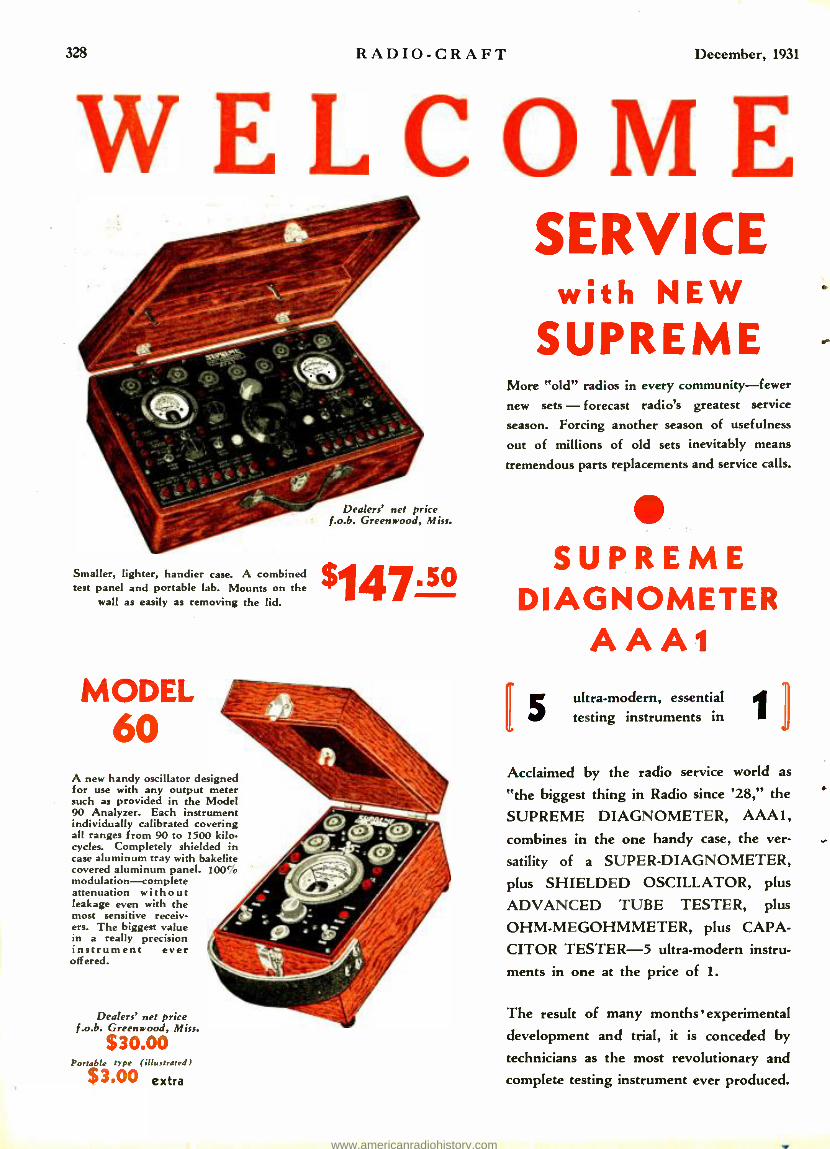
WELCOME
Dealers' net price f.o.b. Greenwood, Miss.
Smaller, lighter, handier case. A combined
147__50 test panel and portable lab. Mounts on the wall as easily as removing the lid.
MODEL 60
A new handy oscillator designed for use with any output meter such as provided in the Model 90 Analyzer. Each instrument individually calibrated covering all ranges from 90 to 1500 kilo. cycles. Completely shielded in case aluminum tray with bakelite covered aluminum panel. 100' modulation -complete attenuation without leakage even with the most sensitive receiv- ers. The biggest value in a really precision instrument ever offered.
Dealers' net price f.o.b. Greenwood, Miss.
$30.00 Portable type (illustrated)
$3.00 extra
SERVICE with NEW
SUPREME More "old" radios in every community -fewer new sets - forecast radio's greatest service
season. Forcing another season of usefulness
out of millions of old sets inevitably means
tremendous parts replacements and service calls.
SUPREME DIAGNOMETER
AAA1 ultra -modern, essential testing instruments in
Acclaimed by the radio service world as
"the biggest thing in Radio since '28," the
SUPREME DIAGNOMETER, AAA1,
combines in the one handy case, the ver-
satility of a SUPER -DIAGNOMETER, plus SHIELDED OSCILLATOR, plus
ADVANCED TUBE TESTER, plus
OHM -MEGOHMMETER, plus CAPA-
CITOR TESTER -5 ultra- modern instru-
ments in one at the price of 1.
The result of many months experimental
development and trial, it is conceded by
technicians as the most revolutionary and complete testing instrument ever produced.
www.americanradiohistory.com

December, 1931 RADIO -CRAFT 329
RADIO'S GREATEST SEASON testing EQUIPMENT Smart radio men who know what it means in dol- lars and cents to stand at the top of their pro- fession with equipment that insures economical service for themselves and their clients, are wel- coming this season of opportunity with "New" SUPREME, TESTING INSTRUMENTS.
Supreme Oscillator Model 70
A thoroughly shielded, completely attenuated oscil- lator of the highest type. Combined oscillator -out put meter -high resistance ohmmeter can be obtained in a beautiful hardwood carrying c e providing un- equaled led flexibility in service ranges. Send coupon for details.
Dealers' net price J. o. b. Greenwood, Miss.
Supreme Oscillator Model 70. Less tubes and batteries
Supreme Output- Ohmmeter
$49.75 $30.00
Handsome Carrying Case of hard- wood for combined Oscillator, Out. $5.00 put-Ohmmeter and Accessories
ASK Y(UR Jt,ltUI It Prat I)E\IONSI It . \11 ,N All leading jobbers can demonstrate the economy and investment value of "SUPREME" TESTING IN- STRUMENTS. If yours can't, indicate on oupon what instrument interested in and name of jobber. Welcome Radio's greatest service season with up to date testing equipment -the SUPREME way.
Distributors in all principal cities Foreign Division,
130 West 42nd St., New York City Cable Address Lopreh New York
Supreme Analyzer
Model 90
Dealers' net price f. o. b. Greenwood, Miss.
(illustrated) Portable type
$78.so A new Model 90 Analyzer borrowing some of the tremendous features of the AAA1 DIAGNOMETER. Greater simplicity, greater range and speed. Analysis of screen grid and Vari- able-Mu circuits without oscillation and complete analysis of r.f. and power pentode circuits. The only analyzer providing plete rectifier circuit analy- sis, including helium rec- tifiers and providing direct readings of resistance values up to 500,000 ohms in two ranges utilizing ch e i. ..It battery potential provided in the analyzer. There is no analyzer on the merket to le n moo h approaching servicing the sere cing range and elasticity of the new Model 90.
Supreme Model 40
A tube tester of improved design equal to instruments selling for double its modest price. Tests all tubes without adapters, including power and r.f. pen- todes and provides for filament o heater potentials of 1.5, 2.0, 3.3, 5.0, 6.3, and 7.5 volts to any of the five sockets on the panel -a very flexible arrangement. A "grid shift" test of all amplifiers is provided with a bias- ing arrangement automatically de termined by the plate current load of the tube under test,
u that the so
controlling grid biasing potential may be observed on the ni. . Incorpor ates a gas test fore amplifiers, cathode -heater short test for heater types, and tests both plates of full wave ectifiers. Everything that could be desired in a high class, efficient tube tester -and at a price that fits the pocket book.
Dealers' net price f.o.b. Greenwood, Miss.
$30.00 Portable type (illustrated)
$3.00 extra
SUPREME INSTRUMENTS CORPORATION 420 Supreme Building, Greenwood, Miss.
Please send me lull particulars on cs TPREMf DIAGNOMETER AAA! SUPREME SET ANALYZER MODEL 90 -- SUPREME MODEL 40 E SUPREME MODEL 60 L. SUPREME MODEL 70
Name
Address
City
Jobber's Name City
- - -. State
State
www.americanradiohistory.com

330 RADIO-CRAFT December, 1931
6The lop of the World is ourProuíng Ground" The arctic is ha rd 1 y the ideal place to
test radio equipment. Severe magnetic disturbances, violent electrical storms and the Aurora Borealis conspire to make radio communication extremely difficult if not actually impossible. Yet, Lincoln engineers used the polar regions as the proving ground for Lincoln equipment.
The schooner "Bowdoin" of the MacMillan Arctic Expedi- tion was Lincoln equipped, and for the first time in the twelve year history of this famous expedition contact with Chicago was maintained daily! Not only were daily short- wave messages received clearly and consistently but broad- cast programs and contacts with 17 foreign countries were enjoyed! Such remarkable perfotmance won high praise from members of the expedition and set a new record of performance under the most adverse conditions.
As if this were not alone sufficient to firmly establish Lincoln leadership, the exclusive Lindbergh news scoop
The Famous Lincoln Chassis
Both the Lincoln DeLuxe SW -32 ami De Luxe IN :- SW- 10 are identical in design, both utilizing the high (rower of ten tubes. 'the DC -SW -10 has a very low drain and operates on dry "B" batteries and any two (2) volt ":t" supply.
Elimination of AC line interference makes the DC -SW -10 desirable in city communities.
again focused national and internal. al a t tenlion upon the phenomenal capabilities of Lincoln equipment. When, on August 5, Col. and Mrs. Lindbergh were feared lost in the arctic wilderness, a Chicago operator sitting at his Lincoln receiver caught the anxiously awaited signal front the speeding plane. The message was relayed to the press and within a few hours the story, with a detailed account of the actual interchange of signals, headlined in 965 papers throughout the country.
Nor are such spectacular achievements confined solely to arctic expeditions. Lincoln receivers, in thousands of homes, are consistently outperforming every other known type of equipment. Super -power under perfect control gives the new Lincoln tremendous range, and the specially designed audio system endows Lincoln receivers with a rich, vibrant, life -like tone. A Lincoln Radio is your assur- ance that you possess the ultimate in design, quality and performance.
World - Wide Reception Imagine being able to tune in short -wave stay in every corner of the globe with the sanie ease and certainty of tuning your local broadcast station! Imagine having the entire world of radio at your finger tips- air -mail, amateur phone, short -wave broadcast, police. Trans -atlantic phone, and all the other fascinating features of the air at your command wit! t having to change a coil or disturb a single connect' I Imagine tone of actual life -like fidelity, rich and vibrant with all of the subtle overtones and harmonics preserved intact! It has been the dreamt of every radio enthusiast, and now such a receiver is here!
The new Lincoln DeLuxe SW -32 embodies all of these features. Broadcast and short -waves are received with equal case. Plug -in coils have been banished forever -a small no- capacity selector switch on the front panel gives instantaneous access to either broadcast or any of the short -wave bands. A low -high power switch gives added power for the IIX fan. The low- power position is sufficient for full loud speaker volume on stations within 500 or 1000 miles, the high -power position for 'round the world reerption.
Lincoln Radio Corporation Dept. R.C.12. 329 So. Wood St. Chicago, Illinois.
Will you please send illustrated folder describing the Lincoln DeLuxe "32" models.
,tame
Street City Stele
fila d, the Lincoln DeLuxe SW -32, an AC male!. This same chassis may be had in the IM. model, the Lincoln DeLuxe DC- SW -10.
without Plug-in Coils ! ! Super- power, developed by Lincoln engineers, gives an e ' ly new concept' of radio performance. A Lincoln owner in Tennessee listens to 92 foreign short -wave sta- t s out of a total of 128 foreign phone stations. From Cushing, Oklahoma, comes the report, "Seven stations received from Japan one morning, all in the broadcast band." Another Lincoln owner says, "Listening to 2YA Wellington, New Zealand, Oska, Sendai, and Kumamoto, (750, 770, 790 KC) in Japan, K('MC in Honolulu, 2BL Sydney, Australia, all in the broadcast band." Such astounding feats are by no means exceptional. Lincoln receivers are built to give outstanding service. Constructed by competent engineers to the highest stand- ards of laboratory precision, each Lincoln receiver is pledged to outperform any other radio equipment known! The tremendous amplification of four stages of tuned I. F. transformat give the Lincoln receiver lower and range unheard of before. A specially designed audio system pro- duces lone of amazing quality. From the sweet liquid of the clarinet to the rich resonant bass viol, every instru- ment and every voice is brought to your home with all of the timbre and quality of the living artist. Speakers, specially built for the Lincoln receivers insure faithful reproduction of the audio output. May we not send you an illustrated folder describing each rueslel in detail?
LINCOLN RADIO CORPORATION 329 S. Wood St.. Dept. R. C. -12. CHICAGO, ILL.
www.americanradiohistory.com

IllECEMBER 1931
VOL. III -No. 6 adio aff
FOR TME
SERVICE MAN . DEALER . RADIOTRICIAN
"Takes the Resistance Out of Radio " Editorial Offices, 96.98 Park Place, New York, N. Y.
HUGO GERNSBACK Editor
Radio Education By HUGO GERNSBACK
IAM frequently asked by many of my readers what steps I would recommend for .them to obtain a good radio educa- tion. My correspondents are usually vague as to what course they wish to pursue, since they specify simply
"radio," with no qualification as to any particular branch of the science.
At the outset, I must point out that radio today is such a
tremendously involved industry that it is well -nigh impossible for any utan to know everything connected with it. A radio tube expert is so far removed from the radio broadcast expert that the two have little in common; they might just as well work in entirely different lines. In fact, they really do.
Before it is possible to state much about this or that radio education. the seeker of knowledge must have a definite pur- pose in mind. Ile must'know in advance which section of the radio field attracts hint most. If he has never had any ex- perience in any of the various branches of radio, then I would smuggest that he first take a course, which might he either by corresl lence or by personal instruction, with any of the many excellent radio schools with which this country abounds. This, then, will give the prospect an idea of the branch of radio he will finally choose.
A radio education should start off primarily with hooks which deal with the different subjects in the field. There are, of course, ixs,ks treating radio generally and giving an outline of the different branches of the subject, but the books on the specialized applications are the most important which the future radio man will have to study.
Of course, every student in radio should have a general knowledge of its various branches, although it will he impos- sible to master all of them perfectly. In due time the student will choose, if he intends to be successful, a certain branch and specialize in that branch if possible.
i consider it, however, of paramount importance that, no ratter what the radio student does, he should have an excel- lent knowledge of electricity because without this background, it will be difficult to accomplish much in the profession.
Then, to nay mind, the future radio man should not neglect taking a course in aa' resident radio school, which is very im- portant. I consider the practical information thus gained of the highest possible importance, because those things which one does with his own hands give l xperienee and knowledge which cannot be obtained in any other way. Of course, the same purpose can be achieved in a laboratory or a factory; but
the radio education here will be, at best, more or less one - sided because, in few factories, and in few laboratories, will the student have at his disposal all of the different machinery, apparatus, etc., which he will encounter in a well- equipped resident school.
All of these previous remarks, naturally, are only general, and cannot fit each and every case. For instance, the man who wants to become a radio tube engineer will have to traverse a somewhat different path; although the elementary groundwork, that is, electricity, then hook and practical knowl- edge gained in a resident salmi, will also apply as a general groundwork toward a future education.
Yet the tube engineer must have other knowledge besides purely electrical and radio. He must, in the first place, be a good physicist. He must also be well versed in mathematics, and he should know something about metallurgy and glass. He should also know something about the finer mechanics, for the reason that modern vacuum tubes are highly intricate from a mechanical viewpoint and, indeed, the entire art is tending to become as delicate in its technique as watchmaking.
These facts would seem to be self- evident; but it is surpris- ing how few students pay much attention to such details, with the result that many make a wrong start and become "third- raters" in their chosen field when they could rate first just as well.
Every branch of radiu is tremendously complicated, and only those w$o are well -equipped mentally in every sub- divisinm of the branch will make a success in the end.
And then, to be sure, a radio education is never finished. When the preliminary education has been completed, then study begins in earnest, and never stops. It then becomes necessary to get hold of every scrap of printed information in the particular branch of the art. Even a month's neglect of the current literature is often sufficient to make a man a "back -number," even if only temporarily so. Not only must the newest and latest advances in the art be studied front the public's viewpoint, Itut One's competitors must he watched closely, in the present trend of the times, and their activities followed avidly from day to clay.
And even, when all of this is accomplished, the most brilliant open in the radio profession will tell you, that the higher their own education the less they themselves consider it complete; because the more we learn, the more we understand how little we actually know of any one subject. It is only those with lim- ited knowledge who consider that they have learned all there is to know in any line.
331
www.americanradiohistory.com

332 RADIO -CRAFT December, 1931
OUTPUT
110
VOLTS
A- C.
110
VOLTS
D. C.
INPUT
The THYRATRON Inverter By L. VAN DER MEL
EVER since the advent of the alternating current receiver with its tremendous inherent advantages over those oper- ated by batteries, there has been an insistent demand for better quality and more volume. This demand is gradually
being satisfied as new tubes, circuits, and speakers are being devel- oped. But to the man who lives in direct current districts, the modern advancements have not been applied.
Although satisfactory operation of radio receivers in locations supplied with direct current has been obtained in the past, they have been handicapped by certain inherent limitations of this type of power. These limitations fall in the following general classifi- cations:
In view of the low voltage usually available in direct current, and the fact that it is impossible, within economic reason, to raise this voltage, the output of D.C. receivers is lower than that of receivers supplied with alternating current.
Even with inferior performance the choice of D.C. model receiv- ers is necessarily small due to the small market in which they may be sold.
While the use of a motor generator set or a converter may be
bad in conjunction with A.C. receivers in D.C. districts, it is
not recommended in view of the obv' undesirability of having rotating machinery in the hone. 'l'he electrical and mechanical noises accompanied with such machinery, together with the addi- tional cost of filters necessary to obviate the noises, raise the cost of the receiver sometimes to a prohibitive value.
The motors usually used for phonograph work are of the syn- chronous type, and because of the variation in frequency of toe voltage output of shall rotating machines, they can not be suc-
cessfully used. All of the above reasons have created a demand for a device
that would facilitate the operation of A.C. receivers from a D.C.
source. This demand has been satisfied by the development of a
new type of converter called the Thyratron Inverter, model "TH- 10" designed by the RCA Victor Co.
Briefly, the Thyratron is a three element gas -filled tube that rias characteristics such that it may convert D.C. into A.C. (This tube
has been discussed in detail in the September 1930 issue of RAUto-
CaAr-r). It consists of an indirectly heated cathode, grid. anode
or plate, and a globule of mercury. The heater is operated at the D.C. line voltage, i.e.. 105 -125 volts.
The component parts of the Inverter consist of a grid exciter transformer, automatic starting and frequency conttol circuits, plate commutation capacitor, limiting reactor, and a radio fre-
quency filter system.
'l'he principle of operation of the Inverter is quite simple, being that of an oscillating circuit at (10 cycles. The Thyratrons (two of them being used in this set) supply power in pulses to a circuit consisting of inductance and capacity. The circuit is tuned to a frequency of 60 cycles, and thus generates the A.C. power neces-
sary to operate the receiver in a manner similar to any other alternating current set.
The A.C. power generated is sufficient not only to operate the radio set, but a phonograph motor, the maximum total power that may be drawn being 225 watts.
The advantages to be gained by the use of the Thyratron tubes rather than rotating machinery are noiseless operation( both elec-
trical and mechanical), lack of moving parts, can be housed in
the cabinet of the receiver proper, and will allow the full use
of the maximum sensitivity of the receiver. The device is 101/. ins. wide, 101/ ins. high, 53 /i ins. deep and
weighs 39 pounds. A photograph of the finished product is illus- trated above. This is a rear view and the Thyratrons are clearly visible.
As more details regarding this interesting device are received, they will he published in lt.tmo- CRAFT.
v, OC r
lM'E RLKr-f
17e5
uov,Ae ,- ourwr
fl..?! a-.
-il-1-1l-*
Eí 3r 000(báSO 0 8 06J080'
9.. c
±00 000 .. I l Y"1-rr-` r 1 .
J.Y
R r.a 9,
The crhematir diagram of the Thyratron Inverter is sho;en above. When ì1e vrlts (1.C. are applied to tl,e input. 110 volts A.C. is obtained at
the output.
www.americanradiohistory.com

December, 1931 RADIO -CRAFT 333
The U. S. Signal Corps BALLOON
The one pound transmitter illustrated in the center photograph ascends to a height of 10 miles to facilitate the taking of meteorological
observations.
ANY of us have, at one time or another, purchased small gas- filled balloons, tied a string to them and watched them soar
tp into the atmosphere. It was good fun when we were young, but most of us have avoided this means of enjoyment upon reach- ing maturity. The United States Arun', however, still persí..ts in indulging in this fornt of entertainment, only now for serious pur- poses.
Meteorological observations conducted by the United States Army to determine the condition of the upper strata such as air temper- ature, pressure, I lity, and direction and speed of movement, for military, industrial, and weather forecasting purposes, stake use of small Italhmns for obtaining this information. When observa- tions only of wind direction and speed are required, the procedure is to send aloft small balloons of about six incites (uninflated) in diameter and follow them with theodolites. The rates of ascension may easily be calculated with a knowledge of their weight, dimen- sions, and free lift of the balloon. Only a small amount of addi- tional calculation is then necessary to determine the position of the balloon at given intervals of time, usually one minute.
'l'hir method of determining the characteristics of the atmosphere has main' inherent faults. The length of time involved in the final calculations, the effect of fog and rain, especially at night, and the general instability of the method, all were instrumental in deter- mining whether or not radio might be used to determine the path of the balloon during its flight.
In 1923 the Signal Corps Laboratories at McCook Field started a series of ex- periments whose purpose was to develop a transmitter and receiver which would be suitable for this work. The project was dropped for a time, but was recently taken up again by the Signal Corps Laboratories at Fort Monmouth. It is not neces- sary to enter into a discus- sion of the various circuits that were tried during the
Firm re .1 renter. :l photograph shneinn the completed transmitter including the tube and barrer.
Figure B right. A set -up of the SCR -170 receiver. Observe the loop antenna used for direction tinting.
Figure C left. The complete 6.1d transmitter and receiver, showing the balloons ready for ascension.
course of the experiments, and consequently we will confine our at- tention only to the final products.
The Transmitter The transmitter finally selected is shown in Fig. A, the wiring
diagram of which is depicted in Fi',. 1. By referring to this figure, it is seen that the supporting and trailing wires of the transmitter
really net as the antenna and counterpoise; the length of these wires (commonly called legs) are so adjusted that, together with the induc- tance L of the transmit- ter, an operating wave- length of approximately 125 meters is secured.
This little set, known as the Signal Corps Type BC- 164, weighs but 11 ounces; the total weight including the legs and battery being only 171%, ounces. As can be
(Continued on page 364)
Co1494R40ORJ ; Cm
^R[arnERaTOK cK
7.7-1 TL
S
JACK root 510545 SarfERY r
a.SV y tltlt
Fig. 4 Thr .schematic diagram of the receiver used with the direction finder. It is a brr tutee receiver employing two stages of R. F., a detector and two stages of
www.americanradiohistory.com

334 Recently, a number of our readers suggested that we burlesque some of
our well -known radio set manufacturers' advertisements. The idea of burlesquing national advertisers seems to have taken the
Horrible superiority
ZEN -ITCH MODEL 939%
Ten -Tube Supper- Heteroecious with genuine Autocratic Tun. ing and Tone Tee. Totality. A sickly designed tomboy of tare hardwoods complete with Zen -itch Quality tubers, $1.95 . . Other new Zen -itch Receivers from 13 cents to two bits.
ZEN -ITCH
Tone Tee Totality
ZEN -ITCH and science have at last developed the great Tee -totaller Radio. This titanic prohibition radio is ten years ahead over all others. At last you have
a set that gives you what you want, when you want it. Dispensing anything from best shellac varnish down to near -beer.
Fully equipped with a static suppressing cocktail shaker, noiseless cuspidor, chromium plated shock absorbing foot rail, free lunch attachment with anti -
fading control, variable mu seltzer, automatic electric bottle selector, cocktail shaker equipped with screen grids, autocratic volume control which also dispenses
sawdust on 10 kilocycle selectivity. Special long distance liquor tester built right into the set; tests all hard liquor aromatically on short wave lengths. Automatic volume control of set locks up all liquor as soon as guests become too noisy.
NEW 1942 SUPPER -HETEROECIOUS
LONG DISTANCE AUTOCRATIC RADIO
the rare quality that leaves NO (s)tone unheard
Hollow music! Something missing! There are notes and tonal beauties you NEVER hear with an ordinary radio. Why cheat yourself of FULL radio enjoyment, when ZEN -ITCH
TONE -TOTALITY leaves NOTHING unheard.
ZEN -ITCH RADIO CORPORATION, CHICAGO, ILL (very much so) World's Largest Bakers of High Trade Radio
This advertisement not paid for. Wish it were, though!
www.americanradiohistory.com

country by storm of late -hence our acquiescence to the popular demand. If you like this sort of thing we will be happy to comply. Suggestions and contributions will be welcomed by the Editors.
335
loTIVATE R FAIT RADIO
\\11/
Compact Model 1922B.C.- Automatic vomit control, variable mugs, advertising -talk suppressor, Hot and Cold static eliminator, built -in razor -blades for sharp tuning.
"We wouldn't trade our Hotwater Bent for any two other radios"
(ANOTHER UNSALTED, SPONDOOLIX TESTIMONIAL)
OF THEIR own free will, thousands of Hotwater Bent owners send
such letters as this: "After frying fourteen popular makes of radio in our home we selected the Hotwater Bent for its beautiful, clear bone, its delectivity and its handsome clarinet. We wouldn't parade it for any other two radios on the market." From Mrs. V. C., Cleveland, Ohio.
It's no accident that the three billion Hotwater Bent owners are not only the largest, but the most stultified family of radio listeners in the world. The extra valet built into every Hotwater Bent makes them so.
Here's more than slow price -more than snowy performance when new. Here's intellect of smallest retail - quality that endears.
Look out for VALUE this year as never before. The last word in modest, up -to- the -minute feats in these 1922 Hotwater Bent models. Look for slow prices, tool -but not too slow for safety. Look for a radio you can love with and be snappy with.
Buy VALUE. Buy wistfully. for losing satisfaction. At any water Bent dealer's -on general payment terms.
Buy Hot - over-
HOTWATER BENT MANUFACTURING CO., PHILATELICS, PA.
GOLDARN VALUES with the GOLDAIiN VOICE
Neither is this one.
Nine New Goldarn Values Models
Everyone a Super -Heterodox -bone control and statistic reducer -auto- matic vomit control if you want it, (and who doesn't at sea ?) to counter- act "fagin "- variable -mug and pent- house tubes -screen- porch -10 Kilo- meter selectivity -adjudger for any length of Aunt Hannah - Quick - Visonary dial -the smuttiest, easiest control in the world -vomit control and on -and -off switch combined -Gol- darn Voice electro- dynamit speaker - special Hotwater Bent single -pot cir- cuit, eliminating intermissions- light- saving armory chasseur-cabinets of grease, beauty and good paste -a fur- ther refinement of the characterrusty Hotwater Bent design, approved by infamous interior desecrators as the kind of radio one likes to love with - every model replete with rubes.
www.americanradiohistory.com

336 RADIO-CRAFT December, 1931
NEW Devices The latest radio equipment is described here for
Fig. A
Left is shown a
photograph of the ll'c ton Photronic Cell, and below its component parts. The simplicity of its construction is
obvious.
CURRENT GENERATING "PE"' By H. G. Cisin, M.E!
A\ NEW photo -electric device, the "photronic" cell, illustrated Fig. A, which is capable of generating sufficient current
operate a sensitive relay, is now avaiiahie. There are four main points concerning
which the technician exhibits particular in- terest, as follows: sensitivity to light change, speed of action with respect to light change, methods of operation, and construction. Con- cerning the last factor there is little in- formation available at the present time; of course, this dues not affect the operation of the unit. The other items will be consid- ered; also, other characteristics of this
CELL
Fig. B .4 robinet of mod -
ernistic design.
glass cuver- plate, a copper contact -ring (which connects to the
"plate- prong of a l'\ -base connection, the special light- sensitive
plate (extreme lower right), a special washer, the second contact-
ring and its 1\ -hase "filament" cnnection- prong, the second black
washer, and lal:elite case -plug (upper right) which screws into
the case and holds together the entire assembly. .\ tiny plug in
the center of the light -sensitive plate spaces it from the glass
cover- plate.
Its active element is the specially -treated disc. When light impinges upon it, an electron stream is produced; thus there is a
direct transformation of light energy into electrical energy.
As far as is known, the life of the cell is practically unlimited and a continuous current flow does not harm it in any way. Since
it does not contain any liquid nor require vac or gas, there
is nothing to get out of order as it is not subject to physical or
chemical change and it has a constant output. It can he exposed
to direct sunlight without deterioration, has no dark current si.:ce
its energy is derived directly and only from light; no drifting, hence
no circuit ad,iustmmnts are necessary; no fatigue; and is non -
mierophonie. The resistance of the cell varies fr 1M)0 ohms at
10 foot -candle, illumination, to 300 ohms at 240 foot -candles
intensity.
This device, shown completely assembled in Fig. A, measures
over all only 3 x 1 in. thick; sold weighs only 31,2 ozs.
This new device, manufactured by the Weston Electrical Instru- ment Co., is known as the Model 594 Photronic Cell. Altl gh
in simple in construction, each component has received the same
to attention to precision which has characterized all previous Weston
products.
Fig. 2
Two diagrams in which the pl:ofrm:ic cell may be surd: left. connections for a meter or relay
output; at right, lam ilspeaAvr operation.
really marvelous instrument, which is des-
tined to cotta into great prominence. As illustrated in the graph, Fig. 1, the
sensitivity is approximately 81) microamperes per lumen. Preliminary frequency- response
tests indicate that the action is so rapid, it probably will be sutisfartory for use in talking motion picture stud television trans- mission work; coheir- sensitivity graphs have
not tis yet been completed. Connections which may be engtlooed are shown in Fig. 2; at .1, the circuit for direct operation of it utillianmteter or 5-ma. relay; at B, recom- mended circuit for indication (on a Il oui
speaker, etc.) where the light intensity changes rapidly. As shown in Fig. A, the
utter simplicity of the Photronic cell is
striking. The assembly proceeds in the following
order: Into the bakelite shell (extreme left), is dropped one of two black washers, a
THE MODERN RADIO CABINET AS evidenced in the Westinghouse "Col -
tunaire," l'hilco "I.azyhov," and other late model receivers, radio cabinets are rap- idly climbing out of the rut of convention, their design taking a tern which bids fair to establish new standards of comparison in the cabinet- makers art.
h i
o
......\Mpp ñ... i r{C.... R-..1. 1 .... .1... f u.Am. ii miI. e IMI li>E1..1.1..1 \\ l./.11.. 11.:11\\lrl Itir7M \`........LMI.... 11 O 111 L\ 1..11.1.11./111.1. IFMIfE..\.....I...1....1 111.I.1.. fCaE1'..\1.....1.1.1 111.11. f 5:11 J. ... i./........... 1.1......1.1\II M.11..111 fl.?l.lr/l.ri\...ln ...1.r1..rii1..67ÑNEM Q ]...r4 CELL R &STPNC
\ .
WM MU. ITN 550NM5 f1 1sr7.. EY.,RE515TANCE . ...I...1.. .Q 11I ..1.111 .11.11 1....ß]s11[i]mEi0IC7QQ ..1......11.1 1..1... 0
LIGHT INTENSITY -FOOT-CANDLES
1 1.
r Fig. 1
Response curves of Mr Weston Photronic Cell. 77u.sc illustrate Hie variation of output current and cell resistance as the light intensity changes.
t In collatarction with the inventors, Messrs.
C. Il. Bartlett and A. Il. Lambe of the Weston IC1, et rival Instrument Corp.)
www.americanradiohistory.com

December, 1931 RADIO -CRAFT
in RADIO the trade, Service Man, and home- constructor.
A late cabinet construction available to set builders and owners, which is designed to accommodate any receiver chassis, is illus- trated in Fig. B. Note the side panniers for current periodicals, and the "modernistic" lines slightly modified by curves. Another cabinet model is designed to ac ouuuodate in its top a standard midget set, cabinet and all and in lieu of the front panel and speaker -grille shown in Fig. II, there are provided shelves for hooks.
The same firm, Washington Radio Furniture Co., manufactures other models, including a tall, narrow bookcase design. At the top is a section just large enough for a midget chassis and repro- ducer; a small door closes this portion of the front. Surmounting the case is a fancy riser which may be cut to fit a small electric or spring clock.
HARMONIC SERVICE OSCILLATOR
RADIO information, like the data in all other fields, is changing every day. For instance, the service oscillator of yesterday,
designed to cover the extremely wide frequency range of, say 115 to 1680 Içe., would have been a rather bulky instrument incorporat- ing either a tapped coil and range -selecting switch or plug -in coils; either design would necessitate the use of a multi -scale graph.
Modern oscillators, however, may incorporate the principle of harmonic production in vacuum -tube circuits, with conse- quent reduction of size and increased speed in their use. 'l'he theory involved, and a discussion of one conmIercial instrument of this type, appeared in the July 1931 issue of RAmo-Ca,trr. Another " harmonic -type oscillator" of the shielded type is the Acrocycle Oscillator, Fig. C; the schematic circuit is relatively standard, Fig. 3.
This new service instrument has a combination scale and pointer
337
Fig. C
Above. The At-rotcle Harmonic Oscillator. The exterior of the shielded unit is shown at the left; center, the shielded lead: at right,
interior arrangement.
Fig. D :I group photograph of novel German units. Above. upper left. Fig. 01;
upper right, Fig. 02; center left, Fig. 1)1: lower left. Fig. D4; lower right, Fig. 05.
Fig. 4
of special design, Fig. 4. Frequencies are read at the intersections of a red line (shown
dotted in Fig. 4); for increased accuracy, a magnifying glass may be used. l'he celluloid pointer fastens at the periphery of the knob.
Quick shifts in tuning may be made with the large knob; a 68 to 1 ratio vernier is shown at the right. The small knob controls the power output which may be increased sufficiently for neutraliz- ing circuits by pushing the antenna plug (at the end of the twin - conductor, shielded lead) farther into the post marked ANT., until the tip touches connection J, Fig. 3.
Coils IA and 1.2 are little 350 -turn pancakes % -in. wide, wound with aalunit No. 28 S.C.F. wire on forms 2 -in. in diameter. Con- denser CI is a trimmer (ad- justed and sealed at the fac- tory) in shunt to the 350 mild'. tuning condenser C. Units R1 and SW. are ganged. The batteries re- quired for operation are con- tained in a separately shielded section in the lower part of the oscillator.
Although the A crocycle Oscillator is available as an AN
independent, shielded unit, as shown in Figs. :1 and C, the Service Man may prefer to obtain the more complete o -5000 OHMS
instrument which includes this oscillator, the required '30 tube, four No. 2 dry cells (for the "A" potential),
(Continued on page 365)
Left. An enlarged view of the scale used'on the harmonic oscillator. Note the curvature of the tuning pointer.
J
La o-2so
MING L2
sv.
OMS
GND.
SIGNAL VOL. CONTROL .A+ A- .B+- B= 223 V.
Fig. 3 The diagram of connections of
Acraucle oscillator. the
www.americanradiohistory.com

338 RADIO -CRAFT December, 1931
R. F. Ci Design Some Notes on Calculating R.F. Coil Resistance
By C. W. PALMER
WHEN the screen -grid type of tube was first introduced to the Amer- ican market, it was believed that poor selectivity was an inherent
part Of its action. However, as design engineers became more experienced in its use, it was found that the apparently poor selectivity was due to the greater :unplitica- t' per stage and to the constants of the parts used in the early sets. Later, band - selectors were employed to give the desired selectivity and constants were used which equalized the amplification over the entire broadcast band.
It is well known that the band- selector causes an appreciable reduction in the R.I'. amplification, as well as requiring very care- ful adjustment; all of which results in an increase in the costs of production. With this point in mind, the writer set out some hue ago to find a suitable means for obtain - ng sufficient selectivity without the use
If hand- selectors. This was not done with the idea of detracting from the use of such using devices, but rather to find a means rf reducing the cost of making sets in pro-
r
r 10
L
6
5
4
3
rn R F RESiSTANCE .. B D C RESISTANCE
32 50 t 26 24 22
B_5- S. GAUGE
Fig. 1 . \ote that for the smaller as age afire the A.C. resistance of a coil may be several times its
D.C. resistance.
duction without sacrificing either amplifica- tion or selectivity.
Increasing the R. F. Gain
After some deliberation, it was decided that the most logical point of attack was in the lt.F% grid coils. The results obtained by redesigning the coils in several trial sets were so gratifying that it was decided that others might find the information use- ful. 'l'he following notes made at the time deal entirely with the secondary coils. Later, perhaps, we will discuss some changes in the primary coils, especially the primary of the antenna coupler.
The amplification obtainable in an R.F. amplifier depends primarily on the ratio of the inductance to the capacity multiplied by the resistance (of the coil); expressed
L mathematically, -, and it is evident that
C R the greater the inductance compared to the rapacity and coil resistance, e, the greater the amplification that may be realized. :1s the size of the inductance (I.) is limited both by the maximum wavelength to be received,
(Continued on next page)
WF nF Z
sa Fó ó
.9
.8
.7
.6
.5
.4
6
2
6
; 20 -A- Pal E P,011
22 m
Eill%M11 --,_-- 11 III
., C'
MIMI. Ow,
~ B
A
2 3 4 5 LENGTH OF WINOINO - INCHES
.8
.7
.6
.5
.4
.3
7
6
5
4
3
8
7
6
S
4
CV -B-
22
..A1 ` II11121
.ym 24 MaSiß1 ,26 -11111111111
zé -'. .-..---
- _. C'
'B Á
C
B Á
.8
.7
.6
.5
.4
.3 8
7
6
5
4 10
9
8
6
ce c
181
pa . rEQGI -...-
, NI.,,' msomm.
m 24
t6 '- ' .... 28
\ C'
A'
B
A
I 3 4 5 1 2 3 4 LENGTH OF W NOING - INCHES LENGTH OF WINDING - INCHES
Fi!ar, 4, upper row. The curves .4, It, and C indicate the opttmum site wire for various winding lengths, inductance and toil diameters. Crones :l, R. and C are coils 3 ins., 2% ins., and 2 ins. in diameter, respectively. The three roes .4, B, and C are for coils of different lengths; .4 to be used with .0005 -mf. tuning condensers, B with .00035.mf., and C with .00025 -mf. condensers. Figure 5, center. The R.F. resistance of coils of various winding lengths, inductance, and diameters, is shown, taker at 450 meters. Figure 6, lower. The R.F. resistance of coils of various winding lengths, inductance, and diameters. taken at 300 art ̂ rs, it illustrated.
t
www.americanradiohistory.com

December, 1931 RADIO -CRAFT 339
The ANTENAPLEX SYSTEM TIII, procedure for installing the
\ntenaplex system in existing build- ings is as simple as wiring these structures for any other purpose,
Fig. J At A is shown the surface box, at R the 'Yap - let," at C the Cabloy clamps, at n the Cab loy. at E the tap to the outlet box, al F the base of the surface box. and at G the mounting screws.
'National Sales Engineer, Centralized Radio, RCA Victor Co., Inc.
(Paler III) By E. JAI" QUINBY*
such as electric signaling >c steins, telephones, or electric lights.
The Cabloy, which is a lead covered con- ductor 5/IG" in diameter, may he readily "fished" through hollow partitions, or run "open" :dung the surface, and where thus exposed, it should be secured at frequent intervals by the cable clamps furnished for this purpose. This little clamp or clip, re- quires only one screw to attach it to the wall surface, baseboard, or other trim, and is so
designed that it provides a suitable anchor- age for the Cabloy, without crushing or otherwise injuring the conductor sheath or insulation.
For such cases, and for cases where ex- posed or surface wiring is employed, a spe- cial circular surface box has been developed, Fig. I, which has many advantages over the usual rectangular surface lux. First, the round cover presents no sharp corners to catch or interfere with objects ordinarily moved hack and forth past its surface; sec- ond, it is universal in its application for horizontal and vertical runs, and will also ace late locations where it is desired to transfer from a horizontal to a vertical run; third, it will adapt itself to locations where it is desired to effect transition frown
Fig. I .4t .4 is shown the mounting .drip, at B the mounting screws, at C the clamping ears, and
at I) and F. the antenna and ground posts.
concealed to surface wiring; fourth, its base is provided with clamping ears which not only secure the ends of the Cabloy in place, but also effect the necessary bonding nating current voltmeters and ammeters.
t('nntinued on page 367)
R. F. COIL DESIGN and the size of the tuning condenser (C), it can he readily seen that reduction of the coil resistance (It) must result in an in- crease in the amplification. Thus it will be found that to cover the broadcast band, 340 titillihenries is the uraximum permissible inductance that may be used with a .00025- inf. tuning condenser; and even then, either very loose coupling (between primary and r
Y
O
Is
14
13
12
11
10
9
ó 8
á r ,4 6
5
4
3
2
1
O
A- FOR K CURVE A 0.25 0.5 0.75 1.00 1.25
1
t
A RAT O LENGTH OF WINDING
DIAMETER OF COIL
2.0 1 6 1 4 1.0 0 6 0.2 A' FOR S CURVE
Fig. 3 The values of K and S used in the calculations
may be taken directly from the curves.
(Continued from page 331()
secondary'), or an antenna series condenser, is needed to tune below 250 meters,- because of the effect of the capacity of the antenna.
If the coil resistance (R) in the above ratio was the direri current resistance of the coil it would he a simple matter to reduce it merely by increasing the size of the wire. But Fig. 1 shows that there is a point beyond which the radio frequency resistance increases with a further increase in the wire size. The curves in this ligure were male from data obtained with a coil of 74 turns of No. 21 wire, wound on a form 3 inches in diameter and 2'' inches long.
Finding R.F. Resistance 'l'he It.F. resistance was calculated from
IIutterworth's furnnla:
R 1 -R {1 +F+ G (Kn .) 2 L 2D/ r
in which RI is the R.F. resistance of the coil. in ohms; lt, the D.C. resistance of the winding, also in ohms; n. the total number of turns; and (I, the diameter of the wire in the stone units as 1), the diameter of the coil. Both l' and (i are factors propor- tional to:
1= 92.8 where f is the frequency at which the coil is to he used and d, the diameter of the wire in millimeters. K is the shape factor, which depends upon the length and diameter
dl/T-
P.
2.1
2.0
1.9
1.e
IT 1.6
1.5
14
13 1.2
l.l 1.0
09 0.13
0z
06 0.5 04 03 02 010
2 3 4 5
U. -2 Fig. 2
The values of F and G corresponding to eurves :t and Il may be determined from this graph.
of the winding. The values of F, G, and K are shown graphically in Figs. 2A, 2II, and :3, respectively.
As an illustration of the procedure used in calculating the Il.F. resistance of a coil, the example cited above may he used.
The wire is. .565 -millimeter in diameter (determined from a wire table); and a wavelength of 300 meters (1,100,000 cycles) will be used. The D.C. resistance of the wire is .0214 -ohm per foot. The linear
(Continued on page 366)
6 7
1.25'1 1:0 1.15
I.10
1.05
1.00
a95
aso
0es
,SO
07s
010
06s
0.60 055
0.50
0.45
040 035
0.30
0.25
020 8
www.americanradiohistory.com
340 112 ADM-GRAFT
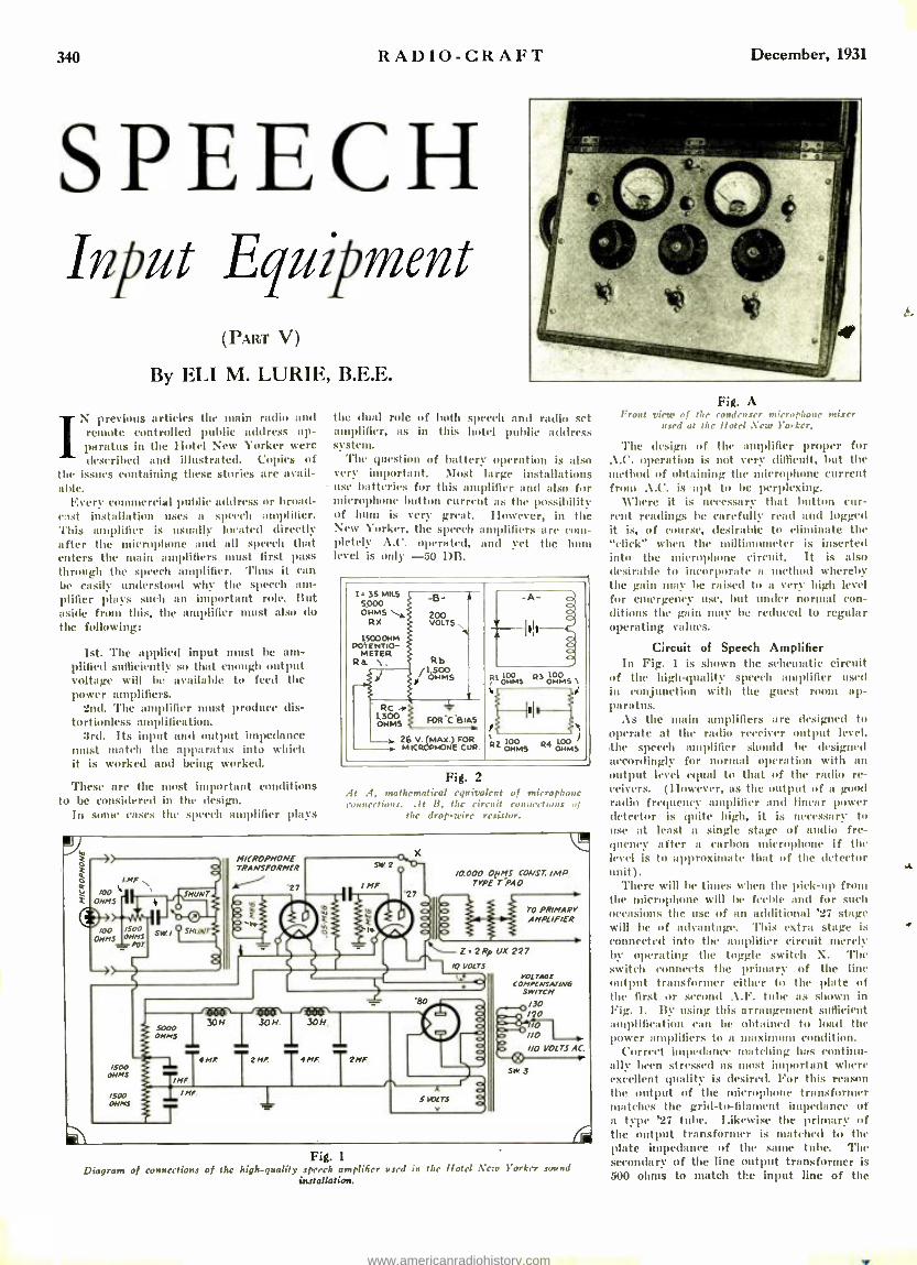
SPEECH Input Equipment
(PART V)
By ELI M. LURIE, B.E.E.
1 previous articles the main radio uul remote controlled public address ap- paratus paratus in the Hotel New Yorker were described and illustrated. Copies of
the issues containing these stories are avail- able.
Every commercial public address or broad- cast installation uses a speech amplifier. 'fuis amplifier is usually located directly after the microphone and all speech that enters the main amplifiers must first pass
December, 1931
the dual role of both speech and radio set amplifier, as in this hotel public address system.
'l'he question of battery operation is also very important. Most large installations use batteries for this amplifier and also for tuuictaphone button current as the possibility of hum is very great. However, in the New Yorker, the speech amplifiers are com- pletely A.C. operated, and yet the ban level is only -50 DB.
through the speech amplifier. Thus it can be easily understood why the speech am- plifier plays such an important role. But aside from this, the amplifier must also do the following:
1st. The applied input must be am- plified sufficiently so that enough output voltage will he available to feed the power amplifiers.
2nd. The amplifier must produce dis - tortionless amplification.
3rd. Its input and output impedance t match the apparatus into which
it is worked and being worked.
I. 3S MILS 5,000 OHMS
RX
1SOOOHM POTENTIO-
METER Rs \.
-B-
VÇT S-.
Rb 1,500 OHMS R OHMS RS öNMS
/
Rc 1.
FOR C BIAS
26 v. (Max) FOR MICROPHONE CUR.
:a 100 OHMS R4 LOO
OHMS
These are the most important conditions to be considered in the design.
In some cases the speech amplifier plays
Fig. 2 :It A, mathematical equivalent of microphone convections. At B, the circuit connections of
the drop -wire resistor.
I.MF
0
/t's/00 II L
MICROPHONE TRANSFORMER
27 aMF /0.000 OHMS CONST IMP.
TYPE -T PAO
/00 /500 sl« Y SHUN
OHMS OHMS cor
/500 OHMS
/500 OHMS
5000 OHMS
MF
H 30N. 30N
4 M 25F 4 M 2MF
TO PR /MARY AMPLIFIER
Z2RFUX227 /q VOLTS
t.
MF 5WLTS
VOL TAGE COMPENSATING
SWITCH
130 /20 l0
I/O I/O VOLTS AC.
SW 3
Fig. 1
Diagram of connections of the high- quality speech amplifier Used in the hotel New Yorker sound installation.
Fig. A Front rime of the condenser microphone mirer
used at the hotel New Yorker.
The design of the amplifier proper for A.C. operation is not very difficult, but the method of obtaining the microphone current from A.C. is apt to be perplexing.
Where it is necessary that button cur- rent readings be carefully read und logged it is, of course, desirable to eliminate the "click" when the millianuneter is inserted into the microphone circuit. It is also desirable to incorporate a method whereby the gain may be raised to a very high level for emergency use, but under normal con- ditions the gain may be reduced to regular operating values.
Circuit of Speech Amplifier In Fig. 1 is shown the schematic circuit
of the high -quality speech amplifier used in conjunction with the guest room ap- paratus.
As the main amplifiers are designed to operate at the radio receiver output level, the speech amplifier should be designed accordingly for normal operation with an output level equal to that of the radio re- ceivers. (However, as the output of a good radio frequency :amplifier and linear power detector is quite high, it is necessary to use at least a single stage of audio fre- quency after it carbon microphone if the level is to approximate that of the detector unit).
There will be times when the pick -up fr the microphone will be feeble and for such occasions the use of an additional '27 stage will be of advantage. This extra stage is connected into the amplifier circuit merely by operating the toggle switch X. The switch connects the primary of the line output transformer either to the plate of the first or second A.F. tube as shown in Fig. 1. By using this arrangement sufficient amplification can be obtained to load the power amplifiers to a maxinmmll condition.
Correct impedance matching has continu- ally been stressed as most important where excellent quality is desired. For titis reason the output of the microphone transformer matches the grid- to-fill lit impedance of al type '27 tube. Likewise the primary of the output transformer is matched to the plate impedance of the saune tube. The secondary of the line output transformer is 500 ohms to match the input line of the
www.americanradiohistory.com

December, 1931 RADIO -CRAFT 341
primary amplifier in the main amplifier rack. It will be observed that resistance coupling
is used in the second stage. Resistance coupling will usually produce even ampli- fication and is also good in that the re- sulting gain can equal no more than that of the input voltage, times the amplifica- tion factor of the tube. Distortion is there- fore l' led in the amplifier to a very low value and can be considered almost neg- ligible.
Ilowever, where resistance coupling is used difficulties arise due to the charac- teristic low frequency oscillation ("motor - boating") occurring in this type of am- -. Oilier. To eliminate any possibility of such oscillation an extra filter section consisting of a 30 henry choke and 4 inf. condenser is added to the regular filter circuit. In addition, the plate supply is steadied by a low resistance drop -wire of 5750 ohms.
Of most interest is the method used to obtain microphone button current. In Fig. 2A is the equivalent microphone cir- cuit. As the microphone transformer is designed to match the impedance of the microphone, its split primary will have an impedance of 100 ohms on each side. Each button will, therefore, be in series with 100 ohms making a total of 200 ohms on each side of the button battery. The Western Electric standard broadcast microphone (type 387) is usually operated at about 20 milliamperes per button. Therefore, it fol- lows that to supply this current our bat- ten' must have u potential of 4 volts or 1e. =4= (.02) (200). Also as we have two sides to supply, the total wattage will he
Fig. 5 Schematic circuit of the condenser microphone
miser illustrated in Fig. .4.
W = EI x 2 = 4 x (.020) (2) _ .16 -watt necessary.
In Fig. 2B is the circuit of the drop -wire resistor. 'l'he output voltage is 2I0 volts and as the "bleeder" current will determine any voltage drop across the drop -wire, it is well to consider this item first. 'l'he variable 1500 ohm potent' ter Ito is used to supply the microphone with its E.M.F. This potentiometer is in parallel with a 1500 ohm resistor lt h. The bleeder cur- rent will, therefore, divide between the two resistors. The total resistance of these two parallel resistors will be 7.50 ohms. This added to the 5000 ohm resistor Itx makes a total of 57.50 ohms as the whole drop -wire resistance. Our "bleeder" cur -
200 rent will, therefore, he I = -= 35 ma.
5750 As the bleeder current divides between the two 1500 ohm resistors each resistor will
35 have approximately - or 17.5 milliamperes
2 passing through it.
Fig. 4 Schematic circuit of the power amplifier design
for hotel use.
Thus the voltage across Ra will he 1500 x .0175 = 26+ volts, and the wattage dissipated by this resistor will be 0.45 -watt. 'l'he microphone circuit resistance will, how- ever, be connected in parallel with some section of Ita and this must therefore be considered. As the microphone wattage has previously been calculated as .16- watt, the rating of Ha mast be equal to .16 -f- .45 = .61 -watt. A two- watt, 1500 olnn poten- tiometer should be satisfactory and can be used in this position.
It is true that the microphone circuit will be connected across only a small portion of Ra but every calculation should always be made for the extreme case. Thus Ito can supply a maximum potential of 26 volts, but as only about four volts are required for a single microphone the slider will gen- erally be across only a small portion of the resistor. The idea of having as much as 26 volts available is for use in case several microphones are to be used. (With such a condition each microphone will generally have its own matching transformer.)
Every one who has had any experience with carbon microphones knows the diffi- culty of eliminating clicks when taking microphone current readings. The usual procedure when reading button current is to insert a milliauumeter, first into the circuit of one of the buttons, and then, after the
reading is obtained, the milliammeter is inserted in the other button circuit. In each case, the circuit is broken as the meter is cut into and out of each circuit which produces a decided and loud click. To eliminate this interference, engineers de- vised ninny different schemes. One makes use of relays that open the microphone cir- cuit to the milliaumleter only after the meter has been inserted, thus eliminating clicks. Of course such a method could be used with excellent results, but the cost offsets the advantage. Another system makes use of various filter arrangements which are connected across the jack into which the meter is plugged, but, with this method, there is almost always a small resulting click that at times is extremely disagreeable.
Perhaps the easiest and yet possibly the best solution of the above problem is to use a low reading uailliaumueter with two shnts. Any 0-1 up to a 0 -5 milliauuneter may be used. The shunts may be made out of heavy resistor wire of about number 12 gauge; they are connected as shown in Fig. 1. 'l'he shunts flay be designed to carry
SW+ Ñél
1R Rl; R2
R3
SW R2
MIG R N12 R3
SW i R2
wéS l R R R3
TO LINE s.
s
-8-
Fig. 6 At .4, this circuit shows the manner in which constant impedance is obtained in the micro- phone "atteuuator circuit." At B, theoretical
figure of reference.
10 to 15 times the current passing through the meter. The scale on the meter is cali- brated to read directly the total current through each button as the double throw switch SW. 1 is placed across either shunt. Supposing the meter is a 0-5 milli: ter, then the scale is changed to read from 0 -50 milliamperes.
Of course the of values of the shunts depend upon the internal resistance of the
(Continued oN page 368)
N-
RISOWi 100.000
OHMS
NMS
'39 A CS,IjF '39A C7 F
n °o r(t:MOONOIy
KT* RS
r(EO
nF7 i At 7 ct 1W a tstst
'3 A
CB,1MF t4im R l2 (CSO o00
1fl1'iI"ti C6 OMMS ' IT
09-B 0 a ::
CIO,IMF, t[( alo.r r OMMS OuMS
o PI
cc
IMF
-1i
650.0
K3 24 15,000 OHMS
K2
C 1 MF.
15COHMS + 6V
Fig. 3 Redesigned 11'.E. 41:1 speech amplifier circuit. Direct current mast be used on the filaments.
This current is most conveniently obtained from dry.rectifier -type ".4" units.
www.americanradiohistory.com

342 RADIO -CRAFT
A practical appli- cation of a copper.
oxide meter.
N the first part of this series which ap- peared in the November issue of It.voto- CeAFr, the historical development of the D.C. voltmeter and ammeter was
discussed, starting from the original tangent galvanometer.
The "instrument problem' received h attention from such distinguished minds as Deprez and D'Arsonval in France, Kelvin, ferry and Ayrton in England, Sicilians and I- lunnnel in Germany, and many others of equal fame, in the time succeeding Oer- sted's and Schweiggers' crude devices.
Dr. Weston, in the United States, after many years of strenuous effort developed the first permanent magnet pivoted moving coil type of instrument. This development of Dr. Weston revolutionized meter design, and placed the art of electrical measure- ment on a new plane.
In the determination of the effectiveness of an alternating current, the square root of the average squares of all the instan- taneous values of alternating current is taken, and expressed in units of a given direct current which will produce the same power or heating effect as the given alter- nating current. 'l'he value so determined is called the effective or H.M.S. value, and is .707 of the ntaxintimi value.
Instruments used for al- ternating current nteasure- ntents indicate directly in "It.M.S." or effective valo .
(the direct current equiv- alents) staking the compu- tation of these values un- necessary.
Under these conditions we see that the maximum volt- age per alternation in a commercial 110 volt A.C. circuit is 155 volts on each half of the cycle.
Iron Vane Instrument The most common type of instrument for
alternating current measurements is known
December, 1931
Magic in
Meters ( PART II)
In this second of a series of articles, Mr. Denton describes the various types of A. C. meters used
in radio work.
as the iron vane type. This class of meter can he found in most set analyzers and is generally recognized as the most practical for low frequencies.
Referring to Fig. IA, we see that there are two bars or vanes of soft iron hung vertically in the center of a coil. If no cur- rent is applied to the coil, there will be no movement as shown. When a direct or alter- nating current is passed through the coil as indicated in Fig. III, the bars repel each other. Regardless of the direction of current flow, the upper end of the two pole pieces are magnetized either 1 or S, depending upon the direction of current flow, and the lower ends either S or N. Following the haw that like poles repel, we find that the hers are thrust apart.
The commercial models have one of the vanes fixed in position in the coil and the other vane free to move on a pivot, the in- dicating pointer being fastened to the mov- ing vane to facilitate movement over a scale as indicated in Fig. IC. It will be noted that the movable pole piece can be displaced only by rotation caused by the repulsion.
By CLIFFORD E. DENTON the case in direct current meters: the force which causes
the movements of the iron vane depends on the strength of the magnetic field set up in the coil, and the field strength of the coil depends upon the amount of current flowing in the winding. When the current flows through the coil, the movable iron vane rotates to such a position that the opposing force exerted by the spring and the magnetic force of repulsion become equal. 'l'he indicator then stops and shows the scale value of the current flowing in the circuit.
in the alternating current voltmeter, the field coil consists of a fairly large number of turns of comparatively fine wire. As it is impossible to wind a coil with 'sufficient resistance to prevent a flow Of current which would damage the winding, a resist- ance is placed in the circuit so that the current flowing through the coil is reduced to a satisfactory value.
:Ammeters have coils wound with com- paratively heavy wire. 'l'he size of the wire depend on the current ranges of the meter.
Shunts for use with alternating current ammeters arc not recom- mended, especially when the instrument is being used on more than one frequency. If the meter has been cali- brated at one frequency and is to he used on :mother, it should be re- calibrated so as to compensate for any error caused by the shunts.
Multipliers for extending the voltage range of alter- nating current voltmeters are satisfactory as long as the resistors used maintain their ohmic value.
Figures 2 and 3 show the electrical circuits of alternating current volt- meters and ammeters.
Fig. 1
The principle of operation of the iron-vane movement used in shaxrn abort.
The rotation of this pole piece is opposed by springs which do not carry current as is
.4.C. meters it
www.americanradiohistory.com

w
December, 1931 RADIO -CRAFT 343
The Solenoidal Meter An instrument that employs a very simple
movement is known as the "solenoidal meter." Referring to Fig. 4, we sec that it consists of a coil with a plunger C fastened to the indicating arm B. This area is pivoted at point l' so that the plunger can move freely into the coil as indicated.
Current flowing through the compara- tively low resistance coil "sucks" up the soft iron plunger, causing the indicator to move over the scale which can be calibrated by sending known values of current through the coil. A weight NV controls the action of the plunger and the damping of the indicating pointer is accomplished by the eddy cur- rents in the plunger. This type of movement is inaccurate, due to the large errors caused by hysteresis losses which are traceable to the excessive mass of the moving parts.
This movement will be found only in the less costly instruments.
Hot -Wire and Thermocouple Types High frequency alternating current meas-
urements are general- ly based on the heat- ing effects caused by passing a c u r r e u t through a strip of Metal. Ilot -wire !pe- ters depend for their action on the expan- sion of a metal wire when heated, the wire generally used for the heater being platinum. 'l'he latter type of A. C. meter is used ex- tensively for high fre- quency measurements, hut it uses a consid- erable amount Of power, is easy to burn out, and is not per- manent in calibration.
'l'he wire All, Fig. b is selected for its ability to expand when it is heated by the high frequency cur- rent, and is connected as manner that the current to he measured will flow through it. The spring S tends to hold the wire AB taut through thread C. 'l'he resultant motion Caused by the ex- pansion of the wire causes the pointer P, which is rigidly attached to roller It, to move over the scale. The movement of the pointer depends upon the amount of cur- rent flowing through the wire.
In the case of the thermal ammeter, we find that the voltage generated at the Junc- tion K of the two dissimilar metals CI), Fig. 6, in contact with the wire Ali, is im- pressed across the direct current millivolt- meter M.
The heat in wire AB is generated because of the A.C. energy flowing through the cir- cuit, and is equal to that which would be generated for a certain number of amperes of direct current. The deflection of the needle indicates the effective value of A.C. energy as do the iron vane and solenoidal meters.
The thermal junction generally used is made up of the metals copper and constan- tan, and is heated by a fine wire through
which the current flows. To increase the sensitivity, the ,junction is generally mounted in a small glass bulb.
The voltage developed by the thermo- couple is directly proportional to the tem- perature, and the temperature of the heated wire is proportional to the square of the al- ternating current flowing in the heater; the reading of the meter then, is proportional to the square of the current through the heater wire. This meter is sometimes called a "current -squared" Rueter.
Since a D.C. meter reads average values, the scale of this meter may be marked so as to read the square root of the average value, which as we have seen before, is the effec- tive value of the A.C.
Copper -Oxide Meters With the development of the modern radio
set, a demand for sensitive voltameters of low power consumption was created. Direct current movements which can satisfy these requirements can be readily built with a.
sensitivity of 1000 ohms per volt. This means that a current of one milliampere is sufficient for a full scale deflection. This may be done by simple rectifying the . \.C.
voltage to be meas- ured and applying it to the D.C. meter.
'('here a r e several methods whereby we can rectify the alter- nating current to be measured. 'l'he first is by the use of a crys- tal rectifier, Fig. 7. 'l'he crystal, however, is generally too un- stable in operation and needs to be adjusted quite often, and is also subject to burn -out at comparatively low cur- rent values. The sec- ond is be the use of a tube rectifier, the cir-
cuit of which is shown in Fig. A. 'l'he ordinary design of such a device generally I' 'ts its application because it is subject to tube failure, and every time the tube needs to be
Figure 4 above. The magnetic- field genera rd by the coil "sucks" up the plunger C, mor ,g
the pointer It over Me scale. Figure 5 belon'. The expansion of the raire 9B causes the pointer to more over the scale.
to the circuit in such
replaced, the instru- ment nmst be re-cali- brated. 'l'he same in- strument is sometimes used as an output meter, when the indi- cations are for com- parison only.
'l'he third and most desirable method of rectification is by the use of the copper ox- ide rectifier, Fig. 9. This type is satisfac- tory from the stand- point of ruggedness, sensitivity, and con- stancy. Its main dis- advantage is that the meter indicates "aver- age" values instead of effective values.
This introduces an inaccuracy in readings which becomes apparent when the voltage to be measured has a distorted wave form. Fig. 10 shows a graph representing a dis- torted sine wave which would cause an error of about two per -cent. In most cases, however, such small inaccuracies are of but little importance to the Service Man.
DISSIMILAR
METALS/
i R
CARBORUNDUM CRYSTAL
AC INPUT
DC METER
Figure 6 left. The thermo- jonction at K gen- cratcs a D.C. voltage which is applied to M.
Figure 7 right. Olsen that the crystal recti- fier is used to rectify the :LC. voltage to be
measured.
The wave form of most of the voltages encountered in a radio set will closely ap- proximate sine waves; thus, for practical purposes the distortion and its consequent error due to the rectifier will be negligible. Figure 11 is an example of the actual oscil- lograms taken of the voltages within a Itadiola "60" showing the close approach of the wave form to a sine wave.
Rectifier type instruments have a large capacitance due to the rectifier, which causes a change in scale deflection as the frequency of the applied voltage to be measured is varied. The effect of this capacity is not great at low frequencies, but above about three thousand cycles the error is augmented by the increase in frequency. This is not as serious an objection as it ap- pears to be at first glance, because the Ser- vice ilIn seldom requires absolute accuracy above the standard commercial frequencies.
Momentary over -loads of three to ten times the normal voltage rating do not damage the rectifier, thus reducing to a minimum the danger of destruction of the unit due to over -load.
A Universal Meter Many interesting and serviceable pieces of
equipment can be constructed using the
Figure 2 left. Illustration of the mode of connection of the moving vane type of :l.C. ammeter.
Figure 3 right. Connections of the multipliers in the moving -vane type of A.C. voltmeter.
www.americanradiohistory.com

344 RADIO -CRAFT December, 1931
An Electrolytic Condenser Rectifier A Novel Power Pack Design Including Only a Transformer and Electrolytic Condenser
By P. M. JAROWEY
THE almost universal use of tubes, of one forma or another, for rectifying alternating current to obtain a pulsat- ing direct current, and the subsequent
use of condensers and chokes for obtaining a somewhat constant output, has so stand- ardized the radio power unit that rectifica- tion and filtration without the use of them does not seem to have been given much thought.
While conducting some experiments last Autumn, the idea of using electrolytic con- densers for both rectification and filtration occured to me, and I am passing it along in the hopes that it may find a place in the laboratory of some experimenter.
Figure 1 is a schematic diagrams of the entire arrangement. As can he readily seen, i tconsists of the conventional power trans- former and an electrolytic condenser. This condenser (a double unit is shown although two single ones with their negative terminals connected together may be used with the same results) acts- as both the rectifier and the filter. The results obtained with this arrangement have been far better than those obtained by using the vacuum tube rectifier and its associated filter.
Theory of Operation An electrolytic condenser, like any other
condenser, must consist of two conducting
PT
%U
SEC
A.0 VOLTS NOT TO EXCEED REM( vALUE
'' OF THE RATED CONDENSER
I VOLTAGE
POS ELECTRO S
NEC, ELECTRODE
METAL J PLATES/
r
D.0 LOAD
Fig. 1
.1 simple power pack. The electrolytic con- denser design limits the output.
plates separated by a dielectric. The greater the area of the plates and the smaller the distance between them, the greater the capacity of the condenser. If the dielectric is other than air, the capacity is usually greater than if air were used. The dielectric
t not he too thin, because if it is, then the voltage that can he impressed across it without puncturing is very small. Thus it is seen that the design of a condenser st
Magic in Meters (Continued from
standard millianuueter in conjunction with a copper -oxide rectifier. Figure 12 indicates an arrangement which gives accurate indi- cations in A.C. and D.C. circuits, the maxi - mima ranges being limited only by the de- sires of the constructor. In this circuit a Weston 301 universal meter is used and is provided with a double scale. The upper scale is used when the instrument is con- nected for alternating current measurements and has a range from 0 -5 volts, and the lower is the D.C. scale and is also calibrated from 0 -5 volts. The sensitivity of both the A.C. and D.C. scales is 1000 ohms per volt.
The meter has four external connections
FIG.10
C'
D'lüii Id
IiIIrVVlaaioViuV'u'JVUJVü'tVUdVIJV'VuüV6'
FIG. 11
Figure 10 above. An illustration of a distorted sine wave.
Figure 11 below. .4t A and B is shown the wave form of the unrectified filament voltage in a commercial receiver, and at C and D the un- rectified plate voltage. Note that they are all
pure sine waves.
and a shunt which is calibrated for the meter. The alternating current ranges are thus 5 volts and 1 milliampere and the direct current ranges are 50 millivolts and 1 am- pere. 'l'hus by the selection of the proper values of multipliers and shunts the instrument can be used to measure D.C. and A.C. volt- ages and currents. 'The volt- age and current ranges indicated in the diagram cuver most of the require- ments of the Service Man.
The material required to construct the instrument consists of the 301 universal meter, a double throw double pole switch, a
four contact switch, the panel for mount- ing the parts, and the necessary bind- ing posts or connect- ors for the various ranges. The number of resistors necessary for the multipliers and shunts depends on the ranges to be covered.
The efficiency of an instrument of this kind depends upon the accuracy of the resistors used. The builder should not at- tempt to use resist-
be a function of its capacity, size, and oper- ating voltage.
In the electrolytic condenser, a large metal conductor, coiled so as to minimize space, is used as one plate, and a sointion of borax and water for the other plate. \Chen the unit is connected across a properly poled source of D.C. (positive to the metal plate, and negative to the solution, the latter con- tact being made via the metal container) a
film of hydroxide gas is formed on the metal plate of the condenser. This film of gas, only a few atoms thick, is the dielectric. 'lite large area of the plates and the exceed - ingly small thickness of the dielectric ac- count for the relatively high capacity of the unit.
Now, an analysis of the action of an elec- trolytic condenser will reveal that current will pass freely and continuously from the electrolyte to the metal plate when the elec- trolyte is positive with respect to the metal plate, but current will not flow in the reverse direction when the polarity of the applied voltage is reversed. It is this characteristic of the condenser that enables it to be used as it rectifier.
(Continued on page 369)
page 343)
ors of dubious quality, since accurate resist- ors must be used. Ni n- inductive types of resistors should always be used in alternat- ing current measurements due to the errors introduced by inductive action.
Figure S left. The use of the vacuum tube as a rectifier used for measuring A.C. voltages.
Figure 9 right. A bridge connection of dry -disc rectifiers may be used for measuring alternating voltages with a D.C. meter.
1000v
750V
500V
250V
400v
5o V
40 V
5V
t A.C.
250,000 OHMS
250.000 OHMS
250,00004445
425,00004MS
50.000
40,000 04145
5000 045
SET SWITCH 'S' AT IMA 'WHEN USING AS VOLTMETER
IM1
IOO M A
2.5 M A
15 MA
M.A
! r 1
SOS 2.063 33.35 OHMS OHMS OHMS
Fig. 12 Complete circuit diagram illustrating hone a D.C. meter may be used as
an .I.C. voltmeter, and both as a D.C. voltmeter and ammeter
www.americanradiohistory.com

December. P)31 RADIO -CRAFT 345
The Service Man's Forum Where His Findings May Benefit Other Radio Technicians
THE SMALL -TOWN SERVICE MAN Edita.r, ItAano-CRAIT:
I mu an independent Service Man in a town of 14,010 inhabitants. I have worked for a dealer, but in view of the small re- muneration received, I went in business for myself. I advertise in the two newspapers here, pass out curds from door to door, but business is very slow, although I have been in business for myself only two months. Most of the work that I get is the result of recommendations from satisfied customers.
I have read letters in the "Open Forum" front Service Men in the larger cities who seem to be successful, but I never hear from anyone from a town the size of this, who has much to say.
I would like to have vim publish this let- ter, and would also like to hear from Serv- ice Men in the smaller towns who are suc- cessful, that is, men who are in my ouw class as regards population.
I belong to the Official Radio Service .ife,,'s Association and think that every live honest -to- goodness Service Man should join.
ItA LP] l J. WiIITrER, Route No. 2, Freemont, Ohio.
AN A. K. BOOSTER Editor, RADIO -CRAFT:
I wish to answer to the article submitted by Julius Denims in the Open Forum col- umn in your September issue of RAnto- CRAIT.
lie complains of being unable to receive service data regarding Atwater Kent Radio sets from his local distributor. I wish to state that u great deal of credit is due to the Atwater Kent Manufacturing Company
FACTS
Open every day including Sunday and Holidays.
We charge one dollar for a service in. spection calL
Service man is on the job within an hour after call is received.
Two complete shifts of men working from 8 A. M. till 12 midnight.
25 service men equipped with meten to study your individual troubles.
All service men equipped with autos.
We convert A. C. sets to D. C. and versa, visa also change battery sets to
electric sets.
Automobile radio sets installed and serviced.
REAL RADIO SERVICE man en,n
550 State Street, Brooklyn, N. Y.
CUmberland 6.4060 6.4059 6.4061
.4 few well-chosen paragraphs outline the com- plete service. Lettering is red on blue; card
measures 4 x 6% in.
for having, without a doubt, the most up- to-date service manual I have in niv pos- session.
It readily helps to locate and correct any condition which might interfere with the proper functioning of the receiver. This valuable Manual l is offered to any Service Man who, can prove his qualifications by simply writing for a copy on his business stationery.
Expert Radio Service We rer,r.n matte. Noe, or F.Lrv,.
C.mmngh.n.,,J Spa 11011 Tuly J.L. end Free Amhed..J >J.o M.nh.11 Ser.nr
Ouse Complete Radio Service la merest Member of dui 011ii id lt.J,., S,e.i..me:. Assn.
Mace tais teed In year rail, fer tatare reference
RTw in nerd of ami -. Jtoo stabs-2515
.n5
R. J. Witter's Radio Service Fremont, Ohio
..l Service Man capitalizes his association mem- bership. Lettering is black on brown; the card
measures 3'' /a x 5% in.
I hope the time will come when other Radio Manufacturing Companies will fol- low the example set by the Atwater Kent Manufacturing Company, and publish data which will be as helpful in servicing their receivers.
JACK I.EVINE, 137 Front Street, Worcester, Mass.
"KILLING" SERVICE CALLS By Henry H. Klappert
A',TER five years of customers' service
experience, I have come to the eon- clusian that 50% of future service calls can be killed at the time of installation by the simple expedient of doing the ,job right. By this, I Mean making a test of the fila- ment voltage and reconmaending to the cus- tomer the use of a line resistor if necessary. Most of them will buy one of these devices on the installer's saav so. If the filament is held down to 2.4 colts, on 2.5 -volt tubes, little trouble will he experienced for over a year. They should also be tested at this tinte for loose elements and current output. On tapping the tube when in the socket. loose elements will generally show up; mad such tubes should be changed immediately. So much for the set.
When the antenna and ground are in- stalled, the installer should remember that a Service Jlan might some time be on that ,job checking for trouble and will probably have to disconnect at various points along the aerial and ground systems. Nothing is more annoying than to have to pull out a
number of tacks to do this. A first -class installer takes into consideration, not only neatness and electrical efficiency of the job, but also that that set might have to he serviced. A good installation should be made as follows:
Leave about six (fr) feet of wire, from the antenna and ground binding posts of the set to the point where the lends are tacked to the baseboards; so that when the set is moved away from the wall these wires will not pull off. They should be tacked sepa- rately along the baseboards, at least two inches apart, to that point where they will naturally separate going to their respective destinations. The ground clamp should then be put on a clean surface,. making sure it is firmly tightened; it is good policy at this time to tell the customer to tighten this up again in about two weeks to take up the stretch in the metal. 'flic ground wire should be put through the clip, and the end sl Id be skinned for a length sufficient to wind around a few times. A hop of about three inches should be left at this point so the Service Man can disconnect it easily if necessary. This advice also applies to the inside connection of the lead -in strip.
Now for the antenna; if located in It large city, on top of an apartment building, it is advisable to put this up as high as is practical and about 100 feet long if pos- sible. I have found that the non -made static level is reduced by a long antenna in most cases. This seems hard to believe, but I ant writing fronts practical experience. Of course, if the set is located near a power- ful broadcast station, the antenna will have to be shorter.
The lead -in wire should then be stripped for about three inches, and twisted a num- ber of times about the antenna wire. As no connector for this purpose is sent with an antenna kit. twisting the wire is the best procedure I can suggest; it should
(Continued on page 369)
O. the .hotmskee repel. cou, .ugh! O. the baiter tn.", Tour ,IgYev Don the fish man 'trait Tone ,..1! Dar. the .:.. e... .n .rr ,,, CumUnr
RA Z Y? WELL -then why do
you call a Butcher to repair your Radio?
Every service man employed by REAL RADIO SERVICE is a qualified radio engineer, whose ability has been proven by many years experience.
All work done by REAL RADIO SERVICE is absolutely guaranteed.
REAL RADIO SERVICE . oifi.e:
550 State Street, Brooklyn, N. Y. CUmberland 6.4060
6.4059 6.4061
A "catch" heading. This is the reverse side of the card illustrated at the left of this pnoe.
www.americanradiohistory.com
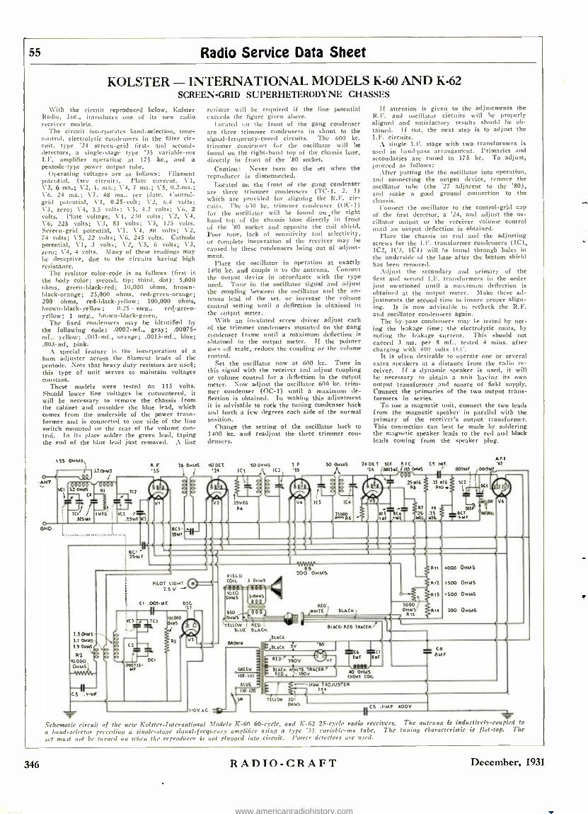
- ce - eMF
55 Radio Service Data Sheet
KOLSTER - INTERNATIONAL MODELS K -60 AND K -62 SCREEN -GRID SUPERHETERODYNE CHASSES
With the circuit reproduced below, bolster Radio, Inc., introduces one of its new radio receiver models.
The circuit incorporates band- selection, tone - control, electrolytic condensers in the filter cir- cuit, type '24 screen -grid first- and second - detectors, a single -stage type '35 variable -mu I.F. amplifier operating at 175 kc., and a pentode -type power output tube.
Operating voltages are as follows: Filament potential, (see circuit). Plate current. VI, W3, 6 ma.; \'2, 1. ma.; V4, 7 ma.; V5, 0.2 -ma.; \'G. 24 ma.; \7, 48 nta.. per plate. Control - grid potential, \'I. 0.25 -volt; V2, 6.4 volts; \'3, zero; W4, 3.5 volts; W5. 4.2 volts; \'6, 2 volts. Plate voltage, VI, 230 volts; \'2, V4, W6, 225 volts; \'3, 85 volts; V5, 125 volts. Screen -grid potential, WI, V4. 80 volts; \'2, 74 volts; V5, 22 volts; V6, 245 volts. Cathode potential, VI, 3 volts; W2, \'5, 6 volts; V3, zero; V4, 4 volts. \)any of these readings may be deceptive, due to the circuits having high resistance.
The resistor color-code is as follows (first k the body color; second, tip; third. dot): 5,000 ohms, green -black -red; 10,000 ohms, brown - black- orange; 25,000 ohms, red -green -orange; 200 ohms, red -black -yellow; 100,000 ohms, brown - black- yellow; 0.25 - meg., red- green- yellow; 1 meg., brown- black- green.
The fixed condensers may be identified by the following code: .0002 -mf., gray; .00075 - mf., yellow; .001 -mi, orange; .0015 -mf., blue; . 003 -mf, pink.
A special feature is the incorporation of a
hum adjuster across the filament leads of the pentode. Note that heavy duty resistors are used; this type of unit serves to maintain voltages constant.
These models were tested on 115 volts. Should lower line voltages be encountered, it will be necessary to remove the chassis from the cabinet and unsolder the blue lead, which comes from the underside of the power trans- former and is connected to one side of the line switch mounted on the rear of the volume con- trol. in its place solder the green lead, taping the end of the blue lead just removed. A line
55 OHMS,I
I !_ 152oMM5 O C lílQl ANT
2.5 OHMS
5.1 OHIO S 5 OHMS
311 10000 OHMS
resistor will be required if the line potential exceeds the figure given above.
Located on the front of the gang condenser are three trimmer condensers in shunt to the signal- frequency -tuned circuits. The 600 kc. trimmer condenser for the oscillator will be
found on the right -hand top of the chassis base, directly in front of the '80 socket.
Caution: Never turn on the set when the reproducer is disconnected.
Located on the front of the gang condenser are three trimmer condensers ('FC -1, 2, 3) which are provided for aligning the K.F. cir- cuits. The 600 ¡cc. trimmer condenser (OC -1) for the oscillator will be found on the right hand top of the chassis base directly in front of the '80 socket and opposite the coil shield. Poor tone, lack of sensitivity and selectivity, or complete inoperation of the receiver may be
caused by these condensers being out of adjust- ment.
Place the oscillator in operation at exactly 1400 kc. and couple it to the antenna. Connect the output device in accordance with the type used. Tune in the oscillator signal and adjust the coupling between the oscillator and the an- tenna lead of the set, or increase the volume control setting until a deflection is obtained in the output meter.
With an insulated screw driver adjust each of the trimmer condensers mounted on the gang condenser frame until a maximum deflection is obtained in the output meter. If the pointer goes off scale, reduce the coupling or the volume control.
Set the oscillator now at 600 kc. Tune in this signal with the receiver and adjust coupling or volume control for a deflection in the output meter. Now adjust the oscillator 600 kc. trim- mer condenser (OC -1) until a maximum de- flection is obtained. In making this adjustment it is advisable to rock the tuning condenser back and forth a few degrees each side of the normal position.
Change the setting of the oscillator back to 1400 kc. and readjust the three trimmer con- densers.
R. F. 26 OHMS 167 DU. SO OHMS I F.
'35 j 'is ICt IC2 IS
° N
2p ED luci t05-000a6 úi ssi[ 1IIIL»»»>». >.,»,,,,, EMT '7 7\ "1.1:
.15uF. L')l ' R5 FIELD 200 OHMS
PILOT 16HC COIL- 3 Rlt 2.5 V o50 ----
OMMS .)-OHHS R13
CI .001-M O5C. '2T
If attention is given to the adjustments the R.N. and oscillator circuits will be properly aligned and satisfactory results should be ob- tained. If not, the next step is to adjust the I.N. circuits.
A single I.P. stage with two transformers is used in ban .pass arrangement. Primaries and secondaries are tuned to 175 kc. To adjust, proceed as follows:
After putting the the oscillator into operation, and connecting the output device, remove the oscillator tube (the '27 adjacent to the '80), and make a good ground connection to the chassis.
Connect the oscillator to the control -grid cap of the first detector, a '24, and adjust the os- cillator output or the receiver volume control until an output deflection is obtained.
Place the chassis on end and the adjusting screws for the I.P. transformer condensers (ICI, IC2, IC3, IC4) will lie found through holes in the underside of the base after the bottom shield has been removed.
Adjust the secondary and primary of the first and second I.F. transformers in the order just mentioned until a maximum ,deflection is obtained at the output meter. Make these ad- justments the second time to insure proper align- ing. It is now advisable to recheck the R.F. and oscillator condensers again.
The by -pass condensers may le tested by not- ing the leakage time; the electrolytic units, by noting the leakage current. This should not exceed 3 ma. per 8 mf., tested 4 ntins. after charging with 400 volts D.C.
it is often desirable to operate one or several extra speakers at a distance from the radio re- ceiver. If a dynamic speaker is used, it will be necessary to obtain a unit having its own output transformer and source of field supply. Connect the primaries of the two output trans- formers in series.
To use a magnetic unit, connect the two leads from the magnetic speaker in parallel with the primary of the receiver's output transformer. This connection can lest be made by soldering the magnetic speaker leads to the red and black leads coming from the speaker plug.
50 OHMS 250E7 M.4 RFC. CI -.ME '24 .000)40 1165 OHMS .0054.1F
BLACK. RED TRACER
610511
100 Ito
SLI no-1to
110V SC
40 OHMS CHOHE COIL
I TEIIOw 201
OHMS
- -- HIM I ADJUSTER iv
4000 OHMS
1500 OHMS
1500 OHMS
100 OHMS
CS .1MF. 400V
Schematic circuit of Our new Kolstrr- International Models K -60 60- cycle, and K -62 25 -cycle radio receivers. The an cuna is inductively -coupled to
a Gaud- elector preceding a single -.stage signal- frcqucney amplifier using a type '35 variable-mu tube. The tuning characteristic is flat -top. The
set mus not be turned on :rhea the reproducer it not plugged into circuit. l'on'er detectors are used.
346 R:\Din-CR:\PT December, 1931
www.americanradiohistory.com

Radio Service Data Sheet 56
U. S. RADIO AND TELEVISION MODELS 99 AND 99X
Perhaps the most simplified commercial superheterodyne receiver as yet developed is the lo. 99 chassis, a circuit of which is shown below.
The design includes a combination oscillator and first -detector \'1, using a type '24 screen - grid tube; an I.F. amplifier V2, using a type '35 variable -mu tube; a second -detector \'3, using a type '24 screen -grid tube; a pentode power output tube \4; and the usual '80 recti- fier V.S. lote the absence of a separate oscil- lator tube. The intermediate frequency is 262 kc. A band- selector precedes the detector - oscillator.
A surge of energy fed into the secondary of the oscillator inductively causes this circuit to begin to oscillate at its resonant frequency, 262 kc. above the signal frequency. This oscil- lator frequency is fed back through the tap in the secondary coil into the grid circuit of the first -detector. There, the oscillating signal is amplified and fed inductively through the primary system in the plate circuit of the tube back into the secondary, thus sustaining the oscillations at the frequency to which the oscil- lator secondary Circuit is tuned.
Operating voltages for this receiver are as follows: Filament potential, VI, \'2, V3, V4, 2.25 volts; V5. 4.9 volts. Plate potential, Vi, \2, 165 volts; V3, 128 volts; V4, 205 volts. Screen -grid potential, CI, v2, 65 volts; V3, 60 volts; \'4, 225 volts. Plate current, \'1, 1.3 ma.; V2, 6.4 ma.; V3, 0.22 -ma; V4, 29 ma.; VS, 27 ma. per plate. Control -grid potential, C1, 4.5 to 5.25 volts; \'2, 2.5 volts; V3, 6.5 volts; V4. 16 volts. Screen -grid current. VI. 0.4 -ma.; V2, 1.5 ma.; \-3, 0.05 -ma.; \-4, 8 m3. Cathode potential, \'l, 4.5 to 515 volts; \'2. LS volts; V3, 6.5 volts.
Connections to the power transformer as- sembly are given in the illustration of this por- tion of the receiver.
The bias voltage on the first -detector will vary, depending on the frequency to which the receiver is tuned. The voltage is the highest at the center of the dial and drops off at both ends. The rea- son for this change in bias voltage is due to the change in the oscillatory current with change of frequency setting.
8000 OHMS
'24
Pentode (5 -tube) Superheterodyne Receivers
41( .1144r 72iayinp[
Power transformer terminal connections of the Model 99 Chassis.
All plate readings are measured with a 600.000 ohm meter. The second - detector screen -grid po- tential must also be read with a high - resistance meter owing to the resistance in this circuit. The pentode grid voltage cannot satisfactorily be read at the socket between the grid and filament owing to the high resistance in the grid circuit. This potential must be read across the 300 -ohm section of the voltage divider resistor at which section the bias voltage for this tube is developed.
Should the circuit oscillate on being connected up, it may be due to type '35 or '24 tubes whose characteristics vary considerably from the stand-
ard. Also, check the ground connection; and note also the line potential.
Parts arrangement on top of the Model 99 receiver chassis. To prevent circuit oscillation it h essential to keep all leads short and in correct /oration. For good operation, an important item
is good tubes.
51
plFl_Le
52 f
'3S 1F2 PZ s 52
60.000 .01 -14F
'24 ,001 -M F. OHMS '47
o
IF P2
3.000 ONMS
SC
8MF
06
Pl SI'
20,000 NHS
4'r 1-M F
q
V3 R r
.02
100,000 OHMS
MF RED
300 OHMS" 10,000 11,000 3.000 OHMS V OHMS OHMS
WHITE
A x,
- 1
.006-M F.
Schematic circuit of the Moffett 99 60- cycle. and 99X 25 -eyrie superheterodyne receivers. .4 band -selector precedes the first -detector- oscillator, 11. The signal frequency settings of the .orrice oscillator must be accurately known, as the dial is calibrated to read directly in broadcast band
frequencies.
December, 1931 RADIO -CRAFT 347
www.americanradiohistory.com

348 R ADIO-CR A F T December, 1931
Favorite Radio The "pet" testing equipment of Service Men is de- scribed in detail by the Service Men themselves.
A ONE -METER SERVICE UNIT By Henry E. Sigle
ATHOUGH any number of articles on I
resonance indicators have been pub- lished in various radio magazines, the writer has seen none that are as han(IV or that cover such a range of usefulness as the one to be described.
As seen from the diagram below, the unit is a combination resonance indicator and vac uum tube voltmeter. It may be used to measure receiver output, or to balance and neutralize R.F. stages. One meter is thus used for two purposes, which is an item of importance in the small shop.
The capacity C should be very small (about 100 umaf.) and should be so adjusted that as resonance is approached the pointer of the meter drops gradually and returns to normal just as gradually when the resonant point is passed. If in passing the resonant point, the pointer "breaks" and quickly rises to normal, it is an indication that C is too large.
Diagram of the single unit tester. Ti Tana the switch is thrown to the left, it is a racy in tube voltmeter: when thrown fo the right. it is
an oscillator and resonance indicator.
The coil -condenser tuning arrangement may he any that covers the hand required, and may be salvaged from an old set if so desired. It is advisable to use either a Vernier condenser or a vernier dial. A larger tube V may be employed (thus allow- ing the use of a less sensitive meter, or even a cheap "B" battery voltmeter with its resist- ance removed). This, however, destroys the portability of the instrument through the use of heavier filament batteries.
With the switch SW thrown to the R.I. side, we are ready to align condensers.
For such sets as Crosleys that have the tuning condensers entirely enclosed, we use an old tube base with the lend from R soldered to the first grid prong for aligning the first two stages, the lead I being al- ways grounded to the chassis of the receiver. The end of the condenser shaft on the stage to be aligned is slotted with a hacksaw to facilitate turning the condenser when the set screws are loosened. (All aligning should
he done with the small panel balancers at the neutral or center positions.) Each con- denser should he set so that they are all ri sunant for the same position of the R.I. dial. For the detector stage it is necessary to attach lt to the coil end of the grid con- denser. All of the above applies to receivers that use the neutro(lvne method of oscilla- tion control.
For sets that use the grid resistor or ` losscr" method, such as the Atwater Kent, it is necessary to connect lt to the coil end of the grid resistor, a battery clip being used for this purpose.
It is important to keep the relative posi- tion of the lead It constant with respect to the various parts of the receiver. To ac- complish this, we use in our shop a rubber hand attached to the ceiling in order to hold the lead up over the set, allowing it to drop straight down to the condenser under test.
With the switch on the V.1'.V.M. side, the unit may be used to neasure set output, to balance or neutralize receivers by the con- ventional methods, or for any of the number of things for which this device is. suitable.
The entire arrangement, including bat- teries, is built in a box 12 x 4 x 6 ins.
AN INEXPENSIVE CAPACITY METER By E. M. Hanken
HUR- often has the Service Man wished to know the capacity of a certain filter
or by -pass condenser, but, like the most of us, found that the usual capacity measuring instr ants were too expensive to own? Of course, the larger sizes can be measured ap- proximately by the use of an A.C. anmieter, but this method will not measure the smaller condensers easily.
The writer has solved this problem by us- ing the circuit shown in Fig. I.
The parts needed are a 0 -1 milliammeter, which is a very useful instrument that most Service flan have on hand, a Westinghouse dry disc rectifier (such as used on the of 1
0-1 D.C. -+ MILLIAMMETER
TIP JACKS FOR 1 \ TESTING CAPACITY
Attl 110Y. W.
h 4 '
LAND DRY DISC S. DRY
60\ 60,
A A.C.
A.0 1 Z INPUT
TIP JACKS FOR TESTING FOR SNORTS
D.C. OUTPUT
Fig. I Circuit connections of the capacity meter. .1 dry-disc rectifier in conjunction with a D.C. meter is used for measuring values between
.005 - and 10 mf.
OO 0 0
u MI .. .0!
10 1.0 .025 .M . O
8 .8 .02 II ;E 6 .6 .015..;.N 4
Z
.4
.Z
.Ol ,, .DD=ri E, 0 0 .2 .4 .6 .8 1.0
Fig. 2 The values of rapacity are obtained directly from the curies above. The abscissas correspond to the meter readings. and the vertical lines to capacity. (urns I. 2 and 3 correspond to the
different values of shunts used.
Ilectox trickle charger and on some dynamic speakers), a 25 watt, 110 volt lamp and socket, two toggle switches, four 'phone tip jacks, and a pair of cords.
The diagram is self -explanatory. The shunts are home made of 0.016 -in. diameter nichrome wire. Shunt No. I is approximately 3 ins. long, and should be adjusted to rend exactly 0.9 -ma. with a good 1.0 mf. con- denser in the circuit. Shunt No. 2 is 0.5 -in. long, and should be adjusted to rend 1.0 ma. with a 10 inf. condenser in the circuit. The terminals on these shunts should be clamped rather than soldered, because solder does not "take" well to nichrome wire.
These readings may show a slight varia- tion with different rectifiers, but after n few checks on condensers of known capacity, the service man will he able to determine calisci- ties at least within the accuracy with which the average commercial condensers are male.
For checking smaller capacities than about .005 -mf., the writer would advise the bridge balance method, lint the above scheme gets most of the troublesome ones.
By reference to the diagram, two sets of tip -jacks will be found. If a condenser is
to be tested for a short, it is connected be- tween terminals 1 and 2. If the condenser i.
shorted the lamp will light up, if not, the hump will not light. On the other hand, when a condenser, known to be good, is to be measured, then it should he connected between terminals 3 and 4. The resulting meter reading should then he referred to tha chart reproduced in Fig. 2.
www.americanradiohistory.com

December, 1931 RADIO- CRAFT 49
Testing Equipment ADAPTER FOR TESTING RECTIFIERS
By Alfred Pogany
IN altering a tester for sets and tubes,
which I made some years ago for use with battery -operated receivers, I found the device described very handy and, as it is easy to duplicate, i think other Service Men will find it useful.
A sketch of the adapter used for testing "BN" rectifiers. Th; switches are for the purpose of conveniently changing the socket connections.
The ordinary tester has a milliammeter in series with the plate lead. To measure or test rectifier tubes of the filament type, it is necessary to swing the plate lead al- ternately to the "I "' and "G" on the socket of the rectifier -that is, to one or the other plate.
In a gaseous ( "BFI ") rectifier, the "plates" are connected to the filament prongs, and the test consists of disconnecting one anode and, after observing the meter reading on the other, rearranging the connections for the other reading.
This adapter is nucale of a t'X tube base and a Pilot L'X sub -lase socket, two S. I'. s.'l'. and one S.P.D.T. switches. Such switches can be bought for 10 cents; I had them, and to make the adapter as compact as possible, I removed the blades and points from their bases and used the shell of the t'X base to Hululant them as shown. Since the rectifier plates carry fairly high voltages, to avoid a possible shock I removed the small fiber insulation from the switch blades and borrowed three celluloid tips (disguised as bakelite tips), from Friend Wife's um- brella while she was not looking. These I placed on the switch blades as new handles.
'l'he entire arrangement is very compact and may easily be carried in any service kit. While the use of gaseous rectifiers is becoming less and less as time goes on, the Service Man ran never tell when he is go- ing to "strike" one in the field.
CALIBRATING VOLTMETERS By A. R. Haidell
HIGH-RANGE D.C. voltameters, suitable for testing power -supply units, are
expensive. 'l'he Service Man usually has available, or can buy at small cost, a good low -range meter, for the reason that such are in more common use; his problem is to calibrate the voltmeter for high voltages with a reasonaa ili' degree of accuracy.
Perhaps the simplest method is to con- nect some high -resistance units in series and, with the aid of the low -range meter, measure the drug across a known fraction Of the total resistance. 'l'hus, for example, suppose that five small 110 -volt, 10 -watt lamps are connected in series across a D.C. supply of 500 volts (such as the supply to a transmitter) furnished by a rectifier, or a small generator. The voltage across each lamp can be measured; and the sum of these voltages will be the total available.
For this work a high degree of accuracy is usually not necessary. The voltages across the lamps, or resistors, are meas- ured; the sum of the readings being the total voltage of the source. ,1 resistor (in this case having approximately four times the resistance of the voltmeter itself) is then connected in series with the instru- ment; and the meter is connected directly across the high voltage. Tho scale is then marked with the measured value previously
The volt,' ie drop across each lamp should he 100 volts, if tire 10 -weatt lamps are connected
across a 500 volt source.
determined. If the D.C. voltage is variable, a low value should be used at first; and various readings can thus be obtained. A "11" unit which is known to be in good operating condition can be used for cali- bration purposes; but the loa(l taken by small lamps will be too great. Resistors of suitable value should be used in this case.
AN IMPROVEMENT IN OHMMETERS By C. Porter Ferrell
THE average Service Man is familiar with the need for an ohmmeter of sonic
sort as the most convenient means of check- ing up on the various resistors with which the modern radio set and power -pack is blessed.
For general use these instruments seem to fall into three different ('lasses; the con- tinuity test type, Fig. 1, the slide -wire bridge type, Fig. 2, and the two meter
type, in which the unknown resistance R is determined by the application of Ohm's Law, R -E /I, Figs. 3 and 4.
The first is quite convenient as far as portability is concerned; it gives direct read- ings of resistance over its entire range, and
Figure 1. left. The usual circuit diagram of a continuity tester.
Figure 2. right. The slide wire bridge method of measuring resistance.
it is most useful as a continuity tester aside from its value as an ohmmeter. It falls down chiefly in that its useful range is quite limited, since the scale is crowded for the higher values of resistors.
'l'he second type in which a rotary slide - wire, standard resistances, galvanometer, etc., provide a true bridge method of meas- uring resistors, is not so common, although at least one instrument maker has marketed such a device for radio service. Unless' an expensive galvanometer is used, the sensi- tivity of the instrument is poor, and the accuracy suffers accordingly; and, as in all slide -wire bridges, the glue cent error in- creases rapidly as the balance point moves from the center of the slide wire.
'l'he third type using a continuously vari- able E.'iI.F., a voltmeter for reading F, and an ammeter (usually the 1.0 nia. range) for reading the current through lt, is direct reading (if the current is made s deci- mal factor of unit-, then the volts read on the voltmeter divided by the decimal mul- tiple of unity gives the value of It in ohms), the side hieing necessarily evenly divided, and, while the accuracy is better for some values than others, with good lume-
ters it is possible to obtain excellent results in a short time.
There have been various articles on the construction of ohmmeters; the first two types are not particularly easy to calibrate without the use of standard resistances, but the third requires no extra equipment aside from a voltmeter reading up to ten volts
(Continued on page 370)
Sw. 011,4
= 1
s.
®
l00. -- R
Figure 3. left. The voltmeter- ammeter method of measuring resistance.
Figure 4. right. The final circuit of the improved ohmmeter.
www.americanradiohistory.com

350 RADIO-CRAFT December, 1931
operating Notes The Analysis of Radio Receiver Symptoms
BY BERTRAM M. FREED WHILE on the trail of the elusive
hunt some time ago, an effort was made to determine the cause and cure of this annoying condition,
which is present in most of the Zenith "50" series receivers. Several sets were taken down for purposes of isolating or locating the fault of the cumph..int. The very first move was the substitution of power transformers with those of different manufacture, but this was of no help. Electrolytic condensers were changed and larger by-pass condensers were employed in the different circuits, all to no avail. Condensers were connected across the filter chokes in various tuned filter circuits. These changes in most cases reduced the hum a slight amount, hut the result on the whole was not very satisfactory. However, one result was obtained, that of proving
Fig. 2 Connections in RC.l capacitor and reactor
packs.
definitely that the trouble did not lie in the filter circuit of the pack.
This receiver utilizes two stages of push - pull audio amplification, which is preceded IT a single '27 audio stage. 'l'he second stage uses '27 type tubes in push -pull.
When the '24 detector was removed, the 1 still remained, pointing to the audio stages as the only possible source of the complaint.
Different sized carton resistors were con - nected or shunted across the grids of the second stage '27 tubes. Finally a 250,0(X)
ohm resistor turned the trick. The 1111111
was almost entirely "killed" with very lit- tle decrease in volume. In some sets it was necessary to employ a 100,000 ohm resistor to obtain the some results. All steps taken in the elimination have pur- posely been set down so that hum in other receivers can be located in like manner.
Perhaps nanny Service Men ha ye been
confronted with a Majestic model "132" receiver that operated intermittently with some noise and fading. Especially when pressure was applied to the tuning knoll did this complaint make itself known. The trouble was finally located in the rotor contact of the tuning enndenser gang. The rotor of the gang is not electrically con- nected to the chassis but only relies upon a mechanical friction contact for its con-
nection. To get at the trouble, the shield must be removed from the tuning gang. At the front end of the shaft, in back of the dial and directly outside the bath -tub will be seen the friction collar upon which the copper contact rides. The contact will be found to be corroded and must of its tension gone. 'Phis contact should be re- moved by loosening and taking out the two screws that hold it. Polish it with steel wool and clean well. 'l'he friction collar should then be taken off by loosen- ing the set screw, and the side which the contact arm rides on should be thoroughly cleaned of all oil and polished with sand- paper or steel wool. Before the shield is replaced, use a pipe cleaner on all the plates of the variable condensers and make certain that the plates are mot in tom close
pros' 'h to each other, as they may short, a more than infrequent complaint with these sets.
Perhaps the most common trouble found in Majestic sets since the Model "90" series receivers were turned out, is in shorted transformer units. Several months ago, men- tion was made of a shorted phono- pickup input transformer. 'Wile short turned out to be nothing more than the connecting lug biting into the core of time transformer - beneath the cardboard terminal strip. Since that time many primtaries of push -pull in- put transformers have been f d shorted in the same manner. .
It is not necessary to discard the sup- posedly "shorted" unit, but only tu disre- gard the lug terminal. Unsolder the trans- former kid that connects to the lug and connect it directly to the proper circuit lead. 'Phis can be clone conveniently, as the trans- former lead is not soldered to the under- side of the lug but emerges a short dis- tance from it, the lug being used only as a.
means for coupling the two !cads. This explanation will he more ciclin understood IT reference to Fig. 3.
Great care should he exercised in the handling of the new Zcnette suporheterudyne rcericer, Fig. 1. This set uses as pair of tì oaf. electrolytic condensers in such man- ner that it high voltage exists between the cams of the condensers. 'Pile field of the dynamic speaker is used as a choke in the negative return of the filter systems and is also utilized to obtain grid bias for the pentode power tube. Consequently, the cons of the eleetrol'tics are above ground potential and canv sufficient "wallop" to cause physical injury. Incidentally, sev- eral cases of fading have been reported on this set and where it has not been caused by a defective screen -grid tube or pour soldered connections, it has been traced to either or both of the 0.1 -nif. small tubular by -pass condensers in the first -detector and intermediate frequency grid returns. 'l'he remedy is obvious.
Where these receivers are found to be
insensitive on the high frequency end of the scale, it is necessary to rebalance the condenser gang, which contains two com-
pensators. These should be aligned at 15(1(1
and 600 kilocycles respectively. In con-
junction with these adjustments, the oscil- lator trimmer may also be adjusted with good results. This condenser adjustment is located on the side of the chassis below the R.F. coil and oscillator tube. 'l'he ad- justment should be made at the low end of the scale. If the volume control shaft should become grounded to the chassis, then no control will be obtained. Loosening the mounting nut and resetting the insulating fiber Washer will correct this condition.
.\ great dead of the fading experienced with most electric receivers is due to faulty tubes, generally of the screen -grid heater type. With the use of the ordinary plug - in set analyzer, it is very difficult to detect a fading tube unless much time is spent. Only in rare cases, will the Service Man have the fortune of locating the offending tube while on the job only a few minutes. However, the possession of an A.C. tube tester will prove of invaluable assistance in determining the tube at fault in only it few nmoments. Of course, every man has his own methods and ideas upon the .subject of testing tubes, but the following material has been subjected to innumerable tests.
The tube tester is plugged into the al- ternating current supply and placed in chase proximity to the set, which has been
Fig. 3 !luj.Stìc "90" POUT r transformer otcusionully
gonad as shown.
turned or switched "on." The heated tube is placed into the tester and the control grid cap clipped into place. At once, the tube should be tested by pressing the proper buttons. If the tube is good it will pass the required milliampere reading and con- tinue to hold that reading as the buttons are kept down. :1 had tube will soon cause the meter needle to fall back, souetines slowly and gradually and at other times in ,jumps of several milliamperes. :After
www.americanradiohistory.com
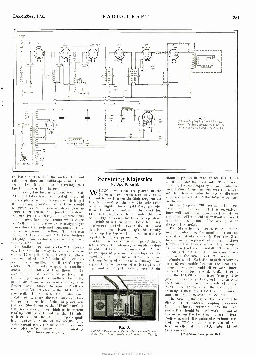
December, 1931 RADIO -CRAFT 351
OJC
nr
r.
e R
e 7 Y
v i>:
'roywr.r
T Fig. 1
1
Schematic circuit of the "Zenette' model Zenith superheterodyne re- ceivers . IH, CH and RH ;No. 3:1.
esting the tube. and the meter does not fall core than one milliampere in the 90 econel test, it is almost a certttinty that he tube under test is good.
However, the test is not yet completed. After all tubes have been tested and good ones replaced in the receiver which is put in operating condition, each tube should be given several successive sharp taps in order to determine the possible existence of loose elements. .faun- of these "loose ele- ment" tubes have been found which check perfectly on a tube checker or analyzer, yet cause the set to fade and sometimes become inoperative upon %lbrlion. The addition of one of these compact A.C. tube checkers is highly recommended as a valuable adjunct
- to any service kit. On lfadinbi "tri" find Victor "It" receiv-
ers, the conditions may he met where one of the '1:; amplifiers is ineffective, or where the removal of one '4.5 tube will clear up man otherwise muffled and distorted repro- duction. These sets employ a modified audio design. different than those usually met in st;,nsb rd commercial receivers. A tapped high impedance audio choke acting as an auto transformer, and coupling con- densers are utilized to more effectively couple the '21- (Hector to the '45 tubes in push -pull. In addition, two leaks, each 430,0(u) ohms, secure the necessary- grid bias for proper operation of the '4.5 power am- plifiers. Should one of the .025 -m f. coupling condensers short, a very high plate current reading will be obtained on the '45 tube, with consequent distortion and poor qual- ity. Likewise, if one of the 430,000 ohm leaks should open, the same effect will en- sue. Most often, however, these coupling
(Continued on page 371)
Servicing Majestics By Jas. P. Smith
WHEN new tubes are placed in the Majestic "70' series they ntap- cause
the set to oscillate on the high frequencies; this is natural, i, as the new Majestic tubes have a slightly lower grid -late capacity than the set was originally balanced for. If a balancing wrench is handy this can he quickly remedied by backing up about an eighth of a turn on the three balancing condensers located between the H.F. and detector tubes. Even through this usually clears up the truuhle it is best to use the regular balancing procedure.
When it is desired to have proof that a
set is properly balanced, a simple system as outlined here is recouunended. A roll of transparent gummed paper tape can be purchased at a music or stationery store, and can be used to make a dummy from a good tube by tearing off a short piece c f tape and sticking it around one of tl e
REErisr.Y6 TUBE SOiJ1Er-rrit 4-60
rc CHASSIS TO on ,.,ir +ssE.+e,- (w..R aECE.*r.<Lr .
eoo m.r eEy,,: oR f--+n r3.600 OR" RFS.STR
Fig. A Power distribution plate ira Majestic radio sets. Note the IÌ -set position of terminal No. 1.
filament prongs of each of the H.F. tubes as it is being balanced out. This insures that the internal capacity of each tube has been balanced out and removes the hazard of the dummy tube having a different capacity from that of the tube to be used in the set.
In the Majestic "90" series it has been found that ass aerial that is excessively long will cause oscillation, and sometimes a set that will not whistle without an aerial will do so with one. The remedy is to shorten the aerial.
The Majestic '52" series came out he- fore the advent of the multi -mu tubes but circuit constants are such that the G -24 tubes can be replaced with the multi -mu G -51's and will show a vast improvement as to noise level and cross -talk. This change improves the set SO that it compares favor- ably with the new model '21" series.
Numbers of Majestic superheterodynes have given trouble because the heat fre- quency oscillator would either work inter- mittently or refuse to work at all. It seems that the 150.000 ohm resistor from grid to ground is very important, and that the ones used for quite a while are subject to de- fects. To determine if the oscillator is working. remove the tube front that socket and note the difference in reception.
The tone of the superheterodyne will be distorted if the antenna coupling condenser is not adjusted correctly. On the "1i(1" series this should be done with the aid of the meter on the front as the ear is inef- fective against the automatic vol con- trol. A `(10" series volume control will have no effect if the A.V.C. tube will not pass current.
(Continued on pane 371)
www.americanradiohistory.com

352 RADIO-CRAFT December, 1931
RECORDING S'T'UDIO DESIGN
By GEORGE J. SALIBA, S.B.
INSTANTANEOUS recording, while or- iginally intended for use in the home, lends itself very nicely to commercial applications. In the first article of this
series on recording (see the June 1931 is- Sue Of It Arno-Cams-19, these applications and the different uses to which instantaneous recording could he lucratively put were pointed out, and now it is the purpose of this article to give a more technical descrip- tion of the apparatus and how it should he
used. Conuuercial studios for instantaneous re-
cording can be divided into two separate types- first, studios devoted exclusively to voice recordings and individual instrument playing and, second, studios that have facili- ties for recording complete orchestras and hands.
In the first type of studio only one micro- phone is used and the recording machine, amplifier, eta., are all located in the same room with the microphone. This room usu- , :ily contains about 42 sq. ft. of floor space, end the over -all frequency characteristic is not made very flat since it is rarely neces- sary to record any frequency above 4,000 cycles. A moderately priced two -button car- bon microphone is used in conjunction with a suitable amplifier whose gain is ad t 75 UII, and a made -over pick -up is all that is necessary as equipment. For the recording machine an ordinary phonograph turntable is all that is necessary if pre- grooved rec- ords are to be used, but if blank uncut rec- ords are desired for recording, then it is absolutely essential that an excellent feed - s.. rew device be used in order to insure a good even groove. As has been pointed out in previous articles, if the recording machine Inat:es a periodic groove -that is, the lines
are unevenly spaced, when the record is
played back the results will be poor and if steps are not taken to prevent this, the fin- ished product will only serve to cast reflec- tion on the studio with a consequent loss of business.
A pi: should be provided for accom- paniment and it is usually a good policy to have a person who is a pianist run the studio. This will cut down labor costs and at the saute time attract the singers who usually are very reticent about singing if accompaniment is not easily provided. For playback, the acoustic phonograph is best. The reason why this type of machine is
recommended is that if the finished record
w000 CELOTEX
lierl7 TABLE A
E11
AMP ANO 3i RADIO IC
lia : a1Iftit::::101:/
MINER VOL. INDICATOR
RECORDING RPING TUEIW TABL
RODUCE
ROOM DOUBLE TURNTABLE
PO
Fig. 2 .4 sound recording studio and control -room design. Double walls furnish adequate sound
insulation.
_T1
IP Pl AMP.
T1 Pl ÌI _TL Pi
I ogI I IT2 P2
jI l'II I bo-.T3 Pi IIII
MP. I I T2 II -
i SEC.
i T2
(I ¡II P2 ( I
EC
1
SEC.
I a--.
I la_°
3 I T4 IIo-T3
IIo °
PS T4 I T4
b--TO 2 -SUTTON MICROPHONES CL-TO 2-SUTTON MICROPHONES 'TO SINGLE BUTTON MICROPHONES
Fig. 4 Fig. 5 1 ne series potential divider The parallel constant output
type of microphone miser. impedance type of mixer.
Fig. 6 'crier -type constant output
impedance mixer.
CELOTEX WOOD
R EC MACH AND
AMP
DOUBLE DOOR
Fig. 1
¡ulterior layout of a sound recording studio. Dimensions are given.
plays hack satisfactorily on it, the customer is assured of success in his own home. Too many of these small studios that are rapidly springing up all over the country use in- efficient apparatus and naturally their re- sults are poor. To compensate for these poor results on playback, electrical repro- duction is used and the record then sounds quite satisfactory in the studio, but when it is reproduced in the home on the old style phonograph (of which there are still many in existence) the results are very poor. 'l'he reproducer may be too heavy or the groove may not be deep enough with the result that there is double tracking. The cust -r is dissatisfied, and therefore any future business f him is lost. Instead of becoming at supporter, he turns "knocker." In the writer's opinion, the acid test for any instantaneous record is the acoustic phonograph. If the record sounds well on this, then it will sound much better on any other type of machine.
Acoustical Treatment of Studios In most of the studios that the writer
has had occasion to conic in contact with, the acoustic treatment of the studio has been simply to cover the walls and ceiling with heavy drapes and the floor with a
heavy carpet. A studio that is so treated will prove unsatisfactory for recording fron the standpoint of fidelity. The record will sound "tubby" and very unnatural. This is due to the absorption of all the high fre- quencies by the heavy drapes. For propel acoustics the studio should be so constructed that there is n certain amount of resonance present so that the high frequencies may be properly recorded. In the proper treatment of recording rooms two olrjt.(.ts must be kept in view; first, the exclusion of all unwanted external noises, and second, the production of the right acoustic conditions for good recording.
'l'he excluding of extraneous noises is ac- complished by building the roost of double walls (see Fig. 1) with a dead acme space be- tween them. The dead air space is an excel- lent insulating med. against sound and is very effective in keeping out external noises. Great care must be taken to see that the walls and ceiling are all absolutely air tight. If this construction is carefully followed
(Continued on. page 373)
Tr www.americanradiohistory.com

December, 1931 RADIO -CR AFT 353
The D: °: Portable - 4 H. C. CISIN, M.E.
Fig. A Appearance of the A.C. -D.C. Portable -4 radio receiver. which has the advantage of versatility its
its power requirements.
THE A.C.-D.C. Portable -Four receiver (illustrated in Fig. A), powered from any convenient 110 -volt light socket, possesses many interesting and useful
applications. For the traveling inn, such a receiver is a splendid "companion," as he can use it practically anv plaie he happens to stop. The Service Han can utilize this portable as an important nid in test work in the field, or to replace a larger set while the latter is undergoing repair at the shop. For emergency use, for camps, bungalows, or as an extra set in the home, it is ideal.
This receiver employs a simple but ef- fective circuit. Fig. 1. There are two stages of tuned radio frequency, a tuned detector and a single resistance- coupled audio stage. 'l'he three tuned stages are "ganged" to- gether, using n 3-gang shielded tuning con- denser. Screen -grid tubes are used in the R.F. stages and detector, while the highly efficient pentode is used as the output power - tube. For A.C. work a type '80 rectifier is employed. This is not used when the set is connected to a direct current source, but it is left in the socket at all times.
Effective vol control is attained by means of a cathode series resistor of the
potentiometer type 12, designed especially for sudi use. An examination of the schem- atic diagram reveals a number of interesting features. The filaments of all four tubes are in series at all times, instead of being in parallel, as in the ordinary A.C. sets.
The line voltage is reduced to correct fila- ment voltage by means of a 300-ohm resistor 3:3. This arrangement works equally well on A.C. or U.C., since the voltage drop through the resistor and filaments is the saint in either case. Since all the tubes are of the heater type, wherein the filament serves merely as the heating element and is separ- ate from the tube circuit proper, this series arrangement of the filaments does not affect the amplifying properties of the circuit in the least. Grid bias on each tube is obtained by the drop across a resistor, of correct value, between the cathode and the metal chassis.
'l'he novel universal A.C.-D.C. feature of this circuit is the invention of Arthur C. Ansley, a New York radio engineer. Through the use of an ingenious switching arrange- ment, it is unnecessary to change the tubes or the wiring, when changing from an alter- muting to a direct current source, or vice versa. All necessary changes in the circuit are made, merely by slipping off a plug or cap at the rear of the receiver and replacing it with a second cap, marked for the kind of current to be employed. 'l'he caps have different connections, thus changing all the circuits which need to be changed. For example, by changing caps, the primary of the power transformer is connected to the line on A.C. and left open on D.C. This also takes cave of the rectifier tube, since it is lighted from a winding on the power transformer. 'l'he D.C. line is connected to the input of the filter, with due regard to the polarity, so that the choke 39 and the electrolytic three -section condenser 36, 37, 38 relative the ripple from the plate voltage. The speaker field, which serves as the sec- ond choke on A.C., is connected directly across the line on D.C.
(Continued on page 375)
4
3 I
-p a zz u ; ìir
8 12
t o -tlul ]6= i g , 3a
CAD !e
1__n
I z?IFiRis;?sa_-a! -43__{!?__as-Ac.cu CD3' =-CL_=17?tF=i7.37-1sF.ì`-yt 44- ac. CAP
4l- 7E1041W1L RVO
ovot ic... D.C.
E1D COM
Fig. 1 Schematic circuit of the "Portable -4." Connecting terminal strip 43 or 44 to terminal plug 42
changes the airing for A.C. or D.C. operation, respectively.
www.americanradiohistory.com

354 RADIO -CRAFT
SERVICE ELLING All-Wave
SUPERS TART I )
December, 1931
Fig. A
Contrary to general opinion, the problem of keeping a short -wave receiver sold is up to the Service Man who installs the set rather than to the floor salesman.
By McMURDO SILVER*
RTICLES on short -wave design, construction, and operation have appeared in n roes past issues of It. nIo- CRat-r (and the contemporary publication, Siuner- R',LVe CRAFT), vet perhaps the t important point of all has not been
clearly stated and discussed This is the fact that the selling of the short -wave and broadcast
band receiver is, in the final analysis, the job of the Service Man. The dealer's salesman on the floor may get the customer to sign on the (lotted line, but if the sale is to "stick," it is up to the Service Man who installs the set to properly instruct the customer. The Service Man must he thoroughly informed not only on general radio service, but also on the fundamental factors involved in satisfactory short -wave receiver operation.
Reception below 200 meters has not been particularly popular - if it man' be said to have been at all popular -with broadcast listeners to programs of purely entertainment variety who now represent the hulk of the innrket. Buying a short -wave radio set and immediately expecting to be able to turn its knobs and, with
President, Silver- Marshall, Inn.
no understanding of what they are doing, get thoroughly enjoyable entertainment from it, is expecting the imlps.sille; and if the receiver is sold by the average store salesman, any attempt he may make to show the customer how to operate the set (aural in most cases he will make no attempt, for he does not know himself) will be carefully forgotten by the customer by the time the set arrives at his home.
Since the result will be no short -wave reception at all, and a prompt complaint will he lodged at the store, the writer feels that the most important aspect of short -wave receiver servicing today is the proper instruction of the store Service .faun so that when he makes the initial installation of the receiver, he may intelli- gently show the customer what to do to get good results. The servicing of defective short -wave receivers is, in comparison to this problem, of decidedly secondary importance.
As practically all broadcast receivers today are superheterodynes, and as practically all of the "all-wave" receivers now available to the public employ the superheterodyne principle at least for the short -wave bands, consideration will he given here to the super- heterodyne type of receiver only; and since its operation is con-
Ls lb l< Id C4
ri". ° E t -... SW. if: á i_ °`íIl
e r r 18V vi '
+ 1 I
C25
C24
510
I
Sw4 r LI
Sw b
C29
SW b
rr
16
R17
I I
RRI
I I
ri 'CÌ
C26
511 . 60V
R16
C21
C6
51
L2
52 IFT1 54 tFT2 SS IFTS
56 1T6v CII Tl
., htöle
L4
C,
C2
5H
SL
C16
R 10 C18
1R IS
7 C19
Rd MAI 1 f
SV 45v 96v
Swl
20V
Si 225v
I ' RS
rl
VT r- -
111121 (: I
59
°
'225v
BlVE.
800 T2 litni,'5--
áOwMS' Y
o m i FC BC VC
525V 240WI 15V
VII Li}= i C14
Fig. I The circuit diagram of the Silver-Marshall 726511' short -:ear, receiver. The short-wave converter is shown to the left of the dotted line and the
broadcast receiver, whiclr is also used as the I.F. amplifier, is slnxrn to the right.
www.americanradiohistory.com
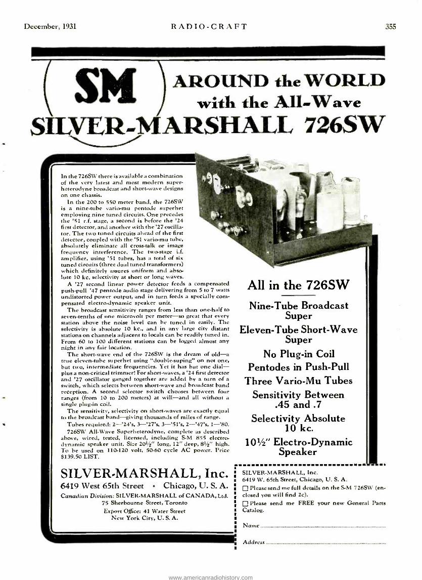
December, 1931 RADIO -CRAFT 355
AROUND the WORLD with the All-Wave
SILVER-MARSHALL 726SW
In the 726SW there is available a combination of the very latest and most modern super- heterodyne broadcast and short -wave designs ort one chassis.
In the 200 to 550 meter band, the 726SW is a nine -tube vario-mu pentode superhet employing nine tuned circuits. One precedes the '51 r.f. stage, a second is before the '24 first detector, and another with the '27 oscilla- tor. The two tuned circuits ahead of the first detector, coupled with the '51 vario-mu tube, absolutely eliminate all cross -talk or image frequency interference. The two-stage i.f. amplifier, using '51 tubes, has a total of six tuned circuits (three dual tuned transformers) which definitely assures uniform and abso- lute 10 kc. selectivity at short or long waves.
A '27 second linear power detector feeds a compensated push -pull '47 pentode audio stage delivering from 5 to 7 watts undistorted power output, and in turn feeds a specially com- pensated electrodynamic speaker unit.
The broadcast sensitivity ranges from less than one -half to seven -tenths of one microvolt per meter -so great that every station above the noise level can be tuned in easily. The selectivity is absolute 10 kc., and in any large city distant stations on channels adjacent to locals can be readily tuned in. From 60 to 100 different stations can be logged almost any night in any fair location.
The short-wave end of the 726SW is the dream of old -a true eleven -tube superhet using "double.suping" on not one, hut two, intermediate frequencies. Yet it has but one dial - plus a non -critical trimmer! For short-waves, a '24 first detector and '27 oscillator ganged together are added by a turn of a switch, which selects between short -wave and broadcast band reception. A second selector switch chooses between four ranges (from 10 to 200 meters) at will -and all without a single plug -in coil.
The sensitivity, selectivity on short-waves are exactly equal to the broadcast band -giving thousands of miles of range.
Tubes required: 2- '24's, 3- '27's, 3- '51's, 2- '47's, 1 -'80. 726SW All-Wave Superheterodyne, complete as described
above, wired, tested, licensed, including S-M 855 electro- dynamic speaker unit. Size 201/2" long, 12" deep, 81/2" high. To be used on 110.120 volt, 50-60 cycle AC power. Price $139.50 LIST.
SILVER -MARSHALL, Inc. 6419 West 65th Street Chicago, U. S. A. Canadian Division: SILVER -MARSHALL of CANADA, Ltd.
75 Sherbourne Street, Toronto Export Office: 41 Water Street
New York City, U. S. A.
All in the 726SW
Nine -Tube Broadcast Super
Eleven -Tube Short -Wave Super
No Plug -in Coil Pentodes in Push -Pull
Three Vario -Mu Tubes Sensitivity Between
.45 and .7
Selectivity Absolute 10 kc.
101/2" Electro- Dynamic Speaker
SILVER- MARSHALL, Inc. 6419 W. 65th Street, Chicago, U. S. A.
Please send me full details on the S.M 726SW (en- closed you will find 2c).
Please send me FREE your new General Parts Catalog.
Name
Address ---- --- --- --- --- -- --_.
www.americanradiohistory.com

356 RADIO -CRAFT December, 1931
siderabiv more critical on short waves than is that of a T.R.F. receiver with a short -wave superheterodyne "converter" ahead of it, the Service Man mastering the operating technique of a thor- oughly good short -wave superheterodyne will he more than com- petent to handle the few rare cases where he is called upon to install or service a T.It.F. receiver with a short -wave superhetero- dyne converter.
Example of Receiver
As an example, the Silver -Marshall 726 -SW short -wave and broad- cast band superheterodyne has been selected, for it represents one of the sharpest of broadcast hand superheterodynes now upon the market. This instrument is illustrated in Figs. A and B; the schematic circuit is shown in Fig. I.
As shown in Fig. A, there are seven controls on the front panel -three knobs at the top, and four at the bottom. The upper left - hand knob is the short- wave band selector switch SW'h, having four positions which select the 10 -20, 20 -40, 40 -80, and 80 -200 meter
Fig. B A photograph of the under -side of the Sflrer.Marahall Model 726 -S1V
all-Trove receiver.
bands. Directly to its right is the short -wave tuning dial, and directly below this, the short -wne tuning knob.
At the tipper- center of the panel is the short -wave trimmer, Cc in Fig. I, connected in shunt to the short -wave detector VI grid -circuit tuning condenser C20, to permit accurate alignment between the short -wave oscillator and detector circuits, it being impracticable to gang these with the sane accuracy as on the broadcast band where no manually operated try r adjustments a re necessary.
To the right of this trimmer knob is the broadcast band tuning dial, and directly below it, the broadcast band tuning knob. At the extreme upper right is the range selector switch (SWa in Fig. 1) which permits Hie dative of either the short -wave (10 to 200 meters) or broadcast (200 tu 545 meters) range. The two lower- center knobs are: left, the tune control, equally effective on short -weave or broad- cast bands; and right, the combined volume control and on -off switch, likewise effective on both bands.
Examining the circuit diagram of Fig. I, the portion to the right of the vertical dotted line is essentially n broadcast band superheterodyne, consisting of a timed R.F. stage \'3, a first -de- tector V4, an oscillator \'5, two 175 -kc. LF. stages V6-V7, n second - detector \B, a push -pull pentode output stage \9 -\'IO, and the usual rectifier, \"11. To the left of the dotted line is the built -in short -wave converter, consisting of a first detector \'1, and oscil- lator V2.
When the receiver is to be operated on the broadcast hand, the switch SWa is thrown to the right. In this position, one set of contacts connects the antenna directly to the primary of the broad- cast band R.F. transformer I1 and to the plate of the short -wave first detector. although this is of no importance. A second set
opens the plate circuit to the short -wave oscillator and the screen circuit of the short -wave first -detector rendering these circuits inoperative. The receiver is then tuned by the right hand dial, the vol and tone being controlled by the two lower- center knobs.
When the set is to be operated in the short -wave hand, the switch SWa is thrown to the left, which connects the antenna to
the grid circuit of the short -wave first -detector through the com- pensating condenser Ca and closes the plate circuit to the short- wave oscillator and the screen circuit of the short -wave first - detector. Selection of the proper short -wave range is then inutile by the SW'b, at the upper left of the panel, which selects the proper first -detector grid coil and the proper oscillator plate and grid coils for the particular band desired. When the switches are in this position, the receiver is essentially the dream of old -a "double super " -in that two 1.F. frequencies, rather than one, are employed.
When the broadcast band dial is set to some clear channel near 650 ke. (necessarily only between 600 and 700 ke.) the short- wave oscillator serves to heterodyne the received signal to this frequency (which is the first I.F. frequency) where it is amplified by what world be the R.F. stage and first -detector on the broadcast band, but in this case is actually the first level of I.F. amplification and second detector. By means of the second oscillator of the receiver, this 651) kc. I.F. signal is re- heterexlyned to the second intermediate frequency, or 175 ke., where it passes through the main, or second I.F. amplifier of the receiver to the third, or power detector, and thence into the push -pull pentode output stage.
All of this may sound extremely complicated, but actually it is very simple, and the only problems encountered are clue entirely to the extreme selectivity of the receiver -its selectivity is many, many times superior to that of the best short -wave receivers here- tofore available, while its selectivity on the broadcast banal is superior to that of any competitive superheterodyne the writer has yet had the opportunity to examine.
I.et us suppose a customer has received Midi a set, that it has been installed in his honte without any instruction as to its opera- tion, and that he happily tries to tune in signals on his new pos- session. Ile will, first, probably try the broadcast band, if he has taken sufficient trouble to examine the control legend on the receiver panel to see what he is doing. Ile will have no par- ticular difficulty in tuning in broadcast stations, although he may have some difficulty in getting satisfactory tone quality, for his first step will be, unquestionably, to turn the volume of the control well up before tuning the signal in, then reduce the volume, with very excellent chances of not having the signal properly tuned in, and by virtue of the extreme selectivity of the receiver, cutting out some of the necessary side -bands.
The thing for hint to learn is that in tuning au superheterodyne, he must tune in his signal at any volume level lie Wishes, then reduce it by means of the voluute control (and not under any circumstance by (lettining) until the signal is just audible, after which he roust re -tune the signal and adjust his volume to the level he desires. After he knows this (and it is doubtful if be does at first, unless the store salesman has driven it very firmly into his head -which is likewise improbable) he will, tifter tiring of the broadcast banal programs, attempt to tune in some short -wave signals and this is where his fun will begin.
Tuning an SW Receiver
Buoying tuned in a number of broadcast stations without any difficulty, he will expect the same thing to happen on the short- wave end of the set, and after knitting it into operation by throwing the necessary switches, he will gaily turn the short -wave tuning dial, only to hear nothing at all except a good background noise. After doing this several times over a period of a few hours, he will be thoroughly disgusted, will call up the store and tell them to send out a Service Man in a hurry, for the set won't work - or else he will tell the store to pick up the set -that he doesn't want such a " piece of ,junk." Whereupon the Service Man will probably be sent out to show him that the set really is not so had after all and that all he needs to do is learn how to operate it. Needless to say, it is vitally essential that the Service Man know how to operate the set himself.
'l'he writer can not impress too strongly upon the Service Man rending the foregoing paragraphs, the absolute necessity of im- planting firmly in his mind the ideas they contain, for upon hint fells entirely the success or the hick of success which his store will have in selling short -wave receivers, for whether or not they stair sold is dependent upon his ability to show the customer how to operate them and obtain satisfaction from short -waive reception. Once he has thoroughly implanted this in his mind to the extent where no amount of pressure will tend to alter his opinion of its importance, he may consider the more conventional servicing aspects Of short -wave and broadcast band superheterodynes.
www.americanradiohistory.com

December, 1931
WANTED 357.
$20 ío$35 a week men who want
to earn$50 ío$75 a week and more ODAY -more than any time be- fore in the history of the great Radio T Industry- Manufacturers, Broadcast-
ing Stations, Sound Picture and Television concerns, and others -are on the look- out for men capable of being promoted to their more responsible jobs.
They can get all the men they want for their ordinary work -jobs that pay $20 to $35 a week or less. Which, of course, is one reason why these jobs don't pay better wages -almost any man can do the work.
But for their better- paying jobs -those jobs that pay $50 to $75 a week and up -well, its different. Here brains, not muscle, are required. Here knowledge, not guess work, is necessary. Here men capable of some day being promoted to still better- paying jobs are needed. This big demand for men of this type has been brought abcut by the amazingly rapid expan- sion of the Radio field. Because of dozens and dozens of new, and almost revolutionary, developments, hundreds and hundreds of big - pay jobs have been created almost over -night.
Radio work is no longer limited to the building and servicing of Radio sets.
It now includes such other things as Sound Pictures, Public Address Systems, Radio in Industry, Radio in Aviation, Radio aboard ship (for operating mechanisms of different kinds, and even for running the ship itself), telephotography, Television, etc.- everything, in fact, that makes use of the vacuum tube or photo -electric cell.
Radio devices, today, are operating great ma- chines formerly operated by man -are grading by color or size such manufactured articles as
cigars, paper, silks, etc. -are counting people or automobiles as they go by any given point - are turning on and off lights in our big factories or on our city streets -are operating airplanes in the air -directing ships at sea from stations on land- creating music more perfect than played by our best masters -and doing a thou- sand other things not dreamed of a few years ago.
To know Radio is to know the principles of all of these things.
And to such men the great Radio Industry offers many wonderful opportunities -steady work at good pay, NOW -and an early ad- vancement to still better -paying jobs, as a
future. - But no ordinary knowledge of Radio will do. To qualify for these better- paying jobs- -men
must know the theory and practical application of all Radio devices -old and new, and they should be able to teach other men some of the things they know.
That means they must be "trained ". As few men can afford to get this training at some College or University, the Radio and Television Institute, of Chicago, was organized to train men at home -no matter where they live -in their spare time -easily and quickly - and at a cost of only a few cents a day.
The Radio and Television Institute is the ONLY Institution of its kind whose Course of home -training is actually supervised by an Advisory Board of outside business men, -all highly paid engineers and executives, - each actively connected with some large Radio concern. It is, too, the ONLY Radio School to be endorsed by some fifteen of our largest and most progressive manufacturers of Radio and Television equipment. These public endorse- ments were given to guide ambitious men who seek a future in Radio. These manufacturers want all such men to know thattthe Radio and Television Institute has their unqualified ap- proval, and their hearty support, in its work of training men, through spare -time home- study, for the many better -paying jobs that exist today in Radio ... Sound Pictures ... and Television work.
Radio and Television Institute home -training prepares men, easily and quickly, for these better- paying jobs. It is the ONE recognized connecting link between ambitious men and a
splendid future in Radio.
To the man then, who is earning $20 to $35 a week NOW -and who would like to earn $50 to $75 a week or more -regardless of whether or not he is doing Radio work today -we say in all honestness -"we think we can help you." Just mail the coupon below for full particulars of our plan and a free copy of the new Opportunity Book.
Redio-First an experiment -then a plaything -now a giant Industry -the fastest growing industry the world has ever known -offering thousands of wonderful opportunities to am-
bitious men.
RADIO AND TELEVISION INSTITUTE DEPT. 69 2130 LAWRENCE AVENUE, CHICAGO
Please send me a copy of your Opportunity Book and full particulars of your plan for helping men into good pay positions in the Radio field.
Name
Address
City State
www.americanradiohistory.com

35S
OSCILLATOR (Licensed by A. T. & T. Co.)
818 Net to 1 t dealer $30 list
*21 Net to
dealer with output meter
If not at your Jobbers, we will ship direct when remittance
accompanies order.
A sturdy modulated instrument care- fully made. Completely shielded with separate battery compartment. Fur- nished with 22 % -v. and 3 -v. batteries. Uses one '30 tube. Covers broadcast band (550 -1500 -k.c.) and intermediate band (120 -185 k.c.). Operating in- structions attached in case cover with shielded wire leads. Very compact. In leatherette case, 6 x 11% x 5% in.
Weighs but 8 pounds. Built to high standards.
Every serviceman should have the No. 550 oscillator to align r.f. gang con- densers, locate defective r.f. trans- formers, adjust i.f. transformers, check oscillator stage and determine sensi- tivity of a receiver. A necessary in- strument. Get yours today. Write for catalog of servicing instruments.
Readrite Meter Works Established 1904
17 College Ave., Bluffton, Ohio
RADIO -CRAFT December, 1931
RADIO -CRAFT KINKS
THE RADIO -VIOLIN By Fess Christiani
R\UlO programs may now be received through the medium of the violin. Find
the center of a small magnetic speaker disc, and solder a small wood screw to it at the center. Then cut a wooden violin mute as
',tow _ z
Fig. A The radio -violin. The improvised speaker unit on the violin bridge, facilitates radio accom-
paniments.
shown in Fig. 1 and screw it to the speaker diaphragm. The telephone unit is now as- sembled together with the mute and the entire arrangement attached to the bridge of a violin as shown in Fig. A.
When a program comes over the radio, one may have the novel experience of walk- ing about the roost accompanying it. I
play an obligati), and the tone is very clear. There is a great "kick" in it for both listener and player.
SPEAKER DIAPHRAGM AND WOOD SCREW.
Fig, 1
.I hone -made mute is screwed to a speaker diaphragm.
IMPROVING RECEIVER OPERATION By George Stoneham
THOSE service men who wish to im- prove the operation of the seven tube
Federal Orthosonic receiver at a very low cost, may make the changes outlined below which resulted in a decided improvement in operation over that received prior to making the change.
This receiver uses the BA Raytheon tube for rectification, and . consequently the slightest change in line voltage manifests itself in corresponding changes of the fila- ment voltages and current of the 'OlA tubes whose filaments are connected in series. By substituting two '80 tubes for
the Raytheon as shown in the diagram of Fig. 2, the hum experienced with the old mode of connections entirely disappeared and ex- cellent stability of operation was secured.
'l'he five volt winding for the pilot lamp is used to supply the filament of the '80's and there is sufficient room in the power unit to house the two new tubes. The cost of the additional parts necessary for the change is negligible compared to the in- creased satisfaction secured.
Incidentally, if a small coil, tripped in the center, that will match the tuning condenser is used in the first stage instead of the loop, and is connected to a short aerial, an increase in the selectivity and distance received will be noted.
Fig. 2 By replacing the RA Raytheon with two '80's, the operation of the Federal Orthosonic receiver is mach improved. The three condensers marked C and the resistor R which arc used in the original circuit, are ant needed after the unit
has been retired as shown.
USES OF THE TEST PROBE
By Jos. Riley
TTCHNICIANS breaking in to the ser- vice field may be interested in knowing
the uses to which the simple test probe (il- lustrated on page 275 in the November issue of It.tmo- CRAFT) may be put. As stated in the issue referred to, the probe is small, extremely handy, and should find a place in the pocket of everyone who tests a radio receiver.
(1) Open Circuited By -pass Condensers If a receiver oscillates, or has excessive
hum, remove the lamp from the probe end, attach the fest probe clip to the chassis, turn on the set, and touch the high voltage end of all the by -pass condensers. The set will perform normally when the faults condenser is touched. 'l'iris is illustrated in Fig. 3A.
(2) Short Circuited By -pass Condensers Insert the standard lamp in the probe,
connect a 41,4 volt battery in series with the clip lend, connect the other end of the bat- tery to the chassis of the receiver, and touch the probe point to the opposite ter-
www.americanradiohistory.com

December, 1931
minais of the condensers. A shorted con- denser is indicated by the lighting of the lump to full brilliancy.
(3) Testing Tuning Condensers and Coils Turn off the set. Connect a 41/4-volt bat -
tery in series with the probe and the chassis. With a standard lamp in the test probe, touch the probe to the grid end of the It.F. coil. 'l'he lamp should light at half bril- liancy. The tuning condenser should then be rotated and if at any point the lamp jumps to full brilliancy, then the condenser is shorted at that point. See Fig. 3A.
(4) Aligning Tuning Condensers Turn on the radio set, start the test oscil-
lator and tune it in. Attach the test probe clip to one terminal of the voice coil of the speaker :and touch the probe point to the other. (A few sets will require connecting
Fig. 3 At the left, A, locating shorted by -pass con- densers; at the right, R, testing tuning coils
and condensers.
the tester in series with the voice coil, rather than in parallel with it.) Adjust the vol- ume control for minimum brilliancy of the lamp. Then adjust the individual tuning condensers for maximum illumination. This operation should be repeated several times.
(5) Checking R.F. Coil Polarity Connect the tester to the set as described
in (3). With the lamp at one -half brilliancy, place a small magnetic compass beside the probe and note the direction of the pointing needle. This should be repeated for every other R.F. coil; the compass should point in the sanie direction in all cases.
(6) Checking High Voltage
For making voltage or current tests beyond the means of the tester, the stand- ard lamp may be removed and a neon lamp inserted in its stead. Using this arrange-
-4 ment every high voltage point in the receiver may be tested with ease.
(7) As a Trouble Lamp By directly connecting a 41/2-volt lamp
across the terminals of the probe, it may be used as a very handy trouble lamp for exam- ining the chassis of radio sets.
(8) Miscellaneous By replacing the standard lamp with one
rated at 6 volts, complete continuity of the ignition system in an automobile may be
easily and conveniently checked. The clip is attached anywhere on the chassis of the car and the probe touched to the "high" side of the lamps. The lighting of the lamp indicates the presence of voltage.
Continuity tests may also be made by con- necting the probe as described in (3).
RADIO -CRAFT
"I SERVICE
HUNDREDS OF SETS
EASILY WITH THIS
R ESISTOR GUIDE"
359
"I would not give up your Resistor Guide for ten times the price I paid for it. It is my constant companion and saves me many hours of guess work. I service hundreds of sets easily by using the Guide, with greater in- come as a result of it."
(Name on request)
MF 41/2
This statement from a serviceman's letter, one of hundreds mailed to us, goes to the root of the resistor problem in repair work.
The I.R.C. Guide is a remarkable time saver. It is a short cut to trouble finding. You are through with one set and on to the next in one -tenth the time it would otherwise take.
The reason? This book gives the value and code of each resistor, and its position in the circuit, of nearly every popular make of radio receiver. More than 200 circuits listed.
The busiest season of the whole year in radio is here. Be ready to get and handle your share of the business. Over 8000 servicemen use the I.R.C. Guide. Write for your copy.
INTERNATIONAL RESISTANCE COMPANY Philadelphia - - - - Toronto
FREE with Metallized Resistors
%Vith the purchase of 10 I.R.C. Metallized Resistors, from any wholesaler, you will re- ceive the Guide free -or it may he bought for $1. Loose -leaf sheets, mailed to you peri- odically without charge, will keep it con- stantly up to date. Mail the coupon today.
INTERNATIONAL RESISTANCE CO., C12 I 2006 Chestnut St., Philadelphia
Gentlemen: (Check offer you are interested in)
Li enclose $1.00 for Replacement Guide.
Please send price list of Metallized Resistors. 1
wish to purchase assortment of ten, which will en- title me to Repistor Guide Free.
NAME
ADDRESS
CITY STATE
Makers of
I R C
(Meta&
RESISTORS
www.americanradiohistory.com

360
ACROCYCLE OSCILLATOR
A self- contained miniature transmitter with dial calibrated in Kilocycles. Any frequency between 115 K. C. and 1680 K. C. can be easily produced accurately. Indispensable for aligning Super- Heterodyne receivers with intermediate frequencies of 130.175- 260 -475 K. C. and all others. List Price $30.00. Service men or dealers. Net Price $17.50. Leatherette carrying case extra. Net $2.00. Tube and batteries extra. Net $2.33. If your jobber does not carry, order direct. Sent express collect or C. O. D. with a
deposit of $1.50.
This instrument made by the manu- facturers of the SUBMARINER SHORT WAVE ADAPTER now priced at $12.50.
ORDER TO -DAY
J -M -P MFG. CO., INC. 3350 Fond du Lac Ave.
Milwaukee, Wisconsin, U.S.A. Cable Address: "SUBMARINER"
,PROFIT On Every Service Call Easily installed in 5 min. Utes. Write Dept. RC -I3
for money-malt- ing Propsitìnn.
14MPERrrá (grpona &Mn 561 BROADWAY MEW YORK
With
PERITE Self Adjusting
LINY0^LTA E CONTROL
RADIO-CRAFT December, 1931
The Radio Craftsman'; Page
RADIO -CRAFT SET "STEPS OUT" Editor, 1tsmo-Ca.trr:
Yes sir, the two tube A.C. Pentode sure is a loud little set! I had constructed a three tube transformer coupled receiver using a '24, a '27 and a pentode when your article came along. 'faking out the audio stage and rewiring it according to your diagram, I find that the 1)X that this little set brings in during the daytime Is unusual.
My primary coil is 13,', in. in diameter, has 10 turns and is wound over the ground end of the secondary. 'l'he tickler has 20
turns, the plate circuit is by- passed with a
.00035 -mf. condenser, and regeneration is secured by means of a 25,000 ohm poten- tiometer. I find that at 250,000 ohm grid - leak in the first stage and a 2 meg. leak ill the second stage .add to the volume.
I picked up it government "ditty" lox which is ,just the right size for the job. I also find that when the regeneration con- trol is advanced, the set makes a good oscillator around the .hop, giving a strong clean signal. Selectivity is fairly good on a 140 foot aerial, and with a 10 foot lead connected to the antennas post, the volume is fair on locals with no interference from adjacent stations.
I am going to try a stage of S.G. ahead of the detector to try for better volume, DX, and selectivity. If someone would make a 2 volt battery about ti in. on each side, it might be excellent for use with a two or three tube portable set.
To get back to our set, it surely is sur- prising what it will do. I wish you had published one about three months ago, for then I would have had a portable on my vacation.
D. VERNE C II.t]fae:RS, 543 It-. 146 St., New 1-nrk,
A PRIZE WINNER Editor, RADIO-CRAFT:
You can't imagine nay surprise when your letter finally reached me way out here after being forwarded from Norfolk, my home.
And the contents of it simply thrilled me! I could hardly believe my eyes. I ,just wanted to thank you very, very much. After reacting your letter I rushed clown to n
news -stand to get the September issue of ItAmn -CRAP l, but what a time I had trying to find one -every place had sold out.
From now on I shall never miss it, and shall give it more of nn attention because of your consideration of nie.
MRS. KART. N.tsll, 502 Son(I 3rd Street, Son Josr, Cal.
(Mrs. Nash was the winner of the second prize of a contest conducted by ltsmo -CaArr some months ago. 'l'he contest was con- ducted in order to determine the best three names for both professionals and non- professionals in the sound field. The win- ners were announced in the September issue of RAnlo- CRAPT).
AN EAPERItS Editor, 1tAD10 -Cane.
Presenting my vi
state that I think it was mentioned regt molter, such as was in 'Unto-Caner sou
I have my own it
graph, and my inter receivers (not shot indeed, the experim science and gets rot
than those that del). and furthermore he for less cost than t Service Man-any t
who has his own ohs cillator, etc., can he the design of coils, science, one must I
630,
ENTER'S VOICE
tw, please allow rue to is about time something riling the radio experi- discussed in an editorial
time ago. t amplifier and phono-
est lies in the "Midget" t waves at all). Yes !titer moves along with re of a "kick" from it nu upon it for a living, can conduct his studies to Service Man. 1 said xperimenter, of course, ureter, set analyzer, os- one, but to really study etc., and advance with e an experimenter.
FRAN R URMARCO,
k St., Yonkers, N. Y.
Paste This Label into Your Radio IF THIS RADIO STOPS
CALL CUmberland 6.4060
FOR REAL RADIO SERVICE 550 State St. at Flatbush Ave. Brooklyn, N. Y.
Prompt Service- Alvays Open -Including Sunday
,In "inside the set" poster.
RE. THE WATSONGRAPH Editor, ltnnlo- CR.trr:
As one of the engineers who are working on the development of the "Watsongraph" Wireless Typewriter, described on page 74 of the August issue of ItAnurCRA }-r, I wish to bring to your notice an error appearing in one of the circuits; this error was made by me, when I made the original drawings.
'l'he Thyratron circuit shows the grid bias on the transformer side of the grid con- denser, instead of on the grid of the tube. Please accept un apologies for this error, which is without doubt my fault.
'l'he fact that these tubes are gas filled does not change the grid circuit action in the least, the input circuit being practically the same as that of the standard three elec- trode vacuum tube. An examination of the circuit as sent to you, and published in lt ADIo-CRAFT, will slow that the grid bias battery and grid resistor tend to short - circuit the secondary of the input trans- former, while the grid of the tube, having no bias, is in a very sensitive and unstable condition. 'T'herefore, if the lead from the grid of the tube to the grid condenser is very long, and parallel to circuits carrying audio currents, including the sixty cycle used to heat the filament of the tube, the tube will have a tendency to ionize, even when no signal is impressed on the primary of the input transformer.
54 I STANSFIRI.D,
150 -15 Sanford Are., Flushing, L. I.
www.americanradiohistory.com

December, 1931 RADIO -CRAFT
VARIABLE RESISTORS Interesting Facts About Volume Controls
By DR. L. VAN DER MEL, PH.D.
jr
is a relatively easy matter for a Ser- vice Man to calculate the proper size resistor to use in a power pack or in a grid circuit if the voltage across and
the current through the resistor are known. But when the problem is to determine the correct size and type resistor to use as a vol control across a transformer, the Service Man is usually at a loss to know just what factors to take into consideration in order to arrive at a definite conclusion.
The ordinary procedure is to try several sizes, and linally select the one that gives the most uniform variation in response. Needless to say, the results of this method are based on the ability of the Service Man to guess accurately and not on his technical knowledge, consequently the "heuristic" method of solution is not recommended.
A resistor shunted across the secondary of a high impedance transformer should satisfy four requirements. First, with equal increments of the dial setting, uniform varia-
A volume control resistor may he placed across either primary or secondary. depending upar.
their impeda un
tion of the final output should be obtained; second, the effect of the addition of the vol- nine control rat the impedance of the circuit should be negligible; third, the movement of the sliding contact over the resistance ele- ment should be noiseless from With a phys- ical and an electrical standpoint; and fourth, the resistance should not draw so much cur- rent that it will burn out.
To overcome the first problem, the resist- ance element should be calibrated "logarith- nicall," or in other words should be tap- ered. 'l'he reason for this will be apparent when it is realized that the ear does not respond uniformly to nniforin increases in sound power. If, let us say, 10 milliwatts of sound energy produces a certain auwunt of "loudness," then 20 milliwatts will not produce a signal twice as loud. 'l'he degree of increment in loudness is proportional to the logarithm of the change in power. In order then, that the ear recognize uniform sound increases, it is essential that the change in voltage to a tube van' in such a mariner that the final output will vary in a smooth manner. Reliable manufacturers of volume controls really design their units to faithfully follow the logarithmic law.
' T'he proper size resistor to use depends almost entirely on the impedance to which it is to he connected. If it is too low, it alters the impedance of the line, draws excessive current, eventually gets noisy, and the varia- tion in output is large for small changes in the vol control setting. If, on the other
hand, it is too large, the impedance of the line will not be upset, it will not draw excessive current, will not get noisy so easily, but the volume will be crowded on one end of the unit which really means non-uniform- ity of response.
From the foregoing it can easily be ap- preciated that the choice of the proper resist- ance is very e plicate(' front a mathe- matical stan(point, in fact mathematics is seldom resorted to in practice for such computations. Theory indicates, and experi- ment verifies, that the resistance volume control should be front 10 to 15 times the impedance it is to be connected across as shown in the figure. Values between these limits have none of the disadvantages out- lined above, and when properly tapered result in very satisfactory results.
Obviously, the "hitch" in the problem is to know the impedance of the transformer across which it is to be connected. To assist the Service Man in determining the proper size volume control to use in present day circuits, the Central Radii) Laboratirrirs have prepared a lumdy little booklet which gives not only the Ill.. and A.F. circuits in which volume controls are used, but lists numerous radio receivers and states the values of variable resistors used. This book- let is discussed elsewhere in this issue.
"HOW THE INTERNATIONAL RE- SISTANCE COMPANY CAN BE OF
MORE SERVICE TO THE SERVICE MAN"
TILE above is the subject of a contest (carrying a total cash prize award of
$1 i5.(H) in the following (lenunlinations: First prize, $100.01); second, $.50.00; third, $10.00; fourth, fifth, and sixth, $.i.00 each.
The rules to be observed are as follows: (1), Contest is open to all owners of the I.R.C. Service Man's Resistor Replacement Guide; (2), All letters must mention the designation mark on one of the metal ends of this year's "K" -type metallized resistor (last year the mark was the letter X); (3), All letters must be typed, and less than 21W)
words; (4), Members of the I.H.C. organi- zation are not eligible; (5), Tying contest- ants eadh will receive the full amount of the award. 'l'he closing date of the contest is December 1st.
Rhetoric and phraseology are of no con- sideration; what is wanted are ideas which will enable the International Resistance Company, Philadelphia, Pa., to be of more service to the thousands of radio Service Men in the field.
AUTOMOTIVE TUBE LIFE RECENT tests on Sylvania automotive
tubes of the 6.3-volt filament, cathode - heater type, indicate the average life of 1,000 operating hours may he obtained if the filament potential is kept within the limits of 5.5 to 6.5 volts.
,,
WHICH BRANCHES
OF RADIO DO YOU PREFER?
Aircraft Radio... Broadcast Station or Studio ... Direction Finder and Radio Compass ... Talking Pictures ... Film and Disc Recording ... Servicing Home Entertainment Equipment ...Television
Learn Them at RCA INSTITUTES, Inc. New developments ... new inventions ... new problems come almost every day in the radio industry. Yet only the well- trained man can hope to win. Prepare yourself!
For no other purpose than to train and equip men of unusual promise... RCA Institutes, Inc. maintains four complete resident schools in New York, Philadelphia, Boston and Chicago. They are the only schools asso- ciated with the largest, most complete research laboratory in the radio industry.
These schools offer elementary and ad- vanced courses, based on 22 years experi- ence, in practical radio. See list in coupon below. New courses added, old ones con- stantly revised as new developments are perfected.
Win Radio Scholarship from RCA Institute
If you cannot attend the resident schools, RCA Institutes Extension Courses enable you to study at home. Special laboratory equipment furnished. Outstanding graduates of home courses become eligible for one term free scholarship at nearest resident school. Cost of either extension or resident study moderate. Will you become a vital part of a great and thrilling industry? Write for details. The coupon makes it easy.
RCA INSTITUTES, Inc.
L
ItC.s Inst mates. in,., Dept. NP-1 2. 7 Varick Strict. N. Y. Gentlemen: Piece send me your ' 1 Ceteing. t em checking below the phew. of radio in which 1 am par. tioulsrly interested. C Aircraft Radio El Disc and Film Reoord. C Broadcast Station or Studio id
Tslking Pictures Servicing Home Enter.
C Direction Finder and Radio ttomsnt Ecuipmant Compass Television
N
Atlr"r On.Mtbs Ag
www.americanradiohistory.com
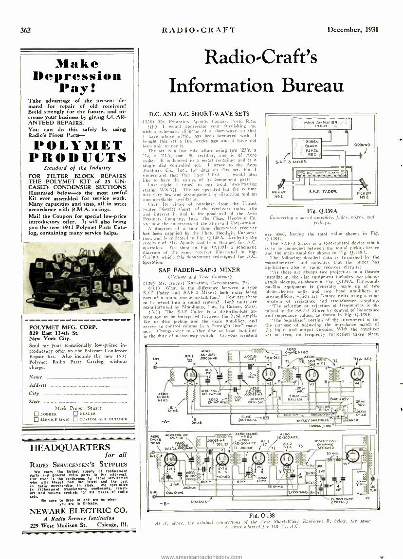
362
Make Depression
Pay! Take advantage of the present de- mand for repair of old receivers! Build strongly for the future, and in- crease your business by giving GUAR- ANTEED REPAIRS. You can do this safely by using Radio's Finest Parts-
POLYMET PRODUCTS
Standard of the Industry FOR FILTER BLOCK REPAIRS THE POLYMET KIT of 25 UN- CASED CONDENSER SECTIONS illustrated below -is the most useful Kit ever assembled for service work. Many capacities and sizes, all in strict accordance with R.M.A. ratings. Mail the Coupon for special low -price introductory offer. It will also bring you the new 1931 Polymet Parts Cata- log, containing many service helps.
POLYMET MFG. CORP. 829 East 134th St. New York City. Send me your sensationally low- priced in- troductory offer on the Polymet Condenser Repair Kit. Also include the new 1931 Polymet Radio Parts Catalog, without charge.
Name
Address - - - - - City .-.-------------- - - - - -- State ----- -- - -- -- --
Mark Proper Square JOBBER DEALER
SERVICE MAN CUSTOM SET BUILDER
HEADQUARTERS for all
RADIO SERVICE\MEN'S SUPPLIES We carry the largest supply of replacement
parts and general radio parts in the midwest. Our store is the rendezvous for radio servicemen who will always end the latest and the best in radio merchandise in stock. We specialize in replacement transformers. condensers, resist- ers and volume controls for all makes of radio sets.
Be sure to drop in and see us when you are In Chicago.
NEWARK ELECTRIC CO. A Radio Service Institution
229 West Madison St. Chicago, Ill.
RADIO -CRAFT December, 1931
Radio- Craft's Information Bureau
D.C. AND A.C. SHORT -WAVE SETS WE) Mr. Ernestine Aponte, Caguas. Porto Rico.
(Q.) I would appreciate your furnishing me with a schematic diagram of a short -wave set that I have whose wiring has been tampered with. I (ought this set a few weeks ago and I have not been able to use it.
The sct is a five tube affair using two '27's, a '24, a '71A, one '80 rectifier, and is of Aero make. It is housed in a metal container and is a
single dial controlled set. I wrote to the zero Products Co., Inc., for data on this set, but I understand that they have failed. I would also like to have the values of its component parts.
Last night I tuned to our local broadcasting station \\'KAQ. The set operated but the volume was very low and accompanied by distortion and an uncontrullal,le oscillation.
(A.) By virtue of purchase from the United States district Court. of the receivers right, title and interest in and to the good -will of the zero Products Company, Inc., The Chas. Iloodwin Co. are now the successors of the aforesaid Corporation.
A diagram of a four tube short -wave receiver has been supplied by the (has. Iloodwin Corpora- tion, and is indicated in Fig. Q.138.. Evidently the receiver of Mr. Aponte hail been changed for A.C. operation. We show in Fig. 0.13S11 a schematic diagram of the same receiver illustrated in Fig. Q.138.\ which this department redesigned for A.C. operation.
SAF FADER -SAF -3 MIXER (Volume and Tone Controls)
(139) Mr. :\ugust Karlotten, Germantown, Pa. (Q.1) What is the difference between a type
SAF Fader and SAE-3 Mixer: both units being part of a sound movie installation? How are these to be wired into a sound system? Both units are manufactured by Simplimus, Inc., in Boston, Mass.
(. \.l) The S. \F Fader is a distortionless at- tenuator to be interposed between the head ampli- tier or disc pickup and the main amplifier, and serves to control volume in a "straight line" man- ner. Change -over to either disc or head amplifier is the duty of a two -way switch. Vitreous resistors
GREEN BLACK BLACK RED
Fig. Q.139A Connecting a sound amplifier, fader, mixer, and
pickups.
are used, having the total value shown in Fig. 0.13911.
The SAF-3 Mixer is a tone -control device which is to be connected between the sound pickup device and the main amplifier shown in Fig. Q.139A.
The following detailed data is furnished by the manufacturer. and indicates that the mixer has application also in radio receiver circuits:
".\s there are always two projectors in a theatre installation, the disc equipment includes two phono- graph pickups, as shown in Fig. 0.139, %. The sound - on -film equipment is generally made up of two photo -electric cells and two head amplifiers or preamplifiers; which are 2 -stage units using a com- bination of resistance and transformer coupling.
"The selection or rejection of frequencies is ob- tained in the SAF -3 Mixer by control of inductance and impedance values, as shown in Fig. Q.13911.
"The 'equalizer' portion of the instrument is for the purpose of adjusting the impedance match of the input and output circuits. With the equalizer set at zero, no frequency Correction takes place,
RFI '22
o
AERO AE -1581 .00014-HE
AERO CNNOY(E N46O
A -PERO 8\ A 30APF'I T
71A AFC
AERO CHOKE se 65
PERO AE -1582
.00025 AF.
.00 200NM5 WITH $W"
.l0 ONNS
\ 5
0,1045
seno PERO COL KIT CNOKE LWT. LO
Ne65 PERO AE -1581
RF. 1.24=0144K
_-PERO CHOKE SEBO ÁE-300 AFT.
AERO A.FL SAE- SOOA.FT. 27 A.F.2
T It .001;NF i /T2 +1A S
BLUE 445V
YELIOW - - e-i I \
GROUND'A=
BROWN i180
TO VOICE COIL DYNAMIC SPEAKER
20 Nys NT
ONO
Or
Vlx
ÌS
.003-MF
AERÓ AEf5B2 .00025-
60O OHMS
4 MF
20ONM5
CHASSIS/
2.0000NM5
ww
- iT`l MF BT 15 000 004 (TOTAL)
T PT
Fig. 0.138 .41 .1, above, the original connections of the Aero Short-Ware Receiver; B, belote, the same
receiver adapted for 110 l'., .4.C.
www.americanradiohistory.com

December, 1931 RADIO.CRAFT
no matter what the setting of the 'compensator,' as the impedance of the amplifier input is lower than the impedance of the pad.
"The 'compensator' controls the amount of low, medium, or high frequency cut-off.
"With the equalizer set at half -way or 5,000 ohms, any amount of the high, medium, or low frequencies can be cut out by adjusting the com- pensator. When the compensator is set at zero, maximum correction occurs; however, if it is neces- sary to secure mere correction, the resistance in the equalizer circuit can he increased. For in- stance, with H1 set at 1110)00 ohms, and I<_' at zero, the frequency '.rand passed by the impedance-
20,000 OHMS
s
ll 1z z
to 1
9
c
4
DX 2 3 4 trKKlpz
FW
GROUND ;II
5
g MEADOW
T
_BMEUD AEV2
10 A.,,
RED BUCK-
5.A .F 3MIxER
mono CELLS AND HEAD AMPLIFIER
Rl. 10,000 OMMS EQUALIZE
<<tRt .04 -MF 3 POINT TAP SWITCH
NI GH pa
OMS
.04ML , } : Ax LOW 4 ZERO Ir
f
Y 1 COMPENSATOR
S HENRY ZERO POSITION
CHOKE
TO MAIN AMPLIFIER - - GREEN
Fig. Q.139B Constructional details of the S:IF tone control.
capacity combination will be greatly broadened. Now, by moving the 3-way selector switch to 'low,' 'med iuni,' or 'high,' only the low, medium. or high notes, respectively. will be by-passed through the impedance- capacity combination. re- sulting in only high frequencies being passed from input to output at the 'low' setting of the switch; low frequency selection at the 'high' setting: and in 'medium,' only the extremely low and extremely higin notes will be by- passed."
This method of tone control is more convenient than tie system described in "Ail Ideal Sound System for high Power." in the August 1931 issue of RAntrr- CSAFT: although the tone eorrection has substantially the same graph as shown in Fig. 2 of the article. It is very convenient to apply to phonograph pickups and radio receiver output cir- cuits, in addition to its use primarily in sound movie installations.
"PAM 19" POWER AMPLIFIER (140) Mr. Ellis E. Jacobs, New Redford. Conn. (0.1) ('lease show in ItAWO-CMAFT the schematic
circuit of the Samsun type "Pam 19' power
amplifier. It floes not seem to be possible to obtain a circuit from the manufacturers, thus making it difficult to make repairs without going through a lot of checking of wires, measuring of resistors, and calculation for the unknown value of defective units. This amplifier uses two '27.s. two fib's, and two '50s (the latter in push -pull).
(A.1) All available information on this power amplifier appears in Fig. 0.140. It is presumed that standard condenser values may be used in the positions for filter and by-pass action; the exact ones, however, have not been furnished by the manufacturers, to date. However, it may be con- venient in some instances to obtain each condenser value from a perfect amplifier of the sanie type. Since Mr, Jacobs does not state the trouble he is experiencing, we cannot otTer a diagnosis. It is necessary to use high- grade, high -voltage -test con - detvers in this amplifier, that to the fact that the potentiometer type of voltage divider. which puts a load across the power transformer until the tube hlansent.s have had a chance tu heat up and short their load across it, is not used in the "ram 19 "; the standard or "slow heater"
' s requiring
about 30 to 45 seconds to Irring the plate current Irais to normal rating.
"SCHOOLS" REPORTED BY RADIO ACCORDING to World-Radio, the little
town of Aalesund has beets the center of activities in the latest step taken by the Norwegian fisher(' authorities in an effort to net as many herring as possible (luring the six weeks of their season.
Experienced herring fishermen were as- signed to two radio- equipped airplanes, which zig- zagged across a 200 -mile itillyrinth of fjords, bays, and inlets. As soon as it herring school was sighted, the fact was radioed to Aalesund, and from there relayed to the waiting fishing fleet, 15,0(k) fishermen and 2,000 twitor- vessels.
Although each school contains millions of fish, it may not be sighted; and since a small season's catch may nHan privation for thou - sands, the economic' advantage of this ap- plication of radio at once becomes evident.
TROUBLE SHOOTING CONTEST R\DIP shows this year have been of
particular interest to Service Men through the activity of Mr. Hathaway, Asso- ciate Editor of Radio Industries magazine, who instituted the idea of a "trouble shoot- ing" contest.
A number of receiver citasses are placed in individual booths, each chassis having its particular fault. The contestant pro- gresses from booth to booth, being timed un each ",job." All the instruments required for each series of tests are available in the respective booths. :1un A.C. power line in back of the booths is tappeti to connection receptacles,
Lists of fun and kern rivalry exist at such get- tagethers.
4000 OHMS v i /4MEG v VS Ti lei I.MEG '505 4000
TZ ¡OHMS
V V
-C OUT- PUT
Fig. 0.140 Schematic circuit of the ,Samson "P.4.1f 19- audio amplifier. Published by special permission of
Cameron Publishing Co. Condenser C may not be required.
363
SIJPERHETERODYNE New Pentode Output Variable Mu
Camole te with Tubes
The Crosley LITLFELLA
see the NEW eROsI.FY' LTTLFE1.1. % -- a S -tube t Iole model SI'l'EIIHE:'Tr:ItolmNE: radio receiver, ineopw- Iling big set features vet housed in an exquisite cabinet of u Ira ca lout r
(
ne `
. 17 inches h gli. Pentode output. vial- :tile Litt tote. fullfloating tun ng coil dynamic. speaker,
tuntinmn a Istrplessl static and tone control, omhined vol -
uin e m ,trol and ..n -nut switch, illuminated dial with vender rive -suri features as these make The i'resle) LITI.FF.LL.t he ore:ue.t .f all radio values. Only $rp;. J.; nnMete.
. Ism the I.ITI,Im1'. a " u
toxin model hpe elra,sis $48 00 with selling fo uldy tubes
Push -Pull Pentode Output SUPERHETERODYNE
The Crosley PLAYBOY
8 TUBES
4975 with t Tubes
Complete
n exquisitely designed all wood compact table model. IT Inches high, housing the flew Crosley x -tutee luDIPPull Pen - nnIe output. variable Mu. Sul erheterod -ne chassis with latest type Crosley full floating inning roil dynamic peaker. Two the- element Pentode output tubes emmected in push -pull: two variable Mu tubes: continuous (steplessl variable static and tone control; Illuminated hairline shadow dial with ember hire; rnnhhw,l voluuo' control and on -off .switch; frill floating moving roll dynamic speaker. Privet] an a zlnuly low. .Uso c ale models. The CHEERIO at $aa. n0. The ylEiutl- 31AKKR ai $73.00. oie LNNOI'NI'E:1t at $x.3 o0, the I'L.tYTI)IE: (Electric l'1.a -k Modell at $03.00. It,- cn,. rating the .une type SUPERHETERODYNE ell.. -si., 10111. p Mill tubes. Noter before such radio Yalu, lot
Push -Pull Pentode Output SUPERHETERODYNE
with METER TUNING AND Automatic Volume Control
The Crosley TENSTRIKE
$69 =NV
Complete with 10 Tubes
An u l
ually atty:ulhe and powerful table model radio re- rrherinrnrnuruhlg the la.tuhe Push -pull Pentode Ihnuul. variable Si u. SI' l'E:1tIfETE.1IODVNE chassis with \I ETEIL TI'NINIi rund .twlltnrlunl Size fens lee fall floral hog urn fnR roil dynamic speaker. Stump walnut vetiver front P. +n,I w ich barb u nti L ''hobo'. Top. sides and pilasters of walnut tl I,L. Ul uunslnns: 'Lot." high. 16" wide In" deep, also a 1 1. gnitirrm six -legged col -
sir, Completo
sole model with s ie type chassis +J 59111 atI le Tuba's
(Western l'riccs Slightly Higher) THE CROSI.EY RADIO CORPORATION
POwgi. CROSLEY, Jtt., President Home of 'the Nation's Station -WLW Cincinnati
www.americanradiohistory.com
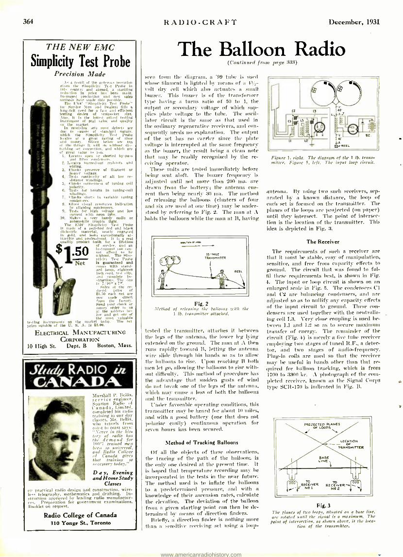
364
THE NEW EMC
Simplicity Test Probe )'recision Made
Ai a result of the generous ment han Risen the Sinaullcity Test Probe In lids country and abroad. a startling redut inn in price has been made. Increased product ion and new sales methods have made this possible.
The l Ill' "Simplicity Test ling,e' for Sees ire Men and Dealers fills 1.41g-felt need for a fast and efficient testing desire of s eel pocket site. .t inn, It is the lowest Priced test log lust rumen) of real value and quality on !market. arket.
In receiving sets n.l defects are
I
to causes of standard mal ore. .latch the Simplicity Test Probe s aces at a great saving of time .md money. Garen below are ten
the things it will do without dls- whing set
111
t eCtlon, and which are great sahne to Non.
11. Locates open g shorted by -pass ont fiber i 'lessors.
2. L vtes burned -nut resistors and wiring.
3. Checks presence of filament or heater soltage.
4. Tests continuity of all low re- sistance windings.
5. Checks r °r reettoess of tuning cull polarity.
G. Tests for breaks In tuning -coil windings.
T. checks shorts in variable tuning o.lensers.
8. t ;lies casual resonance indlrat inn in aligning condenser.
G. Tests for high voltage and loaf current ash n t tube. lit Makes a o handy radio or automobile , trouble light.
The halt' Simplicity l'est Probe Is made of a polished red and black tic Iriarte material, neatly engraved
gold, and looks exceptionally at t
and professional. It is a real > product built for a lift-Hine
of set, ire, and an instrument liar afford g di g a be itithoot. The Slm- o licit y Test Probe Is guaranteed and conies with stand - tatup. eighteen Inch coral. test clin.
Hmal complete In-
ruclhan. The size Is 7 1g" x 7 ".
Saules at the re- duced ¡rire f 81.50 each net are now made direct from I he facto-y.
mSend your check or
aoney order to ua t the address be-
low and get one of the illOst valuable
test In Ill strumtnt.: MI the market luttas. The net vivo mtslde of the L. S. A. la $2.00.
ELECTRICAL MANUFACTURING CORPORATION
10 High St. Dept. B Boston, Mass.
MI cry RADIO tia CANADA
Marshall P. Ileitis. ser vice engineer. Sparton Radio of C ana d a, Limited, completed his radio tr: g in our day classes. Mr. Relais, who travels from coast to coast says: ".Never in the his- tory of radio lias the. demand for lune( trained men N-eau so unir'rrral, and Radio CoOrpe of Canada gites that training. so necessary today."
Day, Evening and Home Study
Classes on 'Tactical radio design and construction. wire-
telegraphy. mathematics and drafting. In- -t ruction approved by leading radio manufactur-
e
Preparation for government examinations. lauuuklet on request.
Radio College of Canada 310 Yonge St., Toronto
RADIO -CRAFT December, 1931
The Balloon Radio (Continued front page 33:1)
seen from the diagram, a '99 tube is used whose filament is lighted by means of a
volt dry dry cell which also actuates a small buzzer. This buzzer is of the transformer type haying it turns radio of 51) to 1, the output or secondary coltuge of which sup- plies plate voltage to the tube. The oscil- lator circuit is the saule as that used in the ordinary regenerative receivers, and con- sequently needs no explanation. 'l'he output of the set has no carder since the plate voltage is interrupted at the saune frequency as the buzzer, the result being a clam note that may be readily recognized by the re- ceiving operator.
These units are tested immediately before being sent aloft. 'l'he buzzer frequency is adjusted until not more than 200 titi. are drawn from the battery; the antenna cur- rent then being nearly 30 Ia. The method of releasing the balloons (clusters of four and six are used at one time) may be under- stood by referring to Fig. 2. 'l'he Otan at A holds the balloons while the man at B, having
wow
®ttigio
15-MILE TRataSMRTER
nt Fig. 2
.Method of releasing the balloons with the 1 lb. transmitter attached.
tested the transmitter, attaches it between the legs of the antenna, the lower leg lying extended on the ground. The man at A then runs rapidly toward Il, letting the antenna wire slide through his hands so its to :allow the balloons to rise. Upon reaching B both men let go, allowing the balloons to rise with- out difficulty. This method of procedure has
the advantage that sudden gusts of wind do nut break one of the legs of the antenna, which may cause a loss of both the balloons and the transmitter.
Under favorable operating conditions, this transmitter may he heard for about 10 miles, and with a good battery (one that does not polarize easily) continuous operation for seven hours has been secured.
Method of Tracking Balloons
Of all the objects of these observations, the tracing of the path of the balloon:, is the only one desired at the present t - It is hoped that temperature recording may be
incorporated in the tests in the near future. The method used is to inflate the balloons to a predetermined pressure, and with a
knowledge of their ascension rates, calculate the elevation. 'l'he deviation of the balloon from a given starting point can then be de- termined by means of direction finders.
Briefly, a direction finder is nothing more than a sensitive receiving set using a loop-
Figure I. right. T te diagram of the I lb. trans- mitter. Figure 5, left. 7hr input loop circuit.
antenna. By lasing two such receivers, sep- arated by it known distance, the loop of each set is focused on the transmitter. The planes of the loops are projected (on paper) until they intersect. The point of intersec- tion is the location of the transmitter. This idea is depicted in Fig. 3.
The Receiver
The requirements of such a receiver are that it t be stable, easy of manipulation, sensitive, and free from capacity effects to ground. The circuit that was found to ful- fil these requirements best, is shown in Fig. 4. The input or loop circuit is shown on an enlarged scale in Fig. 5. The condensers CI and C2 are balancing condensers, and are adjusted so as to nullify any capacity effects of the input circuit to ground. These con- densers are used together with the neutraliz- ing coil I.3. Very close coupling is used be-
tween L1 and 1.2 so as to secure ma . transfer of energy. The remainder of the circuit (Fig. 4) is merely n five tube receiver employing two stages of tuned R.F., a detec- tor, and two stages of audio- frequency. Plug -in coils are used so that the receiver may he useful in bands other than that re- quired for balloon tracking, which is from non to 3300 kc. A photograph of the c -
'Acted receiver, known as the Signal Corps type SCR-170 is indicated in Fig. B.
Fig. 3 Tite planes of two loops, situated on a base line, are rotated until the signal is a maximum. The point of intersection. as shown aborc, is the loca-
tion of the transmitter.
www.americanradiohistory.com
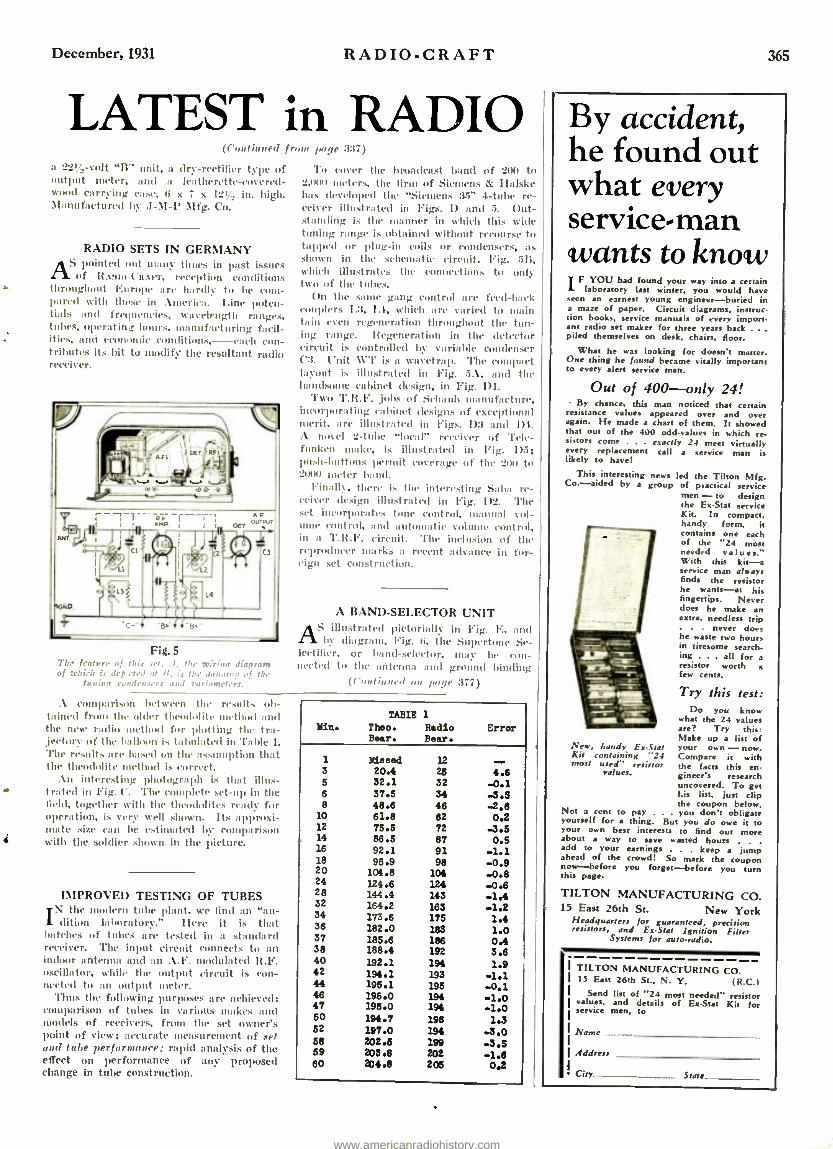
December, 1931 RADIO -CRAFT
LATEST in RADIO (fol inueel front lode 337)
n 221, -volt "B" unit, a dry- rectifier type of output meter, and a leatherette- covered- wood carrying case, (i x 7 x 12.1, in. high. Manufactured by J -M -l' Mfg. Co.
RADIO SETS IN GERMANY AS pointed out many times in past issues
of lt.tmo -Cu. i-r, reception conditions throughout Europe are hardly to be corn- pared with those in America. I.ine poten- tials and frequencies, wavelength ranges, tubes, operating hours, manufacturing facil- ities, and economic conditions, -each con- tributes its bit to modify the resultant radio receiver.
ION
To curer the broadcast band of 200 to 2,000 ureters, the firm of Siemens & Halske has developed the "Siemens :35. 4 -tulle re- ceiver illustrated in Figs. D and 5. (Mt- standing is the manner in which this with tuning range is obtained without recourse to tapped or plug -in exils or condensers, as shown in the schematic c'irc'uit, Fig. 513, which illustrates the connections to only two) of the tubes.
On the sauce gang control are feed -hock couplers L3, 1.1, w'hic'h are varied tu main tain even regeneration through t the tun- ing range. Regeneration in the detector circuit is controlled by variable condenser C3. Unit R°l' is a wavetrap. The compact layout is illustrated in Fig. 5A, and the handsome cabinet design, in Fig. D1.
Two '1'.It.F. ,jobs of Schaub manufacture, incorporating cabinet designs of exceptional merit, are illustrated in Figs. 1)3 and 1)4. A novel 2 -tube "local" receiver of '1'cic- funken make, is illustrated in Fig. 1)5; posh- hnttuns permit coverage of the SOU to 2(11)0 ureter band.
Finally, there is the interesting al re- ceiver design illustrated in Fig. 1)2. The set incorporates tone control, manual vol- ume control, and automatic volume control, in a T.It.I'. circuit. The inclusion of the reproducer marks a recent advance in for- eign set construction.
A BAND -SELECTOR UNIT JS illustrated pictorially in Fig. E, and A by diagram, Fig. 6, the Suiwrtune Se-
lectifier, or band -selector, suey he con- nected to the antenna and ground binding
(Continued ou there :177)
Fig. 5 The feature of this set. .1 the wiring diagram of which is dep feted at it, is the !wonting of the
touring condensers and vuriameters.
A comparison between the results ob- tained from the older theodolite method and the new radio method for plotting the tra- ,jector' of the Balloon is hahuLated in Table 1.
The results fl c h;ised mn the assumption that the theodolite method is correct.
An interesting photograph is that illus- . trated in Fig. C. 'l'he complete set -tap in the field, together with the tin ' a i,ilites ready for operation, is very well shown. Its approxi- mate sire can be estimated by comparison with the soldier shown in the picture.
IMPROVED TESTING OF TUBES the odern tithe plant, we find an "au-
dition m
dition Labortur :" Here it is that batches of tubes are tested in a standard receiver. The input circuit connects to an indoor antenna and an A.F. modulated R.F. oscillator, while the output circuit is con- nected to a 1 output meter.
'l'hus the following purposes are achieved: comparison of tubes in various makes and models of receivers, from the set owner's point of view; accurate measurement of set and tube performance: rapid analysis of the effect on performance of any proposed change in tube construction.
TABLE
Theo. Bear.
1
Radio Bear.
Error
1 Miesed 12 3 20.4 25 4.6 5 32.1 32 -0.1 6 8
37.5 48.6
34 46
-3.5 -2.6
10 61.8 82 0.2 12 75.5 72 -3.5 14 86.5 87 0.5 16 92.1 91 -1.1 18 98.9 98 -0.9 20 104.8 104 -0.8 24 124.6 124 28 144.4 143 -1.4 32 164.2 163 -1.2 34 173.6 175 1.4 36 182.0 183 1.0 37 185.6 186 0.4 38 188.4 192 3.6 40 192.1 194 1.9 42 194.1 193 -1.1 44 195.1 195 -0.1 46 196.0 194 -1.0 47 195.0 194 -1.0 50 194.7 198 1.3 52 197.0 194 -3.0 68 202.5 199 .3.5 59 203.6 202 -1.6 60 204.8 205 0.2
365
By accident, he found out what every service -man wants to know
IF YOU had found your way into a certain laboratory last winter, you would have
seen an earnest rnest young engineer -buried in a maze ofpaper. Circuit diagrams, instruc- tion books, service manuals of every import. ant radio set maker for three years back . piled themselves on desk, chairs, floor.
What he was looking for doesn't matter. One thing he found became vitally important to every alert service man.
Out of 400 -only 24! By chance, this man noticed that certain
resistance values appeared over and over again. He made a chart of them. It showed that out of the 400 odd- values in which re- sistors come . . . exactly 24 meet virtually every replacement call a service man is likely to have!
This interesting news led the Tilton Mfg. Co. -aided by a group of practical service
men - to design the Ex -Stet service Kit. In compact, handy form, it contains one each of the "24 most needed values." With this kit -a service man always finds the resistor he wants -at his fingertips. Never does he make an extra, needless trip
never does he waste two hours in tiresome search- ing . . . all for a resistor worth a few cents.
Try this test: Do you know
what the 24 values are? Try this: Make up a list of your own -now. Compare it with the facts this en. gineer's research uncovered. To get his list, just clip the coupon below.
Not a cent to pay . you don't obligate yourself for a thing. But you do owe it to your own best interests to find out more about a way to save wasted hours . . .
add to your earnings . . . keep a jump ahead of the crowd! So mark the coupon now -before you forget -before you turn this page.
New, handy Ex -Seat Kit
c ontaining "24
most used resistor values.
TILTON MANUFACTURING CO. 15 East 26th St. New York
Headquarters for guaranteed, precision resistors, and Ex -Scat Ignition Filter
Systems ¡or auto -radio.
TILTON MANUFACTURING CO. 15 East 26th St., N. Y. (R.C.)
Send list of "24 most needed" resistor values. and details of Ex -Stet Kit for service men, to
Name
Address
City State
www.americanradiohistory.com
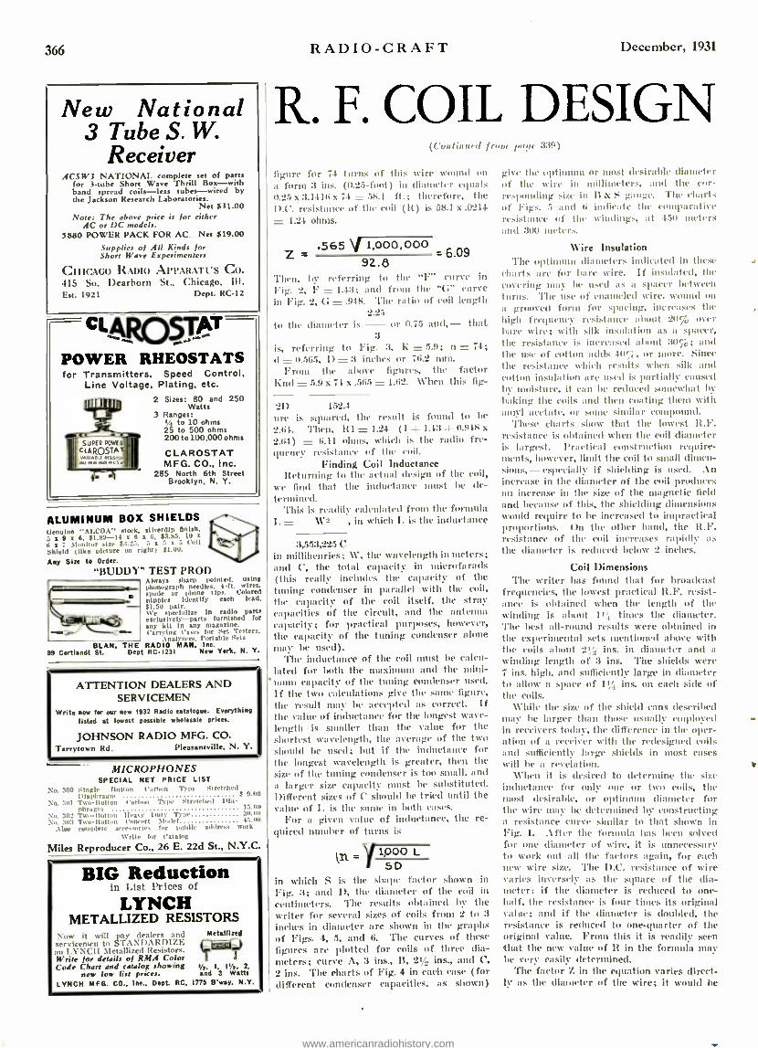
366 R:Al)IO -CRAFT December, 1931
New National 3 Tube S. W.
Receiver ACSW3 NATIONAL complete set of parts
for 3 -tube Short Wave Thrill Box -with band spread coils -less tubes -wired by the Jackson R h Laboratories.
Net $31.00 Note: The above price is for either
AC or DC models. 5880 POWER PACK FOR AC Net $19.00
Supplies of All Kinds for Short Wave Experimenters
CHICAGO RADIO APPARATUS CO. 415 So. Dearborn St., Chicago, III. Esc. 1921 Dept. RC -12
CLAD pT- POWER RHEOSTATS for Transmitters, Speed Control,
Line Voltage, Plating, etc.
2 Sizes: 80 and 250 Watts
3 Ranges: to 10 ohms
25 to 500 ohms 200 to 100,000 ohms
CLAROSTAT MFG. CO., Inc.
285 North 6th Street Brooklyn, N. Y.
SUPER ROWE
CLAROSTA
s., awse `.aan,
ALUMINUM BOX SHIELDS Genuine "ALCOA' stock, slhertip finish. 5 a 9 z 6. 51.89 -14 a 6 a 6, 23.85. 10 a
ti a 7 Monitor sire $3.25, 5 5 a 5 Coll Shield (like picture on right) 41.00.
Any Size to Order.
"BUDDY" TEST PROD Always sharp pointed, using phonograph needles. 4-ft. wires. spade or phone lips. Colored nipples Identify each lead. 41.50 pair. We specialize in radio parts eselusbely -puts furnished for any kit in any magazine. Carping eases for t Testers.
Analyzers. Portable Sets ELAN, THE RADIO MAN. Ins.
89 Cartlandt St. Dept RC1231 New York. N. Y.
ATTENTION DEALERS AND SERVICEMEN
Write now for our new 1932 Radio catalogue. Everything listed at lowest possible wholesale prices.
JOHNSON RADIO MFG. CO. Tarrytown Rd. Pleasantville, N. Y.
MICROPHONES SPECIAL NET PRICE LIST
No. 300 Ì ogle í110510n Carbon Type Stretched
No. 301 Two -Button Cartoon Type Stretched Pia - phragul 15.00
No. 302 Two - Milton Healy Hut)' Tppe 30.110
No 'loi Two - Button Concert Model 45.01)
A Is, ilete avet,sories for public address work
Write for Cat aing
Miles Reproducer Co., 26 E. 22d St., N.Y.C.
BIG Reduction in List I'riec= of
LYNCH METALLIZED RESISTORS
Nov it will pay dealers and Metallired sin is to S -PA \I) ARPI7rs. ¡}
1 " 1 NCII Metallized Resistors. In Write for details of RMA Color Code Chart and catalog showing 1/2, I. I' /i. 2.
new low list prices. and 3 Watts
LYNCH MFG. CO.. Inc.. Dept. RC. 1775 Byway, N.Y.
R. F. COIL DESIGN (C'ontintied frone 1111,1, 339)
figure for 7.1 turns of this wire wound on
a form :3 ins. (11.25 -font) in diameter equals 0.25 x :3.4416 x 74 = 58.1 ft.; therefore, the 1).C. resistance of the coil (R) is 58.1 x.0244 = 1.21 ohms.
Z .565 V 1,000,000 6.09
92.8 'l'Iten, by referring to the "F" curve in Fig. 2, F = 1.4:3; and from the "G' curve in Fig. 2, G = X1.48. 'l'Ire ratio of coil length
2.2.5
to the diameter is - or 0.75 and,- that 3
is, referring to Fig. 3, K = 5.9; n = 74; d = 11.565, D = :3 inches or 711.2 111111.
From the above figures, the factor Ind = 5.9 x 74 x .565 = 1.62. When this fig-
21) 1.52.1
are is squared, the result is found to he
2.64. Then, HI = 1.24 (1 -4- 1.43 -1- 0.918 N
2.64) = 6.11 ohms, which is the radio fre- quency resistance of the coil.
Finding Coil Inductance Returning tu the actual design of the coil,
we find that the inductance must he de- termined.
This is readily calculated from the formula I.= \C2 , in which I. is the inductance
:3,5.5:3,225 C in millihenries; \V, the wavelength in meters; and C, the total capacity in micrufarads (this really includes the capacity of the tuning condenser in parallel with the coil, the capacity of the coil itself, the stray capacities of the circuit, and the antenna capacity; for practical purposes, however, the capacity of the tuning condenser :done maw be used).
The inductance of the coil must be calcu- lated for both the maximum and the mmini-
enituu capacity of the tuning condenser used.
If the two calculations give the same figure, the result may he accepted as correct. If the value of inductance for the longest wave- length is smaller than the value for the shortest wavelength, the average of the two should be used; but if the inductance for the longest wavelength is greater, then the Mgr of the tuning condenser is too small. and
a larger size capacity must be suhstittited. Different sizes of C should be tried until the value of I, is the same in both cases.
For a given value of inductance, the re- quired number of turns is
11:3 5D
in which S is the shape factor shown in Fig. 3; and D, the diameter of the coil in
centimeters. The results obtained by the writer for several sizes of coils from 2 to 3
inches in diameter are shown in the graphs of Figs. 4, 5, and 6. The curves of these
figures are plotted for coils of three dia- meters; curve A, 3 ins., 13, 21/2 ins., and C, 2 ins. The charts of Fig. 4 in each case (for different condenser capacities, as shown)
give the optimum or most desirable diameter of the wire in millimeters, and the cor- respunding size in B & S gauge. The charts of Figs. 5 and G indicate the comparative resistance of the windings, at 450 ureters and 300 meters.
Wire Insulation 'l'he optimum diameters indicated in these
charts are for ha re wire. If insulated, the covering may be used as a spacer between turns. 'l'he use of enameled wire, wound on
ii grooved fora) for spacing, increases the high frequency resistance about 20% over bare wire; with silk insulation as a spacer, the resistance is increased about 309,; and the use of cotton adds lilri, or more. Since the resistance which results when silk and cotton insulation are used is partially caused by moisture, it can be reduced somewhat by
baking the coils and then coating them with Iunyl acetate, or some similar compound.
These charts show that the lowest R.F. resistance is obtained when the coil diameter is largest. Practical construction require- ments, however, Iilnit the coil to small dimen- sions,- especiaall' if shielding is used. An increase in the di:uueter of the coil produces an increase in the size of the magnetic field and because of this, the shielding dimensions would require to be increased to impractical proportions. On the other hand, the It.F. resistance of the coil increases rapidly as the diameter is reduced below 2 inches.
Coil Dimensions The writer has found that for broadcast
frequencies, the lowest practical R.F. resist- ance is obtained when the length of the winding is about 114 times the diameter. The best all -round results were obtained in the experimental sets Mentioned above with the coils about 24 ,, ins. in diameter and a
winding length of :3 ins. The shields were 7 ins. high, and sufficiently large in diameter to allow a space of 114 ins. on each side of the coils.
While the size of the shield cans described may be larger than those usually employed in receivers today, the difference in the oper- ation of a receiver with the redesigned coils and sufficiently Large shields in Most cases will he a revelation.
When it is desired to determine the size inductance for only one or two coils, the most desirable, or optimum diameter for the wire may be determined by constructing a resistance curve similar to that shown in Fig. I. After the formula has been solved for one diameter of wire, it is unnecessary to work out all the factors again, for each new wire size. 'l'he D.C. resistance of wire varies inversely as the square of the dia- meter: if the diameter is reduced to one - half, the resistance is four times its original value; and if the diameter is doubled, the resistance is reduced to one- quarter of the original value. From this it is readily seen that the new value of R in the formula may he very easily determined.
The factor Z in the equation varies direct- ly as the diameter of the wire; it would be
www.americanradiohistory.com
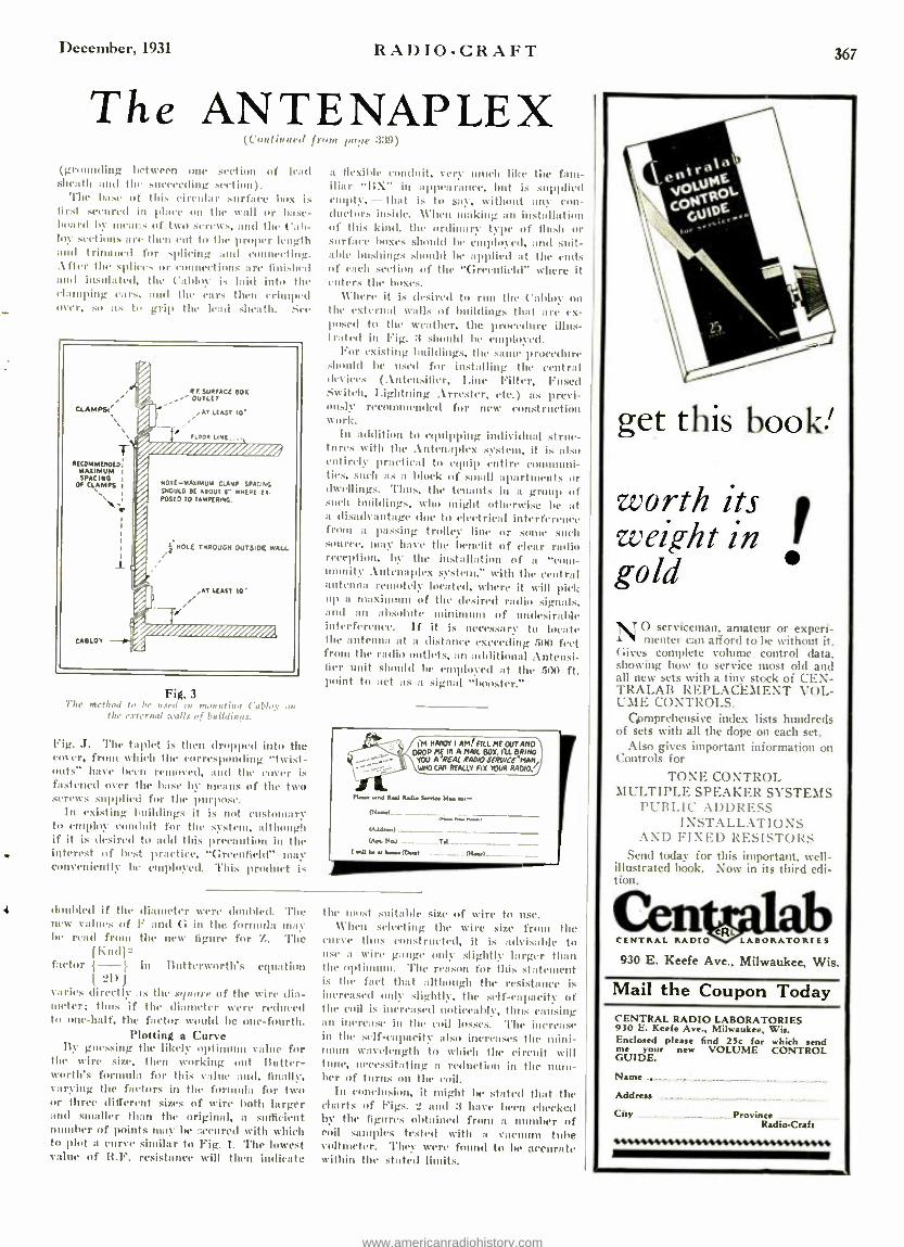
December, 1931 RADIO -CRAFT
The ANTENAPLEX (C'oulinneu fron 1,,I.r, :,anal
(grounding between one section of lead sheath and the succeeding section).
The hase of this circular surface box is first secured in place on the wall or base- board by means of two screws, ami the Call- boy sections are then cut to the proper length and trimmed for splicing and connecting. .After the .splices or connections are finished and insulated, the ('alloy i., laid into the damping caws. and t the ears then crimped over, so as to grip the lead sheath. See
CLAMPS,'
RECOMMENDED MAXIMUM SPACING
OF CLAMPS
EABLOY
R F SURFACE Box OUTLET
eAT LEAST 10'
FLOOR LINE
MOTE- MAXIMUM CLAMP SPACING SHOULD BE ABOUT Ç WHERE Ex. POSED TO TAMPERING.
i
2 HOLE THROUGH OUTSIDE WALL
,AT LEAST 10-
Fig. 3 The method to be nard in mit atinO Cablu_e on
the external [calls of buildings.
.T. l'he taplet is then dropped into the 'u Ser, from which the corresponding "twist - outs" have been removed, Dud the coyer is fastened over the base by nleuns of the two screws supplied for the purpose.
In existing buildings it is not customary to employ conduit for the system, although if it is desired to add this precaution in the interest of best practice, "Greenfield" may conveniently be employed. This product is
doubled if the new values of be read from
Ihn(1ì- factor ( -}
21) )
varies directly sas the *el neire of the wire dia - meter; thus if the diameter were reduced to one -half, the factor would be one- fourth.
Plotting a Curve By guessing the likely optimum value for
the wire size, then working out Butter- worth's formula for this value and, finally, varying the factors in the formula for two or three different sizes of wire both larger and smaller than the original, a sufficient number of points May be ,ecured with which to plot a curve similar to Fig. 1. The lowest value of R.F. resistance will then indicate
at flexibly yuauluit, very much like tile fam- iliar "B X- in appearance, but is supplied empty, -that is to say, without any con - ductors inside. When Making an installation of this kind, the ordinary type of flush or surface boxes should he engloyed, and suit- able bushings should be applied at the ends of each section of the "Greenfield" where it enters the la 130.S.
\Vhere it is desired to run the Cabloy on the external w:dls of buildings that arc ex- posed to the weather, the procedure illus- trated in Fig. :3 should be employed.
For existing buildings, the some procedure should be used for installing the central Reviews (Antcnsilier, Line Filter, Fused Switeb, Lightning Arrester, etc.) as previ- ously recommended for new construction wllrk.
In addition to equipping individual struc- tures with the Antenaplex system, it is also entirely practicalI to equip entire eonnnuni ties, such as a block of small apartments or dwellings. Thus the tenants in a group of such buildings, who might otherwise be at a disadvantage due to electrical interference from a passing trolley lime or some such source, may have the benefit of clear radio reception, by the installation of a "com- munity .\ntenaplex system:' with the central antenna remotely located. where it will pick up a uuaxianuna of Hoc desired radio signals, and an absolute minimum of undesirable interference. If it is necessary to locate the antenna at a distance exceeding .5(1(1 feet Iron the radio outlets, an additional Antensi- lier unit should be employed at the .500 ft. point to act as a signal "booster."
I'M HRRDY I AMf FILL ME OUT AKA DROP Alf IN A MAIL BOX. ILL BRING
YOU AREAL RAM SCRP /COMAN WND CAA REALLY FIX YOUR RADIO.
Nis rM 14.1 Rdls E-.IS ra- M.- (V.-.) .,....,-., lMdm 1
(AP,. Na......_.._ Ti._..._--- t -et V M Irtprn _._._.. .__._.1Nrn
diameter were (budded. 'l'he F and G in the formula may the new ligure for Z. 'l'he
in Buttcrvorth's cquatpon
the most suitable size of wire to use. When selecting the wire size fr the
curve thus constructed, it is advisable to use a wire gauge only slightly Lager than the optimum. The reason for this statement is the fact that although the resistance is increased only slightly, the self -capacity of the coil is increased noticeably, thus causing an increase in the coil losses. 'flat increase in the self -capacity also increases the mini- mum wavelength to which the circuit will tune, necessitating a reduction in the num- ber of turns on the coil.
In conclusion, it might be stated that the charts of Figs. 2 and 3 have been checked by the figures obtained from a number of coil samples tested with a vac tube voltmeter. They were found to be accurate within the stated limits.
367
\en %1:40. E
vo1 -Ot. c0¿ E U0 .
get this boo'
worth its i weight in n gold
NO serviceman, amateur or experi- menter can afford to he without it.
Gives complete volume control data. showing how to service most old and all new sets with a tiny stock of CEN- TRALAB REPLACEMENT VOL- UME CONTROLS.
Comprehensive index lists hundreds of sets with all the dope on each set.
Also gives important information on Controls for
TONE CONTROL M LLTIPLE SPEAKER SYSTEMS
PUBLIC ADDRESS INSTALLATIONS
AND FIXED RESISTORS Send today for this important, well -
illustrated book. Now in its third edi- tion.
Gems . CENTRAL RADIO LABORATORIES
930 E. Keefe Ave., Milwaukee, Wis.
Mail the Coupon Today CENTRAL RADIO LABORATORIES 930 E. Keefe Ave., Milwaukee, Wis. Enclosed please find 25c for which send me your new VOLUME CONTROL GUIDE.
Name _._
Address
City - Province
Radio -Craft
www.americanradiohistory.com

;111,4 RADIO-CRAFT December, 1931
Speech meter and as most meters have different values, a definite resistance for the shunts cannot be realized until the meter resistance itself is known. This will usually be quite low and the shunt resistance is designed to carry 10 times the current through the meter. In other words, if the meter reads 1.5 milliamperes, then only 1.5 Milliamperes is actually passing through the ureter and 13.5 millituuperes are going through the shunt.
An easy method of calibrating the meter is to temporarily use a 0 -15 or 0 -20 mil- liampere ureter in series with either side of the Microphone and in this way check the reading of the 0--5 millitnnneter and shnt. The value of the shunt resistance can be varied until the proper value of current reading is obtained.
In operation there will not be any notice- able disturbance when the meter is con- nected across either shunt.
Condenser Microphones
If a speech amplifier is constructed along these lines with microphone current taken as described above, excellent results should be obtained. However, it would perhaps be well to indicate methods of designing equipment for handling condenser micro- phones.
Input Equipment (Continued from paye 341)
As mentioned in previous articles, the public address system in the New Yorker consists of modified Western Electric ap- paratus, in that the amplifiers were re- designed for remote control. In this sys- tem there are two channels. each of which includes five stages of push -pull and by inter -connections it is possible to obtain an almost inconceivable amount of gain.
'l'he speech amplifiers originally were Western Electric 11.\'s. Ilia (IV up of three stages of .straight . \.I'., using resistance coupling and operating front batteries. The tulles used are \W.E.- 1:39.\'s which are iden- tical in filament and plate voltage to the \W1) -1Y.
')'hex amplifiers were redesigned to use three stages of resistance coupling in lush - pull retaining the \\'.1:.- 239.\'s. The schem- atic is shown in Fig. 3. Direct current must be used on the filaments and to obtain this voltage a copper -oxide rectifier is used on each public address channel. These units furnish b Colts which is reduced to the op- erating potential of 1.1 volts by suitable series resistors.
'l'he plate voltage is obtained from the 390 -volt Ilutxiuuuu potential of the first power amplifier. whose schematic is shown in Fig. 4, and is dropped to al t 175 to 200 volts through the biasing and plate resistors.
Now as Western Electric condenser mi- crophones require voltages for an internal amplifier as well as for the "mike" itself, it would be advantageous to take this volt- age from the speech amplifier. 'Wherefore. the "mike" amplifier uses \W.E.- 239.\ tubes, and all voltages are supplied froid the speech
amplifier. 'Flue lines raining down front the control
room to the various public rooms have an
impedance of 100 ohms. The "mikes" have an impedance of 50 ohms. In order to match the microphones ta the line it is necessary to either use at matching trans- former or, if more than one condenser "mike" is to be rased, some sort of ut mixing control It is obviously much better pray- flee to combine a group of "mikes" through a mixer than it is to just connect them across al transmission line; first, because one has indic ideal control over each "mike'; and second, because the impedance of both line and "mikes" remains unchanged.
Design Considerations
To design a mixer that will fulfill the above it is necessary to understand ,just what an ideal mixer should do in order to produce distort' less output. 'l'he first thing is constant impedance controls that will keep the iutpedaneu of the line constant regardless of the setting of the controls.
Thinking of Making EXTRA Money in spare time?
Servicing Electric Refrigerators Brings Many Easy Dollars
The First Complete Refrigeration
Servite Manual Published
T.II E idea of electricians. radio service men and other mechanically inclined men, servicing refrigeration 2. units is self -evident and the tl ght has occurred to perhaps untold thousands ever since electric refrigeration started. Vet nothing was dour. because the average man knows little or nothing about refrigeration. Compared with servicing a radio set or wiring a home for electricity, the servicing of a refrigerator is absurdly simple. once you get the hang of it.
The (PFEIL IAL Itv..FRII.ERAt Ins SesvtcE 'M ANval. has been edited by I.. K. Wright. who is an expert and a leading refrigeration authority. Ile is a ntentber of the American Society of Mechanical Engineers. American Society of Refrigeration Engineers. The National Association of Practical Engineers. etc.
In this Refrigeration \fannal every page is pro- fusely illustrated : every refrigerator part is car -
fully explained: diagrams are furnished of every known machine: special care is given to the servic- ing end. The tools needed are illustrated and ex- plained: there are trouble shooting charts. and other service data.
Remember there is big money in the refrigera- tion servicing bnfilIPER. There. are thousands of firms selling refrigerators every tan and they need to be cared for often. Eventually there will t. more refrigerators than radios. V. not Mel .
your earnings with a full or spare time bu-i. - by servicing refrigerators.
OVER 1,000 DIAGRAMS 352 Pages Flexible Looseleaf Binder Complete Service Data
Here are some of the important chapters: Inc onto, t iule t.0 ulue lairlgmlat Ion Sen hint{ Business Ilistory Of Refrigeration Fundamentals of Refrigeration
Ueseript bon of All It noun Trprs of RefrIReration ordre Tool, and Shop Equipment
Motors Trouble shooting )'nit l'arts. Va:ves and .Aulnmsile Equipment }bikes and .atwmdfirai bon of Cnhs st:umfarturers of Cabinets Refrigerants and Autumanr Equipment
and ]lady other Important ehapurre. .\lreatly hundreds of copies of the OFFICIAL
REFRIGERATION SERV1cE MANUAL have been sold; and there still remains the greatest opportunity for thousands more to learn how to make more money in a short time through openings in this new field.
t-
I
Mail Coupon Today! GERNSBACK PUBLICATIONS. Ise. RC -12 56-98 Park Plate, New York, N. Y.
I enrinse bures-Ills my remittance for $5.00 (check cr looney order preferred) for which rat are to vend to RI, MAREe prepaid. one ropy of the OFFICIAL REFRIGERATION SERVICE MANUAL.
Nahar
1 Address
I t'Ity Stab
www.americanradiohistory.com

December, 1931 RADIO-CRAFT 369
SERVICE FORUM Killing Service Calls
(('unlinued from paye 1t5)
be taped to stop corrosion at this point. The wire is then dropped to the window.
If a "nail -it" knob can be used here, use it to take the weight of the lead wire off the antenna. At the window, the lead wire should be fastened with one of these knobs to prevent swaying; and should be skinned for nhout three inches and pushed through the dip of the lead -in strip, leaving about two inches sticking through. This end should be wound once around the head of a tack, and the tack driven home through the small eyelet in the end, to prevent loosening at this point. A tack here will prevent one of the most prevalent complaints I know of.
Of course the above description of an installation is not ideal by any means; but it is about the best that can he done in a city apartment with the time allowed an
installer. I have not forgotten the lightning arrester; about the best place for this is fastened to the inside of the cabinet, with two sepnñtte lends running from the binding posts on the chassis to the arrester. These wires can then be easily disconnected.
The operation of the set should then be explained to the customer, with a short talk on the various noises that will he encoun- tered.
The average time for the above installa- tion, checking tubes, etc., is about one hour and, counting traveling time on a straight route, about seven can be done in an eight - hour day.
(Simple as these recommendations ap- pear, they are worth while to consider. - Service Editor.)
Condenser - Rectifier (('unlin utsl from paye 31.1)
As the coltoge applied to the condenser decreases, the first half of the condenser begins to discharge thus maintaining the current constant. In other words, while one - half of the condenser is charging, the other half is passing current, and as this current decreases, the first condenser begins to dis- charge thus keeping a constant current through the load.
It can be seen that the rated voltage of the condenser should he equal to the peak value of one -half of the total transformer voltage. For rectifying and filtering high voltages and currents a series-parallel (.011114-
nation of electrolytic condensers may be used to advantage.
Referring tu the diagram, when the Metal plte of one -half of the condenser becomes positive the electrolyte is negative. No cur- rent cala flow through this half of the con- denser, but a short heavy charging current flows that raises its potential until it is equal to the peak value of the A.C. voltage across the transformer. Thus this half of the condenser becomes charged at the same time the second half of the unit is passing current to the load because the electrolyte is positive with respect to its metal plate.
In the past ninny engineers thought that an ordinary potentiometer would perform sat - isfactorilt, but experience and theory have definitely proved that the use of a poten- tiometer results in very poor frequency re- sponse when the potent ionuter is used across a line as n volume control.
In Fig. A is shown the type of mixer that is used in the New Yorker; the schem-
. atic circuit is illustrated in Fig. 5. Let us now consider the attenuators which
are used aacriiss the outputs of the "mikes." In Fig. 6:\ this particular section is shown,
1 and if the circuit is examined it will be noticed that the attenuators are wired in series with the output windings tapped.
Refer now to Fig. 6R. The resistor which is placed across the winding Q changes the effective impedance of the winding. How- ever, if we put another resistor in series with the entire unit as shown, it is possible to once again return to the natural imped- ance of the winding (that is, to the (4 B- lion where no shunting resistor is used). The reason being of course, that the series resistor balances out the shunting effect.
This then, is the purpose of the odd tap- ping arrangement which is used in the fin- ished design, for not only is it possible to keep the impedance constant but also the shunting effect is ehinainated for all practical purposes. The values of the various parts
of the attenuators as used in this mixer lare given in Fig. 5.
However, it is comparatively simple to design et pad for any audio circuit These values are computed by using the following formulas:
Z °THE IMPEDANCE AT 1,000 CYCLES R1= 3Z R2= (Z)(r)
Z }r R3 =Z R v THE OUTPUT RESISTANCE OF
THE MICROPHONE UNIT. R, n resistor having the same resistance
as the "mike" unit output transformer sec- ondary is inserted in place of the "mike" unit whenever the "mike" unit is thrown out of the circuit, thus keeping the value of It always constant.
'l'he switching arrangement shown in the schematic umkes it possible to read all volt- ages lilt the plate current of the "mike" amplifier tube (which is built into the con- denser mike unit).
The mixer gives excellent results and the output is in no was' lacking of either highs or lows. For further information on con- stant-impedance vol controls the author refers you to the August issue of RAnto- CR.ti r wherein this subject was discussed.
Only
$645 Rw ar Span the World with thisSetf A new radio thrill for you: Lis en in DIRECT to London, Paris, 1terlin, Buenos Aires and other broadcasting stations throughout the world via short waves. Enjoy unique foreign programs from strange lands. Your ordinary receiver cannot take in these low wave stations. WORLD-WIDE RE- CEIVER gets 14 to 550 meter stations with sur- prising clarity.
AERO SHORT WAVE Super- Heterodyne Converter
Converts Your AC or DC Radio Set Into a Short Wave Super- Heterodyne
15 to 200 METERS
Now in addition to your regular receiver you can have a Short \Vane Super - heterodyne set that will enable you to tune in short wave stations from many different parts of the world. All you have to do is to connect the Aero Converter to your own set and you are then eady to span the world. The Aero Converter is adaptable for .\C or DC radio sets. Contains its own filament supply. It voltage can easily be obtained from your regular radio set, or cou may use a single 45 voltage It lottery. Vo - plug -in coils. Single tuning dial. Very easy to tune. No whistle or squeals. Uses two U \227 tubes, one as oscillator and one as mixer.
Price List AC Model. lem tubes. ready for operation 112.50 DC Model for batteryopersted sets 11.50
2 Matched U X227 tubes at 75c each 1.50 145 Von B Battery 1.45
New Aero Midget $16.50 Using the latest type Pen- tode and Multi - \fu Tubes. This Midget performs on distance and has tone qualities like a large ex- pensive set. Wonderful selectivity. Full dynamic speaker. full vision dial, beautiful walnut finish cabinet. A 5 -tube set. Price for set of 5 tubes. $4.50. Available in 25 cycle $2.50 extra.
Aero Pentode Auto Radio Amazingly Low Price! Quality Performance
Me guarantee this Is the latest Aodel o tube ero f' e n !ode Auto Radio. Due to' the use of the latest Pentode Tubes. this set is
nual In per. fnnnance to any a -tube
r er Ising
set. The circuit used is one which will be embodied in most of the ex- pensive 1092 model auto radios. The omplele set
Ileauperal ell remote mi from tthedash- your ar
-
Thls set will pull In stations within a radius of Loon Niles sold will delhcr the ,olum, :nid tone qualities of
an electric set.
Price of Set only $20.00 Price complete. ' including tubes. batteries. dynamic streaker and suppressors, all ready to install and use. Cann. TERMS: Should you order C. O. D. a deposit of $1.00 Is required on Short ware Receiver or Short Was. ('nn-
ter. A deposit of $5.00 Is recul red on the Aero Midget or Auto Radio. ar; discount allowed If remit- tame is sent In full.
Write for Bargain Catalog CHARLES HOODWIN COMPANY
4240 Lincoln Ave., Dept. M-150 Chicago, Illinois
www.americanradiohistory.com

370
SKINDERVIKEN
The Most Sensitive Microphone Button (ACTUAL SIZE NOT BIGGER THAN A QUARTER)
You can easily make a highly sensitive detecto.. phone by using a Skinderviken Transmitter Button to collect the sound waves. You can build your own outfit without buying expensive equipment. Think of the fun you can have with such an
instrument. You can install an outfit in your home and hear
the conversation being held all over the house. Full directions for connecting the button for
use as a detectophone are given in our 12 -page booklet.
These wonderful little SKINDERVIKEN micro- phone buttons may be used for hundreds of uses.
such as:
RADIO AMPLIFIER PHONOGRAPH AMPLIFIER DETECTOPHONE TELEPHONE AMPLIFIER
STETHOSCOPE LOUD SPEAKER AMPLIFIER MICROPHONE CRYSTAL SET AMPLIFIER
HOME RECORDING OUTFIT. ETC.
95c EACH Two for $ .i5 12 -PAGE INSTRUCTION BOOKLET
containing suggestions and diagrams for innumerable uses, furnished with each unit.
EVERY AMATEUR SHOULD HAVE TWO OR THREE OF THESE AMPLIFIERS IN HIS LABORATORY
WE PAY Sì.5.00 IN CASH for every new use developed for this unit
and accepted and published by us.
SEND NO MONEY When the postman delivers your order you pay him for whatever you have ordered, plus a few cents postage.
(Canada and Foreign: cash with orders)
PRESS GUILD. Inc.. RC -1231
16 Murray St., New York, N. Y. Please mall me at once as many of the following item.
as I have Indicated. .... Sklnderviken Transmitter Units at 95c. for 1; $1.75
for 2: $2.50 for 3: $3.20 for 4.
When delivered I will par the postman the coot of the Items specified plus postage.
Name
Address
Cllr Stata
in AGE NTS /10^1101110C WANTED
Short Wave Units- RADIOPHONE Earn up to $100 a creek. Every Radio Fan interested. Lat- est 1VO :.E RITE Models. Operates on any radio. Thrill to
all. Special hone Demonstrator offer to LIVE Wires. So
write today to 20th Century Co., 1509 Coke Bldg., Kansas
City. Mo.
PATENTS Write for Free Guide Book "HOW TO OBTAIN A PATENT" and Record of
Invention Blank. Send model or sketch and descrip- tion of your invention for our Free Opinion whether it comes within Patent Office Rules. RADIO and ELEC- TRICAL Cases a Specialty. Prompt. Efficient Service.
PAYMENT OF FEES IN INSTALLMENTS VICTOR J. EVANS & CO.. 923 - 9th, Washington, D. C.
RADIO -CRAFT December, 1931
FAVORITE TEST EQUIPMENT An Improved Ohmmeter
(Continued front. page 319)
and even this is not absolutely essential. 'l'he following is a suggestion for the con- struction of an instrument of this type adapted to read lower values than usual.
Most constructors advocate the shunting of the 0 -1 milliammeter to 10 ma. in order to read the lower values of It, but it is sim- pler and better to use lower values of E; fur instance if E is in millivolts and I in milliamperes then It will be given directly in ohms, where It is the suet of Nie unknown resistance and the resistance of the milli- ammeter. Fortunately, millivoltmetcrs are
u one of our most couuon types of instru- ments though everyone may not recognize it; for example, all Weston :301 millüuu- meters above 30 ma. are calibrated to 11H) millivolts, and provided with a shunt such that the drop is 100 inv. when the full stile current is flowing. l'or our pur- pose a 0 -100 milliammeter with the shunt removed gives its a 0 -100 millivoltmeter, scale and all; if this is provided with mul- tipliers for 1 and 10 volt ranges it will he
just what we need. Thus in Fig. 4 we
have an instrument reading from 0 to 100,000
ohms which can be made quite compact. The list of parts for this tester is as fol- lows: the battery may be four of the small penlight batteries to furnish 12 volts; a
0 -2001) and a 0 -200 ohm potentiometer to vary the voltage; a Weston :301, 0 -100 mil- liammeter with the shunt removed and pro- vided with 1 and 10 volt Itipliers; a three point switch for the voltmeter ranges, a Weston :301, 0 -1 milliammeter, a push but- ton switch for the battery circuit (thus avoiding undue drain on the battery); and it panel and case as desired by the individual builder. These should be wired with fairly hero{ wire, old fashioned No. 11. bus makes a. neat job.
The ranges covered are as given in the fol- lowing chart:
Ma. Vm. Range in Ohms Reading Range (Weston :301)
1.0 0 -100 1111. 0 -73 1.0 0 -1000 nn', 50 -973 1.0 0 -10 volts 500 - 10,000
0.1 0 -10 volts 10,000- 100,000 To calibrate the multipliers for the 1 and
10 volt ranges it is easiest to use a 0 -10 voltmeter as a standard; the approximate values will he 1.0 and 300 ohms.
To determine the correction to be clade for the resistance of the milli inuueter, short the terminals at It und react resistamo, suh- tract this from the total to obtain the true value when measuring an unknown resistor; if it Weston :301, 0 -1 milliammeter is used, the value to be subtracted will be 27 ohms.
For the higher values of resistance it will not be necessary to make any correction.
SILVER ANNIVERSARY BOOKLET AHISTORY of the "Auction" is avail-
able to anyone sending a stamped ad- dressed envelope to the DeForest Radio Co., Passaic, N. J., for a copy of "A Quarter Century of Radio Progress." This attrac- tive and instructive booklet was prepared as it souvenir of the Silver Anniversary (1900 -1931) of the De Forest "And'
STATEMENT OF THE OWNERSHIP. MANAGE- MENT. CIRCULATION. ETC., REQUIRED BY THE
ACT OF CONGRESS OF AUGUST 24. 1912.
Of RadioCraft. Published monthly at Mt. \[orris. fur October I. 1:131. State of New fork County of New York as.
Itefure ple. a Notary Public in and for the State and linty aforesaid, personally appeared Ir. log S. Ilan -
hehner, who, baring beep duly sworn al eurding to law. deposes anti says that he Is the business manager of RadioCraft and that the following is. to the best of his knowledge and belief. a true st ;dement of the
nership. lha
nagement. etc.. of the aforesaid publica- tion tor the date shorn In Nie abuse caption. required by the .lot of .\ugust 21, 1912, embodied in section III. i'mt al Laws ami Regulations, to wit
I. That the names and addresses of the publisher, editor. managing editor. and business manager are Publisher, 'Icrhnt -Crft l'ubli doing Corp.. 401 North
Wes lr> A, e. . )It. Morris. Ill, Editor. Ilugn Gernshark, 98 Park Place, New York City. \Ianaghhg Kiltur, It. O. lVashburnc. 98 Park flare.
New York City. Business NI ;onager. Irving S. Maneeimer, 93 Park Place.
New York City. 2. That the mcners are:
Teehni -Craft Publishing Cori,.. 401 No. Wesley .Keane, M:. Morris. III.
Hugo Cernsbark. OS I'ark flare. New York City. Sidney Gemsbaok. 9s Park Place. New York City. D. Manheluher, OS Park flare. New York City.
:I. 'chat the known bondholders, ,nurt gagnes, and other security nobler. uw'ning ur holding 1 per cent or more of total amount of bonds. mortgages, or other securities are: None.
4. That the two paragraph.. next above. giving the names of the non ers, st x khulders and security hold- ers. If any. contain not only the list of stockholders and security holders as they aptwvr Mum the hairs of
the bat al sers in r where the spa$hwider or security holder appears upon s the hooks of One
pang trustee or In any other flduclary relation, the as On. person ,.rihraunw for ninon such
trustee Is acting. is given; also that the said two para- graphs contain statements embracing afflant's full knowledge and belief as to the rinvmstau.s und con- tilt Ions under ,chirp stockholders and security hollers who do not appear upon the Rooks of the company trustees, hold stork and s ertarl t les In a rat p aclty other than that of a bola tide owner: and this alliant has no reason to belle, e that any other person. a ssoelai ion, or corporation has any interest direr( or Indirect In the said stock. bonds. or other securities than as so stated by him.
IRVING S. ?I.tNFIEIYI ER Sworn to and subscribed before me this lath day of
September, 1931. M.\CRICK COYNE, Notary Public.
I SEA I.I (My commission expires Manh 30. 1932.1
Classified Advertisements Advertisements in this section arc inserted at the cost of tell cents per word fur each insertion -name, initial and address each count as one word. Cash should accompany all classified advertisements unless placed by a recognized advertising agency. No less than tell words are accepted. Adver- tising for the January. 1932. issue should be received not later than November 9th.
FORMULAS
MAKE AND SEI.I. your own products. We will furnish you an y formulas. Write for our litera. ture. Chemical Institute, 19R Park Place, New York, N. Y.
RADIO
SERVICE MEN. ATTENTION - Speakers re. wound, magnetized. repaired, $2.00 to $2.75. Com- plete Power Pack Service-Transformers rewound. condenser blocks repaired, resistors duplicated. Guaranteed. Clark Brothers Radio Co., Allia, Iowa.
MAKE World's simplest radio. Crystal with in- structions, 25c. Music Sales. Independence, Mo.
SSA0" ANYONE "v.'s PROVES THAT THIS IS not the actual photo of myself showing my superb physique and how the Ross System has increased my own height to 6 ft. 3 3-4 inches. hundreds of Testimonials. Clients up to 45 years old gain from I to 6 inches In a few weeks!!
Firtt In I90? First Te.dey
No ApphIanees -NO Drugs -NI Dieting. ROSS SYSTEM NEVER FAILS. Fee Ten Dollars Corn- Plots. Cone Incline Test linens and Pan Rulers 5
cents stamps Allow time for return mails across this Atlantic." G. MALCOLM ROSS. Height Specialist. Scarborough. England. (P. 0. Box 15).
www.americanradiohistory.com

December, 1931 RADIO-CRAFT
OPERATING NOTES (Condono -d froto page 351)
condensers open circuit, causing one ' 45 tube to become inoperative. When one Of the leaks opens, repair is easily effected, for these carbon resistors are reedit accessible.
A defective coupling condenser either spurted or open -circuited presents quite an- other problem, for these units are incor- porated in the so- called (RCA) capacitor and coupling reactor pack. It stands with- out question. that the eomplete reactor pack can be changed, but this is unnecessary, though many of these units, most likely, have already been replaced. The only changes necessary are the addition of the new .025-nlf. eondcnser to the grid circuit of the '45 stage containing the shorted con - denScr.
Two green wires emerge from the capaci- tor reactor block that go to the grids of the '45 tubes, as shown in Fig. 2. Place the new unit in series with the Lead widen chimes froto the defective unit (shorted) and that job is done. However, when either of the two coupling condensers open-circuits, the change is slightly !lore complicated. Ilere we must determine which of the two in the pack or block is open. This can be done by the discharge method, testing front one grid of the '45 to terminal No. 5
on the block, or the hump of solder located in one conic- of the Nock between terminals Nos. 3 and 4. 'l'he new unit should be con- nected in series between Nn. 5 and the grid of one '45, or in series with the 1111111) of solder to the grid of the other '45.
Distortion on Radiolas "80," "82" and "86" will he found in some cases to be caused by an open (';0,0(1) ohm carbon resistance in series with the push -pull input secondary return. Al t all resistors used in Radiota and Victor sets use Wood's metal ends. When the proper value for a repair is not at hand, a temporary and usually a per- manent ,job can be had hp swelling the \Vood's metal ends with flie tip of a hot electric soldering iron. However, care should he exercised in applying the iron, for Wood's metal has a very low fusing point. The "open" usually occurs at the end of the resistor and sweating often does the trick of repair.
The same trouble found on several Peer- less Couriers caused mulch aggravation to several Service Men. The receiver burned out the 'Hi rectifier as soon the set was turned on. A dead short was found across the filter output. Each condenser was dis- connected and given a charge- discharge test and each checked perfectly. After sev- eral hours of work, it was found that the condenser with the vehlow lead emerging from the condenser block broke down un- der load. This same condenser was found fo act the same way on several receivers.
For at least six months. Service Men were perplexed by the problem of fading in the Kennedy "632," in which volume would cut down to an audible whisper and, after a few moments, come hack to normal before a test could be made to determine the cause. Several of these chasses were taken into the shop to undergo a "life test," and as soon as a set became inoperative, tests were made.
For instance,. in one case, the detector plate voltage was found al 1 nil, accom- panied by an increase in other voltages. This was traced to a partial short in the detector's plate titter, (a combination which consisted of an R.F. choke and condenser assembly, s' lar to that used in the Stronl- berg- Carlson "641," "642," "652 ") one con- denser being the apparent cause of the trouble; pressure on the sides of the case
would clear the short, or bring it hack. In- stead of discarding the unit, the metal case of which was grounded, it was carefully taped and insulated, and external .002-m f. condensers were Connected from either side of the choke to chassis.
In another case, the .06 -nmf. blocking con- denser was found to open and close the circuit, causing fading; the remedy in this ease was replacement. If a tone lower in pitch is more pleasing tu the owner, a
0.1 -mf. condenser may be substituted for the .Ob -Ilf.
This model incorporates a certain type of Jensen speaker, in which the voice coil is w 1 with it wire resembling ahuninunt: the flexible pigtails cannot be soldered, so
the connection is obtained through it heavily - etonpressed mc.'lanicad contact. Vibration. luusening the ettntact, produces an open coil and fading, then sudden recovery. When the fact, that all voltages were correct and receiver parts in good order, pointed to it
faulty speaker, this was replaced with an- other Jensen instrument of nearly the sanie characteristics.
SERVICING MAJESTICS (Continued from page 351)
There is a simple method to test the filter pack condensers in the three different types Of Majestic powerpacks. Each type can he identified by the number of con - nections or traps on it. 'l'he 9l'6 has ten, the 81'6 has eleven, and both the 71'6 and 7111'6 have twelve. We are only interested in connections 1, 2, 3 and 4, Fig. A.
Disconnect the powcrpack from the set and then turn it on so that the G -80 tube lights up. If there is a frying and popping in the condensers it shows that one was leaking and that the no -load voltage of the pack has broken it down. If the frying clues not occur, then with a screwdriver short from No. 1 to NO. 4. This should give a white breakdown flash. If it gives a red are, it steams that one or more con- densers are open. After leaving it on for a minute or two, turn it off, and about fifteen seconds later test again from No. 1
to No. 4. There should be a white break- down discharge. If not, it indicates that one of the condensers is shorted or leaking.
In the \laa,jestic "91)" series, trouble has been experienced with the .004 detector plate by-pass condenser. In nearly every ease where they have broken down it will be noticed that two .002 condensers of like manufacture have been riveted together. In replacing, he sure to use two riveted to- gether of different makes. It seems that they stand up better if that precaution is taken.
371
the building and re- pairing of all kinds of radio receivers !
'I91 F: three volumes of this 1.11 ran cuver the entire field of building. repairing and -.trouble-shooting"
on Modena radio receivers. The Library is up- to -the- nniuute in every re «pert and is based "on the very latest developm.mts in the design and rnauufaet ure of equip- ment. The rapidly-growing interest in short -wave and television reception is thoroughly covered in a com- plete section which deals with the construction of hi, Ina. of apparatus.
Radio Construction
Library LI
NCLUDING CONSTRUCTION OF SHORT-WAVE AND
TELEVISION RECEIVERS By JAMES A. MOYER and
JOHN F. WOSTREL Faculty, University Extension, Massachusetts Department
of Education
Three Volumes - 1087 Pages, 6x9 605 Illustrations
VOLUME L presents the fundamental principles of radio so clearly and simply that anyone of average training will be able to read, understand and apply them. It gives actual working drawings and lists of mat eria Is for the rollstruet ton of many typical sets. VOLUME Il: fully discusses all of the elementary principles of radio construction and repair. An ex- planation of the necessary steps for "trouble- shooting," repairing, servicing and constructing radio sets successfully. Practical data is also given on antenna systems, battery eliminators, loud speakers, chargers, etc. This volume includes complete instruc- tions for the const rocs ion and operation of short-wave and television receivers. VOLUME III: covers the essential principles under- lying the operation of vacuum tubes in as non- technical a manner As is consistent with accuracy. It discusses the construction, action, reactivation, testing and use of vacuum tubes; and an interesting section is devoted to remote control of industrial processes; and precision measurements. EXAMINE these books for 10 days FREE This Libras is not only a thorough home -study course, hut a handy means of reference for the more experienced radio experimenter, repair man, and radio shop- owner. To these men, as well as to those who desire to advance in the radio profession, this offer of a In clays' Free Examination is made. Simply clip, fill in, and mail this coupon
McGRAW-HILL F R E E EXAMINATION C O U P O N
MCGRAW -HILL BOOK COMPANY, INC., 370 Seventh Avenue. New York. Oentlrmen, -Send me the new RADIO CONSTRTYC- Free Examination.
all f
charges atl factoryenIl .end EÌí0 In 10 days, and 52.00 a month until 57.50 heu been
paid. If not wanted I will renon the set at your expense.
Name
Home Address
City and State
Position
Name of Company RC -12.31 (WRITE PLAINLY AND FILL IN ALL LINES)
www.americanradiohistory.com
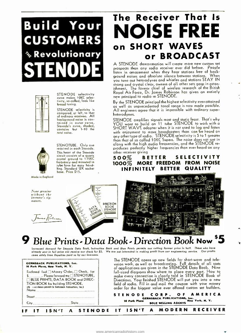
Build Your CUSTOMERS
.i.e. Revolutionary
STENODE
Made in England
None genuine without the inrentor s sig- nature.
STENODE selectivity curve makes 10KC selec- tivity, so- called, look like broad tuning.
STENODE selectivity is compared, at left, to that of ordinary receivers. All background noise is con- tained in outer curve. Stenodé s curve, shaded, contains but 1 -10 the total noise.
STENOTUBE. Only one required in each Stenode. This heart of the Stenode circuit consists of a quartz crystal ground to 1 75KC frequency and mounted in tube Form for easy hand- ling. Standard UX socket base. Price S15.
The Receiver That Is
NOISE FREE on SHORT WAVES
or BROADCAST A STENODE demonstration will create more new custom set
prospects than any radio receiver ever did before. People listen in amazement when they hear stations free of back- ground noises and absolute silence between stations. When you tune out heterodynes and whistles and stations STAY IN strong and crystal clear, owners of all other sets gasp in aston- ishment. The former chief of wireless research of the British Royal Air Force, Dr. James Robinson has given an entirely new principal to radio in STENODE.
By the STENODE principal the highest selectivity ever attained as well as unprecedented tonal range is now made possible. All engineers agree that it is impossible with ordinary super - heterodynes.
STENODE amplifies signals most and static least. That's why YOU want to build an 11 tube STENODE to work with a SHORT WAVE adapter when it is not used to log and listen with enjoyment to more broadcasters than can be heard on any other type of radio. STENODE selectivity is 5 to 1 greater than that of so called 10KC Supers. The noise does not get in
along with the high audio frequencies, and the STENODE re- produces perfectly higher frequencies than ever heard on any other receiver giving
500% BETTER SELECTIVITY 1000% MORE FREEDOM FROM NOISE
INFINITELY BETTER QUALITY
DIRECTION
O,n0'o% STE ODE
St
er,.-4l!!!1
T
9 Blue Prints - Data Book - Direction Book Now $5 Increased demand for Stenode Data Book, Instruction Book and Blue Prints permits our cutting former price in half. Those who have already sent in full price will receive our check for $5. We are not interested in making profit from our engineering service. Our profits come solely from Royalties paid us by our licensees.
GERNSBACK PUBLICATIONS, Inc. 98 Park Place, New York, N. Y.
Enclosed find j Money Order, Check, For
S . Please forward me STENOTUBE, ['BLUE PRINTS, DATA BOOK and DIREC- TION BOOK for building STENODE. (N. rail checks payable to Bernsbark Publications, Inc.) Name
Street
City State
The STENODE opens up new fields for short -wave and tele- vision work, as well as broadcasting Full details of all sorts of applications are given in the STENODE Data Book. Nine full -sized diagrams show where to place every art. How to make every connection is clearly told in STENODE Book of Directions. Your finished STENODE will put you into a new field of radio. Fill in and mail the coupon with your money order for the biggest value ever offered custom set builders.
S T E N O D E C O R P . O F AMERICA GERNSBACK PUBLICATIONS, Inc.
98 Park Place New York, N. Y. SOLE SELLING AGENTS
IF IT ISN'T A STENODE IT ISN'T A MODERN RECEIVER
www.americanradiohistory.com
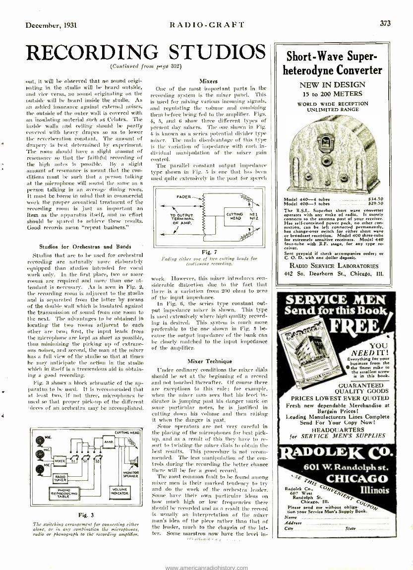
December, 1931 RADIO -CRAFT 373
RECORDING STUDIOS (Continued front page 352)
out, it will be observed that no sound origi- nating in the studio will be heard outside, and vice versa, no sound originating on the outside will be heard inside the studio. As an added insurance against external noises, the outside of the outer wall is covered with an insulating material such as Celotex. The inside walls and ceiling should be partly covered with heavy drapes so as to lower the reverberation constant. The amount of drapery is best determined by experiment. The room should have a slight aunount of resonance so that the faithful recording of the high notes is possible. By a slight amount of resonance is meant that the con- ditions must be such that a person talking at the microphone will sound the Satre as a person talking in an average dining rooms.
It st be borne in mind that in commercial work the proper acoustical treatment of the recording room is ,just as important an item as the apparatus itself, and no effort should be spared to achieve these results. Good records nlcan "repeat business."
Studios for Orchestras and Bands
Studios that are to be used for orchestral recording are naturally more elaborately equipped than studios intended for vocal work only. In the first place, two or more noms are required and more than one at- tendant is necessary. As is seen in Fig. 2,
the recording room is adjacent to the studio and is separated from the latter by means of the double wall which is insulated against the transmission of sound from one room to the next. 'l'he advantages to be obtained in locating the two rooms adjacent to each other are two; first, the input leads from the microphone are kept as short as possible, thus minimising the picking up of extrane- ous noises, and second, the man at the mixer has a full view of the studio so that at times he may anticipate the action in the studio which in itself is a tremendous aid in obtain- ing a good recording.
Fig. 3 shows a block schematic of the ap- paratus to 1w used. It is recommended that at least two, if not three, microphones be used so that proper pick -up of the different nieces of an orchestra may be accomplished.
Fig. 3
The switching crroagcment for connecting either alone, or in any combination the microphones, radio or phonograph to the recording amplifier.
Mixers One of the most important parts in the
recording system is the mixer panel. This is used for mixing various incoming signals, and regulating the volume and combining them before being fed to the amplifier. Figs. 4, 5, and 6 show three different types of present day mixers. The one shown in Fig. 4 is known as a series potential divider type mixer. 'l'he main disadvantage of this type is the variation of impedance with each in- dividual inanipulation of the mixer gain control.
'l'he parallel constant output impedance type shown in Fig. 5 is one that has been
used quite extensively in the past for speech
FADER
TO OUTPUT TERMINAI. OF AMP.
CUTTING HEAD
mIMPP
\ N?1 Ntt 2
/
Fig. 7
Fading either one of two rutting brads for Continuous recording.
work. However, this mixer introduces con- siderable distortion due to the fact that there is a variation from 200 ohms to zero of the input impedance.
In Fig. 6, the series type constant out- put impedance mixer is shown. This type is used extensively where high quality record- ing is desired. This system is much more preferable to the one shown in Fig. 5 be-
cause the output impedance of the hank can be closely matched to the input impedance of the amplifier.
Mixer Technique
Under ordinary conditions the mixer dials should be set at the beginning of a record and not touched thereafter. Of course there are exceptions to this rule; for example, when the mixer man sees that his level in- dicator is ,jumping past his danger mark on sonie particular notes, he is ,justified in cutting down his volume and then raising it when the danger is past.
Some operators are not very careful in the placing of the microphones for hest pick- up, and as a result of this they have to re- sort to twisting the mixer dials to obtain the best results. This procedure is not recom- mended. The less manipulation of the con- trols during the recording the better chance there will be for a good record.
The most common fault to be found among mixer men is their marked tendency to try and do the work of the orchestra leader. Sonic have their own particular ideas on how much high or low frequencies there should he recorded :rod as a result the record is usually an interpretation of the mixer man's idea of the piece rather than that of the leader, mulch to the chagrin of the lat- ter. Some maestros now have the level in-
Short -Wave Super- heterodyne Converter
NEW IN DESIGN 15 to 200 METERS
WORLD WIDE RECEPTION UNLIMITED RANGE
Model 440-4 tubes $34.50 Model 400-3 tubes $29.50
The R.S.L. Superhet short wave converter operates with any make of radio. It merely connects to the antenna post of your receiver. Has self -contained power pack, no other con- nection, can be left connected permanently, has change -over switch for either short wave or broadcast reception. Model 400 three -tube for extremely sensitive receivers. Model 440 four -tube with R.F. stage. for any type re. ceiver. Sent prepaid if check accompanies order; or C. O. D. with one dollar deposit.
RADIO SERVICE LABORATORIES
442 So. Dearborn St., Chicago, Ill.
SERVICE MEN Send for this Book
FREE! a
YOU NEED IT !
Everything for your business from the the finest mike t.. the smallest screw is in this book.
GUARANTEED QUALITY GOODS
PRICES LOWEST EVER QUOTED Fresh new dependable Merchandise at
Bargain Prices! Leading Manufacturers Lines Complete
Send For Your Copy Now! HEADQUARTERS
for SERI ICE .ifF.N'S SUPPLIES
RADOLEK CO. 601 W. Randolph st.
CHICAGO Illinois
..yE Ty
Radolek Co., Con,` 607 West
Randolph St. Chicago. Ill. CU
Please send me without oblige- lipoN
tion your Service Man's Supply Book. Name Address City State
www.americanradiohistory.com
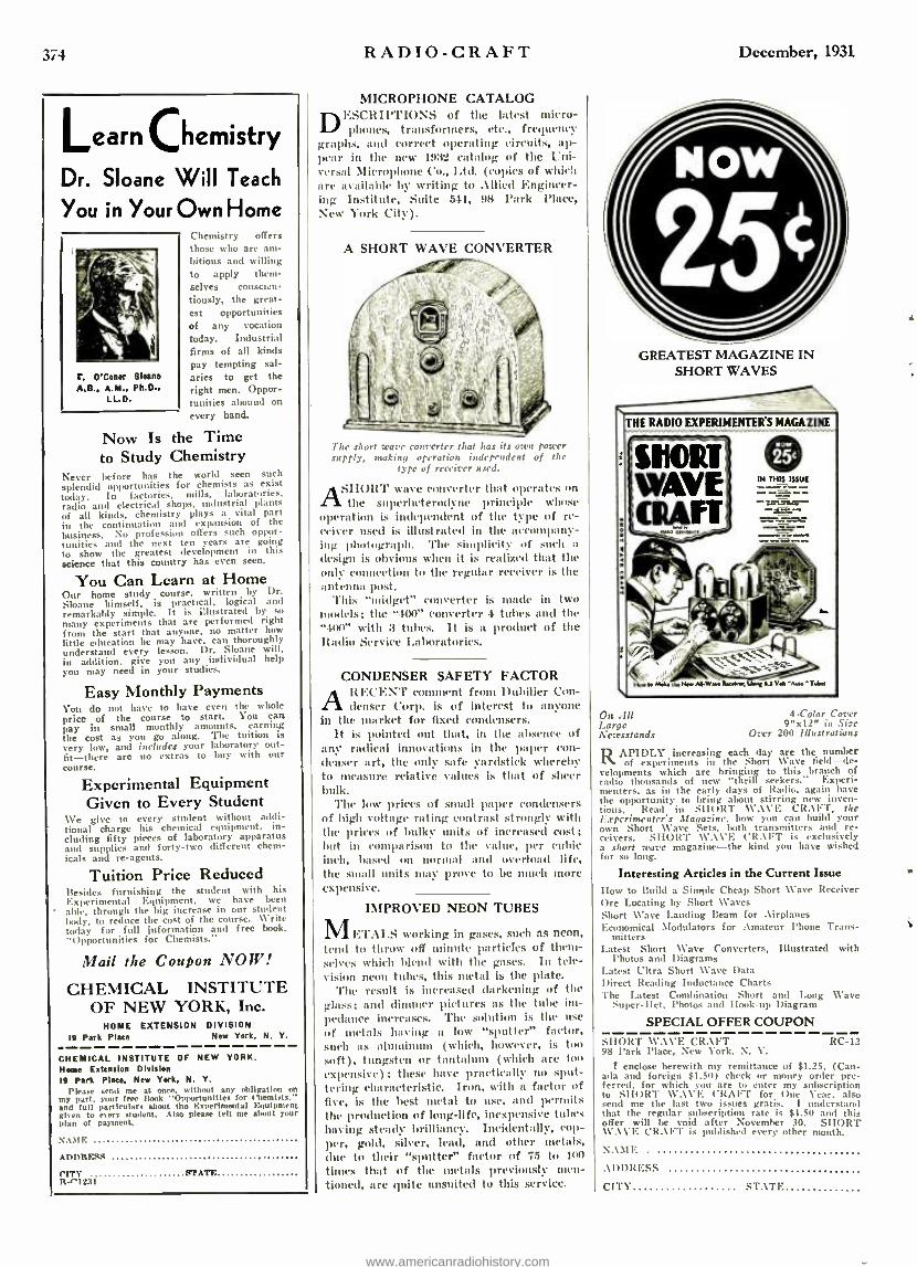
i4 RADIO -CRAFT December, 1931
Learn Chemistry
Dr. Sloane Will Teach
You in Your Own Home
T. 0'Conor Sloan A.B., A.M., Ph.D..
LL.D.
Chemistry offers those who are am- bitious and willing to apply them- selves conscien- tiously, the great- est opportunities of any vocation today. Industrial firms of all kinds pay tempting sal- aries to get the right men. Oppor- tunities abound on
every hand.
Now Is the Time to Study Chemistry
Never before has the world seen such
splendid opportunities for chemists as exist today. In factories, mills. laboratories, radio and electrical shops. Industrial plants of all kinds, chemistry plays a vital part in the continuation and expansion of the business. No profession otters such oppor- tunities and the next ten years are going to show the greatest development in this science that this country has even seen.
You Can Learn at Home Our home study course, written by Dr. Sloane himself, is practical, logical and remarkably simple. It is illustrated by so
many experiments that are performed right from the start that anyone, no matter how little education he may have, can thoroughly understand every lesson. Dr. Sloane will, in addition, give you any individual help you may need in your studies.
Easy Monthly Payments You do not have to have even the whole price of the course to start. You can pay in small monthly amounts, earning the cost as you go along. The tuition is very low, and includes your laboratory out- fit -there are no extras to buy with our course.
Experimental Equipment Given to Every Student
We give to every student without addi- tional charge his chemical equipment, in- cluding fifty pieces of laboratory apparatus and supplies and forty -two different chem- icals and re- agents.
Tuition Price Reduced Besides furnishing the student with his Experimental Equipment, we have been aule, through the big increase in our student body, to reduce the cost of the course. Write today for full information and free book, "Opportunities for Chemists."
Mail the Coupon NOW!
CHEMICAL INSTITUTE OF NEW YORK, Inc.
NOME EXTENSION DIVISION 19 Park Plate New York, N. Y.
CHEMICAL INSTITUTE OF NEW YORK. Horne Extension Division 19 Park Place, New York, N. Y.
Please send me t without any obligation on my part. your tree (took t' Opportunities for Chemists." and full particulars about tho Experimental Equipment given to exert' student. Also please tell me about your plan of payment.
N.\y1F.
ADDRESS
CITY R?ATL R- '.'1271
MICROPHONE CATALOG DESCIII1'l'IONS of the latest micro-
phones, transformers, etc., frequency graphs, and correct operating circuits, ap- pear in the new 1932 catalog of the Uni- versal Microphone Co., I Ad. (copies of which are available by writing to Allied Engineer- ing Institute, Suite 541, 98 Park Place, New York City).
A SHORT WAVE CONVERTER
The short wave converter that has its own power supply, making oN'rationt independent of the
type of receiver used.
ASHORT wave converter that operates on the superheterodyne principle whose
operation is independent of the type of re- ceiver used is illustrated in the accompany- ing photograph. The simplicity of such it
design is obvious when it is realized that the only connection to the regular receiver is the antenna post.
This "midget" converter is made in two models; the "400" converter 4 tulles and the "400" with 3 tubes. It is a product of the Radio Service Laboratories.
CONDENSER SAFETY FACTOR A RECENT comment from Dubilier Con-
denser Corp. is of interest to anyone in the market for fixed condensers.
It is pointed out that, in the absence of any radical innovations in the paper con- denser art, the only safe yardstick whereby to measure relative values is that of sheer bulk.
The low prices of small paper condensers of high voltage rating contrast strongly with the prices of bulky units of increase(\ cost; but in comparison to the value, per cubic inch, based on normal and overload life, the small units may prove to be much more expensive.
IMPROVED NEON TUBES
METAIS working in gases, such as neon, tend to throw off minute particles of them- selves which blend with the gases. In tele- vision neon tubes, this metal is the plate.
The result is increased darkening of the glass; and dimmer pictures as the tube im- pedance increases. The solution is the use
of metals having a low "sputter" factor, such as aluminum (which, however, is too soft), tungsten or tantalum (which are too expensive); these have practically no sput- tering characteristic. Iron, with a factor of five, is the best nietal to use, and permits the production of long -life, inexpensive tubes having steady brilliancy. Incidentally, cop- per, gold, silver, lead, and other metals, due to their "sputter" factor of 75 to 100
times that of the metals previously men- tioned, are quite unsuited to this service.
GREATEST MAGAZINE IN SHORT WAVES
o
THE RADIO EXPERIMENTERS MAGAZINE
UICRT WAVE G11AFT
-
Má, in Hen ni-Wan k,-..s, Unan sy Vd'AUO' T.b
On MI Large Newsstands
4 -Color Corer 9 "x12" in Size
Over 200 Illustrations
RAPIDLY increasing each day are the number of experiments in the Short Nave field -de-
velopments which are bringing to this branch of radio thousands of new "thrill seekers." Experi- menters, as in the early days of Radio, again have the opportunity to bring about stirring new inven- tions. Read in SI I()RT WAVE CR.\l'T, the Experimenter's Magazine. how you can build your own Short Wave Sets. loth transmitters and re- ceivers. SIIORT WAVE ('R. \IFT is exclusively a short ware magazine -the kind you have wished for so long.
Interesting Articles in the Current Issue
How to Build a Simple Cheap Short \Cave Receiver Ore Locating by Short \Caves Short Wave Landing Beam for Airplanes Economical Modulators for Amateur Phone Trans-
mitters Latest Short Wave Converters, Illustrated with
l'hotos and Diagrams Latest Ultra Short Wave Data Direct Reading Inductance Charts The Latest Combination Short and Long Wave
Super -Het. Photos and Ilook -up Diagram
SPECIAL OFFER COUPON SHORT WAVE CRAFT RC -12 98 \'ark Place, New York. N. Y.
I enclose herewith my remittance of $1.25, (Can- ada and foreign $1.50) check or money order pre- ferred, for which you are to enter my subscription to SHORT WAVE ('RAFT for one fear. also send me the last two issues gratis. I understand that the regular subscription rate is $I.50 and this offer will be void after November 30. SHORT \y.\Vlì. Clt.\F'l' is published every other month.
NAM E
ADDRESS
CITY STATE
www.americanradiohistory.com

December,1931 RADIO -CRAFT
The Portable FOUR - TUBE RADIO RECEIVER
(Continued from page 353)
Other features of this set include the use of "Conoid" shielded R.F. coils, metallized
.e resistors and the new "Infant" Model dy- namic reproducer. All pawls have liven selected first, because of their high quality, accuracy, and efficiency; second, because of unusual compactness; and third, because of inherent ability to withstand the rough usage accorded a portable receiver. The metal chassis is extremely compact, being only 10 x
x Il., ins. high, as shown in Fig. 2. shed iron chassis is used of No. 16
gauge. Only two sides are bent down (front and hack) to form the chassis walls. Al- though the chassis deck is 10 in. long, the upright walls measure only 9 in., since 1/ in. is cut away at Glob end. This provides a
flange of t,, -in. width for fastening the chassis to the upright wooden supports in the carrying ease.
Next, the holes for the six sockets are to be drilled in the chassis, and the sockets mounted; then, the three binding posts are mounted; also, the terminal plug 42, which consists of a piece of Irakelite or composi- tion, 31/., x 11/2 x ! -in. thick, with pin jacks arranged in two rows. The A.C. and D.C. caps are provided with tips which plug into the terminal jacks. An additional polariz- ing tip is provided on each cap, to prevent it from being inserted incorrectly.
The three -gang condenser is fastened to the chassis by means of right -angle brackets; the resistor 33 and choke 39 are mounted in hack. The chassis is turned upside down anti switch 41, resistor 35 and volume control 12 are mounted. The electrolytic condenser is uuuuntcd, by means of the mounting ring provided with it. All the other fixed con- densers and then the power transformer 31, are naunte I as indicated.
The filament circuit now may be wired in. Starting from the 110 volt plug, one side is connected to imperite socket 40 and the
other side to power switch 41. The other ter- minal of the autuperite socket goes to pin jack "c" on the terminal plug, while the other side of the power switch is connected to jack "d." From "e," connection is mule to pilot light 34; thence to resistor 11:3 and then to the filament terminal of socket 9. The fila- ment wiring continues from one socket to the next, so that all four tubes will have their filaments in series. The wiring then returns from the last socket to ' ,jack "d.
Grid circuits are wired in next. Flexible leads are brought from the condenser stators of (i, 11 and 17 to the caps of tubes 9, 14.
and 21, respectively. .% flexilde lend is also brought up from fixed eondcnscr 24, to the cap of tube 28, through it hole drilled in the chassis deck. Plate circuits are wired in, then cathode circuits, volume control, by- pass condensers to chassis; then power trans- former, rectifier tube and filter system. Resistors 20, 23, 25, 8 and 27 are soldered in place during the process of wiring.
'l'he three It. F. coils are mounted after most of the wiring is completed, since they cover up the bottoms of sockets 9, 14 and 21. A suitable bracket is fastened between the two sides of the chassis, as shown in the botton view, and the three coils 5, 10 and 1(i are fastened to this. The dial is then attached to the condenser shaft. It should be noted that binding posts 1, 2 and 3 must all be carefully insulated fr the chassis.
After the wiring is completed, the set is to be tested both on A.C. and D.C.; chang- ing the caps according to the type of cur- rent employed. The chassis and speaker are then mounted in the carrying -case, as shown in Fig. 3.
This portable may 1w used with aerial and ground; or ground alone. In the latter case, at wire jumper should be connected between binding posts 1 and 3, as indicated by the dotted lines in Fig. 1.
Figure 2, left and renter. The complete layout of the parts is indicated. alt the left, the top view, in the renter. an under -side rime. Figure 3. right. The position of the set after it is set sn the
carrying case. Above, rear; and below, front' views.
375
EVERT RADIO SERVICE: VA] should read this hook which tells you how to ,,sake more money out of radio sees Ire. There are secrets whirl] "old timers" has learned through years of experience. You can now have the benefits of these. You don't pay a penny -you don't promise
h t any pay
d,ligatioit of this any kind with nur
you
If you WI sign and send in the coupon. It is pan of our plan to help Independent radin men profit by the experience of others In the industry and make a bigger Income.
Brim Full of Facts Thus book was o ritten by a man who has probably had more experience than any une else in the industry. It tells you in simple language the principles and practices which made hint the outstanding figure in the radio world that lie is today. These are a few of the subjects full cos red: Selling tiro public on radio service Value of Personality - Newspaper alert l sing -- lluslnv.s literature -Types of ser- vice letters -Electric signs -Making tubes business builders.
This book IS for service men only and will he sent FREE. and fully po.t paid anon nrript of the coupon ronudeteiy tilled in.
RADIO SERVICE MEN'S GUILD 1259 Fullerton A Chicago, Illinois.
Y. may send me your book "Making Money Out of Radio Rervire' absolutely FREE and fully post paid (Please answer these simple questions):
What radio training have you had?
No. of years in radio?
Do you give radio all your time?
Hose you a store?
tin you work for some one else, If so who?
Name
tddress
lily State
Radio Dealers! Radio Service Men !
New Low Prices Guaranteed Replacement Condenser Blocks
and Transformers Net Atwater -Kent 37 Cond. Blink with chokes.$3.95 Atwater -Kent 37 Power Transformer 2.95 Atwater -Kent 40 Pack Complete 6.50 Zenith 2E9. Stewart-Warner, Mohawk
Blocks 3 45 Majestic "B" Eliminator Cond. Block 2.95 Eleetrolytie Condenser, 2 Anode 2.10 Electrolytic Condenser, 3 Anode 2.75
Hardtoget parts -We have them Send to your repair work for estimate
Write for our FK!:!: CATALOGUE Grant Radio Laboratories
6521% South Halsted St.. Chicago, III.
TUBE CHECKER Transformers: 1, 1 1/2, 2, 21/2, .3, 5, 6.3, 71/2 volts. 30 watts. Full Instructions Included for building new type tube tester. Will test pen- todes, 6.3 auto all screen grid and new 2 volt type. Shipping wt. 5 lbs. Add P. P. $2.25 net.
L & L ELECTRIC CO. .336 Madison Ave. Memphis, Tenn.
www.americanradiohistory.com

376 RADIO -CRAFT
Did This Ever Happen to You? You want to get the exact and technical meaning of a word or phrase in radio! You
are in doubt about a radio formula or radio circuit! You look through a maze of books and magazines losing your time and your temper.
Why nut have al i our desk or in your library a copy of
S. GERNSBACK'S RADIO ENCYCLOPEDIA
:1n., t{nt an cxpl :ni.n imp or o nr, I in lin. These explanations -or, rather. detini-
i :,ins -are not brief outline information like tbo,e of an Ordinary dictionary. but they give in fullest detail. and at considerable length, the meaning and application of every word. phrase. general and special term used in the science of radio. Thcy are written in plain, everyday English, easily understood by anyone.
Practically every definition in the book is illus- trated by drawings. photographs. diagrams. or charts. All you need to do is to look up as you would in a dictionary. the word or phrase ;flout which you are seeking information. Furthermore, each page is key -indexed. for greater convenience and nced in locating any definition. . \L1. THE SUBJECT - MATTER IS ARRANGED IN . \I.P,I. \nETIC. \I. ORDER.
Numerous tables, charts. and maps are distributed throughout the text. .\ large section of the Appen- dix contains information of commercial value. such as lists of all radio receivers, their manu- facturers, trade names, tubes used. styles, etc. There are charts of tube- socket lay -outs of all makes of sets; broadcast stations listed by wave -lengths, call letters, towns and states. etc.
In the text you will find biographical notes. with portraits, of all the men who by their inventions, discoveries, and research, have made radio what it is today. Large sections of the text are devoted to such important subjects as television. trouble- shooting, servicing. short -wave reception and trans- mission, testing instruments. sound projection. etc.
Full descriptions are given of all vacuum-tubes, the theory of their construction, characteristics, testing and manufacturing.
The latest inventions, such as the Radio Knife, Ultra- short waves, Variable -Mu tubes, and locating treasures by radio, are as fully described by word
and picture as are the old -time Marconi coherers and detectors.
It took a large staff of editorial assistants and draftsmen over six months to assemble, classify, and illustrate all the material printed in this book.
Mail Coupon TODAY !
S. GERNSBACI CORPORATION nt 98 Park Plane. New York. N. Y.
Kindly send nie one copy of the new Second flip: S. Qenhank Radio Encyclopedia. I enclose her :.
83.99. check or money order preferred. (Foreign Canada. add 35e extra for pottage.) If the honk d
not nome up to my expectations. or is not as repro - rnted. I can return it, and have my money refunded
in full.
Name
Address
City State
Iho I IY?I Sornud I .d it ism is a S,,lunoe ..f 352 pages. It is a large book 9 inches wide by 12 inches high. and weighs three pounds. There are 2,201 radio definitions, . \lfC indexed like a dictionary. or any other encyclopedia, making every bit of radio information you want 'findable."
The new book contains 1,253 detailed technical illustrations, 34 tables and charts. and 24 pages of Appendix. etc. The binding is flexible red morocco -
keratol. with title gold - stamped on corer and back - lane. The text is printed on durable, fine ledger paper, and the loose -leaf construction permits of new material being added, such as notes, addenda data, etc.
Why You Should Own This Invaluable Volume
IIIS greatly enlarged Second Edition Radio Encyclopedia is an absolute necessity to every- one interested in Radio. It answers all radio
questions. increases your knowledge. and saves your time. It covers every known radio problem, and is a gold- mine of practical information for every radio ratan.
It is of equal service to: The Radio Engineer. who wants to refresh his
memory on formulas and circuits; The Radio Manufacturer. Jobber. and Dealer, who
is interested in the commercial side of radio as well as the technical:
The Radio Service Man and the Radio Con- structor, who wants to have on hand a guide to the principles and design of radio equipment;
The Radio Student and the Layman, who will find the whole t: eory and practice of radio explained here in the simplest terms, beginning with the first principles and leading up to the most advanced theory.
$3.98
TAIS book is the NEW 1931 EDITION OF TILE FAMOCS FIRST
RADIO ENCYCLOPEDIA I y S. Gernsback. the first look of its kind ever published in America.
The new Second Edition - just off the press -is fully revised, rewritten. and en- larged. It is the absolutely tip -to -the- minute new model of the pioneer First Radio Encyclopedia, which became the stand -by of all radio men in every part of the world.
3'),000 Rou(rht the First Edition!
December, 1931
List of Parts One .00035 -mf. (ea. section) Cardwell Triple
Variable Condenser, type 317 -C Shielded (i, 11, 17;
One .1 -ntf. (ea. section) Double Section Aerovox Metal Case Condenser, type 461- 21 7, 15;
One .1 -tuf. Aerovox Metal Case By -Pass Condenser, type 260 22;
One t /., lof. Aerovox By -Pass Condenser, type 207 19;
One 2 inf. Aerovox By -Pass Condenser, type 207 26;
One Aerovox Triple Section Dry Electrolytic Condenser, type E5 -248 in can 21/., x3 in. dia., 8 inf., 36; 4 ntf., 37; 2 tuf., 38;
One .0(025 -utf. Aerovox Utica Condenser, type 1460 4;
One .001 -tuf. Aerovox mien Condenser, type 1460 22A;
One .INN -rad. Aerovox Mica Condenser, type 1450 24;
One Conoid Shielded Antenna Coil 5; Two Conoid Shielded R.F. Coils 10, 16; One 20,000 ohm Durham Metallized Resistor
Powerohut, type M.F.4 20; One 200,000 ohm Durham Metallized Resistor
l'oweroluu, type M.F.4 23; en() .500,000 ohm Durham Metallized Resistor
l'owerolnu, type M.F.4 25; One Elcctrad Volume Control Potent' ter,
type RI -202 12; One ElectradTruvolt Flexible Resistor, type
2(: 1300 27; One Electra(' 'l.'ruvolt Flexible Resistor, type
2G 500(1 8; One Elect rad Truvolt Fixed Resistor, type
II-70 with tap at :3000 ohms :35;
One Elect rad 'l'ruvolt Fixed Resistor, type C -3 :3:3;
One Antperite Self -Adjusting Line Voltage Control, type 5.A -5 40;
Four Five -Prong t-Y wafer -type Alden Sockets 9, 14, 21, 28;
Two Four -Prong t'\ wafer -type Alden Sockets 32, 40;
Three Alden Binding Posts 1, 2, 3; One Trutest Power Transformer, Secondary
500 volts venter- tapped, with 5 volt fila- ment winding for 180 tube :31;
One 'Protest 30 -henry choke 39; One Trutest Power Switch 41; One Special Ansley Terminal Plug 42; One :Ansley A.C. Cap for Plug -4:1;
One :Ansley D.C. Cap for )'lug 44; One No. 15 Gauge Sheet Iron Chassis 10 in.
long, by 71/2 in. sleep, by 11/_ in. high, eut froid sheet 10 x
One Roll Comic() Braidite hook -up Rire, Solid Core;
Three 136 Arcturus Screen Grid 'Pubes 9, 14, 21;
One 138 Arcturus Pentode Tube 28; One 180 Arcturus Full -Wave Rectifier Tube
32;
One 2t!, Volt Dial Light 34; One Can Rester Radio Solder (Resin Core); One Wright- DeCoster "'Infant" model, Dy-
namic Reproducer 30, equipped with 15,- 000 ohm impedance output transformer 29 for 138 Pentode Tube;
One Ansley Leatherette Carrying Case with removable snap -hinge front cover. (For distensions and other details as to mount- ing of set, speaker, etc., see accompanying illustrations.)
www.americanradiohistory.com

.3
f
f
December, 1931 RADIO -CRAP I
LATEST in RADIO (Continued from page 383)
posts of any radio set and serve greatly to increase the selectivity of the receiver as a whole. Of course, if the receiver is of the older, unshielded type, the unit is not likely to function effectively where operation is within local range of a powerful station; naturally, this condition could not be blamed on the Selcctifier.
Fig. E The Band -Selector radio accessory
The tuning condensers are ganged, and shunted by trininlers. Coil 1.1 has at IS turn primary and 70 turn secondary; coil L2, vice versa. The tithing is 1 ! i -in. in diameter, wound with No. 2t4 enalu. wire. In addi- tion to the t.apacitative euupling afforded by C, there is inductive coupling between coils 1.1 and 1.3. to maintain even band width over the tuning range.
This device, manufactured by Supertone Products Corp., is recommended to all who desire increased selectivity. Note that the reduction of sensitivity is the sauce as oc- eurs in all receive'.' (111111lillaltills incorporat- ing I.a nd- selection; and in s circuits it may be found to be compensated by other conditions in the circuit (notably, increased regeneration).
LATE RECEIVER DESIGN ADIFFEItENT' note in radio receiver design has been struck in the I'hilco
"Ltuzvhov" illustrated in Fig. F. 'l'he top of the cabinet has been lowered to arm- chair level; and the cup recessed for tuning and volume controls. Excellent reproduc- tion is obtained from the dynamic repro- ducer, which is behind the ornamental grille at the end of the cabinet.
As indicated in the schematic circuit of this superheterodyne receiver, which ap- peared on page 230 of the October 1931 issue
Fig. 6 C.; t. flit 0 f r. m m, rcial band-selector.
of ItAnIo- CRAvr, the following tubes are used: four '24's, one '27, one '47 pentode, and an '80 rectifier.
VOLUME CONTROL REPLACEMENT GUIDE
Shat VICE MIEN are advised to write to Central Radio Laboratories, 900 E.
Keefe Ave., Milwaukee, Cis., for their copy of "('cuitr, dab 'Vol Control Guide for Service Men." This twenty-live cent hook contains a considerable amount of informa- tion of value to the practical radio repair- man.
This booklet introduces a new reference method for determining the correct value land type of yohnue control resistor replalce- ntent required for any one of nearly 1,01)0 different receiver 'muftis.
In addition, sufficient engineering infor- mation is furnished to enable the Service Men to find out thiS data nwerning models not listed; besides valuable notes in con- nection with faders, attenuators, tone con- trols, resistor color ales, ganged units in- corporating variable resistors, and other (le- vices. Preferable circuits for each type of service are illustrated.
Fig. F The Philco "Lau }boy." The controls are reached through the top recess; the reproducer grille is
on the end.
THE "ALL- TELEVISION" RECEIVER TO meet the demand for a radio set de-
signed exclusively for operation in the television btnd,'there has been developed a 7 -tube receiver incorporating two type '35 variable-mu tubes, three type '27's, one '47, and one '80.
The pentode output tube, after exhaustive tests, was selected as the most satisfactory one to use.
This receiver, manufactured by Television Apparatus Co., contains numerous struc- tural features which will be described in a forthcoming issue of lt.tulo- CR.trr.
377
New Edition Containing 100 Pages
A-C 12ADIOt 8 FLEXIBLE
MAROON VOLUMES
Ilex pages, .120e. 'r:Intrations. deluxe.
d stamped binding. r n each tt.ol. rai index In Vol.
I cry sub- to
er l e o-trh -ht -
rte re glad to send a set to your hume tu examine and use as your own for 10 days -to show you that here is the most up -to- date and complete work on Elec. tricity mer published written io CIIOI't Ea ut Columbia L'. -MILLIERS of Calif. "Tech." -HARRISON of General Elec- tric and 20 other noted Elec- trical Engineers. Starts off with elementary Electricity in simple, non -technical language for the beginner and includes es cry Engineering branch for use of experts on the Job.
Complete Electrical Reading Course Elect rally the biggest industry in the world, continues to grow the trust rapidly. And It offers better jobs. bigger .;Jades and a brighter future limn any !kid, Every dollar. every hour invested in learning Elec- tricity will tome back to you a thousand -fold. I.,am in
snare tone with these banks al one -fifth the -n,t of trade
Out l tie for organized study, . quiz -'tuca hm, and year's free consult lag member- ship in the American Techni- cal Sudely included without extra cost. If y nl mall coupon ianmrdtat eit.
AMERICAN TECHNICAL SOCIETY Dept. E.926
Drexel Ave. 5. 58th St.. Chicago
LOOK IT UP! ands of these e used as ltKl'-
I :l.NtE hooks by- employed in
-.11. building un and al-
puts the Iu 220,000
right at jour linger tips.
AMERICAN TECHNICAL SOCIETY Dept. E -926 Drexel Ave. & 58th St.. Chicago Please send fur I o lays' free trial v -.In tie set of t:le,t rIcal Engineering just on the pres, subject to return if 1 wish to. (1 pay the few cents express charges on recrlpt of hooks. yon pay express If returned. If I decide to keep thew, I till pay $2.011 after III Jays Mal. then 5: -00 a month until $:N. au, spe'9ai a,ltrrt¡sing prier. 1. pail. otter which h,nik. heeMU, my properly. Tear'. Consult lllg )Ieu:brlhi a . he hwludrd free.
.tddre.s
t:uqdo,yrJ by
Employer's Address
Model "BB" List Price
THE MASTERPIECE In Microphone Construction
-The New Heavy Duty Model "BB"
A tu'o- button microphone that has benuno the talk of the radio In- dutry. It is 3 In. In diameter by 2 In. thick and is nearly twice as heaty as any other microphone in
s2/'Irrs Its class. Equipped with ext ray 500 peaty 24 IQ. Gold Sing tenter. V 1lnndundn diaphragms. (lair line precision of Manufacture. Fully
guaranteed. Finished In highly polished chrome plate. nnp:ue this new. beawy duty 'Model 'Atli ", listing at $ 25..10, with any $40.00 to $50.00 microphone on the market.
UNIVERSAL MICROPHONE CO., Ltd. 1163 Hyde Park Blvd., Inglewood, Calif., U. S. A.
r" TRUVOLT RESISTORS, Ciao with adjustable clips, mean
quicker service and fewer parts to stock. All standard sizes.
www.americanradiohistory.com

378
Index to Advertisers
A
Amperite Corporation. .... 360
Arco Tube Company 379
B
Blatt the Radio Man, Inc
Cable Radio Tube Corp Carolina Crest Hotel Central Radio Laboratories Chemical Institute uf N. V Chicago Radio Apparatus Co Clarostat Mfg. l'ompant Classified Section C °nnie's Inn Coyne Electrical School....... ........... 323, 325
Crosley Radio Corp 363
C
366
Inside Front Cover 380
... 367 378 366 166 170 180
Drake Ilotel D
E
Electrad, Inc Electrical Mfg. Corp Victor J. Evans
380
377 364 370
G
Gernsback Corp.. S..... ( ;ernhack Publications. lac Grant Radio Laboratories Grenpark Company
376 '6, 368. 372, 374
375 382
H
lloodwin Company, Chas
I
International Resistance Co
J
JMP Mfg. Company Johnson Radio Mfg. Co
369
359
L
L & L Electric Company Lincoln Hotel Lincoln Radio Corp. Lynch Mfg. Company
360 366
375 380 329 366
M
McGraw -Hill Book Company Miles Mfg. Company
371 366
N
National Radio Institute 384 Newark Electric Company 362 New Bismark Hotel 380
P Perryman Electric Co., Inc 122 Pilot Radio & Tube Corp Back Cover Polymet Mfg. Company 362 Popular Book Corp. 378 Press Guild, Inc 370
R
Radio & Television Institute.. 357 Radio Circular Company... 383 Radio College of Canada 364 Radio Trading Company 381 RCA Institutes. Tin.. 361 Radio Service Lab. 373 Radio Training Asoe. ,I A Inv rr ca .... 321 Radolek Company 173 RCA Institutes, Inc 361 Reatlrite Meter \Cork., 358 Ross, Malcom.... ...... . . ... 370 Roth Press 379
S
Scott Radio Laboratories, Inc., E. II.... 327 Silver -Marshall, Inc 355 Supreme Instruments Corp. 327, 328
T Tilton Mfg. Company 365 Twentieth Century Company 370
U
Universal Microphone Company 377
(While every precaution is taken to insure accu. racy, we cannot guarantee against the possibility of an occasional change or omission in the pre paration of this index.)
RADIO -CRAFT December, 1931
(Continued from pane 979)
Mentor placed in front of them to enable them to control their volume more easily by signaling their hand instead of leaving the interpretation of their piece to the mercy of the mixer titan who is usually a better technician than musician.
Double Turntable 'l'he use of :a double turntable is absolute-
ly essential in that continuous recordings may he made. The turntables should he
provided with a fader so that the cutting in of one recorder while the (other is bring cut out is accomplished without any loss of sound. 'This is indicated in Fig, 7. The tables should have n shift mechanists s(o
that they may be rota either at 7$ R. I'. M. or 331/3 R. P. M. The large Ili" records (:331/3 H. P. M.) which run from 12 to 15
minutes continuously are especially suited for the recording of radio programs. A full quarter -hour program can be fully recorded (on one (lise. If the radio recordings are to be made for individual radio stars, then it is inadvisable to give them a 3:31/3 record because of their inability to obtain :331/:1 lt. I'. M. reproducing tables. When the tintiIile turn -table is used the fading should be carefully done. Every attempt should he made to make the changeover when there is it lull in the sound, for instance, when a chorus is ended or when Ia change of actin is being noted by music.
..tluutinunt should not be used for 16': slow speed records because the fibre or thorn needle that is used for playback wears its point out before the record is finished with the natural result of poor reprochu'ti(on. Only materials that can be played back with steel needles should be used for the large records.
'l'he method of connecting the radio re- ceiver is shown in Fig. 3. It is noted that when switches SI and 52 are closed, the outputs of both the radio set and the mixer are fed to the cutters. This hook -up allows the studio to make novel records, for example announcements can he made over the regu- lar voice system to introduce any radio pro- gram, and talks in the studio may be record- ed with :a radio musical program.
The phonograph turntable provides the facilities for dubbing, or re- recording as it is more c'orrec'tly known, and is connected into the circuit by switch S :3 (Fig. 3).
'l'he subject of commercial recording is so broad that the writer has not attempted to discuss tan much detail due to lack of space, hut any information that is desired may be obtained by ndelressing inquiries to the Sound Recording Department of RADIX/- CRAM
SOUND -RECORDING EDDIE CANTOR A F'l'ER Eddie Cantor, comedian, had com-
pleted a transcontinental telepturne con- versation with Samuel Goldwyn, producer, it was stated that the sound -on -film record SKI/111d become a part of their contract, and W0111(1 be recognized as legal signatures.
The sound recording equipment, devel- oped by lt('A- I'h(ot(ophone, Inc., was con- nected to the telephone line; and thus it was possible to record both sides of the conversation, in addition to the voices of the telephone operators as they set up their respective connections on the long -distance line.
wags fall ;meractlon, and dereriadom of ed analyze,., tube doming, o,ollitwr¡ stn .
by L. Van der Mel Mae. Ru. i.n.d,.
C Copy ERE is the latest
brave, and one of impor-
tant which we have ever Ls rate most
ed. It 11 Is lung ,. :t itnlzr- want for there is not a Service atan or a ra liotrlcian who 1m, not an 1111111, iiale use for this welcome b,adt.
It Is the tint book that explains t '(iM l'i. KTELY the operation of analyzers, tube checkers, orillawro, etc., Inn,, a thoroughly practical standpoint. the biaik i.. hit ruled for Senire Men of all classes, whether junior grade or
expert. ]E Its will find a tremendous mount of Ilse
pages. Nothing has been left to your own Ingenuity ; everything is complete.
The contents: CHAPTER la Introduction:
The Problems of the Sen ice Man General Description of Modern Receivers The Need for a Radio Set Analyzer What to Expect frum an Analyzer
CHAPTER 2: The Analyzer; The Fundamental Requirements of an Analyzer The Switches or Push Buttons '1-he .t mnteter Mialtiscale Ammeter. The Shunt and Its Calibration The B.C. Voltmeter The Multiscale i).C. Voltmeter The Multiplier and Its Calibration The A.C. Voltmeter The Design of a Simple Analyzer
eRAPTER 3: Trouble Shooting with the Analyzer; elassiliration of Trouble -
(I) External to the receiver 121 in the receiver proper
(a) Mechanical troubles Ib) Electrical troubles.
Detailed Analysis of Electrical Troublea- (1) Tube Testing (2) legalizing trouble
(a I By past xperience On Il actual test of circuit
(31 Interpretation of analyzer readings ID Tube charts (use of 131 Circuit diagrams (use oft la) Testing the power unit (7) The use of the analyzer In testing individual units
.tddi annal Feat. res and I'se: of the .Analyzer- - ( I) As a modulated R. F. oscillator (21 As a means of lining ut. R.P. and I.F. amplifiers (3) As an output meter
care and Maintenance of Analyzers Conclusion and Brief Summary
CHAPTER 4 Detailed de.rript ion s, photographs, and circuit diagrams of
g couu, mal set analyzers.
This book is sold at a ridiculously low price, because it is our aim to put this valuable work in the hands of 100,000 Service Men and Radiotrieians before the end et this year.
Published bs It.t MO-CRAFT magazine. it has included In it all worth -while information available to the radio secs i lug profession; and for that reason the Price of the loa,k is kept at a sen' nominal figure.
We know that. if you are at all interested In radio s,nice work, slog will send at 0111,e for this valuable book.
Rush Coupon TODAY! GERNSBACK PUBLICATIONS. inc., RC -12 96.58 Park Piste, New York, N. Y.
T enclose herrui tit fifty (50c) cents, for which send rte a copy of your book 'Radio Set Analyzers and Hoy to Use Them."
Name
Address
City and State
J
www.americanradiohistory.com

December, 1931 RADIO -CRAFT
SHIP RADIO INSTALLATIONS R\DIO technicians may be interested in
' the following information, furnished by Wright-De Coster, concerning the latest ship's sound installation, Which is proceed- ing rapidly on six mail ships of the United Fruit bine may in cunstruetiun. The sys- tem incorporates central -controlled radio and group addre,s, with sound distribution tu six main pains.
The rack -and -panel in the control room carries a monitor reproducer of the mag- netic type, and a 3 -stage power amplifier with hype '50 tubes in push -pull. The radio tuner chassis inetirpurittes six stages of It.F. The electric phonograph is pro - vided with an automatic record changer. All dynamic reproducer fields are energized by the ship's current supply, which is 110 volts, D.C. To obtain A.C. far the remainder of the equipment, motor- generators are used.
Dvnamic reproducers in ornamental con- soles are connected to outlets in the dining saloon, smoking nano, and in the ball -room (at opposite corners of the room); weather- proof units may be plugged into outlets either on starboard or port side of the promenade deck, for dancing. Each repro- ducer is equipped with its own volume con- trol, of the constant- impedance type.
THE RADIOTRON MERCHANDISER AF'rER 18 months of testing and experi-
mentation, the "radio merchandiser" illustrated above has been developed. Free copies of a balk let listing station calls, etc., and calling a t tent inn to the "free tube -test- ing service" offered by the dealer, are dis- tributed.
Every single detail in the design of the nierehantliser has hem' developed in the light of good sales practice; and use of the finished device, illustrated, should help greatly to boost tube sales.
When the customer brings tubes in for test, every step in the procedure may be followed, including the usual meter tests and, in addition, an actual operating test
The latest device for increasing tube sales is the "tube merchandiser "; one of two models being
illustrated above.
379
GREATEST TUBE SALE OF i931 THE L41, l,r IaRIETY OF TUBES IN THE WORLD
, bo Mt- antic quality tomparnble to the be,t
l
.r.1 c c. ., rk t. la, . We will replace within 30 days ally tube that not gin en complete ,atórnct Ions
Such atz a.u.lri ug tube sale has inner been conducted.
COMPLETE STOCK ALWAYS READY FOR IMMEDIATE SHIPMENTS I rder Iiota titi, pare and note the following terrils: Ni. order ad ceplcd for lc.. Than $ .wo. It is not necessary to sell the full amount of rash :I1th tlo
order an lung a, your order is a nupanied by 20{: of the salue. Shnnuent will go forward to you by express or parcel post C. O. U. all prives are F. O. B. Factory. Newark.
X -201.1 I'X22ti l' Y E stE7 l'X -171.\ UN-171 UN -2 in l'x -I sri l' X1hit l'y- 11,11
5 .30 .30 .30
.311
.10
.10
.40
. 10 I y -19J SnuWanl base .40
UX -112 .40 I'X -119.\ .40 I' X- ßtuc'. .10 l'Y -224 .40 1, X -243 .40
ttuadrode 5 -prong 2111.1 for special circuit, .60
Special detector tube 21111.1 - a :wooer - sens Mise detector .60
Special radio frequency 201A- ,1 pe r-sensltive 20I.\ .60
Special audio frequency 201.1 - Spé,uper-
.ensillce .G0 cial 17IAt 1 -2 null, titra sated filament .60
T-14 1210A High ylul high ends inn .G0
Switch rube. 201.\ or 112 or 151 l ais le life -all In one .60
Adapter tube 226, 171t, to conovert bal. .ris to AC. each. .00
1"X -210-For power amplifer 1.10 l'X -250- .Cower amplifier 1.10 Ballast tube l.nn UN- .22- Screen grid 1.I.i Tellon Ten, d non Tube 1" Cath-
ode Squire Telinn Television Tube. 114"
Coothoule Square 3.s5 Pbotoelect rlr tell "r'aeslmu."
Sire ozerall :1 I'ti;" 5, c-, Size on eran 1a 4"
Photons lerl tic -ell "l'ntansium, ". 3 '81 WI,I 1- Oet retor . %nap .60 11 1,-12- I art est or Ana, .60
RECTIFIER AND CHARGER BULBS Pholoelectrlc 121 OII. retuf, lug rube In. it lypel 61.40 e,,,. Type i lo map. Irb-kle ,'larger bulb 2.011
cell. 2 tops Old and new type charger bulbs i list 54.001, atop I rungar Type' 2.00 ' n,l c: am. old type
tour urger bulb, mist Sa. no c, our prlee uTungar Type i 3.75 I'X -2x0 I',cd at a full -w:oe rectifier for high coussin. .411
a tip. 00 i X's-vI 11.11f was:. rectifier 1.10 l'Y -s47 -Power pentode 85 Itecri t . Ì : ' ! ' Tube especially designed for use with F'relnuan 11a -Ier "It" l'Y- 235 -Super rvmtrol screen Eli :, l '\- loran, base. limited quantity .30 aril amp. n 85 l'X -+.- Il .lt-wa,e Reedier mercury naos or 5.00 1'1 -5 51- variable Mu 85 DISCOUNTS: 100 tubes and over I0^ó. 500 tubes and over I0°ó and I0^ó
ARCO TUBE COMPANY 38 -40 PARK PLACE, NEWARK, N. J.
NEW TYPE TUBES Cl-- 2226- Srreen Grid Radio Freq.
Arm, L'Y- 237- Iletectur Amplifier .... 85 t.Y -238 -1Nower Amplifier Pentode 85 l'X- 230 -Dry cell amp. and de-
tevtnr .60 l'x- 2:11 -Guy cell amp 00 rX- "- 32-I1q cell screen grid
SERVEN
ICE IMPROVE YOUR BUSINESS M By Keeping
FRONT
( RADIOMINDER I
Your Name Before Your Customers not people don't n
to
n bur floe lay. the station. the dial caber and hour of their tncnrite progr:ows and Sill u- preelate a kmIlnmlteler Bard with snares to recant such in- f matron. It sill be kept for the longest thole in any hone. Give Itadlondnder Cards with your ad printe,l on to your customer, or place one in every home In your neighborhood and they w 111 constantly remind the people of you and thus think of you.
There's No Better Way To Make People Think of You Every Day
These cards are far superior to looniness earls and their cost insignificant r o
nsldering the benefit you will derive. Orders accepted for as little as
1 Radiominders with your Q q Ad of 5 Lines Printed for mi5 Each additional 100 Cards
50e Postpaid Card .Ize 314 x 5,4 inches. Aol .onus 1 x 8 Inches. Printed attractively on heasy Golden land Itrlstnl Card. I-se ink and handprint your ropy and mall with remittance to Dept. C -ROTH PRESS, 846 Sutter Ave.,
Brooklyn, N. Y.
Every Day BACK
of the tubes in a standard radio receiver. Features of the merchandiser are: (A),
fear -way lighted sign, which illuminates the tube tester and also calls attention to the free testing service; (II), space, at rear, for new tube stuck, wrapping materials, etc., under lock and key; (('), display of matin tube styles, to facilitate selection; (D), current outlets for tube checker; (I;), space fur Nines most frequently called for; (F), shelf for tube checker; (G), shelf for wrapping; (II), drawer for returned tubes; (I), standard receiver chassis for checking tubes in actual radio performance.
GOLD -CONTACT MICROPHONES MODERN microphones embody many de-
sign improvements. For instance, mi- crophones made tender the trade name of "Universal" employ a process by which at
sheet of 21.-carat gold is stumped on the
surface of n duritiunlin diaphragm. This process is superior to gold- plating
The diaphragm (where the plating flakes off the diaphragm) and prevents corrosion at the eontact of diaphragm and carbon gran- ules; since plated gold is porous to the cor- rosive acids in the air.
TABLE OF TRANSMITTING CONDENSERS
A\IA'rit'lt transmitting enthusiasts and commercial designers may obtain "Re-
lease No. 130," entitled, "Convenient 'fables for Selecting Transmitting Condensers," list- ing the various types of Cardwell transmit- ting condensers, for tinning and neutraliz- ing. to be used under various tube and power limitations, by writing to Allied Engineer- ing Institute, Suite 541, 98 Park PI., N. Y. C.
www.americanradiohistory.com
380 RADIO-CRAFT
Hotel Directory of the Radio Trade
TI-II: I-IO"I'fìl.S ON THIS PAGE ARE PATRONIZED BY THE RAI)IO TRADE. MAtiI? THEM YOUR HEAI)QUAR"l'I;RS
One in a Thousand
At 999 hotels in Atlantic City you can get the same thing .. .
rooms with or without meals .. .
*An Original and Unique Service has made
THE
CAROLINA CREST
The Thousandth Hotel
*Abed or at your service table enjoy a delicious Tray Breakfast WITHOUT CHARGE - in the privacy of your own comfortable room while you glance through your morning paper . . . then wonder -as all our guests do- how we happened to move your home to the
CAROLINA CREST North Carolina Ave., near Boardwalk
ATLANTIC CITY, N. J.
RATES:
Single -$4 and $5 Double -$7 and $8
Every room with private bath - Bed lamps and at least three windows.
ITS WISE TO MAKE RESERVATIONS IN ADVANCE
A riotously gay new revue at
Connie's Inn featuring the
finest in' colored entertain- ment! Dance- compelling music by Fletcher Hender- son and his orchestra.
CONNIE'S INN 131st St. -7th Ave., N. Y. C.
Tel. Tillinghast 5 -6630
Here Is The Hotel nearest to the Merchandise Mart and the wholesale district ... on La Salle Street, the financial center ... in the theatre district, two blocks from the new Opera House ... and close to the State Street Stores. Large, light rooms . super- comfort beds ... soft water for your bath .. .
silent mail signals in each room ... four distinctive dining rooms ... nationally known for Good Food. Write for book- let with downtown map.
Rooms with bath, $3.50, $4.00, $4.50, $5.00 and $6.00.
Rooms without bath, $2.50. NLW
BIJ'MARCK HOTEL CHICAGO
RANDOLPH AT LA SALLE
I)ecember, 1931
AN ADDRESS OF DISTINCTION"
1,t
Exceptional in Every Detail
THE finer character of THE DRAKE accommodat ions, foods and service is reflected in the continued patronage of seasoned travelers...and in the extra comfort the guest enjoys. Rates begin at ;4.00 per day. Permanent Suites at Special Discounts.
/ .
THE ID A I F\ HCTEL CHICA6t
(Inder Rlaeketme Management
.tlllr .,-. ' '. ,t,tt ,,::'.. .' 1
" ' 1.
.
, s,' ;;,
. '
el
The New and Beautiful
HOTEL LINCOLN You are assured of MAXIMUM
COMFORT and MAXIMUM SERVICE
1400 Rooms, each with tub and shower -Servidor
SINGLE: $3.00, $3.50, $4.00, $5.00
DOUBLE: $4.00, $5.00, $6.00, $7.00
RADIO -DeForest Direct -now being installed in every guest room
Oá-c4vl Qa PNA
www.americanradiohistory.com

December, 1931
STOP SHOPPING!! HERE'S a NEW plan, which saves .ou money. Stop shopping -
the lowest prices are right on this page. Yes, lower than in our own catalog. Why? Because no house can get out a new cata- log every month. but by advertising in this magazine we can bring
381
you the latest and lowest prices up to the time this ad is printed. We watch our competitors and do not allow anyone to undersell us. We meet ANY price on NEW merchandise. Order direct front this page and save money. IOW satisfaction on every transaction.
Pacent "250" Power Auditorium Amplifier
11 Ds!
One of the Most POW-
Will Super Power Am- plifiers ever
made.
Now $8275 CONTAINS 2 STAGES SUPER POWER
A.F. AMPLIFICATION 'Phis. faumus amplifier is prusiUed with input sol (Jilt put tran.finm +s for working from a nuumgra Ph pick-up il.lu a 2000 -shut trails
swan line or iutu tu r mpliug transforulcr molted st ltb inmist d) saune reprolueer,. - s ,
The tubes required are une '26, une '30 and n oe 'SI rectifier. \ \'luge npIXIlItn111 output is e
not required a 'D) I,.ay be substituted fur N '50 in We output. Automatic adios, wont
ikes care of the d:screp:nmy ill voltages. 'I lie undistorted Irosser uutp111 is 2.5 watt.-- - enough for four small dynamic reprouucers. I ids degree of po (Julint prusidrs sails-
' rtor)' coverage torr audliuriuus hating a dump of 25.1/to Alibi feet. The input volt-
necessary to prou le maximum output. Is N 25 volts.
Ideal for theatres seating approximately 3.000 people, dance halls, schools, lectures. hospi-
tals, ditoriums, outdoor gatherings. etc.. etc. The gigantic power is at all times within control -for teat matter, it can be used in any home. . s the volume can be regulated down to 1 hsper. A PHONOGRAPH
a
ADDRESS AMPLIFIER SYSTEM. EÌC. Use of the 29 rube i :, the input slaw makes the lutug -warming u:,' period Slipping weight. G9 Ills. uterall , 15 x pia x 074" high. List Price. 190.00. No. 1925- Paeent Model 250 Power $8 75 Amplifier Iles lids.,. WO p Your Price
RADIO MIRROR l'ENLI'l'E The Latest an -I Cle. erect 'ILoI ter hell, Sen iceman. The t.I) des ice that 'labor, you to 1.1111K \ItnlNU t OtN}14t l'NDE1tNE.\Tlf Inaccessible spots. Your vhbm is ()SLY in a straight line. but sri: I, the NI irrer-Peolite yrI eau look around a degree angle. You , tookr under the ,whole ,tuns and
now not. d ,sire.
ever' socket` behind c onlensers, transform- ers. This is pale possible by the powerful pocket flashlight to which Is at- tached GENUINE DENTAL MAGNIFY. ING MIRROR. Mirror clips on or ow So flashlight can be seed alone If desired. The cleverest device yet. Complete with battery arid bulb. Shipping eight it Nu. 189$- Mirror- Penllte. ListPrice a C $2.50. YOUR PRICE Os7
NEW! "LITTLE GIANT"
DYNAMIC SPEAKER
Absolutely the small- est Jyuamde speaker that will w ithsland the strain of modern output power tubes. ever ra mLlelured.
Suitable for use un roll. et. 11 portable and automobile rece errs. Measures but 6tí Ill. lung overall, having a N, in. dlaPhragnr and weighing but 4 Ins. The "Little lilani" has. muter test. actually Rested a ten -room apartment with faithfully ref a,e lurd mode of virtually original tone quality. Field winding has a realsruu'.' of 2590 ohms and may therefore be energized by using it as a fitter choke In the p wer park. thereby sere. Jim a double purls.'. Thus last feature makes the "Little G Cant` excellently suited fur portable .tl' sots. since It dues away with filter chokes and thus with I nsider able weight. Equipped with Iluiltin output transformer to work front any stamlanl out- put power tube arr Ingenr'nt. S¡pII) the power tube n tube. used uheu onlering. 'hipping weight 5 Its. List Price $6,50. Ni. 1549. LITTLE GIANT DY- NAMIC SPEAKER. Your Price $lLre J Baldwin RIVAL Speaker Unit A loud speaker wit hearing the world famous Baldwin mark, Designed for use with horn t)Pe speakers or with old style phonographs. l'nmpl. -t with cool. Shipping weight I Ih. POSITIVELY LOWEST PRICE THIS UNIT HAS EVER BEEN SOLD. No. 1520- Baldwin "Rival" Unit. ACC YOUR PRICE ._. YJ
NEW READRITEAnalyzer This Iltree meter analyzer has selector switch for checking all part of tube circuits by
e Inc III the set wehot t. Scheer loo for teat ingltvoltages of plate. grid. cathode and screen. grid dune quickly and accurately. Plate current. filament volts, line and luster suptly cults are measured. Grid so lira test for tubes used. Just posh ono button for screen-grid and other huron for other tubes. Makesl listing of all type tubes simple and thorough. dy -curt grid bacery' Is furnished. Battery Is used fur grid test und continuity testing of transformers, chokes, etc. I'atmcity and resistance charts furnished supuse
OW' use of Instruments fur testing condensers. also measuring resistances up to 100,000 ohms. Eight scale readings of utters may be used sep.
arately with the jack terminals provided. Scalo
readings are 0 -60- :100 -600 u. l'. cons. 0- 10.1IÚ. I o to milliamperes. . \.C. and D.C. filament voltages ere amura rely
r,.I e n -r Strom case with leatherette covering. Attractive act. ,ils lo ",s inches. "Wdpping weight 13 lbs. List Prlee $25.00. Q14.70
to. ì0U -ll AOHITE ANALYZER. YOUR PRICE awl
Free 36 page Radio Treatise No. 23
RADIO 1 SERVICE TREATISE /774,2",'
RADIO BARGAIN CATALOG
FREE! '5 New lfook -Ip'. etc
3511 Illustrations.
I "_, new Summer Edition of our greatly enlarged It 'D10 SERVICE TREATISE has just corne ow the press. If you liked the winter Issue. yep 55 111 like this one a hunlre,Qnld. It contains auute 71 new hnuk -ups. circuit diagrams: and some :150 Illustrations. POSITIVELY THE GREATEST BOOK EVER PUT OUT BY ANYONE. Among the new matters listed are:
VACUUM TUBE TREATISE. with many illustra- tions: full page Yartlttllt Tube .teerage Characteris- tie l'hart: How to Take Can. of Your Tithes: How to Connect Phonograph l'Ifk -ups: Impr,ning the Tune Quality of Old Sets; Connecting Additional Loud Speakers: all null' illustrated with dia- grams. Other articles: Modernizing Old Radio Sets: Row to Convert Battery io 1' we, Sets: Selection of Tubes: Push -Pull Annlitiers: R, Ive Ina . \uJln Tranafimoers: Phono .Vmehment -1 Iluw to Choose Power Transformers: Voltage Ohiders \l'oage of Power Transformers: Selecting awl Insta II jug iteplavei nut Part In Radio Sets: Filter , ii 1111- ser,, Ihtairill'; Eliminators. WRITE TODAY. Enclose 2 cents for postage.
Treatise sent by return mail.
NEW NEW!! Superheterodyne S -W Converter
At last a short -warn converter that 'nn- verts guy broadcast set into a superhete- rodyne :hurl -wave re- reiver. Employs three 227 tubes and covers rs from 20 t 115 me- ters. No plug -in roil Coll switch is used to rover all w %elengths. Single dial control. no body rapacity. no smteals. Tlds conver- ter Iras 1,11111 -in fila- ment transformer to heat the three 227's.
:tll you need to obtain from your revelsee Is a Iles It ive It tultage anywhere from 45 to Ian nits. Voltage is not cintrai: no moles- tation of the r ee iser. Sn Pimple a child x.111 operate it.
e Sire 7 x 10 z 1 inrhea.
Shipping weight. S lbs. List Price $25.00.
No. tubes). YOUR PRICE
Converter (less $14.69 N
World- 1%'ide Short -Wave Set NOT A CONVERTER
A perfect radio short -nase receiver for ' between It and 21111 nutters. 'ru put into operation. I- o n ireet antenna. ground. 15-volt ll and two No. O din' r, and
"A" batteries, and headphones to time fasts provided. plug 111 a type '30 tube, ana tune in! .\n ingenuous tir - cult makes u'ssi- 1de a Lruu socle- winding Plug -in design. This little ins:notlrnt has the saule sensitiv- ity as many hic, shielded short wave revell- ers INIStillg ten times as much. A power amplifier m.ly be added for any degree of volume. Complete with I plug -in coils. Ila, tine w
n dial for precision tuning.
Never has ta hest class short-wave set sold for so little money. Tills short .V1 app. et masltre. 5 t4z7x I inn. high, us-er all Ship. weight. 3 tbs. List price. $12.311.
No. 1686 -World -Wide S. -W. Set. $6 25 Your price WWI s77
G MONTHS GUARANTEED NEONTRON TUBES Soil II a 6 MONTHS l'REE RFTI..s1'KSIF.NT I:1'ARANTEE BASIS. PROVIDING TUBE LIMITS! All lobes are carefully melertesred before shlPment. and carefully pecked. IM not nntfuse these HIGH qu'A I.ITY tubes with arty other 'low priced" tubes -nor low prices are possible beeense we do VOLUME business: NEW
Chol.e Chaire Choice Choice of Clmlee I Choler, 230 231
__6 h12.í 21.E "_ 231 217 227 200A -199X 250 210 232 235 1711 1991'V -120 171 250 2311-37 201.1 221 251 5)1
63c ea. I 69c ea. 79c ea. 11.58 ea. 1.08 ea. 1.50 ea.
R.C.A. LICENSED TRIAD AND PERRYMAN TUBES These nationally ahertised tubes ar
e
gust steed l'NltNDITIUNALLY or sIX nrontls, prt:es arts slightly higher then our NEIIN'rRON4 because these tubes are of much
better quality. See listing above for tube numbers. Chnlro Choice I Choice Choice I Choice ChM e Price ( Pelee Price Price I Price + Prie
76e 96e 86e 51.76 51.4G $2.0
THORDARSON "245" Power Transformer
A Miniature Power Plant - Supplies All ABC Voltages - 80 Watts
In addition to sup- plying a full 250 colts to the plates and 50rults to the grid, f nail u
'I5 tubes In pu`' pull. this teal,. former no a y br used Pi light the filaments of seven or eight 2 .volt Pigment tubes; and by connecting In series two of the three 2.5-volt filaurent seconda- ries it Is possible tu light 5 -volt fil- aments too. Five
bntdories: SI 1 Y. 2 Amp.: S2 -310 V.
ent. T.' S3 V.. 3 Atop. Pent. T.: F.. 10'. tun.: S1 -2'4 V.. :l Amp. Cod. T. lust the power transformer for build
ing up a high -grade public address amplifier to use a screen -grid A.F. amplifier to boost the output of a microphone or phonograph pick -up' tallow in, this d ith Iwo stages nt puslrprall and pliticattm conslsttug of two '27's In the firstittage and tsvu'15's in the sroni. Rom,. of transformer has bakélite panel on iitiI, are ni aurai all taps. It outperforms ANY similar trans former. Slimly Sen tee Men keep this uuod,1 Irxm +Pmn'r o
o hand for rginiey retla,solenls In hundreds of makes
of radin sets. l'or 110 -120 volts. 30.80 eVelee Size: 5 In. high s 4 s 3'. In Shipping weight. 8 lbs. List Price. $15.00. No. 1450- Thordanon Power $ 3.84 Transformer. YOUR PRICE
Flewelling- Dayton SW adapter This wonderful instru- ment connects to any A.C. radin set by pul-
e Into rube socket in place of the toile I which must be a ty '2
y
or h
pe paler" Lobel the plug
which Is 111 the end of its 2 -ft. cable; then Put tube into tube - socket of nd:u.ter. Remove aerial Trion bnnpeast Set and connect to antenna plot on adapter. SIS-chai p111g. In ion! No. I covers a wavelength band of 17 tu 29 meters; roll No 2. Nn. 3. 47 -61 ureters. t'h minrt- anceS come with the adaptor. Ig t .xi" high. overall. Ship. weight 1 lbs.
No. 1613 - Dayton Flewelling Short-Wave Adapter. List Price. 515.60. YOUR PRICE (without tube).... 147
93
Short -Wave Converter Mild a slmrt we con- verter at Inssest price ml
eza,r1, but with which
cllent results a r e ntahtahl IleVertileiVSS.
The voltage fur the three 227 tithes pied nuy be obla lne,1 (nail an exter- nal filament transformer
a win -hmc .1f2iy volts a in a pacer park. w'ase- tenet i front 30 to 110
meters. No plug -in eons: roil switch la Iused lu rover ss a te band. Single dial tuning*
I ranting. no body eapa,'tly, un squeals. Leakontplenser postulation Converter . sL +tang of all parts Iles, filament transformen In'lll,ling f'lin't, panel. diaarirn and 4, page Instruction sheet less tulae I. No. 1619 -YOUR PRICE Y4' No. 1615-6-Volt Battery Model. same (ripe.
High -Voltage Condenser Units We guarantee these con- densers
Ideal for itigenero They
Ideal far generd re- placement purposes and can e
1 installed In any new Lover -pack. All condensers are furnished with 5 -Inch lengths of tinned "push- back" wire.
Cat. No. 1702 1703 1704 1705
600 VOLTS Mld. Your
Capac. Pries $0.25
1 .30 2 .40 4 .60
800 VOLTS Cat. Mid. Your
I Ne. Capac. Price 1706 1 $0.40 1707 2 .70 1708 4 1.05
WE ARE A WHOLESALE HOUSE AND CAN- NOT ACCEPT ORDERS FOR LESS THAN 63.00.
if C. O. D. shipment is desired, please remit 20% remittance, which must accompany all orders.
If full cash accompanies order, deduct 2% discount. Send money order -certified check-U. S. stamps.
Radio Trading Co. 23 West Broadway
New York, N. Y.
ORDER FROM THIS PAGE. You will find special prices from time to time in this magazine. Get our big FREE catalog for the greatest Radio Bargains.
Should you wish goods shipped by parcel post. be sure to include sufficient extra remittance for same. Any excess will be refunded.
www.americanradiohistory.com
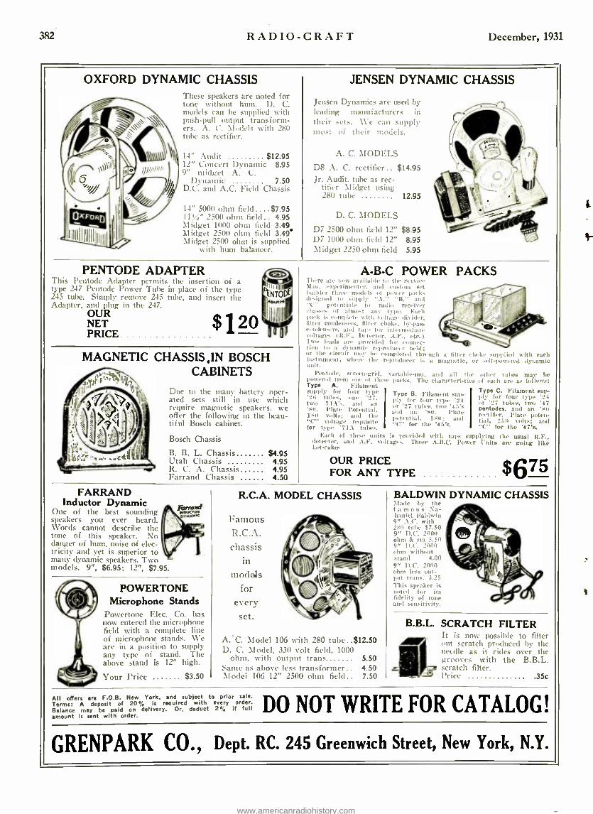
382 RADIO-CRAFT December, 1931
OXFORD DYNAMIC CHASSIS These speakers are noted for tone without hum. D. C. models can be supplied with push -pull output transform- ers. A. C. Models with 280 tube as rectifier.
14" Audit $12.95 12" Concert Dynamic 8.95 9" midget A. C.
Dynamic 7.50 D.C. and A.C. Field Chassis
14" 5000 ohm field ....$7.95 11 ,A" 2500 ohm field.. 4.95 Midget 1000 ohm field 3.49 Midget 2500 ohm field 3.49. Midget 2500 ohm is supplied
with hum balancer.
JENSEN DYNAMIC CHASSIS
Jensen Dynamics are used by leading manufacturers in their sets. We can supply most of their models.
A. C. MODELS
D8 A. C. rectifier.. $14.95 Jr. Audit. tube as rec-
tifier Midget using 280 tube 12.95
D. C. MODELS
D7 2500 ohm field 12" $8.95 D7 1000 ohm field 12" 8.95 Midget 2250 ohm field 5.95
PENTODE ADAPTER This Pentode Adapter permits the insertion of a type 247 Pentode Power Tube in place of the type 245 tube. Simply remove 245 tube, and insert the Adapter, and plug in the 247.
OUR NET PRICE
$120
MAGNETIC CHASSIS ,IN BOSCH CABINETS
Due to the many battery oper- ated sets still in use which require magnetic speakers, we offer the following in the beau- tiful Bosch cabinet.
Bosch Chassis
B. B. L. Chassis $4.95 Utah Chassis 4.95 R. C. A. Chassis 4.95 Farrand Chassis 4.50
A -B-C POWER PACKS There are now available to the Service Man, experimenter, and rust ore stet h uiWer three models ut power packs desrgunl tu supply A. B, and "C" potent in Is to radio receiver chasses of almost :un type. Each pack is complete with voltage divider, filter condensers, filter choke. by -pass n mdensenl, und taps for int vini,.liat, voltages I R.F., Detector, A.F.. etc.) Two leads are provided fur connec- tion to a dynamic reproducer field; or the circuit may be completed t lin tigh a filter oh instrument, where the reproducer is a magnetic, u unit.
Pentode, screen -grid. v:niable -mu, powered from ow .d Ihts, reeks. The Type A. Filament supply for four type '3n tithes, une two 71 A's, and an 'so. plate Potent ill, 1.51) Volts: and the "C" voltage requisite for type '71A tubes.
Earl; of these units is provided detector, and A.F. voltages. These hot -cake
Type B. Fi ply for fou or '227 tulle and an 's Jr Ment ial, "C" for th
oke supplied with each r self -powered dynamic
:rad all the other tubes may be characteristics of each are as follows:
Type C. Filament sup- ply for four type '24 or '27 tubes, two '47 pentodes. and an 'tin rectifier. Plate poten- tial, 250 volts: and "C" for the '47's.
with taps supplying the usual R.F., A.B.C. Pourer Unite are going like
lament sup - r type 224
s. two '45's 11. Plate 1 511 : and
e '45's.
OUR PRICE FOR ANY TYPE $675
FARRAND Inductor Dynamic
One of the best Holding speakers you ever heard. Words cannot describe the tone of this speaker. No danger of hum, noise of elec- tricity and yet is superior to many dynamic speakers. Two models. 9 ", $6.95; 12 ", $7.95.
POWERTONE Microphone Stands
Powertone Elec. Co. has now entered the microphone field with a complete line of microphone stands. We are in a position to supply any type of stand. The above stand is 12" high.
Your Price $3.50
R.C.A. MODEL CHASSIS
Famous R.C.A. chassis
in
models for
every set.
A.C. Model 106 with 280 tube ..$12.50 D. C. Model, 330 volt field, 1000
ohm, with output trans 5.50 Same as above less transformer.. 4.50 Model 106 12" 2ßf0 ohm fitltl.. 7.50
All offers are F.O.B. New York, and subject to prior sale. Terms: A deposit of 20% is required with every order. Balance may be paid on delivery. Or, deduct 2', if full amount is sent with order.
BALDWIN DYNAMIC CHASSIS \lade Iy the famous Na- haniel Baldwin 9" . \.C. with 250 tube $7.50 9" D.C. 2000 ohm & sta 5.50 9" D.C. 2000 ohm without stand 4.00 9" D.C. 2000 ohm less out- put trans. 3.25 This speaker is anted for its fidelity of tone an d sensitivity.
B.B.L. SCRATCH FILTER .r It is now possible to filter out scratch produced by the nec(lle as it rides over the grooves with the B.B.L. scratch filter. Price .35c
DO NOT WRITE FOR CATALOG!
GRENPARK CO., Dept. RC. 245 Greenwich Street, New York, N.Y.
www.americanradiohistory.com

4
Famous Model 4iGtt Gordon Phono -Motor and Turntable
First time at this price. Ruggedly constructed throughout. Spanish felt gears assure silence. Equipped with automamtic stop control. In- duction type, no brushes. Easy to install - exceptionally quick starting torque. For 110
volt 60 cycle alternating current. Proven de-
pendability has made this New Gordon Electric Phonograph Motor and Turntable the accepted standard of ex- cellence for the industry. ass
First time at t h i s price. Make a nce s ll
profit and build List $30.00 good will with OUR $8.95 everyone. PRICE O
Farrand Dynamic Chassis Famed for its simplicity and reliability. Easily installed in all types of radio or phonograph consoles. Tonal range and fidelity superior to any other reproducing unit in general use. Dimension: Height 9 inches, width t?i inches. depth 7 inches. For A.C. current.
4
OUR PRICE
$5.95
Condenser Block for Majestic
"B" Eliminator Replacement f o r defective blocks in "B" Eliminators - identical in electrical character- istics and outside dimensions. Can also be used in any make "B" Eliminator as well as most power packs
OUR PRICE
$2.75
Gordon Acme 4 Pick -Up with Volume Control
Genuine Bakelite arm with beautiful natural wood fin- ish will not show wear a will plated metal. Faith- fully reproduces the entire musical range.
OUR PRICE _ ". $4.50 I.C.A. Test Leads- a nere "Ity to the
dealer o Lee-
- i and tran. 40c
Fixed Pigtail Resistors OHMS
500 10,000 '75.000 1,000 15,000 100,000 1,600 20,000 1.25,000 1,800 25,000 150,000 4,000 30,000 250,000 4,700 40,000 1 Megohm 5,000 60,000 2 Megohms
OUR PRICE 75c PER DOZ
R. C. A. Loudspeaker 103 A beautiful speaker, superb in its faithful reproduction. Molde I
frame and pedestal resemble hand carved oak. Mechanism concealed by attractive tapestry.
(Genuine R.C.A., List $18.00
$3.50
New Type Elkon Dry Disc Rectifier
Standard on "A" Elim- inators for Majestic, Mayolian. Webster, El- Iron. Bernard. Fada, Knapp. Sentinel, Metro, G e n e r a l Instrument, Philco (Elkon equipped) and also on Elkon 3
amp., and Briggs Je Stratton chargers.
List $7.011
OUR PRICE
$3.45 Baldwin Rival Unit
This Nathaniel Baldwin unit is
one of the finest. For phono-
graph, automobile and portable radio outfits. We otter this fam- ous unit now at a sensationally reduced price.
OUR PRICE
Atwater -Kent Condenser & Filter Block
For Model 37 and 38 Sets
Ideal filtering system for ANY make A. C. set using 171 -A tube. Contains propet chokes and high voltage condensers. Flexible wire colored leads same as original.
HOOK -UP Green wire to 280, black b( R.F. plate. yellow to Power Tube plate, white to first audio by -pass, white to C.T. of 226 resistance, red to detector OUR plate. Wire from PRICE can to ground. $2.95
Kolster K -6 Speaker 1fagmIi, t) sp, :!k.r Itendarkable tune aual dn'; sul- nnm tu .spare. Beautifully carved. fine walnut cabinet. EquiPired with highly nsitive rsize magnet and driving unit. uFaith- fut reproduction front the faint-
est u1,tper tu fullest Loluine of it
brass hand. List $20.00
OUR PRICK $3.35
AIR -KING Superheterodyne S.W Converter The greatest converter
ever built. Bring- in tumor ;ut stations clear a
s
t hell. l'ert: ally --et into :t -hart , 27 re, .river. I:m
3,2 111114.4 :
d
2n to 113 miter- . .l w it, h rimers all Single ,liar I
hotly rapa, ity. t
Iles built-in Iran -former to I,. at 3 227':. All red from your receiver is a posit ice It. -ouate front
1:, to Ism volt:. Voltage I: not erit leal: n o mbs- tat ion of the receiver.
- ..-, in. t\'eitlt
OUR 1'Itl('F
$14.70
OUR PRICE 50c VICTOR ABC
Power Transformer For use with 6 -226,
: -245. 1 -227 and 1 -280 d u b e s. Magnetically shielded preventing hum. Can safely be overload- ed 30',i. High voltages, too volts at 150 mils on either side of center tap. Extra large case especially designed to prevent overheating.
Can Be Used For Any Power Amplifier Using 245 Tubes
Size: 41_ a 5 x 5t inches. No. 1- Center tap of 9 and 14 (5 volts). No. 2 and 4 -2', Volts. No. 5 and i -1 in. V. High amp. 1226). No. 3 and 6- Primary 1110V. input). No. 8- Center tap of 12 and 17 t2t6t V.) No. 8 and 14 -5 Volta 1280). No. 10 and 15 -High voltage for B supply. No. 16- Center tap of above. No. 12 and 17 -214.: in. volts high
¡GE) OUR PRICE
FREE Catalog -means money to you These are only a few samples of the values to he found in our catalog. It is full of items on which you can make from 511 to 300'; profit. And the best of them is, they are sound. well known, trademarked articles you can depend upon. Send 20c7 with the order and articles will hr shipped C.O.D. Order any of the above sr- tides direct from this page. And be sure to ask for the catalog. It means money to you!
RADIO CIRCULAR CO. 225 Varick St. New York City
ORDER DIRECT... from this page! RADIO CIRCULAR CO., 225 Varick Street, New York City
Enclosed Mad 8.. - - . This is 20',i of items listed below. I will pay balance upon receipt of merchandi-,
We regret that we cannot accept orders under $5.00.
Name
Address
LEM MMMMM MUM MM
TEAR IT OUT NOW!
Send for FREE catalog! RADIO CIRCULAR CO. 225 Varick Street, New York City Please send me our catalog of radio bargains I ran make a profit on.
u I m,deretand this obligates me in no way.
Ill Nome
Address
O Also please send catalog. City State... 161 MMMMMMMMMM J
www.americanradiohistory.com

381 R ADIO - C R A F 'I December, 1931
eb:A YOU'RE WANTED
> ;g Pay Radio Job J. E. Smith l'rc >i,lent,
'ational Radio Institute the man who has directed the Home -Study training of more men for the Radio Industry than any other man in America.
¡7/ Tan You atflomeinYour Spareune forRilDIO TELEVISION 'TALKING MOVIES
Aircraft Radio
Aviation is need- ing more and more trained Radio men. Operators employe. i through Civil Sem ice Commission earn $1,620 to $2,800 a year.
Set Servicing Spare -finie sot servicing is paying N. R. I. men $200 to $1.000 a year. Full -time men are making as much as M. $75 and $ 100 a week.
Broadcasting Stations
Need trained men continually for jobs paying $1,200 to $5,000 a year.
Ship Operating
Radio operators on ships see the world free and get good pay plus expenses.
Talking Movies
An invention mad, possible by Radio, offers many fine ,jobs to well-trained Radio men, paying $75 to $200 a week.
Television The coming field of many great op- portunities is cov- ered by my course.
IYOU are earning a penny less than $50 a F week, send for my book of information on the
opportunities in Radio. It is free. Clip the coupon NOW. Why be satisfied with $25, $30 or $40 a week for longer than the short time it takes to get ready for Radio?
Radio's Growth Opening Hundreds of $50, S7S, $100 a Week Jobs Every Year In about ten years Radio has grown from a
$2,000,000 to a $1,000,000,000 industry. Over 800,000 jobs have been treated. Hundreds more are being opened every year by its continued growth. Men and young men with the right train- ing -the kind of training I give you -are step- ping into Radio at two and three times their former salaries. J. A. Vaughn, 3107 S. Grand Boulevard, St. Louis, Mo., writes: "Before I en- tered Radio I was making $35 a week. Last week I earned $110 selling and servicing sets. I owe my success to N. R. I."
You Have Many Jobs To Choose From 11rua:Ir:utinK >c:ti u u. ,i:;ü,..: u. rui ors, sta-
tion main:tg. -1 and pity $1.200 to r:4000 a > ear. Jlnnu- facturers continually need testers. iu speet ors. fu reu uu, engineers, service wen. buyers. for jobs paying up to $7.500 a year. Radio operators on ships enjoy life, sec the world, with board and lodging free and get good pay besides. Dealers and jobbers employ service men, salesmen, buyers. I nut agers. and pay $30 to $100 a week. Tlon , °al,, r oPI"'rtIniti. _ too.
So Many Opportunities Many N. R. 1. Men Make $200 to $1000 While Learning
The day yon enroll with me I'll show yon how to do 28 jobs, common in most every neighborhood, for spare - time money. Throughout your course I send you infor-
I give you S Outfits of Radio Parts for Practical Home Experiments
You ran build over 100 cir- cuits with these outfits. You build and experiment with,¡ the circuits used in Crosley, Atwater Kent. Eveready. Majestic, Zenith, and other popu- lar sets. You learn how these sets work, why they work, how to make them work. This makes learning at home easy, fasci- nating, practical.
motion on servicing popular makes of sets ; I give you the plans and ideas that are making $200 to $1,000 for hundreds of N. R. I. students in their spare time while studying. My course is famous as the one that paye for itself. O. W. rage. 133 Pine Street, McKensle, Tenn., avriles: "I picked up $035 in my spare time while taking your course."
Talking Movies, Television and Aircraft Radio are Also Included
Special training in Talking Movies, Television and home Television experiments, Radio's use in Aviation, Servicing and Merchandising Sets. Broadcasting, Com- mercial and Ship Operating are included. I am so sure that I can train you satisfactorily that I will agree in writing to refund every penny of your tuition if you are not satisfied with my Lessons and Instruction Service upon completing.
64-page Book of Information Free Get your ropy today. It tells you where Radio's good
Jobs are, what they pay, telle you about my course, what others who have taken it are doing and making. Find out what Radio offers you, with- out the slightest obligation. ACT NOW!
J. E. SMITH, President National Radio Institute
Dept. 1 -NX Washington, D. C.
J. E. SMITH, President National Radio institute, Dept. 1 -NX Washington, D. C.
Dear Mr. Smith: Send me your fret 64 -page book, "Rich Rewards in Radio." I
understand this does not obligate me and that no salesman will call.
Fante
Address
City- State
l
www.americanradiohistory.com

NOW On All
Newsstands
25c The Copy
4 , > \\ .,.a .. i . L
1.
IIII rctuwyw aewc(wtr,ms 9uOro !(t[vi1.O.v/
I R.
EeloR
4-Color Cover Over 100 Illustrations
96 Panes -9x12 in.
LC
/.:'ST(RCORTROI MLL R.MIMruR
Ro10 I¡ wMrtttR INJr-/MC M OC) l
' 1 : SNORr S wMVC(IOR-MLlul ` ' aSS a.Y,LOM(ITiLAMDMY.
\ óiä GL
4 M. = Ma.am ...
IL st
TO MY RADIO FRIENDS WILL YOU BET 25c ON ME?
I want to ask you. as a special favor, to stop at your nearest newsstand and get an issue of EVERYDAY SCIENCE AND t,II'l'1l.\NII'S 1111 the full11wing unprecedented arrangement:
'fake the magazine lion,`. look it over carefully anti read Moose articles which are of inthr. -st to you. lf, when yon finish reading the magazine. you have found that you havn't had your 11101103'8 worth, von may return the magazine to tae 11111 1 will immediately
refund your quarter. plus postage which you paid in returning the magazine. I am making th IS unp rend en ted offer simply to get you aeq uain tell with the magazine,
:old iss.aliSe I honestly brliere tuat every issue of l`: \'67111 "I4. \l' S('1I :N/'1:. \NI) yil:t'IL\NII'S will be worth many dollars to you with the important information yon can't got elsewhere.
RADIO AND TELEVISION I wont you to look particularly at the Ti.'" radio and television Sctinn eunlaining
n treuleudous amount of infurnatiun for radio experimenters, of the kind you cannot possibly get elsewhere.
This special offer to you is I- 1 ,luring the month of November only. I hope you will do me the favor to take me up on tIlls uuprrccd,nted propo$i tloa. Won't you ideasi write and tell till how the book strikes you*:
Cordially yours, 11. ,il:ItNSI:.\t'tC.
14
4001CC RLCU.[R (SNoRI.1.a.tMLCI
)I. SRLSúuim[ñ D[l' ^ srw4ts
:iR
h4:;::i:iC°7 ^:MAGE"ANO"VOICC"
120011 SYNCHRONOUS '-
EVERYDAY SCIENCE AND MECHANICS 100 Park Place, New York, N. Y.
www.americanradiohistory.com

tLththe Short Wave Stati om&
Qfthe Word: direct nth the NEW PI LOT
This 4 -tube Short - Wave Converter trans- forms any modern radio receiver into a short -wave set in- stantly. Complete with newest type tubes, in- cluding rectifier.
$39.50
SUPER WASP
Day or night, Pilot's marvelous SUPER -WASP brings in all kinds of new and startling things - airplane-to- ground conversations, transoceanic tele- phone calls, foreign broadcasting stations and, most exciting of all, police headquarters in a dozen cities talking to their radio -equipped "emergency cruisers." This 11 -tube Super- heterodyne has separate controls for the broadcast band, with special high quality, high selectivity circuit. Including newest tubes and built -in dy- $99.50 namic speaker.
Pilot Radio & Tube Corporation Lawrence, llass. Please send nie complete information about:
The new SUPER -WASP 1 The 4 -tube Converter
I enclose Soc for one year's subscription to Radio Resign beginning with the current issue.
Name City
type
a www.americanradiohistory.com