milestone pilot project - publications.gov.sk.capublications.gov.sk.ca/documents/66/99425-2017-006...
TRANSCRIPT
MILESTONE PILOT PROJECT
Submitted to: Saskatchewan Ministry of EnvironmentEnvironmental Assessment Branch
17 March 2017
Milestone Project – Pilot Plant
Page | 1 MARCH 2017
TTable of Contents 1.0 Introduction ......................................................................................................................... 3 2.0 Background .......................................................................................................................... 5
2.1 Project History .................................................................................................................. 5 2.2 Project Ownership ............................................................................................................ 5
3.0 Pilot Project - Project Description ........................................................................................ 7 3.1 Location ............................................................................................................................ 7 3.2 Mining .............................................................................................................................. 7
3.2.1 Solution Mining Method ........................................................................................... 7 3.2.2 Mine Plan .................................................................................................................. 7
3.3 Process ............................................................................................................................. 8 3.3.1 NaCl Handling System ............................................................................................... 8 3.3.2 NaCl Mix Tank ........................................................................................................... 8 3.3.3 Crystallization Pond Brine Gravity Flow System ....................................................... 8 3.3.4 Slurry Thickener Overflow and Centrifuge Centrate ................................................ 8 3.3.5 Boilers ....................................................................................................................... 9 3.3.6 Purge Pond ................................................................................................................ 9
4.0 Impacts Assessment ........................................................................................................... 10 4.1 Project Location.............................................................................................................. 10 4.2 Study Areas ..................................................................................................................... 10
4.2.1 Local Study Area ...................................................................................................... 10 4.2.2 Regional Study Area ................................................................................................ 10
4.3 Site Characterization ...................................................................................................... 10 4.4 Data Collection ............................................................................................................... 11
4.4.1 Desktop Study ......................................................................................................... 11 4.4.2 Geophysical Surveys ............................................................................................... 11 4.4.3 Geotechnical Drilling ............................................................................................... 11 4.4.4 Stratigraphy ............................................................................................................. 12 4.4.5 Hydraulic Testing..................................................................................................... 12 4.4.6 Hydrostratigraphic Units - LSA ................................................................................ 12
4.5 Crystallization Pond ........................................................................................................ 13 4.5.1 Groundwater Flow Model – Methodology ............................................................. 13 4.5.2 Groundwater Flow Model ....................................................................................... 14 4.5.3 Pathways Analysis ................................................................................................... 14 4.5.4 Flow and Solute Transport Model Results .............................................................. 15 4.5.5 Crystallization Pond Construction ........................................................................... 16
4.6 Water Supply .................................................................................................................. 16 4.6.1 Supply Options ........................................................................................................ 16 4.6.2 Preferred Water Supply Option .............................................................................. 18 4.6.3 Water Supply Pipeline ............................................................................................. 19
4.7 Site Access ...................................................................................................................... 19 4.7.1 Functional Standard ................................................................................................ 19
Milestone Project – Pilot Plant
Page | 2 MARCH 2017
4.7.1 Section A ................................................................................................................. 20 4.7.2 Section A1 ............................................................................................................... 21 4.7.3 Section A2 ............................................................................................................... 21 4.7.4 Section B1 ............................................................................................................... 22 4.7.5 Section B2 ............................................................................................................... 22 4.7.6 Section C1 ............................................................................................................... 22 4.7.7 Section C2 ............................................................................................................... 22 4.7.8 Section C3 ............................................................................................................... 23 4.7.9 Preferred Option ..................................................................................................... 23
5.0 Consultations ..................................................................................................................... 24 6.0 Summary ............................................................................................................................ 25 List of Figures and Tables
Figure Title 2.1 Western Potash Corp Ownership 3.1 Pilot Project Location 3.2 Pilot Plant and Three Horizontal Caverns 3.3 Pilot Well Trajectory and Completion Well Details 3.4 Possible Location of Three Additional Caverns After 6 Years 3.5 3.6 3.7
Process Flow Diagram InjectionProcess Flow Diagram Solution Mining and Crystallization PondProcess Flow Diagram Debrining, Drying, & Loadout
3.8 Civil Layout4.1 Aerial View of Pilot Plant Location – NW20-14-17W24.2 Regional and Local Study Areas4.3 Local Study Area Borehole Location Plan4.4 Local Study Area Cross Sections I-I’, II-II’, III-III’, IV-IV’ and V-V’4.5 Local Study Area Cross Sections VI-VI’, VII-VII’, VIII-VIII’ AND IX-IX’4.6 Local Study Area 5m Resistivity Depth Slice4.7 Local Study Area 20m Resistivity Depth Slice4.8 Local Study Area 40m Resistivity Depth Slice4.9 Local Study Area 5m Depth Interpreted Soil Type
4.10 Local Study Area 20m Depth Interpreted Soil Type4.11 Local Study Area 40m Depth Interpreted Soil Type4.12 Borehole Location Plan (2016 Study)4.13 Stratigraphic Cross Section – Pilot Project Location (2016)4.14 Proposed Water Well Location4.15 Proposed Water Well Location with Land Use Imagery4.16 Pilot Project Site Access Options4.17 Functional Standard for Road Construction and Maintenance
Table Title2.1 Pilot Project Work Completed in 2015-20164.1 Hydraulic Testing Results (Golder, 2013)4.2 Hydraulic Testing Results (Clifton, 2017)4.35.1
Brine Migration Prediction - Milestone A Project TMAProject Consultations and Meetings - Sept 2015 to March 2017

Milestone Project – Pilot Plant
Page | 3 MARCH 2017
11.0 Introduction
The Milestone Project is a proposed potash solution mining pilot plant located in southern Saskatchewan approximately 35 km southeast of the city of Regina. It is close to existing, long-running potash mines with excellent access to all required infrastructure
In late 2012, Western Potash Corp (Western Potash) delivered a Feasibility Study detailing compelling project economics for a 2.8 million tonne per year (TPY) Primary + Secondary (‘Milestone A’) operation. Operating costs per tonne were among the lowest in the industry at $62 CAD at full production capacity. The initial capital requirement for the project was $2.9 Billion CAD (2012) with a deferred capital requirement of $400 Million CAD. The Saskatchewan Ministry of Environment issued Environmental Assessment approval for the Milestone project in March of 2013.
The Milestone A Feasibility Study scope was designed from a specific strategic perspective, one that focused on business and project risk reduction while maximizing value resulting in a large tonnage, long life, mining methodology similar to that used for over forty years at Mosaic's Belle Plaine Potash Solution Mine.
Since discovery of the Milestone resource in 2009, Western Potash has diligently pursued Project finance scenarios that would bring the Milestone A option into production. This process has proven to be very challenging given current potash pricing environment and the broad commodity pricing cycles inherent to the potash market. A new paradigm was required in order to effectively exploit the Milestone asset while reducing CAPEX, maintaining competitive OPEX, and insulating Western Potash from these broad commodity pricing cycles.
NOVOPRO PROJECTS INC in association with AGAPITO ASSOCIATES INC were mandated by Western Potash Corp to complete a Scoping Study for the Milestone Project that would effectively exploit the Milestone asset through reduced levels of production, using secondary solution mining techniques, while reducing CAPEX and maintaining competitive OPEX. This is known as the Milestone Pilot Potash Project.
The secondary solution mining process involves selective KCl solution mining from horizontally drilled holes into the base of the Prairie Evaporites. KCl crystal production is then achieved through injection of hot NaCl saturated water and recovery of brine. The brine is pumped to a crystallization pond where the brine cools resulting in KCl precipitation. The advantage of this process is that solution mining methodologies are simplified, and no NaCl tailings are produced.
Agapito initially prepared an evaluation of the project’s geology and mining method, after which Novopro completed the design of the surface facilities, including processing and supporting infrastructure, for the production of all necessary drawings and documents, and completed an AACE (Association for the Advancement of Cost Engineering) Class 4 +/- 25% Capital and Operating Cost estimate for the project.
Two potential processing options were identified at the outset of the project, namely the production of muriate of potash (MOP) using mechanically cooled crystallizers (OPTION A) or via a cooling crystallization pond (OPTION B). Based on a detailed feasibility review of both options, Western Potash initially proposed the mechanically cooled option. In 2015 Western
Milestone Project – Pilot Plant
Page | 4 MARCH 2017
Potash submitted a project proposal to Saskatchewan Ministry of Environment (MOE) describing the Pilot Potash Project. The project was reviewed by MOE and received a “Ministerial Change Approval Pursuant to Section 16(2)(a) of The Environmental Assessment Act” (approval dated 10 September, 2015).
Subsequent to the Novopro/Agapito scoping study, Western Potash commissioned Amec Foster Wheeler (AFW) to complete an engineering design for a 146,000 tonne per year Pilot Project based on the results of the Scoping Study. The AFW report provided a detailed design and Cost Estimate (AACE +/- 10%) for a 146,000 tpy facility based on the selective mining methodology. Agapito Associates provided the mining engineering and cavern design services. Included in the design are two changes from the Scoping Study: use of a crystallization pond instead of mechanical crystallization, and project location. In addition, the location of the groundwater supply well has also been moved and is addressed in this report.
This document represents a submission to Saskatchewan Ministry of Environment-Environmental Assessment Branch for review of the changes to the Pilot Project under The Environmental Assessment Act.
This report supplements the original Pilot Project Report and only addresses the changes to the Pilot Project, namely the introduction of the Crystallization Pond, change in location and water well pipeline routing.
Milestone Project – Pilot Plant
Page | 5 MARCH 2017
22.0 Background
2.1 Project History The 2015 Pilot Project Description provides a description of the work completed on the Milestone Project from the company’s inception in 2007 to July 2015 when the arrangement with Tairui was announced.
Table 2.1 shows the additional main activities that have occurred since the 2015 Pilot Project Description was submitted:
Task Timeline Updated NI 43-101 Report August 2015 Finalized Financing Arrangement with Tairui September 2015 Amec Foster Wheeler Commissioned to Prepare Detailed Engineering Report for 146,000 tpy Pilot Project March 2016
Land Purchase for Pilot Project January 2017 Amec Foster Wheeler Report Delivered November 2016
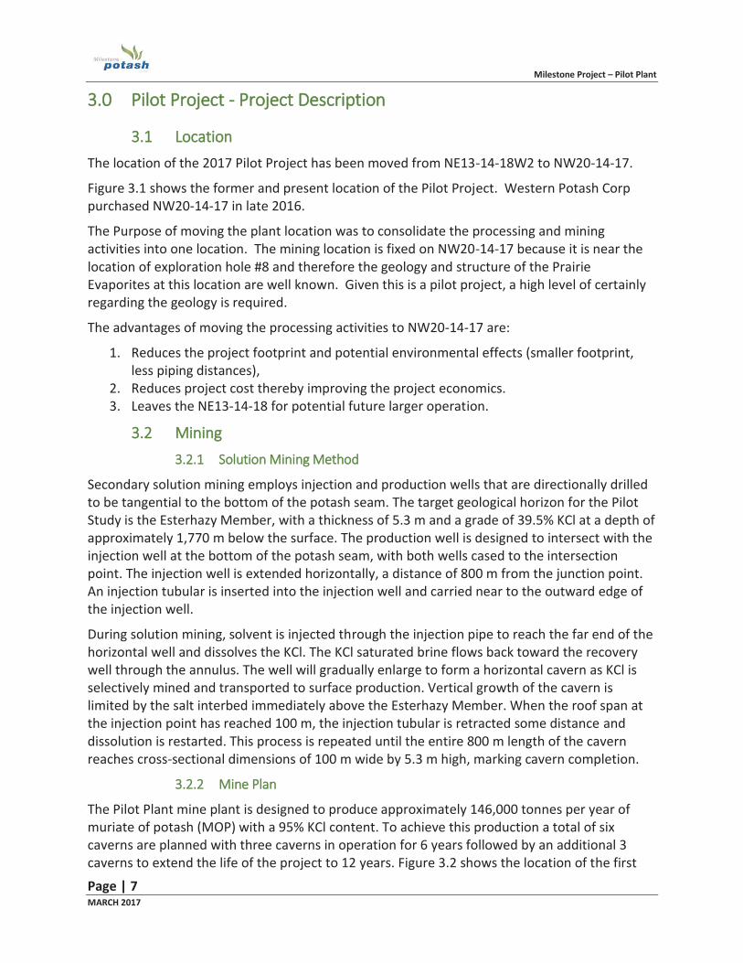
Table 2.1 Pilot Project Work Completed in 2015-2016
2.2 Project Ownership Western Potash is a publicly-traded (TSX:WPX) mineral development company engaged in the evaluation, exploration and development of the Milestone Potash Project. Western Potash was formed in 2007 under the British Columbia Business Corporation. Western Potash’s head office is located in Vancouver British Columbia and an operations office is located in Regina, Saskatchewan.
China BlueChemical Ltd. and Benewood Holdings Corporation, through a joint venture company (CBCHC) completed a strategic investment in Western Potash, purchasing approximately 45 million common shares for 19.9% ownership stake in Western Potash. Western Potash and CBCHC have signed an off-take term sheet whereby CBCHC, or a purchaser designated by it, can purchase of the lesser of 30% or 1 million tonnes of potash annually for a term of 20 years (pricing of product sold under the agreement will be based on market terms).
On July 6, 2015 Western Potash entered into an agreement with Beijing Tairui Innovation Capital Management Ltd. (“Tairui”). Under the terms of the agreement, Tairui will make a strategic equity investment of $80 million (CAD) in Western Potash which will result in Tairui holding a 51% ownership stake in Western Potash. Proceeds from the investment will be use to the development of a pilot plant scale selective solution mining operation as described in this document.
The arrangement with Tairui was finalized in September, 2015.
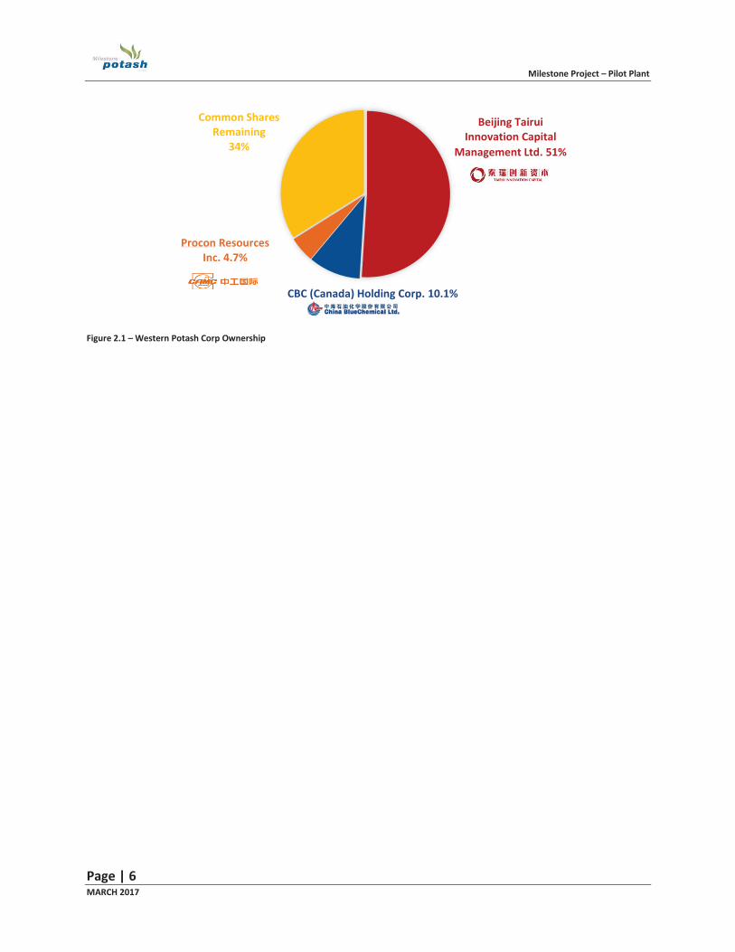
Figure 2.1 shows the company’s share ownership.
Milestone Project – Pilot Plant
Page | 6 MARCH 2017
Figure 2.1 – Western Potash Corp Ownership
Beijing Tairui Innovation Capital
Management Ltd. 51%
CBC (Canada) Holding Corp. 10.1%
Procon Resources Inc. 4.7%
Common Shares Remaining
34%
Milestone Project – Pilot Plant
Page | 7 MARCH 2017
33.0 Pilot Project - Project Description
3.1 Location The location of the 2017 Pilot Project has been moved from NE13-14-18W2 to NW20-14-17.
Figure 3.1 shows the former and present location of the Pilot Project. Western Potash Corp purchased NW20-14-17 in late 2016.
The Purpose of moving the plant location was to consolidate the processing and mining activities into one location. The mining location is fixed on NW20-14-17 because it is near the location of exploration hole #8 and therefore the geology and structure of the Prairie Evaporites at this location are well known. Given this is a pilot project, a high level of certainly regarding the geology is required.
The advantages of moving the processing activities to NW20-14-17 are:
1. Reduces the project footprint and potential environmental effects (smaller footprint, less piping distances),
2. Reduces project cost thereby improving the project economics. 3. Leaves the NE13-14-18 for potential future larger operation.
3.2 Mining 3.2.1 Solution Mining Method
Secondary solution mining employs injection and production wells that are directionally drilled to be tangential to the bottom of the potash seam. The target geological horizon for the Pilot Study is the Esterhazy Member, with a thickness of 5.3 m and a grade of 39.5% KCl at a depth of approximately 1,770 m below the surface. The production well is designed to intersect with the injection well at the bottom of the potash seam, with both wells cased to the intersection point. The injection well is extended horizontally, a distance of 800 m from the junction point. An injection tubular is inserted into the injection well and carried near to the outward edge of the injection well.
During solution mining, solvent is injected through the injection pipe to reach the far end of the horizontal well and dissolves the KCl. The KCl saturated brine flows back toward the recovery well through the annulus. The well will gradually enlarge to form a horizontal cavern as KCl is selectively mined and transported to surface production. Vertical growth of the cavern is limited by the salt interbed immediately above the Esterhazy Member. When the roof span at the injection point has reached 100 m, the injection tubular is retracted some distance and dissolution is restarted. This process is repeated until the entire 800 m length of the cavern reaches cross-sectional dimensions of 100 m wide by 5.3 m high, marking cavern completion.
3.2.2 Mine Plan
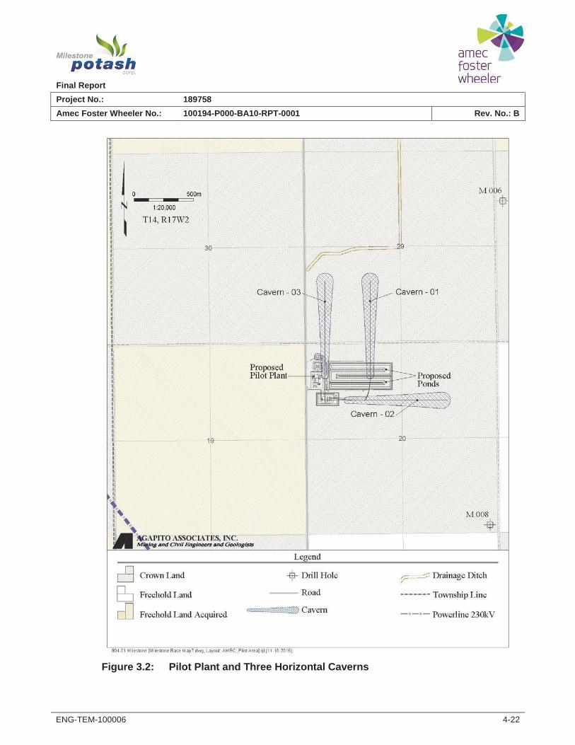
The Pilot Plant mine plant is designed to produce approximately 146,000 tonnes per year of muriate of potash (MOP) with a 95% KCl content. To achieve this production a total of six caverns are planned with three caverns in operation for 6 years followed by an additional 3 caverns to extend the life of the project to 12 years. Figure 3.2 shows the location of the first

Figure 3.1 – Pilot Project Location Range 18 Range 17
Pilot Plant Location NW20-14-17W2
Milestone “A” Project Site TWP 14
Final ReportProject No.: 189758Amec Foster Wheeler No.: 100194-P000-BA10-RPT-0001 Rev. No.: B
ENG-TEM-100006 4-22
Figure 3.2: Pilot Plant and Three Horizontal Caverns
Final ReportProject No.: 189758Amec Foster Wheeler No.: 100194-P000-BA10-RPT-0001 Rev. No.: B
ENG-TEM-100006 4-20
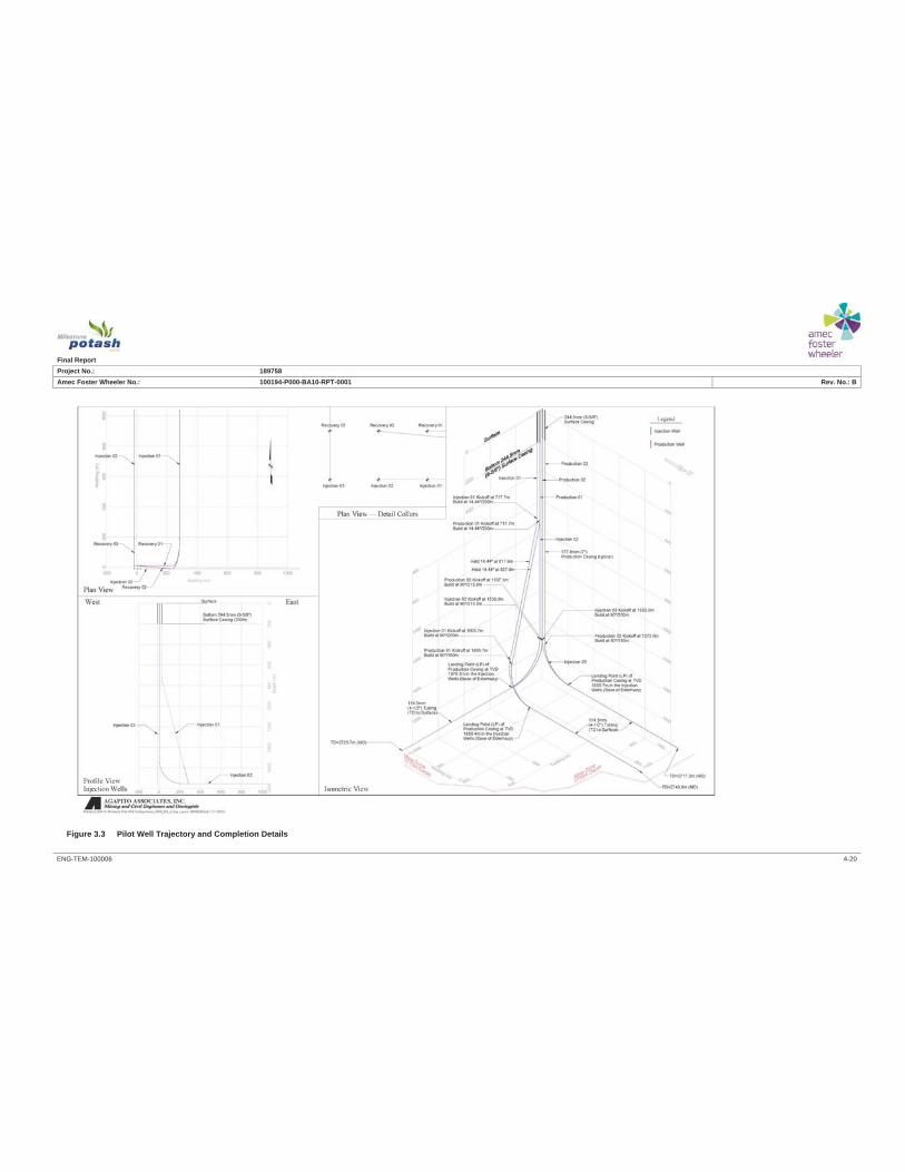
Figure 3.3 Pilot Well Trajectory and Completion Details
Final ReportProject No.: 189758Amec Foster Wheeler No.: 100194-P000-BA10-RPT-0001 Rev. No.: B
ENG-TEM-100006 4-62
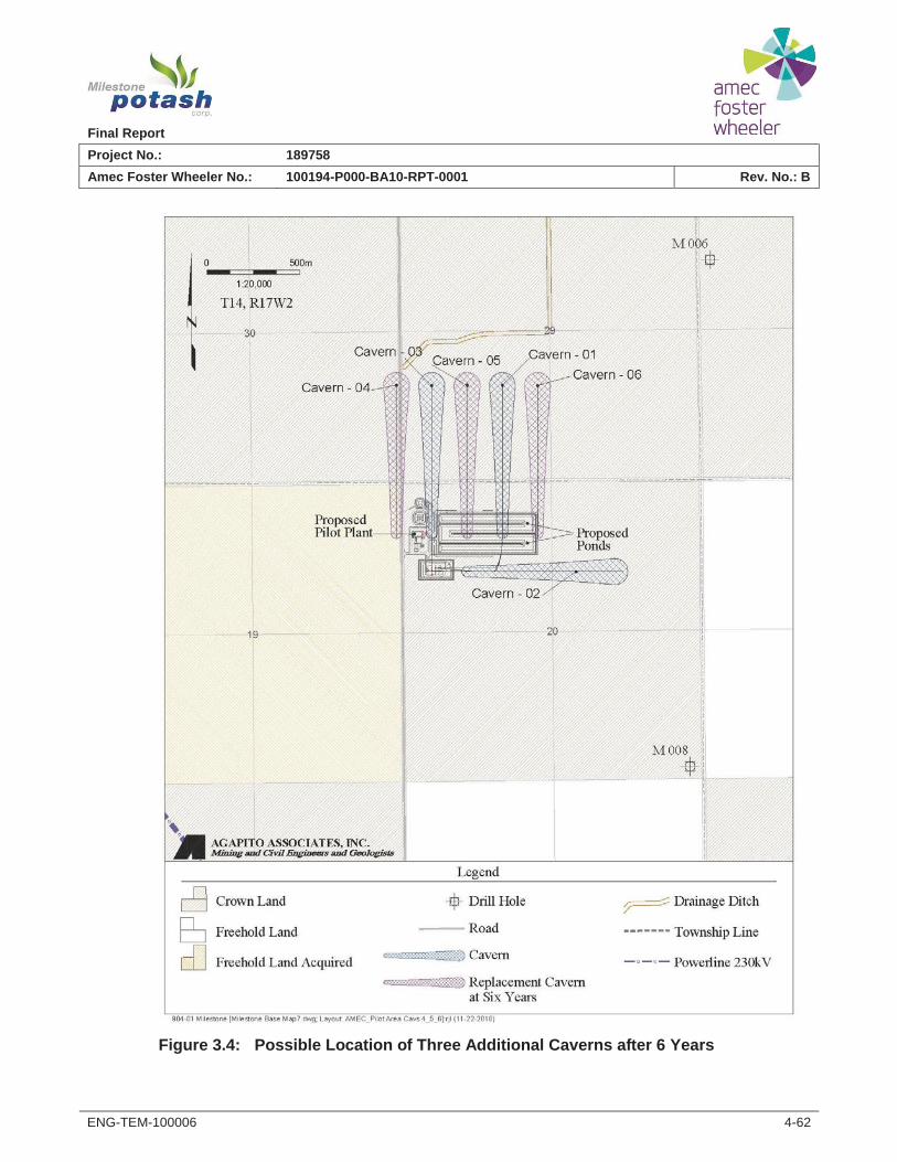
Figure 3.4: Possible Location of Three Additional Caverns after 6 Years
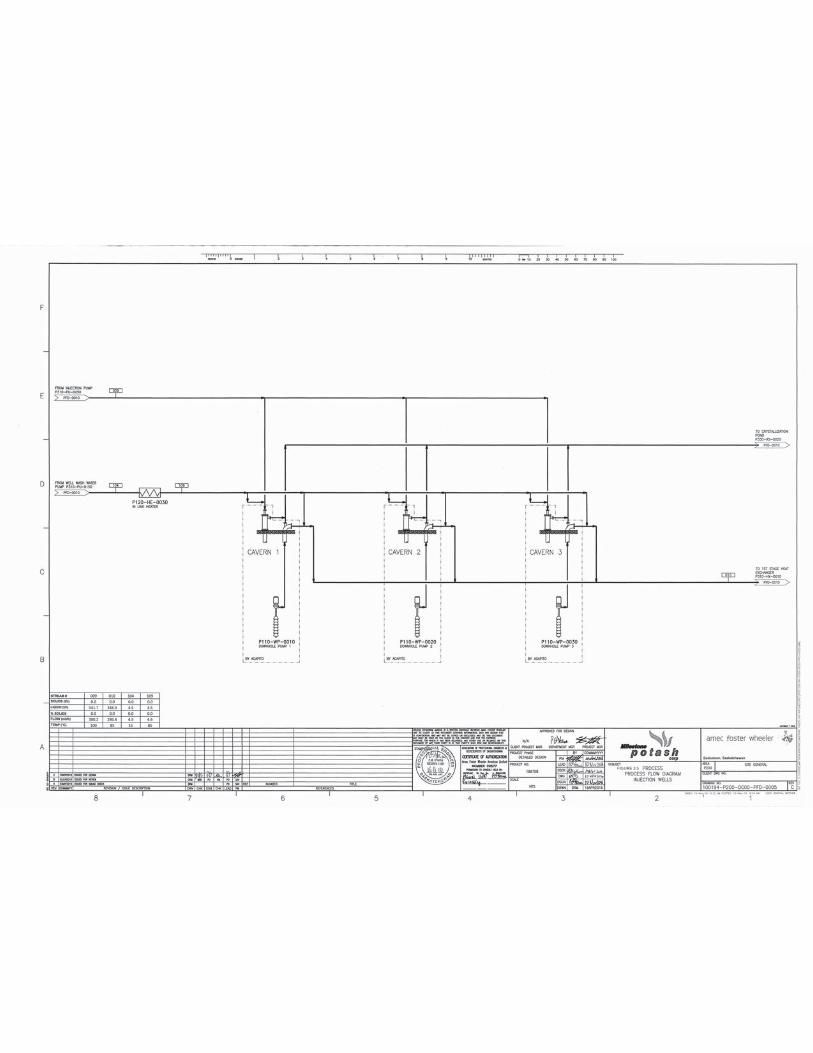
FIGURE 3.5
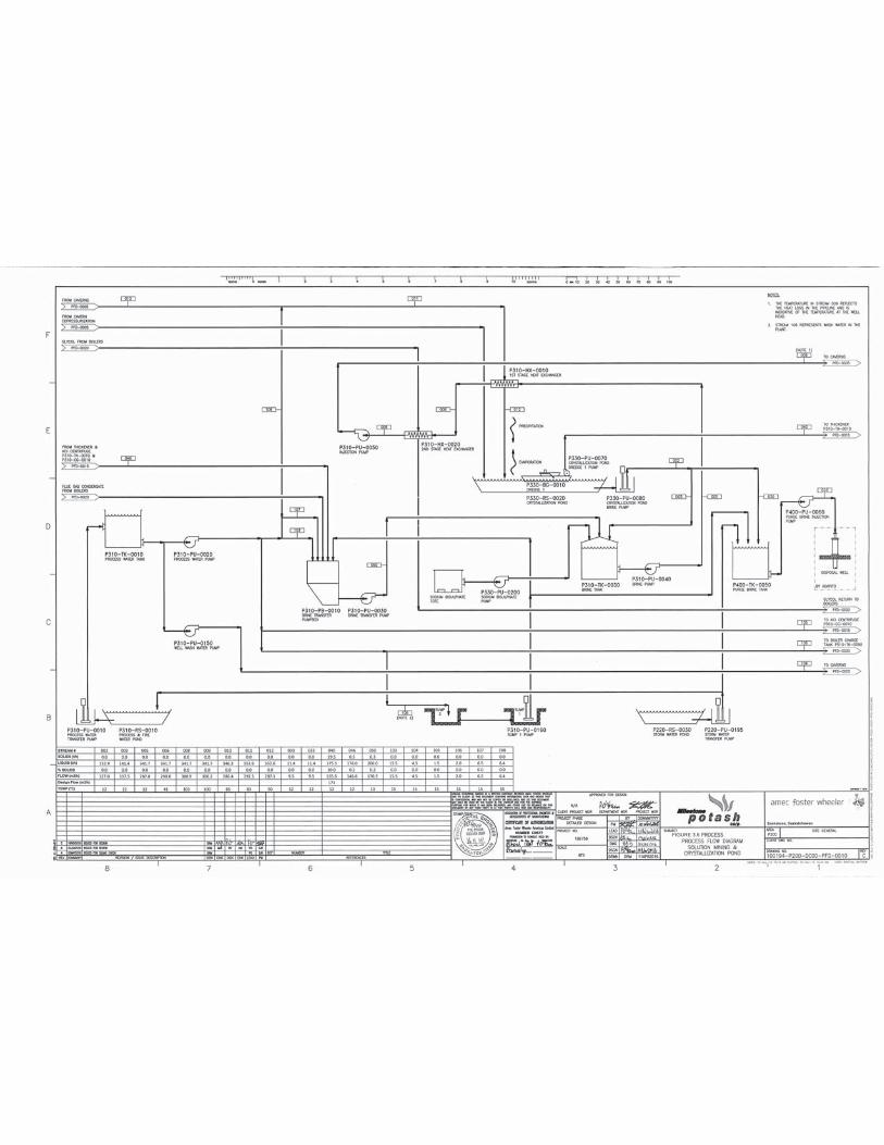
FIGURE 3.6
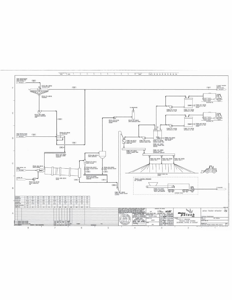
FIGURE 3.7
Milestone Project – Pilot Plant
Page | 8 MARCH 2017
three caverns developed from the first pad. Each cavern will be developed from an 800 meter horizontal well that includes an injection tubular and a production well. The injection tubular can be moved to relocate the injection location or it can be perforated to relocate the injection point. Figure 3.3 shows the drilling trajectories for the caverns. Figure 3.4 shows the possible location of the second set of caverns planned for years 6-12 (although this may be optimized based on the results of the initial caverns).
33.3 Process This section describes the Pilot Plant process system. Slight changes to the process from the 2015 Project Description have been designed and are described below.
Process flow diagrams are shown in figures 3.5-3.7
3.3.1 NaCl Handling System
The sodium chloride (NaCl) system that was envisioned in the scoping study consisted of trucks unloading the NaCl over a grating to an underground conveyor on the exterior of the process plant. The conveyor fed the exterior NaCl bucket elevator which then fed the exterior 500 tonne capacity (4 days) NaCl loading bin. The loading bin fed a metering screw conveyor which ran into the plant and fed the NaCl mix tank.
Dissolution testing by Agapito showed that higher concentrations of NaCl in the solvent were detrimental to potassium chloride (KCl) dissolution. Agapito then recommended that the project does not need a NaCl saturation system.
3.3.2 NaCl Mix Tank
To accomplish heating of the NaCl in the mix tank, the scoping study called design included for a steam lance immersed directly in the NaCl mix tank. This is an inefficient way to heat since no condensate is produced and the volume of condensate lost must be made up with water. Amec Foster Wheeler has removed the heating requirement from the mix tank and instead will heat the NaCl in a heat exchanger after it is added to the injection brine.
3.3.3 Crystallization Pond Brine Gravity Flow System
The scoping study design assumed a gravity flow system to feed the reclaim brine from the crystallization pond to the process plant. Gravity flow from the crystallization pond to the plant cannot be achieved without raising the elevation of the crystallization pond which would result in significantly more fill and a higher cost for the crystallization pond.
Amec Foster Wheeler has proposed a reclaim brine pumping system.
3.3.4 Slurry Thickener Overflow and Centrifuge Centrate
The scoping study proposed that the overflow from the slurry thickener and the centrifuge centrate flow into a tank before being pumped back to the crystallization pond where it would flow by gravity to the cold solvent sump. The slurry thickener overflow and the centrifuge centrate are essentially the same material as the reclaim brine coming from the crystallization pond through the proposed gravity flow line. Rather than pump the slurry thickener overflow and the centrifuge centrate back to the pond, this material could be diverted directly to the
Milestone Project – Pilot Plant
Page | 9 MARCH 2017
cold solvent sump to reduce the flow required from the proposed gravity line. This has an evenbigger impact given that the gravity flow line will be replaced by a pumping system. Thevolume of brine required from the crystallization pond has therefore been reduced by 51%from 282 m3/hr to 137 m3/hr.
Implementing this change would reduce the volume of brine required from the crystallizationpond from 282 m3/hr to 137 m3/hr, a reduction of 51% – reducing the pumping capacity of theproposed reclaim brine pumping system.
33.3.5 Boilers
The scoping study assumed steam boilers operating at a pressure of 345 kPa.
Amec Foster Wheeler has proposed the use of glycol boilers instead of steam boilers. This willresult in the following optimizations:
The CAPEX for the glycol system is lower than the equivalent steam boiler.The glycol boilers are 10% more efficient than the steam boilers, resulting in lowerenergy usage and hence OPEX.The glycol boilers do not require makeup chemicals (a cost savings of approximately$30,000 per year).The glycol boilers do not require operators with 1st and 2nd class steam and only a 4th
class steam ticket is required.
3.3.6 Purge Pond
The purge pond located upstream of the disposal well proposed in the scoping study has beenreplaced with a small purge brine tank. Implementing this change will result in a lower CAPEXwith the removal of the purge pond and less chance of any environmental impact.
Figure 3.8 shows the civil layout of the plant site.

FIGURE 3.8
Milestone Project – Pilot Plant
Page | 10 MARCH 2017
44.0 Impacts Assessment
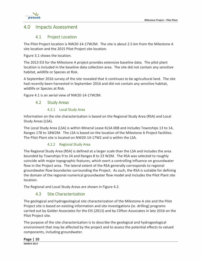
4.1 Project Location The Pilot Project location is NW20-14-17W2M. The site is about 2.5 km from the Milestone A site location and the 2015 Pilot Project site location.
Figure 3.1 shows the location.
The 2013 EIS for the Milestone A project provides extensive baseline data. The pilot plant location is included in the baseline data collection area. The site did not contain any sensitive habitat, wildlife or Species at Risk.
A September 2016 survey of the site revealed that it continues to be agricultural land. The site had recently been harvested in September 2016 and did not contain any sensitive habitat, wildlife or Species at Risk.
Figure 4.1 is an aerial view of NW20-14-17W2M.
4.2 Study Areas 4.2.1 Local Study Area
Information on the site characterization is based on the Regional Study Area (RSA) and Local Study Areas (LSA).
The Local Study Area (LSA) is within Mineral Lease KLSA 008 and includes Townships 13 to 14, Ranges 178 to 18W2M. The LSA is based on the location of the Milestone A Project facilities. The Pilot Plant site is located on NW20-14-17W2 and is within the LSA.
4.2.2 Regional Study Area
The Regional Study Area (RSA) is defined at a larger scale than the LSA and includes the area bounded by Townships 9 to 24 and Ranges 8 to 23 W2M. The RSA was selected to roughly coincide with major topographic features, which exert a controlling influence on groundwater flow in the Project area. The lateral extent of the RSA generally corresponds to regional groundwater flow boundaries surrounding the Project. As such, the RSA is suitable for defining the domain of the regional numerical groundwater flow model and includes the Pilot Plant site location.
The Regional and Local Study Areas are shown in Figure 4.2.
4.3 Site Characterization The geological and hydrogeological site characterization of the Milestone A site and the Pilot Project site is based on existing information and site investigations (ie. drilling) programs carried out by Golder Associates for the EIS (2013) and by Clifton Associates in late 2016 on the Pilot Project site.
The purpose of the site characterization is to describe the geological and hydrogeological environment that may be affected by the project and to assess the potential effects to valued components, including groundwater.
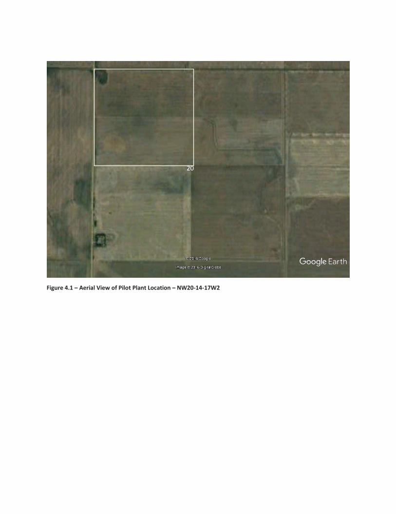
Figure 4.1 – Aerial View of Pilot Plant Location – NW20-14-17W2
20
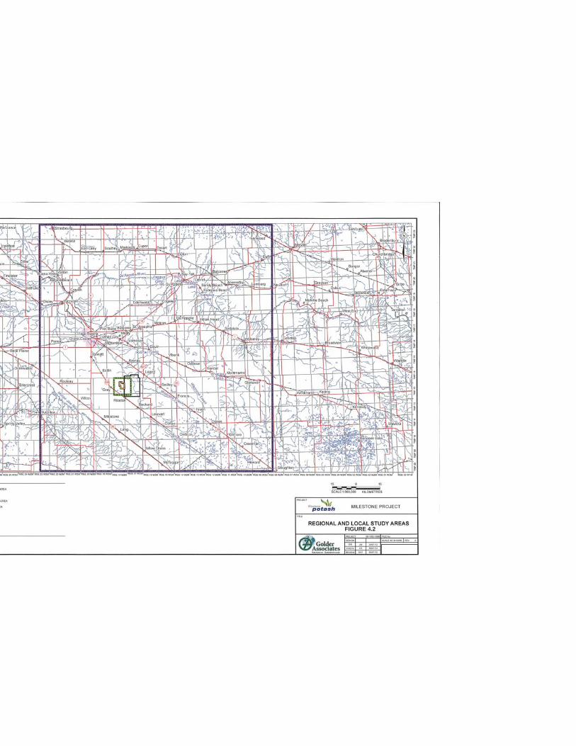
FIGURE 4.2
Milestone Project – Pilot Plant
Page | 11 MARCH 2017
The Pilot Project site location is located approximately 2.5 kilometers northeast of theMilestone A project site. Extensive site characterization was completed for Milestone A as partof the EIS. Additional site characterization was completed on the Pilot Plant site location late2016 as part of the Pilot Project design.
The hydrogeological site characterization of the LSA which includes both the Milestone AProject and the Pilot Project describes the extents of major hydrostratigraphic units andbaseline data collection results and is summarized below.
44.4 Data Collection4.4.1 Desktop Study
For the purposes of the Pilot Project, only site characterization of the LSA is provided in thisreport. Site characterization of the RSA is provided in the Milestone ‘A’ Project EIS (2013).
Existing surface, subsurface and groundwater information were compiled to provide ageological and hydrogeological characterization in the LSA. Compilation of existing informationincluded the collection of existing borehole logs, study reports, and publications. About 500borehole logs were reviewed. They included geophysical traces and soil lithology descriptions.
As part of the Environmental Impact Assessment for the Milestone A project, 38 boreholeswere drilled within the LSA; 17 were used for geotechnical purposes (WP-11-201 to WP-11-218)and 21 were used for stratigraphic characterization (WP-10-001 to WP-11-201) (Figure 4.3).
4.4.2 Geophysical Surveys
An airborne geophysical survey was conducted to augment intrusive investigations throughcollection of electromagnetic and magnetic data to provide a measure of apparent conductivityversus depth across the LSA. This data was used to assist in the interpretation of the lithologyof the glacial drift deposits.
4.4.3 Geotechnical Drilling
Geotechnical investigations were performed as part of the Milestone A Project EIS and for thePilot Project (Clifton 2016) to collect information in support of the surface infrastructure civildesign for the environmental assessment. The purpose of the field investigation was to providethe following:
Define the subsurface soil strata and determine relevant engineering properties (Shearstrength, bearing capacity, compressibility) for each stratigraphic unit encompassing themost likely locations for infrastructure;Discuss general condition observed in the LSA and the potential effects these conditionscould have on foundation design for the various infrastructure; and,Provide commentary on pertinent geotechnical issues identified during the subsurfaceinvestigation.
For the EIS, 17 boreholes were drilled at depths ranging from 11.6 meters to 21.6 m. Soilsamples were taken at varying depths for geotechnical properties and the holes were thenbackfilled with cement.
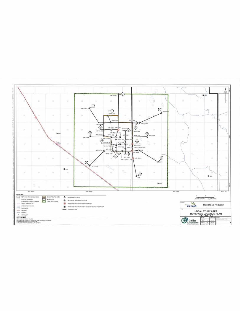
FIGURE 4.3
Milestone Project – Pilot Plant
Page | 12 MARCH 2017
44.4.4 Stratigraphy
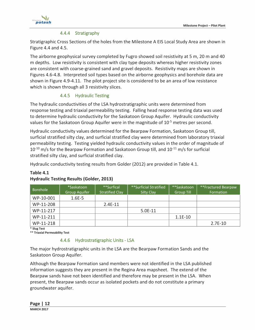
Stratigraphic Cross Sections of the holes from the Milestone A EIS Local Study Area are shown in Figure 4.4 and 4.5.
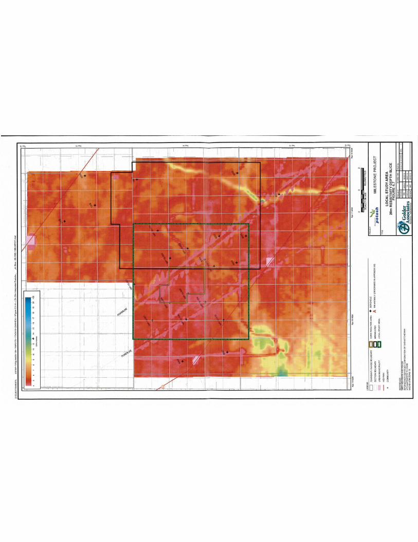
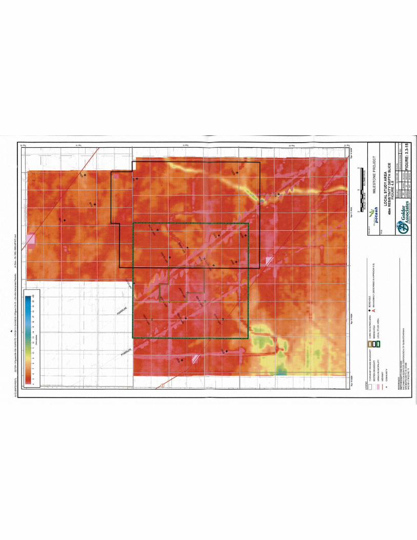
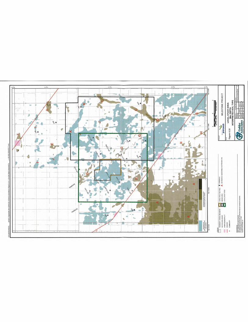
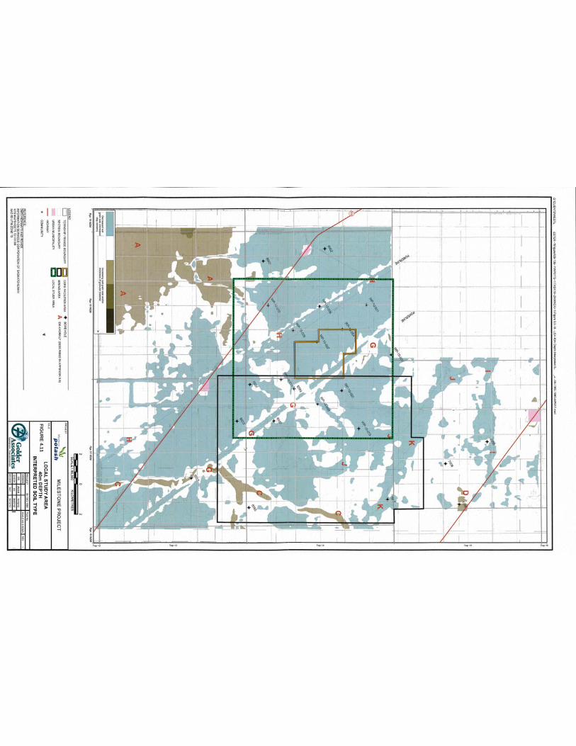
The airborne geophysical survey completed by Fugro showed soil resistivity at 5 m, 20 m and 40 m depths. Low resistivity is consistent with clay type deposits whereas higher resistivity zones are consistent with coarse-grained sand and gravel deposits. Resistivity maps are shown in Figures 4.6-4.8. Interpreted soil types based on the airborne geophysics and borehole data are shown in Figure 4.9-4.11. The pilot project site is considered to be an area of low resistance which is shown through all 3 resistivity slices.
4.4.5 Hydraulic Testing
The hydraulic conductivities of the LSA hydrostratigraphic units were determined from response testing and triaxial permeability testing. Falling head response testing data was used to determine hydraulic conductivity for the Saskatoon Group Aquifer. Hydraulic conductivity values for the Saskatoon Group Aquifer were in the magnitude of 10-5 metres per second.
Hydraulic conductivity values determined for the Bearpaw Formation, Saskatoon Group till, surficial stratified silty clay, and surficial stratified clay were determined from laboratory triaxial permeability testing. Testing yielded hydraulic conductivity values in the order of magnitude of 10-10 m/s for the Bearpaw Formation and Saskatoon Group till, and 10-11 m/s for surficial stratified silty clay, and surficial stratified clay.
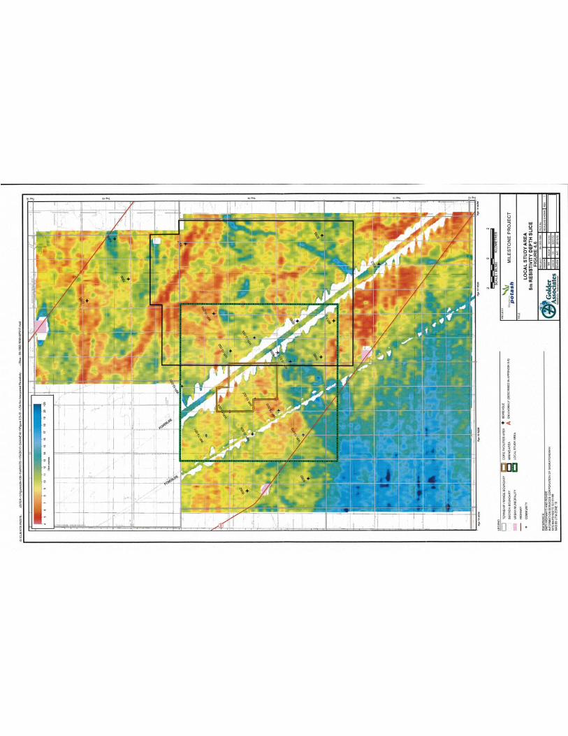
Hydraulic conductivity testing results from Golder (2012) are provided in Table 4.1.
Table 4.1 Hydraulic Testing Results (Golder, 2013)
Borehole *Saskatoon Group Aquifer
**Surfical Stratified Clay
**Surficial Stratified Silty Clay
**Saskatoon Group Till
**Fractured Bearpaw Formation
WP-10-001 1.6E-5 WP-11-208 2.4E-11 WP-11-217 5.0E-11 WP-11-211 1.1E-10 WP-11-218 2.7E-10
* Slug Test ** Triaxial Permeability Test
4.4.6 Hydrostratigraphic Units - LSA
The major hydrostratigraphic units in the LSA are the Bearpaw Formation Sands and the Saskatoon Group Aquifer.
Although the Bearpaw Formation sand members were not identified in the LSA published information suggests they are present in the Regina Area mapsheet. The extend of the Bearpaw sands have not been identified and therefore may be present in the LSA. When present, the Bearpaw sands occur as isolated pockets and do not constitute a primary groundwater aquifer.

FIGURE 4.4
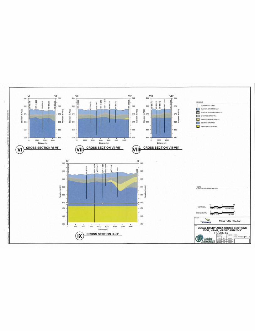
FIGURE 4.5
FI
GU
RE
4.6
FIG
UR
E 4.
7
FI
GU
RE
4.8

FIGU
RE 4.9
Figu
re 4
.10
FIGU
RE 4.11
Milestone Project – Pilot Plant
Page | 13 MARCH 2017
The Saskatoon Group aquifer was encountered in the southeast part of the LSA and a small area along the LSA boundary in the southwest. Aquifer depths ranged from 9.75 to 12.0 m BGS and ranged in thickness from 0.6 m to 7.5 m. Intersection of the aquifer in historical boreholes and further interpretation were used to delineate the boundaries in the southeast of the LSA where it becomes increasingly expansive and reaches a thickness of 9.75m as measured in a historical borehole.
Based on work completed by Clifton Associates (2016) no surficial aquifers were encountered on the Pilot Project site.
44.5 Crystallization Pond Information provided in the Environmental Impact Statement (January 2013) for the Milestone Project was used as part of the basis for design for the Pilot Project crystallization pond.
The Milestone A project proposed Primary + Secondary mining. Primary mining accounted for 2.0 million tpy and product recovery was through mechanical crystallization which would produce salt tailings. The tailings would be contained in a Tailings Management Area Section 3.7 of the EIS describes the TMA features. Secondary mining accounted for 800,000 tonnes of the 2.8 mtpy total production with product recovery being achieved in crystallization pond located beside the TMA.
Geological and hydrogeological site characterization studies identified potential areas for the TMA where primary containment would be provided by natural soils, thereby reducing the reliance on engineered containment systems. Highly plastic clay and underlying clayey till of the lacustrine plains in the vicinity of the project are the main geological units that would inhibit the vertical migration of seepage from the TMA that would have been part of the Milestone A Project.
Based on the analysis of the TMA and the proximity of Milestone Pilot Project site to Milestone A project site, it is reasonable to transfer the TMA seepage analysis interpretation to the crystallization pond for the Milestone Pilot Project.
Information provided in the EIS for Milestone A is summarized below and is used as the basis for assessment of the Pilot Project crystallization pond
4.5.1 Groundwater Flow Model – Methodology
As part of the EIS, geologic units were classified according to their role in the hydrogeologic system. This included a review of existing literature, compilation of historical hydrogeological data, hydraulic testing of geologic units and collection of baseline groundwater hydraulic head and chemistry data. A conceptual hydrogeologic model was developed taking into consideration the information described above and the extent of hydrostratigraphic units described in the geological model. A numerical groundwater flow model was developed based on the site geology and conceptual hydrogeology model and calibrated to observed conditions as a means of interpretation of the groundwater flow system. Geological and hydrogeological site characterization form the basis for the development of a solute transport model that is integral to the design of waste management facilities and the assessment of the groundwater flow pathways in connection with the LSA.
Milestone Project – Pilot Plant
Page | 14 MARCH 2017
The numerical groundwater models are based on the conceptual models. The stratigraphy provides the basic layer structure for the models. The hydraulic conductivity data and estimates are used to assign initial model parameter values.
Given the proximity of the Pilot Project site to the Milestone A project site, and resulting similarity in the stratigraphic nature of both sites, results of the groundwater flow and solute transport are applicable to both locations and is discussed below.
44.5.2 Groundwater Flow Model
Two groundwater flow models were developed for the Milestone A Project corresponding to the local and regional site characterization. The regional scale model extends approximately 60 km from the proposed core facilities area whereas the local scale is focused on the core facilities area and provides greater refinement of the geological conditions beneath the site. The regional model provides a general understanding and approximation of the regional flow patterns which provides initial boundary conditions for the local model and estimates of the hydraulic properties for the principal stratigraphic units. The local model provides increased definition of the hydrostratigraphy in the project area which provides a more refined understanding of flow patterns and potential seepage pathways rom the proposed project site.
In terms of the crystallization pond, only groundwater flow and solute transport modelling for the LSA is presented here. For reference, detailed information about the RSA groundwater flow model is presented in Annex II of the Milestone A Project EIS document.
4.5.3 Pathways Analysis
Impacts analysis for the Crystallization Pond assumes the following:
Crystallization pond dimensions of 416 m x 226 m, approximately 4 m deep with 3m of liquid depth. The pond will be constructed with in situ material;
Pond location is NW20-14-17W2. Geotechnical evaluation identified lacustrine clay overlying glacial till and bedrock shale. Fifteen (15) boreholes were drilled on the pilot plant site in late 2016 to provide
geological and hydrogeological site characterization and to support the design of the crystallization pond.
The location of the boreholes is shown in figure 4.12. The site stratigraphy is shown in figure 4.13.
As part of the 2016 site investigation, attempts were made to determine groundwater levels. No water table was observed in any of the installed piezometers. Since the soil was unsaturated, the piezometers were filled with water approximately three times prior to testing. This is a standard method when unsaturated soil conditions are encountered.
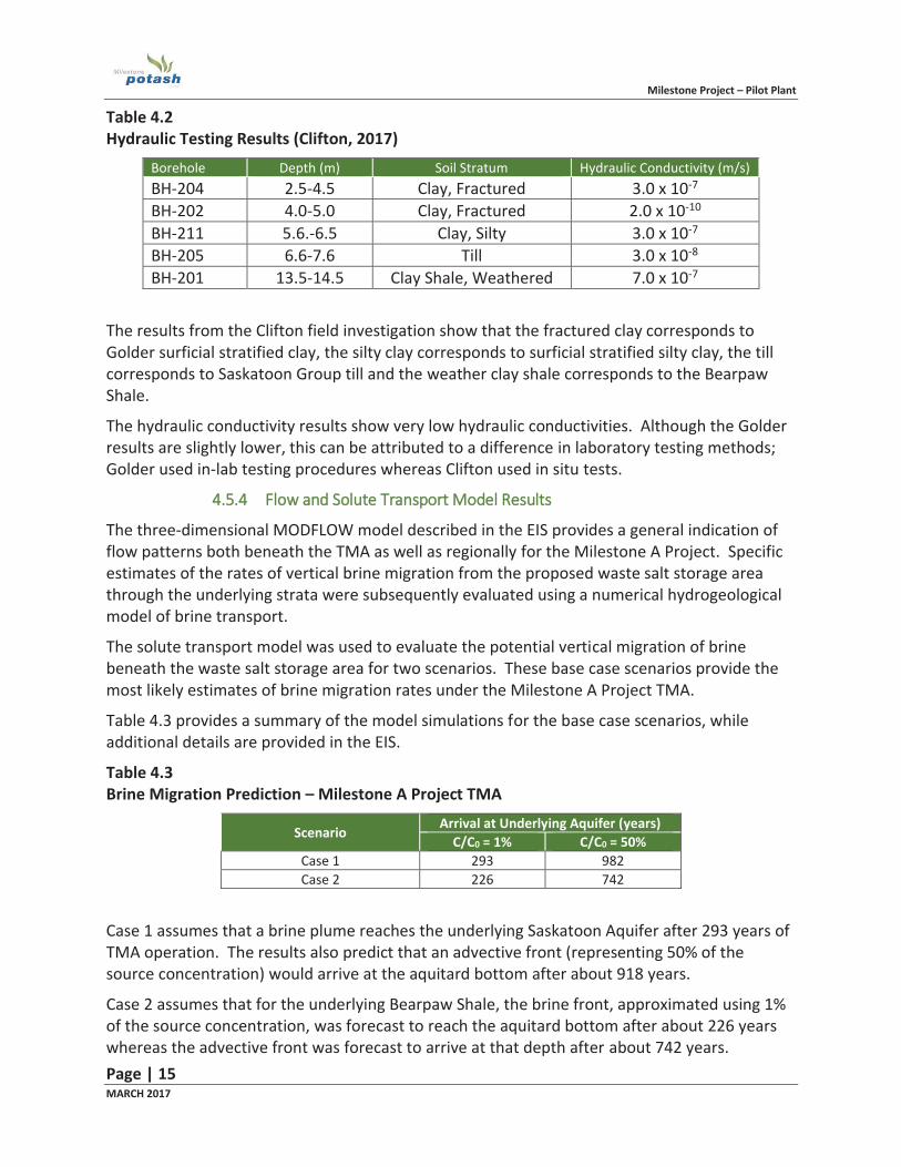
Hydraulic conductivity testing results from Clifton Associates (2017) are shown in table 4.2.
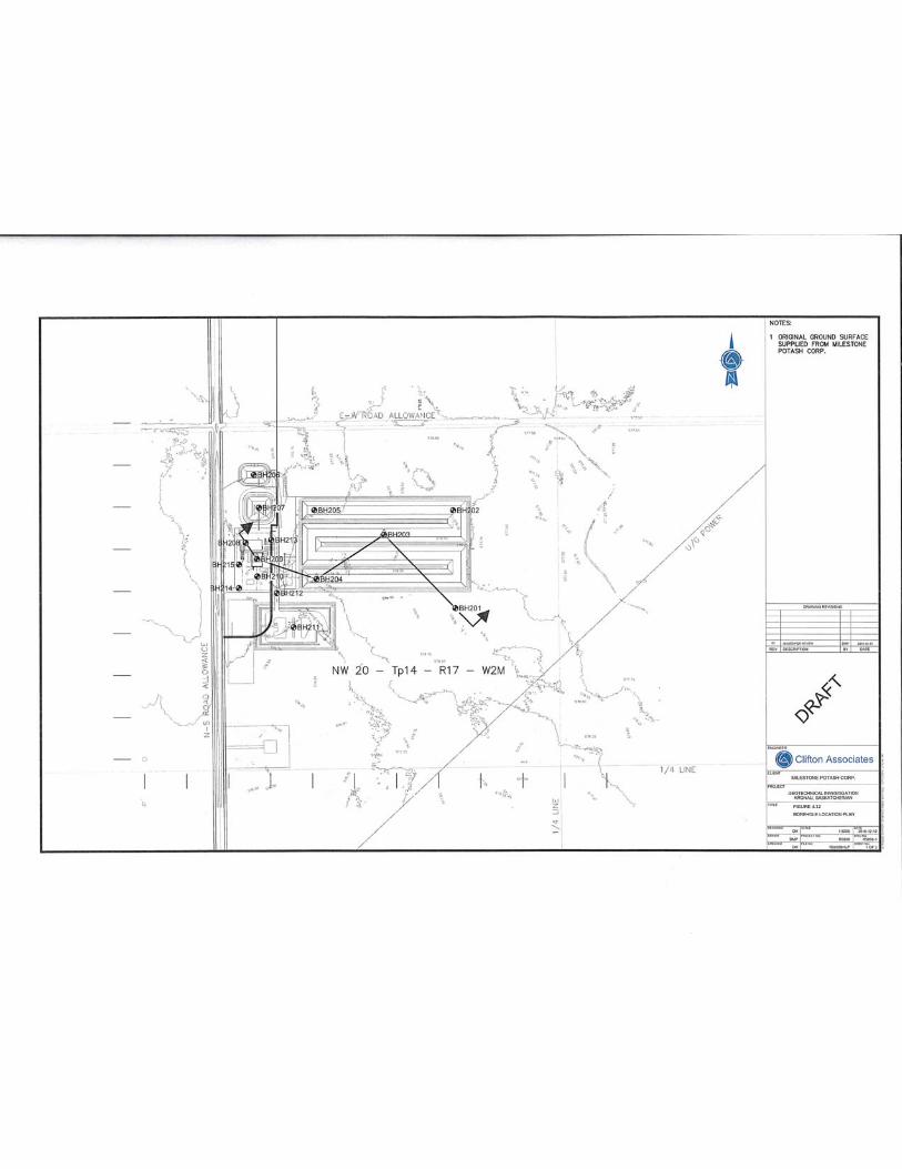
FIGURE 4.12

FIGURE 4.13
PILOT PROJECT LOCATION (2016)
Milestone Project – Pilot Plant
Page | 15 MARCH 2017
Table 4.2 Hydraulic Testing Results (Clifton, 2017)
Borehole Depth (m) Soil Stratum Hydraulic Conductivity (m/s) BH-204 2.5-4.5 Clay, Fractured 3.0 x 10⁻⁷ BH-202 4.0-5.0 Clay, Fractured 2.0 x 10⁻¹⁰
BH-211 5.6.-6.5 Clay, Silty 3.0 x 10⁻⁷
BH-205 6.6-7.6 Till 3.0 x 10⁻⁸ BH-201 13.5-14.5 Clay Shale, Weathered 7.0 x 10⁻⁷
The results from the Clifton field investigation show that the fractured clay corresponds toGolder surficial stratified clay, the silty clay corresponds to surficial stratified silty clay, the tillcorresponds to Saskatoon Group till and the weather clay shale corresponds to the BearpawShale.
The hydraulic conductivity results show very low hydraulic conductivities. Although the Golderresults are slightly lower, this can be attributed to a difference in laboratory testing methods;Golder used in-lab testing procedures whereas Clifton used in situ tests.
44.5.4 Flow and Solute Transport Model Results
The three-dimensional MODFLOW model described in the EIS provides a general indication offlow patterns both beneath the TMA as well as regionally for the Milestone A Project. Specificestimates of the rates of vertical brine migration from the proposed waste salt storage areathrough the underlying strata were subsequently evaluated using a numerical hydrogeologicalmodel of brine transport.
The solute transport model was used to evaluate the potential vertical migration of brinebeneath the waste salt storage area for two scenarios. These base case scenarios provide themost likely estimates of brine migration rates under the Milestone A Project TMA.
Table 4.3 provides a summary of the model simulations for the base case scenarios, whileadditional details are provided in the EIS.
Table 4.3Brine Migration Prediction – Milestone A Project TMA
Scenario Arrival at Underlying Aquifer (years)C/C0 = 1% C/C0 = 50%
Case 1 293 982Case 2 226 742
Case 1 assumes that a brine plume reaches the underlying Saskatoon Aquifer after 293 years of TMA operation. The results also predict that an advective front (representing 50% of the source concentration) would arrive at the aquitard bottom after about 918 years.
Case 2 assumes that for the underlying Bearpaw Shale, the brine front, approximated using 1% of the source concentration, was forecast to reach the aquitard bottom after about 226 years whereas the advective front was forecast to arrive at that depth after about 742 years.
Milestone Project – Pilot Plant
Page | 16 MARCH 2017
The groundwater flow and solute transport modelling work completed by Golder suggests solute breakthrough from the TMA to the underlying Saskatoon Group aquifer and Bearpaw Shale will occur after several hundred years. Considering the similar nature of the hydraulic conductivities for the Pilot Plant site and the Milestone A Project site, it can be expected that groundwater flow from the crystallization pond may behave in a similar manner. However, given the lower hydraulic head pressures that will be present in the crystallization pond (only about 3 m depth/head) any seepage from the crystallization pond is not likely to move as fast as predicted from the Milestone A Project TMA. In addition, there are no shallow aquifers (Saskatoon Group sands) on the Pilot Project site, and therefore, no groundwater receptors.
44.5.5 CCrystallization Pond Construction
The geology and hydrogeology of the LSA provides natural containment from potential brine seepage from the crystallization pond. As such, synthetic liners or modified geosynthetic liners would not provide significant additional containment.
Highly plastic clay soils such as those present at the Pilot Plant project site tend to consolidate in the presence of brine. Brine invasion would tend to therefore increase the hydraulic conductivity of the in situ soils to some extent. The bulk of the lateral flow would be expected to be within the upper 4 to 5 m of the highly plastic clay strata.
As part of the site application construction process, detailed designs will be submitted to Ministry of Environment. For the crystallization pond, the existing topsoil will be stripped and stockpiled. The underlying clay will be scarified and re-compacted. Existing clay will be used to construct the pond berms. Proper erosion protection will be provided on the inside and outside slopes of the crystallization pond.
Monitoring wells will be installed on the outside of the crystallization pond. The wells will be competed at various depths to monitor potential brine seepage. In the event of brine seepage, remedial action will be undertaken and would likely involve excavation of a perimeter trench with recompacted clay or a perimeter cutoff wall. However, given the short duration of the Pilot Project (12 years) and the relatively long time for brine migration, it is unlikely that brine seepage from the crystallization pond will occur before pond decommissioning.
4.6 Water Supply 4.6.1 Supply Options
In 2012 Western Potash Corp and the City of Regina entered into an agreement whereby the City of Regina would supply treated effluent to Western Potash Corp for it’s Milestone A Project. The agreement remains binding.
The Pilot Plant requires substantially less water (1,000 m3/day) than the Milestone A Project. Therefore, construction of a pipeline from the City of Regina Wastewater Treatment Plant to the Milestone site is not financially feasible for the Pilot Project. Western Potash Corp evaluated several options for water supply for the Pilot Project including:
Shallow groundwater; Domestic water wells;
Milestone Project – Pilot Plant
Page | 17 MARCH 2017
Community of White City supply; Local Surficial water including Wascana Creek; Deep Aquifer (Mannville); Trucking water from City of Regina.
SShallow Groundwater
In late 2015, Western Potash drilled a well into the Judith River Aquifer near the Milestone A Project site. The well did not produce sufficient water volumes. It was determined that local surficial aquifers would not provide a sustainable water supply for the Pilot Project.
Domestic Water Wells
Using a domestic (potable) water supply would use water from one of the local municipalities. Although there are pipelines in the area which provide potable water, none have the capacity to meet the requirements of the pilot plant. Further, all of the existing systems provide potable water with a higher cost of $3 to $5/m3 compared to about $0.65/m3 or less for raw water.
The only domestic supply system in the area with sufficient capacity is in the Regina area. Tying into the Regina system would require a pipeline similar to one from the City of Regina wastewater treatment facility, which, when combined with the higher usage fee would make this option less desirable that the wastewater treatment plant option.
White City Supply
SaskWater was engaged to discuss the option of supply water to the site from their pumping stations located at White City Sk. This would require a 35 km long pipeline to be constructed from White City to the Pilot Plant site. The cost of a water line from White City is $14 million and would only be able to supply water for the Pilot Plant; it would not be able to supply additional volumes for an expanded facility.
Local Surficial Water Including Wascana Creek
Wascana Creek flows east-west about five km north of the Pilot Project site location.
Historical hydrographs of water flow in Wascana Creek were assessed as part of this option evaluation. Pumping a sufficient volume of water from Wascana Creek is contingent upon spring runoff.
Typically, there will be a window of approximately 6-12 weeks to pump the required volume of water from Wascana Creek. Water pumped from Wascana Creek could be supplemented with increased surface runoff diversion. In a year with a dry winter, the volume of water available to be removed from the Creek may not be sufficient to meet the needs of the plant.
Additionally, the water source that would be used as a contingency are local sloughs and they are also dependent on spring runoff. In a dry year, such as 2016, sloughs can dry up and there could be insufficient flow in Wascana Creek to satisfy the water requirements. A substantial water storage pond (one-year supply) is also needed. Therefore, this option is not considered feasible.
Milestone Project – Pilot Plant
Page | 18 MARCH 2017
DDeep Aquifer-Mannville
An extensive evaluation of the deep aquifers was conducted by RPS Energy. RPS evaluated all exploration boreholes and 3D seismic data from the Milestone Project to determine the availability of water. The assessment suggests that sufficient volumes of water may be available near exploration hole #9/10 located near section 34-13-17W2. This area is located about 7.5 km southeast of the Pilot Project site.
A Manville well would involve using oilfield equipment to drill the well, recovering Mannville sediments for analysis and screen design and pump test. If the pump test determined that the well could produce sufficient and sustainable volumes, then an underground HDPE pipeline (4 inch or 6 inch) would be constructed from the wellhead to the Pilot Project site.
Trucking Water from City of Regina
Approximately 25 truckloads of water per day would be required. However, the ongoing costs would be over $3 million per year. Trucking water could be done during emergency situations (well maintenance etc.) or to supplement one of the other options, but is not considered a feasible option by itself.
4.6.2 Preferred Water Supply Option
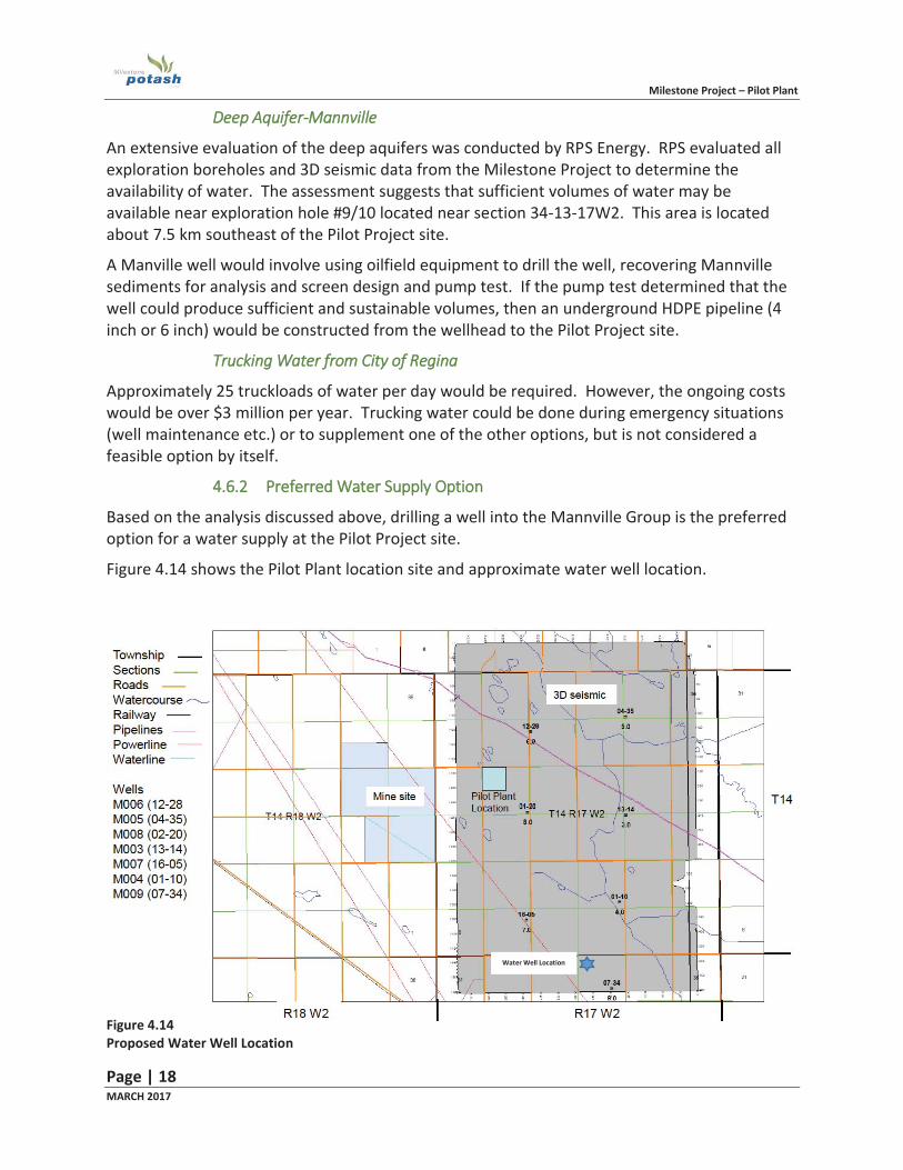
Based on the analysis discussed above, drilling a well into the Mannville Group is the preferred option for a water supply at the Pilot Project site.
Figure 4.14 shows the Pilot Plant location site and approximate water well location.
Figure 4.14 Proposed Water Well Location
Water Well Location
Milestone Project – Pilot Plant
Page | 19 MARCH 2017
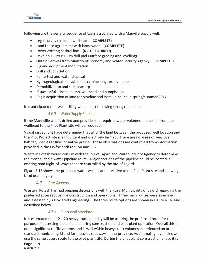
Following are the general sequence of tasks associated with a Manville supply well.
Legal survey to locate wellhead – (COMPLETE) Land Lease agreement with landowner – (COMPLETE) Lower existing Sasktel line – (NOT REQUIRED) Develop 130m x 130m drill pad (surface grading and levelling) Obtain Permits from Ministry of Economy and Water Security Agency – (COMPLETE) Rig and equipment mobilization Drill and completion Pump-test and water disposal Hydrogeological analysis to determine long term volumes Demobilization and site clean-up If successful – install pump, wellhead and pumphouse Begin acquisition of land for pipeline and install pipeline in spring/summer 2017.
It is anticipated that well drilling would start following spring road bans.
44.6.3 Water Supply Pipeline
If the Mannville well is drilled and provides the required water volumes, a pipeline from the wellhead to the Pilot Plant site will be required.
Visual inspections have determined that all of the land between the proposed well location and the Pilot Project site is agricultural and is actively farmed. There are no areas of sensitive habitat, Species at Risk, or native prairie. These observations are confirmed from information provided in the EIS for both the LSA and RSA.
Western Potash would consult with the RM of Lajord and Water Security Agency to determine the most suitable water pipeline route. Major portions of the pipeline could be located in existing road Right-of-Ways that are controlled by the RM of Lajord.
Figure 4.15 shows the proposed water well location relative to the Pilot Plant site and showing Land use imagery.
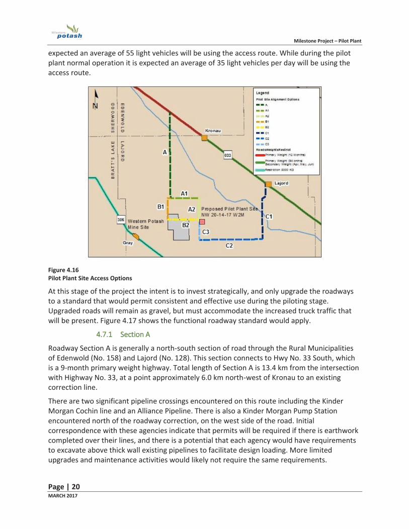
4.7 Site Access Western Potash has had ongoing discussions with the Rural Municipality of Lajord regarding the preferred access routes for construction and operations. Three main routes were examined and assessed by Associated Engineering. The three route options are shown in Figure 4.16. and described below.
4.7.1 Functional Standard
It is estimated that 12 – 20 heavy trucks per day will be utilizing the preferred route for the purpose of accessing the pilot site during construction and pilot plant operation. Overall this is not a significant traffic volume, and is well within heavy truck volumes experienced on other standard municipal grid and farm access roadways in the province. Additional light vehicles will use the same access route to the pilot plant site. During the pilot plant construction phase it is
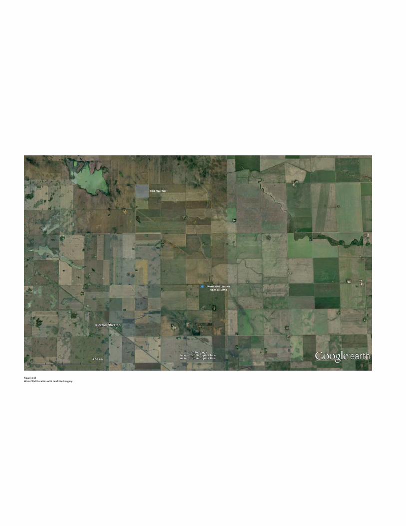
Figure 4.15Water Well Location with Land Use Imagery
Pilot Plant Site
Water Well LocationNE34-13-17W2
Milestone Project – Pilot Plant
Page | 20 MARCH 2017
expected an average of 55 light vehicles will be using the access route. While during the pilot plant normal operation it is expected an average of 35 light vehicles per day will be using the access route.
Figure 4.16 Pilot Plant Site Access Options
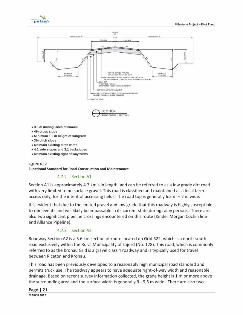
At this stage of the project the intent is to invest strategically, and only upgrade the roadways to a standard that would permit consistent and effective use during the piloting stage. Upgraded roads will remain as gravel, but must accommodate the increased truck traffic that will be present. Figure 4.17 shows the functional roadway standard would apply.
44.7.1 Section A
Roadway Section A is generally a north-south section of road through the Rural Municipalities of Edenwold (No. 158) and Lajord (No. 128). This section connects to Hwy No. 33 South, which is a 9-month primary weight highway. Total length of Section A is 13.4 km from the intersection with Highway No. 33, at a point approximately 6.0 km north-west of Kronau to an existing correction line.
There are two significant pipeline crossings encountered on this route including the Kinder Morgan Cochin line and an Alliance Pipeline. There is also a Kinder Morgan Pump Station encountered north of the roadway correction, on the west side of the road. Initial correspondence with these agencies indicate that permits will be required if there is earthwork completed over their lines, and there is a potential that each agency would have requirements to excavate above thick wall existing pipelines to facilitate design loading. More limited upgrades and maintenance activities would likely not require the same requirements.
Milestone Project – Pilot Plant
Page | 21 MARCH 2017
Figure 4.17 Functional Standard for Road Construction and Maintenance
44.7.2 Section A1
Section A1 is approximately 4.3 km’s in length, and can be referred to as a low grade dirt road with very limited to no surface gravel. This road is classified and maintained as a local farm access only, for the intent of accessing fields. The road top is generally 6.5 m – 7 m wide.
It is evident that due to the limited gravel and low grade that this roadway is highly susceptible to rain events and will likely be impassable in its current state during rainy periods. There are also two significant pipeline crossings encountered on this route (Kinder Morgan Cochin line and Alliance Pipeline).
4.7.3 Section A2
Roadway Section A2 is a 3.6 km section of route located on Grid 622, which is a north-south road exclusively within the Rural Municipality of Lajord (No. 128). This road, which is commonly referred to as the Kronau Grid is a gravel class 4 roadway and is typically used for travel between Riceton and Kronau.
This road has been previously developed to a reasonably high municipal road standard and permits truck use. The roadway appears to have adequate right-of-way width and reasonable drainage. Based on recent survey information collected, the grade height is 1 m or more above the surrounding area and the surface width is generally 9 - 9.5 m wide. There are also two
3.5 m driving lanes minimum 4% cross slope Minimum 1.0 m height of subgrade 3% ditch slope Maintain existing ditch width 4:1 side slopes and 3:1 backslopes Maintain existing right of way width
Milestone Project – Pilot Plant
Page | 22 MARCH 2017
significant pipeline crossings encountered on this route (Kinder Morgan Cochin line and Alliance Pipeline).
44.7.4 Section B1
Roadway Section B1 is a 3.7 km section of route that runs primarily north south. This road is classified and maintained as a farm access, and has a built up grade with reasonable surface gravel being evident.
4.7.5 Section B2
Roadway Section B2 is a 5.2 km section of route located in a currently undeveloped section of municipal road allowance. There is essentially no roadway embankment here, and this section can be best described as requiring greenfield construction.
There are several large low and wet areas present that have been highly affected by previous wet periods in this section. Based on the lack of existing roadway grade combined with low areas and wet soil conditions, construction in this area will be more challenging and costly than other options.
4.7.6 Section C1
All three segments of Section C are completely within the R.M. of Lajord. Roadway Section C1 is an 8.9 km section of route that runs north south, and ties into the south edge of the community of Lajord. There is only one apparent residence along this section of route, adjacent to the intersection of Hwy 33
This roadway is designated as a Class 5 rural road, which typically indicates that it was built to accommodate truck traffic. A local seed plant hauls on this road, and there is indication that it experiences both higher traffic amounts and truck traffic than segments C2 and C3.
Roadway sections identified as section C have not been surveyed and as such no plan profiles have been generated. The existing road top was measured via tape measure at 10 m overall and the surface shows a hardened surface with limited loose surface gravel.
The embankment appears to be built to an acceptable geometric standard for the intended use, and drainage and ditching appear to be typical for the area. There is a sign posted near the Highway 33 intersection that indicates the road is rated for primary weights.
4.7.7 Section C2
Roadway Section C2 is a 9.7 km section of road that runs east west. There is one residence located along this section of route, and that home appears to be set back a reasonable distance from the roadway.
Field observations indicate that the road has been built up to a reasonable secondary grid standard, and currently has a top width of approximately 7.3 m. Overall this segment was in good condition at the time of inspection, and measurements indicate that grade height and ditch widths appears to be reasonable for use with the limited amount of additional expected truck traffic. Note that there are also two significant pipeline crossings encountered on this section (Kinder Morgan Cochin line and Alliance Pipeline).
Milestone Project – Pilot Plant
Page | 23 MARCH 2017
44.7.8 Section C3
Roadway Section C3 is a 3.3 km section of route that runs north south and terminates at the pilot site. Section C3 and Section A2 are both segments of the Kronau Grid and meet at the pilot site. There is one residence located along this section of route, and that home appears to be set back a reasonable distance from the roadway.
Field measurements indicated a top width of 9 m + and similar to Section A2, this section is built up to a reasonably high standard with adequate ditching and drainage. At the time of inspection, it was sufficiently gravelled for its current intended use.
4.7.9 Preferred Option
Based on discussions with the RM of Lajord, the preferred Pilot Plant site access option is route A/A1/A2. This route has been agreed to in principle between the RM of Lajord and Western Potash. Consultations will be held with the RM of Edenwold regarding the small portion of segment A2 that is located just south of Highway #33 (Figure 4.16).
Milestone Project – Pilot Plant
Page | 24 MARCH 2017
55.0 Consultations
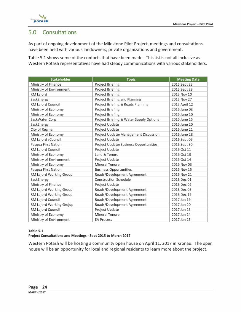
As part of ongoing development of the Milestone Pilot Project, meetings and consultations have been held with various landowners, private organizations and government.
Table 5.1 shows some of the contacts that have been made. This list is not all inclusive as Western Potash representatives have had steady communications with various stakeholders.
Stakeholder Topic Meeting Date
Ministry of Finance Project Briefing 2015 Sept 23 Ministry of Environment Project Briefing 2015 Sept 29 RM Lajord Project Briefing 2015 Nov 10 SaskEnergy Project Briefing and Planning 2015 Nov 27 RM Lajord Council Project Briefing & Roads Planning 2015 April 12 Ministry of Economy Project Briefing 2016 June 03 Ministry of Economy Project Briefing 2016 June 10 SaskWater Corp Project Briefing & Water Supply Options 2016 June 15 SaskEnergy Project Update 2016 June 20 City of Regina Project Update 2016 June 21 Ministry of Economy Project Update/Management Discussion 2016 June 28 RM Lajord /Council Project Update 2016 Sept 09 Pasqua First Nation Project Update/Business Opportunities 2016 Sept 30 RM Lajord Council Project Update 2016 Oct 11 Ministry of Economy Land & Tenure 2016 Oct 13 Ministry of Environment Project Update 2016 Oct 14 Ministry of Economy Mineral Tenure 2016 Nov 03 Pasqua First Nation Business Opportunities 2016 Nov 15 RM Lajord Working Group Roads/Development Agreement 2016 Nov 21 SaskEnergy Construction Schedule 2016 Dec 01 Ministry of Finance Project Update 2016 Dec 02 RM Lajord Working Group Roads/Development Agreement 2016 Dec 05 RM Lajord Working Group Roads/Development Agreement 2016 Dec 19 RM Lajord Council Roads/Development Agreement 2017 Jan 19 RM Lajord Working Grojup Roads/Development Agreement 2017 Jan 20 RM Lajord Council Project Update 2017 Jan 23 Ministry of Economy Mineral Tenure 2017 Jan 24 Ministry of Environment EA Process 2017 Jan 25
Table 5.1 Project Consultations and Meetings - Sept 2015 to March 2017
Western Potash will be hosting a community open house on April 11, 2017 in Kronau. The open house will be an opportunity for local and regional residents to learn more about the project.
Milestone Project – Pilot Plant
Page | 25 MARCH 2017
66.0 Summary
In January 2013, Western Potash received Ministerial Approval under the terms and conditions of the Government of Saskatchewan’s The Environmental Assessment Act for a proposed 2.8 million tonne per year potash solution mine known as ‘The Milestone Project’.
Subsequent to the 2013 Approval, global potash economics experienced a substantial decrease and resulted in reduced capital expenditures for new and existing potash developments. Although the Milestone Project is recognized as a world-class deposit, Western Potash identified the need to develop the project under a new paradigm given the challenging market conditions.
In 2015 Western Potash commissioned a Scoping Study to evaluate the feasibility of a Pilot Project to extract the Milestone Project resource using a ‘Selective’ solution mining methodology. Selective solution mining utilizes horizontal drilling technology and the injection of water that is near saturated with NaCl. The purpose of the Pilot Project is to test, evaluate and optimize the conceptual horizontal solution mining method and to investigate how the method can be applied to full-scale potash production.
The Scoping Study provided a high-level assessment of the project and was used in support of an application to Ministry of Environment-Environmental Assessment Branch in 2015. The project was reviewed by MOE and received a “Ministerial Change Approval Pursuant to Section 16(2)(a) of The Environmental Assessment Act” (approval dated 10 September, 2015).
Subsequent to the Scoping Study, Western Potash commissioned AMEC Foster Wheeler to complete an AACE Class 3 design (+/- 10%) for the project. The project is based on the Scoping Study but contains some design changes, notably;.
Use of a crystallization pond instead of mechanical evaporation and crystallization for KCl recovery;
Project Location; and, Location of water source well.
The three changes are considered minor in nature in terms of potential environmental effects.
The location has been moved adjacent to the wellfield in order to minimise piping distances and transport of fluids. The location change is in fact considered a positive environmental benefit to the project as described in the Scoping Study. The location of the wellfield and plant site is on agricultural land that does not contain sensitive habitat or Species at Risk.
The introduction of a crystallization pond has potential environmental effects in terms of brine migration. A site characterization program completed in late 2016 determined that the shallow stratigraphy at the project site generally consists of, in descending order, clay, till and Bearpaw shale and provides natural containment due to the low hydraulic conductivity of the underlying stratrigraphic units. Extensive groundwater flow and solute transport modelling completed as part of the EIS for the ‘Milestone A’ Project suggested that brine migration in the Local Study Area will take up to several hundred years to migrate appreciable distances. It can be
Milestone Project – Pilot Plant
Page | 26 MARCH 2017
concluded that brine migration rates will be similar or less at the Pilot Plant location given the nature of the stratigraphy.
The preferred water source for the Pilot Project is a Mannville water well located about 7.5 km from the project site. Mannville water is highly mineralized and not of potable quality but is of sufficient quality for solution mining. Drilling a well is anticipated in the spring of 2017. If hydrogeological testing determines that the well can provide sufficient water volumes, a pipeline from the wellhead to the project site would be completed in conjunction with local landowners and the Rural Municipality of Lajord.
This document provides a description of the current Pilot Project based on the Amec Foster Wheeler design and emphasizes the three main changes to the approved Pilot Project (Sept, 2015 approval). This submission is meant to supplement the Project Description for the Scoping Study design which was provided to Ministry of Environment in 2015 and approved in September, 2015.
Milestone Project – Pilot Plant
Page | 27 MARCH 2017
RReferences
Associated Engineering (2017). Milestone Potash Corp. Milestone Pilot Plant Access Roadway. February 2017.
Clifton Associates Ltd. (2017). DRAFT Milestone Potash Corp. Pilot Plant Geotechnical Investigation NW20-TP14-RG17-W2M Kronau SK. File R5808. February 2017.
AMEC Foster Wheeler (2016). Milestone Pilot Plant Project. 100194-P000-BA10-RPT-0001. Prepared for Milestone Potash Corp.
Western Potash Corp. (2015). Project Proposal – Western Potash Corp Milestone Solution Mine Pilot Project. Submitted to Saskatchewan Ministry of Environment, Environmental Assessment Branch.
Golder Associates Ltd. (2013). Milestone Potash Project Environmental Impact Statement. Prepared for Western Potash Corp.