mill safe start miii - sdg technologies motor, especially if ... any earth fault on the motor /...
TRANSCRIPT

Mill Safety Start System Mark III
Mill Safe Start MIII
• Protecting the largest LRS-started mills since 2010.
• Generation III Mill Safe Start: o Still the only proven real-time locked
charge protection for grinding mills started with LRS.
o Extensive specialized rotor protection functions focused on grinding mills applications.
o LRS dipper speed control for optimized start-up.
o Comprehensive analysis of each start-up, now including R-trace.
o Pre-empt electrical and mechanical problems by taking corrective action expediently.

Mill Safety Start System
Backgound “extra care must be taken in the launching of the largest vessels, so as to avoid the peril of the big ship splitting apart under their own great weight.” “Nature cannot produce a horse as large as twenty ordinary horses,” “Likewise the current belief that, in the case of artificial machines the very large and the small are equally feasible and lasting is a manifest error.” – from Two New Sciences by Galileo Galilei. Economics favours bigger grinding mills. The strength of steel limits the maximum feasible size of the geared grinding mill. Geared grinding mills today push these limits. Extra care therefore needs to be exercised to minimize the torque transients and shock loads these giant geared mills are subjected to.
The two biggest transient events that a geared grinding mill is subjected to are torque transients during start-up, and a locked charge incident, also called a drop charge. The Mill Safety Start addresses both of these concerns. The need for locked charge protection is reflected in the 2004 proceedings published by the Society for Mining, Metallugy and Exploration based in Littleton, Colorado, USA: “The installation of a locked charge protection system is critical for large diameter SAG and ball mills.” Dropped charge incidents are still occurring despite rigid barring regimes prior to starting.
The Mill Safety Start System calculates the ore angle in real time during the start-up, and the mill is tripped if the ore is cemented, before it can drop and damage the mill bearings and structure. Specialized rotor side protection detects conditions not possible from stator side protection. Although liquid resistance starting is a mature technology, it is being applied to more demanding big mill starting applications today than ever before. Starting problems can result in the application of high torque transients to the mill gearbox, pinion gear and girth gear with damaging results. Similarly, high rotor current spikes can cause electrical motor problems. By recording the rotor currents at start-up, comprehensive liquid resistance starter performance analysis can be done, ensuring the early detection of liquid resistance starter problems and enabling corrective action to prevent damage to electrical motors, gearboxes, pinion gears and girth gear. Additionally, with clever control of the LRS dipper speed, the torque curve during starting may be optimized and some problems solved.
2
Safety Start Steps: 1. Mill is started. 2. Locked charge protection relay protects against
cemented charge dropping and damaging mill. 3. Optimizes troque trace with dipper speed control. 4. Limit damage in case of slipring flash or failure. 5. Control room operator sees a mimic indicating
mill and ore angle in real time, with an intuitive graph telling exactly how safe (or unsafe) the start was.
6. Comprehensive recordings are transferred via Internet to the SDG Mill Safety Start server.
7. The startup is evaluated from the recordings, including liquid resistance starter performance and locked charge protection relay functioning.
8. A report is generated and emailed to all authorized persons.
9. All information easily available in web interface.
Mill Safety Start

Mill Safety Start System
Rotor Protection
• Specialized rotor side protection.
• Specialized protection focused on Grinding Mill applications.
• Achieve speed and sensitivity not obtainable with standard stator-side protection.
• Minimize damage, in many cases enabling in situ repair, avoiding motor change-out and drastically reducing downtime.
• Detailed flagging via simple panel indicators and HMI instructions enables quick first line fault finding even before detailed trace analysis and prevent operator error.
• Detailed COMTRADE traces available online or from HMI.
• Based on many years of detailed event recordings from previous Mill Safe Start generations.
Overview
After many years of analyzing rotor side recordings of the start-ups of grinding mills and witnessing many rotor side electrical faults, it became clear that several mill-focused rotor side specialized protection functions would greatly enhance the primary stator-side protection, in many cases preventing or greatly reducing damage and down-time. Apart from the Locked Charge Protection function, the Mill Safe Start also includes the following protection functions:
1. Mill Jammed (Special Locked Rotor protection) 2. Slip ring or Motor Flash. ( Special Rotor E/F) 3. LRS Flash (Overcurrent, quick dI/dt) 4. Torque too high. (Time-adaptive Overcurrent)
Although analogues can be made with standard IEC and IEEE protection elements, it should be realized that tailoring the protection to the rotor circuit on the mill-specific application presents unique opportunities and comes with unique challenges. For example, the frequency of the rotor circuit varies widely, and it is therefore not possible to use standard protection algorithms that assume a fixed system frequency. Each fault condition is clearly indicated by a panel pilot light and on the HMI, ensuring accurate fault identification.
Mill Jammed While a locked rotor is no problem on a squirrel cage motor, it has associated complications on a wound rotor induction motor, especially if driving a grinding mill. A locked rotor condition has been found more commonly at Mill Safe Start sites than would have been suspected, due to problems with barring/inching gear interlocks or main gear problems. Without the Mill Jammed protection, the LRS dippers continues to move down, increasing torque, and the stator side protection trips only by the time it reaches a high enough current to trip on overload. This is extremely undesirable and leads for example to barring/inching motors exploding, pitted slip-rings which causes excessive brush wear leading to slip-ring flashing, or broken mechanical couplings or gears.
3
The Mill Safe Start “Mill Jammed” element measures the motor speed by means of the rotor current frequency, and implements a Mill Jammed protection that trips the mill immediately if the mill does not speed up within a short time after application of power.
Slip Ring Flash/ Rotor fault This is one of the most common rotor circuit faults and more often than not causes much damage, necessitating change-out of the motor. Excessive brush wear can start unexpectedly, and can generate enough carbon dust in a short period to cause a slip-ring flash on the next start-up. If the motor is tripped in time there is a good chance that the slip-ring compartment can be cleaned out, any slip-ring damage polished out and the motor restarted. Other faults can often be repaired in situ if the motor is tripped before major damage is done. A typical example of an easily repairable fault experienced at MSS sites includes a failure of the bracket keeping the bars in place between the windings and the slip rings. However, typically the standard stator-side motor protection only trips the motor when enough damage has been done to necessitate a change-out of the motor, resulting in much more downtime. The Mill Safe Start measuring position on the rotor side between the motor and the LRS affords a unique opportunity to detect the fault immediately (within 1ms) and issue an instantaneous trip. The rotor windings are not earthed in the motor, the only path to earth is therefore through the LRS. Any earth fault on the motor / slip-ring side of the Mill Safe Start CTs can therefore instantaneously be detected,
Mill Safety Start System
Rotor Protection (continued 1)
as some current will bypass the CTs, flowing from the earth fault directly to earth, and the sum of the CTs will therefore not be zero as it should be. As there are high resistances in the rotor circuit at this point limiting fault current, it is generally not possible from the stator side to detect the single phase earth fault, and the motor is only tripped when the fault has developed into a three phase fault, and even then the standard overcurrent protection is slow enough to ensure extensive damage. (Depending on the motor speed, i.e. rotor voltage, at the time when the earth fault develops into a 3ph fault. If early enough in the start-up, there is a chance to trip I>>, else there is no way to avoid a lengthy IDMT and much damage with conventional protection.)
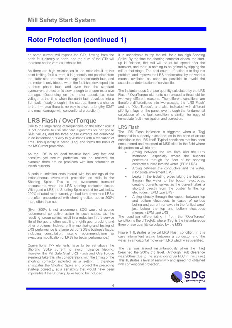
LRS Flash / OverTorque Due to the large range of frequencies on the rotor circuit it is not possible to use standard algorithms for per phase RMS values, and the three phase currents are combined in an instantaneous way to give traces with a resolution of 1ms. This quantity is called |Tag| and forms the basis of the MSS rotor protection. As the LRS is an ideal resistive load, very fast and sensitive yet secure protection can be realized, for example there are no problems with iron saturation or inrush currents. A serious limitation encountered with the settings of the instantaneous overcurrent protection on mills is the Shorting Spike. This is the overcurrent transient encountered when the LRS shorting contactor closes. With good a LRS the Shorting Spike should be well below 200% of rated rotor current, yet bad turn-down ratio LRS’s are often encountered with shorting spikes above 200% more often than not. (Even 300% is not uncommon. SDG would of course recommend corrective action in such cases, as the resulting torque spikes result in a reduction in the service life of the gears, often resulting in girth gear cracking and other problems. Indeed, online monitoring and testing of LRS performance is a large part of SDG’s business focus, including consultation, issuing recommendations or executing modification of LRSs for better performance.) Conventional I>> elements have to be set above the Shorting Spike current to avoid nuisance tripping. However the Mill Safe Start LRS Flash and OverTorque elements take this into consideration, with the timing of the shorting contactor included as a setting. It therefore anticipates the Shorting Spike and protect the preceding start-up correctly, at a sensitivity that would have been impossible if the Shorting Spike had to be included.
4
It is undesirable to trip the mill for a too high Shorting Spike. By the time the shorting contactor closes, the start-up is finished, the mill will be at full speed after the transient, and there is nothing to be gained by tripping the mill at that stage. The best course of action is to flag this problem, and improve the LRS performance by the various means available as soon as possible to avoid the associated deterioration of service life. The instantaneous 3 phase quantity calculated by the LRS Flash / OverTorque elements can exceed a threshold for two very different reasons. The different conditions are therefore differentiated into two classes, the “LRS Flash” and the “OverTorque”, and also indicated with different pilot light flags on the panel, even though the fundamental calculation of the fault condition is similar, for ease of immediate fault investigation and correction.
LRS Flash The LRS Flash indication is triggered when a |Tag| threshold is suddenly exceeded, as in the case of an arc condition in the LRS itself. Typical conditions that has been encountered and recorded at MSS sites in the field where this protection will trip are:
• Arcing between the live bars and the LRS metalwork, especially where the busbars penetrates through the floor of the shorting contactor cubicle into the water. (EPM LRS)
• Arcing between the conductors and the water. (Horizontal movement LRS)
• Leaks in the isolating pipes taking the busbars through the water to the bottom electrodes, creating currents spikes as the current takes a shortcut directly from the busbar to the top electrodes. (EPM type LRS)
• Arcing directly through the vapour between top and bottom electrodes, in cases of serious boiling and current run-away in the “critical area” just before the top and bottom electrodes merges. (EPM type LRS)
The condition differentiating it from the “OverTorque” condition is the d|Tag|/dt, where |Tag| is the instantaneous three phase quantity calculated by the MSS. Figure 1 illustrates a typical LRS Flash condition, in this case intermittent arcing between a conductor and the water, in a horizontal movement LRS which was overfilled. The trip was issued instantaneously when the |Tag| breached the 200% trip level. (Although fault clearance was 200ms due to the signal going via PLC in this case.) This illustrates a level of sensitivity and speed not obtained with conventional protection.

Mill Safety Start System
Rotor Protection (continued 2)
Figure 1 OverTorque The OverTorque indication is triggered when a |Tag| threshold is immediately exceeded at energization, or else slowly exceeded by ramping up. Typical conditions that has been encountered at MSS sites in the field where this protection will trip are:
• LRS dipper position not at top/start position when motor energized.
• LRS dippers move down too quickly.
• Electrolyte concentration too high.
• Electrolyte too hot. Having a different flag for LRS Flash and OverTorque aids quick first line fault finding on site, even before detailed analysis of the recorded traces.
Figure 2 illustrates an OverTorque trip, in this case a mill jammed condition tripped on by a Generation I Mill Safe Start that was not equipped with the Mill Jam protection. The LRS moved down with the mill jammed, and was tripped when the torque reached the setting of 150%, preventing mechanical damage in this case.
5
Figure 2

Mill Safety Start System
LRS dipper speed control
Note1: The first and second Mill Safe Start torque traces demonstrate the control possible over the current rise in the critical area (inside ovals, as indicated). Apart from the disappearance of the critical area current rise due to the proper speed control of the dippers, the second LRS also has a very much smaller (almost negligible) shorting spike. This is incidental, and not a consequence of the dipper speed control. It is simply because the second LRS has a much better performance, with a Turn Down Ratio in excess of 200/1.
Dipper movement The movement of the LRS electrodes was at a constant speed in the past, simply because this was the simplest. As the resistance of the LRS changes, the torque/speed curve of the motor is changed. It is obvious from the family of torque/speed curves of a wound rotor induction motor that the same absolute unit of resistance change (called R0 in the curves above) towards the end of the start-up results in a bigger change in the curve. This pushes up the load point, with high rotor currents and high voltages between the electrodes as they are approaching each other, high power dissipation in an increasingly small area of water between the electrodes, causing boiling and in bad cases severe arcing between the electrodes through the vapor. By controlling the electrodes with non-linear movement according to the correct theoretical curve, the critical area current rise disappears. This is a higher speed at the start dropping to a lower speed at the end. It is of course possible to lower the critical area current rise by using a slower constant speed, but this causes unnecessary heating of the water and increases the minimum starting torque necessary to pull away the mill.
6
As many LRSs are still fitted with linear movement, or simple piece-wise linear movement sections, the Mill Safe Start includes the facility to control the LRS dippers via a 4-20mA output to the VFD driving the LRS worm gear motor(s).
Temperature compensation Damage to girth gears is often encountered where the LRS water temperature is not controlled tightly. Electrolyte conductivity varies widely with temperature. If the concentration is tuned so that the mill still pulls away at the coldest temperatures, it leads to excessive starting torque at hot temperatures in regions with varying ambient, or after a few start-ups in quick succession. Subsequent reduction in service life of the gears results. The Mill Safe Start electrode movement can optionally compensate for different water temperatures, keeping start-up torque constant over a wide range of water temperatures. (This is only useful with LRSs with a good turn down ratio, as effectively a shorter run of the dippers is used at colder temperatures.)
Dangerous rise in current as the top and bottom electrodes near each other while the mill is still too slow, due to linear dipper movement.
Change in wound rotor induction motor torque/speed curve increases towards the end with linear dipper movement, pushing the load point up.
If the dipper speed is controlled correctly, the critical area current rise disappears. (Note 1)
Mill Safety Start System
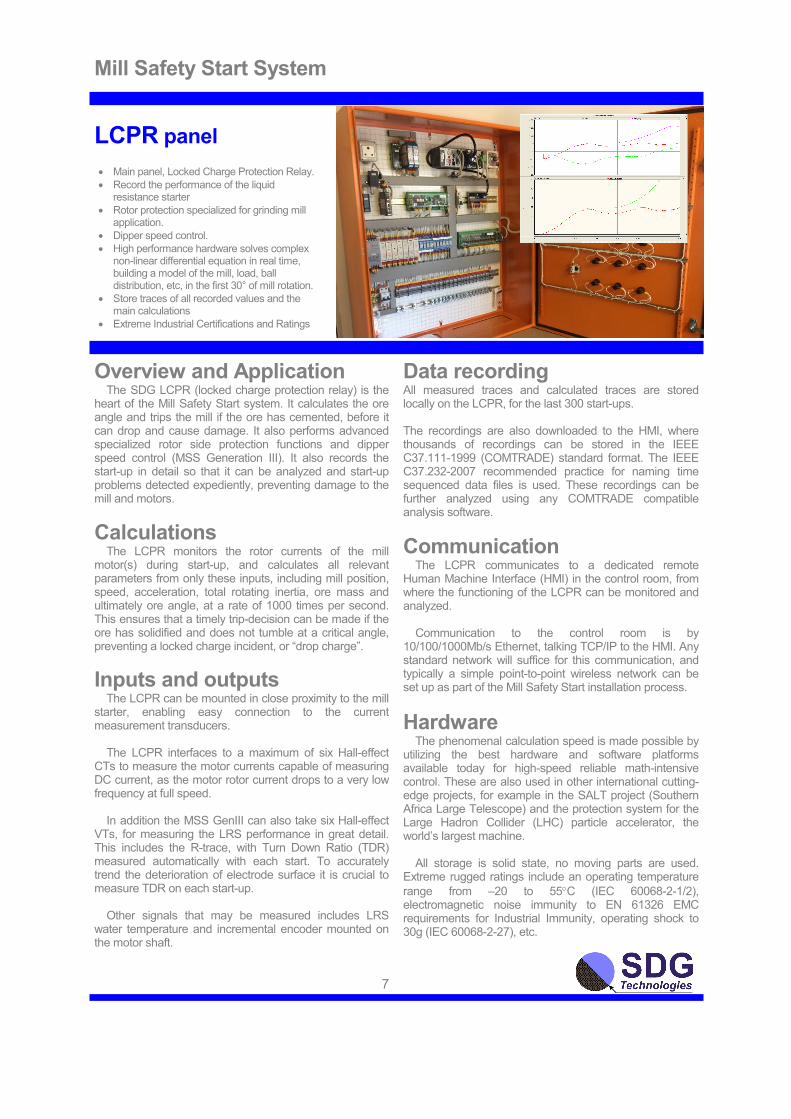
LCPR panel
• Main panel, Locked Charge Protection Relay.
• Record the performance of the liquid resistance starter
• Rotor protection specialized for grinding mill application.
• Dipper speed control.
• High performance hardware solves complex non-linear differential equation in real time, building a model of the mill, load, ball distribution, etc, in the first 30° of mill rotation.
• Store traces of all recorded values and the main calculations
• Extreme Industrial Certifications and Ratings
Overview and Application
The SDG LCPR (locked charge protection relay) is the heart of the Mill Safety Start system. It calculates the ore angle and trips the mill if the ore has cemented, before it can drop and cause damage. It also performs advanced specialized rotor side protection functions and dipper speed control (MSS Generation III). It also records the start-up in detail so that it can be analyzed and start-up problems detected expediently, preventing damage to the mill and motors.
Calculations The LCPR monitors the rotor currents of the mill motor(s) during start-up, and calculates all relevant parameters from only these inputs, including mill position, speed, acceleration, total rotating inertia, ore mass and ultimately ore angle, at a rate of 1000 times per second. This ensures that a timely trip-decision can be made if the ore has solidified and does not tumble at a critical angle, preventing a locked charge incident, or “drop charge”.
Inputs and outputs
The LCPR can be mounted in close proximity to the mill starter, enabling easy connection to the current measurement transducers. The LCPR interfaces to a maximum of six Hall-effect CTs to measure the motor currents capable of measuring DC current, as the motor rotor current drops to a very low frequency at full speed. In addition the MSS GenIII can also take six Hall-effect VTs, for measuring the LRS performance in great detail. This includes the R-trace, with Turn Down Ratio (TDR) measured automatically with each start. To accurately trend the deterioration of electrode surface it is crucial to measure TDR on each start-up. Other signals that may be measured includes LRS water temperature and incremental encoder mounted on the motor shaft.
7
Data recording All measured traces and calculated traces are stored locally on the LCPR, for the last 300 start-ups. The recordings are also downloaded to the HMI, where thousands of recordings can be stored in the IEEE C37.111-1999 (COMTRADE) standard format. The IEEE C37.232-2007 recommended practice for naming time sequenced data files is used. These recordings can be further analyzed using any COMTRADE compatible analysis software.
Communication
The LCPR communicates to a dedicated remote Human Machine Interface (HMI) in the control room, from where the functioning of the LCPR can be monitored and analyzed. Communication to the control room is by 10/100/1000Mb/s Ethernet, talking TCP/IP to the HMI. Any standard network will suffice for this communication, and typically a simple point-to-point wireless network can be set up as part of the Mill Safety Start installation process.
Hardware The phenomenal calculation speed is made possible by utilizing the best hardware and software platforms available today for high-speed reliable math-intensive control. These are also used in other international cutting-edge projects, for example in the SALT project (Southern Africa Large Telescope) and the protection system for the Large Hadron Collider (LHC) particle accelerator, the world’s largest machine. All storage is solid state, no moving parts are used. Extreme rugged ratings include an operating temperature
range from –20 to 55°C (IEC 60068-2-1/2), electromagnetic noise immunity to EN 61326 EMC requirements for Industrial Immunity, operating shock to 30g (IEC 60068-2-27), etc.

Mill Safety Start System
HMI Human Machine Interface
• Monitor your LCPR from the control room.
• Get immediate real-time visual feedback of the mill start-up process.
• Visual mimic of rotation of mill and ore updated 10 times per second.
• Graph of mill angle vs. ore angle gives a quantitative measure of how cemented the ore was at start-up.
• Download traces of all measured values and the main calculations from the LCPR.
• Transfer recordings to the remote SDG server for analysis. Under the Platinum and Gold support plans, all starts are analyzed and a report issued per email for each start-up, according to the most important criteria.
Overview and Application
The SDG HMI (Human Machine Interface) for the LCPR is the window into the Mill Safety Start system, allowing the control room operator to see exactly what the LCPR is doing and how the start-up is progressing in real time. The HMI also serves as a gateway for connecting the Mill Safety Start System to the SDG remote server. The recorded traces of each start-up are transferred to the remote server automatically, enabling SDG Technologies to evaluate the operation of the liquid resistance starter, and also to verify the correct and optimal operation of the LCPR and all calculations thereof.
Display At the moment that the start-up is detected, the HMI starts plotting the ore angle against the mill angle. If this plot reaches the green SAFE area to the right of the graph, the start-up is declared safe, i.e. the mill has
rotated to a certain angle (for example 90°) while the ore angle remained below the maximum angle. If this plot reaches the red TRIP area at the top of the graph, a trip is issued, i.e. the ore has surpassed the maximum allowable ore angle without tumbling, and the mill must therefore be tripped before the ore can drop and cause damage to the mill.
The plot starts off at an angle of 45°, as the ore angle will remain identical to the mill angle before the charge has tumbled, heading for the top red area. When the ore tumbles, the plot will veer off to the right, and land in the green area, indicating a safe start. The display has such been designed to give a simple and intuitive interface to the LCPR. It indicates not only a TRIP or SAFE decision, but in both instances by what margin that decision was made. A real-time updated mimic of the mill and ore gives an instantaneous indication of the angle of the mill and the ore. (In the screenshot
above, the mill is at 90° and the ore at 30°) The red and green areas can be changed with settings. The display is updated at a rate of 10 times per second, giving a real-time picture of events as it unfolds.
8
Analysis Gateway Bigger mills can withstand relatively smaller torque transients. The performance of the Liquid Resistance Starter (LRS) therefore becomes more important as mill size increases to prevent premature mechanical failure. Problems with the LRS can also lead to electrical motor problems. From the LCPR recordings, the LRS performance can be thoroughly evaluated. For this reason, the facility has been built into the Mill Safety Start system to send all the LCPR recordings to a server at SDG Technologies, where each and every mill start-up can be evaluated according to important criteria. This ensures that possible problems with the LRS are picked up and corrective action recommended, before damage is done to the electrical or mechanical mill components.
Communication
The LCPR connects to the HMI using Ethernet TCP/IP. A wireless link may be set up when the LCPR is installed for this purpose. The HMI connects to the SDG server as a client, and therefore no special internet setup is needed. As long as the HMI can browse the internet, it will find the SDG server, connect to a dedicated port, and transfer the data with a simple TCP/IP protocol. There are no firewall and security issues, like those encountered with static IP servers at site, or FTP.
Hardware and software The HMI is a dedicated high-reliability embedded computer, running the HMI software automatically at start-up. The HMI is supplied with a 19” VGA screen with high reliability LED backlighting, carrying a 5 year warranty.
Mill Safety Start System
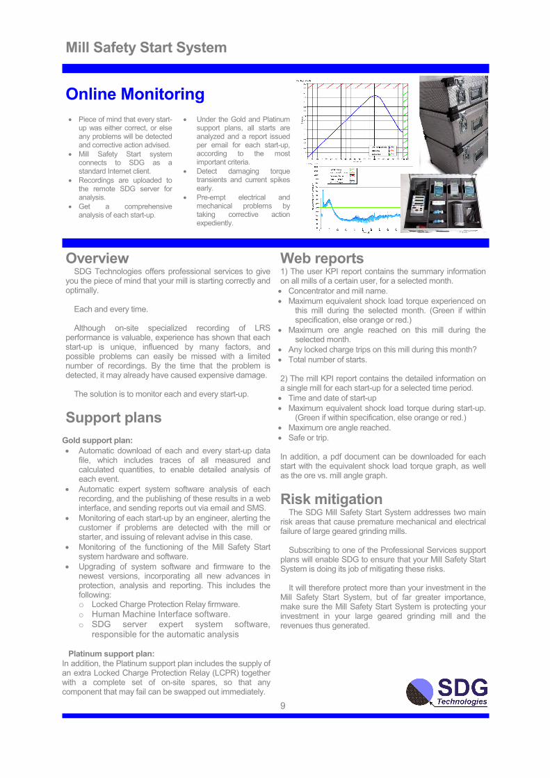
Online Monitoring
• Piece of mind that every start-up was either correct, or else any problems will be detected and corrective action advised.
• Mill Safety Start system connects to SDG as a standard Internet client.
• Recordings are uploaded to the remote SDG server for analysis.
• Get a comprehensive analysis of each start-up.
• Under the Gold and Platinum support plans, all starts are analyzed and a report issued per email for each start-up, according to the most important criteria.
• Detect damaging torque transients and current spikes early.
• Pre-empt electrical and mechanical problems by taking corrective action expediently.
Overview
SDG Technologies offers professional services to give you the piece of mind that your mill is starting correctly and optimally. Each and every time. Although on-site specialized recording of LRS performance is valuable, experience has shown that each start-up is unique, influenced by many factors, and possible problems can easily be missed with a limited number of recordings. By the time that the problem is detected, it may already have caused expensive damage. The solution is to monitor each and every start-up.
Support plans
Gold support plan:
• Automatic download of each and every start-up data file, which includes traces of all measured and calculated quantities, to enable detailed analysis of each event.
• Automatic expert system software analysis of each recording, and the publishing of these results in a web interface, and sending reports out via email and SMS.
• Monitoring of each start-up by an engineer, alerting the customer if problems are detected with the mill or starter, and issuing of relevant advise in this case.
• Monitoring of the functioning of the Mill Safety Start system hardware and software.
• Upgrading of system software and firmware to the newest versions, incorporating all new advances in protection, analysis and reporting. This includes the following: o Locked Charge Protection Relay firmware. o Human Machine Interface software. o SDG server expert system software,
responsible for the automatic analysis
Platinum support plan: In addition, the Platinum support plan includes the supply of an extra Locked Charge Protection Relay (LCPR) together with a complete set of on-site spares, so that any component that may fail can be swapped out immediately.
Web reports 1) The user KPI report contains the summary information on all mills of a certain user, for a selected month.
• Concentrator and mill name.
• Maximum equivalent shock load torque experienced on this mill during the selected month. (Green if within specification, else orange or red.)
• Maximum ore angle reached on this mill during the selected month.
• Any locked charge trips on this mill during this month?
• Total number of starts. 2) The mill KPI report contains the detailed information on a single mill for each start-up for a selected time period.
• Time and date of start-up
• Maximum equivalent shock load torque during start-up. (Green if within specification, else orange or red.)
• Maximum ore angle reached.
• Safe or trip. In addition, a pdf document can be downloaded for each start with the equivalent shock load torque graph, as well as the ore vs. mill angle graph.
Risk mitigation
The SDG Mill Safety Start System addresses two main risk areas that cause premature mechanical and electrical failure of large geared grinding mills. Subscribing to one of the Professional Services support plans will enable SDG to ensure that your Mill Safety Start System is doing its job of mitigating these risks. It will therefore protect more than your investment in the Mill Safety Start System, but of far greater importance, make sure the Mill Safety Start System is protecting your investment in your large geared grinding mill and the revenues thus generated.
9

Mill Safety Start System
Professional services (support plan overview)
Service Platinum Gold Warranty Full set of spares, including spare LCPR, provided on-site for immediate use in the case of component failure.
�
�
�
Automatic analysis and report on start-up via permanent Internet connection between SDG and Safety Start System, monitoring by engineer, advice in case of problems.
�
�
�
Remote update to latest software
�
�
�
Free replacement of faulty hardware for one year
�
�
�
These service plans may be customized for specific requirements.
10

Mill Safety Start System
Specifications: MSS and LCPR (main processor)
Protection Functions • Locked Charge Protection (Frozen Charge)
• Mill Jammed
• Slip Ring Flash / Motor rotor Earth Fault.
• LRS arcing
• Torque too high. (OverTorque)
• Torque limit coupling shear (dual pinion mills)
Recording format, standards, s/rate Sample/rate (measured & calculated traces) . 1kHz Data format..... IEEE C37.111-1999 (COMTRADE) File naming...............................IEEE C37.232-2007
Electromagnetic Compatibility This product meets the following standards of EMC for electrical equipment (measurement and control)
• EN 61326-1 (IEC61326-1); Industrial Immunity
• EN 61000-6-2; Immunity
• EN 55011 Emissions; Group 1, Class A
• EN 55022 / EN 55024
• AS/NZS CISPR 11 and 22
• FCC47 CFR Part 15B
• ICES-001: Class A emissions
Safety Standards This product is designed to meet the requirements of the following standards of safety for electrical equipment for measurement and control use:
• IEC 61010-1, EN 61010-1
• UL 61010-1, CSA 61010-1
• EN 60079-0:2012, EN 60079-15:2010
• IEC 60079-0: Ed 6, IEC 60079-15; Ed 4
• UL 60079-0; Ed 5, UL 60079-15; Ed 3
• CSA 60079-0:2011, CSA 60079-15:2012
CE Compliance This product meets the essential requirements of applicable European Directives, as amended for CE marking, as follows:
• 2014/35/EU; Low-Voltage Directive (safety)
• 2014//30/EU; Electromagnetic Compatibility
• 94/9/EC; Potentially Explosive Atmospheres
Hazardous Locations U.S. (UL) and Canada (C-UL).....Class I, Division 2 Groups A,B,C,D,T4; Class I,Zone2, AEx nA II T4 Europe (ATEX)...............................Ex nA IIC T4 Gc International (IECEx)......................Ex nA IIC T4 Gc
Panel Dimensions (HxWxD) [mm] ........ 1000 x 800 x 320 Ingress protection.............................................. IP65 Colour ........................................Orange (RAL2004)
• Optionally: Red (RAL3020) or Grey (RAL7032)
• Door opens to the right, optionally to the left.
• Options to be specified at time of order. 11
Environmental Note: Factory mounted in IP65 panel, see above.
Operating temperature........................... -20 to 55°C (IEC 60068-2-1, IEC 60068-2-2)
Storage temperature.............................. -40 to 85°C (IEC 60068-2-1, IEC 60068-2-2) Ingress protection............................................. IP 20 Operating humidity............................10 to 90% RH, Non-condensing, (IEC 60068-2-56) Storage humidity .................................5 to 95% RH, Non-condensing, (IEC 60068-2-56) Maximum altitude.......................................... 5000m Pollution degree (IEC 60664) .................................2
Processing Hardware 1) Field Programmable Logic Array: FPGA..................................... Xilinx Kintex-7 7K70T Flip-flops .........................................................82,000 6-input LUTs...................................................41,000 DSP slices (18 × 25 multipliers) .........................240 Available block RAM..................................4,860kbit Number of DMA channels ....................................16 Number of logical interrupts..................................32
2) Micro Processor: uP..................... Intel Atom E3825, 2 core, 1.33GHz On-die L2 Cache................................ 1MB (shared) Memory (RAM)............... 1GB, DDR3L, 8.533 GB/s Memory (Solid-state drive).................................4GB Real-Time Operating System..........NI Linux RT 64 Transfer between uP and FPGA ....................................Gapless DMA with interrupts
3) Development system:
• LabVIEW 2015
• LabVIEW Real-Time Module 2015
• LabVIEW FPGA Module 2015
I/O specifications Analogue Input (AI) ....................16bit, 0.1% of FSD Analogue output (4-20mA) (AO) ...16bit, 0.1% FSD AI max sampling rate................ 250kS/s Aggregate AO max update rate.................................... 200kS/s AI/AO number of channels ................................32/8 AI and AO to ground isolation (Continuous,2000m) ........................250Vrms, Measurement Category II AI and AO to ground isolation (Withstand, 2000m). ................... 2,300Vrms, 5s dielectric withstand test Anti-aliasing filter (on AI) ........................................... . External (SCMOD), RC 482Hz with oversampling
Network Network Interface....... 10/100/1000BaseT Ethernet Compatibility ............................................ IEEE802.3 Communication rates.10Mb/s,100Mb/s, 1000Mbps Maximum cabling distance..............100m/segment