millau viaduct geotechnical studies and foundations · 244 f. schlosser et al. / journal of rock...
TRANSCRIPT

M
Fa
b
c
a
ARRA
KCFPRO
1
awasbett
cm
aTao
PA
1Sh
Journal of Rock Mechanics and Geotechnical Engineering 5 (2013) 243–247
Journal of Rock Mechanics and GeotechnicalEngineering
Journal of Rock Mechanics and GeotechnicalEngineering
journa l homepage: www.rockgeotech.org
illau viaduct geotechnical studies and foundations
. Schlossera,∗, C. Servantb, A. Guillouxc, A. Bergerec
ENPC, FranceEiffage Travaux Publics, FranceTerrasol, France
r t i c l e i n f o
rticle history:eceived 26 March 2013eceived in revised form 1 May 2013ccepted 15 May 2013
a b s t r a c t
The Millau viaduct over the Tarn River is an exceptional bridge considering the height under the deck andthe 2.5 km total length. Each of the seven high piers is founded on a thick raft setting on four large pilesof 5 m in diameter and 10–15 m deep. The ground schematically consists of limestone in the north and ofmarls in the south. As the bridge is very sensitive to foundation settlements, the concessionary company
eywords:able stayed bridgeoundation designile settlement
decided to use the observational method for controlling the displacements and if necessary stabilizethe foundations. The measurements show that the movements have remained small and admissible,particularly in terms of the rotations. The settlements have not occurred continuously under the load, butby steps.
and
ot
tbCph
iaddf
iLt(d
otationbservational method
© 2013 Institute of Rock
. Geological and geotechnical context
The Millau viaduct links two limestone plateaus separated by deep valley eroded by the Tarn River. The sedimentary basins,hich started to form during the middle of the Secondary Era,
ppear to be particularly well preserved. The Tarn has revealed thetratigraphy of the zone which shows Triassic formations at theottom of the valley and then displays the full sequence up to thend of the Jurassic Era which is represented by the limestone at theop of the Larzac plateau to the south of the viaduct as shown onhe right of Fig. 1.
The rock encountered on the site is exclusively sedimentary,omposed partly of dolomitic limestone and partly of compactarls (Mennessier and Collomb, 1983).A study of local tectonics shows that there are old faults which
ffect the older horizons in the sequence, back as far as the Lias.he old faults are located to the north of the viaduct but do notffect the more recent horizons of the geological structure of the topf the southern plateau, such as the Kimmeridgian stage. This type
∗ Corresponding author.E-mail address: [email protected] (F. Schlosser).
eer review under responsibility of Institute of Rock and Soil Mechanics, Chinesecademy of Sciences.
674-7755 © 2013 Institute of Rock and Soil Mechanics, Chinese Academy ofciences. Production and hosting by Elsevier B.V. All rights reserved.ttp://dx.doi.org/10.1016/j.jrmge.2013.05.002
miEmti1a
M
t
Soil Mechanics, Chinese Academy of Sciences. Production and hosting byElsevier B.V. All rights reserved.
f fault was specifically encountered by the northern abutment ofhe viaduct (C0) as shown in Fig. 1.
There are also some more recent non-active faults that affecthe whole stratigraphy of the zone and cut across the viaduct sitey pier P4 and again between pier P7 and the southern abutment8 (Fig. 1). The strike slips on these faults, particularly where theier P4 is located, have caused difficulties for the construction andave required an adaptation of the foundations.
Before starting the earthworks, the concession company andts public works contractor EIFFAGE TP systematically carried outdditional geotechnical surveys of the soils to support the foun-ations by means of destructive drilling down to 10 m below theeepest level of the pile shafts and 15 m below the base of theoundation plates for the abutments.
As everyone knows, the main difficulty with rock mechanicss obtaining representative samples (Panet, 1976; Duncan, 1996).aboratory tests carried out on small samples are not represen-ative of the scale of all the discontinuities in the rock massesespecially the direction and size of the faults), which means thatirect use of the results is not at all reliable. Thus the overallechanical properties of a rocky block, generally assumed to be
sotropic (ϕ, c: internal friction angle and cohesion, respectively;: modulus of deformation) are more and more frequently deter-ined by semi-empirical methods which combine geotechnical
ests with geological observation of the borehole samples and exist-ng outcrops (the RMR (rock mass rating) classification (Bieniawski,989) in accordance with the empirical method proposed by Hoeknd Brown (1988) and Hoek et al. (1995)).
The RMR varies from 0 to 105. The mean values recorded on theillau viaduct site are 65 for the limestone and 53 for the marls.There are three different types of foundation rocks along
he viaduct. The first one, the Bajocian dolomitic limestone at

244 F. Schlosser et al. / Journal of Rock Mechanics and Geotechnical Engineering 5 (2013) 243–247
ical cr
tficv
ottT1
fIaRs
lt
2
dAsspa
asca
ooatt
eaa
Ifibc
ssrfl
Fig. 1. Simplified geotechn
he northern abutment (C0), is a very hard rock with an uncon-ned compressive strength Rc = 110 MPa but with karsts filled withlay. At the top of the platform where the raft was placed, a RMRalue of 70–80 was determined.
The compacted marls from pier P7 to pier P6 constitute the sec-nd rock type. Slides are visible at the soil surface due to the 2 mhick scree layer underlain by soft clay above the marls. Labora-ory tests have given: Rc = 10–15 MPa, E = 3–6 GPa, � = 25 kN/m3.he mean values of shear strength have been determined in the5 m thick top layer of marls: RMR = 45, c = 0.1 MPa, ϕ = 30◦.
The Hettangian limestone on the two sides of the Tarn Riverrom pier P4 to the abutment (C0) constitutes the third rock type.ts bedding is sub-horizontal on the south side and at a 10◦/15◦
ngle on the north side. The results from laboratory tests are:c = 50–70 MPa, E = 8 to 15 GPa, � = 25 kN/m3. The determined sheartrength values are: RMR = 65 to 70, c = 2.5 MPa, ϕ = 37◦.
It can be concluded that the marls are less resistant than theimestone. It is the reason that the piles in marls are enlarged atheir base and are longer than the piles in limestone (Fig. 2).
. Foundation system
The viaduct design produced by the authorities defined andesigned the foundation systems for the piers and abutments.lthough the final system is based on the same principles, it varieslightly depending on whether a given bearing is located on lime-
tone or on marls. The marls not only have weaker mechanicalroperties than the limestone, but also show superficial slide whichffects the upper part.Fig. 2. Standard cross sections of piers in marls and limestone.
apwfi
tud
tocs
mu
3
mms
oss section of the viaduct.
Spread foundations were chosen for abutments C0 and C8 whichre founded on limestone. The foundation system is a monolithicet composed of a 1 m thick raft foundation for each front abutment,onnected to two side footings for each rear abutment with thebutment platforms at different levels.
The foundation system (Fig. 2) for each of the 7 piers is composedf 4 reinforced-concrete piles with a diameter of 5 m and a depthf 10–15 m drilled in the rock and bonded together at the top by
3.5 m thick reinforced-concrete footing, which is itself bonded tohe pier. In marls, the footing is thicker and the piles deeper, withheir base diameter being increased to 7 m.
Foundations of piers 2 and 6 have been taken as the typicalxamples in the present paper. The pier 2 is the highest one (245 m)nd is founded in limestone, while the pier 6 is founded in marlsnd has a medium height.
The behaviour of this type of pier foundation system is complex.t is a piled raft foundation system in which part of the load is trans-erred to the footing. The way that this behaviour was simplifieds particularly restrictive as it was assumed that firstly, the footingears none of the load and secondly that no skin friction (qs = 0) isreated along the shaft except in the case of tensile stress.
This comes down to assuming that bearing capacity dependsolely on the ultimate pressure on the rock at the bottom of thehaft and that settlement results only from deformations of theock at the bottom of the shaft, which makes the foundations moreexible than they really are.
Bearing capacity was defined using standard Terzaghi equationsdapted to take into account the inclination of the load and theroximity to the hillside, to which an overall stability calculationas added for shafts drilled in marly hillsides, as well as for the
oundation of pier P3 in limestone whose overall stability had to bemproved by a reinforced soil retaining wall (Tervoile).
With regard to settlement and foundation rotation subsequento service loads (serviceability limit states), the calculation methodsed was the modulus of reaction to the behaviour hypothesesescribed above.
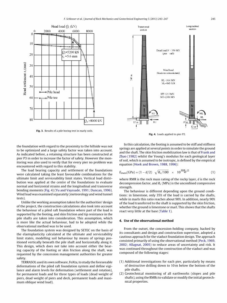
Several pile-loading trial tests were carried out in the marly soilso assess the skin friction along the shaft. Fig. 3 shows the results ofne of these tests on a bored pile with a diameter of 0.80 m. Criticalreep load at point Qc is approximately 5200 kN (qc = 10 MPa) for ahaft head settlement of 5.6 mm.
Despite the uncertainties regarding the assessment of theechanical properties of the rock and the calculation methods
sed, the design for the pier foundations seems to be quite reliable.
. Foundation design
To optimize the foundation design by using the observationalethod required iterations between the calculation results of theost probable behaviour of the foundation and the results of a con-
tant monitoring during the construction. The overall stability of
F. Schlosser et al. / Journal of Rock Mechanics and Geotechnical Engineering 5 (2013) 243–247 245
ttApie
wubnbWt
otspio
tliTirs
dlfpm
saZoe
E
wds
twowr
4
icc2wc
(
(2) Geotechnical monitoring of all earthworks (slopes and pile
Fig. 3. Results of a pile boring test in marly soils.
he foundation with regard to the proximity to the hillside was noto be optimized and a large safety factor was taken into account.s indicated before, a retaining structure has been constructed atier P3 in order to increase the factor of safety. However the mon-
toring was also used to verify that for every pier no problem wasncountered with regard to this stability.
The load bearing capacity and settlement of the foundationsere calculated taking the least favourable combinations for theltimate limit and serviceability limit states. Vertical load distri-ution was applied at the centre of the foundations to evaluateormal and horizontal strains and the longitudinal and transverseending moments (Fig. 4) (Yu and Vayssade, 1991; Duncan, 1996).ind load was examined separately (meteorology and wind tunnel
ests).Unlike the working assumption taken for the authorities’ design
f the project, the construction calculations also took into accounthe behaviour of a piled raft foundation where part of the load isupported by the footing, and skin friction and tip resistance in theile shafts are taken into consideration. This assumption, which
s more like the actual behaviour, had to be adopted while thebservational method was to be used.
The foundation system was designed by SETEC on the basis ofhe elastoplasticity calculated at the ultimate and serviceabilityimit states, modelling soil behaviour by means of springs pos-tioned vertically beneath the pile shaft and horizontally along it.his design, which does not take into account either the bear-ng capacity of the footing or skin friction along the shaft, wasequested by the concession management authorities for greaterafety.
TERRASOL used its own software, FoXta, to study the foreseeableeformations of the piled raft foundation system and define vigi-
ance and alarm levels for deformation (settlement and rotation),or permanent loads and for three types of loads (dead weight of
iers, dead weight of piers and deck, permanent loads and maxi-um oblique wind load).Fig. 4. Loads applied to pier P2.
In this calculation, the footing is assumed to be stiff and stiffnessprings are applied at several points in order to simulate the groundnd the shaft. The skin friction mobilization law is that of Frank andhao (1982) whilst the Young’s modulus for each geological layerf soil, which is assumed to be isotropic, is defined by the empiricalquation (Hoek and Brown, 1988, 1996):
mass(GPa) = (1 − d/2)√
Rc/100 × 10RMR−15
40 (1)
here RMR is the rock mass rating of the rocky layer, d is the rockecompression factor, and Rc (MPa) is the unconfined compressivetrength.
The behaviour is different depending upon the ground condi-ions: in limestone, only 35% of the load is carried by the shafts,hile in marls this ratio reaches about 90%. In addition, nearly 90%
f the load transferred to the shaft is supported by the skin friction,hether the ground is limestone or marl. This shows that the shafts
eact very little at the base (Table 1).
. Use of the observational method
From the outset, the concession-holding company, backed byts consultants and design and construction supervisor, adopted aautious approach for the viaduct foundation design. The approachonsisted primarily of using the observational method (Peck, 1969,002; Allagnat, 2005) to reduce areas of uncertainty and risk. Itas continued throughout the construction of the viaduct and was
omposed of the following stages:
1) Additional investigations for each pier, particularly by meansof destructive drilling down to 10 m below the bottom of thepile shafts.
shafts), using the RMRs to validate or modify the initial geotech-nical properties.
246 F. Schlosser et al. / Journal of Rock Mechanics and Geotechnical Engineering 5 (2013) 243–247
Table 1Settlement and rotation of foundations for piers P2 and P6 for three types of loads.
Case Pier s (mm) Rotation (10−5 rad) Load carried by footingand shaft (%)
Note
ωLong ωTrans Footing Shaft
Case 1 P2 2.80 0.02 0.12 67 33 Dead weight of the pierP6 0.46 −0.3 −0.3 12 88
Case 2 P2 3.60 −0.6 −0.6 67 33 Dead weight of the pier0.76.1
9.3
(
(
(
aubfb
brliit
motsc
bcamb“
aoω
stco
TD
al
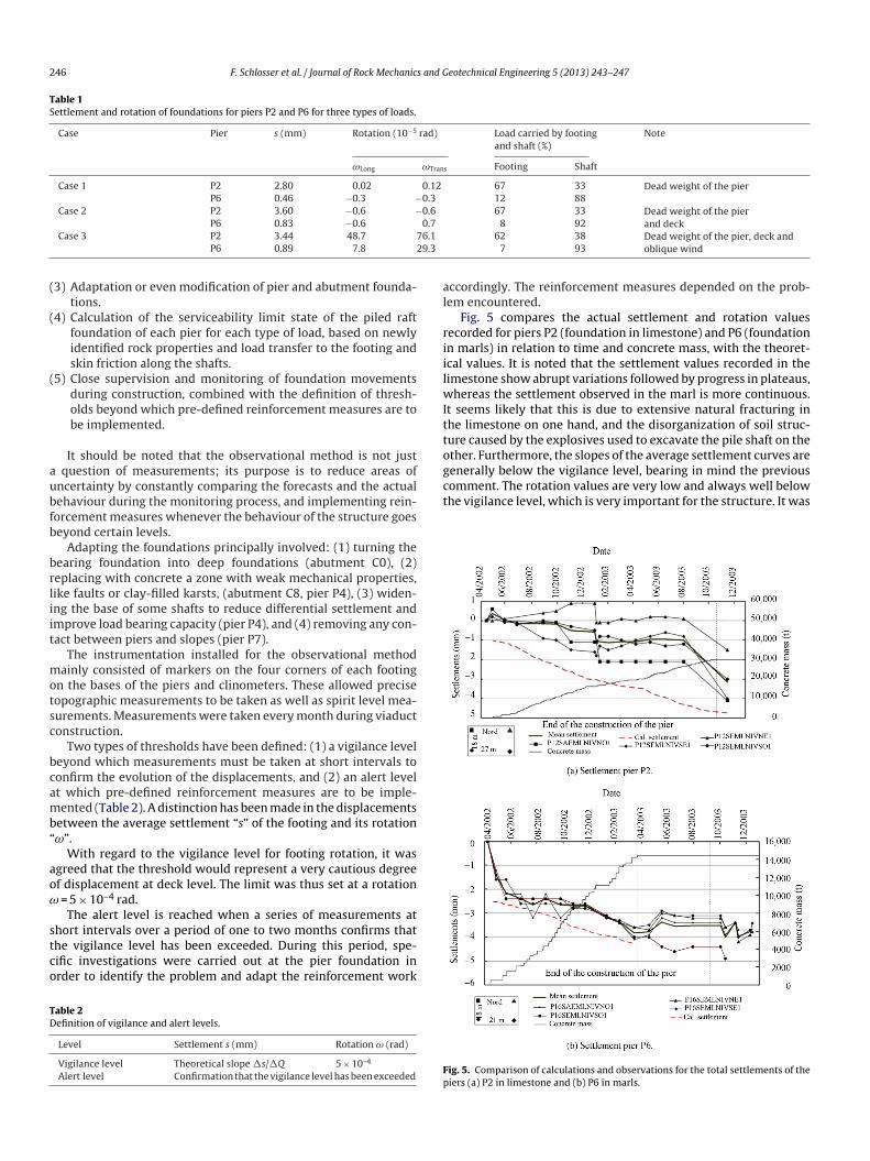
riilwIttogenerally below the vigilance level, bearing in mind the previouscomment. The rotation values are very low and always well belowthe vigilance level, which is very important for the structure. It was
P6 0.83 −0.6Case 3 P2 3.44 48.7 7
P6 0.89 7.8 2
3) Adaptation or even modification of pier and abutment founda-tions.
4) Calculation of the serviceability limit state of the piled raftfoundation of each pier for each type of load, based on newlyidentified rock properties and load transfer to the footing andskin friction along the shafts.
5) Close supervision and monitoring of foundation movementsduring construction, combined with the definition of thresh-olds beyond which pre-defined reinforcement measures are tobe implemented.
It should be noted that the observational method is not just question of measurements; its purpose is to reduce areas ofncertainty by constantly comparing the forecasts and the actualehaviour during the monitoring process, and implementing rein-orcement measures whenever the behaviour of the structure goeseyond certain levels.
Adapting the foundations principally involved: (1) turning theearing foundation into deep foundations (abutment C0), (2)eplacing with concrete a zone with weak mechanical properties,ike faults or clay-filled karsts, (abutment C8, pier P4), (3) widen-ng the base of some shafts to reduce differential settlement andmprove load bearing capacity (pier P4), and (4) removing any con-act between piers and slopes (pier P7).
The instrumentation installed for the observational methodainly consisted of markers on the four corners of each footing
n the bases of the piers and clinometers. These allowed preciseopographic measurements to be taken as well as spirit level mea-urements. Measurements were taken every month during viaductonstruction.
Two types of thresholds have been defined: (1) a vigilance leveleyond which measurements must be taken at short intervals toonfirm the evolution of the displacements, and (2) an alert levelt which pre-defined reinforcement measures are to be imple-ented (Table 2). A distinction has been made in the displacements
etween the average settlement “s” of the footing and its rotationω”.
With regard to the vigilance level for footing rotation, it wasgreed that the threshold would represent a very cautious degreef displacement at deck level. The limit was thus set at a rotation
= 5 × 10⁻⁴ rad.The alert level is reached when a series of measurements at
hort intervals over a period of one to two months confirms thathe vigilance level has been exceeded. During this period, spe-ific investigations were carried out at the pier foundation inrder to identify the problem and adapt the reinforcement work
able 2efinition of vigilance and alert levels.
Level Settlement s (mm) Rotation ω (rad)
Vigilance level Theoretical slope �s/�Q 5 × 10⁻⁴
Alert level Confirmation that the vigilance level has been exceededFp
and deck8 9262 38 Dead weight of the pier, deck and
oblique wind7 93
ccordingly. The reinforcement measures depended on the prob-em encountered.
Fig. 5 compares the actual settlement and rotation valuesecorded for piers P2 (foundation in limestone) and P6 (foundationn marls) in relation to time and concrete mass, with the theoret-cal values. It is noted that the settlement values recorded in theimestone show abrupt variations followed by progress in plateaus,
hereas the settlement observed in the marl is more continuous.t seems likely that this is due to extensive natural fracturing inhe limestone on one hand, and the disorganization of soil struc-ure caused by the explosives used to excavate the pile shaft on thether. Furthermore, the slopes of the average settlement curves are
ig. 5. Comparison of calculations and observations for the total settlements of theiers (a) P2 in limestone and (b) P6 in marls.

and G
cd
5
f
(
(
(
(
(
(
R
A
BDF
H
H
H
M
P
P
F. Schlosser et al. / Journal of Rock Mechanics
hecked, by the yearly controls, that the foundations deformationsid not change 8 years after their completion.
. Conclusions
The findings of the studies and monitoring of the Millau vaductoundations during pier construction are as follows:
1) Despite its limitations, the RMR method which was origi-nally developed for tunnelling in rock masses provides a fairlyreliable assessment of the mechanical properties for the foun-dations on the limestone and compacted marl encountered onthe site.
2) The actual behaviour of the pier foundations proved to be that ofa piled raft foundation in which the load carried by the footingincreases with the stiffness of the soil on which it is laid, whichis particularly relevant for piers with foundations in limestone.
3) The foundation settlement and rotation values recorded duringthe construction and after completion are quite close to theresults of the piled raft foundation calculation.
4) The settlement observed as the piers went up varied accordingto the type of ground. Although it was fairly continuous in themarl, it showed abrupt increases in the limestone, which thencontinued in plateaus.
5) The observational method has been proved to be a sound toolfor monitoring the risk of movement in the pier foundations,given the possibility of discovering unidentified karsts or zonesof heterogeneity.
P
Y
eotechnical Engineering 5 (2013) 243–247 247
6) Overall settlement of the piers under their own weight doesnot exceed 5 mm. The rotations are minimal and can barelybe measured. This means that the thresholds used for theimplementation of the observational method have not yet beenreached.
eferences
llagnat D. La méthode observationnelle pour le dimensionnement interactif desouvrages. Paris: Presses de l’Ecole Nat. des Ponts et Chaussées, Mai; 2005 (inFrench).
ieniawski ZT. Engineering rock mass classifications. New York: Wiley; 1989.uncan CW. Foundations on rock. London: E & FN Spon/Chapman & Hall; 1996.rank R, Zhao SR. Estimation par les paramètres pressiométriques de l’enfoncement
sous charge axiale des pieux forés. Bull. Liaison LCPC No. 119; 1982.oek E, Brown ET. The Hoek-Brown failure criterion – a 1988 update. In: Curran
JH, editor. Proc. 15th Canadian Rock Mech. Symp. Toronto: Department of CivilEngineering, University of Toronto; 1988. p. 31–8.
oek E, Brown ET. Underground excavations in rock. London: E & FN Spon/Chapman& Hall; 1996.
oek E, Kaiser PK, Bawden WF. Support underground: excavations in hard rock.Rotterdam: A.A. Balkema; 1995.
ennessier G, Collomb P. Carte géologique de Millau et sa notice géologique.Orléans Cedex: BRGM; 1983.
anet M. La mécanique des roches appliquée aux ouvrages de génie civil. Nationaledes Ponts et Chaussées: association amicale des ingénieurs anciens élèves del’Ecole Nationale des Ponts et Chaussées; 1976 (in French).
eck RD. Advantages and limitation of the observational method in applied soilmechanics. Geotechnique 1969;19(2):171–87.
eck RD. The observational method can be simple. Proceedings of the ICE Geotech-nical Engineering 2002;149(2):71–4.
u Xianbin, Vayssade B. Joint profiles and their roughness parameters.International Journal of Rock Mechanics and Mining Sciences 1991;28(4):333–6.