millennium 2000 cover 98 - ada · audio design associates, inc., 602-610 mamaroneck ave., white...
TRANSCRIPT

Audio Design Associates, Inc., 602-610 Mamaroneck Ave., White Plains, NY, 10605, (914) 946-9595, FAX (914) 946-9620
MILLENNIUM 2000with
Internal IRL-3000
DESIGN&
INSTALLATION
DEALER MANUALRevised February 2000

- 1 -
ContentsSAFETY INSTRUCTIONS ............................................................................... 2Introduction .................................................................................................... 4Millennium 2000 Keypad Options ................................................................. 5RS-232 Control Simplified ............................................................................. 8ISO-232 ADA Bus to RS-232 Isolated Converter ......................................... 9Cat. 5 Cable................................................................................................... 10Millennium 2000 Physical Differences ....................................................... 11Party Mode .................................................................................................... 12Programming Millennium Room Groups & Party Rooms ........................ 12Cat-Link & The Millennium 2000 ................................................................. 13Millennium 2000 System Wiring ................................................................. 13Multiple Millennium 2000's .......................................................................... 14MC-3000 & MC-5000 Series Programming ................................................. 16MC-3000, MC-3800, and MC-5000 IR Receiver On/Off............................... 19Millennium 2000 - What you will need. ....................................................... 19Millennium Devices You Cannot Use with Millennium 2000 .................... 19Using a UPS (Uninterrupted Power Supply) .............................................. 19Multiple Millenniums - Installation of the System Bus ............................. 20Source AC Connections to the Millennium (cont.) .................................... 21Source AC Connection Option 1 - Using One ACC-48.............................. 22Source AC Switching Option 3 - 2 ACC-48s .............................................. 23Power Amplifier Automatic AC Switching & Installation .......................... 24IR Capture - Internal IRL-3000 ..................................................................... 26Advanced Millennium IR Options ............................................................... 27Installation of ADA Keypads ....................................................................... 30Rack Rail & Hardware and........................................................................... 31Rack Mounting Source Components. ........................................................ 31
©2000 Audio Design Associates, Inc. All rights reserved. Specifications and design param-eters are subject to change without prior notice. "ada", "ada-audio design associates", and"ada-BUS" are registered trademarks of Audio Design Associates, Inc.

- 2 -
SAFETY INSTRUCTIONS
WARNING:
The exclamation point within theequilateral triangle is intendedto alert the user of the presenceof important operating and main-tenance (servicing) instructionsin the literature accompanyingthe appliances.
CAUTION:TO PREVENT RISK OF ELECTRI-CAL SHOCK, DO NOT REMOVECOVER (OR BACK). NO USER-SERVICEABLE PARTS ARE INSIDEANY OF THE UNITS IN THIS SYS-TEM. REFER SERVICING TOQUALIFIED SERVICE PERSON-NEL.
The lightning flash with the ar-rowhead, within an equilateraltriangle, is intended to alert theuser of the presence of un-insu-lated "dangerous voltage" withinthe products' enclosures that maybe of sufficient magnitude to con-stitute a risk of electrical shock topersons.
TO REDUCE THE RISK OF FIRE OR ELECTRICAL SHOCK, DO NOT EXPOSE THEAPPLIANCES IN THIS SYSTEM TO RAIN OR MOISTURE. REPLACE FUSE ONLY ASMARKED.
CAUTION:TO PREVENT ELECTRIC SHOCK, DO NOT PLUG THE UNITS IN THIS SYSTEM INTO ANYOUTLET OR EXTENSION CORD WITHOUT THE STANDARD THREE-PRONG CONFIGU-RATION, WHERE THE CIRCULAR HOLE IS USED FOR THE GROUND PLUG.
IMPORTANT:

- 3 -
SAFETY INSTRUCTIONSREAD INSTRUCTIONS - All the safety and operating instruc-
tions should be read before the appliances are operated.
RETAIN INSTRUCTIONS - The operating instructions shouldbe retained for future reference.
HEED WARNING - All warnings on the appliances and in theoperating instructions should be adhered to.
.
FOLLOW INSTRUCTIONS - All operating and use instructionsshould be followed.
WATER AND MOISTURE - The appliances should not be usednear water - for example, near a bathtub, washbowl, kitchen sink,laundry tub, in a wet basement, or near a swimming pool, etc.
LOCATION - The appliances should be installed in a stablelocation.
WALL OR CEILING MOUNT - The appliances should not bemounted to a wall or ceiling.
VENTILATION - The appliances should be situated so that theirlocation or position does not interfere with their proper ventilation.For example, the appliances should not be situated on a bed, sofa,rug or similar surface that may block the ventilation openings.
HEAT - The appliances should be situated away from heat sourcessuch as radiators, heat registers, stoves, or other appliances thatproduce heat.
POWER SOURCES - The appliances should be connected to apower supply only of the type described in the operating instruc-tions or as marked on the appliances.
GROUNDING - Make sure that the units in the system are alwaysconnected to a standard three-prong grounded outlet (the circularpin is ground). When operating this unit at a higher voltage witha different power cord configuration, consult your dealer for theproper power cord/outlet combination to use before operating thisunit.
POWER CORD PROTECTION - Power supply cords shouldbe routed so that they are not likely to be walked on or pinchedby items placed upon or against them, paying particular attentionto cords at plugs, convenience receptacles, and the points wherethey exit from the appliances.
CLEANING - The appliances should be cleaned only with apolishing cloth or a soft dry cloth. Never clean with furniture wax,benzine, insecticides or other volatile liquids since they maycorrode the face plates.
POWER LINES - An outdoor antenna should be located away from
power lines.
PERIODS OF DISUSE - The power cord of the appliances shouldbe unplugged from the outlet when the units are not in use for along period of time.
OBJECT AND LIQUID ENTRY - Care should be taken so thatobjects do not fall and liquids are not spilled into the enclosuresthrough openings.
DAMAGE REQUIRING SERVICE - The appliances shouldbe serviced by an authorized service center or qualified servicepersonnel when:
• The power supply cords or plugs have been damaged; or• Objects have fallen, or liquid has been spilled into theappliances; or• The appliances have been exposed to rain; or• The appliances do not appear to operate normally orexhibit a marked change in performance; or• The appliances have been dropped; or the enclosures havebeen damaged.
SERVICING - The user should not attempt to service the appliancesbeyond that described in the operating instructions. For all otherservicing, contact the factory.

- 4 -
ROOM 1 ROOM 2 ROOM 3 ROOM 4 ROOM 5 ROOM 6TREB BASS TREB BASS TREB BASS TREB BASS TREB BASS TREB BASS
POWERON
POWEROFF
MILLENNIUM MADE IN U.S.A.
FM 1 FM 2 AM CD 1 CD 2 AUX CASS1
ALL PARTY PRESET SETUPMODE
CASS2
ROOMOF
VOLUP
VOLDN
RECON
ROOM 1 ROOM 2 ROOM 3 ROOM 4 ROOM 5 ROOM 6
2000
IntroductionThe Millennium 2000 was developed to provide greater control of source components withinthe Millennium (all-in-one) system construction. To understand fully the Millennium 2000’splace in the ADA family of multi-room systems, one must have an understanding of both theMillennium and Delta systems.
For those of you familiar wiht the original Millennium System, it provided distribution of eightcomponents, basic transport control, preamplification & amplification for six to thirty-six zoneswith volume and room off/system off control. This Millenium was based on solid state technol-ogy. While it did provide feedback, this too was solid state. Original Millennium keypadsrequired ten wires for control from keypads, 2 wires for voltage and ground, 4 wires for con-trol, and 4 for feedback (The current Millennium uses either ADA Bus or Cat. 5. Cable). Eventhe original Millennium’s with the MIL-232 module, while permitting RS-232 control of thesystem, provided constant feedback. As no microprocessing took place in this Millennium,the system did not have the capacity to simply be polled for a status update.
The Delta System, on the other hand, is extremely sophisticated. It operates on the ADABus® and offers more control of both room acoustics (volume, bass, & treble with numericstatus levels) and source transport functions (including numeric direct access). The wiringscheme dictates four wires; receive, transmit, power, and ground. The Delta mainframe hasa facility to label both source names and room names. These labels are transmitted to key-pads during operation of the system. The keypads are also capable of displaying radio sta-tions, when operating an ADA triple tuner, and CD information, when operating an EsceintTuneBase system.
In essence, the current Millennium (Millennium 2000) is a combination of these two systems.It incorporates a microprocessor for system control and feedback. The keypads that are usedwith the Delta System, are also used by the Millennium 2000. The functional differences ofkeypads on a Millennium 2000 and Delta are minor. The Millennium 2000 features Partyfunctions where the Delta allows you to scroll to specific rooms for control. The Delta keypadsdo feature Bass & Treble control where that function on the Millennium 2000 is set on the frontof the Millennium 2000. Integrating Trinity Tuners, Escient TuneBase, and IRL-3000s oneither system are the same.
Thus the major differences between Millennium 2000 and Delta, other than price, are prima-rily acoustical. While the Millennium 2000 sounds superb, the Delta sounds even better.Also, the Delta frame can hold eight room cards while the Millennium has only six zones perchassis. Lastly, the differences between these two systems is based on sound and its control.The Millennium features bass and treble settings but not remotely. The Delta does featurethese contour controls on the non-2000 series controls. Also, Delta features individual roombalance control, loudness contour and stereo enhancement filters per zone. Perhaps mostimportant, is that theDelta features anacoustical preset perzone that can be re-called automaticallyupon start up.

- 5 -
FM 1 FM 2 CD 1
CD 2 CASS LASER
VCR DSS
VOLUP
VOLDN
ROOMOFF
1 2 3
4 5 6
7 8
PARTY
9
* 0 ENTER
FM 1 FM 2 CD 1
CD 2 CASS LASER
VCR DSS
VOLUP
VOLDN
ROOMOFF
MC-2000
MC-2011 IRT-2000
Millennium 2000 Keypad Options
While initially introduced with only a handful of keypad styles and options, today's Millennium2000 can be controlled from any type of ADA Bus® Keypad using either, standard ADA Bus®wire or Cat. 5 wire. The choice is yours.
Currently, ADA offers four keypad series that work with the Millennium 2000 system. Allkeypad options can be ordered with either ADA Bus® or Cat Link™ connectors.
MC-2000 Series ControlsThe MC-2000 Series is comprised of keypads that donot feature a 12 character alphanumeric LED display.These include the MC-2011 Single-Gang Decora Con-trol, the MC-2000 Double-Gang Decora Control, aswell as the MC-LUT1 and MC-LUT2 Single Gang andDouble Gang controls that are attached to a Lutronbutton board. Please note, that the MC-LUT2, with-out any lighting controls, will actually take up three-gang space due to the layout of the Lutron button be-zel. When using more than a single gang Lutron stylekeypad, always add one gang to the number of gangsused. For example, if you are using a single gangLutron control for lights and a double gang Lutron con-trol for audio (MC-LUT2), the electronics will fit into afour gang box. In the MC-2000 series we also in-clude the IRT-3000 Single Gang IR Transceiver whichis used as an infrared pickup. Finally, the MC-2000features access of the Party 1 function.
MC-LUT

- 6 -
MC-3000 Series ControlsThe MC-3000 Series is comprised of keypads that where previouslydevoted to Delta and Omega Systems. These include the MC-3000and MC-3800 controls in either wall mount or table-top versions.Also included in this series, are the MC-3000 OD and MC-3800 ODAll Weather Outdoor Controls.
All 3000 Series controls feature a 12 character alphanumeric dis-play that will indicate source selected as well as feedback from theTrinity Triple Tuner, Escient TuneBase (Pro MK II), and the IRL-3000.
When using the MC-3000 (or MC-5000) series control,you have the opportunity to program the source registeras you wish. The term source register refers to the sourcebuttons secondary level of programming. For example,when the FM1, FM2, and AM buttons are selected on akeypad that has a source register with these buttons forthe Trinity Triple Tuner, the keypad will both control anddisplay feedback from the tuner. The source register isalso used to lock into Escient or the IRL-3000. Whenusing these controls, you can specify which source but-tons talk to which components. When using MC-2000controls, the source register is set by DIP switches andwhile several options exist, the register is more rigid. Ifyou are mixing and MC-2000 and MC-3000/MC-5000 con-trols, you will want to program the MC-3000/MC-5000source registers to correspond to the MC-2000's DIPswitch source register.
The MC-3000's feature a display, they permit you to labelthe sources on the Millennium 2000. The indoor versionsof these keypads also feature a built-in IR receiver. Thesecontrol options are used when providing a distinctive lookand the outdoor controls are the only optionsavailable for this system (MC-2000 OD is dis-continued). The MC-3000 series controls fea-ture access of both Party 1 and Party 2.
When using theMC-3000 or MC-3800 as a table topbox, use the WPA-3000 Wall PlateAdaptor for sys-tems that are run
on ADA Bus®. For systems run on Cat. 5,create your own tabletop keypad connector.
ROOMOFF
101.90 JAZZ
FM 1 FM 2 AMCD1
CD2
CASS1
CASS2
AUX
PARTY1
PARTY1
VOLUP
VOLDN
PARTY2
PARTY2
ROOMOFF
SHIFT
ROOMOFF
101.90 JAZZ
FM 1 FM 2 AMCD1
CD2
AUXCASS
1
VOLUP
VOLDN
ROOMOFF
SHIFT
8
0
7
*
9
ENTER
2
5
1
4
3
6
CASS2
PARTY1
PARTY1
PARTY2
PARTY2
OFFSHIFT
VOL PTY 1 PTY 2
FM 1 FM 2 AM CD 1 CD 2 DSS DVD AUX
CD PLAYER 2
OFFSHIFT
VOL PTY 1 PTY 2
FM 1 FM 2 AM CD 1 CD 2 DSS DVD AUX
CD PLAYER 2
MC-3000
MC-3800
MC-3000 OD
MC-3800 OD

- 7 -
MC-5000(Rapture)
MC-5000 (Rapture) ControlThe MC-5000 is by far the most popular new con-trol that features backlit rubber buttons that can beset to illuminate in eight different options. Buttonsare grouped by function and each function grouphas three DIP switches that turn on/off the red,green, and blue button LEDs individually. As such,you can mix the color of the keypad to either high-light specific features or provide an illuminated lookthat augments the room's decor. The MC-5000,features a 12 character display and an IR receiver,much like the MC-3000/MC-3800 indoor controls.Again, the MC-5000 is used to program the sourcenames and source register of the Millennium 2000.Finally, the MC-5000 series controls feature accessof both Party 1 and Party 2.
Please note, that unlike the MC-2000 and MC-3000controls, the buttons of the MC-5000 are imprintedinto the rubber as the rubber is curing. While theMC-2000 and MC-3000 keypads have removablechicklet type buttons with an available library of over80 source names, the MC-5000 is pre-made andonly has space for 3 characters per source. ADAoffers eight standard source formats that should fitmost installations. For jobs that absolutely requirecustom formats, please contact ADA.
Standard Formats:
FM1, FM2, AM, CD1, CD2, DSS, DVD, AUXFM1, FM2, FM3, CD1, CD2, DSS, DVD, AUXFM1, FM2, AM, CD1, CD2, CD3, DSS, DVDFM1, FM2, FM3, CD1, CD2, CD3, DSS, DVDFM1, FM2, AM, CD1, CD2, DSS, DSS, AUXFM1, FM2, FM3, CD1, CD2, DSS, DSS, AUXFM1, FM2, CD1, CD2, DSS, DSS, DVD, AUXFM1, FM2, CD1, CD2, DSS, DSS, AUX, AUX
TS-3000 Touch ScreensThe TS-3000 can also be used with the Millennium2000. Featuring an electroluminescent display andfitting larger 3-gang boxes, the TS-3000 will alsodisplay feedback from the Trinity Tuner, EscientTuneBase, and IRL-3000, much like the MC-3000& MC-5000 series controls. The TS-3000 softwareis easy to work with and in many cases, the TS-3000s will be preprogrammed by ADA.
1 2 3
4 5 6
7 8 9
*0
ENT OFF
PARTY 1
EXTRA
VOL
PARTY 2
FM
2F
M1
CD
1C
D2
DS
SD
VD
AUX
AM
TS-3000
- 8 -
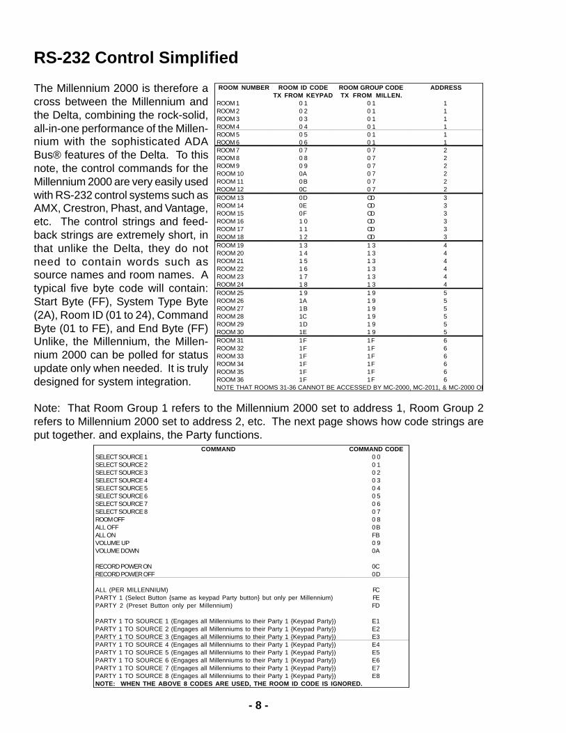
COMMAND COMMAND CODESELECT SOURCE 1 0 0SELECT SOURCE 2 0 1SELECT SOURCE 3 0 2SELECT SOURCE 4 0 3SELECT SOURCE 5 0 4SELECT SOURCE 6 0 5SELECT SOURCE 7 0 6SELECT SOURCE 8 0 7ROOM OFF 0 8ALL OFF 0BALL ON FBVOLUME UP 0 9VOLUME DOWN 0A
RECORD POWER ON 0CRECORD POWER OFF 0D
ALL (PER MILLENNIUM) FCPARTY 1 (Select Button same as keypad Party button but only per Millennium) FEPARTY 2 (Preset Button only per Millennium) FD
PARTY 1 TO SOURCE 1 (Engages all Millenniums to their Party 1 Keypad Party) E1PARTY 1 TO SOURCE 2 (Engages all Millenniums to their Party 1 Keypad Party) E2PARTY 1 TO SOURCE 3 (Engages all Millenniums to their Party 1 Keypad Party) E3PARTY 1 TO SOURCE 4 (Engages all Millenniums to their Party 1 Keypad Party) E4PARTY 1 TO SOURCE 5 (Engages all Millenniums to their Party 1 Keypad Party) E5PARTY 1 TO SOURCE 6 (Engages all Millenniums to their Party 1 Keypad Party) E6PARTY 1 TO SOURCE 7 (Engages all Millenniums to their Party 1 Keypad Party) E7PARTY 1 TO SOURCE 8 (Engages all Millenniums to their Party 1 Keypad Party) E8NOTE: WHEN THE ABOVE 8 CODES ARE USED, THE ROOM ID CODE IS IGNORED.
ROOM NUMBER ROOM ID CODE ROOM GROUP CODE ADDRESSTX FROM KEYPAD TX FROM MILLEN.
ROOM 1 0 1 0 1 1ROOM 2 0 2 0 1 1ROOM 3 0 3 0 1 1ROOM 4 0 4 0 1 1ROOM 5 0 5 0 1 1ROOM 6 0 6 0 1 1ROOM 7 0 7 0 7 2ROOM 8 0 8 0 7 2ROOM 9 0 9 0 7 2ROOM 10 0A 0 7 2ROOM 11 0B 0 7 2ROOM 12 0C 0 7 2ROOM 13 0D OD 3ROOM 14 0E OD 3ROOM 15 0F OD 3ROOM 16 1 0 OD 3ROOM 17 1 1 OD 3ROOM 18 1 2 OD 3ROOM 19 1 3 1 3 4ROOM 20 1 4 1 3 4ROOM 21 1 5 1 3 4ROOM 22 1 6 1 3 4ROOM 23 1 7 1 3 4ROOM 24 1 8 1 3 4ROOM 25 1 9 1 9 5ROOM 26 1A 1 9 5ROOM 27 1B 1 9 5ROOM 28 1C 1 9 5ROOM 29 1D 1 9 5ROOM 30 1E 1 9 5ROOM 31 1F 1F 6ROOM 32 1F 1F 6ROOM 33 1F 1F 6ROOM 34 1F 1F 6ROOM 35 1F 1F 6ROOM 36 1F 1F 6NOTE THAT ROOMS 31-36 CANNOT BE ACCESSED BY MC-2000, MC-2011, & MC-2000 OD
RS-232 Control Simplified
The Millennium 2000 is therefore across between the Millennium andthe Delta, combining the rock-solid,all-in-one performance of the Millen-nium with the sophisticated ADABus® features of the Delta. To thisnote, the control commands for theMillennium 2000 are very easily usedwith RS-232 control systems such asAMX, Crestron, Phast, and Vantage,etc. The control strings and feed-back strings are extremely short, inthat unlike the Delta, they do notneed to contain words such assource names and room names. Atypical five byte code will contain:Start Byte (FF), System Type Byte(2A), Room ID (01 to 24), CommandByte (01 to FE), and End Byte (FF)Unlike, the Millennium, the Millen-nium 2000 can be polled for statusupdate only when needed. It is trulydesigned for system integration.
Note: That Room Group 1 refers to the Millennium 2000 set to address 1, Room Group 2refers to Millennium 2000 set to address 2, etc. The next page shows how code strings areput together. and explains, the Party functions.

- 9 -
When putting control codes together to form strings the following format is used.
To select Source 6 for Room 2, use the code example below.
To turn off Room 3, use the code example below.
To engage Party 1 ("Select" button on some Millennium 2000s) just like the keypads.
The above code will engage all Millennium 2000 Room's locked to track Party 1, to Source 3.Note that the Room ID Code can be any code. This code, while needing to be inserted tocomplete the string, is simply ignored when the fourth byte begins with E.
System Status information is also available using the chart below.
The code structure for status is as follows.
ISO-232 ADA Bus to RS-232 Isolated Converter
The ISO-232 replaces the BC-232 as it offers several additional fea-tures while providing the same interface between ADA Bus® compo-nents and RS-232 control systems. The 9 pin D connector uses pin2 (TX), Pin 3 (RX), and Pin 5* (Gnd now IEEE Standard, *BC-232used pin 6). ISO-232 also optically isolates the ADA Bus® data portfrom the 9 pin D and does not require an additional power supply.
ADA BUSISO-232
1 2 3 4
RS-232Normal
Reverse(TuneBase)
SOURCE STATUS
HIGHER 4 BITS OF ROOMS 1, 3, 5 LOWER 4 BITS OF ROOMS 2, 4, 60 SOURCE 1 0 SOURCE 11 SOURCE 2 1 SOURCE 22 SOURCE 3 2 SOURCE 33 SOURCE 4 3 SOURCE 44 SOURCE 5 4 SOURCE 55 SOURCE 6 5 SOURCE 66 SOURCE 7 6 SOURCE 77 SOURCE 8 7 SOURCE 88 ALL OFF 8 ALL OFF9 ROOM OFF 9 ROOM OFFA N/A A N/AB N/A B N/AC N/A C N/AD N/A D N/AE N/A E N/AF N/A F N/A
START CODE SYSTEM TYPE CODE ROOM ID CODE COMMAND CODE END CODEFF 2A 01 TO 24 01 TO FE FF
START CODE SYSTEM TYPE CODE ROOM ID CODE COMMAND CODE END CODEFF 2A 0 7 0 5 FF
START CODE SYSTEM TYPE CODE ROOM ID CODE COMMAND CODE END CODEFF 2A 0D 0 8 FF
START CODE SYSTEM TYPE CODE ROOM ID CODE COMMAND CODE END CODEFF 2A 01 to 24 E3 FF
START CODE ROOM GROUP CODE ROOMS 1 & 2 ROOMS 3 & 4 ROOMS 5 & 6 SYSTEM TYPE END CODE0F 01 TO 1F 00 TO FF 00 TO FF 00 TO FF 2A F0

- 10 -
The ISO-232 also features Normal/Reverse jumpers making it easier to connect an EscientTuneBase Pro system. When using the ISO-232, not only will it isolate the Escient from thehouse-wide control system wiring array, but it will also permit you to set the jumper pins to theReverse position without switching pins 2 and 3 on the ADA Bus wire. Please note, that whenusing the ISO-232 to provide RS-232 control of the Millennium 2000, the jumper pins are setto the Normal position.
Cat. 5 Cable
ADA has revisited the wiring requirements for all of its data level systems including Millennium2000, Delta, Omega, & 8000. Up until 1999, Delta, Omega, and 8000 required runs of ADABus® wire, a specific 18 gauge three conductor wire with an overall braided shield (at least90% braid) (tin coated copper wire). The braid was used for ground, one wire for voltage, onefor receive, and one for transmit.
With the introduction of Millennium 2000, theengineers at ADA wanted to provide a plat-form whereby one can use standard Cat. 5cable to wire keypads. Even though ADA stillrecommends individual home runs for eachkeypad, Millennium 2000 controls can run onlong Cat. 5 runs (tested up to 1000’ per key-pad run, over 5000’ feet total tested). ADAhas developed two new devices, the Cat-LinkModule which is mounted to the keypad andincorporates an RJ-45 eight pin female con-nector, and the WH-2000 Cat-Link WiringHarness, which features eight female RJ-45connectors and five ADA Bus® four-pin re-movable screw terminal connectors.
This research and development has been ex-panded across other ADA components so thatDelta, Omega, and 8000 systems can nowalso be run on Cat. 5 Cable. While standardMC-3000 & MC-3800 keypad connectors willbe ADA Bus®, you can opt to request thesekeypads with Cat-Link Modules. When or-dering keypads that operate on Cat. 5 cable, you will need to specify (and purchase) the Cat-Link Module for controls working on Delta, Omega, and 8000 Systems. Since most systemscurrently being sold are already prewired with standard ADA Bus® cable, Cat-Link Modulesare an optional accessory for these systems.
Since Millennium 2000 is a new system, all Millennium 2000 keypads come standard with theCat-Link Module built in. When ordering a Millennium 2000 System with MC-2000 seriescontrols, you do not need to order Cat-Link Modules for each control. Millennium 2000 key-pads can be special ordered with the standard four pin ADA Bus® connectors.
RJ-45 Cat. 5 Cable Connector
TopFront
BROWN
BROWN
WHITE
GREEN
WHITE
ORANGE
ORANGE
WHITE
GREEN
BLUE
BLUE
WHITE
8 7 6 5 4 3 2 1
PIN NUMBER COLOR FUNCTIONPIN 1 BROWN +20VPIN 2 BROWN/WHITE GNDPIN 3 GREEN/WHITE TX-PIN 4 ORANGE RX+PIN 5 ORANGE/WHITE RX-PIN 6 GREEN TX+PIN 7 BLUE +20VPIN 8 BLUE/WHITE GND

- 11 -
ROOM 1 ROOM 2 ROOM 3 ROOM 4 ROOM 5 ROOM 6TREB BASS TREB BASS TREB BASS TREB BASS TREB BASS TREB BASS
POWERON
POWEROFF
MILLENNIUM MADE IN U.S.A.
FM 1 FM 2 AM CD 1 CD 2 AUX CASS1
ALL PARTY PRESET SETUPMODE
CASS2
ROOMOF
VOLUP
VOLDN
RECON
ROOM 1 ROOM 2 ROOM 3 ROOM 4 ROOM 5 ROOM 6
2000
L
R
SWITCHEDAC
OUTPUT6A MAX.
ACINPUT
10AMAX.
POWER AMP FUSE4A S.B.-120V2A S.B.-220V
LEFT
RIGHT
2Ω-16ΩSPEAKER
R L+ - - +
ROOM 6 - LINE OUTVARIABLE
FIXED
LEFT
RIGHT
2Ω-16ΩSPEAKER
R L+ - - +
ROOM 5 - LINE OUTVARIABLE
FIXED
LEFT
RIGHT
2Ω-16ΩSPEAKER
R L+ - - +
ROOM 4 - LINE OUTVARIABLE
FIXED
LEFT
RIGHT
2Ω-16ΩSPEAKER
R L+ - - +
ROOM 3 - LINE OUTVARIABLE
FIXED
LEFT
RIGHT
2Ω-16ΩSPEAKER
R L+ - - +
ROOM 2 - LINE OUTVARIABLE
FIXED
LEFT
RIGHT
2Ω-16ΩSPEAKER
R L+ - - +
ROOM 1 - LINE OUTVARIABLE
FIXED
EXPAND
PORT
SOURCEL.V.AC
CONTROL
INPUT 1 INPUT 2 INPUT 3 INPUT 4 INPUT 5 INPUT 6 INPUT 7 INPUT 8
LINEDRIVERMODULE
(NOT FOUNDON
MILLENNIUMSLAVEUNITS)
CAUTIONRISK OF ELECTRIC SHOCK
DO NOT OPEN
ATTENTION!RISQUE DE CHOC ELECTRIQUE.
NE PAS OUVRIR
MADE IN U.S.A.
MILLENNIUM
V CABLE POLARITY V CABLE POLARITY V CABLE POLARITY V CABLE POLARITY V CABLE POLARITY V CABLE POLARITY
ROOM 6 ROOM 5 ROOM 4 ROOM 3 ROOM 2 ROOM 1
CONTROLINPUT/OUTPUT
FROM WIRE HARNESS
PGM BUT IR ER D OK PGM OUTSOURCES IR LEARNERSWITCHEDAC
OUTPUT6A MAX
ACINPUT
10AMAX
AUDIO INPUTS
ADABUS
INFRARED LEARNER1 2 3 4 5 6
1 2 3 4
7 88
IR PROGRAM
NORMAL
IR RECEIVER
RS-232 FOR IR LEARNING ONLY
7 6 5 4 3 2 1
Millennium 2000 Physical Differences
The Millennium 2000 differs from the original Millennium in five visible areas.
1 The Microprocessor is recessed behind the front panel and a small plate providesaccess to this chip.
2 The IR learner module internal to the Millennium 2000 is the same device found in theIRL-3000. Also, there are now eight IR outputs, one for each source.
3 Because the IR learner is internal, you need a PC connected to the Millennium 2000during both IR capture and downloading of the IR information to the Millennium 2000's IRlearner.
4 Four front panel buttons on the Millennium are now used to program the Millennium2000’s address (6 Millennium 2000’s can be used on a single network, 36 Zones), programrooms to turn on with one of two Party modes, and engage Party 1, Party 2, or All On.
5 The rear panel features an ADA Bus® jack (removable screw terminal jack).
These are the only real differences that you will be able to see upon visual inspection of theunit.

- 12 -
Party Mode
The Millennium 2000 Keypads which feature numeric buttons (MC-2000, MC-2000 OD, & TS-2000), also feature a PARTY button. This button will turn on several rooms at once and switchthem to the source selected on the keypad from which the Party button has been pressed.
The ability for a room to be controlled from the keypads Party button, is based on the setup ofthat room’s Millennium 2000 (see below). The Millennium 2000 features three buttons on itsfront panel, Party 1 (or Party), Party 2 (or Preset), and All. While these buttons are used forprogramming the Millennium 2000, they also have operate the Millennium 2000. Unlike thekeypads' Party buttons, the Millennium 2000's Party buttons (& All button) operate only thezones on that Millennium 2000. While All engages all rooms, Party 1 and Party 2 are pro-grammable. In order for any three of these functions to be accessed, a room button must beon. Its source will engage in all rooms set to party. Keypads, unlike the buttons on the frontof each Millennium, will cause all Millennium Rooms (set to track Party 1), to engage.
Programming Millennium Room Groups & Party Rooms
The Millennium 2000 has two levels of programming that can be accomplished in one quickstep. The first level assigns the Millennium's Room Group number. If you are only using oneMillennium in the system, chances are its Room Group number will be 1. If you are usingmore than one Millennium 2000, each one will require a different Room Group number. Thesecond function if the programming of Rooms to engage with Party mode functions.
To enter the Millennium 2000's program mode, press and hold the SETUP MODE button untilboth the PRESET button and the SETUP MODE button are flashing in sequence.
Room GroupsPress the ALL button and the ALL button and SETUP MODE button will begin flashing insequence. Also, one of the first five room buttons will flash. The room buttons correspond tothe Millennium 2000's address Room Group. Normally, the ROOM 1 button will flash indicat-ing that this Millennium 2000 is set to Room Group address 1. To change the address, pressanother room button (Room 6 not used).
Party ModesThe Party mode accessed by the keypad is programmed by first pressing the PARTY buttonwhile in the program mode. At this time, the PARTY and SETUP MODE button will flash. Tohave rooms respond to the keypad's Party button, press their respective room buttons. Notethat the room buttons will begin flashing in sequence for the rooms you have selected to trackthis function. This same procedure is used to set rooms for Party 2 (or Preset) buttons. Whilethese rooms are turned on via the Millennium front panel, an RS-232 system can engageParty 2 just like keypads engage Party 1 (Party 1 can also be activated from RS-232 sys-tems). To program Party 2, press the Preset button and then the appropriate room buttons. Ifyou simply wish to see which rooms are set to Party, simply press either the Preset or Partybuttons. The rooms scheduled to work with these functions will flash in sequence. To exit theMillennium 2000's program mode, press and hold the SETUP MODE button.

- 13 -
Cat-Link & The Millennium 2000
The Millennium 2000 keypads can be home run using either ADA Bus wire or Cat. 5. cable. Ifyou are using ADA Bus wire, then order your Millennium System with WH-3000 Wiring Har-nesses (1 per Millennium). If you are running your keypads on Cat. 5 cable, then you willneed to order WH-2000 Wiring Harnesses. When using the WH-2000, the Millennium con-nects directly to one of the five ADA Bus® connectors on the WH-2000 Wiring Harness. If youare running several Millennium 2000’s you will run each Millennium 2000 to its own WH-2000,and then using a four conductor wire, interconnect the WH-2000’s using the ADA Bus® con-nectors. The Millennium 2000 has a total of six different addresses, permitting you connectup to six units together for a full 36 zone system. Please note that while you can have sixMillenniums connected for a 36 zone system, MC-2000 and MC-2011 keypads only have thecapacity to control zones 1-30. Zones 31-36 can only be controlled by MC-3000, MC-3800,MC-3000 OD, MC-3800 OD, MC-5000, and TS-3000 controls. These last six zones can alsobe controlled by an external control system via RS-232.
The other ADA Bus® connectors found on the WH-2000 can be used for keypads running onADA Bus® wires or connection of ADA Tuners, ISO-232’s used to connect to Escient CDlibrary systems, other ADA Bus® components, and an ISO-232 for connection to a third partycontrol system such as AMX, Crestron, Phast, Lutron, or Vantage. When using any of thesesub-systems in conjunction with multiple Millennium 2000's, you need only to connect thesub-system to one WH-2000, not each WH-2000 in the system.
Each WH-2000 also features eight (8) RJ-54 Cat-Link™ connectors (female). ADA keypadswith Cat-Link™ connectors, wire to RJ-45 connectors that plug into the WH-2000. If you areusing an ADA keypad with an ADA Bus® connector, you will connect it to an open ADA Bus®terminal on the WH-3000or an open terminal onthe WH-2000, not to aCat-Link™ connector.
The Millennium 2000 iseasy to wire. Most com-ponents that are associ-ated to the system main-frame, wire directly to theADA Bus® data ports onthe WH-2000 using an18 gauge four conductorcable. If any of thesecables are longer than10 feet, an ADA Bus®wire would most likelywork better. The key-pads, running on Cat. 5cable connect to theWH-2000.
L
R
SWITCHEDAC
OUTPUT6A MAX.
ACINPUT
10AMAX.
POWER AMP FUSE4A S.B.-120V2A S.B.-220V
LEFT
RIGHT
2Ω-16ΩSPEAKER
R L+ - - +
ROOM 6 - LINE OUTVARIABLE
FIXED
LEFT
RIGHT
2Ω-16ΩSPEAKER
R L+ - - +
ROOM 5 - LINE OUTVARIABLE
FIXED
LEFT
RIGHT
2Ω-16ΩSPEAKER
R L+ - - +
ROOM 4 - LINE OUTVARIABLE
FIXED
LEFT
RIGHT
2Ω-16ΩSPEAKER
R L+ - - +
ROOM 3 - LINE OUTVARIABLE
FIXED
LEFT
RIGHT
2Ω-16ΩSPEAKER
R L+ - - +
ROOM 2 - LINE OUTVARIABLE
FIXED
LEFT
RIGHT
2Ω-16ΩSPEAKER
R L+ - - +
ROOM 1 - LINE OUTVARIABLE
FIXED
EXPAND
PORT
SOURCEL.V.AC
CONTROL
INPUT 1 INPUT 2 INPUT 3 INPUT 4 INPUT 5 INPUT 6 INPUT 7 INPUT 8
LINEDRIVERMODULE
(NOT FOUNDON
MILLENNIUMSLAVEUNITS)
CAUTIONRISK OF ELECTRIC SHOCK
DO NOT OPEN
ATTENTION!RISQUE DE CHOC ELECTRIQUE.
NE PAS OUVRIR
MADE IN U.S.A.
MILLENNIUM
V CABLE POLARITY V CABLE POLARITY V CABLE POLARITY V CABLE POLARITY V CABLE POLARITY V CABLE POLARITY
ROOM 6 ROOM 5 ROOM 4 ROOM 3 ROOM 2 ROOM 1
CONTROLINPUT/OUTPUT
FROM WIRE HARNESS
PGM BUT IR ER D OK PGM OUTSOURCES IR LEARNERSWITCHEDAC
OUTPUT6A MAX
ACINPUT
10AMAX
AUDIO INPUTS
ADABUS
INFRARED LEARNER1 2 3 4 5 6
1 2 3 4
7 88
IR PROGRAM
NORMAL
IR RECEIVER
RS-232 FOR IR LEARNING ONLY
7 6 5 4 3 2 1
OFFSHIFT
VOL PTY 1 PTY 2
FM 1 FM 2 AM CD 1 CD 2 DSS DVD AUX
CD PLAYER 2
ROOMOFF
101.90 JAZZ
FM 1 FM 2 AMCD1
CD2
AUXCASS
1
VOLUP
VOLDN
ROOMOFF
SHIFT
8
0
7
*
9
ENTER
2
5
1
4
3
6
CASS2
PARTY1
PARTY1
PARTY2
PARTY2
OFFSHIFT
VOL PTY 1 PTY 2
FM 1 FM 2 AM CD 1 CD 2 DSS DVD AUX
CD PLAYER 2
1 2 3
4 5 6
7 8 9
*0
ENT OFF
PARTY 1
EXTRA
VOL
PARTY 2
FM
2F
CD
1C
D2
DS
S
DV
D AUX
AM
1 2 3 4
WH-2000
J1
J2
J3
J4
J5
RJ45
RJ45
RJ45
RJ45
RJ45
RJ45
RJ45
RJ45
1 2 3 4 5 6 7 8TO 9 PIN "D"
DELTA-881 2 3 4 5 6 7 81 2 3 4 5 6 7 81 2 3 4 5 6 7 8
1000 WATTSMAX TOTAL
Set Shunting Pins To Engage AC With Zone Or Source Numbers 1-8
120-240 VAC50-60 Hz
QUAD AC CONTROLLER
ACC-48
CAUTIONRISK OF ELECTRIC SHOCK
DO NOT OPEN
ATTENTION!RISQUE DE CHOC ELECTRIQUE.
NE PAS OUVRIR
MADE IN U.S.A.
1. Delta-88 9 Pin "D" programmed for source AC control. - Set one shuntingpin per AC outlet according to source inputs. Set 3 pins for MT-3000.
2. Delta-88 9 Pin "D" programmed for zone AC control. - Set one shuntingpen per AC outlet according to zone numbers. Set all shunting pins onone AC Outlet for All-On source AC control when not using an ACC-3000.
3 421
115
V
FM 1 FM 2 CD 1
CD 2 CASS LASER
VCR DSS
VOLUP
VOLDN
ROOMOFF
1 2 3
4 5 6
7 8
PARTY
9
* 0 ENTER
FM 1 FM 2 CD 1
CD 2 CASS LASER
VCR DSS
VOLUP
VOLDN
ROOMOFF
ADA BUSISO-232
1 2 3 4
RS-232Normal
Reverse(TuneBase)
ADA BUSISO-232
1 2 3 4
RS-232Normal
Reverse(TuneBase)
9 Pin Ribbon Cable
ADA Bus Cable
Cat. 5 Cable
To Escient TuneBase Pro MKII
To External ControlSystem (Crestron, AMX)

- 14 -
Multiple Millennium 2000's
When connecting several Millennium 2000s (Up to six Max), each Millennium 2000 connectsto its own WH-2000 wiring harness. The WH-2000's connect to each other using a fourconductor 18 gauge wire (ADA Bus®) as well. Components common to the entire system,such as IRL-3000 source controllers, ISO-232's for RS-232 systems including Escient'sTuneBase products, are connected to any of the WH-2000's ADA Bus ports since the WH-2000s are connected to each other.
L
R
SWITCHEDAC
OUTPUT6A MAX.
ACINPUT
10AMAX.
POWER AMP FUSE4A S.B.-120V2A S.B.-220V
LEFT
RIGHT
2Ω-16ΩSPEAKER
R L+ - - +
ROOM 6 - LINE OUTVARIABLE
FIXED
LEFT
RIGHT
2Ω-16ΩSPEAKER
R L+ - - +
ROOM 5 - LINE OUTVARIABLE
FIXED
LEFT
RIGHT
2Ω-16ΩSPEAKER
R L+ - - +
ROOM 4 - LINE OUTVARIABLE
FIXED
LEFT
RIGHT
2Ω-16ΩSPEAKER
R L+ - - +
ROOM 3 - LINE OUTVARIABLE
FIXED
LEFT
RIGHT
2Ω-16ΩSPEAKER
R L+ - - +
ROOM 2 - LINE OUTVARIABLE
FIXED
LEFT
RIGHT
2Ω-16ΩSPEAKER
R L+ - - +
ROOM 1 - LINE OUTVARIABLE
FIXED
EXPAND
PORT
SOURCEL.V.AC
CONTROL
INPUT 1 INPUT 2 INPUT 3 INPUT 4 INPUT 5 INPUT 6 INPUT 7 INPUT 8
LINEDRIVERMODULE
(NOT FOUNDON
MILLENNIUMSLAVEUNITS)
CAUTIONRISK OF ELECTRIC SHOCK
DO NOT OPEN
ATTENTION!RISQUE DE CHOC ELECTRIQUE.
NE PAS OUVRIR
MADE IN U.S.A.
MILLENNIUM
V CABLE POLARITY V CABLE POLARITY V CABLE POLARITY V CABLE POLARITY V CABLE POLARITY V CABLE POLARITY
ROOM 6 ROOM 5 ROOM 4 ROOM 3 ROOM 2 ROOM 1
CONTROLINPUT/OUTPUT
FROM WIRE HARNESS
PGM BUT IR ER D OK PGM OUTSOURCES IR LEARNERSWITCHEDAC
OUTPUT6A MAX
ACINPUT
10AMAX
AUDIO INPUTS
ADABUS
INFRARED LEARNER1 2 3 4 5 6
1 2 3 4
7 88
IR PROGRAM
NORMAL
IR RECEIVER
RS-232 FOR IR LEARNING ONLY
7 6 5 4 3 2 1
OFFSHIFT
VOL PTY 1 PTY 2
FM 1 FM 2 AM CD 1 CD 2 DSS DVD AUX
CD PLAYER 2
ROOMOFF
101.90 JAZZ
FM 1 FM 2 AMCD1
CD2
AUXCASS
1
VOLUP
VOLDN
ROOMOFF
SHIFT
8
0
7
*
9
ENTER
2
5
1
4
3
6
CASS2
PARTY1
PARTY1
PARTY2
PARTY2
OFFSHIFT
VOL PTY 1 PTY 2
FM 1 FM 2 AM CD 1 CD 2 DSS DVD AUX
CD PLAYER 2
1 2 3
4 5 6
7 8 9
*0
ENT OFF
PARTY 1
EXTRA
VOL
PARTY 2
FM
2F
CD
1C
D2
DS
S
DV
D AUX
AM
1 2 3 4
WH-2000
J1
J2
J3
J4
J5
RJ45
RJ45
RJ45
RJ45
RJ45
RJ45
RJ45
RJ45
115
V
FM 1 FM 2 CD 1
CD 2 CASS LASER
VCR DSS
VOLUP
VOLDN
ROOMOFF
1 2 3
4 5 6
7 8
PARTY
9
* 0 ENTER
FM 1 FM 2 CD 1
CD 2 CASS LASER
VCR DSS
VOLUP
VOLDN
ROOMOFF
ADA BUSISO-232
1 2 3 4
RS-232Normal
Reverse(TuneBase)
ADA BUSISO-232
1 2 3 4
RS-232Normal
Reverse(TuneBase)
L
R
SWITCHEDAC
OUTPUT6A MAX.
ACINPUT
10AMAX.
POWER AMP FUSE4A S.B.-120V2A S.B.-220V
LEFT
RIGHT
2Ω-16ΩSPEAKER
R L+ - - +
ROOM 6 - LINE OUTVARIABLE
FIXED
LEFT
RIGHT
2Ω-16ΩSPEAKER
R L+ - - +
ROOM 5 - LINE OUTVARIABLE
FIXED
LEFT
RIGHT
2Ω-16ΩSPEAKER
R L+ - - +
ROOM 4 - LINE OUTVARIABLE
FIXED
LEFT
RIGHT
2Ω-16ΩSPEAKER
R L+ - - +
ROOM 3 - LINE OUTVARIABLE
FIXED
LEFT
RIGHT
2Ω-16ΩSPEAKER
R L+ - - +
ROOM 2 - LINE OUTVARIABLE
FIXED
LEFT
RIGHT
2Ω-16ΩSPEAKER
R L+ - - +
ROOM 1 - LINE OUTVARIABLE
FIXED
EXPAND
PORT
SOURCEL.V.AC
CONTROL
INPUT 1 INPUT 2 INPUT 3 INPUT 4 INPUT 5 INPUT 6 INPUT 7 INPUT 8
LINEDRIVERMODULE
(NOT FOUNDON
MILLENNIUMSLAVEUNITS)
CAUTIONRISK OF ELECTRIC SHOCK
DO NOT OPEN
ATTENTION!RISQUE DE CHOC ELECTRIQUE.
NE PAS OUVRIR
MADE IN U.S.A.
MILLENNIUM
V CABLE POLARITY V CABLE POLARITY V CABLE POLARITY V CABLE POLARITY V CABLE POLARITY V CABLE POLARITY
ROOM 6 ROOM 5 ROOM 4 ROOM 3 ROOM 2 ROOM 1
CONTROLINPUT/OUTPUT
FROM WIRE HARNESS
PGM BUT IR ER D OK PGM OUTSOURCES IR LEARNERSWITCHEDAC
OUTPUT6A MAX
ACINPUT
10AMAX
AUDIO INPUTS
ADABUS
INFRARED LEARNER1 2 3 4 5 6
1 2 3 4
7 88
IR PROGRAM
NORMAL
IR RECEIVER
RS-232 FOR IR LEARNING ONLY
7 6 5 4 3 2 1
OFFSHIFT
VOL PTY 1 PTY 2
FM 1 FM 2 AM CD 1 CD 2 DSS DVD AUX
CD PLAYER 2
ROOMOFF
101.90 JAZZ
FM 1 FM 2 AMCD1
CD2
AUXCASS
1
VOLUP
VOLDN
ROOMOFF
SHIFT
8
0
7
*
9
ENTER
2
5
1
4
3
6
CASS2
PARTY1
PARTY1
PARTY2
PARTY2
OFFSHIFT
VOL PTY 1 PTY 2
FM 1 FM 2 AM CD 1 CD 2 DSS DVD AUX
CD PLAYER 2
1 2 3
4 5 6
7 8 9
*0
ENT OFF
PARTY 1
EXTRA
VOL
PARTY 2
FM
2FM
CD
1C
D2
DS
S
DV
D AUX
AM
1 2 3 4
WH-2000
J1
J2
J3
J4
J5
RJ45
RJ45
RJ45
RJ45
RJ45
RJ45
RJ45
RJ45
1 2 3 4 5 6 7 8TO 9 PIN "D"
DELTA-881 2 3 4 5 6 7 81 2 3 4 5 6 7 81 2 3 4 5 6 7 8
1000 WATTSMAX TOTAL
Set Shunting Pins To Engage AC With Zone Or Source Numbers 1-8
120-240 VAC50-60 Hz
QUAD AC CONTROLLER
ACC-48
CAUTIONRISK OF ELECTRIC SHOCK
DO NOT OPEN
ATTENTION!RISQUE DE CHOC ELECTRIQUE.
NE PAS OUVRIR
MADE IN U.S.A.
1. Delta-88 9 Pin "D" programmed for source AC control. - Set one shuntingpin per AC outlet according to source inputs. Set 3 pins for MT-3000.
2. Delta-88 9 Pin "D" programmed for zone AC control. - Set one shuntingpen per AC outlet according to zone numbers. Set all shunting pins onone AC Outlet for All-On source AC control when not using an ACC-3000.
3 421
FM 1 FM 2 CD 1
CD 2 CASS LASER
VCR DSS
VOLUP
VOLDN
ROOMOFF
1 2 3
4 5 6
7 8
PARTY
9
* 0 ENTER
FM 1 FM 2 CD 1
CD 2 CASS LASER
VCR DSS
VOLUP
VOLDN
ROOMOFF
ADA Bus Cable
To Escient TuneBase Pro MKII
To External ControlSystem (Crestron, AMX)
Cat. 5 Cable
9 Pin Ribbon Cable
Cat. 5 Cable

- 15 -
Keypad Settings - MC-2011, MC-2000, & MC-2000 OD
For these keypads to operate properly, theywill need to have their DIP switches set tothe correct room number and source configu-ration.
The first five DIP switches set the room num-ber. The last three DIP switches set thesource control options. To set the room num-bers, it is suggested for first disconnect thekeypad from the system by unplugging theRJ-45 connector (or ADA Bus® jack). Setthe switches correctly and reconnect to thesystem. The chart to the right details theswitch settings for rooms (switches 1 -5).
The final three switches (6-8) determine whatthe source buttons will be controlling after theyhave been selected. For example, if you areusing a Trinity Triple Tuner for FM 1, FM 2,AM, an Escient TuneBase Pro for CD 1, withthe remaining four devices (CD 2, CASS,DSS, DVD, VCR) controlled by IR (or serialdata) using the IRL-3000. This scenario issolved using format number three in the chartbelow where DIP switch 7 is in the UP posi-tion.
The last three DIP switches determine thesource control options and the eight optionslisted below are available. Please note, thatyou cannot alter the order of the sources withrespect to the Millennium 2000's inputs. Theoptions are fixed to the assigned inputs.
If you require an alternate configuration than that stated above, you will need to contact ADAfor custom programming at an additional charge. Please note that you will need to havecustom programmed microprocessors installed in each system keypad.
MILLENNIUM DIP SWITCH SETTINGS1 2 3 4 5
ROOM 1ROOM 2 UPROOM 3 UPROOM 4 UP UPROOM 5 UPROOM 6 UP UP
ROOM 7 UP UPROOM 8 UP UP UPROOM 9 UPROOM 10 UP UPROOM 11 UP UPROOM 12 UP UP UP
ROOM 13 UP UPROOM 14 UP UP UPROOM 15 UP UP UPROOM 16 UP UP UP UPROOM 17 UPROOM 18 UP UP
ROOM 19 UP UPROOM 20 UP UP UPROOM 21 UP UPROOM 22 UP UP UPROOM 23 UP UP UPROOM 24 UP UP UP UP
ROOM 25 UP UPROOM 26 UP UP UPROOM 27 UP UP UPROOM 28 UP UP UP UPROOM 29 UP UP UPROOM 30 UP UP UP UP
MILLENNIUM DIP SWITCH SET MILLENNIUM 2000 INPUTS AND THERE RESPECTIVE SOURCE OPTIONS (IRL-3000 FOR ADDRESS 1 ONLY)6 7 8 INPUT 1 INPUT 2 INPUT 3 INPUT 4 INPUT 5 INPUT 6 INPUT 7 INPUT 8
OPTION 1 IRL PORT 1 IRL PORT 2 IRL PORT 3 IRL PORT 4 IRL PORT 5 IRL PORT 6 IRL PORT 7 IRL PORT 8OPTION 2 UP TRINITY TUN 1 TRINITY TUN 2 TRINITY TUN 3 IRL PORT 4 IRL PORT 5 IRL PORT 6 IRL PORT 7 IRL PORT 8OPTION 3 UP TRINITY TUN 1 TRINITY TUN 2 TRINITY TUN 3 SPECIAL CD 1 IRL PORT 5 IRL PORT 6 IRL PORT 7 IRL PORT 8OPTION 4 UP UP TRINITY TUN 1 TRINITY TUN 2 TRINITY TUN 3 SPECIAL CD 1 SPECIAL CD 2 IRL PORT 6 IRL PORT 7 IRL PORT 8OPTION 5 UP TRINITY TUN 1 TRINITY TUN 2 IRL PORT 3 IRL PORT 4 IRL PORT 5 IRL PORT 6 IRL PORT 7 IRL PORT 8OPTION 6 UP UP TRINITY TUN 1 TRINITY TUN 2 SPECIAL CD 1 IRL PORT 4 IRL PORT 5 IRL PORT 6 IRL PORT 7 IRL PORT 8OPTION 7 UP UP TRINITY TUN 1 TRINITY TUN 2 SPECIAL CD 1 SPECIAL CD 2 IRL PORT 5 IRL PORT 6 IRL PORT 7 IRL PORT 8OPTION 8 UP UP UP IRL PORT 1 IRL PORT 2 SPECIAL CD 1 IRL PORT 4 IRL PORT 5 IRL PORT 6 IRL PORT 7 IRL PORT 8

- 16 -
MC-3000 & MC-5000 Series Programming
The MC-3000, MC-3800, MC-3000 OD, MC-3800 OD, and MC-5000 (Rapture) controls arevoid of DIP switches for room addressing and source register. As such, these controls willneed to be programmed using there buttons and a special setup mode.
The room address determines what room this keypad is controlling. The source registerdetermines what the source buttons are controlling and getting feedback from. So that whenthe FM 1 button, set to Trinity Tuner module 1, is selected, the keypad displays tuner feed-back and the transport buttons control tuner 1. Other register options include the additionaltuner modules, Special CD addresses 1 through 8 (for Escient TuneBase Pro Mark II), andIRL-3000 ports. In the case of the Millennium 2000, the IRL-3000 is internal.
A second external IRL-3000 could be used in conjunction with the internal IRL-3000, but onlyon systems void of MC-2000 series keypads (their limited programming via DIP switches donot permit accessing a second IRL address). However, in systems using only MC-3000, MC-5000 and TS-3000 Series controls, this second IRL-3000 option might assist in controllingsources at some distance from the mainframe. For example, the mainframe including theMillennium 2000 is buried in the basement with a two DSS receivers and the Trinity Tuner.Two CD changers, a DVD, and VCR are located in the family room rack. Perhaps the main-frame was based in another room due to space limitations. In this case, instead of runningfour IR lines from the Millennium 2000 to the four remote sources, simply run an single ADABus line and place the second IRL-3000 behind the remote sources. Again, this scenariowon't work for the MC-2000 or MC-2011 because they cannot be configured outside theireight source register options.
Consideration AWhen working with MC-3000/MC-5000 keypads and MC-2000 or MC-2011s, you will need tofirst configure the MC-2000's source register, setting their DIP switches according to the sourcechart on the bottom of the previous page. Use the same options when programming the MC-3000/MC-5000s.
Consideration BWhen working with MC-5000 Keypads, because of the silk-screened rubber button pad, youwill want to place the sources on the appropriate input as the rubber pads source layout(inputs 1-8) cannot be changed.
Programming1 To enter the program mode of a keypad, press and hold the SHIFT (MC-3000 Series)
or EXTRA (MC-5000 Series) button until the display reads CODE. Then release theSHIFT button.
2 Using the source buttons, reading left to right (where source 1 is on the left and source8 is on the right) enter the code 1867 using the sources buttons (not the numericbuttons.). The keypad will display the code as you are entering it.

- 17 -
Room Address3 Press the BASS UP button once and the display will show the System Type "1:MIL-
LENNIUM". Press BASS UP again and the keypad will display "1:SETUP". PressBASS UP again and the display will read "1:ROOM ###", where the number repre-sents the room address. While the counter can go from 001 to 225, the first 36 ad-dresses are the only ones used with the Millennium 2000 System. As such, only 001 to036 are used.
4 To change the room address use the VOL UP & DN buttons. When you have thekeypad locked into the desired room and wish to program other parameters, continuewith step 5. If you are done programming this keypad, press and release the SHIFT orEXTRA button.
Checking the Source Register5 Press the BASS UP button and the dis-
play will read "2:CHECK 1-8". In thismode, pressing the various source but-tons will display the current source set-tings. The source register will read oneof the options to the right.
Preventing Devices From Being Controlled6 Pressing the BASS UP button again will
display "2:EDIT 1-8" which will quicklychange to reading "2:NONE". If a sourcebutton is not intended to track any func-tion (if you do not want a particular key-pad to control a device), simply press thedevices button at this time. The displaywill quickly read DONE and then returnto the 2:NONE setting.
Locking Source Buttons To Control Specific Tuner Modules, Special CDs, & IRL Ports7 To lock a source button to a specific device, first select the device by pressing VOL UP.
The display will scroll through the register as listed in the chart above. If you pass thedevice you are looking for, use the VOL DN button to return to it. The source registerends at the bottom and top. When the right register is displayed, press the sourcebutton. The display will briefly read DONE and then return to the setting you selected.Repeat this step for all eight sources as needed.
At this time, if you do not want to load other MC-3000/MC-5000 keypads with thisrevised register, simply press and release the SHIFT or EXTRA button to exit the setupmode. If you want to program other keypads with this register continue.
Proceeding to the Label and Programming Steps8 Press the BASS UP button and the display will read "1:EXTRA A-F. Press the BASS
UP button again and the display will read "2:EXTRA 0-9".
DISPLAY WHAT IT MEANS WHAT YOU USE2:NONE NO SOURCE CONTROLTRNTY 0/TUN1 TRIINITY TUNER MODULE 1 ADDRESS 0 STANDARDTRNTY 0/TUN2 TRIINITY TUNER MODULE 2 ADDRESS 0 STANDARDTRNTY 0/TUN3 TRIINITY TUNER MODULE 3 ADDRESS 0 STANDARDIRL3K 0/OUT1 IRL-3000 ON ADDRESS 1 PORT 1 STANDARDIRL3K 0/OUT2 IRL-3000 ON ADDRESS 1 PORT 2 STANDARDIRL3K 0/OUT3 IRL-3000 ON ADDRESS 1 PORT 3 STANDARDIRL3K 0/OUT4 IRL-3000 ON ADDRESS 1 PORT 4 STANDARDIRL3K 0/OUT5 IRL-3000 ON ADDRESS 1 PORT 5 STANDARDIRL3K 0/OUT6 IRL-3000 ON ADDRESS 1 PORT 6 STANDARDIRL3K 0/OUT7 IRL-3000 ON ADDRESS 1 PORT 7 STANDARDIRL3K 0/OUT8 IRL-3000 ON ADDRESS 1 PORT 8 STANDARDIRL3K 1/OUT1 IRL-3000 ON ADDRESS 2 PORT 1IRL3K 1/OUT2 IRL-3000 ON ADDRESS 2 PORT 2IRL3K 1/OUT3 IRL-3000 ON ADDRESS 2 PORT 3IRL3K 1/OUT4 IRL-3000 ON ADDRESS 2 PORT 4IRL3K 1/OUT5 IRL-3000 ON ADDRESS 2 PORT 5IRL3K 1/OUT6 IRL-3000 ON ADDRESS 2 PORT 6IRL3K 1/OUT7 IRL-3000 ON ADDRESS 2 PORT 7IRL3K 1/OUT8 IRL-3000 ON ADDRESS 2 PORT 8SPECIAL CD 1 ESCIENT I/O ADDRESS 1 STANDARDSPECIAL CD 2 ESCIENT I/O ADDRESS 2SPECIAL CD 3 ESCIENT I/O ADDRESS 3SPECIAL CD 4 ESCIENT I/O ADDRESS 4SPECIAL CD 5 ESCIENT I/O ADDRESS 5SPECIAL CD 6 ESCIENT I/O ADDRESS 6SPECIAL CD 7 ESCIENT I/O ADDRESS 7SPECIAL CD 8 ESCIENT I/O ADDRESS 8LVI -3800 SOURCE RELAY CONTROLLERTRNTY 1/TUN1 TRIINITY TUNER MODULE 1 ADDRESS 1TRNTY 1/TUN2 TRIINITY TUNER MODULE 2 ADDRESS 1TRNTY 1/TUN3 TRIINITY TUNER MODULE 3 ADDRESS 1

- 18 -
Labeling Source Names9 Press the BASS UP button again and the display will read LABEL SOURCES immedi-
ately followed by one of the source names. The first letter in the source will also beflashing. At this time, pressing VOL UP or DN will cause this letter to change. Use the>> or << buttons to advance the cursor to the next position. To label a different input,select the source button and repeat these steps.
Programming Millennium & Other MC-3000/5000 Keypads w/Source Register & Names10 Before proceeding with this step make certain that only one keypad is in this setup
mode. This step takes the information programmed in the keypad you are working onand copies its contents to the Millennium 2000 chip. If you have more than one Millen-nium 2000 in your system, the one set to address one (the first unit with the IRL-3000in it) will be the only one capable of receiving this program. Press the BASS UP buttonand the display will read PROGRAM ALL. At this time press the VOL UP or DN once toinitiate the programming procedure.
The display will say PROGRAMMING and then the display will read through all eightsources from the first to the last. Other MC-3000/5000 keypads on the system willdisplay PROGRAMMING and have there source LEDs move left to right. When theload to the primary Millennium 2000 and keypads is done, the display will read FIN-ISHED. Press the SHIFT or EXTRA button to exit the setup mode. The display willread REQUEST DATA and the keypad will return to its operational mode.
If the display will continues to constantly read PROGRAMMING, the Millennium is notresponding to the program. Press the SHIFT or EXTRA button to get out of the setupmode. Re-enter the keypad's program mode and repeat this step. If you still have arestuck in PROGRAMMING, verify that the Millennium Master is in fact on address one.If you want to reset power to the Millennium, turn off its power switch. Please note, ifyou have more then one Millennium on the system or other ADA Bus devices thatprovide power (ie. Cinema Reference), you will need to unplug or remove power fromthese units as well for a clean reset.
CRC ErrorsIf the other keypads in the system have an interruption during their load, they may willdisplay CRC ERROR. As such, something caused the keypad to not fully received thefile load. If this occurred to several keypad, you can repeat step 10. If it occurred toone or two keypads, you can use the Polling procedures described in step 11 to loadthese keypads individually.
Polling A Keypad or Adding A New MC-3000/5000 To An Existing System11 After the new keypad is connected, enter its program mode as before. Repeatedly
press BASS UP button until the "1:ROOM ###" appears in the display. Using the VOLUP or DN buttons, lock in the room address for this keypad. Then press the BASS UPbutton until the display reads POLL INFO. Press VOL UP or DN and the keypad willdownload the source register and source names from the primary Millennium. As thisprocedure occurs, the source lights will advance from left to right. When the poll iscomplete, the keypad will read FINISHED. At this time, press the SHIFT or EXTRAbutton to exit the program mode.
- 19 -
MC-3000, MC-3800, and MC-5000 IR Receiver On/OffTo turn toggle the keypad's IR receiver on or off, press and hold the SHIFT or EXTRA buttonuntil the display reads "CODE: ####". Then using the source buttons, where 1 is to the leftand 8 is to the right, enter the code 1112. The keypad will display the numbers as they areentered. Then press and release the BASS UP button. The keypad's display will indicate ifthe IR receiver is on or off. To change the setting, repeat this procedure.
Millennium 2000 - What you will need.When ordering the Millennium 2000 System, you will need to include the following items inyour proposal.
Millennium 2000 One mainframe per system.Millennium 2000 Slave One slave unit for every additional six zones.WH-2000 or WH-3000 One Wiring Harness per Millennium 2000 or Slave unit.ACC-48 Source AC Controller 1 for every 4 sources, typically one per system will do.Keypads As needed.OptionalTrinity Triple Tuner Triple Tuner - One per system.PhoneBell Alert Override Doorbell & Telephone Paging - One for every six zones as needed.For IR Control of a ZoneIRT-3000 IR Transceiver Needed for any room that will require an IR pickup.IRT-232 & Bits™ Program Used to program learning IR remote controls with IR codes
to control Millennium 2000s (make your own IR remote).To integrate an Escient TuneBaseISO-232 ADA Bus®/RS-232 One per TuneBaseTo integrate a third party control System (AMX, Crestron, Phast)ISO-232 ADA Bus®/RS-232 Only one unit is typically required.
Millennium Devices You Cannot Use with Millennium 2000While it is clear that you can use some of the same components that are used by the standardMillennium System, there are some components that will not integrate with Millennium 2000.VSU-8 Video Switching UnitZT-1 Zone TrackerZS-1 Zone Splitters
Using a UPS (Uninterrupted Power Supply)The Millennium 2000 sounds warm and clean, in particular due to the selection of VCAs(Voltage Control Attenuators) used for volume control. These high quality VCAs do, however,have one drawback, when power is removed from the Millennium 2000, they reset to a zero(no sound) volume level. The only way restore the volume for every zone after power hasbeen restored, is to raise the volume.
If you are installing a Millennium 2000 in an environment where voltage drops, brownouts orpower outages are frequent, you may wish to provide a UPS (same ones used for PCs) tomaintain power during brief or momentary power outages. ADA suggests using a quality UPSwith at least a 600 Watt amp power rating.

- 20 -
Multiple Millenniums - Installation of the System Bus
The Millennium is uniquely designed to be expandable to up to 36 zones using a maximum ofsix Millenniums. While this flexibility typically exceeds the requirements of the most commonsystem, you may need to provide a system with 12 or 18 zones of audio.
The main (master) Millennium, with six zones, can have additional Millenniums connected toit. The additional Millenniums do not require the source component audio input board or thesource IR controller board because the master Millennium already has these circuits built-in.Subsequently, the additional Millenniums (slave units) will have a blank plate were theseconnectors are found on the master Millennium. All Millenniums are then connected togetherusing a 50 pin ribbon cable (System Bus) provided with the system.
The System Bus (50 pin ribbon cable) carries source selection commands, balanced line-levelaudio, source selection conformation feedback, and system on/system off status. This cleanand professional interconnect between multiple Millenniums makes this system ideal, not onlyfor small six room projects but also for the larger multi-room systems as well. No longer will youneed to split the source components audio line-level output to connect multiple mainframeservers. Best of all, the master Millennium provides a boost to standard audio line-levelpermitting up to six Millenniums to be connected together on one system.
When installing several Millenniums, you will plug each Millennium into its own wall AC outlet.ADA suggests using one 15 Amp - 20 Amp circuit per two Millenniums. The AC cords whichconnect the Millennium to the AC outlets is provided with each Millennium in a U.S. male ACversion.
Note: When using more thanone Millennium, you mustuse either the ACC-48 orASU-10 for source ACSwitching.
L
R
SWITCHEDAC
OUTPUT6A MAX.
ACINPUT
10AMAX.
POWER AMP FUSE4A S.B.-120V2A S.B.-220V
LEFT
RIGHT
2Ω-16ΩSPEAKER
R L+ - - +
ROOM 6 - LINE OUTVARIABLE
FIXED
LEFT
RIGHT
2Ω-16ΩSPEAKER
R L+ - - +
ROOM 5 - LINE OUTVARIABLE
FIXED
LEFT
RIGHT
2Ω-16ΩSPEAKER
R L+ - - +
ROOM 4 - LINE OUTVARIABLE
FIXED
LEFT
RIGHT
2Ω-16ΩSPEAKER
R L+ - - +
ROOM 3 - LINE OUTVARIABLE
FIXED
LEFT
RIGHT
2Ω-16ΩSPEAKER
R L+ - - +
ROOM 2 - LINE OUTVARIABLE
FIXED
LEFT
RIGHT
2Ω-16ΩSPEAKER
R L+ - - +
ROOM 1 - LINE OUTVARIABLE
FIXED
EXPAND
PORT
SOURCEL.V.AC
CONTROL
INPUT 1 INPUT 2 INPUT 3 INPUT 4 INPUT 5 INPUT 6 INPUT 7 INPUT 8
LINEDRIVERMODULE
(NOT FOUNDON
MILLENNIUMSLAVEUNITS)
CAUTIONRISK OF ELECTRIC SHOCK
DO NOT OPEN
ATTENTION!RISQUE DE CHOC ELECTRIQUE.
NE PAS OUVRIR
MADE IN U.S.A.
MILLENNIUM
V CABLE POLARITY V CABLE POLARITY V CABLE POLARITY V CABLE POLARITY V CABLE POLARITY V CABLE POLARITY
ROOM 6 ROOM 5 ROOM 4 ROOM 3 ROOM 2 ROOM 1
CONTROLINPUT/OUTPUT
FROM WIRE HARNESS
PGM BUT IR ER D OK PGM OUTSOURCES IR LEARNERSWITCHEDAC
OUTPUT6A MAX
ACINPUT
10AMAX
50 PINRIBBONCABLE(SYSTEM BUS)
9 PINRIBBONCABLE(FOR SOURCEAC SWITCHING)
TO AC
TO AC
TO AC
MAIN MILLENNIUM (MASTER)
SLAVE UNIT
SLAVE UNIT
1 2 3 4 5 6 7 8TO 9 PIN "D"
DELTA-881 2 3 4 5 6 7 81 2 3 4 5 6 7 81 2 3 4 5 6 7 8
1000 WATTSMAX TOTAL
Set Shunting Pins To Engage AC With Zone Or Source Numbers 1-8
120-240 VAC50-60 Hz
QUAD AC CONTROLLER
ACC-48
CAUTIONRISK OF ELECTRIC SHOCK
DO NOT OPEN
ATTENTION!RISQUE DE CHOC ELECTRIQUE.
NE PAS OUVRIR
MADE IN U.S.A.
1. Delta-88 9 Pin "D" programmed for source AC control. - Set one shuntingpin per AC outlet according to source inputs. Set 3 pins for MT-3000.
2. Delta-88 9 Pin "D" programmed for zone AC control. - Set one shuntingpen per AC outlet according to zone numbers. Set all shunting pins onone AC Outlet for All-On source AC control when not using an ACC-3000.
3 421
TO ACC-48 OR ASU-10
- 21 -
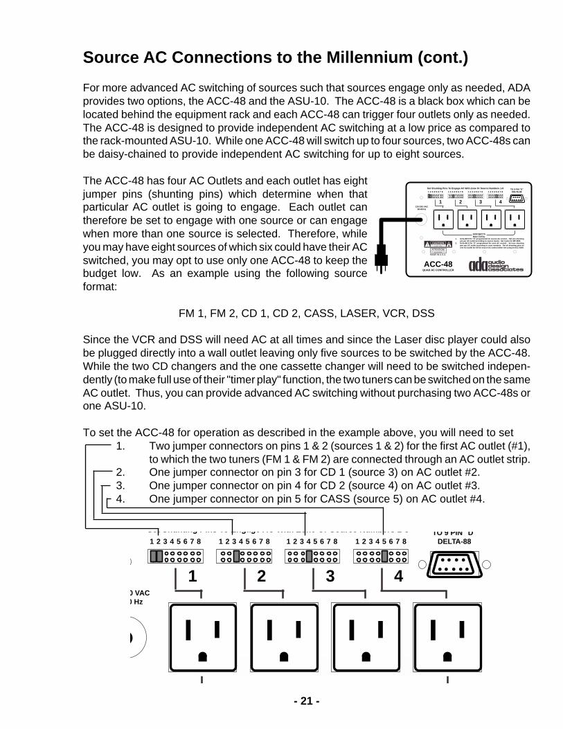
Source AC Connections to the Millennium (cont.)
For more advanced AC switching of sources such that sources engage only as needed, ADAprovides two options, the ACC-48 and the ASU-10. The ACC-48 is a black box which can belocated behind the equipment rack and each ACC-48 can trigger four outlets only as needed.The ACC-48 is designed to provide independent AC switching at a low price as compared tothe rack-mounted ASU-10. While one ACC-48 will switch up to four sources, two ACC-48s canbe daisy-chained to provide independent AC switching for up to eight sources.
The ACC-48 has four AC Outlets and each outlet has eightjumper pins (shunting pins) which determine when thatparticular AC outlet is going to engage. Each outlet cantherefore be set to engage with one source or can engagewhen more than one source is selected. Therefore, whileyou may have eight sources of which six could have their ACswitched, you may opt to use only one ACC-48 to keep thebudget low. As an example using the following sourceformat:
FM 1, FM 2, CD 1, CD 2, CASS, LASER, VCR, DSS
Since the VCR and DSS will need AC at all times and since the Laser disc player could alsobe plugged directly into a wall outlet leaving only five sources to be switched by the ACC-48.While the two CD changers and the one cassette changer will need to be switched indepen-dently (to make full use of their "timer play" function, the two tuners can be switched on the sameAC outlet. Thus, you can provide advanced AC switching without purchasing two ACC-48s orone ASU-10.
To set the ACC-48 for operation as described in the example above, you will need to set1. Two jumper connectors on pins 1 & 2 (sources 1 & 2) for the first AC outlet (#1),
to which the two tuners (FM 1 & FM 2) are connected through an AC outlet strip.2. One jumper connector on pin 3 for CD 1 (source 3) on AC outlet #2.3. One jumper connector on pin 4 for CD 2 (source 4) on AC outlet #3.4. One jumper connector on pin 5 for CASS (source 5) on AC outlet #4.
1 2 3 4 5 6 7 8TO 9 PIN "D"
DELTA-881 2 3 4 5 6 7 81 2 3 4 5 6 7 81 2 3 4 5 6 7 8
1000 WATTSMAX TOTAL
Set Shunting Pins To Engage AC With Zone Or Source Numbers 1-8
120-240 VAC50-60 Hz
QUAD AC CONTROLLER
ACC-48
CAUTIONRISK OF ELECTRIC SHOCK
DO NOT OPEN
ATTENTION!RISQUE DE CHOC ELECTRIQUE.
NE PAS OUVRIR
MADE IN U.S.A.
1. Delta-88 9 Pin "D" programmed for source AC control. - Set one shuntingpin per AC outlet according to source inputs. Set 3 pins for MT-3000.
2. Delta-88 9 Pin "D" programmed for zone AC control. - Set one shuntingpen per AC outlet according to zone numbers. Set all shunting pins onone AC Outlet for All-On source AC control when not using an ACC-3000.
3 421
1 2 3 4 5 6 7 8TO 9 PIN D
DELTA-881 2 3 4 5 6 7 81 2 3 4 5 6 7 81 2 3 4 5 6 7 8
Set Shunting Pins To Engage AC With Zone Or Source Numbers 1 8
0 VAC0 Hz
3 421

- 22 -
1 2 3 4 5 6 7 8TO 9 PIN "D"
DELTA-881 2 3 4 5 6 7 81 2 3 4 5 6 7 81 2 3 4 5 6 7 8
1000 WATTSMAX TOTAL
Set Shunting Pins To Engage AC With Zone Or Source Numbers 1-8
120-240 VAC50-60 Hz
QUAD AC CONTROLLER
ACC-48
CAUTIONRISK OF ELECTRIC SHOCK
DO NOT OPEN
ATTENTION!RISQUE DE CHOC ELECTRIQUE.
NE PAS OUVRIR
MADE IN U.S.A.
1. Delta-88 9 Pin "D" programmed for source AC control. - Set one shuntingpin per AC outlet according to source inputs. Set 3 pins for MT-3000.
2. Delta-88 9 Pin "D" programmed for zone AC control. - Set one shuntingpen per AC outlet according to zone numbers. Set all shunting pins onone AC Outlet for All-On source AC control when not using an ACC-3000.
3 421
L
R
SWITCHEDAC
OUTPUT6A MAX.
ACINPUT
10AMAX.
POWER AMP FUSE4A S.B.-120V2A S.B.-220V
LEFT
RIGHT
2Ω-16ΩSPEAKER
R L+ - - +
ROOM 6 - LINE OUTVARIABLE
FIXED
LEFT
RIGHT
2Ω-16ΩSPEAKER
R L+ - - +
ROOM 5 - LINE OUTVARIABLE
FIXED
LEFT
RIGHT
2Ω-16ΩSPEAKER
R L+ - - +
ROOM 4 - LINE OUTVARIABLE
FIXED
LEFT
RIGHT
2Ω-16ΩSPEAKER
R L+ - - +
ROOM 3 - LINE OUTVARIABLE
FIXED
LEFT
RIGHT
2Ω-16ΩSPEAKER
R L+ - - +
ROOM 2 - LINE OUTVARIABLE
FIXED
LEFT
RIGHT
2Ω-16ΩSPEAKER
R L+ - - +
ROOM 1 - LINE OUTVARIABLE
FIXED
EXPAND
PORT
SOURCEL.V.AC
CONTROL
INPUT 1 INPUT 2 INPUT 3 INPUT 4 INPUT 5 INPUT 6 INPUT 7 INPUT 8
LINEDRIVERMODULE
(NOT FOUNDON
MILLENNIUMSLAVEUNITS)
CAUTIONRISK OF ELECTRIC SHOCK
DO NOT OPEN
ATTENTION!RISQUE DE CHOC ELECTRIQUE.
NE PAS OUVRIR
MADE IN U.S.A.
MILLENNIUM
V CABLE POLARITY V CABLE POLARITY V CABLE POLARITY V CABLE POLARITY V CABLE POLARITY V CABLE POLARITY
ROOM 6 ROOM 5 ROOM 4 ROOM 3 ROOM 2 ROOM 1
CONTROLINPUT/OUTPUT
FROM WIRE HARNESS
PGM BUT IR ER D OK PGM OUTSOURCES IR LEARNERSWITCHEDAC
OUTPUT6A MAX
ACINPUT
10AMAX
VCR
DSS
CASSETTE
LASER
CD 2
CD 1
FM 2
FM 1
ACLINE
CORD
TO ACOUTLET
TO ACOUTLET
9 PIN RIBBONCABLE WITH
9 PIN "D"CONNECTORFOR SOURCEAC TRIGGERS
Source AC Connection Option 1 - Using One ACC-48
In this configuration, using theexample described on the pre-vious page, the two tunersare connected to an AC powerstrip which is plugged into anoutlet set to engage with ei-ther source 1 or source 2.Thus, whenever FM 1 or FM 2are selected, both tuners willturn on. The remaining threeaudio sources are eachconnected to their ownswitched AC outlet. Thethree video sources willnot have their AC trig-gered by the MillenniumSystem.
The ACC-48 connectsdirectly to the Millen-nium through a 9 pinribbon cable providedwith the ACC-48. Thiscable has two 9 pin "D"type connectors, one oneach end of the cableand this cable plugs intoboth the Millennium andthe ACC-48.

- 23 -
Source AC Switching Option 3 - 2 ACC-48s
This option extends the functionality of the system as described in Option 2 such that eachsource turns receives AConly when selected with theexception of the VCR.Thus, each tuner will turn onand off only as needed.Furthermore, the DSS andlaser disc player will receiveAC only when selected.This will not engage theseunits (turn them on) sincemost such devices have asoft-contact power switchwhich resets to off when theunit is unplugged. However,this AC switching functionstill provides automaticpower off in that when, forexample, someone is fin-ished using the laser discplayer, the laser disc willturn completely off when notselected.
The 9 pin ribbon cablewhich connects the Millen-nium to both ACC-48s isprovided with the system.
The diagram below detailsthe jumper pin settings suchthat each source AC outlethas only one jumper pin connector in place corresponding to that sources input position onthe Millennium.
1 2 3 4 5 6 7 8TO 9 PIN "D"
DELTA-881 2 3 4 5 6 7 81 2 3 4 5 6 7 81 2 3 4 5 6 7 8
1000 WATTSMAX TOTAL
Set Shunting Pins To Engage AC With Zone Or Source Numbers 1-8
120-240 VAC50-60 Hz
QUAD AC CONTROLLER
ACC-48
CAUTIONRISK OF ELECTRIC SHOCK
DO NOT OPEN
ATTENTION!RISQUE DE CHOC ELECTRIQUE.
NE PAS OUVRIR
MADE IN U.S.A.
1. Delta-88 9 Pin "D" programmed for source AC control. - Set one shuntingpin per AC outlet according to source inputs. Set 3 pins for MT-3000.
2. Delta-88 9 Pin "D" programmed for zone AC control. - Set one shuntingpen per AC outlet according to zone numbers. Set all shunting pins onone AC Outlet for All-On source AC control when not using an ACC-3000.
3 421
L
R
SWITCHEDAC
OUTPUT6A MAX.
ACINPUT
10AMAX.
POWER AMP FUSE4A S.B.-120V2A S.B.-220V
LEFT
RIGHT
2Ω-16ΩSPEAKER
R L+ - - +
ROOM 6 - LINE OUTVARIABLE
FIXED
LEFT
RIGHT
2Ω-16ΩSPEAKER
R L+ - - +
ROOM 5 - LINE OUTVARIABLE
FIXED
LEFT
RIGHT
2Ω-16ΩSPEAKER
R L+ - - +
ROOM 4 - LINE OUTVARIABLE
FIXED
LEFT
RIGHT
2Ω-16ΩSPEAKER
R L+ - - +
ROOM 3 - LINE OUTVARIABLE
FIXED
LEFT
RIGHT
2Ω-16ΩSPEAKER
R L+ - - +
ROOM 2 - LINE OUTVARIABLE
FIXED
LEFT
RIGHT
2Ω-16ΩSPEAKER
R L+ - - +
ROOM 1 - LINE OUTVARIABLE
FIXED
EXPAND
PORT
SOURCEL.V.AC
CONTROL
INPUT 1 INPUT 2 INPUT 3 INPUT 4 INPUT 5 INPUT 6 INPUT 7 INPUT 8
LINEDRIVERMODULE
(NOT FOUNDON
MILLENNIUMSLAVEUNITS)
CAUTIONRISK OF ELECTRIC SHOCK
DO NOT OPEN
ATTENTION!RISQUE DE CHOC ELECTRIQUE.
NE PAS OUVRIR
MADE IN U.S.A.
MILLENNIUM
V CABLE POLARITY V CABLE POLARITY V CABLE POLARITY V CABLE POLARITY V CABLE POLARITY V CABLE POLARITY
ROOM 6 ROOM 5 ROOM 4 ROOM 3 ROOM 2 ROOM 1
CONTROLINPUT/OUTPUT
FROM WIRE HARNESS
PGM BUT IR ER D OK PGM OUTSOURCES IR LEARNERSWITCHEDAC
OUTPUT6A MAX
ACINPUT
10AMAX
VCR
DSS
CASSETTE
LASER
CD 2
CD 1
FM 2
FM 1
ACLINE
CORD
9 PIN RIBBONCABLE WITH
9 PIN "D"CONNECTORFOR SOURCEAC TRIGGERSTO AC
OUTLETTO AC
OUTLET
1 2 3 4 5 6 7 8TO 9 PIN "D"
DELTA-881 2 3 4 5 6 7 81 2 3 4 5 6 7 81 2 3 4 5 6 7 8
1000 WATTSMAX TOTAL
Set Shunting Pins To Engage AC With Zone Or Source Numbers 1-8
120-240 VAC50-60 Hz
CAUTION
1. Delta-88 9 Pin "D" programmed for source AC control. - Set one shuntingpin per AC outlet according to source inputs. Set 3 pins for MT-3000.
2 Delta 88 9 Pin "D" programmed for zone AC control Set one sh nting
3 421
1 2 3 4 5 6 7 8TO 9 PIN "D"
DELTA-881 2 3 4 5 6 7 81 2 3 4 5 6 7 81 2 3 4 5 6 7 8
1000 WATTSMAX TOTAL
Set Shunting Pins To Engage AC With Zone Or Source Numbers 1-8
120-240 VAC50-60 Hz
CAUTION
1. Delta-88 9 Pin "D" programmed for source AC control. - Set one shuntingpin per AC outlet according to source inputs. Set 3 pins for MT-3000.
3 421

- 24 -
Power Amplifier Automatic AC Switching & Installation
The Millennium 2000 provides several built-in features, one of which is, the ability to easilyintegrate an external power amplifier and have it automatically turn on when zone is turned on.ADA recommends using the ACC-3 Low Voltage Triggered Switched AC Outlet. The ACC-3has two AC outlets which switch on and off together. The ACC-3 can handle a 15 Amp load.
The following diagram details the connection of the ACC-3 to the system such that it receivesa low voltage signal, emanating from the Millennium 2000, when a specific zone is turned on.This signal is derived from pin #2 (ground) and pin #1 (+5VDC) on the two pin screw terminalconnector at the top of the Millennium 2000. These two wires are connected to the appropriatecontacts on the ACC-3. When a zone is on, it will cause the ACC-3's two AC outlets to turn onand subsequently, the power amplifier plugged into the ACC-3 will turn on (providing its powerswitch is left in the on position). When the room turns off, the ACC-3 will turn the power amplifieroff.
Please note, that when using an external power amplifier, you will want that zone on theMillennium 2000 to provide a "variable' line-level audio signal to the amplifier. Make certain thatthe jumper pins (shunting plugs) are positioned to the left in the "variable" position.
115
V
L
R
SWITCHEDAC
OUTPUT6A MAX.
ACINPUT
10AMAX.
POWER AMP FUSE4A S.B.-120V2A S.B.-220V
LEFT
RIGHT
2Ω-16ΩSPEAKER
R L+ - - +
ROOM 6 - LINE OUTVARIABLE
FIXED
LEFT
RIGHT
2Ω-16ΩSPEAKER
R L+ - - +
ROOM 5 - LINE OUTVARIABLE
FIXED
LEFT
RIGHT
2Ω-16ΩSPEAKER
R L+ - - +
ROOM 4 - LINE OUTVARIABLE
FIXED
LEFT
RIGHT
2Ω-16ΩSPEAKER
R L+ - - +
ROOM 3 - LINE OUTVARIABLE
FIXED
LEFT
RIGHT
2Ω-16ΩSPEAKER
R L+ - - +
ROOM 2 - LINE OUTVARIABLE
FIXED
LEFT
RIGHT
2Ω-16ΩSPEAKER
R L+ - - +
ROOM 1 - LINE OUTVARIABLE
FIXED
EXPAND
PORT
SOURCEL.V.AC
CONTROL
INPUT 1 INPUT 2 INPUT 3 INPUT 4 INPUT 5 INPUT 6 INPUT 7 INPUT 8
LINEDRIVERMODULE
(NOT FOUNDON
MILLENNIUMSLAVEUNITS)
CAUTIONRISK OF ELECTRIC SHOCK
DO NOT OPEN
ATTENTION!RISQUE DE CHOC ELECTRIQUE.
NE PAS OUVRIR
MADE IN U.S.A.
MILLENNIUM
V CABLE POLARITY V CABLE POLARITY V CABLE POLARITY V CABLE POLARITY V CABLE POLARITY V CABLE POLARITY
ROOM 6 ROOM 5 ROOM 4 ROOM 3 ROOM 2 ROOM 1
CONTROLINPUT/OUTPUT
FROM WIRE HARNESS
PGM BUT IR ER D OK PGM OUTSOURCES IR LEARNERSWITCHEDAC
OUTPUT6A MAX
ACINPUT
10AMAX
AUDIO INPUTS
ADABUS
INFRARED LEARNER1 2 3 4 5 6
1 2 3 4
7 88
IR PROGRAM
NORMAL
IR RECEIVER
RS-232 FOR IR LEARNING ONLY
7 6 5 4 3 2 1
OUTDOORAREA
RIGHTLEFT
SET THE MILLENNIUM’S LINE LEVELAUDIO OUTPUT TO VARIABLE
PARALLELALL
SPEAKERS ACC-3
1 2 3 4-A+ -B+
Pin 2 (-) GND ¥ Pin 1 (+) +5VDC
TONEWAC
CIRCUIT
ACC-3
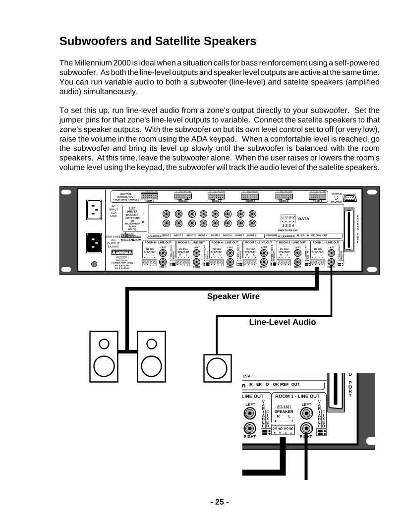
- 25 -
Subwoofers and Satellite Speakers
The Millennium 2000 is ideal when a situation calls for bass reinforcement using a self-poweredsubwoofer. As both the line-level outputs and speaker level outputs are active at the same time.You can run variable audio to both a subwoofer (line-level) and satelite speakers (amplifiedaudio) simultaneously.
To set this up, run line-level audio from a zone's output directly to your subwoofer. Set thejumper pins for that zone's line-level outputs to variable. Connect the satelite speakers to thatzone's speaker outputs. With the subwoofer on but its own level control set to off (or very low),raise the volume in the room using the ADA keypad. When a comfortable level is reached, gothe subwoofer and bring its level up slowly until the subwoofer is balanced with the roomspeakers. At this time, leave the subwoofer alone. When the user raises or lowers the room'svolume level using the keypad, the subwoofer will track the audio level of the satelite speakers.
L
R
SWITCHEDAC
OUTPUT6A MAX.
ACINPUT
10AMAX.
POWER AMP FUSE4A S.B.-120V2A S.B.-220V
LEFT
RIGHT
2Ω-16ΩSPEAKER
R L+ - - +
ROOM 6 - LINE OUTVARIABLE
FIXED
LEFT
RIGHT
2Ω-16ΩSPEAKER
R L+ - - +
ROOM 5 - LINE OUTVARIABLE
FIXED
LEFT
RIGHT
2Ω-16ΩSPEAKER
R L+ - - +
ROOM 4 - LINE OUTVARIABLE
FIXED
LEFT
RIGHT
2Ω-16ΩSPEAKER
R L+ - - +
ROOM 3 - LINE OUTVARIABLE
FIXED
LEFT
RIGHT
2Ω-16ΩSPEAKER
R L+ - - +
ROOM 2 - LINE OUTVARIABLE
FIXED
LEFT
RIGHT
2Ω-16ΩSPEAKER
R L+ - - +
ROOM 1 - LINE OUTVARIABLE
FIXED
EXPAND
PORT
SOURCEL.V.AC
CONTROL
INPUT 1 INPUT 2 INPUT 3 INPUT 4 INPUT 5 INPUT 6 INPUT 7 INPUT 8
LINEDRIVERMODULE
(NOT FOUNDON
MILLENNIUMSLAVEUNITS)
CAUTIONRISK OF ELECTRIC SHOCK
DO NOT OPEN
ATTENTION!RISQUE DE CHOC ELECTRIQUE.
NE PAS OUVRIR
MADE IN U.S.A.
MILLENNIUM
V CABLE POLARITY V CABLE POLARITY V CABLE POLARITY V CABLE POLARITY V CABLE POLARITY V CABLE POLARITY
ROOM 6 ROOM 5 ROOM 4 ROOM 3 ROOM 2 ROOM 1
CONTROLINPUT/OUTPUT
FROM WIRE HARNESS
PGM BUT IR ER D OK PGM OUTSOURCES IR LEARNERSWITCHEDAC
OUTPUT6A MAX
ACINPUT
10AMAX
DATA
1 2 3 4GND-TX-RX-15V
Speaker Wire
Line-Level Audio
LEFT
RIGHT
LINE OUTVARIABLE
FIXED
LEFT
RIGHT
2Ω-16ΩSPEAKER
R L+ - - +
ROOM 1 - LINE OUTVARIABLE
FIXED
D
PORT
IR ER D OK PGM OUTR
15V

- 26 -
IR Capture - Internal IRL-3000
The Millennium 2000 incorporates a built-in IR capture device that loads IR commands fromsource components into nonvolatile memory. As such, you can program your components inyour facility and then disconnect power from the Millennium and install it in your project.
To capture IR commands with the Millennium 2000, you will require a PC and the IRL-3000Software. It is also recommended that you get a copy of the IRL-3000 ProgrammingInstructions. Please read these prior to proceeding.
Rear panel of the Millennium 2000 (the primary Millennium in systems that have more than oneMillennium) features:
An IR receiver for IR capture when operating the IRL-3000 software.A 9-Pin D port that connects to your PC for programming of the IR Learner.A red switch which engages the IR Program mode or sets to Normal operation.8 IR output ports set up for IR flashers without repeating. (note they run right to left.)
1 If you already have IR code sets from projects using the IRL-3000, and do not need tocapture any IR codes, you can simply proceed to downloading the codes.
2 To capture IR codes, connect your PC's com port to the Millennium 2000. Set the redswitch to the IR Program position (In the IRL-3000 Manual, this is the same as pressing the IRL-3000 into the RS-232 position. Open the IRL-3000 software on your PC. Proceed to capturecodes through the IR window in the back of the Millennium.
3 When testing IR codes using the IRL-3000 testing function, connect an IR flasher to IRport 1 on the Millennium.
4 When running the IRL-3000 simulator, connect IR flashers to the appropriate IR ports.
5 When completed, return the red switch to the Normal position.
L
R
SWITCHEDAC
OUTPUT6A MAX.
ACINPUT
10AMAX.
POWER AMP FUSE4A S.B.-120V2A S.B.-220V
LEFT
RIGHT
2Ω-16ΩSPEAKER
R L+ - - +
ROOM 6 - LINE OUTVARIABLE
FIXED
LEFT
RIGHT
2Ω-16ΩSPEAKER
R L+ - - +
ROOM 5 - LINE OUTVARIABLE
FIXED
LEFT
RIGHT
2Ω-16ΩSPEAKER
R L+ - - +
ROOM 4 - LINE OUTVARIABLE
FIXED
LEFT
RIGHT
2Ω-16ΩSPEAKER
R L+ - - +
ROOM 3 - LINE OUTVARIABLE
FIXED
LEFT
RIGHT
2Ω-16ΩSPEAKER
R L+ - - +
ROOM 2 - LINE OUTVARIABLE
FIXED
LEFT
RIGHT
2Ω-16ΩSPEAKER
R L+ - - +
ROOM 1 - LINE OUTVARIABLE
FIXED
EXPAND
PORT
SOURCEL.V.AC
CONTROL
INPUT 1 INPUT 2 INPUT 3 INPUT 4 INPUT 5 INPUT 6 INPUT 7 INPUT 8
LINEDRIVERMODULE
(NOT FOUNDON
MILLENNIUMSLAVEUNITS)
CAUTIONRISK OF ELECTRIC SHOCK
DO NOT OPEN
ATTENTION!RISQUE DE CHOC ELECTRIQUE.
NE PAS OUVRIR
MADE IN U.S.A.
MILLENNIUM
V CABLE POLARITY V CABLE POLARITY V CABLE POLARITY V CABLE POLARITY V CABLE POLARITY V CABLE POLARITY
ROOM 6 ROOM 5 ROOM 4 ROOM 3 ROOM 2 ROOM 1
CONTROLINPUT/OUTPUT
FROM WIRE HARNESS
PGM BUT IR ER D OK PGM OUTSOURCES IR LEARNERSWITCHEDAC
OUTPUT6A MAX
ACINPUT
10AMAX
AUDIO INPUTS
ADABUS
INFRARED LEARNER1 2 3 4 5 6
1 2 3 4
7 88
IR PROGRAM
NORMAL
IR RECEIVER
RS-232 FOR IR LEARNING ONLY
7 6 5 4 3 2 1

- 27 -
Advanced Millennium IR Options
The Millennium 2000 is setup so that it operates with IR flashers and that all outputs will passIR for IR repeating from ADA IR receivers (IRT-3000 or those found in MC-3000, MC-3800, MC-5000, and TS-3000). If you wish to alter these settings, it will require that you open the coverof the Millennium 2000. If you do not want to open the Millennium and wish to make certain IRrepeating is defeated, you can simply turn off the IR receivers (in software) of the keypads andtouch screens.
Prior to jumping right in, here are some features that you can control if you do proceed.
1 Each port can be set individually to be used with either an IR flasher or a direct serialconnection. Direct serial connections are found on the back of many source components, thuspermitting you to avoid using a flasher on the units front panel. For tricks and helpful hints onserial connections, see the IRL-3000 Manual.
2 When using a direct serial connection, you may need to invert the data as some sourcesdo invert the data when connected via a serial link. For more information on inverting serial data,see the IRL-3000 Manual.
3 IR Repeating can be defeated individually per output. As such, if several componentsin your system operate on the same IR command, you can selectively determine which deviceswill receive IR commands when IR repeating. Other devices will only activate from keypadfunctions.
4 You can set ports that are controlling components via a serial link to also operate whenIR repeating.
5 For components that are IR repeating via an IR flasher, you can adjust the global (effectsall ports) IR carrier frequency.
As this procedure will take a little time, just opening the cover requires that you remove 18screws and two nuts, you should ask yourself.
1 Will I be using serial connectors instead of flashers? If the answer is yes, proceed.2 Do I need IR repeating for some but not all sources? If the answer is yes, proceed.3 If you are doing IR repeating but are not having any success and you are certain thekeypads' IR receivers are on, proceed.
WARNING!As you proceed with the adjustments to the Millennium 2000, you will in many cases want tohave your source components available so that their operation with the system can beconfirmed prior to closing up the Millennium 2000. As such, you may actually have theMillennium plugged in while its cover is open. To ensure that all goes well, find a clean andclutter-free working surface that is at least twice as wide as the Millennium. Disconnect powerwhile removing the cover. Prior to applying power with the cover off, make certain all wiringconnections are in tact. Remove power while replacing the cover.

- 28 -
The Millennium 2000 cover has both a circuitboard and transformer mounted to the inside ofthe cover. As such, do not remove all screws.
1 Disconnect the AC Power cord connectedto the Millennium 2000.
2 Remove the 18 perimeter screws thathold the cover in place. Please note, that in thediagram to the right, these screws are markedwith in solid black. The screws that should be leftalone are marked with an X.
3 Remove the two nuts that flank the 9 pinD type connector marked "SOURCE L.V. ACCONTROL" on the upper right hand corner of theback of the Millennium.
4 Gently lift the front edge of the cover andthen slowly slide the cover forward 1/2 to 1 inch,just enough, for the 9 pin D connector that youunfastened, to clear the rear panel chassis cutout.
5 Get a stack of books that, when stacked,measure approximately, 5-1/4 inches in heightand place them to the right side of the Millennium(when viewing from the rear).
6 Slowly open the cover as illustrated in thediagram at the top of the next page. As severalwires are connected to the bottom of the topcover, be careful not to move too quickly, thuspreventing these wires from coming loose.
LIFT FRONT EDGE OF COVER1/2 INCH AND THEN PULL FORWARD
SIDE
FRONT
L
R
SWITCHEDAC
OUTPUT6A MAX.
ACINPUT
10AMAX.
POWER AMP FUSE4A S.B.-120V2A S.B.-220V
LEFT
RIGHT
2Ω-16ΩSPEAKER
R L+ - - +
ROOM 6 - LINE OUTVARIABLE
FIXED
LEFT
RIGHT
2Ω-16ΩSPEAKER
R L+ - - +
ROOM 5 - LINE OUTVARIABLE
FIXED
LEFT
RIGHT
2Ω-16ΩSPEAKER
R L+ - - +
ROOM 4 - LINE OUTVARIABLE
FIXED
LEFT
RIGHT
2Ω-16ΩSPEAKER
R L+ - - +
ROOM 3 - LINE OUTVARIABLE
FIXED
LEFT
RIGHT
2Ω-16ΩSPEAKER
R L+ - - +
ROOM 2 - LINE OUTVARIABLE
FIXED
LEFT
RIGHT
2Ω-16ΩSPEAKER
R L+ - - +
ROOM 1 - LINE OUTVARIABLE
FIXED
EXPAND
PORT
SOURCEL.V.AC
CONTROL
INPUT 1 INPUT 2 INPUT 3 INPUT 4 INPUT 5 INPUT 6 INPUT 7 INPUT 8
LINEDRIVERMODULE
(NOT FOUNDON
MILLENNIUMSLAVEUNITS)
CAUTIONRISK OF ELECTRIC SHOCK
DO NOT OPEN
ATTENTION!RISQUE DE CHOC ELECTRIQUE.
NE PAS OUVRIR
MADE IN U.S.A.
MILLENNIUM
V CABLE POLARITY V CABLE POLARITY V CABLE POLARITY V CABLE POLARITY V CABLE POLARITY V CABLE POLARITY
ROOM 6 ROOM 5 ROOM 4 ROOM 3 ROOM 2 ROOM 1
CONTROLINPUT/OUTPUT
FROM WIRE HARNESS
PGM BUT IR ER D OK PGM OUTSOURCES IR LEARNERSWITCHEDAC
OUTPUT6A MAX
ACINPUT
10AMAX
AUDIO INPUTS
ADABUS
INFRARED LEARNER1 2 3 4 5 6
1 2 3 4
7 88
IR PROGRAM
NORMAL
IR RECEIVER
RS-232 FOR IR LEARNING ONLY
7 6 5 4 3 2 1 STACK OF BOOKS ~ 5-1/4 INCHES TALL
FLIP COVER OVER THIS WAYWIRES WILL FOLLOW
SLIDE COVER FORWARD 1/2 INCHJUST ENOUGH FOR THE 9 PIN D CONNECTORTO CLEAR ITS REAR PANEL SOCKET
REMOVE SCREWS MARKED AS BLACK CIRCLE (18 TOTAL)
DO NOT REMOVE SCREWS THAT ARE INDICATED WITH AN X
9 PIN D
Remove Both ScrewsFlanking 9 Pin D Connector

- 29 -
INVERTNORM
3
INVERT
NORM2
INVERT
NORM
IRDATA
1
INVERT
NORM
4
INVERTNORM
5
INVERT
NORM6
INVERTNORM
7
INVERT
NORM
8
IRDATA
IRDATA
IRDATA
IRDATA
IRDATA
IRDATA
IRDATA
12345678
REMOVEJUMPER
PINSWHENUSING
IRFLASHER
REMOVEIR/DATAJUMPER
TO DEFEATIR REPEATING
FROM ADAIR RECEIVERS
ELEVATED CIRCUITBOARD
40KHz
IR CARRIERWHEN IR REPEATING
INVERTNORM
3
INVERT
NORM2
INVERT
NORM
IRDATA
1
INVERT
NORM
4
INVERTNORM
5
INVERT
NORM6
INVERTNORM
7
INVERT
NORM
8
IRDATA
IRDATA
IRDATA
IRDATA
IRDATA
IRDATA
IRDATA
12345678
REMOVEJUMPER
PINSWHENUSING
IRFLASHER
REMOVEIR/DATAJUMPER
TO DEFEATIR REPEATING
FROM ADAIR RECEIVERS
ELEVATED CIRCUITBOARD
40KHz
IR CARRIERWHEN IR REPEATING
Once the cover is open, you will have access to the IR Learning module. While some ribboncables may get in the way, they can be gently pushed aside when setting the jumper pins.Open the IRL-3000 Manual to the sections that discuss the setting of jumper pins. Note thatthe layout below looks similar to the IRL-3000 on its side. In fact, the two are the same. EachIR output port has actually three jumper pins assigned to it. Two of these pins sit side-by-side,and one pin is grouped with the same pins for all other ports.
The single pin (actually eight of them together, onefor each port) is located to the right side of theboard. These pins determine if you are using aflasher or serial connector (remove for flasher, in-sert for serial connection.) Currently, these jumperconnectors may be in place, but if you look closely,they are only covering one of the two pins, thusnot closing the circuit.
The jumpers marked IR or DATA are for settingthe port to IR repeat. If you are not IR repeatingthis port, ADA suggests removing the jumper.
The jumpers marked NORM or INVERT are usedprimarily for sources connected via a serial jack.Refer to the IRL-3000 manual.
The Trim Pot, located just above the grouping ofeight jumper pins, is used to set the IR carrier level,for sources connected via an IR flasher that areset for IR repeating. The 2 o'clock setting is 40KHz.

- 30 -
Installation of ADA Keypads
Most ADA Keypads are provided on a custom plate which is 1/8" thick. Typically, screwsprovided with these plates are 1" long. The plates do not provide any play once installed. Itis therefore essential that the box in which the keypad is mounted into is completely square.If the box is even slightly off-angle, the keypad, once installed will appear crooked.
Furthermore, the box used, should be checked against akeypad to make certain that the keypad and circuit board willfit into the box. The box should be close to flush with thesurface of the wall but should not extend beyond the surfaceof the wall. The plate should rest flush on top of the wall. ForMC-2000 OD All Weather Outdoor Keypads (double gangkeypad), ADA suggests using a watertight masonry box.
When installing a keypad, be extremely careful with thehandling of the plate and screws. The plates can easily be scratched if handled improperly.
When wiring the keypad, you can remove the screw terminal connector from the keypad's circuitboard and first connect the wire to the connector. The shield (or ground) wire is typicallycompletely exposed (without a jacket) and will require taping. This protection will prevent theground wire from making contact with circuit board traces once the keypad is installed. Sincethe other wires are not exposed when they are inserted into the connector, they will not requiretaping.
1-3/4"
2-3/4"
DOUBLEGANG
MASONRYBOX

- 31 -
Rack Rail & Hardware andRack Mounting Source Components.
ADA makes available to dealers, custom cut rack railsections and rack hardware. Unlike most rack rail avail-able, ADA Rack Rail is 4.5" deep, capable of mountinginside the cabinet, not just along the front edge, but firmlyagainst a larger section of the cabinet's wall. Further-more, ADA's Rack Rail is not pre-threaded, but rather,has holes spaced at EIA Rack Mount Standard intervalsfor rack nuts which clip onto the rack rail. Thus, if a holeis stripped, the stripped rack nut clip can be removed anda new one can be inserted in its place. Furthermore, theclip-on rack nuts provide some play, permitting you to adjust the component as it is inserted intothe rack. ADA provides the rack nuts, rack screws, and rack washers by the dozen and rackrail by linear inch. Please note, if your rack height is 21 inches tall, you will need to order two21 inch rack rails for a total of 42 inches of rack rail.
If you wish to provide the same 1/8" thick qaulity plate finish for sources (and other non-ADAcomponents), complete with rack handles (some units cannot be rack mounted with handles),ADA can custom rack mount source components to match the look of the ADA rack ofequipment. These surround plates are custom cut to a component'sdimensions and are mounted to the plate itself, permitting easyinstallation into the rack using the functional rack handles to positionthe component into place. Unlike other rack plate manufacturers,components rack mounted by ADA are completely mounted to theplate and do not just sit on a shelf and slide through an opening.Also, because the plate is custom cut to the specific source compo-nent, the fit is much tighter than plates provided by other manufac-tures. To properly manufacture and mount the non-ADA compo-nents, ADA will require the sources in-house for a period of two tofour weeks. As with all ADA components, custom rack plates fornon-ADA components can also be made in Brass, Chrome, andBlack Chrome.
When combining ADA components and other components (such assources) which are racked in another manufacturer's rack plate,ADA recommends you allow a space between the other rack platesand the ADA components. This space can be small and could befilled with a piece of wood from the cabinet, providing a separationbetween the two types of plates. Even though another manufacturer'srack plates and ADA plates are both black anodized, there areusually definite differences in plate finish and thickness which maybe noticeable. The cabinet separation will limit these difference frombeing obvious.
4.5" DEPTH
3.5" SAMPLEHEIGHT
1/2"
ON
OFF
POWER
PF-200
FUSE
FUS
E FU
SE
PLAY
CASSETTE 4
MULTI-CASSETTE
PLAY
CASSETTE 4
MULTI-CASSETTE
6 DISC
DISC 3 TRACK 5
PLAY
MULTI-COMPACT DISC PLAYER
6 DISC
6 DISC
6 DISC
DISC 3 TRACK 5
PLAY
MULTI-COMPACT DISC PLAYER
6 DISC
6 DISC
ROOM 1 ROOM 2 ROOM 3 ROOM 4 ROOM 5 ROOM 6TREB BASS TREB BASS TREB BASS TREB BASS TREB BASS TREB BASS
POWERON
POWEROFF
MILLENNIUM MADE IN U.S.A.
FM 1 FM 2 AM CD 1 CD 2 AUX CASS1
CASS2
ROOMOF
VOLUP
VOLDN
RECON
ROOM 1 ROOM 2 ROOM 3 ROOM 4 ROOM 5 ROOM 6
LEFT
ALL
REAR CENTER
RIGHT
OFF MODE VOLUP
VOLDN
VOLPRESET
NOISEMONOENHAN
DELAY DOLBYNR REARPROLOGIC
MPA-500THX 5 CHANNEL AMPLIFIER
ON
OFF
POWER
MPS-500THX POWER SUPPLY