miller engineers, inc. d/b/a souder, miller & associates
TRANSCRIPT
July 7, 2016 9325276
Mr. Jim Winder
St. John Paul II Parish, Inc.
P. O. Box 1530
Santa Teresa, New Mexico 88008
RE: Geotechnical Investigation Report
St John Paul II Parish Church, Borderland Road, Santa Teresa, New Mexico
Dear Mr. Winder;
Enclosed is the recently completed geotechnical investigation report for the above referenced
project. This report presents a discussion of the site and subsurface conditions, the geotechnical
properties of underlying soil strata, recommendations for foundation design and recommended
construction activities based on the proposed use of the site.
We appreciate the opportunity to work with you in preparing this report. Should you have any
questions or comments after reviewing the report, please do not hesitate to contact our office.
Sincerely;
MILLER ENGINEERS, INC. D/B/A
SOUDER, MILLER & ASSOCIATES
Paul J. Pompeo, P.E.
Senior Engineer

GEOTECHNICAL INVESTIGATION
ST JOHN PAUL II PARISH CHURCH
SANTA TERESA, NEW MEXICO
Prepared for
Mr. Jim Winder
St. John Paul II Parish, Inc.
P. O. Box 1530
Santa Teresa, New Mexico 88008
July 7, 2016
This document was prepared under the supervision and direction of the undersigned
whose seal as a Professional Engineer, licensed to practice as such in the State of
New Mexico, is affixed below.
Paul J. Pompeo, P.E.
11490 07/07/2016
NMPE Number Date
Geotechnical Investigation
St John Paul II Parish Church
Santa Teresa, New Mexico
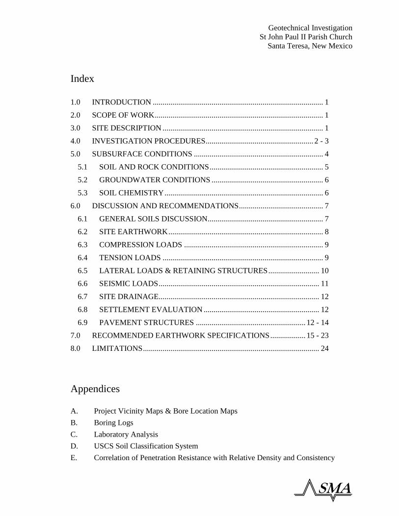
Index
1.0 INTRODUCTION ....................................................................................... 1
2.0 SCOPE OF WORK ...................................................................................... 1
3.0 SITE DESCRIPTION .................................................................................. 1
4.0 INVESTIGATION PROCEDURES ....................................................... 2 - 3
5.0 SUBSURFACE CONDITIONS .................................................................. 4
5.1 SOIL AND ROCK CONDITIONS .......................................................... 5
5.2 GROUNDWATER CONDITIONS ......................................................... 6
5.3 SOIL CHEMISTRY ................................................................................. 6
6.0 DISCUSSION AND RECOMMENDATIONS ........................................... 7
6.1 GENERAL SOILS DISCUSSION........................................................... 7
6.2 SITE EARTHWORK ............................................................................... 8
6.3 COMPRESSION LOADS ....................................................................... 9
6.4 TENSION LOADS .................................................................................. 9
6.5 LATERAL LOADS & RETAINING STRUCTURES .......................... 10
6.6 SEISMIC LOADS .................................................................................. 11
6.7 SITE DRAINAGE.................................................................................. 12
6.8 SETTLEMENT EVALUATION ........................................................... 12
6.9 PAVEMENT STRUCTURES ........................................................ 12 - 14
7.0 RECOMMENDED EARTHWORK SPECIFICATIONS .................. 15 - 23
8.0 LIMITATIONS .......................................................................................... 24
Appendices
A. Project Vicinity Maps & Bore Location Maps
B. Boring Logs
C. Laboratory Analysis
D. USCS Soil Classification System
E. Correlation of Penetration Resistance with Relative Density and Consistency

Geotechnical Investigation
St John Paul II Parish Church
Santa Teresa, New Mexico
Page 1
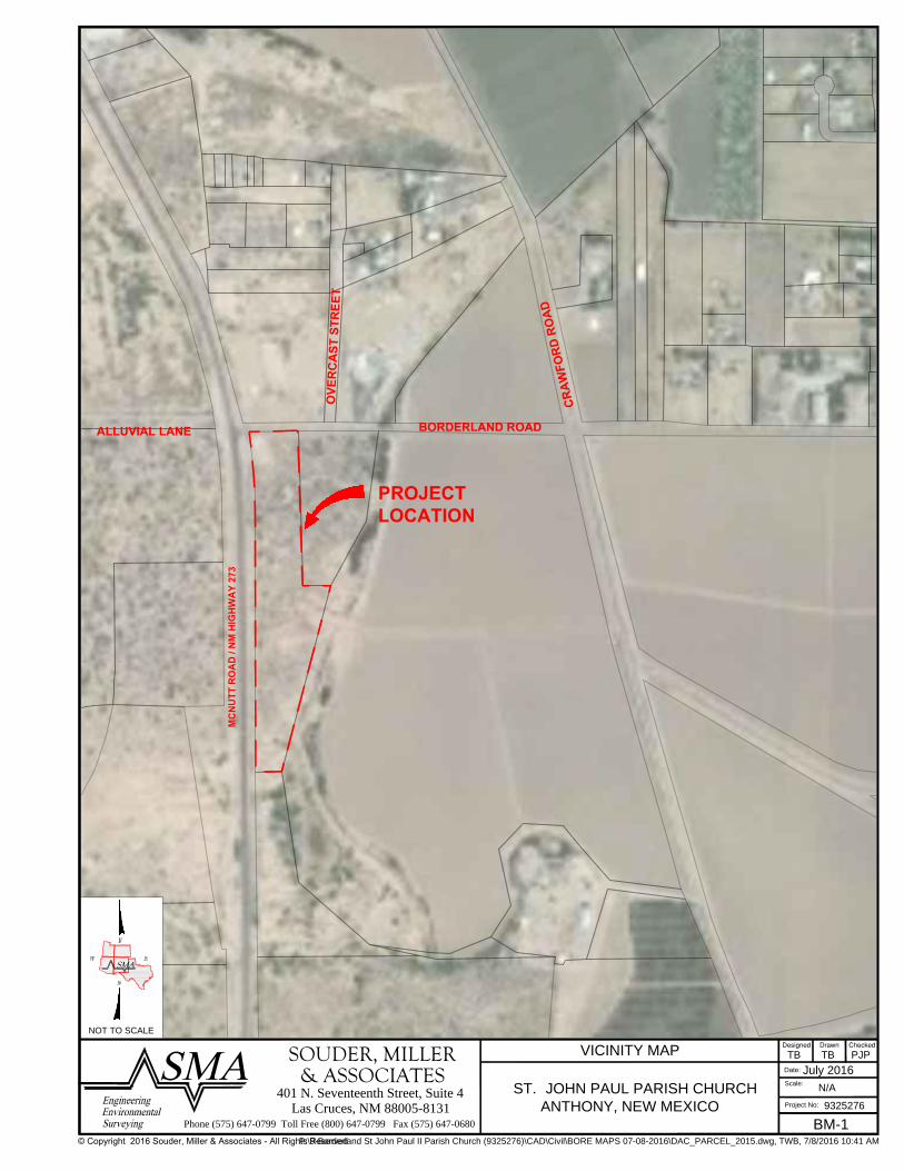
1.0 INTRODUCTION Souder, Miller and Associates (SMA) was retained by Mr. Jim Winder to prepare this
geotechnical report. From the findings of the soil boring, the nature of the substrata soils
will be determined, and its characteristics ascertained. This information shall then be used
to recommend foundation and pavement structures within the project area. A project
location map and boring location map are located in Appendix A.
2.0 SCOPE OF WORK The purpose of the exploration was to obtain subsurface data at the site, provide soil test
boring records, and conduct laboratory testing of select soil samples. The scope of our
studies included drilling 2 soil test borings and conducting laboratory testing on the
retrieved soil samples retrieved by SEI technicians. Discussions of findings are located in
Section 6.0. These include:
A review of our test procedures and the results of all testing conducted
A review of site and subsurface conditions
Boring logs and laboratory test results
Foundation & Earthwork recommendations
3.0 SITE DESCRIPTION A review of the project site was made by SMA personnel prior to drilling operations to
document the current site conditions and characteristics. The project site is located at 1999
Borderland Road north of Santa Teresa, New Mexico. The site rests in is natural condition
covered by sparse native vegetation. The site is traversed by several arroyos with drainage
patterns generally to the east in a moderate to rapid form.

Geotechnical Investigation
St John Paul II Parish Church
Santa Teresa, New Mexico
Page 2
4.0 INVESTIGATION PROCEDURES The general field procedures employed by SEI are summarized in ASTM Specification D-
420 entitled "Investigation and Sampling Soils and Rocks for Engineering Purposes." This
recommended practice lists recognized methods for determining soil and rock distribution
and groundwater conditions. These methods include geophysical and in situ methods as
well as borings.
A CME-85 Drilling Rig, mounted on a Kenworth T800, equipped with hollow-flight
augers, penetration and soil sampling equipment was used on this project. Borings are
drilled to obtain subsurface samples using one of three alternate techniques depending upon
the subsurface conditions. These techniques are continuous 2¼ or 8¼ inch I.D. hollow
stem augers, wash borings using roller cone or drag bits (mud or water) or continuous flight
augers (ASTM D1452). These drilling methods are not capable of penetrating through
material designated as "refusal materials." Refusal, thus indicated, may result from hard
cemented soil, soft weathered rock, coarse gravel or boulders, thin rock seams, or the upper
surface of sound continuous rock. Core drilling procedures are required to determine the
character and continuity of refusal materials.
The subsurface conditions encountered during drilling are reported on a field test boring
record by the Chief Driller. The record contains information concerning the boring
method, samples attempted and recovered, indications of the presence of various materials
such as coarse gravel, cobbles, etc., and observation of groundwater. It also contains the
driller's interpretation of the soil conditions between samples. Therefore, these boring
records contain both factual and interpretive information.
The soil and rock samples plus the field boring records are reviewed by the engineering
staff at SEI. The staff classifies the soils in general accordance with the procedures outlined
in ASTM Specification D2488 and prepares the final boring records which are the basis
for all evaluations and recommendations. The final test boring records represent our

Geotechnical Investigation
St John Paul II Parish Church
Santa Teresa, New Mexico
Page 3
interpretation of the contents of the field records based on the results of the engineering
examination and test of the field samples. These records depict subsurface conditions at
the specific locations and at the particular time when drilled. Soil conditions at other
locations may differ from conditions occurring at the boring locations. Also, the passage
of time may result in a change in the subsurface soil and groundwater conditions at these
boring locations. The lines designating the interface between soil or refusal materials on
the records and on profiles represent approximate boundaries. The actual transition
between materials may be gradual. The boring records are included in Appendix B.
The borings were drilled using hollow-stem augers and solid-flight augers, as noted on the
Boring Logs. Penetration testing and split barrel sampling were conducted in the borings
at regular intervals.
The standard penetration test (SPT) provides an indication of the soil strength and
compressibility. The SPT resistances and split barrel sampling are conducted
simultaneously according to ASTM Specification D1586. At regular intervals, the drilling
tools are removed and soil samples obtained with a standard split tube sampler. The
sampler is first seated six inches, to penetrate any loose cuttings, then driven an additional
foot with blows of a 140 pound hammer falling thirty inches. The number of hammer
blows required to drive the sampler the final foot is recorded and is designated the
"penetration resistance".

Geotechnical Investigation
St John Paul II Parish Church
Santa Teresa, New Mexico
Page 4
5.0 SUBSURFACE CONDITIONS The subsurface condition was determined by 2 soil test borings drilled to a depth of 20 feet
at the location of the proposed church building in accordance to the procedures outlined
later in this report. The boring locations were selected by the Souder, Miller & Associates
project engineer and are shown the site drawings in Appendix A.
Standard Penetration Tests were conducted in the borings at intervals in general accordance
with ASTM D1586. Disturbed samples were obtained during this test and were used to
classify the soils. The standard penetration resistances obtained provide a general
indication of soil strength and compressibility.
The subsurface conditions encountered at the boring locations are shown on the Boring
Logs in Appendix B. These records represent our interpretation of the subsurface
conditions based on the field logs, visual examination of field samples and laboratory
testing of representative field samples. The lines designating the interface between various
strata on the Boring Logs represent the approximate interface location. In reality, the
transition between strata may actually be gradual.

Geotechnical Investigation
St John Paul II Parish Church
Santa Teresa, New Mexico
Page 5
5.1 SOIL AND ROCK CONDITIONS
The soil profile of the test hole shows the following:
Test Hole #1
Depth
Soil Description
Soil Classification
0' - 2.5'
Light Brown Silty Sand
SM
2.5' - 5'
Light Brown Silty Sand
SM
5' - 7.5'
Light Brown Silty Sand
SM
7.5' – 10'
Light Brown Silty Sand
SM
10' - 15'
Light Brown Silty Sand
SM
15' - 20'
Light Brown Silty Sand
SM
20' – 21.5’
Light Brown Sandy Lean Clay
CL
Test Hole #2
Depth
Soil Description
Soil Classification
0' - 2.5'
Light Brown Silty Sand
SM
2.5' - 5'
Light Brown Silty Sand
SM
5' - 7.5'
Light Brown Silty Sand
SM
7.5' – 10'
Light Brown Silty Sand
SM
10' - 15'
Light Brown Silty Sand
SM
15' - 20'
Brown Silty Sand
SM
20' – 21.5’
Light Brown Sandy Lean Clay
CL

Geotechnical Investigation
St John Paul II Parish Church
Santa Teresa, New Mexico
Page 6
5.2 GROUNDWATER CONDITIONS
No groundwater was encountered in the boring at this project site.
5.3 SOIL CHEMISTRY No laboratory tests were performed to determine the chemical properties of the surface
soils within the project area, although record data was reviewed to determine the general
soil properties. Soil properties were determined from soil survey information accessed on-
line via the United States Department of Agriculture Web Soil Survey at
http://websoilsurvey.nrcs.usda.gov/app/WebSoilSurvey.aspx. The soil(s) found within this
project location are as follows:
Soil Chemistry Summary
Soil
Type Soil Name
Hydrologic
Soil
Classification
pH
Range
Salinity
(milliohm/cm)
Corrosivity
Untreated
Steel
Corrosivity
Concrete
Ad Adeline Sandy
Clay Loam B 7.9 to 9.0 < 2.0 High Low
Pa Harkey Loam B 7.4 to 8.4 <4.0 High Low
For these soil types, Type 1 or Type IA cement can be used for most concrete foundations.
If drainage structures are anticipated to have moderate to high sulfate concentrations, Type
II cement should be used.

Geotechnical Investigation
St John Paul II Parish Church
Santa Teresa, New Mexico
Page 7
6.0 DISCUSSION AND RECOMMENDATIONS
6.1 GENERAL FOUNDATION DESIGN CRITERIA
Foundation selection must satisfy two basic, independent criteria. First, the bearing
pressure including the surcharge loads resulting from the placement of existing and
proposed fill materials transmitted to the foundation soils should not exceed an allowable
bearing pressure which includes an adequate factor of safety applied to the soil shear
strength. Second, settlement due to consolidation of the underlying soils during the
operating life of the structure must be within tolerable limits.
As part of this evaluation, the following structure loads were estimated. These values will
be used to develop the recommendations contained herein.
Allowable Maximum Structural Loads
Foundation Type Maximum Loading
Continuous Foundations 2.0 kips / lf
Spot Foundations 2.0 kips / sf
Slabs 1.0 kips / sf

Geotechnical Investigation
St John Paul II Parish Church
Santa Teresa, New Mexico
Page 8
6.2 SITE EARTHWORK
For this site it is anticipated that shallow foundation systems bearing at uniform depths
below finished grade will be utilized. The minimum depth of footings below final finished
site grade is to be a minimum of 12 inches. These types of foundations could include but
not be limited to spot footings, spread footings, continuous or grade beam footings and mat
foundations. Any required fill materials will be from the project site and shall be installed
per Section 7.0.
The soils at and near the existing site grade for this site is primary silty sands. As such, the
site soils are adequate for structures to be directly constructed on, if properly prepared.
Due to moderately low SPT counts and very low moisture content in the upper soil layers,
it is recommended that the top 5.0 feet of existing site soils under proposed foundations
and slabs be excavated, moisture treated and recompacted. Fill and/or backfill materials if
required and as a minimum, shall meet the requirements set forth in Section 7.0 and shall
be placed in compacted layers not to exceed 6 inches in thickness. All fill materials shall
be moisture treated to a level of +/- 2 percent of optimum and compacted to 95 percent of
ASTM D1557. The top layer of native material below any excavated area shall be
scarified, moisture treated to a level of +/- 2 percent of optimum and compacted to 95
percent of ASTM D1557.

Geotechnical Investigation
St John Paul II Parish Church
Santa Teresa, New Mexico
Page 9
6.3 COMPRESSION LOADS
The soils at and near the existing site grade for this site is primary silty sands. Once
moisture treated and properly compacted, proposed structures can bear directly on these
materials at an appropriate depth. The depth of the foundation system below the final
adjacent site grade shall be a minimum of 1.0 feet. Based on the anticipated structure type
and maximum foundation loads, it is recommended that a shallow continuous and spot
foundation system bearing at uniform depths below finished grade can be utilized. The
allowable bearing capacity for foundation design shall not exceed 2,000 psf.
6.4 TENSION LOADS
No uplift or tension loads are expected to be encountered on this project.

Geotechnical Investigation
St John Paul II Parish Church
Santa Teresa, New Mexico
Page 10
6.5 LATERAL LOADS & RETAINING STRUCTURES
The fill and/or backfill soils to be used on this project shall be cohesionless and follow the
requirements of Section 7.0. The following values will be used for the design of retaining
structures within the project area, as applicable.
Retaining Structure Design Parameters
Allowable Bearing Capacity 2,000 psf
Soil Unit Weight 118 pcf
Soil Angle of Internal Friction 30o
Coefficient of Friction (Soil to Concrete) 0.25
Active Earth Pressure, Ka (Level backfill) 40 pcf
Passive Earth Pressure, Kp (Level backfill) 354 pcf
At Rest Earth Pressure, Ko (Level backfill) 59 pcf

Geotechnical Investigation
St John Paul II Parish Church
Santa Teresa, New Mexico
Page 11
6.6 SEISMIC LOADS
Seismic design considerations following the requirements of the 2015 NEHRP Provisions.
Design values are calculated on the United State Geologic Survey website, “Earthquake
Hazards Program” at http://earthquake.usgs.gov/designmaps/us/application.php.
Site Location Information
Risk Category I, II or III
Site Soil Classification E
Location Latitude Longitude
31.883935 -106.649234
Seismic Design Parameters (g)
SS SMS SDS
0.279 0.647 0.431
S1 SM1 SD1
0.092 0.386 0.257

Geotechnical Investigation
St John Paul II Parish Church
Santa Teresa, New Mexico
Page 12
6.7 SITE DRAINAGE
The site drainage patterns are generally to the east in a moderate to rapid form. Final site
development shall be such that water from storm events will not be allowed to saturate
soils under or adjacent to foundation systems. No storm water detention ponds or earth
lined drainage channels shall be constructed within 20 foot of any foundation system.
Positive surface drainage shall be maintained at all times away from the structures with a
minimum slope of 0.5 percent for concrete/asphalt pavement areas and 2.0 percent for
earthen ground cover areas.
6.8 SETTLEMENT EVALUATION
Based on the soil properties found within the project site and the anticipated foundation
loads, the following settlement values have been estimated for site development options
using conventional foundation systems.
Estimated Settlement Values
Estimated Total Settlement 1.0 inches
Estimated Differential Settlement 0.5 inches
These values assume that all earthwork construction within the project site meets the
minimum specifications outlined in Section 7.0. As with most soils, any intrusion of water
into the subgrade below foundations will cause a reduction in bearing capacity. The actual
rate of decrease varies widely depending on the type of soil. This loss of bearing capacity
can lead to differential settlement of the structure and could ultimately lead to failure. For
these reasons, the final site areas shall be developed to account for proper drainage as
outlined in Section 6.7.
Geotechnical Investigation
St John Paul II Parish Church
Santa Teresa, New Mexico
Page 13
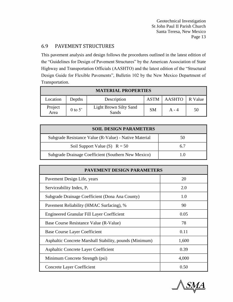
6.9 PAVEMENT STRUCTURES
This pavement analysis and design follows the procedures outlined in the latest edition of
the “Guidelines for Design of Pavement Structures” by the American Association of State
Highway and Transportation Officials (AASHTO) and the latest edition of the “Structural
Design Guide for Flexible Pavements”, Bulletin 102 by the New Mexico Department of
Transportation.
MATERIAL PROPERTIES
Location Depths Description ASTM AASHTO R Value
Project
Area 0 to 5’
Light Brown Silty Sand
Sands SM A - 4 50
SOIL DESIGN PARAMETERS
Subgrade Resistance Value (R-Value) - Native Material 50
Soil Support Value (S) R = 50 6.7
Subgrade Drainage Coefficient (Southern New Mexico) 1.0
PAVEMENT DESIGN PARAMETERS
Pavement Design Life, years 20
Serviceability Index, Pt 2.0
Subgrade Drainage Coefficient (Dona Ana County) 1.0
Pavement Reliability (HMAC Surfacing), % 90
Engineered Granular Fill Layer Coefficient 0.05
Base Course Resistance Value (R-Value) 78
Base Course Layer Coefficient 0.11
Asphaltic Concrete Marshall Stability, pounds (Minimum) 1,600
Asphaltic Concrete Layer Coefficient 0.39
Minimum Concrete Strength (psi) 4,000
Concrete Layer Coefficient 0.50

Geotechnical Investigation
St John Paul II Parish Church
Santa Teresa, New Mexico
Page 14
6.6 PAVEMENT DESIGN (continued)
PARKING LOT TRAFFIC LOADS
Light Duty Pavement Areas 3 ESAL’s
Required Structural Number (SNR) 1.10
Heavy Duty Pavement Areas 10 ESAL’s
Required Structural Number (SNR) 1.38
PAVEMENT RECOMMENDATIONS
The following recommendation lists the minimum thicknesses in specific use areas. SEI
does not recommend the use of asphaltic concrete pavements in layers less than 2.0 inches
thick, base course in layers less than 6 inches thick and Portland Concrete Pavements in
layers less than 6 inches thick for paved surfaces. Only concrete pavements shall be used
in areas of high concentrated loads such as loading docks and dumpster areas.
Light Duty Pavements
Option
Number
Compacted Native
Subgrade Soils
(inches)
Base
Course
(inches)
HMAC
Pavement
(inches)
Concrete
Pavement
(inches)
1 12.0 6.0 2.0 0.0
Heavy Duty Pavements
Option
Number
Compacted Native
Subgrade Soils
(inches)
Base
Course
(inches)
HMAC
Pavement
(inches)
Concrete
Pavement
(inches)
2 12.0 8.0 3.0 *
3 12.0 * * 6.0
All pavements and subgrade materials on this project site shall be installed as per the
recommendations outlined in the New Mexico Department of Transportation, “Standard
Specifications for Highway and Bridge Construction”, latest edition.

Geotechnical Investigation
St John Paul II Parish Church
Santa Teresa, New Mexico
Page 15
7.0 RECOMMENDED EARTHWORK SPECIFICATIONS – SMALL PROJECTS
7.1.1 DESCRIPTION OF WORK: A. This section specifies the requirements for furnishing all equipment, materials,
labor, tools, and techniques for general earthwork construction including, but not
limited to, the following:
1. Site preparation.
2. Excavation.
3. Underpinning.
4. Filling and backfilling.
5. Grading.
6. Soil Disposal.
7. Clean Up.
7.1.2 DEFINITIONS: A. Unsuitable Materials:
1. Fills: Topsoil; frozen materials; construction materials and materials subject to
decomposition; clods of clay and stones larger than 3 inches; organic material,
including silts, which are unstable; and inorganic materials, including silts, too
wet to be stable and any material with a liquid limit and plasticity index
exceeding 40 and 15 respectively. Unsatisfactory soils also include satisfactory
soils not maintained within 4 percent of optimum moisture content at time of
compaction, as defined by ASTM D1557.
2. Existing Subgrade (Except Footing Subgrade): Same materials as 7.1.2.A.1,
that are not capable of direct support of slabs, pavement, and similar items with
possible exception of improvement by compaction, proofrolling, or similar
methods.
Geotechnical Investigation
St John Paul II Parish Church
Santa Teresa, New Mexico
Page 16
3. Existing Subgrade (Footings Only): Same as 7.1.2.A.1, but no fill or backfill.
If materials differ from design requirements, excavate to acceptable strata
subject to the Geotechnical Engineer’s approval.
B. Building Earthwork: Earthwork operations required in area enclosed by a line
located 5 feet outside of principal building perimeter. It also includes earthwork
required for auxiliary structures and buildings.
C. Trench Earthwork: Trench work required for utility lines.
D. Site Earthwork: Earthwork operations required in area outside of a line located 5
feet outside of principal building perimeter and within new construction area with
exceptions noted above.
E. Degree of compaction: Degree of compaction is expressed as a percentage of
maximum density obtained by laboratory test procedure. This percentage of
maximum density is obtained through use of data provided from results of field test
procedures presented in ASTM D1557D, ASTM D2167, and ASTM D6938.
F. Fill: Satisfactory soil materials used to raise existing grades. In the project
construction documents and drawings, the term “fill” means fill or backfill as
appropriate.
G. Backfill: Soil materials or controlled low strength material used to fill an
excavation.
H. Unauthorized excavation: Removal of materials beyond indicated sub-grade
elevations or indicated lines and dimensions without written authorization by the
Project Engineer. No payment will be made for unauthorized excavation or
remedial work required to correct unauthorized excavation.
I. Subgrade: The undisturbed earth or the compacted soil layer immediately below
granular fill.
J. Structure: Buildings, foundations, slabs, curbs, mechanical and electrical
appurtenances, or other man-made stationary features constructed above or below
the ground surface.
K. Borrow: Satisfactory soil imported from off-site for use as fill or backfill.
Geotechnical Investigation
St John Paul II Parish Church
Santa Teresa, New Mexico
Page 17
L. Utilities include on-site underground pipes, conduits, ducts, and cables as well as
underground services within buildings.
7.1.3 APPLICABLE PUBLICATIONS: A. The latest edition of the publications listed below form a part of this specification
to extent referenced. Publications are referenced in text by basic designation only.
B. American Society for Testing and Materials (ASTM):
D1557 .....................................Standard Test Methods for Laboratory Compaction
Characteristics of Soil Using Modified Effort
(56,000 ft-lbf/ft3 (2700 kN m/m3))
D2167 .....................................Standard Test Method for Density and Unit Weight
of Soil in Place by the Rubber Balloon Method
D2487 .....................................Standard Classification of Soil for Engineering
Purposes (Unified Soil Classification System)
D6938 .....................................Standard Test Methods for Density of Soil and Soil-
Aggregate in Place by Nuclear Methods (Shallow
Depth)
7.2 PRODUCTS
7.2.1 MATERIALS: A. General: Provide borrow soil material when sufficient satisfactory soil materials are
not available from excavations.
B. Fills: Material in compliance with ASTM D2487 Soil Classification Groups GW,
GP, GM, SW, SP, SM, SC, and ML, or any combination of these groups; free of
rock or gravel larger than 3 inches in any dimension, debris, waste, frozen materials,
vegetation, and other deleterious matter. Material approved from on site or off site
sources having a minimum dry density of 110 pcf, a maximum Plasticity Index of
15, and a maximum Liquid Limit of 40.

Geotechnical Investigation
St John Paul II Parish Church
Santa Teresa, New Mexico
Page 18
C. Engineered Fill: Naturally or artificially graded mixture of compliance with ASTM
D2487 Soil Classification Groups GW, GP, GM, SW, SP, SM, SC, and ML, or any
combination of these groups, or as approved by the Engineer or material with at
least 90 percent passing a 1 1/2-inch sieve and not more than 12 percent passing a
No. 200 sieve, per ASTM D2940.
7.3 EXECUTION
7.3.1 SITE PREPARATION: A. Clearing: Clear within limits of earthwork operations as shown. Work includes
removal of trees, shrubs, fences, foundations, incidental structures, paving, debris,
trash, and other obstructions.
B. Grubbing: Remove stumps and roots 3 inch and larger diameter. Undisturbed sound
stumps, roots up to 3 inch diameter, and nonperishable solid objects a minimum of
3 feet below subgrade or finished embankment may be left.
C. Disposal: All materials removed from the property shall be disposed of at a legally
approved site, for the specific materials, and all removals shall be in accordance
with all applicable Federal, State and local regulations.
7.3.2 EXCAVATION: A. Shoring, Sheeting and Bracing: Shore, brace, or slope, its angle of repose or to an
angle considered acceptable by the Geotechnical Engineer, banks of excavations to
protect workmen, banks, adjacent paving, structures, and utilities.
1. Design of the temporary support of excavation system is the responsibility of
the Contractor.
2. Construction of the support of excavation system shall not interfere with the
permanent structure and may begin only after a review by the Geotechnical
Engineer.

Geotechnical Investigation
St John Paul II Parish Church
Santa Teresa, New Mexico
Page 19
3. Extend shoring and bracing to a minimum of 5 feet below the bottom of
excavation. Shore excavations that are carried below elevations of adjacent
existing foundations.
4. If bearing material of any foundation is disturbed by excavating, improper
shoring or removal of existing or temporary shoring, placing of backfill, and
similar operations, the Contractor shall provide a concrete, under disturbed
foundations, as directed by Geotechnical Engineer, at no additional cost to the
Owner. Do not remove shoring until permanent work in excavation has been
inspected and approved by Geotechnical Engineer.
B. Excavation Drainage: Operate pumping equipment, and/or provide other materials,
means and equipment as required to keep excavation free of water and subgrade
dry, firm, and undisturbed until approval of permanent work has been received from
Geotechnical Engineer. If the excavation becomes saturated, approval by the
Geotechnical Engineer is also required before placement of the permanent work on
all subgrades.
C. Subgrade Protection: Protect subgrades from softening, undermining, washout, or
damage by rain or water accumulation. Reroute surface water runoff from
excavated areas and not allow water to accumulate in excavations. Do not use
excavated trenches as temporary drainage ditches. When subgrade for foundations
has been disturbed by water, remove disturbed material to firm undisturbed material
after water is brought under control. Replace disturbed subgrade in trenches with
concrete or material approved by the Geotechnical Engineer.
D. Building Earthwork:
1. Excavation shall be accomplished as required by drawings and specifications.
2. Excavate foundation excavations to solid undisturbed subgrade.
3. Remove loose or soft materials to a solid bottom.
4. Fill excess cut under footings or foundations with properly compacted
engineered fill.
5. Do not tamp earth for backfilling in footing bottoms, except as specified.

Geotechnical Investigation
St John Paul II Parish Church
Santa Teresa, New Mexico
Page 20
6. Slope grades to direct water away from excavations and to prevent ponding.
E. Trench Earthwork:
1. Utility trenches:
a. Excavate to a width as necessary for sheeting and bracing and proper
performance of the work.
b. Grade bottom of trenches with bell holes scooped out to provide a uniform
bearing.
c. Support piping on undisturbed earth unless a mechanical support is shown.
F. Site Earthwork: Earth excavation includes excavating pavements and obstructions
visible on surface; underground structures, utilities, and other items indicated to be
removed; together with soil, boulders, and other materials not classified as rock or
unauthorized excavation. Excavation shall be accomplished as required by the
project drawings and specifications. Excavate to indicated elevations and
dimensions within a tolerance of plus or minus 1 inch. Extend excavations a
sufficient distance from structures for placing and removing concrete formwork,
for installing services and other construction, complying with OSHA requirements,
and for inspections. Remove subgrade materials that are determined as unsuitable
by this specification, and replace with acceptable material. If there is a question as
to whether material is unsuitable or not, the Geotechnical Engineer shall obtain
samples of the material and determine the soil classification for each sample to
determine whether it is unsuitable or not.
1. Site Grading:
a. Provide a smooth transition between adjacent existing grades and new
grades.
b. Cut out soft spots, fill low spots, and trim high spots to comply with required
surface tolerances.
c. Slope grades to direct water away from buildings and to prevent ponds from
forming where not designed.

Geotechnical Investigation
St John Paul II Parish Church
Santa Teresa, New Mexico
Page 21
7.3.3 FILLING AND BACKFILLING: A. General: Do not fill or backfill until all debris, water, unsatisfactory soil materials,
obstructions, and deleterious materials have been removed from excavation. For fill
and backfill, use excavated materials and borrow meeting the criteria specified
herein, as applicable. Do not use unsuitable excavated materials. Do not backfill
until foundation walls have been completed above grade and adequately braced,
waterproofing or dampproofing applied, foundation drainage, and pipes coming in
contact with backfill have been installed and work inspected and approved by the
Geotechnical Engineer.
B. Placing: Place materials in horizontal layers not exceeding 8 inches in loose depth
for material compacted by heavy compaction equipment, and not more than 4
inches in loose depth for material compacted by hand-operated tampers and then
compacted. Place backfill and fill materials evenly on all sides of structures to
required elevations, and uniformly along the full length of each structure. Place no
material on surfaces that are muddy, frozen, or contain frost.
C. Compaction: Compact with approved tamping rollers, sheepsfoot rollers,
pneumatic tired rollers, steel wheeled rollers, vibrator compactors, or other
approved equipment (hand or mechanized) well suited to soil being compacted. Do
not operate mechanized vibratory compaction equipment within 10 feet of new or
existing building walls without prior approval of Geotechnical Engineer. Moisten
or aerate material as necessary to provide moisture content that will readily
facilitate obtaining specified compaction with equipment used. Compact soil to not
less than the following percentages of maximum dry density, according ASTM
D1557 as specified below:
1. Fills, Embankments, and Backfill
a. Under proposed structures, building slabs, steps, and paved areas, scarify
and recompact top 12 inches of existing subgrade and each layer of backfill
or fill material in to 95 percent.
b. Landscaped areas to 90 percent.
Geotechnical Investigation
St John Paul II Parish Church
Santa Teresa, New Mexico
Page 22
2. Natural Ground (Cut or Existing)
a. Under building slabs, steps and paved areas, top 6 inches of compacted
material to 95 percent.
7.3.4 GRADING: A. General: Uniformly grade the areas within the limits of this section, including
adjacent transition areas. Smooth the finished surface within specified tolerance.
Provide uniform levels or slopes between points where elevations are indicated, or
between such points and existing finished grades. Provide a smooth transition
between abrupt changes in slope.
B. Cut rough or sloping rock to level beds for foundations. In pipe spaces or other
unfinished areas, fill low spots and level off with coarse sand or fine gravel.
C. Slope backfill outside building away from building walls for a minimum distance
of 5 feet.
D. Finished grade shall be at least 6 inches below bottom line of window or other
building wall openings unless greater depth is shown.
E. Finish subgrade in a condition acceptable to Project Engineer at least one day in
advance of paving operations. Maintain finished subgrade in a smooth and
compacted condition until succeeding operation has been accomplished. Scarify,
compact, and grade subgrade prior to further construction when approved
compacted subgrade is disturbed by Contractor's subsequent operations or adverse
weather.
H. Grading for Paved Areas: Provide final grades for both subgrade and base course
to +/- 0.25 inches of indicated grades.
7.3.5 DISPOSAL OF UNSUITABLE AND EXCESS EXCAVATED MATERIAL: A. Disposal: Remove surplus satisfactory soil and waste material, including
unsatisfactory soil, trash, and debris, and legally dispose of it off of the project site.
B. Place excess excavated materials suitable for fill and/or backfill on site where
directed.

Geotechnical Investigation
St John Paul II Parish Church
Santa Teresa, New Mexico
Page 23
C. Remove from site and dispose of any excess excavated materials after all fill and
backfill operations have been completed.
7.3.6 CLEAN UP: Upon completion of earthwork operations, clean areas within contract limits,
remove tools, and equipment. Provide site clear, clean, free of debris, and suitable
for subsequent construction operations. Remove all debris, rubbish, and excess
material from the project site.

Geotechnical Investigation
St John Paul II Parish Church
Santa Teresa, New Mexico
Page 24
8.0 LIMITATIONS We prepared our report for the specific project and location described here. We conducted
this study using the standard level of care and diligence normally practiced by recognized
engineering firms now performing services of a similar nature under similar circumstances.
This report, including all illustrations, is intended to be used in its entirety.
This report describes our findings and conclusions about subsurface conditions at the
locations identified. We have based our interpretation of the soil and groundwater
conditions on data obtained from the borings drilled for this study. Although we have
allowed for minor variations in subsurface conditions, our recommendations may not be
appropriate for other soil conditions. We recommend informing and retaining SMA if
unanticipated soil conditions are encountered during construction. This will allow us to
review our recommendations and, if necessary, revise our conclusions.
We prepared this report for the exclusive use of the Owner and Engineer. The purpose is
to evaluate the design of the project as it relates to our interpretation of the geotechnical
aspects discussed here. This report should be available to potential contractors for
information only and not as a warranty of subsurface conditions.
The assessment of site environmental conditions or the presence of pollutants in the soil,
rock and groundwater of the site was beyond the scope of this exploration.

Geotechnical Investigation
St John Paul II Parish Church
Santa Teresa, New Mexico
APPENDIX A
PROJECT VICINITY MAP
BORE LOCATION MAP
SOUDER, MILLER& ASSOCIATES
Phone (575) 647-0799 Toll Free (800) 647-0799 Fax (575) 647-0680
401 N. Seventeenth Street, Suite 4Las Cruces, NM 88005-8131
July 2016
© Copyright 2016 Souder, Miller & Associates - All Rights Reserved
Scale:
Project No:
Date:
P:\9-Borderland St John Paul II Parish Church (9325276)\CAD\Civil\BORE MAPS 07-08-2016\DAC_PARCEL_2015.dwg, TWB, 7/8/2016 10:41 AM
VICINITY MAP
BM-1
9325276
NOT TO SCALE
ST. JOHN PAUL PARISH CHURCH
ANTHONY, NEW MEXICO
TBTB PJP
N/A

SOUDER, MILLER& ASSOCIATES
Phone (575) 647-0799 Toll Free (800) 647-0799 Fax (575) 647-0680
401 N. Seventeenth Street, Suite 4Las Cruces, NM 88005-8131
July 2016
© Copyright 2016 Souder, Miller & Associates - All Rights Reserved
Scale:
Project No:
Date:
P:\9-Borderland St John Paul II Parish Church (9325276)\CAD\Civil\BORE MAPS 07-08-2016\DAC_PARCEL_2015.dwg, TWB, 7/8/2016 10:45 AM
BORE LOCATION MAP
BM-2
SCALE: 1" = 300'
BORE #1
LOCATION
PJP
N/A
TBTB
9325276
ST. JOHN PAUL PARISH CHURCH
ANTHONY, NEW MEXICO
BORE #2
LOCATION
BORDERLAND ROAD
ALLUVIAL LANE
MC
NU
TT
R
OA
D / N
M H
IG
HW
AY
2
73

Geotechnical Investigation
St John Paul II Parish Church
Santa Teresa, New Mexico
APPENDIX B
BORING LOGS


Geotechnical Investigation
St John Paul II Parish Church
Santa Teresa, New Mexico
APPENDIX C
LABORATORY ANALYSIS

APPENDIX C - LABORATORY ANALYSIS
SAMPLE HANDLING
After recovery, our engineering staff removed the soil samples from the samplers in field. Theyexamined the samples, visually classified them, and preserved representative portions of eachsample for laboratory testing. They also obtained strength estimates of most cohesive samples inthe field using a calibrated hand penetrometer or a Torvane.
SOIL CLASSIFICATION
Soil Classifications provide a general guide to the engineering properties of various soil types.Representative samples obtained during drilling operations are examined in our laboratory andvisually classified by an engineer. The soils are classified according to consistency (based onnumber of blows from standard penetration tests), color and texture. These classificationdescriptions are included on our Test Boring Records.
The classification system discussed above is primarily qualitative and for detailed soil classificationtwo laboratory tests are necessary: grain size tests and index tests. Using these test results the soilcan be classified according to the AASHTO, FAA, or Unified Classification Systems (ASTMD2487). These soil classifications and the in-place physical soil properties provide and index forestimating the behavior of the soil.
GRAIN SIZE TESTS
Grain size tests are performed to determine the distribution of particle sizes. The soil samples areprepared for testing according to ASTM D421 (dry preparation) or ASTM D2217 (wet preparation).The grain size distribution of soils coarser than a number 200 sieve (0.074 mm opening) isdetermined by passing the samples through a standard set of nested sieves. Usually, these are sandyor gravelly soils. Materials passing the No. 200 sieve are the percent fines (silt and clay sizes).Using a hydrometer, these particles are suspended in water and the particle size distributioncalculated from the measured settlement rate.
INDEX TESTING
Index tests are performed to determine the soil classification and plasticity characteristics.Generally, index tests are conducted on clayey and silty soils. The soil plasticity characteristics aredefined by the Plastic Limit (PL) and the Liquid Limit (LL). The PL and LL are determined inaccordance with ASTM D4318 and are referred to as the Atterberg Limits.

PHYSICAL SOIL PROPERTIES
The in-place physical properties are described by the specific gravity, wet unit weight, moisturecontent, dry unit weight, void ratio, and percent saturation of the soil. The specific gravity andmoisture content are determined according to ASTM D854 and D2216, respectively. The wet unitweight is found by obtaining a known volume of the soil and dividing the wet sample weight by theknown volume. The dry unit weight, void ratio and percent saturation are calculated values.


Geotechnical Investigation
St John Paul II Parish Church
Santa Teresa, New Mexico
APPENDIX D
USCS SOIL CLASSIFICATION SYSTEM


Geotechnical Investigation
St John Paul II Parish Church
Santa Teresa, New Mexico
APPENDIX E
CORRELATION OF PENETRATION RESISTANCE
WITH RELATIVE DENSITY AND CONSISTENCY
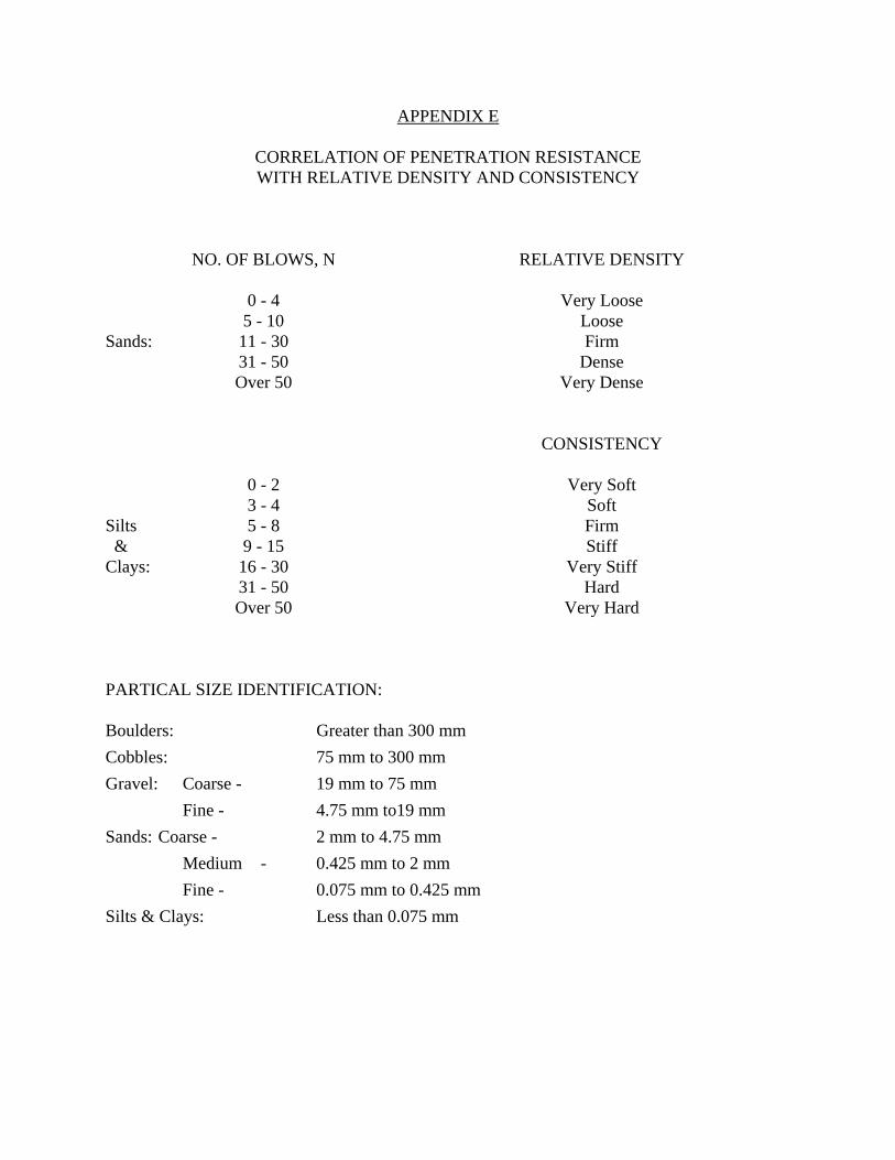
APPENDIX E
CORRELATION OF PENETRATION RESISTANCEWITH RELATIVE DENSITY AND CONSISTENCY
NO. OF BLOWS, N RELATIVE DENSITY
0 - 4 Very Loose5 - 10 Loose
Sands: 11 - 30 Firm31 - 50 DenseOver 50 Very Dense
CONSISTENCY
0 - 2 Very Soft3 - 4 Soft
Silts 5 - 8 Firm & 9 - 15 StiffClays: 16 - 30 Very Stiff
31 - 50 HardOver 50 Very Hard
PARTICAL SIZE IDENTIFICATION:
Boulders: Greater than 300 mmCobbles: 75 mm to 300 mmGravel: Coarse - 19 mm to 75 mm
Fine - 4.75 mm to19 mmSands: Coarse - 2 mm to 4.75 mm
Medium - 0.425 mm to 2 mmFine - 0.075 mm to 0.425 mm
Silts & Clays: Less than 0.075 mm