millimar. electrical length measuring instruments · analog of digital display • single, sum and...
TRANSCRIPT

-
7-�
C ���6
P�300M P�5�6
C ��45S �840
Millimar. Electrical Length Measuring Instruments
Millimar. Electrical Length Measuring InstrumentsOverview
• Compact, handy and simple to operate
• Extremely precise and easy to read due to the clearly defined analog of digital display
• Single, sum and differential measurement; plus limit switches and extreme value memories
Inductive Probes
• Large linearity range, strong output signal and insensitive to interference
• Precise measuring spindle and lever, frictionless ball or spring bearing for the highest
resolution with the lowest hystersis
• Robust construction for use on the shop floor, further models for all applications
• Highly accurate, long term stability and insensitive to environmental influences
• Good zero stability even when changing the measuring range
• Short response time ideal for assessment of fast processes
• Analog or digital display
Incremental Probes
• Highly accurate due to the precision glass scale
• Large measuring range with high resolution for absolute measurement
• Pneumatically cushioned measuring spindle lifter
• Digital output for the connection to a controller or a
computer
• Analog output (optional)
Evaluation Instruments
+
7-3Millimar. Electrical Length Measuring Instruments
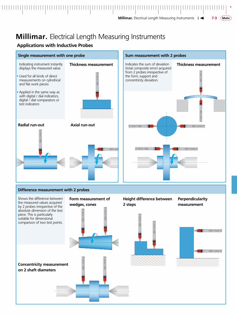
Millimar. Electrical Length Measuring InstrumentsApplications with Inductive Probes
Radial run-out
Single measurement with one probe
Indicating instrument instantly displays the measured value.
• Used for all kinds of direct measurements on cylindrical and flat work pieces
• Applied in the same way as with digital / dial indicators,
digital / dial comparators or test indicators
Perpendicularity measurement
Sum measurement with � probes
Indicates the sum of deviation (total composite error) acquired from 2 probes irrespective of the form, support and concentricity deviation.
Thickness measurement
Difference measurement with � probes
Shows the difference between the measured values acquired by 2 probes irrespective of the absolute dimension of the test piece. This is particularly suitable for dimensional comparison of two test points.
Thickness measurement
Axial run-out
Form measurement of wedges, cones
Concentricity measurement on � shaft diameters
Height difference between � steps
-
7-4
P�00� P�004 P�0�0 A P��04 A
�30� �303 �304 K �3�8 EHE-�056
�340
P�300MA P�300MB �300 �3�0
�30� / �303 / �304 K / �3�8 (Mahr-LVDT) / EHE-Series (Federal-LVDT)
P�300-Series / �300 / �3�0 Series (Mahr-Half Bridge)
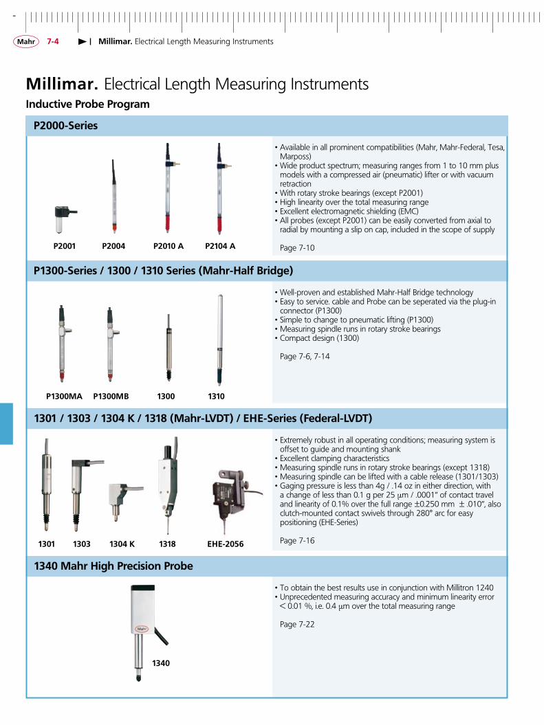
Millimar. Electrical Length Measuring InstrumentsInductive Probe Program
• Well-proven and established Mahr-Half Bridge technology• Easy to service. cable and Probe can be seperated via the plug-in
connector (P1300)• Simple to change to pneumatic lifting (P1300)• Measuring spindle runs in rotary stroke bearings• Compact design (1300)
Page 7-6, 7-14
• Extremely robust in all operating conditions; measuring system is offset to guide and mounting shank
• Excellent clamping characteristics• Measuring spindle runs in rotary stroke bearings (except 1318)• Measuring spindle can be lifted with a cable release (1301/1303)• Gaging pressure is less than 4g / .14 oz in either direction, with a change of less than 0.1 g per 25 µm / .0001“ of contact travel
and linearity of 0.1% over the full range ±0.250 mm ± .010“, also clutch-mounted contact swivels through 280° arc for easy
positioning (EHE-Series)
Page 7-16
• Available in all prominent compatibilities (Mahr, Mahr-Federal, Tesa, Marposs)
• Wide product spectrum; measuring ranges from 1 to 10 mm plus models with a compressed air (pneumatic) lifter or with vacuum retraction
• With rotary stroke bearings (except P2001)• High linearity over the total measuring range• Excellent electromagnetic shielding (EMC)• All probes (except P2001) can be easily converted from axial to radial by mounting a slip on cap, included in the scope of supply
Page 7-10
�340 Mahr High Precision Probe
• To obtain the best results use in conjunction with Millitron 1240• Unprecedented measuring accuracy and minimum linearity error < 0.01 %, i.e. 0.4 µm over the total measuring range
Page 7-22
Millimar. Electrical Length Measuring Instruments
P�000-Series

+
7-5
Mahr
Marposs
Tesa
Mahr-Federal
Half Bridge HB LVDT VLDT (Differential Choke Coil) (Linear Variable (Very Linear Differential Transducer) Differential Transducer)
S S S
Type Mahr Tesa Marposs Mahr-Federal
Carrier frequence KHz 19.4 13 7.5 5 P2001 P2004 192 73.75 115 78.74 P2104
P1300 1300 1301 1303 1304 K 1318
P2010 19.2 29.5 11.5 7.874 1310 19.2 – – –
Amplitude Veff 5 3 3.5 2
Sensitivity mV/V/mm 192 – – –
Electrical specification of various compatibilities
Schematic drawings of Mahr input amplifiers according to the various compatibilities
The measuring principle of inductive probes is based on the change of position of a magnets conductive core moving within a coil system, generally this is distinguished between a half bridge and LVDT’s.
The Mahr P2000 series of probes applies a high linear, patented VLDT transducer which is similar to an LVDT transducer. This also operates according to a differential transformer principle.
Connector pin(contact side)
Oscillator
General Technical Data of Inductive Probes
Oscillator
OscillatorOscillator
Millimar. Electrical Length Measuring Instruments
-
7-6
IP64
Millimar. Electrical Length Measuring Instruments
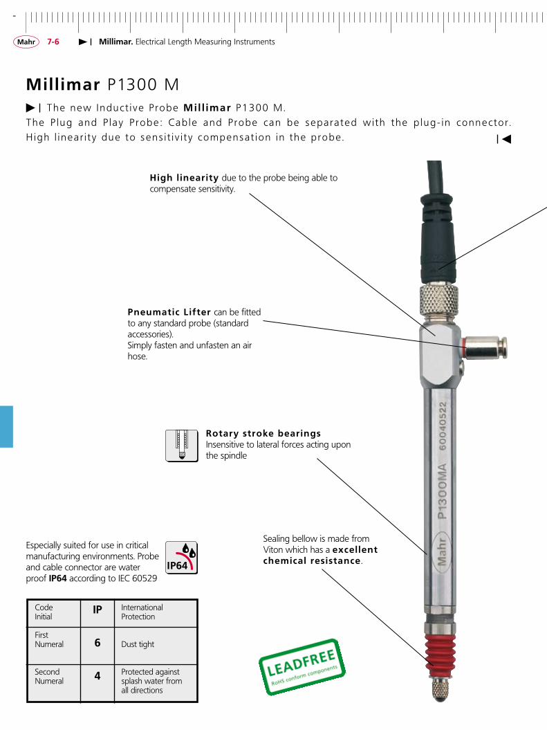
Mill imar P1300 MThe new I nduc t i v e P robe Mi l l imar P1300 M .
The P l ug and P l a y P robe : Cab l e and P robe can be sepa ra t ed w i t h t he p l ug - i n connec to r . H i gh l i nea r i t y due to sens i t i v i t y compensa t i on i n t he p robe .
Especially suited for use in critical manufacturing environments. Probe and cable connector are water proof IP64 according to IEC 60529
High l inearity due to the probe being able to compensate sensitivity.
Pneumatic Lifter can be fitted to any standard probe (standard accessories).Simply fasten and unfasten an air hose.
Rotary stroke bearingsInsensitive to lateral forces acting upon the spindle
Sealing bellow is made from Viton which has a excel lent chemical resistance .
Code International Initial Protection
First Numeral Dust tight
Second Protected against Numeral splash water from all directions
IP
6
4
+
7-7Millimar. Electrical Length Measuring Instruments
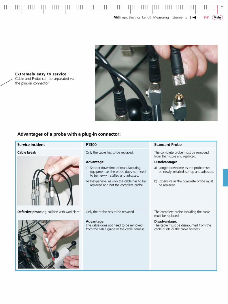
Advantages of a probe with a plug-in connector:
Service incident P�300 Standard Probe
Cable break Only the cable has to be replaced. The complete probe must be removed from the fixture and replaced.
Advantage: Disadvantage:
a) Shorter downtime of manufacturing a) Longer downtime as the probe must equipment as the probe does not need be newly installed, set-up and adjusted. to be newly installed and adjusted. b) Inexpenisve, as only the cable has to be b) Expensive as the complete probe must replaced and not the complete probe. be replaced.
Defective probe e.g. collision with workpiece Only the probe has to be replaced. The complete probe including the cable must be replaced.
Advantage: Disadvantage: The cable does not need to be removed The cable must be dismounted from the from the cable guide or the cable harness cable guide or the cable harness.
Extremely easy to serviceCable and Probe can be separated via the plug-in connector.

-
7-8
IP64
P�300 MA P�300 MB
Features
Millimar. Electrical Length Measuring Instruments
Inductive Probe Millimar P�300 M Half Bridge
• Supplied with: Inductive Probe P1300 Connection cable 2.5 m Screwed sealing plug Hose connector for compressed air Open-ended spanner Operating instructions
Cable and probe can be seperated with the plug-in connector.
Probe type P�300 MA P�300 MB
Measuring range ± 2.0 mm / ± 0.079“ Distance of lower stop1) -- 2.2 . . . 0 mm / -0.09 . . . 0“ Distance of upper stop1) 2.2 . . . 4.4 mm / 0.09 . . . 0.173“ Lifter/Retraction Vacuum Lifter Compressed Air Retraction (Standard option) (max. 1 bar)Measuring force at electrical zero point 0.75 N / ± 0.15 N2) depending upon air pressure Increase in measuring force 0.3 N / mm – Sensitivity deviation 0.3 % Repeatability fw 0.1 µm / 4 µinHysteresis fu 0.5 µm/ 20 µin
Linearity deviation with revised sensitivitywithin range ± 0.5 mm 0.4 µm/ 16 µin within range ± 1.0 mm 1.5 µm/ 60 µin within range ± 2.0 mm 3.0 µm/ 120 µin Protection class according to IEC 60529 IP64 Length of cable 2.5 m / 8 ft (detachable) Compatibility - Mahr Half Bridge
Order no. 4400�80 4400�8�
1) Relative to the electrical zero point. Adjustable; lower and upper stops are simultaneously adjusted2) Measuring force springs are interchangeable, following measuring force springs are available (0.25; 0.5; 1; 1.25; 1.5 N)
Technical Data

+
7-�
�����
����
����
����
����
����� ��
�
�
�
� �
��
�
��
����
��
����
��
��������
�
�
����
����
P�300 MA
P�300 MB
Millimar. Electrical Length Measuring Instruments
Inductive Probe Millimar P�300 M Half Bridge
1 Connection jack for an evaluation instrument 2 Connecting plug for the probe 3 Socket 4 Screw sealing plug SW 4.6 5 Hose connector for compressed air (external diameter 3 mm) 6 Mounting shank 7 Locking nut 8 Sealing bellows 9 Contact point 901 H10 Preferred clamping area
Connector for the air hose (90°)
Connection cable 2.5 m / 8 ft
Individual Components and Accessories P�300M
Order no. P�300 MA without cable 4400�8�P�300 MB without cable 4400�83Hose connector for compressed air 90° 4400�38Cable for P1300 M 2.5 m / 8 ft 4885��0Cable for P1300 M 5 m / 16 ft 4885�5�Cable for P1300 M 10 m / 20 ft 4885�60
Sealing bellows for
P1300 MA 70��546P1300 MB 70�8��0
Order no. Measuring force springs1) for P1300 MA
0.25 N 70�68�7 0.50 N 70�68�7 0.75 N 70�68�8 1.00 N 70�684� 1.25 N 70�557� 1.50 N 70�5505
1) All measuring forces (except 0.25 N) including the sealing bellows have a measuring spring force of approx 0.25 N at zero point.
All dimensions and values are metric
-
7-�0
IP64
IP40
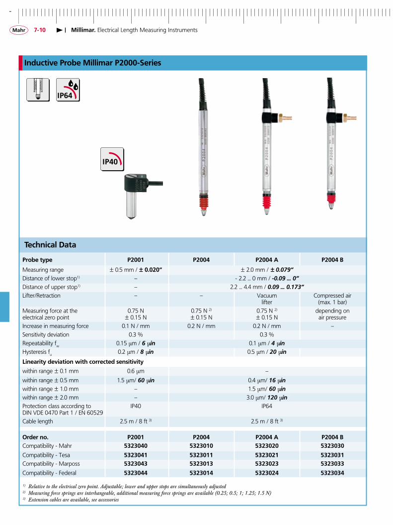
Inductive Probe Millimar P�000-Series
Probe type P�00� P�004 P�004 A P�004 B
Measuring range ± 0.5 mm / ± 0.0�0“ ± 2.0 mm / ± 0.079“Distance of lower stop1) – - 2.2 ... 0 mm / -0.09 ... 0“Distance of upper stop1) – 2.2 ... 4.4 mm / 0.09 ... 0.173“Lifter/Retraction – – Vacuum Compressed air lifter (max. 1 bar)Measuring force at the 0.75 N 0.75 N 2) 0.75 N 2) depending on electrical zero point ± 0.15 N ± 0.15 N ± 0.15 N air pressure Increase in measuring force 0.1 N / mm 0.2 N / mm 0.2 N / mm –Sensitivity deviation 0.3 % 0.3 % Repeatability fw 0.15 µm / 6 µin 0.1 µm / 4 µinHysteresis fu 0.2 µm / 8 µin 0.5 µm / 20 µin
Linearity deviation with corrected sensitivity
within range ± 0.1 mm 0.6 µm –
within range ± 0.5 mm 1.5 µm/ 60 µin 0.4 µm/ 16 µin within range ± 1.0 mm – 1.5 µm/ 60 µinwithin range ± 2.0 mm – 3.0 µm/ 120 µinProtection class according to IP40 IP64DIN VDE 0470 Part 1 / EN 60529Cable length 2.5 m / 8 ft 3) 2.5 m / 8 ft 3)
Order no. P�00� P�004 P�004 A P�004 BCompatibility - Mahr 53�3040 53�30�0 53�30�0 53�3030
Compatibility - Tesa 53�304� 53�30�� 53�30�� 53�303�Compatibility - Marposs 53�3043 53�30�3 53�30�3 53�3033
Compatibility - Federal 53�3044 53�30�4 53�30�4 53�3034
1) Relative to the electrical zero point. Adjustable; lower and upper stops are simultaneously adjusted2) Measuring force springs are interhangeable, additional measuring force springs are available (0.25; 0.5; 1; 1.25; 1.5 N)3) Extension cables are available, see accessories
Technical Data
Millimar. Electrical Length Measuring Instruments
+
7-��
IP64
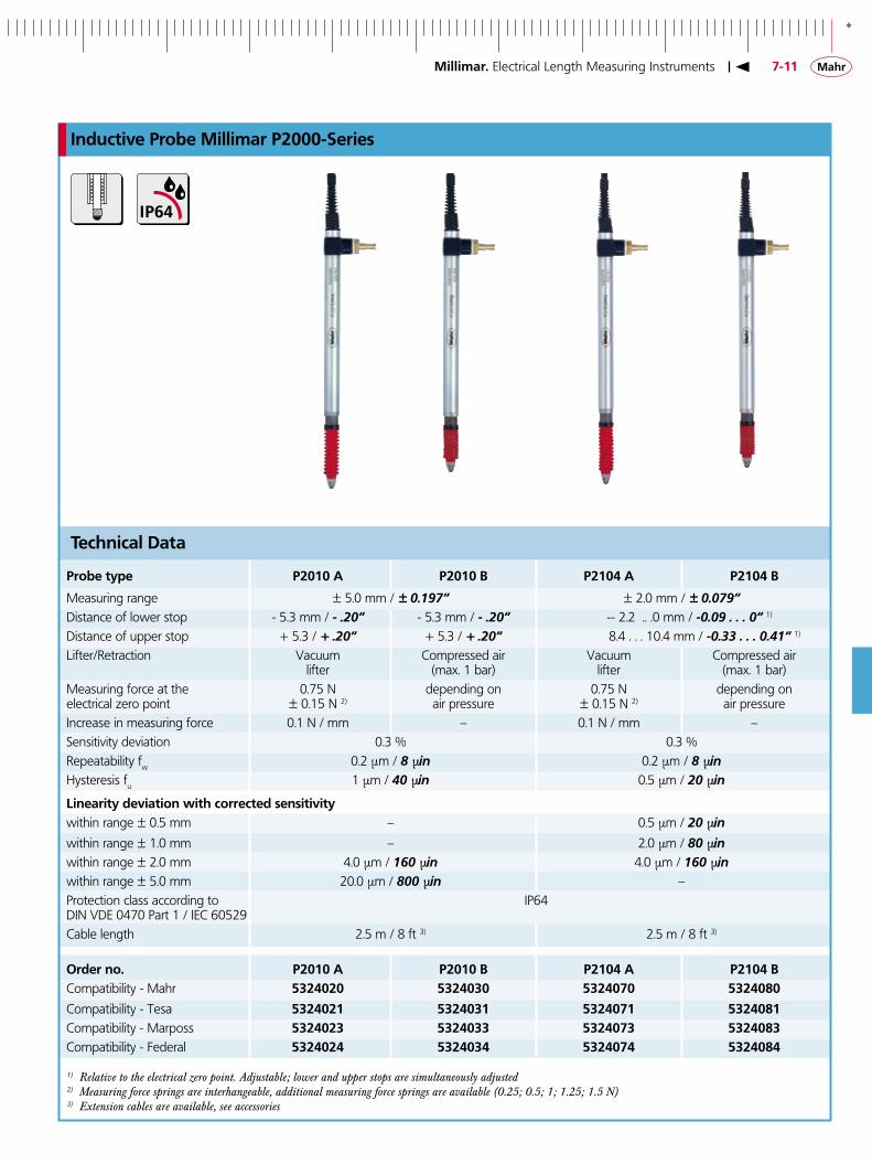
Inductive Probe Millimar P�000-Series
Millimar. Electrical Length Measuring Instruments
Probe type P�0�0 A P�0�0 B P��04 A P��04 B
Measuring range ± 5.0 mm / ± 0.197“ ± 2.0 mm / ± 0.079“Distance of lower stop - 5.3 mm / - .20“ - 5.3 mm / - .20“ - - 2.2 .. .0 mm / -0.09 . . . 0“ 1) Distance of upper stop + 5.3 / + .20“ + 5.3 / + .20“ 8.4 . . . 10.4 mm / -0.33 . . . 0.41“ 1) Lifter/Retraction Vacuum Compressed air Vacuum Compressed air lifter (max. 1 bar) lifter (max. 1 bar)Measuring force at the 0.75 N depending on 0.75 N depending on electrical zero point ± 0.15 N 2) air pressure ± 0.15 N 2) air pressureIncrease in measuring force 0.1 N / mm – 0.1 N / mm –Sensitivity deviation 0.3 % 0.3 % Repeatability fw 0.2 µm / 8 µin 0.2 µm / 8 µinHysteresis fu 1 µm / 40 µin 0.5 µm / 20 µin
Linearity deviation with corrected sensitivitywithin range ± 0.5 mm – 0.5 µm / 20 µin
within range ± 1.0 mm – 2.0 µm / 80 µinwithin range ± 2.0 mm 4.0 µm / 160 µin 4.0 µm / 160 µinwithin range ± 5.0 mm 20.0 µm / 800 µin –Protection class according to IP64DIN VDE 0470 Part 1 / IEC 60529Cable length 2.5 m / 8 ft 3) 2.5 m / 8 ft 3)
Order no. P�0�0 A P�0�0 B P��04 A P��04 BCompatibility - Mahr 53�40�0 53�4030 53�4070 53�4080
Compatibility - Tesa 53�40�� 53�403� 53�407� 53�408�Compatibility - Marposs 53�40�3 53�4033 53�4073 53�4083Compatibility - Federal 53�40�4 53�4034 53�4074 53�4084
1) Relative to the electrical zero point. Adjustable; lower and upper stops are simultaneously adjusted2) Measuring force springs are interhangeable, additional measuring force springs are available (0.25; 0.5; 1; 1.25; 1.5 N)3) Extension cables are available, see accessories
Technical Data

-
7-��
P�0�0 A / P�0�0 B
P�004 A / P�004 B
28
8h6
(3/8
")
88,721,3
6
M2,5(4/48UNF)
+2-20
P�004
26,5
28
3,5
3,6
9
8,3
12,5
ø8h
6(3
/8")
125,734
6
M2,5(4/48UNF)
+5-50
9,2
14
26,5
28
3,5
3,6
9
8,3
12,5
8h6
(3/8
")
88,721,3
6
M2,5(4/48UNF)
+2-20
9,2
14
9,2
14
17,5
11
8h6
34,211
P�00�
P��04 A / P��04 B
26,5
28
3,5
3,6
9
8,3
12,5
8h6
(3/8
")
128,7
37
6
M2,5(4/48UNF)
+2-20
9,2
14
Inductive Probe Millimar P�000-Series
With the supplied slip-on cap, the cable can be flexed to 90° (vertical to horiziontal)
With the supplied slip-on cap, the cable can be flexed to 90° (vertical to horiziontal)
With the supplied slip-on cap, the cable can be flexed to 90° (vertical to horiziontal)
With the supplied slip-on cap, the cable can be flexed to 90° (vertical to horiziontal)
Values shown in brackets apply to Federal-compatibilityAll dimensions and values are metric
Millimar. Electrical Length Measuring Instruments
+
7-�3
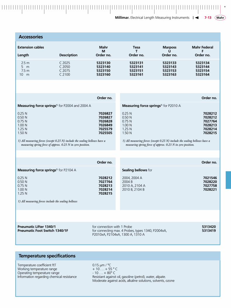
Extension cables Mahr Tesa Marposs Mahr Federal M T U FLength Description Order no. Order no. Order no. Order no. 2.5 m C 2025 53�3�30 53�3�3� 53�3�33 53�3�34 5 m C 2050 53�3�40 53�3�4� 53�3�43 53�3�44 7.5 m C 2075 53�3�50 53�3�5� 53�3�53 53�3�54 10 m C 2100 53�3�60 53�3�6� 53�3�63 53�3�64
Pneumatic Lifter �340/� for connection with 1 Probe 53�34�0Pneumatic Foot Switch �340/�F for connecting max. 4 Probes, types 1340, P2004xA, 53�34�� P2010xA, P2104xA, 1300 A, 1310 A
Accessories
Millimar. Electrical Length Measuring Instruments
Order no. Measuring force springs�) for P2104 A
0.25 N 70�8���0.50 N 70�77640.75 N 70�8��31.00 N 70�8��41.25 N 70�8��5
1) All measuring forces include the sealing bellows
Order no. Measuring force springs�) for P2004 and 2004 A
0.25 N 70�68�70.50 N 70�68�7 0.75 N 70�68�81.00 N 70�684�1.25 N 70�557� 1.50 N 70�5505
1) All measuring forces (except 0.25 N) include the sealing bellows have a measuring spring force of approx. 0.25 N in zero position.
Order no. Measuring force springs�) for P2010 A
0.25 N 70�8���0.50 N 70�8���0.75 N 70�77641.00 N 70�8��31.25 N 70�8��4 1.50 N 70�8��5
1) All measuring forces (except 0.25 N) include the sealing bellows have a measuring spring force of approx. 0.25 N in zero position.
Temperature coefficient ftT 0.15 µm / °CWorking temperature range + 10 . . . + 55 ° COperating temperature range - 10 . . . + 80° CInformation regarding chemical resistance Resistant against oil, gasoline (petrol), water, alipate. Moderate against acids, alkaline solutions, solvents, ozone
Order no. Sealing bellows for
2004, 2004 A 70��546 2004 B 70�8��02010 A, 2104 A 70�7758 2010 B, 2104 B 70�8���
Temperature specifications

-
7-�4
IP64 IP52
Inductive Probe Millimar �300 / �3�0 Half Bridge
Millimar. Electrical Length Measuring Instruments
Technical Data
Probe type �300 �300 A �3�0 �3�0 A �3�0 B
Measuring range ± 2.0 mm / ± 0.079“ ± 5.0 mm / ± 0.197“Distance of lower stop - 2.2 . . .0 mm / -0.09 . . . 0“ 1) - 5.2 mm / - 0.204“Distance of upper stop -2.2 . . . 4.4 mm / -0.09 . . . 0.173“ 1) 5.8 mm / - 0.228“Lifter/Retraction – Vacuum – Vacuum Compressed air lifter lifter (max. 1 bar)Measuring force at the 0.75 N 2) 0.75 N 2) 0.75 N 2) depending on electrical zero point ± 0.15 N ± 0.15 N ± 0.15 N air pressure Increase in measuring force 0.3 N / mm 0.08 N / mm . . . 0.15 N / mm –Sensitivity deviation 0.5 % 0.5 %Repeatability fw 0.1 µm / 4 µin 0.5 µm / 20 µinHysteresis fu 0.5 µm / 20 µin 2 µm / 80 µin
Linearity deviation with corrected sensitivitywithin range ± 0.5 mm 0.4 µm/ 16 µin – within range ± 1.0 mm 1.5 µm / 60 µin –within range ± 2.0 mm 3.0 µm/ 120 µin 10 µm / 400 µin within range ± 5.0 mm – 30 µm / 1200 µinProtection class acc. to IEC 60529 IP64 IP52Cable length 1.5 m / 5 ft 3) Compatibility - Mahr Half Bridge
Order no. 53�3000 53�300� 53�3�00 53�3�0� 53�3�0�
1) Relative to the electrical zero point. Adjustable; lower and upper stops are simultaneously adjusted2) Measuring force springs are interchangeable. additional measuring force springs are available, see accessories3) Extension cables are available, see accessories

+
7-�5
�300 A
�300 �3�0
�3�0 A
�3�0 B
2 6
+ 5-50
4 9
ø8
h6
1 3 3
M2,5
1 8 ,58 ,5ø
8h
6
+ 2-20
8 0
M2,5
1 8 ,58 ,5
ø8
h6
+ 2-20
8 04
,51
9,5
M2,5
2 6
+ 5-50
4 9
ø8
h6
1 3 3
4,5
M2,5
2 6
+ 5-50
5 0 (4 4 ,2 )*
ø8
h6
1 3 3
4,5
M2,5
Accessories
Order no. Measuring force springs for 1300 0.25 N 7005555 0.50 N 7005556 0.75 N 7005557 1.00 N 7005558 1.50 N 700555� 2.00 N 7005560
Measuring force springs for 1310 0.5 N 700354� 0.75 N 7003550 1.00 N 700355� 2.00 N 7003553
Sealing bellows for
1300 300�86�1310 43��787
Order no.
Extension cable for 1300 / 1310 1 m �0�400� 2 m �0�400� 3 m �0�4003 5 m 70��787 7 m �0�4007 10 m 70��788 15 m �0�40�5 18 m 70��78� 20 m �0�40�0 25 m �0�40�5 28 m �0�40�8
Pneumatic lifter �340/� 53�34�0Pneumatic lifter �340/�F 53�34��for 1300 A / 1310 A
* in initial position
Inductive Probe Millimar �300 / �3�0 Half Bridge
Millimar. Electrical Length Measuring Instruments
All dimensions and values are metric
-
7-�6
IP64 IP50����
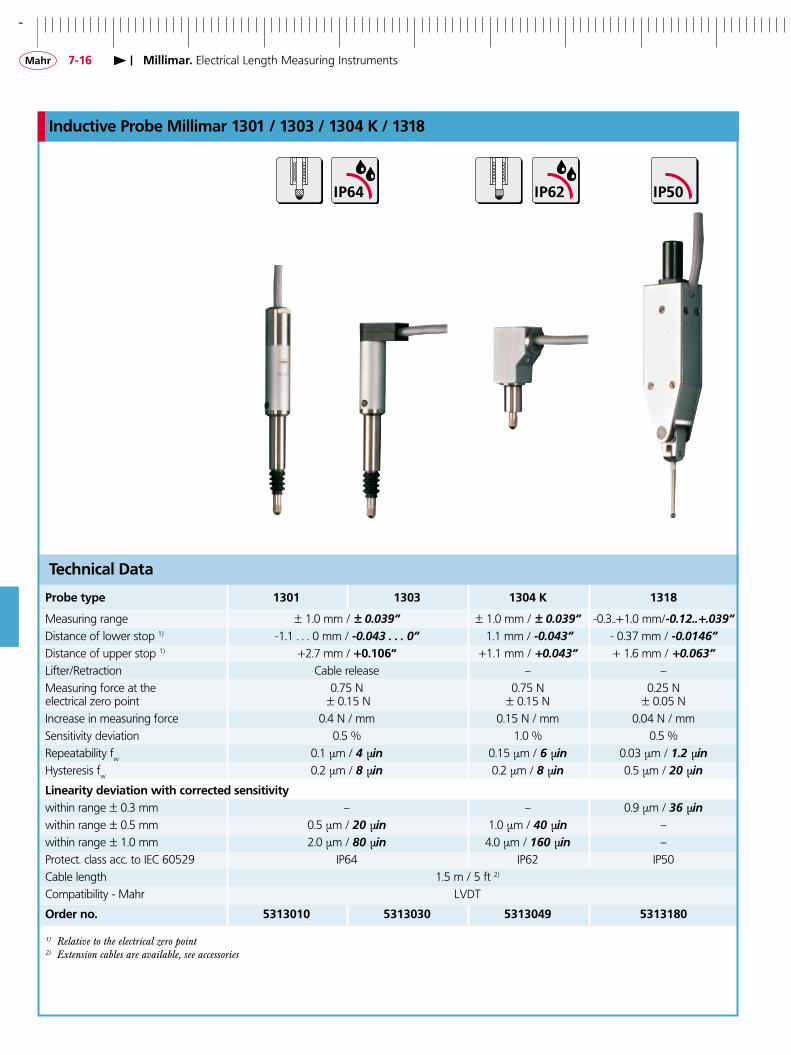
Inductive Probe Millimar �30� / �303 / �304 K / �3�8
Technical Data
Millimar. Electrical Length Measuring Instruments
Probe type �30� �303 �304 K �3�8
Measuring range ± 1.0 mm / ± 0.039“ ± 1.0 mm / ± 0.039“ -0.3..+1.0 mm/-0.12..+.039“ Distance of lower stop 1) -1.1 . . . 0 mm / -0.043 . . . 0“ 1.1 mm / -0.043“ - 0.37 mm / -0.0146“Distance of upper stop 1) +2.7 mm / +0.�06“ +1.1 mm / +0.043“ + 1.6 mm / +0.063“Lifter/Retraction Cable release – –Measuring force at the 0.75 N 0.75 N 0.25 Nelectrical zero point ± 0.15 N ± 0.15 N ± 0.05 N Increase in measuring force 0.4 N / mm 0.15 N / mm 0.04 N / mmSensitivity deviation 0.5 % 1.0 % 0.5 % Repeatability fw 0.1 µm / 4 µin 0.15 µm / 6 µin 0.03 µm / 1.2 µinHysteresis fw 0.2 µm / 8 µin 0.2 µm / 8 µin 0.5 µm / 20 µin
Linearity deviation with corrected sensitivitywithin range ± 0.3 mm – – 0.9 µm / 36 µinwithin range ± 0.5 mm 0.5 µm / 20 µin 1.0 µm / 40 µin – within range ± 1.0 mm 2.0 µm / 80 µin 4.0 µm / 160 µin –Protect. class acc. to IEC 60529 IP64 IP62 IP50Cable length 1.5 m / 5 ft 2) Compatibility - Mahr LVDT
Order no. 53�30�0 53�3030 53�304� 53�3�80
1) Relative to the electrical zero point2) Extension cables are available, see accessories

+
7-�7
�303
�30�
�3�8�304 K
19
ø8h
6
13
21
32,2
1 5 ,6
+ 1-10
2 5
ø8
h6
9 8 ,3
ø1
2
ø1
2,4
1 8
6
7 6 ,7
M2,5
+ 1-10
ø8h
6
ø12
6
M2,5
25
66,5
88
8
21,5
21,5
ø8h
6
12
+1-10 ø
8h6
44
619
18,5
12
M2,
5Inductive Probe Millimar �30� / �303 / �304 K / �3�8
Accessories
Description Order no. Extension Cables for 1301 / 1303 / 1304 K / 1318 ��88/� 1 m / 3 ft 53��88� ��88/�,5 2.5 m / 8 ft 53��88� ��88/5 5 m / 16 ft 53��885 ��88/7,5 7.5 m / 24 ft 53��887 ��88/�0 10 m / 30 ft 53��88�
Cable Release for 1301 / 1303 �3�� 53�3��0
Styluses for 1318 with carbide ball d = 2 mm; L = 21 mm (Standard) 3005��3 d = 1 mm; L = 21 mm 7003�0� d = 3 mm; L = 21 mm 7003�03
Styluses for 1318 with ruby ball d = 2 mm; L = 21 mm 8004�3�
Millimar. Electrical Length Measuring Instruments
All dimensions and values are metric

-
7-�8
EHE-�056
Lever Type Gage Heads F
Millimar. Electrical Length Measuring Instruments
Angle “A” Correction Factor
10 .985 20 .940 30 .866 40 .766 50 .643 60 .500
• Clutch-mounted contact swivels through 280° arc for easy positioning
• Linearity – 0.1% over full range of ±0.250 mm / ±.010”
• Gaging pressure less than 4 g / .14 oz. in either direction,
with a change of less than 0.1 gram per 25 µm / .001” of
contact travel. Special gaging pressures available. Contact Mahr Federal Technical Assistance
Features
• Repeatability better than 0.1 µm / 4 µin • Cable length – 1.2 m / 4 ft • Miniature models include the
same powerful features as standard sized Lever Type Gage Heads
For use on test stands, surface plate work, or where
light pressure is needed.
Automatic Cosine Error Compensation
Order no.
Adaptor to mount EHE-2048 on Model 2400 Stand EAM-�07�
Clamp for mounting EHE-2048 on model 2300 Stand CP-��6
Accessories kit for EHE-2048. Includes EAM-1071, CP-116, EPT-1013, two rectangular holding bars and a holding rod EAS-�333 Replacement tip, 1.6 mm/ .062” dia. steel ball EPT-�004Replacement tip, 0.787 mm/ .031” dia. tungsten carbide ball EPT-�007Replacement tip, steel “volute (normally furnished) EPT-�008Replacement tip, 0.787 mm/ .031” steel ball EPT-�0�3Replacement tip, 1.6 mm/ .062” dia., sapphire ball, 1:1 ratio EPT-�05�-W�Replacement tip, 1.6 mm/ .062” dia., sapphire ball, 2:1 ratio EPT-�05�-W�Replacement tip, 1.6 mm/ .062” dia., sapphire ball, 3:1 ratio EPT-�05�-W3Replacement tip, 1.6 mm/ .062” dia., sapphire ball, 4:1 ratio EPT-�05�-W4Replacement tip, 1.6 mm/ .062” dia., sapphire ball, 5:1 ratio EPT-�05�-W5
Replacement adjustable nose mounting bracket EAT-�0�0Replacement fixed back plate mounting bracket EPL-��40
Accessories
Involute tip (normally furnished) automatically corrects for cosine error when finger is at an angle up to 20°. Simplifies “reach over” jobs.
When exceeding 20°, use ball tip contact and table above. With multiplier function, 832F & 1840F Amplifiers can correct for cosine error.

+
7-��Millimar. Electrical Length Measuring Instruments
Lever Type Gage Heads F
Models and Accessories
Model EHE-�048 – Post Bracket Back, (BK-108) tamper-proof mounted. Option: Conversion Bracket, EAM-1071, attaches quickly and securely in any rotational direction to suit a wide variety of mounting needs.
Model EHE-�056 – Adjustable Nose Mount (EAT-1010), tamper-proof mounted. Permits wide choice of positions and approximately3.8mm/.150in fine adjustment for quick setup with support close to gaging contact.
Model EAT-�0�6 – Fine Adjust Attachment for Lever Type Gage Heads with post mounting option, permits mounting on a wide variety of fixtures.
Model EHE-�050 – Fixed Nose Mount (EAM-1045), tamper-proof mounted. Provides support close to gaging contact for the most critical applications.
Model EAS-�333 – Mounting Kit for use with EHE-2048. Permits Gage Head to be mounted on a wide variety of stands and holding fixtures. Includes Conversion Bracket, EAM-1071 and 0.787mm/.031in diameter ball tip contact.
Model EHE-�05� – Fixed Back Plate, (EPL-1140) tamper-proof mounted. For mounting on adjustable plates or slides in fixtures for continuous duty application.
-
7-�0
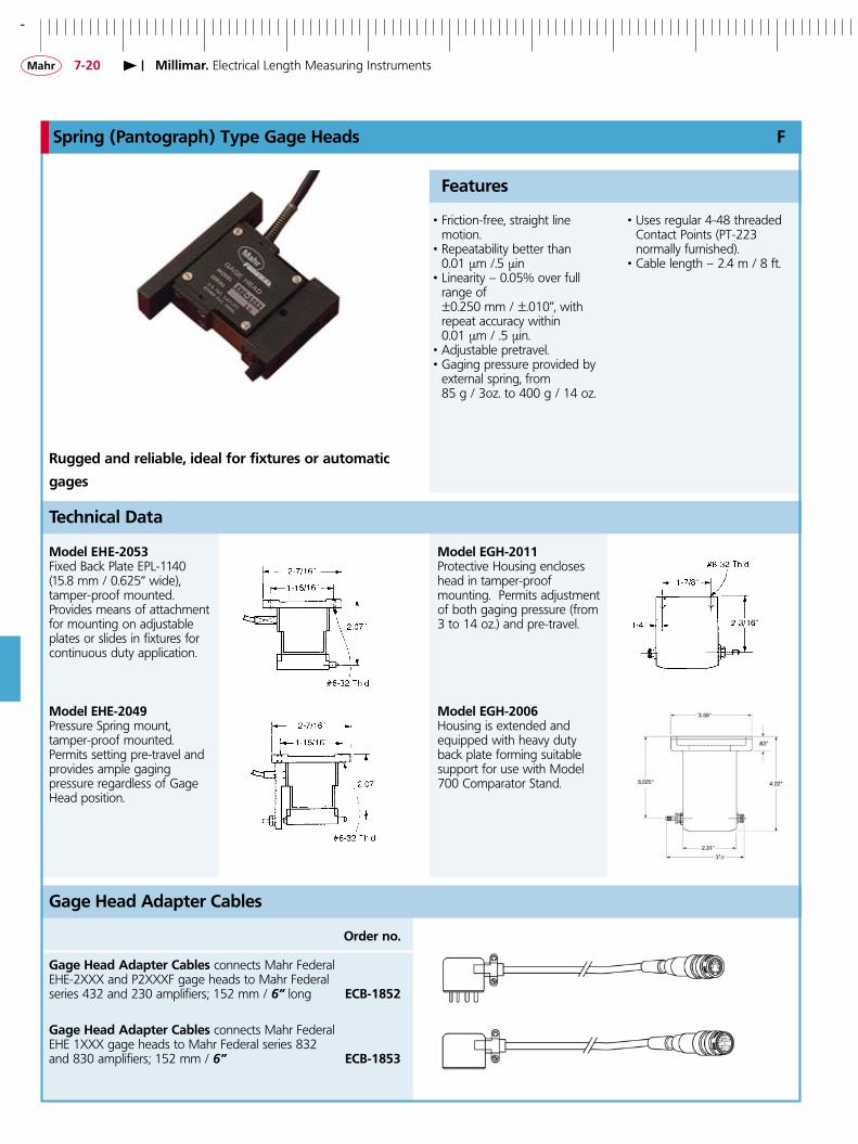
Spring (Pantograph) Type Gage Heads F
Millimar. Electrical Length Measuring Instruments
Model EHE-�053Fixed Back Plate EPL-1140(15.8 mm / 0.625” wide),tamper-proof mounted. Provides means of attachment for mounting on adjustable plates or slides in fixtures for continuous duty application.
• Friction-free, straight line motion.
• Repeatability better than 0.01 µm /.5 µin • Linearity – 0.05% over full
range of ±0.250 mm / ±.010”, with
repeat accuracy within 0.01 µm / .5 µin. • Adjustable pretravel. • Gaging pressure provided by
external spring, from 85 g / 3oz. to 400 g / 14 oz.
Features
• Uses regular 4-48 threaded Contact Points (PT-223
normally furnished). • Cable length – 2.4 m / 8 ft.
Rugged and reliable, ideal for fixtures or automatic
gages
Order no.
Gage Head Adapter Cables connects Mahr Federal EHE-2XXX and P2XXXF gage heads to Mahr Federal series 432 and 230 amplifiers; 152 mm / 6” long ECB-�85�
Gage Head Adapter Cables connects Mahr Federal EHE 1XXX gage heads to Mahr Federal series 832 and 830 amplifiers; 152 mm / 6” ECB-�853
Gage Head Adapter Cables
Model EGH-�0��Protective Housing encloses head in tamper-proof mounting. Permits adjustment of both gaging pressure (from 3 to 14 oz.) and pre-travel.
Technical Data
Model EHE-�04�Pressure Spring mount, tamper-proof mounted. Permits setting pre-travel and provides ample gaging pressure regardless of Gage Head position.
Model EGH-�006Housing is extended and equipped with heavy duty back plate forming suitable support for use with Model 700 Comparator Stand.

+
7-��
AT-��
Millimar. Electrical Length Measuring Instruments
Adapters for Cartridge Type Gage Heads
AD-�38Electronic probe adapter permits using cartridge type gage heads with any regular Mahr Federal indicator.
AAD-66“L” bracket used for mounting .375” diameter gage heads on comparator stands.
AAD-67 For .375” diameter stem, square bracket. 1/4-20 mounting thread.
AAD-�� “T” bracket flange mounted, two 4.3 mm / .169” through holes. For .375” dia. gage heads.
AD-87Split collar adapter for mounting .375” dia. gage heads.For 1/2-32 taps use V-8��
EAD-�0��Right angle adapter for mounting .375” diameter cartridge gage heads on 36B series comparators.

-
7-��
74
12
87 m
ax.
30
20
ø8h6
M2,5
IP64
Inductive Probe Millimar �340
Commercial deviation diagram
Deviationµm
Electrical zero value
Nominal valuemm
• To obtain the best results use in conjunction with the
Millitron 1240
• Unprecedented measuring accuracy and minimum linearity error < 0.01 %, i.e. 0.4 µm over the total measuring range
Features
• Probe is protected against dirt and moisture, thus ideally suited for production related application
• Cable length 1.5 m / 5 ft
�340
Measuring range ± 2 mm / ± 0.079“Distance of lower stop 1) - 2.2 mm / - 0.09“ (adjustable)Distance of upper stop 1) + 3.0 mm / + 0.118“Spindle lift pneumaticMeasuring force 0.75 NSensitivity deviation 0.3 %Repeatability fw ≤ 0.08 µmHysteresis fu 0.08 µm Linearity deviation within range ± 1 mm 0.15 µm ± 2 mm 0.4 µmContact points carbide ballProtection class acc. to IEC 60529 IP64Cable output lateralTemperature coefficient 0.6 µm/KWorking temperature range + 10 . . .+ 40° C / + 50 . . .+ 104°FOperating temperature range - 10 . . .+ 80° C / - 14 . . .+ 176°FHysteris of measuring value - 10 . . .+ 80° C / - 14 . . .+ 176°F
Order no. 53�3400
1) Relative to the electrical zero point
Technical Data
Accessories
Order no. Extension Cable 5 m / 16 ft 53�34�5 Extension Cable 10 m / 32 ft 53�34�� Extension Cable 20 m / 64 ft 53�34�� Extension Cable 30 m / 98 ft 53�34�3
Order no. Pneumatic Lifter �340/�Pneumatic hand pump with an plug-in hoseapprox. 1 m / 3 ft 53�34�0Pneumatic Foot Switch �340/�Ffor connecting max. 4 Probes 1340 53�34��
Millimar. Electrical Length Measuring Instruments
All dimensions and values are metric

+
7-�3
ø 8h6
ø 6,5
17,9
M 2,5
110
6818
,534,8
16,2
10,5
ø 8h6
ø 6,5
18,4
M 2,5
172
9837
41,2 16,2
10,5
IP50
Incremental Probe Millimar P�5�4 / P�5�6
Technical Data
Probe type P�5�4 P�5�6 Output signal 1 Vss Measuring system DIADUR-glass scale with incremental graduation Scale graduation 4 µm Signal period 2 µm Measuring range 12 mm / 0.47“ 25 mm / 0.98“System accuracy ± 0.2 µm Operating position no limitation Measuring force Vertical. downwards 0.6 . . . 0.85 N Vertical. upwards 0.35 . . . 0.6 N Horizontal 0.48 . . . 0.73 N Admissible measuring speed 0.5 m/s Admissible lateral force 0.8 N Max. Acceleration1) Shock in m/s2 1000 Vibration in m/s2 100 Protection class acc. to DIN IP50 Reference temperature 20°C / 68°F Working temperature + 10 . . .+ 40° C / + 50 . . .+ 104°F Storage temperature –20 . . . 70°C / - 4 . . .+ 158°F Weight excluding cable 100 g 180 g Connection cable 1.5 m / 5 ft
Order no. 53�5�40 53�5�60
1) The accuracy of this data is not guaranteed
Millimar. Electrical Length Measuring Instruments
Features
Order-no.
Cable lifter with integral pneumatic damping 30�40��
Extension cables
3 m / 10 ft 4407663 5 m / 16 ft 440766� 7 m / 23 ft 440766� 10 m / 32 ft 4407660
Accessories
• To obtain the best results use in conjunction with C 1245 I
• Excellent accuracy over a large measuring range
• Supplied with: Finger lifter

-
7-�4
MAXMIN
RS232C
Millimar. Evaluation InstrumentsOverview
Millimar. Electrical Length Measuring Instruments
C ��00 IC 830 83�
Catalog page 7 - 26 7 - 27 7 - 28
Display Needle analog scale with Needle analog scale Analog display with 1 digital 2 tolerance markers line display
Measuring channels 1 Inductive Probe (A) According to type, up to: 2 Inductive Probes (A, B) 2 Inductive Probes (A, B) 1 Pneumatic Measuring Instrument (A, B)
Compatible Inductive Probe Mahr Mahr Federal Mahr / TESA / (carrier frequency) Mahr Federal / Marposs
Max. Resolution 0.1 µm / .000002” 0.1 µm / .000005” 0.01 µm / .000001” Input Combinations +A, - A +A, - A, +B , -B , A + B , +A, - A, +B , -B , A + B , A - B , B - A , -A - B A - B , B - A , -A - B
Features / Programs 1 2 / 2 2 / 2 Test steps 1 1 1
Dynamic measurements – – MAX, MIN, MAX-MIN, (MAX+MIN)/2
Statistics functions – – –
Classification – – – Control inuts and outputs/ – – 3 inputs,SPC connectiong – 5 TTL Opto-coupler outputs
Analog output – 1 1
Data interface / ports – – RS232, 9 pin, plug
Configuration Turn switch Turn switch Keypad
Battery operated yes yes yes
Dimensions in mm (H x W x D) 137 x 157 x 80 165 x 190 x 148 254 x 168 x 143

+
7-�5
Millimar. Electrical Length Measuring Instruments
C ��08 C ���6 C ��45 ��40 S �840
7 - 30 7 - 31 7 - 32 7 - 33 7 - 34
Background lit LCD with Background lit LCD with Needle analog scale and Needle analog scale and 1 illuminated bar graph1 analog display and a 1 analog display and a 2 line display 1 line display and 2 line digital display2 digital line digital display 2 digital line digital display
According to type, up to: 2 Inductive Probes (A, B) According to type, up to: 2 Inductive Probes (A, B) According to type, up to:2 Inductive Probes (A, B) • 8 Inductive Probes 2 Incremental Probes (A, B) 2 Inductive Probes (A, B) 1 Pneumatic Meas. Inst. • 4 Incremental Probes 1 Pneumatic Meas. Inst. 1 Pneumatic Meas. Inst. • 2 Pneumatic Meas. Inst. • 8 Analog Signals • or a combination of these inputs
Mahr / TESA / Mahr / TESA / Mahr / TESA Mahr Mahr / TESA Mahr Federal Mahr Federal Mahr Federal Mahr Federal 0.1 µm / .000005” 0.01 µm / .000001” 0.1 µm / .000005” 0.01 µm / .000001” 0.1 µm / .000005”
+A, - A, +B , -B , A + B , +A, - A, +B , -B , A + B , Formula editor for 80 +A, -A, +B, -B A+B, +A-B, A, -A, B, -B, A+B, A-B, A - B , B - A , -A - B A - B , B - A , -A - B characters Functions: -A+B, -A-B -A+B, -A-B + / - / * / ÷/ () / factor
2 / 2 2 / 2 16 / 6 2 / 2 2 / 2 1 1 6 1 1
MAX, MIN, MAX-MIN, MAX, MIN, MAX-MIN, MAX, MIN, MAX-MIN, MAX, MIN, MAX-MIN, MAX, MIN, MAX-MIN, (MAX+MIN)/2 (MAX+MIN)/2 (MAX+MIN)/2, mean (MAX+MIN)/2, mean (MAX+MIN)/2
– – N, x-quer, S, Xmax, Xmin, Range n, xn, x, s, R –
– – max. 998, max. 79 auf I/O max. 30 –
3 Opto-coupler inputs, 3 Opto-coupler inputs, 3 Opto-coupler inputs, 3 Opto-coupler inputs, 3 Opto-coupler inputs, 3 Opto-coupler outputs 3 Opto-coupler outputs 6 Opto-coupler outputs 3 TTL outputs 3 Opto-coupler outputs
– 1 1 1 1
RS232, 9 pin, plug RS232, 9 pin, plug RS232, 9 pin, plug RS232, 9 pin, plug RS232, 9 pin, plug
PC, Keypad PC, Keypad PC, Keypad Keypad PC, Keypad
– – – – –
205 x 160 x 165 205 x 160 x 165 210 x 160 x 155 195 x 156 x 120 487 x 47 x 144

-
7-�6
��00 IC/MZ
IP40
Millimar ��00 IC compact amplifier M
• Compact housing
• Battery powered for portable usage in the workshop
• Large analog display with 2 tolerance markers
• Quick and reliable display of the measured value
• Switchable measuring direction
• One inductive probe can be connected
• Fine adjustment due to the large range zero setter
Features
Accessories
Order-no.
Battery, R 14 battery 1.5 V, (6 are required) 30044�4 Mains Adapter 100-240V~, 50-60Hz 30�7��6*
For appropriate Inductive probes please refer to pages 7-6 to 7-17
* Included in scope of supply
Technical Data
• Battery operation with the commerically available round R14 batteries
• Testing button for batteries
• Supplied with: Mains adapter
��00 IC ��00 IC/MZ
Measuring range ± 3 µm / 0.1 µm ± .0001“ / .000002“Resolution ± 10 µm / 0.2 µm ± .0003“ / .00001“ ± 30 µm / 1 µm ± .001“ / .00002“ ± 100 µm / 2 µm ± .003“ / .0001“ ± 300 µm / 10 µm ± .01“ / .0002“
Scale length 120 mm / 4.724“ Response time 350 ms Probe input 1 Single meas. combinations +A, -A Range of zero adjustment: 5 and 100 µm 1 Large range setter Deviation spread referring to measuring range ≤ 2.5% Protection class acc. to DIN IP40 Working temperature range + 10. . . + 40° C / + 50. . . + 104° F Power supply mains adapter, 9V = ~5 VA Power consumption approx. 0.1 W Dimensions 137 x 157 x 80 mm / 5.394“ x 6.181“ x 3.149“ Weight 1 kg / 2.205 lbs
Order no. 53��000* 53��00�*
* When placing an order please specify which type of mains adapter is required
Millimar. Electrical Length Measuring Instruments
+
7-�7
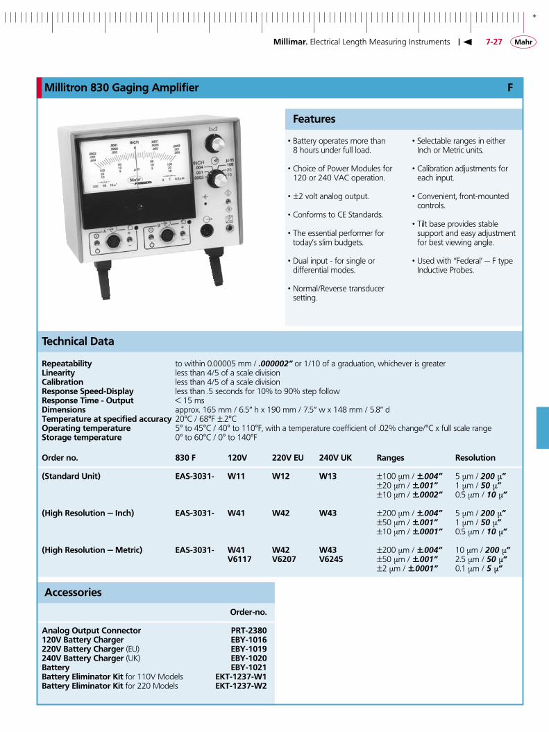
Millitron 830 Gaging Amplifier F
• Battery operates more than 8 hours under full load.
• Choice of Power Modules for 120 or 240 VAC operation.
• ±2 volt analog output.
• Conforms to CE Standards.
• The essential performer for today’s slim budgets.
• Dual input - for single or differential modes.
• Normal/Reverse transducer setting.
Features
Accessories
Order-no.
Analog Output Connector PRT-�380��0V Battery Charger EBY-�0�6��0V Battery Charger (EU) EBY-�0���40V Battery Charger (UK) EBY-�0�0Battery EBY-�0��Battery Eliminator Kit for 110V Models EKT-��37-W�Battery Eliminator Kit for 220 Models EKT-��37-W�
Technical Data
• Selectable ranges in either Inch or Metric units.
• Calibration adjustments for each input.
• Convenient, front-mounted controls.
• Tilt base provides stable support and easy adjustment
for best viewing angle.
• Used with “Federal’ — F type Inductive Probes.
Repeatability to within 0.00005 mm / .000002“ or 1/10 of a graduation, whichever is greaterLinearity less than 4/5 of a scale divisionCalibration less than 4/5 of a scale divisionResponse Speed-Display less than .5 seconds for 10% to 90% step followResponse Time - Output < 15 msDimensions approx. 165 mm / 6.5“ h x 190 mm / 7.5“ w x 148 mm / 5.8“ dTemperature at specified accuracy 20°C / 68°F ±.2°COperating temperature 5° to 45°C / 40° to 110°F, with a temperature coefficient of .02% change/°C x full scale rangeStorage temperature 0° to 60°C / 0° to 140°F
Order no. 830 F ��0V ��0V EU �40V UK Ranges Resolution
(Standard Unit) EAS-303�- W�� W�� W�3 ±100 µm / ±.004” 5 µm / 200 µ” ±20 µm / ±.001” 1 µm / 50 µ” ±10 µm / ±.0002” 0.5 µm / 10 µ”
(High Resolution — Inch) EAS-303�- W4� W4� W43 ±200 µm / ±.004” 5 µm / 200 µ” ±50 µm / ±.001” 1 µm / 50 µ” ±10 µm / ±.0001” 0.5 µm / 10 µ”
(High Resolution — Metric) EAS-303�- W4� W4� W43 ±200 µm / ±.004” 10 µm / 200 µ” V6��7 V6�07 V6�45 ±50 µm / ±.001” 2.5 µm / 50 µ” ±2 µm / ±.0001” 0.1 µm / 5 µ”
Millimar. Electrical Length Measuring Instruments
-
7-�8
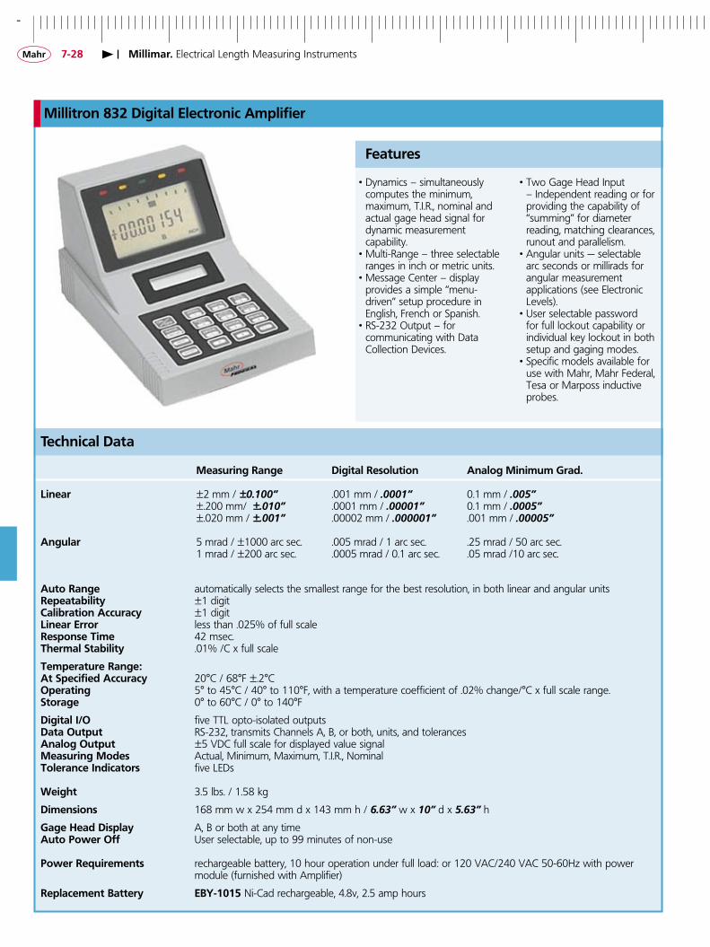
Millitron 83� Digital Electronic Amplifier
• Dynamics – simultaneously computes the minimum,
maximum, T.I.R., nominal and actual gage head signal for dynamic measurement
capability.• Multi-Range – three selectable
ranges in inch or metric units. • Message Center – display provides a simple “menu- driven” setup procedure in
English, French or Spanish.• RS-232 Output – for communicating with Data
Collection Devices.
Features
Technical Data
• Two Gage Head Input – Independent reading or for providing the capability of “summing” for diameter
reading, matching clearances, runout and parallelism.
• Angular units — selectable arc seconds or millirads for angular measurement
applications (see Electronic Levels).
• User selectable password for full lockout capability or individual key lockout in both setup and gaging modes.
• Specific models available for use with Mahr, Mahr Federal, Tesa or Marposs inductive probes.
Measuring Range Digital Resolution Analog Minimum Grad.
Linear ±2 mm / ±0.100” .001 mm / .0001” 0.1 mm / .005” ±.200 mm/ ±.010” .0001 mm / .00001” 0.1 mm / .0005” ±.020 mm / ±.001” .00002 mm / .000001” .001 mm / .00005”
Angular 5 mrad / ±1000 arc sec. .005 mrad / 1 arc sec. .25 mrad / 50 arc sec. 1 mrad / ±200 arc sec. .0005 mrad / 0.1 arc sec. .05 mrad /10 arc sec.
Auto Range automatically selects the smallest range for the best resolution, in both linear and angular unitsRepeatability ±1 digitCalibration Accuracy ±1 digitLinear Error less than .025% of full scaleResponse Time 42 msec.Thermal Stability .01% /C x full scale
Temperature Range:At Specified Accuracy 20°C / 68°F ±.2°COperating 5° to 45°C / 40° to 110°F, with a temperature coefficient of .02% change/°C x full scale range.Storage 0° to 60°C / 0° to 140°F
Digital I/O five TTL opto-isolated outputsData Output RS-232, transmits Channels A, B, or both, units, and tolerancesAnalog Output ±5 VDC full scale for displayed value signalMeasuring Modes Actual, Minimum, Maximum, T.I.R., NominalTolerance Indicators five LEDs
Weight 3.5 lbs. / 1.58 kg
Dimensions 168 mm w x 254 mm d x 143 mm h / 6.63” w x 10” d x 5.63” h
Gage Head Display A, B or both at any timeAuto Power Off User selectable, up to 99 minutes of non-use
Power Requirements rechargeable battery, 10 hour operation under full load: or 120 VAC/240 VAC 50-60Hz with power module (furnished with Amplifier)
Replacement Battery EBY-�0�5 Ni-Cad rechargeable, 4.8v, 2.5 amp hours
Millimar. Electrical Length Measuring Instruments
+
7-��
Millitron 83� Digital Electronic Amplifier
Power 83� F 83� M 83� T 83� U Mahr Federal Mahr Tesa Marposs probe type probe type probe type probe type Order no. Order no. Order no. Order no.
��0VAC adapter �004005 �004000 �0040�5 �0040�0US battery/��0VAC charger �004007 �00400� �0040�7 �0040��EU/UK ��0/�40VAC adapter �004006 �00400� �0040�6 �0040��EU battery/��0VAC charger �004008 �004003 �0040�8 �0040�3UK battery/�40VAC charger �00400� �004004 �0040�� �0040�4
Technical Data
Accessories
Order no.
RS-�3� cable, amplifier to MSP2 printer or computer, 2 m / 6 ft 70�4634
Storage Cover (opaque)– protection for the 832 Amplifier when used in harsh environments ECV-��76Oil/Splash Cover (clear)–protection for the 832 Amplifier when used in harsh environments ECV-��85
Footswitch for HOLD/RESUME, 3 m / 10 ft cable (15 pin) ECB-�857Footswitch for DYNAMIC RESET, or remote zeroing 3 m /1 0 ft cable (15 pin) ECB-�858Footswitch for SEND DATA, 3 m / 10 ft cable (15 pin) ECB-�85�Footswitch for DYNAMIC RESET, or Remote Zeroing, 1.5m/5 ft cable (Phone Plug) 300-50
Remote pushbutton for DYNAMIC RESET, or remote zeroing 1.5 m / 5 ft cable (Phone Plug) ECB-�855Remote pushbutton for SEND DATA, 1.5 m / 5 ft cable (15 pin) ECB-�860Remote pushbutton for HOLD/RESUME, 1.5 m / 5 ft cable (15 pin) ECB-�86�Remote pushbutton for HOLD/RESUME and SEND DATA, 3 m / 10 ft cable (15 pin) ECB-�868
Relay Box – five relays each with Normally Open/Normally Closed contacts; EKT-��36-W3 Contact Rating – 30 Vdc/120 Vac, 3 amps Power Supply – 120 Vac Dimensions – 39 mm x 129 mm x 134.6 mm d/1.53” x 5.082 x 5.3” with ECB-1886W-2, 6.1 mm/24” interconnect cable for amplifier to relay box
Mating connector, Digital I/O connector (15 pin MALE) ECN-�6�5-W�Mating connector, Reset Data connector (3/32 microphone plug) ECN-�6�3Mating connector, RS-232 Digital Output connector (9 pin FEMALE) ECN-�6�5-W�Mating connector, Gage Head to amplifier connector (5 pin MALE) ECN-�6�0
Battery Charger Modules (For 832 Units using 3 pin connector)
Plug-in 120 VAC, 50-60Hz charger for use with 120 Vac battery operated units EBY-�0�8 220 VAC, 50-60Hz charger for use with 220 Vac battery operated units EBY-�0�� 240 VAC, 50-60Hz (UK) charger for use with 240 Vac battery operated units EBY-�030
Power Supply Module (Bypass battery operated units to direct AC source operation)
For 120 Vac models (For 832 Units using 3 pin connector) �0�0000 For 220/240 Vac models (For 832 Units using 3 pin connector) �0�000� Printers
MSP-� line printer: includes power module for 120 V US 4�0�045MSP-� line printer: includes power module for 230 V Euro 4�0�040RS-�3� Cable: Amplifier to Printer, 2.0 m / 6 ft 70�4634Paper rolls for MSP-2 Line Printer 4�0�04�
Millimar. Electrical Length Measuring Instruments

-
7-30
MAXMIN
RS232C
TOL
0
Millimar C ��08 Compact amplifier with background lit display
Functions • Favorites, frequently required
functions can be assigned to the SELECT key
• Static measurements ± A, ± B and all combinations
• Dynamic measurements: Max, Min, Max-Min, Max+Min, mean
• Auto-Detect-Mode, two measuring instruments can be connected (Probe, Plug
Gage . . . ) • Programmable via the integrated key pad or by
RS232 interface in conjunction with the MS-Windows
configuration Software
Features
Display • Background lit LCD-Display
with an analog and a two line digital display
• 5 three color status lamps for warning and tolerances limits
• Up to 2 features can be simultaneously displayed Connections • 2 inputs for inductive probes
(also compatible with probes from Mahr, Tesa,
Mahr-Federal) • RS232 interface • 3 digital inputs for measurement start, master
measurement, send measured values, . . .
• 3 digital outputs for GO, NO GO, rework, measuring
time, . . .
Display Background LCD, 115 mm x 70 mm Analog scale Pointer, 61 graduations
Range and text display 7 digit LCD, 5 x 7 dot matrix, alpha-numeric
Measured value display 7 digit LCD, 7 segments
Tolerance display 5 LEDs, 3 colors
Displayed ranges ± 3, 10, 30, 100, 300, 1000, 3000, 10000 µm ± 0.0001; 0.0003; 0.001; 0.003; 0.01; 0.03; 0.1; 0.3 inch or tolerance related
Resolution 0.1 µm / .000005”
Response time- Meas. value memory 0.010s - Digital display 0.100s - Analog display 0.100s - Outputs 0.020s
Technical Data
Error limits- 10 x analog display 2.5% - Digital display 0.3% (min. 0.2 µm) Temperature coefficient 0.005%/°C Operating temperature 0°C to 45°C / 32°F to 113°F
InterfacesComputer, printer RS232, 9 pin. male (PC-compatible assignment) - Control outputs 3 Opto-coupler-outputs, 2 24V, 100mA- Control inputs 3 Opto-coupler-inputs, 24V, 10mAPower supply viaMains power pack 100V to 240V, 47Hz to 63Hz Power consumption 10 VA Protection class IP54, with conductive dust IP43 Housing dimensions(H x W x D) ca. 205 mm x 160 mm x 165 mm ca. 8.07“ x 6.29“ x 6.49“ Weight ca. 2.1 kg / 4.6 lbs
Order no. C ��08 M Mahr compatible 53��080C ��08 T Tesa compatible 53��08�C ��08 F Mahr-Federal compatible 53��08�
For appropriate Inductive probes please refer to pages 7-6 to 7-17
Order no.
Order no.
Extension cable (9 pin D-Sub-jack to a 70�4634D-Sub-socket), length 3 m / 10 ftControl Unit with 3 push buttons 5330�50Foot switch for for Input 1 5330�55 for Input 2 5330�56 for Input 3 5330�57
Accessories
Millimar. Electrical Length Measuring Instruments

+
7-3�
MAXMIN
RS232C
TOL
0
Millimar C ���6 Compact amplifier with background lit display
Display Background LCD, 115 mm x 70 mm
Analog scale Pointer, 61 graduations
Range and text display 7 digit LCD, 5 x 7 dot matrix, alpha-numeric
Measured value display 7 digit LCD, 7 segments
Tolerance display 5 LEDs, 3 colors
Displayed ranges ± 3, 10, 30, 100, 300, 1000, 3000, 10000 µm ± 0.0001; 0.0003; 0.001; 0.003; 0.01; 0.03; 0.1; 0.3 inch or tolerance related
Resolution 0.01 µm / .000001“
Response time- Meas. value memory 0.010s - Digital display 0.100s - Analog display 0.100s - Outputs 0.020s
Technical Data
Error limits- 10 x analog display 2.5% - Digital display 0.3% (min. 0.2 µm) Temperature coefficient 0.005%/°C Operating temperature 0°C to 45°C / 32°F to 113°F
InterfacesComputer, printer RS232, 9 pin. male (PC-compatible assignment) - Control outputs 3 Opto-coupler-outputs, 2 24V, 100mA- Control inputs 3 Opto-coupler-inputs, 24V, 10mAPower supply viaMains power pack 100V to 240V, 47Hz to 63Hz Power consumption 10 VA Protection class IP54, with conductive dust IP43 Housing dimensions(H x W x D) ca. 205 mm x 160 mm x 165 mm ca. 8.07“ x 6.29“ x 6.49“ Weight ca. 2.1 kg / 4.6 lbs
Order no. C ���6 M Mahr compatible 53���60C ���6 T Tesa compatible 53���6�C ���6 F Mahr-Federal compatible 53���6�
For appropriate Inductive probes please refer to pages 7-6 to 7-17
Order no.
Order no.
Extension cable (9 pin D-Sub-jack to a 70�4634D-Sub-socket), length 3 m / 10 ftControl Unit with 3 push buttons 5330�50Foot switch for for Input 1 5330�55 for Input 2 5330�56 for Input 3 5330�57
Accessories
Functions • Favorites, frequently required
functions can be assigned to the SELECT key
• Static measurements ± A, ± B and all combinations
• Dynamic measurements: Max, Min, Max-Min, Max+Min, mean
• Auto-Detect-Mode, two measuring instruments can be
connected (Probe, Plug Gage . . . ) • Programmable via the inte-
grated key pad or by RS232 interface in conjunction with the
MS-Windows configuration Software
Display • Background lit LCD-Display
with an analog and a two line digital display
• 5 three color status lamps for warning and tolerances limits
• Up to 2 features can be simultaneously displayed• Additional resolution, 0.0� μm / �μin Connections • 2 inputs for inductive probes
(also compatible with probes from Mahr, Tesa, Mahr-Federal)
• RS232 interface • 3 digital inputs for measure-
ment start, master measure-ment, send measured values, . . .
• 3 digital outputs for GO, NO GO, rework, measuring
time, . . .• Analog ouput• Programable analog out-
put voltage (max. ±5V)
Features
Millimar. Electrical Length Measuring Instruments

-
7-3�
MAXMIN
RS232C
TOL
0
����
Millimar C ��45 compact amplifier
Display analog indicator instrument. LCD 53 mm x 40 mm (2.087“ x 1.585“)
Analog scale 145 mm x 80 mm (5.709“ x 3.149“)
Range and Text display 7-point LCD, 5 x 7 dot matrix. alphanumeric
Measured value display 7-point LCD. 7 Segment
Tolerance display 5 LEDs, 3-colors
Display ranges ± 10; 30; 100;. 300; 1000; 3000, 10000 µm ± 0.0003; 0.001; 0.003; 0.01; 0.03; 0.1; 0.3 inchMeasuring range of 4000 (+/.2000) µm, resolutioninductive probe 0.1 µm (measured value display)
Resolution 0.1 µm / .000005”
Response time- Meas. value memory 0.005s- Digital display 0.300s- Analog display 0.050s - 0.300s- Outputs 0.020s
Technical Data
Error limits- 10 x Analog display 2 %- Digital display 0.3 % (min. 0.2 µm)Temperature coefficient ± 0.005%/°COper. temperature range 0°C to 50°C
InterfacesComputer. printer RS232, 9 pin. male (PC-compatible layout)- Control outputs 6 Optocoupler-outputs, 24V, 10mA - Control inputs 3 Optocoupler-inputs, 24V, 100mAAnalog output. voltage programmablePower supply 90 V . . . 264 V. 47Hz . . . 63HzPower consumption 11 VAProtection class IP53 with conductive dust IP43Housing dimensions(H x B x T) ca. 210 mm x 160 mm x 155 mm ca. (8.268“ x 6.299“ x 6.1032“)Weight ca. 2 kg / 4.40 lbs
Order no. C ��45 M Mahr compatible 533��50 C ��45 T Tesa compatible 533��5� C ��45 F Mahr-Federal compatible 533��53
For appropriate Inductive probes please refer to pages 7-6 to 7-17
C ��45 I for probes P1514, P1526 533��54
Order no.
Order no.
Extension cable (9 pin D-Sub-jack to a 70�4634D-Sub-socket), length 3 m / 10 ftControl Unit with 3 push buttons 5330�50Foot switch for for Input 1 5330�55 for Input 2 5330�56 for Input 3 5330�57
Accessories
Display• Analog indicator instrument for display of
measurement values • Two-line LCD for measuring values and
help texts • 5 three color status lamps for warning
and tolerance limits• Up to 3 features can be simultaneously
displayed
Functions• 16 characteristics can be defined • With the formula editor (80 characters)
the input channels C1 to C8 are mathematically linked with 4 basic
arithmetical functions with factors and brackets
• Static measurements: current value, square root, arc tangent
• Dynamic measurements: Max, Min, Max-Min, Max+Min, mean, • Statistical functions: n, x-bar, S, Xmax,
Xmin, R
Features
• Programmable via the integrated keypad or with MS-Windows configuration
software via the RS232 interface• Memory can store up to 500 measurements• Measurement Start / Stop
Connections• 2 input modules can be inserted into
base unit• Following modules are available: - 4 inputs for Inductive Probes (compatible
with Mahr, Mahr-Federal, Tesa)- 2 inputs for Incremental Probes• RS232 interface• 1 Analog output • 3 digital inputs for measurement start,
master measurement / zeroize, send data
• 6 digital outputs for GO, NO GO, rework, ALL GO, measuring time, 4 classes
Millimar. Electrical Length Measuring Instruments

+
7-33
IP40MAXMIN
RS232C TOL
0
����
Millimar ��40 compact amplifier
• Highly accurate processing of measured values
• Zero setting is possible at any point within the measuring range
• Actual value of a standard can be acquired at the touch of a button
• Statistical functions x-bar, s, r and n for 1 parameter
• 2 inputs for Inductive Probes for single, sum or difference measurements
• Tolerance monitoring (with adjustable hysteresis)
• Tolerance field can be set along the total width
Features
• Universal classification possibilities• Extreme value memories of
long stability• RS232C interface for connection to a printer / computer / data logger• Analog output for connecting
a recorder• All functions can be remote controlled using the
RS232C interface
Version Order no.
��40 Front Panel German 53��400 ��40 Front Panel English 53��40� ��40 Front Panel French 53��40�
Order no. Accessories
Display analog/digital
Analog display: Measuring range/resolution ± 1 µm/0.02 µm (± .003 µin/.0001 µin) ± 3 µm/0.1 µm (± .01 µin/.0002 µin) ± 10 µm/0.2 µm (± .03 µin/.01 µin) ± 30 µm/1 µm (± .1 µin/.002 µin) ± 100 µm/2 µm (± .3 µin/.01 µin) ± 300 µm/10 µm (± .00003 µin/.000001 µin) ± 1000 µm/20 µm (± .0001 µin/.000002 µin) ± 3000 µm/100 µm (± .0003 µin/.00001 µin) ± 10000 µm/200 µm (± .001 µin/.00002 µin)
Digital display: Measuring range/resolution ± 200 µm/0.01 µm(± .08 µin/.00001 µin) ± 2000 µm/0.1 µm(± .008 µin/.000001 µin) Probe inputs 2Suitable probes P2000-Series, 1300, 1301, 1303, 1304 K, 13101), 1318, 1340,
Single measurement/ +A, -A, +B, -Bcombinations A+B, +A-B, -A+B, -A-BDynamic Functions Max, Min, Max-Min, (Max+Min)/2, meanStatic Functions n, xn, x, s, RZero adjuster Zero setting at any point
Deviation spread referring to measuring rangeAnalog display ≤ 1.5 %Digital display ≤ 0.01%Analog output ≤ 1 %
Output voltage ± 5 VData output RS 232 CLimit switches 2Signal lamps 3Response time 15 msControl outputs 3Type of output TTLControl inputs 3Protection class acc. to DIN IP40Working temperature range +10 . . . +40°C / + 50. . . + 104° FPower supply 230 V~/115 V~ ± 10%, 50–60 Hz (switchable)
Power consumption ca. 30 VADimensions (W x H x D) 156 x 195 x 120 mm (6.142“ x 7.677“ x 4.7242)
Weight 2.3 kg / 5.07 lbs
1) the probe signal has to be multiplied by factor 10
Technical Data
Order no.
Push buttons ��40/3D for activating 3 differentfunctions e.g., Start, zero setting etc., connection cable 1.5 m/ 5ft 53��430 Foot Switch ��40/�F, connection cable length 2 m/ 5ft 53��43�Data Cable to any. PC (9 pin D-jack)/MSP2 70�4634Statistics Printer MSP�, 230V / 110V 4�0�040
For appropriate inductive probes please refer to pages 7-6 to 7-17Recommended Probe �340 see page 7-22
Millimar. Electrical Length Measuring Instruments

-
7-34
MAXMIN
RS232C
TOL
0
Millimar S �840 compact column amplifier
• Easy to read 3 color analog display
• Measurement in conjunction with inductive probes (e. g. Mahr P2004) or electronic plug gages etc
• Two inputs for inductive probes (compatible with probes from Mahr, Mahr-Federal, Tesa) • Extensive calculation of input
signals: ±A, ±B and all combinations• Dynamic measurements: Max,
Min, Max-Min, Max+Min, Mean
• Programmable either via the integrated keypad or the RS232 interface by means of MS-Windows configuration software
Features
• Programmable warning and tolerance limits, exceeding the limit causes the color to change from green to yellow to red
• Background lit 2 lined LCD to display measured values, help text and measuring units
• Analog output: 3 digital inputs (e.g. start of
measurement, master measurement) 3 digital outputs for GO –
NO GO – rework, measuring time
Order no. S �840 M Mahr compatible 533000�S �840 T Tesa compatible 533000�S �840 F Mahr-Federal compatible 5330�07
For appropriate Inductive probes please refer to pages 7-6 to 7-17
Order no.
Order no.
Base Plate, for up to 3 columns 5330�0�Connection Cable (9 pin D-Sub-jack 70�4634to D-Sub-jack), length 3 m / 10 ftControl Unit with 3 push buttons 5330�50Foot Switch for Millimar Input 1 5330�55 Input 2 5330�56 Input 3 5330�57
Accessories
Technical Data
Analog display 101 LED elements, 3 colorsRange and Text display 7 point LCD, 14 Segment, alphanumericMeasured value display 7 point LCD, 7 SegmentsTolerance display via color changes in the analog display
Display ranges ± 10; 30; 100; 300; 1000; 3000; 10000 µm ± .0003; .001; .003; .01; .03; .1; .3 inch or tolerance relatedMeasuring range of 4000 (+/– 2000) µm, resolution inductive probe 0.1 µm (Digital display)
Resolution 0.1 µm / .000005”
Response time- Meas. value memory 0.008 s- Analog display 0.020 s- Outputs 0.020 s
Error limits- 10 x Analog display 1% (101 LEDs)- Digital display 0.3% (min. 0.2 µm)
Temperature coefficient ± 0.005% / °COperating temp. range 0 . . . 45 °C / 32°F . . . 113°F
InterfacesComputer, printer RS232, 9 pin. male (PC-compatible layout)- Control outputs 3 Optocoupler Outputs, 24 V, 10 mA- Control inputs 3 Optocoupler Inputs, 24 V, 100 mAAnalog output Voltage 1V/mm
Power supply 90 . . . 264 V, 47 . . . 63 HzPower consumption 20 VAProtection class IP53 IP43 with conductive dust
Dimensions (H x W x D) approx. 487 x 47 x 144 mm (19.173“ x 1.850“ x 5.669“)
Weight ca. 1.6 kg / 3.53 lbs
Millimar. Electrical Length Measuring Instruments

+
7-35Millimar. Air Gaging Instruments
Air Gages
Air gaging is a measuring system that uses airflow and / or airpressure to determine the size of measured part. The relationshipbetween air pressure and distance of a restriction (workpiece) to the air escape (jets) can be plotted on a graph (line a).
As the distance between jets and work surface increases, the pressure decreases and the ratio becomes linear as represented by the straight section “B“. This straight portion of the curve can be accurately calibrated, and represents the scale of the Dimensionair. Compare its length with “C“ on the other curve, which is the usable portion of other air gage scales. This longer linear scale gives the Dimensionair its longer usable measuring range.
General Technical Data of Air Gages
• Air plug gages are used for testing cylindrical through bores or blind bores. The plug gage bodies are equipped with two opposing measuring jets which record the measured value without
contact. This arrangement allows the diameter, the
diametric roundness and the cylindricity of bores to be
calculated using a single jet air plug gage.
Description
• The diameter is measured immediately after the air plug gage is introduced, while the diametric roundness
deviation can be tested by rotation around 180° and the cylindricity by movement in a longitudinal direction.
• The maximum measuring range of the air plug gages is 76 µm / .003”.
• Air plug gages are furnished in high chrome stainless steel or chrome plated versions and, if required, with a shut-off valve to conserve air consumption.
• The air tooling long service life is due in part to hardened measuring jets which are recessed relative to the
generated surface of the measuring body and are,
therefore, protected against damage.
• The standard Mahr Federal air tooling is compatible with the complete line of evaluation units. These include Dimensionair, µDimensionair, 830 PE, 1840 PE, and 1841 PE signal sharing column.
Air/Electric convertors for interfacing to gaging computer systems are also
available.
• Special air gage designs for measuring taper, straightness and other applications are available. Contact Mahr Federal.
-
7-36 Millimar. Air Gaging Instruments
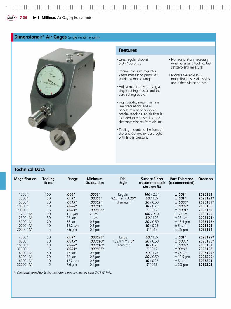
Dimensionair® Air Gages (single master system)
• Uses regular shop air (40 - 150 psig).
• Internal pressure regulator keeps measuring pressures within calibrated range.
• Adjust meter to zero using a single setting master and the zero setting screw.
• High visibility meter has fine line graduations and a
needle-thin hand for clear, precise readings. An air filter is included to remove dust and dirt contaminants from air line.
• Tooling mounts to the front of the unit. Connections are tight with finger pressure.
Features
• No recalibration necessary when changing tooling. Just set zero and measure!
• Models available in 5 magnifications, 2 dial styles,
and either Metric or Inch.
Technical Data
Magnification Tooling Range Minimum Dial Surface Finish Part Tolerance Order no. ID no. Graduation Style (recommended) (recommended) uin / um Ra
1250:1 100 .006“ .0001“ Regular 100 / 2.54 ± .002“ �0�5�83 2500:1 50 .003“ .00005“ 82.6 mm / 3.25” 50 / 1.27 ± .001“ �0�5�84* 5000:1 20 .0015“ .00002“ diameter 20 / 0.50 ± .0005“ �0�5�85* 10000:1 10 .0006“ .00001“ 10 / 0.25 ± .0002“ �0�5�86 20000:1 5 .0003“ .000005“ 5 / 0.12 ± .0001“ �0�5�8� 1250:1M 100 152 µm 2 µm 100 / 2.54 ± 50 µm �0�5��0 2500:1M 50 76 µm 1 µm 50 / 1.27 ± 25 µm �0�5���* 5000:1M 20 38 µm 0.5 µm 20 / 0.50 ± 13.5 µm �0�5���* 10000:1M 10 15.2 µm 0.2 µm 10 / 0.25 ± 5 µm �0�5��3 20000:1M 5 7.6 µm 0.1 µm 5 / 0.12 ± 2.5 µm �0�5��4 4000:1 50 .003“ .000025“ Large 50 / 1.27 ± .001“ �0�5��5* 8000:1 20 .0015“ .000010“ 152.4 mm / 6” 20 / 0.50 ± .0005“ �0�5��6* 16000:1 10 .0006“ .000010“ diameter 10 / 0.25 ± .0002“ �0�5��7 32000:1 5 .0003“ .000005“ 5 / 0.12 ±.0001“ �0�5��8 4000:1M 50 76 µm 0.5 µm 50 / 1.27 ± 25 µm �0�5���* 8000:1M 20 38 µm 0.2 µm 20 / 0.50 ± 13.5 µm �0�5�00* 16000:1M 10 15.2 µm 0.2 µm 10 / 0.25 ± 5 µm �0�5�0� 32000:1M 5 7.6 µm 0.1 µm 5 / 0.12 ± 2.5 µm �0�5�0�
* Contingent upon Plug having equivalent range, see chart on pages 7-43 & 7-44.
+
7-37Millimar. Air Gaging Instruments
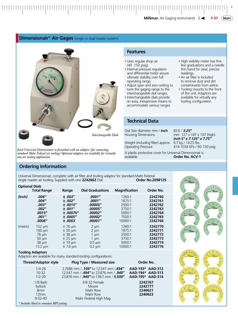
Dimensionair® Air Gages (single or dual master system)
• Uses regular shop air (40 -150 psig).• Internal pressure regulators
and differential meter assure ultimate stability over full operating range.
• Adjust span and zero setting to tune the gaging range to the interchangeable dial ranges.
• Interchangeable dials provide an easy, inexpensive means to accommodate various ranges
Features
• High visibility meter has fine line graduations and a needle thin hand for clear, precise readings.
• An air filter is included to remove dust and dirt contaminants from airline.
• Tooling mounts to the front of the unit. Adaptors are available for virtually any tooling configuration.
Ordering Information
Universal Dimensionair, complete with air filter and tooling adaptor for standard Mahr Federalsingle master air tooling. Supplied with one ��4�66� Dial. Order No.�0�8��5
Technical Data
Dial Size diameter mm / inch 82.6 / 3.25” Housing Dimensions mm 127 x 187 x 197 (high) inch 5” x 7.125” x 7.75”Weight (including filter) approx. 6.7 kg / 14.25 lbs.Operating Pressure 414-1034 kPa / 60-150 psig
A plastic protective cover for Universal Dimensionair is available Order No. ACV-�
Optional Dials Total Range Range Dial Graduations Magnification Order No.
(inch) .006” ± .003” .0001” 1260:1 ��4�760 .004” ± .002” .0001” 1875:1 ��4�76� .003” ± .0015” .00005” 2500:1 ��4�76� .002” ± .001” .00005” 3750:1 ��4�763 .0015” ± .00076” .00002” 5000:1 ��4�764 .001” ± .0005” .00002” 7500:1 ��4�765 .0006” ± .0003 .00001” 10000:1 ��4�766
(metric) 152 µm ± 76 µm 2 µm 1260:1 ��4�770 100 µm ± 50 µm 2 µm 1875:1 ��4�77� 76 µm ± 38 µm 1 µm 2500:1 ��4�77� 50 µm ± 25 µm 1 µm 3750:1 ��4�773 38 µm ± 19 µm 0.5 µm 5000:1 ��4�774 15.2 µm ± 7.6 µm 0.2 µm 10000:1 ��4�776
Tooling AdaptorsAdaptors are available for many standard-tooling configurations:
Thread/Adaptor style Plug Type / Measured size Order No.
1/4-28 2.7686 mm / .109” to 12.547 mm /.494” AAD-��3* AAD-3�� 10-32 12.547 mm / .494” to 23.876 mm / .940” AAD-��4* AAD-3�3 1/2-20 23.876 mm / .940” to 139.7 mm / 5.500” AAD-��5* AAD-3�4
1/8 Barb 3/8-32 Female ��4�767 Setlock Moore ��4�777 8mm Mahr Row ��406�� 12mm Mahr Row ��406�3 9/32-40 Mahr Federal High Mag* Includes bleed to simulate MFI jetting.
Each Universal Dimensionair is furnished with an adaptor (for connecting standard Mahr Federal air tooling) Optional adaptors are available for virtually any air tooling application.
Interchangeable Dials
-
7-38
RS232C DigimaticTOL
0
ABSABS
Millimar. Air Gaging Instruments
μDimensionair® (single master system)
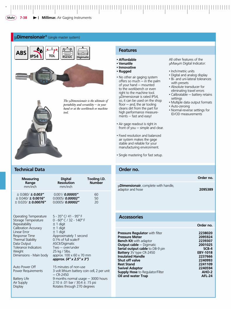
• Affordable • Versatile• Innovative• Rugged
• No other air gaging system offers so much — in the palm
of your hand — mounted to the workbench or even right to the machine tool. µDimensionair is rated IP54, so, it can be used on the shop floor — and, the air tooling cleans dirt from the part for high performance measure-ments — fast and easy!
• Air gage readout is right in front of you — simple and clear.
• Fixed resolution and balanced air system makes the gage stable and reliable for your manufacturing environment.
• Single mastering for fast setup.
Features
All other features of theµMaxµm Digital Indicator:
• Inch/metric units• Digital and analog display• Bi- and uni-lateral tolerances
with presets• Absolute transducer for eliminating travel errors• Calibratable — battery retains
settings• Multiple data output formats• Auto-zeroing• Normal-reverse settings for
ID/OD measurements
Order no. μDimensionair, complete with handle, adaptor and hose �0�538�
Order no.
Order no.
Pressure Regulator with filter ��380�0Pressure Meter �0�5��4Bench Kit with adaptor ��3�307Output cable — Digimatic �00�0�5Serial output cable to DB-9 pin SCB-4Battery 3V type CR-2450 EBY-�0�8Insulated Handle ��37666Shut off valve ��40��3Rest Stand ��4��0�Swivel Adaptor ��405�4Supply Hose to Regulator/Filter AHO-�Oil and water Trap AFL-�4
Accessories
Technical Data
Measuring Digital Tooling I.D. Range Resolution Number mm/inch mm/inch
± 0.080/ ± 0.003” 0.001/ 0.00005” 60 ± 0.040/ ± 0.00�6” 0.0005/ 0.00002” 50 ± 0.020/ ± 0.00076” 0.0005/ 0.00002” 20
Operating Temperature 5 - 35° C/ 41 - 95° F Storage Temperature 0 - 60° C / 32 - 140° FRepeatability ± 1 digitCalibration Accuracy ± 1 digitLinear Error ± 1 digitResponse Time Approximately 1 secondThermal Stability 0.1% of full scale/FData Output ASCII/DigimaticTolerance Indicators Two — over/underWeight 25 kg / 5lbs.Dimensions - Main body approx. 100 x 60 x 70 mm approx. (4” x 2.5” x 3”)
Auto Power Off 15 minutes of non-usePower Requirements 3 volt lithium battery coin cell, 2 per unit — CR-2450Battery Life 9 months normal usage — 3000 hoursAir Supply 2.10 ± .01 bar / 30.4 ± .15 psiDisplay Rotates through 270 degrees
The µDimensionair is the ultimate of portability and versatility — in your hand or at the workbench or machine tool.
+
7-3�
MAXMIN
RS232C
TOL
0
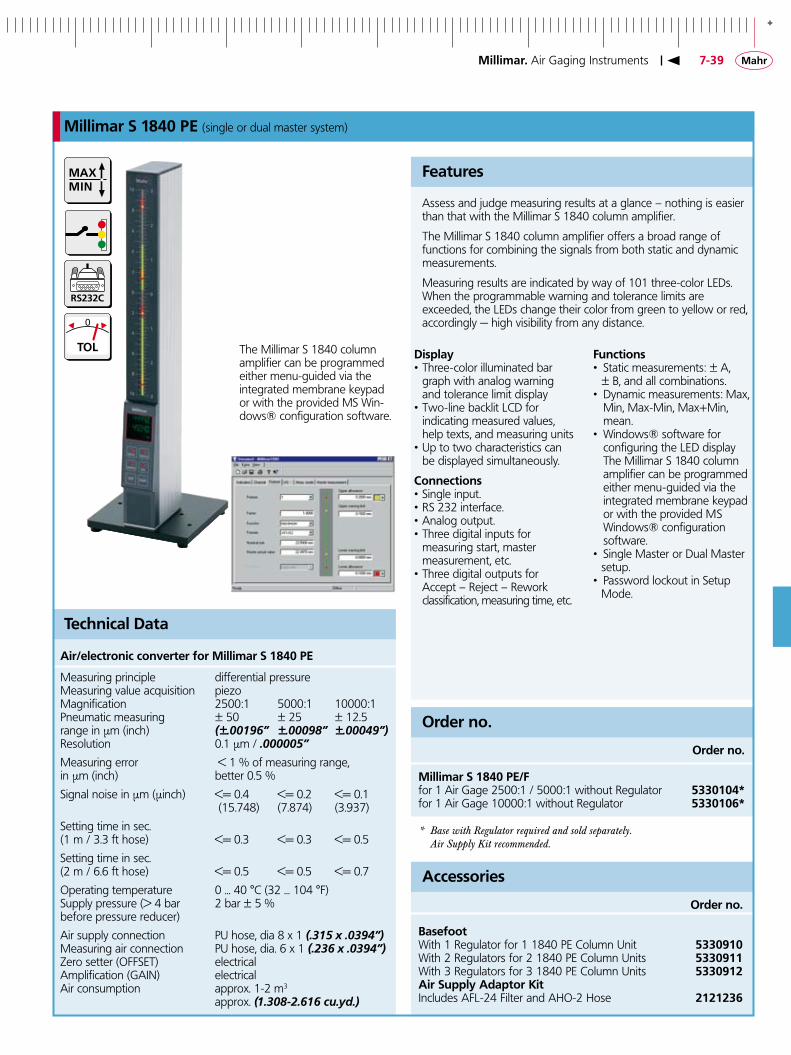
Millimar S �840 PE (single or dual master system)
Display • Three-color illuminated bar
graph with analog warning and tolerance limit display
• Two-line backlit LCD for indicating measured values,
help texts, and measuring units • Up to two characteristics can
be displayed simultaneously.
Connections • Single input. • RS 232 interface. • Analog output. • Three digital inputs for measuring start, master measurement, etc. • Three digital outputs for Accept – Reject – Rework classification, measuring time, etc.
Features
Functions • Static measurements: ± A, ± B, and all combinations. • Dynamic measurements: Max,
Min, Max-Min, Max+Min, mean.
• Windows® software for configuring the LED display The Millimar S 1840 column amplifier can be programmed either menu-guided via the integrated membrane keypad or with the provided MS Windows® configuration software.
• Single Master or Dual Master setup.
• Password lockout in Setup Mode.
Order no. Millimar S �840 PE/F for 1 Air Gage 2500:1 / 5000:1 without Regulator 5330�04*for 1 Air Gage 10000:1 without Regulator 5330�06*
* Base with Regulator required and sold separately. Air Supply Kit recommended.
Order no.
Order no.
Basefoot With 1 Regulator for 1 1840 PE Column Unit 5330��0With 2 Regulators for 2 1840 PE Column Units 5330���With 3 Regulators for 3 1840 PE Column Units 5330���Air Supply Adaptor KitIncludes AFL-24 Filter and AHO-2 Hose �����36
Accessories
Technical Data
Air/electronic converter for Millimar S �840 PE
Measuring principle differential pressureMeasuring value acquisition piezoMagnification 2500:1 5000:1 10000:1Pneumatic measuring ± 50 ± 25 ± 12.5range in µm (inch) (±.00196” ±.00098” ±.00049”)Resolution 0.1 µm / .000005”
Measuring error < 1 % of measuring range,in µm (inch) better 0.5 %
Signal noise in µm (µinch) <= 0.4 <= 0.2 <= 0.1 (15.748) (7.874) (3.937)
Setting time in sec.(1 m / 3.3 ft hose) <= 0.3 <= 0.3 <= 0.5
Setting time in sec.(2 m / 6.6 ft hose) <= 0.5 <= 0.5 <= 0.7
Operating temperature 0 ... 40 °C (32 ... 104 °F)Supply pressure (> 4 bar 2 bar ± 5 %before pressure reducer)
Air supply connection PU hose, dia 8 x 1 (.315 x .0394”)Measuring air connection PU hose, dia. 6 x 1 (.236 x .0394”)Zero setter (OFFSET) electricalAmplification (GAIN) electricalAir consumption approx. 1-2 m3 approx. (1.308-2.616 cu.yd.)
Assess and judge measuring results at a glance – nothing is easier than that with the Millimar S 1840 column amplifier.
The Millimar S 1840 column amplifier offers a broad range of functions for combining the signals from both static and dynamic measurements.
Measuring results are indicated by way of 101 three-color LEDs. When the programmable warning and tolerance limits are exceeded, the LEDs change their color from green to yellow or red, accordingly — high visibility from any distance.
The Millimar S 1840 column amplifier can be programmed either menu-guided via the integrated membrane keypad or with the provided MS Win-dows® configuration software.
Millimar. Air Gaging Instruments

-
7-40
83� Dimensionair® Air Gaging System (single master system)
• Digital and analog displays in a single unit. Large, high contrast digital readout shows exact deviation from zero; analog display shows measurement conditions at a glance.
• Fixed resolution and balanced air system makes the Digital Dimensionair a stable and
reliable system for manufacturing environments.
• Only a single master required to set zero; system is
precalibrated for correct magnification.
• Ranges and resolutions for virtually any air gage application, including 2-, 3-, 4- and 6-jet tooling plus
AirProbes and JetProbes.
Features
• Dynamics measurement capability.
• RS-232 Output – for communicating with a data
collector, computer or printer, permitting statistical process control.
• Master Deviation – enhances measurement by making Auto Zero even more
accurate.
Technical Data
Model Measuring Digital Analog Tooling Range Resolution Resolution I.D. Number
Low ±0.080 mm/ ±.003“ 0.004 mm/ 150µ“ 60Magnification ±0.04 0mm/ ±.0015“ 0.0002 mm/ 10µ“ 0.002 mm/ 75µ“ 50Single or Dual Input ±0.020 mm/ ±.00075“ 0.001 mm/ 38µ“ 20
HighMagnification 0.0001 mm/ 5µ“Single or Dual Input
±0.008mm/ ±.0003“ 0.0004 mm/ 15µ“ 10 ±0.004mm/ ±.00015“ 0.0002 mm/ 8µ“ 5
Number of Jets Voltage/Adaptor Low Magnification High Magnification Low Magnification High Magnification Single Input Single Input Dual Input Dual Input Order no. Order no. Order no. Order no.
1, 2, 3 110 / U.S. �004�00 �004�03 �004�06 �004�0�4 110 / U.S. �004�0� �004�04 �004�07 �004��06 110 / U.S. �004�0� �004�05 �004�08 �004��� 1, 2, 3 240 / International �004��� �004��5 �004��8 �004���4 240 /International �004��3 �004��6 �004��� �004���6 240 / International �004��4 �004��7 �004��0 �004��3
Millimar. Air Gaging Instruments

+
7-4�
MAXMIN
RS232C
TOL
0
C ��45 PE
��08 PE
����
Millimar. Air Gaging Instruments
Millimar C ��08 PE / C ��45 PE (single or dual master system)
C��08 PE Display• Background lit LCD-Display
with an analog and a two line digital display
• 5 three-color status lamps for warning and tolerance limits
• Up to 2 characteristics can be displayed at the same time.
C��08 PE Functions• Favorites, frequently required
functions can be assigned to the SELECT key
• Static measurements ± A, ± B and all combinations
• Dynamic measurements: Max, Min, Max-Min, Max+Min, mean
C��45 PE Display• Analog indicator instrument
for display of measurement value.
• Two-line LCD display for values and menu text
• 5 three-color status lamps for warning and tolerance limits.
• Up to 3 characteristics can be displayed at the same time.
Features
C��45 PE Functions• 16 characteristics can be
defined using an equation editor (80 characters), input channels C1 to C8 are mathematically linked with factors and brackets using the 4 basic mathematical functions.
• Static measurements: Current value, square root, arc tangent.
• Dynamic measurements: Max, Min, Max-Min, Max+Min, Mean value.
• Statistical functions: n, x-bar, S, Xmax, Xmin, R.
• Measured value memory for 5000 measured values.
• Measurement start / stop via keyboard, digital input, RS232.
Technical Data
Order no.
Millimar C ��08 PE/F For 1 Air Gage 2,500:1 / 5000:1 with Regulator 53��0�5Millimar C ��08 PE/F For 1 Air Gage 10,000:1 with Regulator 53��0�3
Millimar C ��45 PE/F For 1 air gage 2,500:1 / 5000:1 with Regulator 533��7�Millimar C ��45 PE/F For 1 air gage 10,000:1 with Regulator 533��73
Millimar C ��45 PE/F� For 2 air gages 2,500:1 / 5000:1 without Regulator 533��75*Millimar C ��45 PE/F� For 2 air gages 10,000:1 without Regulator 533��77*
Air Supply Adaptor Kit includes AFL-24 Filter and AHO-2 Hose �����36
* Baseplate with � Regulators (required for 2 Air Gage Units) 5330�0�
-
7-4�
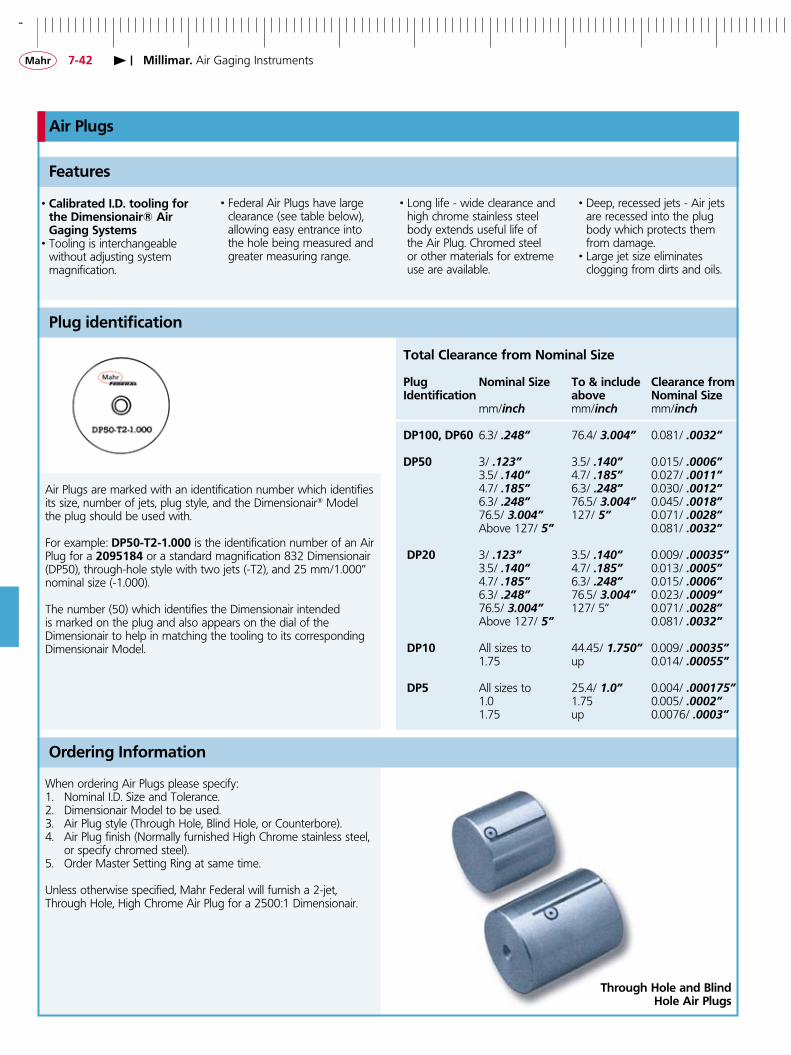
Air Plugs
• Calibrated I.D. tooling for the Dimensionair® Air Gaging Systems
• Tooling is interchangeable without adjusting system
magnification.
Features
• Federal Air Plugs have large clearance (see table below), allowing easy entrance into the hole being measured and greater measuring range.
Plug identification
Total Clearance from Nominal Size
Plug Nominal Size To & include Clearance fromIdentification above Nominal Size mm/inch mm/inch mm/inch
DP�00, DP60 6.3/ .248” 76.4/ 3.004” 0.081/ .0032”
DP50 3/ .123” 3.5/ .140” 0.015/ .0006” 3.5/ .140” 4.7/ .185” 0.027/ .0011” 4.7/ .185” 6.3/ .248” 0.030/ .0012” 6.3/ .248” 76.5/ 3.004” 0.045/ .0018” 76.5/ 3.004” 127/ 5” 0.071/ .0028” Above 127/ 5” 0.081/ .0032”
DP�0 3/ .123” 3.5/ .140” 0.009/ .00035” 3.5/ .140” 4.7/ .185” 0.013/ .0005” 4.7/ .185” 6.3/ .248” 0.015/ .0006” 6.3/ .248” 76.5/ 3.004” 0.023/ .0009” 76.5/ 3.004” 127/ 5” 0.071/ .0028” Above 127/ 5” 0.081/ .0032”
DP�0 All sizes to 44.45/ 1.750” 0.009/ .00035” 1.75 up 0.014/ .00055”
DP5 All sizes to 25.4/ 1.0” 0.004/ .000175” 1.0 1.75 0.005/ .0002” 1.75 up 0.0076/ .0003”
• Long life - wide clearance and high chrome stainless steel body extends useful life of the Air Plug. Chromed steel or other materials for extreme use are available.
• Deep, recessed jets - Air jets are recessed into the plug body which protects them from damage.
• Large jet size eliminates clogging from dirts and oils.
Ordering Information
When ordering Air Plugs please specify:1. Nominal I.D. Size and Tolerance.2. Dimensionair Model to be used.3. Air Plug style (Through Hole, Blind Hole, or Counterbore).4. Air Plug finish (Normally furnished High Chrome stainless steel,
or specify chromed steel).5. Order Master Setting Ring at same time.
Unless otherwise specified, Mahr Federal will furnish a 2-jet,Through Hole, High Chrome Air Plug for a 2500:1 Dimensionair.
Air Plugs are marked with an identification number which identifies its size, number of jets, plug style, and the Dimensionair® Model the plug should be used with.
For example: DP50-T�-�.000 is the identification number of an Air Plug for a �0�5�84 or a standard magnification 832 Dimensionair (DP50), through-hole style with two jets (-T2), and 25 mm/1.000” nominal size (-1.000).
The number (50) which identifies the Dimensionair intended is marked on the plug and also appears on the dial of the Dimensionair to help in matching the tooling to its corresponding Dimensionair Model.
Through Hole and Blind Hole Air Plugs
Millimar. Air Gaging Instruments

+
7-43
5/16-32AAD-55
3-3.5 mm / .��3-.�40“ �.5-�4.�3 mm / .3735-.588“
3.5-4.7 mm / .�40-.�85“ �4.�3-37.7 mm / .588-�.484“
4.7-6.3 mm / .�85-.�48“ 37.7-76.3 mm / �.484-3.004“
6.3-�.5 mm / .�48-.3735“ 76.3-��4.3 mm / 3.004-4.50“
Through Hole Plugs (DP50 - DP20 & 60)
Technical Data
Through Hole Plugs
Above To & include “A” “B” Minimum Measuring Range Hole Length* DP50 DP�0 mm/inch mm/inch mm/inch mm/inch mm/inch mm/inch mm/inch 3 / .123” 3.5 / .140” 23.8 / .9375” 4.8/ .1875” 4.7/ .187” 0.025/ .001” 0.013/ .0005” 3.5 / .140” 4.7 / .185” 23.8 / .9375” 4.8/ .1875” 4.7/ .187” 0.038/ .0015” 0.020/ .00075” 4.7 / .185” 6.3 / .248” 38 / 1.5” 12.7/ .500” 4.7/ .187” 0.051/ .002” 0.025/ .001” 6.3 / .248” 9.5 / .3735” 38 / 1.5” 12.7/ .500” 6.4/ .250” 0.076/ .003” 0.038/ .0015” 9.5 / .3735” 14.93 / .588” 38 / 1.5” 12.7/ .500” 6.4/ .250” 0.076/ .003” 0.038/ .0015”14.93 / .588” 37.7 / 1.484” 41.3 / 1.625” 15.9/ .625” 6.4/ .250” 0.076/ .003” 0.038/ .0015” 37.7 / 1.484” 76.3 / 3.004” 50 / 2” 19/ .750” 6.4/ .250” 0.076/ .003” 0.038/ .0015” 76.3 / 3.004” 114.3 / 4.5” 50 / 2”** 19/ .750” 6.4/ .250” 0.076/ .003” 0.038/ .0015”
* If a guide sleeve or stop collar is used, minimum hole length can be as small as 1.8 mm/.070” for holes larger than 6.3 mm/.248”.** A handle 152 mm/6” long and 33.3 mm/1.31” diameter is supplied with plugs over 76.3 mm/3.004”.
Minimum recommended hole length: .187”
Minimum recommended hole length: .250”. With guide sleeve or stop collar: .070”.May be used with AEX-1 or -2 Extensions for deep holes.
Minimum recommended hole length: .187”
Minimum gageable hole length: .250”. With guide sleeve or stop collar: .070”. May be used with AHA-4 or -5 Extensions for deep holes.
Minimum recommended hole length: .187”
Minimum recommended hole length: .250”. With guide sleeve or stop collar: .070”. May be used with AHA-4 or -5 Extensions for deep holes.
Minimum recommended hole length: .250”With guide sleeve or stop collar: .070”
Minimum recommended hole length: .250”. With guide sleeve or stop collar: .070”.
Millimar. Air Gaging Instruments

-
7-44
3/8-3210-32
5/16-32
AAD-55
AAD-55
3.�-4.7 mm / .�55-.�85“ ��.8-�4.�3 mm / .467-.588“
4.7-6.3 mm / .�85-.�48“ �4.�3-37.7 mm / .588-�.484“
6.3-�.48 mm / .�48-.3735“ 37.7-76.30 mm / �.484-3.004“
�.48-��.8 mm / .3735-.467“ 76.3-�08.��4.3 mm/3.004-4.50“
Blind Hole/Counterbore Plugs (DP50 - DP20 & 60)
Technical Data
Blind Hole/Counterbore Plugs
Above To & include “A” “B” Minimum Measuring Range Hole Length* DP50 DP�0mm/inch mm/inch mm/inch mm/inch mm/inch mm/inch mm/inch 3.9/ .155” 4.7/ .185” 19/ .750” 4/ .156” 6.4/ .250” 0.038/ .0015” 0.01905/ .00075”4.7/ .185” 6.3/ 248” 29.4/ 1.156” 4/ .156” 6.4/ .250” 0.051/ .002” 0.025/ .001”6.3/ .248” 11.8/ .467” 29.4/ 1.156” 4/ .156” 6.4/ .250” 0.076/ .003” 0.038/ .0015”11.8/ .467” 14.93/ .588” 29.4/ 1.156” 4/ .156” 6.4/ .250” 0.076/ .003” 0.038/ .0015”14.93/.588” 37.7/ 1.484” 29.4/ 1.156” 4/ .156” 6.4/ .250” 0.076/ .003” 0.038/ .0015”37.7/ 1.484” 76.3/ 3.004” 35.7/ 1.406” 4/ .156” 6.4/ .250” 0.076/ .003” 0.038/ ..0015”76.3/ 3.004” 114.3/ 4.5” 38/ 1.5”* 4/ .156” 6.4/ .250” 0.076/ .003” 0.038/ .0015”
* A handle 152 mm/ 6“ long and 33.3 mm / 1.31” diameter is supplied with plugs over 76.3 mm / 3.004”
Minimum recommended hole length: .250”.Note: Masters must simulate workpiece for holes of this size.
Minimum recommended hole length: .250”.Shorter bores can be checked. Consult Mahr Federal Customer Resource Center. May be used with Extensions AEX-1 or -2 for deep holes.
Minimum recommended hole length: .250”.
Minimum recommended hole length: .250”. Shorter bores can be checked. Consult Mahr Federal Customer Resource Center. May be used with AHA-4 or -5 Extensions for deep holes.
Minimum recommended hole length: .250”.Shorter bores can be checked. Consult Mahr Federal Customer Resource Center.
Minimum recommended hole length: .250”. Shorter bores can be checked. Consult Mahr Federal Customer Resource Center. May be used with AHA-4 or -5 Extensions for deep holes.
Minimum recommended hole length: .250”. Shorter bores can be checked. Consult Mahr Federal Customer Resource Center. May be used with Extension AHA-28 for deep holes.
Minimum gageable hole length: .250”.
Super Blind Plugs
Blind Hole Air Plugs can be furnished to check shorter holes than listed, and can be furnished to check closer to the bottom of a hole. Holes must be at least 2.8 mm/ .110” long, and the distance from the end of the plug to the center-line of the jets can be as short as 2.2 mm/ .085” for plugs below 6.3 mm/ .248” or 1.9 mm/ .075” for plugs above 6.3 mm/ .248”.
Contact Mahr Federal Customer Resource Center with your requirements
Millimar. Air Gaging Instruments
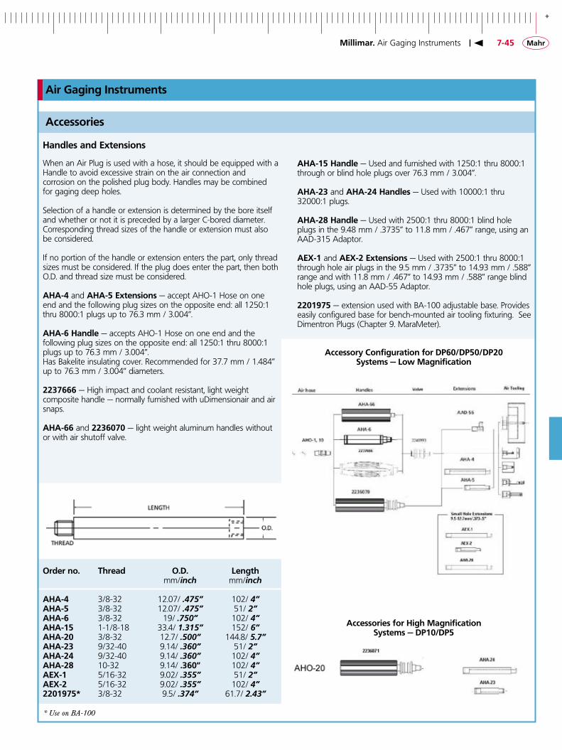
+
7-45
Air Gaging Instruments
Handles and Extensions
Accessories
AHA-�5 Handle — Used and furnished with 1250:1 thru 8000:1 through or blind hole plugs over 76.3 mm / 3.004”.
AHA-�3 and AHA-�4 Handles — Used with 10000:1 thru 32000:1 plugs.
AHA-�8 Handle — Used with 2500:1 thru 8000:1 blind hole plugs in the 9.48 mm / .3735” to 11.8 mm / .467” range, using an AAD-315 Adaptor.
AEX-� and AEX-� Extensions — Used with 2500:1 thru 8000:1 through hole air plugs in the 9.5 mm / .3735” to 14.93 mm / .588” range and with 11.8 mm / .467” to 14.93 mm / .588” range blind hole plugs, using an AAD-55 Adaptor.
��0��75 — extension used with BA-100 adjustable base. Provides easily configured base for bench-mounted air tooling fixturing. See Dimentron Plugs (Chapter 9. MaraMeter).
When an Air Plug is used with a hose, it should be equipped with a Handle to avoid excessive strain on the air connection and corrosion on the polished plug body. Handles may be combined for gaging deep holes.
Selection of a handle or extension is determined by the bore itself and whether or not it is preceded by a larger C-bored diameter. Corresponding thread sizes of the handle or extension must also be considered.
If no portion of the handle or extension enters the part, only thread sizes must be considered. If the plug does enter the part, then both O.D. and thread size must be considered.
AHA-4 and AHA-5 Extensions — accept AHO-1 Hose on one end and the following plug sizes on the opposite end: all 1250:1 thru 8000:1 plugs up to 76.3 mm / 3.004”.
AHA-6 Handle — accepts AHO-1 Hose on one end and the following plug sizes on the opposite end: all 1250:1 thru 8000:1 plugs up to 76.3 mm / 3.004”.Has Bakelite insulating cover. Recommended for 37.7 mm / 1.484” up to 76.3 mm / 3.004” diameters.
��37666 — High impact and coolant resistant, light weight composite handle — normally furnished with uDimensionair and air snaps.
AHA-66 and ��36070 — light weight aluminum handles without or with air shutoff valve.
Order no. Thread O.D. Length mm/inch mm/inch AHA-4 3/8-32 12.07/ .475” 102/ 4”AHA-5 3/8-32 12.07/ .475” 51/ 2”AHA-6 3/8-32 19/ .750” 102/ 4”AHA-�5 1-1/8-18 33.4/ 1.315” 152/ 6”AHA-�0 3/8-32 12.7/ .500” 144.8/ 5.7”AHA-�3 9/32-40 9.14/ .360” 51/ 2”AHA-�4 9/32-40 9.14/ .360” 102/ 4”AHA-�8 10-32 9.14/ .360” 102/ 4”AEX-� 5/16-32 9.02/ .355” 51/ 2”AEX-� 5/16-32 9.02/ .355” 102/ 4”��0��75* 3/8-32 9.5/ .374” 61.7/ 2.43”
* Use on BA-100
Accessory Configuration for DP60/DP50/DP�0Systems — Low Magnification
Accessories for High MagnificationSystems — DP�0/DP5
Millimar. Air Gaging Instruments
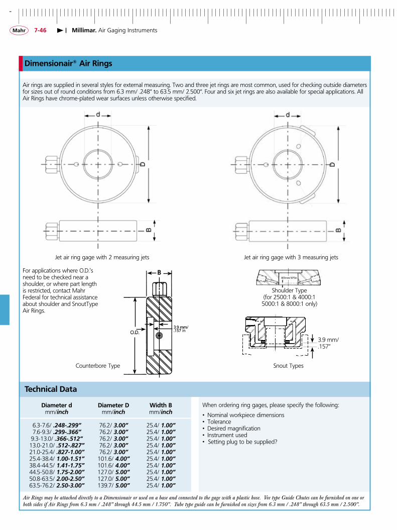
-
7-46
Jet air ring gage with 2 measuring jets Jet air ring gage with 3 measuring jets
Counterbore Type
Dimensionair® Air Rings
Air rings are supplied in several styles for external measuring. Two and three jet rings are most common, used for checking outside diameters for sizes out of round conditions from 6.3 mm/ .248“ to 63.5 mm/ 2.500“. Four and six jet rings are also available for special applications. All Air Rings have chrome-plated wear surfaces unless otherwise specified.
Technical Data
Diameter d Diameter D Width B mm/inch mm/inch mm/inch
6.3-7.6/ .248-.299” 76.2/ 3.00” 25.4/ 1.00” 7.6-9.3/ .299-.366” 76.2/ 3.00” 25.4/ 1.00” 9.3-13.0/ .366-.512” 76.2/ 3.00” 25.4/ 1.00” 13.0-21.0/ .512-.827” 76.2/ 3.00” 25.4/ 1.00” 21.0-25.4/ .827-1.00” 76.2/ 3.00” 25.4/ 1.00” 25.4-38.4/ 1.00-1.51” 101.6/ 4.00” 25.4/ 1.00” 38.4-44.5/ 1.41-1.75” 101.6/ 4.00” 25.4/ 1.00” 44.5-50.8/ 1.75-2.00” 127.0/ 5.00” 25.4/ 1.00” 50.8-63.5/ 2.00-2.50” 127.0/ 5.00” 25.4/ 1.00” 63.5-76.2/ 2.50-3.00” 139.7/ 5.00” 25.4/ 1.00”
When ordering ring gages, please specify the following:
• Nominal workpiece dimensions• Tolerance• Desired magnification• Instrument used• Setting plug to be supplied?
Air Rings may be attached directly to a Dimensionair or used on a base and connected to the gage with a plastic hose. Vee type Guide Chutes can be furnished on one or both sides if Air Rings from 6.3 mm / .248” through 44.5 mm / 1.750”. Tube type guide can be furnished on sizes from 6.3 mm / .248” through 63.5 mm / 2.500”.
For applications where O.D.'s need to be checked near a shoulder, or where part length is restricted, contact Mahr Federal for technical assistance about shoulder and SnoutType Air Rings.
Shoulder Type(for 2500:1 & 4000:1
5000:1 & 8000:1 only)
Snout Types
Millimar. Air Gaging Instruments
3.9 mm/.157”

+
7-47
AMR-��
Air Gaging Accessories
Magnification Kits
Magnification Kits provide a means for checking Amplifier accuracy, traceable to the National Institute of Standards and Technology (NIST). Each Kit contains restrictors that provide pressure characteristics at zero and at both ends of the scale, a calibrated dial diagram and a Certification of Calibration.
Order No. For use with: Tooling
AMR-SPEC-�36 1250:1 DP/DR100�0�4�8� 1260:1 DP/DR60AMR-�� 2500:1/4000:1 DP/DR50AMR-�3 5000:1/8000:1 DP/DR20AMR-�4 10000:1/16000:1 DP/DR10AMR-�5 20000:1/32000:1 DP/DR5
Manifolds
Manifolds allow connecting multiple pieces of air tooling to one Dimensionair. Toggle valves allow activation of the selected tool. Manifolds are compatible with Dimensionairs 1250:1 through 8000:1M Manifolds for use with other Dimensionairs, contact Mahr Federal Customer Resource Center — �-800-333-4�43.
Order No. Description
AAD-8� 2-way ManifoldAAD-83 3-way ManifoldAAD-84 4-way ManifoldAAD-85 5-way Manifold
Hoses
Supply hoses and hoses between Dimensionair and air tooling.
Order No. Description Thread
AHO-� 1.5 m / 5 ft Air Supply Hose. Fits all Dimensionair models. (rubber) 7/16-20AHO-� 0.9 m / 3 ft Air hose for tooling for Models 1250:1 – 8000:1. (Tygon) 3/8-32AHO-8 1.5 m / 5 ft Air hose for tooling on Models 1250:1 – 8000:1. (Tygon) 3/8-32AHO-�0 1.8 m / 6 ft Air hose for Models 1250:1 – 8000:1. (Tygon) 3/8-32AHO-�0 0.9 m / 3 ft Air hose for tooling on Models 10000:1 – 32000:1. (Tygon) 9/32-40ARG-� Replacement O-ring for AHO-1, -8, -10 Hoses and AHA-4, -5, -6, -20 Handles.ARG-6 Replacement O-ring for AHO-20 Hose, AHA-23 and -24 Handles.ARG-�0 For AEX-1, AEX-2 and AHA-28
Traps and Filters
Good gaging practice requires clean, dry air for gage performance. Dimensionair Models are furnished with a particle filter. Shop air contains water and oil, which should be removed, using Model AFL-�4 Oil and Water Separator Trap.
Order No. Description
AFL-�0 Particle Filter (normally furnished on all Dimensionair Models). Filter size: 5 microns; Maximum pressure: 250 p.s.i.; maximum working temperature: 175°F.AFL-�4 Oil and Water Separator Trap, includes mounting hardware. Filtering capacity: 99.7% removal of oil and water; filter size: 3-6 microns; maximum pressure: 150 p.s.i.; flow rate: 20 cubic feet of air/minute @ 80 p.s.i.AFL-�3 Replacement cartridge for AFL-24.AFL-�� Replacement cartridge for AFL-10.AAD-�63 Retrofit Kit for AFL-9
AFL-�4 Trap
Manifold AAD-83
Millimar. Air Gaging Instruments