millimeter-wave test and measurement from 2000-2020
TRANSCRIPT

Millimeter-Wave Test and Measurement from 2000-2020
Dr. Eric W. Bryerton
Virginia Diodes, Inc.
Charlottesville, VA USA

Outline
• ALMA Receiver (LO) Development– Wideband tunerless frequency multipliers up to 1 THz
• Wideband Frequency Multipliers– Add amplifiers and filters -> Sub-mm Signal Generator Extender
• Wideband Schottky Diode Heterodyne Mixers– Add LO amplifiers, etc. -> Sub-mm Spectrum Analyzer Extender– Millimeter-wave Spectrum Analyzer Applications
• Signal Generator Extender + Spectrum Analyzer Extender = Sub-mm Vector Network Analyzer
• Cubesat Sub-mm Radiometers• Conclusion

Frequency [GHz]
ALMA (Atacama Large Millimeter Array)Receiver Development (~1998-2007)
• 66 antennas (12m and 7m dishes)• 10 receiver bands from 30-950 GHz• 2 heterodyne receivers for each band
– HEMT LNA up to 115 GHz, SIS mixer above 115 GHz• Requires local oscillators up to 950 GHz (~20-100 uW)

ALMA Receivers
4
Warm Cartridge Assembly with LO YIG Tuned Oscillator and
Driver Stage (up to ~120 GHz)
Morgan, 2005 CSIC Digest
Cryogenic Front End
4K Stage with SIS Mixers
Schottky Diode Multipliers on 77K Stage
Driver contains integrated multi-chip
modules taking ~12-24 GHz YTO output to 65-
122 GHz output

ALMA Receiver Cryostat
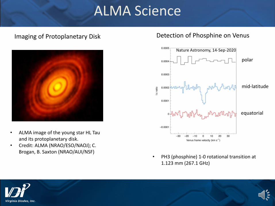
ALMA Science
• ALMA image of the young star HL Tau and its protoplanetary disk.
• Credit: ALMA (NRAO/ESO/NAOJ); C. Brogan, B. Saxton (NRAO/AUI/NSF)
Nature Astronomy, 14-Sep-2020
• PH3 (phosphine) 1-0 rotational transition at 1.123 mm (267.1 GHz)
Imaging of Protoplanetary Disk Detection of Phosphine on Venus
polar
mid-latitude
equatorial

• Development of broadband tunerlessfrequency multipliers was a key enabling technology for ALMA
• Extension to full waveguide band (for tunerless multiplers and then mixers) was a key enabling technology for fullband test and measurement frequency extension modules up to 1.1 THz
From ALMA to Laboratory THz Test and Measurement

THz Signal Generation Using Schottky Diodes
• Use the nonlinearity of the Schottky diode to generate harmonics of a lower frequency signal– Use either nonlinear variable capacitance (varactor:
narrowband, high-efficiency) or resistance (varistor: wideband, low-efficiency)
FINFOUT=N*FIN

Planar Diode Fabrication Technology
• Diodes fabricated at VDI– Small captive cleanroom
for the fabrication of devices
• Schottky Flip Chip Diodes– Low parasitics– Flip chips as small as
100x50x20 um
• Integration of Diode with Coupling Circuitry– Operation to higher
frequencies (>3 THz)
9

Standardized Waveguide Interfaces
• VDI uses a waveguide interface compatible with the IEEE standard– Standard was released in 2016– IEEE P1785 – “Rectangular Metallic
Waveguides and Their Interfaces for Frequencies of 110 GHz and Above”
• Allows for compatibility between different manufacturers
• VDI is currently using waveguide interfaces up to 1.5 THz– Details on the VDI website
10
P1785.2 Interface shown for WM-164 Tripler

Amplified Multiplier Chains (AMC)
• Combination of amplifiers and multipliers
• Nearly all the power in a single tone
– Spectral purity achieved using filtering and balanced designs
11
S
w Nw
x2 xM
Pow
er
Frequency
w Nw
Amp MultiplierSynthesizer
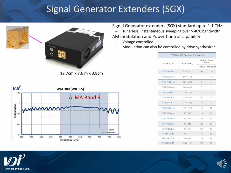
Signal Generator Extenders (SGX)
• Signal Generator extenders (SGX) standard up to 1.1 THz. – Tunerless, instantaneous sweeping over > 40% bandwidth
• AM modulation and Power Control capability– Voltage controlled– Modulation can also be controlled by drive synthesizer
12.7cm x 7.6 m x 3.8cm
ALMA Band 9
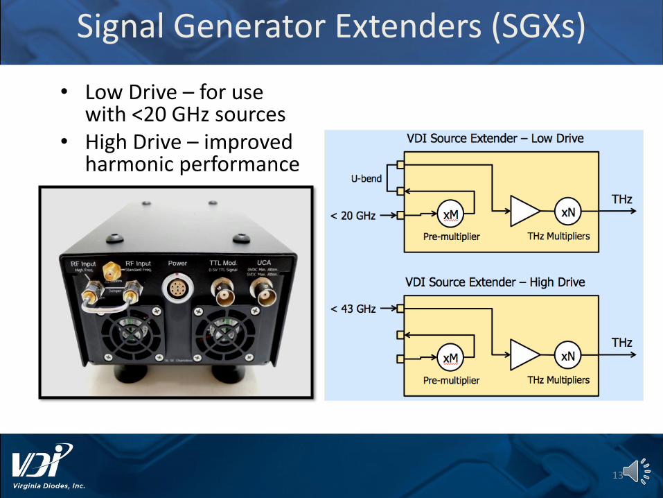
Signal Generator Extenders (SGXs)
• Low Drive – for use with <20 GHz sources
• High Drive – improved harmonic performance
13

Schottky Diode Detectors
• Biased or Zero-bias diodes available
• Waveguide-based detectors– High Sensitivity
• 3000 V/W @ 100 GHz• 300 V/W @ 1.5 THz
– Bandwidth limited to 40-50%
• Quasi-optical Detector– Bandwidth 100 GHz to > 1
THz– Responsivity 500 V/W typ.
• Sub-ns Response time
WR-3.4ZBD Quasi-optical DetectorDC
Output
sigPV det
RF
Input
14

Heterodyne Detection Using Schottky Diodes
• Balanced antiparallel diode configuration– Allows for 2nd harmonic operation with
excellent sensitivity– LO ~ RF / 2
• Diodes mounted in split-block metal housing
• Noise Figure ~ 8 dB (SSB) at D-band
15
RF
LO
IF=RF-2*LO
0
500
1000
1500
2000
100 120 140 160 180
Tmix
(K
) (D
SB)
Frequency (GHz)
Measured Performance of WR-6.5SHM
Note: This is not a classic high harmonic mixer…
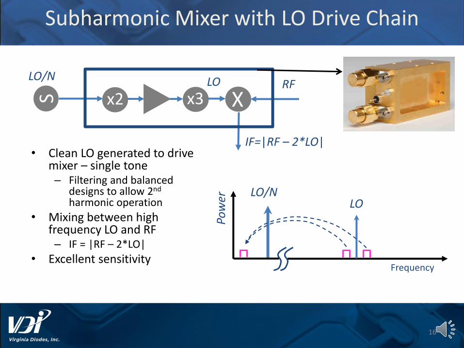
Subharmonic Mixer with LO Drive Chain
16
Pow
er
Frequency
• Clean LO generated to drive mixer – single tone – Filtering and balanced
designs to allow 2nd
harmonic operation
• Mixing between high frequency LO and RF– IF = |RF – 2*LO|
• Excellent sensitivity
S x2 x3 XLO/N LO RF
IF=|RF – 2*LO|
LO/NLO

Test & Measurement: Spectrum Analyzers
• Sophisticated instrument to analyze microwave signals– Spectral purity– Phase noise– Communication Signal
Demodulation– …
• A core microwave test capability– Along with sources and
vector network analyzers
• Can be extended to THz using Schottky mixers
17

Spectrum Analyzer Extenders (SAX)
• Spectrum Analyzer extenders (SAX) standard up to 1.1 THz. – Tunerless, instantaneous sweeping over > 40%
bandwidth– IF Bandwidth up to 40 GHz– DANL 150 dBm/Hz to 750 GHz
• 135 dBm/Hz to 1.1 THz

Regulatory Testing of First 5G Handset
19

Automotive Emissions Application
• Testing up to ~330GHz
N9029AV03 220 – 330 GHz
N9029AV05 140 – 220 GHz
N9029AV08 90 – 140 GHz
N9029AV12 60 – 90 GHz
N9029AH19 40/50-60
GHz @ RF port2
N9029AH12 60-90 GHz
N9029AH05 140-220 GHz
N9029AH03 220-330 GHzLO/IF
LO/IF
LO/IF
LO/IF
N9029AH08 90-140 GHz
U1816C USB
Coaxial
Switch
N9041B UXA
Signal Analyzer
1.85mm(f) to 1.85mm(f) 2m Cable
LO/IF
DC-40/50 GHz @ RF
port1
SWC-19VF-E1

Block Upconversion
IF
LORF
fIF (GHz)
P(d
Bm
)
100 5
• Preserves signal modulation• UpConversion is DSB• LSB can be filtered• Useful as source for Rx
development• Channel characterization
21
fRF (GHz)
P(d
Bm
)
LO*N + 100 LO*NLO*N – 10

SAX-UP for Comm Applications
1/16/2021 22
BPF AmpxN
LO InputHigh Freq.
IF Input
SignalGenerator
SignalGenerator
Block Up-Conversion
• Can be used to upconvert or downconvert wide band modulated signals• The double side band nature of the device makes filtering necessary• VDI has developed a set of waveguide filters and amplifiers to be used for
these applications
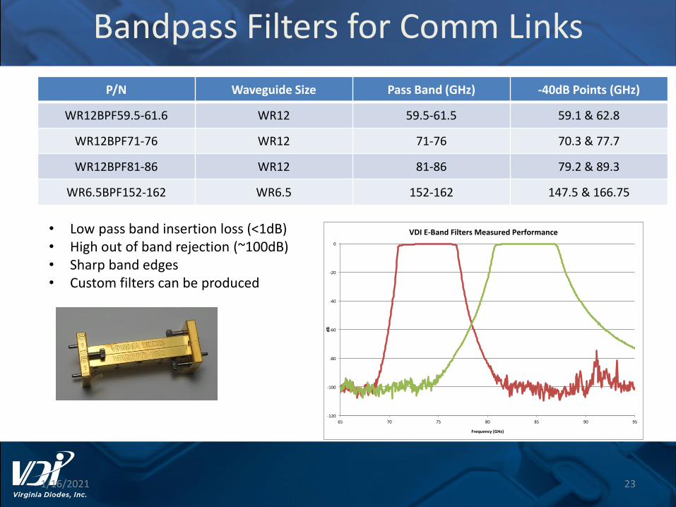
Bandpass Filters for Comm Links
1/16/2021 23
P/N Waveguide Size Pass Band (GHz) -40dB Points (GHz)
WR12BPF59.5-61.6 WR12 59.5-61.5 59.1 & 62.8
WR12BPF71-76 WR12 71-76 70.3 & 77.7
WR12BPF81-86 WR12 81-86 79.2 & 89.3
WR6.5BPF152-162 WR6.5 152-162 147.5 & 166.75
• Low pass band insertion loss (<1dB)• High out of band rejection (~100dB)• Sharp band edges• Custom filters can be produced
-120
-100
-80
-60
-40
-20
0
65 70 75 80 85 90 95
dB
Frequency(GHz)
VDIE-BandFiltersMeasuredPerformance
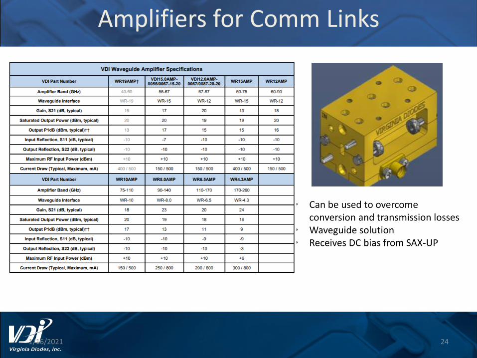
Amplifiers for Comm Links
1/16/2021 24
• Can be used to overcome conversion and transmission losses
• Waveguide solution• Receives DC bias from SAX-UP

SAX: Communications Example
• Simulated radio for signal with 2 GHz modulation bandwidth– Mixer IF centered at 5 GHz
• Allows separation between upper and lower sidebands for filtering
25

THz Vector Network Analyzer Extenders
26
• Calibrated 2-port s-parameter measurements up to 1.5 THz
• Ease of use for probe stations and antenna test chambers
• Integrated components (mixers, multipliers and amplifiers)

Cubesat Sub-Millimeter Radiometers
• Cubesats have significant mass, volume, and power constraints
– Typically 3U (10cm x 10cm x 30cm) or 6U (10cm x 20cm x 30cm)
• Sub-millimeter local oscillators are large DC power consumer
– Minimize multiplication factor after final power amplifier
– Use high-efficiency varactor multipliers
• High level of integration to reduce mass and volume

TROPICS Cubesat Constellation
• 180-206 GHz, 4-channel radiometer• Noise Diode + 3 LNAs + Hybrids +
Filters + Detectors• 2.0” x 1.25” x 0.5”

IceCube: 874-GHz Submillimeter Wave Radiometer for Cloud Ice Remote Sensing
NASA Goddard Space Flight Center
D. L. Wu (P.I.)

30
• Launched as secondary payload on ISS resupply mission on April 18, 2017
• Deployed from ISS on May 17, 2017– Along with 16 other CubeSats– Second set of 17 CubeSats deployed a few days later
IceCube Deployed from ISS

Cubesat Polarimetric Ice Cloud Submillimeter (684 GHz) Sensor
31
LO Input
“Normal” IF
“Ortho” IF
OMT + Twist

• Development of broadband tunerless frequency multipliers, required for ALMA, was a key enabling technology for full waveguide band test and measurement frequency extension modules up to 1.1 THz
• Mixers can be used to upconvert very wideband modulated signals to millimeter-waves
• Schottky diode multiplier and mixer technology still being used and developed for new sub-millimeter wave science instruments
Conclusions

Thank You!