mimo radio channel models - oulu · mimo communications with applications to (b)3g and 4g systems...
TRANSCRIPT

MIMO Communications with Applications to (B)3G and 4G Systems MIMO Radio Channel Models
© J. Ylitalo & M. Juntti, University of Oulu, Dept. Electrical andInform. Eng., Centre for Wireless Communications (CWC) 1
MIMO Radio Channel Models
Tutorial MIMO Communications with Applications to (B)3G and 4G Systems
Juha Ylitalo
Contents1. Scope & Introduction
2. Some channel parameters3. Codit model4. Stochastic models5. METRA model6. SCM model of 3GPP/3GPP2
References
MIMO Communications with Applications to (B)3G and 4G Systems MIMO Radio Channel Models
© J. Ylitalo & M. Juntti, University of Oulu, Dept. Electrical andInform. Eng., Centre for Wireless Communications (CWC) 2
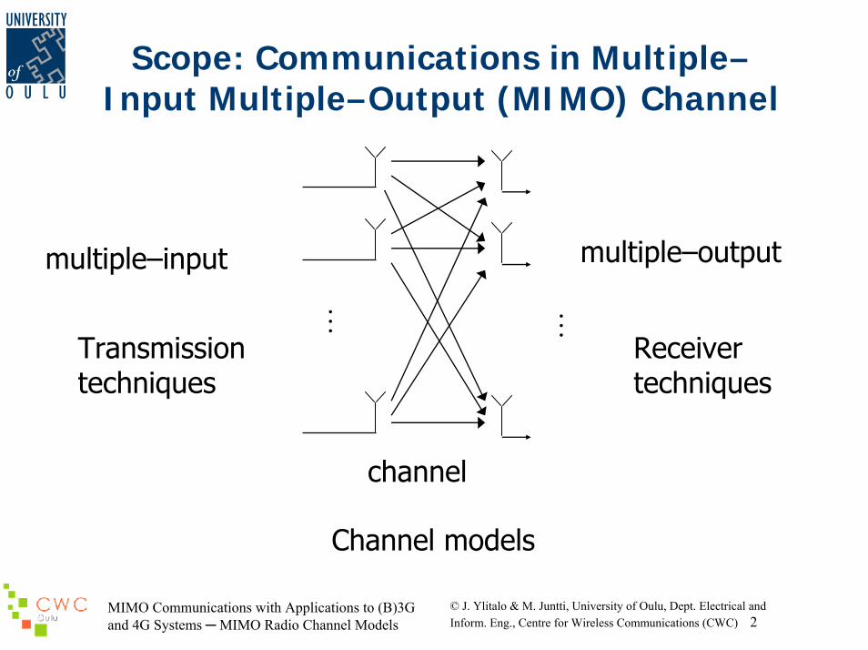
Scope: Communications in Multiple–Input Multiple–Output (MIMO) Channel
M M
multiple–output
Receiver techniques
multiple–input
Transmission techniques
channel
Channel models
MIMO Communications with Applications to (B)3G and 4G Systems MIMO Radio Channel Models
© J. Ylitalo & M. Juntti, University of Oulu, Dept. Electrical andInform. Eng., Centre for Wireless Communications (CWC) 3
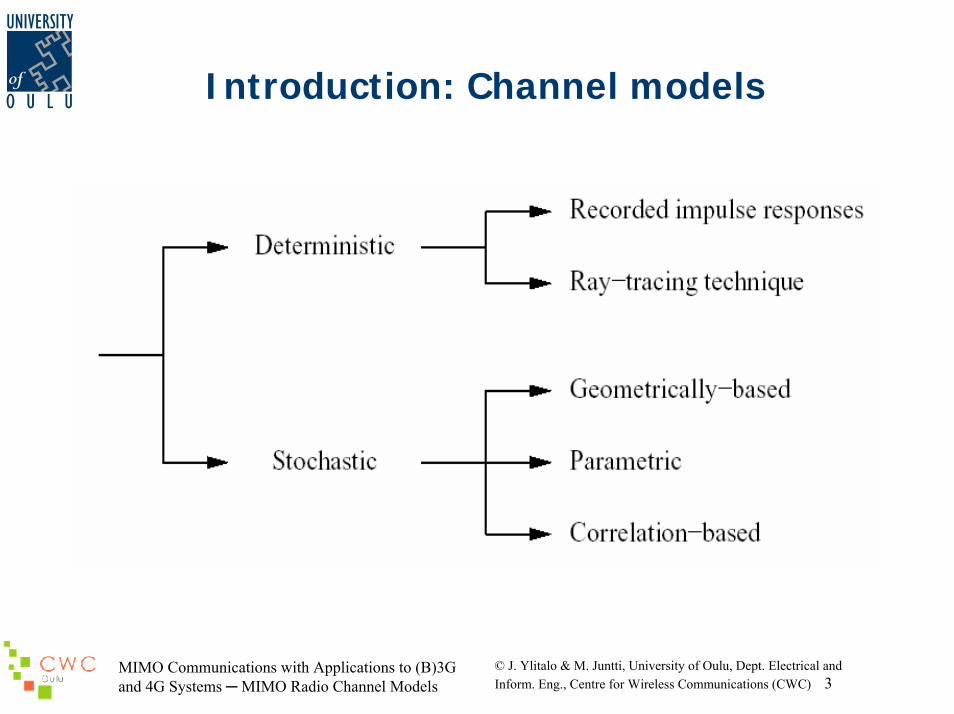
Introduction: Channel models

MIMO Communications with Applications to (B)3G and 4G Systems MIMO Radio Channel Models
© J. Ylitalo & M. Juntti, University of Oulu, Dept. Electrical andInform. Eng., Centre for Wireless Communications (CWC) 4
Introduction …
• Deterministic (geometric) modelling– e.g. specific micro/pico cell environment– can be used as basis for stochastic modelling– example: local area sample of the Codit model
• Stochastic modelling– often based on large measurement campaign– e.g. the so-called Metra MIMO model in 3GPP– example: typical correlation matrices for certain
environments– Geometry based, parametric
“Radio channel model should be based on physical propagation environment"

MIMO Communications with Applications to (B)3G and 4G Systems MIMO Radio Channel Models
© J. Ylitalo & M. Juntti, University of Oulu, Dept. Electrical andInform. Eng., Centre for Wireless Communications (CWC) 5
Antenna Array Principle
MIMO Communications with Applications to (B)3G and 4G Systems MIMO Radio Channel Models
© J. Ylitalo & M. Juntti, University of Oulu, Dept. Electrical andInform. Eng., Centre for Wireless Communications (CWC) 6
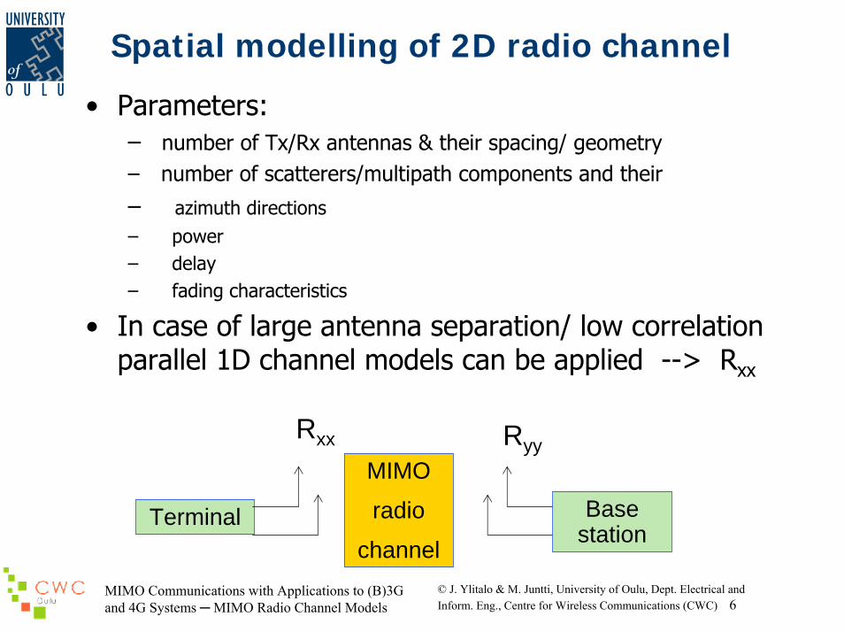
Spatial modelling of 2D radio channel
• Parameters:– number of Tx/Rx antennas & their spacing/ geometry– number of scatterers/multipath components and their
– azimuth directions– power– delay– fading characteristics
• In case of large antenna separation/ low correlation parallel 1D channel models can be applied --> Rxx
Rxx RyyMIMO
radio
channelTerminal Base
station
MIMO Communications with Applications to (B)3G and 4G Systems MIMO Radio Channel Models
© J. Ylitalo & M. Juntti, University of Oulu, Dept. Electrical andInform. Eng., Centre for Wireless Communications (CWC) 7
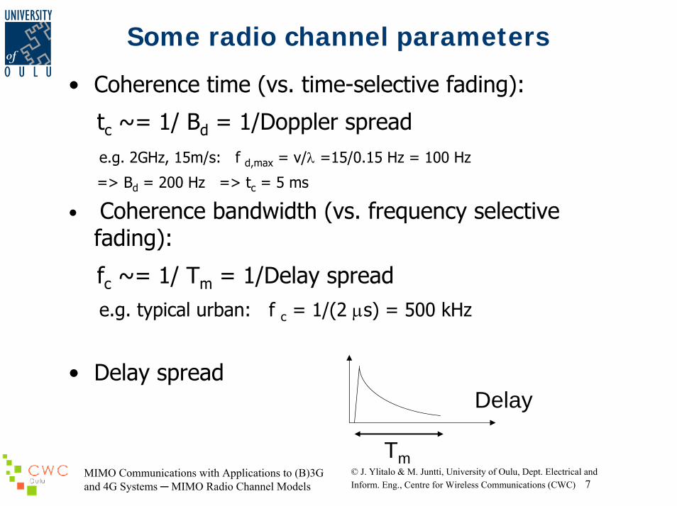
Some radio channel parameters
• Coherence time (vs. time-selective fading):
tc ~= 1/ Bd = 1/Doppler spreade.g. 2GHz, 15m/s: f d,max = v/λ =15/0.15 Hz = 100 Hz
=> Bd = 200 Hz => tc = 5 ms
• Coherence bandwidth (vs. frequency selective fading):
fc ~= 1/ Tm = 1/Delay spreade.g. typical urban: f c = 1/(2 µs) = 500 kHz
• Delay spreadDelay
Tm
MIMO Communications with Applications to (B)3G and 4G Systems MIMO Radio Channel Models
© J. Ylitalo & M. Juntti, University of Oulu, Dept. Electrical andInform. Eng., Centre for Wireless Communications (CWC) 8
Some radio channel parameters
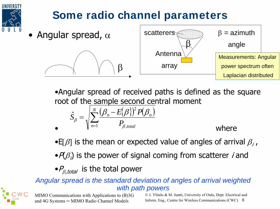
• Angular spread, α
•Angular spread of received paths is defined as the square root of the sample second central moment
• where
•E[β] is the mean or expected value of angles of arrival βi ,
•P(βi) is the power of signal coming from scatterer i and
•Pβ,total is the total power
β = azimuth
angleβscatterers
Antenna
array
( ) ( )∑=
−=
N
n total
nn
PPES
1 ,
2ˆ
ββ
βββ
βMeasurements: Angular
power spectrum often
Laplacian distributed
Angular spread is the standard deviation of angles of arrival weighted with path powers
MIMO Communications with Applications to (B)3G and 4G Systems MIMO Radio Channel Models
© J. Ylitalo & M. Juntti, University of Oulu, Dept. Electrical andInform. Eng., Centre for Wireless Communications (CWC) 9
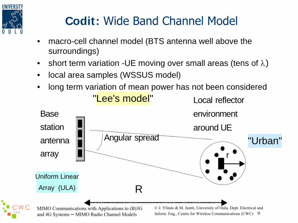
Codit: Wide Band Channel Model
• macro-cell channel model (BTS antenna well above thesurroundings)
• short term variation -UE moving over small areas (tens of λ)• local area samples (WSSUS model)• long term variation of mean power has not been considered
r
Angular spread
Basestationantennaarray
R
Local reflectorenvironmentaround UE
"Lee's model"
Uniform Linear
Array (ULA)
"Urban"

MIMO Communications with Applications to (B)3G and 4G Systems MIMO Radio Channel Models
© J. Ylitalo & M. Juntti, University of Oulu, Dept. Electrical andInform. Eng., Centre for Wireless Communications (CWC) 10
Codit: Wide Band Channel Model, cont’d
• Complex field Ei from one scatterer i:
( ) ( )∑=
++ +=waves
ililii
N
l
kvtjil
kvtjii eaeatE
1
coscos0
00)( θϕθϕ
- ail is the partial wave amplitude for subpath l
- ϕil is a random phase term
- k is the wave number (=2π/λ)
- v is the mobile terminal (UE) velocity
-λ is the wavelength of the carrier
-θil denotes the incident angle between the scatterer i and the UE velocity vector
- Nwaves is the number of partial waves (per scatterer)
MIMO Communications with Applications to (B)3G and 4G Systems MIMO Radio Channel Models
© J. Ylitalo & M. Juntti, University of Oulu, Dept. Electrical andInform. Eng., Centre for Wireless Communications (CWC) 11
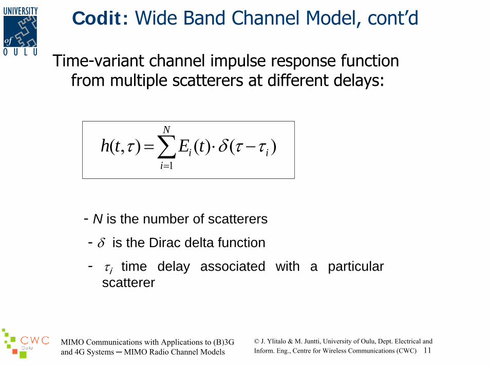
Codit: Wide Band Channel Model, cont’d
Time-variant channel impulse response function from multiple scatterers at different delays:
∑=
−⋅=N
iii tEth
1)()(),( ττδτ
- N is the number of scatterers
- δ is the Dirac delta function
- τi time delay associated with a particular scatterer

MIMO Communications with Applications to (B)3G and 4G Systems MIMO Radio Channel Models
© J. Ylitalo & M. Juntti, University of Oulu, Dept. Electrical andInform. Eng., Centre for Wireless Communications (CWC) 12
Codit: Wide Band Channel Model, cont’d
• Spatio-temporal channel impulse response at antenna element m of a uniform linear array:
βλπ
ττsin)1(2
),(),(dmj
m ethth−
=
- d denotes the inter-element spacing
− β is the azimuth direction of the reflector
MIMO Communications with Applications to (B)3G and 4G Systems MIMO Radio Channel Models
© J. Ylitalo & M. Juntti, University of Oulu, Dept. Electrical andInform. Eng., Centre for Wireless Communications (CWC) 13
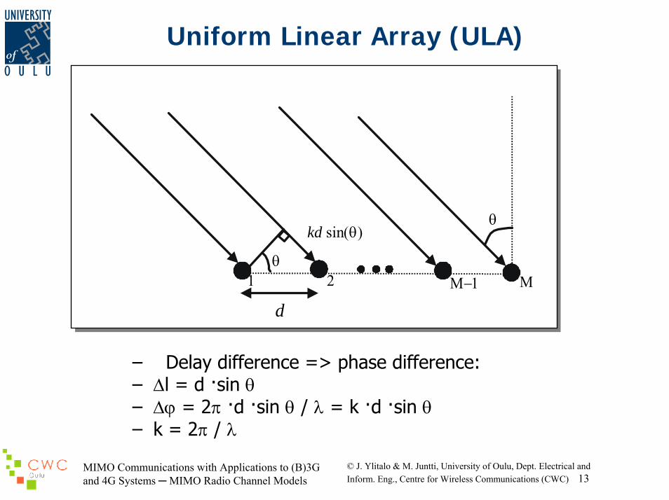
Uniform Linear Array (ULA)
d
θ
kd sin(θ)θ
1 2 Μ−1 Μ
– Delay difference => phase difference:– ∆l = d ·sin θ– ∆ϕ = 2π ·d ·sin θ / λ = k ·d ·sin θ– k = 2π / λ
MIMO Communications with Applications to (B)3G and 4G Systems MIMO Radio Channel Models
© J. Ylitalo & M. Juntti, University of Oulu, Dept. Electrical andInform. Eng., Centre for Wireless Communications (CWC) 14
Stochastic Models – COST 259
• Cost 259 comprehensive attempt to model directional channels (COST 259-DCM)
• Cost direct channel model has a three-level top-bottom structure consisting of
– the cell type(macro-, micro- or pico-cell), – the Radio Environment (RE) and– the Local Parameters (LPs) of the detailed
propagation scenario.• A given set (cell type/RE/LP) fully characterizes a
simulation environment• COST259-DCM is a model framework enabling to tune
the parameters of a specific implementation
MIMO Communications with Applications to (B)3G and 4G Systems MIMO Radio Channel Models
© J. Ylitalo & M. Juntti, University of Oulu, Dept. Electrical andInform. Eng., Centre for Wireless Communications (CWC) 15
Stochastic Models – GBSM
• Geometrically-Based Stochastic Models (GBSM) assume a stochastic distribution of scatterers around the two ends of the connection.
• The channel model is derived from the positions of the scatterers, by applying the laws of
– Specular reflection, – diffraction and – scattering of electro-magnetic waves.
• The shape of the scattering area often accounts for a given kindof scenario.
• Usually, macro-cells are simulated by distributing scatterersaround the UE,
• Micro-cells involve ellipses whose foci are the Node B and the UE location.
• Scatter density and cluster are user defined parameters• Most GBSM are single-bounce models, since they only account for
a single specular reflection at the scatterer surface• Example: the above desribed Codit model

MIMO Communications with Applications to (B)3G and 4G Systems MIMO Radio Channel Models
© J. Ylitalo & M. Juntti, University of Oulu, Dept. Electrical andInform. Eng., Centre for Wireless Communications (CWC) 16
Parametric Stochastic Models – PSM
• Parametric Stochastic Models (PSM) describe the received signal as a superposition of waves.
• A common implementation of these models takes the form of a tapped delay line,
• Each tap reflects a propagation path.
MIMO Communications with Applications to (B)3G and 4G Systems MIMO Radio Channel Models
© J. Ylitalo & M. Juntti, University of Oulu, Dept. Electrical andInform. Eng., Centre for Wireless Communications (CWC) 17
Parametric Stochastic Models – DD
• The Double Directional Channel Model (DDCM) is an example of a PSM.
• Its parameters can be given as a delay-angle distribution or through a spatial scatterer distribution
• The DDCM can be implemented as a tapped delay line model, where each of the N resolvable multipath components has
– complex gain, – delay, and – (DoD, DoA) pair,
regardless of the number of bounces. • Both Tx and Rx antenna characteristics are excluded• Example: SAGE algorithm assumes this model

MIMO Communications with Applications to (B)3G and 4G Systems MIMO Radio Channel Models
© J. Ylitalo & M. Juntti, University of Oulu, Dept. Electrical andInform. Eng., Centre for Wireless Communications (CWC) 18
Parametric Stochastic Models – DD• Where δ is the delta function, θ is the elevation and Φ
is the azimuth.• ξ is a 2x2 matrix whos elements are the complex gain
of the orthogonal polarisations and the cross coupling between polarisations
MIMO Communications with Applications to (B)3G and 4G Systems MIMO Radio Channel Models
© J. Ylitalo & M. Juntti, University of Oulu, Dept. Electrical andInform. Eng., Centre for Wireless Communications (CWC) 19
METRA Channel Model - Overview
• Stochastic model filed in 3GPP in February 2001• Used by major manufacturers for MIMO model• Model is a tapped delay line where each of the taps is
a matrix• Size of each matrix depends on the number of active
elements in transmit and receive ends• Embeds the full correlation information of the channel
into two correlation matrices defined independently • A Kronecker product is performed to combine the
matrices to fully characterize the correlation properties of the MIMO channel
MIMO Communications with Applications to (B)3G and 4G Systems MIMO Radio Channel Models
© J. Ylitalo & M. Juntti, University of Oulu, Dept. Electrical andInform. Eng., Centre for Wireless Communications (CWC) 20
METRA Channel Model – Overview (2)
• One main strengths of the MIMO stochastic model is that it relies on a small set of parameters to fully characterize
• Specifically– power gain of the MIMO channel matrix, – two correlation matrices describing the correlation
properties at both ends of the transmission links,– the associated Doppler spectrum of the channel paths.
• Parameters can be extracted from measurement results,• Parameters can also be derived from single-input/multiple-output
(SIMO) results already published in the open literature.
MIMO Communications with Applications to (B)3G and 4G Systems MIMO Radio Channel Models
© J. Ylitalo & M. Juntti, University of Oulu, Dept. Electrical andInform. Eng., Centre for Wireless Communications (CWC) 21
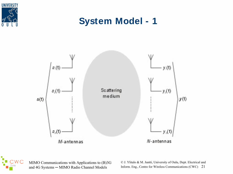
System Model - 1
MIMO Communications with Applications to (B)3G and 4G Systems MIMO Radio Channel Models
© J. Ylitalo & M. Juntti, University of Oulu, Dept. Electrical andInform. Eng., Centre for Wireless Communications (CWC) 22
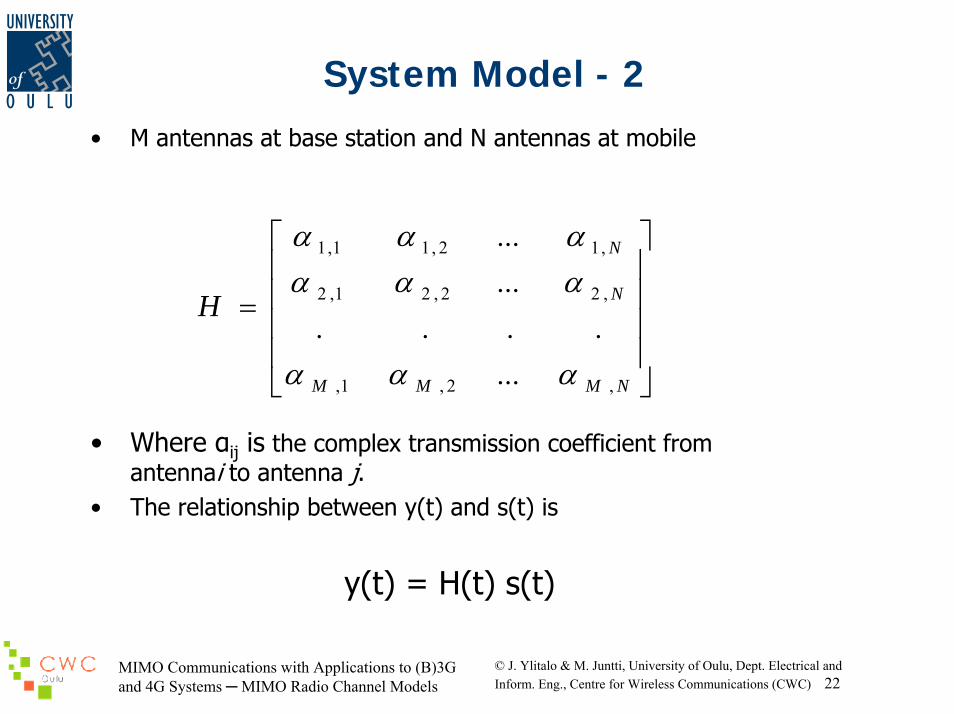
System Model - 2
• M antennas at base station and N antennas at mobile
• Where αij is the complex transmission coefficient from antennai to antenna j.
• The relationship between y(t) and s(t) is
y(t) = H(t) s(t)
⎥⎥⎥⎥
⎦
⎤
⎢⎢⎢⎢
⎣
⎡
=
NMMM
N
N
H
,2,1,
,22,21,2
,12,11,1
.......
...
...
ααα
αααααα
MIMO Communications with Applications to (B)3G and 4G Systems MIMO Radio Channel Models
© J. Ylitalo & M. Juntti, University of Oulu, Dept. Electrical andInform. Eng., Centre for Wireless Communications (CWC) 23
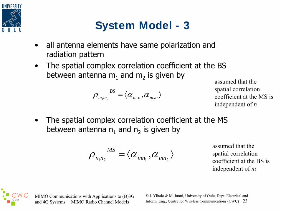
System Model - 3
• all antenna elements have same polarization and radiation pattern
• The spatial complex correlation coefficient at the BS between antenna m1 and m2 is given by
• The spatial complex correlation coefficient at the MS between antenna n1 and n2 is given by
⟩⟨= nmnmBS
mm 2121,ααρ
⟩⟨=2121
, mnmnMS
nn ααρassumed that the spatial correlation coefficient at the BS is independent of m
assumed that the spatial correlation coefficient at the MS is independent of n
MIMO Communications with Applications to (B)3G and 4G Systems MIMO Radio Channel Models
© J. Ylitalo & M. Juntti, University of Oulu, Dept. Electrical andInform. Eng., Centre for Wireless Communications (CWC) 24
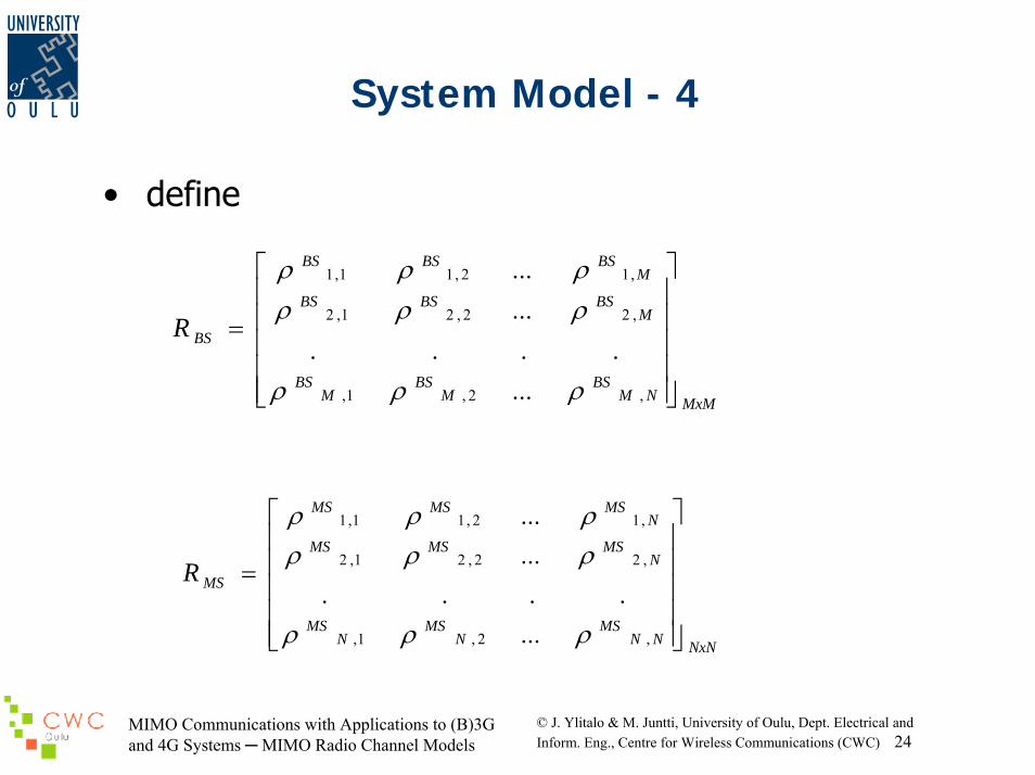
System Model - 4
• define
MxMNMBS
MBS
MBS
MBSBSBS
MBSBSBS
BSR
⎥⎥⎥⎥⎥
⎦
⎤
⎢⎢⎢⎢⎢
⎣
⎡
=
,2,1,
,22,21,2
,12,11,1
.......
...
...
ρρρ
ρρρρρρ
NxNNNMS
NMS
NMS
NMSMSMS
NMSMSMS
MSR
⎥⎥⎥⎥⎥
⎦
⎤
⎢⎢⎢⎢⎢
⎣
⎡
=
,2,1,
,22,21,2
,12,11,1
.......
...
...
ρρρ
ρρρρρρ
MIMO Communications with Applications to (B)3G and 4G Systems MIMO Radio Channel Models
© J. Ylitalo & M. Juntti, University of Oulu, Dept. Electrical andInform. Eng., Centre for Wireless Communications (CWC) 25
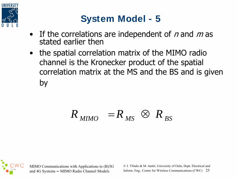
System Model - 5
• If the correlations are independent of n and m as stated earlier then
• the spatial correlation matrix of the MIMO radio channel is the Kronecker product of the spatial correlation matrix at the MS and the BS and is given by
BSMSMIMO RRR ⊗=
MIMO Communications with Applications to (B)3G and 4G Systems MIMO Radio Channel Models
© J. Ylitalo & M. Juntti, University of Oulu, Dept. Electrical andInform. Eng., Centre for Wireless Communications (CWC) 26
Limitations of the Metra Model
• In certain circumstances, model does not deliver the expected capacity improvements
• Such a key-hole behaviour could be experienced – in hallways, – tunnels, or – for very large distances between the UE and Node B.
• In these waveguide-like situations , the channel matrix does not have full rank
MIMO Communications with Applications to (B)3G and 4G Systems MIMO Radio Channel Models
© J. Ylitalo & M. Juntti, University of Oulu, Dept. Electrical andInform. Eng., Centre for Wireless Communications (CWC) 27
Spatial Channel Model(SCM) of 3GPP/3GPP2
• 3rd Generation Partnership Project;TechnicalSpecification Group Radio Access Network:
• Spatial channel model for Multiple Input Multiple Output (MIMO) simulations (Release 6)
• To compare the performance of candidate MIMO schemes at system level
• The link level models are defined only for calibration purposes
MIMO Communications with Applications to (B)3G and 4G Systems MIMO Radio Channel Models
© J. Ylitalo & M. Juntti, University of Oulu, Dept. Electrical andInform. Eng., Centre for Wireless Communications (CWC) 28
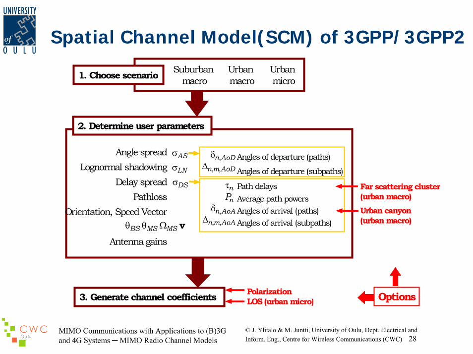
Spatial Channel Model(SCM) of 3GPP/3GPP2
3. Generate channel coefficients
2. Determine user parameters
1. Choose scenario Suburban macro
Urban macro
Urban micro
Angle spreadLognormal shadowing
Delay spreadPathloss
Orientation, Speed Vector
Antenna gainsBSθ MSθ MSΩ v
LNσASσ
DSσ
Angles of departure (paths)
Angles of departure (subpaths)
Path delaysAverage path powersAngles of arrival (paths)Angles of arrival (subpaths)
AoDn,δAoDmn ,,∆
nτnP
AoAn,δAoAmn ,,∆
PolarizationLOS (urban micro)
Far scattering cluster(urban macro)Urban canyon(urban macro)
Options
MIMO Communications with Applications to (B)3G and 4G Systems MIMO Radio Channel Models
© J. Ylitalo & M. Juntti, University of Oulu, Dept. Electrical andInform. Eng., Centre for Wireless Communications (CWC) 29
References
• W.R. Braun and U. Dersch, "A physical mobile radio channel model", IEEE Trans. Vehicular Technology, vol. 40, 1991, pp. 472-482.
• U. Dersch and R.J. Ruegg, "Simulations of the time and frequency selective outdoor mobile radio channel", IEEE Trans. Vehicular Technology, vol. 42, 1993, pp. 338-344.
• 3GPP TR 25.996 V6.1.0 (2003-09)Technical Report, http://www.3gpp.org
• Kermoal,et al., “A Stochastic MIMO Radio Channel Model With Experimental Validation”, IEEE Journal of Selected Areas in Communications, Vol. 20, No. 6, August, 2002