min 470 final exam - exams.skule.caexams.skule.ca/exams/bulk/20171/min470s_2017_ventelationan… ·...
TRANSCRIPT
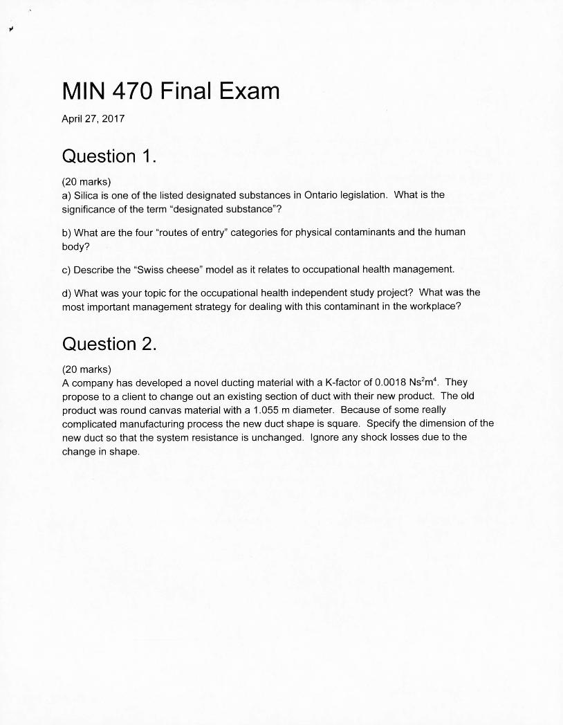
MIN 470 Final Exam April 27, 2017
Question 1.
(20 marks) Silica is one of the listed designated substances in Ontario legislation. What is the
significance of the term "designated substance"?
What are the four "routes of entry" categories for physical contaminants and the human
body?
Describe the "Swiss cheese" model as it relates to occupational health management.
What was your topic for the occupational health independent study project? What was the most important management strategy for dealing with this contaminant in the workplace?
Question 2.
(20 marks) A company has developed a novel ducting material with a K-factor of 0.0018 Ns2m4. They
propose to a client to change out an existing section of duct with their new product. The old product was round canvas material with a 1.055 m diameter. Because of some really complicated manufacturing process the new duct shape is square. Specify the dimension of the new duct so that the system resistance is unchanged. Ignore any shock losses due to the
change in shape.
VO

Question 3. (30 marks) A fan selection exercise is being done for a deep mine where the operating conditions are predicted to be 27 °C, 80% relative humidity, and 130 kPa atmospheric pressure.
Calculate the expected air density.
The following chart is for standard density of 1.200 kg /M3. Calculate a new performance
chart (flow, total pressure, power) for the density calculated in subsection "a".
Q [m3/s] Total Pressure [Pa] Power [kW]
19.36 2526 69.35
23.61 2240 74.57
28.33 1692 74.57
33.05 647 66.37
Question 4. (15 marks) The only equipment you have in the field is two pitot-static tubes, two pieces of hose, and a differential pressure gauge that can only read positive values (not a compound gauge). It is also important to note that you do not have enough tubing to reach from one end of the long section of the duct to the other. You only have enough to connect instruments right around the fan. Notate the positive (+) and negative (-) ports on the gauge.
Draw how you would hook up your equipment to measure fan total pressure under the following
three arrangements:
Fan and inlet bell located at the entrance / start of a long section of duct.
Fan located in the middle of a long section of duct.
Fan located at the exit / end of a long section of duct.

Question 5. (15 marks)
Describe the 5-3 rule when selecting a location to take a ventilation measurement. Why is this
important?
Question 6. (30 marks)
Consider the following fan and duct arrangement. The velocity pressures and pressure losses
(above duct) have been measured and provide in pascals.
10 290 50 200 180 20 600 40
.+ Pv=100
Pv=300
dLIJ Pv=50
Pv=200 -U,
A B C DE F G H Calculate the following:
Gauge static pressure and gauge total pressure at each labeled location
Fan total pressure and static pressure
Shock loss coefficient on entrance
Evasee efficiency on exit
91

Question 7.
(30 marks) Using the attached psychrometric chart (101 .325 kPa), solve the following graphically:
Locate Point A at 10 0C dry-bulb, 5 00 wet-bulb
Locate Point B at 35 °C dry-bulb, 30 % relative humidity
Locate Point C, which is an adiabatic mixture of A and B at 25 °C dry-bulb.
If the flow rate of A is 20 m3/s, what is the flow rate of B to create the mixture of C?
Complete the following table of psychrometric state-point properties:
Dry Bulb [°C]
R. H. [%]
Wet Bulb [°C]
Humidity Ratio [kg/kg]
A.S.V. [M3 /kg]
Enthalpy [kJ/kg]
Point A
Point B
Point C
Question 8. (30 marks)
Consider the following network with resistance values specified in Ns2/m8 for each segment:
Ri = 0.20 R2 = 0.20 R3 = 0.20
R4 = 0.30
FIVACKINCI
Simplify the network to a single resistance. Calculate the flow and pressure drop in each segment if the flow in the first segment is 01 =
100 m3/s.

PV iiRT ri = Md. = 28.966 kg/kmol M M = 18.015268 kg/kmol
I? P R = 8.3144598 kJ/(Kkmol) I?,spec,fie
= Rda 0.287042 kJ/(kgK)
R = 0.461523 kJ/(kg'K)
17:277 P,, = 0.6105(- 237. 3 IT
- Pu
p = 0.621945
11)
101) c baro -
Pharo - P, p = p, (1 + r) P pg/i
=
A + ptt + pgho + Pf07 , = P1 + pil l + pg/u + P1rict jon + Ps/jock
P5,0 + P1.o ± pgho + Pt. f00 P.1 + P0,1 + pgh + Pirictij ± Pshock
4.4 D =
pt,]3 Rc Pfrict(rl
1.325 KCLu2 p Pt P + Pr Id
(li/(i_ + 4))2 11
PJ I .1C W7 , 4
x1.2
3.7
1 2 P, -p
PRQ 2 KCL p >< Rf = 43 1.2
P1.= XP A 1 •
P = C p'ti. A0
X, =
RXp
0.6XA 11=QxP
- 942 L
- KC
Act u.a.1 Static' .P re.$ . ureRega.i n 100/) - _________
Ile The oretic'alSt aticPres .$ureRe gain '1 -
= (1 - 'r))P , ',ic(J(1ir1

Network Simplification
1
Rtotai R1 + R2 + + R Rtotai =
+ + +
Psychrometry & Thermodynamics
1 RdaT Vda = =
Pda Pl)aro - Pw h = 1.005 tdb + r [2501 + 1.884 S = 1.005 tdb+ r [2501 -4.262 twb+ 1.884tdb]
cop = Qoutput
IVITIPUt
Far \ffinity Laws
Q1 N Kr'
tevaporator COP arnot =
t condenser tevaporatol.
- '
P (D2 1J
Pi Kp2
t12 2 HI NI j
~~~2
DI Pi Kp2
He.. -y Cross
>1 - - (RQa Qa 1 - Pf(, n)
- (2RQ + Sf)
Capital Recovery Factor fl
(A/P. i. n) =
(1+i) —1

Atkinson Friction Factors
Airway K [Ns2/m4]
Ventilation piping (steel I fibreglass) 0.003
Concrete lined empty shaft 0.004
Straight rock tunnel 0.01
Concrete lined shaft with streamlined buntons 0.025
Concrete lined shaft with R.S.J. buntons 0.05
Heavily timbered rectangular shaft 0.08
Raise bored hole 0.0024
Duct Material K [Ns2/m4] K [1010 lb- min 2 I ft4 ]
Galvanized Ifiberglass, new 0.0028 15
Galvanized I fiberglass, used 0.0037 20
Canvas / plastic, new 0.0037 20
Canvas I plastic, used 0.0046 25
Spiral-Canvas, new 0.0111 60
Spiral-Canvas, used 0.0136 73.3

H ASHRAE PSYCHROMETRIC CHART NO.1 H
0 NORMAL TEMPERATURE "
& 8 6. --
E ® BAROMETRIC PRESSURE: 101.325 kPa
Copyright 1992 AMERICAN SOCIETY OF HEATING, REFRIGERATING AND AIR-CONDITIONING ENGINEERS, INC. 2/ /\. /.. / . *.,L '
SEA LEVEL
10 0.6
03 So 00 0.6 SENSIBLE HEAT Os so /. 7'- .. V 1 3o,
TOTAL HEAT Ot
/ 00
0 0
/ 02
J 02
ENTHALPY DjL HUMIDITY RATIO ow
00
60 2............../ ............
//
o3,7
______
011 f
/
/.................... -
Ly
-- 0
cr—uj
60 003
----- vMtDlT --- -\ N /1O
:
L..'
70 40
ENTHALPY - Ki PER KILOGRAM OF DRY AIR

/O2
- -\ O2S
L
0213 T ,
Q2 /
024 : j\ c- -.
o22
021
\\
5--
'Y,- .5 -----------X Oil- Ii,)
\, -- LLJ
-.
\ QO8
T 7 /0
s/J \ -
I-
-_._>ks. \ --,. '. ------- oo-
003
-5
00
ENIHALPY- KJ PER KILOGRAM OF DRY AIR
.30
H ASH RAE PSYCHROMETRIC CHART NO.1 H
~(y NORMAL TEMPERATURE 0
E BAROMETRIC PRESSURE: 101.325 kPa E
Copyright 1992 AMERICAN SOCIETY OF HEATING, REFRIGERATING AND AIR-CONDITIONING ENGINEERS, INC.
10
SEA LEVEL 10 -
1.5 EOI - OJ So
SENSIBLE HEAT Os q.Ø - -So
0 TOTAL HEAT 01
00
/
7 .
'S 0 .'
H
ENTHALPY
HUMIDITY RATIO DW / -.----.-
//
7-..---------------- --. 5i -
/.
Y0
d 2,