mineral insulated heater cable installation & operation … installation of the electric heat...
TRANSCRIPT

Mineral insulated Heater CableInstallation & Operation Manual

COntents
general infOrMatiOn ............................................................................1
HOw Heating systeMs wOrk ...............................................................1
PrOduCt seleCtiOn .................................................................................1
reCeiPt & stOrage ...................................................................................1
PiPe lengtH VerfiCatiOn .......................................................................1
drawings ....................................................................................................2
installatiOn .............................................................................................2
Heater Cable COnstruCtiOn ..............................................................4
HigH teMPerature & wattage installatiOns ..............................5
asseMbly instruCtiOns ........................................................................6
Heater Cable attaCHMent ...................................................................7
Heat sink installatiOn .........................................................................8
PuMPs ..........................................................................................................11
instruMentatiOn ..................................................................................12
tHerMal insulatiOn .............................................................................12
eleCtriCal COnneCtiOns ....................................................................13
eleCtriCal requireMents ...................................................................13
testing .......................................................................................................14
PeriOdiC insPeCtiOn reCOrd .............................................................15
start-uP .....................................................................................................16
OPeratiOn & MaintenanCe ................................................................16
trOublesHOOting .................................................................................17
Heat traCe installatiOn reCOrd ...................................................18
liMited warranty .................................................................................19
GENERAL INFORMATION
This manual is designed for use with Easy Heat Mineral Insulated Heater Products. For applications not specifically addressed, please contact your local representative.
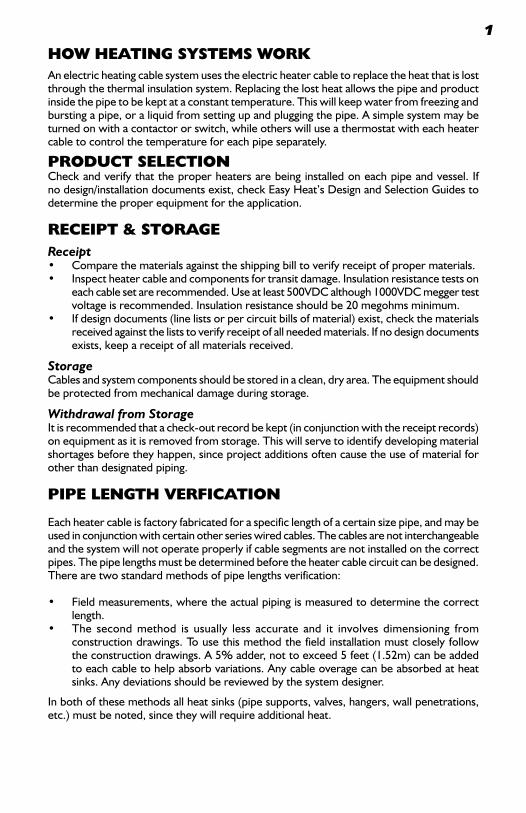
HOw HEATING SySTEMS wORkAn electric heating cable system uses the electric heater cable to replace the heat that is lost through the thermal insulation system. Replacing the lost heat allows the pipe and product inside the pipe to be kept at a constant temperature. This will keep water from freezing and bursting a pipe, or a liquid from setting up and plugging the pipe. A simple system may be turned on with a contactor or switch, while others will use a thermostat with each heater cable to control the temperature for each pipe separately.
PRODUCT SELECTIONCheck and verify that the proper heaters are being installed on each pipe and vessel. If no design/installation documents exist, check Easy Heat’s Design and Selection Guides to determine the proper equipment for the application.
RECEIPT & STORAGEReceipt• Comparethematerialsagainsttheshippingbilltoverifyreceiptofpropermaterials.• Inspectheatercableandcomponentsfortransitdamage.Insulationresistancetestson
each cable set are recommended. Use at least 500VDC although 1000VDC megger test voltage is recommended. Insulation resistance should be 20 megohms minimum.
• Ifdesigndocuments(linelistsorpercircuitbillsofmaterial)exist,checkthematerialsreceived against the lists to verify receipt of all needed materials. If no design documents exists, keep a receipt of all materials received.
StorageCables and system components should be stored in a clean, dry area. The equipment should be protected from mechanical damage during storage.
Withdrawal from StorageItisrecommendedthatacheck-outrecordbekept(inconjunctionwiththereceiptrecords)on equipment as it is removed from storage. This will serve to identify developing material shortagesbeforetheyhappen,sinceprojectadditionsoftencausetheuseofmaterialforother than designated piping.
PIPE LENGTH VERFICATION
Each heater cable is factory fabricated for a specific length of a certain size pipe, and may be usedinconjunctionwithcertainotherserieswiredcables.Thecablesarenotinterchangeableand the system will not operate properly if cable segments are not installed on the correct pipes. The pipe lengths must be determined before the heater cable circuit can be designed. There are two standard methods of pipe lengths verification:
• Fieldmeasurements,wheretheactualpipingismeasuredtodeterminethecorrectlength.
• The secondmethod is usually less accurate and it involves dimensioning fromconstruction drawings. To use this method the field installation must closely follow theconstructiondrawings.A5%adder,nottoexceed5feet(1.52m)canbeaddedto each cable to help absorb variations. Any cable overage can be absorbed at heat sinks. Any deviations should be reviewed by the system designer.
Inbothofthesemethodsallheatsinks(pipesupports,valves,hangers,wallpenetrations,etc.)mustbenoted,sincetheywillrequireadditionalheat.
1
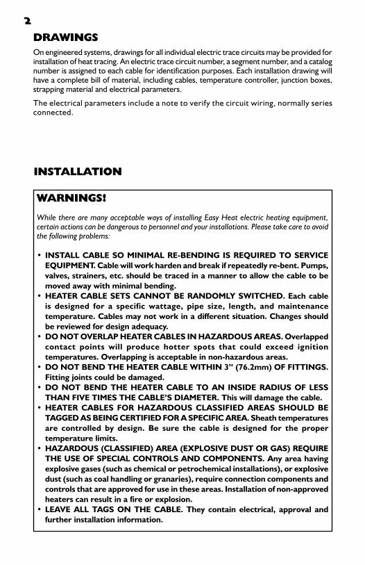
DRAwINGSOn engineered systems, drawings for all individual electric trace circuits may be provided for installation of heat tracing. An electric trace circuit number, a segment number, and a catalog number is assigned to each cable for identification purposes. Each installation drawing will haveacompletebillofmaterial,includingcables,temperaturecontroller,junctionboxes,strapping material and electrical parameters.
The electrical parameters include a note to verify the circuit wiring, normally series connected.
2
INSTALLATION
wARNINGS!
While there are many acceptable ways of installing Easy Heat electric heating equipment, certain actions can be dangerous to personnel and your installations. Please take care to avoid the following problems:
• install Cable sO MiniMal re-bending is required tO serViCe equiPMent. Cable will work harden and break if repeatedly re-bent. Pumps, valves, strainers, etc. should be traced in a manner to allow the cable to be moved away with minimal bending.
•Heater Cable sets CannOt be randOMly switCHed. each cable is designed for a specific wattage, pipe size, length, and maintenance temperature. Cables may not work in a different situation. Changes should be reviewed for design adequacy.
• dO nOt OVerlaP Heater Cables in HazardOus areas. Overlapped contact points will produce hotter spots that could exceed ignition temperatures. Overlapping is acceptable in non-hazardous areas.
•DO nOt bend tHe Heater Cable witHin 3” (76.2mm) Of fittings. fitting joints could be damaged.
•dO nOt bend tHe Heater Cable tO an inside radius Of less tHan fiVe tiMes tHe Cable’s diaMeter. this will damage the cable.
•Heater Cables fOr HazardOus Classified areas sHOuld be tagged as being Certified fOr a sPeCifiC area. sheath temperatures are controlled by design. be sure the cable is designed for the proper temperature limits.
•HazardOus (Classified) area (exPlOsiVe dust Or gas) require tHe use Of sPeCial COntrOls and COMPOnents. any area having explosive gases (such as chemical or petrochemical installations), or explosive dust (such as coal handling or granaries), require connection components and controls that are approved for use in these areas. installation of non-approved heaters can result in a fire or explosion.
•leaVe all tags On tHe Cable. they contain electrical, approval and further installation information.

3SchedulingPressure testing of the pipe and installation of the instruments should be completed prior to the start of the heater cable installation. The installation of the electric heat tracing needs to be coordinated with the piping, insulation, electrical and instrument groups. It should begin only after mechanical construction is completed.
Pre-Installation CheckWalk the piping system and plan the routing of the heater cable. Use this check to verify completionofinstrumentationandmechanicalwork.Allcoatings(paint,etc.)mustbedrybefore attempting the heater cable installation.
Heater Handling• When handling the heater cable, avoid pulling it over or installing against sharp
edges.• Donotkinkorcrushtheheatercable; includingwalkingonordrivingoveritwith
equipment.• Unrollheatercableadjacenttothepipetobetraced,startingatthepowerconnection
end of the circuit.• Keep the cable strung loosely, but close to thepipebeing traced.Thiswill avoid
interference with supports and other equipment.• Attachcabletothepipeatbothendsofthecircuitandworktowardthemiddle.• Additionalheatercableisrequiredonvalves,pipesupportsandotherequipment.See
Section10(HeatSinkInstallation)forexactlengthsandmethodofinstallation.• Makealoopwiththerequiredcablelengthateachheatsink.Loopedlengthscanbe
slightlyadjustedtoensureapropercablefitalongthepipe.• Shapeloopsagainstheatsinkinamannerthatwillalloweasyremoval.
See Section 10.
Heater Cable Location on PipeThe heater cable should be installed at either ten o’clock, two o’clock, four o’clock or eight o’clockpositions.Thishelpspreventphysicaldamagetotheheatercablefromfallingobjectsand being walked on. See Figure 1.
Figure 1
installatiOn Of Heater Cable On a single traCe and dOuble traCed PiPe
4
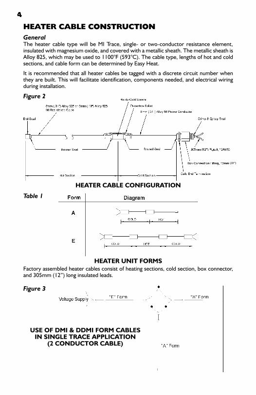
Figure 2
HEATER CAbLE CONSTRUCTIONGeneralThe heater cable type will be MI Trace, single- or two-conductor resistance element, insulated with magnesium oxide, and covered with a metallic sheath. The metallic sheath is Alloy825,whichmaybeusedto1100°F(593°C).Thecabletype,lengthsofhotandcoldsections, and cable form can be determined by Easy Heat.
It is recommended that all heater cables be tagged with a discrete circuit number when they are built. This will facilitate identification, components needed, and electrical wiring during installation.
Heater Cable COnfiguratiOn
Factory assembled heater cables consist of heating sections, cold section, box connector, and305mm(12”)longinsulatedleads.
Heater unit fOrMs
Table 1
Figure 3
use Of dMi & ddMi fOrM Cablesin single traCe aPPliCatiOn
(2 COnduCtOr Cable)
(.51”)

5
Note:Lengthofheatingcablemustbedoubletheactualpipelength(doubletraced)toprovide an electrical path.
use Of sMi fOrM Cable On MultiPle traCe aPPliCatiOn (1 COnduCtOr Cable)
Figure 4
standard•Conductortempbelow316°C(600°F)•Processmaintenanceunder149°C(300°F)
HIGH TEMPERATURE & wATTAGE INSTALLATIONSThecoldleadandhot-coldjunctionhavecopperwireinthem.Thiscopperhastobekeptbelow315°C(600°F)topreventdeteriorationoftheconductors.Thejunctionandcoldleadmounting is changed, based on the application temperatures and cable wattage.
HigH teMP/lOw wattage•Wattagebelow65w/m(20w/ft.)•Steampipingfreezeprotection
regular Cable
eM suffix
Figure 5
Figure 6
6
(qt suffix Or qHt-3)
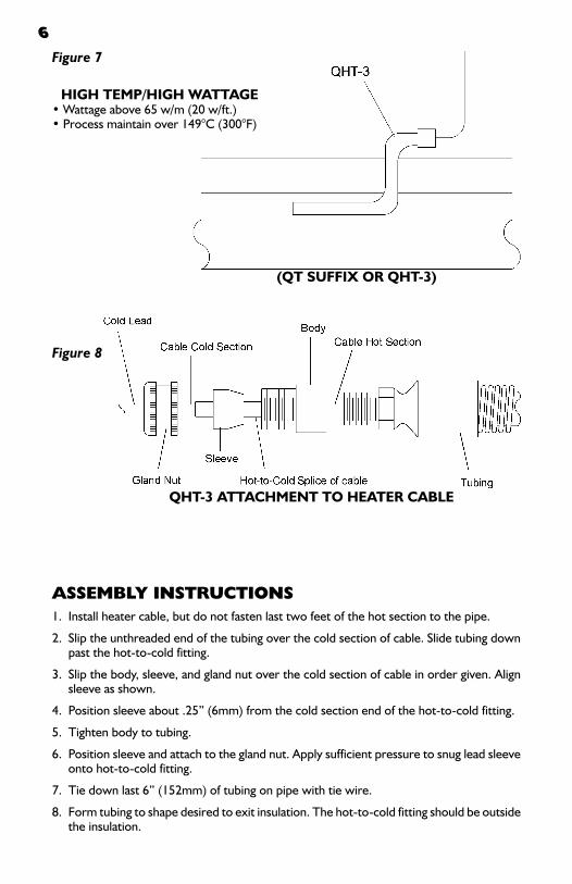
HigH teMP/HigH wattage•Wattageabove65w/m(20w/ft.)•Processmaintainover149°C(300°F)
qHt-3 attaCHMent tO Heater Cable
Figure 8
Figure 7
ASSEMbLy INSTRUCTIONS1. Install heater cable, but do not fasten last two feet of the hot section to the pipe.
2. Slip the unthreaded end of the tubing over the cold section of cable. Slide tubing down past the hot-to-cold fitting.
3. Slipthebody,sleeve,andglandnutoverthecoldsectionofcableinordergiven.Alignsleeve as shown.
4. Positionsleeveabout.25”(6mm)fromthecoldsectionendofthehot-to-coldfitting.
5. Tighten body to tubing.
6. Positionsleeveandattachtotheglandnut.Applysufficientpressuretosnugleadsleeveonto hot-to-cold fitting.
7. Tiedownlast6”(152mm)oftubingonpipewithtiewire.
8. Form tubing to shape desired to exit insulation. The hot-to-cold fitting should be outside the insulation.

7
HigH teMP Cable junCtiOn
installatiOnsuffix qt Or eM
Figure 9
HEATER CAbLE ATTACHMENTHeater cable shall be fastened to the piping with stainless steel straps or tie wire. Steel strapsortiewireshallbeinstalledwithapprox.12"(305mm)spacingasshowninFigure10.Stainless steel straps or tie wire should be used to secure heater cable to pipe and irregular shapedobjectssuchasvalves,etc.Cableshouldbelooselyattachedtoallowforexpansionand contraction without work hardening during thermal cycling of the heater.
Figure 10
Figure 11 Cold Lead
PipeStainless Steel Banding Straps or Tie Wire
MOunting OfHOt-COld junCtiOn

8
Assembly Notes1. For cable length at hanger and support, refer to Table 3.2. Exact configuration may vary.3. Fullyinsulateandweather-seal.
HEAT SINk INSTALLATIONExtra heater cable is required at all heat sinks. Heater cables should be applied in a manner to facilitate the easy removal of valves and small in-line devices, without the removal of excessive thermal insulation or having to cut the cable. The best way to accomplish this is to loop the heater cable. The amount of heater cable installed on each valve, hanger, etc. varies with the pipe size and type of device. Table 3 gives the correct additional cable to be installed on each device.
The following figures show installation details for various typical situations. Figures 12 & 13 show the area of the pipe that is affected by heat losses from items penetrating the insulation such as supports, hangers, valve yokes, etc. Heater cable adders can be applied anywhere in this area to compensate for these heat losses. Refer to Table 3 for proper footage of cable adder required.
Hanger
suPPOrt
Figure 13
Figure 12
9
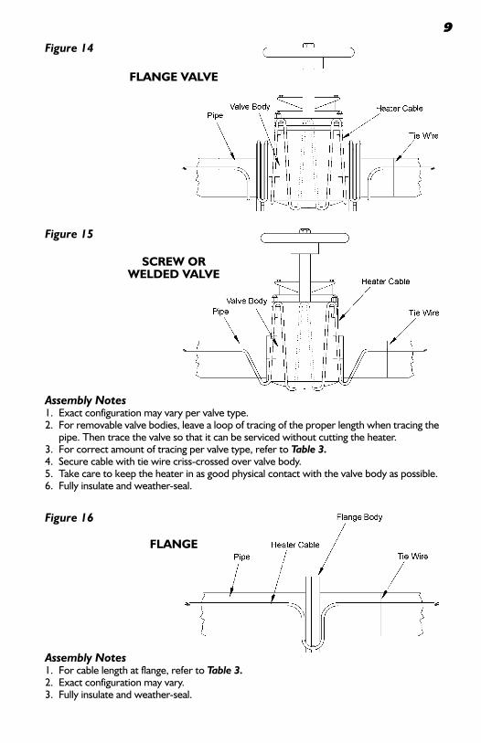
flange ValVe
Figure 14
sCrew Orwelded ValVe
Figure 15
Assembly Notes1. Exact configuration may vary per valve type.2. For removable valve bodies, leave a loop of tracing of the proper length when tracing the
pipe. Then trace the valve so that it can be serviced without cutting the heater.3. Forcorrectamountoftracingpervalvetype,refertoTable 3.4. Securecablewithtiewirecriss-crossedovervalvebody.5. Take care to keep the heater in as good physical contact with the valve body as possible.6. Fullyinsulateandweather-seal.
Figure 16
Assembly Notes1. For cable length at flange, refer to Table 3.2. Exact configuration may vary.3. Fullyinsulateandweather-seal.
flange

10Table 3—Heat Loss Adder
Notes1. Nominalpipelengthinfeet(meters).2. Adders are for various in-line fittings to compensate for areas of greater heat loss.3. Valuesabovearebasedonareaaverageofvariousfittingsavailable,withtheassumptionthatfitting
insulation will be equivalent to pipe insulation. The nominal length of tracer to be applied to a particular fitting would be the value shown in this chart plus the flange-to-flange length of the fitting.
PiPe fitting tyPe
Pipe size in (mm)
flange Pair
Vent & drain
Pipe support
globe, ball & butterfly Valves
gate Valve
.50 (12.70)
.30 (.09)
1.0 (.30)
1.0 (.30)
1.0 (.30)
1.0 (.30)
.75 (19.05)
.30 (.09)
1.0 (.30)
1.5 (.46)
1.0 (.30)
1.5 (.46)
1.00 (25.40)
.30 (.09)
1.0 (.30)
1.5 (.46)
1.0 (.30)
2.0 (.61)
1.50 (38.10)
.30 (.09)
1.0 (.30)
2.0 (.61)
1.5 (.46)
2.5 (.76)
2.00 (50.80)
.30 (.09)
1.0 (.30)
2.0 (.61)
2.0 (.61)
2.5 (.76)
3.00(76.20)
.30 (.09)
1.0 (.30)
2.0 (.61)
2.5 (.76)
3.0 (.91)
4.00(101.60)
.50 (.15)
1.0 (.30)
2.5 (.76)
3.0 (.91)
4.0(1.22)
6.00(152.40)
.80 (.24)
1.0 (.30)
2.5 (.76)
3.5 (1.07)
5.0 (1.52)
8.00 (203.20)
.80 (.24)
1.0 (.30)
2.5 (.76)
4.0 (1.22)
7.0 (2.13)
10.00 (254.00)
.80 (.24)
1.0 (.30)
3.0 (.91)
4.5 (1.37)
8.0 (2.44)
12.00 (304.80)
.80 (.24)
1.0 (.30)
3.0 (.91)
5.0 (1.52)
9.0(2.74)
14.00(355.60)
1.0 (.30)
1.0 (.30)
3.0(.91)
5.5 (1.68)
10.0 (3.05)
16.00(406.40)
1.0 (.30)
1.0 (.30)
3.5 (1.07)
6.0 (1.83)
11.0 (3.35)
18.00 (457.20)
1.0 (.30)
1.0 (.30)
3.5 (1.07)
7.0 (2.13)
12.0 (3.66)
20.00 (508.00)
1.0 (.30)
1.0 (.30)
3.5 (1.07)
7.5 (2.29)
13.0(3.96)
24.00(609.60)
1.0 (.30)
1.75 (.53)
4.0 (1.22)
8.0 (2.44)
15.0 (4.57)

11
Assembly Notes1. Pre-bend loops to fit over the edges of the pump, aminimum of 4” (100mm), before
installing. 2. Mountonpump,adjustingspacingbetweenloopstocoverpumpbody.3. Usetiewireoraluminumtapetoholdcableinplaceonpump.Seestep3.4. Pumpmustbefullyinsulatedandweather-sealed.5. Heater length required for pump application will vary with pump size. Contact your Easy Heat
representative or the factory for details.
Assembly Notes1. Determine the width of the pump to be traced.2. Pre-bend the heater cable starting with the end of the hot section and bend it approximately
at the distance as shown below.3. Continuetomakethese“S”bendsuntilthewholehotsectionhasbeenbent.
PuMP
Figure 18
Figure 17
Centrifugal PuMP
PUMPSAll pumps should be heat traced when suction and discharge lines are heat traced. Pumps should be heat traced with a separate cable. Each pump shall be traced in a manner that will allow the cable to be moved away from the pump for servicing or removal, see Figures 17 & 18. The cables should be pulled away from the pump without kinking the cable. Remove with care so that cable may be replaced in its original condition. If pumps require frequent maintenance, removable insulated enclosures with heaters attached to the enclosure are recommended.

12
INSTRUMENTATIONInstrument lines and their associated instruments shall be traced. Any supports or other heatsinksshallhaveadditionalcableserpentineontheobject.Ifspacewillnotallow,putthe extra cable on the tubing in the area of the heat sink. A separate thermostat should control long runs of instrument lines if the system is process control tracing. The instrument itself should be traced if fluid is in the instrument body. See Figures 19 & 20 for typical instrument tracing details.
Figure 20
leVel gauge
Figure 19
THERMAL INSULATIONPre-Insulation ChecksInspect the heater cable and components for correct installation and possible damage. In particular, verify that:• Heaterisnotonthetopofthepipeandisinstalledflatagainstthepipe.• Theproperextraamountofheatercablehasbeeninstalledateachvalve,flange,pipesupport,
etc., and that it is free from nicks, tears, or gouging.
Installation• Theproperselectionandinstallationofpipeinsulationisessentialforgoodperformanceofaheat
tracing system.• Rigid insulation should be oversized—min. 0.5” (13mm), or the next larger pipe size to
accommodate the heater installation.• Checkthethermalinsulationtypeandthicknessagainstthedesigncriteria.Changesininsulation
type or thickness may require a different wattage heater cable.• Longvertical runsofoversizedpipe insulationwillexperiencetemperaturepiling (heatedair
circulatingupward).Thiscanbereducedbyinstallingairbafflesatapproximately10’(3m)intervals.See Figure 21.
• Wheneverblownonormuddiedinsulationisused,thecableshouldbecoveredwithsometypeoffoilafter it is attached to the pipe, valve, pump, etc., to prevent thermal isolation of heating element.
• Leaksatvalves,flangesorpumpsshouldberepairedandtheinsulationdried.
or Piping
baffle fOr OVersized insulatiOn
Figure 21

13
• Verifythatallpipework,includingwallpenetrations,fittings,etc.,hasbeencompletelyinsulated.
• Insulationmustnotbewetfromrainfallpriortotheapplicationofwaterproofing.Seewarning below.
• Lapjointsonverticalpipingmustbeproperlyoverlappedwiththehigherpiecelappedover the top of the lower piece.
• Bandsealsmustbeusedatlapjointstopreventtheingressofwater.• All penetrations of the lagging (valve stems, hanger rods, etc.)must be properly
waterproofed.• Irregularshapeditems(pumps,etc.)mustbeproperlywaterproofed.• Wetpipe insulationhaspoorthermal insulatingcapabilitieswhichwillresult in line
freeze-up. It will also cause electrolysis & corrosion.• Itisrecommendedthatanotherinsulationresistance(megger)testbedoneafterthe
insulation has been installed to verify that the heating cable was not damaged during the insulation installation.
NOTE: To minimize potential damage to the heater cable, install the insulation as soon as possible.
Marking
Install“ElectricTrace”signsonalternatingsidesfothepipingat10-20feet(3.05-6.10m)intervalsas a warning to maintenance personnel.
awarning: all thermal insulation must be dry to ensure proper functioning of the heat trace system.
ELECTRICAL CONNECTIONSMoisture inside the electrical connection enclosure will cause both corrosion and electrical shorting problems. The potential for this type of problem can be greatly reduced by:• Lowpointconduitdrains—condensationfromconduitcanfillsmallenclosures.• Propersealingofallenclosureopenings.• Bottomconduitentryintoenclosures.• Keepingconduitfittings/pullboxcoversclosedatalltimes.• Keepingenclosurecoversclosedandsecuredasmuchaspossibleduringinstallation
sequence.• Properclosingandsealingofenclosurecoverstopreventleakingintothehousing.• Useofamoistureproofing/electricalspraysealantonthethermostatandelectrical
connections(includingallmetalparts)atcompletionofinstallation.
ELECTRICAL REqUIREMENTSVoltage Rating
Verify that the heater cable voltage rating is suitable for the service used. Voltage and wattage ratings are printed on the cable tag.
Electrical Loading
Size over-current protective devices according to National Electric Code. If devices are other than standard thermal magnetic circuit breakers, consult factory.
Voltage Surge Protection
Surge protection should be installed at the breaker panel if the panel is not isolated from its600V/480Vsupplybyanisolationtransformer.

14Ground Fault Protection
Ground fault circuit breakers are required on most heater applications per the National ElectricCode—checkcodeforappropriatecircuitbreakerprotection.Typically,30matripdevices are required due to the capacitive leakage of the heater cable and its associated power wiring.
Waterproofing
Moisture penetration of the electric system is the single largest source of problems in a heater cable system installation. Therefore, particular care must be given to the proper sealing of allelectricalconnections.Allelectricalconnections(heatertopowerwiring,thermostatconnections,panelandbreakerconnections,etc.)shouldbesealedormoistureproofedin some fashion. See warning.
TESTINGRecommendationsElectrical tests are recommended at specific points on the receipt and installation of heater cable. This periodic testing is designed to prevent the expenditure of wasted labor in the event of damage to the product. Installation costs of the cable and thermal insulation are much greater that the heater cable. Quick identification of any heater cable damage is the most economic approach to an installation. An insulation resistance test is recommended at the following points of the installation process:
• UPONRECEIPToftheheatercable• BEFOREthermalINSULATIONinstallation• IMMEDIATELYAFTERthermalINSULATIONinstallation• AspartofaPERIODICMAINTENANCEprogram
ProcedureTheinsulationresistancetestisusedtocheckfordamagetoheaterjackets.Connectionsfor the megger are made as shown in Figure 22 to the pigtail wires & the metal sheath. Test should use at least a 500VDC megger, however, a 1000VDC megger test is recommended. Minimum acceptable readings should be 20 megohms per cable.
awarning: nuisance tripping of ground fault circuit breakers will occur unless all electrical con-nections are waterproofed and kept dry.
Figure 22 A record should be kept of the readings taken from the time the cable is first installed on the pipe. A history of the insulation resistance reading can be helpful in spotting moisture ingress into the electrical system (by seeinga gradual decline in the insulation resistance)orphysicaldamagetotheheating cable (sharp decline in theinsulationresistance).Asamplerecordform is shown in Figure 23.
15
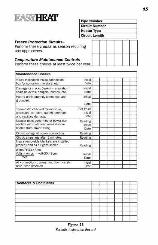
Figure 23Periodic Inspection Record
Freeze Protection Circuits–Perform these checks as season requiring use approaches.
Temperature Maintenance Controls–Perform these checks at least twice per year.
Pipe NumberCircuit NumberHeater TypeCircuit Length
Maintenance Checks
Visual inspection inside connection box for corrosion, moisture, etc.
InitialDate
Damage or cracks (leaks) in insulationseals at valves, hangers, pumps, etc.
InitialDate
Heater cable properly connected and grounded.
Initial
Date
Thermostat checked for moisture, corrosion, set point, switch operation, and capillary damage.
Set PointInitialDate
Megger tests performed at power con-nection with both lead wires discon-nected from power wiring
ReadingInitialDate
Circuit voltage at power connection. ReadingCircuit amperage after 5 minutes. ReadingInsure removable blankets are installed properly and all air gaps sealed. ReadingWatts/Ft/30.48cm.Volts × Amps = w/ft/30.48cm. feet
InitialDate
All connections, boxes, and thermostats have been resealed.
InitialDate
Remarks & Comments

16The Periodic Inspection Record Form may be used in one of two ways:• Onesheetpercircuit.Theresultsofperiodictestsofasinglecircuitarepostedinverticalcolumns,
beginning on the left and working toward the right. This allows easy comparison of test values for up to seven test sequences on an individual circuit.
• Oncircuitpercolumn.Testdataforasingletestsequenceonasmanyassevencircuitscanberecorded on a single sheet.
START-UPHeat-Up TimeHeat-upcapacity(theabilitytoheatthepipeandit’scontentsrapidly)isnotnormallydesignedintothesystem. Cold start-ups should allow adequate time for the pipe to come up to temperature.
OPERATION & MAINTENANCESystem Design Installation & DocumentationThe heating cable system must be properly designed, installed and documented. This documentation should at least include line lists and location identification documentation. As-built installation drawings provide the optimum maintenance tool. Test records should also be considered as part of the system documentation requirements.
Preventive MaintenanceA preventive maintenance program is needed which will encompass both visual and electrical checks of the system. These should be done not only before initial operation of the system, but also after any maintenance has been performed.
Periodic Inspections• Thermalinsulation-checkweatherproofingfordamage,missingseals,cracks,orgapsincaulking
and mastic coatings, damaged, or missing lagging. When damage does exist, the insulation will need toberepairedorreplaced,andthenre-sealed.WETINSULATIONHASPOORINSULATINGPROPERTIES,THEREFORETHE INSULATIONMUSTBEKEPTDRY. If insulationhasbeendamaged,checktheheatercablefordamage—replaceanydamagedsections.
• Inspectjunctionboxes,connectionboxes,andthermostatsforcorrosion,moistureorforeignmatter.• Checktightnessofelectricalconnections,properelectricalinsulationofheatingcablewires,and
adequacy of moisture seal on electrical connections.• Checkallthermostatcapillariestoinsuretheyareshieldedfromphysicaldamageandsecured
properly to the pipe.• Verifythatallthermostatpowerandprobeleadsaresecurelyconnectedandonthecorrectterminal.• Verifythatallenclosure,connectionbox,etc.,coversareproperlyclosed.Alsomakesurethatthe
thermostat is switching on & off by rotating knob set point back and forth, and on by measuring current flow in the circuit when the unit switches on. Reset the knob to the proper temperature after completion of the test.
FrequencyInspections should be made prior to the start of the freeze season on freeze protection systems. Process maintenancesystemsshouldbecheckedonafrequentbasis—atleasttwiceayear.
Personnel TrainingQualified maintenance personnel must be used to maintain the system. It is recommended that periodic training programs be utilized to assist in keeping maintenance personnel up to date on equipment and procedures.
MaintenanceThe heater cables will not require any maintenance, unless damaged. Mechanical temperature controls should have dial stem lubricated and be sprayed with a moisture repellent/corrosion inhibitor once a year on all metal parts. Disconnect the electrical connection for the heater cable and protect it from mechanical or thermal damage during any repair of the piping system. Check the heater cable installation after any piping system repairs per established procedures. Replace and water seal the thermal insulation system.
Damaged ProductsReplace the damaged cable immediately. Moisture migration into the good section of the cable may cause electrical shorting in that cable after repair of the damaged section.
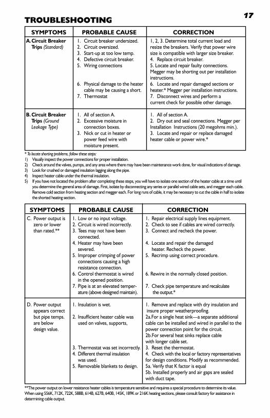
17TROUbLESHOOTING
* To locate shorting problems, follow these steps:1) Visuallyinspectthepowerconnectionsforproperinstallation.2) Checkaroundthevalves,pumps,andanyareawheretheremayhavebeenmaintenanceworkdone,forvisualindicationsofdamage.3) Lookforcrushedordamagedinsulationlaggingalongthepipe.4) Inspectheatercableunderthethermalinsulation.5) Ifyouhavenotlocatedtheproblemaftercompletingthesesteps,youwillhavetoisolateonesectionoftheheatercableatatimeuntil
you determine the general area of damage. First, isolate by disconnecting any series or parallel wired cable sets, and megger each cable. Remove cold section from heating section and megger each. For long runs of cable, it may be necessary to cut the cable in half to isolate the shorted heating section.
syMPtOMs PrObable Cause COrreCtiOn a. Circuit breaker 1. Circuitbreakerundersized. 1,2,3.Determinetotalcurrentloadand trips (Standard) 2. Circuit oversized. resize the breakers. Verify that power wire 3. Start-upattoolowtemp. sizeiscompatiblewithlargersizebreaker. 4. Defectivecircuitbreaker. 4. Replacecircuitbreaker. 5. Wiringconnections 5.Locateandrepairfaultyconnections. Megger may be shorting out per installation instructions. 6. Physicaldamagetotheheater 6. Locateandrepairdamagedsectionsor cable may be causing a short. heater.* Megger per installation instructions. 7. Thermostat 7. Disconnect wires and perform a current check for possible other damage.
b. Circuit breaker 1. All of section A. 1. All of section A. trips (Ground 2. Excessive moisture in 2. Dry out and seal connections. Megger per Leakage Type) connectionboxes. InstallationInstructions(20megohmsmin.). 3. Nickorcutinheateror 3. Locateandrepairorreplacedamaged power feed wire with heater cable or power wire.* moisture present.
**The power output on lower resistance heater cables is temperature sensitive and requires a special procedure to determine its value. Whenusing556K,712K,722K,588B,614B,627B,640B,145K,189Kor216Kheatingsections,pleaseconsultfactoryforassistanceindetermining cable output.
syMPtOMs PrObable Cause COrreCtiOn C. Poweroutputis 1.Lowornoinputvoltage. 1. Repairelectricalsupplylinesequipment. zero or lower 2. Circuit is wired incorrectly. 2. Check to see if cables are wired correctly. thanrated.** 3.Teesmaynothavebeen 3. Connectandrecheckthepower. connected. 4.Heatermayhavebeen 4. Locateandrepairthedamaged severed. heater. Recheck the power. 5. Improper crimping of power 5. Recrimp using correct procedure. connections causing a high resistance connection. 6.Controlthermostatiswired 6.Rewireinthenormallyclosedposition. in the opened position. 7. Pipe is at an elevated temper- 7. Check pipe temperature and recalculate ature(abovedesignedmaintain). theoutput.*
D. Power output 1. Insulation is wet. 1. Remove and replace with dry insulation and appears correct insure proper weatherproofing. butpipetemps. 2. Insufficientheatercablewas 2a.Forasingleheatsink—aseparateadditional are below used on valves, supports, cable can be installed and wired in parallel to the design value. power connection point for the circuit. 2b.For several heat sinks replace cable with longer cable set. 3.Thermostatwassetincorrectly. 3. Resetthethermostat. 4.Differentthermalinsulation 4. Checkwiththelocalorfactoryrepresentatives was used. for design conditions. Modify as recommended. 5.Removableblanketstodesign. 5a.VerifythatKfactorisequal 5b. Installed properly and air gaps are sealed with duct tape.

18
1. Pipe No. _________________________ Date________________________ DESIGN ACTUAL2. Receiving Documentation Heater Cat. Nos. ___________________ ____________________3. Receiving Testing
Date_________________________ A. Check for physical damage. O.K.______________ Damage______________ B. Continuity Check—Check for continuity between power leads. O.K.______________ Open________________ C. 500VDC megger check between leads and sheath, 20 megohms min. Megohms________________________________ 4. Post Installation Testing
Date_________________________
A. Continuity Check—Check for continuity between cold leads. O.K.______________ Open________________
B. 500VDC megger check between leads and sheath, 20 megohms min.
Megohms________________________________ C. Visually check cable installation
prior to release for thermal insulation. O.K.______________ Open________________5. Final Testing & Commissioning
Date_________________________ A. Circuit approved for testing by client.
Approved________________________________ B. 500VDC megger check between
leads and sheath, 20 megohms min. Megohms________________________________ DESIGN ACTUAL
C. Energized Testing (All test data to be within 10% of design data) 1. Circuit Voltage ___________________ ____________________ 2. Intial Current ___________________ ____________________ 3. Current after 15
mins. of operation ___________________ ____________________6. Circuit Acceptance ________________ _________________ This circuit has been tested and documented in accordance with the above itemized data. Ths circuit approved by:Contractor_____________________________________ Date________________Client_________________________________________ Date________________
HEAT TRACE INSTALLATION RECORD
Figure 24The Heat Trace I n s ta l l a t i on Reco rd can be u sed t omon i t o r t he i n i t i a l i n s ta l -l a t i on and check ou t p roces s . Th i s f o rm can be u sed i n con junc t i on w i th the Periodic Inspection Record shown in figure 23.

LIMITED WARRANTY AND LIABILITY
Easy Heat warrants that if there are any defects in material or workmanship in any heating cable or accessory during the first year after the date of purchase, we will provide new products to replace any defective items, or we will refund the purchase price paid for the accessory or cable, not including any labor or other installation costs. As an alternate, we may elect to repair the cable or accessory at our factory with all shipping and other removal costs borne by the purchaser.
We further warrant that, for a period of twelve (12) months after the date of performance, any services performed hereunder will be in a good and skillful manner, based on our understanding of pertinent technical data as of the date of performance of such services. Easy Heat’s sole responsibility and liability in the event of any defect, error, omission, or failure in the services rendered hereunder shall be to provide corrected services of the type provided for herein, designed to correct such defect, error, omissions, or failure, and in no event shall Easy Heat’s liability with respect to such warranty exceed the amount received by it from the Buyer on account of such services.
Our obligation to provide corrected services, new products, refund the purchase price, or perform the repair described above is conditioned upon (a) the installation of the accessory or cable conforming to the specifications set forth in our installation instructions and (b) the accessory or cable not having been damaged by mechanical or electrical activities unrelated to the operation of the accessory or cable.
A refund of your purchase price, provision of replacement products, repair of the accessory or cable or provision of corrected services as described above, shall be your sole and exclusive remedy for a breach of this warranty. THESE ARE THE SOLE AND EXCLUSIVE WARRANTIES GIVEN BY EASY HEAT WITH RESPECT TO THE GOODS AND SERVICES AND ARE IN LIEU OF AND EXCLUDE ALL OTHER WARRANTIES, EXPRESS OR IMPLIED, ARISING BY OPERATION OF LAW OR OTHERWISE, INCLUDING WITHOUT LIMITATION, MERCHANTABILITY AND FITNESS FOR A PARTICULAR PURPOSE WHETHER OR NOT THE PURPOSE OR USE HAS BEEN DISCLOSED TO EASY HEAT IN SPECIFICATIONS, DRAWINGS OR OTHERWISE, AND WHETHER OR NOT EASY HEAT’S PRODUCTS ARE SPECIFICALLY DESIGNED AND/OR MANUFACTURED BY EASY HEAT FOR YOUR USE OR PURPOSE.
This warranty does not extend to any losses or damages due to misuse, accident, abuse, neglect, normal wear and tear, negligence, unauthorized modification or alteration, use beyond rate capacity, or improper installation, maintenance or application. To the extent that you or your agents have supplied specifications, information, representation of operating conditions or other data to Easy Heat in the selection or design of the Goods and the preparation of Easy Heat’s quotation, and in the event that actual operating conditions or other conditions differ from those represented by you, any warranties or other provisions contained herein which are affected by such conditions shall be null and void. (continued on other page)
19

LIMITED WARRANTY AND LIABILITY (continued)
If within thirty (30) days after your discovery of any warranty defects within the warranty period, you notify Easy Heat thereof in writing, Easy Heat shall, at its option, repair, correct or replace F.O.B. point of manufacture, or refund the purchase price for, that portion of the Goods found by Easy Heat to be defective. Failure by you to give such written notice within the applicable time period shall be deemed an absolute and unconditional waiver of your claim for such defects. Goods repaired or replaced during the warranty period shall be covered by the foregoing warranty for the remainder of the original warranty period or ninety (90) days from the date of shipment of the repaired or replaced goods, whichever is longer.
This limited warranty does not cover any costs relating to the repair or replacement of any accessory or cable at the installation site. Our accessories and cables are not easily accessible. A failed accessory or cable usually cannot be easily repaired. Replacement of a failed accessory or cable will require that the materials under which it is installed be removed to permit replacement of the accessory or cable. We will not reimburse any costs relating to the repair or replacement of any accessory or cable at the installation site.
IN NO EVENT, REGARDLESS OF THE FORM OF THE CLAIM OR CAUSE OF ACTION (WHETHER BASED IN CONTRACT, INFRINGEMENT, NEGLIGENCE, STRICT LIABILITY, OTHER TORT OR OTHERWISE), SHALL EASY HEAT’S LIABILITY TO YOU AND/OR YOUR CUSTOMERS EXCEED THE PRICE PAID BY YOU FOR THE SPECIFIC GOODS PROVIDED BY EASY HEAT GIVING RISE TO THE CLAIM OR CAUSE OF ACTION. YOU AGREE THAT WE SHALL NOT BE LIABLE TO YOU OR YOUR CUSTOMERS FOR ANY INCIDENTAL, SPECIAL OR CONSEQUENTIAL OR PUNITIVE DAMAGES. No agent, employee or representative of ours has authority to bind us to any affirmation, representation or warranty concerning the goods sold unless such affirmation, representation or warranty is specifically incorporated by written agreement.
To obtain new products, arrange repair of existing product, or a refund under this warranty, please contact Easy Heat with a description of the defect and proof of purchase at the address noted herein.
ATTN: WARRANTY DEPARTMENT:In US - EasyHeat Inc; 2 Connecticut South Drive, East Granby, CT 06026In CANADA - EasyHeat Ltd; 99 Union Street, Elmira, ON N3B 3L7
20

©2008 Easy Heat www.easyheat.com 14035-001 Rev. 4
US T. (800) 537-4732 / F. (888) 324-2440CAN T. (800) 794-3766 / F. (800) 361-4574