mini-crawler crane - chaseee · mini-crawler crane head office : 3-14, nihonbashi muromachi...
TRANSCRIPT
SERIES
OMURW37C154C1200910APRINTED IN JAPAN
OPERATION&
MAINTENANCEMANUAL
MINI-CRAWLER CRANE
HEAD OFFICE : 3-14, Nihonbashi Muromachi 2-chome, Chuo-ku, Tokyo, 103-0022 Japan
MODEL

0-1
INTRODUCTION
Request to those who operate the crane
SELECT SET
OUTRIGGER
tNOT MAX EXT.
ì²
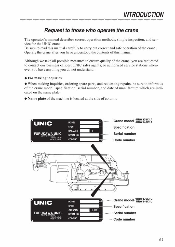
Crane model
Specification
Serial number
Code number
MODEL
SPEC.
CODE NO.
SERIAL NO.
CAPACITYFURUKAWA UNIC
CORPORATIONTOKYO JAPAN
MADE IN JAPAN
t
URW376C1AURW546C1A
MODEL
SPEC.
CODE NO.
SERIAL NO.
CAPACITYFURUKAWA UNIC
CORPORATIONTOKYO JAPAN
MADE IN JAPAN
LBS
Crane model
Specification
Serial number
Code number
URW376C1UURW546C1U
The operator’s manual describes correct operation methods, simple inspection, and ser-vice for the UNIC crane.Be sure to read this manual carefully to carry out correct and safe operation of the crane.Operate the crane after you have understood the contents of this manual.
Although we take all possible measures to ensure quality of the crane, you are requested to contact our business offices, UNIC sales agents, or authorized service stations when-ever you have anything you do not understand.
For making inquiries ◆
Name plate ◆ of the machine is located at the side of column.
When making inquiries, ordering spare parts, and requesting repairs, be sure to inform us ◆of the crane model, specification, serial number, and date of manufacture which are indi-cated on the name plate.
0-2
TABLE OF CONTENTS
8. HOW TO REFER TO WORKING RANGE CHART AND RATED LOAD CHARTWorking range chart 1 ……………………… 8- 1Net rated load chart 2 ………………………… 8- 2
9. DESCRIPTION OF EACH CONTROL DEVICEOverwinding alarm 1 ………………………… 9- 1Automatic stop for overwinding 2 …………… 9- 2Load indicator 3 (With angle meter) ………… 9- 4Warning horn 4 ……………………………… 9- 8 5 Retaining mechanism for slinging wire rope ……… 9- 8 Automatic stop for leaving minimum wire rope 6(With wire rope retaining roller) …………… 9- 8Digital load meter 7 ………………………… 9- 9U-AOL system (Anti overloading system) 8 … 9-14
10. HOW TO OPERATE CARRIER 1 Designation of each control lever and its location ……… 10- 1Preparation before operation 2 ……………… 10- 2How to operate 3 …………………………… 10- 5How to Crawl 4 ……………………………… 10- 8
11. HOW TO OPERATE CRANE 1 Designation of each control lever and its location …… 11- 1Preparation before operation 2 ……………… 11- 2 Inspection before starting crane operation 3 … 11- 3Procedures to set up outriggers 4 …………… 11- 5 5 How to operate boom for derricking(raising and lowering) ……………………… 11-11How to hoist and lower the hook 6 …………… 11-12How to telescope boom 7 …………………… 11-14How to slew boom 8 ………………………… 11-16How to store crane 9 ………………………… 11-18Procedures for storing hook 10 ………………… 11-19How to store outriggers 11 …………………… 11-21
SETUP OF THIS MANUALURW376C1 series 1 ………………………… 0- 4URW540C1 series 2 ………………………… 0- 5
1. FOR SAFETY OPERATIONRequest to customers 1 ……………………… 1- 1
2. SAFETY PRECAUTIONS ON CARRIER OPERATIONBefore operation 1 …………………………… 2- 1During operation 2 …………………………… 2- 2When loading and unloading 3 ……………… 2- 3After operation 4 …………………………… 2- 4
3. SAFETY PRECAUTIONS ON CRANE OPERATIONBefore operation 1 …………………………… 3- 1During operation 2 …………………………… 3- 2After operation 3 …………………………… 3- 4
4. DESCRIPTION OF CARRIER EQUIPMENT ……………………… 4- 1
5. DESCRIPTION OF CRANE EQUIPMENT ……………………… 5- 1
6. NAME PLATESDescription of name plates (Stickers) 1 ……… 6- 1Stickers in detail 2 …………………………… 6- 2
7. DEFINITION OF TERMSOutrigger extension 1 ………………………… 7- 1How boom-sections are extended 2 ………… 7- 4Net rated load 3 ……………………………… 7- 8Rated load 4 ………………………………… 7- 8Lifting capacity 5 …………………………… 7- 8Working radius 6 …………………………… 7- 8Boom length 7 ……………………………… 7- 8Boom angle 8 ………………………………… 7- 8Lift above ground 9 ………………………… 7- 8
0-3
TABLE OF CONTENTS
12. U-WAVE, RADIO REMOTE CONTROL DEVICE, (OPTION)
Request to those who operate the crane 1 …… 12- 1Safety precautions 2 ………………………… 12- 2Designation of each equipment 3 …………… 12- 5Inspection before crane operation 4 ………… 12- 8How to switch crane operation mode 5 ……… 12-10 How to operate the crane through 6 radio control operation …… 12-12 How to replace batteries of transmitter 7 …… 12-34 Daily checks, trouble inspection 8 …………… 12-37
13. MAINTENANCE AND INSPECTION OF CARRIER
Inspection before operation 1 ………………… 13- 2 Inspection and Maintenance which is to be 2carried out every 250 hours or 3 months …… 13-13 Inspection and Maintenance which is to be 3carried out every 500 hours or 6 months …… 13-21 Inspection and Maintenance which is to be 4carried out every 1000 hours or 12 months … 13-23 Non-regular maintenance 5 ………………… 13-29 Storage 6 …………………………………… 13-35Fitting safety covers 7 ……………………… 13-36Maintenance and inspection of engine 8 ……… 13-36
14. MAINTENANCE AND INSPECTION OF CRANE
Inspection before operation 1 ………………… 14-2Cleaning 2 …………………………………… 14-3 3 Inspection of bolts mounting slewing bearings ……… 14-3 Replacement of wire rope (for winding-up) 4 … 14-4 Replacement of expendable parts 5 ………… 14-8
15. WATER SUPPLY AND LUBRICATION TO CARRIER
Precaution when carrying out filling 1 water and lubrication …… 15- 1List of recommended lubricant 2 …………… 15- 2Filling water and lubrication chart 3 ………… 15- 4
16. LUBRICATION TO CRANE Precaution when carrying out lubrication 1 …… 16- 1List of recommended lubricant 2 …………… 16- 2Lubrication chart 3 …………………………… 16- 3Lubrication 4 ………………………………… 16- 4
17. MAJOR SPECIFICATIONSURW376C1A(6-section boom) 1 …………… 17- 1URW376C1U(6-section boom) 2 …………… 17- 7URW546C1A(6-section boom) 3 …………… 17-13URW546C1U(6-section boom) 4 …………… 17-19URW547C1A(7-section boom) 5 …………… 17-25URW547C1U(7-section boom) 6 …………… 17-32 7 Major specification(Radio remote control device)for URW376C1A,URW546C1A,URW547C1A ……………… 17-39 8 Major specification(Radio remote control device)for URW376C1U,URW546C1U,URW547C1U ……………… 17-40
18. MODE INDICATOR LAMP(CONTROL BOX) …………………18- 1
19. MEASURES TO BE TAKEN IN AN EMERGENCY ……………………19- 1
0-4
SETUP OF THIS MANUAL
URW376C1ARS
URW376C1A
ModelSpec.
URW376C1A series
With radio remote controller
Designation (example)
With cable remote controller
Manual specification
URW376C1AR
URW376C1URS
URW376C1U
URW376C1U series
With radio remote controller
With cable remote controller
Manual specification
URW376C1UR
SETUP OF THIS MANUAL
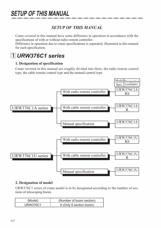
Crane covered in this manual have some difference in operation in accordance with the specifications of with or without radio remote controller.Difference in operation due to crane specifications is separately illustrated in this manual for each specification.
Crane covered in this manual are roughly divided into three, the radio remote control type, the cable remote control type and the manual control type.
1. Designation of specification
URW376C1 series of crane model is to be designated according to the number of sec-tions of telescoping boom.
2. Designation of model
URW376C1 series 1
(Model) (Number of boom section)URW376C1 6 (Only 6 section boom)
0-5
URW546C1ARS
URW546C1A
ModelSpec.
URW540C1A series
With radio remote controller
Designation (example)
With cable remote controller
Manual specification
URW546C1AR
URW546C1URS
URW546C1U
URW546C1U series
With radio remote controller
With cable remote controller
Manual specification
URW546C1UR
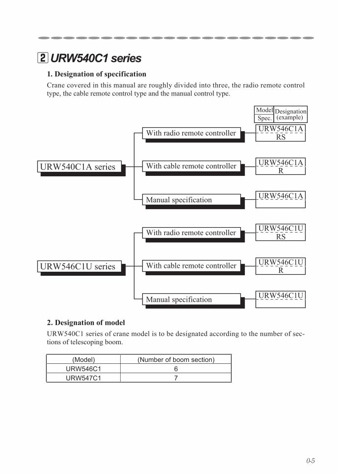
Crane covered in this manual are roughly divided into three, the radio remote control type, the cable remote control type and the manual control type.
1. Designation of specification
URW540C1 series of crane model is to be designated according to the number of sec-tions of telescoping boom.
2. Designation of model
URW540C1 series 2
(Model) (Number of boom section)URW546C1 6URW547C1 7
1-1
1. FOR SAFETY OPERATION
Request to customers 1
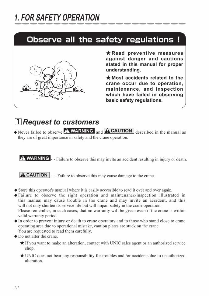
Read preventive measures ★against danger and cautions stated in this manual for proper understanding.
Most accidents related to the ★crane occur due to operation, maintenance, and inspection which have failed in observing basic safety regulations.
… Failure to observe this may invite an accident resulting in injury or death.
CAUTION … Failure to observe this may cause damage to the crane.
Store this operator's manual where it is easily accessible to read it over and over again. ◆ Failure to observe the right operation and maintenance/inspection illustrated in ◆this manual may cause trouble in the crane and may invite an accident, and this will not only shorten its service life but will impair safety in the crane operation. Please remember, in such cases, that no warranty will be given even if the crane is within valid warranty period. In order to prevent injury or death to crane operators and to those who stand close to crane ◆operating area due to operational mistake, caution plates are stuck on the crane. You are requested to read them carefully.Do not alter the crane. ◆
If you want to make an alteration, contact with UNIC sales agent or an authorized service ★shop.
UNIC does not bear any responsibility for troubles and /or accidents due to unauthorized ★alteration.
Observe all the safety regulations !
Never failed to observe ◆ and CAUTION described in the manual as they are of great importance in safety and the crane operation.
2-1
2. SAFETY PRECAUTIONS ON CARRIER OPERATION
Before operation 1
Observe the cautions for securing safety. ★Failure to observe the cautions may cause trouble or serious accident.
2 Be sure to make inspection before operation and periodical voluntary
inspection. If found something wrong, repair it immedi-ately.
3 The crane is prohibited to crawl on a public road by the road traffic law.
1 Dress neatly and wear protectors such as helmet, safety shoes, and gloves without
fail.Do not wear baggy clothes and accessories ★
which can be caught by control levers and fit-tings, and oil-stained working clothes which may catch fire.
WARNING
4 Check that no safety covers have been left removed.
It is very dangerous to start the engine, ★to operate the crane with the safety cover removed as the driving mechanism is exposed.
5 Be sure to stop the engine before refuel-ing or supplying and changing lubricant.
A fire source such as smoking cigarette in mouth is strictly prohibited. Failure to observe this may cause a fire.
6 When starting the engine in a small lim-ited area or indoors, open the windows
and doors for well ventilation.Poor ventilation may invite an exhaust gas ★
poisoning.
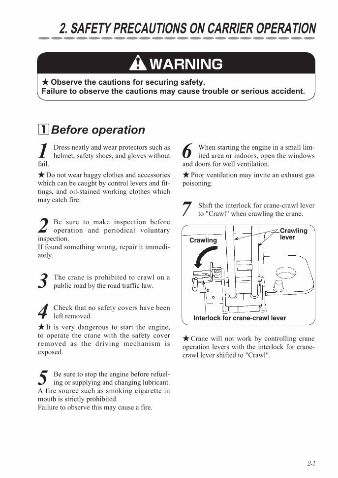
7 Shift the interlock for crane-crawl lever to "Crawl" when crawling the crane.
Crane will not work by controlling crane ★operation levers with the interlock for crane-crawl lever shifted to "Crawl".
Crawlinglever
Interlock for crane-crawl lever
Crawling
2-2
SAFETY PRECAUTIONS ON CARRIER OPERATION
2 When crawling the crane, be sure to put outriggers in a condition of being stored
and store the hook.
1 The machine employs particularly small truck to facilitate working in a restrict-
ed space. Since high performance crane is mounted on the small truck, it has been built with a higher center of gravity.
Take special care not to overturn the crane ★when crawling on a unleveled ground.
During operation 2
3 Do not run the crane with a cargo hoist-ed or without the crane being stored.
4 Special care must be taken to run the crane slowly when making a quick turn
and crawling on a rough road.
5 When running over a bump, be sure to slow down the crane and direct it
straight to the bump to avoid unnecessary shock to the crane body.
6 Be sure to use a foot-board to run over a ramp of more than 15cm.
7 Crawl the crane with low (1st) speed gear on a slope.
8 Be sure to use a pallet against the rub-ber crawler when parking the crane on
a slope.
9 Do not make an abrupt stop and start, and change a course on a slope.
10 When crawling up and down a slope, operate the crane by standing at a
higher position than the crane body.
Less than 10 degrees
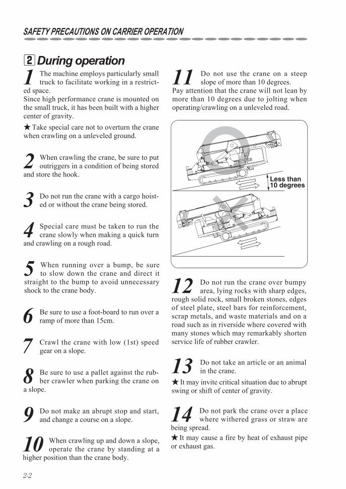
11 Do not use the crane on a steep slope of more than 10 degrees.
Pay attention that the crane will not lean by more than 10 degrees due to jolting when operating/crawling on a unleveled road.
12 Do not run the crane over bumpy area, lying rocks with sharp edges,
rough solid rock, small broken stones, edges of steel plate, steel bars for reinforcement, scrap metals, and waste materials and on a road such as in riverside where covered with many stones which may remarkably shorten service life of rubber crawler.
13 Do not take an article or an animal in the crane.
It may invite critical situation due to abrupt ★swing or shift of center of gravity.
14 Do not park the crane over a place where withered grass or straw are
being spread.It may cause a fire by heat of exhaust pipe ★
or exhaust gas.
2-3
SAFETY PRECAUTIONS ON CARRIER OPERATION
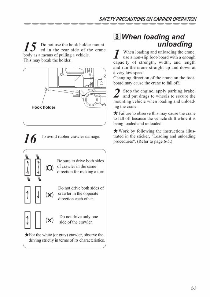
15 Do not use the hook holder mount-ed in the rear side of the crane
body as a means of pulling a vehicle. This may break the holder.
Hook holder
16 To avoid rubber crawler damage.
( )
( )
( )
Be sure to drive both sides of crawler in the same direction for making a turn.
Do not drive both sides of crawler in the opposite direction each other.
Do not drive only one side of the crawler.
★For the white (or gray) crawler, observe the driving strictly in terms of its characteristics.
When loading and 3 unloading1 When loading and unloading the crane,
use a non-slip foot-board with a enough capacity of strength, width, and length and run the crane straight up and down at a very low speed. Changing direction of the crane on the foot-board may cause the crane to fall off.
2 Stop the engine, apply parking brake, and put drags to wheels to secure the
mounting vehicle when loading and unload-ing the crane.
Failure to observe this may cause the crane ★to fall off because the vehicle shift while it is being loaded and unloaded.
Work by following the instructions illus- ★trated in the sticker, "Loading and unloading procedures". (Refer to page 6-5.)
2-4
SAFETY PRECAUTIONS ON CARRIER OPERATION
1 Return the crawling lever and run the engine at a low speed.
After operation 4
2 Shift the crawling lever to "Crane" posi-tion.
3 Stop the engine and remove dirt and dust stuck on the crane body.
Since dust stuck on the battery, electric ★wiring, and engine related components such as muffler may cause a fire in particular, be sure to remove it.
4 Cover the crane or store it in a storage house to prevent it from being accessed
by unrelated persons such as children.Cover the crane after heated sections ★
have been cooled off. Putting a cover on while the crane body is still hot may cause a fire.
5 Remove the starter switch key to store.
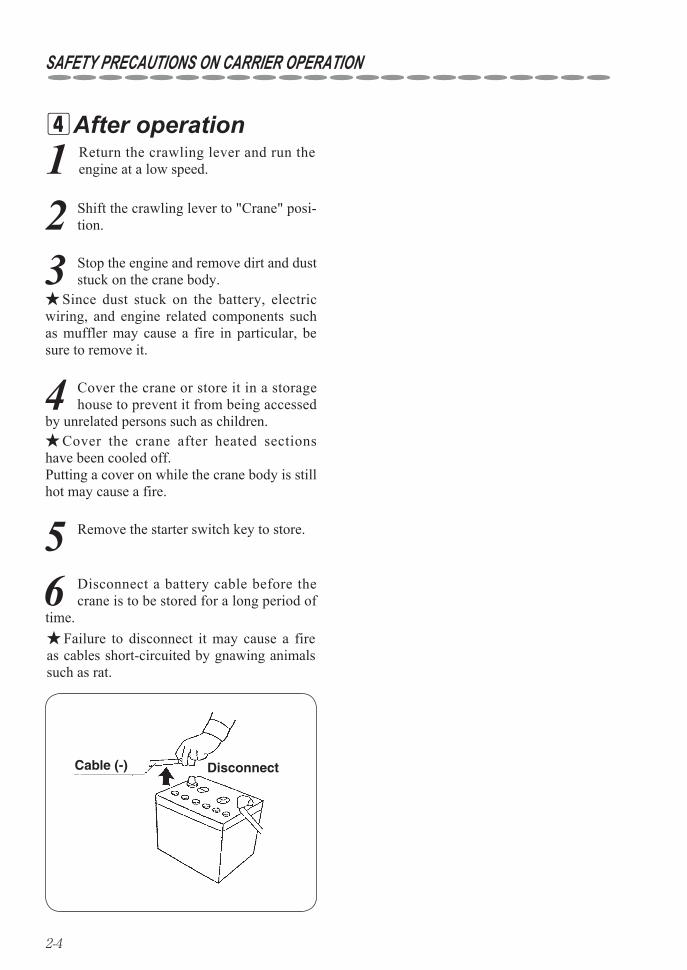
Failure to disconnect it may cause a fire ★as cables short-circuited by gnawing animals such as rat.
6 Disconnect a battery cable before the crane is to be stored for a long period of
time.
Cable (-) Disconnect
3-1
3. SAFETY PRECAUTIONS ON CRANE OPERATION
Before operation 1
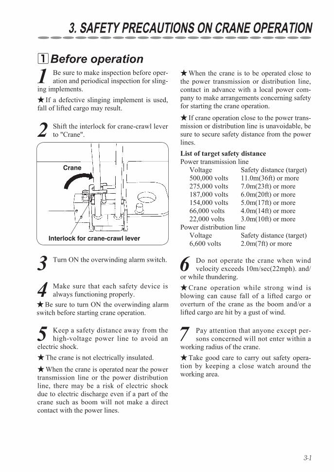
Interlock for crane-crawl lever
Crane
When the crane is to be operated close to ★the power transmission or distribution line, contact in advance with a local power com-pany to make arrangements concerning safety for starting the crane operation.
If crane operation close to the power trans- ★mission or distribution line is unavoidable, be sure to secure safety distance from the power lines.List of target safety distancePower transmission line Voltage Safety distance (target) 500,000 volts 11.0m(36ft) or more 275,000 volts 7.0m(23ft) or more 187,000 volts 6.0m(20ft) or more 154,000 volts 5.0m(17ft) or more 66,000 volts 4.0m(14ft) or more 22,000 volts 3.0m(10ft) or morePower distribution line Voltage Safety distance (target) 6,600 volts 2.0m(7ft) or more
2 Shift the interlock for crane-crawl lever to "Crane".
1 Be sure to make inspection before oper-ation and periodical inspection for sling-
ing implements.If a defective slinging implement is used, ★
fall of lifted cargo may result.
3 Turn ON the overwinding alarm switch.
4 Make sure that each safety device is always functioning properly.
Be sure to turn ON the overwinding alarm ★switch before starting crane operation.
The crane is not electrically insulated. ★When the crane is operated near the power ★
transmission line or the power distribution line, there may be a risk of electric shock due to electric discharge even if a part of the crane such as boom will not make a direct contact with the power lines.
5 Keep a safety distance away from the high-voltage power line to avoid an
electric shock.
6 Do not operate the crane when wind velocity exceeds 10m/sec(22mph). and/
or while thundering.Crane operation while strong wind is ★
blowing can cause fall of a lifted cargo or overturn of the crane as the boom and/or a lifted cargo are hit by a gust of wind.
7 Pay attention that anyone except per-sons concerned will not enter within a
working radius of the crane.Take good care to carry out safety opera- ★
tion by keeping a close watch around the working area.
3-2
SAFETY PRECAUTIONS ON CRANE OPERATION
10 Operation with the crane kept leaning makes it unstable when a
cargo is lifted up. Such operation can cause the crane to be overturned.
8 Make sure that the ground on which outriggers are to be set up is solid and
firm.When setting up the outriggers on an ★
unleveled ground or on a slope, be sure to place a support (such as plank, steel plate etc.) under the outrigger foot flanges to keep the crane level. In addition, when the crane is to be operated on a soft ground, take the same measures to prevent the outrigger foot flanges from sink-ing into the ground when a cargo is lifted up.
9 Lift up the crawler by approx. 50mm (2in.)from the ground.
11 In normal crane operation, be sure to set up the crane level with the
outriggers fully extended.
12 Do not stand under or in front of the hook when unhooking as it swings.
13 Do not try adjusting hydraulic equipment.
During operation 2
1 Pay attention that the hook will not be overwound.
Be sure to turn ON the "overwinding alarm switch".
Remember that the hook is wound up ★when boom is extending.
If the hook hits against the boom top due ★to overwinding of the hook, it may cause damage to wire rope and the sheaves at the boom top and may cause the fall of lifted cargo.
2 Operate each lever slowly and smooth-ly.
An abrupt lever operation with a cargo ★lifted gives an excessive shock to the crane which may cause damage or overturn to the crane.
3 Slew the crane at low speed.
Swing of a lifted cargo increases working ★radius of the crane which may cause it to be overloaded.
4 If the engine speed is too slow when operating the crane, press the accelera-
tor to increase it. Crane operation with the engine (and ★
pump) running at low speed may cause a cargo hoisted up to swing due to pulsation of the engine. This is not a malfunction but impairs smooth control of the crane.
5 Overloaded operation is strictly prohib-ited.
Crane operation with a load exceeding the ★rated load hoisted may cause damage or over-turn to the crane.
3-3
SAFETY PRECAUTIONS ON CRANE OPERATION
6 Pulling a cargo sideways, straight, or obliquely is strictly prohibited.
These operation may cause slewing mem- ★bers, booms, columns, and derrick cylinder to be damaged.
7 When a cargo to be lifted is detached from the ground, stop lifting it up tem-
porarily to confirm safety.When a cargo to be lifted is detached from ★
the ground, stop lifting it up temporarily to make sure that the cargo is kept horizon-tally, the crane maintains its stability, and the rope slinging up the cargo is positioned properly. Then lift it up again after making sure of the safety.
For lowering a cargo, stop lowering it ★immediately before it touches the ground then lower it again gradually.
8 Do not leave from operating position with a cargo hoisted.
Lower a hoisted cargo onto the ground ★before leaving from the operation site.
10 Do not stay under a hoisted cargo.
9 Do not get up on a cargo being hoisted.
This may cause a fall from the cargo being ★hoisted.
11 Pay attention that wire ropes will not be paid out unnecessarily to
prevent ropes from being wound around the drum irregularly.
Operation such as paying out wire ropes ★further with a cargo placed on the ground, retraction and/or lowering boom loosen the ropes to cause them irregular winding which results in remarkable shortening service life of the ropes.
Wind the first layer of rope firmly and ★regularly around the drum.
Correct kinks of rope immediately with a ★mallet.
12 Pay extra attention to underground crane work in which the hook must
be lowered further than the work on the ground.
When paying out wire ropes, be sure that ★more than 3 turns of rope must always be left on the drum.
Oil temperature is apt to rise easily if ★repeated operation of winding up and down the hook, especially in a high lift, is required.
Excessive high temperature of hydraulic ★oil damages high-pressure hoses and gaskets being employed to cause the oil to spout out so that a scald may result.
13 Stop crane operation when tem-perature of hydraulic oil exceeds
80°C(176°F).
3-4
SAFETY PRECAUTIONS ON CRANE OPERATION
After operation 3
1 Make sure that the booms, the outrig-gers, and the hook have been stored
before crawling the crane.
Temperature of both hydraulic and ★gear oil is high immediately after crane operation so that accumulated high pres-sure still remains. Removing filling cap, draining oil, or replac-ing oil filter while temperature is still high allows hydraulic and/or gear oil to spout out and a scald may result.
2 Do not carry out maintenance and inspection while temperature of either
hydraulic oil or gear oil is still high.
3 Since temperature on the engine and the hood in the side is too high immediately
after crane work, touch them after they have been cooled down.
4-1
4. DESCRIPTION OF CARRIER EQUIPMENT
12 345
6714 17
16
8
10 9
16
1112 15
SELECT SET
OUTRIGGER
tNOT MAX EXT.
ì²
13
4-2
DESCRIPTION OF CARRIER EQUIPMENT
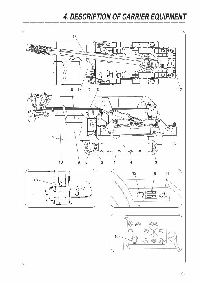
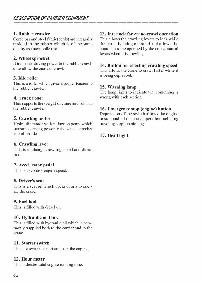
13. Interlock for crane-crawl operationThis allows the crawling levers to lock while the crane is being operated and allows the crane not to be operated by the crane control levers when it is crawling.
14. Button for selecting crawling speedThis allows the crane to crawl faster while it is being depressed.
15. Warning lampThe lamp lights to indicate that something is wrong with each section.
16. Emergency stop (engine) buttonDepression of the switch allows the engine to stop and all the crane operation including traveling stop functioning.
17. Head light
1. Rubber crawlerCored bar and steel fabric(cords) are integrally molded in the rubber which is of the same quality as automobile tire.
2. Wheel sprocketIt transmits driving power to the rubber crawl-er to allow the crane to crawl.
3. Idle rollerThis is a roller which gives a proper tension to the rubber crawler.
4. Truck rollerThis supports the weight of crane and rolls on the rubber crawler.
5. Crawling motorHydraulic motor with reduction gears which transmits driving power to the wheel sprocket is built inside.
6. Crawling leverThis is to change crawling speed and direc-tion.
7. Accelerator pedalThis is to control engine speed.
8. Driver's seatThis is a seat on which operator sits to oper-ate the crane.
9. Fuel tankThis is filled with diesel oil.
10. Hydraulic oil tankThis is filled with hydraulic oil which is com-monly supplied both to the carrier and to the crane.
11. Starter switchThis is a switch to start and stop the engine.
12. Hour meterThis indicates total engine running time.
5-1
5. DESCRIPTION OF CRANE EQUIPMENT
2615
16
17
18
19
20 2821
22
23
24
25
27
1112
26 71 9 8 1314
10 4 5
3
SELECT SET
OUTRIGGER
tNOT MAX EXT.
ì²
5-2
DESCRIPTION OF CRANE EQUIPMENT
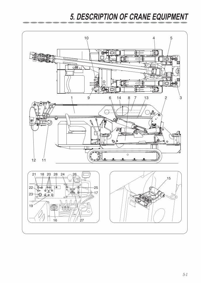
1. BoomIt extends and retracts by hydraulic cylinder and the hook is suspended from its top.
2. ColumnThis is a vertically mounted member on the crane in which boom, winch, and derrick cyl-inders are installed.The column can be turned by slewing device.
12. Overwinding alarmWhen the hook comes close to the boom top, this makes an alarm to warn that wire ropes are to be overwound.
3. FrameThis is fixed on the vehicle to support the col-umn and outriggers.
4. Hoist winchThis is a device which rotates the wire drum by hydraulic motor to hoist up and down a cargo via wire ropes.
5. Slewing deviceThis turns the column by hydraulic motor.
6. Derrick cylinderThis raises and lower the boom.
7. Telescoping cylinderThis extends and retracts sections of boom.
8. OutriggerThis supports the crane to maintain its stabil-ity while it is operated.
9. Crane operating leversRespective levers control raising and lower-ing boom, hoisting a cargo up and down, tele-scoping boom, and slewing boom.
10. Outrigger operating leversThis lever controls outriggers.The outrigger control switch (section 20) selects each movement of extension and retraction.
11. Hook
19. Outrigger vertical/horizontal selec-tor switch
This switches extension/retraction control of vertical cylinder for outriggers and of inner boxes.
13. Wire rope
16. LevelThis an instrument for checking horizontal plane of the crane body.
17. Voice switchThis switches ON and OFF the voice mes-sage.
18. Operation mode switchThis selects crane operation mode and outrig-ger operation mode.
20. Outrigger control switchThis selects extension/retraction of each out-rigger of four (4).Simultaneous extension and retraction of out-riggers can be impossible.
14. Boom angle chartThis can read the working radius value corre-sponding to extended length of the boom and its raised angle.
15. Automatic stop for leaving mini-mum wire rope (With wire rope retaining roller)
This is a devise to restrict slackening of wire rope on the drum which allows to stop unwinding automatically when remaining wire ropes on the drum come close to 3 turns.

5-3
DESCRIPTION OF CRANE EQUIPMENT
21. Hook storing switchTurning the switch to the storing position allows the hook to be stored.
23. Emergency stop (engine) switchDepression of the switch allows the engine to stop and all the crane operation including traveling stop functioning.
22. Horn switchDepression of the switch allows the alarm horn to sound.
24. Automatic stop for over-winding reset switch
When the crane cannot to be operated due to a fault in function of automatic stop for overwinding, turning the switch to reset side releases the automatic stop for overwinding device.
25. Head light switchTurning the switch ON allows the head light to light.
27. Outrigger monitor lamp (extension) When turning outriggers manually from their stored positions and set pins have fully been inserted, the lamp indicating extension of out-rigger lights.Outriggers cannot be operated unless all the four (4) pins have been inserted.
26. Boom storage monitor lamp The monitor lamp lights when the boom has been stored.Outriggers can be operated only when the monitor lamp lights.
28. Mode selector switchThis switches between radio remote control mode and manual operation mode.
6-1
6. NAME PLATES
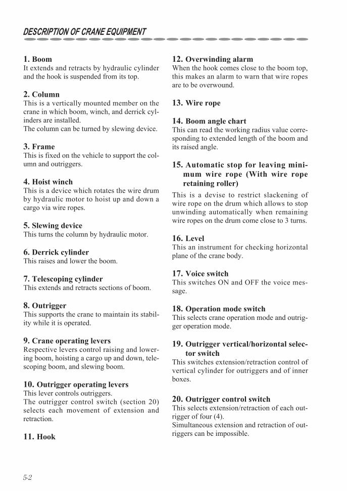
Description of name plates (Stickers) 1The machine is provided with stickers indicating caution (framed in box ) and specifications as shown in the figure below, and in addition to that there are stickers showing control levers, switches, and instructions for lubrication.
Caution, Crawling
Selector, Crawling/Crane
Caution, Storing hook
OR selector valve
Outrigger buzzer
Caution, High temperature
Caution, Watch-your-foot
Boom storage
Caution
Working radius
Hydraulic oil
Caution ,Battery
Emergency operationCaution,Outrigger operation
Chart of net rated load
Outrigger mode
Mass of crane body
Lifting up positionof crane body
Diesel fuel
Preparing crane operationand Storing hook
Load indicator
Loading and unloading procedures
Caution,Mode indicator lampCaution,Slewing boom
Caution,Radio controlled operation
Caution,High temperatureTable,Weight of disassembled parts
Caution,Oil leave check
6-2
NAME PLATES
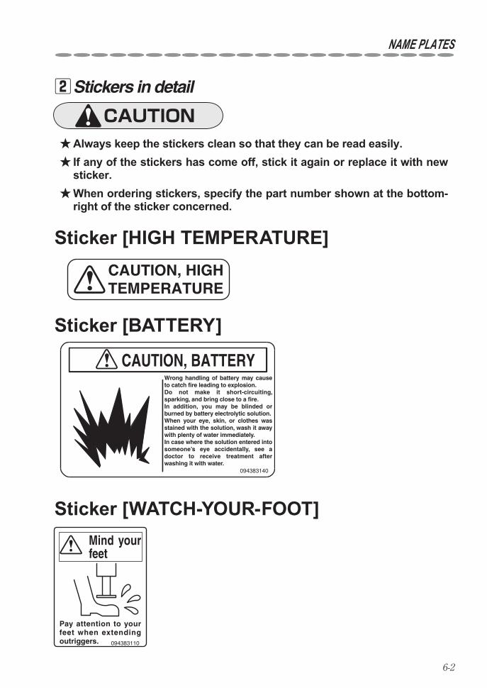
Stickers in detail 2
Always keep the stickers clean so that they can be read easily. ★ If any of the stickers has come off, stick it again or replace it with new ★sticker. When ordering stickers, specify the part number shown at the bottom- ★right of the sticker concerned.
Sticker [BATTERY]
CAUTION, HIGH TEMPERATURE
094383140
CAUTION, BATTERYWrong handling of battery may cause to catch fire leading to explosion.Do not make it short-circuiting, sparking, and bring close to a fire. In addition, you may be blinded or burned by battery electrolytic solution.When your eye, skin, or clothes was stained with the solution, wash it away with plenty of water immediately.In case where the solution entered into someone’s eye accidentally, see a doctor to receive treatment after washing it with water.
Sticker [WATCH-YOUR-FOOT]Mind your feet
Pay attention to your feet when extending outriggers. 094383110
Sticker [HIGH TEMPERATURE]
6-3
NAME PLATES
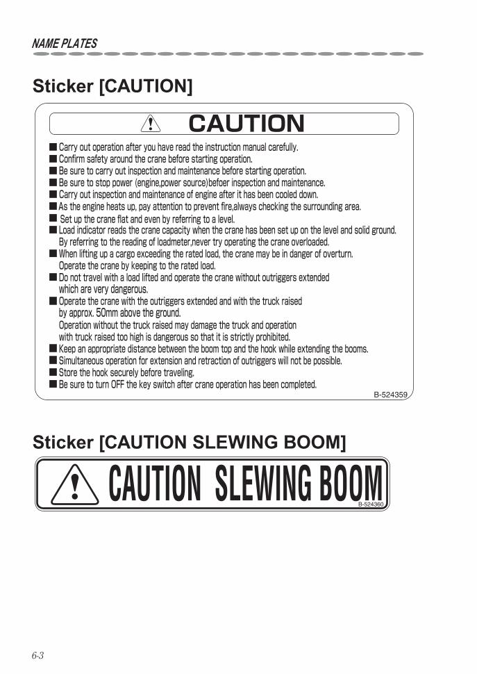
Sticker [CAUTION SLEWING BOOM]
CAUTION SLEWING BOOMB-524360
Sticker [CAUTION]
Operate the crane with the outriggers extended and with the truck raised by approx. 50mm above the ground.
By referring to the reading of loadmeter,never try operating the crane overloaded.
Operate the crane by keeping to the rated load.
which are very dangerous.
Operation without the truck raised may damage the truck and operation with truck raised too high is dangerous so that it is strictly prohibited.
CAUTION
Be sure to turn OFF the key switch after crane operation has been completed.Store the hook securely before traveling.Simultaneous operation for extension and retraction of outriggers will not be possible.Keep an appropriate distance between the boom top and the hook while extending the booms.
Do not travel with a load lifted and operate the crane without outriggers extended
When lifting up a cargo exceeding the rated load, the crane may be in danger of overturn.
Load indicator reads the crane capacity when the crane has been set up on the level and solid ground.Set up the crane flat and even by referring to a level.As the engine heats up, pay attention to prevent fire,always checking the surrounding area.Carry out inspection and maintenance of engine after it has been cooled down.Be sure to stop power (engine,power source)befoer inspection and maintenance.Be sure to carry out inspection and maintenance before starting operation.Confirm safety around the crane before starting operation.Carry out operation after you have read the instruction manual carefully.
B-524359
6-4
NAME PLATES
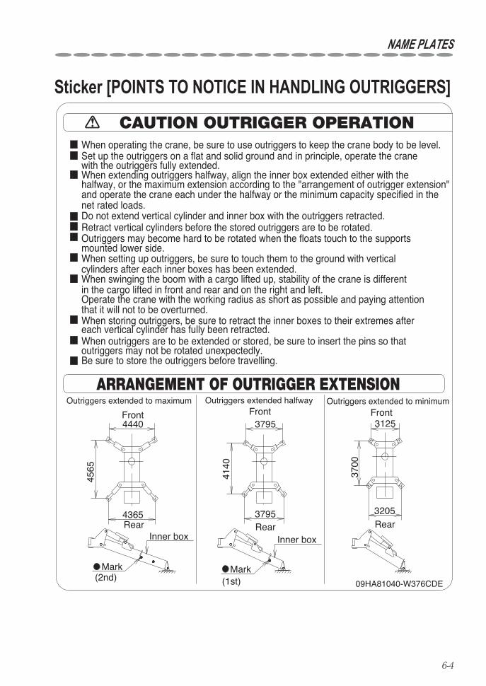
Sticker [POINTS TO NOTICE IN HANDLING OUTRIGGERS]
6-5
NAME PLATES
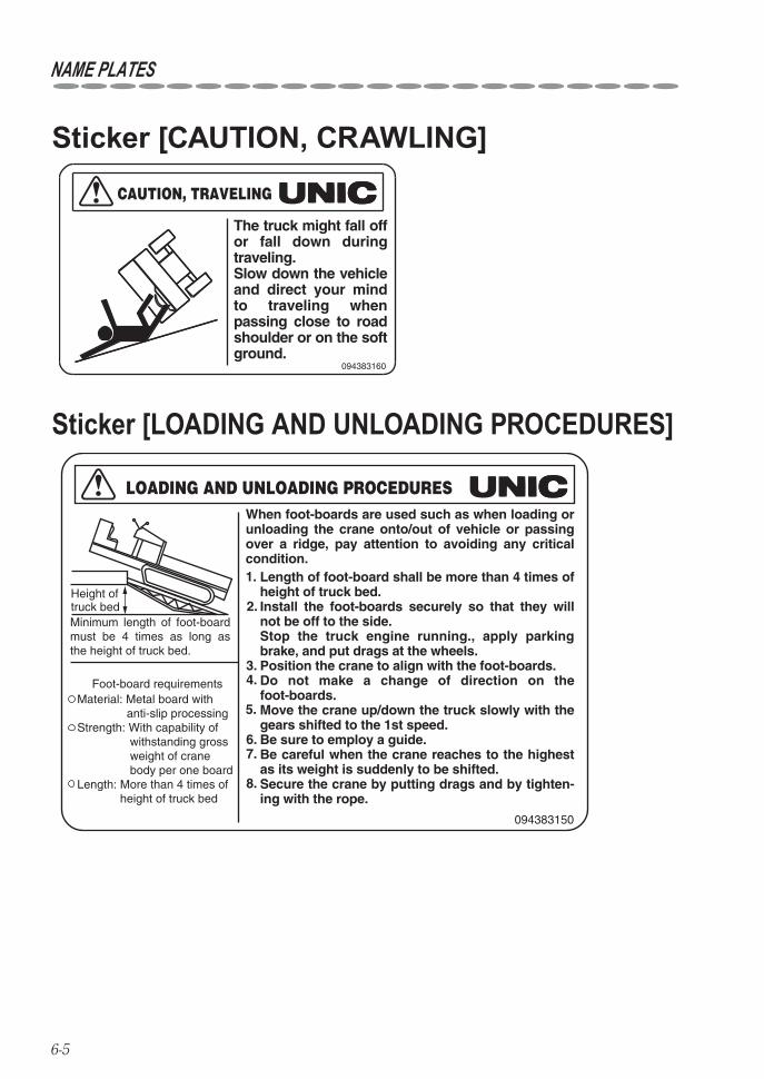
Sticker [CAUTION, CRAWLING]
094383160
CAUTION, TRAVELING
The truck might fall off or fall down during traveling.Slow down the vehicle and direct your mind to traveling when passing close to road shoulder or on the soft ground.
Sticker [LOADING AND UNLOADING PROCEDURES]
Material: Metal board with anti-slip processingStrength: With capability of withstanding gross weight of crane body per one boardLength: More than 4 times of height of truck bed
094383150
LOADING AND UNLOADING PROCEDURES
Height of truck bedMinimum length of foot-board must be 4 times as long as the height of truck bed.
Foot-board requirements
When foot-boards are used such as when loading or unloading the crane onto/out of vehicle or passing over a ridge, pay attention to avoiding any critical condition.
Length of foot-board shall be more than 4 times of height of truck bed.Install the foot-boards securely so that they will not be off to the side.Stop the truck engine running., apply parking brake, and put drags at the wheels.Position the crane to align with the foot-boards.Do not make a change of direction on the foot-boards.Move the crane up/down the truck slowly with the gears shifted to the 1st speed.Be sure to employ a guide.Be careful when the crane reaches to the highest as its weight is suddenly to be shifted.Secure the crane by putting drags and by tighten-ing with the rope.
1.
2.
3. 4.
5.
6. 7.
8.

6-6
NAME PLATES
Sticker [CHART OF NET RATED LOAD]
MODE INDICATOR LAMP
POSSIBLE OPERATION
Flashing of the mode indicator shows abnormality of operation or the equipment. Follow instructions of the instruction manual.
The mode selection switch opposite to the mode indicator lamp allows selection of ON and OFF of radio-controlled operation.
09HA81110-W376CDE
TRAVEL MODE
CAUTION
The above table shows the main mode indication. For details, see the instructions.Mode indicator lamp is on the left side of the outrigger mode lamp.
CRANE MODE
INDICATOR OPERATION MODE(LIT) (STATUS)
OVERWINDING
RADIO CONTROL
STORAGE OF HOOKCANCELLATION OF AUTO-STOP
MODE INDICATOR
MANUAL
AUTOMATIC STOP
When mode indicator lamp is ON, radio-controlled operation can be performed.When mode indicator lamp is OFF, manual operation can be performed.
LEAVING MINIMUM WIRE ROPE
OFFON
RADIO CONTROLMANUALOFF
ONOUTRIGGER MODE
Mode indicator is on the left side of the sticker.
Sticker [MODE INDICATOR LAMP]
WORKING RADIUS(m)
WORKING RADIUS(m)
3.03.03.0
CAUTION
WORKING RADIUS(m)
WORKING RADIUS(m)
WORKING RADIUS(m)
2.0 2.5
300381010-W376C1AR
3.0
3.0 3.52.35
4.0
2.171.951.5
1.671.12
4.5 5.0 5.69
2.7 3.0
1.450.9
1.30.72
1.070.47
10.071.041.03
3.5
0.930.82
0.840.64
0.730.47
0.620.31
0.520.22
0.470.13
4.0
0.380.09
2.242.24
2.09
OUTRIGGERSMAX EXTOUTRIGGERSNOT MAX EXT
OUTRIGGERSMAX EXTOUTRIGGERSNOT MAX EXT
OUTRIGGERSMAX EXTOUTRIGGERSNOT MAX EXT
OUTRIGGERSMAX EXTOUTRIGGERSNOT MAX EXT
OUTRIGGERSMAX EXTOUTRIGGERSNOT MAX EXT
2.06
4.5 5.01.651.57
1.45.5 6.0 7.0 7.88
4.0 4.5 5.0 6.0 7.0 8.0 9.0
4.5 5.0 6.0 7.0 8.0 9.0 10.0 11.0 12.26
4.9 5.5 6.0 7.0 8.0 9.0 10.0 11.0 12.0 13.0
1.221.221.02
1.070.83
0.950.65
0.840.51
0.690.3
0.590.19
0.750.75
0.620.62
0.480.4
0.390.25
0.230.01
0.240.06
0.270.09
0.30.13
0.340.18
0.10.01
0.110.02
0.130.03
0.140.05
0.160.08
0.180.11
0.20.17
0.220.22
0.250.25
0.270.27
0.30.3
14.45
NET RATED LOADS Net rated loads is the lifting capacitiesexcept for the mass of the hook.
NET RATEDLOAD(t)
NET RATEDLOAD(t)
NET RATEDLOAD(t)
NET RATEDLOAD(t)
NET RATEDLOAD(t)
NET RATED LOADS
1+2+3+4+5+6
1+2+3+4+5
1+2+3+4
1+2+3
1+21
1+2+3+4+5
1+2+3+4
1+2+3
BOOM SECTION
BOOM SECTION
BOOM SECTION
BOOM SECTION
BOOM SECTION
Boom means that the boom is extended to the position where the 3rdmark on the 3rd boom-section is visible.
Boom means that the boom is extended to the position where the 2ndmark on the 3rd boom-section is visible.
Boom means that the boom is extended to the position where the 1stmark on the 3rd boom-section is visible.
When each of boom sections being extended is exceeded even slightly, operate itby application of the capacity for the next boom section.
When each of 4 outriggers has been set to different extension,operate the crane byusing the worst extended capacity.
"Outriggers not max ext" means the state that the inner box is extended to the
"Outriggers max ext" means the state that the inner box is extended to the position
an actual working radius including boom deflection under loaded. The net ratedThe net rated load is performance when the crane is placed level and is based on
position where the 2nd mark is invisible.
where the 2nd mark is visible.
load is also based on strength and stability of the crane.
6-7
NAME PLATES
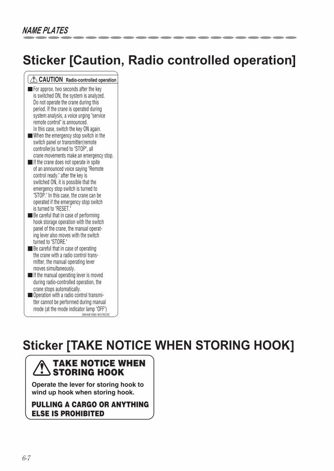
TAKE NOTICE WHEN STORING HOOK
PULLING A CARGO OR ANYTHING ELSE IS PROHIBITED
Operate the lever for storing hook to wind up hook when storing hook.
Sticker [TAKE NOTICE WHEN STORING HOOK]
For approx. two seconds after the key is switched ON, the system is analyzed. Do not operate the crane during this period. If the crane is operated during system analysis, a voice urging "serviceremote control" is announced. In this case, switch the key ON again.
If the manual operating lever is moved during radio-controlled operation, the crane stops automatically.
When the emergency stop switch in the switch panel or transmitter(remote controller)is turned to "STOP", all crane movements make an emergency stop.
Operation with a radio control transmi-tter cannot be performed during manual mode (at the mode indicator lamp "OFF")
If the crane does not operate in spite of an announced voice saying "Remote control ready." after the key is switched ON, it is possible that the emergency stop switch is turned to "STOP." In this case, the crane can be operated if the emergency stop switch is turned to "RESET."Be careful that in case of performing hook storage operation with the switch panel of the crane, the manual operat-ing lever also moves with the switch turned to "STORE."Be careful that in case of operating the crane with a radio control trans-mitter, the manual operating lever moves simultaneously.
09HA81090-W376CDE
CAUTION Radio-controlled operation
Sticker [Caution, Radio controlled operation]
7-1
7. DEFINITION OF TERMS
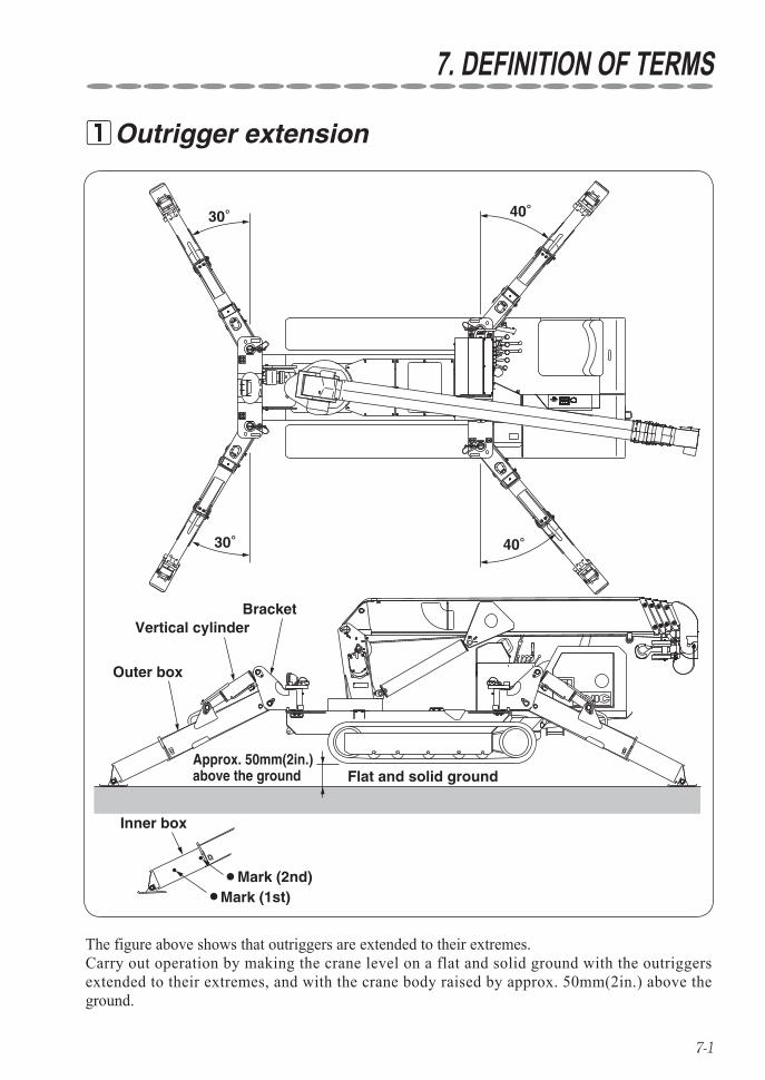
Outrigger extension 1
30°
30°
40°
40°
●
●
Outer box
Vertical cylinderBracket
Approx. 50mm(2in.) above the ground Flat and solid ground
Inner box
Mark (1st)Mark (2nd)
The figure above shows that outriggers are extended to their extremes.Carry out operation by making the crane level on a flat and solid ground with the outriggers extended to their extremes, and with the crane body raised by approx. 50mm(2in.) above the ground.

7-2
DEFINITION OF TERMS
Since the rated load varies according to how the outriggers are extended, the rated load ◆has been set for respective extended conditions. Figure below shows the cases where the outriggers are extended to "maximum", "halfway", and "minimum".
●
4440mm
4565
mm
4365mm
(14.6ft)
(14.3ft)
(15.
0ft)
(13.
6ft)
(12.
1ft)
3795mm
(12.5ft)
(12.5ft)
3795mm
4140
mm
3125mm(10.3ft)
(10.5ft)37
00m
m
3205mm
Outriggers extended to maximumFront
Rear
Mark(2nd)
Rear
Front
Rear
Front
●Mark(1st)
Outriggers not extended to maximum
'Outriggers extended to maximum' means that the inner box is extended to a position where the 2nd mark is visible. 'Outriggers not extended to maximum' means that the inner box is extended to a position where the 2nd mark is invisible. When each of 4(four) outriggers is set to different extension, operate the crane by using the worst extended capacity.
URW376C1A,URW376C1U. 1
7-3
DEFINITION OF TERMS
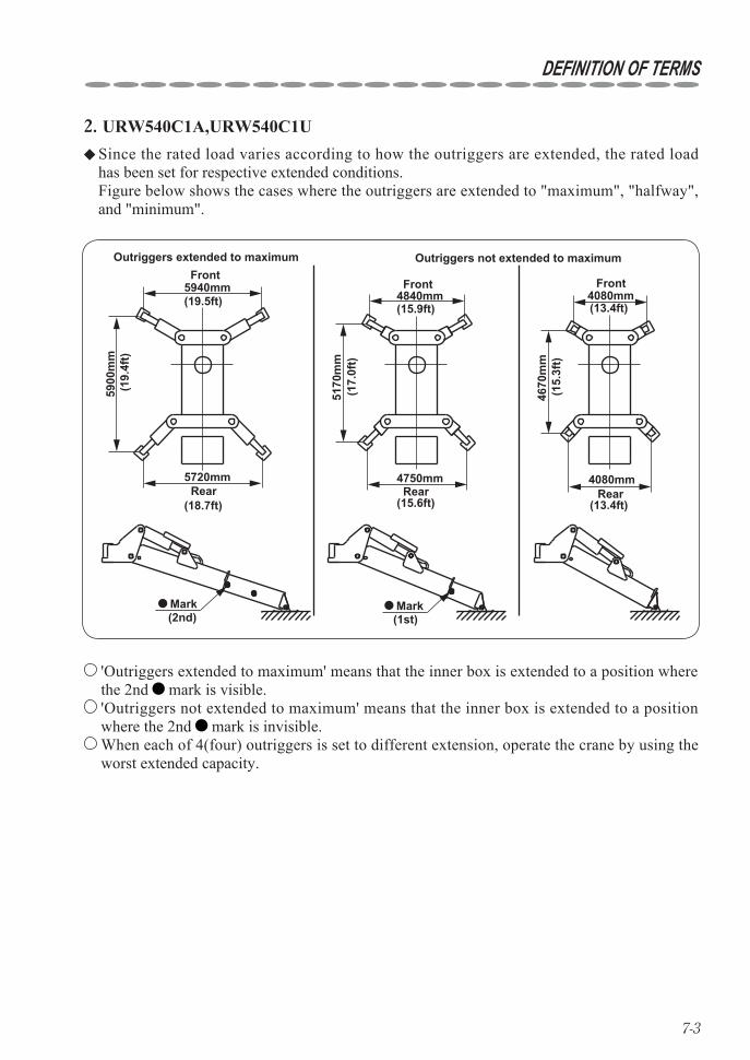
Since the rated load varies according to how the outriggers are extended, the rated load ◆has been set for respective extended conditions. Figure below shows the cases where the outriggers are extended to "maximum", "halfway", and "minimum".
●
5940mm
5900
mm
5720mm
(19.5ft)
(18.7ft)
(19.
4ft)
(17.
0ft)
(15.
3ft)
4840mm
(15.6ft)
(15.9ft)
4750mm
5170
mm
4080mm(13.4ft)
(13.4ft)
4670
mm
4080mm
Outriggers extended to maximumFront
Rear
Mark(2nd)
Rear
Front
Rear
Front
●Mark(1st)
Outriggers not extended to maximum
'Outriggers extended to maximum' means that the inner box is extended to a position where the 2nd mark is visible. 'Outriggers not extended to maximum' means that the inner box is extended to a position where the 2nd mark is invisible. When each of 4(four) outriggers is set to different extension, operate the crane by using the worst extended capacity.
URW540C1A,URW540C1U. 2
7-4
DEFINITION OF TERMS
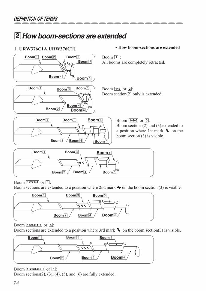
How boom-sections are extended 2URW376C1A,URW376C1U. 1
Boom6
Boom1 Boom3
Boom4Boom2
Boom5
How boom-sections are extended•
Boom6Boom1 Boom3
Boom4Boom2 Boom5
Boom 1+2+3+4 or 4 :Boom sections are extended to a position where 2nd mark on the boom section (3) is visible.
Boom6Boom1 Boom3
Boom4Boom2 Boom5
Boom 1+2+3 or 3 :Boom sections(2) and (3) extended to a position where 1st mark on the boom section (3) is visible.
Boom6
Boom1 Boom3
Boom4Boom2
Boom5 Boom 1+2 or 2 :Boom section(2) only is extended.
Boom6
Boom1 Boom3
Boom4
Boom2Boom5
Boom 1 :All booms are completely retracted.
Boom6
Boom1 Boom3
Boom4Boom2
Boom5
Boom 1+2+3+4+5 or 5 :Boom sections are extended to a position where 3rd mark on the boom section(3) is visible.
Boom 1+2+3+4+5+6 or 6 :Boom sections(2), (3), (4), (5), and (6) are fully extended.
7-5
DEFINITION OF TERMS
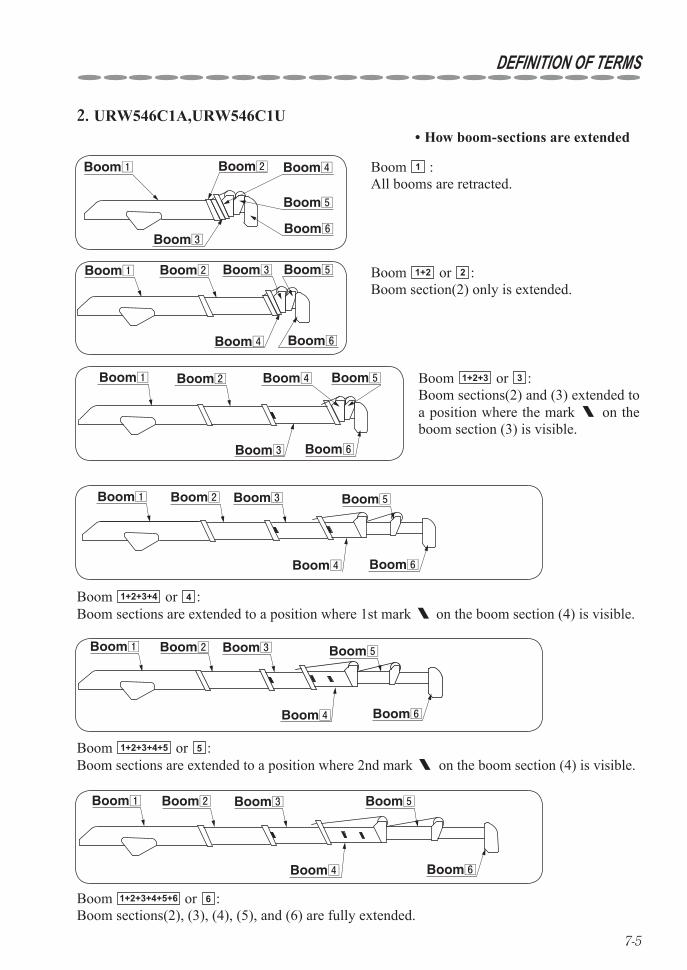
Boom 1 :All booms are retracted.
Boom1 Boom2
Boom3
Boom4
Boom5
Boom6
Boom 1+2 or 2 :Boom section(2) only is extended.
Boom1 Boom2 Boom3
Boom4
Boom5
Boom6
Boom 1+2+3+4 or 4 :Boom sections are extended to a position where 1st mark on the boom section (4) is visible.
Boom1 Boom2 Boom3
Boom4
Boom5
Boom6
Boom 1+2+3+4+5 or 5 :Boom sections are extended to a position where 2nd mark on the boom section (4) is visible.
Boom1 Boom2 Boom3
Boom4
Boom5
Boom6
Boom1 Boom2 Boom3
Boom4
Boom5
Boom6
Boom 1+2+3+4+5+6 or 6 :Boom sections(2), (3), (4), (5), and (6) are fully extended.
URW546C1A,URW546C1U. 2How boom-sections are extended•
Boom1 Boom2
Boom3
Boom4 Boom5
Boom6
Boom 1+2+3 or 3 :Boom sections(2) and (3) extended to a position where the mark on the boom section (3) is visible.
7-6
DEFINITION OF TERMS
7.70mBoom(25ft)
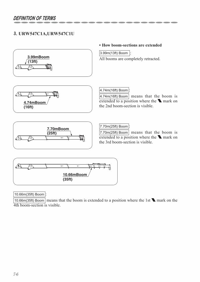
7.70m(25ft) Boom :7.70m(25ft) Boom means that the boom is extended to a position where the mark on the 3rd boom-section is visible.
10.66mBoom(35ft)
10.66m(35ft) Boom :10.66m(35ft) Boom means that the boom is extended to a position where the 1st mark on the 4th boom-section is visible.
4.74mBoom(16ft)
4.74m(16ft) Boom :4.74m(16ft) Boom means that the boom is extended to a position where the mark on the 2nd boom-section is visible.
3.99mBoom(13ft)
3.99m(13ft) Boom :All booms are completely retracted.
How boom-sections are extended•
URW547C1A,URW547C1U. 3
7-7
DEFINITION OF TERMS
13.57mBoom(45ft)
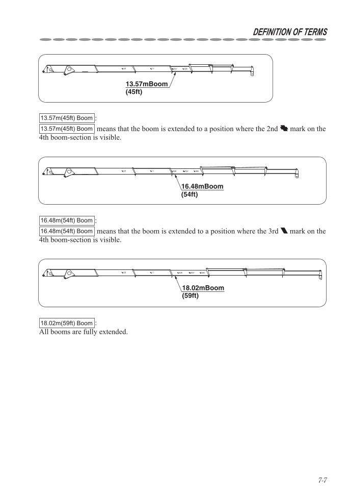
13.57m(45ft) Boom :13.57m(45ft) Boom means that the boom is extended to a position where the 2nd mark on the 4th boom-section is visible.
16.48mBoom(54ft)
16.48m(54ft) Boom :16.48m(54ft) Boom means that the boom is extended to a position where the 3rd mark on the 4th boom-section is visible.
18.02mBoom(59ft)
18.02m(59ft) Boom :All booms are fully extended.
7-8
DEFINITION OF TERMS
Net rated load Rated load
Weight of hooking implements such as hookL
ift
abo
ve g
rou
nd
Working radius
Boom angle
Boom
leng
th
Sheave pin
Boom foot pin
Slewing center
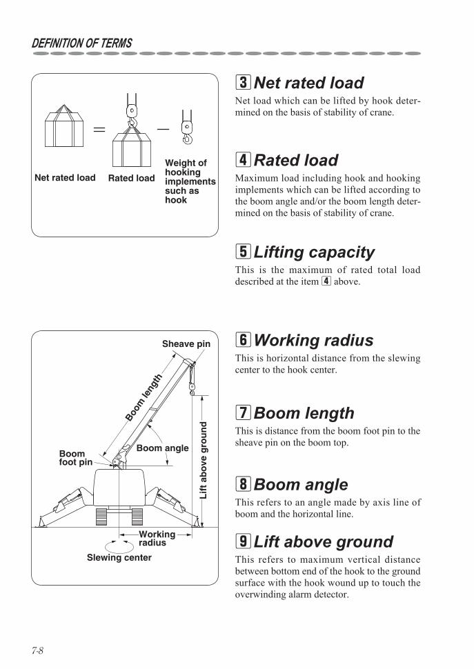
Net rated load 3
Rated load 4
Lifting capacity 5
Working radius 6
Boom length 7
Boom angle 8
Lift above ground 9
Net load which can be lifted by hook deter-mined on the basis of stability of crane.
Maximum load including hook and hooking implements which can be lifted according to the boom angle and/or the boom length deter-mined on the basis of stability of crane.
This is the maximum of rated total load described at the item 4 above.
This is horizontal distance from the slewing center to the hook center.
This is distance from the boom foot pin to the sheave pin on the boom top.
This refers to an angle made by axis line of boom and the horizontal line.
This refers to maximum vertical distance between bottom end of the hook to the ground surface with the hook wound up to touch the overwinding alarm detector.
8-1
8. HOW TO REFER TO WORKING RANGE CHART AND RATED LOAD CHART
Working range chart 1
Boo
m le
ngth
A
B
Working radius
Boom angle
Lift above ground (H)
Working radius with a cargo hoisted
Working radius before hoisting cargo
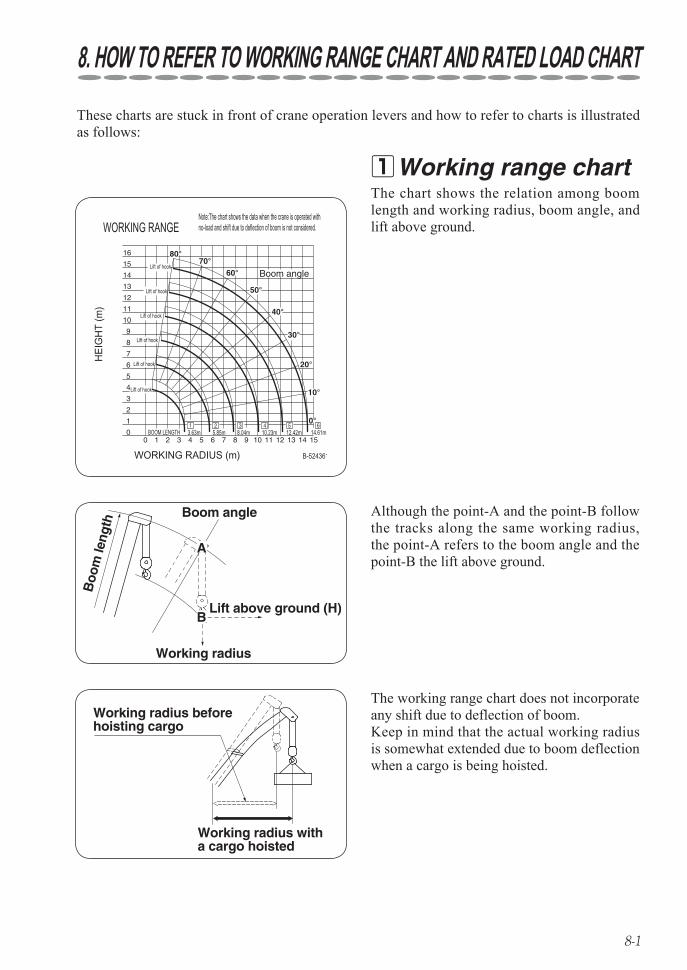
These charts are stuck in front of crane operation levers and how to refer to charts is illustrated as follows:
Although the point-A and the point-B follow the tracks along the same working radius, the point-A refers to the boom angle and the point-B the lift above ground.
The working range chart does not incorporate any shift due to deflection of boom.Keep in mind that the actual working radius is somewhat extended due to boom deflection when a cargo is being hoisted.
The chart shows the relation among boom length and working radius, boom angle, and lift above ground.
8-2
HOW TO REFER TO WORKING RANGE CHART AND RATED LOAD CHART
Net rated load chart 2
1+2+3+4+5+6
1+2+3+4+5
1+2+3+4
1+2+3
1+21WORKING RADIUS(m)
WORKING RADIUS(m)
3.03.03.0
WORKING RADIUS(m)
WORKING RADIUS(m)
WORKING RADIUS(m)
2.0 2.5
3.0
3.0 3.52.35
4.0
2.171.951.5
1.671.12
4.5 5.0 5.69
2.7 3.0
1.450.9
1.30.72
1.070.47
10.071.041.03
3.5
0.930.82
0.840.64
0.730.47
0.620.31
0.520.22
0.470.13
4.0
0.380.09
2.242.24
2.09
OUTRIGGERSMAX EXTOUTRIGGERSNOT MAX EXT
OUTRIGGERSMAX EXTOUTRIGGERSNOT MAX EXT
OUTRIGGERSMAX EXTOUTRIGGERSNOT MAX EXT
OUTRIGGERSMAX EXTOUTRIGGERS
URW376C1A
NOT MAX EXT
OUTRIGGERSMAX EXTOUTRIGGERSNOT MAX EXT
2.06
4.5 5.01.651.57
1.45.5 6.0 7.0 7.88
4.0 4.5 5.0 6.0 7.0 8.0 9.0
4.5 5.0 6.0 7.0 8.0 9.0 10.0 11.0 12.26
4.9 5.5 6.0 7.0 8.0 9.0 10.0 11.0 12.0 13.0
1.221.221.02
1.070.83
0.950.65
0.840.51
0.690.3
0.590.19
0.750.75
0.620.62
0.480.4
0.390.25
0.230.01
0.240.06
0.270.09
0.30.13
0.340.18
0.10.01
0.110.02
0.130.03
0.140.05
0.160.08
0.180.11
0.20.17
0.220.22
0.250.25
0.270.27
0.30.3
14.45
Net rated loads chart
NET RATEDLOAD(t)
NET RATEDLOAD(t)
NET RATEDLOAD(t)
NET RATEDLOAD(t)
NET RATEDLOAD(t)
BOOM SECTION
BOOM SECTION
BOOM SECTION
BOOM SECTION
BOOM SECTION
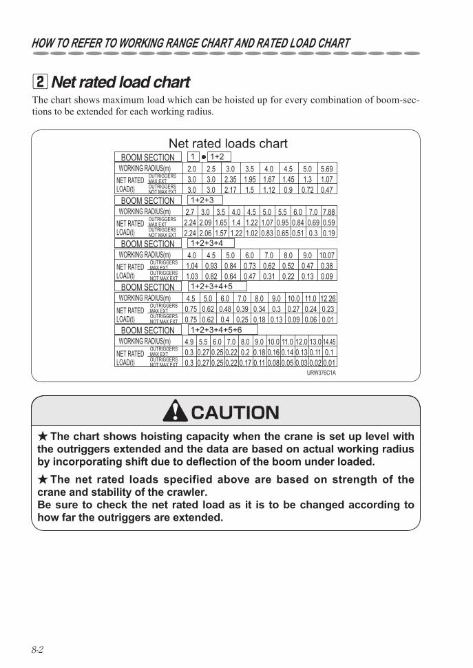
The chart shows maximum load which can be hoisted up for every combination of boom-sec-tions to be extended for each working radius.
The chart shows hoisting capacity when the crane is set up level with ★the outriggers extended and the data are based on actual working radius by incorporating shift due to deflection of the boom under loaded.
The net rated loads specified above are based on strength of the ★crane and stability of the crawler. Be sure to check the net rated load as it is to be changed according to how far the outriggers are extended.
CAUTION
9-1
9. DESCRIPTION OF EACH CONTROL DEVICE
Overwinding alarm 1
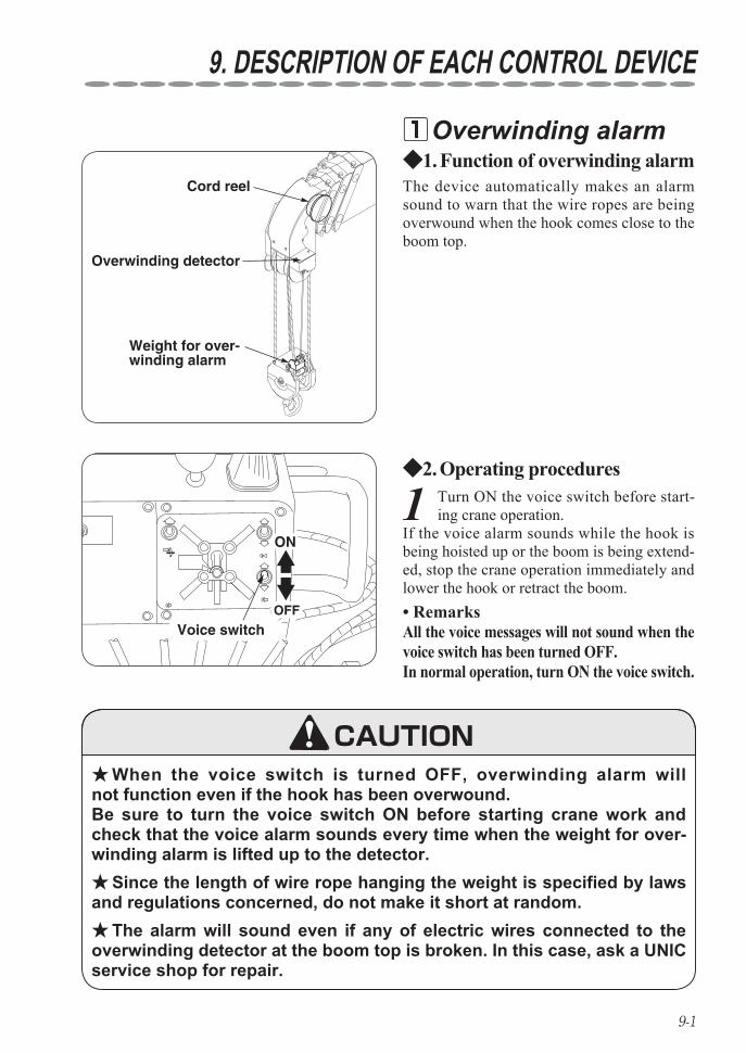
1 Turn ON the voice switch before start-ing crane operation.
If the voice alarm sounds while the hook is being hoisted up or the boom is being extend-ed, stop the crane operation immediately and lower the hook or retract the boom.
Operating procedures2. ◆
When the voice switch is turned OFF, overwinding alarm will ★not function even if the hook has been overwound. Be sure to turn the voice switch ON before starting crane work and check that the voice alarm sounds every time when the weight for over-winding alarm is lifted up to the detector.
Since the length of wire rope hanging the weight is specified by laws ★and regulations concerned, do not make it short at random.
The alarm will sound even if any of electric wires connected to the ★overwinding detector at the boom top is broken. In this case, ask a UNIC service shop for repair.
OFF
ON
Voice switch
Cord reel
Overwinding detector
Weight for over-winding alarm
Function of overwinding alarm1. ◆The device automatically makes an alarm sound to warn that the wire ropes are being overwound when the hook comes close to the boom top.
Remarks • All the voice messages will not sound when the voice switch has been turned OFF. In normal operation, turn ON the voice switch.
CAUTION
9-2
DESCRIPTION OF EACH CONTROL DEVICE
Automatic stop for 2 overwinding
Function of automatic stop for 1. ◆overwinding
Stop(extending) Restore
(retraction)
Stop (raising)
Restore (lowering)
Restore(unwinding)
Stop (winding-up)
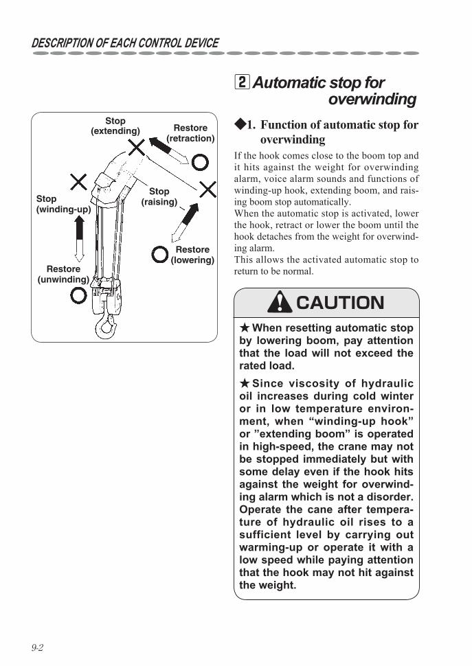
When resetting automatic stop ★by lowering boom, pay attention that the load will not exceed the rated load.
Since viscosity of hydraulic ★oil increases during cold winter or in low temperature environ-ment, when “winding-up hook” or ”extending boom” is operated in high-speed, the crane may not be stopped immediately but with some delay even if the hook hits against the weight for overwind-ing alarm which is not a disorder.Operate the cane after tempera-ture of hydraulic oil rises to a sufficient level by carrying out warming-up or operate it with a low speed while paying attention that the hook may not hit against the weight.
If the hook comes close to the boom top and it hits against the weight for overwinding alarm, voice alarm sounds and functions of winding-up hook, extending boom, and rais-ing boom stop automatically.When the automatic stop is activated, lower the hook, retract or lower the boom until the hook detaches from the weight for overwind-ing alarm.This allows the activated automatic stop to return to be normal.
CAUTION
9-3
DESCRIPTION OF EACH CONTROL DEVICE
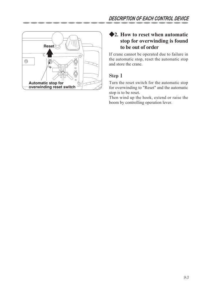
How to reset when automatic 2. ◆stop for overwinding is found to be out of order
Automatic stop for overwinding reset switch
Reset
If crane cannot be operated due to failure in the automatic stop, reset the automatic stop and store the crane.
Step 1Turn the reset switch for the automatic stop for overwinding to "Reset" and the automatic stop is to be reset.Then wind up the hook, extend or raise the boom by controlling operation lever.
9-4
DESCRIPTION OF EACH CONTROL DEVICE
(Side of boom)
PointerScale
CRANE STRENGTH AND STABILITYNET RATED LOADS(t)
URW376C1A
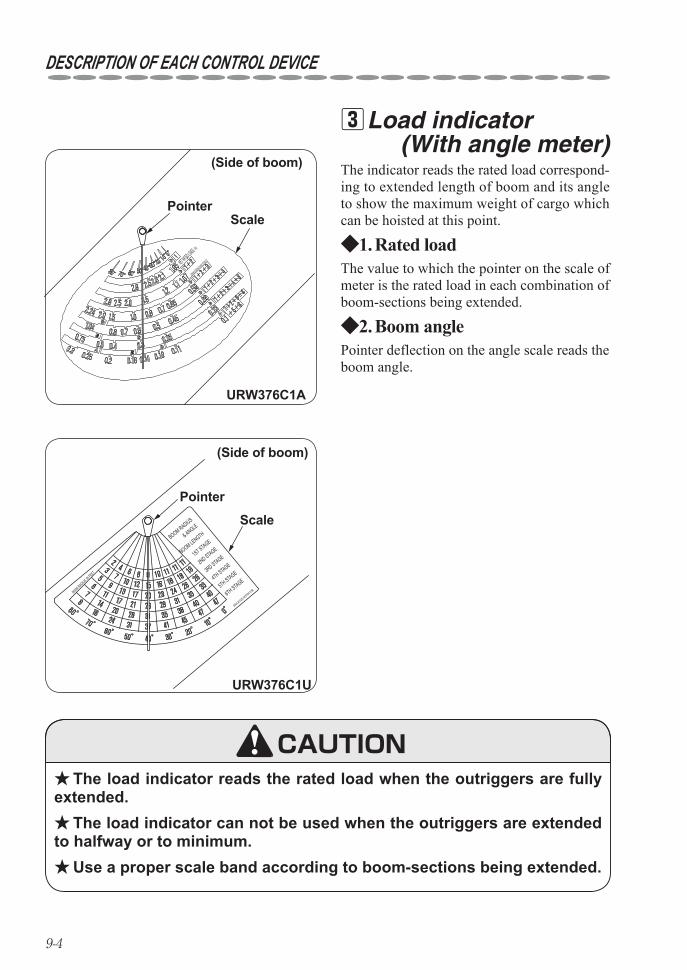
Load indicator 3 (With angle meter)
The load indicator reads the rated load when the outriggers are fully ★extended.
The load indicator can not be used when the outriggers are extended ★to halfway or to minimum.
Use a proper scale band according to boom-sections being extended. ★
The indicator reads the rated load correspond-ing to extended length of boom and its angle to show the maximum weight of cargo which can be hoisted at this point.
Rated load1. ◆The value to which the pointer on the scale of meter is the rated load in each combination of boom-sections being extended.
Pointer deflection on the angle scale reads the boom angle.
Boom angle2. ◆
CAUTION
(Side of boom)
Pointer
Scale
URW376C1U
09VL81020-W376C1URB00M RADIUS IN
FEET
6TH STAGE5TH STAGE
4TH STAGE3RD STAGE
2ND STAGE1ST STAGE
& ANGLE
BOOM RADIUS
BOOM LENGTH
9-5
DESCRIPTION OF EACH CONTROL DEVICE
CRANE STRENGTH AND STABILITY
NET RATED LOADS(t)
(a)(b)
(c)(d)
(e)(f) (g)
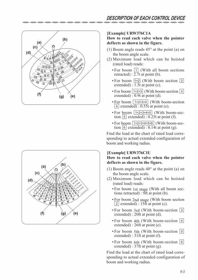
[Example] URW376C1AHow to read each valve when the pointer deflects as shown in the figure.(1) Boom angle reads 45° at the point (a) on
the boom angle scale.(2) Maximum load which can be hoisted
(rated load) reads: • For boom 1 (With all boom sections retracted) : 2.7t at point (b). For boom • 1+2 (With boom section 2 extended) : 1.5t at point (c). For boom • 1+2+3 (With boom-section 3 extended) : 0.9t at point (d). For boom • 1+2+3+4 (With boom-section 4 extended) : 0.55t at point (e).
For boom • 1+2+3+4+5 (With boom-sec-tion 5 extended) : 0.25t at point (f). For boom • 1+2+3+4+5+6 (With boom-sec-tion 6 extended) : 0.14t at point (g).
Find the load at the chart of rated load corre-sponding to actual extended configuration of boom and working radius.
(a) (b)
(c)
(d)
(e)(f) (g)
09VL81020-W376C1URB00M RADIUS IN
FEET
6TH STAGE5TH STAGE
4TH STAGE3RD STAGE
2ND STAGE1ST STAGE
& ANGLE
BOOM RADIUS
BOOM LENGTH
[Example] URW376C1UHow to read each valve when the pointer deflects as shown in the figure.(1) Boom angle reads 40° at the point (a) on
the boom angle scale.(2) Maximum load which can be hoisted
(rated load) reads: • For boom 1st stage (With all boom sec-tions retracted) : 9ft at point (b). For boom • 2nd stage (With boom section 2 extended) : 15ft at point (c).
For boom • 3rd (With boom-section 3 extended) : 20ft at point (d). For boom • 4th (With boom-section 4 extended) : 26ft at point (e). For boom • 5th (With boom-section 5 extended) : 31ft at point (f). For boom • 6th (With boom-section 6 extended) : 37ft at point (g).
Find the load at the chart of rated load corre-sponding to actual extended configuration of boom and working radius.
9-6
DESCRIPTION OF EACH CONTROL DEVICE
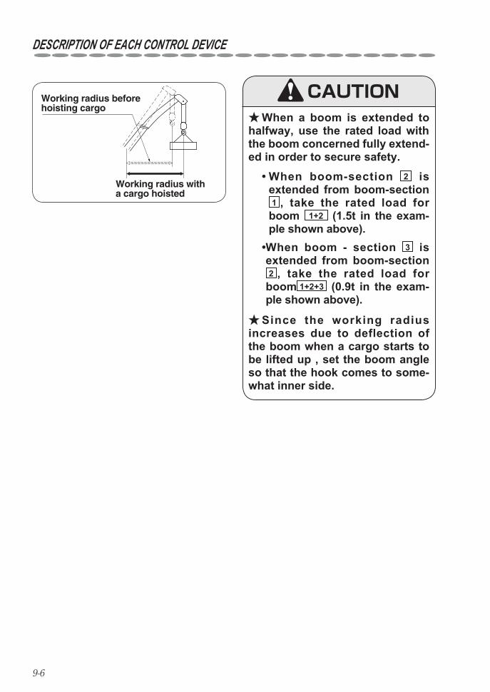
Working radius with a cargo hoisted
Working radius before hoisting cargo
When a boom is extended to ★halfway, use the rated load with the boom concerned fully extend-ed in order to secure safety.
CAUTION
Since the working radius ★increases due to deflection of the boom when a cargo starts to be lifted up , set the boom angle so that the hook comes to some-what inner side.
• When boom-section 2 is extended from boom-section 1 , take the rated load for boom 1+2 (1.5t in the exam-ple shown above).
• When boom - section 3 is extended from boom-section 2 , take the rated load for boom 1+2+3 (0.9t in the exam-ple shown above).
9-7
DESCRIPTION OF EACH CONTROL DEVICE
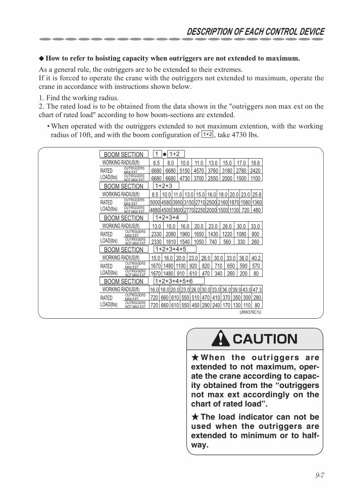
How to refer to hoisting capacity when outriggers are not extended to maximum. ◆
OUTRIGGERSMAX EXTOUTRIGGERSNOT MAX EXT
OUTRIGGERSMAX EXTOUTRIGGERSNOT MAX EXT
OUTRIGGERSMAX EXTOUTRIGGERSNOT MAX EXT
OUTRIGGERSMAX EXTOUTRIGGERSNOT MAX EXT
OUTRIGGERSMAX EXTOUTRIGGERSNOT MAX EXT
WORKING RADIUS(ft)
WORKING RADIUS(ft)
WORKING RADIUS(ft)
WORKING RADIUS(ft)
WORKING RADIUS(ft)
RATEDLOAD(lbs)
RATEDLOAD(lbs)
RATEDLOAD(lbs)
RATEDLOAD(lbs)
RATEDLOAD(lbs)
BOOM SECTION
BOOM SECTION
BOOM SECTION
BOOM SECTION
BOOM SECTION 1+2+3+4+5+6
1+2+3+4+5
1+2+3+4
1+2+3
1+21
66806680
4880
18.6
25.8
4500 3800 2770 2250 2000 1500 1130 720 480
33.0
40.2
47.3
6.5 8.0 10.0 11.0 13.0 15.0 17.06680 5150 4570 3760 3180 2780 24206680 4730 3700 2550 2000 1500 1100
8.5 10.0 11.0 13.0 15.0 16.0 18.0 20.0 23.05000 4580 3950 3150 2710 2500 2160 1870 1580 1360
15.0 16.0 20.0 23.0 26.0 30.023302330
2080 1960 1650 1430 1220 1080 9001810 1540 1050 740 560 330 260
15.0 16.0 20.0 23.0 26.01670 1480 1100 920 820 710 650 590 5701670 1480 910 610 470 340 260 200 80
16.0 18.0 20.0 23.0 26.0 30.0 33.0 36.0 39.0 43.0720 660 610 550 510 470 410 370 350 300 280720 660 610 550 450 290 240 170 130 110 80
30.0 33.0 36.0
13.0
URW376C1U
When operated with the outriggers extended to not maximum extention, with the working • radius of 10ft, and with the boom configuration of 1+2 , take 4730 lbs.
As a general rule, the outriggers are to be extended to their extremes.If it is forced to operate the crane with the outriggers not extended to maximum, operate the crane in accordance with instructions shown below.1. Find the working radius.2. The rated load is to be obtained from the data shown in the "outriggers non max ext on the chart of rated load" according to how boom-sections are extended.
When the outriggers are ★extended to not maximum, oper-ate the crane according to capac-ity obtained from the “outriggers not max ext accordingly on the chart of rated load”.
The load indicator can not be ★used when the outriggers are extended to minimum or to half-way.
CAUTION
9-8
DESCRIPTION OF EACH CONTROL DEVICE
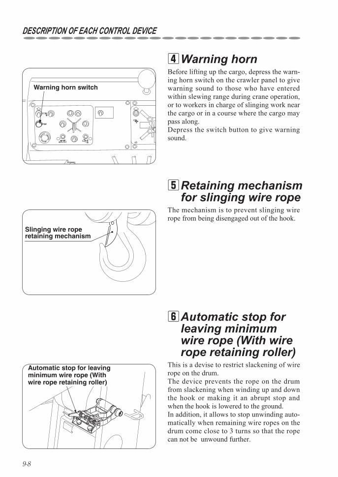
Warning horn 4
Retaining mechanism 5 for slinging wire rope
Warning horn switch
Slinging wire rope retaining mechanism
Automatic stop for leaving minimum wire rope (With wire rope retaining roller)
Automatic stop for 6leaving minimum wire rope (With wire rope retaining roller)
Before lifting up the cargo, depress the warn-ing horn switch on the crawler panel to give warning sound to those who have entered within slewing range during crane operation, or to workers in charge of slinging work near the cargo or in a course where the cargo may pass along.Depress the switch button to give warning sound.
The mechanism is to prevent slinging wire rope from being disengaged out of the hook.
This is a devise to restrict slackening of wire rope on the drum.The device prevents the rope on the drum from slackening when winding up and down the hook or making it an abrupt stop and when the hook is lowered to the ground.In addition, it allows to stop unwinding auto-matically when remaining wire ropes on the drum come close to 3 turns so that the rope can not be unwound further.
9-9
DESCRIPTION OF EACH CONTROL DEVICE
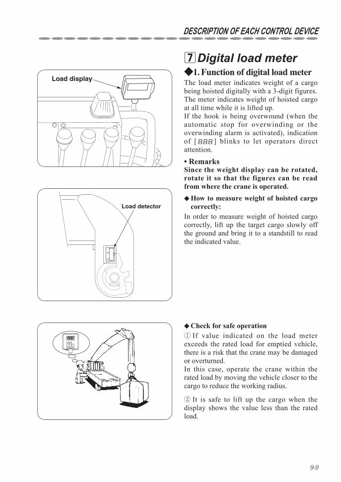
Digital load meter 7
Check for safe operation ◆
Load display
Load detector
Function of digital load meter1. ◆The load meter indicates weight of a cargo being hoisted digitally with a 3-digit figures.The meter indicates weight of hoisted cargo at all time while it is lifted up.If the hook is being overwound (when the automatic stop for overwinding or the overwinding alarm is activated), indication of [ ] blinks to let operators direct attention.
Remarks• Since the weight display can be rotated, rotate it so that the figures can be read from where the crane is operated.
In order to measure weight of hoisted cargo correctly, lift up the target cargo slowly off the ground and bring it to a standstill to read the indicated value.
How to measure weight of hoisted cargo ◆correctly:
If value indicated on the load meter ①exceeds the rated load for emptied vehicle, there is a risk that the crane may be damaged or overturned. In this case, operate the crane within the rated load by moving the vehicle closer to the cargo to reduce the working radius.
It is safe to lift up the cargo when the ②display shows the value less than the rated load.
9-10
DESCRIPTION OF EACH CONTROL DEVICE
The device does not provide the function as measurement equipment ★but is to find out hoisting load of the crane. Therefore, we take no responsibilities for any damage resulted from the use for the purpose of measurement.
The device can apply when using 4-part line hooking system. ★Although load indication may become unstable while the crane is ★
being operated, it is not a trouble. Stop of the crane operation makes it back to normal.
As the distance between the boom top and the hook is getting far ★apart, the load indicated is what the weight of the wire rope between them is included. (When distance between the boom top and the hook is 10m(33ft), weight of the wire rope is approx. 11kg.(25lbs.))
Do not perform pressure washing at the load meter. ★
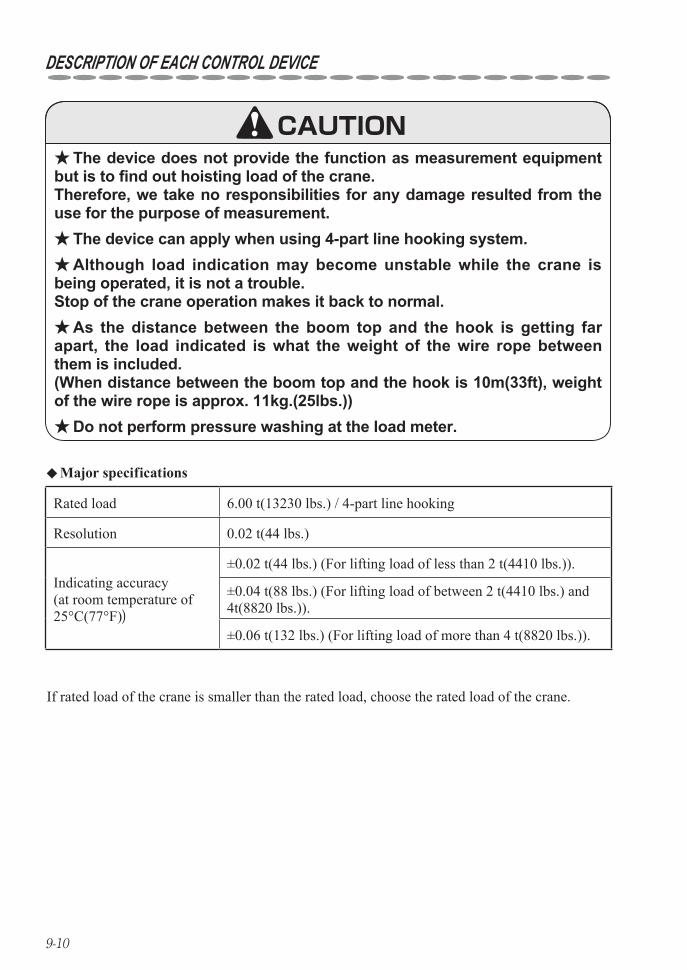
Rated load 6.00 t(13230 lbs.) / 4-part line hooking
Resolution 0.02 t(44 lbs.)
Indicating accuracy(at room temperature of 25°C(77°F))
±0.02 t(44 lbs.) (For lifting load of less than 2 t(4410 lbs.)).
±0.04 t(88 lbs.) (For lifting load of between 2 t(4410 lbs.) and 4t(8820 lbs.)).
±0.06 t(132 lbs.) (For lifting load of more than 4 t(8820 lbs.)).
Major specifications ◆
If rated load of the crane is smaller than the rated load, choose the rated load of the crane.
CAUTION
9-11
DESCRIPTION OF EACH CONTROL DEVICE
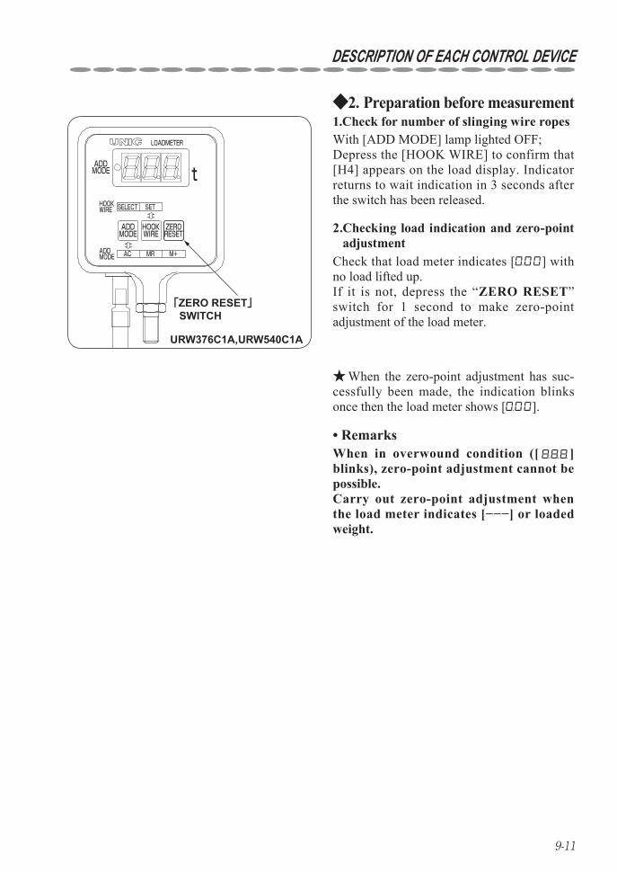
Preparation before measurement2. ◆
「ZERO RESET」 SWITCH
URW376C1A,URW540C1A
HOOKWIRE
ADD MODE
HOOKWIRE
ADDMODE
ZERORESET
SELECT SET
ADDMODE
MR M+AC
LOADMETER
t
Check that load meter indicates [ ] with no load lifted up.If it is not, depress the “ZERO RESET” switch for 1 second to make zero-point adjustment of the load meter.
2. Checking load indication and zero-point adjustment
1.Check for number of slinging wire ropesWith [ADD MODE] lamp lighted OFF; Depress the [HOOK WIRE] to confirm that [H4] appears on the load display. Indicator returns to wait indication in 3 seconds after the switch has been released.
When the zero-point adjustment has suc- ★cessfully been made, the indication blinks once then the load meter shows [ ].
Remarks• When in overwound condition ([ ] blinks), zero-point adjustment cannot be possible.Carry out zero-point adjustment when the load meter indicates [−−−] or loaded weight.
9-12
DESCRIPTION OF EACH CONTROL DEVICE
「ZERO RESET」 SWITCH
URW376C1A,URW540C1A
HOOKWIRE
ADD MODE
HOOKWIRE
ADDMODE
ZERORESET
SELECT SET
ADDMODE
MR M+AC
LOADMETER
t
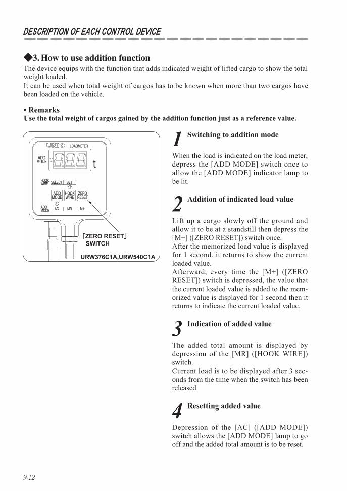
The device equips with the function that adds indicated weight of lifted cargo to show the total weight loaded.It can be used when total weight of cargos has to be known when more than two cargos have been loaded on the vehicle.
How to use addition function3. ◆
Remarks• Use the total weight of cargos gained by the addition function just as a reference value.
1 Switching to addition mode
When the load is indicated on the load meter, depress the [ADD MODE] switch once to allow the [ADD MODE] indicator lamp to be lit.
2 Addition of indicated load value
Lift up a cargo slowly off the ground and allow it to be at a standstill then depress the [M+] ([ZERO RESET]) switch once.After the memorized load value is displayed for 1 second, it returns to show the current loaded value.Afterward, every time the [M+] ([ZERO RESET]) switch is depressed, the value that the current loaded value is added to the mem-orized value is displayed for 1 second then it returns to indicate the current loaded value.
3 Indication of added value
The added total amount is displayed by depression of the [MR] ([HOOK WIRE]) switch.Current load is to be displayed after 3 sec-onds from the time when the switch has been released.
4 Resetting added value
Depression of the [AC] ([ADD MODE]) switch allows the [ADD MODE] lamp to go off and the added total amount is to be reset.
9-13
DESCRIPTION OF EACH CONTROL DEVICE
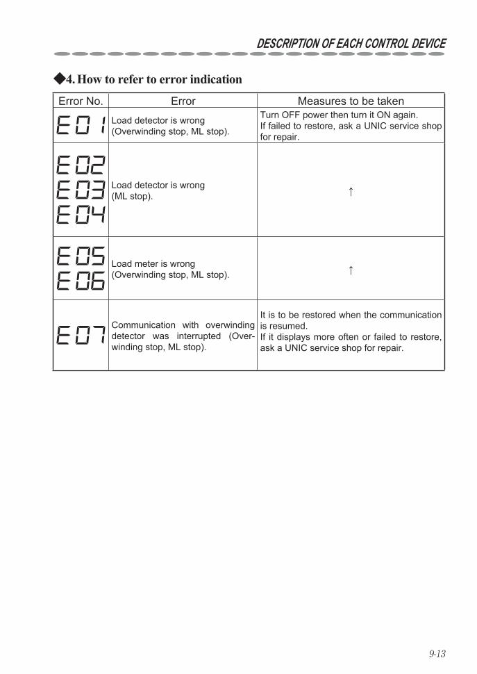
How to refer to error indication4. ◆Error No. Error Measures to be taken
Load detector is wrong (Overwinding stop, ML stop).
Turn OFF power then turn it ON again.If failed to restore, ask a UNIC service shop for repair.
Load detector is wrong (ML stop). ↑
Load meter is wrong (Overwinding stop, ML stop). ↑
Communication with overwinding detector was inter rupted (Over-winding stop, ML stop).
It is to be restored when the com munication is resumed.If it displays more often or failed to restore, ask a UNIC service shop for repair.
9-14
DESCRIPTION OF EACH CONTROL DEVICE
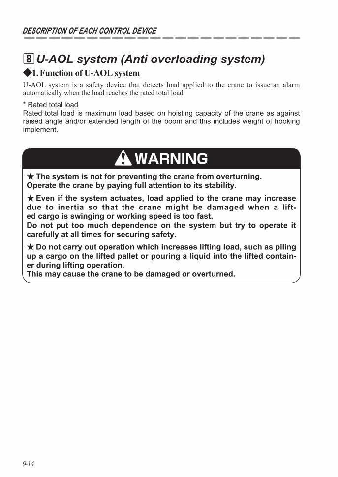
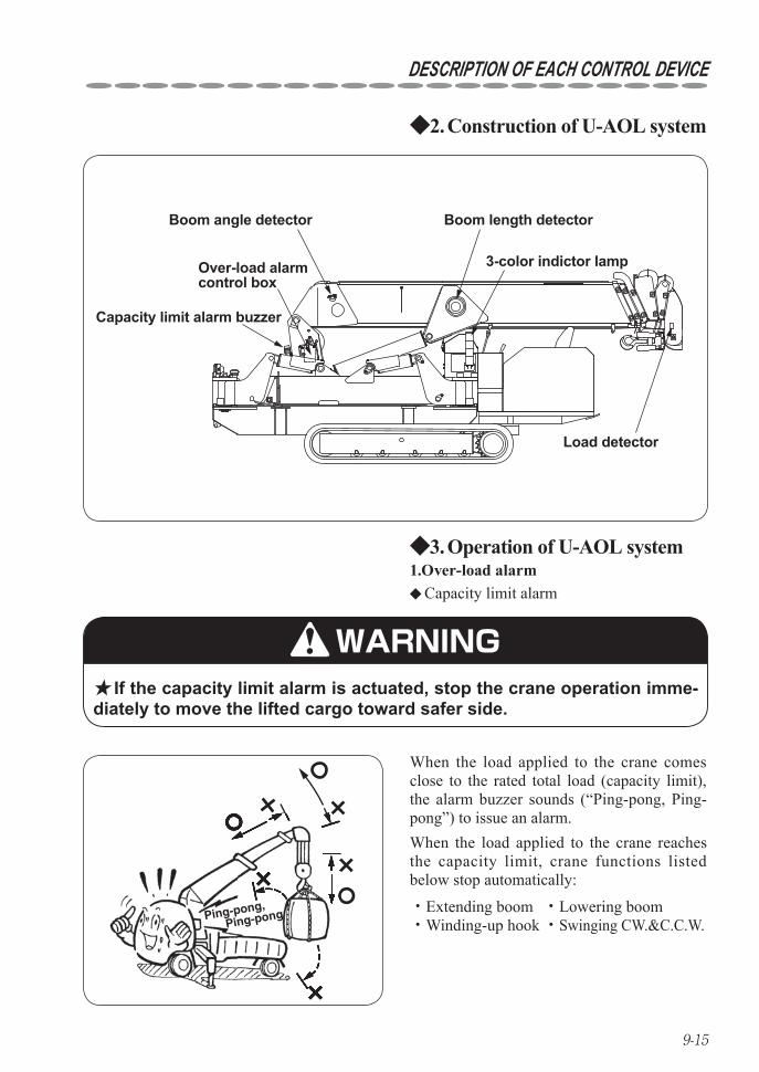
U-AOL system (Anti overloading system) 8
U-AOL system is a safety device that detects load applied to the crane to issue an alarm automatically when the load reaches the rated total load.
* Rated total loadRated total load is maximum load based on hoisting capacity of the crane as against raised angle and/or extended length of the boom and this includes weight of hooking implement.
Function of U-AOL system1. ◆
WARNINGThe system is not for preventing the crane from overturning. ★
Operate the crane by paying full attention to its stability.Even if the system actuates, load applied to the crane may increase ★
due to inertia so that the crane might be damaged when a lift-ed cargo is swinging or working speed is too fast. Do not put too much dependence on the system but try to operate it carefully at all times for securing safety.
Do not carry out operation which increases lifting load, such as piling ★up a cargo on the lifted pallet or pouring a liquid into the lifted contain-er during lifting operation. This may cause the crane to be damaged or overturned.
9-15
DESCRIPTION OF EACH CONTROL DEVICE
Boom angle detector
Over-load alarmcontrol box
Boom length detector
3-color indictor lamp
Load detector
Capacity limit alarm buzzer
Construction of U-AOL system2. ◆
Capacity limit alarm ◆
1.Over-load alarmOperation of U-AOL system3. ◆
WARNING★ If the capacity limit alarm is actuated, stop the crane operation imme-diately to move the lifted cargo toward safer side.
When the load applied to the crane comes close to the rated total load (capacity limit), the alarm buzzer sounds (“Ping-pong, Ping-pong”) to issue an alarm.
Ping-pong,
Ping-pong
When the load applied to the crane reaches the capacity limit, crane functions listed below stop automatically:
・Extending boom ・Lowering boom・Winding-up hook ・Swinging CW.&C.C.W.
9-16
DESCRIPTION OF EACH CONTROL DEVICE
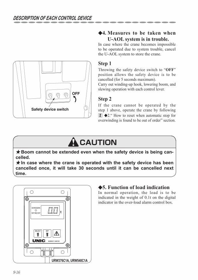
◆4. Measures to be taken when U-AOL system is in trouble.
In case where the crane becomes impossible to be operated due to system trouble, cancel the U-AOL system to store the crane.
Safety device switch
OFF
Step 1Throwing the safety device switch to “OFF” position allows the safety device is to be cancelled (for 5 seconds maximum).Carry out winding-up hook, lowering boom, and slewing operation with each control lever.
Step 2If the crane cannot be operated by the step 1 above, operate the crane by following 2 ◆2.“ How to reset when automatic stop for overwinding is found to be out of order” section.
CAUTION★ Boom cannot be extended even when the safety device is being can-celled.★ In case where the crane is operated with the safety device has been cancelled once, it will take 30 seconds until it can be cancelled next time.
MOMENT LIMITER
tOUTRIGGERS
NOT MAX EXT
SELECT SET
URW376C1A, URW540C1A
◆5. Function of load indicationIn normal operation, the load is to be indicat ed in the weight of 0.1t on the digital indicator in the over-load alarm control box.
9-17
DESCRIPTION OF EACH CONTROL DEVICE
MOMENT LIMITER
tOUTRIGGERS
NOT MAX EXT
SELECT SET
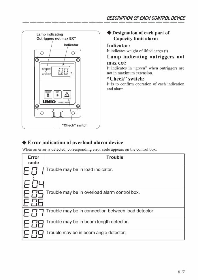
Lamp indicating Outriggers not max EXT
Indicator
“Check” switch
Designation of each part of ◆ Capacity limit alarm
Indicator:It indicates weight of lifted cargo (t).Lamp indicating outriggers not max ext:It indicates in “green” when outriggers are not in maximum extension.“Check” switch:It is to confirm operation of each indication and alarm.
Error code
Trouble
Trouble may be in load indicator.
Trouble may be in overload alarm control box.
Trouble may be in connection between load detector
Trouble may be in boom length detector.
Trouble may be in boom angle detector.
◆ Error indication of overload alarm deviceWhen an error is detected, corresponding error code appears on the control box.
9-18
DESCRIPTION OF EACH CONTROL DEVICE
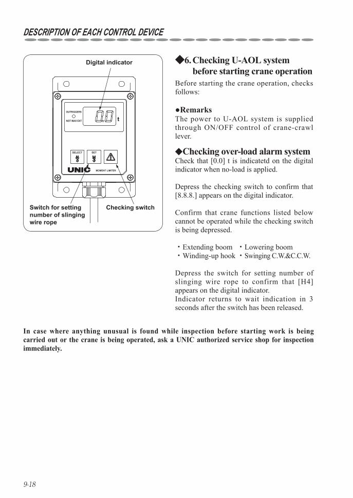
●RemarksThe power to U-AOL system is supplied through ON/OFF control of crane-crawl lever.
MOMENT LIMITER
tOUTRIGGERS
NOT MAX EXT
SELECT SET
Digital indicator
Checking switch Switch for setting number of slinging wire rope
◆ Checking over-load alarm systemCheck that [0.0] t is indicatetd on the digital indicator when no-load is applied.
Depress the checking switch to confirm that [8.8.8.] appears on the digital indicator.
Confirm that crane functions listed below cannot be operated while the checking switch is being depressed.
・Extending boom ・Lowering boom・Winding-up hook ・Swinging C.W.&C.C.W.
Depress the switch for setting number of slinging wire rope to confirm that [H4] appears on the digital indicator.Indicator returns to wait indication in 3 seconds after the switch has been released.
In case where anything unusual is found while inspection before starting work is being carried out or the crane is being operated, ask a UNIC authorized service shop for inspection immediately.
Checking U-AOL system 6. ◆before starting crane operation
Before starting the crane operation, checks follows:
10-1
10. HOW TO OPERATE CARRIER
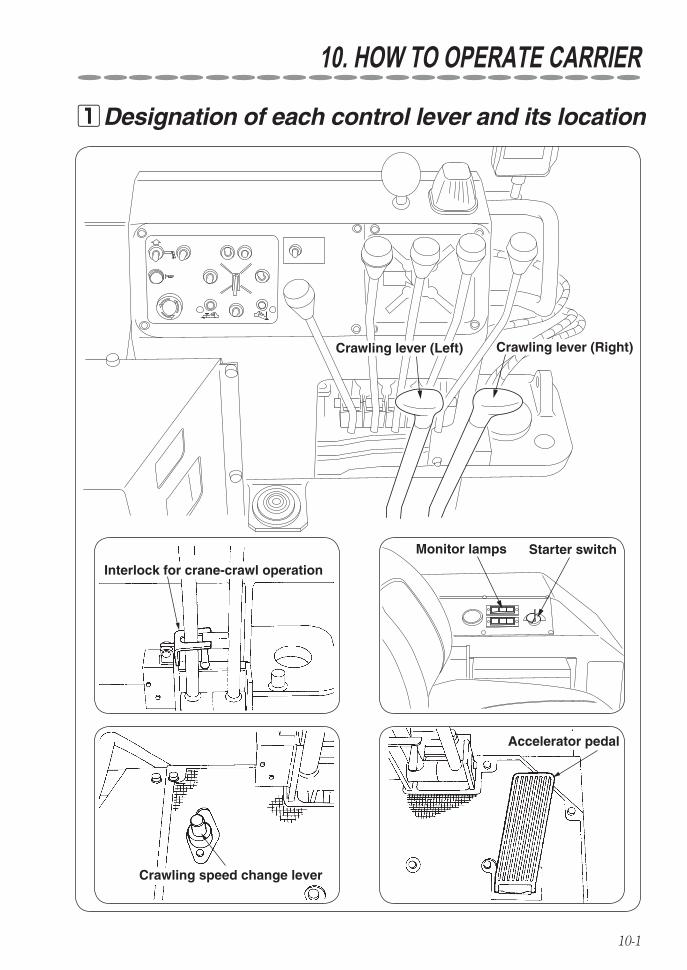
Designation of each control lever and its location 1
Crawling lever (Left) Crawling lever (Right)
Monitor lamps Starter switch
Accelerator pedal
Crawling speed change lever
Interlock for crane-crawl operation
10-2
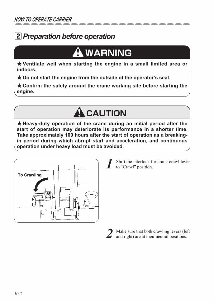
Preparation before operation 2
HOW TO OPERATE CARRIER
WARNING
Heavy-duty operation of the crane during an initial period after the ★start of operation may deteriorate its performance in a shorter time.Take approximately 100 hours after the start of operation as a breaking-in period during which abrupt start and acceleration, and continuous operation under heavy load must be avoided.
CAUTION
Ventilate well when starting the engine in a small limited area or ★indoors.
Do not start the engine from the outside of the operator’s seat. ★Confirm the safety around the crane working site before starting the ★
engine.
1 Shift the interlock for crane-crawl lever to “Crawl” position.
2 Make sure that both crawling levers (left and right) are at their neutral positions.
To Crawling
10-3
HOW TO OPERATE CARRIER
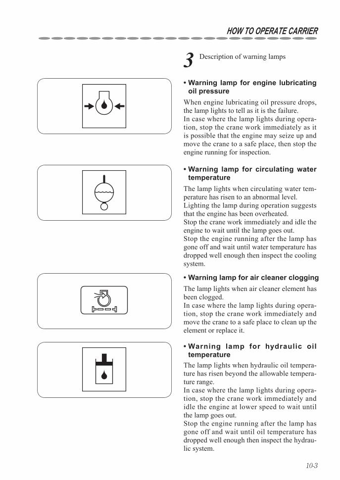
3 Description of warning lamps
Warning lamp for engine lubricating • oil pressure
Warning lamp for circulating water • temperature
Warning lamp for air cleaner clogging•
Warning lamp for hydraulic oil • temperature
When engine lubricating oil pressure drops, the lamp lights to tell as it is the failure.In case where the lamp lights during opera-tion, stop the crane work immediately as it is possible that the engine may seize up and move the crane to a safe place, then stop the engine running for inspection.
The lamp lights when circulating water tem-perature has risen to an abnormal level.Lighting the lamp during operation suggests that the engine has been overheated.Stop the crane work immediately and idle the engine to wait until the lamp goes out.Stop the engine running after the lamp has gone off and wait until water temperature has dropped well enough then inspect the cooling system.
The lamp lights when air cleaner element has been clogged.In case where the lamp lights during opera-tion, stop the crane work immediately and move the crane to a safe place to clean up the element or replace it.
The lamp lights when hydraulic oil tempera-ture has risen beyond the allowable tempera-ture range.In case where the lamp lights during opera-tion, stop the crane work immediately and idle the engine at lower speed to wait until the lamp goes out.Stop the engine running after the lamp has gone off and wait until oil temperature has dropped well enough then inspect the hydrau-lic system.
10-4
HOW TO OPERATE CARRIER
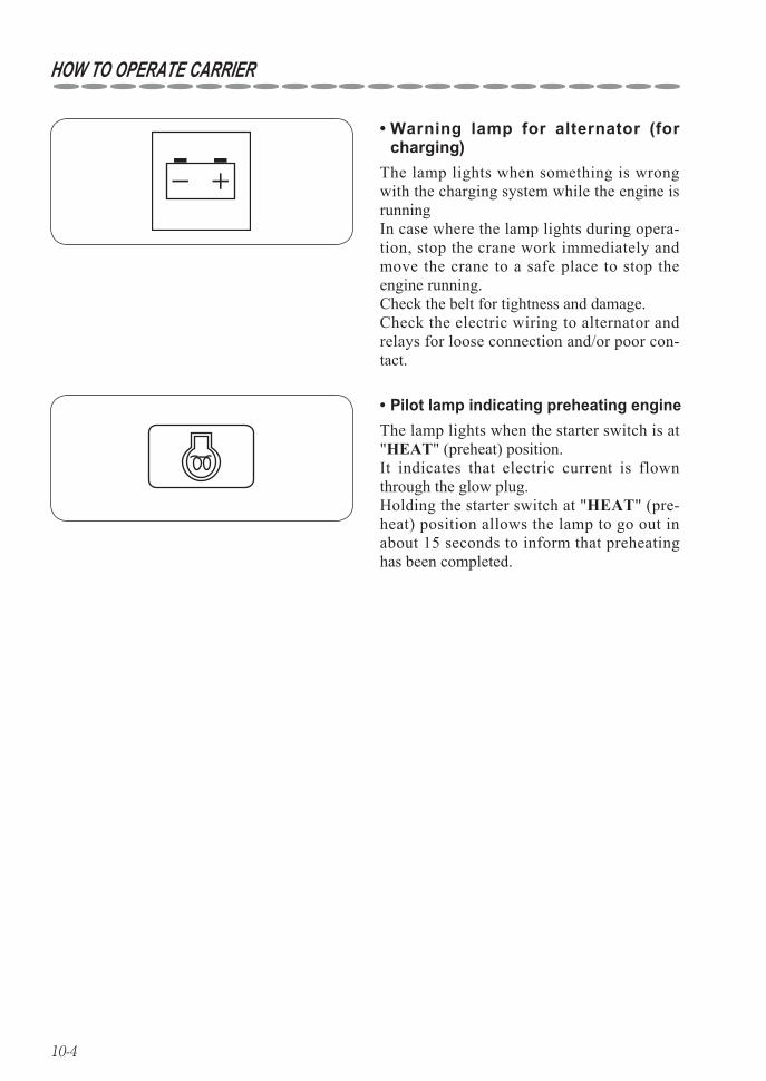
Warning lamp for alternator (for • charging)
Pilot lamp indicating preheating engine•
The lamp lights when something is wrong with the charging system while the engine is runningIn case where the lamp lights during opera-tion, stop the crane work immediately and move the crane to a safe place to stop the engine running.Check the belt for tightness and damage.Check the electric wiring to alternator and relays for loose connection and/or poor con-tact.
The lamp lights when the starter switch is at "HEAT" (preheat) position.It indicates that electric current is flown through the glow plug.Holding the starter switch at "HEAT" (pre-heat) position allows the lamp to go out in about 15 seconds to inform that preheating has been completed.
10-5
HOW TO OPERATE CARRIER
How to operate 3
Starting engine1. ◆
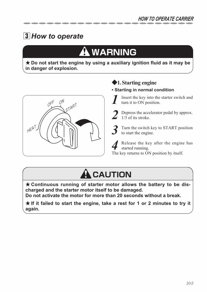
1 Insert the key into the starter switch and turn it to ON position.
HEAT
OFF ON
START
Continuous running of starter motor allows the battery to be dis- ★charged and the starter motor itself to be damaged. Do not activate the motor for more than 20 seconds without a break.
If it failed to start the engine, take a rest for 1 or 2 minutes to try it ★again.
WARNINGDo not start the engine by using a auxiliary ignition fluid as it may be ★
in danger of explosion.
Starting in normal condition•
2 Depress the accelerator pedal by approx. 1/3 of its stroke.
4 Release the key after the engine has started running.
The key returns to ON position by itself.
3 Turn the switch key to START position to start the engine.
CAUTION
10-6
HOW TO OPERATE CARRIER
Starting in a cold weather•
HEAT
OFF ON
START
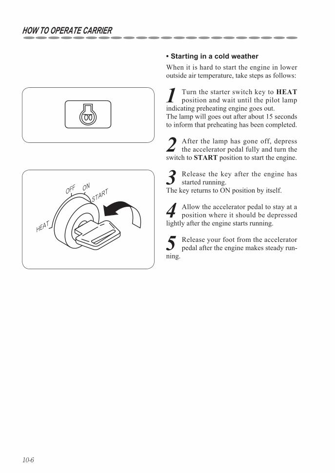
When it is hard to start the engine in lower outside air temperature, take steps as follows:
1 Turn the starter switch key to HEAT position and wait until the pilot lamp
indicating preheating engine goes out. The lamp will goes out after about 15 seconds to inform that preheating has been completed.
4 Allow the accelerator pedal to stay at a position where it should be depressed
lightly after the engine starts running.
2 After the lamp has gone off, depress the accelerator pedal fully and turn the
switch to START position to start the engine.
3 Release the key after the engine has started running.
The key returns to ON position by itself.
5 Release your foot from the accelerator pedal after the engine makes steady run-
ning.
10-7
HOW TO OPERATE CARRIER
Steps to be taken after engine 2. ◆has started
Do not make engine to accelerate abruptly before it has been warmed ★up.
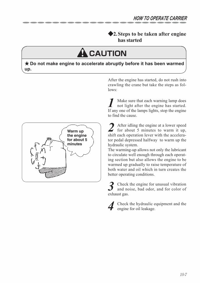
After the engine has started, do not rush into crawling the crane but take the steps as fol-lows:
Warm up the engine for about 5 minutes
CAUTION
3 Check the engine for unusual vibration and noise, bad odor, and for color of
exhaust gas.
1 Make sure that each warning lamp does not light after the engine has started.
If any one of the lamps lights, stop the engine to find the cause.
2 After idling the engine at a lower speed for about 5 minutes to warm it up,
shift each operation lever with the accelera-tor pedal depressed halfway to warm up the hydraulic system. The warming-up allows not only the lubricant to circulate well enough through each operat-ing section but also allows the engine to be warmed up gradually to raise temperature of both water and oil which in turn creates the better operating conditions.
4 Check the hydraulic equipment and the engine for oil leakage.
10-8
HOW TO OPERATE CARRIER
How to Crawl 4
Start the crane crawling after the safety around the crawler has been ★confirmed and make a sign when crawling the crane.
Keep anyone away from the crane. ★Pay special attention when turning left because the left side of crawl- ★
er will be in your blind spot.Crawl the crane as slowly as possible while making a turn. ★Run the crane slowly when making a quick turn and crawling on a ★
rough road.Lock the crawling lever with the interlock for crane-crawl operation ★
and stop the engine running before leaving from the crane.When parking the crane on the street is unavoidable, set up safety ★
devices such as a sign, a barricade, and a blinking light so that passing of other vehicles and pedestrians may not be disturbed.
Put a pallet against the rubber crawler when parking the crane for a ★long period of time.
Do not park the crane over a place where withered grass or straw, ★which is flammable, spread. This may cause a fire by heat of exhaust pipe or exhaust hume.
When crawling the crane on a water filled area, observe to crawl it ★within allowable depth of water.
In case where the machine is forced to turn on the spot (spin turn), be ★sure to stop the movement of the machine first, allow the engine to run at a low speed to make it turn slowly and gently. An abrupt turning not only damages the rubber crawler badly but also causes the machine to bounce from which may invite a very dangerous situation.
WARNING
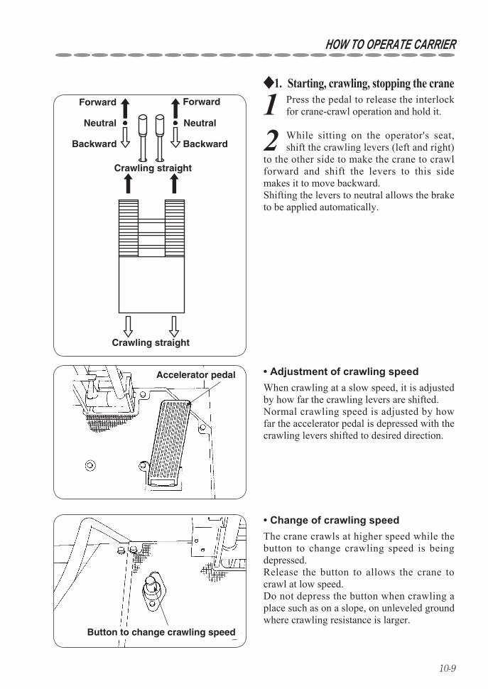
10-9
HOW TO OPERATE CARRIER
Starting, crawling, stopping the crane1. ◆
1 Press the pedal to release the interlock for crane-crawl operation and hold it.
Crawling straight
Forward Forward
Neutral Neutral
Backward Backward
Crawling straight
Adjustment of crawling speed• Accelerator pedal
2 While sitting on the operator's seat, shift the crawling levers (left and right)
to the other side to make the crane to crawl forward and shift the levers to this side makes it to move backward. Shifting the levers to neutral allows the brake to be applied automatically.
When crawling at a slow speed, it is adjusted by how far the crawling levers are shifted.Normal crawling speed is adjusted by how far the accelerator pedal is depressed with the crawling levers shifted to desired direction.
Button to change crawling speed
Change of crawling speed• The crane crawls at higher speed while the button to change crawling speed is being depressed.Release the button to allows the crane to crawl at low speed.Do not depress the button when crawling a place such as on a slope, on unleveled ground where crawling resistance is larger.

10-10
Pivot
Making a turn when the machine is • at a standstill
Shifting the traveling levers both to the right and to the left forward at the same time allows the machine to turn to the right (left) if the left (right) traveling lever is moved much further than the right (left) traveling lever.Shifting the traveling levers both to the right and to the left backward at the same time allows the machine to turn to the right (left) if the left (right) traveling lever is moved much further than the right (left) traveling lever.
HOW TO OPERATE CARRIER
Making a turn2. ◆Making a turn while moving•
Do not operate the right (left) traveling lever with the left (right) traveling lever put at its neutral position. Otherwise, the rubber crawler damages and the machine bounc-es from which may invite a very dangerous situation. In case where the machine is forced to operate this way, be sure to stop the movement of the machine first, allow the engine to run at a low speed to operate it slowly and gently.
Pivot
When traveling forward: It turns to the left (right) by shifting the right (left) traveling lever much further than the left (right) travel-ing lever.When traveling backward: It turns to the left (right) by shifting the right (left) traveling lever much further than the left (right) travel-ing lever.
WARNING
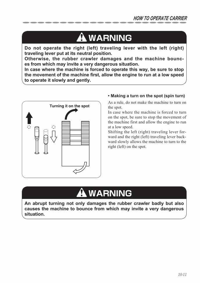
10-11
HOW TO OPERATE CARRIER
Do not operate the right (left) traveling lever with the left (right) traveling lever put at its neutral position. Otherwise, the rubber crawler damages and the machine bounc-es from which may invite a very dangerous situation. In case where the machine is forced to operate this way, be sure to stop the movement of the machine first, allow the engine to run at a low speed to operate it slowly and gently.
WARNING
Turning it on the spot
An abrupt turning not only damages the rubber crawler badly but also causes the machine to bounce from which may invite a very dangerous situation.
Making a turn on the spot (spin turn)• As a rule, do not make the machine to turn on the spot.In case where the machine is forced to turn on the spot, be sure to stop the movement of the machine first and allow the engine to run at a low speed.Shifting the left (right) traveling lever for-ward and the right (left) traveling lever back-ward slowly allows the machine to turn to the right (left) on the spot.
WARNING
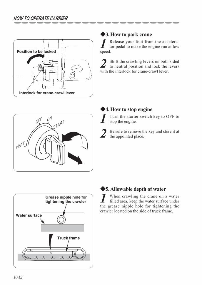
10-12
HOW TO OPERATE CARRIER
How to park crane3. ◆
1 Release your foot from the accelera-tor pedal to make the engine run at low
speed.
How to stop engine4. ◆
1 Turn the starter switch key to OFF to stop the engine.
HEAT
OFF ON
START
Allowable depth of water5. ◆
1 When crawling the crane on a water filled area, keep the water surface under
the grease nipple hole for tightening the crawler located on the side of truck frame.
Truck frame
Grease nipple hole for tightening the crawler
Water surface
2 Shift the crawling levers on both sided to neutral position and lock the levers
with the interlock for crane-crawl lever.
2 Be sure to remove the key and store it at the appointed place.
Interlock for crane-crawl lever
Position to be locked

11-1
11. HOW TO OPERATE CRANE
Designation of each control lever and its location 1
Slewing C.C.W.
Slewing C.W.
BoomExtending
BoomRetracting
HookLowering
HookHoisting
BoomLowering
BoomRaising
Outrigger vertical/horizontal selector switch
Outrigger
Outrigger controlswitch
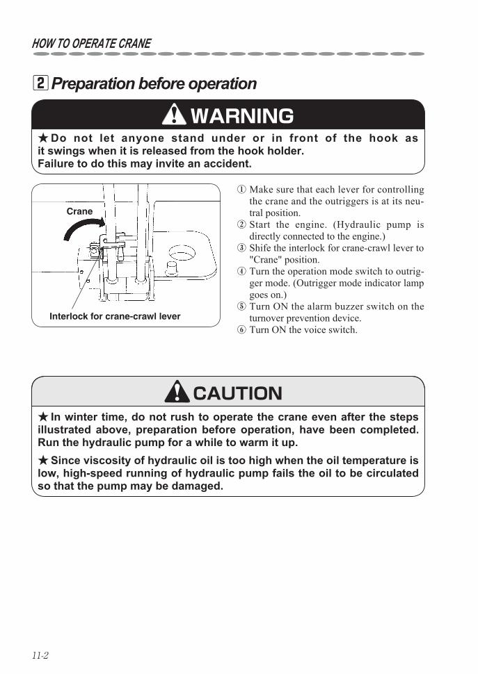
11-2
HOW TO OPERATE CRANE
Preparation before operation 2
① Make sure that each lever for controlling the crane and the outriggers is at its neu-tral position.
② Start the engine. (Hydraulic pump is directly connected to the engine.)
③ Shife the interlock for crane-crawl lever to "Crane" position.
④ Turn the operation mode switch to outrig-ger mode. (Outrigger mode indicator lamp goes on.)
⑤ Turn ON the alarm buzzer switch on the turnover prevention device.
⑥ Turn ON the voice switch.
In winter time, do not rush to operate the crane even after the steps ★illustrated above, preparation before operation, have been completed.Run the hydraulic pump for a while to warm it up.
Since viscosity of hydraulic oil is too high when the oil temperature is ★low, high-speed running of hydraulic pump fails the oil to be circulated so that the pump may be damaged.
Do not let anyone stand under or in front of the hook as ★it swings when it is released from the hook holder. Failure to do this may invite an accident.
WARNING
CAUTION
Crane
Interlock for crane-crawl lever
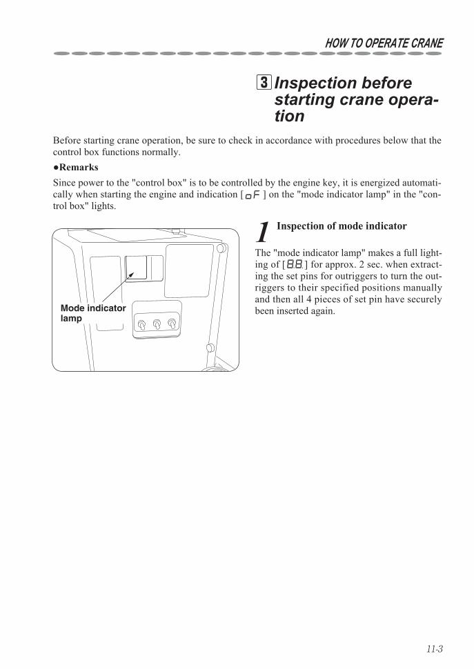
11-3
HOW TO OPERATE CRANE
Inspection before 3starting crane opera-tion
Before starting crane operation, be sure to check in accordance with procedures below that the control box functions normally.
1 Inspection of mode indicator
Mode indicator lamp
●RemarksSince power to the "control box" is to be controlled by the engine key, it is energized automati-cally when starting the engine and indication [ ] on the "mode indicator lamp" in the "con-trol box" lights.
The "mode indicator lamp" makes a full light-ing of [ ] for approx. 2 sec. when extract-ing the set pins for outriggers to turn the out-riggers to their specified positions manually and then all 4 pieces of set pin have securely been inserted again.
11-4
HOW TO OPERATE CRANE
2 System diagnosis
Do not operate the crane while the system diagnosis is being carried out. ★If the crane is operated during the system diagnosis, voice mes-sage, “Beep, Service remote control, Service remote control”, sounds and the crane is turned into inoperable conditions. If this happened, restart the engine.
If it found normal after the system diagnosis, the mode indicator lamp lights numbers. (In case of manual specification, the number [ ] is to be indicated.)Refer to the section "18. Mode indicator lamp(on page 18-1)" for detail.
If the “mode indicator lamp” fails to make a full lighting or voice mes- ★sage, “Beep, Service remote control, Service remote control”, sounds despite the fact that the crane has not been operated, store the crane according to the section “9 2 ◆2 How to reset when automatic stop for over-winding is found to be out of order” and ask a UNIC authorized service shop for repair.
The crane is in the process of system diagno-sis while the "mode indicator lamp" is mak-ing a full lighting.Following items are to be checked by the sys-tem diagnosis.
Checking if electronic circuit in the control • box is functioning properly.
Checking if manual control lever is at its • neutral position.
CAUTION
CAUTION
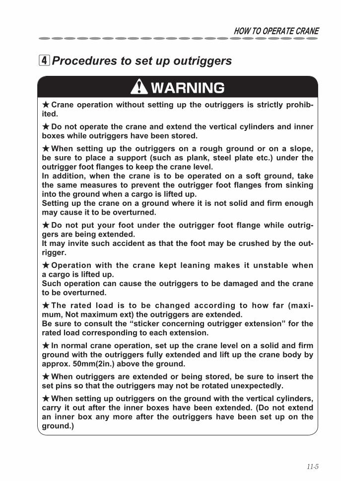
11-5
HOW TO OPERATE CRANE
Procedures to set up outriggers 4
Crane operation without setting up the outriggers is strictly prohib- ★ited.
Do not operate the crane and extend the vertical cylinders and inner ★boxes while outriggers have been stored.
When setting up the outriggers on a rough ground or on a slope, ★be sure to place a support (such as plank, steel plate etc.) under the outrigger foot flanges to keep the crane level. In addition, when the crane is to be operated on a soft ground, take the same measures to prevent the outrigger foot flanges from sinking into the ground when a cargo is lifted up. Setting up the crane on a ground where it is not solid and firm enough may cause it to be overturned.
Do not put your foot under the outrigger foot flange while outrig- ★gers are being extended. It may invite such accident as that the foot may be crushed by the out-rigger.
Operation with the crane kept leaning makes it unstable when ★a cargo is lifted up. Such operation can cause the outriggers to be damaged and the crane to be overturned.
The rated load is to be changed according to how far (maxi- ★mum, Not maximum ext) the outriggers are extended. Be sure to consult the “sticker concerning outrigger extension” for the rated load corresponding to each extension.
In normal crane operation, set up the crane level on a solid and firm ★ground with the outriggers fully extended and lift up the crane body by approx. 50mm(2in.) above the ground.
When outriggers are extended or being stored, be sure to insert the ★set pins so that the outriggers may not be rotated unexpectedly.
When setting up outriggers on the ground with the vertical cylinders, ★carry it out after the inner boxes have been extended. (Do not extend an inner box any more after the outriggers have been set up on the ground.)
WARNING
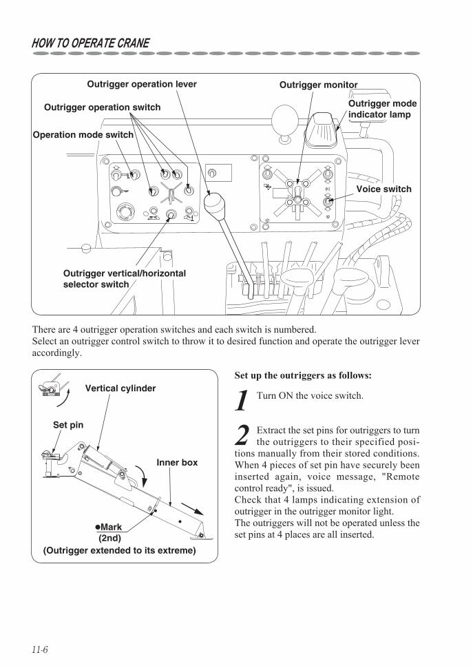
11-6
HOW TO OPERATE CRANE
Outrigger operation lever
Outrigger operation switch
Operation mode switch
Voice switch
Outrigger vertical/horizontal selector switch
Outrigger monitor
Outrigger modeindicator lamp
●Mark
Vertical cylinder
Set pin
(Outrigger extended to its extreme) (2nd)
Inner box
There are 4 outrigger operation switches and each switch is numbered.Select an outrigger control switch to throw it to desired function and operate the outrigger lever accordingly.
Set up the outriggers as follows:
1 Turn ON the voice switch.
2 Extract the set pins for outriggers to turn the outriggers to their specified posi-
tions manually from their stored conditions.When 4 pieces of set pin have securely been inserted again, voice message, "Remote control ready", is issued. Check that 4 lamps indicating extension of outrigger in the outrigger monitor light. The outriggers will not be operated unless the set pins at 4 places are all inserted.
11-7
HOW TO OPERATE CRANE
3 Check that the operation mode is selected to "OUTRIGGER" at this
time and voice message, "Outrigger mode, Outriggers moving, Outriggers moving", sounds and the outrigger mode indicator lamp on the control panel lights. If the outrigger mode indicator lamp fails to be lit, turn the operation mode switch to "OUTRIGGER".
4 Turn the outrigger vertical/horizontal selector switch to "HORIZONTAL".
The voice message, "Change control mode", is heard. The voice message will not be issued when the switch is turned to the mode already selected.
5 Turn the outrigger operation switches (4 places) to "EXTEND" and pull outrig-
ger operation lever toward you to extend the inner box.
6 Turn the outrigger vertical/horizontal selector switch to "VERTICAL".
The voice message, "Change control mode", is heard.
7 Pull outrigger operation lever toward you to extend the vertical cylinder
to set it up on the ground. (Do not extend and retract the inner box after vertical member of outrigger has been set up.)
8 Select the outrigger you want to oper-ate with the outrigger operation switch
concerned and pull the outrigger operation to extend and retract the outrigger while monitoring a level so that the crane body can keep level with the crawler raised by approx. 50mm(2in.). (Since two or more of outriggers cannot be extended or retracted at the same time, extend or retract outriggers separately.)
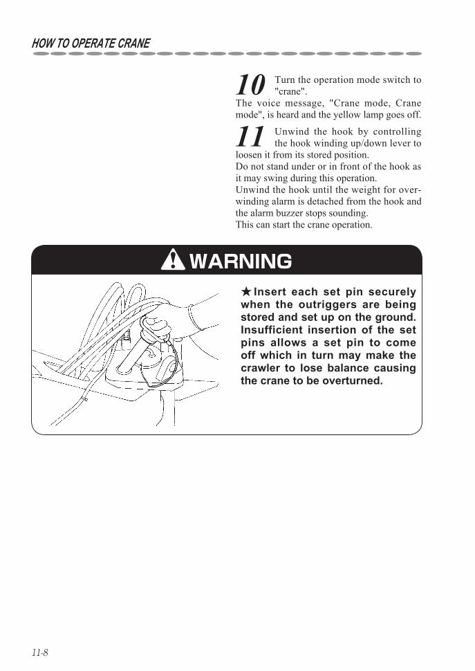
11-8
HOW TO OPERATE CRANE
Insert each set pin securely ★when the outriggers are being stored and set up on the ground.Insufficient insertion of the set pins allows a set pin to come off which in turn may make the crawler to lose balance causing the crane to be overturned.
10 Turn the operation mode switch to "crane".
The voice message, "Crane mode, Crane mode", is heard and the yellow lamp goes off.
11 Unwind the hook by controlling the hook winding up/down lever to
loosen it from its stored position. Do not stand under or in front of the hook as it may swing during this operation. Unwind the hook until the weight for over-winding alarm is detached from the hook and the alarm buzzer stops sounding. This can start the crane operation.
WARNING
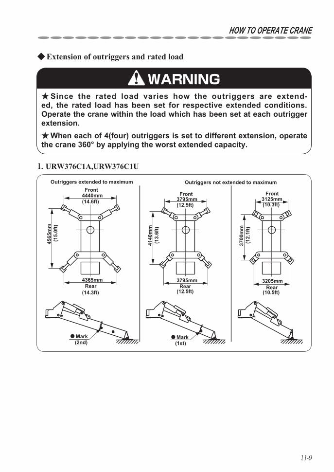
11-9
HOW TO OPERATE CRANE
Extension of outriggers and rated load ◆
Since the rated load varies how the outriggers are extend- ★ed, the rated load has been set for respective extended conditions.Operate the crane within the load which has been set at each outrigger extension.
When each of 4(four) outriggers is set to different extension, operate ★the crane 360° by applying the worst extended capacity.
WARNING
●
4440mm
4565
mm
4365mm
(14.6ft)
(14.3ft)
(15.
0ft)
(13.
6ft)
(12.
1ft)
3795mm
(12.5ft)
(12.5ft)
3795mm
4140
mm
3125mm(10.3ft)
(10.5ft)
3700
mm
3205mm
Outriggers extended to maximumFront
Rear
Mark(2nd)
Rear
Front
Rear
Front
●Mark(1st)
Outriggers not extended to maximum
URW376C1A,URW376C1U. 1
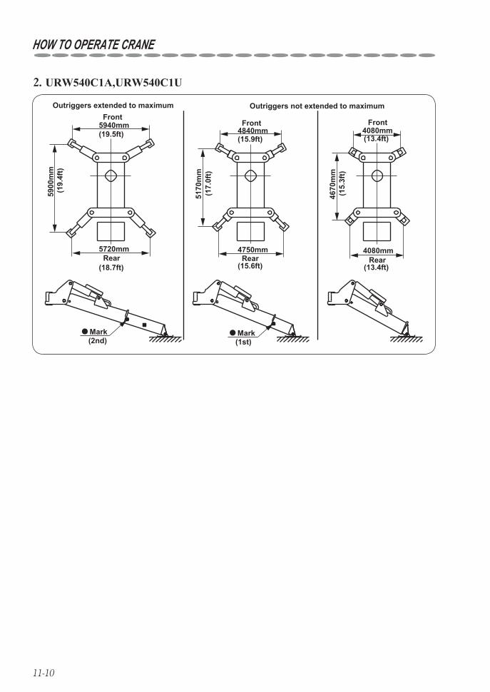
11-10
HOW TO OPERATE CRANE
●
5940mm
5900
mm
5720mm
(19.5ft)
(18.7ft)
(19.
4ft)
(17.
0ft)
(15.
3ft)
4840mm
(15.6ft)
(15.9ft)
4750mm
5170
mm
4080mm(13.4ft)
(13.4ft)
4670
mm
4080mm
Outriggers extended to maximumFront
Rear
Mark(2nd)
Rear
Front
Rear
Front
●Mark(1st)
Outriggers not extended to maximum
URW540C1A,URW540C1U. 2
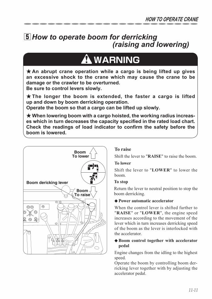
11-11
HOW TO OPERATE CRANE
How to operate boom for derricking 5 (raising and lowering)
To raise
An abrupt crane operation while a cargo is being lifted up gives ★an excessive shock to the crane which may cause the crane to be damage or the crawler to be overturned. Be sure to control levers slowly.
The longer the boom is extended, the faster a cargo is lifted ★up and down by boom derricking operation. Operate the boom so that a cargo can be lifted up slowly.
When lowering boom with a cargo hoisted, the working radius increas- ★es which in turn decreases the capacity specified in the rated load chart.Check the readings of load indicator to confirm the safety before the boom is lowered.
Boom dericking lever
BoomTo raise
Boom To lower
WARNING
Shift the lever to "RAISE" to raise the boom.
Shift the lever to "LOWER" to lower the boom.
To lower
To stopReturn the lever to neutral position to stop the boom derricking.
Power automatic accelerator ◆
When the control lever is shifted further to "RAISE" or "LOWER", the engine speed increases according to the movement of the lever which in turn increases derricking speed of the boom as the lever is interlocked with the accelerator.
Boom control together with accelerator ◆pedal
Engine changes from the idling to the highest speed.Operate the boom by controlling boom der-ricking lever together with by adjusting the accelerator pedal.
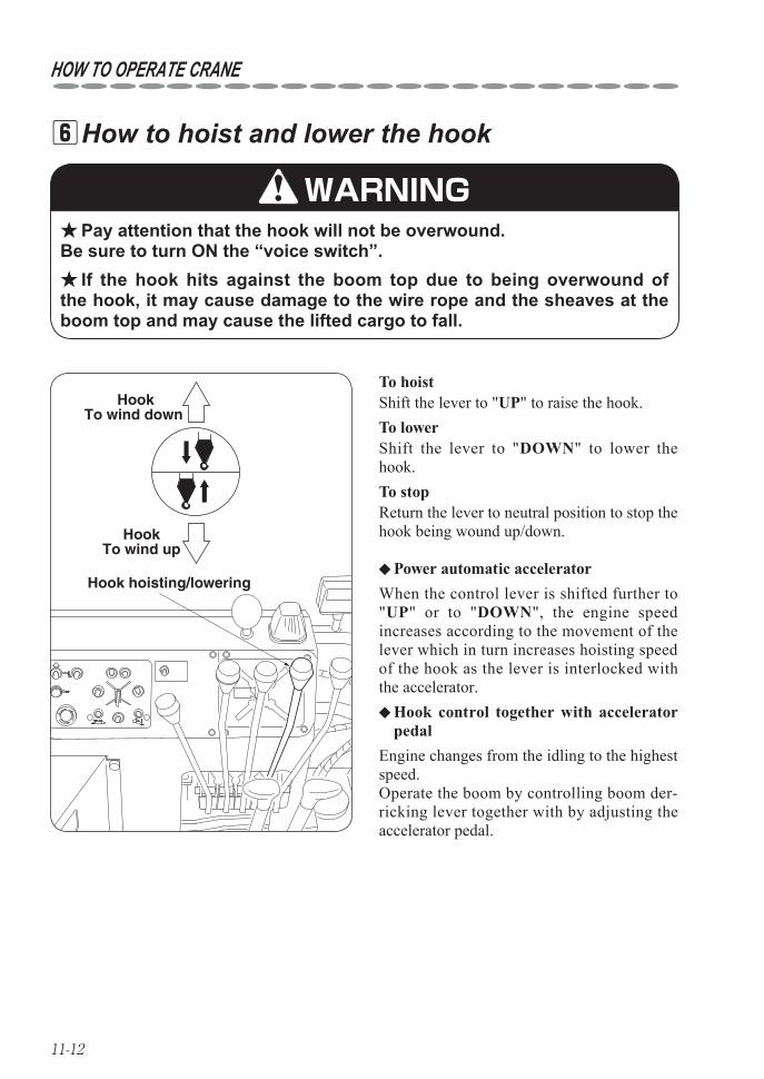
11-12
HOW TO OPERATE CRANE
How to hoist and lower the hook 6
Hook hoisting/lowering
HookTo wind down
HookTo wind up
Pay attention that the hook will not be overwound. ★Be sure to turn ON the “voice switch”.
If the hook hits against the boom top due to being overwound of ★the hook, it may cause damage to the wire rope and the sheaves at the boom top and may cause the lifted cargo to fall.
WARNING
To hoistShift the lever to "UP" to raise the hook.To lowerShift the lever to "DOWN" to lower the hook.To stopReturn the lever to neutral position to stop the hook being wound up/down.
Power automatic accelerator ◆
When the control lever is shifted further to "UP" or to "DOWN", the engine speed increases according to the movement of the lever which in turn increases hoisting speed of the hook as the lever is interlocked with the accelerator.
Hook control together with accelerator ◆pedal
Engine changes from the idling to the highest speed.Operate the boom by controlling boom der-ricking lever together with by adjusting the accelerator pedal.
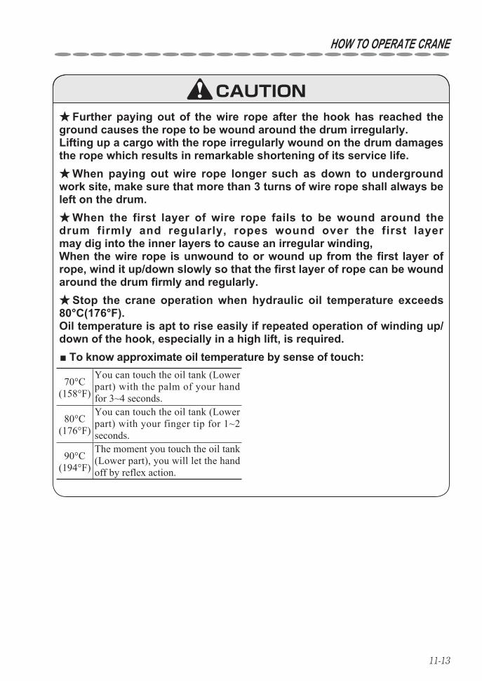
11-13
HOW TO OPERATE CRANE
Further paying out of the wire rope after the hook has reached the ★ground causes the rope to be wound around the drum irregularly. Lifting up a cargo with the rope irregularly wound on the drum damages the rope which results in remarkable shortening of its service life.
When paying out wire rope longer such as down to underground ★work site, make sure that more than 3 turns of wire rope shall always be left on the drum.
When the first layer of wire rope fails to be wound around the ★drum firmly and regularly, ropes wound over the first layer may dig into the inner layers to cause an irregular winding, When the wire rope is unwound to or wound up from the first layer of rope, wind it up/down slowly so that the first layer of rope can be wound around the drum firmly and regularly.
Stop the crane operation when hydraulic oil temperature exceeds ★80°C(176°F). Oil temperature is apt to rise easily if repeated operation of winding up/down of the hook, especially in a high lift, is required.
CAUTION
■ To know approximate oil temperature by sense of touch:
70°C(158°F)
You can touch the oil tank (Lower part) with the palm of your hand for 3~4 seconds.
80°C(176°F)
You can touch the oil tank (Lower part) with your finger tip for 1~2 seconds.
90°C(194°F)
The moment you touch the oil tank (Lower part), you will let the hand off by reflex action.
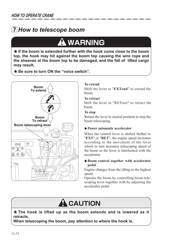
11-14
HOW TO OPERATE CRANE
How to telescope boom 7
Boom telescoping lever
BoomTo retract
BoomTo extend
The hook is lifted up as the boom extends and is lowered as it ★retracts. When telescoping the boom, pay attention to where the hook is.
If the boom is extended further with the hook come close to the boom ★top, the hook may hit against the boom top causing the wire rope and the sheaves at the boom top to be damaged, and the fall of lifted cargo may result.
Be sure to turn ON the “voice switch”. ★
WARNING
To extendShift the lever to "EXTend" to extend the boom.
Power automatic accelerator ◆
To retractShift the lever to "RETract" to retract the boom.To stopReturn the lever to neutral position to stop the boom telescoping.
When the control lever is shifted further to "EXT" or "RET", the engine speed increases according to the movement of the lever which in turn increases telescoping speed of the boom as the lever is interlocked with the accelerator.
Engine changes from the idling to the highest speed.Operate the boom by controlling boom tele-scoping lever together with by adjusting the accelerator pedal.
Boom control together with accelerator ◆pedal
CAUTION
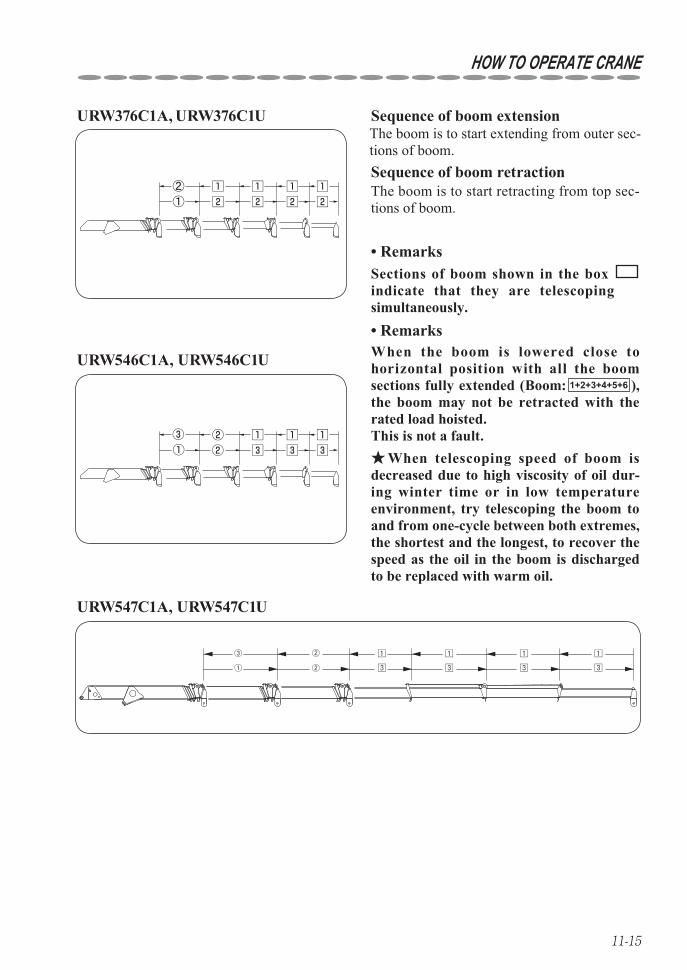
11-15
HOW TO OPERATE CRANE
① ② 3
1
3
1
3
1
3
1②③
Sequence of boom extensionURW376C1A, URW376C1UThe boom is to start extending from outer sec-tions of boom.Sequence of boom retractionThe boom is to start retracting from top sec-tions of boom.
Sections of boom shown in the box indicate that they are telescoping simultaneously.
Remarks•
When telescoping speed of boom is ★decreased due to high viscosity of oil dur-ing winter time or in low temperature environment, try telescoping the boom to and from one-cycle between both extremes, the shortest and the longest, to recover the speed as the oil in the boom is discharged to be replaced with warm oil.
When the boom is lowered close to horizontal position with all the boom sections fully extended (Boom: 1+2+3+4+5+6 ), the boom may not be retracted with the rated load hoisted. This is not a fault.
Remarks•
①
②
URW547C1A, URW547C1U
URW546C1A, URW546C1U
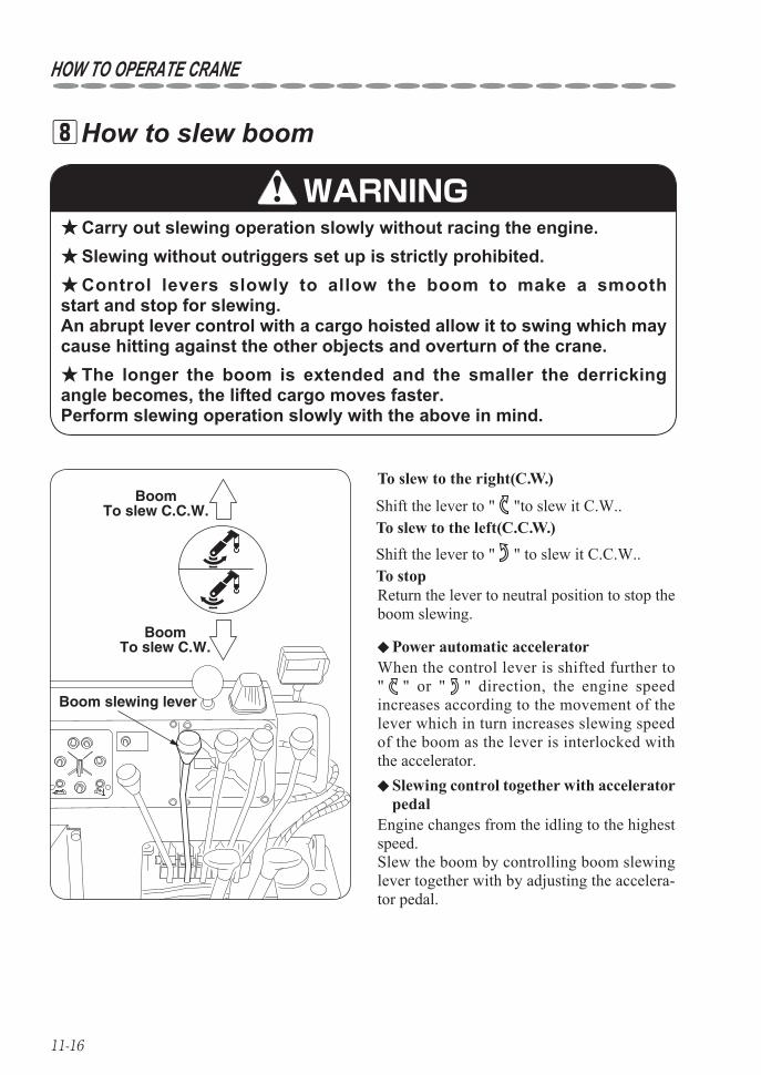
11-16
HOW TO OPERATE CRANE
How to slew boom 8
Carry out slewing operation slowly without racing the engine. ★Slewing without outriggers set up is strictly prohibited. ★Control levers slowly to allow the boom to make a smooth ★
start and stop for slewing. An abrupt lever control with a cargo hoisted allow it to swing which may cause hitting against the other objects and overturn of the crane.
The longer the boom is extended and the smaller the derricking ★angle becomes, the lifted cargo moves faster. Perform slewing operation slowly with the above in mind.
Boom slewing lever
BoomTo slew C.C.W.
BoomTo slew C.W.
WARNING
To slew to the right(C.W.)
Shift the lever to " "to slew it C.W..To slew to the left(C.C.W.)Shift the lever to " " to slew it C.C.W..
Return the lever to neutral position to stop the boom slewing.
To stop
Power automatic accelerator ◆
When the control lever is shifted further to " " or " " direction, the engine speed increases according to the movement of the lever which in turn increases slewing speed of the boom as the lever is interlocked with the accelerator.
Slewing control together with accelerator ◆pedal
Engine changes from the idling to the highest speed.Slew the boom by controlling boom slewing lever together with by adjusting the accelera-tor pedal.
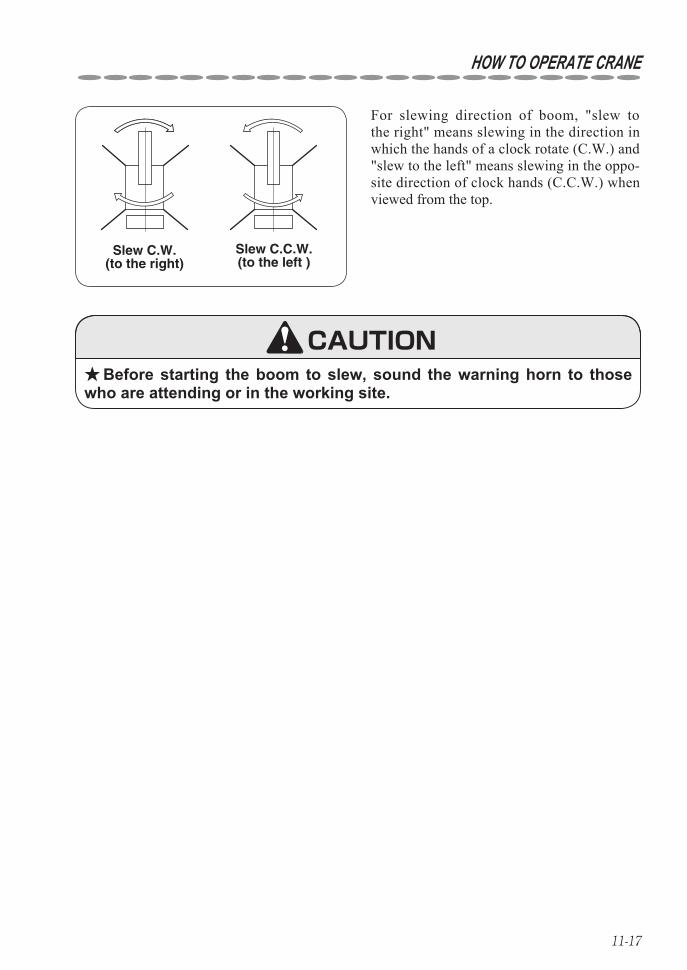
11-17
HOW TO OPERATE CRANE
Slew C.C.W.(to the left )
Slew C.W.(to the right)
For slewing direction of boom, "slew to the right" means slewing in the direction in which the hands of a clock rotate (C.W.) and "slew to the left" means slewing in the oppo-site direction of clock hands (C.C.W.) when viewed from the top.
Before starting the boom to slew, sound the warning horn to those ★who are attending or in the working site.
CAUTION
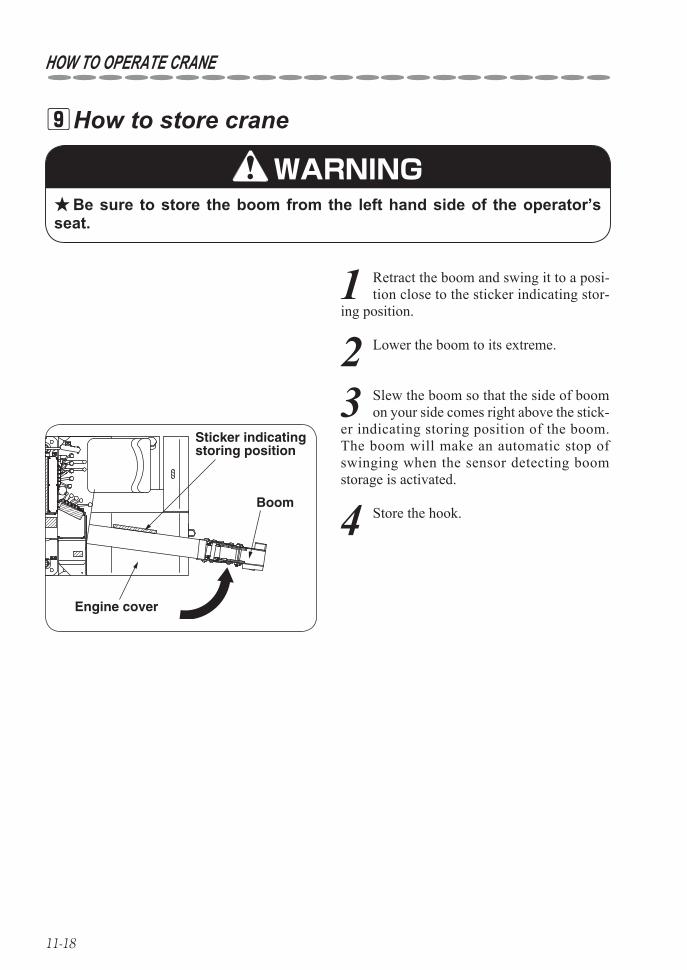
11-18
HOW TO OPERATE CRANE
Sticker indicating storing position
Boom
Engine cover
How to store crane 9
Be sure to store the boom from the left hand side of the operator’s ★seat.
1 Retract the boom and swing it to a posi-tion close to the sticker indicating stor-
ing position.
WARNING
4 Store the hook.
2 Lower the boom to its extreme.
3 Slew the boom so that the side of boom on your side comes right above the stick-
er indicating storing position of the boom.The boom will make an automatic stop of swinging when the sensor detecting boom storage is activated.
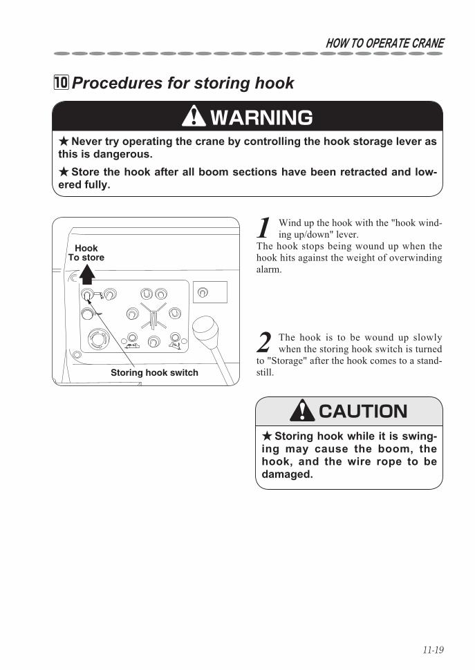
11-19
HOW TO OPERATE CRANE
1 Wind up the hook with the "hook wind-ing up/down" lever.
The hook stops being wound up when the hook hits against the weight of overwinding alarm.
2 The hook is to be wound up slowly when the storing hook switch is turned
to "Storage" after the hook comes to a stand-still.
Procedures for storing hook 10
Never try operating the crane by controlling the hook storage lever as ★this is dangerous.
Store the hook after all boom sections have been retracted and low- ★ered fully.
Storing hook while it is swing- ★ing may cause the boom, the hook, and the wire rope to be damaged.
HookTo store
Storing hook switch
WARNING
CAUTION
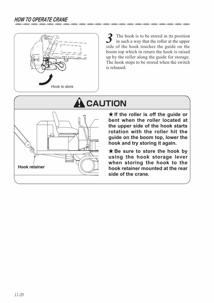
11-20
HOW TO OPERATE CRANE
3 The hook is to be stored in its position in such a way that the roller at the upper
side of the hook touches the guide on the boom top which in return the hook is raised up by the roller along the guide for storage.The hook stops to be stored when the switch is released.
If the roller is off the guide or ★bent when the roller located at the upper side of the hook starts rotation with the roller hit the guide on the boom top, lower the hook and try storing it again.
Be sure to store the hook by ★using the hook storage lever when storing the hook to the hook retainer mounted at the rear side of the crane.
Hook to store
Hook retainer
CAUTION
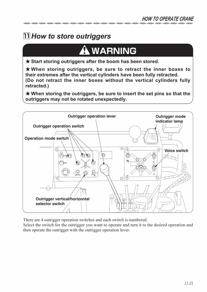
11-21
HOW TO OPERATE CRANE
How to store outriggers 11
Start storing outriggers after the boom has been stored. ★When storing outriggers, be sure to retract the inner boxes to ★
their extremes after the vertical cylinders have been fully retracted. (Do not retract the inner boxes without the vertical cylinders fully retracted.)
When storing the outriggers, be sure to insert the set pins so that the ★outriggers may not be rotated unexpectedly.
Outrigger operation lever
Outrigger operation switch
Operation mode switch
Voice switch
Outrigger vertical/horizontal selector switch
Outrigger modeindicator lamp
There are 4 outrigger operation switches and each switch is numbered.Select the switch for the outrigger you want to operate and turn it to the desired operation and then operate the outrigger with the outrigger operation lever.
WARNING
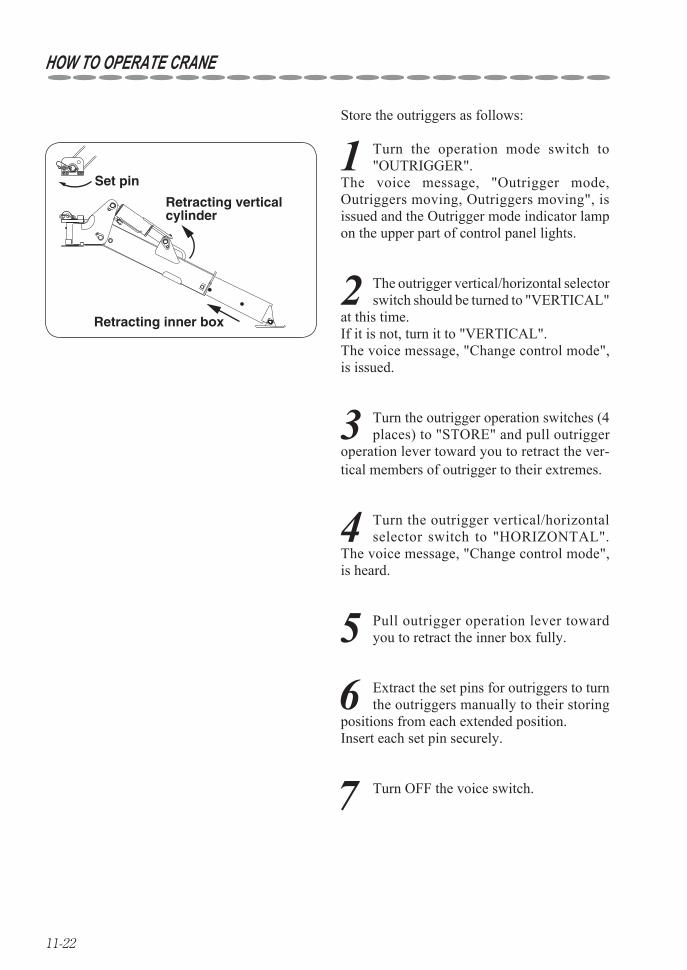
11-22
HOW TO OPERATE CRANE
Store the outriggers as follows:
Retracting inner box
Set pin
Retracting vertical cylinder
1 Turn the operation mode switch to "OUTRIGGER".
The voice message, "Outrigger mode, Outriggers moving, Outriggers moving", is issued and the Outrigger mode indicator lamp on the upper part of control panel lights.
2 The outrigger vertical/horizontal selector switch should be turned to "VERTICAL"
at this time. If it is not, turn it to "VERTICAL". The voice message, "Change control mode", is issued.
3 Turn the outrigger operation switches (4 places) to "STORE" and pull outrigger
operation lever toward you to retract the ver-tical members of outrigger to their extremes.
4 Turn the outrigger vertical/horizontal selector switch to "HORIZONTAL".
The voice message, "Change control mode", is heard.
5 Pull outrigger operation lever toward you to retract the inner box fully.
6 Extract the set pins for outriggers to turn the outriggers manually to their storing
positions from each extended position. Insert each set pin securely.
7 Turn OFF the voice switch.
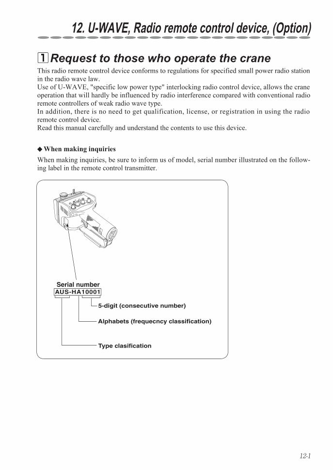
12-1
12. U-WAVE, Radio remote control device, (Option)
Request to those who operate the crane 1
AUS-HA10001Serial number
5-digit (consecutive number)
Alphabets (frequecncy classification)
Type clasification
This radio remote control device conforms to regulations for specified small power radio station in the radio wave law.Use of U-WAVE, "specific low power type" interlocking radio control device, allows the crane operation that will hardly be influenced by radio interference compared with conventional radio remote controllers of weak radio wave type.In addition, there is no need to get qualification, license, or registration in using the radio remote control device.Read this manual carefully and understand the contents to use this device.
When making inquiries, be sure to inform us of model, serial number illustrated on the follow-ing label in the remote control transmitter.
When making inquiries ◆
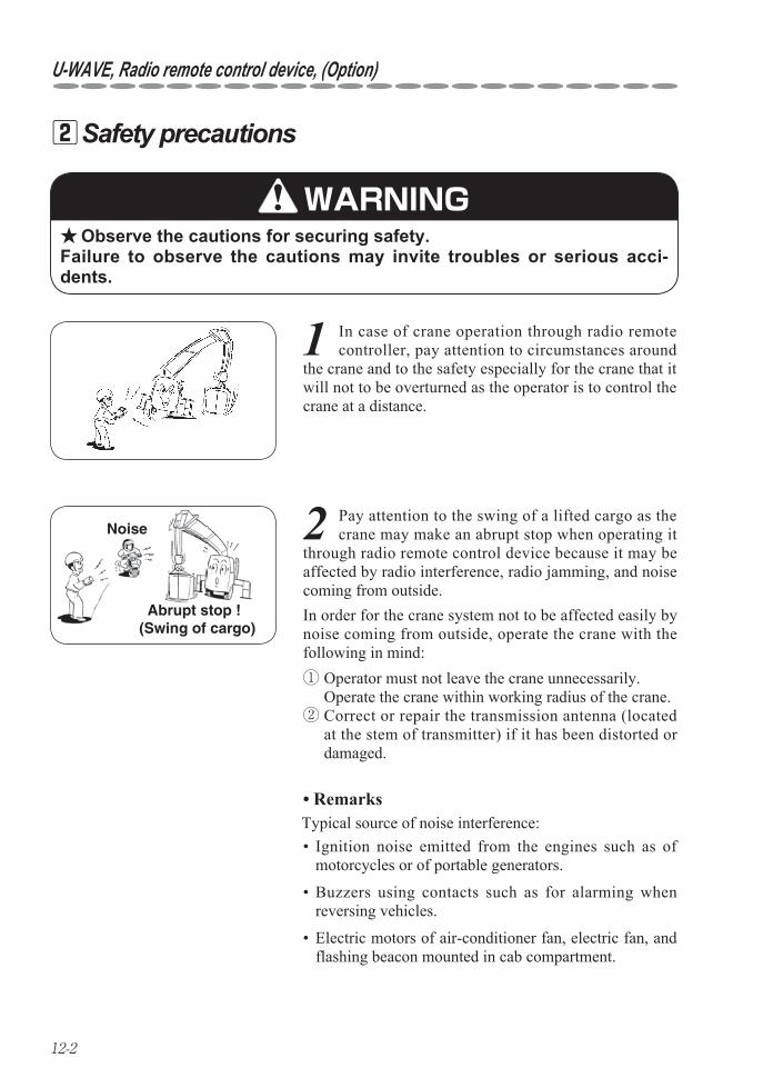
12-2
U-WAVE, Radio remote control device, (Option)
Safety precautions 2
2 Pay attention to the swing of a lifted cargo as the crane may make an abrupt stop when operating it
through radio remote control device because it may be affected by radio interference, radio jamming, and noise coming from outside.
Observe the cautions for securing safety. ★Failure to observe the cautions may invite troubles or serious acci-dents.
1 In case of crane operation through radio remote controller, pay attention to circumstances around
the crane and to the safety especially for the crane that it will not to be overturned as the operator is to control the crane at a distance.
Abrupt stop ! (Swing of cargo)
Noise
WARNING
Remarks•
In order for the crane system not to be affected easily by noise coming from outside, operate the crane with the following in mind:① Operator must not leave the crane unnecessarily. Operate the crane within working radius of the crane.② Correct or repair the transmission antenna (located
at the stem of transmitter) if it has been distorted or damaged.
Ignition noise emitted from the engines such as of • motorcycles or of portable generators.
Buzzers using contacts such as for alarming when • reversing vehicles.
Electric motors of air-conditioner fan, electric fan, and • flashing beacon mounted in cab compartment.
Typical source of noise interference:
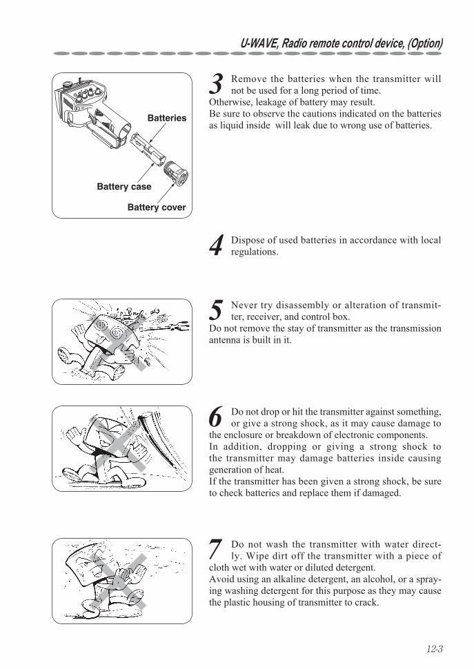
12-3
U-WAVE, Radio remote control device, (Option)
7 Do not wash the transmitter with water direct-ly. Wipe dirt off the transmitter with a piece of
cloth wet with water or diluted detergent. Avoid using an alkaline detergent, an alcohol, or a spray-ing washing detergent for this purpose as they may cause the plastic housing of transmitter to crack.
5 Never try disassembly or alteration of transmit-ter, receiver, and control box.
Do not remove the stay of transmitter as the transmission antenna is built in it.
6 Do not drop or hit the transmitter against something, or give a strong shock, as it may cause damage to
the enclosure or breakdown of electronic components. In addition, dropping or giving a strong shock to the transmitter may damage batteries inside causing generation of heat. If the transmitter has been given a strong shock, be sure to check batteries and replace them if damaged.
3 Remove the batteries when the transmitter will not be used for a long period of time.
Otherwise, leakage of battery may result. Be sure to observe the cautions indicated on the batteries as liquid inside will leak due to wrong use of batteries.
Battery cover
Batteries
Battery case
4 Dispose of used batteries in accordance with local regulations.
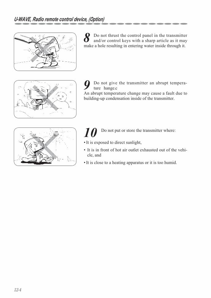
12-4
U-WAVE, Radio remote control device, (Option)
8 Do not thrust the control panel in the transmitter and/or control keys with a sharp article as it may
make a hole resulting in entering water inside through it.
9 Do not give the transmitter an abrupt tempera-ture change.
An abrupt temperature change may cause a fault due to building-up condensation inside of the transmitter.
10 Do not put or store the transmitter where:
It is exposed to direct sunlight,•
It is in front of hot air outlet exhausted out of the vehi-• cle, and
It is close to a heating apparatus or it is too humid.•
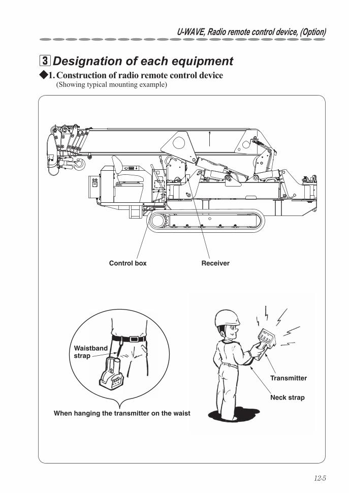
12-5
U-WAVE, Radio remote control device, (Option)
Designation of each equipment 3
Control box Receiver
Waistbandstrap
When hanging the transmitter on the waist
Neck strap
Transmitter
Construction of radio remote control device 1. ◆(Showing typical mounting example)
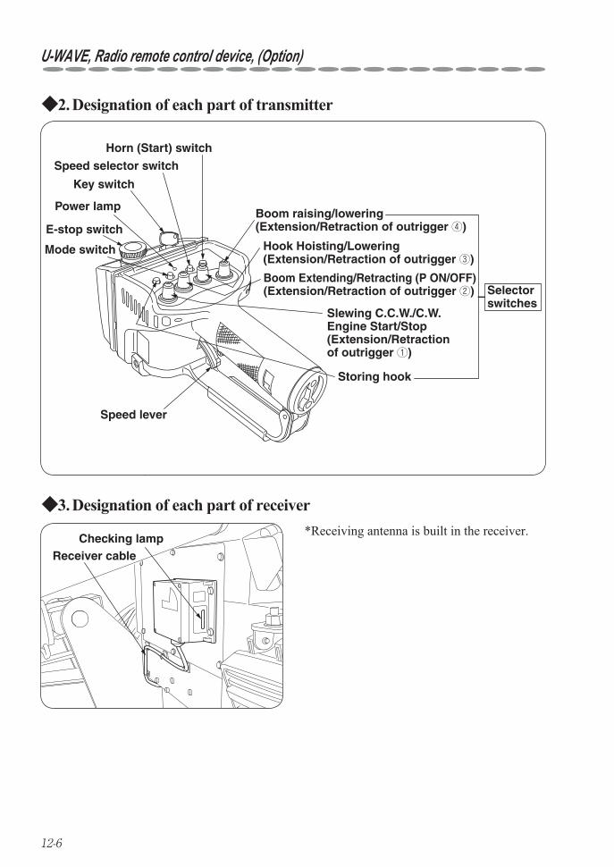
12-6
U-WAVE, Radio remote control device, (Option)
Designation of each part of transmitter2. ◆
Mode switch
Power lamp
E-stop switch
Key switch
Speed selector switch
Horn (Start) switch
Speed lever
Boom Extending/Retracting (P ON/OFF)(Extension/Retraction of outrigger ②) Selector
switches
Storing hook
Boom raising/lowering(Extension/Retraction of outrigger ④)
Slewing C.C.W./C.W.Engine Start/Stop(Extension/Retraction of outrigger ①)
Hook Hoisting/Lowering(Extension/Retraction of outrigger ③)
Designation of each part of receiver3. ◆
Receiver cableChecking lamp
*Receiving antenna is built in the receiver.
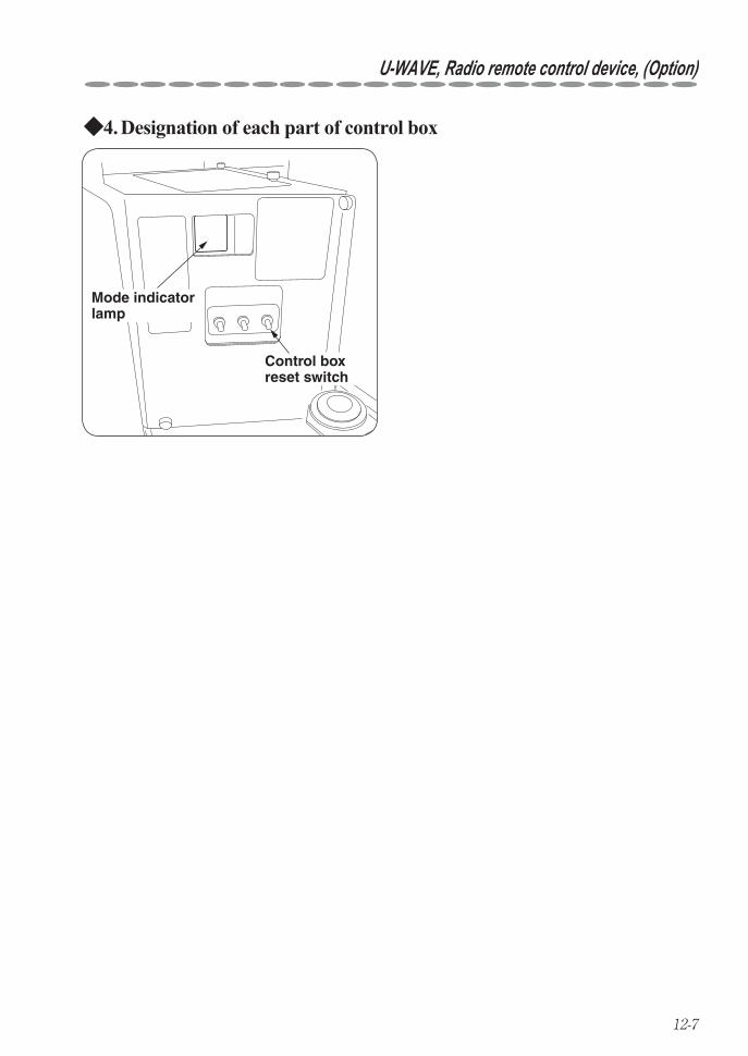
12-7
U-WAVE, Radio remote control device, (Option)
Designation of each part of control box4. ◆
Mode indicator lamp
Control boxreset switch
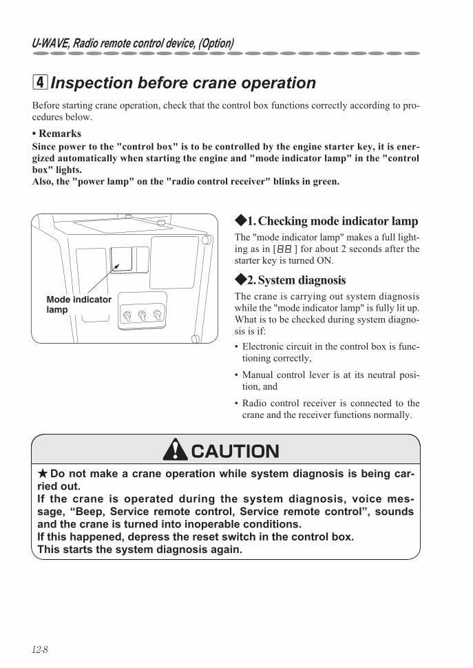
12-8
U-WAVE, Radio remote control device, (Option)
Before starting crane operation, check that the control box functions correctly according to pro-cedures below.
Checking mode indicator lamp1. ◆
Inspection before crane operation 4
Mode indicator lamp
Do not make a crane operation while system diagnosis is being car- ★ried out. If the crane is operated during the system diagnosis, voice mes-sage, “Beep, Service remote control, Service remote control”, sounds and the crane is turned into inoperable conditions. If this happened, depress the reset switch in the control box. This starts the system diagnosis again.
Remarks• Since power to the "control box" is to be controlled by the engine starter key, it is ener-gized automatically when starting the engine and "mode indicator lamp" in the "control box" lights.Also, the "power lamp" on the "radio control receiver" blinks in green.
System diagnosis2. ◆
The "mode indicator lamp" makes a full light-ing as in [ ] for about 2 seconds after the starter key is turned ON.
Electronic circuit in the control box is func-• tioning correctly,
Manual control lever is at its neutral posi-• tion, and
Radio control receiver is connected to the • crane and the receiver functions normally.
The crane is carrying out system diagnosis while the "mode indicator lamp" is fully lit up.What is to be checked during system diagno-sis is if:
CAUTION
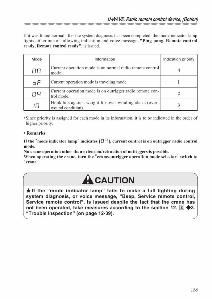
12-9
U-WAVE, Radio remote control device, (Option)
If it was found normal after the system diagnosis has been completed, the mode indicator lamp lights either one of following indication and voice message, "Ping-pong, Remote control ready, Remote control ready", is issued.
Since priority is assigned for each mode in its information, it is to be indicated in the order of • higher priority.
Remarks•
If the “mode indicator lamp” fails to make a full lighting during ★system diagnosis, or voice message, “Beep, Service remote control, Service remote control”, is issued despite the fact that the crane has not been operated, take measures according to the section 12. 8 ◆3. “Trouble inspection” (on page 12-39).
Mode Information Indication priority
Current operation mode is on normal radio remote control mode. 4
Current operation mode is traveling mode. 1
Current operation mode is on outrigger radio remote con-trol mode. 2
Hook hits against weight for over-winding alarm (over-wound condition). 3
If the "mode indicator lamp" indicates [ ], current control is on outrigger radio control mode.No crane operation other than extension/retraction of outriggers is possible.When operating the crane, turn the "crane/outrigger operation mode selector" switch to "crane".
CAUTION
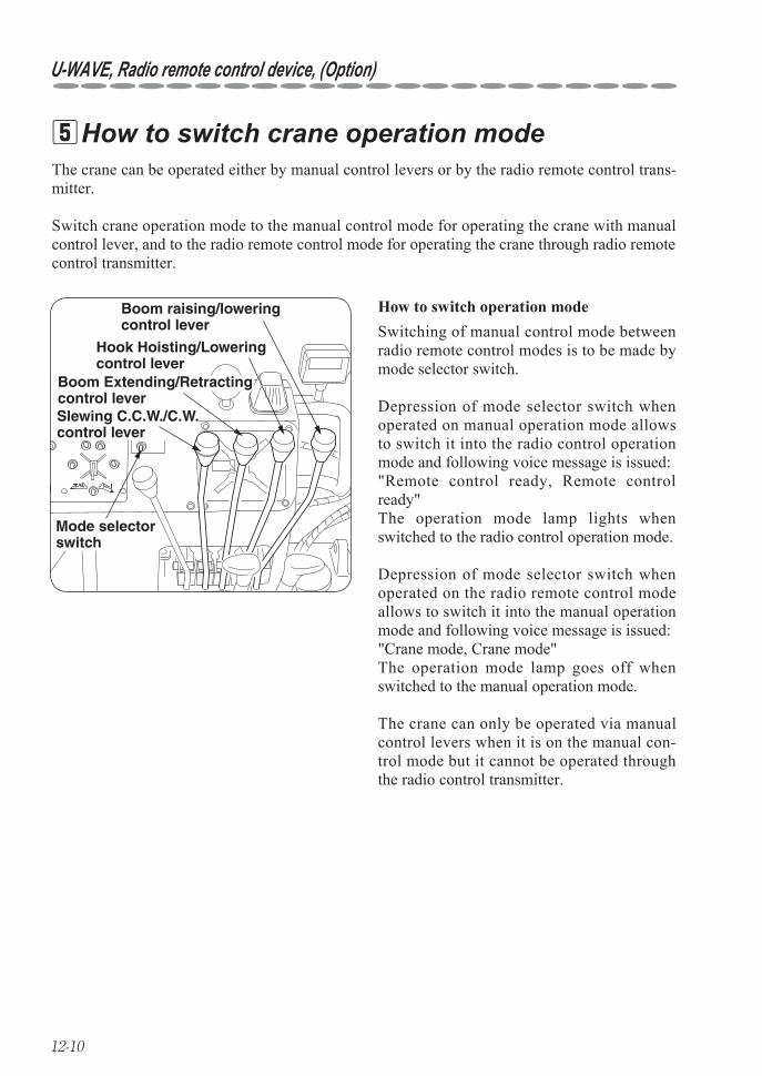
12-10
U-WAVE, Radio remote control device, (Option)
The crane can be operated either by manual control levers or by the radio remote control trans-mitter.
Switch crane operation mode to the manual control mode for operating the crane with manual control lever, and to the radio remote control mode for operating the crane through radio remote control transmitter.
How to switch crane operation mode 5
Boom raising/lowering control lever
Hook Hoisting/Lowering control lever
Boom Extending/Retracting control lever
Mode selectorswitch
Slewing C.C.W./C.W. control lever
How to switch operation modeSwitching of manual control mode between radio remote control modes is to be made by mode selector switch.
Depression of mode selector switch when operated on manual operation mode allows to switch it into the radio control operation mode and following voice message is issued:"Remote control ready, Remote control ready"The operation mode lamp lights when switched to the radio control operation mode.
Depression of mode selector switch when operated on the radio remote control mode allows to switch it into the manual operation mode and following voice message is issued:"Crane mode, Crane mode"The operation mode lamp goes off when switched to the manual operation mode.
The crane can only be operated via manual control levers when it is on the manual con-trol mode but it cannot be operated through the radio control transmitter.
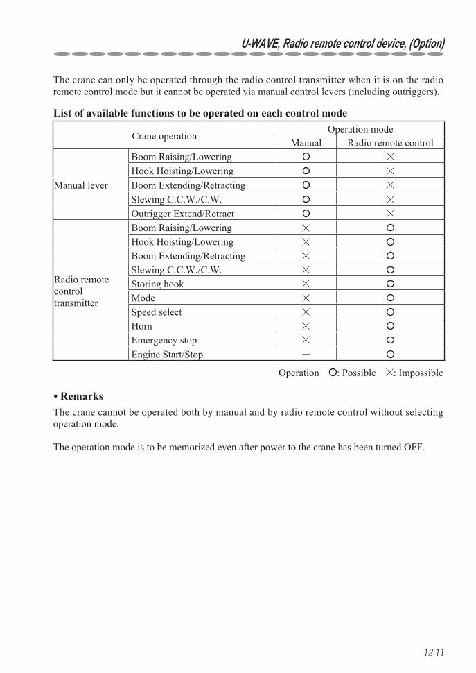
12-11
U-WAVE, Radio remote control device, (Option)
The crane can only be operated through the radio control transmitter when it is on the radio remote control mode but it cannot be operated via manual control levers (including outriggers).
Operation : Possible : Impossible
List of available functions to be operated on each control mode
Crane operationOperation mode
Manual Radio remote control
Manual lever
Boom Raising/LoweringHook Hoisting/LoweringBoom Extending/RetractingSlewing C.C.W./C.W.Outrigger Extend/Retract
Radio remote controltransmitter
Boom Raising/LoweringHook Hoisting/LoweringBoom Extending/RetractingSlewing C.C.W./C.W.Storing hookModeSpeed selectHornEmergency stopEngine Start/Stop ─
Remarks• The crane cannot be operated both by manual and by radio remote control without selecting operation mode.
The operation mode is to be memorized even after power to the crane has been turned OFF.
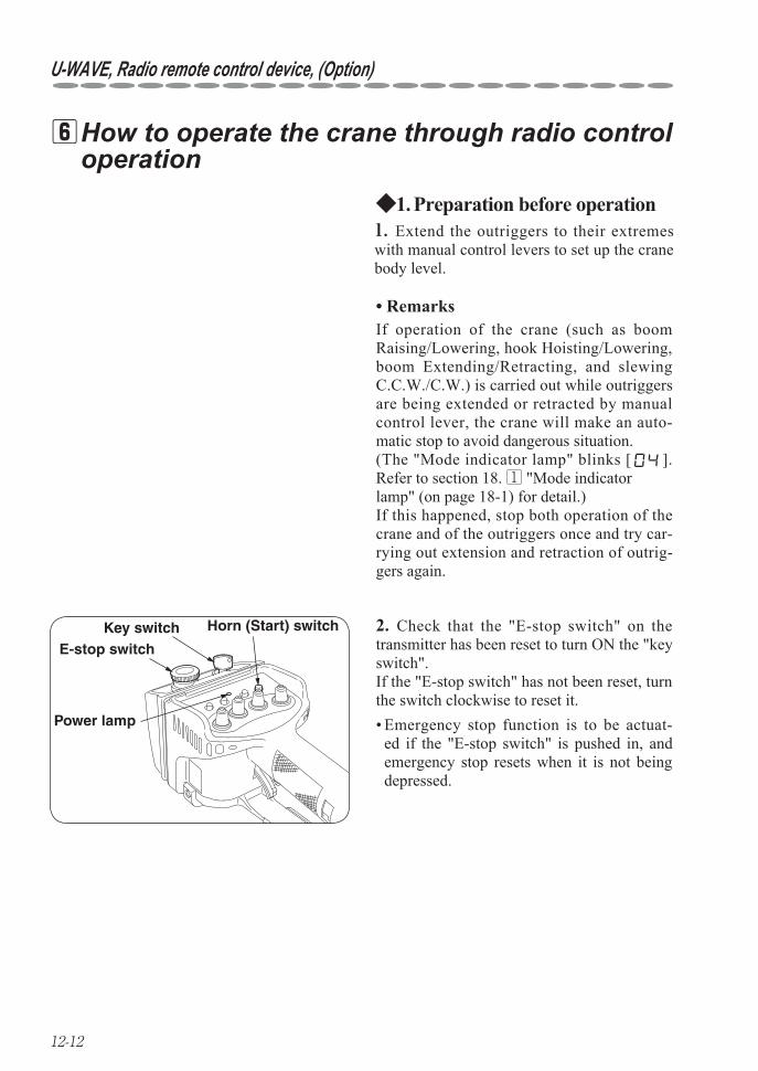
12-12
U-WAVE, Radio remote control device, (Option)
How to operate the crane through radio control 6operation
Preparation before operation1. ◆
Power lamp
E-stop switchKey switch Horn (Start) switch
Remarks•
1. Extend the outriggers to their extremes with manual control levers to set up the crane body level.
2. Check that the "E-stop switch" on the transmitter has been reset to turn ON the "key switch". If the "E-stop switch" has not been reset, turn the switch clockwise to reset it.
If operation of the crane (such as boom Raising/Lowering, hook Hoisting/Lowering, boom Extending/Retracting, and slewing C.C.W./C.W.) is carried out while outriggers are being extended or retracted by manual control lever, the crane will make an auto-matic stop to avoid dangerous situation.(The "Mode indicator lamp" blinks [ ]. Refer to section 18. 1 "Mode indicator lamp" (on page 18-1) for detail.)If this happened, stop both operation of the crane and of the outriggers once and try car-rying out extension and retraction of outrig-gers again.
Emergency stop function is to be actuat-• ed if the "E-stop switch" is pushed in, and emergency stop resets when it is not being depressed.
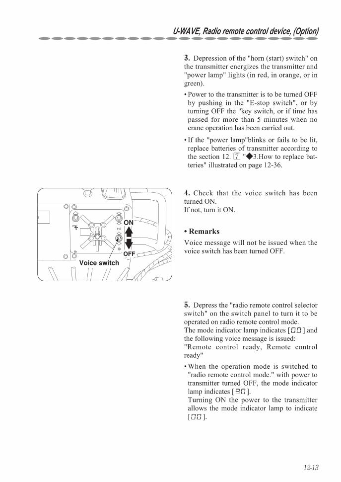
12-13
U-WAVE, Radio remote control device, (Option)
OFF
ON
Voice switch
3. Depression of the "horn (start) switch" on the transmitter energizes the transmitter and "power lamp" lights (in red, in orange, or in green).
4. Check that the voice switch has been turned ON.If not, turn it ON.
5. Depress the "radio remote control selector switch" on the switch panel to turn it to be operated on radio remote control mode. The mode indicator lamp indicates [ ] and the following voice message is issued:"Remote control ready, Remote control ready"
Power to the transmitter is to be turned OFF • by pushing in the "E-stop switch", or by turning OFF the "key switch, or if time has passed for more than 5 minutes when no crane operation has been carried out.
If the "power lamp"blinks or fails to be lit, • replace batteries of transmitter according to the section 12. 7 "◆3.How to replace bat-teries" illustrated on page 12-36.
Voice message will not be issued when the voice switch has been turned OFF.
Remarks•
When the operation mode is switched to • "radio remote control mode." with power to transmitter turned OFF, the mode indicator lamp indicates [ ]. Turning ON the power to the transmitter allows the mode indicator lamp to indicate [ ].
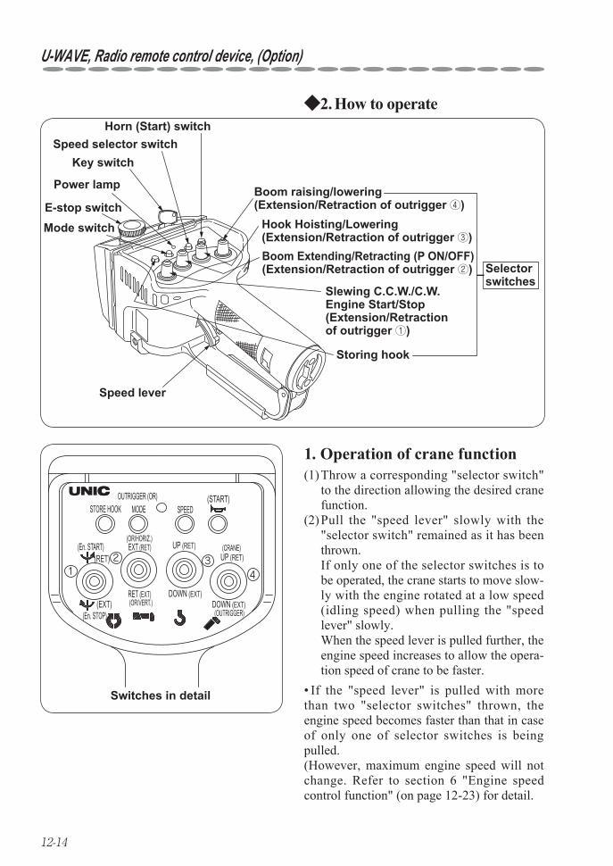
12-14
U-WAVE, Radio remote control device, (Option)
How to operate2. ◆
412 3
Switches in detail
STORE HOOK
(RET)
(START)
(EXT)(En. STOP)
MODEOUTRIGGER (OR)
EXT (RET)
RET (EXT) (OR/VERT.)
SPEED
UP (RET)
DOWN (EXT)
UP (RET)
DOWN (EXT) (OUTRIGGER)
(En. START) (OR/HORIZ.)
(CRANE)
1. Operation of crane function
Mode switch
Power lamp
E-stop switch
Key switchSpeed selector switch
Horn (Start) switch
Speed lever
Boom Extending/Retracting (P ON/OFF)(Extension/Retraction of outrigger ②) Selector
switches
Storing hook
Boom raising/lowering(Extension/Retraction of outrigger ④)
Slewing C.C.W./C.W.Engine Start/Stop(Extension/Retraction of outrigger ①)
Hook Hoisting/Lowering(Extension/Retraction of outrigger ③)
(1) Throw a corresponding "selector switch" to the direction allowing the desired crane function.
(2) Pull the "speed lever" slowly with the "selector switch" remained as it has been thrown.
If only one of the selector switches is to be operated, the crane starts to move slow-ly with the engine rotated at a low speed (idling speed) when pulling the "speed lever" slowly.
When the speed lever is pulled further, the engine speed increases to allow the opera-tion speed of crane to be faster.
If the "speed lever" is pulled with more • than two "selector switches" thrown, the engine speed becomes faster than that in case of only one of selector switches is being pulled. (However, maximum engine speed will not change. Refer to section 6 "Engine speed control function" (on page 12-23) for detail.
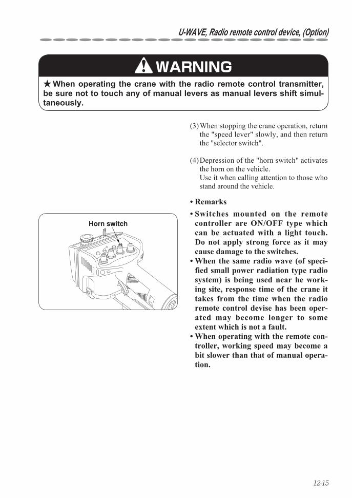
12-15
U-WAVE, Radio remote control device, (Option)
(3) When stopping the crane operation, return the "speed lever" slowly, and then return the "selector switch".
(4) Depression of the "horn switch" activates the horn on the vehicle.
Use it when calling attention to those who stand around the vehicle.
Horn switch
When operating the crane with the radio remote control transmitter, ★be sure not to touch any of manual levers as manual levers shift simul-taneously.
WARNING
Remarks• Switches mounted on the remote • controller are ON/OFF type which can be actuated with a light touch. Do not apply strong force as it may cause damage to the switches. When the same radio wave (of speci-• fied small power radiation type radio system) is being used near he work-ing site, response time of the crane it takes from the time when the radio remote control devise has been oper-ated may become longer to some extent which is not a fault. When operating with the remote con-• troller, working speed may become a bit slower than that of manual opera-tion.
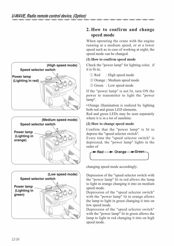
12-16
U-WAVE, Radio remote control device, (Option)
2. How to confirm and change speed mode
Power lamp (Lighting in red)
(High speed mode)Speed selector switch
Power lamp (Lighting inorange)
(Medium speed mode)Speed selector switch
Power lamp (Lighting ingreen)
(Low speed mode)Speed selector switch
Red Orange Green
changing speed mode accordingly.
Depression of the "speed selector switch with the "power lamp" lit in red allows the lamp to light in orange changing it into on medium speed mode.Depression of the "speed selector switch" with the "power lamp" lit in orange allows the lamp to light in green changing it into on low speed mode.Depression of the "speed selector switch" with the "power lamp" lit in green allows the lamp to light in red changing it into on high speed mode.
When operating the crane with the engine running at a medium speed, or at a lower speed such as in case of working at night, the speed mode can be changed.
Orange illumination is realized by lighting • both red and green LED elements. Red and green LEDs may be seen separately where it is in a lot of sunshine.
Check the "power lamp" for lighting color, if it is lit in;
Red : High speed mode ①Orange : Medium speed mode ②Green : Low speed mode ③
If the "power lamp" is not lit, turn ON the power to transmitter to light the "power lamp".
Confirm that the "power lamp" is lit to depress the "speed selector switch".Every time the "speed selector switch" is depressed, the "power lamp" lights in the order of
(2) How to change speed mode
(1) How to confirm speed mode
12-17
U-WAVE, Radio remote control device, (Option)
Remarks• Setting of speed mode is to be memorized even when power to transmitter has been turned OFF.Note that a slight speed difference between swinging C.C.W./C.W. may be found when swinging it on the low speed mode which is not a fault.
(3) Speed mode and manual lever controlManual lever control is also applied to the speed mode.
High speed mode …………… Engine will run at maximum speed.Medium speed mode ……… Engine will run at medium speed range.Low speed mode …………… Engine will run at close to idling speed.
Since setting of speed mode is memorized even when power to radio control transmitter has been turned OFF, speed mode is switched to the mode as the radio control transmitter has memorized previously when the crane is operated through radio control transmitter after power to the crane is turned ON again.
Remarks• Speed mode can only be changed through radio control transmitter.Speed mode switches to high speed mode when power to the crane is turned OFF (starter switch is turned OFF).
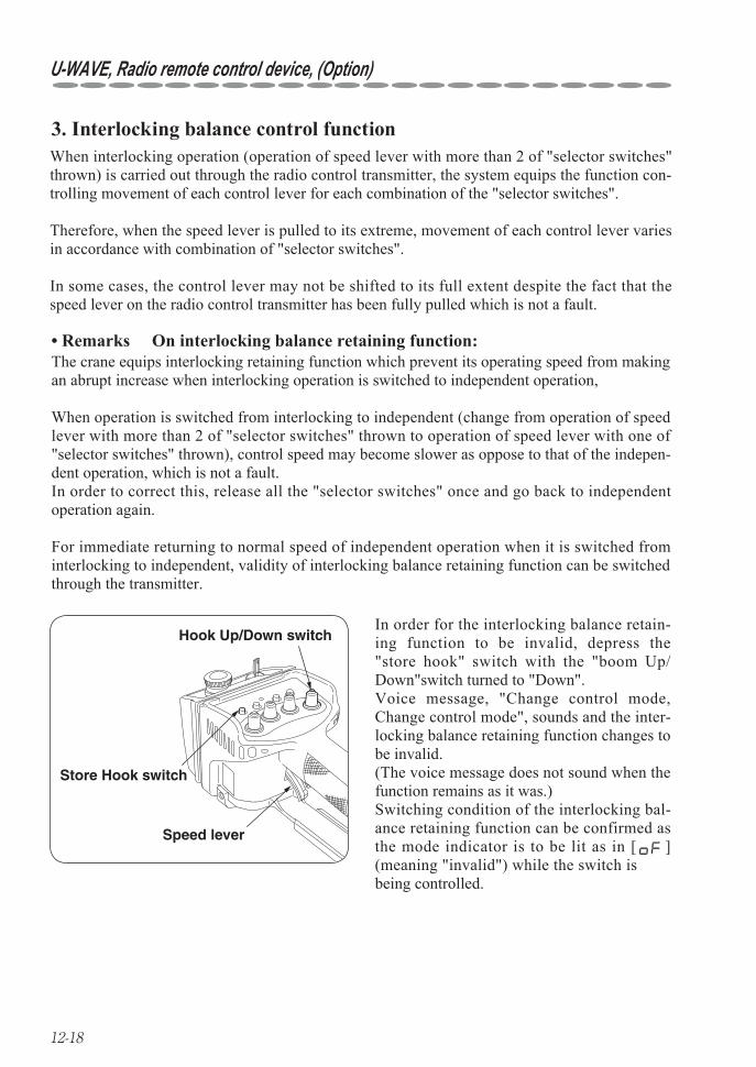
12-18
U-WAVE, Radio remote control device, (Option)
In order for the interlocking balance retain-ing function to be invalid, depress the "store hook" switch with the "boom Up/Down"switch turned to "Down".Voice message, "Change control mode, Change control mode", sounds and the inter-locking balance retaining function changes to be invalid.(The voice message does not sound when the function remains as it was.)Switching condition of the interlocking bal-ance retaining function can be confirmed as the mode indicator is to be lit as in [ ] (meaning "invalid") while the switch is being controlled.
Speed lever
Store Hook switch
Hook Up/Down switch
3. Interlocking balance control functionWhen interlocking operation (operation of speed lever with more than 2 of "selector switches" thrown) is carried out through the radio control transmitter, the system equips the function con-trolling movement of each control lever for each combination of the "selector switches".
Therefore, when the speed lever is pulled to its extreme, movement of each control lever varies in accordance with combination of "selector switches".
In some cases, the control lever may not be shifted to its full extent despite the fact that the speed lever on the radio control transmitter has been fully pulled which is not a fault.
Remarks On interlocking balance retaining function:• The crane equips interlocking retaining function which prevent its operating speed from making an abrupt increase when interlocking operation is switched to independent operation,
When operation is switched from interlocking to independent (change from operation of speed lever with more than 2 of "selector switches" thrown to operation of speed lever with one of "selector switches" thrown), control speed may become slower as oppose to that of the indepen-dent operation, which is not a fault.In order to correct this, release all the "selector switches" once and go back to independent operation again.
For immediate returning to normal speed of independent operation when it is switched from interlocking to independent, validity of interlocking balance retaining function can be switched through the transmitter.
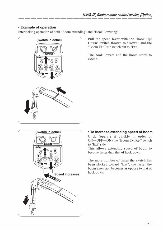
12-19
U-WAVE, Radio remote control device, (Option)
(Switch in detail)
E-STOP OFF ON
STORE HOOK
(RET)
(START)
(EXT)(En. STOP)
MODE
EXT (RET)
RET (EXT)
SPEED
UP (RET)
DOWN (EXT)
UP (RET)
DOWN (EXT)
(En. START)
Speed increases
(Switch in detail)
E-STOP OFF ON
STORE HOOK
(RET)
(START)
(EXT)(En. STOP)
MODE
EXT (RET)
RET (EXT)
SPEED
UP (RET)
DOWN (EXT)
UP (RET)
DOWN (EXT)
(En. START)
Example of operation•
Pull the speed lever with the "hook Up/Down" switch thrown to "Down" and the "Boom Ext/Ret" switch put to "Ext".
The hook lowers and the boom starts to extend.
To increase extending speed of boom•
Interlocking operation of both "Boom extending" and "Hook Lowering".
Click (operate it quickly in order of ON→OFF→ON) the "Boom Ext/Ret" switch to "Ext" side.This allows extending speed of boom to become faster than that of hook down.
The more number of times the switch has been clicked toward "Ext", the faster the boom extension becomes as oppose to that of hook down.

12-20
U-WAVE, Radio remote control device, (Option)
Speed increases
(Switch in detail)
E-STOP OFF ON
STORE HOOK
(RET)
(START)
(EXT)(En. STOP)
MODE
EXT (RET)
RET (EXT)
SPEED
UP (RET)
DOWN (EXT)
UP (RET)
DOWN (EXT)
(En. START)
To increase winding Down speed of • hook
Remarks•
Click the "hook Up/Down" switch to "Down" side.This allows the speed of hook down to become faster than that of boom extension.
The more number of times the switch has been clicked for "Down", the faster the speed of winding Down hook becomes as opposed to that of boom extension.
Repeated clicks allow the other operation • not to function in the end. If this happened, release all the "selector switches" once, or click the "selector switch" for which operation is inactivated.
When one of "selector switches" is • released during the clicking operation, speed of crane under operation may become faster.
The clicking function is possible only • when in 2-interlocking operation. It will not be applied to operation such as of 3-interlocking and 4-interlocking.
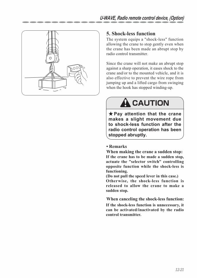
12-21
U-WAVE, Radio remote control device, (Option)
5. Shock-less function
Pay attention that the crane ★makes a slight movement due to shock-less function after the radio control operation has been stopped abruptly.
Remarks • When making the crane a sudden stop:
The system equips a "shock-less" function allowing the crane to stop gently even when the crane has been made an abrupt stop by radio control transmitter.
Since the crane will not make an abrupt stop against a sharp operation, it eases shock to the crane and/or to the mounted vehicle, and it is also effective to prevent the wire rope from jumping up and a lifted cargo from swinging when the hook has stopped winding-up.
CAUTION
If the crane has to be made a sudden stop, actuate the "selector switch" controlling opposite function while the shock-less is functioning.(Do not pull the speed lever in this case.)Otherwise, the shock-less function is released to allow the crane to make a sudden stop.
When canceling the shock-less function:If the shock-less function is unnecessary, it can be activated/inactivated by the radio control transmitter.
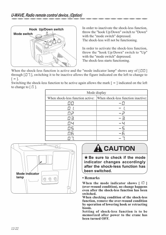
12-22
U-WAVE, Radio remote control device, (Option)
Mode switchHook Up/Down switch In order to inactivate the shock-less function,
throw the "hook Up/Down" switch to "Down" with the "mode switch" depressed.The shock-less will not be functioning.
In order to activate the shock-less function, throw the "hook Up/Down" switch to "Up" with the "mode switch" depressed.The shock-less starts functioning.
When the shock-less function is active and the "mode indicator lamp" shows any of [ ] through [ ], switching it to be inactive allows the figure indicated on the left to change to [ ].Switching the shock-less function to be active again allows the mark [ ] indicated on the left to change to [ ].
Remarks• Mode indicator lamp
Mode displayWhen shock-less function active: When shock-less function inactive:
Be sure to check if the mode ★indicator changes accordingly after the shock-less function has been switched.
CAUTION
When the mode indicator shows [ ] (over-wound condition), no change happens even after the shock-less function has been switched.When checking condition of the shock-less function, remove the over-wound condition by operation of lowering hook or retracting boom.Setting of shock-less function is to be memorized after power to the crane has been turned OFF.
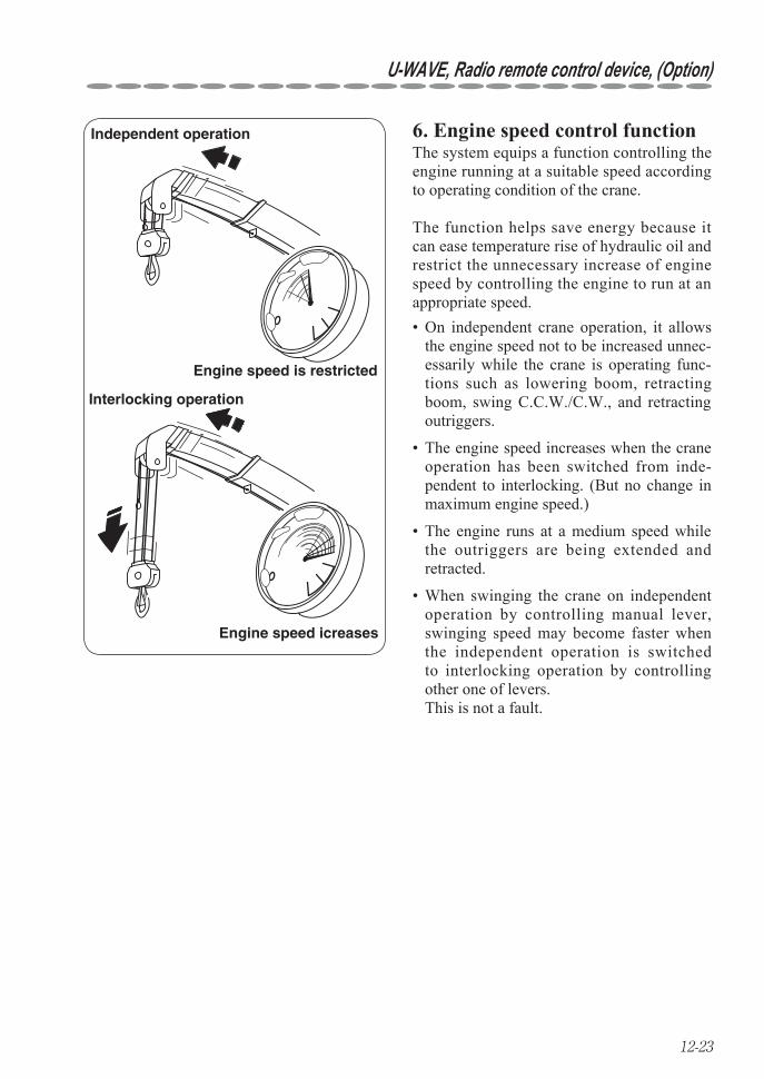
12-23
U-WAVE, Radio remote control device, (Option)
Engine speed icreases
Independent operation
Engine speed is restricted
Interlocking operation
6. Engine speed control functionThe system equips a function controlling the engine running at a suitable speed according to operating condition of the crane.
The function helps save energy because it can ease temperature rise of hydraulic oil and restrict the unnecessary increase of engine speed by controlling the engine to run at an appropriate speed.
On independent crane operation, it allows • the engine speed not to be increased unnec-essarily while the crane is operating func-tions such as lowering boom, retracting boom, swing C.C.W./C.W., and retracting outriggers.
The engine speed increases when the crane • operation has been switched from inde-pendent to interlocking. (But no change in maximum engine speed.)
The engine runs at a medium speed while • the outriggers are being extended and retracted.
When swinging the crane on independent • operation by controlling manual lever, swinging speed may become faster when the independent operation is switched to interlocking operation by controlling other one of levers. This is not a fault.
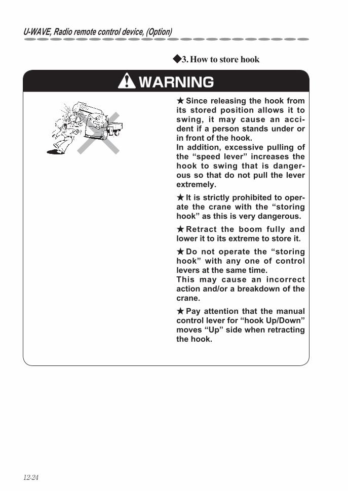
12-24
U-WAVE, Radio remote control device, (Option)
How to store hook3. ◆
Since releasing the hook from ★its stored position allows it to swing, it may cause an acci-dent if a person stands under or in front of the hook. In addition, excessive pulling of the “speed lever” increases the hook to swing that is danger-ous so that do not pull the lever extremely.
It is strictly prohibited to oper- ★ate the crane with the “storing hook” as this is very dangerous.
Retract the boom fully and ★lower it to its extreme to store it.
Do not operate the “storing ★hook” with any one of control levers at the same time. This may cause an incorrect action and/or a breakdown of the crane.
Pay attention that the manual ★control lever for “hook Up/Down” moves “Up” side when retracting the hook.
WARNING
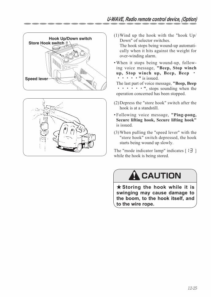
12-25
U-WAVE, Radio remote control device, (Option)
(1) Wind up the hook with the "hook Up/Down" of selector switches.
The hook stops being wound-up automati-cally when it hits against the weight for over-winding alarm.
Speed lever
Store Hook switchHook Up/Down switch
When it stops being wound-up, follow-• ing voice message, "Beep, Stop winch up, Stop winch up, Beep, Beep ・・・・・・" is issued. The last part of voice message, "Beep, Beep ・・・・・・", stops sounding when the operation concerned has been stopped.
(2) Depress the "store hook" switch after the hook is at a standstill.
Following voice message, • "Ping-pong, Secure lifting hook, Secure lifting hook" is issued.
(3) When pulling the "speed lever" with the "store hook" switch depressed, the hook starts being wound up slowly.
The "mode indicator lamp" indicates [ ] while the hook is being stored.
Storing the hook while it is ★swinging may cause damage to the boom, to the hook itself, and to the wire rope.
CAUTION
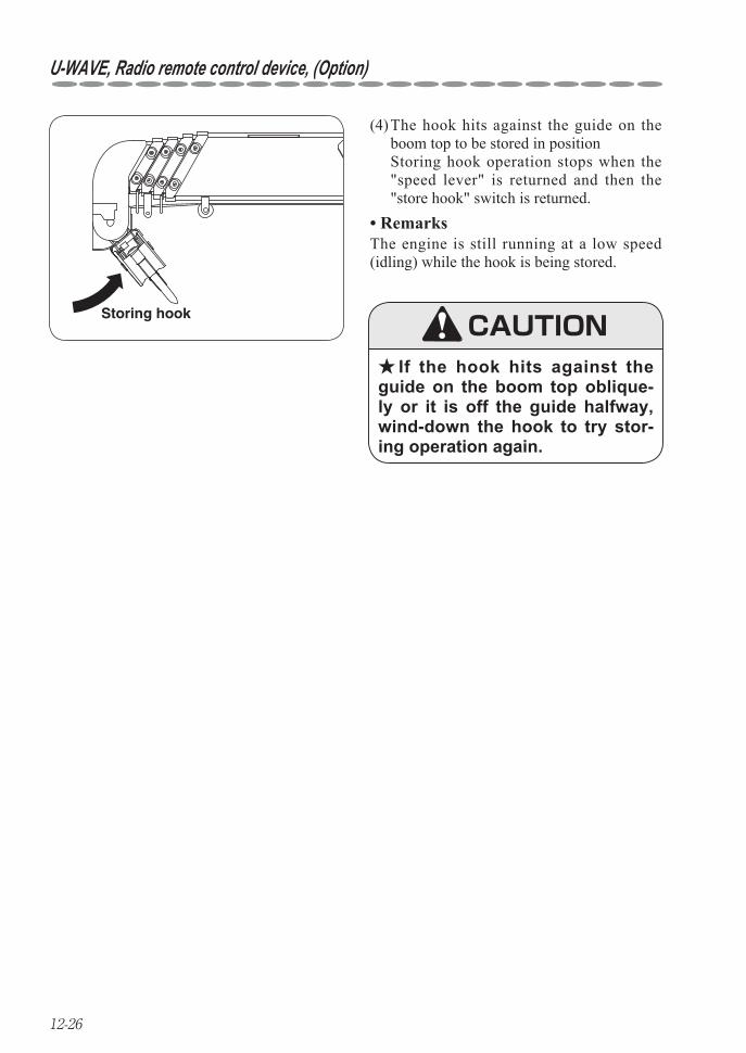
12-26
U-WAVE, Radio remote control device, (Option)
Storing hook
(4) The hook hits against the guide on the boom top to be stored in position
Storing hook operation stops when the "speed lever" is returned and then the "store hook" switch is returned.
Remarks• The engine is still running at a low speed (idling) while the hook is being stored.
If the hook hits against the ★guide on the boom top oblique-ly or it is off the guide halfway, wind-down the hook to try stor-ing operation again.
CAUTION
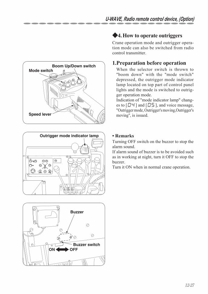
12-27
U-WAVE, Radio remote control device, (Option)
How to operate outriggers 4. ◆Crane operation mode and outrigger opera-tion mode can also be switched from radio control transmitter.
ON OFF
Buzzer
Buzzer switch
Outrigger mode indicator lamp
Boom Up/Down switch Mode switch
Speed lever
1. Preparation before operation When the selector switch is thrown to "boom down" with the "mode switch" depressed, the outrigger mode indicator lamp located on top part of control panel lights and the mode is switched to outrig-ger operation mode. Indication of "mode indicator lamp" chang-es to [ ] and [ ], and voice message, "Outrigger mode, Outrigger's moving,Outrigger's moving", is issued.
Remarks• Turning OFF switch on the buzzer to stop the alarm sound.If alarm sound of buzzer is to be avoided such as in working at night, turn it OFF to stop the buzzer.Turn it ON when in normal crane operation.
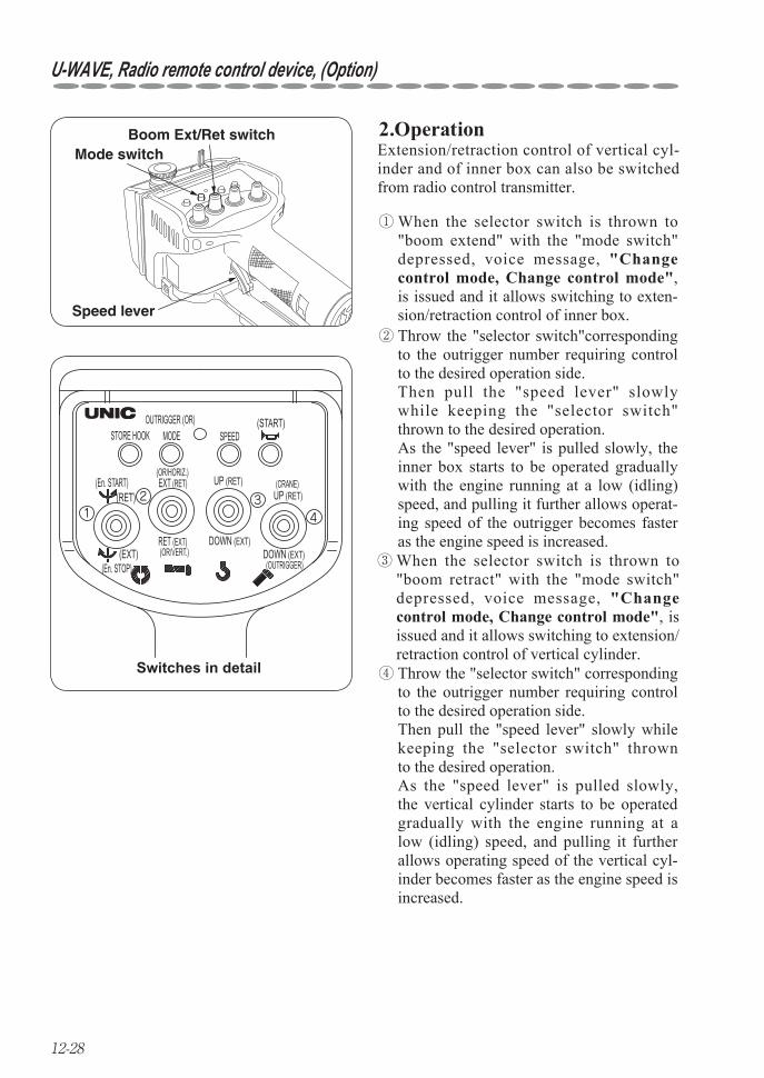
12-28
U-WAVE, Radio remote control device, (Option)
2.OperationMode switch
Boom Ext/Ret switch
Speed lever
412 3
Switches in detail
STORE HOOK
(RET)
(START)
(EXT)(En. STOP)
MODEOUTRIGGER (OR)
EXT (RET)
RET (EXT) (OR/VERT.)
SPEED
UP (RET)
DOWN (EXT)
UP (RET)
DOWN (EXT) (OUTRIGGER)
(En. START) (OR/HORIZ.)
(CRANE)
When the selector switch is thrown to ①"boom extend" with the "mode switch" depressed, voice message, "Change control mode, Change control mode", is issued and it allows switching to exten-sion/retraction control of inner box.
Extension/retraction control of vertical cyl-inder and of inner box can also be switched from radio control transmitter.
Throw the "selector switch"corresponding ②to the outrigger number requiring control to the desired operation side. Then pull the "speed lever" slowly while keeping the "selector switch" thrown to the desired operation. As the "speed lever" is pulled slowly, the inner box starts to be operated gradually with the engine running at a low (idling) speed, and pulling it further allows operat-ing speed of the outrigger becomes faster as the engine speed is increased.
Throw the "selector switch" corresponding ④to the outrigger number requiring control to the desired operation side. Then pull the "speed lever" slowly while keeping the "selector switch" thrown to the desired operation. As the "speed lever" is pulled slowly, the vertical cylinder starts to be operated gradually with the engine running at a low (idling) speed, and pulling it further allows operating speed of the vertical cyl-inder becomes faster as the engine speed is increased.
When the selector switch is thrown to ③"boom retract" with the "mode switch" depressed, voice message, "Change control mode, Change control mode", is issued and it allows switching to extension/retraction control of vertical cylinder.
12-29
U-WAVE, Radio remote control device, (Option)
When it has been switched from the crane mode, it is in ver- ★tical cylinder "Extension/Retraction mode". If extension or retraction of inner box is required, switch it to operation of extension or retraction of inner box.
If it has been selected to the mode (operation) to which is going to be ★selected, voice message will not be issued.
To extendTurn the switch to "Extend" to pull the "speed lever". To retractTurn the switch to "Retract" to pull the "speed lever". To stopReturn the "selector switch" after the "speed lever" has been returned slowly.
When the selector switch is thrown ⑤to "boom Up" with the "mode switch" depressed, voice message, "Crane mode, Crane mode", is issued and the mode is switched to crane operation mode when the outrigger mode indicator lamp located on top part of control panel goes off.
When the "crane/outrigger operation mode selector switch" is turned to "outrigger" (out-rigger mode indicator lamp is being lit), nor-mal crane operation of "boom Up/Down", "hook Up/Down", "telescoping boom", "swinging C.C.W./C.W.", and "storing hook" to be impossible both in radio control trans-mitter and in manual control lever.
Remarks•
CAUTION
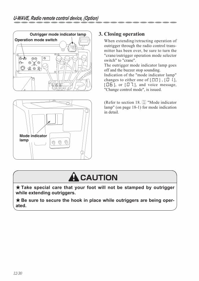
12-30
U-WAVE, Radio remote control device, (Option)
3. Closing operationOperation mode switch
Outrigger mode indicator lamp
Mode indicator lamp
Take special care that your foot will not be stamped by outrigger ★while extending outriggers.
Be sure to secure the hook in place while outriggers are being oper- ★ated.
When extending/retracting operation of outrigger through the radio control trans-mitter has been over, be sure to turn the "crane/outrigger operation mode selector switch" to "crane". The outrigger mode indicator lamp goes off and the buzzer stop sounding. Indication of the "mode indicator lamp" changes to either one of [ ] , [ ], [ ], or [ ], and voice message, "Change control mode", is issued.
(Refer to section 18. 1 "Mode indicator lamp" (on page 18-1) for mode indication in detail.
CAUTION
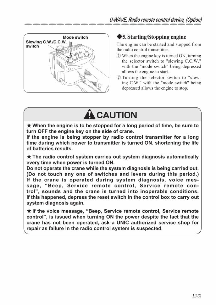
12-31
U-WAVE, Radio remote control device, (Option)
Starting/Stopping engine5. ◆Slewing C.W./C.C.W. switch
Mode switch
When the engine is to be stopped for a long period of time, be sure to ★turn OFF the engine key on the side of crane. If the engine is being stopper by radio control transmitter for a long time during which power to transmitter is turned ON, shortening the life of batteries results.
The radio control system carries out system diagnosis automatically ★every time when power is turned ON. Do not operate the crane while the system diagnosis is being carried out.(Do not touch any one of switches and levers during this period.)If the crane is operated during system diagnosis, voice mes-sage, “Beep, Service remote control, Service remote con-trol”, sounds and the crane is turned into inoperable conditions.If this happened, depress the reset switch in the control box to carry out system diagnosis again.
If the voice message, “Beep, Service remote control, Service remote ★control”, is issued when turning ON the power despite the fact that the crane has not been operated, ask a UNIC authorized service shop for repair as failure in the radio control system is suspected.
The engine can be started and stopped from the radio control transmitter.
Turning the selector switch to "slew- ②ing C.W." with the "mode switch" being depressed allows the engine to stop.
When the engine key is turned ON, turning ①the selector switch to "slewing C.C.W." with the "mode switch" being depressed allows the engine to start.
CAUTION
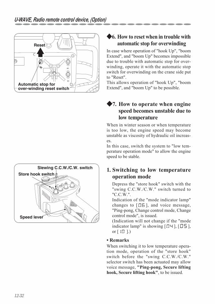
12-32
U-WAVE, Radio remote control device, (Option)
How to reset when in trouble with 6. ◆automatic stop for overwinding
How to operate when engine 7. ◆speed becomes unstable due to low temperature
Automatic stop for over-winding reset switch
Reset
Speed lever
Slewing C.C.W./C.W. switch
Store hook switch
In case where operation of "hook Up", "boom Extend", and "boom Up" becomes impossible due to trouble with automatic stop for over-winding, operate it with the automatic stop switch for overwinding on the crane side put to "Reset".This allows operation of "hook Up", "boom Extend", and "boom Up" to be possible.
1. Switching to low temperature operation mode
When in winter season or when temperature is too low, the engine speed may become unstable as viscosity of hydraulic oil increas-es.In this case, switch the system to "low tem-perature operation mode" to allow the engine speed to be stable.
Depress the "store hook" switch with the "swing C.C.W./C.W." switch turned to "C.C.W.". Indication of the "mode indicator lamp" changes to [ ], and voice message, "Ping-pong, Change control mode, Change control mode", is issued. (Indication will not change if the "mode indicator lamp" is showing [ ], [ ], or [ ].)
Remarks• When switching it to low temperature opera-tion mode, operation of the "store hook" switch before the "swing C.C.W./C.W." selector switch has been actuated may allow voice message, "Ping-pong, Secure lifting hook, Secure lifting hook", to be issued.
12-33
U-WAVE, Radio remote control device, (Option)
2. Resetting low temperature operation mode
Closing crane operation8. ◆
Depress the "store hook" switch with the "swing C.C.W./C.W."switch turned to "C.W.". Indication of "mode indicator lamp" changes to [ ] and voice message "Ping-pong, Change control mode, Change control mode", is issued.(Indication will not change if the "mode indicator" is showing [ ], [ ], or [ ].)
In addition, the low temperature operation mode is to be reset automatically, even when oper-ation illustrated above has not been carried out, after approx. 10 minutes from the time when it has been switched to the "low temperature operation mode". The voice message "Ping-pong, Change control mode, Change control mode", is issued at this time.
Remarks• Response of the crane functions becomes slower when operated on low temperature operation mode.In normal case, operate the crane after warming-up for a while to raise temperature of hydraulic oil.
Under extreme low temperature, crane operation may still be unstable even after the system has been switched to the "low temperature operation mode".In this case take measures such as by carrying out warm-up operation to raise temperature of hydraulic oil or by using hydraulic oil suitable for extreme low temperature.
If viscosity of hydraulic oil is too high at a low temperature, exces- ★sive load will be imposed on hydraulic pumps which may cause dam-age to them. In order to avoid this, be sure to carry out warming-up to raise tempera-ture of hydraulic oil to an appropriate temperature to operate the crane.
CAUTION
After completion of the crane work, turn OFF the starter switch to shut off power to the crane after the boom, the hook, and the out-riggers have been stored in their respective positions.
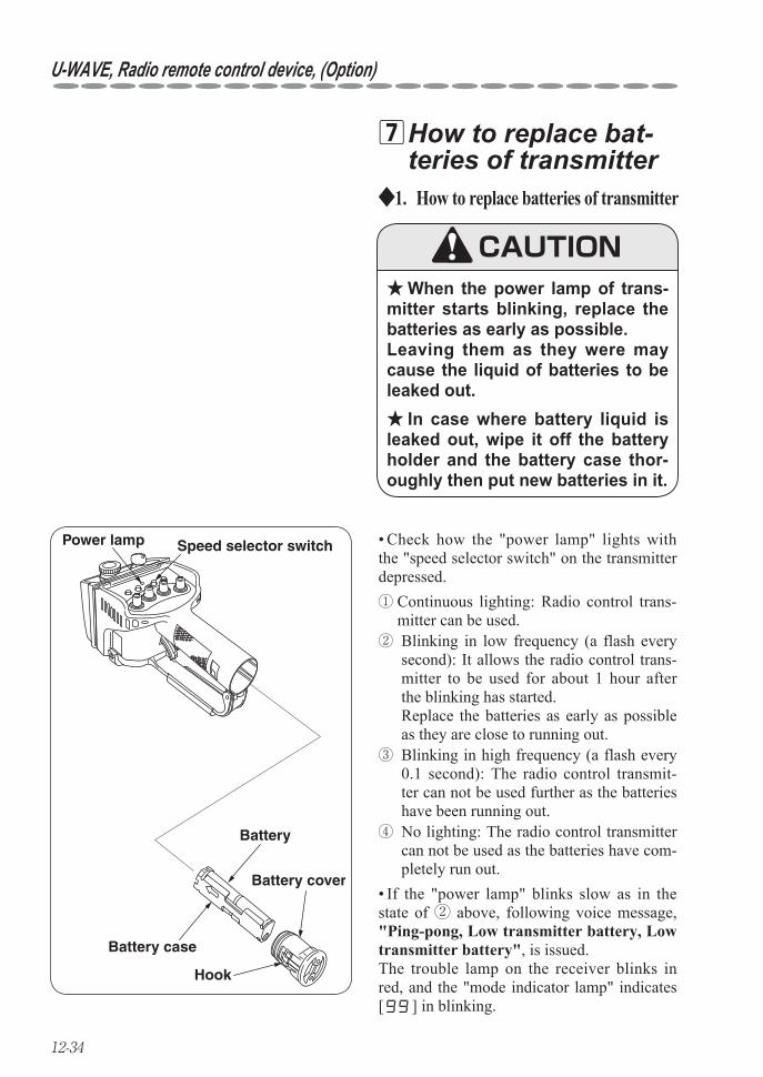
12-34
U-WAVE, Radio remote control device, (Option)
How to replace bat- 7teries of transmitter
When the power lamp of trans- ★mitter starts blinking, replace the batteries as early as possible. Leaving them as they were may cause the liquid of batteries to be leaked out.
In case where battery liquid is ★leaked out, wipe it off the battery holder and the battery case thor-oughly then put new batteries in it.
Check how the "power lamp" lights with • the "speed selector switch" on the transmitter depressed.
Speed selector switch
Battery cover
Battery
Battery case
Hook
Power lamp
How to replace batteries of transmitter1. ◆
CAUTION
Continuous lighting: Radio control trans- ①mitter can be used.
If the "power lamp" blinks slow as in the • state of ② above, following voice message, "Ping-pong, Low transmitter battery, Low transmitter battery", is issued. The trouble lamp on the receiver blinks in red, and the "mode indicator lamp" indicates [ ] in blinking.
No lighting: The radio control transmitter ④can not be used as the batteries have com-pletely run out.
Blinking in low frequency (a flash every ②second): It allows the radio control trans-mitter to be used for about 1 hour after the blinking has started. Replace the batteries as early as possible as they are close to running out. Blinking in high frequency (a flash every ③0.1 second): The radio control transmit-ter can not be used further as the batteries have been running out.
12-35
U-WAVE, Radio remote control device, (Option)
Battery to be employed2. ◆
Do not mix up batteries of old ★and new, of different manufactur-ers, or of different types.
Remarks • About the use of rechargeable batteries
a size AAA battery: 4 piecesUse alkaline-type battery. (Manganese-type battery has a short service life.)
Message suggesting replacement of battery • may not be issued. Be sure to prepare alkaline-type batteries when operating the crane through radio remote control device because rechargeable batteries tend to become inoperable sud-denly.
In some cases, service life of recharge-• able battery may become shorter than that of alkaline battery in accordance with the capacity.
There is a disadvantage such as memory • effect comparing with alkaline-type battery.
Although UNIC recommends the use of alka-line type battery in the radio control device, other rechargeable batteries such as nickel-hydrogen type and nickel-cadmium type may also be used.Pay attention to the following when a rechargeable battery is used:
CAUTION
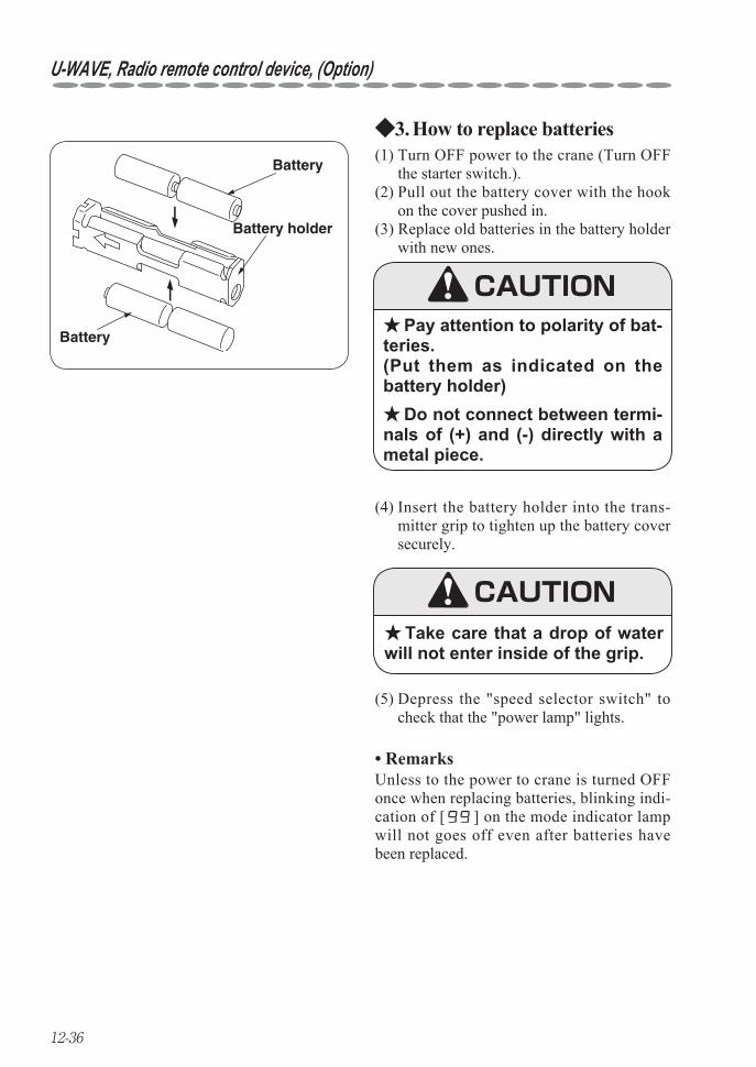
12-36
U-WAVE, Radio remote control device, (Option)
How to replace batteries3. ◆
(4) Insert the battery holder into the trans-mitter grip to tighten up the battery cover securely.
Take care that a drop of water ★will not enter inside of the grip.
(5) Depress the "speed selector switch" to check that the "power lamp" lights.
Battery
Battery
Battery holder
(1) Turn OFF power to the crane (Turn OFF the starter switch.).
(2) Pull out the battery cover with the hook on the cover pushed in.
(3) Replace old batteries in the battery holder with new ones.
Pay attention to polarity of bat- ★teries. (Put them as indicated on the battery holder)
Do not connect between termi- ★nals of (+) and (-) directly with a metal piece.
CAUTION
CAUTION
Remarks• Unless to the power to crane is turned OFF once when replacing batteries, blinking indi-cation of [ ] on the mode indicator lamp will not goes off even after batteries have been replaced.
12-37
U-WAVE, Radio remote control device, (Option)
Daily checks, trouble inspection 8Daily checks1. ◆
For cranes with radio remote control device, you are requested to inspect your crane for follow-ing items as well as carry out daily checks on your crane (read operator's manual of UNIC crane concerned for detail).Check that;
1. Each enclosure of transmitter, receiver, and control box has not been damaged. If the enclosure has been damaged, repair it immediately because moisture and/or dust entered through the break may cause a failure to electronic parts inside and cause incorrect operation of the crane concerned.
2. The stay on the transmitter has not been broken or deformed. The transmitting antenna is built in the stay. If break or remarkable deformation is found in the stay, replace or repair it as soon as pos-sible because it may cause radio interference.
3. Switches and control levers on the radio control transmitter make a smooth operation. Using the remote control transmitter with dust, dirt, and mud being stuck on may lead to failure especially in operation of switches and/or control levers. Wipe them off with a piece of cloth after use. If any of the selector switches fails to function correctly due to contamination, ask a UNIC authorized service shop for cleaning.
Never try disassembly or alteration of the transmitter, the receiver, ★and the control box.
Electric system is very sensitive to moisture. ★Do not wash the transmitter, the receiver, and the control box with water directly.
CAUTION
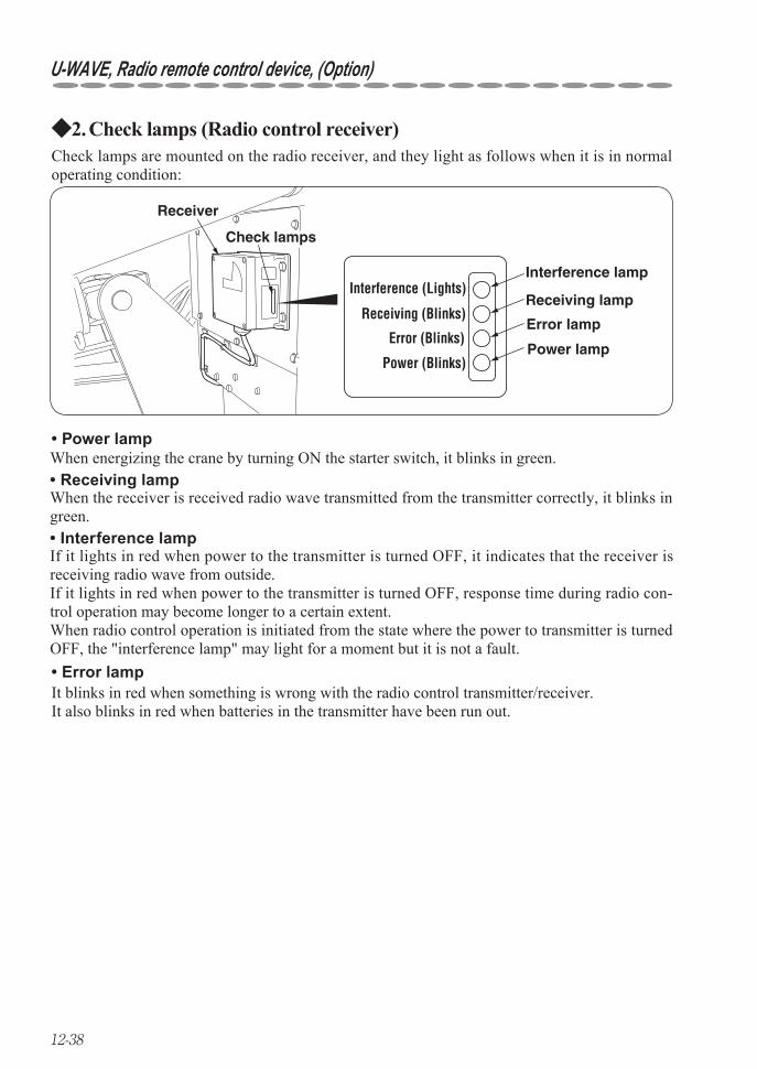
12-38
U-WAVE, Radio remote control device, (Option)
Check lamps (Radio control receiver)2. ◆
Interference (Lights)
Receiver
Check lamps
Interference lamp
Receiving lamp
Error lamp
Power lampPower (Blinks)
Error (Blinks)
Receiving (Blinks)
Check lamps are mounted on the radio receiver, and they light as follows when it is in normal operating condition:
Power lamp• When energizing the crane by turning ON the starter switch, it blinks in green.
Interference lamp• If it lights in red when power to the transmitter is turned OFF, it indicates that the receiver is receiving radio wave from outside. If it lights in red when power to the transmitter is turned OFF, response time during radio con-trol operation may become longer to a certain extent.When radio control operation is initiated from the state where the power to transmitter is turned OFF, the "interference lamp" may light for a moment but it is not a fault.
Receiving lamp• When the receiver is received radio wave transmitted from the transmitter correctly, it blinks in green.
Error lamp• It blinks in red when something is wrong with the radio control transmitter/receiver.It also blinks in red when batteries in the transmitter have been run out.
12-39
U-WAVE, Radio remote control device, (Option)
Trouble inspection3. ◆
If the "error lamp" on the receiver blinks in red, turn OFF the power once and turn it ON again (turn ON the starter switch again).If blinking of "error lamp" persists, repair is needed as the radio remote control device is in fail-ure.
If a trouble is found in the radio remote control device, check the following then contact the nearest UNIC authorized service shop.Check if:
Crane is controlled by manual levers. ① The "power lamp" on the transmitter lights. If it blinks or does not light, replace the bat- ②teries in the transmitter.Switches and control levers on the transmitter make a correct operation. ③ The stay on the transmitter (antenna is built in) has not been broken or deformed. ④ The "mode indicator lamp" in the control box lights and the "power lamp" on ⑤the receiver blinks in green when power to the control box is turned ON. If the "mode indicator lamp" blinks, refer to section "18. 1 Mode indicator" (on page18-1).
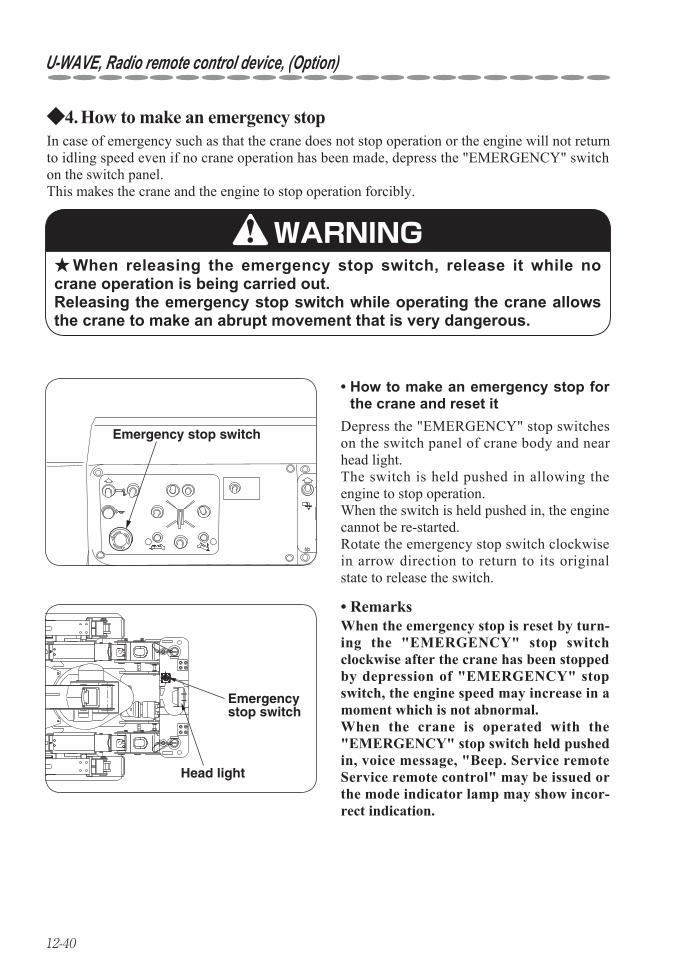
12-40
U-WAVE, Radio remote control device, (Option)
How to make an emergency stop4. ◆
How to make an emergency stop for • the crane and reset it
Emergency stop switch
Emergencystop switch
Head light
In case of emergency such as that the crane does not stop operation or the engine will not return to idling speed even if no crane operation has been made, depress the "EMERGENCY" switch on the switch panel. This makes the crane and the engine to stop operation forcibly.
When releasing the emergency stop switch, release it while no ★crane operation is being carried out. Releasing the emergency stop switch while operating the crane allows the crane to make an abrupt movement that is very dangerous.
WARNING
Depress the "EMERGENCY" stop switches on the switch panel of crane body and near head light.The switch is held pushed in allowing the engine to stop operation.When the switch is held pushed in, the engine cannot be re-started.Rotate the emergency stop switch clockwise in arrow direction to return to its original state to release the switch.
Remarks• When the emergency stop is reset by turn-ing the "EMERGENCY" stop switch clockwise after the crane has been stopped by depression of "EMERGENCY" stop switch, the engine speed may increase in a moment which is not abnormal.When the crane is operated with the "EMERGENCY" stop switch held pushed in, voice message, "Beep. Service remote Service remote control" may be issued or the mode indicator lamp may show incor-rect indication.
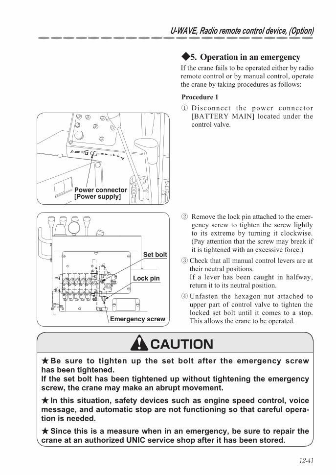
12-41
U-WAVE, Radio remote control device, (Option)
Operation in an emergency5. ◆
Set bolt
Lock pin
Emergency screw
Power connector [Power supply]
Be sure to tighten up the set bolt after the emergency screw ★has been tightened. If the set bolt has been tightened up without tightening the emergency screw, the crane may make an abrupt movement.
In this situation, safety devices such as engine speed control, voice ★message, and automatic stop are not functioning so that careful opera-tion is needed.
Since this is a measure when in an emergency, be sure to repair the ★crane at an authorized UNIC service shop after it has been stored.
Procedure 1
If the crane fails to be operated either by radio remote control or by manual control, operate the crane by taking procedures as follows:
Disconnect the power connector ①[BATTERY MAIN] located under the control valve.
Remove the lock pin attached to the emer- ②gency screw to tighten the screw lightly to its extreme by turning it clockwise. (Pay attention that the screw may break if it is tightened with an excessive force.) Check that all manual control levers are at ③their neutral positions. If a lever has been caught in halfway, return it to its neutral position. Unfasten the hexagon nut attached to ④upper part of control valve to tighten the locked set bolt until it comes to a stop. This allows the crane to be operated.
CAUTION
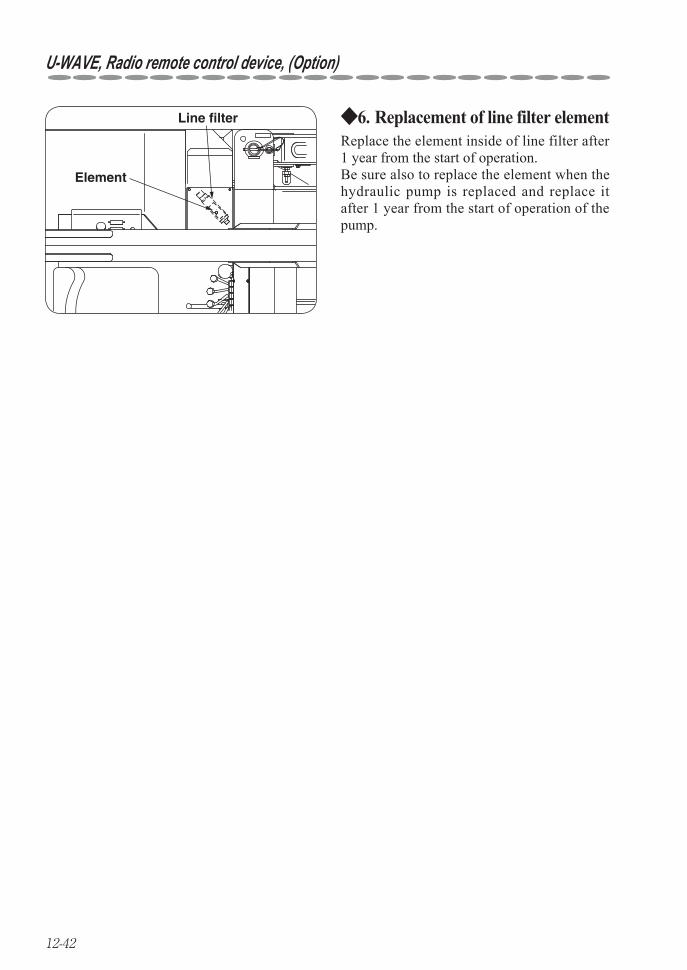
12-42
U-WAVE, Radio remote control device, (Option)
Replacement of line filter element6. ◆
Element
Line filter
Replace the element inside of line filter after 1 year from the start of operation.Be sure also to replace the element when the hydraulic pump is replaced and replace it after 1 year from the start of operation of the pump.

13-1
13. MAINTENANCE AND INSPECTION OF CARRIER
Caution signboard ★Be sure to hang a “caution signboard” such as on control levers while either maintenance or inspection is being carried out, and do not try operating the crane.
Be sure to replace consumable items according to the replace- ★ment criteria. Failure to observe the replacement as specified may cause a break-down and warranty will not be given even if it is within the period to be applied.
When a part needs to be replaced or anything abnormal is found, ★contact a UNIC service shop for consultation or for inspection or ask repair as soon as possible.
WARNING
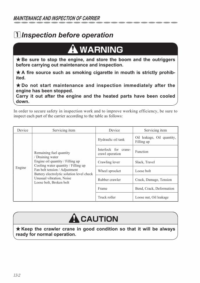
13-2
MAINTENANCE AND INSPECTION OF CARRIER
In order to secure safety in inspection work and to improve working efficiency, be sure to inspect each part of the carrier according to the table as follows:
Inspection before operation 1
Be sure to stop the engine, and store the boom and the outriggers ★before carrying out maintenance and inspection.
A fire source such as smoking cigarette in mouth is strictly prohib- ★ited.
Do not start maintenance and inspection immediately after the ★engine has been stopped. Carry it out after the engine and the heated parts have been cooled down.
Keep the crawler crane in good condition so that it will be always ★ready for normal operation.
WARNING
Device Servicing item Device Servicing item
Engine
Remaining fuel quantity / Draining waterEngine oil quantity / Filling upCooling water quantity / Filling upFan belt tension / AdjustmentBattery electrolytic solution level checkUnusual vibration, NoiseLoose bolt, Broken bolt
Hydraulic oil tank Oil leakage, Oil quantity, Filling up
Interlock for crane-crawl operation Function
Crawling lever Slack, Travel
Wheel sprocket Loose bolt
Rubber crawler Crack, Damage, Tension
Frame Bend, Crack, Deformation
Truck roller Loose nut, Oil leakage
CAUTION
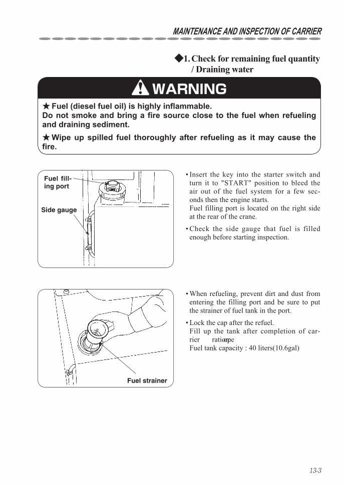
13-3
MAINTENANCE AND INSPECTION OF CARRIER
Check for remaining fuel quantity 1. ◆/ Draining water
Fuel (diesel fuel oil) is highly inflammable. ★Do not smoke and bring a fire source close to the fuel when refueling and draining sediment.
Wipe up spilled fuel thoroughly after refueling as it may cause the ★fire.
Fuel fill-ing port
Side gauge
Fuel strainer
WARNING
Insert the key into the starter switch and • turn it to "START" position to bleed the air out of the fuel system for a few sec-onds then the engine starts. Fuel filling port is located on the right side at the rear of the crane.
Check the side gauge that fuel is filled • enough before starting inspection.
When refueling, prevent dirt and dust from • entering the filling port and be sure to put the strainer of fuel tank in the port.
Lock the cap after the refuel. • Fill up the tank after completion of car-rier operation. Fuel tank capacity : 40 liters(10.6gal)

13-4
MAINTENANCE AND INSPECTION OF CARRIER
Water separator
Moisture mixed with the fuel can be • removed by the water separator.
Retaining ring
Float
Element
Filter case
Water draining level
Draining moisture and sediment by • water separator
Water separator is built in the fuel filter and functions to separate moisture from the water mixed fuel to avoid trouble caused by water.
Check it everyday and remove the retaining ring to drain the accumulated water if the "float" reaches the element inside of the case.
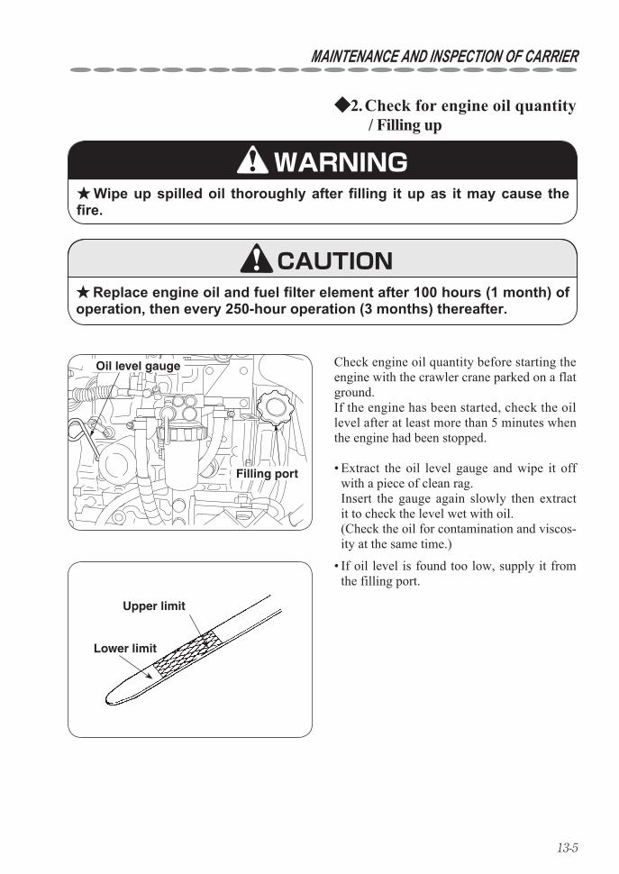
13-5
MAINTENANCE AND INSPECTION OF CARRIER
Oil level gauge
Filling port
Check engine oil quantity before starting the engine with the crawler crane parked on a flat ground.If the engine has been started, check the oil level after at least more than 5 minutes when the engine had been stopped.
Check for engine oil quantity2. ◆ / Filling up
Wipe up spilled oil thoroughly after filling it up as it may cause the ★fire.
Upper limit
Lower limit
WARNING
Replace engine oil and fuel filter element after 100 hours (1 month) of ★operation, then every 250-hour operation (3 months) thereafter.
CAUTION
Extract the oil level gauge and wipe it off • with a piece of clean rag. Insert the gauge again slowly then extract it to check the level wet with oil. (Check the oil for contamination and viscos-ity at the same time.)
If oil level is found too low, supply it from • the filling port.
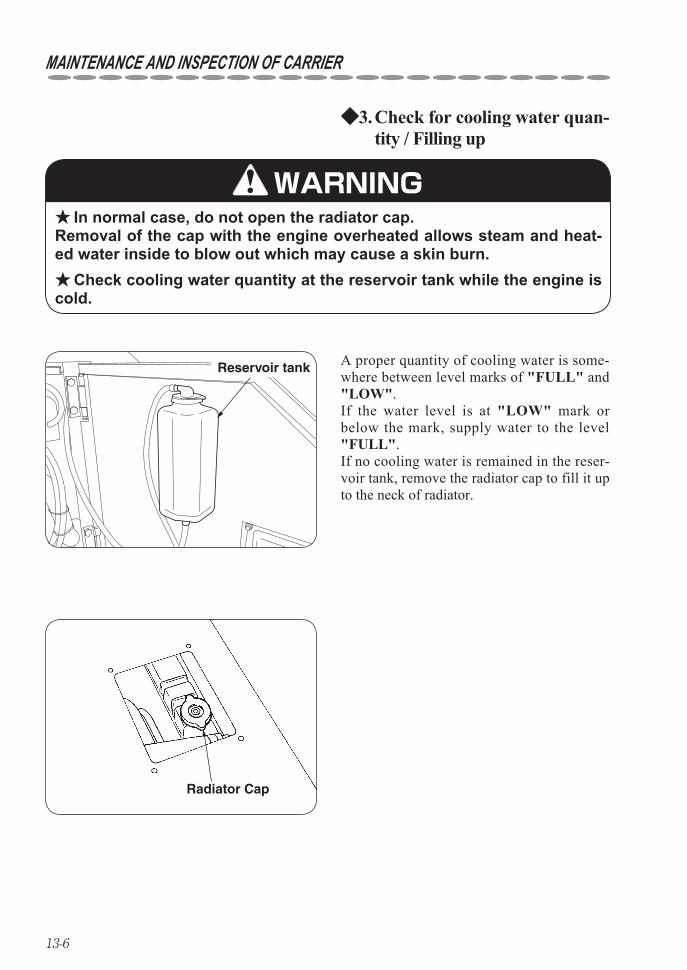
13-6
MAINTENANCE AND INSPECTION OF CARRIER
Reservoir tank A proper quantity of cooling water is some-where between level marks of "FULL" and "LOW".If the water level is at "LOW" mark or below the mark, supply water to the level "FULL".If no cooling water is remained in the reser-voir tank, remove the radiator cap to fill it up to the neck of radiator.
Check for cooling water quan-3. ◆tity / Filling up
In normal case, do not open the radiator cap. ★Removal of the cap with the engine overheated allows steam and heat-ed water inside to blow out which may cause a skin burn.
Check cooling water quantity at the reservoir tank while the engine is ★cold.
Radiator Cap
WARNING
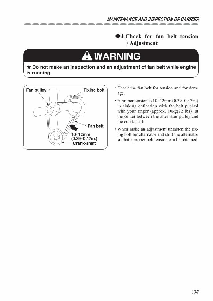
13-7
MAINTENANCE AND INSPECTION OF CARRIER
Fan pulley Fixing bolt
Crank-shaft
10~12mm(0.39~0.47in.)
Fan belt
Check the fan belt for tension and for dam-• age.
A proper tension is 10~12mm (0.39~0.47in.) • in sinking deflection with the belt pushed with your finger (approx. 10kg(22 lbs)) at the center between the alternator pulley and the crank-shaft.
When make an adjustment unfasten the fix-• ing bolt for alternator and shift the alternator so that a proper belt tension can be obtained.
Check for fan belt tension4. ◆ / Adjustment
Do not make an inspection and an adjustment of fan belt while engine ★is running.
WARNING
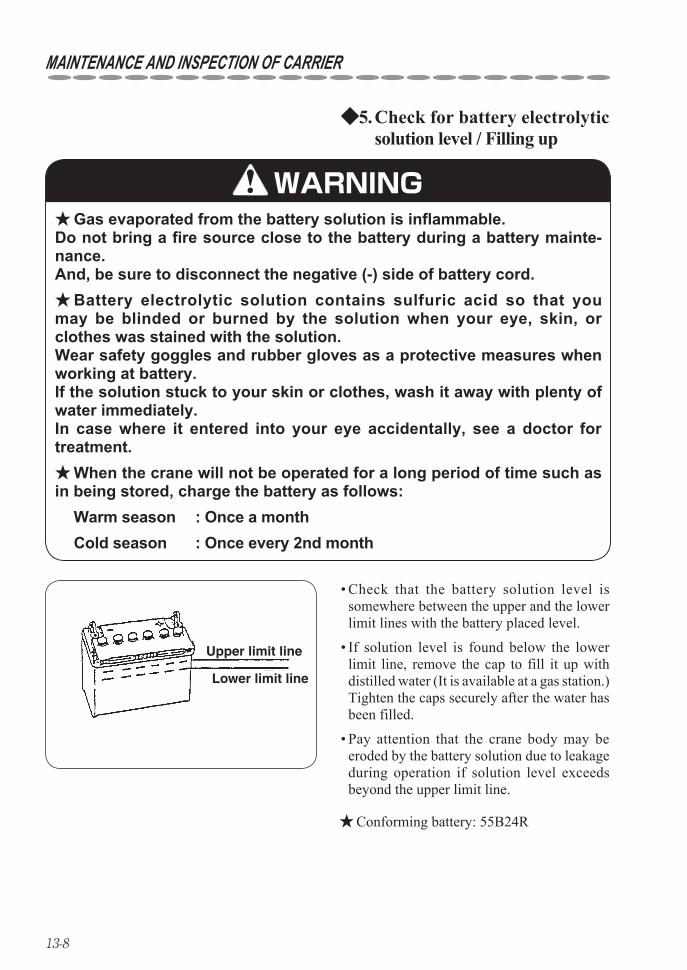
13-8
MAINTENANCE AND INSPECTION OF CARRIER
Check that the battery solution level is • somewhere between the upper and the lower limit lines with the battery placed level.
If solution level is found below the lower • limit line, remove the cap to fill it up with distilled water (It is available at a gas station.) Tighten the caps securely after the water has been filled.
Pay attention that the crane body may be • eroded by the battery solution due to leakage during operation if solution level exceeds beyond the upper limit line.
Check for battery electrolytic 5. ◆solution level / Filling up
Upper limit line
Lower limit line
Gas evaporated from the battery solution is inflammable. ★Do not bring a fire source close to the battery during a battery mainte-nance. And, be sure to disconnect the negative (-) side of battery cord.
Battery electrolytic solution contains sulfuric acid so that you ★may be blinded or burned by the solution when your eye, skin, or clothes was stained with the solution. Wear safety goggles and rubber gloves as a protective measures when working at battery. If the solution stuck to your skin or clothes, wash it away with plenty of water immediately. In case where it entered into your eye accidentally, see a doctor for treatment.
When the crane will not be operated for a long period of time such as ★in being stored, charge the battery as follows: Warm season : Once a month Cold season : Once every 2nd month
WARNING
Conforming battery: 55B24R ★
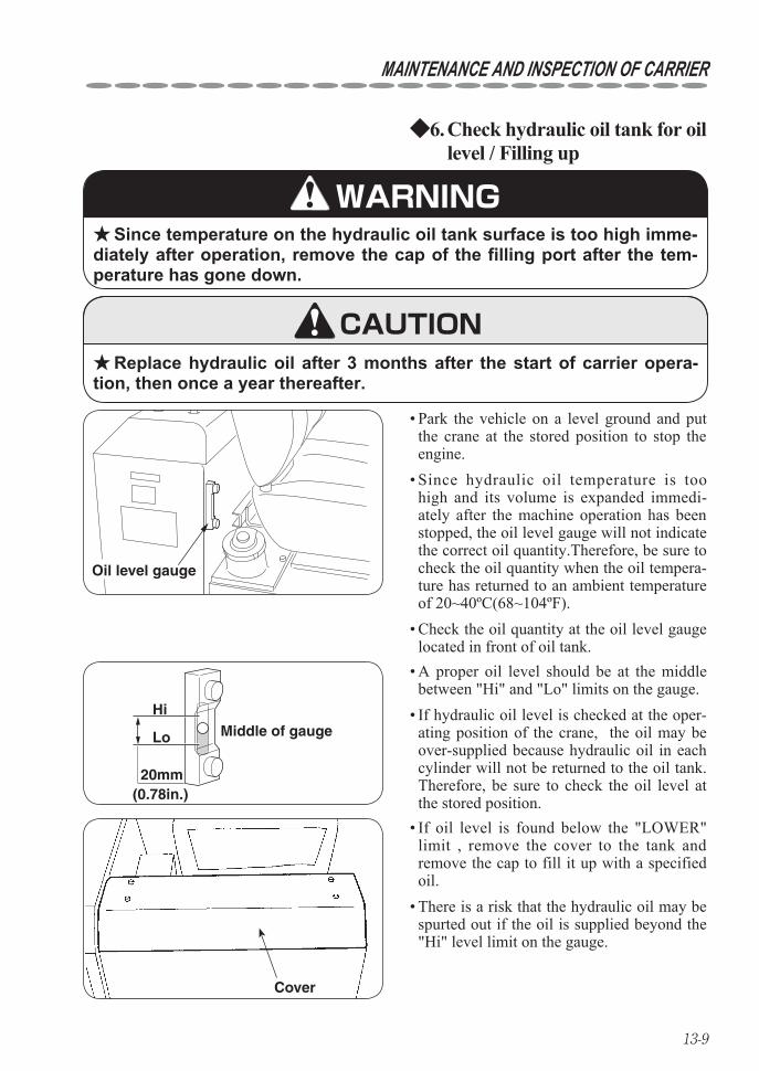
13-9
MAINTENANCE AND INSPECTION OF CARRIER
Check hydraulic oil tank for oil 6. ◆level / Filling up
Since temperature on the hydraulic oil tank surface is too high imme- ★diately after operation, remove the cap of the filling port after the tem-perature has gone down.
Replace hydraulic oil after 3 months after the start of carrier opera- ★tion, then once a year thereafter.
Oil level gauge
Cover
Hi
Lo
20mm(0.78in.)
Middle of gauge
If oil level is found below the "LOWER" • limit , remove the cover to the tank and remove the cap to fill it up with a specified oil. There is a risk that the hydraulic oil may be • spurted out if the oil is supplied beyond the "Hi" level limit on the gauge.
Park the vehicle on a level ground and put • the crane at the stored position to stop the engine. Since hydraulic oil temperature is too • high and its volume is expanded immedi-ately after the machine operation has been stopped, the oil level gauge will not indicate the correct oil quantity.Therefore, be sure to check the oil quantity when the oil tempera-ture has returned to an ambient temperature of 20~40ºC(68~104ºF). Check the oil quantity at the oil level gauge • located in front of oil tank. A proper oil level should be at the middle • between "Hi" and "Lo" limits on the gauge. If hydraulic oil level is checked at the oper-• ating position of the crane, the oil may be over-supplied because hydraulic oil in each cylinder will not be returned to the oil tank.Therefore, be sure to check the oil level at the stored position.
WARNING
CAUTION
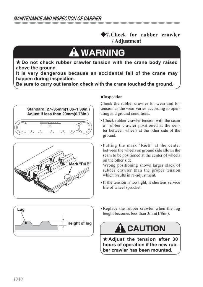
13-10
MAINTENANCE AND INSPECTION OF CARRIER
Standard: 27~35mm(1.06~1.38in.)Adjust if less than 20mm(0.78in.)
Check for rubber crawler7. ◆ / Adjustment
Do not check rubber crawler tension with the crane body raised ★above the ground. It is very dangerous because an accidental fall of the crane may happen during inspection. Be sure to carry out tension check with the crane touched the ground.
R&B
Mark “R&B”
■Inspection
Adjust the tension after 30 ★hours of operation if the new rub-ber crawler has been mounted.
Lug
Height of lug
Replace the rubber crawler when the lug • height becomes less than 3mm(1/8in.).
WARNING
Check the rubber crawler for wear and for tension as the wear varies according to oper-ating and ground conditions.
Check rubber crawler tension with the seam • of rubber crawler positioned at the cen-ter between wheels at the other side of the ground.
Putting the mark "R&B" at the center • between the wheels on ground side allows the seam to be positioned at the center of wheels on the other side. Wrong positioning shows larger slack of rubber crawler than the proper tension which results in re-adjustment.
If the tension is too tight, it shortens service • life of wheel sprocket.
CAUTION
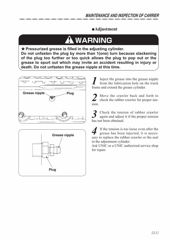
13-11
MAINTENANCE AND INSPECTION OF CARRIER
■Adjustment
Pressurized grease is filled in the adjusting cylinder. ★Do not unfasten the plug by more than 1(one) turn because slackening of the plug too further or too quick allows the plug to pop out or the grease to spurt out which may invite an accident resulting in injury or death. Do not unfasten the grease nipple at this time.
Grease nipple
Grease nipple
Plug
Plug
WARNING
1 Inject the grease into the grease nipple from the lubrication hole on the truck
frame and extend the grease cylinder.
2 Move the crawler back and forth to check the rubber crawler for proper ten-
sion.
3 Check the tension of rubber crawler again and adjust it if the proper tension
has not been obtained.
4 If the tension is too loose even after the grease has been injected, it is neces-
sary to replace the rubber crawler or the seal in the adjustment cylinder. Ask UNIC or a UNIC authorized service shop for repair.
13-12
MAINTENANCE AND INSPECTION OF CARRIER
Do not crawl over lying rocks or stones with sharp edges. ★Do not change direction where there is a difference in ground level. ★Do not make a quick change of direction as it may cause the wheels ★
to go off the rubber crawler. Do not operate the crane on a ground being heated to the tempera- ★
ture of more than 60°C(140°F).Do not stain the rubber crawler with oils such as fuel, hydraulic oil, ★
grease, and the other oil.Do not operate the crane at a place where salt content is abundant. ★When storing the crane for long period of time, store it indoors where ★
it will not be exposed to the ray of the sun or to the rain directly.
CAUTION
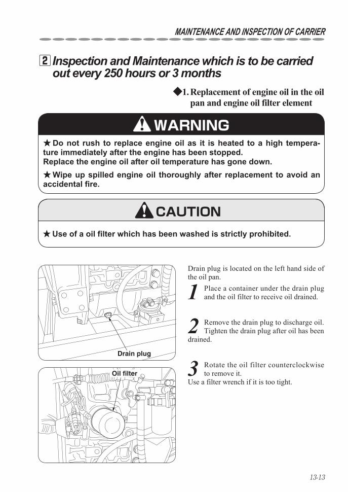
13-13
MAINTENANCE AND INSPECTION OF CARRIER
Inspection and Maintenance which is to be carried 2out every 250 hours or 3 months
Replacement of engine oil in the oil 1. ◆pan and engine oil filter element
Do not rush to replace engine oil as it is heated to a high tempera- ★ture immediately after the engine has been stopped. Replace the engine oil after oil temperature has gone down.
Wipe up spilled engine oil thoroughly after replacement to avoid an ★accidental fire.
Use of a oil filter which has been washed is strictly prohibited. ★
Drain plug is located on the left hand side of the oil pan.
Drain plug
Oil filter
WARNING
CAUTION
1 Place a container under the drain plug and the oil filter to receive oil drained.
2 Remove the drain plug to discharge oil.Tighten the drain plug after oil has been
drained.
3 Rotate the oil filter counterclockwise to remove it.
Use a filter wrench if it is too tight.
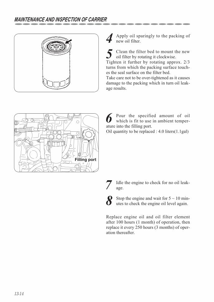
13-14
MAINTENANCE AND INSPECTION OF CARRIER
4 Apply oil sparingly to the packing of new oil filter.
6 Pour the specified amount of oil which is fit to use in ambient temper-
ature into the filling port. Oil quantity to be replaced : 4.0 liters(1.1gal)
Filling port
7 Idle the engine to check for no oil leak-age.
5 Clean the filter bed to mount the new oil filter by rotating it clockwise.
Tighten it further by rotating approx. 2/3 turns from which the packing surface touch-es the seal surface on the filter bed. Take care not to be over-tightened as it causes damage to the packing which in turn oil leak-age results.
8 Stop the engine and wait for 5 ~ 10 min-utes to check the engine oil level again.
Replace engine oil and oil filter element after 100 hours (1 month) of operation, then replace it every 250 hours (3 months) of oper-ation thereafter.
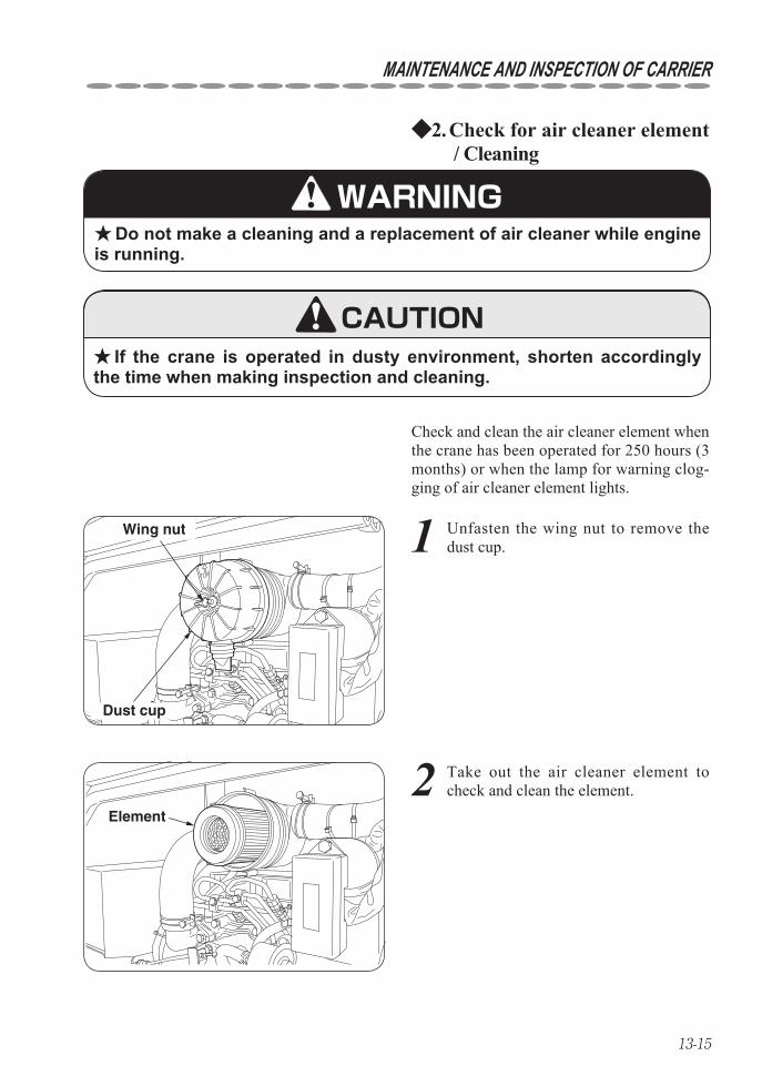
13-15
MAINTENANCE AND INSPECTION OF CARRIER
Check for air cleaner element2. ◆ / Cleaning
Do not make a cleaning and a replacement of air cleaner while engine ★is running.
If the crane is operated in dusty environment, shorten accordingly ★the time when making inspection and cleaning.
Check and clean the air cleaner element when the crane has been operated for 250 hours (3 months) or when the lamp for warning clog-ging of air cleaner element lights.
TOP
Dust cup
Wing nut
2 Take out the air cleaner element to check and clean the element.
Element
WARNING
CAUTION
1 Unfasten the wing nut to remove the dust cup.
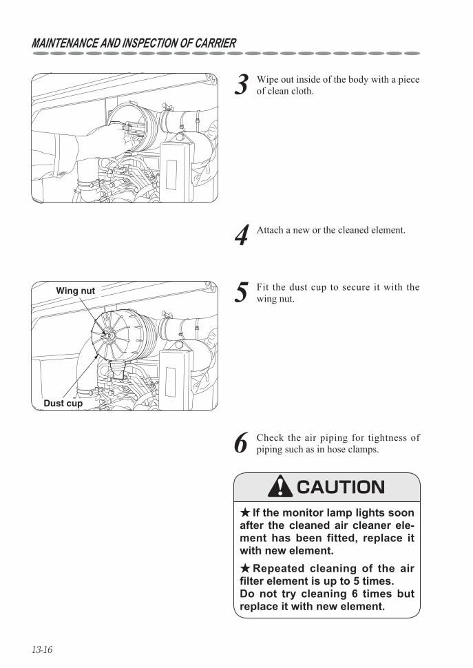
13-16
MAINTENANCE AND INSPECTION OF CARRIER
3 Wipe out inside of the body with a piece of clean cloth.
4 Attach a new or the cleaned element.
5 Fit the dust cup to secure it with the wing nut.
TOP
Dust cup
Wing nut
6 Check the air piping for tightness of piping such as in hose clamps.
If the monitor lamp lights soon ★after the cleaned air cleaner ele-ment has been fitted, replace it with new element.
Repeated cleaning of the air ★filter element is up to 5 times. Do not try cleaning 6 times but replace it with new element.
CAUTION
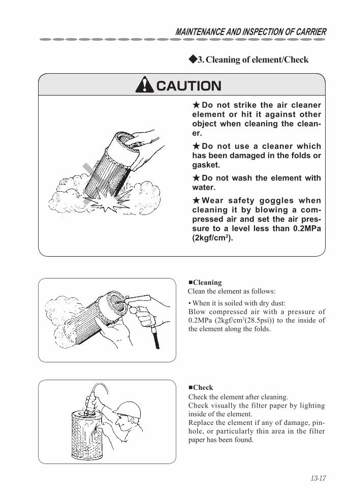
13-17
MAINTENANCE AND INSPECTION OF CARRIER
Cleaning of element/Check3. ◆
Do not strike the air cleaner ★element or hit it against other object when cleaning the clean-er.
Do not use a cleaner which ★has been damaged in the folds or gasket.
Do not wash the element with ★water.
Wear safety goggles when ★cleaning it by blowing a com-pressed air and set the air pres-sure to a level less than 0.2MPa (2kgf/cm2).
■Cleaning
■Check
CAUTION
When it is soiled with dry dust: • Blow compressed air with a pressure of 0.2MPa (2kgf/cm2(28.5psi)) to the inside of the element along the folds.
Clean the element as follows:
Check the element after cleaning.Check visually the filter paper by lighting inside of the element.Replace the element if any of damage, pin-hole, or particularly thin area in the filter paper has been found.
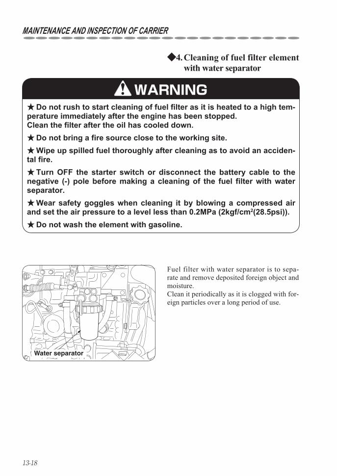
13-18
MAINTENANCE AND INSPECTION OF CARRIER
Cleaning of fuel filter element 4. ◆with water separator
Do not rush to start cleaning of fuel filter as it is heated to a high tem- ★perature immediately after the engine has been stopped. Clean the filter after the oil has cooled down.
Do not bring a fire source close to the working site. ★Wipe up spilled fuel thoroughly after cleaning as to avoid an acciden- ★
tal fire.Turn OFF the starter switch or disconnect the battery cable to the ★
negative (-) pole before making a cleaning of the fuel filter with water separator.
Wear safety goggles when cleaning it by blowing a compressed air ★and set the air pressure to a level less than 0.2MPa (2kgf/cm2(28.5psi)).
Do not wash the element with gasoline. ★
Fuel filter with water separator is to sepa-rate and remove deposited foreign object and moisture.Clean it periodically as it is clogged with for-eign particles over a long period of use.
Water separator
WARNING

13-19
MAINTENANCE AND INSPECTION OF CARRIER
1 Throw the cock of fuel filter with water separator upward to "CLOSE" position.
Turn the cock by more than 90º.
Filter case
Cock
“CLOSE”
“OPEN”
Retaining ring
Element
2 Unfasten the retaining ring to remove the filter case and the element.
3 Wash the element with a diesel fuel and blow compressed air with a pressure of
0.2MPa (2kgf/cm2(28.5psi)) to the inside of the element to remove dust.
4 Also remove foreign particles and mois-ture deposited on the bottom of filter
case.
5 Check the O-ring, replace it with new O-ring if it is found damaged.
6 Fit the cleaned element in the filter case and tighten it into the filter bed with
your hand. In order to prevent it from being over-tight-ened, tighten the retaining ring by rotating approx. 2/3 turns from which the packing sur-face touches the seal surface on the filter bed.
7 Turn the cock on the fuel filter down-ward to "OPEN" position.
8 Bleed the air in the fuel system and check for fuel leakage.
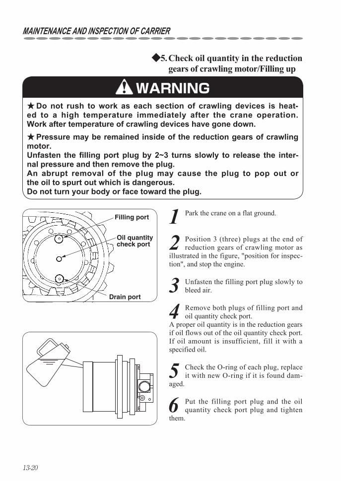
13-20
MAINTENANCE AND INSPECTION OF CARRIER
Check oil quantity in the reduction 5. ◆gears of crawling motor/Filling up
Do not rush to work as each section of crawling devices is heat- ★ed to a high temperature immediately after the crane operation.Work after temperature of crawling devices have gone down.
Pressure may be remained inside of the reduction gears of crawling ★motor. Unfasten the filling port plug by 2~3 turns slowly to release the inter-nal pressure and then remove the plug. An abrupt removal of the plug may cause the plug to pop out or the oil to spurt out which is dangerous. Do not turn your body or face toward the plug.
1 Park the crane on a flat ground.Filling port
Drain port
Oil quantitycheck port
WARNING
2 Position 3 (three) plugs at the end of reduction gears of crawling motor as
illustrated in the figure, "position for inspec-tion", and stop the engine.
3 Unfasten the filling port plug slowly to bleed air.
4 Remove both plugs of filling port and oil quantity check port.
A proper oil quantity is in the reduction gears if oil flows out of the oil quantity check port.If oil amount is insufficient, fill it with a specified oil.
5 Check the O-ring of each plug, replace it with new O-ring if it is found dam-
aged.
6 Put the filling port plug and the oil quantity check port plug and tighten
them.
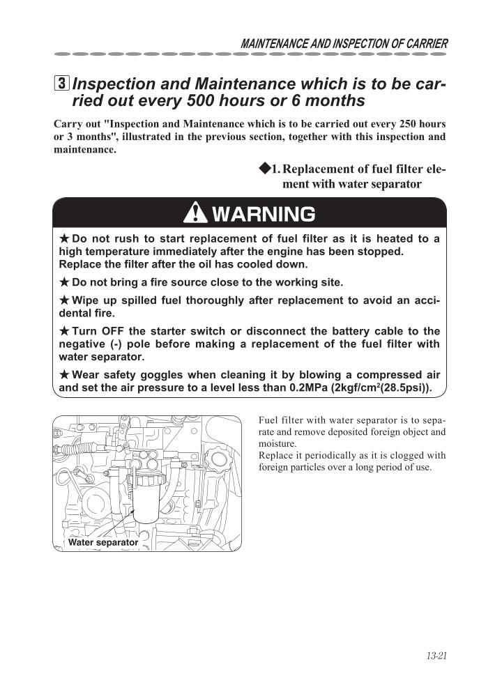
13-21
MAINTENANCE AND INSPECTION OF CARRIER
Carry out "Inspection and Maintenance which is to be carried out every 250 hours or 3 months", illustrated in the previous section, together with this inspection and maintenance.
Inspection and Maintenance which is to be car- 3ried out every 500 hours or 6 months
Replacement of fuel filter ele-1. ◆ment with water separator
Do not rush to start replacement of fuel filter as it is heated to a ★high temperature immediately after the engine has been stopped. Replace the filter after the oil has cooled down.
Do not bring a fire source close to the working site. ★Wipe up spilled fuel thoroughly after replacement to avoid an acci- ★
dental fire.Turn OFF the starter switch or disconnect the battery cable to the ★
negative (-) pole before making a replacement of the fuel filter with water separator.
Wear safety goggles when cleaning it by blowing a compressed air ★and set the air pressure to a level less than 0.2MPa (2kgf/cm2(28.5psi)).
Fuel filter with water separator is to sepa-rate and remove deposited foreign object and moisture.Replace it periodically as it is clogged with foreign particles over a long period of use.
Water separator
WARNING
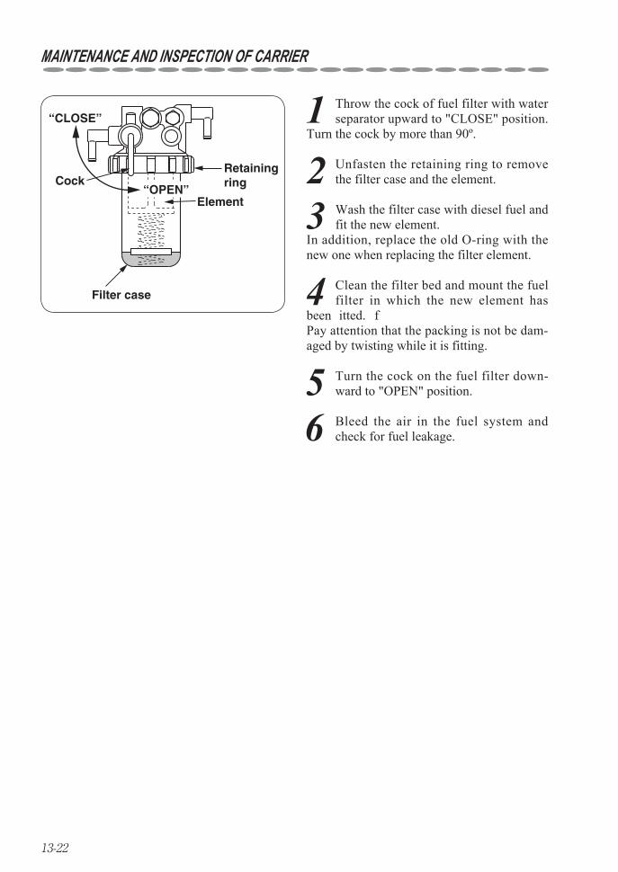
13-22
MAINTENANCE AND INSPECTION OF CARRIER
1 Throw the cock of fuel filter with water separator upward to "CLOSE" position.
Turn the cock by more than 90º.
Filter case
Cock
“CLOSE”
“OPEN”
Retaining ring
Element
2 Unfasten the retaining ring to remove the filter case and the element.
4 Clean the filter bed and mount the fuel filter in which the new element has
been fitted. Pay attention that the packing is not be dam-aged by twisting while it is fitting.
3 Wash the filter case with diesel fuel and fit the new element.
In addition, replace the old O-ring with the new one when replacing the filter element.
5 Turn the cock on the fuel filter down-ward to "OPEN" position.
6 Bleed the air in the fuel system and check for fuel leakage.
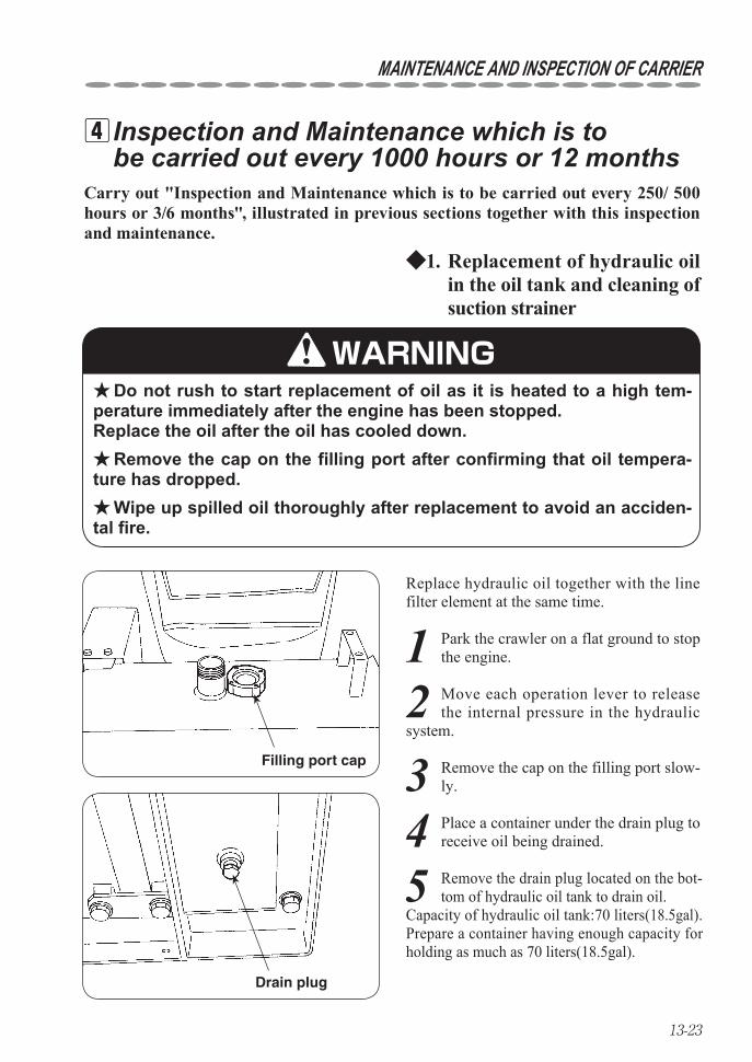
13-23
MAINTENANCE AND INSPECTION OF CARRIER
Carry out "Inspection and Maintenance which is to be carried out every 250/ 500 hours or 3/6 months", illustrated in previous sections together with this inspection and maintenance.
Inspection and Maintenance which is to 4be carried out every 1000 hours or 12 months
Replacement of hydraulic oil 1. ◆in the oil tank and cleaning of suction strainer
Do not rush to start replacement of oil as it is heated to a high tem- ★perature immediately after the engine has been stopped. Replace the oil after the oil has cooled down.
Remove the cap on the filling port after confirming that oil tempera- ★ture has dropped.
Wipe up spilled oil thoroughly after replacement to avoid an acciden- ★tal fire.
Replace hydraulic oil together with the line filter element at the same time.
Filling port cap
Drain plug
WARNING
5 Remove the drain plug located on the bot-tom of hydraulic oil tank to drain oil.
Capacity of hydraulic oil tank:70 liters(18.5gal).Prepare a container having enough capacity for holding as much as 70 liters(18.5gal).
1 Park the crawler on a flat ground to stop the engine.
2 Move each operation lever to release the internal pressure in the hydraulic
system.
3 Remove the cap on the filling port slow-ly.
4 Place a container under the drain plug to receive oil being drained.
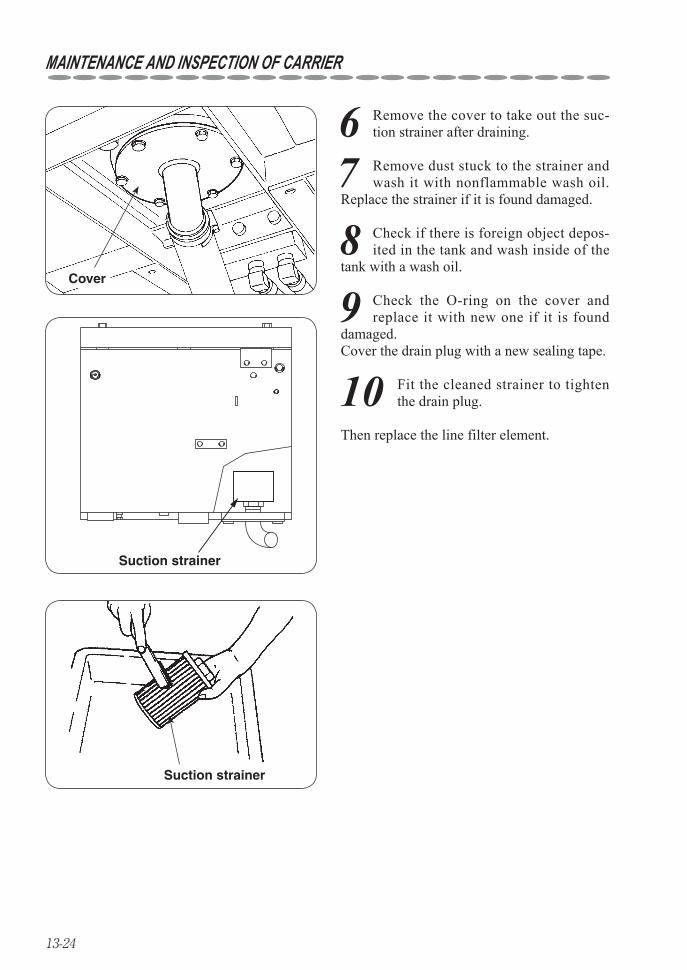
13-24
MAINTENANCE AND INSPECTION OF CARRIER
6 Remove the cover to take out the suc-tion strainer after draining.
Cover
Suction strainer
Suction strainer
Then replace the line filter element.
7 Remove dust stuck to the strainer and wash it with nonflammable wash oil.
Replace the strainer if it is found damaged.
9 Check the O-ring on the cover and replace it with new one if it is found
damaged. Cover the drain plug with a new sealing tape.
8 Check if there is foreign object depos-ited in the tank and wash inside of the
tank with a wash oil.
10 Fit the cleaned strainer to tighten the drain plug.

13-25
MAINTENANCE AND INSPECTION OF CARRIER
Replacement of line filter element2. ◆
Do not rush to start replacement of line filter element as it is heated ★to a high temperature immediately after the engine has been stopped.Replace the filter element after the oil has cooled down.
Wipe up spilled fuel thoroughly after replacement to avoid an acci- ★dental fire.
The line filter is located inside the cover on the front of tank.Replace hydraulic oil together with the line filter element at the same time.
Line filter
3 Apply oil sparingly on the packing of new oil filter.O-ring
WARNING
1 Place a container under the bottom of line filter to receive oil being drained.
2 Rotate the line filter counterclockwise to remove it.
Use a filter wrench if it is too tight.
4 Clean the filter bed to mount the new line filter by rotating it clockwise.
Tighten it further by rotating approx. 2/3 turns from which the packing surface touch-es the seal surface on the filter bed. Take care not to be over-tightened as it causes damage to the packing which in turn oil leak-age results.
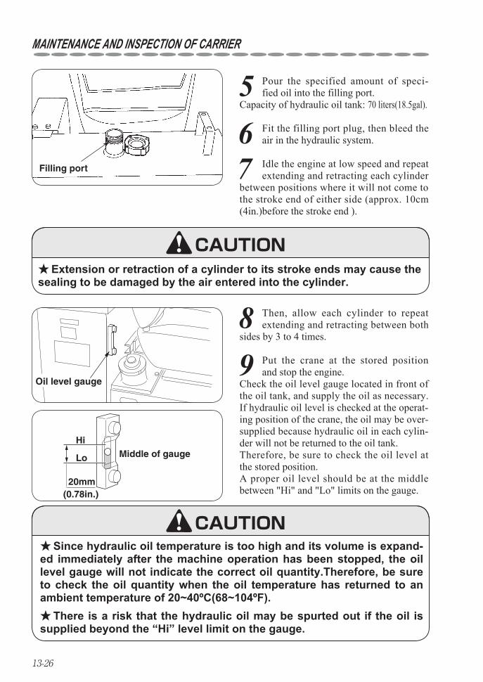
13-26
MAINTENANCE AND INSPECTION OF CARRIER
5 Pour the specified amount of speci-fied oil into the filling port.
Capacity of hydraulic oil tank: 70 liters(18.5gal).
Filling port
Oil level gauge
Extension or retraction of a cylinder to its stroke ends may cause the ★sealing to be damaged by the air entered into the cylinder.
Since hydraulic oil temperature is too high and its volume is expand- ★ed immediately after the machine operation has been stopped, the oil level gauge will not indicate the correct oil quantity.Therefore, be sure to check the oil quantity when the oil temperature has returned to an ambient temperature of 20~40ºC(68~104ºF).
There is a risk that the hydraulic oil may be spurted out if the oil is ★supplied beyond the “Hi” level limit on the gauge.
Hi
Lo
20mm(0.78in.)
Middle of gauge
8 Then, allow each cylinder to repeat extending and retracting between both
sides by 3 to 4 times.
6 Fit the filling port plug, then bleed the air in the hydraulic system.
7 Idle the engine at low speed and repeat extending and retracting each cylinder
between positions where it will not come to the stroke end of either side (approx. 10cm (4in.)before the stroke end ).
9 Put the crane at the stored position and stop the engine.
Check the oil level gauge located in front of the oil tank, and supply the oil as necessary.If hydraulic oil level is checked at the operat-ing position of the crane, the oil may be over-supplied because hydraulic oil in each cylin-der will not be returned to the oil tank. Therefore, be sure to check the oil level at the stored position. A proper oil level should be at the middle between "Hi" and "Lo" limits on the gauge.
CAUTION
CAUTION
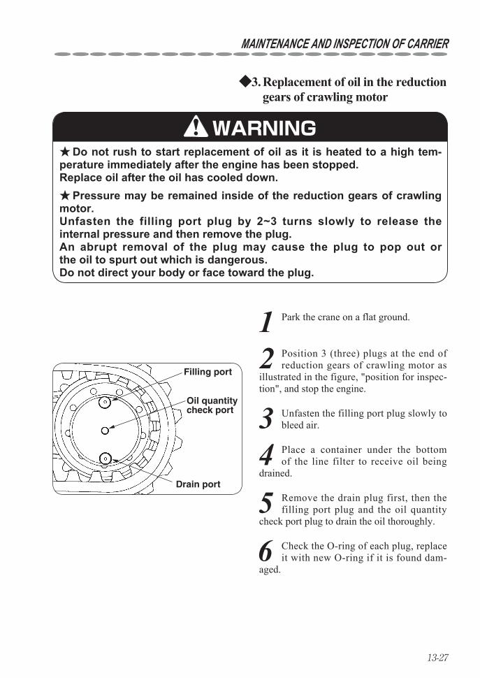
13-27
MAINTENANCE AND INSPECTION OF CARRIER
Replacement of oil in the reduction 3. ◆gears of crawling motor
Do not rush to start replacement of oil as it is heated to a high tem- ★perature immediately after the engine has been stopped. Replace oil after the oil has cooled down.
Pressure may be remained inside of the reduction gears of crawling ★motor. Unfasten the filling port plug by 2~3 turns slowly to release the internal pressure and then remove the plug. An abrupt removal of the plug may cause the plug to pop out or the oil to spurt out which is dangerous. Do not direct your body or face toward the plug.
3 Unfasten the filling port plug slowly to bleed air.
Filling port
Drain port
Oil quantitycheck port
WARNING
1 Park the crane on a flat ground.
2 Position 3 (three) plugs at the end of reduction gears of crawling motor as
illustrated in the figure, "position for inspec-tion", and stop the engine.
6 Check the O-ring of each plug, replace it with new O-ring if it is found dam-
aged.
4 Place a container under the bottom of the line filter to receive oil being
drained.
5 Remove the drain plug first, then the filling port plug and the oil quantity
check port plug to drain the oil thoroughly.
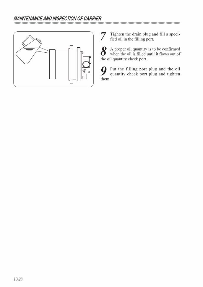
13-28
MAINTENANCE AND INSPECTION OF CARRIER
7 Tighten the drain plug and fill a speci-fied oil in the filling port.
8 A proper oil quantity is to be confirmed when the oil is filled until it flows out of
the oil quantity check port.
9 Put the filling port plug and the oil quantity check port plug and tighten
them.
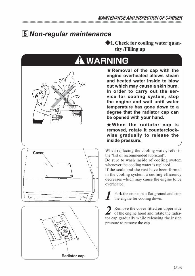
13-29
MAINTENANCE AND INSPECTION OF CARRIER
Non-regular maintenance 5 Check for cooling water quan-1. ◆tity /Filling up
Removal of the cap with the ★engine overheated allows steam and heated water inside to blow out which may cause a skin burn.In order to carry out the ser-vice for cooling system, stop the engine and wait until water temperature has gone down to a degree that the radiator cap can be opened with your hand.
When the radiator cap is ★removed, rotate it counterclock-wise gradually to release the inside pressure.
When replacing the cooling water, refer to the "list of recommended lubricant".Be sure to wash inside of cooling system whenever the cooling water is replaced.If the scale and the rust have been formed in the cooling system, a cooling efficiency decreases which may cause the engine to be overheated.
Cover
Radiator cap
WARNING
2 Remove the cover fitted on upper side of the engine hood and rotate the radia-
tor cap gradually while releasing the inside pressure to remove the cap.
1 Park the crane on a flat ground and stop the engine for cooling down.
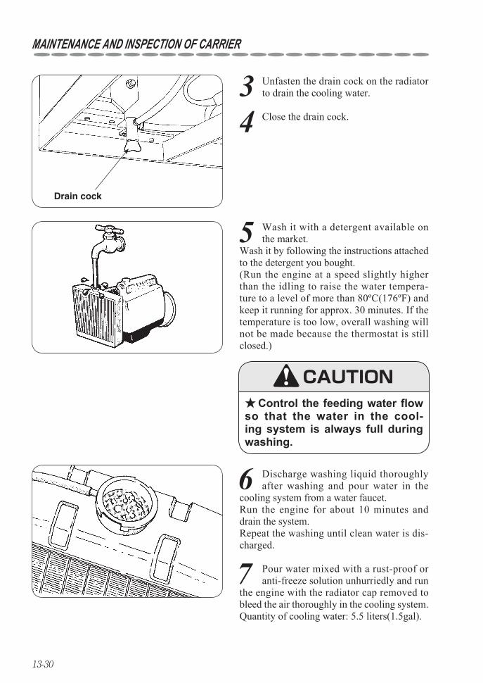
13-30
MAINTENANCE AND INSPECTION OF CARRIER
3 Unfasten the drain cock on the radiator to drain the cooling water.
5 Wash it with a detergent available on the market.
Wash it by following the instructions attached to the detergent you bought. (Run the engine at a speed slightly higher than the idling to raise the water tempera-ture to a level of more than 80ºC(176ºF) and keep it running for approx. 30 minutes. If the temperature is too low, overall washing will not be made because the thermostat is still closed.)
Control the feeding water flow ★so that the water in the cool-ing system is always full during washing.
7 Pour water mixed with a rust-proof or anti-freeze solution unhurriedly and run
the engine with the radiator cap removed to bleed the air thoroughly in the cooling system.Quantity of cooling water: 5.5 liters(1.5gal).
Drain cock
4 Close the drain cock.
CAUTION
6 Discharge washing liquid thoroughly after washing and pour water in the
cooling system from a water faucet. Run the engine for about 10 minutes and drain the system. Repeat the washing until clean water is dis-charged.
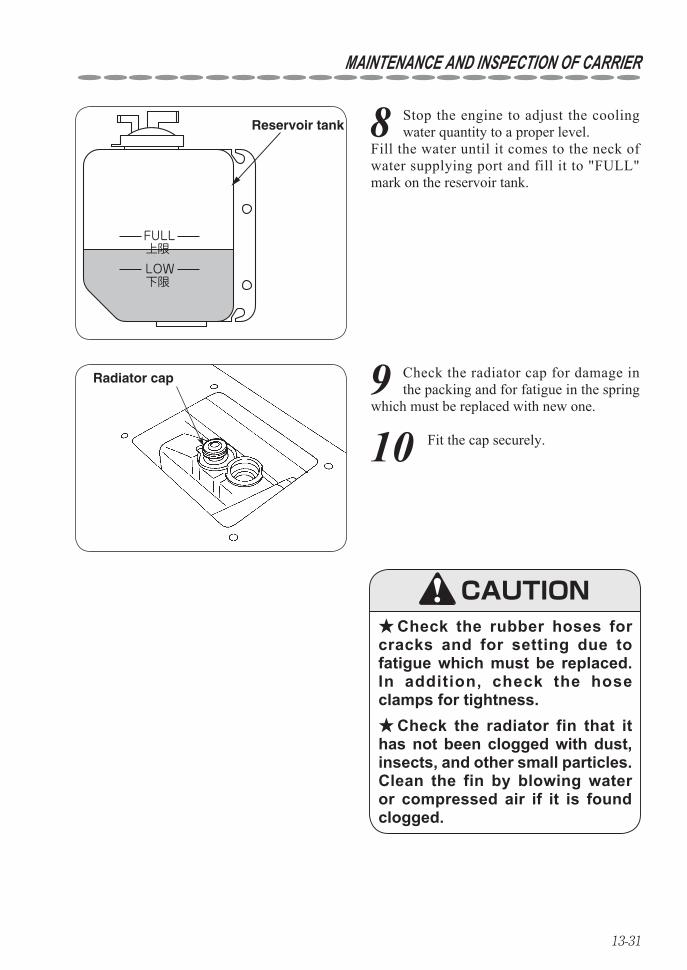
13-31
MAINTENANCE AND INSPECTION OF CARRIER
8 Stop the engine to adjust the cooling water quantity to a proper level.
Fill the water until it comes to the neck of water supplying port and fill it to "FULL" mark on the reservoir tank.
FULL上限LOW下限
Reservoir tank
9 Check the radiator cap for damage in the packing and for fatigue in the spring
which must be replaced with new one.
Check the rubber hoses for ★cracks and for setting due to fatigue which must be replaced.In addition, check the hose clamps for tightness.
Check the radiator fin that it ★has not been clogged with dust, insects, and other small particles.Clean the fin by blowing water or compressed air if it is found clogged.
Radiator cap
10 Fit the cap securely.
CAUTION
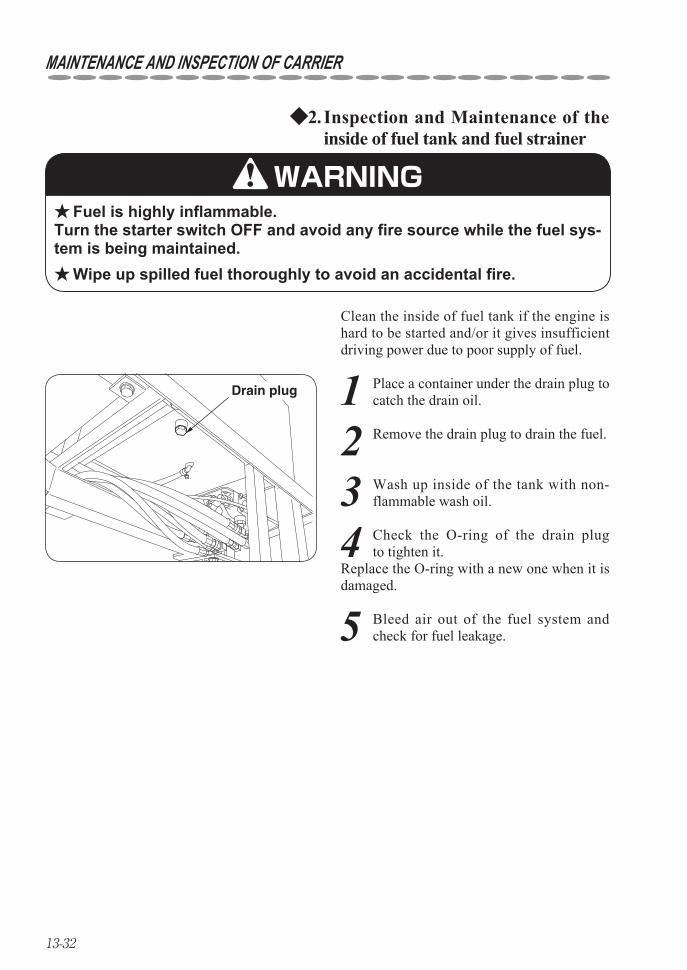
13-32
MAINTENANCE AND INSPECTION OF CARRIER
Inspection and Maintenance of the 2. ◆inside of fuel tank and fuel strainer
Fuel is highly inflammable. ★Turn the starter switch OFF and avoid any fire source while the fuel sys-tem is being maintained.
Wipe up spilled fuel thoroughly to avoid an accidental fire. ★
Clean the inside of fuel tank if the engine is hard to be started and/or it gives insufficient driving power due to poor supply of fuel.
Drain plug
WARNING
1 Place a container under the drain plug to catch the drain oil.
2 Remove the drain plug to drain the fuel.
3 Wash up inside of the tank with non-flammable wash oil.
4 Check the O-ring of the drain plug to tighten it.
Replace the O-ring with a new one when it is damaged.
5 Bleed air out of the fuel system and check for fuel leakage.
13-33
MAINTENANCE AND INSPECTION OF CARRIER
Air bleeding out of fuel system3. ◆
In order to bleed the air out of the fuel sys-tem, turn the starter switch to "START" posi-tion for a few seconds then the engine starts.
Continuous running of starter motor allows the battery to be dis- ★charged and the starter motor itself to be damaged. Do not energize the motor for more than 20 seconds without a break.
If it failed to start the engine, take a rest for 1 or 2 minutes to try it ★again.
CAUTION
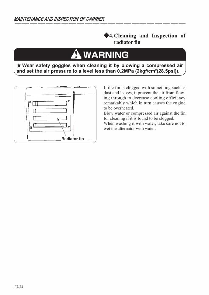
13-34
MAINTENANCE AND INSPECTION OF CARRIER
Cleaning and Inspection of 4. ◆radiator fin
Wear safety goggles when cleaning it by blowing a compressed air ★and set the air pressure to a level less than 0.2MPa (2kgf/cm2(28.5psi)).
If the fin is clogged with something such as dust and leaves, it prevent the air from flow-ing through to decrease cooling efficiency remarkably which in turn causes the engine to be overheated.Blow water or compressed air against the fin for cleaning if it is found to be clogged.When washing it with water, take care not to wet the alternator with water.
Radiator fin
WARNING
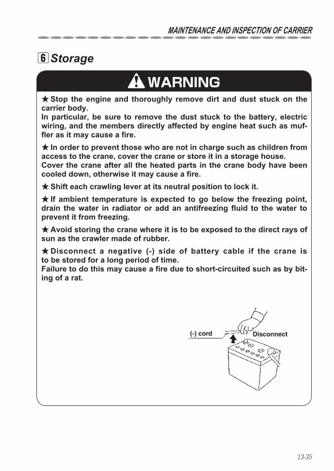
13-35
MAINTENANCE AND INSPECTION OF CARRIER
Storage 6
Stop the engine and thoroughly remove dirt and dust stuck on the ★carrier body. In particular, be sure to remove the dust stuck to the battery, electric wiring, and the members directly affected by engine heat such as muf-fler as it may cause a fire.
In order to prevent those who are not in charge such as children from ★access to the crane, cover the crane or store it in a storage house. Cover the crane after all the heated parts in the crane body have been cooled down, otherwise it may cause a fire.
Shift each crawling lever at its neutral position to lock it. ★If ambient temperature is expected to go below the freezing point, ★
drain the water in radiator or add an antifreezing fluid to the water to prevent it from freezing.
Avoid storing the crane where it is to be exposed to the direct rays of ★sun as the crawler made of rubber.
Disconnect a negative (-) side of battery cable if the crane is ★to be stored for a long period of time. Failure to do this may cause a fire due to short-circuited such as by bit-ing of a rat.
(-) cord Disconnect
WARNING
13-36
MAINTENANCE AND INSPECTION OF CARRIER
Fitting safety covers 7
Be sure to fit the safety covers removed during inspection ★and maintenance where they were fitted originally. It is very dangerous because uncovered rotating members and heated parts may cause injury.
Maintenance and inspection of engine 8Carry out the maintenance and inspection of engine according to "Instruction manual for engine".
WARNING
14-1
14. MAINTENANCE AND INSPECTION OF CRANE
WARNINGCaution signboard ★
Be sure to hang a “caution signboard” such as on control levers while either maintenance or inspection is being carried out, and do not try operating the crane.
Be sure to replace consumable items according to the replacement ★criteria. Failure to observe the replacement as specified may cause a break-down and warranty will not be given even if it is within the period to be applied.
When a part needs to be replaced or anything abnormal is found, ★contact a UNIC service shop for consultation or for ask inspection or repair as soon as possible.
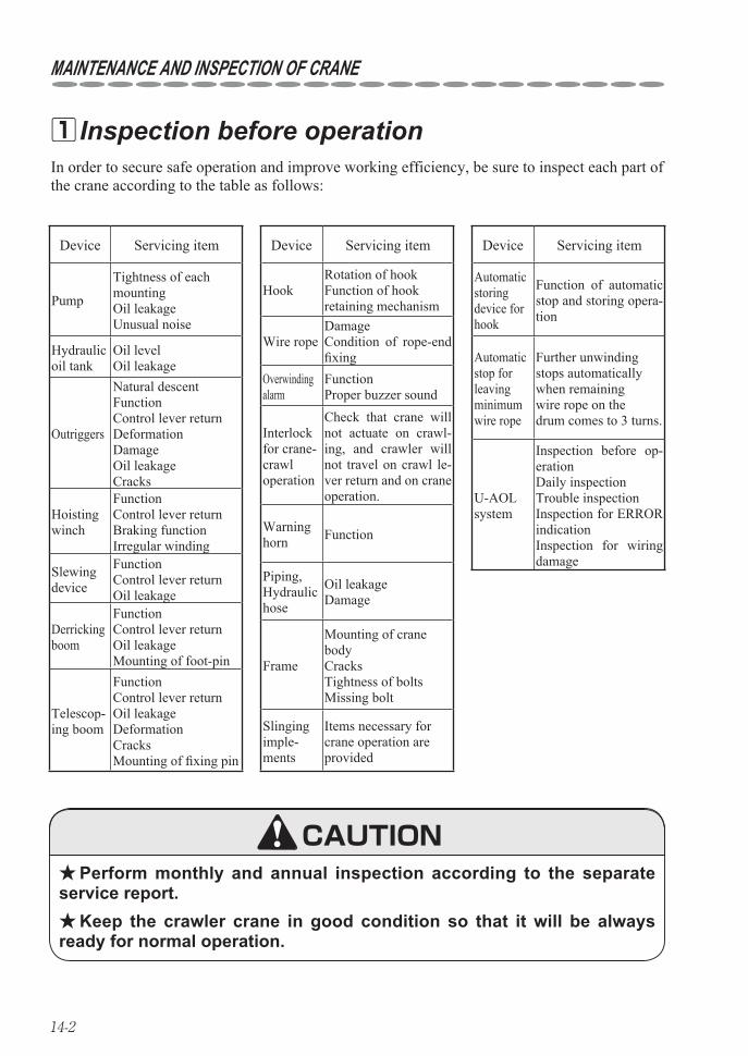
14-2
MAINTENANCE AND INSPECTION OF CRANE
Device Servicing item
Pump
Tightness of eachmountingOil leakageUnusual noise
Hydraulic oil tank
Oil levelOil leakage
Outriggers
Natural descentFunctionControl lever returnDeformation DamageOil leakageCracks
Hoisting winch
FunctionControl lever returnBraking functionIrregular winding
Slewing device
FunctionControl lever returnOil leakage
Derricking boom
FunctionControl lever returnOil leakageMounting of foot-pin
Telescop-ing boom
FunctionControl lever returnOil leakageDeformationCracksMounting of fi xing pin
Device Servicing item
HookRotation of hookFunction of hookretaining mechanism
Wire ropeDamageCondition of rope-end fi xing
Overwinding alarm
FunctionProper buzzer sound
Interlock for crane-crawloperation
Check that crane will not actuate on crawl-ing, and crawler will not travel on crawl le-ver return and on crane operation.
Warning horn Function
Piping, Hydraulic hose
Oil leakageDamage
Frame
Mounting of cranebodyCracksTightness of boltsMissing bolt
Slingingimple-ments
Items necessary for crane operation are provided
Device Servicing item
Automatic storingdevice forhook
Function of automatic stop and storing opera-tion
Automaticstop forleavingminimumwire rope
Further unwindingstops automaticallywhen remainingwire rope on thedrum comes to 3 turns.
U-AOL system
Inspection before op-erationDaily inspectionTrouble inspectionInspection for ERROR indicationInspection for wiring damage
In order to secure safe operation and improve working efficiency, be sure to inspect each part of the crane according to the table as follows:
Inspection before operation 1
Perform monthly and annual inspection according to the separate ★service report.
Keep the crawler crane in good condition so that it will be always ★ready for normal operation.
CAUTION
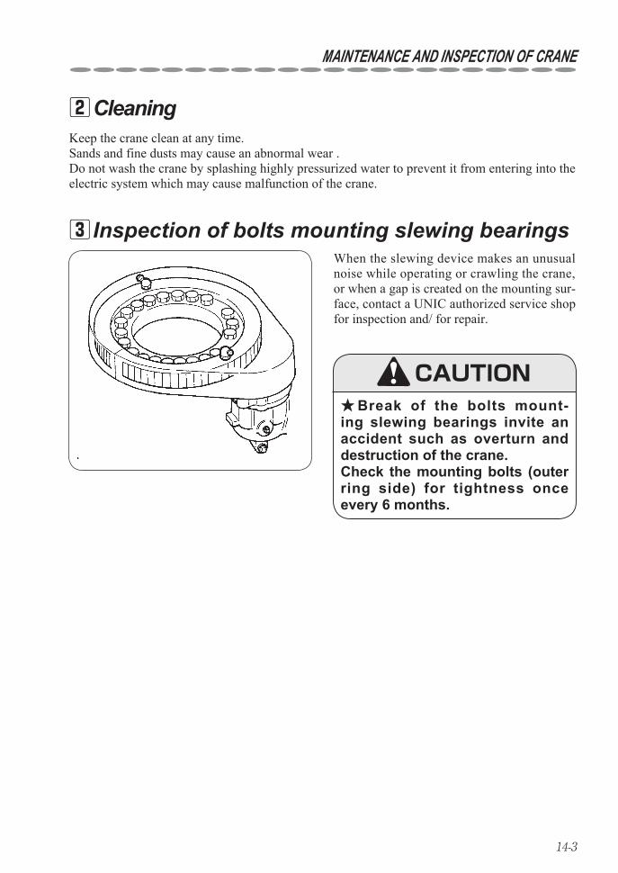
14-3
MAINTENANCE AND INSPECTION OF CRANE
When the slewing device makes an unusual noise while operating or crawling the crane, or when a gap is created on the mounting sur-face, contact a UNIC authorized service shop for inspection and/ for repair.
Keep the crane clean at any time.Sands and fine dusts may cause an abnormal wear .Do not wash the crane by splashing highly pressurized water to prevent it from entering into the electric system which may cause malfunction of the crane.
Cleaning 2
Inspection of bolts mounting slewing bearings 3
Break of the bolts mount- ★ing slewing bearings invite an accident such as overturn and destruction of the crane. Check the mounting bolts (outer ring side) for tightness once every 6 months.
CAUTION
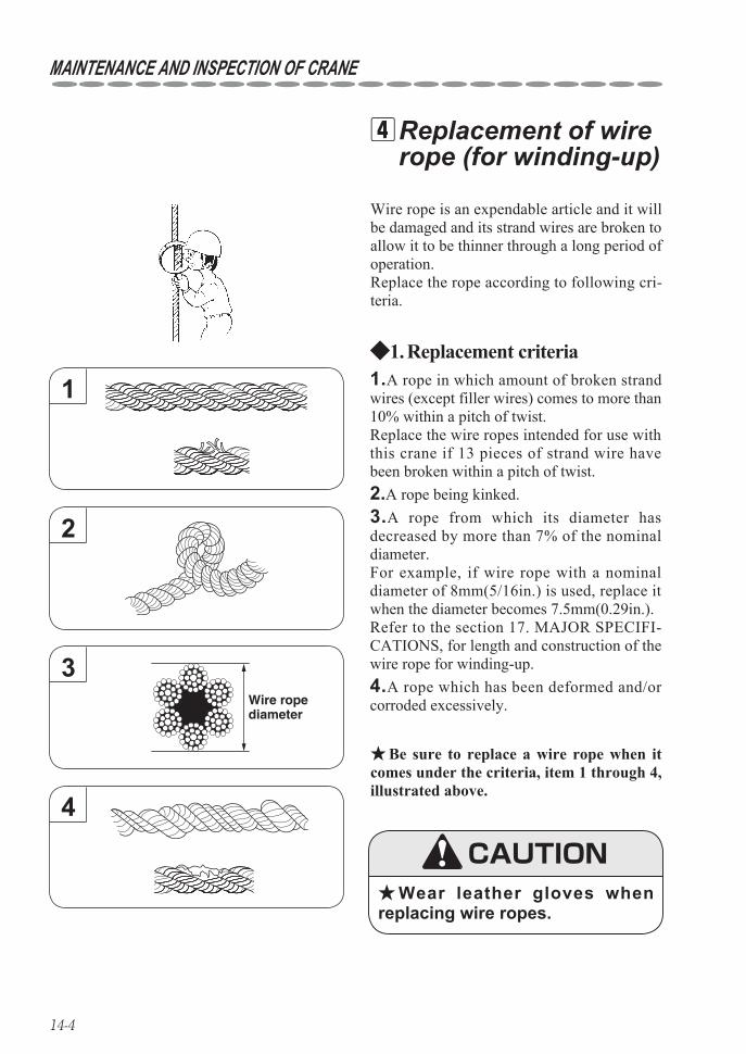
14-4
Be sure to replace a wire rope when it ★comes under the criteria, item 1 through 4, illustrated above.
1.A rope in which amount of broken strand wires (except filler wires) comes to more than 10% within a pitch of twist.Replace the wire ropes intended for use with this crane if 13 pieces of strand wire have been broken within a pitch of twist.2.A rope being kinked.
4.A rope which has been deformed and/or corroded excessively.
3.A rope from which its diameter has decreased by more than 7% of the nominal diameter.For example, if wire rope with a nominal diameter of 8mm(5/16in.) is used, replace it when the diameter becomes 7.5mm(0.29in.).Refer to the section 17. MAJOR SPECIFI-CATIONS, for length and construction of the wire rope for winding-up.
Replacement criteria1. ◆
Wire rope is an expendable article and it will be damaged and its strand wires are broken to allow it to be thinner through a long period of operation.Replace the rope according to following cri-teria.
Replacement of wire 4rope (for winding-up)
CAUTIONWear leather gloves when ★
replacing wire ropes.
1
2
Wire ropediameter
3
4
MAINTENANCE AND INSPECTION OF CRANE
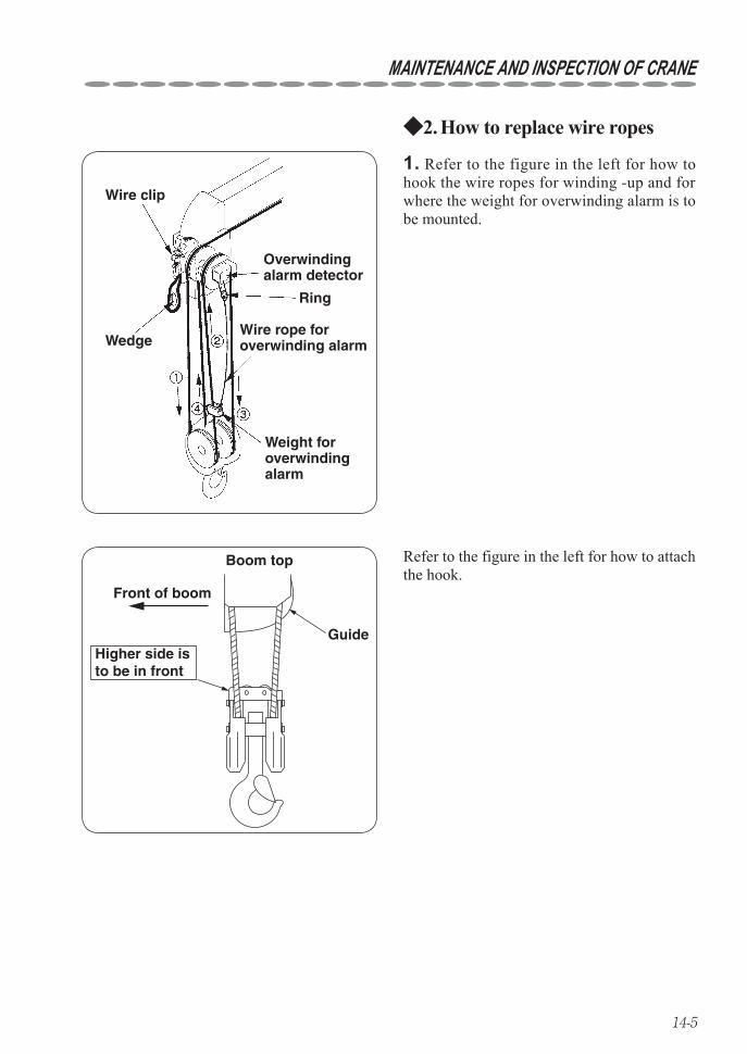
14-5
How to replace wire ropes2. ◆
Ring
Wedge
Wire clip
Weight foroverwindingalarm
Wire rope foroverwinding alarm
Overwindingalarm detector
1. Refer to the figure in the left for how to hook the wire ropes for winding -up and for where the weight for overwinding alarm is to be mounted.
Boom top
Front of boom
GuideHigher side is to be in front
Refer to the figure in the left for how to attach the hook.
MAINTENANCE AND INSPECTION OF CRANE
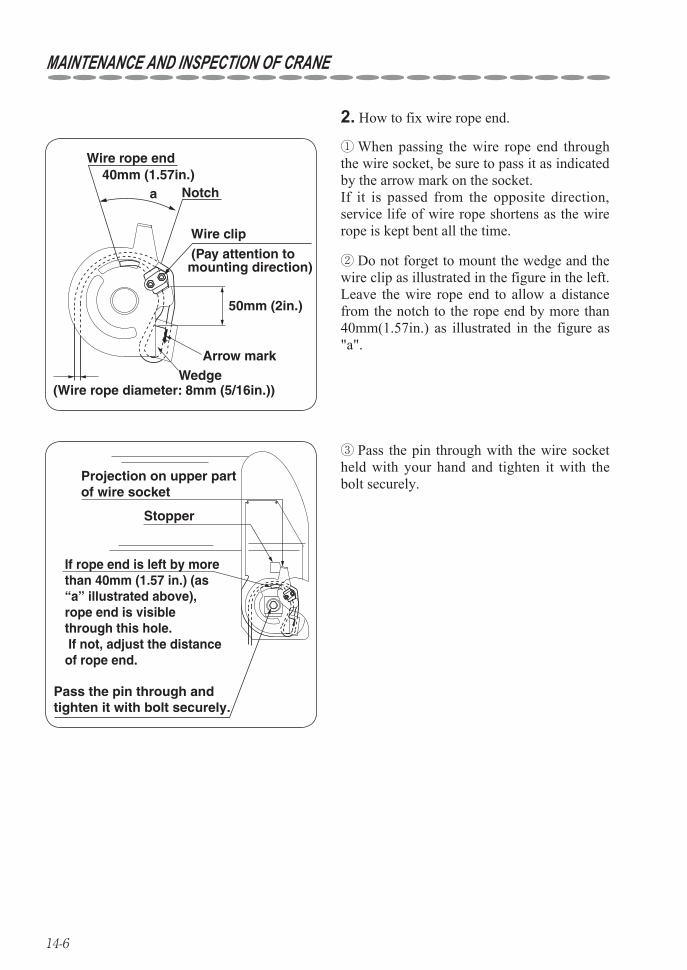
14-6
50mm (2in.)
40mm (1.57in.)a
Wire rope end
Notch
Wire clip
(Pay attention to mounting direction)
Arrow markWedge
(Wire rope diameter: 8mm (5/16in.))
Do not forget to mount the wedge and the ②wire clip as illustrated in the figure in the left.Leave the wire rope end to allow a distance from the notch to the rope end by more than 40mm(1.57in.) as illustrated in the figure as "a".
When passing the wire rope end through ①the wire socket, be sure to pass it as indicated by the arrow mark on the socket. If it is passed from the opposite direction, service life of wire rope shortens as the wire rope is kept bent all the time.
2. How to fix wire rope end.
Projection on upper part of wire socket
Stopper
If rope end is left by more than 40mm (1.57 in.) (as “a” illustrated above), rope end is visible through this hole. If not, adjust the distance of rope end.
Pass the pin through and tighten it with bolt securely.
Pass the pin through with the wire socket ③held with your hand and tighten it with the bolt securely.
MAINTENANCE AND INSPECTION OF CRANE
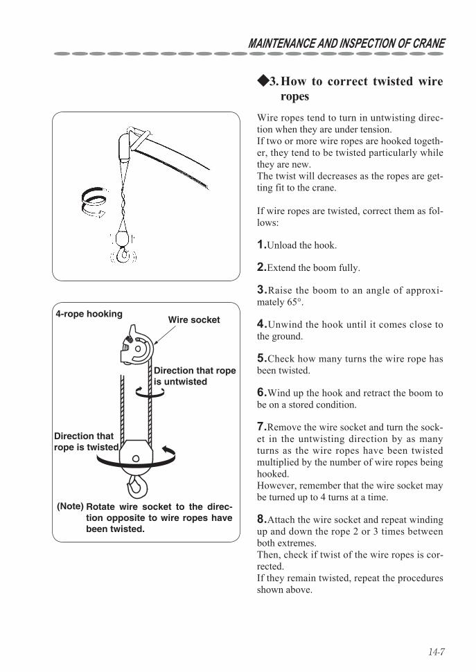
14-7
4-rope hookingWire socket
Direction that rope is untwisted
Direction that rope is twisted
(Note) Rotate wire socket to the direc-tion opposite to wire ropes have been twisted.
8.Attach the wire socket and repeat winding up and down the rope 2 or 3 times between both extremes.Then, check if twist of the wire ropes is cor-rected.If they remain twisted, repeat the procedures shown above.
7.Remove the wire socket and turn the sock-et in the untwisting direction by as many turns as the wire ropes have been twisted multiplied by the number of wire ropes being hooked. However, remember that the wire socket may be turned up to 4 turns at a time.
6.Wind up the hook and retract the boom to be on a stored condition.
5.Check how many turns the wire rope has been twisted.
4.Unwind the hook until it comes close to the ground.
3.Raise the boom to an angle of approxi-mately 65°.
2.Extend the boom fully.
1.Unload the hook.
Wire ropes tend to turn in untwisting direc-tion when they are under tension.If two or more wire ropes are hooked togeth-er, they tend to be twisted particularly while they are new.The twist will decreases as the ropes are get-ting fit to the crane.
If wire ropes are twisted, correct them as fol-lows:
How to correct twisted wire 3. ◆ropes
MAINTENANCE AND INSPECTION OF CRANE
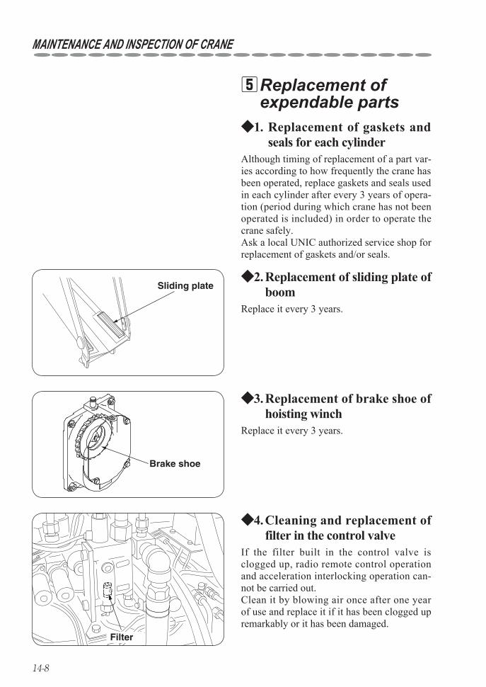
14-8
Replacement of gaskets and 1. ◆seals for each cylinder
Although timing of replacement of a part var-ies according to how frequently the crane has been operated, replace gaskets and seals used in each cylinder after every 3 years of opera-tion (period during which crane has not been operated is included) in order to operate the crane safely.Ask a local UNIC authorized service shop for replacement of gaskets and/or seals.
Replacement of 5expendable parts
Replacement of sliding plate of 2. ◆boom
Replace it every 3 years.
Sliding plate
Replacement of brake shoe of 3. ◆hoisting winch
Replace it every 3 years.
Brake shoe
Cleaning and replacement of 4. ◆filter in the control valve
If the filter built in the control valve is clogged up, radio remote control operation and acceleration interlocking operation can-not be carried out.Clean it by blowing air once after one year of use and replace it if it has been clogged up remarkably or it has been damaged.
Filter
MAINTENANCE AND INSPECTION OF CRANE
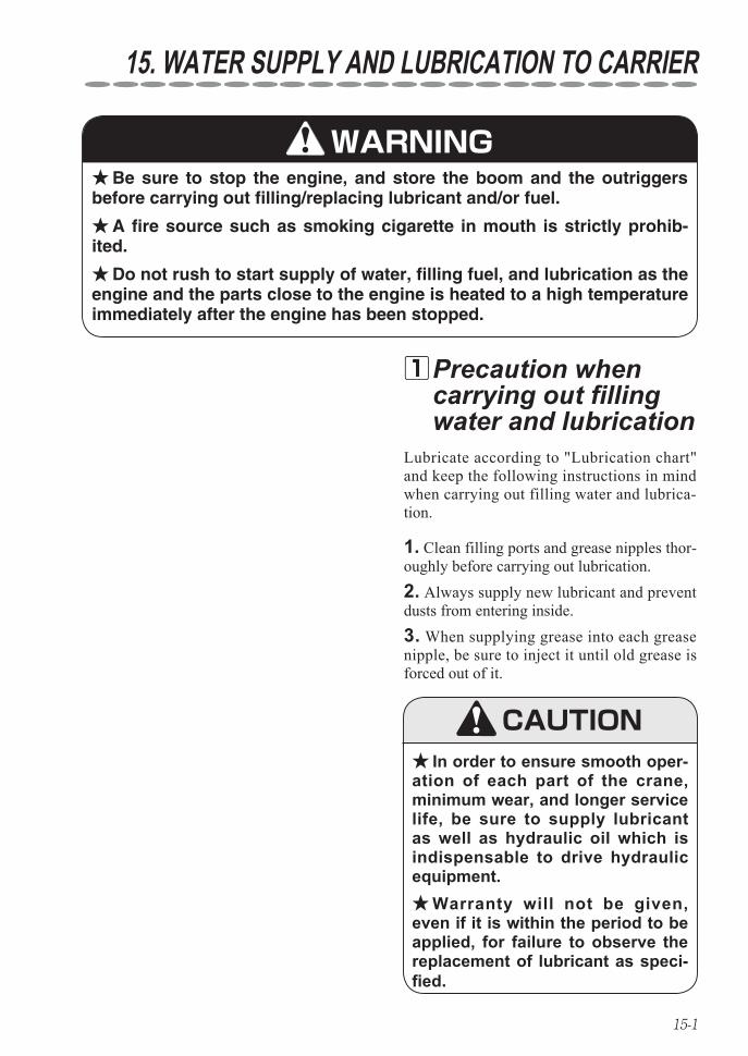
15-1
15. WATER SUPPLY AND LUBRICATION TO CARRIER
1. Clean filling ports and grease nipples thor-oughly before carrying out lubrication.2. Always supply new lubricant and prevent dusts from entering inside.3. When supplying grease into each grease nipple, be sure to inject it until old grease is forced out of it.
Lubricate according to "Lubrication chart" and keep the following instructions in mind when carrying out filling water and lubrica-tion.
Precaution when 1carrying out filling water and lubrication
Be sure to stop the engine, and store the boom and the outriggers ★before carrying out filling/replacing lubricant and/or fuel.
A fire source such as smoking cigarette in mouth is strictly prohib- ★ited.
Do not rush to start supply of water, filling fuel, and lubrication as the ★engine and the parts close to the engine is heated to a high temperature immediately after the engine has been stopped.
WARNING
In order to ensure smooth oper- ★ation of each part of the crane, minimum wear, and longer service life, be sure to supply lubricant as well as hydraulic oil which is indispensable to drive hydraulic equipment.
Warranty will not be given, ★even if it is within the period to be applied, for failure to observe the replacement of lubricant as speci-fied.
CAUTION
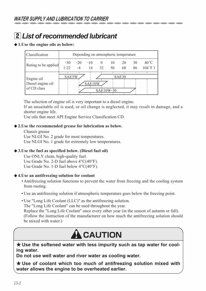
15-2
WATER SUPPLY AND LUBRICATION TO CARRIER
List of recommended lubricant 21.Use the engine oils as below: ◆
Chassis greaseUse NLGI No. 2 grade for most temperatures.Use NLGI No. 1 grade for extremely low temperatures.
2.Use the recommended grease for lubrication as below. ◆
Use ONLY clean, high-quality fuel.Use Grade No. 2-D fuel above 4°C(40°F).Use Grade No. 1-D fuel below 4°C(40°F).
3.Use the fuel as specified below. (Diesel fuel oil) ◆
The selection of engine oil is very important to a diesel engine.If an unsuitable oil is used, or oil change is neglected, it may result in damage, and a shorter engine life.Use oils that meet API Engine Service Classification CD.
Antifreezing solution functions to prevent the water from freezing and the cooling system • from rusting.
Use an antifreezing solution if atmospheric temperature goes below the freezing point.•
Use "Long Life Coolant (LLC)" as the antifreezing solution. • The "Long Life Coolant" can be used throughout the year. Replace the "Long Life Coolant" once every other year (in the season of autumn or fall). (Follow the instruction of the manufacturer on how much the antifreezing solution should be mixed with water.)
4.Use an antifreezing solution for coolant ◆
-30 -20 -10 0 10 20 30(-22 -4 14 32 50 68 86
40104 )
SAE5W SAE30
SAE10W
SAE10W-30
Engine oil Diesel engine oil of CD class
Classification Depending on atmospheric temperature
Rating to be applied
Use the softened water with less impurity such as tap water for cool- ★ing water. Do not use well water and river water as cooling water.
Use of coolant which too much of antifreezing solution mixed with ★water allows the engine to be overheated earlier.
CAUTION
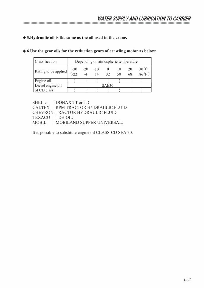
15-3
WATER SUPPLY AND LUBRICATION TO CARRIER
5.Hydraulic oil is the same as the oil used in the crane. ◆
SHELL : DONAX TT or TDCALTEX : RPM TRACTOR HYDRAULIC FLUIDCHEVRON: TRACTOR HYDRAULIC FLUIDTEXACO : TDH OILMOBIL : MOBILAND SUPPER UNIVERSAL.
It is possible to substitute engine oil CLASS-CD SEA 30.
Engine oil Diesel engine oil of CD class
Classification Depending on atmospheric temperature
Rating to be applied
SAE30
-30 -20 -10 0 10 20(-22 -4 14 32 50 68 86 )
30
6.Use the gear oils for the reduction gears of crawling motor as below: ◆
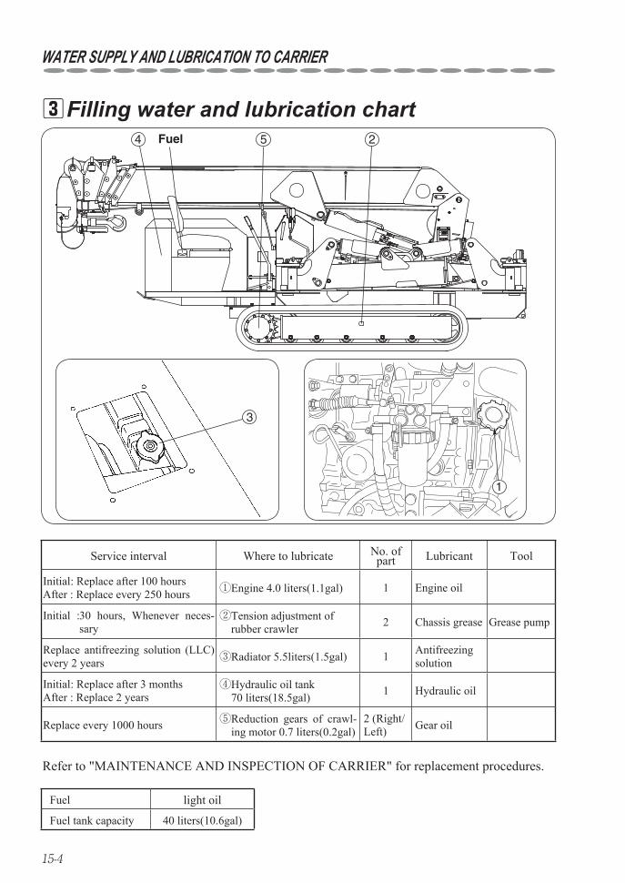
15-4
WATER SUPPLY AND LUBRICATION TO CARRIER
Filling water and lubrication chart 34 5 2Fuel
SELECT SET
OUTRIGGER
tNOT MAX EXT.
ì²
3
1
Refer to "MAINTENANCE AND INSPECTION OF CARRIER" for replacement procedures.
Service interval Where to lubricate No. of part Lubricant Tool
Initial: Replace after 100 hours After : Replace every 250 hours ①Engine 4.0 liters(1.1gal) 1 Engine oil
Initial : 30 hours, Whenever neces-sary
② Tension adjustment of rubber crawler 2 Chassis grease Grease pump
Replace antifreezing solution (LLC) every 2 years ③Radiator 5.5liters(1.5gal) 1 Antifreezing
solution
Initial: Replace after 3 months After : Replace 2 years
④ Hydraulic oil tank 70 liters(18.5gal) 1 Hydraulic oil
Replace every 1000 hours ⑤ Reduction gears of crawl-ing motor 0.7 liters(0.2gal)
2 (Right/Left) Gear oil
Fuel light oil
Fuel tank capacity 40 liters(10.6gal)
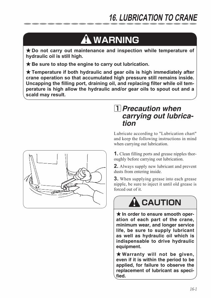
16-1
16. LUBRICATION TO CRANE
Lubricate according to "Lubrication chart" and keep the following instructions in mind when carrying out lubrication.
Precaution when 1carrying out lubrica-tion
WARNINGDo not carry out maintenance and inspection while temperature of ★
hydraulic oil is still high.Be sure to stop the engine to carry out lubrication. ★Temperature if both hydraulic and gear oils is high immediately after ★
crane operation so that accumulated high pressure still remains inside.Uncapping the filling port, draining oil, and replacing filter while oil tem-perature is high allow the hydraulic and/or gear oils to spout out and a scald may result.
CAUTIONIn order to ensure smooth oper- ★
ation of each part of the crane, minimum wear, and longer service life, be sure to supply lubricant as well as hydraulic oil which is indispensable to drive hydraulic equipment.
Warranty will not be given, ★even if it is within the period to be applied, for failure to observe the replacement of lubricant as speci-fied.
1. Clean filling ports and grease nipples thor-oughly before carrying out lubrication.2. Always supply new lubricant and prevent dusts from entering inside.3. When supplying grease into each grease nipple, be sure to inject it until old grease is forced out of it.
16-2
LUBRICATION TO CRANE
List of recommended lubricant 2
List of recommended lubricants1. ◆ ★Use the UNIC genuine hydraulic oils listed below as hydraulic oil for the crane. Use industrial-type hydraulic oil ISO VG 46 for temperatures above 0°C(32°F). ISO VG 22 for temperatures below 0°C(32°F).
Petroleum MakerBrand
ISO VG 22 ISO VG 46
ESSO Spinesso 22 Teresso 46
MOBIL Mobil DTE 22 Mobil DTE Oil Medium
CALTEX Spindura oil 22 Rando Oil 46
SHELL Shell Tellus Oil 22 Shell Tellus Oil 46
Use the recommended greases listed below as grease for lubrication. ★(a) Chassis gr ease Use NLGI No. 2 grade for most temperatures. Use NLGI No. 1 grade for extremely low temperatures.(b) Molybdenum gr ease Use NLGI No. 2 grade.
Petroleum Maker Brand
ESSO Beacon G2
MOBIL Mobilplex Special
CALTEX Molytex Grease EP2
SHELL Retinax AM
Use the recommended lubricants listed below as gear oil for lubrication. ★
Aplication Petroleum Maker Brand
Reducer for winch Shell Shell Spirax EP 90
Reducer for slewing gear
Use API service GL-4 gear oils.(Refer to the followings)
ESSOMOBILCALTEXSHELL
Standard gear oil 90Mobilube GX 90Universal Thuban SAE 90Shell Spirax EP 90
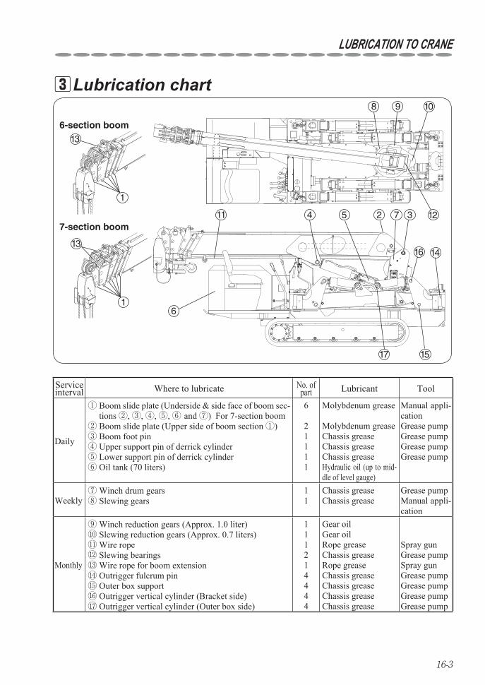
16-3
LUBRICATION TO CRANE
7-section boom
8 9 10
123
1416
1517
725
6
13
1
411
SELECT SET
OUTRIGGER
tNOT MAX EXT.
ì²
6-section boom13
1
Lubrication chart 3
Service interval Where to lubricate No. of
part Lubricant Tool
Daily
① Boom slide plate (Underside & side face of boom sec-tions ②, ③, ④, ⑤, ⑥ and ⑦) For 7-section boom
② Boom slide plate (Upper side of boom section ①)③ Boom foot pin④ Upper support pin of derrick cylinder⑤ Lower support pin of derrick cylinder⑥ Oil tank (70 liters)
6
21111
Molybdenum grease
Molybdenum greaseChassis greaseChassis greaseChassis greaseHydraulic oil (up to mid-dle of level gauge)
Manual appli-cationGrease pumpGrease pumpGrease pumpGrease pump
Weekly⑦ Winch drum gears⑧ Slewing gears
11
Chassis greaseChassis grease
Grease pumpManual appli-cation
Monthly
⑨ Winch reduction gears (Approx. 1.0 liter)⑩ Slewing reduction gears (Approx. 0.7 liters)⑪ Wire rope⑫ Slewing bearings⑬ Wire rope for boom extension⑭ Outrigger fulcrum pin⑮ Outer box support⑯ Outrigger vertical cylinder (Bracket side)⑰ Outrigger vertical cylinder (Outer box side)
111214444
Gear oilGear oilRope greaseChassis greaseRope greaseChassis greaseChassis greaseChassis greaseChassis grease
Spray gunGrease pumpSpray gunGrease pumpGrease pumpGrease pumpGrease pump
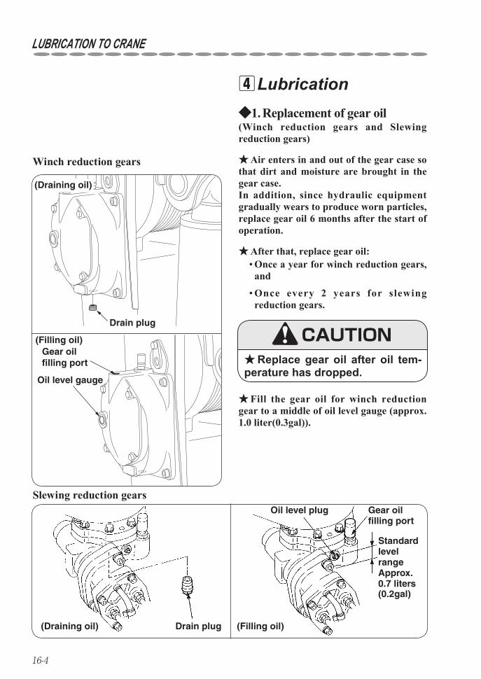
16-4
LUBRICATION TO CRANE
Lubrication 4
• Once a year for winch reduction gears, and
Once every 2 years for slewing • reduction gears.
After that, replace gear oil: ★
Air enters in and out of the gear case so ★that dirt and moisture are brought in the gear case. In addition, since hydraulic equipment gradually wears to produce worn particles, replace gear oil 6 months after the start of operation.
(Winch reduction gears and Slewing reduction gears)
Replacement of gear oil1. ◆
(Draining oil)
Drain plug
(Filling oil)
Oil level gauge
Gear oil filling port
Winch reduction gears
Drain plug(Draining oil)
Oil level plug Gear oil filling port
Standard level range Approx. 0.7 liters(0.2gal)
(Filling oil)
Slewing reduction gears
Fill the gear oil for winch reduction ★gear to a middle of oil level gauge (approx. 1.0 liter(0.3gal)).
Replace gear oil after oil tem- ★perature has dropped.
CAUTION
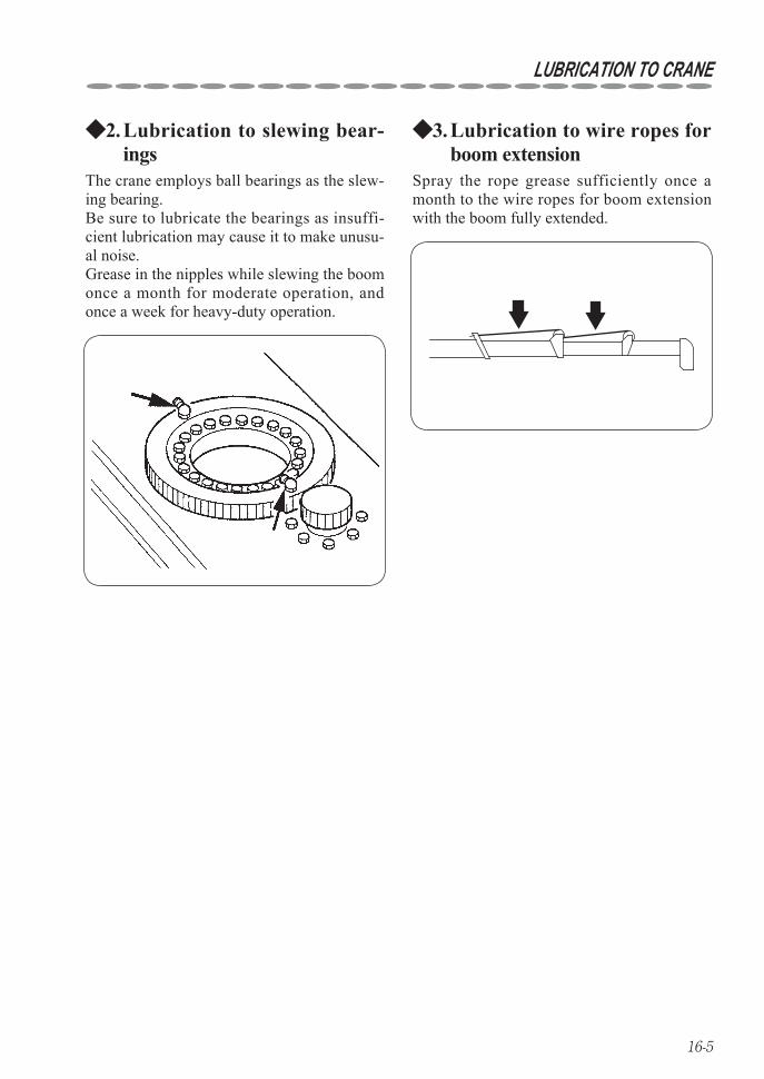
16-5
LUBRICATION TO CRANE
The crane employs ball bearings as the slew-ing bearing.Be sure to lubricate the bearings as insuffi-cient lubrication may cause it to make unusu-al noise.Grease in the nipples while slewing the boom once a month for moderate operation, and once a week for heavy-duty operation.
Lubrication to slewing bear-2. ◆ings
Lubrication to wire ropes for 3. ◆boom extension
Spray the rope grease sufficiently once a month to the wire ropes for boom extension with the boom fully extended.

MEMO
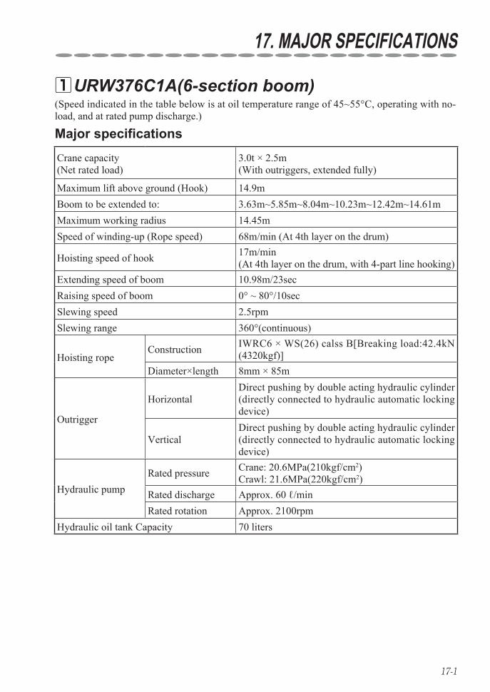
17-1
URW376C1A(6-section boom) 1
Crane capacity (Net rated load)
3.0t × 2.5m(With outriggers, extended fully)
Maximum lift above ground (Hook) 14.9mBoom to be extended to: 3.63m~5.85m~8.04m~10.23m~12.42m~14.61mMaximum working radius 14.45mSpeed of winding-up (Rope speed) 68m/min (At 4th layer on the drum)
Hoisting speed of hook 17m/min(At 4th layer on the drum, with 4-part line hooking)
Extending speed of boom 10.98m/23secRaising speed of boom 0° ~ 80°/10secSlewing speed 2.5rpmSlewing range 360°(continuous)
Hoisting ropeConstruction IWRC6 × WS(26) calss B[Breaking load:42.4kN
(4320kgf)]Diameter×length 8mm × 85m
Outrigger
HorizontalDirect pushing by double acting hydraulic cylinder (directly connected to hydraulic automatic locking device)
VerticalDirect pushing by double acting hydraulic cylinder (directly connected to hydraulic automatic locking device)
Hydraulic pumpRated pressure Crane: 20.6MPa(210kgf/cm2)
Crawl: 21.6MPa(220kgf/cm2)Rated discharge Approx. 60 ℓ/minRated rotation Approx. 2100rpm
Hydraulic oil tank Capacity 70 liters
(Speed indicated in the table below is at oil temperature range of 45~55°C, operating with no-load, and at rated pump discharge.)
Major specifications
17. MAJOR SPECIFICATIONS
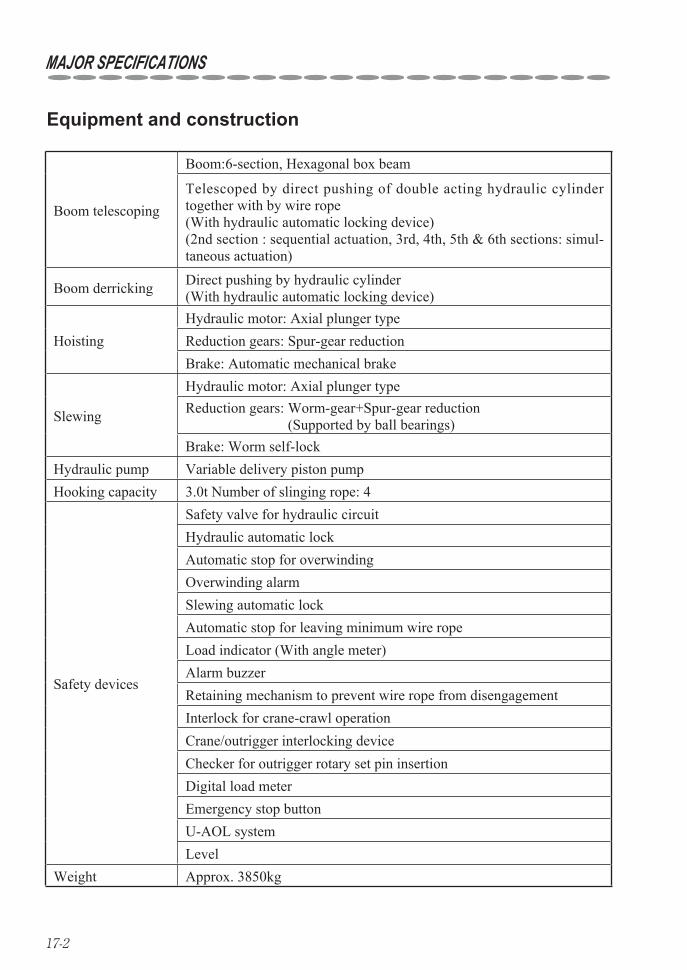
17-2
Boom telescoping
Boom:6-section, Hexagonal box beam
Telescoped by direct pushing of double acting hydraulic cylinder together with by wire rope(With hydraulic automatic locking device)(2nd section : sequential actuation, 3rd, 4th, 5th & 6th sections: simul-taneous actuation)
Boom derricking Direct pushing by hydraulic cylinder(With hydraulic automatic locking device)
HoistingHydraulic motor: Axial plunger typeReduction gears: Spur-gear reductionBrake: Automatic mechanical brake
Slewing
Hydraulic motor: Axial plunger typeReduction gears: Worm-gear+Spur-gear reduction
(Supported by ball bearings)Brake: Worm self-lock
Hydraulic pump Variable delivery piston pumpHooking capacity 3.0t Number of slinging rope: 4
Safety devices
Safety valve for hydraulic circuitHydraulic automatic lockAutomatic stop for overwindingOverwinding alarmSlewing automatic lockAutomatic stop for leaving minimum wire ropeLoad indicator (With angle meter)Alarm buzzerRetaining mechanism to prevent wire rope from disengagementInterlock for crane-crawl operationCrane/outrigger interlocking deviceChecker for outrigger rotary set pin insertionDigital load meterEmergency stop buttonU-AOL systemLevel
Weight Approx. 3850kg
MAJOR SPECIFICATIONS
Equipment and construction

17-3
Crawling Endless rubber crawler
Crawler 300×52.5×88
Length of ground contact 1750mm
Pressure of ground contact 36.0kPa (0.37kgf/cm2)
Crawling speed Forward/Backward: 0~3km/h
Hill-climbing ability 23°
Engine Rated output17.5kW/2100rpm (23.8PS/2100rpm)
Crawling Independently driven by hydraulic power
Parking brake Disc brake with hydraulic motor built-in
Starting engine Electric starter
Fuel tank Capacity: 40 liters
MAJOR SPECIFICATIONS
Crawling device
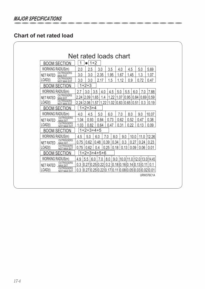
17-4
MAJOR SPECIFICATIONS
1+2+3+4+5+6
1+2+3+4+5
1+2+3+4
1+2+3
1+21WORKING RADIUS(m)
WORKING RADIUS(m)
3.03.03.0
WORKING RADIUS(m)
WORKING RADIUS(m)
WORKING RADIUS(m)
2.0 2.5
3.0
3.0 3.52.35
4.0
2.171.951.5
1.671.12
4.5 5.0 5.69
2.7 3.0
1.450.9
1.30.72
1.070.47
10.071.041.03
3.5
0.930.82
0.840.64
0.730.47
0.620.31
0.520.22
0.470.13
4.0
0.380.09
2.242.24
2.09
OUTRIGGERSMAX EXTOUTRIGGERSNOT MAX EXT
OUTRIGGERSMAX EXTOUTRIGGERSNOT MAX EXT
OUTRIGGERSMAX EXTOUTRIGGERSNOT MAX EXT
OUTRIGGERSMAX EXTOUTRIGGERS
URW376C1A
NOT MAX EXT
OUTRIGGERSMAX EXTOUTRIGGERSNOT MAX EXT
2.06
4.5 5.01.651.57
1.45.5 6.0 7.0 7.88
4.0 4.5 5.0 6.0 7.0 8.0 9.0
4.5 5.0 6.0 7.0 8.0 9.0 10.0 11.0 12.26
4.9 5.5 6.0 7.0 8.0 9.0 10.0 11.0 12.0 13.0
1.221.221.02
1.070.83
0.950.65
0.840.51
0.690.3
0.590.19
0.750.75
0.620.62
0.480.4
0.390.25
0.230.01
0.240.06
0.270.09
0.30.13
0.340.18
0.10.01
0.110.02
0.130.03
0.140.05
0.160.08
0.180.11
0.20.17
0.220.22
0.250.25
0.270.27
0.30.3
14.45
Net rated loads chart
NET RATEDLOAD(t)
NET RATEDLOAD(t)
NET RATEDLOAD(t)
NET RATEDLOAD(t)
NET RATEDLOAD(t)
BOOM SECTION
BOOM SECTION
BOOM SECTION
BOOM SECTION
BOOM SECTION
Chart of net rated load

17-5
MAJOR SPECIFICATIONS
Points to notice, Rated load Rated load showing on the chart is hoisting capacity with the crane set up level and • the data are based on actual working radius by incorporating a shift due to deflection of the boom when loaded. In addition, they are based on strength and stability of the crane. ‘Outriggers max ext’ means the state that the inner box is extended to the position • where the 2nd mark is visible. ‘Outriggers not max ext’ means the state that the inner box is extended to the position • where the 2nd mark is invisible. When each of 4(four) outriggers is set to different extension, operate the crane by • using the worst extended capacity. When each section of boom is extended regardless of an extent, operate the crane • by applying the rated load capacity data under the boom section next to the section being extended. Boom • 1+2+3 means that it is extended to a position where the 1st mark on the 3rd boom-section is visible. Boom • 1+2+3+4 means that it is extended to a position where the 2nd mark on the 3rd boom-section is visible. Boom • 1+2+3+4+5 means that it is extended to a position where the 3rd mark on the 3rd boom-section is visible.
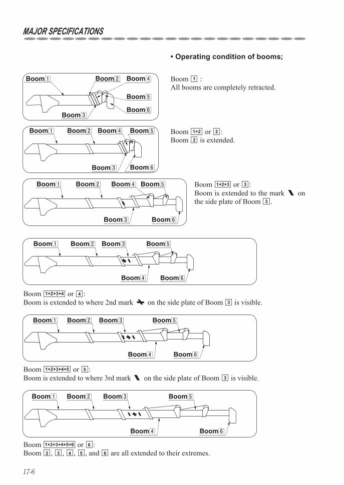
17-6
Operating condition of booms;•
Boom 1 :All booms are completely retracted.
Boom1 Boom2
Boom3
Boom4
Boom5
Boom6
Boom 1+2 or 2 :Boom 2 is extended.
Boom1 Boom2
Boom3
Boom4 Boom5
Boom6
Boom 1+2+3+4 or 4 :Boom is extended to where 2nd mark on the side plate of Boom 3 is visible.
Boom1 Boom2
Boom4
Boom3 Boom5
Boom6
Boom 1+2+3+4+5 or 5 :Boom is extended to where 3rd mark on the side plate of Boom 3 is visible.
Boom1 Boom2
Boom4
Boom3 Boom5
Boom6
Boom1 Boom2
Boom4
Boom3 Boom5
Boom6
Boom 1+2+3+4+5+6 or 6 :Boom 2 , 3 , 4 , 5 , and 6 are all extended to their extremes.
Boom1 Boom2
Boom3
Boom4 Boom5
Boom6
Boom 1+2+3 or 3 :Boom is extended to the mark on the side plate of Boom 3 .
MAJOR SPECIFICATIONS

17-7
MAJOR SPECIFICATIONS
URW376C1U(6-section boom) 2
Crane capacity (Net rated load)
6610 lbs(3.0t) × 8.0ft(2.5m)(With outriggers, extended fully)
Maximum lift above ground (Hook) 48.8ft(14.9m)Boom to be extended to: 11.9ft~19.2ft~26.4ft~33.6ft~40.8ft~47.9ftMaximum working radius 47.4ft(14.45m)Speed of winding-up (Rope speed) 223ft(68m)/min (At 4th layer on the drum)
Hoisting speed of hook 55.8ft(17m)/min(At 4th layer on the drum, with 4-part line hooking)
Extending speed of boom 36ft(10.98m)/23secRaising speed of boom 0° ~ 80°/10secSlewing speed 2.5rpmSlewing range 360°(continuous)
Hoisting ropeConstruction IWRC6 × WS(26) calss B[Breaking load:42.4kN
(9520 lbf(4320kgf))]Diameter×length 5/16in.(8mm) × 254ft(75.5m)
Outrigger
HorizontalDirect pushing by double acting hydraulic cylinder (directly connected to hydraulic automatic locking device)
VerticalDirect pushing by double acting hydraulic cylinder (directly connected to hydraulic automatic locking device)
Hydraulic pumpRated pressure Crane: 20.6MPa 2987psi(210kgf/cm2)
Crawl: 21.6MPa 3130psi(220kgf/cm2)Rated discharge Approx. 15.9gal/min (60 ℓ/min)Rated rotation Approx. 2100rpm
Hydraulic oil tank Capacity 18.5gal(70 liters)
(Speed indicated in the table below is at oil temperature range of 113~131°F(45~55°C), operat-ing with no-load, and at rated pump discharge.)
Major specifications

17-8
MAJOR SPECIFICATIONS
Equipment and construction
Boom telescoping
Boom:6-section, Hexagonal box beam
Telescoped by direct pushing of double acting hydraulic cylinder together with by wire rope(With hydraulic automatic locking device)(2nd section : sequential actuation, 3rd, 4th, 5th & 6th sections: simul-taneous actuation)
Boom derricking Direct pushing by hydraulic cylinder(With hydraulic automatic locking device)
HoistingHydraulic motor: Axial plunger typeReduction gears: Spur-gear reductionBrake: Automatic mechanical brake
Slewing
Hydraulic motor: Axial plunger typeReduction gears: Worm-gear+Spur-gear reduction
(Supported by ball bearings)Brake: Worm self-lock
Hydraulic pump Variable delivery piston pumpHooking capacity 6610 lbs.(3.0t) Number of slinging rope: 4
Safety devices
Safety valve for hydraulic circuitHydraulic automatic lockAutomatic stop for overwindingOverwinding alarmSlewing automatic lockAutomatic stop for leaving minimum wire ropeLoad indicator (With angle meter)Alarm buzzerRetaining mechanism to prevent wire rope from disengagementInterlock for crane-crawl operationCrane/outrigger interlocking deviceChecker for outrigger rotary set pin insertionDigital load meterEmergency stop buttonU-AOL systemLevel
Weight Approx. 8490 lbs.(3850kg)

17-9
MAJOR SPECIFICATIONS
Crawling device
Crawling Endless rubber crawler
Crawler 11.8in.×2in.×88links(300×52.5×88)
Length of ground contact 5.74ft(1750mm)
Pressure of ground contact 36.0kPa (5.3psi(0.37kgf/cm2))
Crawling speed Forward/Backward: 0~1.8mph(0~3km/h)
Hill-climbing ability 23°
Engine Rated output23.5hp(17.5kW)/2100rpm (23.8PS/2100rpm)
Crawling Independently driven by hydraulic power
Parking brake Disc brake with hydraulic motor built-in
Starting engine Electric starter
Fuel tank Capacity:10.6gal(40 liters)
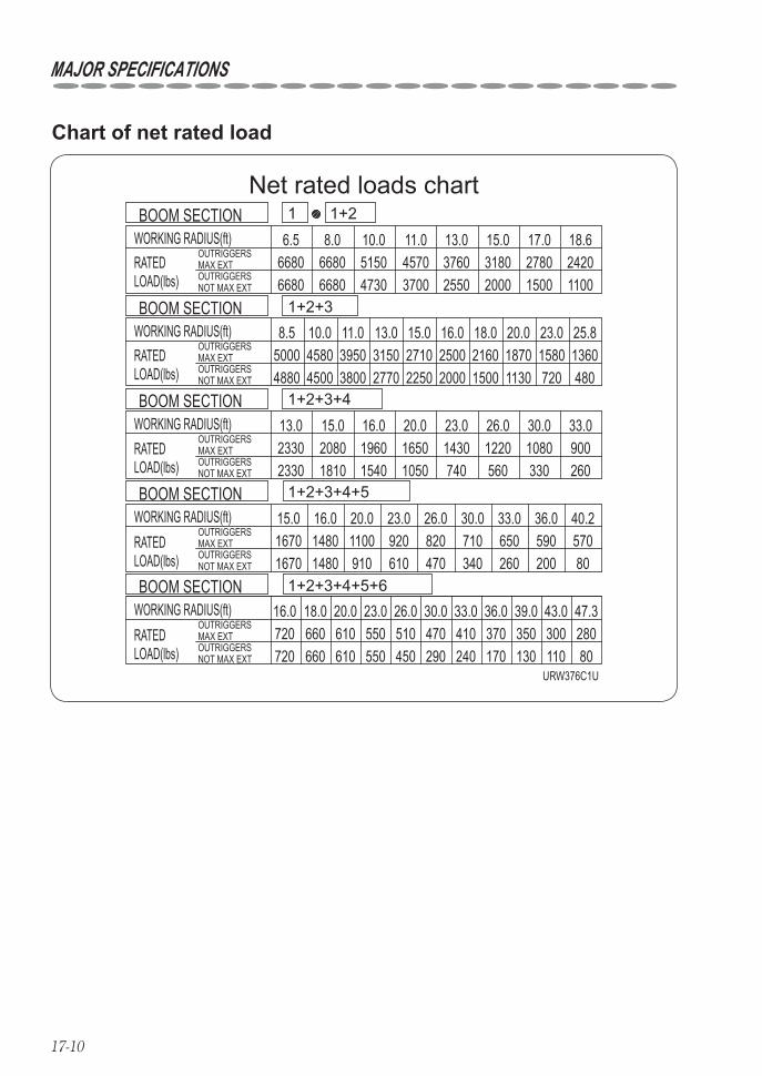
17-10
Net rated loads chart
URW376C1U
66806680
4880
18.6
25.8
4500 3800 2770 2250 2000 1500 1130 720 480
33.0
40.2
47.3
6.5 8.0 10.0 11.0 13.0 15.0 17.06680 5150 4570 3760 3180 2780 24206680 4730 3700 2550 2000 1500 1100
8.5 10.0 11.0 13.0 15.0 16.0 18.0 20.0 23.05000 4580 3950 3150 2710 2500 2160 1870 1580 1360
15.0 16.0 20.0 23.0 26.0 30.023302330
2080 1960 1650 1430 1220 1080 9001810 1540 1050 740 560 330 260
15.0 16.0 20.0 23.0 26.01670 1480 1100 920 820 710 650 590 5701670 1480 910 610 470 340 260 200 80
16.0 18.0 20.0 23.0 26.0
OUTRIGGERSMAX EXTOUTRIGGERSNOT MAX EXT
OUTRIGGERSMAX EXTOUTRIGGERSNOT MAX EXT
OUTRIGGERSMAX EXTOUTRIGGERSNOT MAX EXT
OUTRIGGERSMAX EXTOUTRIGGERSNOT MAX EXT
OUTRIGGERSMAX EXTOUTRIGGERSNOT MAX EXT
30.0 33.0 36.0 39.0 43.0720 660 610
WORKING RADIUS(ft)
550
WORKING RADIUS(ft)
510
WORKING RADIUS(ft)
470
WORKING RADIUS(ft)
410WORKING RADIUS(ft)
370
RATEDLOAD(lbs)
RATEDLOAD(lbs)
350
RATEDLOAD(lbs)
RATEDLOAD(lbs)
RATEDLOAD(lbs)
300 280720 660 610 550 450 290 240 170 130 110 80
30.0 33.0 36.0
13.0
1+2+3+4+5+6
1+2+3+4+5
1+2+3+4
1+2+3
1+21
BOOM SECTION
BOOM SECTION
BOOM SECTION
BOOM SECTION
BOOM SECTION
Chart of net rated load
MAJOR SPECIFICATIONS
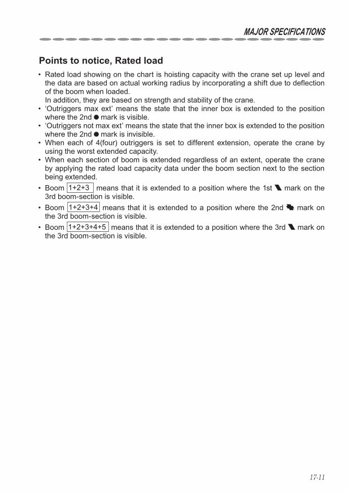
17-11
MAJOR SPECIFICATIONS
Points to notice, Rated load Rated load showing on the chart is hoisting capacity with the crane set up level and • the data are based on actual working radius by incorporating a shift due to deflection of the boom when loaded. In addition, they are based on strength and stability of the crane. ‘Outriggers max ext’ means the state that the inner box is extended to the position • where the 2nd mark is visible. ‘Outriggers not max ext’ means the state that the inner box is extended to the position • where the 2nd mark is invisible. When each of 4(four) outriggers is set to different extension, operate the crane by • using the worst extended capacity. When each section of boom is extended regardless of an extent, operate the crane • by applying the rated load capacity data under the boom section next to the section being extended. Boom • 1+2+3 means that it is extended to a position where the 1st mark on the 3rd boom-section is visible. Boom • 1+2+3+4 means that it is extended to a position where the 2nd mark on the 3rd boom-section is visible. Boom • 1+2+3+4+5 means that it is extended to a position where the 3rd mark on the 3rd boom-section is visible.
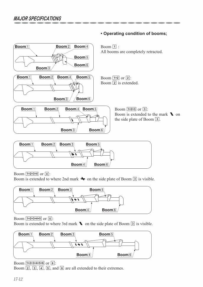
17-12
MAJOR SPECIFICATIONS
Operating condition of booms;•
Boom 1 :All booms are completely retracted.
Boom1 Boom2
Boom3
Boom4
Boom5
Boom6
Boom1 Boom2
Boom3
Boom4 Boom5
Boom6
Boom1 Boom2
Boom4
Boom3 Boom5
Boom6
Boom1 Boom2
Boom4
Boom3 Boom5
Boom6
Boom1 Boom2
Boom4
Boom3 Boom5
Boom6
Boom1 Boom2
Boom3
Boom4 Boom5
Boom6
Boom 1+2 or 2 :Boom 2 is extended.
Boom 1+2+3+4 or 4 :Boom is extended to where 2nd mark on the side plate of Boom 3 is visible.
Boom 1+2+3+4+5 or 5 :Boom is extended to where 3rd mark on the side plate of Boom 3 is visible.
Boom 1+2+3+4+5+6 or 6 :Boom 2 , 3 , 4 , 5 , and 6 are all extended to their extremes.
Boom 1+2+3 or 3 :Boom is extended to the mark on the side plate of Boom 3 .
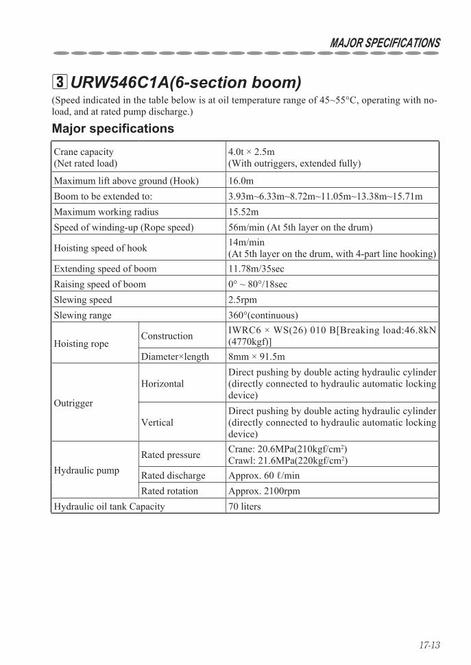
17-13
MAJOR SPECIFICATIONS
URW546C1A(6-section boom) 3
Crane capacity (Net rated load)
4.0t × 2.5m(With outriggers, extended fully)
Maximum lift above ground (Hook) 16.0mBoom to be extended to: 3.93m~6.33m~8.72m~11.05m~13.38m~15.71mMaximum working radius 15.52mSpeed of winding-up (Rope speed) 56m/min (At 5th layer on the drum)
Hoisting speed of hook 14m/min(At 5th layer on the drum, with 4-part line hooking)
Extending speed of boom 11.78m/35secRaising speed of boom 0° ~ 80°/18secSlewing speed 2.5rpmSlewing range 360°(continuous)
Hoisting ropeConstruction IWRC6 × WS(26) 010 B[Breaking load:46.8kN
(4770kgf)]Diameter×length 8mm × 91.5m
Outrigger
HorizontalDirect pushing by double acting hydraulic cylinder (directly connected to hydraulic automatic locking device)
VerticalDirect pushing by double acting hydraulic cylinder (directly connected to hydraulic automatic locking device)
Hydraulic pumpRated pressure Crane: 20.6MPa(210kgf/cm2)
Crawl: 21.6MPa(220kgf/cm2)Rated discharge Approx. 60 ℓ/minRated rotation Approx. 2100rpm
Hydraulic oil tank Capacity 70 liters
(Speed indicated in the table below is at oil temperature range of 45~55°C, operating with no-load, and at rated pump discharge.)
Major specifications

17-14
Boom telescoping
Boom:6-section, Hexagonal box beam
Telescoped by direct pushing of double acting hydraulic cylinder together with by wire rope(With hydraulic automatic locking device)(2nd section : sequential actuation, 3rd, 4th, 5th & 6th sections: simul-taneous actuation)
Boom derricking Direct pushing by hydraulic cylinder(With hydraulic automatic locking device)
HoistingHydraulic motor: Axial plunger typeReduction gears: Spur-gear reductionBrake: Automatic mechanical brake
Slewing
Hydraulic motor: Axial plunger typeReduction gears: Worm-gear+Spur-gear reduction
(Supported by ball bearings)Brake: Worm self-lock
Hydraulic pump Variable delivery piston pumpHooking capacity 4.0t Number of slinging rope: 4
Safety devices
Safety valve for hydraulic circuitHydraulic automatic lockAutomatic stop for overwindingOverwinding alarmSlewing automatic lockAutomatic stop for leaving minimum wire ropeLoad indicator (With angle meter)Alarm buzzerRetaining mechanism to prevent wire rope from disengagementInterlock for crane-crawl operationCrane/outrigger interlocking deviceChecker for outrigger rotary set pin insertionDigital load meterEmergency stop buttonU-AOL systemLevel
Weight Approx. 4910kg
Equipment and construction
MAJOR SPECIFICATIONS
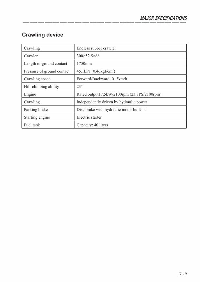
17-15
Crawling Endless rubber crawler
Crawler 300×52.5×88
Length of ground contact 1750mm
Pressure of ground contact 45.1kPa (0.46kgf/cm2)
Crawling speed Forward/Backward: 0~3km/h
Hill-climbing ability 23°
Engine Rated output17.5kW/2100rpm (23.8PS/2100rpm)
Crawling Independently driven by hydraulic power
Parking brake Disc brake with hydraulic motor built-in
Starting engine Electric starter
Fuel tank Capacity: 40 liters
Crawling device
MAJOR SPECIFICATIONS

17-16
MAJOR SPECIFICATIONS
Net rated loads chart
URW546C1A
4.04.0
3.453.45
3.03.0
2.552.4
2.252.0
2.01.65
1.81.35 1.1
0.3
1.61.0
1.88 1.682.02.0
4.3
1.63
1.351.35 1.15
0.750.78 0.65
0.25
0.210.86 0.71
0.350.55
0.250.44
0.180.39 0.33
0.150.270.13
0.210.11
0.16
5.04.0 4.5
2.03.02.02.55
2.42.253.0
3.51.8
1.65
8.538.07.51.2 1.1 0.980.6 0.45
6.56.0 7.01.651.1 0.9 0.75
1.5 1.355.5
1.35
2.02.0 1.8 1.6
1.51.1
1.00.5
0.90.4 0.3
1.11.0
0.950.9
0.860.8
0.710.65
0.60.5
0.550.4
0.50.3
0.450.25
0.40.2
0.350.15
6.0 7.0 8.0 9.0 10.0 11.0 12.0 13.0 14.0 15.0 15.52
0.5 0.40.6 0.5
0.1
OUTRIGGERSMAX EXTOUTRIGGERSNOT MAX EXT
OUTRIGGERSMAX EXTOUTRIGGERSNOT MAX EXT
OUTRIGGERSMAX EXTOUTRIGGERSNOT MAX EXT
OUTRIGGERSMAX EXTOUTRIGGERSNOT MAX EXT
OUTRIGGERSMAX EXTOUTRIGGERSNOT MAX EXT
0.5
WORKING RADIUS(m)
WORKING RADIUS(m)
WORKING RADIUS(m)
WORKING RADIUS(m)
2.5 3.0 3.5 4.0 4.5 5.0 5.5 6.0 6.14
1+2+3+4+5+6WORKING RADIUS(m)
1+2+3+4+5
1+2+3+4
1+2+3
1+21
4.0 4.5 5.0 5.5 6.0 7.0 8.0 9.0 10.0 10.9
5.0 5.5 6.0 7.0 8.0 9.0 10.0 11.0 12.0 13.2
NET RATEDLOAD(t)
NET RATEDLOAD(t)
NET RATEDLOAD(t)
NET RATEDLOAD(t)
NET RATEDLOAD(t)
BOOM SECTION
BOOM SECTION
BOOM SECTION
BOOM SECTION
BOOM SECTION
Chart of net rated load

17-17
MAJOR SPECIFICATIONS
Points to notice, Rated load The net rated load is performance when the crane is placed level and is based on • actual working radius including boom deflection under loaded. The net rated load is also based on strength and stability of the crane. ‘Outriggers max ext’ means the state that the inner box is extended to the position • where the 2nd mark is visible. ‘Outriggers not max ext’ means the state that the inner box is extended to the position • where the 2nd mark is invisible. When each of 4 outriggers has been set to different extension,operate the crane by • using the worst extended capacity. When each of boom sections being extended is exceeded even slightly,operate it by • application of the capacity for the next boom section. Boom • 1+2+3+4 means that the boom is extended to the position where the 1st mark on the 4th boom-section is visible. Boom • 1+2+3+4+5 means that the boom is extended to the position where the 2nd
mark on the 4th boom-section is visible. Operate the crane using the rated load capacity data under the boom extension of: • 1+2+3+4 when the mark on the 3rd boom-section goes beyond the 2nd boom section, regardless of the displacement, 1+2+3+4+5 when the 1st mark on the side plate of the 4th boom-section goes beyond the 3rd boom-section, regardless of the displacement, 1+2+3+4+5+6 when the 2nd mark on the side plate of the 4th boom-section goes beyond the 3rd boom-section, regardless of the displacement.
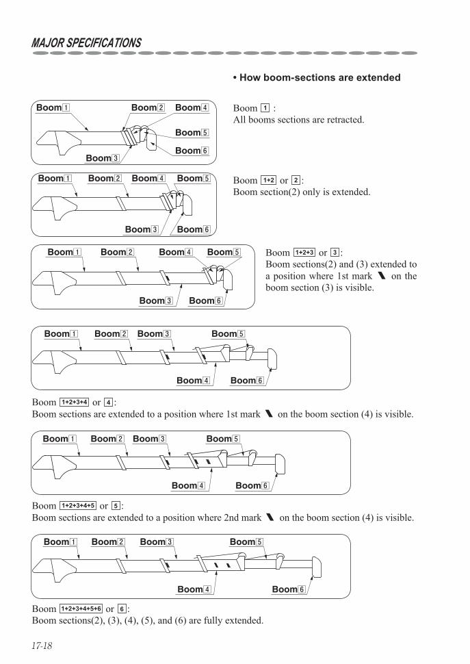
17-18
How boom-sections are extended•
MAJOR SPECIFICATIONS
Boom 1 :All booms sections are retracted.
Boom1 Boom2
Boom3
Boom4
Boom5
Boom6
Boom 1+2 or 2 :Boom section(2) only is extended.
Boom1 Boom2
Boom3
Boom4 Boom5
Boom6
Boom 1+2+3+4 or 4 :Boom sections are extended to a position where 1st mark on the boom section (4) is visible.
Boom1 Boom2
Boom4
Boom3 Boom5
Boom6
Boom 1+2+3+4+5 or 5 :Boom sections are extended to a position where 2nd mark on the boom section (4) is visible.
Boom1 Boom2
Boom4
Boom3 Boom5
Boom6
Boom1 Boom2
Boom4
Boom3 Boom5
Boom6
Boom 1+2+3+4+5+6 or 6 :Boom sections(2), (3), (4), (5), and (6) are fully extended.
Boom1 Boom2
Boom3
Boom4 Boom5
Boom6
Boom 1+2+3 or 3 :Boom sections(2) and (3) extended to a position where 1st mark on the boom section (3) is visible.
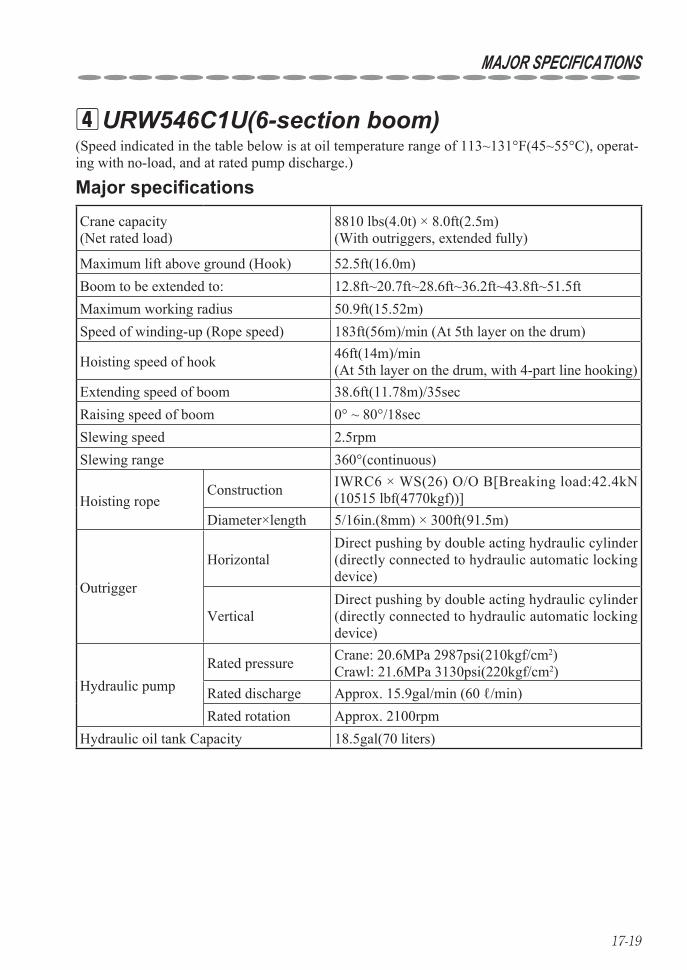
17-19
MAJOR SPECIFICATIONS
URW546C1U(6-section boom) 4(Speed indicated in the table below is at oil temperature range of 113~131°F(45~55°C), operat-ing with no-load, and at rated pump discharge.)
Major specifications
Crane capacity (Net rated load)
8810 lbs(4.0t) × 8.0ft(2.5m)(With outriggers, extended fully)
Maximum lift above ground (Hook) 52.5ft(16.0m)Boom to be extended to: 12.8ft~20.7ft~28.6ft~36.2ft~43.8ft~51.5ftMaximum working radius 50.9ft(15.52m)Speed of winding-up (Rope speed) 183ft(56m)/min (At 5th layer on the drum)
Hoisting speed of hook 46ft(14m)/min(At 5th layer on the drum, with 4-part line hooking)
Extending speed of boom 38.6ft(11.78m)/35secRaising speed of boom 0° ~ 80°/18secSlewing speed 2.5rpmSlewing range 360°(continuous)
Hoisting ropeConstruction IWRC6 × WS(26) O/O B[Breaking load:42.4kN
(10515 lbf(4770kgf))]Diameter×length 5/16in.(8mm) × 300ft(91.5m)
Outrigger
HorizontalDirect pushing by double acting hydraulic cylinder (directly connected to hydraulic automatic locking device)
VerticalDirect pushing by double acting hydraulic cylinder (directly connected to hydraulic automatic locking device)
Hydraulic pumpRated pressure Crane: 20.6MPa 2987psi(210kgf/cm2)
Crawl: 21.6MPa 3130psi(220kgf/cm2)Rated discharge Approx. 15.9gal/min (60 ℓ/min)Rated rotation Approx. 2100rpm
Hydraulic oil tank Capacity 18.5gal(70 liters)
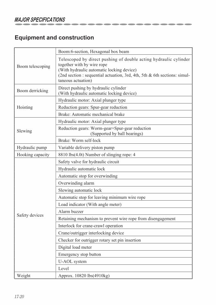
17-20
MAJOR SPECIFICATIONS
Boom telescoping
Boom:6-section, Hexagonal box beam
Telescoped by direct pushing of double acting hydraulic cylinder together with by wire rope(With hydraulic automatic locking device)(2nd section : sequential actuation, 3rd, 4th, 5th & 6th sections: simul-taneous actuation)
Boom derricking Direct pushing by hydraulic cylinder(With hydraulic automatic locking device)
HoistingHydraulic motor: Axial plunger typeReduction gears: Spur-gear reductionBrake: Automatic mechanical brake
Slewing
Hydraulic motor: Axial plunger typeReduction gears: Worm-gear+Spur-gear reduction
(Supported by ball bearings)Brake: Worm self-lock
Hydraulic pump Variable delivery piston pumpHooking capacity 8810 lbs(4.0t) Number of slinging rope: 4
Safety devices
Safety valve for hydraulic circuitHydraulic automatic lockAutomatic stop for overwindingOverwinding alarmSlewing automatic lockAutomatic stop for leaving minimum wire ropeLoad indicator (With angle meter)Alarm buzzerRetaining mechanism to prevent wire rope from disengagementInterlock for crane-crawl operationCrane/outrigger interlocking deviceChecker for outrigger rotary set pin insertionDigital load meterEmergency stop buttonU-AOL systemLevel
Weight Approx. 10820 lbs(4910kg)
Equipment and construction
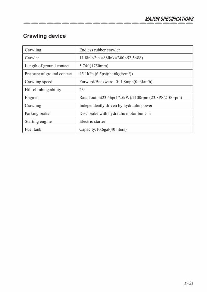
17-21
MAJOR SPECIFICATIONS
Crawling device
Crawling Endless rubber crawler
Crawler 11.8in.×2in.×88links(300×52.5×88)
Length of ground contact 5.74ft(1750mm)
Pressure of ground contact 45.1kPa (6.5psi(0.46kgf/cm2))
Crawling speed Forward/Backward: 0~1.8mph(0~3km/h)
Hill-climbing ability 23°
Engine Rated output23.5hp(17.5kW)/2100rpm (23.8PS/2100rpm)
Crawling Independently driven by hydraulic power
Parking brake Disc brake with hydraulic motor built-in
Starting engine Electric starter
Fuel tank Capacity:10.6gal(40 liters)
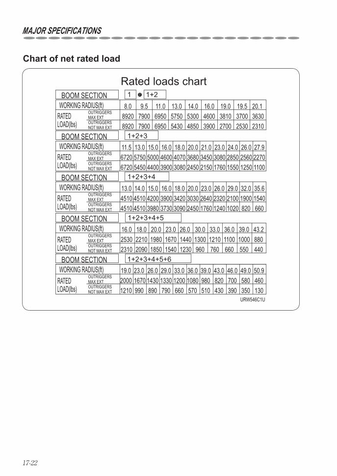
17-22
Rated loads chart
URW546C1U
35.6
43.2
OUTRIGGERSMAX EXTOUTRIGGERSNOT MAX EXT
OUTRIGGERSMAX EXTOUTRIGGERSNOT MAX EXT
OUTRIGGERSMAX EXTOUTRIGGERSNOT MAX EXT
OUTRIGGERSMAX EXTOUTRIGGERSNOT MAX EXT
OUTRIGGERSMAX EXTOUTRIGGERSNOT MAX EXT
WORKING RADIUS(ft)
WORKING RADIUS(ft)
WORKING RADIUS(ft)
WORKING RADIUS(ft)
WORKING RADIUS(ft)
RATEDLOAD(lbs)
RATEDLOAD(lbs)
RATEDLOAD(lbs)
RATEDLOAD(lbs)
RATEDLOAD(lbs) 130
460580350390
700820430510570660790890990
19.0
880100011001210130026.0 30.0 33.0 36.0 39.0
960 760 660 550 440
23.020.018.0253016.0
1980 1670 144012302310 1850 1540
154045104510 820 660
11.56720
13.05750
15.05000
16.04600
18.04070
20.03680
21.03450
23.03080
24.02850
26.02560
27.92270
79007900 6950 5750 5300 4600 3810 3700 3630
20.119.519.016.014.013.011.09.58.0
89208920
6950 5430 4850 3900 2700 2530 2310
6720 5450 4400 3900 3080 2450 2150 1760 1550 1250 1100
12102000
45104510
167023.0
20902210
14.013.0
143026.0
3980420015.0
133029.0
3730390016.0
120033.0
3090342018.0
108036.0
2450303020.0
39.0
1760264023.0
98043.0
1240232026.0
46.0
1020210029.0
49.0
190032.0
50.91+2+3+4+5+6
1+2+3+4+5
1+2+3+4
1+2+3
1+21
BOOM SECTION
BOOM SECTION
BOOM SECTION
BOOM SECTION
BOOM SECTION
Chart of net rated load
MAJOR SPECIFICATIONS
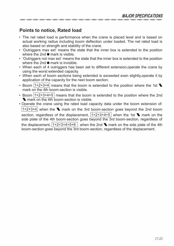
17-23
MAJOR SPECIFICATIONS
Points to notice, Rated load The net rated load is performance when the crane is placed level and is based on • actual working radius including boom deflection under loaded. The net rated load is also based on strength and stability of the crane. ‘Outriggers max ext’ means the state that the inner box is extended to the position • where the 2nd mark is visible. ‘Outriggers not max ext’ means the state that the inner box is extended to the position • where the 2nd mark is invisible. When each of 4 outriggers has been set to different extension,operate the crane by • using the worst extended capacity. When each of boom sections being extended is exceeded even slightly,operate it by • application of the capacity for the next boom section. Boom • 1+2+3+4 means that the boom is extended to the position where the 1st mark on the 4th boom-section is visible. Boom • 1+2+3+4+5 means that the boom is extended to the position where the 2nd
mark on the 4th boom-section is visible. Operate the crane using the rated load capacity data under the boom extension of: • 1+2+3+4 when the mark on the 3rd boom-section goes beyond the 2nd boom section, regardless of the displacement, 1+2+3+4+5 when the 1st mark on the side plate of the 4th boom-section goes beyond the 3rd boom-section, regardless of the displacement, 1+2+3+4+5+6 when the 2nd mark on the side plate of the 4th boom-section goes beyond the 3rd boom-section, regardless of the displacement.

17-24
How boom-sections are extended•
Boom 1 :All boom sections are retracted.
Boom1 Boom2
Boom3
Boom4
Boom5
Boom6
Boom 1+2 or 2 :Boom section(2) only is extended.
Boom1 Boom2
Boom3
Boom4 Boom5
Boom6
Boom 1+2+3+4 or 4 :Boom sections are extended to a position where 1st mark on the boom section (4) is visible.
Boom1 Boom2
Boom4
Boom3 Boom5
Boom6
Boom 1+2+3+4+5 or 5 :Boom sections are extended to a position where 2nd mark on the boom section (4) is visible.
Boom1 Boom2
Boom4
Boom3 Boom5
Boom6
Boom1 Boom2
Boom4
Boom3 Boom5
Boom6
Boom 1+2+3+4+5+6 or 6 :Boom sections(2), (3), (4), (5), and (6) are fully extended.
Boom1 Boom2
Boom3
Boom4 Boom5
Boom6
Boom 1+2+3 or 3 :Boom sections(2) and (3) extended to a position where the mark on the boom section (3) is visible.
MAJOR SPECIFICATIONS
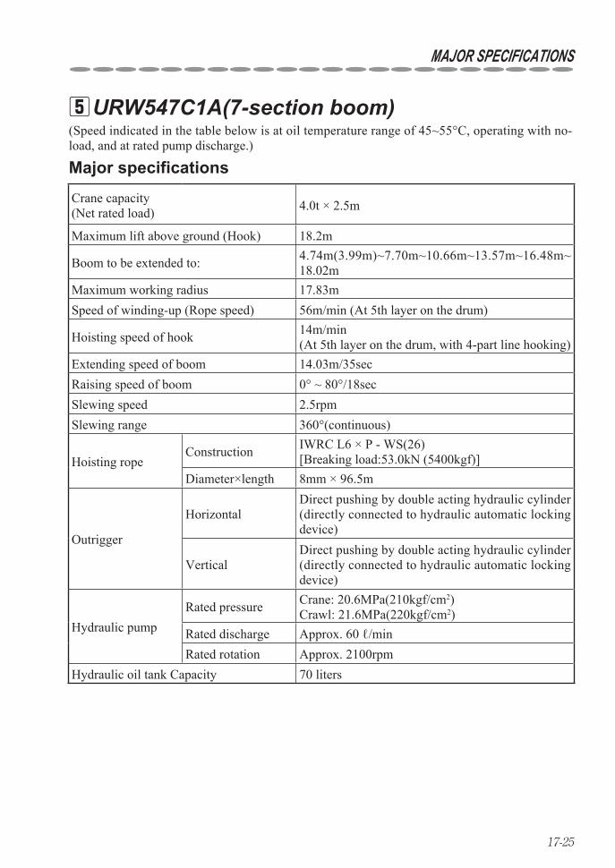
17-25
URW547C1A(7-section boom) 5
Crane capacity (Net rated load) 4.0t × 2.5m
Maximum lift above ground (Hook) 18.2m
Boom to be extended to: 4.74m(3.99m)~7.70m~10.66m~13.57m~16.48m~18.02m
Maximum working radius 17.83mSpeed of winding-up (Rope speed) 56m/min (At 5th layer on the drum)
Hoisting speed of hook 14m/min(At 5th layer on the drum, with 4-part line hooking)
Extending speed of boom 14.03m/35secRaising speed of boom 0° ~ 80°/18secSlewing speed 2.5rpmSlewing range 360°(continuous)
Hoisting ropeConstruction IWRC L6 × P - WS(26)
[Breaking load:53.0kN (5400kgf)]Diameter×length 8mm × 96.5m
Outrigger
HorizontalDirect pushing by double acting hydraulic cylinder (directly connected to hydraulic automatic locking device)
VerticalDirect pushing by double acting hydraulic cylinder (directly connected to hydraulic automatic locking device)
Hydraulic pumpRated pressure Crane: 20.6MPa(210kgf/cm2)
Crawl: 21.6MPa(220kgf/cm2)Rated discharge Approx. 60 ℓ/minRated rotation Approx. 2100rpm
Hydraulic oil tank Capacity 70 liters
(Speed indicated in the table below is at oil temperature range of 45~55°C, operating with no-load, and at rated pump discharge.)
Major specifications
MAJOR SPECIFICATIONS
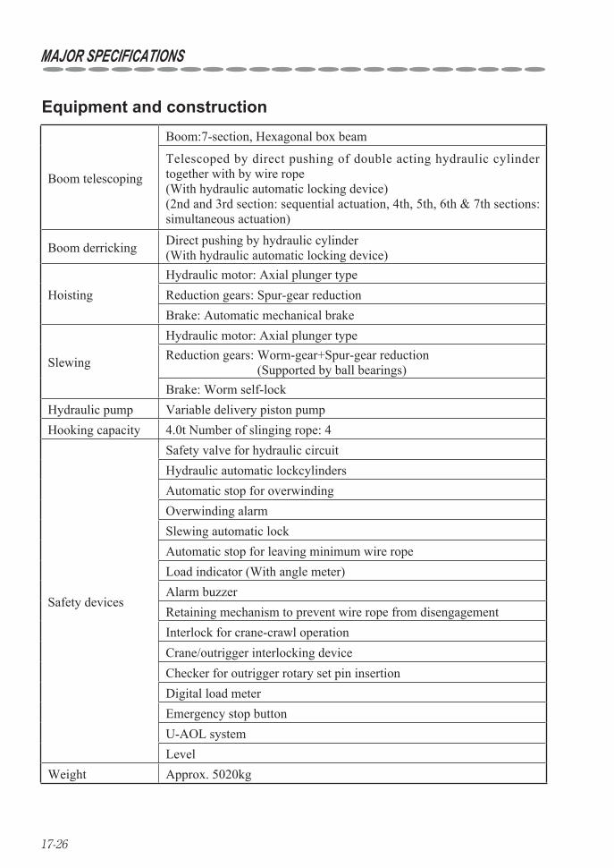
17-26
Equipment and construction
Boom telescoping
Boom:7-section, Hexagonal box beam
Telescoped by direct pushing of double acting hydraulic cylinder together with by wire rope(With hydraulic automatic locking device)(2nd and 3rd section: sequential actuation, 4th, 5th, 6th & 7th sections: simultaneous actuation)
Boom derricking Direct pushing by hydraulic cylinder(With hydraulic automatic locking device)
HoistingHydraulic motor: Axial plunger typeReduction gears: Spur-gear reductionBrake: Automatic mechanical brake
Slewing
Hydraulic motor: Axial plunger typeReduction gears: Worm-gear+Spur-gear reduction
(Supported by ball bearings)Brake: Worm self-lock
Hydraulic pump Variable delivery piston pumpHooking capacity 4.0t Number of slinging rope: 4
Safety devices
Safety valve for hydraulic circuitHydraulic automatic lockcylindersAutomatic stop for overwindingOverwinding alarmSlewing automatic lockAutomatic stop for leaving minimum wire ropeLoad indicator (With angle meter)Alarm buzzerRetaining mechanism to prevent wire rope from disengagementInterlock for crane-crawl operationCrane/outrigger interlocking deviceChecker for outrigger rotary set pin insertionDigital load meterEmergency stop buttonU-AOL systemLevel
Weight Approx. 5020kg
MAJOR SPECIFICATIONS

17-27
Crawling device
Crawling Endless rubber crawler
Crawler 300×52.5×88
Length of ground contact 1750mm
Pressure of ground contact 47.0kPa (0.48kgf/cm2)
Crawling speed Forward/Backward: 0~3km/h
Hill-climbing ability 23°
Engine Rated output17.5kW/2100rpm (23.8PS/2100rpm)
Crawling Independently driven by hydraulic power
Parking brake Disc brake with hydraulic motor built-in
Starting engine Electric starter
Fuel tank Capacity: 40 liters
MAJOR SPECIFICATIONS
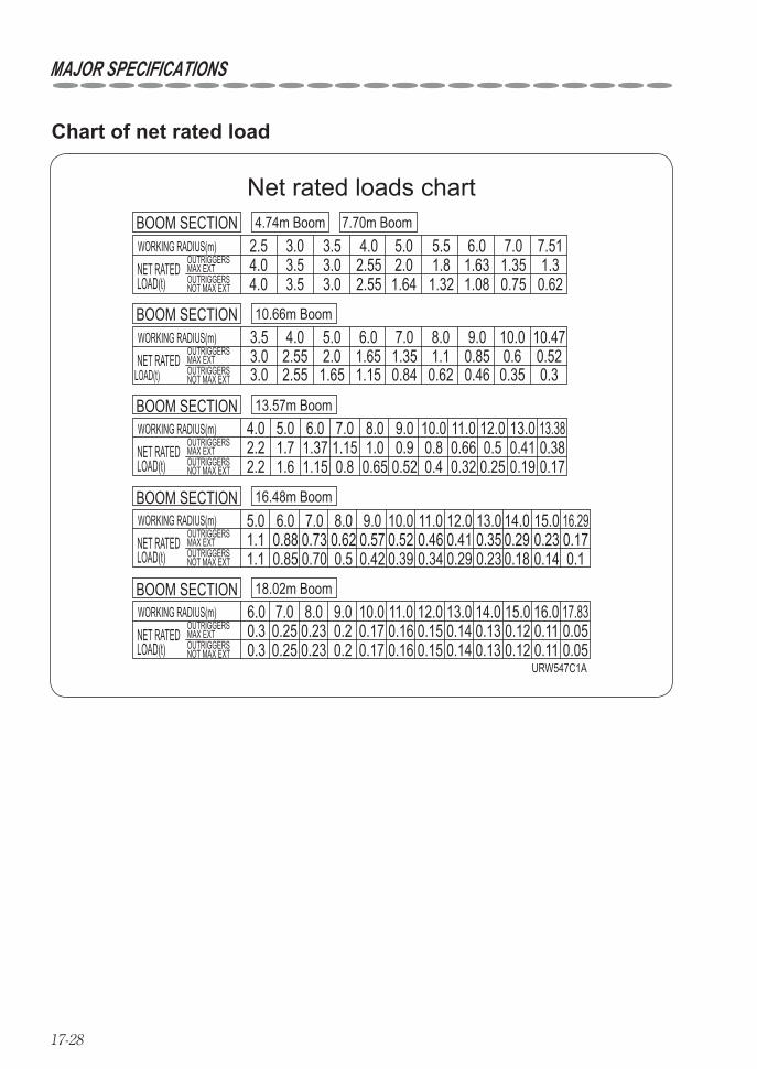
17-28
4.04.0
3.03.0
2.552.55
2.0 1.87.511.3
7.01.63 1.353.5
3.5 0.621.64 1.32 1.08 0.75
2.5 3.0 3.5 4.0 5.0 5.5 6.0OUTRIGGERSMAX EXTOUTRIGGERSNOT MAX EXT
NET RATEDLOAD(t)
4.74m Boom 7.70m BoomWORKING RADIUS(m)BOOM SECTION
3.03.0
2.552.55
5.0 6.0 7.0 8.0 9.0 10.0 10.472.0 1.65 1.35 1.1 0.85 0.6 0.521.65 1.15 0.84 0.62 0.46 0.35 0.3
3.5 4.0OUTRIGGERSMAX EXTOUTRIGGERSNOT MAX EXT
NET RATEDLOAD(t)
10.66m BoomWORKING RADIUS(m)BOOM SECTION
1.71.6
1.371.15
1.150.8
1.0 0.9 0.6613.3811.0 12.0 13.0
2.2 0.8 0.5 0.41 0.380.52 0.4 0.32 0.25 0.19 0.17
5.0 6.04.0 7.0 8.0
0.65
9.0 10.0OUTRIGGERSMAX EXTOUTRIGGERSNOT MAX EXT
NET RATEDLOAD(t)
13.57m BoomWORKING RADIUS(m)BOOM SECTION
2.2
16.290.170.1
0.2315.0
0.14
14.00.290.18
13.00.350.23
11.00.460.34
10.00.520.39 0.29
0.4112.0
0.570.420.5
0.628.07.0
0.730.70
1.19.05.0
0.850.886.0
OUTRIGGERSMAX EXTOUTRIGGERSNOT MAX EXT
NET RATEDLOAD(t)
16.48m BoomWORKING RADIUS(m)BOOM SECTION
1.1
17.830.050.05
16.00.110.11
15.0
0.120.12
12.011.00.150.15
0.160.16
14.013.00.130.13
0.140.14
8.0 9.0 10.00.170.17
0.250.25
0.230.23
0.27.0
0.30.3
6.0OUTRIGGERSMAX EXTOUTRIGGERSNOT MAX EXT
NET RATEDLOAD(t)
18.02m BoomWORKING RADIUS(m)BOOM SECTION
0.2URW547C1A
Net rated loads chart
Chart of net rated load
MAJOR SPECIFICATIONS
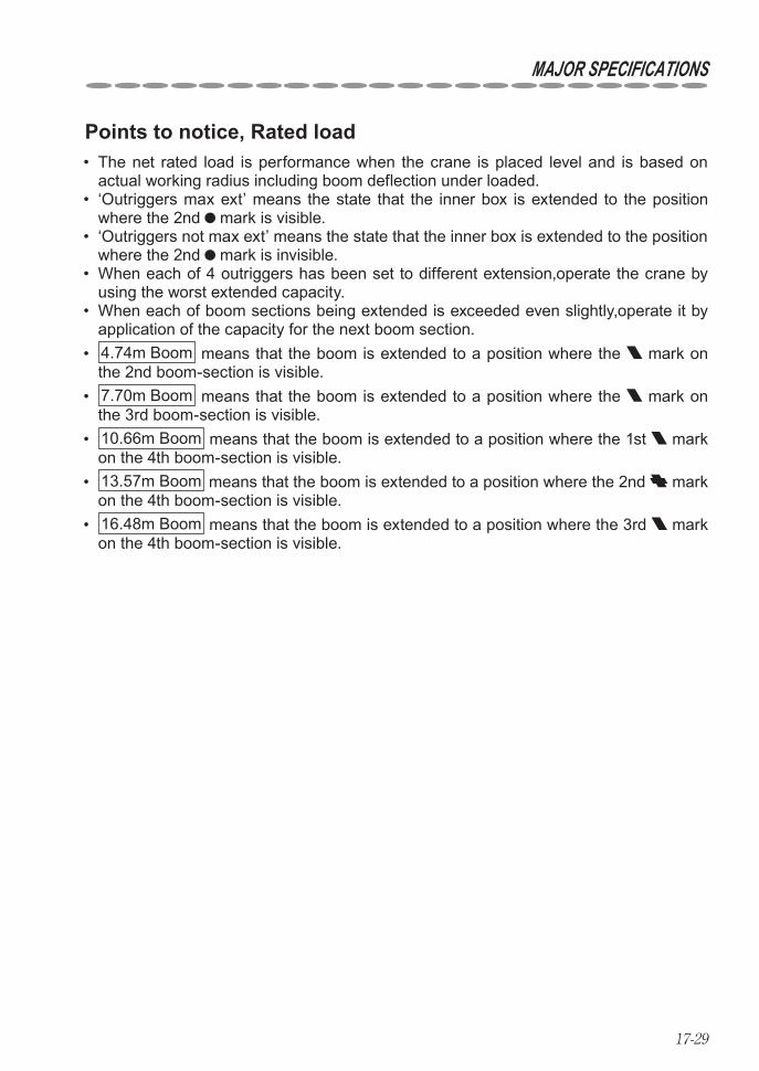
17-29
Points to notice, Rated load The net rated load is performance when the crane is placed level and is based on • actual working radius including boom deflection under loaded. ‘Outriggers max ext’ means the state that the inner box is extended to the position • where the 2nd mark is visible. ‘Outriggers not max ext’ means the state that the inner box is extended to the position • where the 2nd mark is invisible. When each of 4 outriggers has been set to different extension,operate the crane by • using the worst extended capacity. When each of boom sections being extended is exceeded even slightly,operate it by • application of the capacity for the next boom section. • 4.74m Boom means that the boom is extended to a position where the mark on the 2nd boom-section is visible. • 7.70m Boom means that the boom is extended to a position where the mark on the 3rd boom-section is visible. • 10.66m Boom means that the boom is extended to a position where the 1st mark on the 4th boom-section is visible. • 13.57m Boom means that the boom is extended to a position where the 2nd mark on the 4th boom-section is visible. • 16.48m Boom means that the boom is extended to a position where the 3rd mark on the 4th boom-section is visible.
MAJOR SPECIFICATIONS
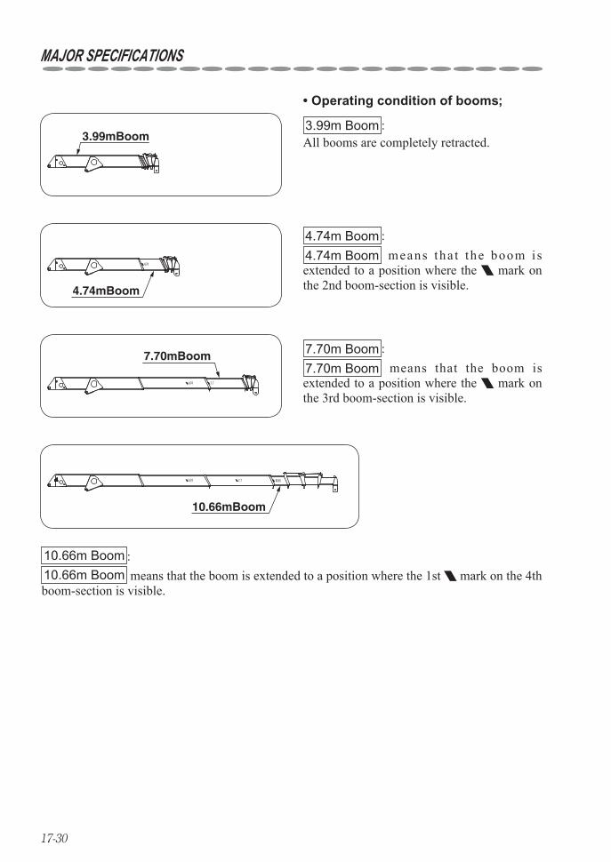
17-30
7.70mBoom 7.70m Boom :7.70m Boom means that the boom is extended to a position where the mark on the 3rd boom-section is visible.
10.66mBoom
10.66m Boom :10.66m Boom means that the boom is extended to a position where the 1st mark on the 4th boom-section is visible.
4.74mBoom
4.74m Boom :4.74m Boom means tha t the boom i s extended to a position where the mark on the 2nd boom-section is visible.
3.99mBoom3.99m Boom :All booms are completely retracted.
Operating condition of booms;•
MAJOR SPECIFICATIONS
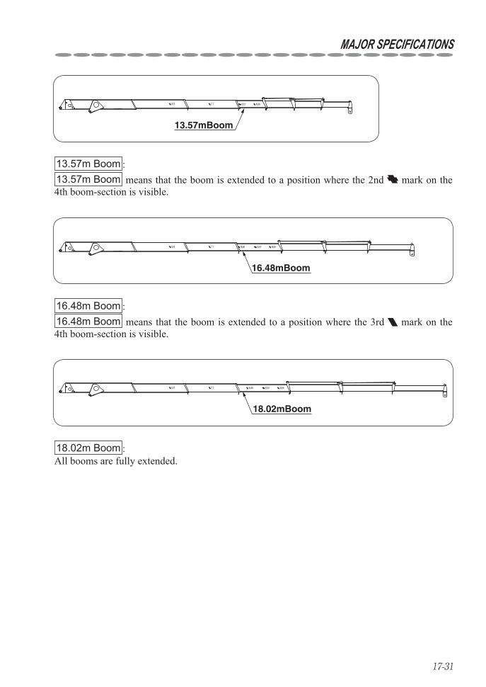
17-31
13.57mBoom
13.57m Boom :13.57m Boom means that the boom is extended to a position where the 2nd mark on the 4th boom-section is visible.
16.48mBoom
16.48m Boom :16.48m Boom means that the boom is extended to a position where the 3rd mark on the 4th boom-section is visible.
18.02mBoom
18.02m Boom :All booms are fully extended.
MAJOR SPECIFICATIONS
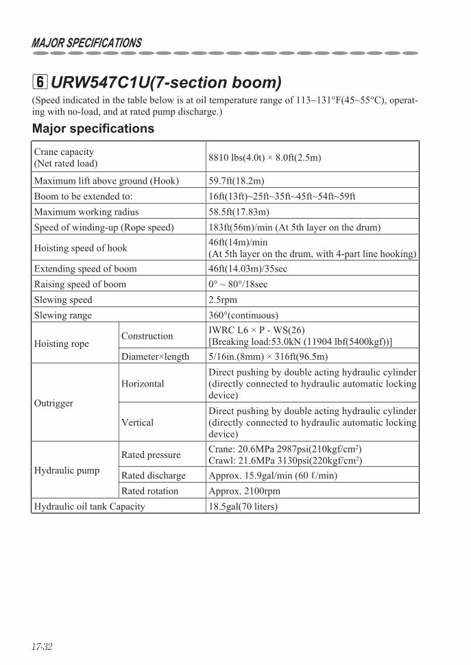
17-32
MAJOR SPECIFICATIONS
URW547C1U(7-section boom) 6(Speed indicated in the table below is at oil temperature range of 113~131°F(45~55°C), operat-ing with no-load, and at rated pump discharge.)
Major specifications
Crane capacity (Net rated load) 8810 lbs(4.0t) × 8.0ft(2.5m)
Maximum lift above ground (Hook) 59.7ft(18.2m)Boom to be extended to: 16ft(13ft)~25ft~35ft~45ft~54ft~59ftMaximum working radius 58.5ft(17.83m)Speed of winding-up (Rope speed) 183ft(56m)/min (At 5th layer on the drum)
Hoisting speed of hook 46ft(14m)/min(At 5th layer on the drum, with 4-part line hooking)
Extending speed of boom 46ft(14.03m)/35secRaising speed of boom 0° ~ 80°/18secSlewing speed 2.5rpmSlewing range 360°(continuous)
Hoisting ropeConstruction IWRC L6 × P - WS(26)
[Breaking load:53.0kN (11904 lbf(5400kgf))]Diameter×length 5/16in.(8mm) × 316ft(96.5m)
Outrigger
HorizontalDirect pushing by double acting hydraulic cylinder (directly connected to hydraulic automatic locking device)
VerticalDirect pushing by double acting hydraulic cylinder (directly connected to hydraulic automatic locking device)
Hydraulic pumpRated pressure Crane: 20.6MPa 2987psi(210kgf/cm2)
Crawl: 21.6MPa 3130psi(220kgf/cm2)Rated discharge Approx. 15.9gal/min (60 ℓ/min)Rated rotation Approx. 2100rpm
Hydraulic oil tank Capacity 18.5gal(70 liters)
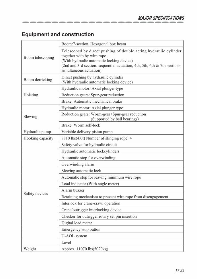
17-33
MAJOR SPECIFICATIONS
Equipment and construction
Boom telescoping
Boom:7-section, Hexagonal box beam
Telescoped by direct pushing of double acting hydraulic cylinder together with by wire rope(With hydraulic automatic locking device)(2nd and 3rd section: sequential actuation, 4th, 5th, 6th & 7th sections: simultaneous actuation)
Boom derricking Direct pushing by hydraulic cylinder(With hydraulic automatic locking device)
HoistingHydraulic motor: Axial plunger typeReduction gears: Spur-gear reductionBrake: Automatic mechanical brake
Slewing
Hydraulic motor: Axial plunger typeReduction gears: Worm-gear+Spur-gear reduction
(Supported by ball bearings)Brake: Worm self-lock
Hydraulic pump Variable delivery piston pumpHooking capacity 8810 lbs(4.0t) Number of slinging rope: 4
Safety devices
Safety valve for hydraulic circuitHydraulic automatic lockcylindersAutomatic stop for overwindingOverwinding alarmSlewing automatic lockAutomatic stop for leaving minimum wire ropeLoad indicator (With angle meter)Alarm buzzerRetaining mechanism to prevent wire rope from disengagementInterlock for crane-crawl operationCrane/outrigger interlocking deviceChecker for outrigger rotary set pin insertionDigital load meterEmergency stop buttonU-AOL systemLevel
Weight Approx. 11070 lbs(5020kg)
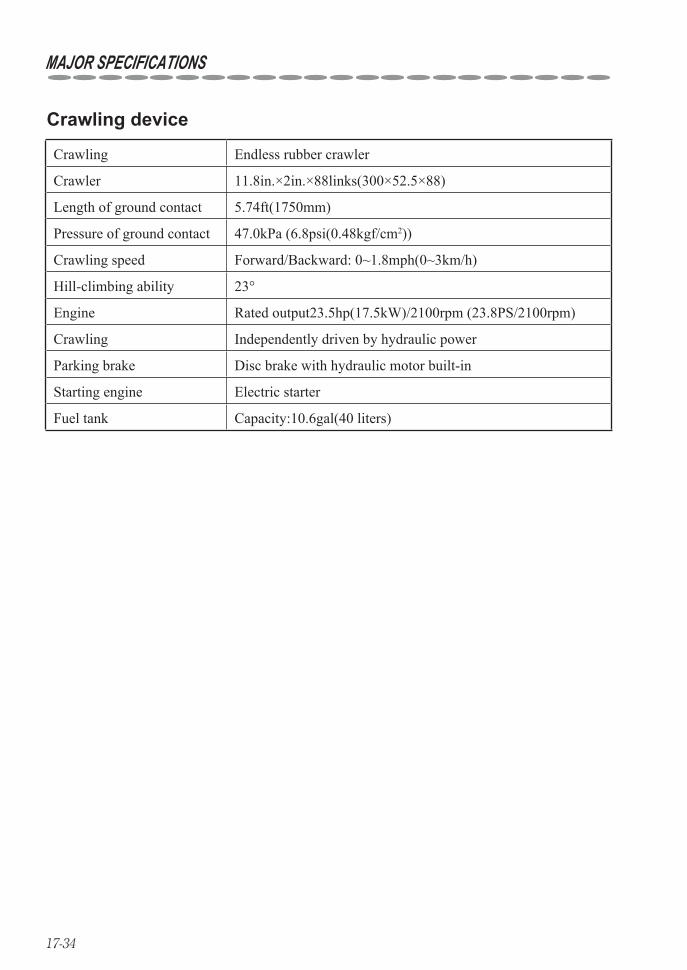
17-34
MAJOR SPECIFICATIONS
Crawling Endless rubber crawler
Crawler 11.8in.×2in.×88links(300×52.5×88)
Length of ground contact 5.74ft(1750mm)
Pressure of ground contact 47.0kPa (6.8psi(0.48kgf/cm2))
Crawling speed Forward/Backward: 0~1.8mph(0~3km/h)
Hill-climbing ability 23°
Engine Rated output23.5hp(17.5kW)/2100rpm (23.8PS/2100rpm)
Crawling Independently driven by hydraulic power
Parking brake Disc brake with hydraulic motor built-in
Starting engine Electric starter
Fuel tank Capacity:10.6gal(40 liters)
Crawling device
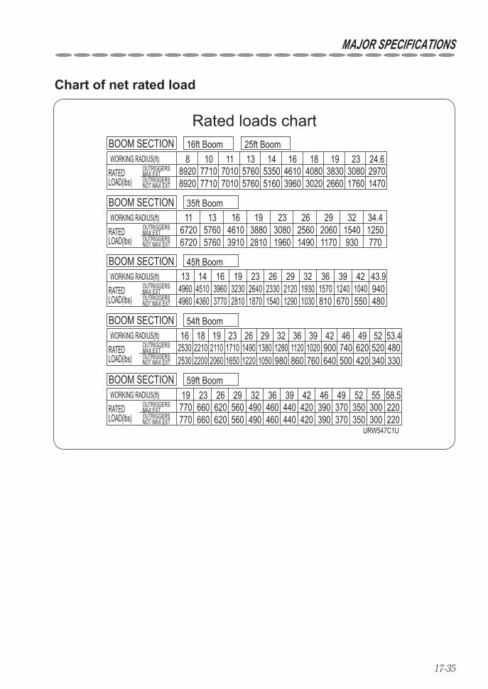
17-35
MAJOR SPECIFICATIONS
Rated loads chart
8 10 11 13 14 16 18 1989208920
77107710
70107010
57605760
53505160
46103960
40803020
38302660
30801760
29701470
23 24.6WORKING RADIUS(ft)OUTRIGGERSMAX EXTOUTRIGGERSNOT MAX EXT
RATEDLOAD(lbs)
16ft Boom 25ft BoomBOOM SECTION
11 13 16 19 23 26 29 3267206720
57605760
46103910
38802810
30801960
25601490
20601170
1540930
1250770
34.4WORKING RADIUS(ft)OUTRIGGERSMAX EXTOUTRIGGERSNOT MAX EXT
RATEDLOAD(lbs)
35ft BoomBOOM SECTION
13 14 16 19 23 26 36 39 424960 4510
436039603770
32302810
26401870
23301540
21201290
19301030
1570810
1240670
1040550
940480
3229 43.9WORKING RADIUS(ft)45ft Boom
OUTRIGGERSMAX EXTOUTRIGGERSNOT MAX EXT
RATEDLOAD(lbs)
BOOM SECTION
4960
16 18 19 23 26 29 32 39 42 46 49 522530 2210
220021102060 1650
36480330
520340
620740420500
900640
1020760
112053.4
8601280980
13801050
14901220
1710WORKING RADIUS(ft)
54ft Boom
OUTRIGGERSMAX EXTOUTRIGGERSNOT MAX EXT
RATEDLOAD(lbs)
BOOM SECTION
2530
19 23 26 29 32 36 39 42 46 52 5549 58.5770770
660660
620620
560 490490
460460
440440
420420
390390
370370
350350
300300
220220
WORKING RADIUS(ft)59ft Boom
OUTRIGGERSMAX EXTOUTRIGGERSNOT MAX EXT
RATEDLOAD(lbs)
BOOM SECTION
560URW547C1U
Chart of net rated load
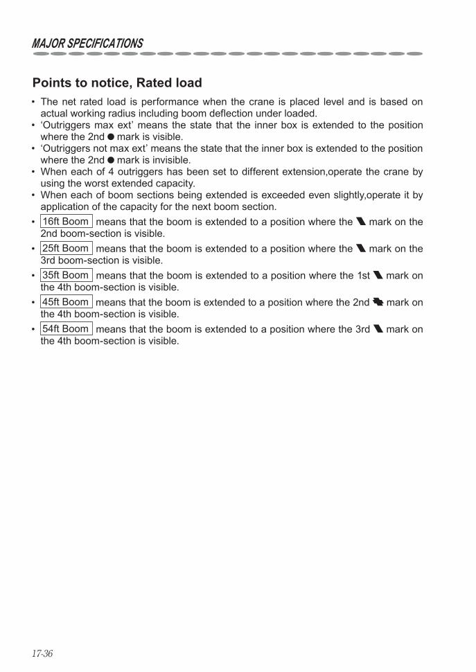
17-36
MAJOR SPECIFICATIONS
Points to notice, Rated load The net rated load is performance when the crane is placed level and is based on • actual working radius including boom deflection under loaded. ‘Outriggers max ext’ means the state that the inner box is extended to the position • where the 2nd mark is visible. ‘Outriggers not max ext’ means the state that the inner box is extended to the position • where the 2nd mark is invisible. When each of 4 outriggers has been set to different extension,operate the crane by • using the worst extended capacity. When each of boom sections being extended is exceeded even slightly,operate it by • application of the capacity for the next boom section. • 16ft Boom means that the boom is extended to a position where the mark on the 2nd boom-section is visible. • 25ft Boom means that the boom is extended to a position where the mark on the 3rd boom-section is visible. • 35ft Boom means that the boom is extended to a position where the 1st mark on the 4th boom-section is visible. • 45ft Boom means that the boom is extended to a position where the 2nd mark on the 4th boom-section is visible. • 54ft Boom means that the boom is extended to a position where the 3rd mark on the 4th boom-section is visible.
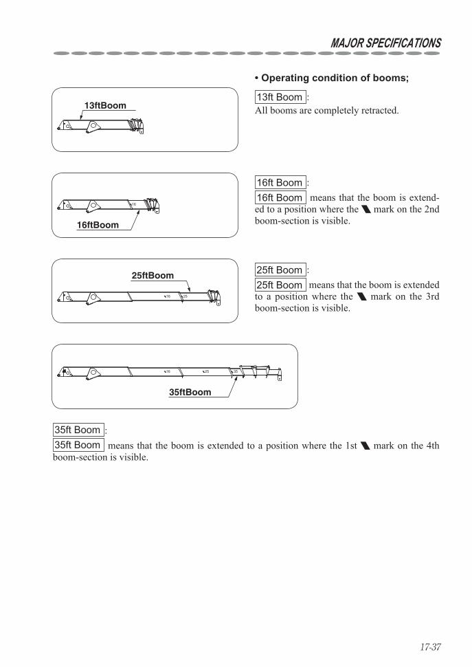
17-37
MAJOR SPECIFICATIONS
25ftBoom
16 25
25ft Boom :25ft Boom means that the boom is extended to a position where the mark on the 3rd boom-section is visible.
35ftBoom
16 25 35
35ft Boom :35ft Boom means that the boom is extended to a position where the 1st mark on the 4th boom-section is visible.
16ftBoom
16
16ft Boom :16ft Boom means that the boom is extend-ed to a position where the mark on the 2nd boom-section is visible.
13ftBoom13ft Boom :All booms are completely retracted.
Operating condition of booms;•
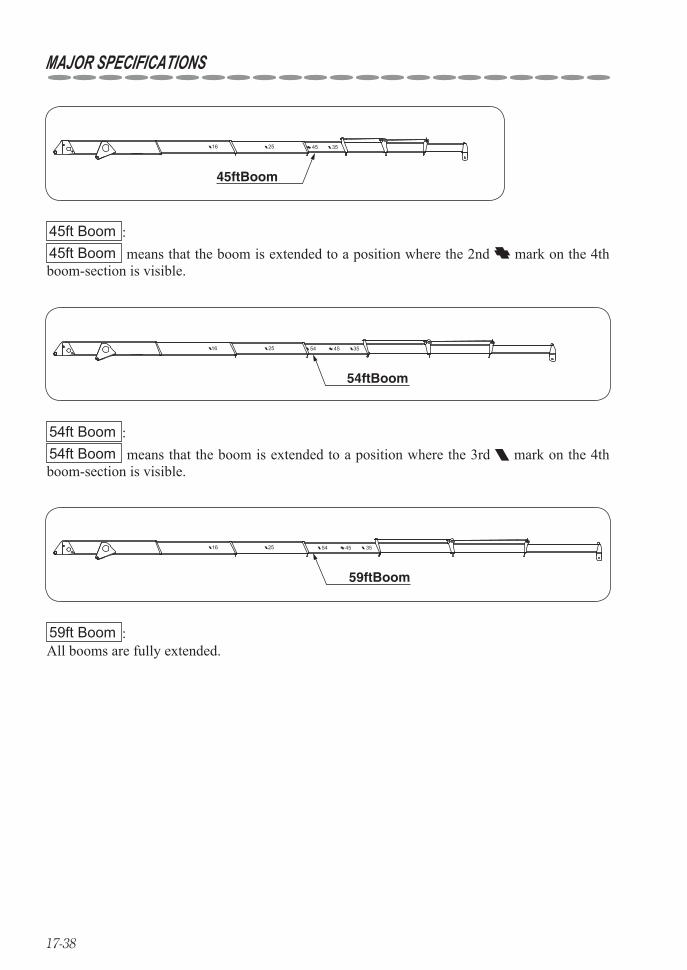
17-38
45ftBoom
16 25 45 35
45ft Boom :45ft Boom means that the boom is extended to a position where the 2nd mark on the 4th boom-section is visible.
54ftBoom
16 25 54 45 35
54ft Boom :54ft Boom means that the boom is extended to a position where the 3rd mark on the 4th boom-section is visible.
59ftBoom
16 25 54 45 35
59ft Boom :All booms are fully extended.
MAJOR SPECIFICATIONS

17-39
Model RC-500HA-AUS, Radio remote control deviceApplied radio wave law Specified small power radio stationRadio frequency 434 MHz bandTransmission output 10 mWFrequency selection Auto-scanning (automatic selection)Service range of radio wave 100m min. (when in good conditions with no radio interference)System structure Combined system of manual and radio remote control operation
Controls (functions operated through radio control transmit-ter)
Selector switches : Boom : Up/Down (Crane mode/Outrigger mode)Hook :Up/DownBoom telescoping: Extend/Retract (P ON/OFF/OR Holizontal/verti-
cal)Slewingt :C.C.W./C.W. (Start/Stop)Store hook :StorageSpeed selector switch:Selection of speed modes : High/Medium/Low speedMode switch : Switching each function by combination of selec-
tor switchHorn switch :Alarm (Horn on mounting vehicle)Speed lever : Both hydraulic control and engine speed control
Power supply Battery on mounting vehicle (DC 12V)Transmitter: a size AAA battery: 4 pieces
Power consumption
Crane: When operating single function at maximum speed, approx. 50W, 120W max. (including control box)
Transmitter (service life with alkaline batteries):20 hours min.
Voice messages
‶Crane mode”‶Remote control ready”‶Stop winch up”‶Secure lifting hook”‶Low transmitter battery”‶Service remote control”‶Change control mode”
Operating temperature range -20°C~+60°C
Storing temperature range -30°C~+75°C
Weight of transmitter 560g (including batteries)
Major specification (Radio remote control device) 7 for URW376C1A,URW546C1A,URW547C1A
MAJOR SPECIFICATIONS
The radio remote control device employs a unique data transmission system and an ID ★(identification) code is assigned to each equipment. Therefore, the crane will not be worked by radio wave radiated from other radio equipment.
About auto-scanning system : ★Auto-scanning system is a system that changes the current frequency to other frequencies auto-matically to avoid radio interference when a similar radio wave is being radiated nearby.
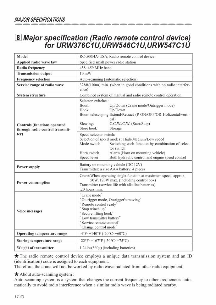
17-40
MAJOR SPECIFICATIONS
Model RC-500HA-USA, Radio remote control deviceApplied radio wave law Specified small power radio stationRadio frequency 458~459 MHz bandTransmission output 10 mWFrequency selection Auto-scanning (automatic selection)Service range of radio wave 328ft(100m) min. (when in good conditions with no radio interfer-
ence)System structure Combined system of manual and radio remote control operation
Controls (functions operated through radio control transmit-ter)
Selector switches : Boom : Up/Down (Crane mode/Outrigger mode)Hook :Up/DownBoom telescoping: Extend/Retract (P ON/OFF/OR Holizontal/verti-
cal)Slewingt :C.C.W./C.W. (Start/Stop)Store hook :StorageSpeed selector switch:Selection of speed modes : High/Medium/Low speedMode switch : Switching each function by combination of selec-
tor switchHorn switch :Alarm (Horn on mounting vehicle)Speed lever : Both hydraulic control and engine speed control
Power supply Battery on mounting vehicle (DC 12V)Transmitter: a size AAA battery: 4 pieces
Power consumption
Crane: When operating single function at maximum speed, approx. 50W, 120W max. (including control box)
Transmitter (service life with alkaline batteries):20 hours min.
Voice messages
‶Crane mode”‶Outrigger mode, Outrigger's moving”‶Remote control ready”‶Stop winch up”‶Secure lifting hook”‶Low transmitter battery”‶Service remote control”‶Change control mode”
Operating temperature range -4°F~+140°F (-20°C~+60°C)
Storing temperature range -22°F~+167°F (-30°C~+75°C)
Weight of transmitter 1.24lbs(560g) (including batteries)
Major specification (Radio remote control device) 8 for URW376C1U,URW546C1U,URW547C1U
The radio remote control device employs a unique data transmission system and an ID ★(identification) code is assigned to each equipment. Therefore, the crane will not be worked by radio wave radiated from other radio equipment.
About auto-scanning system : ★Auto-scanning system is a system that changes the current frequency to other frequencies auto-matically to avoid radio interference when a similar radio wave is being radiated nearby.
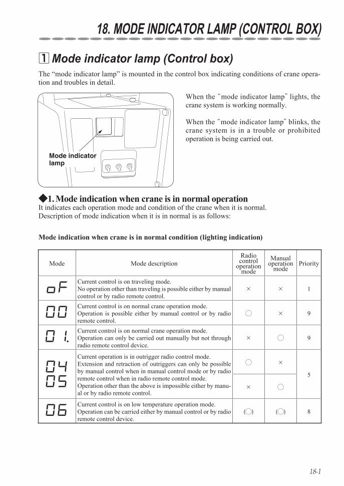
18-1
18. MODE INDICATOR LAMP (CONTROL BOX)
The “mode indicator lamp” is mounted in the control box indicating conditions of crane opera-tion and troubles in detail.
When the ‶mode indicator lamp” lights, the crane system is working normally.
When the ‶mode indicator lamp” blinks, the crane system is in a trouble or prohibited operation is being carried out.
Mode indicator lamp
Mode indication when crane is in normal operation1. ◆It indicates each operation mode and condition of the crane when it is normal.Description of mode indication when it is in normal is as follows:
Mode indicator lamp (Control box) 1
Mode Mode descriptionRadio control
operation mode
Manual operation
modePriority
Current control is on traveling mode.No operation other than traveling is possible either by manual control or by radio remote control.
× × 1
Current control is on normal crane operation mode.Operation is possible either by manual control or by radio remote control.
◯ × 9
Current control is on normal crane operation mode.Operation can only be carried out manually but not through radio remote control device.
× ◯ 9
Current operation is in outrigger radio control mode.Extension and retraction of outriggers can only be possible by manual control when in manual control mode or by radio remote control when in radio remote control mode.Operation other than the above is impossible either by manu-al or by radio remote control.
◯ ×
5
× ◯
Current control is on low temperature operation mode.Operation can be carried either by manual control or by radio remote control device.
(◯) (◯) 8
Mode indication when crane is in normal condition (lighting indication)
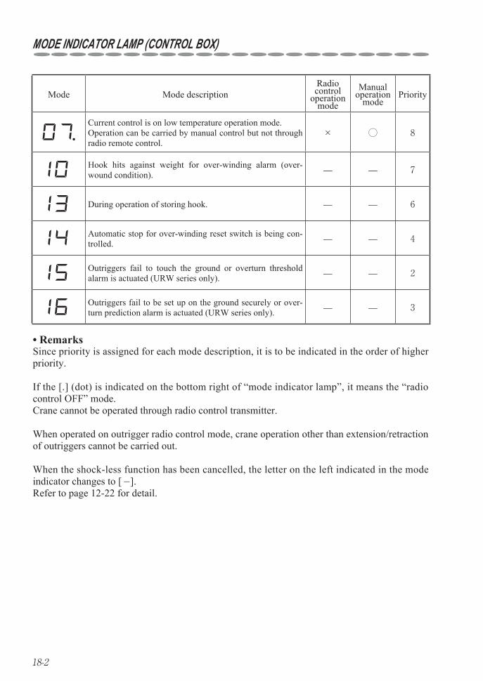
18-2
MODE INDICATOR LAMP (CONTROL BOX)
Mode Mode descriptionRadio control
operationmode
Manual operation
modePriority
Current control is on low temperature operation mode.Operation can be carried by manual control but not through radio remote control.
× ◯ 8
Hook hits against weight for over-winding alarm (over-wound condition). ̶ ̶ 7
During operation of storing hook. ̶ ̶ 6
Automatic stop for over-winding reset switch is being con-trolled. ̶ ̶ 4
Outriggers fail to touch the ground or overturn threshold alarm is actuated (URW series only). ̶ ̶ 2
Outriggers fail to be set up on the ground securely or over-turn prediction alarm is actuated (URW series only). ̶ ̶ 3
Remarks• Since priority is assigned for each mode description, it is to be indicated in the order of higher priority.
If the [.] (dot) is indicated on the bottom right of “mode indicator lamp”, it means the “radio control OFF” mode.Crane cannot be operated through radio control transmitter.
When operated on outrigger radio control mode, crane operation other than extension/retraction of outriggers cannot be carried out.
When the shock-less function has been cancelled, the letter on the left indicated in the mode indicator changes to [-].Refer to page 12-22 for detail.
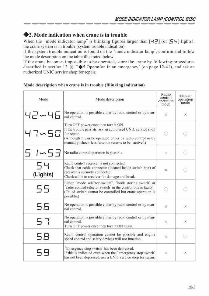
18-3
MODE INDICATOR LAMP (CONTROL BOX)
Mode Mode descriptionRadio control
operation mode
Manual operation
mode
No operation is possible either by radio control or by man-ual control. × ×
Turn OFF power once then turn it ON.If the trouble persists, ask an authorized UNIC service shop for repair. (Although it can be operated either by radio control or by manually, shock-less function returns to be "active".)
◯ ◯
No radio control operation is possible. × ◯
(Lights)
Radio control receiver is not connected.Check that cable connector (located inside switch box) of receiver is securely connected.Check cable to receiver for damage and break.
× ◯
Either "mode selector switch”, "hook storing switch" or "radio control selector switch" in the control box is faulty.(Failed switch cannot be controlled but crane operation is possible.)
◯ ◯
No operation is possible either by radio control or by man-ual control. × ×
No operation is possible either by radio control or by man-ual control.Turn OFF power once then turn it ON again.
× ×
Radio control operation cannot be possible and engine speed control and safety devices will not function. × ◯
"Emergency stop switch" has been depressed.If this is indicated even when the "emergency stop switch" has not been depressed, ask a UNIC service shop for repair.
× ×
Mode description when crane is in trouble (Blinking indication)
Mode indication when crane is in trouble2. ◆When the ‶mode indicator lamp” is blinking figures larger than [ ] (or [ ] lights), the crane system is in trouble (system trouble indication). If the system trouble indication is found on the ‶mode indicator lamp”, confirm and follow the mode description on the table illustrated below: If the crane becomes impossible to be operated, store the crane by following procedures described in section 12. 8 ‶◆5.Operation in an emergency” (on page 12-41), and ask an authorized UNIC service shop for repair.
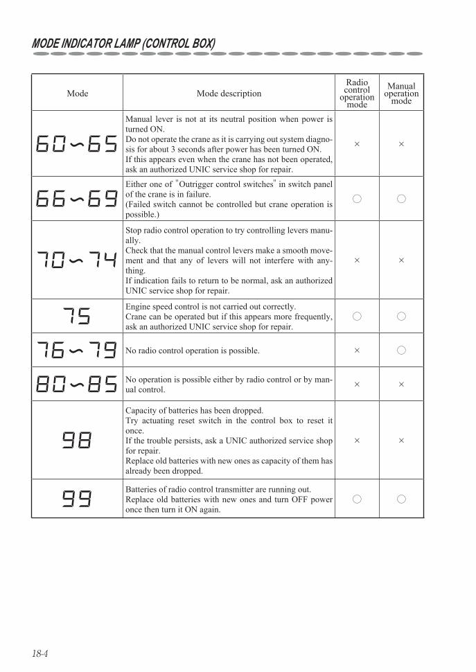
18-4
MODE INDICATOR LAMP (CONTROL BOX)
Mode Mode descriptionRadio control
operation mode
Manual operation
mode
Manual lever is not at its neutral position when power is turned ON.Do not operate the crane as it is carrying out system diagno-sis for about 3 seconds after power has been turned ON.If this appears even when the crane has not been operated, ask an authorized UNIC service shop for repair.
× ×
Either one of "Outrigger control switches" in switch panel of the crane is in failure.(Failed switch cannot be controlled but crane operation is possible.)
◯ ◯
Stop radio control operation to try controlling levers manu-ally.Check that the manual control levers make a smooth move-ment and that any of levers will not interfere with any-thing. If indication fails to return to be normal, ask an authorized UNIC service shop for repair.
× ×
Engine speed control is not carried out correctly.Crane can be operated but if this appears more frequently, ask an authorized UNIC service shop for repair.
◯ ◯
No radio control operation is possible. × ◯
No operation is possible either by radio control or by man-ual control. × ×
Capacity of batteries has been dropped.Try actuating reset switch in the control box to reset it once.If the trouble persists, ask a UNIC authorized service shop for repair.Replace old batteries with new ones as capacity of them has already been dropped.
× ×
Batteries of radio control transmitter are running out.Replace old batteries with new ones and turn OFF power once then turn it ON again.
◯ ◯
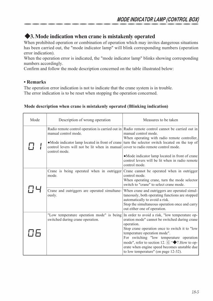
18-5
MODE INDICATOR LAMP (CONTROL BOX)
Mode Description of wrong operation Measures to be taken
Radio remote control operation is carried out in manual control mode.
●Mode indicator lamp located in front of crane control levers will not be lit when in manual control mode.
Radio remote control cannot be carried out in manual control mode.When operating with radio remote controller, turn the selector switch located on the top of cover to radio remote control mode.
●Mode indicator lamp located in front of crane control levers will be lit when in radio remote control mode.
Crane is being operated when in outrigger mode.
Crane cannot be operated when in outrigger control mode.When operating crane, turn the mode selector switch to "crane" to select crane mode.
Crane and outriggers are operated simultane-ously.
When crane and outriggers are operated simul-taneously, both operating functions are stopped automatically to avoid a risk.Stop the simultaneous operation once and carry out either one of operation.
"Low temperature operation mode" is being switched during crane operation.
In order to avoid a risk, "low temperature op-eration mode" cannot be switched during crane operation.Stop crane operation once to switch it to "low temperature operation mode".For switching "low temperature operation mode", refer to section 12. 6 “◆7.How to op-erate when engine speed becomes unstable due to low temperature" (on page 12-32).
Mode description when crane is mistakenly operated (Blinking indication)
Mode indication when crane is mistakenly operated3. ◆When prohibited operation or combination of operation which may invites dangerous situations has been carried out, the "mode indicator lamp" will blink corresponding numbers (operation error indication).When the operation error is indicated, the "mode indicator lamp" blinks showing corresponding numbers accordingly.Confirm and follow the mode description concerned on the table illustrated below:
The operation error indication is not to indicate that the crane system is in trouble.The error indication is to be reset when stopping the operation concerned.
Remarks•
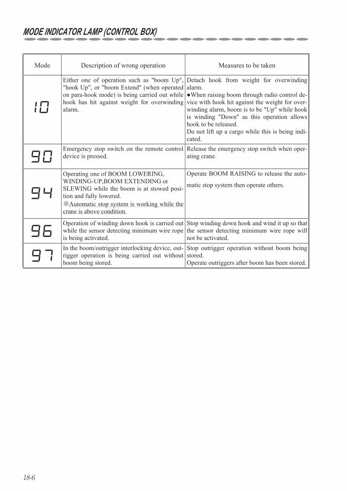
18-6
MODE INDICATOR LAMP (CONTROL BOX)
Mode Description of wrong operation Measures to be taken
Either one of operation such as "boom Up", "hook Up", or "boom Extend" (when operated on para-hook mode) is being carried out while hook has hit against weight for overwinding alarm.
Detach hook from weight for overwinding alarm.●When raising boom through radio control de-vice with hook hit against the weight for over-winding alarm, boom is to be "Up" while hook is winding "Down" as this operation allows hook to be released. Do not lift up a cargo while this is being indi-cated.
Emergency stop switch on the remote control device is pressed.
Release the emergency stop switch when oper-ating crane.
Operating one of BOOM LOWERING, WINDING-UP,BOOM EXTENDING or SLEWING while the boom is at stowed posi-tion and fully lowered.※Automatic stop system is working while the crane is above condition.
Operate BOOM RAISING to release the auto-
matic stop system then operate others.
Operation of winding down hook is carried out while the sensor detecting minimum wire rope is being activated.
Stop winding down hook and wind it up so that the sensor detecting minimum wire rope will not be activated.
In the boom/outrigger interlocking device, out-rigger operation is being carried out without boom being stored.
Stop outrigger operation without boom being stored.Operate outriggers after boom has been stored.
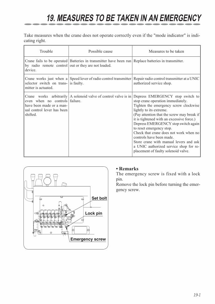
19-1
19. MEASURES TO BE TAKEN IN AN EMERGENCYTake measures when the crane does not operate correctly even if the "mode indicator" is indi-cating right.
Remarks•
Set bolt
Lock pin
Emergency screw
The emergency screw is fixed with a lock pin.Remove the lock pin before turning the emer-gency screw.
Trouble Possible cause Measures to be taken
Crane fails to be operated by radio remote control device.
Batteries in transmitter have been run out or they are not loaded.
Replace batteries in transmitter.
Crane works just when a selector switch on trans-mitter is actuated.
Speed lever of radio control transmitter is faulty.
Repair radio control transmitter at a UNIC authorized service shop.
Crane works arbitrarily even when no controls have been made or a man-ual control lever has been shifted.
A solenoid valve of control valve is in failure.
Depress EMERGENCY stop switch to stop crane operation immediately.Tighten the emergency screw clockwise lightly to its extreme.(Pay attention that the screw may break if it is tightened with an excessive force.)Depress EMERGENCY stop switch again to reset emergency stop.Check that crane does not work when no controls have been made.Store crane with manual levers and ask a UNIC authorized service shop for re-placement of faulty solenoid valve.


HEAD OFFICE : 3-14, Nihonbashi Muromachi 2-chome, Chuo-ku, Tokyo, 103-0022 Japan