miniature bayonet lock connectors designed to … catalogue_full_update...miniature bayonet lock...
TRANSCRIPT
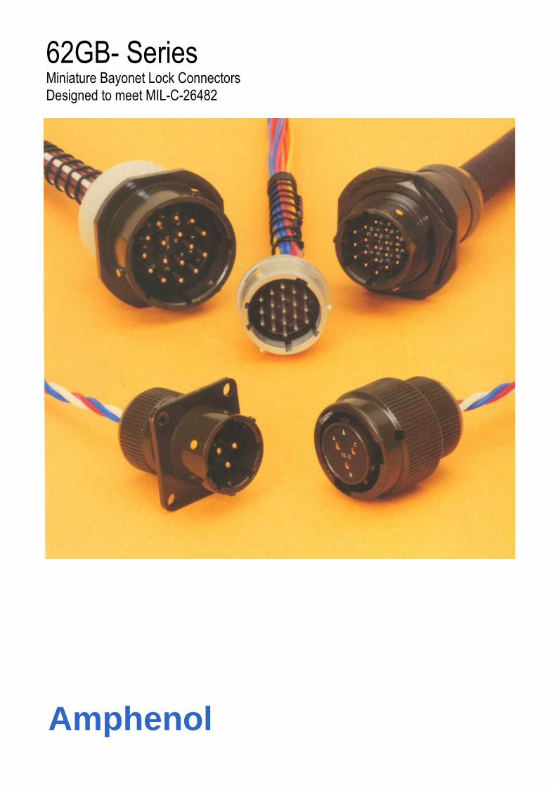
62GB- Series Miniature Bayonet Lock Connectors Designed to meet MIL-C-26482
Amphenol

62GB and Pattern 608 New Planforms
Current: (a) Maximum current per individual contact (in isolation)* at ambient
temperature of 85°C
Contact size 12: 23 A (b) Maximum current per contact through all contacts simultaneously at
an ambient temperature of 85°C
Contact size 12: 20 A
Current: (a) Maximum current per individual
contact (in isolation)* at ambient temperature of 85°C
Contact size 8: 45 A
(b) Maximum current per contact
through all contacts simultaneously at an ambient temperature of 85°C
Contact size 8: 40 A
Sea level 8500m (27,900ft) 21,340m (70,OOOft) 1013 mbar � 320 mbar 44 mbar
Voltage rating I II III I II III I II III Working voltages ** 700 1200 1500 550 650 800 330 380 450
(nominal) d.c. or a.c. peak Voltage proof 2100 3000 3000 1100 1300 1300 660 760 750
d.c. or a.c. peak
* i.e. when only one contact per connector is electrically loaded.
� 1 mbar=102 N/m2=100 Pa
** Establishment of electrical safety factors is the responsibility of the user

CONTENTS Page
Amphenol 62GB Solder Connectors 1
Schedule of Tests 2-3
Connector Styles Available 4-5
Insert Availability 6-7
Ordering 62GB Series Connectors 8-9
Box Mounting Receptacles - Table of Styles 10-11
Box Mounting Receptacles 12-16
Single Hole Fixing Receptacles - Table of Styles 17-19
Single Hole Fixing Receptacles 20-27
Cable Mounting Receptacles - Table of Styles 28
Cable Mounting Receptacles 29-31
Plugs - Table of Styles 32-33
Plugs 34-39
Accessories - Table of Styles 40-41
Accessories 42-48
Cable Accessories - Table of Styles 49-50
Cable Accessories 51-55
Insert Orientations 56
Key/Keyway Orientations 57
Assembly Instructions 58-61
Wire Stripping 62
Torque Details 62

Amphenol ® 62GB solder connectors
This miniature bayonet lock connector series offers designers important features not found in any other range of connectors.
62GB Series connectors – compliant to the United States Military Specification MIL-C-26482E on certificate No. 1713. They are the first and only British connectors to have achieved this. A doubly strong position which Amphenol are well geared to handle. The manufacturing facilities of the Whitstable plant have been cited as exemplary in Europe. Certainly the layout is extensive and extremely efficient.
62GB Series connectors have been well established with Government authorities on an international scale and users can be found in Sweden, Denmark, Norway, Finland, Germany, Spain, Holland, India, Canada and Italy. Derating Connectors must be derated under the following operating conditions: 1. At elevated ambient temperatures, the current ratings
are reduced so that total maximum hot spot temperature of 125°C is not exceeded.
2. At high altitudes, revised voltage ratings become
effective as shown on page 7. 3. When connectors to different specifications are
intermated, the combination must not be operated under conditions more severe than the less stringent clause of either specification.
Basic Construction 62GB Series can be supplied in brass or stainless steel. The normal shell finish used, which has a high resistance to corrosion, is zinc cobalt olive drab. Other finishes may be supplied to special order, such as cadmium plate which is available by adding deviation (714) to the end of part number. For other finishes available, please see part number breakdown Inserts are of polychloroprene rubber compounded to an Amphenol specification. Operating temperature range is -55°C to 125°C, and the connectors have gold-plated contacts designed for soldered connections. Configurations for size 20 contacts range between 2 contacts in the size 8 12.7mm (0.5in diameter) shell up to a maximum of 61 contacts in the size 2436.1 mm (1.5in diameter) shell. Intermediate sizes, and contact data for heavier current ratings are shown in the insert availability chart on page 6 and 7. Hermetic connectors with glass sealed dielectric are manufactured with mild steel shells and nickel iron contacts plated tin over copper. * Other finishes are available on request. Protection Against Mis-Mating or Cross-Plugging Positive shell-to-shell keying is provided with keys and keyways in a choice of either the normal (N) or any of the four preferred alternate positions: B, C, E and F. This prevents mismating between shells of different orientations and overcomes the difficulties associated with rotated inserts and a standard key-keyway orientation. In the latter system, damage to the inserts or contacts can result if excessive force is used to engage non-mating pairs. Rotated inserts are available in positions w, x, y and z. These are to be requested via the part number configuration. See part number breakdown.
1

Schedule of Tests Required for Qualification Approval
Tests
Visual Examination
Dimensions, outline mass(including
contacts) Compatibility Gauging
procedure
Polarization
Engaging and separating force, connector
Contact Holding Force
Sealing (air pressure)
Sealing Hermetic
Contact Resistance
Housing (Shell) Continuity
Insulation Resistance
Voltage Proof
Soldering
Bumping
Sine Vibration
Shock
Acceleration (Steady State)
Rapid Change of Temperature
Climatic Sequence
Flammability
Damp Heat (Steady State)
Brief Description
Engagement max: 0,90 Nm (8.0 lbf.in.) to
4,97 Nm (44 lbf.in.) according to shell size.
Separation min: 0,22 Nm (2.0 lbf.in.) to 1,58
Nm (14.0 lbf.in.) according to shell size.
0,21 N (0.047 lbf) min.size 20
0,56 N (0.126 lbf)min. size 16
Max leakage 28,53 uNm/s (1 cm3/h), 1
bar (14.5 p.s.i.) differential.
Hermetic receptacles have a max leak of 0.1 micron
cubic foot per hour (1 x 10⁻⁶Cm3/s)
5 milliohms max.
200 milliohms max. 5 milliohms max.
grounding spring styles. Plating dependant.
5,000 Megaohms at 500 - 50 V d.c.
See page 7. Duration 1 minute
As BS 9520: 1983, Clause 1.2.6.7,
Method 2. Bit temperature of +350oC
As BS 9520: 1983, Clause 1.2.6.2. 4,000
-10 bumps / 390m / s2 (40 gn).
As BS 9520: 1983, Clause 1.2.6.3. Procedure A. 10 Hz to
5000 Hz, 0.75 mm / 10 gn.
As BS 9520: 1983, Clause 1.2.6.4. 981
m/s2 (100 g n).
As BS 9520: 1983, Clause 1.2.6.5. 490
m/s2 (50 gn).
As BS 9520: 1983, Clause 1.2.6.8. -550C
to +125oC one hour at each
temperature = 1 cycle. 5 cycles to be
completed As BS 9520: 1983, Clause 1.2.6.12.
Severity 55/125/56. As BS 9520: 1983, Clause 1.2.6.9. Direct
flame applied, duration 1 minute. As BS 9520: 1983, Clause 1.2.6.15.
Severity 56 days.
2

Schedules of Tests Required for Qualification Approval
Tests Brief Description
Immersion (at low air pressure)
Mechanical Endurance
High Temperature Endurance
Mould Growth
Salt Mist (plating dependant)
Dust
Robustness of Terminations
Contact Retention (in insert)
Insert Retention (in shell)
Test Prod Damage
Impact
Grounding Spring Holding Force Plugs with grounding
springs only.
Fluid Resistance
Compass Safe Distance
3 cycles at 30 mins each cycle, total immersion in
water at pressure 44 m bar.
500 operations minimum
Long term: 1,000 hrs. at 850 C ambient carrying the
specified current. Short term: 250 hrs at 1250 C, no
current.
As BS 9520: 1983, Clause 1.2.6.15. 28
days duration.
As BS 9520: 1983, Clause 1.2.6.17.
Severity 1. Four spray periods of 2
hours with a humidity storage period of
seven days after each
As BS 9520: 1983, Clause 1.2.6.18
Exposure 30 minutes.
44,5 N (101bf) size 16
22,2 N (5 lbf) size 20 67,0 N (15 lbf) min. size 20
112,0 N (25 lbf) min. size 16
and above 517 KN1m2 (751bf/in 2 min. Moment: 0,056 Nm (0.5 lbf in) size 20
0,225 Nm (2 lbf in) size 16 Five impacts, drop height 1 m (3ft.3 in.). 1,17 N (0.263 lbf) to 2,74 N (0.616 lbf)
according to size. Immersion in 4 solvents and 9 fluids
including aircraft fuels, lubricating oils and
hydraulic fluids. As BS 9520: 1983, Clause 1.2.5.12. 127 mm (5.0 in) min.
3
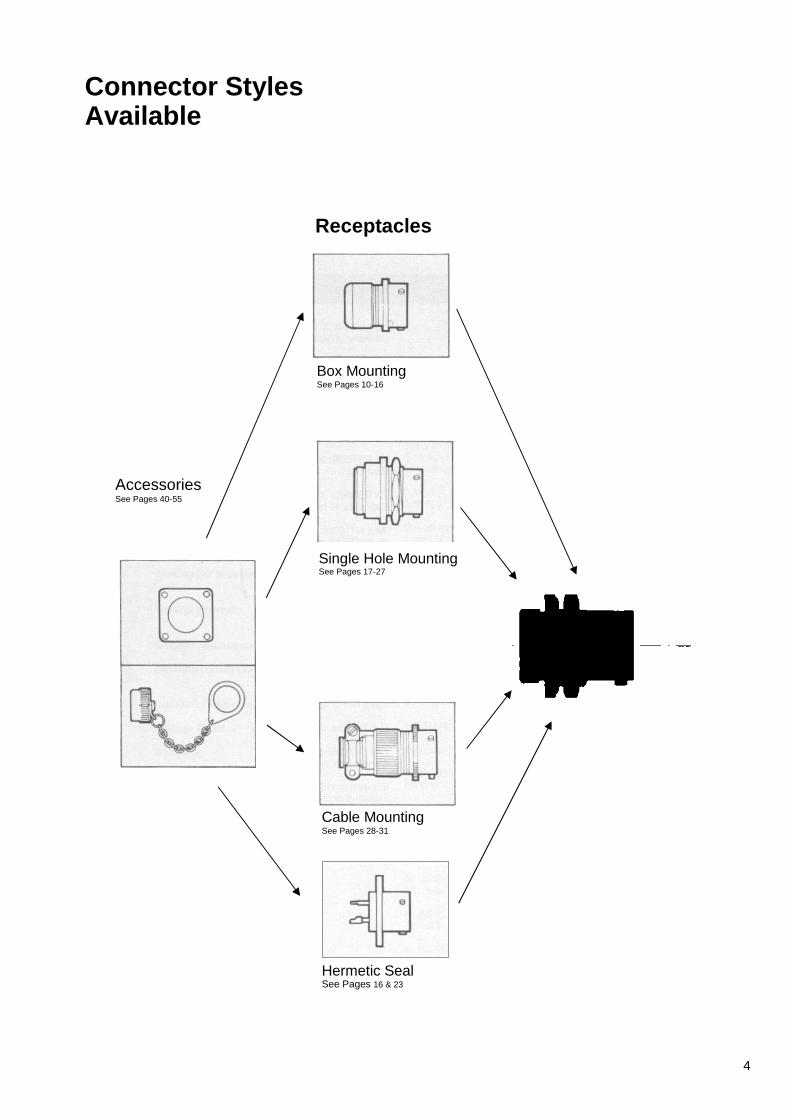
Connector Styles Available
Receptacles
Box Mounting See Pages 10-16
Accessories See Pages 40-55
Single Hole Mounting See Pages 17-27
Cable Mounting See Pages 28-31
Hermetic Seal See Pages 16 & 23
4
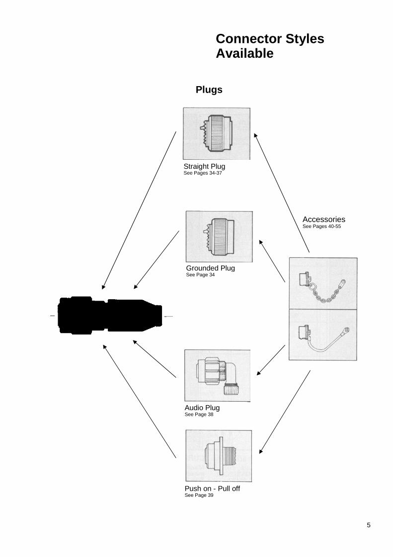
Connector Styles Available
Plugs
Straight Plug See Pages 34-37
Grounded Plug See Page 34
Accessories See Pages 40-55
Audio Plug See Page 38
Push on - Pull off See Page 39
5

Insert Availability
NOTES * This insert arrangement is not included in B.S.
spec., but is available and. listed in MIL-C-26482. � Due to the arrangement of contacts in the
14-12 insert arrangement it is classified, for current derating, in the shell size range 18-24.
Lettering of inserts shown above corresponds to view of front (mating surface of pin inserts or rear face (cable accessory end) of socket inserts.
KEY • No 16 size contacts O No 20 size contacts
CURRENT RATING Maximum current per individual contact (in isolation) at a maximum ambient temperature of 85°C: Size 20 contact 7.5A Size 16 contact 13A The performance of 62GB Series connectors at all times exceeds the maximum continuous bunched rating of the appropriate size wire, or cable of equivalent temperature rating. This bunched rating is therefore the determining factor. In the case of mixed loadings, the greatest individual load shall be the bunched loading. In any combination of ambient temperature plus temperature rise due to current flow through the contacts, the maximum connector internal hot spot temperature of 125°C must not be exceeded. That is, when only one contact per connector is loaded.
6

Insert Availability
VOLTAGE RATINGS
ALTITUDE-THOUSANDS OF FEET (METRES) Relationship between flashover voltage and
altitude for each voltage rating
VOLTAGE RATINGS Two categories of voltage rating are specified in
BS9522 F0017, F0038 and N0001. Rating 1 (700V d.c. working at sea-level) Applicable to the
high contact density inserts shown in the upper section of the insert availability diagram above.
Rating 2 (1200V d.c. working at sea-level) Applicable to
the inserts shown in the lower section of the insert availability diagram.
Altitude derating. Information on voltage derating for
operation at altitudes above sea-level can be obtained from the flashover voltage altitude curves on the left.
22
22-55
D.C. WORKING VOLTAGE
A.C. WORKING VOLTAGE
R.M.S.
PROOF VOLTAGE
D.C. OR A.C. PEAK
Rating 1 Sea level
300 mb at 20°C 8,500m (27,800 ft)
44 mb at 20°C 20,000m (66,000 ft)
Rating 2 Sea level 300 mb at 20°C 8,500m (27,800 ft) 44 mb at 20"C 20,000m (66,000 ft)
700
550
330
120 0
650
380
500
390
230
850
460
270
2100
1100
660
3000
1300
760
24 ALTITUDE
24-61
7

Ordering 62GB Series Connectors
To obtain the specific connector required write down the connector number from the typical example below. Only inserts shown in the availability chart on p. 10&11 can be specified. All connectors are delivered with protective dust covers
62GB SHELL STYLE
1 4 E
Environmental code A - Plain shell, exposed
solder buckets. No grommet
E - Insert seal and grommet seal with grommet nut (excluding 12E which has plain shell and no grommet or nut)
F - As (E) but grommet nut has integral strain relief clamp
H - Hermetic seal no cable accessories
J - As (E) but with resilient gland seal and nut for unscreened jacketed cable. No grommet supplied. See pp. 26-27 for accessory to accept screened jacketed cable.
P - Potting construction complete with potting mould
T - Exposed solder buckets. Threaded shell for cable accessories
Shell style 0 - Receptacle wall mounting 1 - Receptacle cable
mounting 2 - Receptacle box mounting 3 - Receptacle, solder flange
mounting 4 - Receptacle, internally
threaded with cable accessories as illustrated, for single hole mounting
6 - Plug cable mounting 7- Receptacle, plain shell,
single hole mounting
Specification key 1 - Styles originally specified in
MIL-C-26482 5 - Styles exclusive to
BS9522 F0017
Series designation 62ZN – Zinc Nickel finish 62 GB - Aluminium shell 62 GB SS -Stainless steel shell* 62 GB CU - Brass shell* *consult factory for availability 62GB-XXH-Hermetic mild steel shell.
HOW TO ORDER FROM MS CONNECTOR NUMBERS Connector numbers in the AMPHENOL and MS numbering systems. Only alternative insert orientations are specified in MIL-C-26482 which does not include alternative key/keyway orientations.
MS31 - 14 E 18 -11 P X 62GB - 14 E 18 -11 P X
8

Ordering 62GB Series Connectors
INSERT ARRANGEMENT
18 11 P B (044)
Shell size (in sixteenths of an inch) 8, 10, 12, 14, 16 18,20,22,24
Number of contacts 2, 3, 4, 5, 6, 7, 8, 10, 11, 12, 16, 19, 21', 23, 26, 32, 41, 55, 61 * consult factory for availability
Contact Style P - Pins S - Sockets For hermetic connectors. P3 denotes pin contacts with solder bucket terminations. (Standard range). P2 denotes pin contacts with flattened and pierced terminations. (Special order).
Orientation (Omit if normal orientation) Keys/Keyways: A', B, C, D', E. F, (see p. 31) Inserts: W,X,Y,Z.(see p56/57) *Inactive for new designs
Deviations (044) Rough grip heavy duty
coupling ring. (046) Box mounting plug. (214)Fitted with extension
back shell and strain relief clamp without grommet on F types only
(218) Lever coupling ring (219)Contacts for flexible punted
wrung (57A and 12E only) (639) Bright cadmium plated
shells (345) Contacts for flexible punted
wiring 12H,13H 17H only (276) Hermetics with gold
plated contacts. (608) Black anodise. (416) Electroless nickel (714) Cadmium plate
olive drab
62GB - 14E C2098
18-11 18 11
P M
B B
O
Style Insert Arrangement, see above
M - Pin contacts F - Socket contacts
Alternative Key/Key way Orientation
Variant. 0 – Standard
connector
9
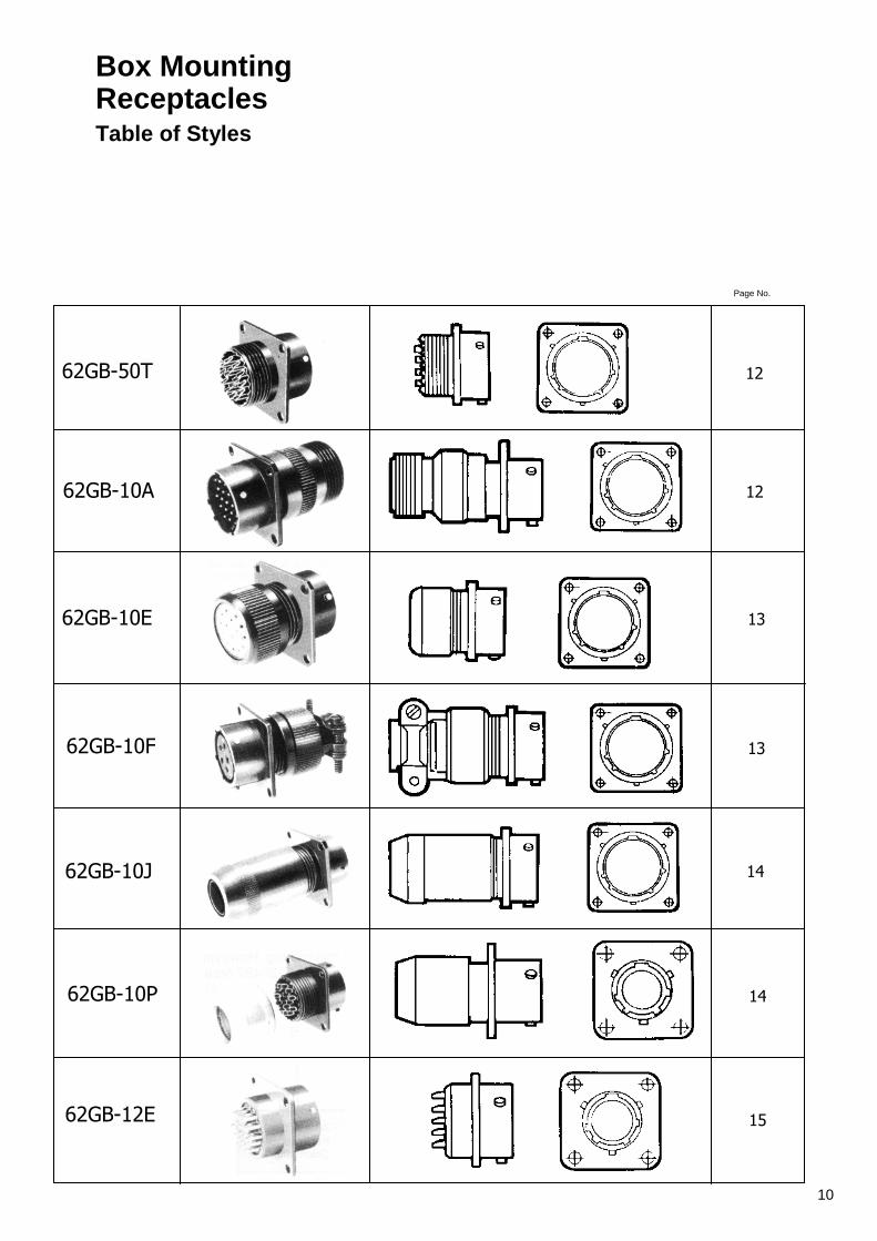
Box Mounting Receptacles Table of Styles
62GB-50T
Page No.
12
62GB-10A 12
62GB-10E 13
62GB-10F 13
62GB-10J 14
62GB-10P 14
62GB-12E 15
10
Page No.
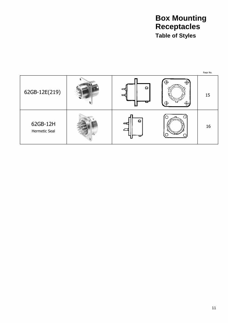
62GB-12E(219) 15
62GB-12H Hermetic Seal
16
Box Mounting Receptacles Table of Styles
11

Shell Size
A max
B ± 0.005 (± 0.13)
c max sq.
D TP Sq.
E dia. ± 0.010
(± 0.254)
F ±0 005 (± 0.13)
G dia
max.
Y dia. max.
X Thread
08 0.978 0.062 0.817 0.594 0120 0.445 0.434 0.473 7/16 – 28 UNEF 24.84 1.58 20.75 15.09 3.05 11.3 11.02 12.02
10 0.978 0.062 0.942 0.719 0.120 0.445 0.558 0.590 9/16 – 24 NEF 24.84 1.58 23.93 18.26 3.05 11.3 14.17 14.99
12 0.978 0.062 1.036 0.812 0.120 0.445 0.683 0.750 11/16 - 24 NEF 24.84 1.58 26.32 20.63 3.05 11.3 17.35 19.05
14 0.978 0.062 1.130 0.906 0.120 0.445 0.808 0.875 13/16 – 20 UNEF 24.84 1.58 28.70 23.10 3.05 11.3 20.52 22.23
16 0.978 0.062 1.223 0.969 0.120 0.445 0.933 1.000 15/16 – 20 UNEF 24.84 1.58 31.07 24.61 3.05 11.3 23.7 25.4
18 0.978 0.062 1.317 1.062 0.120 0.445 1.057 1.125 1.1/16 - 18 NEF 24.84 1.58 33.45 26.58 3.05 11.3 26.85 28.58
20 1.048 0.080 1.442 1.156 0.120 0.555 1.182 1.250 1.3/16 - 18 NEF 26.62 2.03 36.63 29.36 3.05 1410 30.02 31.75
22 1.048 0.080 1.567 1.250 0.120 0.555 1.307 1.375 1.5/16 - 18 NEF 26.62 2.03 39.80 31.75 3.05 14.10 33.20 34.93
24 1.048 0.080 1.692 1.375 0147 0.590 1.432 1.500 1.7/16 – 18 NEF 26.62 2.03 42.98 34.93 3.d4 14.99 36.37 38.1
Shell Size
A max.
B ± 0.005 ( ± 0.13)
C Max. sq.
D TP sq.
E ± 0.010
( ± 0.254)
F ± 0.005 ( ± 0.13)
G dia
max.
Y dia.
max.
M
08 1.624 0.062 0.817 0.594 0.120 0.445 0.561 0.473
1/2 - 28 UNEF 41.25 1.58 20.75 15.09 3.05 11.3 14.25 12.02
10 1.624 0.062 0.942 0.719 0.120 0.445 0.686 0.590
5/8 - 24 NEF 41.25 1.58 23.93 18.26 3.05 11.3 17.43 14.99
12 1.624 0.062 1.036 0.812 0.120 0.445 0.811 0.750
3/4 - 20 UNEF 41.25 1.58 26.32 20.63 3.05 11.3 20.60 19.05
14 1.624 0.062 1.130 0.906 0.120 0.445 0.936 0.875
7/8 - 20 UNEF 41.25 1.58 28.70 23.10 3.05 11.3 23.78 22.23
16 1.624 0.062 1223 0.969 0.120 0.445 1.061 1.000
1 - 20 UNEF 41.25 1.58 31.07 24.61 3.05 11.3 26.98 25.4
18 1.624 0.062 1.317 1.062 0.120 0.445 1.186 1.125
1.3/16 - 18 NEF 41.25 1.58 33.45 26.58 3.05 11.3 30.12 28.58
20 1 .687 0.080 1.442 1.156 0.120 0.555 1.311 1 250
1.3/16 - 18 NEF 42.85 2.03 36.63 29.36 3 05 14.10 33.30 31.75
22 1.687 0.080 1.567 1.250 0.120 0.555 1.436 1.375
1.7/16 - 18 NEF 42.85 2.03 39.80 31.75 3.05 14.10 36.47 34.93
24 1.730 0.080 1.692 1.375 0 147 0.590 1.561 1.500
1.7/16 - 18 NEF 43.94 2.03 42.98 34.93 3.73 14.99 39.65 38.1
Box Mounting Receptacles
50T 62GB-50T
4-hole flange mounting with threaded shell to
accept standard cable accessories.
10A 62GB-10A
4-Hole flange mounting with general
duty back shell. No grommet supplied.
12

Box Mounting Receptacles
10E 62GB-10E MIL-C-26482 MS3110E
Shell A B C D E F G V Size max ± 0.005 max TP ± 0.010 ± 0.005 dia dia.
( ± 0.13) sq. sq. (± 0.254) (± 0.13) max max
08 1.281 0.062 0.817 0.594 0.120 0.445 0.561 0.473 32.54 1 .58 20.75 15.09 3.05 11.3 14.25 12.02
10 1.281 0.062 0.942 0.719 0.120 0.445 0.686 0.590 32.54 1.58 23.93 18.26 3.05 11.3 17.43 14.99
12 1.281 0.062 1.036 0.812 0.120 0.445 0.811 0.750 32.54 1.58 26.32 20.63 3.05 11.3 20.60 19.05
14 1.281 0.062 1.130 0.906 0.120 0.445 0.936 0.875 32.54 1.58 28.70 23.10 3.05 11.3 23.78 22.23
16 1.281 0.062 1.223 0.969 0.120 0.445 1.061 1.000 32.54 1.58 31.07 24.61 3.05 11.3 26.98 25.4
18 1.281 0.062 1.317 1.062 0.120 0.445 1.186 1.125 32.54 1.58 33.45 26.58 3.05 11.3 30.12 28.58
20 1.383 0.080 1.442 1.156 0.120 0.555 1.311 1.250 35.13 2.03 36.63 29.36 3.05 14.10 33.30 31.75
22 1.383 0.080 1.567 1.250 0.120 0.555 1.436 1.375 35.13 2.03 39.80 31.75 3.05 14.10 36.47 34.93
24 1 .383 0.080 1.692 1.375 0.147 0.590 1.561 1.500 35.13 2.03 42.98 34.93 3.74 14.99 39.65 38.1
10F 62GB-10F MIL-C-26482 MS31 10F
Shell A B C D E F G H Y Size max. ± 0.005 max. TP ± 0.010 ± 0.005 dia ± 0.005 dia.
(± 0.13) sq. Sq. (± 0.254) (± 0.13) max. (± 0.13) max.
08 1.762 0.062 0.817 0.594 0.120 0.445 0.828 0.156 0.473 44.76 1.58 20.75 15.09 3.05 11.3 21.03 3.96 12.01
10 1.762 0.062 0.942 0.719 0.120 0.445 0.891 0.188 0.590 44.76 1.58 23.92 18.26 3.05 11.3 22.63 4.78 14.99
12 1 .762 0.062 1.036 0.812 0.120 0.445 1.016 0.312 0.750 44.76 1.58 26.31 20.63 3.05 11.3 25.81 7.93 19.05
14 1.736 0.062 1.130 0.906 0.120 0.445 1.141 0.375 0.875 44.10 1.58 28.70 23.10 3.05 11.3 28.98 9.58 22.23
16 1.876 0.062 1.223 0.969 0.120 0.445 1.203 0.500 1.000 47.65 1.57 31.07 24.61 3.05 11.3 30.56 12.7 25.4
18 1.876 0.062 1.317 1.062 0.120 0.445 1.426 0.625 1.125 47.65 1.58 33.45 26.58 3.05 11.3 36.22 15.87 28.58
20 2.118 0.080 1.442 1.156 0.120 0.555 1.426 0.625 1.250 53.80 2.03 36.63 29.36 3.05 14.10 36.22 15.88 31.75
22 2.118 0.080 1.567 1.250 0.120 0.555 1.567 0.750 1.375 53.80 2.03 39.80 31.75 3.05 14.10 39.80 19.05 34.93
24 2.250 0.080 1.692 1.375 1.147 0.590 1.735 0.800 1.500 57.15 2.03 42.98 34.93 3.74 14.99 44.07 20.32 38.10
4-hole flange mounting with grommet
and grommet nut
4-hole flange mounting with grommet and
grommet nut fitted with integral strain relief
clamp
13

Box Mounting Receptacles
Shell Size
A max
B ± 0.005 ( ± 0.13)
c max.sq
D TP sq
E ± 0.010
( ± 0.254)
F ± 0.005 (± 0.13)
G dia.
max.
Y dia
max
Z Cable Entry min max closed free
08 1.846 0.062 0.817 0.594 0.120 0.445 0.561 0.473 0.168 0.230 46.89 1.58 20.75 15.09 3.05 11.3 14.25 12.02 4.28 5.84
10 1.846 0.062 0.942 0.719 0.120 0.445 0.686 0.590 0.205 0.312 46.89 1.58 23.93 18.26 3.05 11.3 17.43 14.99 5.21 7.93
12 1.947 0.062 1.036 0.812 0.120 0.445 0.811 0.750 0.338 0.442 49.45 1.58 26.32 20.63 3.05 11.3 20.60 19.05 8,59 11.23
14 2.147 0.062 1.130 0.906 0.120 0.445 0.936 0.875 0.416 0.539 54.54 1.58 28.70 23.10 3.05 11.3 23.78 22.23 10.57 13.69
16 2.347 0.062 1.223 0.969 0.120 0.445 1.061 1.000 0.550 0.616 59.61 1.575 31.07 24.61 3.05 11.3 26.96 25.4 13.97 15.65
18 2.547 0.062 1.317 1.062 0.120 0.445 1.186 1.125 0.600 0.672 64.70 1.575 33.45 26.58 3.05 11.3 30.12 28.58 15.24 17.07
20 2.831 0.080 1.442 1.156 0.120 0.555 1.311 1.250 0.635 0.747 71.91 2.03 36.63 29.36 3.05 14.10 33.30 31.75 16.13 18.98
22 3.031 0.080 1.567 1.250 0.120 0.555 1.436 1.375 0.670 0.846 76.99 2.03 39.80 31.75 3.05 14.10 36.47 34.93 17.02 21.49
24 3.074 0.080 1.692 1.375 0.147 0.590 1.561 1.500 0.740 0.894 78.08 2.03 42.98 34.93 3.73 14.99 39.65 38.1 18.80 22.71
10P 62GB-10P
4-hole flange mounting for potting
Shell Size
A max
B ± 0.005 (± 0.13)
c max.sq.
D TP sq
E ± 0.010
(± 0.254)
F ± 0.005 (± 0.13)
G dia. max
Y dia. max
Z dia. min
08 1.453 0.062 0.817 0.594 0.120 0.445 0.572 0.473 0.260 36.91 1.575 20.75 15.09 3.05 11.3 14.53 12.02 6.60
10 1.453 0.062 0.942 0.179 0.120 0.445 0.666 0.590 0.463 36.91 1.58 23.93 18.26 3.05 11.3 16.92 14.99 11.76
12 1.453 0.062 1.036 0.812 0.120 0.445 0.822 0.750 0.577 36.91 1.58 26.32 20.63 3.05 11.3 20.88 19.05 14.15
14 1.453 0.062 1.130 0.906 0.120 0.445 0.907 0.875 0.590 36.91 1.58 28.70 23.10 3.05 11.3 23.04 22.23 14.99
16 1.453 0.062 1.223 0.969 0.120 0.445 1.040 1.000 0.713 36.91 1.58 31.07 24.61 3.05 11.3 26.42 25.40 18.11
18 1.453 0.062 1.317 1.062 0.120 0.445 1.165 1.125 0.835 36.91 1.58 33.45 26.58 3.05 11.3 29.60 28.58 22.21
20 1.672 0.080 1.442 1.156 0.120 0.555 1.285 1.250 1.015 42.47 2.03 36.63 29.36 3.05 14.10 32.64 31.75 25.78
22 1.672 0.080 1.567 1.250 0.120 0.555 1.400 1.375 1.015 42.47 2.03 39.80 31.75 3.05 14.10 35.56 34.93 25.78
24 1.734 0.080 0.692 1.375 0.147 0.590 1.540 1.500 1.265 44.05 2.03 42.98 34.93 3.74 14.99 39.12 38.10 32.13
10J
4-hole flange mounting with clamp for
unscreened jacketed cable. No grommet
supplied
62GB-10J
14
Box Mounting Receptacles
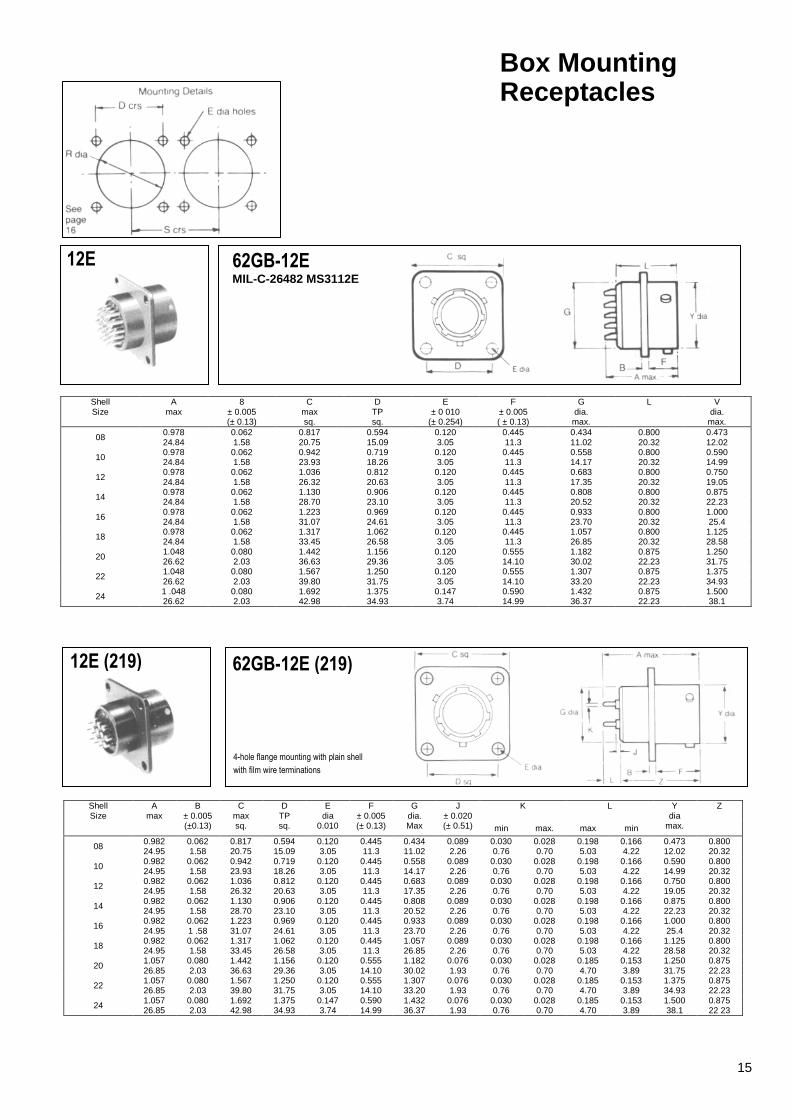
12E 62GB-12E MIL-C-26482 MS3112E
Shell Size
A max
8 ± 0.005 (± 0.13)
C max sq.
D TP sq.
E ± 0 010
(± 0.254)
F ± 0.005 ( ± 0.13)
G dia.
max.
L V dia.
max.
08 0.978 0.062 0.817 0.594 0.120 0.445 0.434 0.800 0.473 24.84 1.58 20.75 15.09 3.05 11.3 11.02 20.32 12.02
10 0.978 0.062 0.942 0.719 0.120 0.445 0.558 0.800 0.590 24.84 1.58 23.93 18.26 3.05 11.3 14.17 20.32 14.99
12 0.978 0.062 1.036 0.812 0.120 0.445 0.683 0.800 0.750 24.84 1.58 26.32 20.63 3.05 11.3 17.35 20.32 19.05
14 0.978 0.062 1.130 0.906 0.120 0.445 0.808 0.800 0.875 24.84 1.58 28.70 23.10 3.05 11.3 20.52 20.32 22.23
16 0.978 0.062 1.223 0.969 0.120 0.445 0.933 0.800 1.000 24.84 1.58 31.07 24.61 3.05 11.3 23.70 20.32 25.4
18 0.978 0.062 1.317 1.062 0.120 0.445 1.057 0.800 1.125 24.84 1.58 33.45 26.58 3.05 11.3 26.85 20.32 28.58
20 1.048 0.080 1.442 1.156 0.120 0.555 1.182 0.875 1.250 26.62 2.03 36.63 29.36 3.05 14.10 30.02 22.23 31.75
22 1.048 0.080 1.567 1.250 0.120 0.555 1.307 0.875 1.375 26.62 2.03 39.80 31.75 3.05 14.10 33.20 22.23 34.93
24 1 .048 0.080 1.692 1.375 0.147 0.590 1.432 0.875 1.500 26.62 2.03 42.98 34.93 3.74 14.99 36.37 22.23 38.1
Shell Size
A max
B ± 0.005 (±0.13)
C max sq.
D TP sq.
E dia
0.010
F ± 0.005 (± 0.13)
G dia. Max
J ± 0.020 (± 0.51)
K
L
Y dia
max.
Z
min max. max min
08 0.982 0.062 0.817 0.594 0.120 0.445 0.434 0.089 0.030 0.028 0.198 0.166 0.473 0.800 24.95 1.58 20.75 15.09 3.05 11.3 11.02 2.26 0.76 0.70 5.03 4.22 12.02 20.32
10 0.982 0.062 0.942 0.719 0.120 0.445 0.558 0.089 0.030 0.028 0.198 0.166 0.590 0.800 24.95 1.58 23.93 18.26 3.05 11.3 14.17 2.26 0.76 0.70 5.03 4.22 14.99 20.32
12 0.982 0.062 1.036 0.812 0.120 0.445 0.683 0.089 0.030 0.028 0.198 0.166 0.750 0.800 24.95 1.58 26.32 20.63 3.05 11.3 17.35 2.26 0.76 0.70 5.03 4.22 19.05 20.32
14 0.982 0.062 1.130 0.906 0.120 0.445 0.808 0.089 0.030 0.028 0.198 0.166 0.875 0.800 24.95 1.58 28.70 23.10 3.05 11.3 20.52 2.26 0.76 0.70 5.03 4.22 22.23 20.32
16 0.982 0.062 1.223 0.969 0.120 0.445 0.933 0.089 0.030 0.028 0.198 0.166 1.000 0.800 24.95 1 .58 31.07 24.61 3.05 11.3 23.70 2.26 0.76 0.70 5.03 4.22 25.4 20.32
18 0.982 0.062 1.317 1.062 0.120 0.445 1.057 0.089 0.030 0.028 0.198 0.166 1.125 0.800 24.95 1.58 33.45 26.58 3.05 11.3 26.85 2.26 0.76 0.70 5.03 4.22 28.58 20.32
20 1.057 0.080 1.442 1.156 0.120 0.555 1.182 0.076 0.030 0.028 0.185 0.153 1.250 0.875 26.85 2.03 36.63 29.36 3.05 14.10 30.02 1.93 0.76 0.70 4.70 3.89 31.75 22.23
22 1.057 0.080 1.567 1.250 0.120 0.555 1.307 0.076 0.030 0.028 0.185 0.153 1.375 0.875 26.85 2.03 39.80 31.75 3.05 14.10 33.20 1.93 0.76 0.70 4.70 3.89 34.93 22.23
24 1.057 0.080 1.692 1.375 0.147 0.590 1.432 0.076 0.030 0.028 0.185 0.153 1.500 0.875 26.85 2.03 42.98 34.93 3.74 14.99 36.37 1.93 0.76 0.70 4.70 3.89 38.1 22 23
62GB-12E (219) 12E (219)
4-hole flange mounting with plain shell
with film wire terminations
15
Box Mounting Receptacles Hermetic Seal
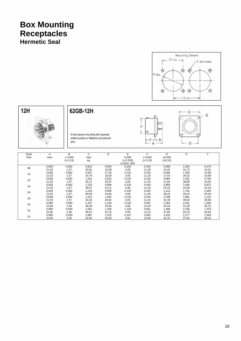
12H 62GB-12H
Shell Size
A max
B ± 0.005 (± 0.13)
C max sq.
D E 0.008
(± 0.203) (±.051) .002
F ± 0.005 (± 0.13)
R ±0.005 (±0.13)
S Y
08 0.828 0.062 0.812 0.594 0.120 0.443 0.568 1.250 0.473 21.03 1.57 20.61 15.08 3.05 11.25 14.42 31.73 12.01
10 0.828 0.062 0.937 0.719 0.120 0.443 0.695 1.359 14.99 21.03 1.57 23.79 18.29 3.05 11.25 17.53 34.52 14.99
12 0.828 0.062 1.031 0.812 0.120 0.443 0.864 1.531 0.750 21.03 1.57 26.17 20.57 3.05 11.25 21.84 38.89 19.05
14 0.828 0.062 1.125 0.906 0.120 0.443 0.989 1.656 0.875 21.03 1.57 28.57 23.11 3.05 11.25 25.15 42.06 22.23
16 0.828 0.062 1.218 0.969 0.120 0.443 1.113 1.781 1.000 21.03 1.57 30.93 24.64 3.05 11.25 28.19 45.24 25.40
18 0.828 0.062 1.312 1.062 0.120 0.443 1.238 1.891 1.125 21.03 1.57 33.32 26.92 3.05 11.25 31.49 48.03 28.58
20 0.890 0.093 1.437 1.156 0.120 0.561 1.363 2.031 1.250 22.60 2.36 36.49 29.46 3.05 14.24 34.54 51.59 30.75
22 0.890 0.093 1.562 1.250 1.120 0.561 1.488 2.156 1.375 22.60 2.36 39.67 31.75 3.05 14.24 37.85 54.76 34.93
24 0 890 0.093 1.687 1.375 0.147 0.593 1.615 2.277 1.500 22.60 2.36 42.84 35.05 3.81 15.06 41.15 57.84 38.10
4-hole square mounting with exposed
solder buckets or flattened and pierced
pins.
16
Single Hole Fixing Receptacles Table of Styles
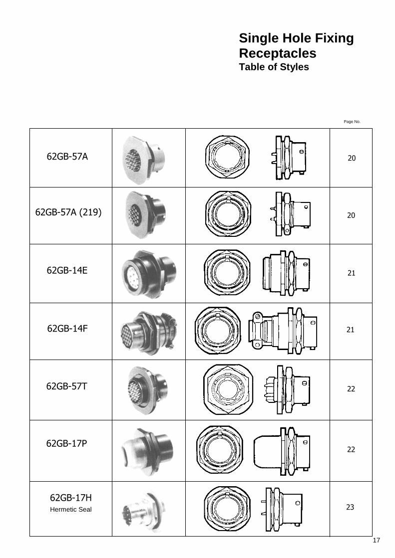
62GB-57A
Page No.
20
62GB-57A (219) 20
62GB-14E 21
62GB-14F 21
62GB-57T 22
62GB-17P 22
62GB-17H Hermetic Seal 23
17

Single Hole Fixing Receptacles Table of Styles
62GB-1 3H Hermetic Seal
62GB-5005-10
62GB-5036-10
62GB-5016-10
62GB-5024
62GB-5052
62GB-5030
Page No.
23
24
24
25
25
26
26
18
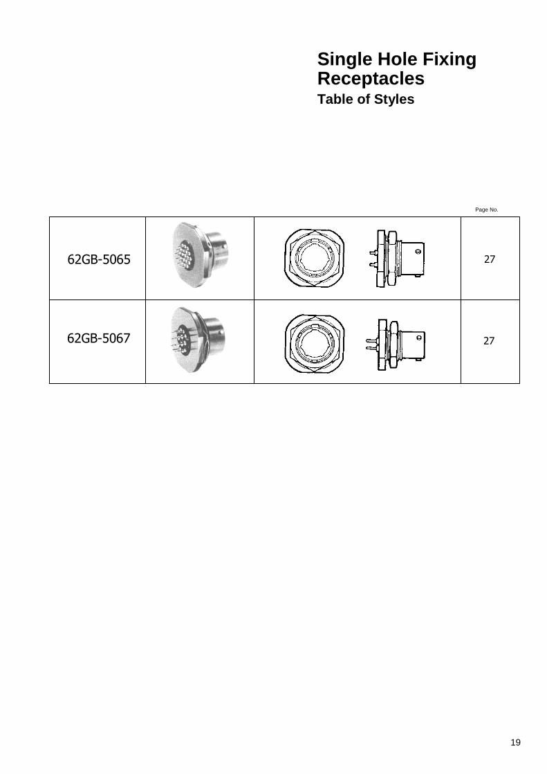
Single Hole Fixing Receptacles Table of Styles
62GB-5065
62GB-5067
Page No.
27
27
19
Single Hole Fixing Receptacles
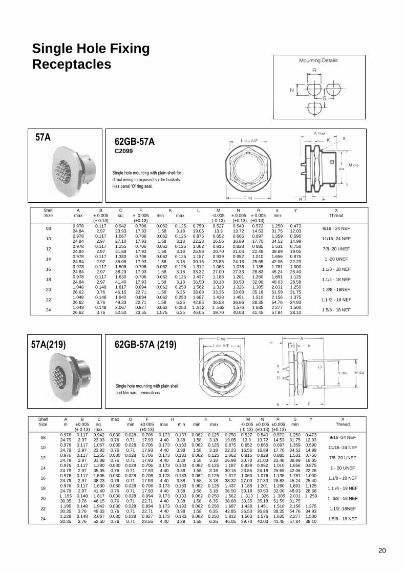
57A 62GB-57A C2099
Single hole mounting with plain shell for
direct wiring to exposed solder buckets.
Has panel 'O' ring seal.
Shell Size
A max
B ± 0.005 (± 0.13)
C sq,
F ± 0.005 (±0.13)
K min max
L M -0.005 (-0.13)
N R ±.0.005 ± 0.005 (±0.13) (±0.13)
s min
Y X Thread
08 0.978 0.117 0.942 0.706 0.062 0.125 0.750 0.527 0.540 0.572 1.250 0.473 9/16 - 24 NEF 24.84 2.97 23.93 17.93 1.58 3.18 19.05 13.3 13.72 14.53 31.75 12.03
10 0.978 0.117 1.067 0.706 0.062 0.125 0.875 0.652 0.665 0.697 1.359 0.590 11/16 -24 NEF 24.84 2.97 27.10 17.93 1.58 3.18 22.23 16.56 16.89 17.70 34.52 14.99
12 0.978 0.117 1.255 0.706 0.062 0.125 1.062 0.815 0.828 0 885 1 531 0.750 7/8 -20 UNEF 24.84 2.97 31.88 17.93 1.58 3.18 26.98 20.70 21.03 22.48 38.89 19.05
14 0.978 0.117 1.380 0.706 0.062 0.125 1.187 0.939 0.952 1.010 1.656 0.875 1 -20 UNEF 24.84 2.97 35.05 17.93 1.58 3.18 30.15 23.85 24.18 25.65 42.06 22.23
16 0.978 0.117 1.505 0.706 0.062 0.125 1 312 1.063 1.076 1.135 1.781 1.000 1.1/8 - 18 NEF 24.84 2.97 38.23 17.93 1.58 3.18 33.32 27.00 27.33 28.83 45.24 25.40
18 0.978 0.117 1.630 0.706 0.062 0.125 1.437 1.188 1.201 1.260 1.891 1.125
1.1/4 - 18 NEF 24.84 2.97 41.40 17.93 1.58 3.18 36.50 30.18 30.50 32.00 48 03 28.58
20 1.048 0.148 1.817 0.894 0.062 0.250 1.562 1.313 1.326 1.385 2.031 1.250 1.3/8 - 18NEF 26.62 3.76 46.15 22.71 1.58 6.35 38.68 33.35 33.68 35.18 51.59 31.75
22 1.048 0.148 1.942 0.894 0.062 0.250 1.687 1.438 1.451 1.510 2.156 1.375 1.1 /2 - 18 NEF 26.62 3.76 49.33 22.71 1.58 6.35 42.85 36.53 36.86 38.35 54.76 34.93
24 1.048 0.148 2.067 0.927 0.062 0.250 1 .812 1 .563 1.576 1 635 2 277 1.500 1.5/8 - 18 NEF 26.62 3.76 52.50 23.55 1.575 6.35 46.05 39.70 40.03 41.45 57.84 38.10
57A(219) 62GB-57A (219)
Single hole mounting with plain shell
and film wire terminations
Shell Size
A m
B ±0.005 (± 0.13)
C sq.
max.
max D min
F ±0.005 (±0.13)
H max min
K min max
L M N R -0.005 ±0.005 ±0.005 (-0.13) (±0.13) (±0.13)
S min
Y X Thread
08 0.976 0.117 0.942 0.030 0.028 0.706 0.173 0.133 0.062 0.125 0.750 0.527 0.540 0.572 1.250 0.473 9/16 -24 NEF 24.79 2.97 23.93 0.76 0.71 17.93 4.40 3.38 1.58 3.18 19.05 13.3 13.72 14.53 31.75 12.03
10 0.976 0.117 1.067 0.030 0.028 0.706 0.173 0.133 0.062 0.125 0.875 0.652 0.665 0.697 1.359 0.590 11/16 -24 NEF 24.79 2.97 23.93 0.76 0.71 17.93 4.40 3.38 1.58 3.18 22.23 16.56 16.89 17.70 34.52 14.99
12 0.976 0.117 1.255 0.030 0.028 0.706 0.173 0.133 0.062 0.125 1.062 0.815 0.828 0.885 1.531 0.750 7/8 -20 UNEF 24.79 2.97 31.88 0.76 0.71 17.93 4.40 3.38 1.58 3.18 26.98 20.70 21.03 22.48 38.89 19.05
14 0.976 0.117 1.380 0.030 0.028 0.706 0.173 0.133 0.062 0.125 1.187 0.939 0.952 1.010 1.656 0.875
1 - 20 UNEF 24.79 2.97 35.05 0.76 0.71 17.93 4.40 3.38 1.58 3.18 30.15 23.85 24.18 25.65 42.06 22.26
16 0.976 0.117 1.505 0.030 0.028 0.706 0.173 0.133 0.062 0.125 1.312 1.063 1.076 1.135 1.781 1.000 1.1/8 - 18 NEF 24.79 2.97 38.23 0.76 0.71 17.93 4.40 3.38 1.58 3.18 33.32 27.00 27.33 28.83 45.24 25.40
18 0.976 0.117 1.630 0.030 0.028 0.706 0.173 0.133 0.062 0.125 1.437 1.188 1.201 1.260 1.891 1.125 1.1 /4 - 18 NEF 24.79 2.97 41.40 0.76 0.71 17.93 4.40 3.38 1.58 3.18 36.50 30.18 30.50 32.00 48.03 28.58
20 1 .195 0.148 1 817 0.030 0.028 0.894 0.173 0.133 0.062 0.250 1 562 1 .313 1 .326 1 .385 2.031 1 .250 1 .3/8 - 18 NEF 30.35 3.76 46.15 0.76 0.71 22.71 4.40 3.38 1.58 6.35 38.68 33.35 35.18 51 59 31.75
22 1.195 0.148 1.942 0.030 0.028 0.894 0.173 0.133 0.062 0.250 1.687 1.438 1.451 1.510 2.156 1.375 1.1/2 -18NEF 30.35 3.76 49.33 0.76 0.71 22.71 4.40 3.38 1.58 6.35 42.85 36.53 36.86 38.35 54.76 34.93
24 1.228 0.148 2.067 0.030 0.028 0.927 0.173 0.133 0.062 0.250 1.812 1.563 1.576 1.635 2.277 1.500 1.5/8 - 18 NEF 30.35 3.76 52.50 0.76 0.71 23.55 4.40 3.38 1.58 6.35 46.05 39.70 40.03 41.45 57.84 38.10
20
Single Hole Fixing Receptacles
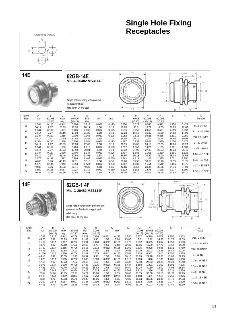
14E 62GB-14E MIL-C-26482 MS3114E
Single hole mounting with grommet
and grommet nut.
Has panel 'O' ring seal
Shell Size
A max
B ±0.005 (±0.13)
C max sq.
F ±0.005 (±0.13)
G Dia Max
K min max
L M N R -0.005 ±0.005 ±0.005 (-0.13) ( ±0.13) (±0.13)
S Y X Thread
08 1.344 0.117 0.942 0.706 0 713 0.062 0.125 0.750 0.527 0.540 0.572 1.250 0.473 9/16-24NEF 34.14 2.97 23.93 17.93 18.11 1.58 3.18 19.05 13.3 13.72 14.53 31.75 12.03
10 1.344 0.117 1.067 0.706 0.838 0.062 0.125 0.875 0.652 0.665 0.697 1.359 0.590 11/16 -24 NEF 34.14 2.97 27.10 17.93 21.29 1.58 3.18 22.23 16.56 16.89 17.70 34.52 14.99
12 1.344 0.117 1.255 0.706 0.963 0.062 0.125 1.062 0.815 0.828 0.885 1.531 0.750
7/8 -20 UNEF 34.14 2.97 31 .88 17.93 24.46 1.58 3.18 26.98 20.70 21.03 22.48 38.89 19.05
14 1 .344 0.117 1.380 0.706 1.088 0.062 0.125 1.187 0.939 0.952 1.010 1.656 0.875 1 - 20 UNEF 34.14 2.97 35.05 17.93 27.63 1.58 3.18 30.15 23.85 24.18 25.65 42.06 22.23
16 1.344 0.117 1.505 0.706 1.213 0.062 0.125 1.312 1.063 1.076 1.135 1.781 1.000 1.1/8 -18NEF 34.14 2.97 38.23 17.93 30.81 1.58 3.18 33.32 27.00 27.33 28.83 45.24 25.40
18 1.344 0.117 1.630 0.706 1.338 0.062 0.125 1.437 1.188 1.201 1.260 1.891 1.125 1.1/4 –18 NEF 34.14 2.97 41.40 17.93 33.98 1.58 3.18 36.50 30.18 30.50 32.00 48.03 28.58
20 1.576 0.148 1 817 0.894 1.463 0.062 0.250 1.562 1.313 1.326 1.385 2.031 1.250 1.3/8 - 18 NEF 40.03 3.76 46.15 22.71 37.16 1.58 6.35 38.68 33.35 33.68 35.18 51.59 31.75
22 1.576 0.148 1.942 0.894 1 .588 0.062 0.250 1.687 1.438 1.451 1.510 2.156 1.375 1.1 /2 - 18 NEF 40.03 3.76 49.33 22.71 40.33 1.58 6.35 42.85 36.53 36.86 38.35 54.76 34.93
24 1.609 0.148 2.067 0.927 1.713 0.062 0.250 1.812 1.563 1.576 1.635 2.277 1.500 1.5/8 - 18 NEF 40.87 3.76 52.50 23.55 43.51 1.58 6.35 46.05 39.70 40.03 41.45 57.84 38.10
14F 62GB-1 4F MIL-C-26482 MS3114F
Single hole mounting with grommet and
grommet nut fitted with integral strain
relief clamp.
Has panel 'O' ring seal
Shell Size
A max
B ±0.005 (±0.13)
C max sq.
F ±0.005 (±0.13)
G dia.
max.
H 0.005
(± 0.13)
K min max
L M N R -0.005 ±0.005 ±0.005 (-0.13) (±0.13) (±0.13)
S Y X Thread
08 1.762 0.117 0.942 0.706 0.828 0.156 0.062 0.125 0.750 0.527 0.540 0.572 1 250 0.473 9/16 -24 NEF 44.75 2.97 23.93 17.93 21.03 3.96 1.58 3.18 19.05 13.3 13.72 14.53 31.75 12.03
10 1.762 0.117 1.067 0.706 0.891 0.188 0.062 0.125 0.875 0.652 0.665 0.697 1.359 0.590 11/16 - 124 NEF 44.75 2.97 27.10 17.93 22.63 4.78 1.58 3.18 22.23 16.56 16.89 17.70 34.52 14.99
12 1.762 0.117 1.255 0.706 1.016 0.312 0.062 0.125 1.062 0.815 0.828 0.885 1.531 0.750 7/8 - 20 UNEF 44 75 2.97 31.88 17.93 25.81 7.93 1.58 3.18 26.98 20.70 21.03 22.48 38.89 19.05
14 1 .736 0.117 1.380 0.706 7.147 0.375 0.062 0.125 1.187 0.939 0.952 1.010 1.656 0.875
1 - 20 NEF 44.10 2.97 35.05 17.93 28.97 9.53 1.58 3.18 30.15 23.85 24.18 25.65 42.06 22.23
16 1.876 0.117 1.505 0.706 1.203 0.500 0.062 0.125 1.312 1.063 1.076 1.135 1.781 1.000 1.1/8 - 18 NEF 47.65 2.97 38.23 17.93 30.56 12.7 1.58 3.18 33.32 27.00 27.33 28.83 45.24 25.40
18 1.876 0.117 1.630 0.706 1.426 0.625 0.062 0.125 1.437 1.188 1.201 1.260 1.891 7.125 1.1/4 - 18 NEF 47.65 2.97 41.40 17.93 36.22 15.88 1.58 3.18 36.50 30.18 30.50 32.00 48.03 28.58
20 2.118 0.148 1.817 0.894 1.426 0.625 0.062 0.250 1.562 1.313 1.326 1.385 2.031 1.250 1.3/8 - 18 NEF 53.8 3. 76 46.15 22.71 36.22 15.88 1.58 6.35 38 68 33.35 33.68 35.18 51 .59 31.75
22 2.118 0.148 1.942 0.894 7.567 0.750 0.062 0.250 1.687 1.438 1.451 1.510 2.756 1.375 1.1/2 -18 NEE 53.8 3.76 49.33 22.71 39.80 19.05 1.58 6.35 42.85 36.53 36.86 38.35 54.76 34.93
24 2.250 0.148 2.067 0.927 1.735 0.800 0.062 0.250 1.812 1.563 1.576 1.635 2.277 1.500 1.5/8 - 18 NEF 57.15 3.76 52.50 23.55 44.07 20.32 1.58 6.35 46.05 39.70 40.03 41.45 57.84 38.10
21

Single Hole Fixing Receptacles
57T 62G B-57T
Single hole mounting with threaded
shell to accept accessories
Shell Size
A max
B ± 0.005 (± 0.13)
c max. sq.
F ± 0.005 (±0.13)
G dia,
max.
K min max
L M -0.005 (- 0.13)
N Y X Thread
08 0.978 0.117 0.942 0.595 0.426 0.062 0.125 0.750 0.527 7/16 - UNEF 0.473 9/16 - 24 NEF 24.84 2.97 23.93 15.12 10.82 1.58 3.18 19.05 13.3 12.03
10 0.978 0.117 1.067 0.595 0.552 0.062 0.125 0.875 0.652 9/16 – UNEF 0.590 11/16 – 24 NEF 24.84 2.97 27.10 15.12 14.02 1.58 3.18 22.23 16.56 14.99
12 0.978 0.117 1.255 0.595 0.677 0.062 0.125 1.062 0.815 11/16 – UNEF 0.750 7/8 – 20 UNEF 24.84 2.97 31 .88 15.12 17.20 1.58 3.18 26.98 20.70 19.05
14 0.978 0.117 1.380 0.595 0.802 0.062 0.125 1.187 0.939
13/16 - UNEF 0.875
1 – 20 UNEF 24.84 2.97 35.05 15.12 20.37 1.58 3.18 30.15 23.85 22.23
16 0.978 0.117 1.505 0.595 0.927 0.062 0.125 1.312 1.063 15/16 – UNEF 1.000 1.1/18 – 18 NEF 24.84 2.97 38.23 15.12 23.55 1.58 3.18 33.32 27.00 25.40
18 0.978 0.117 1.630 0.595 1.052 0.062 0.125 1.437 1.188 1.1/16 – UNEF 1.125 1.1/4 – 18 NEF 24.84 2.98 41.40 15.12 26.72 1.58 3.18 36.50 30.18 28.58
20 1.048 0.148 1.817 0.720 1.167 0.062 0.250 1.562 1.313 1.3/16 – UNEF 1.250 1.3/8 - 18 NEF 26.62 3.76 46.15 18.29 29.65 1 58 6.35 38.68 33.35 31.75
22 1.048 0.148 1.942 0.720 1.292 0.062 0.250 1.687 1.438 1.5/16 – UNEF 1.375 1.1/2 – 18 NEF 26,62 3.76 49.33 18.29 32.82 1.58 6.35 42.85 36.53 34.93
24 1.048 0.148 2.067 0.753 1.416 0.062 0.250 1.812 1.563 1.7/16 - UNEF 1.50 1.5/8 - 18 NEF 26.62 3.76 52.50 19.13 35.97 1.58 6.35 46.05 39.70 38.10
17P 62GB-17P MIL-C-26482 MS3114P
Single hole mounting for potting. Supplied
complete with potting mould locating ring
and panel 'O' ring seal
Shell Size
A max.
B ±0.005 (±0.13)
C max. sq.
F ± 0.005 (±0.13)
G K min max.
L M -0.005 (-0.13)
N ±0.005 (±0.13)
R ±0.005 (±0.13)
Y Z X Thread
08 1.391 0.117 0.942 0.706 0.572 0.062 0.125 0.750 0.527 0.540 0.572 1.250 0.473 0.260 9/16 -24 NEF 35.33 2.97 23.93 17.93 14.53 1.58 3.175 19.05 13.3 13.72 14.53 31.75 12.03 6.60
10 1.391 0.117 1.067 0.706 0.666 0.062 0.125 0.875 0.652 0.665 0.697 1.359 0.590 0.463 11/16 -24 NEF 35.33 2.97 27.10 17.93 16.92 1.58 3.18 22.23 16.56 16.89 17.70 34.52 14.99 11.76
12 1.391 0.117 1.255 0.706 0.822 0.062 0.125 1.062 0.815 0.828 0.885 1.531 0.750 0.557 7/8 - 20 UNEF 35.33 2.97 31.88 17.93 20.88 1.58 3.18 26.98 20.70 21.03 22.48 38.89 19.05 14.15
14 1.391 0.117 1.380 0.706 0.907 0.062 0.125 1.187 0.939 0.952 1.010 1.656 0.875 0.590
1 - 20 UNEF 35.33 2.97 35.05 17.93 23.06 1.58 3.18 30.15 23.85 24.18 25.65 42.06 22.23 14.99
16 1.391 0.117 1.505 0.706 1.040 0.062 0.125 1.312 1 063 1 .076 1.135 1.781 1.000 0.713 1.1/18 – 18 NEF 35.33 2.97 38.23 17.93 26.42 1.58 3.18 33.32 27.00 27.33 28.83 45.24 25.40 18.11
18 1.391 0.117 1.630 0.706 1.165 0.062 0.125 1.437 1.188 1.201 1.260 1.891 1.125 0.835 1.1/4 - 18 NEF 35.33 2.97 41.40 17.93 29.59 1.58 3.175 36.50 30.18 30.50 32.00 48.03 28.58 21.21
20 1.641 0.148 1.817 0.894 1.285 0.062 0.250 1.562 1.313 1.326 1.385 2.031 1.250 1.015 1.3/8 –18 NEF 41.68 3.76 46.15 22.71 32.64 1.58 6.35 38.68 33.35 33.68 35.18 51.59 31.75 25.78
22 1.641 0.148 1.942 0.894 1.400 0.062 0.250 1.687 1.438 1.451 1.510 2.156 1.375 1.015 1.1/2 –18 NEF 41.68 3.76 49.33 22.71 35.56 1.58 6.35 42.85 36.53 36.86 38.35 54.76 34.93 25.78
24 1.674 0.148 2.067 0.927 1 .540 0.062 0.250 1.812 1 .563 1.576 1.635 2.277 1.500 1.265 1.5/8 - 18 NEF 42.52 3.76 52.50 23.55 39.12 1.58 6.35 46.05 39.70 40.03 41.45 57.84 38.10 32.13
22

Single Hole Fixing Receptacles Hermetic Seal
17H 62GB-17H MIL-C-26482 MS3114H
Single hole mounting with pin contacts in one piece
glass-to-metal seal. Exposed solder buckets or
flattened and pierced pins.
Has panel 'O' ring seal
Shell Size
A max.
B ±0.005 (±0.13)
C max.
sq
F ±0.005 (±0.13)
min K max
L M -0.005 (-0.13)
N R ±0.005 ±0.005 (±0.13) (±0.13)
S Y X Thread
08 0.828 0.094 0.942 0.706 0.062 0.125 0.750 0.527 0.540 0.572 1.250 0.473 9/16 - 24 NEF 21.03 2.39 23.93 17.93 1.57 3.18 19.05 13.39 13.72 14.53 31.75 12.01
10 0.828 0.094 1.067 0.706 0.062 0.125 0.875 0.652 0.665 0.697 1.359 0.590 11/16 – 24 NEF 21.03 2.39 27.10 17.93 1.57 3.18 22.23 16.56 16.89 17.70 34.52 14.99
12 0.828 0.094 1.255 0.706 0.062 0.125 1.062 0.815 0.828 0.885 1.531 0.750 7/8 – 20 UNEF 21.03 2.39 31.88 17.93 1.57 3.18 26.97 20.70 21.03 22.48 38.89 19.05
14 0.828 0.094 1.380 0.706 0.062 0.125 1.187 0.939 0.952 1.010 1.656 0.875 1 - 20 UNEF 21.03 2.39 35.05 17.93 1.57 3.18 30.15 23.85 24.18 25.65 42.06 22.23
16 0.828 0.094 1.505 0.706 0.062 0.125 1.312 1.063 1.076 1.135 1.781 1.000 1.1/8 – 18 NEF 21.03 2.39 38.23 17.93 1.57 3.18 33.32 27.00 27.33 28.53 45.24 25.40
18 0.828 0.094 1.630 0.706 0.062 0.125 1.437 1.188 1.201 1.260 1.891 1.125 1.1/4 – 18 NEF 21.03 2.39 41.40 17.93 1.57 3.18 36.50 30.18 30.51 32.00 48.03 28.58
20 0.828 0.125 1.817 0.894 0.062 0.250 1.562 1.313 1.326 1.385 2.031 1.250
1.3/8 – 18 NEF 21.03 3.18 46.15 22.71 1.57 6.35 39.67 33.35 33.68 35.18 51.59 30.75
22 0.890 0.125 1.942 0.894 0.062 0.250 1.687 1.438 1.451 1.510 2.156 1.375 1.1/2 – 18 NEF 22.61 3.18 49.33 22.71 1.57 6.35 42.85 36.53 36.86 38.35 54.76 34.93
24 0.890 0.125 2.067 0.927 0.062 0.250 1.812 1.563 1.576 1.635 2.277 1.500 1.5/8 – 18 NEF 22.61 3.18 52.50 23.55 1.57 6.35 46.02 39.70 40.03 41.53 57.84 38.10
13H 62GB-1 3H MIL-C-26482 MS3113H
Solder mounting with plain shell and exposed
solder buckets or flattened and pierced pins
Shell Size
A max
B ±0.005 (± 0.13)
c max
F ±0.005
( ± 0.13)
G max
J max
R ±0.005
( ± 0.13)
S min
Y dia. max
08 0.828 0.036 0.630 0.426 0.562 0.592 0.578 1.250 0.473 21.03 0.91 16.00 10.82 14.27 15.04 14.68 31.75 12.01
10 0.828 0.036 0.755 0.426 0.672 0.592 0.687 1.359 0.590 21.03 0.91 19.18 10.82 17.07 15.04 17.45 34.52 14.99
12 0.828 0.036 0.849 0.426 0.781 0.592 0.797 1.531 0.750 21.03 0.91 21.56 10.82 19.84 15.04 20.24 38.89 19.05
14 0.828 0.036 0.974 0.426 0.906 0.592 0.922 1.656 0.875 21.03 0.91 24.74 10.82 23.01 15.04 23.42 42.06 22.23
16 0.828 0.036 1.099 0.426 1.031 0.592 1.047 1.781 1.000 21.03 0.91 27.91 10.82 26.19 15.04 26.59 45.24 25.40
18 0.828 0.036 1.223 0.426 1.156 0.592 1.172 1.891 1.125 21.03 0.91 31.06 10.82 29.36 15.04 29.77 48.03 28.58
20 0.890 0.036 1.317 0.488 1.250 0.658 1.266 2.031 1.250 22.61 0.91 33.45 12.40 31.75 16.70 32.16 51.59 30.75
22 0.890 0.036 1.443 0.488 1.375 0.686 1.390 2.156 1.375 22.61 0.91 36.65 12.40 34.93 17.42 35.31 54.76 34.93
24 0.890 0.036 1.567 0.521 1.500 0.719 1.516 2.277 1.500 22.61 0.91 39.80 13.23 38.10 18.26 38.51 57.84 38.10
23

Single Hole Fixing Receptacles
5005 62GB-5005-10 (RSRE SD/C 235025/X)
Single hole mounting plain shell with PC pin
terminated contacts. Reduced diameter
flange with panel 'O' seal
Size 10 only
A max
B +0.001 -0.002 (+0.03) (-0.03)
D dia. max
F +0.002 -0.003 (+0.05) (-0.08)
K min max
M -0.005 (-0.13)
N ±0.003 (±0.08)
R +0.005 (+0.13)
S Y dia.
max.
X Thread
L dia
10 0.877 0.065 0.880 0.681 0.062 0.125 0.655 0.659 0.690 1.017 0.590 11/16 – 24 NEF 0.820 22.28 1.65 22.35 17.29 1.58 3.18 16.63 16.47 17.52 25.83 14.99 20.83
5036 62GB-5036-10 (RSRE SD/C235025/X)
Single hole mounting with circular flange
and P.C. terminations
Size 10 only
Shell Size
A max
B +0.001 -0.002 (+0.03) (-0.05)
D dia. max
F +0.002 -0.003 (+0.05) (-0.08)
Y dia.
max.
K min max
M -0.005 (-0.13)
N ±0.003 (±0.08)
R +0.005 (+0.13)
S X Thread
L dia
10 0.829 0.066 0.880 0.679 0.590 0.062 0.125 0.655 0.659 0.690 1.017 11/16 – 24 NEF 0.820 21.06 1.67 22.35 17.25 14.99 1.57 3.18 16.63 16.47 17.52 25.83 20.83
24

Single Hole Fixing Receptacles
5016 62GB-5016-10 (RSRE SD/C 235025/X)
Single hole mounting plain shell for direct wiring
to exposed solder buckets. Reduced diameter
flange with panel 'O' ring seal Solder bucket: Size 10 only
Shell Size
A max
B +0.002 -0.001 (+0.05) (-0.03)
D dia. max
F + 0.003 - 0.002 (+ 0.08) (- 0.05)
K min max
M - 0.010 (- 0.25)
N ± 0.005 (± 0.13)
R + 0.005 (+ 0.13)
S Y dia.
max.
X Thread
10 0.902 0.064 0.880 0.678 0.062 0.125 0.655 0.665 0.697 1.359 0.590 11/16 – 24 NEF 22.91 1.62 22.35 17.21 1.58 3.18 16.63 16.89 17.70 34.52 14.99
5024 62GB-5024 (RSRE SD/C 35077/X)
Single hole mounting plain shell for direct wiring
to exposed solder buckets. Reduced diameter
flange with panel 'O' ring seal
Solder buckets: Size 8, 12 and 14 only
Shell Size
A max
B ± 0.005 ( ± 0.13)
D dia. max
F ± 0.005 ( ± 0.13)
K min max
M - 0.005 (- 0.13)
N R ± 0.005 ±0.005 (± 0.13) (± 0.13)
S min
Y dia. max
X Thread
08 0.978 0.117 0.830 0.706 0.062 0.125 0.527 0.540 0.572 1.250 0.473 9/16 - 24 NEF 24.84 2.97 21.08 17.93 1.58 3.18 13.3 13.72 14.53 31.75 12.03
12 0.978 0.117 1.130 0.706 0.062 0.125 0.815 0.828 0.885 1.531 0.750 7/8 - 20 UNEF 24.84 2.97 28.70 17.93 1.58 3.18 20.70 21.03 22.48 38.89 19.05
14 0.978 0.117 1.260 0.706 0.062 0.125 0.939 0.952 1.010 1.656 0.875
1 -20 UNEF 24.84 2.97 32.00 17.93 1.58 3.18 23.85 24.18 25.65 42.06 22.23
25

Single Hole Fixing Receptacles
5052 62GB-5052-10
Single hole fixing with circular flange and back
end thread - solder termination
Size 10 only
Shell Size
A max
B (± 0.05) (± 0.03)
C max. sq.
F + 0.003 - 0.002 (+ 0.08) (- 0.05)
K min max
L M - 0.005 (- 0.13)
N ± 0.005 (± 0.13)
R ± 0.005 (± 0.13)
S ± 0.005 (± 0.13)
X Thread
10 0.947 0.062 0.880 0.677 0.062 0.125 0.820 0.650 5/8 – 24 UNEF 0.697 1.359 11/16 – 24 NEF 24.06 1.58 22.35 17.19 1.58 3.18 20.83 16.51 17.70 34.52
5030 62G B-5030
Bulkhead mounting receptacle with solder
terminations
Shell Size
A max
B ± 0.005 (± 0.13)
C ± 0.010 (± 0.25)
F ± 0.005 (± 0.13)
L N Thread
08 0.978 0.094 0.812 0.415 0.563 7/16 - 28 UNEF 24.85 2.39 20.63 10.54 14.30
10 0.978 0.094 0.937 0.415 0.680 9/16 - 24 NEF 24.85 2.39 23.80 10.54 17.28
12 0.978 0.094 1.031 0.415 0.859
11 /16 - 24 NEF 24.85 2.39 26.19 10.54 21.82
14 0.978 0.094 1.125 0.415 0.984 13/16 - 20 UNEF 24.85 2.39 28.58 10.54 25.00
16 0.978 0.094 1.218 0.415 1.108 15/16 - 20 UNEF 24.85 2.39 30.94 10.54 28.15
18 0.978 0.094 1.3121 0.415 1.233 1.1/16 - 18NEF 24.85 2.39 33.33 10.54 31.32
20 1.048 0.102 1.437 0.535 1.358 1.3/16 -18NEF 26.62 2.59 36.50 13.59 34.50
22 1.048 0.102 1.562 0.535 1.483 1.5/16 - 18 NEF 26.62 2.59 39.68 13.59 37.67
24 1.048 0.102 1.687 0.572 1.610 1.7/16 - 18 NEF 26.62 2.59 42.85 14.53 40.90
26

Single Mole Fixing Receptacles
5065 62G B-5065
Single hole mounting with plain shell
and film wire terminations
Shell Size
A max
B ± 0.005 (± 0.13)
C sq.
D max min
F ± 0.005 (± 0.13)
H max min
J ± 0.020 (± 0.51)
K min max
L M N R -0.005 ±0.005 ±0.005 (-0.13) (±0.13) (±0.13)
S Y X Thread
08 1.021 0.117 0.942 0.030 0.028 0.706 0.218 0.178 0.060 0.062 0.125 0.750 0.527 0.540 0.572 1 250 0.473 9/16 - 24 NEF 25.94 2.97 23.93 0.76 0.71 17.93 5.54 4.52 1.52 1.58 3.18 19.05 13.3 13.72 14.53 31.75 12.03
10 1.021 0.117 1.067 0.030 0.028 0.706 0.218 0.178 0.060 0.062 0.125 0.875 0.652 0.665 0.697 1.359 0.590 11/16 - 24 NEF 25.94 2.97 27.10 0.76 0.71 17.93 5.54 4.52 1.52 1.58 3.18 22.23 16.56 16.89 17.70 34.52 14.99
12 1.021 0.117 1.255 0.030 0.028 0.706 0.218 0.178 0.060 0.062 0.125 1.062 0.815 0.828 0.885 1.531 0.750 7/8 - 20 UNEF 25.94 2.97 31.88 0.76 0.71 17.93 5.54 4.52 1.52 1.58 3.18 26.98 20.70 21.03 22.48 38.89 19.05
14 1.021 0.117 1.380 0.030 0.028 0.706 0.218 0.178 0.060 0.062 0.125 1.187 0.939 0.952 1.010 1.656 0.875 1 - 20 UNEF 25.94 2.97 35.05 0.76 0.71 17.93 5.54 4.52 1.52 1.58 3.18 30.15 23.85 24.18 25.65 42.06 22.23
16 1.021 0.117 1.505 0.030 0.028 0.706 0.218 0.178 0.060 0.062 0.125 1.312 1.063 1.076 1.135 1.781 1.000
1.1/8 - 18 NEF 25.94 2.97 38.23 0.76 0.71 17.93 5.54 4.52 1 .52 1.58 3.18 33.32 27.00 27.33 28.83 45 24 25.40
18 1.021 0.117 1.630 0.030 0.028 0.706 0.218 0.178 0.060 0.062 0.125 1.437 1.188 1.201 1.260 1.891 1.125 1.1 /4 - 18 NEF 25.94 2.97 41.40 0.76 0.71 17.93 5.54 4.52 1.52 1.58 3.18 36.50 30.18 30.50 32.00 48.03 28.58
20 1.240 0.148 1.817 0.030 0.028 0.894 0.218 0.178 0.060 0.062 0.250 1.562 1.313 1.326 1.385 2.031 1 .250 1.3/8 - 18 NEF 31.50 3.76 46.15 0.76 0.71 22.71 5.54 4.52 1.52 1.58 6.35 38.68 33.35 33.68 35.18 51.59 31.75
22 1.240 0.148 1942 0.030 0.028 0.894 0.218 0.178 0.060 0.062 0.250 1.687 1.438 1.451 1.510 2.156 1.375 1.1/2 - 18 NEF 31 .50 3.76 49.33 0.76 0.71 22.71 5.54 4.52 1 .52 1.58 6.35 42.85 36.53 36.855 38.35 54.76 34.93
24 1.273 0.148 2.067 0.030 0.028 0.927 0.218 0.178 0.060 0.062 0.250 1.812 1.563 1.576 1.635 2.277 1 .500 1.5/8 - 18 NEF 32.34 3.76 52.50 0.76 0.71 23.55 5.54 4.52 1.52 1.58 6.35 46.05 39.70 40.03 41.45 57.84 38.10
5067 62GB-5067
Single hole mounting with plain shell
and film wire terminations
Shell Size
A max
B ± 0.005 (± 0.13)
C max sq
D max min
F ± 0.005 (± 0.13)
H max min
J ± 0.012 (± 0.30)
K min max
L M N R -0.005 ±0.005 ±0.005 (-0.13) (±0.13) (±0.13)
S Y X Thread
08 1.095 0.117 0.942 0.030 0.028 0.706 0.262 0.230 0.049 0.062 0.125 0.750 0.527 0.540 0.572 1.250 0.473 9/16 - 24 NEF 27.81 2.97 23.93 0.76 0.71 17.93 6.66 5.85 1.24 1.58 3.18 19.05 13.3 13.72 14.53 31.75 12.03
10 1.095 0.117 1.067 0.030 0.028 0.706 0.262 0.230 0.049 0.062 0.125 0.875 0.652 0.665 0.697 1.359 0.590 11/16 - 24 NEF 27.81 2.97 27.10 0.76 0.71 17.93 6.66 5.85 1.24 1.58 3.18 22.23 16.56 16.89 17.70 34.52 14.99
12 1.095 0.117 1.255 0.030 0.028 0.706 0.262 0.230 0.049 0.062 0.125 1.062 0.815 0.828 0.885 1.531 0.750 7/8 - 20 UNEF 27.81 2.97 31.88 0.76 0.71 17.93 6.66 5.85 1.24 1.58 3.18 26.98 20.70 21.03 22.50 38.89 19.05
14 1.095 0.117 1.380 0.030 0.028 0.706 0.262 0.230 0.049 0.062 0.125 1.187 0.939 0.952 1.010 1.656 0.875 1 - 20 UNEF 27.81 2.97 35.10 0.76 0.71 17.93 6.66 5.85 1.24 1.58 3.18 30.15 23.85 24.18 25.65 42.06 22.23
16 1.095 0.117 1.505 0.030 0.028 0.706 0.262 0.230 0.049 0.062 0.125 1.312 1.063 1.076 1.135 1.781 1.000 1.1/8 -18 NEF 27.81 2.97 38.23 0.76 0.71 17.93 6.66 5.85 1.24 1.58 3.18 33.23 27.00 27.33 28.83 45.24 25.40
18 1.095 0.117 1.630 0.030 0.028 0.706 0.262 0.230 0.049 0.062 0.125 1.437 1.188 1.201 1.260 1.891 1.125
1.1 /4 - 18 NEF 27.81 2.97 41.40 0.76 0.71 17.93 6.66 5.85 1.24 1.58 3.18 36.50 30.18 30.51 32.00 48.03 28.58
20 1.309 0.148 1.817 0.030 0.028 0.894 0.262 0.230 0.049 0.062 0.250 1.562 1.313 1.326 1.385 2.031 1 .250 1.3/8 -18 NEF 33.24 3.76 46.15 0.76 0.71 22.71 6.66 5.85 1.24 1.58 6.35 38.68 33.35 33.68 35.18 51.59 31.75
22 1.309 0.148 1.942 0.030 0.028 0.894 0.262 0.230 0.049 0.062 0250 1.687 1.438 1.451 1.510 2.156 1.375 1.1/2 -18 NEF 33.24 3.76 49.33 0.76 0.71 22.71 6.66 5.85 1.24 1.58 6.35 42.85 36.53 36.86 38.35 54.76 34.93
24 1.342 0.148 2.067 0.030 0.028 0.927 0.262 0.230 0.049 0.062 0.250 1.812 1.563 1.576 1.635 2.277 1.500 1.5/8 -18 NEF 34.08 3.76 52.50 0.76 0.71 23.55 6.66 5.85 1.24 1.58 6.35 46.03 39.07 40.03 41.59 57.84 38.10
27
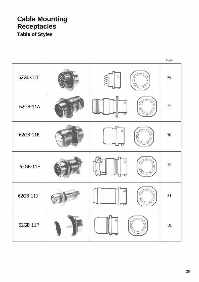
Cable Moun ting Receptacles Table of Styles
62GB-51T
62GB-11A
62GB-11E
62GB-11F
62GB-11J
62GB-11P
Page No.
29
29
30
30
31
31
28

Cable Mounting Receptacles
51T 62GB-51T
Basic cable mounting receptacle with
threaded shell to accept standard cable
accessories.
Shell Size
A max
B ± 0.005 (± 0.13)
C max sq
F ± 0.005 (± 0.13)
Y dia
max
X Thread
08 0.978 0.094 0.817 0.415 0.473 7/16 - 28 UNEF 24.84 2.39 20.75 10.54 12.03
10 0.978 0.094 0.942 0.415 0.590 9/16 - 24 NEF 24.84 2.39 23.93 10.54 14.99
12 0.978 0.094 1.036 0.415 0.750 11 /16 - 24 NEF 24.84 2.39 26.32 10.54 19.05
14 0.978 0.094 1.130 0.415 0.875
13/16 - 20 UNEF 24.84 2.39 28.70 10.54 22.23
16 0.978 0 094 1.223 0.415 1.000 15/16 - 20 UNEF 24.84 2.39 31.07 10.54 25.40
18 0.978 0.094 1.317 0.415 1.125 1.1/16 -18 NEF 24.84 2.39 33.45 10.54 28.58
20 1.048 0.102 1.442 0.535 1.250 1 .3/16 -18 NEF 26 62 2.59 36.63 13.59 31.75
22 1.048 0.102 1.567 0.535 1.375 1.5/16 -18 NEF 26.62 2.59 39.80 13.59 34.93
24 1.048 0.102 1.692 0.560 / 0.574 1.500 1.7/16 -18 NEF 26.62 2.59 42.98 14.23 / 14.58 38.10
11A 62GB-11A
Cable mounting receptacle with general
duty back shell. No grommet supplied.
Shell Size
A max
B ± 0 005 (± 0.13)
C max sq
F ± 0.005 (± 0.13)
G dia
max
Y Dia max
M Thread
08 1.624 0.094 0.817 0.415 0.561 0.473 1/2 - 28 UNEF 41.25 2.39 20.75 10.54 14.25 12.03
10 1 .624 0.094 0.942 0.415 0.686 0.590 5/8 - 24 NEF 41.25 2.39 23.93 10.54 17.43 14.99
12 1.624 0.094 1.036 0.415 0.811 0.750 3/4 - 20 UNEF 41.25 2.39 26.32 10.54 20.60 19.05
14 1.624 0.094 1.130 0.415 0.936 0.875
7/8 - 20 UNEF 41.25 2.39 28.70 10.54 23.78 22.23
16 1.624 0.094 1.223 0.415 1.061 1.000 1 – 20 UNEF 41.25 2.39 31.07 10 54 26.95 25.40
18 1.624 0.094 1.317 0.415 1.186 1.125 1.3/16 – 18 NEF 41.25 2.39 33.45 10.54 30.13 28.58
20 1.687 0 104 / 0.100 1.442 0.535 1.311 1.250 1 3/16 -18 NEF 42.85 2.64 / 2.55 36.63 13.59 33.30 31.75
22 1.687 0.104 / 0.100 1.567 0.535 1.436 1.375 1.7/16 -18 NEF 42.85 2.64 / 2.55 39.80 13.59 36.75 34.93
24 1.730 0.104 / 0.100 1.692 0.569 / 0.574 1.561 1.500 1.7/16 -18 NEF 43.94 2.64 / 2.55 42.98 14.45 / 14.58 39.65 38.10
29

Cable Mounting Receptacles
11E 62GB-11E MIL-C-26482 MS3111E
Cable mounting receptacle with grommet
and grommet nut
Shell Size
A max
B ± 0.005 (± 0.13)
C max sq
F ± 0.005 (± 0.13)
G dia
max
Y dia
max
08 1.281 0.094 0.817 0.415 0.561 0.473 32.54 2.39 20.75 10.54 14.25 12.03
10 1.281 0.094 0.942 0.415 0.686 0.590 32.54 2.39 23.93 10.54 17.43 14.99
12 1.281 0.094 1.036 0.415 0.811 0.750 32.54 2.39 26.32 10.54 20.60 19.05
14 1.281 0.094 1.130 0.415 0.936 0.875 32.54 2.39 28.70 10.54 23.78 22.23
16 1.281 0.094 1.223 0.415 1.061 1.000 32.54 2.39 31.07 10.54 26.95 25.40
18 1.281 0.094 1.317 0.415 1.186 1.125 32.54 2.39 33.45 10.54 3013 28.58
20 1.383 0.102 1.442 0.535 1.311 1.250 35.13 2.59 36.63 13.59 33.30 31.75
22 1.383 0.102 1.567 0.535 1.436 1.375 35.13 2.59 39.80 13.59 36.75 34.93
24 1.383 0.102 1.692 0.569 / 0.574 1.561 1.500 35.13 2.59 42.98 14.45 / 14.58 39.65 38.10
62GB-11F MIL-C-26482 MS3111F
Cable mounting receptacle with
grommet and grommet nut fitted with
integral strain relief clamp
Shell Size
A max
B ± 0.005 (± 0.13)
C max sq
F ± 0.005 (± 013)
G dia
max
H ± 0.005 (± 0.13)
Y dia
max 08 1.762 0.094 0.817 0.415 0.828 0.156 0.473
44.75 2.39 20.75 10.54 21.03 3.96 12.03 10 1.762 0.094 0.942 0 415 0.891 0.188 0.590
44.75 2.39 23.93 10.54 22.63 4.78 14.99 12 1.762 0.094 1.036 0.415 1.016 0.312 0.750
44.75 2.39 26.32 10.54 25.81 7.93 19.05 14 1.736 0.094 1.130 0.415 1.141 0.375 0.875
44.10 2.39 28.70 10.54 28.97 9.53 22.23 16 1.876 0.094 1.223 0.415 1.203 0.500 1.000
47.65 2.39 31.07 10.54 30.56 12.7 25.40 18 1.876 0.094 1.317 0.415 1.426 0.625 1.125
47.65 2.39 33.45 10.54 36.22 15.88 28.58 20 2.118 0.104 / 0.100 1.442 0.535 1 .426 0.625 1.250
53.80 2.64 / 2.55 36.63 13.59 36.22 15.88 31.75 22 2.118 0.104 / 0.100 1.567 0.535 1.567 0.750 1.375
53.80 2.64 / 2.55 39.80 13.59 39.80 19.05 34.93 24 2.250 0.104 / 0.100 1.692 0.569 / 0.574 1.735 0.800 1.500
57.15 2.64 / 2.55 42.98 14.45 / 14.58 44.07 20.32 38.10
11F
30

Cable Mounting Receptacles
11J 62GB-11J
With cable clamp for unscreened jacketed cable. No grommet supplied
Shell Size
A max
B ± 0.005 (± 0.13)
C max sq
F ± 0.005 (± 0.13)
G dia
max
Y dia
max
min closed
Z max free
08 1.846 0.094 0.817 0.415 0.561 0.473 0.168 0.230 46.89 2.39 20.75 10.54 14.25 12.03 4.28 5.84
10 1.846 0.094 0.942 0.415 0.686 0.590 0.205 0.312 46.89 2.39 23.93 10.54 17.43 14.99 5.21 7.93
12 1.947 0.094 1.036 0.415 0.811 0.750 0.338 0.442 49.45 2.39 26.32 10.54 20.60 19.05 8.59 11.23
14 2.147 0.094 1.130 0.415 0.936 0.875 0.416 0.539 54.54 2.39 28.70 10.54 23.78 22.23 10.57 13.69
16 2.347 0.094 1.223 0.415 1.061 1.000 0.550 0.616 59.61 2.39 31.07 10.54 26.95 25.40 13.97 15.65
18 2.547 0.094 1.317 0.415 1.186 1.125 0.600 0.672 64.70 2.39 33.45 10.54 30.13 28.58 15.24 17.07
20 2.831 0.102 1.442 0.535 1.311 1.250 0.635 0.747 71.91 2.59 36.63 13.59 33.30 31.75 16.13 18.98
22 3.031 0.102 1.567 0.535 1.436 1.375 0.670 0.846 76.99 2.59 39.80 13.59 36.75 34.93 17.02 21.49
24 3.074 0.102 1.692 0.569 / 0.574 1.561 1.500 0.740 0.894 78.03 2.59 42.98 14.45 / 14.58 39.65 38.10 18.80 22.71
11P 62GB-11P MIL-C-26482 MS3111P
For potted seal supplied complete with detachable potting mould and location ring
Shell Size
A max
8 ± 0.005 (± 0.13)
C max sq
F ± 0.005 (± 0.13)
G dia
max
Y dia
max
Z min
08 1.316 0.094 0.817 0.415 0.572 0.473 0.260 33.43 2.39 20.75 10.54 14.53 12.03 6.60
10 1.425 0.094 0.942 0.415 0.666 0.590 0.463 36.20 2.39 23.93 10.54 16.92 14.99 11.76
12 1.394 0.094 1.036 0.415 0.822 0.750 0.557 35.41 2.39 26.32 10.54 20.88 19.05 14.15
14 1.394 0.094 1.130 0.415 0.907 0.875 0.590 35.41 2.39 28.70 10.54 23.04 22.23 14.99
16 1.394 0.094 1.223 0.415 1.040 1.000 0.713 35.41 2.39 31.07 10.54 26.42 25.40 18.11
18 1.394 0.094 1.317 0.415 1.165 1.125 0.835 35.41 2.39 33.45 10.54 29.59 28.58 22.21
20 1.612 0.102 1.442 0.535 1.285 1.250 1.015 40.95 2.59 36.63 13.59 32.64 31.75 25.78
22 1.612 0.102 1.567 0.535 1.400 1.375 1.015 40.95 2.59 39.80 13.59 35.56 34.93 25.78
24 1.674 0.102 1.692 0.569 / 0.574 1.540 1.500 1.265 42.52 2.59 42.98 14.45 / 14.58 39.12 38.10 32.13
31

Plugs Table of Styles
62GB-56T
62GB-56TG
62GB-16A
62GB-56T (046)
62GB-16E
62GB-16F
62GB-16P
Page No.
34
34
35
35
36
36
37
32

Plugs Table of Styles
62GB-16J
62GB-5039-10
62GB-5055-10
62GB-5056-10
62GB-5074
Page No.
37
38
38
38
39
33
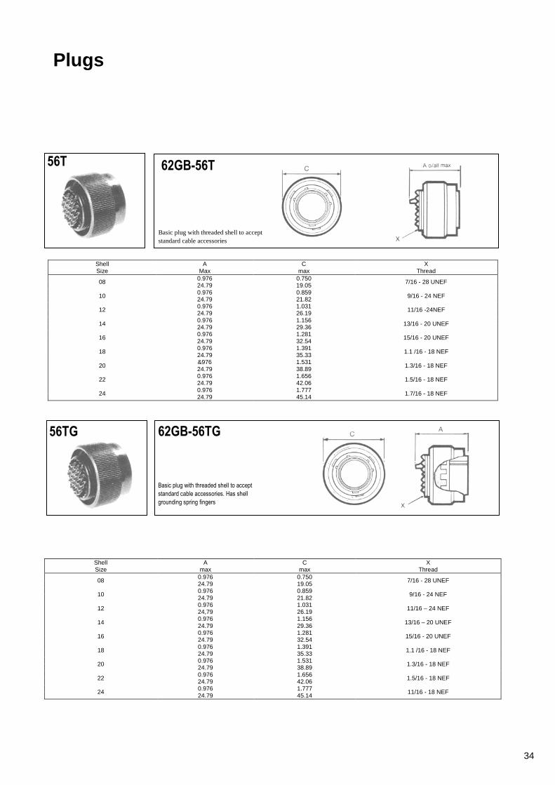
Plugs
56T 62GB-56T
Basic plug with threaded shell to accept standard cable accessories
Shell Size
A Max
C max
X Thread
08 0.976 0.750 7/16 - 28 UNEF 24.79 19.05
10 0.976 0.859 9/16 - 24 NEF 24.79 21.82
12 0.976 1.031 11/16 -24NEF 24.79 26.19
14 0.976 1.156 13/16 - 20 UNEF 24.79 29.36
16 0.976 1.281 15/16 - 20 UNEF 24.79 32.54
18 0.976 1.391 1.1 /16 - 18 NEF 24.79 35.33
20 &976 1.531
1.3/16 - 18 NEF 24.79 38.89
22 0.976 1.656 1.5/16 - 18 NEF 24.79 42.06
24 0.976 1.777 1.7/16 - 18 NEF 24.79 45.14
56TG 62GB-56TG
Basic plug with threaded shell to accept
standard cable accessories. Has shell
grounding spring fingers
Shell Size
A max
C max
X Thread
08 0.976 0.750 7/16 - 28 UNEF 24.79 19.05
10 0.976 0.859 9/16 - 24 NEF 24.79 21.82
12 0.976 1.031 11/16 – 24 NEF 24,79 26.19
14 0.976 1.156
13/16 – 20 UNEF 24.79 29.36
16 0.976 1.281 15/16 - 20 UNEF 24.79 32.54
18 0.976 1.391 1.1 /16 - 18 NEF 24.79 35.33
20 0.976 1.531 1.3/16 - 18 NEF 24.79 38.89
22 0.976 1.656 1.5/16 - 18 NEF 24.79 42.06
24 0.976 1.777 11/16 - 18 NEF 24.79 45.14
34

Plugs
16A 62GB-1 6A
Plug with general duty back shell.
No grommet provided.
Shell Size
A max
C max
G max
M Thread
08 1.614 0.750 0.561 1/2 - 28 UNEF 41.00 19.05 14.25
10 1.614 O.859 0,686 5/8 - 24 NEF 41.00 21.82 17.43
12 1.614 1.031 0.811
3/4 - 20 UNEF 41.00 26.19 20.60
14 1.614 1,156 0.936 7/8 - 20 UNEF 41.00 29.36 23.78
16 1.614 1.281 1.061 1 - 20 UNEF 41.00 32.54 26.95
18 1.614 1.391 1.186 1.3/16 -18 NEF 41.00 35.33 30.13
20 1.614 1.531 1.311 1.3/16 - 18 NEF 41.00 38-89 33.30
22 1.614 1.656 1.436 1.7/16 - 18 NEF 41.00 42.06 36.75
24 1.658 1.777 1.561 1.7116 - 18 NEF 42.11 45.14 39.65
56T 62GB-56T(046)
Box-mounting plug. Available for shell size 16:
other sizes to special order. Cable accessories
cannot be fitted.
Shell Size
A max
J max
K L
16 1.042 1.317 1,000
6.32 NC 26.47 33.45 25.40
20 1.042 1.625 1.250 6.32 NC 26.47 41.28 31.75
22 1.042 1.625 1.250 6.32 NC 26.47 41.28 31.75
35

16E 62GB-16E MIL - C26482 MS3116E
Plug with grommet and grommet
nut
Shell Size
A max
C max
G max
08 1.281 0.750 0.561 32.54 1.05 14.25
10 1.281 0.859 0.686 32.54 21.82 17.431
12 1.281 1.031 0.811 32.54 26.19 20.60
14 1.281 1.156 0.936 I 32.54 29.36 23.78
16 1.281 1.281 1.061 32.54 32.54 26.95
18 1.281 1.391 1.186 32.54 35.33 30.13
20 1.281 1.531 1 .311 32.54 38.89 33.30
22 1.281 1.656 1.436 32.54 42.06 36.75
24 1.281 1.777 1.561 32.54 45.14 39.65
16F 62GB-16F MIL - C26482 MS3116F
Plug with grommet and grommet nut fitted with
integral strain relief clamp.
Shell Size
A max
C dia
max
G dia
max
H ± 0.005 (± 0.13)
08 1.752 0.750 0.828 0.156 44.50 19.05 21.03 3.96
10 1.752 0.859 0.891 0.188 44.50 21.82 22.63 4.78
12 1.752 1.031 1.016 0.312 44.50 26.19 25.81 7.93
14 1.726 1.156 1.141 0.375 43.84 29.36 28.97 9.53
16 1.866 1.281 1.203 0.500 47.40 32.54 30.56 12.70
18 1.866 1.391 1.426 0.625 47.40 35.33 36.22 15.88
20 2.040 1.531 1.426 0.625 51 .81 38.89 36.22 15.88
22 2.040 1.656 1.567 0.750 51.81 42.06 39.80 19.05
24 2.178 1.777 1.735 0.800 55.32 45.14 44.07 20.32
Plugs
36
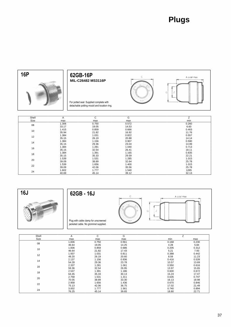
16P 62GB-16P
MIL-C26482 MS3116P
For potted seal. Supplied complete with
detachable potting mould and location ring.
Shell Size
A max
C max
G max
Z min
08 1.306 0.750 0.572 0.260 33.17 19.05 14.53 6.60
10 1.415 0.859 0.666 0.463 35.94 21.82 16.92 11.76
12 1.384 1.031 0.822 0.557 35.15 26.19 20.88 14.14
14 1.384 1.156 0.907 0.590 35.15 29.36 23.04 14.99
16 1.384 1.281 1.040 0.713 35.15 32.54 26.41 18.11
18 1.384 1.391 1.165 0.835 35.15 35.33 29.59 22.21
20 1.539 1.531 1.285 1.015 39.09 38.89 32.64 25.78
22 1.539 1.656 1.400 1.015 39.09 42.06 35.56 25.78
24 1.602 1.777 1.540 1265 40.69 45.14 39.12 32.13
16J 62GB - 16J
Plug with cable clamp for unscreened
jacketed cable. No grommet supplied.
Shell Size
A max
C max
G max
Z min max
08 1.836 0.750 0.561 0.168 0.230 46.64 19.05 14.25 4.28 5.84
10 1.836 0.859 0.686 0.205 0.312 46.64 21.82 17.43 5.21 7.93
12 1.937 1.031 0.811 0.388 0.442 49.20 26.19 20.60 8.59 11.23
14 2.137 1.156 0.936 0.416 0.539 54.28 29.36 23.78 10.57 13.69
16 2.337 1.281 1.061 0.550 0.616 59.36 32.54 26.95 13.97 15.65
18 2.537 1.391 1.186 0.600 0.672 64.45 35.33 30.13 15.24 17.07
20 2.758 1.531 1.311 0.635 0.747 70.05 38.89 33.30 16.13 18.98
22 2.958 1.656 1.436 0.670 0.846 75.13 42.06 36.75 17.02 21.49
24 3.002 1.777 1.561 0.740 0.894 76.25 45.14 39.65 18.80 22.71
Plugs
37

5039 62GB-5039-10 SD/C 235 155 - X SD/C 235 156 - X
Low profile, solder termination plug with 90°
screened cable outlet.
Shell Size
A max
B max
C max
D max
10 1.473 0.500 0.980 1.500 37.41 12.70 24.89 38.10
5055 62GB-5055-10 SD/2 235 193 - X
Low profile solder termination plug with size 12
90°screened cable outlet.
Shell A B C D Size max max max max 10 1.800 0.655 0.980 1.800
45.72 16.64 24.89 45.72
5056 62GB-5056-10
Audio plug with solder termination
Shell Size
A max
B max
C max
10 2.375 0.979 / 0.969 0.310 60.33 24.87 / 24.61 7.87
Plugs
38
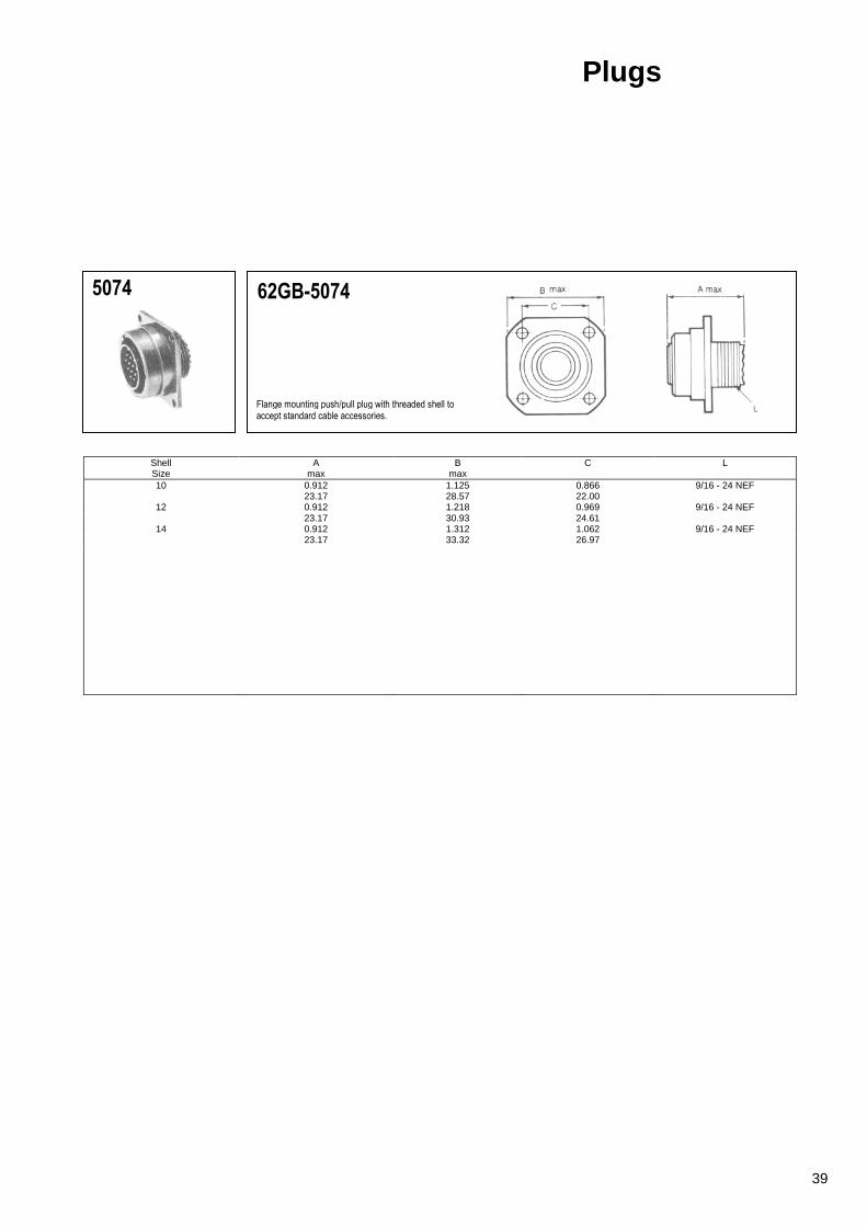
5074 62GB-5074
Flange mounting push/pull plug with threaded shell to accept standard cable accessories.
Shell Size
A max
B max
C L
10 0.912 1.125 0.866 9/16 - 24 NEF 23.17 28.57 22.00
12 0.912 1.218 0.969 9/16 - 24 NEF 23.17 30.93 24.61
14 0.912 1.312 1.062 9/16 - 24 NEF 23.17 33.32 26.97
Plugs
39
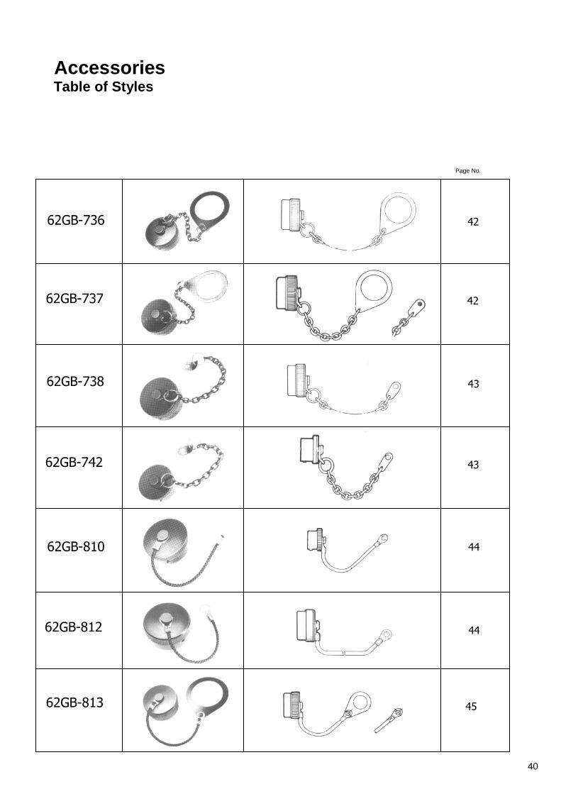
Accessories Table of Styles
62GB-736
62GB-737
62GB-738
62GB-742
62GB-810
62GB-812
62GB-813
Page No.
42
42
43
43
44
44
45
40

Accessories Table of Styles
62GB-814
62GB-997
62GB-998
62GB-1069
62GB-1070
62GB-760
Page No.
45
46
46
47
47
48
41
Accessories
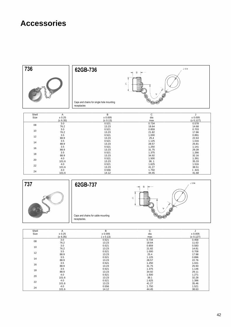
736 62GB-736
Caps and chains for single hole mounting
receptacles
Shell Size
A ± 0.25
(± 6.35)
B ± 0.005 (± 0.13)
C dia
max
J ± 0.005
(± 0,127)
08 3.0 0.521 0.734 0.578
76.2 13.23 18.64 14.68
10 3.0 0.521 0.859 0.703 76.2 13.23 21.82 17.86
12 3.5 0.521 1.000 0.891 88.9 13.23 25.4 22.63
14 3.5 0.521 1.125 1.016 88.9 13.23 28.57 25.81
16 3.5 0.521 1.250 1.141 88.9 13.23 31.75 29.39
18 3.5 0.521 1.375 1.266 88.9 13.23 34.92 32.16
20 4.0 0.521 1.500 1.391 101.6 13.23 38, 1 35.33
22 4.0 0.521 1.625 1.516
101.6 13.23 41.27 38.51
24 4.0 0.556 1.750 1 .641 101.6 14.12 44.45 41.68
737 62GB-737
Caps and chains for cable mounting
receptacles.
Shell Size
A ± 0.25
(± 6.35)
B ± 0.005 ( ± 0.13)
C dia
max
J ± 0.005
(± 0.127)
08 3.0 0.521 0.734 0.458 76.2 13.23 18.64 11.63
10 3.0 0.521 0.859 0.583 76.2 13.23 21.82 14.81
12 3.5 0.521 1.000 0.708 88.9 13.23 25.4 17.98
14 3.5 0.521 1.125 0.896 88.9 13.23 28.57 22.76
16 3.5 0.521 1.250 1.021
88.9 13.23 31.75 25.93
18 3.5 0.521 1.375 1.146 88.9 13.23 34.92 29.11
20 4.0 0.521 1.500 1.271 101.6 13.23 38.1 32.28
22 4.0 0.521 1.625 1.396 101.6 13.23 41.27 35.46
24 4.0 0.556 1.750 1.521 101.6 14.12 44.45 38.63
42

Accessories
738 62GB-738
Caps and chains for flange mounting
receptacles.
Shell Size
A ± 0.25 (± 6.35)
B ± 0.005 (± 0.13)
C dia
max
J ± 0.005
(± 0.127)
08 3.0 0.521 0.734 0.125 76.2 13.23 18.64 3.18
10 3.0 0.521 0.859 0.125 76.2 13.23 21.82 3.18
12 3.5 0.521 1.000 0.125 88.9 13.23 25.4 3.18
14 3.5 0.521 1.125 0.125 88.9 13.23 28.57 3.18
16 3.5 0.521 1.250 0.125 88.9 13.23 31. 75 3.18
18 3.5 0.521 1.375 0.125
88.9 13.23 34.92 3.18
20 4.0 0.521 1.500 0.125 101.6 13.23 38.1 3.18
22 4.0 0.521 1.625 0.125 101.6 13.23 41.27 3.18
24 4.0 0.556 1.750 0.152 101.6 14.12 44.45 3.86
742 62GB-742
Caps and chains for plugs.
Shell Size
A ± 0.25
( ± 6.35)
B ± 0.005 ( ± 0.13)
C dia
max
J ± 0.005
( ± 0.127)
08 3.0 0.522 0.719 0.125 76.2 13.25 18.26 3.18
10 3.0 0.522 0.844 0.125 76.2 13.25 21.43 3.18
12 3.5 0.522 1.000 0.125 88.9 13.25 25.4 3.18
14 3.5 0.522 1.125 0.125 88.9 13.25 28.57 3.18
16 3.5 0.522 1.250 0.125 88.9 13.25 31.75 3.18
18 3.5 0.522 1.357 0.125
88.9 13.25 34.92 3.18
20 4.0 0.584 1.500 0.125 101.6 14.83 38.1 3.18
22 4.0 0.584 1.625 0.125 101.6 14.83 41.27 3.18
24 4.0 0.617 1.750 0.152 101.6 15.67 44.45 3.86
43

Accessories
810 62GB-810
Caps and cords for plugs
Shell Size
A ± 0.25
(± 6.35)
B ± 0.005 (± 0.13)
C dia
max
J ± 0.003 (± 0.08)
08 3.0 0.522 0.719 0.145 76.2 13.25 18.26 3.68
10 3.0 0.522 0.844 3.685 76.2 13.25 21.43 3.68
12 3.5 0.522 1.000 0.145 88.9 13.25 25.4 3.68
14 3.5 0.522 1.125 0.145
88.9 13.25 28.57 3.68
16 3.5 0.522 1.250 0.145 88.9 13.25 31.75 3.68
18 3.5 88.9
0.522 13.25
1.375 34.93
0.145 3.68
20 4.0 0.584 1.500 0.145 101.6 14.83 38.1 3.68
22 4.0 0.584 1.625 0.145 101.6 14.83 41.27 3.68
24 4.0 0.617 1.750 0.171 101.6 15.67 44.45 4.34
812 62GB-812
Caps and cords for flange mounting
receptacles.
Shell Size
A ± 0.25
(± 6.35)
B ± 0.005 (± 0.13)
C dia
max
J ± 0.003 (± 0.08)
08 3.0 0.521 0.734 0.145 76.2 13.23 18.64 3.68
10 3.0 0.521 0.859 0.145 76.2 13.23 21.82 3.68
12 3.5 0 521 1 .000 0.145 88.9 13.23 25.4 3.68
14 3.5 0.521 1.125 0.145 88.9 13.23 28.57 3.68
16 3.5 0.521 1 .250 0.145 88.9 13.23 31.75 3.68
18 3.5 0.521 1.375 0.145 88.9 13.23. 34.92 3.68
20 4.0 0.521 1.500 0.145
101.6 13.23 38.1 3.68
22 4,0 0.521 1.625 0.145 101.6 13.23 41.27 3.68
24 4.0 0.556 1.750 0.171 101 .6 14.12 44.45 4.34
44

Accessories
813 62GB-813
Caps and cords for single hole mounting
receptacles.
Shell Size
A ± 0.25
(± 6.35)
B ± 0.005 (± 0.13)
C max
J + 0.010 (+ 0.25)
08 3.0 0.521 0.734 0.578 76.2 13.23 18.64 14.68
10 3.0 0.521 0.859 0.703 76.2 13.23 21.82 17.86
12 3.5 0.521 1.000 0.891 88.9 13.23 25.4 22.63
14 3.5 0.521 1.125 1.016 88.9 13.23 28.57 25.81
16 3.5 0.521 1.250 1.141 88.9 13.23 31.75 29.39
18 3.5 0.521 1.375 1.266 88.9 13.23 34.92 32.16
20 4.0 0.521 1.500 1.391
101.0 13.23 38.1 35.33
22 4.0 0.521 1.625 1.516 101.6 13.23 41.27 38.56
24 4.0 0.556 1.750 1.641 101.6 14.12 44.45 41.68
814 62GB-814
Caps and cords for cable mounting receptacles.
Shell Size
A ± 0.25
( ± 6.35)
B ± 0.005 ( ± 0.13)
C max
J +0.010
( + 0.25)
08 3.0 0.521 0.734 0.453 76.2 13.23 18.64 11.50
10 3.0 0.521 0.859 0.578 76.2 13.23 21.82 14.64
12 3.5 0.521 1.000 0.703 88.9 13.23 25.4 17.85
14 3.5 0.521 1.125 0.891 88.9 13.23 28.57 22.63
16 3.5 0.521 1.250 1.016 88.9 13.23 31.75 25.80
18 3.5 0.521 1.375 1.141 88.9 13.23 34.92 28.98
20 4.0 0.521 1.500 1.266
101.6 13.23 38.1 32.15
22 4.0 0.521 1.625 1.391 101.6 13.23 41.27 35.33
24 4.0 0.556 1.750 1.516 101.6 14.12 44.45 38.50
45
Accessories
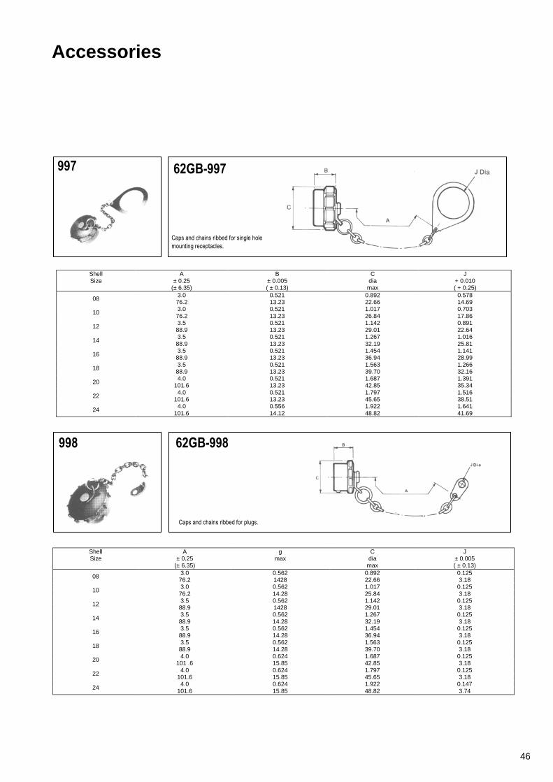
997 62GB-997
Caps and chains ribbed for single hole
mounting receptacles.
Shell Size
A ± 0.25
(± 6.35)
B ± 0.005 ( ± 0.13)
C dia
max
J + 0.010 ( + 0.25)
08 3.0 0.521 0.892 0.578 76.2 13.23 22.66 14.69
10 3.0 0.521 1.017 0.703 76.2 13.23 26.84 17.86
12 3.5 0.521 1.142 0.891 88.9 13.23 29.01 22.64
14 3.5 0.521 1.267 1.016
88.9 13.23 32.19 25.81
16 3.5 0.521 1.454 1.141 88.9 13.23 36.94 28.99
18 3.5 0.521 1.563 1.266 88.9 13.23 39.70 32.16
20 4.0 0.521 1.687 1.391 101.6 13.23 42.85 35.34
22 4.0 0.521 1.797 1.516 101.6 13.23 45.65 38.51
24 4.0 0.556 1.922 1.641 101.6 14.12 48.82 41.69
998 62GB-998
Caps and chains ribbed for plugs.
Shell Size
A ± 0.25
(± 6.35)
g max
C dia
max
J ± 0.005 ( ± 0.13)
08 3.0 0.562 0.892 0.125 76.2 1428 22.66 3.18
10 3.0 0.562 1.017 0.125 76.2 14.28 25.84 3.18
12 3.5 0.562 1.142 0.125 88.9 1428 29.01 3.18
14 3.5 0.562 1.267 0.125
88.9 14.28 32.19 3.18
16 3.5 0.562 1.454 0.125 88.9 14.28 36.94 3.18
18 3.5 0.562 1.563 0.125 88.9 14.28 39.70 3.18
20 4.0 0.624 1.687 0.125 101 .6 15.85 42.85 3.18
22 4.0 0.624 1.797 0.125 101.6 15.85 45.65 3.18
24 4.0 0.624 1.922 0.147
101.6 15.85 48.82 3.74
46

Accessories
1069 62GB-1069
Caps and cords ribbed for single hole
mounting receptacles.
Shell Size
A ± 0.25
(± 6.35)
B ±.0.005 ( ± 0.13)
C dia
max
J + 0.010 ( + 0.25)
08 3.0 0.521 0.892 0.578
76.2 13.23 22.66 14.69
10 8.0 0.521 1.017 0.703 76.2 13.23 26.84 17.86
12 3.5 0.521 1.142 0.891 88.9 13.23 29.01 22.64
14 3.5 0.521 1.267 1.016 88.9 13.23 32.19 25.81
16 3.5 0.521 1.454 1.141 88.9 13.23 36.94 28.99
18 3.5 0.521 1.563 1.266 88.9 13.23 39.70 32.16
20 4.0 0.521 1.687 1.391 101.6 13.23 42.85 35.34
22 4.0 0.521 1.797 1.516
101.6 13.23 45.65 38.51
24 4.0 0.556 1.922 1.641 101.6 14.12 48.82 41.686
1070 62GB-1070
Caps and cords ribbed for flange mounting
receptacles.
Shell Size
A ± 0.25
(± 6.35)
B ± 0.005 ( ± 0.13)
C Dia max
J ± 0.005 (± 0.13)
08 3.0 0.521 0.892 0.117 76.2 13.23 22.66 3.03
10 3.0 0.521 1.017 0.119 76.2 13.23 22.66 3.03
12 3.5 0.521 1.142 0.119 88.9 13.23 29.01 3.03
14 3.5 0.521 1.267 0.119
88.9 13.23 32.19 3.03
16 3.5 0.521 1.454 0.119 88.9 13.23 36.94 3 03
18 3.5 0.521 1.563 0.119 88.9 13.23 39.70 3.03
20 4.0 0.521 1.687 0.119 101.6 13.23 42.85 3.03
22 4.0 0.521 1.797 0.119 101.6 13.23 45.65 3.03
24 4.0 0.556 1.922 0.147 101.6 14.12 48.82 3.74
47

Accessories
760 62GB-760
Flange mounting gasket for box mounting and hermetic receptacles.
Shell Size
0 ± 0.010
(± 0.254)
E ± 0.010
(± 0.254)
F ± 0.008 (± 0.20)
G + 0.010
(+ 0.254)
H
08 0.812 0.594 0.508 0.130 0.042 / 0.016 20.62 15.08 12.90 3.30 1.06 / 0.40
10 0.938 0.719 0.633 0.130 0.042 / 0.016 23.82 18.26 16.07 3.30 1.06 / 0.40
12 1.031 0.813 0.758 0.130 0.042 / 0.016 26.18 20.65 19.25 3.30 1.06 / 0.40
14 1.125 0.906 0.883 0.130 0.042 / 0.016 28.57 23.01 22.42 3.30 1.06 / 0.40
16 1.219 0.969 1.008 0.130 0.042 / 0.016 30.96 24.61 25.60 3.30 1.06 / 0.40
18 1.312 1.063 1.133 0.130 0.042 / 0.016 33.32 27.00 28.77 3.30 1.06 / 0.40
20 1.438 1.156 1.258 0.130 0.042 / 0.016 36.52 29.36 31.95 3.30 1.06 / 0.40
22 1.563 1.250 1.383 0.130 0.042 / 0.016 39.70 31.75 35.13 3.30 1.06 / 0.40
24 1.688 1.375 1.508 0.156 0.042 / 0.016 42.87 34.92 38.30 3.96 1.06 / 0.40
48

Cable Accessories Table of Styles
62GB-584
62GB-585
62GB-586
62GB-587
62GB-711
62GB-720
62GB-776
Page No.
51
51
52
52
53
53
54
49

Cable Accessories Table of Styles
62GB-1225
62GB-5028
Page No.
54
55
50

Cable Accessories
584 62GB - 584 - XX - XXS or P
Grommet seal and nut. Provides an
environmental seal for the exposed solder
buckets in the open back class T shells. Suffix XX - XXS or P enables grommet to be matched to the insert arrangement.
Shell Size
A G max
08 0.545 0.561 13.84 14.25
10 0.545 0.686 13.84 17.43
12 0.545 0.811 13.84 20.60
14 0.545 0.936 13.84 23.78
16 0.545 1.061 13.84 26.95
18 0.545 1.186 13.84 30.13
20 0.545 1.311 13.84 33.30
22 0.545 1.436 13.84 36.75
24 0.501 1.561 12.73 39.65
585 62G B - 585 - XX - XXS or P A2103
Grommet and nut with strain relief clamp. The
clamp prevents the flexing of the wires in the
immediate vicinity of the risers, so avoiding
the risk of leaks. Suffix XX - XXS or P enables grommet to be matched to the insert arrangement.
Shell Sine
A max
G max
max
08 0.991 0 828 0.161 25.17 21.03 4.09
10 0.991 0.891 0.193 25.17 22.63 4.90
12 0 991 1.016 0.317 25.17 25.81 8.05
14 0.965 1.141 0.380 24.51 28.98 9.65
16 1.105 1.203 0.505 28.07 30.56 12.83
18 1.105 1.426 0.630 28.07 36.22 16.00
20 1.285 1.426 0.630 32.64 36.22 16.00
22 1.285 1.567 0.755 32.64 39.80 19.18
24 1.373 1.735 0.805 34.88 44.07 20.45
51
Cable Accessories
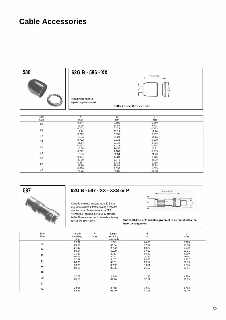
586 62G B - 586 - XX
Potting mould and ring,
supplied together as a set.
Suffix XX specifies shell size.
Shell Size
A max
G max
Z min
08 0.644 0.585 0.260 16.36 14.85 6.60
10 0.753 0.679 0.463 19.13 17.24 11.76
12 0.722 0.835 0.557 18.34 21.20 14.14
14 0.722 0.913 0.590 18.34 23.19 14.98
16 0.722 1.038 0.713 18.34 26.36 18.11
18 0.722 1.163 0.835 18.34 29.54 21.20
20 0 877 1.288 1.015 22 30 32.71 25.78
22 0.877 1.413 1.015 22.30 35.89 25.78
24 0.896 1.538 1.263 22.76 39.06 32.08
587 62G B - 587 - XX - XXS or P
Clamp for screened jacketed cable. 62 Series
only with grommet. Effective sealing is provided
over the range of cables covered by DEF
10(Pattern C) and DEF STAN 61-12 port (see
table). These are supplied to separate order only
for use with style T shells. Suffix XX-XXS or P enables grommet to be matched to the insert arrangement.
Shell Size
length Including
plug
A Max
length Including
receptacle
B max
G max
08 2.732 2.742 0.676 0.775 69.39 69.64 17.17 19.68
10 2.742 2.752 0.676 0.902 69.64 69.90 17.17 22.91
12 3.152 3162 0.812 1.030 80.06 80.31 20.62 2616
14 3.152 3.162 0.926 1.157 80.06 80.31 23.52 29.39
16 3.272 3 282 1.051 1.284 83.10 83.36 26.67 32.61
18 - - - - - - - -
20 3.272 3.345 1.280 1.539 83.10 84.96 32.51 39.09
22 - - - - - - - -
24 3.696 3.768 1.620 1.783 93.87 95.70 41.15 45.29
52

Cable Accessories
711 62G B - 711 - XX - XXS or P
Grommet and nut with right angled strain
relief clamp. The clamp prevents flexing of
the wires in the immediate vicinity of the
risers, so avoiding the risk of leaks (these
are supplied to separate order only for use
with style T shells).
Suffix XX - XXS or P enables grommet to be matched to the insert arrangement.
Shell Size
A max
G max
H ± 0.005 ± 0.13
Q max
08 1.5/32 0.828 0.161 0.733 21.03 4.09 18.62
10 1.3/16 0.891 0.193 0.795 22.63 4.90 20.19
12 1.7/32 1.016 0.317 0.858 25.81 8.05 21.79
14 1.1/4 1.141 0.380 0.915 28.98 9.65 23.24
16 1.5/16 1.203 0.505 1.010 30.56 12.83 25.65
18 1.3/8 1.426 0.630 1.070 36.22 16.00 27.18
20 1.3/8 1.426 0 630 1.140
36.22 16.00 28.96
22 1.29/64 1.567 0.755 1.170 39.80 19.18 29.72
24 1.15/32 1.735 0.805 1.260 44.07 20.45 32.00
720 62G B - 720 - XX
Clamp for unscreened jacketed cable. No
grommet is supplied, for use with 50T, 51T
and 56T styles. Suffix XX specifies shell size.
Shell Size
A max
G max
Z closed
Z free
08 1.085 0.561 0 168 0 230 27.56 14.25 4.28 5.84
10 1.060 0.686 0.205 0.312 26.92 17.43 5.21 7.93
12 1.160 0.81 1 0 338 0.442 29.46 20.60 8.59 1 1.23
14 1.360 0.936 0.416 0.539 1 34.54 23.78 10.57 13.69
16 1.585 1.061 0.550 0.616 40.26 26.95 13.97 15.65
18 1.785 1.186 0.600 0.672 45.34 30.13 15.24 17.57
20 1.981 1.311 0.635 0.747 50.32 33 30 16.13 18.98
22 2.181 1.436 0.670 0.846 55.39 36.75 17.02 21.49
24 2.216 1.561 0.740 0.894 56.28 39.65 18.80 22.71
53

Cable Accessories
776 62GB - 776
General duty shell to accept conduit, AN
3057 or MS 3057 A cable clamps and heat
shrink sleeves.
Shell Size
A max M
Thread
08 0.937 1/2 - 28 UNEF 23.80
10 0.937 5/8 - 24 NEF 23.80
12 0.937 3/4 - 20 UNEF 23.80
14 0.937 7/8 – 20 UNEF 23.80
16 0.937 1 - 20 UNEF 23.80
18 0.937 1.3/16 - 18 NEF 23.80
20 0.937 1.3/16 - 18 NEF 23.80
22 0.937 1.7/16 - 18 NEF 23.80
24 0.937 1.7/16 - 18 NEF 23.80
1225 62GB - 1225
900 clamp for screened jacketed cable. These
are supplied to separate order only for use with
style T shells.
Shell Size
A max
B max
C max
D max
08 0.942 0.821 1.160 0.636 23.93 20.85 29.46 16.15
10 0.883 0.821 1.160 0.636 22.43 20.85 29.46 16.15
12 0.704 0.821 1.160 0.636 17,88 20.85 29.46 16.15
14 1.119 0.937 1.160 0.636 28.42 23.80 29.46 16.15
54

Cable Accessories
5028 62G B - 5028 - XX - XXS or P
75% Clamp for screened jacketed cable with
grommet. Effective sealing is provided over the
range of cables covered by DEF 10 (Pattern C)
and DEF STAN 61 - 12 part 5 (see table).
These are supplied to separate order only and
are intended for use with style T shells.
Suffix XX-XXS or P enables grommet to be matched to the insert arrangement.
Shell Size
length including
receptacle
A Max
length including
plug
B max
G max
max
08 2.416 2.375 0.676 0.775 1.750 61.37 60.24 17.17 19.68 44.45
10 2.573 2.532 0.676 0.902 1.875 65.35 64.39 17.17 22.91 47.63
12 2.666 2.625 0.812 1.030 2.125 67.72 66.68 20.62 26.16 53.98
14 2.760 2.719 0.926 1.157 2.125 70.10 69.04 23.52 29.39 53.98
16 2.790 2.750 1.051 1.284 2.062 70.87 69.80 26.70 32.61 52.38
18 - - - - - - - - - -
20 3.312 3.250 1.280 1 539 2.062 84.13 82.55 32.51 39 09 52.38
22 - - - - - - - - - -
24 3.500 3.375 1.620 1.783 2.187 88.90 85.73 41.15 45.29 55.55
55

Insert Orientations
Normal position with pin contacts
Alternative position of insert with socket contacts (∅ counter clockwise)
Each diagram shows mating face of insert.
Alternate position of insert with pin contacts (∅ clockwise)
Orientation ∅ (degrees) Insert
Arrangement Normal W X Y Z
8-2 0 58 122 - -
8-3 0 60 210 - -
8-33 0 90 - - -
8-4 0 45 - - -
8-98 0 - - - -
10-2 0 - - - -
10-6 0 90 - - -
10-7 0 - - - -
12-3 0 - - 180 -
12-10 0 60 155 270 295
14-5 0 40 92 184 273
14-12 0 43 90 - -
14-15 0 17 110 155 234
14-19 0 30 165 315 -
16-18 0 54 152 180 331
16-23 0 158 270 - -
16-26 0 60 - 275 338
18-11 0 62 119 241 340
18-32 0 85 138 222 265
20-16 0 238 318 333 347
20-41 0 45 126 225 -
22-21 0 16 135 175 349
22-55 0 30 142 226 314
24-61 0 90 180 270 324
56

Key/Keyway Orientations
Datum is always taken from major key or keyway. In receptacles the major keyway always remains fixed in relation to the mounting flange. For the A',B,C,D',E and F orientations, the three bayonet locations and associated minor keyways are rotated complete, in accordance with the table below.
N.B.- The accompanying diagram shows a receptacle shell, with keyways. Corresponding key orientations for a mating plug shell are therefore always clockwise.
Shell Size Values for ∝
(degrees) Values for θ
(degrees) Values for β
(degrees)
N A B C D E F N A B C D E F N A B C D E F
8 105 92 - - 118 118 82 35 35 - - 35 30 50 75 75' - - 75 100 75
10 105 95 85 125 115 115 85 35 35 35 35 35 30 50 75 75 75 75 75 100 75
12 105 97 89 121 113 115 85 35 35 35 35 35 30 50 75 75 75 75 75 100 75
14 105 98 91 119 112 75 120 35 35 35 35 35 30 50 75 75 75 75 75 100 75
16 105 99 93 117 111 75 120 35 35 35 35 35 30 50 75 75 75 75 75 100 75
18 105 100 95 115 110 75 120 35 35 35 35 35 30 50 75 75 75 75 75 100 75
20 105 100 95 115 110 75 120 35 35 35 35 35 30 50 75 75 75 75 75 100 75
22 105 101 97 113 109 7S 120 35 35 35 35 35 30 50 75 75 75 100 75 75 75
24 105 101 97 113 109 75 120 35 35 35 35 35 30 50 75 75 75 75 75 100 75
Shell Size
Values for ϕ (degrees) Orientation
Values for ω (degrees) Orientation
N A B C D E F N A B C D E F
8 50 50 50 50 50 30 45 60 47 - - 73 73 47
10 50 50 50 50 50 30 45 60 50 40 80 70 70 50
12 50 50 50 50 50 30 45 60 52 44 76 68 70 50
14 50 50 50 50 50 30 35 60 53 46 74 67 30 75
16 50 50 50 50 50 30 35 60 54 48 72 66 30 75
18 50 50 50 50 50 30 35 60 55 50 70 65 30 75
20 50 50 50 50 50 30 35 60 55 50 70 65 30 75
22 50 50 50 50 50 30 35 60 56 52 68 64 30 75
24 50 50 50 50 50 30 35 60 56 52 68 64 30 75
57

Assembly Instructions
for Amphenol straight S.J. clamps 62GB-587 for internally and externally screened and unscreened cables to DEF 10 and DEF STAN 61-12 Part 5.
Internally Screened Jacketed Cable ‘Type C’ Cable and Wire Stripping
Strip the outer P.V.C. Jacket of the cable back to dim `A' to expose the internal braid. Trim the braid back to within 19.05mm (0.75 in) of P.V.C. jacket and fold back `B'.
A Dimension
Size mm in 08 34.93 1.375 10 36.51 1.437
12 8 14 41.27 1.625 16 & 20 44.45 1.75
24 49.21 1.937
Strip 5.3mm (0.210 in) to 6.1 mm (0.240 in) of insulation from each wire to expose centre conductor. Tin the ends. If ends fray twist them back to their original lay before tinning.
Initial Assembly Slide onto the cable the following items in this order (1) Nut (2) Washer (3) Gasket (4) Braid Clamp and (5) Clamp Body (6) Grommet.
Solder Connection to Contacts Insert the individual wires into the appropriate grommet holes. At the same time, slide the grommet back as far as possible until the tinned ends of the centre conductors are far enough out of the grommet to permit soldering to the contacts. Insert the tinned ends of wires into the appropriate contacts in 62 series connector and solder into place. Slide the grommet forward over the wired contacts and press firmly into rear of connector shell and against rear face of insert.
58

Assembly Instructions
Externally Screened Jacketed Cable Types ‘B’ & `Q’
Cable and Wire Stripping Strip the outer braid and internal P.V.C. jacket of the cable back to dim ‘A’
A Dimension
Size mm in 08 33.32 1.312 10 34.93 1.375
12 & 14 39.7 1.563 16 & 20 42.85 1.687
24 47.63 1.875
Strip 5.3mm (0.210 in) to 6.1 mm (0.240 in) of insulation from each wire to expose centre conductor. Tin the ends. If ends fray twist them back to their original lay before tinning.
Initial Assembly Slide onto the cable the following items in this order (1) Nut (2) Washer (3) Male Braid Clamp Convolute Screen (See B) as far as possible, and slide on items (4) Female Braid Clamp (5) Gasket and (6) Clamp Body (7) Grommet
Solder Connection to Contacts Insert the individual wires into the appropriate grommet holes. At the same time, slide the grommet back as far as possible, until the tinned ends of the centre conductors are far enough out of the grommet to permit soldering to the contacts. Insert the tinned ends of wires into the appropriate contacts in 62 series connector and solder into place. Slide the grommet forward over the wired contacts and press firmly into the rear of connector shell and against rear face of insert.
Unscreened Jacketed Cables Type `A' All procedures concerning this type of cable to be as for internally screened jacketed cable, but all references to screen (Braid) to be disregarded.
59

Assembly Instructions
for Amphenol angled S.J. clamps 62GB-5028 for internally and externally screened and unscreened cables to DEF 10 and DEF STAN 61-12 Part 5.
Internally Screened Jacketed Cable Type `C’
Cable and Wire Stripping Strip the outer P.V.C. jacket of the cable back to dim `A' to expose the internal braid. Trim the braid back to within 19.05mm (0.75 in) of P.V.C. jacket and fold back `B'.
A Dimension
Size mm in
08 58.15 2.89 10,12,14 66.68 2.625
16 69.85 2.75 20 88.9 3.50 24 95.25 3.75
Strip 5.3mm (0.210 in) to 6.1 mm (0.240 in) of insulation from each wire to expose centre conductor. Tin the ends. If ends fray, twist them back to their original lay before tinning.
Initial Assembly Slide onto the cable the following items in this order (1) Nut (2) Washer (3) Gasket (4) Braid Clamp (5) 75o Angled Body (6) Grommet.
Solder Connection to Contacts Insert the individual wires into the appropriate grommet holes. At the same time, slide the grommet back as far as possible, until the tinned ends of the centre conductors are far enough out of the grommet to permit soldering to the contacts. Insert the tinned ends of wires into the appropriate contacts in 62 series connector and solder into place. Slide the grommet forward over the wired contacts and press firmly into the rear of the connector shell and against rear face of insert.
60

Assembly Instructions
Solder Connection to Contacts Insert the individual wires into the appropriate grommet holes. At the same time, slide the grommet back as far as possible, until the tinned ends of the centre conductors are far enough out of the grommet to permit soldering to the contacts. Insert the tinned ends of wires into the appropriate contacts in 62 series connector and solder into place. Slide the grommet forward over the wired contacts and press firmly into the rear of connector shell and against rear face of insert.
A Dimension
Size mm in
08 58.15 2.89 10,12,14 66.68 2.625
16 69.85 2.75 20 88.9 3.50 24 95.25 3.75
Externally Screened Jacketed Cables
Type `B' & `Q'
Cable and Wire Stripping
Strip the outer braid and internal P.V.C. jacket of the
cable back to dim `A'.
Strip 5.3mm (0.210 in) to 6.1 mm (0.240 in) of insulation from each wire to expose centre conductor Tin the ends. If ends fray, twist them back to their original lay before tinning.
Initial Assembly Slide onto the cable the following items in this order:(1) Nut (2) Washer (3) Male Braid Clamp - Convolute Screen (See B) as far as possible and slide on items:(4) Female Braid Clamp (5) Gasket (6) 75o Right Angled Body (7) Grommet.
Unscreened Jacketed Cables Type `A' All procedures concerning this type of cable to be as for internally screened jacketed cable, but all references to screen (Braid) to be disregarded.
61

Assembly Instructions
Wire Stripping Strip 5.3mm (0.210 in) to 6.1 mm (.240 in) of insulation from end of wires to expose centre conductor and tin the ends. If ends fray, twist them back to their original lay before tinning.
Wire Accommodation
Wire Seal and Conductor
Contact Size
Colour Code
Wire Insulation min. dia. max. dia.
Conductor max. dia.
ins (mm) ins (mm) ins (mm)
20 16
Red Blue
0.047 (1.19) 0.066 (1.68)
0.085 (2.16) 0.109 (2.77)
0.042 (1.07) 0.062 (1.57)
Recommended Tightening Torques
Single Hole Shell Size 8 10 12 14 16 18 20 22 24
Fixing Nm 3.73 4.07 6.78 7.34 8.25 9.26 11.98 13.90 15.03
Receptacles lbf. ins. 33 36 60 65 73 82 106 123 133
Accessories Nm 3.39-3.96 3.96-4.52 4.52-5.09 5.09-5.65 5.65-6.78 6.78-7.91 8.48-9.04 9.61-10.17 10.74-11.3
lbf. ins. 30-35 35-40 40-45 45-50 55-60 65-70 75-80 85-90 95-100
62

Notice: Products are sold subject to Amphenol’s Standard Conditions of Sale. All specifications and statements contained herein are believed to be correct at the time of printing but no representation or warranty, express or implied, is given as to any specification or statement contained herein. Product specifications including performance characteristics are typical only and subject to deviation. Specifications are also subject to change without notice. Users should not assume that all safety measures are indicated or that other measures may not be required. No representation or warranty, express or implied, is given that any use of products (including any stated or suggested use) does not infringe any patent, registered design or other third party rights and no stated or suggested use of products can be taken to recommend any such infringement.
Amphenol Thanet Way, Whitstable, Kent, CT5 3JF Tel: 01227 773200 Fax: 01227 276571 [email protected] www.amphenol.co.uk

Mouser Electronics
Authorized Distributor
Click to View Pricing, Inventory, Delivery & Lifecycle Information: Amphenol:
62GB56T1210SN 62GB12E1210SN 62GB12E0833PN 62GB12E1626SN 62GB12E1419PN 62GB12E1007PN
62GB12E1203SN 62GB12E1006SN 62GB56T1419PN 62GB56T1006PN 62GB56T1007PF 62GB12E1006PN
62GB12E1210PN 62GB56T1007PE 62GB16F1412SN 62GB16J1006PN 62GB16J1007PF 62GB16J1203SN
62GB16F1006PN 62GB16F1002SN 62GB50391006PN 62GB16F1412PN 62GB16F1006SN 62GB16F1415PN
62GB16J1210PN 62GB16J1006SN 62GB54031608PB 62GB54031608PE 62GB54031811PE416
62GB54031604SB416 62GB54031203PC771 62GB54031208PF 62GB53931811PN714 62GB53931208SZ714
62GB53931210PC 62GB53931210PE714 62GB53931210PN416 62GB53931210PW 62GB50652255PF416
62GB54031604PY771 62GB54031210PN714 62GB54031210PX771 62GB54031210PY714 62GB54031210PZ416
62GB54031210SB 62GB54031210SN771 62GB54031210SW714 62GB54021208PC771 62GB54021208PE714
62GB54021208PF 62GB56TG2255PY044771 62GB56TG2461PW044771 62GB56TG2461PZ044771
62GB57A1419SN219771 62GB57T1415SN 62GB5850804P 62GB50652255PZ416 62GB50652255PZ771
62GB50652255SB 62GB50652255SF714 62GB50652255SN416 62GB50652255SN771 62GB50652255SW
62GB50652255SW714 62GB50652255SZ714 62GB50671210SN 62GB50671402SN 62GB50671419SN
62GB50671802PN 62GB50671802PN771 62GB50671802PX 62GB50671802SB 62GB50671802SB771
62GB50671802SC714 62GB50671802SF714 62GB5851608S 62GB5851832S 62GB5852255P771 62GB7112461P
62GB73620 62GB73722714 62GB73812714 62GB73822416 62GB81012 62GB81024 62GB81024771
62GB81212714 62GB81312 62GB81322714 62GB81422416 62GB99822416 62GB50671802SY 62GB51T1419SN
62GB56T0833SN044771760 62GB56T0833SN771760 62GB56T1006PN416760 62GB56T1007PF416760
62GB56T1210SN044771760 62GB56TG1214PY044771 62GB56TG1214PZ044771