miniature differential circuit breaker circuit breaker of the above character which has a high...
TRANSCRIPT

Oct. 19, 1965 C, F, DALZEL, 3,213,321 MINIATURE DIFFERENTIAL CIRCUIT BREAKER
Filed May 31, 1963 4. Sheets-Sheet .
A ?a Fig. I N S -
2. TRIP S CIRCUIT
INVENTOR, Charles F. Dalziel
2AA (se/a Attorneys

Oct. 19, 1965 C. F. DALZE 3,213,321 MINIATURE DIFFERENTIAL CIRCUIT BREAKER
Filed May 31, 1963 4. Sheets-Sheet 2
INVENTOR. Charles F Dalziel
"-Z44 (324.2 Attorneys

Oct. 19, 1965 C. F. DALZEL, 3,213,321 MINIATURE DIFFERENTIAL CIRCUIT BREAKER
Filed May 31, 1963 4. Sheets-Sheet 3
OOO --
NL | | | | | | N MAX. BODY CURREN AT 240 VOLTS SOO SN -H --
al U-4
4OO N ---- \ N MAX. BODY CURRENT AT 20 VOLTS
N S. 2 N --- 2OO N -- - g
na WENTRICULAR FIBRELLATIO o THRESHOLD r 43 |-
al OO -H F.G. 3 CIRCUT H -
is 60 - - |--|-- s FG. 2 CRCUIT s
m- ra O 2 40 l- C -- SS 4. O 3 O S2 2 ---|-- N-2O F.G. 6 CIRCUIT
ET-GO OR FREEZNG THRESHOLD
O T- H
44 Fig. 7 a OO OO2 OO4 OO6 O. O2 O4. Os O 2 4 S O
CURRENT DURATION - SECONDS
g 2
2
Fig. 8 g55 2
of L
al
Fig. 9 H 2
a. da
s
s
INVENTOR. s Charles F. Dalziel 5OO OOO 5OO
SECONDARY WINDING TURNS BY 2244 Ge/2 3. ad
Attorneys
Oct. 19, 1965 C. F. DALZIEL 3,213,321 MINIATURE DIFFERENTIAL CIRCUIT BREAKER
Filed May 31, 1963 4. Sheets-Sheet 4
s Fig.
s
OOOOOO
/ INVENTOR. RT s Charles F Dalziel
"-Z24 se4. Attorneys

United States Patent Office 3,213,321 Patented Oct. 19, 1965
3,23,321 MINATURE OFFERENTIAL CRCUT BREAKER Charles F. Dalziel, 2240 Virginia St., Berkeley, Calif.
Filed May 31, 1963, Ser. No. 284,706 6 (Claims. (C. 317-18)
This application is a continuation-in-part of my ap plication Serial No. 85,364, filed January 27, 1961.
This invention relates to a miniature differential circuit breaker and more particularly to a miniature differential circuit breaker for use on low voltage utilization circuits in homes and commercial and industrial installations which include sensitive ground fault detection. As is well known to those skilled in the art, a circuit
breaker is a device utilized for interrupting a circuit be tween separable contacts under both normal and abnor mal conditions. Interruption under normal conditions occurs when currents are interrupted which are not in excess of the continuous current capacity of the circuit breaker. Interruption under abnormal conditions occurs when currents are interrupted which are in excess of the continuous current capacity of the circuit breaker and of those currents interrupted which are caused by short cir cuits, overloads, or currents due to other unusual condi tions. An abnormal condition is also present when cur rent is flowing from one line to ground even though such current may be much less than the continuous current capacity of the circuitbreaker. As is also well known to those skilled in the art, con
ventional circuit breakers are customarily provided with two separate means for detecting abnormal conditions. These are called "overload” and “short circuit' trip ele ments. On currents of an overload condition, circuit interruption is caused by the operation of a relatively slow moving overcurrent element which usually begins to function at 105 percent to 125 percent of the rated con tinuous current capacity of the circuit breaker. In con trast, short circuit interruption is caused by the opera tion of a very fast acting magnetic mechanism which functions at currents between 600 to 1000 percent of the rated continuous current capacity of the breaker. Thus, it can be seen that an interruption of the circuit for Cur rents in excess of the rated capacity of the breaker is automatic. Operation of such circuit breakers for nor mal current conditions at or below the rated current ca pacity for the breaker is at the control of the operator. The purpose of overload protection is to protect both
the circuit and/or its associated load from prolonged over currents and hence from the danger of developing exces sive temperatures which might be deleterious to the in sulating or cause a fire. Short circuit protection is de signed to instantly protect against currents of short cir cuit magnitude and to rapidly interrupt the circuit to minimize physical destruction at the short circuit and to minimize hazards to persons near the point of fault due to electric shock hazards, electric arcing, flames and the sputtering of molten metal. The overload protection and the short circuit protection conventionally provided in connection with circuit breakers do not protect against line-to-ground short circuits when the current flowing is less than the rated current capacity of the breaker. In view of the potential hazards from electric shock, fire and explosion, there is a great need for means for detect ing when an abnormal current is flowing from line-to ground and for immediately interrupting the circuit to halt such an abnormal flow. The "differential' circuit breakers heretofore utilized in certain European countries have been generally unsatisfactory for Such purposes. In general, such breakers have been unsatisfactory because they have been too insensitive to ensure complete protec tion to human life. In the direct trip and stored energy trip mechanisms, the energy for actuating the circuit
5
O
20
25
3 5
40
50
55
60
2 breaker becomes less as the sensitivity is increased, and for his reason the continuous current ratings of European differential circuit breakers are limited to small capacities, with the result that such breakers find no application in the U.S.A. Such breakers have also been unsatisfactory because they require a primary winding having several turns thereby greatly increasing the difficulty of construc tion and the cost of such breakers. There is, therefore, a need for a new and improved miniature circuit breaker, having in addition to the customary overload and short circuit trip elements, an additional ultra-sensitive trip ele ment which will function on line-to-ground currents such as those experienced in human accidents involving defec tive electrical appliances, wiring or equipment.
In general, it is an object of the present invention to provide a miniature differential circuit breaker, or a mag netically operated miniature differential circuit breaker which can be utilized effectively for providing electrical Safety on low voltage utilization circuits which over comes the above named disadvantages. Another object of the invention is to provide a minia
ture differential circuit breaker of the above character having great sensitivity. Another object of the invention is to provide a minia
ture differential circuit breaker of the above character which has low continuous energy consumption. Another object of the invention is to provide a minia
ture differential circuit breaker of the above character which has a trip circuit having power capabilities suffi cient to operate large miniature circuit breakers. Another object of the invention is to provide a minia
ture differential circuit breaker of the above character which has a current sensitivity sufficient to protect human life against electrocution. Another object of the invention is to provide a minia
ture differential circuit breaker of the above character which utilizes novel trigger trip circuits which monitor the voltage of the secondary winding of a differential transformer. Another object of the invention is to provide a minia
ture differential circuit breaker of the above character in which the necessary energy for operating the trip coil , of the miniature circuit breaker is derived from the power circuit being protected. Another object of the invention is to provide a minia
ture differential circuit breaker of the above character having a minimum operating current which is sufficiently low so as not to create an undue electrical hazard and which at the same time is not so low as to cause an un warranted amount of nuisance tripping.
Another object of the invention is to provide a minia ture differential circuit breaker of the above character in which the primary winding for the differential trans former can consist of a single turn,
Another object of the invention is to provide a minia ture differential circuit breaker of the above character which is relatively simple in construction and low in cost. Another object of the invention is to provide a minia
ture differential circuit breaker of the above character in which the transformer requires a very low exciting Current. Another object of the invention is to provide a miniature
differential circuit breaker of the above character which has a high tripping speed to ensure that the circuit breaker will clear the circuit quickly enough to prevent electrocu tion of human life, and to minimize the likelihood of starting a fire or explosion.
Another object of the invention is to provide a minia ture, magnetically operated, differential circuit breaker of the above character which has a fail-safe feature de signed to make the mechanism inherently self-protecting against both open circuits and short circuits.
3,213,32. 3.
Additional objects and features of the invention will appear from the following description in which the pre ferred embodiments have been set forth in detail in con junction with the accompanying drawings.
Referring to the drawings: FIGURE 1 is a circuit diagram partially in block form
showing how my miniature differential circuit breaker is incorporated in a low voltage distribution circuit. FIGURE 2 is a circuit diagram of a highly sensitive
trigger trip circuit utilizing a transistor and gas triode for use in my miniature differential circuit breaker. FIGURE 3 shows another highly sensitive trip circuit
utilizing a transistor, a gas diode switch and a seal-in relay for my miniature differential circuit breaker. FIGURES 4 and 5 illustrate completely transistorized
trip circuits for utilization in my miniature differential circuit breakers. FIGURE 6 illustrates a trip circuit using transistor
and semiconductor switches for use in my miniature differential circuit breakers. FIGURE 7 shows the current-time characteristics of
my miniature differential circuit breakers with trip cir cuits shown in FIGURES 2, 3 and 6 Superimposed upon the major low voltage shock hazards. FIGURE 8 shows curves representing the very small
variations in trip current versus load current for various loads. FIGURE 9 is a curve which illustrates the influence of
the number of turns on the secondary winding of the differential transformer on the minimum trip or minimum operating current of the miniature differential circuit breaker. FIGURE 10 shows a circuit for providing sensitive
protection against high resistance line-to-ground faults and which is suitable for protecting humans from electrocution. FIGURE 11 shows a circuit in which two relays have
been added to provide a "fail-safe' magnetically con trolled circuit breaker or interruptor especially designed to detect ground faults in the wiring of underwater lighting Systems of Swimming pools.
In general, my miniature differential circuit breaker is utilized for detecting high resistance short circuits to ground or abnormal leakage current to ground between two conductors forming one or more paths for electricity in an electrical circuit and in which one of the conductors is intentionally grounded at or near the power source. The miniature differential circuit breaker consists of means for detecting an unbalance in current in the conductors and means for interrupting the circuit when the unbalanc ing exceeds a predetermined amount. The means for detecting unbalance in the current in the conductors con sists of a differential transformer which is preferably pro vided with single turn primary windings and a multiple turn Secondary winding. The primary windings are wound in such a manner that the total magnetomotive force produced by the primary windings is balanced out So that the net flux in the core of the transformer is Zero under normal conditions, and under abnormal con ditions, such as current flow to ground, a net flux is pro duced in the core which produces a voltage in the second. ary winding. The means for interrupting the circuit when the unbalance exceeds a predetermined amount include transistors, silicon controlled rectifiers, vacuum tubes and/ or relays which energize the trip coil of the miniature differential circuit breaker and thereby cause interruption of the power circuit when the voltage produced by the Secondary winding of the differential transformer exceeds a predetermined value.
In FIGURE 1, I have shown a distribution circuit in corporating my miniature differential circuit breaker 11. As shown in FIGURE 1, the low voltage utilization circuit can be of any conventional type. It can be a single or a polyphase circuit, and it can consist of 2, 3 or 4 wires as long as the distribution system is one of a type which utilizes one conductor intentionally grounded at the
10
15
20
30
40
60
70
5
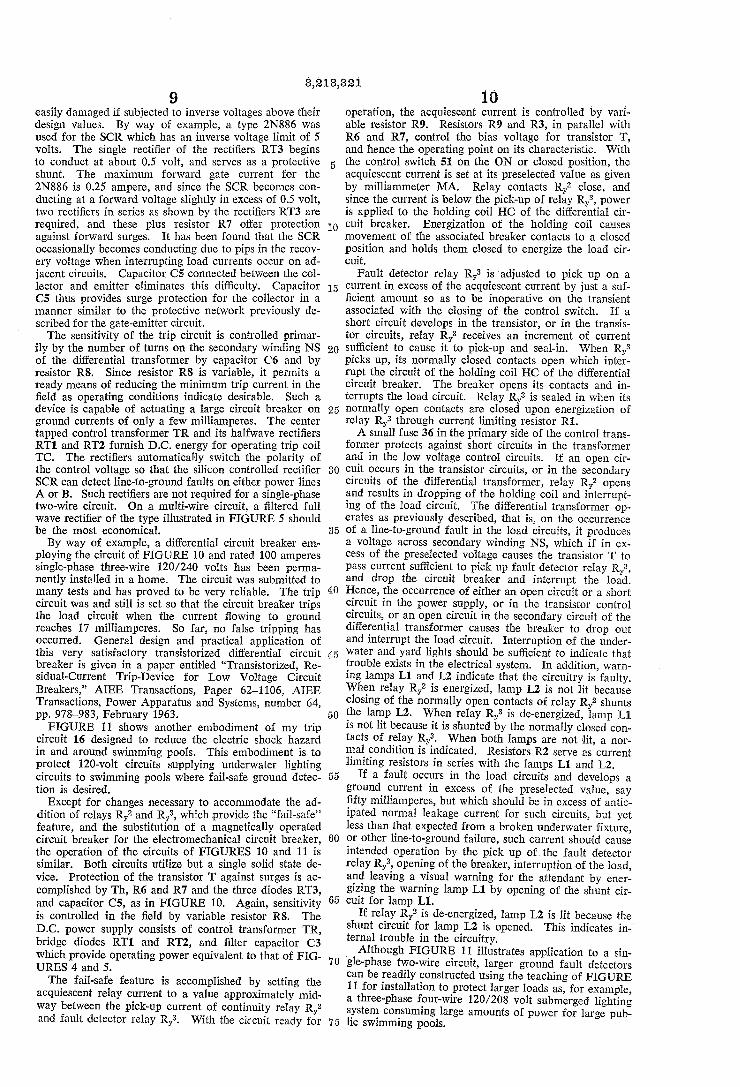
4. source end. For example, in FIGURE 1, I have shown three wires A, B and N which can be the conventional 120-240 volt distribution grounded neutral circuit com monly utilized in the United States in which 120 volts is obtained between one of the conductors A or B and the neutral conductor N, or 240 volts between the conductors A and B. The miniature differential circuit breaker 11 consists
of a differential transformer 12. The differential trans former 12 is provided with a magnetic core 13 of Suitable material such as “Mumetal.” A plurality of primary windings are shown on the magnetic core 13. These windings are designated as NP, NP-1, NP-2, etc. The number of primary windings is normally equal to the number of conductors in the distribution circuit, and must be equal to the number of primaries utilized in the cir cuits it is desired to protect. All of the primary windings are provided with the same number of turns so that NP equals NP-1 equals NP-2 equals NP-3, etc. Preferably, it is desirable that the primary windings have only one turn for some very distinct advantages which are pointed out hereinafter. The primary windings are Wound in such a manner that when the distribution circuit is operat ing under normal conditions, the total magnetomotive force produced by the windings in the magnetic core 13 is balanced out so that the net flux in the core 13 is equal to zero. Under abnormal conditions in the distribution cir cuit caused by a current flow to ground, a net flux is pro duced in the magnetic core 13. The differential transformer 12 also includes a Sec
ondary winding NS which is utilized for detecting an un balance in the current in the conductors A, B and N'as hereinafter described. The secondary winding is con nected to a trip circuit 16 by conductors 17 and 18. The trip circuit 16 is connected to a trip coil TC by conductors 21 and 22. The trip coil TC is utilized for operating breaker contacts 23 and 24 for interrupting the power cir cuit by opening conductors A and B. Energy for operat ing the trip coil is supplied from the power conductors 26 and 27 connected to the trip circuit 16. With the circuit shown in FIGURE 1, it is apparent
that when a current flow occurs between conductors A or B and ground on the load side of the breaker, a net flux will be produced in core 13 of the transformer 12. The flux produces a voltage in the secondary winding NS which causes operation of the trip circuit 16. The trip circuit 16 causes power to be applied from the conductors 26 and 27 to the trip coil TC to energize the same to open the breaker contacts 23 and 24. The conventional over load and short circuit trip elements 28 and 29 continue to perform their intended functions and are in no way affected by the presence or operation of trip circuit 16.
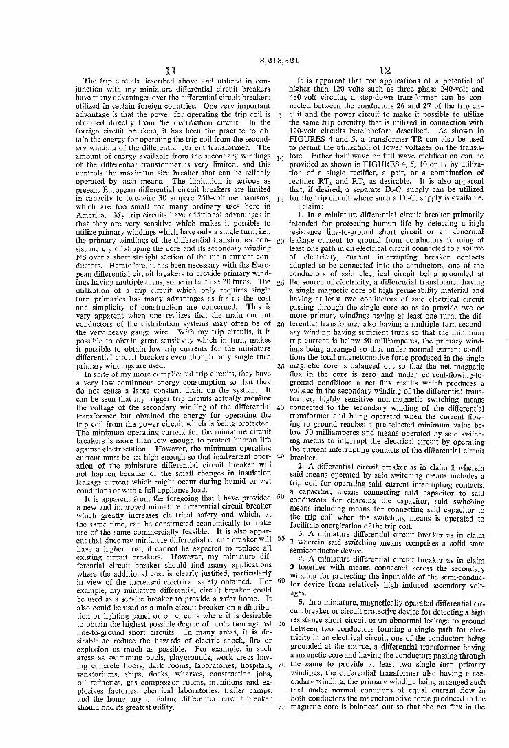
Specific embodiments of the trip circuit 16 are shown in FIGURES 2-6 and 10-11. In FIGURE 2, there is shown a highly sensitive trigger trip circuit utilizing a transistor and a gas triode. When sufficient voltage is developed in the secondary winding NS of the differential transformer 12, the transistor T becomes conducting. As indicated, a voltage is applied between the base and the emitter of the transistor T. Suitable means is provided for Supplying control voltage to the transistor T. Instead of a step-down transformer, a capacitor-resistor potential divider 31 is used consisting of a plurality of serially con nected capacitors C-1 with a resistor R-1 in parallel with each capacitor. This potential divider has the advantage of filtering the half wave rectified A.C. from the rectifier RT and at the same time reduces the continuous current drain to a very low value. As shown in the drawing, three capacitors C-1, and
three resistors R-1 are provided in the divider 31 which form three sets with each set consisting of a resistor R-1 with a capacitor C-1 in parallel with it. Transistor T is connected between the first and second sets of the capaci tors and resistors numbered from the top to the bottom as viewed in FIGURE 2. The emitter of the transistor T

3,218,82i. 5
is connected between the second and third sets of capaci tors and resistors through a charging capacitor C-2.
Conduction of the transistor T causes charging of the capacitor C-2. When the Voltage across the capacitor C-2 plus the voltage across the lowest capacitor C-1 in the potential divider 31 or, in other words, the capacitor C-1 in the third set reaches the breakdown voltage of the gas triode GT, the triode GT fires. The sudden firing of the gas triode GT permits current from the power con ductors 26 and 27 to flow through the trip coil to energize the trip coil TC which, as explained previously, opens the breaker contacts 23 and 24 to interrupt the power cir cuit. The trip coil TC is primarily energized by the stored charge in the capacitor C-3 connected across lines 26 and 27 which, as explained previously, are connected to the distribution lines. The trip coil TC is also ener gized by the continuous current flow through the half wave rectifier RT from the same A.C. source. The cold cathode triode GT remains conducting until the differen tial circuit breaker opens the distribution circuit. Open ing of the distribution circuit restores the trip circuit to its normal condition. A resistor R-2 is connected between the starter ele
ment of the gas triode and the negative side of the cir cuitry. This resistor serves two functions. During nor imal operating conditions on the distribution circuit, the resistor R-2 serves to pass the leakage current of tran sistor T and produces a negative charge on the capacitor C-2 with respect to the charge on capacitor C-1 directly connected thereto. This prevents the gas triode GT from inadvertently conducting unless there is sufficient ground fault current to reverse the polarity of the votlage on the capacitor C-2 and to build up the voltage in the posi tive direction on capacitor C-2 sufficient to cause Sudden firing of the gas triode GT as hereinbefore described. The resistor R-2 also serves as a ballast and decreases the sensitivity of the circuit so that it will be relatively insensi tive to the minute changes in insulation resistance, espe cially changes in insulation leakage around the Socketter minals of the gas triode due to atmospheric conditions. The resistance R-2 may also be varied or changed if
desired to obtain precise control of the minimum operat ing current for the miniature differential circuit breaker. It, therefore, makes it possible to compensate for slight differences in transistors utilized for the transistor T or triodes used for the triode GT. Also, it can be used to increase or decrease the sensitivity of my miniature circuit breaker instead of increasing or decreasing the number of turns on the secondary of the differential transformer.
In FIGURE 3 is shown another embodiment of my trip circuit 56. This circuit is also very sensitive and utilizes a gas diode as a switch with a seal-in relay as shown in the drawing. The circuit operates in a manner similar to the circuit shown in FIGURE 2, Thus, when the charge on the capacitor C-2 plus the charge on the lowest capacitor C-1 reaches a sufficient value, the gas diode GD suddenly breaks down causing energization of the Winding of relay Ry to cause closing of its contacts and application of power from the conductors 26 and 27 to the trip coil TC in the same manner as described in con junction with the circuit shown in FIGURE 2, As soon as the winding of relay Ry is energized and
its contacts close, a holding circuit is established by the circuit comprised of the resistor R-4 and the rectifier RT-2. The function of rectifier RT-2 is as follows: At the instant the cold cathode diode GD conducts, the holding circuit is a very high resistance in comparison with the resistance of the winding of relay Ry, and prac tically all of the current flowing through diode GD flows through the relay winding, thus assuring maximum sen sitivity. When the contacts of relay Ry close, the cur rent through rectifier RT-2 is reversed due to the dis charge of capacitor C-3, the rectifier becomes conducting, and the relay contacts are instantly sealed in by the appreciable current which now flows in the holding cir
IO
20
40
50
5 5
60
65
70
5
6 cuit R-4 and RT-2. The circuit resets automatically upon interruption of the power to the distribution con ductors A and B.
In FIGURES 4 and 5, I have shown two additional embodiments of my trip circuit 16 which are completely transistorized. Each of the circuits consists of a tran sistor T which is operated by the voltage developed across the secondary winding NS of the differential trans former. Operation of the transistor T causes the ampli fying transistor AT to be turned on which, in turn, causes conduction of the power transistor PT. The sudden power flow in the power transistor PT causes energization of the trip coil TC to open the distribution circuit as hereinbefore described. The resistors R-1 and R-2 serve as current limiting resistors.
It will be noted that FIGURES 4 and 5 are identical except for the position of trip coil TC and the fact that a resistor R-3 is provided in FIGURE 4. The resistor R-3 permits control of the bias voltage, and hence the operating point of the power transistor PT. AS pointed out previously, the magnetic core 13 utilized
in the transformer differential transformer 12 can be formed of any suitable material. However, in order to achieve high sensitivity, it is preferable that the ma terial be of a type having high permeability. For ex ample, as explained previously, I have found that a core material known as "Mumetal' is satisfactory. In cer tain embodiments, it may be desirable to use a self saturating core material such as round loop "High-Mu 80.' When such a material is utilized in connection with a trip circuit such as shown in FIGURES 4 and 5, it may also be desirable to provide shunt means to protect the transistors from high voltage Surges during the one or two cycles required for the short circuit elements to operate and clear the distribution circuit of short circuits of very high current magnitude. To this end, suitable means such as Zener diodes Z have been provided across the secondary windings NS in FIGURES 4 and 5. If desired, thyrite shunts may be used in combination with the Zener diodes, or as an alternate, ordinary diodes may be used. To be acceptable for American practice, a miniature
circuit breaker must have ample interrupting capacity (5000 amperes in the U.S.A. in contrast to 2000 amperes in Europe), and hence the breaker must safely with stand currents up to the specified limit. Although such currents will be interrupted rapidly by the short circuit trip elements 28 and 29, means must be provided to protect trip circuit 6 from the relatively high voltage which will be induced in the secondary winding NS dur ing the one or two cycles required for the short circuit trip elements to become actuated and for the breaker contacts 23 and 24 to extinguish the short circuit current arc. Satisfactory means may consist of the use of a Self-saturating magnetic core either alone or shunted by non-linear devices as discussed in the foregoing and illustrated in FIGURES 4 and 5. These circuits are basic in the development of com
pletely transistorized trip circuits for differential circuit breakers. Such circuits are readily modified by one familiar with the art and cognizant of the requirements of differential circuit breakers. Thus, this invention is not restricted to the specific circuits given herewith which are merely offered by way of illustrating a few possible means of accomplishing desired results. Such modified circuits are known as multivibrator circuits and are char acterized by Such names as trigger circuits, flip-flop cir cuits, emitter coupled, collector coupled, NPNP switch, and double base diode circuits. One such embodiment is presented in FIGURE 6 as hereinafter described. A distinguishing feature of all satisfactory trip circuits
is Sudden conduction or instantaneous trigger action once the preselected minimum trip current is reached. This is a requirement because of the limited energy available from Winding NS at such low trip currents and the re

3,213,331 7
quirement of low continuous current drain even during times of rather high leakage current, which under ad verse conditions may approach but obviously cannot exceed the minimum trip current value. Another embodiment of my trip circuit 6 is shown
in FIGURE 6. It actually is a modification of the cir cuits shown in FIGURES 4 and 5 with the additional advantages of having a sudden switch characteristic, a very reliable low trip current with a low energy drain, and the use of standard components. When sufficient voltage is developed in the secondary winding NS, the transistor T begins conducting and charges the capacitor C-2. When the voltage across the capacitor C-2 reaches a high enough value in spite of the drain caused by the resistor R-1, the unijunction switching transistor UNJ which has a negative resistance characteristic suddenly fires. The resulting pulse of voltage produced across the resistor R-4 causes firing of the silicon controlled rectifier SCR. The resulting current flow through the rectifier SCR causes energization of the trip coil TC and thereby causes tripping of differential circuit breaker and resetting of the circuit. The differential circuit breaker must trip because the
silicon controlled rectifier SCR continues to conduct until the distribution circuit is deenergized to cut off the power on the conductors 26 and 27. Power is supplied to the circuit by halfwave rectifier RT. The capacitors C-3 and C-4 serve as filters for the power supplies for the solid state devices. The resistor R-5 serves as a voltage dropping resistor. The resistors R-2 and R-3 serve as current limiting resistors. By way of example, one embodiment of the circuit
shown in FIGURE 6 had the following circuit elements with the following values: Transistor T-Type TI-2N342 Unijunction Transistor UNJ-Type GE-2N489 Silicon Control Rectifier SCR-Type GE-C10B Rectifier RT-Type GE-1N1696 R-1-4.5 x 10⁶ ohms R-2-470 ohms R-3=470 ohms R-4-30 ohms R-5=33,000 ohms C-2s:0.1 microfarads C-3 and C-4=4 microfarads Voltage on conductors 26 and 27-120 volts A.C. Voltage supplied by rectifier RT=--170 volts Voltage Supplied by voltage dropping resistor R-5- - -30
volts Primary windings NP, NP-1 and NP-2-1 turn Secondary winding NS=2000 turns Trip coil–500 turns, 300 ohms
This circuit was found to give excellent results as shown by the curve identified as FIGURE 6 circuit in FIGURE 7. For comparison purposes, I have also shown curves obtained with circuits shown in FIGURES 2 and 3.
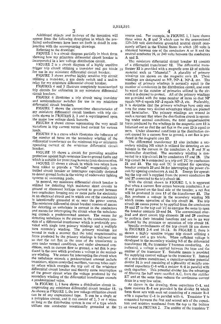
In FIGURE 7, there are also shown two curves 41 and 42 which represent the maximum body current at 240 volts and at 120 volts, respectively. This is the maxi mum current likely to flow during an accident and is established by the conventional body resistance and the nominal circuit voltage. For example, with a 120 volt circuit, I=E/R=120/500=0.24 ampere or 240 milli amperes where 500 ohms represents the conventional body resistance between major extremities. Two addi tional curves 43 and 44 are shown in FIGURE 7. Curve 43 represents the ventricular fibrillation threshold and curve 44 represents the "let-go' or “freezing” threshold. Both of these curves were obtained experimentally as re ported in my papers entitled "Threshold 60-Cycle Fibril lating Currents' in AIEE Transactions, Part III, pp. 667 673, for October 1960, and "Let-Go Currents and Volt ages,” in AIEE Transactions, Part II, pp. 49-56 for May 1956, respectively.
8 It is readily apparent from FIGURE 7 that the minia
: ture differential circuit breakers in FIGURES 2, 3 and 6
(
2O
25
30
35
40
60
70
75
provide a high degree of protection for the human body against electrocution for currents up to the maximum likely to flow between the major extremities during hu man accidents which occur in connection with conven tional distribution voltages. For example, if it is as Sumed that there is a ground current of approximately 52 milliamperes with the embodiment shown in FIGURE 6, the miniature differential circuit breaker should open Within .05 of a second as shown in the curve. This is Well below the ventricular fibrillation threshold. Even though it is apparent that any current in excess of 9 mil liamperes may constitute a "let-go” hazard, the limiting of the body current to values of 20 to 30 milliamperes constitutes a great improvement in electrical safety which Would otherwise not be possible without the use of my miniature differential circuit breaker. Also, it should be pointed out that it is my belief that if a freezing contact On a 120-volt circuit which resulted in an initial current of 15 to 20 milliamperes would also certainly within a relatively short time decrease the skin resistance to permit the flow of currents within the tripping range (20 to 30 milliamperes) of my miniature differential circuit breaker. My differential circuit breaker, therefore, makes pos
sible a great improvement in electrical safety because there is little if any evidence of serious injury to the human body from currents below approximately 30 to 50 milliamperes. The great improvement in electrical safety is apparent when it is recalled that usual house circuits are protected with 15 to 20 ampere devices which are ob viously totally inoperative on currents likely to flow through the human body during accidents involving elec trical utilization circuits. The accuracy with which my miniature differential cir
cuit breaker can separate the line-to-ground currents of a few milliamperes from load currents up to 100 amperes is illustrated in FIGURE 8. Three different curves 51, 52 and 53 are shown. Curve 51 represents a 115-volt load Supplied from line A to neutral, curve 52 represents a 230-volt load supplied from line A to line B and curve 53 represents a 115-volt load supplied from line B to neutral. From these curves, it is apparent that the trip current varied less than 2 milliamperes with a change in load from Zero to 100 amperes. As also explained previously, the sensitivity of my
miniature differential circuit breaker can be controlled in Several Ways. One way of obtaining the greatest amount of control of the sensitivity or the minimum trip capa bilities of the circuit is by changing the number of turns in the secondary winding NS. In FIGURE 9, I have shown the sensitivity which can be readily obtained by Using single turn primary windings, and a single secondary winding wound on a "Mumetal' core. Another embodiment of my trip circuit 16 is shown in
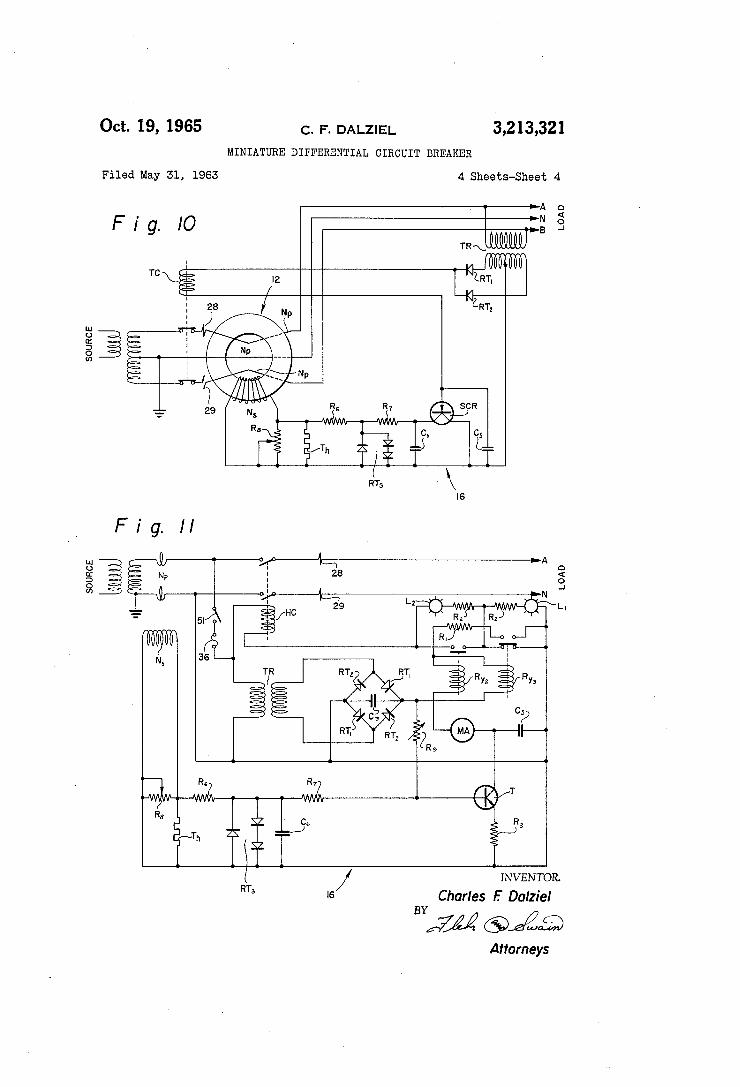
FIGURE 10. This development is a simplification of the circuit of FIGURE 6, in which only a single silicon con trolled Tectifier SCR is utilized. The SCR suddenly con ducts when the gate to emitter voltage reaches its critical value. At this instant, the control transformer TR ener gizes trip coil TC and opens the circuit breaker thereby interrupting the load circuit.
Silicon controlled rectifiers fail if subjected to gate cur rents or inverse gate voltages above their design values. The circuit comprising the thyrite non-linear resistor Th, resistors R6 and R7, and the three diodes RT3 protect the SCR against high voltages induced in the secondary winding NS of the differential transformer during high Current low-impedance line-to-ground short circuits on the load circuit. High voltage produced in winding NS is typically the peaked voltage waveform of a highly over Saturated magnetic core and has the characteristic of a high impedance source. Resistors Th and R6 reduce the resulting currents to a value within the rating of rectifiers RT3. As previously stated, solid state devices may be
3,218,321 9
easily damaged if subjected to inverse voltages above their design values. By way of example, a type 2N886 was used for the SCR which has an inverse voltage limit of 5 volts. The single rectifier of the rectifiers RT3 begins to conduct at about 0.5 volt, and serves as a protective shunt. The maximum forward gate current for the 2N886 is 0.25 ampere, and since the SCR becomes con ducting at a forward voltage slightly in excess of 0.5 volt, two rectifiers in series as shown by the rectifiers RT3 are required, and these plus resistor R7 offer protection against forward surges. It has been found that the SCR occasionally becomes conducting due to pips in the recov ery voltage when interrupting load currents occur on ad jacent circuits. Capacitor C5 connected between the col lector and emitter eliminates this difficulty. Capacitor C5 thus provides surge protection for the collector in a manner similar to the protective network previously de scribed for the gate-emitter circuit. The sensitivity of the trip circuit is controlled primar
ily by the number of turns on the secondary winding NS of the differential transformer by capacitor C6 and by resistor R8. Since resistor R8 is variable, it permits a ready means of reducing the minimum trip current in the field as operating conditions indicate desirable. Such a device is capable of actuating a large circuit breaker on ground currents of only a few milliamperes. The center tapped control transformer TR and its halfwave rectifiers RT1 and RT2 furnish D.C. energy for operating trip coil TC. The rectifiers automatically switch the polarity of the control voltage so that the silicon controlled rectifier SCR can detect line-to-ground faults on either power lines A or B. Such rectifiers are not required for a single-phase two-wire circuit. On a multi-wire circuit, a filtered full wave rectifier of the type illustrated in FIGURE 5 should be the most economical. By way of example, a differential circuit breaker em
ploying the circuit of FIGURE 10 and rated 100 amperes single-phase three-wire 120/240 volts has been perma nently installed in a home. The circuit was submitted to many tests and has proved to be very reliable. The trip circuit was and still is set so that the circuit breaker trips the load circuit when the current flowing to ground reaches 17 milliamperes. So far, no false tripping has occurred. General design and practical application of this very satisfactory transistorized differential circuit breaker is given in a paper entitled “Transistorized, Re sidual-Current Trip-Device for Low Voltage Circuit Breakers,” AIEE Transactions, Paper 62-1106, AIEE Transactions, Power Apparatus and Systems, number 64, pp. 978-983, February 1963. FIGURE 11 shows another embodiment of my trip
circuit 16 designed to reduce the electric shock hazard in and around swimming pools. This embodiment is to protect 120-volt circuits supplying underwater lighting circuits to swimming pools where fail-safe ground detec tion is desired.
Except for changes necessary to accommodate the ad dition of relays R2 and R3, which provide the "fail-safe' feature, and the substitution of a magnetically operated circuit breaker for the electromechanical circuit breaker, the operation of the circuits of FIGURES 10 and 11 is similar. Both circuits utilize but a single solid state de vice. Protection of the transistor T against Surges is ac complished by Th, R6 and R7 and the three diodes RT3, and capacitor C5, as in FIGURE 10. Again, sensitivity is controlled in the field by variable resistor R8. The D.C. power supply consists of control transformer TR, bridge diodes RT1 and RT2, and filter capacitor C3 which provide operating power equivalent to that of FIG URES 4 and 5. The fail-safe feature is accomplished by setting the
acquiescent relay current to a value approximately mid Way between the pick-up current of continuity relay R? and fault detector relay R,8. With the circuit ready for
O
20
30
40
55
60
70
10 operation, the acquiescent current is controlled by vari able resistor R9. Resistors R9 and R3, in parallel with R6 and R7, control the bias voltage for transistor T, and hence the operating point on its characteristic. With the control switch 51 on the ON or closed position, the acquiescent current is set at its preselected value as given by milliammeter MA. Relay contacts R2 close, and since the current is below the pick-up of relay R8, power is applied to the holding coil HC of the differential cir cuit breaker. Energization of the holding coil causes movement of the associated breaker contacts to a closed position and holds them closed to energize the load cir cuit.
Fault detector relay R3 is adjusted to pick up on a current in excess of the acquiescent current by just a suf ficient amount so as to be inoperative on the transient associated with the closing of the control switch. If a short circuit develops in the transistor, or in the transis tor circuits, relay R3 receives an increment of current Sufficient to cause it to pick-up and seal-in. When R,3 picks up, its normally closed contacts open which inter rupt the circuit of the holding coil HC of the differential circuit breaker. The breaker opens its contacts and in terrupts the load circuit. Relay R3 is sealed in when its normally open contacts are closed upon energization of relay Ry through current limiting resistor R1. A Small fuse 36 in the primary side of the control trans
former protects against short circuits in the transformer and in the low voltage control circuits. If an open cir cuit occurs in the transistor circuits, or in the secondary circuits of the differential transformer, relay Ry? opens and results in dropping of the holding coil and interrupt ing of the load circuit. The differential transformer op erates as previously described, that is, on the occurrence of a line-to-ground fault in the load circuits, it produces a Voltage across secondary winding NS, which if in ex cess of the preselected voltage causes the transistor T to pass current sufficient to pick up fault detector relay R3, and drop the circuit breaker and interrupt the load. Hence, the occurrence of either an open circuit or a short circuit in the power Supply, or in the transistor control circuits, or an open circuit in the secondary circuit of the differential transformer causes the breaker to drop out and interrupt the load circuit. Interruption of the under Water and yard lights should be sufficient to indicate that trouble exists in the electrical system. In addition, warn ing lamps L1 and L2 indicate that the circuitry is faulty. When relay Ry? is energized, lamp L2 is not lit because closing of the normally open contacts of relay R.? shunts the lamp L2. When relay Ry, is de-energized, lamp L1 is not lit because it is shunted by the normally closed con tacts of relay Ry. When both lamps are not lit, a nor mal condition is indicated. Resistors R2 serve as current limiting resistors in series with the lamps L. and L2.
If a fault occurs in the load circuits and develops a ground current in excess of the preselected value, say fifty milliamperes, but which should be in excess of antic ipated normal leakage current for such circuits, but yet less than that expected from a broken underwater fixture, or other line-to-ground failure, such current should cause intended operation by the pick up of the fault detector relay Ry, opening of the breaker, interruption of the load, and leaving a visual warning for the attendant by ener. gizing the Warning lamp L1 by opening of the shunt cir cuit for lamp L1.
If relay Ry” is de-energized, lamp L2 is lit because the shunt circuit for lamp L2 is opened. This indicates in ternal trouble in the circuitry.
Although FIGURE 11 illustrates application to a sin gle-phase two-wire circuit, larger ground fault detectors can be readily constructed using the teaching of FIGURE 11 for installation to protect larger loads as, for example, a three-phase four-wire 120/208 volt Submerged lighting system consuming large amounts of power for large pub lic Swimming pools.
3,213,321
The trip circuits described above and utilized in con junction with my miniature differential circuit breakers have many advantages over the differential circuit breakers utilized in certain foreign countries. One very important advantage is that the power for operating the trip coil is obtained directly from the distribution circuit. In the foreign circuit breakers, it has been the practice to ob tain the energy for operating the trip coil from the second ary winding of the differential current transformer. The amount of energy available from the secondary windings of the differential transformer is very limited, and this controls the maximum size breaker that can be reliably operated by such means. The limitation is serious as present European differential circuit breakers are limited in capacity to two-wire 30 ampere 250-volt mechanisms, which are too small for many ordinary uses here in America. My trip circuits have additional advantages in that they are very sensitive which makes it possible to utilize primary windings which have only a single turn, i.e., the primary windings of the differential transformer con sist merely of slipping the core and its secondary winding NS over a short straight section of the main current con ductors. Heretofore, it has been necessary with the Euro pean differential circuit breakers to provide primary wind ings having multiple turns, some in fact use 20 turns. The utilization of a trip circuit which only requires single turn primaries has many advantages as far as the cost and simplicity of construction are concerned. This is very apparent when one realizes that the main current conductors of the distribution systems may often be of the very heavy gauge wire. With my trip circuits, it is possible to obtain great sensitivity which in turn, makes it possible to obtain low trip currents for the miniature differential circuit breakers even though only single turn primary windings are used.
In spite of my more complicated trip circuits, they have a very low continuous energy consumption so that they do not cause a large constant drain on the System. It can be seen that my trigger trip circuits actually monitor the voltage of the secondary winding of the differential transformer but obtained the energy for operating the trip coil from the power circuit which is being protected. The minimum operating current for the miniature circuit breakers is more than low enough to protect human life against electrocution. However, the minimum operating current must be set high enough so that inadvertent oper ation of the miniature differential circuit breaker will not happen because of the small changes in insulation leakage current which might occur during humid or Wet conditions or with a full appliance load.
It is apparent from the foregoing that I have provided a new and improved miniature differential circuit breaker which greatly increases electrical safety and which, at the same time, can be constructed economically to make use of the same commercially feasible. It is also appar ent that since my miniature differential circuit breaker will have a higher cost, it cannot be expected to replace all existing circuit breakers. However, my miniature dif ferential circuit breaker should find many applications where the additional cost is clearly justified, particularly in view of the increased electrical safety obtained. For example, my miniature differential circuit breaker could be used as a service breaker to provide a Safer home. It also could be used as a main circuit breaker on a distribu tion or lighting panel or on circuits where it is desirable to obtain the highest possible degree of protection against line-to-ground short circuits. In many areas, it is de sirable to reduce the hazards of electric shock, fire or explosion as much as possible. For example, in Such areas as swimming pools, playgrounds, Work areas hav ing concrete floors, dark rooms, laboratories, hospitals, Sanatoriums, ships, docks, wharves, construction jobs, oil refineries, gas compressor rooms, munitions and ex plosives factories, chemical laboratories, trailer camps, and the home, my miniature differential circuit breaker should find its greatest utility.
5
O
20
30
40
5 5
60
t 5
12 It is apparent that for applications of a potential of
higher than 120 volts such as three phase 240-volt and 480-volt circuits, a step-down transformer can be con nected between the conductors 26 and 27 of the trip cir cuit and the power circuit to make it possible to utilize the same trip circuitry that is utilized in connection with 120-volt circuits hereinbefore described. As shown in FIGURES 4 and 5, a transformer TR can also be used to permit the utilization of lower voltages on the transis tors. Either half wave or full wave rectification can be provided as shown in FIGURES 4, 5, 10 or 11 by utiliza tion of a single rectifier, a pair, or a combination of rectifier RT and RT as desirable. It is also apparent that, if desired, a separate D.C. supply can be utilized for the trip circuit where such a D.-C. supply is available.
I claim: 1. In a miniature differential circuit breaker primarily
intended for protecting human life by detecting a high resistance line-to-ground short circuit or an abnormal leakage current to ground from conductors forming at least one path in an electrical circuit connected to a Source of electricity, current interrupting breaker contacts adapted to be connected into the conductors, one of the conductors of said electrical circuit being grounded at the source of electricity, a differential transformer having a single magnetic core of high permeability material and having at least two conductors of said electrical circuit passing through the single core so as to provide two or more primary windings having at least one turn, the dif ferential transformer also having a multiple turn second ary winding having sufficient turns so that the minimum trip current is below 50 milliamperes, the primary wind ings being arranged so that under normal current condi tions the total magnetomotive force produced in the single magnetic core is balanced out so that the net magnetic flux in the core is zero and under current-flowing-to ground conditions a net flux results which produces a Voltage in the secondary winding of the differential trans former, highly sensitive non-magnetic switching means connected to the secondary winding of the differential transformer and being operated when the current flow ing to ground reaches a pre-selected minimum value be low 50 milliamperes and means operated by said switch ing means to interrupt the electrical circuit by operating the current interrupting contacts of the differential circuit breaker.
2. A differential circuit breaker as in claim 1 wherein Said means operated by said switching means includes a trip coil for operating said current interrupting contacts, a capacitor, means connecting said capacitor to said conductors for charging the capacitor, said Switching means including means for connecting said capacitor to the trip coil when the Switching means is operated to facilitate energization of the trip coil.
3. A miniature differential circuit breaker as in claim 1 wherein said Switching means comprises a solid state Semiconductor device.
4. A miniature differential circuit breaker as in claim 3 together with means connected across the Secondary winding for protecting the input side of the semi-conduc tor device from relatively high induced secondary volt ageS.
5. In a miniature, magnetically operated differential cir cuit breaker or circuit protective device for detecting a high resistance short circuit or an abnormal leakage to ground between two conductors forming a single path for elec tricity in an electrical circuit, one of the conductors being grounded at the source, a differential transformer having a magnetic core and having the conductors passing through the same to provide at least two single turn primary Windings, the differential transformer also having a sec ondary winding, the primary winding being arranged such that under normal conditions of equal current flow in both conductors the magnetomotive force produced in the magnetic core is balanced out so that the net flux in the

3,213,321 3.
core is zero, and under abnormal conditions of unequal current flow in the two conductors a net fux results which produces a voltage in the secondary winding of the differ ential transformer, said means for detecting the voltage in the secondary winding including switching means which is operated when the next flux in the secondary winding reaches a predetermined value, means operated by said switching means to interrupt the electrical circuit when the Switching means is operated and automatic lo fail-safe means to protect against electrical faults.
6. A miniature, magnetically operated differential cir cuit breaker as in claim 5 wherein said automatic fail safe means includes at least two relays, operation of either or both relays causing immediate de-energization of the
14 magnetically controlled circuit breaker and interruption of the electrical circuit.
References Cited by the Examiner UNITED STATES PATENTS
1,504,691 8/24 Hochstadter ---------- 317-26 2,238,570 4/41 Schweitzer ------------ 317-27 2,844,765 7/58 Sosnoski--------------- 317-18 3,018,356 1/62 Busch et al. ------------ 317-33
OTHER REFERENCES IBM Technical Publication: “A New Transistor With
Thyratron-Like Characteristics,” Richard F. Rutz and Arvid W. Berger, May 26, 1955.
15 SAMUEL BERNSTEIN, Primary Examiner.