minimum operational performance standards for …read.pudn.com/downloads775/ebook/3071458/rtca...
TRANSCRIPT

RTEquation Chapter 6 Section 1 RTCA, Inc.
1828 L Street, NW, Suite 805 Washington, D.C. 20036, USA
MINIMUM OPERATIONAL PERFORMANCE STANDARDS FOR GLOBAL POSITIONING
SYSTEM/WIDE AREA AUGMENTATION SYSTEM AIRBORNE EQUIPMENT
RTCA DO-229D Prepared By: December 13, 2006 SC-159

Copies of this document may be obtained from
RTCA, Inc. 1828 L Street NW, Suite 805 Washington, DC 20036, USA
Telephone: 202-833-9339 Facsimile: 202-833-9434 Internet: www.rtca.org
Please call RTCA for price and ordering information

Foreward This report was prepared by Special Committee 159 (SC-159) and approved by the RTCA Program Management Committee (PMC) on December 13, 2006. RTCA, Incorporated is a not-for-profit corporation formed to advance the art and science of aviation and aviation electronic systems for the benefit of the public. The organization functions as a Federal Advisory Committee and develops consensus based recommendations on contemporary aviation issues. RTCA’s objectives include but are not limited to: • Coalescing aviation system user and provider technical requirements in a manner that
helps government and industry meet their mutual objectives and responsibilities;
• Analyzing and recommending solutions to the system technical issues that aviation faces as it continues to pursue increased safety, system capacity, and efficiency;
• Developing consensus on the application of pertinent technology to fulfill user and provider requirements, including development of minimum operational performance standards for electronic systems and equipment that support aviation; and
• Assisting in developing the appropriate technical material upon which positions for the International Civil Aviation Organization and the International Telecommunication Union and other appropriate international organizations can be based.
The organizations’ recommendations are often used as the basis for government and private sector decisions as well as the foundation for many Federal Aviation Administration Technical Standard Orders. Since RTCA is not an official agency of the United States Government, its recommendations may not be regarded as statements of official government policy unless so enunciated by the U.S. government organization or agency having statutory jurisdiction over any matters to which the recommendations relate.

This Page Intentionally Left Blank

ii
© 2006, RTCA, Inc.
TABLE OF CONTENTS
1.0 PURPOSE AND SCOPE _________________________________________________ 1 1.1 Introduction________________________________________________________________ 1 1.2 System Overview____________________________________________________________ 3
1.2.1 Wide Area Augmentation System _____________________________________________________3 1.2.2 GNSS Satellite Signal Characteristics __________________________________________________4
1.2.2.1 GPS Signal Characteristics ______________________________________________________4 1.2.2.2 WAAS Signal Characteristics ____________________________________________________5
1.3 Operational Goals ___________________________________________________________ 6 1.3.1 Intended Operational Applications _____________________________________________________6 1.3.2 Operational Environment ____________________________________________________________6 1.3.3 International Compatibility___________________________________________________________7
1.4 Equipment Classes __________________________________________________________ 8 1.4.1 Functional Classes _________________________________________________________________8 1.4.2 Operational Classes ________________________________________________________________9 1.4.3 Relation of Classes to Document Organization __________________________________________10
1.5 Aiding and Barometric Vertical Navigation_____________________________________ 11 1.5.1 SBAS and Barometric Vertical Navigation _____________________________________________11 1.5.2 Aiding of Fault Detection and Exclusion _______________________________________________12
1.6 Test Considerations_________________________________________________________ 12 1.6.1 Environmental Tests _______________________________________________________________12 1.6.2 Bench Tests______________________________________________________________________12
1.7 Definition of Key Terms _____________________________________________________ 13 1.7.1 General Terms ___________________________________________________________________13 1.7.2 Alert Limits and Protection Levels____________________________________________________14 1.7.3 Fault Detection and Exclusion (FDE) Terms ____________________________________________15
1.8 Assumptions and Approach to Selected Issues___________________________________ 20 1.8.1 General _________________________________________________________________________20
1.8.1.1 GPS Constellation and WAAS/SBAS Ground/Space Segments _________________________20 1.8.1.2 GPS/SBAS Performance _______________________________________________________20 1.8.1.3 Applicability ________________________________________________________________21 1.8.1.4 Interoperability_______________________________________________________________21 1.8.1.5 Integrity Monitoring___________________________________________________________21 1.8.1.6 Navigational Waypoints________________________________________________________21 1.8.1.7 RF Interference ______________________________________________________________22 1.8.1.8 Time of Applicability of Information in the SBAS Signal-in-Space ______________________22 1.8.1.9 Change of Broadcast Ephemeris _________________________________________________22 1.8.1.10 SBAS Regional Message Type (Message Type 27 and 28) __________________________22
1.8.2 Approach Applications _____________________________________________________________22 1.8.2.1 SBAS Performance for Approaches ______________________________________________22 1.8.2.2 Approach Path-in-Space _______________________________________________________23 1.8.2.3 LNAV/VNAV, LP, LPV Approach Position Integrity ________________________________23 1.8.2.4 Vector-to-Final (VTF) Approach_________________________________________________24
2.0 EQUIPMENT PERFORMANCE AND TEST PROCEDURES _________________ 25 2.1 General Requirements ______________________________________________________ 25
2.1.1 Requirements Applicable to Beta, Gamma, and Delta Equipment____________________________25 2.1.1.1 General Requirements for All Navigation Modes ____________________________________25
2.1.1.1.1 Airworthiness _____________________________________________________________25 2.1.1.1.2 General Performance _______________________________________________________25

ii
© 2006, RTCA, Inc.
2.1.1.1.3 Fire Resistance ____________________________________________________________25 2.1.1.1.4 Equipment Interfaces _______________________________________________________25 2.1.1.1.5 Effects of Test ____________________________________________________________25
2.1.1.2 GPS Signal Processing Requirements _____________________________________________25 2.1.1.3 SBAS Signal Processing Requirements____________________________________________26
2.1.1.3.1 Acquisition and Track ______________________________________________________26 2.1.1.3.2 Demodulation and Forward Error Correction (FEC) Decoding_______________________27 2.1.1.3.3 SBAS Satellite Pseudorange Determination _____________________________________27
2.1.1.4 SBAS Message Processing _____________________________________________________27 2.1.1.4.1 Message Type 0 - Don’t Use for Safety Applications ______________________________27 2.1.1.4.2 Message Type 1 - PRN Mask Assignments ______________________________________28 2.1.1.4.3 Message Types 2-5 and 24 - Fast Corrections ____________________________________28 2.1.1.4.4 Message Type 6 - Integrity Information_________________________________________28 2.1.1.4.5 Message Type 7 - Fast Correction Degradation___________________________________29 2.1.1.4.6 Message Type 9 - SBAS Satellite Navigation Message_____________________________29 2.1.1.4.7 Message Type 17 - SBAS Satellite Almanac _____________________________________29 2.1.1.4.8 Message Type 27 - SBAS Service Message______________________________________29 2.1.1.4.9 Message Timeout Periods ___________________________________________________29 2.1.1.4.10 Combining Data from Separate Broadcasts _____________________________________31 2.1.1.4.11 Message Type 24 and 25 Long-Term Corrections________________________________31 2.1.1.4.12 Application of Differential Corrections ________________________________________32 2.1.1.4.13 Message Type 28 - Clock-Ephemeris Covariance Matrix Message___________________33
2.1.1.5 Satellite Integrity Status ________________________________________________________33 2.1.1.5.1 Step Detector _____________________________________________________________33 2.1.1.5.2 SBAS UNHEALTHY Designation ____________________________________________34 2.1.1.5.3 SBAS UNMONITORED Designation__________________________________________34 2.1.1.5.4 SBAS HEALTHY Designation _______________________________________________34 2.1.1.5.5 GPS UNHEALTHY Designation______________________________________________35 2.1.1.5.6 GPS HEALTHY Designation ________________________________________________35
2.1.1.6 Satellite Selection_____________________________________________________________35 2.1.1.7 Initial Acquisition Time________________________________________________________36 2.1.1.8 Satellite Acquisition Time ______________________________________________________37
2.1.1.8.1 GPS Satellite Acquisition Time _______________________________________________37 2.1.1.8.2 SBAS Satellite Acquisition Time______________________________________________37
2.1.1.9 Satellite Reacquisition Time ____________________________________________________37 2.1.1.10 Sensitivity and Dynamic Range________________________________________________37 2.1.1.11 Equipment Burnout Protection ________________________________________________39 2.1.1.12 Integrity in the Presence of Interference _________________________________________39 2.1.1.13 Alerts/Outputs _____________________________________________________________40
2.1.1.13.1 Protection Level __________________________________________________________40 2.1.1.13.2 Navigation Alert__________________________________________________________40
2.1.2 Requirements for En Route and Terminal Mode _________________________________________41 2.1.2.1 Accuracy ___________________________________________________________________41 2.1.2.2 Integrity Requirements_________________________________________________________41
2.1.2.2.1 Development Assurance_____________________________________________________41 2.1.2.2.1.1 Hardware Compliance __________________________________________________42 2.1.2.2.1.2 Software Compliance ___________________________________________________42
2.1.2.2.2 Integrity Monitoring________________________________________________________42 2.1.2.2.2.1 SBAS-Provided Integrity Monitoring_______________________________________42 2.1.2.2.2.2 FDE-Provided Integrity Monitoring ________________________________________42
2.1.2.2.2.2.1 Time-to-Alert______________________________________________________44 2.1.2.2.2.2.2 Missed Alert Probability _____________________________________________44 2.1.2.2.2.2.3 False Alert Probability_______________________________________________44 2.1.2.2.2.2.4 Failed Exclusion Probability __________________________________________44 2.1.2.2.2.2.5 Availability _______________________________________________________45
2.1.2.3 Equipment Reliability _________________________________________________________45 2.1.2.4 Satellite Tracking Capability ____________________________________________________45

iiiiii
© 2006, RTCA, Inc.
2.1.2.5 Dynamic Tracking ____________________________________________________________45 2.1.2.6 Position Output ______________________________________________________________46
2.1.2.6.1 Position Output Data Update Rate _____________________________________________46 2.1.2.6.2 Position Output Data Latency ________________________________________________46
2.1.3 Requirements for LNAV ___________________________________________________________46 2.1.3.1 Accuracy ___________________________________________________________________46 2.1.3.2 Integrity Requirements_________________________________________________________46
2.1.3.2.1 Development Assurance_____________________________________________________46 2.1.3.2.1.1 Hardware Compliance __________________________________________________46 2.1.3.2.1.2 Software Compliance ___________________________________________________46
2.1.3.2.2 Integrity Monitoring________________________________________________________46 2.1.3.2.2.1 SBAS-Provided Integrity Monitoring_______________________________________47 2.1.3.2.2.2 FDE-Provided Integrity Monitoring ________________________________________47
2.1.3.2.2.2.1 Time-to-Alert______________________________________________________47 2.1.3.2.2.2.2 Missed Alert Probability _____________________________________________47 2.1.3.2.2.2.3 False Alert Probability_______________________________________________47 2.1.3.2.2.2.4 Failed Exclusion Probability __________________________________________47 2.1.3.2.2.2.5 Availability _______________________________________________________47
2.1.3.2.2.3 FD Prediction _________________________________________________________47 2.1.3.3 Equipment Reliability _________________________________________________________48 2.1.3.4 Satellite Tracking Capability ____________________________________________________48 2.1.3.5 Dynamic Tracking ____________________________________________________________48 2.1.3.6 Position Output ______________________________________________________________48
2.1.3.6.1 Position Output Update Rate _________________________________________________49 2.1.3.6.2 Position Output Latency_____________________________________________________49
2.1.3.7 SBAS Message Processing _____________________________________________________49 2.1.3.8 Application of Differential Correction Terms _______________________________________49 2.1.3.9 Satellite Selection_____________________________________________________________49
2.1.4 Requirements for LNAV/VNAV Operations ____________________________________________49 2.1.4.1 Accuracy ___________________________________________________________________49
2.1.4.1.1 Smoothing _______________________________________________________________49 2.1.4.1.2 Measurement Quality Monitoring _____________________________________________50 2.1.4.1.3 Accuracy ________________________________________________________________50 2.1.4.1.4 GPS Satellites_____________________________________________________________51 2.1.4.1.5 SBAS Satellites ___________________________________________________________51 2.1.4.1.6 Position Solution __________________________________________________________52
2.1.4.2 Integrity Requirements_________________________________________________________52 2.1.4.2.1 Development Assurance_____________________________________________________52
2.1.4.2.1.1 Hardware Compliance __________________________________________________52 2.1.4.2.1.2 Software Compliance ___________________________________________________52
2.1.4.2.2 Integrity Monitoring________________________________________________________52 2.1.4.2.2.1 SBAS-Provided Integrity Monitoring_______________________________________52 2.1.4.2.2.2 Fault Detection-Provided Integrity Monitoring _______________________________52
2.1.4.2.2.2.1 Frequency of Fault Detection _________________________________________53 2.1.4.2.2.2.2 Missed Alert ______________________________________________________53 2.1.4.2.2.2.3 False Alert ________________________________________________________53 2.1.4.2.2.2.4 Availability _______________________________________________________53
2.1.4.3 Equipment Reliability _________________________________________________________53 2.1.4.4 Satellite Tracking Capability ____________________________________________________53 2.1.4.5 Tracking Constraints __________________________________________________________53
2.1.4.5.1 GPS Tracking Constraints ___________________________________________________54 2.1.4.5.2 SBAS Tracking Constraints __________________________________________________56
2.1.4.6 Correlation Peak Validation_____________________________________________________56 2.1.4.7 Dynamic Tracking ____________________________________________________________57 2.1.4.8 Position Output ______________________________________________________________57
2.1.4.8.1 Position Output Update Rate _________________________________________________57 2.1.4.8.2 Position Output Latency_____________________________________________________57
iv
© 2006, RTCA, Inc.
2.1.4.9 SBAS Message Processing _____________________________________________________57 2.1.4.9.1 Message Type 2-5, 6 and 24 Fast Corrections ____________________________________57 2.1.4.9.2 Message Types 24 and 25 Long-Term Corrections ________________________________58 2.1.4.9.3 Message Type 18 - Ionospheric Grid Point Masks ________________________________58 2.1.4.9.4 Message Type 26 - Ionospheric Grid Point Delays ________________________________58 2.1.4.9.5 Message Types 7 and 10 - Degradation Parameters________________________________58
2.1.4.10 Application of Differential Correction Terms _____________________________________58 2.1.4.10.1 Application of Clock and Ephemeris Corrections ________________________________58 2.1.4.10.2 Application of Ionospheric Corrections ________________________________________58 2.1.4.10.3 Application of Tropospheric Corrections_______________________________________59
2.1.4.11 Satellite Selection __________________________________________________________59 2.1.4.12 Alerts/Outputs/Inputs________________________________________________________59
2.1.4.12.1 Protection Level __________________________________________________________59 2.1.4.12.2 Navigation Alert__________________________________________________________60
2.1.5 Requirements for LPV and LP Approach Operations _____________________________________60 2.1.5.1 Accuracy ___________________________________________________________________60 2.1.5.2 Integrity Requirements_________________________________________________________60
2.1.5.2.1 Development Assurance_____________________________________________________60 2.1.5.2.1.1 Hardware Compliance __________________________________________________61 2.1.5.2.1.2 Software Compliance ___________________________________________________61
2.1.5.2.2 Integrity Monitoring________________________________________________________61 2.1.5.2.2.1 SBAS-Provided Integrity Monitoring_______________________________________61 2.1.5.2.2.2 Fault Detection-Provided Integrity Monitoring _______________________________61
2.1.5.2.2.2.1 Frequency of Fault Detection _________________________________________62 2.1.5.2.2.2.2 Missed Alert ______________________________________________________62 2.1.5.2.2.2.3 False Alert ________________________________________________________62 2.1.5.2.2.2.4 Availability _______________________________________________________62
2.1.5.3 Equipment Reliability _________________________________________________________62 2.1.5.4 Satellite Tracking Capability ____________________________________________________62 2.1.5.5 Tracking Constraints __________________________________________________________62
2.1.5.5.1 GPS Tracking Constraints ___________________________________________________62 2.1.5.5.2 SBAS Tracking Constraints __________________________________________________62
2.1.5.6 Correlation Peak Validation_____________________________________________________62 2.1.5.7 Dynamic Tracking ____________________________________________________________62 2.1.5.8 Position Output ______________________________________________________________62
2.1.5.8.1 Position Output Update Rate _________________________________________________62 2.1.5.8.2 Position Output Latency_____________________________________________________63
2.1.5.9 SBAS Message Processing _____________________________________________________63 2.1.5.9.1 Message Type 2-5, 6 and 24 Fast Corrections ____________________________________63 2.1.5.9.2 Message Types 24 and 25 Long-Term Corrections ________________________________63 2.1.5.9.3 Message Type 18 - Ionospheric Grid Point Masks ________________________________63 2.1.5.9.4 Message Type 26 - Ionospheric Grid Point Delays ________________________________63 2.1.5.9.5 Message Types 7 and 10 - Degradation Parameters________________________________63
2.1.5.10 Application of Differential Correction Terms _____________________________________63 2.1.5.11 Satellite Selection __________________________________________________________63 2.1.5.12 Alerts/Outputs/Inputs________________________________________________________64
2.1.5.12.1 Protection Level __________________________________________________________64 2.1.5.12.2 Navigation Alert__________________________________________________________64
2.1.5.13 HPL and VPL Prediction_____________________________________________________64 2.2 Class Gamma Requirements_________________________________________________ 66
2.2.1 Class Gamma General Requirements _________________________________________________66 2.2.1.1 General Human Factors Requirements and Applicable Documents ______________________66
2.2.1.1.1 Controls _________________________________________________________________67 2.2.1.1.1.1 Operation ____________________________________________________________67 2.2.1.1.1.2 Control Labels_________________________________________________________67
2.2.1.1.2 Equipment Operating Procedures______________________________________________67

vv
© 2006, RTCA, Inc.
2.2.1.1.3 Minimum Workload Functions _______________________________________________67 2.2.1.1.4 Displays _________________________________________________________________69
2.2.1.1.4.1 Discernability _________________________________________________________69 2.2.1.1.4.2 Brightness, Contrast, and Color ___________________________________________70 2.2.1.1.4.3 Angle of Regard _______________________________________________________70 2.2.1.1.4.4 Symbology ___________________________________________________________70 2.2.1.1.4.5 Alphanumerics ________________________________________________________70 2.2.1.1.4.6 Moving Map __________________________________________________________71 2.2.1.1.4.7 Primary Navigation Display ______________________________________________71 2.2.1.1.4.8 Bearing Labels ________________________________________________________71
2.2.1.1.5 Annunciations ____________________________________________________________71 2.2.1.1.5.1 Annunciators__________________________________________________________72 2.2.1.1.5.2 Messages_____________________________________________________________72
2.2.1.1.6 Set of Standard Function Labels ______________________________________________72 2.2.1.1.7 Set of Standard Abbreviations and Acronyms ____________________________________73
2.2.1.2 Path Selection________________________________________________________________76 2.2.1.2.1 Flight Plan Selection _______________________________________________________76 2.2.1.2.2 Flight Plan Review_________________________________________________________76 2.2.1.2.3 Flight Plan Activation ______________________________________________________77 2.2.1.2.4 Waypoint Sequencing ______________________________________________________77 2.2.1.2.5 Manually-Selected Active Waypoint ___________________________________________77
2.2.1.2.5.1 Direct To _____________________________________________________________77 2.2.1.2.5.2 TO/FROM Course Selection______________________________________________77 2.2.1.2.5.3 Manually-Selected Waypoint and Waypoint Sequencing________________________78
2.2.1.2.6 User-Defined Waypoints ____________________________________________________78 2.2.1.2.7 Emergency Procedures______________________________________________________78
2.2.1.3 Path Definition_______________________________________________________________78 2.2.1.3.1 Initial Fix (IF)_____________________________________________________________79 2.2.1.3.2 Fixed Waypoint to a Fixed Waypoint (TF) ______________________________________79 2.2.1.3.3 DME Arcs (AF) and Constant Radius to a Fix (RF) _______________________________79 2.2.1.3.4 Direct To (DF) ____________________________________________________________80 2.2.1.3.5 Course to a Fix Waypoint (CF) _______________________________________________81 2.2.1.3.6 FROM Leg _______________________________________________________________81 2.2.1.3.7 Fly-By Turns _____________________________________________________________81
2.2.1.3.7.1 Fly-By Turn Indications _________________________________________________82 2.2.1.3.7.2 Fly-By Theoretical Transition Area ________________________________________82 2.2.1.3.7.3 Acceptable Means of Defining Fly-By Turns_________________________________83
2.2.1.3.8 Fly Over Turns ____________________________________________________________83 2.2.1.3.9 Fixed Radius Turns ________________________________________________________84 2.2.1.3.10 Waypoint Sequencing _____________________________________________________84 2.2.1.3.11 Holding Patterns / Procedure Turns ___________________________________________85 2.2.1.3.12 Magnetic Course _________________________________________________________86 2.2.1.3.13 Dead Reckoning __________________________________________________________86 2.2.1.3.14 Fuel Management and Alerting ______________________________________________86 2.2.1.3.15 Geodesic Path Computation Accuracy_________________________________________87 2.2.1.3.16 Parallel Offsets ___________________________________________________________87
2.2.1.4 Navigation Displays___________________________________________________________88 2.2.1.4.1 Primary Navigation Display__________________________________________________88 2.2.1.4.2 Non-Numeric Display/Output Characteristics ____________________________________88
2.2.1.4.2.1 Electrical Output _______________________________________________________88 2.2.1.4.2.2 Display ______________________________________________________________89
2.2.1.4.3 Active Waypoint Distance Display ____________________________________________89 2.2.1.4.4 Active Waypoint Bearing Display _____________________________________________89 2.2.1.4.5 Track Displays ____________________________________________________________90
2.2.1.4.5.1 Desired Track _________________________________________________________90 2.2.1.4.5.2 Track Angle __________________________________________________________90 2.2.1.4.5.3 Track Angle Error______________________________________________________90

vi
© 2006, RTCA, Inc.
2.2.1.4.6 Display of TO or FROM Operation ____________________________________________90 2.2.1.4.7 Waypoint Bearing/Distance Display ___________________________________________90 2.2.1.4.8 Estimate of Position Uncertainty ______________________________________________90 2.2.1.4.9 Magnetic Course __________________________________________________________90 2.2.1.4.10 Ground Speed____________________________________________________________90 2.2.1.4.11 Aircraft Present Position ___________________________________________________91
2.2.1.5 Database Requirements ________________________________________________________91 2.2.1.5.1 Access __________________________________________________________________91 2.2.1.5.2 Content __________________________________________________________________91 2.2.1.5.3 Database Standard _________________________________________________________92 2.2.1.5.4 Reference Coordinate System ________________________________________________92
2.2.1.5.4.1 Incorporation of Conversion Algorithms ____________________________________92 2.2.1.5.4.2 Operational Approval ___________________________________________________92
2.2.1.6 Alerts/Outputs _______________________________________________________________93 2.2.1.6.1 Caution Associated with Loss of Integrity Monitoring _____________________________93 2.2.1.6.2 Caution Associated with Loss of Navigation _____________________________________93
2.2.1.7 Mode Switching Requirements __________________________________________________93 2.2.2 Class Gamma Requirements for En Route / Terminal Operation_____________________________97
2.2.2.1 General Human Factors Requirements ____________________________________________97 2.2.2.2 Path Selection________________________________________________________________97 2.2.2.3 Path Definition_______________________________________________________________97 2.2.2.4 Navigation Displays___________________________________________________________97
2.2.2.4.1 Primary Navigation Displays _________________________________________________97 2.2.2.4.2 Non-Numeric Cross-Track Deviation __________________________________________98 2.2.2.4.3 Numeric Cross-Track Deviation ______________________________________________98 2.2.2.4.4 Displayed Data Update Rate _________________________________________________98 2.2.2.4.5 Display Update Latency _____________________________________________________98
2.2.2.5 Database Requirements ________________________________________________________98 2.2.2.6 Alerts ______________________________________________________________________98
2.2.2.6.1 Alert Limits ______________________________________________________________98 2.2.2.6.2 Caution Associated with Loss of Integrity Monitoring _____________________________98 2.2.2.6.3 Caution Associated with Loss of Navigation _____________________________________99
2.2.2.7 En Route / Terminal Mode Switching Requirements _________________________________99 2.2.2.7.1 En Route Mode Switching Requirements _______________________________________99
2.2.2.7.1.1 Entry Criteria _________________________________________________________99 2.2.2.7.1.2 Exit Criteria__________________________________________________________100 2.2.2.7.1.3 Display Transition Requirements _________________________________________100
2.2.2.7.2 Terminal Mode Switching Requirements_______________________________________100 2.2.2.7.2.1 Entry Criteria ________________________________________________________100 2.2.2.7.2.2 Exit Criteria__________________________________________________________100 2.2.2.7.2.3 Display Transition Requirements _________________________________________100
2.2.3 Class Gamma Requirements for LNAV Approach Operation ______________________________100 2.2.3.1 General Human Factors Requirements ___________________________________________100 2.2.3.2 Path Selection_______________________________________________________________100
2.2.3.2.1 Approach Selection _______________________________________________________101 2.2.3.2.2 Missed Approach Sequencing _______________________________________________101
2.2.3.3 Path Definition______________________________________________________________101 2.2.3.3.1 Approach Path Definition___________________________________________________101 2.2.3.3.2 Missed Approach Path Definition ____________________________________________103 2.2.3.3.3 Departure Path Definition __________________________________________________104 2.2.3.3.4 Vertical Path for LNAV Procedures __________________________________________104
2.2.3.4 Navigation Displays__________________________________________________________105 2.2.3.4.1 Primary Navigation Displays ________________________________________________105 2.2.3.4.2 Non-Numeric Cross-Track Deviation _________________________________________105 2.2.3.4.3 Numeric Cross-Track Deviation _____________________________________________105 2.2.3.4.4 Missed Approach Waypoint Distance Display___________________________________106 2.2.3.4.5 Missed Approach Waypoint Bearing Display ___________________________________106

vviiii
© 2006, RTCA, Inc.
2.2.3.4.6 Displayed Data Update Rate ________________________________________________106 2.2.3.4.7 Display Update Latency ____________________________________________________106
2.2.3.5 Database Requirements _______________________________________________________106 2.2.3.6 Alerts _____________________________________________________________________107
2.2.3.6.1 Alert Limits _____________________________________________________________107 2.2.3.6.2 Caution Associated with Loss of Integrity Monitoring ____________________________107 2.2.3.6.3 Caution Associated with Loss of Navigation ____________________________________107
2.2.3.7 Mode Switching Requirements _________________________________________________108 2.2.3.7.1 LNAV Approach Mode Switching Requirements ________________________________108
2.2.3.7.1.1 Entry Criteria ________________________________________________________108 2.2.3.7.1.2 Exit Criteria__________________________________________________________108 2.2.3.7.1.3 Display Transition Requirements _________________________________________108
2.2.3.7.2 Departure Requirements____________________________________________________109 2.2.3.7.2.1 Entry Criteria ________________________________________________________109 2.2.3.7.2.2 Exit Criteria__________________________________________________________109 2.2.3.7.2.3 Display Transition Requirements _________________________________________109
2.2.4 Class Gamma Requirements for LNAV/VNAV Operations _______________________________109 2.2.4.1 General Human Factors Requirements ___________________________________________109 2.2.4.2 Path Selection_______________________________________________________________109
2.2.4.2.1 5-Digit Channel Selection __________________________________________________109 2.2.4.2.2 Approach Selection _______________________________________________________110 2.2.4.2.3 Missed Approach Sequencing _______________________________________________110 2.2.4.2.4 Deselection of Vertical Guidance_____________________________________________110
2.2.4.3 Path Definition______________________________________________________________110 2.2.4.3.1 Approach Path Definition___________________________________________________110 2.2.4.3.2 Missed Approach Path Definition ____________________________________________111 2.2.4.3.3 Navigation Center Offset ___________________________________________________111
2.2.4.4 Navigation Displays__________________________________________________________111 2.2.4.4.1 Primary Navigation Displays ________________________________________________111 2.2.4.4.2 Non-Numeric Lateral Cross-Track Deviation ___________________________________112
2.2.4.4.2.1 Definition of Final Approach Segment Lateral deviations ______________________112 2.2.4.4.2.2 Non-VTF Deviation with FAS Data Block__________________________________112 2.2.4.4.2.3 VTF Deviation with FAS Data Block______________________________________113 2.2.4.4.2.4 Deviation without FAS Data Block _______________________________________113 2.2.4.4.2.5 Missed Approach Deviation _____________________________________________113
2.2.4.4.3 Numeric Lateral Cross-Track Deviation _______________________________________114 2.2.4.4.4 Non-Numeric Vertical Deviation _____________________________________________114 2.2.4.4.5 Missed Approach Waypoint/LTP/FTP Distance Display __________________________116 2.2.4.4.6 Missed Approach Waypoint/LTP/FTP Bearing Display ___________________________116 2.2.4.4.7 Displayed Data Update Rate ________________________________________________116 2.2.4.4.8 Display Update Latency ____________________________________________________117 2.2.4.4.9 Display of Vertical Accuracy________________________________________________117
2.2.4.5 Database Requirements _______________________________________________________117 2.2.4.5.1 Content _________________________________________________________________117 2.2.4.5.2 Data Integrity ____________________________________________________________118
2.2.4.6 Alerts _____________________________________________________________________118 2.2.4.6.1 Alert Limits _____________________________________________________________118 2.2.4.6.2 Caution Associated with Loss of Integrity Monitoring ____________________________118 2.2.4.6.3 Caution Associated with Loss of Navigation ____________________________________119 2.2.4.6.4 Low Altitude Alert ________________________________________________________120 2.2.4.6.5 Alerting Scheme__________________________________________________________120
2.2.4.7 LNAV/VNAV Approach Mode Switching Requirements ____________________________120 2.2.4.7.1 Entry Criteria ____________________________________________________________120 2.2.4.7.2 Exit Criteria _____________________________________________________________121 2.2.4.7.3 Display Transition ________________________________________________________121 2.2.4.7.4 Advisory of LNAV/VNAV Availability _______________________________________121
2.2.5 Class Gamma Requirements for LP and LPV Approach Operations _________________________121

viii
© 2006, RTCA, Inc.
2.2.5.1 General Human Factors Requirements ___________________________________________121 2.2.5.2 Path Selection_______________________________________________________________122
2.2.5.2.1 5-Digit Channel Selection __________________________________________________122 2.2.5.2.2 Approach Name Selection __________________________________________________122 2.2.5.2.3 Missed Approach Sequencing _______________________________________________122 2.2.5.2.4 Selection of the Approach Type______________________________________________122
2.2.5.3 Path Definition______________________________________________________________122 2.2.5.3.1 Approach Path Definition___________________________________________________122 2.2.5.3.2 Missed Approach Path Definition ____________________________________________122 2.2.5.3.3 Navigation Center Offset ___________________________________________________122
2.2.5.4 Navigation Displays__________________________________________________________123 2.2.5.4.1 Primary Navigation Displays ________________________________________________123 2.2.5.4.2 Non-Numeric Lateral Cross-Track Deviation ___________________________________123
2.2.5.4.2.1 Definition of Final Approach Segment Lateral Deviations _____________________123 2.2.5.4.2.2 Non-VTF Deviation ___________________________________________________123 2.2.5.4.2.3 VTF Deviation _______________________________________________________123 2.2.5.4.2.4 Missed Approach Deviation _____________________________________________123
2.2.5.4.3 Numeric Lateral Cross-Track Deviation _______________________________________123 2.2.5.4.4 Non-Numeric Vertical Deviation _____________________________________________123 2.2.5.4.5 Missed Approach Waypoint/LTP/FTP Distance Display __________________________123 2.2.5.4.6 Missed Approach Waypoint/LTP/FTP Bearing Display ___________________________123 2.2.5.4.7 Displayed Data Update Rate ________________________________________________123 2.2.5.4.8 Display Update Latency ____________________________________________________123 2.2.5.4.9 Display of Vertical Accuracy________________________________________________124
2.2.5.5 Database Requirements _______________________________________________________124 2.2.5.5.1 Content _________________________________________________________________124 2.2.5.5.2 Data Integrity ____________________________________________________________124
2.2.5.6 Alerts _____________________________________________________________________125 2.2.5.6.1 Alert Limits _____________________________________________________________125 2.2.5.6.2 Caution Associated with Loss of Integrity Monitoring ____________________________125 2.2.5.6.3 Caution Associated with Loss of Navigation ____________________________________125 2.2.5.6.4 Low Altitude Alert ________________________________________________________126 2.2.5.6.5 Alerting Scheme__________________________________________________________126
2.2.5.7 LP/LPV Approach Mode Switching Requirements__________________________________127 2.2.5.7.1 Entry Criteria ____________________________________________________________127 2.2.5.7.2 Exit Criteria _____________________________________________________________127 2.2.5.7.3 Display Transition ________________________________________________________127 2.2.5.7.4 Advisory of LPV, LP Availability ____________________________________________127
2.3 Class Delta-4 Requirements for Approach Operations ___________________________ 128 2.3.1 General Human Factors Requirements ________________________________________________128 2.3.2 Approach Selection_______________________________________________________________128
2.3.2.1 Confirmation of Selected Approach _____________________________________________128 2.3.3 Path Definition __________________________________________________________________128
2.3.3.1 Navigation Center Offset ______________________________________________________129 2.3.4 Navigation Displays ______________________________________________________________129
2.3.4.1 Non-Numeric Lateral Cross-Track Deviation ______________________________________129 2.3.4.2 Non-Numeric Vertical Deviation________________________________________________129 2.3.4.3 Landing Threshold Point/Fictitious Threshold Point Distance Display___________________129 2.3.4.4 Data Update Rate ____________________________________________________________129 2.3.4.5 Data Update Latency _________________________________________________________129
2.3.5 Database Requirements ___________________________________________________________129 2.3.5.1 Content____________________________________________________________________130 2.3.5.2 Access ____________________________________________________________________130
2.3.6 Alerts _________________________________________________________________________130 2.3.6.1 Alert Limits ________________________________________________________________130 2.3.6.2 Caution Associated with Loss of Navigation_______________________________________130

iixx
© 2006, RTCA, Inc.
2.4 Airborne Equipment Performance - Environmental Conditions ___________________ 131 2.4.1 Environmental Tests ______________________________________________________________132
2.4.1.1 Required Performance ________________________________________________________132 2.4.1.1.1 Accuracy _______________________________________________________________132 2.4.1.1.2 Loss of Navigation Indication _______________________________________________133 2.4.1.1.3 Loss of Integrity Indication _________________________________________________133 2.4.1.1.4 Initial Acquisition Test_____________________________________________________133 2.4.1.1.5 Sensitivity and Dynamic Range ______________________________________________133 2.4.1.1.6 Navigation Display________________________________________________________133 2.4.1.1.7 Database ________________________________________________________________133 2.4.1.1.8 Mode Annunciation _______________________________________________________133 2.4.1.1.9 TO-TO and TO-FROM Capability____________________________________________133 2.4.1.1.10 System Operating ________________________________________________________134
2.4.1.2 Clarification of Environmental Tests_____________________________________________134 2.4.1.2.1 Power Input Tests_________________________________________________________134 2.4.1.2.2 Icing Tests ______________________________________________________________134 2.4.1.2.3 RF and Induced Signal Susceptibility Tests_____________________________________134 2.4.1.2.4 Lightning Induced Transient Susceptibility Tests ________________________________135 2.4.1.2.5 Lightning Direct Effects Tests _______________________________________________135 2.4.1.2.6 Crash Safety Shock _______________________________________________________135
2.5 Test Methods and Procedures _______________________________________________ 143 2.5.1 Test Cross Reference Matrix _______________________________________________________145 2.5.2 SBAS Message Loss Rate Test______________________________________________________223
2.5.2.1 Evaluation of Message Loss Rate During the Measurement Accuracy Test _______________223 2.5.2.2 Test Procedure ______________________________________________________________223 2.5.2.3 Pass/Fail Determination _______________________________________________________223 2.5.2.4 Evaluation of Message Loss Rate During the 24-Hour System Accuracy Test_____________223
2.5.2.4.1 Test Procedure ___________________________________________________________223 2.5.2.4.2 Pass/Fail Criteria _________________________________________________________223
2.5.3 Step Detector Test________________________________________________________________223 2.5.3.1 Verification of Step Detector Operation Without Exclusion Capability __________________224 2.5.3.2 Verification of No Interference with Fault Detection Algorithm _______________________224 2.5.3.3 Verification of Step Detector Operation with Exclusion Capability _____________________224 2.5.3.4 Verification of No Interference with Exclusion of the FDE Algorithm __________________225
2.5.4 Initial Acquisition Test Procedures___________________________________________________225 2.5.4.1 Simulator and Interference Conditions ___________________________________________225 2.5.4.2 Test Procedures (Initial Acquisition) _____________________________________________226 2.5.4.3 Pass/Fail Determination _______________________________________________________226 2.5.4.4 Test Procedures (Initial Acquisition After Abnormal Interference) _____________________228
2.5.5 Reserved _______________________________________________________________________228 2.5.6 Satellite Reacquisition Time Test ____________________________________________________228
2.5.6.1 Simulator and Interference Conditions ___________________________________________228 2.5.6.2 Test Procedures _____________________________________________________________229 2.5.6.3 Pass/Fail Determination _______________________________________________________230
2.5.7 Interference Rejection Test_________________________________________________________230 2.5.7.1 Simulator and Interference Conditions ___________________________________________230 2.5.7.2 Test Procedures _____________________________________________________________231 2.5.7.3 Pass/Fail Determination _______________________________________________________231
2.5.8 Accuracy Tests __________________________________________________________________231 2.5.8.1 Measurement Accuracy Test ___________________________________________________231 2.5.8.2 Simulator and Interference Conditions ___________________________________________232
2.5.8.2.1 Test Procedures __________________________________________________________234 2.5.8.3 24-Hour Actual Satellite Accuracy Test __________________________________________236
2.5.8.3.1 Test Procedure ___________________________________________________________236 2.5.8.3.2 Pass/Fail Criteria _________________________________________________________236
2.5.8.4 SBAS Tracking Bias _________________________________________________________236

x
© 2006, RTCA, Inc.
2.5.9 Integrity Monitoring Test Procedures_________________________________________________237 2.5.9.1 General Test Conditions ______________________________________________________237
2.5.9.1.1 Test Philosophy __________________________________________________________237 2.5.9.1.2 GPS Constellation ________________________________________________________237 2.5.9.1.3 Applicability of RTCA/DO-178B ____________________________________________237 2.5.9.1.4 Test Repetition ___________________________________________________________238 2.5.9.1.5 Protection Level/Alert Limit ________________________________________________238 2.5.9.1.6 Time-to-Alert ____________________________________________________________238
2.5.9.2 Availability Tests ____________________________________________________________238 2.5.9.3 Off-Line FDE Tests __________________________________________________________241
2.5.9.3.1 Off-Line Test Setup _______________________________________________________241 2.5.9.3.2 Selection of Geometries ____________________________________________________241 2.5.9.3.3 Test Procedure ___________________________________________________________242
2.5.9.3.3.1 Class Gamma Equipment _______________________________________________242 2.5.9.3.3.2 Class Beta Equipment __________________________________________________243
2.5.9.3.4 Pass/Fail Criteria _________________________________________________________243 2.5.9.4 False Alert Rate Test _________________________________________________________244
2.5.9.4.1 False Alert Rate Simulations for Snapshot Algorithms ____________________________244 2.5.9.4.2 False Alert Rate Simulations for Non-Snapshot Algorithms ________________________245
2.5.9.5 On-Line Verification Test _____________________________________________________245 2.5.9.5.1 On-Target Computational Test_______________________________________________245 2.5.9.5.2 On-Line Behavioral Test ___________________________________________________246
2.5.10 LNAV/VNAV, LP, LPV Approach Fault Detection ___________________________________246 2.5.10.1 General Test Conditions ____________________________________________________246
2.5.10.1.1 Test Philosophy _________________________________________________________246 2.5.10.1.2 GPS Constellation _______________________________________________________246 2.5.10.1.3 Applicability of RTCA/DO-178B ___________________________________________247 2.5.10.1.4 Test Repetition __________________________________________________________247 2.5.10.1.5 Protection Level/Alert Limit _______________________________________________247 2.5.10.1.6 Time-to-Alert ___________________________________________________________247
2.5.10.2 Availability Tests__________________________________________________________247 2.5.10.3 Off-Line Missed Alert Tests _________________________________________________247
2.5.10.3.1 Off-Line Test Setup ______________________________________________________247 2.5.10.3.2 Selection of Geometries ___________________________________________________249 2.5.10.3.3 Test Procedures and Pass/Fail Criteria________________________________________249
2.5.10.4 False Alert Rate Test _______________________________________________________250 2.5.10.5 On-Line Verification Test ___________________________________________________250
2.5.10.5.1 On-Target Computational Test______________________________________________250 2.5.10.5.2 On-Line Behavioral Test __________________________________________________251
2.5.11 Test Procedures for Class Gamma Equipment________________________________________251 2.5.11.1 General Gamma Bench Test Procedures ________________________________________251
2.5.11.1.1 Simulated Flight Bench Test Procedures ______________________________________252 2.5.11.1.1.1 Simulated Flight Plan Test 1____________________________________________252 2.5.11.1.1.2 Simulated Flight Plan Test 2____________________________________________253
2.5.11.1.2 Waypoint Distance Display ________________________________________________267 2.5.11.1.3 Equipment Response Time Test_____________________________________________268 2.5.11.1.4 Loss of Power and Navigation Cautions and Annunciations _______________________269 2.5.11.1.5 Cross-Track Deviation Display Bench Test for En Route and Terminal ______________269 2.5.11.1.6 Cross-Track Deviation Display Test for LNAV Approaches ______________________273
2.5.11.2 Reserved ________________________________________________________________278 2.5.11.3 Human Factors Bench Tests _________________________________________________278
2.5.11.3.1 Equipment Usability______________________________________________________278 2.5.11.3.2 Display Brightness and Readability Test ______________________________________278 2.5.11.3.3 Audible Alerts Test ______________________________________________________281 2.5.11.3.4 Equipment Controls Test __________________________________________________282
3.0 INSTALLED EQUIPMENT PERFORMANCE_____________________________ 285

xxii
© 2006, RTCA, Inc.
4.0 OPERATIONAL CHARACTERISTICS ___________________________________ 287
5.0 MEMBERSHIP ______________________________________________________ 289
APPENDIX A SPACE-BASED AUGMENTATION SYSTEM SIGNAL SPECIFICATION A.1 Introduction______________________________________________________________ A-1 A.2 Signal Characteristics____________________________________________________ A-1
A.2.1 Carrier Frequency_____________________________________________________________ A-1 A.2.2 Spurious Transmissions ________________________________________________________ A-1 A.2.3 Modulation __________________________________________________________________ A-1 A.2.4 Carrier Phase Noise ___________________________________________________________ A-1 A.2.5 Signal Spectrum ______________________________________________________________ A-1 A.2.6 Signal Characteristics Modified Relative To GPS ____________________________________ A-2
A.2.6.1 Doppler Shift ____________________________________________________________ A-2 A.2.6.2 Carrier Frequency Stability _________________________________________________ A-2 A.2.6.3 Polarization _____________________________________________________________ A-2 A.2.6.4 Code/Carrier Frequency Coherence __________________________________________ A-2 A.2.6.5 User Received Signal Levels __________________________________________________ A-2 A.2.6.6 Correlation Loss____________________________________________________________ A-2 A.2.6.7 Maximum Code Phase Deviation_______________________________________________ A-3
A.3 SBAS C/A Codes __________________________________________________________ A-3 A.3.1 Requirements ________________________________________________________________ A-3 A.3.2 Identification of SBAS Codes ___________________________________________________ A-3 A.3.3 SBAS Codes_________________________________________________________________ A-3 A.3.4 Recommended SBAS/GPS Coder Implementation ___________________________________ A-3
A.4 SBAS Signal Data Contents and Formats______________________________________ A-5 A.4.1 Introduction _________________________________________________________________ A-5 A.4.2 Principles and Assumptions _____________________________________________________ A-6
A.4.2.1 Data Rate _______________________________________________________________ A-6 A.4.2.2 Timing _________________________________________________________________ A-6 A.4.2.3 Error Corrections _________________________________________________________ A-7 A.4.2.4 Tropospheric Model ______________________________________________________ A-7 A.4.2.5 Residual Tropospheric Error __________________________________________________ A-9 A.4.2.6 PRN Masks _______________________________________________________________ A-9 A.4.2.7 Number of Satellites ______________________________________________________ A-9 A.4.2.8 Issue of Data ______________________________________________________________ A-9 A.4.2.9 Acquisition Information_____________________________________________________ A-10
A.4.3 Format Summary ____________________________________________________________ A-10 A.4.3.1 Block Format _____________________________________________________________ A-10 A.4.3.2 Block Length and Content ___________________________________________________ A-10 A.4.3.3 Parity ___________________________________________________________________ A-10 A.4.3.4 Preamble ________________________________________________________________ A-12
A.4.4 Messages and Relationships Between Message Types _______________________________ A-12 A.4.4.1 Do Not Use for Safety Applications Message Type 0 ______________________________ A-14 A.4.4.2 PRN Mask Assignments Message Type 1 _______________________________________ A-14
A.4.4.2.1 PRN Mask Transition ___________________________________________________ A-15 A.4.4.3 Fast Corrections Message Types 2 - 5 __________________________________________ A-15 A.4.4.4 Integrity Information Message Type 6__________________________________________ A-17 A.4.4.5 Fast Correction Degradation Factor Message Type 7 ______________________________ A-18 A.4.4.6 Degradation Factors Message Type 10 _________________________________________ A-20 A.4.4.7 Long Term Satellite Error Corrections Message Type 25 ___________________________ A-20 A.4.4.8 Mixed Fast Corrections/Long Term Satellite Error Corrections Messages Type 24 _______ A-24 A.4.4.9 Ionospheric Grid Point Masks Message Type 18 _________________________________ A-25 A.4.4.10 Ionospheric Delay Corrections Messages Type 26 ______________________________ A-31
A.4.4.10.1 Pierce Point Location Determination ______________________________________ A-33

xii
© 2006, RTCA, Inc.
A.4.4.10.2 Selection of Ionospheric Grid Points_______________________________________ A-34 A.4.4.10.3 Ionospheric Pierce Point Vertical Delay and Model Variance Interpolation ________ A-36 A.4.4.10.4 Computing Slant Ionospheric Delay and Ionospheric Model Variance ____________ A-39
A.4.4.11 GEO Navigation Message Type 9 ___________________________________________ A-40 A.4.4.12 GEO Almanacs Message Type 17___________________________________________ A-41 A.4.4.13 SBAS Service Message Type 27 ____________________________________________ A-43
A.4.4.13.1 Definition of Regions __________________________________________________ A-43 A.4.4.14 Null Message Type 63 and Internal Test Message 62____________________________ A-45 A.4.4.15 SBAS Network Time/UTC/GLONASS Time Offset Parameters Message Type 12 ____ A-45 A.4.4.16 Clock-Ephemeris Covariance Matrix Message Type 28 __________________________ A-46
A.4.5 Modeling the Degradation of Data_______________________________________________ A-49 A.4.5.1 Fast and Long-Term Correction Degradation ____________________________________ A-50
A.4.5.1.1 Fast Correction Degradation______________________________________________ A-50 A.4.5.1.2 Range-Rate Correction Degradation _______________________________________ A-51
A.4.5.1.2.1 Range-Rate Correction Degradation - IODF ≠ 3 ___________________________ A-51 A.4.5.1.2.2 Range-Rate Correction Degradation - Either IODF = 3 _____________________ A-51
A.4.5.1.3 Long Term Correction Degradation ________________________________________ A-52 A.4.5.1.3.1 Long Term Correction Degradation - Velocity Code =1 ____________________ A-52 A.4.5.1.3.2 Long Term Correction Degradation - Velocity Code = 0 ____________________ A-53 A.4.5.1.3.3 GEO Navigation Message Degradation __________________________________ A-53
A.4.5.1.4 Degradation for En Route Through LNAV___________________________________ A-53 A.4.5.2 Degradation of Ionospheric Corrections ________________________________________ A-54
A.4.6 Principles and Rules for the Generation and Use of Data _____________________________ A-55 A.4.7 Timing ____________________________________________________________________ A-55
A.5 References:______________________________________________________________ A-56
APPENDIX B STANDARD GPS/WAAS ASSUMPTIONS ____________________________ B.1 GPS Constellation _________________________________________________________ B-1 B.2 WAAS Constellation_______________________________________________________ B-1 B.3 Selective Availability_______________________________________________________ B-2 B.4 GPS Satellite Failure_______________________________________________________ B-2 B.5 GPS Constellation for Availability Analysis____________________________________ B-2 B.6 Signal Quality Monitoring __________________________________________________ B-3
B.6.1 Dead Zones___________________________________________________________________B-3 B.6.2 False Peaks ___________________________________________________________________B-3 B.6.3 Distortions ___________________________________________________________________B-4 B.6.4 Threat Models ________________________________________________________________B-4
B.6.4.1 Threat Model A _____________________________________________________________B-4 B.6.4.2 Threat Model B _____________________________________________________________B-4 B.6.4.3 Threat Model C _____________________________________________________________B-4
APPENDIX C STANDARD RECEIVED SIGNAL AND INTERFERENCE ENVIRONMENT _____________________________________________________________
C.1 Introduction______________________________________________________________ C-1 C.2 Operating Interference Environment _________________________________________ C-1
C.2.1 Out-of-Band Interference ________________________________________________________C-1 C.2.1.1 Out-of-Band Pulse Interference _________________________________________________C-2
C.2.2 In-Band and Near-Band Interference _______________________________________________C-2 C.2.2.1 In-Band and Near-Band Pulsed Interference _______________________________________C-3
C.2.3 GNSS Noise __________________________________________________________________C-4 C.3 Minimum Standard Antenna Frequency Selectivity _____________________________ C-4

xxiiiiii
© 2006, RTCA, Inc.
APPENDIX D DATA FORMAT FOR HIGH INTEGRITY INFORMATION TO SUPPORT STRAIGHT AND ADVANCED LANDING APPROACH OPERATIONS ________________
D.1 Introduction______________________________________________________________ D-1 D.2 Format __________________________________________________________________ D-1
D.2.1 Overall Structure _____________________________________________________________ D-1 D.2.2 Data Block Description ________________________________________________________ D-1 D.2.3 Data Block Structure __________________________________________________________ D-2
D.3 Final Approach Segment Data Block _________________________________________ D-2 D.3.1 Final Approach Segment Parameter Definition ______________________________________ D-3 D.3.2 Final Approach Segment Data Table ______________________________________________ D-5
D.4 Advanced Procedures Data Blocks ___________________________________________ D-6 D.5 CRC Definition ___________________________________________________________ D-6 D.6 Informative Section________________________________________________________ D-6
D.6.1 Integrity Protection of Data Blocks _______________________________________________ D-6 D.6.2 Approach Path Selection _______________________________________________________ D-7 D.6.3 Data Block Generation _________________________________________________________ D-7 D.6.4 Database Formatting and Distribution _____________________________________________ D-8 D.6.5 CRC Generation and decoding___________________________________________________ D-8 D.6.6 CRC selection________________________________________________________________ D-9 D.6.7 Reference Coordinate System __________________________________________________ D-10
D.7 References:______________________________________________________________ D-10
APPENDIX E BASELINE WEIGHTED NAVIGATION SOLUTION AND NAVIGATION SYSTEM ERROR ALGORITHMS FOR SBAS VERTICALLY GUIDED APPROACHES ___
E.1 Introduction______________________________________________________________ E-1 E.2 Baseline Navigation Solution ________________________________________________ E-1 E.3 References _______________________________________________________________ E-2
APPENDIX F VELOCITY DATA IN SUPPORT OF ADS-B __________________________ F.1 Introduction______________________________________________________________ F-1 F.2 Velocity Solution with Figure of Merit ________________________________________ F-1 F.3 References _______________________________________________________________ F-4
APPENDIX G REQUIREMENTS FOR BAROMETREIC ALTIMETER AIDING ________ G.1 General__________________________________________________________________ G-1 G.2 Altimeter Aiding with GNSS Calibration ______________________________________ G-1
G.2.1 Requirements for Calibration ____________________________________________________ G-1 G.2.2 Calculation of σbaro____________________________________________________________ G-2 G.2.3 Actual Use of the Altitude Measurement to Augment GNSS ___________________________ G-3
G.3 Barometric Altimeter Aiding Using Baro-corrected Pressure Altitude______________ G-4 G.3.1 Requirements for calibration ____________________________________________________ G-4 G.3.2 Calculation of σbaro____________________________________________________________ G-4 G.3.3 Actual Use of the Barometric Altitude Measurement to Augment GNSS __________________ G-5 G.3.4 Requirements for Pilot Interaction ________________________________________________ G-5
G.4 Test Procedures___________________________________________________________ G-5 G.5 References _______________________________________________________________ G-6
xiv
© 2006, RTCA, Inc.
APPENDIX H STANDARD OUTPUT FORMAT ___________________________________ H.1 Introduction______________________________________________________________ H-1 H.2 GPS Minimum Output and Output Timing ____________________________________ H-1
H.2.1 Minimum GPS/SBAS Output____________________________________________________ H-1 H.2.2 Timing _____________________________________________________________________ H-3
H.3 Other Desirable GPS Outputs _______________________________________________ H-5 H.4 Summary ________________________________________________________________ H-5 H.5 References:_______________________________________________________________ H-5
APPENDIX I MODE SWITCHING FLOWCHART FOR GAMMA EQUIPMENT ________ I.1 Introduction_______________________________________________________________ I-1
APPENDIX J SBAS-BASED PROTECTION LEVELS FOR EN ROUTE THROUGH LPV APPROACH__________________________________________________________________
J.1 SBAS Protection Level Equations - General Least Squares Solutions________________J-1 J.2 HPLSBAS Parameters ________________________________________________________J-2
J.2.1 K _____________________________________________________________________________ J-2 J.2.2 Variance of Fast and Long Term Correction Residuals ___________________________________ J-3 J.2.3 Variance of Ionospheric Delay ______________________________________________________ J-3 J.2.4 Variance of Airborne Receiver Errors ________________________________________________ J-3 J.2.5 Variance of Tropospheric Errors ____________________________________________________ J-5
J.3 Rationale for HPL and VPL Parameters _______________________________________J-5 J.3.1 Selection of K Values _____________________________________________________________ J-5 J.3.2 Rationale for Fast and Long-Term Residuals ___________________________________________ J-5 J.3.3 Rationale for Ionospheric Delay Residuals ____________________________________________ J-6 J.3.4 Rationale for Receiver Residuals ____________________________________________________ J-6 J.3.5 Rationale for Tropospheric Residuals_________________________________________________ J-6
APPENDIX K FAULT DETECTION AND EXCLUSION REFERENCES_______________
APPENDIX L THE DIRECT AND INDIRECT GEODETIC PROBLEMS FOR GREAT CIRCLE NAVIGATION ________________________________________________________
L.1 General__________________________________________________________________ L-1 L.2 Definitions of Terms _______________________________________________________ L-2 L.3 Nomenclature ____________________________________________________________ L-2 L.4 WGS-84 Parameters (from [5]) ______________________________________________ L-3 L.5 The Indirect Problem ______________________________________________________ L-3 L.6 The Direct Problem________________________________________________________ L-5 L.7 Validation________________________________________________________________ L-6 L.8 References _______________________________________________________________ L-9
APPENDIX M TEST CONSIDERATIONS ________________________________________ M.1 Introduction______________________________________________________________M-1 M.2 (Initial) Acquisition and Reacquisition Testing Statistical Justification _____________M-1 M.3 Accuracy Statistical Justification ____________________________________________M-2 M.4 General Simulator Scenario Conditions _______________________________________M-4

xxvv
© 2006, RTCA, Inc.
M.5 Example Test Set-up and Compensation of Signals, Noise and Interference _________M-5 M.5.1 Description of the Test Set-up ___________________________________________________ M-5 M.5.2 Use of the Test Set-up for the Accuracy Test (See 2.5.8) ______________________________ M-6
APPENDIX N REFERENCE MATERIAL FOR DETERMINING THE MEAN SEA LEVEL HEIGHT FROM WGS-84 COORDINATES ________________________________________
N.1 Introduction______________________________________________________________ N-1 N.1.1 General Altimetry_____________________________________________________________ N-1 N.1.2 Mean Sea Level (MSL) Altitude _________________________________________________ N-1 N.1.3 Barometric Altitude ___________________________________________________________ N-2 N.1.4 Radar Altitude _______________________________________________________________ N-2 N.1.5 GPS Altitude ________________________________________________________________ N-2 N.1.6 SBAS-Derived Altitude ________________________________________________________ N-2
APPENDIX O GLOSSARY AND ACRONYMS _____________________________________
APPENDIX P IONOSPHERIC GRID POINT (IGP) SELECTION FLOWCHARTS_______ P.1 Introduction______________________________________________________________ P-1
APPENDIX Q SBAS CONSIDERATIONS FOR HELICOPTERS______________________ Q.1 General__________________________________________________________________ Q-1
Q.1.1 Helicopter/Heliport Deceleration _________________________________________________ Q-1 Q.1.2 PinS Description______________________________________________________________ Q-1
Q.2 PinS Approach Operations _________________________________________________ Q-1 Q.2.1 Fictitious Helipoint Equivalence to Fictitious Threshold Point __________________________ Q-1 Q.2.2 FAS Data Block Application to PinS Procedures ____________________________________ Q-1 Q.2.3 PinS Lateral Display Scaling ____________________________________________________ Q-3 Q.2.4 Vertical Display Scaling________________________________________________________ Q-3
Q.3 Deceleration Point Annunciation_____________________________________________ Q-3 Q.4 Selective CDI and HAL Values to Support Tighter Route Area Semi-widths ________ Q-4 Q.5 Autopilot Considerations ___________________________________________________ Q-4 Q.6 Heliport Approach Database Considerations___________________________________ Q-4
APPENDIX R REQUIREMENTS AND TEST PROCEDURES FOR TIGHTLY INTEGRATED GPS/INERTIAL SYSTEMS ________________________________________
R.1 Introduction______________________________________________________________ R-1 R.2 Requirements_____________________________________________________________ R-1
R.2.1 General FDE Requirements ______________________________________________________R-1 R.2.1.1 Fault Free Performance _______________________________________________________R-2
R.2.2 Unique Additional Requirements__________________________________________________R-3 R.2.2.1 Assumed Failure Mechanisms __________________________________________________R-3 R.2.2.2 Detection limit ______________________________________________________________R-4 R.2.2.3 SatZap ____________________________________________________________________R-4 R.2.2.4 Receiver Clock Aiding________________________________________________________R-5 R.2.2.5 Altitude Aiding _____________________________________________________________R-5 R.2.2.6 Discriminator Averaging ______________________________________________________R-5 R.2.2.7 Inertial Coasting Performance Evaluation _________________________________________R-6
R.2.2.7.1 Accuracy Coasting________________________________________________________R-6 R.2.2.7.2 Integrity Coasting ________________________________________________________R-7
R.2.2.8 Gravity Compensation ________________________________________________________R-8 R.3 Tightly Integrated GPS/Inertial Design Concepts _______________________________ R-9

xvi
© 2006, RTCA, Inc.
R.3.1 Integration Methods ____________________________________________________________R-9 R.3.1.1 Pre-residual (Innovation) Screening _____________________________________________R-9 R.3.1.2 Post-Residual Monitoring ____________________________________________________R-10 R.3.1.3 Additional Measurement Bias States ____________________________________________R-10 R.3.1.4 Multiple Kalman Filters ______________________________________________________R-10 R.3.1.5 Extrapolation Method _______________________________________________________R-10 R.3.1.6 Solution Separation Method __________________________________________________R-10
R.3.2 Detection and Exclusion Mechanisms _____________________________________________R-11 R.3.2.1 Transient Detection/Exclusion for 2 nmi/hour Grade Systems ________________________R-11 R.3.2.2 Satellite Redundancy ________________________________________________________R-11 R.3.2.3 Integrity Coasting___________________________________________________________R-11 R.3.2.4 Gravity/Schuler Coupling ____________________________________________________R-11 R.3.2.5 Other Schuler Coupling Related Effects _________________________________________R-12
R.4 Assumptions_____________________________________________________________ R-12 R.4.1 Signal Error Model____________________________________________________________R-12 R.4.2 Satellite Clock Drift Characteristics_______________________________________________R-13
R.5 Validation_______________________________________________________________ R-13 R.5.1 Categorization of Detection and Exclusion Mechanisms_______________________________R-13
R.5.1.1 Examples _________________________________________________________________R-14 R.5.2 Covariance Simulation _________________________________________________________R-14
R.5.2.1 Covariance Simulation Methods for Availability Evaluation _________________________R-14 R.5.3 False Alert Probability _________________________________________________________R-15 R.5.4 Fault Free Accuracy Performance ________________________________________________R-15 R.5.5 Off-Line Rare Normal Verification _______________________________________________R-16 R.5.6 Off-Line Detection/Exclusion Verification _________________________________________R-16
R.5.6.1 Detection and Exclusion Mechanism Equivalent to RAIM ___________________________R-16 R.5.6.2 Claimed Additional Detection and Exclusion Mechanisms___________________________R-16
R.5.6.2.1 Examples _____________________________________________________________R-17 R.5.6.2.1.1 RAIM with Transient Detection/Exclusion ________________________________R-17 R.5.6.2.1.2 Solution Separation Detection and Exclusion ______________________________R-17
R.5.6.2.2 Reference RAIM Models__________________________________________________R-18 R.5.6.3 Integrity Coasting___________________________________________________________R-18
R.5.7 On-Line Validation ___________________________________________________________R-19 R.5.8 Gravity Compensation Validation ________________________________________________R-19 R.5.9 Ionospheric Error Models_______________________________________________________R-20
R.5.9.1 Ionospheric Daily Variation___________________________________________________R-20 R.5.9.2 Ionospheric Storms _________________________________________________________R-20
R.6 References ______________________________________________________________ R-21
APPENDIX S PROCESSING FLOW DIAGRAMS __________________________________ S.1 Introduction______________________________________________________________ S-1
APPENDIX T GEO BIAS ANALYSIS TOOL_______________________________________ T.1 GEO Bias Algorithm Rationale ______________________________________________ T-1 T.2 GEO Bias Algorithm Procedure (Overview) ___________________________________ T-1 T.3 Analysis _________________________________________________________________ T-2
T.3.1 GEO Filter Models _____________________________________________________________T-3 T.3.1.1 Future GEOs _______________________________________________________________T-5
T.3.2 Range Normalization ___________________________________________________________T-5 T.4 Bias Model Tool: Instructions and examples ___________________________________ T-6
APPENDIX U GUIDANCE MATERIAL FOR INTERFACING WITH ADS-B _________

xxvviiii
© 2006, RTCA, Inc.
U.1 Purpose and Scope ________________________________________________________ U-1 U.2 Position Output and Validity ________________________________________________ U-1 U.3 Horizontal Figure of Merit (HFOM)__________________________________________ U-1 U.4 Horizontal Protection Limit (HPL) ___________________________________________ U-1 U.5 Velocity__________________________________________________________________ U-2 U.6 Vertical Figure of Merit and Vertical Protection Limit (VPL)_____________________ U-2
FIGURES FIGURE 1-1 WAAS ARCHITECTURE..................................................................................................... 5 FIGURE 1-2 FUNCTIONAL CLASSES .................................................................................................. 10 FIGURE 1-3 DIAGRAM OF FDE CONDITIONS................................................................................... 16 FIGURE 1-4 MARKOV CHAIN FOR FDE ............................................................................................. 17 FIGURE 1-5 EXAMPLE FDE EVENTS .................................................................................................. 18 FIGURE 2-1 SENSITIVITY AND DYNAMIC RANGE CONFIGURATION ....................................... 39 FIGURE 2-2A RECEIVER BANDWIDTH AND AVERAGE CORRELATOR SPACING FOR E-L
DISCRIMINATOR TRACKING OF GPS SATELLITES................................................................. 55 FIGURE 2-2B RECEIVER BANDWIDTH AND AVERAGE CORRELATOR SPACING FOR DD
DISCRIMINATOR TRACKING OF GPS SATELLITES................................................................. 56 FIGURE 2-3 TF LEG ................................................................................................................................ 79 FIGURE 2-4 RF LEG ................................................................................................................................ 80 FIGURE 2-5 DIRECT-TO PATH DEFINITION...................................................................................... 81 FIGURE 2-6 CF LEG ................................................................................................................................ 81 FIGURE 2-7 FLY-BY THEORETICAL TRANSITION AREA .............................................................. 83 FIGURE 2-8 FLY-OVER THEORETICAL TRANSITION AREA......................................................... 84 FIGURE 2-9 WAYPOINT SEQUENCING .............................................................................................. 85 FIGURE 2-10 DEFAULT NAVIGATION MODES ................................................................................ 95 FIGURE 2-11 FULL-SCALE DEFLECTION AND DEFINED PATH FOR NORMAL LNAV
APPROACH (not VTF approach) .................................................................................................... 102 FIGURE 2-12 FULL SCALE DEFLECTION AND DEFINED PATH FOR LNAV VTF APPROACH
.......................................................................................................................................................... 103 FIGURE 2-13 MISSED APPROACH SCENARIOS.............................................................................. 104 FIGURE 2-14 FINAL APPROACH SEGMENT DEFINITION ............................................................ 111 FIGURE 2-15 VTF FINAL APPROACH SEGMENT LATERAL DEVIATIONS WITH FAS DATA
BLOCK............................................................................................................................................. 113 FIGURE 2-16 FINAL APPROACH SEGMENT VERTICAL DEVIATIONS ...................................... 116 FIGURE 2-17 FLIGHT PROFILE FOR FLIGHT PLAN 1 .................................................................... 266 FIGURE 2-18 FLIGHT PROFILE FOR FLIGHT PLAN 2 ................................................................... 267 FIGURE 2-19 CROSS-TRACK DEVIATION FOR EN ROUTE AND TERMINAL........................... 271 FIGURE 2-20 CROSS TRACK DEVIATION FOR VTF LNAV APPROACH .................................. 275 FIGURE 2-21 CROSS-TRACK DEVIATION FOR LNAV APPROACH .......................................... 277 FIGURE A-1 SBAS/GPS CODER IMPLEMENTED WITH SINGLE G2 OUTPUT PLUS
PROGRAMMABLE G2 DELAY ....................................................................................................A-5 FIGURE A-2 SBAS/GPS CODER IMPLEMENTED WITH A PROGRAMMABLE INITIAL G2
STATE ..............................................................................................................................................A-5 FIGURE A-3 CONVOLUTIONAL ENCODING...................................................................................A-6 FIGURE A-4 DATA BLOCK FORMAT..............................................................................................A-10 FIGURE A-5 INTERRELATIONSHIPS OF MESSAGES...................................................................A-13 FIGURE A-6 EXAMPLE PRN MASK.................................................................................................A-15

xviii
© 2006, RTCA, Inc.
FIGURE A-7 TYPES 2 - 5 FAST CORRECTIONS MESSAGES FORMAT.....................................A-16 FIGURE A-8 TYPE 6 INTEGRITY MESSAGE FORMAT.................................................................A-17 FIGURE A-9 TYPE 7 FAST CORRECTION DEGRADATION FACTOR MESSAGE FORMAT...A-19 FIGURE A-10 TYPE 25 LONG TERM SATELLITE ERROR CORRECTIONS Velocity Code = 0 A-21 FIGURE A-11 TYPE 25 LONG TERM SATELLITE ERROR CORRECTIONS Velocity Code = 1 A-23 FIGURE A-12 TYPE 24 MIXED FAST CORRECTION/LONG TERM SATELLITE ERROR
CORRECTIONS MESSAGE FORMAT........................................................................................A-25 FIGURE A-13 EXAMPLE OF AN IONOSPHERIC GRID MASK.....................................................A-27 FIGURE A-14 PREDEFINED GLOBAL IGP GRID (BANDS 9 AND 10 ARE NOT SHOWN).......A-30 FIGURE A-15 TYPE 18 IGP MASK MESSAGE FORMAT...............................................................A-31 FIGURE A-16 TYPE 26 IONOSPHERIC DELAY CORRECTIONS MESSAGE FORMAT ............A-32 FIGURE A-17 IONOSPHERIC PIERCE POINT GEOMETRY..........................................................A-34 FIGURE A-18 IONOSPHERIC GRID POINT INTERPOLATION.....................................................A-36 FIGURE A-19 FOUR-POINT INTERPOLATION ALGORITHM DEFINITIONS............................A-38 FIGURE A-20 THREE-POINT INTERPOLATION ALGORITHM DEFINITIONS..........................A-39 FIGURE A-21 TYPE 9 GEO NAVIGATION MESSAGE FORMAT .................................................A-40 FIGURE A-22 TYPE 17 GEO ALMANACS MESSAGE FORMAT ..................................................A-42 FIGURE A-23 SERVICE MESSAGE TYPE 27...................................................................................A-44 FIGURE A-24 TYPE 28 CLOCK-EPHEMERIS COVARIANCE MATRIX MESSAGE FORMAT .A-48 FIGURE C-1 INTERFERENCE LEVELS AT THE ANTENNA PORT ............................................... C-1 FIGURE C-2 IN-BAND AND NEAR-BAND INTERFERENCE ENVIRONMENTS ......................... C-2 FIGURE C-3 FREQUENCY SELECTIVITY......................................................................................... C-5 FIGURE D-1 FINAL APPROACH SEGMENT DIAGRAM .................................................................D-2 FIGURE D-2 PROBABILITY OF UNDETECTED ERROR.................................................................D-9 FIGURE D-3 PROBABILITIES OF CORRECT DECODING AND DETECTED ERRORS.............D-10 FIGURE H-1 GPS TIMING RELATIONSHIPS .....................................................................................H-4 FIGURE M-1 (RE)ACQUISITION TEST PROBABILITY STATISTICS........................................... M-2 FIGURE M-2 PSEUDORANGE ACCURACY TEST PASS CRITERIA............................................. M-3 FIGURE M-3 PSEUDORANGE ACCURACY TEST PASS PROBABILITY..................................... M-4 FIGURE P-1 GRID POINT SELECTION CRITERIA ........................................................................... P-2 FIGURE P-2 ABS IPP LATTITUDE BELOW 60 DEG (5X5) .............................................................. P-3 FIGURE P-3 ABS IPP LATITUDE BELOW 85 DEG........................................................................... P-4 FIGURE P-4 ABS IPPLATITUDE BETWEEN 60 & 75 DEG BANDS 9-10 ....................................... P-5 FIGURE P-6 ABS IPP LATITUDE ABOVE 85 DEG ........................................................................... P-6 FIGURE P-7 ABS IPP LATITUDE BELOW 60 DEG (10X10 SQUARES) ......................................... P-7 FIGURE P-8 ABS IPP LATITUDE BELOW 60 DEG (10X10 TRIANGLES) ..................................... P-8 FIGURE P-9 ABS IPP LATITUDE BETWEEN 60 & 75 DEG BANDS 9-10 ...................................... P-9 FIGURE Q-1 LATERAL DISPLAY SCALING FOR PinS APPROACH OPERATIONS ...................Q-3 FIGURE R-1 FLIGHT PROFILE ASSUMED FOR THE COASTING TIMES .................................... R-8 FIGURE S-1 APPLICATION OF SBAS CORRECTION PARAMETERS........................................... S-2 FIGURE S-2 SATELLITE CORRECTIONS (WHEN SBAS-BASED SIGMA VALUES ARE
APPLIED)......................................................................................................................................... S-3 FIGURE S-3 IONOSPHERIC CORRECTIONS..................................................................................... S-4 FIGURE S-4 GEOMETRIC RANGE (WHEN SBAS-BASED SIGMA VALUES ARE APPLIED).... S-5 FIGURE S-5 POSITION SOLUTION (WHEN SBAS-BASED SIGMA VALUES ARE APPLIED)... S-6 FIGURE S-6 CLOCK/EPHEMERIS CONTRIBUTION TO WEIGHT USED FOR HPLFD FOR EN
ROUTE THROUGH APPROACH (LNAV).................................................................................... S-7 FIGURE T-1 COMPARISON OF CORRELATION PEAKS FOR A NARROWBAND GEO AND A
GPS CORRELATION PEAK........................................................................................................... T-1 FIGURE T-2 OVERVIEW OF GEO BIAS CALCULATION ALGORITHM FOR A SINGLE
RECEIVER....................................................................................................................................... T-2

xxiixx
© 2006, RTCA, Inc.
FIGURES T-3 AND T-4 MAGNITUDE AND GROUP DELAY RESPONSES OF THE WAAS GEO SIGNAL GENERATOR IN COMBINATION WITH THE NARROWBAND GEO (AOR-W).... T-4
FIGURES T-5 AND T-6 MAGNITUDE AND GROUP DELAY RESPONSES OF THE GCCS GEO SIGNAL GENERATOR IN COMBINATION WITH THE WIDEBAND (PANAMSAT/ORBITAL) GEO .................................................................................................................................................. T-4
FIGURES T-7 AND T-8 MAGNITUDE AND PHASE RESPONSES OF A SAMPLE RECEIVER (FINAL IF, PRECORRELATION) FILTER.................................................................................... T-4
FIGURES T-9 AND T-10 ALL EARLY-MINUS-LATE AND DOUBLE-DELTA TRACKING ERRORS OF GPS AND INMARSAT NARROWBAND GEO SIGNALS AS OUTPUT BY TOOL GIVEN THE SAMPLE INPUT PARAMETERS ABOVE (EXAMPLE 1) .................................... T-8
FIGURES T-11 AND T-12 ALL EARLY-MINUS-LATE AND DOUBLE-DELTA TRACKING ERRORS OF GPS AND MTSAT NARROWBAND GEO SIGNALS AS OUTPUT BY TOOL GIVEN THE SAMPLE INPUT PARAMETERS ABOVE (EXAMPLE 1) .................................... T-8
FIGURES T-13 AND T-14 ALL EARLY-MINUS-LATE AND DOUBLE-DELTA TRACKING ERRORS OF GPS AND WIDEBAND GEO SIGNALS AS OUTPUT BY TOOL GIVEN THE SAMPLE INPUT PARAMETERS ABOVE (EXAMPLE 1)........................................................... T-9
FIGURES T-15 AND T-16 SUMMARY OF GEO BIAS ERRORS FOR ALL (32+19) GPS AND SBAS PRNS AS OUTPUT BY TOOL GIVEN THE SAMPLE INPUT PARAMETERS ABOVE (EXAMPLE 1). RECEIVER DESIGN PASSES IF ALL BIASES ARE BELOW LIMTS INDICATED ON PLOTS................................................................................................................. T-9
FIGURES T-17 AND T-18 ALL EARLY-MINUS-LATE AND DOUBLE-DELTA TRACKING ERRORS OF GPS AND INMARSAT NARROWBAND GEO SIGNALS AS OUTPUT BY TOOL GIVEN THE SAMPLE INPUT PARAMETERS ABOVE (EXAMPLE 2) .................................. T-11
FIGURES T-19 AND T-20 ALL EARLY-MINUS-LATE AND DOUBLE-DELTA TRACKING ERRORS OF GPS AND MTSAT NARROWBAND GEO SIGNALS AS OUTPUT BY TOOL GIVEN THE SAMPLE INPUT PARAMETERS ABOVE (EXAMPLE 2) .................................. T-11
FIGURES T-21 AND T-22 ALL EARLY-MINUS-LATE AND DOUBLE-DELTA TRACKING ERRORS OF GPS AND WIDEBAND GEO SIGNALS AS OUTPUT BY TOOL GIVEN THE SAMPLE INPUT PARAMETERS ABOVE (EXAMPLE 2)......................................................... T-12
FIGURES T-23 AND T-24 SUMMARY OF GEO BIAS ERRORS FOR ALL (32+19) GPS AND SBAS PRNS AS OUTPUT BY TOOL GIVEN THE SAMPLE INPUT PARAMETERS ABOVE (EXAMPLE 2). RECEIVER DESIGN PASSES IF ALL BIASES ARE BELOW LIMTS INDICATED ON PLOTS............................................................................................................... T-12
TABLES TABLE 1-1 EQUIPMENT CLASSES AND REQUIREMENTS ORGANIZATION.............................. 11 TABLE 2-1 TIMEOUT INTERVALS ...................................................................................................... 30 TABLE 2-2 FAST CORRECTION USER TIME-OUT INTERVAL EVALUATION............................ 31 TABLE 2-3 URA VALUES ...................................................................................................................... 43 TABLE 2-4A GPS TRACKING CONSTRAINTS FOR E-L DLL DISCRIMINATORS........................ 54 TABLE 2-4B GPS TRACKING CONSTRAINTS FOR DD DLL DISCRIMINATORS ........................ 54 TABLE 2-4C SBAS RANGING FUNCTION TRACKING CONSTRAINTS ........................................ 56 TABLE 2-5 SAFETY-CRITICAL FUNCTIONS ..................................................................................... 68 TABLE 2-6 LABELS AND MESSAGES................................................................................................. 73 TABLE 2-7 FLY-BY THEORETICAL TRANSITION AREA ‘R’ AND Y VALUES ........................... 82 TABLE 2-8 NON-NUMERIC ELECTRICAL OUTPUT REQUIREMENTS ......................................... 89 TABLE 2-9 NON-NUMERIC DISPLAY REQUIREMENTS ................................................................. 89 TABLE 2-10 NON-NUMERIC DISPLAY REQUIREMENTS ............................................................... 94 TABLE 2-11 DEFINITION OF DEFAULT NAVIGATION MODES .................................................... 96 TABLE 2-12 SUMMARY OF TYPICAL MODE SWITCHING TRANSITIONS.................................. 96

xx
© 2006, RTCA, Inc.
TABLE 2-13 SUMMARY OF CHANGES IN CROSS-TRACK FULL SCALE DEFLECTION FOR MODE SWITCHING ......................................................................................................................... 97
TABLE 2-14 CLASS BETA-1 ENVIRONMENTAL TEST REQUIREMENTS .................................. 136 TABLE 2-15 CLASS GAMMA-1 ENVIRONMENTAL TEST REQUIREMENTS ............................. 137 TABLE 2-16 CLASS BETA-2 ENVIRONMENTAL TEST REQUIREMENTS .................................. 138 TABLE 2-17 CLASS GAMMA-2 ENVIRONMENTAL TEST REQUIREMENTS ............................. 139 TABLE 2-18 CLASS BETA-3 ENVIRONMENTAL TEST REQUIREMENTS .................................. 140 TABLE 2-19 CLASS GAMMA-3 ENVIRONMENTAL TEST REQUIREMENTS ............................. 141 TABLE 2-20 CLASS DELTA-4 ENVIRONMENTAL TEST REQUIREMENTS................................ 142 TABLE 2-21 TEST CROSS REFERENCE MATRIX............................................................................ 147 TABLE 2-22 GRADUATED SAMPLING PASS/FAIL CRITERIA ..................................................... 227 TABLE 2-23 STEADY STATE ACCURACY TEST CWI VALUES ................................................... 233 TABLE 2-24 SATELLITE EQUIVALENT POWER SPECTRAL DENSITY...................................... 234 TABLE 2-25 PASS THRESHOLD TABLE ........................................................................................... 236 TABLE 2-26 MAXIMUM NUMBER OF OUTCOMES TO OFF-LINE FDE TEST............................ 244 TABLE 2-27 WAYPOINT INFORMATION FOR FIRST FLIGHT PLAN FOR SIMULATED FLIGHT
PLAN TEST 1................................................................................................................................... 252 TABLE 2-28 WAYPOINT INFORMATION FOR SIMULATED FLIGHT PLAN TEST 2 ............... 254 TABLE 2-29 SIMULATED FLIGHT PLAN TEST NUMBER 1 .......................................................... 255 TABLE 2-30 SIMULATED FLIGHT PLAN TEST NUMBER 2 .......................................................... 261 TABLE 2-31 WAYPOINTS FOR CROSS TRACK DEVIATION BENCH TEST FOR EN ROUTE
AND TERMINAL ............................................................................................................................ 272 TABLE 2-32 TEST SEQUENCE FOR EN ROUTE AND TERMINAL CROSS-TRACK DEVIATION
.......................................................................................................................................................... 273 TABLE 2-33 TEST SEQUENCE FOR VTF LNAV APPROACH CROSS TRACK DEVIATION ..... 274 TABLE 2-34 TEST SEQUENCE FOR LNAV APPROACH CROSS-TRACK DEVIATION.............. 276 TABLE 2-35 HUMAN FACTORS TEST: CHECKLIST 1. EQUIPMENT USABILITY.................... 279 TABLE 2-36 HUMAN FACTORS TEST: CHECKLIST 2. DISPLAY BRIGHTNESS ...................... 280 TABLE 2-37 HUMAN FACTORS TEST: CHECKLIST 3. AUDIBLE ALERTS ................................ 282 TABLE 2-38 HUMAN FACTORS TEST: CHECKLIST 4. EQUIPMENT CONTROLS.................... 283 TABLE A-1 SBAS RANGING C/A CODES .........................................................................................A-4 TABLE A-2 METEOROLOGICAL PARAMETERS FOR TROPOSPHERIC DELAY.......................A-8 TABLE A-3 MESSAGE TYPES...........................................................................................................A-13 TABLE A-4 PRN MASK ASSIGNMENTS .........................................................................................A-14 TABLE A-5 TYPE 6 INTEGRITY MESSAGE CONTENT ................................................................A-18 TABLE A-6 EVALUATION OF UDREII ............................................................................................A-18 TABLE A-7 TYPE 7 FAST CORRECTION DEGRADATION FACTOR MESSAGE CONTENTS
........................................................................................................................................................A-19 TABLE A-8 FAST CORRECTIONS DEGRADATION FACTOR AND USER TIME-OUT INTERVAL
EVALUATION...............................................................................................................................A-19 TABLE A-9 TYPE 10 DEGRADATION FACTORS...........................................................................A-20 TABLE A-10 TYPE 25 LONG TERM SATELLITE ERROR CORRECTIONS HALF MESSAGE
PARAMETERS WITH VELOCITY CODE OF 0 .........................................................................A-22 TABLE A-11 TYPE 25 LONG TERM SATELLITE ERROR CORRECTIONS HALF MESSAGE
PARAMETERS WITH VELOCITY CODE OF 1 .........................................................................A-23 TABLE A-12 PREDEFINED WORLD-WIDE IGP SPACING – BANDS 0 - 8..................................A-25 TABLE A-13 PREDEFINED WORLD-WIDE IGP SPACING - BANDS 9 - 10 ................................A-25 TABLE A-14 IONOSPHERIC MASK BANDS ...................................................................................A-28 TABLE A-14 IONOSPHERIC MASK BANDS (CONTINUED) ........................................................A-29 TABLE A-15 TYPE 18 IGP MASK MESSAGE CONTENTS ............................................................A-31 TABLE A-16 IONOSPHERIC DELAY MODEL PARAMETERS FOR MESSAGE TYPE 26.........A-32 TABLE A-17 EVALUATION OF GIVEII ...........................................................................................A-33
xxxxii
© 2006, RTCA, Inc.
TABLE A-18 TYPE 9 GEO NAVIGATION MESSAGE PARAMETERS .........................................A-41 TABLE A-19 TYPE 17 GEO ALMANACS MESSAGE PARAMETERS ..........................................A-42 TABLE A-20 TYPE 27 SERVICE MESSAGE PARAMETERS.........................................................A-44 TABLE A-21 δUDRE INDICATOR EVALUATION..........................................................................A-45 TABLE A-22 SBAS NETWORK TIME/UTC PARAMETERS ..........................................................A-46 TABLE A-23 UTC STANDARD IDENTIFIER...................................................................................A-46 TABLE A-24 TYPE 28 CLOCK-EPHEMERIS COVARIANCE MATRIX MESSAGE PARAMETERS
........................................................................................................................................................A-49 TABLE A-25 MESSAGE CONTENT BROADCAST INTERVALS ..................................................A-56 TABLE B-1 OPTIMIZED 24 GPS CONSTELLATION ........................................................................ B-1 TABLE B-2 GPS CONSTELLATION ON DECEMBER 1, 1995 AT 00:00 UTC................................ B-3 TABLE C-1 OUT-OF-BAND PULSE INTERFERENCE...................................................................... C-2 TABLE C-2 IN-BAND AND NEAR-BAND INTERFERENCE BANDWIDTH DEFINITIONS ........ C-3 TABLE C-3 IN-BAND AND NEAR-BAND PULSE INTERFERENCE .............................................. C-4 TABLE C-4 EFFECTIVE NOISE DENSITY FOR ALL GNSS SOURCES ......................................... C-4 TABLE C-5 FREQUENCY SELECTIVITY .......................................................................................... C-5 TABLE D-1 FINAL APPROACH SEGMENT (FAS)............................................................................D-5 TABLE G-1 PRESSURE GRADIENT ERRORS (KNOWN GL)..........................................................G-3 TABLE G-2 PRESSURE GRADIENT ERRORS (UNKNOWN GL) ....................................................G-3 TABLE H-1 MINIMUM GPS OUTPUT ................................................................................................H-1 TABLE L-1 TEST CASE INPUT ........................................................................................................... L-7 TABLE L-2 TEST CASE OUTPUT ....................................................................................................... L-8 TABLE L-3 NUMBER OF ITERATIONS ............................................................................................. L-8 TABLE M-1 GRADUATED SAMPLING PASS/FAIL CRITERIA..................................................... M-2 TABLE R-1 SUMMARY OF FDE REQUIREMENTS.......................................................................... R-1 TABLE R-2 SUMMARY OF FAILURE TYPE PROBABILITIES....................................................... R-4 TABLE R-3 ACCURACY COASTING PERFORMANCE EXAMPLE ............................................... R-7 TABLE R-4 INTEGRITY COASTING PERFORMANCE EXAMPLE ................................................ R-8 TABLE R-5 EQUIVALENT ALTITUDE ACCURACY ..................................................................... R-11 TABLE R-6 REQUIRED NUMBER OF TRIALS FOR EACH FAILURE MODE ............................ R-17

xxii
© 2006, RTCA, Inc.
THIS PAGE INTENTIONALLY LEFT BLANK

11
© 2006, RTCA, Inc.
1.0 PURPOSE AND SCOPE
1.1 Introduction
This document contains minimum operational performance standards (MOPS) for airborne navigation equipment (2D and 3D) using the Global Positioning System (GPS) augmented by Satellite-Based Augmentation Systems (SBAS); which, in the U.S. is the Wide Area Augmentation System (WAAS). DO-229 only provides standards for single frequency airborne navigation equipment. A separate document will be created in the future to address standards for dual frequency equipment. These standards are intended to be applicable to other SBAS providers, such as European Geostationary Navigation Overlay Service (EGNOS) and Japan’s Multi-functional Transport Satellite (MTSAT) Satellite-based Augmentation System (MSAS).
In this document, the term “shall” is used to indicate requirements. An approved design should comply with every requirement, which can be assured by inspection, test, analysis, or demonstration. The term “must” is used to identify items that are important but are either duplicated somewhere else in the document as a “shall”, or are considered to be outside the scope of this document. The term “should” is used to denote a recommendation that would improve the SBAS equipment, but does not constitute a requirement.
The standards define minimum performance, functions and features for SBAS-based sensors that provide position information to a multi-sensor system or separate navigation system. They also address SBAS-based Area Navigation (RNAV) equipment to be used for the en route, terminal, and Lateral Navigation (LNAV) phases of flight. These standards are based upon a nominal allocation of the aircraft-level requirements in RTCA/DO-236B, Minimum Aviation System Performance Standards: Required Navigation Performance for Area Navigation, accounting for the unique issues associated with SBAS and GNSS navigation service and minimizing the need for pilot training. These standards also define performance, functions and features for equipment that satisfies the requirements for Lateral Navigation/Vertical Navigation (LNAV/VNAV), Localizer Performance without vertical guidance (LP), and Localizer Performance with Vertical guidance (LPV) instrument procedures. The standards cover SBAS-based equipment that is designed to serve combinations of the above phases of flight.
Compliance with these standards by manufacturers, installers and users is recommended as one means of assuring that the equipment will satisfactorily perform its intended functions under conditions encountered in routine aeronautical operations, and will ensure a basic compatibility with the requirements defined in RTCA/DO-236B. Manufacturers and operators who elect to comply directly with the requirements of RTCA/DO-236B as part of an aircraft certification (type certificate or supplemental type certificate) may bypass these RNAV standards, but are not expected to be eligible for a Class Gamma TSO authorization.
The regulatory application of these standards is the responsibility of appropriate government agencies. In the United States, the Federal Aviation Administration (FAA) has published a Technical Standard Order (TSO) for GPS/WAAS equipment to reference the requirements and bench test procedures in Section 2.
The word “equipment”, as used in this document, includes all components or units necessary (as determined by the equipment manufacturer or installer) to properly perform its intended function. For example, the airborne “equipment” may include: sensor(s), a computer unit, an input-output unit that interfaces with existing aircraft displays/systems, a control unit, a display, shock mount(s), etc. In the case of this example, all of the

2
© 2006, RTCA, Inc.
foregoing components or units constitute the “equipment”. It should not be inferred from this example, however, that all GPS/SBAS navigation equipment will necessarily include all of the foregoing components or units. The particular components of GPS/SBAS equipment will depend upon the design used by the equipment manufacturer, subject to the constraint that the equipment must meet the applicable requirements of this MOPS.
Section 1 of this document provides information and assumptions needed to understand the rationale for equipment characteristics and requirements stated in the remaining sections. It describes typical equipment applications and operational goals and forms the basis for the standards stated in Sections 2.
Section 2 contains the performance requirements. When measured values of equipment performance could be a function of the measurement method, this section also defines standard test conditions as well as testing methods. Section 2 contains the minimum performance standards for the equipment. These standards define required performance under standard operating conditions and stressed physical environmental conditions. It also details the recommended test procedures necessary to demonstrate compliance.
Section 3 provides references to guidance material for installed equipment performance.
Section 4 provides references to guidance material describing SBAS equipment operational characteristics.
Appendices A through D are normative. Specifically, Appendix A contains the SBAS signal specification, Appendix B contains GPS assumptions, Appendix C describes the standard interference environment, and Appendix D defines the database record for approaches that require a Final Approach Segment (FAS) data block.
Appendix E includes a description of the baseline weighted least squares algorithm. It also includes an example means of implementing the navigation system error algorithm.
Appendix F and G describe additional SBAS capabilities that are not required by the MOPS. Appendix F describes capabilities that may be considered for ADS-B. Appendix G describes the requirements and test procedures for baro-aided FDE capability that is optional under this MOPS.
Appendix H describes a recommended output standard for implementing functions required by this MOPS. But, the GPS/SBAS equipment is not required to use this method.
Appendix I provides a typical mode switching processing flow diagram from the terminal area to the approach. The intent of appendix I is to aid in understanding the mode transition requirements.
Appendix J describes required methods of calculating SBAS-based protection levels, based upon the data in the SBAS message.
Appendix K provides a list of references concerning the fault detection and exclusion (FDE) algorithm that can be used during the en route, terminal area, and approach phases of flight as a reversionary mode for providing integrity.
Appendix L describes an example method for making WGS-84 computations.
Appendices M through Q are informative. Appendix M contains background material for bench tests. Appendix N provides guidance for determining Mean Sea Level height from WGS-84 coordinates and a reference to obtain the 1996 Earth Gravitational Model (EGM 96). Appendix O is a glossary and Appendix P provides flowcharts for the Ionospheric Grid Point (IGP) selection process. Appendix Q contains SBAS considerations for helicopters.

33
© 2006, RTCA, Inc.
Appendix R contains requirements and test procedures for tightly integrated GPS/inertial systems when fault-detection and exclusion is used to provide integrity. Any equipment that uses integrated GPS/inertial must meet the requirements and accomplish the test procedures of this appendix.
Appendix S contains DO-229D process flow diagrams intended to be an example of the computation and logic flow that meets MOPS requirements for the possible operational modes. It is not intended to show all allowable implementations. Instead, a representative implementation is shown with references to the applicable MOPS requirements.
Appendix T contains a description of the tool to determine GEO bias error in receiver correlator designs. This tool can be used to demonstrate receivers meet the GEO bias requirement in this MOPS. Copies of the actual tool can be obtained through the RTCA Inc. online store at www.rtca.org and downloading the file: DO-229D GEO Bias Tool.
Appendix U provides guidance for interfacing equipment conforming to this MOPS with ADS-B equipment. All classes of equipment compliant with this MOPS are expected to satisfy the requirements for initial U.S. ADS-B applications.
Note: All equations in the appendices are labeled sequentially using the appendix letter identifier (e.g., [A-1], [A-2], etc.) so that the equations may be referenced.
1.2 System Overview
The WAAS is an SBAS augmentation to GPS that calculates GPS integrity and correction data on the ground and uses geostationary satellites (GEOs) to broadcast integrity, correction data and ranging signals to GPS/SBAS users. It is a safety critical system consisting of a ground network of reference and integrity monitor data processing sites to assess current GPS performance, as well as a space segment that broadcasts that assessment to Global Navigation Satellite System (GNSS) users to support navigation from en route through LPV operations. Users of the system include all aircraft applying the WAAS data and ranging signal.
1.2.1 Wide Area Augmentation System
A conceptual overview of the WAAS architecture is provided in Figure 1-1. The WAAS is made up of an integrity and reference monitoring network, processing facilities, geostationary satellites, and control facilities.
Wide area reference stations and integrity monitors are widely dispersed data collection sites that contain GPS/WAAS ranging receivers that monitor all signals from the GPS, as well as the WAAS geostationary satellites. The reference stations collect measurements from the GPS and WAAS satellites so that differential corrections, ionospheric delay information, GPS/WAAS accuracy, WAAS network time, GPS time, and UTC can be determined.
The wide area reference station and integrity monitor data are forwarded to the central data processing sites. These sites process the data in order to determine differential corrections, ionospheric delay information, and GPS/WAAS accuracy, as well as verify residual error bounds for each monitored satellite. The central data processing sites also generate navigation messages for the geostationary satellites and WAAS messages. This information is modulated on the GPS-like signal and broadcast to the users from geostationary satellites.

4
© 2006, RTCA, Inc.
1.2.2 GNSS Satellite Signal Characteristics
GNSS refers to a world-wide position and time determination system that uses satellite ranging signals to determine user location. It encompasses all satellite ranging technologies, including GPS and additional satellites. Different components of the GNSS can have different signal characteristics (e.g. GPS, Global Orbiting Navigation Satellite System (GLONASS), WAAS satellites).
1.2.2.1 GPS Signal Characteristics
The GPS ranging signal is modulated with data at 50 symbols/second that defines the satellite’s position, system time, clock correction parameters, as well as the health and accuracy of the transmitted data and ranging signal. The user computes a pseudorange to the satellite by timing the arrival of the GPS signal. The user equipment uses the pseudoranges from the satellites to compute the receiver’s internal clock offset and a three-dimensional position fix. A pseudo-random noise (PRN) code, known as the Coarse Acquisition (C/A) code, is generated at a rate of 1.023 MHz and modulated onto the GPS L1 frequency (1575.42 MHz). All GPS satellites transmit at the same L-band frequency. The carrier is modulated with a specific C/A code for each GPS satellite.
The GPS coordinate system provided by the signal is the Cartesian earth-centered earth-fixed (ECEF) coordinates as specified in the World Geodetic System 1984 (WGS-84). The GPS position is determined in the WGS-84 coordinate system.

55
© 2006, RTCA, Inc.
FIGURE 1-1 WAAS ARCHITECTURE
The GPS Control Segment consistently manages GPS time to within one microsecond of Universal Coordinated Time (UTC) (modulo one second). For time coordination purposes, an offset between GPS time and UTC is provided in the GPS navigation message and is specified to have an SPS accuracy of 340 nanoseconds 95% of time. Detailed GPS Standard Positioning Service (SPS) information is provided in the GPS SPS Performance Standard, October 2001, and IS-GPS-200D, “Navstar GPS Space Segment / Navigation User Interfaces”, December 2004.
1.2.2.2 WAAS Signal Characteristics
The WAAS signal is transmitted from geostationary satellites on the GPS L1 frequency (1575.42 MHz). The 500 symbols/second WAAS data stream is added modulo-2 to a 1023-bit PRN code, which will then be biphase shift-keyed (BPSK) modulated onto the L1 carrier frequency at a rate of 1.023 Mega-chips/second (Mcps). Detailed WAAS signal characteristics, as well as formats and data contents, are provided in Appendix A. The WAAS network time (WNT) is maintained such that the offset from GPS is less than 50 nanoseconds. The WAAS network time offset from UTC after correction is less than 20 nanoseconds.

6
© 2006, RTCA, Inc.
1.3 Operational Goals
The operational goal of the SBAS is to augment GPS SPS so that GPS/SBAS is the only radionavigation equipment required onboard the aircraft to meet aviation radionavigation performance requirements for oceanic, remote area and domestic en route, terminal, and approach phases of flight.
The SBAS signal provides the augmentation to GPS to obtain the required accuracy improvement for LPV approaches, as well as integrity, continuity, and availability of navigation for all phases of flight. Within the service volume, the level of service will be dependent on the user’s equipment and service availability. When the aircraft is outside the SBAS service volume, the GPS/SBAS equipment will support en route through LNAV approach operations using FDE.
Additional goals for GPS/SBAS are to provide:
a) flexibility for future enhancements;
b) positioning and time for automatic dependent surveillance;
c) ground movement monitoring (with augmentation);
d) growth to GPS/Ground-Based Augmentation System (GBAS) for Category III precision approach; and
e) replacement of other radionavigation systems.
1.3.1 Intended Operational Applications
This document describes airborne equipment that is capable of providing single frequency GPS/SBAS positioning function suitable for navigation in the en route, terminal, and approach phases of flight. It also describes additional criteria that must be met for airborne equipment that provides flight guidance information based upon a desired flight plan. The equipment provides GPS/SBAS lateral navigation for en route through LNAV and LP approaches. For LPV, and LNAV/VNAV approaches, both lateral and vertical GPS/SBAS navigation is provided. The positioning function is precise and reliable, and may ultimately support other applications such as dependent surveillance and surface navigation.
1.3.2 Operational Environment
The GPS/SBAS is intended to be a primary means of radionavigation within the U.S. National Airspace System (NAS). As such, GPS/SBAS may be used on aircraft as the primary-means of navigation within designated airspace, so that other radionavigation equipment is not required on the aircraft. Operations and procedures that are designed to utilize the enhanced capabilities described in this document must be implemented to capture all the benefits of the GPS/SBAS. It is anticipated that the NAS will transition to increased reliance on GNSS and decreased emphasis on ground-based radionavigation aids.
The GPS/SBAS is a unique system in that it provides service to a very large area. Due to the increased impact of a failure of the GPS/SBAS infrastructure, the requirements on SBAS signal-in-space performance are more stringent than other conventional radionavigation aids. As with conventional aids, operational precautions will be used to mitigate a potentially hazardous situation in the event of a failure.
The GPS/SBAS may result in the decommissioning of other radionavigation aids on the ground and the removal of other radionavigation equipment from the cockpit. Although

77
© 2006, RTCA, Inc.
the ultimate degree to which these reductions can be made is not yet known, it is believed that they will result in significant savings both to the aviation authority and the aeronautical community. The operating environment is expected to evolve to capture the benefits of improved RNAV capabilities, resulting in increased operational efficiency. The GPS/SBAS is a radionavigation system that provides improved performance to support both existing and future operations.
1.3.3 International Compatibility
The operational concept for GNSS and Space-Based Augmentation Systems is predicated on the combination of the different GNSS elements without pilot intervention. As GNSS is a global system, there should be no flight crew interaction based on airspace, so that the flight crew should not be involved in the selection of different SBASs (e.g., WAAS, EGNOS, MSAS).
For LPV and LP approaches that require designating a particular SBAS service provider, the FAS data block contains an SBAS service provider ID that can be confirmed against the ID broadcast in a Type 17 message. This can be accomplished transparent to the flight crew, consistent with the operational concept.
For LNAV and LNAV/VNAV approaches, it is expected that States will approve all combinations of GNSS elements, to include SBAS services provided by another State. If a State decides to approve a subset of GNSS elements for less stringent approach operations there may be serious operational restrictions depending on the capability of the equipment. While all participating States are coordinating through ICAO to ensure that SBAS provides seamless global coverage, it is important to recognize the potential ramifications if it becomes necessary for a State to approve a subset of GNSS operations. These ramifications depend upon the capability of the user equipment. For example, if the U.S. FAA were to approve WAAS operations, but not EGNOS operations the impact on equipment and operations could be as follows:
a) Equipment with deselection capability: Equipment that provides this optional capability could deselect EGNOS in U.S. airspace. Potential implementations of this capability could be realized through parameters stored in the updatable navigation database, software modifications, or pilot interface. A pilot interface provides the most flexibility to accommodate operational needs, but requires training and is contrary to the basic operational concept for GNSS. Database implementations could link approved SBAS providers to specific procedures or regions.
b) Equipment that is designed to only use WAAS: For equipment intended to be used only in the U.S. NAS, operational restrictions can be avoided by using WAAS alone. However, this equipment could not be used where WAAS is not approved, and the potential benefits of using EGNOS or MSAS, when they are approved, would not be realized.
c) Equipment that is designed to use all SBAS providers: The operation of this equipment is consistent with the basic operational concept, but could suffer severe restrictions in the event that a State does not approve the use of another service. Users of this equipment would be forced to revert to non-GNSS navigation, or VFR flight, in the event that EGNOS were not approved in the U.S. In an environment where GNSS is the only navigation service, the economic impacts to users of this equipment could be severe.
A similar operational issue can arise for the approval of SBAS operations outside the airspace of the SBAS service provider. Throughout most of South America, WAAS

8
© 2006, RTCA, Inc.
equipment on an aircraft could use the WAAS signal to support approaches whenever the WAAS signal is available. If a State chose to approve GPS operations, but not WAAS, then any equipment that does not provide the capability described in item a) would not be usable in that State’s airspace.
1.4 Equipment Classes
Equipment developed to this MOPS should be identified with the applicable functional and operational equipment class (e.g., Class Beta-3) that describe the equipment capabilities. These classes are defined below.
1.4.1 Functional Classes
Class Beta. Equipment consisting of a GPS/SBAS sensor that determines position (with integrity) and provides position and integrity data to an integrated navigation system (e.g., flight management system, multi-sensor navigation system). This equipment also provides integrity in the absence of the SBAS signal through the use of Fault Detection and Exclusion (FDE).
Class Gamma. Equipment consisting of both the GPS/SBAS position sensor (defined by Class Beta) and a navigation function, so that the equipment provides path deviations relative to a selected path. The equipment provides the navigation function required of a stand-alone navigation system. This equipment also provides integrity in the absence of the SBAS signal through the use of FDE. In addition, this class of equipment requires a database, display outputs and pilot controls.
Class Delta. Equipment consisting of both the GPS/SBAS position sensor (defined by Class Beta) and a navigation function, so that the equipment provides path deviations relative to a selected final approach path, similar to Class Gamma. However, not all of the functions provided by Class Gamma equipment are available from Class Delta. In particular, Class Delta does not provide an RNAV capability and is not required to provide a FAS database or direct pilot controls. It is understood that Class Delta equipment does provide a means to be controlled. The Delta class of equipment is only applicable to Class 4 that is intended to provide an ILS alternative. Aircraft that install Delta class equipment are expected to have a separate RNAV capability, as RNAV (GPS) approaches assume an RNAV capability up to the Final Approach Waypoint (FAWP) and for the missed approach (after the LTP/FTP). The integration of these systems is outside the scope of this document.
Figure 1-2 shows possible architectures for the three functional classes. Functions shown in the dark gray region are required for that class of equipment. The light gray shaded regions designate functions that may or may not be included in the GPS/SBAS equipment. For example, the shaded region shown for Class Gamma indicates that the actual displays may be part of the GPS/SBAS equipment, or the displays may be separate and the GPS/SBAS equipment simply provides electrical output(s).
Note: There are a number of integration issues associated with the installation of Class Beta equipment (such as compatibility with the navigation computer). Compatibility will have to be established for each navigation computer; the appropriate standards for determining that compatibility are not included in this standard. Class Gamma equipment can interface directly with the pilot via a display. Class Gamma equipment is capable of operating as stand-alone equipment. Class Beta, Delta, and combined Beta/Delta equipment must be integrated with other systems such as a navigation system and a control/display unit or system to provide functionality equivalent to stand-alone Class Gamma

99
© 2006, RTCA, Inc.
equipment. It is recognized that navigation systems and control/display systems are varied. It is not the intent of these MOPS to capture these variations but to capture the requirements that these variations must satisfy to qualify as equivalent Gamma equipment.
1.4.2 Operational Classes
Class 1. Equipment that supports oceanic and domestic en route, terminal, approach (LNAV), and departure operation. When in oceanic and domestic en route, terminal, LNAV, and departure operations, this class of equipment can apply the long-term and fast SBAS differential corrections when they are available.
Class 2. Equipment that supports oceanic and domestic en route, terminal, approach (LNAV, LNAV/VNAV), and departure operation. When in LNAV/VNAV, this class of equipment applies the long-term, fast, and ionospheric corrections. When in oceanic and domestic en route, terminal, approach(LNAV), and departure operations, this class of equipment can apply the long-term and fast SBAS differential corrections when they are available.
Class 3. Equipment that supports oceanic and domestic en route, terminal, approach (LNAV, LNAV/VNAV, LP, LPV), and departure operation. When in LPV, LP, or LNAV/VNAV, this class of equipment applies the long-term, fast, and ionospheric corrections. When in oceanic and domestic en route, terminal, approach (LNAV), and departure operations, this class of equipment can apply the long-term and fast SBAS differential corrections when they are available.

10
© 2006, RTCA, Inc.
FIGURE 1-2 FUNCTIONAL CLASSES
Class 4. Equipment that supports only the final approach segment operation. This class of equipment is intended to serve as an ILS alternative that supports LP and LPV operations with degradation (fail-down) from LPV to lateral only (LNAV). Class 4 equipment is only applicable to functional Class Delta, and equipment that meets Class Delta-4 is also likely to meet the requirements for Class Beta-1, -2, or -3.
Note: Class 1, 2, and 3 equipment provides navigation for both domestic and oceanic/remote area en route operation. The equipment can provide a single mode for both operations, that must satisfy all of the en route requirements. Alternatively, the equipment may provide two separate modes: an oceanic mode and a domestic en route mode. The only difference between these modes is the horizontal alert limit and the time-to-alert (Section 2.2.2.6). Unless otherwise specified, the term “en route” refers to the en route navigation mode, that can accommodate both domestic and oceanic/remote en route phases of flight.
1.4.3 Relation of Classes to Document Organization
This MOPS addresses the requirements for Class Beta, Gamma, and Delta equipment as described by Table 1-1.

1111
© 2006, RTCA, Inc.
TABLE 1-1 EQUIPMENT CLASSES AND REQUIREMENTS ORGANIZATION
Section Must be met for Equipment Class
Beta Gamma Delta
1 2 3 1 2 3 4
2.1.1 General Requirements Υ Υ Υ Υ Υ Υ Υ
2.1.2 Requirements for En Route/Terminal
Υ Υ Υ Υ Υ Υ
2.1.3 Requirements for LNAV Approach
Υ Υ Υ Υ Υ Υ
2.1.4 Requirements for LNAV/VNAV Approach
Υ Υ Υ Υ
2.1.5 Requirements for LP and LPV Approach
Υ Υ Υ
2.2.1 General Class Gamma Requirements
Υ Υ Υ
2.2.2 Class Gamma En Route/Terminal
Υ Υ Υ
2.2.3 Class Gamma LNAV Approach
Υ Υ Υ
2.2.4 Class Gamma LNAV/VNAV Approach
Υ Υ
2.2.5 Class Gamma LP and LPV Approach
Υ Υ
2.3 Class Delta Requirements Υ
1.5 Aiding and Barometric Vertical Navigation
1.5.1 SBAS and Barometric Vertical Navigation
Section 2 of this document addresses the use of SBAS vertical position as used on the final approach segment of an LNAV/VNAV or LPV approach procedure. Section 2.2.3.3.4 addresses using GNSS vertical position for advisory guidance on LNAV approach procedures. The use of SBAS vertical position for other operations is not addressed, as a separate barometric altimeter is expected to provide vertical position during en route operations, terminal operations, and LNAV approaches. The altimeter will be independent of the GPS/SBAS equipment and display directly to the pilot. That barometric altitude is used for determination of minimum segment altitudes, minimum descent altitudes and decision heights and is outside the scope of this document.
Optionally, the equipment may use a baro-altimeter input to provide vertical navigation (VNAV) capability in accordance with applicable requirements and advisory material (e.g., FAA Advisory Circular (AC) 20-129 and RTCA/DO-236B). Barometric VNAV is used in all phases of flight, and can be used for vertical guidance on an LNAV/VNAV approach. Barometric VNAV has universal coverage (ie, is not dependent on SBAS coverage), but there may be temperature limitations for use of barometric VNAV on

12
© 2006, RTCA, Inc.
approach. Class 2 or 3 equipment that provides barometric VNAV must address the integration issues of SBAS-vertical and barometric-vertical. Equipment with advisory capability should provide a means for the pilot to inhibit vertical guidance to support nonprecision approach training requirements.
Barometric altitude performance has not been shown to be adequate for vertical guidance on LPV or LP approaches.
1.5.2 Aiding of Fault Detection and Exclusion
Although it is not required, the use of barometric altitude for the fault detection and exclusion (FDE) algorithm is highly recommended. Baro-aiding can significantly improve the system availability outside of the SBAS service volume (for the en route, terminal area, and LNAV phases of flight, FDE is required to be performed only when the SBAS is not providing integrity). Implementations that provide increased availability may be used and may obtain operational benefits in areas outside the SBAS service volume.
Other sensors, such as clock-aiding, Loran or inertial, may also be used as part of the FDE algorithm. Such an algorithm would need to meet all the FDE requirements. FDE algorithms that use other navigation signals external to the aircraft, such as Loran or VOR/DME, must satisfy the availability requirement without the use of the other navigation signals. The manufacturer must provide the means to test and analyze alternate FDE algorithms to demonstrate compliance.
1.6 Test Considerations
The test procedures specified in Section 2 is intended to be used as recommended means of demonstrating compliance with the minimum acceptable performance parameters specified herein. Although specific test procedures are cited, it is recognized that other methods may be suitable. These alternate procedures may be used if they provide at least equivalent information. In such cases, the procedures cited herein should be used as one criterion in evaluating the acceptability of the alternate procedures.
1.6.1 Environmental Tests
Environmental tests are specified in Section 2.4. These tests, like bench tests, are performed at the equipment level. The procedures and their associated limit requirements provide a laboratory means of determining the electrical and mechanical performance of the equipment under conditions expected to be encountered in actual aeronautical operations. Test results may be used by equipment manufacturers as design guidance, in preparation of installation instructions and, in certain cases, for obtaining formal approval of equipment design and manufacture.
1.6.2 Bench Tests
The test procedures specified in Section 2.5 provide a means to demonstrate equipment performance in a simulated environment. Test results may be used as design guidance for monitoring manufacturing compliance and, in certain cases, for obtaining formal approval of equipment design and manufacture.
Due to the number of possible sensor complements and position-fixing modes for this equipment, and the actual service to be provided, it is deemed impractical to define complete test procedures for all current and future equipment designs. Test procedures

1133
© 2006, RTCA, Inc.
contained in Section 2.5 apply to the minimum system requirements in accordance with the minimum performance parameters specified in this standard.
1.7 Definition of Key Terms
Appendix O provides a glossary of the terms used in this document. This section expands upon the definitions of key terms in order to increase document clarity and establish a common foundation of terminology.
1.7.1 General Terms
Availability: The availability of a navigation system is the ability of the system to provide the required function and performance at the initiation of the intended operation. Availability is an indication of the ability of the system to provide usable service within the specified coverage area. Signal availability is the percentage of time that navigational signals transmitted from external sources are available for use. Availability is a function of both the physical characteristics of the environment and the technical capabilities of the transmitter facilities.
Continuity: The continuity of a system is the ability of the total system (comprising all elements necessary to maintain aircraft position within the defined airspace) to perform its function without interruption during the intended operation. More specifically, continuity is the probability that the specified system performance will be maintained for the duration of a phase of operation, presuming that the system was available at the beginning of that phase of operation and was predicted to operate throughout the operation.
Horizontal Figure of Merit: The HFOM is the radius of a circle in the horizontal plane (the local plane tangent to the WGS-84 ellipsoid), with its center being at the true position, that describes the region assured to contain the indicated horizontal position with at least a 95% probability under fault-free conditions at the time of applicability.
Misleading Information: Within this standard, misleading information is defined to be any data that is output to other equipment or displayed to the pilot that has an error larger than the alert limit (HAL/VAL) or current protection level (HPL/VPL) , without any indication of the error (e.g., flag) within the time-to-alert for the applicable phase of flight. For equipment that is aware of the navigation mode, and therefore the alert limit, misleading information is defined relative to the alert limit. If the equipment is not aware of the mode, then misleading information is defined relative to the protection level, since the alert limit is not known. This includes all output data, such as position, non-numeric cross-track, numeric cross-track, and distance-to-waypoint as applicable.
Navigation Mode: The navigation mode refers to the equipment operating to meet the requirements for a specific phase of flight. The navigation modes are: oceanic/remote, en route, terminal, and approach (including LNAV, LNAV/VNAV, LP and LPV levels of service). The oceanic/remote mode is optional; if it is not provided, the en route mode can be substituted for the oceanic mode. In addition, departure guidance is provided by Class 1, 2 and 3 equipment in the terminal mode.
Required Navigation Performance (RNP): A statement of the navigation performance necessary for operation within a defined airspace. See applicable requirements and advisory material (e.g., FAA AC 90-101 and RTCA/DO-236B).
SBAS-based Sigma: A parameter derived from SBAS UDREI (see Appendix J, Sections J.1 and J.2.2) used for SBAS-provided integrity or used in FDE for de-weighting

14
© 2006, RTCA, Inc.
satellites when SBAS clock corrections (and ephemeris corrections if applicable) are applied to a satellite measurement.
Note: If SBAS ionospheric corrections are applied and σUIRE is derived from Message Type 26 data, but SBAS clock corrections (and ephemeris corrections if applicable) are not applied and σi as defined in Section J.1 is derived using GPS URA instead of UDREI, then σi is not an SBAS-based sigma as defined in this MOPS.
1.7.2 Alert Limits and Protection Levels
Horizontal Alert Limit: The Horizontal Alert Limit (HAL) is the radius of a circle in the horizontal plane (the local plane tangent to the WGS-84 ellipsoid), with its center being at the true position, that describes the region that is required to contain the indicated horizontal position with the required probability for a particular navigation mode (e.g. 10-
7 per flight hour for en route), assuming the probability of a GPS satellite integrity failure being included in the position solution is less than or equal to 10-4 per hour.
Vertical Alert Limit: The Vertical Alert Limit (VAL) is half the length of a segment on the vertical axis (perpendicular to the horizontal plane of WGS-84 ellipsoid), with its center being at the true position, that describes the region that is required to contain the indicated vertical position with a probability of 1-2x10⁻⁷ per approach, for a particular navigation mode, assuming the probability of a GPS satellite integrity failure being included in the position solution is less than or equal to 10-4 per hour.
Horizontal Protection LevelFault Detection: The Horizontal Protection LevelFault Detection (HPLFD) is the radius of a circle in the horizontal plane (the local plane tangent to the WGS-84 ellipsoid), with its center being at the true position, that describes the region assured to contain the indicated horizontal position. It is a horizontal region where the missed alert and false alert requirements are met for the chosen set of satellites when autonomous fault detection is used. It is a function of the satellite and user geometry and the expected error characteristics: it is not affected by actual measurements. Its value is predictable given reasonable assumptions regarding the expected error characteristics.
Vertical Protection LevelFault Detection: The Vertical Protection LevelFault Detection (VPLFD) is half the length of a segment on the vertical axis (perpendicular to the horizontal plane of WGS-84 ellipsoid), with its center being at the true position, that describes the region assured to contain the indicated vertical position when autonomous fault detection is used. It defines the vertical region where the missed alert and false alert requirements are met for the chosen set of satellites when autonomous fault detection is used.
Horizontal Protection LevelSBAS: The Horizontal Protection LevelSBAS (HPLSBAS) is the radius of a circle in the horizontal plane (the plane tangent to the WGS-84 ellipsoid), with its center being at the true position, that describes the region assured to contain the indicated horizontal position. It is the horizontal region where the missed alert requirement can be met. It is based upon the error estimates provided by SBAS.
Vertical Protection LevelSBAS: The Vertical Protection LevelSBAS (VPLSBAS) is half the length of a segment on the vertical axis (perpendicular to the horizontal plane of WGS-84 ellipsoid), with its center being at the true position, that describes the region assured to contain the indicated vertical position. It defines the vertical region where the missed alert requirement can be met. It is based upon the error estimates provided by SBAS.
Horizontal Uncertainty Level: The Horizontal Uncertainty Level (HUL) is an estimate of horizontal position uncertainty, based on measurement inconsistency, that bounds the

1155
© 2006, RTCA, Inc.
true error with high probability (at least 99.9 percent). This estimate will not be available if there are four or fewer measurements available (because there is no redundancy).
Vertical Uncertainty Level: The Vertical Uncertainty Level (VUL) is an estimate of vertical position uncertainty, based on measurement inconsistency, that bounds the true error with high probability (at least 99.9 percent). This estimate will not be available if there are four or fewer measurements available (because there is no redundancy).
Horizontal Exclusion LevelFault Detection: The Horizontal Exclusion LevelFault Detection (HELFD) is the radius of a circle in the horizontal plane, where the missed alert and failed exclusion requirements can be met when autonomous Fault Detection and Exclusion is used (i.e., exclusion is available). It is only a function of the satellite and user geometry and the expected error characteristics: it is not affected by actual measurements. Therefore, this value is predictable.
1.7.3 Fault Detection and Exclusion (FDE) Terms
Fault Detection and Exclusion (FDE): Fault detection and exclusion is a receiver processing scheme that autonomously provides integrity monitoring for the position solution, using redundant range measurements. The FDE consists of two distinct parts: fault detection and fault exclusion. The fault detection part detects the presence of an unacceptably large position error for a given mode of flight. Upon the detection, fault exclusion follows and excludes the source of the unacceptably large position error, thereby allowing navigation to return to normal performance without an interruption in service. The fault detection aspects of FDE are referred to as Receiver Autonomous Integrity Monitoring (RAIM). However, FDE also includes the capability to isolate and exclude failed ranging sources so that navigation can continue in the presence of the failure.
Figure 1-3 provides a diagram of the conditions associated with FDE. Figure 1-4 shows a Markov state diagram of the events associated with autonomous fault detection. Finally, Figure 1-5 shows several example scenarios that can lead to the FDE events defined below.
Alert: For the definitions of missed alert, false alert, and time-to-alert, an alert is defined to be an indication that is provided by the GPS/SBAS equipment when the positioning performance achieved by the equipment does not meet the integrity requirements. This alert is one of the conditions that would cause a navigation alert (ref. 2.1.1.13.2, item d).
Positioning Failure: If the equipment is aware of the navigation mode/alert limit, a positioning failure is defined to occur whenever the difference between the true position and the indicated position exceeds the applicable alert limit. If the equipment is not aware of the navigation mode/alert limit, a positioning failure is defined to occur whenever the difference between the true position and the indicated position exceeds the applicable protection level (either horizontal or vertical as applicable).
Note 1: Additional system utility may be obtained by outputting the HUL after a positioning failure has been detected.
Missed Detection: A missed detection is defined to occur when a positioning failure is not detected.
Note 2: The term, missed detection, refers to internal processing of the FDE algorithm. It does not refer to an alert that is issued by the GPS/SBAS equipment.

16
© 2006, RTCA, Inc.
POSITION
VALIDPOSITION
NODETECTION
DETECTION EXCLUSION RESULT
DETECTIONCORRECTEXCLUSION NORMAL
OPERATION(1 LESS SV)
FAILEDEXCLUSION
(TRUE)ALERT
WRONGEXCLUSION
MISSEDALERT
MISSEDALERT
N/A
MISSEDDETECTION
FALSEDETECTIONNO
EXCLUSION
FALSEALERT
EXCLUSION
NORMALOPERATION(1 LESS SV)
N/A
NORMALOPERATION
INVALIDPOSITION
FIGURE 1-3 DIAGRAM OF FDE CONDITIONS

1177
© 2006, RTCA, Inc.
FIGURE 1-4 MARKOV CHAIN FOR FDE

18
© 2006, RTCA, Inc.
Mag
nitu
de o
f Pos
ition
ing
Failu
re
HAL(HPL if
HAL not known)
AlertIssued
timeOnset ofPositionFailure
TTA
c) Failed Exclusion (True Alert - Can’t Exclude)
Mag
nitu
de o
f Pos
ition
ing
Failu
re
HAL(HPL if
HAL not known)
AlertIssued
timeOnset ofPositionFailure
TTA
d) Failed Exclusion (True Alert - Can’t Exclude)
Not excludeRamping Failure
Mag
nitu
de o
f Pos
ition
ing
Failu
reHAL
(HPL ifHAL not
known)
No alertIssued
timeOnset ofPositionFailure
TTAMissedAlert
a) Missed Alert (due to Missed Detection)
Mag
nitu
de o
f Pos
ition
ing
Failu
re
HAL(HPL if
HAL not known)
No alertIssued
timeOnset ofPositionFailure
TTA
b) Missed Alert (Due to Wrong Exclusion)
Not excludeRamping Failure
Mag
nitu
de o
f Pos
ition
ing
Failu
re
HAL(HPL if
HAL not known)
No AlertIssued
timeOnset ofPositionFailure
TTA
e) Exclusion (First Attempt)
CorrectExclusion
Mag
nitu
de o
f Pos
ition
ing
Failu
re
HAL(HPL if
HAL not known)
AlertIssued
timeOnset ofPositionFailure
TTA
c) Failed Exclusion (True Alert - Can’t Exclude)
Mag
nitu
de o
f Pos
ition
ing
Failu
re
HAL(HPL if
HAL not known)
AlertIssued
timeOnset ofPositionFailure
TTA
c) Failed Exclusion (True Alert - Can’t Exclude)
Mag
nitu
de o
f Pos
ition
ing
Failu
re
HAL(HPL if
HAL not known)
AlertIssued
timeOnset ofPositionFailure
TTA
d) Failed Exclusion (True Alert - Can’t Exclude)
Not excludeRamping Failure
Mag
nitu
de o
f Pos
ition
ing
Failu
re
HAL(HPL if
HAL not known)
AlertIssued
timeOnset ofPositionFailure
TTA
d) Failed Exclusion (True Alert - Can’t Exclude)
Not excludeRamping Failure
Mag
nitu
de o
f Pos
ition
ing
Failu
reHAL
(HPL ifHAL not
known)
No alertIssued
timeOnset ofPositionFailure
TTAMissedAlert
a) Missed Alert (due to Missed Detection)
Mag
nitu
de o
f Pos
ition
ing
Failu
reHAL
(HPL ifHAL not
known)
No alertIssued
timeOnset ofPositionFailure
TTAMissedAlert
a) Missed Alert (due to Missed Detection)
Mag
nitu
de o
f Pos
ition
ing
Failu
re
HAL(HPL if
HAL not known)
No alertIssued
timeOnset ofPositionFailure
TTA
b) Missed Alert (Due to Wrong Exclusion)
Not excludeRamping Failure
Mag
nitu
de o
f Pos
ition
ing
Failu
re
HAL(HPL if
HAL not known)
No alertIssued
timeOnset ofPositionFailure
TTA
b) Missed Alert (Due to Wrong Exclusion)
Not excludeRamping Failure
Mag
nitu
de o
f Pos
ition
ing
Failu
re
HAL(HPL if
HAL not known)
No AlertIssued
timeOnset ofPositionFailure
TTA
e) Exclusion (First Attempt)
CorrectExclusion
Mag
nitu
de o
f Pos
ition
ing
Failu
re
HAL(HPL if
HAL not known)
No AlertIssued
timeOnset ofPositionFailure
TTA
e) Exclusion (First Attempt)
CorrectExclusion
Mag
nitu
de o
f Pos
ition
ing
Failu
re
HAL(HPL if
HAL not known)
No alertIssued
timeOnset ofPositionFailure
TTA
e) Exclusion (second attempt)
CorrectExclusion
Not excludeRamping Failure
Mag
nitu
de o
f Pos
ition
ing
Failu
re
HAL(HPL if
HAL not known)
No alertIssued
timeOnset ofPositionFailure
TTA
e) Exclusion (second attempt)
Exclusion
Mag
nitu
de o
f Pos
ition
ing
Failu
re
HAL(HPL if
HAL not known)
No alertIssued
timeOnset ofPositionFailure
TTA
e) Exclusion (second attempt)
Exclusion
Not excludeRamping Failure
Mag
nitu
de o
f Pos
ition
ing
Failu
re
HAL(HPL if
HAL not known)
AlertIssued
timeOnset ofPositionFailure
TTA
c) Failed Exclusion (True Alert - Can’t Exclude)
Mag
nitu
de o
f Pos
ition
ing
Failu
re
HAL(HPL if
HAL not known)
AlertIssued
timeOnset ofPositionFailure
TTA
c) Failed Exclusion (True Alert - Can’t Exclude)
Mag
nitu
de o
f Pos
ition
ing
Failu
re
HAL(HPL if
HAL not known)
AlertIssued
timeOnset ofPositionFailure
TTA
d) Failed Exclusion (True Alert - Can’t Exclude)
Not excludeRamping Failure
Mag
nitu
de o
f Pos
ition
ing
Failu
re
HAL(HPL if
HAL not known)
AlertIssued
timeOnset ofPositionFailure
TTA
d) Failed Exclusion (True Alert - Can’t Exclude)
Not excludeRamping Failure
Mag
nitu
de o
f Pos
ition
ing
Failu
reHAL
(HPL ifHAL not
known)
No alertIssued
timeOnset ofPositionFailure
TTAMissedAlert
a) Missed Alert (due to Missed Detection)
Mag
nitu
de o
f Pos
ition
ing
Failu
reHAL
(HPL ifHAL not
known)
No alertIssued
timeOnset ofPositionFailure
TTAMissedAlert
a) Missed Alert (due to Missed Detection)
Mag
nitu
de o
f Pos
ition
ing
Failu
re
HAL(HPL if
HAL not known)
No alertIssued
timeOnset ofPositionFailure
TTA
b) Missed Alert (Due to Wrong Exclusion)
Not excludeRamping Failure
Mag
nitu
de o
f Pos
ition
ing
Failu
re
HAL(HPL if
HAL not known)
No alertIssued
timeOnset ofPositionFailure
TTA
b) Missed Alert (Due to Wrong Exclusion)
Not excludeRamping Failure
Mag
nitu
de o
f Pos
ition
ing
Failu
re
HAL(HPL if
HAL not known)
No AlertIssued
timeOnset ofPositionFailure
TTA
e) Exclusion (First Attempt)
CorrectExclusion
Mag
nitu
de o
f Pos
ition
ing
Failu
re
HAL(HPL if
HAL not known)
No AlertIssued
timeOnset ofPositionFailure
TTA
e) Exclusion (First Attempt)
CorrectExclusion
Mag
nitu
de o
f Pos
ition
ing
Failu
re
HAL(HPL if
HAL not known)
AlertIssued
timeOnset ofPositionFailure
TTA
c) Failed Exclusion (True Alert - Can’t Exclude)
Mag
nitu
de o
f Pos
ition
ing
Failu
re
HAL(HPL if
HAL not known)
AlertIssued
timeOnset ofPositionFailure
TTA
c) Failed Exclusion (True Alert - Can’t Exclude)
Mag
nitu
de o
f Pos
ition
ing
Failu
re
HAL(HPL if
HAL not known)
AlertIssued
timeOnset ofPositionFailure
TTA
d) Failed Exclusion (True Alert - Can’t Exclude)
Not excludeRamping Failure
Mag
nitu
de o
f Pos
ition
ing
Failu
re
HAL(HPL if
HAL not known)
AlertIssued
timeOnset ofPositionFailure
TTA
d) Failed Exclusion (True Alert - Can’t Exclude)
Not excludeRamping Failure
Mag
nitu
de o
f Pos
ition
ing
Failu
reHAL
(HPL ifHAL not
known)
No alertIssued
timeOnset ofPositionFailure
TTAMissedAlert
a) Missed Alert (due to Missed Detection)
Mag
nitu
de o
f Pos
ition
ing
Failu
reHAL
(HPL ifHAL not
known)
No alertIssued
timeOnset ofPositionFailure
TTAMissedAlert
a) Missed Alert (due to Missed Detection)
Mag
nitu
de o
f Pos
ition
ing
Failu
re
HAL(HPL if
HAL not known)
No alertIssued
timeOnset ofPositionFailure
TTA
b) Missed Alert (Due to Wrong Exclusion)
Not excludeRamping Failure
Mag
nitu
de o
f Pos
ition
ing
Failu
re
HAL(HPL if
HAL not known)
No alertIssued
timeOnset ofPositionFailure
TTA
b) Missed Alert (Due to Wrong Exclusion)
Not excludeRamping Failure
Mag
nitu
de o
f Pos
ition
ing
Failu
re
HAL(HPL if
HAL not known)
No AlertIssued
timeOnset ofPositionFailure
TTA
e) Exclusion (First Attempt)
CorrectExclusion
Mag
nitu
de o
f Pos
ition
ing
Failu
re
HAL(HPL if
HAL not known)
No AlertIssued
timeOnset ofPositionFailure
TTA
e) Exclusion (First Attempt)
CorrectExclusion
Mag
nitu
de o
f Pos
ition
ing
Failu
re
HAL(HPL if
HAL not known)
No alertIssued
timeOnset ofPositionFailure
TTA
e) Exclusion (second attempt)
CorrectExclusion
Mag
nitu
de o
f Pos
ition
ing
Failu
re
HAL(HPL if
HAL not known)
No alertIssued
timeOnset ofPositionFailure
TTA
e) Exclusion (second attempt)
CorrectExclusion
Not excludeRamping Failure
Mag
nitu
de o
f Pos
ition
ing
Failu
re
HAL(HPL if
HAL not known)
No alertIssued
timeOnset ofPositionFailure
TTA
e) Exclusion (second attempt)
Exclusion
Mag
nitu
de o
f Pos
ition
ing
Failu
re
HAL(HPL if
HAL not known)
No alertIssued
timeOnset ofPositionFailure
TTA
e) Exclusion (second attempt)
Exclusion
Not excludeRamping Failure
FIGURE 1-5 EXAMPLE FDE EVENTS
Time-To-Alert: Time-to-Alert is the maximum allowable elapsed time from the onset of a positioning failure until the equipment annunciates the alert.
Failed Exclusion (exclusion not possible): A failed exclusion is defined to occur when a true positioning failure is detected and the detection condition is not eliminated within the time-to-alert (from the onset of the positioning failure). A failed exclusion would cause a navigation alert.
Wrong Exclusion: A wrong exclusion is defined to occur when a detection occurs, and a positioning failure exists but is undetected after exclusion, resulting in a missed alert.
Missed Alert: Positioning failures that are not annunciated (as an alert) within the time-to-alert are defined to be missed alerts. Both missed detection and wrong exclusion conditions can cause missed alerts after the time-to-alert expires.
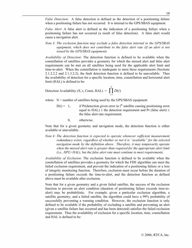
1199
© 2006, RTCA, Inc.
False Detection: A false detection is defined as the detection of a positioning failure when a positioning failure has not occurred. It is internal to the GPS/SBAS equipment.
False Alert: A false alert is defined as the indication of a positioning failure when a positioning failure has not occurred (a result of false detection). A false alert would cause a navigation alert.
Note 3: The exclusion function may exclude a false detection internal to the GPS/SBAS equipment, which does not contribute to the false alert rate (if an alert is not issued by the GPS/SBAS equipment).
Availability of Detection: The detection function is defined to be available when the constellation of satellites provides a geometry for which the missed alert and false alert requirements can be met on all satellites being used for the applicable alert limit and time-to-alert. When the constellation is inadequate to meet these requirements (Sections 2.1.2.2.2 and 2.1.3.2.2), the fault detection function is defined to be unavailable. Thus the availability of detection for a specific location, time, constellation and horizontal alert limit (HAL) is defined to be:
Detection Availability (X, t, Const, HAL) = D ii
N
( )=
∏1
where N = number of satellites being used by the GPS/SBAS equipment
D(i) = 1, if Pr(detection given error in ith satellite causing positioning error equal to HAL) ≥ the detection requirement and Pr (false alert) ≤ the false alert rate requirement.
0, otherwise.
Note that for a given geometry and navigation mode, the detection function is either available or unavailable.
Note 4: The detection function is expected to operate whenever sufficient measurement redundancy exists, regardless of whether or not it is “available” for the selected navigation mode by the definition above. Therefore, it may temporarily operate when the missed alert rate is greater than required for the appropriate alert limit (i.e., HPL>HAL), but the false alert rate must continue to meet requirements.
Availability of Exclusion: The exclusion function is defined to be available when the constellation of satellites provides a geometry for which the FDE algorithm can meet the failed exclusion requirement, and prevent the indication of a positioning failure or a loss of integrity monitoring function. Therefore, exclusion must occur before the duration of a positioning failure exceeds the time-to-alert, and the detection function as defined above must be available after exclusion.
Note that for a given geometry and a given failed satellite, the success of the exclusion function to prevent an alert condition (duration of positioning failure exceeds time-to-alert) may be probabilistic. For example: given a particular exclusion algorithm, a satellite geometry, and a failed satellite, the algorithm could have a 99% probability of successfully preventing a warning condition. However, the exclusion function is only defined to be available if the probability of excluding a satellite and preventing an alert (given a satellite failure has occurred and has been detected) satisfies the failed exclusion requirement. Thus the availability of exclusion for a specific location, time, constellation and HAL is defined to be:

20
© 2006, RTCA, Inc.
Exclusion Availability (X, t, Const, HAL) = E ii
N
( )=
∏1
where N = the number of satellites being used by the GPS/WAAS equipment
E(i) = 1, if Pr(Failed exclusion) ≤ 10-3 and detection still available after exclusion, given ith satellite failed,
0, if Pr(Failed exclusion) > 10-3 or detection not available given ith satellite failed.
Note that for a given geometry and navigation mode, the exclusion function is either available or unavailable.
Note 5: The fact that the definition of exclusion availability states that detection is required to be available after exclusion occurs is only intended to be used as a comparison of algorithmic availability. There may be significant operational benefit gained by an algorithm that is designed such that it is capable of excluding even when detection is not available after exclusion. However, such an algorithm must still meet the missed alert (including wrong exclusion) requirement on a per failure basis. In other words, there must be a means of demonstrating that, when exclusion is attempted without subsequent detection, the equipment excludes the correct satellite with a probability of at least 0.999 (a 0.001 probability of missed alert).
1.8 Assumptions and Approach to Selected Issues
1.8.1 General
1.8.1.1 GPS Constellation and WAAS/SBAS Ground/Space Segments
It is assumed that the GPS constellation provides the accuracy and availability specified in the 2005 Federal Radionavigation Plan and GPS SPS Performance Standard, October 2001. It is also assumed that the GPS signals being transmitted are in conformance with IS-GPS-200D, “Navstar GPS Space Segment / Navigation User Interfaces”, December 2004; and, that Selective Availability (SA) is inactive per U.S. government policy. It is assumed that the WAAS-specific ground and space segments operate in accordance with the WAAS Specification FAA E-2892B, Change 2 dated August 13, 2001. It is assumed that other SBAS ground and space segments will comply with International Civil Aviation Organization Annex 10, Volume I. It is also assumed that the signal-in-space format is in accordance with Appendix A of this document.
Note: In the absence of SA, the availability of GPS/SBAS integrity, particularly FDE, is dramatically increased. The GPS Signal Specification has been replaced by GPS SPS Performance Standard, October 2001, and IS-GPS-200D, “Navstar GPS Space Segment / Navigation User Interfaces”, December 2004. SA was turned off on 1 May 2000.
1.8.1.2 GPS/SBAS Performance
Initially, it is envisioned that aircraft using the GPS/SBAS signal will maintain conformance to current airway or other airspace separation requirements and to available/applicable approach and terminal instrument procedures. Over time, it is anticipated that these requirements and procedures will be revised and/or extended to take advantage of GPS/SBAS capabilities.
2211
© 2006, RTCA, Inc.
Note: RTCA Special Committee 181 defined Required Navigation Performance (RNP) standards in RTCA/DO-236B, Minimum Aviation System Performance Standards (MASPS): Required Navigation Performance (RNP) for Area Navigation (RNAV). The requirements of this document satisfy many of the requirements specified in RTCA/DO-236B.
1.8.1.3 Applicability
The contents of this MOPS are applicable to GPS/SBAS equipment installed in aircraft operating both within and outside of the coverage area served by the SBAS. Integrity outside of the SBAS coverage area, may be assured by use of autonomous Fault Detection and Exclusion (FDE) or through the use of Message Type 28.
1.8.1.4 Interoperability
This document specifies a standard that will provide interoperability between WAAS signals-in-space provided by the FAA and other potential international service providers and receiving equipment developed by different manufacturers. Interoperability will simplify certification procedures and permit users to obtain maximum benefit from GPS/SBAS equipage. This degree of standardization is intended to accelerate the advent of a generally available SBAS capability. In order to promote aircraft interface standardization, Appendix H provides a recommended GPS/SBAS data output standard.
1.8.1.5 Integrity Monitoring
The integrity of the GPS and SBAS geostationary satellite signals is monitored by the SBAS ground system in accordance with the appropriate SBAS specification (WAAS Specification FAA-E-2892B, change 2, dated August 13, 2001 for the WAAS system). The airborne GPS/SBAS receiver then determines which particular sets of satellites to use in the navigation solution. The integration of FDE techniques with SBAS-provided integrity information is discussed in Section 2.1.2.2 of this document. This document assumes that the FDE requirements for GPS/SBAS sensors are driven by the need to provide navigation in the event that an operation is to begin during a period of time that the SBAS is not available. Such navigation will have lower availability than that supplied by the SBAS. In addition, FDE provides the necessary integrity and continuity for operations outside of SBAS coverage.
1.8.1.6 Navigational Waypoints
It is assumed that appropriate waypoints are provided to the aircraft’s navigation system with sufficient accuracy and integrity for the SBAS-supported phases of operation. This document uses the term “waypoints” as a generic term to refer to navigation fixes regardless of whether they are coincident with existing navigation aids or are used as part of a published procedure. Additionally, it is assumed that when GPS/SBAS-based LNAV, LNAV/VNAV, LP, and LPV approaches are approved for the same approach chart they will have the same Initial Approach Waypoint (IAWP), Intermediate Waypoint (IWP), Final Approach Waypoint (FAWP), Landing Threshold Point/ Fictitious Threshold Point (LTP/FTP), and Missed Approach Waypoint (MAWP). The use of these terms in this document is intended to provide a concise definition of these points for the manufacturers of GPS/SBAS equipment: there is no intent to replace the standard terminology already in use in the cockpit, (IAF, IF, FAF, MAP, MAHP). Further, it is assumed that the FAWP is less than 30 nautical miles from the destination airfield. The relationship between these waypoints and the navigation service provided is discussed within the mode switching requirements in Section 2.2 of this document.

22
© 2006, RTCA, Inc.
Note: RTCA/DO-200A addresses the processing of aeronautical data. RTCA Special Committee 181 is developing a revision of RTCA/DO-201A that will address waypoint generation and distribution for all phases of operation.
1.8.1.7 RF Interference
It is assumed that this document’s specification of the RF interference environment specified in Appendix C in which GPS/SBAS sensors must operate successfully will be consistent with the real environment.
1.8.1.8 Time of Applicability of Information in the SBAS Signal-in-Space
It is assumed that the time of applicability of the differential information in the SBAS signal-in-space is the start of transmission from the SBAS GEO of the 1-second message block containing that information. It is anticipated that this start of transmission will be synchronized to the beginning of the corresponding SBAS Network Time (SNT) second (SNT is planned to be negligibly different in this regard from GPS time).
1.8.1.9 Change of Broadcast Ephemeris
It is assumed that after the broadcast ephemeris has changed, the SBAS ground segment will generate satellite corrections based on the old ephemeris for a period of time in order to ensure that all user receivers have decoded the new ephemeris.
1.8.1.10 SBAS Regional Message Type (Message Type 27 and 28)
Message Types (MT) 27 and 28 allow characterization of residual errors specific to a region. MT 27 allows an arbitrary region and associated degradation of performance to be defined. MT 28 models the residual ephemeris error, which is the only system error that has a regional impact that is not otherwise modeled. A service provider may broadcast a Type 28 message, or a Type 27 message, or neither, but not both. GPS/SBAS airborne equipment must be able to decode and use the data in both Type 27 and Type 28 messages.
1.8.2 Approach Applications
1.8.2.1 SBAS Performance for Approaches
SBAS approaches include the use of horizontal and vertical instrument guidance and failure monitoring. High accuracy SBAS Approaches rely on the concept of using a Final Approach Segment (FAS) datablock. There is only one FAS per approach procedure that contains precise information for conducting LPV or LP approaches. It is recommended for SBAS equipment to use the FAS when flying LNAV/VNAV approaches that are co-located with LPV or LP. The approach type available for use is determined by the ability of the SBAS system to provide the necessary level of integrity to support the charted approach types.
The four approach types are defined below:
Approach operations requiring the Final Approach Segment (FAS) data block:
a) Localizer Performance with Vertical guidance (LPV) to alert limits consistent with decision altitudes as low as 200 ft above the threshold. At locations where the SBAS service or airport infrastructure doesn’t support the 200 ft decision altitude, LPV will use the same horizontal alert limits, but less stringent vertical alert limits with decision altitudes as low as 250 ft.
2233
© 2006, RTCA, Inc.
b) Localizer Performance without Vertical guidance (LP) to horizontal alert limit consistent with LPV criteria.
Approach operations not requiring the FAS data block:
c) Lateral navigation/vertical navigation (LNAV/VNAV) approaches with a less stringent horizontal alert limit and vertical alert limit than LPV. The vertical alert limit is consistent with barometric VNAV.
d) Lateral navigation (LNAV) approaches to horizontal alert limit consistent with LNAV/VNAV but no vertical capability.
Note: Equipment requirements for non-SBAS provided vertical guidance (such as Baro VNAV) are outside the scope of this MOPS.
This MOPS requires that the annunciated naming convention be stored in the navigation database since the chart naming convention for these levels of service has not been internationally standardized.
Class Beta-2 and Class Gamma-2 equipment provides the LNAV/VNAV and LNAV approach types while Class Beta-3 and Class Gamma-3 equipment provides all four approach types. Class Delta-4 can support LPV and LP approach procedures while allowing degradation (fail-down) from LPV to LNAV. Class Delta-4 equipment does not support missed approaches. Missed approach guidance is provided by other RNAV equipment on-board the aircraft.
LPV (35m VAL) can provide a decision altitude as low as 200 ft where the SBAS service and airport infrastructure support these approaches. In other locations, LPV (50m VAL) will be used to provide decision altitudes as low as 250 ft. However, LPV (35m VAL) and LPV (50m VAL) will not be charted on the same approach procedure.
Class Beta-3, Gamma-3, and Delta-4 equipment provide LP approaches in locations where obstacles or some other non-GPS/SBAS related reason prevents charting procedures with vertical guidance to LPV criteria. LP and LPV will not be charted concurrently. The LP concept is to use the same lateral precision as LPV to create an approach that potentially has lower minimums than LNAV/VNAV.
1.8.2.2 Approach Path-in-Space
Approach path-in-space accuracy and integrity requirements for GPS/SBAS are discussed in Section 2.2.4 for LNAV/VNAV and Section 2.2.5 for LPV and LP. These requirements presume that path-in-space creation is accomplished using a process that assures high accuracy and integrity of source information for the GPS/SBAS equipment. Integrity of data distribution is accomplished through the use of the standard CRC algorithm described in Section 2.2.4 for LNAV/VNAV and Section 2.2.5 for LPV and LP (the format of data defining the path-in-space for the Final Approach Segment of a GPS/SBAS approach is presented in Appendix D).
1.8.2.3 LNAV/VNAV, LP, LPV Approach Position Integrity
Horizontal and vertical protection level estimates developed using the SBAS signal-in-space (HPLSBAS and VPLSBAS) and autonomous fault detection, as described in Appendix J, are used to assure GPS/SBAS integrity during approach operations. Using autonomous fault detection assures GPS/SBAS integrity with acceptable GPS/SBAS continuity, particularly in the presence of geographically localized (e.g., atmospheric) phenomena that cannot be fully modeled by the SBAS ground segment.

24
© 2006, RTCA, Inc.
The GPS/SBAS equipment will have the capability to predict approach type availability prior to the aircraft reaching the FAWP. Depending on the approach type that is available, the approach may be initiated to the appropriate charted minimums. The avionics will then iteratively compute: (1) aircraft position and a corresponding Vertical Alert Limit (VAL); and, (2) VPLSBAS. The approach can be continued unless either VPLSBAS becomes greater than VAL or a fault is detected by the fault detection algorithm. A similar process will be followed in the horizontal dimension.
1.8.2.4 Vector-to-Final (VTF) Approach
This document introduces the concept of a VTF approach for Class Gamma equipment. Although GPS/SBAS equipment can provide guidance relative to a complete approach procedure, it is sometimes advantageous to intercept the final approach segment of the procedure. This capability is inherent in ILS, where the path in space is fixed and the aircraft simply captures that path.
GPS/SBAS equipment provides equivalent functionality with the VTF approach. If the aircraft is vectored to the final approach segment of an approach defined by a FAS data block, the pilot selects a VTF approach that causes the equipment to discontinue using the published procedure and provide guidance relative to the (extended) final approach segment. It is anticipated that the aircraft will be vectored to intercept that approach in the same fashion aircraft are currently vectored to intercept an ILS. For approaches not defined by a FAS data block, VTF guidance will be provided relative to the inbound course to the final approach waypoint, as these procedures may include a short turn onto the final approach segment.
In addition to this capability to intercept the final approach segment, GPS/SBAS equipment can circumvent any portion of a procedure as necessary through the use of the “Direct-To” function.

2255
© 2006, RTCA, Inc.
2.0 EQUIPMENT PERFORMANCE AND TEST PROCEDURES
2.1 General Requirements
The requirements of this section apply to Class Beta, Class Gamma, and Class Delta equipment (see Table 1-1). Section 2.1.1 applies to all equipment and all navigation modes, while Sections 2.1.2 through 2.1.5 define the additional requirements for the en route/terminal mode, and approach mode (LNAV, LNAV/VNAV, LP and LPV). The equipment must meet all of the requirements for the applicable navigation modes, depending on the Operational Class.
2.1.1 Requirements Applicable to Beta, Gamma, and Delta Equipment
2.1.1.1 General Requirements for All Navigation Modes
2.1.1.1.1 Airworthiness
When installed, the equipment’s design and manufacture shall not impair the airworthiness of the aircraft.
2.1.1.1.2 General Performance
The equipment shall perform its intended function, as defined by this MOPS and the manufacturer.
2.1.1.1.3 Fire Resistance
All materials used shall be self-extinguishing except for small parts (such as knobs, fasteners, seals, grommets and small electrical parts) that would not significantly contribute to propagating a fire.
2.1.1.1.4 Equipment Interfaces
The interfaces with other aircraft equipment shall be designed so that normal or abnormal GPS/SBAS equipment operation shall not adversely affect the operation of other equipment. Conversely, normal or abnormal operation of other equipment shall not adversely affect the GPS/SBAS equipment except as specifically allowed.
Note: These requirements assume that the GPS/SBAS equipment is properly installed and the equipment it is interfacing with is both adequately designed and properly installed.
2.1.1.1.5 Effects of Test
The equipment shall be designed so that applying the specified test procedures shall not produce a condition detrimental to the equipment’s performance, except as specifically allowed in this MOPS.
2.1.1.2 GPS Signal Processing Requirements
The equipment shall be designed to process the GPS signals and necessary data described in the latest GPS SPS Performance Standard, October 2001, and IS-GPS-200D, “Navstar GPS Space Segment / Navigation User Interfaces”, December 2004, under interference conditions described in Appendix C and under the minimum signal conditions defined in Section 2.1.1.10. If the ionospheric corrections provided by the SBAS are not applied to

26
© 2006, RTCA, Inc.
a pseudorange, then the equipment shall decode the ionospheric coefficients in the GPS navigation message and apply the ionospheric corrections described in the IS-GPS-200D, “Navstar GPS Space Segment / Navigation User Interfaces”, December 2004. If the ionospheric corrections provided by SBAS are applied to a satellite pseudorange, the GPS ionospheric model shall not be used for that satellite. A tropospheric correction shall also be applied (an acceptable algorithm is described in Appendix A, Section A.4.2.4).
GPS satellite navigation data shall be continuously decoded. Except for “not healthy” information (as defined in Section 2.1.1.5.5), new clock and ephemeris data (subframes 1, 2 and 3 of the GPS navigation message) shall only be used when the data is verified by reception of a second message containing the same data with a broadcast IODE that matches the 8 least-significant bits of broadcast IODC. Ionospheric data (subframe 4) shall not be used until the data is verified by reception of a second message, potentially from a different satellite, containing the same data. The equipment shall apply the satellite clock correction (including relativistic corrections) derived from the clock parameters in subframe 1 of the GPS navigation message after smoothing the pseudorange measurement (if applicable).
Note: GPS navigation data in subframes 1, 2, and 3 may not always be updated in the same frame.
In addition, the equipment shall not mistake one GPS satellite for another due to cross-correlation during acquisition or reacquisition. An acceptable means of preventing cross-correlation effects during acquisition is to reject GPS satellite ranging data if there is a 3000 km separation between satellite positions derived from the almanac and broadcast ephemerides.
Note: Equipment should be able to track satellites under conditions of ionospheric scintillation that could occur during solar maximum at auroral and equatorial latitudes. There is insufficient information to characterize scintillation and define appropriate requirements and tests for inclusion in this MOPS. However, equipment should be able to track satellites through phase jitter and amplitude fading that can result from scintillation. New requirements may be defined when ionospheric effects can be adequately characterized.
2.1.1.3 SBAS Signal Processing Requirements
2.1.1.3.1 Acquisition and Track
The equipment shall be designed to acquire, track and use the SBAS PRN codes as described in Appendix A, paragraph A.3.3, under interference conditions described in Appendix C, and under the minimum signal conditions defined in Section 2.1.1.10. Paragraph A.3.4 describes two methods for accomplishing this function.
If the ionospheric corrections provided by the SBAS are not applied to a pseudorange, then the equipment shall decode the ionospheric coefficients in the GPS navigation message and apply the ionospheric corrections described in the IS-GPS-200D, “Navstar GPS Space Segment / Navigation User Interfaces”, December 2004. If the ionospheric corrections provided by SBAS are applied to a satellite pseudorange, the GPS ionospheric model shall not be used for that satellite. A tropospheric correction shall be applied (an acceptable algorithm is described in Appendix A, Section A.4.2.4).
In addition, when using an SBAS satellite for ranging, the equipment shall not mistake one SBAS satellite for another due to cross-correlation during acquisition or reacquisition. An acceptable means of preventing cross-correlation effects during

2277
© 2006, RTCA, Inc.
acquisition is to reject SBAS satellite ranging data if there is a 200 km separation between the satellite positions derived from most recent almanac (received within 15 minutes) and the broadcast ephemerides.
The equipment shall not use SBAS PRN codes other than those specified in Table A-1 of Appendix A.
2.1.1.3.2 Demodulation and Forward Error Correction (FEC) Decoding
The equipment shall be designed to demodulate the signals described in the SBAS Signal Specification, paragraph A.2.3. The embedded forward error correction shall be applied in order to minimize data errors in the decoded messages.
The equipment shall not use any message when the Cyclic Redundancy Check described in Appendix A, paragraph A.4.3.3, does not check.
The SBAS message loss rate shall be less than 1 message in 103 for the interference conditions described in Appendix C and under the minimum signal conditions defined in Section 2.1.1.10.
Note: Testing this requirement will require an output of whether or not the CRC for a message has failed to determine the message loss rate.
2.1.1.3.3 SBAS Satellite Pseudorange Determination
The equipment shall determine the pseudorange to each SBAS satellite that is currently being used in the position computation. These pseudoranges shall be referenced to the same time base as that of the GPS satellites. The equipment shall apply SBAS differential corrections to pseudoranges used in the position computation. The equipment shall account for earth rotation in determining the pseudorange. If the ionospheric corrections provided by the SBAS are not applied to the SBAS satellite pseudoranges, then the equipment shall decode the ionospheric coefficients in the GPS navigation message and apply the ionospheric corrections described in IS-GPS-200D, “Navstar GPS Space Segment / Navigation User Interfaces”, December 2004. A tropospheric correction shall also be applied (an acceptable algorithm is described in Appendix A, Section A.4.2.4).
2.1.1.4 SBAS Message Processing
The equipment shall be able to process Message Types 0, 1, 2, 3, 4, 5, 6, 7, 9, 17, 24, 25, 27, and 28 in all navigation modes. Additional message requirements for approach mode (including LNAV/VNAV, LP and LPV) are defined in 2.1.4.9, and 2.1.5.9. Any such messages may optionally be used in modes for which they are not specifically required, but shall then conform to the relevant requirements. If an optional message is used, the loss of those messages shall not cause loss of function. For example, if SBAS ionospheric corrections are used during an LNAVapproach, timeout of those corrections should result in reversion to the GPS ionospheric model as described in Section 2.1.1.2. Message Types the equipment is not specifically designed to decode shall be ignored.
Note: It is recommended that equipment apply SBAS ionospheric corrections whenever available and monitored.
2.1.1.4.1 Message Type 0 - Don’t Use for Safety Applications
Equipment that receives a Message Type 0 shall cease using and discard any ranging data and all message types 1-7, 9-10, 18, 24-28 obtained from that SBAS signal (PRN code).
28
© 2006, RTCA, Inc.
Other message types may be retained, such as message type 17, for potential performance enhancements. In addition, that SBAS signal (PRN code) shall be deselected for at least one minute (See Appendix A, Section A.4.4.1).
Note 1: Message Type 0 will be used during new SBAS satellite testing, and could be used if the SBAS ground system determined that there was a problem in the signals or data already transmitted. In the end state WAAS there will be at least one other WAAS satellite in view for the GPS/SBAS equipment to use. This message applies to a particular PRN signal; it does not apply to the satellite itself as there could be more than one signal broadcast by a satellite.
Note 2: If a Message Type 0 is being broadcast, no particular level of integrity is guaranteed. When WAAS is testing, Type 2 messages will not be broadcast. Instead, the contents of a Type 2 message will be provided in the Type 0 message. Other service providers may broadcast both Type 0 and Type 2 messages during testing. The non-safety-of-life user can use the data at the user’s own risk.
Note 3: Other service providers may choose to send other types of information in a Type 0 message. Processing such a message is under the full responsibility of receiver manufacturers.
2.1.1.4.2 Message Type 1 - PRN Mask Assignments
The equipment shall be able to store and use two PRN masks per GEO PRN signal. The equipment shall be able, during the transition period between masks, to use corrections with different IODPs simultaneously. This prevents any interruption of service during the PRN mask switching (See Appendix A, Section A.4.4.2).
2.1.1.4.3 Message Types 2-5 and 24 - Fast Corrections
All classes of equipment shall decode Message Types 2, 3, 4, 5 and 24. Neither integrity nor correction data shall be used for any satellite unless the IODP matches the IODP obtained from a Type 1 message (See Appendix A, Sections A.4.4.3 and A.4.4.8).
The equipment shall determine and apply the fast corrections for each SBAS HEALTHY satellite range measurement being used in the position solution when an SBAS-based sigma is used for that satellite. If FDE is being used to assure integrity for en route through LNAV and the satellite is a GPS satellite, then applying fast, long-term, and range-rate corrections is optional. The equipment shall apply fast corrections to SBAS HEALTHY GEO range measurements used in the position solution.
2.1.1.4.4 Message Type 6 - Integrity Information
All classes of equipment shall decode Message Type 6. The equipment shall decode the UDREI for use in determining the integrity of the corrected position. Four IODFj’s are broadcast, one for each fast corrections message type (2-5). If an IODFj is equal to 3 in an integrity (type 6) message, the equipment shall use the UDREs regardless of the IODFj in the associated type 2-5, 24 message. If the IODFj is less than 3 in an integrity message, the equipment shall use the σUDRE’s only if the IODFj matches the IODF in the associated fast corrections message (type 2-5 or 24) (See Appendix A, Section A.4.4.4). When interpreting a type 6 message, the user equipment shall use the most recently received PRN mask for which corrections have been received.

2299
© 2006, RTCA, Inc.
2.1.1.4.5 Message Type 7 - Fast Correction Degradation
The equipment shall decode Message Type 7 and determine the timeout interval for fast corrections (See Appendix A, Section A.4.4.5).
2.1.1.4.6 Message Type 9 - SBAS Satellite Navigation Message
The equipment shall use the navigation information contained in Message Type 9, which contains SBAS satellite orbit information, to determine the location of each SBAS satellite being tracked. The equipment shall always use the most recent Message Type 9 (See Appendix A, Section A.4.4.11).
2.1.1.4.7 Message Type 17 - SBAS Satellite Almanac
The most recent almanac data for at least two SBAS satellites above the minimum mask angle, if available, shall be stored to support rapid acquisition of a new SBAS satellite (See Appendix A, Section A.4.4.12). Almanac data for a different service provider other than the sender shall only be used to provide the equipment with the satellite location.
2.1.1.4.8 Message Type 27 - SBAS Service Message
The equipment shall examine the information contained in all Type 27 messages, if broadcast, to determine the δUDRE factor applicable to the user location. The equipment shall use the applicable δUDRE factor to inflate the fast and long-term correction residual variances (σ2
flt) as described in Appendix J, Section J.2.2 (Reference: A.4.4.13, A.4.5.1, and J.2.2.) to SBAS HEALTHY satellites when an SBAS-based sigma is being used for that satellite.
The data in a Type 27 message shall be retained for the time-out interval in Table 2-1, even after power-off. If a Type 27 message with a new IODS indicates a higher δUDRE for the user location, the higher δUDRE shall be applied to SBAS HEALTHY satellites immediately when an SBAS-based sigma is being used for a satellite. A lower δUDRE (with respect to the last complete IODS set) in a new Type 27 message shall not be used until the complete set of messages with the new IODS has been received. Once the complete set of Type 27 messages with a given IODS has been received, all previously received Type 27 messages with different IODS shall be discarded.
Note: WAAS and MSAS will not broadcast the Type 27 message.
If an active Type 27 message exists, the equipment shall use SBAS-based sigmas only when it has the complete Type 27 message set.
Note: Type 27 messages are optional on the part of the SBAS service providers and may, or may not, be broadcast.
2.1.1.4.9 Message Timeout Periods
SBAS equipment shall only use data until it has timed out. The beginning of the timeout interval is the end of the reception of a message. The timeout intervals are a function of the navigation mode. Timeout intervals are given in Table 2-1. The timeout interval for fast corrections is a function of the fast corrections degradation factor broadcast in a Type 7 message and the navigation mode of the equipment, as shown in Table 2-2. The most recently decoded aij shall apply. The SBAS ground system will adjust the maximum fast correction broadcast interval to ensure that fast corrections do not time- out prematurely. Those data items that do not timeout shall continue to be used until
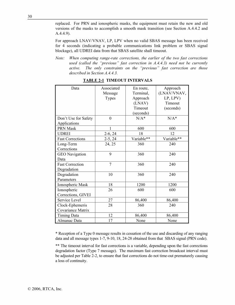
30
© 2006, RTCA, Inc.
replaced. For PRN and ionospheric masks, the equipment must retain the new and old versions of the masks to accomplish a smooth mask transition (see Section A.4.4.2 and A.4.4.9).
For approach LNAV/VNAV, LP, LPV when no valid SBAS message has been received for 4 seconds (indicating a probable communications link problem or SBAS signal blockage), all UDREI data from that SBAS satellite shall timeout.
Note: When computing range-rate corrections, the earlier of the two fast corrections used (called the “previous” fast correction in A.4.4.3) need not be currently active. The only constraints on the “previous” fast correction are those described in Section A.4.4.3.
TABLE 2-1 TIMEOUT INTERVALS
Data Associated Message
Types
En route, Terminal, Approach (LNAV) Timeout (seconds)
Approach (LNAV/VNAV,
LP, LPV) Timeout (seconds)
Don’t Use for Safety Applications
0 N/A* N/A*
PRN Mask 1 600 600 UDREI 2-6, 24 18 12 Fast Corrections 2-5, 24 Variable** Variable** Long-Term Corrections
24, 25 360 240
GEO Navigation Data
9 360 240
Fast Correction Degradation
7 360 240
Degradation Parameters
10 360 240
Ionospheric Mask 18 1200 1200 Ionospheric Corrections, GIVEI
26 600 600
Service Level 27 86,400 86,400 Clock-Ephemeris Covariance Matrix
28 360 240
Timing Data 12 86,400 86,400 Almanac Data 17 None None
* Reception of a Type 0 message results in cessation of the use and discarding of any ranging data and all message types 1-7, 9-10, 18, 24-28 obtained from that SBAS signal (PRN code).
** The timeout interval for fast corrections is a variable, depending upon the fast corrections degradation factor (Type 7 message). The maximum fast correction broadcast interval must be adjusted per Table 2-2, to ensure that fast corrections do not time-out prematurely causing a loss of continuity.

3311
© 2006, RTCA, Inc.
TABLE 2-2 FAST CORRECTION USER TIME-OUT INTERVAL EVALUATION
Fast Corrections Degradation Factor
Indicator (aij)
En Route through LNAV User Time-
Out Interval for corrections - seconds
LNAV/VNAV, LP, LPV User Time-Out
Interval for corrections - seconds
Maximum Fast Correction Update Interval (seconds)
0 180 120 60 1 180 120 60 2 153 102 51 3 135 90 45 4 135 90 45 5 117 78 39 6 99 66 33 7 81 54 27 8 63 42 21 9 45 30 15
10 45 30 15 11 27 18 9 12 27 18 9 13 27 18 9 14 18 12 6 15 18 12 6
2.1.1.4.10 Combining Data from Separate Broadcasts
In approach (LNAV/VNAV, LP, or LPV), corrections and integrity data for all satellites shall be obtained from the same SBAS signal (PRN code). Otherwise, corrections for satellites may be obtained from different SBAS signals (PRN codes, including signals from different SBAS service providers, e.g., EGNOS or MSAS). If data from multiple SBAS satellites are used, then the equipment shall account for differences in the time reference used to generate corrections (e.g., SBAS network time as achieved by each satellite). For each individual GPS or SBAS satellite, the fast correction, σ2
UDRE, long-term corrections, ionospheric correction, σ2
GIVE, fast correction degradation factor δUDRE, and any Type 10 message degradation factors used shall be derived from a single SBAS signal (PRN code).
Ranging measurements from multiple SBAS satellites may be used in the position solution.
Note: The difference in SNT may be solved for or the uncertainties in the ranges may be inflated to account for the SNT differences. In the case where corrections and error bounds from 2 different GEO PRNs are used, an acceptable method for accounting for the SNT differences is to increase the uncertainty on one of the satellite’s data by the equivalent of 100 nanoseconds - +50 nanoseconds for the first SBAS signal (PRN code) and –50 nanoseconds for the second SBAS signal (PRN code).
2.1.1.4.11 Message Type 24 and 25 Long-Term Corrections
The equipment shall decode Message Types 24 and 25 and determine the long-term clock and ephemeris corrections for all GPS satellites and for all SBAS satellites operated by a different service provider than the satellite providing corrections.

32
© 2006, RTCA, Inc.
Note: Service providers may or may not provide Message Type 24/25 long-term correction data for GEOs belonging to the SBAS provider. User equipment should not apply Long Term Corrections for GEOs belonging to the same service provider as the GEO providing corrections.
Long term correction data shall not be used for any satellite unless the IODP matches the IODP obtained from a Type 1 Message. For GPS satellites, the equipment shall compare the Issue of Data (SBAS IOD) in the SBAS Type 24 or 25 Messages for each GPS satellite with the IODE of that GPS satellite being used by the equipment. There are three possible outcomes:
a) The SBAS IOD and GPS IODE match (the normal condition). In this case, the SBAS correction shall be applied using the current GPS IODE to compute satellite position when an SBAS-based sigma is used for that satellite.
b) The SBAS IOD and GPS IODE do not match, but the SBAS IOD matches the previous GPS IODE (a condition that will happen for a few minutes each hour). In this case, the SBAS corrections shall be applied using the previous GPS IODE to compute satellite position when an SBAS-based sigma is used for that satellite.
c) The SBAS IOD and GPS IODE do not match, nor does the SBAS IOD match the previous GPS IODE (a rare condition). In this case, the equipment shall not apply the fast or long-term correction nor use an SBAS-based sigma for that satellite.
The equipment shall retain old ephemeris information for at least 5 minutes, or until a match between SBAS IOD and GPS IODE is obtained.
Note: Retaining old ephemeris information for 5 minutes means there is a need to store at least three sets of broadcast ephemeris, as GPS satellite data can be updated twice within a five minute interval.
When long-term corrections are applied the airborne equipment shall use the active long term correction with latest time of applicability that is less (earlier) than the current time whenever possible. If long-term corrections are received with a time of applicability in the future, those corrections should not be used until: 1) the current time equals the time of applicability; or 2) the previous long-term corrections time out.
Note: The SBAS will generate each satellite correction based on the old ephemeris for approximately two minutes after the GPS broadcast ephemeris has changed to ensure the user equipment has decoded the new ephemeris. During this period, the equipment needs to retain the old ephemeris to ensure the pseudorange measurement and the long-term correction for that satellite are based on the same ephemeredes.
2.1.1.4.12 Application of Differential Corrections
If the equipment filters code or Doppler measurements in developing a pseudorange estimate, the differential corrections shall be applied after filtering, and immediately before computing a position. The equipment shall apply the following corrections to SBAS HEALTHY satellites when an SBAS-based sigma is being used for that satellite:
a) Long term corrections for all GPS satellites;
b) Long term corrections for all SBAS satellites operated by a different service provider than the satellite providing corrections;
c) Fast corrections; and,
d) Range rate corrections.

3333
© 2006, RTCA, Inc.
Long term, fast, and range rate corrections shall not be applied to SBAS UNHEALTHY or SBAS UNMONITORED satellites. The model variance of the residual error shall be as defined in Section J.2.2 when an SBAS-based sigma is being used for that satellite.
Since there are no Range-Rate Corrections (RRCs) broadcast directly by the SBAS, the equipment shall compute these from the SBAS Message Type 2-5 and 24 data when an SBAS-based sigma is being used for a satellite. The RRC is computed by differencing fast corrections as described in Section A.4.4.3.
The equipment shall correct the pseudorange as:
( ) ( ) ( ) ( ) ( )ofiofiiofiimeasuredicorrectedi tttRRCtPRCtPRtPR ,,,,, −×++=
The clock offset error correction and clock drift error correction shall be computed from the information in Message Types 24 and 25 in accordance with Appendix A, Section 4.4.7, and added to the ΔtSV term obtained from the satellite navigation data message when an SBAS-based sigma is used for a satellite. Likewise, the satellite position correction shall be computed and applied in accordance with Appendix A, Section A.4.4.7 when an SBAS-based sigma is used for a satellite. If an active fast correct, valid range-rate correction, active long-term correction (GPS and SBAS satellites operated by a different service provider than the satellite providing corrections), or active SBAS ephemeris data does not exist for a satellite, the equipment shall not use an SBAS-based sigma for that satellite.
2.1.1.4.13 Message Type 28 - Clock-Ephemeris Covariance Matrix Message
The equipment shall examine the information contained in Type 28 messages to determine the δUDRE factor applicable to the user location. The equipment shall use the applicable δUDRE factor to calculate the fast and long-term residual variances (σ2
flt) as described in Section J.2.2 (Reference A.4.4.16 and A.4.5.1) when an SBAS-based sigma is being used for that satellite. If a Type 28 message received for any satellite is still active, then SBAS-based sigmas shall be used only for satellites with an active Type 28 message. If there is no active Type 28 message, all the δUDRE terms are defined to be 1 (unless a Type 27 message has been received). The Type 28 message data shall not be used for any satellite unless the IODP matches the IODP obtained from a Type 1 message (See Appendix A, Section A.4.4.3).
2.1.1.5 Satellite Integrity Status
The equipment shall designate each GPS and SBAS satellite as SBAS UNHEALTHY, SBAS UNMONITORED, or SBAS HEALTHY as defined in Sections 2.1.1.5.2 through 2.1.1.5.4. The order of precedence is as listed. The equipment shall also designate each satellite as GPS HEALTHY or GPS UNHEALTHY, as defined in Sections 2.1.1.5.5 and 2.1.1.5.6. The latency of this designation must be consistent with the requirements of Sections 2.1.1.13, 2.1.4.12, and 2.1.5.12.
2.1.1.5.1 Step Detector
The equipment shall detect a pseudorange step greater than 700 meters on any satellite used in the position solution, including steps that cause loss of lock for less than 10 seconds. A pseudorange step can be caused by:
a) A change in navigation data; or
b) A sudden change in the code phase.
34
© 2006, RTCA, Inc.
The equipment shall falsely declare a pseudorange step less frequently than or equal to 3.33x10⁻⁷ per sample. If the equipment is capable of recovering a satellite after a step error has been declared, the declaration of a pseudorange step shall only be cleared if it is verified through autonomous fault detection.
Note: The manufacturer is free to choose any method to detect step errors. However, any method used should properly take into account satellite movement and aircraft dynamics.
2.1.1.5.2 SBAS UNHEALTHY Designation
The equipment shall designate any GPS or SBAS satellite as SBAS UNHEALTHY upon the occurrence of any of the following conditions:
a) The equipment has successfully decoded a UDREI of 15, indicating that the SBAS has assessed the satellite’s signal as unusable;
b) The step detection function has declared a step error;
c) For SBAS satellites, URA index is 15 or higher; or
d) For SBAS satellites, failure of parity on 4 successive messages.
The SBAS UNHEALTHY status for that satellite shall be changed only after the condition has cleared (including time-out of UDREI data) and none of the above conditions exist. When an SBAS satellite is designated as UNHEALTHY due to any one of the above conditions, the integrity and correction data can continue to be applied.
Note: Although not considered SBAS UNHEALTHY, satellites with UDREI ≥12 cannot be used for LNAV/VNAV, LP and LPV (see sections 2.1.4.11 and 2.1.5.11).
2.1.1.5.3 SBAS UNMONITORED Designation
The equipment shall designate any GPS or SBAS satellite as SBAS UNMONITORED upon the occurrence of any of the following conditions (if not designated as SBAS UNHEALTHY):
a) SBAS UDREI=14 (“Not Monitored”);
b) SBAS data is not provided (satellite not in mask);
c) SBAS signals are not being received (affects all satellites);
d) SBAS data has timed out; or
e) If using long-term corrections, SBAS IOD and GPS IODE cannot be reconciled, as described in 2.1.1.4.11.
The SBAS UNMONITORED status for that satellite shall be changed only after the condition has cleared and none of the above conditions exist.
2.1.1.5.4 SBAS HEALTHY Designation
A GPS or SBAS satellite shall be designated as SBAS HEALTHY if the following conditions are both met and if not designated as SBAS UNHEALTHY or SBAS UNMONITORED:
a) The step detection function has not declared a step error; and,
b) The equipment has not received a UDREI of 14 or 15 for the satellite;

3355
© 2006, RTCA, Inc.
Note: The SBAS may declare a satellite as usable under some conditions even when the GPS navigation message indicates the satellite is UNHEALTHY. For example, the GPS satellite may be declared UNHEALTHY for P(Y)-code reasons while the C/A-code is operating normally. In such a case the user may utilize the satellite in any mode of navigation.
2.1.1.5.5 GPS UNHEALTHY Designation
The equipment shall designate any GPS satellite as GPS UNHEALTHY if the GPS satellite navigation message meets any of the following conditions:
a) 6 bit health word in subframe 1: all cases where MSB=”1” (ref. 20.3.3.3.1.4 and 20.3.3.5.1.3 of IS-GPS-200D, “Navstar GPS Space Segment / Navigation User Interfaces”, December 2004;
b) Failure of parity on 5 successive words (3 seconds);
c) User range accuracy index of 8 or more;
d) Bit 18 of the HOW set to 1(Ref. 20.3.2 of IS-GPS-200D, “Navstar GPS Space Segment / Navigation User Interfaces”, December 2004.);
e) All bits in subframe 1, 2, or 3 are 0’s; f) Default navigation data is being transmitted in subframes 1, 2, or 3 (ref. 20.3.3.2
of IS-GPS-200D, “Navstar GPS Space Segment / Navigation User Interfaces”, December 2004); or
g) The preamble does not equal 8B (hexadecimal) or 139 (decimal).
The GPS UNHEALTHY status for a satellite shall be changed only after the condition has cleared.
Note: The condition of failure of parity on 5 successive words is intended to avoid processing an interfering signal by mistake.
2.1.1.5.6 GPS HEALTHY Designation
The equipment shall designate any GPS satellite as GPS HEALTHY if it does not satisfy any of the criteria listed under Section 2.1.1.5.5 (if not designated as GPS UNHEALTHY).
2.1.1.6 Satellite Selection
The equipment shall monitor the data broadcast of at least one SBAS signal (PRN code) that is providing valid integrity information, if one is available. The equipment should select the best SBAS signal (PRN code), taking into account the correction and integrity information that is being provided.
Note: Selecting the SBAS signal has a significant impact on the availability and reliability of the SBAS position. Selecting the SBAS satellite with the highest elevation angle that is broadcasting applicable ionospheric corrections is normally sufficient.
To ensure continued performance in the event of losing the SBAS signal (PRN code), a second SBAS signal (PRN code) should be monitored if available. Two PRN codes may be broadcast from the same GEO.
The equipment shall automatically select satellites for use in the navigational computation and for use in the FDE algorithm (if the FDE algorithm is being applied).

36
© 2006, RTCA, Inc.
An SBAS HEALTHY designation shall override a GPS UNHEALTHY designation, except that a GPS satellite designated as GPS UNHEALTHY due to failure of parity on five successive words or due to default navigation data shall not be used. The equipment shall not use the range measurement from any satellite designated SBAS UNHEALTHY in the position solution; however, the data from an SBAS UNHEALTHY GEO can be used as described in 2.1.1.5.2.
The equipment shall automatically select satellites and integrity mode (HPLSBAS or HPLFD as appropriate for phase of flight) for use in the position solution. The equipment shall be able to incorporate GEO range measurements, when available, into the position solution. The equipment shall use the same set of satellites in the position solution and for integrity (FDE or SBAS).
Note: Selecting the satellites and correction method has a significant impact on the availability and reliability of the position with integrity. If possible, an all-in-view receiver should be used and compute HPLFD and HPLSBAS based on all satellites useable for each HPL to determine which set of satellites and HPL provides the best performance (i.e., smallest HPL). If this is not possible, the manufacturer should consider that SBAS HEALTHY satellites do not always provide the best performance. Within the GEO footprint but well outside the service volume, an SBAS position can frequently still be computed but has poor satellite geometry since the corrected satellites are in the same general direction.
When a change to the selected set of satellites is necessary, the equipment shall accomplish this change within the time-to-alert (6 seconds for LNAV/VNAV, LP and LPV, or as specified in section 2.1.2.2.2.2.1 or 2.1.3.2.2.2.1 for other operations).
The equipment may allow selection/de-selection of SBAS service providers as described in Section 1.3.3.
It is recommended that the equipment does not provide manual de-selection of satellites to avoid situations where the pilot incorrectly de-selects satellites or fails to re-select them. In a GPS/SBAS environment, it is highly unlikely that the pilot is aware of a satellite failure that the GPS/SBAS system has not flagged. If manual de-selection is implemented, the manufacturer shall address these issues. Consideration should be given to: 1) annunciations to remind the pilot that satellites have been de-selected; 2) the capability to readily re-select satellites; and, 3) the appropriate training to ensure proper equipment operation. The equipment shall clear all previous manual de-selections at power-up.
Manual selection of satellites that have been designated SBAS UNHEALTHY or GPS UNHEALTHY shall be prohibited.
2.1.1.7 Initial Acquisition Time
The equipment shall be capable of acquiring satellites and determining a position without any initialization information, including time, position, and GPS and SBAS almanac data.
The time from power application to first valid position fix shall be less than 5 minutes with 95% confidence given the following:
a) Latitude and longitude initialized within 60 nautical miles;
b) Time and date within 1 minute;
c) Valid almanac data and unobstructed satellite visibility;
d) Under interference conditions of Appendix C;

3377
© 2006, RTCA, Inc.
e) Under the signal conditions defined in Section 2.1.1.10.
In this context, valid position fix means all of the following conditions are met:
a) If available, signals from at least one SBAS satellite are received and processed within the 5-minute period;
b) The determined position meets the accuracy requirements of Section 2.1.2.1, and continues to meet the requirement after the first valid position fix;
c) Integrity monitoring is provided as defined in Section 2.1.2.2.2.
2.1.1.8 Satellite Acquisition Time
2.1.1.8.1 GPS Satellite Acquisition Time
After steady state accuracy has been established, i.e., at least one minute of accurate navigation, the equipment shall be capable of incorporating a new GPS satellite signal into the position within 80 seconds. This requirement applies to a satellite with the minimum signal power in the presence of interfering signals described in Appendix C, and assumes valid almanac data is available.
Note: 66 seconds is required to ensure that a new ephemeris message is received twice, plus 14 seconds for Doppler and range bin search. The 80 seconds begins when a satellite becomes available.
2.1.1.8.2 SBAS Satellite Acquisition Time
After steady state accuracy has been established, i.e., at least one minute of accurate navigation, the equipment shall be capable of acquiring a new SBAS satellite signal, applying the SBAS integrity information, and incorporating that satellite signal into the position solution within 134 seconds. This requirement applies to a satellite with the minimum signal power in the presence of interfering signals described in Appendix C, and assumes valid almanac data is available.
Note: 120 seconds is required to ensure that the equipment has time to demodulate a Message Type 9 navigation message and applicable fast corrections, plus an additional 14 seconds. The 134 seconds begins when a satellite becomes available.
2.1.1.9 Satellite Reacquisition Time
For satellite signal outages of 30 seconds or less when the remaining satellites provide a GDOP of 6 or less, the equipment shall reacquire the satellite within 20 seconds from the time the signal is reintroduced. This requirement applies to a satellite with the minimum signal power in the presence of interfering signals as described in Appendix C.
Note: For SBAS satellites, the momentary loss of signal does not obviate any of the time out intervals defined for SBAS data in Section 2.1.1.4.9. The equipment can continue to use data until it times out.
2.1.1.10 Sensitivity and Dynamic Range
This MOPS defines one equipment architecture with respect to an active antenna that includes a preamplifier as shown in Figure 2-1. Minimum requirements for a minimum standard active antenna are defined in RTCA/DO-301. Manufacturers that restrict their sensor interoperability to a specific antenna can use the unique characteristics of their

38
© 2006, RTCA, Inc.
active antenna in defining the sensitivity and dynamic range (and associated test conditions) as described in this document. All antennas shall comply with RTCA/DO-301, and to the extent non-standard antenna performance is used to define the SBAS equipment requirements, that performance shall be validated in accordance with the tests and methods described in RTCA/DO-301.
Throughout this section (and the test procedures), signal and interference power levels are specified at the input to the preamplifier (antenna port in Figure 2-1) unless otherwise stated. The manufacturer must specify the minimum and maximum preamplifier gain (minimum gain is specified in RTCA/DO-301 but the maximum gain is not) and the corresponding minimum and maximum installation loss (Lmin and Lmax in Figure 2-1). These limits should be defined in the installation instructions.
a) Equipment compatible with a minimum standard RTCA/DO-301-compliant antenna: The equipment shall accommodate GPS and SBAS signals with a minimum input signal power of –136.5 dBm and a maximum input signal power of –115.5 dBm (although acceptable acquisition and tracking performance may not be achievable throughout this entire range). The equipment shall have the capability of tracking GPS and SBAS satellites with a minimum input signal power of -134 dBm in the presence of sky and antenna thermal noise density (Nsky,antenna) of -172.5 dBm/Hz and the Appendix C interference conditions. The equipment shall have the capability of tracking GPS satellites with a maximum power of at least -121 dBm and SBAS satellites with a maximum power of at least -115.5 dBm.
b) Equipment compatible with a specific RTCA/DO-301-compliant antenna: All signal-in-space power levels in this paragraph are referenced to the output of a 0 dBi circularly polarized antenna. The equipment shall accommodate GPS and SBAS signals with a minimum signal-in-space power of -131 dBm and a maximum signal-in-space power of –119.5 dBm (although acceptable acquisition and tracking performance may not be achievable throughout this entire range). The equipment shall have the capability of tracking GPS and SBAS satellites with a minimum signal-in-space power of -128.5 dBm in the presence of sky and antenna thermal noise density (Nsky,antenna) for a specific antenna and the Appendix C interference conditions. The equipment shall have the capability of tracking GPS satellites with a maximum signal-in-space power of at least -123 dBm and SBAS satellites with a maximum signal-in-space power of at least –119.5 dBm.
The manufacturer must specify any unique antenna requirements (e.g., minimum gain at 5 degree elevation angle, G/T ratio). The manufacturer must determine the minimum and maximum signal power levels at the antenna port, accounting for the antenna radiation pattern. The maximum signal power level may account for the combined satellite antenna and specific antenna radiation patterns. For the minimum standard antenna, this effect results in a 2 dB reduction in the maximum GPS signal power level with respect to the sum of the maximum signal in space and the maximum gain of the antenna radiation pattern. The GNSS Noise and external interference are not adjusted by the antenna radiation pattern.
Note 1: The requirements for Class 2, 3, and 4 equipment are only applicable to antennas that comply with (or exceed) RTCA/DO-301; antennas that do not comply with RTCA/DO-301 are not supported. For class 1 equipment, an RTCA/DO-228-compliant passive antenna is acceptable.
3399
© 2006, RTCA, Inc.
Note 2: If a specific antenna is to be used, or the manufacturer elects to demonstrate tracking at a lower mask angle (< 5 degrees), then gain values must be adjusted, and sensitivity and dynamic range specified.
Note 3: Nsky,antenna is determined by the antenna G/T for 1575.42 +2MHz, as the correlation of the noise density outside +2 MHz with the C/A code spectrum has a negligible effect. RTCA/DO-301 provides the method to determine sky and antenna thermal noise density (Nsky,antenna) from G/T. RTCA/DO-301 also provides for guidance on the preamplifier gain to support the test procedures.
Note 4: Acceptable acquisition and tracking performance may not be achievable for the minimum signal-in-space levels of -136.5 dBm depending on the external interference environment and actual level of inter- and intra-system interference. For SBAS signals, these effects can be managed by SBAS service providers for their service volumes, taking into account the actual power level, the users antenna mask angle and resulting gain, and the actual level of inter- and intra-system interference. For GPS signal, the minimum signal-in-space power is -128.5 dBm.
Note 5: The requirements contained in this section are based on a minimum antenna gain of -5.5 dBic and a maximum antenna gain of +4.0 dBic
FIGURE 2-1 SENSITIVITY AND DYNAMIC RANGE CONFIGURATION
2.1.1.11 Equipment Burnout Protection
The equipment shall withstand, without damage, an in-band CW signal of +20 dBm input to the preamplifier at the antenna port.
Note: For a DO-301 or DO-228 antenna, the output of the preamplifier (before any Fixed loss shown in Figure 2-1) is limited to +20 dBm.
2.1.1.12 Integrity in the Presence of Interference
The equipment shall satisfy the applicable integrity requirement within the time-to-alert (See section 2.1.2.2.2.2.1, 2.1.3.2.2.2.1, and 6 seconds for LNAV/VNAV, LP and LPV approach operations) for the output of misleading information in the presence of interfering signals higher in power than the values specified in Appendix C. Under these extreme conditions, it is acceptable to output a navigation alert, but not to output misleading information. The equipment shall autonomously return to steady state

40
© 2006, RTCA, Inc.
accuracy (according to the conditions in Section 2.1.1.7) within 5 minutes after the interference conditions return to those specified in Appendix C for initial acquisition.
Note 1: This requirement is comprehensive in nature in that it is intended to prevent the output of misleading information under any unintentional interference scenario that could arise and specify the recovery time. It is not intended to address the potential effects of intentional interference. While it is recognized that this requirement is impossible to completely verify through testing, an acceptable means of compliance can be found in Section 2.5.4 (Scenario #2 Initial Acquisition Time after abnormal interference Test) and Section 2.5.7.
Note 2: To support problem investigations and maintenance, it is recommended that the equipment output the signal-to-noise ratio for each satellite. This data can be useful when determining if a particular outage is caused by the environment or by receiver anomalies.
2.1.1.13 Alerts/Outputs
The equipment provides data outputs when significant conditions occur that affect flight decisions, in particular loss of integrity monitoring or navigation. For Class Gamma equipment the data output requirements in this section only apply when supporting external applications such as ADS-B. Additional alert/output requirements for Class Gamma and Class Delta equipment can be found in Sections 2.2.1.6 and 2.3.6, respectively.
Note: The requirements in this section apply to the output of position and integrity to other equipment. For example, the time to alert for the position output is 8.0 seconds since the use of that data is not defined while for deviation outputs additional time is allowed based on the navigation mode. Class Gamma and Delta equipment have additional requirements that pertain to the output of deviation and integrity information to the pilot.
2.1.1.13.1 Protection Level
The equipment shall output the Horizontal Protection Level (either the HPLSBAS applicable to en route through LNAV operations; the HPLSBAS applicable to LNAV/VNAV, LP, and LPV; or, the HPLFD as described in Sections 2.1.2.2.2, 2.1.3.2.2, 2.1.4.2.2, and 2.1.5.2.2). The latency of the SBAS-based protection levels shall not exceed 2.0 seconds, from the arrival at the antenna port of the last bit of a message that affects the horizontal protection level. When downgrading from HPLSBAS to HPLFD, the equipment must meet an 8.0 second time to alert requirement from the most recent valid computation of HPLSBAS. The equipment shall indicate if the HPL cannot be calculated (insufficient number of SBAS HEALTHY satellites and fault detection is not available).
Note 1: In addition to the HPL, the equipment may output the HUL.
Note 2: When no HPL can be calculated, integrity monitoring is not provided.
2.1.1.13.2 Navigation Alert
The equipment shall provide an indication or output of the loss of navigation capability within one second of the onset of any of the following conditions:
a) The absence of power (loss of function is an acceptable indicator);
b) Equipment malfunction or failure;

4411
© 2006, RTCA, Inc.
c) The presence of a condition lasting five seconds or more where there are an inadequate number of usable satellites to compute a position solution (i.e., no computed data);
d) The presence of a condition where fault detection detects a position failure that cannot be excluded within the 8.0 second time-to-alert.
The alert shall be returned to its normal state immediately upon termination of the responsible condition.
Note: These requirements do not preclude the implementation of a dead reckoning mode that would allow continued display of navigation information even under condition c), together with a clear indication that the equipment is using the dead reckoning mode.
2.1.2 Requirements for En Route and Terminal Mode
2.1.2.1 Accuracy
The horizontal radial position fixing error shall not exceed 32m, 95th percentile, when HDOP is normalized to 1.5. This requirement shall be met under the minimum signal conditions defined in Section 2.1.1.10 and interference conditions defined in Appendix C.
Note 1: The assumptions are as follows: signal-in-space pseudorange error of 6m; avionics pseudorange error of no more than 5m (rms); a 0.45m (rms) multipath error; a 7 m (rms) ionospheric delay model error; and, a 0.25m (rms) residual tropospheric delay error. The dominant pseudo-range error for users of the GPS Standard Positioning Service is the ionospheric error that remains after application of the ionospheric corrections. This error is also highly variable and depends on conditions such as user geomagnetic latitude, level of solar activity (i.e., point of the solar cycle that applies), level of ionospheric activity (i.e., whether there is a magnetic storm, or not), elevation angle of the pseudo-range measurement, season of the year, and time of day. The ionospheric delay model error assumption reflected in the position fixing error is generally conservative; however, conditions can be found under which the assumed 7 m (1 σ) error during solar maximum would be inadequate. Flight Technical Error (FTE), waypoint error, and RNAV path computation error are not included in this error.
Note 2: Section 2.5.8 describes the test for this requirement. Section 2.5.8 uses a sensor pseudorange accuracy threshold of 5 meters.
If a time output is provided, it shall be within 1 second of coordinated universal time (UTC).
2.1.2.2 Integrity Requirements
2.1.2.2.1 Development Assurance
The hardware and software shall be designed such that the output of misleading information, considered to be a major failure condition, shall be improbable. To demonstrate compliance it will be necessary to conduct a safety assessment to evaluate the system’s implementation against known failure conditions.

42
© 2006, RTCA, Inc.
Note 1: The design requirements applicable to this hazard classification depend upon the aircraft type. The following two paragraphs define acceptable means of compliance for the most stringent application of this hazard classification.
Note 2: In addition to showing compliance with the above requirement, for equipment that supports approach, arrival and departure phases of flight, the European Aviation Safety Agency requires that for electronic display systems, displaying hazardously misleading navigational or position information simultaneously on both pilots’ displays must be “Extremely Remote” (reference- CS 25.1309 and AMC 25.1309).
2.1.2.2.1.1 Hardware Compliance
An acceptable means of compliance for the equipment (oceanic/en route/terminal modes) is to show that failures resulting in misleading information are not more probable than 10-
5/flight hour. For complex firmware implementations such as application-specific integrated circuits (ASIC’s), processes similar to those described in RTCA/DO-178B or RTCA/DO-254 provide an acceptable means of compliance with applicable airworthiness requirements.
2.1.2.2.1.2 Software Compliance
AC 20-115B, which references RTCA/DO-178B, provides an acceptable means for showing that software complies with applicable airworthiness requirements. One acceptable approach to software development is to develop all software that affects navigation and integrity functions to at least the Level C criteria, as defined in RTCA/DO-178B. Another acceptable approach is to substantiate software levels in the safety assessment.
2.1.2.2.2 Integrity Monitoring
The equipment shall be capable of computing HPLSBAS and HPLFD. If the equipment uses integrated GPS/inertial and does not use the SBAS integrity and correction data, it shall meet the requirements and accomplish the test procedures in Appendix R.
2.1.2.2.2.1 SBAS-Provided Integrity Monitoring
The equipment shall compute a horizontal protection level HPLSBAS as defined in Appendix J using only satellites designated SBAS HEALTHY.
2.1.2.2.2.2 FDE-Provided Integrity Monitoring
The equipment shall have a fault detection and exclusion (FDE) capability that uses redundant GPS and SBAS ranging measurements to provide independent integrity monitoring. The equipment shall compute a horizontal protection level (HPLFD) using a weighted FDE algorithm. If the equipment uses a mixture of corrected and uncorrected satellites, the FDE algorithm shall account for the difference between SNT and GPS time.
Note 1: Uncorrected GPS measurements are referenced to GPS time, and both GEO and corrected GPS measurements are referenced to SBAS Network Time.
Note 2: The difference between SNT and GPS time may be solved for or the uncertainties in the ranges may be inflated to account for the difference. An acceptable method for accounting for the difference is to increase the uncertainty on one of the sets (corrected or uncorrected satellites) by the equivalent of 50 nanoseconds.

4433
© 2006, RTCA, Inc.
This algorithm shall be used to monitor the navigation solution whenever SBAS integrity is not available. The detection function refers to the capability to detect a positioning failure that affects navigation, while the exclusion function refers to the capability to exclude one or more satellites from the solution and prevent a positioning failure from affecting navigation.
An acceptable value for the weight is the reciprocal of the estimated variance of range error. The weight shall account for clock/ephemeris, ionospheric, tropospheric, and airborne contributions to range error. If uncorrected GPS measurements are used, an acceptable value for the standard deviation of clock/ephemeris error is the URA. If corrected GPS or GEO range measurements are used, an acceptable value for the standard deviation of clock/ephemeris error is σflt as defined in Appendix J, paragraph J.2.2. An acceptable value for tropospheric error is given in Appendix A, paragraph A.4.2.5. An acceptable value of ionospheric error is σi,UIRE given in Appendix J, paragraph J.2.3 (the value of σi,UIRE depends on whether SBAS-based or single-frequency GPS ionospheric corrections are used). An acceptable value for airborne contribution to range error is σi,air given in Appendix J, paragraph J.2.4.
Note 1: The nominal URA index in IS-GPS-200D, “Navstar GPS Space Segment / Navigation User Interfaces”, December 2004, paragraph 20.3.3.3.1.3 can be used to determine range-domain uncertainty by assuming the URA maps into the near-Gaussian distribution. For convenience, Table 2-3 shows the mapping from URA index to URA value.
TABLE 2-3 URA VALUES
URA Index URA value (m) 0 2 1 2.8 2 4 3 5.7 4 8 5 11.3 6 16 7 32 8 64 9 128
10 256 11 512 12 1024 13 2048 14 4096 15 Do not use
Note 2: The URA does not include the tropospheric or ionospheric uncertainties. These uncertainties are included in Appendix J. The conversion to sigma of the SBAS URA from message type 9 is not standardized among service providers and should not be used for that purpose.
Note 3: The position solution and the FDE algorithms should use the same variance weights to maintain the same statistical characterization of the measurements used.

44
© 2006, RTCA, Inc.
Equipment that uses barometric altitude to improve the performance of this algorithm shall meet the requirements specified in Appendix G. Equipment that uses inertial information to improve the performance of this algorithm shall meet the requirements specified in Appendix R. Equipment that uses other measurements (besides GPS, SBAS, barometric altitude or inertial) must demonstrate that equivalent safety and performance are obtained. FDE algorithms that use other navigation signals external to the aircraft such as LORAN or VOR/DME must be shown to satisfy the availability requirement without the use of the other navigation signals. The manufacturer must provide the means to test and analyze alternate FDE algorithms to demonstrate compliance.
Note: This FDE capability is required to provide a transition to primary means-navigation using the SBAS. It enables operation outside of the SBAS coverage area and provides a secondary means of providing integrity should a catastrophic SBAS failure occur.
2.1.2.2.2.2.1 Time-to-Alert
Class Beta equipment shall alert within 8 seconds for FDE-provided integrity monitoring.
Note: The loss of navigation display timing requirements for Class Gamma and Class Delta equipment is discussed in 2.2.2.6.3, 2.2.3.6.3, 2.2.4.6.3, 2.2.5.6.3 and 2.3.6.
2.1.2.2.2.2.2 Missed Alert Probability
The probability of missed alert shall be less than or equal to 0.001 for every geometry and every navigation mode, regardless of which satellite is causing the positioning failure. If this requirement is not met for a given geometry, then the detection function is defined to be unavailable for that geometry (See Section 1.7.3).
Note 1: This requirement is on the missed alert rate generated by the GPS/SBAS equipment. The missed alert probability is a function of missed detection and wrong exclusion.
Note 2: The testing paragraph defines specific constellations to be used to evaluate this requirement.
2.1.2.2.2.2.3 False Alert Probability
The probability of false alert shall be less than or equal to 3.33x10⁻⁷ per sample. This requirement shall be met for every geometry.
Note: The testing paragraph defines specific constellations to be used to evaluate this requirement.
2.1.2.2.2.2.4 Failed Exclusion Probability
The probability of failed exclusion shall be less than or equal to 10-3 for every geometry and every navigation mode, regardless of which satellite is causing the positioning failure. If this requirement is not met for a given geometry, then the exclusion function is defined to be unavailable for that geometry (See Section 1.7.3).
Note: This requirement is on the alert rate generated by the GPS/SBAS equipment due to failed exclusion. It is equivalent to the probability that a positioning failure is annunciated when a GPS satellite failure occurs and is detected internally. For some algorithms, this probability may be 0 in that exclusion is conducted whenever a failure is detected, if at least 6 measurements are available.

4455
© 2006, RTCA, Inc.
However, such an algorithm could only be used if it also meets the missed alert requirement.
2.1.2.2.2.2.5 Availability
The availability of the FDE algorithm to meet the above requirements with a HAL of 2 nm, when evaluated over the constellations and grids specified in the test procedures (Section 2.5.9), using the same satellite selection algorithm used by the equipment, and using a mask angle of 5 degrees, shall be greater than or equal to the following:
Availability of detection: 99.95%
Availability of exclusion: 99.30%
The availability of the FDE algorithm to meet the above requirements with a HAL of 1 nm, when evaluated over the constellations and grids specified in the test procedures (Section 2.5.9), using the same satellite selection algorithm used by the equipment, and using a mask angle of 5 degrees, shall be greater than or equal to the following:
Availability of detection: 99.90%
Availability of exclusion: 98.45%
Note: This requirement is intended to provide a means to assess the adequacy of FDE algorithms. These numbers are based upon simulation and analysis of the practical availability. These numbers are intended to ensure a consistent minimum capability that can be used by airspace system designers. This availability has not been determined to meet all operational requirements.
2.1.2.3 Equipment Reliability
The equipment should be designed for reliable operation.
2.1.2.4 Satellite Tracking Capability
The equipment shall be capable of simultaneously tracking a minimum of 8 GPS satellites and no SBAS satellites. It shall also be capable of simultaneously tracking at least 6 GPS satellites and two SBAS satellites, including demodulating and storing SBAS data from both satellites.
2.1.2.5 Dynamic Tracking
When the aircraft has dynamics within normal maneuvers defined by the maximum ground speeds and accelerations shown below, the equipment shall meet the accuracy requirements of 2.1.2.1 and the satellite acquisition time requirements of 2.1.1.8 and the satellite reacquisition requirements of 2.1.1.9. Note that g = acceleration of gravity = 9.8 m/s2.
Ground Horiz. Vertical Total Speed Accel. Accel. Jerk 800 kt 0.58 g 0.5 g 0.25 g/s
Abnormal maneuvers are defined to be maneuvers whose accelerations/jerks exceed these values, up to the maximum ground speeds and accelerations shown below.
Ground Horiz. Vertical Total Speed Accel. Accel. Jerk 800 kt 2 g 1.5 g 0.74 g/s
46
© 2006, RTCA, Inc.
During abnormal maneuvers, the equipment shall not output misleading information. When the aircraft returns to normal maneuvers from abnormal maneuvers, the equipment shall meet the steady-state reacquisition requirements of Section 2.1.1.9. During the abnormal maneuver period, loss-of-navigation capability and loss-of-integrity monitoring alerts and outputs shall function as specified.
2.1.2.6 Position Output
The equipment shall determine a position for navigation. This position shall represent the WGS-84 position of the aircraft antenna (or center of navigation) at the time of applicability.
The equipment shall output (via an electronic data interface) the position, velocity, horizontal figure of merit, and applicable HPL.
Note: The position, velocity, HFOM and applicable HPL are collectively referred to as the position output data in the following subsections. Appendix H provides guidance concerning an electronic data interface.
2.1.2.6.1 Position Output Data Update Rate
The minimum update rate of position output data shall be once per second.
2.1.2.6.2 Position Output Data Latency
The latency of the position, velocity, and HFOM output, defined as the interval between the time of the measurement and the time of applicability of the position and velocity, shall be less than or equal to 500 milliseconds.
Note: Latency of the HPL is defined in Section 2.1.1.13.1.
The position output data shall be output prior to 200 milliseconds after the time of applicability.
2.1.3 Requirements for LNAV
2.1.3.1 Accuracy
See Section 2.1.2.1.
2.1.3.2 Integrity Requirements
2.1.3.2.1 Development Assurance
See Section 2.1.2.2.1.
2.1.3.2.1.1 Hardware Compliance
See Section 2.1.2.2.1.1
2.1.3.2.1.2 Software Compliance
See Section 2.1.2.2.1.2
2.1.3.2.2 Integrity Monitoring
See Section 2.1.2.2.2.

4477
© 2006, RTCA, Inc.
2.1.3.2.2.1 SBAS-Provided Integrity Monitoring
See Section 2.1.2.2.2.1.
2.1.3.2.2.2 FDE-Provided Integrity Monitoring
See Section 2.1.2.2.2.2.
2.1.3.2.2.2.1 Time-to-Alert
See Section 2.1.2.2.2.2.1.
2.1.3.2.2.2.2 Missed Alert Probability
See Section 2.1.2.2.2.2.2.
2.1.3.2.2.2.3 False Alert Probability
See Section 2.1.2.2.2.2.3.
2.1.3.2.2.2.4 Failed Exclusion Probability
See Section 2.1.2.2.2.2.4.
2.1.3.2.2.2.5 Availability
The availability of the FDE algorithm to meet the above requirements with an horizontal alert limit (HAL) of 0.3 nm, when evaluated over the constellations and grids specified in the test procedures (Section 2.5.9), using the same satellite selection algorithm used by the equipment, and using a mask angle of 5 degrees, shall be greater than or equal to the following:
Availability of detection: 99.80%
Availability of exclusion: 93.10%
The availability of the FDE algorithm to meet the above requirements with an HAL of 0.1 nm, when evaluated over the constellations and grids specified in the test procedures (Section 2.5.9), using the same satellite selection algorithm used by the equipment, and using a mask angle of 5 degrees, shall be greater than or equal to the following:
Availability of detection: 96.30%
Availability of exclusion: 45.40%
Note: This requirement is intended to provide a means to assess the adequacy of FDE algorithms. These numbers are based upon simulation and analysis of the practical availability. These numbers are intended to ensure a consistent minimum capability that can be used by airspace system designers. This availability has not been determined to meet all operational requirements.
2.1.3.2.2.3 FD Prediction
All equipment classes shall provide an FD prediction algorithm to enable LNAV approach operations outside of SBAS coverage. If the equipment uses barometric altitude to improve availability, the availability of corrected barometric altitude (either by automatic or manual altimeter setting input) may be assumed for this purpose. For the

48
© 2006, RTCA, Inc.
purpose of this calculation an acceptable value of the standard deviation of pressure altitude error is 50 meters.
A means to manually identify a satellite that is expected to be unavailable at the destination (for scheduled maintenance as identified in an FAA Notice to Airmen) may be provided. Identification of such a satellite for FD prediction purposes shall not affect the satellite selection process or deselect that satellite from use in the navigation solution.
When making FD predictions within 30 NM of the destination, current weights may be used. For FD predictions, an acceptable value of the URA index for GPS satellites is 3. Acceptable values of ionospheric, tropospheric, and multipath error are the values associated with the satellite elevation angle at the estimated location and time of arrival.
An acceptable value for ( ) 2/122 ][][ ii divgnoise σσ + (section J.2.4) is the maximum value of RMSpr_air,GPS at the minimum GPS signal level as specified in section 2.1.4.1.4 according to the equipment airborne Accuracy Designator. If range measurements do not have the same time reference, the difference between time references must be accounted for as described in Paragraph 2.1.2.2.2.2.
Note: Guidance on the prediction capability is provided in FAA AC 20-138A (paragraphs 12c and 12e).
2.1.3.3 Equipment Reliability
See Section 2.1.2.3.
2.1.3.4 Satellite Tracking Capability
See Section 2.1.2.4.
2.1.3.5 Dynamic Tracking
When the aircraft has dynamics within normal maneuvers defined by the maximum ground speeds and accelerations shown below, the equipment shall meet the accuracy requirements of 2.1.3.1 and the satellite acquisition time requirements of 2.1.1.8 and the satellite reacquisition requirements of 2.1.1.9. Note that g = acceleration of gravity = 9.8 m/s2.
Ground Horiz. Vertical Total Speed Accel. Accel. Jerk 250 kt 0.58 g 0.5 g 0.25 g/s
Abnormal maneuvers are defined to be maneuvers whose accelerations/jerks exceed these values, up to the maximum ground speeds and accelerations shown below.
Ground Horiz. Vertical Total Speed Accel. Accel. Jerk 250 kt 2 g 1.5 g 0.74 g/s
During abnormal maneuvers, the equipment shall not output misleading information. When the aircraft returns to normal maneuvers from abnormal maneuvers, the equipment shall meet the steady-state reacquisition requirements of Section 2.1.1.9. During the abnormal maneuver period, loss-of-navigation capability and loss-of-integrity monitoring alerts and outputs shall function as specified.
2.1.3.6 Position Output
See Section 2.1.2.6.

4499
© 2006, RTCA, Inc.
2.1.3.6.1 Position Output Update Rate
See Section 2.1.2.6.1.
2.1.3.6.2 Position Output Latency
See Section 2.1.2.6.2.
2.1.3.7 SBAS Message Processing
See Section 2.1.1.4.
2.1.3.8 Application of Differential Correction Terms
See Section 2.1.1.4.12.
2.1.3.9 Satellite Selection
In addition to the general requirements of Section 2.1.1.6, the equipment shall select at least two SBAS satellites, if they are available. When two SBAS satellites are available, the equipment shall be capable of switching between SBAS data streams to maximize continuity of function.
2.1.4 Requirements for LNAV/VNAV Operations
LNAV/VNAV functional requirements apply to the extended Final Approach Segment (FAS). The FAS prescribes the three-dimensional straight-line path in space that an aircraft is supposed to fly on final approach.
2.1.4.1 Accuracy
2.1.4.1.1 Smoothing
The equipment shall perform carrier smoothing. In the presence of a code-carrier divergence rate of up to 0.018 m/s, the smoothing filter output shall achieve an error less than 0.25 m within 200 seconds after initialization, relative to the steady-state response of the following filter:
( )11 2 −− −+= nnnproj PP φφπλ
( )P projnnP ααρ −+= 1
where
Pn is the carrier-smoothed pseudorange in meters,
Pn 1− is the previous carrier-smoothed pseudorange in meters,
P proj is the projected pseudorange in meters,
ρ n is the raw pseudorange measurement in meters (code loop carrier driven, 1st order or higher and with a one sided noise bandwidth greater than or equal to 0.125 Hz),
50
© 2006, RTCA, Inc.
λ is the wavelength in meters,
φ n is the accumulated carrier phase measurement in radians,
φ 1−n is the previous accumulated carrier phase measurement in radians, and
α is the filter weighting function (a unit less parameter), equal to the sample
interval in seconds divided by the time constant of 100 seconds.
Note 1: The difference between the steady-state response of the smoothing filter implemented in the equipment and the steady-state response of the filter defined above is included in the accuracy requirements of section 2.1.4.1.3.
Note 2: One acceptable implementation of the airborne smoothing filter is the filter specified above. This filter is standardized to allow differences between this nominal filter and the dual-frequency ground system filters induced by ionospheric divergence to be included in the broadcast error bounds (σGIVE and σUDRE as appropriate). Smoothing can be done in parallel with other acquisition processes, making the smoothed pseudoranges available as quickly as possible.
2.1.4.1.2 Measurement Quality Monitoring
The satellite signal tracking quality shall be monitored such that the allocated integrity risk due to undetected cycle slip or other undetected measurement fault is within the manufacturer’s allocation.
Note 1: The risk is allocated as part of the integrity budget and the continuity impact of these monitors is allocated within the continuity budget.
Note 2: During an approach, satellite power levels may vary (e.g., due to elevation angles and fading effects that may result in cycle slips). If the satellite is used for positioning and guidance, the loss of the satellite may result in loss of function. The specified interference will further lower the signal-to-noise ratio. Excessive CW interference could cause large pseudorange errors – see Notes 3) and 4) below.
Note 3: An example of a monitoring method to maintain integrity at low power and in the presence of normal interference is signal-to-noise ratio monitoring and navigation message parity checking.
Note 4: A raw pseudorange measurement that deviates excessively from the projected smoothed pseudorange should be excluded from being used by the smoothing filter. If successive measurements are consistently discarded, which would be the case if a carrier or pseudorange step has occurred, the carrier-smoothed pseudorange should not be used. One possible implementation:
If | (ρn – Pproj) | < 10 m
then Pn = Pproj + α(ρn-Pproj)
Otherwise Pn=Pproj
2.1.4.1.3 Accuracy
The accuracy requirements specified in Sections 2.1.4.1.4 and 2.1.4.1.5 represent the performance in steady state. These requirements include errors such as processing errors,
5511
© 2006, RTCA, Inc.
thermal noise, interference, and any residual ionospheric errors caused by a difference between the implemented smoothing filter and the smoothing filter defined in Section 2.1.4.1.1 in the presence of code carrier divergence rate. The code-carrier divergence rate is assumed to be a Normal distribution with zero mean and a standard deviation of 0.012 m/s. Steady-state operation is defined to be following 360 seconds of continuous operation of the smoothing filter.
Note 1: Other than the steady-state ionospheric divergence error, the specified accuracy requirements do not include residual signal propagation errors (e.g., multipath or residual tropospheric errors).
Note 2: Receiver accuracy performance is classified in terms of the Airborne Accuracy Designations.
Note 3: The code-carrier divergence rate assumption does not affect equipment that implements the filter defined in Section 2.1.4.1.1, since the steady-state error from that filter is defined to be zero regardless of the magnitude of the code-carrier divergence (it is the reference filter).
2.1.4.1.4 GPS Satellites
The RMS of the total steady-state equipment contribution to the error in the corrected pseudorange for a GPS satellite (RMSpr_air,GPS) at the minimum and maximum signal levels (Section 2.1.1.10) shall be as follows:
Minimum signal level:
a) RMSpr_air,GPS ≤ 0.36 meters for Airborne Accuracy Designator-A, and
b) RMSpr_air,GPS ≤ 0.15 meters for Airborne Accuracy Designator-B
Maximum signal level:
a) RMSpr_air,GPS ≤ 0.15 meters for Airborne Accuracy Designator-A, and
b) RMSpr_air,GPS ≤ 0.11 meters for Airborne Accuracy Designator-B.
Note 1: The Airborne Accuracy Designator characterizes the airborne equipment’s contribution to error in the differentially corrected pseudoranges. The Airborne Accuracy Designator consists of a single letter associated with the accuracy of the equipment. Two designators are defined in this document.
Note 2: Two levels of receiver accuracy are defined to retain consistency with the GBAS MOPS. However, it is anticipated that SBAS-only avionics will be developed to the AAD-A requirements since significant differences in SBAS availability have not been identified. Manufacturers who choose the AAD-B standard to enable growth towards CAT III GBAS can document that compliance for both SBAS and GBAS.
2.1.4.1.5 SBAS Satellites
The RMS of the total steady-state equipment contribution to the error in the corrected pseudorange for an SBAS satellite (RMSpr_air,GEO) at the minimum and maximum signal levels (Section 2.1.1.10) shall be as follows:
Minimum signal level: RMSpr_air,GEO ≤ 1.8 meters
Maximum signal level: RMSpr_air,GEO ≤ 1.0 meters
Note: This accuracy does not include the relative tracking bias addressed in the following requirement.

52
© 2006, RTCA, Inc.
The relative tracking bias of an SBAS satellite as compared to GPS satellites shall not exceed 5 m for a narrowband signal and 0.5 m for a wideband signal.
Note: This bias is caused by differences in net group delay through the receiver correlator that result from the signal bandwidth of the SBAS satellite as compared to a GPS satellite. It is not observable in a satellite simulator that does not mimic the unique signal characteristics of the SBAS satellites. The characteristics of the narrowband and wideband SBAS signals for this requirement are defined in the test procedures (see Section 2.5.8.4). Appendix T describes and acceptable tool to determine the relative tracking bias. Copies of the actual tool can be obtained through the RTCA Inc. online store at www.rtca.org and downloading the file: DO-229D GEO Bias Tool.
2.1.4.1.6 Position Solution
The equipment shall compute three-dimensional position using a linearized, weighted least-squares solution as defined in Appendix E.
2.1.4.2 Integrity Requirements
2.1.4.2.1 Development Assurance
See Section 2.1.2.2.1.
2.1.4.2.1.1 Hardware Compliance
See Section 2.1.2.2.1.1
2.1.4.2.1.2 Software Compliance
See Section 2.1.2.2.1.2
2.1.4.2.2 Integrity Monitoring
The equipment shall compute SBAS-based protection levels (HPLSBAS and VPLSBAS). The equipment shall also perform fault detection, if more than four range measurements (GPS and/or SBAS) are available. The availability of integrity monitoring is determined solely on the SBAS-based protection levels, while the detection of a failure is based on both methods of integrity.
Note 1: The LNAV/VNAV integrity method is discussed in detail in Section 2.2.4.6. It has been designed to maximize the detection probability of an error with minimal impact on availability.
Note 2: If only 4 satellites are available and SBAS-based protection levels are within the alert limits, LNAV/VNAV may be performed.
2.1.4.2.2.1 SBAS-Provided Integrity Monitoring
The equipment shall compute Horizontal and Vertical Protection Levels (HPLSBAS and VPLSBAS) as described in Appendix J.
2.1.4.2.2.2 Fault Detection-Provided Integrity Monitoring

5533
© 2006, RTCA, Inc.
The equipment shall have a fault detection integrity monitoring capability that uses redundant SBAS-corrected GPS and SBAS ranging measurements to provide independent integrity monitoring.
Note 1: If only 4 ranging sources are available, LNAV/VNAV can be performed using SBAS integrity only.
Note 2: The equipment is required to provide a fault-detection capability to detect local anomalies that may not be detectable by SBAS. Since the underlying probability of these anomalies is not quantified, it is not practical to assign a missed alert probability to the fault detection algorithm. Instead the equipment is required to use the information redundancy that is available to the maximum extent possible.
2.1.4.2.2.2.1 Frequency of Fault Detection
The fault detection algorithm shall be performed at a rate of at least once per minute or within 6 seconds of a change in the set of satellites that are being used in the navigation solution.
Note: This requirement is consistent with the time to alert requirement of 6 seconds, since it is only intended to detect slowly changing conditions.
2.1.4.2.2.2.2 Missed Alert
There is no missed alert probability requirement for LNAV/VNAV.
Note: For the purpose of testing, the vertical protection level (VPLTFD) is evaluated on the basis of a missed alert probability of 0.1.
2.1.4.2.2.2.3 False Alert
The probability of false alert shall be less than or equal to 1.6 x 10⁻⁵ per sample. This requirement shall be met for every geometry.
2.1.4.2.2.2.4 Availability
The fault detection function algorithm availability to meet the above requirements shall be greater than or equal to 95 percent. This requirement assumes: a missed alert rate of 0.1 and a vertical alert limit of 25 m, when evaluated over the constellations and grids specified in the test procedures (Section 2.5.10); using the same satellite selection algorithm used by the equipment; and, using a mask angle of 5 degrees.
Note: The alert limit and missed alert rate assumed here are only test conditions to assess the adequacy of fault detection algorithms.
2.1.4.3 Equipment Reliability
The equipment should be designed for reliable operation.
2.1.4.4 Satellite Tracking Capability
See Section 2.1.2.4.
2.1.4.5 Tracking Constraints
Due to the nature of possible satellite failures, and the necessity to protect against their effects, it is necessary to constrain the technical implementation of the GPS receiver. These constraints are described in terms of Delay Lock Loop (DLL) discriminator

54
© 2006, RTCA, Inc.
correlator spacing, receiver bandwidth and receiver differential group delay. A receiver shall use one of the combinations defined below. The satellite failure effects considered in developing these constraints were:
a) Distorted satellite signal causing multiple correlation peaks.
b) Correlator peak asymmetry in transmitted signal due to code coherent spurious signals (such as reflected signals or code transition induced waveforms in the satellite).
c) Code coherent spurious signals distorted by RF filter differences.
d) Flat correlation peaks causing excessive noise or drift.
e) Discriminator behavior based on transient distorted satellite signal conditions.
Depending on the pre-correlation bandwidth of the equipment, the correlator spacing (d) and the differential group delay shall be within the range as defined in Table 2-4A-C.
2.1.4.5.1 GPS Tracking Constraints
For early-minus-late (E-L) DLL discriminator tracking GPS satellites, the pre-correlation bandwidth of the equipment, correlator spacing (d), and the differential group delay shall be within the ranges as defined in Table 2-4A.
TABLE 2-4A GPS TRACKING CONSTRAINTS FOR E-L DLL DISCRIMINATORS
Region (Figure 2-
2A)
3 dB Pre-correlation
bandwidth, BW
Average Correlator
Spacing (d) [C/A chips]
Instantaneous Correlator
Spacing (d) [C/A chips]
Equipment Differential
Group Delay Allocation
1 2<BW≤7 MHz 0.045-1.1 0.04-1.2 ≤ 600 nsec – N 2 7<BW≤16 MHz 0.045-0.21 0.04-0.235 ≤ 150 nsec – N 3 16<BW≤20 MHz 0.045-0.12 0.04-0.15 ≤ 150 nsec – N
Note: N is the antenna allocation through the output of the pre-amp. For a standard antenna, N is 25 nsec. The instantaneous correlator spacing is defined as the spacing between a particular set of early and late samples of the correlation function. The average correlator spacing is defined as a one-second average of the instantaneous correlator spacing. The average applies over any one-second time frame.
The discriminator (Δ) shall be based upon an average of correlator spacings within the specified range. Either a coherent or a non-coherent discriminator may be used.
For the Double Delta (DD) DLL discriminators of the type Δ = 2Δd1 - Δ2d1 tracking GPS satellites, the pre-correlation bandwidth of the equipment, correlator spacings (d1 and 2d1), and the differential group delay shall be within the range as defined in Table 2-4B. Either a coherent or a non-coherent discriminator may be used.
TABLE 2-4B GPS TRACKING CONSTRAINTS FOR DD DLL DISCRIMINATORS
Region
3 dB precorrelation bandwidth, BW Average correlator spacing range (d1 and 2d1)
[C/A chips]
Instantaneous correlator
spacing range (d1 and 2d1)
Differential Group Delay
1 MHzx
chipMHz 12)50( +∗− < BW < 7 MHz
0.1-0.2 0.09-0.22 ≤ 600 nsec - N

5555
© 2006, RTCA, Inc.
2< BW ≤7 MHz 0.2-0.6 0.18-0.65
MHzxchipMHz 12)50( +∗− < BW <
MHzxchipMHz 2.11)40( +∗
0.045-0.07 0.04-0.077
MHzxchipMHz 12)50( +∗− < BW < 14 MHz
0.07-0.1 0.062-0.11
2
7 < BW ≤ 14 MHz 0.1-0.24 0.09-0.26
≤ 150 nsec - N
3 14 < BW ≤ 16 MHz 0.07-0.24 0.06-0.26 ≤ 150 nsec - N
Note 1: Where x is the average correlator spacing (chips).
Note 2: N is the antenna allocation through the output of the pre-amp. For a standard antenna, N is 25 nsec.
The equipment differential group delay in seconds is defined as:
( )[ ] ( )[ ]df
fddf
fd360
1 21 Φ−
Φ⋅ where:
f1 and f2 are any frequencies within the 3 dB bandwidth of the pre-correlation filter.
Φ(f) is the combined phase response of the equipment in degrees (excluding the antenna).
f is the frequency in Hz.
For the DD DLL Discriminators, the pre-correlation filter shall roll-off by at least 30 dB per octave in the transition band.
1.1
16 MHz
7 MHz
.045
20 MHz
Region 1
2 MHz
Region 2
Region 3
0.12 0.21
Average Correlator Spacing
Rec
eive
r Ban
dwid
th
.08
FIGURE 2-2A RECEIVER BANDWIDTH AND AVERAGE CORRELATOR SPACING FOR E-L DISCRIMINATOR TRACKING OF GPS SATELLITES

56
© 2006, RTCA, Inc.
2MHz
7MHz
10MHz
13MHz14MHz
16MHz
0.045 0.07 0.1 0.2 0.24 0.6
Region 3
Region 1
Region 2
Average Correlator Spacing
Rec
eive
r Ba
ndw
idth
FIGURE 2-2B RECEIVER BANDWIDTH AND AVERAGE CORRELATOR SPACING FOR DD DISCRIMINATOR TRACKING OF GPS SATELLITES
2.1.4.5.2 SBAS Tracking Constraints
For the E-L and DD DLL discriminator tracking SBAS satellites, the pre-correlation bandwidth of the equipment, correlator spacing (d, d1 and 2d1), and the differential group delay shall be within the range as defined in Table 2-4C.
TABLE 2-4C SBAS RANGING FUNCTION TRACKING CONSTRAINTS
Region 3 dB Pre-correlation bandwidth, BW
Average Correlator Spacing (d, d1 and 2d1) [C/A chips]
Instantaneous Correlator Spacing (d, d1 and 2d1) [C/A chips]
Equipment Differential Group Delay
1 2<BW≤7 MHz 0.045-1.1 0.04-1.2 ≤ 600 nsec – N 2 7<BW≤20 MHz 0.045-1.1 0.04-1.2 ≤ 150 nsec – N
Note: N is the antenna allocation through the output of the pre-amp. For a standard antenna, N is 25 nsec.
For the DD DLL Discriminators, the pre-correlation filter shall roll-off by at least 30 dB per octave in the transition band.
2.1.4.6 Correlation Peak Validation
The equipment shall acquire the main C/A code correlation peak for each GPS and SBAS ranging source used for the navigation solution.

5577
© 2006, RTCA, Inc.
For Double Delta DLL discriminators, the equipment shall operate at the correct tracking point corresponding to the strongest peak within the main C/A code correlation peak.
Note: The requirement to track the strongest peak is based on the effect of potential satellite signal failures on DD DLL discriminators (See B.6). It does not apply to E-L DLL discriminators. DD DLL discriminators may demonstrate compliance with this requirement by verifying that the strongest peak is tracked during acquisition and reacquisition. It is not necessary to continually monitor for this condition.
2.1.4.7 Dynamic Tracking
When the aircraft has dynamics within normal maneuvers defined by the maximum ground speeds and accelerations shown below, the equipment shall output positions meeting the accuracy requirements of Section 2.1.4.1 and the satellite acquisition time requirements of 2.1.1.8 and the satellite reacquisition requirements of 2.1.1.9. Note that g = acceleration of gravity = 9.8 m/s2.
Ground Horiz. Vertical Total Speed Accel. Accel. Jerk 250 kt 0.58 g 0.5 g 0.25 g/s
Abnormal maneuvers are defined to be maneuvers having accelerations/jerks that exceed these values, up to the maximum ground speeds and accelerations shown below.
Ground Horiz. Vertical Total Speed Accel. Accel. Jerk 250 kt 2 g 1.5 g 0.74 g/s
During abnormal maneuvers, the equipment shall not output misleading information. When the aircraft returns to normal maneuvers from abnormal maneuvers, the equipment shall meet the steady-state reacquisition requirements of Section 2.1.1.9. During the abnormal maneuver period, loss-of-navigation and loss-of-integrity monitoring alerts and outputs shall function as specified.
2.1.4.8 Position Output
See Section 2.1.2.6.
2.1.4.8.1 Position Output Update Rate
See Section 2.1.2.6.1.
Note: The displayed data for LNAV/VNAV must be updated at a 5 Hz rate (see 2.2.4.4.7).
2.1.4.8.2 Position Output Latency
See Section 2.1.5.8.2.
2.1.4.9 SBAS Message Processing
The minimum message set to be decoded consists of Message Types 0, 1, 2, 3, 4, 5, 6, 7, 9, 10, 17, 18, 24, 25, 26, 27, and 28.
2.1.4.9.1 Message Type 2-5, 6 and 24 Fast Corrections

58
© 2006, RTCA, Inc.
Message Types 2-5 and 24 shall be processed in accordance with Section 2.1.1.4.3 and Message Type 6 shall be processed in accordance with Section 2.1.1.4.4.
2.1.4.9.2 Message Types 24 and 25 Long-Term Corrections
The equipment shall meet the requirements specified in Section 2.1.1.4.11.
2.1.4.9.3 Message Type 18 - Ionospheric Grid Point Masks
Section A.4.4.9 of Appendix A defines a mask of ones and zeros that indicate which grid points have an associated ionospheric delay, developed by the SBAS and given in Message Type 26. The equipment shall decode the information in Message Type 18 to accurately and unambiguously identify the grid point latitude and longitude for each correction in the associated Message Type 26. The equipment shall be able to store and use two IGP masks per GEO PRN signal. It shall be able, during the transition period between masks, to use corrections with different Issue Of Data Ionospheric (IODI) simultaneously. This prevents any interruption of service during the IGP mask switching (See Appendix A, Section A.4.4.9).
2.1.4.9.4 Message Type 26 - Ionospheric Grid Point Delays
The equipment shall decode the Message Type 26 and store the vertical delay and Grid Ionospheric Vertical Error Indicator (GIVEI) at each grid point needed to compute ionospheric corrections where information is provided by the SBAS.
If the IODI in Message Type 26 does not match that of the applicable previous Message Type 18, the equipment shall continue to use previous estimates until a match is achieved, (See Appendix A, Section A.4.4.10).
2.1.4.9.5 Message Types 7 and 10 - Degradation Parameters
The equipment shall decode Message Types 7 and 10 as described in Appendix A, Section A.4.4.5 and A.4.4.6. These degradation parameters are used in computing HPLSBAS and VPLSBAS as described in Appendices A and J.
2.1.4.10 Application of Differential Correction Terms
The equipment shall meet the requirements specified in 2.1.1.4.12, except as modified below:
The equipment shall correct the pseudorange as:
( ) ( ) ( ) ( ) ( )PR t PR t PRC t RRC t t t TC ICi corrected i measured i i of i of i of i i, , , , ,= + + × − + +
where:
TCi is the tropospheric model described in Section 2.1.4.10.3
ICi is the ionospheric model described in Section 2.1.4.10.2.
2.1.4.10.1 Application of Clock and Ephemeris Corrections
Clock and ephemeris corrections are applied as described in Section 2.1.1.4.12.
2.1.4.10.2 Application of Ionospheric Corrections

5599
© 2006, RTCA, Inc.
Section A.4.4.10 of Appendix A defines the vertical ionospheric delays and associated model variances for each grid point identified in Message Type 18. The equipment shall first compute an ionospheric pierce point and obliquity angle for each satellite used in the position computation.
The equipment shall compute the ionospheric slant range delay and error model variance as defined in Appendix A, Section A.4.4.10.4 using information from Message Type 26. Satellites shall not be used in the position computation if this correction cannot be computed.
2.1.4.10.3 Application of Tropospheric Corrections
Equipment shall apply the tropospheric delay correction specified in Appendix A, Section A.4.2.4.
2.1.4.11 Satellite Selection
In addition to the general requirements of Section 2.1.1.6, the equipment shall select at least two SBAS satellites that are broadcasting correction data (including ionosphere) for the user’s location, if they are available. When two SBAS satellites are available, the equipment shall be capable of switching between SBAS data streams to maximize continuity of function. For procedures defined by a FAS data block, (see Appendix D), the equipment shall only use data from satellites where the service provider ID in the Type 17 message matches the service provider ID in the FAS data block unless any service provider may be used (ID=15).
The position determination shall not include satellites (GPS or SBAS) with elevation angles below 5 degrees.
Only satellites designated SBAS HEALTHY with an associated UDREI of less than 12 shall be used for the position solution.
Note 1: Tracking two SBAS satellites is required to enhance continuity of correction information. For best results, it is advisable that the satellite selection algorithm selects satellites for ranging that optimize the fault detection algorithm performance, to enhance the availability of high integrity. This may mean that no SBAS satellites are used in the position solution, depending upon constraints of the number of satellites incorporated in the position and the satellite geometry.
Note 2: For standalone LNAV/VNAV approaches (see Section 2.2.4.3.1), the equipment may use data from any SBAS satellite.
Note 3: Excluding a satellite if the UDREIi is greater than or equal to 12 allows the service provider to designate satellites not to be used for this type of approach under certain failure conditions.
2.1.4.12 Alerts/Outputs/Inputs
The equipment will provide, either as data outputs or as display alerts, information when significant conditions occur that affect flight decisions, in particular loss of integrity monitoring or navigation. Such conditions are described in Sections 2.1.4.12.1 and 2.1.4.12.2 for Class Beta-2 equipment. The requirements for Class Gamma-2, Class Gamma-3 and Class Delta-4 equipment can be found in Sections 2.2.4.6, 2.2.5.6 and 2.3.6, respectively.
2.1.4.12.1 Protection Level

60
© 2006, RTCA, Inc.
Class Beta-2 equipment shall output SBAS-based protection levels (HPLSBAS and VPLSBAS) at least once per second. The latency of the output of the SBAS-based protection levels shall not exceed 0.7 seconds. This latency is measured from the arrival at the antenna port of the last bit of a message that affects the horizontal or vertical protection levels, to output of the last bit of a message containing the protection levels. The equipment shall indicate if the HPLSBAS and VPLSBAS cannot be calculated (insufficient number of SBAS HEALTHY satellites).
Note: The equipment that determines deviation data from the Beta-2 position has been allocated a latency of 0.1 seconds. Class Gamma and Delta equipment requirements can be found in Sections 2.2.4.6, 2.2.5.6 and 2.3.6.
2.1.4.12.2 Navigation Alert
Class Beta-2 equipment shall provide an indication or output of the loss of navigation capability within 1.0 second of the onset of any of the following conditions:
a) The absence of power (loss of function is an acceptable indicator);
b) Equipment malfunction or failure;
c) The presence of a condition where fault detection detects a position failure
d) There are an insufficient number of SBAS HEALTHY satellites (e.g., onset of condition is when the last bit of a SBAS message indicating “Don’t Use” arrives at the antenna port).
The alert shall be returned to its normal state immediately upon termination of the responsible condition.
Note: A navigation alert does not require removal of navigation information from the navigation display. Consideration should be given to continued display of navigation information concurrent with the failure/status annunciation when conditions warrant.
2.1.5 Requirements for LPV and LP Approach Operations
LPV, and LP approach functional requirements apply to the extended Final Approach Segment (FAS). For LPV, the FAS prescribes the three-dimensional straight-line path in space that an aircraft is supposed to fly on final approach. For LP the FAS prescribes the two-dimensional straight line path in space that an aircraft is supposed to fly on final approach.
2.1.5.1 Accuracy
See Section 2.1.4.1 and all subsections.
2.1.5.2 Integrity Requirements
2.1.5.2.1 Development Assurance
The hardware and software shall be designed such that the output of misleading information, considered to be a severe-major/hazardous failure condition, shall be extremely remote during a 150-second approach. To demonstrate compliance it will be necessary to conduct a safety assessment to evaluate the system’s implementation against known failure conditions.

6611
© 2006, RTCA, Inc.
Note: The design requirements applicable to this hazard classification depend upon the aircraft type. The following two paragraphs define acceptable means of compliance for the most stringent application of this hazard classification.
2.1.5.2.1.1 Hardware Compliance
An acceptable means of compliance for the equipment (approach LP or LPV mode) is to show that failures resulting in misleading information are not more probable than 10-7/ 150 seconds. For complex firmware implementations such as application-specific integrated circuits (ASIC’s), processes similar to those described in RTCA/DO-178B or RTCA/DO-254 provide an acceptable means of compliance with applicable airworthiness requirements.
2.1.5.2.1.2 Software Compliance
AC 20-115B, which references RTCA/DO-178B, provides an acceptable means for showing that software complies with applicable airworthiness requirements. One acceptable approach to software development is to develop all software that affects navigation and integrity functions for LP and LPV to at least the Level B criteria, as defined in RTCA/DO-178B. Another acceptable approach is to substantiate software levels in the safety assessment.
2.1.5.2.2 Integrity Monitoring
For LPV, the equipment shall compute SBAS-based protection levels (HPLSBAS and VPLSBAS). For LP, the equipment shall compute SBAS-based horizontal protection levels (HPLSBAS). The equipment shall also perform fault detection, if more than four range measurements (GPS and/or SBAS) are available. The presence of integrity monitoring is determined solely on the SBAS-based protection levels, while the detection of a failure is based on both methods of integrity.
Note 1: The LPV or LP integrity method is discussed in detail in Section 2.2.5.6. It has been designed to maximize the detection probability of an error with minimal impact on availability.
Note 2: If only 4 satellites are available and SBAS-based protection levels are within the alert limits, LPV or LP may be performed.
2.1.5.2.2.1 SBAS-Provided Integrity Monitoring
See Section 2.1.4.2.2.1.
2.1.5.2.2.2 Fault Detection-Provided Integrity Monitoring
The equipment shall have a fault detection integrity monitoring capability that uses redundant SBAS-corrected GPS and SBAS ranging measurements to provide independent integrity monitoring.
Note 1: If only 4 ranging sources are available, LPV or LP can be performed using SBAS integrity only.
Note 2: The equipment is required to provide a fault-detection capability to detect local anomalies that may not be detectable by SBAS. Since the underlying probability of these anomalies is not quantified, it is not practical to assign a missed alert probability to the fault detection algorithm. Instead the equipment is required to use the information redundancy that is available to the maximum extent possible.

62
© 2006, RTCA, Inc.
2.1.5.2.2.2.1 Frequency of Fault Detection
See Section 2.1.4.2.2.2.1
2.1.5.2.2.2.2 Missed Alert
There is no missed alert probability requirement for LPV, and LP.
Note: For testing purposes, the Vertical Protection Level - Test (VPLTFD) is evaluated on the basis of a missed alert probability of 0.1.
2.1.5.2.2.2.3 False Alert
See Section 2.1.4.2.2.2.3.
2.1.5.2.2.2.4 Availability
See Section 2.1.4.2.2.2.4.
2.1.5.3 Equipment Reliability
See Section 2.1.4.3.
2.1.5.4 Satellite Tracking Capability
See Section 2.1.2.4.
2.1.5.5 Tracking Constraints
See Section 2.1.4.5.
2.1.5.5.1 GPS Tracking Constraints
See Section 2.1.4.5.1.
2.1.5.5.2 SBAS Tracking Constraints
See Section 2.1.4.5.2.
2.1.5.6 Correlation Peak Validation
See Section 2.1.4.6.
2.1.5.7 Dynamic Tracking
See Section 2.1.4.7.
2.1.5.8 Position Output
See Section 2.1.2.6.
2.1.5.8.1 Position Output Update Rate
The Class Beta-3 equipment shall compute and output a position at a 5 Hz rate to support an unaided LPV and LP navigator. The equipment shall compute and output a position at a 1 Hz rate to support a LPV and LP navigator that is aided by a separate sensor

6633
© 2006, RTCA, Inc.
providing at least 5 Hz data (e.g., inertial). Each computed position shall be dynamically independent of the previous position.
Note 1: To be dynamically independent, a computed position must account for acceleration occurring in the interval since the last position. Extrapolation of position through velocity vectors is not adequate to meet this requirement. Using carrier phase measurements at 5 Hz is adequate for this purpose.
Note 2: If only 4 ranging sources are available, LPV or LP can be performed using SBAS integrity only.
2.1.5.8.2 Position Output Latency
For Class Beta-3 equipment that supports an unaided LPV and LP navigator, the overall latency, defined as the interval between the time of measurement and time of applicability of the measurement, shall not exceed 300 milliseconds. The output of the data defining the position shall also be completed prior to 300 milliseconds after the time of the measurement. Class Beta-3 equipment that supports an LPV and LP navigator that is aided by a separate sensor shall have overall latency that does not exceed 400 milliseconds, and the output of data defining the position shall also be completed prior to 400 milliseconds after the time of the measurement.
Note: The specified output latency may not be sufficient for all aircraft installations.
2.1.5.9 SBAS Message Processing
See Section 2.1.4.9.
2.1.5.9.1 Message Type 2-5, 6 and 24 Fast Corrections
See Section 2.1.4.9.1.
2.1.5.9.2 Message Types 24 and 25 Long-Term Corrections
See Section 2.1.1.4.11.
2.1.5.9.3 Message Type 18 - Ionospheric Grid Point Masks
See Section 2.1.4.9.3.
2.1.5.9.4 Message Type 26 - Ionospheric Grid Point Delays
See Section 2.1.4.9.4.
2.1.5.9.5 Message Types 7 and 10 - Degradation Parameters
See Section 2.1.4.9.5.
2.1.5.10 Application of Differential Correction Terms
See Section 2.1.4.10 and all sub-sections.
2.1.5.11 Satellite Selection
See Section 2.1.4.11.

64
© 2006, RTCA, Inc.
2.1.5.12 Alerts/Outputs/Inputs
The equipment will provide, either as data outputs or as display alerts, information when significant conditions occur that affect flight decisions, in particular loss of integrity monitoring or navigation. Such conditions are described in Sections 2.1.5.12.1 and 2.1.5.12.2 for Class Beta-3 equipment. The requirements for Class Gamma-2, Class Gamma-3 and Class Delta-4 equipment can be found in Sections 2.2.4.6, 2.2.5.6 and 2.3.6, respectively.
2.1.5.12.1 Protection Level
Class Beta-3 equipment shall output SBAS-based protection levels (HPLSBAS and VPLSBAS) at least once per second. The latency of the output of the SBAS-based protection levels shall not exceed 0.7 seconds. This latency is measured from the arrival at the antenna port of the last bit of a message that affects the horizontal or vertical protection levels, to output of the last bit of a message containing the protection levels. The equipment shall indicate if the HPLSBAS and VPLSBAS cannot be calculated (insufficient number of SBAS HEALTHY satellites). Note that when the HPLSBAS and VPLSBAS cannot be calculated, LPV or LP are not available.
Note: The equipment that determines deviation data from the Beta-3 position has been allocated a latency of 0.1 seconds. Class Gamma and Delta equipment requirements can be found in Sections 2.2.4.6, 2.2.5.6 and 2.3.6. Class Gamma and Delta equipment are required to compute the HPLSBAS and VPLSBAS, but are not required to output them to an external device.
2.1.5.12.2 Navigation Alert
Class Beta-3 equipment shall provide an indication or output of the loss of navigation capability within 1.0 second of the onset of any of the following conditions:
a) The absence of power (loss of function is an acceptable indicator);
b) Equipment malfunction or failure;
c) The presence of a condition where fault detection detects a position failure.
Class Beta-3 equipment shall also provide an indication or output of the loss of navigation capability within 0.6 seconds of the onset of any of the following conditions:
d) There are an insufficient number of SBAS HEALTHY satellites (e.g., onset of condition is when the last bit of an SBAS message indicating “Don’t Use” arrives at the antenna port).
The alert shall be returned to its normal state immediately upon termination of the responsible condition.
Note: A navigation alert does not require removal of navigation information from the navigation display. Consideration should be given to continued display of navigation information concurrent with the failure/status annunciation when conditions warrant.
2.1.5.13 HPL and VPL Prediction
For equipment that elects to support prediction, the equipment shall be able to compute and output a prediction of HPLSBAS and VPLSBAS. The latency of the prediction output and data used for this prediction shall be no more than one minute. This requirement is in support of the selection of approach type described in Section 2.2.5.2.4.

6655
© 2006, RTCA, Inc.
Note: An acceptable means of predicting the VPL is to multiply the largest ratio of VPL to VDOP over the previous 5 minutes using 1 Hz sample by the predicted VDOP 5 minutes in the future (including only those satellites already being tracked and discarding any satellites that are expected to drop below 5 degrees). The same logic can be used for predicting HPL.

66
© 2006, RTCA, Inc.
2.2 Class Gamma Requirements
The requirements of Section 2.2 apply to Class Gamma equipment. Section 2.2.1 applies to all operational classes and all navigation modes, while Sections 2.2.2 through 2.2.5 define the additional requirements for the en route/terminal, and approach (LNAV, LNAV/VNAV, or LP/LPV) mode. The equipment must meet all of the requirements for the applicable navigation modes, depending on the Operational Class.
2.2.1 Class Gamma General Requirements
2.2.1.1 General Human Factors Requirements and Applicable Documents
Note: The requirements in this section are intended to provide a consistent application and interpretation of the human factors issues associated with developing equipment to be used as a primary means of navigation. These requirements are intended to provide design guidance, and it is not implied that every “shall” must be specifically tested. The test procedures described in Section 2.5.11 further define these requirements by describing a method of determining compliance, and it is recommended that the test procedures be reviewed in conjunction with these requirements.
Controls and displays should be consistent with the referenced human factors guidelines below. Controls and displays should be designed to maximize operational suitability, minimize pilot workload, and minimize the possibility of human error associated with equipment operations. Maintaining situational awareness is a key factor in catching errors.
Guidelines for the design of the human factors aspects of controls displays and operating procedures are available in the following documents:
- FAA-AC 25-11 Transport Category Airplane Electronic Display Systems (AC 25-11), July, 1987
- SAE Aerospace Recommended Practice 4102-4 Flight deck alerting systems (ARP 4102-4), July, 1988
- SAE Aerospace Recommended Practice 4102-7 Electronic Displays (ARP-4102-7), July, 1988
- Military Standard 1472D, Human engineering design criteria for military systems, equipment, and facilities, 1989
- SAE Aerospace Standard on Nomenclature and Abbreviations for Use on the Flight Deck SAE AS 425C), December, 1985
- Title 14, Code of Federal Regulations, part 25.1322 (14 CFR part 25.1322)
- Guidelines for the Design of GPS and LORAN Receiver Controls and Displays, Huntley, M.S.,1995, DOT/FA/RD-95/1, DOT-VNTSC-FAA-95-7 (Huntley, 1995)
Relevant portions of the first three documents and others are reviewed and abstracted in (Huntley, 1995). This document also includes background information and additional relevant detail required for display and control design issues identified below.
Where multiple actions are necessary to accomplish a function, the equipment shall provide contextual information of the active subfunction or mode (e.g., NAV, FPL).

6677
© 2006, RTCA, Inc.
2.2.1.1.1 Controls
The design and operation of controls should be consistent with the principles and specifics presented in the above documents.
2.2.1.1.1.1 Operation
Controls that are normally adjusted in flight shall be accessible without interfering with the visibility of critical displays. Controls shall provide clear tactile or visual feedback when operated. The controls shall be movable without excessive effort and detents shall be well defined. Control spacing, physical size, and control logic shall be sufficient to avoid inadvertent activation. Controls shall be operable with the use of only one hand.
2.2.1.1.1.2 Control Labels
Labels shall be readable from viewing distances of 30 inches, under anticipated lighting conditions (Section 2.5.11.3.2). Labels should be unobstructed by controls when viewed within the angle of regard, and located next to or on the controls that they reference. Label placement should follow a consistent logic. Terminology for labeling should describe the function of the control in meaningful terms. Terms should be consistent with those on the display of the function or mode selected and spelled out whenever possible.
2.2.1.1.2 Equipment Operating Procedures
Equipment operating procedures should be designed to maximize operational suitability, minimize pilot workload, and minimize reliance on pilot memory. Detectability of operating errors should be maximized. The actions required to recover from errors should be intuitive, quick, and with minimum impact on subsequent operations. Where possible, maximum use of prompting should be used to minimize reliance on pilot memory.
Operating rules and use of controls required to implement equipment functions should be consistent from mode to mode.
Use of prompting cues shall be consistent. For example, if used as such a cue, illumination of controls would always indicate that the illuminated control should be used next.
2.2.1.1.3 Minimum Workload Functions
Operations that occur with a high frequency or are conducted under potentially stressful operating conditions (e.g. missed approaches) must be possible with a small number of control operations. The number of operations may be minimized through the use of dedicated controls, anticipation of pilot requirements and the use of quick-access menus designed to facilitate rapid selection of required navigation functions, such as direct flight to a waypoint and returning to the final approach course after a missed approach.
The tasks shown in Table 2-5 shall be capable of being accomplished within the indicated time (as a bench test without distraction). The number of actions is included as a guideline. Both the time and number of actions are worst-case, regardless of where the function is initiated (i.e., the pilot may be in the middle of doing something else before initiating the function). An action is defined as a discrete action: e.g., a single button push or a continuous turn of a knob, even if the knob must be turned multiple times. It is acceptable to exceed the maximum number of actions, provided the particular actions

68
© 2006, RTCA, Inc.
required are easy to accomplish and result in a comparable pilot workload (e.g., repeated button pushes of the same button).
To reduce negative transfer between equipment, the recommended pilot procedure to accomplish these functions is included in Table 2-5.
TABLE 2-5 SAFETY-CRITICAL FUNCTIONS
Function Recommended
Maximum Number of
Actions
Maximum Time to
Accomplish
Recommended Pilot Procedure
En route/terminal-related functions: Access primary navigation information (see Section 2.2.1.1.4.7)
1 2 seconds Select primary navigation display.
Suspend automatic sequencing or Hold at the active waypoint (ref. Section 2.2.1.3.11)
2
5
2 seconds
10 seconds
Select SUSP Select [holding] function, select course
Direct to any named waypoint in a published departure, arrival, or approach procedure already in active flight plan (including selecting the waypoint)
5 10 seconds Select waypoint, then select Direct-To.
Direct to any waypoint in the database, but not in the active flight plan (including selecting a five character waypoint)1
14
20 seconds Select waypoint, then select Direct-To or Select Direct-To function, then select waypoint.
Select a course to or from an active waypoint
4 10 seconds Select desired course on [OBS] or Select “course to/from” function, then select course.
Select one of the 9 nearest airports and go Direct.
4 10 seconds Select NRST function, select airport, select Direct-To

6699
© 2006, RTCA, Inc.
Approach-Related Functions: Select and activate an approach at the departure airport, which may be pre-programmed as alternate flight plan.
5 10 seconds Select airport, select approach. or Select and activate the pre-programmed flight plan.
Select and activate an approach at an airport, given that the airport is the active waypoint
11 13 seconds
Select approach, activate
Initiation of the missed approach procedure (ref. Section 2.2.3.2.2) upon sequencing the MAWP, if manually initiated.
2 2 seconds Pilot procedure may vary with published missed approach procedure.
Anytime after the IAWP, repeat the approach with the same IAWP (including providing guidance to the IAWP)
5
10 seconds Select IAWP, select Direct-To.
Initiate a different approach, or the same approach with a different IAWP, at the same airport as a previously selected or activated approach, either before, during, or after conducting the original approach (including providing guidance to the IAWP)
8
10 seconds
Select approach, select IAWP, initiate guidance to IAWP
Selecting a Vector-to-Final (VTF) to the approach in the active flight plan when in either terminal or approach mode
6
8 seconds Select VTF.
Note 1: The “Recommended Pilot Procedure” column describes one or more means, but not the only means, for a receiver to be considered readily intuitive for a pilot with minimum experience and some training in using SBAS receivers. Receivers not using these standards should demonstrate an equivalent level of simplicity.
Note 2: The “Recommended Maximum Number of Actions” column presumes that the selected waypoint is not a duplicate, as selecting a waypoint from a list of duplicates may involve additional actions.
2.2.1.1.4 Displays
Note: Additional information on electronic displays can be found in AC-25-11.
2.2.1.1.4.1 Discernability
Alerts and symbols shall be distinctive and readily discernable from one another. If a control is used to perform multiple functions, the functionality shall be clearly distinguished. There should be a clear indication when any control is in an altered state and not the default (e.g., if a knob is pulled out and functions differently). Fields that are editable, selectable, or require operator entry should be clearly denoted.
The equipment should provide an indication when additional information (e.g., pages) is available.

70
© 2006, RTCA, Inc.
2.2.1.1.4.2 Brightness, Contrast, and Color
Displays shall be readable and colors shall be discernable under anticipated lighting conditions (Section 2.5.11.3.2). Aviation conventions should be observed when using colors for coding. Color coded safety-critical information should be accompanied with another distinguishing characteristic such as shape or location. No more than five colors should be used on the display. When color is used to distinguish between functions and indications, red shall not be used other than for warning indications (hazards that may require immediate corrective action). Amber (yellow) shall be reserved for caution indicators. Blue should be avoided because it is difficult for the human eye to bring blue symbols into focus and to distinguish the color from yellow when the symbols are small. (Ref. AC 25-11 for generally accepted aviation practices.)
2.2.1.1.4.3 Angle of Regard
All displays shall be fully readable up to a horizontal viewing angle of 35 degrees from normal to the face of the display screen. They shall be fully readable up to a vertical viewing angle of 20 degrees from normal to the face of the display screen. This angle of regard does not ensure that the equipment may be installed in any aircraft; it is recommended that the angle of regard be maximized to increase the flexibility of the equipment for installation.
2.2.1.1.4.4 Symbology
Displays should use characteristics and symbols similar to those shown on published charts and sectionals or with commonly accepted aviation practices. The potential for misinterpreting symbols should be minimized. Symbols used for one purpose on published charts should not be used for another purpose on the equipment display. Guidelines for electronic display symbology are provided in SAE ARP 4102-7.
2.2.1.1.4.5 Alphanumerics
Display of letters and numbers depicting primary data shall be readable from viewing distances of 30 inches under anticipated lighting conditions (Section 2.5.11.3.2). The required size may depend upon the display technology used. Initial guidelines for symbol sizes for the indicated categories of information are:
0.18” for primary data
0.12” for secondary data
0.09” for legends
Note: Installation restrictions may be used to compensate for limitations of display designs.
Information critical to determining aircraft location and closure rate on the active waypoint, the waypoint name, and the desired track should be presented in a manner that facilitates rapid cross-checking by the pilot. This information should be differentiated from other information, and it should be located in a consistent manner (including order and position). Except on map displays, the initial approach, final approach, missed approach and missed approach holding waypoints shall be labeled clearly when used as part of an approach procedure. If space limitations require the use of abbreviations, see Section 2.2.1.1.7.

7711
© 2006, RTCA, Inc.
2.2.1.1.4.6 Moving Map
Map displays contribute significantly to pilot positional awareness, facilitate the location of crew programming errors, and provide important checks on the location of waypoints that define instrument approach procedures. However, because they are so compelling and believable, it is essential that they be designed and implemented with care. If a moving map is provided, the following requirements apply.
It should be easy to cross-check map formats with paper renditions of the same information, such as instrument approach procedure charts and sectionals. Map scale shall be appropriate and clear. Map update rates shall be appropriate for approach, terminal and en route operations. Map orientation, such as north-up or track-up, shall be capable of being displayed on the map page and shall be pilot selectable, if multiple orientations are available. Aircraft location and track shall be shown on the plan view and on the profile view if available. The display of obstructions shall reflect database precision. If the map is used as a primary means of steering guidance, the accuracy determination should take into account any cartography error contribution.
Note: RTCA SC-181 has developed RTCA/DO-257A, Minimum Operational Performance Standards for the depiction of Navigational Information on Electronic Maps. Manufacturers should comply with these standards.
2.2.1.1.4.7 Primary Navigation Display
As discussed in Sections 2.2.1.4, 2.2.3.4, and 2.2.4.4 below, it is permitted to use a selectable display, in lieu of continuous display, for certain primary navigation display parameters. If a selectable display is used for this purpose, reconfiguring the display to access the primary navigation information shall require a maximum of two operator actions.
2.2.1.1.4.8 Bearing Labels
All bearing data fields shall be labeled as “°” to the right of the bearing value. All true bearing data fields shall be labeled as “°T” to the right of the bearing value. The “°T” label could be indicated with a one or two characters. (This applies to all courses, tracks, and bearings).
2.2.1.1.5 Annunciations
Visual annunciations shall be consistent with the criticality of the annunciation and shall be readable under all cockpit illumination conditions (See Section 2.5.11.3.2). Visual annunciations shall not be so bright or startling as to reduce pilot dark adaptation. The use of colors to code annunciations should follow color conventions described in AC 25-11, SAE ARP 4102-4, and 14 CFR, part 25.1322.
Auditory alerts have the advantage of being useful regardless of the pilots head and eye orientation, but their use with GPS/SBAS equipment should be considered with care to avoid compromising other auditory alerts that may be available in the cockpit. When used, auditory alerts should be consistent with ARP 4102-4 and adaptable to the annunciator philosophy of the aircraft. Auditory alerts should not be used as the sole source of information, but to draw the pilots attention to information on a visual display, and they should be detectable by the pilot when wearing a headset.
Warnings, annunciations, and messages not critical to the safety of instrument approaches or missed approaches should be suppressed during those phases of terminal operations.

72
© 2006, RTCA, Inc.
2.2.1.1.5.1 Annunciators
A simple font should be used for all alphanumerics. Characters used on alert and status indications should be of the size and brightness necessary to be readable without error or strain under anticipated lighting conditions (Section 2.5.11.3.2). Brightness shall be controllable, which does not preclude automatic adjustment. The equipment shall provide the capability to test all external annunciators.
2.2.1.1.5.2 Messages
Messages should be grouped by urgency level and listed chronologically within each group. All current messages shall be retrievable. An indication shall be provided to identify new messages. The equipment should also indicate when there are current messages.
2.2.1.1.6 Set of Standard Function Labels
Table 2-6 lists potential functions and indications, and provides the associated label or message. Not all of these functions are required. If a function is implemented as a discrete action, the equipment shall use the labels or messages in the Table. If several of the following functions are accomplished as a discrete action, one of the applicable labels in Table 2-6 shall be used (e.g., suspend automatic sequencing and accessing the ability to select a course to or from a waypoint would be labeled “DCRS”). Except for waypoint identifiers, these abbreviations shall not be used to represent a different term.

7733
© 2006, RTCA, Inc.
TABLE 2-6 LABELS AND MESSAGES
Function Label/Message Enter, confirm or acknowledge Enter (ENT) Suspend / unsuspend automatic waypoint sequencing
Suspend (SUSP)
Access to selecting a course to or from a waypoint
OBS, CRS[1]
Clear previous entry, no, or delete Clear (CLR) Activates and deactivates the cursor Cursor (CRSR) Access to a message Message (MSG) Access Direct-To function Direct To ( D ) Access to nearest airports or other fixes
Nearest (NRST)
Access to flight planning functions Flight Plan (FPL) Select Vectors-to-Final (Section 2.2.3.2.1)
Vectors-to-Final (VTF)
Access to primary navigation display (Section 2.2.1.4.1)
NAV or MAP[3]
Annunciations Indication that there is a message Message (MSG, M) Indication of loss of integrity monitoring
LOI “Loss of Integrity - Cross Check Nav.”
Indication of impending turn WPT (flashing)[2], or “Turn to [next heading] in [distance] nm”
Indication of start of turn WPT (continuously lit, not flashing)[2], or “Turn to [next heading] now”
[1] If this function is accomplished using a button, it shall be labeled “OBS” to avoid confusion with “CRSR”. For display of the selected course, including the ability to select that course, it may be labeled “OBS” or “CRS”.
[2] This can be used to indicate other conditions (e.g., waypoint alerting).
[3] If the primary navigation information is integrated on the same display as a moving map, the term “MAP” can be used.
2.2.1.1.7 Set of Standard Abbreviations and Acronyms
When using abbreviations and acronyms, the following abbreviations and acronyms should be used for the terms below, including use in checklists, messages, identification and labels for control functions. These abbreviations should not be used to represent a different term, and they shall be used consistently in the design of the pilot handbook supplements, quick reference checklists and the controls and displays of the equipment.
Note: These requirements are intended to increase the compatibility and consistency between different GPS/SBAS equipment. This will become more important as GPS/SBAS equipment begins to replace VOR and DME equipment as the basic navigation capability. It is not the intent of this list to require upper case abbreviations, as many of these abbreviations may be clearly represented in a

74
© 2006, RTCA, Inc.
combination of upper and lower case type. In all cases the meaning should be easily construed and remain consistent in a given piece of equipment.
Acknowledge (ACK) Active, Activate (ACT, ACTV) Airport, Aerodrome (APT) Air Traffic Control (ATC) Alert/Alerting (ALRT) Altitude (ALT) Along-Track Distance (ATD) Along-Track Error (ATE) Along-Track (ATK) Approach, Approach Control (APPR, APR) Area Navigation (RNAV) Arm, Armed (ARM) Barometric setting (BARO) Bearing (BRG) Cancel (CNCL) Center runway (C) Centigrade (C) Clear (CLR) Coordinated Universal Time (UTC) Course (CRS) Course Deviation Indicator (CDI) Course-to Fix (CF) Cross-Track (XT, XTK) Cross-Track Error (XTE) Cursor (CRSR) Database (DB) Dead Reckoning (DR) Decision Altitude (DA) Delete (DEL) Departure, Departure Control (DEP) Desired Track (DK, DTK) Destination (DEST) Dilution of Precision (DOP) Direct, Direction (DIR) Direct-To (direct symbol, D with arrow) Direct-to Fix (DF) Distance (DIS, DIST) Drift Angle (DA) East (E) Emergency Safe Altitude (ESA) En Route (ENR) En Route Safe Altitude (ESA) Enter (ENT) Estimated Time of Arrival (ETA) Estimated Time of Departure (ETD) Estimated Time En Route (ETE) Fahrenheit (F) Feet, Foot (‘, FT) Feet per Minute (FPM)
Final Approach Waypoint, for waypoint identifiers (f, FA, FAWP)
Flight Level (FL) Flight Plan (FPL) From (FR) Full-Scale Deflection (FSD) Global Navigation Satellite System
(GNSS) Global Positioning System (GPS) Greenwich Mean Time (GMT) Ground speed (GS) Heading (HDG) Height Above Threshold (HAT) Hold, Holding, Holding Pattern (HLD) Horizontal Alert Limit (HAL) Horizontal Protection Level (HPL) Horizontal Situation Indicator (HSI) Horizontal Uncertainty Level (HUL) Instrument Flight Rules (IFR) Initial Approach Waypoint, for
waypoint identifiers (i, IA, IAWP) Intermediate Waypoint (IWP) Intersection (INT) Lateral Navigation (LNAV) Lateral Navigation/Vertical Navigation
(LNAV/VNAV, L/V) Localizer Performance with Vertical
Guidance (LPV) Localizer Performance without Vertical
Guidance (LP) Latitude (LAT) Left (L, LFT) Left runway (L) Localizer (LOC) Localizer-type Directional Aid (LDA) Longitude (LON) Magnetic (M, MAG) Mean Sea Level (MSL) Message (MSG) Meters (M) Military Operating Area (MOA) Millibars (mB) Minimum Descent Altitude (MDA) Minimum En Route Altitude (MEA) Minimum Safe Altitude (MSA) Missed-Approach Holding Waypoint
(h, MH, MAHWP)

75
© 2006, RTCA, Inc.
Missed-Approach Waypoint, for waypoint identifiers (m, MA, MAWP)
Nautical Mile (nm, NM) Nautical Miles per Hour, Knots (KT) Nearest (NRST) Non-Directional Beacon (NDB) Non-Precision Approach (NPA) North (N) Offset (OFST) Off Route Obstacle Clearance Altitude
(OROCA) Omni-Bearing Selector (OBS) Outer Marker (OM) Parallel Track (PTK) Precision Approach (PA) Present Position (PPOS, PP) Procedure (PROC) Procedure Turn (PT) Radial (R, RAD) Radial/Distance (R/D) Radius-to Fix (RF) Range (RNG) Receiver Autonomous Integrity Monitoring (RAIM) Relative Bearing (RB) Required Navigation Performance (RNP) Reverse, Revision, Revise (REV) Right (R, RT) Right runway (R) Route (RTE) Runway (RWY) Selective Availability (SA) Sequence, Sequencing (SEQ) Setup (SET) South (S) Special Use Airspace (SUA) Standard Terminal Arrival Route (STAR) Suspend (SUSP) Temperature (TEMP) Terminal (TERM, TER) Test (TST) Threshold Crossing Height (TCH) Time-to-Alert (TTA) To (TO) To/From (T/F) Tower (TWR) Track (TK, TRK) Track-to Fix (TF) Track Angle Error (TKE) Transition Altitude (TA) Transition Level (TL) True (T) True Airspeed (TAS)
True Heading (TH) Variation (VAR) Vector (VECT) Vector-to Final (VTF) Vertical Alert Limit (VAL) Vertical Navigation (VNAV, VNV) Vertical Protection Level (VPL) Vertical Speed (VS) Vertical Track (VTK) Vertical Track Error (VTE) Vertical Uncertainty Level (VUL) VHF Omni-Directional Range (VOR) Visual Flight Rules (VFR) Warning (WARN, WRN) Waypoint (WPT) West (W) Wide Area Augmentation System
(WAAS) World Geodetic System (WGS)

76
© 2006, RTCA, Inc.
2.2.1.2 Path Selection
Note: The inherent nature of RNAV procedures requires that a series of waypoints can be connected to define a procedure. In this document, the term “flight plan” is used to refer to this basic concept, and can refer to any sequence of waypoints that are interconnected (such as an approach procedure). The equipment should allow the pilot to select and activate an approach procedure without specifically accessing the flight plan functions defined in Section 2.2.1.2.
2.2.1.2.1 Flight Plan Selection
The equipment shall be capable of accommodating an active flight plan of at least twenty discrete waypoints. The equipment shall also be capable of maintaining at least one alternate flight plan. If named automatically, the equipment should label the flight plans with the departure and arrival airports when any flight plan is presented for review, edit, activation, or deletion. If no departure or arrival airport is identified, the flight plan should be labeled with the first and last waypoints as appropriate.
The equipment shall be capable of creating these flight plans, consisting of at least the following items, strung together in any order:
a) The ability to select a procedure by name, and automatically include the series of waypoints and paths that define the procedure (refer to database requirements in Sections 2.2.3.5, 2.2.4.5 and 2.2.5.5, for a discussion of the appropriate procedures);
b) The ability to individually select waypoints by name as part of the flight plan. Waypoint names shall be consistent with published names. The equipment shall provide a minimum 5-character field for input and display of database fix identifiers. Airport identifiers shall be accessible using standard ICAO nomenclature when available (e.g., KJFK);
c) The ability to manually select user-defined waypoints as part of the flight plan. (The equipment must provide the capability to manually enter user-defined waypoints as required in Section 2.2.1.2.6.)
The equipment shall provide a means for the operator to differentiate between duplicate waypoint identifiers in the database, including waypoints in the navigation database and user defined waypoints.
2.2.1.2.2 Flight Plan Review
The equipment shall provide a means to readily display each waypoint of any flight plan for review. The active leg or waypoint shall be identified as such. The equipment should provide a means for the pilot to be able to verify the waypoints in the flight plan (e.g., leg distance, desired leg track, or total flight plan distance).
The equipment shall provide the ability to edit the flight plan, including the ability to insert or delete any waypoint in the flight plan other than those waypoints that are part of a published procedure (departure, arrival, approach). For those waypoints that are part of a published procedure, the equipment shall provide the capability to bypass waypoints or proceed to a waypoint not part of the published procedure. Modifying the final approach segment (i.e., inserting a waypoint between the FAWP and MAWP or bypassing the FAWP or MAWP) shall disable the approach mode.

77
© 2006, RTCA, Inc.
The equipment shall allow the operator to replace a procedure (i.e., departure, arrival or approach) with a different procedure without first deleting the procedure. The equipment shall prompt the operator before replacing a procedure.
When a flight plan is being reviewed or edited, any change shall not be incorporated into the flight plan until that change has been accepted.
The time lag between accepting changes to an active flight plan and outputting navigation guidance derived from the modified flight plan shall not exceed five seconds.
2.2.1.2.3 Flight Plan Activation
Means shall be provided for the pilot to select and activate a flight plan. Prior to activating the flight plan, the equipment shall ensure that the data in the flight plan or obtained from the database is valid. For example, the equipment may verify the entire database upon initial power-up, provided the corruption of the data after verification is improbable. If the database is not available or fails a verification check, the equipment shall continue to function, preventing access to the invalid data (but still providing access to valid data, including user-defined waypoint functions).
Note: The location of a waypoint can change without a change to the name of the waypoint, so it is not adequate to only check the name. When a flight plan includes a procedure (e.g., an approach procedure), the entire procedure should be confirmed as the published procedure may have changed by adding/deleting a waypoint, moving a waypoint, etc.
2.2.1.2.4 Waypoint Sequencing
For “TO-TO” navigation, the equipment shall automatically sequence waypoints in the active flight plan. If automatic sequencing is suspended for any reason, the equipment shall retain the active flight plan for later selection.
If the equipment provides the capability to suspend and unsuspend automatic sequencing as a discrete action (SUSP), the equipment shall continuously annunciate when waypoint sequencing has been suspended. When the pilot deselects SUSP mode, automatic sequencing of waypoints shall resume upon reaching the current waypoint if the current waypoint is in the flight plan. If the current waypoint is not in the flight plan, the equipment should facilitate rejoining the flight plan.
Note: Waypoint sequencing may be suspended for a number of reasons, including: manually accomplishing procedure turns and holding patterns; initial leg of a missed approach procedure; and defining a course to/from a fix. It is possible to accomplish these functions without a unique manual ability to suspend automatic sequencing.
2.2.1.2.5 Manually-Selected Active Waypoint
2.2.1.2.5.1 Direct To
The equipment shall provide the capability to fly from the present position “Direct To” any designated waypoint.
2.2.1.2.5.2 TO/FROM Course Selection
The equipment shall provide a means of selecting and displaying an active waypoint and a desired course “TO” or “FROM” that waypoint. The minimum entry and display

78
© 2006, RTCA, Inc.
resolution of such a selected course shall be one degree. The equipment shall provide the capability to intercept any course to a designated waypoint (CF path). The equipment shall provide an indication, capable of installation in the normal field of view, of whether the equipment is in “TO” or “FROM” operation.
2.2.1.2.5.3 Manually-Selected Waypoint and Waypoint Sequencing
If the desired “TO” waypoint is selected from the active flight plan, automatic sequencing of the remaining waypoints in the active flight plan shall continue following the “TO” waypoint.
If the desired “TO” waypoint is not selected from the active flight plan, the waypoints in that flight plan shall be retained. When the manually selected waypoint is crossed, the equipment shall automatically enter “FROM” operation, maintaining the prior track. The equipment shall remain in “FROM” operation until the pilot manually selects another “TO” waypoint, either on the active flight plan or not.
Note: When the desired waypoint is selected from the flight plan, it is recommended that the equipment facilitate the pilot intercepting the course or track defined by the flight plan leg leading to the desired waypoint.
2.2.1.2.6 User-Defined Waypoints
The equipment shall provide the capability to manually enter and display (prior to its use in the flight plan) the coordinates of a waypoint in terms of latitude and longitude with a resolution of 0.1 minute or better. The equipment shall also provide the capability to create a waypoint at the present position.
The equipment shall provide the ability to enter a waypoint as a range and bearing from another waypoint, with range resolution of 0.1 NM and bearing resolution of one degree or better.
Note: If space permits, the equipment should automatically name user-defined waypoints. Standardized names are recommended for radial/distance waypoints (e.g., LAX240/20). For waypoints entered as a lat/long, a standardized name is not practical.
2.2.1.2.7 Emergency Procedures
The equipment shall provide the capability to determine at least the nearest (NRST) 9 airports, and shall provide the capability to fly directly to any of them. If the NRST function provides access to other types of waypoints, airports should be the default to support rapid identification of a nearby airport in case of an emergency.
Note: The equipment should provide additional information about the runways and approaches available at the nearest airports (e.g., display of the runway length and communication frequencies).
2.2.1.3 Path Definition
The equipment shall define a desired flight path based upon the active flight plan. The current position of the aircraft shall be determined relative to that desired path to determine cross-track deviation. Except as specifically noted, the equipment shall auto-sequence from one waypoint to the next, in accordance with the flight plan, along the flight path. The desired path shall be defined according to the leg type:
TF leg: straight segment between two waypoints

79
© 2006, RTCA, Inc.
CF leg: straight segment following a course to a waypoint
“FROM” leg: straight line following a course from a waypoint
Other leg types are optional. If the equipment is designed to perform DME arcs or RF legs (constant radius turn segment), it shall meet the requirements in Section 2.2.1.3.3.
The equipment shall not permit the flight crew to select a procedure or route that is not supported by the equipment, either manually or automatically (e.g., a procedure is not supported if it incorporates an RF leg and the equipment does not provide RF leg capability).
Note: Procedures (approaches, arrivals, departures) are defined by a series of waypoints and leg types. RNAV procedures (including GPS approaches) and authorized overlay procedures (designated with “or GPS” in title) can be defined using the leg types above and manual procedures (e.g., climb on a heading to an altitude).
2.2.1.3.1 Initial Fix (IF)
An initial fix is defined by a fixed waypoint. An initial fix is used only to define the beginning of a route.
Note: An initial fix does not define a desired track in of itself, but is used in conjunction with leg type (e.g. TF) to define the desired path.
2.2.1.3.2 Fixed Waypoint to a Fixed Waypoint (TF)
A TF leg shall be defined by a WGS-84 geodesic path between two fixed waypoints (Figure 2-3). The first waypoint is either the previous leg termination in the flight plan or an IF.
A
B
Path: Geodesic Course between A and BTermination: Fixed Waypoint B
FIGURE 2-3 TF LEG
2.2.1.3.3 DME Arcs (AF) and Constant Radius to a Fix (RF)
If the ability to perform DME arcs is provided, the equipment shall permit the pilot to readily accomplish such approach procedures using piloting techniques similar to those applicable when referencing a DME facility. This capability may be coded as an arc-to-a-fix (AF) leg type in accordance with ARINC 424.
Note: The equipment should ensure that the non-numerical cross-track information is portrayed relative to the published arc or is flagged.
If the equipment is designed to perform RF legs, an RF leg shall be defined by a constant radius circular arc path about a defined turn center that terminates at a fixed waypoint. The termination fixed waypoint, the turn direction of the leg and the turn center are provided by the navigation database. The radius shall be computed as the distance from the turn center to the termination waypoint by the navigation computer. The beginning of
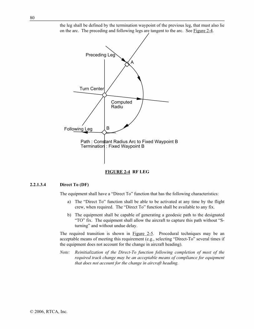
80
© 2006, RTCA, Inc.
the leg shall be defined by the termination waypoint of the previous leg, that must also lie on the arc. The preceding and following legs are tangent to the arc. See Figure 2-4.
FIGURE 2-4 RF LEG
2.2.1.3.4 Direct To (DF)
The equipment shall have a “Direct To” function that has the following characteristics:
a) The “Direct To” function shall be able to be activated at any time by the flight crew, when required. The “Direct To” function shall be available to any fix.
b) The equipment shall be capable of generating a geodesic path to the designated “TO” fix. The equipment shall allow the aircraft to capture this path without “S-turning” and without undue delay.
The required transition is shown in Figure 2-5. Procedural techniques may be an acceptable means of meeting this requirement (e.g., selecting “Direct-To” several times if the equipment does not account for the change in aircraft heading).
Note: Reinitialization of the Direct-To function following completion of most of the required track change may be an acceptable means of compliance for equipment that does not account for the change in aircraft heading.
A
Turn Center
Computed Radiu
B
Path : Constant Radius Arc to Fixed Waypoint B Termination : Fixed Waypoint B
Following Leg
Preceding Leg

81
© 2006, RTCA, Inc.
No S turnsStart DirectTO leg
Previousleg
FIGURE 2-5 DIRECT-TO PATH DEFINITION
2.2.1.3.5 Course to a Fix Waypoint (CF)
A CF leg shall be defined by a WGS-84 geodesic path that terminates at a fixed waypoint with a defined course. The course may be defined as magnetic or true. See Figure 2-6.
A
Path: Inbound Geodesic Course "a"Termination: fixed Waypoint A
a
FIGURE 2-6 CF LEG
2.2.1.3.6 FROM Leg
The equipment shall provide the capability to define a desired course from a waypoint. That course shall define a WGS-84 geodesic path that passes through the “FROM” waypoint with the desired course.
2.2.1.3.7 Fly-By Turns
The equipment shall provide fly-by turn capability. The equipment should provide deviations through the turn.
Unless otherwise designated by a procedure, all turns with heading changes of less than or equal to 120 degrees shall be accomplished as fly-by turns.
Note: The fly-by performance of the equipment will be evaluated when installed in an aircraft. Consideration should be given to coupled operation, bank angles, altitude and different airspeeds. Equipment that relies on procedural means (i.e., do not provide guidance through turns) to accomplish the turn may not be able to be coupled to left-right deviation autopilots.

82
© 2006, RTCA, Inc.
2.2.1.3.7.1 Fly-By Turn Indications
The equipment shall provide an indication at the start of a defined turn, to indicate to the pilot that the turn has begun, (See Figure 2-9.)
The equipment shall provide an indication prior to the start of a defined turn, to indicate to the pilot that a turn is anticipated. It is recommended that this indication be provided 10 seconds prior to the turn initiation distance for turns up to 120 degrees, and 30 seconds prior to turn initiation for turns of 120 degrees or more. (See Figure 2-9.) The equipment shall provide an indication of the desired course of the next active leg no later than the onset of the turn anticipation indication.
Note: These requirements may be satisfied through the use of a moving map display if it is the primary navigation display and it provides adequate representation of the turn to ensure that the turn is initiated at the correct point.
2.2.1.3.7.2 Fly-By Theoretical Transition Area
The defined path shall ensure that the turn is accomplished within the theoretical transition area defined below (see Figure 2-7).
There are no turn requirements for turns greater than 120 degrees.
The theoretical transition area is defined by the region circumscribed by the two legs and an arc with radius ‘R’ that intercepts the first leg at a distance of ‘Y’ from the transition waypoint. The values of ‘R’ and ‘Y’ are defined for various operations in Table 2-7:
TABLE 2-7 FLY-BY THEORETICAL TRANSITION AREA ‘R’ AND Y VALUES
Region Track Change (α) Max. Radius (R) Max. Turn Initiation Distance
(Y) High Altitude (above 19,500 ft)
< 24.1° 93.7 NM R tan
α2
⎛⎝⎜
⎞⎠⎟
≥ 24.1° Y
tanα2
⎛⎝⎜
⎞⎠⎟
20 NM
Low Altitude (below 19,500 ft)
≤ 46.0° Y
tanα2
⎛⎝⎜
⎞⎠⎟
3.65 NM
> 46.0° 8.59 NM R tan
α2
⎛⎝⎜
⎞⎠⎟
Feeder, Missed Approach and Departure
≤ 46.0° Y
tanα2
⎛⎝⎜
⎞⎠⎟
1.78 NM
> 46.0° 4.18 NM R tan
α2
⎛⎝⎜
⎞⎠⎟
Initial Approach ≤ 46.0° Y
tanα2
⎛⎝⎜
⎞⎠⎟
1.45 NM

83
© 2006, RTCA, Inc.
Region Track Change (α) Max. Radius (R) Max. Turn Initiation Distance
(Y) > 46.0° 3.41 NM
R tanα2
⎛⎝⎜
⎞⎠⎟
Intermediate Approach
≤ 46.0° Y
tanα2
⎛⎝⎜
⎞⎠⎟
1.00 NM
> 46.0° 2.38 NM R tan
α2
⎛⎝⎜
⎞⎠⎟
Y R
α
Theoreticaltransitionarea
TransitionWaypoint
FIGURE 2-7 FLY-BY THEORETICAL TRANSITION AREA
2.2.1.3.7.3 Acceptable Means of Defining Fly-By Turns
An acceptable means of complying with 2.2.1.3.7.2 is as follows:
The equipment determines the turn initiation distance according to the following equations:
radius of turn (NM) = R =( )
( )1 458 5
2
10.tan
× − groundspeedφ
turn initiation distance (NM) = Y = R tanα2
⎛⎝⎜
⎞⎠⎟
where: φ = bank angle (nominal of 15°)
α = track change (degrees)
groundspeed in knots
Note: It is acceptable to provide deviations relative to the arc with radius R.
2.2.1.3.8 Fly Over Turns
The equipment shall define a path to accomplish fly-over turns that passes through the transition waypoint. There are no requirements that apply to the transition area, as the

84
© 2006, RTCA, Inc.
equipment provides guidance relative to the two straight segments to and from the transition waypoint. See Figure 2-8.
TheoreticalTransition
Area
TransitionWaypoint
FIGURE 2-8 FLY-OVER THEORETICAL TRANSITION AREA
2.2.1.3.9 Fixed Radius Turns
It is recommended that the equipment be capable of defining a path to accomplish fixed radius turns. The turn radius is defined among a small set of predetermined values: 22.5 NM above FL195 (High altitude) and 15.0 NM at or below FL195 as defined in ICAO RGCSP “Guidance material for RNP” document.
The parameters necessary to define a fixed radius turn are the definition of the transition waypoint and the fixed path transition requirement associated with the route or transition.
Note: This type of turn may be used to space two parallel routes close together. When this is used, the turn will be published and denoted as a high altitude or low altitude turn. Thus the turn radius is a function of the route, and not the aircraft altitude.
2.2.1.3.10 Waypoint Sequencing
The equipment shall provide an indication when a waypoint is sequenced (crossed).
If cross-track deviations are provided relative to a curved path through the turn at a waypoint and the estimated position is within the theoretical transition area, the waypoint shall be sequenced when the estimated position crosses the bisector of the angle defined by the leg on either side of the waypoint, (See Figure 2-9).
If cross-track deviations are not provided relative to a curved path through the turn at a waypoint, the waypoint shall be sequenced at the turn initiation point and deviations provided relative to the extension of the next leg.
Note: For VNAV guidance, vertical deviations are based upon sequencing to the next leg at the bisector. Therefore, sequencing at the turn initiation point is not acceptable for VNAV.
After sequencing past a waypoint, the equipment shall be capable of recalling it if necessary. An example application of this feature is an ATC request to “hold at previous waypoint”.
When the final waypoint in the flight plan is the active waypoint, the equipment shall automatically switch to “FROM” operation at the active waypoint.

85
© 2006, RTCA, Inc.
Note 1: An acceptable means of compliance would be to provide a flashing indication prior to the turn, provide a solid indication at the start of the turn, and remove the indication when deviations are provided relative to the next leg.
Note 2: These requirements replace the waypoint alert requirements of RTCA/DO-208.
Impending turn
Start ofturn
Waypointsequencing
anglebisector
FIGURE 2-9 WAYPOINT SEQUENCING
2.2.1.3.11 Holding Patterns / Procedure Turns
The equipment shall provide the capability to accomplish holding patterns at any waypoint. The equipment shall provide the capability to accomplish procedure turns in accordance with published procedures.
If holding patterns are accomplished manually, then they will be accomplished by suspending automatic waypoint sequencing prior to the hold waypoint. The equipment should allow the pilot to suspend automatic waypoint sequencing with a single pilot action. If holding patterns are accomplished automatically, then the characteristics of a particular installation should be considered.
If automatic sequencing of the flight plan has been suspended, the equipment shall indicate the condition. Automatic sequencing of flight plan waypoints shall resume upon completion or cancellation of the suspended mode.
Note 1: Conventional holding pattern entry procedures are based on overflying the station or fix upon which the holding pattern is based. A consequence is the need for additional protection for entry procedures, particularly on the non-holding side of the holding pattern. With the advent of more capable RNAV systems, it may not be necessary to overfly the station or holding waypoint and more airspace-efficient holding patterns can be developed. RTCA/SC-181 is including criteria for advanced holding patterns in the RNP MASPS. This advanced holding pattern information should be considered by the manufacturer.
Note 2: Pubishing procedures that include procedure turns is expected to cease as the NAS transitions to satellite-based navigation. As such, no specific capability to accomplish procedure turns is required in the equipment other than the capability to enter “FROM” operation and accomplish the procedure turn manually. Consideration should be given to coding procedure turns so they can be accomplished without the pilot manually suspending automatic sequencing on the outbound leg and then manually activating it on the inbound leg.

86
© 2006, RTCA, Inc.
2.2.1.3.12 Magnetic Course
The source of the magnetic variation used for paths that are defined using magnetic course shall be in accordance with the following:
a) If the leg is part of a database terminal area procedure and the magnetic variation is specified by the State for that procedure, the magnetic variation to be used is the value specified.
b) If the leg is not part of a procedure and the active fix is a VOR or TACAN, the magnetic variation to be used is the published station declination for the VOR or TACAN.
c) If the leg is not part of a procedure and the terminating fix is not a VOR or TACAN, the magnetic variation to be used shall be defined by the equipment using an internal model.
The navigation equipment shall have the capability of assigning a magnetic variation at any location within the region that flight operations may be conducted using Magnetic North reference. The assigned magnetic variation shall be within two degrees of the value determined at the same location and time by an internationally recognized magnetic model that is valid for the time of computation (e.g. USGS, IGRF).
2.2.1.3.13 Dead Reckoning
The equipment shall provide a Dead Reckoning capability in the en route mode. The Dead Reckoning capability shall be active whenever no position can be obtained from GPS/SBAS. Dead Reckoning shall be clearly indicated to the pilot. This caution may be implemented by flagging the primary navigation display.
If automatic input of TAS or heading is not available, the equipment shall project the last known GPS/SBAS position forward using last known position, groundspeed and desired track. The equipment shall continue to navigate relative to the active flight plan. The equipment shall change its assumed track in accordance with the flight plan (i.e., if the flight plan requires a track change, the equipment assumes that the pilot performs the track change as displayed by the equipment). The equipment shall provide the capability to determine bearing to an airport, based upon the dead reckoning position (e.g., accessible via the nearest airport function described in Section 2.2.1.2.7).
Note: The performance of the dead reckoning capability can be significantly improved by the input of more recent information, such as a position updating capability (e.g., place/bearing/distance as reported by ATC) and groundspeed updating.
It is recommended that the equipment accept TAS and heading inputs. If this capability is provided and this information is available, the equipment shall project the last known GPS/SBAS position forward using TAS and heading, corrected for last known wind. The equipment shall continue to navigate using this position and the active flight plan.
2.2.1.3.14 Fuel Management and Alerting
Note: Class Gamma GPS/SBAS equipment has access to a significant amount of information that could be used to assist the pilot in managing fuel resources. Consideration should be given to providing a fuel monitoring function to alert the pilot if the estimated fuel reserves fall below an acceptable level. Equipment that provides this capability should have access to reliable fuel consumption rates, ideally from a fuel flow sensor. It may be possible to provide a capability similar to the automatic fuel-flow sensor by defining algorithms that model the

87
© 2006, RTCA, Inc.
amount of fuel burned based upon aircraft trajectory (e.g., climb, cruise, descent). This capability should be provided in a manner that minimizes pilot workload and reliance on memory.
2.2.1.3.15 Geodesic Path Computation Accuracy
The cross-track path deviation error between the computed path used to determine cross-track deviations and the true geodesic shall be less than 10% of the horizontal alert limit of the navigation mode applicable to the leg containing the path.
Note: This requirement may be satisfied by using an algorithm that satisfies this accuracy requirement for paths of any length (e.g., Appendix L); or, by using an algorithm that approximates the geodesic with the required accuracy for paths of a limited length (e.g., great circle approximations). In the latter case, the equipment must limit the maximum length of individual path segments either procedurally or by insertion of additional waypoints that must be available for filing as part of the flight plan.
2.2.1.3.16 Parallel Offsets
The parallel offset is defined as a route that is alongside, but offset from, the original active route. The basis of the offset path is the original flight plan leg(s) and one or more offset reference points as computed by the navigation equipment.
Note: The parallel offset function enables an aircraft to be flown on a flight path offset from the center line of a route while maintaining all characteristics of that flightpath, as if it were being flown centrally on the route. Examples for the use of offsets are weather avoidance, air traffic conflict avoidance, etc.
Each computed offset reference point is located so that it lies on the intersection of lines drawn parallel to the host route at the desired offset distance and the geodesic that bisects the track change angle. An exception to this occurs if there is a route discontinuity (or end of route). In this case, the offset reference point is located abeam of the original flight plan waypoint at the specified offset distance.
The offset path and associated offset reference points must be created to the same standards as the host route. The earth model must be WGS-84 and the offset reference points must have the same or better resolution than the host route waypoints.
The parallel offset function shall be available for en route TF and the geodesic portion of DF leg types at a minimum.
If a leg of the base route is a geodesic, then the corresponding leg of the offset route shall also be a geodesic. If the base route leg is a TF leg, the offset route leg shall be the geodesic drawn between the offset reference points corresponding to the beginning and end of the base route leg (the offset “FROM” and “TO” waypoints). In the case of a DF base route leg, the first offset reference point shall be abeam of the start of the geodesic part of the base route DF leg.
Note: This means that a geodesic parallel offset leg will not be exactly parallel to its corresponding geodesic base route leg, nor will points in the middle of the offset leg be exactly at the specified offset distance from the base route leg. This difference is more noticeable for very long base route legs and for larger offset distances.
The equipment shall have the capability to fly parallel tracks at a selected offset distance. When executing a parallel offset, the navigation mode and all performance requirements
88
© 2006, RTCA, Inc.
of the original route in the active flight plan shall be applicable to the offset route. The equipment shall provide a capability to enter offset distance in increments of 1 nm, left or right of course. The equipment shall be capable of offsets of at least 20 nm. The fact that the equipment is operating in offset mode shall be clearly indicated to the flight crew. When in offset mode, the equipment shall provide reference parameters (e.g., cross-track deviation, distance-to-go, time-to-go) relative to the offset path and offset reference points.
An offset shall not be propagated through route discontinuities, unreasonable path geometries, or beyond the initial approach fix. Annunciation shall be given to the flight crew prior to the end of the offset path, with sufficient time to return to the original path. Once a parallel offset is activated, the offset shall remain active for all flight plan route segments until removed automatically, until the flight crew enters a “Direct-To” routing, or until flight crew (manual) cancellation.
Note: RTCA/DO-236B provides additional information on parallel offsets. Unreasonable path geometries are defined in DO-283A as track changes greater than 120 degrees and a combination of ground speed, track changes, and closely related fixes that prevent the definition of a flyable path.
2.2.1.4 Navigation Displays
2.2.1.4.1 Primary Navigation Display
At a minimum, the non-numeric cross-track deviation shall be continuously displayed in all navigation modes (either on an internal or external display).
At a minimum, the following navigation parameters shall be displayed, either continuously or on the selectable display, in all navigation modes (either on an internal or external display):
a) Active waypoint distance or estimated time en route to the active waypoint
b) Active waypoint name
c) Active waypoint bearing
d) (Desired track and actual track) or track angle error
e) Indication of navigation “TO” or “FROM” the active waypoint
Distance, bearing, desired track, actual track, and track angle error shall be distinguishable.
2.2.1.4.2 Non-Numeric Display/Output Characteristics
2.2.1.4.2.1 Electrical Output
If the equipment is providing non-numeric deviations, the electrical output shall have the following characteristics shown in Table 2-8.

89
© 2006, RTCA, Inc.
TABLE 2-8 NON-NUMERIC ELECTRICAL OUTPUT REQUIREMENTS
Requirement (% of Full-Scale)
Resolution of Electrical Output 1% Accuracy of Centered Display 3% Linearity of Display or Electrical Output 5%
Note: These characteristics can be demonstrated by driving any display.
2.2.1.4.2.2 Display
If the equipment provides a non-numeric display of cross-track deviation (or vertical deviation for LNAV/VNAV or LPV) that is intended to substitute for an external display, the equipment display shall have the following characteristics shown in Table 2-9.
TABLE 2-9 NON-NUMERIC DISPLAY REQUIREMENTS
Requirement (% of Full-Scale)
Readability* 10% Minimum Discernible Movement 2% Accuracy of Centered Display 3% Linearity of Display 5%
*Readability refers to the ability to determine the magnitude of a deviation (as a percentage of full-scale deflection.
2.2.1.4.3 Active Waypoint Distance Display
When in “TO” operation, the distance to the active waypoint shall be displayed. When in “FROM” operation, the distance from the active waypoint shall be displayed. The distance shall be displayed with a resolution of 0.1 NM up to a range of 99.9 NM from the waypoint, and 1 NM between 100 NM and 9999 NM. A moving map may obviate the need for a numerical output.
2.2.1.4.4 Active Waypoint Bearing Display
The equipment shall provide the capability to display bearing “TO” the active waypoint. The equipment may provide the capability to display the bearing “FROM” the active waypoint. If this capability is provided, there shall be an indication of whether the displayed bearing is “TO” the waypoint or “FROM” the waypoint. The bearing shall be displayed with a resolution of one degree. The equipment shall be capable of displaying the bearing in true or magnetic bearing as selected. A moving map may obviate the need for a numerical output.
Note: Installations may require the display of non-numerical bearing. Consideration should be given to the enhanced situational awareness provided by moving map displays. Alternatively, the equipment should be capable of driving a horizontal situation indicator (HSI).

90
© 2006, RTCA, Inc.
2.2.1.4.5 Track Displays
2.2.1.4.5.1 Desired Track
The equipment shall display the desired track (DTK) of the active leg expressed as a course in units of degrees with 1° resolution.
2.2.1.4.5.2 Track Angle
The track angle shall be displayed with 1° resolution.
2.2.1.4.5.3 Track Angle Error
The track angle error shall be displayed with 1° resolution.
2.2.1.4.6 Display of TO or FROM Operation
The equipment shall provide a continuous indication of whether it is in “TO” or “FROM” operation (either integrated or on a separate display).
2.2.1.4.7 Waypoint Bearing/Distance Display
The equipment shall be capable of displaying the distance and bearing to any selected waypoint. For waypoints in the active flight plan, the equipment shall be capable of displaying the estimated time to arrive at the waypoint (this calculation may assume current groundspeed). This can be displayed as either estimated time of arrival (ETA) or as the estimated time en route (ETE).
2.2.1.4.8 Estimate of Position Uncertainty
Note: RTCA/DO-236B, Section 3.1.2, defines a requirement for the display of navigational uncertainty in RNP airspace. GPS/SBAS equipment is not required to provide this capability. For equipment that intends to be RNP-compliant, the HPL may be used as the basis for this display but is not necessarily sufficient.
2.2.1.4.9 Magnetic Course
For the display of navigation data in magnetic degrees, the following conventions shall be used:
a) DTK: The desired track is based on true-to-magnetic conversion at the user location, using the magnetic model.
b) BRG to or from a waypoint: The bearing is based on true-to-magnetic conversion at the user location, using the magnetic model.
c) CRS (OBS): The magnetic course is based on the true-to-magnetic conversion at the waypoint location, using the same magnetic conversion as used to define the path.
2.2.1.4.10 Ground Speed
The equipment shall provide a display of ground speed with one knot resolution.

91
© 2006, RTCA, Inc.
2.2.1.4.11 Aircraft Present Position
The equipment shall provide a display of the aircraft present position in latitude and longitude with 0.1 minute resolution.
2.2.1.5 Database Requirements
2.2.1.5.1 Access
Manual entry/update of the navigation database data defined in Sections 2.2.1.5.2, 2.2.3.5, 2.2.4.5 and 2.2.5.5 shall not be possible. (This requirement does not preclude the storage of “user-defined data” within the equipment.) When data are recalled from storage they shall also be retained in storage. Updating the navigation database shall be accomplished using a high-integrity data validation technique such as a cyclic redundancy check (CRC). The system shall provide a means to identify the navigation data base version and valid operating period. The equipment shall indicate if the database is not yet effective or out of date.
2.2.1.5.2 Content
The equipment shall provide an updateable navigation database containing at least the location and path information, referenced to WGS-84 or equivalent. This navigation database shall provide a minimum resolution of 0.01 minute of latitude/longitude and 0.1 degree “°” for course information for the area(s) in which IFR operations are intended. These requirements apply to the following:
a) Airports;
b) VORs, DMEs (including DMEs collocated with localizers), collocated VOR/DME’s, VORTACs, and NDBs (including NDBs used as locator outer marker);
c) All named waypoints and intersections shown on en route and terminal area charts; and,
d) RNAV departure procedures and arrival routes (STARs), including all waypoints and intersections.
Departures and arrivals shall be retrievable as a procedure so that selecting the procedure by name results in loading the appropriate waypoints and legs into the flight plan. Waypoints shall be identified as “fly-over” or “fly-by” in accordance with the published procedure.
Note 1: It is recognized that many datums exist other than WGS-84 and that conversions exist between various datums. However, datums and conversions other than WGS-84 cannot be approved without determining acceptable datum equivalency to WGS-84. It is the responsibility of the approving authority to determine if an alternate datum is equivalent.
Note 2: There is a considerable benefit to storing Special Use Airspace (SUA) in the database and providing situational awareness to the pilot of the aircraft’s position and track relative to the SUA. A moving map display provides awareness of the proximity of the SUA, even when the track is parallel to it. Other methods should also be considered, such as an alert of a potential SUA violation. This awareness will become more important in the absence of ground-based navigation aids that currently provide a local reference point.

92
© 2006, RTCA, Inc.
Note 3: Manufacturers should consider the transition to RNP when designing the navigation database and database interface. It is anticipated that procedures will be published with an RNP type that would supersede the default navigation mode as described in Section 2.2.1.7.
2.2.1.5.3 Database Standard
The equipment navigation databases shall meet the standards specified in Section 2 of RTCA/DO-200A, “Standards for Processing Aeronautical Data.”
Manufacturers must develop an approved process for updating the database to maintain data currency. This process will be evaluated in conjunction with the equipment.
2.2.1.5.4 Reference Coordinate System
It is recognized that many datums exist other than WGS-84, and that well-established methods exist to convert location information from one datum to another, for many datums other than WGS-84. Two issues should be addressed with respect to the use of source data in alternate datums:
a) Accuracy of source data: The data that is published in an alternate datum has to be accurate within that datum before it can be used. Unlike WGS-84, which is a worldwide reference system, local datums are subject to offset errors within a region. As long as these offset errors are consistent within a region, they have no impact on conventional ground-based navigation because the errors cancel out. However, these offsets translate directly into errors when used by GPS in a WGS-84 environment.
b) Accuracy of Datum Conversion: Although datum conversions have been published, many datums are not well defined or consistently applied. This can create errors in converted position data.
2.2.1.5.4.1 Incorporation of Conversion Algorithms
GPS/SBAS equipment (including the data distribution process) may include conversion algorithms from alternate datums to WGS-84. Each algorithm must be clearly defined and tested. It is recommended that manufacturers use industry or government standard algorithms. These conversion algorithms may be certified as accomplishing the specified algorithm. Note that operational approval must also be obtained as discussed below.
When designing equipment that can display and enter latitude/longitude information in datums other than WGS-84, the equipment shall annunciate to the pilot that a datum other than WGS-84 is being used. This annunciation shall be designed to prevent errors in the latitude/longitude information entered by the pilot, as well as misinterpretation of displayed latitude/longitude, from accidentally selecting the wrong datum.
2.2.1.5.4.2 Operational Approval
It is anticipated that the operational approval of the equipment will ensure that the potential error sources identified above are not detrimental to the intended operation. This may be accomplished in a number of different ways, including:
a) Determining that the error sources do not significantly contribute to a position error in the oceanic/domestic en route and terminal phases of flight.
b) Determining that a specific conversion algorithm, in combination with a specific source datum, results in acceptable accuracy. For example, it may be determined

93
© 2006, RTCA, Inc.
that the conversion specified in Defense Mapping Agency TR 8350.2 provides an acceptable conversion algorithm for converting data in “Tokyo Mean Value” datum from Japan to WGS-84.
The FAA has determined that NAD-83 is equivalent to WGS-84 without a conversion algorithm.
Operational approval of the conversion is not expected to be necessary if the conversion is used for the following purposes: displaying latitude/longitude information; entering latitude/longitude information when defining a user waypoint.
2.2.1.6 Alerts/Outputs
Note: The requirements in this section apply to the output of deviation. Class Gamma and Delta equipment have additional requirements that pertain to the output of position and integrity information to other equipment (see Section 2.1.1.13). For example, the time to alert for the position output is 8.0 seconds since the use of that data is not defined while for deviation outputs additional time is allowed based on the navigation mode.
2.2.1.6.1 Caution Associated with Loss of Integrity Monitoring
Class Gamma equipment shall provide a caution, independent of any operator action, when the equipment has a loss of integrity monitoring. This caution shall be capable of installation in the pilot’s normal field of view. The equipment shall also provide an indication when integrity monitoring capability is restored. The conditions defining loss of integrity monitoring can be found in Sections 2.2.2.6.2, 2.2.3.6.2, 2.2.4.6.2, and 2.2.5.6.2.
Note 1: Example implementations that satisfy this requirement include a pop-up message at the onset of this condition (“Loss of Integrity - Crosscheck Nav”) and another message when monitoring is restored (“Integrity Restored - Normal Ops”). The first message may be accompanied by a unique and continuous annunciator (“LOI”) that turns on when there is no integrity monitoring and turns off when integrity monitoring is restored.
Note 2: The loss of integrity monitoring caution should not result in the removal of navigation information from the navigation display.
2.2.1.6.2 Caution Associated with Loss of Navigation
Class Gamma equipment shall continuously provide a caution, independent of any operator action, that indicates the loss of navigation capability. This caution shall be a unique annunciator capable of installation in the pilot’s primary field of view. This caution may be implemented by flagging the primary navigation display. The conditions for this caution are specified in Sections 2.2.2.6.3, 2.2.3.6.3, 2.2.4.6.3, and 2.2.5.6.3.
Note: Guidance information will continue to be displayed when the equipment reverts to dead reckoning (2.2.1.3.13), to at least include DTK.
2.2.1.7 Mode Switching Requirements
The equipment shall display the current navigation mode upon user request. The modes are defined in Table 2-10.

94
© 2006, RTCA, Inc.
TABLE 2-10 NON-NUMERIC DISPLAY REQUIREMENTS
Navigation Mode (see Note 2)
HAL (Nominal)
Full-Scale Deflection (Nominal)
En Route 2 NM 2 NM Terminal 1 NM 1 NM
LNAV or LNAV/VNAV Approach
0.3 NM Angular/Linear (Sections
2.2.3.7/2.2.4.7) LPV or LP Approach (see
Note 1) Database
(Section 2.2.5.5) Angular/Linear
(Section 2.2.5.7)
Note 1: There are four approach types within the approach mode: LNAV, LNAV/VNAV, LP, and LPV. LNAV/VNAV and LPV provide vertical guidance. LPV (35m VAL) can provide a 200 ft decision altitude at airports with appropriate infrastructure. LP provides the same lateral guidance as LPV, but without vertical guidance, so it is categorized with LPV within the scope of this document.
Note 2: The oceanic/remote mode is not defined in this document, since it is an optional mode.
The equipment shall automatically switch to the default mode upon entering the region defined for that mode. The default modes are defined in Table 2-11 and shown in Figure 2-10. Only those modes that are applicable to the operational class of the equipment apply. Table 2-12 provides a transitional matrix summarizing the automatic switching requirements. Table 2-13 summarizes the required changes in cross-track full-scale deflection during automatic mode switching. Appendix I provides a typical mode switching processing flow diagram from the terminal area to the approach. The intent of Appendix I is to aid in understanding the mode transition requirements.
Note 3: A unique precise departure mode (in addition to the departure guidance provided as part of Class 1, 2 and 3 terminal mode), that combines LPV approach integrity and accuracy with a tighter display sensitivity, may provide an additional benefit to a segment of the aviation community (e.g., rotorcraft). That capability is not precluded by this MOPS.
In approach mode the current approach type shall be continuously annunciated in accordance with the database (see section 2.2.4.5.1 and 2.2.5.5.1) and switches to LNAV during fail-down from LNAV/VNAV or LPV.

95
© 2006, RTCA, Inc.
En Route at last waypoint in departure procedures
Terminal at first waypoint in arrival route
Terminal for departure
Departure Airport
Terminal at 31 nm from Destination/MAWP/LTP/FTP
MAWP
Approach when FAWP is active waypoint and bearing to FAWP is within 45 degrees of final approach segment desired track.
Terminal for missed approach
En Route at 30 nm from departure (if no dep. procedure)
FAWP
IAWP
Mode may stay as approach on the initial leg of a missed approach (if first leg is TF and aligned within 3 degrees)
MAHWP
FIGURE 2-10 DEFAULT NAVIGATION MODES

96
© 2006, RTCA, Inc.
TABLE 2-11 DEFINITION OF DEFAULT NAVIGATION MODES
Default Navigation Mode
Definition of Region
En Route At a radial distance ≥ 30 NM from departure airport; and At a radial distance ≥ 31 NM from the destination airport/MAWP/LTP/FTP; and The last waypoint in a departure has been sequenced (if applicable); and The first waypoint in an arrival route has not been sequenced (if applicable).
Terminal Not in en route navigation mode region (defined above), and Not in approach navigation mode region (defined below).
Approach VTF has been selected; or all of the following conditions are true: On an approach procedure; and the FAWP, MAWP (LTP/FTP), or the first waypoint in the missed approach procedure is the active waypoint and prior to the turn initiation point (the first waypoint in the missed approach procedure only applies if the first leg in the missed approach procedure is a TF leg aligned within 3 degrees of the final approach path); and if FAWP is the active waypoint, the bearing to the FAWP is within 45° of final approach segment track.
TABLE 2-12 SUMMARY OF TYPICAL MODE SWITCHING TRANSITIONS
To From
En Route Terminal Approach
En Route -
Sequence the first waypoint in arrival route; or 31 NM from
destination airport/MAWPLTP/FTP.
N/A
Terminal Sequence the last departure waypoint, if applicable, and ≥30
NM from departure airport.
-
Selection of VTF approach; or the FAWP is the active
waypoint and the bearing to FAWP is within 45° of the desired track of the final
approach segment. Approach N/A After pilot de-selects Approach;
or After initiation of missed
approach procedure, either sequencing the MAWP (for
missed approach procedures that do not start with a TF leg aligned
within 3 degrees of the final approach path) or at the turn initiation point for the first
waypoint in the missed approach procedure (for missed approach
procedures that start with a TF leg within 3 degrees of the final approach path); executing a Direct-To; or end of flight.
-

97
© 2006, RTCA, Inc.
TABLE 2-13 SUMMARY OF CHANGES IN CROSS-TRACK FULL SCALE DEFLECTION FOR MODE SWITCHING
To From
En Route Terminal Approach
En Route - Change from ±2 NM FSD to ±1 NM FSD over distance of 1 NM;
start transition when entering terminal mode
N/A
Terminal Change from ±1 NM FSD to ±2 NM FSD over distance of 1 NM; start transition when
entering en route mode
- If VTF, switch immediately.Otherwise, change from ±1 NM FSD to approach FSD
over distance of 2 NM; start transition at 2 NM from
FAWP. Approach N/A Change to ±1 NM (note 2) (note 1) Approach (Departure operation) (note 3)
N/A If initial leg is aligned with runway, change from ±0.3 NM FSD to ±1 NM FSD at the turn initiation point of the first fix in
the departure procedure
N/A
Note 1: There are also several sensitivity changes within the approach modes, including a transition to missed approach, as defined in Sections 2.2.3.4.2, 2.2.4.4.2, and 2.2.5.4.2.
Note 2: This change can take as long as 30 seconds to provide a smooth transition for autopilots.
Note 3: Although the indicated mode is terminal, unique departure guidance is only provided by Class 1, 2 and 3 equipment. The requirements for departure operation can be found in Section 2.2.3.7.
2.2.2 Class Gamma Requirements for En Route / Terminal Operation
2.2.2.1 General Human Factors Requirements
There are no additional human factors requirements.
2.2.2.2 Path Selection
There are no additional path selection requirements.
2.2.2.3 Path Definition
There are no additional path definition requirements.
2.2.2.4 Navigation Displays
2.2.2.4.1 Primary Navigation Displays
There are no additional navigation parameters for the primary navigation display.

98
© 2006, RTCA, Inc.
2.2.2.4.2 Non-Numeric Cross-Track Deviation
Full-scale deflection (FSD) in oceanic/remote mode shall not exceed ± 5 NM.
Full-scale deflection in en route mode shall be ± 2 NM.
Full-scale deflection in terminal mode shall be ± 1 NM.
Note: Section 2.2.1.7 and 2.2.2.7 discuss the appropriate full-scale deflection during an automatic mode change.
2.2.2.4.3 Numeric Cross-Track Deviation
When in oceanic/remote, en route, or terminal mode, the equipment shall provide either a display or electrical output of numeric cross-track deviation with a range of at least ± 20 NM (left and right). The equipment shall provide a resolution of 0.1 NM for deviations up to 9.9 NM, and a resolution of 1 NM for deviations greater than 9.9 NM.
2.2.2.4.4 Displayed Data Update Rate
The equipment shall update required data presented by a display at a rate of 1 Hz or more.
Note: If the navigation information is used to drive an autopilot, the displayed data rate may be required to meet more stringent requirements, depending on the autopilot requirements.
2.2.2.4.5 Display Update Latency
Latency of the display or electrical output shall not exceed 1 second for required data, from the time of applicability of the position solution to the time the corresponding information is displayed/output.
Note: If the navigation information is output to a separate display with significant latency, the display update latency may be required to meet more stringent requirements.
2.2.2.5 Database Requirements
There are no additional database requirements.
2.2.2.6 Alerts
2.2.2.6.1 Alert Limits
The HAL for the navigation modes shall be:
Oceanic/Remote 4 NM En Route 2 NM Terminal 1 NM
Note: Future RNP applications may require additional alert limits beyond those stated above.
2.2.2.6.2 Caution Associated with Loss of Integrity Monitoring
When integrity is provided by FDE, the equipment shall provide a loss of integrity monitoring caution within the required time to alert for the phase of flight if the current

99
© 2006, RTCA, Inc.
HPLFD exceeds the HAL (see Section 2.2.1.6.1 and 2.2.2.6.3). When switching from HPLSBAS to HPLFD, the equipment must meet the FDE time to alert requirement from the most recent valid computation of HPLSBAS.
When integrity is provided by SBAS, the equipment shall provide a loss of integrity monitoring caution (see Section 2.2.1.6.1) within two seconds if the current HPLSBAS exceeds the HAL.
2.2.2.6.3 Caution Associated with Loss of Navigation
The loss of navigation caution shall be output/displayed within one second of the onset of any of the following conditions:
a) The absence of power (loss of function is an acceptable indicator);
b) Equipment malfunction or failure;
c) The presence of a condition lasting five seconds or more where there are an inadequate number of satellites to compute a position solution;
d) Fault detection detects a position failure that cannot be excluded within the time-to-alert when integrity is provided by FDE.
Note: Once a failure is detected relative to the HPLFD, the HUL may be used to bound the error until it exceeds the HAL. This provides the most time for the exclusion algorithm to exclude the failure without increasing the probability of a missed alert.
The fault detection function shall detect positioning failures within the following times-to-alert. A detection results in a loss of navigation caution (see Section 2.2.1.6.2).
Time-to-Alert
Oceanic/Remote: 1 minute
En Route: 30 seconds
Terminal: 10 seconds
The equipment shall distinguish between these different causes of the loss of navigation capability. For example, a single loss of navigation caution can be provided, if it is accompanied by a message for conditions b) through d) indicating the cause of the alert. A blank display could indicate condition a).
The caution shall be returned to its normal state immediately upon termination of the responsible condition.
Note: A loss of navigation alert does not require removal of navigation information from the navigation display. Consideration should be given to continued display of navigation information concurrent with the failure/status annunciation when conditions warrant.
2.2.2.7 En Route / Terminal Mode Switching Requirements
2.2.2.7.1 En Route Mode Switching Requirements
2.2.2.7.1.1 Entry Criteria
There are no additional conditions for entering the en route mode.

100
© 2006, RTCA, Inc.
2.2.2.7.1.2 Exit Criteria
There are no additional conditions for exiting the en route mode.
2.2.2.7.1.3 Display Transition Requirements
Upon automatic transition to en route mode from terminal mode, the non-numeric cross-track sensitivity shall gradually decrease from ±1 NM FSD to ±2 NM FSD over a distance of 1 NM.
2.2.2.7.2 Terminal Mode Switching Requirements
2.2.2.7.2.1 Entry Criteria
Automatic mode switching from en route to terminal mode shall occur at a distance of 31 NM from the destination airport. It is acceptable to assume that the pilot intends to land at any airport in the flight plan.
2.2.2.7.2.2 Exit Criteria
There are no additional conditions for exiting the terminal mode.
2.2.2.7.2.3 Display Transition Requirements
Upon automatic transition from en route mode to the terminal mode, the non-numeric cross-track sensitivity shall increase from ±2 NM FSD to ±1 NM FSD over a distance of 1 NM.
2.2.3 Class Gamma Requirements for LNAV Approach Operation
The requirements in this section apply to SBAS equipment used to conduct LNAV approach procedures and allows for advisory vertical guidance on such approaches.
Note: Advisory vertical guidance is defined as supplemental guidance where the barometric altimeter remains the pilot’s primary altitude reference.
2.2.3.1 General Human Factors Requirements
There are no additional human factor requirements.
2.2.3.2 Path Selection
The equipment shall enable the pilot to select the approach path of the aircraft by selecting the airport, approach identifier, initial approach fix, and (as applicable) the runway. Once the approach has been selected, the approach name (airport, runway, route indicator) shall be accessible for display.
Note: The inherent nature of RNAV procedures requires that a series of waypoints can be connected to define a procedure. In this document, the term “flight plan” is used to refer to this basic concept, and can refer to any sequence of waypoints, that are interconnected (such as an approach procedure). The equipment should allow the pilot to select and activate an approach procedure without specifically accessing the flight plan functions defined in Section 2.2.1.2.

101
© 2006, RTCA, Inc.
2.2.3.2.1 Approach Selection
For procedures with multiple IAWPs, the equipment shall present all IAWPs and provide the capability for pilot selection of the desired IAWP. After selection and entry of the desired IAWP into the flight plan, the remaining waypoints for the approach and missed approach shall automatically be inserted in the flight plan in the proper sequence.
The equipment shall provide the capability for the pilot to manually select a VTF approach, indicating that the pilot does not intend to fly the entire procedure. The VTF approach is defined in Section 2.2.3.3.1. Until the FAWP has been sequenced, the equipment shall indicate, either continuously or on the primary navigation display, that a VTF approach has been selected. This indication is not intended as a unique and separate annunciator.
For LNAV approaches that are coincident with LP or LPV approaches, the equipment may use the 5-digit channel number described in 2.2.4.2.1 for approach selections.
Note 1: The equipment should also provide the capability to link feeder routes to the selected approach.
Note 2: The capability to select a VTF approach is required to enable Air Traffic Control to circumvent a complete approach procedure and to facilitate immediate transitioning onto the final approach segment.
2.2.3.2.2 Missed Approach Sequencing
The equipment shall allow the pilot to initiate the missed approach with a manual action. It shall be possible to take this action before crossing the MAWP, in which case the equipment shall automatically initiate the missed approach procedure at the MAWP. Note that there are many implementations for selecting a missed approach, including canceling approach mode, which automatically selects terminal mode.
Note: After crossing the MAWP, a prompt should be provided for this action.
The equipment should provide the capability to readily proceed Direct-To any waypoint in the missed approach procedure.
2.2.3.3 Path Definition
2.2.3.3.1 Approach Path Definition
If the pilot has not selected a VTF approach, deviations shall be provided with respect to the active leg of the approach procedure. Full-scale deflection shall be angular or linear as shown in Figure 2-11.
If the pilot has selected a VTF approach, deviations shall be provided relative to the inbound course to the FAWP. Full-scale deflection shall be angular or linear as shown in Figure 2-12. The active waypoint shall initially be the FAWP. The equipment should also account for short turns onto the final approach where the FAWP may not be crossed.
Note: A VTF approach can be selected at any time.
If the pilot has selected “Direct-To” the FAWP, and the difference between the desired track to the FAWP and the desired track of the final approach segment is greater than 45 degrees, the equipment shall indicate that the FAWP will not be sequenced (the intercept angle at the FAWP is too sharp). In this case, the equipment shall suspend automatic sequencing.

102
© 2006, RTCA, Inc.
Note: For published procedures where a single waypoint is used for the initial or intermediate waypoint and the final approach waypoint, the procedure should be coded to recognize that this fix will be overflown and a procedure turn conducted. The equipment should automatically recognize that the procedure turn has been completed and the pilot has intercepted the inbound course to the FAWP, and automatic sequencing should be enabled if the resulting desired track is within 45 degrees of the final approach segment track. This is the same point at which the approach mode would become active. The same implementation should be used in the case of a large angle intercept at the FAWP that is not part of a published procedure, since the pilot is expected to conduct a procedure turn.
The missed approach waypoint shall be a fly-over waypoint unless otherwise designated (see Section 2.2.1.3.7).
For LNAV approaches that are co-located on the same published procedure with LP or LPV approaches, it is recommended to define the LNAV path with the FAS data block (i.e., the FPAP and LTP/FTP data). When LNAV procedures use a FAS data block, the FPAP and LTP/FTP shall define the final approach path. These parameters are defined in Appendix D. Figure 2-15 (excluding the vertical components) shows the path definition for the LNAV final approach segment defined by a FAS data block.
±1 nm
±2 degree angular
Origin=10,000ft past MAWP/LTP/FTP
±350 ft
MAWP/LTP/FTP FAWP
IWP or IAWP or intitiation of
Direct-To FAWP
Sensitivity must change from ±1 nm FSD to either ±2 degrees FSD or a maximum of 0.3 NM FSD at the FAWP. Change occurs over 2 NM and is completed at the FAWP.
0.3 nm linear
FIGURE 2-11 FULL-SCALE DEFLECTION AND DEFINED PATH FOR NORMAL LNAV APPROACH (not VTF approach)

103
© 2006, RTCA, Inc.
± 1nm
±2 degree angular
Origin=10000ft past MAWP/LTP/FTP
Inbound track to FAWP ± 350 ft MAWP/LTP/FTPFAWP
0.3 nm linear
FIGURE 2-12 FULL SCALE DEFLECTION AND DEFINED PATH FOR LNAV VTF APPROACH
2.2.3.3.2 Missed Approach Path Definition
a) If a missed approach is not initiated prior to crossing the MAWP, the equipment shall automatically switch to “FROM” mode at the MAWP and continue on the same course. If the pilot initiates the missed approach, then the equipment shall provide guidance relative to the procedure.
b) If a missed approach is initiated prior to crossing the MAWP, the desired path to and after the MAWP shall be defined by the procedure.
The equipment shall be capable of using at least the following legs in defining missed approach procedures: TF, CF, and Direct-To. The Direct-To procedure does not result in a repeatable path. Examples are shown in Figure 2-13. Note that the TF leg will frequently be a straight continuation of the approach segment.
Note: The scenarios depicted in Figure 2-13 are intended to cover different approach procedure designs. The manufacturer should use these scenarios to properly code the procedure so that minimal pilot interaction is necessary to fly the missed approach.
MAWP
B.
C.
TF or CF LEG A. If pilot has not selected missed approach,
equipment enters FROM mode aftercrossing MAWP.
B. Pilot selects missed approach, equipmentimmediately switches to providingguidance relative to TF or CF leg.
C. If pilot selected missed approach beforecrossing MAWP, equipment sequences tonext waypoint after crossing MAWP.MAWP is fly-over waypoint, unlessotherwise designated.
MAWP A.
B. C.

104
© 2006, RTCA, Inc.
FIGURE 2-13 MISSED APPROACH SCENARIOS
2.2.3.3.3 Departure Path Definition
Class 1, 2 and 3 equipment shall provide guidance for departure procedures. The types of departure procedures are identical to the missed approach procedures.
2.2.3.3.4 Vertical Path for LNAV Procedures
The equipment may provide a vertical path and display vertical deviations for LNAV approach procedures. When vertical path capability is provided, then:
a) The vertical path shall be defined as described in Section 2.2.4.3.1 for LNAV/VNAV approaches without a FAS datablock or for Class 1 equipment that does not process FAS data blocks.
Note 1: This information is not necessarily defined by the procedure designer. The organization that defines the vertical path is responsible for ensuring consistency with published altitude requirements. This includes the minimum or required altitude associated with each segment and with any step-down fix.
Note 2: The pilot is responsible for meeting all the minimum altitude restrictions (e.g., MDA and step-down fixes) published with the selected LNAV approach.
b) The vertical path shall be selected automatically when the lateral path is selected (Section 2.2.3.2.1).
c) The equipment shall meet the requirements of Section 2.2.4.4.4 for non-numeric vertical deviation display.
d) The equipment shall meet the requirements of Section 2.2.4.4.9 for display of vertical accuracy.
e) The equipment shall meet the vertical accuracy requirement of 106 ft (95%) relative to the WGS-84 ellipsoid.
Note: The accuracy requirement is derived from the baro-VNAV standards (RTCA/ DO-283A, Appendix H)
MAWP A
B.
Direct-TO LEGA. If pilot has not selected missed approach,
equipment enters FROM mode after crossing MAWP.
B. Pilot selects missed approach, equipment provides Direct-TO next waypoint.
C. If pilot selected missed approach before crossing MAWP, equipment provides Direct-To from MAWP to next waypoint. MAWP is fly-over waypoint, unless otherwise designated.

105
© 2006, RTCA, Inc.
2.2.3.4 Navigation Displays
2.2.3.4.1 Primary Navigation Displays
There are no additional parameters for the primary navigation display.
2.2.3.4.2 Non-Numeric Cross-Track Deviation
The full-scale deflection for LNAV shall either be identical to LNAV/VNAV as defined in 2.2.4.4.2 (only possible for procedures with FAS path definition records); or shall be one of the following:
1. Angular deviations
1) If a VTF approach has not been selected:
a) Prior to 2NM from the FAWP, the FSD shall be ±1 NM;
b) Between 2 NM from the FAWP and the FAWP, the FSD shall gradually change to the FSD specified in c) below at the FAWP;
c) At and beyond the FAWP, but before initiating a missed approach, the full-scale deflection shall be the minimum of: constant FSD of ±0.3 NM; or angular Full-Scale Deflection (FSD) defined by a ±2.0 degree wedge with origin located 10,000 feet past the MAWP. The FSD shall continue to decrease or shall reach a minimum of ±350 feet. See Figure 2-11 for an illustration of the linear sensitivity close to the runway.
2) If a VTF has been selected:
a) The FSD shall be the minimum of: constant FSD of ±1 NM; or angular FSD defined by a ±2.0 degree wedge with origin located 10,000 feet past the Missed Approach Waypoint (MAWP). The FSD shall continue to decrease or shall reach a minimum of ±350 feet. See Figure 2-12 for an illustration of the linear sensitivity close to the runway.
2. Linear Deviations
a) Prior to 2NM from the FAWP, the FSD shall be ±1 NM;
b) Between 2 NM from the FAWP and the FAWP, the FSD shall gradually change to the FSD of ±0.3 NM at the FAWP;
c) At and beyond the FAWP, but before initiating a missed approach, the full-scale deflection shall be ±0.3 NM.
The full-scale deflection shall change to ±0.3 NM when a missed approach is initiated.
Note: LNAV equipment may provide advisory vertical guidance. Advisory vertical guidance is defined as supplemental guidance where the barometric altimeter remains the pilot’s primary altitude reference. This advisory guidance should use the vertical path and deviations defined in Section 2.2.4. This advisory guidance may be provided even when SBAS corrections or integrity information is not available. This advisory guidance cannot be used to descend below the LNAV MDA or step-down altitudes.
2.2.3.4.3 Numeric Cross-Track Deviation
When in approach mode, the equipment shall provide either a display or electrical output of cross-track deviation with a range of at least ±9.99 NM (left and right). The

106
© 2006, RTCA, Inc.
equipment shall provide a resolution of 0.01 NM for deviations up to 9.99 NM, and a resolution 0.1 NM for deviations greater than 9.99 NM (if provided).
2.2.3.4.4 Missed Approach Waypoint Distance Display
When in terminal or approach mode, the distance to the missed approach waypoint shall be available for display until the MAWP is sequenced. The distance shall be displayed with a resolution of 0.1 NM up to a range of 99.9 NM. If a moving map is provided, the map may obviate the need for a numerical output.
Note: Design consideration should be given to avoid confusion between the waypoint distance display and the MAWP distance display.
2.2.3.4.5 Missed Approach Waypoint Bearing Display
When in terminal or approach mode, the bearing to the missed approach waypoint shall be available for display until the MAWP is sequenced. The bearing shall be displayed with a resolution of one degree. The equipment shall be capable of displaying the bearing in true or magnetic bearing as selected. If a moving map is provided, the map may obviate the need for a numerical output.
Note: Consideration should be given to the enhanced situational awareness that is provided by moving map displays.
2.2.3.4.6 Displayed Data Update Rate
Refer to paragraph 2.2.2.4.4.
2.2.3.4.7 Display Update Latency
Refer to paragraph 2.2.2.4.5.
2.2.3.5 Database Requirements
In addition to the requirements of paragraph 2.2.1.5.2, the equipment shall store the LNAV approach procedures in the area(s) in which IFR operation is intended. The LNAV approach procedure consists of:
a) Runway number and label (required for approach identification);
b) Initial approach waypoint (IAWP);
c) Intermediate approach waypoint(s) (IWP) (when applicable);
d) Final approach waypoint (FAWP);
e) Missed approach waypoint (MAWP);
f) Designation of a “FROM” leg at MAWP (if applicable, identifies that equipment could suspend sequencing until manual action is taken);
g) Additional missed approach waypoints (when applicable); and
h) Missed approach holding waypoint (MAHWP).
The complete sequence of waypoints, in the correct order for each approach and departure, shall be retrievable as a procedure (so that selecting the procedure by name results in loading the appropriate waypoints and legs into the flight plan).
Note 1: There may be cases where the FAS may not be straight-in, and will not line up with the runway centerline.
107
© 2006, RTCA, Inc.
Waypoints used as a final approach waypoint (FAWP) or missed approach waypoint (MAWP) in an LNAV approach procedure shall be uniquely identified as such (when appropriate) to provide proper approach mode operation.
The equipment shall also store the departure procedures in the area(s) in which IFR operation is intended. Departure procedures will typically start with a CF leg.
Note 2: For a given aircraft installation, it is permissible to exclude procedures associated with runways at which the aircraft is not capable of landing.
2.2.3.6 Alerts
2.2.3.6.1 Alert Limits The horizontal alert limit for LNAV approaches shall be 0.3 NM.
2.2.3.6.2 Caution Associated with Loss of Integrity Monitoring
When integrity is provided by FDE, the equipment shall provide a loss of integrity monitoring caution (see Section 2.2.1.6.1) within 10 seconds if the current HPLFD exceeds the HAL. When switching from HPLSBAS to HPLFD, the equipment must meet the FDE time to alert requirement from the most recent valid computation of HPLSBAS.
When integrity is provided by SBAS, the equipment shall provide a loss of integrity monitoring caution (see Section 2.2.1.6.1) within two seconds if the current HPLSBAS exceeds the HAL.
Note 1: Although this requirement is stated for LNAV approaches, its applicability is limited to outside the FAWP since a loss of integrity monitoring after sequencing the FAWP is defined to be a loss of navigation as described in Section 2.2.3.6.3, item e).
Note 2: Future RNP applications may require the application of additional alert limits beyond those stated above.
2.2.3.6.3 Caution Associated with Loss of Navigation
The equipment shall provide an indication when the navigation system is no longer adequate to conduct or continue the LNAV approach by means of a navigation warning flag on the navigation display. The indication shall be displayed within one second of the onset of any of the following conditions:
a) The absence of power (loss of function is an acceptable indicator);
b) Equipment malfunction or failure;
c) The presence of a condition lasting five seconds or more where there are an inadequate number of satellites to compute a position solution;
d) Fault detection detects a position failure that cannot be excluded within the time to alert when integrity is provided by FDE. When in LNAV, the fault detection function shall detect positioning failures within 10 seconds after the onset of the positioning failure.
Note: Once a failure is detected relative to the HPLFD, the HUL may be used to bound the error until it exceeds the HAL. This provides the most time for the exclusion algorithm to exclude the failure without increasing the probability of a missed alert.

108
© 2006, RTCA, Inc.
When integrity is provided by FDE inside the FAWP, the equipment shall provide a loss of navigation indication within 10 seconds (including all computation delays and latencies) of the HPLFD exceeding the HAL.
When integrity is provided by SBAS inside the FAWP, the equipment shall provide a loss of navigation indication within two seconds (including all computation delays and latencies) of the HPLSBAS exceeding the HAL.
Prior to sequencing the FAWP, the indication (flag) shall be returned to its normal state immediately upon termination of the responsible condition. If the responsible condition begins or continues after sequencing the FAWP, the indication (flag) may be latched until the equipment is no longer in the LNAV approach.
Note: A loss of navigation alert does not require removal of navigation information from the navigation display. It is acceptable to continue to display navigation information concurrent with the failure/status annunciation when conditions warrant.
2.2.3.7 Mode Switching Requirements
2.2.3.7.1 LNAV Approach Mode Switching Requirements
2.2.3.7.1.1 Entry Criteria
There are no additional requirements for the entry criteria.
2.2.3.7.1.2 Exit Criteria
When a missed approach is initiated and the first leg in the missed approach procedure is not a TF leg aligned within 3 degrees of the final approach path, the equipment shall automatically switch to terminal mode after sequencing the MAWP.
When a missed approach is initiated and the first leg in the missed approach procedure is a TF leg aligned within 3 degrees of the final approach path, the equipment shall automatically switch to terminal mode at the turn initiation point for the first waypoint in the missed approach procedure.
Note: Consideration should be given to delaying the transition to terminal mode if the first leg following the MAWP is within 3 degrees of the final approach path and is a leg other than a TF leg.
If the pilot initiates “Direct-To” any waypoint while in approach (LNAV) mode, the equipment shall automatically switch to terminal mode.
2.2.3.7.1.3 Display Transition Requirements
Upon entering approach (LNAV) mode when a VTF has not been selected, there is no change in FSD until the aircraft reaches a distance of 2 NM from the FAWP as specified in 2.2.3.4.2.
Upon entering approach (LNAV) mode when a VTF has been selected, the equipment shall immediately transition to the angular/linear guidance as defined in Section 2.2.3.4.2.
Display transition when initiating a missed approach is described in Section 2.2.3.4.2.
The sensitivity shall change from ±0.3 NM to ±1 NM when the equipment changes to terminal mode.

109
© 2006, RTCA, Inc.
Note 1: When using angular deviations, the approach sensitivity at the FAWP depends upon the length of the final approach segment. It will be the minimum of ±0.3 NM and the angular splay illustrated in Figure 2-11.
Note 2: The sensitivity change from ±0.3 NM to ±1 NM can take as long as 30 seconds to provide a smooth transition for autopilots.
2.2.3.7.2 Departure Requirements
2.2.3.7.2.1 Entry Criteria
Departure guidance may be selected manually. Once a departure procedure is activated, the equipment shall provide approach (LNAV) accuracy and integrity. The annunciated mode may be terminal mode if a separate departure annunciation is not provided.
2.2.3.7.2.2 Exit Criteria
The equipment shall automatically revert to normal terminal mode operation at the turn initiation point of the first waypoint in a departure procedure.
2.2.3.7.2.3 Display Transition Requirements
The full-scale deflection shall change from ±0.3 NM to ±1 NM at the turn initiation point of the first waypoint in the departure procedure.
2.2.4 Class Gamma Requirements for LNAV/VNAV Operations
Note: The requirements in this section apply to SBAS equipment used to conduct LNAV/VNAV approaches. Section 2.2.5 contains requirements for equipment providing horizontal and vertical guidance for LP (horizontal only) and LPV approaches.
2.2.4.1 General Human Factors Requirements
There are no additional human factors requirements.
2.2.4.2 Path Selection
The equipment shall provide path selection in accordance with section 2.2.3.2.
The equipment shall also enable the pilot to select the approach path by using the 5-digit channel number, then selecting the desired initial approach fix or VTF. The Reference Path Identifier shall be accessible for display.
2.2.4.2.1 5-Digit Channel Selection
For procedures defined by a FAS data block (see Section 2.2.4.3.1), entering the channel number shall result in the database providing the FAS data block to the navigation equipment. Subsequent selection of the initial approach fix shall result in selection of the entire approach procedure including missed approach. The equipment shall provide a means for the operator to differentiate among approaches if a channel number has been reused.
Note 1: The channel number consists of 5 numeric characters in the range 20000 to 99999 (channel numbers from 00000 to 19999 are reserved for ILS and MLS). ICAO has allocated 20000 to 39999 for procedures uplinked by GBAS or GRAS,

110
© 2006, RTCA, Inc.
and has allocated 40000 to 99999 for SBAS and GRAS. The same tuning reservations can be found in ARINC 755. These MOPS strictly abide by this tuning selection convention.
Note 2: For standalone LNAV/VNAV approaches (see Section 2.2.4.3.1), this requirement does not apply.
Note 3: The channel number is intended to be a globally unique identifier for an individual approach and should not be reused. The combination of the channel number and airport ID from the FAS datablock will be unique.
2.2.4.2.2 Approach Selection
SBAS equipment shall provide the capability to select approaches as defined in Section 2.2.3.2.1. Once a procedure has been selected, the equipment shall automatically obtain the appropriate Final Approach Segment data for those approaches where it is defined.
2.2.4.2.3 Missed Approach Sequencing
The equipment shall allow the pilot to initiate the missed approach in accordance with Section 2.2.3.2.2.
The equipment should provide the capability to readily proceed “Direct-To” any waypoint in the missed approach procedure.
2.2.4.2.4 Deselection of Vertical Guidance
The equipment should provide a means for the pilot to inhibit vertical guidance.
Note: This capability supports nonprecision approach training requirements. Equipment that does not provide this capability is expected to have limitations to ensure that an alternate means of conducting non-precision approaches (e.g. VOR) is available. The alternate equipment must be installed and maintained in accordance with appropriate regulations (e.g., for VOR conduct a VOR check as described in 14 CFR 91.171). In addition, the FAA plans to reduce the number of non-RNAV approaches so an operator may eventually have to fly some distance to practice a non-RNAV approach procedure.
2.2.4.3 Path Definition
2.2.4.3.1 Approach Path Definition
For procedures defined by a FAS data block, the final approach path shall be defined by: the Flight Path Alignment Point (FPAP), Landing Threshold Point/Fictitious Threshold Point (LTP/FTP), and the Threshold Crossing Height (TCH) and glidepath angle. The threshold location is referred to as the LTP if it is co-located with the runway and FTP if it is displaced from the runway. The glidepath angle is defined relative to the local tangent plane of the WGS-84 ellipsoid. These parameters are defined in Appendix D. Figure 2-14 shows the path definition for the final approach segment for procedures defined by a FAS data block. The path definition may be based upon a hyperbolic path to mimic ILS glideslope characteristics, where the virtual glidepath antenna location is offset from the runway by less than 500 feet.
The final approach path for standalone LNAV/VNAV approaches (without a FAS data block) is defined by the intersection of the approach lateral path (as defined in Section

111
© 2006, RTCA, Inc.
2.2.3.3.1) with the vertical path defined by the threshold location, threshold crossing height, and glidepath angle.
Note 1: Some approach paths may be offset by a few degrees from the runway centerline. This can be handled by placing the FTP and FPAP at points off the runway surface.
Note 2: For LNAV/VNAV approaches that are collocated with LP or LPV approaches, the LNAV/VNAV path is defined by the FAS data block (i.e., the FPAP and LTP/FTP data).
ulat
urw
GPIP
GPIP
FPAP
FPAP
Glidepath Angle
TCH
uvert
urw
WGS-84 Ellipsoid
LTP/FTP
LTP/FTP
Plan View
Profile View
Earth's surface
LTP/FTP height
FIGURE 2-14 FINAL APPROACH SEGMENT DEFINITION
2.2.4.3.2 Missed Approach Path Definition
See Section 2.2.3.3.2.
2.2.4.3.3 Navigation Center Offset
The equipment shall provide a means for compensating for the navigation center offset for each installation. The equipment shall not provide the flight crew with a means of changing information associated with this compensation during flight.
Note: The fact that the GNSS antenna is top-mounted results in several feet of vertical difference between the antenna and the aircraft center of navigation, significantly larger than for ILS antennas. The center-of-navigation to wheel-crossing height will be evaluated for each installation. For most installations, a fixed vertical offset is adequate.
2.2.4.4 Navigation Displays
2.2.4.4.1 Primary Navigation Displays
Non-numeric vertical deviation shall be continuously displayed when in LNAV/VNAV.

112
© 2006, RTCA, Inc.
2.2.4.4.2 Non-Numeric Lateral Cross-Track Deviation
2.2.4.4.2.1 Definition of Final Approach Segment Lateral deviations
Final approach segment lateral deviations (see Figure 2-15) are defined from the following:
a) lateral deviation reference plane: the plane that contains the LTP/FTP vertical direction vector and the flight path alignment point (FPAP).
b) vertical direction vector: the vector that passes through the LTP/FTP and is normal to the WGS-84 ellipsoid at the LTP/FTP.
c) GNSS Azimuth Reference Point (GARP): the point that lies in the horizontal plane containing the LTP/FTP and is 305 m beyond the point where the vertical projection of the FPAP intersects this plane.
Positive lateral deviations shall correspond to aircraft positions to the left of the lateral deviation reference plane, as observed from the LTP/FTP facing toward the FPAP.
The final approach segment lateral deviation is referenced to the lateral deviation reference plane and is defined to be proportional to the angle (αlat) measured at the GARP between the aircraft and the lateral deviation reference plane, with full-scale deflection (FSD) at a lateral cross-track error of:
⎟⎟⎠
⎞⎜⎜⎝
⎛±= −
(m) GARP toLTP/FTP from Distance(m) LTP/FTPat Width Course FAStan 1
,FSlatα
Note: Compatibility with ILS display systems can be achieved by converting the lateral deviation to μA (DDM) based upon a FSD at 150 μA (0.155 DDM).
2.2.4.4.2.2 Non-VTF Deviation with FAS Data Block
If a VTF has not been selected and a FAS data block is available, the lateral deviation shall be as follows:
a) On the approach side of the FAWP, the deviation shall be either: i) Prior to 2 NM from the FAWP, the deviation shall be linear, with FSD
for a cross-track error of ±1 nm. Between 2 NM from the FAWP and the FAWP, the deviation sensitivity shall gradually change to the final approach segment lateral deviation sensitivity; or
ii) The deviation shall be the final approach segment lateral deviation.
b) Between the FAWP and the LTP/FTP, the deviation shall be the final approach segment lateral deviation;
c) Between the LTP/FTP and a point that is prior to the GARP by a distance equal to either 305 m plus the ΔLength Offset (if the ΔLength Offset parameter is provided) or 305 m (if the ΔLength Offset parameter is not provided), the deviation shall be either the final approach segment lateral deviation or linear (i.e., proportional to distance from the aircraft center of navigation to the closest point on the lateral deviation reference plane) with FSD for a cross-track error of ±(Course Width at LTP/FTP).
d) Beyond this point, the deviation shall be linear with FSD for a cross-track displacement of ±0.3 NM.

113
© 2006, RTCA, Inc.
2.2.4.4.2.3 VTF Deviation with FAS Data Block
If a VTF has been selected and a FAS data block is available, the lateral deviation shall be as follows:
a) On the approach side of the LTP/FTP, the deviation shall be either:
i) At a distance greater than ( )1
tan ,α lat FSNM to the GARP, the deviation shall
be linear with FSD for a cross-track error of ±1 NM. Between
( )FSlat ,tan1
αNM to the GARP and the LTP/FTP, the deviation shall be the
final approach segment lateral deviation (Figure 2-15);or
ii) The deviation shall be the final approach segment lateral deviation (Figure 2-15).
b) Between the LTP/FTP and a point that is prior to the GARP by a distance equal to 305 m plus the ΔLength Offset (if the ΔLength Offset parameter is provided) or 305 m (if the ΔLength Offset parameter is not provided), the deviation shall be either the final approach segment lateral deviation or linear with FSD for a cross-track error of ±(Course Width at LTP/FTP);
c) Beyond this point, the deviation shall be linear with FSD for a cross-track displacement of ±0.3 nm.
Procedure Centerline
Angular Scaling,Full Scale determined by
LTP/FTP, FPAP, Course Width
Linear Sensitivity, FSD = +0.3 nm
GARP FPAP LTP/FTP
Course Width
Linear Scaling (optional),Full Scale = 1 nm
Linear Scaling (optional),Full Scale = Course Width
Length Offset
305m
0.3 nm
FIGURE 2-15 VTF FINAL APPROACH SEGMENT LATERAL DEVIATIONS WITH FAS DATA BLOCK
2.2.4.4.2.4 Deviation without FAS Data Block
The equipment shall provide the angular deviations as defined in Section 2.2.3.4.2.
2.2.4.4.2.5 Missed Approach Deviation
When a missed approach is initiated, the deviation shall be linear with FSD for a cross-track error of ± 0.3 NM.

114
© 2006, RTCA, Inc.
Note: This deviation only applies on the initial portion of the missed approach while still in approach mode, see section 2.2.4.7.2.
2.2.4.4.3 Numeric Lateral Cross-Track Deviation
See Section 2.2.3.4.3.
2.2.4.4.4 Non-Numeric Vertical Deviation
Final approach segment vertical deviations (see Figure 2-16) are defined from the following:
• horizontal reference plane: the plane that contains the LTP/FTP and is normal to LTP/FTP vertical direction vector.
• Glide Path Intercept Point (GPIP): the intersection of the glide-path with the horizontal reference plane.
• vertical deviation reference surface: one of the following:
a) The conical surface containing the FAS whose apex is at the GPIP and whose axis of symmetry is parallel to the LTP/FTP vertical direction vector;
b) A conical surface as described in (a) above, but whose apex is offset up to 150 m from the GPIP in a direction normal to the lateral deviation reference plane; or
c) A hyperbolic surface that asymptotically approaches the conical surface described in (a) above, whose minimum height is not more than 8 m above the GPIP.
• origin: the point on the vertical deviation reference surface with the minimum height above the GPIP (for (a) and (b) above, this point is the apex of the cone)
Positive vertical deviations shall correspond to aircraft positions above the glide path.
The final approach segment vertical deviation is defined to be proportional to the angle (αvert) measured at the origin between the aircraft and the point on the vertical deviation reference surface that is closest to the aircraft, with full-scale deflection (FSD) for a vertical error of
( )αvert FS, .= ±0 25 FAS glidepath angle .
The vertical deviation shall be as follows (MLVD is Minimum Linear Vertical Deviation):
a) At a distance greater than or equal to )tan( ,FSvert
MLVDα
to the origin, the vertical
deviation shall be either:
i) At a distance greater than )tan(
150
,FSvert
mα
to the origin, the deviation shall be
linear with FSD for a vertical error of 150 m. Between )tan(
150
,FSvert
mα
and
)tan( ,FSvert
MLVDα
to the origin, the deviation shall be the final approach segment
vertical deviation (Figure 2-16a); or

115
© 2006, RTCA, Inc.
ii) The deviation shall be the final approach segment vertical deviation (Figure 2-16b).
b) Closer than )tan( ,FSvert
MLVDα
to the origin, the deviation shall be either the final
approach segment vertical deviation or linear (i.e., proportional to distance from the aircraft center of navigation to the closest point on the vertical deviation reference surface) with FSD for a vertical error of ±MLVD m.
The Minimum Linear Vertical Deviation (MLVD) shall be 45m.
Vertical deviations shall be flagged as invalid if:
a) The lateral position of the aircraft is outside of a ±35 degree wedge with origin at the GARP, centered on the FAS; or,
b) The aircraft is not on the approach side of the GPIP.
When a missed approach is initiated, the vertical deviations for approach shall be flagged as invalid.
Note 1: Compatibility with ILS display systems can be achieved by converting the vertical deviation to μA (DDM) based upon a FSD at 150 μA (0.175 DDM).
Note 2: The final approach path for standalone LNAV/VNAV approaches is defined by the intersection of the approach lateral path (as defined in Section 2.2.3.3.1) with the vertical path defined by the threshold location, threshold crossing height, and glidepath angle.
LNAV/VNAV: FSD = +45 m LPV: FSD = +15 m
FSD = +0.25(glidepath angle)
FSD = +150 m
Note: Offset conical vertical deviation reference surface and hyperboloid surface are not depicted.
GPIP
Optional
a Linear Deviation
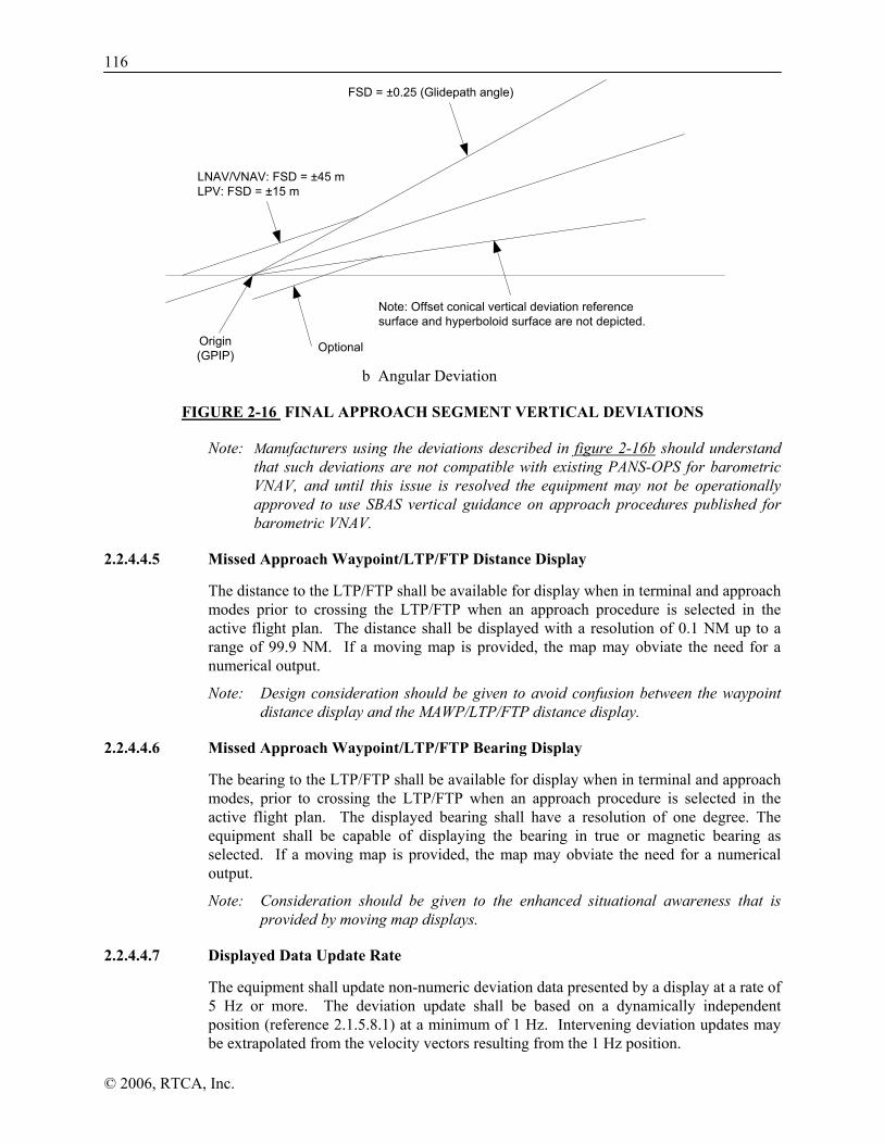
116
© 2006, RTCA, Inc.
FSD = ±0.25 (Glidepath angle)
LNAV/VNAV: FSD = ±45 mLPV: FSD = ±15 m
Origin(GPIP)
Note: Offset conical vertical deviation referencesurface and hyperboloid surface are not depicted.
Optional
b Angular Deviation
FIGURE 2-16 FINAL APPROACH SEGMENT VERTICAL DEVIATIONS
Note: Manufacturers using the deviations described in figure 2-16b should understand that such deviations are not compatible with existing PANS-OPS for barometric VNAV, and until this issue is resolved the equipment may not be operationally approved to use SBAS vertical guidance on approach procedures published for barometric VNAV.
2.2.4.4.5 Missed Approach Waypoint/LTP/FTP Distance Display
The distance to the LTP/FTP shall be available for display when in terminal and approach modes prior to crossing the LTP/FTP when an approach procedure is selected in the active flight plan. The distance shall be displayed with a resolution of 0.1 NM up to a range of 99.9 NM. If a moving map is provided, the map may obviate the need for a numerical output.
Note: Design consideration should be given to avoid confusion between the waypoint distance display and the MAWP/LTP/FTP distance display.
2.2.4.4.6 Missed Approach Waypoint/LTP/FTP Bearing Display
The bearing to the LTP/FTP shall be available for display when in terminal and approach modes, prior to crossing the LTP/FTP when an approach procedure is selected in the active flight plan. The displayed bearing shall have a resolution of one degree. The equipment shall be capable of displaying the bearing in true or magnetic bearing as selected. If a moving map is provided, the map may obviate the need for a numerical output.
Note: Consideration should be given to the enhanced situational awareness that is provided by moving map displays.
2.2.4.4.7 Displayed Data Update Rate
The equipment shall update non-numeric deviation data presented by a display at a rate of 5 Hz or more. The deviation update shall be based on a dynamically independent position (reference 2.1.5.8.1) at a minimum of 1 Hz. Intervening deviation updates may be extrapolated from the velocity vectors resulting from the 1 Hz position.
117
© 2006, RTCA, Inc.
Note: If the same information is used to drive an autopilot, the displayed data rate may be required to meet more stringent requirements, depending on the autopilot requirements.
2.2.4.4.8 Display Update Latency
The overall latency for the LNAV/VNAV navigator, defined as the interval between the time of measurement and time of applicability of the measurement, shall not exceed 400 milliseconds. The data output defining the position shall also be completed prior to 400 milliseconds after the time of the measurement.
Note: The specified output latency may not be sufficient for all aircraft installations.
2.2.4.4.9 Display of Vertical Accuracy
The equipment shall make available for display the 95% confidence vertical accuracy.
Note: This information can be used by the pilot to increase situational awareness of the current GPS/SBAS performance.
2.2.4.5 Database Requirements
2.2.4.5.1 Content
In addition to the requirements of paragraph 2.2.1.5.2, the equipment shall store the LNAV/VNAV procedures in the area(s) where IFR operation is intended. These procedures consist of either the data defined in Appendix D (Table D-1) for approaches requiring a FAS data block, or as defined in 2.2.4.3.1, plus identification of the types of approach that are published (i.e., LPV, LP, and/or LNAV/VNAV), and the naming convention associated with the types of approach (e.g., “LPV”, “LP”, or “LNAV/VNAV”).
The equipment shall also store the data necessary to support stand-alone LNAV/VNAV approaches (i.e., LNAV/VNAV approaches to runway ends that do not also have approaches with a FAS data block). The LNAV/VNAV approach data consists of the height of the runway threshold, threshold crossing height, and glidepath angle.
The complete sequence of waypoints, in the correct order for each approach, must be retrievable as a procedure (so that selecting the procedure by name results in loading the appropriate waypoints and legs into the flight plan).
Waypoints used as a final approach waypoint (FAWP) and LTP/FTP/MAWP in an LNAV/VNAV procedure shall be uniquely identified as such to provide proper approach mode operation.
Note 1: The database must identify which types of approaches are published to enable the equipment to use the appropriate alert limit for the operation. There is no requirement to identify the decision altitude/height or minimum descent altitude in the equipment database for the approach.
Note 2: For a given aircraft installation, it is permissible to exclude procedures associated with runways at which the aircraft is not capable of landing.
Note 3: The database may include vertical path information for approaches (the height of the threshold above the ellipsoid, the height of a desired path over the threshold and the glide path angle).

118
© 2006, RTCA, Inc.
Note 4: The FAS defines the desired final approach segment path. Each FAS data set contains parameters that define a single approach. Currently, the FAS data set defines a straight-line approach. Other FAS Data sets (e.g., other than a straight line) may be defined in the future. The FAS path for the straight line approach is defined by four parameters including the Landing Threshold Point/Fictitious Threshold Point (LTP/FTP), Flight Path Alignment Point (FPAP), Threshold Crossing Height (TCH), and the Glide Path Angle (GPA). A typical Final Approach Segment Diagram is shown graphically in Figure 2-14. The Final Approach Segment Data set parameters are defined in Appendix D.
Note 5: For standalone LNAV/VNAV approaches, the azimuthal alignment is defined by the vector from the FAWP to the MAWP, rather than by the LTP/FTP and the FPAP. See Section 2.2.4.3.1.
2.2.4.5.2 Data Integrity
Once the FAS data block has been decoded, the equipment shall apply the CRC to the data block as defined in Appendix D to determine if the data is valid. If the FAS data block does not pass the CRC test, the equipment shall not allow activation of LNAV/VNAV for that approach.
Note: Vertical guidance may also be provided on an LNAV or LNAV/VNAV approach where FAS data does not exist. In this case, these requirements would not apply.
2.2.4.6 Alerts
2.2.4.6.1 Alert Limits
Prior to sequencing the FAWP, the HAL shall be 0.3 NM. There is no VAL.
After sequencing the FAWP, the alert limits shall be as follows:
a) LNAV/VNAV: HAL 556 m and VAL 50 m
Note: If a FAS data block is available and used during LNAV/VNAV approaches, the intent is for the equipment to not use the FAS HAL and VAL.
The equipment shall not provide the flight crew a means of changing the alert limit.
The equipment shall use the alert limits for the monitoring described in Sections 2.2.4.6.2 and 2.2.4.6.3.
2.2.4.6.2 Caution Associated with Loss of Integrity Monitoring
The equipment shall provide a loss of integrity monitoring caution (see Section 2.2.1.6.1) within two seconds if the current HPLSBAS exceeds the HAL, when using SBAS for integrity.
Note: Although this requirement is stated for LNAV/VNAV approaches, its applicability is limited to outside the FAWP since a loss of integrity monitoring after sequencing the FAWP is defined to be a loss of navigation as described in Section 2.2.4.6.3).
If HPLSBAS is not available, the equipment shall use HPLFD in accordance with 2.1.3.2.2.2 and provide a loss of integrity monitoring caution within 10 seconds if the current HPLFD exceeds the HAL. When switching from HPLSBAS to HPLFD, the equipment must meet the FDE time to alert requirement from the most recent valid computation of HPLSBAS.

119
© 2006, RTCA, Inc.
Note: The use of HPLFD is required as an automatic reversion to LNAV approach capability.
2.2.4.6.3 Caution Associated with Loss of Navigation
The equipment shall provide an indication that the navigation system is no longer adequate to conduct or continue the LNAV/VNAV approach by means of a warning flag or equivalent indicator on the vertical and/or lateral navigation display.
Both lateral and vertical flags or equivalent indicators shall be displayed within one second of the onset of any of the following conditions when in LNAV/VNAV:
a) The absence of power (loss of function is an acceptable indicator);
b) Equipment malfunction or failure; or,
c) The presence of a condition where fault detection detects a position failure that cannot be excluded (Section 2.1.2.2.2.2 and 2.1.4.2.2.2).
If the aircraft is below 1000 ft HAT, or if the LTP/FTP/MAWP is the active waypoint, the vertical flag or equivalent indicator shall be displayed within one second of the onset of any of the following conditions:
a) There are an insufficient number of SBAS HEALTHY satellites (e.g., onset of condition is when the last bit of an SBAS message indicating “Don’t Use” arrives at the antenna port); or,
b) The horizontal protection level exceeds the alert limit as defined in Section 2.2.4.6.1.
In addition, the vertical flag or equivalent indicator shall be displayed within 0.8 seconds of the onset of the following condition:
c) The vertical protection level exceeds the alert limit as defined in Section 2.2.4.6.1.
When vertical deviations are flagged for LNAV/VNAV procedures and integrity is provided by FDE, the lateral flags or equivalent indicators shall be displayed within 10 seconds (including all computation delays and latencies) of the HPLFD exceeding the HAL.
When vertical deviations are flagged for LNAV/VNAV procedures and integrity is provided by SBAS, the lateral flags or equivalent indicators shall be displayed within two seconds (including all computation delays and latencies) of the HPLSBAS exceeding the HAL.
Note: The condition where only the vertical deviations are flagged provides an automatic reversion to LNAV approach capability. When HPLSBAS cannot be computed or exceeds the alert limit, the equipment has up to 10 seconds (per 2.1.3.2.2.2) to determine HPLFD and display an indication.
Prior to sequencing the FAWP, the indications (flags) shall be returned to the normal state immediately upon termination of the responsible condition. If the responsible condition begins or continues after sequencing the FAWP, the indications (flags) may be latched until the equipment is no longer in the LNAV/VNAV approach.
Note: A loss of navigation alert does not require removal of navigation information from the navigation display. It is acceptable to continue to display navigation information concurrent with the failure/status annunciation when conditions warrant.

120
© 2006, RTCA, Inc.
2.2.4.6.4 Low Altitude Alert
Prior to sequencing the FAWP, the equipment shall provide an altitude alert if the estimated position is lower than the desired FAWP height by more than 50 m + VPL unless the equipment provides a TAWS function (TSO-C151).
Note 1: An acceptable implementation is to calculate the desired FAWP altitude as the desired ellipsoidal height at the FAWP by using the defined final approach segment. Another acceptable means is to provide VNAV guidance on the intermediate segment.
Note 2: This function provides additional safety against Controlled Flight Into Terrain (CFIT) during the approach phase. It does not provide vertical guidance on any leg of the approach other than the glidepath itself; on other legs vertical guidance is still provided by the altimeter (based on barometric altitude). It is intended primarily for implementation in classes of aircraft that are not equipped with terrain awareness and warning system (TAWS) equipment and that have no VNAV capability or access to barometric altitude by the GPS/SBAS equipment. Experience suggests that CFIT accidents can be significantly reduced by adding this capability.
Note 3: This function is based on the fact that the aircraft should not descend below the FAWP altitude prior to the FAWP, either as part of the procedure vertical profile or as the result of ATC instructions. The alert altitude as required, provides margin for the accuracy of the geometric altitude provided by GPS/SBAS and for discrepancies between geometric altitude and barometric altitude as accounted for in procedure design.
2.2.4.6.5 Alerting Scheme
Under normal operation, when an LNAV/VNAV procedure has been entered into the active flight plan and the equipment is in LNAV/VNAV, the vertical and lateral integrity flags shall be out of view, and the guidance displays shall show the deviations from track in vertical and lateral dimensions.
2.2.4.7 LNAV/VNAV Approach Mode Switching Requirements
2.2.4.7.1 Entry Criteria
The approach (LNAV/VNAV) mode shall not be activated unless all of the following conditions are met:
a) Valid long-term, fast, and ionospheric SBAS corrections are available and being applied to at least 4 satellites;
b) An approach procedure has been selected; and
c) For procedures defined by a FAS data block, the FAS data associated with the LNAV/VNAV procedure has been verified using the CRC as described in 2.2.4.5.2.
Note: Vertical guidance is provided for standalone LNAV/VNAV and may also be provided on an LNAV approach where FAS data does not exist. In these cases, condition c) would not apply.

121
© 2006, RTCA, Inc.
2.2.4.7.2 Exit Criteria
When a missed approach is initiated and the first leg in the missed approach procedure is not a TF leg aligned within 3 degrees of the final approach path, the equipment shall automatically switch to the terminal mode after sequencing the MAWP.
When a missed approach is initiated and the first leg in the missed approach procedure is a TF leg aligned within 3 degrees of the final approach path, the equipment shall automatically switch to terminal mode at the turn initiation point for the first waypoint in the missed approach procedure.
Note: Consideration should be given to delaying the transition to terminal mode if the first leg following the MAWP is within 3 degrees of the final approach path and is a leg other than a TF leg.
If the pilot initiates “Direct-To” any waypoint while in LNAV/VNAV, the equipment shall automatically switch to terminal mode.
2.2.4.7.3 Display Transition
Upon entering the LNAV/VNAV when a VTF has not been selected, display scaling changes are as specified in 2.2.4.4.2 and Figure 2-15.
Upon entering the LNAV/VNAV when a VTF has been selected, the equipment shall immediately transition to the angular/linear guidance as defined in Section 2.2.4.4.2 and Figure 2-15.
Display transitions when initiating a missed approach are described in Section 2.2.3.4.2 and shown in Figure 2-15. The sensitivity shall change from ±0.3 NM to ±1 NM when the equipment changes to terminal mode.
Note: The sensitivity change from ±0.3NM to ±1 NM can take as long as 30 seconds to provide a smooth transition for autopilots.
2.2.4.7.4 Advisory of LNAV/VNAV Availability
The equipment shall indicate if LNAV/VNAV is not available when in approach (LNAV/VNAV) mode and prior to sequencing the FAWP.
Note: Example means of providing this indication include: indicating the approach (LNAV/VNAV) in amber, flagging the vertical guidance, or indicating loss of integrity. Indication after the FAWP is sequenced is not included within this requirement because it is already addressed using the vertical flag in accordance with 2.2.4.6.3.
2.2.5 Class Gamma Requirements for LP and LPV Approach Operations
Note: The requirements in this section apply to LP and LPV approaches. This includes two approach types with vertical guidance: LPV (35m VAL) and LPV (50m VAL), and one approach type without vertical guidance: LP. These approach classifications are generically called “approach” in this MOPS. Except when specifically noted, every requirement applies to LPV (35m VAL) and LPV (50m VAL). Only the horizontal requirements apply to LP.
2.2.5.1 General Human Factors Requirements
There are no additional human factors requirements.

122
© 2006, RTCA, Inc.
2.2.5.2 Path Selection
See Section 2.2.4.2.
2.2.5.2.1 5-Digit Channel Selection
See Section 2.2.4.2.1.
2.2.5.2.2 Approach Name Selection
See Section 2.2.4.2.2.
2.2.5.2.3 Missed Approach Sequencing
See Section 2.2.4.2.3.
2.2.5.2.4 Selection of the Approach Type
The equipment shall provide a means to select which type of approach will be conducted (LPV or LP, LNAV/VNAV or LNAV). This selection may be manual or automatic.
For automatic selection, the equipment shall select either Approach (LPV or LP), Approach (LNAV/VNAV), or Approach (LNAV) when entering approach mode. The automatically-selected approach type shall be the most accurate approach where the alert limit(s) are predicted to be supported, and where a minimum is published for the selected procedure. The order of precedence is LPV or LP, LNAV/VNAV, then LNAV. If LPV or LP is both published and predicted to be available, the equipment shall indicate that it is available. If LPV or LP is published and is not predicted to be available, the equipment shall indicate that it is not available and shall indicate the approach type that is available (e.g., “LPV not available – Use LNAV/VNAV minima”). A prediction for Approach (LNAV) is not necessary. Once annunciated, the equipment shall not change from Approach (LPV) to Approach (LNAV/VNAV) or from Approach (LP) to Approach (LNAV) unless the approach is reselected or the pilot selects a different approach type.
For manual selection, when entering approach mode the equipment shall indicate if the manually-selected approach type is not predicted to be available.
Note: An acceptable means of predicting the VPL is to multiply the largest ratio of VPL to VDOP over the previous 5 minutes (using 1 Hz sampling) by the predicted VDOP 5 minutes in the future (including only those satellites already being tracked and discarding any satellites that are expected to drop below 5 degrees). The same logic can be used for predicting HPL.
2.2.5.3 Path Definition
2.2.5.3.1 Approach Path Definition
LP and LPV approaches shall only be available for procedures defined by a FAS data block. See Section 2.2.4.3.1.
2.2.5.3.2 Missed Approach Path Definition
See Section 2.2.3.3.2.
2.2.5.3.3 Navigation Center Offset
See Section 2.2.4.3.3.

123
© 2006, RTCA, Inc.
2.2.5.4 Navigation Displays
2.2.5.4.1 Primary Navigation Displays
Non-numeric vertical deviation shall be continuously displayed when in LPV.
2.2.5.4.2 Non-Numeric Lateral Cross-Track Deviation
2.2.5.4.2.1 Definition of Final Approach Segment Lateral Deviations
See Section 2.2.4.4.2.1.
2.2.5.4.2.2 Non-VTF Deviation
See Section 2.2.4.4.2.2.
2.2.5.4.2.3 VTF Deviation
See Section 2.2.4.4.2.3.
2.2.5.4.2.4 Missed Approach Deviation
See Section 2.2.4.4.2.5.
2.2.5.4.3 Numeric Lateral Cross-Track Deviation
See Section 2.2.3.4.3.
2.2.5.4.4 Non-Numeric Vertical Deviation
For LPV the vertical deviation shall be as per Section 2.2.4.4.4 except the minimum linear vertical deviation (MLVD) is 15m.
2.2.5.4.5 Missed Approach Waypoint/LTP/FTP Distance Display
See Section 2.2.4.4.5.
2.2.5.4.6 Missed Approach Waypoint/LTP/FTP Bearing Display
See Section 2.2.4.4.6.
2.2.5.4.7 Displayed Data Update Rate
The equipment shall update non-numeric deviation data presented by a display at a rate of 5 Hz or more. Each deviation update shall be dynamically independent (Reference Section 2.1.5.8.1)
Note: If the same information is used to drive an autopilot, the displayed data rate may be required to meet more stringent requirements, depending on the autopilot requirements.
2.2.5.4.8 Display Update Latency
For the LPV or LP navigator, the overall latency, defined as the interval between the time of measurement and time of applicability of the measurement, shall not exceed 400 milliseconds. The output of the data defining the position shall also be completed prior to 400 milliseconds after the time of the measurement.

124
© 2006, RTCA, Inc.
Note: The specified output latency may not be sufficient for all aircraft installations
2.2.5.4.9 Display of Vertical Accuracy
See Section 2.2.4.4.9.
2.2.5.5 Database Requirements
2.2.5.5.1 Content
In addition to the requirements of paragraph 2.2.1.5.2, the equipment shall store the LPV and LP procedures for the area(s) where IFR operation is intended, including the data defined in Appendix D (Table D-1). For each procedure, the equipment shall also identify the types of approach that are published (i.e., LPV, LP, and/or LNAV/VNAV), and the naming convention associated with the types of approach (e.g., “LPV”, “LP”, “LNAV/VNAV”).
Note: The expected HAL for LPV and LP approaches is 40 m. The FAA plans to implement a 35m VAL where the airport infrastructure and availability can support LPV procedures to a 200 ft decision altitude. For all other LPV approaches, the FAA plans to implement a 50m VAL. Other SBAS service providers may implement other alert limits (e.g., 20 m).
The complete sequence of waypoints, in the correct order for each approach, must be retrievable as a procedure (so that selecting the procedure by name results in loading the appropriate waypoints and legs into the flight plan).
Waypoints used as a final approach waypoint (FAWP) and LTP/FTP in an LPV and LP procedures shall be uniquely identified as such to provide proper approach mode operation.
Note 1: The database must identify which types of approaches are published to enable the equipment to use the appropriate alert limit for the operation. There is no requirement to identify the decision altitude/height or minimum descent altitude in the equipment database for the approach.
Note 2: For a given aircraft installation, it is permissible to exclude procedures associated with runways at which the aircraft is not capable of landing.
Note 3: The FAS defines the desired final approach segment path. Each FAS data set contains parameters that define a single approach. Currently, the FAS data set defines a straight-line approach. Other FAS Data sets (e.g., other than a straight line) may be defined in the future. The FAS path for the straight line approach is defined by four parameters including the Landing Threshold Point/Fictitious Threshold Point (LTP/FTP), Flight Path Alignment Point (FPAP), Threshold Crossing Height (TCH), and the Glide Path Angle (GPA). A typical Final Approach Segment Diagram is shown graphically in Figure 2-14. The Final Approach Segment Data set parameters are defined in Appendix D.
2.2.5.5.2 Data Integrity
Once the FAS data block has been decoded, the equipment shall apply the FAS CRC to the data block as defined in Appendix D to determine if the data is valid. If the FAS data block does not pass the CRC test, the equipment shall not allow activation of LPV or LP for that approach.

125
© 2006, RTCA, Inc.
2.2.5.6 Alerts
2.2.5.6.1 Alert Limits
Prior to sequencing the FAWP, the HAL shall be 0.3 NM. There is no VAL.
After sequencing the FAWP, the alert limits for LP and LPV shall be as follows:
a) LP: HAL is stored in the FAS data block.
b) LPV: HAL and VAL as stored in the FAS data block.
The equipment shall not provide the flight crew a means of changing the alert limit.
The equipment shall use the alert limits for the monitoring described in Sections 2.2.5.6.2 and 2.2.5.6.3.
2.2.5.6.2 Caution Associated with Loss of Integrity Monitoring
The equipment shall provide a loss of integrity monitoring caution (see Section 2.2.1.6.1) within two seconds if the current HPLSBAS exceeds the HAL when using SBAS for integrity.
Note: Although this requirement is stated for the LPV and LP approaches, its applicability is limited to outside the FAWP since a loss of integrity monitoring after sequencing the FAWP is defined to be a loss of navigation as described in Section 2.2.5.6.3).
If HPLSBAS is not available, the equipment shall use HPLFD in accordance with 2.1.3.2.2.2 and provide a loss of integrity monitoring caution within 10 seconds if the current HPLFD exceeds the HAL. When switching from HPLSBAS to HPLFD, the equipment must meet the FDE time to alert requirement from the most recent valid computation of HPLSBAS.
Note: The use of HPLFD is required as an automatic reversion to LNAV approach capability.
2.2.5.6.3 Caution Associated with Loss of Navigation
The equipment shall provide an indication that the navigation system is no longer adequate to conduct or continue the LPV or LP, approach by means of a warning flag or equivalent indicator on the vertical or lateral navigation display.
Both lateral and vertical flags or equivalent indicators (lateral flag only or equivalent indicator for LP) shall be displayed within one second of the onset of any of the following conditions when in LPV or LP:
a) The absence of power (loss of function is an acceptable indicator);
b) Equipment malfunction or failure; or,
c) The presence of a condition where fault detection detects a position failure that cannot be excluded (Section 2.1.2.2.2.2 and 2.1.4.2.2.2).
For LPV procedures, if the aircraft is below 1000 ft HAT, or if the LTP/FTP/MAWP is the active waypoint, the vertical flag or equivalent indicator shall be displayed within one second of the onset of any of the following conditions:
a) There are an insufficient number of SBAS HEALTHY satellites (onset of condition is when the last bit of a SBAS message indicating “Don’t Use” arrives at the antenna port)

126
© 2006, RTCA, Inc.
b) The horizontal protection level exceeds the alert limit as defined in Section 2.2.5.6.1.
In addition, the vertical flag or equivalent indicator shall be displayed within 0.8 seconds of the onset of the following condition:
c) The vertical protection level (VPLSBAS) exceeds the alert limit as defined in Section 2.2.5.6.1.
When vertical deviations are flagged for LPV procedures and integrity is provided by FDE, the lateral flags or equivalent indicators shall be displayed within 10 seconds (including all computation delays and latencies) of the HPLFD exceeding 0.3 NM
When vertical deviations are flagged for LPV procedures and integrity is provided by SBAS, the lateral flags or equivalent indicators shall be displayed within two seconds (including all computation delays and latencies) of the HPLSBAS exceeding 0.3 NM.
Note: The condition where only the vertical deviations are flagged provides an automatic reversion to LNAV approach capability. When HPLSBAS cannot be computed or exceeds the alert limit, the equipment has up to 10 seconds (per 2.1.3.2.2.2) to determine HPLFD and display an indication.
For LP procedures, the lateral flag or equivalent indicator shall be displayed within one second of the onset of any of the following conditions:
a) There are an insufficient number of SBAS HEALTHY satellites (onset of condition is when the last bit of a SBAS message indicating “Don’t Use” arrives at the antenna port)
b) HPLSBAS exceeds the alert limit as defined in Section 2.2.5.6.1.
Note: Automatic reversion from LP to LNAV is not appropriate since there is no differentiation in the pilot’s primary field of view (LPV to LNAV is clearly indicated by flagging the vertical deviations).
Prior to sequencing the FAWP, the indications (flags) shall be returned to the normal state immediately upon termination of the responsible condition. After sequencing the FAWP, the indications (flags) may be latched until the equipment is no longer in the LPV or LP approach.
Note: A loss of navigation alert does not require removal of navigation information from the navigation display. It is acceptable to continue to display navigation information concurrent with the failure/status annunciation when conditions warrant.
2.2.5.6.4 Low Altitude Alert
When in LPV, the equipment shall apply the low altitude alert requirement in section 2.2.4.6.4.
2.2.5.6.5 Alerting Scheme
Under normal operation, when an LPV or LP procedure has been entered into the active flight plan and the equipment is in LPV or LP, the vertical and lateral integrity flags shall be out of view (only lateral integrity flag for LP). Also, the guidance displays shall show the deviations from track in vertical and lateral dimensions (only lateral for LP).

127
© 2006, RTCA, Inc.
2.2.5.7 LP/LPV Approach Mode Switching Requirements
2.2.5.7.1 Entry Criteria
The approach (LPV, LP) mode shall not be activated unless all of the following conditions are met:
a) Valid long-term, fast, and ionospheric SBAS corrections are available and being applied to at least 4 satellites;
b) An approach procedure has been selected; and
c) The FAS data associated with the approach procedure has been verified using the CRC as described in 2.2.4.5.2.
2.2.5.7.2 Exit Criteria
When a missed approach is initiated and the first leg in the missed approach procedure is not a TF leg aligned within 3 degrees of the final approach path, the equipment shall automatically switch to the terminal mode after sequencing the MAWP.
When a missed approach is initiated and the first leg in the missed approach procedure is a TF leg aligned within 3 degrees of the final approach path, the equipment shall automatically switch to terminal mode at the turn initiation point for the first waypoint in the missed approach procedure.
Note: Consideration should be given to delaying the transition to terminal mode if the first leg following the MAWP is within 3 degrees of the final approach path and is a leg other than a TF leg.
If the pilot initiates “Direct-To” any waypoint while in LPV or LP, the equipment shall automatically switch to terminal mode.
2.2.5.7.3 Display Transition
Upon entering LPV or LP when a VTF has not been selected, there is no change in FSD until the aircraft reaches a distance of 2 NM from the FAWP as specified in 2.2.4.4.2.
Upon entering LPV or LP when a VTF has been selected, the equipment shall immediately transition to the angular/linear guidance relative to the (extended) FAS as defined in Section 2.2.4.4.2.
Display transitions when initiating a missed approach are described in Section 2.2.3.4.2 and shown in Figure 2-15. The sensitivity shall change from ±0.3 NM to ±1 NM when the equipment changes to terminal mode.
Note: The sensitivity change from ±0.3NM to ±1 NM can take as long as 30 seconds to provide a smooth transition for autopilots.
2.2.5.7.4 Advisory of LPV, LP Availability
When in approach (LPV) or approach (LP) mode and prior to sequencing the FAWP, the equipment shall indicate if LPV or LP is not available.
Note: Example means of providing this indication include: indicating the approach (LPV) or approach (LP) in amber; flagging the vertical guidance (LPV) or horizontal guidance (LP); or, indicating loss of integrity. Indication after the FAWP is sequenced is not included within this requirement because it is already addressed using the flags in accordance with 2.2.5.6.3.

128
© 2006, RTCA, Inc.
2.3 Class Delta-4 Requirements for Approach Operations
Class Delta equipment provides path deviation data to navigation displays, an automatic flight control system, a flight director and/or flight management system computer, and may or may not directly drive a display. The Class 4 designation applies to equipment that provides an “ILS look-alike signal” only for approach and landing operations, but does not support other modes of operation.
Class Delta-4 equipment receives FAS data from a flight management computer or it may optionally host a FAS database. Class Delta-4 equipment is directed to input the FAS data or it may be directed to select the desired FAS by any number of means such as an FMS, dedicated controller and so on. Class Delta-4 defines the desired path based on FAS data and provides guidance with respect to this desired path. Except for specific cases described in this section, class Delta-4 equipment shall meet the requirements of this section, Section 2.1.1, and, when providing deviations that are not flagged, the LPV and LP approach requirements in Section 2.1.5.
2.3.1 General Human Factors Requirements
Class Delta-4 must satisfy the requirements of Section 2.2.1.1, as applicable.
Note: If the equipment does not include any controls or displays, there are no human factors requirements.
2.3.2 Approach Selection
For equipment hosting a FAS database, accepting the 5-digit channel number from an external source shall result in selection of the corresponding FAS data block. The equipment shall provide a means for the operator to differentiate among approaches if a channel number has been reused.
For equipment that does not host a FAS database, the equipment shall accept a FAS data block from an external source.
Note: The channel number is intended to be a globally unique identifier for an individual approach and should not be reused. The combination of the channel number and airport ID from the FAS datablock will be unique.
2.3.2.1 Confirmation of Selected Approach
The approach name (airport, runway including letter if appropriate, route indicator) and the Reference Path Identifier shall be accessible for display. The equipment shall validate the CRC for the selected FAS data block and only use it if the FAS data block CRC passes.
2.3.3 Path Definition
The final approach path shall be defined by: the Flight Path Alignment Point (FPAP), Landing Threshold Point/Fictitious Threshold Point (LTP/FTP), and the Threshold Crossing Height (TCH) and glidepath angle. The threshold location is referred to as the LTP if it is collocated with the runway and FTP if it is displaced from the runway. The glidepath angle is defined relative to the local tangent plane of the WGS-84 ellipsoid. These parameters are defined in Appendix D. Figure 2-14 shows the path definition for the final approach segment for procedures defined by a FAS data block. The path definition may be based upon a hyperbolic path to mimic ILS glideslope characteristics,
129
© 2006, RTCA, Inc.
where the virtual glidepath antenna location is offset from the runway by less than 500 feet.
2.3.3.1 Navigation Center Offset
See Section 2.2.4.3.3.
2.3.4 Navigation Displays
For equipment that provides a navigation display, the requirements in section 2.2.1.4 shall apply.
2.3.4.1 Non-Numeric Lateral Cross-Track Deviation
The equipment shall provide lateral deviations in accordance with Sections 2.2.5.4.2.1 and 2.2.5.4.2.3.
2.3.4.2 Non-Numeric Vertical Deviation
The equipment shall provide vertical deviations in accordance with Section 2.2.5.4.4.
Note: Some Delta-4 equipment does not provide missed approach capability. In those instances, the missed approach initiation requirement does not apply.
2.3.4.3 Landing Threshold Point/Fictitious Threshold Point Distance Display
Prior to crossing the LTP/FTP, the distance (length of the slant range vector projected onto the plane tangent to the WGS-84 ellipsoid at the LTP/FTP) to the LTP/FTP shall be output or displayed whenever the equipment is outputting valid lateral deviations. The distance shall be output or displayed with a resolution of 0.1 nm up to a range of 99.9 nm from the waypoint. If a moving map is provided, the map may obviate the need for a numerical output.
2.3.4.4 Data Update Rate
The equipment shall update the deviation data at a minimum rate of 5 Hz. The equipment shall update other required data at a rate of 1 Hz or more. Each deviation and distance to LTP/FTP update shall be dynamically independent (Reference Section 2.1.5.8.1)
Note: If the same information is used to drive an autopilot, the displayed data rate may be required to meet more stringent requirements, depending on the autopilot requirements.
2.3.4.5 Data Update Latency
The overall latency, defined as the interval between the time of measurement and the completion of transmission of the lateral/vertical deviation output reflecting the measurement, shall not exceed 400 msec. The distance to threshold output latency, defined as from the interval between the time of applicability and the completion of transmission, shall not exceed 400 msec.
2.3.5 Database Requirements
If the equipment hosts the database, the equipment shall meet the requirements of Section 2.2.1.5.3 in addition to the requirements in 2.3.5.1, and 2.3.5.2.
130
© 2006, RTCA, Inc.
2.3.5.1 Content
The equipment shall store the LPV and LP FAS data for the area(s) where IFR operation is intended. When degrading to lateral guidance, the equipment will use the FAS data block for these procedures.
Note: In addition to the FAS data defined in Appendix D (FAS data block Table D-1), the equipment may also include in its database final approach specific information such as the corresponding 5 digit channel number, provided the additional information does not interfere with the FAS data.
2.3.5.2 Access
Manual entry/update of the FAS database defined in Section 2.3.5.1 shall not be possible. When data are recalled from storage they shall also be retained in storage. Updating the FAS database shall be accomplished using a high-integrity data validation technique such as a cyclic redundancy check (CRC). The system shall provide a means to identify the FAS database version and valid operating period. The equipment shall indicate if the FAS database is not yet effective or out of date.
2.3.6 Alerts
2.3.6.1 Alert Limits
The alert limits for LPV and LP shall be as follows:
a) LP: HAL as stored in the database.
b) LPV: HAL and VAL as stored in the database
Note: Equipment provides LNAV-capable deviations while on an LPV approach if the vertical deviations are flagged. This provides a very reliable reversionary capability using either HPLSBAS or HPLFD and uses the LNAV HAL as described in 2.3.7.2.
When switching from HPLSBAS to HPLFD, the equipment must meet the FDE time to alert requirement from the most recent valid computation of HPLSBAS.
The equipment shall not provide the flight crew a means of changing the alert limit.
2.3.6.2 Caution Associated with Loss of Navigation
The equipment shall provide an indication when the approach navigation system is no longer adequate to conduct or continue the approach (LPV or LP) by means of a warning flag or equivalent indicator on the vertical or lateral navigation display.
For LPV and LP procedures, both lateral and vertical flags or equivalent indicators (lateral flag only or equivalent indicator for LP) shall be displayed within one second of the onset of any of the following conditions:
a) The absence of power (loss of function is an acceptable indicator); or,
b) Equipment malfunction or failure; or,
c) The presence of a condition where fault detection detects a position failure.
For LPV procedures, the vertical flag or equivalent indicator shall be displayed within one second of the onset of any of the following conditions:

131
© 2006, RTCA, Inc.
a) There are an insufficient number of SBAS HEALTHY satellites (onset of condition is when the last bit of a SBAS message indicating “Don’t Use” arrives at the antenna port); or,
b) HPLSBAS exceeds the alert limit as defined in Section 2.3.6.1.
In addition (for LPV procedures), the vertical flag or equivalent indicator shall be displayed within 0.8 seconds of the onset of the following condition:
c) The vertical protection level exceeds the alert limit as defined in Section 2.3.6.1.
When vertical deviations are flagged for LPV procedures and integrity is provided by FDE, the lateral flags or equivalent indicators shall be displayed within 10 seconds (including all computation delays and latencies) of the HPLFD exceeding 0.3 NM
When vertical deviations are flagged for LPV procedures and integrity is provided by SBAS, the lateral flags or equivalent indicators shall be displayed within two seconds (including all computation delays and latencies) of the HPLSBAS exceeding 0.3 NM.
Note: The condition where only the vertical deviations are flagged provides an automatic reversion to LNAV approach capability. When HPLSBAS cannot be computed or exceeds the alert limit, the equipment has up to 10 seconds (per 2.1.3.2.2.2) to determine HPLFD and display an indication.
For LP procedures, the lateral flag or equivalent indicator shall be displayed within one second of the onset of any of the following conditions:
a) There are an insufficient number of SBAS HEALTHY satellites (onset of condition is when the last bit of a SBAS message indicating “Don’t Use” arrives at the antenna port); or,
b) HPLSBAS exceeds the alert limit as defined in Section 2.3.6.1.
Note: Automatic reversion from LP to LNAV is not appropriate since there is no differentiation in the pilot’s primary field of view (LPV to LNAV is clearly indicated by flagging the vertical deviations).
The indications (flags) shall be returned to the normal state immediately upon termination of the responsible condition.
Note: A loss of navigation alert does not require removal of navigation information from the navigation display. It is acceptable to continue to display navigation information concurrent with the failure/status annunciation when conditions warrant.
2.4 Airborne Equipment Performance - Environmental Conditions
The environmental tests and performance requirements described in this subsection are intended to provide a laboratory means of determining the overall performance characteristics of the equipment under conditions representative of those that may be encountered in actual operations.
The environmental performance requirements identified in this section must be met for all components in the airborne GPS/SBAS equipment .
Some of the environmental tests contained in this subsection need not be performed unless the manufacturer wishes to qualify the equipment for the particular environmental condition. The unshaded columns of Tables 2-13 through 2-19 identify the environmental tests that are required to qualify the equipment. The shaded columns identify the optional environmental tests that are to be performed if the manufacturer
132
© 2006, RTCA, Inc.
wishes to qualify the equipment for these additional environmental conditions. An “X” in the rows of Tables 2-13 through 2-19 identifies the GPS/SBAS requirements that must be met while the equipment is subjected to the environmental test condition specified in the columns.
Unless otherwise specified, the pass/fail criteria are those specified in the test procedures applicable to the requirements listed in Tables 2-13 through 2-19, as modified by Section 2.4.1.1. The test procedures applicable to a determination of equipment performance under environmental test conditions are set forth in RTCA document DO-160E, Environmental Conditions and Test Procedures for Airborne Equipment.
Some of the performance requirements in Sections 2.1 and 2.2 of this document do not need to be tested to all of the conditions contained in RTCA/DO-160E; these requirements/conditions are not listed in Tables 2-13 through 2-19. Judgment and experience have indicated that these particular performance parameters are not susceptible to certain environmental conditions and that the level of performance specified in Sections 2.1 and 2.2 will not be measurably degraded by exposure to these particular environmental conditions.
2.4.1 Environmental Tests
Tables 2-13 through 2-19 show matrix charts that define the tests required for a particular class of equipment. They show the paragraph numbers in RTCA/DO-160E that describe the individual environmental tests. These tests must be performed on the test article as specified in the tables. They are as follows:
Table 2-14 Class Beta-1 Environmental Test Requirements
Table 2-15 Class Gamma-1 Environmental Test Requirements
Table 2-16 Class Beta-2 Environmental Test Requirements
Table 2-17 Class Gamma-2 Environmental Test Requirements
Table 2-18 Class Beta-3 Environmental Test Requirements
Table 2-19 Class Gamma-3 Environmental Test Requirements
Table 2-20 Class Delta-4 Environmental Test Requirements
RTCA/DO-160E contains equipment categories for each environmental condition with different environmental test limits for each category. The equipment manufacturer is allowed to choose to which environmental category the article is to be qualified, except for Lightning and Radio Frequency Susceptibility tests, for which a minimum test level is specified. The manufacturer’s certification must specifically state the environmental categories for which the article is qualified.
2.4.1.1 Required Performance
The following paragraphs state procedure requirements for demonstrating performance requirements stated in Tables 2-14 through 2-20.
2.4.1.1.1 Accuracy
The demonstration of accuracy while subjecting the equipment to environmental tests described in RTCA/DO-160E must be done in accordance with Section 2.5.8.1 of this MOPS only for the test case with a broadband external interference noise. For all environmental tests except for temperature tests (RTCA/DO-160E, Section 4.5.1 and 4.5.3) the procedure will not need to last longer than the minimum duration of the
133
© 2006, RTCA, Inc.
particular test as specified in RTCA/DO-160E. The test threshold is the 125% PASS THRESHOLD column in Table 2-25 and has been defined to yield an 80% probability of failing equipment with a true accuracy of 125% of the required accuracy (e.g., 0.45 m for GPS at minimum signal power with airborne accuracy designator A).
Accuracy demonstrations must be performed to the tightest requirement for all navigation modes capable by the equipment.
Note: For other than LNAV/VNAV, LP, and LPV, a simpler test procedure may be used to demonstrate accuracy under environmental conditions.
2.4.1.1.2 Loss of Navigation Indication
While demonstrating this performance requirement any of the sources that generate this indication may be used.
2.4.1.1.3 Loss of Integrity Indication
While demonstrating this performance requirement any of the sources that generate this indication may be used.
2.4.1.1.4 Initial Acquisition Test
The Initial Acquisition Time after abnormal interference test included within the Initial Acquisition test does not need to be performed during environmental testing.
2.4.1.1.5 Sensitivity and Dynamic Range
Demonstration of this requirement should be done in conjunction with demonstration of accuracy.
2.4.1.1.6 Navigation Display
Class Gamma equipment should provide the appropriate displays throughout the test.
2.4.1.1.7 Database
Demonstration of this requirement shall consist of the following after each appropriate environmental test has been performed:
a) Demonstrate the integrity of the database by verifying a CRC or other appropriate error detection scheme.
b) Demonstrate the loading and verification of an updated database by loading several data items from the data base.
2.4.1.1.8 Mode Annunciation
The manufacturer must demonstrate this requirement as noted.
2.4.1.1.9 TO-TO and TO-FROM Capability
If the Class Gamma equipment only supplies an electrical output and does not display “TO-TO” or “TO-FROM” indicators, demonstration of this requirement is not necessary.
134
© 2006, RTCA, Inc.
2.4.1.1.10 System Operating
The “System Operating” row in Tables 2-13 through 2-19 exist for the environmental tests that require the system to simply be powered and operational while the environmental test is being performed.
2.4.1.2 Clarification of Environmental Tests
The following paragraphs provide additional guidance for the environmental tests described in RTCA/DO-160E.
2.4.1.2.1 Power Input Tests
When Normal Operating Conditions Tests, outlined in RTCA/DO-160E par. 16.5.1 & 16.6.1, are being performed, the equipment shall operate during the tests without interruption, so that the accuracy requirement shall continue to be met. When Abnormal Operating Conditions Tests, par. 16.5.2 & 16.6.2, are being performed, the equipment is not required to operate normally during the specified minimum voltage period, but must not provide misleading information during and after the test, and must meet the initial acquisition time requirement after the minimum voltage period.
2.4.1.2.2 Icing Tests
Icing tests are required primarily for the antenna and only if the manufacturer wants to qualify the antenna as part of the GPS/SBAS equipment. If an antenna is used that already has been qualified in this area, this environmental test is not required.
2.4.1.2.3 RF and Induced Signal Susceptibility Tests
The equipment shall be qualified to at least equipment Category T of Section 20 of RTCA/DO-160E for conducted and radiated radio frequency susceptibility, and provide the required accuracy during the test. The high level radiated susceptibility does not apply between 1500 MHz and 1640 MHz.
To limit test time during the frequency scans of Sections 19.3.2 and 20, the accuracy test can be run on the aggregate data and repeated only at the frequencies of greatest susceptibility. The frequencies of greatest susceptibility should be determined by at least the following two methods. First, by inspection of the receiver design, the most susceptible frequencies are identified. Second, the value of pseudo-range error during the test will be compared to the sigma (not RMS) of the error during the scan and the frequencies with errors that deviate significantly from the aggregate are identified. The identification of frequencies can be made over sub-regions of the full frequency range as convenient given the set-up changes required when switching frequency bands; in this case, the aggregate data will be evaluated over each sub-region. Full accuracy tests are run at each of the specific frequencies identified by both methods for each type of test (conduction, radiated, and induced susceptibility).
Alternatively, the C/No (or the σnoise) can be monitored to determine susceptibility as long as frequency dwell time is sufficient to detect the effect.
In addition, the GPS equipment shall provide the required tracking when subjected to a radiated signal with continuous wave modulation at a frequency of 1.57542 GHz and an electric field strength of 20mv/meter measured at the exterior case of the GPS receiver. The radiated susceptibility test procedures of RTCA/DO-160E, Section 20, should be followed when conducting this test. The test should be conducted with simulated satellite inputs and should not result in the loss of track of any satellite used for navigation. The
135
© 2006, RTCA, Inc.
duration of the test must be sufficient to determine if tracking has been lost (20 seconds should normally be long enough, depending on the coasting features used by the GPS equipment).
2.4.1.2.4 Lightning Induced Transient Susceptibility Tests
The equipment should at least be qualified with an appropriate wave form set and test level from Section 22 of RTCA/ DO-160E for lightning induced transient susceptibility which is compatible with the GPS/SBAS antenna(s) specified to be used with the equipment by the manufacturer. The equipment is not required to operate normally during the lightning transient test, and must automatically become operational within the specified acquisition time requirement.
2.4.1.2.5 Lightning Direct Effects Tests
Lightning Direct Effects Tests outlined in Section 23 of RTCA/ DO-160E are required for the antenna. The antenna(s) should function normally after the lightning direct effects tests have been conducted.
Note: Because of GPS/SBAS antenna mounting requirements, the antenna should be qualified for mounting in at least Lightning Zone 2A.
2.4.1.2.6 Crash Safety Shock All equipment shall pass the crash safety shock test as specified in of RTCA/ DO-160E, Section 7.3. Applicants shall select the aircraft type and the appropriate shock levels to which they wish to qualify their equipment.

136
© 2006, RTCA, Inc.
TABLE 2-14 CLASS BETA-1 ENVIRONMENTAL TEST REQUIREMENTS
Class BETA-1D
O-1
60E
Req
uire
men
t
Low
Ope
ratin
g Te
mp.
Tes
t
Hig
h Sh
ort-T
ime
Tem
p. T
est
Hig
h O
pera
ting
Tem
p. T
est
In-F
light
Los
s of
Coo
ling
Altit
ude
Test
Dec
ompr
essi
on T
est
Ove
rpre
ssur
e Te
st
Tem
pera
ture
Var
iatio
n Te
st
Hum
idity
Tes
t
Ope
ratio
nal S
hock
s
Cra
sh S
afet
y S
hock
s
Vibr
atio
n Te
st
Exp
losi
on P
roof
ness
Tes
t
Con
dens
atio
n D
rip P
roof
Tes
t
Drip
Pro
of T
est
Spr
ay P
roof
Tes
t
Con
t. S
tream
Pro
of T
est
Spr
ay T
est
Imm
ersi
on T
est
San
d an
d D
ust T
est
Fung
us R
esis
tanc
e Te
st
Sal
t Fog
Tes
t
Mag
netic
Effe
ct T
est
Nor
m/A
bnor
m O
p C
ondi
tions
(AC
)
Nor
m/A
bnor
m O
p C
ondi
tions
(DC
)
Volt.
Spi
ke C
ond.
Tes
t
Audi
o Fr
eq. C
ond.
Sus
c. T
est
Indu
ced
Sig
nal S
usc.
Tes
t
RF
Susc
eptib
ility
Test
Emis
sion
of R
F En
ergy
Tes
t
Ligh
tnin
g In
d. T
rans
. Sus
c.
Ligh
tnin
g D
irect
Effe
cts
Icin
g
Ele
ctro
stat
ic D
isch
arge
Fire
, Fla
mm
abilit
y Te
st
MOPS Section Requirement Se
ctio
n
4.5.
2
4.5.
3
4.5.
4
4.5.
4
4.6.
1
4.6.
2
4.6.
3
5 6 7.2
7.3
8 9 10.3
.1
10.3
.2
10.3
.3
10.3
.4
11.4
.1
11.4
.2
12 13 14 15 16.5
.1,2
16.6
.1,2
17 18 19 20 21 22 23 24 25 26
2.1.3.1 Accuracy X X X X X X X X X X X X X X X X X X X X X X X X X X X X X X2.1.1.13.2 Loss of Nav. X X2.1.1.13.1 Loss of Integrity X X2.1.1.10 Sensitivity X X X X X X X X X X X X X X X X X X X X X X X X X X X X X X2.1.1.7 Acquisition Time X X X2.1.1.9 Reacquisition Time X XNA Sys. Operating X X
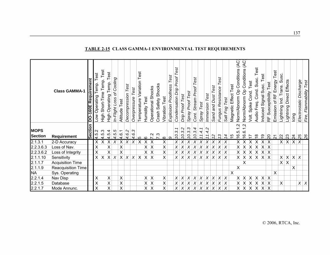
113377
© 2006, RTCA, Inc.
TABLE 2-15 CLASS GAMMA-1 ENVIRONMENTAL TEST REQUIREMENTS
Class GAMMA-1D
O-1
60E
Req
uire
men
tLo
w O
pera
ting
Tem
p. T
est
Hig
h Sh
ort-T
ime
Tem
p. T
est
Hig
h O
pera
ting
Tem
p. T
est
In-F
light
Los
s of
Coo
ling
Altit
ude
Test
Dec
ompr
essi
on T
est
Ove
rpre
ssur
e Te
stTe
mpe
ratu
re V
aria
tion
Test
Hum
idity
Tes
tO
pera
tiona
l Sho
cks
Cra
sh S
afet
y Sh
ocks
Vibr
atio
n Te
stE
xplo
sion
Pro
ofne
ss T
est
Con
dens
atio
n D
rip P
roof
Tes
tD
rip P
roof
Tes
tS
pray
Pro
of T
est
Con
t. S
tream
Pro
of T
est
Spr
ay T
est
Imm
ersi
on T
est
San
d an
d D
ust T
est
Fung
us R
esis
tanc
e Te
stS
alt F
og T
est
Mag
netic
Effe
ct T
est
Nor
m/A
bnor
m O
p C
ondi
tions
(AC
)N
orm
/Abn
orm
Op
Con
ditio
ns (A
C)
Volt.
Spi
ke C
ond.
Tes
tAu
dio
Freq
. Con
d. S
usc.
Tes
tIn
duce
d Si
gnal
Sus
c. T
est
RF
Susc
eptib
ility
Test
Emis
sion
of R
F En
ergy
Tes
tLi
ghtn
ing
Ind.
Tra
ns. S
usc.
Ligh
tnin
g D
irect
Effe
cts
Icin
gE
lect
rost
atic
Dis
char
geFi
re, F
lam
mab
ility
Test
MOPS Section Requirement Se
ctio
n4.
5.2
4.5.
34.
5.4
4.5.
54.
6.1
4.6.
24.
6.3
5 6 7.2
7.3
8 9 10.3
.110
.3.2
10.3
.310
.3.4
11.4
.111
.4.2
12 13 14 15 16.5
.1,2
16.6
.1,2
17 18 19 20 21 22 23 24 25 26
2.1.3.1 2-D Accuracy X X X X X X X X X X X X X X X X X X X X X X X X X X X X X X2.2.3.6.3 Loss of Nav. X X X X X X X X X X X X X X X X X X X X X2.2.3.6.2 Loss of Integrity X X X X X X X X X X X X X X X X X X X X X2.1.1.10 Sensitivity X X X X X X X X X X X X X X X X X X X X X X X X X X X X X X2.1.1.7 Acquisition Time X X X2.1.1.9 Reacquisition Time X XNA Sys. Operating X X2.2.1.4 Nav Disp X X X X X X X X X X X X X X X X X X X X X2.2.1.5 Database X X X X X X X X X X X X X X X X X X X X X X X X2.2.1.7 Mode Annunc. X X X X X X X X X X X X X X X X X X X X X

138
© 2006, RTCA, Inc.
TABLE 2-16 CLASS BETA-2 ENVIRONMENTAL TEST REQUIREMENTS
Class BETA-2D
O-1
60E
Req
uire
men
tLo
w O
pera
ting
Tem
p. T
est
Hig
h Sh
ort-T
ime
Tem
p. T
est
Hig
h O
pera
ting
Tem
p. T
est
In-F
light
Los
s of
Coo
ling
Altit
ude
Test
Dec
ompr
essi
on T
est
Ove
rpre
ssur
e Te
stTe
mpe
ratu
re V
aria
tion
Test
Hum
idity
Tes
tO
pera
tiona
l Sho
cks
Cra
sh S
afet
y Sh
ocks
Vibr
atio
n Te
stE
xplo
sion
Pro
ofne
ss T
est
Con
dens
atio
n D
rip P
roof
Tes
tD
rip P
roof
Tes
tSp
ray
Pro
of T
est
Con
t. S
tream
Pro
of T
est
Spra
y Te
stIm
mer
sion
Tes
tSa
nd a
nd D
ust T
est
Fung
us R
esis
tanc
e Te
stSa
lt Fo
g Te
stM
agne
tic E
ffect
Tes
tN
orm
/Abn
orm
Op
Con
ditio
ns (A
C)
Nor
m/A
bnor
m O
p C
ondi
tions
(DC
)Vo
lt. S
pike
Con
d. T
est
Audi
o Fr
eq. C
ond.
Sus
c. T
est
Indu
ced
Sign
al S
usc.
Tes
tR
F Su
scep
tibilit
y Te
stEm
issi
on o
f RF
Ener
gy T
est
Ligh
tnin
g In
d. T
rans
. Sus
c.Li
ghtn
ing
Dire
ct E
ffect
sIc
ing
Elec
trost
atic
Dis
char
geFi
re, F
lam
mab
ility
Test
MOPS Section Requirement Se
ctio
n4.
5.2
4.5.
34.
5.4
4.5.
54.
6.1
4.6.
24.
6.3
5 6 7.2
7.3
8 9 10.3
.110
.3.2
10.3
.310
.3.4
11.4
.111
.4.2
12 13 14 15 16.5
.1,2
16.6
.1,2
17 18 19 20 21 22 23 24 25 26
2.1.4.1 2-D Accuracy X X X X X X X X X X X X X X X X X X X X X X X X X X X X X X2.1.4.12.2 Loss of Nav. X X2.1.4.12.1 Loss of Integrity X X2.1.1.10 Sensitivity X X X X X X X X X X X X X X X X X X X X X X X X X X X X X X2.1.1.7 Acquisition Time X X X2.1.1.9 Reacquisition Time X XNA Sys. Operating X X

113399
© 2006, RTCA, Inc.
TABLE 2-17 CLASS GAMMA-2 ENVIRONMENTAL TEST REQUIREMENTS
Class GAMMA-2D
O-1
60E
Req
uire
men
tLo
w O
pera
ting
Tem
p. T
est
Hig
h Sh
ort-T
ime
Tem
p. T
est
Hig
h O
pera
ting
Tem
p. T
est
In-F
light
Los
s of
Coo
ling
Altit
ude
Test
Dec
ompr
essi
on T
est
Ove
rpre
ssur
e Te
stTe
mpe
ratu
re V
aria
tion
Test
Hum
idity
Tes
tO
pera
tiona
l Sho
cks
Cra
sh S
afet
y Sh
ocks
Vibr
atio
n Te
stE
xplo
sion
Pro
ofne
ss T
est
Con
dens
atio
n D
rip P
roof
Tes
tD
rip P
roof
Tes
tS
pray
Pro
of T
est
Con
t. S
tream
Pro
of T
est
Spr
ay T
est
Imm
ersi
on T
est
San
d an
d D
ust T
est
Fung
us R
esis
tanc
e Te
stS
alt F
og T
est
Mag
netic
Effe
ct T
est
Nor
m/A
bnor
m O
p C
ondi
tions
(AC
)N
orm
/Abn
orm
Op
Con
ditio
ns (D
C)
Volt.
Spi
ke C
ond.
Tes
tAu
dio
Freq
. Con
d. S
usc.
Tes
tIn
duce
d S
igna
l Sus
c. T
est
RF
Susc
eptib
ility
Test
Emis
sion
of R
F En
ergy
Tes
tLi
ghtn
ing
Ind.
Tra
ns. S
usc.
Ligh
tnin
g D
irect
Effe
cts
Icin
gE
lect
rost
atic
Dis
char
geFi
re, F
lam
mab
ility
Test
MOPS Section Requirement Se
ctio
n4.
5.2
4.5.
34.
5.4
4.5.
54.
6.1
4.6.
24.
6.3
5 6 7.2
7.3
8 9 10.3
.110
.3.2
10.3
.310
.3.4
11.4
.111
.4.2
12 13 14 15 16.5
.1,2
16.6
.1,2
17 18 19 20 21 22 23 24 25 26
2.1.4.1 Accuracy Req. X X X X X X X X X X X X X X X X X X X X X X X X X X X X X X2.2.4.6.3 Loss of Nav. X X X X X X X X X X X X X X X X X X X X X2.2.4.6.2 Loss of Integrity X X X X X X X X X X X X X X X X X X X X X2.1.1.10 Sensitivity X X X X X X X X X X X X X X X X X X X X X X X X X X X X X X2.1.1.7 Acquisition Time X X X2.1.1.9 Reacquisition Time X XNA Sys. Operating X X2.2.4.4 Nav Disp X X X X X X X X X X X X X X X X X X X X X2.2.4.5 Database X X X X X X X X X X X X X X X X X X X X X2.2.1.7 Mode Annunc. X X X X X X X X X X X X X X X X X X X X X

140
© 2006, RTCA, Inc.
TABLE 2-18 CLASS BETA-3 ENVIRONMENTAL TEST REQUIREMENTS
MOPS Section Requirement Se
ctio
n4.
5.2
4.5.
34.
5.4
4.5.
54.
6.1
4.6.
24.
6.3
5 6 7.2
7.3
8 9 10.3
.110
.3.2
10.3
.310
.3.4
11.4
.111
.4.2
12 13 14 15 16.5
.1,2
16.6
.1,2
17 18 19 20 21 22 23 24 25 26
2.1.5.1 Accuracy Req. X X X X X X X X X X X X X X X X X X X X X X X X X X X X X X2.1.5.12.2 Loss of Nav. X X2.1.5.12.1 Loss of Integrity X X2.1.1.10 Sensitivity X X X X X X X X X X X X X X X X X X X X X X X X X X X X X X2.1.1.7 Acquisition Time X X X2.1.1.9 Reacquisition Time X XNA Sys. Operating X X

114411
© 2006, RTCA, Inc.
TABLE 2-19 CLASS GAMMA-3 ENVIRONMENTAL TEST REQUIREMENTS
Class Gamma 3D
O-1
60E
Req
uire
men
tLo
w O
pera
ting
Tem
p. T
est
Hig
h S
hort-
Tim
e Te
mp.
Tes
tH
igh
Ope
ratin
g Te
mp.
Tes
tIn
-Flig
ht L
oss
of C
oolin
gA
ltitu
de T
est
Dec
ompr
essi
on T
est
Ove
rpre
ssur
e Te
stTe
mpe
ratu
re V
aria
tion
Test
Hum
idity
Tes
tO
pera
tiona
l Sho
cks
Cra
sh S
afet
y S
hock
sVi
brat
ion
Test
Exp
losi
on P
roof
ness
Tes
tC
onde
nsat
ion
Drip
Pro
of T
est
Drip
Pro
of T
est
Spr
ay P
roof
Tes
tC
ont.
Stre
am P
roof
Tes
tS
pray
Tes
tIm
mer
sion
Tes
tS
and
and
Dus
t Tes
tFu
ngus
Res
ista
nce
Test
Sal
t Fog
Tes
tM
agne
tic E
ffect
Tes
tN
orm
/Abn
orm
Op
Con
ditio
ns (A
C)
Nor
m/A
bnor
m O
p C
ondi
tions
(DC
)V
olt.
Spi
ke C
ond.
Tes
tA
udio
Fre
q. C
ond.
Sus
c. T
est
Indu
ced
Sign
al S
usc.
Tes
tR
F Su
scep
tibilit
y Te
stE
mis
sion
of R
F E
nerg
y Te
stLi
ghtn
ing
Ind.
Tra
ns. S
usc.
Ligh
tnin
g D
irect
Effe
cts
Icin
gE
lect
rost
atic
Dis
char
geFi
re, F
lam
mab
ility
Test
MOPS Section Requirement Se
ctio
n4.
5.2
4.5.
34.
5.4
4.5.
54.
6.1
4.6.
24.
6.3
5 6 7.2
7.3
8 9 10.3
.110
.3.2
10.3
.310
.3.4
11.4
.111
.4.2
12 13 14 15 16.5
.1,2
16.6
.1,2
17 18 19 20 21 22 23 24 25 26
2.1.5.1 Accuracy Req. X X X X X X X X X X X X X X X X X X X X X X X X X X X X X X2.2.5.6.3 Loss of Nav. X X X X X X X X X X X X X X X X X X X X X2.2.5.6.2 Loss of Integrity X X X X X X X X X X X X X X X X X X X X X2.1.1.10 Sensitivity X X X X X X X X X X X X X X X X X X X X X X X X X X X X X X2.1.1.7 Acquisition Time X X X2.1.1.9 Reacquisition Time X XNA Sys. Operating X X2.2.5.4 Nav Disp X X X X X X X X X X X X X X X X X X X X X2.2.5.5 Database X X X X X X X X X X X X X X X X X X X X X2.2.1.7 Mode Annunc. X X X X X X X X X X X X X X X X X X X X X

142
© 2006, RTCA, Inc.
TABLE 2-20 CLASS DELTA-4 ENVIRONMENTAL TEST REQUIREMENTS
Class Delta 4D
O-1
60E
Req
uire
men
tLo
w O
pera
ting
Tem
p. T
est
Hig
h Sh
ort-T
ime
Tem
p. T
est
Hig
h O
pera
ting
Tem
p. T
est
In-F
light
Los
s of
Coo
ling
Altit
ude
Test
Dec
ompr
essi
on T
est
Ove
rpre
ssur
e Te
stTe
mpe
ratu
re V
aria
tion
Test
Hum
idity
Tes
tO
pera
tiona
l Sho
cks
Cra
sh S
afet
y S
hock
sVi
brat
ion
Test
Exp
losi
on P
roof
ness
Tes
tC
onde
nsat
ion
Drip
Pro
of T
est
Drip
Pro
of T
est
Spr
ay P
roof
Tes
tC
ont.
Stre
am P
roof
Tes
tS
pray
Tes
tIm
mer
sion
Tes
tS
and
and
Dus
t Tes
tFu
ngus
Res
ista
nce
Test
Sal
t Fog
Tes
tM
agne
tic E
ffect
Tes
tN
orm
/Abn
orm
Op
Con
ditio
ns (A
C)
Nor
m/A
bnor
m O
p C
ondi
tions
(DC
)Vo
lt. S
pike
Con
d. T
est
Audi
o Fr
eq. C
ond.
Sus
c. T
est
Indu
ced
Sig
nal S
usc.
Tes
tR
F Su
scep
tibilit
y Te
stEm
issi
on o
f RF
Ene
rgy
Test
Ligh
tnin
g In
d. T
rans
. Sus
c.Li
ghtn
ing
Dire
ct E
ffect
sIc
ing
Ele
ctro
stat
ic D
isch
arge
Fire
, Fla
mm
abilit
y Te
st
MOPS Section Requirement Se
ctio
n4.
5.2
4.5.
34.
5.4
4.5.
54.
6.1
4.6.
24.
6.3
5 6 7.2
7.3
8 9 10.3
.110
.3.2
10.3
.310
.3.4
11.4
.111
.4.2
12 13 14 15 16.5
.1,2
16.6
.1,2
17 18 19 20 21 22 23 24 25 26
2.1.5.1 Accuracy Req. X X X X X X X X X X X X X X X X X X X X X X X X X X X X X X2.2.5.6.3 Loss of Nav. X X X X X X X X X X X X X X X X X X X X X2.2.5.6.2 Loss of Integrity X X X X X X X X X X X X X X X X X X X X X2.1.1.10 Sensitivity X X X X X X X X X X X X X X X X X X X X X X X X X X X X X X2.1.1.7 Acquisition Time X X X2.1.1.9 Reacquisition Time X XNA Sys. Operating X X2.2.5.4 Nav Disp X X X X X X X X X X X X X X X X X X X X X2.3.5 Database X X X X X X X X X X X X X X X X X X X X X2.2.1.7 Mode Annunc. X X X X X X X X X X X X X X X X X X X X X2.2.4.5 Database X X X X X X X X X X X X X X X X X X X X X X

114433
© 2006, RTCA, Inc.
2.5 Test Methods and Procedures
The following definitions of terms and conditions of tests are applicable to equipment tests specified herein:
a. Power Input Voltage
Unless otherwise specified, all tests shall be conducted with the power input voltage adjusted to design voltage ±2 percent. The input voltage shall be measured at the input terminals of the equipment under test.
b. Power Input Frequency
(1) In the case of equipment designed for operation from an AC power source of essentially constant frequency (e.g. 400 Hz), the input frequency shall be adjusted to design frequency ±2 percent.
(2) In the case of equipment designed for operation from an AC power source of variable frequency (e.g. 300-1000 Hz), unless otherwise specified, tests shall be conducted with the input frequency adjusted to within ±5 percent of a selected frequency and within the range for which the equipment is designed.
c. Standard Test Signals and Simulator Requirements
(1) The GPS/SBAS simulator shall operate in accordance with the GPS SPS Performance Standard, Navstar GPS Interface Specification (IS-GPS-200D), specification for Wide Area Augmentation System (FAA-E-2892B, Change 2), and Appendix A.
Note: The development of software to RTCA/DO-178B includes tool qualification of the GPS/SBAS simulator.
(2) Unless otherwise specified, all GPS and SBAS signals will not indicate UNHEALTHY, erroneous, failed, abnormal, or marginal conditions. The signals will contain ranging errors and SBAS corrections as calculated by approved models of the troposphere, ionosphere, satellite clock, and satellite ephemeris.
(3) The broadband noise used to simulate sky and antenna thermal noise density (Nsky,antenna), GNSS test noise (IGNSS,Test) and external interference (IExt,Test) shall have a bandwidth greater than the RF bandwidth of the equipment under test. IGNSS,Test is defined as the broadband noise needed to ensure that the total effective noise (including the intra-system noise produced by the interfering satellites actually simulated during the test procedure) equals the values specified in Appendix C. The pulsed interference source requires an on/off ratio of 154 dB in order to achieve the necessary isolation. The CWI interference generator shall be accurate to within 1 kHz.
(4) The signal and interference levels cited in the following test procedures are defined with respect to the input of the antenna preamplifier. The test set-up must include a test amplifier, that has the same gain as the active portion of the antenna. If any interference is inserted after the test amplifier, the interference level must be adjusted to reflect the expected interference at the insertion point. The minimum or maximum installation loss (as appropriate for the test case) must be included in the test setup, using passive devices. This accounts for the noise generated by the aircraft cabling. When using a specific antenna, the satellite signal levels at the test preamplifier input are adjusted based on the minimum antenna radiation pattern above five degrees; the maximum antenna

114444
© 2006, RTCA, Inc.
radiation pattern (taking into account the satellite gain characteristics); and the CW interference levels, adjusted by the minimum frequency selectivity of the specific antenna/preamplifier.
(5) The test signals presented to the equipment under test, unless otherwise specified, shall account for the minimum preamplifier gain and maximum loss (Lmax) between the antenna port and the receiver port. Unless otherwise specified, the interference tests are conducted with one GPS satellite at maximum power (-121 dBm which includes maximum combined satellite and antenna radiation pattern gain), one satellite at minimum power (-134 dBm which includes minimum radiation pattern gain), and remaining satellites 3 dB above the satellite at minimum power.
(6) For interference tests conducted with all satellites at maximum power, the test signals presented to the equipment under test shall be the maximum input signal at the receiver port accounting for the maximum preamplifier gain minimum fixed loss (Lmin) between the antenna port and the receiver port.
(7) The test setup must provide the total specified broadband noise at the input to the test amplifier. This total noise comes from the simulator, a noise generator (as appropriate), and the test amplifier. The simulator noise (ISimulator) includes all noise generated by the test equipment up to the input to the test amplifier. The test amplifier noise figure is NFAmp, and broadband noise from the noise generator is ING. The test setup must ensure that:
[10ISimulator/10 + 10ING/10 + 290k(10NFAmp/10 - 1)] ≥
[10Nsky,antenna/10 + 10IGNSS,Test/10 + 10IExt,Test/10]
Note that additional noise is included in the test from the GNSS signals that are simulated and from the noise contribution of the loss block.
Note 1: The specified test procedures provide a representative level of self-interference when acquiring, re-acquiring, and tracking the minimum signal. The test represents a reasonable baseline scenario with respect to self-interference caused by C/A code GPS and SBAS signals, P(Y), and Earth Coverage M code GPS signals, Galileo signals, and QZSS signals.
Note 2: Authorized emissions are regulated to a level below the external interference levels (as described in Appendix C) to provide a safety margin.
Note 3: RTCA is updating RTCA/DO-235 to address complete GNSS inter/intra system interference environment. The GNSS Noise specified herein represents the current state of this work at time of publication and includes a safety margin.
Note 4: Refer to Appendix M for examples of the broadband noise calibration.
d. Adjustment of Equipment
The circuits of the equipment under test shall be aligned and adjusted in accordance with the manufacturers’ recommended practices prior to the application of the specified tests.
e. Test Instrument Precautions
Due precautions shall be taken during the tests to prevent the introduction of errors or misleading data resulting from the connection of voltmeters, oscilloscopes and other test instruments across the input and output impedance of the equipment under test.
f. Ambient Conditions

114455
© 2006, RTCA, Inc.
Unless otherwise specified, all tests shall be conducted under the conditions of ambient room temperature, pressure and humidity. However, room temperature shall not be lower than 10 degrees Celsius.
g. Warm-up
Unless otherwise specified, all tests shall be conducted after the manufacturers’ specified warm-up period.
h. Connected Loads
Unless otherwise specified, all tests shall be conducted with the equipment connected to loads having the impedance values for which it is designed.
i. Analysis
Analysis is the method of verification which consists of comparing hardware or software design with known scientific and technical principles, technical data, or procedures and practices to validate that the proposed design will meet the specified functional or performance requirements
j. Demonstration
Demonstration is the method of verification where qualitative versus quantitative validation of a requirement is made during a dynamic test of the equipment. Additional definition applied to this term includes:
(1) In general, software functional requirements are validated by demonstration since the functionality must be observed through some secondary media.
k. Inspection
Inspection is the method of verification to determine compliance with specification requirements and consists primarily of visual observations or mechanical measurements of the equipment, physical location, or technical examination of engineering support documentation.
l. Test
Test is the method of verification that will measure equipment performance under specific configuration load conditions and after the controlled application of known stimuli. Quantitative values are measured, compared against previous predicated success criteria and then evaluated to determine the degree of compliance.
The following subsections define the minimum test procedures required to substantiate the minimum operation performance required for sensors using GPS/SBAS. Alternative procedures may be used if they provide an equivalent evaluation of the GPS/SBAS equipment. These test procedures assume the GPS/SBAS equipment is compliant with the minimum standard, and no additional augmentations (e.g., barometric aiding) are incorporated.
2.5.1 Test Cross Reference Matrix
The test cross reference matrixes for the Beta and Gamma equipment bench test procedures are shown in Table 2-21. This table includes information on (1) the requirement paragraph, (2) the test paragraph associated with the corresponding requirement paragraph, (3) the method of testing, (4) a concise version of the requirement, (5) the pass/fail criteria for each test, and (6) comments. The paraphrased version of the requirements in column four is provided as a quick reference for the test matrix and does not replace or supersede the actual requirements. The first column of the

114466
© 2006, RTCA, Inc.
table lists the paragraph in Section 2 that contains the Beta or Gamma equipment requirement. Often, one section will contain more than one requirement. As a general rule, anytime the word “shall” appears in the requirement section, a test method is associated with that requirement. This is illustrated in the following example on how to read the tables.
Example: The test cross reference matrix for the Gamma equipment begins with Section 2.2.1.1 (General Human Factors Requirements). This section contains four requirements that require verification. The first column lists the requirement paragraph, in this case 2.2.1.1. The second column is the subsection in Section 2.5 where tests for these requirements can be found. In some cases individual tests are assigned to each requirement in the section. In this case, three of the four requirements in Section 2.2.1.1 have tests specified in Section 2.5.10. The manufacturer is responsible for satisfying all equipment requirements whether or not specific tests are identified.
The third column of the table lists the method for testing each requirement. The definitions of the four types of test methods (Inspection, Demonstration, Analysis, and Test) are found in Section 2.5 (Test Methods and Procedures). The first requirement is verified through compliance with specifications. This is accomplished with the test method of “Inspection” or “I”. This example illustrates how the “Inspection” test method is used to verify different manufacturer designs against the referenced design guidance documents and regulations. Other verifications by this method can include inspection of equipment handbooks, equipment design documentation, test results, and functional or software design documents that are used to follow development requirements such as RTCA/DO-178B. The remaining three requirements in Section 2.2.1.1 are verified qualitatively, which corresponds to a Demonstration or D. Any requirements specified as test (T), or analysis (A) must be validated by the manufacturer by showing the appropriate analysis, and the results of any testing performed to support the analysis. The expression not applicable (N/A) is used when no verification is required. The expression is used for statements that are provided as design information and are not testable requirements. The next column specifies the pass/fail criteria for each requirement. Conducting the test method allocated to each requirement satisfies the pass/fail criteria. In this example, the pass/fail criteria for the requirements in Section 2.2.1.1 that are verified by “D”, will be satisfied with acceptable results from the appropriate human factors bench test. The final column lists remarks or references related requirements.
Note: The use of “,” is equivalent to “and”.

114477
© 2006, RTCA, Inc.
TABLE 2-21 TEST CROSS REFERENCE MATRIX
Requirement Paragraph
Test Para.
Test Method
General Requirements Pass/Fail Criteria Related Rqts
2.1.1.1.1 Airworthiness
- I a) Airborne equip. does not impair airworthiness.
Airworthiness assured.
2.1.1.1.2 General Performance
2.5 and all sub-sections
A,D,I,T
a) Equip. performs as specified by this MOPS and the manufacturer.
Equip. is compliant with this MOPS and manufacturer specified requirements.
2.1.1.1.3 Fire Resistance
- I a) Equip. is self-extinguishing. No fire propagation.
2.1.1.1.4 Equipment Interfaces
- A, D or I
a) Equip. does not affect, nor is affected by, other airborne equipment when either system is operating normally or abnormally.
Equip. is not affected by or affects performance of other aircraft equip.
2.1.1.1.5 Effects of Test
- I a) Equip. is not detrimentally affected by these test procedures.
Equip. is not damaged by tests.
2.1.1.2 GPS Signal Processing Requirements
2.5.3-2.5.9
T
I or T
I or T
I or T I or T I or T
I or T
I or T
a) Processes and uses GPS signals and data under interference & minimum signal conditions. b) GPS-provided iono correction model used when SBAS iono corrections are not used c) GPS iono model not applied to satellite measurement pseudoranges when using SBAS iono corrections. d) Tropospheric corrections are applied. e) GPS nav data decoded continuously. f) New clock and ephemeris parameters are used when verified by reception of 2nd msg with same data & IODE that matches 8 least-significant bits of IODC. g) Iono data is used after it has been verified by 2nd msg with same data. h) Satellite clock corrections, including relativistic corrections, are applied to
Equip. navigates with GPS. Equip. properly selects and uses iono models. Tropo corrections are properly applied. Downlink data is decoded continuously. Equip. validates ephem. before use. Equip. validates iono. data before use. Equip. properly applies satellite clock correction parameters. Equip. protects against cross-correlation.
2.1.1.7 2.1.1.8 2.1.1.9 2.1.1.10 2.1.1.12 2.1.2.1 2.1.3.1 2.1.4.1

114488
© 2006, RTCA, Inc.
Requirement Paragraph
Test Para.
Test Method
General Requirements Pass/Fail Criteria Related Rqts
I or T
pseudorange after smoothing (if applicable). i) GPS satellites are not mistaken due to cross-correlation during acquisition or reacquisition.
2.1.1.3.1 Acquisition and Track
2.5.4 T
I or T
I or T
I or T I or T
I or T
a) Acquires and tracks SBAS PRN codes at specified power levels and interference conditions. b) Equipment uses GPS-provided iono correction model when SBAS iono corrections are not used. c) GPS iono model not applied to satellite measurements pseudoranges when SBAS iono corrections are used. d) Tropospheric corrections are applied. e) SBAS satellites are not mistaken due to cross-correlation during acquisition or reacquisition. f) Only PRN codes specified in Appendix A are used to track SBAS satellites.
SBAS signals are acquired and tracked under specified interference and power levels. Equip. protects against cross-correlation of SBAS satellites. Equip. only uses specified SBAS PRN codes to track SBAS satellites.
2.1.1.3.2 Demodulation and FEC Decoding
2.5.2
T
I and T
A and T
A and T
a) Demodulates and decodes SBAS data. b) FEC correction applied to minimize data errors. c) Equip. does not use any message with CRC failures. d) The SBAS message loss rate is less than 1 message in 103 for interference & minimum signal conditions specified. in Appendix C & Section 2.1.1.10.
Equip. demods, decodes, and uses SBAS data using FEC; messages are not used if CRC fails. Message loss rate, due to signal processing compliant signals is < 10-3. for all modes.
2.1.1.10
2.1.1.3.3 SBAS Satellite Pseudorange Determination
2.5.8 T I
a) Equipment computes pseudorange for each SBAS satellite used in position computation. b) SBAS pseudoranges referenced to the same time base as GPS satellites.
Tests show equip. can incorporate SBAS p-rng. into position solution. Documentation proves SBAS p-rng’s are referenced to GPS time base. SBAS p-rng’s are corrected for iono

114499
© 2006, RTCA, Inc.
Requirement Paragraph
Test Para.
Test Method
General Requirements Pass/Fail Criteria Related Rqts
T
I and T
I and T
I or T
c) SBAS differential corrections applied to pseudoranges used in the position solution. d) SBAS pseudorange is properly corrected for earth rotation. e)SBAS pseudoranges corrected using GPS iono coefficients if SBAS iono corrections are not used. f) Tropospheric corrections are applied.
using SBAS iono corrections or, if SBAS corrections unavailable, GPS iono corrections. Tropo. corrections are applied to SBAS pseudoranges.
2.1.1.4 SBAS Message Processing
2.5.2-2.5.9 T
I or T
T
I or T
a) Message Types 0-7, 9, 17, 24-25, and (if broadcast) 27-28 are processed in all navigation modes. b) Decoded messages used optionally in other modes are compliant with their respective requirements. c) Loss of optional messages does not cause loss of function. d) Message types the equip. is not specifically designed to decode, are ignored.
Specified msgs. are decoded. Others may be decoded as specified by this MOPS. Any other messages are ignored.
2.1.1.2. 2.1.3.7 2.1.4.9
2.1.1.4.1 Message Type 0 - Don’t Use for Safety Applications
- -
I and T I
Upon receipt of this message for safety-of-life applications; a) Data (from message types 1-7, 9-10, 18, 24-28) and ranging is discarded and no longer used from the issuing PRN code. b) The issuing PRN code is deselected for one minute.
Data and ranging from the issuing PRN code is not used and discarded, and the PRN code deselected for one minute (for safety-of-life users).
2.1.1.4.2 Message Type 1 - PRN Mask Assignments
- -
I or T
I or T
a) Two PRN masks per GEO PRN can be stored and used.
b) During mask transitions, corrections with different IODPs can be used simultaneously.
Service is not interrupted during PRN mask switching.

115500
© 2006, RTCA, Inc.
Requirement Paragraph
Test Para.
Test Method
General Requirements Pass/Fail Criteria Related Rqts
2.1.1.4.3 Message Type 2-5 and 24 - Fast Corrections
- - - -
I and T
I and T
T
T
a) Message Types 2, 3, 4, 5, and 24 are decoded. b) Integrity and correction data not used until IODP matches IODP from Type 1 msg. c) Fast corrections applied to each SBAS HEALTHY satellite range measurement used in the position solution when SBAS-based sigma used for that satellite. d) Fast corrections applied to SBAS HEALTHY GEO range measurements used in position solution.
Msgs. 2, 3, 4, 5, and 24 are decoded. SBAS integrity and correction data not used until IODPs match. Fast corrections are applied to all SBAS HEALTHY satellites used in the position solution.
2.1.1.4.4 Message Type 6 -Integrity Information
- - - - -
I and T T
T
T
T
a) Message Type 6 is decoded. b) UDREI is used to compute integrity of the corrected position. c) If IODFj = 3 then UDREs are used regardless of the value of IODFj in the associated Type 2-5 & 24 message. d) If IODFj < 3 then σUDRE’s are used only if IODFj matches IODF in the associated fast corrections message (type 2-5 & 24). e) Most recently received PRN masks are used for which corrections have been recieved.
Msg. Type 6 is decoded. UDREI is used to compute the integrity of the corrected position. If IODFj = 3 then UDREs are used regardless of the value of IODFj in the associated fast correction message, otherwise if IODFj < 3 the IODFj of the associated fast correction must match the IODFj in Msg. Type 6.
2.1.1.4.5 Message Type 7 – Fast Correction Degradation
- -
I and T I or T
a) Message Type 7 is decoded. b) Timeout intervals for fast corrections are computed.
Msg. Type 7 is decoded. Timeout intervals for fast corrections are computed.

115511
© 2006, RTCA, Inc.
Requirement Paragraph
Test Para.
Test Method
General Requirements Pass/Fail Criteria Related Rqts
2.1.1.4.6 Message Type 9 - SBAS Satellite Navigation Message
- -
I and T
I and T
a) Message Type 9 is processed for orbital information, used to compute SBAS satellite locations. b) Most recent Message Type 9 is used.
Msg. 9 data used to compute SBAS satellite locations. Most recent Msg. 9 is used.
2.1.1.4.7 Message Type 17 - SBAS Satellite Almanac
- -
I and T
I and T
a) Most recent almanac data for 2 SBAS satellites above the minimum mask angle are stored. b) Almanac data for different service provider other than sender only used for alert of satellite location.
Equip. obtains, stores, and maintains most recent almanac data for 2 or more SBAS satellites.
2.1.1.4.8 Message Type 27 - SBAS Service Message
- - - - - -
I and T
T
D or T
I or T
I or T
I orT
a) Message Type 27 decoded to determine the δUDRE factor applicable to the user location. b) Equip. uses the applicable δUDRE factor to inflate σ2
flt to SBAS HEALTHY satellites when SBAS-based Sigma is used. c) Equip retains Message Type 27, for appropriate time-out interval, even after power-off. d) Equip. immediately applies higher δUDRE to SBAS HEALTHY satellites when using SBAS-based sigma when recieving Type 27 message with a new IODS indicating higher δUDRE for the user location. e) A lower δUDRE in a new Type 27 message will not be used until the complete set of messages with the new IODS has been received. f) After receiving a complete set of Type 27 messages with a given IODS, equip. discards all previously received
Equip. uses msg. 27 to determine if equip. is in region of applicability. Equip uses UDRE factor to inflate the values of σUDRE indicated in a Type 2-6 or 24 message. The equip. uses the higher δUDRE unless a complete set of messages with the new IODS has been received. When a complete set of Type 27 messages are received with a given IODS, all previous Type 27 messages are purged.
Appendix J (J.2.2)

115522
© 2006, RTCA, Inc.
Requirement Paragraph
Test Para.
Test Method
General Requirements Pass/Fail Criteria Related Rqts
-
I or T
Type 27 messages with different IODS. g) If active Type 27 msg exists, equip. uses SBAS-based sigmas on when there is a complete Type 27 msg set.
2.1.1.4.9 Message Timeout Periods
- - - -
T
T T T
a) Approach LNAV/VNAV, LP, LPV timeout when no valid SBAS for 4 seconds. b) Data used until it has timed out. c) Most recently decoded aij applies. d) Data, for which there is no time out, is used until replaced.
Data will be used until it has either timed out or is replaced.
2.1.1.4.10 Combining Data from Separate Broadcasts
- - -
T
I and T
T
a) In approach (LNAV/VNAV, LP, or LPV), corrections and integrity data obtained from the same SBAS PRN. b) When not in approach (LNAV/VNAV, LP, or LPV), and when combining data from separate broadcasts, equip. accounts for time differences in data from multiple SBAS PRNs. c) For each sat., equip. derives fast correction, σ2
UDRE, long-term correction, iono correction, σ2
GIVE, fast degradation factor δUDRE, and Type 10 msg from single SBAS signal (PRN code).
When in the approach (LNAV/VNAV, LP, or LPV) mode, for each sat., integrity and correction data is used from only one PRN.
2.1.1.4.11 Message Type 24 and 25 Long-Term Corrections
- - -
I and T
I and T
I and T
a) Message Types 24 and 25 are decoded and resulting long-term clock & ephemeris corrections determined for all GPS satellites and SBAS satellites operated by different service provider. b) Long-term corrections are not used unless IODP matches that obtained from a Type 1 message. c) Long-term corrections will not be utilized unless IODP matches that obtained from a Type 1 message.

115533
© 2006, RTCA, Inc.
Requirement Paragraph
Test Para.
Test Method
General Requirements Pass/Fail Criteria Related Rqts
- - - - - -
I and T
I and T
I and T
I and T
I and T
I and T
d) For GPS satellites, the equipment compares the Issue of Data (SBAS IOD) in the SBAS Type 24 or 25 message with the IODE of that GPS satellite being used by the equipment. There are three possible outcomes: 1) The SBAS IOD and GPS IODE
match (the normal condition) a. apply the SBAS correction
using the current GPS IODE to compute satellite position;
2) The SBAS IOD and GPS IODE do not match, but the SBAS IOD matches the previous GPS IODE (a condition which will happen for a few minutes each hour)
a. apply the SBAS corrections using the previous GPS IODE to compute satellite position;
3) They do not match, nor does the SBAS IOD match the previous GPS IODE (a rare condition)
a. do not apply the fast or long-term correction or use SBAS-based sigma.
e) Equipment retains old ephemeris data at least 5 minutes, or until obtaining matching SBAS IOD and GPS IODE. f) When long term corrections are applied the equipment uses the active long term correction with latest time of applicability.

115544
© 2006, RTCA, Inc.
Requirement Paragraph
Test Para.
Test Method
General Requirements Pass/Fail Criteria Related Rqts
RECOMMENDATION: g) If long term corrections are received with a time of applicability in the future, don’t use those corrections until: 1) current time equals the time of applicability; or 2) previous long term corrections time out.
2.1.1.4.12 Application of Differential Corrections
- - - - - - -
I and T
I and T
I and T
I and T
I and T
I and T
I and T
a) If equip. uses code filtering or Doppler measurements, differential corrections applied after filtering and immediately before computing a position. b) Equip. applies Long term (for GPS; and, SBAS operated by different service provider), fast and range rate corrections to SBAS HEATHY satellites when an SBAS-based sigma is used. c) Long term, fast and range corrections are not applied to SBAS UNHEALTHY, and SBAS UNMONITORED satellites. d) Equip. uses model variance of fast and long term corrections residuals defined in J.2.2. e) Range-Rate Corrections computed from data contained in Message Types 2-5 and 24 for SBAS-based sigma. f) Pseudorange corrected per equation in 2.1.1.4.12. g) Clock offset and clock drift error corrections computed from data in msg Types 24 and 25 per A.4.4.7 and added to tSV obtained from satellite navigation data for SBAS-based sigma. h) Satellite position correction applied
The equip. applies corrections to Code phase and Doppler measurements as specified.
Appendix A Appendix J

115555
© 2006, RTCA, Inc.
Requirement Paragraph
Test Para.
Test Method
General Requirements Pass/Fail Criteria Related Rqts
- -
I and T
I and T
per A.4.4.7 for SBAS-based sigma. i) Equip. does not use SBAS-based sigma for a satellite without active fast correct, valid range-rate correction, active long-term correction (GPS and SBAS satellites operated by a different service provider than the satellite providing corrections), or active SBAS ephemeris data.
2.1.1.4.13 Message Type 28 – Clock-Ephemeris Covariance Matrix Message
- - - -
I and T
T
D or T
I, and D or T
a) Message Type 28 processed to determine if equip. is within region of applicability. b) Equip. uses the applicable δUDRE factor to calculate the value of σflt for each satellite when SBAS-based sigma used. c) If active Type 28 is received on a satellite, then SBAS-based sigmas used only for satellites with active Type 28 msg. d) Message Type 28 only used if the IODP agrees with the IODP obtained from Message Type 1.
Equip. uses msg. 28 to calculate σflt as defined in Appendix A, A.4.4.3.. The equip. will ensure that the IODP agrees with the IODP associated with the PRN mask in msg. 1. Satellites without Type 28s when other satellites have active Type 28s will use Appendix J.2.2 to determine variance of residual errors.
2.1.1.5 Satellite Integrity Status
- -
I and T
I and T
a) Equip. designates each GPS and SBAS satellite as SBAS UNHEALTHY, SBAS UNMONITORED, or SBAS HEALTHY. b) Equip. designates each GPS satellite as GPS HEALTHY or GPS UNHEALTHY.
Each GPS and SBAS satellite is evaluated and assigned an SBAS integrity status. Each GPS satellites is assigned a GPS health status.
2.1.1.5.2 - 2.1.1.5.6 2.1.1.13 2.1.4.12 2.1.5.12

115566
© 2006, RTCA, Inc.
Requirement Paragraph
Test Para.
Test Method
General Requirements Pass/Fail Criteria Related Rqts
2.1.1.5.1 Step Detector
2.5.3 - -
I and T
A or T
I or T
a) Pseudorange step errors > 700 m on any satellite used in the position solution are detected, including steps causing loss of lock < 10 seconds. b) False pseudorange step error declarations will occur < 10-5 /hr. c) P-range step error declaration cleared only by FD validation.
700 m steps on any satellite used in the position solution. Analysis or test documentation infers false detections occur < 10-5/hr. Pseudorange step declarations are cleared only by FD.
2.1.1.5.2 SBAS UNHEALTHY Designation
- -
I and T
I and T
a) GPS or SBAS satellites designated SBAS UNHEALTHY when:
1) UDREI = 15; 2) step detection function has
declared an error; For SBAS satellites 3) URA ≥ 15; or, 4) Parity failure on 4 successive
messages. b) Satellites declared SBAS UNHEALTHY, change status only after condition has cleared.
GPS or SBAS satellites are designated SBAS UNHEALTHY for the specified conditions. GPS or SBAS satellite is assigned new SBAS integrity status when the condition has cleared.
2.1.1.5.3 SBAS UNMONI-TORED Designation
- -
I and T
I and T
a) GPS or SBAS satellites are designated as SBAS UNMONITORED when:
1) SBAS UDREI = 14 (not monitored);
2) SBAS data is not provided (satellite not in mask);
3) SBAS signals are not received; 4) SBAS data has timed-out; or 5) WAAS IOD and GPS IODE
cannot be reconciled (if long term corrections applied).
b) SBAS UNMONITORED Satellites change status only after condition has cleared/no other listed conditions exist.
GPS or SBAS satellite is designated UNMONITORED for the specified conditions. GPS or SBAS satellite is assigned new SBAS integrity status when the condition has cleared.
2.1.3.7.3

115577
© 2006, RTCA, Inc.
Requirement Paragraph
Test Para.
Test Method
General Requirements Pass/Fail Criteria Related Rqts
2.1.1.5.4 SBAS HEALTHY Designation
- I and T a) GPS or SBAS satellite designated SBAS HEALTHY if:
1) step detector has not declared an error; 2) no UDREI of 14 or 15 received for satellite; and; 3) not designated as SBAS UNHEALTHY or SBAS UNMONITORED.
GPS or SBAS satellites reflect SBAS health designation, if a step error has not been detected on the satellite.
2.1.1.5.5 GPS UNHEALTHY Designation
- -
I and T
I and T
a) GPS satellites are designated as GPS UNHEALTHY if:
1) 6 bit health word in subframe 1: MSB=1;
2) Parity fails on 5 successive words (3 seconds);
3) URA index ≥8; 4) Bit 18 of the HOW = 1; 5) bits =0 in subframe 1, 2, or 3; 6) default navigation data is
transmitted in subframes 1, 2, or 3; or,
7) preamble ≠ 8B (hexadecimal) or 139 (decimal).
b) Satellites declared GPS UNHEALTHY, change status only after condition has cleared.
GPS satellites are designated GPS UNHEALTHY when space segment declares it UNHEALTHY. New GPS health is assigned after the current UNHEALTHY condition clears.
2.1.1.5.6 GPS HEALTHY
- I and T a) GPS satellites are designated GPS HEALTHY if they do not meet the criteria listed in Section 2.1.1.5.5.
GPS satellites are declared HEALTHY when GPS space segment declares them HEALTHY and continuity is maintained on reception of health data.
2.1.1.5.5
2.1.1.6 Satellite Selection
-
D or T
a) The equip. monitors the data broadcast of at least one SBAS satellite that is providing valid integrity information, if available.
The equip. automatically selects a complement of satellites for nav and FDE. At least one SBAS satellite is selected. Continuity of integrity is
2.1.1.5.2 2.1.2.2.2.2.1 2.1.3.2.2.2.

115588
© 2006, RTCA, Inc.
Requirement Paragraph
Test Para.
Test Method
General Requirements Pass/Fail Criteria Related Rqts
- - - - - - - - - -
I and T
T
D or T
I and T
I and T
I and T
D or T
D
D
D or T
b) Equip automatically selects satellites for use in the navigational computation, and FDE (if being applied). c) SBAS HEALTHY overrides GPS UNHEALTHY except for failure of parity on five successive words or due to default navigation data. d) Equip. does not use range measurements in position soln. from SBAS UNHEALTH satellites. e) Equip. automatically selects satellites and integrity mode (HPLSBAS or HPLFD appropriate to flight phase) for use in the position solution. f) Equip. able to include GEO range measurements into position solution when available. g) Equip. uses same set of satellites in position soln and for integrity (FDE or SBAS). h) Equip. changes satellite set within time-to-alert. i) If manual de-selection implemented, the following issues will be addressed by the manufacturer:
1) Pilot incorrectly de-selecting satellites;
2) Pilot fails to re-select satellites 3) Likelihood that pilot knows of
satellite failure that GPS/SBAS hasn’t flagged.
j) If manual de-selection implemented, satellites de-selections are cleared at power-up. k) Manual selection of SBAS UNHEALTHY or GPS UNHEALTHY
maximized. SBAS UNHEALTHY satellites are not used. UNHEALTHY satellites cannot be selected.
1

115599
© 2006, RTCA, Inc.
Requirement Paragraph
Test Para.
Test Method
General Requirements Pass/Fail Criteria Related Rqts
satellites is prohibited. RECOMMENDATION: l) Equip. should select the best SBAS satellite based on the correction and integrity data being provided. m) To ensure continued performance in the event of losing the SBAS signal (PRN code), a second SBAS signal (PRN code) should be monitored. n) Equip. should not provide manual satellite de-selection. If provided, mfg. Should consider:
1) Annunciating that satellites are de-selected;
2) Providing re-select capability; 3) Including appropriate training to
ensure proper operation. 2.1.1.7 Initial Acquisition Time
2.5.4 D or T
T
a) Equip. acquires satellites and determines position without initialization information. b) TTFF less than 5 minutes with 95% confidence, given:
1) Initialization of LAT/LONG within 60 nm;
2) TIME/DATE within 1 minute; 3) Valid almanac, and
unobstructed satellite visibility; 4) Specified interference
conditions (Appendix C); and 5) Minimum signal conditions
specified in Section 2.1.1.10.
Equip. tracks satellites and navigates without initialization data. Equip. demonstrates satellites can be acquired and steady-state nav. can be obtained in less than 5 min.
2.1.1.10
2.1.1.8.1 GPS Satellite Acq. Time
- T a) During steady state operation, GPS satellites acquired and incorporated into position solution within 80 seconds.
During steady-state op, new GPS satellites in view can be acquired and used in the nav. sol’n in 80 seconds.
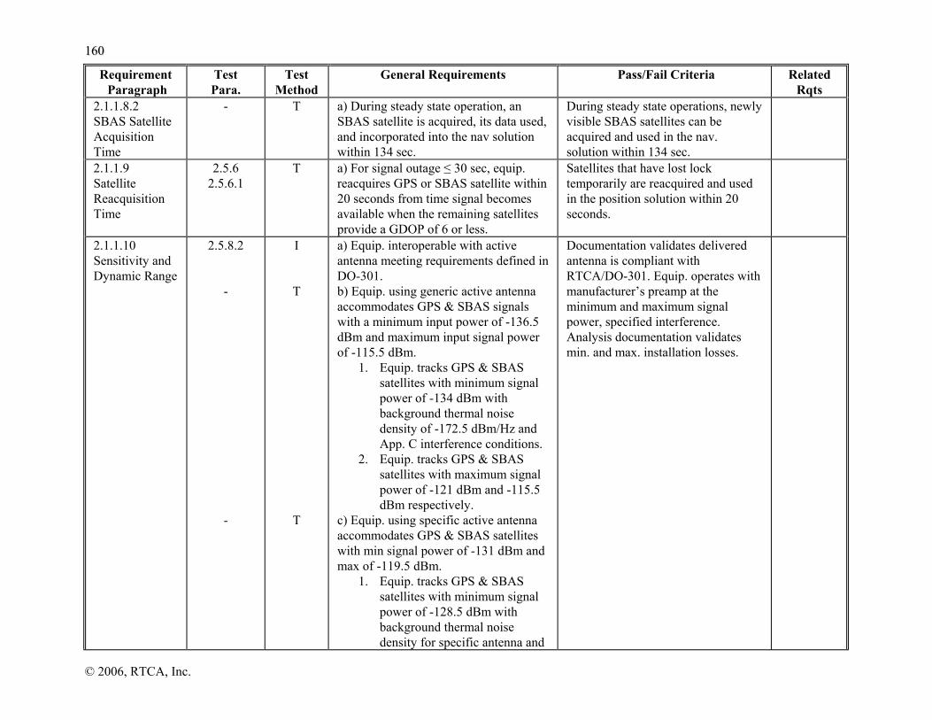
116600
© 2006, RTCA, Inc.
Requirement Paragraph
Test Para.
Test Method
General Requirements Pass/Fail Criteria Related Rqts
2.1.1.8.2 SBAS Satellite Acquisition Time
- T a) During steady state operation, an SBAS satellite is acquired, its data used, and incorporated into the nav solution within 134 sec.
During steady state operations, newly visible SBAS satellites can be acquired and used in the nav. solution within 134 sec.
2.1.1.9 Satellite Reacquisition Time
2.5.6 2.5.6.1
T a) For signal outage ≤ 30 sec, equip. reacquires GPS or SBAS satellite within 20 seconds from time signal becomes available when the remaining satellites provide a GDOP of 6 or less.
Satellites that have lost lock temporarily are reacquired and used in the position solution within 20 seconds.
2.1.1.10 Sensitivity and Dynamic Range
2.5.8.2 - -
I
T
T
a) Equip. interoperable with active antenna meeting requirements defined in DO-301. b) Equip. using generic active antenna accommodates GPS & SBAS signals with a minimum input power of -136.5 dBm and maximum input signal power of -115.5 dBm.
1. Equip. tracks GPS & SBAS satellites with minimum signal power of -134 dBm with background thermal noise density of -172.5 dBm/Hz and App. C interference conditions.
2. Equip. tracks GPS & SBAS satellites with maximum signal power of -121 dBm and -115.5 dBm respectively.
c) Equip. using specific active antenna accommodates GPS & SBAS satellites with min signal power of -131 dBm and max of -119.5 dBm.
1. Equip. tracks GPS & SBAS satellites with minimum signal power of -128.5 dBm with background thermal noise density for specific antenna and
Documentation validates delivered antenna is compliant with RTCA/DO-301. Equip. operates with manufacturer’s preamp at the minimum and maximum signal power, specified interference. Analysis documentation validates min. and max. installation losses.

116611
© 2006, RTCA, Inc.
Requirement Paragraph
Test Para.
Test Method
General Requirements Pass/Fail Criteria Related Rqts
App. C interference conditions. 2. Equip. tracks GPS & SBAS
satellites with maximum signal power of -123 dBm and -119.5 dBm respectively.
2.1.1.11 Equipment Burnout Protection
- T a) Equip. withstands, without damage, in-band CWI @ +20 dBm at the antenna port.
Application of CWI +20dBm signal does not damage equip.
2.1.1.12 Integrity in the Presence of Interference
2.5.7 T
T
a) Equip. satisfies integrity TTA and does not produce misleading information in presence of high interference. b) Equip. recovers within 5 minutes after the interference is removed.
Equip. does not produce misleading information when subjected to high interference power levels.
2.1.1.7 2.1.2.2.2.2.1 2.1.3.2.2.2.1
2.1.1.13.1 Protection Level
- - - -
D
T
T
D
a) Equip. outputs HPLSBAS applicable to operation, or HPLFD as specified in Sections 2.1.2.2.2, 2.1.3.2.2, 2.1.4.2.2 and 2.1.5.2.2. b) SBAS-based protection level latencies do not exceed 2.0 seconds. c) HPLFD latency does not exceed FDE TTA from last valid HPLSBAS computation. d) Equip. indicates if HPL not calculated.
It is shown the equip. can produce and output HPLs within 2.0 seconds of the arrival of UDRE/GIVE data, and indicate when HPL not calculated.
2.1.2.2.2 2.1.3.2.2 2.1.4.2.2 2.1.5.2.2
2.1.1.13.2 Navigation Alert
- - -
2.5.9
D or T A or T
T
T
a) Equip provides loss of navigation indication or output within 1 second for any of the following: 1) Loss of power. 2) Equip. malfunctions or failures. 3) For ≥ 5 sec., an insufficient number
of satellites available to compute a position solution.
4) Fault detection cannot exclude a
Equip. indicates loss of navigation for: loss of power; equip. malfunctions or failures; when insufficient number of satellites available to compute a position fix for five seconds; detected but cannot be excluded within TTA. Loss of navigation indication is cleared upon termination of the condition.

116622
© 2006, RTCA, Inc.
Requirement Paragraph
Test Para.
Test Method
General Requirements Pass/Fail Criteria Related Rqts
-
D or T
position failure within TTA. b) Alert returns to normal state immediately upon termination of the responsible condition.
TABLE 2-21 TEST CROSS REFERENCE MATRIX (CONTINUED)
Requirement Paragraph
Test Para.
Test Method
Requirements for En Route and Terminal Mode
General Requirements
Pass/Fail Criteria Related Rqts
2.1.2.1 Accuracy
2.5.8
2.5.7
2.5.8
T
T
T
a) Horizontal radial position fixing error does not exceed 32 meters, 95th percentile, when HDOP normalized to 1.5. b) Accuracy is maintained under minimum signal conditions and in presence of interference. c) Time, if provided, is within 1 sec of UTC.
Equip. performs with the required accuracy under the specified signal and interference conditions. Equip. provides time within 1 sec of UTC.
2.1.1.10
2.1.2.2.1 Development Assurance
2.5.7 A, I, and T
a) HW and SW designed so output of misleading information (a major failure condition) is improbable.
The equip. design assures misleading information is improbable.
2.1.2.2.1.1 2.1.2.2.1.2
2.1.2.2.2 Integrity Monitoring
- -
I and T
I and T
a) Equip. is capable of computing HPLSBAS and HPLFD. b) If equip. uses GPS/inertial and does not use SBAS integrity and correction data, it meets requirements and accomplishes tests in Appendix R.
Equip. computes HPLSBAS and HPLFD as appropriate.
2.1.2.2.2.1 SBAS - Provided Integrity Monitoring
- I and T
a) HPLSBAS is computed as defined in Appendix J using only SBAS HEALTHY satellites.
Equip. produces an HPLSBAS. Appendix J

116633
© 2006, RTCA, Inc.
Requirement Paragraph
Test Para.
Test Method
Requirements for En Route and Terminal Mode
General Requirements
Pass/Fail Criteria Related Rqts
2.1.2.2.2.2 FDE - Provided Integrity Monitoring
2.5.9 I and T
I and T
T
I and T
I or T
I or T
I and T
I and T
a) Equip. has autonomous FDE capability using redundant GPS & SBAS ranging measurements. b) Equip. computes HPLFD using weighted algorithm. c) Equip. accounts for SNT and GPS time differences if a mixture of corrected and uncorrected satellites are used. d) FDE used whenever SBAS integrity is not available. e) HPLFD accounts for combination of clock/ephemeris, tropo, iono and airborne error. f) Weight accounts for clock/ephemeris, iono, tropo, airborne contribution to ranging error. g) Baro-aided FDE is compliant to Appendix G. h) Inertial-aided FDE is compliant to Appendix R.
Equip. that provides an autonomous FDE capability which is used whenever SBAS integrity is not available. Tests validate the FDE algorithms are compliant to this specification. Documentation or tests prove equip. produces an HPLFD that bounds the horz. position error.
2.1.2.2.2.2.1 Time to Alert
2.5.9 T a) Time to alert for Class Beta is 8 seconds.
Equip provides alert within TTA.
2.1.2.2.2.2.2 Missed Alert Probability
2.5.9 A and T a) Probability of missed alert is ≤ 0.001 for every geometry and every nav mode.
Analysis validates documentation and tests prove equip.’s missed alert probability is ≤ 0.001.
1.7.3
2.1.2.2.2.2.3 False Alert Probability
2.5.9 A
A
a) Probability of false alert ≤ 3.33x10⁻⁷ per sample. b) False alert probability met for every geometry.
Analysis validates documentation and tests prove equip.’s false alert probability is compliant.
1.7.3
2.1.2.2.2.2.4 Failed Exclusion Probability
2.5.9 A and T a) Probability of failed exclusion is ≤ 10-3 for every geometry and every nav mode.
Analysis validates documentation and tests prove equip.’s failed exclusion probability is ≤ 10-3/hour.
1.7.3

116644
© 2006, RTCA, Inc.
Requirement Paragraph
Test Para.
Test Method
Requirements for En Route and Terminal Mode
General Requirements
Pass/Fail Criteria Related Rqts
2.1.2.2.2.2.5 Availability
2.5.9 A and T A and T
A and T A and T
For HAL = 2nm: a) Availability of detection is ≥ 99.95 %. b) Availability of exclusion is ≥ 99.30 %.
For HAL = 1nm c) Availability of detection is ≥ 99.90%. d) Availability of exclusion is ≥ 98.45%.
Analysis validate proves availability of detection ≥ 99.95 % and availability of and exclusion ≥ 99.30 % for case 1. Analysis validate proves availability of detection ≥ 99.9 % and availability of and exclusion ≥ 98.45% for case 2.
2.1.2.4 Satellite Tracking Requirements
2.5.6 2.5.7
2.5.7
I and T
I and T
a) Equipment capable of tracking a minimum of 8 GPS satellites (and no SBAS satellites). b) Equipment capable of tracking at least six GPS satellites and two SBAS satellites, including the demod and storing of data from both SBAS satellites.
Equip. is shown to be capable of tracking 8 GPS satellites simultaneously. Equip. is shown to be capable of tracking 6 GPS and 2 SBAS satellites simultaneously.
2.1.2.5 Dynamic Tracking
2.5.8 T
T
T
T
a) Equipment maintains accuracy, acquisition, and reacquisition specified in 2.1.2.1, 2.1.1.8, and 2.1.1.9 during normal dynamics specified in 2.1.2.5. b) Equipment does not produce misleading information during abnormal maneuvers specified in 2.1.2.5. c) Equip. meets steady-state reacquisition requirements in 2.1.1.9 when abnormal maneuvers complete. d) Loss-of-navigation and loss-of-integrity alerts operate as specified during abnormal maneuvers.
Equip. maintains accuracy, acquisition, reacquisition during normal dynamics under the specified signal power and interference conditions. Abnormal maneuvers do not cause misleading information. Reacquisitions are performed, as specified, when the abnormal maneuvers complete. Proper indication of loss of navigation and loss of integrity is shown during abnormal maneuvers.
2.1.1.8 2.1.1.9 2.1.1.13.2 2.1.2.1
2.1.2.6 Position Output
- - -
D or T
I or T
D
a) Equip. determines position for navigation. b) Position represents WGS-84 position of antenna or center of navigation. c) Equip. electronically outputs position, velocity, HFOM, and applicable HPL.
Equip. produces a position referenced to the WGS-84 standard. Class Beta equip. outputs the nav. solution.

116655
© 2006, RTCA, Inc.
Requirement Paragraph
Test Para.
Test Method
Requirements for En Route and Terminal Mode
General Requirements
Pass/Fail Criteria Related Rqts
2.1.2.6.1 Position Output Data Update Rate
- T a) Equip. minimum update rate of position output data is once per second.
The equip. is shown to update and output the nav. solution once per second.
2.1.2.6.2 Position Output Data Latency
- -
T
T
a) Latency of the position, velocity, HFOM output is ≤500 milliseconds. b) Position output data is output prior to 200 msec after the time of applicability.
Equip. outputs position with 0.5 sec. latency (wrt measurement time of the pseudorange). Output is prior to 200 msec after the time of applicability.
TABLE 2-21 TEST CROSS REFERENCE MATRIX (CONTINUED)
Requirement Paragraph
Test Para.
Test Method
Requirements for LNAV Approach Operations
General Requirements
Pass/Fail Criteria Related Rqts
2.1.3.1 Accuracy
a) Equip. complies with 2.1.2.1. Equip. performs with the required accuracy under the specified signal and interference conditions.
2.1.1.10
2.1.3.2.1 Development Assurance
a) Equip. complies with 2.1.2.2.1. - 2.1.2.2.1
2.1.3.2.2 Integrity Monitoring
a) Equip. complies with 2.1.2.2.2. - 2.1.2.2.2
2.1.3.2.2.1 SBAS - Provided Integrity Monitoring
a) Equip. complies with 2.1.2.2.2.1. - 2.1.2.2.2.1
2.1.3.2.2.2 FDE - Provided Integrity
a) Equip. complies with 2.1.2.2.2.2 - 2.1.2.2.2.2
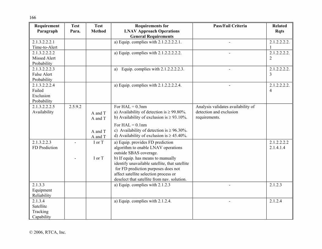
116666
© 2006, RTCA, Inc.
Requirement Paragraph
Test Para.
Test Method
Requirements for LNAV Approach Operations
General Requirements
Pass/Fail Criteria Related Rqts
2.1.3.2.2.2.1 Time-to-Alert
a) Equip. complies with 2.1.2.2.2.2.1. - 2.1.2.2.2.2.1
2.1.3.2.2.2.2 Missed Alert Probability
a) Equip. complies with 2.1.2.2.2.2.2. - 2.1.2.2.2.2.2
2.1.3.2.2.2.3 False Alert Probability
a) Equip. complies with 2.1.2.2.2.2.3. - 2.1.2.2.2.2.3
2.1.3.2.2.2.4 Failed Exclusion Probability
a) Equip. complies with 2.1.2.2.2.2.4. - 2.1.2.2.2.2.4
2.1.3.2.2.2.5 Availability
2.5.9.2 A and T A and T
A and T A and T
For HAL = 0.3nm a) Availability of detection is ≥ 99.80%. b) Availability of exclusion is ≥ 93.10%.
For HAL = 0.1nm c) Availability of detection is ≥ 96.30%. d) Availability of exclusion is ≥ 45.40%.
Analysis validates availability of detection and exclusion requirements.
2.1.3.2.2.3 FD Prediction
- -
I or T
I or T
a) Equip. provides FD prediction algorithm to enable LNAV operations outside SBAS coverage. b) If equip. has means to manually identify unavailable satellite, that satellite for FD prediction purposes does not affect satellite selection process or deselect that satellite from nav. solution.
2.1.2.2.2.2 2.1.4.1.4
2.1.3.3 Equipment Reliability
a) Equip. complies with 2.1.2.3 - 2.1.2.3
2.1.3.4 Satellite Tracking Capability
a) Equip. complies with 2.1.2.4. - 2.1.2.4

116677
© 2006, RTCA, Inc.
Requirement Paragraph
Test Para.
Test Method
Requirements for LNAV Approach Operations
General Requirements
Pass/Fail Criteria Related Rqts
2.1.3.5 Dynamic Tracking
- - - -
T
T
T
T
a) Equip. maintains accuracy, acquisition, reacquisition specified in 2.1.3.1, 2.1.1.8, and 2.1.1.9 during normal dynamics specified in 2.1.3.5. b) Equipment does not produce misleading information during abnormal maneuvers specified in 2.1.3.5. c) Meets steady-state reacquisition requirements in 2.1.1.9 when abnormal maneuvers complete. d) Loss-of-navigation and loss-of-integrity alerts operate as specified during abnormal maneuvers.
Equip. maintains accuracy, acquisition, reaquisition during normal dynamics under the specified signal power and interference conditions. Abnormal maneuvers do not cause misleading information. Reacquisitions are performed, as specified, when the abnormal maneuvers complete. Proper indication of loss of navigation and loss of integrity is shown during abnormal maneuvers.
2.1.1.8 2.1.1.9 2.1.3.1 2.1.3.5
2.1.3.6 Position Output
a) Equip. complies with 2.1.2.6. Equip. is compliant with 2.1.2.6. 2.1.2.6
2.1.3.6.1 Position Output Update Rate
a) Equip. complies with 2.1.2.6.1. Equip. is compliant with 2.1.2.6.1. 2.1.2.6.1
2.1.3.6.2 Position Output Latency
a) Equip. complies with 2.1.2.6.2. Equip. is compliant with 2.1.2.6.2. 2.1.2.6.2
2.1.3.7 SBAS Message Processing
a) Equip. complies with 2.1.1.4
Equip. properly processes Message Types per Section 2.1.1.4.
2.1.1.4
2.1.3.8 Application of Differential Correction Terms
a) Equip complies with 2.1.1.4.12
Differential corrections are applied properly.
2.1.1.4.12
2.1.3.9 Satellite Selection
- - -
D or T D or T
D or T
a) Equip complies with 2.1.1.6 b) At least two SBAS satellites are selected, when available. c) Equip. capable of switching between SBAS data streams to maximize
Show the equip. selects two SBAS satellites when two or more are visible. Docs shows the equip. switches between valid SBAS data, from different SBAS satellites, to
2.1.1.6

116688
© 2006, RTCA, Inc.
Requirement Paragraph
Test Para.
Test Method
Requirements for LNAV Approach Operations
General Requirements
Pass/Fail Criteria Related Rqts
continuity of function. maximize continuity of function.
TABLE 2-21 TEST CROSS REFERENCE MATRIX (CONTINUED)
Requirement Paragraph
Test Para.
Test Method
Requirements for LNAV/VNAV Approach Operations
General Requirements
Pass/Fail Criteria Related Rqts
2.1.4.1.1 Smoothing
- -
A A
a) Equip. performs carrier smoothing. b) Smoothing filter error less than 0.25 m within 200 seconds in presence of code-carrier divergence of up to 0.018 m/s.
Smoothing algorithm described. Analysis data shows error cannot exceed 0.25 m with code-carrier divergence of up to 0.018 m/s.
2.1.4.1.2 Measurement Quality Monitoring
- A a) Signal monitored to determine if allocated integrity risk is within manufacturer’s allocation.
Analysis data to show that undetected cycle slips or other undetected measurement faults within manufacturer’s allocation.
2.1.4.1.4 GPS Satellites
2.5.8 T
T
a) RMSpr_air,GPS at min. signal level is: 1) ≤ 0.36 m for Accuracy
Designator (AD) A; and, 2) ≤ 0.15 m for AD B.
b) RMSpr_air,GPS at max. signal level is: 1) ≤ 0.15 m AD A; and, 2) ≤ 0.11 m for AD B.
Equipment contribution to GPS satellite errors meets values in the requirement.
2.1.4.1.5 SBAS Satellites
2.5.8 -
T
T
a) RMSpr_air,GEO is ≤ 1.8 m at the minimum signal level and ≤ 1.0 m at the maximum signal level. b) Relative SBAS to GPS satellite tracking bias ≤ 5 m for narrowband and ≤ 0.5 m for wideband.
Equipment contribution to GEO satellite errors meets values in the requirement. Relative tracking bias meets values in the requirement.
2.1.4.1.6 Position Solution
2.5.8 T a) Equip. computes 3D position using a linearized, weighted least-squares solution, defined in Appendix E.
Equip. uses the linearized, weighted least-squares solution, defined in Appendix E
Appendix J
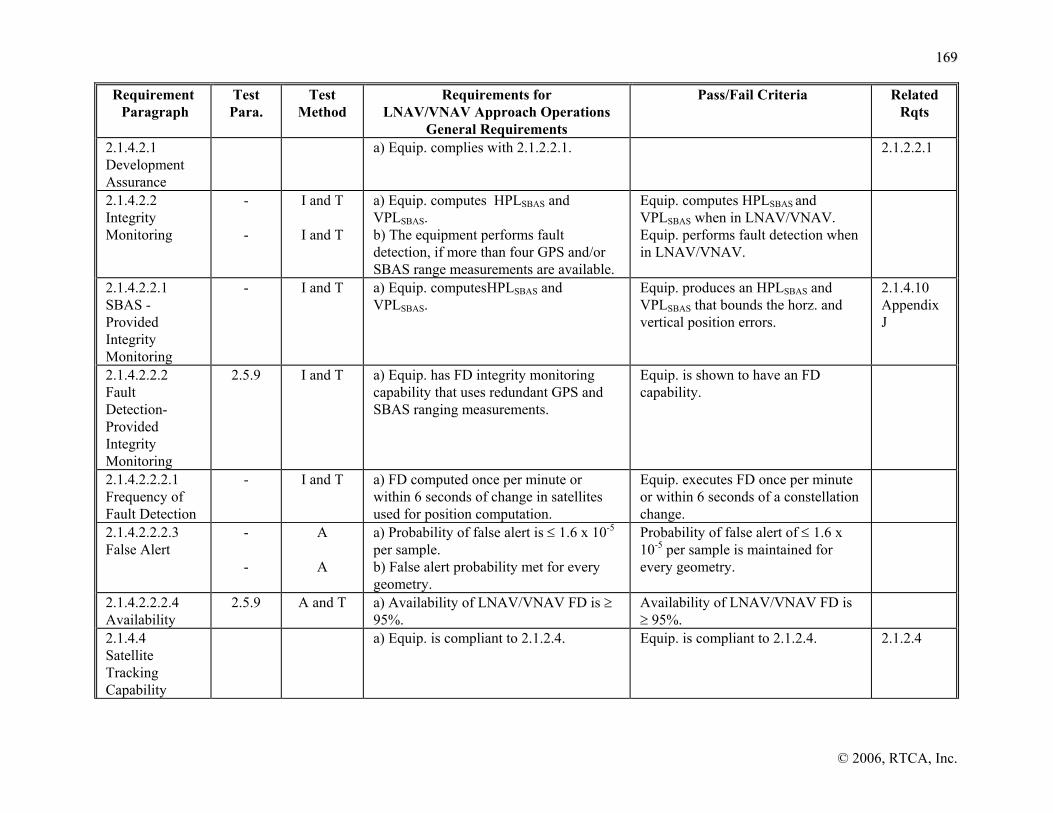
116699
© 2006, RTCA, Inc.
Requirement Paragraph
Test Para.
Test Method
Requirements for LNAV/VNAV Approach Operations
General Requirements
Pass/Fail Criteria Related Rqts
2.1.4.2.1 Development Assurance
a) Equip. complies with 2.1.2.2.1. 2.1.2.2.1
2.1.4.2.2 Integrity Monitoring
- -
I and T
I and T
a) Equip. computes HPLSBAS and VPLSBAS. b) The equipment performs fault detection, if more than four GPS and/or SBAS range measurements are available.
Equip. computes HPLSBAS and VPLSBAS when in LNAV/VNAV. Equip. performs fault detection when in LNAV/VNAV.
2.1.4.2.2.1 SBAS - Provided Integrity Monitoring
- I and T
a) Equip. computesHPLSBAS and VPLSBAS.
Equip. produces an HPLSBAS and VPLSBAS that bounds the horz. and vertical position errors.
2.1.4.10 Appendix J
2.1.4.2.2.2 Fault Detection-Provided Integrity Monitoring
2.5.9 I and T
a) Equip. has FD integrity monitoring capability that uses redundant GPS and SBAS ranging measurements.
Equip. is shown to have an FD capability.
2.1.4.2.2.2.1 Frequency of Fault Detection
- I and T a) FD computed once per minute or within 6 seconds of change in satellites used for position computation.
Equip. executes FD once per minute or within 6 seconds of a constellation change.
2.1.4.2.2.2.3 False Alert
- -
A
A
a) Probability of false alert is ≤ 1.6 x 10⁻⁵ per sample. b) False alert probability met for every geometry.
Probability of false alert of ≤ 1.6 x 10⁻⁵ per sample is maintained for every geometry.
2.1.4.2.2.2.4 Availability
2.5.9 A and T a) Availability of LNAV/VNAV FD is ≥ 95%.
Availability of LNAV/VNAV FD is ≥ 95%.
2.1.4.4 Satellite Tracking Capability
a) Equip. is compliant to 2.1.2.4. Equip. is compliant to 2.1.2.4. 2.1.2.4

117700
© 2006, RTCA, Inc.
Requirement Paragraph
Test Para.
Test Method
Requirements for LNAV/VNAV Approach Operations
General Requirements
Pass/Fail Criteria Related Rqts
2.1.4.5 Tracking Constraints
- -
I I
a) Equip. uses E-L or DD DLL discriminator. b) Depending on equipment pre-correlation bandwidth, the correlator spacing and differential group delay are within range defined in Table 2-4A-C.
2.1.4.5.1 GPS Tracking Constraints
- - - -
I I I I
a) For E-L discriminator tracking GPS satellites, the pre-correlation bandwidth, correlator spacing, and differential group delay is within ranges in Table 2-4A. b) The discriminator is within the specified range. c) For DD discriminators tracking GPS satellites, the pre-correlation bandwidth, correlator spacing, and differential group delay is within ranges in Table 2-4B. d) For Double Delta discriminators tracking GPS satellites, the pre-correlation filter rolls-off 30 dB per octave.
Equipment meets values in the requirement.
2.1.4.5.2 SBAS Tracking Constraints
- -
I I
a) For E-L and DD discriminator tracking SBAS satellites, the pre-correlation bandwidth, correlator spacing, and differential group delay is within ranges in Table 2-4C. b) For Double Delta discriminators tracking SBAS satellites, the pre-correlation filter rolls-off 30 dB per octave.
Equipment meets values in the requirement.
2.1.4.6 Correlation Peak Validation
- -
T
T
a) The equipment acquires the main C/A code correlation peak for each GPS and SBAS ranging source used in the navigation solution. b) For Double Delta DLL discriminators, the equipment operates at the correct
a) Show that the main C/A code correlation peak is acquired.
b) For double delta DLL
discriminators, demonstrate that the strongest peak is tracked

117711
© 2006, RTCA, Inc.
Requirement Paragraph
Test Para.
Test Method
Requirements for LNAV/VNAV Approach Operations
General Requirements
Pass/Fail Criteria Related Rqts
tracking point within the main C/A correlation peak.
during acquisition and reacquisition.
2.1.4.7 Dynamic Tracking
2.5.8 T
T
T
T
a) Equipment maintains accuracy, acquisition, reacquisition during normal maneuvers specified within 2.1.4.1, 2.1.1.8, and 2.1.1.9 during specified normal maneuvers.. b) Equipment does not produce misleading information during abnormal maneuvers. c) Meets reacquisition requirements in 2.1.1.9 when abnormal maneuvers complete. d) Loss-of-navigation and loss-of-integrity monitoring operates as specified during abnormal maneuvers.
Equip. maintains accuracy, acquisition, reacquisition during normal dynamics under the specified signal power and interference conditions. Abnormal maneuvers do not cause misleading information. Reacquisitions are performed, as specified, when the abnormal maneuvers complete. Proper indication of loss of navigation and loss of integrity is shown during abnormal maneuvers.
2.1.1.8 2.1.1.9 2.1.4.1
2.1.4.8 Position Output
a) Equip. complies with Section 2.1.2.6. 2.1.2.6
2.1.4.8.1 Position Output Update Rate
a) Equip. complies with 2.1.2.6.1 2.1.2.6.1
2.1.4.8.2 Position Output Latency
a) Equip. complies with 2.1.5.8.2. 2.1.2.6.2
2.1.4.9.1 Message Type 2-5, 6 and 24 Fast Corrections
- -
I and T
I and T
a) Message Type 2-5 and 24 is processed in accordance with Section 2.1.1.4.3. b) Message Types 6 is processed in accordance with Section 2.1.1.4.4.
Message Type 2-6 and 24 are processed.
2.1.1.4.3 2.1.1.4.4 A.4.4.3 A.4.4.8
2.1.4.9.2 Message Type 24 and 25 Long-Term Corrections
- I and T a) Equip. complies with Section 2.1.1.4.11.
2.1.1.4.11

117722
© 2006, RTCA, Inc.
Requirement Paragraph
Test Para.
Test Method
Requirements for LNAV/VNAV Approach Operations
General Requirements
Pass/Fail Criteria Related Rqts
2.1.4.9.3 Message Type 18 Ionospheric Grid Point Masks
- - -
I and T
I or T
I or T
a) Equipment decodes Message Types 18 to accurately and unambiguously identify the grid point latitude and longitude for each correction in Message 26. b) Equipment stores and uses two IGP masks per GEO PRN signal. c) During IGP mask transition, corrections with different IODIs are used simultaneously.
Equip. identifies grid point latitudes and longitudes for each correction in Message Type 26.
A.4.4.9
2.1.4.9.4 Message Type 26 – Ionospheric Grid Point Delays
- -
I and T
I and T
a) Equip. decodes Msg Type 26 and stores vertical delay/GIVEI for each grid point to compute ionospheric corrections. b) Previous data is used until match is achieved if IODI in Msg Type 26 does not match that in Msg Types 18.
A.4.4.10
2.1.4.9.5 Message Types 7 and 10 – Degradation Parameters
- I and T a) Equipment decodes Message Types 7 and 10 as specified in Appendix A.
Equip. decodes Msg. Types 7 and 10. A.4.4.5 A.4.4.6
2.1.4.10 Application of Differential Correction Terms
- I and T a) Equip. meets requirements specified in 2.1.1.4.12 except to correct pseudorange defined in section 2.1.4.10.
2.1.1.4.12 2.1.4.10.3 2.1.4.10.2
2.1.4.10.1 Application of Clock and Ephemeris Corrections
- I and T a) Clock and ephemeris corrections are applied as described in section 2.1.1.4.12.
The equip. applies corrections to Code phase and Doppler measurements as specified.
2.1.1.4.12
2.1.4.10.2 Application of Ionospheric Corrections
- -
T
T
a) Equip. computes iono pierce point and obliquity angle for each satellite used in the position computation. b) Equip. computes the ionospheric slant range delay and error model variance
Test prove the equip.; computes the iono pierce point and obliquity angle for each satellite used in the position; iono correction is computed and used as specified.
A.4.4.10

117733
© 2006, RTCA, Inc.
Requirement Paragraph
Test Para.
Test Method
Requirements for LNAV/VNAV Approach Operations
General Requirements
Pass/Fail Criteria Related Rqts
-
T
defined in A.4.4.10.4 using Message Type 26 information. c) Satellites not used in position solution if correction not computed.
2.1.4.10.3 Application of Tropospheric Corrections
- T a) Tropospheric corrections are computed and applied as defined in A.4.2.4.
Documentation or tests show tropo. corrections are applied per A.4.2.4.
A.4.2.4
2.1.4.11 Satellite Selection
- - - - -
D or T
D or T
T
T
T
a) Equip. complies with 2.1.1.6. b) At least two SBAS satellites are selected (if available) that provide data for the user’s location. c) Equip. capable of switching between SBAS data streams to maximize continuity. d) Only uses data if service provider ID matches ID specified in the FAS data block (except FAS ID = 15). e) No satellites below 5 degrees are used in the position solution. f) Only SBAS HEALTHY satellites with UDREI < 12 are used in the position solution.
The equip. is capable of: selecting at least two SBAS satellites that provide data for the user’s location; switching between SBAS data streams to maximize continuity; using data only from service provider specified in the FAS data block; will not use satellites below 5 degrees in the position solution; uses only SBAS HEALTHY satellites in the position solution.
2.1.1.6
2.1.4.12.1 Protection Level
- - -
D
T
D
a) Class Beta-2 outputs HPLSBAS and VPLSBAS once per second. b) Latency of SBAS-based protection levels are ≤ 0.7 seconds. c) Equip. indicates if HPLSBAS and VPLSBAS cannot be calculated.
It shown the Class Beta-2 outputs HPLSBAS and VPLSBAS once per second. Test shows the equip.’s latency for the protection levels is ≤ 0.7 seconds. LNAV/VNAV not avail when protection levels cannot be calculated.
2.2.4.6 2.3.6
2.1.4.12.2 Navigation Alert
Beta-2 equip.provides an indication of loss of navigation within one second at the of the onset of the following
Equip. indicates loss of nav. for: loss of power; equip. malfunctions or failures; FD detects a fault; Class
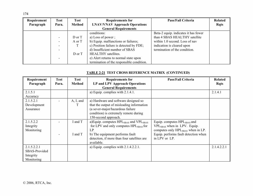
117744
© 2006, RTCA, Inc.
Requirement Paragraph
Test Para.
Test Method
Requirements for LNAV/VNAV Approach Operations
General Requirements
Pass/Fail Criteria Related Rqts
- - - - -
D or T A or T
T
D or T
conditions: a) Loss of power ; b) Equip. malfunctions or failures; c) Position failure is detected by FDE; d) Insufficient number of SBAS HEALTHY satellites. e) Alert returns to normal state upon termination of the responsible condition.
Beta-2 equip. indicates it has fewer than 4 SBAS HEALTHY satellite within 1.0 second. Loss of nav indication is cleared upon termination of the condition.
TABLE 2-21 TEST CROSS REFERENCE MATRIX (CONTINUED)
Requirement Paragraph
Test Para.
Test Method
Requirements for LP and LPV Approach Operations
General Requirements
Pass/Fail Criteria Related Rqts
2.1.5.1 Accuracy
a) Equip. complies with 2.1.4.1. 2.1.4.1
2.1.5.2.1 Development Assurance
- A, I, and T
a) Hardware and software designed so that the output of misleading information (a sever-major/hazardous failure condition) is extremely remote during 150-second approach.
2.1.5.2.2 Integrity Monitoring
- -
I and T
I and T
a)Equip. computes HPLSBAS and VPLSBAS for LPV and only computes HPLSBAS for LP. b) The equipment performs fault detection, if more than four satellites are available.
Equip. computes HPLSBAS and VPLSBAS when in LPV. Equip. computes only HPLSBAS when in LP. Equip. performs fault detection when in LPV or LP.
2.1.5.2.2.1 SBAS-Provided Integrity Monitoring
a) Equip. complies with 2.1.4.2.2.1. 2.1.4.2.2.1

117755
© 2006, RTCA, Inc.
Requirement Paragraph
Test Para.
Test Method
Requirements for LP and LPV Approach Operations
General Requirements
Pass/Fail Criteria Related Rqts
2.1.5.2.2.2 Fault Detection-Provided Integrity Monitoring
2.5.9 I and T
a) Equip. has FD integrity monitoring capability that uses redundant GPS and SBAS ranging measurements.
Equip. is shown to have an FD capability.
2.1.5.2.2.2.1 Frequency of Fault Detection
a) Equip. complies with 2.1.4.2.2.2.1. 2.1.4.2.2.2.1
2.1.5.2.2.2.3 False Alert
a) Equip. complies with 2.1.4.2.2.2.3. 2.1.4.2.2.2.3
2.1.5.2.2.2.4 Availability
a) Equip. complies with 2.1.4.2.2.2.4. 2.1.4.2.2.2.4
2.1.5.4 Satellite Tracking Capability
a) Equip. complies with 2.1.2.4. 2.1.2.4
2.1.5.5 Tracking Constraints
a) Equip. complies with 2.1.4.5. 2.1.4.5
2.1.5.5.1 GPS Tracking Constraints
a) Equip. complies 2.1.4.5.1. 2.1.4.5.1
2.1.5.5.2 SBAS Tracking Constraints
a) Equip. complies with 2.1.4.5.2. 2.1.4.5.2
2.1.5.6 Correlation Peak Validation
a) Equip. complies with 2.1.4.6. 2.1.4.6
2.1.5.7 Dynamic Tracking
a) Equip. complieswith 2.1.4.7. 2.1.4.7
2.1.5.8 Position Output
a) Equip. complies with 2.1.2.6 2.1.2.6

117766
© 2006, RTCA, Inc.
Requirement Paragraph
Test Para.
Test Method
Requirements for LP and LPV Approach Operations
General Requirements
Pass/Fail Criteria Related Rqts
2.1.5.8.1 Position Output Update Rate
- - -
T
T
T
a) Beta-3 equip. computes and outputs a position at a 5 Hz rate to support an unaided LPV and LP navigator. b) Equip. computes and outputs a position at a 1 Hz rate to support an LPV and LP navigator that is aided by a separate sensor providing at least 5 Hz data. c) Each position is dynamically independent of the previous position.
2.1.5.8.2 Position Output Latency
- - - -
T
T
T
T
a) Latency is ≤300 milliseconds for Beta-3 equipment that supports an unaided LPV and LP navigator. b) Output of the position defining data is <300 milliseconds after measurement time. c) Latency is ≤400 milliseconds for Beta-3 equipment that supports an aided LPV and LP navigator. d) Output of the position defining data is <400 milliseconds after measurement time.
2.1.5.9 SBAS Message Processing
a) Equip. complies with 2.1.4.9. 2.1.4.9
2.1.5.9.1 Message Types 2-5, 6 and 24 Fast Corrections
a) Equip. complies with 2.1.4.9.1. 2.1.4.9.1
2.1.5.9.2 Message Types 24 and 25 LTC Corrections
a) Equip. complies with 2.1.1.4.11.
2.1.1.4.11
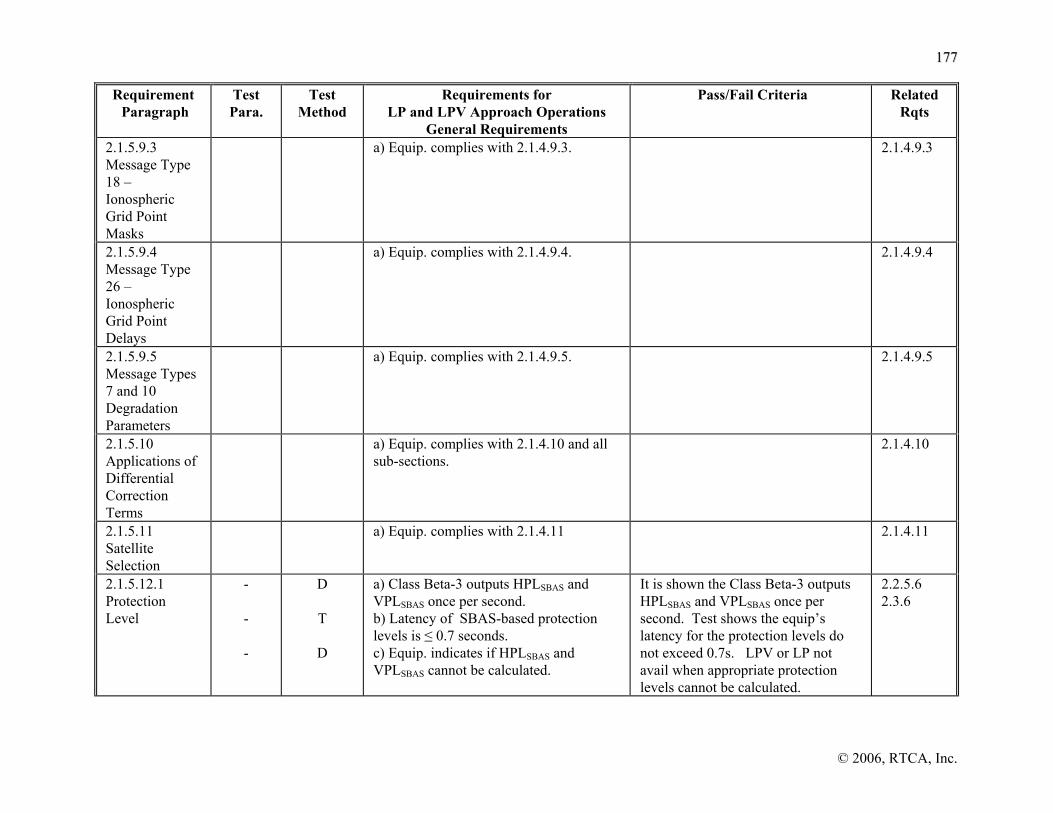
117777
© 2006, RTCA, Inc.
Requirement Paragraph
Test Para.
Test Method
Requirements for LP and LPV Approach Operations
General Requirements
Pass/Fail Criteria Related Rqts
2.1.5.9.3 Message Type 18 – Ionospheric Grid Point Masks
a) Equip. complies with 2.1.4.9.3. 2.1.4.9.3
2.1.5.9.4 Message Type 26 – Ionospheric Grid Point Delays
a) Equip. complies with 2.1.4.9.4. 2.1.4.9.4
2.1.5.9.5 Message Types 7 and 10 Degradation Parameters
a) Equip. complies with 2.1.4.9.5. 2.1.4.9.5
2.1.5.10 Applications of Differential Correction Terms
a) Equip. complies with 2.1.4.10 and all sub-sections.
2.1.4.10
2.1.5.11 Satellite Selection
a) Equip. complies with 2.1.4.11 2.1.4.11
2.1.5.12.1 Protection Level
- - -
D
T
D
a) Class Beta-3 outputs HPLSBAS and VPLSBAS once per second. b) Latency of SBAS-based protection levels is ≤ 0.7 seconds. c) Equip. indicates if HPLSBAS and VPLSBAS cannot be calculated.
It is shown the Class Beta-3 outputs HPLSBAS and VPLSBAS once per second. Test shows the equip’s latency for the protection levels do not exceed 0.7s. LPV or LP not avail when appropriate protection levels cannot be calculated.
2.2.5.6 2.3.6

117788
© 2006, RTCA, Inc.
Requirement Paragraph
Test Para.
Test Method
Requirements for LP and LPV Approach Operations
General Requirements
Pass/Fail Criteria Related Rqts
2.1.5.12.2 Navigation Alert
- - - - - -
D or T A or T
T
D or T
Beta-3 equip.provides an indication of loss of navigation within one second at the of the onset of the following conditions: a) Loss of power. b) Equip. malfunctions or failures. c) Position failure is detected by FDE. d) Class Beta-3 indicates loss of navigation within 0.6 seconds if there are an insufficient number of SBAS HEALTHY satellites. e) Alert returns to normal state immediately upon termination of the responsible condition.
Equip. indicates loss of nav. for: loss of power; equip. malfunctions or failures; FD detects a fault; Class Beta-3 equip. indicates it has fewer than 4 SBAS HEALTHY satellite within 0.6 seconds. Loss of nav indication is cleared upon termination of the condition.
2.1.5.13 HPL and VPL Prediction
- -
I and T
T
a) Equip. computes/outputs predicted HPLSBAS and VPLSBAS if it provides this optional capability. b) Latency of output and data used in the prediction is ≤ 1 minute.
2.2.5.2.4
TABLE 2-21 TEST CROSS REFERENCE MATRIX (CONTINUED)
Requirement Paragraph
Test Para.
Test Method
Gamma Equipment General Requirements
Pass/Fail Criteria Related Rqts
2.2.1.1.1.1 Operation
2.5.11.3.1 2.5.11.3.4
2.5.11.3.4
2.5.11.3.4
2.5.11.3.4
2.5.11.3.1
D D
D
D
D
D
a) Controls are accessible. b) Use of controls does not interfere with display of critical information. c) Controls provide tactile or visual feedback d) Controls movable without excessive effort and detents well defined. e) Control design avoids inadvertent activation. f) Controls operable with one hand.
Frequently used flight controls easily adjustable. Use of controls does not obstruct displays. Feedback is adequate, minimal risk of inadvertent activation or deactivation. Knob shape & size is distinguishable and aids in pilot’s use. Detents are well defined. Operations of controls accomplished with use of one hand.

117799
© 2006, RTCA, Inc.
Requirement Paragraph
Test Para.
Test Method
Gamma Equipment General Requirements
Pass/Fail Criteria Related Rqts
2.2.1.1.1.2 Control Labels
2.5.11.3.2 2.5.11.3.2
I I
a) Labels readable from 30 inches. b) Readable under anticipated light conditions. RECOMMENDATIONS: c) Should be next to controls and not obstructed. d) Placement should be consistent. e) Label terminology should be appropriate and consistent.
Labels are readable under various lighting conditions from up to 30 in. Not obstructed by use of controls.
2.2.1.1.3 2.2.1.1.5
2.2.1.1.2 Operating Procedures
2.5.11.3.1
I
a) Prompting cues are consistent. RECOMMENDATION: b) Should minimize pilot workload, reliance on pilot memory. c) Should maximize operational suitability. d) Should provide easy operator detection and recovery from operating errors. e) Operating rules should be consistent in all operating modes.
Minimal need for handbook procedures. Displays and control labels easily convey information, proper operation of controls with one hand and feedback provided. Minimum number of controls needed to complete tasks. Data entry procedures are simple and easy. Prompts are easily understood and documentation verifies consistent use of prompts in each mode. Documents and bench testing verify that a minimum number of control actions are necessary for each situation listed.
2.2.1.1
2.2.1.1.3 Minimum Workload Functions
- D a) Tasks in Table 2-5 can be accomplished within times provided.
Demonstrate that each task in Table 2-5 can be accomplished with the time provided.
2.2.1.1.4.1 Discernability
2.5.11.3.1 2.5.11.3.2 2.5.11.3.1
D
D
a) Alertsand symbols are distinctive and discernable from one another. b) Functionality clearly distinguished if control performs multiple functions. RECOMMENDATION:
Alerts, functionality, and symbols are distinctive and discriminable from one another.

118800
© 2006, RTCA, Inc.
Requirement Paragraph
Test Para.
Test Method
Gamma Equipment General Requirements
Pass/Fail Criteria Related Rqts
c) Equip. should provide clear indication when control is not in default mode. d) Fields requiring operator entries should be clearly denoted.
2.2.1.1.4.2 Displays - Brightness, Contrast, & Color
2.5.11.3.2
2.5.11.3.2
D
D I
a) Readable under anticipated light conditions. b) Colors are distinct from one another. c) Red = warning, Yellow = caution. RECOMMENDATION: d) Colors should follow aviation conventions. e) Color coded safety-critical information should have another distinguishing characteristic. f) Blue color should be avoided.
Display is readable. Display brightness is adjustable. Colors are distinguishable from one another under all ambient light conditions. Documents verify colors follow aviation conventions.
2.2.1.1.4.3 Angle of Regard
2.5.11.3.2
2.5.11.3.2
D
D
a) Displays are usable in horizontal view of ± 35 degrees to normal. b) Displays are usable in vertical view of ± 20 degrees to normal.
Display is readable in all ambient light conditions up to an angle of 35 degrees in the horizontal plane, and up to 20 degrees in vertical plane normal to the equipment display.
2.2.1.1.4.5 Alpha-numeric
2.5.11.3.2
2.5.11.1.1.2
D
D
a) Displays are readable from 30 inches under anticipated light conditions. b) Initial, Final, Missed Approach and Missed Approach Holding WPTs are labeled clearly. RECOMMENDATION: c) Location/closure rate on the active WPT, WPT name, and desired track information should facilitate cross-checking by pilot. d) WPT, WPT name, desired track should be differentiated from other information and consistently located.
Displays are readable, symbols & letters are distinguishable under various ambient light conditions. Initial, Final Missed Approach, Missed Approach Holding WPTs are clearly labeled.
2.2.1.1.1.2

118811
© 2006, RTCA, Inc.
Requirement Paragraph
Test Para.
Test Method
Gamma Equipment General Requirements
Pass/Fail Criteria Related Rqts
2.2.1.1.4.6 Moving Map
2.5.11.3.1 2.5.11.3.1 2.5.11.3.1
2.5.11.3.1
-
D D D
D D or I
a) Map scale is appropriate & clear. b) Map display update rates appropriate. c) Map orientation clearly indicated and selectable for multiple orientations. d) Aircraft location & track shown. e) Obstructions depicted on map displays reflect the data base precision. RECOMMENDATION: f) Map formats should be easily cross-checked with paper renditions. g) Maps used for primary steering guidance should account for cartography error contribution to accuracy.
Symbology is distinct and symbols in close proximity are distinguishable. Map motion and display update is not distracting, symbols maintain integrity. Clear indication of orientation: track-up and north-up. Aircraft location & heading appear on map. Track lines are distinguishable from course lines. Ground obstructions consistent with database & sectionals.
2.2.1.1.4.7 Primary Nav Display
- I a) If primary nav display page is used (in lieu of continuous), reconfiguring takes a maximum of two operator actions.
Information can be obtained with maximum of two actions.
2.2.1.4.1 2.2.4.4.1 2.2.5.4.1
2.2.1.1.4.8 Bearing labels
- -
I I
a) Bearing data field labels have “°” to the right of the bearing value. b) True bearing data field labels have “°T” to the right of bearing value.
All bearing labels have “°” to the right of the bearing value. Documentation verifies placement of “°T” to right of bearing value.
2.2.1.1.5 Annunciations
2.5.11.3.2
2.5.11.3.2
D
D
a) Visual alerts consistent with criticality and readable under all light conditions. b) Visual alerts not startling or too bright in dark conditions. RECOMMENDATION: c) Colors should follow conventions and regulations. d) Auditory alerts should be consistent with ARP 4102-4 and annunciator philosophy used in the aircraft. e) Auditory alerts should not be sole source of information. f) Annunicators should be detectable
Visual alerts are distinguishable under all light conditions. Alert illumination is not disruptive to pilot’s dark adaptation. If the equipment implements audible alerts the bench test 2.5.11.3.3 must be executed. In addition the auditory alerts should be consistent with ARP 4102-4.

118822
© 2006, RTCA, Inc.
Requirement Paragraph
Test Para.
Test Method
Gamma Equipment General Requirements
Pass/Fail Criteria Related Rqts
when wearing a headset. g) Suppress warnings, annunciations, messages not critical during instrument approaches during that flight phase.
2.2.1.1.5.1 Annunciators
2.5.11.3.2 -
D D
a) Brightness is controllable. b) Capability to test external annunciators. RECOMMENDATION: c) Simple font should be used. d) Alert and status characters should be readable without errors.
The brightness is manually controllable. Demonstrate capability provided to test external annunciators.
2.2.1.1.5.2 Messages
- -
I I
a) All current messages are retrievable. b) Indication provided of new messages. RECOMMENDATION: c) Should be grouped by urgency and listed chronologically within group. d) Equipment should indicate when there are current messages.
Messages of higher criticality should supersede lower urgency levels that are current. Documentation shows current messages are retrievable, and Indication provided for new message.
2.2.1.1.6 Set of Std Function Labels
- - - -
I I I I
a) Equip. uses labels or messages in Table 2-6. b) Function implemented as discrete action has one label. c) Several listed functions accomplished as discrete action use one of the applicable labels in Table 2-6. d) Abbreviations are not used to represent a different term, except waypoint identifiers.
Documentation shows that Table 2-6 labels and messages are used for applicable functions.
2.2.1.1.7
2.2.1.1.7 Set of Std Abbreviations
-
I
a) The abbreviations are used consistently in checklists, handbooks, etc. RECOMMENDATION: b) The equipment should use the standard set of abbreviations.
Documentation shows that the standard set of abbreviations are used consistently in the equipment displays, checklists, labels, etc.
2.2.1.1.1.2 2.2.1.1.3 2.2.1.1.4 2.2.1.1.6

118833
© 2006, RTCA, Inc.
Requirement Paragraph
Test Para.
Test Method
Gamma Equipment General Requirements
Pass/Fail Criteria Related Rqts
c) Abbreviations should not be used to represent different term.
2.2.1.2.1 FP Selection
2.5.11.1.1.1,(-).2
2.5.11.1.1.1,(-).2
- 2.5.11.1.1.1,(-).2
-
2.5.11.1.1.1
2.5.11.1.1.1
D
D
D I & D
D D
D
a) Hold an active FP with ≥ 20 WPTs and at least one alternate FP. b) Select by name and automatically include series of waypoints and paths. c) Can individually select WPT by name. d) WPT names consistent with published names and Airport identifiers use ICAO nomenclature. e) Equip. has as least 5-character field. f) Ability to manually select user-defined waypoints as part of FP. g) Differentiate between duplicate waypoint identifiers in the database including user defined & nav database. RECOMMENDATION: h) Automatically named FP should be labeled with dep/arr airports when FP presented for review, edit, activation, deletion.
Enter, store, select, & edit at least 2 FPs, one with ≥ 20 WPTs. Equipment can process FPs, which consist of the selection methods listed. Inspection of documentation states WPT names are consistent with published names. Airport identifiers are ICAO compliant nomenclature. Operator provided differentiation between identical database and user defined WPT identifiers.
2.2.1.2.6 2.2.3.5 2.2.4.2 2.2.4.5 2.2.5.5
2.2.1.2.2 FP Review
2.5.11.1.1.1,(-).2
2.5.11.1.1.1
2.5.11.1.1.1 - - -
D
D
D I I I
a) Readily display each WPT of any FP. b) Active leg or WPT identified. c) Ability to edit FP and insert & delete WPTs except those part of a published procedure. d) Ability to bypass WPTs in a published procedure or go to WPT not in procedure. e) Modifying the FAS (inserting WPT between FAWP & MAWP) disables the approach mode. f) Operator can replace procedure without
WPTs are displayed in sequence for a FP. Display all WPTs, intersections & nav. aids in correct order. Documentation verifies user ability to bypass WPTs in a published procedure and that modifying the FAS disables the approach mode. Ability to edit FP (including replacing a procedure) with no changes to Active FP until accepted and activated. Output of guidance after accept FP changes does not exceed 5 seconds. Equipment can
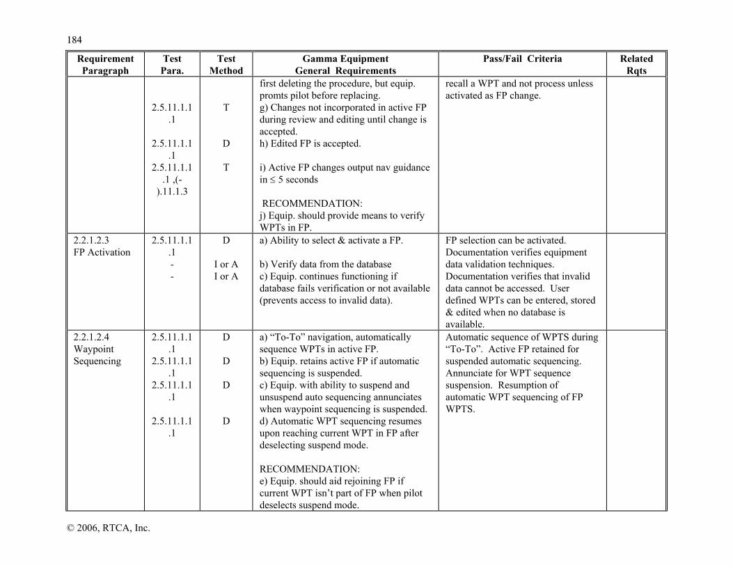
118844
© 2006, RTCA, Inc.
Requirement Paragraph
Test Para.
Test Method
Gamma Equipment General Requirements
Pass/Fail Criteria Related Rqts
2.5.11.1.1.1
2.5.11.1.1.1
2.5.11.1.1.1 ,(-
).11.1.3
T
D
T
first deleting the procedure, but equip. promts pilot before replacing. g) Changes not incorporated in active FP during review and editing until change is accepted. h) Edited FP is accepted. i) Active FP changes output nav guidance in ≤ 5 seconds RECOMMENDATION: j) Equip. should provide means to verify WPTs in FP.
recall a WPT and not process unless activated as FP change.
2.2.1.2.3 FP Activation
2.5.11.1.1.1 - -
D
I or A I or A
a) Ability to select & activate a FP. b) Verify data from the database c) Equip. continues functioning if database fails verification or not available (prevents access to invalid data).
FP selection can be activated. Documentation verifies equipment data validation techniques. Documentation verifies that invalid data cannot be accessed. User defined WPTs can be entered, stored & edited when no database is available.
2.2.1.2.4 Waypoint Sequencing
2.5.11.1.1.1
2.5.11.1.1.1
2.5.11.1.1.1
2.5.11.1.1.1
D
D
D
D
a) “To-To” navigation, automatically sequence WPTs in active FP. b) Equip. retains active FP if automatic sequencing is suspended. c) Equip. with ability to suspend and unsuspend auto sequencing annunciates when waypoint sequencing is suspended. d) Automatic WPT sequencing resumes upon reaching current WPT in FP after deselecting suspend mode. RECOMMENDATION: e) Equip. should aid rejoining FP if current WPT isn’t part of FP when pilot deselects suspend mode.
Automatic sequence of WPTS during “To-To”. Active FP retained for suspended automatic sequencing. Annunciate for WPT sequence suspension. Resumption of automatic WPT sequencing of FP WPTS.

118855
© 2006, RTCA, Inc.
Requirement Paragraph
Test Para.
Test Method
Gamma Equipment General Requirements
Pass/Fail Criteria Related Rqts
2.2.1.2.5.1 Direct To
2.5.11.1.1 D a) Equipment supports ‘Direct To’ a WPT.
Equipment provides guidance from present position direct to a waypoint.
2.2.1.2.5.2 TO/FROM Course Selection
2.5.11.1.1.1
2.5.11.1.1.1
2.5.11.1.1.1
2.5.11.1.1.1
D
D
D
D
a) Permit selection, display and course “TO” or “FROM” active WPT. b) Entry/display resolution is minimum of 1 degree. c) Intercept a course to a WPT (CF). d) Indication of “TO” or “FROM” operation in normal field of view.
Display and guidance to active WPTs and sequencing between “TO” WPTs. Verify Course with 1 degree resolution. CP path intercepting a course to a WPT and CF leg to a WPT. Display indication of “TO” or “FROM” operation.
2.2.1.2.5.3 Manually-Selected WPT and WPT sequencing
2.5.11.1.1.1
2.5.11.1.1.1
2.5.11.1.1.1
2.5.11.1.1.1
D
D
D
D
a) Auto seqn. of remaining WPTs in active flight plan following the selected “TO” WPT in active FP. b) If selected “TO” WPT is not in FP, FP is retained and not deleted. c) Equip. enters “FROM” operations after crossing manually selected WPT not in FP and maintains prior track. d) Equipment remains in “FROM” operation until pilot seclects another “TO” WPT.
If “TO” WPT is in active FP, equipment auto. sequences remaining WPTs after “TO”, active FP remains after selecting “TO”. If “TO” WPT is not in active FP, WPTs are retained. “FROM” operation automatically entered after crossing manually selected WPT. Provides guidance “FROM” WPT following the prior track. Remains in “FROM” until manually selected.
2.2.1.2.6 User Defined WPTs
2.5.11.1.1.1
2.5.11.1.1.1
2.5.11.1.1.1
D
D
D
a) Enter & display WPT coordinates in lat./long. with at least 0.1 min’s. resolution. b) Create waypoint at current position. c) WPTs entered by range/bearing with 0.1 nm range resolution and 1 degree bearing resolution.
Enter & display coordinates in lat./long with at least than 0.1 min’s. User Defined WPT can be created at current position. Range resolution of 0.1 NM & bearing of 1 degree or better with local declination. Documentation verifies use of local declination for bearing or verifies Std mag-var model.
2.2.1.2.7 Emergency Procedures
2.5.11.1.3 -
D
D
a) Capability to identify/fly directly to nearest nine airports. b) Default is airports if nearest function also includes other WPT types.
Verify activating [NRST] function(s) identify nearest 9 airports and permit Direct To any of the airports.
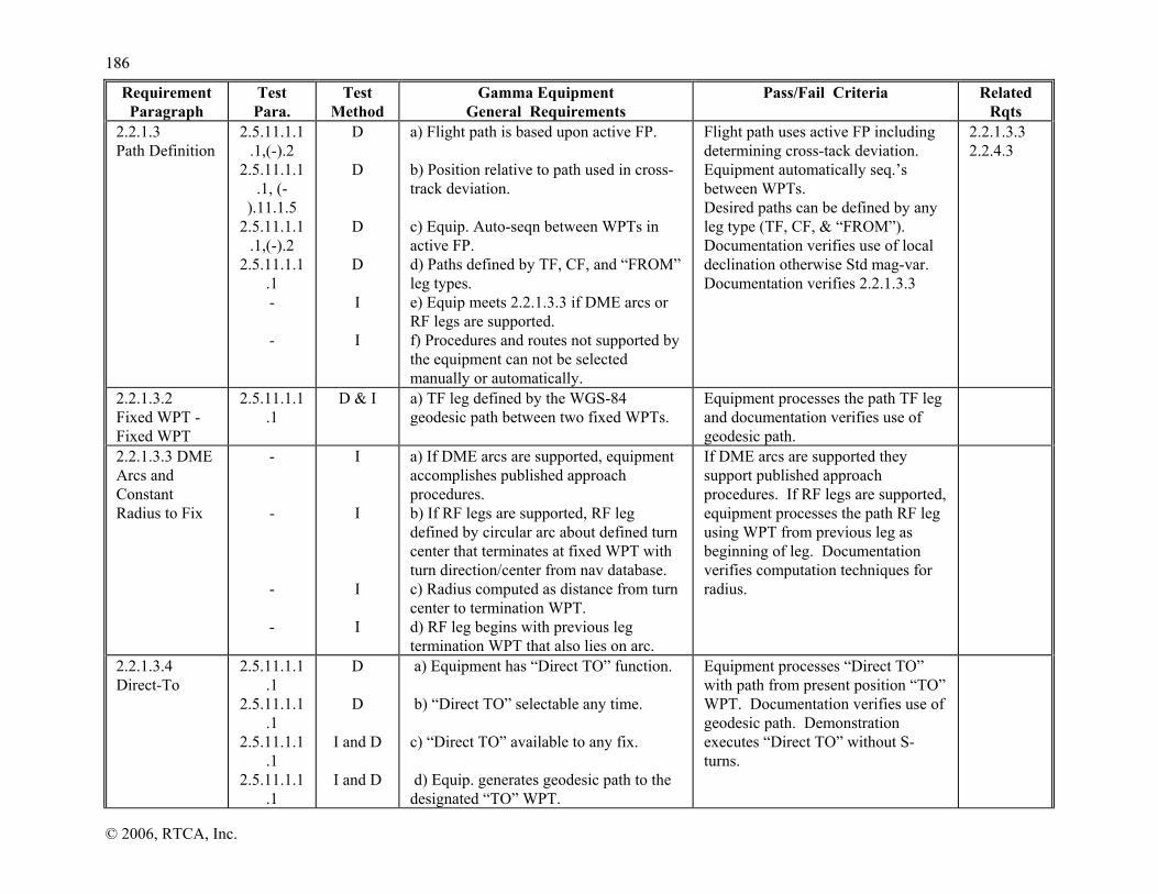
118866
© 2006, RTCA, Inc.
Requirement Paragraph
Test Para.
Test Method
Gamma Equipment General Requirements
Pass/Fail Criteria Related Rqts
2.2.1.3 Path Definition
2.5.11.1.1.1,(-).2
2.5.11.1.1.1, (-
).11.1.5 2.5.11.1.1
.1,(-).2 2.5.11.1.1
.1 - -
D
D
D
D I I
a) Flight path is based upon active FP. b) Position relative to path used in cross-track deviation. c) Equip. Auto-seqn between WPTs in active FP. d) Paths defined by TF, CF, and “FROM” leg types. e) Equip meets 2.2.1.3.3 if DME arcs or RF legs are supported. f) Procedures and routes not supported by the equipment can not be selected manually or automatically.
Flight path uses active FP including determining cross-tack deviation. Equipment automatically seq.’s between WPTs. Desired paths can be defined by any leg type (TF, CF, & “FROM”). Documentation verifies use of local declination otherwise Std mag-var. Documentation verifies 2.2.1.3.3
2.2.1.3.3 2.2.4.3
2.2.1.3.2 Fixed WPT - Fixed WPT
2.5.11.1.1.1
D & I a) TF leg defined by the WGS-84 geodesic path between two fixed WPTs.
Equipment processes the path TF leg and documentation verifies use of geodesic path.
2.2.1.3.3 DME Arcs and Constant Radius to Fix
- - - -
I I I I
a) If DME arcs are supported, equipment accomplishes published approach procedures. b) If RF legs are supported, RF leg defined by circular arc about defined turn center that terminates at fixed WPT with turn direction/center from nav database. c) Radius computed as distance from turn center to termination WPT. d) RF leg begins with previous leg termination WPT that also lies on arc.
If DME arcs are supported they support published approach procedures. If RF legs are supported, equipment processes the path RF leg using WPT from previous leg as beginning of leg. Documentation verifies computation techniques for radius.
2.2.1.3.4 Direct-To
2.5.11.1.1.1
2.5.11.1.1.1
2.5.11.1.1.1
2.5.11.1.1.1
D
D
I and D
I and D
a) Equipment has “Direct TO” function. b) “Direct TO” selectable any time. c) “Direct TO” available to any fix. d) Equip. generates geodesic path to the designated “TO” WPT.
Equipment processes “Direct TO” with path from present position “TO” WPT. Documentation verifies use of geodesic path. Demonstration executes “Direct TO” without S-turns.

118877
© 2006, RTCA, Inc.
Requirement Paragraph
Test Para.
Test Method
Gamma Equipment General Requirements
Pass/Fail Criteria Related Rqts
2.5.11.1.1.1
I and D e) Equip. captures path without S-turns.
2.2.1.3.5 Course to a Fix WPT
2.5.11.1.1.1 ,(-).2
D and I
a) CF leg defined by WGS-84 geodesic path terminating at fixed WPT with defined course.
Equipment processes the path CF leg and documentation verifies use of geodesic path.
2.2.1.3.6 FROM leg
2.5.11.1.1.1 ,(-).2
-
D I
a) Equip. defines desired course “FROM” a WPT. b) Course is WGS-84 geodesic path.
Equipment provides “FROM” guidance and documentation verifies use of geodesic path.
2.2.1.3.7 Fly-by Turns
2.5.11.1.1.1,(-).2
2.5.11.1.1
.1,(-).2
D
D
a) Equipment provides capability for fly-by turns. b) Turns with heading changes less than or equal to 120 degrees use fly-by turns unless designated by database procedure. RECOMMENDATION: c) Equip. should provide deviations thru turn.
Equipment provides guidance for Fly By Turns for heading changes less than or equal to 120 degrees.
2.2.1.3.7.1 Fly-by Turn Indications
2.5.11.1.1.1,(-).2
2.5.11.1.1.1,(-).2
2.5.11.1.1.1,(-).2
D
D
D
a) Indication at start of turn. b) Indication prior to start of fly-by turn (turn anticipation). c) Equip. indicates desired course of next leg not later than turn anticipation indication. RECOMMENDATION: d) Turn anticipation should be 10 seconds prior for turns < 120 degrees, 30 seconds for turns ≥ 120 degrees.
Indication provided to user prior to, and at the start of a defined Fly-by turn. Indication of course for next leg no later than turn anticipation.
2.2.1.3.7.2 Fly-by Theoretical Transition Area
- A a) Defined path of fly-by turn accomplished within Theoretical Transition areas listed.
Documentation and analysis (See 2.2.1.3.7.3 Acceptable means) verifies that the equipment will provide guidance within the Theoretical Transition areas listed.
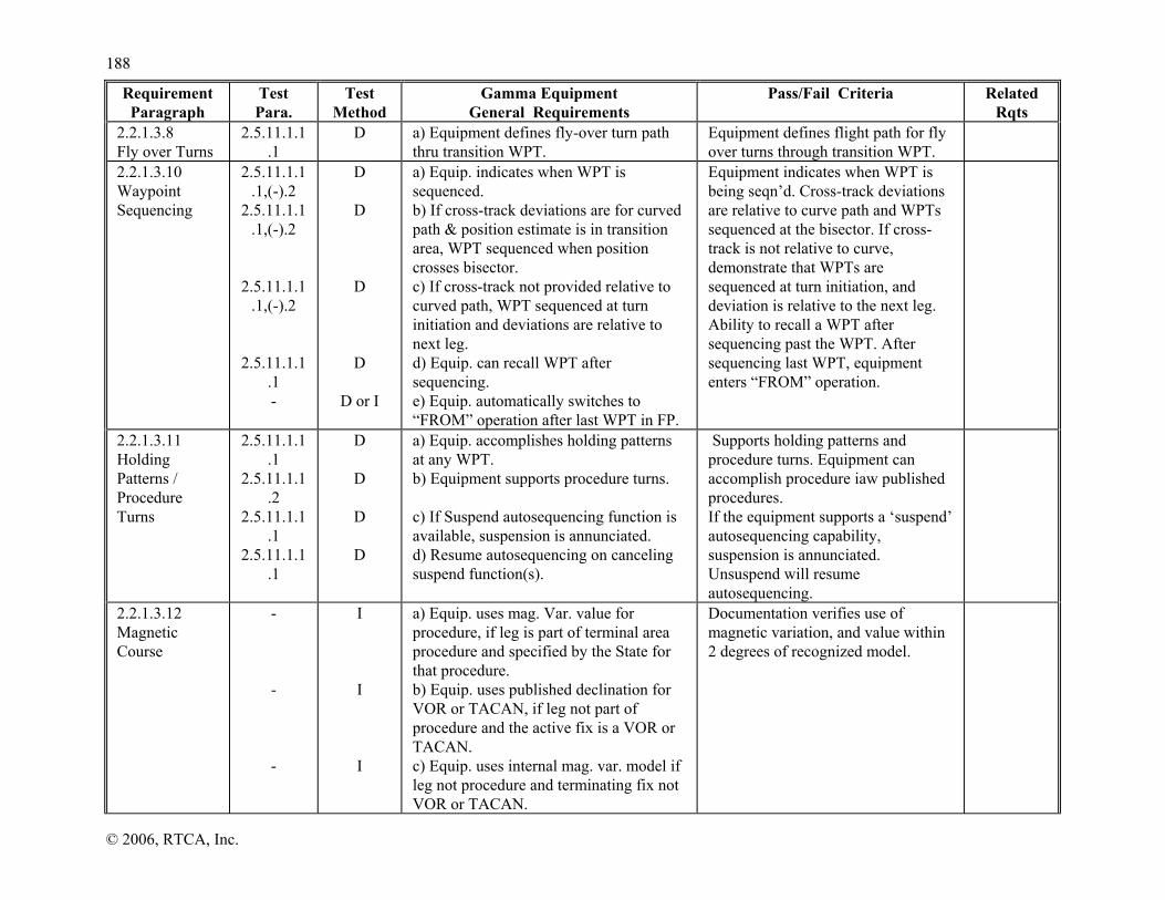
118888
© 2006, RTCA, Inc.
Requirement Paragraph
Test Para.
Test Method
Gamma Equipment General Requirements
Pass/Fail Criteria Related Rqts
2.2.1.3.8 Fly over Turns
2.5.11.1.1.1
D a) Equipment defines fly-over turn path thru transition WPT.
Equipment defines flight path for fly over turns through transition WPT.
2.2.1.3.10 Waypoint Sequencing
2.5.11.1.1.1,(-).2
2.5.11.1.1.1,(-).2
2.5.11.1.1.1,(-).2
2.5.11.1.1.1 -
D
D
D
D
D or I
a) Equip. indicates when WPT is sequenced. b) If cross-track deviations are for curved path & position estimate is in transition area, WPT sequenced when position crosses bisector. c) If cross-track not provided relative to curved path, WPT sequenced at turn initiation and deviations are relative to next leg. d) Equip. can recall WPT after sequencing. e) Equip. automatically switches to “FROM” operation after last WPT in FP.
Equipment indicates when WPT is being seqn’d. Cross-track deviations are relative to curve path and WPTs sequenced at the bisector. If cross-track is not relative to curve, demonstrate that WPTs are sequenced at turn initiation, and deviation is relative to the next leg. Ability to recall a WPT after sequencing past the WPT. After sequencing last WPT, equipment enters “FROM” operation.
2.2.1.3.11 Holding Patterns / Procedure Turns
2.5.11.1.1.1
2.5.11.1.1.2
2.5.11.1.1.1
2.5.11.1.1.1
D
D
D
D
a) Equip. accomplishes holding patterns at any WPT. b) Equipment supports procedure turns. c) If Suspend autosequencing function is available, suspension is annunciated. d) Resume autosequencing on canceling suspend function(s).
Supports holding patterns and procedure turns. Equipment can accomplish procedure iaw published procedures. If the equipment supports a ‘suspend’ autosequencing capability, suspension is annunciated. Unsuspend will resume autosequencing.
2.2.1.3.12 Magnetic Course
- - -
I I I
a) Equip. uses mag. Var. value for procedure, if leg is part of terminal area procedure and specified by the State for that procedure. b) Equip. uses published declination for VOR or TACAN, if leg not part of procedure and the active fix is a VOR or TACAN. c) Equip. uses internal mag. var. model if leg not procedure and terminating fix not VOR or TACAN.
Documentation verifies use of magnetic variation, and value within 2 degrees of recognized model.

118899
© 2006, RTCA, Inc.
Requirement Paragraph
Test Para.
Test Method
Gamma Equipment General Requirements
Pass/Fail Criteria Related Rqts
- -
I I
d) Equip. can assign mag. var. using mag. North reference. e) Assigned mag. Var. within two degrees of value given by recognized model.
2.2.1.3.13 Dead Reckoning
- - - - - - - -
D
D
D
D
D
D
D
D
a) Dead Reckoning capability is provided. b) DR is active and clearly indicated when no position can be obtained from GPS/SBAS. c) If automatic input of TAS or heading not available, DR projects last known GPS/SBAS position by last known groundspeed and desired track. d) DR capability continues to navigate relative to the active flight plan. e) DR capability changes assumed track in accordance with flight plan. f) Equip. can determine bearing to airport, based upon DR position. g) If TAS and heading is provided, DR projects last known GPS/SBAS position using TAS and heading, corrected for last known wind. h) If TAS/heading provided, equip. continues to navigate using this position and active FP. RECOMMENDATION: i) Equip. should accept TAS and heading input.
2.2.1.3.15 Geodesic Path Computation Accuracy
- A a) The cross-track path deviation error between the computed path used to determine cross-track deviations and the true geodesic is less than 10% of the horizontal alert limit of the navigation mode applicable to the leg containing the

119900
© 2006, RTCA, Inc.
Requirement Paragraph
Test Para.
Test Method
Gamma Equipment General Requirements
Pass/Fail Criteria Related Rqts
path. 2.2.1.3.16 Parallel Offsets
- - - - - - - - - - -
D or I
A
A
A
D or I
D
D
D
D or I
D
D or I
a) Available for en route TF and geodesic portion of DF leg types at a minimum. b) If base route leg is geodesic, corresponding offset leg is geodesic. c) If base route leg is TF, corresponding offset leg is geodesic drawn between beginning and end offset reference points from base route. d) If base route leg is DF, first offset reference point is abeam of the start of the geodesic part of the base route DF leg. e) Capability to fly offset tracks at selected distance with same navigation modes and performance requirements as base route. f) Can enter offset distance up to 20nm in 1nm increments left or right of course. g) Equip. provides clear indication when operating in offset mode. h) Provides reference parameters relative to offset path and reference points. i) Offset paths not propagated through route discontinuities, unreasonable path geometries, or beyond IAF. j) Annunciation given prior to end of offset path. k) Offset remains active for all segments until automatically removed, direct-to routing selected, or manual cancellation.
2.2.1.4.1 Primary Nav Display
2.5.11.1.5, (-).6
2.5.11.1.1.1 ,(-).2
D
D
a) Non-numeric cross-track deviation is continuously displayed. b) Nav. parameters below are continuously displayed or available on a selectable page:
1) Active WPT dist., or, ETA to
Nonnumeric cross-track deviation is continuously displayed. Nav. parameters are continuously displayed or available on a selectable page. Each Nav. display parameter is
2.2.3.4.1 2.2.4.4.1 2.2.5.4.1

119911
© 2006, RTCA, Inc.
Requirement Paragraph
Test Para.
Test Method
Gamma Equipment General Requirements
Pass/Fail Criteria Related Rqts
2.5.11.1.1.2,
2.5.11.1.2
D
active WPT. 2) Active WPT name. 3) Active WPT bearing. 4) Desired TRK and actual TRK, or
TRK angle error. 5) Active WPT “TO” or “FROM”
indication. c) Distance, bearing, desired track, actual track and track angle error are distinguishable.
distinguishable from each other.
2.2.1.4.2.1 Electrical Output
-
T
a) Electrical outputs to drive non-numeric displays meet characteristics in Table 2-8.
Test is conducted with data showing electrical characteristics for resolution, accuracy, linearity are satisfied.
2.2.1.4.2.2 Display
2.5.11.1.5 D a) Non-numeric display characteristics meet requirements in Table 2-9.
Characteristics for nonnumeric display of cross track resolution, accuracy, linearity min. discernible movement are met with bench test. Mfgr must show Readability is met.
2.2.2.4.2 2.2.2.4.4 2.2.2.4.5 2.2.3.4.2 2.2.4.4.2
2.2.1.4.3 Active WPT Distance Display
2.5.11.1.1.1
2.5.11.1.2
2.5.11.1.2
D
D
D
a) Distance to WPT displayed in “TO” operation and from WPT in “FROM” operations. b) WPT distance display resolution of 0.1 NM for ranges up to 99.9 NM. c) Display resolution 1 NM at ranges between 100 and 9999 NM.
WPT distance available within resolution (NM) appropriate to distance “TO” or “FROM” WPT.
2.2.1.4.4 Active WPT Bearing Display
2.5.11.1.1.1,(-).2
2.5.11.1.1.2
2.5.11.1.1.1, (-).2
2.5.11.1.1.1 ,(-).2
-
D
D
D
D
D
a) Bearing to active WPT displayed in “TO” operation. b) If provided, bearing from active WPT displayed in “FROM” Operation.
1) Equip. provides “TO” or “FROM” indication.
c) Bearing displayed with resolution of 1 degree. d) Bearing displayed in true or magnetic
Bearing to/from WPT is displayed for appropriate operation (“TO/FROM”). In “FROM” operation, the display indicates whether bearing is to or from the WPT. Bearing resolution is 1 degree. Display in either true or magnetic.

119922
© 2006, RTCA, Inc.
Requirement Paragraph
Test Para.
Test Method
Gamma Equipment General Requirements
Pass/Fail Criteria Related Rqts
2.2.1.4.5.1 Desired Track
2.5.11.1.1.2
D a) Equip displays active leg desired track with 1° resolution.
Equip displays desired tk.
2.2.1.4.5.2 Track Angle
2.5.11.1.1.2
D a) The track angle is displayed with 1° resolution.
2.2.1.4.5.3 Track Angle Error
2.5.11.1.1.2
D a) The track angle error is displayed with 1° resolution.
2.2.1.4.6 Display of TO/FROM
2.5.11.1.1.1,(-).2
D a) Equipment continuously displays indication of “TO” or “FROM” operation.
Equipment continuously outputs “TO” or “FROM” Operation.
2.2.1.4.7 Waypoint Bearing/ Distance Display
2.5.11.1.1.1 -
D
D or I
a) Equipment can display range/bearing to any WPT. b) Equip. displays ETA or ETE for WPTs in active FP.
Equipment displays range/bearing to selected WPT. Display estimated time to arrive at the WPT (e.g., ETA or ETE).
2.2.1.4.9 Magnetic Course
- - -
I I I
a) DTK is based on true-to-magnetic conversion at user location, using magnetic model. b) BRG TO/FROM WPT is based on true-to-magnetic conversion at user location, using magnetic model. c) CRS is based on true-to-magnetic conversion at WPT location, using same magnetic conversion as used to define path.
Documentation verifies conventions for DTK, BRG, and CRS.
2.2.1.4.10 Ground Speed
- D a) Equip. provides display of ground speed with one knot resolution.
2.2.1.4.11 Aircraft Present Position
2.5.11.1.1.1
D a) Equip. provides display of present Lat/Long with 0.1 minute resolution.
2.2.1.5.1 Access
- - -
I I
I and T
a) No manual database updating. b) Data recalled from storage also retained in storage. c) Database updates use high-integrity data validation technique.
Database (e.g., Jeppesen data) cannot be manually updated, excludes user defined data. Data remains in storage. Updating of database includes data integrity and
2.2.1.5.2 2.2.3.5 2.2.4.5 2.2.5.5

119933
© 2006, RTCA, Inc.
Requirement Paragraph
Test Para.
Test Method
Gamma Equipment General Requirements
Pass/Fail Criteria Related Rqts
- -
D
D
d) Equip. provides means to identify database version and operating dates. e) Equip. indicates if database is not yet effective or out of date.
validation such as CRC. Can identify version and operating dates. Indicates if database is not yet effective or out of date.
2.2.1.5.2 Content
- - - -
2.5.11.1.1.1
2.5.11.1.1.1, (-).2
-
D and I I I I I
D
D
a) Nav. Database is updatable, containing location/path information, referenced to WGS-84, 0.01 minute Lat/Long resolution, and 0.1° course resolution for:
1) Airports 2) VORs, DMEs, NDBs 3) All named WPTs and
intersections shown on en route and terminal charts.
4) RNAV departure procedures and STARS
b) Departures and arrivals retrievable as named procedures. c) Waypoints identified as “fly-over” or “fly-by” IAW published procedure.
Nav. database will store updatable data with lat./long of 0.01 min. or better, for airports, VORs, NDBs, WPTs and intersections etc. Documentation verifies that all WPTs and intersections on charts are provided and all SIDS and STARS. SIDs and STARs retrievable as a procedure. Departures and arrivals retrievable as a procedure. Waypoints identified as appropriate.
2.2.3.5 2.2.4.5.1 2.2.5.5.1
2.2.1.5.3 Standard
- I, T & A
a) Data base(s) comply with Section 2 of RTCA DO-200A.
Data bases meet specified rqts. in section2 of RTCA/DO-200A. Process for updating database to maintain data integrity will be evaluated.
2.2.1.5.4.1 Incorporation of Conversion Algorithms
- -
D or I I
a) Equip. annunciates when displaying lat/long in datum other than WGS-84. b) Annunciation is designed to prevent errors or misinterpretation.
The display and data entry of lat/long in other than WGS-84 is annunciated.

119944
© 2006, RTCA, Inc.
Requirement Paragraph
Test Para.
Test Method
Gamma Equipment General Requirements
Pass/Fail Criteria Related Rqts
2.2.1.6.1 Caution Associated with Loss of Integrity Monitoring
- - -
D I D
a) Equip. issues caution to indicate any loss of integrity monitoring. b) Caution in pilot’s primary field. c) Equip. indicates when integrity monitoring capability is restored.
Caution for loss of integrity monitoring, and indication when capability is restored. Loss of integrity monitoring caution provided by separate annunciator and is distinguishable.
2.1.1.13 2.2.2.6.2 2.2.3.6.2 2.2.4.6.2 2.2.5.6.2
2.2.1.6.2 Annunciation - Navigation Caution
2.5.11.1.4
2.5.11.1.4
D and I
D and I
a) Equip. continuously indicates a caution for loss of nav. b) Caution provided by unique annunciator in primary field of view.
Caution of loss of equipment’s navigation capability. Caution of loss of navigation is provided by means of a separate annunciator and is distinguishable.
2.1.1.13.2 2.2.2.6.3 2.2.3.6.3 2.2.4.6.3 2.2.5.6.3
2.2.1.7 Mode Switching Requirements
2.5.11.1.1.1
2.5.11.1.1.1
2.5.11.1.5 2.5.11.1.6
2.5.11.1.1
.1 2.5.11.1.5 2.5.11.1.6
D
D
D
a) Display nav. mode on request, en route, terminal, approach (LNAV, LNAV/VNAV, LP, LPV ). b) Equip. automatically switches to default mode when entering region defined for that mode. c) Approach type is continuously annunciated in approach mode and switches to LNAV during fail-down.
Nav mode indicated on request. Optional Oceanic/remote mode verified by inspection. Modes follow Tables 2-8 and 2-9, 2-10. Mode automatically switches to default mode. Approach type is annunciated by continuous indication. For modes, Auto switches are indicated.
2.2.4.5 2.2.3.7 2.2.4.7 2.2.5.7 Tables 2-8, 2-9, 2-10
TABLE 2-21 TEST CROSS REFERENCE MATRIX (CONTINUED)
Requirement Paragraph
Test Para.
Test Method
Gamma Equipment En Route/Terminal Requirements
Pass/Fail Criteria Related Rqts
2.2.2.4.2 Non-Numeric Cross-Track
-
2.5.11.1.5
T
T
a) Full-scale deflection in oceanic/remote mode doesn’t exceed ±5 NM. b) Full-scale deflection in en route mode is ±2 NM. c) Full-scale deflection in terminal mode
Oceanic/remote full-scale deflection is ≤ ±5 NM. En route full-scale deflection is ±2 NM. Terminal full-scale deflection is ±1
2.2.1.4.2.2

119955
© 2006, RTCA, Inc.
Requirement Paragraph
Test Para.
Test Method
Gamma Equipment En Route/Terminal Requirements
Pass/Fail Criteria Related Rqts
2.5.11.1.5 T is ±1 NM. NM. 2.2.2.4.3 Numeric Cross-Track Deviation
2.5.11.1.5
2.5.11.1.5
2.5.11.1.5
D
T
T
a) Equip. displays or outputs a numeric cross-track deviation with range at least ± 20 NM for oceanic/remote, en route, terminal. b) Min. resolution of 0.1 NM for ranges ≤ 9.9 NM. c) Min. resolution of 1 NM for ranges > 9.9 NM.
The display or output is at least -20 NM (left) and +20 NM (right). Resolution of 0.1 NM for ranges ≤ 9.9 NM and 1.0 NM for ranges > 9.9 NM.
2.2.2.4.4 Display Update Rate
2.5.11.1.3 T
a) Display update rate of 1 Hz or more. Data presented on the display updated ≥ 1 Hz in En Route/ Terminal mode.
2.2.2.4.5 Display Up-date Latency
2.5.11.1.3 T aa)) EEqquuiipp.. ddiissppllaayy oorr eelleeccttrriicc oouuttppuutt ddooeess nnoott eexxcceeeedd 11 sseecc.. llaatteennccyy ffoorr rreeqquuiirreedd ddaattaa..
The latency of data displayed ≤ 1 sec.
2.2.2.6.1 Alert Limits
2.5.9.1.5 2.5.9.3
I and T a) HAL for navigation modes are: Oceanic/Remote 4 NM En Route 2 NM Terminal 1 NM
2.2.2.6.2 Caution Associated with Loss of Integrity Monitoring
2.5.9.1.6 2.5.9.3
- -
T
T
I and A
a) For FDE-provided integrity, equipment provides loss of integrity monitoring caution within phase of flight alert time if HPLFD exceeds the HAL. b) HPLFD latency does not exceed FDE TTA from last valid HPLFD or HPLSBAS computation. c) For SBAS-provided integrity, equipment provides loss of integrity monitoring caution within 2 seconds if current HPLSBAS exceeds HAL.
Test to verify that when HPL exceeds HAL there is nav. warning flag or other indication. Documentation and verifies default HAL values of Oceanic (4 NM), en route (2 NM), and Terminal (1 NM) and SBAS warning indication.
2.2.1.6.1, 2.2.1.7
2.2.2.6.3 Caution with Loss of Nav.
2.5.11.1.4
D or T D
a) Equip. outputs/displays loss of nav indication within one second for the following:
1) Absence of power. 2) Equipment malfunction or
Caution for power loss and equipment malfunction or failure within one second. Caution for inadequate satellites in position soln. lasting for 5 or more seconds.

119966
© 2006, RTCA, Inc.
Requirement Paragraph
Test Para.
Test Method
Gamma Equipment En Route/Terminal Requirements
Pass/Fail Criteria Related Rqts
-
2.5.11.1.4
A
T
T
T
(D and I) or T
failure. 3) Inadequate number of satellites in
position soln. (lasting 5 seconds or more).
4) FDE detects pos. failure and not excluded within TTA.
b) FDE detects position failures resulting in loss of nav caution within following times-to-alert:
1) Oceanic/Remote 1 min. 2) Enorute 30 sec 3) Terminal 10 sec
c) Equipment distinguishes between types of loss of navigation capability. d) Caution returns to normal state upon termination
Caution for fault detected and not excluded. Test data verifies Time-to-alerts: Oceanic (1 min.), En Route (30 secs), and Terminal (10 secs). Equipment distinguishes between cautions. Caution returns to normal state upon termination of caution condition.
2.2.2.7.1.3 En Route Display Transition
2.5.11.1.5,
2.5.11.1.1.1
D and T a) Terminal to en route non-numeric cross-track sensitivity gradually decreases from ±1 NM FSD to ±2 NM FSD over a distance of 1 NM
Display sensitivity for automatic transition to en route mode decreases gradually until full-scale sensitivity of ±2 NM is achieved within 1 NM.
2.2.1.7 Table 2-5
2.2.2.7.2.1 Terminal Entry Criteria
2.5.11.1.1.1
D
a) Automatic mode switching to terminal mode occurs 31NM from the destination airport.
Mode switching from en route to terminal mode is annunciated and does not occur at intermediate airports.
2.2.1.7
2.2.2.7.2.3 Display Transition Rqts.
2.5.11.1.5,
2.5.11.1.1.1
D and T
a) En route to terminal non-numeric display sensitivity gradually increases from ±2 NM FSD to ±1 NM FSD over a distance of 1 NM.
Display sensitivity for automatic transition from en route to terminal increases gradually until full-scale sensitivity of ±1 NM is achieved within 1 NM
2.2.1.7 Table 2-5

119977
© 2006, RTCA, Inc.
TABLE 2-21 TEST CROSS REFERENCE MATRIX (CONTINUED)
Requirement Paragraph
Test Para. Test Method
Gamma Equipment LNAV Approach Requirements
Pass/Fail Criteria Related Rqts
2.2.3.2 Path Selection
2.5.11.1.1.1, (-).2
2.5.11.1.1.1, (-).2
D
D
a) Equip. enables approach path selection by selecting airport, approach idententifier, IAF, and (as applicable) runway. b) Once approach is selected, approach name is accessible.
2.2.3.2.1 Approach Selection
2.5.11.1.1.1, (-).2
2.5.11.1.1.2
2.5.11.1.1.2
2.5.11.1.1.2 2.5.11.1.7
D
D
D
D
a) Equip. presents/permits selection among all IAWPs. b) Equip. automatically inserts remaining WPTs after IAWP selection. c) Equip. permits manual selection of VTF approach. d) Equip. indicates that VTF has been selected until FAWP is sequenced.
Pilot can select between multiple IAWPs and remaining WPTs. After selecting an IAWP, the WPTs remaining in approach plan are listed in proper seqn. Manual selection of VTF approach and bypass complete approach procedure. VTF indication until the FAWP has sequenced.
2.2.1.2.1 2.2.4.2.1
2.2.3.2.2 Missed Approach Sequencing
2.5.11.1.1.2
2.5.11.1.1.2
2.5.11.1.1.2
D
D
D
a) Equipment provides capability to activate missed approach with manual action. b) Selecting missed approach prior to MAWP initiates missed approach at the MAWP. RECOMMENDATION: c) Equipment should provide a capability to go “Direct-TO” any WPT in missed approach procedure.
Equipment provides capability to activate procedure with a manual action. Selecting a missed approach prior to MAWP executes missed approach at the MAWP. Verify the display sensitivity changes immediately to +0.3nm Equipment should provide a capability to go “Direct-TO” any WPT in missed approach procedure.
2.2.3.3.1 Approach Path Definition
2.5.11.1.1.2, 2.5.11.1.6
- -
D
D
a) If VTF approach is not selected, deviation provided with respect to active leg of approach (FSD angular or linear). b) If VTF approach selected, guidance is relative to the inbound course to the FAWP (FSD angular or linear).
For non-VTF, deviation is respect to active leg. For VTF guidance is relative to inbound course of the FAWP. The active waypoint in a VTF is the FAWP. If Direct-To FAWP and difference of desired track to track of
2.2.1.2.1 2.2.1.3.8 2.2.4.3.1

119988
© 2006, RTCA, Inc.
Requirement Paragraph
Test Para. Test Method
Gamma Equipment LNAV Approach Requirements
Pass/Fail Criteria Related Rqts
2.5.11.1.1.2 - -
D
D
D I
c) Active WPT on VTF approach is initially the FAWP. d) If “Direct TO” FAWP selected and difference with final approach segment desired track is >45 degrees:
1) Equip. indicates the FAWP will not be sequenced.
2) Equip. also suspends autosequencing.
e) MAWP is fly-over WPT unless designated otherwise. f) Equip. using a FAS data block for LNAV co-located with LP or LPV defines final approach path with FPAP and LTP/FTP. RECOMMENDATION: g) Equip. accounts for short turns where FAWP not crossed. h) Equip. uses FAS data block for LNAV approaches co-located with LP or LPV.
final approach is >45, then indicated FAWP is not sequenced. Equipment suspends autosequencing. MAWP is fly-over WPT. Verify that the nonnumeric display or electrical output indicates a positive FSD.
2.2.3.3.2 Missed Approach Path Definition
2.5.11.1.1.2
2.5.11.1.1.2 -
D
D
D
a) If missed approach not initiated prior to MAWP equip. switches to“FROM” after crossing MAWP. b) If missed approach initiated prior to MAWP, desired path to and after MAWP is defined by the procedure. c) Equipment can use TF, CF, and Direct-To legs for missed approach procedure.
When missed approach not selected when crossing MAWP, go to “FROM”. Then provide procedure guidance when missed approach selected. If selected prior to MAWP, continue approach to MAWP and then automatically activate missed procedure. Demonstrated for all types of missed approaches shown in Figure 2-13. Equipment provides TF, CF, and Direct-To capability in missed approach procedure.
2.2.3.7.1.2 2.2.3.7.1.3

119999
© 2006, RTCA, Inc.
Requirement Paragraph
Test Para. Test Method
Gamma Equipment LNAV Approach Requirements
Pass/Fail Criteria Related Rqts
2.2.3.3.3 Departure Path Definition
- I a) Class 1, 2 and 3 equipment provides guidance for departure procedures.
Documentation shows the equipment provides guidance for departure procedures.
2.2.3.3.4 Vertical Path for LNAV Procedures
- - - - -
I
D
D
A
A or T
If equip. provides vertical path and displays vertical deviations, then: a) Vertical path is defined in Section 2.2.4.3.1 (no FAS datablock, or, Class 1 equip). b) Vertical path is selected automatically when the lateral path is selected. c) Equip. meets non-numeric vertical deviation display requirements in section 2.2.4.4.4. d) Equip. meets vertical accuracy display requirements in section 2.2.4.4.9. e) Equipment meets the vertical accuracy requirement of 106 ft (95%) relative to the WGS-84 ellipsoid.
2.2.3.2.1 2.2.4.3.1 2.2.4.4.4 2.2.4.4.9
2.2.3.4.2 Non-Numeric Cross-Track Deviation
2.5.11.1.6
D
a) Cross-track deviation for LNAV is identical to LNAV/VNAV as defined in 2.2.4.4.2 (when FAS data block available); or:
1) VTF not selected (angular devs) a. >2NM from FAWP, FSD
±1 NM. b. Between 2NM and
FAWP, FSD gradually changes to ±0.3 NM linear, or, ±2.0 degree wedge with origin located 10,000 feet past the MAWP.
c. FAWP to missed approach, FSD ±0.3 NM linear, or, ±2.0 degree
Cross-track deviation is compliant with 2.2.3.4.2, or, (with FAS) 2.2.4.4.2.
2.2.1.4.2.2 2.2.2.4.2 2.2.3.2.2 2.2.4.4.2 Fig. 2-14

220000
© 2006, RTCA, Inc.
Requirement Paragraph
Test Para. Test Method
Gamma Equipment LNAV Approach Requirements
Pass/Fail Criteria Related Rqts
2.5.11.1.6
D
wedge with origin located 10,000 feet past the MAWP (FSD continues to decrease or reaches ±350 ft min).
2) VTF selected (angular devs) a. FSD ±1 NM linear, or, ±
2.0 degree wedge with origin located 10,000 feet past the MAWP (FSD continues to decrease or reaches ±350 ft min).
3) Linear devs a. >2NM from FAWP, FSD
±1 NM. b. Between 2NM and
FAWP, FSD gradually changes to ±0.3 NM.
c. At and beyond FAWP but before initiating missed approach, FSD is constant ±0.3 NM
b) FSD changes to ±0.3 NM when a missed approach is initiated.
2.2.3.4.3 Numeric Cross-Track Deviation
2.5.11.1.6 - -
D
D
D
a) Equipment provides cross-track deviation display or electrical output with range of at least ± 9.99 NM. b) Resolution of 0.01 NM for deviations up to 9.99 NM. c) Resolution of 0.1 NM for deviations greater than 9.99 NM if provided.
Equipment outputs on display, or electrically, the cross track deviation with a resolution of 0.01 NM. up to 9.99 NM. Outputs resolution of 0.1 NM for deviation greater than 9.99 NM. Verify that the numeric cross-track deviation is displayed, or that electrical output is continuously provided during the en route mode..
2.2.2.4.3

220011
© 2006, RTCA, Inc.
Requirement Paragraph
Test Para. Test Method
Gamma Equipment LNAV Approach Requirements
Pass/Fail Criteria Related Rqts
2.2.3.4.4 MAWP Distance Display
2.5.11.1.1.2
2.5.11.1.1.2
D
I & D
a) Distance to MAWP is available for display. b) Distance display resolution is 0.1 NM up to range of 99.9 NM.
Prior to crossing MAWP the distance is available for displayed to the MAWP. Display resolutions are 0.1 NM up 99 NM from waypoint. Documentation verifies 1. NM resolution from 100 to 9999 NM.
2.2.3.3.2 2.2.3.7.1.3
2.2.3.4.5 MAWP Bearing Display
2.5.11.1.1.2
2.5.11.1.1.2 -
D
D I
a) Bearing to MAWP is available for display. b) Bearing displayed with resolution of 1 degree. c) Equip. displays bearing in true or magnetic bearing as selected.
Bearing is displayed prior to MAWP. Bearing resolution is 1 degree. Displays true or magnetic bearing as selected.
2.2.3.3.2 2.2.3.7.1.3
2.2.3.4.6 Displayed Data Update Rate
a) Equip. complies with 2.2.2.4.4. 2.2.2.4.4
2.2.3.4.7 Displayed Update Latency
a) Equip. complies with 2.2.2.4.5. 2.2.2.4.5
2.2.3.5. Database Reqts.
2.5.11.1.1.2
2.5.11.1.1.2
2.5.11.1.1.2
D
I and D
I and D
a) Equip. complies with 2.2.1.5.2, and stores both LNAV approach procedures and departure procedures for the area(s) in which IFR operation is intended b) Equip. stores and retrieves complete sequence of WPTs in correct order for approach and departure procedures. c) FAWP and MAWP are uniquely identified.
Verify by documentation inspection and demonstration the storage and presentation of the complete sequence of LNAV and departure WPTs. Equipment stores, recalls all WPTs, intersections, nav. aids, holding patterns, procedure turns, etc. as procedures. FAWP and missed approach WPTs are uniquely identified in approach (LNAV) mode.
2.2.1.5.2
2.2.3.6.1 Alert Limits
- I & D a) HAL for LNAV approaches is 0.3 NM. The equipment uses a HAL of 0.3 NM for LNAV approaches.
2.2.3.6.2 Caution - Loss of Integrity Monitoring
2.5.11.1.4 T
T
a) Equipment provides loss of integrity monitoring indication within 10 seconds if the HPLFD exceeds the HAL. b) HPLFD latency does not exceed FDE TTA from last valid HPLFD or HPLSBAS
Test to verify that when HPL exceeds HAL there is nav. warning flag or other indication. Documentation and demonstration verifies the default values for LNAV (0.3 NM).
2.2.1.6.1 2.2.1.7 2.2.2.6

220022
© 2006, RTCA, Inc.
Requirement Paragraph
Test Para. Test Method
Gamma Equipment LNAV Approach Requirements
Pass/Fail Criteria Related Rqts
I & D
computation. c) Equipment provides loss of integrity monitoring caution within 2 seconds if current HPL SBAS exceeds HAL.
2.2.3.6.3 Caution -Loss of Navigation
2.5.11.1.4
2.5.11.1.4
2.5.11.1.4
D
D or T
D A T
T
T
T
D or T
D or T
D and I or T
a) Nav. warning flag indication when system not adequate for LNAV. b) Nav. flag displayed within 1 second when:
1) Absence of power. 2) Equipment malfunction or failure. 3) Inadequate number of satellites in
position soln.(lasting 5 seconds or more).
4) Fault detected and not excluded within TTA.
5) FDE detects position failure that can’t be excluded.
6) FDE detects positioning failure within 10 secs.
c) With FDE integrity inside the FAWP, equip. provides loss of nav. indication within 10 sec of HPLFD exceeding the HAL. d) With SBAS integrity inside the FAWP, equip. provides loss of nav. indication within 2 sec of HPLSBAS exceeding the HAL. e) Prior to FAWP, flag returned to normal state upon termination of responsible condition.
1. At and beyond FAWP, flag latched until equip. no longer in LNAV.
Equipment annunciates when navigation capability is inadequate to support LNAV. Indication with nav. warning flag in 1 second. Caution for power loss and equipment malfunction or failure within one second. Caution for inadequate satellites in position soln. Caution for fault detection not excluded or available. Fault detection within 10 secs. after onset of positioning failure.
2.2.1.6.2 2.2.1.7 2.2.2.6
2.2.3.7.1.2 Exit Criteria
-
D
a) Equip. automatically switches to terminal mode after MAWP when missed approach is selected and 1st leg in
Equip. properly switches to terminal mode when transitioning into a missed approach or initiating Direct-To any

220033
© 2006, RTCA, Inc.
Requirement Paragraph
Test Para. Test Method
Gamma Equipment LNAV Approach Requirements
Pass/Fail Criteria Related Rqts
2.5.11.1.1.2
2.5.11.1.1.2
D
D
procedure is not a TF leg within 3 degrees of final approach path. b) Equip. automatically switches to terminal mode at turn initiation point for 1st WPT in missed approach procedure, if 1st leg is TF leg aligned within 3 degrees of the final approach path. c) Equip. automatically switches to terminal mode if pilot initiates “Direct-To” any WPT while in approach (LNAV) mode.
WPT while in approach (LNAV) mode.
2.2.3.7.1.3 Display Transition Requirements
2.5.11.1.6
2.5.11.1.6
2.5.11.1.1.2
D
D
D
a) If non-VTF, equipment does not change FSD until 2NM from FAWP. b) If VTF, immediately transition to angular/linear guidance. c) Sensitivity changes from +0.3 NM to +1 NM when equipment changes to terminal mode.
For Non-VTF display sensitivity changes over 2 NM from FAWP. If VTF, immediately switch to angular/linear guidance. Sensitivity changes when transitioning from LNAV to terminal mode.
2.2.3.3.2 2.2.3.4.2 2.2.3.4.4 2.2.3.4.5 2.2.3.7.2.3
2.2.3.7.2.1 Departure Entry Criteria
2.5.11.1.1.1 D a) Equipment uses LNAV accuracy and integrity once departure is activated.
Equipment uses LNAV accuracy and integrity on departure procedure.
2.2.3.7.2.2 Departure Exit Criteria
- D a) Equipment reverts to terminal mode at first WPT turn initiation.
Equipment uses terminal mode sensitivities, accuracy and integrity at turn initiation for first WPT.
2.2.3.7.2.3 Display Transition Requirements
- D a) FSD changes from +0.3 NM to +1 NM at turn initiation point of first WPT turn initiation.
Equipment changes from +0.3 to +1 NM at turn initiation for first WPT.
2.2.3.3.2 2.2.3.4.2 2.2.3.4.4 2.2.3.4.5 2.2.3.7.1.3

220044
© 2006, RTCA, Inc.
TABLE 2-21 TEST CROSS REFERENCE MATRIX (CONTINUED)
Requirement Paragraph
Test Para.
Test Method
Gamma Equipment LNAV/VNAV Approach Requirements
Pass/Fail Criteria Related Rqts
2.2.4.2 Path Selection
- -
D
D
a) Equip. complies with 2.2.3.2 including reference path identifier (when defined). b) Equip. supports approach path selection using 5-digit channel number then selecting desired IAF or VTF.
Equip. tuning design is compliant with these requirements.
2.2.3.2
2.2.4.2.1 5-Digit Channel Selection
- - -
D
D
D
a) Database provides FAS data to navigation equip. based upon channel number. b) Subsequent selection of initial approach fix results in selection of the entire approach procedure including missed approach. c) Equip. has means to differentiate approaches if a channel number is reused.
The equip. properly responds to the input of a 5-digit channel selection.
2.2.4.3.1
2.2.4.2.2 Approach Selection
- -
D
D
a) Equip. has capability to select approaches as specified in Section 2.2.3.2.1. b) Once selected, equip. automatically obtains FAS data.
Equipment accepts 5 digit channel input. Database provides data with approach procedure definition and FAS (if applicable).
2.2.3.2.1 2.2.4.5
2.2.4.2.3 Missed Approach Sequencing
- D
a) Equip. allows pilot to initiate the missed approach IAW 2.2.3.2.2. RECOMMENDATION: b) Equipment should provide the capability to proceed “Direct-To” any waypoint in the missed approach procedure
Equip. allows pilot to initiate a missed approach.
2.2.3.2.2
2.2.4.3.1 Approach Path Definition
- I a) Final approach path defined by FPAP, LTP/FTP, TCH, and glidepath angle for procedures defined by FAS data block.
Inspection of documentation indicates proper definition of final approach path.
Appendix D

220055
© 2006, RTCA, Inc.
Requirement Paragraph
Test Para.
Test Method
Gamma Equipment LNAV/VNAV Approach Requirements
Pass/Fail Criteria Related Rqts
2.2.4.3.2 Missed Approach Path Definition
2.5.11.1.1.2
D a) Equip. is compliant with 2.2.3.3.2. 2.2.3.3.2
2.2.4.3.3 Navigation Center Offset
- -
D
I or D
a) Equipment compensates for installation navigation center offset. b) Navigation Center Offset cannot be changed during flight.
The equipment translates nav. center from antenna to another point. Documentation verifies translation is inhibited during flight. This offset may include lateral and vertical. Also requires Installation Test.
2.2.4.4.1 Primary Nav. Displays
- D a) Non-numeric vertical deviation continuously displayed in LNAV/VNAV mode.
Nonnumeric vertical deviation during LNAV/VNAV modes is continuously displayed.
2.2.1.4.1
2.2.4.4.2.1 Definition of Final Approach Segment Lateral Deviations
- DD
a) Positive lateral deviations correspond to aircraft positions to left of lateral deviation reference plane, as observed from the LTP/FTP facing toward the FPAP.
FSD is managed properly during LNAV/VNAV mode.
Fig 2-16
2.2.4.4.2.2 Non-VTF Deviation with FAS Data Block
- - -
DD oorr II
DD oorr II
DD oorr II
a) Lateral deviations on approach side of FAWP are either: 1) >2 NM from FAWP, FSD ±1 nm
linear devs. Between 2 NM and FAWP, dev sensitivity gradually changes to the final approach segment; or,
2) The deviation is the final approach segment lateral deviation.
b) Between FAWP and LTP/FTP, deviation is the final approach segment lateral deviation. c) Between LTP/FTP and a point 305m or 305m + ΔLength Offset prior to the GARP, the deviation is either the final

220066
© 2006, RTCA, Inc.
Requirement Paragraph
Test Para.
Test Method
Gamma Equipment LNAV/VNAV Approach Requirements
Pass/Fail Criteria Related Rqts
-
DD oorr II
approach segment lateral deviation or linear with FSD of ±(Course Width at LTP/FTP). d) Beyond this point, the deviation shall be linear with FSD for a cross-track displacement of ±0.3 NM.
2.2.4.4.2.3 VTF Deviation with FAS Data Block
- - -
DD oorr II
DD oorr II
DD oorr II
a) Lateral deviations on approach side of LTP/FTP are either:
1) At a distance greater than
( )1
tan ,α lat FS NM to the GARP,
deviation is linear with FSD for a cross-track error of ±1 NM.
Between ( )1
tan ,αlat FSNM to the
GARP and the LTP/FTP deviation is FAS lateral deviation; or,
2) FAS lateral deviation. b) Between LTP/FTP and a point 305m or 305m + ΔLength Offset prior to the GARP, the deviation is either the final approach segment lateral deviation or linear with FSD for cross-track error of ±(Course Width at LTP/FTP). c) Beyond the point in b), deviations are linear with FSD for a cross-track displacement of ±0.3 NM.
2.2.4.4.2.4 Deviation without FAS Data Block
2.5.11.1.6
D a) Equipment provides angular deviations as defined in Section 2.2.3.4.2.
Cross-track deviation is compliant with 2.2.3.4.2.
2.2.1.4.2.2 2.2.2.4.2 2.2.3.4.2

220077
© 2006, RTCA, Inc.
Requirement Paragraph
Test Para.
Test Method
Gamma Equipment LNAV/VNAV Approach Requirements
Pass/Fail Criteria Related Rqts
2.2.4.4.2.5 Missed Approach Deviation
- D a) Deviation is linear with FSD for a cross-track error of ±0.3 NM when missed approach is initiated.
2.2.3.4.2 2.2.3.7.2.3 Fig. 2-14
2.2.4.4.3 Numeric Cross-Track Deviation
a) Equip. complies with 2.2.3.4.3. 2.2.3.4.3
2.2.4.4.4 Non-Numeric Vertical Deviation
- -
D
D or T
a) Positive vertical deviations correspond to aircraft positions above the glide path. b) The vertical deviation is either:
1) At a distance greater than or equal to
)tan( ,FSvert
MLVDα to the origin, vertical
deviation is either:
i) At a distance greater than
)tan(150
,FSvert
mα to the origin,
deviation is linear with FSD for a vertical error of 150 m. Between
)tan(150
,FSvert
mα and )tan( ,FSvert
MLVDα to
the origin, the deviation is the final approach segment vertical deviation (Figure 2-16a); or
ii) The deviation is the final approach segment vertical deviation .
2) Closer than )tan( ,FSvert
MLVDα to the origin,
the deviation is either:
Guidance is continuously provided in LNAV/VNAV mode. Demonstrate that FSD meets requirements.
2.2.1.4.2

220088
© 2006, RTCA, Inc.
Requirement Paragraph
Test Para.
Test Method
Gamma Equipment LNAV/VNAV Approach Requirements
Pass/Fail Criteria Related Rqts
- - -
D or T
D
D
i) the final approach segment vertical deviation; or,
ii) linear (i.e., proportional to distance from the aircraft center of navigation to the closest point on the vertical deviation reference surface) with FSD for a vertical error of ±MLVD m.
c) The minimum linear vertical deviation (MLVD) is 45m. d) Vertical deviations flagged as invalid if:
1) The lateral position of the aircraft is outside of a ±35 degree wedge with origin at the GARP, centered on the FAS; or, 2) The aircraft is not on the approach side of the GPIP..
e) Vertical guidance is flagged when missed approach is initiated.
2.2.4.4.5 Missed Approach Waypont/ LTP/ FTP Distance Display
- -
D I
a) Distance to LTP/FTP available for display in terminal & approach modes prior to crossing LTP/FTP. b) Distance resolution of 0.1 NM up to range of 99.9 NM.
Demonstrate that range to LTP/FTP is available for display in terminal and approach modes, when approach procedure is selected. Documentation describes display resolution and range.
2.2.1.4.3 2.2.1.4.7 2.2.3.4.4
2.2.4.4.6 Missed Approach Waypont/ LTP/ FTP Bearing Display
- - -
D I I
a) Bearing to LTP/FTP available for display in terminal & approach modes, prior to crossing LTP/FTP. b) Bearing resolution of 1 Degree. c) Bearing displayed in true or magnetic bearing as selected.
Demonstrate that bearing to LTP/FTP is available for display in terminal and approach modes, when approach procedure is selected. Documentation states bearing can be displayed in true or magnetic. Also states that local declination is used for magnetic bearing.
2.2.1.4.4 2.2.1.4.7 2.2.3.4.5

220099
© 2006, RTCA, Inc.
Requirement Paragraph
Test Para.
Test Method
Gamma Equipment LNAV/VNAV Approach Requirements
Pass/Fail Criteria Related Rqts
2.2.4.4.7 Displayed Data Update Rate
- -
T
T
a) Non-numeric display update rate of at least 5 Hz. b) Deviation updates based on dynamically independent position at a 1 Hz rate.
Data is dynamically independent and at a 1Hz rate and is presented on the display updated at least 5 Hz in LNAV/VNAV mode.
2.1.4.8.1 2.1.5.8.1
2.2.4.4.8 Display Update Latency
- -
T
T
a) Latency of electrical output does not exceed 400 msec. b) Data output defining the position is completed prior to 400 msec after time of measurement.
The latency of data displayed is measured to not exceed 400 msec.
2.2.2.4.5
2.2.4.4.9 Display of Vertical Accuracy
- A a) 95% confidence value for vertical accuracy is available for display.
Vertical accuracy is displayed for 95% confidence.
2.2.4.5.1 Content
- - -
I & D
D
D
aa)) EEqquuiippmmeenntt ssttoorreess LNAV/VNAV pprroocceedduurreess iinn aarreeaa((ss)) iinntteennddeedd wwhheerree IIFFRR ooppeerraattiioonn iiss iinntteennddeedd.. b) EEqquuiippmmeenntt ssttoorreess ddaattaa nneecceessssaarryy ffoorr ssttaanndd-- aalloonnee LNAV/VNAV aapppprrooaacchheess.. c) Waypoints used as FAWP and LTP/FTP/MAWP are uniquely identified to provide proper approach mode operation.
. 2.2.1.5.1 2.2.1.5.2 2.2.3.5
2.2.4.5.2 Data Integrity
- -
I
T
a) Equipment applies CRC for data validation. b) Invalid CRC check prevents activation of LLNNAAVV//VVNNAAVV for that approach.
Documentation verifies applicability of CRC to FAS data. Test verifies that an invalid CRC check of FAS data does not result in activation of LNAV/VNAV.
2.2.1.5.1
2.2.4.6.1 Alert Limits
- - - -
T
T or D
D
D or I
a) Prior to FAWP HAL = 0.3 NM and no VAL. b) After sequencing FAWP, alert limits are HAL 556 m and VAL 50 m. c) Equip. prevents crew from changing alert limits. d) Equip. uses alert limits for monitoring
HAL and VAL are managed properly to support LNAV/VNAV operations.
2.2.4.5.1 2.2.4.6.2 2.2.4.6.3 2.2.4.7.4

221100
© 2006, RTCA, Inc.
Requirement Paragraph
Test Para.
Test Method
Gamma Equipment LNAV/VNAV Approach Requirements
Pass/Fail Criteria Related Rqts
described in 2.2.4.6.2 and 2.2.4.6.3. 2.2.4.6.2 Caution Associated with Loss of Integrity Monitoring
- T or D
T or D
T
a) Equip. provides a lost of integrity monitoring caution within 2 seconds if HPLSBAS > HAL. b) Equip. provides a loss of integrity monitoring caution within 10 seconds if HPLFD > HAL if HPLSBAS unavailable. c) HPLFD latency does not exceed FDE TTA from last valid HPLFD or HPLSBAS computation.
2.1.2.2.2.1 2.1.2.2.2.2 2.2.1.6.1 2.2.4.6.3
2.2.4.6.3 Caution Associated with Loss of Navigation
- - - - - -
D
D or T
A or T
D or T
D or T
D or T
a) Lateral and/or vertical nav. warning flag/indicator when system not adequate for LNAV/VNAV. b) Both flags or indicators displayed within 1 second of the any of the following:
1) Absence of power. 2) Equipment malfunction or failure. 3) FDE detects position failure that cannot be excluded.
c) Vertical flag or indicator displayed within 1 second for the following conditions when the active waypoint is either LTP/FTP/MAWP; or, aircraft altitude < 1000 ft HAT:
1) Insufficient SBAS healthy satellites. 2) HPL exceeds alert limit.
d)Vertical flag or indicator displayed within 0.8 seconds when:
1) VPLSBAS exceeding alert limit. e) With FDE integrity inside the FAWP, equip. provides loss of nav. indication within 10 sec of HPLFD exceeding the HAL. f) With SBAS integrity inside the FAWP,
Equipment uses warning flag on vertical and/or lateral display to indicate nav system cannot support any approach operation. Test shows that both flags, or indicators, are measured to be displayed within 1 second for all three specified conditions. Test verifies that both flags, or indicators, are measured to be displayed within 1 second for all three specified conditions. Test verifies that the vertical flag, or indicator is displayed within 0.8 seconds of onset of VPL exceeding the alert limit.
2.1.2.2.2.2 2.1.4.2.2.2 2.2.1.6.2 2.2.2.6.3 2.2.3.6.3 2.2.4.6.1
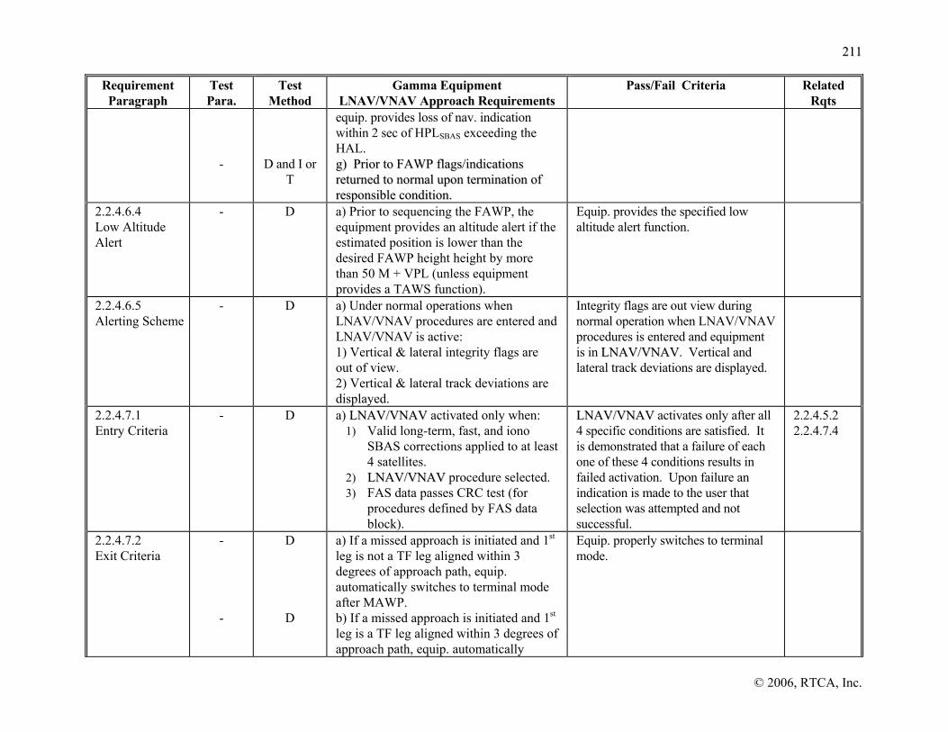
221111
© 2006, RTCA, Inc.
Requirement Paragraph
Test Para.
Test Method
Gamma Equipment LNAV/VNAV Approach Requirements
Pass/Fail Criteria Related Rqts
-
D and I or T
equip. provides loss of nav. indication within 2 sec of HPLSBAS exceeding the HAL. gg)) PPrriioorr ttoo FFAAWWPP ffllaaggss//iinnddiiccaattiioonnss rreettuurrnneedd ttoo nnoorrmmaall uuppoonn tteerrmmiinnaattiioonn ooff rreessppoonnssiibbllee ccoonnddiittiioonn..
2.2.4.6.4 Low Altitude Alert
- D
a) Prior to sequencing the FAWP, the equipment provides an altitude alert if the estimated position is lower than the desired FAWP height height by more than 50 M + VPL (unless equipment provides a TAWS function).
Equip. provides the specified low altitude alert function.
2.2.4.6.5 Alerting Scheme
- D a) Under normal operations when LNAV/VNAV procedures are entered and LNAV/VNAV is active: 1) Vertical & lateral integrity flags are out of view. 2) Vertical & lateral track deviations are displayed.
Integrity flags are out view during normal operation when LNAV/VNAV procedures is entered and equipment is in LLNNAAVV//VVNNAAVV. Vertical and lateral track deviations are displayed.
2.2.4.7.1 Entry Criteria
- D
a) LLNNAAVV//VVNNAAVV activated only when: 1) Valid long-term, fast, and iono
SBAS corrections applied to at least 4 satellites.
2) LLNNAAVV//VVNNAAVV procedure selected. 3) FAS data passes CRC test (for
procedures defined by FAS data block).
LLNNAAVV//VVNNAAVV activates only after all 4 specific conditions are satisfied. It is demonstrated that a failure of each one of these 4 conditions results in failed activation. Upon failure an indication is made to the user that selection was attempted and not successful.
2.2.4.5.2 2.2.4.7.4
2.2.4.7.2 Exit Criteria
- -
D
D
a) If a missed approach is initiated and 1st leg is not a TF leg aligned within 3 degrees of approach path, equip. automatically switches to terminal mode after MAWP. b) If a missed approach is initiated and 1st leg is a TF leg aligned within 3 degrees of approach path, equip. automatically
Equip. properly switches to terminal mode.

221122
© 2006, RTCA, Inc.
Requirement Paragraph
Test Para.
Test Method
Gamma Equipment LNAV/VNAV Approach Requirements
Pass/Fail Criteria Related Rqts
-
D
switches to terminal mode at turn initiation point for first WPT in missed approach procedure. c) If “Direct-To” any WPT is initiated during a LNAV/VNAV approach, equip. automatically switches to terminal mode.
2.2.4.7.3 Display Transition
- - -
D
D
D
a) When VTF not selected, equip. complies with section 2.2.4.4.2 and figure 2-15. b) When VTF selected, eeqquuiipp.. immediately transitions to angular/linear guidance IAW section 2.2.4.4.2 and figure 2-15. c) Sensitivity changes immediately from ±0.3 NM to ±1 NM when equip. changes to terminal mode.
Display transitions are performed as specified.
2.2.3.4.2 2.2.4.4.2 Fig 2-15 Fig 2-15
2.2.4.7.4 Advisory of LLNNAAVV//VVNNAAVV Availability
- D
a)When in approach (LNAV/VNAV) mode and prior to sequencing the FAWP, the equipment indicates if LNAV/VNAV is not available.
TABLE 2-21 TEST CROSS REFERENCE MATRIX (CONTINUED)
Requirement Paragraph
Test Para.
Test Method
Gamma Equipment LPV/LP Approach Requirements
Pass/Fail Criteria Related Rqts
2.2.5.2 Path Selection
- D a) Equip. complies with 2.2.4.2. 2.2.3.2 2.2.4.2
2.2.5.2.1 5-Digit Channel Selection
- D aa)) EEqquuiipp.. ccoommpplliieess wwiitthh 22..22..44..22..11.. 2.2.4.2.1
2.2.5.2.2 Approach Name Selection
- D aa)) EEqquuiipp.. ccoommpplliieess wwiitthh 22..22..44..22..22.. 2.2.3.2.1 2.2.4.2.2
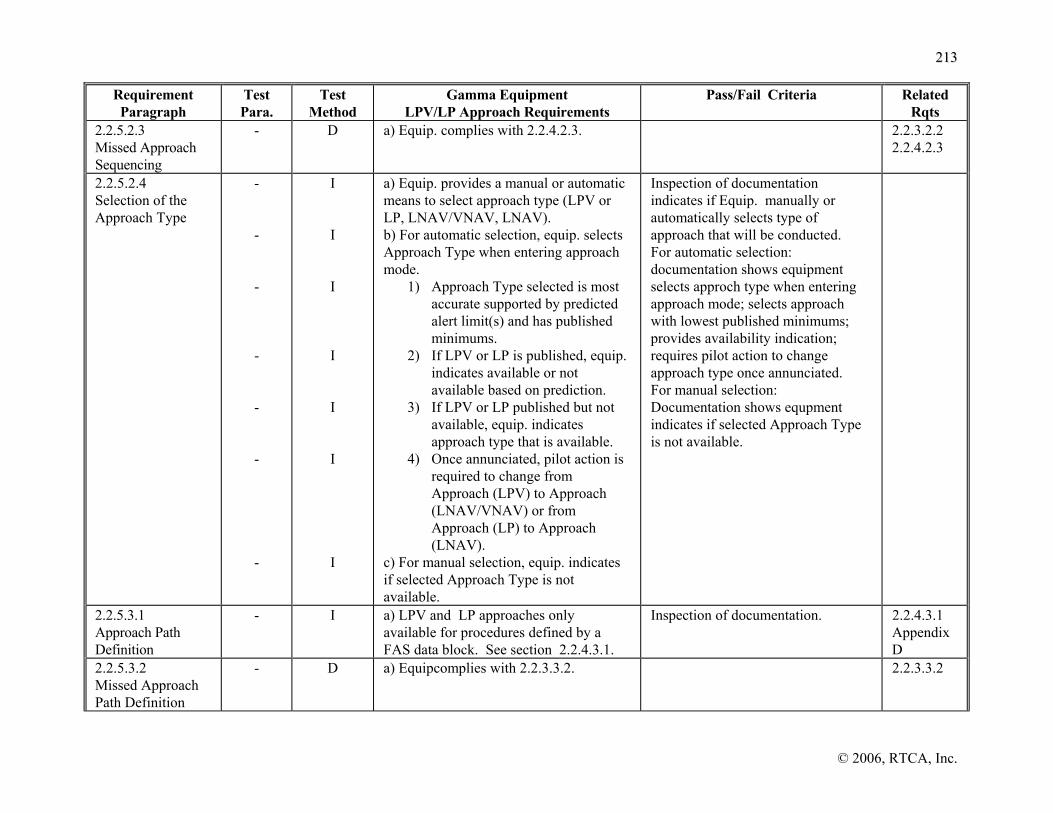
221133
© 2006, RTCA, Inc.
Requirement Paragraph
Test Para.
Test Method
Gamma Equipment LPV/LP Approach Requirements
Pass/Fail Criteria Related Rqts
2.2.5.2.3 Missed Approach Sequencing
- D a) Equip. complies with 2.2.4.2.3. 2.2.3.2.2 2.2.4.2.3
2.2.5.2.4 Selection of the Approach Type
- - - - - - -
I I I I I I I
a) Equip. provides a manual or automatic means to select approach type (LPV or LP, LNAV/VNAV, LNAV). b) For automatic selection, equip. selects Approach Type when entering approach mode.
1) Approach Type selected is most accurate supported by predicted alert limit(s) and has published minimums.
2) If LPV or LP is published, equip. indicates available or not available based on prediction.
3) If LPV or LP published but not available, equip. indicates approach type that is available.
4) Once annunciated, pilot action is required to change from Approach (LPV) to Approach (LNAV/VNAV) or from Approach (LP) to Approach (LNAV).
c) For manual selection, equip. indicates if selected Approach Type is not available.
Inspection of documentation indicates if Equip. manually or automatically selects type of approach that will be conducted. For automatic selection: documentation shows equipment selects approch type when entering approach mode; selects approach with lowest published minimums; provides availability indication; requires pilot action to change approach type once annunciated. For manual selection: Documentation shows equpment indicates if selected Approach Type is not available.
2.2.5.3.1 Approach Path Definition
- I a) LPV and LP approaches only available for procedures defined by a FAS data block. See section 2.2.4.3.1.
Inspection of documentation. 2.2.4.3.1 Appendix D
2.2.5.3.2 Missed Approach Path Definition
- D a) Equipcomplies with 2.2.3.3.2. 2.2.3.3.2

221144
© 2006, RTCA, Inc.
Requirement Paragraph
Test Para.
Test Method
Gamma Equipment LPV/LP Approach Requirements
Pass/Fail Criteria Related Rqts
2.2.5.3.3 Navigation Center Offset
- aa)) EEqquuiipp.. ccoommpplliieess wwiitthh 22..22..44..33..33.. 2.2.4.3.3
2.2.5.4.1 Primary Nav. Displays
- D a) Non-numeric vertical deviation continuously displayed in LPV.
Nonnumeric vertical deviation during LPVis continuously displayed.
2.2.1.4.1 2.2.1.4.2
2.2.5.4.2.1 Definition of Final Approach Segment Lateral Deviations
- AA
a) Equip. complies with 2.2.4.4.2.1.
2.2.4.4.2.1
2.2.5.4.2.2 Non-VTF Deviation
- AA a) Equip. complies with 2.2.4.4.2.2 2.2.4.4.2.2
2.2.5.4.2.3 VTF Deviation
- AA a) Equip. complies with 2.2.4.4.2.3 2.2.4.4.2.3
2.2.5.4.2.4 Missed Approach Deviation
- AA a) Equip. complies with 2.2.4.4.2.5 2.2.4.4.2.5 2.2.4.7.2
2.2.5.4.3 Numeric Cross-Track Deviation
- D or I a) Equip. complies with 2.2.3.4.3. 2.2.3.4.3
2.2.5.4.4 Non-Numeric Vertical Deviation
- A
a) Equip. complies with 2.2.4.4.4 except MLVD is 15m.
2.2.1.4.2 2.2.4.4.4
2.2.5.4.5 Missed Approach Waypont/ LTP/ FTP Distance Display
- D or I aa)) EEqquuiipp.. ccoommpplliieess wwiitthh 22..22..44..44..55.. 2.2.4.4.5
2.2.5.4.6 Missed Approach Waypont/ LTP/ FTP Bearing Display
- D or I a) Equip. complies with 2.2.4.4.6. 2.2.4.4.6

221155
© 2006, RTCA, Inc.
Requirement Paragraph
Test Para.
Test Method
Gamma Equipment LPV/LP Approach Requirements
Pass/Fail Criteria Related Rqts
2.2.5.4.7 Displayed Data Update Rate
- -
T or A
A
a) Non-numeric deviation data display update rate of at least 5 Hz. b) Each deviation update is dynamically independent.
Data is dynamically independent and presented on the display updated at least 5 Hz in LPV or LP.
2.1.2.6.1 2.1.4.8.1 2.1.5.8.1
2.2.5.4.8 Displayed Update Latency
- -
T
T
a) Overall latency between measurement and applicability does not exceed 400 msec. b) Output of data defining position completed prior to 400 msec after time of measurement.
The latency of data displayed is measured to not exceed 400 msec.
2.1.5.8.2
2.2.5.4.9 Display of Vertical Accuracy
- A a) Equip. complies with 2.2.4.4.9. 2.2.4.4.9
2.2.5.5.1 Content
- - -
I & D
D
D
aa)) EEqquuiippmmeenntt ssttoorreess LLPPVV aanndd LLPP pprroocceedduurreess ffoorr aarreeaa((ss)) wwhheerree IIFFRR ooppeerraattiioonn iiss iinntteennddeedd,, iinncclluuddiinngg ddaattaa ddeeffiinneedd iinn AAppppeennddiixx DD ((TTaabbllee DD--11)).. b) Equipment identifies types of approaches published and naming conventions. c) Waypoints used as FAWP and LTP/FTP are uniquely identified to provide proper approach mode operation.
. 2.2.1.5.1 2.2.1.5.2 2.2.3.5 2.2.4.5.1
2.2.5.5.2 Data Integrity
- -
I
T
a) Equipment applies FAS CRC for data validation b) Invalid FAS data block CRC check prevents activation of LPV and LP for that approach.
Documentation verifies applicability of CRC to FAS data. Test verifies that an invalid CRC check of FAS data does not result in activation of LLPPVV aanndd LLPP.
2.2.1.5.1 2.2.4.5.2
2.2.5.6.1 Alert Limits
- - -
T
T or D
D
a) Prior to FAWP HAL = 0.3 NM and no VAL. b) After sequencing FAWP, alert limits for LP are: HAL as stored in FAS data block, and LPV are: HAL and VAL as stored in FAS data block. c) Equip. does not allow crew to change
HAL and VAL are managed properly to support LP and LPV operations.
2.2.5.6.2 2.2.5.6.3 2.2.5.7.4

221166
© 2006, RTCA, Inc.
Requirement Paragraph
Test Para.
Test Method
Gamma Equipment LPV/LP Approach Requirements
Pass/Fail Criteria Related Rqts
-
I
alert limits. f) Equip. uses alert limits for monitoring loss of integrity and navigation per sections 2.2.5.6.2 and 2.2.5.6.3.
2.2.5.6.2 Caution Associated with Loss of Integrity Monitoring
- - -
T or D
T or D
T
aa)) EEqquuiipp.. pprroovviiddeess aa lloossss ooff iinntteeggrriittyy mmoonniittooiirrnngg ccaauuttiioonn wwiitthhiinn 22 sseeccoonnddss iiff tthhee ccuurrrreenntt HHPPLLSSBBAASS eexxcceeeeddss HHAALL.. b) Equip. provides loss of integrity monitoring caution within 10 sec when HPLFD exceeds HAL if HPL SBAS not available. c) HPLFD latency does not exceed FDE TTA from last valid HPLFD or HPLSBAS computation.
2.1.3.2.2.2 2.2.1.6.1 2.2.5.6.3
2.2.5.6.3 Caution Associated with Loss of Navigation
- - - -
D
D or T
A or T
D or T
a) Lateral and/or vertical nav. warning flag/indicator when system not adequate for LPV or LP. b) Both flags or indicators (lateral only for LP) displayed within 1 second of the any of the following:
1) Absence of power. 2) Equipment malfunction or
failure. 3) FDE detects position failure
that cannot be excluded. c) For LPV, vertical flag or indicator displayed within 1 second for the following conditions when the active waypoint is either LTP/FTP/MAWP; or, aircraft altitude < 1000 ft HAT:
1) Insufficient number of SBAS HEALTHY satellites.
2) HPL exceeds alert limit in 2.2.5.6.1.
d) Vertical flag or indicator displayed within 0.8 seconds when:
Equipment uses warning flag on vertical and/or lateral display to indicated nav system cannot support any approach operation. Test shows that both flags, or indicators, are measured to be displayed within 1 second for all three specified conditions. Test verifies that both flags, or indicators, are measured to be displayed within 1 second for all three specified conditions. Test verifies that the vertical flag, or indicator is displayed within 0.8 seconds of onset of VPL exceeding the alert limit.
2.1.2.2.2.2 2.1.4.2.2.2 2.2.1.6.3 2.2.2.6.3 2.2.3.6.3 2.2.4.6.3 2.2.5.6.1

221177
© 2006, RTCA, Inc.
Requirement Paragraph
Test Para.
Test Method
Gamma Equipment LPV/LP Approach Requirements
Pass/Fail Criteria Related Rqts
- - - -
D or T
D or T
D or T
D and I or T
1) VPLSBAS exceeding alert limit.
e) With FDE integrity and vertical deviations flagged for LPV, equip. provides loss of lateral nav. indication within 10 sec of HPLFD exceeding the 0.3 NM. f) With SBAS integrity and vertical deviations flagged for LPV, equip. provides loss of nav. indication within 2 sec of HPLSBAS exceeding the 0.3 NM. g) For LP, lateral flag/indicator displayed within 1 sec for any of the following:
1) Insufficient number of SBAS HEALTHY satellites.
2) HPLSBAS exceeds alert limit. h) Prior to FAWP, flags/indicators immediatetly return to normal state upon termination of responsible condition.
2.2.5.6.4 Low Altitude Alert
- D a) In LPV, equipment complies with 2.2.4.6.4.
Equip. provides the specified low altitude alert function.
2.2.4.6.4
2.2.5.6.5 Alerting Scheme
- D a) Under normal operations when LPV or LP procedures are entered and LPV or LP is active: 1) Vertical & lateral integrity flags are
out of view (only lateral integrity flag for LP).
2) Vertical & lateral track deviations are displayed (only lateral track deviations for LP).
Integrity flags are out view during normal operation when LPV or LP procedures are entered and equipment is in LPV or LP. Vertical and lateral track deviations are displayed as appropriate.
2.2.5.7.1 Entry Criteria
-
D
a) LPV or LP activated only when: 1) Valid long-term, fast, and iono
SBAS corrections applied to at least 4 satellites.,
LPV or LP activates only after all conditions are satisfied. It is demonstrated that a failure of each one of the conditions results in failed
2.2.4.5.2 2.2.5.5.2 2.2.5.7.4

221188
© 2006, RTCA, Inc.
Requirement Paragraph
Test Para.
Test Method
Gamma Equipment LPV/LP Approach Requirements
Pass/Fail Criteria Related Rqts
2) LPV or LP approach procedure selected,
3) FAS data passes CRC test.
activation.
2.2.5.7.2 Exit Criteria
- - -
D
D
D
a) When a missed approach is initiated and 1st leg is not a TF leg aligned within 3 degrees of the final approach path, equip. automatically switches to terminal mode after sequencing the MAWP. b) When a missed approach is initiated and 1st leg is a TF leg aligned within 3 degrees of the final approach path, equip. automatically switches to terminal mode at turn initiation point for first WPT in missed approach procedure. c) If the pilot initiates “Direct-To” any waypoint while in LPV or LP, the equipment automatically switches to terminal mode.
Equip. properly switches to terminal mode.
2.2.5.7.3 Display Transition
- - -
D
D
D
a) When VTF not selected, LPV or LP FSD does not change until aircraft is 2 NM from FAWP. b) When VTF selected, LLPPVV oorr LLPP immediately transitions to angular/linear guidance relative to extended FAS. c) Sensitivity changes immediately from ±0.3 NM to ±1NM when equip. changes to terminal mode.
Display transitions are performed as specified.
2.2.3.4.2 2.2.4.4.2
2.2.5.7.4 Advisory of LLPPVV oorr LLPP Availability
-
D orI
a) In approach (LPV or LP) mode prior to sequencing the FAWP, equipment indicates if LPV is unavailable.
Inspection of Documentation or demonstration verifies equipment provides an LPV or LP unavailability indication.
2.2.5.6.3

221199
© 2006, RTCA, Inc.
TABLE 2-21 TEST CROSS REFERENCE MATRIX (CONTINUED)
Requirement Paragraph
Test Para.
Test Method
Delta Equipment Approach Requirements
Pass/Fail Criteria Related Rqts
2.3 Class Delta-4 Requirements for Approach Operations
a) Equip. is compliant with 2.1.1 and 2.1.5, except for specific cases described in section 2.3.
2.1.1 2.1.5
2.3.2 Approach Selection
2.5.11.1.1.1
-
2.5.11.1.1.1
D
D
D
a) If hosting a database, equipment outputs the FAS data block upon acceptance of 5-digit channel number b) Can differentiate among approaches if a channel number is reused c) If not hosting a FAS database, equipment accepts FAS data blocks from external source.
Equipment properly responds to the input of a 5-digit channel number
2.2.1.2.1 2.2.4.2
2.3.2.1 Confirmation of Selected Approach
- -
D
I or T
a) Approach name and reference path identifier accessible for display b) Equipment validates the integrity of the FAS data block prior to its use
Documentation verifies applicability of CRC to FAS data. Test verifies that an invalid CRC check of FAS data does not result in activation of LLPPVV aanndd LLPP.
2.2.5.5.2
2.3.3 Path Definition
- I a) Final approach path defined by FPAP, LTP/FTP, TCH, and glidepath angle.
Inspection of documentation indicates proper definition of final approach path.
Appendix D Figure 2-14
2.3.3.1 Navigation Center Offset
- a) Equip. complies with section 2.2.4.3.3. 2.2.4.3.3.
2.3.4 Navigation Displays
- a) Equip. complies with section 2.2.1.4 (if providing nav display).
2.2.1.4.
2.3.4.1 Non-Numeric Lateral Cross-Track Deviation
- D
a) Equip. complies with 2.2.5.4.2.1 and 2.2.5.4.2.3.
2.2.5.4.2

222200
© 2006, RTCA, Inc.
Requirement Paragraph
Test Para.
Test Method
Delta Equipment Approach Requirements
Pass/Fail Criteria Related Rqts
2.3.4.2 Non-Numeric Vertical Deviation
- D a) Equip. complies with 2.2.5.4.4. 2.2.4.4.4
2.3.4.3 Landing Threshold Point/Fictitious Threshold Point Distance Display
- -
D
D or T
a) Equip. outputs or displays distance to LTP/FTP prior to crossing LTP/FTP when outputting valid lateral deviations. b) Distance output or displayed with range of up to 99.9 nm with a resolution of 0.1 nm.
2.3.4.4 Data Update Rate
- - -
T T
I or T
a) Updates deviation data at ≥ 5 Hz b) Udates other data at ≥ 1 Hz c) Deviation and distance to LTP/FTP are dynamically independent
Data is dynamically independent Deviation data updated at least at 5 Hz. Other data updated at 1 Hz
2.2.4.4.7 2.2.5.4.7
2.3.4.5 Data Update Latency
- T a) Overall latency not to exceed 400 msec. b) Distance to threshold latency not to exceed 400 msec.
The latency of data displayed is measured to not exceed 400 msec
2.2.5.4.8
2.3.5 Database Requirements
2.5.11.1.1.1
I or T
a) Equipment complies with 2.2.1.5.3 , 2.3.5.1 and 2.3.5.2. if it hosts database.
2.3.5.1 2.3.5.2
2.3.5.1 Content
2.5.11.1.1.1
D a) Stores LPV and LP FAS data for areas where IFR operation is intended.
2.3.5.2 Access
- - - - -
D or I I I
D
D
a) No manual FAS data base updating. b) Data recalled from storage also retained in storage. c) Updating database uses high-integrity data validation technique. d) Equip. identifies the FAS database version and its operating period. e) Equip. indicates if the database is not yet effective or out of date.
Database (e.g., Jeppesen data) cannot be manually updated, excludes user defined data. Data remains in storage. Updating of database includes data integrity and validation such as CRC. Can identify version and operating dates. Indicates if database is not yet effective or out of date
2.2.1.5.2, 2.2.4.5.1 2.3.5.1.
2.3.6.1 Alert Limits
- -
D D
a) HAL for LP as stored in database. b) HAL and VAL for LPV as stored in database.
HAL and VAL are managed properly to support LP and VAL operations.

222211
© 2006, RTCA, Inc.
Requirement Paragraph
Test Para.
Test Method
Delta Equipment Approach Requirements
Pass/Fail Criteria Related Rqts
- T
D or I
c) FDE latency (LNAV downgrade) does not exceed TTA from last valid computation of HPLFD or HPLSBAS. d) No manual changing of alert limit.
2.3.6.2 Caution Associated with Loss of Navigation
- - - - - -
D
D or T
A or T
D or T
D or T
D or T
a) Equipment warns when the navigation system does not support the approach b) For LPV and LP procedure equipment displays flags (both vertical and lateral) within one second at the onset of the following conditions:
1) Loss of power 2) Equipment malfunction or
failure 3) Detection of a position failure
c) For LPV, equipment displays vertical flag within one second of the onset of the following conditions:
1) Insufficient number of SBAS HEALTHT satellites
2) HPLSBAS exceeds the alert limit d) For LPV Procedures, equipment displays vertical flag within .8 seconds of the onset of the following condition:
1) Vertical protection level exceeds the alert limit
e) With FDE integrity and vertical deviations flagged, equip. provides loss of lateral nav. indication within 10 sec of HPLFD exceeding the 0.3 NM. f) With SBAS integrity and vertical deviations flagged, equip. provides loss of lateral nav. indication within 2 sec of HPLSBAS exceeding the 0.3 NM. g) For LP Procedures, equipment displays
Caution if the approach navigation is not supportable. Caution for power loss and equipment malfunction or positioning failure within one second. Caution for inadequate number of satellites, and failure to bound the HPL. Caution for failure to bound the VPL within 0.8 second for LPV. Set lateral flag witin one second following the setting of the vertical flag if HPLSBAS and HPLFD exceed 0.3 nm. For LP, caution insufficient number of satellites or failure to bound the HPL. Caution returns to normal state upon termination of caution condition.
2.3.6.1

222222
© 2006, RTCA, Inc.
Requirement Paragraph
Test Para.
Test Method
Delta Equipment Approach Requirements
Pass/Fail Criteria Related Rqts
- -
D or T
D and I or T
lateral flags within one second of the onset of any of the following conditions:
1) Insufficient numberof SBAS HEALTHY satellites
2) HPLSBAS exceeds the alert limit h) Alert returns to the normal state following the elimination of the responsible condition for the flag.

222233
© 2006, RTCA, Inc.
2.5.2 SBAS Message Loss Rate Test
2.5.2.1 Evaluation of Message Loss Rate During the Measurement Accuracy Test
2.5.2.2 Test Procedure
The data to verify the SBAS message loss rate in the presence of interference shall be collected in conjunction with the Measurement Accuracy tests using the test cases where the SBAS satellite is at minimum power level. During this test, the total number of messages that are lost (CRC does not check) shall be recorded and used as the test statistic. The test statistic may be collected over messages received from more than one SBAS satellite and from more than one test scenario.
A minimum of 22,500 messages shall be collected and processed.
2.5.2.3 Pass/Fail Determination
The total number of SBAS messages lost shall be less than or equal to 34 messages.
Note: Using this criterion, 99% of the equipment designed to meet a 10-3 message loss rate will pass this test. Similarly, less than 5% of the equipment designed to a message loss rate of 2.0 x 10⁻³ will pass this test. When more than the minimum number of messages are collected, the maximum number of messages lost can be increased as long as the 5% probability of passing equipment with a message loss rate of 2.0 x 10⁻³ is not exceeded.
2.5.2.4 Evaluation of Message Loss Rate During the 24-Hour System Accuracy Test
2.5.2.4.1 Test Procedure
The data to verify the SBAS message loss rate using the signal from a live SBAS satellite shall also be collected in conjunction with the 24-Hour System Accuracy Test. During this test, the total number of messages that are lost (CRC does not check) shall be recorded and used as the test statistic. The test statistic may be collected over messages received from more than one SBAS satellite.
86,400 messages shall be collected and processed if one SBAS satellite is in view, or 172,800 messages shall be evaluated if two SBAS satellites are in view.
2.5.2.4.2 Pass/Fail Criteria
The total number of SBAS messages lost shall be less than or equal to a total of 133 or 251 messages if tracking one or two SBAS satellites, respectively.
Note: Using this criterion, 99% of the equipment designed to meet a 1.25 x 10⁻³ message loss rate will pass this test. Similarly, only 5% of the equipment designed to a message loss rate of 2 x 10⁻³ will pass this test. The thresholds for this test were inflated to 1.25 x 10⁻³ to allow margin for a static, ground-based test. For a 10-3 message loss rate, these thresholds would be 109 and 204, respectively.
2.5.3 Step Detector Test
The step detector is tested under four scenarios. If the manufacturer can show by inspection that its equipment’s step detection mechanism is insensitive to the type of step
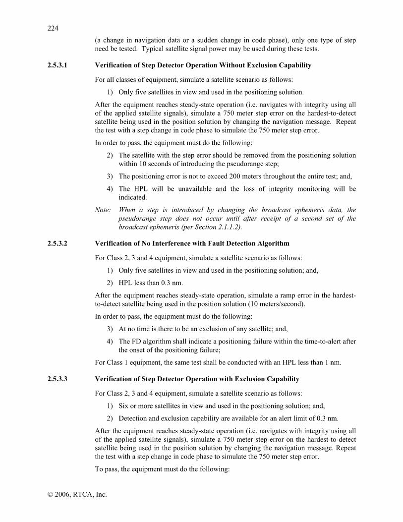
222244
© 2006, RTCA, Inc.
(a change in navigation data or a sudden change in code phase), only one type of step need be tested. Typical satellite signal power may be used during these tests.
2.5.3.1 Verification of Step Detector Operation Without Exclusion Capability
For all classes of equipment, simulate a satellite scenario as follows:
1) Only five satellites in view and used in the positioning solution.
After the equipment reaches steady-state operation (i.e. navigates with integrity using all of the applied satellite signals), simulate a 750 meter step error on the hardest-to-detect satellite being used in the position solution by changing the navigation message. Repeat the test with a step change in code phase to simulate the 750 meter step error.
In order to pass, the equipment must do the following:
2) The satellite with the step error should be removed from the positioning solution within 10 seconds of introducing the pseudorange step;
3) The positioning error is not to exceed 200 meters throughout the entire test; and,
4) The HPL will be unavailable and the loss of integrity monitoring will be indicated.
Note: When a step is introduced by changing the broadcast ephemeris data, the pseudorange step does not occur until after receipt of a second set of the broadcast ephemeris (per Section 2.1.1.2).
2.5.3.2 Verification of No Interference with Fault Detection Algorithm
For Class 2, 3 and 4 equipment, simulate a satellite scenario as follows:
1) Only five satellites in view and used in the positioning solution; and,
2) HPL less than 0.3 nm.
After the equipment reaches steady-state operation, simulate a ramp error in the hardest-to-detect satellite being used in the position solution (10 meters/second).
In order to pass, the equipment must do the following:
3) At no time is there to be an exclusion of any satellite; and,
4) The FD algorithm shall indicate a positioning failure within the time-to-alert after the onset of the positioning failure;
For Class 1 equipment, the same test shall be conducted with an HPL less than 1 nm.
2.5.3.3 Verification of Step Detector Operation with Exclusion Capability
For Class 2, 3 and 4 equipment, simulate a satellite scenario as follows:
1) Six or more satellites in view and used in the positioning solution; and,
2) Detection and exclusion capability are available for an alert limit of 0.3 nm.
After the equipment reaches steady-state operation (i.e. navigates with integrity using all of the applied satellite signals), simulate a 750 meter step error on the hardest-to-detect satellite being used in the position solution by changing the navigation message. Repeat the test with a step change in code phase to simulate the 750 meter step error.
To pass, the equipment must do the following:

222255
© 2006, RTCA, Inc.
3) The satellite with the step error shall be removed from the position solution within 10 seconds of introducing the step error;
4) The positioning error is not to exceed 200 meters throughout the entire test, before and after the introduction of the step error; and
5) HPL will change.
For Class 1 equipment, the same test shall be conducted with detection and exclusion capability available for an alert limit of 1 nm and a pseudorange step of 3000 m.
Note: When a step is introduced by changing the broadcast ephemeris data, the pseudorange step does not occur until after receipt of a second set of the broadcast ephemeris (per Section 2.1.1.2).
2.5.3.4 Verification of No Interference with Exclusion of the FDE Algorithm
For Class 2, 3, and 4, simulate a satellite scenario as follows:
1) Six or more satellites in view and used in the positioning solution; and,
2) Detection and exclusion capability are available for an alert limit of 0.3 nm.
After the equipment reaches steady-state operation, simulate a ramp error in the hardest-to-detect satellite being used in the position solution (10 meters/second).
In order to pass, the equipment must do the following:
3) The exclusion function should operate normally, eliminating the error as a positioning failure develops.
For Class 1 equipment, the same test shall be conducted with detection and exclusion capability available for an alert limit of 1 nm.
2.5.4 Initial Acquisition Test Procedures
2.5.4.1 Simulator and Interference Conditions
The tests to verify initial acquisition performance shall be run for each of the GPS/SBAS signal generator (simulator) scenarios described below:
Scenario #1:Initial Acquisition Time Test
1) Exactly 5 GPS satellites with C/A code only.
2) Broadband GNSS test noise (IGNSS,Test) of spectral density equal to -173.4 dBm/Hz at the antenna port (the contribution of simulated satellites has been removed for the specified noise density).
3) Broadband external interference (IExt,Test) of spectral density equal to -176.5 dBm/Hz at the antenna port.
4) Thermal noise contribution from the sky and from the antenna (See Nsky,antenna in 2.1.1.10).
5) One satellite at maximum power (including maximum combined satellite and aircraft antenna gain), one satellite at minimum power (including minimum antenna gain), and other satellites 3 dB above the one satellite at minimum power (see 2.1.1.10).
6) Platform dynamics: Constant velocity of 800 kt beginning at 5,000 ft (MSL) and performing a 3° climb.

222266
© 2006, RTCA, Inc.
The test to verify initial acquisition performance after abnormal interference shall be run for the GPS signal generator (simulator) scenario described below:
Scenario #2: Initial Acquisition Time after abnormal interference Test
1) Exactly 5 GPS satellites with C/A code only.
2) Broadband GNSS test noise (IGNSS,Test) of spectral density equal to -173.4 dBm/Hz at the antenna port (the contribution of simulated satellites has been removed for the specified noise density).
3) Broadband external interference (IExt,Test) of spectral density equal to -176.5 dBm/Hz at the antenna port.
4) Thermal noise contribution from the sky and from the antenna (See Nsky,antenna in 2.1.1.10).
5) One satellite at maximum power (including maximum combined satellite and aircraft antenna gain), one satellite at minimum power (including minimum antenna gain), and other satellites 3 dB above the one satellite at minimum power (See 2.1.1.10).
6) Platform dynamics: Constant velocity of 800 kt and constant altitude.
The GNSS and external interference is to be applied to the receiver before it is powered on or the simulator is engaged.
2.5.4.2 Test Procedures (Initial Acquisition)
1) The broadband GNSS test noise, the broadband external interference noise, and Nsky,antenna shall be simulated.
2) The simulator scenario shall be engaged and the satellites RF shall be turned on.
3) The airborne equipment shall be powered and initialized to a position with total radial error equal to 60 nautical miles, and one minute (60 seconds) of error in time with respect to the starting position and time reference in the simulator. It is assumed that the receiver has obtained a valid almanac for the simulator scenario to be tested prior to conducting these tests.
4) The time to first valid position fix (TTFF), defined as the time from when the equipment is powered on until the first valid position (with integrity, i.e. HPL is available) is output, shall be observed. Integrity shall be provided by the sensor’s FDE algorithm. Along with the TTFF, at least the next 60 seconds of continuous position fixes (a minimum of 60 data points) after the initial fix shall also be recorded in order to verify the accuracy requirement.
5) Precise ephemeris shall be purged or rendered invalid at the end of each acquisition attempt.
6) Go to Step 2 and repeat as required.
2.5.4.3 Pass/Fail Determination
The accuracy statistic, that will be compared with the 15 m (95%) horizontal accuracy requirement stated in section 2.1.2.1 shall be computed using the 2drms formula shown below.

222277
© 2006, RTCA, Inc.
( )
2 2
2
1
15
drms
i
iN
dHDOPi
N
=
⎛⎝⎜
⎞⎠⎟∑
=
.
where:
2drms=Twice the distance, root-mean-square
di = Instantaneous 2-D horizontal position error (meters)
N = Number of points considered
HDOP = Instantaneous Horizontal Dilution of Precision
The use of the 2drms formula provides a conservative estimate of the 95% error and effectively weights large position errors that may be caused by unwanted interference. A failure by the sensor to produce a position output after 5 minutes indicates a failure mode, and results in declaring the test a failure.
Scaling the instantaneous 2-dimensional position error (di) by 1.5/HDOPi provides a means of normalizing the tests to a constant HDOP = 1.5 and accounts for fluctuations in the satellite coverage due to changing geometries. HDOPi may be obtained from the receiver under test or calculated separately. Only those satellites used in the position solution shall be included in the HDOPi calculation. The manufacturer shall demonstrate the validity of the values chosen for HDOPi.
To determine the initial acquisition pass/fail criteria, consider a single trial where the sensor under test provides a valid position fix within the required time (5 minutes) and maintains the required accuracy (15 m, 95%) for at least the next 60 seconds. This sensor is considered to have passed one (1) trial. Table 2-22 shows the total test disposition and represents a quit-while-ahead testing approach designed to keep testing times at a reasonable length.
TABLE 2-22 GRADUATED SAMPLING PASS/FAIL CRITERIA
Trials Cumulative Failures within Specified Time
Test Disposition
First Ten (10 )Trials Zero (0) One (1) Two (2) or More
Pass Run Ten (10) More Fail
Second Ten (10) Trials Zero (0) One (1) or Two (2) Three (3) or More
Pass Run Ten (10) More Fail
Third Ten (10) Trials Zero (0) One (1) or More
Pass Fail
For example, if no failures occur in the first ten trials, success for that simulator and interference case would be declared and the current test terminated. A single failure in the first set of ten trials necessitates running the next set of ten trials. Two or more failures during the first ten trials indicates that the sensor has failed that particular test, and so on. Justification for the above-stated criteria is shown in Appendix M.

222288
© 2006, RTCA, Inc.
2.5.4.4 Test Procedures (Initial Acquisition After Abnormal Interference)
The abnormal CW interference frequency is at 1575.42 MHz and the power level is selected to ensure that no GPS satellites can be tracked at that power. The test procedure is the same as the initial acquisition test, with the following exceptions:
1) Before the equipment has output a valid position for one minute, the signal power may be set to a higher level, or, the broadband noise to a lower level to facilitate acquisition.
2) After the equipment has output a valid position for one minute, apply the abnormal CW interference. Remove the abnormal interference after 1 minute in the first trial, 2 minutes in the second trial, and so on up to 10 minutes in the tenth trial.
3) The time to first valid position fix (TTFF) for this test is defined as the time from when the abnormal CW interference is removed until the first valid position (with integrity, i.e. HPL is available) is output.
4) When reinitializing between trials, it is not necessary to purge the precise ephemeris data.
2.5.5 Reserved
2.5.6 Satellite Reacquisition Time Test
2.5.6.1 Simulator and Interference Conditions
The tests to verify reacquisition performance shall be run for each of the GPS/SBASsignal generator (simulator) scenarios described below:
Scenario #1: Steady-State Reacquisition Time Test (GPS C/A code Only)
1) Broadband GNSS test noise (IGNSS,Test) of spectral density equal to -172.4 dBm/Hz at the antenna port (the contribution of simulated satellites has been removed for the specified noise density).
2) Thermal noise contribution from the sky and from the antenna (See Nsky,antenna in 2.1.1.10).
3) Broadband external interference noise (IExt,Test) of spectral density equal to -170.5 dBm/Hz at the antenna port for Class 3 and 4 equipment, and for Class 1 or 2 equipment intended for installations with SATCOM. For Class 1 and 2 equipment not intended for installation with SATCOM, the broadband external interference noise is -173.5 dBm/Hz.
4) Platform dynamics: Constant velocity of 800 kt beginning at 5,000 ft (MSL) and performing a 3° climb.
5) Any number of GPS satellites at any power until the sensor reaches steady state navigation.
6) Then one satellite at maximum power (including maximum combined satellite and aircraft antenna gain), one satellite at minimum power (including minimum antenna gain), and other satellites 3 dB above the one satellite at minimum power (See 2.1.1.10).
7) Then, turn off the minimum power satellite to retain exactly 4 GPS satellites providing a GDOP of 6 or less, preparing to reacquire the lost GPS satellite,

222299
© 2006, RTCA, Inc.
which is just above the mask angle and whose RF state (on or off) shall be controlled by the simulator.
8) Finally, the signal from the fifth GPS satellite to be acquired is turned on at minimum power.
Scenario #2: Steady-State Reacquisition Time Test (GPS C/A code only & SBAS)
1) Fast correction update rate shall be 6 seconds.
2) Thermal noise contribution from the sky and from the antenna (See Nsky,antenna in 2.1.1.10).
3) Broadband GNSS test noise (IGNSS,Test) of spectral density equal to –173.4 dBm/Hz at the antenna port (the contribution of simulated satellites has been removed from the specified noise density).
4) Broadband external interference noise (IExt,Test) of spectral density equal to -170.5 dBm/Hz at the antenna port for Class 3 and 4 equipment, and for Class 1 or 2 equipment intended for installations with SATCOM. For Class 1 and 2 equipment not intended for installation with SATCOM, the broadband external interference noise is -173.5 dBm/Hz.
5) Platform dynamics: Constant velocity of 800 kt beginning at 5,000 ft (MSL) and performing a 3° climb.
6) Any number of GPS satellites and one SBAS satellite at any power until the sensor reaches steady state navigation.
7) Then one satellite at maximum power (including maximum combined satellite and aircraft antenna gain), one SBAS satellite at minimum power (including minimum antenna gain), and other satellites 3 dB above the one satellite at minimum power (See 2.1.1.10).
8) Then, turn off the minimum power satellite to retain exactly 4 GPS satellites providing a GDOP of 6 or less and no SBAS satellite, preparing to reacquire the lost SBAS satellite which is just above the mask angle and whose RF state (on or off) shall be controlled by the simulator.
9) Finally, the signal from the SBAS satellite to be acquired is turned on at minimum power.
2.5.6.2 Test Procedures
1) The broadband GNSS test noise, the broadband external interference noise, and Nsky,antenna shall be simulated.
2) The simulator scenario shall be engaged and the satellites RF shall be turned on.
3) The airborne equipment shall be powered. It is assumed that the receiver has obtained a valid almanac for the simulator scenario to be tested prior to conducting these tests.
4) The sensor shall be allowed to reach steady state accuracy before the satellite to be reacquired is cycled off and on. Once in steady state navigation, the simulated satellites and the broadband noise shall be set to the appropriate steady state power levels.
5) The satellite whose reacquisition is being tested shall be removed from the sensor, at least until the sensor has lost lock on the satellite and removed the

223300
© 2006, RTCA, Inc.
satellite from the position solution, and then reapplied to the sensor within 30 seconds.
6) The reacquisition time, or time to satellite inclusion, defined as the time from when the satellite under test is reapplied to the sensor until the first valid position which includes that satellite is output, shall be observed. In addition, at least the next 60 seconds of position fixes (sampled at the minimum of once per second) after the inclusion of the reacquired satellite, shall also be recorded in order to verify the 15 m (95%) requirement. Note that for Simulator Scenario 1, the satellite to be reacquired shall be a GPS satellite, and for Scenario 2, the reacquired satellite shall be an SBAS Satellite.
7) Reset the scenario (including signal and noise power levels), go to Step 2 and repeat as required.
2.5.6.3 Pass/Fail Determination
The accuracy statistic shall be computed using the 2drms formula as shown in Section 2.5.4.3.
To determine the reacquisition time pass/fail criteria, the graduated sampling pass/fail criteria of Table 2-22 shall be used. A single trial success occurs when the sensor under test includes the reacquired satellite into the position solution within the required time (20 seconds for scenario 1 and 27 seconds for scenario 2) and maintains the required accuracy, 15 m (95%), for the following 60 seconds.
The statistical justification for the reacquisition time test follows that for initial acquisition and can be found in Appendix M.
2.5.7 Interference Rejection Test
2.5.7.1 Simulator and Interference Conditions
These tests are intended to verify the performance of the sensor in the presence of in-band continuous-wave interference conditions at and above the levels of Appendix C. Tests shall be run for each of the GPS/SBAS signal generator (simulator) scenarios described below.
The simulation and interference conditions shall conform to the following two requirements:
1) Simulated GPS RF for PRN 6 shall be at the minimum power level for the equipment (as described in Section 2.1.1.10). Other satellites shall be at a high power level to minimize the effect of interference on their pseudorange.
2) The CWI frequency tested shall be 20 Hz ±5 Hz offset below the 3rd spectral line below the received carrier frequency of PRN 6 (i.e., 3020 Hz offset from the carrier frequency). The initial CW power shall be -120.5 dBm (may be reduced during initial acquisition). The I/S ratio will be varied according to the test procedures. The exact frequency relationship must be maintained throughout the test. The scenario shall include PRN 6 because it is used in the definition of the CWI frequency.
Note: This evaluation method is based on the assumption that a weighted least-squares position algorithm is implemented, and that the baseline integrity algorithms are used. If a different form of positioning or integrity method is used, this evaluation method may not be appropriate.

223311
© 2006, RTCA, Inc.
2.5.7.2 Test Procedures
1) The CW interference to be applied shall be turned on and connected to the sensor. Note that the power of the CW interference during initial acquisition is lower than that for steady-state operation. Broadband external interference and GNSS test noise do not need to be simulated for this test.
2) The simulator scenario shall be engaged and the satellites RF shall be turned on.
3) The airborne equipment shall be powered and initialized. It is assumed that the receiver has obtained a valid almanac for the simulator scenario to be tested prior to conducting these tests.
4) The sensor shall be allowed to reach steady state. When the sensor has reached steady state, the power of the CW interference shall be adjusted to -120.5 dBm.
5) The CW interference power shall be maintained until the accuracy has reached steady-state. Pseudorange measurements and pseudorange validity indications (e.g., isolation bit) for all satellites shall be recorded during this interval.
6) The power of the CW interfering signal shall be increased by 1 dB and maintained for 200 seconds.
7) Go to Step 5 and repeat until PRN 6 has been excluded from the navigation solution. Increase the CW interfering signal another 3 dB and verify that PRN 6 is still excluded.
2.5.7.3 Pass/Fail Determination
For each sample when the PRN 6 pseudorange is declared valid, the following error criterion shall be evaluated:
jj
jnoise PRN jZ N
N≤−⎡
⎣⎢⎢
⎤
⎦⎥⎥
5 331
6. , ,σ
where:
( )j PRN j PRN j jZ PR R c t≡ − −6 6, , Δ
( ) ( )j
jij ij
ic t N PR R
jNΔ ≡ −
=∑1
1
PRij = smoothed pseudo-range, channel i, time j
Rij = true range, satellite i, time j (includes extrapolation)
Nj = number of satellites at time j
σnoise,ij = receiver output or equivalent, satellite i, time j (refer to Appendix J.2.4)
If the error criterion is exceeded for more than the appropriate time to alert, the test fails.
2.5.8 Accuracy Tests
2.5.8.1 Measurement Accuracy Test
The purpose of the Accuracy Test is to validate that the equipment meets the accuracy requirements of Section 2.1.2.1, 2.1.3.1, and 2.1.4.1.3 under the specified interference

223322
© 2006, RTCA, Inc.
conditions. It is also intended to verify that the σnoise and σdivg used in the protection level equations are appropriate bounds on the residual errors allocated to the receiver tracking performance. It is not intended to verify the accuracy of the atmospheric corrections; these corrections need not be included in the test. Data may be collected concurrently during these tests to validate the SBAS Message Loss Rate requirements in Section 2.1.1.3.2.
Note: This evaluation method is based on the assumption that a least-squares position algorithm (per Section 2.1.4.1.4) is implemented. If a different form of positioning is used, this evaluation method may not be appropriate.
2.5.8.2 Simulator and Interference Conditions
The simulation and interference conditions shall conform to the following requirements:
1) For all test scenarios, the broadband GNSS test noise and Nsky,antenna shall be simulated. There are three sets of interference test scenarios: broadband external interference noise, Continuous Wave Interference, and pulsed interference.
a) The broadband external interference noise (IExt,Test) has a spectral density equal to -170.5 dBm/Hz at the antenna port for Class 3 and 4 equipment, and for Class 1 or 2 equipment intended for installations with SATCOM. For Class 1 and 2 equipment not intended for installation with SATCOM, the broadband external interference noise is -173.5 dBm/Hz.
b) The CW power and frequencies are listed in Table 2-23.
c) For the pulsed interference tests, a pulse modulated carrier at 1575.42 MHz with a signal bandwidth of 1 MHz, with peak carrier level of +10 dBm, pulse width of 125 usec, and duty cycle of 1% shall be used. This corresponds to an I/S ratio of +144 dB for GPS and SBAS satellites.
2) The GNSS test noise depends on the number, power, and type of satellites simulated during the test. The power spectral density of the total GNSS Noise (IGNSS) is -171.9 dBm/Hz (See Appendix C.2.3). This GNSS Noise was derived for GPS tracking but is used in the test for both GPS and SBAS tracking to allow simultaneous testing of GPS and SBAS thereby reducing test time. However it is acceptable to run the SBAS testing separately using a total GNSS Noise (IGNSS) of -173.0 dBm/Hz for accuracy verification and/or collection of the SBAS message loss rate data. The effective noise power spectral density (ITest) of the satellites present in the simulator scenario may be removed from the total GNSS Noise; to do so, the satellite equivalent power spectral density specified in Table 2-24 (IGH, IGL, ISH, and ISL) is removed for each satellite present. The number of maximum power GPS satellites is NGH, the number of minimum power GPS satellites is NGL, the number of maximum power SBAS satellites is NSH, and the number of minimum power SBAS satellites is NSL. The GNSS test noise is determined by removing ITest from IGNSS as follows:
IGNSS,Test = 10log10[10-171.9//10 - 10ITest/10]
where:
ITest = 10log10[(NGL)10IGL/10 + (NGH)10IGH/10 + (NSL)10ISL/10 + (NSH)10ISH/10]
Note: The indicated power levels (both signal and noise) are for the steady-state portion of the tests; power levels are set to the required values once steady state navigation has been achieved. Refer to Appendix M for an explanation of how

223333
© 2006, RTCA, Inc.
ITest is derived and examples of the computation of IGNSS,Test and how it may be applied.
3) Simulated GPS and SBAS RF shall be at the minimum power level for the equipment, except for the broadband external interference noise case that shall be tested at the maximum power level as well as the minimum power level. For test cases that require the minimum power level, one GPS satellite shall be set to the maximum power level (including maximum transmit power and maximum combined satellite and aircraft antenna gain). For these cases the pseudorange samples of the satellite at maximum power are not used in the evaluation. The scenario shall include PRN 6 because it is used in the definition of the CWI frequency. For all conditions, during the portion of the test where accuracy is evaluated, at least two SBAS satellites shall be used.
Note 1: The steady-state accuracy test will include a total of nine cases (ten when installed on aircraft with SATCOM).
4) The total duration of each test case test shall be based upon sampling intervals required to obtain samples that are statistically independent. Independent samples collected during the initial acquisition and before steady-state operation are used for the validation of σnoise overbounding. The samples collected prior to steady-state operation should not be used for the steady-state RMS accuracy
evaluation and the steady-state evaluation of [ ] [ ]⎟
⎠⎞⎜
⎝⎛ + idivginoise σσ 22
2/1
. It may be advantageous to extend the duration of this test so the data can be used to support evaluation of SBAS Message Loss Rate.
TABLE 2-23 STEADY STATE ACCURACY TEST CWI VALUES*
Frequency (MHz) Power (dBm) I/S (dB)
1525.0 1555.42
1575.42** 1595.42 1610.0 1618.0
1626.0***
-12.0 -89.5 -120.5 -89.5 -30.0 -12.0 +8.0
122.0 44.5 13.5 44.5 104.0 122.0 142.0
* The CWI power is specified at the antenna port. The actual level used during testing is reduced by the minimum frequency selectivity of the active antenna adjusted for any filtering in the test set-up itself. When demonstrating compatibility with a minimum standard antenna, the frequency selectivity is specified in Appendix C.3 (derived from RTCA/DO-301). When using a specific antenna, its minimum frequency selectivity can be used when determined in accordance with RTCA/DO-301.
** The CWI frequency tested shall be 20 Hz ± 5 Hz offset below the 3rd spectral line below the carrier frequency of PRN 6 (i.e., 3020 Hz offset from the carrier frequency). The CWI must be synchronized to the satellite signal provided. The exact frequency relationship must be maintained throughout the test.
*** Only Required for Aircraft with SATCOM
Note: Care should be taken when applying non-L1 CW frequencies so that the L1 CW and broadband specifications are not exceeded.

223344
© 2006, RTCA, Inc.
TABLE 2-24 SATELLITE EQUIVALENT POWER SPECTRAL DENSITY
Satellite Type Maximum Power Satellite
Minimum Power Satellite
GPS IGH = -183.5 dBm/Hz IGL = -196.5 dBm/Hz SBAS ISH = -179.8 dBm/Hz ISL = -198.3 dBm/Hz
Note: These values of equivalent power spectral density were computed using the same assumptions as were used to determine the total GNSS Noise in Appendix C.
2.5.8.2.1 Test Procedures
1) The test unit is connected to the RF signal and interference source.
2) The simulator scenario shall be engaged and the satellites RF shall be turned on.
3) The equipment under test shall be powered and initialized. It is assumed that the receiver has obtained a valid almanac for the simulator scenario to be tested prior to conducting these tests.
4) When the unit is navigating, the interference to be applied shall be applied to the equipment under test, and the power of the signal and interference shall be adjusted to the required level. Sampling should begin for each satellite immediately after it is included in the navigation solution for the σnoise overbounding evaluation described in paragraph 7) below.
5) When steady-state accuracy is reached, data are recorded as follows:
6) Initially, 50 independent samples of pseudorange data are recorded at the required sampling interval (see note below).
Note: The sampling interval will be two times the integration interval used for carrier phase smoothing of pseudoranges. For example, if the integration interval used for carrier smoothing of the pseudoranges is 100 second, the sampling interval will be 200 seconds. If ten pseudoranges are collected per sampling interval (nine independent measurements), the duration of the initial data collection period will be 20 minutes.
7) The normalized RMS range error statistic, RMS_PR, is computed according to the following formula, using all collected samples (including those prior to steady-state operation):
[ ]
M
N
Z
)M(PR_RMS
M
1j
jN
1i j2
ij,norm
2ij
∑⎪⎭
⎪⎬⎫
⎪⎩
⎪⎨⎧
∑σ
≡= =
where:
jijijij )tc(RPRZ Δ−−≡
( )∑ −≡Δ=
jN
1iijij
jj RPR
N1)tc(

223355
© 2006, RTCA, Inc.
( )
2j
N
ik1k
2kj,noise
2ij,noise
2j
2ij,norm N
1Nj
⎥⎥⎥
⎦
⎤
⎢⎢⎢
⎣
⎡σ+σ−
=σ
∑≠=
where:
PRij = smoothed pseudo-range, channel i, time j
Rij = true range, satellite i, time j (includes extrapolation)
Nj = number of satellites at time j
M = number of sampling intervals
σnoise,ij = satellite i, time j (refer to Appendix J.2.4)
Note 1: Interchannel biases on the simulator may impede the accuracy test specified herein. It may be necessary to determine this bias and inflate the test threshold based upon equipment calibration. If two receivers are used to remove this bias (via double-differencing), the test must account for potential interchannel biases in the receivers themselves and cannot simply remove all bias components.
Note 2: Since code-carrier divergence is not simulated in this test, the σdivg term is not used in this normalization. Validation of σdivg should be accomplished by analysis.
8) Verification of σnoise overbounding: The error statistic is compared to the 110% Pass Threshold of Table 2-25 based on the Number of Independent Samples (NIS), where NIS is given by:
( ) ( )∑=
−≡M
jjNMNIS
11
If RMS_PR is below the pass threshold, the result is a pass. If the RMS_PR is not below the pass threshold, additional data may be collected. In this case, the RMS_PR shall include the initial independent samples plus all additional data, and the formulas and pass criteria of this section (which apply for an arbitrary number of samples) shall be used.
Note: It is expected that the pass criteria will not be met with the initial data collection (only the initial acquisition and 50 steady-state operation independent samples due to the limited sample size. Development of the test criteria, and the associated pass probabilities are described in Appendix M.
9) Steady-state value of ( ) 2/12divg
2noise ]i[]i[ σ+σ : Using only those samples collected
during steady-state, the average ( ) 2/12divg
2noise ]i[]i[ σ+σ output values for each
satellite are compared to the requirements of J.2.4. The output values must be less than or equal to the required accuracy values for the designator of the equipment.
10) Verification of RMS accuracy: The steps defined in paragraph 6 and 7 are repeated using only those samples collected during steady-state operation and using the required RMS accuracy (sections 2.1.4.1.3.1 and 2.1.4.1.3.2) (minus

223366
© 2006, RTCA, Inc.
any steady-state value of σdivg) instead of the output σnoise,i,j in the computation of σnorm,i,j. The pass criteria defined in section 7 applies.
TABLE 2-25 PASS THRESHOLD TABLE
NIS 110% Pass Threshold 125% Pass Threshold 25-50 N/A 1.084 50-75 0.954 1.137
75-100 0.981 1.159 100-150 0.998 1.172 150-200 1.017 1.187 200-300 1.028 1.196 300-400 1.042 1.206 400-500 1.050 1.212 500-750 1.055 1.216
750-1000 1.063 1.222 1000-1250 1.068 1.226 1250-1500 1.072 1.229 1500-2000 1.074 1.231
> 2000 1.078 1.233
Note: The 110% pass threshold yields a 10% probability of passing equipment with a true accuracy of 110% of the required accuracy. The 125% pass threshold yields an 80% probability of failing equipment with a true accuracy of 125% of the required accuracy.
2.5.8.3 24-Hour Actual Satellite Accuracy Test
2.5.8.3.1 Test Procedure
The equipment shall be tested over a 24-hour period using actual (live) GPS and SBAS satellites. The horizontal and vertical position errors shall be normalized by 1.1dmajor and 1.1 du (Class 2, 3 and 4) as defined in Appendix J, except where the multipath term (σmp) is replaced by a term representative of the ground test environment. The RMS of the normalized errors is compared to the pass threshold in Table 2-25. For Class 2, 3 and 4 equipment, this RMS should be determined over the set of data points when all data is applied (fast, long term, range rate, ionospheric corrections and degradation data). The equipment shall operate at the highest mode attainable for its declared Operational Class, limited only by the availability afforded by a fault-free GPS/SBAS signal-in-space.
For Class 2, 3 and 4 equipment, this test shall be performed at a location that provides at least 90% availability of ionospheric corrections.
2.5.8.3.2 Pass/Fail Criteria
Equipment shall be considered pass if accuracy and integrity requirements are maintained throughout the 24-hour test (i.e. the RMS condition is met and the error never exceeds the HPL or VPL).
2.5.8.4 SBAS Tracking Bias
The SBAS tracking bias is caused by differences in net group delay through the receiver correlator that result from the signal bandwidth of the SBAS satellite as compared to a GPS satellite. It is not observable in a satellite simulator that does not mimic the unique

223377
© 2006, RTCA, Inc.
signal characteristics of the SBAS satellites, and is difficult to isolate in the 24-hour live signal test due to the other error contributions (e.g. multipath). Therefore, this effect is identified through analysis.
The filtering characteristics of the equipment must be identified as an input to the analytical model. This characterization should be accomplished through a combination of test and analysis, where sample articles are tested to determine the net effects and the expected variation due to production tolerances is taken into account. The contribution of a standard antenna/preamplifier to the antenna port can be neglected as it is bound to 25ns relative group delay across the band.
The SBAS satellite characteristics are based on the characteristics of the first-generation WAAS satellites (Inmarsat III) and second-generation WAAS satellites. An acceptable tool is described in Appendix T.
2.5.9 Integrity Monitoring Test Procedures
The verification of the FDE algorithm for the equipment shall consist of four tests. The first test (Section 2.5.9.2) shall demonstrate that the FDE algorithm provides proper fault detection and fault exclusion availability, and will be performed off-line. The second test (Section 2.5.9.3) is an off-line test to verify that the missed alert and failed exclusion requirements are satisfied. The third test (Section 2.5.9.4) is an off-line test to verify the false alert rate. The final test (Section 2.5.9.5) is an on-line test to verify that the algorithm that is implemented in the equipment is identical to the algorithm used during the off-line tests. Note that the on-line test specifies several additional off-line scenarios for comparison to on-line results.
2.5.9.1 General Test Conditions
2.5.9.1.1 Test Philosophy
These tests specify the procedures and pass/fail criteria for equipment demonstrating compliance with the FDE requirements in Section 2.1.2.2.2.2 and 2.1.3.2.2.2. With the exception of the first test for availability, the test is independent of the navigation mode and does not have to be repeated for different modes.
2.5.9.1.2 GPS Constellation
The GPS satellite constellation to be used in the simulations shall be the 24 satellite constellation defined in Appendix B. In all tests, the satellite selection algorithm and number of channels shall be the same as that used by the equipment. The mask angle shall be 5 degrees, regardless of the mask angle of the particular equipment under test.
2.5.9.1.3 Applicability of RTCA/DO-178B
The off-line FDE software used for testing compliance with the FDE requirements shall at least be compliant to RTCA/DO-178B Level D or equivalent. The software shall be designed such that the implementations of the position solution, FDE, and satellite selection algorithms are functionally identical in both the GPS/SBAS equipment and the off-line software.
The proof of equivalence to RTCA/DO-178B and functional identity depends upon the methods, platforms, code, and tools used. In the simplest case, the platforms, code, and tools are identical. It is recognized that these elements are variable. The proof of equivalence and identity lies on the developer and is dependent upon circumstance. The

223388
© 2006, RTCA, Inc.
RTCA/DO-178B level will also vary dependent upon the criticality of the equipment. The particular method to be used must be negotiated with the relevant regulatory agencies. RTCA/DO-178B Level D has been determined to be acceptable for the off-line tests.
2.5.9.1.4 Test Repetition
If the equipment fails two successive tests defined in Section 2.5.9.3 or 2.5.9.4 with different sets of numbers for the random processes, the integrity algorithm must be modified to correct the problem before re-testing. Re-testing must be done for all FDE tests.
2.5.9.1.5 Protection Level/Alert Limit
In order to reduce the amount of test time, these tests are based upon the HPLFD used internal to the equipment. By predicating these tests upon the HPLFD, the navigation mode is irrelevant and the tests can be conducted only once. In addition, the satellite geometry should not be a dominant factor since the equipment is tested to the worst-case satellite. The off-line HPLFD used for this test shall not include any additional margin that is a function of the navigation mode. For example, if the HPLFD is 0.2 nm, but the equipment inflates this value to the approach (LNAV) HAL of 0.3 nm to improve the false alert rate, the equipment must be tested to a HPLFD = 0.2 nm. Therefore, for the purposes of these tests a positioning failure is referenced to the HPLFD, not the HAL. Similarly, the tests conducted when exclusion is available are referenced to the HELFD, not the HAL.
2.5.9.1.6 Time-to-Alert
These tests shall use the appropriate time-to-alert for the equipment under test. Recall that the total time-to-alert for the position output is 8 seconds, regardless of the value of HPLFD. For Class Gamma, the time-to-alert applicable to deviation output is 10, 10, 30, and 60 seconds for the approach (LNAV), terminal, en route, and oceanic modes respectively. When applied to this test, the total time-to-alert for Class Gamma is:
for all HPLFD’s ≤ 1.0 nm, TTA = 10 seconds;
for HPLFD’s > 1.0 nm and < 4.0 nm, TTA = 30 seconds; and
for HPLFD’s ≥ 4.0 nm, TTA = 60 seconds.
The time-to-alert used in these tests shall accommodate the equipment latencies after fault detection and provides time to attempt exclusion before indicating the fault. For example, if a Class Beta sensor has a 200 ms delay in issuing a navigation alert due to a positioning failure, then the time-to-alert for these tests would be (8 seconds - 0.2 seconds) = 7.8 seconds. Inspection or analysis of the FDE algorithm is sufficient to ensure that the time-to-alert for Glass Gamma position output is 8 seconds.
2.5.9.2 Availability Tests
The off-line test described in this paragraph shall be used to demonstrate compliance with the availability requirements of Section 2.1.2.2.2.2.5 and 2.1.3.2.2.2.5. Availability of fault detection and fault exclusion shall be determined for each of the space-time points in the following analysis grid sampled every 5 minutes for 12 hours from 00:00:00 to 12:00:00 UTC (144 time points). Since SA is currently turned off and will remain off for the foreseeable future, the availability of FDE without SA shall be determined with the error model described below:

223399
© 2006, RTCA, Inc.
Gaussian Error Models: The residual errors for GPS pseudorange measurements for non-failed GPS satellites shall be modeled by RSSing the error components per Appendix J:
2,
2,
2,
2,
2tropoiairiUIREiURAii σσσσσ +++=
where σi is the standard deviation of satellite i pseudorange measurement. The 4 terms are specified below.
The first term σi,URA, is set to 5.7 m.
The term σi,UIRE is the ionospheric delay estimation error of Fpp x τvert m where Fpp is the ionospheric obliquity factor and τvert is the ionospheric time delay. From Appendix A.4.4.10.4, Fpp is given by equation A-42):
21
2cos1
−
⎥⎥⎦
⎤
⎢⎢⎣
⎡⎟⎟⎠
⎞⎜⎜⎝
⎛+
−=Ie
iepp hR
RF θ
where iθ is the satellite i elevation angle, and from Appendix A.4.4.10.1, terms Re and hI
are defined to be Re = 6378136.0 m, hI = 350000.0 m. The term τvert is obtained from IS-GPS-200D and its derivation is repeated below:
022.0)11.0(
0137.0−
+=
iθψ in semi circles
)cos( iUi αψφφ += in semi circles
416.0)416.0( => iiIF φφ
416.0)416.0( −=−< iiIF φφ
)cos()sin(
i
iUi φ
αψλλ += in semi circles
)617.1cos(064.0 −+= iim λφφ in semi circles
180⋅= mm φφ in degrees
81)20( 2 =≤ vertmIF τφ
25.20)5520( 2 =<< vertmIF τφ
36)55( 2 =≤ vertmIF τφ
The new terms are defined as follows:
Uφ user latitude
Uλ user longitude
iα satellite i azimuth

224400
© 2006, RTCA, Inc.
The third term is the multipath and receiver noise modeled as a Gaussian white sequence with samples that are uncorrelated in time and a standard deviation of σi,air. The standard deviation σi,air is itself composed of three terms (see Appendix J.2.4):
( ) 2/1222,, ][][][ iii divgmultipathGPSnoiseairi σσσσ ++=
These first and third terms are specified as a constant defined in Appendix J.2.4 for a receiver Airborne Accuracy Designator A under minimum power conditions. For a GPS satellite, the summed first and third terms must be less than or equal to 0.36; for the purposes of modeling, the worst case is set as:
( ) 2/122, ][][ ii divgGPSnoise σσ + = 0.36 meters
This second term is specified in Appendix J.2.4, as: deg)10/(53.013.0][ ieimultipath
θσ −+= meters
where, as before, iθ is the satellite elevation angle in degrees.
The last term, σi,tropo is the tropospheric delay estimation error. It is modeled as a random constant with a standard deviation of σi,tropo as specified in Appendix A.4.2.4, equations A-10 and A-11:
)(sin002001.0001.1)(
2i
imθ
θ+
=
and
( ))(, θσσ iTVEtropoi m⋅= meters
with σTVE = 0.12 meters and as before, iθ is the satellite elevation angle.
This completes the total sigma model for the satellite pseudo range measurement.
Analysis grid: Points are sampled every three degrees in latitude from zero to ninety degrees north. Each latitude circle will have points separated evenly in longitude, defined as:
⎟⎟
⎠
⎞
⎜⎜
⎝
⎛=
)360),cos(/deg3(360
360.
latitudereesMINROUND
steplong
This grid yields 2353 points.
Note that the total number of space-time points is 2353*144 = 338,832 points.
The availability of fault detection for each space-time point shall be determined as defined in Section 1.7.3. The availability of detection shall be determined for the terminal (Class 1, 2 and 3) and LNAV HALs (Class 1, 2, 3, and 4).
Similarly, the availability of exclusion shall be calculated for each space-time point as defined in Section 1.7.3. The availability of exclusion shall be determined for the terminal (Class 1, 2 and 3) and LNAV HALs (Class 1, 2 and 3).
The availability calculations for each space-time point shall be based upon the same set of satellites that would be used by the equipment. This requires that the satellite selection

224411
© 2006, RTCA, Inc.
algorithm be used to select the satellites for use in the FDE algorithm. In addition, the mask angle shall be 5 degrees.
The total number of space-time points for which the detection function is available shall be determined (Nd). The total number of space-time points for which the exclusion function is available shall be determined (Na). The availability is then determined as:
Availability of Detection = dN338832
Availability of Exclusion = aN338832
If additional augmentations are used to improve system availability, the effects of those augmentations must be completely simulated. In particular, equipment logic that affects when the augmentation is applied shall be simulated. For augmentations that do not result in predictable HPLFD’s for a given geometry, location, and time, the statistical nature of the HPLFD must be taken into consideration and the total number of samples taken increased accordingly.
FDE algorithms that use other navigation signals external to the aircraft, such as Loran or VOR/DME, must satisfy the availability requirement without the use of the other navigation signals. The manufacturer must provide the means to test and analyze alternate FDE algorithms to demonstrate compliance. Note that these algorithms must also be demonstrated to satisfy the missed alert, false alert, and failed exclusion requirements when the external navigation signals are used.
2.5.9.3 Off-Line FDE Tests
2.5.9.3.1 Off-Line Test Setup
For GPS signals, the noise models specified above shall apply to the pseudo range measurements. The effect of equipment tracking-loop noise shall be modeled with a single white noise term with an RMS value representative of the equipment under test at the minimum signal-to-noise ratio (C/N0). Such noise shall be generated as Gaussian white sequence with samples that are uncorrelated in time. The sampling interval used in the simulation tests shall not exceed 1 second. A GPS satellite malfunction shall be simulated as a ramp error in measured pseudorange with a slope of 5 m/s.
Different noise samples shall be used for each satellite being used in the FDE algorithm, and new sets of noise samples are to be generated and used for each run.
During all runs in the off-line simulation tests, satellite velocities are to be set to zero, and the satellite positions are to be frozen at the values for the selected geometry. This ensures that HPL will not change during the run.
All tests in this section are based upon the assumption that all satellite range measurements have identical error models, the equipment shall de-weight each range measurement based upon the expected error residual. In this case, the equipment must demonstrate that it satisfies all FDE requirements with a combination of expected error characteristics. Appendix J discusses the performance bounds on the measurement residuals for a variety of correction scenarios.
2.5.9.3.2 Selection of Geometries
The space-time points analyzed under Section 2.5.9.2 shall be reviewed to yield the following sets of points. If the geometries cannot be found for any set, deselect satellites in order to find acceptable geometries.

224422
© 2006, RTCA, Inc.
Set 1: Twenty geometries shall be selected to provide an approximately uniform range of HPLFD from 0.1 nm to the maximum HAL supported by the equipment (e.g., 4 nm). Note that only the missed alert and false alert probabilities are required to be satisfied under this condition.
Set 2: Twenty geometries shall be selected to provide an approximately uniform range of HELFD from 0.1 nm to the maximum HAL supported by the equipment (e.g., 4 nm). Note that all requirements (missed alert, false alert, failed exclusion) must be satisfied for this set.
2.5.9.3.3 Test Procedure
One of the most difficult issues to test is the integration of the exclusion and detection functions. In particular, the exclusion requirements state that the equipment must exclude the failure prior to the radial error becoming unacceptable and without alerting the user. In Class Gamma equipment, this can be performed by taking advantage of the HAL knowledge. For example, once a failure is detected relative to the HPLFD, the HUL may be used to bound the error until it exceeds the HAL. This provides the most time for the exclusion algorithm to exclude the failure without increasing the probability of a missed alert.
For Class Beta equipment that does not know the HAL, the decision of when to indicate a failure to the user can, in this situation, be made by the navigation management unit (typically a flight management system). Therefore, it is acceptable for Class Beta equipment to indicate an alert as soon as a detection occurs together with an output of the HUL. In this case, the navigation management unit must decide when the error becomes unacceptable and must be annunciated.
To properly test the equipment, separate outcomes are required for Class Gamma equipment and Class Beta equipment. Class Beta equipment that does know the HAL (by accepting it as an input) may comply with either test. Regardless of the Class Beta design, the integrated system would be expected to withhold indication of the failure until it becomes unacceptable if exclusion is available.
In addition to the data recorded specifically for this test, the position trace and alert status shall be recorded for several runs in support of the on-line test procedures. See Section 2.5.9.5 for a discussion of which runs should be retained.
2.5.9.3.3.1 Class Gamma Equipment
For each of the 40 geometries selected above, a ramp-type failure with a velocity of 5 m/s shall be introduced. For Set 1, the failure shall be introduced in the most difficult to detect satellite. The HAL for each run in Set 1 shall be set equal to the HPLFD to obtain the proper alerting. For Set 2, the failure shall be introduced in the most difficult to exclude satellite. The HAL for each run in Set 2 shall be set equal to the HELFD to obtain proper alerting. A Monte-Carlo (random) trial run shall then be made with the ramp initiated at the time of the chosen geometry (defined as t=0).
The run is to be continued until one of the following three events occurs (1-3):
1) Correct Exclusion: The right satellite is excluded (the wrong satellite may initially be excluded provided the position error does not exceed the HELFD for longer than the time-to-alert);
2) Failed Exclusion: A navigation alert is output due to detected positioning failure; or,

224433
© 2006, RTCA, Inc.
3) Missed Alert: The position error exceeds the HPLFD (Set 1) or HELFD (Set 2) for longer than the time-to-alert without a navigation alert (this could be due to missed detection or wrong exclusion).
A total of 1650 trials shall be run for each of the 20 geometries in Set 1 and the 20 geometries in Set 2. The number of occurrences of each outcome shall be recorded for each geometry set defined in Section 2.5.9.3.2.
2.5.9.3.3.2 Class Beta Equipment
For each of the 40 geometries selected above, a ramp-type failure with a velocity of 5 m/s shall be introduced. For Set 1, the failure shall be introduced in the most difficult to detect satellite. For Set 2, the failure shall be introduced in the most difficult to exclude satellite. A Monte-Carlo (random) trial run shall then be made with the ramp initiated at the time of the chosen geometry (defined as t=0).
For Set 1, the run is to be continued until one of the following three events occur (1-3):
1) Correct Exclusion: The right satellite is excluded before the position error exceeds the HAL (HPLFD in this test) for longer than the time to alert;
2) Failed Exclusion: A navigation alert is output due to detected positioning failure; or
3) Missed Alert: The position error exceeds the HAL (HPLFD in this test) for longer than the time-to-alert without a navigation alert (this could be due to missed detection or wrong exclusion).
For Set 2, the run is to be continued until one of the following three events occur (4-6):
4) Correct Exclusion: The right satellite is excluded before the position error exceeds the HAL (HELFD in this test) for longer than the time to alert;
5) Failed Exclusion: A navigation alert is output when the position error exceeds the HELFD for longer than the time to alert; or
6) Missed Alert: The position error exceeds the HAL (HELFD in this test) for longer than the time-to-alert without a navigation alert (this could be due to missed detection or wrong exclusion).
Since Class Beta equipment may not be aware of the HAL, it is acceptable for a navigation alert to be output prior to exclusion. The run should be continued until the occurrence of one of the three outcomes listed above (4-6).
A total of 1650 trials shall be run for each of the 20 geometries in Set 1 and the 20 geometries in Set 2. The number of occurrences of each outcome shall be recorded for each geometry set defined in Section 2.5.9.3.2.
2.5.9.3.4 Pass/Fail Criteria
For the equipment to pass, the total number of events for each satellite set shall be less than or equal to the numbers shown in Table 2-26.
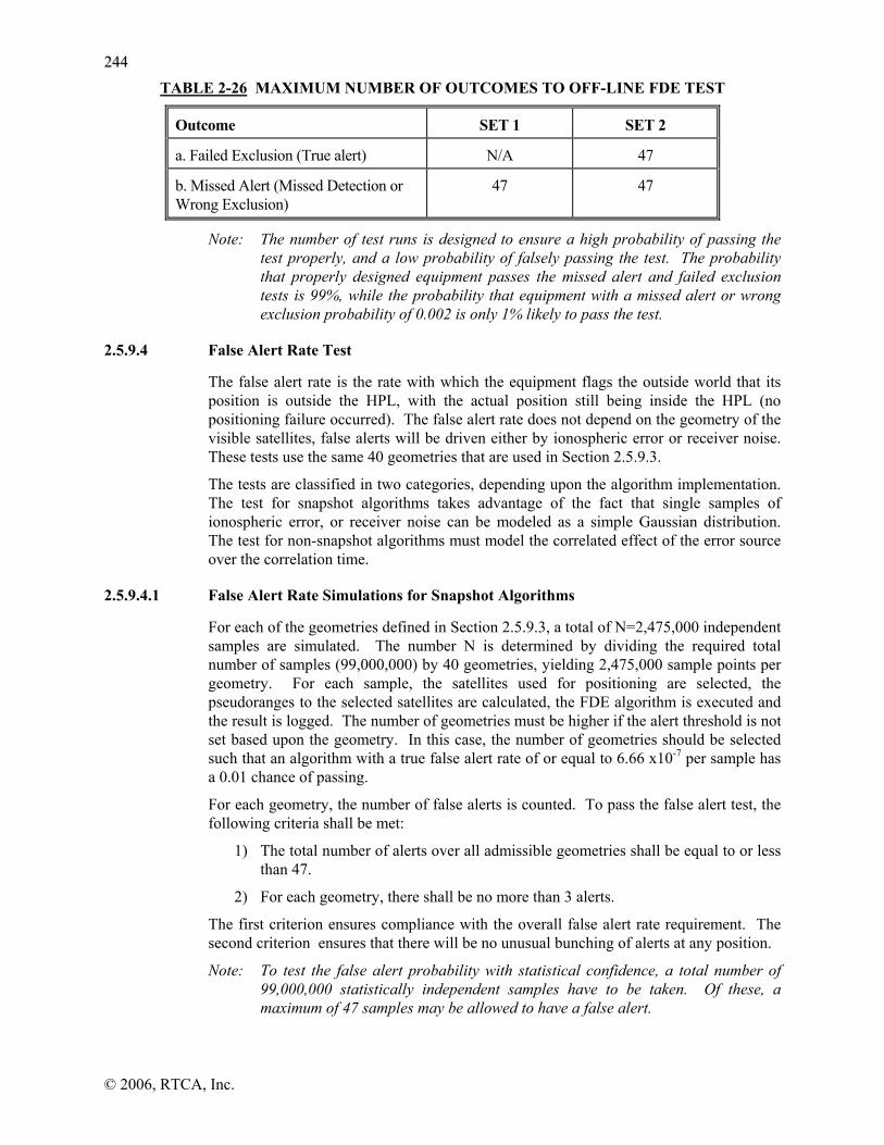
224444
© 2006, RTCA, Inc.
TABLE 2-26 MAXIMUM NUMBER OF OUTCOMES TO OFF-LINE FDE TEST
Outcome SET 1 SET 2
a. Failed Exclusion (True alert) N/A 47
b. Missed Alert (Missed Detection or Wrong Exclusion)
47 47
Note: The number of test runs is designed to ensure a high probability of passing the test properly, and a low probability of falsely passing the test. The probability that properly designed equipment passes the missed alert and failed exclusion tests is 99%, while the probability that equipment with a missed alert or wrong exclusion probability of 0.002 is only 1% likely to pass the test.
2.5.9.4 False Alert Rate Test
The false alert rate is the rate with which the equipment flags the outside world that its position is outside the HPL, with the actual position still being inside the HPL (no positioning failure occurred). The false alert rate does not depend on the geometry of the visible satellites, false alerts will be driven either by ionospheric error or receiver noise. These tests use the same 40 geometries that are used in Section 2.5.9.3.
The tests are classified in two categories, depending upon the algorithm implementation. The test for snapshot algorithms takes advantage of the fact that single samples of ionospheric error, or receiver noise can be modeled as a simple Gaussian distribution. The test for non-snapshot algorithms must model the correlated effect of the error source over the correlation time.
2.5.9.4.1 False Alert Rate Simulations for Snapshot Algorithms
For each of the geometries defined in Section 2.5.9.3, a total of N=2,475,000 independent samples are simulated. The number N is determined by dividing the required total number of samples (99,000,000) by 40 geometries, yielding 2,475,000 sample points per geometry. For each sample, the satellites used for positioning are selected, the pseudoranges to the selected satellites are calculated, the FDE algorithm is executed and the result is logged. The number of geometries must be higher if the alert threshold is not set based upon the geometry. In this case, the number of geometries should be selected such that an algorithm with a true false alert rate of or equal to 6.66 x10⁻⁷ per sample has a 0.01 chance of passing.
For each geometry, the number of false alerts is counted. To pass the false alert test, the following criteria shall be met:
1) The total number of alerts over all admissible geometries shall be equal to or less than 47.
2) For each geometry, there shall be no more than 3 alerts.
The first criterion ensures compliance with the overall false alert rate requirement. The second criterion ensures that there will be no unusual bunching of alerts at any position.
Note: To test the false alert probability with statistical confidence, a total number of 99,000,000 statistically independent samples have to be taken. Of these, a maximum of 47 samples may be allowed to have a false alert.

224455
© 2006, RTCA, Inc.
2.5.9.4.2 False Alert Rate Simulations for Non-Snapshot Algorithms
For each of the geometries defined in Section 2.5.9.3, a total of N=82,500 hours of operation is to be simulated. The number N is determined by dividing the required total number of simulation hours (3,300,000) by 40 geometries, yielding 82,500 hours per geometry. During each simulation run of 82,500 hours, the satellite velocities are to be set to zero, and the satellite positions are to be frozen at the values for the selected marginal geometry. This ensures that the HAL/HPL will not change during the run.
For the purpose of this test, a false alert is defined as the occurrence of an alert indication in the absence of a real positioning failure, regardless of how long the alert indication is provided. The total number of alerts shall be counted. Only the number of indication occurrences will be counted, not the duration of the indication. To pass the false alert test, the following criteria shall be met:
1) The total number of alerts over all admissible geometries shall be less than or equal to 47.
2) There shall be no more than 3 alerts for each admissible geometry.
The first criterion ensures compliance with the overall false alert rate requirement. The second criterion ensures that there will be no unusual clustering of alerts at any one position.
Note: The false alert rate for non-snapshot algorithms cannot be easily converted into a false alert probability. For these algorithms, a total number of 3,300,000 hours of operation has to be simulated to gain statistical confidence. During this simulation, no more than 47 false alerts can be allowed for the equipment to pass the test.
2.5.9.5 On-Line Verification Test
The purpose of the on-line verification tests is to ensure that the off-line algorithms and the on-line implemented algorithms are identical in function, performance, and computational (logical and arithmetic) results. This requirement is derived from the fact that all statistical performance results are determined by the off-lines tests.
Because the off-line and on-line tests use fundamentally different data generators, it is not possible to ensure that any off-line and on-line tests, under identical scenarios, will produce identical results. Therefore, there shall be two separate tests: an on-target computational test; and, an on-line behavioral test. An additional test is specified for LNAV/VNAV, LP, and LPV approach fault detection.
2.5.9.5.1 On-Target Computational Test
The purpose of the on-target test is to ensure that software on the target processor (in the GPS/SBAS equipment) produces equivalent output data as the off-line algorithm, for identical input data. This test does not have to be conducted if the off-line tests described in Sections 2.5.9.3 and 2.5.9.4 are performed on the target processor using the same FDE software used in the GPS/SBAS equipment.
For the purpose of this test, equivalent means that arithmetic variables are within 0.1 meter of the off-line values and all logical variables are strictly identical (including logical counters, etc.).
The on-target test requires that the target software be exercised by forty satellite scenarios; one from each constellation in Set 1 and Set 2 as defined in Section 2.5.9.3.2. A ramp failure shall be generated as defined in Section 2.5.9.3.2 in each case.

224466
© 2006, RTCA, Inc.
1) For each satellite static scenario, the input data to the off-line navigation/FDE algorithm shall be recorded with its computational results. At a minimum, the computational results shall include the HPLFD, horizontal radial position error, alert flag, and loss of integrity flag. Any additional variables internal to the navigation/FDE algorithm may also be recorded.
2) This input data will be duplicated in the on-target software and the input data will exercise the on-target navigation/FDE software. The computational results of the on-target software will be recorded and compared to the off-line results. The strict meaning of equivalent is defined above. The computational results for the on-line and on-target implementations are required to be equivalent.
2.5.9.5.2 On-Line Behavioral Test
The test shall be run using five constellations selected from the forty used under Section 2.5.9.5.1 that have a relatively constant HPLFD and HELFD for the duration of the test. A ramp failure shall be generated as defined in Section 2.5.9.3.3 in each case. All test scenarios will be conducted with the equipment stationary (non-dynamic).
To pass the behavioral test:
1) The equipment position fixing difference shall only exceed 5 meters for periods of 2 seconds or less.
2) The equipment HPLFD difference shall only exceed 50 meters for periods of 10 seconds or less.
If these thresholds are exceeded, the cause of the difference shall be identified and that cause must be within the expected characteristics of the algorithm.
2.5.10 LNAV/VNAV, LP, LPV Approach Fault Detection
The verification of the fault detection algorithm for the equipment in a approach (LNAV/VNAV, LP, LPV) mode shall consist of four tests. The first test (Section 2.5.10.2) shall demonstrate that the fault detection algorithm provides proper fault detection availability, and will be performed off-line. The second test (Section 2.5.10.3) is an off-line test to verify that the missed alert requirement is satisfied. (Note that fault detection availability and missed alert requirements are only for test purposes. In real operations, fault detection will be executed regardless of the geometry and the missed alert probability that can be guaranteed by the geometry). The third test (Section 2.5.10.4) is an off-line test to verify the false alert rate. The final test (Section 2.5.10.5) is an on-line test to verify that the algorithm that is implemented in the equipment is identical to the algorithm used during the off-line tests. (Note that the on-line test specifies several additional off-line scenarios for comparison to on-line results.)
2.5.10.1 General Test Conditions
2.5.10.1.1 Test Philosophy
These tests specify the procedures and pass/fail criteria for equipment demonstrating compliance with the LPV fault detection requirements in Sections 2.1.4.2.2.2 and 2.1.5.2.2.2.
2.5.10.1.2 GPS Constellation
See Section 2.5.9.1.2

224477
© 2006, RTCA, Inc.
2.5.10.1.3 Applicability of RTCA/DO-178B
See Section 2.5.9.1.3 (fault detection only instead of FDE)
2.5.10.1.4 Test Repetition
If the equipment fails two successive tests defined in Section 2.5.10.3 or 2.5.10.4 with different sets of numbers for random processes, the integrity algorithm must be modified to correct the problem before re-testing. Re-testing must be done for all fault detection tests.
2.5.10.1.5 Protection Level/Alert Limit
The fault detection performance tests for approach (LNAV/VNAV, LP, LPV) mode are based upon the VPLTFD. As was defined earlier in Sections 2.1.4.2.2.2 and 2.1.5.2.2.2.2, VPLTFD is similar to VPLFD except that the missed alert probability guaranteed by fault detection is 0.1, instead of 0.001. VPLTFD, missed alert probability, and availabilities are used only for the purpose of testing for LPV fault detection. The availability test is based on vertical alert limit of 25 m.
2.5.10.1.6 Time-to-Alert
The time-to-alert requirement is as specified in section 2.1.2.2.2.2.1, 2.1.3.2.2.2.1, and it is 6 seconds for LNAV/VNAV, LP, and LPV approach operations.
2.5.10.2 Availability Tests
The off-line tests described in this paragraph shall be used to demonstrate compliance with the availability requirements of Sections 2.1.4.2.2.2 and 2.1.5.2.2.2. Availability of fault detection shall be determined for each of the space-time points in the analysis grid defined in Section 2.5.9.2 sampled every 5 min for 12 hr from 00:00:00 to 12:00:00 UTC (144 time points). The standard deviations are defined in 2.5.10.3.1. For snapshot FDE algorithms, the noise process is modeled as a Gaussian white sequence with samples that are uncorrelated in time and a standard deviation of σi for each satellite i pseudorange.
The availability of fault detection for each space-time point shall be determined as defined in Section 1.7.3, except that missed alert probability requirement is 0.1 instead of 0.001 and therefore it is based on VPLTFD defined in Sections 2.1.4.2.2.2 and 2.1.5.2.2.2.2.
The availability calculations for each space-time point shall be based upon the same set of satellites that would be used by the equipment. This requires that the satellite selection algorithm be used to select the satellites for use in the fault detection algorithm. In addition, the mask angle shall be 5 deg.
2.5.10.3 Off-Line Missed Alert Tests
2.5.10.3.1 Off-Line Test Setup
The residual errors for post-SBAS correction pseudorange measurements for non-failed GPS satellites shall be modeled by RSSing the error components per Appendix J:
σ σ σ σ σi i flt i UIRE i air i tropo2 2 2 2 2= + + +, , , ,
where σi is the standard deviation of satellite i’s pseudorange measurement. The 4 terms are specified below.

224488
© 2006, RTCA, Inc.
The first term σi,flt, is provided by Appendix .2.2:
( ) ( )[ ]2,
2, termconstant+⋅= UDREUDREiflti δσσ
with δUDRE set equal to 1 and the constant term set equal to zero. The model is a random constant with standard deviation is σi,UDRE = 0.562 m. This will result in σi,flt = 0.562 m.
The term σi,UIRE is the ionospheric delay estimation error modeled as a second-order Gauss-Markov process with an auto-correlation time of 120 sec and a standard deviation of Fpp x σUIVE m where σUIVE = 0.432 m and Fpp is the ionospheric obliquity factor. From Appendix A.4.4.10.4, Fpp and σi,UIRE are given by equations A-42 and A-43:
21
2cos1
−
⎥⎥⎦
⎤
⎢⎢⎣
⎡⎟⎟⎠
⎞⎜⎜⎝
⎛+
−=Ie
iepp hR
RF θ
and
σ σUIRE pp UIVEF2 2 2= ⋅
where iθ is the satellite elevation angle, and from Appendix A.4.4.10.1, terms Re and hI
are defined to be Re = 6378136.0 m, hI = 350000.0 m,. The third term is the multipath and receiver noise modeled as a Gaussian white sequence with samples that are uncorrelated in time and a standard deviation of σi,air. The standard deviation σi,air is itself comprised of three terms (see Appendix J.2.4):
( ) 2/1222,, ][][][ iii divgmultipathGPSnoiseairi σσσσ ++=
These first and third terms are specified as a constant defined in Appendix J.2.4 for a receiver Airborne Accuracy Designator A under minimum power conditions. For a GPS satellite, the summed first and third terms must be less than or equal to 0.36; for the purposes of modeling, the worst case is set as:
( ) 2/122, ][][ ii divgGPSnoise σσ + = 0.36 meters
This second term is specified in Appendix J.2.4, as: deg)10/(53.013.0][ ieimultipath
θσ −+= meters
where as before, iθ is the satellite elevation angle in degrees.
The last term, σi,tropo is the tropospheric delay estimation error. It is modeled as a random constant with a standard deviation of σi,tropo as specified in Appendix A.4.2.4, equations A-10 and A-11:
)(sin002001.0001.1)(
2i
imθ
θ+
=
and
( ))(, θσσ iTVEtropoi m⋅= meters
with σTVE = 0.12 meters and as before, iθ is the satellite elevation angle.

224499
© 2006, RTCA, Inc.
This completes the total sigma model for the satellite pseudo range measurement.
The sampling interval used in the simulation tests shall not exceed 1 second. It shall be assumed that only one anomalous post-correction pseudorange measurement occurs at a time, and it shall be simulated as a ramp error in pseudorange measurement with a slope of 0.2 m/sec.
Different noise samples shall be used for each satellite being used in the fault detection algorithm, and new sets of noise samples are to be generated and used for each run.
During all runs in the off-line simulation tests, satellite velocities are to be set to zero, and the satellite positions are to be frozen at the values for the selected geometry.
The equipment shall de-weight each range measurement based upon the expected error residual.
2.5.10.3.2 Selection of Geometries
The space-time points analyzed under Section 2.5.10.2 shall be reviewed to yield a set of twenty geometries that provide an approximately uniform range of VPL from 5 m to 100 m. If the geometries cannot be found for any set, deselect satellites in order to find acceptable geometries.
2.5.10.3.3 Test Procedures and Pass/Fail Criteria
In addition to the data recorded specifically for the off-line test, the position trace and alert status shall be recorded for several runs in support of the on-line test procedures.
For each of the 20 geometries selected in Section 2.5.10.3.2, a ramp-type failure with a velocity of 0.2 m/sec shall be introduced in the most difficult to detect satellite. The VAL for each run shall be set equal to the VPLTFD to obtain the proper alerting. A Monte-Carlo (random) trial run shall then be made with the ramp initiated at the time of the chosen geometry (defined as t = 0). The run is to be continued until one of the following three events occurs (1-3).
1) The alert is triggered without the vertical position error exceeding VPLTFD. This is called a “false detection”.
2) The vertical position error exceeds VPLTFD and the alert is also triggered within the allowable time-to-alert. This is called a “timely detection”.
3) The vertical position error exceeds VPLTFD but the alert is not triggered within the specified time-to-alert. This is called a “miss”.
A total of 14 trials shall be run for each of the 20 geometries. The number of occurrences of each outcome shall be recorded for each of the 20 geometries.
For the equipment to pass, the total number of misses shall be less than or equal to 40.
Note: The number of test runs is designed to ensure a high probability of passing the test properly, and a low probability of falsely passing the test. The probability that properly designed equipment passes the missed alert tests is 99 percent, while the probability that equipment with a missed alert probability greater than or equal to twice the requirement (i.e., 0.2) will pass the test is less than 1 percent.

225500
© 2006, RTCA, Inc.
2.5.10.4 False Alert Rate Test
The false alert rate shall not depend on the geometry of the visible satellites, but is mainly driven by the values of the statistical parameters characterizing post-SBAS correction pseudorange measurements. The false alert rate test uses the same 20 geometries that are used in Section 2.5.10.3. Because there are only one or two independent samples for the duration of a typical LP/LPV approach, the following test may be used for both the snapshot and non-snapshot algorithm implementations.
Note 1: Manufacturers may choose to use an elevated statistical distribution for the post-correction pseudorange measurement errors to reduce the number of samples required to yield the desired statistical confidence. If manufacturers choose to do so, they must demonstrate that their test method yields at least equivalent statistical confidence to the tests described below.
For each of the geometries defined in Section 2.5.10.3, a total of N = 165,000 samples are simulated. The number N is determined by dividing the required total number of samples 3,300,000 by 20 geometries, yielding 165,000 sample points per geometry. For each sample, the satellites used for positioning are selected, the post-correction pseudoranges to the selected satellites are calculated, the fault detection algorithm is executed, and the result is logged.
For each geometry, the number of false alerts is counted. To pass the false alert test, the following criteria shall be met:
1) The total number of alerts over all admissible geometries shall be equal to or less than 47.
2) There shall be no more than 3 alerts for each geometry.
The first criterion ensures compliance with the overall false alert rate requirement. The second criterion ensures that there will be no unusual bunching of alerts at any position.
Note 2: To test this probability with statistical confidence, a total number of 3,300,000 statistically independent samples have to be taken. Of these, a maximum of 47 samples may be allowed to have a false alert.
2.5.10.5 On-Line Verification Test
The purpose of the on-line verification tests is as described in Section 2.5.9.5. Because the off-line and on-line tests use fundamentally different data generators, it is not possible to ensure that any off-line and on-line tests, under identical scenarios, will produce identical results. Therefore, there shall be two separate tests: an on-target computation test; and an on-line behavioral test.
2.5.10.5.1 On-Target Computational Test
Refer to Section 2.5.9.5.1 with the following exceptions.
For the purpose of this test, equivalent means that arithmetic variables are within 0.01 m of the off-line values and all logical variables are strictly identical.
The on-target test requires that the target software be exercised by twenty satellite scenarios defined in Section 2.5.10.3.2. A ramp failure shall be generated as defined in Section 2.5.10.3.3.

225511
© 2006, RTCA, Inc.
2.5.10.5.2 On-Line Behavioral Test
The behavioral tests will be conducted on the GPS/SBAS equipment using a satellite simulator. This test shall be performed using five geometries out of 20 defined in Section 2.5.10.3.2 that have a relatively constant VPL for the duration of the test. A ramp failure shall be generated as defined in Section 2.5.10.3.3. All test scenarios will be conducted with the equipment stationary.
To pass the behavioral test:
1) The equipment position fixing difference shall be less than 1 meter, but may exceed 1 meter for a period of 400 ms or less.
2) The equipment VPL difference shall be less than 1.5 meters, but may exceed 1.5 meters for a period of 400 ms or less.
If these thresholds are exceeded, the cause of the difference shall be identified and that cause must be within the expected characteristics of the algorithm.
2.5.11 Test Procedures for Class Gamma Equipment
This section describes specific Gamma equipment tests. The equipment required to perform these tests shall be defined by the equipment manufacturer as a function of the specific sensor configuration of the equipment. Since these tests may be accomplished more than one way, alternative test equipment setups, test conditions, or simulated flight scenarios may be used where equivalent evaluation of the GPS/SBAS equipment can be accomplished. Combinations of tests may be used whenever appropriate.
The test equipment signal sources shall provide the appropriate signal format to the specific system under test without contributing to the error values being measured. When used, the simulator(s) shall follow the same protocols (i.e. message types, message contents, frequency of messages) described in Appendix A, the WAAS Signal Specification.
2.5.11.1 General Gamma Bench Test Procedures
The bench test procedures described below require the use of simulators to assume the role of the other components of the total system. Therefore, a manufacturer can use an airborne system and test it to the bench tests described in this section. However, to have Gamma equipment certified, flight tests shall also be conducted.
Bench tests can be conducted with a test equipment configuration similar to Figures 2-19 and 2-20. [Generic Bench Test Configuration] The configuration includes entering flight plan information into the Gamma equipment under test. Information corresponding to the flight plan, such as waypoints and aircraft speed, is entered into the simulator. The simulator uses this information to provide RF signals to the Gamma equipment. These signals simulate aircraft flight for various patterns and paths corresponding to the processed flight plan. In addition to the flight plan derived information (e.g., waypoints), the simulator processes the appropriate satellite constellation from Appendix B.
Unless otherwise noted, the ground speed of the simulated aircraft should be compatible with the ground speed of an aircraft, for which the equipment is being tested for each mode (e.g., en route/remote, terminal, approach). Bench tests that successfully pass the criteria only need to be performed once unless otherwise indicated.

225522
© 2006, RTCA, Inc.
2.5.11.1.1 Simulated Flight Bench Test Procedures
The approach for bench testing Gamma equipment requirements includes the use of multiple flight plans to create different operational test conditions. This test methodology maximizes the use of GPS/SBAS simulators for dynamic bench testing. This approach is effective in evaluating GPS/SBAS equipment performance and functional capabilities in a cost effective manner.
The first simulated flight plan is a flight departure from JFK International Airport [KJFK], New York, NY, and arrival at Los Angeles International Airport [KLAX], Los Angeles, CA. However, only a portion of this flight is tested. The second simulated flight is for a departure from, a GPS approach to and a missed approach at William R. Pogue Municipal Airport (airport identifier: 0F8, zero foxtrot eight), Sand Springs, OK. Executing these flight plans along with additional manual inputs and/or observations during the simulated flights will verify several requirements. The flight plans can be conducted in their entirety, or by conducting portions of each flight plan at a time.
When these two flight plans were developed it was realized that the waypoints and airways used in the flight plans would most likely change in the future. For example, in flight plan number 1 the standard instrument arrival at KLAX named REEDR.3 might be changed in the future to REEDR.4. For this reason, the manufacturer has the option of adjusting the flight plan, or using another flight plan provided that the individual requirements referenced in Tables 2-32 and 2-33 are still verified. The flight profiles in Figures 2-21 and 2-22 must be duplicated with any new flight plan.
2.5.11.1.1.1 Simulated Flight Plan Test 1
This test includes entering two flight plans and simulating a flight departure from KJFK and arrival at KLAX. The test uses a 20 waypoint flight plan but is executed for only a portion of the flight. The manufacturer has the option to select aircraft type and aircraft speeds, but they should be appropriate for the intended equipment’s market and application.
Note that the first eight waypoints in this flight plan are identified by latitude/longitude positions. The waypoints in the remainder of the flight plan include references to current navaids, intersection positions or names. These waypoints and approaches may be adjusted to accommodate changes in the navigation database. The waypoints and their characteristics (e.g., lat/long, bearing and range to each other) are identified in the following tables. These waypoints are also referred to in Figure 2-17, Flight Profile for Flight Plan 1.
Figure 2-17 illustrates the flight plan and deviations to the flight plan during the bench test. The table below (Table 2-27) characterizes the waypoints used in this test. They describe the latitude/longitude positions, bearing and range between waypoints and the magnetic variations at each waypoint. The current names of Flight Plan No. 1 Waypoints 1 to 8 are provided for information purposes.
TABLE 2-27 WAYPOINT INFORMATION FOR FIRST FLIGHT PLAN FOR SIMULATED FLIGHT PLAN TEST 1
FP WPT No.
WPT Name
LATITUDE LONG Distance between
WPTs (NM)
True Heading
(Degrees)
Mag Vari-ation
KJFK N40° 38’ 23.10”
W072° 46’ 44.13”
W13
1 CRI N40° 36’ W 073° 53’ KJFK to W11

225533
© 2006, RTCA, Inc.
44.90” 40.00” WPT1 5.53
252.82 o
2 RBV N40° 12’ 08.6”
W074° 29’ 42.05”
WPT 1 to 2 36.91
228.42 o
W11-W10
KJFK to WPT2 82.89
252.16 o
W10
3 LOBES N40° 11’ 24.30”
W74° 38’ 47.07”
WPT 2 to 3 6.99
263.99 o
W10-W12
4 COPES N40° 07’ 50.58”
W75° 22’ 36.37”
WPT 3 to 4 33.79
264.19 o
W12-W11
5 SIELE N40° 05’ 31.93”
W75° 49’ 07.29”
WPT 4 to 5 20.47
263.67 o
W11
6 J6/J230 N40° 01’ 00.47”
W76° 30’ 53.22”
WPT 5 to 6 32.39
262.20 o
W11
7 FLIRT N39° 55’ 43.89”
W76° 42’ 14.41”
WPT 6 to 7 10.20
238.93 o
W11
8 MRB N39° 23’ 08.06”
W77° 50’ 54.18”
WPT 7 to 8 62.23
238.81 o
W10-W7
1) Setup the test equipment according to section 2.5. Configure the simulator with the satellite constellation in Appendix B and the equivalent simulated flight information from Table 2-27, Simulated Flight Plan Test Number 1.
2) Conduct the test in the sequence of steps provided in the table. Note any flight plan deviations or test anomalies that occur during the test. Verify that the success criteria for each step is satisfactory.
2.5.11.1.1.2 Simulated Flight Plan Test 2
This bench test includes a simulated flight for departure from, GPS approach to, and missed approach at William R. Pogue Municipal Airport (0F8). This simulated flight verifies requirements associated with terminal airspace and involves a missed approach and holding pattern. The manufacturer has the option to select aircraft type and aircraft speeds but they should be appropriate for the intended equipment’s market and application. Figure 2-18 illustrates the flight plan and deviations to the flight plan during the bench test. Table 2-28 contains the latitude and longitude positions of the waypoints used in the flight plan. If the tester elects to change the waypoints or procedures, the flight profile in Table 2-29 must remain the same.

225544
© 2006, RTCA, Inc.
TABLE 2-28 WAYPOINT INFORMATION FOR SIMULATED FLIGHT PLAN TEST 2
WPT Name
LATITUDE LONG Distance between WPTs (NM)
True Heading
(Degrees)
Mag Vari-ation
DARRO N35° 59’ 39.05”
W96° 14’ 12.43”
DARRO TO ACERT 4.99
85.3 E8
ACERT N36° 00’ 03.51 »
W96° 08’ 03.94”
ACERT TO CENTO 4.99
85.3 E8
CENTO N36° 00’27.66”
W96° 01’55.39”
NA NA E8
FANCY N36° 05’02.96”
W96° 08’33.84”
ACERT TO FANCY 4.99
355.37 E8
WILUM N36° 10’02.41”
W96° 09’03.77”
FANCY TO WILUM 5.00
355.37 E8
ABCUX N36° 15’59.02 »
W96° 09’39.48”
WILUM TO ABCUX 5.95
355.36 E8
1) Setup the test equipment according to section 2.5. Configure the simulator with the satellite constellation in Appendix B and the equivalent simulated flight information for Table 2-30 Simulated Flight Plan Test Number 2.
2) Conduct the test in Table 2-30. The flight profile is illustrated in Figure 2-18. Note any flight plan deviations or test anomalies that occur during the test. Verify that the success criteria for each step is satisfactory.

255
© 2006, RTCA, Inc.
TABLE 2-29 SIMULATED FLIGHT PLAN TEST NUMBER 1
Step Action Success Criteria Phase of Requirement
1. Enter departure airport (KJFK) and arrival airport (KLAX).
Verify that both airports are accepted. Preflight 2.2.1.5.2
2. Enter the following flight plan as a stored or alternate flight plan (the intent is that this flight plan is activated later in this test) Waypoints 2 through 5 from Table 2-27,Waypoint 6 from Table 2-27 (enter as 274° radial from RBV and 248° radial from LRP), Waypoints 7 through 8 from Table 2-27. Complete creation of a flight plan to the arrival airport (KLAX) with a maximum of 18 waypoints. The additional waypoints must include a user waypoint at N40 49.3 W088 43.9 and an arrival route (e.g., REEDR 3) into KLAX.
Verify that the flight plan data is accepted.
Preflight 2.2.1.2.1
3. Verify that the user defined waypoint (Waypoint 6; J6/J230) was accepted as entered. Verify that the entry of the two radials defining this intersection was accepted as a waypoint and that the resolution was at least one degree.
Preflight 2.2.1.2.5
4. Verify that the latitude and longitude (N 40 49.3 W 088 43.9) entry was displayed as latitude and longitude before the data was entered into the flight plan and that the resolution was at least 0.1 minute.
Preflight 2.2.1.2.5
5. Verify that the arrival route (e.g., REEDR.3) was in the data base including the appropriate transitions for the arrival (e.g., three transitions associated with REEDR.3). Verify that by entering selected arrival and transition(s) that all the appropriate waypoints were accepted into the flight plan.
Preflight 2.2.1.2.1, 2.2.3.2, 2.2.3.3.1
6. Verify following waypoints are accepted: KJFK, RBV, LOBES, SIELE, user defined intersection (Waypoint 6; J6/J230), FLIRT, MRB, and the remaining waypoints added to the flight plan.
Preflight 2.2.1.3, 2.2.1.2.1
7. Verify that each leg is accepted with its course and distance. Preflight 2.2.1.2.1,

225566
© 2006, RTCA, Inc.
Step Action Success Criteria Phase of Requirement
2.2.1.2.2 8. Verify that the flight plan entered is not the active flight plan. Preflight 2.2.1.2.2 9. Enter vertical path information, such as
flight level altitude (FL350), if required. Verify that any vertical path information (flight level) is accepted. Preflight
10. Enter the departing runway (31L) if required.
Verify the departing runway is accepted. Preflight
11. Enter second flight plan for a flight from Philadelphia airport (KPHL) to Tampa airport (KTPA): KPHL, OOD, LAL (e.g., DIRECT LAL), KTPA
Verify the second flight plan can be activated. Verify that the first flight plan entered remains in the equipment and is not active.
Preflight 2.2.1.2.2
11A. Enter vertical path information, such as flight level (FL 160), if required.
Verify that any vertical path information (flight level) is accepted. Preflight
12. Verify that the following waypoints are accepted: KPHL, OOD, LAL, KTPA.
Preflight 2.2.1.3
13. Select & Activate the first flight plan Verify first flight plan entered (KJFK to KLAX) is now the active flight plan.
Preflight 2.2.1.3, 2.2.1.2.3
14. Review the entire flight plan verifying that each leg is identified including the arrival route (e.g., REEDR.3).
Preflight 2.2.1.2.1
15. Insert CRI (Waypoint 1 from Table 2-27) into the active flight plan prior to RBV
Verify that waypoint CRI is entered and is a part of the active flight plan.
Preflight 2.2.1.2.1
15A. Enter the following user defined waypoint after WPT CRI: CRI 220R/30.1 DME
Verify that the waypoint is accepted. Verify the resolution of 220 degrees and 30.1 nm.
Preflight 2.2.1.2.1
16. Delete the following from the flight plan: CRI 220R/30.1 DME
Verify the user-defined waypoint is deleted from the flight plan. Preflight 2.2.1.2.1
17. Enter the following route change after WPT CRI: CRI 221R/30.2 DME
Verify that the waypoint is accepted. Verify that the range is 30.2 nm and that the bearing resolution is 221 degrees.
Preflight 2.2.1.2.1, 2.2.1.2.2
18. Execute the route change in the previous step. Note: Some equipment may have already accepted the route change and do not need to “execute” in order to perform the verification for this step.
Verify that the route change is accepted. Verify that the flight plan is still active.
Preflight 2.2.1.2.1, 2.2.1.2.2

257
© 2006, RTCA, Inc.
Step Action Success Criteria Phase of Requirement
19. Verify that resolutions of 1 degree in the 221R and 0.1 nm in the 30.2 distance was accepted.
Preflight 2.2.1.2.5
20. Bench test begins simulated flight –Take off
Verify that during departure the display sensitivity change from 0.3 nm FSD at departure end of runway to 1.0 nm FSD over a distance of 2 nm. Verify that automatic mode switching is annunciated. Verify that terminal mode is indicated after Take-off. Note: The sensitivity changes will stop after 2 nm.
Depart to Terminal
2.2.2.7.2.3, Table 2-5, 2.2.1.7
21. After take off, execute: “DIRECT RBV”.
Verify that “DIRECT RBV” is accepted. Verify that the access to the “DIRECT RBV” feature was by means of a single manual action.
Terminal 2.2.1.2.2, 2.2.1.2.4
22. Verify the “Direct TO” RBV leg was accepted and that the flight plan is intact with no discontinuity between RBV and WPT LOPES.
Terminal 2.2.1.2.4, 2.2.1.3, 2.2.1.3.4
23. Verify that the numeric cross-track deviation is displayed, or that a electrical output is continuously provided during terminal mode.
Terminal 2.2.1.4.2.2 2.2.2.4.3
24. Intentionally left blank. 25. Intentionally left blank. 26. Verify automatic annunciation when the default mode switches to en
route mode. Note: During transition to en route mode the display sensitivity decreases (full scale sensitivity + 5 nm).
Terminal to En Rte
2.2.1.7
27. Manually request current navigation mode. Verify that the current mode indicated is en route. En Route 2.2.1.7
28. Verify that an indication is provided that RBV is the active “TO” WPT.
En Route 2.2.1.2.4
29. Verify that an annunciation is issued prior to WPT RBV and again at the WPT crossing.
En Route 2.2.1.3.7, 2.2.1.3.10
30. Proceed 4-5 nm on J230 past WPT RBV. Verify that when passing WPT RBV the next WPT LOBES is automatically sequenced and becomes the active “TO” WPT.
En Route 2.2.1.2.4
31. Recall WPT RBV on the display. Verify that RBV can be recalled. En Route 2.2.1.2.2 32. Proceed on a 90 degree heading change to
the right. Note: This is intended to position the aircraft for a flyover of RBV from the
The simulated aircraft should now proceed north of the airway. En Route 2.2.1.2.2
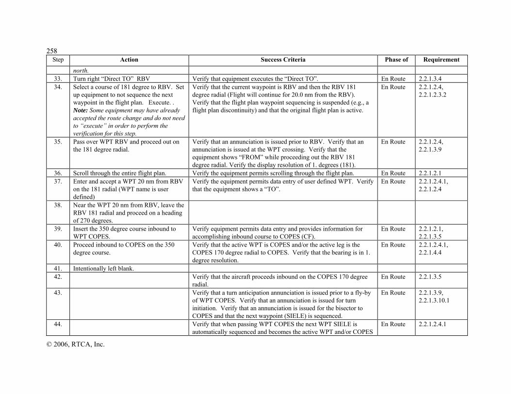
225588
© 2006, RTCA, Inc.
Step Action Success Criteria Phase of Requirement
north. 33. Turn right “Direct TO” RBV Verify that equipment executes the “Direct TO”. En Route 2.2.1.3.4 34. Select a course of 181 degree to RBV. Set
up equipment to not sequence the next waypoint in the flight plan. Execute. . Note: Some equipment may have already accepted the route change and do not need to “execute” in order to perform the verification for this step.
Verify that the current waypoint is RBV and then the RBV 181 degree radial (Flight will continue for 20.0 nm from the RBV). Verify that the flight plan waypoint sequencing is suspended (e.g., a flight plan discontinuity) and that the original flight plan is active.
En Route 2.2.1.2.4, 2.2.1.2.3.2
35. Pass over WPT RBV and proceed out on the 181 degree radial.
Verify that an annunciation is issued prior to RBV. Verify that an annunciation is issued at the WPT crossing. Verify that the equipment shows “FROM” while proceeding out the RBV 181 degree radial. Verify the display resolution of 1. degrees (181).
En Route 2.2.1.2.4, 2.2.1.3.9
36. Scroll through the entire flight plan. Verify the equipment permits scrolling through the flight plan. En Route 2.2.1.2.1 37. Enter and accept a WPT 20 nm from RBV
on the 181 radial (WPT name is user defined)
Verify the equipment permits data entry of user defined WPT. Verify that the equipment shows a “TO”.
En Route 2.2.1.2.4.1, 2.2.1.2.4
38. Near the WPT 20 nm from RBV, leave the RBV 181 radial and proceed on a heading of 270 degrees.
39. Insert the 350 degree course inbound to WPT COPES.
Verify equipment permits data entry and provides information for accomplishing inbound course to COPES (CF).
En Route 2.2.1.2.1, 2.2.1.3.5
40. Proceed inbound to COPES on the 350 degree course.
Verify that the active WPT is COPES and/or the active leg is the COPES 170 degree radial to COPES. Verify that the bearing is in 1. degree resolution.
En Route 2.2.1.2.4.1, 2.2.1.4.4
41. Intentionally left blank. 42. Verify that the aircraft proceeds inbound on the COPES 170 degree
radial. En Route 2.2.1.3.5
43. Verify that a turn anticipation annunciation is issued prior to a fly-by of WPT COPES. Verify that an annunciation is issued for turn initiation. Verify that an annunciation is issued for the bisector to COPES and that the next waypoint (SIELE) is sequenced.
En Route 2.2.1.3.9, 2.2.1.3.10.1
44. Verify that when passing WPT COPES the next WPT SIELE is automatically sequenced and becomes the active WPT and/or COPES
En Route 2.2.1.2.4.1

259
© 2006, RTCA, Inc.
Step Action Success Criteria Phase of Requirement
to SIELE becomes the active leg. Note: This path is defined by a TF leg. WPT LOBES may be dropped from the flight plan.
45. Set up the equipment to accomplish a holding pattern in the northeast quadrant of WPT SIELE with the following characteristics: “HOLD EAST OF SIELE ON J230, RIGHT TURNS, 10 MILE LEGS”.
Verify that an annunciation is issued prior to WPT SIELE. Verify that an annunciation is issued at the WPT crossing. If automatic sequencing has been suspended, verify that the equipment indicates the condition. Verify that a holding pattern can be accomplished. Note: Manually accomplishing a holding pattern may require additional equipment entries.
En Route 2.2.1.3.11
46. Verify that the equipment allows the selection of the inbound course of J230 (274 degrees) to the holding fix.
En Route 2.2.1.3.11
47. Scroll through the entire flight plan while in the holding pattern.
After entering the holding pattern, verify that the remainder of the flight plan is retained.
En Route 2.2.1.2.2, 2.2.1.3.11
48. After entering a second holding pattern and heading west on the inbound leg of the holding pattern, discontinue the holding pattern and continue on to SIELE.
Verify that the flight plan to LAX still exists as the active flight plan. Note: A “Direct TO” or other commands may be necessary to reestablish flight plan sequencing. Verify that an annunciation is issued prior to WPT SIELE. Verify that an annunciation is issued at the WPT crossing.
En Route 2.2.1.3.7, 2.2.1.3.9, 2.2.1.3.11
49. Verify that the equipment has readily returned to automatic WPT sequencing prior to crossing SIELE and that the aircraft continues on the active flight plan.
En Route 2.2.1.2.4.1, 2.2.1.3
50. Verify that the equipment recognizes the user defined intersection (Waypoint 6; J6/J230) and provides information to continue on the flight plan to WPT FLIRT.
En Route 2.2.1.3
51. Verify that a turn anticipation annunciation is issued prior to a fly-by of intersection J230/J6. Verify that an annunciation is issued for turn initiation. Verify that an annunciation is issued for the bisector to Intersection J230/J6 and that the next flight plan wpt (FLIRT) is sequenced. Verify a “TO” indication is provided and bearing to WPT FLIRT.
En Route 2.2.1.3.6, 2.2.1.3.9, 2.2.1.3.10.1, 2.2.1.4.5, 2.2.1.4.4
52. Verify that an annunciation is issued prior to WPT FLIRT and again at the WPT crossing.
En Route 2.2.1.3.7, 2.2.1.3.9
53. Verify that the numeric cross-track deviation is displayed, or that a En Route 2.2.2.4.3

226600
© 2006, RTCA, Inc.
Step Action Success Criteria Phase of Requirement
electrical output is continuously provided during the en route mode. 54. After passing WPT FLIRT enter a user
defined WPT at current position. Verify a user defined WPT can be created at the current position on the flight path. After passing WPT FLIRT verify that flight plan guidance continues on a straight line path.
En Route 2.2.1.2.6
55. Initiate insertion of Martinsburg (KMRB) airport in the flight plan prior to WPT MRB when within 10 nm of approaching WPT MRB, but do not cause KMRB to become part of the active flight plan.
Verify that there is no mode switch from en route mode into terminal mode. Note: MRB airport is about 5.9 nm from WPT MRB.
En Route 2.2.2.7.2.1
56. Test Completion Verify that the equipment still recognizes MRB as the next WPT. This test is completed.
En Route

261
© 2006, RTCA, Inc.
TABLE 2-30 SIMULATED FLIGHT PLAN TEST NUMBER 2
Step Action Success Criteria Phase of Requirement 1. Enter William R. Pogue Municipal
Airport (airport identifier: 0F8, zero foxtrot eight,), Sand Springs, OK, as the departure and arrival airport.
Verify that the departure and arrival airport was accepted. Verify that the equipment accesses ICAO compliant airport nomenclature.
Preflight 2.2.1.2.1
2. Enter vertical path information, such as altitude (2400 ft.), if required.
If applicable, verify that any vertical path information (altitude) is accepted.
Preflight
3. Bench test begins simulated flight -Take off Runway 35.
Terminal
4. Execute a turn left and proceed on a heading of 260o.
Terminal
5. Retrieve GPS Approach to 0F8, runway 35
Verify that all IAWP’s are available for selection (ACERT, CENTO, DARRO,).
Terminal 2.2.3.2.1 2.2.3.5
6. Select DARRO as the IAWP and activate the approach. If applicable select ‘Direct To’ DARRO
Verify that DARRO is the IAWP. Verify that the approach (LNAV) procedure consists of the following: a) Runway number and label, b) FAWP, MAWP and MAHWP
Terminal 2.2.3.2.1 2.2.3.5
7. Verify that the approach waypoints ACERT, FANCY, and WILUM were automatically inserted in the active flight plan. Verify that the MAHWP ABCUX was automatically inserted in the active flight plan. Verify that the bearing and distance to the missed approach waypoint is available for display.
Terminal 2.2.3.2.1 2.2.1.4.7 2.2.3.4.4 2.2.3.4.5
8. Verify that the direct to DARRO course was accepted. Verify that DARRO is the active waypoint. Verify that the equipment provides guidance to DARRO. Verify that a continuous indication is provided that the equipment is in “TO” operation.
Terminal 2.2.1.2.5.2 2.2.1.2.5.3 2.2.1.4.6
9.
Verify that the following navigation parameters are displayed either continuously or on a selectable page: a) Active WPT distance or estimated time to WPT
Terminal 2.2.1.4.1

226622
© 2006, RTCA, Inc.
Step Action Success Criteria Phase of Requirement b) Active WPT name c) Active WPT bearing d) Desired track e) Actual track or track angle error
10. Verify that a turn anticipation annunciation is issued prior to a fly-by turn of WPT DARRO. Verify that an annunciation is issued for turn initiation. Verify that an annunciation is issued for sequencing (crossing) the WPT. Verify the waypoints are sequenced when the position is at the bisector of the angle formed by the leg to and from DARRO. Verify that the next waypoint ACERT is sequenced. Note: the equjipment should provide positive course guidance through the turn.
Terminal 2.2.1.3.10 2.2.1.3.7 2.2.1.3.7.1
11. After fly-by of DARRO request current navigation mode and verify that equipment has remained in Terminal mode. Verify that the equipment provides guidance for the fly-by turn by computing and displaying deviation commands to accomplish the turn.
Terminal 2.2.1.7
12. Verify that the equipment provides an indication of the desired track of the next active leg prior to the onset of the turn anticipation indication. Verify that a turn anticipation annunciation occurs prior to the start of a fly-by turn of WPT ACERT. Verify that an annunciation is issued for turn initiation. Verify that an annunciation is issued for sequencing the WPT (e.g., at the bisector of the angle formed by the leg to and from ACERT). Verify that WPT FANCY (FAWP) is sequenced. Verify that the equipment provides guidance for a fly-by turn.
Terminal/ approach (LNAV)
2.2.1.3.7.1 2.2.1.3.10 2.2.1.3.7
13.
Verify automatic mode switch to approach (LNAV) when the FAWP (WPT FANCY) is the active waypoint.
approach 2.2.1.7 Table 2-11
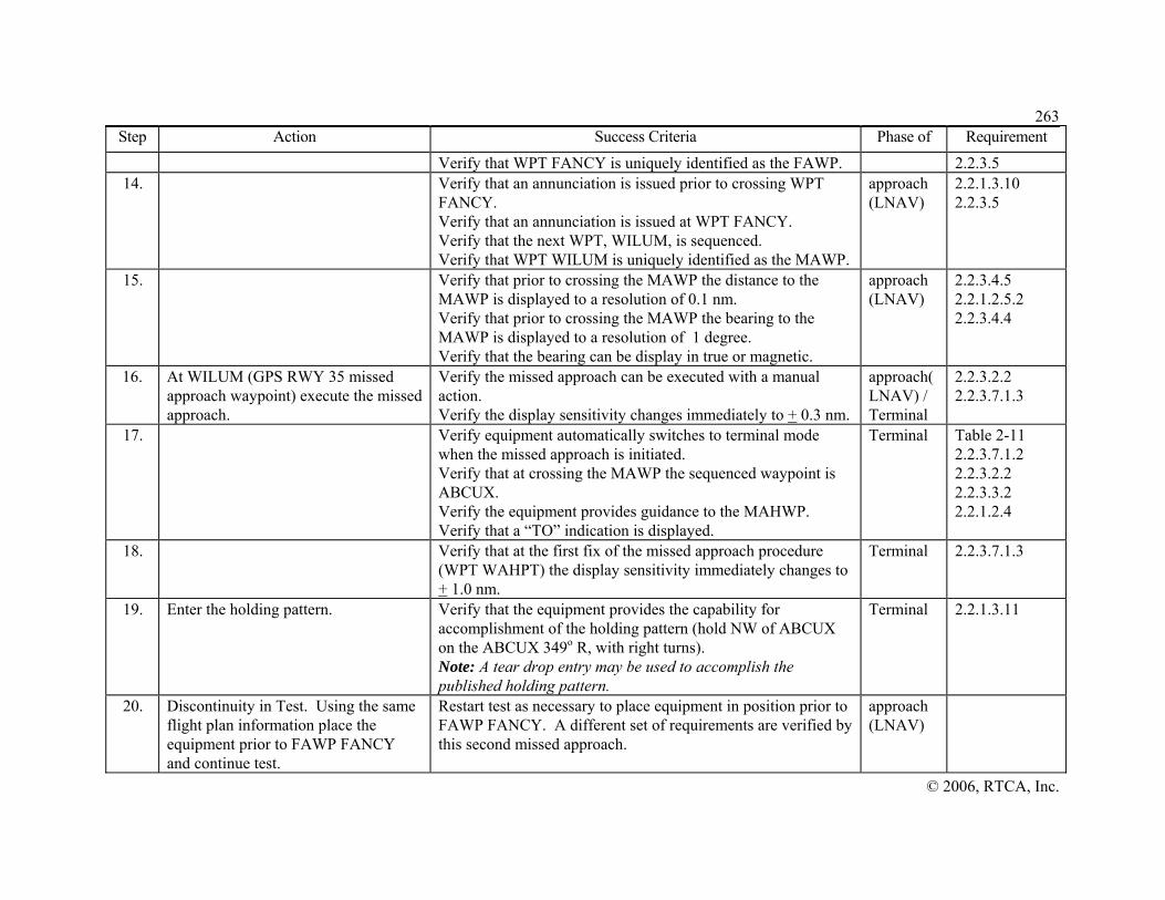
263
© 2006, RTCA, Inc.
Step Action Success Criteria Phase of Requirement Verify that WPT FANCY is uniquely identified as the FAWP. 2.2.3.5
14. Verify that an annunciation is issued prior to crossing WPT FANCY. Verify that an annunciation is issued at WPT FANCY. Verify that the next WPT, WILUM, is sequenced. Verify that WPT WILUM is uniquely identified as the MAWP.
approach (LNAV)
2.2.1.3.10 2.2.3.5
15. Verify that prior to crossing the MAWP the distance to the MAWP is displayed to a resolution of 0.1 nm. Verify that prior to crossing the MAWP the bearing to the MAWP is displayed to a resolution of 1 degree. Verify that the bearing can be display in true or magnetic.
approach (LNAV)
2.2.3.4.5 2.2.1.2.5.2 2.2.3.4.4
16. At WILUM (GPS RWY 35 missed approach waypoint) execute the missed approach.
Verify the missed approach can be executed with a manual action. Verify the display sensitivity changes immediately to + 0.3 nm.
approach(LNAV) / Terminal
2.2.3.2.2 2.2.3.7.1.3
17. Verify equipment automatically switches to terminal mode when the missed approach is initiated. Verify that at crossing the MAWP the sequenced waypoint is ABCUX. Verify the equipment provides guidance to the MAHWP. Verify that a “TO” indication is displayed.
Terminal Table 2-11 2.2.3.7.1.2 2.2.3.2.2 2.2.3.3.2 2.2.1.2.4
18. Verify that at the first fix of the missed approach procedure (WPT WAHPT) the display sensitivity immediately changes to + 1.0 nm.
Terminal 2.2.3.7.1.3
19. Enter the holding pattern.
Verify that the equipment provides the capability for accomplishment of the holding pattern (hold NW of ABCUX on the ABCUX 349o R, with right turns). Note: A tear drop entry may be used to accomplish the published holding pattern.
Terminal 2.2.1.3.11
20. Discontinuity in Test. Using the same flight plan information place the equipment prior to FAWP FANCY and continue test.
Restart test as necessary to place equipment in position prior to FAWP FANCY. A different set of requirements are verified by this second missed approach.
approach (LNAV)

226644
© 2006, RTCA, Inc.
Step Action Success Criteria Phase of Requirement 21. Verify that WPT FANCY is sequenced.
After crossing the FAWP, verify that WILUM is sequenced. approach (LNAV)
2.2.1.3.10
22. PRIOR to MAWP WILUM, execute a missed approach.
Verify the missed approach can be executed with a manual action. Verify equipment automatically switches to terminal mode with initiation of the missed approach. Verify that WILUM is a flyover waypoint. Verify the equipment sequences to ABCUX after crossing WILUM.
approach(LNAV) / Terminal
2.2.1.7 2.2.1.3.8 2.2.3.2.2 2.2.3.3.2
23. Verify the display sensitivity immediately changes to +0.3 nm. Verify guidance is provided to the MAHWP.
Terminal 2.2.3.7.1.3
24. Discontinuity in Test. Using the same flight plan information place the equipment prior to FAWP FANCY and continue test.
Restart test as necessary to place equipment in position prior to FAWP FANCY. A different set of requirements are verified by this third missed approach.
approach (LNAV)
25. Verify that WPT FANCY is sequenced. Verify that an annunciation is issued prior to crossing WPT FANCY. Verify that an annunciation is issued at WPT FANCY.
approach (LNAV)
2.2.1.3.7.1 2.2.1.3.10
26. After crossing the FAWP, verify that the next WPT, WILUM, is sequenced. Verify the equipment crosses the MAWP (WPT WILUM).
approach (LNAV)
2.2.1.3.10
27. After passing MAWP WILUM, do not select the missed approach.
Verify that the equipment automatically changes at the MAWP (WPT WILUM) from a “TO” waypoint to a “FROM” waypoint. Verify that after crossing the MAWP a prompt is provided to execute a missed approach. Verify the same course that existed prior to WILUM (349o) is followed after WPT WILUM. Note: Some equipment may not provide the prompt to execute the missed approach.
approach (LNAV)
2.2.3.2.2 2.2.3.3.2 2.2.1.3.6
28. Proceed on a heading of 040o approach

265
© 2006, RTCA, Inc.
Step Action Success Criteria Phase of Requirement 29. Execute the missed approach. Verify the missed approach can be executed with a manual
action. Verify that the equipment shows guidance to the MAHWP (WPT ABCUX). Verify that the mode automatically switches to Terminal.
approach (LNAV)/ Terminal
2.2.1.7 2.2.3.2.2 2.2.3.3.2 2.2.1.3.11
30. This test is complete.

226666
© 2006, RTCA, Inc.
FIGURE 2-17 FLIGHT PROFILE FOR FLIGHT PLAN 1
KJFK Airport
WPT1
WPT2 WPT3
WPT4
WPT5
WPTNEW RRaaddiiaall 222211oo 3300..22 NNMM
User Defined WPT181o Radial
20.1 NM
270o Heading
Course of 350o To WPT4
WPT4 170o
N
= Original FP or deviations not flown
= Actual route flown
Preflight1-22
23
32
34
3520
24
43
41
40
# = Baseline FP Step Number
= User Defined Waypoint
WPT8
WPT2 - 274o
WPT7
48
44
57
58
User Defined WPT
39
= Flight Plan Waypoint
WPT6
54
274o (J230)

267
© 2006, RTCA, Inc.
FIGURE 2-18 FLIGHT PROFILE FOR FLIGHT PLAN 2
2.5.11.1.2 Waypoint Distance Display
This bench test includes verifying requirements associated with the display of waypoint distances. The test involves simulating an active waypoint at various distances from the Gamma equipment and verifying the display readouts and resolutions.
1) Configure the equipment for bench tests according to section 2.5. Configure the simulator with the satellite constellation in Appendix B.
N = Baseline FP Step Number = Actual Route Flown = Missed Approach and Holding Pattern at Waypoint ABCUX
#
William R. Pogue Municipal Airport Sand Springs, OK
(FAWP) FANCY
(MAWP) WILUM
ABCUX Missed Approach Holding Waypoint (e.g. tear drop entry)
ACERT
(IAWP) DARRO
349o
169o
349o
349o
6
20
13
24
27
15
18
19
Heading 260o
3-5
22
10 11
Note: This flight plan supports three tests.

226688
© 2006, RTCA, Inc.
2) Position the active waypoint 102.3 nm from the aircraft and verify the distance readout is 102 nm. Step the aircraft position towards the waypoint in 0.1 nm increments from 102.3 to 99.7 nm. Verify the display resolution switches from 102 to 101, 100, 99.9, 99.8 and 99.7 nm.
3) Position the active waypoint 1002.3 nm from the aircraft and verify the distance readout is 1002 nm. Step the aircraft position towards the waypoint in 0.1 nm increments from 1002.3 to 998.3 nm. Confirm the display resolution from 1002.3 to 998.3 is 1. nm and switches from 1002 to 1001, 1000, 999, and 998.
4) Position the active waypoint 9999 nm from the aircraft and verify the distance readout is 9999 nm. Step the aircraft position towards the waypoint in 1. nm increments from 9999 to 9995 nm. Confirm the display resolution from 9999 to 9995 is 1. nm and switches from 9999 to 9998, 9997, 9996, and 9995.
2.5.11.1.3 Equipment Response Time Test
This bench test verifies equipment response times. It includes measuring display latency, display update rates, and time to provide flight guidance during nominal and heavy processing conditions. The test objective is to verify that response times are met under both normal and high usage conditions. The test requires the equipment to process two waypoint flight plans, activate a simulated flight, perform manual entries, exercise equipment functionality such as fault detection, and measuring equipment responses. The manufacturer has the option to select aircraft type and aircraft speeds but they should be appropriate for the intended equipment’s market and application.
1) Setup the test equipment according to section 2.5. Configure the simulator with the satellite constellation in Appendix B and the equivalent simulated flight information from Table 2-29, Simulated Flight Plan Test Number 1. This test includes entering two flight plans and simulating a flight departure from New York (KJFK).
2) During this test measure equipment responses and verify that display latency does not exceed 1 second and the display update rate in en route and terminal mode is at least 1 Hz. Verify that guidance derived from flying this course is provided in at least five seconds. Verify that the time between accepting changes to active flight plan and outputing navigation guidance does not exceed five seconds.
3) Make the following changes to Table 2-29.
a) At step 31 add the following:
ACTION: Reduce the number of satellites simulated in the satellite constellation in Appendix B until a navigation alert is annunciated. Restore all satellites in the constellation.
SUCCESS CRITERIA: Verify that a caution is annunciated for loss of navigation capabilities. Verify the caution is annunciated within 6 seconds. Verify that the navigation data (e.g., distance to waypoint) is flagged or removed.
b) At step 39 add the following:
ACTION: Execute the function(s) necessary to identify the nearest [NRST] nine (9) airports to the current position.
SUCCESS CRITERIA: Verify that the nine airports presented are the closest airports to the position according to the database. Verify equipment responses (e.g., display update rate) are within required times.
269
© 2006, RTCA, Inc.
4) Conduct the test steps 1 to 41 provided in Table 2-29. Note any test anomalies that occur during the test. Verify that the success criteria for each step is satisfactory. Verify the equipment response times meet requirements during the entire test.
2.5.11.1.4 Loss of Power and Navigation Cautions and Annunciations
The following test verifies the indication of loss of navigation capability for specific situations. This test is not inclusive of all causes for the annunciation of a loss of navigation. This test can be used to verify loss of: General Loss of Navigation Caution (2.2.1.6.2), En Route/Terminal (2.2.2.6.2) and approach (LNAV) Navigation Caution (2.2.3.6.2). The manufacturer must still verify by inspection of documentation the applicable requirements.
1) Setup the test equipment according to section 2.5. Configure the simulator with the satellite constellation in Appendix B. Conduct the following test procedures and verify that an indication is provided for loss of navigation with each step.
2) Remove the electrical power to the equipment. Verify that a caution is annunciated for loss of navigation capabilities within one second. Verify the caution is a unique, independent annunciator. Verify that for approach (LNAV) qualified equipment that a loss of navigation indication is provided by means of a dropped navigation flag. Restore the power. Verify that the equipment returns to its normal state. If the Gamma equipment uses multiple or separate power inputs (power for separate components such as a display and receiver), repeat this step by removing power for each component. Verify a loss of navigation caution is annunciated, restore the power and verify a return to normal state for each instance.
3) Reduce the number of satellites simulated in the satellite constellation in Appendix B until a navigation alert is annunciated. Verify that a caution is annunciated for loss of navigation capabilities within the time-to-alert period plus one second (en route is 6 seconds). Verify that the navigation data (e.g., distance to waypoint) is flagged or removed. Verify that for approach (LNAV) qualified equipment that a loss of navigation indication is provided by means of a dropped navigation flag. Restore all satellites in the constellation. Verify that the equipment returns to its normal operating state.
4) Create a condition were the Gamma equipment will determine that an equipment malfunction or failure has occurred (e.g., disconnect antenna, Gamma equipment software failure). Verify that a caution is annunciated for loss of navigation capabilities within one second. Verify that for approach (LNAV) qualified equipment that a loss of navigation indication is provided by means of a dropped navigation flag. Correct the malfunction or induced failure and verify that the equipment returns to its normal operating state.
5) Verify that the equipment distinguishes between the different causes of loss of navigation created in steps 2 to 4.
2.5.11.1.5 Cross-Track Deviation Display Bench Test for En Route and Terminal
Bench testing of some requirements necessitate test conditions where the simulated aircraft position (RF signals output from the simulator) differs from the active Gamma equipment flight plan. For example, to test nonnumeric display deviations of aircraft position, the simulated output positions from the simulator deviate from the processed flight plan. This difference will provide an aircraft course deviation from the flight plan

227700
© 2006, RTCA, Inc.
and permit verification of appropriate display requirements. This bench test uses this test condition and also verifies some manual mode switching requirements.
1) Configure the equipment according to section 2.5. Configure the simulator with the satellite constellation in Appendix B. Turn off the Selective Availability (SA).
2) Program the simulator to the waypoints shown in Figure 2-19 (Cross Track Deviation for En Route and Terminal) and Table 2-31 (Waypoints for Cross Track Deviation). Table 2-31 includes the latitudes and longitudes for the simulator waypoints and flight plan waypoints for an approach to Atlantic City International airport (ACY). The table also includes additional information to assist in test preparations and execution. This includes deviation distances from the flight path centerline and range along the centerline from runway threshold. The table includes the Geodesic coordinates for a direct flight. These Geodesic points are flight points on the flight centerline to the simulator waypoints. Comments are also provided for each test step in Table 2-32.
3) Enter the flight plan information into the Gamma equipment for a direct flight from waypoint 1 to ACY runway 13 as shown in the figure. The airport forces a mode switch from En route to terminal at 30 nm from the airport. Conduct the test and verify the steps in Table 2-32.

271
© 2006, RTCA, Inc.
FIGURE 2-19 CROSS-TRACK DEVIATION FOR EN ROUTE AND TERMINAL
Flight Plan Waypoint 1
FAWP
MAWP
1
2
3
4
5
67
8
+ 0.04 nm from centerline
- 25 nm from centerline
- 2 nm from centerline
1 nm
1 nm
+ 0.02 nm from centerline
+ 25 nm from centerline
-1 nm from centerline
En Route
Terminal Mode (30 nm from airport at MAWP)
# = Test Step
= Simulator
= Simulator flight
= Equipment flight plan = Course according to equipment flight plan

227722
© 2006, RTCA, Inc.
TABLE 2-31 WAYPOINTS FOR CROSS TRACK DEVIATION BENCH TEST FOR EN ROUTE AND TERMINAL Test Step
Flight Plan
Sim. Wypt
Simulator Waypoints
FP
Range to
Cross-
Track Dev.
Geodesic- Flight points on
Great Circle path
No.
Wypt
No.
Latitude
Longitude
airport(nm)
(nm)
Latitude
Longitude
Comments
1
1
64.0
0 N 39 58 30.67003
W 075 48 44.86552
FP wypt No.1 64nm, bearing 117.9875
1
N 39 58 28.54907
W 075 48 46.33055
64.0
0.04
First Simulator wypt offset from FP.
2
N 39 58 0.36510
W 075 47 37.41888
63.0
0.04
N 39 58 2.48582
W 075 47 35.9542
These waypoints are used to show a minimum discernible movement on the nonnumeric display. The simulator outputs position information that shows deviations from the flight plan centerline of ∀0.04 nm.
3
N 39 57 36.41067
W 075 46 25.59114
62.0
-0.04
N 39 57 34.29019
W 075 46 27.05705
4
N 39 57 8.20339
W 075 45 16.71007
61.0
-0.04
N 39 57 6.08315
W 075 45 18.17640
5
N 39 56 35.74471
W 075 44 10.77819
60.0
0.04
N 39 56 37.86471
W 075 44 9.31146
6
N 39 56 7.51511
W 075 43 19.92940
59.0
0.04
N 39 56 9.63487
W 075 43 0.46225
2
7
N 40 13 29.00575
W 075 16 8.28826
49.0
-25.00
N 39 51 26.71086
W 075 31 32.83425
The equipment must show a numeric cross track deviation of -20 nm. This is shown by having the simulator output positions -25 nm from the flight plan centerline.
3
8
N 39 46 34.40862
W 075 14 18.90203
35.0
-2.00
N 39 44 48.71420
W 075 15 32.79225
In the en route mode the full scale deflection is 2.0 nm from centerline.
9
N 39 46 5.88373
W 075 13 10.42463
34.0
-2.00
N 39 44 20.20127
W 075 14 24.33544
4
10
N 39 43 18.85611
W 075 09 13.67629
30.0
-1.00
N 39 42 26.03709
W 075 09 50.66493
Transition of full scale deflection from en route to terminal mode is from 2 to 1 nm. Terminal full scale deflecion is 1 nm.
5
11
N 39 42 50.28100
W 075 08 5.28759
29.0
-1.00
N 39 41 57.46796
W 075 08 42.28647
Waypts 10 & 11 are 1 nm from centerline
12
N 39 41 29.94379
W 075 07 33.18365
28.0
-0.02
N 39 41 28.88761
W 075 07 33.92368
Minimum discernible movement on nonnumeric display in terminal mode (∀0.02 nm from centerline).
13
N 39 40 59.23999
W 075 06 26.31678
27.0
0.02
N 39 41 0.29605
W 075 06 25.57655
14
N 39 40 44.94027
W 075 05 52.14966
26.5
0.02
N 39 40 45.99606
W 075 05 51.40886
15
N 39 40 18.44356
W 075 04 42.34468
25.5
-0.02
N 39 40 17.38768
W 075 04 43.08522
6
16
N 39 40 4.13511
W 075 04 8.18863
25.0
-0.02
N 39 40 3.07929
W 075 04 8.92927
7
17
N 39 13 16.98428
W 075 08 11.11450
15.0
25.00
N 39 35 16.32449
W 074 52 46.63195
The equipment must show a numeric cross track deviation of +20 nm. This is shown by having the simulator output positions +25nm from the flight plan centerline.
8
18
N 39 30 28.45544
W 074 41 25.89835
5.0
0.00
N 39 30 28.4554
W 074 41 25.89835
Simulator wypts = flight centerline.
2
19
N 39 30 14.03284
W 074 40 51.90268
4.5
0.00
N 39 30 14.03284
W 074 40 51.90268
Simulator wypt 19 = FP FAWP
3
20
N 39 28 4.10484
W 074 35 46.11732
0.0
0.00
N 39 28 4.10484
W 074 35 46.11732
Simulator wypt 20 = FP MAWP/DP

273
©© 22000066,, RRTTCCAA,, IInncc..
TABLE 2-32 TEST SEQUENCE FOR EN ROUTE AND TERMINAL CROSS-TRACK DEVIATION
STEP Success Criteria and Observations 1 Verify at step 1 in Figure 2-19 that a minimum discernible movement is apparent
in the non-numeric display. This movement corresponds to a +2% (0.04 nm) and -2% (0.04 nm) of the full scale (+2 nm in the en route mode). Verify that the resolution of the electrical output is 1% of full scale.
2 Verify that at step 2 in Figure 2-19 the numeric display or electrical output for the cross-track deviation is at least -20 nm (left).
3 Verify that at step 3 in Figure 2-19 the nonnumeric display or electrical output for the full scale deflection is 2.0 nm for En Route mode.
4 Verify that prior to entering the terminal area the display sensitivity increases gradually within 1 nm.
5 Verify that an automatic mode switch from En Route to Terminal occurs. Verify that an annunication is provided to indicate a mode switch. Verify that at step 5 in Figure 2-19 the nonnumeric display or electrical output for the full scale deflection is 1.0 nm for terminal mode.
6 Verify that at step 6 in Figure 2-19 that a minimum discernible movement is apparent in the non-numeric display. This movement corresponds to a +2% (+0.02 nm) of the full scale (1 nm in terminal mode). Verify the resolution of the electrical output is +1% of full scale.
7 Verify that at step 7 in Figure 2-19 the numeric display or electrical output for the cross-track deviation is at least +20 nm (right).
8 At step 8 in Figure 2-19 both the simulator inputs and flight plan are equal. Verify that at step 8 in Figure 2-19 the accuracy of the nonnumeric centered display is at least + 3% of full scale.
2.5.11.1.6 Cross-Track Deviation Display Test for LNAV Approaches
This bench test requires the Gamma equipment to process flight data different from the simulator to verify the approach (LNAV) display requirements. Note that this test is intended to verify the angular deviations defined in option A of section 2.2.3.4.2. Manufacturers choosing to implement the linear deviations described in option B must adjust these procedures to account for the constant 0.3NM FSD past the FAWP. The manufacturer has the option to select aircraft type and aircraft speeds.
The following test is for a VTF LNAV approach.
1) Configure the equipment according to section 2.5. Configure the simulator with the satellite constellation in Appendix B. Turn off the Selective Availability (SA). Program the simulator to the waypoints shown in Figure 2-20. Enter the flight plan information into the Gamma equipment for a VTF LNAV approach as shown in the figure.
2) Conduct the test and verify the steps in Table 2-33.

227744
© 2006, RTCA, Inc.
TABLE 2-33 TEST SEQUENCE FOR VTF LNAV APPROACH CROSS TRACK DEVIATION
STEP Success Criteria and Observations 1 At step 1 in Figure 2-20 the equipment starts processing in Terminal mode
beginning at Flight Plan WPT 1. The equipment is programmed to head directly toward the airport runway in order to conduct a VTF LNAV approach. At or prior to this waypoint, activate the VTF LNAV approach. This waypoint is 27.99 nm from MAWP/DP. The simulator waypoint begins at a point 1.0 nm perpendicular to FP, which is at the terminal mode full-scale deflection (negative).
2 Verify that the nonnumeric display or electrical output indicates the full scale deflection between steps 1 and 2. Verify the FSD is-1.0 nm. At step 2, the 2.0 degree wedge intercepts the 1.0 nm FSD at a distance of 26.99 nm from the MAWP, along the flight path.
3 Verify that the nonnumeric display or electrical output indicates that the full scale deflection was maintained between step 2 and step 3. The simulated inputs will now transition to a positive FSD along the 2 degree wedge beginning in step 4.
4 Verify that the nonnumeric display or electrical output indicates a positive FSD. 5 Verify that the nonnumeric display or electrical output indicates a positive full
scale deflection between steps 4 and 5. 6 At this step the 2.0 degree wedge is 0.30 nm perpendicular from the flight path
and a distance of 6.94 nm from the MAWP along the flight path. Verify that the display indicates a negative full scale deflection at this point.
7 Verify that the display or electrical output indicates a positive, angular full scale deflection between steps 6 and 7.
8 Verify that the nonnumeric display or electrical output indicates no deviation from the flight path. The simulator flight path and flight plan overlap from step 8 until the MAWP.
9 Verify that after crossing the MAWP the full scale deflection is 350 feet.

275
©© 22000066,, RRTTCCAA,, IInncc..
FIGURE 2-20 CROSS TRACK DEVIATION FOR VTF LNAV APPROACH
This bench test requires the Gamma equipment to process flight data different from the simulator to verify the LNAV approach display requirements. Note that this test is intended to verify the angular deviations defined in option A of section 2.2.3.4.2.
= Simulator waypoints
= Simulator flight path
= Course according to equipment flight plan
5 NM
1
6
Flight Plan Waypoint 1
MAWP/DP
1.0 NM
# = Test Step Number
Airport Runway
5 NM
16.99 NM
8
Intersection of 2 degrees and 1.0 NM
2 degrees= 2 degrees from MAWP/DP
2
3
4
5
7
= Flight Plan Wypt
FAWP
IAWP
350 ft from centerline
9
1.0 NM
6.94 NM

227766
© 2006, RTCA, Inc.
Manufacturers choosing to implement the linear deviations described in option B must adjust these procedures to account for the constant 0.3NM FSD past the FAWP. The manufacturer has the option to select aircraft type and aircraft speeds.
This test is for a non-VTF LNAV approach.
1) Configure the equipment according to section 2.5. Configure the simulator with the satellite constellation in Appendix B. Turn off the Selective Availability (SA). Program the simulator to fly the simulator flight path shown in Figure 2-21. Enter the flight plan information into the Gamma equipment for a straight-in LNAV approach as shown in the figure.
2) Conduct the test and verify the steps in Table 2-34.
TABLE 2-34 TEST SEQUENCE FOR LNAV APPROACH CROSS-TRACK DEVIATION
STEP Success Criteria and Observations 1 At step 1 in Figure 2-21 the equipment starts processing in Terminal mode at
Flight Plan WPT 1. The equipment is programmed to head directly toward the airport runway in order to conduct an LNAV approach. This waypoint is 15 nm from the MAWP/DP. The simulator waypoint begins at a point 1.0 nm perpendicular to the FP, and at the terminal mode full-scale deflection (negative).
2 Verify that the nonnumeric display or electrical output indicates FSD between steps 1 and 2. Verify the FSD is -1.0 nm. At step 2, the position is at an along track distance of 2.0 nm from the FAWP, after which the FSD should gradually change to the 2 degree angular deviations.
3 Verify that the nonnumeric display or electrical output is less than the full scale deflection between steps 2 and 3. At step 3, the position intercepts the 2 degree angular wedge at an along track distance of 1.0 nm from the FAWP.
4 Verify that the nonnumeric display or electrical output increases to reach full scale deflection between steps 3 and 4. At step 4, the FSD is along the 2.0 degree wedge and is ± 0.232 nm perpendicular from the flight path. Verify that the angular nonnumeric display or electrical output indicates full scale deflection.
5 Verify that the display or electrical output indicates a negative, full scale deflection is along the 2.0 degree wedge between steps 4 and 5.
6 Verify that the nonnumeric display or electrical output indicates no deviation from the flight path. The simulator flight path and the flight plan overlap from step 6 until the MAWP/DP.
7 Verify that after crossing the MAWP the full scale deflection is 350 feet.

277
©© 22000066,, RRTTCCAA,, IInncc..
FIGURE 2-21 CROSS-TRACK DEVIATION FOR LNAV APPROACH
1 NM
= Simulator waypoints
= Simulator flight path
= Course according to equipment flight plan
Flight Plan Waypoint 1
# = Test Step Number
= 2 degrees from MAWP/DP
= Flight Plan Wypt
1
5 NM 6
MAWP/DP
Airport Runway
2 degrees
2
3
4
5
7
FAWP
350 ft from centerline
1.0 NM
4
1 NM
8 NM
3
2
1
227788
© 2006, RTCA, Inc.
2.5.11.2 Reserved
2.5.11.3 Human Factors Bench Tests
The following static bench tests verify the usability of the Gamma equipment controls and displays. They include equipment usage, display characteristics, audible alerts, and equipment controls. A series of test cases are followed by checklists that an evaluator completes to assess the equipment requirements. See Tables 2-37, 2-38, 2-39, and 2-40. The qualification of each item is based on the requirements in section 2.2.
Note: These checklists are based on the FAA Human Factors and Operations Checklist for Standalone GPS receivers (TSO-C129 A1) dated Dec. 1994.
2.5.11.3.1 Equipment Usability
The objective of this test is to evaluate the Gamma equipment’s data entry, display information, and workload. This is accomplished by entering a flight plan (e.g., waypoints), editing the flight plan, and assessing the usability of the equipment to perform these tasks. The test procedure is to enter the two flight plans from the bench test in paragraph 2.5.11.1.1.1 (Table 2-29) into the Gamma equipment using only one hand. This task will include entering waypoints using different methods, scrolling through the flight plan, retrieving and editing waypoints, conducting flight plan entry procedures, etc. After conducting the bench test in paragraph 2.5.11.1.1.1, or an equivalent test, evaluate the capabilities of the equipment according to Checklist 1 (Table 2-35) (Equipment Usability) indicating the results as pass, pass with exception, or fail. The “pass with exception” evaluation provides a means to note when a criteria item is satisfactory but remedial action should be considered by the manufacturer, or the capability is marginal but acceptable.
2.5.11.3.2 Display Brightness and Readability Test
The objective of this bench test is to evaluate the brightness and readability of the numeric and non-numeric displays under various lighting conditions. If applicable, this test would also be conducted for a moving map display. This test involves qualitative assessments of the displays under three ambient light conditions: Dark, Indirect lighting, and Bright. The test procedure is to conduct the test cases in Checklist 2 (Display Brightness, Table 2-36) by viewing the Gamma equipment displays from a distance and viewing angle similar to the perspective of a pilot for installed equipment. Evaluate the equipment according to the evaluation criteria in the Checklist indicating the results as pass, pass with exception, or fail.

279
©© 22000066,, RRTTCCAA,, IInncc..
TABLE 2-35 HUMAN FACTORS TEST: CHECKLIST 1. EQUIPMENT USABILITY
Evaluation Criteria Pass Pass / exception
Fail
Data Entry Procedures 1. Feedback is provided during data entry. 2. Programming steps are simple and easy. 3. Confirmation of action is provided prior to activation.
Display Information 1. Waypoints category information is displayed. 2. Waypoint to be edited is clearly denoted. 3. Any prompts are understandable & consistent. 4. Capability provided to verify data entry. 5. Route legs are identifiable. 6. Routes are identifiable. 7. Distance & Bearing are clearly distinquishable. 8. Desired track, Actual track, and Track angle error are clearly distinquishable from one another. 9. When multiple actions are necessary to perform a function, the equipment provides contextual information of the active subfunction or mode that is unambiguous.
Moving Map Display (if applicable) 1. Symbology is distinct: Clear indication of individual position, Distinction between overlapping symbols, tracks from course lines, Distinction between symbols in close proximity. 2. Map motion is not distracting: Screen refresh rate is
not distracting, Symbols maintain shape integrity. 3. Map characteristics are apparent: Clear indication of
track-up and north-up, display of map scale.
Workload 1. Dependence on memory to complete a task is minimal. 2. Minimum number of controls needed to complete
tasks. 3. Single hand operation to complete tasks.

228800
© 2006, RTCA, Inc.
TABLE 2-36 HUMAN FACTORS TEST: CHECKLIST 2. DISPLAY BRIGHTNESS
Evaluation Criteria Pass Pass / exception
Fail
Test Case 1. Dark Ambient Conditions. Equipment displays are presenting flight plan information with no ambient lighting (artificial or natural lighting). 1. Brightness adjustments are acceptable and easy to use.
(If manual adjustments are available.) 2. Colors are clearly distinguishable from one another. 3. Small symbols can be discriminated from one another. 4. Small alphanumerics can be discriminated. *1 5. Characters embedded in text can be discriminated. 6. Control labels & displays are readable from 30 inches. 7. Displays are readable from up to 35 degrees in the
horizontal plane normal to the display. 8. Displays are readable from up to 20 degrees in the
vertical plane normal to the display. 9. Visual alerts are apparent and alert illumination is not
disruptive to pilots dark adaptation.
Test Case 2. Indirect, Reflected Ambient Conditions. Equipment displays FP information in a normal level of artificial (room) and indirect natural lighting. Test observer faces equipment & window during daylight. 1. Brightness adjustments are acceptable and easy to use.
(If manual adjustments are available.) 2. Colors are clearly distinguishable from one another. 3. Small symbols can be discriminated from one another. 4. Small alphanumerics can be discriminated. *1 5. Characters embedded in text can be discriminated. 6. Control Labels & displays are readable from 30
inches. 7. Displays are readable from up to 35 degrees in the
horizontal plane normal to the display. 8. Displays are readable from up to 20 degrees in the
vertical plane normal to the display. 9. Visual alerts are apparent on the display.

281
©© 22000066,, RRTTCCAA,, IInncc..
Evaluation Criteria Pass Pass / exception
Fail
Test Case 3. Bright Ambient Conditions. Equipment displays FP information with a normal level of artificial (room) lighting and direct sunlight reflecting on equipment displays. 1. Brightness adjustments are acceptable. (If manual
adjustments are available.) 2. Colors are clearly distinguishable from one another. 3. Small symbols can be discriminated from one another. 4. Small alphanumerics can be discriminated. *1 5. Characters embedded in text can be discriminated. 6. Control labels & displays are readable from 30 inches. 7. Displays are readable from up to 35 degrees in the
horizontal plane normal to the display. 8. Displays are readable from up to 20 degrees in the
vertical plane normal to the display. 9. Light reflection causes no distraction. 10. Reflection causes no interference with displayed information. 11. Visual alerts are apparent on the display.
*1 Example is distinguishing “2” from “Z”, and “5” from “S”.
2.5.11.3.3 Audible Alerts Test
The objective of this bench test is to evaluate the quality and discrimination between audible alerts for Gamma equipment that implements audible alerts. This test involves qualitative assessments of auditory alerts by an observer with average hearing capabilities and using a test configuration that may include using a representative pilots headset.
Test procedure includes presenting all of the auditory alerts that can be issued from the equipment to the test observer. The observer deactivates each individual alert. After hearing all the auditory alerts the observer evaluates the alerts according to Checklist 3 (Audible Alerts, Table 2-37) indicating the results as pass, pass with exception, or fail.

228822
© 2006, RTCA, Inc.
TABLE 2-37 HUMAN FACTORS TEST: CHECKLIST 3. AUDIBLE ALERTS
Evaluation Criteria Pass Pass / exception
Fail
Audibility/Distraction Level 1. Sufficiently loud, Quality of pitch, duration of alert.
Alert Distinction 1. Discriminate alerts by pitch, loudness, and pattern.
Distinction between Critical and Non-Critical Alerts 1. Discriminated the critical and non-critical alerts;
Loudness, pitch, duration or pattern.
Alert Deactivation 1. Alerts are easily deactivated.
Workload, Memory requirements 1. Dependence on memory for the alerts is minimal,
Redundant Alert status indicated (display and sound).
2.5.11.3.4 Equipment Controls Test
The objective of this bench test is to evaluate the knobs and buttons for ease of use and functionality for equipment operations. This test involves qualitative assessments of characteristics of the equipment and that the equipment’s design minimizes operator errors.
Test procedure includes presenting the Gamma equipment from a distance and viewing angle similar to the perspective of a pilot for the installed equipment. The test participant exercises all the knobs and buttons according to their intended use. After operating the equipment the observer evaluates the equipment according to Checklist 4 (Equipment Controls, Table 2-38) indicating the results as pass, pass with exception, or fail.

283
©© 22000066,, RRTTCCAA,, IInncc..
TABLE 2-38 HUMAN FACTORS TEST: CHECKLIST 4. EQUIPMENT CONTROLS
Evaluation Criteria Pass Pass / exception
Fail
Activation 1. Force required to activate knobs/buttons is acceptable. 2. Feedback is adequate, minimal risk of inadvertent
activation or deactivation.
Accessibility 1. Requires only single hand operations, identifiable, use
does not obscure displays.
Arrangement 1. Logical arrangement according to functional groups, sequence of use, and frequency of use.
Operations 1. Minimal chance of error, Easy error recovery, usability.
Knob Shape & Size 1. Does not interfere with use, distinguishable, aids in
pilots use.
Labels 1. Construction: Discernible and readable on equipment. 2. Placement: Unobstructed by use. 3. Terminology: Labels describe function of knob, Are consistent across equipment, abbreviations conform to aviation usage.

228844
© 2006, RTCA, Inc.
THIS PAGE INTENTIONALLY LEFT BLANK
285
©© 22000066,, RRTTCCAA,, IInncc..
3.0 INSTALLED EQUIPMENT PERFORMANCE
Installation material for Class Beta, Gamma, and Delta equipment can be found in AC 20-130A Airworthiness approval of Navigation or Flight Management Systems Integrating Multiple Navigation Sensors; and, 20-138A Airworthiness Approval of Global Navigation Satellite System (GNSS) Equipment. Related guidance material for installation includes Advisory Circulars:
• AC 20-129, Airworthiness Approval of Vertical Navigation (VNAV) Systems for Use in the U.S. National Airspace System and Alaska;
• AC 23-1309-1C, Equipment, Systems, and Installations in Part 23 Aircraft;
• AC 25-1309-1A, System Design and Analysis;
• AC 43.13-1B, Acceptable Methods, Techniques, and Practices – Aircraft Inspection and Repair; and,
• AC 43.13-2A, Acceptable Methods, Techniques, and Practices – Aircraft Alterations.

228866
© 2006, RTCA, Inc.
THIS PAGE INTENTIONALLY LEFT BLANK

287
©© 22000066,, RRTTCCAA,, IInncc..
4.0 OPERATIONAL CHARACTERISTICS
Information on SBAS operational characteristics can be found in the Aeronautical Information Manual (AIM). Specific information for a particular installed product will typically be found in a flight manual supplement, or, the manufacturer’s literature. Related guidance material on SBAS operations can be found in the following Advisory Circulars:
• AC 90-79, Recommended Practices and Procedures for the Use of Electronic Long-Range Navigation Equipment;
• AC 90-94, Guidlines for Using GPS Equipment for IFR En route and Terminal Operations & for Nonprecision Instrument Approaches;
• AC 90-96, Approval of U.S. Operators and Aircraft to Operate under Instrument Flight Rules (IFR) in European Airspace Designated for Basic Area Navigation (BRNAV/RNP-5); and,
• AC 91-49, General Aviation Procedures for Flight in North Atlantic Minimum Navigation Performance Specification Airspace.

228888
© 2006, RTCA, Inc.
THIS PAGE INTENTIONALLY LEFT BLANK

289
©© 22000066,, RRTTCCAA,, IInncc..
5.0 MEMBERSHIP
Special Committee 159
Navigation Equipment Using the Global Positioning System (GPS)
Co-Chairman Christopher Hegarty The MITRE Corporation/CAASD George Ligler Project Management Enterprises, Inc. Secretary Young Lee The MITRE Corporation/CAASD Steven Aab Rockwell Collins, Inc. Hamza Abduselam Federal Aviation Administration Raghavendra Achanta Advanced Management Technology Wayland Adams Honeywell International, Inc. Mark Ahlbrecht Honeywell International, Inc. Jeffrey Aimar The Boeing Company Jean-Claude Aime French CAA Dennis Akos University of Colorado Gerard Alcouffe Thales Avionics, Inc. Frank Alexander Northwest Airlines, Inc. Kenneth Alexander Federal Aviation Administration David Anderson U. S. Department of Commerce Rob Anderson Federal Aviation Administration Carl Andren The Institute of Navigation Robert Anoll Federal Aviation Administration Jean-Pierre Arethens Thales Avionics, Inc. John Ashley The MITRE Corporation Laurent Azoulai Airbus France Chad Baber Consultant Michael Ball Nothrop Grumman Corportation Clayton Barber Garmin International, Inc. Melvin Barmat Jansky/Barmat Telecommunications John Barrer The MITRE Corporation Terrence Barrett UCI John Barrows Barrows Consulting Associates Chris Bartone Ohio University Steve Baruch LSL-LAW Frederic Bastide Sofreavia Edward Bayliss MIT Lincoln Laboratory Michael Beamish Analysis Unlimited Kevin Bean The MITRE Corporation Steven Bellingham NAV Canada Don Benson The MITRE Corporation Knute Berstis NOAA Gerhard Berz Skyguide Yi Bian Innovative Solutions International, Inc. Michael Biggs Federal Aviation Administration

229900
© 2006, RTCA, Inc.
Barry Billmann Innovative Solutions International, Inc. Kathleen Boseley Honeywell International, Inc. Phil Boughton DORS International Michael Braasch Ohio University Ronald Braff The MITRE Corporation Allen Branch Federal Aviation Administration Mats Brenner Honeywell International, Inc. Kevin Bridges Federal Aviation Administration Ned Brokloff The Johns Hopkins University Alison Brown NAVSYS Corporation Sam Buckwalter ARINC, Inc. Deane Bunce Federal Aviation Administration Jason Burns Federal Aviation Administration Bob Buschette Rockwell Collins, Inc. Hank Cabler Federal Aviation Administration Curtis Call Honeywell International, Inc. Alan Cameron Northrop Grumman Corporation James Carroll Volpe National Transportation Systems Center Tim Cashin The MITRE Corporation Rick Cassell Rannoch Corporation Rebecca Casswell U. S. Coast Guard Eric Chatre Galileo Support Structure Jean Chenebault Alcatel Space Industries Lawrence Chesto Consultant Thomas Christein SAIC Barbara Clark Federal Aviation Administration Gregory Clark AMTI Clark Cohen IntegriNautics Corporation Ray Cole Federal Express Corporation George Cooley Garmin AT, Inc. Richard Cooley Honeywell International, Inc. Jim D’ottaui Federal Aviation Administration Steven Davies Raytheon Systems Company James Davis Free Flight Systems Jerry Davis Airbus Industries Bruce DeCleene Federal Aviation Administration Thomas Dehel Federal Aviation Administration Mike DiBenedetto Ohio University Mike Dion Alion Science and Technology Maria Dipasquantonio Federal Aviation Administration James Doherty Institute for DEF Analyses Daniel Domey CMC Electronics, Inc. Joe Dorfler DORS International John Doughty Garmin International, Inc. Christopher Douglas Sierra Nevada Corporation Ed Drocella U.S. Department of Commerce Kevin Dutton Honeywell International, Inc. Glen Dyer ITT Industries Bakry El-Arini The MITRE Corporation Joe Elchynski Honeywell International, Inc. Leo Eldredge Federal Aviation Administration Bryant Elrod ITT Industries

291
©© 22000066,, RRTTCCAA,, IInncc..
William Ely Airservices Australia Per Enge Stanford University Robert Erlandson SAIC Carl Evers Rannoch Corporation Sohel Fares CMC Electronics, Inc. Richard Farr American Airlines, Inc. James Fernow The MITRE Corporation John Foley Garmin AT, Inc. JoAnn Ford Federal Aviation Administration Thomas Foster SAIC Robert Frazier Federal Aviation Administration Sally Frodge Federal Aviation Administration Peter Fyfe The Boeing Company Paul Galyean Navcom Technology Robert Geary Titan Corporation Michael Geyer Volpe National Transporation Systems Center Kyle Gilbertson Free Flight Systems David Girts Honeywell International, Inc. Tracey Golden JetBlue Airways Russell Gollnich Rockwell Collins, Inc. Pamela Gomez Federal Aviation Administration Joe Grabowski ZETA Associates Sylvie Grand-Perret Eurocontrol Robert Grappel MIT Lincoln Laboratory Charisse Green Federal Aviation Administration Duncan Greer Queensland University of Technology Dieder Guenter ISI, Inc. Herve Guichon Thales Avionics, Inc. Gondo Gulean Eurocontrol Tim Hailes Aviation Data Systems (Australia) Alan Hankin Innovative Solutions International, Inc. Wayne Hanley Innovative Solutions International, Inc. Joe Hansen Sierra Nevada Corporation Steve Harding Qinetiq, ATC Research Group Matt Harris The Boeing Company Randolph Hartman Honeywell International, Inc. Stephen Heppe Telenergy Michael Hilbert AMTI Nobuo Hiroe NEC Corporation Dave Holloway Comant Industries, Inc. Philip Holmer Titan Corporation Kent Horton Delta Air Lines, Inc. Susan Houston Federal Aviation Administration Kris Hutchison Aviation Spectrum Resources, Inc. Peter Hwoschinsky Federal Aviation Administration Richard Idiens FDC Belgium Jean-Luc Issler CNES Robert Jackson Raytheon Systems Company Steven Jackson Federal Aviation Administration Merlin James Honeywell International, Inc. James Jameson Aerospace Corporation James Janky Trimble Navigation

229922
© 2006, RTCA, Inc.
Robert Jeans NATS Ltd. David Jensen Honeywell International, Inc. Steve Jones Federal Communications Commission Jeff Kacirek Honeywell International, Inc. Rudolph Kalafus Trimble Navigation Elliott Kaplan The MITRE Corporation Tim Katanik Raytheon Systems Company Robert Kelly Kelly Systems Engineering Paul Kline Honeywell International, Inc. Joseph Kolesar The MITRE Corporation Karl Kovach ARINC, Inc. John Kraemer Volpe National Transporation Systems Center Steve Kuhar Federal Express Corporation E.F. Charles LaBerge Honeywell International, Inc. Jonathan Lai Rockwell Collins, Inc. Stephane Lannelongue Alcatel Space Industries Vladimir Latev Universal Avionics Systems Roland Lejeune The MITRE Corporation Michael Lemke Department of Defense Cedric Lewis Innovative Solutions International Fan Liu Honeywell International, Inc. Gary Livack Federal Aviation Administration Bruno Lobert Alcatel Space Industries Robert Loh Innovative Solutions International, Inc. Russell Longley CMC Electronics, Inc. Benjamin Longwood Alion Science & Technology Mark Lorenz ITT Industries Robert Lorenz Magellan Ming Luo Stanford University Paul Magno Helicopter Association International Robert Mallet Technology Planning Inc. Ian Mallett CASA Central Authority Christophe Marionneau Thales Avionics, Inc. Kelly Markin The MITRE Corporation Tim Martin Titan Corporation Navin Mathur AMTI Jim McDonald Honeywell International, Inc. Keith McDonald Navtech Consulting Edward McGann Megapulse, Inc. Gary McGraw Rockwell Collins, Inc. Thomas McKendree Raytheon Systems Company Keith McPherson Airservices Australia Paul Mettus Lockheed Martin Corporation Jeff Meyers Federal Aviation Administration Barry Miller Federal Aviation Administration Bradford Miller Federal Aviation Administration James Miller National Aeronautics and Space Administration Calvin Miles Federal Aviation Administration Pratap Misra MIT Lincoln Laboratory Steve Mitchell NATS Ltd. Steve Molina Department of Defense/JSC Frederick Moorefield U.S. Navy

293
©© 22000066,, RRTTCCAA,, IInncc..
Kenneth Morgan Honeywell International, Inc. Joseph Morrissey The MITRE Corporation Thomas Morrissey ZETA Associates Harold Moses RTCA, Inc. Campbell Motley Advanced Management Technology Joel Murdock Federal Express Corporation Timothy Murphy The Boeing Company Arun Murthi Aero & Space USA, Inc. K. Prasad Nair Project Management Enterprises Inc. Mitchell Narins Federal Aviation Administration Tien Ngo U.S. Navy James Nixon Innovative Solutions International, Inc. Paul Novak SAIC Yataka Nozaki NEC Corporation Orville Nyhus Honeywell International, Inc. Daniel O’Laughlin The MITRE Corporation John Oelschlaeger Honeywell International, Inc. Larry Oliver Federal Aviation Administration David Olsen Federal Aviation Administration A.J. Oria Overlook Systems Technologies, Inc. Rick Qwen The MITRE Corporation Rick Packard ARINC, Inc. Mike Palmer Transport Canada Patrice Pasturel Garmin AT, Inc. Michael Perz U.S. Air Force Barbara Pederson Rockwell Collins, Inc. William Petruzel Federal Aviation Administration Eric Phelts Standford University Elio Picchetti Rockwell Collins, Inc. Brian Pierce ARINC Inc. Ryan Porisch Honeywell International, Inc. Daniel Porras GMV (Spain) Paul Prisaznuk ARINC Inc. Sam Pullen Stanford University Patrick Quach NASA Langley Jim Radice U.S. Coast Guard Srini Raghavan Aerospace Corporation B. Rao The MITRE Corporation Jayanta Ray Accord Software & Systems, Inc. Patrick Reddan ZETA Associates Patrick Reines Honeywell International Inc. John Rickards Federal Aviation Administration Lionel Ries CNES Abbas Rizvi Federal Aviation Administration Paul Rodriguez Leventhal, Senter & Lewman Jeff Ross Time Domain Corporation Linn Roth Locus, Inc. Benoit Roturier DGAC Steve Rowson Thales ATM, Inc. Jason Rudisill Honeywell International, Inc. Dean Rudy Sierra Nevada Corporation John Rudzis ARINC Inc.

229944
© 2006, RTCA, Inc.
William Ruhl CMC Electronics, Inc. William Russell Russell Systems John Savoy Honeywell International, Inc. Albert Sayadian Federal Aviation Administration Walter Scales The MITRE Corporation Joseoh Scheitlin Honeywell International, Inc. Tim Schempp Raytheon Systems Company Ron Schroer SAIC David Scull OPTIMUS Corporation Mark Settle NTIA Ralph Sexton Innovative Solutions Interntional, Inc. M. Shenoy Accord Software & Systems, Inc. Ranjeet Shetty Advanced Management Technology Curtis Shively The MITRE Corporation C. Edward Sigler AMTI Trent Skidmore Ohio University Rhonda Slattery ARINC, Inc. Bernald Smith The Soaring Society of America/FAI Allen Snowball WSIC Navigation Systems Dusty Somerville JetBlue Airways George Sotolongo The Boeing Company Cary Spitzer AvioniCon, Inc. Thomas Stansell Stansell Consulting Ken Staub Trios Associates, Inc. Jeff Stevens ARINC Inc. Bob Stimmler Raytheon Systems Company Victor Strachan Litton Industries, Inc. Alex Stratton Rockwell Collins, Inc. John Studenny CMC Electronics, Inc. Mahesh Surathu Rockwell Collins, Inc. Abdul Tahir Aviso, Inc. Michael Teems The Johns Hophins University Tom Teetor Defense Concept Associates Inc. Henry Therrien ARINC Inc. Patrick Thusius U.S. Air Force Marcus Tittiger Transport Canada Michael Tran The MITRE Corporation Mike Tuley IDA Consultant David Turner NOAA Ted Urda Federal Aviation Administration A . J. Van Dierendonck AJ Systems/NovAtel, Inc. Karen Van Dyke Volpe National Transporation Systems Center Frank Van Graas Ohio University Kevin Vanderwerf Honeywell International, Inc. Christopher Varner The MITRE Corporation Lewis Vaughn U.S. Air Force Michael Vaujin Honeywell International, Inc. Frederick Ventrone ARINC Inc. Javier Ventura-Traveset European Space Agency Matthew Wade Federal Aviation Administration James Waid Honeywell International, Inc. Kenneth Wallace ARINC Incorporated

295
©© 22000066,, RRTTCCAA,, IInncc..
Todd Walter Stanford University Alan Waltho Intel Corporation Rick Walton Lockheed Martin Corporation Raymond Wasilko Federal Aviation Administration David Weinreich Globalstar Limited Partnership Mike Webb Federal Aviation Administration Michael Whitehead Satloc Joel Wichgers Rockwell Collins, Inc. Larry Wiederholt The MITRE Corporation Jeffrey Williams Federal Aviation Administration Robert Williams Department of Defense/JSC Christopher Wolf Federal Aviation Administration Marcus Wolf Federal Communications Commission Sandra Wright Alion Science & Technology Thomas Wright Alion Science & Technology Victor Wullschleger Federal Aviation Administration David York Helicopter Association International Jim Young Honeywell International, Inc. Robert Yowell Aerospace Corporation Tom Zalesk U. S. Navy Nestor Zarraoa-Lopez GMV - Spain Melvin Zeltser The MITRE Corporation

229966
© 2006, RTCA, Inc.
THIS PAGE INTENTIONALLY LEFT BLANK

©© 22000066,, RRTTCCAA,, IInncc..
APPENDIX A
SPACE-BASED AUGMENTATION SYSTEM SIGNAL SPECIFICATION

© 2006, RTCA, Inc.
THIS PAGE INTENTIONALLY LEFT BLANK

AAppppeennddiixx AA PPaaggee AA--11
©© 22000066,, RRTTCCAA,, IInncc..
A.1 Introduction
The Space-Based Augmentation System (SBAS) uses satellites (initially geostationary satellites (GEOs)) to broadcast Global Navigation Satellite System (GNSS) integrity and correction data to GNSS users. The GEOs also provide a ranging signal that augments the GNSS, which is made up of the Global Positioning System (GPS) and the GLObal NAvigation Satellite System (GLONASS) systems.
This appendix defines the service to be provided by the SBAS. It provides specifications for SBAS ranging signal characteristics, and contents and format for SBAS integrity and corrections data. This appendix also defines certain user equipment functions necessary to correctly interpret and apply SBAS data.
A.2 Signal Characteristics
The signal broadcast via the SBAS GEOs to the SBAS users is designed to minimize standard GPS receiver hardware modifications. The GPS frequency and GPS-type of modulation, including a Coarse/Acquisition (C/A) PRN code, will be used. In addition, the code phase timing will be maintained close to GPS time to provide a ranging capability.
A.2.1 Carrier Frequency
The SBAS broadcast will consist of a single carrier frequency of 1575.42 MHz (GPS L1).
A.2.2 Spurious Transmissions
Spurious transmissions will be at least 40 dB below the unmodulated carrier power over all frequencies.
A.2.3 Modulation
GPS-type modulation will be used for the code and the data. Message symbols at a rate of 500 symbols per second (sps) will be added modulo-2 to a 1023-bit PN code, which will then be bi-phase shift-keyed (BPSK) modulated onto the carrier at a rate of 1.023 M-chips per second. Code/carrier coherence will be maintained as described in Section A.2.6.4. Code/data coherence will be maintained as described in [1]. The 500 sps will be synchronized with the 1 kHz C/A code epochs.
A.2.4 Carrier Phase Noise
The phase noise spectral density of the unmodulated carrier will be such that a phase locked loop of 10 Hz one-sided noise bandwidth will be able to track the carrier to an accuracy of 0.1 radians rms.
A.2.5 Signal Spectrum
The broadcast signal will be at the GPS L1 frequency of 1575.42 MHz. At least 95% of the broadcast power will be contained within a ±12 MHz band centered at the L1 frequency. The bandwidth of the signal transmitted by a SBAS satellite will be at least 2.2 MHz.
AAppppeennddiixx AA PPaaggee AA--22
©© 22000066,, RRTTCCAA IInncc..
A.2.6 Signal Characteristics Modified Relative To GPS
A.2.6.1 Doppler Shift
The Doppler shift, as perceived by a stationary user, on the signal broadcast by SBAS GEOs will be less than 40 meters per second (≈210 Hz at L1) in the worst case (at the end of life of the GEOs). The Doppler shift is due to the relative motion of the GEO.
A.2.6.2 Carrier Frequency Stability
The short-term stability of the carrier frequency (square root of the Allan Variance) at the input of the user's receiver antenna will be better than 5×10-11 over 1 to 10 seconds, excluding the effects of the ionosphere and Doppler.
A.2.6.3 Polarization
The broadcast signal will be right-handed circularly polarized. The ellipticity will be no worse than 2 dB for the angular range of ±9.1° from boresight.
A.2.6.4 Code/Carrier Frequency Coherence
The lack of coherence between the broadcast carrier phase and the code phase will be limited. The short term (< 10 seconds) fractional frequency difference between the code phase rate and the carrier frequency will be less than 5×10-11 (one sigma). That is,
fMHz
fMHz
ff
code carrier1023 1575 42 0. .
− <Δ
(A- 1)
where Δf f0 has a one-sigma value of 5×10-11. Over the long term (< 100 seconds), the difference between the change in the broadcast code phase, converted to carrier cycles by multiplying the number of code chips by 1540, and the change in the broadcast carrier phase, in cycles, will be within one carrier cycle, one sigma. This does not include code/carrier divergence due to ionospheric refraction in the downlink propagation path.
A.2.6.5 User Received Signal Levels
The received radiated power level into a 0 dBi Right-Hand-Circularly-Polarized (RHCP) antenna from a SBAS GEO on or near the surface of the earth will be greater than -131 dBm at elevation angles greater than 5 degrees. The maximum received power level will be -119.5 dBm in such an antenna.
A.2.6.6 Correlation Loss
Correlation loss is defined as the ratio of output powers from a perfect correlator for two cases: 1) the actual received SBAS signal correlated against a perfect unfiltered PN reference, or 2) a perfect unfiltered PN signal normalized to the same total power as the SBAS signal in case 1, correlated against a perfect unfiltered PN reference.
The correlation loss resulting from modulation imperfections and filtering inside the SBAS satellite payload will be less than 1 dB.

AAppppeennddiixx AA PPaaggee AA--33
©© 22000066,, RRTTCCAA,, IInncc..
A.2.6.7 Maximum Code Phase Deviation
The maximum uncorrected code phase of the broadcast signal will not deviate from the equivalent SBAS Network Time by more than can be accommodated by the GEO time correction provided in the GEO Navigation Message (±2-20 seconds). The maximum corrected code phase deviation will be limited in accordance with the overall signal-in-space performance requirements.
A.3 SBAS C/A Codes
A.3.1 Requirements
The following is the definition of the C/A codes (herein called the SBAS codes) to be used by SBAS GEOs broadcasting a GPS look-alike signal. The requirements imposed on these selected codes are as follows:
a) They must belong to the same family of 1023-bit Gold codes as the 37 C/A codes reserved by the GPS system and specified in the Navstar Global Positioning System Interface Specification (IS-GPS-200D) [1]. The first 32 are assigned to GPS satellites, while the last 5 (of which two are the same) are reserved for other uses.
b) They must not adversely interfere with GPS signals.
A.3.2 Identification of SBAS Codes
The SBAS codes are identified in three ways:
a) PRN number,
b) G2 delay in chips,
c) Initial G2 state
The definition of either the G2 delay or initial G2 setting is required for implementation of the generation of the selected codes. Arbitrary PRN numbers are assigned to the selected codes.
A.3.3 SBAS Codes
SBAS codes are a subset of the nineteen selected Satellite Based Augmentation System (SBAS) codes that are presented in Table A-1. Like the GPS C/A codes, the PRN number is arbitrary, but starting with 120 instead of 1. The actual codes are defined by either the G2 delay or the initial G2 register setting. The ranking of the codes in Table A-1 is by the average number of cross correlation peaks when correlating those codes with the 36 different GPS codes with zero Doppler difference. Receivers should be designed to acquire and track all of the codes in Table A-1 (including the unallocated PRN codes).
Note: The most current table for Assigned SBAS Ranging C/A Codes can be found on the GPS program office website at http://gps.losangeles.af.mil/prn.
A.3.4 Recommended SBAS/GPS Coder Implementation
The assigned codes cannot be implemented using the two-tap selection derived for the GPS C/A codes. Thus, the recommended SBAS coder implementation is either a programmable G2 shift register delay with single output (Figure A-1), or a programmable initial G2 shift register state with a single output (Figure A-2). The reserved GPS C/A
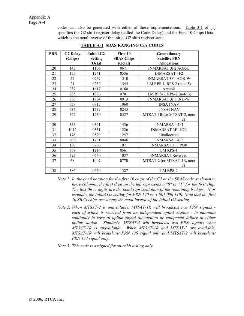
AAppppeennddiixx AA PPaaggee AA--44
©© 22000066,, RRTTCCAA IInncc..
codes can also be generated with either of these implementations. Table 3-1 of [1] specifies the G2 shift register delay (called the Code Delay) and the First 10 Chips Octal, which is the octal inverse of the initial G2 shift register state.
TABLE A-1 SBAS RANGING C/A CODES
PRN G2 Delay (Chips)
Initial G2 Setting (Octal)
First 10 SBAS Chips
(Octal)
Geostationary Satellite PRN Allocations
120 145 1106 0671 INMARSAT 3F2 AOR-E 121 175 1241 0536 INMARSAT 4F2 122 52 0267 1510 INMARSAT 3F4 AOR-W 123 21 0232 1545 LM RPS-1, RPS-2 (note 3) 124 237 1617 0160 Artemis 125 235 1076 0701 LM RPS-1, RPS-2 (note 3) 126 886 1764 0013 INMARSAT 3F5 IND-W 127 657 0717 1060 INSATNAV 128 634 1532 0245 INSATNAV 129 762 1250 0527 MTSAT-1R (or MTSAT-2, note
2) 130 355 0341 1436 INMARSAT 4F1 131 1012 0551 1226 INMARSAT 3F1 IOR 132 176 0520 1257 Unallocated 133 603 1731 0046 INMARSAT 4F3 134 130 0706 1071 INMARSAT 3F3 POR 135 359 1216 0561 LM RPS-1 136 595 0740 1037 INMARSAT Reserved 137 68 1007 0770 MTSAT-2 (or MTSAT-1R, note
2) 138 386 0450 1327 LM RPS-2
Note 1: In the octal notation for the first 10 chips of the G2 or the SBAS code as shown in these columns, the first digit on the left represents a "0" or "1" for the first chip. The last three digits are the octal representation of the remaining 9 chips. (For example, the initial G2 setting for PRN 120 is: 1 001 000 110). Note that the first 10 SBAS chips are simply the octal inverse of the initial G2 setting.
Note 2: When MTSAT-2 is unavailable, MTSAT-1R will broadcast two PRN signals - each of which is received from an independent uplink station - to maintain continuity in case of uplink signal attenuation or equipment failure at either uplink station. Similarly, MTSAT-2 will broadcast two PRN signals when MTSAT-1R is unavailable. When MTSAT-1R and MTSAT-2 are available, MTSAT-1R will broadcast PRN 129 signal only and MTSAT-2 will broadcast PRN 137 signal only.
Note 3: This code is assigned for on-orbit testing only.

AAppppeennddiixx AA PPaaggee AA--55
©© 22000066,, RRTTCCAA,, IInncc..
SET TOALL 1'S
CODECLOCK
G1 CODER
G2 CODER
G1(t)
INITIALIZE
COUNTER
GATESTART
G2 DELAY
1 2 3 4 5 6 7 8 9 10
1 2 3 4 5 6 7 8 9 10 G2(t+n T )i c
G1(t)G2(t+n T )i c
FIGURE A-1 SBAS/GPS CODER IMPLEMENTED WITH SINGLE G2 OUTPUT PLUS
PROGRAMMABLE G2 DELAY
SET TOALL 1'S
CODECLOCK
G1 CODER
G2 CODER
G1(t)
G2(t+n T )
G1(t)G2(t+n T )
INITIALIZE
INITIAL G2 STATE
G2 STATE
1 2 3 4 5 6 7 8 9 10
+
1 2 3 4 5 6 7 8 9 10
+
i c
i c+
•• • • • •
FIGURE A-2 SBAS/GPS CODER IMPLEMENTED WITH A PROGRAMMABLE INITIAL G2
STATE
A.4 SBAS Signal Data Contents and Formats
A.4.1 Introduction
A given SBAS GEO will broadcast either coarse integrity data or both such data and wide area corrections. The coarse integrity data will include use/don’t-use information on all satellites in view of the applicable region, including the GEOs. Correction data include estimates of the error after application of the corrections.

AAppppeennddiixx AA PPaaggee AA--66
©© 22000066,, RRTTCCAA IInncc..
The parameter, σ2UDRE, is the variance of a Normal distribution associated with the user
differential range error for a satellite after application of fast corrections and long term corrections, excluding atmospheric effects. The parameter, σ2
GIVE, is the variance of a Normal distribution associated with the residual ionospheric vertical error at an IGP for an L1 signal.
A.4.2 Principles and Assumptions
Certain principles and assumptions are used as a guide in the definition of the format and data contents. First of all, the signal data bandwidth should have the necessary capacity to broadcast both integrity and corrections data simultaneously for the entire service region. Next, information common to both the integrity and corrections data should not be repeated in order to minimize the required data rate. Note that the delivered level of accuracy can be controlled by adjusting the accuracy of the corrections, but integrity is always provided.
A.4.2.1 Data Rate
The baseline data rate will be 250 bits per second. The data will always be rate 1/2 convolutional encoded with a Forward Error Correction (FEC) code. Therefore, the symbol rate that the SBAS receiver must process is 500 symbols per second (sps). The convolutional coding will be constraint length 7 as standard for Viterbi decoding, with a convolutional encoder logic arrangement as illustrated in Figure A-3. The G1 symbol is selected on the output as the first half of a 4 millisecond data bit period. (If soft decision decoding is used, the bit error rate (BER) performance gain of this combination of coding and decoding is 5 dB over uncoded operation.) As an example, the algorithms for the implementation of this decoding are described in George C. Clark and J. Bibb Cain, Error Correction Coding for Digital Communications, Plenum Press, New York, 1981 [2].
A.4.2.2 Timing
SBAS Network Time (SNT) is defined as that which is maintained, after corrections, to GPS system time, within the overall SBAS performance requirements. Data blocks will maintain synchronism with the GPS data blocks to within the same performance requirements. It is noted that, when using corrections, the user's solution for time will be with respect to the SBAS Network Time, and not with respect to GPS system time. If corrections are not applied, then the solution will be with respect to a composite GPS/SBAS Network Time, and the resulting accuracy will be affected by the difference between the two. SBAS Network Time will be within 50 nanoseconds of GPS system time. Estimates of the time difference between SBAS Network Time and Universal Coordinated Time (UTC) and GLONASS system time will be provided in an appropriate data message (Type 12).
G1 (171 OCTAL)
G2 (133 OCTAL)
DATA INPUT(250 BPS)
SYMBOLCLOCK
OUTPUT SYMBOLS (500 SPS)
(ALTERNATING G1/G2)
FIGURE A-3 CONVOLUTIONAL ENCODING
AAppppeennddiixx AA PPaaggee AA--77
©© 22000066,, RRTTCCAA,, IInncc..
The leading edge of the first symbol that depends on the first bit of the current message is broadcast from the SBAS satellite synchronous with a one second epoch of SNT.
A.4.2.3 Error Corrections
There will be two types of correction data — fast and long-term. The fast corrections are intended to correct for rapidly changing errors such as GNSS clock errors, while the long-term corrections are for slower changing errors due to the atmospheric and long term satellite clock and ephemeris errors. The fast corrections are common to all users and will be broadcast as such.
For the slower corrections, the users are provided with ephemeris and clock error estimates for each satellite in view (Message Types 24 and 25). Although long term satellite clock errors are common to all regions, they are slow-varying and Issue of Data (IOD) dependent. Therefore, they are best accommodated as part of the slower corrections. Separately, users are provided with a wide-area ionospheric delay model and sufficient real-time data to evaluate the ionospheric delays for each satellite using that model (Message Types 18 and 26). Specific procedures for using the corrections are given with the definition of the relevant messages.
SBAS will ensure that discontinuities in the satellite position after application of long term corrections are minimized so that the range error is typically compensated by the σ2
UDRE when range-rate corrections are calculated (see Section A.4.5).
In addition, the degradation of accuracy (see Section A.4.5) is modeled to account for the possibility that any messages are missed by the user.
A.4.2.4 Tropospheric Model
Because tropospheric refraction is a local phenomenon, all users will compute their own tropospheric delay correction.
The tropospheric delay correction [TCi] for satellite i takes the form:
( ) )( iwethydi ElmddTC ⋅+−= (A- 2)
where [dhyd , dwet (m)] are the estimated range delays for a satellite at 90° elevation angle, caused by atmospheric gases in hydrostatic equilibrium and by water vapor respectively, and [m(Eli) (dimensionless)] is a mapping function to scale the delays to the actual satellite elevation angle [Eli].
[dhyd, dwet] are calculated from the receiver’s height and estimates of five meteorological parameters: pressure [P (mbar)], temperature [T (K)], water vapor pressure [e (mbar)], temperature lapse rate [β (K/m)] and water vapor “lapse rate” [λ (dimensionless)].
Values of each of the five meteorological parameters, applicable to the receiver latitude [φ] and day-of-year [D] (starting with 1 January), are computed from the average and seasonal variation values given in Table A-2. Each parameter value [ξ] is computed as:
ξ φ ξ φ ξ φπ
( , ) ( ) ( ) cos( )
.minD
D D= − ⋅
−⎛⎝⎜
⎞⎠⎟0
236525
Δ (A- 3)
where Dmin=28 for northern latitudes, Dmin=211 for southern latitudes, and ξ0, Δξ are the average and seasonal variation values for the particular parameter at the receiver’s latitude. For latitudes ⏐φ⏐ ≤ 15° and ⏐φ⏐ ≥ 75°, values for ξ0 and Δξ are taken directly from Table A-2. For latitudes in the range 15° < ⏐φ⏐ < 75°, values for ξ0 and Δξ at the

AAppppeennddiixx AA PPaaggee AA--88
©© 22000066,, RRTTCCAA IInncc..
receiver’s latitude are each pre-calculated by linear interpolation between values for the two closest latitudes [φi, φi+1] in Table A-2:
[ ]ξ φ ξ φ ξ φ ξ φφ φ
φ φ0 0 0 1 01
( ) ( ) ( ) ( )( )
( )= + − ⋅
−−+
+i i i
i
i i (A- 4)
[ ]Δ Δ Δ Δξ φ ξ φ ξ φ ξ φφ φ
φ φ( ) ( ) ( ) ( )
( )( )
= + − ⋅−−+
+i i i
i
i i1
1 (A- 5)
TABLE A-2 METEOROLOGICAL PARAMETERS FOR TROPOSPHERIC DELAY
Average Latitude
(°) P0
(mbar) T0 (K)
e0 (mbar)
β0 (K/m)
λ0
15° or less 1013.25 299.65 26.31 6.30e-3 2.77
30 1017.25 294.15 21.79 6.05e-3 3.15
45 1015.75 283.15 11.66 5.58e-3 2.57
60 1011.75 272.15 6.78 5.39e-3 1.81
75° or greater 1013.00 263.65 4.11 4.53e-3 1.55
Seasonal Variation
Latitude (°)
ΔP (mbar)
ΔT (K)
Δe (mbar)
Δβ (K/m)
Δλ
15° or less 0.00 0.00 0.00 0.00e-3 0.00
30 -3.75 7.00 8.85 0.25e-3 0.33
45 -2.25 11.00 7.24 0.32e-3 0.46
60 -1.75 15.00 5.36 0.81e-3 0.74
75° or greater -0.50 14.50 3.39 0.62e-3 0.30
Zero-altitude zenith delay terms [zhyd, zwet (m)] are calculated as:
zk R Pghyd
d
m=
−10 61 (A- 6)
zk R
g ReTwet
d
m d=
+ −⋅
−101
62
( )λ β (A- 7)
where k1 = 77.604 K/mbar, k2 = 382000 K2/mbar, Rd = 287.054 J/(kg⋅K), and gm = 9.784 m/s2.
[dhyd, dwet] are calculated as:
AAppppeennddiixx AA PPaaggee AA--99
©© 22000066,, RRTTCCAA,, IInncc..
dHT
zhyd
gR
hydd
= −⎛⎝⎜
⎞⎠⎟
⋅1β β
(A- 8)
wet
Rg
wet zTHd d
⋅⎟⎠⎞
⎜⎝⎛ −=
−+ 1)1(
1β
λ
β (A- 9)
where g = 9.80665 m/s2 and the receiver’s height, [H] is expressed in units of meters above mean-sea-level.
The tropospheric correction mapping function for satellite elevation, [m(Eli)], is calculated in one of two ways:
A simplified calculation of [m] is valid for satellite elevation angles [Eli] of not less than 4°:
m ElEl
ii
( ).
. sin ( )=
+
10010 002001 2
(A- 10a)
An alternate calculation of [m] is valid for satellite elevation angles [Eli] of not less than 2°:
⎟⎟
⎠
⎞
⎜⎜
⎝
⎛⎟⎟⎠
⎞⎜⎜⎝
⎛⎥⎦
⎤⎢⎣
⎡−°
⋅+⋅⎟⎟
⎠
⎞
⎜⎜
⎝
⎛
+=
2
2 )4(0
015.01)(sin002001.0
001.1)(ii
i ElMAX
ElElm [A-10b]
A.4.2.5 Residual Tropospheric Error
The residual error parameter σi,tropo for the tropospheric delay correction for satellite i, based on the model of A.4.2.4 above, is:
( ))(, Elm iTVEtropoi ⋅= σσ (units are in meters) (A- 11)
where the tropospheric vertical error is σTVE = 0.12 meters.
A.4.2.6 PRN Masks
Masks will be used to designate which PRN belongs to which correction slot. For example, GPS satellites are assigned the first PRNs (1-37). These masks improve the efficiency of the broadcast by preventing the continual inclusion of PRNs for fast corrections and σ2
UDRE parameters. In the case of GLONASS satellites, the PRN indicates the GLONASS constellation slot number.
A.4.2.7 Number of Satellites
The SBAS will provide data for a maximum of 51 satellites.
A.4.2.8 Issue of Data
The fast correction data for each satellite supported will be accompanied by a Fast Correction Issue of Data (IODF) to prevent erroneous application of σ2
UDRE. The long

AAppppeennddiixx AA PPaaggee AA--1100
©© 22000066,, RRTTCCAA IInncc..
term satellite correction data for each satellite supported will be accompanied by Issue of Data (IOD) information to prevent erroneous application of correction data. The SBAS issue of long term satellite correction data will be identical to the GPS IOD Ephemeris defined in [1] for the GPS satellites, and identical to a similar term for the GLONASS satellites when defined. Various other SBAS issues of data defined below will also be applied to prevent erroneous use of the PRN and Ionospheric Grid Point (IGP) masks.
A.4.2.9 Acquisition Information
Preambles will be provided in the messages for data acquisition.
A.4.3 Format Summary
24-BITSPARITY212-BIT DATA FIELD
8-BIT PREAMBLE OF 24 BITS TOTAL IN 3 CONTIGUOUS BLOCKS6-BIT MESSAGE TYPE IDENTIFIER (0 - 63)
250 BITS - 1 SECOND
DIRECTION OF DATA FLOW FROM SATELLITE; MOST SIGNIFICANT BIT (MSB) TRANSMITTED FIRST
FIGURE A-4 DATA BLOCK FORMAT
A.4.3.1 Block Format
The block format for the 250 bits per second data rate is shown in Figure A-4. A block is defined as the complete 250 bits, while a message is defined as the 212 bit data field. The start of the first 8-bit part of every other 24-bit distributed preamble will be synchronous with the 6-second GPS subframe epoch to within the overall SBAS performance requirements. The block transmission time will be one second.
The 8-bit preamble starts at bit 0 of the 250-bit block followed by the 6-bit Message Type at bit 8. The data field then starts at bit 14, followed by the parity field that starts at bit 226. The sequence of the data words is shown in the figures describing the message formats while the number of bits per data word is given in the tables describing message contents. The order of the words in those tables is not related to the sequence of the words in the message.
A.4.3.2 Block Length and Content
Blocks will be 250 bits long (one second), consisting of an 8-bit part of a distributed preamble, a 6-bit message type, a 212-bit message and 24-bits of Cyclic Redundancy Check (CRC) parity. This block length is consistent with the required time-to-alert, and it provides an efficient parity-to-data ratio. Any message type can occur in any given one-second interval.
A.4.3.3 Parity
Twenty-four bits of CRC parity will provide protection against burst as well as random errors with a probability of undetected error ≤ 2-24 = 5.96×10⁻⁸ for all channel bit error probabilities ≤ 0.5. The CRC word is calculated in the forward direction on the entire bit-oriented message, including the block header containing the preamble and message type identifier, and using a seed of 0. The sequence of 24 bits (p1,p2,...,p24) is generated from

AAppppeennddiixx AA PPaaggee AA--1111
©© 22000066,, RRTTCCAA,, IInncc..
the sequence of information bits (m1,m2,...,m226). This is done by means of a code that is generated by the polynomial
( )g X g Xii
i=
=∑
0
24 (A- 12)
where g ii = =
=
1 0 1 3 4 5 6 7 10 11 14 17 18 23 240
forotherwise
, , , , , , , , , , , , ,
This code is called CRC-24Q (Q for Qualcomm Corporation) [4]. The generator polynomial of this code is in the following form (using binary polynomial algebra):
( ) ( ) ( )g X X p X= +1 (A- 13)
where p(X) is the primitive and irreducible polynomial
( )p X X X X X
X X X X X X
= + + +
+ + + + + + +
23 17 13 12
11 9 8 7 5 3 1 (A- 14)
When, by the application of binary polynomial algebra, the above g(X) is divided into m(X)X24, where the information sequence m(X) is expressed as
( )m X m m X m X m Xk k kk= + + + ⋅⋅⋅ +− −
−1 2
21
1 (A- 15)
the result is a quotient and a remainder R(X) of degree < 24. The bit sequence formed by this remainder represents the parity check sequence. Parity bit pi, for any i from 1 to 24, is the coefficient of X24-i in R(X).
This code has the following characteristics [5, 6, 7, 8]:
a) It detects all single bit errors per code word.
b) It detects all double bit error combinations in a codeword because the generator polynomial g(X) has a factor of at least three terms.
c) It detects any odd number of errors because g(X) contains a factor 1+X.
d) It detects any burst error for which the length of the burst is ≤ 24 bits.
e) It detects most large error bursts with length greater than the parity length r = 24 bits. The fraction of error bursts of length b > 24 that are undetected
1) 2-24 = 5.96 × 10⁻⁸, if b > 25 bits.
2) 2-23 = 1.19 × 10⁻⁷, if b = 25 bits.
The encoding and decoding procedures can be found in [8] (for example). An example message (a Message Type 2) with passed parity is given as follows:
Preamble, Message ID, IODF, IODP: Binary: 11, followed by Hex: 1824
13 corrections: Hex: 003|c00|3c2|200|03f|4bc|000|3c0|03c|003|c00|03f|fd8 13 UDREIs: Hex: 0003cb240003f Parity: Hex: a0f7dd

AAppppeennddiixx AA PPaaggee AA--1122
©© 22000066,, RRTTCCAA IInncc..
A.4.3.4 Preamble
The distributed preamble will be a 24-bit unique word, distributed over three successive blocks. These three 8-bit words will be made up of the sequence of bits — 01010011 10011010 11000110. The start of every other 24-bit preamble will be synchronous with a 6-second GPS subframe epoch.
With respect to the convolutional encoding, the preamble is within the decoded bit stream. It will be encoded just like all of the other bits. It is a place marker, and cannot be used for acquisition or encoded bit synchronization prior to convolutional decoding. The users’ convolutional decoding algorithm must provide synchronization to the data bits.
A.4.4 Messages and Relationships Between Message Types
Table A- 3 presents the set of message types. Unless otherwise stated, data is represented in unsigned binary format.
To associate data in different message types, a number of issue of data (IOD) parameters are used. These parameters include:
IODk (GPS IOD Clock - IODCk, GPS IOD Ephemeris - IODEk, GLONASS Data - IODGk): Indicates GPS clock and ephemeris issue of data or GLONASS clock and ephemeris issue of data, where k = satellite
IOD PRN Mask (IODP): Identifies the current PRN mask
IOD Fast Correctionsj (IODFj): Identifies the current fast corrections, where j = fast corrections Message Type (Types 2 - 5)
IOD Ionospheric Grid Point Mask (IODI): Identifies the current Ionospheric Grid Point mask
IOD Service Message (IODS): Identifies the current Service Message(s) Type 27
The relationship among the messages is shown in Figure A-5. The IOD's (including GPS IODC and IODE and GLONASS equivalent term when defined) are specific to each satellite, and are updated separately. Broadcast data will only be referenced to one PRN mask, one Ionospheric Grid Point mask, and one active set of Service Messages at a time. Since fast corrections are always provided in different message types including blocks of 13 satellites, a different IODF is used for each block. Note that the SBAS will ensure that the long-term corrections are sent several times when modified and the magnitude of the change will be small so that an issue of data is not necessary to connect Type 24 or 25 and Type 2 - 5 messages. In addition, the SBAS will update long term corrections at a rate high enough to accommodate these small changes, while also accommodating missed messages by the users.

AAppppeennddiixx AA PPaaggee AA--1133
©© 22000066,, RRTTCCAA,, IInncc..
TABLE A-3 MESSAGE TYPES
Type Contents Section No. 0 Don't use for safety applications (for SBAS testing) A.4.4.1 1 PRN Mask assignments, set up to 51 of 210 bits A.4.4.2
2 to 5 Fast corrections A.4.4.3 6 Integrity information A.4.4.4 7 Fast correction degradation factor A.4.4.5 8 Reserved for future messages — 9 GEO navigation message (X, Y, Z, time, etc.) A.4.4.11
10 Degradation Parameters A.4.4.6 11 Reserved for future messages — 12 SBAS Network Time/UTC offset parameters A.4.4.15
13 to 16 Reserved for future messages — 17 GEO satellite almanacs A.4.4.12 18 Ionospheric grid point masks A.4.4.9
19 to 23 Reserved for future messages — 24 Mixed fast corrections/long term satellite error corrections A.4.4.8 25 Long term satellite error corrections A.4.4.7 26 Ionospheric delay corrections A.4.4.10 27 SBAS Service Message A.4.4.13 28 Clock-Ephemeris Covariance Matrix Message A.4.4.16
29 to 61 Reserved for future messages — 62 Internal Test Message — 63 Null Message A.4.4.14
GPS
Ephemeris
GPS Clock
PRN Mask
(1)
Long-term Corrections
(25)
Fast Corrections
(2 - 5, 24)
Integrity Information
(6)
IODEk
IODC k
IOD k
IODP
No IOD:repeat msg, small changes
IODF j
IODP
Ionospheric Mask (18)
Ionospheric Corrections
(26)
IODP
Service Message
27
IODS
Acceleration Information
(7)
GLONASS DATA
IODGk
C-E Cov Matrix
(28)
IODP
GEO Navig
(9)
IODI
FIGURE A-5 INTERRELATIONSHIPS OF MESSAGES

AAppppeennddiixx AA PPaaggee AA--1144
©© 22000066,, RRTTCCAA IInncc..
A.4.4.1 Do Not Use for Safety Applications Message Type 0
The first message type, Message Type 0, will be used primarily during system testing. The receipt of a Message Type 0 will result in the cessation of the use of any ranging data and all message types 1-7, 9-10, 18, 24-28 obtained from that SBAS signal (PRN code). Other message types may be retained, such as message type 17, for potential performance enhancements. In addition, that SBAS signal (PRN code) will be deselected for at least one minute.
While testing, WAAS will broadcast the contents of a type 2 message in each type 0 message. In the rare event that a Type 0 message is used to indicate a problem with the signal or broadcast data, it will not contain the Type 2 contents but will be empty (all 0’s). For users who do not require integrity (equipment under test or equipment used for non-safety applications), the message type 0 that is not empty may be used for ranging and corrections. Other SBAS service providers may broadcast both Type 0 and Type 2 messages during testing.
A.4.4.2 PRN Mask Assignments Message Type 1
The PRN Mask is given in Message Type 1. It consists of 210 ordered slots, each of which indicates if data is provided for the corresponding satellite as defined in Table A-4. For example, a one in the fifth slot indicates data is being provided for GPS PRN 5 and the 40th slot indicates GLONASS Slot Number 3. The mask will have up to 51 bits set in the 210 slots. Note that the satellites for which corrections are provided must be ordered from 1 to a maximum of 51, in order to decode Message Types 2 - 5, 6, 7, 24, 25 and 28. Data in Message Types 2 - 5, 6, 7 and the fast corrections part of Message Type 24 are provided sequentially. Long term corrections in Message Types 24 and 25 and clock-ephemeris covariance matrix data in Message Type 28 may or may not be provided sequentially, since the PRN Mask number is specified for each correction. The mask will be followed by a 2-bit issue of data PRN (IODP) to indicate the mask’s applicability to the corrections and accuracies contained in messages to which the mask applies. An example of a PRN mask is shown in Figure A-6.
TABLE A-4 PRN MASK ASSIGNMENTS
PRN Slot
Assignment
1 to 37 GPS/GPS Reserved PRN 38 to 61 GLONASS Slot Number plus 37
62 to 119 Future GNSS 120 to 138 GEO/SBAS PRN 139 to 210 Future GNSS/GEO/SBAS/Pseudolites

AAppppeennddiixx AA PPaaggee AA--1155
©© 22000066,, RRTTCCAA,, IInncc..
Bit number (in order of transmission)
1
2
3
4
5
6
7
38
209
210
PRN Mask
0
0
1
0
1
0
1
10 ‘0’s 20 ‘1’s
1
0
0
PRN Code Number
PRN
3
PRN
5
PRN
7
GLONASS
Slot 1
PRN Mask
Value PRN Mask Number
1
2
3
24
FIGURE A-6 EXAMPLE PRN MASK
A.4.4.2.1 PRN Mask Transition
The transition of the PRN Mask to a new one (which will be infrequent) will be controlled with the 2-bit IODP, which will sequence to a number between 0 and 3. The same IODP will appear in the applicable Message Types 2 - 5, 7, 24, 25 and 28. This transition would probably only occur when a new satellite is launched or when a satellite fails and is taken out of service permanently. In the latter case, there would be no hurry to do so, unless the slot is needed for another satellite. It could simply be flagged as a don't use satellite. A degraded satellite may be flagged as a don’t use satellite temporarily.
If the IODP of the mask does not agree with the IODP in the applicable Message Types 2 - 5, 7, 24, 25 and 28, the user will not use the applicable message until a mask with the matching IODPs agree. The change of IODP in the PRN mask message will always occur before the IODP changes in all other messages. During a change-over of the IODP in the PRN mask, the user equipment continues to use the old mask to decode messages until a corrections message using the new mask is received, and stores the new mask so that there are no interruptions to service when the new mask becomes effective. As the new mask starts to be used, the user will use some data which correlated with the old mask and some data that correlated with the new mask. However, if the IODP changes in those message types before receipt of the new PRN mask, these message types cannot be used until receipt of the new mask.
A.4.4.3 Fast Corrections Message Types 2 - 5
The fast corrections messages format is illustrated in Figure A-7. Message Type 2 contains the data sets for the first 13 satellites designated in the PRN mask. Message Type 3 contains the data sets for satellites 14 - 26 designated in the PRN mask, etc., through Message Type 5, which contains the data sets for satellites 40 through 51 designated in the PRN mask. The last data set of Message Type 5 is not used due to the constraint that corrections can only be provided for 51 satellites (see Message Type 6). A fast corrections message type will only be sent if the number of satellites designated in the PRN mask requires it: e.g., Message Type 5 will only be broadcast if 40 or more satellites are designated. Message Types 2 - 5 and 24 contain a 2-bit IODFj. The IODFj, where j is the fast corrections Message Type (2 – 5, 24), is used to associate the σ2
UDRE contained in a Message Type 6. When there is no alert condition for any of the satellites in a message type 2-5 and 24, the range of each IODFj counter is only 0 to 2. When an alert occurs in one or more of the satellites in a message type 2-5 or 24, IODFj = 3. An

AAppppeennddiixx AA PPaaggee AA--1166
©© 22000066,, RRTTCCAA IInncc..
IODFj = 3 indicates that the σ2UDRE information in a Message Type 2-6 and 24 applies to
all active data in the corresponding message type (j = 2 - 5), rather than a particular set of fast corrections. If there are 6 or fewer satellites in a block, they may be placed in a mixed corrections message, Type 24. The last half of Message Type 24 is reserved for long term corrections. The fast data set for each satellite consists of 16 bits; a 12-bit fast correction and a 4-bit UDRE Indicator (UDREI). The UDREI is described in Section A.4.4.4. Each message also contains a 2-bit IODP indicating the associated PRN mask. Refer to Section A.4.4.2 for the application of IODP.
Note: Since SBAS is required to provide integrity protection for all active corrections, when a Message Type 2 – 5 with IODFj < 3 is received following the reception of a message of the same type with IODFj = 3, the receiver can continue to apply the UDRE in the message with IODFj = 3 until the message ceases to be active, or, alternatively, it can immediately apply the UDRE in the more recent message with IODFj < 3.
The 12-bit fast correction (PRCf) has a 0.125 meter resolution, for a valid range of -256.000 m to +255.875 m. If the range is exceeded, a don't use indication will be inserted into the UDREI field. The user should ignore extra data sets not represented in the PRN mask. The time of applicability (tof) of the PRCf is the start of the epoch of the SNT second that is coincident with the transmission at the GEO satellite of the first bit of the message block.
24-BITSPARITY
8-BIT PREAMBLE OF 24 BITS TOTAL IN 3 CONTIGUOUS BLOCKS6-BIT MESSAGE TYPE IDENTIFIER (= 2, 3, 4 & 5)
250 BITS - 1 SECOND
IODF (2 BITS)13 12-BIT FAST CORRECTIONS
DIRECTION OF DATA FLOW FROM SATELLITE; MOST SIGNIFICANT BIT (MSB) TRANSMITTED FIRST
IODP (2 BITS)
PRCf
UDREIREPEAT FOR 12 MORE SATELLITESREPEAT FOR 12MORE SATELLITES
13 4-BIT UDREIs
FIGURE A-7 TYPES 2 - 5 FAST CORRECTIONS MESSAGES FORMAT
Range-rate corrections (RRC) of the fast corrections will not be broadcast. The user will compute these rates-of-change by differencing fast corrections (regardless of IODFj) [9]. The total fast correction for a given satellite will be applied as
( ) ( ) ( ) ( )PR t PR t PRC t RRC t t tcorrected measured of of of= + + × −( ) (A- 16)
If aii ≠ 0, the RRC is computed by the user differencing fast corrections (Refer to Section A.4.4.5):
RRC tPRC PRC
tofcurrent previous( ) =
−
Δ (A- 17)
where:
PRCcurrent = the most recent fast correction (same as PRC(tof) )
PRCprevious = a previous fast correction
Δt = (tof - tof,previous)
tof = time of applicability of the most recent fast correction
tof,previous = time of applicability of the PRCprevious

AAppppeennddiixx AA PPaaggee AA--1177
©© 22000066,, RRTTCCAA,, IInncc..
If aii = 0, the RRC is equal to zero (0).
The most recent fast correction received (PRCcurrent) must be used when computing the RRC. The range rate correction must time out if Δt > Ifc,j ( the shortest fast correction time-out interval for any satellite included in the associated fast corrections message (j=2,..,5) or fast corrections in Message Type 24). In addition, the RRC must time-out if (t- tof -1) > 8Δt.
In selecting the previous fast correction to be used in determining the RRC, the user should select the fast correction which minimizes the degradation due to fast corrections and range rate corrections (A.4.5.1.2.2). During an alert condition, it is likely that several corrections will be sent over a short period of time. In this case, in order to minimize the noise effect on RRC, the previous fast correction closest to Ifc/2 seconds prior to the current fast correction should be used.
Anytime a “don’t use” or "not monitored" indication is received, and is then followed by a valid correction, the calculation of the RRC must be reinitialized. During re-initialization, the RRC will not be used. The computation of RRC is required even in the case of an identical IODFj.
The high degree of resolution of these fast corrections should not be confused with correction accuracy. The actual accuracy provided will be indicated by the σ2
UDRE data.
A.4.4.4 Integrity Information Message Type 6
The integrity information message is shown in Figure A-8. Each message includes an IODFj for each fast corrections Message Type (2 - 5). The σ2
UDRE information for each block of satellites applies to the fast corrections with the corresponding IODFj. For example, if IODF3=1, then the σ2
UDRE’s for satellites 14 - 26 apply to the corrections provided in a previously broadcast Type 3 message that had the IODF = 1. An IODFj = 3 indicates that the σ2
UDRE's apply to all active data from the corresponding message type (j = 2 - 5). Since all satellites in the PRN mask are mapped to Message Types 2-5, it is not necessary to explicitly include an IODF for Message Type 24 in Message Type 6. The information transmitted in Message Type 6 should be applied to the applicable satellites in Message Type 24 (e.g., if the Type 24 message contains correction data for satellites 27 to 32, then IODF4 is associated with that Type 24 message). The remaining 204 bits are divided into 51 slots of 4 bit UDREIs, one for each satellite in the mask. This message format is described in Table A-5. Message Type 6 allows the fast corrections of Message Type 2-5 and 24 to be updated infrequently, commensurate with the dynamics of the satellite clock errors. If all fast corrections are being updated at a six second rate, Message Type 6 may not be required since the UDREIs are also included in Message Types 2-5 and 24; however, under certain timing conditions a Type 6 will be needed even if only one satellite has an alert. Message Type 6 can also be used to indicate an alert condition on multiple satellites.
24-BITSPARITY
8-BIT PREAMBLE OF 24 BITS TOTAL IN 3 CONTIGUOUS BLOCKS6-BIT MESSAGE TYPE IDENTIFIER (= 6)
250 BITS - 1 SECOND
DIRECTION OF DATA FLOW FROM SATELLITE; MOST SIGNIFICANT BIT (MSB) TRANSMITTED FIRST
IODF2, IODF3, IODF4 & IODF5 (2 BITS EACH)
51 4-BIT UDREIs
FIGURE A-8 TYPE 6 INTEGRITY MESSAGE FORMAT

AAppppeennddiixx AA PPaaggee AA--1188
©© 22000066,, RRTTCCAA IInncc..
The 4-bit UDREIs are used for the evaluation of the σ2UDRE’s, indicating the accuracy of
combined fast and long-term error corrections, not including the accuracy of the ionospheric delay corrections (indicated in σ2
GIVE’s), which are computed from the indicators that are provided separately in Message Type 26. The ephemeris accuracy component is an “equivalent” range accuracy, rather than accuracy of each of the Earth-Centered-Earth-Fixed (ECEF) components. Evaluation of the model variance (σ2
UDRE) versus indicator value is given in Table A-6. The σ2
UDRE (in Type 2 – 6, 24) applies at a particular time and degrades as defined in Section A.4.4.5.
TABLE A-5 TYPE 6 INTEGRITY MESSAGE CONTENT
Parameter No. of Bits
Scale Factor (LSB)
Effective Range
Units
IODF2 2 1 0 to 3 unitless IODF3 2 1 0 to 3 unitless IODF4 2 1 0 to 3 unitless IODF5 2 1 0 to 3 unitless
For each of 51 satellites — — — — UDREI 4 (see Table A-6) (see Table A-6) unitless
TABLE A-6 EVALUATION OF UDREIi
UDREIi UDREi Meters σ2i,UDRE
Meters2 0 0.75 0.0520 1 1.0 0.0924 2 1.25 0.1444 3 1.75 0.2830 4 2.25 0.4678 5 3.0 0.8315 6 3.75 1.2992 7 4.5 1.8709 8 5.25 2.5465 9 6.0 3.3260
10 7.5 5.1968 11 15.0 20.7870 12 50.0 230.9661 13 150.0 2078.695 14 Not Monitored Not Monitored 15 Do Not Use Do Not Use
A.4.4.5 Fast Correction Degradation Factor Message Type 7
The σ2UDRE broadcast in Types 2 - 6 and 24 applies at a time prior to or at the time of
applicability of the associated corrections. The Type 7 message specifies the applicable IODP, system latency time (tlat) and the fast correction degradation factor indicator (aii) for computing the degradation of fast and long term corrections as described in Section A.4.5.1.

AAppppeennddiixx AA PPaaggee AA--1199
©© 22000066,, RRTTCCAA,, IInncc..
The Type 7 message contents are described in Table A-7 and its format is shown in Figure A-9. Table A-8 provides the evaluation of the fast corrections degradation factor given the degradation factor indicator, aii. Table A-8 also shows the user time-out interval for fast corrections. The time-out interval for fast corrections is reckoned from the end of reception of the fast correction message.
TABLE A-7 TYPE 7 FAST CORRECTION DEGRADATION FACTOR MESSAGE CONTENTS
Parameter No. of Bits
Scale Factor (LSB)
Effective Range
Units
System latency (tlat) 4 1 0 to 15 seconds IODP 2 1 0 to 3 unitless Spare 2 — — —
For each of 51 satellites 204 — — — Degradation factor indicator (aii) 4 1 0 - 15 —
24-BITSPARITY
8-BIT PREAMBLE OF 24 BITS TOTAL IN 3 CONTIGUOUS BLOCKS6-BIT MESSAGE TYPE IDENTIFIER (= 7)
250 BITS - 1 SECONDDIRECTION OF DATA FLOW FROM SATELLITE; MOST SIGNIFICANT BIT (MSB) TRANSMITTED FIRST
IODP (2 BITS)
51 4-BIT UDRE degradation factor indicators
tl (4 BITS)SPARE (2 BITS)
FIGURE A-9 TYPE 7 FAST CORRECTION DEGRADATION FACTOR MESSAGE FORMAT
TABLE A-8 FAST CORRECTIONS DEGRADATION FACTOR AND USER TIME-OUT
INTERVAL EVALUATION
Fast Corrections Degradation
Factor Indicator
(aii)
Fast Corrections Degradation Factor (ai)-
m/s2
User Time-Out Interval for fast corrections - seconds En Route through LNAV
Approach (Ifc)
User Time-Out Interval
for fast corrections - seconds
LNAV/VNAV, LPV, LP Approach
(Ifc)
Maximum Fast
Correction Update Interval
(seconds)
0 0.00000 180 120 60 1 0.00005 180 120 60 2 0.00009 153 102 51 3 0.00012 135 90 45 4 0.00015 135 90 45 5 0.00020 117 78 39 6 0.00030 99 66 33 7 0.00045 81 54 27 8 0.00060 63 42 21 9 0.00090 45 30 15
10 0.00150 45 30 15 11 0.00210 27 18 9 12 0.00270 27 18 9 13 0.00330 27 18 9 14 0.00460 18 12 6 15 0.00580 18 12 6

AAppppeennddiixx AA PPaaggee AA--2200
©© 22000066,, RRTTCCAA IInncc..
A.4.4.6 Degradation Factors Message Type 10
The degradation factors are described in Table A-9. These factors are used as described in Sections A.4.4.16 and A.4.5.
TABLE A-9 TYPE 10 DEGRADATION factors
Parameter No. of Bits
Scale Factor (LSB)
Effective Range
Units
Brrc 10 0.002 0 to 2.046 m Cltc_lsb 10 0.002 0 to 2.046 m Cltc_v1 10 0.00005 0 to 0.05115 m/s Iltc_v1 9 1 0 to 511 s Cltc_v0 10 0.002 0 to 2.046 m Iltc_v0 9 1 0 to 511 s
Cgeo_lsb 10 0.0005 0 to 0.5115 m Cgeo_v 10 0.00005 0 to 0.05115 m/s Igeo 9 1 0 to 511 s Cer 6 0.5 0 to 31.5 m
Ciono_step 10 0.001 0 to 1.023 m Iiono 9 1 0 to 511 s
Ciono ramp 10 0.000005 0 to 0.005115 m/s RSSUDRE 1 — 0 to 1 unitless RSSiono 1 — 0 to 1 unitless
Ccovariance 7 0.1 0 to 12.7 unitless Spare 81 — — —
Note 1: The spare bits may be used to define degradation factors applicable to GLONASS satellites.
Note 2: If message type 28 is not broadcast by a service provider, the term Ccovariance is not used.
Note 3: For Iiono and Iltc_v0, if a “0” is received the user must use a “1”
A.4.4.7 Long Term Satellite Error Corrections Message Type 25
Message Type 25 will be broadcast to provide error estimates for slow varying satellite ephemeris and clock errors with respect to WGS-84 ECEF coordinates. These corrections are estimated with respect to the GNSS broadcast clock and ephemeris parameters. These long-term corrections are not applied for SBAS satellites operated by that service provider. Instead, the Type 9 GEO Navigation Message will be updated as required to prevent slow varying GEO satellite errors. For example, WAAS does not broadcast long term corrections for WAAS satellites, but it would broadcast them for EGNOS and MSAS satellites.
Table A-10 and Figure A-10 present the first half of the Type 25 message representing the corrections for the long term satellite position and clock offset errors of two satellites when only those corrections are needed for the required accuracy. Table A-11 and Figure A-11 present the first half of the Type 25 message representing corrections for the long term satellite position, velocity, clock offset and drift errors of one satellite when velocity and drift corrections are also needed. Table A-10 and Table A-11 only present the definition of the first 106 bits of the 212 bit message. The second 106 bits have the same definition. The first bit of the 106 bits is a velocity code, indicating whether or not this half-message includes clock drift and velocity component error estimates. If it is set to a

AAppppeennddiixx AA PPaaggee AA--2211
©© 22000066,, RRTTCCAA,, IInncc..
1, the message includes clock drift and velocity component estimates; otherwise it consists of only clock offset and position component error estimates, but for 2 satellites, instead of 1. Thus, the message can consist of error estimates for 1, 2, 3 or 4 satellites, depending upon the velocity codes in both halves of the message and how many satellites are being corrected. The error estimates are accompanied by the IODP associated with the PRN mask. Refer to Section A.4.4.2 for the application of IODP.
24-BITSPARITY
8-BIT PREAMBLE OF 24 BITS TOTAL IN 3 CONTIGUOUS BLOCKS6-BIT MESSAGE TYPE IDENTIFIER (= 25)
250 BITS - 1 SECOND
ISSUE OF DATA; SEE [1]
DIRECTION OF DATA FLOW FROM SATELLITE; MOST SIGNIFICANT BIT (MSB) TRANSMITTED FIRST
δ x δy δz
PRN MASK NUMBER
VELOCITY CODE = 0
δ x δy δz SECOND HALF OF MESSAGEδafo δafo
IODP SPARE
FIGURE A-10 TYPE 25 LONG TERM SATELLITE ERROR CORRECTIONS Velocity Code = 0
The PRN Mask No. is the sequence number of the bits set in the 210 bit mask (that is, between 1 and 51). As opposed to data in Message Types 2 - 5, the data in this Type 25 message does not have to appear in sequence. Error corrections for satellites with faster changing long term errors can be repeated at a higher rate than ones with slower changing long term errors. The IODP of the message must agree with the IODP associated with the PRN mask in Message Type 1.
Note that the ranges of the clock offset and position component error estimates when the velocity code is 0 are less than if the velocity code is 1. The reason for this is for data rate efficiency. Usually, the necessity for clock drift and velocity component error estimates is small. Only the clock offset and position component error estimates will be broadcast, unless any of the errors (position, velocity, offset or drift) are large enough to warrant their use on a satellite-by-satellite basis.
Figure A-10 presents the case where 2 satellite position and clock offset corrections occupy the first half of the message. Figure A-11 presents the case where one satellite's position and velocity and clock offset and drift corrections occupy that position. Each could have just as well occupied the second half of the message while the other occupied the first, or one type could occupy both halves.

AAppppeennddiixx AA PPaaggee AA--2222
©© 22000066,, RRTTCCAA IInncc..
TABLE A-10 TYPE 25 LONG TERM SATELLITE ERROR CORRECTIONS HALF MESSAGE PARAMETERS WITH VELOCITY CODE OF 0
(Position and Clock Offset Corrections Only)
Parameter No. of Bits
(Note 1)
Scale Factor (LSB)
Effective Range
(Note 1)
Units
Velocity Code = 0 1 1 — unitless PRN Mask No.(Note 2) 6 1 0 to 51 —
Issue of Data (Note 3) 8 1 0 to 255 unitless δx (ECEF) 9 0.125 ±32 meters δy (ECEF) 9 0.125 ±32 meters δz (ECEF) 9 0.125 ±32 meters
δaf0 10 2-31 ±2-22 seconds PRN Mask No.(Note 2) 6 1 0 to 51 ---
Issue of Data (Note 3) 8 1 0 to 255 unitless δx (ECEF) 9 0.125 ±32 meters δy (ECEF) 9 0.125 ±32 meters δz (ECEF) 9 0.125 ±32 meters
δaf0 10 2-31 ±2-22 seconds IODP 2 1 0 to 3 unitless Spare 1 — — —
Note 1: All signed values are coded as two's complement, with the sign bit occupying the MSB. The effective range is smaller than indicated, as the maximum positive value is actually constrained to be one value less (the indicated value minus the resolution).
Note 2: Mask sequence. The count of 1's in mask from the first position representing the subject satellite, if set to 0, no satellite is represented and the portion of the message associated with this PRN mask number should be ignored.
Note 3: The Issue of Data has the format of the 8-bit GPS Issue of Data-Ephemeris. See [1].

AAppppeennddiixx AA PPaaggee AA--2233
©© 22000066,, RRTTCCAA,, IInncc..
TABLE A-11 TYPE 25 LONG TERM SATELLITE ERROR CORRECTIONS HALF MESSAGE PARAMETERS WITH VELOCITY CODE OF 1 (Velocity and Clock Drift Corrections Included)
Parameter No. of Bits
(Note 1)
Scale Factor (LSB)
Effective Range
(Note 1)
Units
Velocity Code = 1 1 1 — unitless PRN Mask No.(Note 2) 6 1 0 to 51 —
Issue of Data (Note 3) 8 1 0 to 255 unitless δx (ECEF) 11 0.125 ±128 meters δy (ECEF) 11 0.125 ±128 meters δz (ECEF) 11 0.125 ±128 meters
δaf0 11 2-31 ±2-21 seconds δx rate-of-change (ECEF) 8 2-11 ±0.0625 meters/sec δy rate-of-change (ECEF) 8 2-11 ±0.0625 meters/sec δz rate-of-change (ECEF) 8 2-11 ±0.0625 meters/sec
δaf1 8 2-39 ±2-32 seconds/sec Time-of-Day Applicability to 13 16 0 to 86,384 seconds
IODP 2 1 0 to 3 unitless
Notes 1, 2, and 3: See notes to Table A-10
24-BITSPARITY
8-BIT PREAMBLE OF 24 BITS TOTAL IN 3 CONTIGUOUS BLOCKS6-BIT MESSAGE TYPE IDENTIFIER (= 25)
250 BITS - 1 SECOND
ISSUE OF DATA; SEE [1]
DIRECTION OF DATA FLOW FROM SATELLITE; MOST SIGNIFICANT BIT (MSB) TRANSMITTED FIRST
δx δy δz
PRN MASK NUMBER
VELOCITY CODE = 1δaf1
SECOND HALF OF MESSAGEt oδafo δx.
δy.
δz.
IODP (2 BITS)
FIGURE A-11 TYPE 25 LONG TERM SATELLITE ERROR CORRECTIONS Velocity Code = 1
In case of the clock offset error correction (δaf0) and clock drift error correction (δaf1), the user will compute the clock time error estimate δΔtSV at time-of-day t as
( ) 0010 fGattaattffSV
δδδδ +⎟⎠⎞⎜
⎝⎛ −+=Δ (A- 18)
where t0 is the time of day applicability, correcting for rollover if needed.
This correction will be added to ΔtSV as computed in Section 20.3.3.3.3.1 of [1]. The TGD correction must also be applied as stated in Section 20.3.3.3.3.2 of [1]:
(ΔtSV)L1 = ΔtSV - TGD
Although technically TGD converts ΔtSV to (ΔtSV)L1P(Y), and an offset can exist between C/A code and P(Y) code, the application of SBAS fast corrections results in referencing the corrected pseudoranges to C/A code.
If the velocity code is set to 0, the δaf1 term is simply set to 0. The δafG0 is an additional correction for the GLONASS satellites (that may be) provided in the Type 12 message. It

AAppppeennddiixx AA PPaaggee AA--2244
©© 22000066,, RRTTCCAA IInncc..
is set to 0 for the GPS satellites. Note that the to provided in the Type 25 message has nothing to do with the reference times broadcast from the GNSS satellites. It is the time of applicability of the error corrections, and not the GNSS satellite parameters. This time of applicability will usually be approximately 2 minutes in the future of the transmission time of the message, minimizing resolution errors for at least 4 minutes.
Likewise, the user will compute the position error correction vector as
⎟⎠⎞⎜
⎝⎛ −
⎥⎥⎥
⎦
⎤
⎢⎢⎢
⎣
⎡+
⎥⎥⎥
⎦
⎤
⎢⎢⎢
⎣
⎡=
⎥⎥⎥
⎦
⎤
⎢⎢⎢
⎣
⎡
0tt
zyx
zyx
zyx
k
k
k
&
&
&
δδδ
δδδ
δδδ
(A- 19)
This correction vector will be added to the satellite coordinate vector [xk yk zk]T (WGS-84 ECEF) computed from the equations in Table 2-16 of [1], or from Section 4.5 of [3]. If the velocity code is set to 0, the rate-of-change vector is simply set to 0. The rules on the time of applicability are the same as for the clock error correction computations. Note that for velocity code = 0, the time of applicability is the time the message is sent. If the time of applicability is in the future, velocity code must = 1; however, for velocity code = 1, the time of applicability may be in the past if the prior long-term message is missed.
The 8-bit issue of data (IOD) broadcast in the message must match that of the GPS broadcast IODC and IODE (in the case of IODC, the least significant 8 bits). If the GNSS broadcast IOD’s do not match the IOD broadcast in Message Type 25, it is an indication that the broadcast IOD’s have changed. The user will continue to use the matched data previously broadcast until a new matching Message Type 24 or 25 is broadcast for that particular satellite. (All satellites do not have the same IOD.) These new matching messages will be broadcast within the time constraints for user initialization.
Upon transmission of new clock and ephemeris data from GNSS satellites, the SBAS will continue to broadcast corrections to the old long term clock and ephemeris data for a period of 2 to 4 minutes. This delay enables all SBAS users to acquire the new GNSS data.
A.4.4.8 Mixed Fast Corrections/Long Term Satellite Error Corrections Messages Type 24
The Type 24 mixed fast/long-term message will be broadcast under the conditions described in Section A.4.4.3. Figure A-12 presents the Type 24 Mixed Fast Correction/Long Term Satellite Error Corrections Message. The first half of the message consists of six fast data sets (12 bits for PRCf and 4 for UDREI as defined in A.4.4.3) according to the PRN mask sequence, followed by the 2-bit IODP, a 2-bit Block ID indicating which corrections block is provided, and the 2-bit IODF, leaving 4 spare bits, for a total of 106 bits. The Block ID (0, 1, 2, 3) will indicate whether the Type 24 message contains the fast corrections associated with a Type 2, Type 3, Type 4, or Type 5 message, respectively. The final 106 bits of the data field are composed of a 106-bit half message as described in Section A.4.4.7. With this message type, when the total number of satellites being corrected by SBAS is between 1 and 6, 14 and 19, 27 and 32 or 40 and 45, long-term corrections for one or two satellites can be accommodated every time a set of fast error corrections is broadcast for satellites 1 through 6, 14 through 19, 27 through 32 or 40 through 45.
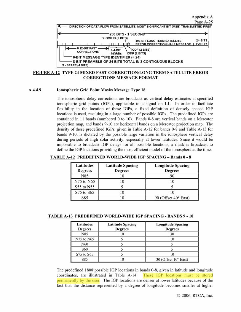
AAppppeennddiixx AA PPaaggee AA--2255
©© 22000066,, RRTTCCAA,, IInncc..
24-BITSPARITY
8-BIT PREAMBLE OF 24 BITS TOTAL IN 3 CONTIGUOUS BLOCKS6-BIT MESSAGE TYPE IDENTIFIER (= 24)
250 BITS - 1 SECOND
DIRECTION OF DATA FLOW FROM SATELLITE; MOST SIGNIFICANT BIT (MSB) TRANSMITTED FIRST
S - SPARE (4 BITS)
S106-BIT LONG TERM SATELLITEERROR CORRECTION HALF MESSAGE
IODP (2 BITS)
BLOCK ID (2 BITS)
IODF (2 BITS)6 12-BIT FASTCORRECTIONS 6 4-BIT
UDREIs
FIGURE A-12 TYPE 24 MIXED FAST CORRECTION/LONG TERM SATELLITE ERROR
CORRECTIONS MESSAGE FORMAT
A.4.4.9 Ionospheric Grid Point Masks Message Type 18
The ionospheric delay corrections are broadcast as vertical delay estimates at specified ionospheric grid points (IGPs), applicable to a signal on L1. In order to facilitate flexibility in the location of these IGPs, a fixed definition of densely spaced IGP locations is used, resulting in a large number of possible IGPs. The predefined IGPs are contained in 11 bands (numbered 0 to 10). Bands 0-8 are vertical bands on a Mercator projection map, and bands 9-10 are horizontal bands on a Mercator projection map. The density of these predefined IGPs, given in Table A-12 for bands 0-8 and Table A-13 for bands 9-10, is dictated by the possible large variation in the ionosphere vertical delay during periods of high solar activity, especially at lower latitudes. Since it would be impossible to broadcast IGP delays for all possible locations, a mask is broadcast to define the IGP locations providing the most efficient model of the ionosphere at the time.
TABLE A-12 PREDEFINED WORLD-WIDE IGP SPACING – Bands 0 - 8
Latitudes Degrees
Latitude Spacing Degrees
Longitude Spacing Degrees
N85 10 90 N75 to N65 10 10 S55 to N55 5 5 S75 to S65 10 10
S85 10 90 (Offset 40° East)
TABLE A-13 PREDEFINED WORLD-WIDE IGP SPACING - BANDS 9 - 10
Latitudes Degrees
Latitude Spacing Degrees
Longitude Spacing Degrees
N85 10 30 N75 to N65 5 10
N60 5 5 S60 5 5
S75 to S65 5 10 S85 10 30 (Offset 10° East)
The predefined 1808 possible IGP locations in bands 0-8, given in latitude and longitude coordinates, are illustrated in Table A-14. These IGP locations must be stored permanently by the user. The IGP locations are denser at lower latitudes because of the fact that the distance represented by a degree of longitude becomes smaller at higher

AAppppeennddiixx AA PPaaggee AA--2266
©© 22000066,, RRTTCCAA IInncc..
latitudes. The IGP grid at the equator has 5° spacings, increasing to 10° north of N55° and south of S55°, and finally becoming spaced 90° at N85° and S85° around the poles. (The IGPs at S85° are offset by 40° to accommodate an even distribution of bands as described below.) There are 384 possible IGP locations in bands 9 and 10, given by latitude and longitude. These IGP locations must also be stored permanently by the user. When using these bands, the IGP grid at 60° has 5° longitudinal spacings, increasing to 10° spacings at 65°, 70°, and 75°, and finally becoming spaced 30° at N85° and S85° around the poles. The IGPs at S85° are offset by 10° to align with the spacings in bands 0-8 described above.
The total IGP grid represents too many IGPs for broadcasting in a single message. Thus, the grid is divided into 11 Bands (numbered 0 to 10), and each message indicates the Band associated with 201 possible IGPs (bands are designated with rectangular areas with bold numbers in Figure A-14). Each of bands 0-8 covers 40° of longitude; bands 9-10 cover 25° of latitude and 360° of longitude. When bands 9 and/or 10 are sent, the IGP mask values are set to 0 in bands 0-8 for all IGPs north of 55°N and south of 55°S. Message Type 18 provides a mask for any one of the 11 bands indicated by the band number. Each message also contains an ionospheric mask issue of data (IODI) to ensure that the ionospheric corrections are properly decoded. An additional 4-bit number indicates how many band masks are being broadcast by the subject GEO, so that a user knows whether all available data has been received or whether to wait for another band mask. Note that the user only has to collect and save the vertical delays for IGPs located within a limited distance of his location. A given GEO would only broadcast IGPs in bands (up to 8) that cover the observable IGPs visible from the intersection of its footprint and the controlling system’s service volume. If the number of bands is 0, the message is used to indicate that no ionospheric delay corrections are being provided, indicating the LNAV/VNAV, LP, and LPV approach service is not being provided by the broadcasting GEO.
Within bands 0 through 7, the IGPs are numbered from 1 to 201. Within band 8, the IGPs are numbered from 1 through 200. Within bands 9 and 10, the IGPs are numbered from 1 through 192. In bands 0 to 8, the IGPs are numbered counting up from the southwest corner (bottom-left) up each longitude column of the band (from south to north) and continuing for each column from west to east (left-to-right) from the bottom of each column. For example, in Band 0, IGP #1 is at S75, W180, and IGP #201 is at N55, W145 (See Table A-14). In bands 9 and 10, the IGPs are numbered counting eastward from the western corner closest to the equator along each latitude row of the band (from west to east) and continuing for each row towards the poles. For example, in band 9, IGP #1 is at N60, W180, and IGP #192 is at N85, E150 (See Table A-14).
In the mask, a bit set to one (“1”) indicates that ionospheric correction information is being provided for the associated IGP. If the bit is set to zero (“0”), no ionospheric correction information is provided for that IGP. An example of an ionospheric grid point mask is shown in Figure A-13.

AAppppeennddiixx AA PPaaggee AA--2277
©© 22000066,, RRTTCCAA,, IInncc..
Band 0 Band 1 Band 2 Band 3 Band 4 Band 5 Band 6 Band 7 Band 8 Band 9 Band10IGP Mask
IGP BandMask(Set of IGP maskvalues)
IGP BandMask values
0 1 1 1 1 0 1 0 1 1 1 1 1 1 1 1 1 1 1 1 0 0 1 1 1 0
1 2 3 4 5 6 7 8 9 10 11 12 13 14 15IGP Blocks 1 2 3 4 5 6 7 ...............
The IGP block identifier for this IGPblock is 0
The IGP Band Identifier for this IGPBand Mask is 2
The IGP block identifier for this IGPblock is 1
FIGURE A-13 EXAMPLE OF AN IONOSPHERIC GRID MASK
The IODI will sequence through the range from 0 to 3, changing each time the IGP mask changes, which is expected to happen rarely. The user will ensure that the IODI of the bands being used agree with the corresponding IODI in Message Type 26 before applying the vertical delays to the model. The format of Message Type 18 is illustrated in Figure A-15 with contents described in Table A-15.
At the edge of the GEO footprint, the ionospheric pierce points (IPPs) could be located beyond IGPs of the bands being broadcast. However, because of overlap of GEO footprints, those IPPs would be covered by an adjacent GEO broadcasting an adjacent band. The adjacent GEO itself would be at a higher elevation angle.

AAppppeennddiixx AA PPaaggee AA--2288
©© 22000066,, RRTTCCAA IInncc..
TABLE A-14 IONOSPHERIC MASK BANDS
Bits in Mask Band 0
180 W 75S, 65S, 55S, 50S, 45S, ..., 45N, 50N, 55N, 65N, 75N, 85N 1 to 28 175 W 55S, 50S, 45S, ..., 45N, 50N, 55N 29 to 51 170 W 75S, 65S, 55S, 50S, 45S, ..., 45N, 50N, 55N, 65N, 75N 52 to 78 165 W 55S, 50S, 45S, ..., 45N, 50N, 55N 79 to 101 160 W 75S, 65S, 55S, 50S, 45S, ..., 45N, 50N, 55N, 65N, 75N 102 to 128 155 W 55S, 50S, 45S, ..., 45N, 50N, 55N 129 to 151 150 W 75S, 65S, 55S, 50S, 45S, ..., 45N, 50N, 55N, 65N, 75N 152 to 178 145 W 55S, 50S, 45S, ..., 45N, 50N, 55N 179 to 201
Band 1 140 W 85S, 75S, 65S, 55S, 50S, 45S, ..., 45N, 50N, 55N, 65N, 75N 1 to 28 135 W 55S, 50S, 45S, ..., 45N, 50N, 55N 29 to 51 130 W 75S, 65S, 55S, 50S, 45S, ..., 45N, 50N, 55N, 65N, 75N 52 to 78 125 W 55S, 50S, 45S, ..., 45N, 50N, 55N 79 to 101 120 W 75S, 65S, 55S, 50S, 45S, ..., 45N, 50N, 55N, 65N, 75N 102 to 128 115 W 55S, 50S, 45S, ..., 45N, 50N, 55N 129 to 151 110 W 75S, 65S, 55S, 50S, 45S, ..., 45N, 50N, 55N, 65N, 75N 152 to 178 105 W 55S, 50S, 45S, ..., 45N, 50N, 55N 179 to 201
Band 2 100 W 75S, 65S, 55S, 50S, 45S, ..., 45N, 50N, 55N, 65N, 75N 1 to 27 95 W 55S, 50S, 45S, ..., 45N, 50N, 55N 28 to 50 90 W 75S, 65S, 55S, 50S, 45S, ..., 45N, 50N, 55N, 65N, 75N, 85N 51 to 78 85 W 55S, 50S, 45S, ..., 45N, 50N, 55N 79 to 101 80 W 75S, 65S, 55S, 50S, 45S, ..., 45N, 50N, 55N, 65N, 75N 102 to 128 75 W 55S, 50S, 45S, ..., 45N, 50N, 55N 129 to 151 70 W 75S, 65S, 55S, 50S, 45S, ..., 45N, 50N, 55N, 65N, 75N 152 to 178 65 W 55S, 50S, 45S, ..., 45N, 50N, 55N 179 to 201
Band 3 60 W 75S, 65S, 55S, 50S, 45S, ..., 45N, 50N, 55N, 65N, 75N 1 to 27 55 W 55S, 50S, 45S, ..., 45N, 50N, 55N 28 to 50 50 W 85S, 75S, 65S, 55S, 50S, 45S, ..., 45N, 50N, 55N, 65N, 75N 51 to 78 45 W 55S, 50S, 45S, ..., 45N, 50N, 55N 79 to 101 40 W 75S, 65S, 55S, 50S, 45S, ..., 45N, 50N, 55N, 65N, 75N 102 to 128 35 W 55S, 50S, 45S, ..., 45N, 50N, 55N 129 to 151 30 W 75S, 65S, 55S, 50S, 45S, ..., 45N, 50N, 55N, 65N, 75N 152 to 178 25 W 55S, 50S, 45S, ..., 45N, 50N, 55N 179 to 201
Band 4 20 W 75S, 65S, 55S, 50S, 45S, ..., 45N, 50N, 55N, 65N, 75N 1 to 27 15 W 55S, 50S, 45S, ..., 45N, 50N, 55N 28 to 50 10 W 75S, 65S, 55S, 50S, 45S, ..., 45N, 50N, 55N, 65N, 75N 51 to 77 5 W 55S, 50S, 45S, ..., 45N, 50N, 55N 78 to 100
0 75S, 65S, 55S, 50S, 45S, ..., 45N, 50N, 55N, 65N, 75N, 85N 101 to 128 5 E 55S, 50S, 45S, ..., 45N, 50N, 55N 129 to 151 10 E 75S, 65S, 55S, 50S, 45S, ..., 45N, 50N, 55N, 65N, 75N 152 to 178 15 E 55S, 50S, 45S, ..., 45N, 50N, 55N 179 to 201
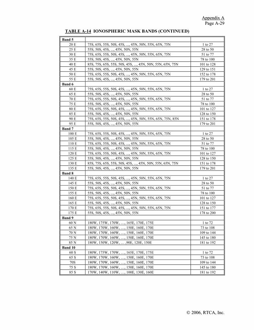
AAppppeennddiixx AA PPaaggee AA--2299
©© 22000066,, RRTTCCAA,, IInncc..
TABLE A-14 IONOSPHERIC MASK BANDS (CONTINUED)
Band 5 20 E 75S, 65S, 55S, 50S, 45S, ..., 45N, 50N, 55N, 65N, 75N 1 to 27 25 E 55S, 50S, 45S, ..., 45N, 50N, 55N 28 to 50 30 E 75S, 65S, 55S, 50S, 45S, ..., 45N, 50N, 55N, 65N, 75N 51 to 77 35 E 55S, 50S, 45S, ..., 45N, 50N, 55N 78 to 100 40 E 85S, 75S, 65S, 55S, 50S, 45S, ..., 45N, 50N, 55N, 65N, 75N 101 to 128 45 E 55S, 50S, 45S, ..., 45N, 50N, 55N 129 to 151 50 E 75S, 65S, 55S, 50S, 45S, ..., 45N, 50N, 55N, 65N, 75N 152 to 178 55 E 55S, 50S, 45S, ..., 45N, 50N, 55N 179 to 201
Band 6 60 E 75S, 65S, 55S, 50S, 45S, ..., 45N, 50N, 55N, 65N, 75N 1 to 27 65 E 55S, 50S, 45S, ..., 45N, 50N, 55N 28 to 50 70 E 75S, 65S, 55S, 50S, 45S, ..., 45N, 50N, 55N, 65N, 75N 51 to 77 75 E 55S, 50S, 45S, ..., 45N, 50N, 55N 78 to 100 80 E 75S, 65S, 55S, 50S, 45S, ..., 45N, 50N, 55N, 65N, 75N 101 to 127 85 E 55S, 50S, 45S, ..., 45N, 50N, 55N 128 to 150 90 E 75S, 65S, 55S, 50S, 45S, ..., 45N, 50N, 55N, 65N, 75N, 85N 151 to 178 95 E 55S, 50S, 45S, ..., 45N, 50N, 55N 179 to 201
Band 7 100 E 75S, 65S, 55S, 50S, 45S, ..., 45N, 50N, 55N, 65N, 75N 1 to 27 105 E 55S, 50S, 45S, ..., 45N, 50N, 55N 28 to 50 110 E 75S, 65S, 55S, 50S, 45S, ..., 45N, 50N, 55N, 65N, 75N 51 to 77 115 E 55S, 50S, 45S, ..., 45N, 50N, 55N 78 to 100 120 E 75S, 65S, 55S, 50S, 45S, ..., 45N, 50N, 55N, 65N, 75N 101 to 127 125 E 55S, 50S, 45S, ..., 45N, 50N, 55N 128 to 150 130 E 85S, 75S, 65S, 55S, 50S, 45S, ..., 45N, 50N, 55N, 65N, 75N 151 to 178 135 E 55S, 50S, 45S, ..., 45N, 50N, 55N 179 to 201
Band 8 140 E 75S, 65S, 55S, 50S, 45S, ..., 45N, 50N, 55N, 65N, 75N 1 to 27 145 E 55S, 50S, 45S, ..., 45N, 50N, 55N 28 to 50 150 E 75S, 65S, 55S, 50S, 45S, ..., 45N, 50N, 55N, 65N, 75N 51 to 77 155 E 55S, 50S, 45S, ..., 45N, 50N, 55N 78 to 100 160 E 75S, 65S, 55S, 50S, 45S, ..., 45N, 50N, 55N, 65N, 75N 101 to 127 165 E 55S, 50S, 45S, ..., 45N, 50N, 55N 128 to 150 170 E 75S, 65S, 55S, 50S, 45S, ..., 45N, 50N, 55N, 65N, 75N 151 to 177 175 E 55S, 50S, 45S, ..., 45N, 50N, 55N 178 to 200
Band 9 60 N 180W, 175W, 170W, …, 165E, 170E, 175E 1 to 72 65 N 180W, 170W, 160W, …, 150E, 160E, 170E 73 to 108 70 N 180W, 170W, 160W, …, 150E, 160E, 170E 109 to 144 75 N 180W, 170W, 160W, …, 150E, 160E, 170E 145 to 180 85 N 180W, 150W, 120W, … ,90E, 120E, 150E 181 to 192
Band 10 60 S 180W, 175W, 170W, …, 165E, 170E, 175E 1 to 72 65 S 180W, 170W, 160W, …, 150E, 160E, 170E 73 to 108 70S 180W, 170W, 160W, …, 150E, 160E, 170E 109 to 144 75 S 180W, 170W, 160W, …, 150E, 160E, 170E 145 to 180 85 S 170W, 140W, 110W, …, 100E, 130E, 160E 181 to 192

AAppppeennddiixx AA PPaaggee AA--3300
©© 22000066,, RRTTCCAA IInncc..
N75
N65
N55
0
0W180N85
W100 E100W140 W60 W20 E20 E60 E140
N50
S75
S65
S55
S85
S500 1 2 3 4 5 6 7 8
FIGURE A-14 PREDEFINED GLOBAL IGP GRID (BANDS 9 AND 10 ARE NOT SHOWN)

AAppppeennddiixx AA PPaaggee AA--3311
©© 22000066,, RRTTCCAA,, IInncc..
TABLE A-15 TYPE 18 IGP MASK MESSAGE CONTENTS
Parameter No. of Bits
Scale Factor (LSB)
Effective Range
Units
Number of Bands being broadcast
4 1 0 to 11 unitless
Band Number 4 1 0 to 10 unitless Issue of Data - Ionosphere (IODI)
2 1 0 to 3 unitless
IGP Mask 201 — — unitless Spare 1 — — —
24-BITSPARITY201-BIT MASK FIELD
8-BIT PREAMBLE OF 24 BITS TOTAL IN 3 CONTIGUOUS BLOCKS6-BIT MESSAGE TYPE IDENTIFIER (18)
250 BITS - 1 SECOND
NO. OF BANDS (4 BITS)BAND NUMBER (4 BITS)2-BIT ISSUE OF DATA (IODI)
1-SPARE BIT
FIGURE A-15 TYPE 18 IGP MASK MESSAGE FORMAT
A.4.4.10 Ionospheric Delay Corrections Messages Type 26
The Type 26 Ionospheric Delay Corrections Message provides the users with vertical delays (relative to an L1 signal) and their accuracy (σ2
GIVE’s) at geographically defined IGPs identified by band number and IGP number in Table A-14. The grid points are indicated in Figure A-14.
Each message contains a band number and a block ID that indicates the location of the IGPs in the respective band mask. The 4-bit block ID (0-13) indicates to which IGPs the corrections apply. Block 0 contains the IGP corrections for the first 15 IGPs designated in the band mask. Block 1 contains the IGP corrections for IGPs 16 - 30 designated in the band mask, etc. Each band is therefore divided into a maximum of 14 blocks. Corrections associated with slot numbers that exceed the number of IGPs indicated in the IGP band mask should be ignored.
The data content for this message is given in Table A-16 with a format presented in Figure A-16. The evaluation of the σ2
GIVE’s is given in Table A-17. These vertical delays and the evaluated σ2
GIVE’s will be interpolated by the user to the IPP of the observed satellite. This computed vertical delay and the associated σ2
UIVE (model variance for user ionospheric vertical error computed from associated σ2
GIVE's) must then be multiplied by the obliquity factor computed from the elevation angle to the satellite to obtain a slant range correction and the slant range correction error (σ2
UIRE).

AAppppeennddiixx AA PPaaggee AA--3322
©© 22000066,, RRTTCCAA IInncc..
TABLE A-16 IONOSPHERIC DELAY MODEL PARAMETERS FOR MESSAGE TYPE 26
Parameter No. of Bits
Scale Factor (LSB)
Effective Range
Units
Band Number 4 1 0 to 10 unitless Block ID 4 1 0 to 13 unitless For Each of 15 Grid Points 13 — — —
IGP Vertical Delay Estimate 9 0.125 0 to 63.875 meters Grid Ionospheric Vertical
Error Indicator (GIVEI)4 1 0 to 15 unitless
IODI 2 1 0 to 3 unitless Spare 7 — — —
24-BITSPARITY
8-BIT PREAMBLE OF 24 BITS TOTAL IN 3 CONTIGUOUS BLOCKS6-BIT MESSAGE TYPE IDENTIFIER (= 26)
250 BITS - 1 SECOND
DIRECTION OF DATA FLOW FROM SATELLITE; MOST SIGNIFICANT BIT (MSB) TRANSMITTED FIRST
S
S = SPARE (7 BITS)
BLOCK ID (4 BITS)IGP VERTICAL DELAY (9 BITS)GIVEI (4 BITS)
REPEAT FOR 14 MORE GRID POINTS
2 3 4 5 6 7 8 9
IODI
10 11 12 13 14
BAND NUMBER (4 BITS)
15
FIGURE A-16 TYPE 26 IONOSPHERIC DELAY CORRECTIONS MESSAGE FORMAT
The 9-bit IGP vertical delays have a 0.125 meter resolution, for a 0-63.750 meter valid range. A vertical delay of 63.875 meters (111111111) will indicate don't use. That is, there are no IGP vertical delays greater than 63.750 meters. If that range is exceeded, a don't use indication will be used.

AAppppeennddiixx AA PPaaggee AA--3333
©© 22000066,, RRTTCCAA,, IInncc..
TABLE A-17 EVALUATION OF GIVEIi
GIVEIi GIVEi Meters σ2i,GIVE
Meters2 0 0.3 0.0084 1 0.6 0.0333 2 0.9 0.0749 3 1.20 0.1331 4 1.5 0.2079 5 1.8 0.2994 6 2.1 0.4075 7 2.4 0.5322 8 2.7 0.6735 9 3.0 0.8315
10 3.6 1.1974 11 4.5 1.8709 12 6.0 3.3260 13 15.0 20.7870 14 45.0 187.0826 15 Not Monitored Not Monitored
A.4.4.10.1 Pierce Point Location Determination
Considering the satellite and user locations, the user must first determine the location of the ionospheric pierce point of the signal path from the satellite. The location of an ionospheric pierce point (IPP) is defined to be the intersection of the line segment from the receiver to the satellite and an ellipsoid with constant height of 350 km above the WGS-84 ellipsoid. The following equations provide a method for determining the latitude and longitude of that pierce point. First, the latitude is computed as
( )φ φ ψ φ ψpp u pp u pp A= +−sin sin cos cos sin cos1 radians (A- 20)
where, as illustrated in Figure A-17, Ψpp is the earth's central angle between the user position and the earth projection of the pierce point computed as:
ψ πpp
e
e IE
RR h
E= − −+
⎛⎝⎜
⎞⎠⎟−
21sin cos radians (A- 21)
A is the azimuth angle of the satellite from the user’s location (φu, λu) measured clockwise from north. E is the elevation angle of the satellite from the user's location (φu, λu) measured with respect to the local-tangent-plane. Re is the approximate radius of the earth’s ellipsoid (taken to be 6378.1363 km). hI is the height of the maximum electron density (taken to be equal to 350 km). The longitude of the pierce point is:
If φu > 70°, and tan ψppcos A > tan(π/2 - φu)
or if φu < -70°, and tan ψppcos (A + π) > tan(π/2 + φu)

AAppppeennddiixx AA PPaaggee AA--3344
©© 22000066,, RRTTCCAA IInncc..
⎟⎟⎠
⎞⎜⎜⎝
⎛−+= −
pp
ppupp
Aφ
ψπλλ
cossinsin
sin 1 radians (A- 22)
Otherwise,
λ λψ
φpp upp
pp
A= +
⎛
⎝⎜⎜
⎞
⎠⎟⎟
−sinsin sin
cos1 radians (A- 22a)
E
ψpp
φ , λu u
ppφ , λ pp
EARTH'SCENTER
EARTH'SELLIPSOID
IONOSPHERE
hI
R e
USER
TOSATELLITE
PIERCEPOINT
NOT TO SCALE
FIGURE A-17 IONOSPHERIC PIERCE POINT GEOMETRY
A.4.4.10.2 Selection of Ionospheric Grid Points
After determining the location of the user ionospheric pierce point, the user must select the IGPs to be used to interpolate the ionospheric correction and model variance. This selection is done based only on the information provided in the mask, and must be done without regard to whether or not the selected IGPs are monitored, not monitored, or don’t use. The selection process will take place as described below. Flowcharts for the IGP process are in Appendix P.
a) For an IPP between N60° and S60°:
1) if four IGPs that define a 5-degree-by-5-degree cell around the IPP are set to one in the IGP mask, they are selected; else,
2) if any three IGPs that define a 5-degree-by-5-degree triangle that circumscribes the IPP are set to one in the IGP mask, they are selected; else,
3) if any four IGPs that define a 10-degree-by-10-degree cell around the IPP are set to one in the IGP mask, they are selected; else,
4) if any three IGPs that define a 10-degree-by-10-degree triangle that circumscribes the IPP are set to one in the IGP mask, they are selected; else,

AAppppeennddiixx AA PPaaggee AA--3355
©© 22000066,, RRTTCCAA,, IInncc..
5) an ionospheric correction is not available.
b) For an IPP between N60° and N75° or between S60° and S75°:
1) if four IGPs that define a 5-degree latitude-by-10-degree longitude cell around the IPP are set to one in the IGP mask, they are selected; else,
2) if any three IGPs that define a 5-degree latitude-by-10-degree longitude triangle that circumscribes the IPP are set to one in the IGP mask, they are selected; else,
3) if any four IGPs that define a 10-degree-by-10-degree cell around the IPP are set to one in the IGP mask, they are selected; else,
4) if any three IGPs that define a 10-degree-by-10-degree triangle that circumscribes the IPP are set to one in the IGP mask, they are selected; else,
5) an ionospheric correction is not available.
c) For an IPP between N75° and N85° or between S75° and S85°:
1) if the two nearest IGPs at 75° and the two nearest IGPs at 85° (separated by 30° longitude if Band 9 or 10 is used, separated by 90° otherwise) are set to one in the IGP mask, a 10-degree-by-10-degree cell is created by linearly interpolating between the IGPs at 85° to obtain virtual IGPs at longitudes equal to the longitudes of the IGPs at 75°; else,
Note: The σ2GIVEs are linearly interpolated along the 85 degree line to form virtual
σ2GIVEs to go with the virtual IGPs.
2) an ionospheric correction is not available.
d) For an IPP north of N85°:
1) if the four IGPs at N85° latitude and longitudes of W180°, W90°, 0° and E90° are set to one in the IGP mask, they are selected; else,
2) an ionospheric correction is not available.
e) For an IPP south of S85°:
1) if the four IGPs at S85° latitude and longitudes of W140°, W50°, E40° and E130° are set to one in the IGP mask, they are selected; else,
2) an ionospheric correction is not available.
This selection is based only on the information provided in the mask, without regard to whether the selected IGPs are monitored, “Not Monitored”, or “Do Not Use”. If any of the selected IGPs is identified as “Do Not Use”, an ionospheric correction is not available. If four IGPs are selected, and one of the four is identified as “Not Monitored”, then three-point interpolation is used if the IPP is within the triangular region covered by the three corrections that are provided.

AAppppeennddiixx AA PPaaggee AA--3366
©© 22000066,, RRTTCCAA IInncc..
a) Example of 5 x 5degree triangle
x
c) Example of interpolation northof 75 N, south of 85 N
x
b) Example of 10 x 10 degreetriangle
xIGP not used
virtual IGPs inter-polated from pts at 85
FIGURE A-18 IONOSPHERIC GRID POINT INTERPOLATION
A.4.4.10.3 Ionospheric Pierce Point Vertical Delay and Model Variance Interpolation
Although the data broadcast to the user is in the form of vertical IGP delays, these points do not generally correspond with his computed IPP locations. Thus, it is necessary for the user to interpolate from the broadcast IGP delays to that at his computed IPP locations. Given three or four nodes of a cell of the IGP grid described above that surround the user's IPP to a satellite, the user interpolates from those nodes to his pierce point (examples are presented in Figure A-18) using the following algorithm.
The IGPs selected as described in A.4.4.10.2 must be used in this interpolation, with one exception. If four IGPs were selected, and one of the four is identified as “not monitored”, then the three-point interpolation should be used if the user’s pierce point is within the triangular region covered by the three corrections that are provided. If one of the four is identified as “don’t use”, the entire square must not be used.
For four-point interpolation, the mathematical formulation for interpolated vertical IPP delay τvpp(φpp, λpp) as a function of IPP latitude φpp and longitude λpp is
( ) ( )τ φ λ τvpp pp pp ii
pp pp viW x y, ,==∑
1
4 (A- 23)
where the general equation for the weighting function is

AAppppeennddiixx AA PPaaggee AA--3377
©© 22000066,, RRTTCCAA,, IInncc..
( )f x y xy, = (A- 24)
and τvi are the broadcast grid point vertical delay values at four corners of the IGP grid, as shown in Figure A-19. In particular, τvpp is the output value at desired pierce point pp, whose geographical coordinates are φpp, λpp,
yxW pppp=1 (A- 25)
( ) yxW pppp−= 12 (A- 26)
( )( )yxW pppp −−= 113 (A- 27)
( )yxW pppp −= 14 (A- 28)
Δλ λ λpp pp= − 1 (A- 29)
Δφ φ φpp pp= − 1 (A- 30)
For IPP’s between N85° and S85°,
x pppp=
−
Δλ
λ λ2 1 (A- 31)
y pppp=
−
Δφ
φ φ2 1 (A- 32)
where (see Figure A-19)
λ1 = longitude of IGPs west of IPP λ2 = longitude of IGPs east of IPP φ1 = latitude of IGPs south of IPP φ2 = latitude of IGPs north of IPP
For IPPs north of N85° or south of S85°,
y pppp
=− °
°
φ 85
10 (A- 33)
x y ypppp
pp pp=−
°⋅ − +
λ λ3
901 2( ) (A- 34)
where:
λ1 = longitude of the second IGP to the east of the IPP.
λ2 = longitude of the second IGP to the west of the IPP.
λ3 = longitude of the closest IGP to the west of the IPP.
λ4 = longitude of the closest IGP to the east of the IPP.
Note that if λ1 and λ2 cross 180° of longitude, the calculation of xpp must account for the discontinuity in longitude.

AAppppeennddiixx AA PPaaggee AA--3388
©© 22000066,, RRTTCCAA IInncc..
x
y
τv2
φ1
λ1
φ2
λ2
Δλpp=λpp-λ1
Δφpp=φpp-φ1
τvpp(φpp, λpp)USER'S IPP
τv1
τv3 τv4
FIGURE A-19 FOUR-POINT INTERPOLATION ALGORITHM DEFINITIONS
For three-point interpolation between 75°S and 75°N, a similar algorithm is used:
( ) ( )τ φ λ τvpp pp pp ii
pp pp viW x y, ,==∑
1
3 (A- 35)
yW pp=1 (A- 36)
yxW pppp −−= 12 (A- 37)
xW pp=3 (A- 38)
The pierce points are numbered as shown in Figure A-14 so that grid point #2 is always the vertex opposite the hypotenuse and the distance-ratios (x, y) are always determined relative to the distance to grid point #2. It should be noted that there are three additional orientations of the triangle shown in Figure A-20.

AAppppeennddiixx AA PPaaggee AA--3399
©© 22000066,, RRTTCCAA,, IInncc..
x
y
τv1
φ1
λ1
φ2
λ2
Δλpp=λpp-λ1
Δφpp=φpp-φ1
τvpp(φpp, λpp)USER'S IPP
τv2 τv3
FIGURE A-20 THREE-POINT INTERPOLATION ALGORITHM DEFINITIONS
The σ2UIVE will be interpolated by the users from the σ2
ionogrid’s defined at the IGPs to the IPP as follows:
( )σ σUIVE n pp pp n ionogridn
W x y2 2
1
4= ⋅
=∑ , , (A- 39)
or
( )σ σUIVE n pp pp n ionogridn
W x y2 2
1
3= ⋅
=∑ , , (A- 40)
where σ2ionogrid is the model variance of ionospheric vertical delays at an IGP. If the
degradation model (using Message Types 7 and 10) is used, σ2ionogrid is calculated as
described in section A.4.5.2. If the degradation model is not used, but SBAS provided ionospheric model is used, σ2
ionogrid equals σ2GIVE.
A.4.4.10.4 Computing Slant Ionospheric Delay and Ionospheric Model Variance
Once the user establishes the vertical delay at the pierce point, the user can then multiply that vertical delay by the obliquity factor Fpp to obtain the ionospheric correction (ICi) to be added to the pseudorange measurement:
),(),( ppppvppppppppsppi FIC φλτφλτ ⋅−=−= (A- 41)
where τvpp is the interpolated vertical delay at the user-to-satellite IPP derived as described above, and
FR ER hpp
e
e I= −
+⎛⎝⎜
⎞⎠⎟
⎡
⎣
⎢⎢
⎤
⎦
⎥⎥
−
12
12cos
(A- 42)

AAppppeennddiixx AA PPaaggee AA--4400
©© 22000066,, RRTTCCAA IInncc..
The σ2UIRE is computed as:
σ σUIRE pp UIVEF2 2 2= ⋅ (A- 43)
A.4.4.11 GEO Navigation Message Type 9
Figure A-21, Table A-18, and Table 2-3 (Section 2.1.2.2.2.2) present the Type 9 GEO Navigation Message representing the position, velocity and acceleration of the geostationary satellite, in ECEF Coordinates, and its apparent clock time and frequency offsets. Also included is the time of applicability (t0) and an accuracy exponent (URA) representing the health of the GEO ranging signal. aGf0 and aGf1 will be an estimate of the time offset and drift with respect to SBAS Network Time. Their combined effect will be added to the estimate of the satellite's transmit time.
24-BITSPARITY
8-BIT PREAMBLE OF 24 BITS TOTAL IN 3 CONTIGUOUS BLOCKS 6-BIT MESSAGE TYPE IDENTIFIER (= 9)
250 BITS - 1 SECOND
SPARE
DIRECTION OF DATA FLOW FROM SATELLITE; MOST SIGNIFICANT BIT (MSB) TRANSMITTED FIRST
*
*ACCURACY EXPONENT (URA); SEE SECTION 2.1.2.2.2.2
X G YG ZG GX.
GY.
GZ.
a Gf0 a Gf1
G X..
G Z . . G Y . .
t 0
FIGURE A-21 TYPE 9 GEO NAVIGATION MESSAGE FORMAT
The position and time of the GEO will be propagated to time-of-day t, corrected for end-of-day cross-over, as
( ) ( )200 2
1 ttZYX
ttZYX
ZYX
ZYX
G
G
G
G
G
G
G
G
G
Gk
Gk
Gk
−⎥⎥⎥
⎦
⎤
⎢⎢⎢
⎣
⎡
+−⎥⎥⎥
⎦
⎤
⎢⎢⎢
⎣
⎡
+⎥⎥⎥
⎦
⎤
⎢⎢⎢
⎣
⎡=
⎥⎥⎥
⎦
⎤
⎢⎢⎢
⎣
⎡
&&
&&
&&
&
&
&
(A- 44)
and t = tG – ΔtG = tG – (aGf0 + aGf1(tG – t0)) (A- 45)
where tG is the (uncorrected) time at which the signal left the GEO, expressed in that GEO’s reference time (i.e., the GEO satellite’s PRN code phase time when the signal left the satellite), and t0 is the time of applicability of the message, corrected for end-of-day cross-over. The ranges of the parameters in this message allow for GEO inclination angles of up to ±8°.
Note: Equation A-45 does not require iteration (one iteration is sufficient).
In contrast to the time correction for GPS satellites, there is no user correction for general relativity to GEO time. Any relativity effects will be removed by the earth station controlling the GEO signal.
Note: The Sagnac corrections (Earth’s rotation) must be accounted for. One method is to add δrs to GEO pseudoranges where:

AAppppeennddiixx AA PPaaggee AA--4411
©© 22000066,, RRTTCCAA,, IInncc..
cxRRr ZUG
es)(
Ω= &δ
is the spin rate of the earth,
RG is the position of the GEO,
RU is the user position,
X is vector cross-product,
Z represents the z-component, and
C is the speed of light
Another method is to modify the GEO x-y-z position accordingly.
TABLE A-18 TYPE 9 GEO NAVIGATION MESSAGE PARAMETERS
Parameter No. of Bits (Note 1)
Scale Factor (LSB)
Effective Range (Note 1)
Units
Reserved 8 t0 13 16 0 to 86,384 seconds URA (Note 2) 4 (Note 2) (Note 2) (Note 2) XG (ECEF) 30 0.08 ±42,949,673 meters YG (ECEF) 30 0.08 ±42,949,673 meters ZG (ECEF) 25 0.4 ±6,710,886.4 meters XG Rate-of-Change 17 0.000625 ±40.96 meters/sec YG Rate-of-Change 17 0.000625 ±40.96 meters/sec ZG Rate-of-Change 18 0.004 ±524.288 meters/sec XG Acceleration 10 0.0000125 ± 0.0064 meters/sec2 YG Acceleration 10 0.0000125 ± 0.0064 meters/sec2 ZG Acceleration 10 0.0000625 ± 0.032 meters/sec2 aGf0 12 2-31 ±0.9537×10⁻⁶ seconds aGf1 8 2-40 ±1.1642×10⁻¹⁰ seconds/sec
Note 1: All signed values are coded as two's complement, with the sign bit occupying the MSB. The effective range is smaller than indicated, as the maximum positive value is actually constrained to be one value less (the indicated value minus the resolution).
Note 2: See Section 2.1.2.2.2.2, Table 2-3. A URA of 15 indicates the satellite ranging signal should not be used. Other URA values are not standardized amongst service providers and should not be used.
A.4.4.12 GEO Almanacs Message Type 17
Almanacs for GEOs will be broadcast periodically to alert the user of their existence, location, the general service provided and health and status. Almanacs for three satellites will be broadcast in the GEOs Almanacs Message Type 17 illustrated in FIGURE A-22 and defined in Table A-19. These messages will be repeated to include all GEOs. Unused almanacs will have a PRN number of 0 and should be ignored.
Ω .

AAppppeennddiixx AA PPaaggee AA--4422
©© 22000066,, RRTTCCAA IInncc..
24-BITSPARITY
8-BIT PREAMBLE OF 24 BITS TOTAL IN 3 CONTIGUOUS BLOCKS6-BIT MESSAGE TYPE IDENTIFIER (= 17)
250 BITS - 1 SECOND
DIRECTION OF DATA FLOW FROM SATELLITE; MOST SIGNIFICANT BIT (MSB) TRANSMITTED FIRST
TIME-OF-DAY (11 BITS)
XG YG ZG
DATA ID (2 BITS)PRN NUMBER (8 BITS)HEALTH AND STATUS (8 BITS)
67 BITS; REPEAT FOR 2 MORE SATELLITES
2 3DERIVATIVES
FIGURE A-22 TYPE 17 GEO ALMANACS MESSAGE FORMAT
TABLE A-19 TYPE 17 GEO ALMANACS MESSAGE PARAMETERS
Parameter No. of Bits (Note 1)
Scale Factor (LSB)
Effective Range
(Note 1)
Units
For each of 3 satellites 67 — — — Data ID 2 1 0 to 3 unitless
PRN Number 8 1 0 to 210 — Health and Status 8 — — unitless
XG (ECEF) 15 2,600 ±42,595,800 meters YG (ECEF) 15 2,600 ±42,595,800 meters ZG (ECEF) 9 26,000 ±6,630,000 meters
XG Rate-of-Change 3 10 ± 40 meters/sec YG Rate-of-Change 3 10 ± 40 meters/sec ZG Rate-of-Change 4 60 ± 480 meters/sec
to (Time-of-Day) 11 64 0 to 86,336 seconds
Note: All signed values are coded as two's complement, with the sign bit occupying the MSB. The effective range is smaller than indicated, as the maximum positive value is actually constrained to be one value less (the indicated value minus the resolution).
The position of a GEO using the parameters of Table A-19 will be evaluated using Equations A-44 and A-45 with the acceleration components set to 0 and t0 set to the Time-of-Day given in the message.
The Data ID is 00.
Health and Status bits are defined as follows (see note):
Bit 0 (LSB) Ranging On (0), Off (1) Bit 1 Corrections On (0), Off (1) Bit 2 Broadcast Integrity On (0), Off (1) Bits 3 Reserved Bits 4-7 Service Provider ID
Note: The type 17 message is provided to help the user equipment decide which GEO satellites would provide the best service. The data in the message does not override or invalidate data provided in other SBAS messages. Bit 0 indicates that the GEO is/isn’t intended to be used as a ranging source. Bit 1 indicates that the GEO is/isn’t intended to provide fast corrections. Bit 2 indicates if the GEO satellite is/isn’t intended to provide integrity. When Bit 2 is set, the GEO satellite will be broadcasting a type 0 message or will designate all corrections as not monitored.

AAppppeennddiixx AA PPaaggee AA--4433
©© 22000066,, RRTTCCAA,, IInncc..
The service provider ID is given as:
ID Service Provider 0 WAAS 1 EGNOS 2 MSAS 3-13 Not Yet Assigned 14-15 Reserved
A.4.4.13 SBAS Service Message Type 27
Type 27 messages may be transmitted to increase the σUDRE values in selected areas. The format of Message Type 27 is given in Figure A-23 and Table A-20. Type 27 message parameters apply only to the service provider transmitting the message.
The Number of Service Messages parameter in each Type 27 message indicates the total number of unique Type 27 messages for the current Issue of Data, Service (IODS). Each unique message for that IODS includes a sequential Service Message Number. The IODS is incremented in all messages, each time that any parameter in any Type 27 message is changed.
Each Type 27 message specifies δUDRE factors to be applied to integrity monitoring algorithms of users when inside or outside of the set of geographic regions defined in that message. δUDRE indicators are associated with δUDRE values of Table A-21 that multiply the model standard deviation defined using the UDREI parameters in the Type 2 - 6 and Type 24 Messages. One δUDRE indicator applies to users within any of the regions specified in that message. A second δUDRE indicator applies to users outside all regions in all Type 27 messages. When more than one Type 27 message is broadcast with a common IODS, the δUDRE Indicator – Outside parameter has the same value in all messages.
A.4.4.13.1 Definition of Regions
Each message contains up to five geographic regions, as indicated in the Number of Regions parameter. If less than five regions are specified, they occupy the lowest available bit positions.
Each geographic region has either triangular or rectangular shape, in a latitude/longitude coordinate frame, as indicated by its Region Shape parameter. Three or four coordinates specify the corners of the region, depending on its shape. The latitudes and longitudes of Coordinates 1 and 2 are broadcast. Coordinate 3 takes the Coordinate 1 latitude and the Coordinate 2 longitude. For a square region, Coordinate 4 takes the Coordinate 2 latitude and the Coordinate 1 longitude.
Each region boundary is a closed polygon connecting its set of assigned coordinates. The boundary segments have constant slopes in the latitude/longitude co-ordinate frame, and the change in latitude or longitude along the boundary segment between two co-ordinates will not exceed ±179°. (For example, a segment between co-ordinates at N70°/E170° and N50°/W12° would pass through the location N60°/W101°.) Points on a region boundary are considered to be inside the region.
Regions defined within a single message or in separate messages may overlap each other. Associated with each message is a Priority Code parameter, used to establish precedence of UDRE factors where regions in two or more messages overlap. The Priority Code indicates the relative rank for the regions defined in that message. Where two regions overlap, the UDRE factor for the region with the higher Priority Code value is applicable.

AAppppeennddiixx AA PPaaggee AA--4444
©© 22000066,, RRTTCCAA IInncc..
Where two regions of equal Priority Code overlap, the lower UDRE factor (i.e. - better performance) is applicable.
FIGURE A-23 SERVICE MESSAGE TYPE 27
TABLE A-20 TYPE 27 SERVICE MESSAGE PARAMETERS
Parameter No. Of Bits
(Note 1)
Scale Factor (LSB)
Effective Range
Units
Issue of Data , Service (IODS) 3 1 0 to 7 — Number of Service Messages (Note 2)
3 1 1 to 8 —
Service Message Number (Note 2) 3 1 1 to 8 — Number of Regions 3 1 0 to 5 — Priority Code 2 1 0 to 3 — δUDRE Indicator – Inside (Note 3) 4 1 0 to 15 — δUDRE Indicator – Outside (Note 3)
4 1 0 to 15 —
For each of up to 5 regions: — — — — Coordinate 1 Latitude (Note 4) 8 1 ±90 degrees Coordinate 1 Longitude (Note 4) 9 1 ±180 degrees Coordinate 2 Latitude (Note 4) 8 1 ±90 degrees Coordinate 2 Longitude (Note 4) 9 1 ±180 degrees Region Shape (Note 5) 1 — — — Spare 15 — — —
Note 1: All signed values are coded as two's complement, with the sign bit occupying the MSB.
Note 2: Value is coded with an offset of one, such that a coded value of 7 (binary '111') indicates that Number of Messages or Message Number is 8.
Note 3: δUDRE Indicators are interpreted using Table A-21.
Note 4: Positive values denote North latitude or East longitude.
Note 5: Coding of Region Shape: 0 denotes a triangular region, 1 denotes a square region.
24 BITSPARITY
8-BIT PREAMBLE OF 24 BITS TOTAL IN 3 CONTIGUOUS BLOCKS6-BIT MESSAGE TYPE IDENTIFIER (= 27)
250 BITS - 1 SECOND
COORDINATE 1 LONGITUDE (9 BITS; LSB = 1°, RANGE = ±180°) (+ = NORTH OR EAST, - = SOUTH OR WEST)
δUDRE INDICATOR - OUTSIDE (4 BITS; 0 - 15)
DIRECTION OF DATA FLOW FROM SATELLITE; MOST SIGNIFICANT BIT (MSB) TRANSMITTED FIRST
SPARE (15 BITS)
δUDRE INDICATOR - INSIDE (4 BITS; 0 - 15)PRIORITY CODE (2 BIT; 0 - 3)
IODS (3 BITS; 0 - 7)NUMBER OF SERVICE MESSAGES (3 BITS; 1 - 8)SERVICE MESSAGE NUMBER (3 BITS; 1 - 8)
COORDINATE 1 LATITUDE (8 BITS, LSB = 1°, RANGE = ±90°)
REPEAT FOR 4 MORE REGIONS
2 3 4 5
COORDINATE 2 LONGITUDE (9 BITS; LSB = 1°, RANGE = ±180°) COORDINATE 2 LATITUDE (8 BITS, LSB = 1°, RANGE = ±90°)
NUMBER OF REGIONS (3 BITS; 0 - 5)
REGION SHAPE (1 BIT; 0 = TRIANGLE, 1 = SQUARE)

AAppppeennddiixx AA PPaaggee AA--4455
©© 22000066,, RRTTCCAA,, IInncc..
TABLE A-21 δUDRE INDICATOR EVALUATION
δUDRE Indicator δUDRE 0 1 1 1.1 2 1.25 3 1.5 4 2 5 3 6 4 7 5 8 6 9 8
10 10 11 20 12 30 13 40 14 50 15 100
A.4.4.14 Null Message Type 63 and Internal Test Message 62
The Null Message Type 63 is used as a filler message if no other message is available for broadcast for the one-second time slot. The Internal Test Message Type 62 is used for internal testing purposes. The user will continue to use the GEO broadcast and ranging capabilities.
A.4.4.15 SBAS Network Time/UTC/GLONASS Time Offset Parameters Message Type 12
Message Type 12 will consist of the 8-bit preamble, a 6-bit message type identifier (= 12) followed by 104 information bits for the UTC parameters, then followed by 3 bits to indicate the UTC time standard from which the offset is determined. The next 20 bits are the Time of Week (TOW) in seconds of the beginning of the message, followed by a 10 bit GPS Week number (WN) as defined in Section 2.4.3.1 of [1]. The final 75 bits are spare bits (possibly to be partially replaced with the difference between SBAS Network Time and GLONASS time). Table A-23 defines the UTC parameters along with the other 33 bits defined above. The definition of these parameters and the applicable algorithms are in Sections 20.3.3.5.1.6 and 20.3.3.5.2.4 of [1], with the exception that the UTC parameters will correlate UTC time with the SBAS Network Time rather than with GPS time. The UTC standard used is indicated by the three bits interpreted as indicated in Table A-24. A GLONASS Indicator of “0” indicates that GLONASS time parameters are not provided.
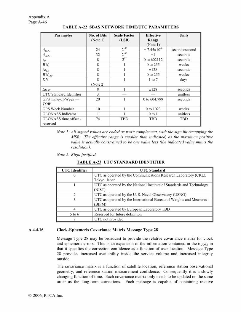
AAppppeennddiixx AA PPaaggee AA--4466
©© 22000066,, RRTTCCAA IInncc..
TABLE A-22 SBAS NETWORK TIME/UTC PARAMETERS
Parameter No. of Bits (Note 1)
Scale Factor (LSB)
Effective Range
(Note 1)
Units
A1SNT 24 2-50 ± 7.45×10⁻⁹ seconds/second A0SNT 32 2-30 ±1 seconds t0t 8 212 0 to 602112 seconds WNt 8 1 0 to 255 weeks ΔtLS 8 1 ±128 seconds WNLSF 8 1 0 to 255 weeks DN 8
(Note 2) 1 1 to 7 days
ΔtLSF 8 1 ±128 seconds UTC Standard Identifier 3 — — unitless GPS Time-of-Week — TOW
20 1 0 to 604,799 seconds
GPS Week Number 10 1 0 to 1023 weeks GLONASS Indicator 1 1 0 to 1 unitless GLONASS time offset - reserved
74 TBD TBD TBD
Note 1: All signed values are coded as two's complement, with the sign bit occupying the MSB. The effective range is smaller than indicated, as the maximum positive value is actually constrained to be one value less (the indicated value minus the resolution).
Note 2: Right justified.
TABLE A-23 UTC STANDARD IDENTIFIER
UTC Identifier UTC Standard 0 UTC as operated by the Communications Research Laboratory (CRL),
Tokyo, Japan 1 UTC as operated by the National Institute of Standards and Technology
(NIST) 2 UTC as operated by the U. S. Naval Observatory (USNO) 3 UTC as operated by the International Bureau of Weights and Measures
(BIPM) 4 UTC as operated by European Laboratory TBD
5 to 6 Reserved for future definition 7 UTC not provided
A.4.4.16 Clock-Ephemeris Covariance Matrix Message Type 28
Message Type 28 may be broadcast to provide the relative covariance matrix for clock and ephemeris errors. This is an expansion of the information contained in the σUDRE in that it specifies the correction confidence as a function of user location. Message Type 28 provides increased availability inside the service volume and increased integrity outside. The covariance matrix is a function of satellite location, reference station observational geometry, and reference station measurement confidence. Consequently it is a slowly changing function of time. Each covariance matrix only needs to be updated on the same order as the long-term corrections. Each message is capable of containing relative

AAppppeennddiixx AA PPaaggee AA--4477
©© 22000066,, RRTTCCAA,, IInncc..
covariance matrices for two satellites. This maintains the real-time six-second updates of integrity and scales the matrix to keep it within a reasonable dynamic range. Cholesky factorization is used to reliably compress the information in the covariance matrix, C. The matrix Cholesky factor is an upper triangular matrix, R. This information can be used to reconstruct the relative covariance matrix as RTR = C, where the superscript T denotes the matrix transpose. This factorization guarantees that the received covariance matrix remains positive-definite despite quantization errors. Because R is upper triangular, it contains only 10 non-zero elements for each satellite. These 10 elements are divided by a scale factor (SF) to determine the matrix, E, and broadcast in half of Message Type 28. The elements of R can be written as shown in equation A- 46.
R=E⋅SF,
⎥⎥⎥⎥⎥
⎦
⎤
⎢⎢⎢⎢⎢
⎣
⎡
=
EEEEEEEEEE
E
4,4
4,33,3
4,23,22,2
4,13,12,11,1
00000
0 (A- 46)
and SF = 2(scale exponent – 5).
The relative clock-ephemeris correction covariance is reconstructed as shown in equation A- 47.
RRC T ⋅= (A- 47)
The covariance matrix is used to modify the broadcast σUDRE values as a function of user position. The location-specific modifier is specified by equation A- 48.
εδ CT ICIUDRE +⋅⋅= (A- 48)
where I is the 4-D line of sight vector from the user to the satellite in the WGS-84 coordinate frame, where the first three components are the unit vector from the user to the satellite and the fourth component is a one. The additional term εC is to compensate for the errors introduced by quantization. If degradation data from a Type 10 message is available, the εc value is derived from Ccovariance (broadcast in a Type 10 message) as shown in equation A- 49.
SFC arianceC ⋅= covε (A- 49)
If Ccovariance type 10 data is not available, εC is set to zero, but there is an 8 meter degradation applied as defined in Appendix J, J.2.2.
The δUDRE is used in equation A- 50. Thus a service provider could use Type 27 or Type 28, but not both.
Table A-24 and Figure A-24 present the contents of the Type 28 message representing the Cholesky factor of the clock-ephemeris covariance matrix for two PRN codes. The covariance matrices are accompanied by the IODP associated with the PRN mask. Refer to Section A.4.4.2 for the application of IODP.
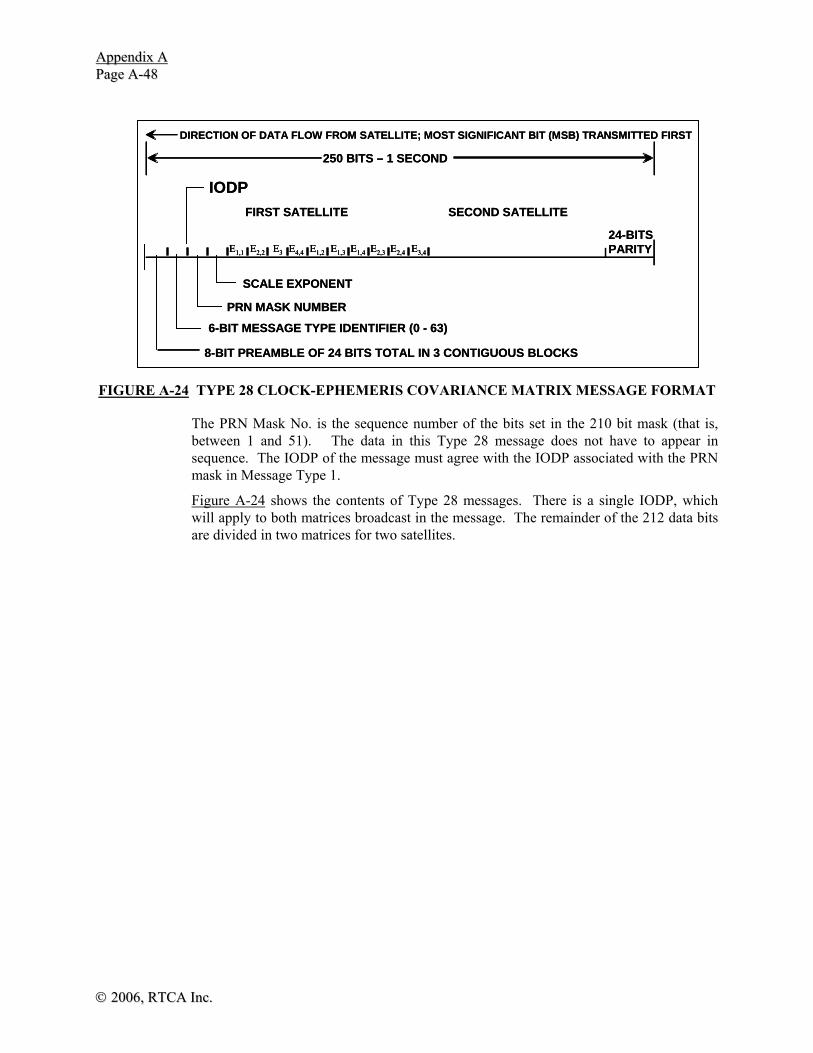
AAppppeennddiixx AA PPaaggee AA--4488
©© 22000066,, RRTTCCAA IInncc..
FIGURE A-24 TYPE 28 CLOCK-EPHEMERIS COVARIANCE MATRIX MESSAGE FORMAT
The PRN Mask No. is the sequence number of the bits set in the 210 bit mask (that is, between 1 and 51). The data in this Type 28 message does not have to appear in sequence. The IODP of the message must agree with the IODP associated with the PRN mask in Message Type 1.
Figure A-24 shows the contents of Type 28 messages. There is a single IODP, which will apply to both matrices broadcast in the message. The remainder of the 212 data bits are divided in two matrices for two satellites.
DIRECTION OF DATA FLOW FROM SATELLITE; MOST SIGNIFICANT BIT (MSB) TRANSMITTED FIRST
8-BIT PREAMBLE OF 24 BITS TOTAL IN 3 CONTIGUOUS BLOCKS
6-BIT MESSAGE TYPE IDENTIFIER (0 - 63)
PRN MASK NUMBER
SCALE EXPONENT
FIRST SATELLITE SECOND SATELLITE
IODP
E1,1 E2,2 E3 E4,4 E1,2 E1,3 E1,4 E2,3 E2,4 E3,4
24-BITSPARITY
250 BITS – 1 SECOND
DIRECTION OF DATA FLOW FROM SATELLITE; MOST SIGNIFICANT BIT (MSB) TRANSMITTED FIRST
8-BIT PREAMBLE OF 24 BITS TOTAL IN 3 CONTIGUOUS BLOCKS
6-BIT MESSAGE TYPE IDENTIFIER (0 - 63)
PRN MASK NUMBER
SCALE EXPONENT
FIRST SATELLITE SECOND SATELLITE
IODP
E1,1 E2,2 E3 E4,4 E1,2 E1,3 E1,4 E2,3 E2,4 E3,4E1,1 E2,2 E3 E4,4 E1,2 E1,3 E1,4 E2,3 E2,4 E3,4
24-BITSPARITY
250 BITS – 1 SECOND

AAppppeennddiixx AA PPaaggee AA--4499
©© 22000066,, RRTTCCAA,, IInncc..
TABLE A-24 TYPE 28 CLOCK-EPHEMERIS COVARIANCE MATRIX MESSAGE PARAMETERS
Parameter No. of
Bits (Note 1)
Scale Factor (LSB)
Effective Range
(Note 1)
Units
IODP 2 1 0 to 3 unitless PRN Mask No.(Note 2) 6 1 0 to 51 ---
Scale exponent 3 1 0 to 7 unitless E1,1 9 1 0 to 511 unitless E2,2 9 1 0 to 511 unitless E3,3 9 1 0 to 511 unitless E4,4 9 1 0 to 511 unitless E1,2 10 1 ±512 unitless E1,3 10 1 ±512 unitless E1,4 10 1 ±512 unitless E2,3 10 1 ±512 unitless E2,4 10 1 ±512 unitless E3,4 10 1 ±512 unitless
PRN Mask No.(Note 2) 6 1 0 to 51 --- Scale exponent 3 1 0 to 7 unitless
E1,1 9 1 0 to 511 unitless E2,2 9 1 0 to 511 unitless E3,3 9 1 0 to 511 unitless E4,4 9 1 0 to 511 unitless E1,2 10 1 ±512 unitless E1,3 10 1 ±512 unitless E1,4 10 1 ±512 unitless E2,3 10 1 ±512 unitless E2,4 10 1 ±512 unitless E3,4 10 1 ±512 unitless
Note 1: All signed values are coded as two’s complement, with the sign bit occupying the MSB. The effective range is smaller than indicated, as the maximum positive value is actually constrained to be one value less (the indicated value minus the resolution).
Note 2: Mask sequence. The count of 1’s in mask from the first position in mask to the position representing the subject satellite. If set to 0, no satellite is represented and the remainder of the message should be ignored.
A.4.5 Modeling the Degradation of Data
The fast corrections, long-term corrections, and ionospheric corrections are all designed to provide the most recent information to the user. However, there is always the possibility that the user will fail to receive one of these messages, either due to momentary shadowing or a random bit error. In order to guarantee integrity even when some messages are not received, the user performing an LNAV/VNAV, LP, or LPV approach operation must apply models of the degradation of this information. For other

AAppppeennddiixx AA PPaaggee AA--5500
©© 22000066,, RRTTCCAA IInncc..
navigation modes, the use of this model is optional and a global degradation factor can be used instead as described in Appendix J, J.2.2. The system, in turn, will monitor the old data to ensure that it remains valid until it times out. This section describes the degradation of data.
A.4.5.1 Fast and Long-Term Correction Degradation
The residual error associated with the fast and long-term corrections is characterized by the variance (σflt
2) of a model distribution. This term is computed as:
( ) ( )[ ]
( ) ( )[ ]⎪⎩
⎪⎨
⎧
=++++⋅
=++++⋅=
)10(1,
)10(0,
22222
2
2
TypeMessageRSSifUDRE
TypeMessageRSSifUDRE
UDREerltcrrcfcUDRE
UDREerltcrrcfcUDRE
flt
εεεεδσ
εεεεδσσ
(A- 50)
where:
RSSUDRE = root-sum-square flag in Message Type 10
σUDRE = model parameter from Message Type 2-6, 24 (ref. A.4.4.4)
δUDRE = δUDRE factor for user location, if defined in Message Type 27 or 28 (ref. A.4.4.13 for type 27 and A.4.4.16 for type 28), otherwise δUDRE equals 1
ε fc = degradation parameter for fast correction data (ref. A.4.5.1.1)
ε rrc = degradation parameter for range rate correction data (ref. A.4.5.1.2)
ε ltc = degradation parameter for long term correction or GEO navigation message data (ref. A.4.5.1.3)
ε er = degradation parameter for en route through NPA applications (ref. A.4.5.1.4)
A.4.5.1.1 Fast Correction Degradation
The degradation parameter for fast correction data is defined as:
( )ε fc u lata t t t= − +2
2/ (A-51)
where:
a = the fast correction degradation factor determined from Message Type 7 (ref. A.4.4.5)
t = the current time
tu = For UDREIs broadcast in Type 2-5 and 24, this time equals the time of applicability of the fast corrections. For UDREIs broadcast in Type 6 and if the IODF = 3, this time also equals the time of applicability of the fast corrections (tfc). For UDREIs broadcast in Type 6 and IODF ≠ 3, this time is defined to be the time of transmission of the first bit of the Type 6 message at the GEO. Note that the most recent UDREI data cannot be used if it is broadcast in a Type 6 message, the IODFj

AAppppeennddiixx AA PPaaggee AA--5511
©© 22000066,, RRTTCCAA,, IInncc..
does not equal 3, and the IODFj does not equal the IODFj broadcast in the fast correction message for the same satellite.
tlat = the system latency determined from Message Type 7 (ref. A.4.4.5)
A.4.5.1.2 Range-Rate Correction Degradation
If aii = 0 then the range-rate correction degradation (εrrc) is also equal to 0, see Section A.4.4.5. Otherwise, the range-rate degradation is divided into two cases. The first case covers the situation where the IODFs of both the current and previous fast corrections are not equal to 3. The second case covers the situation where at least one of the IODFs is equal to 3. The following terms are used to define these degradation functions: The range rate correction must time out if Δt > Ifc,j ( the shortest fast correction time-out interval for any satellite included in the associated fast corrections message (j=2,..,5) or fast corrections in Message Type 24).
a = the fast corrections degradation factor determined from Message Type 7 (ref. A.4.4.5). This parameter is satellite-specific.
t = the current time
Ifc,j = the shortest time-out interval for any satellite included in the associated fast corrections (fc) message (j=2,..,5) or fast corrections in Message Type 24.
Brrc = a parameter associated with the relative estimation noise and round-off error derived from Message Type 10.
IODFcurrent = IODF associated with most recent fast correction
IODFprevious= IODF associated with previous fast correction
Δt = (tof - tof,previous)
tof= time of applicability of the most recent fast correction
tof,previous= time of applicability of the previous fast correction
A.4.5.1.2.1 Range-Rate Correction Degradation - IODF ≠ 3
The degradation parameter for range-rate correction data is defined as:
( )⎪⎪⎪
⎩
⎪⎪⎪
⎨
⎧
≠−−⎟⎟⎠
⎞⎜⎜⎝
⎛Δ
+
=−=
13)(,4
13)(,0
, MODIODFIODFifttt
BaI
MODIODFIODFif
previouscurrentofrrcjfc
previouscurrent
rrcε (A-52)
A.4.5.1.2.2 Range-Rate Correction Degradation - Either IODF = 3
The degradation parameter for range-rate correction data is defined as:
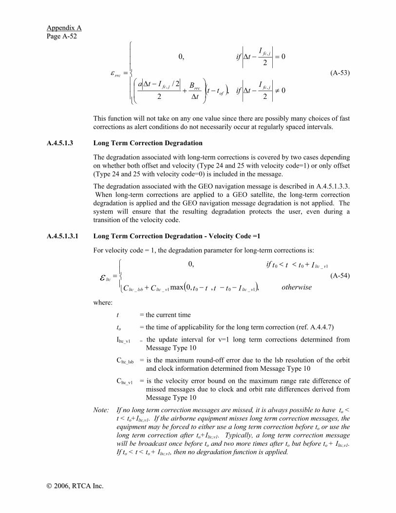
AAppppeennddiixx AA PPaaggee AA--5522
©© 22000066,, RRTTCCAA IInncc..
( )⎪⎪⎪
⎩
⎪⎪⎪
⎨
⎧
≠−Δ−⎟⎟
⎠
⎞
⎜⎜
⎝
⎛
Δ+
−Δ
=−Δ
=
02
,2
2/
02
,0
,,
,
jfcof
rrcjfc
jfc
rrc
Itiftt
tBIta
Itif
ε (A-53)
This function will not take on any one value since there are possibly many choices of fast corrections as alert conditions do not necessarily occur at regularly spaced intervals.
A.4.5.1.3 Long Term Correction Degradation
The degradation associated with long-term corrections is covered by two cases depending on whether both offset and velocity (Type 24 and 25 with velocity code=1) or only offset (Type 24 and 25 with velocity code=0) is included in the message.
The degradation associated with the GEO navigation message is described in A.4.5.1.3.3. When long-term corrections are applied to a GEO satellite, the long-term correction degradation is applied and the GEO navigation message degradation is not applied. The system will ensure that the resulting degradation protects the user, even during a transition of the velocity code.
A.4.5.1.3.1 Long Term Correction Degradation - Velocity Code =1
For velocity code = 1, the degradation parameter for long-term corrections is:
( )⎪⎩
⎪⎨
⎧
−−−+
+<<=
otherwiseIttttCC
Itttif
vltcvltclsbltc
vltc
ltc
,,,0max
,0
1_001__
1_00
ε (A-54)
where:
t = the current time
to = the time of applicability for the long term correction (ref. A.4.4.7)
Iltc_v1 = the update interval for v=1 long term corrections determined from Message Type 10
Cltc_lsb = is the maximum round-off error due to the lsb resolution of the orbit and clock information determined from Message Type 10
Cltc_v1 = is the velocity error bound on the maximum range rate difference of missed messages due to clock and orbit rate differences derived from Message Type 10
Note: If no long term correction messages are missed, it is always possible to have to < t < to+Iltc,v1. If the airborne equipment misses long term correction messages, the equipment may be forced to either use a long term correction before to or use the long term correction after to+Iltc,v1. Typically, a long term correction message will be broadcast once before to and two more times after to but before to + Iltc,v1. If to < t < to + Iltc,v1, then no degradation function is applied.
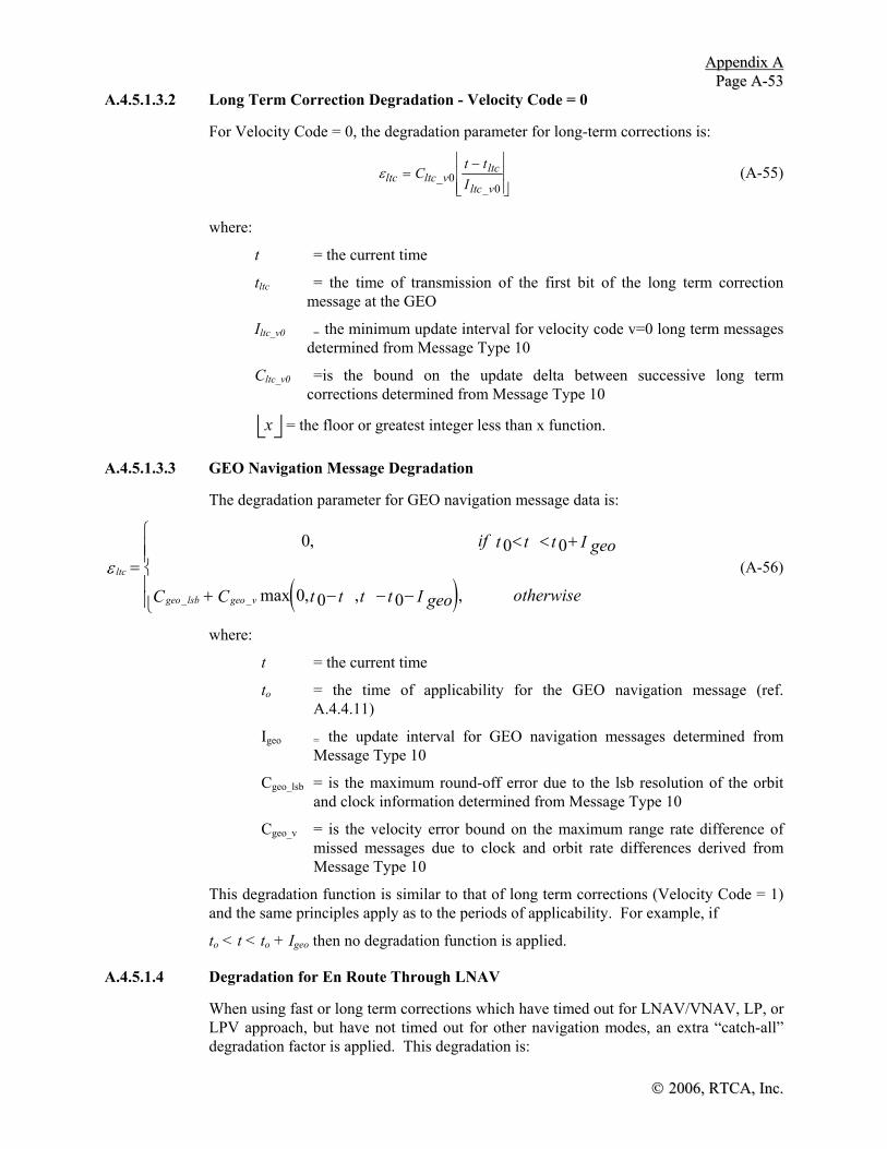
AAppppeennddiixx AA PPaaggee AA--5533
©© 22000066,, RRTTCCAA,, IInncc..
A.4.5.1.3.2 Long Term Correction Degradation - Velocity Code = 0
For Velocity Code = 0, the degradation parameter for long-term corrections is:
εltc ltc vltc
ltc vC
t tI
=−⎢
⎣⎢⎢
⎥
⎦⎥⎥
__
00
(A-55)
where:
t = the current time
tltc = the time of transmission of the first bit of the long term correction message at the GEO
Iltc_v0 = the minimum update interval for velocity code v=0 long term messages determined from Message Type 10
Cltc_v0 =is the bound on the update delta between successive long term corrections determined from Message Type 10
x⎣ ⎦ = the floor or greatest integer less than x function.
A.4.5.1.3.3 GEO Navigation Message Degradation
The degradation parameter for GEO navigation message data is:
( )ltc
geo lsb geo v
if t t t geoI
C C t t t t geoI otherwiseε =
< < +
+ − − −
⎧
⎨⎪⎪
⎩⎪⎪
0 0 0
0 0 0
,
max , , ,_ _
(A-56)
where:
t = the current time
to = the time of applicability for the GEO navigation message (ref. A.4.4.11)
Igeo = the update interval for GEO navigation messages determined from Message Type 10
Cgeo_lsb = is the maximum round-off error due to the lsb resolution of the orbit and clock information determined from Message Type 10
Cgeo_v = is the velocity error bound on the maximum range rate difference of missed messages due to clock and orbit rate differences derived from Message Type 10
This degradation function is similar to that of long term corrections (Velocity Code = 1) and the same principles apply as to the periods of applicability. For example, if
to < t < to + Igeo then no degradation function is applied.
A.4.5.1.4 Degradation for En Route Through LNAV
When using fast or long term corrections which have timed out for LNAV/VNAV, LP, or LPV approach, but have not timed out for other navigation modes, an extra “catch-all” degradation factor is applied. This degradation is:

AAppppeennddiixx AA PPaaggee AA--5544
©© 22000066,, RRTTCCAA IInncc..
⎪⎪⎪⎪
⎩
⎪⎪⎪⎪
⎨
⎧
=
),,/(
),,/(,0
,
LPVLPVNAVLNAVapproachforouttimedhave
scorrectiontermlongorfastifC
LPVLPVNAVLNAVapproachforouttimedhave
scorrectiontermlongnorfastneither
er
erε (A-57)
where:
Cer = degradation parameter determined from Message Type 10
A.4.5.2 Degradation of Ionospheric Corrections
The residual error associated with the ionospheric corrections is characterized by the variance (σionogrid
2) of a model distribution. This parameter is applicable at each ionospheric grid point, and must be interpolated to the user pierce point and translated to slant range (A.4.4.10). This term is computed as:
( )σ
σ ε
σ εionogrid
GIVE iono iono
GIVE iono iono
if RSS Message Type
if RSS Message Type
2
2
2 2
0 10
1 10=
+ =
+ =
⎧
⎨⎪⎪
⎩⎪⎪
, ( )
, ( ) (A-58)
where:
RSSiono = root-sum-square flag from Message Type 10
σGIVE = model parameter from Message Type 26 (ref. A.4.4.10)
and
εiono iono stepiono
ionoiono ramp ionoC
t tI
C t t=−⎢
⎣⎢
⎥
⎦⎥ + −_ _ ( ) (A-59)
where:
Ciono_step = the bound on the difference between successive ionospheric grid delay values determined from Message Type 10
t = the current time
tiono = the time of transmission of the first bit of the ionospheric correction message at the GEO
Ciono_ramp = the rate of change of the ionospheric corrections determined from Message Type 10
Iiono = the minimum update interval for ionospheric correction messages determined from Message Type 10
x⎣ ⎦ = the floor or greatest integer less than x function

AAppppeennddiixx AA PPaaggee AA--5555
©© 22000066,, RRTTCCAA,, IInncc..
A.4.6 Principles and Rules for the Generation and Use of Data
The following principles and rules apply for the SBAS capable receiver (from these principles, the necessary message generation rules at the control center Station may be inferred).
a) The CRC must pass on the received block.
b) The user should correlate with the entire 24 bits of the preamble, but not necessarily in successive 1-second blocks. This assures frame synchronization while allowing for occasional block errors without repeating a complete synchronization.
c) "Use/don't use" or error correction data cannot be used until a Type 1 message providing the PRN mask with an issue of data (IODP) applicable to the data have been decoded. However, long term satellite error corrections and UDREIs can be stored by the users prior to this event and tagged useful once this event and the event in 4) below occurs. Type 1 messages will be broadcast at a rate sufficient to not degrade the user's first fix capability.
d) The embedded Issues of Data (IOD’s) in the long term satellite error corrections will match those in use by the receiver prior to use.
e) Long term satellite error corrections, ionospheric delay error corrections and GEO Navigation Messages will all be broadcast at a rate sufficient to not degrade the user's first fix capability.
A.4.7 Timing
Integrity information (σ2UDRE’s encoded in Types 2 - 5, Type 24 or Type 6) will be
broadcast at least once every six seconds. All other messages will be broadcast in-between, meeting the constraints imposed in Section A.4.5 above and not exceeding the maximum update interval in Table A-25 below. The required intervals apply to data content, not arbitrary messages.
The update intervals do not imply that update rates consistent with Table A-25 will meet all required performance requirements (such as ionospheric delay accuracy). In addition, the data link will broadcast a valid message every second to provide a continuity of signal. The Type 62 and Type 63 messages are valid messages but contain no data. The user time-out intervals defined in Tables A-25 and A-8 limit the time interval of applicability of all correction, integrity and GEO navigation data. The time-out interval for each data is reckoned from the end of reception of the message containing the data.
In addition to the normal messages listed in Table A-25, every alert condition (broadcast in a Type 2 - 5, Type 24, Type 6, Type 26 message) will be repeated three times after the initial notification of the alert condition (for a total of four times in four seconds). Subsequent messages can be broadcast at the normal update rate.
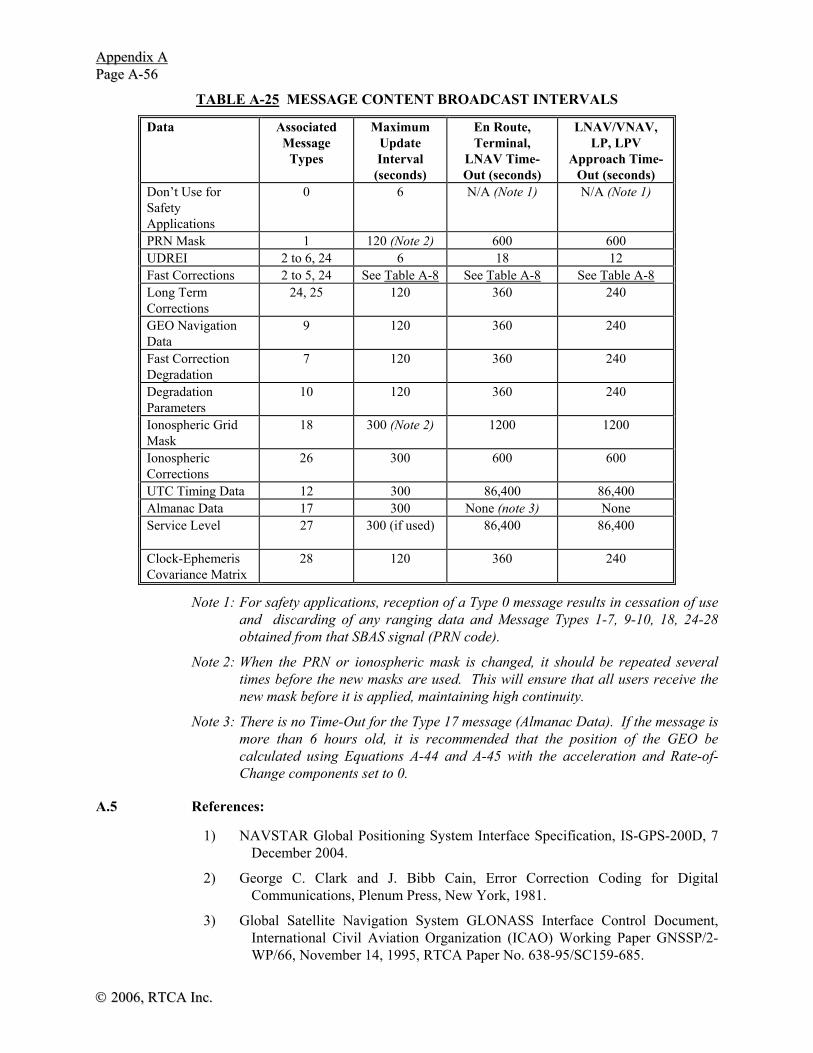
AAppppeennddiixx AA PPaaggee AA--5566
©© 22000066,, RRTTCCAA IInncc..
TABLE A-25 MESSAGE CONTENT BROADCAST INTERVALS
Data Associated Message
Types
Maximum Update Interval
(seconds)
En Route, Terminal,
LNAV Time-Out (seconds)
LNAV/VNAV, LP, LPV
Approach Time-Out (seconds)
Don’t Use for Safety Applications
0 6 N/A (Note 1) N/A (Note 1)
PRN Mask 1 120 (Note 2) 600 600 UDREI 2 to 6, 24 6 18 12 Fast Corrections 2 to 5, 24 See Table A-8 See Table A-8 See Table A-8 Long Term Corrections
24, 25 120 360 240
GEO Navigation Data
9 120 360 240
Fast Correction Degradation
7 120 360 240
Degradation Parameters
10 120 360 240
Ionospheric Grid Mask
18 300 (Note 2) 1200 1200
Ionospheric Corrections
26 300 600 600
UTC Timing Data 12 300 86,400 86,400 Almanac Data 17 300 None (note 3) None Service Level 27 300 (if used)
86,400 86,400
Clock-Ephemeris Covariance Matrix
28 120 360 240
Note 1: For safety applications, reception of a Type 0 message results in cessation of use and discarding of any ranging data and Message Types 1-7, 9-10, 18, 24-28 obtained from that SBAS signal (PRN code).
Note 2: When the PRN or ionospheric mask is changed, it should be repeated several times before the new masks are used. This will ensure that all users receive the new mask before it is applied, maintaining high continuity.
Note 3: There is no Time-Out for the Type 17 message (Almanac Data). If the message is more than 6 hours old, it is recommended that the position of the GEO be calculated using Equations A-44 and A-45 with the acceleration and Rate-of-Change components set to 0.
A.5 References:
1) NAVSTAR Global Positioning System Interface Specification, IS-GPS-200D, 7 December 2004.
2) George C. Clark and J. Bibb Cain, Error Correction Coding for Digital Communications, Plenum Press, New York, 1981.
3) Global Satellite Navigation System GLONASS Interface Control Document, International Civil Aviation Organization (ICAO) Working Paper GNSSP/2-WP/66, November 14, 1995, RTCA Paper No. 638-95/SC159-685.

AAppppeennddiixx AA PPaaggee AA--5577
©© 22000066,, RRTTCCAA,, IInncc..
4) J. K. Wolf and R. D. Blakeney II, “An Exact Evaluation of the Probability of Undetected Error for Certain Shortened Binary CRC Codes,” MILCOM ‘88 Conference Proceedings, Vol. 1, Paper 15-2, Washington, DC, 1988, pp. 287 - 292.
5) W. W. Peterson and E. J. Weldon, Jr., Error Correcting Codes, The MIT Press, Cambridge, MA, 1972.
6) W. W. Peterson and D. T. Brown, “Cyclic Codes for Error Detection,” Proceedings of the IRE, January 1961, pp. 228 - 235.
7) S. Lin and D. J. Costello, Jr., Error Control Coding: Fundamentals and Applications, Prentice-Hall, Inc., Englewood Cliffs, NJ, 1983.
8) W. Stallings, Data and Computer Communications, Macmillan Publishing Co., New York, NY, 1985, pp. 105 - 110.
9) Christopher J. Hegarty, “Optimal Differential GPS for a Data Rate Constrained Broadcast Channel,” Proceedings of the ION GPS-93, Sixth International Technical Meeting of the Satellite Division of The Institute of Navigation, Salt Lake City, Utah, September 22 - 24, 1993, pp. 1527 - 1535.

AAppppeennddiixx AA PPaaggee AA--5588
©© 22000066,, RRTTCCAA IInncc..
THIS PAGE INTENTIONALLY LEFT BLANK

©© 22000066,, RRTTCCAA,, IInncc..
APPENDIX B
STANDARD GPS/WAAS ASSUMPTIONS

©© 22000066,, RRTTCCAA IInncc..
THIS PAGE INTENTIONALLY LEFT BLANK

Appendix B Page B-1
© 2006, RTCA, Inc.
B.1 GPS Constellation
The following parameters describe the target location orbital elements of the Optimized 24 GPS Constellation (Table B-1).
TABLE B-1 OPTIMIZED 24 GPS CONSTELLATION
Orbital Plane
Semimajor Axis (a)
Eccentricity (e)
Inclination Angle (i)
Rt. Ascension
of Ascending Node (Ω)
Arg. of Perigee
(ω)
Mean Anomaly
(M)
1. A1 26559800 0.0 55.0 272.847 0.0 268.126 2. A2 26559800 0.0 55.0 272.847 0.0 161.786 3. A3 26559800 0.0 55.0 272.847 0.0 11.676 4. A4 26559800 0.0 55.0 272.847 0.0 41.806 5. B1 26559800 0.0 55.0 332.847 0.0 80.956 6. B2 26559800 0.0 55.0 332.847 0.0 173.336 7. B3 26559800 0.0 55.0 332.847 0.0 309.976 8. B4 26559800 0.0 55.0 332.847 0.0 204.376 9. C1 26559800 0.0 55.0 32.847 0.0 111.876
10. C2 26559800 0.0 55.0 32.847 0.0 11.796 11. C3 26559800 0.0 55.0 32.847 0.0 339.666 12. C4 26559800 0.0 55.0 32.847 0.0 241.556 13. D1 26559800 0.0 55.0 92.847 0.0 135.226 14. D2 26559800 0.0 55.0 92.847 0.0 265.446 15. D3 26559800 0.0 55.0 92.847 0.0 35.156 16. D4 26559800 0.0 55.0 92.847 0.0 167.356 17. E1 26559800 0.0 55.0 152.847 0.0 197.046 18. E2 26559800 0.0 55.0 152.847 0.0 302.596 19. E3 26559800 0.0 55.0 152.847 0.0 333.686 20. E4 26559800 0.0 55.0 152.847 0.0 66.066 21. F1 26559800 0.0 55.0 212.847 0.0 238.886 22. F2 26559800 0.0 55.0 212.847 0.0 345.226 23. F3 26559800 0.0 55.0 212.847 0.0 105.206 24. F4 26559800 0.0 55.0 212.847 0.0 135.346
The epoch date for this constellation is June 30, 1993 at 23:34:24 (1993, 6, 30, 23 hr, 34 min, 24 sec UTC, or GPS Week 703, 344064 seconds).
B.2 WAAS Constellation
For the purpose of simulator testing, WAAS satellites are located at the following longitudes and inclination angles.
WAAS Satellite Longitude Inclination
PRN 120 W 15.5 2.3 degrees PRN 122 W 55.5 2.3 degrees PRN 134 W 179.5 2.3 degrees

Appendix B Page B-2
©© 22000066,, RRTTCCAA,, IInncc..
B.3 Selective Availability
Selective Availability will be modeled as the sum of (1) a second-order Gauss-Markov process with an auto-correlation time of 118 seconds and a standard deviation of 23 m, and (2) a random constant with normal distribution, a mean of zero and a standard deviation of 23 m.
The second-order Gauss-Markov process is described by the power spectral density:
s c mrado
( )/ sec
ωω ω
=+
2
4 4
2
4 4
where C2 = 0.002585 m2 ω0 = 0.012 rad/sec
The SA processes on all satellites are to be statistically independent. When modeling a single independent SA sample (for a single snapshot or for samples greater than 2 minutes apart), SA can be modeled by a Gaussian random variable with a mean of zero and a standard deviation of 33 m.
B.4 GPS Satellite Failure
The probability of a satellite integrity failure is 10-4 per hour for the GPS position solution (based on 3 satellite major service failures/year/constellation, assuming 8 satellites in view). A satellite integrity failure is defined to be an insidious failure that contributes to a hazardously misleading situation.
B.5 GPS Constellation for Availability Analysis
Table B-2 contains the location of the GPS satellites on December 1, 1995 at 0000UTC. These locations can be used for the FDE availability analysis, and may also be used to test simulation orbit software.

Appendix B Page B-3
© 2006, RTCA, Inc.
TABLE B-2 GPS CONSTELLATION ON DECEMBER 1, 1995 AT 00:00 UTC
(GPS Week: 829 GPS Seconds: 00432000)
SVID MEAN ANOMALY
OMEGA_O X-Position Y-Position Z-Position
1 268.126 -2.253 -14870571.94 8899797.75 -20126665.56 2 161.786 -2.253 23589887.94 11991875.55 -2266072.27 3 11.676 -2.253 -16176102.35 -16770562.96 12747741.24 4 41.806 -2.253 -4355434.09 -17071145.97 19875340.13 5 80.956 57.747 15395084.60 5233826.18 21000509.74 6 173.336 57.747 -1695661.81 25682884.00 -6552646.52 7 309.976 57.747 -9297858.71 -23002281.98 -9479864.10 8 204.376 57.747 -9361634.66 18753790.62 -16311900.87 9 111.876 -242.253 -9092026.91 19872361.08 15094611.22 10 11.796 -242.253 22600908.12 -5583452.08 12784638.87 11 339.666 -242.253 21913985.95 -14935082.68 1464070.04 12 241.556 -242.253 -10617702.92 -11042774.34 -21696647.11 13 135.226 -182.253 -24936980.94 -5007408.16 7648256.07 14 265.446 -182.253 13908721.33 -9596379.71 -20490972.24 15 35.156 -182.253 7188942.92 17419062.74 18716792.70 16 167.356 -182.253 -22645671.90 -13176689.83 -4355613.11 17 197.046 -122.253 7720020.91 -20979445.69 -14341795.98 18 302.596 -122.253 10802779.38 21135634.15 -11916706.88 19 333.686 -122.253 3560816.01 26307697.10 -805381.07 20 66.066 -122.253 -15149811.05 1603096.34 21756292.96 21 238.886 -62.253 11566835.96 10254727.75 -21597959.17 22 345.226 -62.253 -22547453.11 13577895.19 3560350.61 23 105.206 -62.253 6551951.60 -19489487.66 16812340.02 24 135.346 -62.253 16838480.90 -19079928.60 7605580.96
All semi-major axes are 26559800 meters.
All eccentricities are 0.0
All orbital planes are inclined at 55 degrees.
OMEGA_0 = omega - 275.1.
B.6 Signal Quality Monitoring
The signal effects that might cause a Double Delta (DD) Delay Lock Loop (DLL) discriminator to track the wrong peak can be categorized into three different effects on the correlation function as follows:
B.6.1 Dead Zones
If the correlation function loses its peak, then the receiver’s discriminator function will include a flat spot or dead zone. If the reference receiver and aircraft receiver settle in different portions of this dead zone, then Misleading Information (MI) can result.
B.6.2 False Peaks
If the reference receiver and aircraft receiver lock to different peaks, then MI could exist.

Appendix B Page B-4
©© 22000066,, RRTTCCAA,, IInncc..
B.6.3 Distortions
If the correlation peak is misshapen, then an aircraft that uses a correlator spacing other than the one used by the reference receivers may well suffer MI.
B.6.4 Threat Models
The GPS threat model has three parts that can create the three correlation peak pathologies listed above.
B.6.4.1 Threat Model A
Threat Model A consists of the normal C/A code signal except that all positive chips have a falling edge that leads or lags relative to the correct end time for that chip. This threat model is associated with a failure in the Navigation Data Unit (NDU), the digital partition of a GPS satellite. Threat Model A has a single parameter Δ, which is the lead (Δ < 0) or lag (Δ > 0) expressed in fractions of a chip. The range for this parameter is −0.12< Δ ≤0.12. Within these ranges, Threat Model A generates the dead zones described above. (Note that waveforms with lead need not be tested, because their correlation functions are simply advances of the correlation functions for lag. Hence the MI threat is identical.)
B.6.4.2 Threat Model B
Threat Model B introduces amplitude modulation and models degradations in the analog section of the GPS satellite. More specifically, it consists of the output from a second order system when the nominal C/A code baseband signal is the input. Threat Model B assumes that the degraded satellite subsystem can be described as a linear system dominated by a pair of complex conjugate poles. These poles are located at σ ± j2πfd , where σ is the damping factor in nepers/second and fd is the resonant frequency with units of cycles/second. They can also be used to specify the impulse response h2nd(t) or the unit step response e(t). The unit step response of a second order system is given by
( )⎪⎭
⎪⎬⎫
⎪⎩
⎪⎨⎧
>⎥⎦
⎤⎢⎣
⎡+−−
≤= 0sincosexp1
00)( tttt
tte
dd
d ωωσωσ
Threat Model B corresponding to 2nd order anomalies uses the following ranges for the parameters defined above :
Δ=0; 4 ≤ fd ≤ 17 and 0.8 ≤ σ ≤ 8.8. Within these parameter ranges, Threat Model B generates distortions of the correlation peak as well as false peaks.
B.6.4.3 Threat Model C
Threat Model C introduces both lead/lag and amplitude modulation. More specifically, it consists of outputs from a second order system when the C/A code signal at the input suffers from lead or lag. This waveform is a combination of the two effects described above. Threat Model C includes all three parameters described above with the following ranges:
-0.12 ≤ Δ ≤ 0.12; 7.3 ≤ fd ≤ 13 and 0.8 ≤ σ ≤8.8.

Appendix B Page B-5
© 2006, RTCA, Inc.
Within these parameter ranges, Threat Model C generates dead zones, distortions of the correlation peak, and false peaks.

Appendix B Page B-6
©© 22000066,, RRTTCCAA,, IInncc..
THIS PAGE INTENTIONALLY LEFT BLANK

© 2006, RTCA, Inc.
APPENDIX C
STANDARD RECEIVED SIGNAL AND INTERFERENCE ENVIRONMENT

©© 22000066,, RRTTCCAA,, IInncc..
THIS PAGE INTENTIONALLY LEFT BLANK

AAppppeennddiixx CC PPaaggee CC--11
©©,, 22000066,, RRTTCCAA,, IInncc..
C.1 Introduction
This appendix specifies the RF Interference environment at and around L-band frequencies for GPS/SBAS receivers. It also describes the frequency selectivity of the minimum standard antenna.
All signal levels in this appendix are specified in dBm measured at the antenna port.
C.2 Operating Interference Environment
Interference levels specified in this appendix are defined at the antenna port regardless of antenna radiation pattern.
Figure C-1 represents the operating interference environment. The regions of this figure indicated as having interference with bandwidths other than CW are considered to represent in-band and near-band interference with received power levels defined in Figure C-2 as a function of bandwidth. Figure C-3 represents the frequency selectivity of the minimum standard antenna in order to define the operating environment of equipment using such an antenna.
C.2.1 Out-of-Band Interference
The out-of-band continuous wave (CW) interfering signals can be as high as the levels shown in Figure C-1, measured at the antenna port. The CW interference level below 1500 MHz increases linearly to 25.5 dBm at 1315 MHz. The CW level increases linearly above 1640 MHz, to 21.5 dBm at 2 GHz, accounting for High Intensity Radiation Fields (HIRF).
-130
-120
-110
-100
-90
-80
-70
-60
-50
-40
-30
-20
-10
0
10
1500
1505
1510
1515
1520
1525
1530
1535
1540
1545
1550
1555
1560
1565
1570
1575
1580
1585
1590
1595
1600
1605
1610
1615
1620
1625
1630
1635
1640
FREQUENCY - MHz
INTE
RFE
REN
CE
LEV
EL -
dBm
40 MHz
CENTERED AT 1575.42 MHz
-89.5
(1525,-12)
(1626.5,+8)
-120.5
CW INTERFERENCEBELOW LOWER LINE
INTERFERENCE VARIES
WITH BANDWIDTHBELOW -89.5 dBm
1 MHz
(1618,-12)
AIRCRAFT WITH SATCOM
ALL OTHERS
FIGURE C-1 INTERFERENCE LEVELS AT THE ANTENNA PORT
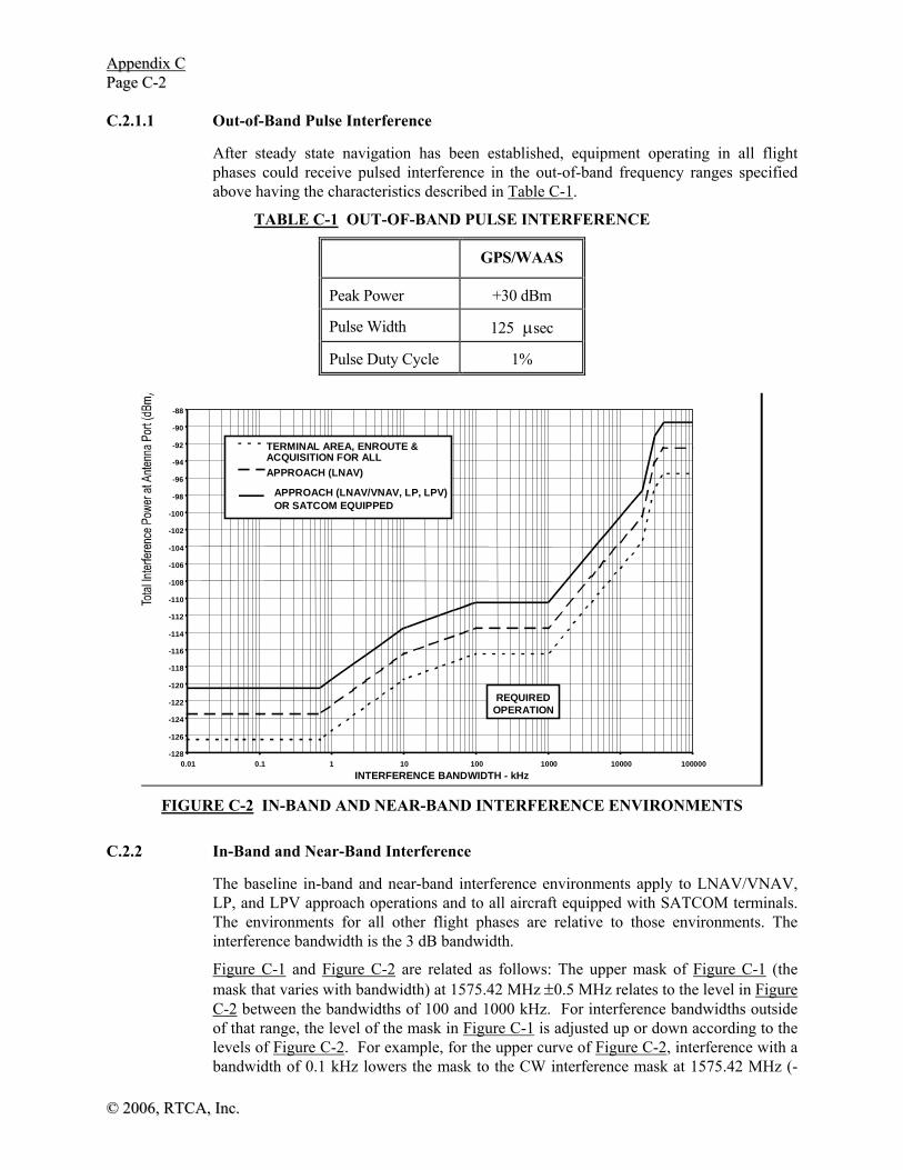
AAppppeennddiixx CC PPaaggee CC--22
©© 22000066,, RRTTCCAA,, IInncc..
C.2.1.1 Out-of-Band Pulse Interference
After steady state navigation has been established, equipment operating in all flight phases could receive pulsed interference in the out-of-band frequency ranges specified above having the characteristics described in Table C-1.
TABLE C-1 OUT-OF-BAND PULSE INTERFERENCE
GPS/WAAS
Peak Power +30 dBm
Pulse Width 125 μsec
Pulse Duty Cycle 1%
-128 -126 -124 -122 -120 -118 -116 -114 -112 -110 -108 -106 -104 -102 -100 -98 -96 -94 -92 -90 -88
0.01 0.1 1 10 100 1000 10000 100000 INTERFERENCE BANDWIDTH - kHz
TERMINAL AREA, ENROUTE &ACQUISITION FOR ALLAPPROACH (LNAV)
APPROACH (LNAV/VNAV, LP, LPV)OR SATCOM EQUIPPED
REQUIREDOPERATION
FIGURE C-2 IN-BAND AND NEAR-BAND INTERFERENCE ENVIRONMENTS
C.2.2 In-Band and Near-Band Interference
The baseline in-band and near-band interference environments apply to LNAV/VNAV, LP, and LPV approach operations and to all aircraft equipped with SATCOM terminals. The environments for all other flight phases are relative to those environments. The interference bandwidth is the 3 dB bandwidth.
Figure C-1 and Figure C-2 are related as follows: The upper mask of Figure C-1 (the mask that varies with bandwidth) at 1575.42 MHz ±0.5 MHz relates to the level in Figure C-2 between the bandwidths of 100 and 1000 kHz. For interference bandwidths outside of that range, the level of the mask in Figure C-1 is adjusted up or down according to the levels of Figure C-2. For example, for the upper curve of Figure C-2, interference with a bandwidth of 0.1 kHz lowers the mask to the CW interference mask at 1575.42 MHz (-

AAppppeennddiixx CC PPaaggee CC--33
©©,, 22000066,, RRTTCCAA,, IInncc..
120.5 dBm), while interference with a bandwidth of 20 MHz raises the mask at 1575.42 MHz at a level of -97.5 dBm. In addition, if the center of the interference moves away from 1575.42 MHz, the levels of Figure C-2 for bandwidths not greater than 20 MHz are raised according to the mask of Figure C-1. For example, for the upper curve of Figure C-2, for interference centered at 1565.42 MHz, the curve of Figure C-2 is increased by 13 dB.
After steady state navigation has been established, the equipment could receive an interfering signal in the frequency range of 1575.42 ±BWI/2 MHz that is as high as the levels defined in Table C-2 as a function of interfering signal bandwidth BWI:
TABLE C-2 IN-BAND AND NEAR-BAND INTERFERENCE BANDWIDTH DEFINITIONS
BANDWIDTH INTERFERENCE LEVEL
0 ≤ BWI ≤ 700 Hz -120.5 dBm
700 Hz < BWI ≤ 10 kHz Linearly increasing[1] from -120.5 dBm to -113.5 dBm
10 kHz < BWI ≤ 100 kHz Linearly increasing[1] from -113.5 dBm to -110.5 dBm
100 kHz < BWI ≤ 1 MHz -110.5 dBm
1 MHz < BWI ≤ 20 MHz Linearly increasing[1] from -110.5 to -97.5 dBm[2]
20 MHz < BWI ≤ 30 MHz Linearly increasing[1] from -97.5 to -91.1 dBm[2]
30 MHz < BWI ≤ 40 MHz Linearly increasing[1] from -91.1 to -89.5 dBm[2]
40 MHz < BWI -89.5 dBm[2]
[1] Increase in interference power is linear for the units shown in Figure C-2.
[2]Interference levels will not exceed –110.5 dBm/MHz in the frequency range of 1575.42 ± 10 MHz.
These interfering levels as a function of bandwidth are shown in Figure C-2.
The in-band and near-band interference levels for the LNAV approach steady-state navigation operations are 3 dB less than those for LNAV/VNAV, LP, and LPV approach steady-state navigation operations. For terminal area and en route steady-state navigation operations, and for initial acquisition of the GPS and WAAS signals prior to steady-state navigation for all flight phase operations, the in-band and near-band interference levels are 6 dB less than those for LNAV, LNAV/VNAV, and LPV approach steady-state navigation operations.
C.2.2.1 In-Band and Near-Band Pulsed Interference
After steady state navigation has been established, equipment operating in all flight phases could receive pulsed interference in the in-band and near-band frequency ranges specified above having the characteristics described in Table C-3.

AAppppeennddiixx CC PPaaggee CC--44
©© 22000066,, RRTTCCAA,, IInncc..
TABLE C-3 IN-BAND AND NEAR-BAND PULSE INTERFERENCE
GPS/SBAS
Peak Power +10 dBm
Pulse Width 125 μsec
Pulse Duty Cycle 1%
SSiiggnnaall BBaannddwwiiddtthh 1 MHz
C.2.3 GNSS Noise
The GNSS Noise is a broadband noise with spectral density that has an equivalent effect on the equipment than the aggregate power from the anticipated future GNSS environment, including GPS C/A, P/Y, and M-code signals from a full GPS constellation, SBAS C/A code signals from the anticipated SBAS providers, QZSS and Galileo. Values are specified in Table C-4 for different receiver functions due to different signal coupling and operational requirements.
TABLE C-4 EFFECTIVE NOISE DENSITY FOR ALL GNSS SOURCES
Receiver Function Effective Noise Density (dBm/Hz)
Initial Acquisition (GPS Only)*
-172.9
GPS Tracking and Re-acquisition
-171.9
SBAS Tracking and Re-acquisition
-173.0
* In the presence of many GPS signals, it is assumed that the receiver will acquire GPS satellites first so that an SBAS signal is not necessary for initial acquisition.
C.3 Minimum Standard Antenna Frequency Selectivity
When received by a minimum standard antenna, interfering signals are attenuated, at minimum, in accordance with the frequency selectivity shown in Table C-5 and Figure C-3.

AAppppeennddiixx CC PPaaggee CC--55
©©,, 22000066,, RRTTCCAA,, IInncc..
TABLE C-5 FREQUENCY SELECTIVITY
Frequency (MHz) Selectivity (dB) 1315 ≤ f < 1504.42 -50 dB
1504.42 ≤ f < 1554.42 Linearly increasing from -50 dB to -5 dB 1554.42 ≤ f < 1558.42 Linearly increasing from -5 dB 1558.42 ≤ f ≤ 1591.92 0 dB 1591.92 < f ≤ 1605.42 Linearly decreasing to -25.35 dB 1605.42 < f ≤ 1625.42 Linearly decreasing from -25.35 dB to -50 dB
1625.42 < f ≤ 2000 -50 dB
-70
-65
-60
-55
-50
-45
-40
-35
-30
-25
-20
-15
-10
-5
0
1.495 1.505 1.515 1.525 1.535 1.545 1.555 1.565 1.575 1.585 1.595 1.605 1.615 1.625 1.635
Frequency (GHz)
Freq
uenc
y Se
lect
ivity
(dB
)
FIGURE C-3 FREQUENCY SELECTIVITY

AAppppeennddiixx CC PPaaggee CC--66
©© 22000066,, RRTTCCAA,, IInncc..
THIS PAGE INTENTIONALLY LEFT BLANK

©©,, 22000066,, RRTTCCAA,, IInncc..
APPENDIX D
DATA FORMAT FOR HIGH INTEGRITY INFORMATION TO SUPPORT STRAIGHT AND ADVANCED LANDING APPROACH OPERATIONS

©© 22000066,, RRTTCCAA,, IInncc..
THIS PAGE INTENTIONALLY LEFT BLANK

Appendix D Page D-1
© 2006, RTCA, Inc.
D.1 Introduction
Unlike ILS or MLS where the approach path is defined by radio signals originating from a properly aligned ground station antenna, GNSS LP and LPV approaches are based on reference paths defined by surveyed points. Coordinates defining these points must be of high resolution and integrity. This appendix defines the format for this type of data.
The information to support computed straight and advanced approach procedures is comprised of several items. These include runway and airport information, procedure naming and approach and departure procedure waypoint information. The information for straight-in approaches is fully described in the following paragraphs. This format provides integrity protection for the data it contains. The primary purpose of this format is to support straight-in LPV and LP approaches for navigation systems requiring this data to determine the reference path. The first and principal application is the provision of high accuracy and high integrity data for GPS/SBAS LPV and LP approach operations. LPV and LP approach airborne equipment must be capable of interpreting this format.
The format is also capable of supporting advanced approaches and departures; but, the specific format for advanced procedures is currently undefined.
D.2 Format
D.2.1 Overall Structure
Although data may be stored or transmitted in any way, the data is organized in data blocks for the purpose of computing the CRC. Each data block contains all the information necessary for one single path. This appendix describes the data block structure only for the computation of the CRC. The database organization, including how this information is stored in a database, is left to the industry. The data suppliers and the equipment manufacturers will find ways of assembling the data blocks into the databases for the users.
To organize the databases additional data elements may need to accompany the data blocks. Because these extra elements do not necessarily require high integrity protection and also because any additional data may change while the final approach path segment remains constant, it was chosen not to include them in this appendix.
D.2.2 Data Block Description
The block contains data for a single operation. It is self-contained and includes a means to preserve integrity from the time it is generated and validated to the time that it is used in airborne equipment. All of the information necessary to describe the paths and its designation is contained within it. This primarily includes the following: airport identification, runway designation and position, procedure type (provides flexibility for advanced procedures such as departure or curved approach), procedure name, and runway surveyed points. The data block is generated, protected by application of a CRC and validated by the appropriate authorities before distribution. The data block can be transported, reformatted and distributed as long as the original format can be recovered, thereby allowing the verification of the original CRC distributed with the data block by the authority.

Appendix D Page D-2
© 2006, RTCA, Inc.
D.2.3 Data Block Structure
The data block structure consists of a series of fields of different size. The sequence of the fields depends on the operation type the data block supports. Fields common to the different types of operations are placed in the beginning of the data blocks. It is recognized that the data does not have to be stored or transferred in this format; a more suitable condensed format may be used.
Only the format for straight-in procedures is defined at this time. Note that the data blocks for advanced procedures are likely to have different lengths. Table D-1 indicates the overall structure for straight-in approaches. The data items are defined in Section D.3.
The CRC field always terminates the data block.
D.3 Final Approach Segment Data Block
The Final Approach Segment Data Block contains the parameters, which define a single final approach segment. Figure D-1 depicts a final approach segment and illustrates the parameters, which define the approach path. Each FAS data block ends with a CRC generated by the procedure designer and unchanged until used. This protects the integrity of the final approach segment data.
ulat
urw
GPIP
GPIP
FPAP
FPAP
GlidepathAngle
TCH
uvert
urw
WGS-84 Ellipsoid
LTP/FTP
LTP/FTP
Plan View
Profile View
Earth's surface
LTP/FTP height
FIGURE D-1 FINAL APPROACH SEGMENT DIAGRAM
The protected FAS data blocks are validated individually by the civil authorities. The data blocks include data that allow for an unambiguous FAS selection against the desired approach charts.

Appendix D Page D-3
© 2006, RTCA, Inc.
D.3.1 Final Approach Segment Parameter Definition
Operation Type: indicates whether the operation is an approach procedure, an advanced operation or others to be defined later. The valid range is limited to 0-15. The convention for coding is as follows:
0 = straight-in approach procedure
1,2 = reserved
3-15 = spare
Note: Advanced operation can be straight-in approaches followed by a missed-approach, a curved approach, a precise departure procedure, or roll-out and taxiing procedures.
SBAS Service Provider ID: represents the SBAS service provider that is authorized for use with the approach. Service provider ID of 15 indicates that any provider may be used. Service provider ID of 14 indicates the FAS data block is not intended for SBAS use.
Airport Identification: represents the three or four alphanumeric characters used to designate airport facilities and corresponds to the ICAO airport identifier. Each character is coded using bits b1 to b6 of its International Alphabet No. 5 representation (reference Section 2.4.2). For each character, bit b1 is transmitted first, and two zero bits are appended after bit b6, so that 8 bits are transmitted for each character. The right-most character is transmitted first. Only upper case letters, numbers, and IA-5 “space” (“10 0000”) are used. When a three-character identifier is used, the right-most (first transmitted) character is IA-5 "space".
Runway Number: represents the approach runway number. The valid range is 0-36. Runway numbers 1 through 36 designate runway or point in space final approach course rounded to the nearest 10 degrees and the designation 0 identifies heliport operations.
Runway Letter: represents the runway letter, where used to differentiate between parallel runways. The valid range is 00 through 11. The convention for coding is as follows:
00 = no letter 10 = C (center)
01 = R (right) 11 = L (left)
Approach Performance Designator: The Approach Performance Designator field is not used by SBAS equipment.
Route Indicator: One-letter identifier used to differentiate between multiple approaches to the same runway end. Characters are coded using bits b1 to b5 of International Alphabet No. 5. The letter is an IA-5 (now called International Reference Alphabet IRA5) “space” or upper-case alpha character, excluding the letters "I" and "O". Note that a “space” is represented as zeros for bits b1 to b5.
Reference Path Data Selector: A numerical identifier used to select the FAS data block (desired approach). It is intended for GBAS and is not used for SBAS operations.
Reference Path Identifier: represents the three or four alphanumeric characters used to uniquely designate the reference path. The reference path identifier is synonymous with the “approach ID” located beneath the channel number on instrument approach plates and is unique only for a given airport. Only upper-case alpha characters or numeric digits are
Appendix D Page D-4
© 2006, RTCA, Inc.
used. The most significant two bits of every character (8-bit word) are zero. Alphanumeric characters are coded using bits b1 to b6 of International Alphabet ISO No. 5. When a three-character identifier is used, the right-most character b1 to b6 are set to indicate a blank (10 0000).
Note: Existing charting convention charts the leading character as a W, the runway number, and a trailing alpha character. For point in space procedures the final approach course rounded to the closest 10 degrees replaces the runway number.
LTP/FTP Latitude: represents the latitude of the threshold defined in WGS-84 coordinates and encoded in arc seconds. The most significant bit is the sign bit:
0 = positive (Northern Hemisphere)
1 = negative (Southern Hemisphere)
LTP/FTP Longitude: represents the longitude of the threshold defined in WGS-84 coordinates and encoded in arc seconds. The most significant bit is the sign bit:
0 = positive (Eastern Hemisphere)
1 = negative (Western Hemisphere)
Landing Threshold Point (LTP)/Fictitious Threshold Point (FTP) Height Above Ellipsoid: represents the WGS-84 height of the LTP/FTP. This field is coded as an unsigned value with an offset of -512 m. A value of zero in this field places the LTP/FTP 512 m below the earth ellipsoid.
ΔFlight Path Alignment Point – Latitude: represents the difference in latitude of the runway Flight Path Alignment Point (FPAP) from the LTP/FTP, defined in WGS-84 coordinates and encoded in arc seconds. The most significant bit is the sign bit. Positive values denote the FPAP latitude north of the LTP/FTP latitude. Negative values denote the FPAP latitude south of the LTP/FTP latitude.
ΔFlight Path Alignment Point – Longitude: represents the difference in longitude of the runway Flight Path Alignment Point (FPAP) from the LTP/FTP, defined in WGS-84 coordinates and encoded in arc seconds. The most significant bit is the sign bit. Positive values denote the FPAP longitude east of the LTP/FTP longitude. Negative values denote the FPAP longitude west of the LTP/FTP longitude.
Approach Threshold Crossing Height (TCH): the height of the FAS path above the LTP/FTP defined in either feet or meters as indicated by the Approach TCH Units Selector.
Approach Threshold Crossing Height (TCH) Units Selector: this bit defines the units used to describe the Threshold Crossing Height. The definition of the bit is:
0 = feet
1 = meters
Glidepath Angle (GPA): represents the angle of the FAS path (glide path) with respect to the horizontal plane tangent to the WGS-84 ellipsoid at the LTP/FTP.
Course Width at Threshold: The lateral displacement from the path defined by the FAS at the LTP/FTP at which full-scale deflection of a course deviation indicator is attained. This field is coded as an unsigned fixed-point number with an offset of 80 meters. A value of zero in this field indicates a course width of 80 meters at the LTP/FTP. The

Appendix D Page D-5
© 2006, RTCA, Inc.
course width field is ignored if the Runway Number is coded as 0 (helicopter pad). Instead, a course width of 38 m is used at the LTP/FTP.
∆Length offset: The distance from the stop end of the runway to the FPAP. A coding of 1111 1111 indicates that the value is not provided.
Horizontal Alarm Limit (HAL): represents the horizontal alarm limit to be used during the approach. The range of values is 0 to 51.0 m with a 0.2 m resolution.
Vertical Alarm Limit (VAL): represents the vertical alarm limit to be used during the approach. The range of values is 0 to 51.0 m with a 0.2 m resolution. A value of 0 indicates that vertical deviations cannot be used (i.e., a lateral-only approach).
Final Approach Segment CRC: is a 32 bit cyclic redundancy check (CRC) appended to the end of each FAS Data Block in order to ensure approach data integrity. The CRC word is calculated on the entire data block. A complete description of the CRC is provided in Section D.5.
D.3.2 Final Approach Segment Data Table
TABLE D-1 FINAL APPROACH SEGMENT (FAS)
Data content Bits used Range of values Resolution Operation type 4 0 to 15 1 SBAS provider ID 4 0 to 15 1 Airport ID 32 - - Runway number (Note 1) 6 0 to 36 1 Runway letter 2 - - Approach performance designator 3 0 to 7 1 Route indicator 5 - - Reference path data selector 8 0 to 48 1 Reference path identifier 32 - - LTP/FTP latitude 32 ± 90.0 ° 0.0005 arcsecLTP/FTP longitude 32 ± 180.0 ° 0.0005 arcsecLTP/FTP height 16 -512.0 to 6041.5 m 0.1 m ΔFPAP latitude 24 ± 1.0 ° 0.0005 arcsecΔFPAP longitude 24 ± 1.0 ° 0.0005 arcsecApproach threshold crossing height (TCH)
15 0 to 1638.35 m (0 to 3276.7 ft)
0.05 m (0.1 ft)
Approach TCH units selector 1 - - Glidepath angle (GPA) 16 0 to 90.0 ° 0.01° Course width at threshold (Note 1)
8 80.0 to 143.75 m 0.25 m
ΔLength offset 8 0 to 2032 m 8 m Horizontal Alert Limit (HAL) 8 0 to 51.0 m 0.2 m Vertical Alert Limit (VAL) (Note 2)
8 0 to 51.0 m 0.2 m
Final approach segment CRC 32 - -
Note 1: When the runway number is set to 00, then the course width field is ignored and the course width is 38 meters.

Appendix D Page D-6
© 2006, RTCA, Inc.
Note 2: A VAL of 0 indicates that the vertical deviations cannot be used (i.e., a lateral-only approach).
D.4 Advanced Procedures Data Blocks
The data format has the capability through the procedure identifier, to accommodate advanced procedures. The format for those procedures is currently undefined.
D.5 CRC Definition
The CRC consists of the coefficients of the remainder R(x) of the modulo-2 division of two polynomials:
[ xM(x)G(x)
] = Q(x)+R(x)G(x)
K2mod
Where k is the number of bits in the CRC and the polynomial and M(x) consists of the sequence of data bits to be protected by the CRC (excluding the CRC bits):
M x m xii
nn i( ) =
−
−∑1
The data bits (m1, ...,mn) are treated as a single word of n bits, arranged in order of transmission without any byte-wise reversal of bits.
Numbering of the data block goes from the LSB to the MSB, beginning with the operation type and following through all of the data. The CRC follows with R1 as the MSB (ie. xk ) and the last bit is Rk (ie. x1 ).
G(x) is the FAS Data Block generator polynomial:
G(x) = x32 + x31 + x24 + x22 + x16 + x14 + x8 + x7 + x5 +x3 + x + 1
Q(x) is the quotient of the division.
The quotient Q(x) is obtained by dividing xk *M(x) by G(x) starting with m1(or mi) and G1 = xk considered as being the highest bits in their respective polynomial as follows:
[m1*x (n+32) + m2*x (n+31) + ... + mn*x 32 ] / [x 32 +x 31 +x 24 +x 22 +x 16 + x 14 + x 8+x 7 +x 5 +x 3 +x + 1]
The remainder of the division must match the received CRC R1 through R32 bits
R1*x 32 + R2*x 31 +R3*x 30 ........ + R32*x1
D.6 Informative Section
D.6.1 Integrity Protection of Data Blocks
The principle of integrity protection resides in the presence of a CRC for each data block. The CRC is added to the data block when it is generated. The airborne equipment verifies the data integrity by generating the CRC as part of the procedure design process and comparing it to the CRC of the data block supplied by the authority. A perfect match indicates the data is not corrupted and can be used. The use of a CRC provides a
Appendix D Page D-7
© 2006, RTCA, Inc.
theoretical bound on the probability of undetected error of 2-r, where r is the number of bits of the CRC. For this format a 32 bit CRC is used. The corresponding upper bound for the 32 bit code is 2.3283 x 10⁻¹⁰. The CRC, CRC-32Q(Q for Qualcomm) was chosen [1]. It has proven well behaved at all the bit error rates for message length of the same order magnitude as the ones likely to occur for the data blocks.
ILS and MLS certifying authorities commission ground installations and create approach procedures for landing using the facility. The integrity is ensured by proper alignment of the transmitting antennas, flight checks and integrity monitors on the transmitted signal. For approaches based on data, the integrity of the approach rests on the data describing the approach path. Likewise the integrity is ensured by the certifying authorities when they issue the data block for use. They design the approach procedure, calculate the parameters, organize the data block and calculate the CRC. The data block is then validated by flight test or other suitable means before being issued. The integrity is ensured when the airborne equipment making use of the data successfully passes the CRC on the data block. It is allowed to reformat the data blocks for the purpose of distribution, creating databases customized to operator missions. However the on-board equipment must be able to recover the original format bit-for-bit without any exception. The original CRC should be transferred as is without any transformation.
D.6.2 Approach Path Selection
Another element key to the integrity of approaches based on data is the approach selection. The CRC verification does not guarantee that the proper approach has been selected. It is the responsibility of the pilot to verify proper approach path selection. This may be accomplished through the approach identifier, or a combination of the airport, runway, and route indicators.
D.6.3 Data Block Generation
The data generation typically starts with a precise survey of both ends of the runway to be served. The geodetic coordinates are based on the WGS-84 system. The landing threshold point/fictitious threshold point (LTP/FTP) and flight path alignment point (FPAP) are determined from these surveyed points, and will usually be coincident with the runway threshold at both runway ends. The TCH and glidepath angle are determined by the obstacle avoidance criteria in use for the operations to be supported.
Once the FPAP geodetic coordinates are determined, the FPAP position can be expressed by the difference of coordinates with respect to the LTP/FTP. The FPAP does not require a vertical component in order to define the glidepath. Its sole role is to define the vertical plane which defines the lateral deviation reference. For the calculations on-board the aircraft and for the procedure designer, the FPAP is defined to be at the same ellipsoid height as for the LTP/FTP.
The data block is then finalized by adding the other data and by calculating the CRC.
The data block is then entered into flight inspection equipment for validation. The authorities fly the approach and validate the data and CRC. They must also ensure that the data to be published on the approach plates correspond to the data block.
The data is then issued to the industry for distribution.

Appendix D Page D-8
© 2006, RTCA, Inc.
D.6.4 Database Formatting and Distribution
Data blocks need to be transferred to the data providers preferably on electronic media. A transportation layer compatible with the media must be defined.
A standard textual-based version of the binary data needs to be defined to be able to share data whenever transfer of the binary data block is not possible. Care must be taken to ensure that transformation to and from binary and textual format can be done such that every bit can be recovered. This ensures a successful CRC.
The same sub-committee also needs to standardize means of integrating data blocks into databases to allow for seamless departure, en route, terminal, and LPV/LP approach.
Industry may elect to standardize a method of data reformatting and high integrity database transportation. For example, high integrity data could be integrated in the ARINC-424 format. For this purpose the data block elements can be extracted and reformatted, provided certain rules are followed. The values contained in the numeric fields should be expressed in the new format such that they can be retrieved in the original format without a change in any of the bits. There should be no transformation that truncates or rounds numbers. In addition, the original CRC must be transferred unchanged throughout the distribution chain.
The industry must define where the reverse transformation must take place and define a protocol for passing the high integrity data from the storage equipment to the GPS/SBAS equipment on-board the aircraft.
Equipment manufacturers or data providers gather into a database the information required for the operation of their customers. The data blocks need to be organized (or merged) into the database. In this case data block transformation can take place. The rules governing data block transformation set in the previous paragraph are also followed.
D.6.5 CRC Generation and decoding
Using an (n,k) cyclic code, the encoded message can be formulated in systematic form (parity bits follow information bits) using a three step procedure.
1) Multiply the message polynomial M(x) by xr, where r = n-k = 32. This effectively appends 32 zero bits to the end of the dividend.
2) Divide the product xr M(x) by the generator polynomial, G(x). The CRC contains the coefficients of the remainder polynomial resulting from this division operation.
3) Add the remainder, R(x), from the division operation in step 2 to the product calculated in step 1 to form the codeword
v(x) = R(x) + xr M(x) = Q(x) G(x),
where Q(x) is the quotient polynomial from step 2.
x(32) M(x)/G(x) = Q(x) + R(x)/G(x)
Note 1: All arithmetic operations are performed modulo 2.
Note 2: G(x) is of the form (1+x)P(x), where P(x) is a primitive and irreducible polynomial of order r-1 = n-k-1.

Appendix D Page D-9
© 2006, RTCA, Inc.
D.6.6 CRC selection
Performance comparisons of several CRC techniques were done by Qualcomm Corporation.
The results of this performance analysis are presented in Reference 1. The CRC labeled CRC-32Q demonstrates a probability of undetected error below the upper bound of:
2-32 = 2.3283E-10
for a wide range of message lengths.
1.E-13
1.E-12
1.E-11
1.E-10
1.E-09
1.E-04 1.E-03 1.E-02 1.E-01 1.E+00
Probability of Bit Error (Pb)
Pro
babi
lity
of U
ndet
ecte
d E
rror
(Pue
)
n = 64n = 128n = 256n = 512n = 10242^(-32)
FIGURE D-2 PROBABILITY OF UNDETECTED ERROR

Appendix D Page D-10
© 2006, RTCA, Inc.
0.0
0.1
0.2
0.3
0.4
0.5
0.6
0.7
0.8
0.9
1.0
1.E-04 1.E-03 1.E-02 1.E-01 1.E+00
Probability of Bit Error (Pb)
Prob
abili
ty
Pc (n = 64)Pde (n = 64)Pc (n = 128)Pde (n = 128)Pc (n = 256)Pde (n = 256)Pc (n = 512)Pde (n = 512)Pc (n = 1024)Pde (n = 1024)
FIGURE D-3 PROBABILITIES OF CORRECT DECODING AND DETECTED ERRORS
D.6.7 Reference Coordinate System
The geodetic coordinate system based on WGS-84 has been chosen for the LTP/FTP and FPAP because they correspond to surveyed points on the ground. The unit of measure adopted is the 0.01 arc-second. It provides adequate resolution anywhere on earth. With it coordinates can be converted back and forth from degrees, minutes, seconds notation to the binary format adopted without any change in the conversion outcome. This is of primary importance if the CRC is to be successful.
D.7 References:
1. Wolf, J. K., and R. D. Blakeney, II, 1988, "An Exact Evaluation of the Probability of Undetected Error for Certain Shortened Binary CRC Codes", MILCOM '88 Conference Proceeding, pp. 287- 292 (paper 15-2), Vol. 1, Washington, DC.
2. Lin, S., and D. J. Costello, Jr., 1983, Error Control Coding: Fundamentals and Applications, Englewood Cliffs, NJ: Prentice-Hall, Inc.

©© 22000066,, RRTTCCAA,, IInncc..
APPENDIX E
BASELINE WEIGHTED NAVIGATION SOLUTION AND NAVIGATION SYSTEM ERROR ALGORITHMS FOR SBAS VERTICALLY GUIDED APPROACHES

©© 22000066,, RRTTCCAA,, IInncc..
THIS PAGE INTENTIONALLY LEFT BLANK

AAppppeennddiixx EE PPaaggee EE--11
©© 22000066,, RRTTCCAA,, IInncc..
E.1 Introduction
This appendix describes the baseline algorithm for computing the navigation solution during an LNAV/VNAV, LP, LPV approach, where this algorithm makes use of a weighted least squares method to solve the navigation equations.
All classes of equipment must realize navigation solutions which perform at least as well as the algorithm described in Section E.2.
E.2 Baseline Navigation Solution
The basic linearized GPS measurement equation is: [1]
y = G • x + ε
where x is the four dimensional position vector (north, east, up and clock) about which the linearization has been made, y is an N dimensional vector containing the raw pseudorange measurements minus the expected ranging values based on the location of the satellites and the location of the user (x), G is the observation matrix and ε is an N dimensional vector containing the errors in y. The expected pseudoranges from the linearization point to the satellites are determined from the linearization point. The observation matrix consists of N rows of line of sight vectors from x to each satellite, augmented by a 1 for the clock. Thus the ith row corresponds to the ith satellite in view and can be written in terms of the elevation angle Eli and the azimuth angle Azi
[ ]Gi = − − −cos sin cos cos sini i i i iEl Az El Az El 1 = ith row of G
when positive azimuth is defined clockwise from North.
Note: The sign and coordinate frame convention used is different from the one adopted for LAAS in RTCA/DO-253 and for the ICAO standards; however, the definitions of the G-matrix adopted by these standards are all mathematically equivalent.
The weighted least squares solution for x is the solution (found by iteration) to: [2]
ySyWTG-1
GWTGx ⋅≡⋅⋅⋅⎟⎠⎞⎜
⎝⎛ ⋅⋅=ˆ
where the definition has been made:
( )S G W G G WT -1 T≡ ⋅ ⋅ ⋅ ⋅
and where W is the weighting matrix (see below). In this case, the weighted least squares solution is also a minimum variance solution. This baseline algorithm assumes that the error sources for each satellite are uncorrelated with the error sources for any other satellite. The weighting matrix will be diagonal and its inverse will look like:

AAppppeennddiixx EE PPaaggee EE--22
©© 22000066,, RRTTCCAA,, IInncc..
⎥⎥⎥⎥
⎦
⎤
⎢⎢⎢⎢
⎣
⎡
=
Nw
ww
W
L
MOMM
L
L
00
0000
2
1
, σ/1 2iiw =
While this assumption may not be strictly true, it should be a reasonably good approximation. For the baseline weighting algorithm, the variances are described in Appendix J.
E.3 References
1. Milliken, R. J. and Zoller, C. J., Principle of Operation of NAVSTAR and System Characteristics, Global Positioning System Vol I, published by the Institute of Navigation, 1980, pp 3-14.
2. Strang, G., Introduction to Applied Mathematics, Wellesly-Cambridge Pub., 1986.

©© 22000066,, RRTTCCAA,, IInncc..
APPENDIX F
VELOCITY DATA IN SUPPORT OF ADS-B

©© 22000066,, RRTTCCAA,, IInncc..
THIS PAGE INTENTIONALLY LEFT BLANK

AAppppeennddiixx FF PPaaggee FF--11
©© 22000066,, RRTTCCAA,, IInncc..
F.1 Introduction
This appendix describes the additional data processing manufacturers may consider to support ADS-B. The MOPS is dedicated to ensuring a position, time, and integrity solution using SBAS or GPS data. To support ADS-B, the velocity solution is required as well. This completes the P-V-T solution in support of ADS-B.
The SBAS receiver validates and assures the integrity of the GPS data such as the the ephemeris, the GPS measurements, both pseudo range and delta range data, the SBAS data such as the SBAS messages, and the SBAS measurements such as the SBAS pseudo range and delta range data. It is understood that pseudo range data is derived from the received signal code phase and that the delta range data is derived from the received signal integrated carrier phase.
It is well known that a finite difference velocity with respect to the navigation frame may be derived from the integrated carrier phase (or delta range). A simple algorithm is presented below, it is understood there are numerous techniques to produce such a solution. The simple algorithm presented below allows the basic concept of the Figure of Merit to be presented. This will be referred to as the velocity solution.
It has been observed that the SBAS carrier phase data has numerous discontinuities that render the SBAS carrier phase data undesirable for use in a velocity solution. It is assumed that such discontinuities are undesirable, therefore only GPS delta-range data will be considered for use in the velocity solution unless there are an insufficient amount of GPS satellites to support the computation.
The integrity of this velocity solution is provided by:
a) The receiver GPS and SBAS data integrity (all broadcast data is validated),
b) The receiver GPS and SBAS measurement integrity (all measurement data is validated); and,
c) SBAS receiver signal processing (carrier to noise estimates are validated)
Integrity is available from either SBAS or GPS augmented by RAIM. Should neither of these be available, integrity is understood to be unavailable. If receiver integrity is unavailable, then the integrity of the velocity solution will be unavailable as well. Furthermore, additional integrity is provided by the step detector, the SBAS receiver signal processing stages such as those found in the code and carrier tracking loops, and their respective signal-to-noise estimators. The velocity solution derives its integrity from the SBAS receiver’s integrity mechanisms. No further integrity data processing is required to validate the velocity solution integrity. It is assumed that whenever the SBAS receiver determines it has complete integrity, then the velocity solution can be produced. The velocity solution presented below is qualified by a figure of merit. This figure of merit can be used by the ADS-B system as the velocity uncertainty.
F.2 Velocity Solution with Figure of Merit
The solution is based on the model:

AAppppeennddiixx FF PPaaggee FF--22
©© 22000066,, RRTTCCAA,, IInncc..
ρ1 = [ (Xu - Xs)12 + (Yu - Ys)1
2 + (Zu - Zs)12 + R1 ]2
ρ0 = [ (Xu - Xs)02 + (Yu - Ys)0
2 + (Zu - Zs)02 + R0 ]2
Δρ = ρ1 - ρ0
Where the pseudo range at time t1 is ρ1 and the pseudo range at at time t0 is ρ0 and the ideal delta range measurement between the two instantaneous pseudo ranges ρ1 and ρ0 is Δρ for each satellite. The pseudo range measurements are made using ideal code tracking loops and the delta measurement is made using an ideal carrier tracking loop. Let the measured delta range be denoted by: Δρ. The user position is the vector [Xu Yu Zu R ] in WGS-84 coordinates with Xu, Yu, and Zu as position and R is the clock uncertainty in the same units as position. The vector [Xs Ys Zs ] is the satellite position in WGS-84 coordinates.
Assume the position solutions have been determined from the code phase measurements according to the weighted least squares solution provided in appendix E for time instances t0 and t1. We desire a delta position solution in the local level navigation frame corresponding to the delta range measurements at time t1. This delta position measurement, divided by the time difference Δt = t1 - t0 will yield the linear velocity.
Velocity Algorithm:
Let P1 denote the solved-for position in the local navigation frame with clock uncertainty in the same units as position (there is no need to scale clock uncertainty into time) at t1 using ρ1 and the weighted least squares solution as in Appendix E. Assume the point P1 is known and there is no uncertainty with respect to P1.
Now form the fictitious measurement ρ0= (ρ1 – Δρ) and solve for P0 using the same Appendix E algorithm, but with the differences described below. Note that P0 is not the same solution as P0 that would result from the Appendix E weighted least squares using ρ0. P0 is derived from ρ0= (ρ1 – Δρ) and with the algorithmic differences described below. Once P0 has been obtained, the finite difference is:
ΔP = P1 - P0
Note that another means to determine ΔP is to use P0 as the linearization point instead. The above equation becomes ΔP = P1 - P0 where P1 is solved for using the corresponding fictitious measurement: ρ1= (ρ0 + Δρ), given P0. The results will be nearly identical and well within the FOM limit. The finite difference velocity vector is determined from:
V = ΔP/Δt
The vector V contains velocity north, east, up, and the clock rate in the same units as the velocity components.
With respect to Appendix E, the basic linearized GPS measurement equation is:
y = G • x + ε
where x is the four dimensional position vector (north, east, up and clock) about which the linearization has been made, y is an N dimensional vector containing the fictitious pseudorange measurements minus the expected ranging values based on the location of the satellites and the location of the user (x), G is the observation matrix and ε is an N dimensional vector containing the errors in y. The expected fictitious pseudoranges from the linearization point to the satellites are determined from the linearization point P. The

AAppppeennddiixx FF PPaaggee FF--33
©© 22000066,, RRTTCCAA,, IInncc..
observation matrix consists of N rows of line of sight vectors from x to each satellite, augmented by a 1 for the clock. Thus the ith row corresponds to the ith satellite in view and can be written in terms of the elevation angle Eli and the azimuth angle Azi
[ ]Gi = − − −cos sin cos cos sini i i i iEl Az El Az El 1 = ith row of G
when positive azimuth is defined clockwise from North.
Note: The sign and coordinate frame convention used is different from the one adopted for LAAS in RTCA/DO-253 and for the ICAO standards; however, the definitions of the G-matrix adopted by these standards are all mathematically equivalent.
The weighted least squares solution for x is the solution (found by iteration) to
( ) ySyWGGWGx T-1T ⋅≡⋅⋅⋅⋅⋅=ˆ
where the definition has been made
( ) WGGWGS T-1T ⋅⋅⋅⋅≡ and where W is the weighting matrix corresponding to the noise variance of the delta range measurements. In this case, the weighted least squares solution is also a minimum variance solution. This baseline algorithm assumes that the error sources for each satellite are uncorrelated with the error sources for any other satellite. The weighting matrix will be diagonal and its inverse will look like
⎥⎥⎥⎥
⎦
⎤
⎢⎢⎢⎢
⎣
⎡
=
Nw
ww
W
L
MOMM
L
L
00
0000
2
1
, σ/1 2iiw =
While this assumption may not be strictly true, it should be a good approximation. For the baseline weighting algorithm, the delta range variances are determined from the carrier-to-noise estimators for each integrated carrier phase measurement.
The Figure of Merit is derived from the co-variance of the solution. The co-variance matrix is:
Var(V) ( )-1T GWG ⋅⋅= / Δt2
a 4 x 4 matrix. The diagonal elements correspond to the variance of finite difference velocity components in the north, east, up, and clock range-rate coordinates. The 95% probability Figures of Merit are given by:
Velocity Horizontal FOM = 2 [ diag11{Var(V)} + diag22{Var(V)} ]1/2
Velocity Vertical FOM = 2 [ diag33{Var(V)} ]1/2
This completes the algorithm and outputs for ADS-B.

AAppppeennddiixx FF PPaaggee FF--44
©© 22000066,, RRTTCCAA,, IInncc..
F.3 References
1. Milliken, R. J. and Zoller, C. J., Principle of Operation of NAVSTAR and System Characteristics, Global Positioning System Vol I, published by the Institute of Navigation, 1980, pp 3-14.
2. Strang, G., Introduction to Applied Mathematics, Wellesly-Cambridge Pub., 1986
FIGURE E-1 FUNCTIONAL DIAGRAM OF NSE ALGORITHM

©© 22000066,, RRTTCCAA,, IInncc..
APPENDIX G
REQUIREMENTS FOR BAROMETREIC ALTIMETER AIDING

©© 22000066,, RRTTCCAA,, IInncc..
THIS PAGE INTENTIONALLY LEFT BLANK

AAppppeennddiixx GG PPaaggee GG--11
©© 22000066,, RRTTCCAA,, IInncc..
G.1 General
Barometric altimeter data may be used to augment GNSS. There are two different methods of obtaining barometric altimeter data and deweighting it before the data gets incorporated in the GNSS position solution: one uses altimeter data calibrated with GNSS derived altitude data and the other uses pressure altitude data corrected for the local barometric pressure setting. The incorporation of pressure altitude data calibrated by GNSS significantly improves the availability of detection and exclusion for en route and terminal modes. The use of local barometric pressure setting increases the availability of detection and exclusion for LNAV approach. This appendix specifies the requirements for equipment that incorporates barometric altimeter data using either method, as defined below.
In both methods, a weighted linearized equation shall be used:
wy = wGx (1)
where
w =
1 − 1 σ 0 . . . 0
0 2 − 1 σ . . . 0
. . . . . . . . . . . .
0 0 . . . baro− 1 σ
⎡
⎣
⎢ ⎢ ⎢
⎤
⎦
⎥ ⎥ ⎥
where σi is the standard deviation of the pseudorange measurement error for the ith satellite and σbaro is standard deviation of the barometric altitude error estimated as described in this appendix.
Note: Consideration should be given to the selection of when to incorporate altitude aiding to improve availability and minimize HPLFD. If baro-corrected pressure altitude is used, altitude aiding should only be used when necessary, in order to reduce the pilot workload associated with entering the barometric correction.
G.2 Altimeter Aiding with GNSS Calibration
This method involves two steps: calibration of the altimeter data with GNSS data when the integrity of GNSS data can be assured with good user-to-satellite geometry, and actual use of the data.
G.2.1 Requirements for Calibration
a) The equipment shall use altimeter data with the same altimeter setting. This requirement can be met by consistently using pressure altitude without local barometric altitude correction.
b) Prior to calibration, the vertical calibration error, σvc, shall be calculated using fault detection only with GNSS satellites in a manner similar to the calculation of a VPLFD with the following requirements:
1) A false alarm probability (Pfa) shall be no more than 0.05 and
2) Missed detection probability (Pmd) shall be no more than 0.32

AAppppeennddiixx GG PPaaggee GG--22
©© 22000066,, RRTTCCAA,, IInncc..
Calibration shall not be performed if a detection condition exists relative to this detection threshold.
Note: Pmd of 0.32 is the probability of a normally distributed variable having a value larger than 1σ. (See [1] for the rationale.)
c) Upon calculation of σvc, recalibration shall be done (i.e., the most recent calibration shall be replaced with the new calibration) when and only when all the following conditions are met:
1) Both navigation and FD functions exist and no fault has been detected with the FD algorithm.
2) The test statistic for FD is less than a threshold that corresponds to the 95th percentile given that no other errors are present.
3) The σvc calculated in 2 above is less than σbaro calculated on the basis of the most recent calibration, using the growth model described below.
d) For calibration (or recalibration), the following shall be recorded:
1) The offset between the pressure altitude and the GNSS-derived altitude
2) σvc
3) The time of calibration
G.2.2 Calculation of σbaro
The parameter σbaro is used to deweight the pressure altitude data before it is incorporated in the position solution equation. When σbaro is determined using a GNSS vertical calibration, it shall be calculated as follows:
σbaro= RSS (σvc, σh, σt, σv), where
σvc = GNSS vertical calibration error (at the time of the most recent calibration)
At the time of each new GNSS vertical calibration, the following errors are zero. Otherwise,
σh = kh * dh, where
kh = horizontal error growth rate = 0.5 m/nmi dh = horizontal distance between current position and the position of
most recent GNSS vertical calibration
σt = kt * t, where
kt = time error growth rate = 15 m/hr t = time elapsed since the most recent GNSS vertical calibration
σv = Algebraic sum of the errors obtained for each of the applicable pressure gradient regions in Table G-1 or G-2, for the aircraft altitude change since the most recent GNSS calibration.

AAppppeennddiixx GG PPaaggee GG--33
©© 22000066,, RRTTCCAA,, IInncc..
Table G-1 may be used if local ground level (GL) is known or can be estimated as follows. If local GL is not explicitly known, and if the nearest flight plan "TO" or "FROM" waypoint is within 30 nmi (horizontal) of the estimated present position, GL may be estimated as the GL associated with the waypoint (e.g., published elevation of a Navaid or airport). If both waypoints are more than 30 nmi, but less than 100 nmi from the present position, and both have an associated GL, then local GL may be estimated as the HIGHER of the GLs associated with the "TO" or "FROM" waypoint.
Table G-2 shall be used If GL is not known and cannot be estimated using these methods. In this case, GL is assumed to be 6,000 ft MSL and the surface effects causing the largest pressure gradient error are assumed to be present between 6,000 ft and 12,000 ft MSL. If GL is below 6,000 MSL, table may result in a small to moderate overestimation of the altimeter error.
Table G-2 may always be used in lieu of Table G-1 to simplify calculations.
TABLE G-1 PRESSURE GRADIENT ERRORS (KNOWN GL)
Indicated (Geometric) Altitude Pressure Gradient Error (1 σ) Above 18,000 ft, MSL 13 m per 1000 ft altitude change 6,000 ft AGL to 18,000 ft, MSL 23 m per 1000 ft. altitude change Below 6000 ft, AGL 32.5 m per 1000 ft. altitude change
TABLE G-2 PRESSURE GRADIENT ERRORS (UNKNOWN GL)
Indicated (Geometric) Altitude Minimum Pressure Gradient Error (1σ) Above 18,000 ft, MSL 13 m per 1000 ft altitude change 12,000 ft MSL to 18,000 ft MSL 23 m per 1000 ft. altitude change Below 12,000 ft MSL: First, 6,000 ft of change Remainder of change
32.5 m per 1000 ft. altitude change 23m per 1000 ft. altitude change
For example, suppose that σvc = 200 m, dh = 40 nmi, t = 30 min = 0.5 hr, and
altitude at the time of the last calibration = 12,000 ft, MSL current aircraft altitude = 5,000 ft, MSL
i) If it is known or estimated that local ground level is at 2,000 ft, MSL, then:
σv = 23 x (12000 - 8000) / 1000 + 32.5 (8000 - 5000) / 1000 = 189.5 m, and
σbaro = RSS (200, 40 x 0.5, 189.5, 0.5 x 15) = 276.3 m.
ii) If local ground level is unknown or cannot be estimated, then:
σv = 32.5 x (12000 - 6000) / 1000 + 23 (6000 - 5000) / 1000 = 218 m, and
σbaro = RSS (200, 40 x 0.5, 218, 0.5 x 15) = 296.6 m
G.2.3 Actual Use of the Altitude Measurement to Augment GNSS
Pressure data can only be incorporated into the position solution after calibration. The pressure altitude, properly scaled as shown above, should be used to augment GNSS

AAppppeennddiixx GG PPaaggee GG--44
©© 22000066,, RRTTCCAA,, IInncc..
when the navigation and/or the necessary FDE functions cannot be provided by GNSS alone. This method can be used in any of the en route, terminal, and LNAV approach operations as long as it maintains the consistency of data between the time of calibration and the time of actual use of the data. This consistency requirement is met if pressure altitude is consistently used.
G.3 Barometric Altimeter Aiding Using Baro-corrected Pressure Altitude
This method is to use pressure altitude data corrected for the local barometric pressure setting and the difference between the WGS-84 ellipsoid altitude and mean sea level altitude at the present position. Although this method can achieve the most benefit in the LNAV approach operations, it may also be used for en route and terminal operations as long as it consistently uses the properly corrected the pressure altitude.
Note: Consideration must be given to the pilot workload associated with baro-corrected pressure altitude. The necessity for the pilot to double-enter the local pressure setting into the barometer and the GPS/SBAS equipment should be avoided. The possible lack of integrity associated with the manual entry of the setting should also be considered.
G.3.1 Requirements for calibration
The correction for the pressure altitude data shall meet the following requirements:
a) This correction may be provided by automatic or manual input.
b) The pressure altitude data corrected for the local barometric pressure setting shall be corrected with the difference between the WGS-84 ellipsoid altitude and mean sea level altitude at the present position with sufficient accuracy. This requirement can be met with a table that stores the ellipsoid bounded by 10 deg of latitude and longitude.
G.3.2 Calculation of σbaro
In the method of using baro-corrected pressure altitude, σbaro shall be calculated as follows:
σbaro = RSS (σht, σa, σv)
where: σht= 33 m, representing errors due to horizontal and temporal separation
between the aircraft and baro correction (See [2] for its derivation) σa= Altimeter accuracy error = 10 m σv = Algebraic sum of the errors obtained for each of the applicable pressure
gradient regions in Table G-1, for the difference between the aircraft altitude and the altitude of the reference station
For this calculation, GL is the lower of the reference station GL or local GL. If local GL is not explicitly known, and if the nearest flight plan "TO" or "FROM" waypoint is within 30 nmi of the estimated present (horizntal) position, GL may be estimated as the GL associated with the waypoint (e.g., published elevation of a Navaid or airport). If both waypoints are more than 30 nmi, but less than 100 nmi from the present position, and both have an associated GL, then local GL may be estimated as the LOWER of the

AAppppeennddiixx GG PPaaggee GG--55
©© 22000066,, RRTTCCAA,, IInncc..
GLs associated with the "TO" or "FROM" waypoint. If either the reference station GL or an estimate of the local GL is not available or if both waypoints are not within 100 nmi from the present location, GL should be estimated as MSL. To simplify calculations, GL may always be estimated as MSL.
For example, suppose that:
altitude of the reference station = 1000 ft, MSL = 0 ft, AGL current aircraft altitude = 6,000 ft, MSL
Then, σv = 32.5 x (5000 - 0) / 1000 = 162.5 m
and thus
σbaro = RSS (162.5, 33, 10) = 166.12 m.
G.3.3 Actual Use of the Barometric Altitude Measurement to Augment GNSS
When navigation and/or FDE functions cannot be provided by GNSS alone, properly corrected pressure altitude data and scaled as shown above, may be used to augment GNSS. This method can be used in any of the en route, terminal, and LNAV approach operations as long as properly corrected and scaled data is used.
G.3.4 Requirements for Pilot Interaction
If the system has a capability to accept an automatic input of barometric corrected altitude data, then this method of barometric altimeter aiding may be used with no requirements for pilot interaction.
However, if the equipment is to use this method only for the LNAV approach, and if there is no automatic barometric input capability, then the equipment shall provide the following:
Concurrent with the approach alert, a suitable means to alert the pilot of the need to manually insert the barometric pressure setting shall be provided. This alert will be followed by the pilot's insertion of the barometric pressure setting and then a pilot's input with a single action indicating to the receiver that the insertion has been made. Upon receipt of this indication, the receiver shall incorporate the altitude measurement in the navigation solution and the FDE algorithm according to the procedure outlined above. If such an insertion is not made, pressure altitude shall continue to be used with GNSS calibration.
G.4 Test Procedures
It is recognized that equipment manufacturers will have different implementations of FDE algorithms and barometric aiding in these algorithms. Differences in implementation will greatly influence any test procedures. It is therefore left to the manufacturer to define tests that show compliance with the requirements listed in this appendix. However, such tests shall cover all applicable requirements and cases (e.g., when testing compliance with Table G-2, all cases in the table have to be tested - at
AAppppeennddiixx GG PPaaggee GG--66
©© 22000066,, RRTTCCAA,, IInncc..
altitudes between 0 and 6000 ft, between 6000 and 12000 ft, between 12000 and 18000 ft, and above 18000 ft).
G.5 References
1. John Studenny, "Baro-Altimeter Calibration for GPS Integrity", RTCA Paper No. 235-95/SC159-639, April, 1995.
2. John Dobyne, "Barometric Altimeter Aiding of GPS", Proceedings of the International Technical Meeting of the Satellte Division of the Institute of Navigation, September, 1989.

©© 22000066,, RRTTCCAA,, IInncc..
APPENDIX H
STANDARD OUTPUT FORMAT

©© 22000066,, RRTTCCAA,, IInncc..
THIS PAGE INTENTIONALLY LEFT BLANK

Appendix H Page H-1
©© 22000066,, RRTTCCAA,, IInncc..
H.1 Introduction
As GPS receivers meeting this MOPS are certified for primary means of navigation, it is anticipated that the GPS/SBAS position output will be made available for other on-board and external applications. On-board examples include: ground navigation moving map displays, cockpit displays of traffic information, and weather mapping systems. Users of GPS position which are external to the aircraft include: Traffic Alert and Collision Avoidance System (TCAS) [e.g.,RTCA/DO-185], Automatic Dependent Surveillance (ADS) [e.g., RTCA/DO-212], and Automatic Dependent Surveillance - Broadcast (ADS-B) [RTCA/SC-186]. It is important that the GPS position outputs sent to these applications convey the accuracy and integrity provided by the certified GPS receiver. This appendix therefore recommends a minimum output standard for GPS/SBAS equipment that can provide reliable position data to these applications.
Particularly for external applications used to separate aircraft, it is essential that there be no ambiguity in comparing aircraft positions and velocities. For this reason, not only the aircraft position but its time of applicability must meet a common definition.
H.2 GPS Minimum Output and Output Timing
This section describes the recommended minimum output as well as output timing.
H.2.1 Minimum GPS/SBAS Output
The equipment outputs recommended here are based on the data items specified in the ADS MOPS (RTCA/DO-212) as well as the industry standards (e.g., ARINC 743A). The parameters listed in Table H-1 represent a minimum set of parameters that should be available from equipment meeting this MOPS. Clearly, additional data may be provided and provisions to request specific data at various rates may be desirable options. While the intent is not to require a specific output interface, it is recommended that industry standards (e.g., ARINC 743A, 429) be adhered to in the interest of avionics interoperability.
Table H-1 summarizes key characteristics of the twelve basic parameters that are recommended for a minimum GPS output. The first column is provided for reference to the ARINC 743A field labels used to identify each parameter as it is output on the ARINC 429 output bus. The output formats are typically two's complement binary numbers (BNR) except for the date that is in binary coded decimal (BCD). The units for each parameter are listed. The positive sense is indicated but many are magnitudes only. The range or maximum is given for each variable. The size in bytes and number of significant bits (excluding sign) are also shown. The resolution of the least significant bit is given for the number of significant bits shown, though some implementations may provide greater accuracy.
TABLE H-1 MINIMUM GPS OUTPUT
743A Label Parameter Fmt Units pos+ Range** Sig Bits Resolut. LSB

Appendix H Page H- 2
© 2006, RTCA, Inc.
110, 120 GNSS Latitude* BNR degrees N ±180 31 8.38E-8 111, 121 GNSS Longitude* BNR degrees E ±180 31 8.38E-8
247 Horiz. Figure of Merit BNR nm *** 16 15 4.88E-4 130 Horiz. Protection Level BNR nm *** 16 15 4.88E-4 076 GNSS Altitude (MSL) BNR ft up ±131,072 20 0.125 136 Vert. Figure of Merit BNR ft *** 32,768 15 1.0 133 Vertical Protection Level BNR ft *** 32,768 15 1.0 103 GNSS True Track Angle BNR degrees cw- ±180 15 0.0055 112 GNSS Ground Speed BNR knots *** 4,096 15 0.125 165 Vertical GNSS Velocity BNR ft/min up ±32,768 15 1.0
150,140 Time (UTC, UTC Fine) BNR seconds *** 86,400 31 61.035μs260 Date BCD ddmmyy *** N/A 6 1 day 370 GNSS Height BNR ft up ±131,072 20 0.125
*** Always Positive
** When no value is available or the value is invalid, the default will be all "ones".
* When either latitude or longitude for a position are invalid, both set to -180Ε.
The resolution of the least significant bit for latitude and longitude is 8.38E-8, which is less than 9.4 centimeters. This should be sufficient accuracy for even the most accurate modes of operation. The GNSS Height field gives the geodetic height above the WGS-84 ellipsoid and is not corrected for geoidal or barometric variations. The difference between label 076 and label 370 is defined within ARINC-743A-4. The applicable geoid model is EGM96, a joint NASA/NGA (formerly NIMA) model that can be found at http://cddisa.gsfc.nasa.gov/926/egm96/egm96.html. EGM-96 will be updated in the fall of 2006 to EGM-06. Both EGM-96 and EGM-06 (when published) can be used as an acceptable geoid model; and, EGM-96 will continue to be available on the website listed above after EGM-06 is published. Appendix N contains guidance information on altimetry and Mean Sea Level conversion relative to WGS-84.
The Horizontal and Vertical Figure of Merit are the current assessment of the 95% accuracy (i.e., 2drms) of the reported position in these dimensions. The Horizontal and Vertical Protection Levels are the current assessment of the integrity bounds on the reported position in each dimension. It is recognized that the GPS solution may incorporate various levels of augmentation from sources such as inertial navigation, altitude aiding, clock coasting, the Wide Area Augmentation System (WAAS) or the Local Area Augmentation System (LAAS). In each case the equipment is expected to assess its accuracy (i.e., Figure of Merit) as well as its integrity (i.e., Protection Level) in both the horizontal and vertical dimensions. Reporting these parameters should, therefore, replace the need for discrete information about the equipment configuration or status. These parameters are expected to be valid at the time of the report and any delay in recognizing a change in them should be commensurate with the required integrity warning time for that mode.

Appendix H Page H-3
©© 22000066,, RRTTCCAA,, IInncc..
The GPS True Track Angle is the bearing from true north of the velocity vector of the aircraft's GPS antenna. Likewise, the GPS Ground Speed is the speed of the GPS antenna relative to the ground. Vertical Velocity is a signed binary integer in units of feet per minute.
The time parameter is the UTC (universal coordinated time) time of day in seconds. The time of day (contained in the first 17 bits) advances to 86,399 and then starts over at zero. The remainder of the field (14 bits) allow time to be specified to a precision of 61μs. The interpretation of the time field is discussed under Section H.2.2. Finally, the date is given in three two-digit BCD fields of day, month, and year.
H.2.2 Timing
In producing an output of GPS position there are four times of interest: a) the time the measurement is made, b) the time the output is available to external applications, c) the time for which the position solution is valid (i.e., User Time Epoch), and d) the UTC Epoch (i.e., the start of a new UTC second). Figure H-1 depicts these events with the lower line representing the measurement of the satellite (SV) data by the tracking loops in the GPS receiver signal processor. Once the measurement has been made, the receiver's data processor can compute a solution including the correction for the receiver clock bias as depicted on the middle line. This solution is computed to be valid at the User Time Epoch which in general may differ from the UTC Epoch. In most GPS receivers (e.g., ARINC 743A) the receiver hardware also generates a pulse at the User Time Epoch as shown on the top line. In some receivers this time pulse is also aligned with the UTC epoch. The actual output of the GPS parameters may precede this time. It is desirable that the time between the measurement and the time of output be as small as possible so that the position can be used before the estimate gets stale.

Appendix H Page H- 4
© 2006, RTCA, Inc.
Output
(a) SatelliteMeasurement Valid
(d) UTCEpoch
(b) GPS OutputCompleted
SV DataComputation Time
Hardware SatelliteMeasurement Time Optional SV
Measurement Data
200 msmax.
Latitude,
Longitude,
HFOM, HPL,
Altitude etc.
GPSSolution
(c) Valid
max time = 500 ms
Computation Time
Time Mark(User)
User Time Epoch(GPS Solution Valid)
Output
Output
(a) SatelliteMeasurement Valid
(d) UTCEpoch
(b) GPS OutputCompleted
SV DataComputation Time
Hardware SatelliteMeasurement Time Optional SV
Measurement Data
200 msmax.
Latitude,
Longitude,
HFOM, HPL,
Altitude etc.
GPSSolution
(c) Valid
max time = 500 ms
Computation Time
Time Mark(User)
User Time Epoch(GPS Solution Valid)
Output
FIGURE H-1 GPS TIMING RELATIONSHIPS
In addition to the above, there is a very good reason for asking that the time of validity (User Time Epoch) be made as close to the UTC Epoch as possible. When external users such as Air Traffic surveillance or TCAS units on other aircraft want to compute the distance between aircraft, they need to compute positions at a common time such as the UTC Epoch. In order to minimize the extrapolation errors, it is desirable to have the GPS output time and valid time (User Time Epoch) as close to the UTC Epoch as possible. It is therefore recommended that the User Time Epoch be aligned with the UTC Epoch as close as possible. This will have the benefit of not only reducing the extrapolation and latency errors, but will also cause the lower order time bits to be zero. If the receiver is unable to align the User Time Epoch and the UTC Epoch then the external application would have to extrapolate the solution to the nearest UTC Epoch using the velocity data, with the attendant degradation in position accuracy.
In order to keep the total time between the SV measurement and the GPS output/ User/UTC Time Epoch as short as possible it is desirable that the time required for the GPS output to take place be small. Typical output data rates (e.g., ARINC 429) are 100,000 bps. Thus it takes only 5.1 ms to output fifteen ARINC 429 data words, which is not very significant compared to the total time available.

Appendix H Page H-5
©© 22000066,, RRTTCCAA,, IInncc..
It is required that the GPS output period be once per UTC second (Section 2.1.2.6.1). Options for higher rates may be desirable, particularly for applications involving the approach phase of flight (Section 2.1.4.6.1).
H.3 Other Desirable GPS Outputs
The above basic set of parameters is a recommended minimum that will assure that the GPS set provides at least a minimal level of interoperability with other avionics applications. In addition to this basic data, some applications (e.g., inertial navigation system) may need to have access to the underlying satellite measurements (e.g., ARINC 743A). Class Gamma equipment, containing a navigator, may perform flight following functions analogous to a flight management system (FMS). In this case, data normally provided by the FMS (e.g., ARINC 702, 704, 738) may optionally be provided by the GPS set. This data may include waypoints on the planned flight path as used in the ADS Predicted Route Group (RTCA/DO-212).
H.4 Summary
This appendix recommends that basic GPS outputs be provided for use by on-board and external systems. Basic position and velocity data should be provided with a one second period aligned to the UTC Epoch. Associated accuracy and integrity assessments will allow the position data to be properly used regardless of the details of the equipment configuration or mode of operation.
H.5 References:
1. The Development of the Joint NASA GSFC and NIMA Geopotential Model EGM96, NASA Goddard Space Flight Center, Greenbelt, Maryland, 20771 USA, July 1998.
2. Technical Characteristics of the NAVSTAR GPS, June 1991, Appendix 6, Section 1.

Appendix H Page H- 6
© 2006, RTCA, Inc.
THIS PAGE INTENTIONALLY LEFT BLANK

©© 22000066,, RRTTCCAA,, IInncc..
APPENDIX I
MODE SWITCHING FLOWCHART FOR GAMMA EQUIPMENT

©© 22000066,, RRTTCCAA,, IInncc..
THIS PAGE INTENTIONALLY LEFT BLANK

Appendix I Page I-1
© 2006, RTCA, Inc.
I.1 Introduction
This appendix provides a flowchart to illustrate navigation mode switching and associated changes in scaling of deviation outputs by Class Gamma equipment, discussed in Section 2.2.1.7. The flowchart uses the following conventions:

Appendix I Page I-2
© 2006, RTCA, Inc.

Appendix I Page I-3
© 2006, RTCA, Inc.

Appendix I Page I-4
© 2006, RTCA, Inc.

© 2006, RTCA, Inc.
APPENDIX J
SBAS-BASED PROTECTION LEVELS FOR EN ROUTE THROUGH LPV APPROACH

©© 22000066,, RRTTCCAA,, IInncc..
THIS PAGE INTENTIONALLY LEFT BLANK

Appendix J Page J-1
© 2006, RTCA, Inc.
J.1 SBAS Protection Level Equations - General Least Squares Solutions
The equipment shall use the following equations for computing the protection levels. The parameters in these equations shall be used as defined in Section J.2.
⎩⎨⎧
⋅⋅
=approach LPV LP, LNAV/VNAV,for
LNAV through routeen for
,
,
majorPAH
majorNPAHSBAS dK
dKHPL
VPLSBAS = KVdU
where:
dddddd ENnortheastnortheast
major
222 222
22+
−+
+≡ ⎟
⎠⎞⎜
⎝⎛
d seast east i ii
N2 2 2
1=
=∑ , σ = variance of model distribution that overbounds the true error
distribution in the east axis.
d snorth north i ii
N2 2 2
1=
=∑ , σ = variance of model distribution that overbounds the true error
distribution in the north axis.
d s sEN east i north i ii
N=
=∑ , , σ 2
1= covariance of model distribution in the east and north
axis.
d sU U i ii
N2 2 2
1=
=∑ , σ = variance of model distribution that overbounds the true error
distribution in the vertical axis.
seast,i = the partial derivative of position error in the east direction with respect to the pseudorange error on the ith satellite
snorth,i = the partial derivative of position error in the north direction with respect to the pseudorange error on the ith satellite
sU,i = the partial derivative of position error in the vertical direction with respect to the pseudorange error on the ith satellite
σ σ σ σ σi i flt i UIRE i air i tropo2 2 2 2 2= + + +, , , ,
Note: dmajor corresponds to the error uncertainty along the semimajor axis of the error ellipse.
For a general least squares position solution, the projection matrix S is defined as:

Appendix J Page J-2
© 2006, RTCA, Inc.
( )S G W G G WT T=
⎡
⎣
⎢⎢⎢⎢⎢
⎤
⎦
⎥⎥⎥⎥⎥
= ⋅ ⋅ ⋅ ⋅−
s s ss s s
s s ss s s
east east east N
north north north N
U U U N
t t t N
, , ,
, , ,
, , ,
, , ,
1 2
1 2
1 2
1 2
1
L
L
L
L
where
the ith row of the geometry matrix G is defined as follows:
[ ]Gi = − − −cos sin cos cos sini i i i iEl Az El Az El 1 = ith row of G
when positive azimuth is defined clockwise from North.
Note: The sign and coordinate frame convention used is different from the one adopted for LAAS in RTCA/DO-253 and for the ICAO standards; however, the definitions of the G-matrix adopted by these standards are all mathematically equivalent.
⎥⎥⎥⎥
⎦
⎤
⎢⎢⎢⎢
⎣
⎡
=
Nw
ww
W
L
MOMM
L
L
00
0000
2
1
For LNAV/VNAV, LP, LPV approach,
σ/1 2iiw =
Note: When the weights are equal to 1/σi2, the matrix is as follows:
( )d d d dd d d dd d d dd d d d
east EN EU ET
EN north NU NT
EU NU U UT
ET NT UT T
T
2
2
2
2
1
⎡
⎣
⎢⎢⎢⎢⎢
⎤
⎦
⎥⎥⎥⎥⎥
=−
G WG
J.2 HPLSBAS Parameters
J.2.1 K
The value of KH for computing HPL is:
KH,NPA = 6.18 for en route through LNAV
KH,PA = 6.0 for LNAV/VNAV, LP, LPV
The value of KV for computing VPL is:
KV = 5.33

Appendix J Page J-3
© 2006, RTCA, Inc.
J.2.2 Variance of Fast and Long Term Correction Residuals
When long term, fast and range rate corrections are applied to a satellite and the degradation model is used (type 7 and 10 message data):
i flt,2σ is the model variance for the residual error as defined in Appendix A, Section
A.4.5.1.
When long term, fast and range-rate corrections are applied to a satellite and the degradation model is not used or an active type 7 or 10 message data is not available:
( ) ( )[ ]2,
2, 8mUDREUDREiflti +⋅= δσσ
Note: δUDRE is included if Type 27 or Type 28 messages are received, otherwise δUDRE is equal to 1.
J.2.3 Variance of Ionospheric Delay
When SBAS-based ionospheric corrections are applied:
i U IR E,2σ is the model variance for the slant range ionospheric error, as defined in
Section A.4.4.10 and A.4.5.2.
When GPS-based ionospheric corrections are applied:
( )⎪⎭
⎪⎬⎫
⎪⎩
⎪⎨⎧
⋅⎟⎠⎞
⎜⎝⎛= 2
22, ,
5 vertppiono
UIREi FcTMAX τσ
c = the speed of light in a vacuum (2.99792458x10⁸ meters/sec, see IS-GPS-200D pg 89)
Tiono = ionospheric correction (seconds, see Section 20.3.3.5.2.5 of IS-GPS-200D)
Fpp = obliquity factor (Section A.4.4.10.4)
⎪⎩
⎪⎨
⎧
<≤<
≤≤=
m
m
m
vert
mm
m
φφ
φτ
55,65520,5.4200,9
mφ is the geomagnetic latitude as defined in Section 20.3.3.5.2.5 of IS-GPS-200D.
Note 1: User equipment must convert φm from semicircles to degrees. One semicircle is defined as 180 degrees or π radians.
Note 2: The GPS-based ionospheric correction model may only be used for en route, terminal, and LNAV approach operations.
Note 3: The GPS-based ionospheric model is valid for satellite elevation angles not less than 2 degrees.
Note 4: The SBAS-based ionospheric model is valid for satellite elevation angles not less than 5 degrees.
J.2.4 Variance of Airborne Receiver Errors
The parameter, i air,σ , shall be as follows:
Appendix J Page J-4
© 2006, RTCA, Inc.
For Class 1 equipment:
σ2i,air = 25m2
For Class 2, 3 and 4 equipment:
( ) 2/1222 ][][][][ iiii divgmultipathnoiseair σσσσ ++=
The installed multipath error for the airborne equipment is described by the distribution, N(0,σ2
multipath) where: deg)10/]i[(
multipath e53.013.0]i[ θ−+=σ (in meters)
θ[i] = elevation angle of satellite (in degrees)
Note: The multipath error sigma is valid down to 2 degrees.
σdivg[i] (in meters) shall be greater than or equal to the differentially-corrected pseudorange error induced by the steady-state effects of the airborne smoothing filter relative to the steady-state response of the filter defined in Section 2.1.4.1.1, given an ionospheric divergence that is defined to have a constant rate of 0.018 m/s.
Note: If the airborne smoothing filter converges to a different steady-state bias than the standard filter, a steady-state error will remain which must be accounted for in σdivg. When the smoothing filter is initialized or re-initialized the difference between the steady-state response of the standard filter and the initial response of the filter does not need to be included due to the nature in which SBAS corrections are generated.
σnoise [i] (in meters) shall be the standard deviation of a normal distribution that bounds the errors in the tails of the distribution associated with the GNSS receiver for satellite i, including receiver noise, thermal noise, interference, inter-channel biases, extrapolation, time since smoothing filter initialization, and processing errors.
The parameter σnoise must change to reflect current signal conditions. For example, degradation to system accuracy due to interference must be accounted for in the value of RMSpr_air that is used in the protection level computations, within the time to alert.
Note: The test procedures of Section 2.5.8.1 are sufficient to show compliance with the both the accuracy requirement in Section 2.1.4.1 and the σnoise requirement for integrity. The σnoise validated through those tests can be used as the standard deviation of a normal distribution that bounds the tails of the error distribution associated with the receiver tracking performance.
The steady-state value of ( ) 2/12divg
2noise ]i[]i[ σ+σ at the minimum and maximum signal
levels (Section 2.1.4.1.3) shall be as follows:
GPS Satellites Minimum signal level:
( ) 2/12divg
2noise ]i[]i[ σ+σ ≤ 0.36 meters for airborne Accuracy Designator A; and,
( ) 2/12divg
2noise ]i[]i[ σ+σ ≤ 0.15 meters for airborne Accuracy Designator B
GPS Satellites, Maximum signal level:

Appendix J Page J-5
© 2006, RTCA, Inc.
( ) 2/12divg
2noise ]i[]i[ σ+σ ≤ 0.15 meters for airborne Accuracy Designator A; and,
( ) 2/12divg
2noise ]i[]i[ σ+σ ≤ 0.11 meters for airborne Accuracy Designator B
SBAS Satellites, Minimum signal level:
( ) 2/12divg
2noise ]i[]i[ σ+σ ≤ 1.8
SBAS Satellites, Maximum signal level:
( ) 2/12divg
2noise ]i[]i[ σ+σ ≤ 1.0
Note: These inequalities are consistent with the accuracy requirement defined in Section 2.1.4.1.
J.2.5 Variance of Tropospheric Errors
For equipment which applies the tropospheric model described in Section A.4.2.4,
i tropo,σ = as defined in Section A.4.2.4.
For equipment which does not apply the tropospheric model described in Section A.4.2.4, the equipment shall include a model of the residual error that overbounds the rare tropospheric delays.
J.3 Rationale for HPL and VPL Parameters
This section provides a brief discussion of the values of KH,NPA, KH,PA, and KV described in Section J.2.
J.3.1 Selection of K Values
The values of KH,NPA, KH,PA, and KV were originally chosen to be consistent with certain assumptions on the distribution of position error and on error correlation time. It was then realized that these assumptions may not hold under all conditions, but that the choice of values is somewhat arbitrary. The fundamental underlying requirement is that SBAS service providers must send UDREs and GIVEs such that the values of HPLSBAS and VPLSBAS bound their respective errors with target probabilities.
For en route through LNAV approach, HPLSBAS must bound horizontal radial position error with a probability of 1 - 10-7 per hour; i.e., the probability that horizontal radial position error exceeds HPLSBAS must not exceed 10-7 in any hour, except possibly for brief periods less than the time-to-alert. For LNAV/VNAV, LP, and LPV approaches, the probability that horizontal cross-track error or vertical error or both exceed their respective protection levels must not exceed 2x10⁻⁷ per approach. Only one dimension is used for HPLSBAS in LNAV/VNAV, LP, and LPV approaches, since the along-track tolerance is so much larger than the cross-track. The worst-case dimension is used.
J.3.2 Rationale for Fast and Long-Term Residuals
When applying fast and long-term corrections, the parameter to be used is determined from the broadcast information. If the degradation parameters from Type 10 message are not applied, a conservative bound of 8 m (σ ) is used.

Appendix J Page J-6
© 2006, RTCA, Inc.
J.3.3 Rationale for Ionospheric Delay Residuals
The ionospheric delay residual is derived from broadcast data when ionospheric corrections are applied. Otherwise, a conservative bound for the vertical delay is used depending on the pierce point latitude. To account for the possibility that erroneous values are broadcast by GPS in the navigation message, a scaled version of the GPS-based ionospheric correction is also used.
J.3.4 Rationale for Receiver Residuals
These values are consistent with the requirements and tests in Section 2.
J.3.5 Rationale for Tropospheric Residuals
The tropospheric delay residual has been based on an assessment of tropospheric errors.

© 2006, RTCA, Inc.
APPENDIX K
FAULT DETECTION AND EXCLUSION REFERENCES

© 2006, RTCA, Inc.
THIS PAGE INTENTIONALLY LEFT BLANK

Appendix K Page K-1
© 2006, RTCA, Inc.
The following references provide additional information concerning fault detection and exclusion.
1. Brown, G., RTCA Paper No. 491-94/SC-159-584, November 7, 1994.
2. Brenner, M., "Implementation of a RAIM Monitor in a GPS Receiver and an Integration GPS/IRS", Proceedings of ION GPS-90, Colorado Springs, CO, September 9-21, 1990.
3. Farrell, J., "Extended RAIM (ERAIM) - Estimation of SV Clock Offset", Proceedings of ION GPS-92.
4. Kelly, R. J., "Hypothesis Testing as Applied to GPS Receiver Autonomous Integrity Monitoring", Ohio University Lectures, October 1955.
5. Kelly, R. J., "Derivation of the RAIM Algorithm from First Principles with Performance Comparisons Between Published Algorithms", Proceedings of ION Technical Meeting, January, 1996.
6. Lee, Y., "Example Fault Detection and Exclusion Algorithm, RTCA Paper No. 595-95/SC159-683.
7. Parkinson, B., Axelrad, P., "Autonomous GPS Integrity Monitoring Using the Pseudorange Residual", ION, Vol. 35, No. 2, Summer, 1988.
8. Sturza, M., "Navigation System Integrity Monitoring Using Redundant Measurements", Navigation, ION, Vol. 35, No. 4, Winter 1988-89.
9. Van Dyke, K., et al, Summary of RTCA SC-159 GPS Integrity Working Group Activities, Proceedings of ION Technical Meeting, January, 1996.

Appendix K Page K-2
© 2006, RTCA, Inc
THIS PAGE INTENTIONALLY LEFT BLANK

© 2006, RTCA, Inc.
APPENDIX L
THE DIRECT AND INDIRECT GEODETIC PROBLEMS FOR GREAT CIRCLE NAVIGATION

© 2006, RTCA, Inc
THIS PAGE INTENTIONALLY LEFT BLANK
Appendix L Page L-1
© 2006, RTCA, Inc.
L.1 General
One of the most important considerations as the NAS evolves from a station-referenced navigation system to an earth-referenced navigation system is the earth model (datum) used for Aviation Information Publications (AIPs) and air navigation systems. This appendix describes the geometry of the WGS-84 ellipsoid, and defines the geodetic latitude and longitude of a point on that ellipsoid. An example algorithm is then given for solving the following, which is called the inverse problem of geodesy:
Given the geodetic latitude and longitude of two points on the WGS-84 ellipsoid, find the range and bearing of the shortest path between them.
This path is called a geodesic.
A related problem is the direct problem of geodesy:
Given the departure geodetic latitude and longitude, the geodesic path length, and the departure bearing on the WGS-84 ellipsoid, find the arrival latitude, longitude and bearing.
The corresponding problem on the surface of a sphere has the following well-known and elementary solution. Suppose that one is given a pair of distinct, nonantipodal points on the surface of a sphere. (Recall that two (distinct) points on the surface of an ellipsoid are said to be antipodal if they are located symmetrically with respect to the center of the ellipsoid). Then these two points, together with the center of the sphere, determine a plane. This plane intersects the surface of the sphere in two circular arcs which together form a circle called a great circle. The shorter of these two circular arcs is the shortest path on the surface of the sphere that joins the prescribed points.
For two antipodal points on the surface of a sphere, there are infinitely many planes that contain both of those points and which also contain, the center of the sphere. Any of the circular arcs determined by the intersection of one of these planes with the surface of the sphere will be a geodesic. Hence, the problem does not have a unique solution in this case.
On a nonspherical, ellipsoid, the situation is considerably different. (It is therefore inappropriate to refer to geodesics on a nonspherical ellipsoid as "great circles"). In particular, the only geodesics that are plane curves are those that lie along a meridian or along the equator [1]. Furthermore, the geodesic can in general be computed to an arbitrary level of accuracy only iteratively. The iterative algorithms presented here were published in [2], and will yield accuracy to within fractions of a millimeter if the termination criterion ε is taken to be 10-12 (unless the two points are antipodal, or nearly antipodal. The geodesic is nonunique or highly sensitive to small changes in the problem data, respectively, in that case). This accuracy is generally obtained in no more than six iterations. Compared to "closed-form" approximate solutions, such as that in [3], the algorithm presented here is simpler to implement in software. Further discussion of various algorithms may be found in [4].

Appendix L Page L-2
© 2006, RTCA, Inc.
L.2 Definitions of Terms
Throughout this appendix, the term ellipsoid will specifically refer to an ellipsoid of revolution, obtained by rotating an ellipse about its minor axis. The points at which the minor axis intersects the surface of the ellipsoid are called the North and South poles. The plane which passes through the center of the ellipsoid and which is normal to the minor axis is called the equatorial plane. The equatorial plane intersects the surface of the ellipsoid in a circle, called the equator.
The geodetic latitude of a point on an ellipsoid is the angle between the equatorial plane and the outward normal vector at that point on the ellipsoid. This angle is taken to be positive in the Northern Hemisphere and negative in the Southern Hemisphere.
Any plane that is orthogonal to the equatorial plane and that passes through the center of the ellipsoid intersects the surface of the ellipsoid in an ellipse, called a meridian. One of these meridians is arbitrarily selected as a reference, and is called the Greenwich meridian. The longitude of a point on the ellipsoid is determined by the angle between the plane that contains the meridian passing through that point, and the plane which contains the Greenwich meridian. (The longitude of either pole is undefined). Longitude is customarily expressed in degrees, measured Eastward from the Greenwich meridian.
A curve that is traversed in a specified direction is said to be oriented. The bearing of an oriented smooth curve on an ellipsoid describes the direction of the tangent vector to that curve, at a particular point on that curve. Bearing is usually expressed in degrees, measured clockwise from local North. (Local (true) North at a point on an ellipsoid is defined as the direction of the tangent vector to the meridian at that point, where the meridian is oriented toward the North Pole. Note that local North is undefined at either pole, so this description of bearing does not apply there).
L.3 Nomenclature
B1 = Geodetic latitude of departure point, in degrees.
L1 = Longitude of departure point, in degrees.
B2 = Geodetic latitude of arrival point, in degrees.
L2 = Longitude of arrival point, in degrees.
α1 = Bearing of the geodesic, at the departure point, in radians
α2 = Bearing of the geodesic, at the arrival point, in radians
s = Range (arclength along the geodesic) from departure point to arrival point, in meters.

Appendix L Page L-3
© 2006, RTCA, Inc.
L.4 WGS-84 Parameters (from [5])
a = 6378137 m (WGS-84 semimajor axis).
b = 6356752.3142 m (WGS-84 semiminor axis).
e2 = 6.694379991013 x 10⁻³ (square of WGS-84 first eccentricity)
= (a2 - b2)/a2
(e')2 = 6.73949674227 x 10⁻³ (square of WGS-84 second eccentricity)
= (a2 - b2)/b2
f = 3.35281066474 x 10⁻³ (WGS-84 flattening)
= (a - b)/a
L.5 The Indirect Problem
The inputs are:
B1 = Departure geodetic latitude in degrees
L1 = Departure geodetic longitude in degrees
B2 = Arrival geodetic latitude in degrees
L2 = Arrival geodetic longitude in degrees
(B1, L1) and (B2, L2) are with respect to the WGS-84 ellipsoid.
The outputs are:
s = Geodesic path length on the WGS-84 ellipsoid
α1 = Departure bearing at (B1, L1) in radians
α2 = Arrival bearing at (B2, L2) in radians
The algorithm is specified as follows:
a) Convert geodetic latitude from degrees to radians.
Φ1 = πB1/180
Φ2 = πB2/180
b) Compute the difference in longitude, in radians.
ΔL = (π/180) (L2 - L1)
c) Compute the "reduced latitudes", in radians.
β1 = tan-1 [(1 - f) tan (Φ1)]
β2 = tan-1 [(1 - f) tan (Φ2)]

Appendix L Page L-4
© 2006, RTCA, Inc.
d) Initialize the iteration.
λk = ΔL
e) Perform the following iteration, until
| λk+1 - λk | < ε ,
where ε is the termination criterion:
sin cos sin cos sin sin cos cos = ( ) + ( - )2 k2
1 2 1 2 k2σ β λ β β β β λ , 0
cosσ = sinβ1 sinβ2 + cosβ1 cosβ2 cosλk,
σ = atan2 (sinσ, cosσ),
sincos cos sin
sinc1 2 k = ,α
β β λσ
0
cos2αe = 1 - sin2αe ,
coscos
sincos
cos2 =
-2
, if 0;
0 , otherwisem
1 22
e
2eσ
σβ βα
α ≠⎧
⎨⎪
⎩⎪0
C = (f/16) cos2αe [ 4 + f ( 4 - 3 cos2 αe ) ] ,
λk+1 = ΔL + (1 - C) f sinαe { σ + C sin σ [ cos2σm + C cosσ ( -1 + 2 cos22σm ) ] }
where the function atan2 has following definition, as in FORTRAN:
f) The range s, and the bearings α1 and α2 at the departure point and arrival point, respectively, may now be computed as follows:
u2 = (e')2 cos2α,
A = 1 + (u2/16384) {4096 + u2 [- 768 + u2 (320 - 175 u2)]},
B = (u2/1024) {256 + u2 [-128 + u2 (74 - 47 u2)]},
Δσ = B sinσ {cos2σm + (1/4) B [(-1 + 2 cos22σm ) cos σ - (1/6) B (-3 + 4 sin2 σ) (-3 + 4 cos22σm ) cos 2σm]},
atan2(Y, X) =
(Y / X), if X > 0;
(Y / X)+ , if X < 0;
/ 2, if X = 0 Y > 0;
- / 2, if X = 0 Y < 0.
-1
-1
tan
tan π
π
π
∧
∧
⎧
⎨
⎪⎪⎪
⎩
⎪⎪⎪

Appendix L Page L-5
© 2006, RTCA, Inc.
s = bA (σ - Δσ),
α1 = (180/π) atan 2(cosβ2 sinλk+1, cosβ1 sinβ2 - sinβ1 cosβ2 cosλk+1),
α2 = (180/π) atan 2(cosβ1 sinλk+1, -sinβ1 cosβ2 + cosβ1 sinβ2 cosλk+1),
Note that α2 is the bearing at the destination point, of the arriving geodesic which originated at the departure point. The so-called back azimuth, or initial bearing of the geodesic that departs from the arrival point and returns to the departure point, is
α2 ± π
L.6 The Direct Problem
The inputs are:
B1 Departure geodetic latitude in degrees
L1 Departure geodetic longitude in degrees
s Geodesic path length
α1 Departure bearing at (B1, L1) in radians
The outputs are:
B2 Arrival geodetic latitude in degrees
L2 Arrival geodetic longitude in degrees
α2 Arrival bearing at (B2, L2)
The algorithm is specified as follows:
a) Convert geodetic latitude and longitude to radians
Φ1 = π B1/180
λ1 = π L1/180 positive east, negative west
b) Compute the reduced latitude
β1 = atan [(1 - f) tan (Φ1) ] ... 2 quadrant arctan
c) Compute equatorial geodesic angular distance and azimuth
tan σe = tanβ1 / cosα1
sin αe = cosβ1 sinα1
cos2αe = 1 - sin2αe
d) Initialize the iteration
u2 = (e')2 cos2 αe
A = 1 + (u2/16384) {4096 + u2 [- 768 + u2 (320 - 175 u2)]},
B = (u2/1024) {256 + u2 [-128 + u2 (74 - 47 u2)]},

Appendix L Page L-6
© 2006, RTCA, Inc.
σi = s/bA
e) Perform the following iteration, until
| σi+1 - σi | ≤ ε
where ε is the termination criterion:
2σm = 2σe + σi
Δσ = B {cos2σm + 1/4 B [(-1 + 2 cos22σm) cos σi – 1/6 B (-3 + 4 sin2σi) ( -3 + 4 cos22σm) cos2σm]} sinσi
σi+1 = s/bA + Δσ
f) Compute arrival point and arrival azimuth
σ = σi+1
Y = sinβ1 cosσ + cosβ1 sinσ cos α1
X = (1- f) [sin2 αe + (sinβ1 sinσ - cosβ1 cosσ cosα1)2]1/2
Φ2 = atan (Y/X)... 2 quadrant arctan
Y = sin σ sin α1
X = cosβ1 cosσ - sinβ1 sinσ cosα1
Z = atan2 (Y, X).... 4 quadrant arctan
Z is positive east
C = f/16 [4 + f(4 - 3cos2αe)]cos2αe
λ2 = λ1 + Z - (1 - C) f{ σ + C [cos2σm + C (-1 + 2cos22σm) cosσ] sinσ} sinαe
Y = sin αe
X = - sinβ1 sinσ + cosβ1 cosσ cos α1
α2 = atan2 (Y, X) ... 4 quadrant arctan
Note that α2 is the bearing at the arrival point, of the arriving geodesic which originated at the departure point. The so called back azimuth, or initial bearing of the geodesic which departs from the arrival point and returns to the departure point, is
α2 ± π
L.7 Validation
The Indirect Problem algorithm described above was tested by computing the range and bearing of the geodesics between all ordered pairs of distinct locations listed in RTCA DO-208 MOPS Section 2.5.2.5.2.1 above. The value of the termination criterion ε used was 10-12. The maximum number of iterations required in any of these 552 cases was 8, with a

Appendix L Page L-7
© 2006, RTCA, Inc.
mean of 4.92 and a median of 5.
Geodesic curves on an ellipsoid may be computed by solving the following system of nonlinear ordinary differential equations, where the unknown quantities are the geodetic latitude B, longitude L, and bearing α, at each point on the geodesic, and where the independent variable t is arclength along the geodesic divided by a:
dB/dt = [(1 - e2 sin2 B)3/2 cosα] (1-e2)
dL/dt = [(1 - e2 sin2 B)1/2 sinα] cosB
dα/dt = (1 - e2 sin2 B)1/2 sin α tan B
(For a derivation of these equations, see pp. 80-83 of [2]).
For each departure point, range, and bearing (at the departure point), the actual terminal point of the corresponding geodesic curve was computed by numerically integrating these equations, using the Runge-Kutta-Fehlberg algorithm of order (4, 5), and a local truncation error tolerance of 10-14. The distance between the actual terminal point and the desired arrival point was then computed. In every case, this distance was less than two-tenths of one millimeter.
For the convenience of anyone wishing to implement the above algorithm in software, seven test cases are supplied here. (These test cases are suggested in [4]). Table L-1 below lists the geodetic latitude of the departure points, and the geodetic latitude and longitude of the arrival points. (The departure points are all on the Greenwich meridian).
TABLE L-1 TEST CASE INPUT
Case Departure Latitude Arrival Latitude Arrival Longitude
1 37.331931575000 26.128566516667 41.476529802778
2 35.269791283333 67.370771216667 137.791198430556
3 1.000000000000 -0.998286322222 179.296674991667
4 1.000000000000 1.020885977778 179.771622900000
5 41.696077777778 41.696166666667 0.000155555556
6 30.000000000000 37.892351622222 116.321302341667
7 37.000000000000 28.260193152778 -2.627646994444
The results for each of these cases are shown in Table L-2 below. (The value of the termination criterion ε used was again 10-12).

Appendix L Page L-8
© 2006, RTCA, Inc.
TABLE L-2 TEST CASE OUTPUT
Case Departure Bearing α1 Arrival Bearing α2 Ranges 1 95.4669065012712 118.100037749533 4,085,797.710457452 15.7398635998781 144.927624307827 8,084,459.012811783 89.0255041313847 90.9762395789926 19,959,214.62618214 5.0047450389878 174.995222917504 19,779,362.83846265 52.6771685463032 52.6772720198999 16.28332731179166 45.0000844826718 129.136526168938 10,002,067.68337207 -165.000275690672 -166.421458799296 999,975.508415485
Table L-3 below shows the required number of iterations, and the error (distance between the desired arrival and the actual terminal point), for each test case.
TABLE L-3 NUMBER OF ITERATIONS
Case Number of Iterations
Error Significant Decimals α1 α2 s
1 5 1.38189930304136 x 10⁻⁵ 10 10 5 2 4 5.62351088062680 x 10⁻⁵ 7 9 4 3 5 1.42575492953545 x 10⁻⁴ 6 5 4 4 18 1.41770874909204 x 10⁻⁴ 8 7 4 5 3 6.87589522482552 x 10⁻⁸ 7 6 7 6 4 4.84762978049413 x 10⁻⁵ 9 9 4 7 5 7.19785012259682 x 10⁻⁶ 9 9 5
Note that the data shown in Table L-2 are the literal output obtained by running the algorithm on a particular platform, and that not all of the digits shown are significant. The last three columns of Table L-3 give the number of digits to the right of the decimal point which are considered to be significant, for each of the data shown in Table L-2. These were obtained by rounding, in turn, the departure bearing, arrival bearing, and range for each case, to different levels of precision, and computing the actual terminal point of the corresponding geodesic. For the arrival bearing, the departure point and arrival point were exchanged, and the departure bearing was replaced by the arrival bearing minus 180°). The number of decimals considered to be significant was determined by the minimum level of precision which resulted in the error between the actual terminal point and the desired arrival point being within fifty percent of the value shown in Table L-3.
The Direct Problem algorithm was validated with above data as well, with nearly identical results.
As a final validation, it is recommended that random pairs of (B1, L1) and (B2, L2) be generated. These pairs may then be fed into the Indirect Problem algorithm to produce α1, α2 and s. Then, (B1, L1), α1 and s may be fed into the Direct Problem algorithm to obtain (B2, L2) and α2. The differences (B2 - B1), (L2 - L1), (α2- α1) should small, < 10-10. This is the closed form validity check.
Appendix L Page L-9
© 2006, RTCA, Inc.
L.8 References
1. Frederick Pearson II, Map projections: theory and applications. CRC Press, Boca Raton-Ann Arbor - London - Tokyo, 1990.
2. T. Vicenty, "Direct and inverse solution of geodesics on the ellipsoid with application of nested equations", Survey Review, No. 176 (1975), pp. 88-93.
3. E.M. Sodano, "General non-iterative solution of the inverse and direct geodetic problems", Bulletin Géodésique, No. 75 (1965), pp. 69-89.
4. R.H. Rapp, Geometric Geodesy: Part II. Department of Geodetic Science and Surveying, The Ohio State University, Columbus, Ohio, March 1993.
5. Department of Defense World Geodetic System 1984: Its definition and relationships with local geodetic systems, second edition. Defense Mapping Agency Technical Report TR-8350.2, Defense Mapping Agency, Fairfax, Virginia, September 1991.

Appendix L Page L-10
© 2006, RTCA, Inc.
THIS PAGE INTENTIONALLY LEFT BLANK

© 2006, RTCA, Inc.
APPENDIX M
TEST CONSIDERATIONS

© 2006, RTCA, Inc.
THIS PAGE INTENTIONALLY LEFT BLANK

AAppppeennddiixx MM PPaaggee MM--11
©© 22000066,, RRTTCCAA,, IInncc..
M.1 Introduction This appendix presents the statistical justification for the testing and pass/fail criteria presented in sections 2.5.4, 2.5.6, and 2.5.8. In addition, simulator scenario guidelines for these sections are presented.
M.2 (Initial) Acquisition and Reacquisition Testing Statistical Justification
Tests for (initial) acquisition and reacquisition time can be considered to follow a binomial distribution based on the following assumptions:
a) Each acquisition attempt is an independent trial, i.e. the results of any single trial do not depend on the results of any previous trial, and
b) Only two test states are possible - (re)acquire (within the specified time and accuracy) or not (re)acquire.
The binomial distribution is represented by the following:
P(y) ny
p qy=0
n
y=0
ny n y∑ ∑=
⎛⎝⎜
⎞⎠⎟ −
where:
ny
n!y!(n y)!
⎛⎝⎜
⎞⎠⎟ =
−
and
P(y) = Probability of failing a test
a = Graduated sampling variable (0, 1, or 2)
y = Number of failures
n = Number of trials
p = Probability of failing a single trial
q = Probability of passing a single trial
A graduated sampling approach will be employed to keep test times within reason. The graduated sampling variable (a) will be allowed to vary between zero and two, according to the approach shown in Table M-1. The acquisition test is broken out into a series of three segments each composed of ten trials. The “quit-while-ahead” concept will be used. For example, if no failure occurs in the first 10 trials, success would be declared and the test terminated. If one failure occurred in the first 10 trials, at least 10 more trials (after the first 10) would be required prior to declaring the test successful. Therefore let:
α = Probability of rejecting a good receiver
β = Probability of accepting a bad receiver
Rational for this method of testing is based on achieving an acceptably low β risk with a small number of samples and deferring rejection of a good receiver (low α) until a larger sample is obtained. Such a test concept will, on the average, shorten the duration of the testing. The overall probability of passing the three-segment, 30 trial test is related to the probability of success per individual trial. Receivers that are nominally designed to have

AAppppeennddiixx MM PPaaggee MM--22
©© 22000066,, RRTTCCAA IInncc..
a 0.95 probability of passing a single test will have 0.86 probability of passing the overall test. Conversely, the probability of a “bad” receiver, one that has a 0.80 chance of passing a single trial, will only pass the overall test with a probability of 0.16. Thus, this graduated test procedure has a high probability of rejecting a bad receiver. Figure M-1 shows the probability of passing the overall test after each 10-segment trial for receivers of varying quality.
TABLE M-1 GRADUATED SAMPLING PASS/FAIL CRITERIA
Trials Cumulative Failures within Specified Time
Test Disposition
First Ten (10 )Trials Zero (0) One (1) Two (2) or More
Pass Run Ten (10) More Fail
Second Ten (10) Trials Zero (0) One (1) or Two (2) Three (3) or More
Pass Run Ten (10) More Fail
Third Ten (10) Trials Zero (0) One (1) or More
Pass Fail
Initial Acquisition Test Probabilities
0.0
0.1
0.2
0.3
0.4
0.5
0.6
0.7
0.8
0.9
1.0
0.75 0.80 0.85 0.90 0.95 1.00
P(Success Per Trial)
P(Pa
ssin
g O
vera
ll Te
st)
After 10After 20After 30
FIGURE M-1 (RE)ACQUISITION TEST PROBABILITY STATISTICS
M.3 Accuracy Statistical Justification The accuracy test is designed to ensure an acceptably low risk of passing the test for equipment that fails to meet its claimed accuracy as represented by its σ noise output. This β risk is formally specified as:
β = Pr{test is passed | σ > 1.1σ noise} ≤ 0.1

AAppppeennddiixx MM PPaaggee MM--33
©© 22000066,, RRTTCCAA,, IInncc..
where σ represents the actual RMS accuracy of the equipment. This risk specification can be used to develop a pass criterion for the normalized accuracy statistic RMS_PR(M). Under the steady-state tracking conditions specified in Section 2.5.8, assuming that the residual pseudo-range errors are zero mean and Gaussian random variables with variance σ2, it can be shown that the probability distribution of RMS_PR(M) is equal to the Chi distribution with NIS degrees of freedom and with parameter σ/σnoise:
Pr{RMS_PR(M) ≤ X} = χ(X, σ /σnoise,NIS)
The pass threshold T can be found as a function of NIS by solving the implicit equation:
χ(T, 1.1,NIS) = 0.1
The solution is graphed as a function of NIS in Figure M-2.
0.8
0.85
0.9
0.95
1
1.05
1.1
1.15
1.2
0 50 100 150 200 250 300 350 400 450 500NUMBER OF INDEPENDENT SAMPLES
NO
RM
AL
IZE
D A
CC
UR
AC
Y S
TA
TIS
TIC Pass Line (Beta=0.1)
Typical Test Result
KEEP TESTING IN THIS REGION
PASS REGION
FIGURE M-2 PSEUDORANGE ACCURACY TEST PASS CRITERIA
The probability of passing the test for equipment that meets the requirement, PP(NIS), can be determined by evaluating the following Chi distribution:
PP(NIS) = χ(T, 1,NIS)
The pass probability as a function of NIS is shown in Figure M-3.

AAppppeennddiixx MM PPaaggee MM--44
©© 22000066,, RRTTCCAA IInncc..
0
0.1
0.2
0.3
0.4
0.5
0.6
0.7
0.8
0.9
1
0 100 200 300 400 500 600 700 800Number of Independent Samples
Pass
Pro
babi
lity
for
Com
plia
nt E
quip
men
t
Pass Probability (Beta=0.1)
FIGURE M-3 PSEUDORANGE ACCURACY TEST PASS PROBABILITY
M.4 General Simulator Scenario Conditions
Nominal GPS Constellation: GPS 24 Satellite Constellation (Appendix B)
Starting Coordinates: Chosen By Manufacturer
Assumed Mask Angle: 5°
Guidelines
Removal of unwanted GPS satellites to meet the required number of satellites for a test can be accomplished by selecting appropriate starting coordinates or by turning the RF off for unwanted satellites. If the RF is turned off, the almanac must reflect the actual satellites simulated (for which RF is on). Time dependent satellite removal (and reapplication) will be accomplished by turning the satellite of interest on and off (RF control), in a manner approximating satellite blockage or shielding. During the initial acquisition portion of all tests, the same satellites will be applied throughout, with no satellites rising or setting.
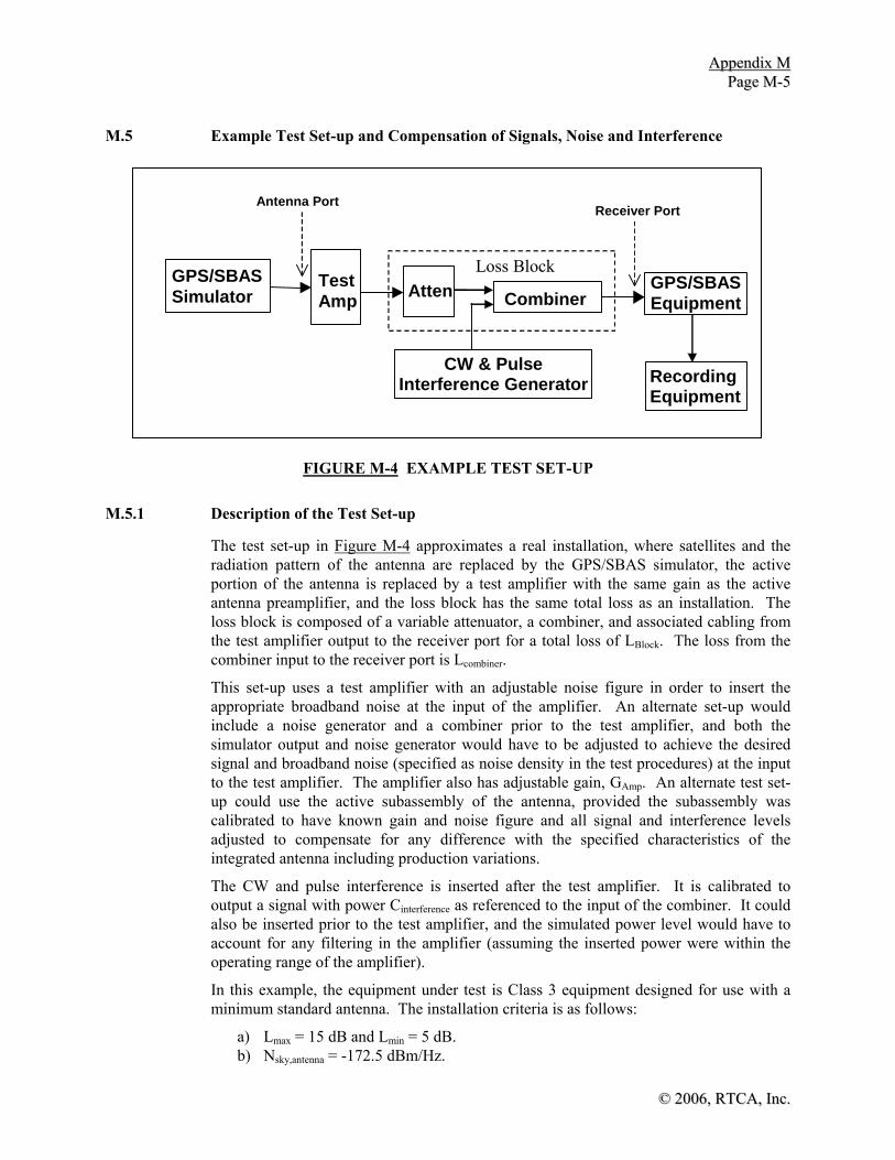
AAppppeennddiixx MM PPaaggee MM--55
©© 22000066,, RRTTCCAA,, IInncc..
M.5 Example Test Set-up and Compensation of Signals, Noise and Interference
Combiner
Receiver Port
Recording Equipment
GPS/SBAS Equipment
Test Amp
GPS/SBAS Simulator Atten
CW & Pulse Interference Generator
Loss Block
Antenna Port
FIGURE M-4 EXAMPLE TEST SET-UP
M.5.1 Description of the Test Set-up
The test set-up in Figure M-4 approximates a real installation, where satellites and the radiation pattern of the antenna are replaced by the GPS/SBAS simulator, the active portion of the antenna is replaced by a test amplifier with the same gain as the active antenna preamplifier, and the loss block has the same total loss as an installation. The loss block is composed of a variable attenuator, a combiner, and associated cabling from the test amplifier output to the receiver port for a total loss of LBlock. The loss from the combiner input to the receiver port is Lcombiner.
This set-up uses a test amplifier with an adjustable noise figure in order to insert the appropriate broadband noise at the input of the amplifier. An alternate set-up would include a noise generator and a combiner prior to the test amplifier, and both the simulator output and noise generator would have to be adjusted to achieve the desired signal and broadband noise (specified as noise density in the test procedures) at the input to the test amplifier. The amplifier also has adjustable gain, GAmp. An alternate test set-up could use the active subassembly of the antenna, provided the subassembly was calibrated to have known gain and noise figure and all signal and interference levels adjusted to compensate for any difference with the specified characteristics of the integrated antenna including production variations.
The CW and pulse interference is inserted after the test amplifier. It is calibrated to output a signal with power Cinterference as referenced to the input of the combiner. It could also be inserted prior to the test amplifier, and the simulated power level would have to account for any filtering in the amplifier (assuming the inserted power were within the operating range of the amplifier).
In this example, the equipment under test is Class 3 equipment designed for use with a minimum standard antenna. The installation criteria is as follows:
a) Lmax = 15 dB and Lmin = 5 dB. b) Nsky,antenna = -172.5 dBm/Hz.

AAppppeennddiixx MM PPaaggee MM--66
©© 22000066,, RRTTCCAA IInncc..
c) Gain of the active portion of the antenna GAnt = 30 ± 3 dB. d) Active antenna Selectivity per DO-301, for example -50 dB at 1626 MHz.
The equipment is calibrated to determine noise levels and loss. In this example, the following values are used:
a) GPS/SBAS Simulator: ISimulator = -174 dBm/Hz with an adjustable signal level of CSimulator both referred to the input of the test amplifier.
b) Combiner with loss LCombiner = 5 dB from its input to the Receiver Port.
M.5.2 Use of the Test Set-up for the Accuracy Test (See 2.5.8)
As the broadband noise is generated by the simulator and the adjustable noise figure of the amplifier, the appropriate noise figure must be determined for the accuracy tests. Two levels must be computed for the minimum signal level tests since some tests include external broadband interference and some do not. An additional level must be determined for the test with all satellites at maximum power.
For the minimum signal level tests, the test amplifier gain (GAmp) is set to 27 dB (minimum GAnt) and the total loss to 15 dB (LBlock = Lmax). A ten-channel simulator is used, with one GPS satellite at maximum power (-121 dBm), seven minimum-power GPS satellites (-134 dBm) and two minimum-power SBAS satellites (-134 dBm). In order to determine the required GNSS test noise, the effective noise of the satellites simulated in the test is subtracted from the total GNSS noise of -171.9 dBm/Hz. Using the equation in 2.5.8.2:
ITest = 10log10[(NGL)10IGL/10 + (NGH)10IGH/10 + (NSL)10ISL/10 + (NSH)10ISH/10] = 10log10[(7)10-196.5/10 + (1)10-183.5/10 + (2)10-198.3/10 + (0)10-179.8/10] = -182.0 dBm/Hz
and
IGNSS,Test = 10log10[10IGNSS/10 - 10ITest/10] = 10log10[10-171.9/10 - 10-182.0/10] = -172.4 dBm/Hz
The noise that must be generated by the test amplifier is determined by subtracting the simulator noise from the total broadband noise for the test (the sum of Nsky,antenna, IGNSS,Test and IExt,Test). The external noise is -170.5 dBm/Hz for those cases that include external noise, so that the equivalent test noise that must be generated is:
ITotal,Test = 10log10[10Nsky,antenna/10 + 10 IGNSS,Test /10 + 10 IExt,Test /10 - 10 ISimulator /10]
= 10log10[10-172.5/10 + 10-172.4/10 + 10-170.5/10 - 10-174/10] = -167.9 dBm/Hz
The equivalent noise factor is determined as: NFAmp(ext) = 10Log10(1 + 10 ITotal,Test /10/k/290) = 7.06 dB

AAppppeennddiixx MM PPaaggee MM--77
©© 22000066,, RRTTCCAA,, IInncc..
For those tests without external broadband noise (e.g., CW and pulse interference cases and to expedite initial acquisition in other tests):
ITotal,Test = 10log10[10Nsky,antenna/10 + 10 IGNSS,Test /10 - 10 ISimulator /10]
= 10log10[10-172.5/10 + 10-172.4/10- 10-174/10] = -171.3 dBm/Hz
And the equivalent noise factor is determined as:
NFAmp(no ext) = 10Log10(1 + 10ITotal,Test/10/k/290) = 4.55 dB
The CW and pulse interference levels must be adjusted based on the specified antenna gain, antenna frequency selectivity and installation loss. To determine the power level at the signal generator the loss of the combiner must be offset. For example, for the +8 dBm CW signal at 1626 MHz:
CInterference,CW = IInt + GAmp - Selectivity - LBlock + LCombiner = +8 + 27 - 50 - 15 + 5 = -25 dBm
The pulse power is limited by the maximum output of the active antenna (Pout):
CInterference,pulse = Pout - LBlock + LCombiner = +20 - 15 + 5 = +10 dBm
Repeating the analysis for the maximum signal case yields the following:
LBlock = Lmin = 5 dB. GAmp = maximum GAnt = 33 dB. Eight maximum level GPS satellites: CSimulator = -121 dBm. Two maximum SBAS satellites: CSimulator = -115.5 dBm ITest = 10log10[(NGL)10IGL/10 + (NGH)10IGH/10 + (NSL)10ISL/10 + (NSH)10ISH/10] = 10log10[(0)10-196.5/10 + (8)10-183.5/10 + (0)10-198.3/10 + (2)10-179.8/10] = -172.5 dBm/Hz
IGNSS,Test = 10log10[10IGNSS/10 - 10ITest/10] = 10log10[10-171.9/10 - 10-172.5/10] = -181.4 dBm/Hz
For Broadband External Interference Noise of IExt,Test = -170.5 dBm/Hz:
ITotal,Test = 10log10[10Nsky,antenna/10 + 10 IGNSS,Test /10 + 10 IExt,Test /10 - 10 ISimulator /10] = 10log10[10-172.5/10 + 10-181.4/10 + 10-170.5/10 - 10-174/10] = -169.5 dBm/Hz
So: NFAmp,ext = 10Log10(1 + 10 ITotal,Test /10/k/290) = 5.82 dB

AAppppeennddiixx MM PPaaggee MM--88
©© 22000066,, RRTTCCAA IInncc..
THIS PAGE INTENTIONALLY LEFT BLANK

©© 22000066,, RRTTCCAA,, IInncc..
APPENDIX N
REFERENCE MATERIAL FOR DETERMINING THE MEAN SEA LEVEL HEIGHT FROM WGS-84 COORDINATES

©© 22000066,, RRTTCCAA IInncc..
THIS PAGE INTENTIONALLY LEFT BLANK

AAppppeennddiixx NN PPaaggee NN--11
©© 22000066,, RRTTCCAA,, IInncc..
N.1 Introduction
The material in this appendix is provided as guidance material only. There are no requirements associated with this appendix.
The GPS and SBAS coordinate system is known as the WGS-84 coordinate system. The WGS-84 reference ellipsoid is the surface on which GPS and SBAS longitude, latitude, and altitude are computed. The GPS and SBAS computed WGS-84 altitude is not the Mean Sea Level (MSL) altitude.
All map reference charts used in aviation make reference to altitude expressed as a MSL altitude.
A model has been developed to relate WGS-84 altitude to the MSL Altitude. The MSL altitude is itself based on a model of the Mean Sea Level. The model referenced in this appendix is the Earth Gravitational Model of the year 1996 (EGM-96). More information on EGM-96 can be found at the website: http://cddisa.gsfc.nasa.gov/926/egm96/ egm96.html. The National Imagery and Mapping Agency, NASA Goddard Space Flight Center, and Ohio State University developed this model. It provides the mathematical conversion between WGS-84 and the Mean Sea Level.
Note: EGM-96 will be updated to EGM-06 in the fall of 2006. Both models will be available at the NASA website listed above and either is acceptable for use as a geoid model.
The true MSL altitude and the EGM-96 model are equivalent in theory. The practitioner is cautioned against drawing the conclusion that the EGM-96 model is equivalent to a QNH pressure altitude. The reason is that the EGM-96 model integrity has not been established in these MOPS. Establishing the integrity of the EGM-96 model and establishing the equivalence between EGM-96 and the QNH pressure altitude is beyond the scope of these MOPS. Despite this, the EGM-96 model is a reasonable approximation to the MSL altitude.
NASA anticipates releasing an update to the Earth Gravitational Model in the fall of 2006 that will be EGM-06. The 1996 Model will still be maintained on the website listed above along with the 2006 version. Either EGM-96 or EGM-06 can be used as a reasonable approximation to the MSL altitude.
N.1.1 General Altimetry
Aircraft altitude may be obtained from a pressure altimeter, a radar altimeter, or a GPS/SBAS sensor. Although these instruments produce an altitude measurement, they are not measurements of the same fundamental quantity and therefore, these measurements cannot be used inter-changeably. As mentioned above, the primary altitude instrument in the aircraft is the pressure altimeter, the SBAS sensor altitude is not recognized at this time as the primary altitude sensor.
N.1.2 Mean Sea Level (MSL) Altitude
The MSL is an average sea level surface and is understood to be the zero MSL altitude surface. The MSL surface cannot be directly observed due to tidal actions, weather, melting of glaciers, tectonic plate movement, and other effects. Measuring the MSL surface is done by measuring the earth’s gravity with satellites and developing a mathematical model of an average and constant gravity surface. This constant gravity

AAppppeennddiixx NN PPaaggee NN--22
©© 22000066,, RRTTCCAA IInncc..
surface defines the MSL zero-altitude surface and is referred to as the geoid. The geoid is a complicated surface and is described by formidable set of functions and is provided by the above referenced website.
N.1.3 Barometric Altitude
The primary aircraft altitude instrument is the pressure altimeter. Pressure altimeters are employed in three different operating modes:
a) QNH mode: the standard pressure altitude is corrected using local correction data, typically from a nearby weather station, usually located at the destination airport
b) QNE mode: the standard setting of 29.92 in.Hg (1013.2 millibars) is used as the MSL zero altitude (the standard atmospheric model)
c) QFE mode: the altimeter is set to read zero when on the airport surface thereby showing height above the airfield.
At and above a transition altitude, all aircraft use the standard QNE altimeter setting, and altitudes are termed flight levels (FL). For example, 29,000 ft becomes FL290. The transition altitude in United States airspace is 18,000 ft (FL180) or 5500 m. Regardless of how the actual air pressure changes in the atmosphere, the QNE barometric altitude has the same definition (and conversion from air pressure to altitude) for all aircraft. Note that QNE altitude is not true MSL altitude. However, all aircraft flying above FL180 use QNE to set their altitude. QNE and MSL altitude are not the same fundamental quantity.
N.1.4 Radar Altitude
All radar altimeters measure the smallest range between the terrain immediately below the aircraft and the aircraft radar altimeter antenna. The radar altimeter is intended for instrument approaches that require accurate height above the landing runway threshold. Most radar altimeters do not operate at heights greater than 2500 ft (750 m) above ground.
N.1.5 GPS Altitude
GPS sensors provide WGS-84 altitude information. The WGS-84 altitude is not a MSL altitude. GPS altitude is derived as an altitude above the WGS-84 reference ellipsoid. MSL models exist that allow conversion between GPS altitude and MSL altitude. One such model is the EGM96 model. A MSL model allows conversion between GPS and MSL altitude.
N.1.6 SBAS-Derived Altitude
SBAS altitude is in general, more accurate and has better integrity than GPS altitude. The same WGS-84 coordinate system is used for both GPS and SBAS. SBAS derived altitude can be used for conducting Localizer with Precision Vertical (LPV) landing approaches; however, LPV approach plates reference MSL. The Final Approach Segment (FAS) is specified in WGS-84 coordinates, not MSL. As described above, even though QNH and EGM-96 are similar fundamental measurements, the EGM-96 model has not established its integrity to be used as an equivalent QNH source. However, QNH cannot be used for any precision approach applications.

©© 22000066,, RRTTCCAA,, IInncc..
APPENDIX O
GLOSSARY AND ACRONYMS

©© 22000066,, RRTTCCAA IInncc..
THIS PAGE INTENTIONALLY LEFT BLANK

AAppppeennddiixx OO PPaaggee OO--11
© 2006, RTCA, Inc.
AC - Advisory Circular ACARS - Aircraft Communications, Addressing and Reporting System Active Antenna - A generic term for a passive antenna element integrated with a preamplifier; it refers to both the minimum standard antenna and a specific antenna. Active Waypoint - A waypoint to or from which navigational guidance is being provided. For a parallel offset, the active waypoint may or may not be at the same geographical position as the parent waypoint. When not in the parallel offset mode (operating on the parent route), the active and parent waypoints are at the same geographical position. ADS - Automatic Dependent Surveillance ADS - B - Automatic Dependant Surveillance-Broadcast Advisory - An annunciation that is generated when crew awareness is required and subsequent crew action may be required; the associated color is unique but not red or amber/yellow. (Source: Advisory Circular AC 25 - 11). AGL - Above Ground Level AIP - Aviation Information Publications Along - Track Distance - The distance along the desired track from the waypoint to the perpendicular line from the desired track to the aircraft. Applications - Specific use of systems that address particular user requirements. For the case of GNSS, applications are defined in terms of specific operational scenarios. Area Navigation (RNAV) - Application of the navigation process providing the capability to establish and maintain a flight path on any arbitrary chosen course that remains within the coverage area of navigation sources being used. RNAV utilizing capabilities in the horizontal plane only is called 2D RNAV, while RNAV that also incorporates vertical guidance is called 3D RNAV. Time navigation (TNAV) may be added to either 2D or 3D systems. TNAV added to a 3D system is called 4D. ARINC - Aeronautical Radio ASIC - Application Specific Integrated Circuit ATC - Air Traffic Control Availability - The availability of a navigation system is the ability of the system to provide the required function and performance at the initiation of the intended operation. Availability is an indication of the ability of the system to provide usable service within the specified coverage area. Signal availability is the percentage of time that navigational signals transmitted from external sources are available for use. Availability is a function of both the physical characteristics of the environment and the technical capabilities of the transmitter facilities.
AAppppeennddiixx OO PPaaggee OO--22
© 2006, RTCA, Inc.
Barometric Altitude - Geopotential altitude in the earth's atmosphere above mean standard sea level pressure datum surface, measured by a pressure (barometric) altimeter. BCD - Binary Coded Decimal BER - Bit Error Rate BNR - Binary Numbers BPSK - Binary Phase Shift Keying BW - Bandwidth C/A - Coarse Acquisition CAT-I PA - Category I Precision Approach Caution - An annunciation that is generated when immediate crew awareness is required and subsequent crew action will be required; the associated color is amber/yellow. (Source: Advisory Circular AC25 - 11). CC - Clock Correction CDI - Course Deviation Indicator Center of Navigation - The mathematical point, referenced to the aircraft coordinate frame, associated with the GNSS navigation solution. This point would typically be the phase center of the GNSS antenna, but could also be an offset or translated point (e.g., might be translated vertically to the level of the wheels of a large aircraft). CF - Course-to-Fix CFIT - Controlled Flight Into Terrain Continuity - The continuity of a system is the ability of the total system (comprising all elements necessary to maintain aircraft position within the defined airspace) to perform its function without interruption during the intended operation. More specifically, continuity is the probability that the specified system performance will be maintained for the duration of a phase of operation, presuming that the system was available at the beginning of that phase of operation, and predicted to exist throughout the operation. Coverage - The coverage provided by a radionavigation system is that surface area or space volume in which the signals are adequate to permit the user to determine position to a specified level of accuracy. Coverage is influenced by system geometry, signal power levels, receiver sensitivity, atmospheric noise conditions and other factors that affect signal availability. CRC - Cyclic Redundancy Check CW - Continuous Wave CWI - Continuous Wave Interference DCH - Datum Crossing Height

AAppppeennddiixx OO PPaaggee OO--33
© 2006, RTCA, Inc.
DD - Double Delta DDL - Delay Lock Loop Desired Course
a) True - A predetermined desired course direction to be followed (measured in degrees from true north).
b) Magnetic - A predetermined desired course direction to be followed (measured in degrees from local magnetic north).
Desired Track - The planned or intended track between two waypoints. It is measured in degrees from either magnetic or true north. The instantaneous angle may change from point to point along the great circle track between waypoints. DME - Distance Measuring Equipment DOD - U.S. Department of Defense DOP - Dilution Of Precision DP - Datum Point D.R. - Dead Reckoning EC - Ephemeris Correction ECEF - Earth Centered Earth Fixed EFIS - Electronic Flight Instruments System EGNOS - European Geostationary Navigation Overlay Service EL - Glidepath Angle (approach path elevation angle) E-L - Early minus Late (correlator) ELT - Emergency Locating Transmitter En Route - A phase of navigation covering operations between departure and termination phases. En route phase of navigation has two subcategories: en route domestic/continental and en route oceanic. FAA - Federal Aviation Administration FAF - Final Approach Fix FAS - Final Approach Segment FAWP - Final Approach Waypoint

AAppppeennddiixx OO PPaaggee OO--44
© 2006, RTCA, Inc.
FD - Fault Detection FDE - Fault Detection and Exclusion FEC - Forward Error Correction Final Approach Fix (FAF) - A point in space used to indicate the position at which an aircraft on a standard approach should be stabilized with appropriate guidance being supplied for the Final Approach Segment. (Source: FAA) Final Approach Segment (FAS) - The straight line segment that prescribes the three-dimensional geometric path in space that an aircraft is supposed to fly on final approach. This segment is defined by two points in space, the Glide Path Intercept Waypoint (GPIWP) and the Threshold Crossing Waypoint (TCWP). Flight Technical Error (FTE) - The accuracy with which the aircraft is controlled as measured by the indicated aircraft position with respect to the indicated command or desired position. It does not include blunder errors. FMS - Flight Management System FPAP - Flight Path Alignment Point FSD - Full Scale Deflection FTE - Flight Technical Error GARP - GNSS Azimuth Reference Point GBAS – Ground-Based Augmentation System GDOP - Geometric Dilution of Precision GEO - Geostationary Geocentric - Relative to the earth as a center, measured from the center of the earth. Geodesy - The science related to the determination of the size and shape of the earth (geoid) by such direct measurements as triangulation, leveling and gravimetric observations; which determines the external gravitational field of the earth and, to a limited degree, the internal structure. Geometric Dilution of Position (GDOP) - The ratio of position error of a multilateration system. More precisely, it is the ratio of the standard deviation of the position error to the standard deviation of the measurement errors, assuming all measurement errors are statistically independent and have a zero mean and the same standard distribution. GDOP is the measure of the "goodness" of the geometry of the multilateration sources as seen by the observer; a low GDOP is desirable, a high GDOP undesirable. (See also PDOP, HDOP and VDOP.) Geostationary - An equatorial satellite orbit that results in a constant fixed position of the satellite over a particular earth surface reference point. (GPS and GLONASS satellites are not geostationary.). GIVE - Grid Ionospheric Vertical Error

AAppppeennddiixx OO PPaaggee OO--55
© 2006, RTCA, Inc.
GIVEI - Grid Ionospheric Vertical Error Indicator GL - Ground Level Global Navigation Satellite System (GNSS) - GNSS is a world-wide position, velocity, and time determination system, that includes one or more satellite constellations, receivers, and system integrity monitoring, augmented as necessary to support the required navigation performance for the actual phase of operation. GPIP - Glide Path Intercept Point Global Positioning System (GPS) - A space-based positioning, velocity and time system composed of space, control and user segments. The space segment, when fully operational, will be composed of 24 satellites in six orbital planes. The control segment consists of five monitor stations, three ground antennas and a master control station. The user segment consists of antennas and receiver-processors that provide positioning, velocity, and precise timing to the user. GLONASS - Global Orbiting Navigation Satellite System GNSS - Global Navigation Satellite System GNSSU - GNSS (Landing) Unit GPS - Global Positioning System GRAS – Ground-based Regional Augmentation System HAL - Horizontal Alert Limit HAT - Height Above Touchdown HDOP - Horizontal Dilution of Precision Height Above Touchdown (HAT) - Specifically, the height above the Runway Intercept Waypoint. In using this term for airborne equipment specifications, care should be taken to define the point on the aircraft (GPS antenna, wheel height, center of mass) that applies. HF - High Frequency HIRF - High Intensity Radiation Fields Horizontal Dilution of Precision (HDOP) - The ratio of user-referenced horizontal position error to measurement error of a multilateration system. (See GDOP for a more detailed description.) HOW - Hand Over Word HPL - Horizontal Protection Level HSI - Horizontal Situation Indicator

AAppppeennddiixx OO PPaaggee OO--66
© 2006, RTCA, Inc.
HUL - Horizontal Uncertainty Level Hz - Hertz (cycles per second) IAWP - Initial Approach Waypoint IC - Ionospheric Correction ICAO - International Civil Aviation Organization ID - Identification IFR - Instrument Flight Rules IGP - Ionospheric Grid Point ILS - Instrument Landing System IMC - Instrument Meteorological Conditions INS - Inertial Navigation System IOD - Issue of Data IODC - Issue of Data Clock IODE - Issue of Data Ephemeris IODF - Issue of Data Fast Correction IODI - Issue of Data Ionospheric IODP - Issue of Data PRN mask IODS - Service Issue of Data IPP - Ionospheric Pierce Point IPV - Instrument Procedures with Vertical guidance I/S - interference-to-signal ratio IWP - Intermediate Waypoint L1 - 1575.42 MHz LAAS - Local Area Augmentation System LNAV - Lateral Navigation LORAN - Long Range Navigation

AAppppeennddiixx OO PPaaggee OO--77
© 2006, RTCA, Inc.
LP - Localizer Performance without vertical guidance LPV - Localizer Performance with Vertical guidance LSB - Least Significant Bit LSR - Least Squares Residual LTP/FTP - Landing Threshold Point/ Fictitious Threshold Point m - Meters MAHWP - Missed Approach Holding Waypoint Mask Angle - A fixed elevation angle referenced to the user's horizon below which satellites are ignored by the receiver software. Mask angles are used primarily in the analysis of GNSS performance, and are employed in some receiver designs. The mask angle is driven by the receiver antenna characteristics, the strength of the transmitted signal at low elevations, receiver sensitivity and acceptable low elevation errors. MASPS - Minimum Aviation System Performance Standards MDA - Minimum Descent Altitude MAWP - Missed Approach Waypoint Mcps - Mega-chips/second Minimum Standard Antenna - Active antenna compliant with the minimum requirements of RTCA/DO-301. Misleading Information - Within this standard, misleading information is defined to be any data that is output to other equipment or displayed to the pilot that has an error larger than the alert limit (HAL/VAL) or current protection level (HPL/VPL) , without any indication of the error (e.g., flag) within the time-to-alert for the applicable phase of flight. For equipment that is aware of the navigation mode, and therefore the alert limit, misleading information is defined relative to the alert limit. If the equipment is not aware of the mode, then misleading information is defined relative to the protection level, since the alert limit is not known. This includes all output data, such as position, non-numeric cross-track, numeric cross-track, and distance-to-waypoint as applicable. MLS - Microwave Landing System MLVD – Minimum Linear Vertical Deviation MOPS - Minimum Operational Performance Standards MSAS - MTSAT Satellite-based Augmentation System MSL - Mean Sea Level MT - Message Type
AAppppeennddiixx OO PPaaggee OO--88
© 2006, RTCA, Inc.
MTBF - Mean Time Between Failure MTSAT - Multifunction Transport Satellite NAD-83 - North American Datum 1983 NAS - U.S. National Airspace System NAV - Navigation NAVAID - Navigation Aid Navigation Mode - The navigation mode refers to the equipment operating to meet the requirements for a specific phase of flight. The navigation modes are: oceanic/remote, en route, terminal, and approach. The oceanic/remote mode is optional; if it is not provided, the en route mode can be substituted for the oceanic mode. NDB - Non-Directional Beacon NIS - Number of Independent Samples NM - Nautical Mile Nonprecision Approach - Operationally, a standard instrument approach procedure in which no glideslope/glidepath is provided. (Source: FAA Order 7110.65, Air Traffic Control) NPA - Nonprecision Approach NSE - Navigation System Error OBS - Omni Bearing Selector PA - Precision Approach PDOP - Position Dilution of precision Planned Primary Means of Navigation - Planned primary means of navigation refers to the capability of planning an operation around scheduled outages so that the system is available for a particular flight and the operational continuity, integrity and accuracy requirements are met. Position Dilution of Precision (PDOP) - The ratio of user-referenced three-dimensional position error to measurement error of a multilaterial system. PDOP is the root-sum-square of HDOP and VDOP. Position Fix - A derived location of an entity in a common coordinate system. Position Fixing Error - The accuracy with which a navigation sensor in combination with a navigation computer can calculate and provide an output of actual location in relation to desired location in an operational environment. PPOS - Present Position

AAppppeennddiixx OO PPaaggee OO--99
© 2006, RTCA, Inc.
PR - Pseudo Range PRC - Pseudo Range Correction Precision Approach (PA) - Operationally, a standard instrument approach procedure in which a glideslope/glidepath is provided. (Source: FAA Order 7110.65, Air Traffic Contol) PRN - Pseudo Random Noise Pseudorange - The distance from the user to a satellite plus an unknown user clock offset distance. With four satellite signals it is possible to compute position and offset distance. If the user clock offset is known, three satellite signals would suffice to compute a position. Radionavigation - The determination of position, or the obtaining of information relating to position, for the purposes of navigation by means of the propagation properties of radio waves. RAIM - Receiver Autonomous Integrity Monitoring RDP - Runway Datum Point Receiver Autonomous Integrity Monitoring (RAIM) - A technique whereby a civil GNSS receiver/processor determines the integrity of the GNSS navigation signals without reference to sensors or non-DoD integrity systems other than the receiver itself. This determination is achieved by a consistency check among redundant pseudorange measurements. Reliability - The probability of performing a specified function without failure under given conditions for a specified period of time. Required Navigation Performance (RNP) - A measure of the navigation system performance within a defined airspace, route, or procedure, including the operating parameters of the navigations systems used within that airspace. (Source: Adapted from the ICAO Separation Panel). RF - Radio Frequency RF - Radius-turn-to-Fix RGCSP - Review of General Concepts of Separation Panel RMI - Radio Magnetic Indicator RNAV - Area Navigation RNP - Required Navigation Performance RRC - Range Rate Correction rss - Root-Sum-Square RTCA - RTCA, Inc. (publishes documents with the RTCA designator)

AAppppeennddiixx OO PPaaggee OO--1100
© 2006, RTCA, Inc.
s - Second SA - Selective Availability (also written as S/A) SAE - Standard Aerospace Equipment SATCOM - Satellite Communications SBAS - Satellite Based Augmentation System (SBAS) - International name used in the Global Navigation Satellite System Panel (GNSSP) Standards and Recommended Practices (SARPs) for a set of programs that use satellites to transmit GPS and GLONASS integrity and correction data. The U.S. program is WAAS that currently is planned to provided integrity and corrections to GPS and SBAS satellites only. Selective Availability (S/A) - A set of techniques for denying the full accuracy and selecting the level of positioning, velocity, and time accuracy of GPS available to users of the Standard Positioning Service (L1 frequency) signal. SC - Special Committee (RTCA Special Committees) SNR - Signal to Noise Ratio SNT - SBAS Network Time Specific Antenna - An active antenna that complies with all the minimum performance requirements of RTCA/DO-301 but is specified to exceed some requirements. The testing methods of RTCA/DO-301 are used to demonstrate performance. SPS - Standard Positioning Service sps - symbols per second Standard Positioning Service (SPS) - The standard specified level of positioning, velocity and timing accuracy that is available, without qualifications or restrictions, to any user on a continuous worldwide basis. STAR - Standard Terminal Arrival Routes SV - Satellite Vehicle TC - Tropospheric Correction TCAS - Traffic Alert and Collision Avoidance System TCH - Threshold Crossing Height TCP - Threshold Crossing Point Terminal Area - A general term used to describe airspace in which approach control service or airport traffic control service is provided. TERPS - Terminal Instrument Procedures

AAppppeennddiixx OO PPaaggee OO--1111
© 2006, RTCA, Inc.
TF - To-From Threshold Crossing Height (TCH) - The height of the straight line extension of the glidepath above the runway at the threshold. TOD - Time of Day; Top of Descent Total System Error (TSE) - Generic: The root-sum-square of the navigation source error, airborne component error, display error and flight technical error. Specific: The root-sum-square of the position fixing error, display error, course selection error and flight technical error. TOW - Time of Week Track Angle - Instantaneous angle measured from either true or magnetic north to the aircraft's track. TSE - Total System Error TSO - Technical Standards Order TTA - Time to Alert TTFF - Time To First valid position Fix UDRE - User Differential Range Error UDREI - User Differential Range Error Indicator UERE - User Equivalent Range Error UIVE - User Ionospheric Vertical Error URA - User Range Accuracy User Range Accuracy (URA) - The one-sigma estimate of user range errors in the navigation data for each individual satellite. It includes all errors for which the space or control segment is responsible. It does not include any errors introduced at the user set. UTC - Universal Time Coordinated VAL - Vertical Alert Limit VDOP - Vertical Dilution of Precision Vertical Dilution of Precision (VDOP) - The ratio of user-referenced vertical position error to measurement error of a multilateration system (see GDOP for a more detailed description). Vertical Navigation (VNAV) - A function of RNAV equipment that calculates, displays and provides guidance to a vertical profile or path. Vertical Profile - A line or curve, or series of connected lines and/or curves in the vertical plane, defining an ascending or descending flight path either emanating from or terminating at a specified waypoint and altitude,

AAppppeennddiixx OO PPaaggee OO--1122
© 2006, RTCA, Inc.
or connecting two or more specified waypoints and altitudes. In this sense, a curve may be defined by performance of the airplane relative to the airmass. VFR - Visual Flight Rules VHF - Very High Frequency VNAV - Vertical Navigation VOR - VHF Omni-directional Range VORTAC - VHF Omni-directional Range / Tactical Air Navigation VPL - Vertical Protection Level VPLT – Vertical Protection Level - Test VTF - Vector-to-Final (Approach) VUL - Vertical Uncertainty Level WAAS - Wide Area Augmentation System Warning - An annunciation that is generated when immediate recognition and corrective or compensatory action is required; the associated color is red. (Source: Advisory Circular AC25 - 11) WGS-72 - World Geodetic Survey 1972 WGS-84 - World Geodetic Survey 1984 WMS - Wide-area Master Stations (WAAS) WN - Week Number World Geodetic Survey (WGS) - A consistent set of parameters describing the size and shape of the earth, the positions of a network of points with respect to the center of mass of the earth, transformations from major geodetic datums, and the potential of the earth (usually in terms of harmonic coefficients). WPT - Waypoint WRS - Wide-area Reference Stations (WAAS)

© 2006, RTCA, Inc.
APPENDIX P
IONOSPHERIC GRID POINT (IGP) SELECTION FLOWCHARTS

© 2006, RTCA, Inc.
THIS PAGE INTENTIONALLY LEFT BLANK

AAppppeennddiixx PP PPaaggee PP--11
©© 22000066,, RRTTCCAA,, IInncc..
P.1 Introduction
This appendix provides the flowcharts for IGP selection discussed in Appendix A, Section A.4.4.10.2.

AAppppeennddiixx PP PPaaggee PP--22
©© 22000066,, RRTTCCAA,, IInncc..
| Latitude | <= 55 deg
Calculate IPP Latitude and
Longitude
Calculate four IGP'sfor a 5x5 cell
| Latitude | <= 75 deg
Latitude > 85 deg
| Latitude | <= 85 deg
Determine Bandand IGP #'s
1
No
No
No
Calculate four IGP'sfor a 5x10 cell
received a valid Type 18 for
Band 9 (10) Yes
Yes
Calculate four IGP'sfor a 10x10 cell
Determine IGP #'s
Determine Band(0-8) and IGP #'s
3
Yes
No
received a valid Type 18 for
Band 9 (10) Yes Yes
Four IGP's are: 85N, 180W 85N, 90W
85N, 0 85N, 90E
Yes
Determine IGP #'s
Determine Band(0-8) and IGP #'s
Four IGP's are: 85S, 140W 85S, 50W 85S, 40E
85S, 130E
5 4
No
| Latitude | <= 60deg
received a valid Type 18 for
Band 9 (10)
No
No
Yes No
Yes
2
Generate a 10 x 10 cell using 1, or possibly 2, virtual IGPs interpolated from the IGPs at Lat 85 and the 2 nearest IGPs at Lat 75
Generate a 10 x 10 cell using 1, or possibly 2, virtual IGPs interpolated from the IGPs at Lat 85 and the 2 nearest IGPs at Lat 75
FIGURE P-1 GRID POINT SELECTION CRITERIA

AAppppeennddiixx PP PPaaggee PP--33
©© 22000066,, RRTTCCAA,, IInncc..
1
are the 4 IGP's defined in Mask
Havecurrent Type 26
info for all 4IGP's
are 3 of the 4 IGP's defined
in the Mask
6
Havecurrent Type 26info for 3 of the
4 IGP's
Determine weights,interpolate correction
and UIVE
Is IPP in thetriangle definedby the 3 IGP's
Yes Yes
No
Yes Yes
Yes
Is IPP in the triangle defined
by 3 IGP's
Havecurrent Type 26
info for all 3IGP's
Unable to formionospheric correction
No
No
No No
Yes
No
Yes No
FIGURE P-2 ABS IPP LATTITUDE BELOW 60 DEG (5X5)

AAppppeennddiixx PP PPaaggee PP--44
©© 22000066,, RRTTCCAA,, IInncc..
2
are the 4 IGP'sdefined in Mask
Havecurrent Type 26
info for all 4IGP's
are 3 of the 4 IGP's defined
in the Mask
Havecurrent Type 26info for 3 of the
4 IGP's
Determine weights,interpolate correction
and UIVE
Is IPP in thetriangle definedby the 3 IGP's
Yes
Yes
No
Yes Yes
Unable to formionospheric correction
No
No No
Is IPP in the triangle defined by the 3 IGP's
No Yes
No
Have current Type 26
info for all 3 IGP's
Yes
No
Yes
8
9
FIGURE P-3 ABS IPP LATITUDE BELOW 85 DEG
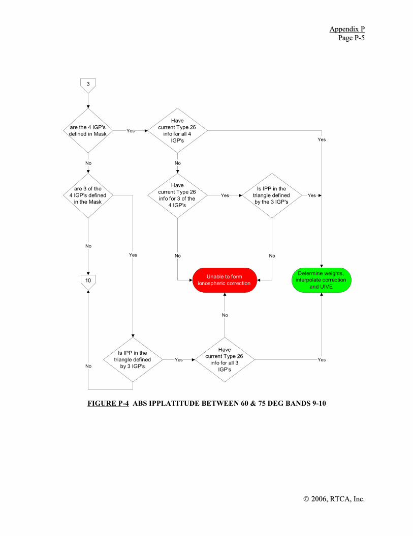
AAppppeennddiixx PP PPaaggee PP--55
©© 22000066,, RRTTCCAA,, IInncc..
3
are the 4 IGP's defined in Mask
Havecurrent Type 26
info for all 4IGP's
are 3 of the 4 IGP's defined
in the Mask
10
Havecurrent Type 26info for 3 of the
4 IGP's
Determine weights,interpolate correction
and UIVE
Is IPP in thetriangle defined by the 3 IGP's
Yes Yes
No
Yes Yes
Yes
Is IPP in the triangle defined
by 3 IGP's
Havecurrent Type 26
info for all 3IGP's
Unable to formionospheric correction
No
No
No No
Yes
No
Yes No
FIGURE P-4 ABS IPPLATITUDE BETWEEN 60 & 75 DEG BANDS 9-10

AAppppeennddiixx PP PPaaggee PP--66
©© 22000066,, RRTTCCAA,, IInncc..
FIGURE P-6 ABS IPP LATITUDE ABOVE 85 DEG
4
are the 4 IGP's defined in Mask
Havecurrent Type 26
info for all 4IGP'
Determine weights, interpolate correction
and UIVE
Ye
N
Unable to formionos pheric correction
Interpolate virtual grid points to form 10x10 cell Ye
N
FIGURE P 5 ABS IPP LATITUDE BETWEEN 75 & 85 DEG
5
are the 4 IGP's defined in Mask
Havecurrent Type 26
info for all 4IGP'
Determine weights,interpolate correction
and UIVE
Ye
Unable to form ionosphericcorrectionN
Ye
N
-

AAppppeennddiixx PP PPaaggee PP--77
©© 22000066,, RRTTCCAA,, IInncc..
6
Are all 4 IGPs defined in the
mask
Calculate four IGPs for 10x10 cell with odd Latitudes
and evenLongitudes
Determine Band and IGP #s
8
Yes
Are all 4 IGPs defined in the
mask
Calculate four IGPs for 10x10 cell
with evenLatitudes and even
Longitudes
Determine Band and IGP #s
Yes
No
A
No
Are all 4 IGPs defined in the
mask
Calculate four IGPs for 10x10 cell with odd Latitudes
and oddLongitudes
Determine Band and IGP #s
Are all 4 IGPs defined in the
mask
Calculate four IGPs for 10x10 cell
with evenLatitudes and odd
Longitudes
Determine Band and IGP #s
No
A
Yes
Yes
7
No
FIGURE P-7 ABS IPP LATITUDE BELOW 60 DEG (10X10 SQUARES)

AAppppeennddiixx PP PPaaggee PP--88
©© 22000066,, RRTTCCAA,, IInncc..
7
Are 3 of the 4 IGPs defined in the
mask
Recall the four IGPs for 10x10 cell with odd Latitudes
and even Longitudes
9
YesRecall the four
IGPs for 10x10 cell with even
Latitudes and even Longitudes
Yes
No
A
No
Recall the fourIGPs for 10x10 cellwith odd Latitudes
and odd Longitudes
Recall the fourIGPs for 10x10 cell
with even Latitudes and odd
Longitudes
No
A
Yes
Yes
No
Unable to formionospheric correction
Is the IPP in thetriangle defined by
the 3 IGPs
Yes
No
Is the IPP in thetriangle defined by
the 3 IGPs
Yes
No
Is the IPP in thetriangle defined by
the 3 IGPs
Yes
No
Is the IPP in thetriangle defined by
the 3 IGPs
Yes
No
Are 3 of the 4IGPs defined in the
mask
Are 3 of the 4IGPs defined in the
mask
Are 3 of the 4 IGPs defined in the
mask
FIGURE P-8 ABS IPP LATITUDE BELOW 60 DEG (10X10 TRIANGLES)

AAppppeennddiixx PP PPaaggee PP--99
©© 22000066,, RRTTCCAA,, IInncc..
10
Are all 4 IGPs defined in the
mask
Calculate four IGPs for 10x10 cell
with even Latitudes
Determine IGP #s
8
Yes
Are all 4 IGPs defined in the
mask
Calculate four IGPs for 10x10 cell with odd Latitudes
Determine IGP #s
Yes
No
A
No
Recall four IGPsfor 10x10 cell with
even Latitudes
Recall four IGPsfor 10x10 cell with
odd Latitudes
No
A
Are 3 of the 4IGPs defined in the
mask
Is the IPP in the triangle defined by
the 3 IGPs
Yes
No
Are 3 of the 4IGPs defined in the
mask
Is the IPP in the triangle defined by
the 3 IGPs
Yes
NoUnable to form
ionospheric correction
No
9
Yes
Yes
FIGURE P-9 ABS IPP LATITUDE BETWEEN 60 & 75 DEG BANDS 9-10

AAppppeennddiixx PP PPaaggee PP--1100
©© 22000066,, RRTTCCAA,, IInncc..
THIS PAGE INTENTIONALLY LEFT BLANK

©© 22000066,, RRTTCCAA,, IInncc..
APPENDIX Q
SBAS CONSIDERATIONS FOR HELICOPTERS

©© 22000066,, RRTTCCAA,, IInncc..
THIS PAGE INTENTIONALLY LEFT BLANK

Appendix Q Page Q-1
© 2006, RTCA, Inc.
Q.1 General
Q.1.1 Helicopter/Heliport Deceleration
PinS procedures in the future may include vertically guided operations. Unlike airplanes, helicopters making approaches to heliports, on the visual segment from the missed approach point (MAPt), must first decelerate to a stop and then land. Airplanes can fly the Vref speed to the threshold and then land and decelerate on the runway. This difference requires the need to support an additional heliport approach requirement with SBAS. Point-in-Space (PinS) and heliport instrument approach operations necessitate that the distance required to decelerate be protected. This is accomplished with a deceleration point annunciation to the pilot. If the visual references for the heliport are not in sight, the pilot will execute a missed approach when arriving at the decision altitude (DA), MAPt or upon receiving a deceleration point annunciation, whichever occurs first. This deceleration point annunciation advises the pilot that he may have insufficient distance to decelerate and land safely on the heliport.
Q.1.2 PinS Description
PinS approach obstacle clearance and procedure design criteria are contained in FAA Order 8260.3B and FAA Order 8260.42B. Testing has shown that when proceeding visually from the missed approach point to the heliport, a minimum distance of 2,600 feet is required for the helicopter to decelerate and land for helicopters flying the final approach segment at 70 KIAS. As a result, since most IFR certified helicopters can fly a minimum speed of 70 knots, procedure design criteria dictates the minimum distance from the missed approach point to the heliport, when proceeding visually on a PinS approach, is 2,600’.
Q.2 PinS Approach Operations
Q.2.1 Fictitious Helipoint Equivalence to Fictitious Threshold Point
SBAS avionics, for other than LNAV and LNAV/VNAV approaches, utilize the final approach segment (FAS) data block to describe the final approach segment ray in space. For procedures that are not aligned with the runway centerline, the geometry of the final approach segment is oriented on a fictitious threshold point. This point is not located on the runway.
Since almost all PinS final approach segments are not aligned with the heliport approach corridor, the PinS final approach segment geometry should be oriented on a fictitious helipoint which is not located on or above the heliport surface, like the actual helipoint. When the final approach segment is aligned with the heliport approach corridor, the fictitious helipoint becomes the helipoint.
Q.2.2 FAS Data Block Application to PinS Procedures
Possible encoding for the FAS data block fields for PinS operations is described below.
a) Operation Type: Currently, 0 is reserved for straight-in or PinS procedures.
b) Service Provider Identifier: 0 for WAAS, 1 for EGNOS, 2 for MSAS. A service provider ID of 15 indicates that any provider may be used and a service provider ID of 14 indicates the FAS data block is not intended for SBAS use.

Appendix Q Page Q-2
©© 22000066,, RRTTCCAA,, IInncc..
c) Airport Identifier: If the heliport has an identifier, it is encoded. If the heliport does not have an identifier, the MAPt waypoint name may be used, since it is the closest described point in the procedure database to the heliport.
d) Runway Number: Runway number is interpreted as the final approach course rounded to the nearest 10 degrees.
e) Runway Letter: Since there is no runway associated with this approach, no letter (“00”) is encoded.
f) Approach Performance Designator: The Approach Performance Designator field is intended for use by GBAS equipment and is not used for SBAS operations.
g) Route Indicator: Encoded as shown in Appendix D.
h) Reference Path Data Selector (RPDS): A numerical identifier used to select the FAS data block (desired approach). It is intended for GBAS and is not used for SBAS operations.
i) Reference Path Identifier: Since these procedures are not flown to runways, the two-digit runway number is replaced with the final approach segment track rounded to the closest 10 degrees.
Note: This coding is consistent with a single PinS procedure supporting approaches to several widely separated landing sites.
j) Landing Threshold Point (LTP)/Fictitious Threshold Point (FTP) – Lattitude: This entry is replaced with the fictitious helipoint (or helipoint) latitude encoded as the LTP/FTP is encoded in Appendix D.
k) Landing Threshold Point (LTP)/Fictitious Threshold Point (FTP) – Longitude: This entry is replaced with the fictitious helipoint (or helipoint) longitude encoded as the LTP/FTP is encoded in Appendix D.
l) LTP/FTP Height Above Ellipsoid (HAE): This entry is replaced with the height above ellipsoid of the fictitious helipoint (or helipoint) encoded as the LTP/FTP HAE is encoded in Appendix D.
m) Δ Flight Path Alignment Point (FPAP) – Lattitude: This is the latitude of a point located on a geodesic line beyond the fictitious helipoint (or helipoint) that is aligned with the PinS final approach track. It is encoded as in Appendix D.
n) Δ Flight Path Alignment Point (FPAP) – Longitude: This is the longitude of a point located on a geodesic line beyond the fictitious helipoint (or helipoint)that is aligned with the PinS final approach track. It is encoded as in Appendix D.
o) Threshold Crossing Height (TCH): This should be analogous to the orthometric height of the fictitious helipoint (or helipoint) above the orthrometric height of the heliport and encoded as depicted in Appendix D.
p) TCH Units Selector: Encoded as depicted in Appendix D.
q) Glidepath Angle: Encode as shown in Appendix D.
r) Course Width at Threshold: This is replaced with the course width at the fictitious helipoint (or helipoint).
s) Δ Length Offset: Since there is no runway associated with procedure the field is encoded with a 0.

Appendix Q Page Q-3
© 2006, RTCA, Inc.
t) Horizontal Alert Limit (HAL): Encoded as shown in Appendix D. PinS procedures have HAL=40.
u) Vertical Alert Limit (VAL): For PinS procedures with lateral only guidance, VAL=0.
v) Final Approach Segment CRC Remainder: Calculated and encoded as shown in Appendix D.
Q.2.3 PinS Lateral Display Scaling
Flight testing has shown that adequate display scaling resulted when the course width at the fictitious helipoint (or helipoint) was encoded as depicted in Figure Q-1.
2o Splay
H
GARP
FPAP
FictitiousHelipoint
Course Width+/-350’
MAPtCourse Width
+/-440’
3 nm FAFCourse Width
+/-1,075’
10,000’ 2,600’ 3 nm
MAPt FAF
FIGURE Q-1 LATERAL DISPLAY SCALING FOR PinS APPROACH OPERATIONS
Q.2.4 Vertical Display Scaling
Reserved.
Q.3 Deceleration Point Annunciation
Both the industry and the FAA, through several flight test programs, realize the need for the protection of the helicopter deceleration distance from the MAPt to the heliport for PinS approach operations. The mechanism tested was the use of a deceleration point annunciation.
Although a fixed distance implementation was tested, this fixed distance activation of the annunciation has been viewed as inefficient for a system that has knowledge of ground speed and highly accurate distance to go information. It has been proposed a 2nd order system be implemented to utilize the additional state knowledge. Other implementations may also be sufficient.

Appendix Q Page Q-4
©© 22000066,, RRTTCCAA,, IInncc..
Q.4 Selective CDI and HAL Values to Support Tighter Route Area Semi-widths
The helicopter industry has firmly established a need for tighter route obstacle clearance and separation requirements for en route and helicopter terminal routing. In order to support the requirements, the need for selective identification of the HAL and full-scale display scaling in the terminal and en route modes are needed to support the industry’s requirements.
Possible values of HAL and full-scale display scaling to meet the industry’s terminal routing needs may be as low as HAL = 0.1 nm and lateral display scaling of +/- 0.3 nm. The selectivity should be based on a route segment basis and based on database information.
Q.5 Autopilot Considerations
Obstacle clearance requirements for helicopter approach operations are more stringent than equivalent obstacle clearance requirements for Category A GPS approach. Additionally, there is no runway “in front” of the final approach segment to provide initial missed approach obstacle clearance.
This often results in the need for an immediate climbing turn and the use of an initial DF leg in the missed approach routing to the missed approach holding fix. The approach procedures being flown below Vy airspeeds and the need for immediate lateral maneuvering have resulted in large flight technical errors (FTE) when initiating missed approaches with a coupled autopilot.. Routinely, much better FTE results on the missed approach have occurred during testing with manual flight.
Q.6 Heliport Approach Database Considerations
ARINC 424 database specifications do not fully support helicopter PinS approach operations. The limitations include:
a) Coding heliport location when an identifier does not exist for the heliport.
b) Coding the Airport Reference Point (ARP) when a heliport identifier does not exist.
c) Coding multiple landing areas for a single PinS approach procedure.
d) The encoding range of the glide path angle on the final approach segment.
e) For LPV procedures and lateral only guidance procedures for PinS operations, standardized FAS data block encoding to support these operations is essential.
It is recognized these are not SBAS issues. However, if the benefits of SBAS are to be realized the database issues must be addressed.

© 2006, RTCA, Inc.
APPENDIX R
REQUIREMENTS AND TEST PROCEDURES FOR TIGHTLY INTEGRATED GPS/INERTIAL SYSTEMS

©© 22000066,, RRTTCCAA,, IInncc..
THIS PAGE INTENTIONALLY LEFT BLANK

AAppppeennddiixx RR PPaaggee RR--11
©© 22000066,, RRTTCCAA,, IInncc..
R.1 Introduction
This appendix includes assumptions, requirements and verification procedures for equipment that utilizes a tight integration of GPS and inertial information to enhance navigation performance for en route through approach (LNAV). Tightly integrated systems process and monitor pseudo ranges individually based on inertial information in order to prevent pseudo-range errors from causing system integrity violations. Systems that perform blending of GPS and Inertial Reference System (IRS) position information with no access to individual pseudorange measurements are not tightly integrated. Examples are included to clarify the meaning of assumptions, requirements and validation procedures. The requirements in this appendix apply to tightly integrated GPS/inertial systems using an aircraft-based integrity augmentation (fault detection and exclusion) under the assumption that SBAS/GBAS differential corrections are not available. Equipment that satisfies these requirements shall also satisfy the requirements in Section 2.1 of this MOPS, or alternatively, the requirements set forth in TSO-C129a Class B and C.
Note 1: As used in the last sentence of the paragraph above, “equipment” is defined as a GPS receiver, inertial sensor, and integration function.
Note 2: The FAA’s TSO process allows for certification of incomplete systems, and as part of this process, the equipment manufacturer is responsible for identifying the TSO requirements that are not applicable to their device.
R.2 Requirements
Section 2.1.2.2.2.2 provides the basic requirements for any FDE implementation. Section R.2.1 clarifies the application of these requirements to GPS/inertial applications. Additional requirements that are unique for this type of integration are included in Section R.2.2.
R.2.1 General FDE Requirements
Tightly integrated GPS/Inertial systems shall meet the FDE requirements summarized in Table R-1. The table also includes the requirement applicable to rare normal (fault free, HPLFF) errors (such as inertial sensor errors) affecting a single user.
TABLE R-1 SUMMARY OF FDE REQUIREMENTS
Parameter Requirement Missed alert probability (satellite failure) 0.001 False alert rate 10-5/hour Probability (pMI) of exceeding HPLFD 10-7/hour Probability (pMI) of exceeding HPLFF 10-5/hour Failed exclusion probability (satellite failure)
0.001
The equipment shall be capable of computing the horizontal protection level HPLFD. HPLFD shall be a function of measurement accuracy and geometry only and shall not depend on individual measurements.
Note 1: This appendix focuses on the detection and exclusion of satellite failures. Failures may also occur in the equipment providing baro altitude, the GPS receiver e.g. receiver clock, the inertial sensors and inertial data processing.

AAppppeennddiixx RR PPaaggee RR--22
©© 22000066,, RRTTCCAA,, IInncc..
Traditionally these types of equipment failures has been detected and excluded based on dual or triple redundancy of equipment. Some of these errors can however alternatively be detected by the tightly integrated system. Guidelines for single string (no redundancy) detection and exclusion of such failures have not yet been developed by the RTCA. It must be demonstrated that the tightly integrated GPS/Inertial system as installed provides adequate detection and exclusion capability to meet the system integrity requirements also when considering equipment failures.
Note 2: The integrity risk of 10-7 per hour covers all types of satellite signal failure conditions including ionospheric anomalies such as ionospheric storm fronts.
Note 3: There is no system level requirement to annunciate or exclude a satellite from the
tightly integrated solution if HPL continues to bound horizontal position error. Systems may compensate for satellite failures by incorporating models of satellite failures in their estimation algorithms instead of simply excluding satellites from the solution. The conditions under which this compensation is done and when an exclusion is done will be system design dependent and should be substantiated through the certification process. Additionally, the compensation and exclusion function monitor intervals must be taken into account to address the possibility of multiple satellite failures.
R.2.1.1 Fault Free Performance
GPS stand-alone fault free performance has two performance components, the 95% accuracy and the rare normal performance. The 95% accuracy requirements are found in Section 2.1.2.1. The rare normal performance is tied to the fault free horizontal protection level (HPLFF), which is a 10-5/ hour limit. The rare normal performance factors in local rare normal atmospheric conditions and inertial sensor induced rare normal drifts.
There is no allocation for rare normal events in section 2.1.2.1. The reason for this is that the protection level for the faulted condition, HPLFD, in most cases bounds the rare normal level, HPLFF, in a snapshot algorithm so that HPL = max (HPLFF, HPLFD) = HPLFD. In a tightly integrated system, inertial coasting may cause the rare normal limit to be dominant over the limit for the faulted condition in times of poor satellite coverage.
The probability per hour of a rare normal event assuming a time between independent events of τ in hours and a probability of exceeding HPLFF based on the horizontal error (inertial sensor errors, ionospheric delay, multipath, thermal noise) distribution of pffd is pffd/τρ . The time between independent events is a function of the dynamic properties of the error.
For example, if the time between independent events is 0.2 hours and the error is bounded by a normal distribution, the rare normal limit (HPLFF) for a snapshot algorithm based on a 10-5 per hour integrity risk allocation, corresponding to a probability pffd = 10-5/hour × 0.2 hour = 0.2 × 10⁻⁵ which corresponds to a 4.75-sigma (two sided Gaussian), is
HPLFF = Kffd HDOP σ = 4.75 HDOP σ (R-1)
Where σ is the 1-sigma of the error in the pseudo range. For comparison, the protection limit HPL1 calculated by a snapshot FDE algorithm using Gaussian statistics under the hypothesis of one faulty satellite is

AAppppeennddiixx RR PPaaggee RR--33
©© 22000066,, RRTTCCAA,, IInncc..
HPLFD = max { HPLFD,n } (R-2) where
HPLFD,n = an Kfd σd + Kmd bn σ (R-3)
In these equations an (n=1,..,N) and bn (n=1,..,N) are geometry dependent parameters of the same order of magnitude as the HDOP. The sigma numbers for false detection and missed detection are approximately Kfd = 5 and Kmd=3. This demonstrates that the HPLFD generally exceeds HPLFF in snapshot Receiver Autonomous Integrity Monitoring (RAIM) and the HPLFF is therefore usually not emphasized. In integrated systems where inertial signals are used to propagate GPS information between GPS filter updates, the HPLFF contribution to the integrity risk is essential.
In addition, mis-modeling of the inertial sensor errors may result in an incorrect 1-sigma position accuracy, which in turn results in an incorrect HPLFF. To ensure integrity, it is important to verify that the accuracy requirement is met with all significant error sources included. For integrated GPS/inertial systems it is further important to include gyro/accelerometer noise and bias instability as well as the errors induced by normal airplane dynamics (acceleration and angular rates).
R.2.2 Unique Additional Requirements
R.2.2.1 Assumed Failure Mechanisms
Tightly integrated GPS/inertial systems can readily detect and exclude range rate error steps greater than 2 meters/second. Averaging of the RAIM discriminator (see Section R.2.2.6) can improve the RAIM based HPL for drifts smaller than 0.1 meters/second. The dependence on the failure characteristics makes it necessary to use a set of representative failure mechanisms for testing. An Integrity FMEA (reference 6) has been conducted on Block I, II and IIA satellites and provided predictions of the misleading information (MI) failure probability for all known failure mechanisms. Observed failure rates have confirmed that these probabilities are conservative. In order to provide some additional margin and to factor in the uncertainty associated with future satellite failure modes, the assigned failure probabilities are enlarged (3.448 ×) relative to the predicted probabilities, and the minimum assumed failure probability has been inflated to 10-6 /hour/satellite. The step of 700-3000 meters is already required to be detected by the step monitor in Section 2.1.1.5.1 and this failure mode is therefore not included. Table R-2 lists the predicted failure types, the predicted probability, assigned test range and assigned probability. The assigned MI failure probabilities will be updated if appropriate FMEA data becomes available.

AAppppeennddiixx RR PPaaggee RR--44
©© 22000066,, RRTTCCAA,, IInncc..
TABLE R-2 SUMMARY OF FAILURE TYPE PROBABILITIES
Predicted MI Failure Type,
meters/second (m/s)
Block I, II, IIA Predicted MI
Failure Probability in units of 10-7/ hour/satellite
Assigned Test Range
Assigned MI Failure
Probability in units of 10-5/ hour/satellite
Ramp 0.01 m/s 2 Ramp 0.01-0.05 m/s 1 Ramp 0.1 m/s 1 Ramp 0.05-0.25 m/s 1 Ramp 0.5 m/s 3 Ramp 0.25-0.75 m/s 1 Ramp 1.0 m/s 10 Ramp 0.75-2.5 m/s 3.5 Ramp 5.0 m/s 12 Ramp 2.5-5.0 m/s 4.1
Step 300 meters 1 Step 300-700 meters 1 Step 3000 meters 34 Step 700-3000 meters N/A
Note 1: The IFMEA and observed failure rates for Block I, II, and IIA satellites indicate that larger acceleration errors occur with a probability that is negligible versus 10-7/h, and that failure induced accelerations with a probability of 10-7/h or higher, can not exceed 0.1 μg. Performance degradation due to small accelerations (<0.1μg) are covered by the 0.01 m/s ramp and an acceleration failure mechanism is therefore not included.
Note 2: The model for the data in Table R-2 has been established based on experimental data and Integrity Failure Modes and Effects Analysis (IFMEA) by ARINC in El Segundo, California. The data used to establish this model is summarized in the Aberration Characterization Sheets (ACS) documented in reference 6.
R.2.2.2 Detection limit
The probability, pMI, of exceeding HPLFD with no integrity alert (integrity risk) specified in Table R–1 shall be defined as
pMI = k
K
=∑
1pf,k pmd,k (R-5)
where pmd,k is the conditional probability of exceeding HPLFD for failure mode k, pf,k is the assigned MI failure probability in Table R-2 and K is the number of failure modes. The continuity risk pcont associated with a satellite failure that cannot be excluded before a loss of function occurs, shall be defined as
pcont = ∑=
K
k 1pf,k pfexl,k (R-6)
where pfexl,k is the conditional probability of failed exclusion for failure mode k.
Note 1: The HPL provided by the tightly integrated system as defined in this appendix only needs to consider the limited set of failure scenarios defined above.
Note 2: The required continuity risk depends on operational considerations and is expected to be in the range 10-7/h – 10-5/h.
R.2.2.3 SatZap
Due to the monitoring performed by the GPS control segment (SatZap) and the changes planned to occur as part of the GPS modernization it is expected that slowly drifting

AAppppeennddiixx RR PPaaggee RR--55
©© 22000066,, RRTTCCAA,, IInncc..
satellites will be detected and removed before the error has any significant impact. As soon as this monitoring is in place and its performance documented it will be possible to make use of the synergy between tightly integrated systems and the control segment monitoring by modifying the equipment to comply with a different set of MI failure probabilities.
R.2.2.4 Receiver Clock Aiding
The receiver clock frequency random walk 1-sigma shall not exceed 1 feet/s / s under steady state thermal conditions. The frequency drift shall not exceed 3 ppm/°C under transient thermal conditions.
Note 1: When using a Kalman filter based integration or other equivalent integration the receiver clock error is usually incorporated in the state model. To assure interoperability when using different GPS receivers a minimum clock standard is required.
Note 2: The maximum temperature rate of change specified in DO-160D for all equipment categories is 5°C /minute.
Note 3: A significantly lower temperature sensitivity than 3 ppm/°C would require the use of an oven-controlled crystal oscillator (OCXO) and exclude the use of a temperature compensated crystal oscillator (TCXO) in the GPS receiver.
Note 4: This requirement applies to the GPS receiver oscillator, and does not directly place requirements on the tightly integrated GPS/inertial function.
If receiver clock aiding is used to enhance integrity, the algorithms that perform calibration shall be designed to prevent the satellite failure itself from affecting the integrity of the calibration. Conventional Kalman filter integrations using clock states for offset and drift rate with no further enhancements to protect these states in a failure situation will not meet this requirement.
Note: Oscillators are temperature sensitive devices. The drift stability in a transient thermal environment, such as a receiver just turned on, is significantly degraded relative to a steady state thermal environment. An airplane descending from en route to non precision approach experiences significant temperature gradients which affect the stability of the clock.
R.2.2.5 Altitude Aiding
If pressure altitude aiding is used to enhance integrity, the algorithms that perform calibration shall be designed to prevent the satellite failure itself from affecting the integrity of the calibration. Conventional Kalman filter integrations using a bias error state with no further enhancements to protect this state in a failure situation will not meet this requirement. RAIM algorithms meeting this requirement (without the use of inertial measurements) are included in Appendix G.
Note: When using a Kalman filter based integration or other equivalent integration, the pressure altitude bias error is usually incorporated in the state model.
R.2.2.6 Discriminator Averaging
A system using discriminator averaging when determining the horizontal protection limit (HPLn) shall consider: (1) the impact of the temporal correlation, ρ, of the discriminator noise, (2) the impact of slowly changing errors that are not reduced by averaging (e.g.

AAppppeennddiixx RR PPaaggee RR--66
©© 22000066,, RRTTCCAA,, IInncc..
ionospheric error), and (3) the reduction in detection performance for failures with dynamics that are fast relative to the averaging period.
R.2.2.7 Inertial Coasting Performance Evaluation
The inertial sensors in tightly integrated GPS/inertial systems are continuously calibrated using GPS measurements. This means that the system can propagate the established position accurately if the GPS signals are lost due to any unexpected event such as interference, scintillation, masking, unexpected satellite failure, etc. There are two types of coasting considered here – accuracy coasting and integrity coasting. Accuracy coasting is the propagation of the established position and corresponding accuracy bound after the loss of GPS assuming no failures were in progress prior to the loss. The accuracy bound is typically the HFOM which represents a conservative 95% limit. Integrity coasting is the propagation of the position and corresponding integrity bound assuming the worst case satellite undetected failure was in progress just prior to the loss of GPS. The bound is the horizontal protection limit (HPL) and must take into account the miscalibration of the hybrid solution due to the undetected failure. To promote the use of this capability a method to establish the coasting performance is defined below.
Note: The performance requirements applicable to inertial coasting are provided in RTCA/DO-236A. The inertial coasting error represents a navigation system error that, combined with the flight technical error, constitutes the total system error defined by the RNP type. The allowed coasting time (coasting capability) is ultimately determined by the NSE tolerance provided by the RNP type. The coasting capability can be established from the horizontal radial error distribution, typically the 95% limit, in meters or nmi as a function of time in minutes from the point the GPS function was lost.
R.2.2.7.1 Accuracy Coasting
The horizontal coasting error distribution as a function of time should be evaluated under the following conditions: Inertial errors should be initialized by either beginning the simulation error-free and flying 60 minutes on pure inertial, or by initializing the simulation with correct or conservative accumulated inertial errors. Then GPS measurements should be incorporated for a calibration time of 60 minutes. The HDOP should stay above 1.5 throughout the calibration. Frozen satellite positions may be used. The evaluation should be performed with correct or conservative gyro/accelerometer noise, correct or conservative gyro/accelerometer bias instability and a representative receiver clock model. Altitude information as mechanized in the system under evaluation, may be used during the coasting phase to prevent vertical channel instability. In this evaluation the calibration and coasting should be performed during straight and level flight. The coasting error distribution is a statistical measure and covariance propagation techniques may be used to determine the performance. At least 500 Monte Carlo simulations, including calibration and subsequent coasting, using the algorithms implemented in the system should be run to verify the covariance propagation model used to predict the claimed coasting performance.
Note 1: The 500 Monte Carlo simulations, including initial errors, may be replaced by 500 tests performed on the equipment
Note 2: This requirement is not applicable if a coasting capability is not claimed as part of the equipment performance parameters.
An example of accuracy coasting performance illustrating the order of magnitude of the coasting error during straight and level flight, is shown in Table R-3. Values in the table

AAppppeennddiixx RR PPaaggee RR--77
©© 22000066,, RRTTCCAA,, IInncc..
were generated by simulation using the following assumptions:
a) Steady state achieved prior to coasting.
b) Coasting in straight and level flight in NPA phase.
c) HDOP = 1.5.
d) Pseudorange noise error sigma = 2 m.
e) Pseudorange bias error sigma = 10 m.
f) Filter update rate = 2 min.
g) Gyro bias error sigma = 0.01 deg/hr (τ = 1 hr).
h) Gravity deflection sigma = 5 arcsec.
i) Gravity correlation distance = 20 nmi.
j) Aircraft velocity = 180 knots.
k) Accelerometer bias calibration error sigma = 10 μg.
l) Gyro noise sigma = 0.001 deg/√h.
m) Gyro misalignment: 10 ppm.
TABLE R-3 ACCURACY COASTING PERFORMANCE EXAMPLE
Coasting time 95% accuracy 0 min 30 m
10 min 100 m 20 min 340 m 30 min 800 m 60 min 2700 m
For additional information on coasting performance see reference 4 in Section R.6.
Note: It is emphasized that Table R-3 is provided as an example only, and is based on a particular set of assumptions. The results can vary significantly depending on the assumptions.
R.2.2.7.2 Integrity Coasting
If valid HPL outputs continue during GPS outages, the required probabilities must be maintained. The probability of missed alert due to a latent satellite failure shall remain less than 10-3 during outages (a latent satellite failure remains undetected prior to loss of GPS). In other words, an undetected satellite failure prior to the loss of GPS may mis-calibrate the hybrid filter(s), and this impact must be reflected in the HPL.
The false alert rate shall remain less than 10-5/hour during outages.
If exclusion capability during integrity coasting is claimed, then the probability of failed exclusion (the inability to remove, or properly bound using HEL, all impact of a failed satellite from the position solution) shall remain less than 10-3 during outages.
An example of integrity coasting performance illustrating the order of magnitude of the coasting time that HPL remains below a HAL typical of approach (LNAV) and Terminal operations is shown in Table R-4. Values in the table were generated by simulation using the same set of assumptions in the Accuracy Coasting (R.2.2.7.1) except for the flight profile shown in Figure R-1.

AAppppeennddiixx RR PPaaggee RR--88
©© 22000066,, RRTTCCAA,, IInncc..
The initial flight direction is as shown in the figure: “T” to “E” for terminal area navigation and “N” to “D” for approach (LNAV). It is assumed that the aircraft always has an hour of calibration on a straight and level flight before it loses the GPS signals. The location of the complete loss of GPS signals is selected such that the no-fault HMI and GPS/IRS HPL requirements are met until the end point (that is, A and B for approach (LNAV) and terminal navigation, respectively).
500 kn
A
BC
D250 kn
220 kn 180 kn
110 kn
5 nmi
40 nmi
200 nmi
E
T
N
500 kn
A
BC
D250 kn
220 kn 180 kn
110 kn
5 nmi
40 nmi
200 nmi
E
T
N
FIGURE R-1 FLIGHT PROFILE ASSUMED FOR THE COASTING TIMES
TABLE R-4 INTEGRITY COASTING PERFORMANCE EXAMPLE
Flight Phase / Operation Horizontal Alert Limit Coasting time Approach (LNAV) 0.6 nmi 13-14 minutes
Terminal 2.0 nmi 23-24 minutes
It is emphasized that Table R-4 is provided as an example only, and is based on a particular set of assumptions. The results can vary significantly depending on the assumptions.
R.2.2.8 Gravity Compensation
Gravity compensation error is a significant source of position drift for two nautical mile per hour inertial navigation systems. Errors in the gravity models can cause errors in the integrated inertial GPS systems that become problematic particularly during coasting conditions. To reduce these errors, some form of gravity compensation algorithms must be applied. The gravity compensation error is typically expressed in terms of gravity deflection and gravity anomaly. Gravity deflection is defined as the deviation of the gravity vector from the vertical. Gravity anomaly is defined as a magnitude error in the size of the gravity vector. Investigations of the distribution of gravity deflection and anomaly data demonstrate that the data does not form a normal distribution. While most of the world can be modeled assuming one-sigma deflection of 5 arc-sec, there are specific isolated regions where the deflections are much larger -- up to 50 arc-sec. These

AAppppeennddiixx RR PPaaggee RR--99
©© 22000066,, RRTTCCAA,, IInncc..
gravity errors do not produce “random” errors, as the same errors will occur on every flight over a local area.
The National Geospatial-Intelligence Agency (NGA, formerly NIMA) maintains an unclassified database of the Earth’s gravitational field referenced as the Earth Gravitational Model 1996 (EGM96), and is maintained as part of the WGS-84 world model. Models with additional resolution may be made available in the future (e.g. EGM06). This database can be used to create a worldwide gravity model that reduces the total gravity compensation error.
The tightly integrated system shall properly account for the local gravity anomalies and deflections such that the HPL continues to bound the system errors while operating in areas of increased gravity anomaly/deflections, even when coasting. Suitable mechanisms include an appropriate subset of the following:
a) Over-bounding using a standard model with an elevated sigma level.
b) Compensation using a gravity map.
c) Adjustment of the filter parameters (e.g. increase the process noise).
R.3 Tightly Integrated GPS/Inertial Design Concepts
This section, that is descriptive in nature and contains no requirements, describes basic techniques that can be used to enhance the integrity of tightly integrated solutions.
R.3.1 Integration Methods
Conventional Kalman filters are used to integrate inertial information with external measurements from various ranging sources such as GPS or Loran. The Kalman filter relies on an accurate inertial error model and known statistical inertial sensor error distributions as well as a linearized measurement model for GPS pseudoranges and the associated pseudorange error statistics.
The transient that is produced by a position step or a sudden drift in a satellite, is detectable in the measurement residuals or innovations. This transient behavior can be used to enhance the detection and exclusion capability for a limited set of failure modes.
Note: The conventional Kalman filter in itself does not improve the integrity of the GPS solution since it will easily adapt to and incorporate any GPS position offset or drift as a natural dynamic state (position error state or velocity error state).
In a situation when redundant satellite information is available, errors will develop in all satellite post residuals (after application of measurements) or pre residuals (before application) as a satellite failure progresses and the initial transient has settled. Any method that provides a detection scheme solely based on these remaining residuals (transient assumed gone) is approximately equivalent to traditional RAIM and will therefore not further augment the RAIM function. If the residuals are averaged over time the method is equivalent to RAIM using discriminator averaging. One exception to this simple rule is the Gravity/Schuler coupling, which provides additional detection capability over unaided RAIM (see Section R.3.2.4).
R.3.1.1 Pre-residual (Innovation) Screening
This method is routinely used in Kalman filter based estimators. The statistics of the innovations can be calculated from the covariance matrix P. If one or several innovations associated with a measurement far exceed the expected 1-sigma value, the measurement

AAppppeennddiixx RR PPaaggee RR--1100
©© 22000066,, RRTTCCAA,, IInncc..
is excluded. This method provides exclusion capability for large steps, ramps and ramp rates. Multiple measurement failures can be handled. Slow drifts or drift rates are, however, not excluded and detection and exclusion of such failure types can only be provided by other methods, e.g., RAIM. Innovation screening will typically eliminate the faulty measurement and the HPL can be calculated by determining the worst-case navigation error impact over all possible satellite failure modes.
R.3.1.2 Post-Residual Monitoring
The post residual (residual error after processing of measurements) is calculated right after the estimator has processed all the measurements. The statistics of the post residual can be calculated from the covariance matrix P. If one or several residuals far exceed the expected 1-sigma value, it can be concluded that one or more of the measurements must have been in error. Normally this method mixes elements of RAIM and innovation screening and it is not straightforward to sort out which effect that is dominating. Therefore, an exclusion capability is not provided in the general case.
R.3.1.3 Additional Measurement Bias States
The addition of ramp failure states in a Kalman filter based estimator produces a mechanism for detection that is equivalent to RAIM, but no calculation of HPL has been proposed for this method.
R.3.1.4 Multiple Kalman Filters
If multiple Kalman filters are used, where a different satellite has been excluded in each filter, the residual monitoring and additional bias states methods, described above, will provide an exclusion mechanism equivalent to RAIM. However no method for calculating the exclusion limit HEL has been proposed for this method.
R.3.1.5 Extrapolation Method
The extrapolation method utilizes a simultaneous combination of both transient and redundancy effects to detect failures. The measurements are stored in buffers over 30 minute periods. This provides a detection capability, which is enhanced over RAIM for slow failures because of the information that is retained from previously processed measurements (compare discriminator averaging). A bank of parallel Kalman filters is used to: (1) test newly acquired satellites before they are used in the main Kalman filter, and (2) to isolate failed satellites once the failure is detected by the main Kalman filter. The HPL is calculated by computing parallel solutions corresponding to different failure modes. The magnitude of the worst-case failure is determined partially based on simulations to provide probability of detection and correct isolation exceeding 99.9%.
R.3.1.6 Solution Separation Method
A bank of Kalman filters using the solution separation method provides a non transient detection capability that has been enhanced over RAIM based on the redundancy information that is retained from previously processed measurements via the inertial function. A procedure for calculating HPL is an integral part of this method. No assumption is made about the dynamics of the failure when HPL is calculated. The enhancements provided by external aiding information (e.g. filter states representing corrections to external aiding information), such as receiver clock and pressure altitude, will be incorporated in the calculated HPL. No miss-calibration is possible since one of the reference sub-filters using the aiding will not contain the failing satellite.

AAppppeennddiixx RR PPaaggee RR--1111
©© 22000066,, RRTTCCAA,, IInncc..
R.3.2 Detection and Exclusion Mechanisms
R.3.2.1 Transient Detection/Exclusion for 2 nmi/hour Grade Systems
The transient effect can be used to exclude a faulty satellite. This type of monitor provides increased detection and exclusion capability in a situation when RAIM is not effective. If for example a pre residual (innovation) monitor is used to detect ramps, it can be shown by simulation that ramps above 2 meters/second can be detected with a 0.999 detection probability in all situations when RAIM is not effective (assuming at least one hour of good geometry prior to the failure). This leads to 100% (detection and exclusion) availability for ramps above 2 meters/second when RAIM is unavailable. This highly available but restricted exclusion capability demonstrates the basic advantage and also limitation of this type of enhancement.
Note: The detection/exclusion ramp limit of 2 meters/second is achievable by equipment using commercial grade navigation sensors i.e. inertial systems meeting a 2 nmi/hour performance (95%).
R.3.2.2 Satellite Redundancy
Measurement redundancy is the mechanism that is used in RAIM. It is because of the satellite measurement redundancy that Kalman filter post residuals continue to grow with the satellite error after the initial transient has settled. Without any redundancy no such growth will occur.
R.3.2.3 Integrity Coasting
In this case dynamic states that contain redundancy information (defined based on the assumption that only one satellite will fail) are time propagated based on inertial information. An example of this mechanism is the solution separation method where sub-filters and dual covariance propagators are used to retain this redundancy information.
R.3.2.4 Gravity/Schuler Coupling
The Gravity/Schuler coupling effect can be demonstrated by letting the vertical channel, incorporating a z-accelerometer, combine with the Schuler dynamics of one of the horizontal channels in a Kalman filter. As measurements that are the sum of the vertical position and the clock phase error, combine with measurements that are the sum of the lateral position and the same clock phase error, the vertical position error will be pulled in. This effect is not sensitive to the clock performance but is strongly related to the z-accelerometer accuracy. The reason for this effect is that the Kalman filter is able to eliminate the clock phase error due to the radically different dynamics of the vertical and horizontal channels. Most GPS/Inertial Kalman filters will automatically incorporate this type of information. This means that integrity below 1 nmi can be established with only 4 satellites (in good geometry) in view and no altitude aiding if an accurate z-accelerometer is used. It can be demonstrated that an accurate z-accelerometer is approximately equivalent to an altitude measurement. The z-accelerometer versus altitude accuracy relation is summarized in Table R-5 (see Reference 1 in Section R.6).
TABLE R-5 EQUIVALENT ALTITUDE ACCURACY
Acceleration, micro Gs (μg)
Altitude, Meters (m)
300 μg 920 m

AAppppeennddiixx RR PPaaggee RR--1122
©© 22000066,, RRTTCCAA,, IInncc..
100 μg 420 m 40 μg 300 m 20 μg 280 m
R.3.2.5 Other Schuler Coupling Related Effects
When exposed to MI failures (such as ramps) and after the transient has rung out, innovations or residuals often gradually deviates from zero in an oscillatory manner. This phenomenon is due to the horizontal Schuler coupling and other long term coupling effects. The reason for the deviation is that the satellite drift causes a linear position growth while the inertial position error growth has an 84 minute oscillatory component. Due to the long oscillation period (84 minutes) these effects are generally not timely enough to improve the detection and exclusion capability.
R.4 Assumptions
R.4.1 Signal Error Model
Validation activities shall model pseudorange error using statistical test data that represent all significant sources of measurement error. This data will be generated by the combination of five independent models: ionospheric, tropospheric, satellite clock & ephemeris, receiver noise, and multipath.
Ionospheric error shall be modeled using the International Reference Ionosphere 2001 (IRI-2001) model. The IRI-2001 model was developed and validated by IRI, an international project sponsored by the Committee on Space Research (COSPAR) and the International Union of Radio Science (URSI). It models the ionospheric daily variation, but does not model storms. Since statistical data is needed from a deterministic model, the model inputs will be randomized in the test procedures. IRI-2001 accounts for temporal and spatial correlation between satellite measurements. Other iono models may be used, but they must be validated.
Tropospheric error shall be modeled using a first-order Gauss-Markov process with a 30 minute correlation time. The sigma shall be scaled per the tropo residual error sigma equation defined in Appendix A, Section A.4.2.5. Simultaneous measurements from different satellites are assumed to be uncorrelated. Other tropo models may be used, but they must be validated.
Note: The 30 minute correlation time is representative of a typical storm system passing through. The assumption of uncorrelated measurements is the conservative assumption. Correlated components would be mostly removed by the user clock bias states.
Satellite clock & ephemeris error shall be modeled using a first-order Gauss-Markov process with a 2 hour correlation time and a 2m sigma. No correlation is assumed between satellites. Other clock & ephemeris models may be used, but they must be validated.
Note: References 7 and 8 provide justification for the sigma magnitude. The correlation time can be justified as follows: Ephemeris prediction would be related to the orbit of the satellites (i.e. periodic with a 12 hour period). There may also be occasional (every few hours) small steps due to ephemeris data uploads. Satellite clock errors are most likely a slow integrated random walk process (with occasional resets via uploads). The error model is an approximation of all of these error sources (very slow orbital errors, fast but
AAppppeennddiixx RR PPaaggee RR--1133
©© 22000066,, RRTTCCAA,, IInncc..
small resets, and slow noisy clock drift).
Receiver and multipath error shall be modeled using the airborne receiver error model in Appendix J, Section J.2.4. If the tightly integrated inertial/GNSS function does not use carrier phase smoothing of the code, the error model shall use a 25 second correlation time. If smoothing is used, the smoothing constant shall be used.
Note: This model is applicable to an aircraft in flight, and not to an aircraft on the ground.
These models are valid for satellite elevation angles above 5 degrees. If satellites below 5 degrees are used, then adequate steps must be taken to ensure system safety.
R.4.2 Satellite Clock Drift Characteristics
For errors, such as a systematic drift in the atomic clock onboard the satellite, a slow acceleration in the pseudo range error will result. A sudden frequency shift in the satellite clock will lead to a ramp in the pseudo range. Errors in the satellite clock correction parameters in the navigation message will have a similar impact: for instance an error in af1 causes a ramp type failure and an error in af2 causes an (pseudo range) acceleration error.
Note: For block II/IIA cesium clocks the af2 term in the navigation message is hard-coded to zero. The block IIR satellites use a rubidium clock that exhibit small accelerations and the af2 term is used. The maximum acceleration error that could occur if af2 was incorrect is 0.1 μg. The effect of such a small acceleration on the tightly integrated system is approximately the same as the effects of a small ramp.
R.5 Validation
R.5.1 Categorization of Detection and Exclusion Mechanisms
Due to the special character of a tightly integrated approach the tests in Section R.5 shall be performed with correct or conservative gyro/accelerometer noise, correct or conservative gyro/accelerometer bias instability, correct or conservative scale-factor and misalignment errors, normal airplane dynamics and correct or conservative receiver clock model.
Normal airplane dynamics shall include turns in the terminal area as follows: For terminal and non precision approach use straight and level flight during calibration (when failure is not present) and one single 180 degree turn using a 1.5 degree/second turn rate started right after the failure is initiated. The ground speed is approximately 200 knots.
If altitude and/or clock aiding are used these measurements shall also be included in the verification.
If the position solution is updated at a low rate (such as a 2.5-min time step) the growth in the solution error between updates must be considered. The performance shall be measured and verified both before and after the measurement update.
The manufacturer shall categorize the failure detection and exclusion mechanisms employed by the monitor algorithms that are to be validated. The mechanisms identified in this appendix are:
a) Transient detection and exclusion ( e.g. innovation screening )
b) Satellite geometric redundancy (e.g. RAIM)

AAppppeennddiixx RR PPaaggee RR--1144
©© 22000066,, RRTTCCAA,, IInncc..
c) Inertially propagated geometric redundancy (e.g. solution separation)
d) Discriminator or residual time averaging (e.g. RAIM or extrapolation method )
e) Gravity/Schuler coupling
The limitations and performance of each implemented detection/exclusion mechanism shall be demonstrated in test cases chosen by the manufacturer. This material will be used by the certification authority to assess the authenticity of the claimed improvements over normal RAIM.
R.5.1.1 Examples
The transient detection can be demonstrated by testing different ramp scenarios in geometries with no redundancy (4 satellites).
The performance of the redundancy based monitor (RAIM equivalent) which may include discriminator (residual) averaging, altitude and/or clock aiding can be demonstrated using ramps below the transient exclusion threshold or with the transient exclusion mechanism disabled.
R.5.2 Covariance Simulation
The Kalman filter technique provides a powerful verification tool referred to as covariance simulation. This type of prediction can be used for availability determination for different satellite constellations but shall not replace off line verification of the implemented detection and exclusion algorithms.
R.5.2.1 Covariance Simulation Methods for Availability Evaluation
When system availability is determined, Monte Carlo techniques for verification of detection probability and false detection probability at each space-time point would be impractical since several million space-time points need to be evaluated. The covariance simulation technique which is based on the statistical 1-sigma and correlation information that can be extracted from the Kalman filter covariance matrix P makes it possible to determine these probabilities based on a single run at the desired space-time point.
The Covariance simulation involves six steps for each failure type:
a) Determine the fault free distributions of the discriminator value.
b) Determine the fault free distribution of the horizontal error.
c) Determine the statistical correlation between the discriminator value and the horizontal error.
d) Determine the fault induced deterministic discriminator value as a function of time with the simulated noise turned off and with the same Kalman filter settings as in step a).
e) Determine the horizontal error as a function of time with the simulated noise turned off and with the same Kalman filter settings as in step b.
f) Establish the radial horizontal protection limit by determining the smallest radial limit (HPL) for which the probability that the test variable are below the thresholds while the horizontal error exceeds HPL is less than or equal to 0.001 for all possible satellite errors (For a detailed discussion on covariance simulation, see Reference 5, Section R.6).
AAppppeennddiixx RR PPaaggee RR--1155
©© 22000066,, RRTTCCAA,, IInncc..
Note 1: Since the Kalman filter is a linear filter the noise distributions in steps a) and b) can be superimposed on the deterministic functions.
Note 2: Steps a), b), and c) define a multidimensional probability density f(t1,…,tm,x1,x2) of horizontal error x1,x2 and test variables t1 ,…, tm combined. The condition
|tk| < Dk k=1,…,m and r=22
21 xx + > HPL is an event that can be defined in
this multidimensional space. Usually a manufacturer would use approximate conservative methods to simplify the HPL calculation.
Note 3: The HPL determined this way relies on a series of assumptions and derivations. The procedure for determining the correct HPL by a multidimensional probability density function is complex and further assumptions would be used to simplify this calculation. It is therefore required that the resulting HPL calculation be validated by Monte Carlo simulation.
R.5.3 False Alert Probability
The false alert rate shall be verified per 2.5.9.4.2. The time required to achieve enough independent samples to test the required statistical limits may be impractical, so the detection and exclusion thresholds may be adjusted so that the test time is reduced to a reasonable level, such as days rather than weeks or months.
Note 1: If due to the observed event rate in a particular test, the required confidence as defined in 2.5.9.4.1 can be established with less than the nominal number of independent samples, the test can be terminated earlier.
Note 2: To the uninitiated, it seems preferable to increase the measurement noise level (ionosphere) instead of adjusting the threshold so that the tested algorithm remains intact during testing but in tightly integrated systems it is important to preserve the relation between inertial sensor errors and measurement noise during the testing.
All the detection/exclusion mechanisms shall be active and tested at the same time. The total amount of false detections and exclusions shall be verified. If more monitors are used the total false detection allocation shall reflect contributions from each additional mechanism.
R.5.4 Fault Free Accuracy Performance
The snapshot 95% horizontal accuracy test is defined in Section 2.5.4.3. If the inertial integration is performed by a recursive filter with memory, the scaling (1.5/HDOP) used in the test is not appropriate. The testing shall be performed versus the 2drms accuracy limit that is provided by the integration filter. For a Kalman filter with position error in states 1, 2, 3 (North, East, Down) this limit is expressed as:
2drms = 2 p p11 22+ (R-7)
The accuracy test shall be performed using the signal error models in Section R.4.1 and maximum thermal noise (minimum S/N0). The accuracy test shall demonstrate that the instantaneous horizontal position error stays below 2drms, as defined above, 95% of the time.
The test shall evaluate at least 360 independent samples using the satellite constellation in Appendix B.

AAppppeennddiixx RR PPaaggee RR--1166
©© 22000066,, RRTTCCAA,, IInncc..
Of great importance is the verification that Kffd drms < HPL under all circumstances (see rare normal verification).
R.5.5 Off-Line Rare Normal Verification
A test shall be performed to verify that the fault-free rare normal HPL (H0) properly bounds the horizontal position error. This test may be performed at the same time as the false alert tests of R.5.3. For the purposes of this test, the sigma multiplier Kffd can be adjusted to increase the allowed integrity failure rate, resulting in a reduced fault-free HPL (H0) such that a 99% confidence that twice the increased integrity failure rate can be demonstrated over the duration of the tests. In this case, up to 47 independent instances of the position error exceeding the HPL (H0) would be allowed.
R.5.6 Off-Line Detection/Exclusion Verification
All position errors shall be evaluated relative to the HPL that is calculated by the equipment under test or if exclusion is tested the predicted HEL. The test first verifies normal RAIM performance and then moves on to test cases where the claimed HPL(HEL) performance is better than the performance provided by RAIM. The corresponding RAIM baseline performance shall be provided for all test cases as a reference. A failure to clearly identify and demonstrate the function of the mechanism responsible for the improved HPL (HEL) (relative to RAIM) in a test case, shall render the test invalid (see Section R.5.1).
Note: The reason for this requirement is that the entire test otherwise could be performed only in regions where RAIM is available and not in regions where the additional performance is claimed.
R.5.6.1 Detection and Exclusion Mechanism Equivalent to RAIM
The off-line detection/exclusion test procedure in Section 2.5.9.3.3.2 shall be performed to verify the RAIM equivalent performance, i.e. 1650 trials must be run for each of the 40 geometries (20 for detection and 20 for exclusion) with the (software) algorithm that is implemented in the equipment. The following exceptions apply:
a) The RAIM equivalent performance shall be verified based on Section 2.5.9.3.3.2 using ramps that will not trigger any of the other detection/exclusion mechanisms augmenting the RAIM function.
b) If the RAIM algorithm and the augmentation algorithms are implemented separately, the augmentation algorithms may be disabled and RAIM tested according to Section 2.5.9.3.3.2 using 5 meters/second ramps.
Alternatively the RAIM equivalent performance may be tested according to step 2) to 5) in Section R.5.6.2 using the geometries defined in Section 2.5.9.3.3.2.
R.5.6.2 Claimed Additional Detection and Exclusion Mechanisms
The equipment manufacturer shall perform the following:
a) Select 20/20 different typical scenarios i.e. geometries and previous history providing HPL< HPLRAIM / HEL < HELRAIM.
b) Perform 1650 trials using a mixture of failure modes according to Table R-6 for each scenario (geometry and previous history).

AAppppeennddiixx RR PPaaggee RR--1177
©© 22000066,, RRTTCCAA,, IInncc..
c) For each failure mode, the magnitude of the ramps (step) shall be distributed uniformly in the interval designated in Table R-6. The failure shall be introduced in the most difficult to detect/exclude satellite.
d) For each failure mode, the failure ramp and the change in geometry shall be coordinated so that the desired HPL/HEL would have been exceeded if detection/ exclusion had not occurred.
e) Alternatively, if the geometry history is immaterial for obtaining the claimed HPL/HEL, the desired geometry may be frozen.
Evaluated over all 20 scenarios the number of missed detections/exclusions shall be less than the 47. The number of trials for detection and exclusion verification is 40 × 1650 = 66,000.
TABLE R-6 REQUIRED NUMBER OF TRIALS FOR EACH FAILURE MODE
Failure Type Number of trials for each failure mode
Assumed MI Failure Probability in units of
10-5/h/satellite Ramp 0.01-0.05 m/s 114 2/29 Ramp 0.05-0.25 m/s 57 1/29 Ramp 0.25-0.75 m/s 170 3/29 Ramp 0.75-2.5 m/s 569 10/29 Ramp 2.5-5.0 m/s 683 12/29 Step 300-700 m 57 1/29
R.5.6.2.1 Examples
R.5.6.2.1.1 RAIM with Transient Detection/Exclusion
The off-line missed detection/exclusion rate verification is to be performed in time-space points where HPL (HEL) < HPLRAIM (HELRAIM). HPL (HEL) is solely determined by the inertially aided transient exclusion mechanism. Twenty different geometries must be identified and 1650 trials must be performed for each geometry. The failure ramp and the change in geometry must be coordinated so that the desired HPL (HEL) would have been exceeded if detection/exclusion had not occurred. The number of missed detection (exclusion) must be less than or equal to 47.
Note: The transient detection is not effective for slow ramps. This test example would illustrate the outcome of the test in which the integrity enhancement is not meeting the requirements.
R.5.6.2.1.2 Solution Separation Detection and Exclusion
In the regions where this method is claiming no more than snapshot RAIM performance and provided that any transient detection mechanism is disabled, the same method that is used for RAIM verification is also applicable to this method. As the 40 geometry cases are chosen observe that:
a) The geometry may remain fixed through out the test (see Section 2.5.9.3.1)
b) The geometries that reflect a range of HPL/HEL values shall be chosen based on the solution separation HPL/HEL (HPLsolsep/HELsolsep) and not the RAIM related HPLraim (HELraim).

AAppppeennddiixx RR PPaaggee RR--1188
©© 22000066,, RRTTCCAA,, IInncc..
In the regions where additional performance over RAIM is claimed, the algorithm must be tested separately by choosing 20 geometries each for detection and exclusion that tests detection/exclusion in situations where HPLsolsep (HELsolsep) < HPLraim (HELraim). For solution separation these regions are referred to as RAIM holes. This means that HPLraim (HELraim) changes from a HPLraim (HELraim) that meets the horizontal alert limit (HAL) initially, but due to a loss of a critical satellite, subsequently moves to a higher level (above HAL). Each failure ramp and the change in geometry must be coordinated so that the desired HPLsolsep (HELsolsep) would have been exceeded if detection/exclusion had not occurred. The 20 integrity limits HPLsolsep (HELsolsep) are chosen in the interval specified in Section 2.5.9.3.2.
R.5.6.2.2 Reference RAIM Models
All example integration methods that provide a HPL output presented in this appendix are associated with a specific snapshot RAIM method. For example, the solution separation technique can also be used as a snapshot RAIM method. The associated RAIM algorithm is the solution separation based RAIM. This method has been proved to be equivalent to the parity space based RAIM using a Gaussian discriminator in Reference 1. The extrapolation method is using χ2 residual statistics as described in Reference 2 and the corresponding RAIM algorithm using χ2 statistics and the slope concept, has been shown to be equivalent to parity space and range comparison techniques in reference 3.
For pressure altitude calibration aiding, the reference is provided in Appendix G. The RAIM algorithm used as a reference shall be tested according to Section 2.5.9.
R.5.6.3 Integrity Coasting
If claims of integrity coasting are made, validation shall be performed for the false alert rate, missed alert probability and failed exclusion probability during GPS outages.
For validation of the false alert rate, a minimum of two coasting geometries shall be evaluated. Each coasting geometry shall include the same number of samples as each geometry within Sets 1 and 2 (Sets 1 and 2 are defined in Section 2.5.9.3.2) for the offline false alert test. A coasting geometry requires that enough satellites have been removed such that the system is in an integrity coasting mode. The total number of false alerts within each coasting run shall be less than or equal to 3. The additional coasting geometries shall be combined with the false alert results corresponding to R.5.3 by substituting for the geometries within Sets 1 and 2 that had the lowest number of false alerts. After substituting the coasting geometries into the results for Sets 1 and 2, the total number of false alerts shall be less than or equal to 47.
For validation of the missed alert and failed exclusion probabilities, a minimum of two coasting geometries shall be evaluated. Each coasting geometry shall include 1650 trials. A coasting geometry requires that enough satellites have been removed such that the system is in an integrity coasting mode. In general, integrity coasting implies dropping to fewer than five measurements available, but all measurements except altitude must be dropped in this test. For each coasting geometry, the satellite error injection shall be timed such that detection of the error occurs while the system is in the coasting condition. This verifies that the system can detect/exclude latent failures. The additional coasting geometries shall be combined with the RAIM Equivalent results corresponding to R.5.6.1 via the following:
a) Substitute the coasting geometries for the geometries within Set 1 that had the lowest number of missed alerts.

AAppppeennddiixx RR PPaaggee RR--1199
©© 22000066,, RRTTCCAA,, IInncc..
b) Substitute the coasting geometries for the geometries within Set 2 that had the lowest number of failed exclusions.
After substituting the coasting geometries into the results for Set 1, the total number of missed alerts shall be less than or equal to 47. After substituting the coasting geometries into the results for Set 2, the total number of missed alerts and failed exclusions shall be less than or equal to 47.
R.5.7 On-Line Validation
The on-line validation for tightly integrated GPS/inertial systems follows the guidelines in Section 2.5.9.5. If the off-line simulation is not performed on the target processor using the same software used in the equipment, 40 satellite failure scenarios shall be run using the off-line simulation and the on-target software and the result evaluated according to Section 2.5.9.5.1. The 40 scenarios shall be chosen so that all types of detection/exclusion mechanisms subject to off-line testing are represented. The Behavioral test in Section 2.5.9.5.2 shall be performed as stated but the number of failure scenarios shall be 5 per detection/exclusion mechanisms.
R.5.8 Gravity Compensation Validation
Gravity disturbances occur because the earth’s actual gravity vector does not match that generated from the WGS-84 geoid. Models such as Earth Gravity Model EGM 96 and EGM2006 developed and released by the NGA provide the data necessary to compensate for gravity disturbances and are considered valid for the purpose of GPS/inertial integration. The accuracy of the compensation depends upon the fidelity of the gravity model (i.e. the degree and order of the spherical harmonics implementation of EGM). Even after full compensation there will be residual gravity disturbance errors.
The validation strategy for performance claims related to the effect of gravity disturbances is to exercise the system mechanization in a Monte Carlo evaluation against random gravity disturbances representing the residual errors. The random gravity disturbance model will be generated from valid models of the earth gravity field.
Typically gravity disturbance errors are non Gaussian in nature. The statistical model shall over-bound the tails of the residual error distribution.
A variety of models are acceptable including those based on Attenuated White Noise (AWN) and Gauss-Markov processes. The key element of the test is that the model used should represent the statistics of the residual gravity disturbances after the integrated system has performed its compensation. The Gauss-Markov process model is used here to illustrate the principle.
The effect of gravity disturbances can be simulated by a statistical model, one example is the Gauss-Markov Gravity Model (GMGM), which is generated from a series of medium order (2nd to 4th) Gauss-Markov processes.
The statistical model includes processes of varying correlation distance. In this appendix the designation M(x) denotes the reduction of the statistical model to processes with correlation distances of x or less. After compensation with the state of the art EGM there will be residual errors which can be represented by M(x) for some x.
Tightly coupled GPS/Inertial systems can be divided into two classes depending on their a priori knowledge of gravity disturbance:
Class 1 systems implement no a priori knowledge – i.e., the gravity vector is generated from the WGS 84 geoid

AAppppeennddiixx RR PPaaggee RR--2200
©© 22000066,, RRTTCCAA,, IInncc..
Class 2 systems implement some a priori knowledge – i.e., the gravity vector is generated from a truncated (reduced degree and order) version of the state-of-the-art EGM.
a) Class 2 includes those systems implementing full a priori knowledge (i.e. truncation is zero).
Tightly-coupled GPS/Inertial systems are mechanized to accommodate gravity disturbances using some combination of the following two techniques:
Deterministic Compensation (DC):
The DC technique is implemented by estimating the actual earth gravity by applying corrections derived from the EGM. The EGM compensations may be derived from the full model or from some reduced degree and order approximation. After DC the residual gravity disturbances may be validly represented by M(x) where x is determined by the level of truncation of the EGM model.
Statistical Compensation (SC):
The SC technique is implemented by adjusting the parameters of the tightly-coupled filter to overbound the degree of variation of the residual (uncompensated by DC) gravity disturbances. The SC technique may incorporate real time adjustment of the filter parameters based on a priori knowledge.
One acceptable method to test a system is to validate:
a) M(x) by subtracting the DC implementation from the full EGM (with no truncation). deriving the statistics of the residuals and comparing them with the statistics of M(x) The use of M(x) for the test is based on the assumption that the implemented DC would have removed all the lower frequency components.
b) the DC implementation values for random geographic locations versus the full EGM model
c) the performance provided by the compensation scheme by running an appropriate sequence of Monte Carlo tests against M(x).
SC mechanisms use a priori knowledge to adjust the tightly-coupled filter parameters. The testing strategy discussed above is randomized and does not permit a priori knowledge. In place of a priori knowledge, the actual output of the M(x) may be used to initiate parameter modification. Because the parameter modification is not based on the full EGM model, a suitable random process should be added to the output of the M(x) to represent the imperfections in a priori knowledge.
R.5.9 Ionospheric Error Models
R.5.9.1 Ionospheric Daily Variation
The IRI-2001 model is deterministic. The location, date, and time model inputs shall be randomized to generate statistical test data that can be applied to Monte Carlo trials for missed alert, failed exclusion/compensation, and false alert/rare normal tests. The time and date should be randomized over one (eleven year) solar cycle.
R.5.9.2 Ionospheric Storms
In addition to the ionospheric daily variation modeled by IRI, recorded storm data shall be used as the basis for the ionospheric component of pseudorange error in some trials. HPL shall always bound position error during these trials. Storms occurring on the

AAppppeennddiixx RR PPaaggee RR--2211
©© 22000066,, RRTTCCAA,, IInncc..
following dates shall be processed: 06 November 2001, 24 November 2001, 30 October 2003, and 7-8 November 2004.
Note: These dates represent worst-case storms in recent history where ionospheric data is available. Manufacturers should analyze their equipment for sensitivity to these effects, and include proper design margin to cover future, larger storms.
R.6 References
1. Brenner, M., 1995, “Integrated GPS/Inertial Fault Detection Availability,” Proceedings of ION GPS-95, Palm Springs, CA, September 1995, Institute of Navigation, Alexandria, VA.
2. Diesel, J. W., and S. Luu, September 1995, “GPS/IRS AIME: Calculation of Thresholds and Protection Radius Using Chi-Square Methods,” Proceedings of ION GPS-95, Palm Springs, CA, Institute of Navigation, Alexandria, VA.
3. Brown, R. G. , 1992, “ A Baseline GPS RAIM Scheme and a Note on the equivalence of Three RAIM Methods” Institute of Navigation Special Monograph Series, Vol. V, Institute of Navigation, Alexandria, VA.
4. Lee, Y. C. and D. O'Laughlin, "A Performance Analysis of a Tightly Coupled GPS/Inertial System for Two Integrity Monitoring Methods," Proceedings of The 12th International Technical Meeting of the Satellite Division of the Institute of Navigation (ION GPS-99), September 14-17, 1999, Nashville, Tennessee
55.. Lee, Y. C. and D. O'Laughlin, "A Further Analysis of Integrity Methods for Tightly Coupled GPS/IRS Systems," Proceedings of The 2000 National Technical Meeting of the Institute of Navigation, January 26-28, 2000, Anaheim, California
6. RTCA Paper No. 034-01/SC159-867.
7. Kovak K., “New UERE Budget for the Modernized Navstar GPS”, Proceedings of The 2000 National Technical Meeting of the Institute of Navigation, January 26-28, 2000, Anaheim, California.
8. Conker, R.S., “An Examination of GPS Signal-in-Space User Range Errors and Their Correlation with Broadcast User Range Accuracies During 2004”, 2005, The MITRE Corporation.

AAppppeennddiixx RR PPaaggee RR--2222
©© 22000066,, RRTTCCAA,, IInncc..
THIS PAGE INTENTIONALLY LEFT BLANK

© 2006, RTCA, Inc.
APPENDIX S
PROCESSING FLOW DIAGRAMS

© 2006, RTCA, Inc.
THIS PAGE INTENTIONALLY LEFT BLANK

Appendix S Page S- 1
© 2006, RTCA, Inc.
S.1 Introduction
The MOPs computation requirements for SBAS based navigation position and integrity (protection levels) solution is fairly complex. The logic can change based on what corrections are used, which satellite they are obtained from, and the equipment mode. The following diagram is intended to be an example of the computation and logic flow that meets MOPs requirements for the possible operational modes. It is not intended to show all allowable implementations or all requirements. Instead a representative implementation is shown with references to the applicable MOPs requirements. The intent of the following diagrams is illustrative, showing the interplay of the MOPs requirements in producing a navigation solution and integrity protection levels.
The figure S-1 shows the pseudorange corrections that are common to all modes of operation (when appropriate corrections are available) although not all corrections are required when FDE is used in en route through approach (LNAV) modes. The figure S-2 depicts the logic of applying corrections and integrity values from the SBAS system. Figure S-3 shows the logic detail for ionospheric corrections. Separate paths are shown for en route, terminal and approach (LPV, LP, LNAV/VNAV, LNAV) modes. Figure S-4 depicts the computations for the geometric range calculations. Figure S-5, shows the calculation of position and protection levels for en route, terminal, and approach (LPV, LP, LNAV/VNAV, LNAV) modes. The diagram is meant to illustrate the requirements for approach operations. In actuality, the “integrity is not provided” for the LPV, LP, and LNAV/VNAV operations would never be exercised. Instead, only range sources satisfying requirements (corrections available from one appropriate SBAS satellite) would be used. If at least 4 range sources satisfying requirements exist, the position and protection levels are computed. Figure S-6 depicts the recommended weighting scheme for computing satellite weights for use in weighted FDE.

Appendix S Page S-2
© 2006, RTCA, Inc.
* SBAS fast, long-term and ionospheric corrections are not required for GPS satellite measurements when using FDE for en route through NPA.
FIGURE S-1 APPLICATION OF SBAS CORRECTION PARAMETERS
δrsGEO Only: A.4.4.11
GEOMETRICRANGE [S-4]
POSITIONSOLUTION
[S-5]
+
-
CLOCKCORRECTIONPOLYNOMIAL
TROPOSPHERICCORRECTION
IONOSPHERICCORRECTION*
[S-3]
FASTCORRECTIONS*
[S-2]
+
+
+
TGD (GPS ONLY)
IS-GPS-200D 20.3.3.3.3.2
-Δtr
(GPS ONLY)IS-GPS-200D 20.3.3.3.3.1
+ +
SECONDSTO METERS
TCi
ICi
PRCi(ti,of) +RRCi(ti,of)× (t-ti,of)
+
GPS: 20.3.3.3.3.1 (IS-GPS-200D)GEO: MT 9 A.4.4.11
CARRIER SMOOTHED
PSEUDORANGE
Pn
2.1.4.1.1,J.2.4
POSITION, VELOCITY, tsv,tG
PRi,corrected
tsv,tG
tsv,tGPOSITION
POSITION
tsv,tG
δΔtsv(t)
GPS: c ×(Δtsv+ δΔtsv(t) -TGD+Δtr)+TCiGEO: c ×(ΔtG+ δΔtsv(t)) + δrs+TCi
2.1.4.10.3
tsv,tGPOSITION
2,airiσ
2, fltiσ
2,UIREiσ
2,tropoiσ
2iσ
Di
WAAS LONG TERM CLOCK
CORRECTION*(GPS & GEO)
ΔtsvΔtG
MT 25, MT 24 A.4.4.7
2.1.1.4.11
+
(Optional for Enroutethru LNAV)
MT 18, 262.1.4.10.2, A.4.4.10.420.3.3.5.2.5 (IS-GPS-200D)
MT 2-5, 242.1.1.4.12

Appendix S Page S- 3
© 2006, RTCA, Inc.
FIGURE S-2 SATELLITE CORRECTIONS (WHEN SBAS-BASED SIGMA VALUES ARE APPLIED)
Is Sat. SBASUNHEALTHY?
Is Sat. SBASUNMONITORED?
RANGE SOURCEIS NOT USABLE
Yes
Yes
No
2.1.1.4.13
COMPUTEMT27 δUDRE
COMPUTEMT28 δUDRE
δUDRE=1
MT27, A.4.4.13
MT28, A.4.4.16
MT 28 AVAILABLEFOR THIS
SAT?
RECEIVEDA FULL SET OF
MT27 ?
HAS MT27 or MT28
FOR ANY SATELLITEBEEN RECEIVED
FROM THISGEO?
No
No
Yes
ARE MT7 / MT10
DEGRADATION PARAMETERS
USED?
( ) ( )[ ]2,2, 8mUDREUDREiflti +⋅= δσσ
MT27,MT28, MT6, MT2-5, MT24 J.2.2
AREAPPROPRIATE*
FAST, LONG TERM AND RANGE RATE
CORRECTIONSAVAILABLE?
No
Yes
CalculatePRCi(ti,of), RRCi(ti,of)
( )⎪⎩
⎪⎨⎧
=++++=++++
=10
22222,
2,
2,,2
,UDREerltcrrcFCUDREiUDREi
UDREerltcrrcFCUDREiUDREiflti RSSif
RSSifεεεεσδεεεεσδσ
MT6, MT2-5, MT24, MT7, MT10 A.4.5.1
Yes
No
MT2-5, MT24A.4.4.3
MT7, MT10A.4.5
PRCi(ti,of) + RRCi(ti,of) × (t-ti,of)2, fltiσ
UDREI>=12 & LPV, LP
or LNAV/VNAVOPERATION?
MT2-5,24,6 2.1.4.11
No
No
Yes
MT2-5,6,24,25 2.1.1.5.32.1.1.4.12
MT2-5,24,6 2.1.1.5.22.1.4.112.1.2.2.2.12.1.1.4.12
Yes
Yes
MT2-5, MT24, MT252.1.1.4.32.1.1.4.112.1.1.4.12
No
1
1
2.1.1.4.13
2.1.1.4.8
1
Is Sat. SBASUNHEALTHY?
Is Sat. SBASUNMONITORED?
RANGE SOURCEIS NOT USABLE
Yes
Yes
No
2.1.1.4.13
COMPUTEMT27 δUDRE
COMPUTEMT28 δUDRE
δUDRE=1
MT27, A.4.4.13
MT28, A.4.4.16
MT 28 AVAILABLEFOR THIS
SAT?
RECEIVEDA FULL SET OF
MT27 ?
HAS MT27 or MT28
FOR ANY SATELLITEBEEN RECEIVED
FROM THISGEO?
No
No
Yes
ARE MT7 / MT10
DEGRADATION PARAMETERS
USED?
( ) ( )[ ]2,2, 8mUDREUDREiflti +⋅= δσσ ( ) ( )[ ]2,2, 8mUDREUDREiflti +⋅= δσσ
MT27,MT28, MT6, MT2-5, MT24 J.2.2
AREAPPROPRIATE*
FAST, LONG TERM AND RANGE RATE
CORRECTIONSAVAILABLE?
No
Yes
CalculatePRCi(ti,of), RRCi(ti,of)
( )⎪⎩
⎪⎨⎧
=++++=++++
=10
22222,
2,
2,,2
,UDREerltcrrcFCUDREiUDREi
UDREerltcrrcFCUDREiUDREiflti RSSif
RSSifεεεεσδεεεεσδσ
MT6, MT2-5, MT24, MT7, MT10 A.4.5.1
Yes
No
MT2-5, MT24A.4.4.3
MT7, MT10A.4.5
PRCi(ti,of) + RRCi(ti,of) × (t-ti,of)2, fltiσ
PRCi(ti,of) + RRCi(ti,of) × (t-ti,of)2, fltiσ
UDREI>=12 & LPV, LP
or LNAV/VNAVOPERATION?
MT2-5,24,6 2.1.4.11
No
No
Yes
MT2-5,6,24,25 2.1.1.5.32.1.1.4.12
MT2-5,24,6 2.1.1.5.22.1.4.112.1.2.2.2.12.1.1.4.12
Yes
Yes
MT2-5, MT24, MT252.1.1.4.32.1.1.4.112.1.1.4.12
No
1
1
2.1.1.4.13
2.1.1.4.8
1
*Service providers may or may not provide Message Type 24/25 long-term correction data for GEOs belonging to the SBAS provider. User equipment should not apply long-term corrections for GEOs belonging to the same service provider as the GEO providing corrections. Long-term corrections are required for all SBAS satellites operated by a different service provider than the satellite providing corrections
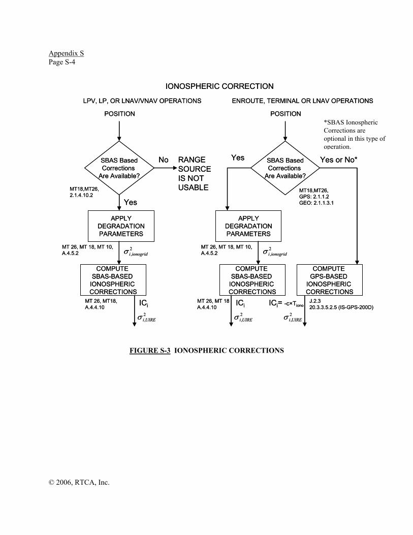
Appendix S Page S-4
© 2006, RTCA, Inc.
FIGURE S-3 IONOSPHERIC CORRECTIONS
POSITION
SBAS BasedCorrections
Are Available?
Yes
No RANGE SOURCEIS NOT USABLE
ICi
COMPUTE SBAS-BASED
IONOSPHERIC CORRECTIONS
2,UIREiσ
MT 26, MT18, A.4.4.10
APPLYDEGRADATIONPARAMETERS
2,ionogridiσ
MT 26, MT 18, MT 10, A.4.5.2
MT18,MT26, 2.1.4.10.2
LPV, LP, OR LNAV/VNAV OPERATIONS
POSITION
SBAS BasedCorrections
Are Available?
Yes Yes or No*
COMPUTE GPS-BASED
IONOSPHERIC CORRECTIONS
ICi= -c×Tiono
2,UIREiσ
J.2.3 20.3.3.5.2.5 (IS-GPS-200D)
COMPUTE SBAS-BASED
IONOSPHERIC CORRECTIONS
ICi2,UIREiσ
MT 26, MT 18A.4.4.10
APPLYDEGRADATIONPARAMETERS
2,ionogridiσ
MT 26, MT 18, MT 10, A.4.5.2
MT18,MT26, GPS: 2.1.1.2 GEO: 2.1.1.3.1
ENROUTE, TERMINAL OR LNAV OPERATIONS
IONOSPHERIC CORRECTION
POSITION
SBAS BasedCorrections
Are Available?
Yes
No RANGE SOURCEIS NOT USABLE
ICi
COMPUTE SBAS-BASED
IONOSPHERIC CORRECTIONS
2,UIREiσ
MT 26, MT18, A.4.4.10
APPLYDEGRADATIONPARAMETERS
2,ionogridiσ
MT 26, MT 18, MT 10, A.4.5.2
MT18,MT26, 2.1.4.10.2
LPV, LP, OR LNAV/VNAV OPERATIONS
POSITION
SBAS BasedCorrections
Are Available?
Yes Yes or No*
COMPUTE GPS-BASED
IONOSPHERIC CORRECTIONS
ICi= -c×Tiono
2,UIREiσ
J.2.3 20.3.3.5.2.5 (IS-GPS-200D)
COMPUTE SBAS-BASED
IONOSPHERIC CORRECTIONS
ICi2,UIREiσ
MT 26, MT 18A.4.4.10
APPLYDEGRADATIONPARAMETERS
2,ionogridiσ
MT 26, MT 18, MT 10, A.4.5.2
MT18,MT26, GPS: 2.1.1.2 GEO: 2.1.1.3.1
ENROUTE, TERMINAL OR LNAV OPERATIONS
IONOSPHERIC CORRECTION
*SBAS Ionospheric Corrections are optional in this type of operation.
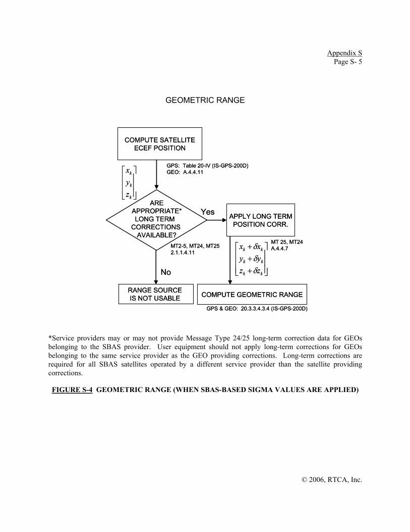
Appendix S Page S- 5
© 2006, RTCA, Inc.
GEOMETRIC RANGE
*Service providers may or may not provide Message Type 24/25 long-term correction data for GEOs belonging to the SBAS provider. User equipment should not apply long-term corrections for GEOs belonging to the same service provider as the GEO providing corrections. Long-term corrections are required for all SBAS satellites operated by a different service provider than the satellite providing corrections.
FIGURE S-4 GEOMETRIC RANGE (WHEN SBAS-BASED SIGMA VALUES ARE APPLIED)
COMPUTE SATELLITEECEF POSITION
GPS: Table 20-IV (IS-GPS-200D)GEO: A.4.4.11
APPLY LONG TERMPOSITION CORR.
MT 25, MT24 A.4.4.7
AREAPPROPRIATE*LONG TERM
CORRECTIONS AVAILABLE?
MT2-5, MT24, MT252.1.1.4.11
COMPUTE GEOMETRIC RANGE
⎥⎥⎥
⎦
⎤
⎢⎢⎢
⎣
⎡
k
k
k
zyx
⎥⎥⎥
⎦
⎤
⎢⎢⎢
⎣
⎡
+++
kk
kk
kk
zzyyxx
δδδ
GPS & GEO: 20.3.3.4.3.4 (IS-GPS-200D)
Yes
No
RANGE SOURCE IS NOT USABLE

Appendix S Page S-6
© 2006, RTCA, Inc.
FIGURE S-5 POSITION SOLUTION (WHEN SBAS-BASED SIGMA VALUES ARE APPLIED)
DO THE CORRECTIONS FOR
ALL SATELLITES COMEFROM THE SAME
GEO?
ACCOUNT FOR THEDIFFERENCE IN TIMEREFERERENCE USED
TO GENERATECORRECTIONS
RAIM / RAIM FDE
ARE ALLSATS IN THE
SOLUTION DESIGNATED SBAS HEALTHY?
No**
SBAS POSITIONSOLUTION
PRi,corrected-Di2iσ
POSITIONHPL
2.1.1.4.10
Yes
E.2J.1
LPV, LP, OR LNAV/VNAV OPERATIONS ENROUTE, TERMINAL OR LNAV OPERATIONS
DO THE CORRECTIONS FOR
ALL SATELLITESCOME FROM THE
SAME GEO?
No
ARE ALLSATS IN THE
SOLUTION DESIGNATED SBAS HEALTHY?
No
SBAS POSITIONSOLUTION
PRi,corrected-Di2iσ
Yes
E.2J.1
Yes INTEGRITY IS NOTPROVIDED*
POSITIONHPLVPL
Yes
No
ACCOUNT FOR THEDIFFERENCE IN TIME
REFERERENCE BETWEENSBAS AND GPS
2.1.1.4.10
POSITIONHPL
POSITION SOLUTION
2.1.4.2.2.1
2.1.2.2.2.12.1.1.4.10
2.1.2.2.2.2
DO THE CORRECTIONS FOR
ALL SATELLITES COMEFROM THE SAME
GEO?
ACCOUNT FOR THEDIFFERENCE IN TIMEREFERERENCE USED
TO GENERATECORRECTIONS
RAIM / RAIM FDE
ARE ALLSATS IN THE
SOLUTION DESIGNATED SBAS HEALTHY?
No**
SBAS POSITIONSOLUTION
PRi,corrected-Di2iσ
POSITIONHPL
2.1.1.4.10
Yes
E.2J.1
LPV, LP, OR LNAV/VNAV OPERATIONS ENROUTE, TERMINAL OR LNAV OPERATIONS
DO THE CORRECTIONS FOR
ALL SATELLITESCOME FROM THE
SAME GEO?
No
ARE ALLSATS IN THE
SOLUTION DESIGNATED SBAS HEALTHY?
No
SBAS POSITIONSOLUTION
PRi,corrected-Di2iσ
Yes
E.2J.1
Yes INTEGRITY IS NOTPROVIDED*
POSITIONHPLVPL
Yes
No
ACCOUNT FOR THEDIFFERENCE IN TIME
REFERERENCE BETWEENSBAS AND GPS
2.1.1.4.10
POSITIONHPL
POSITION SOLUTION
2.1.4.2.2.1
2.1.2.2.2.12.1.1.4.10
2.1.2.2.2.2
*This branch of the diagram emphasizes the requirements for LPV, LP, LNAV/VNAV operations. In reality, the user would attempt to use a subset of ranging sources and SBAS satellite corrections that will allow the computation of an SBAS position solution useable for LPV, LP and LNAV/VNAV operations. **SBAS Unhealthy Satellites are not allowed in a RAIM/RAIM FDE Position Solution. (2.1.1.6) Uncorrected GPS measurements may be used (2.1.2.2.2.2).

Appendix S Page S- 7
© 2006, RTCA, Inc.
FIGURE S-6 CLOCK/EPHEMERIS CONTRIBUTION TO WEIGHT USED FOR HPLFD FOR EN ROUTE THROUGH APPROACH (LNAV)
* Minimum corrections include ΔtSV, TGD, tropospheric, and ionospheric corrections for GPS satellites.
** All applicable corrections are MT 9 clock, tropospheric, ionospheric, fast, and range rate for GEOs of the SBAS used as the source of corrections; the previous corrections and long-term corrections for GEOs of SBASs other than the SBAS used as the source of corrections; and, minimum corrections, fast, long-term, and range rate corrections for GPS. User equipment should not apply Long-term corrections for GEOs belonging to the same service provider as the GEO providing corrections. Long-term corrections are required for all SBAS satellites operated by a different service provider than the satellite providing corrections.
*** To apply fast, long-term, and range-rate corrections, the UDREI must be < 14 per Section 2.1.1.4.12.
Is satelliteset to “Do Not
Use?”
yes
no
Whichcorrections will be
applied?
only minimumcorrections*
yes; must apply all applicable corrections**
clock/ephemeris weight= GPS URA
all applicable corrections***
Doesan active MT
27 exist?
done (can’t use satellite range measurement in position solution)
yes
no
If different satellite measurements are referenced to different time bases (e.g., GPS time and SBAS Network Time, or to Network Times of different SBASs), then adjust either weight or HPLFD to account for difference in time references
Doesan active MT
28 exist?
noAre
any Type 27messagesmissing?
Isthere an activeMT 28 for this
PRN?
clock/ephemeris weight = σ flt
yes
yes
no
yes
no
Is satellitea GEO?
no
Satellite is not useable as a ranging source unless satellite is a GPS satellite used with minimum corrections (see left branch)

Appendix S Page S-8
© 2006, RTCA, Inc.
THIS PAGE INTENTIONALLY LEFT BLANK

© 2006, RTCA, Inc.
APPENDIX T
GEO BIAS ANALYSIS TOOL

© 2006, RTCA, Inc.
THIS PAGE INTENTIONALLY LEFT BLANK

Appendix T Page T-11
© 2006, RTCA, Inc.
T.1 GEO Bias Algorithm Rationale
SBAS GEO and GPS signal parameters are not matched. (See Figure T-1.) The WAAS Narrowband (NB) GEOs have a signal bandwidth ~2MHz. The wideband (WB) GEO signal bandwidths are ~20MHz. Some foreign GEOs are ~4MHz wide. However the GPS signal bandwidth is ~20-30MHz . As a result of these and other filter differences, receiver signal processing may introduce range biases between GPS and GEO signals.
In this document, “narrowband” will refer to any GEO with a bandwidth ≤ 4MHz wide, and “wideband” will refer to any GEO with a bandwidth ≥18MHz wide.
-1 -0.8 -0.6 -0.4 -0.2 0 0.2 0.4 0.6 0.8 1 0 0.1 0.2 0.3 0.4 0.5 0.6 0.7 0.8 0.9
1
Code Offset
Nor
mal
ized
Am
plitu
de
GEO
GPS
Correlation Peak Comparison
-1 -0.8 -0.6 -0.4 -0.2 0 0.2 0.4 0.6 0.8 1 0 0.1 0.2 0.3 0.4 0.5 0.6 0.7 0.8 0.9
1
Code Offset
GEO
GPS
Correlation Peak Comparison
FIGURE T-1 COMPARISON OF CORRELATION PEAKS FOR A NARROWBAND GEO AND A GPS CORRELATION PEAK.
Note: Both peaks were passed through a user receiver filter.
These biases can be difficult to observe in practice. Signal generators do not accurately model the GEO signals. Live data contains errors (e.g., multipath) that may conceal small biases of this type. Hence, the analytical test in this appendix proposes to use actual GEO and receiver filter characteristics and discriminator configuration to model the potential biases between the GPS and GEO signals.
The maximum GPS-GEO bias magnitudes should be:
• less than 5m for the narrowband GEOs,
• less than 0.5m for the wideband GEOs
T.2 GEO Bias Algorithm Procedure (Overview)
The following algorithm description is provided for manufacturers to determine the GEO bias error in their correlator design.

Appendix T Page T-22
© 2006, RTCA, Inc.
IF - f 3dB IF+ f 3dB IF-f3dB IF+f3dB
GEO Filter Receiver Filter Code
IF-f3dB IF+f3dB
Receiver Filter Code
- BIAS GEO PRN Autocorrelation
GPS PRN Autocorrelation
IF - f 3dB IF+ f 3dB IF-f3dB IF+f3dB
GEO Filter Receiver Filter Code
IF-f3dB IF+f3dB
Receiver Filter Code
- BIAS GEO PRN Autocorrelation
IF - f 3dB IF+ f 3dB IF-f3dB IF+f3dB
GEO Filter Receiver Filter Code
IF - f 3dB IF+ f 3dB IF-f3dB IF+f3dB
GEO Filter Receiver Filter Code
IF-f3dB IF+f3dB
Receiver Filter Code
IF-f3dB IF+f3dBIF-f3dB IF+f3dB
Receiver Filter Code
- - - GEO PRN Autocorrelation
GPS PRN Autocorrelation
BIAS
FIGURE T-2 OVERVIEW OF GEO BIAS CALCULATION ALGORITHM FOR A SINGLE RECEIVER
Note: The above procedure must be computed once for each GPS and SBAS PRN (32+19 total) used to form the GPS autocorrelation function above. These are compared to a total of four (2 narrowband + 2 wideband) GEOs.
For each geostationary satellite and receiver of interest, the following steps must be performed:
1) GPS autocorrelation must be formed and filtered by the user receiver pre-correlation filter model(s).
2) GEO autocorrelation must be formed and filtered by the same receiver pre-correlation filter model(s).
3) The tracking error of the GPS signal must be computed using the discriminator of the GPS signal within that receiver.
4) The tracking error of the GEO signal must be computed using the discriminator of the GPS signal within that receiver.
5) Compute the difference in between the aforementioned GPS and GEO tracking errors within the same receiver.
6) Repeat Steps (a)-(e) for all GPS and SBAS PRNs. This includes PRNs 1-32 for GPS and PRNs 120-138 for SBAS.
7) Check results and ensure the requirements are met (<5m bias for narrowband GEOs, <0.5m for wideband GEOs).
T.3 Analysis
The analysis of this appendix assumes the incoming signals have been translated to baseband and are phase locked with zero phase error. The GPS PRN is represented by )(m tc .
The GEO bias may be analyzed by examining the autocorrelation functions. The ideal autocorrelation function )(, τRmn is given by:
Appendix T Page T-33
© 2006, RTCA, Inc.
∫∞
∞−
∗= dfefCfCfHR fjR
πτ 2)()()()( (1)
where, )( fH represents the transfer function of the combined filter that affect the frequency domain representation of the incoming signal )( fC . For accurate modeling,
( )H f should include the filters on the satellite, the antenna and LNA, and inside the receiver. )( fCR
∗ is the complex conjugate of the transfer function of the replica code.
The GPS signal is modeled as an ideal incoming signal (i.e., ( ) ( )RC f C f= ) and Equation 1 becomes:
∫∫∞
∞−
∗∞
∞−
∗ == dfefCfCdfefCfCfHR fjR
fjRGPSGPS
ππτ 22 )()()()()()( (2)
For a given user receiver with front-end filter characteristics captured by )( fHUSER , this becomes:
∫∞
∞−
∗= dfefCfCfHR fjRUSERGPSUSER
πτ 2, )()()()(
(3)
For the GEO signal, Equation 1 becomes:
∫∞
∞−
∗= dfefCfCfHR fjRGEOGEO
πτ 2)()()()( (4)
After receiver filtering, this equation becomes:
∫∞
∞−
∗= dfefCfCfHfHR fjRGEOUSERGEOUSER
πτ 2, )()()()()(
(5)
The early-minus-late (EML) tracking errors at a correlator spacing d (in C/A code chips) is found by solving the following discriminator equation for τ(d):
( ) ⎥⎦
⎤⎢⎣
⎡=⎟
⎠⎞
⎜⎝⎛ +−⎟
⎠⎞
⎜⎝⎛ −= 0
22arg dRdRdeml τττ
(6)
The double-delta (DD) tracking errors at a correlator spacing d1 (in C/A code chips) is found by solving the following discriminator equation for τDD( d1):
( ) ( ) ( )1 11 1 1arg 2 0
2 2DDd dd R R R d R dτ τ τ τ τ
⎧ ⎫⎡ ⎤⎛ ⎞ ⎛ ⎞ ⎡ ⎤= ⋅ − − + − − − + =⎨ ⎬⎜ ⎟ ⎜ ⎟⎢ ⎥ ⎣ ⎦⎝ ⎠ ⎝ ⎠⎣ ⎦⎩ ⎭ (7)
T.3.1 GEO Filter Models
Narrowband: )()( fHfH GEONBGEO = Applied to PRN122 (Inmarsat, AOR-W) and to PRN134 (Inmarsat, POR):

Appendix T Page T-44
© 2006, RTCA, Inc.
-30 -20 -10 0 10 20 30-160 -140 -120 -100 -80 -60 -40 -20
0
Frequency (MHz)
Mag
nitu
de (d
B)
-30 -20 -10 0 10 20 30-160 -140 -120 -100 -80 -60 -40 -20
0
Frequency (MHz)
-30 -20 -10 0 10 20 30-2000
-1000
0
1000
2000
3000
4000
Frequency (MHz)
Gro
up D
elay
(nse
c)
-30 -20 -10 0 10 20 30-2000
-1000
0
1000
2000
3000
4000
Frequency (MHz)
FIGURES T-3 and T-4 MAGNITUDE AND GROUP DELAY RESPONSES OF THE WAAS GEO SIGNAL GENERATOR IN COMBINATION WITH THE NARROWBAND GEO (AOR-W)
Note: This model is applied for both narrowband GEO PRNs 122 and 134.
Wideband: )()( fHfH GEOWBGEO = Applied to PRN135 (PanAmSat/Orbital @ 133W) and PRN138 (Telesat/Astrium satellite @ 107W):
-30 -20 -10 0 10 20 30-160 -140 -120 -100 -80 -60 -40 -20
0
Frequency (MHz)
Mag
nitu
de (d
B)
-30 -20 -10 0 10 20 30-160 -140 -120 -100 -80 -60 -40 -20
0
Frequency (MHz)
-30 -20 -10 0 10 20 30-2000
-1500
-1000
-500
0
500
1000
1500
2000
Frequency (MHz)
Gro
up D
elay
(nse
c)
-30 -20 -10 0 10 20 30-2000
-1500
-1000
-500
0
500
1000
1500
2000
Frequency (MHz)
FIGURES T-5 and T-6 MAGNITUDE AND GROUP DELAY RESPONSES OF THE GCCS GEO SIGNAL GENERATOR IN COMBINATION WITH THE WIDEBAND (PanAmSat/Orbital) GEO
User Filter (Example): )( fHUSER
-15 -10 -5 0 5 10 15-80 -70 -60 -50 -40 -30 -20 -10
0
Frequency (MHz)
Mag
nitu
de (d
B)
-15 -10 -5 0 5 10 15-80 -70 -60 -50 -40 -30 -20 -10
0
Frequency (MHz)
-15 -10 -5 0 5 10 15-4.5
-4
-3.5
-3
-2.5
-2
-1.5
-1
-0.5
0
Frequency (MHz)
Phas
e (r
ad)
-15 -10 -5 0 5 10 15-4.5
-4
-3.5
-3
-2.5
-2
-1.5
-1
-0.5
0
Frequency (MHz) FIGURES T-7 AND T-8 MAGNITUDE AND PHASE RESPONSES OF A SAMPLE RECEIVER
(FINAL IF PRECORRELATION) FILTER

Appendix T Page T-55
© 2006, RTCA, Inc.
T.3.1.1 Future GEOs
As future GEOs are put into service, it is up to each service provider to protect their users from the biases specific to these new satellites. The service provider must determine an acceptable method to bound the bias and calculate their GEO UDRE values. One acceptable method would be to update the GEO bias model tool (or develop a similar tool) with new GEO filter models. The threshold for the test using this new tool must be selected such that it includes all previously certified receivers. Service providers may request that already certified receivers rerun this tool with new GEO filter models for use in determining these thresholds (note that this is not a requirement).
T.3.2 Range Normalization
To find the contribution of range error introduced only by the receiver (e.g., user) filters, the tracking error measured by the pure signal-in-space is subtracted from the range measured on the signal post-receiver filtering at the correlator spacings of an ideal reverence receiver(s) having perfect, non-distorting filters. This normalization process ensures that any user receiver that also has a perfect, non-distorting receiver filter and which is configured identically to this reference receiver results in zero error.
The selected reference (EML) receiver correlator spacings are: d = dref,GEO = 0.3 chips (for narrowband (<8MHz) GEOs), d = dref,GEO = 0.1 chips (for wideband (8≥MHz) GEOs), and d = dref,GPS = 0.1 chips.
Note: This range-normalized, reference bias value is generally pre-computed and stored.
For both EML and DD receivers, the range normalization constants are found from:
( ) , ,, , arg 0
2 2ref GPS ref GPS
norm gps eml ref GPS GPS GPS
d dd R Rτ τ τ
⎡ ⎤⎛ ⎞ ⎛ ⎞= − − + =⎢ ⎥⎜ ⎟ ⎜ ⎟
⎝ ⎠ ⎝ ⎠⎣ ⎦ (8)
( ) , ,, , arg 0
2 2ref GEO ref GEO
norm geo eml ref GEO GEO GEO
d dd R Rτ τ τ
⎡ ⎤⎛ ⎞ ⎛ ⎞= − − + =⎢ ⎥⎜ ⎟ ⎜ ⎟
⎝ ⎠ ⎝ ⎠⎣ ⎦ (9)
Then, for EML user receivers the uncorrected, range-normalized GEO bias is given by:
( )⎥⎥⎦
⎤
⎢⎢⎣
⎡=⎟⎟
⎠
⎞⎜⎜⎝
⎛+−⎟⎟
⎠
⎞⎜⎜⎝
⎛−= 0
22arg ,
,,
,,,GPSUSER
GPSUSERGPSUSER
GPSUSERGPSUSERemlgpsuser
dR
dRd τττ (10)
( )⎥⎥⎦
⎤
⎢⎢⎣
⎡=⎟⎟
⎠
⎞⎜⎜⎝
⎛+−⎟⎟
⎠
⎞⎜⎜⎝
⎛−= 0
22arg ,
,,
,,,GEOUSER
GEOUSERGEOUSER
GEOUSERGEOUSERemlgeouser
dR
dRd τττ (11)
( ) ( ) ( ) ( ) ( ), , , , , , , ,bias eml user geo eml USER GEO norm geo eml ref GEO user gps eml USER GPS norm gps eml ref GEOd d d d dτ τ τ τ τ⎡ ⎤ ⎡ ⎤= − − −⎣ ⎦ ⎣ ⎦ (12)
And, for DD receivers, the uncorrected, range-normalized GEO bias is given by:
( ) ( ) ( )[ ]⎪⎭
⎪⎬⎫
⎪⎩
⎪⎨⎧
=+−−−⎥⎥⎦
⎤
⎢⎢⎣
⎡⎟⎟⎠
⎞⎜⎜⎝
⎛+−⎟⎟
⎠
⎞⎜⎜⎝
⎛−⋅= 0
222arg ,,,,
,,
,,,, GPSUSERGPSUSERGPSUSERGPSUSER
GPSUSERGPSUSER
GPSUSERGPSUSERGPSUSERDDgpsuser dRdR
dR
dRd τττττ
(13)
( ) ( ) ( )[ ]⎪⎭
⎪⎬⎫
⎪⎩
⎪⎨⎧
=+−−−⎥⎥⎦
⎤
⎢⎢⎣
⎡⎟⎟⎠
⎞⎜⎜⎝
⎛+−⎟⎟
⎠
⎞⎜⎜⎝
⎛−⋅= 0
222arg ,,,,
,,
,,,, GEOUSERGEOUSERGEOUSERGEOUSER
GEOUSERGEOUSER
GEOUSERGEOUSERGEOUSERDDgeouser dRdR
dR
dRd τττττ
(14)
( ) ( ) ( ) ( ) ( ), , , , , , , , , ,,bias DD USER GPS USER GEO user geo DD USER GEO norm geo eml ref GEO user gps DD USER GPS norm gps eml ref GPSd d d d d dτ τ τ τ τ⎡ ⎤ ⎡ ⎤= − − −⎣ ⎦ ⎣ ⎦
(15)
Appendix T Page T-66
© 2006, RTCA, Inc.
Where, for DD receivers, ,USER GEOd and ,USER GPSd represent the “inner” correlator spacings (or, dinner = douter/2).
T.4 Bias Model Tool: Instructions and examples
1) Copy all zipped files to the same directory,
2) Start Matlab (v6.5 or later),
3) Change to that directory. (Type cd directory_name)
4) Prepare single filter file of combined (aggregated) front-end filters for desired receiver with frequency, magnitude (dB), and phase (rad) (or group delay (ns)) response data in columns. (<10kHz frequency resolution; +/- 30MHz frequency span with at least 50dB of attenuation at the band edges to prevent aliasing. (A detailed description of how to do this is beyond the scope of this appendix.) Sample files (test_filer_1_001.dat and cheby_02.dat) are provided for use in the test cases shown below.
5) Type model_tool_v4c at command prompt to start. (Script version number along with script name may change if an update becomes available on RTCA-hosted download site. Check for updates at http://www.rtca.org.)
Note: Intermediate plots can be disabled by setting PLOT_RESULTS = 0; in the main script
6) Results are automatically saved to file: “summary_results_all.mat.” This file contains the following two key matrices:
a) summary_results: This is a 51x4 matrix of biases (one column for each WAAS GEO PRN—PRN122, PRN134, PRN135, PRN138, PRN129, and PRN137).
b) TrackingErrorSummaryMat: This is a structure of four three-dimensional tracking error matrices: TrackingErrorSummaryMat.PRN122, TrackingErrorSummaryMat.PRN134, TrackingErrorSummaryMat.PRN135, TrackingErrorSummaryMat.PRN138, TrackingErrorSummaryMat.PRN129, and TrackingErrorSummaryMat.PRN137. Each of these structure entries is a 20x4x51 matrix. The first dimension corresponds to 20 correlator spacings (0.05chips to 1.0 chips (max), in 0.05-chip increments; this refers to the “inner” or “d1” spacing only for DD receivers). The second corresponds to two columns with EML and DD GEO tracking errors followed by two columns with EML and DD GPS tracking errors. The third dimension corresponds to each of the (32+19) GPS and SBAS PRNs.
EXAMPLE 1: Sample Output (Screen Capture below)
======================================= NOTE: Frequency span of filter data in must be >=30MHz and should have a frequency resolution of 10kHz or less. NOTE: Frequency span of filter data in must be >=30MHz and should have a frequency resolution of 10kHz or less. Enter datafile of filter characteristics: test_filter_1_001.dat Frequency (MHz) column #: 1 Magnitude (dB) column #: 2

Appendix T Page T-77
© 2006, RTCA, Inc.
Phase (rad) column # (Enter zero to extract phase info from group delay): 0 Group delay (ns) column # (Enter zero to extract group delay info from phase): 3 Enter filter IF frequency (70MHz is typical): 0 Is GPS tracking Early-minus-Late? (1 = E-L; 0 = Double-delta): 1 Enter GPS correlator spacing (chips): 0.1 Is Narrowband GEO tracking Early-minus-Late? (1 = E-L; 0 = Double-delta): 1 Enter Narrowband GEO correlator spacing (chips): 0.3 Is Wideband GEO tracking Early-minus-Late? (1 = E-L; 0 = Double-delta): 1 Enter Wideband GEO correlator spacing (chips): 0.1 Program will repeat for all (32) GPS and (19) SBAS PRNs. GPS PRN1: Processing GEO PRNs 122 (AOR-W, narrowband) and 135 (PanAmSat/Orbital GCCS-1, wideband) ... Processing narrowband GEO filter... Processing wideband GEO filter... Computing tracking errors... GPS PRN1: Processing GEO PRNs 134 (POR, narrowband) and 138 (TeleSat/Atrium GCCS-2, wideband) ... Processing narrowband GEO filter... Processing wideband GEO filter... Computing tracking errors... GPS PRN1: Processing GEO PRNs 129 (MTSAT-1r, narrowband) and 137 (MTSAT-2, narrowband) ... Processing narrowband GEO filter... Processing wideband GEO filter... Computing tracking errors... Results for Narrowband WAAS GEOs ... >>> Estimated PRN 122 (AOR-W) GEO-GPS bias (UNcorrected) : 0.23159 meters >>> Estimated PRN 134 (POR) GEO-GPS bias (UNcorrected) : 0.24604 meters

Appendix T Page T-88
© 2006, RTCA, Inc.
Results for WIDEBAND WAAS GEOs ... >>> Estimated PRN135 (PanAmSat/Orbital GCCS-1) GEO-GPS bias (UNcorrected) : -0.03348 meters >>> Estimated PRN138 (TeleSat/Atrium GCCS-2) GEO-GPS bias (UNcorrected) : -0.020975 meters Results for Narrowband MTSAT GEOs ... >>> Estimated PRN 129 (MTSAT-1r) GEO-GPS bias (UNcorrected) : 0.21553 meters >>> Estimated PRN 137 (MTSAT-2) GEO-GPS bias (UNcorrected) : 0.30512 meters Check (PRN1) results for accuracy. <press any key to resume>
Note: The iteration above repeats for each of (32+19) GPS and SBAS PRNs. Results are automatically saved to “summary_results_all.mat” Output plots are below.
FIGURES T-9 AND T-10 ALL EARLY-MINUS-LATE AND DOUBLE-DELTA TRACKING ERRORS OF GPS AND INMARSAT NARROWBAND GEO SIGNALS AS OUTPUT BY TOOL
GIVEN THE SAMPLE INPUT PARAMETERS ABOVE (EXAMPLE 1)
FIGURES T-11 AND T-12 ALL EARLY-MINUS-LATE AND DOUBLE-DELTA TRACKING ERRORS OF GPS AND MTSAT NARROWBAND GEO SIGNALS AS OUTPUT BY TOOL
GIVEN THE SAMPLE INPUT PARAMETERS ABOVE (EXAMPLE 1)

Appendix T Page T-99
© 2006, RTCA, Inc.
FIGURES T-13 AND T-14 ALL EARLY-MINUS-LATE AND DOUBLE-DELTA TRACKING ERRORS OF GPS AND WIDEBAND GEO SIGNALS AS OUTPUT BY TOOL GIVEN THE
SAMPLE INPUT PARAMETERS ABOVE (EXAMPLE 1)
FIGURES T-15 AND T-16 SUMMARY OF GEO BIAS ERRORS FOR ALL (32+19) GPS AND SBAS PRNS AS OUTPUT BY TOOL GIVEN THE SAMPLE INPUT PARAMETERS ABOVE
(EXAMPLE 1). RECEIVER DESIGN PASSES IF ALL BIASES ARE BELOW LIMTS INDICATED ON PLOTS
EXAMPLE 2: Sample Output (Screen Capture below)
======================================= NOTE: Frequency span of filter data in must be >=30MHz and should have a frequency resolution of 10kHz or less. Enter datafile of filter charateristics: cheby2_01.dat Frequency (MHz) column #: 1 Magnitude (dB) column #: 2 Phase (rad) column # (Enter zero to extract phase info from group delay): 0 Group delay (ns) column # (Enter zero to extract group delay info from phase): 4 Enter filter IF frequency (70MHz is typical): 70

Appendix T Page T-1100
© 2006, RTCA, Inc.
Is GPS tracking Early-minus-Late? (1 = E-L; 0 = Double-delta): 1 Enter GPS correlator spacing (chips): 0.1 Is Narrowband GEO tracking Early-minus-Late? (1 = E-L; 0 = Double-delta): 1 Enter Narrowband GEO correlator spacing (chips): 0.3 Is Wideband GEO tracking Early-minus-Late? (1 = E-L; 0 = Double-delta): 1 Enter Wideband GEO correlator spacing (chips): 0.1 Program will repeat for all (32) GPS and (19) SBAS PRNs. GPS PRN1: Processing GEO PRNs 122 (AOR-W, narrowband) and 135 (PanAmSat/Orbital GCCS-1, wideband) ... Processing narrowband GEO filter... Processing wideband GEO filter... Computing tracking errors... GPS PRN1: Processing GEO PRNs 134 (POR, narrowband) and 138 (TeleSat/Atrium GCCS-2, wideband) ... Processing narrowband GEO filter... Processing wideband GEO filter... Computing tracking errors... GPS PRN1: Processing GEO PRNs 129 (MTSAT-1r, narrowband) and 137 (MTSAT-2, narrowband) ... Processing narrowband GEO filter... Processing wideband GEO filter... Computing tracking errors... Results for Narrowband WAAS GEOs ... >>> Estimated PRN 122 (AOR-W) GEO-GPS bias (UNcorrected) : -1.2091 meters >>> Estimated PRN 134 (POR) GEO-GPS bias (UNcorrected) : -1.2083 meters Results for WIDEBAND WAAS GEOs ... >>> Estimated PRN135 (PanAmSat/Orbital GCCS-1) GEO-GPS bias (UNcorrected) : 0.0015529 meters >>> Estimated PRN138 (TeleSat/Atrium GCCS-2) GEO-GPS bias (UNcorrected) : 0.012743 meters Results for Narrowband MTSAT GEOs ... >>> Estimated PRN 129 (MTSAT-1r) GEO-GPS bias (UNcorrected) : -1.2111 meters >>> Estimated PRN 137 (MTSAT-2) GEO-GPS bias (UNcorrected) : -1.2281 meters Check (PRN1) results for accuracy. <press any key to resume>
Note: The iteration above repeats for each of (32+19) GPS and SBAS PRNs. All results are automatically saved to “summary_results_all.mat.” Output plots are below.

Appendix T Page T-1111
© 2006, RTCA, Inc.
FIGURES T-17 AND T-18 ALL EARLY-MINUS-LATE AND DOUBLE-DELTA TRACKING ERRORS OF GPS AND INMARSAT NARROWBAND GEO SIGNALS AS OUTPUT BY TOOL
GIVEN THE SAMPLE INPUT PARAMETERS ABOVE (EXAMPLE 2)
FIGURES T-19 AND T-20 ALL EARLY-MINUS-LATE AND DOUBLE-DELTA TRACKING ERRORS OF GPS AND MTSAT NARROWBAND GEO SIGNALS AS OUTPUT BY TOOL
GIVEN THE SAMPLE INPUT PARAMETERS ABOVE (EXAMPLE 2)

Appendix T Page T-1122
© 2006, RTCA, Inc.
FIGURES T-21 AND T-22 ALL EARLY-MINUS-LATE AND DOUBLE-DELTA TRACKING ERRORS OF GPS AND WIDEBAND GEO SIGNALS AS OUTPUT BY TOOL GIVEN THE
SAMPLE INPUT PARAMETERS ABOVE (EXAMPLE 2)
FIGURES T-23 AND T-24 SUMMARY OF GEO BIAS ERRORS FOR ALL (32+19) GPS AND SBAS PRNS AS OUTPUT BY TOOL GIVEN THE SAMPLE INPUT PARAMETERS ABOVE
(EXAMPLE 2). RECEIVER DESIGN PASSES IF ALL BIASES ARE BELOW LIMTS INDICATED ON PLOTS

© 2006, RTCA, Inc.
APPENDIX U
GUIDANCE MATERIAL FOR INTERFACING WITH ADS-B

© 2006, RTCA, Inc.
THIS PAGE INTENTIONALLY LEFT BLANK
Appendix U Page U-1
© 2006, RTCA, Inc.
U.1 Purpose and Scope
This appendix contains guidance information for interfacing equipment conforming to this standard with ADS-B equipment. All classes of equipment compliant with this standard are expected to satisfy the requirements for initial U.S. applications for ADS-B.
U.2 Position Output and Validity
As required by Section 2.1.2.6, the equipment will output a position at 1 Hz with a time of applicability within 200 ms of the time of the output. A higher update rate may be provided by certain equipment (e.g., Class Beta-3 equipment is required to output position at 5 Hz unless it is restricted to integration in aircraft with an inertial reference unit). Compensation of position from this position to the ADS-B-reported position must be accomplished by the ADS-B equipment in order to calibrate it to the time of transmission. Particular attention should be paid to any alert conditions that may be indicated through other parameters or flags on the interface. When RAIM detects a failure that cannot be excluded, ADS-B equipment should set the position output to invalid rather than adjusting another parameter since there is a position error that is unbounded.
U.3 Horizontal Figure of Merit (HFOM)
As required by 2.1.2.6, the equipment will output the HFOM (defined in 1.7.2) along with the position, at an update rate of at least 1 Hz. The HFOM only describes the fault-free accuracy and does not consider non-normal events such as anomalous ionospheric conditions.
U.4 Horizontal Protection Limit (HPL)
As required by 2.1.2.6 and 2.1.1.13.1, the equipment will output a HPL. The HPLFD and HPLSBAS applicable to en route through LNAV approach operations (see Appendix J.2.1) are interchangeable in that they define the radius of a circle centered on the true position which contains the estimated position with a probability of 1-10-7 per hour with respect to signal-in-space failures. Failure of the avionics is not considered in defining the HPL. However, the HPLSBAS applicable to LNAV/VNAV, LPV and LP operations is slightly different as it defines a circle that contains the estimated position with a probability less than 1-2x10⁻⁷ per 150 seconds. It can be scaled to the per hour number by inflating by KH,NPA/KH,PA (6.18/6), an increase of 3%. The K factors are defined in Appendix J. Depending on the interface standard the equipment may output the HPL applicable to an annunciated mode (LPV or not LPV), may output both values in different portions of the output data, or may always output an HPL applicable to en route through LNAV.
While the HPL is output at a rate of 1 Hz, the effects of latency and time-to-alert need to be considered in the ADS-B context. The equipment has up to 8 seconds before a fault condition (error exceeding the HPL) must be detected and flagged.
The allocation of risk to the HPLSBAS can vary by the SBAS service provider, and it is the SBAS signal-in-space requirements (ICAO Annex 10) that constrain the probabilities as described above. The 2x10⁻⁷ per 150 second requirement has been allocated primarily to the vertical axis, so in reality the probability of exceeding the horizontal limit is significantly smaller. The scaling to a per hour number can be accomplished due to commonality in the parameters and equations that define the HPL: this translation is not based on any assumptions of the SBAS design or requirements allocation.

Appendix U Page U-2
©© 22000066,, RRTTCCAA,, IInncc..
When using the HPLFD or the HPLSBAS applicable to en route through LNAV operations it is important to recognize that the parameter has only been validated down to ~0.1 NM. While HPL values significantly smaller than this are typically output, they may not actually achieve the desired level of integrity as there are some error contributions that are no longer negligible but have not been taken into consideration (e.g., correlation of ionospheric errors across satellites). The HPLSBAS applicable to LPV, LP and LNAV/VNAV operations takes all errors into consideration and is valid for very small values of HPLSBAS.
Particular attention should be paid to any alert conditions that may be indicated through other parameters or flags on the interface. When a failure is detected, the equipment may output the HUL but this parameter should not be used for ADS-B. Some equipment may continue to output the HPL, but the HPL has no applicability once a failure is detected. ADS-B equipment should set the position output to invalid rather than adjusting another parameter.
U.5 Velocity
As required by Section 2.1.2.6, the equipment will output an estimate of velocity. This estimate may be derived a number of different ways, from measurement of change in carrier phase to a difference of successive position solutions. Appendix F defines a recommended method of determining the velocity estimate and a velocity figure of merit. However, there is no requirement on the accuracy of the velocity estimate so ADS-B integration should not assume any particular accuracy unless additional information is provided by the GPS/SBAS manufacturer.
U.6 Vertical Figure of Merit and Vertical Protection Limit (VPL)
The equipment is not required to output vertical Figure of Merit, or VPL. Within navigation, the geometric height derived from GNSS is used only on the final approach segment of an instrument approach procedure. When integrating with ADS-B, the integrator should make no assumptions of the validity of output vertical parameters without additional data from the manufacturer. It is significant to note that there are no industry conventions for defining a VPL that has the same interpretation as the HPL for en route through LNAV. The only VPL that is defined by this standard applies to LPV and LNAV/VNAV approach operations (see definition of VPLSBAS in Section 1.7.3).