miniplex-3 series nmea 0183/2000 multiplexer …4 introduction the miniplex-3 series nmea...
TRANSCRIPT
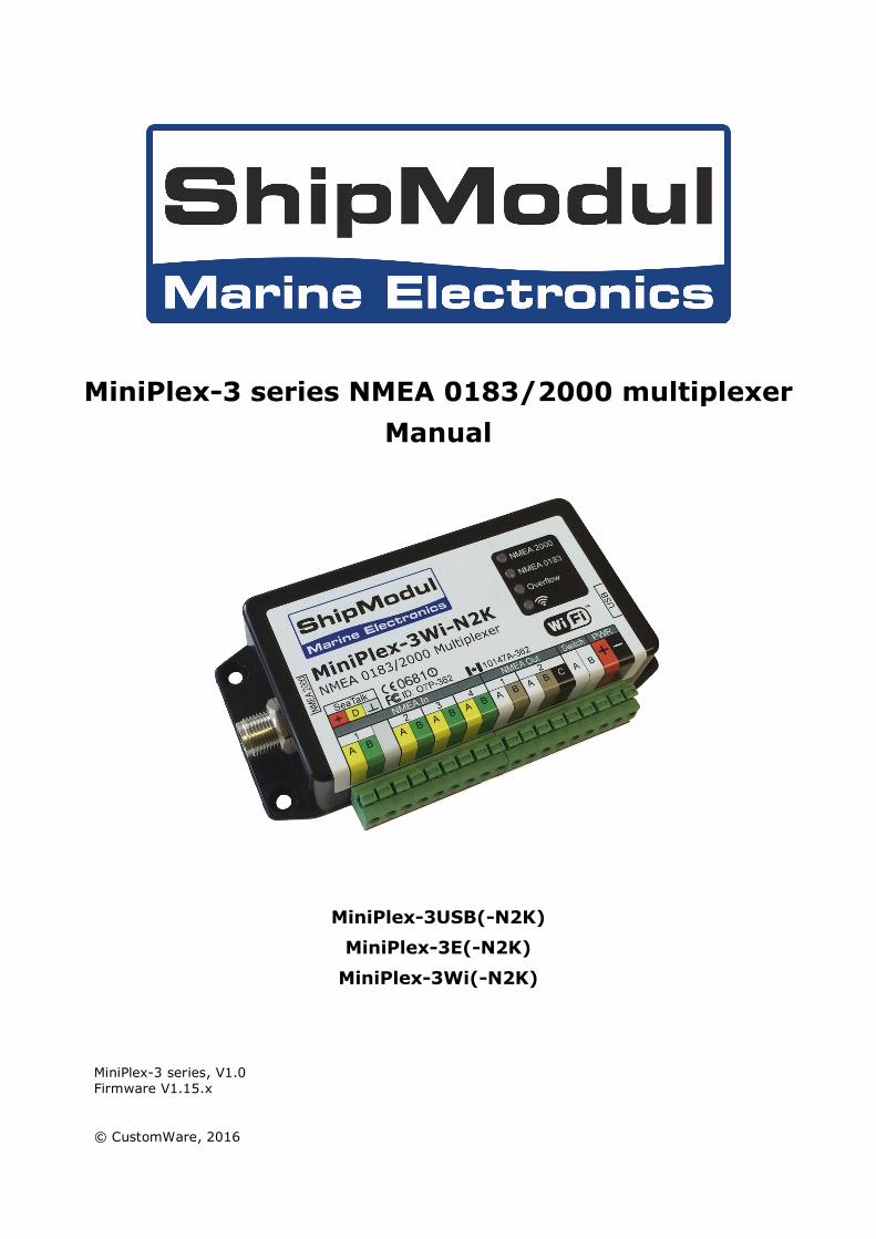
MiniPlex-3 series NMEA 0183/2000 multiplexer Manual
MiniPlex-3USB(-N2K)
MiniPlex-3E(-N2K)
MiniPlex-3Wi(-N2K)
MiniPlex-3 series, V1.0 Firmware V1.15.x © CustomWare, 2016
2
Introduction ................................................................................................................................ 4NMEA 0183 ................................................................................................................................. 4
NMEA Sentences ....................................................................................................................... 4Talkers and Listeners ................................................................................................................ 4The Multiplexer ......................................................................................................................... 5The Host ................................................................................................................................. 5The MiniPlex-3 Multiplexer ......................................................................................................... 6
Galvanic Isolation .................................................................................................................. 6NMEA 2000 ........................................................................................................................... 6Feature Set ........................................................................................................................... 6
Host Port .................................................................................................................................... 8USB Port .................................................................................................................................... 8
Driver Installation .................................................................................................................. 9Network Basics ......................................................................................................................... 14
IP Address .......................................................................................................................... 14Netmask ............................................................................................................................. 14Port Number ........................................................................................................................ 14Protocols ............................................................................................................................. 15
Assigning IP addresses ............................................................................................................ 15Ethernet Interface ..................................................................................................................... 16
Search ................................................................................................................................ 17Network Recovery ................................................................................................................ 18
WiFi Interface ........................................................................................................................... 19WiFi Access Point .................................................................................................................... 19App Behaviour ........................................................................................................................ 20Connect to another WiFi Access Point/Router .............................................................................. 20
Here is how to connect the MiniPlex-3Wi to an Access Point: ...................................................... 21NMEA 0183 Ports ....................................................................................................................... 25
NMEA 0183 Signals ................................................................................................................. 25NMEA 0183 Inputs .................................................................................................................. 25NMEA 0183 Outputs ................................................................................................................ 26Combining Ports ..................................................................................................................... 27SeaTalk ................................................................................................................................. 27
NMEA 2000 ............................................................................................................................... 28Connecting to the NMEA 2000 network ...................................................................................... 29
Power Supply ............................................................................................................................ 30Indicators ................................................................................................................................. 30Data Throughput ....................................................................................................................... 31MPX-Config-3 ............................................................................................................................ 33
Menu .................................................................................................................................... 34Controls ................................................................................................................................ 35
MiniPlex Connection ............................................................................................................. 35Viewer Options .................................................................................................................... 36NMEA Inputs/Outputs ........................................................................................................... 37Options .............................................................................................................................. 40NMEA Conversions ............................................................................................................... 41Sentence Filtering & Routing .................................................................................................. 43NMEA 2000 ......................................................................................................................... 46
Firmware Update ....................................................................................................................... 47Procedure .............................................................................................................................. 47
Mounting .................................................................................................................................. 48Technical Reference ................................................................................................................... 49
NMEA 0183 Glossary ............................................................................................................... 49Talker ID’s .......................................................................................................................... 49Sentence formatters ............................................................................................................. 49
Supported NMEA 2000 PGN’s .................................................................................................... 51Translated SeaTalk datagrams .................................................................................................. 52Firmware Update Error messages .............................................................................................. 53Standard NMEA 0183 Sentences ............................................................................................... 54
$MXSTN – Multiple Data ID ................................................................................................... 54$MXPGN – NMEA 2000 PGN Data ........................................................................................... 54
Proprietary NMEA 0183 Sentences ............................................................................................ 56Example ............................................................................................................................. 56$PSMDC – Get Configuration record ........................................................................................ 57$PSMDN – Set NMEA 2000 Configuration ................................................................................. 57$PSMDCF – Set Configuration ................................................................................................ 57
3
$PSMDCFQ – Get Configuration .............................................................................................. 57$PSMDDR – Set Default Route ............................................................................................... 57$PSMDFL – Set Filter Rules .................................................................................................... 58$PSMDID – Set Talker ID ...................................................................................................... 59$PSMDIN – Input options ...................................................................................................... 60$PSMDLDR – Loader message ................................................................................................ 60$PSMDOP – Set Options ........................................................................................................ 61$PSMDOV – Overflow ........................................................................................................... 62$PSMDRESET – Reset the multiplexer ..................................................................................... 62$PSMDSP – Set Speed .......................................................................................................... 62TAG Block ........................................................................................................................... 63$PSMDUI – Set Unique Identifier ............................................................................................ 63$PSMDVER – Get Version ...................................................................................................... 63$PSMDWI – WiFi Control ....................................................................................................... 63
Technical Specifications ........................................................................................................... 65MiniPlex-3USB ..................................................................................................................... 65MiniPlex-3USB-N2K .............................................................................................................. 65MiniPlex-3E ......................................................................................................................... 66MiniPlex-3E-N2K .................................................................................................................. 66MiniPlex-3Wi ....................................................................................................................... 67MiniPlex-3Wi-N2K ................................................................................................................ 67
4
Introduction The MiniPlex-3 series NMEA multiplexers enable the connection of multiple NMEA 0183/2000 devices and a host device like a PC, a laptop or a tablet. All models share the same number of NMEA ports and features. They differ in the type of host interface, the interface that talks to the computer. Some models also have an NMEA 2000 interface.
This manual covers all models of the MiniPlex-3 series. There is a chapter for each type of host port. The remaining part of the manual covers NMEA 0183 connections and configuration, which are the same for all models.
We will also explain NMEA 0183 and how things connect (or not).
For all –N2K model there’s a chapter about NMEA 2000.
NMEA 0183 The NMEA 0183 Standard, a communication standard defined by the NMEA organization (www.nmea.org), defines a communication protocol called NMEA 0183 that enables navigation instruments and devices to exchange data with each other.
This way, a compass can send a heading to a radar to enable a north-up display, a GPS can send cross-track and waypoint information to an autopilot in order to steer a programmed course.
NMEA Sentences NMEA data is made up of readable text sentences. If you would connect the output of a navigation instrument to the serial port of a computer and start a program that displays the incoming data, you would see something like this:
$GPGGA,143357.999,5301.0061,N,00635.5479,E,1,06,1.9,90.0,M,,,,0000*2E
$GPGGA,143357.999,5301.0061,N,00635.5479,E,1,06,1.9,90.0,M,,,,0000*39
$GPGLL,5301.0061,N,00635.5479,E,143357.999,A*22
$HEHDT,67.0,T*1E
This is plain text in a format that is laid out in the NMEA 0183 standard. Every device that receives this information would know that the sentence starting with GPGLL originates from a GPS (hence the GP at the beginning of the sentence) and that it contains the geographic longitude and latitude (GLL).
The term “NMEA sentence” is used for NMEA data because it is made up of single lines of text. Throughout this manual, “NMEA sentences” and “NMEA data” will be used randomly.
Talkers and Listeners The NMEA 0183 standard defines talkers and listeners. A device that sends information is a talker and a device that receives information is a listener. When connected to each other, the talker sends information to the listener.
Communication using the NMEA 0183 protocol involves at least one talker sending data to one listener. Figure 1 on the right shows such a minimal system: a gyrocompass sends heading data to a radar.
It is important to know that a talker or listener port is named after its function, not after what it is connected to. So a talker port sends out information but it connects to a listener. This might be confusing at times so further in this manual we will use the terms input and output instead of listener and talker port respectively.
The NMEA 0183 standard specifies that a talker should have enough driving capacity to talk to four listeners. This is as easy to achieve as telling a story to an audience of four people - the only requirement is to talk loud enough.
Gyro Radar
Figure 1
5
Figure 2
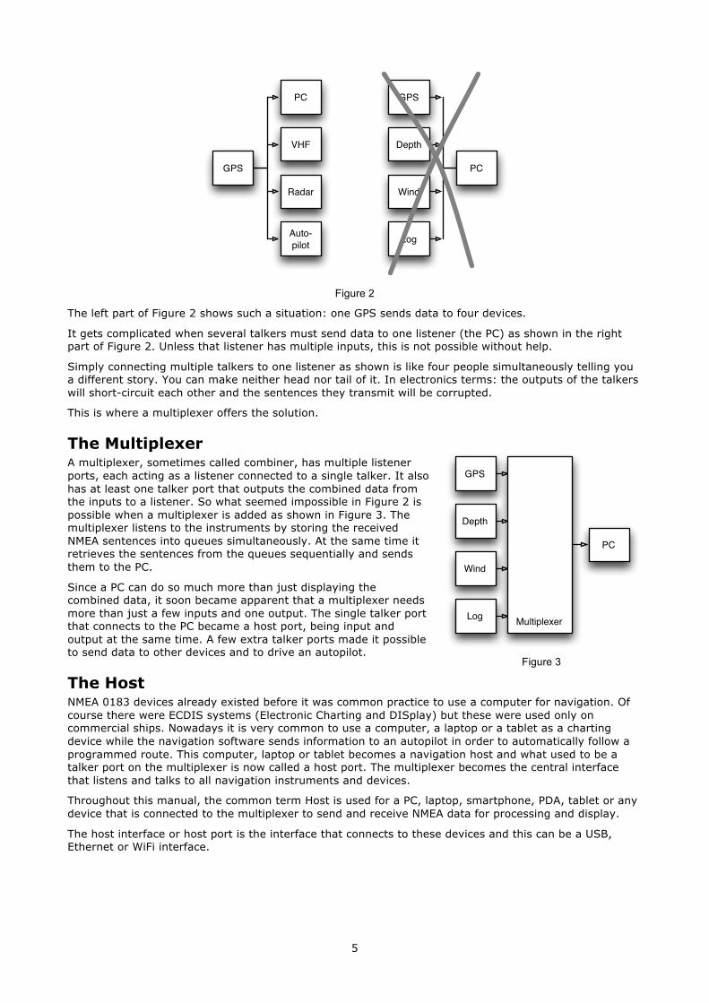
The left part of Figure 2 shows such a situation: one GPS sends data to four devices.
It gets complicated when several talkers must send data to one listener (the PC) as shown in the right part of Figure 2. Unless that listener has multiple inputs, this is not possible without help.
Simply connecting multiple talkers to one listener as shown is like four people simultaneously telling you a different story. You can make neither head nor tail of it. In electronics terms: the outputs of the talkers will short-circuit each other and the sentences they transmit will be corrupted.
This is where a multiplexer offers the solution.
The Multiplexer A multiplexer, sometimes called combiner, has multiple listener ports, each acting as a listener connected to a single talker. It also has at least one talker port that outputs the combined data from the inputs to a listener. So what seemed impossible in Figure 2 is possible when a multiplexer is added as shown in Figure 3. The multiplexer listens to the instruments by storing the received NMEA sentences into queues simultaneously. At the same time it retrieves the sentences from the queues sequentially and sends them to the PC.
Since a PC can do so much more than just displaying the combined data, it soon became apparent that a multiplexer needs more than just a few inputs and one output. The single talker port that connects to the PC became a host port, being input and output at the same time. A few extra talker ports made it possible to send data to other devices and to drive an autopilot.
The Host NMEA 0183 devices already existed before it was common practice to use a computer for navigation. Of course there were ECDIS systems (Electronic Charting and DISplay) but these were used only on commercial ships. Nowadays it is very common to use a computer, a laptop or a tablet as a charting device while the navigation software sends information to an autopilot in order to automatically follow a programmed route. This computer, laptop or tablet becomes a navigation host and what used to be a talker port on the multiplexer is now called a host port. The multiplexer becomes the central interface that listens and talks to all navigation instruments and devices.
Throughout this manual, the common term Host is used for a PC, laptop, smartphone, PDA, tablet or any device that is connected to the multiplexer to send and receive NMEA data for processing and display.
The host interface or host port is the interface that connects to these devices and this can be a USB, Ethernet or WiFi interface.
GPS
PC
VHF
Radar
Auto-pilot
PC
GPS
Depth
Wind
Log
PC
GPS
Depth
Wind
Log Multiplexer
Figure 3
6
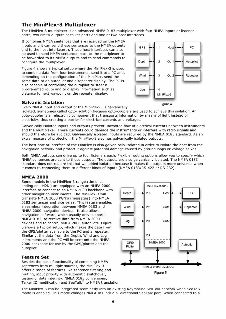
The MiniPlex-3 Multiplexer The MiniPlex-3 multiplexer is an advanced NMEA 0183 multiplexer with four NMEA inputs or listener ports, two NMEA outputs or talker ports and one or two host interfaces.
It combines NMEA sentences that are received on the NMEA inputs and it can send these sentences to the NMEA outputs and to the host interface(s). These host interfaces can also be used to send NMEA sentences back to the multiplexer to be forwarded to its NMEA outputs and to send commands to configure the multiplexer.
Figure 4 shows a typical setup where the MiniPlex-3 is used to combine data from four instruments, send it to a PC and, depending on the configuration of the MiniPlex, send the same data to an autopilot and a repeater display. The PC is also capable of controlling the autopilot to steer a programmed route and to display information such as distance to next waypoint on the repeater display.
Galvanic Isolation Every NMEA input and output of the MiniPlex-3 is galvanically isolated, sometimes called opto-isolation because opto-couplers are used to achieve this isolation. An opto-coupler is an electronic component that transports information by means of light instead of electricity, thus creating a barrier for electrical currents and voltages.
Galvanically isolated inputs and outputs prevent unwanted flow of electrical currents between instruments and the multiplexer. These currents could damage the instruments or interfere with radio signals and should therefore be avoided. Galvanically isolated inputs are required by the NMEA 0183 standard. As an extra measure of protection, the MiniPlex-3 also has galvanically isolated outputs.
The host port or interface of the MiniPlex is also galvanically isolated in order to isolate the host from the navigation network and protect it against potential damage caused by ground loops or voltage spikes.
Both NMEA outputs can drive up to four listeners each. Flexible routing options allow you to specify which NMEA sentences are sent to these outputs. The outputs are also galvanically isolated. The NMEA 0183 standard does not require this but we added isolation because it makes the outputs more universal when it comes to connecting them to different kinds of inputs (NMEA 0183/RS-422 or RS-232).
NMEA 2000 Some models in the MiniPlex-3 range (the ones ending on ‘-N2K’) are equipped with an NMEA 2000 interface to connect to an NMEA 2000 backbone with other navigation instruments. The MiniPlex-3 will translate NMEA 2000 PGN’s (messages) into NMEA 0183 sentences and vice versa. This feature enables a seamless integration between NMEA 0183 and NMEA 2000 navigation devices. It also allows navigation software, which usually only supports NMEA 0183, to receive data from NMEA 2000 devices and to control NMEA 2000 autopilots. Figure 5 shows a typical setup, which makes the data from the GPS/plotter available to the PC and a repeater. Similarly, the data from the Depth, Wind and Log instruments and the PC will be sent onto the NMEA 2000 backbone for use by the GPS/plotter and the autopilot.
Feature Set Besides the basic functionality of combining NMEA sentences from multiple sources, the MiniPlex-3 offers a range of features like sentence filtering and routing, input priority with automatic switchover, testing of data integrity, NMEA 0183 conversions, Talker ID modification and SeaTalk® to NMEA translation.
The MiniPlex-3 can be integrated seamlessly into an existing Raymarine SeaTalk network when SeaTalk mode is enabled. This mode changes NMEA In1 into a bi-directional SeaTalk port. When connected to a
Figure 4
PCGPS
Depth
Wind
LogMiniPlex-3
In1
In2
In3
In4
Out1
Out2
Host
Autopilot
Repeater
PCDepth
Wind
Log
GPS/Plotter
MiniPlex-3-N2K
In1
In2
In3
In4
Out1
Out2
Host
Autopilot
Repeater
NMEA 2000
NMEA 2000 BackboneFigure 5

7
Raymarine SeaTalk network, the multiplexer will share all data between all 3 buses: SeaTalk, NMEA 0183 and NMEA 2000: Received SeaTalk data will be converted and transmitted as NMEA 0183 and NMEA 2000 while at the same time, NMEA 0183 and NMEA 2000 will be converted into SeaTalk data.
All MiniPlex-3 models have the same features and number of NMEA inputs and outputs. The only difference between each model is the type of host port. The following chapters describe the details of each host port.
8
Host Port The host port is the port that connects to a PC, laptop, smartphone, PDA, tablet or any device that is connected to the multiplexer to receive the combined NMEA data for processing and display. Throughout this manual, the Host port will be used to describe any of the interfaces USB, Ethernet or WiFi. The type of the available host(s) port differs for each type of multiplexer.
The host port is always bi-directional: it delivers the combined NMEA 0183/2000/SeaTalk data from the multiplexer to the host in the form of NMEA 0183 sentences. At the same time it can receive NMEA 0183 sentences from the host, which are sent to the NMEA outputs and converted into NMEA 2000 and SeaTalk. The host port is also used to configure the multiplexer and to update its firmware.
The following chapters describe each type of host port. The applicable type of multiplexer is listed underneath the caption.
USB Port (MiniPlex-3USB, MiniPlex-3USB-N2K)
The USB port is galvanically isolated from the multiplexer to prevent ground loops when connected to a computer. Ground loops can result in excessive currents in ground connections, which could destroy the multiplexer or the serial port of the connected computer.
Because of this galvanic isolation, a MiniPlex-3 with a USB port will not be powered from the USB bus unlike older MiniPlex models. The MiniPlex-3 always requires a separate power supply to operate. The USB port circuitry however does receive its power from the USB bus. A computer will therefore always show a virtual COM port when the multiplexer is connected, with or without power supply.
The USB port supports flow control. With a waypoint activated, a navigation application can send many sentences at a time to the multiplexer to control an autopilot. The same happens, when uploading waypoints and routes through the multiplexer to a GPS.
Since the communication speed of the USB interface is 10 to 100 times higher than an NMEA 0183 output, this will cause the host buffer in the multiplexer to fill very rapidly. Eventually, sentences will be lost.
To prevent this loss of sentences, the navigation application must support hardware flow control (CTS/RTS). This allows the multiplexer to temporarily suspend the flow of data when the host buffer in the multiplexer is almost full. Unfortunately, not all applications support this. As of firmware version 1.14,x the multiplexer has a larger host buffer to prevent overflow in such cases.
Flow control settings can be found in the communication port settings of your software, and is often called “flow control” or “handshake”. Set the flow control to “Hardware” or “CTS/RTS”. Do not use “Xon/Xoff” flow control. The latter uses special characters instead of a hardware signal. These characters are not part of the NMEA standard and therefore not supported by the multiplexer.
9
Driver Installation To use a MiniPlex-3 with a USB port, a driver must be installed. This driver creates a virtual COM port, which can be opened by navigation software.
The CD contains drivers for Microsoft Windows (Windows 2000, XP, Vista, 7, 8 and 10) and Apple’s Mac OS X.
Windows 7 and up When the MiniPlex is connected to the computer for the first time, Windows will automatically download the most recent drivers from the Windows Update Service if an Internet connection is available. Without Internet connection, these drivers must be installed manually.
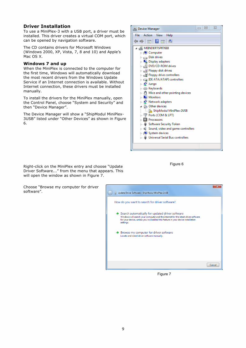
To install the drivers for the MiniPlex manually, open the Control Panel, choose “System and Security” and then “Device Manager”.
The Device Manager will show a “ShipModul MiniPlex-3USB” listed under “Other Devices” as shown in Figure 6.
Right-click on the MiniPlex entry and choose “Update Driver Software...” from the menu that appears. This will open the window as shown in Figure 7.
Choose “Browse my computer for driver software”.
Figure 7
Figure 6
10
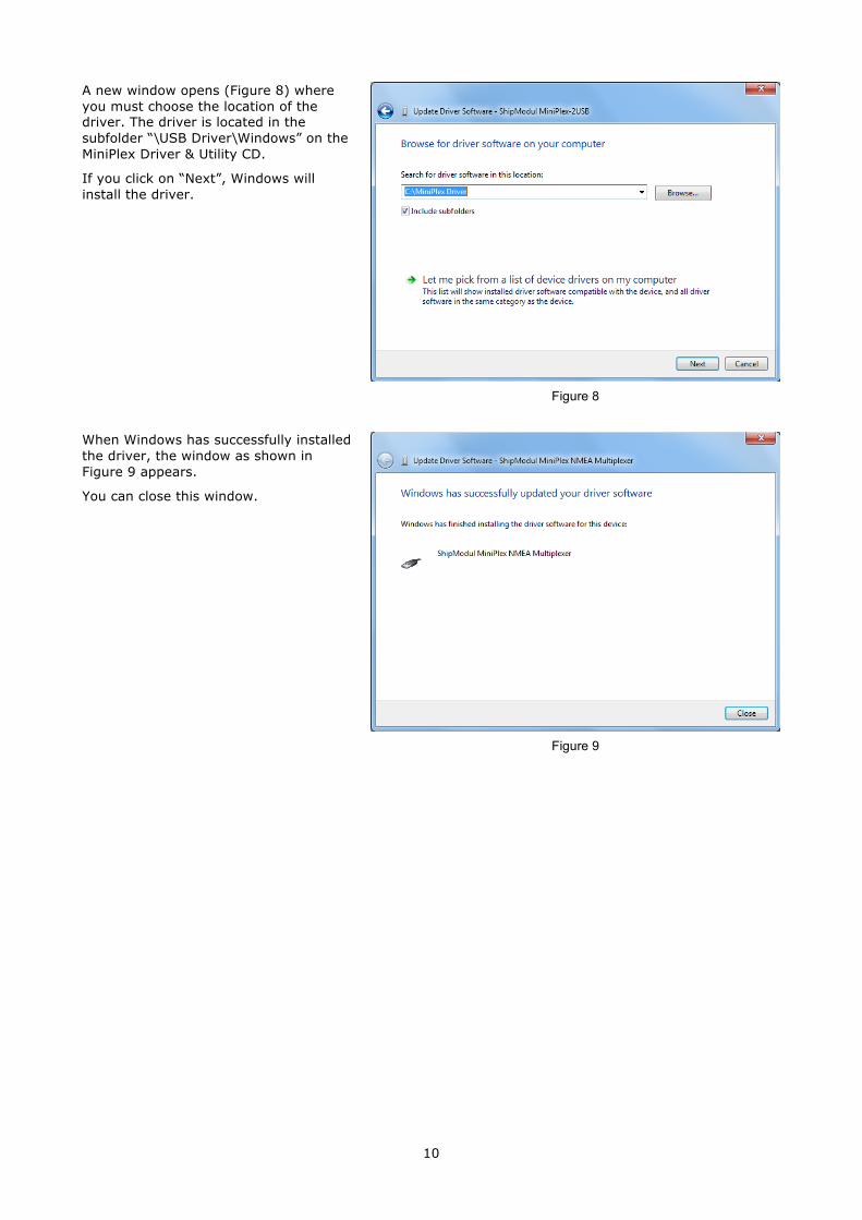
A new window opens (Figure 8) where you must choose the location of the driver. The driver is located in the subfolder “\USB Driver\Windows” on the MiniPlex Driver & Utility CD.
If you click on “Next”, Windows will install the driver.
When Windows has successfully installed the driver, the window as shown in Figure 9 appears.
You can close this window.
Figure 8
Figure 9
11
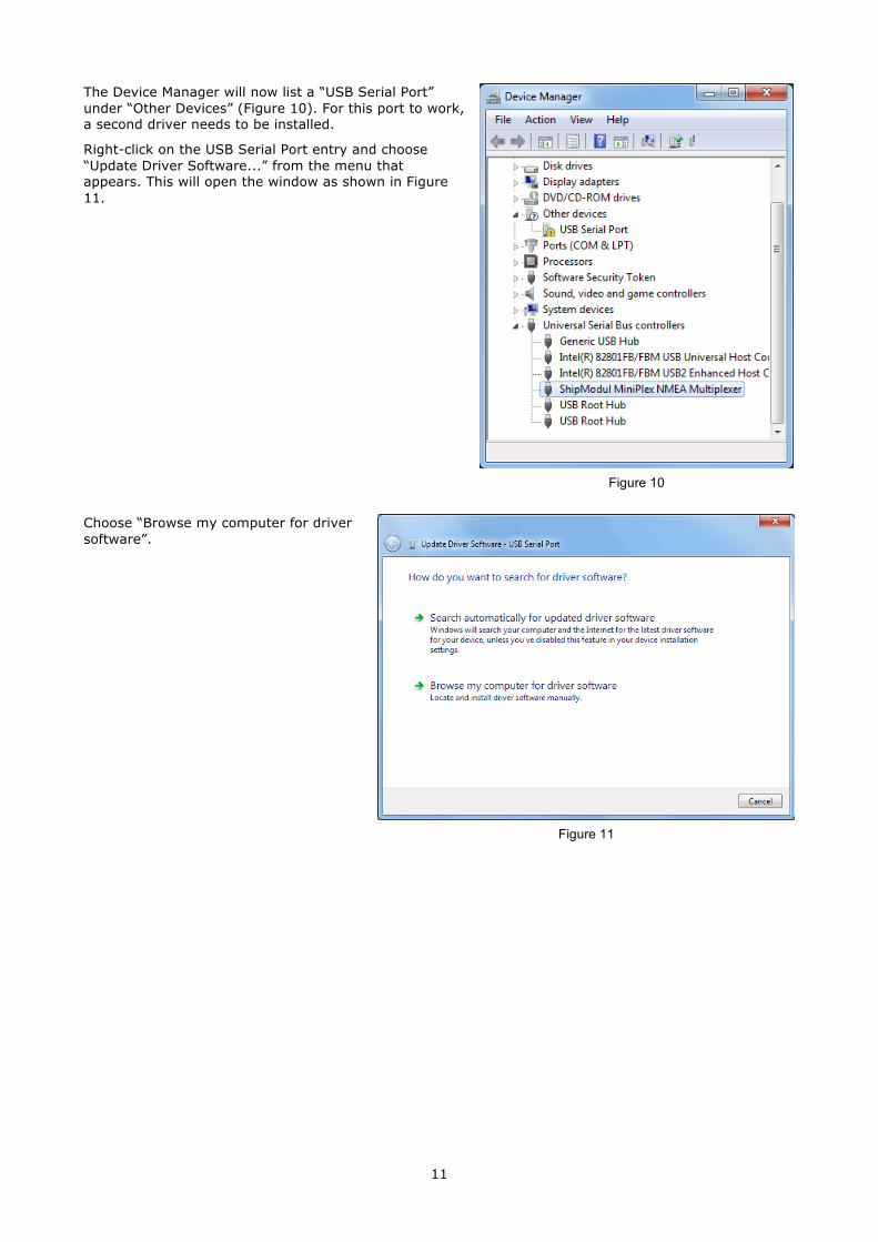
The Device Manager will now list a “USB Serial Port” under “Other Devices” (Figure 10). For this port to work, a second driver needs to be installed.
Right-click on the USB Serial Port entry and choose “Update Driver Software...” from the menu that appears. This will open the window as shown in Figure 11.
Choose “Browse my computer for driver software”.
Figure 11
Figure 10
12
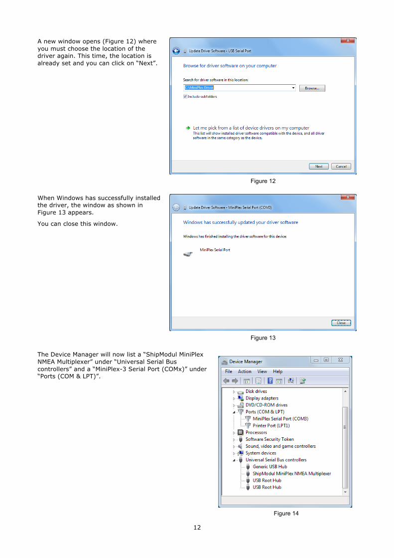
A new window opens (Figure 12) where you must choose the location of the driver again. This time, the location is already set and you can click on “Next”.
When Windows has successfully installed the driver, the window as shown in Figure 13 appears.
You can close this window.
The Device Manager will now list a “ShipModul MiniPlex NMEA Multiplexer” under “Universal Serial Bus controllers” and a “MiniPlex-3 Serial Port (COMx)” under “Ports (COM & LPT)”.
Figure 12
Figure 13
Figure 14
13
Windows XP When the multiplexer is connected to a USB port for the first time, Windows will detect new hardware and prompts you for a driver. Insert the supplied CD into the drive and follow the instructions on your screen. If you have an Internet connection, you can let Windows search the Internet for updated drivers. Otherwise, when asked to automatically search for drivers, answer no and choose the option to tell Windows where to find the driver. The driver can be found on the supplied CD, in de folder “\USB Driver\Windows”
The installation on Windows is a two-step process. First, the driver for the multiplexer will be installed. Next, Windows will detect a USB Serial device and will install a second driver. On Windows XP systems, there can be a delay of up to 10 seconds between the installation of both drivers, which sometimes leads to the wrong conclusion that the installation is complete after the first driver is installed. On Windows Vista and Windows 2000 systems, there is only very little delay.
When the installation is complete, a new virtual COM port will be created.
If necessary, the number of this COM port can be changed in the Windows Device Manager. Click on the ‘+’ sign next to the entry marked as “Ports (COM & LPT)”. This will expand the entry to list all available COM ports on your computer. The port for the multiplexer is listed as “MiniPlex Serial Port (COMx)” where “COMx” is the name of the newly created serial port.
To change this port number, double click on the “MiniPlex-3 Serial Port (COMx)” entry to open the property page for this port. Next, select the “Port Settings” tab and click on the “Advanced…” button. In the appearing window the assigned port number can be changed. Do not change any other setting in this window.
It is possible to select a port number that is already present on the computer, like COM1. The original COM1 port will then be disabled as long as the multiplexer is connected to the computer. This feature allows the port number to be set in a low range from COM1 to COM4, to accommodate software that only allows COM1 to COM4 to be selected.
More than one multiplexer can be connected at the same time. Every new unit will create a new virtual COM port. Once created, the COM port will always be assigned to the same multiplexer regardless of the USB port being used.
Windows allows a maximum of 256 COM ports. However not all software may be able to select COM ports numbered above COM9.
When installing updated drivers, uninstall the original drivers first with the “Add/Remove Programs” icon in the Control Panel or use the “Update Driver” button on the Driver page of the “MiniPlex Serial Port” property-page.
Mac OS X The OS X driver is available as a disk image file (.dmg) and can be found on the supplied CD in the “USB Driver” folder. Run the installer by double clicking on the icon. Follow the instructions on the screen. When the installation is complete, plug in the USB cable of the MiniPlex. The MiniPlex will show up in the ports list of your navigation software as MiniPlex-xxxxxxxx where the xx’s represent the serial number of the MiniPlex.
14
Network Basics A network interface connects the multiplexer directly to a network with possibly more than one device. In general, there can be more than one multiplexer connected to a network and/or more than one device that needs to communicate with a multiplexer.
In order to understand how a networked multiplexer works and how to connect to it, it is necessary to know a little bit about IP addresses, port numbers and protocols.
IP Address Every device on a network has a unique number to be able to identify that device. This allows us to send a message to one single device on a network. These numbers are called MAC addresses. Every device in the world that is connected to a network has such a MAC address. The MAC address of a device is sometimes printed on a label and looks like this:
00-20-4A-E4-28-58
These addresses are a bit cryptic and not easy to work with. Therefore a mechanism is used to assign a more easy to read number to a device, called an IP address. An IP address consists of four numbers grouped together, separated by dots. Each number can range from 0 to 255. An IP address looks like this:
192.168.1.45
Assigning an IP address to a device could be compared to sticking a coloured label to your house. Now the postman only needs to remember the colour of your label instead of your complete address. Of course, someone needs to manage a list that matches the colour to your address in order to prevent two houses of receiving the same coloured label. Networks and network devices have mechanisms built in that take care of this so we don’t have to worry about it (it’s called ARP or Address Resolution Protocol).
Netmask Another tricky bit of networking is a netmask. A netmask basically determines which part of an IP address is the network address and which part is the device address. In its most basic form, a netmask consists of four numbers, similar to an IP address, that are either 255 or 0. And the 255’s always come first. A device always has an IP address AND a netmask, for instance:
192.168.1.45 and 255.255.255.0
This combination of IP address and netmask tells us that the first three numbers of the IP address are the network address (192.168.1) and the fourth (45) is the device’s address. It also means that this particular combination limits the number of devices on this network to 254 (0 and 255 are reserved).
A network address allows us to send a single message to all devices on the network, instead of sending it to one single device. This is called a broadcast (see below). In this example, the broadcast address is 192.168.1.255. The last number here is 255, which means that it targets all devices on the network.
If we have an IP/netmask combination of 192.168.1.45/255.255.0.0, it means the network address is 192.168 and the device’s address 1.45, that there are 65534 possible devices (0.0 and 255.254 are reserved) and that the broadcast address is 192.168.255.255.
If you’re completely lost at this point, don’t worry. Just remember two things:
• All devices on a single network must have the same netmask • All devices on a single network must have the same network address
So when the netmask for example is 255.255.255.0, the first three numbers of the IP addresses must be the same.
Port Number A port number can be seen as a sub address within one single device. When a message is sent over the network, it always contains the IP address of the sender, the IP address of the receiver and a port number. This port number is just a logical number that determines the type of data in the message.
Web servers for instance, always listen to messages that have port number 80. If you start your web browser and enter the name of a web site, the request to show the contents of a page is sent to a web server using port number 80. Similarly, your mail program always uses port number 110 to retrieve mail from a mail server and port number 25 to send mail to a mail server.
The use of different port numbers allows us to use the same physical device on a network for different services.
15
Port numbers are not chosen arbitrarily, they are standardized and controlled by an organization called IANA.
Our multiplexers all use port number 10110, which is a registered port for NMEA data.
Protocols Two transport protocols are available for sending data over the network: UDP and TCP. UDP can be used in two different modes: Broadcast and Directed.
UDP Broadcast NMEA sentences are broadcast on the network using UDP messages. Every device on the network will receive these messages. At the same time, any device on the network can send data to the multiplexer, either to its IP address (directed) or as a broadcast. UDP Broadcast has the following properties:
• Every device on the network will receive NMEA data from the multiplexer. • Every device on the network can send NMEA data to the multiplexer. • Other MiniPlex-3E/2Wi’s on the same network will also receive each other’s data. It is therefore
possible to send NMEA data over the network from NMEA device to another. Care should be taken to prevent buffer overflows by selectively routing the desired NMEA data to an NMEA output at the receiving end and blocking unwanted NMEA data.
• Routers do not pass UDP Broadcasts from one network to another so this mode can only be used on one network.
• Delivery of NMEA data is not guaranteed, messages can be lost. • Wi-Fi routers often assign a low priority to UDP broadcasts, resulting in dropped messages. Typically
up to 5% of the messages gets lost.
UDP Directed With directed UDP data is sent to a specific IP address. The advantage is that it travels across routers and networks and can therefore also be used to send NMEA data over the Internet. Any device on the network can send data to the multiplexer either to its IP address (directed) or as a broadcast. Directed UDP has the following properties:
• Travels across routers/networks and the Internet. • Higher change of delivery than UDP broadcast. • Every computer on the network can send NMEA data to the multiplexer. • Only one computer can receive NMEA data from the multiplexer. • Delivery of NMEA data is not guaranteed, messages can be lost.
TCP When using TCP, a device sets up an exclusive connection with the MiniPlex. The TCP protocol is reliable, which means that when data gets lost on the way from one device to another, it is automatically retransmitted. Both the MiniPlex-3E and the MiniPlex-3Wi are limited to one TCP connection at a time.
TCP has the following properties:
• Travels across routers/networks and the Internet. • Only one computer or other device may communicate with the multiplexer. • Reliable connection. Lost messages are automatically retransmitted.
Although TCP might seem the best option from the above, it is favourable to use UDP. Compared with TCP, UDP will minimize network bandwidth. To send periodically updated sensor data, it is usually more appropriate to NOT use a guaranteed-delivery protocol like TCP. In navigation applications, the best thing to do in the rare event that a message doesn't get through is to simply wait for the next message. The TCP protocol forces retries which increase network traffic unnecessarily.
UDP resembles NMEA the most because NMEA is also a message based broadcast protocol without any acknowledgements or retries.
Assigning IP addresses When devices are connected to a network, they all must have a unique IP address and a matching netmask. One way of achieving this is to set the IP address and netmask of each device manually. The other way is to let a DHCP server take care of this.
DHCP is an acronym for Dynamic Host Configuration Protocol and it is a mechanism to automatically assign IP addresses to devices (hosts) on a network. A DHCP server on a network will respond to requests from DHCP clients to obtain an IP address.
In a typical network environment, a router acts as a DHCP server while other devices such as computers, laptops, tablets and smartphones are DHCP clients, receiving IP addresses from the DHCP server. This
16
ensures that you can connect these devices to the network without worrying about IP addresses, netmasks and gateways - al of this is taken care of by the DHCP server.
The MiniPlex-3Wi acts as a WiFi access point with a DHCP server built-in. When a device joins its WiFi network, it will automatically receive an IP/netmask from the MiniPlex-3Wi. The only thing you have to do is to enter the fixed IP address of the MiniPlex-3Wi (10.0.0.1) in your navigation software.
The MiniPlex-3E is completely different in this respect. It has a DHCP client and thus relies on a DHCP server already present on the network to obtain an IP/netmask automatically. If no DHCP server is present, you have to manually assign an IP/netmask. This is the case for instance, if your “network” is just the MiniPlex-3E and a computer. Obviously you will need to assign a manual IP address and netmask to your computer too in this case.
Auto-IP When DHCP request remains unanswered, a device assigns itself an IP address in the range of 169.254.0.0 to 169.254.255.254 with netmask 255.255.0.0. This is called an Auto-IP address. Although two devices with an Auto-IP address on the same network can perfectly communicate with each other, this is not a desired situation because these addresses are assigned totally at random. So every time a devices powers up, the address changes within the Auto-IP range and you’ll never be sure of its IP address. Also, the time it takes for a device to auto-assign varies wildly from a few seconds to over a minute.
Ethernet Interface (MiniPlex-3E, MiniPlex-3E-N2K)
If you are going to use a MiniPlex-3E, it is important to know whether your network has a DHCP server or not. If you have a router or a WiFi Access Point, it is most likely that they have a DHCP server enabled. In this case, you don’t need to manually assign a fixed IP address to the MiniPlex-3E if the following conditions are met:
• The DHCP server always assigns the same IP address to the same MAC address • The DHCP pool of free addresses will never be exhausted
This ensures that the MiniPlex-3E will always get the same IP address. The best practice however is to assign a fixed IP and netmask to the MiniPlex-3E.
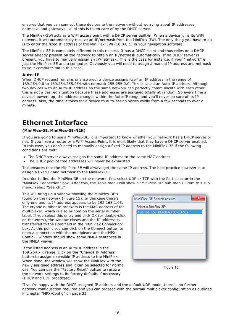
In order to find the MiniPlex-3E on the network, first select UDP or TCP with the Port selector in the “MiniPlex Connection” box. After this, the Tools menu will show a “MiniPlex-3E” sub-menu. From this sub-menu, select “Search…”
This will bring up a window showing the MiniPlex-3E’s found on the network (Figure 15). In this case there’s only one and its IP address appears to be 192.168.1.95. The cryptic number in brackets is the MAC address of the multiplexer, which is also printed on the serial number label. If you select this entry and click OK (or double-click on the entry), the window closes and the IP address is transferred to the Host field in the “MiniPlex Connection” box. At this point you can click on the Connect button to open a connection with the multiplexer and the MPX-Config-3 window should show some NMEA sentences in the NMEA viewer.
If the listed address is an Auto-IP address in the 169.254.x.x range, click on the “Change IP Address” button to assign a sensible IP address to the MiniPlex. When done, the window will show the MiniPlex with the newly assigned address and it can be selected for normal use. You can use the “Factory Reset” button to restore the network settings to its factory defaults if necessary (DHCP and UDP broadcast).
If you’re happy with the DHCP assigned IP address and the default UDP mode, there is no further network configuration required and you can proceed with the normal multiplexer configuration as outlined in chapter “MPX-Config” on page 33.
Figure 15
17
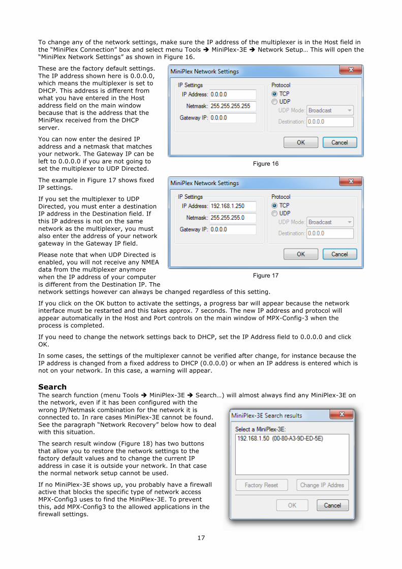
To change any of the network settings, make sure the IP address of the multiplexer is in the Host field in the “MiniPlex Connection” box and select menu Tools è MiniPlex-3E è Network Setup… This will open the “MiniPlex Network Settings” as shown in Figure 16.
These are the factory default settings. The IP address shown here is 0.0.0.0, which means the multiplexer is set to DHCP. This address is different from what you have entered in the Host address field on the main window because that is the address that the MiniPlex received from the DHCP server.
You can now enter the desired IP address and a netmask that matches your network. The Gateway IP can be left to 0.0.0.0 if you are not going to set the multiplexer to UDP Directed.
The example in Figure 17 shows fixed IP settings.
If you set the multiplexer to UDP Directed, you must enter a destination IP address in the Destination field. If this IP address is not on the same network as the multiplexer, you must also enter the address of your network gateway in the Gateway IP field.
Please note that when UDP Directed is enabled, you will not receive any NMEA data from the multiplexer anymore when the IP address of your computer is different from the Destination IP. The network settings however can always be changed regardless of this setting.
If you click on the OK button to activate the settings, a progress bar will appear because the network interface must be restarted and this takes approx. 7 seconds. The new IP address and protocol will appear automatically in the Host and Port controls on the main window of MPX-Config-3 when the process is completed.
If you need to change the network settings back to DHCP, set the IP Address field to 0.0.0.0 and click OK.
In some cases, the settings of the multiplexer cannot be verified after change, for instance because the IP address is changed from a fixed address to DHCP (0.0.0.0) or when an IP address is entered which is not on your network. In this case, a warning will appear.
Search The search function (menu Tools è MiniPlex-3E è Search…) will almost always find any MiniPlex-3E on the network, even if it has been configured with the wrong IP/Netmask combination for the network it is connected to. In rare cases MiniPlex-3E cannot be found. See the paragraph “Network Recovery” below how to deal with this situation.
The search result window (Figure 18) has two buttons that allow you to restore the network settings to the factory default values and to change the current IP address in case it is outside your network. In that case the normal network setup cannot be used.
If no MiniPlex-3E shows up, you probably have a firewall active that blocks the specific type of network access MPX-Config3 uses to find the MiniPlex-3E. To prevent this, add MPX-Config3 to the allowed applications in the firewall settings.
Figure 16
Figure 17
Figure 18
18
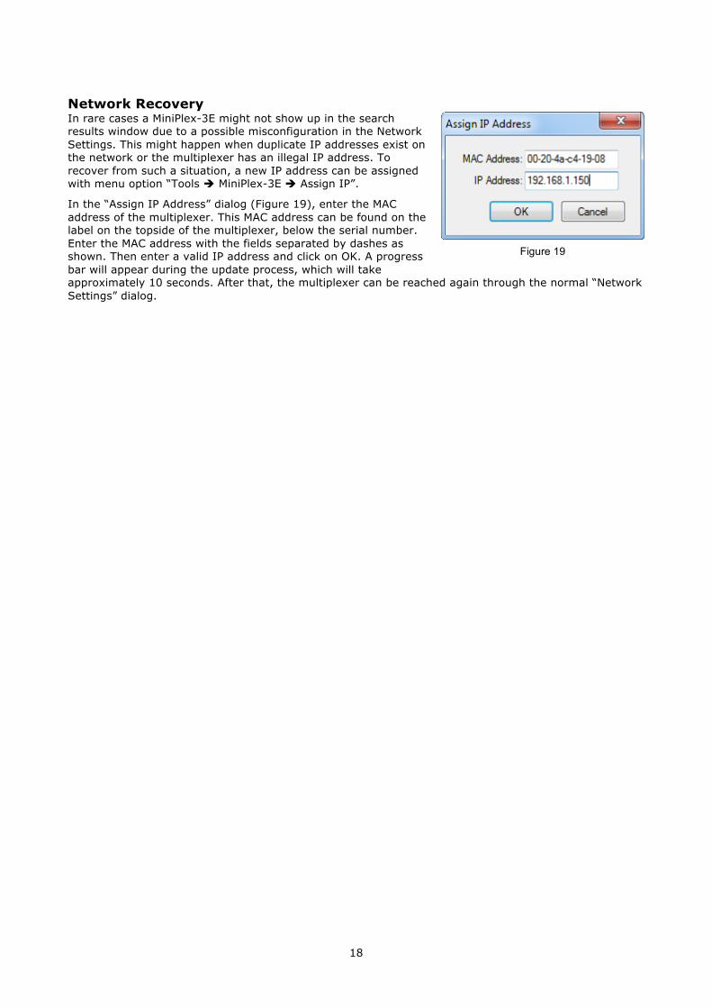
Network Recovery In rare cases a MiniPlex-3E might not show up in the search results window due to a possible misconfiguration in the Network Settings. This might happen when duplicate IP addresses exist on the network or the multiplexer has an illegal IP address. To recover from such a situation, a new IP address can be assigned with menu option “Tools è MiniPlex-3E è Assign IP”.
In the “Assign IP Address” dialog (Figure 19), enter the MAC address of the multiplexer. This MAC address can be found on the label on the topside of the multiplexer, below the serial number. Enter the MAC address with the fields separated by dashes as shown. Then enter a valid IP address and click on OK. A progress bar will appear during the update process, which will take approximately 10 seconds. After that, the multiplexer can be reached again through the normal “Network Settings” dialog.
Figure 19
19
WiFi Interface (MiniPlex-3Wi, MiniPlex-3Wi-N2K)
Through its WiFi interface, the MiniPlex-3Wi(-N2K) can communicate with wireless devices like an iPad, iPhone, a PC or a Mac.
WiFi Access Point The MiniPlex-3Wi provides a wireless access point through its 802.11b/g/n interface with the following parameters:
SSID (name): MiniPlex-xxxxxxxx Password: MiniPlex Security: WPA2 IP address: 10.0.0.1 Port: 10110 Protocol: TCP/IP DHCP: yes
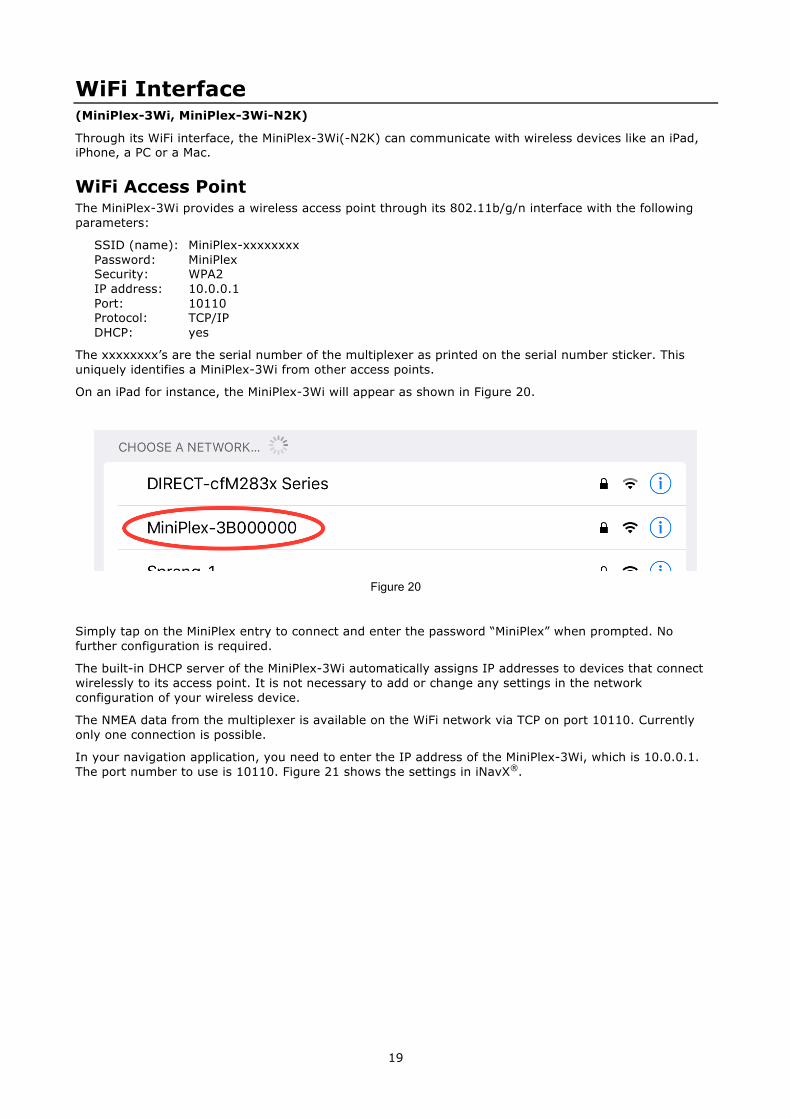
The xxxxxxxx’s are the serial number of the multiplexer as printed on the serial number sticker. This uniquely identifies a MiniPlex-3Wi from other access points.
On an iPad for instance, the MiniPlex-3Wi will appear as shown in Figure 20.
Figure 20
Simply tap on the MiniPlex entry to connect and enter the password “MiniPlex” when prompted. No further configuration is required.
The built-in DHCP server of the MiniPlex-3Wi automatically assigns IP addresses to devices that connect wirelessly to its access point. It is not necessary to add or change any settings in the network configuration of your wireless device.
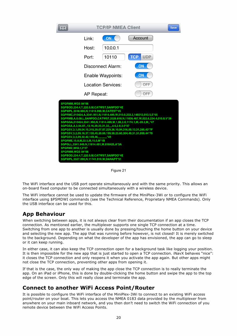
The NMEA data from the multiplexer is available on the WiFi network via TCP on port 10110. Currently only one connection is possible.
In your navigation application, you need to enter the IP address of the MiniPlex-3Wi, which is 10.0.0.1. The port number to use is 10110. Figure 21 shows the settings in iNavX®.
20
Figure 21
The WiFi interface and the USB port operate simultaneously and with the same priority. This allows an on-board fixed computer to be connected simultaneously with a wireless device.
The WiFi interface cannot be used to update the firmware of the MiniPlex-3Wi or to configure the WiFi interface using $PSMDWI commands (see the Technical Reference, Proprietary NMEA Commands). Only the USB interface can be used for this.
App Behaviour When switching between apps, it is not always clear from their documentation if an app closes the TCP connection. As mentioned earlier, the multiplexer supports one single TCP connection at a time. Switching from one app to another is usually done by pressing/touching the home button on your device and selecting the new app. The app that was running before however, is not closed! It is merely switched to the background. Depending on what the developer of the app has envisioned, the app can go to sleep or it can keep running.
In either case, it can also keep the TCP connection open for a background task like logging your position. It is then impossible for the new app that is just started to open a TCP connection. iNavX behaves “nice”: it closes the TCP connection and only reopens it when you activate the app again. But other apps might not close the TCP connection, preventing other apps from opening it.
If that is the case, the only way of making the app close the TCP connection is to really terminate the app. On an iPad or iPhone, this is done by double-clicking the home button and swipe the app to the top edge of the screen. Only this will really close and terminate the app.
Connect to another WiFi Access Point/Router It is possible to configure the WiFi interface of the MiniPlex-3Wi to connect to an existing WiFi access point/router on your boat. This lets you access the NMEA 0183 data provided by the multiplexer from anywhere on your main inboard network, and you then don’t need to switch the WiFi connection of you remote device between the WiFi Access Points.
21
The MiniPlex-3Wi provides a web interface to configure the WiFi access point and many other parameters related to the TCP server and network.
We recommend you not to change any other setting in the web interface than what is described here, as some settings are critical for the NMEA data communication. In any case, you can always get the factory WiFi configuration back by issuing “PSMDWI,A” command in MPX-Config3 via the USB port (Manual NMEA Sentence Input); this re-initialization takes appr. 30 seconds.
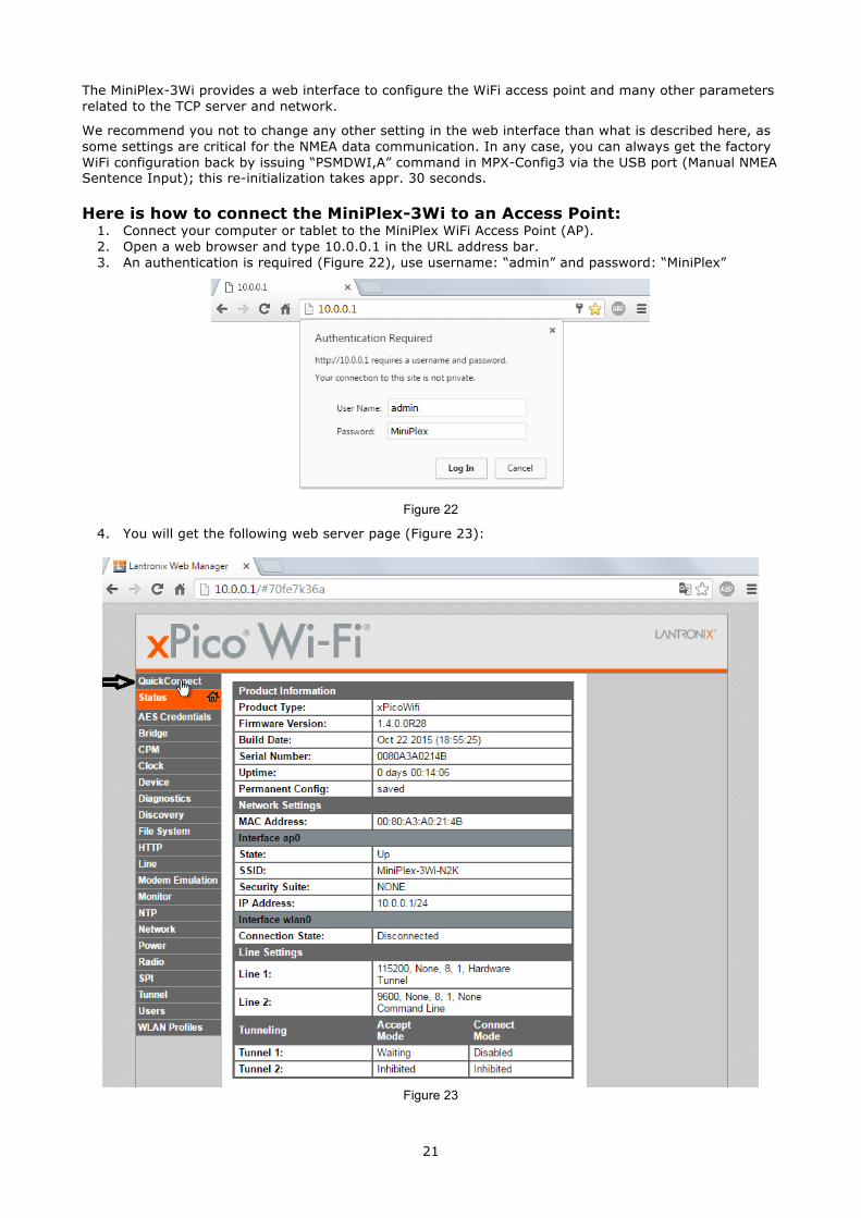
Here is how to connect the MiniPlex-3Wi to an Access Point: 1. Connect your computer or tablet to the MiniPlex WiFi Access Point (AP). 2. Open a web browser and type 10.0.0.1 in the URL address bar. 3. An authentication is required (Figure 22), use username: “admin” and password: “MiniPlex”
Figure 22
4. You will get the following web server page (Figure 23):
Figure 23
22
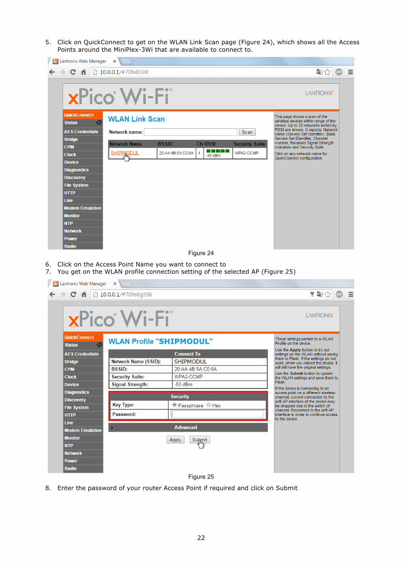
5. Click on QuickConnect to get on the WLAN Link Scan page (Figure 24), which shows all the Access Points around the MiniPlex-3Wi that are available to connect to.
Figure 24
6. Click on the Access Point Name you want to connect to 7. You get on the WLAN profile connection setting of the selected AP (Figure 25)
Figure 25
8. Enter the password of your router Access Point if required and click on Submit
23
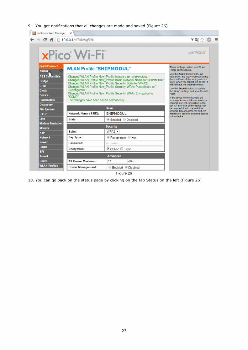
9. You get notifications that all changes are made and saved (Figure 26)
Figure 26
10. You can go back on the status page by clicking on the tab Status on the left (Figure 26)
24
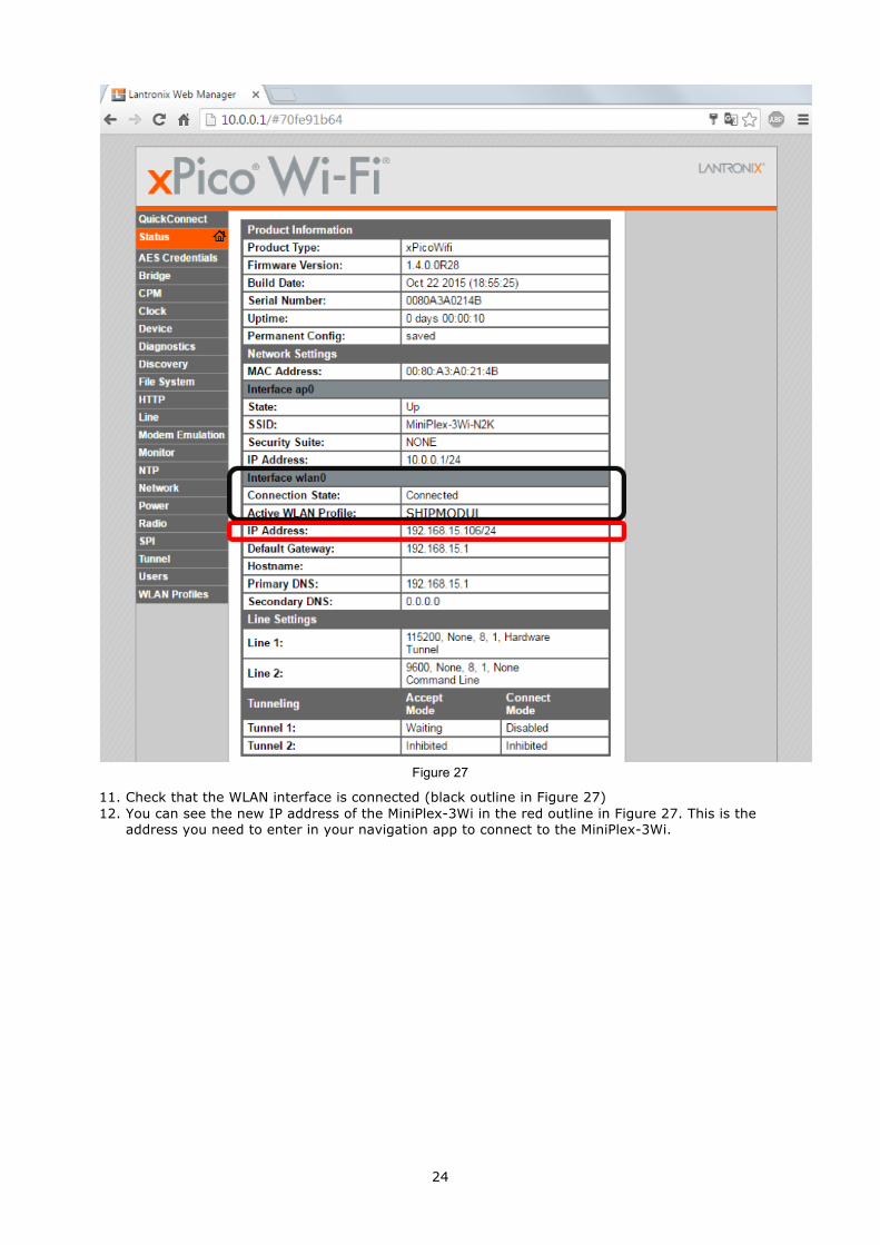
Figure 27
11. Check that the WLAN interface is connected (black outline in Figure 27) 12. You can see the new IP address of the MiniPlex-3Wi in the red outline in Figure 27. This is the
address you need to enter in your navigation app to connect to the MiniPlex-3Wi.
25
NMEA 0183 Ports The NMEA 0183 ports are the inputs/listener ports and outputs/talker ports on the MiniPlex-3, which connect to NMEA 0183 ports on navigation instruments, chart plotters etc. There are many interpretations and variations of NMEA 0183 ports so we’ll explain a few things first.
NMEA 0183 Signals Although the NMEA 0183 standard specifies the signal names, voltage levels and connection methods very clearly, the reality is far from this ideal world.
The most important property of an NMEA 0183 port is that the connections or wires are labelled A and B and that it uses a differential signalling scheme. This means that data is transmitted on both wires, but in “opposite direction”. Both wires are driven between 5V and 0V and opposite of each other: when wire A is at 5V, wire B is at 0V and when wire A is at 0V, wire B is at 5V. The advantage of this signalling scheme is that it is very insensitive to electrical interference.
NMEA A and B are often labelled as NMEA + and - respectively. When connecting devices, simply connect NMEA A to NMEA A or NMEA + and NMEA B to NMEA B or NMEA -.
Some devices even have NMEA + and NMEA – the other way around. It is perfectly safe to swap the wires if no signal is received when connected to an NMEA 0183 port of the MiniPlex-3.
Things get complicated when manufacturers don’t follow the NMEA 0183 standard, which is very often the case. Many devices have an NMEA 0183 interface, which is electrically speaking an RS-232 interface. The only resemblance with the NMEA 0183 standard is the format of the data transmitted. Electrically, they are an entirely different world. The used signal names differ wildly and often lead to confusion. When a device has a NMEA input with connections “Data In” and “Data Return” it is often not clear whether this input is galvanically isolated or if “Data Return” is simply another name for “Signal ground”.
Instead of being fully compatible with the NMEA 0183 standard, many devices use a single-ended signalling scheme where data is transmitted on one a single wire while the power ground provides the return path. Single ended devices often have connection names like TX and Gnd (transmit and ground) on the NMEA output and RX and Gnd (receive and ground) on the NMEA input. Also used are Data Out, Data In and Signal Ground. Mix these with standard NMEA connections and confusion is imminent!
The MiniPlex-3 Series multiplexers takes away the confusion by offering galvanically isolated NMEA inputs and outputs. Because of this isolation, a ground reference no longer exists: both the A and B signals of an NMEA port are completely “floating”. This means that you don’t have to think about the nature of an input or output of the device you want to connect to multiplexer. Any NMEA output of a device can be connected to an NMEA input of the multiplexer while an NMEA output of the multiplexer can be connected to any type of input of your device or instrument.
NMEA 0183 Inputs The MiniPlex-3 has four NMEA inputs called In1 to In4. Each input should be connected to one output only. These inputs are galvanically isolated from the multiplexer, as specified by the NMEA 0183 standard.
The default communication speed of the NMEA 0183 inputs is 4800 Baud (NMEA standard) and it can be set to any value from 4800 to 57600 Baud using MPX-Config-3. Set the speed of an input to 38400 Baud if it will be connected to an AIS receiver or transponder.
Connect the A and B terminals of the NMEA input on the multiplexer to the A and B terminals of the NMEA 0183 output on the navigation device as shown in Figure 28 on the left. These terminals may also be labelled as Data+/Data-, TX+/TX-, Out+/Out– or ve+/ve-.
Some navigation devices have single ended outputs with only one data terminal. Connect this terminal to the A terminal of the multiplexer input, and connect the ground of the navigation device to the B terminal of the multiplexer input as shown on the right in Figure 28. The navigation device’s data ground is often combined with its power supply ground. In that case, connect the power ground of the navigation device to the B terminal of the multiplexer input.
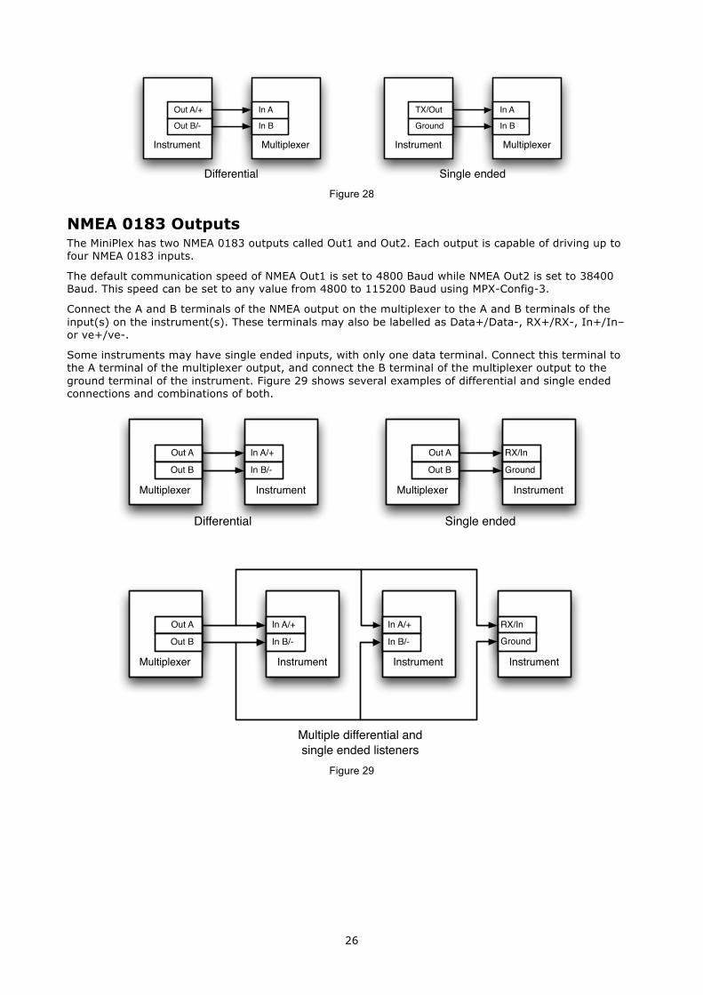
26
Figure 28
NMEA 0183 Outputs The MiniPlex has two NMEA 0183 outputs called Out1 and Out2. Each output is capable of driving up to four NMEA 0183 inputs.
The default communication speed of NMEA Out1 is set to 4800 Baud while NMEA Out2 is set to 38400 Baud. This speed can be set to any value from 4800 to 115200 Baud using MPX-Config-3.
Connect the A and B terminals of the NMEA output on the multiplexer to the A and B terminals of the input(s) on the instrument(s). These terminals may also be labelled as Data+/Data-, RX+/RX-, In+/In– or ve+/ve-.
Some instruments may have single ended inputs, with only one data terminal. Connect this terminal to the A terminal of the multiplexer output, and connect the B terminal of the multiplexer output to the ground terminal of the instrument. Figure 29 shows several examples of differential and single ended connections and combinations of both.
Figure 29
Multiplexer
In A
In B
Instrument
Out A/+
Out B/-
Differential
Multiplexer
In A
In B
Instrument
TX/Out
Ground
Single ended
Multiple differential and single ended listeners
Instrument
In A/+
In B/-
Multiplexer
Out A
Out B
Differential
Instrument
RX/In
Ground
Single ended
Multiplexer
Out A
Out B
Instrument
In A/+
In B/-
Multiplexer
Out A
Out B
Instrument
In A/+
In B/-
Instrument
RX/InGround
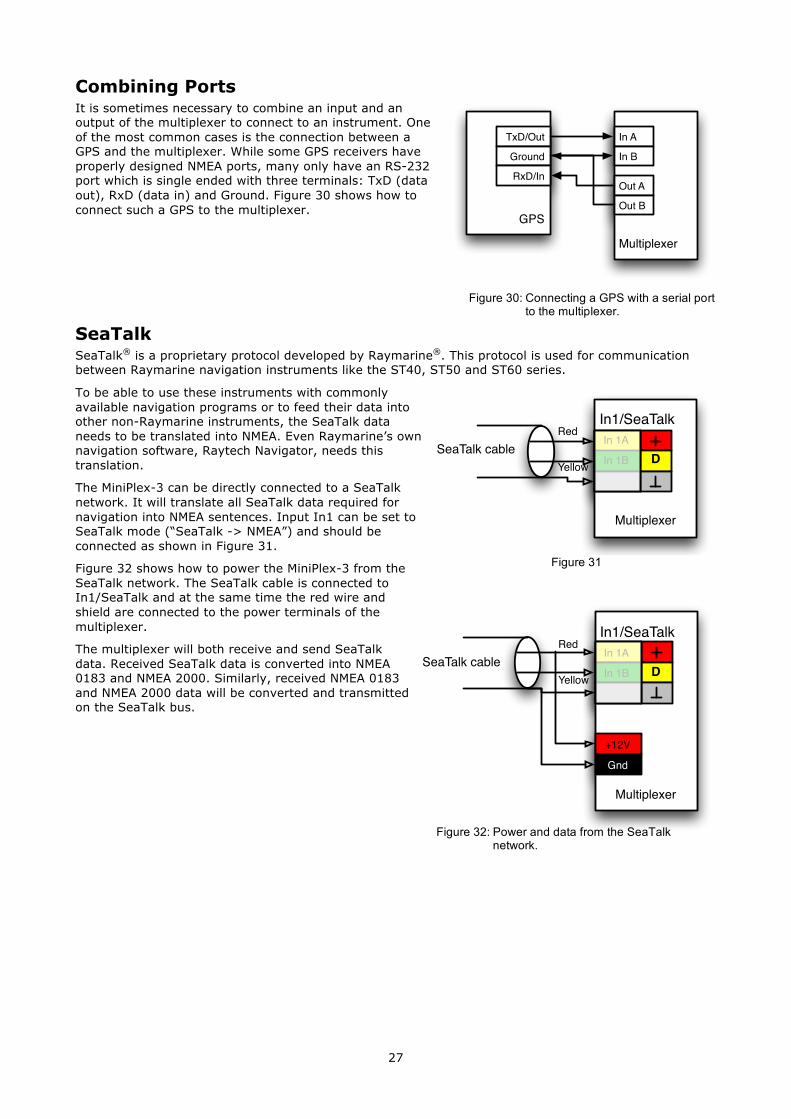
27
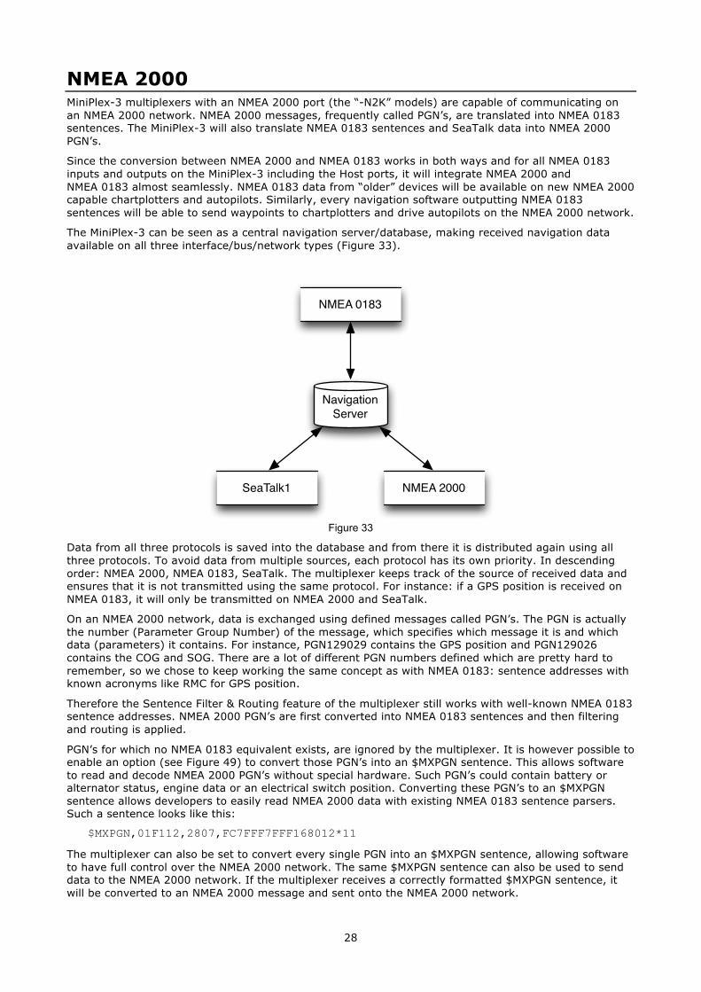
Combining Ports It is sometimes necessary to combine an input and an output of the multiplexer to connect to an instrument. One of the most common cases is the connection between a GPS and the multiplexer. While some GPS receivers have properly designed NMEA ports, many only have an RS-232 port which is single ended with three terminals: TxD (data out), RxD (data in) and Ground. Figure 30 shows how to connect such a GPS to the multiplexer.
SeaTalk SeaTalk® is a proprietary protocol developed by Raymarine®. This protocol is used for communication between Raymarine navigation instruments like the ST40, ST50 and ST60 series.
To be able to use these instruments with commonly available navigation programs or to feed their data into other non-Raymarine instruments, the SeaTalk data needs to be translated into NMEA. Even Raymarine’s own navigation software, Raytech Navigator, needs this translation.
The MiniPlex-3 can be directly connected to a SeaTalk network. It will translate all SeaTalk data required for navigation into NMEA sentences. Input In1 can be set to SeaTalk mode (“SeaTalk -> NMEA”) and should be connected as shown in Figure 31.
Figure 32 shows how to power the MiniPlex-3 from the SeaTalk network. The SeaTalk cable is connected to In1/SeaTalk and at the same time the red wire and shield are connected to the power terminals of the multiplexer.
The multiplexer will both receive and send SeaTalk data. Received SeaTalk data is converted into NMEA 0183 and NMEA 2000. Similarly, received NMEA 0183 and NMEA 2000 data will be converted and transmitted on the SeaTalk bus.
Figure 30: Connecting a GPS with a serial port to the multiplexer.
Figure 32: Power and data from the SeaTalk network.
GPS
TxD/Out
Ground
RxD/In
Multiplexer
In A
In B
Out A
Out B
SeaTalk cable
Multiplexer
In 1A
In 1B
Red
Yellow D
In1/SeaTalk
SeaTalk cable
Multiplexer
Red
Yellow
+12V
Gnd
In 1A
In 1B D
In1/SeaTalk
Figure 31
28
NMEA 2000 MiniPlex-3 multiplexers with an NMEA 2000 port (the “-N2K” models) are capable of communicating on an NMEA 2000 network. NMEA 2000 messages, frequently called PGN’s, are translated into NMEA 0183 sentences. The MiniPlex-3 will also translate NMEA 0183 sentences and SeaTalk data into NMEA 2000 PGN’s.
Since the conversion between NMEA 2000 and NMEA 0183 works in both ways and for all NMEA 0183 inputs and outputs on the MiniPlex-3 including the Host ports, it will integrate NMEA 2000 and NMEA 0183 almost seamlessly. NMEA 0183 data from “older” devices will be available on new NMEA 2000 capable chartplotters and autopilots. Similarly, every navigation software outputting NMEA 0183 sentences will be able to send waypoints to chartplotters and drive autopilots on the NMEA 2000 network.
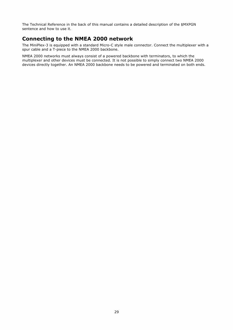
The MiniPlex-3 can be seen as a central navigation server/database, making received navigation data available on all three interface/bus/network types (Figure 33).
Figure 33
Data from all three protocols is saved into the database and from there it is distributed again using all three protocols. To avoid data from multiple sources, each protocol has its own priority. In descending order: NMEA 2000, NMEA 0183, SeaTalk. The multiplexer keeps track of the source of received data and ensures that it is not transmitted using the same protocol. For instance: if a GPS position is received on NMEA 0183, it will only be transmitted on NMEA 2000 and SeaTalk.
On an NMEA 2000 network, data is exchanged using defined messages called PGN’s. The PGN is actually the number (Parameter Group Number) of the message, which specifies which message it is and which data (parameters) it contains. For instance, PGN129029 contains the GPS position and PGN129026 contains the COG and SOG. There are a lot of different PGN numbers defined which are pretty hard to remember, so we chose to keep working the same concept as with NMEA 0183: sentence addresses with known acronyms like RMC for GPS position.
Therefore the Sentence Filter & Routing feature of the multiplexer still works with well-known NMEA 0183 sentence addresses. NMEA 2000 PGN’s are first converted into NMEA 0183 sentences and then filtering and routing is applied.
PGN’s for which no NMEA 0183 equivalent exists, are ignored by the multiplexer. It is however possible to enable an option (see Figure 49) to convert those PGN’s into an $MXPGN sentence. This allows software to read and decode NMEA 2000 PGN’s without special hardware. Such PGN’s could contain battery or alternator status, engine data or an electrical switch position. Converting these PGN’s to an $MXPGN sentence allows developers to easily read NMEA 2000 data with existing NMEA 0183 sentence parsers. Such a sentence looks like this:
$MXPGN,01F112,2807,FC7FFF7FFF168012*11
The multiplexer can also be set to convert every single PGN into an $MXPGN sentence, allowing software to have full control over the NMEA 2000 network. The same $MXPGN sentence can also be used to send data to the NMEA 2000 network. If the multiplexer receives a correctly formatted $MXPGN sentence, it will be converted to an NMEA 2000 message and sent onto the NMEA 2000 network.
NavigationServer
SeaTalk1
NMEA 0183
NMEA 2000
29
The Technical Reference in the back of this manual contains a detailed description of the $MXPGN sentence and how to use it.
Connecting to the NMEA 2000 network The MiniPlex-3 is equipped with a standard Micro-C style male connector. Connect the multiplexer with a spur cable and a T-piece to the NMEA 2000 backbone.
NMEA 2000 networks must always consist of a powered backbone with terminators, to which the multiplexer and other devices must be connected. It is not possible to simply connect two NMEA 2000 devices directly together. An NMEA 2000 backbone needs to be powered and terminated on both ends.
30
Power Supply The multiplexer must be powered from an externally supplied DC voltage from 8 to 35V. The power supply connection is protected against reversed polarity.
Indicators The LEDs on the MiniPlex provide information about the status and operation of the multiplexer. When the multiplexer is power up, all LEDs flash once.
Green (NMEA 2000): This LED flashes when an NMEA 2000 PGN is received.
Green (NMEA 0183): This LED flashes upon reception of a valid NMEA sentence. During a firmware update, this LED flashes upon reception of a firmware block.
Red (Overflow): This LED flashes on a buffer overflow, indicating that a currently received NMEA sentence will be lost. During start-up, this LED is on for a short moment while the multiplexer checks if firmware is loaded or if a firmware update is initiated by MPX-Config-3. If firmware is found, the LED goes off. When the LED stays lit, no firmware was found. During a firmware update, this LED is on. When the update is completed, the LED goes off. If the LED stays on after a firmware update error, it indicates that no valid firmware is present.
31
Data Throughput A multiplexer is not the Holy Grail for connecting NMEA 0183 devices. It should be fairly obvious that if a device combines data from four sources, the total amount of data that must be forwarded is the sum of the amount of each source. Still, the NMEA 0183 standard specifically limits the communication speed to 4800 Baud or bits per second, which equals 480 characters per second.
So, when using a multiplexer, a situation could arise where more data is received than can be transmitted because of the speed limitations of the NMEA 0183 outputs. Such a situation will lead to an overflow of the input queues of the multiplexer.
When an NMEA 0183 sentence is being received and a queue is filled up, this sentence is discarded because the MiniPlex only forwards complete NMEA 0183 sentences. This event is indicated by a blink of the red LED. The indicators in the “Input Overflow” section of MPX-Config-3 will also show this event.
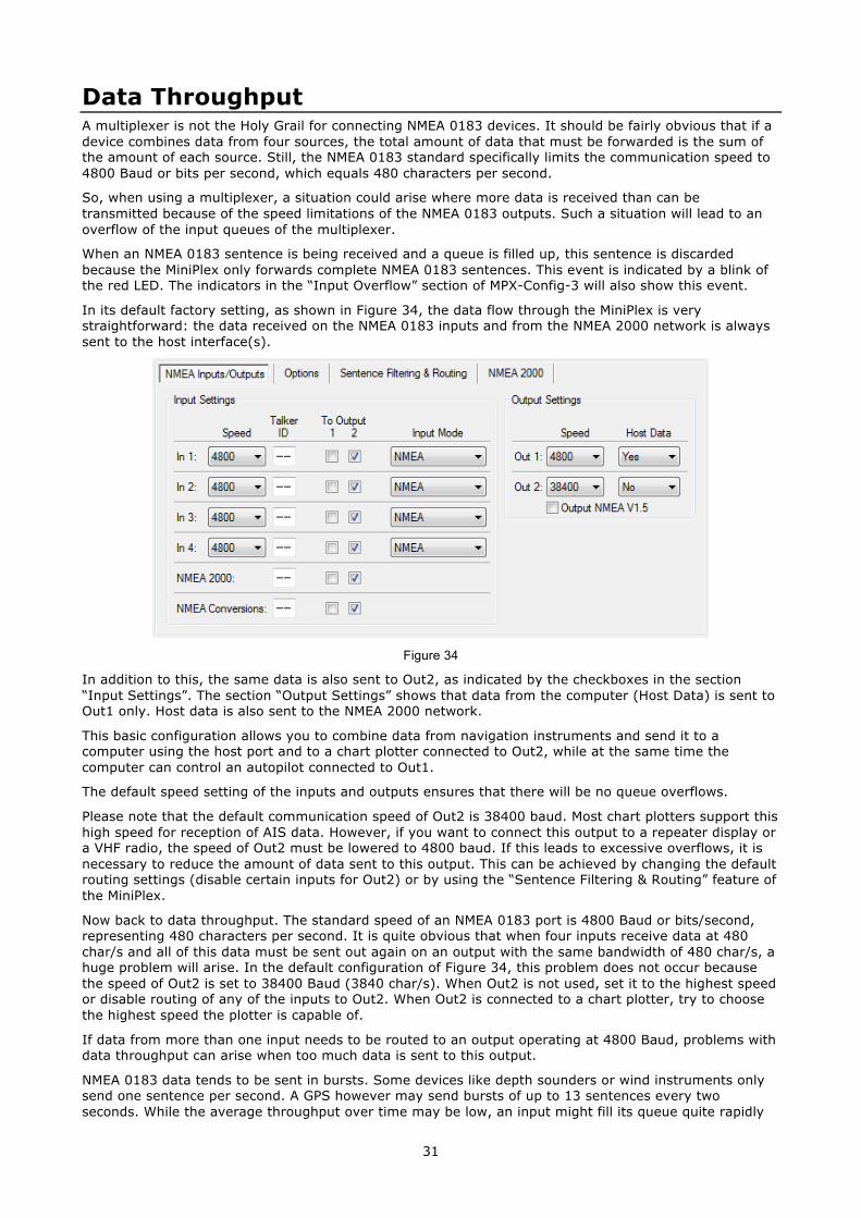
In its default factory setting, as shown in Figure 34, the data flow through the MiniPlex is very straightforward: the data received on the NMEA 0183 inputs and from the NMEA 2000 network is always sent to the host interface(s).
Figure 34
In addition to this, the same data is also sent to Out2, as indicated by the checkboxes in the section “Input Settings”. The section “Output Settings” shows that data from the computer (Host Data) is sent to Out1 only. Host data is also sent to the NMEA 2000 network.
This basic configuration allows you to combine data from navigation instruments and send it to a computer using the host port and to a chart plotter connected to Out2, while at the same time the computer can control an autopilot connected to Out1.
The default speed setting of the inputs and outputs ensures that there will be no queue overflows.
Please note that the default communication speed of Out2 is 38400 baud. Most chart plotters support this high speed for reception of AIS data. However, if you want to connect this output to a repeater display or a VHF radio, the speed of Out2 must be lowered to 4800 baud. If this leads to excessive overflows, it is necessary to reduce the amount of data sent to this output. This can be achieved by changing the default routing settings (disable certain inputs for Out2) or by using the “Sentence Filtering & Routing” feature of the MiniPlex.
Now back to data throughput. The standard speed of an NMEA 0183 port is 4800 Baud or bits/second, representing 480 characters per second. It is quite obvious that when four inputs receive data at 480 char/s and all of this data must be sent out again on an output with the same bandwidth of 480 char/s, a huge problem will arise. In the default configuration of Figure 34, this problem does not occur because the speed of Out2 is set to 38400 Baud (3840 char/s). When Out2 is not used, set it to the highest speed or disable routing of any of the inputs to Out2. When Out2 is connected to a chart plotter, try to choose the highest speed the plotter is capable of.
If data from more than one input needs to be routed to an output operating at 4800 Baud, problems with data throughput can arise when too much data is sent to this output.
NMEA 0183 data tends to be sent in bursts. Some devices like depth sounders or wind instruments only send one sentence per second. A GPS however may send bursts of up to 13 sentences every two seconds. While the average throughput over time may be low, an input might fill its queue quite rapidly
32
when a burst of sentences is received. The queues in the MiniPlex are quite large and can contain up to 30 sentences of GPS data.
A couple of occasional blinks of the red LED over a period of a few seconds means that large bursts of sentences are received and a queue is hitting its limit. Some sentences are discarded but most of them will be forwarded without problems. Such a situation is totally acceptable and would mean that for instance one depth, wind or position update is missed every few seconds.
A quite different situation may arise with some fluxgates or gyrocompasses. These devices may send their heading sentences with a speed up to 40 sentences per second! Instead of queuing a burst of sentences every one or two seconds, the multiplexer must queue a constant stream of sentences, possibly utilizing the maximum bandwidth of the multiplexer. Such a situation can lead to a queue that is constantly filled up to its maximum capacity. If this happens, use the sentence filter to reduce the frequency of the heading sentences and/or block all sentences which do not need to be sent to the output which is the bottleneck.
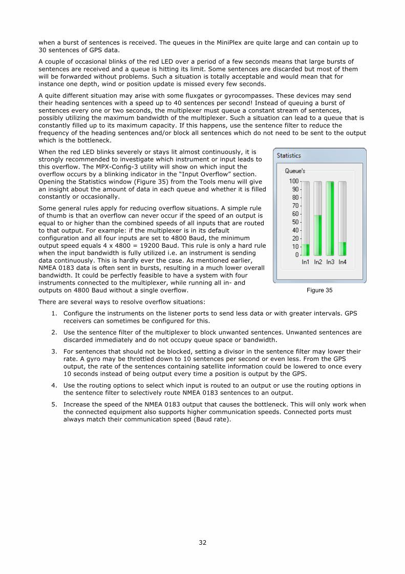
When the red LED blinks severely or stays lit almost continuously, it is strongly recommended to investigate which instrument or input leads to this overflow. The MPX-Config-3 utility will show on which input the overflow occurs by a blinking indicator in the “Input Overflow” section. Opening the Statistics window (Figure 35) from the Tools menu will give an insight about the amount of data in each queue and whether it is filled constantly or occasionally.
Some general rules apply for reducing overflow situations. A simple rule of thumb is that an overflow can never occur if the speed of an output is equal to or higher than the combined speeds of all inputs that are routed to that output. For example: if the multiplexer is in its default configuration and all four inputs are set to 4800 Baud, the minimum output speed equals 4 x 4800 = 19200 Baud. This rule is only a hard rule when the input bandwidth is fully utilized i.e. an instrument is sending data continuously. This is hardly ever the case. As mentioned earlier, NMEA 0183 data is often sent in bursts, resulting in a much lower overall bandwidth. It could be perfectly feasible to have a system with four instruments connected to the multiplexer, while running all in- and outputs on 4800 Baud without a single overflow.
There are several ways to resolve overflow situations:
1. Configure the instruments on the listener ports to send less data or with greater intervals. GPS receivers can sometimes be configured for this.
2. Use the sentence filter of the multiplexer to block unwanted sentences. Unwanted sentences are discarded immediately and do not occupy queue space or bandwidth.
3. For sentences that should not be blocked, setting a divisor in the sentence filter may lower their rate. A gyro may be throttled down to 10 sentences per second or even less. From the GPS output, the rate of the sentences containing satellite information could be lowered to once every 10 seconds instead of being output every time a position is output by the GPS.
4. Use the routing options to select which input is routed to an output or use the routing options in the sentence filter to selectively route NMEA 0183 sentences to an output.
5. Increase the speed of the NMEA 0183 output that causes the bottleneck. This will only work when the connected equipment also supports higher communication speeds. Connected ports must always match their communication speed (Baud rate).
Figure 35
33
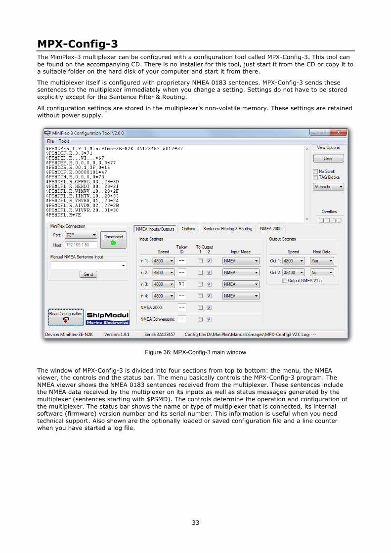
MPX-Config-3 The MiniPlex-3 multiplexer can be configured with a configuration tool called MPX-Config-3. This tool can be found on the accompanying CD. There is no installer for this tool, just start it from the CD or copy it to a suitable folder on the hard disk of your computer and start it from there.
The multiplexer itself is configured with proprietary NMEA 0183 sentences. MPX-Config-3 sends these sentences to the multiplexer immediately when you change a setting. Settings do not have to be stored explicitly except for the Sentence Filter & Routing.
All configuration settings are stored in the multiplexer’s non-volatile memory. These settings are retained without power supply.
Figure 36: MPX-Config-3 main window
The window of MPX-Config-3 is divided into four sections from top to bottom: the menu, the NMEA viewer, the controls and the status bar. The menu basically controls the MPX-Config-3 program. The NMEA viewer shows the NMEA 0183 sentences received from the multiplexer. These sentences include the NMEA data received by the multiplexer on its inputs as well as status messages generated by the multiplexer (sentences starting with $PSMD). The controls determine the operation and configuration of the multiplexer. The status bar shows the name or type of multiplexer that is connected, its internal software (firmware) version number and its serial number. This information is useful when you need technical support. Also shown are the optionally loaded or saved configuration file and a line counter when you have started a log file.
34
Menu The menu contains two sub-menus: File and Tools. Some options of these menus are disabled or not visible, depending on the type of connected multiplexer or on the status of the connection.
The File menu offers the following choices:
Log NMEA… Start writing NMEA data to a log file. A log file is a plain text file and can later be opened by any text editor to examine the data. The Log counter on the status bar will show the number of NMEA sentences that are currently written to the log file.
Log Diagnostic Info… Start writing to a log file with the addition of a time stamp at the beginning of each NMEA sentence.
Stop Log Stop writing NMEA data to the current log file and close that file.
Load Configuration… Load a previously saved configuration file into the multiplexer. The current configuration will be overwritten. A configuration file stores all settings made with MPX-Config-3.
Save Configuration Save the current configuration to a previously file.
Save Configuration As… Save the current configuration to a new file.
Update MiniPlex Firmware… Load new a firmware file into the multiplexer.
Exit This exits MPX-Config-3.
The Tools menu offers the following choices:
Show Statistics Opens a window showing bars that indicate how much NMEA data is stored in the input queues. This is a useful option for diagnosing data congestion and overflow situations as mentioned in paragraph “Data Throughput”. A queue that is filled constantly can lead to unacceptable delays in data transfer.
MiniPlex-3E Opens a sub-menu for the MiniPlex-3E.
Reset Factory Settings… Reset the multiplexer to its default factory configuration.
About Show a window with version information.
The MiniPlex-3E sub-menu offers the following choices:
Network Setup… Open a window to setup the network parameters of a MiniPlex-3E.
Search… Search the network for MiniPlex-3E’s. A window is shown with the search results.
Assign IP… Assign an IP address to a MiniPlex-3E using its MAC address.
35
Controls
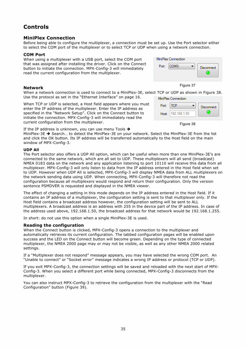
MiniPlex Connection Before being able to configure the multiplexer, a connection must be set up. Use the Port selector either to select the COM port of the multiplexer or to select TCP or UDP when using a network connection.
COM Port When using a multiplexer with a USB port, select the COM port that was assigned after installing the driver. Click on the Connect button to initiate the connection. MPX-Config-3 will immediately read the current configuration from the multiplexer.
Network When a network connection is used to connect to a MiniPlex-3E, select TCP or UDP as shown in Figure 38. Use the protocol as set in the “Ethernet Interface” on page 16.
When TCP or UDP is selected, a Host field appears where you must enter the IP address of the multiplexer. Enter the IP address as specified in the “Network Setup”. Click on the Connect button to initiate the connection. MPX-Config-3 will immediately read the current configuration from the multiplexer.
If the IP address is unknown, you can use menu Tools è MiniPlex-3E è Search… to detect the MiniPlex-3E on your network. Select the MiniPlex-3E from the list and click the OK button. Its IP address will be transferred automatically to the Host field on the main window of MPX-Config-3.
UDP All The Port selector also offers a UDP All option, which can be useful when more than one MiniPlex-3E’s are connected to the same network, which are all set to UDP. These multiplexers will all send (broadcast) NMEA 0183 data on the network and any application listening to port 10110 will receive this data from all multiplexer. MPX-Config-3 will only listen to data from the IP address entered in the Host field when set to UDP. However when UDP All is selected, MPX-Config-3 will display NMEA data from ALL multiplexers on the network sending data using UDP. When connecting, MPX-Config-3 will therefore not read the configuration because all multiplexers would respond and return their configuration. Only the version sentence PSMDVER is requested and displayed in the NMEA viewer.
The effect of changing a setting in this mode depends on the IP address entered in the Host field. If it contains an IP address of a multiplexer, the configuration setting is sent to that multiplexer only. If the Host field contains a broadcast address however, the configuration setting will be sent to ALL multiplexers. A broadcast address is an address with 255 in the device part of the IP address. In case of the address used above, 192.168.1.50, the broadcast address for that network would be 192.168.1.255.
In short: do not use this option when a single MiniPlex-3E is used.
Reading the configuration When the Connect button is clicked, MPX-Config-3 opens a connection to the multiplexer and automatically retrieves its current configuration. The tabbed configuration pages will be enabled upon success and the LED on the Connect button will become green. Depending on the type of connected multiplexer, the NMEA 2000 page may or may not be visible, as well as any other NMEA 2000 related settings.
If a “Multiplexer does not respond” message appears, you may have selected the wrong COM port. An “Unable to connect” or “Socket error” message indicates a wrong IP address or protocol (TCP or UDP).
If you exit MPX-Config-3, the connection settings will be saved and reloaded with the next start of MPX-Config-3. When you select a different port while being connected, MPX-Config-3 disconnects from the multiplexer.
You can also instruct MPX-Config-3 to retrieve the configuration from the multiplexer with the “Read Configuration” button (Figure 39).
Figure 37
Figure 38
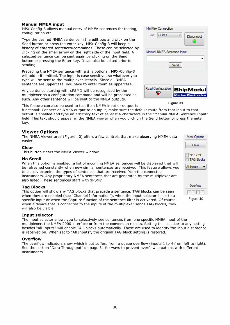
36
Manual NMEA input MPX-Config-3 allows manual entry of NMEA sentences for testing, configuration etc.
Type the desired NMEA sentence in the edit box and click on the Send button or press the enter key. MPX-Config-3 will keep a history of entered sentences/commands. These can be selected by clicking on the small arrow on the right side of the input field. A selected sentence can be sent again by clicking on the Send button or pressing the Enter key. It can also be edited prior to sending.
Preceding the NMEA sentence with a $ is optional, MPX-Config-3 will add it if omitted. The input is case sensitive, so whatever you type will be sent to the multiplexer literally. Since all NMEA sentence are uppercase, you have to enter them as uppercase.
Any sentence starting with $PSMD will be recognized by the multiplexer as a configuration command and will be processed as such. Any other sentence will be sent to the NMEA outputs.
This feature can also be used to test if an NMEA input or output is functional: Connect an NMEA output to an input, make sure the default route from that input to that output is enabled and type an arbitrary text of at least 6 characters in the “Manual NMEA Sentence Input” field. This text should appear in the NMEA viewer when you click on the Send button or press the enter key.
Viewer Options The NMEA Viewer area (Figure 40) offers a few controls that make observing NMEA data easier.
Clear This button clears the NMEA Viewer window.
No Scroll When this option is enabled, a list of incoming NMEA sentences will be displayed that will be refreshed constantly when new similar sentences are received. This feature allows you to closely examine the types of sentences that are received from the connected instruments. Any proprietary NMEA sentences that are generated by the multiplexer are also listed. These sentences start with $PSMD.
Tag Blocks This option will show any TAG blocks that precede a sentence. TAG blocks can be seen when they are enabled (see “Channel Information”), when the input selector is set to a specific input or when the Capture function of the sentence filter is activated. Of course, when a device that is connected to the inputs of the multiplexer sends TAG blocks, they will also be visible.
Input selector The input selector allows you to selectively see sentences from one specific NMEA input of the multiplexer, the NMEA 2000 interface or from the conversion results. Setting this selector to any setting besides “All Inputs” will enable TAG blocks automatically. These are used to identify the input a sentence is received on. When set to “All Inputs”, the original TAG block setting is restored.
Overflow The overflow indicators show which input suffers from a queue overflow (inputs 1 to 4 from left to right). See the section “Data Throughput” on page 31 for ways to prevent overflow situations with different instruments.
Figure 39
Figure 40
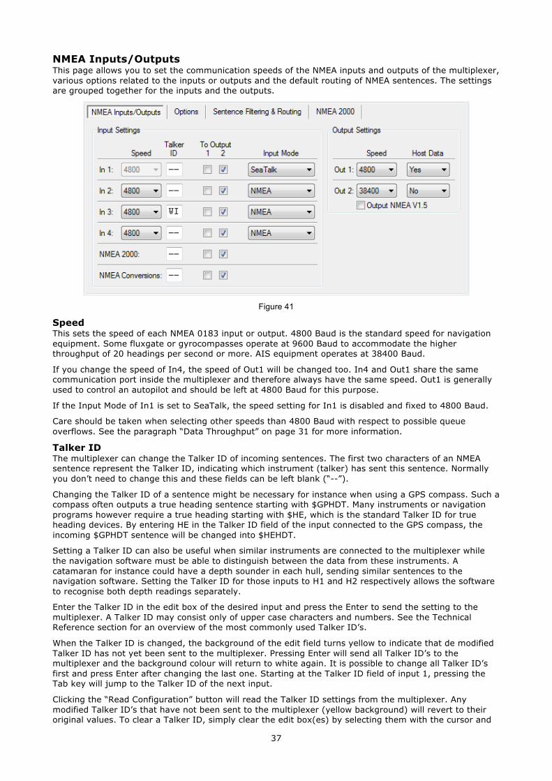
37
NMEA Inputs/Outputs This page allows you to set the communication speeds of the NMEA inputs and outputs of the multiplexer, various options related to the inputs or outputs and the default routing of NMEA sentences. The settings are grouped together for the inputs and the outputs.
Figure 41
Speed This sets the speed of each NMEA 0183 input or output. 4800 Baud is the standard speed for navigation equipment. Some fluxgate or gyrocompasses operate at 9600 Baud to accommodate the higher throughput of 20 headings per second or more. AIS equipment operates at 38400 Baud.
If you change the speed of In4, the speed of Out1 will be changed too. In4 and Out1 share the same communication port inside the multiplexer and therefore always have the same speed. Out1 is generally used to control an autopilot and should be left at 4800 Baud for this purpose.
If the Input Mode of In1 is set to SeaTalk, the speed setting for In1 is disabled and fixed to 4800 Baud.
Care should be taken when selecting other speeds than 4800 Baud with respect to possible queue overflows. See the paragraph “Data Throughput” on page 31 for more information.
Talker ID The multiplexer can change the Talker ID of incoming sentences. The first two characters of an NMEA sentence represent the Talker ID, indicating which instrument (talker) has sent this sentence. Normally you don’t need to change this and these fields can be left blank (“--”).
Changing the Talker ID of a sentence might be necessary for instance when using a GPS compass. Such a compass often outputs a true heading sentence starting with $GPHDT. Many instruments or navigation programs however require a true heading starting with $HE, which is the standard Talker ID for true heading devices. By entering HE in the Talker ID field of the input connected to the GPS compass, the incoming $GPHDT sentence will be changed into $HEHDT.
Setting a Talker ID can also be useful when similar instruments are connected to the multiplexer while the navigation software must be able to distinguish between the data from these instruments. A catamaran for instance could have a depth sounder in each hull, sending similar sentences to the navigation software. Setting the Talker ID for those inputs to H1 and H2 respectively allows the software to recognise both depth readings separately.
Enter the Talker ID in the edit box of the desired input and press the Enter to send the setting to the multiplexer. A Talker ID may consist only of upper case characters and numbers. See the Technical Reference section for an overview of the most commonly used Talker ID’s.
When the Talker ID is changed, the background of the edit field turns yellow to indicate that de modified Talker ID has not yet been sent to the multiplexer. Pressing Enter will send all Talker ID’s to the multiplexer and the background colour will return to white again. It is possible to change all Talker ID’s first and press Enter after changing the last one. Starting at the Talker ID field of input 1, pressing the Tab key will jump to the Talker ID of the next input.
Clicking the “Read Configuration” button will read the Talker ID settings from the multiplexer. Any modified Talker ID’s that have not been sent to the multiplexer (yellow background) will revert to their original values. To clear a Talker ID, simply clear the edit box(es) by selecting them with the cursor and
38
press the Del or Backspace key on your keyboard and finally press Enter. An empty Talker ID setting will show two dashes.
To Output 1 & 2 These options allow you to set the default route from the NMEA 0183 inputs, the NMEA 2000 port and the conversion results to the NMEA 0183 outputs. The default route as showed in Figure 41 routes all inputs to Out2 and none to Out1. The NMEA 0183 inputs and NMEA 2000 port are always routed to the host port. Similarly, the Host port is always routed to the NMEA 2000 port. Only filter rules can override this.
The default route is applied to an input when no specific route for an NMEA 0183 sentence exists in the sentence filter. A match in the sentence filter always takes precedence over the default route.
Input Mode The NMEA 0183 inputs of the multiplexer can be set to different modes besides standard NMEA, to be able to accept “not quite standard” NMEA, plain text or SeaTalk. The following modes are supported:
NMEA: Normal NMEA processing. This is the default processing mode which checks sentences for correct formatting. They must start with a ‘$’ or ‘!’ character and end with a Carriage Return (CR) and a Line Feed (LF) character in that order. If a sentence contains a checksum, the checksum of the sentence is calculated and compared with the checksum field of the sentence. If all of the conditions above are met, the sentence is passed. Otherwise it is rejected. This processing meets the IEC/EN60945 standard.
NMEA (ERR): Pass NMEA sentences that contain a checksum error unmodified, bypassing all further NMEA processing and filtering. Only the default route is applied.
NMEA (CR/LF): Relaxed NMEA format checking. This will pass a sentence that is incorrectly terminated. A sentence is considered terminated if it ends on a CR, a LF or a combination of both in arbitrary order.
Text to NMEA: Accept a plain text string and forward it in a standard NMEA $--TXT sentence. Any character with an ASCII value > 32 (a space) is considered to be the start of a string. The string must end on a CR or LF and may not be longer than 61 characters. A longer string is discarded. Only valid NMEA characters are passed. Invalid characters are stripped from the input data. The Total number and Sentence number fields are always set to ‘01’. The Text Identifier field of the $MXTXT sentence contains the input number on which the text was received. When for instance ‘Hello World’ is received on input 3, the resulting sentence will be: $MXTXT,01,01,03,Hello World*6E.
Text to PTXT: Accept a plain text string and forward it in a $PTXT sentence. Any character with an ASCII value > 32 (a space) is considered to be the start of a string. The string must end on a CR or LF and may not be longer than 61 characters. A longer string is discarded. All characters with an ASCII value from 32 to 127 are passed.
Plain Text: Accept a plain text string and forward it as a plain text string. Any character with an ASCII value > 32 (a space) is considered to be the start of a string. The string must end on a CR or LF and may not be longer than 61 characters. A longer string is discarded. All characters with an ASCII value from 32 to 127 are passed. The multiplexer will always end a forwarded string with a CR/LF pair.
SeaTalk: This option enables translation of SeaTalk® data received on In1 into NMEA 0183 sentences and NMEA 2000 PGNs (only on NMEA 2000 enabled multiplexers). SeaTalk (often called SeaTalk1 to distinguish it from SeaTalk NG) is a proprietary protocol developed by Raymarine and is used for data exchange between Raymarine navigation instruments like the ST40, ST50 and ST60 series. To be able to use these instruments with commonly available navigation programs or to feed their data into non-Raymarine instruments, SeaTalk data needs to be translated into NMEA 0183 sentences. See the Technical Reference section for an overview of translated SeaTalk data. Selecting this option will automatically set the communication speed of In 1 to 4800 Baud and disable the speed setting.
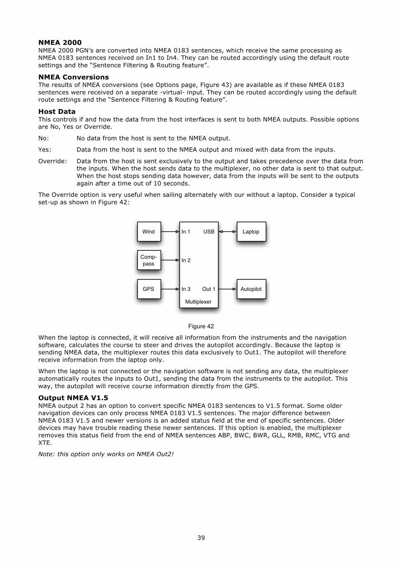
39
NMEA 2000 NMEA 2000 PGN’s are converted into NMEA 0183 sentences, which receive the same processing as NMEA 0183 sentences received on In1 to In4. They can be routed accordingly using the default route settings and the “Sentence Filtering & Routing feature”.
NMEA Conversions The results of NMEA conversions (see Options page, Figure 43) are available as if these NMEA 0183 sentences were received on a separate -virtual- input. They can be routed accordingly using the default route settings and the “Sentence Filtering & Routing feature”.
Host Data This controls if and how the data from the host interfaces is sent to both NMEA outputs. Possible options are No, Yes or Override.
No: No data from the host is sent to the NMEA output.
Yes: Data from the host is sent to the NMEA output and mixed with data from the inputs.
Override: Data from the host is sent exclusively to the output and takes precedence over the data from the inputs. When the host sends data to the multiplexer, no other data is sent to that output. When the host stops sending data however, data from the inputs will be sent to the outputs again after a time out of 10 seconds.
The Override option is very useful when sailing alternately with our without a laptop. Consider a typical set-up as shown in Figure 42:
Figure 42
When the laptop is connected, it will receive all information from the instruments and the navigation software, calculates the course to steer and drives the autopilot accordingly. Because the laptop is sending NMEA data, the multiplexer routes this data exclusively to Out1. The autopilot will therefore receive information from the laptop only.
When the laptop is not connected or the navigation software is not sending any data, the multiplexer automatically routes the inputs to Out1, sending the data from the instruments to the autopilot. This way, the autopilot will receive course information directly from the GPS.
Output NMEA V1.5 NMEA output 2 has an option to convert specific NMEA 0183 sentences to V1.5 format. Some older navigation devices can only process NMEA 0183 V1.5 sentences. The major difference between NMEA 0183 V1.5 and newer versions is an added status field at the end of specific sentences. Older devices may have trouble reading these newer sentences. If this option is enabled, the multiplexer removes this status field from the end of NMEA sentences ABP, BWC, BWR, GLL, RMB, RMC, VTG and XTE.
Note: this option only works on NMEA Out2!
Wind
Comp-pass
GPS Autopilot
Laptop
Multiplexer
In 1
In 2
In 3
USB
Out 1
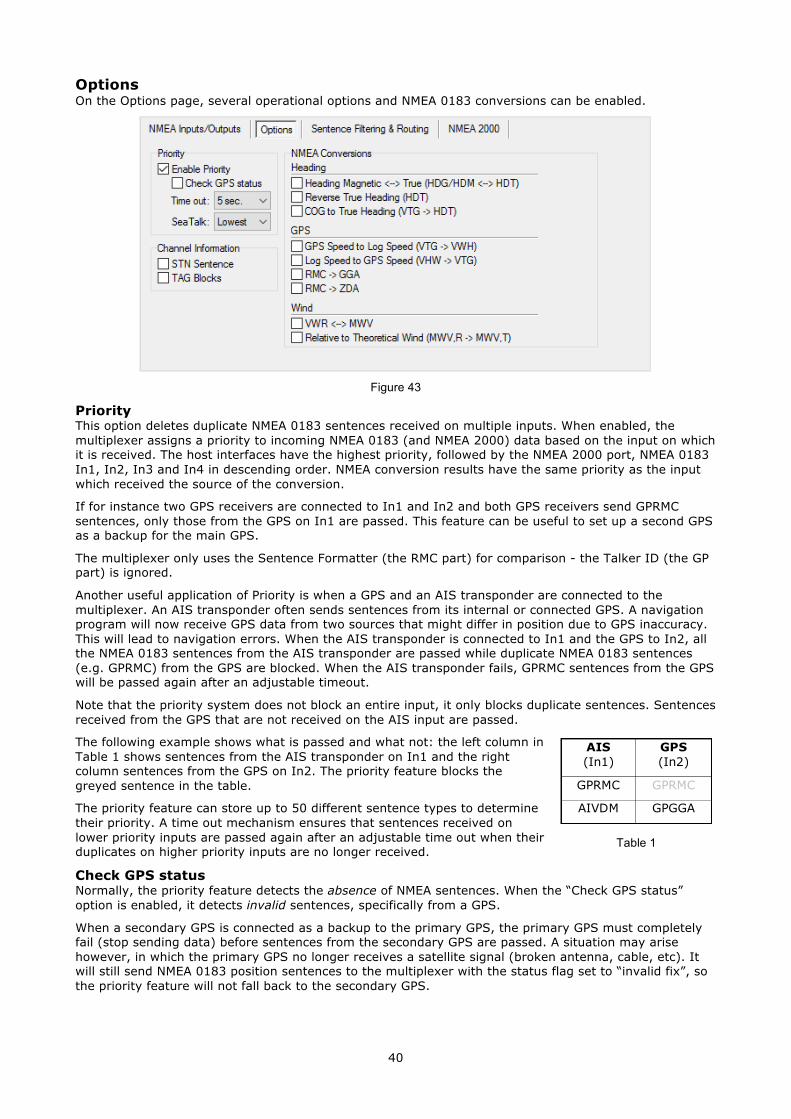
40
Options On the Options page, several operational options and NMEA 0183 conversions can be enabled.
Figure 43
Priority This option deletes duplicate NMEA 0183 sentences received on multiple inputs. When enabled, the multiplexer assigns a priority to incoming NMEA 0183 (and NMEA 2000) data based on the input on which it is received. The host interfaces have the highest priority, followed by the NMEA 2000 port, NMEA 0183 In1, In2, In3 and In4 in descending order. NMEA conversion results have the same priority as the input which received the source of the conversion.
If for instance two GPS receivers are connected to In1 and In2 and both GPS receivers send GPRMC sentences, only those from the GPS on In1 are passed. This feature can be useful to set up a second GPS as a backup for the main GPS.
The multiplexer only uses the Sentence Formatter (the RMC part) for comparison - the Talker ID (the GP part) is ignored.
Another useful application of Priority is when a GPS and an AIS transponder are connected to the multiplexer. An AIS transponder often sends sentences from its internal or connected GPS. A navigation program will now receive GPS data from two sources that might differ in position due to GPS inaccuracy. This will lead to navigation errors. When the AIS transponder is connected to In1 and the GPS to In2, all the NMEA 0183 sentences from the AIS transponder are passed while duplicate NMEA 0183 sentences (e.g. GPRMC) from the GPS are blocked. When the AIS transponder fails, GPRMC sentences from the GPS will be passed again after an adjustable timeout.
Note that the priority system does not block an entire input, it only blocks duplicate sentences. Sentences received from the GPS that are not received on the AIS input are passed.
The following example shows what is passed and what not: the left column in Table 1 shows sentences from the AIS transponder on In1 and the right column sentences from the GPS on In2. The priority feature blocks the greyed sentence in the table.
The priority feature can store up to 50 different sentence types to determine their priority. A time out mechanism ensures that sentences received on lower priority inputs are passed again after an adjustable time out when their duplicates on higher priority inputs are no longer received.
Check GPS status Normally, the priority feature detects the absence of NMEA sentences. When the “Check GPS status” option is enabled, it detects invalid sentences, specifically from a GPS.
When a secondary GPS is connected as a backup to the primary GPS, the primary GPS must completely fail (stop sending data) before sentences from the secondary GPS are passed. A situation may arise however, in which the primary GPS no longer receives a satellite signal (broken antenna, cable, etc). It will still send NMEA 0183 position sentences to the multiplexer with the status flag set to “invalid fix”, so the priority feature will not fall back to the secondary GPS.
AIS (In1)
GPS (In2)
GPRMC GPRMC
AIVDM GPGGA
Table 1
41
When “Check GPS status” is enabled however, the multiplexer will check the status field of the GPS sentences, detect the invalid position fix and fall back to the secondary GPS. Sentences of which the Status flag is checked are APB, GGA, GLL, RMA, RMB, RMC, VTG and XTE.
Time Out This setting allows you to set the time it takes before sentences from a lower priority input are passed.
SeaTalk Priority This sets the priority of the SeaTalk data in relation to In2 to In4. It can be either Highest (SeaTalk – In 2 – In 3 – In 4) or Lowest (In 2 – In 3 – In 4 - SeaTalk).
Channel Information These options insert channel number information in the NMEA stream sent to the host interfaces. Channel numbers allow distinguishing between similar data from different instruments, like two depth sounders on the same boat.
When “STN Sentence” is enabled, each received NMEA sentence is preceded by am $MXSTN sentence to indicate on which NMEA input the following sentence was received. The example in Figure 44 shows that an IIGGA sentence was received on In1, a GPGGA sentence on In2, an IIGLL sentence on In1 and an HEHDT sentence on In3.
$MXSTN,01*71 $IIGGA,143357.999,5301.0061,N,00635.5479,E,1,06,1.9,90.0,M,,,,0000*2E $MXSTN,02*72 $GPGGA,143357.999,5301.0061,N,00635.5479,E,1,06,1.9,90.0,M,,,,0000*39 $MXSTN,01*71 $IIGLL,5301.0061,N,00635.5479,E,143357.999,A*22 $MXSTN,03*73 $HEHDT,67.0,T*1E
The $MXSTN sentence is defined by the NMEA standard and a description can be found in the Technical Reference at the back of this manual. When “TAG Blocks” is enabled, the multiplexer adds an NMEA 0183 V4.0 TAG block to each sentence. This TAG block contains a source identification parameter indicating on which input that sentence was received. Figure 45 shows the same data as above, but with TAG blocks added.
\s:MX02-1*42\$IIGGA,143357.999,5301.0061,N,00635.5479,E,1,06,1.9,90.0,M,,,,0000*2E \s:MX02-2*41\$GPGGA,143357.999,5301.0061,N,00635.5479,E,1,06,1.9,90.0,M,,,,0000*39 \s:MX02-1*42\$IIGLL,5301.0061,N,00635.5479,E,143357.999,A*22 \s:MX02-3*40\$HEHDT,67.0,T*1E
See the Technical Reference section for a description of TAG blocks.
NMEA Conversions NMEA Conversions allow you to convert specific NMEA 0183 sentences into new NMEA 0183 sentences. The originating sentence used for the conversion is forwarded as usual but can optionally be blocked using the sentence filter. The conversion results are available on a virtual input called “NMEA Conversions” on the “NMEA Inputs/Outputs” page and on input C on the “Sentence Filtering & Routing” page. They can be routed anywhere using the default route and the Sentence Filter.
Heading Magnetic <-> True (HDG/HDM <-> HDT) If this option is enabled, the multiplexer converts magnetic and true heading in both directions. If the multiplexer receives an HDG or HDM sentence, it will generate and output an HDT sentence (true heading). If the multiplexer receives an HDT sentence, it will generate and output an HDG sentence.
If the HDG sentence contains a magnetic variation, it is used to calculate the true heading from the magnetic heading. Otherwise the magnetic heading value is just copied. A variation received in an RMC sentence is also used to calculate the true heading. The variation in an HDG sentence takes precedence over the variation in an RMC sentence.
This option can be useful when a device needs a true heading while only a fluxgate compass is available on board. Many satellite telephones for instance need a true heading to be able to direct their antenna to the right communications satellite.
Figure 44
Figure 45
42
Reverse True Heading (HDT) This option allows you to reverse the true heading in a received HDT sentence. When an HDT sentence is received, the multiplexer generates a new HDT sentence with 180° added to the original heading. This can be used to provide two opposing navigation stations on ferries with a heading from the same source. Use the default route or Sentence Filter to route each sentence to a different NMEA output and only one to the host if needed.
COG to True Heading (VTG -> HDT) This option generates an HDT sentence when a VTG sentence is received.
GPS Speed to Log Speed (VTG -> VHW) When enabled, the multiplexer will generate a VHW sentence (water speed and heading) when a VTG sentence (course over ground and ground speed) is received. The VTG sentence is generated by a GPS and the VHW sentence by a log. Often the paddlewheel of a log gets stuck when fouled and this option offers a solution to substitute the log data with GPS data.
Log Speed to GPS Speed (VHW -> VTG) This option generates a VTG sentence (course over ground and ground speed) when a VHW sentence (water speed and heading) is received. This can be useful if a device needs a VTG sentence while only a Log is available.
RMC -> GGA This options generates a GGA sentence when an RMC sentence is received.
RMC -> ZDA This options generates a ZDA (time and date) sentence when an RMC sentence is received.
Wind: VWR <-> MWV This option generates an MWV sentence from a VWR sentence and vice versa. Sometimes software expects one sentence while the wind instrument generates the other. By enabling this option, ‘old’ and ‘new’ can be connected without problems.
Relative to Theoretical Wind (MWV,R -> MWV,T) This option lets the multiplexer calculate the Theoretical Wind (often called True Wind) from the Apparent Wind. When the multiplexer receives an MWV sentence with Apparent/Relative Wind, it will generate a new MWV sentence with Theoretical Wind. If only VWR sentences are received, the VWR <-> MWV option can be enabled to convert to an MWV sentence first.
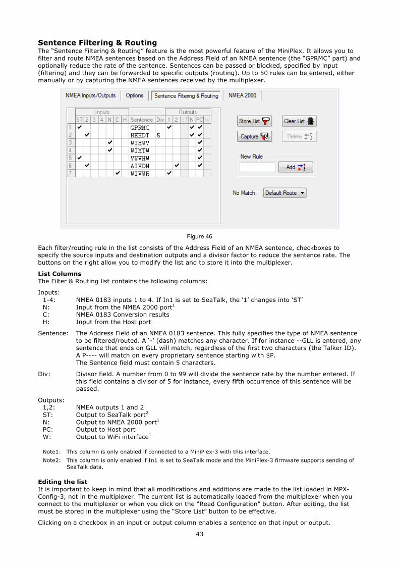
43
Sentence Filtering & Routing The “Sentence Filtering & Routing” feature is the most powerful feature of the MiniPlex. It allows you to filter and route NMEA sentences based on the Address Field of an NMEA sentence (the “GPRMC” part) and optionally reduce the rate of the sentence. Sentences can be passed or blocked, specified by input (filtering) and they can be forwarded to specific outputs (routing). Up to 50 rules can be entered, either manually or by capturing the NMEA sentences received by the multiplexer.
Figure 46
Each filter/routing rule in the list consists of the Address Field of an NMEA sentence, checkboxes to specify the source inputs and destination outputs and a divisor factor to reduce the sentence rate. The buttons on the right allow you to modify the list and to store it into the multiplexer.
List Columns The Filter & Routing list contains the following columns:
Inputs: 1-4: NMEA 0183 inputs 1 to 4. If In1 is set to SeaTalk, the ‘1’ changes into ‘ST’ N: Input from the NMEA 2000 port1
C: NMEA 0183 Conversion results H: Input from the Host port
Sentence: The Address Field of an NMEA 0183 sentence. This fully specifies the type of NMEA sentence to be filtered/routed. A ‘-’ (dash) matches any character. If for instance --GLL is entered, any sentence that ends on GLL will match, regardless of the first two characters (the Talker ID). A P---- will match on every proprietary sentence starting with $P. The Sentence field must contain 5 characters.
Div: Divisor field. A number from 0 to 99 will divide the sentence rate by the number entered. If this field contains a divisor of 5 for instance, every fifth occurrence of this sentence will be passed.
Outputs: 1,2: NMEA outputs 1 and 2 ST: Output to SeaTalk port2
N: Output to NMEA 2000 port1
PC: Output to Host port W: Output to WiFi interface1
Note1: This column is only enabled if connected to a MiniPlex-3 with this interface. Note2: This column is only enabled if In1 is set to SeaTalk mode and the MiniPlex-3 firmware supports sending of
SeaTalk data.
Editing the list It is important to keep in mind that all modifications and additions are made to the list loaded in MPX-Config-3, not in the multiplexer. The current list is automatically loaded from the multiplexer when you connect to the multiplexer or when you click on the “Read Configuration” button. After editing, the list must be stored in the multiplexer using the “Store List” button to be effective.
Clicking on a checkbox in an input or output column enables a sentence on that input or output.
44
The Sentence and Divisor fields can be edited by selecting it with the cursor. Edit mode is entered in several ways:
● Press function key F2 on your keyboard. This enters Edit mode with the cursor at the end of the text. Move the cursor around with the mouse or arrow keys.
● Press Enter or click with the cursor: This enters Edit mode with the text selected and the cursor at the end. Any character or number that is typed now will erase the existing text entirely unless the cursor is moved around with the mouse or arrow keys. This will unselect the text.
● Double-click on the entry. This enters Edit mode the same way as pressing Enter or clicking it for the second time.
When changes are made, press Enter to confirm them or press Escape to discard any changes and exit Edit mode.
The Technical Reference section lists commonly used Talker IDs and Sentence Formatters. This list can be a useful aid while setting up the sentence filter.
The following buttons are available to edit the list:
Store List Stores the list from MPX-Config-3 into the multiplexer. This overwrites the list in the multiplexer.
Capture Enables capture mode. The list will be filled automatically with NMEA 0183 sentences currently received by the multiplexer.
Add Add a new rule. Type the desired sentence address into the edit box next to the Add button and click on Add or press the enter key. This will enter a new rule with all inputs and outputs disabled. The input is case-insensitive; every entered sentence address will be converted into uppercase. The input must contain 5 characters, including dashes. Numbers are also allowed.
Delete Delete a rule from the list in MPX-Config-3. Select the entry to be deleted by clicking on the address in the Sentence column and click on the Delete button.
Default Action This setting determines what happens if a received sentence is not found in the filter/routing list. It can be set to either apply the default route or to block it.
Clear List This button clears the list in MPX-Config-3 (not in the multiplexer!). To clear the list in the multiplexer, click on the Store List button after clearing the list in MPX-Config-3.
Filling the list The filter rules can be entered in two ways: manually and automatically. You can add individual sentences to the list and set the desired routing information. You can also fill the list automatically with the Capture button. All controls will be disabled during capture and the Capture button changes to Stop. Leave the capture mode running for approximately 10 seconds. By that time, all connected instruments will have sent NMEA sentences. Click on Stop to end the capture mode.
It is very important to realize that using capture to fill the list overrides the default routes since every sentence is in the filter list.
It is absolutely necessary to review and modify the routing settings for each sentence after a Capture! It is often best not to use the filter at all if you don’t need sentence-specific routing.
Use the filter with care! Simply capturing the list and storing it unmodified is useless and can lead to unforeseen problems!
Operation When the multiplexer receives an NMEA 0183 sentence, it searches the filter list for a match. It doesn’t matter if this sentence is received on one of the NMEA 0183 inputs, a conversion result or a converted NMEA 2000 PGN. They are all treated equally.
The order of the filter/routing rules in the multiplexer is exactly the same as shown in MPX-Config-3. When a match is found, the input on which the sentence was received is checked against the input settings (checkboxes in the “Inputs” columns) of this rule to determine whether the sentence may be passed or not. If the input matches, the sentence is passed for further processing or conversion and eventually it is routed to any enabled output (checkboxes in the “Outputs” column). For each sentence received, the entire filter/routing list is scanned and a sentence may occur multiple times in the filter list.
If no match is found, the “No Match” setting determines what happens next: when set to “Default Route”, the default routes are applied. When it is set to Block, the sentence is always blocked.
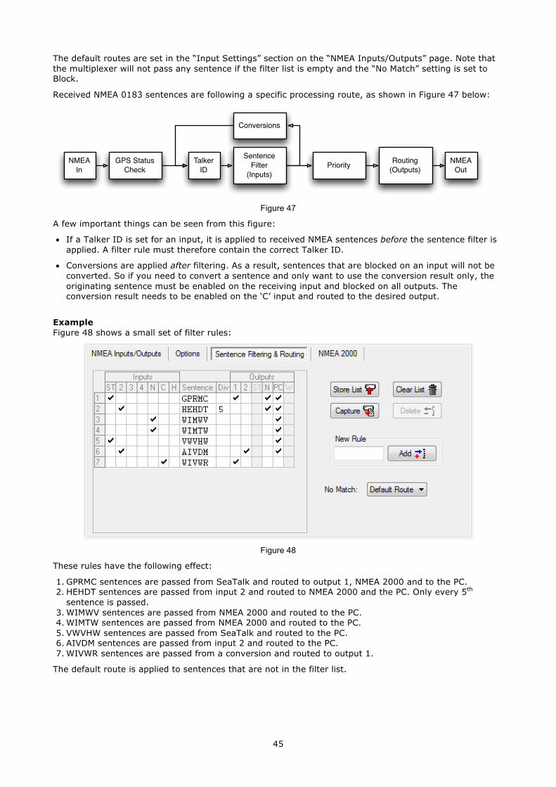
45
The default routes are set in the “Input Settings” section on the “NMEA Inputs/Outputs” page. Note that the multiplexer will not pass any sentence if the filter list is empty and the “No Match” setting is set to Block.
Received NMEA 0183 sentences are following a specific processing route, as shown in Figure 47 below:
Figure 47
A few important things can be seen from this figure:
• If a Talker ID is set for an input, it is applied to received NMEA sentences before the sentence filter is applied. A filter rule must therefore contain the correct Talker ID.
• Conversions are applied after filtering. As a result, sentences that are blocked on an input will not be converted. So if you need to convert a sentence and only want to use the conversion result only, the originating sentence must be enabled on the receiving input and blocked on all outputs. The conversion result needs to be enabled on the ‘C’ input and routed to the desired output.
Example Figure 48 shows a small set of filter rules:
Figure 48
These rules have the following effect:
1. GPRMC sentences are passed from SeaTalk and routed to output 1, NMEA 2000 and to the PC. 2. HEHDT sentences are passed from input 2 and routed to NMEA 2000 and the PC. Only every 5th
sentence is passed. 3. WIMWV sentences are passed from NMEA 2000 and routed to the PC. 4. WIMTW sentences are passed from NMEA 2000 and routed to the PC. 5. VWVHW sentences are passed from SeaTalk and routed to the PC. 6. AIVDM sentences are passed from input 2 and routed to the PC. 7. WIVWR sentences are passed from a conversion and routed to output 1.
The default route is applied to sentences that are not in the filter list.
Talker ID
Conversions
GPS Status Check
Sentence Filter
(Inputs)PriorityNMEA
InRouting
(Outputs)NMEA
Out
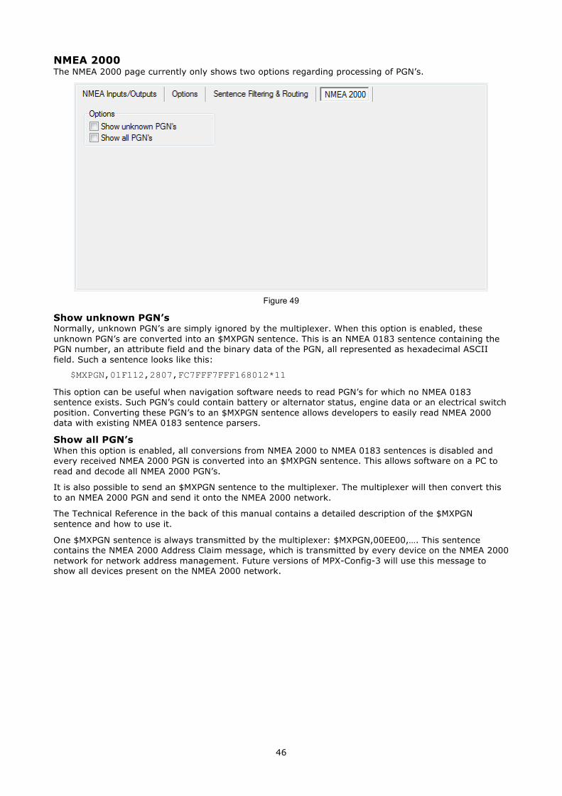
46
NMEA 2000 The NMEA 2000 page currently only shows two options regarding processing of PGN’s.
Show unknown PGN’s Normally, unknown PGN’s are simply ignored by the multiplexer. When this option is enabled, these unknown PGN’s are converted into an $MXPGN sentence. This is an NMEA 0183 sentence containing the PGN number, an attribute field and the binary data of the PGN, all represented as hexadecimal ASCII field. Such a sentence looks like this:
$MXPGN,01F112,2807,FC7FFF7FFF168012*11
This option can be useful when navigation software needs to read PGN’s for which no NMEA 0183 sentence exists. Such PGN’s could contain battery or alternator status, engine data or an electrical switch position. Converting these PGN’s to an $MXPGN sentence allows developers to easily read NMEA 2000 data with existing NMEA 0183 sentence parsers.
Show all PGN’s When this option is enabled, all conversions from NMEA 2000 to NMEA 0183 sentences is disabled and every received NMEA 2000 PGN is converted into an $MXPGN sentence. This allows software on a PC to read and decode all NMEA 2000 PGN’s.
It is also possible to send an $MXPGN sentence to the multiplexer. The multiplexer will then convert this to an NMEA 2000 PGN and send it onto the NMEA 2000 network.
The Technical Reference in the back of this manual contains a detailed description of the $MXPGN sentence and how to use it.
One $MXPGN sentence is always transmitted by the multiplexer: $MXPGN,00EE00,…. This sentence contains the NMEA 2000 Address Claim message, which is transmitted by every device on the NMEA 2000 network for network address management. Future versions of MPX-Config-3 will use this message to show all devices present on the NMEA 2000 network.
Figure 49
47
Firmware Update Firmware updates with new features or bug fixes will be available through our web site. These firmware files can be downloaded to your computer and loaded into the multiplexer using option “Update MiniPlex Firmware…” from the File menu.
Procedure Make sure the multiplexer is connected to your computer via USB or Ethernet, start MPX-Config-3 and connect to the multiplexer.
Download the firmware update and unpack the .zip file. Remember in which folder you stored the .mpx file.
Choose “Update MiniPlex Firmware…” from the File menu.
Using the file dialog, locate and select the firmware image file. When you have selected the file and clicked on OK, the update process is started. The image file’s integrity and version is checked first before initiating the download procedure in the multiplexer.
When the download is started, the red LED on the multiplexer will be lit continuously while the green LED blinks on reception of data from the computer. MPX-Config-3 will show a progress indicator during the update process. When the update is complete and successful, a message will show “The firmware update was successful”.
Any errors that occur during the process will be shown. It is important to make a note of the error message when asking for support. See “Firmware Update Error messages“ for an explanation of the error messages.
Whenever the update process aborts, the multiplexer will start outputting “$PSMDLDR…” sentences. This indicates that no firmware is loaded and the multiplexer waits for a new firmware update. Just try updating again until the process is successfully finished.
Sometimes the communication during the firmware update times out and the update is aborted with an error message. This time out can be caused by delays in the communication drivers that are part of Windows. These time outs happen frequently when software is running which communicates with other serial devices.
When such a time out occurs, the MiniPlex has no firmware loaded and the internal loader keeps sending $PSMDLDR… sentences, indicating that it waits for a firmware upload. Just try updating again until the process is successful. Sometimes it helps to try the update on a different computer.

48
Mounting The multiplexer is not waterproof. It should be mounted at a dry place such as behind the instrument panel on a flat surface.
Make sure there is enough space around the multiplexer to connect the NMEA 0183 wiring at the bottom, the NMEA 2000 connector on the left side and USB/Network connector on the right side of the housing.
49
Technical Reference
NMEA 0183 Glossary This glossary lists the most common Talker ID’s and Sentence Formatters in alphabetical order.
Talker ID’s AG Autopilot (general) AP Autopilot (magnetic) AI Automatic Identification System CD Communications: Digital Selective Calling (DSC) CR Data receiver CS Satellite CT Radio telephone (MF/HF) CV Radio telephone (VHF) CX Scanning receiver DE Decca navigator DF Direction finder EC Electronic chart systems (ECS) EI Electronic chart display and information system (ECDIS) EP Emergency position indicating radio beacon (EPIRB) ER Engine room monitoring systems GP Global Positioning System (GPS) GL GLONASS receiver GN Global navigation satellite system (GNSS) HC Heading sensors: compass, magnetic HE gyro, north seeking HN gyro, non-north seeking II Integrated instrumentation IN Integrated navigation LC Loran, Loran-C MX Multiplexer P Proprietary sentence RA Radar and/or radar plotting SD Sounder, depth SN Electronic positioning system, other/general SS Sounder, scanning TI Turn rate indicator VD Velocity sensors: doppler, other/general VM speed log, water, magnetic VW speed log, water, mechanical VR Voyage data recorder YX Transducer ZA Timekeepers: atomic clock ZC chronometer ZQ quartz ZV radio updated WI Weather instruments
Sentence formatters AAM Waypoint arrival alarm ACK Acknowledgement alarm ALM GPS almanac data ALR Set alarm state APB Heading/track controller (Autopilot) sentence B BEC Bearing and distance to waypoint, dead reckoning BOD Bearing, origin to destination BWC Bearing and distance to waypoint BWR Bearing and distance to waypoint, rhumb line BWW Bearing, waypoint to waypoint DBT Depth below transducer DCN DECCA position DPT Depth DSC Digital selective calling information DSE Expanded digital selective calling
50
DSI DSC transponder initialise DSR DSC transponder response DTM Datum reference FSI Frequency set information GBS GNSS Satellite fault detection GGA Global positioning system fix data GLC Geographic position, LORAN-C GLL Geographic position, latitude/longitude GNS GNSS fix data GRS GNSS range residuals GSA GNSS DOP and active satellites GST GNSS pseudo range error statistics GSV GNSS satellites in view HDG Heading, deviation and variation HDT Heading, true HMR Heading monitor – receive HMS Heading monitor – set HSC Heading steering command HTC Heading/track control command HTD Heading/track control data LCD LORAN-C signal data MLA Glonass almanac data MSK MSK receiver interface MSS MSK receiver signal status MTW Water temperature MWD Wind direction and speed MWV Wind speed and angle OSD Own ship data PGN NMEA 2000 PGN data RMA Recommended minimum specific LORAN-C data RMB Recommended minimum navigation information RMC Recommended minimum specific GNSS data ROT Rate of turn RPM Revolutions RSA Rudder sensor angle RSD Radar system data RTE Routes SFI Scanning frequency information STN Multiple data ID TLB Target label TLL Target latitude and longitude TTM Tracked target message TXT Text transmission VBW Dual ground/water speed VDR Set and drift VHW Water speed and heading VLW Distance travelled through the water VPW Speed, measured parallel to wind VTG Course over ground and ground speed WCV Waypoint closure velocity WNC Distance, waypoint to waypoint WPL Waypoint location XDR Transducer measurements XTE Cross-track error, measured XTR Cross-track error, dead reckoning ZDA Time and date ZDL Time and distance to variable point ZFO UTC and time from origin waypoint ZTG UTC and time to destination waypoint
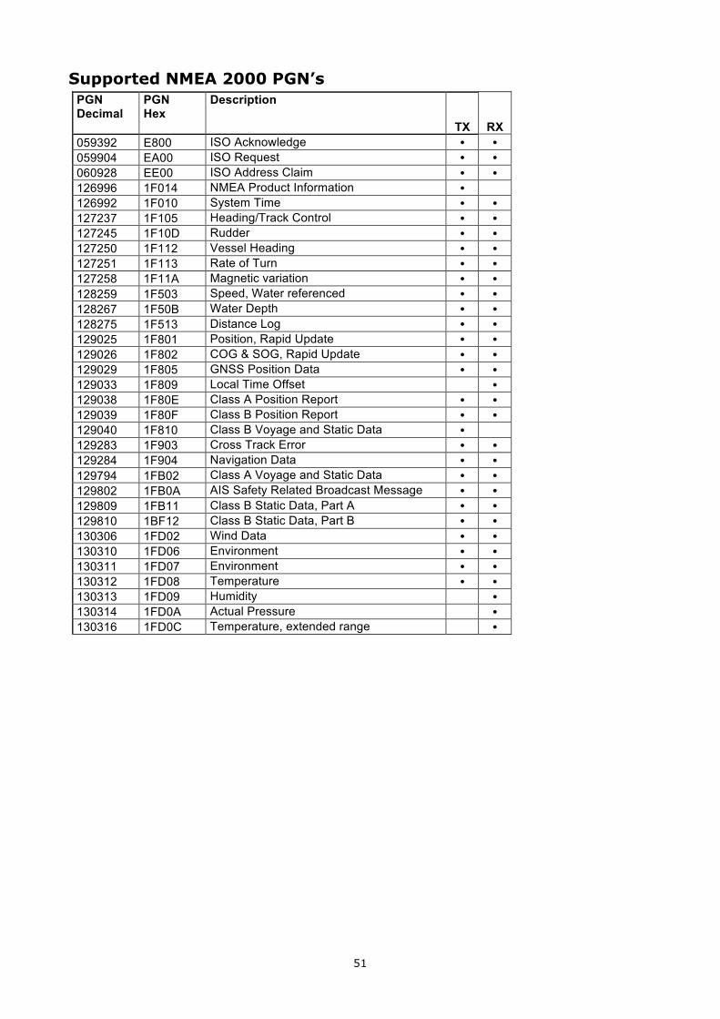
51
Supported NMEA 2000 PGN’s PGN Decimal
PGN Hex
Description
TX RX 059392 E800 ISO Acknowledge � � 059904 EA00 ISO Request � � 060928 EE00 ISO Address Claim � � 126996 1F014 NMEA Product Information � 126992 1F010 System Time � � 127237 1F105 Heading/Track Control � � 127245 1F10D Rudder � � 127250 1F112 Vessel Heading � � 127251 1F113 Rate of Turn � � 127258 1F11A Magnetic variation � � 128259 1F503 Speed, Water referenced � � 128267 1F50B Water Depth � � 128275 1F513 Distance Log � � 129025 1F801 Position, Rapid Update � � 129026 1F802 COG & SOG, Rapid Update � � 129029 1F805 GNSS Position Data � � 129033 1F809 Local Time Offset � 129038 1F80E Class A Position Report � � 129039 1F80F Class B Position Report � � 129040 1F810 Class B Voyage and Static Data � 129283 1F903 Cross Track Error � � 129284 1F904 Navigation Data � � 129794 1FB02 Class A Voyage and Static Data � � 129802 1FB0A AIS Safety Related Broadcast Message � � 129809 1FB11 Class B Static Data, Part A � � 129810 1BF12 Class B Static Data, Part B � � 130306 1FD02 Wind Data � � 130310 1FD06 Environment � � 130311 1FD07 Environment � � 130312 1FD08 Temperature � � 130313 1FD09 Humidity � 130314 1FD0A Actual Pressure � 130316 1FD0C Temperature, extended range �
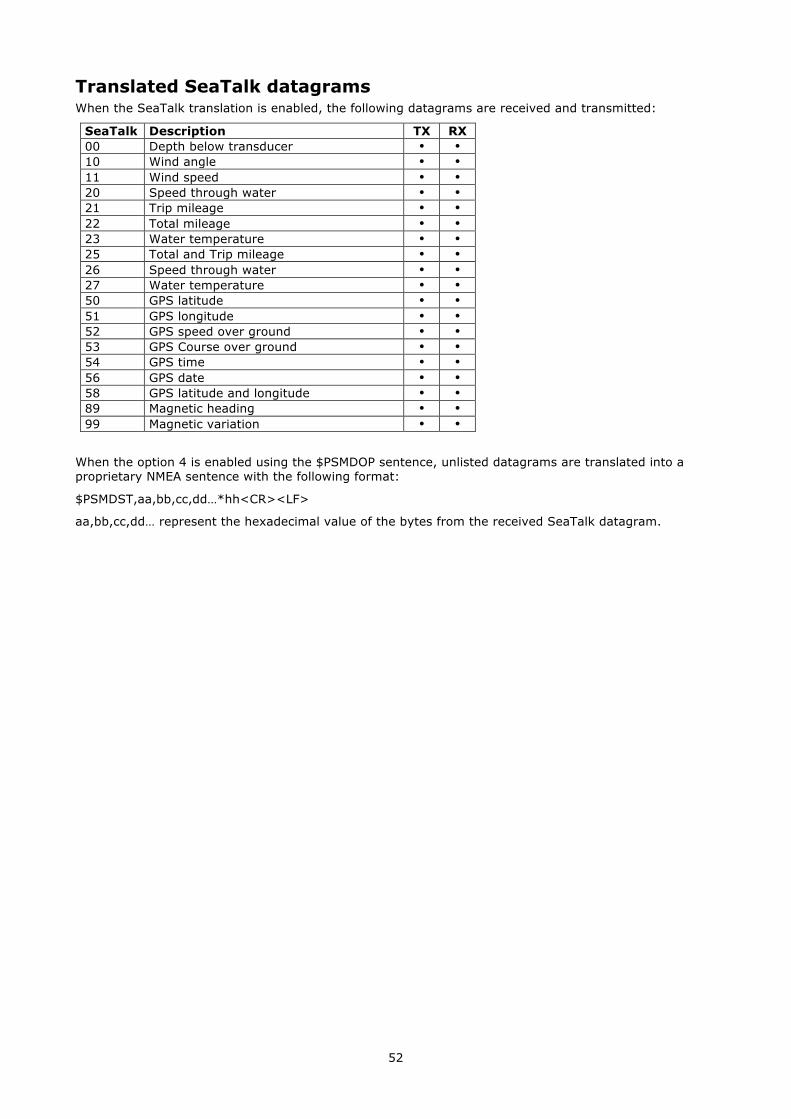
52
Translated SeaTalk datagrams When the SeaTalk translation is enabled, the following datagrams are received and transmitted:
SeaTalk Description TX RX 00 Depth below transducer � � 10 Wind angle � � 11 Wind speed � � 20 Speed through water � � 21 Trip mileage � � 22 Total mileage � � 23 Water temperature � � 25 Total and Trip mileage � � 26 Speed through water � � 27 Water temperature � � 50 GPS latitude � � 51 GPS longitude � � 52 GPS speed over ground � � 53 GPS Course over ground � � 54 GPS time � � 56 GPS date � � 58 GPS latitude and longitude � � 89 Magnetic heading � � 99 Magnetic variation � �
When the option 4 is enabled using the $PSMDOP sentence, unlisted datagrams are translated into a proprietary NMEA sentence with the following format:
$PSMDST,aa,bb,cc,dd…*hh<CR><LF>
aa,bb,cc,dd… represent the hexadecimal value of the bytes from the received SeaTalk datagram.
53
Firmware Update Error messages During a firmware update, the following warnings or error messages may be displayed:
The firmware update failed This message appears when the overall update process failed without any other error message. It is shown when the updated multiplexer firmware does not report a version message after start-up.
Not a valid firmware file The file you are trying to open is not a valid firmware file. A firmware file not only ends with an “.mpx” extension, it also contains a distinct signature that must be present. This prevents you from accidentally loading the wrong file into the multiplexer.
Unsupported firmware file version The firmware file version is not supported by MPX-Config-3. Currently, there is only one firmware file version but it is not unlikely that in the future new version are developed which require an update of MPX-Config-3.
Firmware file is corrupt The firmware file is damaged, possible due to an error during download from our website.
The version of the firmware file is lower than the version of the multiplexer. Do you really want to proceed?
You are trying to update the firmware in the multiplexer with an older version. This is just a warning and very well possible to do.
Bootloader initialisation failed When MPX-Config-3 starts the update process, a small program called the Bootloader must be started in the multiplexer. This message tells you that the bootloader could not be started. This can happen when you try to update the multiplexer while navigation instruments are connected and sending lots of NMEA data to the multiplexer. This can interfere with starting the update process. Disconnect or power down the instruments to prevent this problem.
Firmware file does not match with the multiplexer type Most firmware files will be compatible with all types of multiplexers. It is however possible that special firmware is made available which only runs on a specific type of multiplexer. If this message appears, you apparently are trying to update using a firmware file that is not suitable for your type of multiplexer.
Bootloader: Erase command timeout An error occurred when the bootloader tried to erase the old firmware.
Bootloader: Encryption command timeout The bootloader did not respond to the Encryption command sent by MPX-Config-3.
Bootloader: Programming timeout There was an error during programming a section of the firmware image.
Bootloader: CRC command timeout The bootloader failed to calculate the checksum of the newly loaded firmware image.
Bootloader: CRC error The calculated checksum of the newly loader firmware image does not match the checksum if the image file. Apparently there was a communication error between MPX-Config-3 and the multiplexer. You can try to update again.
Invalid response from bootloader The bootloader returned an unknown response to a command from MPX-Config-3.
54
Standard NMEA 0183 Sentences The following standard NMEA 0183 sentences are used by the MiniPlex-3.
$MXSTN – Multiple Data ID When STN sentences are enabled ($PSMDOP, option 11), the multiplexer transmits a $MXSTN sentence before every NMEA sentence that is sent from the host interface.
Format: $MXSTN,xx*hh<CR><LF> xx: Input number, 00 to 06.
The Input Number indicates on which the following NMEA sentence was received:
00: Internally generated responses ($PSMD sentences) 01: NMEA 0183 Input 1 or SeaTalk 02: NMEA 0183 Input 2 03: NMEA 0183 Input 3 04: NMEA 0183 Input 4 05: NMEA 2000 06: Conversion results
$MXPGN – NMEA 2000 PGN Data This sentence transports NMEA 2000 Single Frame messages over NMEA 0183. The MiniPlex will output this sentence with Talker ID “MX”. When sent to the MiniPlex, the Talker ID is ignored unless a Filter Rule exists for this sentence.
Format: $--PGN,pppppp,aaaa,c--c*hh<CR><LF>
pppppp: PGN of the NMEA 2000 message, 3 byte hexadecimal number. If the PGN is non-global, the lowest byte contains the destination address.
aaaa: Attribute Word, 2 byte hexadecimal number. This word contains the priority, the DLC code and then source/destination address of the message, formatted as shown below:
15 14 13 12 11 10 9 8 7 6 5 4 3 2 1 0 ┌───┬───┬───┬───┬───┬───┬───┬───┬───┬───┬───┬───┬───┬───┬───┬───┐ │ S │ Priority │ DLC │ Address │ └───┴───┴───┴───┴───┴───┴───┴───┴───┴───┴───┴───┴───┴───┴───┴───┘ S: Send bit. When an NMEA 2000 message is received, this bit is 0.
To use the $MXPGN sentence to send an NMEA 2000 message, this bit must be set to 1.
Priority: Message priority. A value between 0 and 7, a lower value means higher priority.
DLC: Data Length Code field, contains the size of the message in bytes (1..8) or a Class 2 Transmission ID (9..15).
Address: Depending on the Send bit, this field contains the Source Address (S=0) or the Destination Address (S=1) of the message.
c--c: Data field of the NMEA 2000 message, organized as one large number in hexadecimal notation from MSB to LSB. This is in accordance with “NMEA 2000 Appendix D”, chapter D.1, “Data Placement within the CAN Frame”.
The size of this field depends on the DLC value and can be 1 to 8 bytes (2 to 16 hexadecimal characters).
NMEA 2000 Reception When the multiplexer converts an NMEA 2000 message into an $MXPGN sentence, the S bit in the Attribute field will be 0 and the Address field contains the source address of the message. The destination address of the message is either global or contained in the lower byte of the PGN, in accordance with the NMEA 2000/ISO specification.
NMEA 2000 Transmission A $--PGN sentence sent to the multiplexer will be converted to an NMEA 2000 message if the S bit in the Attribute field is 1.
The Address field is the Destination Address of the NMEA 2000 message. The Source Address of the message will be the address the multiplexer has acquired during the Address Claim Procedure. If a global PGN is used, the contents of the Address field will be ignored. A non-global PGN can be sent globally by setting the Address field to 0xFF.
55
The Destination Address of a non-global PGN can also be specified by loading it into the lower byte of the PGN. The Address field of the Attribute word must be set to 0x00 for this.
The DLC field must be set to the size of the Data field (1 to 8 bytes) and the actual size of the Data field must match with the DLC. If the DLC field us used as a Class 2 Transmission ID (9..15), the size of the Data field must be 8 bytes/16 characters. If any of these conditions is not met, the message will not be transmitted.
For quick transmission of an NMEA 2000 message, the Attribute field of the $--PGN sentence may be omitted. In this case, the following values for the Attribute will be assumed:
S: 1 Priority: 7 DLC: Set automatically from the size of the Data field (c—c) field. Address: 0. The Destination Address of the message will be contained in the PGN field (pppppp).
Examples A received PGN 127250 (hex: 1F112, Vessel Heading) will be converted into the following $MXPGN sentence:
$MXPGN,01F112,2807,FC7FFF7FFF168012*11
The Attribute word shows a received frame (S=0), with priority 2, it is 8 bytes and the Source Address is 0x07.
To tranmit PGN127250, the following $--PGN sentence must be sent to the multiplexer:
$MXPGN,01F112,A800,FC7FFF7FFF168012*65
In this example, the Address field of the Attribute field is ignored and set to 0x00 because PGN 127250 is a Global PGN.
An ISO Request (PGN 059904) can be transmitted in the following ways:
$MXPGN,00EA00,F309,01F016*68 $MXPGN,00EA09,,01F016*1D
In both cases, this message is sent to Destination Address 0x09. In the first sentence, the Destination Address is specified in the Attribute word, the second sentence has it embedded in the PGN field.
56
Proprietary NMEA 0183 Sentences The MiniPlex multiplexers are configured with proprietary NMEA sentences that can be sent to the multiplexer through the host interface. These will be called commands.
The multiplexer can also output proprietary NMEA sentences on a host interface to output status information or a response to a received proprietary NMEA sentence.
The multiplexer also outputs some standard NMEA sentences. These sentences all start with ‘MX’, which is the talker ID for a multiplexer as defined by the NMEA standard.
The host interface is the port that connects to a computer, laptop, smartphone or tablet by means of RS-232, USB, Bluetooth, WiFi or Ethernet. A MiniPlex can have more than one host interface. When the multiplexer outputs something on a host interface, it is sent to all host interfaces simultaneously. All host interfaces operate equally and have equal priority.
All MiniPlex proprietary sentences have the following format:
$PSMDxxx,a,b,…*hh<CR><LF>
$P: Start of a proprietary sentence as dictated by the NMEA standard SMD: ShipModul manufacturer mnemonic xxx: One, two- or three-character sentence formatter a,b,…: Optional fields *hh: Optional checksum field <CR><LF>: Cariage Return and Line Feed characters that terminate the sentence
Unless specified otherwise, fields are optional and may be skipped when no change is required. For instance, a $PSMDCF,C,,,,1 sentence only enables Channel Numbers. The preceding fields are skipped (,,,,) and the trailing fields are omitted.
For ease of manual configuration, these sentences do not require a checksum. If the sentence has a checksum however, it is checked and the sentence is rejected on a checksum failure. Sentences output by the multiplexer always contain a checksum. Checksums are denoted with *hh in the descriptions below.
Sentences that are used to both set and retrieve a configuration setting have a Sentence Status field. This field is the first field of the sentence and can be one of the following:
C: the sentence was a configuration command R: the sentence was a response to a command
A configuration command is sent to the multiplexer to change a setting. A response is sent by the multiplexer to report a setting.
Unless specified otherwise, all command sentences return a response with their settings when sent without parameters.
A command sentence with its Sentence Status field set to ‘R’ is ignored by the multiplexer.
Example The $PSMDID sentence controls the Talker ID settings of the multiplexer. When $PSMDID is sent to the multiplexer, it will report with the current Talker ID settings with:
$PSMDID,R,aa,bb,cc,dd,ee*hh
To set the change the Talker ID settings, send the following sentence:
$PSMDID,C,aa,bb,cc,dd,ee
57
$PSMDC – Get Configuration record This command outputs all configuration settings at once. When $PSMDC is sent to the multiplexer, it responds with a $PSMDC sentence with the following format:
Format: $PSMDC,x,c--c*hh<CR><LF>
x : Configuration record number
c--c: Configuration record data, 64 hexadecimal characters representing a block of 32 bytes.
$PSMDN – Set NMEA 2000 Configuration This command is used to set NMEA 2000 configruation parameters and has several sub-commands. When issued without any parameters, the multiplexer will output all NMEA 2000 configuration settings with a series of PSMDN,R… sentences.
Format: $PSMDM,a,c,x,y,…*hh<CR><LF>
a: Sentence Command/Status flag: R = sentence is a response with current settings C = sentence is a command to change settings Q = Request PGN 60928 (Address Claim) from all devices
c : Sub-command
x,y,…: Parameters
The following sub-commands are defined:
N: Set the network parameters:
$PSMDN,a,N,x,y,z*hh<CR><LF>
x: Source Address, 0..251 y: Device Instance, 0..255 z: System Instance, 0..15
$PSMDCF – Set Configuration This sentence sets various configuration settings of the multiplexer.
Format: $PSMDCF,a,b,t*hh<CR><LF>
a: Sentence Status flag: R = sentence is a response with current settings C = sentence is a command to change settings
b: Baudrate selector for the RS-232 interface (ignored when no RS-232 port present): 0 = 4800 Baud 1 = 9600 Baud 2 = 19200 Baud 3 = 38400 Baud 4 = 57600 Baud 5 = 115200 Baud
t: Priority Timeout (in seconds): 0 = 1 1 = 2 2 = 3 3 = 5 4 = 10 5 = 30
$PSMDCFQ – Get Configuration This sentence requests all configuration sentences at once.
$PSMDDR – Set Default Route This sentence specifies the default route from the NMEA inputs to the NMEA outputs and from the host interface to the NMEA outputs. Any route set by the FL sentence overrides the standard route.
Format: $PSMDDR,a,xx,b,yy,c*hh<CR><LF>
58
a: Sentence Status flag: R = sentence is a response with current settings C = sentence is a command to change settings
xx: Input field for NMEA Out1. This is a hexadecimal number where each bit represents an NMEA input. The following bits are defined:
0: NMEA In 1 1: NMEA In 2 2: NMEA In 3 3: NMEA In 4 4: NMEA 2000 5: NMEA Conversions
When a bit is 1, the input is routed to output 1, otherwise the input is not routed.
b: Host data to NMEA Out1: 0: Host data is not routed 1: Host data is routed 2: Host data is routed and overrides data from the inputs. A time out mechanism will route data from the inputs when no data from the host is received.
yy: Input field for NMEA Out2. This is a hexadecimal number where each bit represents an NMEA input. The following bits are defined:
0: NMEA In 1 1: NMEA In 2 2: NMEA In 3 3: NMEA In 4 4: NMEA 2000 5: NMEA Conversions
When a bit is 1, the input is routed to output 1, otherwise the input is not routed.
c: Host data to NMEA Out2: 0: Host data is not routed 1: Host data is routed 2: Host data is routed and overrides data from the inputs. A time out mechanism will route data from the inputs when no data from the host is received.
$PSMDFL – Set Filter Rules This sentence specifies a filter and routing rule that is applied on every incoming NMEA sentence. Filter rules are specified using the address field of an NMEA sentence. For each filter rule, the inputs on which the sentence may be received must be specified. Optionally, a divisor and an output routing field can be added.
Sentences for which no rule exists are passed or blocked, depending on the filter mode set by field ‘f’ of the CF sentence.
Format: $PSMDFL,a,ccccc,xx,dd,yy*hh<CR><LF>
a: Sentence Status flag: R = sentence is a status report of current settings C = sentence is a command to change settings
ccccc: Address field of the filter rule (e.g. ‘GPRMC’, ‘IIMWV’, etc). This field may contain wildcard characters (‘-’). For instance, ‘GP---’ will apply to all sentences starting with ‘GP’. Similarly, ‘—MWV’ will apply to all sentences ending on ‘MWV’ regardless of the Talker ID. Multiple filter rules with the same address field may be entered to route similar sentences form different inputs to different outputs.
xx: Input field. This is a hexadecimal number where each bit represents an NMEA input. The following bits are defined:
0: NMEA In 1 1: NMEA In 2 2: NMEA In 3 3: NMEA In 4 4: NMEA 2000 5: NMEA Conversions 6: Host input
When a bit is 1, the sentence is forwarded, otherwise the sentence is blocked from that input.
59
dd: Optional divisor factor (0..99). The rate or frequency of a sentence is divided by this number to reduce the number of sentences over time. If for instance a divisor of 6 is specified, only every 6th occurrence of this sentence is passed.
yy: Optional routing field. This is a hexadecimal number where each bit represents an output. The following bits are defined:
0: NMEA Out1 1: NMEA Out2 2: SeaTalk bus 3: NMEA 2000 4: Wireless output 5: Host output
When a bit is 1, the sentence is routed to that output. When this field is omitted, a default of ‘C0’ is assumed, routing the specified sentence to all the Host and Wireless output only.
hh: Optional checksum
An FL sentence with the word DELETE in the ‘ccccc’ field erases all rules. An FL sentence with only a ‘ccccc’ field will erase that entry. The filter accepts duplicate entries with the same ‘ccccc’ field to allow separate routes from inputs to outputs.
Example: $PSMDFL,C,HEHDT,18,5,05<CR><LF>
This sentence specifies a rule for all sentences that have ‘HEHDT’ in the address field. It only passes HEHDT sentences from inputs 3 and 4, the rate is lowered by a factor of 5 and the sentence is routed to NMEA Out1 and the host only.
When the filter list is requested, the multiplexer responds by sending FL sentences, one for each list entry. An empty FL sentence marks the end of the list.
Example response:
$PSMDFL,R,GPRMC,19,0,0F*4A<CR><LF> $PSMDFL,R,GPGGA,18,0,0F*56<CR><LF> $PSMDFL,R,--VWT,02,5,01*50<CR><LF> $PSMDFL,R,GPGSV,10,0,04*55<CR><LF> $PSMDFL,R*2C<CR><LF>
The sentences may not be dumped as one contiguous block. In case of much NMEA data, they may be interspersed with other NMEA sentences.
$PSMDID – Set Talker ID This sentence sets a Talker ID translation for a specific input. If a Talker ID is specified, the original Talker ID of the sentences received on that input is replaced by the specified one, before sending the sentence to the host.
Format: $PSMDID,a,aa,bb,cc,dd,ee,ff*hh<CR><LF>
a: Sentence Status flag: R = sentence is a response with current settings C = sentence is a command to change settings
aa: Talker ID for input 1/SeaTalk bb: Talker ID for input 2 cc: Talker ID for input 3 dd: Talker ID for input 4 ee: Talker ID for NMEA 2000 input ff: Talker ID for conversion results hh: optional checksum
An empty field clears the ID and disables the translation for that specific channel.
60
$PSMDIN – Input options Set the operating mode of an NMEA input.
Format: $PSMDIN,a,x,x,x,x
a: Sentence Status flag: R = sentence is a response with current settings C = sentence is a command to change settings
x: Operating mode field for input 1 to 4:
0: Normal NMEA processing.
1: Pass NMEA sentences containing an erroneous checksum unmodified, bypassing all further NMEA processing.
2: Relaxed NMEA format checking. Normally the multiplexer only passes sentences when they are correctly formatted: starting with a ‘$’ or a ‘!’ and ending on a CR/LF pair. When this mode is selected, an NMEA sentence will be passed if it starts with a ‘$’ or a ‘!’ and ends on a CR or a LF or a combination of both in arbitrary order. A sentence with a checksum error is blocked.
3: Accept plain text strings as input and forward them in $MXTXT sentences. Any character with an ASCII value > 32 (a space) is considered to be the start of a string. The string must end on a CR or LF and may not be longer than 61 characters. A longer string is discarded. Only valid NMEA characters are passed. Invalid characters are stripped from the input data. The Total number and Sentence number fields are always set to ‘01’. The Text Identiefier field of the $MXTXT sentence contains the input number on which the text was received. When for instance ‘Hello World’ is received on input 3, the resulting sentence will be: $MXTXT,01,01,03,Hello World*6E
4: Accept plain text strings as input and forward them in $PTXT sentences. Any character with an ASCII value > 32 (a space) is considered to be the start of a string. The string must end on a CR or LF and may not be longer than 61 characters. A longer string is discarded. The multiplexer will always end a forwarded string with a CR/LF pair. All characters with an ASCII value from 32 to 127 are passed.
5: Accept plain text strings as input and forward them as plain text. Any character with an ASCII value > 32 (a space) is considered to be the start of a string. The string must end on a CR or LF and may not be longer than 61 characters. A longer string is discarded. The multiplexer will always end a forwarded string with a CR/LF pair. All characters between from ASCII 32 to 127 are passed.
6: SeaTalk to NMEA conversion on input 1 only. When this mode is selected, the $PSMDOP response will show option 3 enabled. Any other mode (0..4) will clear both SeaTalk options in the $PSMDOP response.
$PSMDLDR – Loader message This sentence is output by the bootloader on the host interface. It contains the loader version and multiplexer ID. The loader will wait for a special key during 0.2s after sending this sentence. When no key is received, the multiplexer application code is started. If no application code is found, the loader will continue sending this sentence.
Format: $PSMDLDR,xx,v.v,zzz
xx: Hardware ID of the multiplexer (a hexadecimal number) v.v: Bootloader version number zzz: Hardware name of the multiplexer
The following hardware ID’s and names are defined:
10: MPX-3S 11: MPX-3U 12: MPX-3E 13: MPX-3UW 90: MPX-3S-N 91: MPX-3U-N 92: MPX-3E-N 93: MPX-3UW-N
Example: $PSMDLDR,91,2.0,MPX-3U
This multiplexer has a MPX-3U board with an NMEA 2000 interface and the bootloader is version 2.0.
61
$PSMDOP – Set Options This sentence is used to enable or disable various options.
Format: $PSMDOP,a,o,e*hh<CR><LF> or: $PSMDOP,a,xxxxxxxx*hh<CR><LF>
a: Sentence Status flag: R = sentence is a response with current settings C = sentence is a command to change settings
o: option number
e: 0 = off/disable 1 = on/enable
xxxxxxxx: all options at once as a 32 bit hexadecimal number. Each bit represents an option where bit 0 is option 0, bit 1 is option 1 etc.
Example: $PSMDOP,C,6,1<CR><LF> (enables option 6) $PSMDOP,C,00000021<CR><LF> (enables options 5 and 0)
The following options are defined:
0: Enable Priority
1: Enable highest priority for SeaTalk data. Only effective when Priority and SeaTalk translation are enabled.
2: Test GPS status field for priority check. When enabled, the status field of a GPS related sentence is checked. When the data is invalid, the sentence is discarded to allow the Priority feature to pass GPS data from a lower priority input.
3: Enable SeaTalk to NMEA translation. This will also be reflected in the $PSMDIN response: input 5 will report SeaTalk mode.
4: Convert SeaTalk datagrams into $PSMDST,xx,xx,… sentences. Datagrams are only converted if they are not translated into NMEA. When option 3 is enabled, only unknown datagrams are converted, otherwise all datagrams are converted. . This will also be reflected in the $PSMDIN response: input 5 will report SeaTalk mode.
5: Reserved for future use.
6: Heading translation. When a magnetic heading sentence (HDM or HDG) is received, the multiplexer generates a true heading sentence (HDT). The heading is corrected for magnetic variation if this field is available in the HDG or HDM sentence. When a True heading (HDT) is received, the multiplexer generates an HDM sentence.
7: Velocity translation. Generate a log sentence (VHW) from a GPS speed sentence (VTG). This is the opposite translation of option 16.
8: Wind translation. When a VWR sentence is received, an MWV,R is generated. Reception of an MWV sentence results in either a VWR or a VWT sentence, depending on the R or T flag in de MWV sentence.
9: Filter Block. Block sentences that are not in the Filter & Routing list. The default is to pass sentences that are not in the list.
10: Reverse heading. When enabled, a new HDT sentence is generated from an incoming HDT sentence with the heading reversed by 180 degrees. Use the Sentence Filter to route the original and new HDT sentences to different outputs.
11: Output channel information with STN sentences. When enabled, the multiplexer transmits an STN sentence before each individual sentence to indicate on which input this sentence was received.
12: Output channel information with TAG Blocks. . When enabled, the multiplexer transmits a TAG Block before each individual sentence to indicate on which input this sentence was received.
13: Enable conversion from NMEA 0183 V3.0 to V1.5 sentences for NMEA Out2. The following sentences are converted: APB, BWC, BWR, GLL, RMB, RMC, VTG, XTE and ZDL.
14: Generate theoretical wind speed from apparent wind speed. This options generates an MWV,T sentence. The necessary SOG is extracted from received RMC or VTG sentences. This option can be used in conjunction with option 8, to first convert VWR to MWV,R and then to MWV,T
15: Position translation. Generate a GGA sentence when an RMC sentence is received.
62
16: Velocity translation. Generate a VTG sentence when a VHW sentence is received. This is the opposite translation of option 7.
30: Output unknown NMEA 2000 PGN’s as an $MXPGN sentence.
31: Output all NMEA 2000 PGN’s as an $MXPGN sentence.
When a PSMDOP sentence without any parameters is sent, the multiplexer returns an OP sentence with a 32 bit hexadecimal number. Each bit represents an option where bit 0 is option 0, bit 1 Is option 1 etc.
Format: $PSMDOP*hh<CR><LF>
Response: $PSMDOP,R,xxxxxxxx*hh<CR><LF>
$PSMDOV – Overflow In case of a queue overflow (blinking red LED on the multiplexer), an overflow sentence is output on the host interface, to indicate on which input queue the overflow occurred:
Format: $PSMDOV,xx*hh<CR><LF>
xx: Hexedecimal field. The folliwing bits indicate on which input queue the overflow occurred:
0: NMEA In 1 1: NMEA In 2 2: NMEA In 3 3: NMEA In 4 4: NMEA 2000
$PSMDRESET – Reset the multiplexer This sentence resets the multiplexer and starts the bootloader. When a ‘1’ is given as parameter, the factory settings of the multiplexer are restored.
Format: $PSMDRESET,x*hh<CR><LF>
x: Optional parameter to indicate an action while resetting 1: restore the multiplexer to its factory settings
After a reset, the multiplexer outputs a LDR sentence and a VER sentence on the host interface.
$PSMDSP – Set Speed This sentence sets the baudrate of the NMEA inputs and outputs.
Format: $PSMDSP,a,b,c,d,e,f,g[*hh]<CR><LF>
The following fields are defined for setting the various inputs and outputs:
a: Sentence Status flag: R = sentence is a response with current settings C = sentence is a command to change settings
b: NMEA In 1 c: NMEA In 2 d: NMEA In 3 e: NMEA In 4/Out 1 f: NMEA Out 2 g: RS-232 host port (ignored on multiplexers without RS-232 host port)
Valid field values are:
0 = 4800 Baud 1 = 9600 Baud 2 = 19200 Baud 3 = 38400 Baud 4 = 57600 Baud 5 = 115200 Baud (field e and f only)
Field ‘e’ is ignored when SeaTalk translation is enabled with the CF sentence.
63
TAG Block When TAG Blocks are enabled ($PSMDOP, option 12), the multiplexer adds a TAG block to every NMEA sentence that is sent from the host interface. This TAG block has one source parameter, containing the UI of the multiplexer and the input the sentence was received on. It has the following format:
\s:UI-x*hh\
where UI is the Unique Identifier of the multiplexer and ‘x’ is a digit representing the input number.
0: Internally generated responses ($PSMD sentences) 1: NMEA 0183 Input 1 or SeaTalk 2: NMEA 0183 Input 2 3: NMEA 0183 Input 3 4: NMEA 0183 Input 4 5: NMEA 2000 6: Conversion results
If no UI is specified with the PSMDUI sentence, “MXnn” is sent, where “nn” are the last two digits of the serial number of the multiplexer.
A heading sentence received on input 1 will be sent to the host as
\s:MX01-1*1E\$HEHDT,23.5*37<CR><LF>
$PSMDUI – Set Unique Identifier Sets the Unique Identiefier (UI) of the multiplexer. This UI is sent as source parameter in TAG blocks sent by the multiplexer.
Format: $PSMDUI,a,c--c*hh<CR><LF> a: Sentence Status flag:
R = sentence is a response with current settings C = sentence is a command to change settings
c--c: Unique Identifier, 15 character maximum. If this field exceeds the maximum character count, is not present or empty, the UI is reset to “MXnn” where “nn” are the last two digits of the serial number of the multiplexer.
$PSMDVER – Get Version This sentence retrieves version information from the multiplexer.
Format: $PSMDVER
The multiplexer responds with the following version sentence:
$PSMDVER,1.9.1,MiniPlex-3USB-N2K,39000943,A013*hh<CR><LF>
1.9.1: firmware version number MiniPlex-3USB-N2K: multiplexer name 39000943: serial number
A013: Multiplexer capabilities. This is a 4 digit, 16-bit field represented as a hexadecimal number. Each bit identifies a capability of the multiplexer. The following bits are defined: 2-0: Host interface type, 0 = serial, 1 = USB, 2 = Ethernet, 3 = USB 3: SeaTalk1 transmission supported 4: NMEA 2000 supported 15-13: Multiplexer generation: 5 = 4th generation
hh: checksum
$PSMDWI – WiFi Control This sentence controls the WiFi module on the multiplexer. This sentence always results in a response sentence from the multiplexer. This response reflects the response of the WiFi module or the result of the operation.
Format: $PSMDWI,x,a,b..*hh<CR><LF
x: Sub-command. See below a,b..: Optional parameters required by a subcommand
Response: $PSMDWI,message
64
The following sub-commands are defined:
1-13: Set the WiFi channel number
A: Configure the WiFi module with the multiplexer default access point settings:
SSID: MiniPlex-xxxxxxxx Password: MiniPlex Channel: 1 IP address: 10.0.0.1 Network mask: 255.255.255.0 TCP port: 10110
xxxxxxxx is the serial number of the multiplexer..
W: Set the WLAN parameters of the WiFi connection:
$PSMDWI,W,mode,ssid,phrase*hh<CR><LF>
mode: A = Access Point ssid: SSID of the WiFi connection phrase: Optional password (8 characters minimum)
65
Technical Specifications
MiniPlex-3USB Supply voltage: 8 – 35 VDC, protected against reversed polarity.
Current consumption: 50 mA (100 mA max. with fully loaded talker ports)
Host interface: USB, galvanically isolated
Inputs: 4 x NMEA 0183/RS-422, galvanically isolated. Input 1 can be set to SeaTalk mode
Input resistance: >1.4 kOhm
Input current: 0.5mA @ 2V 3.0mA @ 5V 7.1mA @ 10V
Outputs: 2 x NMEA 0183/RS-422, galvanically isolated.
Max output current: 20mA @ >2V
Filter list size: 50 sentence types
Priority list size: 50 sentence types
Speed NMEA In 1-3: 4800 - 57600 Baud
Speed NMEA In 4/Out 1: 4800 - 57600 Baud
Speed NMEA Out 2: 4800 - 115200 Baud
Indicators: Overflow and Data
Dimensions: 138 x 72 x 33 mm
Housing: Flame retardant ABS.
MiniPlex-3USB-N2K NMEA 2000 Port: LEN: 1
Speed: 250kbps
Connector: M12 male Micro-C
66
MiniPlex-3E Supply voltage: 8 – 35 VDC, protected against reversed polarity.
Current consumption: 100 mA (150 mA max. with fully loaded talker ports)
Host interface: 10BASE-T/100BASE-TX Ethernet
Supported protocols: TCP/IP and UDP, port 10110 for NMEA communication TCP/IP, port 10110 for firmware updates TCP/IP and UDP, port 30718 for network configuration ARP, ICMP and DCHP for network management
Inputs: 4 x NMEA 0183/RS-422, galvanically isolated. Input 1 can be set to SeaTalk mode
Input resistance: >1.4 kOhm
Input current: 0.5mA @ 2V 3.0mA @ 5V 7.1mA @ 10V
Outputs: 2 x NMEA 0183/RS-422, galvanically isolated.
Max output current: 20mA @ >2V
Filter list size: 50 sentence types
Priority list size: 50 sentence types
Speed NMEA In 1-3: 4800 - 57600 Baud
Speed NMEA In 4/Out 1: 4800 - 57600 Baud
Speed NMEA Out 2: 4800 - 115200 Baud
Indicators: Overflow and Data
Dimensions: 138 x 72 x 33 mm
Housing: Flame retardant ABS.
MiniPlex-3E-N2K NMEA 2000 Port: LEN: 1
Speed: 250kbps
Connector: M12 male Micro-C
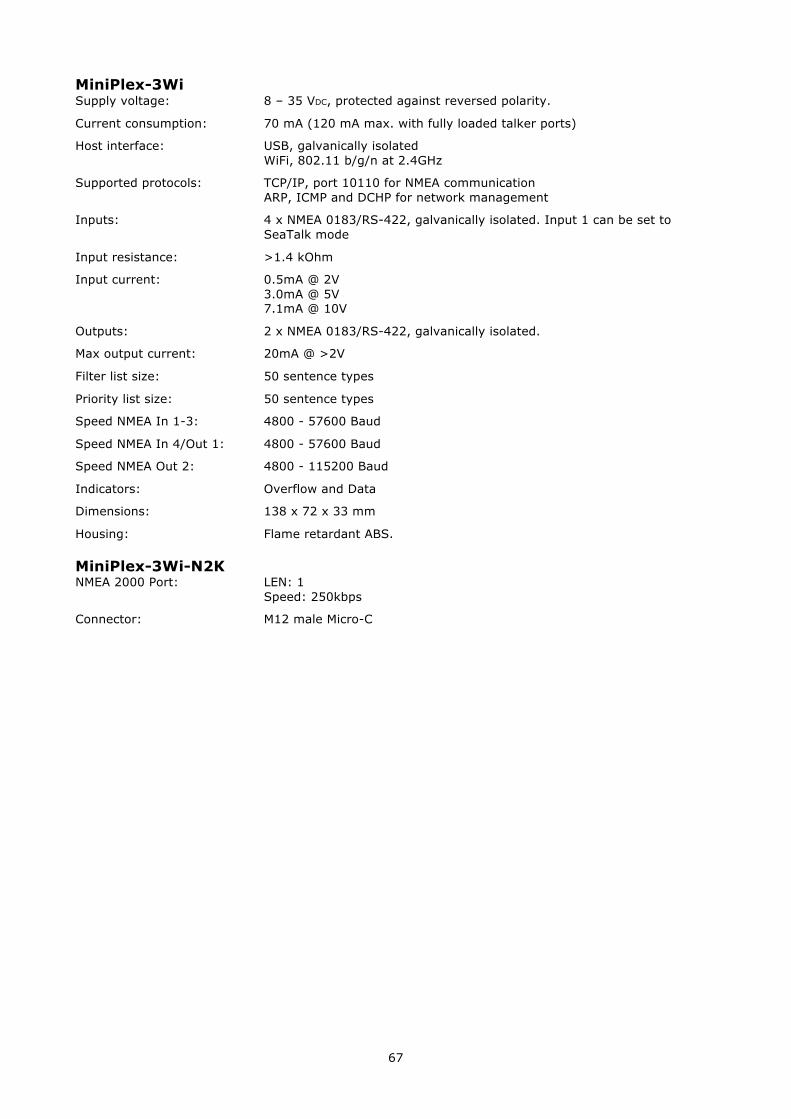
67
MiniPlex-3Wi Supply voltage: 8 – 35 VDC, protected against reversed polarity.
Current consumption: 70 mA (120 mA max. with fully loaded talker ports)
Host interface: USB, galvanically isolated WiFi, 802.11 b/g/n at 2.4GHz
Supported protocols: TCP/IP, port 10110 for NMEA communication ARP, ICMP and DCHP for network management
Inputs: 4 x NMEA 0183/RS-422, galvanically isolated. Input 1 can be set to SeaTalk mode
Input resistance: >1.4 kOhm
Input current: 0.5mA @ 2V 3.0mA @ 5V 7.1mA @ 10V
Outputs: 2 x NMEA 0183/RS-422, galvanically isolated.
Max output current: 20mA @ >2V
Filter list size: 50 sentence types
Priority list size: 50 sentence types
Speed NMEA In 1-3: 4800 - 57600 Baud
Speed NMEA In 4/Out 1: 4800 - 57600 Baud
Speed NMEA Out 2: 4800 - 115200 Baud
Indicators: Overflow and Data
Dimensions: 138 x 72 x 33 mm
Housing: Flame retardant ABS.
MiniPlex-3Wi-N2K NMEA 2000 Port: LEN: 1
Speed: 250kbps
Connector: M12 male Micro-C