minispec mq-series user manual - · pdf fileminispecminispec mq-series user manual version...
TRANSCRIPT

minispec
minispec mq-SeriesUser ManualVersion 001
Innovation with Integrity
●
AIC

Copyright © by Bruker Corporation
All rights reserved. No part of this publication may be reproduced, stored in a retrievalsystem, or transmitted, in any form, or by any means without the prior consent of thepublisher. Product names used are trademarks or registered trademarks of their re-spective holders.
This manual was written by
AIC
© October 20, 2015 Bruker Corporation
P/N: E1400011
For further technical assistance for this product, please do not hesitate to contact yournearest BRUKER dealer or contact us directly at:
Bruker CorporationAm Silberstreifen76287 RheinstettenGermanyPhone: +49 721-5161-6155/+1 978-667-9580E-mail: [email protected]: www.bruker.com
Contents
E1400011_1_001 3
Contents1 About This Manual ............................................................................................................................. 5
1.1 Policy Statement ................................................................................................................. 51.2 Symbols and Conventions .................................................................................................. 5
2 Safety................................................................................................................................................... 72.1 Intended Use....................................................................................................................... 72.2 Qualified Personnel............................................................................................................. 72.3 Correct Usage..................................................................................................................... 72.4 Electrical Safety .................................................................................................................. 82.5 Lifting Safety ....................................................................................................................... 92.6 Personal Safety................................................................................................................... 92.6.1 Safety for Persons Wearing Pacemakers ........................................................................... 92.6.2 Safety During Cryogen Refilling........................................................................................ 102.6.3 Safety When Working with VT Probe Systems................................................................. 112.6.4 Safety When Working with Glassware.............................................................................. 11
3 Transport, Packaging and Storage ................................................................................................. 133.1 Symbols on the Packaging ............................................................................................... 133.2 Inspection at Delivery........................................................................................................ 143.3 Packaging ......................................................................................................................... 143.4 Storage ............................................................................................................................. 15
4 Technical Data .................................................................................................................................. 174.1 General Information .......................................................................................................... 174.2 Connection Values............................................................................................................ 184.3 Operating Conditions ........................................................................................................ 194.4 Rating Plate ...................................................................................................................... 20
5 Introduction....................................................................................................................................... 215.1 Improvements ................................................................................................................... 225.2 Siting Considerations ........................................................................................................ 225.2.1 Environmental Considerations .......................................................................................... 235.3 Installation of the minispec mq-Series .............................................................................. 245.3.1 Unpacking the System...................................................................................................... 255.3.2 Electronic Control and the Magnet Unit Connections ....................................................... 275.3.3 Electronic Control, Magnet and Gradient Unit Connections ............................................. 285.4 Specifications mq-Series .................................................................................................. 295.4.1 Weights and Dimensions .................................................................................................. 295.4.2 Electrical Specifications .................................................................................................... 295.5 Interpretation of the LEDs ................................................................................................. 305.5.1 mq-Series Systems........................................................................................................... 305.6 Calibration Samples Hatch and Probe Exchange............................................................. 31
6 Getting Started.................................................................................................................................. 336.1 Software Installation.......................................................................................................... 336.2 Connecting the PC to the minispec for the First Time ...................................................... 34

Contents
4 E1400011_1_001
6.2.1 Direct Cable Connection ................................................................................................... 346.2.2 Connection to a Network................................................................................................... 356.3 Wake-up State of the minispec.exe Software ................................................................... 356.4 Configuration of the Software, the Welcome Box ............................................................. 356.4.1 Selecting Applications and Connections........................................................................... 366.4.2 Changing Analyser Type and Calibration Permission....................................................... 366.5 General Measurement Handling ....................................................................................... 366.6 List of Standard Applications ............................................................................................ 37
7 The minispec Standard Windows ................................................................................................... 397.1 The Signal Window........................................................................................................... 397.2 The Results Window......................................................................................................... 397.3 The Spreadsheet Window................................................................................................. 407.3.1 Execution of Spreadsheets ............................................................................................... 407.3.2 Saving Spreadsheets........................................................................................................ 407.3.3 Monitoring ......................................................................................................................... 40
8 The minispec Menu Functions ........................................................................................................ 418.1 The Bars ........................................................................................................................... 418.2 The File Menu ................................................................................................................... 428.3 The Edit Menu................................................................................................................... 458.4 The minispec Menu........................................................................................................... 468.5 The Measurement Menu................................................................................................... 498.6 The Parameter Menu ........................................................................................................ 518.6.1 The Acquisition Parameter Table Command .................................................................... 518.6.2 The Application Configuration Table Command ............................................................... 538.6.3 The Acquisition Pre-Delay Time command....................................................................... 548.6.4 The Repetitive Measurement Settings Command ............................................................ 548.7 The View Menu ................................................................................................................. 548.8 The Process Menu............................................................................................................ 588.9 The Window Menu ............................................................................................................ 598.10 The Help Menu ................................................................................................................. 60
9 The Experiment Editor ExpSpel for the mq-Series ....................................................................... 61
10 Basic NMR Principles....................................................................................................................... 63
11 Maintenance...................................................................................................................................... 6511.1 Cleaning............................................................................................................................ 65
12 Dismantling and Disposal................................................................................................................ 6712.1 Dismantling ....................................................................................................................... 6712.2 Disposal ............................................................................................................................ 67
13 Contact .............................................................................................................................................. 69
List of Figures................................................................................................................................... 71
Index .................................................................................................................................................. 73

About This Manual
E1400011_1_001 5
1 About This ManualThis manual enables safe and efficient handling of the device.This manual is an integral part of the device, and must be kept in close proximity to thedevice where it is permanently accessible to personnel. In addition, instructions concerninglabor protection laws, operator regulations tools and supplies must be available and adheredto.Before starting any work, personnel must read the manual thoroughly and understandits contents. Compliance with all specified safety and operating instructions, as well as localwork safety regulations, are vital to ensure safe operation.The figures shown in this manual are designed to be general and informative and may notrepresent the specific Bruker model, component or software/firmware version you areworking with. Options and accessories may or may not be illustrated in each figure.
1.1 Policy StatementIt is the policy of Bruker to improve products as new techniques and components becomeavailable. Bruker reserves the right to change specifications at any time.Every effort has been made to avoid errors in text and figure presentation in this publication.In order to produce useful and appropriate documentation, we welcome your comments onthis publication. Support engineers are advised to regularly check with Bruker for updatedinformation.Bruker is committed to providing customers with inventive, high quality products and servicesthat are environmentally sound.
1.2 Symbols and ConventionsSafety instructions in this manual are marked with symbols. The safety instructions areintroduced using indicative words which express the extent of the hazard.In order to avoid accidents, personal injury or damage to property, always observe safetyinstructions and proceed with care.
DANGERDANGER indicates a hazardous situation which, if not avoided, will result indeath or serious injury.This is the consequence of not following the warning.1. This is the safety condition.u This is the safety instruction.

About This Manual
6 E1400011_1_001
WARNINGWARNING indicates a hazardous situation, which, if not avoided, could resultin death or serious injury.This is the consequence of not following the warning.1. This is the safety condition.u This is the safety instruction.
CAUTIONCAUTION indicates a hazardous situation, which, if not avoided, may result inminor or moderate injury or severe material or property damage.This is the consequence of not following the warning.1. This is the safety condition.u This is the safety instruction.
NOTICENOTICE indicates a property damage message.This is the consequence of not following the notice.1. This is a safety condition.u This is a safety instruction.
SAFETY INSTRUCTIONSSAFETY INSTRUCTIONS are used for control flow and shutdowns in the eventof an error or emergency.This is the consequence of not following the safety instructions.1. This is a safety condition.u This is a safety instruction.
This symbol highlights useful tips and recommendations as well asinformation designed to ensure efficient and smooth operation.

Safety
E1400011_1_001 7
2 SafetyThis manual contains notices which should be observed to ensure your own personal safetyas well as to protect the spectrometer and the connected equipment.
2.1 Intended UseThe minispec is a pulsed time-domain NMR analyzer used for the monitoring of NMRreceptive nuclei, particularly hydrogen, fluorine and phosphorus, but sometimes other nuclei.This product is intended to be used solely for measurements on industrial samples. Theminispec has not been tested for compliance with regulatory agencies for human subjectexposure to radio frequency irradiation. Although no indication that any danger exists, underno circumstance is this product intended for measurements on humans.
2.2 Qualified PersonnelThe minispec may only be set up and operated in conjunction with the instructions in thismanual. Only qualified personnel should be allowed to work on this equipment. The primaryinstallation, maintenance and repair of the minispec may only be carried out by personnelwhich are authorized by BRUKER.All repairs, adjustments and alignments performed on any components of the minispec mustbe carried out strictly in accordance with the established safety practices and standards ofthe country where the instrument is installed.
2.3 Correct UsageThis device and its components may only be used in the way discussed with a BRUKERspecialist and in connection with devices or components from other manufacturers whichhave been approved or recommended by BRUKER.
Note: This product can only function correctly and safely if it is transported, stored, set upand installed correctly, and operated and maintained as recommended by BRUKER.

Safety
8 E1400011_1_001
2.4 Electrical SafetyThere is no danger of electrical shock during routine operation of the spectrometer, howeverthe following precautions must be followed to assure user safety and protection of theinstrument.
WARNINGElectrical hazard from electrical shockA life threatening shock may result when maintenance is performed.u Place the mains power switch in the OFF position (direction labeled "0" on the switch).u Disconnect the device from the electrical power supply before maintenance. Use a
voltmeter to verify that the device is not under power!u Be sure that the power supply cannot be reconnected without notice.u Ensure that all warning labels are in place.u Only trained personnel should carry out maintenance.
The safety precautions applicable to any electronic device connected to AC power must beobserved.Always use the power cable that is delivered with the product.If replacement of the power cable is necessary, make sure that the ratings with regard to thepower consumption of the device are suitable.
WARNINGElectrical hazard from stored electrical chargeA life threatening shock or material damage may result from a stored electrical charge.Never touch electrical contacts or semiconductor chips with any object (conductive or non-conductive) unless all of the following conditions are met:u The power switch is off.u The power plug is disconnected from either the power socket or the main power socket
on the spectrometer.u The conductive object and you are grounded.ð This precaution prevents the possibility of electrical shock from stored charge within the
power supply circuitry or the transfer of static charge that can damage semiconductorchips.
Note: No other components within the spectrometer should be touched (even with the poweroff) without first contacting a Bruker service representative to obtain all necessaryinstructions, to ensure user and spectrometer safety.

Safety
E1400011_1_001 9
2.5 Lifting SafetyThe standard magnet unit may weigh up to 150 kg depending on the type of the minispecAnalyzer, to ensure safety the follow safety instructions must be followed:
CAUTIONRisk of injury from lifting heavy objects.The unit is very heavy and may lead to injury when lifting.u Do not attempt to lift the unit over the edge of the carton, remove the carton first.u Do not attempt to lift the unit on your own or without necessary precaution against
injury.u Use a hoist if available.u Follow the step-by-step instructions in the installation section of this manual.
2.6 Personal Safety
2.6.1 Safety for Persons Wearing Pacemakers
The instrument contains strong magnetic fields, some of which extend beyond the magnetunit house (see stray field diagram below). These pose no danger to routine users, but arehazardous to persons with heart pacemakers or other medical implantations.
WARNINGDanger to life from strong magnetic fields!Strong magnetic fields may cause serious injuries or death and significant damage toproperty.u Persons fitted with heart pacemakers must be kept away from the device. The
functionality of the heart pacemaker could be compromised.u Persons with metal implants must be kept away from the device. Implants may heat up
or be subject to magnetic attraction.u Ferromagnetic materials, tools, and electromagnets must be kept away from the
magnetic source. Such materials could be subject to magnetic attraction and may flyaround the room, injuring or killing people. Minimum distance 3 meters.
u Remove magnetic items (jewelry, watches, pens etc.) before carrying out maintenancework.
u Keep electronic equipment away from the magnetic source. Such equipment could bedamaged.
u Keep storage media, credit cards etc. away from the magnetic source. Data could beerased.

Safety
10 E1400011_1_001
Example of a Stray Field Plot for a Typical 0.47T / 20 MHz Magnet
The above figure is an example of a stray filed plot for a typical 0.47T/20 MHz magnet, plotsfor other frequencies are available in the Pre-installation Manual (included on the minispecsoftware CD or memory stick).
2.6.2 Safety During Cryogen Refilling
WARNINGDanger of injury due to burns from cold cryogensInjury from burns may occur when coming in contact with cold cryogens.u Avoid tipping over the liquid nitrogen container.u Operators should be properly trained on the handling of liquid nitrogen.u Warning signs should be in place on liquid nitrogen containers.

Safety
E1400011_1_001 11
2.6.3 Safety When Working with VT Probe Systems
WARNINGDanger of injury due to burns (hot/cold) when working with VT probe systemsThe operator may burn their hands or fingers when touching a very hot or cold sample, orthe top of the VT probe.u Wear protective gloves while handling hot or cold samples.u Wear protective gloves when working around the VT probe.u Only trained personnel should be working with the VT probe system.
2.6.4 Safety When Working with Glassware
WARNINGDanger of injury from glassware or ceramics breakage!Broken glassware or ceramics may cause minor injuries or material damage, but may alsoresult in a life threatening situation if hazardous substances are used.u If glassware or ceramics breaks, refer to the corresponding precautions and cleaning/
disinfection instructions.u Wear protective equipment.u Perform all tasks with the glassware or ceramics carefully.u Before carrying out any maintenance work, remove the samples and use dummy
samples if necessary.u Strictly observe the correct sample adjustment, i.e. the maximum sample height.u Always transport the glassware or ceramics with the cover, if applicable. Never turn the
glassware or ceramics upside down or on it’s side.u The laboratory supervisor is responsible for:
ð Establishing and enforcing standard sample handling and cleaning procedures.
ð Establishing and enforcing the use of protective clothing and equipment.
ð Training laboratory personnel.
ð Preparing an emergency plan.

Safety
12 E1400011_1_001

Transport, Packaging and Storage
E1400011_1_001 13
3 Transport, Packaging andStorage
Installation, initial commissioning, retrofitting, repairs, adjustments or dismantling of thedevice must only be carried out by Bruker Service or personnel authorized by Bruker.Damage due to servicing that is not authorized by Bruker is not covered by your warranty.
3.1 Symbols on the PackagingThe following symbols are affixed to the packaging material. Always observe the symbolsduring transport and handling.
Top The arrow tips on the sign mark the top of thepackage. They must always point upwards;otherwise the content may be damaged.
Fragile Marks packages with fragile or sensitivecontents.Handle the package with care; do not allow thepackage to fall and do not allow it to beimpacted.
Protect Against Moisture Protect packages against moisture and keepdry.
Attach Here Lifting gear (lifting chain, lifting strap) mustonly be attached to points bearing this symbol.
Center of Gravity Marks the center of gravity of packages.Note the location of the center of gravity whenlifting and transporting.
Weight, Attached Load Indicates the weight of packages.Handle the marked package in accordancewith its weight.
Permitted Stacking Load Indicates packages which are partiallystackable.Do not exceed the maximum load-bearingcapacity specified on the symbol in order toavoid damaging or destroying the content.
Transport, Packaging and Storage
14 E1400011_1_001
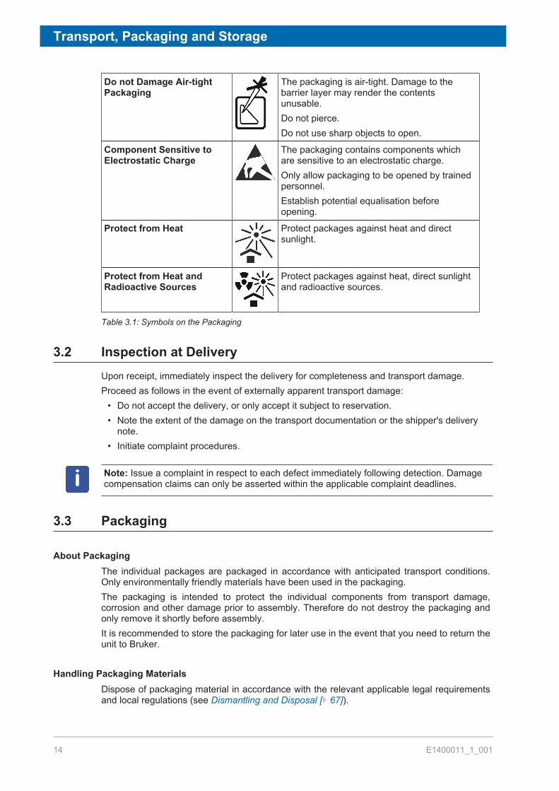
Do not Damage Air-tightPackaging
The packaging is air-tight. Damage to thebarrier layer may render the contentsunusable.Do not pierce.Do not use sharp objects to open.
Component Sensitive toElectrostatic Charge
The packaging contains components whichare sensitive to an electrostatic charge.Only allow packaging to be opened by trainedpersonnel.Establish potential equalisation beforeopening.
Protect from Heat Protect packages against heat and directsunlight.
Protect from Heat andRadioactive Sources
Protect packages against heat, direct sunlightand radioactive sources.
Table 3.1: Symbols on the Packaging
3.2 Inspection at DeliveryUpon receipt, immediately inspect the delivery for completeness and transport damage.Proceed as follows in the event of externally apparent transport damage:
• Do not accept the delivery, or only accept it subject to reservation.• Note the extent of the damage on the transport documentation or the shipper's delivery
note.• Initiate complaint procedures.
Note: Issue a complaint in respect to each defect immediately following detection. Damagecompensation claims can only be asserted within the applicable complaint deadlines.
3.3 Packaging
About PackagingThe individual packages are packaged in accordance with anticipated transport conditions.Only environmentally friendly materials have been used in the packaging.The packaging is intended to protect the individual components from transport damage,corrosion and other damage prior to assembly. Therefore do not destroy the packaging andonly remove it shortly before assembly.It is recommended to store the packaging for later use in the event that you need to return theunit to Bruker.
Handling Packaging MaterialsDispose of packaging material in accordance with the relevant applicable legal requirementsand local regulations (see Dismantling and Disposal [} 67]).

Transport, Packaging and Storage
E1400011_1_001 15
3.4 Storage
Storage of the PackagesStore the packages under the following conditions:
• Do not store outdoors.• Store in dry and dust-free conditions.• Do not expose to aggressive media.• Protect against direct sunlight.• Avoid mechanical shocks.• Storage temperature: 15 to 35 °C.• Relative humidity: max. 60%.• If stored for longer than 3 months, regularly check the general condition of all parts and
the packaging. If necessary, top-up or replace preservatives.
Note: Under certain circumstances, storage instructions may be affixed to packages whichexpand the requirements specified here. Comply with these accordingly.

Transport, Packaging and Storage
16 E1400011_1_001

Technical Data
E1400011_1_001 17
4 Technical Data
4.1 General Information
No. Series Type Weight(kg)
Length(cm)
Width(cm)
Heigth(cm)
1 mq-Series mq60 145 65 75 33
2 mq-Series mq40 145 65 75 33
3 mq-Series mq20 Airgap 33 mm* 145 65 75 33
4 mq-Series mq20 Airgap 25 mm* 135 65 75 33
5 mq-Series mq20 Toothpaste Analyzer 105 65 75 33
6 mq-Series mq10 135 65 75 33
7 mq-Series mq7.5 155 65 75 33
8 mq-Series mq20 Airgap 33 mm with PGU* 170 65 100 33
9 mq-Series mq20 Airgap 25 mm with PGU* 160 65 100 33
10 mq-Series mq10 with PGU 160 65 100 33
11 mq-Series mq7.5 with PGU 180 65 100 33
12 mq-Series PGU only 25 65 25 33
Table 4.1: Technical Data: General Information
All specifications above are without the PC. Weights and dimensions apply to theinstruments, not to the packaged systems.* For configurations with a high temperature probe, an additional table is used. However, thistable is not considered in the specifications provided.

Technical Data
18 E1400011_1_001
4.2 Connection Values
Electrical
No. Series Type ND/NE/NF
Voltage/VAC
ApparentPowerConsumptionMaximum/VA
CircuitProtection
Frequency/Hz
1 mq-Series
mq60 NF 100-240 300/250 3.15 AT(2 pieces)
50-60
2 mq-Series
mq40 NF 100-240 300/250 3.15 AT(2 pieces)
50-60
3 mq-Series
mq20 Airgap 33mm*
NF 100-240 300/250 3.15 AT(2 pieces)
50-60
4 mq-Series
mq20 Airgap 25mm*
NF 100-240 300/250 3.15 AT(2 pieces)
50-60
5 mq-Series
mq20ToothpasteAnalyzer
NF 100-240 300/250 3.15 AT(2 pieces)
50-60
6 mq-Series
mq10 NF 100-240 300/250 3.15 AT(2 pieces)
50-60
7 mq-Series
mq7.5 NF 100-240 300/250 3.15 AT(2 pieces)
50-60
8 mq-Series
mq20 Airgap 33mm with PGU*
NF 100-240*** 300/250 3.15 AT(2 pieces)
50-60
9 mq-Series
mq20 Airgap 25mm with PGU*
NF 100-240*** 300/250 3.15 AT(2 pieces)
50-60
10 mq-Series
mq10 with PGU NF 100-240*** 300/250 3.15 AT(2 pieces)
50-60
11 mq-Series
mq7.5 with PGU NF 100-240*** 300/250 3.15 AT(2 pieces)
50-60
12 mq-Series
PGU only NF 110/230factory set
300 2.5 A(2 pieces)
50-60
Table 4.2: Electrical Connection Values
Technical Data
E1400011_1_001 19
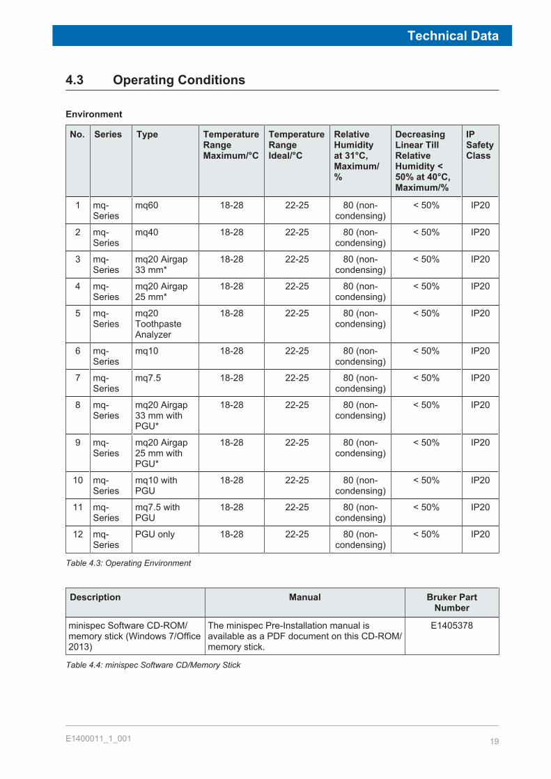
4.3 Operating Conditions
Environment
No. Series Type TemperatureRangeMaximum/°C
TemperatureRangeIdeal/°C
RelativeHumidityat 31°C,Maximum/%
DecreasingLinear TillRelativeHumidity <50% at 40°C,Maximum/%
IPSafetyClass
1 mq-Series
mq60 18-28 22-25 80 (non-condensing)
< 50% IP20
2 mq-Series
mq40 18-28 22-25 80 (non-condensing)
< 50% IP20
3 mq-Series
mq20 Airgap33 mm*
18-28 22-25 80 (non-condensing)
< 50% IP20
4 mq-Series
mq20 Airgap25 mm*
18-28 22-25 80 (non-condensing)
< 50% IP20
5 mq-Series
mq20ToothpasteAnalyzer
18-28 22-25 80 (non-condensing)
< 50% IP20
6 mq-Series
mq10 18-28 22-25 80 (non-condensing)
< 50% IP20
7 mq-Series
mq7.5 18-28 22-25 80 (non-condensing)
< 50% IP20
8 mq-Series
mq20 Airgap33 mm withPGU*
18-28 22-25 80 (non-condensing)
< 50% IP20
9 mq-Series
mq20 Airgap25 mm withPGU*
18-28 22-25 80 (non-condensing)
< 50% IP20
10 mq-Series
mq10 withPGU
18-28 22-25 80 (non-condensing)
< 50% IP20
11 mq-Series
mq7.5 withPGU
18-28 22-25 80 (non-condensing)
< 50% IP20
12 mq-Series
PGU only 18-28 22-25 80 (non-condensing)
< 50% IP20
Table 4.3: Operating Environment
Description Manual Bruker PartNumber
minispec Software CD-ROM/memory stick (Windows 7/Office2013)
The minispec Pre-Installation manual isavailable as a PDF document on this CD-ROM/memory stick.
E1405378
Table 4.4: minispec Software CD/Memory Stick

Technical Data
20 E1400011_1_001
NormaI environmental conditions (CAN/CSA 61010-1-12; IEC 61010-1: 2010; ANSI/UL 61010-1)• Indoor use only.• Maximum operation altitude: 2000 m.• Ideal operating temperature: 22-25 °C. Minimum operating temperature: 18°C maximum
operating temperature: 28°C humidity (non-condensing): 20-80%.• Maximum relative humidity 80% for temperatures up to 31 or decreasing linearly to 50%
relative humidity at 40 °C.• MAINS supply voltage fluctuations up to ±10% of the nominal voltage.• TRANSIENT OVERVOLTAGES up to the levels of OVERVOLTAGE CATEGORY II.• Pollution degree 2.• Protection class IP20.
4.4 Rating PlateThe rating plate is located at the power input and includes the following information:
Figure 4.1: The minispec MQ-Series Rating Plate

Introduction
E1400011_1_001 21
5 IntroductionThe minispec is a benchtop Nuclear Magnetic Resonance (NMR) analyzer for detection ofhydrogen (1H), fluorine (19F), and other abundant NMR-active nuclei. Its common applicationis in polymer, chemical and agrifood industry quality control and quality assurance (QC/QA),where it is routinely used for fast, reproducible and non-destructive analysis. The minispec isalso used for a diverse range of applications in research and development (R&D) laboratoriesin industry, universities, and medical research facilities.This manual provides instructions on proper installation of the minispec and an introduction tothe use of the minispec hardware and software. Topics covered include:
• Installation of hardware (section Installation of the minispec mq-Series)• Installation of software for WindowsTM 7 32-bit/64-bit (section Software Installation)• Configuration (section Configuration of the Software, the Welcome Box)• Proper operation of the system (section General Measurement Handling)
Once installation and configuration is complete, it is beneficial to read the softwareintroduction to familiarize yourself with the minispec capabilities. For installation proceduresyou may also refer to the latest version of the Pre-Installation manual (booklet).The software functions (NF systems) are discussed step by step, using pictures to helpfamiliarize the user with all of the accessible minispec features (sections The minispecStandard Windows [} 39] and The minispec Menu Functions [} 41]).Users who wish to program the minispec should refer to the chapter The Experiment EditorExpSpel for the mq-Series [} 61]). Finally, for a better understanding of the principlesinvolved, an introduction to the basics of NMR is provided in section Basic NMR Principles[} 63].
Figure 5.1: The minispec mq Magnet Unit (left) and Electronic Control Unit (right)
The minispec.exe software is the standard software running on all mq-Series systems (NFsystems) and is described in this manual.The minispec mq-Series analyzers can be operated with the minispec Plus software, whichis delivered optionally with the system. This is a standalone software package and there areseparate manuals available on the minispec software CD that explain the operation:
• minispec Plus Administration
Introduction
22 E1400011_1_001
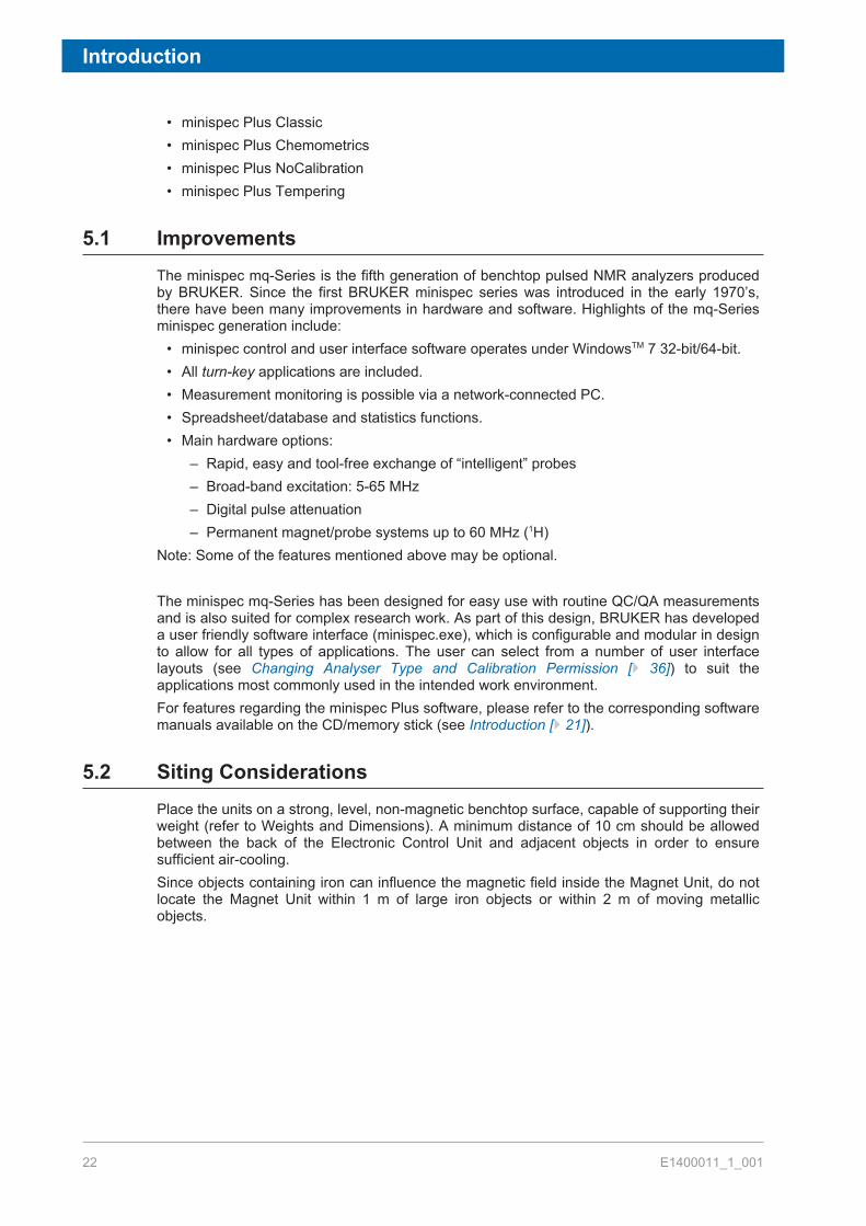
• minispec Plus Classic• minispec Plus Chemometrics• minispec Plus NoCalibration• minispec Plus Tempering
5.1 ImprovementsThe minispec mq-Series is the fifth generation of benchtop pulsed NMR analyzers producedby BRUKER. Since the first BRUKER minispec series was introduced in the early 1970’s,there have been many improvements in hardware and software. Highlights of the mq-Seriesminispec generation include:
• minispec control and user interface software operates under WindowsTM 7 32-bit/64-bit.• All turn-key applications are included.• Measurement monitoring is possible via a network-connected PC.• Spreadsheet/database and statistics functions.• Main hardware options:
– Rapid, easy and tool-free exchange of “intelligent” probes– Broad-band excitation: 5-65 MHz– Digital pulse attenuation– Permanent magnet/probe systems up to 60 MHz (1H)
Note: Some of the features mentioned above may be optional.
The minispec mq-Series has been designed for easy use with routine QC/QA measurementsand is also suited for complex research work. As part of this design, BRUKER has developeda user friendly software interface (minispec.exe), which is configurable and modular in designto allow for all types of applications. The user can select from a number of user interfacelayouts (see Changing Analyser Type and Calibration Permission [} 36]) to suit theapplications most commonly used in the intended work environment.For features regarding the minispec Plus software, please refer to the corresponding softwaremanuals available on the CD/memory stick (see Introduction [} 21]).
5.2 Siting ConsiderationsPlace the units on a strong, level, non-magnetic benchtop surface, capable of supporting theirweight (refer to Weights and Dimensions). A minimum distance of 10 cm should be allowedbetween the back of the Electronic Control Unit and adjacent objects in order to ensuresufficient air-cooling.Since objects containing iron can influence the magnetic field inside the Magnet Unit, do notlocate the Magnet Unit within 1 m of large iron objects or within 2 m of moving metallicobjects.
Introduction
E1400011_1_001 23
CAUTIONAccident or material damage hazard from falling or tilting instrumentInstrument may fall down or tilt during installation, retrofitting, dismantling, or while movingon a cart.u Use the carrying handles during lifting.u When a table or cart is used, it should meet the requirements in the site planning guide.u The instrument should be secured to the cart or table.
5.2.1 Environmental Considerations
The minispec should be used in areas free from direct sunlight, heat sources and powercables.A constant temperature is important for field stability and accurate reproduction ofmeasurement results.The usual magnet temperature (if not indicated different) is 40°C for all instruments.These temperatures have been selected because they are well above the expected ambient(laboratory) temperatures and therefore allow accurate tempering of the minispec unit.Tempering of the magnet and the console electronics is accomplished with a closed cyclezero maintenance, air ventilation system, so that no external air is ventilated through theconsole or the Analyzer Unit.In some factory environments where dust may be a problem, it may be desirable to house theminispec computer in a clean room or ventilated housing, which is protected from dust. TheAnalyzer Unit can be placed nearby at a location more convenient for process personnel.The instrument contains strong magnetic fields, some of which extend beyond the Analyzerunit housing (see stray field diagram page 14-17). These pose no danger to routine users,but are hazardous to persons with heart pacemakers or other medical implantations.

Introduction
24 E1400011_1_001
WARNINGRisk to life due to high magnetic fieldsA magnetic field of more than 0.5 mT (5 Gauss) is life-threatening for people withpacemakers or active metal implants. Exposure to more than 8 T can cause damage tohealth. Duration of exposure (8 h/day) above the limit of 200 mT can cause damage tohealth. Ferromagnetic tools in the magnetic field are significantly hazardous. Disks andelectronic devices may be damaged.u Mark the magnetic field of more than 0.5 mT (5 Gauss) before start up.u Keep people with active medical implants or heart pacemakers away from the 0.5 mT
(5 Gauss) area.u The permanent workplace of employees must be outside the 0.5 mT (5 Gauss) area.u Do not stay or work at magnetic fields of more than 8 T.u Prevent exposure of more than 200 mT for more than 8 h/day.u Keep disks, credit cards and electronic devices away from the identified area.u Do not use ferromagnetic tools or items within the identified area.u Only use non-ferromagnetic transportation dewars or pressure cylinders for the
cryogenic agents.u Only use non-ferromagnetic ladders or steps.u Remove magnetic items (jewelry, watches, pens etc.) before carrying out maintenance
work.
WARNINGDanger of injury or material damage due to strong magnetic fields!Injury or material damage may result due to the strong magnetic fields that can draw metallicobjects towards the magnet.u DO NOT locate the instrument next to large iron-containing objects or near moving
metallic objects.u DO NOT place any iron-containing object on the minispec magnet unit. Be aware that
the magnetic field can erase magnetic recording media such as computer diskettes orcredit cards.
u DO NOT place these items or clothing containing these items on the magnet unit.u Leave the dust cover on the probe canal when the instrument is not in use.
5.3 Installation of the minispec mq-SeriesIn general, the minispec mq-Series consists of three units:
• Magnet Unit, containing the magnet system and the probe assembly• Electronic Control Unit with the NMR electronics• Standard PC user interface for measurement control, data processing, etc.

Introduction
E1400011_1_001 25
Figure 5.2: The minispec Magnet Unit (left) and Electronic Control Unit (right).
A number of optional accessories can be added and adapted for use: Gradient Unit (forpulsed field gradient experiments), electronic balances, auto sampler, temperature controlbaths and variable temperature control units, etc.
5.3.1 Unpacking the System
When unpacking the instrument ensure that all components listed in the packing list are partof the delivery.
CAUTIONDanger of property damage due to improper handling.The shipping container must remain in an upright position at all times. It has twocompartments separated by a wooden plate: an upper part, which contains the ElectronicControl Unit, and a lower part containing the Magnet Unit. The magnet unit is secured to theshipping container from below with four bolts.u DO NOT tilt the container when removing these bolts.
CAUTIONAccident or material damage hazard from falling or tilting instrumentInstrument may fall down or tilt during installation, retrofitting, dismantling, or while movingon a cart.u Use the carrying handles during lifting.u When a table or cart is used, it should meet the requirements in the site planning guide.u The instrument should be secured to the cart or table.
Introduction
26 E1400011_1_001
CAUTIONRisk of injury from lifting heavy objects.The unit is very heavy and may lead to injury when lifting.u Do not attempt to lift the unit over the edge of the carton, remove the carton first.u Do not attempt to lift the unit on your own or without necessary precaution against
injury.u Use a hoist if available.u Follow the step-by-step instructions in the installation section of this manual.
To unpack the system:1. Use a 13 mm wrench to remove the four bolts from the bottom of the container.2. Remove the shipping straps and open the container.3. Remove the packing material from around the Electronic Control Unit.4. Remove the Electronic Control Unit from the container, together with the wooden plate
that it is mounted on (do not tip!). Remove the four mounting bolts from below the plateusing a 13 mm wrench. Once loose, remove the Electronic Control Unit and set it in a safelocation.
5. Remove the packing material from around the Magnet Unit. Remove the retaining screwsor nails from the bottom of the wooden pallet and detach the shipping carton.
6. While keeping it level, carefully lift the Magnet Unit from the pallet using the handles oneither side, and place it on a sturdy cart or benchtop.
When using a hoist, make sure the straps are capable of carrying the magnet´s weight andare attached in such a way that the magnet cannot fall, slip, topple or turn while beingcarried.
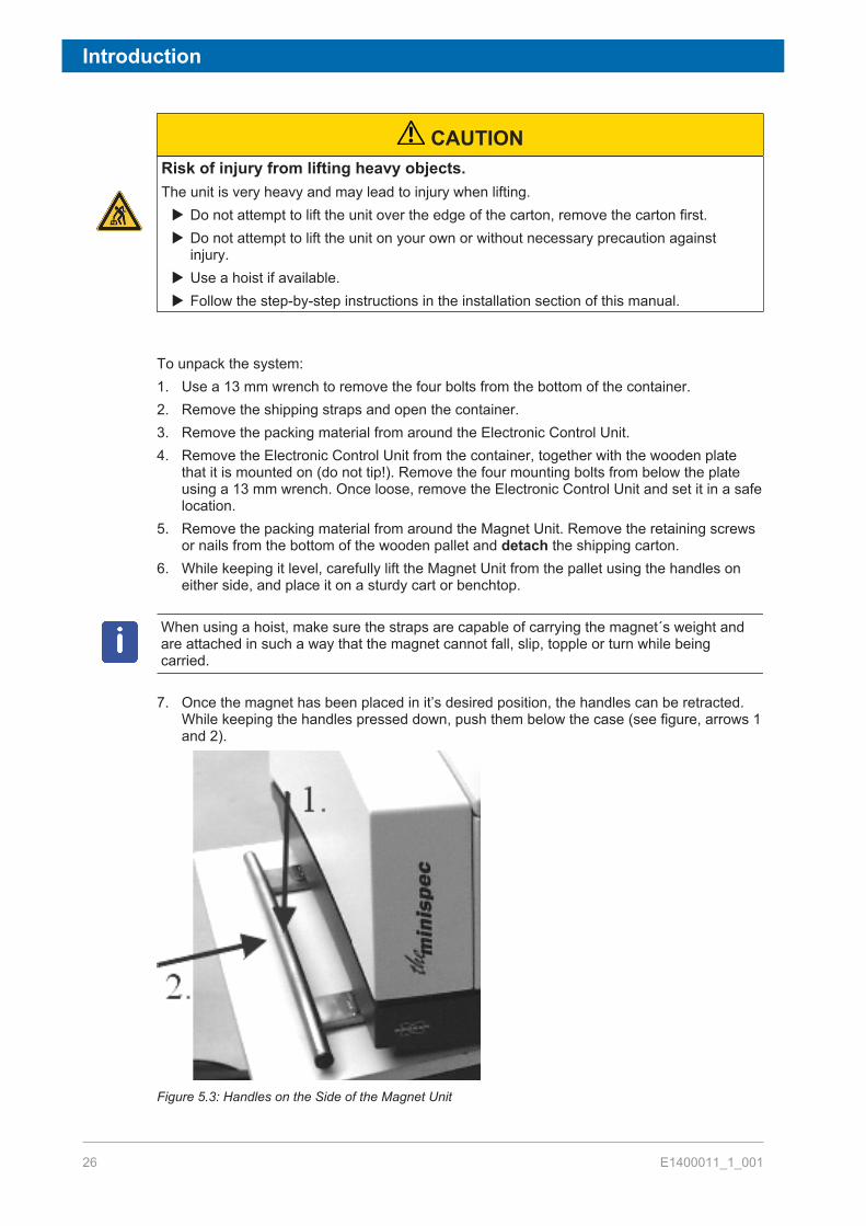
7. Once the magnet has been placed in it’s desired position, the handles can be retracted.While keeping the handles pressed down, push them below the case (see figure, arrows 1and 2).
Figure 5.3: Handles on the Side of the Magnet Unit

Introduction
E1400011_1_001 27
8. Remove and retain the clear plastic dust covers from each component of the minispec andinspect them for damage.
9. If either unit appears to be damaged, contact your BRUKER representative immediately.Due to accessories, consumables or optional units packaging may vary. Bruker will makeevery effort to deliver the instrument damage free. Therefore, packaging needs to be adaptedto the specific customer order. Due to safety regulations, the system may be packed withadditional shielding elements or may be declared as dangerous goods.
5.3.2 Electronic Control and the Magnet Unit Connections
The connectors are located on the bottom of the back planes. Connect the two units asshown in the figures below:
Figure 5.4: Electronic Control and Magnet Units
1. Main power input. 3 to 5. Connections to the units.2. Ethernet connection.
Here is an expanded view of the connections:
Figure 5.5: Back Planes of the Electronic Control Unit (top) and Magnet Unit (bottom)
1. Mains Power Input 4. Interface to Gradient Unit2. Ethernet (10 Base T) Connection 5. Interface to Electronic Control Unit3. Interface to Magnet Unit 6. Interface to Gradient Unit
Introduction
28 E1400011_1_001
5.3.3 Electronic Control, Magnet and Gradient Unit Connections
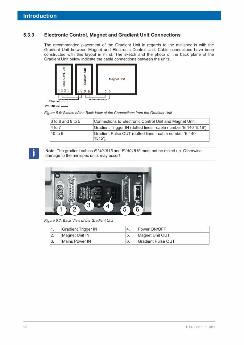
The recommended placement of the Gradient Unit in regards to the minispec is with theGradient Unit between Magnet and Electronic Control Unit. Cable connections have beenconstructed with this layout in mind. The sketch and the photo of the back plane of theGradient Unit below indicate the cable connections between the units.
Figure 5.6: Sketch of the Back View of the Connections from the Gradient Unit
3 to 8 and 9 to 5 Connections to Electronic Control Unit and Magnet Unit.4 to 7 Gradient Trigger IN (dotted lines - cable number ‘E 140 1516‘).10 to 6 Gradient Pulse OUT (dotted lines - cable number ‘E 140
1515‘).
Note: The gradient cables E1401515 and E1401516 must not be mixed up. Otherwisedamage to the minispec units may occur!
1 2 3 4 5 6Figure 5.7: Back View of the Gradient Unit
1. Gradient Trigger IN 4. Power ON/OFF2. Magnet Unit IN 5. Magnet Unit OUT3. Mains Power IN 6. Gradient Pulse OUT

Introduction
E1400011_1_001 29
5.4 Specifications mq-Series
5.4.1 Weights and Dimensions
Electronic ControlUnit
Magnet Unit Gradient Unit(optional)
Dimensions (W x H xD) in cm
25 x 33 x 65 47 x 33 x 65 25 x 33 x 65
Weight (kg) 20 depends on magnet 25
5.4.2 Electrical Specifications
minispec mq-Series NF systems:The instrument’s E-Box is specified for the following mains voltages (wideline):
• Input voltage range: 100 – 240 V AC 50/60 Hz.• Fuse rating mq-Series NF: 2 x 3.15 AT.
The gradient unit is specified as follows:• Input voltage range: Either 220-240V or 110-120V (50/60 Hz) factory set.• Fuse rating: 2 x 2.5 A.
GroundingGrounding is vital for the safe operation of the instrument. Never operate with the groundingconductor disconnected. If the local wiring does not provide a ground, an earth-to-chassisconnection must be added at the user’s location.
Note: Since the input voltage may be unstable in a laboratory environment, it isrecommended to connect the minispec to a separate circuit that is not used by any otherequipment. Furthermore, a voltage stabilizer or UPS may be required to avoid instrumentinstabilities or other unexpected system behavior caused by a fluctuating input voltage.
Introduction
30 E1400011_1_001
5.5 Interpretation of the LEDsUsers receive continuous indication of the status of the different units in the form of lightemitting diodes (LEDs), which are built into the front panel of the units.
5.5.1 mq-Series Systems
Electronic Control UnitRight LED, connection status indicator:
• ON (green): PC communication to the Electronic Control Unit is OK.• OFF: No communication between the Electronic Control Unit and the PC.
Left LED, status indicator:• ON (green): The Electronic Control Unit is powered on and working.• OFF: The Electronic Control Unit is not working.
Magnet UnitRight LED, indicates the magnet temperature status:
• RED: Pre-heating.• YELLOW: Transition to normal heating/temperature fine adjustment.• GREEN: Temperature is OK.
Left LED, connection status indicator:• ON (green): Communication between the Electronic Control Unit and Magnet Unit is OK.• OFF: No communication between the Electronic Unit and Magnet Unit.
Gradient Unit (optional)Right LED:
• ON (green): Gradient Unit is on standby.• OFF: Gradient pulse execution.
Left LED, connection status indicator:• ON (green): The gradient unit is powered on and working.• OFF: The gradient unit is not working.

Introduction
E1400011_1_001 31
5.6 Calibration Samples Hatch and Probe ExchangeThe Magnet Unit cover has two outer hatches or doors.
• The first one is on the front panel of the unit and can be used to contain the calibrationsamples. Pressing on the upper part of the hatch will unlock and open it.
• The second is the top hatch, which allows access into the minispec magnet compartmentand permits quick and tool-free exchange of probes.
To replace a probe the hatch at the top of the Magnet Unit must be opened:1. Release the front hatch to expose the red button in the front of the unit.2. Press the red button to release the top latch and open the hatch as far as it will go.3. A second hinged lid, blue in color, will become visible. Lift this lid up and lean it against
the outer hatch.
WARNINGDanger of injury due to falling lidThe hinged lids may close unexpectedly during probe exchange causing injury to hands orfingers.u Ensure that the gas spring on the outer lid is operating correctly.u The blue inner hinged lid does not have a gas spring, use extreme care when
exchanging the probe assembly.
4. The probe assembly is fixed with two quick-release fasteners. To release the fasteners,lift up the D-rings until they snap into a vertical position, then use them to rotate thefastener posts until released (refer to the figure below).
5. While grasping the D-rings, carefully pull upward to loosen the preamplifier connectionunder the mounting plate, than raise the assembly (mounting bar with probe andpreamplifier attached) out of the magnet gap.
Figure 5.8: Ring of the Quick-Release Fastener (left) and the Raising of the Probe Assembly (right)
1. Rings2. Rotating the rings.
To open the fasteners, turn the rings (1) upward and rotate them (2)

Introduction
32 E1400011_1_001
Replace the assembly by following the instructions in reversed order.Intelligent probes were developed for the minispec mq-Series. When you exchange a probe,the software will read the most important parameters (pulse length, resonance frequency)from the probe itself. The software will prompt the user to confirm the settings. Aftertemperature stabilization it is recommended to run the Daily Check procedure. In certaincases a fine tuning by running Update Settings (see The minispec Menu [} 46]) is beneficial.
Getting Started
E1400011_1_001 33
6 Getting StartedIn general, minispec systems which are delivered with a personal computer already have theminispec software installed. In this case, the user can skip the software installationinstructions (see Software Installation [} 33]) and proceed to the instructions on initializationof the PC-to-minispec connection (see Connecting the PC to the minispec for the First Time[} 34]).When a user provides their own personal computer, or if software needs to be reinstalled foruse with the minispec, refer to the installation instructions below.The middle sections of this chapter describe how the user can configure the software(minispec.exe) by selecting the analyzer type from among the list of pre-set types (see Wake-up State of the minispec.exe Software [} 35]) and by setting the user level e.g. allowcalibrations or only measurements (section Configuration of the Software, the Welcome Box).Later, a short introduction provides general instructions on how to run measurements (sectionGeneral Measurement Handling).A list of all standard applications is added at the end of the chapter (section List of StandardApplications).
6.1 Software InstallationExecute the following steps only if the PC has not been pre-configured for theminispec.
1. Insert the installation CD in your drive, or when using a memory stick, insert the stick in aUSB port.
2. Open the Windows EXPLORER and check the media for a ReadMe.txt file. If aReadMe.txt file is available, follow the instructions provided in this file.
3. If not, execute the Setup file with a double click or select the setup entry with the rightmouse button and select Open in the displayed menu.
4. Follow the instructions in the Setup program.´ The Setup program copies the files into the folder you specify during the setup
procedure.5. To start the minispec.exe software, double click on the minispec.exe file in the main
folder. Alternatively, you can create a shortcut on the Windows desktop to the fileminispec.exe.
With the first start up, the configuration of the minispec software (minispec.exe) is set to theQC-Analyzer. To change the settings refer to the section Wake-up State of the minispec.exeSoftware [} 35].Optionally, the mq-Series instruments may be operated with the minispec Plus software, withthe above described minispec.exe software running in the background as an acquisitionserver. Systems that are equipped with minispec Plus software will install this additionalprogram automatically. The manual minispec Plus Administration, together with the otherminispec Plus manuals, provide further details. These can be found on the minispec softwareCD/memory stick in the folder Documentation.Systems equipped with minispec Plus software do not necessarily need to start theminispec.exe software before using minispec Plus. If the system is properly installed (refer tothe corresponding minispec Plus manual), then minispec Plus can be opened without first

Getting Started
34 E1400011_1_001
opening the minispec.exe software. However in some cases it might be useful to first run theminispec.exe software to make sure there is a proper network connection from PC to theminispec, then afterwards switch to minispec Plus program.Please note that for proper installation of minispec Plus software further softwarerequirements may apply, refer to the corresponding minispec Plus manual for details.
6.2 Connecting the PC to the minispec for the First Time
6.2.1 Direct Cable Connection
1. If the software is running (e.g. after installation), then exit the minispec software.2. Connect the PC to the minispec using the blue crossed-wire UTP-cable, which is
delivered with the minispec (10-Base-T with RJ45 connectors, see the figures in thesection Installation of the minispec mq-Series [} 24]).
3. Power ON the instrument and computer.4. If not already installed, use the Network entry in the Windows Control Panel to install a
TCP/IP protocol on your PC. The exact procedure for adding the TCP/IP protocoldepends on the Windows version that is used, refer to the Windows softwaredocumentation for a detailed description.
5. Select TCP/IP ‘Properties’. Confirm or enter the following entries: IP-address:192.168.1.2 Subnet-mask: 255.255.255.0´ If other values are defined, alter them accordingly. Re-boot your computer.
6. Start the minispec software on the PC.´ Some program information will be displayed for a short time, after which a Welcome
Box will be displayed. Entries in the select boxes indicate how the PC will attempt toconnect to the minispec console and what applications will be loaded.
7. Connect to the minispec electronic unit (mq-Series) using the indicated default serialnumber NF0000 by clicking OK in the displayed Welcome Box.´ Communication is attempted from the PC software over the TCP/IP to the CPU/
Ethernet controller in the console at the default IP address 192.168.1.1. Connection isindicated at the top status line with the message, for example, Connected to NF3826.The IP address of the console will be displayed in a small box on the bottom edge ofthe program window.
´ If the connection with the default serial number NF0000 cannot be established, re-tryusing the IP address ‘192.168.1.1’ instead of the default ‘NF0000’ from the Welcomebox settings.
8. If the connection still fails, make sure the cable is a crossed-wire twisted pair cable andthat it is connected properly.´ If connection still does not succeed, then the problem may be due to incorrect IP
addresses or Subnet mask for the PC or the minispec. Normally the minispec consoleis shipped with the default IP address set to 192.168.1.1 and a subnet mask of255.255.255.0. However, in some circumstances the minispec console may be set toother values (e.g. if a minispec has already been installed on a network, whereasanother IP address will be needed, or a PC is being exchanged, or the software had tobe reloaded on a fresh hard disk).
9. If a connection cannot be established and the setting of the console IP address issuspect, the Internet web browser page contains information (see Help menu) on how toreset the IP address, however please check with your local Bruker support for moredetails, if necessary.
Getting Started
E1400011_1_001 35
6.2.2 Connection to a Network
A direct connection of the PC and minispec using the blue crossed-wire UTP cable isrecommended. When a connection to a network is desired, a second network car will help toestablish such a connection. The second network card allows the PC to be connected to thenetwork, while the direct connection from the minispec to the PC is still in place.
Notes:In case of connection problems:
1. Double check the PC IP address and other network related entries.2. Recheck if straight-through twisted pair cables are used, in this case they should not be
used.´ Now, whenever you start the minispec software, contact to the minispec will be
established automatically.
6.3 Wake-up State of the minispec.exe SoftwareWhen the software starts, a general dialog is displayed concerning the software version andthe copyright. Then a Welcome Box opens and displays information about the configurationof the system. The wake-up configuration is the configuration used with your lastminispec session. To continue with the same settings and start the minispec software clickOK. If you want to change the settings refer to the next section, Configuration of theSoftware, the Welcome Box.
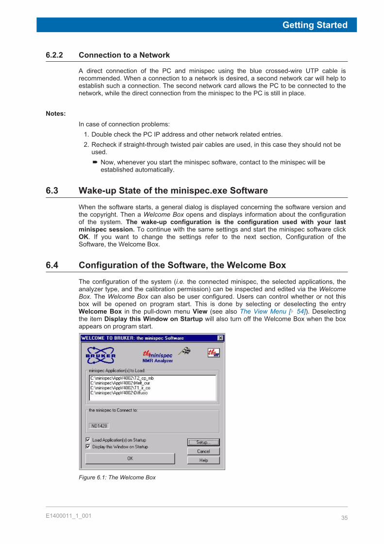
6.4 Configuration of the Software, the Welcome BoxThe configuration of the system (i.e. the connected minispec, the selected applications, theanalyzer type, and the calibration permission) can be inspected and edited via the WelcomeBox. The Welcome Box can also be user configured. Users can control whether or not thisbox will be opened on program start. This is done by selecting or deselecting the entryWelcome Box in the pull-down menu View (see also The View Menu [} 54]). Deselectingthe item Display this Window on Startup will also turn off the Welcome Box when the boxappears on program start.
Figure 6.1: The Welcome Box
Getting Started
36 E1400011_1_001
Several symbols, entries and buttons are displayed in the Welcome Box:• Applications to be loaded (path and file name in the white field).• Serial number of the minispec to be connected to (here: ND1428).• Type of analyzer (here: NMR Analyser).• The calibration permission is symbolized using a flag.
The wake-up application can also be selected for future program start-up. When the user hasfinished with the selections, the OK button is used to start the software.To change the configuration, press the Setup button. The configuration is protected by asimple log-in mechanism.
• First log-in: Press the Setup button. Enter and confirm a password. The password will besaved automatically and you will need it for every subsequent log-in. Handle thepassword carefully! Only users who have permission to make changes to calibrationsand software configurations should have knowledge of the password. If passwordprotection is not desired, simply click OK or <Enter> without entering a password whenthe password entry box appears and confirm this in the following box.
• Later log-in: Press the Setup button and enter the password or click twice on OK ifpassword protection is not used.
6.4.1 Selecting Applications and Connections
If you click Setup in the Welcome Box you will open the configuration level of the welcomedialogue. This password procedure is described in the section above. Up to 20 applicationscan be selected simultaneously for every analyzer type (except for the SFC-Analyzer whereonly one application is allowed) to be loaded at the startup. To add applications to the list useBrowse... to access a file selector box or use Delete to remove applications from the list.To choose another minispec, use the Select button in the Select minispec to connect to field.
6.4.2 Changing Analyser Type and Calibration Permission
Use the Customize button in the configuration level (see Selecting Applications andConnections) to open a dialog box. In this window the analyzer type and the calibrationpermission can be selected by checking the corresponding select box with a mouse click.Two options, RELAXATION TIME and the NMR analyzer, require a license number tooperate. The number will be requested while connecting to the minispec (after you click theOK button in the Welcome Box) when one of these options is selected. If ordered with thesystem, this license number is issued on the first page of this booklet, labeled as the ExpSpellicense number.
6.5 General Measurement HandlingThe most important commands that are used to control measurements are: the Runcommand to start a measurement and the Stop command to interrupt a measurement inprogress. Measurements can be started through a number of commands and by activating anumber of software icons or features. For example, the general Run command can be startedthrough the RUN button from the top icon bar or bottom button panel, from the pull-downmenu minispec, or by simply pressing <Enter>. If the user has been given permission toperform sample calibrations, then the Calibrate command is available. Other forms ofmeasurement are available for convenience, including a repetitive run command and acommand to detect the raw NMR signal.
Getting Started
E1400011_1_001 37
The following sequence of actions is generally followed in preparation for measurements:1. Turn on your minispec and your PC (if they were turned off).
´ Wait until the console CPU/Ethernet process boots, as indicated by the lighting of theleft (green) LEDs located on the front edge of the magnet and console.
2. Connect the PC to the minispec you want to use and configure the software, e.g. chooseapplications or an analyzer type.´ Wait until the right LED on the magnet unit is green. This can take up to 3 hours to
ensure optimum temperature stability. If the system was turned off for several days, orit was moved to another place, insert the calibration sample with 0% solid content andrun the Update Settings routine.
´ If you want to perform SFC (Solid Fat Content) determinations and the analyzer typeis not set to SFC-Analyzer, then make sure the option SFC is checked in theInstrument Settings submenu of the pull-down menu the minispec before you startthe Update Settings.
3. Depending on the application you use (see your application description), start yourmeasurement or calibration with the Run or Calibrate command.
The software includes full automatic tuning routines to adjust the measurement settings, forexample pulse length, receiver gain, and magnetic field. You can tune these settingsperiodically to ensure the instrument validity over time.The Daily Check command should be executed once a day to check the most importantinstrument settings and hardware functionality.Every 24 hours, a yellow field on the right of the display will automatically indicate the needfor another Daily Check. Running the Daily Check periodically ensures conformance toGood Laboratory Practice (GLP).For minispec.exe software (version 2.8 and higher) as delivered in 2015, an applicationversion control has been implemented, checking the compatibility of the ExpSpel application,with other software components, like firmware and FPGA.Customers using non-compatible versions will get error messages when starting theapplications. The error messages may be ignored, thus running the application with anincorrect combination of software components. In such a case, the accuracy of the results isquestionable.
6.6 List of Standard ApplicationsWith the mq-Series minispec, nearly all standard applications are executable without anylicense number. The most common applications are listed below:
• Solid fat content determination in fat compositions using Solid Fat Content (ratio)calibration standards with certificates.
• Oil/fat & moisture in:– Chocolate.– Cocoa powder.– Milk powder.
• Oil & Moisture in:– Seeds.– Nuts.– Olives.
• Droplet size analysis in emulsions (protected).• Xylene soluble content in polypropylene.

Getting Started
38 E1400011_1_001
• Additive determinations in polymers.• Polybutadiene/polystyrene content in SBR.• Density in polyethylene.• Crystallinity determinations in polymers.• Spin-finish determinations (OPU and WPU) on textile fibers.• Total hydrogen content determinations in hydrocarbons like:
– Jet fuel.– Other distillates.
• Oil content determinations in wax/paraffin.• Oil content determination in:
– Sulfur.– Other chemical powders.
• Relaxation time analysis on contrast agents/liquids.• Moisture content analysis on powders and tablets.• Contactless weighting of powders and tablets.• Fluorine content in toothpaste.
The minispec software for mq-Series systems comprises various minispec Application Pools(like for instance Application Pool Ratio or others). Each pool contains many applicationswhich are ready to be executed by the operator. For the list of minispec standard applicationslisted above, there are suitable application programs in the Application Pools that allow theuser to run those standard applications. Only the droplet size applications are currentlyprotected via a license number mechanism (please contact your local Bruker office fordetails).Separate documents describing the various minispec Application Pools exist and can befound on the minispec Software CD/memory stick in the folder Documentation.Use of the applications in the various Application Pools is described in the minispecApplication Manual – also located in the Documentation folder on the CD/memory stick.
The minispec Standard Windows
E1400011_1_001 39
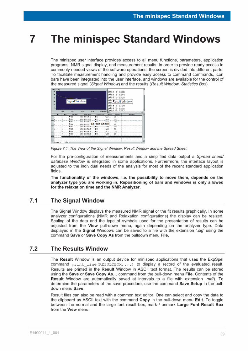
7 The minispec Standard WindowsThe minispec user interface provides access to all menu functions, parameters, applicationprograms, NMR signal display, and measurement results. In order to provide ready access tocommonly needed views of the software operations, the screen is divided into different parts.To facilitate measurement handling and provide easy access to command commands, iconbars have been integrated into the user interface, and windows are available for the control ofthe measured signal (Signal Window) and the results (Result Window, Statistics Box).
Figure 7.1: The View of the Signal Window, Result Window and the Spread Sheet.
For the pre-configuration of measurements and a simplified data output a Spread sheet/database Window is integrated in some applications. Furthermore, the interface layout isadjusted to the individual needs of the analysis for most of the recent standard applicationfields.The functionality of the windows, i.e. the possibility to move them, depends on theanalyzer type you are working in. Repositioning of bars and windows is only allowedfor the relaxation time and the NMR Analyzer.
7.1 The Signal WindowThe Signal Window displays the measured NMR signal or the fit results graphically. In someanalyzer configurations (NMR and Relaxation configurations) the display can be resized.Scaling of the data and the type of symbols used for the presentation of results can beadjusted from the View pull-down menu, again depending on the analyzer type. Datadisplayed in the Signal Windows can be saved to a file with the extension ‘.sig’ using thecommand Save or Save Copy As from the pulldown menu File.
7.2 The Results WindowThe Result Window is an output device for minispec applications that uses the ExpSpelcommand print_line(RESULTBOX,...) to display a record of the evaluated result.Results are printed in the Result Window in ASCII text format. The results can be storedusing the Save or Save Copy As… command from the pull-down menu File. Contents of theResult Window are automatically saved at intervals to a file with extension .mdt). Todetermine the parameters of the save procedure, use the command Save Setup in the pull-down menu Save.Result files can also be read with a common text editor. One can select and copy the data tothe clipboard as ASCII text with the command Copy in the pull-down menu Edit. To togglebetween the normal and the large font result box, mark / unmark Large Font Result Boxfrom the View menu.
The minispec Standard Windows
40 E1400011_1_001
7.3 The Spreadsheet WindowSpreadsheets have a number of functions in the minispec software:
• They allow a clear data input for the preparation of a measurement series.• They give a listed view of the measurement results.• They allow the data to be saved and post processed in common file formats (like MS
ACCESS/EXCEL).• A spreadsheet will be displayed automatically if it is implemented in the loaded
application.
7.3.1 Execution of Spreadsheets
Normally the tables are executed after RUN is selected, beginning from row one to the end ofthe entries. But you can also measure single rows of the table by marking these lines andthen selecting RUN. This may be useful if not all samples are prepared at the beginning ofthe analysis or if several measurements should be repeated.
7.3.2 Saving Spreadsheets
Spreadsheet data are saved automatically every time an entry is changed and any time theENTER key is pressed. The filename is generated by the minispec software:<application>\MMMYY\DD\hh\mm\ss.mdb with:<application>: path of the current applicationMMM: month (Jan, Feb, Mar,..., Nov, Dec)JJ: year (99, 00, 01, ...)DD: day (01, 02, ..., 31)hh: hour (00, 01, ...23)mm: minute (00, 01, ..., 59)ss: second (00, 01, ..., 59)
Saving in ASCII-formatThe files can be saved alternatively in ASCII-format by using the Save or Save Copy Ascommands. The file name will be prompted in a standard file selector box, and the fileextension used is *.tab. The first row of the data includes the headlines of the spreadsheet,the columns are spaced with a <TAB>. The ASCII tables can also be opened with standardtext editors like NOTEPAD/WORDPAD or MS-EXCEL.
7.3.3 Monitoring
During a measurement the spreadsheet is updated by the minispec software every time aresult is added. The tables can be opened on the measurement PC or any other PCequipped with the minispec.exe software or MS-ACCESS 2013. External monitoring of themeasurement results via a network connection is therefore possible.
The minispec Menu Functions
E1400011_1_001 41
8 The minispec Menu FunctionsThe minispec software provides many opportunities for data display, data saving, andmeasurement handling. This chapter describes all functions that are available when thesoftware is configured as NMR-Analyzer .When the minispec is used only for specialized applications (SFC, OIL) many of thesefunctions are unnecessary. In this case, the number of menu options is reduced to simplifythe interface and make the software easier to use when the configuration is adjusted tocertain analyzer types. Commands whose functionality may be not reasonable in somecontexts appear grayed or may no longer be visible.The actions of the functions are described below.
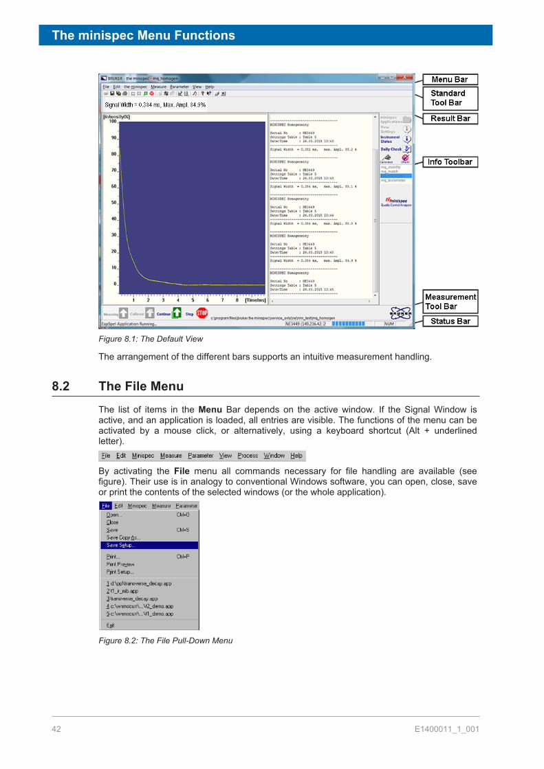
8.1 The BarsThe minispec software menu structure and toolbars are designed within the framework ofmost standard Windows software to ensure intuitive handling (see the screen layout in thefigure below). In the Menu bar actions can be selected via pull-down menus. Icons are alsoused for commonly used actions and remain visible in the Standard toolbar. Depending onthe options selected, the most important commands for the execution and abortion ofmeasurements may also be accessible through large icons on a Measurement toolbar,which is usually positioned at the bottom of the screen below the signal window. In theResult bar the numerical result(s) of the last measurement is displayed. The Info toolbarcontains easily selectable buttons pertaining to the instrument status and parameter display,as well as a list of loaded applications. Finally, the status of the measurement andconnections are summarized in the Status bar. The functionality of these items is describedin the following sections in detail.Adjustment of the bars (i.e. the possibility to move them) depends on the configuration ofanalyzer type you are working in. Repositioning of bars and windows is only allowed for therelaxation time and the NMR Analyzer.
The minispec Menu Functions
42 E1400011_1_001
Figure 8.1: The Default View
The arrangement of the different bars supports an intuitive measurement handling.
8.2 The File MenuThe list of items in the Menu Bar depends on the active window. If the Signal Window isactive, and an application is loaded, all entries are visible. The functions of the menu can beactivated by a mouse click, or alternatively, using a keyboard shortcut (Alt + underlinedletter).
By activating the File menu all commands necessary for file handling are available (seefigure). Their use is in analogy to conventional Windows software, you can open, close, saveor print the contents of the selected windows (or the whole application).
Figure 8.2: The File Pull-Down Menu
The minispec Menu Functions
E1400011_1_001 43
The Open CommandShortcuts: Standard Tool Bar:
Keys: CTRL+OUse this command to open an existing document in a new window.One can select either:
• A complete minispec application (filename extension .app) consisting of maximum fourwindows: an editor window with ASCII-text in ExpSpel programming language; the SignalWindow with the measured signals; the Result Box; and in some cases a spreadsheet.
• Measured signals (filename extension .sig) and measured data Result Boxes (file nameextension .mdt) separated from its minispec application.
• Diagnostics files.
The Close CommandUse this command to close all windows in the active application or document.If the focus is on one of the four views (windows) of a minispec application, the completeminispec application with all views will be closed.Shortcut: Standard Tool Bar:
If you want to close all applications use:Shortcut: Standard Tool Bar:
The Save command (Save As, Save Copy As)Use the Save command to save the active document to its current name and directory. Whenyou save a document for the first time, the minispec software displays the Save Copy Asdialog box for input of a name. If you want to change the name and directory of an existingdocument before you save it, choose the Save Copy As command.If you want to make a copy of an existing document, choose the Save Copy As... command.Shortcuts: Standard Tool Bar:
Keys: CTRL+S
The Save Setup CommandThe Result box displays results derived from the NMR data (after evaluation steps defined inthe minispec application). Results are automatically saved as ASCII text at intervals (fileextension: .mdt ).To set the parameters for the save procedure, select Save Setup from the result box filemenu:
The minispec Menu Functions
44 E1400011_1_001
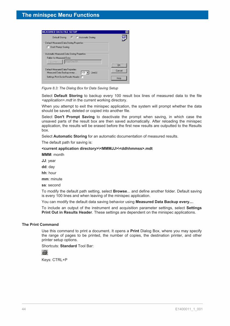
Figure 8.3: The Dialog Box for Data Saving Setup
Select Default Storing to backup every 100 result box lines of measured data to the file<application>.mdt in the current working directory.When you attempt to exit the minispec application, the system will prompt whether the datashould be saved, deleted or copied into another file.Select Don't Prompt Saving to deactivate the prompt when saving, in which case theunsaved parts of the result box are then saved automatically. After reloading the minispecapplication, the results will be erased before the first new results are outputted to the Resultsbox.Select Automatic Storing for an automatic documentation of measured results.The default path for saving is:<current application directory>\<MMMJJ>\<ddhhmmss>.mdtMMM: monthJJ: yeardd: dayhh: hourmm: minutess: secondTo modify the default path setting, select Browse... and define another folder. Default savingis every 100 lines and when leaving of the minispec application.You can modify the default data saving behavior using Measured Data Backup every....To include an output of the instrument and acquisition parameter settings, select SettingsPrint Out in Results Header. These settings are dependent on the minispec applications.
The Print CommandUse this command to print a document. It opens a Print Dialog Box, where you may specifythe range of pages to be printed, the number of copies, the destination printer, and otherprinter setup options.Shortcuts: Standard Tool Bar:
Keys: CTRL+P
The minispec Menu Functions
E1400011_1_001 45
The Print Preview CommandUse this command to display the active document as it would appear when printed. The mainwindow will be replaced with a print preview window in which one or two pages will bedisplayed in their print format. The Print Preview toolbar offers options to view either one ortwo pages at a time, movement back and forth through the document, zoom in and out ofpages and to initiate a print job.
The Print Setup CommandUse this command to select a printer and a printer connection. This command presents aPrint Setup dialog box where the printer and its connection are specified.
The 1, 2, 3, 4, 5 CommandsUse the numbers and filenames listed at the bottom of the File menu to open the last fivedocuments you closed. Select the document you want to open.
The Exit CommandUse this command to end your minispec session. You can also use the Close command. Theminispec software prompts you to save documents when unsaved changes exist.Shortcuts: Headline:
Keys: ALT+F4
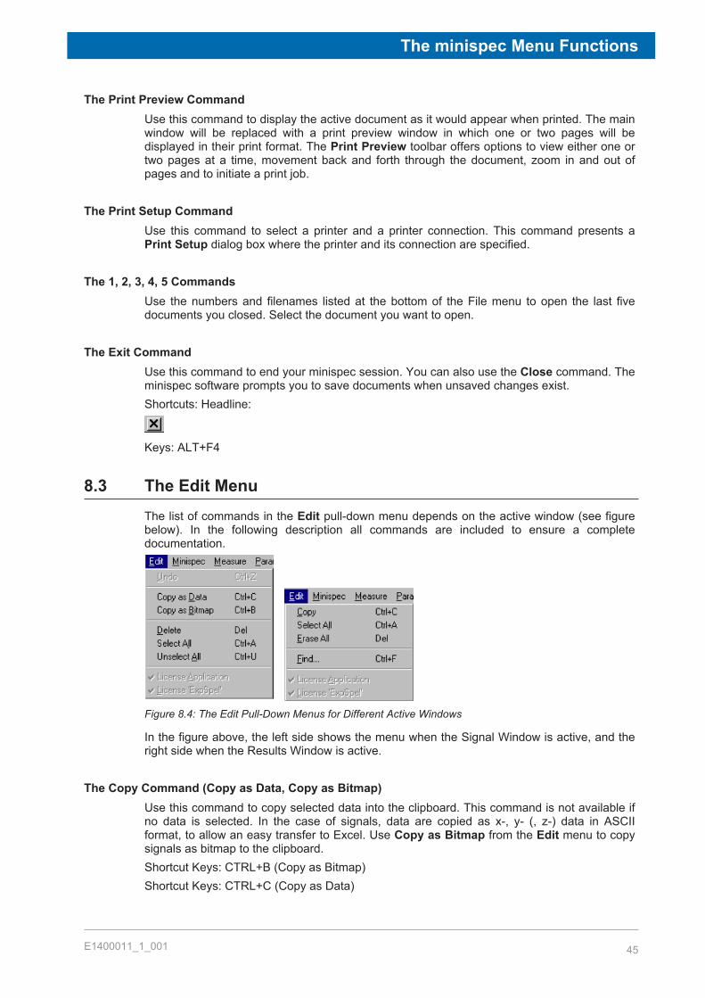
8.3 The Edit MenuThe list of commands in the Edit pull-down menu depends on the active window (see figurebelow). In the following description all commands are included to ensure a completedocumentation.
Figure 8.4: The Edit Pull-Down Menus for Different Active Windows
In the figure above, the left side shows the menu when the Signal Window is active, and theright side when the Results Window is active.
The Copy Command (Copy as Data, Copy as Bitmap)Use this command to copy selected data into the clipboard. This command is not available ifno data is selected. In the case of signals, data are copied as x-, y- (, z-) data in ASCIIformat, to allow an easy transfer to Excel. Use Copy as Bitmap from the Edit menu to copysignals as bitmap to the clipboard.Shortcut Keys: CTRL+B (Copy as Bitmap)Shortcut Keys: CTRL+C (Copy as Data)

The minispec Menu Functions
46 E1400011_1_001
The Select All CommandSelects the entire content of the Result Window. In the Signal Window this command is onlyvalid in connection with calibrations.Shortcut Keys: CTRL+A
The Unselect All CommandUnselects the entire content of the Result Window. In the Signal Window this command isonly valid in connection with calibrations.Shortcut Keys: CTRL+U
The Erase All CommandErases the entire content of the Result Window, without erasing the data from thecorresponding automatically saved measured data file.Shortcut Keys: Del
The Find CommandUse this command for searching and highlighting words or text fragments.Shortcut Keys: CTRL+F
8.4 The minispec MenuAll commands concerning instrument settings are included in this menu item. The commandsfor the magnet heater calibration and the receiver tuning are only available for BRUKERservice personnel and therefore are grayed with a normal software startup. The list ofcommands depends on the status of the instrument (see figure). If there is no applicationloaded, the list is enlarged by the commands Connect and Disconnect.
Figure 8.5: The minispec Pull-Down Menu
The Connect/Disconnect CommandOnce the system requirements for TCP/IP have been fulfilled, a software link between theminispec software running on a PC, and the minispec must be initialized. To establish the PCto minispec connection, select minispec Connect. Alternatively you can select Connect inthe Welcome Box.Enter the minispec serial number when prompted by the Connection Dialog Box.The minispec serial number must have the form NFxxxx for mq-systems.

The minispec Menu Functions
E1400011_1_001 47
The minispec serial number, which is the host name of the minispec, is used to identify theBRUKER minispec, controlled by the minispec software that is running on a PC in a TCP/IPnetwork.Use the command Disconnect from the menu to disconnect from the current minispec (e.g.prior to reconnecting to another minispec).
The Instrument Settings CommandMinispec instrument settings (see the figure below) are instrument dependent values such asthe pulse lengths and the magnetic field at NMR resonance. Instrument settings differ fromminispec to minispec, and must be tuned the first time a minispec is connected. You can usethis command to change the settings of the instrument with manual input.
Figure 8.6: The minispec Settings Table
You can change the listed settings by manual input or with the Update Settings command.Grayed entries are disabled.
Shortcut: Standard Tool Bar:
The settings that can be changed are shown in the figure above. If the minispec Settingsare disabled on a connected minispec, customize your minispec software (through theWelcome Box) to access the calibration parameters.The Advanced button in the settings table allows access to a list of instrument setting tablenames. The user may select the appropriate settings table to be used by the instrument,define custom names for the settings tables with the help of the Customize button (e.g.settings table name could be set to the probe name), and save the current entries under anew name.Entries in the settings table about SFC are only relevant in the case of the SFC-Analyzer. Ifthe SFC-item in the upper middle part of the settings table is marked, then the UpdateSettings and the Daily Check routines will include steps to determine the SFC-specificvalues. The factors (K, F, and O) and the sampling windows for a solid fat content analysisare definable via the SFC-Settings button.

The minispec Menu Functions
48 E1400011_1_001
The Update Settings CommandAn update may be necessary after the system has been installed, relocated or the probeassembly has been changed. An instrument settings update is also recommended if theDaily Check fails and no other cause of the failure can be localized. One should first checkthe sample, the cable connections and the sample position inside the probe before runningUpdate Settings.For instrument optimization it is recommended running the Update Settings routine. TheUpdate Settings routine can also be used to update selected settings.If the Update Settings menu stays disabled on a connected minispec, customize yourminispec software (through the Welcome Box) to provide access to the calibrationparameters.
The Daily Check CommandA blue mark (validated) symbol on the right side of the Info Toolbar indicates a well checkedminispec instrument.
This option tests the instrument settings but does not change them. A quick check isrecommended once a day (every 24 hours). A checkmark (Checked) in the Info toolbarsignifies a well-checked minispec instrument. An un-calibrated minispec instrument isindicated by a yellow mark (Check!).
To run the Daily Check, use the corresponding toolbar button or select Daily Check from themenu. If one of the checks fails it indicates that there is a mismatch between the expectedand the given performance. Use the Update Settings command to perform an update, butmake sure before that everything is well connected/adjusted and no other problem applies.Double check that the sample used is the correct one.Shortcut: Info Toolbar:
The Balance Settings CommandOne can connect a scale by serial interface to the PC's communication port in order toelectronically transfer sample weight information (weights are necessary for some absoluteapplications). To enter the port configuration dialog, close all minispec applications, thenselect Balance from the Setup menu. Access is limited to users who have permission toenter the minispec main menu or calibration. Select the balance type, then the port toconnect the balance to. Select the port parameters according to the settings on the scale. Toset the standard values, click Default before leaving the Settings Table. To leave the SettingsTable unchanged, click Cancel. To re-load old settings from file after modifications, click Re-Read. To leave the Settings Table with the new values, click OK.
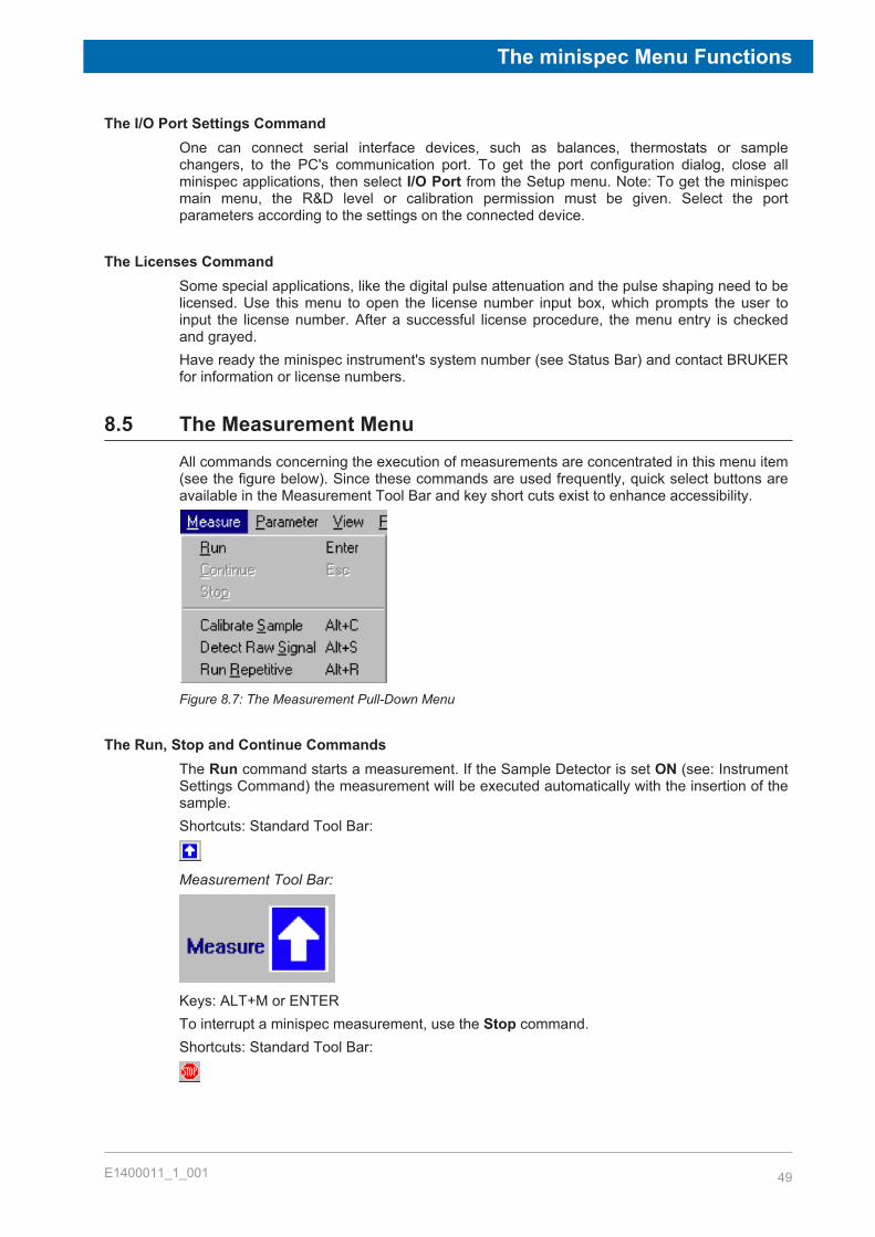
The minispec Menu Functions
E1400011_1_001 49
The I/O Port Settings CommandOne can connect serial interface devices, such as balances, thermostats or samplechangers, to the PC's communication port. To get the port configuration dialog, close allminispec applications, then select I/O Port from the Setup menu. Note: To get the minispecmain menu, the R&D level or calibration permission must be given. Select the portparameters according to the settings on the connected device.
The Licenses CommandSome special applications, like the digital pulse attenuation and the pulse shaping need to belicensed. Use this menu to open the license number input box, which prompts the user toinput the license number. After a successful license procedure, the menu entry is checkedand grayed.Have ready the minispec instrument's system number (see Status Bar) and contact BRUKERfor information or license numbers.
8.5 The Measurement MenuAll commands concerning the execution of measurements are concentrated in this menu item(see the figure below). Since these commands are used frequently, quick select buttons areavailable in the Measurement Tool Bar and key short cuts exist to enhance accessibility.
Figure 8.7: The Measurement Pull-Down Menu
The Run, Stop and Continue CommandsThe Run command starts a measurement. If the Sample Detector is set ON (see: InstrumentSettings Command) the measurement will be executed automatically with the insertion of thesample.Shortcuts: Standard Tool Bar:
Measurement Tool Bar:
Keys: ALT+M or ENTERTo interrupt a minispec measurement, use the Stop command.Shortcuts: Standard Tool Bar:

The minispec Menu Functions
50 E1400011_1_001
Measurement Tool Bar:
The command Continue is used to leave an intermediate process in order to continuerunning the minispec application (e.g. during a waiting time, a data acquisition or a fitdisplay).Shortcuts: Standard Tool Bar:
Measurement Tool Bar:
Keys: ESC
The Calibrate CommandA typical minispec application detects NMR signals of the sample and then calculates theresult from the NMR signal. In some cases, the result can be directly calculated from themeasured signal (e.g. a relaxation time). In other cases the minispec applications may use areference method and calibration line to determine a sample property (e.g. oil, water or fatcontent) from the NMR signal. As a consequence, the NMR signal must first be calibratedwith respect to sample properties. Select Calibrate Sample from the Measurement menu.Shortcuts: Standard Tool Bar:
Measurement Tool Bar:
Keys: ALT+CRunning a minispec sample calibration leads the user through several steps. In most casessome application specific values (see: The Application Parameter Table Command) need tobe defined.To calibrate a minispec application, proceed as follows:
1. Prepare at least 3 samples of known content for measurement.2. Perform test measurements with each calibration sample to adjust the acquisition
parameters from the Acquisition Parameter Table in the Parameter menu. Adjust thereceiver gain to the sample with the strongest signal.
3. Save the parameters and leave the parameter table.4. Run the sample calibration and follow the prompts.

The minispec Menu Functions
E1400011_1_001 51
A flag in the Info Toolbar indicates a calibrated minispec application.
An uncalibrated minispec application is labeled with the following flag:
The Detect raw Signal CommandIn some cases, for example to adjust the acquisition parameters, it might be helpful to detectthe signal without data processing. This command was implemented to execute only thepulse sequence and acquisition without data processing or result output.Shortcut: Keys: ALT+S
The Run Repetitive CommandWith this command a measurement can be repeated several times at a regular interval.Shortcut Keys: ALT+RSelect 'Repetitive Measurement Settings' from the Parameter menu to determine thewaiting time in seconds before a repetitive minispec measurement, the delay between twosuccessive repetitions, and the maximum number of repetitive measurements.
8.6 The Parameter MenuAll parameters for acquisitions, applications and repetitive measurements can be defined withthe assistance of the commands in this menu:
Figure 8.8: The Parameter Pull-Down Menu
8.6.1 The Acquisition Parameter Table Command
Acquisition parameters are application dependent values (for example receiver gain, recycledelay and number of scans to accumulate) that help define data acquisition. These valuescan be modified when a minispec is connected to the PC and a minispec application hasbeen loaded. To modify acquisition parameters open the Acquisition Parameter Table.Shortcuts: Standard Tool Bar:
Keys: ALT+PTo save the modifications to file, click <Save> before you leave the Parameter Table.
Note: Calibrated minispec applications will loose their calibration, if parameters are changed.

The minispec Menu Functions
52 E1400011_1_001
If the Save button stays disabled on a connected minispec, customize your minispecsoftware to provide access to the calibrated application.Experiment parameters that can be edited through the Acquisition Parameters menu:
Figure 8.9: The Acquisition Parameter Table
Scans (1 – 32000)Scans is used to set the number of times the NMR experiment should be repeated for signalaveraging before the result is evaluated. The required number of scans depends on thesignal strength, the desired signal-to-noise (which will limit the precision of themeasurement), and the desired speed of analysis (time between scans is set by the RecycleDelay). Signal to noise improves with the square root of the number of scans. The remainingnumber of scans during an experiment is shown in the lower right corner of the display.
RD (seconds)RD, or Recycle Delay, is used to set the time delay in seconds between repeated scans. Therecycle delay is usually set just a little longer than the relaxation time of the sample. If thedelay is deliberately made shorter than the sample relaxation time, one or more dummy shotscan be made prior to the experiments in order to ensure that the first scan has the samehistory as all subsequent scans.
Gain (mq-Series NF systems: 40 – 119dB)Gain sets the signal amplification in the receiver. It is a common procedure to set the gainsuch that the highest part of the signal reaches about 80% of the signal input range. It isknown that the noise start to increase significantly when exceeding 95…100dB. As the NFminispec features a high signal resolution like 14/15 bit, it is also possible to work with lowerinput signal levels, thus avoiding gain values that are too high.
Note that the gain should not be changed for calibrated applications. If the range of inputsignals is too large for one gain setting, it may be better to have several calibrations withdifferent gain settings.

The minispec Menu Functions
E1400011_1_001 53
Dummy Shots (0 - 32000)Pulses before the measurement can be made prior to the experiments, in order to ensure thatthe first scan has the same magnetization history as all subsequent scans.
Static Gradient (x, y, z, -100…+100)If a Pulse Gradient Unit is attached, this parameter (typically x) is used to control a staticgradient generated with a constant current to the gradient coils. The static gradient reducesthe line width by spoiling the magnetic field homogeneity. The strength of the static gradientreaches approximately 1% of the pulsed gradient.
Detection mode (magnitude/real/imaginary/complex)Sets the mode of signal detection. Magnitude detection calculates the root of the sum of thesquares of the real and imaginary parts of the signal, which are recorded by the quadraturereceiver. The magnitude mode is independent of the detection angle, and not as sensitive tooff-resonance effects of the magnetic field, but does not include any signed information (i.e. isalways positive). Data recorded in complex mode has a real and imaginary component andcan be Fourier transformed for viewing in the frequency domain (see The Process Menu[} 58]).For applications requiring phase information (e.g. T1 relaxation), the in- and out-of-phasecomponents can be measured separately using the real and imaginary modes respectively. Ifthe detection angle and the magnetic field have been adjusted optimally, the real componentwill be at maximum and the imaginary component will be zero.
Digital BandwidthNF systems come with a real digital filter which means that the dwell time is related to thesetting of the digital filter. Changing the digital filter from the standard value in the applicationsoftware may lead to non-sense NMR signals. Make sure the relation between digital filterand dwell is understood and set accordingly.In the latest version of the minispec software, the digital filter is defined within the ExpSpelapplication and cannot be altered from the Acquisition Parameter Table.The selection of the digital bandwidth is described in the new ExpSpel programming manualfor NF systems. Of course the user can work with all the ExpSpel application examplesprovided within the various application pools.
8.6.2 The Application Configuration Table Command
The most common minispec applications can be configured for the special requirements ofthe current measurement (e.g. whether the liquid or solid fat content has to be determined).The command opens a table where the application options can easily be edited.Shortcuts: Standard Tool Bar:
Keys: ALT+PThe Application Configuration Table is optional, not all minispec applications need a samplecalibration or configuration, thus the configuration table may not be available for theseapplications.

The minispec Menu Functions
54 E1400011_1_001
8.6.3 The Acquisition Pre-Delay Time command
In some cases a defined delay is desired between the time a sample is inserted and the timeof measurement start (e.g. if time is needed to allow the temperature of the sample toequilibrate in the magnet). The Acquisition Pre-Delay Time command allows such a delayto be set. The waiting time is added to the recycle delay of the first scan of the dataacquisition. Once a measurement is triggered, you can override the acquisition pre-delay andcontinue with data acquisition by selecting the Continue command.
8.6.4 The Repetitive Measurement Settings Command
Repetitive measurements require several control parameters. When this command isselected, a table appears where the following parameters can be specified: the waiting timein seconds before a repetitive minispec measurement begins, the delay between twosuccessive repetitions, and the maximum number of repetitive measurements.
8.7 The View MenuEach user can configure the screen for the special requirements of a measurement. With thehelp of the pull-down menu View one can adjust the arrangement of the different windows,the display of toolbars, the font size for the result output and much more. The list of availablecommands depends on the active window and the active application:
Figure 8.10: The View Pull-Down Menu
The View Default and the Toolbars CommandsThe minispec software shows four tool bars: the Standard Tool Bar, the Result Bar, theMeasurement Tool Bar and the Info Tool Bar (see the figure above). When the minispecsoftware is configured as the Relaxation Time or NMR Analyzer type, all toolbars are dockingtoolbars. This means that the toolbars can be moved to any location on the entire screen bypressing and holding the left mouse key. The location can be outside of the minispecsoftware main window, within the main window docked (e.g. on the left, right, top or bottom),or switched off entirely. To switch toolbars on and off, mark/unmark the corresponding toolbarin the minispec application menu View.To get an impression of the toolbars and to restore the default screen select View Default.Shortcut Keys: ALT+V
The minispec Menu Functions
E1400011_1_001 55
The Info Views CommandThis command is subdivided into four parts:1. minispec Settings: If you choose this item you will get a table of all minispec application
relevant instrument settings and parameters. Shortcut: Info Toolbar:The function is disabled (grayed) if no minispec is connected.
2. minispec System Status: The user can get a real-time indication of the status of theminispec instrument, particularly:
– Magnet Unit temperature and status.– Sample orifice status (sample inserted or not).– Sample insertion detection (grayed if sample detection is set OFF.– Transmitter power status.– Heater power status.– Electronic Control Unit temperature status (grayed if Control Unit temperature
detection is set OFF.– External Gradient Unit status.– Possibility of attenuated and shaped pulses.
The entries are marked with a checkmark ( ) when the corresponding item status is OK.Shortcut: Info Tool Bar:
3. Results Mean. This function displays the Statistics Box (see figure), a window whichallows general monitoring of measurement results. The Statistics Box contains:
– Mean value.– Standard deviation.– Current data value.– Total number of data.– Maximum value.– Minimum value.– Difference between minimum and maximum value.– Graphic representation (Statistics “Meter”).
The window can be minimized with the double arrow in the upper right part of the box (seefigure). Only the graphic view will be displayed in the minimized form. The green area inthe graph displays the range of tolerance for the measurement, the vertical lines throughthe meter indicate the actual values, and the continuous broad vertical line represents themean value.
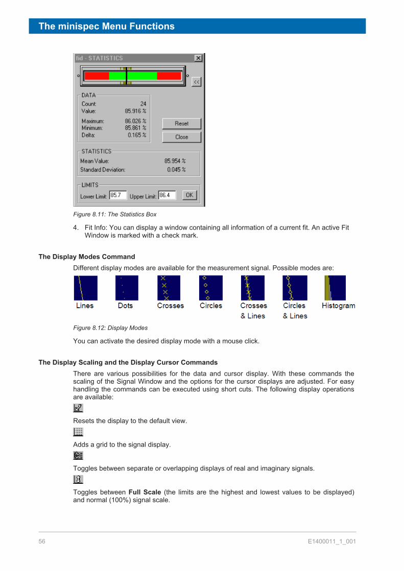
The minispec Menu Functions
56 E1400011_1_001
Figure 8.11: The Statistics Box
4. Fit Info: You can display a window containing all information of a current fit. An active FitWindow is marked with a check mark.
The Display Modes CommandDifferent display modes are available for the measurement signal. Possible modes are:
Figure 8.12: Display Modes
You can activate the desired display mode with a mouse click.
The Display Scaling and the Display Cursor CommandsThere are various possibilities for the data and cursor display. With these commands thescaling of the Signal Window and the options for the cursor displays are adjusted. For easyhandling the commands can be executed using short cuts. The following display operationsare available:
Resets the display to the default view.
Adds a grid to the signal display.
Toggles between separate or overlapping displays of real and imaginary signals.
Toggles between Full Scale (the limits are the highest and lowest values to be displayed)and normal (100%) signal scale.

The minispec Menu Functions
E1400011_1_001 57
Zoom Scale on / off. To zoom, mark the signal with the rectangle cursor. Using the leftmouse button you can toggle between the left/upper and the right/lower limit. The zoomrange is defined using the right mouse button. To reset, use the right mouse button or clickthe Reset button.
Fix Scale on / off. Fixes the display scale (e.g. after zooming) and the display type if usedbefore a measurement.
Data Cursor on / off. Allows the data cursor to be moved with the mouse or cursor keys.When activated, data point information is available in the Status Bar.
Distance Cursor on / off. Allow the mouse or cursor keys to be used to position the distancecursors. Use the left mouse button to toggle between the left and right distance cursor. Datapoints distance information can be found in the Status Bar.
Marker Cursor on / off. Use the mouse or the cursor keys to position the data cursor. Youcan observe data point information (and the distance from the fitted value) in the Status Bar.The field is only active if a calibrated data file for the application exists.
Note: Zooming, data, distance and marker cursors can only be used exclusively.
The Welcome Box CommandOn the BRUKER minispec program start, the software wakes up with the Welcome Box (seealso section Configuration of the Software, the Welcome Box). The Welcome Box offers thepossibility of adapting some software settings to the user’s purposes (e.g. selecting aminispec application or connecting a minispec). To switch off the Welcome Box, uncheckDisplay this Window on Startup in the Welcome Box. On restarting BRUKER minispecsoftware, the last minispec connection and minispec applications will be reloadedautomatically. One can deselect loading the minispec application after program start viaswitching off the option Load Application on Startup in the Welcome Box. You can alsoswitch on / off the Welcome Box by marking / unmarking the Welcome Box command in theView menu.
The Large Font Result Box CommandThe information in the Result Window can be displayed using two different font sizes.Marking this entry you will choose the larger font.
The Diagnostics View CommandWith this command a window is opened up which displays various information for diagnosticpurposes. These options are helpful for checking the instrument status, connections, andcommands. Different diagnostics are available, depending on the active window. The transferof the diagnostic information from the minispec to the PC, and the display in the DiagnosticsView needs time and system resources, thus this command can be used to regulateperformance as required.

The minispec Menu Functions
58 E1400011_1_001
Note: To ensure a failure-free operation use these options only for diagnostic purposes andnot in the background for standard measurements. Unmark Diagnostics View and alldiagnostic possibilities when they are not any longer required!
The Pulse Ram Diagnostics CommandThis command is only available if the Editor Window is active. If you mark this command,information is printed about the pulse pattern of the NMR pulse sequence into theDiagnostics View.
The Connection, Commands and Suppress Status Diagnostics CommandsIf Connection Diagnostics is marked, information will be printed about the connectionbetween the minispec software and the minispec connected. With Commands Diagnostics,information will be printed about the data exchange into the Diagnostics View. Some statusinformation about the hardware is requested every second. These requests take also place ifthe status has not changed during the last interval. For a clear and easy diagnostic it may beuseful to suppress the printing using the command Suppress Status Diagnostics.
Some of the functions described might only be available in certain minispec.exe softwareversions.
8.8 The Process MenuThe Process item is only displayed when a Signal Window is active. Different commands fordata processing are summarized in this pull-down menu:
Figure 8.13: The Process Pull-Down Menu
Within the context not all commands may be reasonable, in which case they will be grayed.The following series of built-in signal processing features are available:
The Fit CommandThis command is only available in connection with calibrations. You can fit your calibrationdata and display the fit results (see Info Views, point 4).
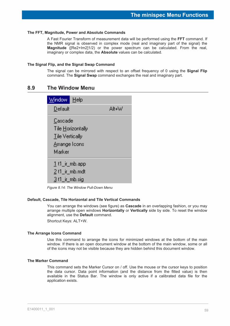
The minispec Menu Functions
E1400011_1_001 59
The FFT, Magnitude, Power and Absolute CommandsA Fast Fourier Transform of measurement data will be performed using the FFT command. Ifthe NMR signal is observed in complex mode (real and imaginary part of the signal) theMagnitude ([Re2+Im2]1/2) or the power spectrum can be calculated. From the real,imaginary or complex data, the Absolute values can be calculated.
The Signal Flip, and the Signal Swap CommandThe signal can be mirrored with respect to an offset frequency of 0 using the Signal Flipcommand. The Signal Swap command exchanges the real and imaginary part.
8.9 The Window Menu
Figure 8.14: The Window Pull-Down Menu
Default, Cascade, Tile Horizontal and Tile Vertical CommandsYou can arrange the windows (see figure) as Cascade in an overlapping fashion, or you mayarrange multiple open windows Horizontally or Vertically side by side. To reset the windowalignment, use the Default command.Shortcut Keys: ALT+W.
The Arrange Icons CommandUse this command to arrange the icons for minimized windows at the bottom of the mainwindow. If there is an open document window at the bottom of the main window, some or allof the icons may not be visible because they are hidden behind this document window.
The Marker CommandThis command sets the Marker Cursor on / off. Use the mouse or the cursor keys to positionthe data cursor. Data point information (and the distance from the fitted value) is thenavailable in the Status Bar. The window is only active if a calibrated data file for theapplication exists.
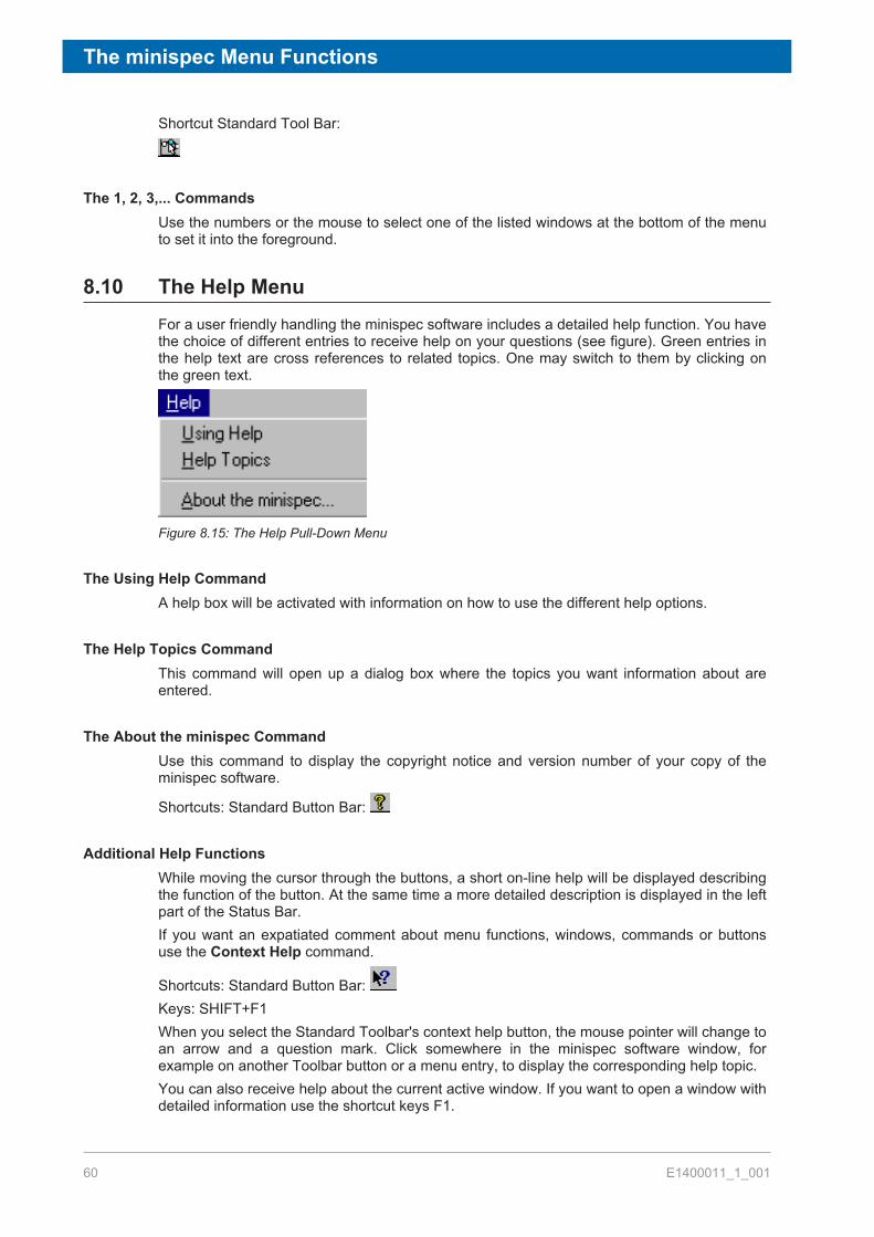
The minispec Menu Functions
60 E1400011_1_001
Shortcut Standard Tool Bar:
The 1, 2, 3,... CommandsUse the numbers or the mouse to select one of the listed windows at the bottom of the menuto set it into the foreground.
8.10 The Help MenuFor a user friendly handling the minispec software includes a detailed help function. You havethe choice of different entries to receive help on your questions (see figure). Green entries inthe help text are cross references to related topics. One may switch to them by clicking onthe green text.
Figure 8.15: The Help Pull-Down Menu
The Using Help CommandA help box will be activated with information on how to use the different help options.
The Help Topics CommandThis command will open up a dialog box where the topics you want information about areentered.
The About the minispec CommandUse this command to display the copyright notice and version number of your copy of theminispec software.
Shortcuts: Standard Button Bar:
Additional Help FunctionsWhile moving the cursor through the buttons, a short on-line help will be displayed describingthe function of the button. At the same time a more detailed description is displayed in the leftpart of the Status Bar.If you want an expatiated comment about menu functions, windows, commands or buttonsuse the Context Help command.
Shortcuts: Standard Button Bar: Keys: SHIFT+F1When you select the Standard Toolbar's context help button, the mouse pointer will change toan arrow and a question mark. Click somewhere in the minispec software window, forexample on another Toolbar button or a menu entry, to display the corresponding help topic.You can also receive help about the current active window. If you want to open a window withdetailed information use the shortcut keys F1.

The Experiment Editor ExpSpel for the mq-Series
E1400011_1_001 61
9 The Experiment Editor ExpSpelfor the mq-SeriesThe macro programming language ExpSpel was developed to allow the user to design theirown experiments and to modify the BRUKER standard applications. In the mq-series a largevariety of new commands have been implemented to enlarge the number of experiments.Important tools defined in ExpSpel are:
• Pulse sequences– loops, conditional jumps, flags, ...– acquisition parameters– time and wait functions– RF-pulse attenuation– Pulsed field gradients and static gradients
• Data acquisition– acquisition time– acquisition points– acquisition modus
• Data processing– signal display– measured data information– fit routines– FFT
• Data In/Output– implementation of Spread sheets– definition of file formats
• Calibration procedures• Instrument settings• Control of peripherals
In order to use ExpSpel, a license is required (only available in R & D levels). The licensenumber must be entered when prompted when the PC is connected to the minispec for thefirst time. Alternatively, you can select Licenses from the minispec pull down menu and enterthe license number when prompted.
To open the editor window use the button. The menu bar changes, an additional item –ExpSpel‑ is displayed. This pull-down menu allows an application to be loaded, a spell checkto be made (short cut: ) and applications to be translated. A translation can be performedby loading the file into ExpSpel and clicking the Translate command in the ExpSpel pull-down menu. To minimize the editor window click the button. The experiment editor worksmuch like conventional editors. Use the Edit pull-down menu to access copy, paste and otheractions. Usually the ExpSpel files are saved with the extension: .app.

The Experiment Editor ExpSpel for the mq-Series
62 E1400011_1_001
For a detailed description of ExpSpel refer to the extended Help file where all accessiblecommands and actions are described in detail. Help Topics can be accessed from the Helppull down menu. When the item About: ExpSpel is selected, an overview of ExpSpel isdisplayed in the index.When inspecting an ExpSpel sequence, it is also possible to highlight a command of interestand press F1 to immediately receive instructions about this command.An updated ExpSpel manual has been written for the NF series, especially pointing out theprogramming changes as compared to the series ND minispec systems. This new manual ispart of the mq-series documentation.
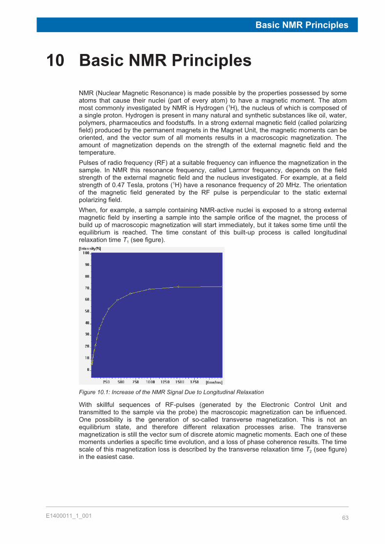
Basic NMR Principles
E1400011_1_001 63
10 Basic NMR PrinciplesNMR (Nuclear Magnetic Resonance) is made possible by the properties possessed by someatoms that cause their nuclei (part of every atom) to have a magnetic moment. The atommost commonly investigated by NMR is Hydrogen (1H), the nucleus of which is composed ofa single proton. Hydrogen is present in many natural and synthetic substances like oil, water,polymers, pharmaceutics and foodstuffs. In a strong external magnetic field (called polarizingfield) produced by the permanent magnets in the Magnet Unit, the magnetic moments can beoriented, and the vector sum of all moments results in a macroscopic magnetization. Theamount of magnetization depends on the strength of the external magnetic field and thetemperature.Pulses of radio frequency (RF) at a suitable frequency can influence the magnetization in thesample. In NMR this resonance frequency, called Larmor frequency, depends on the fieldstrength of the external magnetic field and the nucleus investigated. For example, at a fieldstrength of 0.47 Tesla, protons (1H) have a resonance frequency of 20 MHz. The orientationof the magnetic field generated by the RF pulse is perpendicular to the static externalpolarizing field.When, for example, a sample containing NMR-active nuclei is exposed to a strong externalmagnetic field by inserting a sample into the sample orifice of the magnet, the process ofbuild up of macroscopic magnetization will start immediately, but it takes some time until theequilibrium is reached. The time constant of this built-up process is called longitudinalrelaxation time T1 (see figure).
Figure 10.1: Increase of the NMR Signal Due to Longitudinal Relaxation
With skillful sequences of RF-pulses (generated by the Electronic Control Unit andtransmitted to the sample via the probe) the macroscopic magnetization can be influenced.One possibility is the generation of so-called transverse magnetization. This is not anequilibrium state, and therefore different relaxation processes arise. The transversemagnetization is still the vector sum of discrete atomic magnetic moments. Each one of thesemoments underlies a specific time evolution, and a loss of phase coherence results. The timescale of this magnetization loss is described by the transverse relaxation time T2 (see figure)in the easiest case.

Basic NMR Principles
64 E1400011_1_001
Figure 10.2: Decay of the NMR Signal Due to Transverse Relaxation
Secondly, the system naturally tends to relax back to the thermal equilibrium. This process isequivalent to the polarization process described above and takes place with the time constantT1. Various other processes are known from NMR-theory, depending on the pulse sequencesused to manipulate the magnetization. These processes are described by different relaxationtimes, some examples are T1ρ, T1D, and T2e.Substances and materials can be characterized by relaxation measurements because therelaxation times are highly sensitive to molecular properties. For example, they can besensors for various ranges of molecular motions. The large range of motions that can becharacterized by NMR is a main point which makes NMR to such a valuable tool in analysis.For example, because of their different relaxation behavior solid and liquid parts in onesample can be distinguished clearly and their amount determined as in solid fat content(SFC) measurements. As a consequence such materials as foodstuff, cosmetics, chemicalproducts and much more can be investigated. For a more detailed description refer to theapplication descriptions available from Bruker.Furthermore, the intensity of the NMR signal is a function of the number of atomic momentscontributing to the macroscopic magnetization. Therefore, the signal is a measure of thenumber of nuclei in a sample. Minispec methods make use of this relationship to determinethe amount of, for example, oil or moisture in a wide range of samples.In summary, NMR makes use of the nuclei in substances as sensors of their surroundings,yielding important information about the matter. Since both excitation and detection areperformed via electromagnetic waves in the radio frequency region, this analytical method iscontactless, non-destructive, and rapid.
Maintenance
E1400011_1_001 65
11 Maintenance
11.1 Cleaning
Before CleaningDisconnect the mains cable from the unit before cleaning.
Cleaning the Main UnitUse a clean damp cloth to wipe off any residue from the outside of the unit. Wipe off excessmoisture immediately with a dry cloth.For non water soluble marks, wipe using a cloth with a few drops of isopropyl alcohol.
Before Reconnecting the Power SupplyWait until the unit is completely dry before reconnecting the power supply!

Maintenance
66 E1400011_1_001

Dismantling and Disposal
E1400011_1_001 67
12 Dismantling and DisposalFollowing the end of its operational life, the unit can be returned to Bruker for safe disposal. Ifthis is impractical, the unit should be disposed of safely as prescribed by local environmentalregulations.
Installation, initial commissioning, retrofitting, repairs, adjustments or dismantling of thedevice must only be carried out by Bruker Service or personnel authorized by Bruker.Damage due to servicing that is not authorized by Bruker is not covered by your warranty.
12.1 Dismantling
Before starting dismantling:1. Shut down the device and secure to prevent restarting.2. Physically disconnect the power supply from the device; discharge stored residual energy.3. Remove consumables, auxiliary materials and other processing materials and dispose of
in accordance with the environmental regulations.4. Clean assemblies and parts properly and dismantle in compliance with applicable local
occupational safety and environmental protection regulations.
12.2 DisposalIf no return or disposal agreement has been made, send the dismantled components forrecycling as prescribed by local environmental regulations.
• Scrap metals.• Send plastic elements for recycling.• Dispose of packaging material in accordance with the relevant applicable legal
requirements and local regulations.• Sort and dispose of other components in accordance with their material composition.
NOTICEDanger to the environment from incorrect handling of pollutants!Incorrect handling of pollutants, particularly incorrect waste disposal, may cause seriousdamage to the environment.u Always observe local environmental regulations regarding handling and disposal of
pollutants.u Take the appropriate actions immediately if pollutants escape accidentally into the
environment. If in doubt, inform the responsible municipal authorities about the damageand ask about the appropriate actions to be taken.

Dismantling and Disposal
68 E1400011_1_001

Contact
E1400011_1_001 69
13 ContactManufacturer:
Bruker BioSpin GmbHAm SilberstreifenD-76287 RheinstettenGermanyHelpdesk Europe: (+49) 721-5161-6155Helpdesk USA: (+1) 978-667-9580
E-Mail: [email protected]
http://www.bruker.com
WEEE DE43181702
Bruker BioSpin HotlinesContact our Bruker BioSpin service centers.Bruker BioSpin provides dedicated hotlines and service centers, so that our specialists canrespond as quickly as possible to all your service requests, applications questions, softwareor technical needs.Please select the service center or hotline you wish to contact from our list available at:
http://www.bruker.com/service/information-communication/helpdesk/magnetic-resonance.html

Contact
70 E1400011_1_001

List of Figures
E1400011_1_001 71
List of Figures
Figure 4.1: The minispec MQ-Series Rating Plate.......................................................................... 20Figure 5.1: The minispec mq Magnet Unit (left) and Electronic Control Unit (right)........................ 21Figure 5.2: The minispec Magnet Unit (left) and Electronic Control Unit (right).............................. 25Figure 5.3: Handles on the Side of the Magnet Unit ....................................................................... 26Figure 5.4: Electronic Control and Magnet Units ............................................................................ 27Figure 5.5: Back Planes of the Electronic Control Unit (top) and Magnet Unit (bottom)................. 27Figure 5.6: Sketch of the Back View of the Connections from the Gradient Unit............................ 28Figure 5.7: Back View of the Gradient Unit..................................................................................... 28Figure 5.8: Ring of the Quick-Release Fastener (left) and the Raising of the Probe Assembly
(right) ............................................................................................................................ 31Figure 6.1: The Welcome Box ........................................................................................................ 35Figure 7.1: The View of the Signal Window, Result Window and the Spread Sheet. ..................... 39Figure 8.1: The Default View .......................................................................................................... 42Figure 8.2: The File Pull-Down Menu ............................................................................................. 42Figure 8.3: The Dialog Box for Data Saving Setup ......................................................................... 44Figure 8.4: The Edit Pull-Down Menus for Different Active Windows ............................................. 45Figure 8.5: The minispec Pull-Down Menu ..................................................................................... 46Figure 8.6: The minispec Settings Table ........................................................................................ 47Figure 8.7: The Measurement Pull-Down Menu ............................................................................. 49Figure 8.8: The Parameter Pull-Down Menu .................................................................................. 51Figure 8.9: The Acquisition Parameter Table ................................................................................. 52Figure 8.10: The View Pull-Down Menu ........................................................................................... 54Figure 8.11: The Statistics Box ......................................................................................................... 56Figure 8.12: Display Modes .............................................................................................................. 56Figure 8.13: The Process Pull-Down Menu ...................................................................................... 58Figure 8.14: The Window Pull-Down Menu ...................................................................................... 59Figure 8.15: The Help Pull-Down Menu............................................................................................ 60Figure 10.1: Increase of the NMR Signal Due to Longitudinal Relaxation........................................ 63Figure 10.2: Decay of the NMR Signal Due to Transverse Relaxation............................................. 64

List of Figures
72 E1400011_1_001

Index
E1400011_1_001 73
Index
Numerics1, 2, 3, 4, 5 Commands .................................... 45
AAcquisition parameters..................................... 51Add applications ............................................... 36Analyzer type.................................................... 35Application Pools .............................................. 38Application programs........................................ 39
BBalance Settings command.............................. 48Basic NMR Principles....................................... 63Blue crossed-wire UTP-cable........................... 34
CCalibrate command .................................... 36, 50Cleaning the Main Unit ..................................... 65Close Command............................................... 43Connect/Disconnect Command........................ 46Connectors ....................................................... 27Copy Command ............................................... 45CTRL+P............................................................ 44Customize button ............................................. 36
DDaily Check command ..................................... 48Default Storing.................................................. 44Detect raw Signal command ............................ 51Detection mode (magnitude/real/imaginary/
complex)...................................................... 53Detection of hydrogen ...................................... 21Dismantling....................................................... 67Disposal............................................................ 67Dummy Shots ................................................... 53
EEdit pull-down menu......................................... 45Electrical Connection Values............................ 18Electronic Control Unit...................................... 24Erase All command .......................................... 46Exit Command.................................................. 45ExpSpel ............................................................ 61ExpSpel license number................................... 36
F
File menu.......................................................... 42Find command.................................................. 46
HHelp menu ........................................................ 34
II/O Port Settings command .............................. 49Inspect the delivery .......................................... 14Installation CD .................................................. 33Instrument Settings command.......................... 47IP addresses .................................................... 34
LLicense number................................................ 61Licenses command .......................................... 49List of commands ............................................. 46
MMagnet Unit ...................................................... 24Measurement results ........................................ 39Menu functions ................................................. 39minispec Plus software..................................... 33minispec Software CD/Memory Stick ............... 19
NNMR analyzer................................................... 36NMR signal display........................................... 39
OOpen Command ............................................... 43Operating Environment .................................... 19
PPackaging......................................................... 14parameters ................................................. 39, 51Print Command ................................................ 44Print Preview Command................................... 45Print Setup Command ...................................... 45
QQC/QA measurements ..................................... 22
RRating plate ...................................................... 20RD (seconds) ................................................... 52Recycling.......................................................... 67RELAXATION TIME ......................................... 36
Index
74 E1400011_1_001
Remove applications ........................................ 36Result Box ........................................................ 43Result Window ................................................. 39RUN.................................................................. 40Run command .................................................. 36Run Repetitive command ................................. 51Run, Stop and Continue commands ................ 49
SSave command ................................................ 43Save Setup Command ..................................... 43Saving in ASCII-format ..................................... 40Scans (1 – 32000) ............................................ 52Select All command.......................................... 46Setup program.................................................. 33Signal Window.................................................. 39Siting Considerations ....................................... 22Spreadsheets ................................................... 40Standard applications....................................... 37Stop command ................................................. 36
TTCP/IP ‘Properties’ ........................................... 34Technical Data: ................................................ 17Toolbars ........................................................... 41Transport and handling .................................... 13
UUnpacking the System ..................................... 26Unselect All command...................................... 46Update Settings command ............................... 48User interface ................................................... 39
WWake-up configuration ..................................... 35Welcome Box ................................................... 35

E1400011_1_001 75
