ministry of agriculture participatory small scale
TRANSCRIPT

MINISTRY OF AGRICULTURE
Participatory Small scale Irrigation Development
Program
TRAINING MANUAL ON THE DESIGN OF IRRIGATION
INFRASTRUCTURE FOR SMALL SCALE IRRIGATION
PROJECTS
FACULTY OF CIVIL AND WATER RESOURCES ENGINEERING,
BAHIR DAR INSTITUTE OF TECHNOLOGY (BiT)
BAHIR DAR UNIVERSITY
July, 2018
BAHIR DAR, ETHIOPIA


Faculty of Civil and Water Resources Engineering
Training Manual for Design of Irrigation Infrastructure for Small Scale Irrigation Projects-------- I
TABLE OF CONTENTS
List of Figures ..................................................................................................................................... III
List of Tables ....................................................................................................................................... IV
1. INTRODUCTION ........................................................................................................................ 1
2. PLANNING & DESIGN OF IRRIGATION INFRASTRUCTURE ........................................... 2
2.1 Introduction .......................................................................................................................... 2
2.2 Duty (Design Discharge Determination): ............................................................................ 2
2.3 Potential Evapotranspiration & Crop evapotranspiration .................................................... 3
2.4 Dependable and effective rainfall ........................................................................................ 3
2.5 Net Irrigation Water Requirement ....................................................................................... 4
2.6 Irrigation Efficiencies .......................................................................................................... 4
2.7 Irrigation Scheduling ........................................................................................................... 6
2.8 Selection of Irrigation Methods ........................................................................................... 6
2.8.1 Free flooding irrigation method ....................................................................................... 9
2.8.2 Check flooding irrigation method .................................................................................. 10
2.8.3 Basin flooding irrigation method ................................................................................... 10
2.8.4 Border irrigation method ............................................................................................... 11
2.8.5 Furrow irrigation method ............................................................................................... 12
2.8.5.1 Furrow Layout ................................................................................................................... 13
2.8.5.1.1 Furrow length .............................................................................................................................. 13
2.8.5.1.2 Furrow shape ............................................................................................................................... 14
2.8.5.1.3 Furrow spacing ............................................................................................................................ 15
2.8.5.2 Irrigating Furrows/ Wetting patterns ................................................................................. 16
2.8.6 Sprinkler irrigation method ........................................................................................... 17
2.8.7 Drip irrigation method ................................................................................................... 17
3. IRRIGATION SYSTEM LAY-OUT ......................................................................................... 19
3.1. System Lay out Considerations.......................................................................................... 19
3.2. Design of the canal system ................................................................................................ 20
3.2.1. Flow Depth and Section Capacity ................................................................................. 21
3.1.1. Curves in canals ............................................................................................................. 23
3.1.2. Canal losses ................................................................................................................... 24
3.2. Canal Design ...................................................................................................................... 24
3.2.1. Main Canal Design ........................................................................................................ 25
3.2.2. Lining of irrigation canals ............................................................................................. 28
3.2.3. Design of Distribution Systems (Secondary & Tertiary)............................................... 29
3.1.1. Canal L-Section ............................................................................................................. 32

Faculty of Civil and Water Resources Engineering
Training Manual for Design of Irrigation Infrastructure for Small Scale Irrigation Projects-------- II
4. LAND DRAINAGE WORKS .................................................................................................... 32
4.1. Drainage Canal Design Discharge Estimation ................................................................... 33
4.2. Interceptor Drain (Catch Drain) ......................................................................................... 34
5. DESIGN OF IRRIGATION SYSTEM STRUCTURES ............................................................ 35
5.1 Design of Division Box ..................................................................................................... 35
5.2 Design of Drop Structures ................................................................................................. 36
5.3 Design of Chute structure (Simplified method) ................................................................. 39
5.4 Pipe Culvert (road crossing) Structure ............................................................................... 41
5.5 Design of River crossing structure (Multi span flume) ...................................................... 46
6. ENGINEERING COST ESTIMATION TABLE FORMAT FOR INFRASTRUCTURE
SYSTEM ............................................................................................................................................. 51
7. DRAWINGS ............................................................................................................................... 60
8. REFERENCES ........................................................................................................................... 61
Annexes ............................................................................................................................................... 62
Annex-1: Manning’s roughness coefficient for different canal lining materials ............................ 62
Annex-2: Suggested maximum flow velocities and side slopes for lined and unlined channels .... 63

Faculty of Civil and Water Resources Engineering
Training Manual for Design of Irrigation Infrastructure for Small Scale Irrigation Projects-------- III
List of Figures
Figure 2-1: Crop water Requirement ...................................................................................... 3
Figure 2-2: Net Irrigation Requirement ................................................................................... 4
Figure 2-3: Irrigation water losses in the field ........................................................................ 5
Figure 2-4: Check flooding irrigation ................................................................................... 10
Figure 2-5: Check flooding irrigation ..................................................................................... 10
Figure 2-6: Basin flooding irrigation system ........................................................................ 11
Figure 2-7: (a) Border flooding irrigation system, (b) Tail water outlet for a block-end border
system ..................................................................................................................................... 11
Figure 2-8: Field layout of Furrow Irrigation system ............................................................ 12
Figure 2-9: Deep, narrow furrow on a sandy soil ................................................................... 15
Figure 2-10: Wide, shallow furrows on a clay soil ............................................................... 15
Figure 2-11: A double-ridged furrow .................................................................................... 15
Figure 2-12: Different wetting patterns in furrows, depending on the soil type (a- Sand, b-
Loam and c- Clay) .................................................................................................................. 16
Figure 2-13: Ideal wetting pattern ......................................................................................... 17
Figure 2-14: Sprinkler irrigation method ............................................................................. 17
Figure 2-15: Drip irrigation method ..................................................................................... 18
Figure 3-1: General of Irrigation System Lay out ................................................................. 20
Figure 3-2: Typical Main Canal X-section ............................................................................ 23
Figure 3-4: Typical Irrigation Canal Sections ....................................................................... 26
Figure 5-1: Typical one-way division box ............................................................................ 35
Figure 5-2: Division Box on field on earthen canal .............................................................. 36

Faculty of Civil and Water Resources Engineering
Training Manual for Design of Irrigation Infrastructure for Small Scale Irrigation Projects-------- IV
List of Tables
Table 2-1: Indicative values of conveyance Efficiency ........................................................... 5
Table 2-2: Indicative values of the field application efficiency (ea) ........................................ 5
Table 2-3: Effect of natural condition on the selection of type of irrigation methods ............. 7
Table 2-4: Selection of an irrigation method based on the depth of the net irrigation application
.................................................................................................................................................. 8
Table 2-5: practical values of maximum furrow lengths (m) depending on slope, soil type,
stream size and net irrigation depth ........................................................................................ 14
Table 3-1: Recommended values of slope of canal ................................................................ 21
Table 3-2: Some parameters of trapezoidal x-section ............................................................ 21
Table 3-3: Sample Design Format for a typical main canal ................................................... 23
Table 3-4: Values of minimum radii of canal curves for different canal capacities .............. 24
Table 3-5: Limiting velocity for different types of soil formation ......................................... 27
Table 3-6: Recommended Values for Canal Parameters ........................................................ 27
Table 4-1: Value of “C” is based on the recommendation of tables ...................................... 33
Table 5-1: Hydraulic characteristics of the canal ................................................................... 42
Table 5-2: Uniform flow in circular sections flowing partly full ........................................... 42
Table 5-3: Load coefficient due to bedding ........................................................................... 45
Table 6-1: Cost Summery ...................................................................................................... 51
Table 6-2: General Items ....................................................................................................... 52
Table 6-3: Bill of quantity of Infrastructure and drainage system (Right side) .................... 57
Faculty of Civil and Water Resources Engineering
Training Manual for Design of Irrigation Infrastructure for Small Scale Irrigation Projects 1
1. INTRODUCTION
This manual is developed as a reference material for experts working in the area of irrigation
and drainage and other experts who are responsible for the design and development of small
scale hydraulic structures. This manual, together with its companions, is designed to offer
practical guidance in the design and construction of small scale irrigation structure like,
canals (lined and earthen), river crossings (flumes and culverts), road crosses, drainage
structures and rehabilitation of irrigation conveyance structures such as drops, turnouts,
canals, etc. on minor irrigation schemes etc. The manual contains practical examples of
irrigation system planning, canal layout and associated structures which can be built using
locally available materials by local artisans and mostly farmer labor.
In particular, this training manual is designed to assist engineers/experts in the design and
upgrading of traditional irrigation schemes as well rehabilitation of modern schemes. It
contains all necessary design guidelines and procedures for irrigation system designs
starting from layout. The procedures and examples are arranged stepwise so that the user
can easily understand. The guideline focuses on canal and drain design including design of
small conveyance and water distribution structures.

Faculty of Civil and Water Resources Engineering
Training Manual for Design of Irrigation Infrastructure for Small Scale Irrigation Projects 2
2. PLANNING & DESIGN OF IRRIGATION INFRASTRUCTURE
Irrigation may be defined as the science of artificial application of water to the land, in
accordance with the crop requirements throughout the crop period for full-fledged
nourishment of the crops. Irrigation is the application of water by artificial and scientific
way for plants to increase crop production. In order to plan, the irrigation system design, the
following data’s are needed to be available before the hydraulic & Structural design of
irrigation systems: Hydrology (flood, demand, etc.), Agronomic data, Geological Data,
Topographical Data (Topo map of the command area, detailing important features) and Soil
Data, etc
2.1 Introduction
In several parts of the world, the moisture available in the root-zone soil, either from the
rain or from underground waters, may not be sufficient for the requirement of the plant life.
This deficiency may be either for the entire crop season or for only parts of the crop season.
For optimum plant growth, therefore, it becomes necessary to make up the deficiency by
adding water to the root-zone soil. This artificial application of water to land for
supplementing the naturally available moisture in the root-zone soil for the purpose of
agricultural production is termed irrigation.
Irrigation schemes can be broadly grouped in to two main categories: (i). Surface water
irrigation schemes, and (ii). Ground water irrigation schemes. Surface water irrigation
schemes uses diversions, storages, pumps, etc., methods to obtain their supplies from rivers
and lakes. Ground water irrigation schemes use open wells, deep and shallow wells to lift
water from the water bearing strata below the earth’s surface. The choice of an irrigation
scheme depends on several factors, such as surface topography, rainfall characteristics, type
of source available, subsoil profile, etc. One should, however, always plan to use surface
and ground water together to drive maximum benefits. Such use is termed conjunctive use
of surface and ground waters.
2.2 Duty (Design Discharge Determination):
It is used to determine Evapotranspiration, Crop evapotranspiration, Dependable rainfall
and Net irrigation Requirement. It is the process of Identify peak value for the designed
cropping pattern and adjusts the above value for Irrigation efficiencies, hours of irrigation
in a day, etc. Normally crop water demand is determined by the agronomists by considering
different parameters.

Faculty of Civil and Water Resources Engineering
Training Manual for Design of Irrigation Infrastructure for Small Scale Irrigation Projects 3
2.3 Potential Evapotranspiration & Crop evapotranspiration
Figure 2-1: Crop water Requirement
2.4 Dependable and effective rainfall
It is the process used to determine 75% dependable rainfall from the time series of rainfall
data collected from Meteorological station and for calculating the effective rainfall. The
75% dependable rainfall indicates that the rainfall can be available 75% of the time.
Reference (ETo), crop
evapotranspiration under standard
(ETc) and non-standard conditions
(ETc adj)
Crop growth stages for
different types of crops
Generalized crop
coefficient curve
for the single
crop coefficient
approach
Faculty of Civil and Water Resources Engineering
Training Manual for Design of Irrigation Infrastructure for Small Scale Irrigation Projects 4
Methods to determine the dependable and effective rainfall:
i. Fixed Percentage: Effective Rainfall = % of Total Rainfall
ii. An empirical formula developed by FAO/AGLW
Effective Rainfall = 0.6 * Total Rainfall – 10……… (Total Rainfall < 70 mm)
Effective Rainfall = 0.8 * Total Rainfall – 24…………. (Total Rainfall > 70 mm)
iii. Method of USDA Soil Conservation Service
Effective Rainfall = Total Rainfall / 125 * (125 - 0.2 * Total Rainfall) … (Total Rainfall
< 250 mm)
Effective Rainfall = 125 + 0.1 * Total Rainfall……. (Total Rainfall > 250 mm)
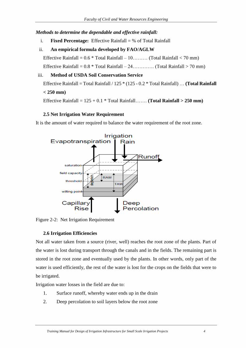
2.5 Net Irrigation Water Requirement
It is the amount of water required to balance the water requirement of the root zone.
Figure 2-2: Net Irrigation Requirement
2.6 Irrigation Efficiencies
Not all water taken from a source (river, well) reaches the root zone of the plants. Part of
the water is lost during transport through the canals and in the fields. The remaining part is
stored in the root zone and eventually used by the plants. In other words, only part of the
water is used efficiently, the rest of the water is lost for the crops on the fields that were to
be irrigated.
Irrigation water losses in the field are due to:
1. Surface runoff, whereby water ends up in the drain
2. Deep percolation to soil layers below the root zone

Faculty of Civil and Water Resources Engineering
Training Manual for Design of Irrigation Infrastructure for Small Scale Irrigation Projects 5
Figure 2-3: Irrigation water losses in the field
To express which percentage of irrigation water is used efficiently and which percentage is
lost, the term irrigation efficiency is used. The scheme irrigation efficiency (e in %) is
that part of the water pumped or diverted through the scheme inlet which is used effectively
by the plants. The scheme irrigation efficiency can be sub-divided into:
Conveyance efficiency (ec) which represents the efficiency of water transport in
canals. The conveyance efficiency (ec) mainly depends on the length of the canals,
the soil type or permeability of the canal banks and the condition of the canals.
Field application efficiency (ea) which represents the efficiency of water
application in the field. The field application efficiency (ea) mainly depends on the
irrigation method and the level of farmer discipline.
Table 2-1: Indicative values of conveyance Efficiency
Soil type Earthen canals Lined canals
Canal length Sand Loam Clay
Long(>2000m) 60% 70% 80% 95%
Medium(200-2000m) 70% 75% 85% 95%
Short(<200m) 80% 85% 90% 95%
Table 2-2: Indicative values of the field application efficiency (ea)
Irrigation methods Field application efficiency
Surface irrigation (border, furrow, basin) 60%
Sprinkler irrigation 75%
Drip irrigation 90%

Faculty of Civil and Water Resources Engineering
Training Manual for Design of Irrigation Infrastructure for Small Scale Irrigation Projects 6
Once the conveyance and field application efficiency have been determined, the scheme
irrigation efficiency (e) can be calculated, using the following formula:
Where:
e = scheme irrigation efficiency (%)
ec = conveyance efficiency (%)
ea = field application efficiency (%)
A scheme irrigation efficiency of 50-60% is good; 40% is reasonable, while a scheme
Irrigation efficiency of 20-30% is poor.
2.7 Irrigation Scheduling
An irrigation scheduling criteria includes the definition of the following three variables:
1. Irrigation Application Timing: Defines WHEN irrigation applications should be given.
The default option is to irrigate when 100% of Readily Available Moisture (RAM) is
depleted. This option is aimed at preventing the crops from being under any stress
(optimal scheduling).
2. Application Depths: Defines HOW MUCH water should be given in each irrigation
application. The default option is to refill the soil to its field capacity (100% of readily
available moisture).
3. Start of Scheduling: Defines the date at which scheduling calculations should start. The
default option is to start at the first planting date of each crop in the cropping pattern.
2.8 Selection of Irrigation Methods
To choose the designed irrigation method, the designer in consultation of the farmer must
know the advantages and disadvantages of the various methods. He or she must know which
method suits the local conditions best. Unfortunately, in many cases there is no single best
solution: all methods have their advantages and disadvantages. Testing of the various
methods, under the prevailing local conditions, provides the best basis for a sound choice of
irrigation method.
Normally, the suitability of the various irrigation methods, i.e. surface, sprinkler or drip
irrigation depends mainly on the following factors:
i. Natural conditions: - The natural conditions such as soil type, slope, climate, water
quality and availability, have direct impact on the choice of an irrigation method. The
Faculty of Civil and Water Resources Engineering
Training Manual for Design of Irrigation Infrastructure for Small Scale Irrigation Projects 7
following table summarizes the natural condition that affects the type of irrigation
methods.
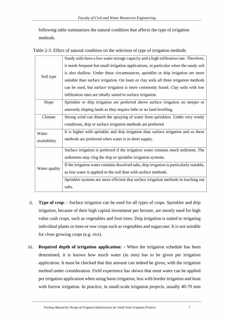
Table 2-3: Effect of natural condition on the selection of type of irrigation methods
Soil type
Sandy soils have a low water storage capacity and a high infiltration rate. Therefore,
it needs frequent but small irrigation applications, in particular when the sandy soil
is also shallow. Under these circumstances, sprinkler or drip irrigation are more
suitable than surface irrigation. On loam or clay soils all three irrigation methods
can be used, but surface irrigation is more commonly found. Clay soils with low
infiltration rates are ideally suited to surface irrigation.
Slope Sprinkler or drip irrigation are preferred above surface irrigation on steeper or
unevenly sloping lands as they require little or no land levelling.
Climate Strong wind can disturb the spraying of water from sprinklers. Under very windy
conditions, drip or surface irrigation methods are preferred.
Water
availability
It is higher with sprinkler and drip irrigation than surface irrigation and so these
methods are preferred when water is in short supply.
Water quality
Surface irrigation is preferred if the irrigation water contains much sediment. The
sediments may clog the drip or sprinkler irrigation systems.
If the irrigation water contains dissolved salts, drip irrigation is particularly suitable,
as less water is applied to the soil than with surface methods.
Sprinkler systems are more efficient that surface irrigation methods in leaching out
salts.
ii. Type of crop: - Surface irrigation can be used for all types of crops. Sprinkler and drip
irrigation, because of their high capital investment per hectare, are mostly used for high
value cash crops, such as vegetables and fruit trees. Drip irrigation is suited to irrigating
individual plants or trees or row crops such as vegetables and sugarcane. It is not suitable
for close growing crops (e.g. rice).
iii. Required depth of irrigation application: - When the irrigation schedule has been
determined, it is known how much water (in mm) has to be given per irrigation
application. It must be checked that this amount can indeed be given, with the irrigation
method under consideration. Field experience has shown that most water can be applied
per irrigation application when using basin irrigation, less with border irrigation and least
with furrow irrigation. In practice, in small-scale irrigation projects, usually 40-70 mm

Faculty of Civil and Water Resources Engineering
Training Manual for Design of Irrigation Infrastructure for Small Scale Irrigation Projects 8
of water are applied in basin irrigation, 30-60 mm in border irrigation and 20-50 mm in
furrow irrigation. This means that if only little water is to be applied per application, e.g.
on sandy soils and a shallow rooting crop, furrow irrigation would be most appropriate.
However, none of the surface irrigation methods can be used if the sand is very coarse,
i.e. if the infiltration rate is more than 30 mm/hour. If, on the other hand, a large amount
of irrigation water is to be applied per application, e.g. on a clay soil and with a deep
rooting crop, border or basin irrigation would be more appropriate. The net irrigation
application values used are only a rough guide. They result from a combination of soil
type and rooting depth. For example: if the soil is sandy and the rooting depth of the crop
is medium, it is estimated that the net depth of each irrigation application will be in the
order of 35 mm.
Table 2-4: Selection of an irrigation method based on the depth of the net irrigation
application
Soil
type
Rooting depth of
the crop
Net irrigation depth per
application (mm) Irrigation method
Sand
Shallow 20-30 short furrows
Medium 30-40 medium furrows, short borders
Deep 40-50
long furrows, medium borders, small
basins
Loam
Shallow 30-40 medium furrows, short borders
Medium 40-50
long furrows, medium borders, small
basins
Deep 50-60 long borders, medium basins
Clay Shallow 40-50
long furrows, medium borders, small
basins
Medium 50-60 long borders, medium basins
Deep 60-70 large basins
iv. Type of technology: - The type of technology affects the choice of irrigation method. In
general, drip and sprinkler irrigation are technically more complicated methods. The
purchase of equipment requires high capital investment per hectare. Surface irrigation
systems, in particular small-scale schemes are usually requires less sophisticated
equipment for both construction and maintenance (unless pumps are used). The

Faculty of Civil and Water Resources Engineering
Training Manual for Design of Irrigation Infrastructure for Small Scale Irrigation Projects 9
equipment needed is often easier to maintain and less dependent on the availability of
foreign currency.
v. Previous experience with irrigation: - The choice of an irrigation method also depends
on the irrigation tradition within the region or country. Introducing a previously unknown
method may lead to unexpected complications. It is not certain that the farmers will
accept the new method. The servicing of the equipment may be problematic and the costs
may be high compared to the benefits. Often it will be easier to improve the traditional
irrigation method than to introduce a totally new method.
vi. Required labour inputs: - Surface irrigation often requires a much higher labour input
for construction, operation and maintenance than sprinkler or drip irrigation. Surface
irrigation requires accurate land levelling, regular maintenance and a high level of
farmers' organization to operate the system. Sprinkler and drip irrigation require little
land levelling; system operation and maintenance are less labour-intensive.
Generally, surface irrigation is by far the most widespread irrigation method. It is normally
used when conditions are favourable: mild and regular slopes, soil type with medium to low
infiltration rate, and a sufficient supply of surface
or groundwater. In the case of steep or irregular
slopes, soils with a very high infiltration rate or
scarcity of water, sprinkler and drip irrigation may
be more appropriate. When introducing sprinkler
and drip irrigation it must be ensured that the
equipment can be maintained.
Here are the methods of water application for the
command area which is selected based on the above
discussed points.
2.8.1 Free flooding irrigation method
There are many cases where croplands are irrigated without regard to efficiency or
uniformity. These are generally situations where the value of the crop is very small or the
field is used for grazing or recreation purposes. Small land holdings are generally not subject
to the array of surface irrigation practices of the large commercial farming systems. Also in
this category are the surface irrigation systems like check-basins which irrigate individual

Faculty of Civil and Water Resources Engineering
Training Manual for Design of Irrigation Infrastructure for Small Scale Irrigation Projects 10
trees in an orchard, for example. While these systems represent significant percentages in
some areas, they will not be discussed in detail in this paper. The evaluation methods can
be applied if desired, but the design techniques are not generally applicable nor need they
be since the irrigation practices tend to be minimally managed.
Figure 2-4: Check flooding irrigation
2.8.2 Check flooding irrigation method
The system is similar to ordinary flooding. Water is controlled by surrounding the check
area with low and flat levees. The check is filled with water at a fairly high rate and allowed
to stand until the water infiltrates. The confined plot area varies from 0.2 to 0.8 hectares
Figure 2-5: Check flooding irrigation
2.8.3 Basin flooding irrigation method
Basin irrigation is the most common form of surface irrigation, particularly in regions with
layouts of small fields. If a field is level in all directions, is encompassed by a dyke to
prevent runoff, and provides an undirected flow of water onto the field, it is herein called a
basin.
There are few crops and soils not amenable to basin irrigation, but it is generally favoured
by moderate to slow intake soils, deep-rooted and closely spaced crops. Crops which are
sensitive to flooding and soils which form a hard crust following irrigation can be basin
irrigated by adding furrowing or using raised bed planting. Basins can be served with less
command area and field watercourses than can border and furrow systems because their

Faculty of Civil and Water Resources Engineering
Training Manual for Design of Irrigation Infrastructure for Small Scale Irrigation Projects 11
level nature allows water applications from anywhere along the basin perimeter.
Basin irrigation has a number of limitations, two of which, are associated with soil crusting
and crops that cannot accommodate inundation.
Figure 2-6: Basin flooding irrigation system
2.8.4 Border irrigation method
Border irrigation can be viewed as an extension of basin irrigation to sloping, long
rectangular or contoured field shapes, with free draining conditions at the lower end. Water
is applied to individual borders from small hand-dug checks from the field head ditch. When
the water is shut off, it recedes from the upper end to the lower end. Sloping borders are
suitable for nearly any crop except those that require prolonged ponding.
(a) (b)
Figure 2-7: (a) Border flooding irrigation system, (b) Tail water outlet for a block-end
border system

Faculty of Civil and Water Resources Engineering
Training Manual for Design of Irrigation Infrastructure for Small Scale Irrigation Projects 12
2.8.5 Furrow irrigation method
Furrow irrigation avoids flooding the entire field surface by channeling the flow along the
primary direction of the field using furrows. Water infiltrates through the wetted perimeter
and spreads vertically and horizontally to refill the soil reservoir. Furrows are often
employed in basins and borders to reduce the effects of topographical variation and crusting.
The distinctive feature of furrow irrigation is that the flow into each furrow is independently
set and controlled as opposed to furrowed borders and basins where the flow is set and
controlled on a border by border or basin by basin basis.
Furrow irrigation is suitable for a wide range of soil types, crops and land slopes. It is
suitable for many crops, especially row crops. Crops that would be damaged if water
covered their stem or crown should be irrigated by furrow irrigation systems. Furrows
provide better on-farm water management flexibility under many surface irrigation
conditions. The discharge per unit width of the field is substantially reduced and
topographical variations can be more severe. A smaller wetted area reduces evaporation
losses. Furrows provide the irrigator more opportunity to manage irrigations toward higher
efficiencies as field conditions changed for each irrigation throughout a season.
There are several disadvantages with furrow irrigation. These may include: (1) an
accumulation of salinity between furrows; (2) an increased level of tailwater losses; (3) the
difficulty of moving farm equipment across the furrows; (4) the added expense and time to
make extra tillage practice (furrow construction); (5) an increase in the erosive potential of
the flow; (6) a higher commitment of labour to operate efficiently; and (7) furrow systems
are more difficult to automate, particularly with regard to regulating an equal discharge in
each furrow.
Figure 2-8: Field layout of Furrow Irrigation system

Faculty of Civil and Water Resources Engineering
Training Manual for Design of Irrigation Infrastructure for Small Scale Irrigation Projects 13
2.8.5.1 Furrow Layout
This section deals with the shape, length and spacing of furrows. Generally, the shape,
length and spacing are determined by the natural circumstances, i.e. slope, soil type and
available stream size. However, other factors may influence the design of a furrow system,
such as the irrigation depth, farming practice and the field length.
2.8.5.1.1 Furrow length
Furrows must be on consonance with the slope, the soil type, the stream size, the irrigation
depth, the cultivation practice and the field length. The impact of these factors on the furrow
length is discussed below.
1. Slope: - Although furrows can be longer when the land slope is steeper, the maximum
recommended furrow slope is 0.5% to avoid soil erosion. Furrows can also be level and
are thus very similar to long narrow basins. However a minimum grade of 0.05% is
recommended so that effective drainage can occur following irrigation or excessive
rainfall. If the land slope is steeper than 0.5% then furrows can be set at an angle to the
main slope or even along the contour to keep furrow slopes within the recommended
limits. Furrows can be set in this way when the main land slope does not exceed 3%.
Beyond this there is a major risk of soil erosion following a breach in the furrow system.
On steep land, terraces can also be constructed and furrows cultivated along the terraces.
2. Soil type: - In sandy soils water infiltrates rapidly. Furrows should be short, so that water
will reach the downstream end without excessive percolation losses. In clay soils, the
infiltration rate is much lower than in sandy soils. Furrows can be much longer on clayey
than on sandy soils.
3. Stream size: - Normally stream sizes up to 0.5 l/sec will provide an adequate irrigation
provided the furrows are not too long. When larger stream sizes are available, water will
move rapidly down the furrows and so generally furrows can be longer. The maximum
stream size that will not cause erosion will obviously depend on the furrow slope; in any
case, it is advised not to use stream sizes larger than 3.0 l/sec.
4. Irrigation depth: - Applying larger irrigation depths usually means that furrows can be
longer as there is more time available for water to flow down the furrows and infiltrate.
5. Cultivation practice: - When the farming is mechanized, furrows should be made as
long as possible to facilitate the work. Short furrows require a lot of attention as the
flow must be changed frequently from one furrow to the next. However, short furrows

Faculty of Civil and Water Resources Engineering
Training Manual for Design of Irrigation Infrastructure for Small Scale Irrigation Projects 14
can usually be irrigated more efficiently than long ones as it is much easier to keep the
percolation losses low.
6. Field length: - It may be more practical to make the furrow length equal to the length
of the field, instead of the ideal length, when this would result in a small piece of land
left over. Equally the length of field may be much less than the maximum furrow length.
This is not usually a problem and furrow lengths are made to fit the field boundaries.
The table below gives some practical values of maximum furrow lengths under small-scale
irrigation conditions. The values shown in Table 3 are lower than those generally given in
irrigation handbooks. These higher values are appropriate under larger scale, fully
mechanized conditions.
Table 2-5: practical values of maximum furrow lengths (m) depending on slope, soil type,
stream size and net irrigation depth
Furrow slope
(%) Maximum stream size
(l/s) per furrow
Clay Loam Sand
Net irrigation depth (mm)
50 75 50 75 50 75
0 3 100 150 60 90 30 45
0.1 3 120 170 90 125 45 60
0.2 2.5 130 180 110 150 60 95
0.3 2 150 200 130 170 75 110
0.5 1.2 150 200 130 170 75 110
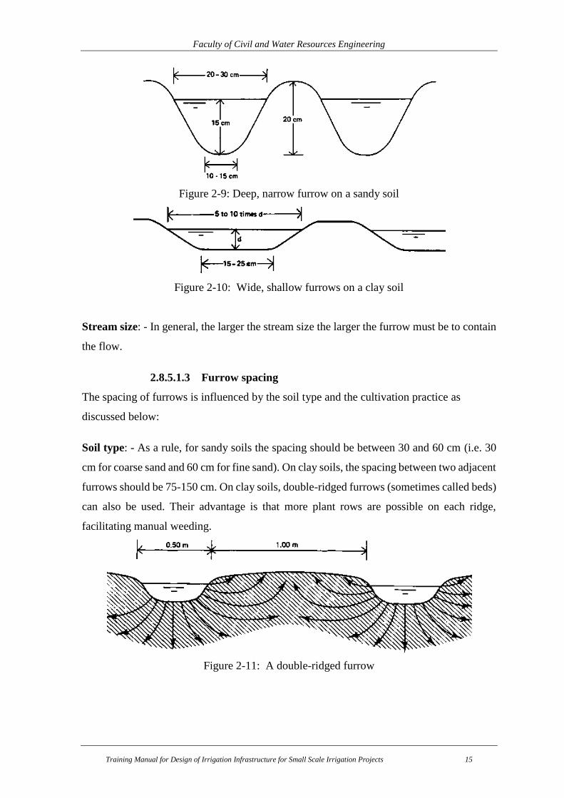
2.8.5.1.2 Furrow shape
The shape of furrows is influenced by the soil type and the stream size as discussed below:
Soil type: - In sandy soils, water moves faster vertically than sideways (lateral). Narrow,
deep V-shaped furrows are desirable to reduce the soil area through which water percolates.
However, sandy soils are less stable, and tend to collapse, which may reduce the irrigation
efficiency.
In clay soils, there is much more lateral movement of water and the infiltration rate is much
less than for sandy soils. Thus a wide, shallow furrow is desirable to obtain a large wetted
area to encourage infiltration.
Faculty of Civil and Water Resources Engineering
Training Manual for Design of Irrigation Infrastructure for Small Scale Irrigation Projects 15
Figure 2-9: Deep, narrow furrow on a sandy soil
Figure 2-10: Wide, shallow furrows on a clay soil
Stream size: - In general, the larger the stream size the larger the furrow must be to contain
the flow.
2.8.5.1.3 Furrow spacing
The spacing of furrows is influenced by the soil type and the cultivation practice as
discussed below:
Soil type: - As a rule, for sandy soils the spacing should be between 30 and 60 cm (i.e. 30
cm for coarse sand and 60 cm for fine sand). On clay soils, the spacing between two adjacent
furrows should be 75-150 cm. On clay soils, double-ridged furrows (sometimes called beds)
can also be used. Their advantage is that more plant rows are possible on each ridge,
facilitating manual weeding.
Figure 2-11: A double-ridged furrow

Faculty of Civil and Water Resources Engineering
Training Manual for Design of Irrigation Infrastructure for Small Scale Irrigation Projects 16
Cultivation practice: - In mechanized farming a compromise is required between the
machinery available to cut furrows and the ideal spacings for crops. Mechanical equipment
will result in less work if a standard width between the furrows is maintained, even when
the crops grown normally require a different planting distance. This way the spacing of the
tool attachment does not need to be changed when the equipment is moved from one crop
to another. However, care is needed to ensure that the standard spacings provide adequate
lateral wetting on all soil types.
2.8.5.2 Irrigating Furrows/ Wetting patterns
In order to obtain a uniformly wetted root zone, furrows should be properly spaced, have a
uniform slope and the irrigation water should be applied rapidly.
As the root zone in the ridge must be wetted from the furrows, the downward movement of
water in the soil is less important than the lateral (or sideways) water movement. Both lateral
and downward movement of water depends on soil type.
(a) (b) (c)
Figure 2-12: Different wetting patterns in furrows, depending on the soil type (a- Sand, b-
Loam and c- Clay)
Ideal wetting pattern: - In an ideal situation adjacent wetting patterns overlap each other,
and there is an upward movement of water (capillary rise) that wets the entire ridge, thus
supplying the root zone with water.

Faculty of Civil and Water Resources Engineering
Training Manual for Design of Irrigation Infrastructure for Small Scale Irrigation Projects 17
Figure 2-13: Ideal wetting pattern
To obtain a uniform water distribution along the furrow length, it is very important to have
a uniform slope and a large enough stream size so that water advances rapidly down the
furrow. In this way large percolation losses at the head of the furrow can be avoided.
2.8.6 Sprinkler irrigation method
With sprinkler irrigation, artificial rainfall is created. The water is led to the field through a
pipe system in which the water is under pressure. The spraying is accomplished by using
several rotating sprinkler heads or spray nozzles.
Figure 2-14: Sprinkler irrigation method
2.8.7 Drip irrigation method
In drip irrigation, also called trickle irrigation, the water is led to the field through a pipe
system. On the field, next to the row of plants or trees, a tube is installed. At regular intervals,
near the plants or trees, a hole is made in the tube and equipped with an emitter. The water
is supplied slowly, drop by drop, to the plants through these emitters.

Faculty of Civil and Water Resources Engineering
Training Manual for Design of Irrigation Infrastructure for Small Scale Irrigation Projects 18
Figure 2-15: Drip irrigation method

Faculty of Civil and Water Resources Engineering
Training Manual for Design of Irrigation Infrastructure for Small Scale Irrigation Projects 19
3. IRRIGATION SYSTEM LAY-OUT
Desirable locations for irrigation canals on any gravity project, their cross-sectional designs
and construction costs are governed mainly by topographic and geologic conditions along
different routes of the cultivable lands. Any irrigation canal consists of different sizes and
capacities. Accordingly, the canals are classified as main, secondary, tertiary and field
canals depending on the size of the irrigation scheme. The main canals takes its supplies
directly from the river through the head regulator and act as a feeder canal supplying water
to secondary and tertiary canals. Usually, direct irrigation from the main canal is not
practical. Main canals must convey water to the higher elevations of the cultivable area. The
secondary canals takes their supplies from the main canals and feed the tertiary and/or the
field canals. Secondary and tertiary canals convey water to the different parts of the irrigable
areas. Field canals are the smaller units in the system and used to feed water to the furrows.
The feeder (field) canals will be ready to deliver water to various blocks. The boundaries of
these blocks should be determined by the farmers who will be jointly responsible for
distribution of water within each block. Within the blocks, field canals are used to convey
water to individual plots.
Technical and social issues are considered in determining the canal layout, alignments and
the location of block boundaries for which the views of both the woreda expert and user
farmers have been incorporated.
Irrigation system layout shows the network of irrigation canals main canals, secondary
canals, etc) and the off-takes and the areas served by each; also land drainage networks.
3.1. System Lay out Considerations
A primary concern in the layout of the system is that it serves the purpose of conveying and
distributing water to key locations in the areas of service. The excavation and earth fill
volumes should not be excessive, otherwise the construction costs may be tremendous. In
reaches constructed over fill, the seepage losses tend to be high, even if the canal is lined.
Hence, canals are often designed to follow the existing topography for the design slope. The
selection of bed slope (longitudinal bed slope) should also take into account the existing
slopes of the terrain, so as to minimize deviations in canal routing. Curves in canals should
not be too sharp.
The planning of an irrigation canal project includes the determination of canal alignment
and the water demand. The type of the canals (trapezoidal or rectangular) and the lining
Faculty of Civil and Water Resources Engineering
Training Manual for Design of Irrigation Infrastructure for Small Scale Irrigation Projects 20
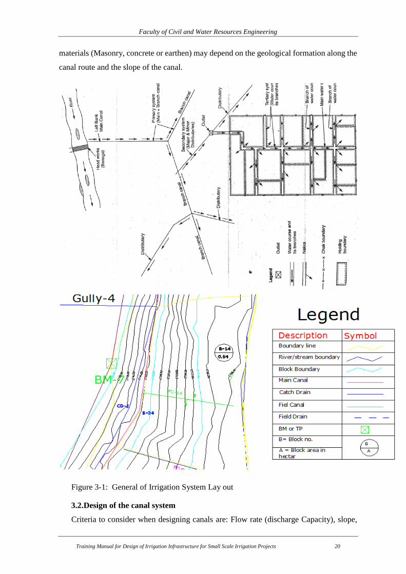
materials (Masonry, concrete or earthen) may depend on the geological formation along the
canal route and the slope of the canal.
Figure 3-1: General of Irrigation System Lay out
3.2. Design of the canal system
Criteria to consider when designing canals are: Flow rate (discharge Capacity), slope,

Faculty of Civil and Water Resources Engineering
Training Manual for Design of Irrigation Infrastructure for Small Scale Irrigation Projects 21
soil type, size of the command to be irrigated by the canal, Hydraulic operational
characteristics, Cost and Site Conditions (geology of canal routes, etc).
3.2.1. Flow Depth and Section Capacity
The canal sections are designed using Manning’s equations:
2/13/2 ** SRAQ
Normally, the followings are determined from the field:
The command area to be irrigated, (A)
The slope of the canal (s)
The irrigation water requirement, duty
The mannig’s roughness coefficient (η)
From the above given conditions, by fixing the bed width and the section of the canal
(rectangular or trapezoidal), it is possible to determine the flow depth.
Table 3-1: Recommended values of slope of canal
Type of canals Range of Slope
Main canals 1/700-1/1,500
Secondary canals 1/700-1/1,000
Tertiary canals 1/500-1/700
Field ditches 1/300-1/500
Channel section type and Side slopes
Table 3-2: Some parameters of trapezoidal x-section
Discharge (m3/s) b/d Side slope Freeboard (m) Velocity (m/s)
0 -0.15 1 1.1 0.3 0.25-0.30
0.15-0.30 1 1.1 0.3 0.30-0.35
0.30-0.40 1 1.1 0.35 0.35-0.40
0.40-0.50 2 1.1 0.4 0.40-0.45
Note: Use flow master software to determine the flow depth
Exercise-1: Design an earthen trapezoidal section of irrigation main canal for the following
given conditions:
Size of command area of 200ha,
Longitudinal slope = 1/1000
Side slope = 1V: 1H
Duty= 2.0 lt/s/ha

Faculty of Civil and Water Resources Engineering
Training Manual for Design of Irrigation Infrastructure for Small Scale Irrigation Projects 22
Manning’s roughness, η = 0.022
Solution: to design the canal dimensions, either trial and error using excel sheet, flow master
software or Autodesk Land Desktop software can be used.
Here, the exercise is solved using Autodesk Land Desktop:
Step-1: Compute the required dischare to irrigate 200ha. Q= duty* Area = 200*2 =400lt/s
Step-2: adjust the unit, Click Hydrology, settings, and then units to adjust it.
Step-4: Adjust the data in the window, and then the calculated results are shown on the left
side of the window.
Step-5: After adjusting all the data, it is possible to export the input and output data to the
text format. Click output, text, then the final end result can be obtained as below.
Step-2: click hydrology, channel, Trapezoidal
At the end the following windows will be displayed:
Faculty of Civil and Water Resources Engineering
Training Manual for Design of Irrigation Infrastructure for Small Scale Irrigation Projects 23
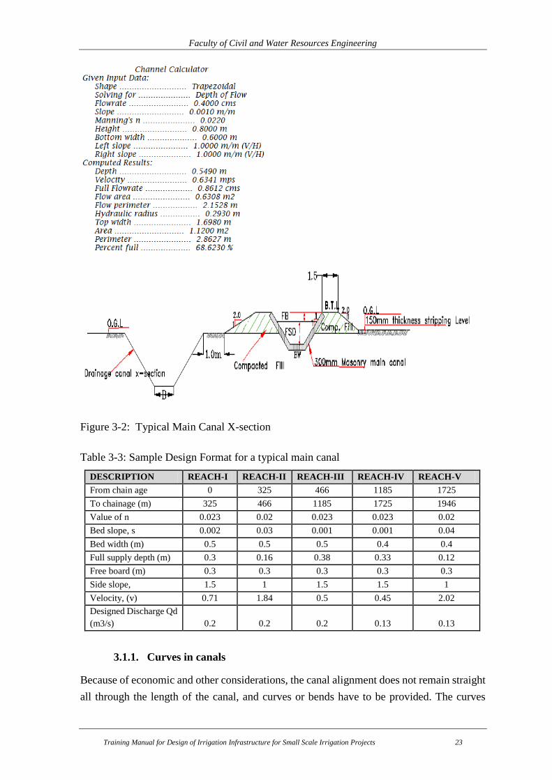
Figure 3-2: Typical Main Canal X-section
Table 3-3: Sample Design Format for a typical main canal
DESCRIPTION REACH-I REACH-II REACH-III REACH-IV REACH-V
From chain age 0 325 466 1185 1725
To chainage (m) 325 466 1185 1725 1946
Value of n 0.023 0.02 0.023 0.023 0.02
Bed slope, s 0.002 0.03 0.001 0.001 0.04
Bed width (m) 0.5 0.5 0.5 0.4 0.4
Full supply depth (m) 0.3 0.16 0.38 0.33 0.12
Free board (m) 0.3 0.3 0.3 0.3 0.3
Side slope, 1.5 1 1.5 1.5 1
Velocity, (v) 0.71 1.84 0.5 0.45 2.02
Designed Discharge Qd
(m3/s) 0.2 0.2 0.2 0.13 0.13
3.1.1. Curves in canals
Because of economic and other considerations, the canal alignment does not remain straight
all through the length of the canal, and curves or bends have to be provided. The curves

Faculty of Civil and Water Resources Engineering
Training Manual for Design of Irrigation Infrastructure for Small Scale Irrigation Projects 24
cause distributed flow conditions resulting in eddies or cross currents which increase the
losses. In the curved channel portion, the water surface is not level in the transverse
direction. There is a rise and drop of water surface in the outer and inner edge of the curves,
resulting a decrease and increase of flow velocities, respectively. Hence, there may be
erosion in the outer bank and deposition in the inner bends. Therefore, if curves are
unavoidable, it should have a long radius of curvature. The permissible minimum radius of
curvature for a canal curve depends on the type of canals, dimensions of cross-sections,
velocities during full-capacity operations, earth formation along canal alignment and danger
of erosion along the paths of curved canal.
Table 3-4: Values of minimum radii of canal curves for different canal capacities
Canal capacity (m3/s) Minimum radius of curvature (m)
Less than 0.3 100
0.3 to 3.0 150
3.0 to 15.0 300
15.0 to 30 600
30 to 85 900
More than 85 1500
3.1.2. Canal losses
When water comes in contact with an earthen surface, whether artificial or natural, the
surface absorbs water. This absorbed water percolates deep into the ground and is the main
cause of the loss of water carried by a canal. In addition some canal water is also lost due to
evaporation, which may be estimated around 10% of the quantity of water lost due to
seepage. The seepage loss is mainly depended on the material through which the canal
passes. Obviously, the loss is greater in coarse, less in loam and still less in clay.
For the purpose of estimating the water requirements of a canal, the total loss due to
evaporation and seepage, also known as conveyance loss, is expressed as m3/s per million
square meters of either wetted perimeter or the exposed water surface area.
3.2. Canal Design
With the water conveyance system for irrigation, comprising of the main canal, branch
canals (secondary), tertiary canals, field canals and water courses agreed upon with the
farmers, you are now ready to design canal sections and identify appropriate location of
various conveyance structures. The design process comprises of finding out of longitudinal
slopes of the channels and fixing the cross sections. The channels themselves may be made
up of different construction materials. For example, the main canals and secondary canals

Faculty of Civil and Water Resources Engineering
Training Manual for Design of Irrigation Infrastructure for Small Scale Irrigation Projects 25
may be lined and the smaller ones unlined depending upon the soil and estimates of seepage
losses in the canal. During longitudinal surveys, lengths of canals passing through sandy
soils or erodible soils should be marked on the longitudinal profile.
3.2.1. Main Canal Design
The basic data requirements to design the main canals are:
Peak water requirement or duty of the area in (l/s/ha)
The maximum command area, A in ha
Manning’s roughness coefficient
Canal gradient or slope for the given soil
The type of canal section to be used
Principle:
The design discharge of the main canal is based on the peak crop water requirements
which may account for the conveyance and field application efficiencies). In
addition, an allowance, often up to 10 to 20% depending upon the soil and reliability
of data, is sometimes included to account for inaccuracies in estimating some of the
design parameters.
In traditional or modern schemes in Amhara region, most canals are earthen canal
cross section. Key elements to be determined include, top bank width, bottom width
(b), side slopes (X: 1), water depth (d), freeboard, total depth (D = d + freeboard),
wetted area (As), wetted perimeter (P).’ And Hydraulic Radius (R = As/P) as shown
in Figure below.
Faculty of Civil and Water Resources Engineering
Training Manual for Design of Irrigation Infrastructure for Small Scale Irrigation Projects 26
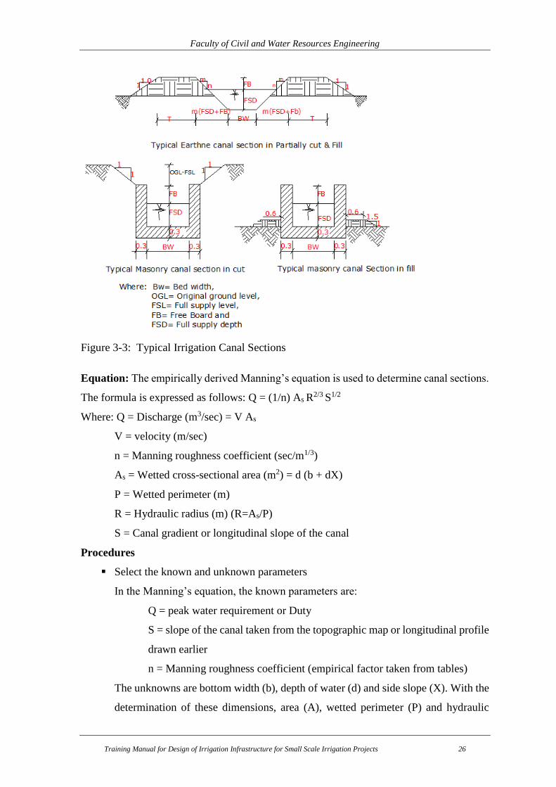
Figure 3-3: Typical Irrigation Canal Sections
Equation: The empirically derived Manning’s equation is used to determine canal sections.
The formula is expressed as follows: Q = (1/n) As R2/3 S1/2
Where: Q = Discharge (m3/sec) = V As
V = velocity (m/sec)
n = Manning roughness coefficient (sec/m1/3)
As = Wetted cross-sectional area (m2) = d (b + dX)
P = Wetted perimeter (m)
R = Hydraulic radius (m) (R=As/P)
S = Canal gradient or longitudinal slope of the canal
Procedures
Select the known and unknown parameters
In the Manning’s equation, the known parameters are:
Q = peak water requirement or Duty
S = slope of the canal taken from the topographic map or longitudinal profile
drawn earlier
n = Manning roughness coefficient (empirical factor taken from tables)
The unknowns are bottom width (b), depth of water (d) and side slope (X). With the
determination of these dimensions, area (A), wetted perimeter (P) and hydraulic
Faculty of Civil and Water Resources Engineering
Training Manual for Design of Irrigation Infrastructure for Small Scale Irrigation Projects 27
radius (R) can be estimated.
Select assumed non-scouring and non-silting velocities for various soils of your
command area.
Canals carrying water with excessively high velocities may cause erosion of the bed and the
sides of the channel leading to the collapse of the canal. If the velocity is low, the sediment
will deposit in the canal requiring frequent cleaning. Low velocities also encourage weed
and plant growth in the channel. Therefore, the minimum permissible velocity should inhibit
the growth of vegetation in the canal. In addition, the velocity should be high enough not to
permit the settlement of suspended material (non-silting velocity). The velocity chosen
should be higher than the “Minimum permissible velocity" to prevent growth of vegetation
and lower than the “Maximum permissible velocity” which will deter both sedimentation
and vegetative growth. Maximum permissible velocities depend on the soil material, but
generally for small scale irrigation projects a design velocity of about 0.75 to 1 m/sec is
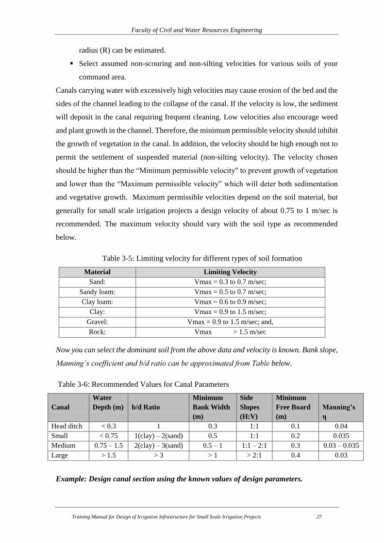
recommended. The maximum velocity should vary with the soil type as recommended
below.
Table 3-5: Limiting velocity for different types of soil formation
Material Limiting Velocity
Sand: Vmax = 0.3 to 0.7 m/sec;
Sandy loam: Vmax = 0.5 to 0.7 m/sec;
Clay loam: Vmax = 0.6 to 0.9 m/sec;
Clay: Vmax = 0.9 to 1.5 m/sec;
Gravel: Vmax = 0.9 to 1.5 m/sec; and,
Rock: Vmax > 1.5 m/sec
Now you can select the dominant soil from the above data and velocity is known. Bank slope,
Manning’s coefficient and b/d ratio can be approximated from Table below.
Table 3-6: Recommended Values for Canal Parameters
Canal
Water
Depth (m)
b/d Ratio
Minimum
Bank Width
(m)
Side
Slopes
(H:V)
Minimum
Free Board
(m)
Manning’s
η
Head ditch < 0.3 1 0.3 1:1 0.1 0.04
Small < 0.75 1(clay) – 2(sand) 0.5 1:1 0.2 0.035
Medium 0.75 – 1.5 2(clay) – 3(sand) 0.5 – 1 1:1 – 2:1 0.3 0.03 – 0.035
Large > 1.5 > 3 > 1 > 2:1 0.4 0.03
Example: Design canal section using the known values of design parameters.
Faculty of Civil and Water Resources Engineering
Training Manual for Design of Irrigation Infrastructure for Small Scale Irrigation Projects 28
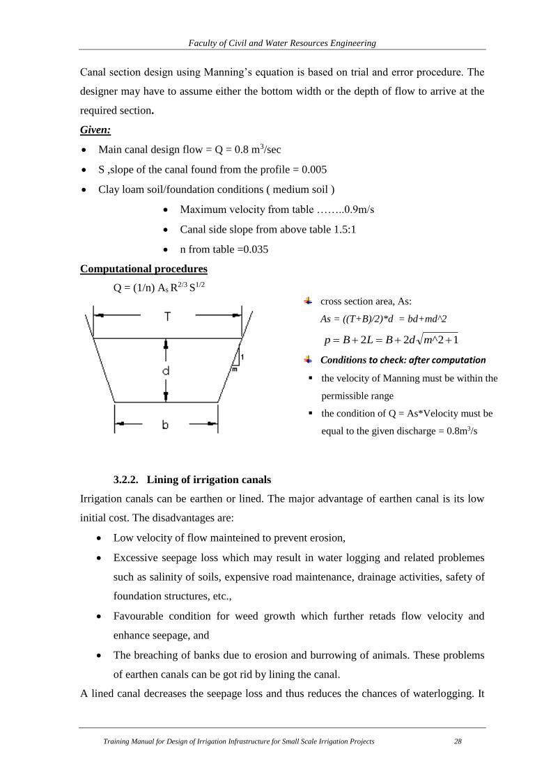
Canal section design using Manning’s equation is based on trial and error procedure. The
designer may have to assume either the bottom width or the depth of flow to arrive at the
required section.
Given:
Main canal design flow = Q = 0.8 m3/sec
S ,slope of the canal found from the profile = 0.005
Clay loam soil/foundation conditions ( medium soil )
Maximum velocity from table ……..0.9m/s
Canal side slope from above table 1.5:1
n from table =0.035
Computational procedures
Q = (1/n) As R2/3 S1/2
3.2.2. Lining of irrigation canals
Irrigation canals can be earthen or lined. The major advantage of earthen canal is its low
initial cost. The disadvantages are:
Low velocity of flow mainteined to prevent erosion,
Excessive seepage loss which may result in water logging and related problemes
such as salinity of soils, expensive road maintenance, drainage activities, safety of
foundation structures, etc.,
Favourable condition for weed growth which further retads flow velocity and
enhance seepage, and
The breaching of banks due to erosion and burrowing of animals. These problems
of earthen canals can be got rid by lining the canal.
A lined canal decreases the seepage loss and thus reduces the chances of waterlogging. It
cross section area, As:
As = ((T+B)/2)*d = bd+md^2
12^22 mdBLBp
Conditions to check: after computation
the velocity of Manning must be within the
permissible range
the condition of Q = As*Velocity must be
equal to the given discharge = 0.8m3/s

Faculty of Civil and Water Resources Engineering
Training Manual for Design of Irrigation Infrastructure for Small Scale Irrigation Projects 29
also saver water which can be utilized for additional irrigation. A lined canal provides safety
against breaches and prevents weed growth thereby reducing the annual maintenance cost
of the canal. Because of relatively smooth surface lining, a lined canal requires a flatter
slope. This results in an increase in the command area.
3.2.3. Design of Distribution Systems (Secondary & Tertiary)
1. Determination of Minimum Channel Water Level (MCWL) for Each Irrigation
Block
This is a level at the end of the canal and the elevation can be obtained by knowing the
higher ground elevation at end of the canal. Then, to irrigate all areas below this bed level,
all head loss back up to the outlet must be added and the outlet fixed.
MCWL = elevation at the end + canal length *(slope of canal) + head regulator (0.05)
Exercise: The field channel slope is 1 in 1000; the distance from the weir outlet to the lower
higher ground is 100m. Calculate MCWL if the culvert level is 10 m.
MCWL = 10 + 100/1000 + 0.05 = 10.15 m
If the channel water level is at 10.15 m, the highest ground level in the irrigation block will
be irrigated. The designer should make a judgment on the high ground level to ensure that
the minimum channel water level is not too high.
2. Plot the Design Top Water Level on the Longitudinal Section for Each Canal.
Existing ground levels, taken from the surveying, are plotted for each channel and the
MCWL for each channel are marked in the appropriate locations on a graph paper. A line,
passing through the highest MCWL regarded as top water level (TWL), is produced
backwards at the selected hydraulic gradient or slope of the bed level.
The slope of the canal should be adjusted to coincide as closely as possible with ground
slopes thus minimizing earth moving. However steep slopes are dangerous. The maximum
slope of earthen channels depends on soil type and must be selected in the ranges not greater
than 1 in 300 in medium or heavy soils (clay loam or clay) or 1 in 1,000 in light soils (sand
or loam).
For greater slopes or for sudden drops in ground levels, using channel lining or drop
structures is necessary. For flatter Slopes, it is advisable to make the canal gradient as high

Faculty of Civil and Water Resources Engineering
Training Manual for Design of Irrigation Infrastructure for Small Scale Irrigation Projects 30
as possible or the channel embankment height may be increased even though a certain
amount of land may be reduced.
3. Mark the Channel TWL on the Longitudinal Profile of Main Canal
The longitudinal profile of the main canal has been prepared in the above steps. Mark the
top water level (TWL) elevation on the longitudinal profile of the main canal at the division
box. Once all the TWL of field channels have been marked, draw a line joining all TWLs.
This line is the minimum canal water level (MCWL) of the main canal required to irrigate
the entire command area.
The MCWL should be checked with the design depth (d) of water in the main canal. If the
design depth is lower than MCWL, the canal section should be redesigned to increase the
depth. If the design depth is higher than MCWL, attempts should be made to lower the depth
either by lowering the bed elevation or adjusting the slope of the bed of canal. At a junction
of two feeder canals (a division), the water level upstream must be adjusted for the canal
with the higher command.
4. Determine Construction Levels for Field Canals.
After the top water level (TWL) has been drawn, the dimensions of the channel are decided.
Typical cross sections for each of the channels can be estimated using the Manning’s
equation or selecting from standard sections. The depth of water is determined by the canal
slope which may vary depending on soil type, existing ground slope and TWL. Knowing
the depth of flow, the channel invert level (IL) may be calculated and entered into the
channel design and drawn on the main section.
To prevent overtopping by surges resulting from fluctuations in discharge, or through the
consolidation of embankments, a freeboard allowance is added to the TWL to obtain the
bank top level (BTL).
5. Determine Construction Dimensions and Levels for Structures
The locations of outlets, drop structures and division boxes are determined in previous
Steps. The upstream invert level of a structure is determined by the invert of the upstream
canal. This is equal to the upstream water level (MCWL) minus the depth of flow. The
downstream invert level of a standard check or division structure by reducing the loss of

Faculty of Civil and Water Resources Engineering
Training Manual for Design of Irrigation Infrastructure for Small Scale Irrigation Projects 31
energy caused by the structure. When loss of energy through the structure cannot be
calculated, it is safe to assume an energy loss of 0.05m through the structure.

Faculty of Civil and Water Resources Engineering
Training Manual for Design of Irrigation Infrastructure for Small Scale Irrigation Projects 32
3.1.1. Canal L-Section
The slope of the channel is fixed based on existing topography/slope consistent with
economy. A steeper slope governed by maximum permissible velocity, will be most
economical, but it will lower the FSL, causing less irrigation. Hence, the maximum possible
irrigation would indicate flatter slopes governed by minimum permissible velocity. A
balance between these two limits must be adopted for selecting a suitable bed slope for the
channel. If the chosen designed slope is found to be flatter than the natural available slope,
the difference can be adjusted by providing suitably designed falls (drop structures).
Normally, the profiles of the canals are done by using simple dos based software called l-
section. To use L-section, you have to have an AutoCAD 2002 or 2004 version and
Microsoft excel 1997-2003 versions in your computer.
The output from the L-Section looks like the following.
Figure 3-4: Result from Canal L-Section
4. LAND DRAINAGE WORKS
A drainage system is necessary to remove excess water from the irrigated land. This excess
water may be e.g. waste water from irrigation or surface runoff from rainfall. It may also
include leakage or seepage water from the distribution system.
Excess surface water is removed through shallow open drains. Excess groundwater is
removed through deep open drains or underground pipes. Two types of drainage can be
provided
Surface drainage,

Faculty of Civil and Water Resources Engineering
Training Manual for Design of Irrigation Infrastructure for Small Scale Irrigation Projects 33
Sub-surface drainage
Surface drainage
The removal of excess rain water falling on the fields or the excess irrigation water
applied to the fields, by constructing open ditches, field drains, and other related
structures.
The land is sloped towards these ditches or drains, as to make the excess water flow
in to these drains
Main activities in this category are:
Drainage System layout (to be prepared simultaneously with the irrigation canal
layout)
Drainage System Selection
Drainage canals design
Drainage Canal Design Discharge Estimation
Drainage canal x-sections
Interceptor Drain (Catch Drain)
Drainage canal structures
4.1. Drainage Canal Design Discharge Estimation
The in-field drainage can be designed for the 1 in 5 year 24 hour rainfall event i.e. the drains
are designed to remove the volume of runoff from a 1 in 5 year, 24 hour storm in 24 hours.
The rational method estimates the peak run off at a specific watershed location as a function
of the drainage area, run off coefficient, and mean rainfall intensity for a duration equal to
the time of concentration, Tc. 𝑄 = 1
3.6 *C*i*A
Where, Q: design peak discharge (m3/sec)
C: runoff coefficient
i: rainfall intensity in mm/h for the design return period and for a duration equal
to the “time of concentration ” of the watershed
A: the watershed area (km2)
Table 4-1: Value of “C” is based on the recommendation of tables
Topography and vegetation Soil texture
Open sandy loam Clay and silt loam Tight clay
Woodland Flat 0-5% slope 0.1 0.3 0.4
Rolling 5-10% slope 0.25 0.35 0.5

Faculty of Civil and Water Resources Engineering
Training Manual for Design of Irrigation Infrastructure for Small Scale Irrigation Projects 34
Topography and vegetation Soil texture
Open sandy loam Clay and silt loam Tight clay
Hilly 10-30% slope 0.3 0.5 0.6
Pasture
Flat 0-5% slope 0.1 0.3 0.4
Rolling 5-10% slope 0.16 0.36 0.55
Hilly 10-30% slope 0.22 0.42 0.6
Cultivated
Flat 0-5% slope 0.3 0.5 0.6
Rolling 5-10% slope 0.4 0.6 0.7
Hilly 10-30% slope 0.52 0.72 0.82
4.2. Interceptor Drain (Catch Drain)
The interceptor drains run parallel to the main canal. The drains intercept the overland flow
from the uplands above the canal. The interceptor drains will discharge into the rivers or
nearby gullies as appropriate:
Estimation of catchment area for the interceptor drain
Inlet and outlet conditions
Protection works
Canal structures
Identify the structures in your irrigation system
Drop Structures
Division Boxes /Turnouts
Cross-drainage structures
Measuring structures
Protective structures, Etc
Collect appropriate data for the design of the structures (hydrology, geology, detailed
topomap, etc)
Design your structures (typical designs, hence systematize your work)

Faculty of Civil and Water Resources Engineering
Training Manual for Design of Irrigation Infrastructure for Small Scale Irrigation Projects 35
5. DESIGN OF IRRIGATION SYSTEM STRUCTURES
5.1 Design of Division Box
The division boxes are used to divert the required amount of water from the parent canal to
the branching canal for the specified period of time to irrigate the command area. Normally,
gates are provided at the division boxes to control the outflow of water. The function of
division boxes is to serve the proportioning of the irrigation water based on the available
land downstream.
Basic Consideration of the Design
At each division boxes, control gates are provided
The basin width of the division boxes is equal to the bed width of the main canal
plus some additional width for stabilizing the flow.
The proportionality of the division boxes is adjusted with the width of the outlet and
the head over the sill is the same on both canals. It follows the continuity equation.
Width of outlet to tertiary canal, Br = (Qr /Qo) x Bo
Where Qr = Design discharge to tertiary canal
Qo = Design discharge in the main canal
Bo = Main canal bed width
But from construction point of view provide bed widths < 0.25m outlet width.
Figure 5-1: Typical one-way division box
Where:
B1, B2 and B3= are canal bed widths,
B= basin width,
L= width of basin

Faculty of Civil and Water Resources Engineering
Training Manual for Design of Irrigation Infrastructure for Small Scale Irrigation Projects 36
Figure 5-2: Division Box on field on earthen canal
Example: find the minimum bed width for the Tertiary canal capacity of 80 l/s diverted from
main canal of Q=240 l/s .Take the bed width of main canal is 0.6m.
Solution:
Qr = Design discharge to tertiary canal =80l/sec
Qo = Design discharge in the main canal = 240l/sec
Bo = Main canal bed width = 0.6m
Width of each outlet = (80/240)* 0.6 = 0.20 m
But from construction point of view provide 0.30 m outlet width.
5.2 Design of Drop Structures
Drop structures are required when the ground slope along which the canals are laid is beyond
the recommended limit. A canal given with higher slope than the recommended will be
dangerous and will create erosion of the command area and becomes deepen thereby not
commanding the irrigable land. Canal of higher slope having higher discharge will make
the risk more sever. Therefore, it will be advisable to break the slope length into reasonable
lengths so that the recommended slopes can be easily maintained minimizing scouring of
the channels. The height of drops should not be greater than 1m and less than 0.5m. If the
land slope is too steep the drop spacing will be denser and construction of drops may not be
economical. In such cases the canal should be wholly lined with masonry (chutes).
The location of a fall has to be judiciously worked out such that there should be a balance
between the quantities of excavation and filling. Further the height of the fall has to be
decided, since it is possible to provide larger falls at longer intervals or smaller falls at

Faculty of Civil and Water Resources Engineering
Training Manual for Design of Irrigation Infrastructure for Small Scale Irrigation Projects 37
shorter intervals. It may be observed that the portion of the canal which is running in filling
may be able to serve the surrounding area by releasing water by gravity. For the portion of
the canal that is running in excavation, if surrounding areas have to be irrigated, it has to be
done through pumping.
There are various types of fall structures, some of which are no more provided these days.
The most widely used one is the USBR type of drop. The design principle for this type of
drop is discussed below:
Figure 5-3: Typical location for providing canal drop or fall
1. Critical flow hydraulics parameters
a. Design discharge, Q
b. Height of drop, H
c. Width of drop, bc= bed width of main canal
d. Unit discharge, q =Q/bc
e. Critical depth, g
qdc
3/2
2. Stilling basin
a. Lip height, 2
dca

Faculty of Civil and Water Resources Engineering
Training Manual for Design of Irrigation Infrastructure for Small Scale Irrigation Projects 38
b. Length, L c
cc hdh
d
h
dL
3
7.01.15.2
c. Width of Basin, 91.9
46.18
Q
QB
Example: Design a Vertical Drop (U.S.B.R. Type) the given data
Figure 5-4: typical drop structure
1. Given data:
a. Design discharge = 0.4m3/s
b. Height of drop =1m
c. Canal bed width, B = 0.8m
2. Critical flow hydraulics
a. Width of drop= canal bed width = 0.80m
b. Unit discharge,
mm
b
c
sec//500.0)80.0(
400.0 3
e. Critical depth,
mg
qd c 294.0
81.9
500.03
123
12
3. Stilling basin
a. Lip height,
mused
a c 15.0147.02
294.0
2
Faculty of Civil and Water Resources Engineering
Training Manual for Design of Irrigation Infrastructure for Small Scale Irrigation Projects 39
muse
hdh
d
h
dLLengthb c
cc
6.154.1383.0)289.3(
294.0*0.10.1
294.07.0
0.1
294.01.15.2
7.01.15.2,.
3
3
c. Width. museQ
QB 20.113.1
91.9)400.0(
)400.0(46.18
91.9
46.18
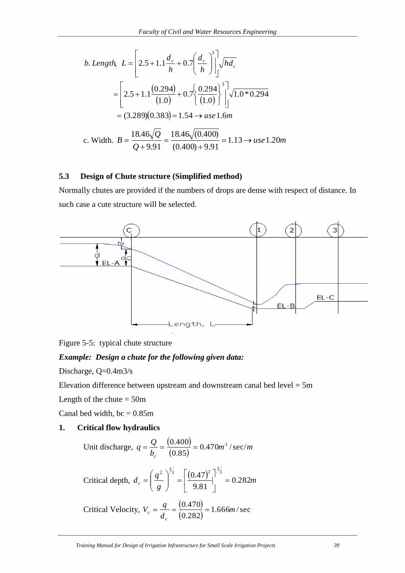
5.3 Design of Chute structure (Simplified method)
Normally chutes are provided if the numbers of drops are dense with respect of distance. In
such case a cute structure will be selected.
Figure 5-5: typical chute structure
Example: Design a chute for the following given data:
Discharge, Q=0.4m3/s
Elevation difference between upstream and downstream canal bed level = 5m
Length of the chute = 50m
Canal bed width, bc = 0.85m
1. Critical flow hydraulics
Unit discharge,
mmb
c
sec//470.085.0
400.0 3
Critical depth,
mg
qd c 282.0
81.9
47.03
123
12
Critical Velocity,
sec/666.1282.0
470.0m
d
qV
c
c

Faculty of Civil and Water Resources Engineering
Training Manual for Design of Irrigation Infrastructure for Small Scale Irrigation Projects 40
Velocity head,
mxg
Vh c
vc 141.081.92
666.1
2
22
Water area, mxdbA ccc 240.0)282.0()850.0(
Wetted Perimeter, mxdbP ccc 414.1)282.0(2)85.0(2
Hydraulic radius,
mP
AR
c
c
c 1697.0414.1
240.0
Water surface slope,
00854.0
1697.0
666.1017.02
32
2
32
x
R
nVI
c
c
c
2. Energy at Section (C)
mZhdE
mBELAELZ
vccc 423.5)000.5()141.0()282.0(
00.5)000.1795()000.1800(..
3. Energy at Section (1)
Designation Results of the calculation
Trial number 1 2 3 4
Assumed depth, d1 0.20 0.10 0.105 0.1045
b1 = b 0.85 0.85 0.85 0.85
A1 = b1*d1 0.1700 0.0850 0.0893 0.0888
V1 = Q/A1 2.3529 4.7059 4.4818 4.5032
hv1 = V1^2/(2g) 0.2822 1.1287 1.0238 1.0336
P1 = b1 +2*d1 1.2500 1.0500 1.0600 1.0590
R1 = A1/P1 0.1360 0.0810 0.0842 0.0839
I1 = [(ηV1)/(R1^(2/3)]^2 0.0229 0.1828 0.1573 0.1596
Im = (Ic+I1)/2 0.0157 0.0956 0.0829 0.0841
hf1 = Im*L 0.7854 4.7824 4.1460 4.2041
E1 = d1 +hv1 +hf1 1.2676 6.0111 5.2748 5.3422
E1= Ec = 5.423 Too small Too Big a little small o.k.
4. Conjugate depth after jump
Froude number,
48.4)104.0(81.9
525.4
1
1 xgd
VF
Conjugate depth, mFd
d r 609.01)48.4(812
104.0181
2
2212

Faculty of Civil and Water Resources Engineering
Training Manual for Design of Irrigation Infrastructure for Small Scale Irrigation Projects 41
5. Stilling basin
a. Length, musexdL 50.2436.2)609.0(44 2
b. Width,
muse
Q
QB 20.113.1
91.9400.0
400.046.18
91.9
46.18
c. Bottom elevation (EL.C)
maBELCEL
musemEEa
mhdE
mhdE
mxg
Vh
smd
qV
v
v
v
850.1794)15.0()000.1795(..
15.0120.0)519.0()639.0(
519.0)019.0()500.0(
639.0)030.0()609.0(
030.081.92
772.0
2
/772.0609.0
470.0
32
333
222
22
22
2
2
5.4 Pipe Culvert (road crossing) Structure
Pipe culvert crossing structure is provided when the irrigation canal crosses the road. To
bypass the water a pipe culvert can be designed as below. But it is also possible to construct
the canal at the crossing point using masonry and hence, provide a slab cover.
Figure 5-6: Typical road crossing structure
Example: designing of pipe culvert
1. Hydraulic calculation
a. Given Data
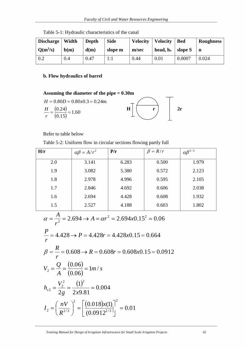
Faculty of Civil and Water Resources Engineering
Training Manual for Design of Irrigation Infrastructure for Small Scale Irrigation Projects 42
Table 5-1: Hydraulic characteristics of the canal
Discharge
Q(m3/s)
Width
b(m)
Depth
d(m)
Side
slope m
Velocity
m/sec
Velocity
head, hv
Bed
slope S
Roughness
n
0.2 0.4 0.47 1:1 0.44 0.01 0.0007 0.024
b. Flow hydraulics of barrel
Assuming the diameter of the pipe = 0.30m
60.115.0
24.0
.24.03.080.080.0
r
H
mxDH
H r 2r
Refer to table below
Table 5-2: Uniform flow in circular sections flowing partly full
H/r 2/ rA P/r rR / 3/2
2.0
1.9
1.8
1.7
1.6
1.5
3.141
3.082
2.978
2.846
2.694
2.527
6.283
5.380
4.996
4.692
4.428
4.188
0.500
0.572
0.595
0.606
0.608
0.603
1.979
2.123
2.105
2.038
1.932
1.802
01.0
0912.0(
)1(018.0
004.081.92
1
2
/106.0
06.0
0912.015.0608.0608.0608.0
664.015.0428.4428.4428.4
06.015.0694.2694.2
2
3/2
2
3/22
22
22
2
22
2
x
R
nVI
xg
Vh
smA
QV
xrRr
R
xrPr
P
xrAr
A
v
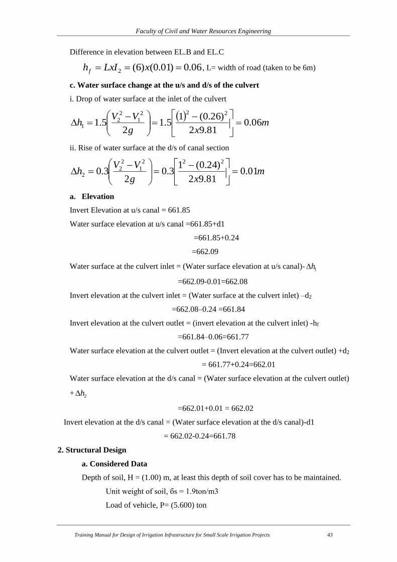
Faculty of Civil and Water Resources Engineering
Training Manual for Design of Irrigation Infrastructure for Small Scale Irrigation Projects 43
Difference in elevation between EL.B and EL.C
06.0)01.0()6(2 xLxIh f , L= width of road (taken to be 6m)
c. Water surface change at the u/s and d/s of the culvert
i. Drop of water surface at the inlet of the culvert
m
xg
VVh 06.0
81.92
)26.0(15.1
25.1
222
1
2
21
ii. Rise of water surface at the d/s of canal section
mxg
VVh 01.0
81.92
)24.0(13.0
23.0
222
1
2
22
a. Elevation
Invert Elevation at u/s canal = 661.85
Water surface elevation at u/s canal =661.85+d1
=661.85+0.24
=662.09
Water surface at the culvert inlet = (Water surface elevation at u/s canal)- 1h
=662.09-0.01=662.08
Invert elevation at the culvert inlet = (Water surface at the culvert inlet) –d2
=662.08–0.24 =661.84
Invert elevation at the culvert outlet = (invert elevation at the culvert inlet) -hf
=661.84–0.06=661.77
Water surface elevation at the culvert outlet = (Invert elevation at the culvert outlet) +d2
= 661.77+0.24=662.01
Water surface elevation at the d/s canal = (Water surface elevation at the culvert outlet)
+ 2h
=662.01+0.01 = 662.02
Invert elevation at the d/s canal = (Water surface elevation at the d/s canal)-d1
= 662.02-0.24=661.78
2. Structural Design
a. Considered Data
Depth of soil, H = (1.00) m, at least this depth of soil cover has to be maintained.
Unit weight of soil, бs = 1.9ton/m3
Load of vehicle, P= (5.600) ton

Faculty of Civil and Water Resources Engineering
Training Manual for Design of Irrigation Infrastructure for Small Scale Irrigation Projects 44
b. Load
Figure 5-7: Distribution of load over pipe culvert
i. Dead load
Soil: W1 = бs *H = 1.90*1= 1.9ton/m2
ii. Live load
E = 0.20 + 1.75H = 0.20 + 1.75(1.00) = (1.950) m
F = 2.25 + 1.75H = 2.25 + 1.75 (1.00) = (4.000) m
2
2 /436.1)0.0(1)00.4)(95.1(
)6.5(2)1(
2mtoni
EF
PW
Where, i: impact factor
iii. Total load
W = w1 + w2 = (1.900) + (1.436) = 3.336 tan/m3
C. Moment
Maximum bending moment
R= 0.5(D+ t) = 0.5[(0.3) + (0.05)] =0.175
M= kWR2= (0.314) (3.336) (0.175)2 =0.032
Where, W: uniform load (ton/m2)
R: radius of culvert (m)
Impact factor of the various fill depth
Depth of fill H (m) Impact factor, i
0.0 - 0.3 0 - 0.3
0.3 - 0.6 0.2
0.6 - 0.9 0.1
Over 0.9 0

Faculty of Civil and Water Resources Engineering
Training Manual for Design of Irrigation Infrastructure for Small Scale Irrigation Projects 45
t: Wall thickness (m)
k: load coefficient due to bedding
Table 5-3: Load coefficient due to bedding
Angle of
bedding
(deg).
K Bedding material Remark
Granular Concrete Granular Concrete
90
120
180
0.314
0.275
0.250
0.303
0.243
0.220
ii. Minimum resisting moment
)003.0()06.0(
)175.0)(07.0(239.0)175.0(318.0239.0318.0
/07.04.2)071.0(1.0)(
1.04
)05.0(23.014.3
4
)2(
071.04
)3.0(14.3
4
2
12
2
22
2
222
1
Q
QRWQRM
mtonxAAW
mxtD
A
mxD
A
cr
cc
Where, бc Unit weight of culvert (ton/m3)
Q: Required supporting strength (ton/m)
Wc: Weight of culvert (ton/m2)
d. Required supporting strength
Mr = f*M
Where, F: factor of safety (=1.5)
Mr M
(0.06) Q + (0.003) = 1.5 (0.032) = (0.05)
Q= [(0.05) – (0.003)] / (0.06) = (0.78) ton/m
Concrete pipe with extra –quality usually shows the strength of 2,380 kg/m .It can be
assumed that the strength of the pipe is the same that of concrete pipe. Hence, Q=780kg/m
< 2,380 kg/m o.k.
However, it is very common to strengthen the pipe by bundling 10cm thick cement mortar
conventionally. Details are shown in the drawing Album.
e. Design of bedding
Concrete bedding

Faculty of Civil and Water Resources Engineering
Training Manual for Design of Irrigation Infrastructure for Small Scale Irrigation Projects 46
c
c
b
Mdand
b
pm
4.26'455.0
0
where, )4(3
2' factorsafetypP
'455.0
2))cos1)((sin)(
4
'
PH
HdtrHtr
PM c
Where, H: horizontal stress (ton/m)
:c Allowable stress of concrete (30kg/cm2)
r: inside radius (cm)
t: wall thickness (cm)
: Angle of bedding (degree)
d: thickness of the bedding (cm)
:0 Allowable tangential stress of concrete (=3kg/ cm2)
b: limit length =100cm
p = 3.336 ton/m
r = 15cm
t = 5cm
cmusecmd
dd
dd
d
cmkgd
dM
cmuseb
Hm
mtonxPH
mtonxPP
c
1536.14
0384.142453.4
453.4384.142)30)(100(
)506180,16(4.26
)..(50616180
2
012,190cos1515012,1)90sin()5(15
4
224,2
537.33100
012,1
/012.1)224.2(455.0'455.0
/224.2)336.3(3
2
3
2'
2
00
0
5.5 Design of River crossing structure (Multi span flume)
When the discharging canal crosses Main River or gullies the design of flume is very
important to bypass the flow to the required place.
I. Design of Flume
Design a flume having one pier at the center. The span has a length of 7m.
Hydraulic Design of multi-spian Flume structure
For maximum safety, take the longest span, i.e. 7m, flume bed width=0.30m, total canal

Faculty of Civil and Water Resources Engineering
Training Manual for Design of Irrigation Infrastructure for Small Scale Irrigation Projects 47
depth =0.45m.
1. Load analysis
A. Live load: Critical condition, when the canal is full of water.
mKNw /32.181.9*45.0*30.01
B. Dead load: Assume the thickness of the bed slab of the canal is 20cm and thickness
of the wall is 10cm.
W2= (0.2*0.4+2*0.1*0.45)24=4.08kN/m
C. Design load:
Wd=1.3*1.32+1.6*4.08=8.244KN/m
Since the beam is an indeterminate beam, for analysis use three moment equation method.
bXAbaXAaL
McMbMa **6
42
Take section at one support, say B:
Load distribution on the slab of flume
KNlw
M 50.508
49*244.8
8
*max,
2
, mLbXaX 5.32/
30.2698*8*3
49*244.8*2*
8*3
**2 2
LLw
AaAb
55.9425.3*30.269**
bXAbXaAa
For simply supported beam; Ma=Mc=0.
Then mKNMbMb /85.2840.11555.942*27
6*4
2

Faculty of Civil and Water Resources Engineering
Training Manual for Design of Irrigation Infrastructure for Small Scale Irrigation Projects 48
,0Mb KNRALw
MbLRA 73.247/85.282
7*244.8
2
**
22
,0Fv mKNRBRBRALw /28.3043.277*244.8*
Let’s take a section at X-distance from support A.
2**
2xwxRAMx
mw
RAXxwRAxwRA
x
m67.3
244.8
28.30*0*
Hence, Moment is maximum at 3.67m from support A.
mKNxw
xRAM 61.552
67.3*244.867.3*28.30
2
**max,
22
2. Design for Bending
The following data are known:
MPafyk 420 ; Mpafck 25 ; MPaEs 000,200 ; MPaEc 000,26
MPas
fykfyd 22.365
15.1
420
;
MPas
fckfcd 17.11
5.1
25420*67.0*67.0
Reinforcement ratio: 0161.0*
0035.0
0028.0
fyd
fcd
Es
fyd
To ensure ductility, 0121.00161.0*75.0*75.0max
3956.017.11
22.365*0121.0max*max
fcd
fyd
Where: fyk - tensile strength of reinforcement;
fck - Compressive strength of concrete;
fyd - Design strength of reinforcement;
fcd - Design strength of concrete;

Faculty of Civil and Water Resources Engineering
Training Manual for Design of Irrigation Infrastructure for Small Scale Irrigation Projects 49
Ec - Modulus of elasticity of concrete; and
Es -Modulus of elasticity of steel; Es =200GPa at yield point.
3714.02
3956.03956.0
2
max
1
max 22
mmddbfcd
M50.174
3714.0*400*17.11
10*50.50
**
max 6
2
2
covused
erdD
, where: D is the total depth, d, calculated depth, and
ϕused is the diameter of the bar.
mmD 50.1922
161050.174 , Dcalculated (192.50mm) < Dassumed (200mm),
hence, the assumed thickness is sufficient.
282.0200*400*17.11
10*5.50
**
max2
6
2
dbfcd
M ,
340.0282.0*211*211
3956.0max340.0 , this indicates the section is singly reinforced.
Therefore, 289.831400*200*22.365
17.11*340.0*** mmdb
fyd
fcdAs
Area of steel, 222
06.2014
16*
4
*mm
Das
Number of bars, 406.201
89.831
as
Asn
Provide 4φ16mm bars @1266.67mm c/c spacing as main reinforcement.
Canal Wall Design
The total force due to water on the canal wall is:
mKNh
hh
Ph /993.02
45.0*81.9
2*
2
0* 22
Check for shear force for the canal wall thickness
232 /10*93.9/93.91*1.0
993.0max mmKNmKN
Area
forcetotalV
Allowable shear stress of C-25 concrete is 3.75N/mm2. Therefore the thickness
of the wall is sufficient for shear.
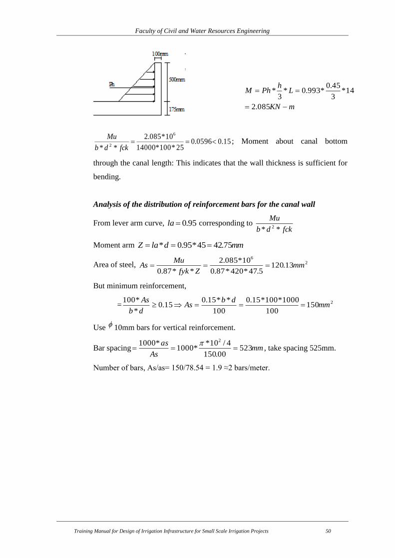
Faculty of Civil and Water Resources Engineering
Training Manual for Design of Irrigation Infrastructure for Small Scale Irrigation Projects 50
15.00596.025*100*14000
10*085.2
**
6
2
fckdb
Mu; Moment about canal bottom
through the canal length: This indicates that the wall thickness is sufficient for
bending.
Analysis of the distribution of reinforcement bars for the canal wall
From lever arm curve, 95.0la corresponding to fckdb
Mu
** 2
Moment arm mmdlaZ 75.4245*95.0*
Area of steel, 26
13.1205.47*420*87.0
10*085.2
**87.0mm
Zfyk
MuAs
But minimum reinforcement,
= 2150100
1000*100*15.0
100
**15.015.0
*
*100mm
dbAs
db
As
Use 10mm bars for vertical reinforcement.
Bar spacing mmAs
as523
00.150
4/10**1000
*1000 2
, take spacing 525mm.
Number of bars, As/as= 150/78.54 = 1.9 ≈2 bars/meter.
mKN
Lh
PhM
085.2
14*3
45.0*993.0*
3*

Faculty of Civil and Water Resources Engineering
Training Manual for Design of Irrigation Infrastructure for Small Scale Irrigation Projects 51
6. ENGINEERING COST ESTIMATION TABLE FORMAT FOR
INFRASTRUCTURE SYSTEM
The preparation and subsequent use of bills of quantities on construction projects is the
major process involving measurement techniques. The bill of quantities (measurements of
work’s specification) is prepared from the drawings by the quantity surveyor. It has to be
made in accordance with “Standard Technical Specifications Method of Measurements for
Construction of Buildings” by BaTCoDA. Normally, it is very essential to develop an excel
sheet to compute the earth works and also other items. Here, a sample infrastructure item of
works are listed.
Some uses of bill of quantities
To measure the work contained in the construction or alteration of building works
in a systematic and standard manner in order to obtain competitive tenders from
contractors
To assist in the preparation of valuations of work in progress in order to make stage
payments to the contractor
To assist the contractor in planning resources such as materials, labor and plant
To assist the valuations of variations occurring during the progress of the project
To assist in the preparation of the final account at the completion of the project
Table 6-1: Cost Summery
Bill No. Description Amount in Birr
1 General Items
2 Headwork Structure
3 Irrigation and Infrastructure
4 Access /Inspection road
Total
VAT (15%)
Grand Total
Note: i. 10% of the total price will be covered by the user community
ii. Formwork is part of concrete works
iii. Cart away up to 200m downstream and simple site clearing works (removal of
grasses, crop root remains and etc) are part of excavation works and during bidding
all the contractors shall fill rate with this concept in mind.

Faculty of Civil and Water Resources Engineering
Training Manual for Design of Irrigation Infrastructure for Small Scale Irrigation Projects 52
Table 6-2: General Items
SN Description Unit Qty Rate Total
Amount
1 Preparatory Work
1.1 Mobilization LS
1.2 Demobilization LS
1.3
Provide standard project indicator post using --m*----
m flat sheet metal using RHS as column and stiffening
starting from the construction time, one at turn from
main road and the other at turn to the project
(beginning of access road to project)
No
Sub total
2 Camp (Staff residence, Office, Store, Café, Kitchen,
Toilet & Shower)
A Residential (8m by 4m) & office (6m by 4m) rooms
2.1 Earth Work
2.1.1 Excavation for any type of materials (up to a
maximum of 1 m depth) m3
2.1.2
Provide and fill hard core with hard basaltic or
equivalent stone, well compacted and blinded with
crushed stone
m2
2.2 Concrete and Masonry Work
2.2.1
Stone masonry work below and above ground level
(up to a maximum of 1m below ground and 0.5m above
ground)
m3
2.2.2 Concrete fill on floor slab C-10 (10cm thick). m3
2.3 Carpentry and Walling
2.3.1
Supply, assemble and fix in position eucalyptus wall
post of length 3 m with span length of 1.2m with anti-
termite treatment
No
2.3.2 Supply and fix purlin in Eucalyptus wood size 50 x 70
mm nailed into eucalyptus truss m
2.3.3
Supply and fix wall cover in G-32 mm corrugated
galvanized iron sheet fixed into zigba wood purlin with
dome headed galvanized nails (purlin and ridge cover
measured separately)
m2
2.3.4 Chip wood wall ceiling m2
2.3.5 Supply and fix 4x5 mm ceiling buttons m
2.4 Carpentry and Roofing
2.4.1
Supply, assemble and fix in position eucalyptus roof
truss of length 3m span price shall include the
application of three coats and external anti-termite
treatment as per the drawing
No
2.4.2
Supply and fix purlin in eucalyptus wood size 50 x 70
mm nailed into eucalyptus truss including three coats
of anti - termite external treatment
m

Faculty of Civil and Water Resources Engineering
Training Manual for Design of Irrigation Infrastructure for Small Scale Irrigation Projects 53
SN Description Unit Qty Rate Total
Amount
2.4.3
Supply and fix roof cover in G-32 mm corrugated
galvanized iron sheet fixed into Zigba wood purlin
with dome headed galvanized nails (purlin and ridge
cover measured separately)
m2
2.4.4 Supply and fix G-32 mm CIS windows size 1x1.2m
with all accessories No
2.4.5 Supply and fix G-32 mm CIS doors size 1.0x2.10m
with all accessories No
2.5 Finishing
2.5.1 Floor screed in cement mortar m2
Sub total
3 Store (4m by 3m)
3.1 Earth Work
3.1.1 Excavation for any type of materials up to 1m depth m3
3.1.2
Provide and fill hard core with hard basaltic or
equivalent stone, well compacted and blinded with
crushed stone
m2
3.2 Concrete and Masonry Work
3.2.1 Stone masonry work below and above ground level m3
3.2.2 Concrete fill on floor slab C-10. m3
3.3 Carpentry and Walling
3.3.1 Supply, assemble and fix in position eucalyptus wall
post of length 3 m span with anti-termite treatment No
3.3.2
Supply and fix wall cover in G-32 mm corrugated
galvanized iron sheet fixed into eucalyptus wood
purlin with dome headed galvanized nails
m2
3.4 Carpentry and Roofing
3.4.1
Supply, assemble and fix in position eucalyptus roof
truss of length 3m span with the application of three
coats and external anti-termite treatment
No
3.4.2
Supply and fix purlin in eucalyptus wood size 50 x 70
mm nailed into eucalyptus truss including three coats
of anti - termite external treatment
m
3.4.3
Supply and fix roof cover in G-32 mm corrugated
galvanized iron sheet fixed into Zigba wood purlin
with dome headed galvanized nails (purlin and ridge
cover measured separately)
m2
3.4.4 Supply and fix CIS G-32 mm windows size 1x1.2m
with all accessories No
3.4.5 Supply and fix CIS G-32 mm doors size 1.0x2.10m
with all accessories No
3.5 Finishing
3.5.1 Floor screed in cement mortar m2
Sub total
4 Cafe & Kitchen (3m by 4m)

Faculty of Civil and Water Resources Engineering
Training Manual for Design of Irrigation Infrastructure for Small Scale Irrigation Projects 54
SN Description Unit Qty Rate Total
Amount
4.1 Earth Work
4.1.1 Excavation for any type of materials m3
4.1.2
Provide and fill hard core with hard basaltic or
equivalent stone, well compacted and blinded with
crushed stone
m2
4.2 Concrete and Masonry Work
4.2.1 Stone masonry work below and above ground level m3
4.2.2 Concrete fill on floor slab C-10. m3
4.3 Carpentry and Walling
4.3.1 Supply, assemble and fix in position eucalyptus wall
post of length 3 m span with anti-termite treatment No
4.3.2
Supply and fix wall cover in G-32 mm corrugated
galvanized iron sheet fixed into eucalyptus wood
purlin with dome headed galvanized nails
m2
4.4 Carpentry and Roofing
4.4.1
Supply, assemble and fix in position eucalyptus roof
truss of length 3m span with the application of three
coats and external anti-termite treatment
No
4.4.2
Supply and fix purlin in eucalyptus wood size 50 x 70
mm nailed into eucalyptus truss including three coats
of anti - termite external treatment
m
4.4.3
Supply and fix roof cover in G-32 mm corrugated
galvanized iron sheet fixed into Zigba wood purlin
with dome headed galvanized nails (purlin and ridge
cover measured separately)
m2
4.4.4 Supply and fix G-32 mm CIS windows size 1x1.2m
with all accessories No
4.4.5 Supply and fix G-32 mm CIS doors size 1.0x2.10m
with all accessories No
4.5 Finishing
4.5.1 Floor screed in cement mortar m2
Sub total
5 Shower and Toilet (2.5m by 3m)
5.1 Earth Work
5.1.1 Excavation for any type of materials as per the
drawing m3
5.2 Concrete, Masonry and reinforcement Work
5.2.1 Stone masonry work m3
5.2.2 Concrete fill on floor slab C-10. m3
5.2.3 Concrete C-20 for cover slab (the cost includes m3
5.3.1
Furnish and install reinforcement bars having φ 12mm
(price includes woodwork, formwork and other
associated activities)

Faculty of Civil and Water Resources Engineering
Training Manual for Design of Irrigation Infrastructure for Small Scale Irrigation Projects 55
SN Description Unit Qty Rate Total
Amount
5.3.2
Furnish and install reinforcement bars having φ -----
mm (price includes woodwork, formwork and other
associated activities)
5.4 Carpentry and Walling
5.3.1 Supply, assemble and fix in position eucalyptus wall
post of length 3 m span with anti-termite treatment No
5.3.2
Supply and fix wall cover in G-32 mm corrugated
galvanized iron sheet fixed into eucalyptus wood
purlin with dome headed galvanized nails
m2
5.4 Carpentry and Roofing
5.4.1
Supply, assemble and fix in position eucalyptus roof
truss of length 3m span with the application of three
coats and external anti-termite treatment
No
5.4.2
Supply and fix purlin in eucalyptus wood size 50 x 70
mm nailed into eucalyptus truss including three coats
of anti - termite external treatment
m
5.4.3
Supply and fix roof cover in G-32 mm corrugated
galvanized iron sheet fixed into Zigba wood purlin
with dome headed galvanized nails (purlin and ridge
cover measured separately)
m2
5.4.4 Supply and fix G-32 mm CIS windows size 1x1.2m
with all accessories No
5.4.5 Supply and fix G-32 mm CIS doors size 1.0x2.10m
with all accessories No
5.5 Finishing
5.5.1 Floor screed in cement mortar m2
Sub total
6 Guard House (---m by ---m)
6.1 Earth Work
6.1.1 Excavation for any type of materials as per the
drawing m3
6.2 Concrete, Masonry and reinforcement Work
6.2.1 Stone masonry work m3
6.2.2 Concrete fill on floor slab C-10. m3
6.2.3 Concrete C-20 for cover slab (the cost includes m3
6.2.4
Furnish and install reinforcement bars having φ 12mm
(price includes woodwork, formwork and other
associated activities)
6.2.5
Furnish and install reinforcement bars having φ -----
mm (price includes woodwork, formwork and other
associated activities)
6.3 Carpentry and Walling
6.3.1 Supply, assemble and fix in position eucalyptus wall
post of length 3 m span with anti-termite treatment No

Faculty of Civil and Water Resources Engineering
Training Manual for Design of Irrigation Infrastructure for Small Scale Irrigation Projects 56
SN Description Unit Qty Rate Total
Amount
6.3.2
Supply and fix wall cover in G-32 mm corrugated
galvanized iron sheet fixed into eucalyptus wood
purlin with dome headed galvanized nails
m2
6.4 Carpentry and Roofing
6.4.1
Supply, assemble and fix in position eucalyptus roof
truss of length 3m span with the application of three
coats and external anti-termite treatment
No
6.4.2
Supply and fix purlin in eucalyptus wood size 50 x 70
mm nailed into eucalyptus truss including three coats
of anti - termite external treatment
m
6.4.3
Supply and fix roof cover in G-32 mm corrugated
galvanized iron sheet fixed into Zigba wood purlin
with dome headed galvanized nails (purlin and ridge
cover measured separately)
m2
6.4.4 Supply and fix G-32 mm CIS windows size 1x1.2m
with all accessories No
6.4.5 Supply and fix G-32 mm CIS doors size 1.0x2.10m
with all accessories No
6.5 Finishing
6.5.1 Floor screed in cement mortar m2
Sub total
7 Diversion and Dewatering during construction (this
includes for all works from camping to infrastructure) Ls
8 Preparation of as built drawing Ls
9
Fence Work (wood posts buried with cement concrete
and tied with barbed wire at an interval of 1.5 m) 6m
by 2.10m double hinged door
m
Sub total
Total for Preparatory Work

Faculty of Civil and Water Resources Engineering
Training Manual for Design of Irrigation Infrastructure for Small Scale Irrigation Projects 57
Table 6-3: Bill of quantity of Infrastructure and drainage system (Right side) Item
Description Unit Qty Unit Rate
(Birr)
Total Cost
(Birr)
1 Main Canal (MC)
1.1 Clearing and Excavation
1.1.1 Clearing Bushes, Shrubs, Trees and roots
including roots along the canal area and its
environs
m2
1.1.2 Earth Excavation m2
1.1.3 Soft Rock m3
1.1.4 Random Rock m3
1.15 Hard Rock (Sound rock) m3
1.2 Concrete Work (when bedding is required)
1.2.1 Concrete Bedding (C-10) m3
1.2.2. C-20 concrete for production of slab
(including 10 mm dia bar as shown in the
working drawing)
m3
1.2.2 10 mm dia reinforcement bars kg
1.3 Masonry work
1.3.1 Masonry for canal lining with 1:3 ratio m3
1.3.2 Plastering with 1:3 ratio m2
1.4 Fill and Compaction
1.4.1 Backfill and compaction by the excavated
material m3
Sub Total
2 Tertiary Canals
2.1 TC-1
1 Clearing and Excavation
1.1 Clearing Bushes, Shrubs, Trees and roots
including roots along the canal and its
environs
m2
1.2 Earth excavation m3
1.3 Fill and Compaction with selected material m3
Sub Total
2.2 TC-2
1 Clearing and Excavation
1.1 Clearing Bushes, Shrubs, Trees and roots
including roots along the canal and its
environs
m2
1.2 Earth excavation m3
1.3 back fill and Compaction m3
2 Masonry Work
2.1 Stone Masonry m3
2.2 Plastering m2
Sub Total
3 Division Boxes and Turnouts
A Division Box and Turnout on Main Canal
3.1 Masonry/Stone Work
3.1.1 Masonry with 1:3 ratio m3
3.1.2 Plastering with 1:3 ratio m3
3.1.3 Cemented Stone Pitch m3
Sub Total
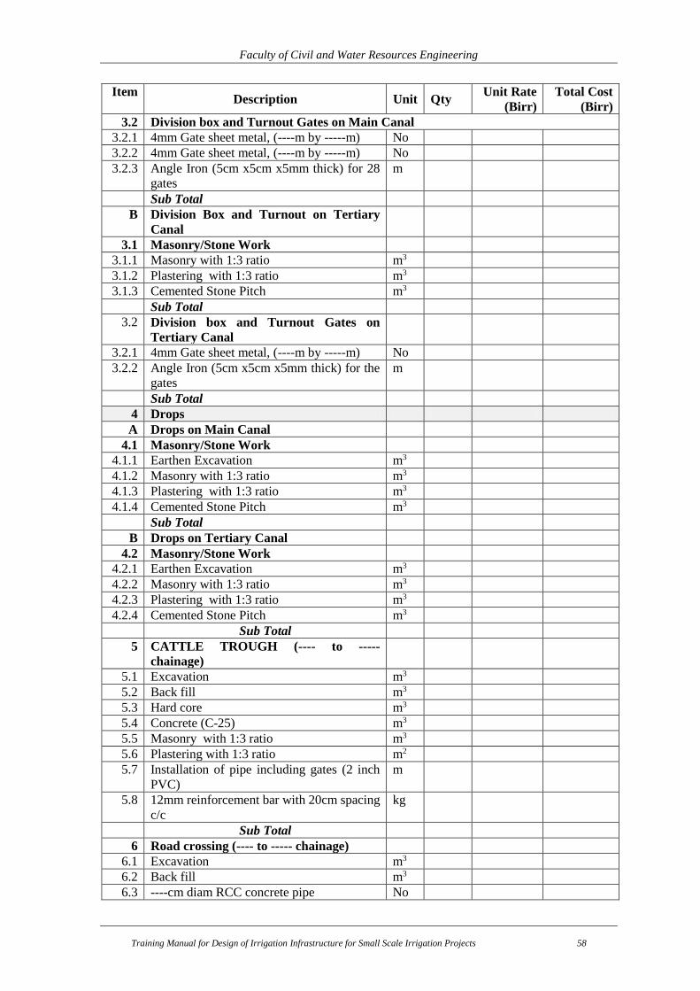
Faculty of Civil and Water Resources Engineering
Training Manual for Design of Irrigation Infrastructure for Small Scale Irrigation Projects 58
Item Description Unit Qty
Unit Rate
(Birr)
Total Cost
(Birr)
3.2 Division box and Turnout Gates on Main Canal
3.2.1 4mm Gate sheet metal, (----m by -----m) No
3.2.2 4mm Gate sheet metal, (----m by -----m) No
3.2.3 Angle Iron (5cm x5cm x5mm thick) for 28
gates
m
Sub Total
B Division Box and Turnout on Tertiary
Canal
3.1 Masonry/Stone Work
3.1.1 Masonry with 1:3 ratio m3
3.1.2 Plastering with 1:3 ratio m3
3.1.3 Cemented Stone Pitch m3
Sub Total
3.2 Division box and Turnout Gates on
Tertiary Canal
3.2.1 4mm Gate sheet metal, (----m by -----m) No
3.2.2 Angle Iron (5cm x5cm x5mm thick) for the
gates
m
Sub Total
4 Drops
A Drops on Main Canal
4.1 Masonry/Stone Work
4.1.1 Earthen Excavation m3
4.1.2 Masonry with 1:3 ratio m3
4.1.3 Plastering with 1:3 ratio m3
4.1.4 Cemented Stone Pitch m3
Sub Total
B Drops on Tertiary Canal
4.2 Masonry/Stone Work
4.2.1 Earthen Excavation m3
4.2.2 Masonry with 1:3 ratio m3
4.2.3 Plastering with 1:3 ratio m3
4.2.4 Cemented Stone Pitch m3
Sub Total
5 CATTLE TROUGH (---- to -----
chainage)
5.1 Excavation m3
5.2 Back fill m3
5.3 Hard core m3
5.4 Concrete (C-25) m3
5.5 Masonry with 1:3 ratio m3
5.6 Plastering with 1:3 ratio m2
5.7 Installation of pipe including gates (2 inch
PVC)
m
5.8 12mm reinforcement bar with 20cm spacing
c/c
kg
Sub Total
6 Road crossing (---- to ----- chainage)
6.1 Excavation m3
6.2 Back fill m3
6.3 ----cm diam RCC concrete pipe No

Faculty of Civil and Water Resources Engineering
Training Manual for Design of Irrigation Infrastructure for Small Scale Irrigation Projects 59
Item Description Unit Qty
Unit Rate
(Birr)
Total Cost
(Birr)
6.4 Masonry with 1:3 ratio m3
6.5 Plastering with 1:3 ratio m3
Sub Total
7 Footpath crossings (---- to ----- chainage)
7.1 Excavation m3
7.2 Back fill m3
7.3 C-20 concrete for production of slab
(including ----- mm dia bar as shown in the
working drawing)
m3
Sub Total
Total of Bill for Irrigation and Drainage Infrastructure (Right side)

Faculty of Civil and Water Resources Engineering
Training Manual for Design of Irrigation Infrastructure for Small Scale Irrigation Projects 60
7. DRAWINGS
After designing of the structures, the drawings have to be prepared for each structure with
the specified scale. The drawings should be clear, easily understandable, and in standard
manner. Here are some of the lists of the drawings that have to be included but not limited
to:
Iirrigation system layout
Section and profile of main, secondary and teritary canals
Plan and section of Division box, drop, chute, road crossings and drainage crossings
Section and profile of catch and collector drains canals
Faculty of Civil and Water Resources Engineering
Training Manual for Design of Irrigation Infrastructure for Small Scale Irrigation Projects 61
8. REFERENCES
1. Amhara National Regional State, Sustainable Water Harvesting and Institutional
Strengthening for Amhara (SWHISA); Surface Irrigation System Design guide for
use of woreda Prepared By Melese S & Sisay A.
2. Different design reports of the region
3. Irrigation EngineerPractices by Ministry of Water Resources
4. Irrigation Methods, FAO Land and Water Training Manual No 5
5. NRCS National Engineering Handbook Part 623, Irrigation, Chapter 4, Surface
Irrigation
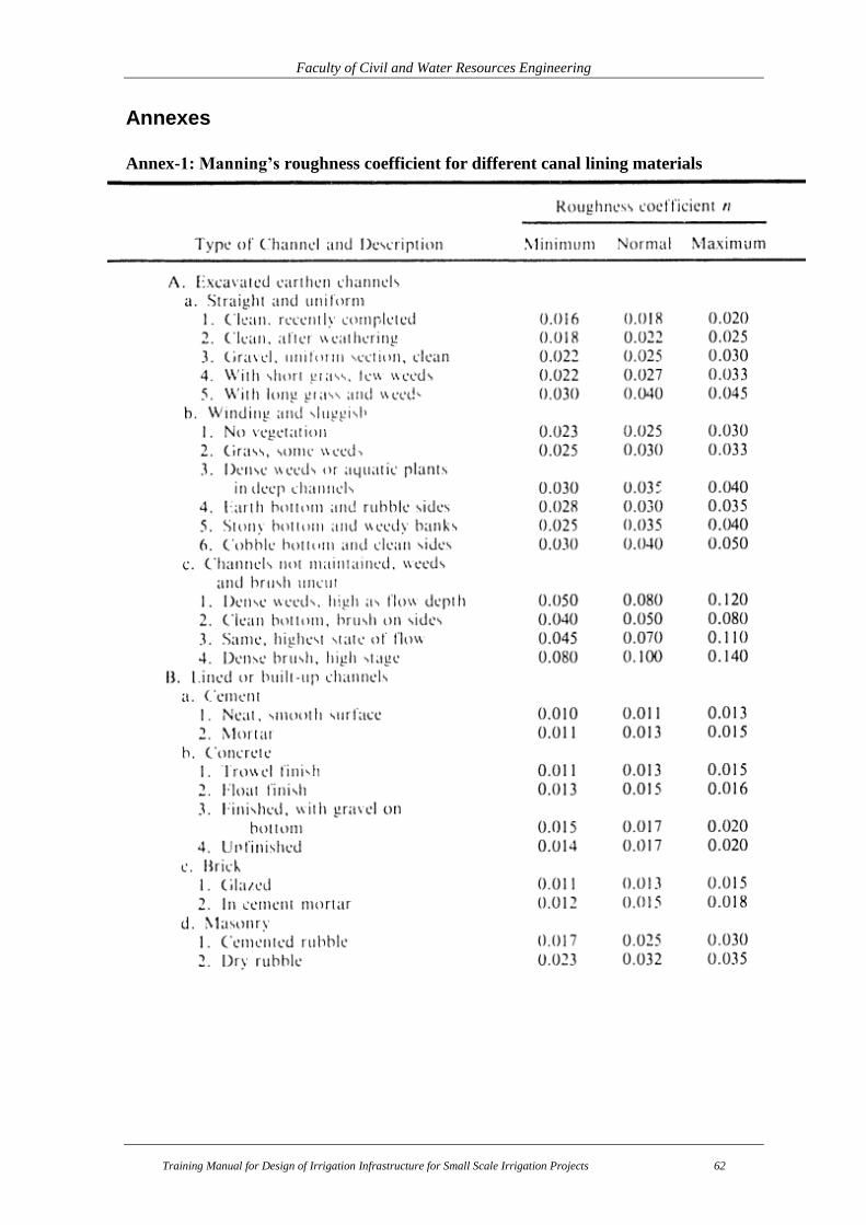
Faculty of Civil and Water Resources Engineering
Training Manual for Design of Irrigation Infrastructure for Small Scale Irrigation Projects 62
Annexes
Annex-1: Manning’s roughness coefficient for different canal lining materials

Faculty of Civil and Water Resources Engineering
Training Manual for Design of Irrigation Infrastructure for Small Scale Irrigation Projects 63
Annex-2: Suggested maximum flow velocities and side slopes for lined and unlined
channels