ministry of defence defence standard 00-25(part 2)/issue 2
TRANSCRIPT

Ministry of Defence
Defence Standard
00-25(PART 2)/Issue 2 14 February 1997
HUMAN FACTORSFOR DESIGNERS OF EQUIPMENT
PART 2: BODY SIZE
This Defence Standard supersedes
Def Stan 00-25 (Part 2)/Issue 1
Dated 30 August 1985

DEF STAN 00-25 (PART 2)/2
AMENDMENTS ISSUED SINCE PUBLICATION
AMD NO DATE OF TEXT AFFECTED SIGNATURE &ISSUE DATE
Revision Note
Since the 00-25 Part 2 Issue 1 appeared in 1985 there have been severalimportant trends which increase the difficulty of the equipment designer’stask. The MANPRINT Handbook provides a useful guide to current philosophyin this area. Far greater use is now being made of female militarypersonnel in the front line. This means that the designer has toaccommodate a much greater range of sizes eg 50% greater range in somedimensions. Population dimensions are increasing at rates of up to 0.07%per year, eg in terms of standing height, the average soldier and sailorpopulations are increasing by over a millimetre each year. Since someequipment is likely to remain in service for several decades, the engineerneeds to consider designing his equipment to fit populations which have notyet been born, also, with the trend towards multi-national projects andforeign customers, the designer needs to be aware of ethnic anthropometricdifferences between potential user populations.
Historical Record
This Defence Standard supersedes Defence Standard 00-25 (Part 2)/1published on 30 August 1985 which had its origins in “Human Factors forDesigners of Naval Equipment” (a naval handbook in two volumes) publishedin 1971.

DEF STAN 00-25 (PART 2)/2
Arrangement of Defence Standard 00-25
The arrangement of the Parts comprising Def Stan 00-25 is shown below:
PART 1 -PART 2 -PART 3 -PART 4 -PART 5 -PART 6 -PART 7 -PART 8 -PART 9 -
IntroductionBody SizeBody Strength and StaminaDesign of the WorkplaceThe Physical Environment: Stresses and HazardsVision and LightingVisual DisplaysAuditory InformationVoice Communication
PART 10 - ControlsPART 11 - Design for MaintainabilityPART 12 - SystemsPART 13 - Human Computer InteractionPART 14 - Training and Instruction (In Preparation)
Two or more Parts may apply to any one equipment and it is thereforeessential that all Parts be read and used where appropriate

Collation Page

DEF STAN 00-25 (PART 2)/2
HUMAN FACTORS FOR DESIGNERS OF EQUIPMENT
PART 2: BODY SIZE
PREFACE
This Defence Standard supersedesDef Stan 00-25 (Part 2) Issue 1
dated 30 August 1985
i This Part of the Defence Standard presents descriptive detail, technicaldata and diagrams relating to some of the important factors concerned withbody size for design application.
ii This Part of the Defence Standard is published under the authority ofthe Human Factors Subcommittee of the Defence Engineering and EquipmentStandardization Committee (DEESC).
iii This Standard has been agreed by the authorities concerned with itsuse and is intended to be used whenever relevant in all future designs,contracts, orders etc and whenever practicable by amendment to thosealready in existence. If any difficulty arises which prevents applicationof the Defence Standard, the Directorate of Standardization shall beinformed so that a remedy may be sought.
iv Any enquiries regarding this Standard in relation to an invitation totender or a contract in which it is incorporated are to be addressed to theresponsible technical or supervising authority named in the invitation totender or contract.
v This Standard has been devised for the use of the Crown and itscontractors in the execution of contracts for the Crown. The Crown herebyexcludes all liability (other than liability for death or personal injury)whatsoever and howsoever arising (including, but without limitation,negligence on the Part of the Crown its servants or agents) for any loss ordamage however caused where the Standard is used for any other purpose.
vi Any enquiries regarding this Standard in relation to an invitation totender or a contract in which it is incorporated are to be addressed to theresponsible technical or supervising authority named in the invitation totender or contract.
1

DEF STAN 00-25 (PART 2)/2
CONTENTS PAGE
Preface
Section One. General
0 Introduction1 Scope2 Related Documents
Section Two. Fundamentals of Anthropometry for Consideration inWorkspace Design
3 Human variation
Section Three. Structural Anthropometry
4 Definition
Section Four. Functional Anthropometry
5 Definition
Section Five. Anthropometric Movement of Body Members
6 Definition
Section Six. Posture and Body Anthropometrics
7 Definition
Section Seven. Design Procedure Checklist
Table ATable BTable CTable DTable ETable F
Table G
Table HTable J
Table KTable LTable M
Table N
Male Body Dimension in Millimetres (Standing)Male Body Dimensions in Millimetres (Sitting)Male Body Dimensions in Millimetres (SittingMale Hand, Foot and Head Dimensions in MillimetresFemale Body Dimension in Millimetres (Standing)Female Body Dimensions in Millimetres (Sitting), Hands,Feet and HeadMale Body Weight in Kilograms and Female Body Weight inKilogramsPopulation Age at Time of Survey and Number in SurveyComparison of Aircrew Data from Different NationsDimensions in MillimetresGrip Correction FactorsAdditions to Anthropometric Dimensions for ClothingDimensions of Body Linkages Expressed as a Percentage ofStature from Figures 20 and 21
444
9
29
Equations for Calculating Percentile Values from the Mean and
43
48
55
1316192223
25
2727
283640
45
Standard Deviation A-1
Tables A2 to D2 5th and 95th Percentile Body measurements inmillimetres for Male Military personnel 24
2

DEF STAN 00-25 (PART 2)/2
CONTENTS PAGE
Tables E2 to F2 5th and 95th Percentile Body measurements inmillimetres for Female Military personnel
Figure 1Figure 2
Figure 3Figure 4Figure 5Figure 6Figure 7Figure 8Figure 9Figure 10Figure 11Figure12a & 12bFigure 13
Figure 14
Figure 15Figure 16
Note: Add
Figure 17Figure 18Figure 19Figure 20Figure 21Figure 22
Figure 23Figure 24Figure 25Figure 26Figure 27
Gaussian (Normal) Distribution CurveNear “Normal” Female and Male Population Distribution ofArm SpanBody Dimensions (Standing)Body Dimensions (Sitting)Body Dimensions (Sitting)Breadth and Span DimensionsFunctional Reaches (Sitting)Hand DimensionsFoot DimensionsHead DimensionsSeat Reference Point3rd and 97th Percentile Male and Female MilitaryPersonnel Forward Functional Reach EnvelopesHead and Eye Pointing Boundaries with a Slack Harness(Fast Jet Aircrew in Ejection Seat, with Helmet, OxygenMask, Life Saving Jacket and Flying Clothing)Head and Eye Pointing Boundaries with Tight Harness
26
6
8111415171820202130
33
34
(Fastjet Aircrew in Ejection Seat with Helmet, Oxygen Mask,Life Saving Jacket and Flying Clothing) 35Functional Grip Dimensions 36Functional Dimensions for Confined Work Spaces 37
corrections for clothing as given in table L
Aperture Dimensions for Manual Tasks 38Example Showing Importance of Clothing Correction 39Escape Hatch Dimensions 41Sagittal Plane Body Linkage 44Coronal Plane Body Linkage 44Path of Instantaneous Centre of Shoulder Rotation Showinga Very Large and Erratic pathway for Effective Centres 46Line of Sight Parameters 50Functional arc of the Upperlimb 51Seated Posture Support 52Functional Wrist Angle 53Functional Seated Posture 54
Annex A Statistical Aspects of Anthropometry A-1Annex B Sources of Anthropometric Data B-1Annex C List of Quoted References C-1
3

DEF STAN 00-25 (PART 2)/2
HUMAN FACTORS FOR DESIGNERS OF EQUIPMENTPART 13: HUMAN COMPUTER INTERACTION
0 Introduction
0.1 A knowledge of the sizes and shapes of human beings, both male andfemale, is essential to the designer who wishes to match equipment andenvironments to the human user. Adequate clearance must be provided forthe tallest, the broadest, and the fattest of individuals. At the sametime, the smallest person must be able to reach and operate all of thecontrols and be able to see all the displays.
0.2 The branch of science which deals with the measurement of the humanbody is called anthropometry, and anthropometrics is the term used for theapplication of such data.
1 Scope
1.1 This Part of this Standard discusses both ‘structural’ and‘functional’ anthropometrics and their relationship to the design of theworkspace.
1.2 This Part of this Standard deals with the important concept of bodylinkages and the use made, by designers, of two-dimensional manikins andcomputer man-models.
1.3 This document also discusses postural stress and the provision ofsatisfactory working postures. Many military personnel, such as aircrew,wear restraining harnesses which restrict reach and vision still further.This factor is particularly relevant to Helmet Mounted Sights (HMS) whosepotential has not been realised due to anthropometric and harnessconstraints.
1.4 The anthropometric data in this Part of this Standard refers to bothmale and female service personnel.
1.5 With much equipment now being produced and procured on a multi-national basis, the designer needs to be aware of national differences inanthropometry. Recent US Armybut up-to-date data from otherthe time of the compilation of
2 Related Documents
2.1 TheStandard
documents andare listed at
anthropometric data has been included hereareas such as Europe, was not available atdata for this Defence Standard.
publications referred to in this Part of theAnnex C.
4

DEF STAN 00-25 (PART 2)/2
2.2 Related documents can be obtained from:
DOCUMENT SOURCE
British Standards (BS) and (BS EN) BSIPublications Sales Department
Linford WoodMILTON KEYNESMK14 6LE
Defence Standards Directorate of Standardization(Stan 1)Kentigern House65 Brown StreetGLASGOW G2 8EX
2.3 Reference in this Part of the Standard to any related document meansin any invitation to tender or contract the edition and all amendmentscurrent at the date of such tender or contract unless a specific edition isindicated.
5

DEF STAN 00-25 (PART 2)/2
Section Two. Fundamentals of Anthropometry for Consideration in WorkspaceDesign
3 Human Variations
Because of the truism that ‘people come in assorted sizes’, it is rarelypossible to tailor, or customize, a piece of equipment to an individualoperator. The designer is almost always required to create a workspacewhich is compatible with a range of individuals. Therefore the first stepin workspace design should be to define the ‘target’ population who willuse the equipment.
3.1 Human body variation dimensions
The variation which is found in most human body dimensions conforms quiteclosely to the Gaussian, or ‘normal’, distribution. For any givendimension, values tend to cluster around an average, and extreme cases arerelatively rare. (See figure below)
3rd PERCENTILE 50th PERCENTILE 97th PERCENTILE(3% of the population is (3% of the population isto the left of this point) to the right of this point,
97% to the left)
Fig 1: Gaussian (Normal) Distribution Curve
3.2 Human variation presented as percentiles
3.2.1 Variation in anthropometric data is often described in terms ofpercentiles (%les). For any dimension in any population of individuals,‘n’ percent of people are smaller than the ‘nth’ percentile. Hence, 3% areshorter in stature than the 3rd %le, 97% are shorter than the 97th %le, andso on. For most practical purposes, we may consider the 50th percentileand the ‘average’ or ‘mean’ to be one and the same.
3.2.2 Two important points should be reinforced at this stage:
(a) a percentile value refers to one dimension only; hence, a man ofaverage (50th %le) height may well have a larger waist depth (eg 80th %le);
(b) a percentile value refers to a specific population; hence, the 50th%le stature for UK aircrew (1783 mm) is the 63rd %le for UK non aircrew.
6

DEF STAN 00-25 (PART 2)/2
3.3 Designing for the 'target' population
3.3.1 From the following extreme example it can be seen that ‘designingfor the average man’ will result in equipment which is poorly matched tothe range of users.
Consider the case of a doorway or passage designed, both in height andwidth, to average (50th %le) dimensions. Such a door would greatlyinconvenience those of the population who were taller or wider thanaverage. The 50% of people taller than average would have to stoop,however, since there are some people who are not only shorter than averagebut also wider than average, a certain additional number of individualswould have to squeeze through, or pass throughout sideways. Hence, thedoor or passage ‘designed for the average person’ would be suitable forless than half the people who used it.
3.3.2 The most difficult problems arise in those workplaces where severaldimensions are all critical for various reasons: cockpits and driving seatsprovide good examples of this. Although the designer should accommodate apopulation range of 5th to 97th percentile, (3rd to 97th where possible) itmust be remembered that a person who is 3rd percentile in stature certainlyis not 3rd percentile in all other dimensions.
For example, if all personnel who are 3rd percentile and less or 97thpercentile and more are excluded, when 6 critical design dimensions areused, it is not 94% of the population but only 78.6% who are acceptable.
Dimension Range % of Total PopulationLimitation Accommodated
Sitting height 3 to 97% ile 94
Buttock-knee length 3 to 97% ile 89
Buttock-heel length 3 to 97% ile 87
Functional reach 3 to 97% ile 84
Sitting knee height 3 to 97% ile 83
Bideltoid breadth 3 to 97% ile
3.4 The limitations of anthropometry in design
78.6
3.4.1 The dimensional matching of machine to operator is a complex matter.Constraints which are truly critical are not always easy to identify andanthropometric tables should be used only when the designer understands thewhole situation.
7

DEF STAN 00-25 (PART 2)/2
3.4.2 The use of anthropometrics at the drawing-board stage doesnecessarily ensure an ergonomically sound design. Designs should
notbe
thoroughly tested firstly by the use of computer based dynamic designtools, and then by conducting fitting trials on a full-scale mock-up of theequipment using a representative sample of users.
3.4.3 The use of anthropometrics is only one stage in the application ofergonomics in the design of equipment.
3.5 Increasing use of the female population. Until recently, the majorityof female military personnel were employed in office environments, ratherthan in the front line. That situation has now changed, with women servingas aircrew and on warships. The engineer must now take account of bothmale and female sizes when designing equipment.
The twin population distributions shown below, illustrates the increasedrequirement and consequent difficulty that an equipment designer now has,to accommodate all potential users.
Fig 2: Near 'Normal' Female and Male Population Distribution of Arm Span
8
DEF STAN 00-25 (PART 2)/2
Section Three. Structural Anthropometry
4 Definition
Structural (or static) anthropometry concerns those dimensions taken withthe body in rigid standardized positions.
4.1 Statistics and Diagrams. It is not possible to include here everydimension a designer may require. Therefore, a list of those dimensionsconsidered to be most representative in the field of equipment design andworkspace layout has been compiled.
The tabulated data for the Armed Services are taken from those sourceslisted at annex B. To date, a major survey of British civilians has notbeen conducted.
Equipment should be designed around the operators who have to work there,both now and in the future. This has not always happened in the past. Itis further complicated by the fact that equipment may remain in service for40 years, or even longer eg The DC3, which is still flying in considerablenumbers, first flew in 1935 and was, itself, based on the earlier DC-2design. Not only has the equipment in the cockpits changed radically, butthe size of the user population is constantly changing due to ethnic,genetic, nutritional and gender reasons.
For example, in the past a design for the RAF might have had to cope onlywith a 5th to 95th percentile range of dimensions and strengths of maleBritons. Now, a multi-national design will have to accommodate not onlypersonnel from 4 or more nations, but also from male and femalepopulations.
If the equipment is likely to be in service for several decades, then theincreasing dimensions of each population will have to be forecast for 30 to40 years in the future. Surveys of Australians over a 50 year periodshowed an increase in average stature of 1.3 mm a year for males and 0.9 mmfor females. This trend is accelerating and repeated elsewhere wheregeneral living conditions have improved and where there is a greatergenetic mixing in the population.
4.2 Clothing corrections and other assumptions. All data in section 3diagrams and tables refer to UNCLOTHED AND UNSHOD PERSONS: Before such datacan be used, corrections for clothing and footwear must be added whereverapplicable - see clause 5.4 and table L.
4.2.1 Tables A - D show the body dimensions for 3rd, 50th and 97thpercentile unclothed military males. The data are broken down intodimensions taken from UK (1987) and US (1988) surveys. The designer shouldwhere possible try to accommodate the range from 3rd to 97th percentile forall 32 dimensions and these data are given in the first part of each table.However, some MOD requirements call for only 5th to 95th percentiles to beaccommodated by equipment. Hence data for 5th and 95th percentile male andfemale populations are also given in tables A-2 to F-2.
9

DEF STAN 00-25 (PART 2)/2
4.2.2 Beside each actual data point is an estimate of how that dimensionwill have changed by the year 2000, assuming that the population dimensionswill continue to increase in size at the current rate. MOD will specifywhether the use of extrapolated data is to be demanded.
4.2.3 For the precise operational definitions of each dimension thedesigner should refer to the original sources from which the data wasextracted - see annex B. It should be noted that measurement techniquesare not always precisely the same in different surveys.
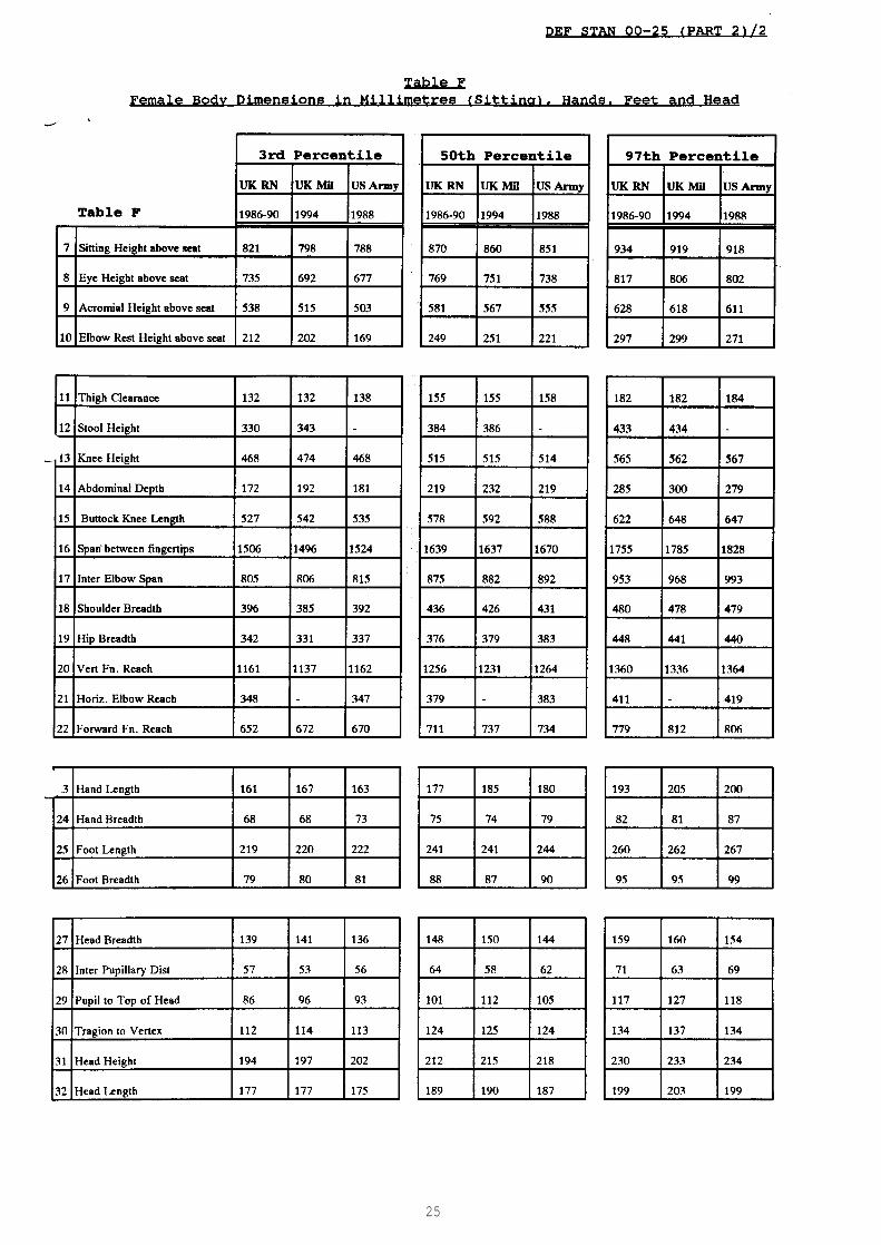
4.3 Female population data. Until recently, data on military femalepopulations has been limited. It is not, therefore, possible to predictthe increase in size of females for the year 2000 as has been attempted formales, here in Tables A to D. However, the data in tables E and F forfemale military personnel is relatively current and should be used untilfurther data becomes available.
4.4 Age and sample sizes. Table H lists the population ages and samplesizes from which the data in tables A to G have been derived.
4.5 National aircrew comparison.
4.5.1 Table J lists equivalent data for dimensions 1-32, where available,for German, US, Italian and Royal Air Force aircrew.
4.5.2 It indicates that there were differences between the four separateaircrew populations when the data was collected in the 1960/70 decade.However, care is needed in interpreting the data since it is likely that,for some dimensions at least, different anthropometric measuring techniqueswere employed to obtain the data as the RAF aircrew certainly cannot be 22%greater than that for the other nationalities.
4.5.3 Furthermore, it can be assumed that most if not all, of themeasurements will have increased, probably at the rate of at least 0.03%per year since the data was collected.
Index Male Female
Table Table
Body Dimensions (Standing A E
Body Dimensions (Sitting) B F
Breadth and span Dimensions C F
Functional Reaches (Sitting) C F
Hand and Foot Dimensions D F
Head Dimensions D F
Body Weight G G
Population ages and sample sizes H H
National Aircrew Comparisons I
10

DEF STAN 00-25 (PART 2)/2
1
2
3
4
5
6
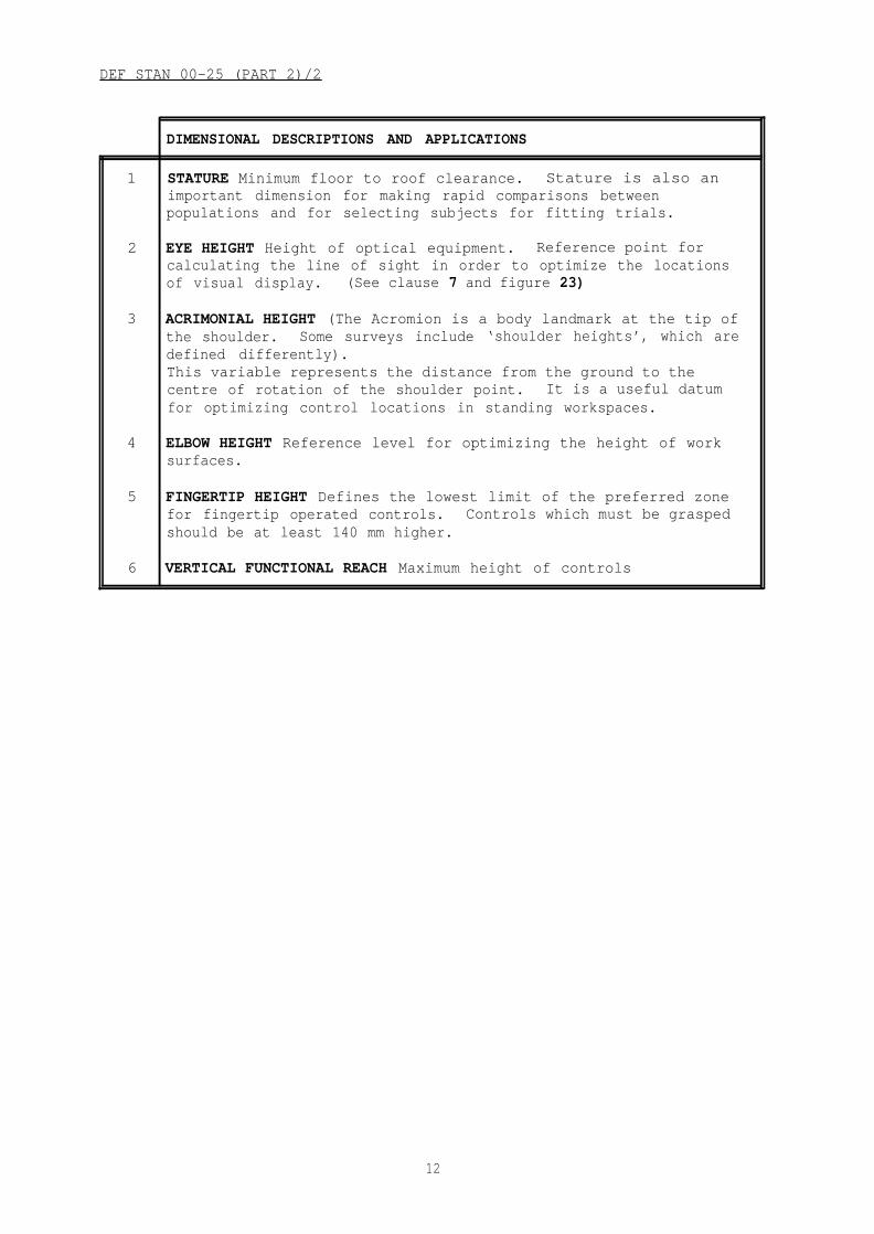
DIMENSIONAL DESCRIPTIONS AND APPLICATIONS
STATURE Minimum floor to roof clearance. Stature is also animportant dimension for making rapid comparisons betweenpopulations and for selecting subjects for fitting trials.
EYE HEIGHT Height of optical equipment. Reference point forcalculating the line of sight in order to optimize the locationsof visual display. (See clause 7 and figure 23)
ACRIMONIAL HEIGHT (The Acromion is a body landmark at the tip ofthe shoulder. Some surveys include ‘shoulder heights’, which aredefined differently).This variable represents the distance from the ground to thecentre of rotation of the shoulder point. It is a useful datumfor optimizing control locations in standing workspaces.
ELBOW HEIGHT Reference level for optimizing the height of worksurfaces.
FINGERTIP HEIGHT Defines the lowest limit of the preferred zonefor fingertip operated controls. Controls which must be graspedshould be at least 140 mm higher.
VERTICAL FUNCTIONAL REACH Maximum height of controls
12


DEF STAN 00-25 (PART 2)/2
7
8
9
10
Fig 4: Body Dimensions (Sitting)
DIMENSIONAL DESCRIPTIONS AND APPLICATIONS
SITTING HEIGHT Minimum seat to roof clearance. Maximumheight of the visual obstruction caused by a sitting person.
EYE HEIGHT Height of optical equipment above the seatsurface, reference level for calculating lines of sight inorder to optimize the location of visual displays.Variability in this dimension may determine the range ofseat adjustment required.
ACROMIAL HEIGHT Distance between the seat surface and thecentre of rotation of the shoulder; a reference point inoptimizing the location of controls (See clause 7).
ELBOW-REST HEIGHT Height above the seat surface of arm-rest, desk-tops, keyboards and other important controls.Variability in this dimension may determine the range ofvertical adjustment required of the seat.
14

DEF STAN 00-25 (PART 2 )/2
11
12
13
14
15
Fig 5: Body Dimensions (Sitting)
DIMENSIONAL DESCRIPTIONS AND APPLICATIONS
THIGH CLEARANCE Minimum vertical clearance between seatsurface and underside of the table or other obstruction.
STOOL HEIGHT (Represented with the subject’s thighshorizontal, his shanks vertical, and the soles of hisflat on the ground).
KNEE HEIGHT Minimum vertical clearance between floor
feet
(orfootrest) and underside of table or other obstruction.
ABDOMINAL (STOMACH) DEPTH Minimum forward clearance betweenseat back and obstructions above thigh level - eg tableedges, steering wheels
BUTTOCK TO KNEE LENGTH Minimum forward clearance betweenseat back and obstructions at level of the seat surface.
15

16

DEF STAN 00-25 (PART 2)/2
16
17
18
19
Fig 6: Breadth and Span Dimensions
DIMENSIONAL DESCRIPTIONS AND APPLICATIONS
SPAN Overall lateral limits of reach. Appropriatereduction must be made if controls are to be operated otherthan with the fingertips. (See clause 5)
INTER-ELBOW SPAN Lateral clearance for good elbow roomduring manual activities.
SHOULDER BREADTH (BI-DELTOID BREADTH) Minimum lateralclearance required in workspace. Note. This dimension isnot the same as bi-acromial breadth.
HIP BREADTH Width of seat. (Minimum lateral clearance forthe thighs will be up to 70 mm greater than this dimension.)
17

DEF STAN 00-25 (PART 2)/2
20
21
22
Fig 7: Functional Reaches (Sitting)
DIMENSIONAL DESCRIPTIONS AND APPLICATIONS
VERTICAL FUNCTIONAL REACH Maximum height of controlsabove the seat surface
ELBOW FUNCTIONAL REACH Maximum forward location of thecontrols for operation with the upper arm vertical and theforearm horizontal.
FORWARD FUNCTION REACH (This represents the distance fromthe back of the shoulders to the thumb-tip of a pinchgrip.) Maximum forward location of controls for easyoperation.
Note: These reach measurements are made to the tip of the thumb as itmakes a pinch grip with the forefinger. Corrections must be made for othertypes of grip. The subject of reach is discussed at clause 5.
18


DEF STAN 00-25 (PART 2)/2
Fig 8: Hand Dimensions Fig 9: Foot Dimensions
DIMENSIONAL DESCRIPTIONS AND APPLICATIONS FOR FIG 8
HAND LENGTH Direct application of this dimension arelimited, but it is useful for making comparisons betweenpopulations and in selecting subjects for fitting trials.
HAND BREADTH (METACARPAL BREADTH) Access, of hand, tonarrow apertures. Design of handgrips, lifting handles,etc.
DIMENSIONAL DESCRIPTIONS AND APPLICATIONS FOR FIG 9
FOOT LENGTH Design of foot-operated controls.
FOOT BREADTH Design of foot-operated controls.
20

DEF STAN 00-25 (PART 2)/2
27
28
29
30
31
32
Fig 10: Head Dimensions
DIMENSIONAL DESCRIPTIONS AND APPLICATIONS
HEAD BREADTH Minimum lateral clearance for head and themaximum horizontal head breadth above the ears (the locationof this dimension is highly variable). Useful for head phonedesign.
INTERPUPIILARY DISTANCE The horizontal distance between thecentres of the pupils when the subject looks straight ahead.Used in the design of binocular devices for example.
PUPIL TO VERTEX The vertical distance from the centre of theeye to the vertex (crown)
TRAGION TO VERTEX The vertical distance between the centreof the ear and the crown. Used in the design of the headphone set for example.
HEAD HEIGHT This distance between the most inferior point ofthe menton (chin) and the vertex (crown)
HEAD LENGTH The dimension between the lowest point on thehead (between the crown ridge) and the rear most point,wherever found (usually in the mid-sagittal planes).
21

22

23

24
25

DEF STAN 00-25 (PART 2)/2
Tables E2 to F2 5th and 95th Percentile Body Measurements in Millimetres for
Female Military Personnel
TABLE E2 Female Body Dimensions (Standing)
TABLE F-2 Female Body Dimensions (Sitting)
26

27

28

DEF STAN 00-25 (PART 2)/2
Section Four. Dynamic Anthropometry
5 Definition
Dynamic anthropometry deals with the dimension of the workspace envelopeneeded by personsdimensions, whichposition, dynamicaccordingly.
5.1 Reach data.
as they perform their work. Unlike static bodyare measured with the subject in a rigid, standardizedmeasurements are made in working positions and vary
In many workspace design problems it is important to knowhow far an operator is able to reach in a given direction from a specifiedreference point.
5.2 Formal reach dimensions. All data in section 3 tables and diagramsrefer to straightforward anatomical distances (or static body dimensions)although it should be appreciated that an individual is able to reach agood deal further forward than this distance, by thrusting forward orprotracting their shoulders, and by flexing and inclining the trunk.However, even this increased reach may be severely limited if the person isconstrained by a tight harness, protective clothing or seat geometry. (SeeFigs 12a and 12b and clause 5.2.5).
5.2.1 Dynamic reach dimensions. The total volume of space which anindividual can reach by adopting whatever postural combination is mostadvantageous, is defined by a three dimensional system of co-ordinates,centred on, for example the seat reference point, known as a workspaceenvelope (or kinosphere) (see Figures 12a and 12b). Typical examples ofworkspace envelopes will be found in Van Cott and Kincade.
5.2.2 Figures 12a and 12b show the 3rd and 97th percentile Dynamic rightarm reach envelopes for both male and female current UK military personnel.(It is assumed that the left arm reach envelopes will mirror the rightarm’s). The reach envelopes shown are intended as a guide and assume thatlightly clothed personnel are restrained in a seat with a lap strap.
5.2.3 Distances from the Seat Reference Point (SRP) (See Figure 11) areshown in millimetres. The SRP is at the centre line of the seat pan (whichis tilted up at 6°) where it meets the seat back, which is inclinedbackwards at 13°. Distance from seat reference point, dimensions are measured from SRP vertical axis and not reclined back.
5.2.4 Different seat geometry, use of a tight restraining harness andbulky protective clothing such as helmets, NBC clothing, life savingjackets etc, will change and generally reduce the reach envelope.
29

DEF STAN 00-25 (PART 2)/2
Fig 11: Seat Refence Point (SRP)
30

DEF STAN 00-25 (PART 2)/2
5.2.2 The workspace envelope. The seat reference point (SRP) illustratedin figure 11, is commonly used as a standard starting point for reachdimensions of seated operators and is defined as the midpoint of theintersection of the place of the seat surface, with the plane of the backrest surface of the seat and tangents of the mid-line contours of theseated person.
The seat reference line (SRL) and the seat reference vertical (SRV)illustrated in figures 12a and 12b are reference lines plotted from theseat reference point to vertical axsis to highlight reach boundaries whenconverted to horizontal contours.
The examples are presented as a guide to the designer to introduce theworkspace envelope pictorially, and should not be considered as a basis ofpracticality towards design aspects of functional ergonomics. At presentdimensional representations of the horizontal boundaries for Britishcivilian and military personnel are not readily available. However, afuller description can be found in Van Cott and Kinkade but it should beemphasised that the dimensions tabulated in this work should be treatedwith caution, they apply only to the populations that are similar in sizeand proportions to the US Air Force and cannot be used indiscriminately forall populations.
5.2.3 Anthropometry of reach. The anthropometry of reach can be viewed interms of a relatively large volume which is ‘possible’, within which aresuccessively smaller volumes which are ‘acceptable’, ‘preferred’ or‘optimal’ for a particular activity (see clause 7.1 Working Posture) andalso Defence Standard 00-25 PART 4: Workplace Design and PART 10: Controls.
5.2.4 Reach for workspace layout
(a) Arm reach data is essential for equipment designsimply because different controls demand varyingof movement and force. Arm length measurements,standing subjects as a maximum length to qualify
and workspace layoutdegrees of precisionoriginally taken fromanatomical
difference, have now proliferated into numerous dimensions, bothstanding and sitting, involving various combinations of position ofthe hand, arm and shoulder.
(b) It is impossible to consider the zone which is defined by the rotationof the upper limb about the shoulder joint anatomically resembling aball and socket (See section 5 regarding the range of movement of bodymembers, and the guidelines in Defence Standard 00-25, PART 3concerning the safe limits for force applications).
5.2.5 Head and eye pointing boundaries. When considering Helmet MountedSighting Systems for weapon aiming, the designer needs to be aware ofpossible head and eye movement limitations caused by equipment orprotective clothing interference.
Figures 13 and 14 show typical head and eye movement boundaries for fighterpilots, for both the slack and tight restraining harness cases.
31

DEF STAN 00-25 (PART 2)/2
5.2.5 (Contd)
Both figures show a side elevation view of a sphere with the pilot lookingforwards (to the left). The pilot’s eye datum is at the 90°, 0° co-ordinate at the centre of the sphere. From this position, the 3rdpercentile male pilot (in terms of head movement - not stature) can onlypoint his head 40° upwards, with a slack harness when looking straightahead. When looking sideways (90°) he can look only 26° upwards and 10°downwards.
The side of the cockpit prevents the eye from looking downwards40° to the side, even for the 90%le pilot with
This is a general guide to pilots head and eyefollowing points should be noted:
(a) There is considerable variability in head
a slack harness.
pointing ability
mobility between
(b
more than
and the
subjects.subject dimensions such asThis mobility has little correlation with
Sitting Eye Height, but appears to be dependent upon the pilot’spostural strategy.
When wearing a tight harness, head movement upwards and rearwards isseverely restricted by interference between the ejection seat head boxand the pilot’s protective helmet.
(c) Head movement is limited also by interference between the life-savingjacket and the oxygen mask/helmet assembly. Eye pointing is sometimeslimited by the bulk of the oxygen mask.
(d) If the harness is worn in the unlocked or slack state, an additional10° to 20° of head movement can be achieved.
(e) If the eye, rather than the head, can be used for aiming, then anadditional 50° becomes available to use.
Little furtherweapon control
anthropometric information on head and eye pointing forhas become available since Lovesey’s paper in 1987.
32


35

DEF STAN 00-25 (PART 2)/2

DEF STAN 00-25 (PART 2)/2
5.3 Accessibility of confined workspaces
5.3.1 When space is at a premium, it may be necessary to specify minimumdimensions for access by maintenance personnel (plumbers, fitters etc).Figure 16 gives dimensions which will accommodate virtually all civilian,or female Service personnel, however, allowances must be made for footwear,helmets, equipment etc. (Refer to clause 5.4 for clothing corrections.)
5.3.2 When such dimensions are critical, the designers are urged to checkusing a full scale mock up using subjects representing the largest andbulkiest members of the working population wearing maximum clothingassemblies applicable to climatic/operational conditions.
CRAWLING LENGTH AND HEIGHT KNEELING LENGTH AND HEIGHT
PRONE LENGTH AND HEIGHT
MINIMUM SQUATTING HEIGHT
Fig 16: Functional Dimensions for Confined Work Spaces
Note: Add corrections for clothing as given in Table L.
37

DEF STAN 00-25 (PART 2)/2
5.3.3 Accessibility for manual tasks
(a) Access openings provided for adjusting and handling interior itemsshould be sized to permit the required operations and where possibleprovide an adequate view of the item being manipulated. Access coversshould be equipped with grasp areas or other means for opening them.Allowance should be made for the clearance of the operators gloved ormittened hand if the access is located externally and may requireservicing under cold weather conditions. Some examples of accessallowances which may be encountered are shown in figure 17. Foraccess and correct spacing of controls, refer to DefenceStandard 00-25. Part 10: Controls, and Part 11: Design forMaintainability.
Fig 17: Aperture Dimensions for Manual Tasks
38
I

DEF STAN 00-25 (PART 2)/2
5.3.3 (Contd)
(b) Certain functional dimensions of the workspace can not be adequatelyderived from simple anthropometric dimensions of the type consideredin Section 4. Some dimensions relevant to the design of maintenanceaccess spaces and to the layout of multiple controls on equipment aresummarized in figure 17. It should be emphasized that the dimensionsindicated in this figure are approximate and that additional allowancemay have to be made for special clothing, gloves and footwear.
5.4 Clothing corrections for anthropometric data
5.4.1 Because surveys are generally conducted on semi-nude subjects,clothing corrections must be considered by designers when planningworkspace layout and control positioning etc. Substantial differences canoccur in anthropometric data with the addition of clothes, tools andequipment see table L for clothing corrections. For overhead reach thereis a decrement due to clothing restrictions.
5.4.2 An important factor which determines the clothing correction to beapplied, is the NBC operational and/or environmental conditions in whichthe equipment is to be used, ranging from perhaps, arctic to a tropicalenvironment. For example, in figure 18, a 60 x 110 mm aperture handgripwhich will comfortably admit the largest ungloved hands needs to beincreased to 100 x 200 mm for a man wearing arctic mittens.
Handgrip dimensionsadequate for normalclimate conditions
Severe arctic conditionswould render same hand-grip inadequate forefficient operation
Fig 18: Example Showing Importance of Clothing Correction
39

DEF STAN 00-25 (PART 2)/2
Table L
Additions to Anthropometric Dimensions for Clothing
Dimensions in millimetres
Description COMBAT COLDWEATHER
Stature 64 76
Eye height standing 27 36
Sitting height 38 51
Eye height sitting 1 10
Thigh clearance 4 23
Knee height 33 56
Buttock to knee length 5 51
Shoulder breadth 6 152
Hip breadth 13 152
Abdominal depth 13 51
Foot Length 41 68
Foot breadth 5 46
Hand breadth N/A 43
Hand thickness N/A 84
N/A data not available
Note: Table L (above) is intended as a guide only. With the issue of thecombat soldier 95 (CS95) clothing system which includes the MK6 combathelmet and boots it is no longer possible to define a single combatensemble. Crews for armoured vehicles wear helmets designed for use inthose vehicles.
5.4.3 Civilian footwear, the extremes of personal taste, can addsubstantially to the variability of stature as well as the mean. Clearancedimensions in workspace and passageways may require to take account of avariety of personal equipment and luggage (headset, rescue gear, tool bagsetc).
Note: This is absolutely vital for damage control, fire fighting andemergency escape. In these circumstances dimensions must be chosen whichwill allow 100% of the population to pass without impediment. Militaryheadgear may add over 50 mm stature and boots up to 30 mm.
An example of a subject wearing bulky equipment, such as a parachute isgiven on page 41, showing dimensions of an escape hatch.
40

DEF STAN 00-25 (PART 2)/2
5.4.4 Designers of military equipment cannot consider these factorswithout data. It is more likely that the operator will need to conform toagreed standards, ie, military environment ie short hair, beard possiblestates
Fig 19: Escape Hatch Dimension
Note: The dimensions in escape hatch design should be chosen which willallow 100% of the population to pass through without impediment.
5.5 Maximal static forces and space requirements
5.5.1 Static (isometric) force as applied to a control means the exertionof muscle force such that the muscles tighten but do not change theirlength during this tension. The control does not move, or movesnegligibly, in relation to the operator’s body.
5.5.2 In workspace where manual forces must be exerted it is important toprovide sufficient clearance for the operator to use his body to thegreatest mechanical advantage. Cramped conditions or obstacles in theworkspace lead to a reduction in the person’s capacity to exert force andan increased level of strain (see Section 6: Posture and also DefenceStandard 00-25 Part 3: Body Strength and Stamina).
5.5.3 The necessity for an operator to exert a force, or support a load,while leaning forward over an obstacle should be avoided. Some approximateguidelines to space requirements are as follows:
Lateral clearance. Inter-elbow span (see figure 6, section 3) provides areasonable indication of the space required for unrestricted activity. Aclearance of 550 mm either side of the mid-line is satisfactory for mostpurposes. (This figure should be increased if the required force has asideways component).
41

DEF STAN 00-25 (PART 2)/2
5.5.3 (Contd)
Clearance behind the operator. Measuring backwards from the operatorshands the following distances should prove adequate for static exertions.
LIFTING FORCES 550 mmPULLING OR PUSHING FORCES 1250 mm
Note: Pushing forces are increased by the presence of an obstacle behindthe operator if he is able to use it for bracing himself. The more complexcase of dynamic exertion should be solved by trial and error.
42

DEF STAN 00-25 (PART 2)/2
Section Five. Anthropometric Movement of Body Members
6 Definition
The human body may be generally described as a small number of rigid links,connected at specific points about which they are free to rotate.
6.1 Body linkages
6.1.1 To plan positioning and operability of controls, a designer requiresdata concerning the range of movement of the torso, arms and legs in orderto establish the comfortable limits for maximum efficiency.
6.1.2 The moveable joints of the body, articulated by means of ligaments(tough fibrous bands), are of several types, the three most important are:hinge joints (finger), pivot joints (elbow), and ball and socket joints(shoulder and hip). Thus, the human body is basically an open chain systemof ‘links’ rotating around joints. The end members of these open-chainlinks, the hands and feet, can occupy a limitless number of positions inspace as a result of the cumulative ranges of these joints (DEMPSTER).
6.2 Dynamic range of movement
6.2.1 The functional (or dynamic) data presented so far has beenempirically determined in ad hoc studies to solve specific practicalproblems. The application of such data is of necessity limited to a narrowrange of situations, similar to those in which the data was originallygathered. There are times when a designer needs to reach an approximatesolution to a novel problem in functional anthropometrics.
6.2.2 The thigh link extends from the centre of rotation of the hip jointto that of the knee. The shank or lower leg link extends from the knee tothe ankle, etc. In table M the average lengths of these links areexpressed as a percentage of the stature. Designations 1 to 17 in table Mrefer to dimensions of the body as seen in side elevation, (known toanatomists as the SAGITTAL PLANE, see figure 20), whereas designation 18and 19 refer to dimensions of the body as seen in front elevation (known toanatomists as the CORONAL PLANE - see figure 21).
43

DEF STAN 00-25 (PART 2)/2
44

DEF STAN 00-25 (PART 2)/2
Table MDimensions of Body Linkages Expressed as a Percentage of Stature
1
2
3
4
5
6
7
8
9
10
11
12
13
14
15
16
17
18
19
from Figs 20 and 21
DESCRIPTION
THIGH
SHANK (LOWER LEG)
ANKLE HEIGHT
HEEL TO ANKLE (HORIZONTAL PROJECTION)
HEEL TO BALL OF FOOT
FOOT LENGTH
ARM (ie SHOULDER TO ELBOW)
FOREARM
WRIST TO CENTRE OF GRIP
HAND LENGTH
HIP TO SRP (HORIZONTAL
HIP TO SRP (VERTICAL)
SHOULDER TO SEAT
LOWER NECK (C7 VERTEBRA) TO SEAT
EYE LEVEL TO SEAT
SITTING HEIGHT
EYE TO AXIS OF HEAD (HORIZONTAL)
TRANSVERSE SHOULDERS
TRANSVERSE HIPS
PERCENTAGE OF STATURE
28.4
23.4
4.7
3.3
11.2
15.3
17.3
15.5
3.8
10.9
6.9*
5.2*
32.0
37.8
45.9
52.3
5.7
22.5
9.8
* The seat reference point (SRP) is the centre point of a line formed bythe intersection of the planes of the back and base of a fully compressedseat and tangents of the mid-line contours of the seated man (seefigure 11).
6.2.3 It should be emphasised that figure 20 is only an approximation tothe truth, the trunk, for example, is by no means a rigid link and thespine is flexible in all three anatomical planes. The centre of rotationof the shoulder joint is by no means static; (see figure 22) the shouldergirdle clavicle and scapula, (or ‘collar bone’ and ‘shoulder blade’) aremobile with respect to the rib cage.
45

DEF STAN 00-25 (PART 2)/2
Fig 22: Path of Instantaneous Centre of Shoulder Rotation Showinga very Large and Erratic Pathway for Effective Centres
6.2.4 In using the link system to visualize the reaches possible with thelimbs for a given posture, it must be remembered that the actual bodyjoints are not simple centres of rotation, and that some of the body linksare by no means rigid (for example, the shoulder joint is not positivelylocated at the upper end of a rigid upper trunk link - see figure 22).Also the possible range of joint movements are dependant on the joint, andthat muscular movements of one link about another may vary considerably,not only with the angular disposition of the links, but also with thepostural relationships of adjacent links. Thus postures and reach possiblewith a manikin (see clause 6.3) may be of little or no practicalsignificance for the man. Computer man models may provide betterapproximations than manikins (see clause 6.3).
6.2.5 The designer should bear these limitations in mind. The modelwould, for example, make a highly conservative estimate of a reach envelopeand is of great value when considering the interaction between workingposture and workspace (refer to para 7.1 Working Posture and also DefenceStandard 00-25 Part 4: Workplace Design.
46

I
DEF STAN 00-25 (PART 2)/2
6.3 Manikins
6.3.1 Two dimensional cut-outs or “manikins”, representing the human formand realistically articulated, are used by many designers as an aid tothinking at the drawing board. Detailed drawings from which such manikinsmay be constructed have been published by Dempster and elsewhere. They maybe constructed to represent individuals of average bodily proportions andvarious statures. (They should not be thought of as representing an ‘nthpercentile person”, since nobody can be nth percentile in all dimensions). Certain manufacturers of drawing instruments market design manikins bothflat and three dimensional some of which are very strangely proportioned;it is advisable to check their dimensions against table M. A well made setof drawing board manikins will quickly repay the effort of theirconstruction. They can be usefully supplemented by cut-outs for helmets,boots, gloves, parachutes, etc.
6.3.2 There is now an increasing use of computer based anthropometricsmodels, by means of which, hypothetical workspace geometries may beevaluated against stored sets of anthropometric data. Reductions in theprice of computer hardware (particularly graphics terminals) allows thewidespread distribution of standard software packages for such purposes.The use of computer models take much of the drudgery out of anthropometricsand free the ergonomist and designer for the more creative pursuits oftheir respective crafts.
SAMMIE (UK)
JACK (USA)
COMBIMAN (USA)
Computerised man-models which are available are:
System for Aiding Man-Machine InteractionEvaluation
Computer Graphics System for Man-MachineInteraction Evaluation
Computerised Biomechanical Man Model
Many other computerised man-models are available which are alreadyincorporated in CAD systems and others are under development. The designerwill have to decide which model offers the best overall solution to hisrequirements. However, the computer model should be used in conjunctionwith trials using full-scale mock-ups and subject representing the criticalanthropometric dimensions of the target population. (See clause 3.4.2).
47

DEF STAN 00-25 (PART 2)/2
Section Six. Posture and Body Anthropometics
7 Definiton
For the purpose of this Part of this Standard, posture is defined as theorientation of the parts of the body with respect to each other and to theimmediate physical environment.
7.1 Working posture. Relationships between the dimensions of theoperators and those of their workspace determine the posture in which theyultimately have to perform their task. Thus by applying anthropometricdata at an early design stage a satisfactory working posture for operators,of non-standardized dimensions will be achieved.
Note: Poor or inappropriate posture leads to discomfort, fatigue andinefficiency; if prolonged, it may be sufficiently damaging to render theoperator unfit for duty. (Although it cannot be proved that poor postureis solely responsible for any specific disease, it is certain that anexisting disorder will be severely accelerated by a working posture whichstresses the affected part of the body.) (eg, RSI).
Further information on posture and the recommended forces that can beapplied are given in DefenceStamina.
7.2 Body position
7.2.1 Many human dimensionsstandardize and compare, the
Standard 00-25 Part 3: Body Strength and
vary with posture or body position. Toanthropometrist usually requires specific,
erect positions rarely assumed by people at work or at rest. Because fewpeople normally stand or sit completely erect, “normal” standing height,sitting height, and eye height involve ‘slump’ and are thus significantlyless, than when measured with the body erect. Standing height is shorterthan prone or supine length. Hip breadth and waist depth are larger in theseated than in the standing position. Most dynamic dimensions are alteredby body movement, thus maximum arm reach with free movement of the shoulderor trunk is much greater than with the shoulder and trunk restrained.
7.2.2 The complexity of the anatomy and mechanics of the human body issuch that the prediction of a complete workspace envelope is scarcelypossible from a knowledge of the structure and function of the componentparts. The empirically determined envelope represents the ultimate limitsof a persons’ reaching capacity and requires the adoption of extremepostures. These postures cannot be maintained for any length of time, andtherefore are not suitable for the performance of any but the lightestmanipulative tasks.
7.3 General recommendations concerning working posture
7.3.1 Wherever possible mobility in the workspace should be encouraged, bygiving the operator room to stretch and fidget. Placing continuousmechanical loading on any part of the body should be avoided (see DefenceStandard 00-25 Part 4: Workplace Design and Part 5: Stresses and Hazards).These goals, however, may be impossible to achieve due to overridingnecessity for restraining harnesses, limited headroom etc, but anindividual’s working posture is one of the factors which determine theforces which he maybe expected to exert in the execution of his task (seeDefence Standard 00-25 Part 3: Body Strength and Stamina)
48

DEF STAN 00-25 (PART 2)/2
7.3.2 The relative advantages of standing and sitting working postures,although elementary, are often ignored. They should be considered at theoutset, as should the possibility that a work-station could be devisedwhich would allow the operator to stand or sit as he pleased during hisperiod of duty.
SITTING on a purpose built seat provides a stable base of finely controlledmanipulative activities, especially in situations where the working area isitself subject to vibration or acceleration; is restful to the operator andallows the use of a greater number of control devices, eg pedals.
STANDING allows mobility, and the application of large forces by theoperator (provided he has adequate working clearance and “footing”.
A variety of mobile seats in a static workplace can be devised which givethe seated operator many of the advantages of a standing position.
7.4 Causes of postural stress
7.4.1 Individuals differ greatly in their response to a given posturalstress. A stooped position or badly designed seat (eg a seat causing toohigh a pressure in the invertebral discs) which are scarcely noticed by oneperson may be cripplingly painful for another. Bad working posture mayinteract with other stresses, eg sub-optimal environmental conditions,mental workload, operational hazard or poor general health. The nature ofthese interactions can be very complex.
7.4.2 The following causes of postural stress may be identified.
(a)
(b)
(c)
(d)
The need to maintain one or more unsupported parts of the body againstthe force of gravity. This occurs, for example, when the arms andhands must be held away from the body, either forwards or to be thesides and above the head. Stooped working postures in which eitherthe trunk or the head must be inclined forward are bad for thisreason.
Twisted or asymmetric postures. The operation of pedals from astanding position provides a particularly acute example of thisproblem, as do workspaces which require their users to have “eyes inthe backs of their heads”.
Postures in which joints must be maintained near to the limits oftheir ranges. "Cramped" or “stretched” positions place muscles andligaments under tension and may restrict blood flow. In general, aposture which uses the middle third of a joint’s range is to bepreferred. The ranges of joints, motion are discussed in DefenceStandard00-25 Part 3: Body Strength and Stamina.
Excessive pressure on the surface of soft and fleshy parts of the bodyor overlying bony prominencies. This occurs frequently to theschialtuberosities of the buttock when sitting in poorly designedseats.
49

DEF STAN 00-25 (PART 2)/2
7.5 Areas of posture stress
7.5.1 Eyes, head and neck (standing or sitting work)
(a)
(b)
Posture. Posture of the head and neck is generally determined by thevisual requirements of the task. Forward tilting of the head leads totension in the neck muscles which is painful (and potentially harmfulif prolonged). The head should be as near vertical as possible.Focusing the eyes on close objects for extended periods causes eye strain.
Equipment design features. Frequently used visual displays should beplaced within an angle of 30 deg downwards from a horizontal linedrawn at eye level, as shown in figure 23 and within 30° either sideof the centre line. Minimum comfortable viewing distance is 500 mm;700 mm is to be preferred. Displays should be bold enough andsufficiently well illuminated to be legible at this latter distance.It is desirable that important sources of visual information should beat similar distances from the eyes, since older operators experiencedifficulty in making frequent changes in visual focal length. Tiltedwork surfaces and raised reading stands are often helpful. (SeeDefence Standard 00-25 Part 6: Vision and Lighting, Part 7: VisualDisplays and Part 10: Controls).
7.5.2 Back (standing work)
(a) Posture. The operator should not be required to stoop for prolongedperiods during standing work.
(b) Equipment design features. Controls and work surface placed too lowor too far away cause stooping. The preferred work surface height formedium or light manipulative tasks is 50 - 150 mm below elbow level.For heavy work, a slightly lower surface is preferred (eg 150 - 250 mmbelow elbow level). Controls should preferably be at a height betweenthe shoulder and the elbow, and should never be outside the arcdescribed by the upper limb as it rotates about the shoulder. (Theradius of the circle is the shoulder to grip distance and is shown infigure 24.
50

DEF STAN 00-25 (PART 2)/2
.ARC OF ROTATION
OF UPPER LIMBOUTER LIMIT FOR
FREQUENTLY USED CONTROLS
GENERALLYPREFERREDHEIGHTS FORCONTROLS
FOR WORKINGSURFACES
Fig 24 Functional Arc of the Upper Limb7.5.3 Back (Sitting work)
(a)
(b)
Posture. A variety of research evidence indicates that it isdesirable to maintain a modest spinal curvature such that there is aslight concavity in the lumbar region (ie the “small of the back”approximately at waist level). Slumped sitting postures, in which thespine becomes convex to the rear lead to back strain; especially ifthe seat itself is subject to vibration (eg in a moving vehicle).
Equipment design features. Working chairs and vehicle seats shouldprovide positive support in the small of the back, or lumbar region(ie between the third and fifth lumbar vertebrae). For office orcontrol working chairs at 8° - 10° backward tilt of the seat squabaids contact with the backrest (see example in figure 25).Inappropriately located vehicle pedals cause the operator’s pelvis totilt backwards and slide forwards in the seat; this leads to slumpedspinal posture (for correct positioning of pedals refer to DefenceStandard 00-25 Part 10: Controls). A seat profile which produces onlya low pressure in the invertebral discs and requires very little
51

DEF STAN 00-25 (PART 2)/2
static muscular effort is also the one that causes the fewest achesand pains. When more and less discomfort is experienced it isevidently associated with greater stresses falling upon the discs andfatigue symptoms in the muscles. Opening out the angle between theseat and the backrest to 110° results in less electrical activity inthe muscles and greater comfort (Grandjean).
Fig 25: Seated Posture Support
52

DEF STAN 00-25 (PART 2)/2
7.5.4 Upper Limb (standing or sitting work)
(a) Posture. Shoulders should be relaxed and the upper arm should be asnear vertical as possible. (If the forearm or hand are supported; theabove considerations cease to be relevant.) The forearm should beapproximately at right angles to the upper arm. Wrist joints shouldbe close to the mid-points of their range of movement.
(b) Equipment design features. The range of adjustability of the heightsof seats should allow operators of all sizes to position themselvescorrectly with respect to hand operated controls. Keyboards should belocated close to the elbow height of the operator. Handles of toolsetc, should conform to the natural angle of the wrist so that manualtasks are less demanding - see figure 26. In the design of many finemanipulative tasks, desirable posture of the upper limb may conflictwith the visual requirements described above. Specially designedsupports for the forearms may be required. Tilted work surfaces mayalso help to resolve this problem.

DEF STAN 00-25 (PART 2)/2
7.5.5 Lower Limb (sitting work)
(a)
(b)
Posture. The thigh should be horizontal or inclined slightly upwards(a maximum of 5° for a static position, and up to 15° for avehicle/motion situation), with the thighs parallel to each other orslightly spread. The shank should make an angle of between 30° and90° with the thigh. The trunk should be inclined at an angle of 105°- 110° with the thigh (110° - 130° with the horizontal), The sole ofthe foot would be at right angles to the shank (see figure 27). Alsothe buttock height should be higher than heel height.
Equipment design features. Sufficient seat adjustability must beprovided to allow all operators to achieve the above posture. A seatwhich is too high causes pressure on the underside of the thigh whichmay seriously impair circulation to the lower limb. Short operatorsmay require footrests and a heel stop.) Pedal locations must bechosen with care. For further details of pedal design see DefenceStandard Part 10: Controls.

DEF STAN 00-25 (PART 2)/2
Section Seven. Design Procedure Check List
8 Definition
This Part of this Standard is a guide for the designer to use theanthropometric data systematically and effectively, in order to accommodatea target population for design application. A suitable procedure checklist is as follows:
(a)
(b)
(c)
(d)
(e)
(f)
(g)
(h)
Define the target population.
Locate sources of data for your target population or for the nearestreasonable equivalent (refer to Annex B).
Establish the critical dimensional constraints, ranking them in orderof importance. Consider: Clearance, Reach, Working Posture etc andconsult ergonomists at the early stages of the design process toestablish what effect the constraints might be on operatorperformance.
Decide on the percentile range of the target population to beaccommodated. If however the User is forced to exclude more, theergonomist should be consulted to recommend a reduced percentile rangeto be accommodated in the User’s requirement, and the designer shoulddesign accordingly.
Select necessary anthropometric data, adding increments for clothingand equipment.
By interaction of design alternatives determine desirable workspacedimensions with reference to the above.
Check that adjustment in one region does not cause problems inanother.
The ergonomist should where possible build a full-sized mock-up orutilise technology such as virtual reality to achieve the same end inoperational clothing and simulating their workplace tasks.
55

Collation Page
56

DEF STAN 00-25 (PART 2)/2ANNEX A
Statistical Aspects of Anthropomentry
A.1 The patterns of variations of the majority of bodily dimensionsconform quite closely to a statistical model known as the Gaussian, or‘normal’ distribution. (Refer to Section 2 for a qualitative introductionto this concept). The Gaussian distribution describing any variable ischaracterised by two parameters:
The arithmetic mean (m)
The standard deviation (s)
Where:
x i = an individual person’s value of the variablen = number of people upon whom measurements were made
A.2 The mean locates the ‘centre’ of the distribution and the standarddeviation describes the extent to which values might be expected to deviatefrom the mean. Strictly speaking a distinction should be drawn between theparameters of a sample and those of the population from which the samplewas drawn eg between the sample of aircrew measured, and the total numberof aircrew in the Air Force. The larger the number of persons in thesample ‘n’, the more accurate will be the sample parameters as indicatorsof the population parameters.
A.3 If the mean and standard deviation of any variable is known then anypercentile of interest may be calculated. Equations for calculating aselection of percentiles are given in table N. The accuracy of suchcalculations depends on the accuracy with which the parameters are knownand on the extent to which the distribution is truly normal.
Table N Equations for Calculating Percentile Values from the
Mean and Standard Deviation
0.5 %le = m - 2.58s 75th %le = m + 0.67s1st %le = m - 2.33s 80th %le = m + 0.84s2.5 %le = m - 1.96s 85th %le = m + 1.04s3rd %le = m - 1.88s 90th %le = m + 1.28s5th %le = m - 1.65s 95th %le = m + 1.65s1Oth %le = m - 1.28s 97th %le = m + 1.88s15th %le = m - 1.04s 97.5 %le = m + 1.96s2Oth %le = m - 0.84s 99th %le = m + 2.33s25th %le = m - 0.67s 99.5 %le = m + 2.58s
A-1

DEF STAN 00-25 (PART 2)/2ANNEX A (Concluded)
A.4 Calculations of this kind enable the determination of the percentageof a population who would be accommodated by a particular workspacedimension or range of adjustability. The form of the normal distributionshows that the percentile values are increasingly widely spaced when movedaway from the mean in either direction. Expanding design limits to includefurther percentiles is an increasingly costly endeavour. The percentile atwhich to stop, poses a question which has no hard and fast answer.Practice and precedent is in favour of designing from the 3rd to the 97thpercentile and trusting to human adaptability to cope with residual mis-matches which might arise. Clearly there are cases where such a procedurewould be unacceptable, in the case, for example, of an escape hatch (see5.3.3).
A.5 Consider now the problem of choosing design limits for several relatedworkspace dimensions. In designing for the 3rd and 97th percentile valuesfor the first dimension the 6% of individuals outside these limits areexcluded. For each subsequent dimension more individuals are excluded.Operational constraints have forced the User to accept the smaller 5th to95th percentile range for Main Battle Tanks (MBTs). However, an infantryvehicle was developed for the 3rd to 97th percentile range, otherwise toomany men at the extremes of the user population are excluded particularlyat the larger end.
A.6 The statistical calculations which would highlight just how many moreindividuals are excluded is complicated. It depends on the degree to whichthe bodily dimensions concerned are correlated with each other. a fullertreatment of these and other statistical matters will be found in Roebucket al.
A-2

ANNEX BDEF STAN 00-25 (PART 2)/2
Sources of Anthropometric Data
B.1 RAF Aircrew
RAE Technical Report 730803 and 73137DRA, Farnborough, HantsAn Anthropometric Survey of 2000 Royal Air Force Aircrew 1970/1971
B.2 Army
This data was supplied by the Army Personnel Research Establishment, (nowDRA, Centre Human Sciences), Farnborough, Hants. It was generated bycombining the results of three surveys of 500 RAC Servicemenr 500Infantrymen and 100 Guardsmen. These surveys have been publishedseparately as:
(a)
(b)
(c)
B.3
(a)
(b)
(c)
(d)
(e)
B.4
19891988
B.5
B.6
1972 APRE Report 36/73Anthrompometry of 500 RAC Servicemen
1973-74 APRE Report 17/76Anthropometry of 500 Infantrymen
1977 APRE Report 37/76A comparison of the Anthropometry of 100 Guardsmen with 500Infantrymen,500 RAC Servicemen and 200 RAF Aircrew
Roval Navy
1990 INM Report 18/90An Anthropometric Survey of 1353 RN Personnel 1986-90
1990 INM Report 7/90An Anthropometric Survey of 367 RN Airmen 1987-88
1990 INM Report 15/90An Anthropometric survey of 136 Personnel of the WRNS 1986-90
1990 INM Report 17/90An Anthropometric Survey of 431 RN Submariners 1986-1990
1990 INM Report 14/90An Anthropometric Survey of 361 Royal Marines 1989
US Army
Natick Report TR89/044Anthropometric Survey of US Army Personnel
Anthropometric Survey of UK Military Females (J E Aplin) 1995
Civilians
No extensive anthropometric surveys of British civilians have beenconducted. Hence no data is listed in this Standard.
B-1

DEF STAN 00-25 (PART 2)/2ANNEX B (Concluded)
Collation Page
B-2

DEF STAN 00-25 (PART2)/2ANNEX C
List of Quoted References
C.1 HMSO
The MANPRINT Handbook
Ministry of Defence, LondonMANPRINT draws together the six domains of Manpower,Human Factors, Engineering, System Safety and Health
C.2 DEMPSTER W T
Space Requirements of the Human OperatorWADC Technical Report 55/159Wright-Patteson Airforce Base, OhioAlthough old and difficult to obtain, it remains theof the concepts of body linkages. Contains detailedproduction of drawing board manikins.
C.3 GARRETT J W AND KENNEDY K W
A Collation of Anthropometry (2 Vol)AMRL-TR-68-1Wright-Patterson Air Force Base, OhioAn extensive collection of anthropometric data, bothdrawn from worldwide sources.
Personnel, Training, Hazard Assessment.
definitive discussioninstruction for the
military and civilian,
C.4 GRANDJEAN
Fitting the task to the ManAn ergonomic approach
C.5 LOVESEY E J
The Need for Improved Vision in Air CombatProceedings: Vision in Vehicles II, Nottingham
C.6 ROEBUCK J A: KROEMER K H AND THOMSON W G
Engineering Anthropometry MethodsJohn Wiley & Sons: New York(The nearest thing to a textbook of anthropometrics existing at present.)
C.7 VAN COTT H P; KINKADE R G
Human Engineering Guide to Equipment DesignJoint Army - Navy - Air Force Steering Committee (USA)
C.8 HUMAN FACTORS FOR DESIGNERS OF NAVAL EQUIPMENT
Medical Research Council: Royal Naval Personnel Research Committee:Operational Efficiency Subcommittee.
C-1

DEF STAN 00-25 (PART 2)/2ANNEX C (Concluded)
Collation Page
C-2

Collation Page

DEF STAN 00-25 (PART 2)/2
© Crown Copyright 1997
Published by and obtainable from:Ministry of DefenceDirectorate of StandardizationKentigern House65 Brown StreetGLASGOW G2 8EX
Tel No: 0141-224 2531/2Fax No: 0141-224 2503
This Standard may be fully reproducedexcept for sale purposes. Thefollowing condition must be observed:1 The Royal Coat of Arms and the
publishing imprint are to beomitted.
2 The following statement is to beinserted on the cover:‘Crown Copyright. Reprinted by(name of organization) with thepermission of Her Majesty’sStationery Office.’
Requests for commercial reproductionshould be addressed to MOD Stan 1,Kentigern House, 65 Brown Street,Glasgow G2 8EX
The following Defence Standard file reference relates to the work on thisStandard - D/D Stan/328/l/2.
Contract Requirements
When Defence Standards are incorporated into contract users are responsiblefor their correct application and for complying with contract requirements.
Defence Standard
Defence Standards are revised when necessary by the issue either ofamendments or of revised editions. It is imporatant that users of DefenceStandards should ascertain that they are in possession of the latestamendments or editions. Information on all Defence Standards is containedin Def Stan 00-00 (Part 3) Section 4, Index of Standards for DefenceProcurement - Index of Defence Standards and Specifications publishedannually and supplemented periodically by Standards in Defence News. Anyperson who, when making use of a Defence Standard encounters an inaccuracyor ambiguity is requested to notify the Directorate of Standardizationwithout delay in order that the matter may be investigated and appropriateaction taken.
95/60005

DIRECTORATE OF STANDARDIZATION
MINISTRY OF DEFENCE
D Stan 4b, Room 1138,Kentigern House, 65 Brown Street,Glasgow, G2 8EXTel: 0141 224 2548Fax: 0141 224 2503
Your Ref
Our Ret D/I) Stan/328/01/02
Date: 7 August, 1997
AMENDMENT NOTICE
Def Stan 00-25 (Part 2)/Issue 2
Human Factors for Designers of Equipment Part 2: Body Size
Amendment 1 (Revised Text)
This notice has been agreed by the authorities concerned with the use of the above Standard.
1 - Page 22. Remove page entirely and insert new page.
2 Make a note of this Amendment in the Amendment Record.
G McBridefor Directorate of Standardization
1
