mintdrive ii installation manualservo-repair.com/documents/baldor/1901-1002.pdf · baldor shall not...
TRANSCRIPT

Visit us on the web:
www.servo-repair.com www.servorepair.ca
www.ferrocontrol.com www.sandvikrepair.com
www.accuelectric.com
For 24/7 repair services :
USA: 1 (888) 932 - 9183 Canada: 1 (905) 829 -2505
Emergency After hours: 1 (416) 624 0386
Servicing USA and Canada
Scroll down to view your document!
Over 100 years cumulative experience
24 hour rush turnaround / technical support service
Established in 1993
The leading independent repairer of servo motors and drives in North America.
MintDriveII
Servo & Position Control
SERVO DRIVE
Installation Manual
10/02 MN1901

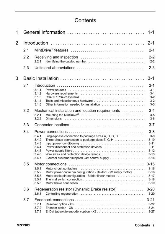
Contents iMN1901
Contents
1 General Information 1-1. . . . . . . . . . . . . . . . . . . . . . . . . . . . . . . . .
2 Introduction 2-1. . . . . . . . . . . . . . . . . . . . . . . . . . . . . . . . . . . . . . . .2.1 MintDriveII features 2-1. . . . . . . . . . . . . . . . . . . . . . . . . . . . . . . . . . . . .
2.2 Receiving and inspection 2-2. . . . . . . . . . . . . . . . . . . . . . . . . . . . . . . .2.2.1 Identifying the catalog number 2-2. . . . . . . . . . . . . . . . . . . . . . . . . . . . . . . . . . . .
2.3 Units and abbreviations 2-3. . . . . . . . . . . . . . . . . . . . . . . . . . . . . . . . . .
3 Basic Installation 3-1. . . . . . . . . . . . . . . . . . . . . . . . . . . . . . . . . . . .3.1 Introduction 3-1. . . . . . . . . . . . . . . . . . . . . . . . . . . . . . . . . . . . . . . . . . . .
3.1.1 Power sources 3-1. . . . . . . . . . . . . . . . . . . . . . . . . . . . . . . . . . . . . . . . . . . . . . . .3.1.2 Hardware requirements 3-1. . . . . . . . . . . . . . . . . . . . . . . . . . . . . . . . . . . . . . . . .3.1.3 RS485 / RS422 systems 3-2. . . . . . . . . . . . . . . . . . . . . . . . . . . . . . . . . . . . . . . .3.1.4 Tools and miscellaneous hardware 3-2. . . . . . . . . . . . . . . . . . . . . . . . . . . . . . . .3.1.5 Other information needed for installation 3-3. . . . . . . . . . . . . . . . . . . . . . . . . . .
3.2 Mechanical installation and location requirements 3-4. . . . . . . . . . .3.2.1 Mounting the MintDriveII 3-5. . . . . . . . . . . . . . . . . . . . . . . . . . . . . . . . . . . . . . . . .3.2.2 Dimensions 3-6. . . . . . . . . . . . . . . . . . . . . . . . . . . . . . . . . . . . . . . . . . . . . . . . . . .
3.3 Connector locations 3-7. . . . . . . . . . . . . . . . . . . . . . . . . . . . . . . . . . . . .
3.4 Power connections 3-8. . . . . . . . . . . . . . . . . . . . . . . . . . . . . . . . . . . . . .3.4.1 Single-phase connection to package sizes A, B, C, D 3-9. . . . . . . . . . . . . . . .3.4.2 Three-phase connection to package sizes E, G, H 3-10. . . . . . . . . . . . . . . . . . .3.4.3 Input power conditioning 3-11. . . . . . . . . . . . . . . . . . . . . . . . . . . . . . . . . . . . . . . . .3.4.4 Power disconnect and protection devices 3-11. . . . . . . . . . . . . . . . . . . . . . . . . .3.4.5 Power supply filters 3-12. . . . . . . . . . . . . . . . . . . . . . . . . . . . . . . . . . . . . . . . . . . . .3.4.6 Wire sizes and protection device ratings 3-13. . . . . . . . . . . . . . . . . . . . . . . . . . .3.4.7 External customer supplied 24V control supply 3-14. . . . . . . . . . . . . . . . . . . . . .
3.5 Motor connections 3-15. . . . . . . . . . . . . . . . . . . . . . . . . . . . . . . . . . . . . .3.5.1 Motor circuit contactors 3-16. . . . . . . . . . . . . . . . . . . . . . . . . . . . . . . . . . . . . . . . .3.5.2 Motor power cable pin configuration - Baldor BSM rotary motors 3-16. . . . . . .3.5.3 Motor cable pin configuration - Baldor linear motors 3-17. . . . . . . . . . . . . . . . . .3.5.4 Thermal switch connection 3-18. . . . . . . . . . . . . . . . . . . . . . . . . . . . . . . . . . . . . . .3.5.5 Motor brake connection 3-19. . . . . . . . . . . . . . . . . . . . . . . . . . . . . . . . . . . . . . . . .
3.6 Regeneration resistor (Dynamic Brake resistor) 3-20. . . . . . . . . . . . .3.6.1 Controlling regeneration 3-20. . . . . . . . . . . . . . . . . . . . . . . . . . . . . . . . . . . . . . . . .
3.7 Feedback connections 3-21. . . . . . . . . . . . . . . . . . . . . . . . . . . . . . . . . . .3.7.1 Resolver option - X8 3-22. . . . . . . . . . . . . . . . . . . . . . . . . . . . . . . . . . . . . . . . . . . .3.7.2 Encoder option - X8 3-24. . . . . . . . . . . . . . . . . . . . . . . . . . . . . . . . . . . . . . . . . . . .3.7.3 EnDat (absolute encoder) option - X8 3-27. . . . . . . . . . . . . . . . . . . . . . . . . . . . . .
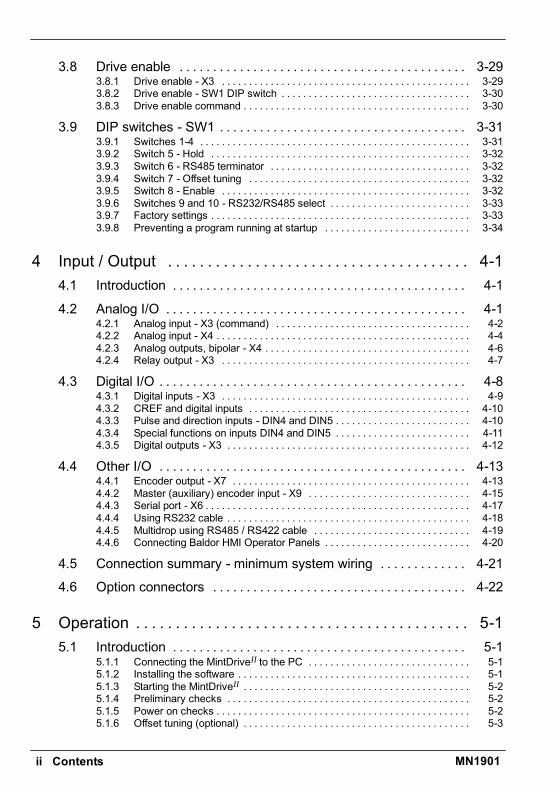
ii Contents MN1901
3.8 Drive enable 3-29. . . . . . . . . . . . . . . . . . . . . . . . . . . . . . . . . . . . . . . . . . .3.8.1 Drive enable - X3 3-29. . . . . . . . . . . . . . . . . . . . . . . . . . . . . . . . . . . . . . . . . . . . . .3.8.2 Drive enable - SW1 DIP switch 3-30. . . . . . . . . . . . . . . . . . . . . . . . . . . . . . . . . . .3.8.3 Drive enable command 3-30. . . . . . . . . . . . . . . . . . . . . . . . . . . . . . . . . . . . . . . . . .
3.9 DIP switches - SW1 3-31. . . . . . . . . . . . . . . . . . . . . . . . . . . . . . . . . . . . .3.9.1 Switches 1-4 3-31. . . . . . . . . . . . . . . . . . . . . . . . . . . . . . . . . . . . . . . . . . . . . . . . . .3.9.2 Switch 5 - Hold 3-32. . . . . . . . . . . . . . . . . . . . . . . . . . . . . . . . . . . . . . . . . . . . . . . .3.9.3 Switch 6 - RS485 terminator 3-32. . . . . . . . . . . . . . . . . . . . . . . . . . . . . . . . . . . . .3.9.4 Switch 7 - Offset tuning 3-32. . . . . . . . . . . . . . . . . . . . . . . . . . . . . . . . . . . . . . . . .3.9.5 Switch 8 - Enable 3-32. . . . . . . . . . . . . . . . . . . . . . . . . . . . . . . . . . . . . . . . . . . . . .3.9.6 Switches 9 and 10 - RS232/RS485 select 3-33. . . . . . . . . . . . . . . . . . . . . . . . . .3.9.7 Factory settings 3-33. . . . . . . . . . . . . . . . . . . . . . . . . . . . . . . . . . . . . . . . . . . . . . . .3.9.8 Preventing a program running at startup 3-34. . . . . . . . . . . . . . . . . . . . . . . . . . .
4 Input / Output 4-1. . . . . . . . . . . . . . . . . . . . . . . . . . . . . . . . . . . . . .4.1 Introduction 4-1. . . . . . . . . . . . . . . . . . . . . . . . . . . . . . . . . . . . . . . . . . . .
4.2 Analog I/O 4-1. . . . . . . . . . . . . . . . . . . . . . . . . . . . . . . . . . . . . . . . . . . . .4.2.1 Analog input - X3 (command) 4-2. . . . . . . . . . . . . . . . . . . . . . . . . . . . . . . . . . . .4.2.2 Analog input - X4 4-4. . . . . . . . . . . . . . . . . . . . . . . . . . . . . . . . . . . . . . . . . . . . . . .4.2.3 Analog outputs, bipolar - X4 4-6. . . . . . . . . . . . . . . . . . . . . . . . . . . . . . . . . . . . . .4.2.4 Relay output - X3 4-7. . . . . . . . . . . . . . . . . . . . . . . . . . . . . . . . . . . . . . . . . . . . . .
4.3 Digital I/O 4-8. . . . . . . . . . . . . . . . . . . . . . . . . . . . . . . . . . . . . . . . . . . . . .4.3.1 Digital inputs - X3 4-9. . . . . . . . . . . . . . . . . . . . . . . . . . . . . . . . . . . . . . . . . . . . . .4.3.2 CREF and digital inputs 4-10. . . . . . . . . . . . . . . . . . . . . . . . . . . . . . . . . . . . . . . . .4.3.3 Pulse and direction inputs - DIN4 and DIN5 4-10. . . . . . . . . . . . . . . . . . . . . . . . .4.3.4 Special functions on inputs DIN4 and DIN5 4-11. . . . . . . . . . . . . . . . . . . . . . . . .4.3.5 Digital outputs - X3 4-12. . . . . . . . . . . . . . . . . . . . . . . . . . . . . . . . . . . . . . . . . . . . .
4.4 Other I/O 4-13. . . . . . . . . . . . . . . . . . . . . . . . . . . . . . . . . . . . . . . . . . . . . .4.4.1 Encoder output - X7 4-13. . . . . . . . . . . . . . . . . . . . . . . . . . . . . . . . . . . . . . . . . . . .4.4.2 Master (auxiliary) encoder input - X9 4-15. . . . . . . . . . . . . . . . . . . . . . . . . . . . . .4.4.3 Serial port - X6 4-17. . . . . . . . . . . . . . . . . . . . . . . . . . . . . . . . . . . . . . . . . . . . . . . . .4.4.4 Using RS232 cable 4-18. . . . . . . . . . . . . . . . . . . . . . . . . . . . . . . . . . . . . . . . . . . . .4.4.5 Multidrop using RS485 / RS422 cable 4-19. . . . . . . . . . . . . . . . . . . . . . . . . . . . .4.4.6 Connecting Baldor HMI Operator Panels 4-20. . . . . . . . . . . . . . . . . . . . . . . . . . .
4.5 Connection summary - minimum system wiring 4-21. . . . . . . . . . . . .
4.6 Option connectors 4-22. . . . . . . . . . . . . . . . . . . . . . . . . . . . . . . . . . . . . .
5 Operation 5-1. . . . . . . . . . . . . . . . . . . . . . . . . . . . . . . . . . . . . . . . . .5.1 Introduction 5-1. . . . . . . . . . . . . . . . . . . . . . . . . . . . . . . . . . . . . . . . . . . .
5.1.1 Connecting the MintDriveII to the PC 5-1. . . . . . . . . . . . . . . . . . . . . . . . . . . . . .5.1.2 Installing the software 5-1. . . . . . . . . . . . . . . . . . . . . . . . . . . . . . . . . . . . . . . . . . .5.1.3 Starting the MintDriveII 5-2. . . . . . . . . . . . . . . . . . . . . . . . . . . . . . . . . . . . . . . . . .5.1.4 Preliminary checks 5-2. . . . . . . . . . . . . . . . . . . . . . . . . . . . . . . . . . . . . . . . . . . . .5.1.5 Power on checks 5-2. . . . . . . . . . . . . . . . . . . . . . . . . . . . . . . . . . . . . . . . . . . . . . .5.1.6 Offset tuning (optional) 5-3. . . . . . . . . . . . . . . . . . . . . . . . . . . . . . . . . . . . . . . . . .
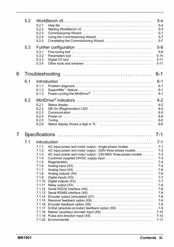
Contents iiiMN1901
5.2 WorkBench v5 5-4. . . . . . . . . . . . . . . . . . . . . . . . . . . . . . . . . . . . . . . . . .5.2.1 Help file 5-4. . . . . . . . . . . . . . . . . . . . . . . . . . . . . . . . . . . . . . . . . . . . . . . . . . . . . .5.2.2 Starting WorkBench v5 5-5. . . . . . . . . . . . . . . . . . . . . . . . . . . . . . . . . . . . . . . . . .5.2.3 Commissioning Wizard 5-7. . . . . . . . . . . . . . . . . . . . . . . . . . . . . . . . . . . . . . . . . .5.2.4 Using the Commissioning Wizard 5-7. . . . . . . . . . . . . . . . . . . . . . . . . . . . . . . . .5.2.5 Completing the Commissioning Wizard 5-7. . . . . . . . . . . . . . . . . . . . . . . . . . . .
5.3 Further configuration 5-8. . . . . . . . . . . . . . . . . . . . . . . . . . . . . . . . . . . .5.3.1 Fine-tuning tool 5-8. . . . . . . . . . . . . . . . . . . . . . . . . . . . . . . . . . . . . . . . . . . . . . . .5.3.2 Parameters tool 5-10. . . . . . . . . . . . . . . . . . . . . . . . . . . . . . . . . . . . . . . . . . . . . . . .5.3.3 Digital I/O tool 5-11. . . . . . . . . . . . . . . . . . . . . . . . . . . . . . . . . . . . . . . . . . . . . . . . .5.3.4 Other tools and windows 5-11. . . . . . . . . . . . . . . . . . . . . . . . . . . . . . . . . . . . . . . .
6 Troubleshooting 6-1. . . . . . . . . . . . . . . . . . . . . . . . . . . . . . . . . . . .6.1 Introduction 6-1. . . . . . . . . . . . . . . . . . . . . . . . . . . . . . . . . . . . . . . . . . . .
6.1.1 Problem diagnosis 6-1. . . . . . . . . . . . . . . . . . . . . . . . . . . . . . . . . . . . . . . . . . . . . .6.1.2 SupportMet feature 6-1. . . . . . . . . . . . . . . . . . . . . . . . . . . . . . . . . . . . . . . . . . . .6.1.3 Power-cycling the MintDriveII 6-1. . . . . . . . . . . . . . . . . . . . . . . . . . . . . . . . . . . .
6.2 MintDriveII indicators 6-2. . . . . . . . . . . . . . . . . . . . . . . . . . . . . . . . . . . .6.2.1 Status display 6-2. . . . . . . . . . . . . . . . . . . . . . . . . . . . . . . . . . . . . . . . . . . . . . . . .6.2.2 DB On (Regeneration) LED 6-5. . . . . . . . . . . . . . . . . . . . . . . . . . . . . . . . . . . . . .6.2.3 Communication 6-5. . . . . . . . . . . . . . . . . . . . . . . . . . . . . . . . . . . . . . . . . . . . . . . .6.2.4 Power on 6-6. . . . . . . . . . . . . . . . . . . . . . . . . . . . . . . . . . . . . . . . . . . . . . . . . . . . .6.2.5 Tuning 6-6. . . . . . . . . . . . . . . . . . . . . . . . . . . . . . . . . . . . . . . . . . . . . . . . . . . . . . . .6.2.6 Status display shows a digit or E. 6-6. . . . . . . . . . . . . . . . . . . . . . . . . . . . . . . .
7 Specifications 7-1. . . . . . . . . . . . . . . . . . . . . . . . . . . . . . . . . . . . . .7.1 Introduction 7-1. . . . . . . . . . . . . . . . . . . . . . . . . . . . . . . . . . . . . . . . . . . .
7.1.1 AC input power and motor output - single-phase models 7-1. . . . . . . . . . . . . .7.1.2 AC input power and motor output - 230V three-phase models 7-2. . . . . . . . . .7.1.3 AC input power and motor output - 230-460V three-phase models 7-3. . . . . .7.1.4 Customer supplied 24VDC supply input 7-3. . . . . . . . . . . . . . . . . . . . . . . . . . . .7.1.5 Regeneration 7-4. . . . . . . . . . . . . . . . . . . . . . . . . . . . . . . . . . . . . . . . . . . . . . . . . .7.1.6 Analog input (X3) 7-5. . . . . . . . . . . . . . . . . . . . . . . . . . . . . . . . . . . . . . . . . . . . . . .7.1.7 Analog input (X4) 7-6. . . . . . . . . . . . . . . . . . . . . . . . . . . . . . . . . . . . . . . . . . . . . . .7.1.8 Analog outputs (X4) 7-6. . . . . . . . . . . . . . . . . . . . . . . . . . . . . . . . . . . . . . . . . . . .7.1.9 Digital inputs (X3) 7-7. . . . . . . . . . . . . . . . . . . . . . . . . . . . . . . . . . . . . . . . . . . . . .7.1.10 Digital outputs (X3) 7-7. . . . . . . . . . . . . . . . . . . . . . . . . . . . . . . . . . . . . . . . . . . . .7.1.11 Relay output (X3) 7-8. . . . . . . . . . . . . . . . . . . . . . . . . . . . . . . . . . . . . . . . . . . . . .7.1.12 Serial RS232 interface (X6) 7-8. . . . . . . . . . . . . . . . . . . . . . . . . . . . . . . . . . . . . .7.1.13 Serial RS485 interface (X6) 7-8. . . . . . . . . . . . . . . . . . . . . . . . . . . . . . . . . . . . . .7.1.14 Encoder output (simulated) (X7) 7-8. . . . . . . . . . . . . . . . . . . . . . . . . . . . . . . . . .7.1.15 Resolver feedback option (X8) 7-9. . . . . . . . . . . . . . . . . . . . . . . . . . . . . . . . . . .7.1.16 Encoder feedback option (X8) 7-9. . . . . . . . . . . . . . . . . . . . . . . . . . . . . . . . . . . .7.1.17 EnDat (absolute encoder) feedback option (X8) 7-9. . . . . . . . . . . . . . . . . . . . .7.1.18 Master (auxiliary) encoder input (X9) 7-10. . . . . . . . . . . . . . . . . . . . . . . . . . . . . .7.1.19 Pulse and direction input (X9) 7-10. . . . . . . . . . . . . . . . . . . . . . . . . . . . . . . . . . . .7.1.20 Environmental 7-11. . . . . . . . . . . . . . . . . . . . . . . . . . . . . . . . . . . . . . . . . . . . . . . . .
iv Contents MN1901
Appendices
A Accessories A-1. . . . . . . . . . . . . . . . . . . . . . . . . . . . . . . . . . . . . . . .A.1 Introduction A-1. . . . . . . . . . . . . . . . . . . . . . . . . . . . . . . . . . . . . . . . . . . .
A.1.1 Factory fitted options A-1. . . . . . . . . . . . . . . . . . . . . . . . . . . . . . . . . . . . . . . . . . .A.1.2 Motor power cables A-2. . . . . . . . . . . . . . . . . . . . . . . . . . . . . . . . . . . . . . . . . . . . .A.1.3 Motor power cable part numbers A-2. . . . . . . . . . . . . . . . . . . . . . . . . . . . . . . . . .A.1.4 Feedback cables A-3. . . . . . . . . . . . . . . . . . . . . . . . . . . . . . . . . . . . . . . . . . . . . . .A.1.5 Feedback cable part numbers A-4. . . . . . . . . . . . . . . . . . . . . . . . . . . . . . . . . . . .A.1.6 EMC filters A-5. . . . . . . . . . . . . . . . . . . . . . . . . . . . . . . . . . . . . . . . . . . . . . . . . . . .A.1.7 Regeneration resistors A-7. . . . . . . . . . . . . . . . . . . . . . . . . . . . . . . . . . . . . . . . . .
B Control System B-1. . . . . . . . . . . . . . . . . . . . . . . . . . . . . . . . . . . . .B.1 Introduction B-1. . . . . . . . . . . . . . . . . . . . . . . . . . . . . . . . . . . . . . . . . . . .
B.1.1 Positioning system with speed controller B-1. . . . . . . . . . . . . . . . . . . . . . . . . . .B.1.2 Positioning system without speed controller B-2. . . . . . . . . . . . . . . . . . . . . . . .B.1.3 Speed amplifier B-3. . . . . . . . . . . . . . . . . . . . . . . . . . . . . . . . . . . . . . . . . . . . . . . .B.1.4 Torque amplifier B-4. . . . . . . . . . . . . . . . . . . . . . . . . . . . . . . . . . . . . . . . . . . . . . . .
B.2 Control system operation B-5. . . . . . . . . . . . . . . . . . . . . . . . . . . . . . . .B.2.1 Position controller B-5. . . . . . . . . . . . . . . . . . . . . . . . . . . . . . . . . . . . . . . . . . . . . .B.2.2 Speed controller B-6. . . . . . . . . . . . . . . . . . . . . . . . . . . . . . . . . . . . . . . . . . . . . . .B.2.3 Torque controller and feedback B-7. . . . . . . . . . . . . . . . . . . . . . . . . . . . . . . . . . .
C CE Guidelines C-1. . . . . . . . . . . . . . . . . . . . . . . . . . . . . . . . . . . . . .C.1 Outline C-1. . . . . . . . . . . . . . . . . . . . . . . . . . . . . . . . . . . . . . . . . . . . . . . .
C.1.1 EMC Conformity and CE marking C-1. . . . . . . . . . . . . . . . . . . . . . . . . . . . . . . . .C.1.2 Use of CE compliant components C-2. . . . . . . . . . . . . . . . . . . . . . . . . . . . . . . . .C.1.3 EMC wiring technique C-2. . . . . . . . . . . . . . . . . . . . . . . . . . . . . . . . . . . . . . . . . . .C.1.4 EMC installation suggestions C-3. . . . . . . . . . . . . . . . . . . . . . . . . . . . . . . . . . . . .C.1.5 Wiring of shielded (screened) cables C-4. . . . . . . . . . . . . . . . . . . . . . . . . . . . . .
General Information 1-1MN1901
LT0159A02 Copyright Baldor (c) 2002. All rights reserved.
This manual is copyrighted and all rights are reserved. This document or attached software may not,in whole or in part, be copied or reproduced in any form without the prior written consent of Baldor.Baldor makes no representations or warranties with respect to the contents hereof and specificallydisclaims any implied warranties of fitness for any particular purpose. The information in thisdocument is subject to change without notice. Baldor assumes no responsibility for any errors thatmay appear in this document.Mintt is a registered trademark of Baldor.Windows 95, Windows 98, Windows ME, Windows NT, Windows XP and Windows 2000 areregistered trademarks of the Microsoft Corporation. UL and cUL are registered trademarks ofUnderwriters Laboratories. EnDat is a registered trademark of Heidenhain Corporation.
Limited WarrantyFor a period of two (2) years from the date of original purchase, Baldor will repair or replace withoutcharge controls and accessories that our examination proves to be defective in material orworkmanship. This warranty is valid if the unit has not been tampered with by unauthorized persons,misused, abused, or improperly installed and has been used in accordance with the instructions and/orratings supplied. This warranty is in lieu of any other warranty or guarantee expressed or implied.Baldor shall not be held responsible for any expense (including installation and removal),inconvenience, or consequential damage, including injury to any person or property caused by items ofour manufacture or sale. (Some countries and U.S. states do not allow exclusion or limitation ofincidental or consequential damages, so the above exclusion may not apply.) In any event, Baldorstotal liability, under all circumstances, shall not exceed the full purchase price of the control. Claims forpurchase price refunds, repairs, or replacements must be referred to Baldor with all pertinent data asto the defect, the date purchased, the task performed by the control, and the problem encountered. Noliability is assumed for expendable items such as fuses. Goods may be returned only with writtennotification including a Baldor Return Authorization Number and any return shipments must be prepaid.
1 General Information 1

1-2 General Information MN1901
Product NoticeOnly qualified personnel should attempt the start-up procedure or troubleshoot this equipment.This equipment may be connected to other machines that have rotating parts or parts that arecontrolled by this equipment. Improper use can cause serious or fatal injury. Only qualified personnelshould attempt to start-up, program or troubleshoot this equipment.
Safety NoticeIntended use: These drives are intended for use in stationary ground based applications in industrialpower installations according to the standards EN60204 and VDE0160. They are designed formachine applications that require variable speed controlled three-phase brushless AC motors. Thesedrives are not intended for use in applications such as:
H Home appliancesH Medical instrumentationH Mobile vehiclesH ShipsH Airplanes.
Unless otherwise specified, this drive is intended for installation in a suitable enclosure. The enclosuremust protect the drive from exposure to excessive or corrosive moisture, dust and dirt or abnormalambient temperatures. The exact operating specifications are found in section 7 of this manual. Theinstallation, connection and control of drives is a skilled operation, disassembly or repair must not beattempted. In the event that a drive fails to operate correctly, contact the place of purchase for returninstructions.
Precautions
WARNING: Do not touch any circuit board, power device or electrical connection before youfirst ensure that no high voltage is present at this equipment or other equipment towhich it is connected. Electrical shock can cause serious or fatal injury. Onlyqualified personnel should attempt to start-up, program or troubleshoot thisequipment.
WARNING: Be sure the system is properly earthed/grounded before applying power. Do notapply AC power before you ensure that earths/grounds are connected. Electricalshock can cause serious or fatal injury.
WARNING: Be sure that you are completely familiar with the safe operation and programmingof this equipment. This equipment may be connected to other machines that haverotating parts or parts that are controlled by this equipment. Improper use cancause serious or fatal injury. Only qualified personnel should attempt to program,start-up or troubleshoot this equipment.

General Information 1-3MN1901
WARNING: Be sure all wiring complies with the National Electrical Code and all regional andlocal codes. Improper wiring may result in unsafe conditions.
WARNING: The stop input to this equipment should not be used as the single means ofachieving a safety critical stop. Drive disable, motor disconnect, motor brake andother means should be used as appropriate. Only qualified personnel shouldattempt to program, start-up or troubleshoot this equipment.
WARNING: Improper operation or programming of the drive may cause violent motion of themotor and driven equipment. Be certain that unexpected motor movement will notcause injury to personnel or damage to equipment. Peak torque of several timesthe rated motor torque can occur during control failure.
WARNING: The motor circuit might have high voltages present whenever AC power isapplied, even when the motor is not moving. Electrical shock can cause serious orfatal injury.
WARNING: If a motor is driven mechanically, it might generate hazardous voltages that areconducted to its power terminals. The enclosure must be earthed/grounded toprevent possible shock hazard.
WARNING: When operating a rotary motor with no load coupled to its shaft, remove the shaftkey to prevent it flying out when the shaft rotates.
WARNING: A regeneration resistor may generate enough heat to ignite combustible materials.To avoid fire hazard, keep all combustible materials and flammable vapors awayfrom the brake resistors.
CAUTION: To prevent equipment damage, be certain that the input power has correctly sizedprotective devices installed.
CAUTION: To prevent equipment damage, be certain that input and output signals arepowered and referenced correctly.
CAUTION: To ensure reliable performance of this equipment be certain that all signals to/fromthe drive are shielded correctly.
CAUTION: Suitable for use on a circuit capable of delivering not more than the RMSsymmetrical short circuit amperes listed here at rated voltage.Horsepower RMS Symmetrical Amperes1-50 5,000
CAUTION: Avoid locating the drive immediately above or beside heat generating equipment,or directly below water or steam pipes.

1-4 General Information MN1901
CAUTION: Avoid locating the drive in the vicinity of corrosive substances or vapors, metalparticles and dust.
CAUTION: Do not connect AC power to the drive terminals U, V and W. Connecting ACpower to these terminals may result in damage to the drive.
CAUTION: Baldor does not recommend using Grounded Leg Delta transformer power leadsthat may create earth/ground loops and degrade system performance. Instead,we recommend using a four wire Wye.
CAUTION: Drives are intended to be connected to a permanent main power source, not aportable power source. Suitable fusing and circuit protection devices are required.
CAUTION: The safe integration of the drive into a machine system is the responsibility of themachine designer. Be sure to comply with the local safety requirements at theplace where the machine is to be used. In Europe these are the MachineryDirective, the ElectroMagnetic Compatibility Directive and the Low VoltageDirective. In the United States this is the National Electrical code and local codes.
CAUTION: Drives must be installed inside an electrical cabinet that provides environmentalcontrol and protection. Installation information for the drive is provided in thismanual. Motors and controlling devices that connect to the drive should havespecifications compatible to the drive.
CAUTION: Violent jamming (stopping) of the motor during operation may damage the motorand drive.
CAUTION: Do not tin (solder) exposed wires. Solder contracts over time and may causeloose connections. Use crimp connections where possible.
CAUTION: Electrical components can be damaged by static electricity. Use ESD(electro-static discharge) procedures when handling this drive.
CAUTION: Ensure that resolver or encoder wires are properly connected. Incorrectinstallation may result in improper movement.
CAUTION: The threaded holes in the top and bottom of the enclosure are for cable clamps.Be sure to use a M4 bolt no longer than 12mm in length. Longer bolts mightshort-circuit the electrical components inside the drive.
CAUTION: Removing the cover will invalidate UL certification.

Introduction 2-1MN1901
2.1 MintDriveII featuresThe MintDriveII combines a powerful fully featured motion controller and brushless servocontrol into a compact package. This provides a flexible and powerful motion control solutionfor single axis rotary and linear positioning systems. Programmable in Mint, applications canbe quickly written and tested. Standard features include:
H Single axis AC brushless drive with integrated Mint controllerH Wide range of models with continuous current ratings from 2.5A to 27.5AH Direct connection to 115VAC or 230VAC single-phase or 230-460VAC three-phase
supplies (model dependent)H Resolver or encoder feedbackH Programmable in Mint, with multi-tasking capabilityH Position, velocity and current control, preset and point to point moves, software cams and
gearingH Auto-tuning wizard (including position loop) and software oscilloscope facilitiesH 8 optically isolated digital inputsH 3 optically isolated digital outputsH 2 general-purpose analog inputs (can be used as a speed or torque command reference)H 2 general-purpose analog outputsH 1 control relayH Selectable RS232 or RS485 communicationsH Flash memory for program storage (128k)H Non-volatile RAM.
Factory-fitted options expand the I/O capabilities of the MintDriveII and provide CAN bus,DeviceNet or Profibus connectivity. See Appendix A for details about options. MintDriveII willoperate with a large number of brushless servo motors - for information on selecting Baldorservo motors, please see the sales brochure BR1202 (BR1800 for linear motors) availablefrom your local Baldor representative.
This manual is intended to guide you through the installation of MintDriveII. The sectionsshould be read in sequence.
The Basic Installation section describes the mechanical installation of the MintDriveII, thepower supply connections and motor connections. The other sections require knowledge ofthe low level input/output requirements of the installation and an understanding of computersoftware installation. If you are not qualified in these areas you should seek assistance beforeproceeding.
2 Introduction 2

2-2 Introduction MN1901
2.2 Receiving and inspectionWhen you receive your MintDriveII, there are several things you should do immediately:
1. Check the condition of the shipping container and report any damage immediately to thecarrier that delivered your MintDriveII.
2. Remove the MintDriveII from the shipping container and remove all packing material. Thecontainer and packing materials may be retained for future shipment.
3. Verify that the catalog number of the MintDriveII you received is the same as the catalognumber listed on your purchase order. The catalog number is described in the next section.
4. Inspect the MintDriveII for external damage during shipment and report any damage to thecarrier that delivered your MintDriveII.
5. If MintDriveII is to be stored for several weeks before use, be sure that it is stored in a locationthat conforms to thestorage humidity and temperaturespecifications shown in section7.1.20.
2.2.1 Identifying the catalog numberThe MintDriveII is available with different current ratings and package sizes. The catalognumber is marked on the front of the unit, just below the Baldor logo. It is a good idea to lookfor the catalog number (sometimes shown as ID/No: ) and write it in the space provided here:
Catalog number: MDH______________-________Installed at: ________________________ Date: ______A description of a catalog number is shown here, using the example MDH1A05TB-RC23:
Meaning Alternatives
MDH MintDriveII family -
1 Requires an AC supply voltage of 115 Volts, 1Φ 2=230V (1Φ or 3Φ);4=230V-460V (3Φ)
A05 Continuous current rating of 5.0A A02=2.5A; A07=7.5A; A15=15A;A20=20A; A27=27.5A
T Built in AC power supply -
B Dynamic Brake with a built in transistor andresistor (available on 2.5A and 5A models only)
R=Requires external brakingresistor
R Feedback option is a resolver E=Encoder;D=EnDat (absolute encoder)
C Options: 1 CAN channelB=CAN & Auxiliary I/O;D=DeviceNet; P=Profibus DP;N=No options specified
2 Serial port type is combined RS232 / RS485 -
3 Customers own 24VDC supply is required topower the internal MintDriveII logic
0= Internally generated 24VDCsupply*
* An external 24VDC supply will always be required to operate the enable input, digital inputsand digital outputs on connectors X3 and X4. See sections 4.3.1 to 4.3.5.

Introduction 2-3MN1901
2.3 Units and abbreviationsThe following units and abbreviations are used in this manual:
V Volt (also VAC and VDC). . . . . . . . . . . . . . .W Watt. . . . . . . . . . . . . .A Ampere. . . . . . . . . . . . . . .Ω Ohm. . . . . . . . . . . . . . .µF microfarad. . . . . . . . . . . . . .pF picofarad. . . . . . . . . . . . . .mH millihenry. . . . . . . . . . . . .
Φ phase. . . . . . . . . . . . . . .ms millisecond. . . . . . . . . . . . . .µs microsecond. . . . . . . . . . . . . .ns nanosecond. . . . . . . . . . . . . .
Kbaud kilobaud (the same as Kbit/s in most applications). . . . . . . . . . .MB megabytes. . . . . . . . . . . . .CDROM Compact Disc Read Only Memory. . . . . . . . .CTRL+E on the PC keyboard, press Ctrl then E at the same time.. . . . . . . . .
mm millimeter. . . . . . . . . . . . .m meter. . . . . . . . . . . . . . .in inch. . . . . . . . . . . . . . .ft feet. . . . . . . . . . . . . . .lb-in pound-inch (torque). . . . . . . . . . . . .Nm Newton-meter (torque). . . . . . . . . . . . .
ADC Analog to Digital Converter. . . . . . . . . . . .DAC Digital to Analog Converter. . . . . . . . . . . .AWG American Wire Gauge. . . . . . . . . . . .(NC) Not Connected. . . . . . . . . . . .

2-4 Introduction MN1901

Basic Installation 3-1MN1901
3.1 IntroductionYou should read all the sections in Basic Installation to ensure safe installation.This section describes the mechanical and electrical installation of the MintDriveII in thefollowing stages:
H Location considerationsH Mounting the MintDriveII
H Connecting the AC power supplyH Connecting the optional customer supplied 24VDC control supplyH Connecting the motorH Installing a regeneration resistor (Dynamic Brake resistor)H Connecting the feedback deviceH Connecting the drive enable input.
These stages should be read and followed in sequence.
3.1.1 Power sourcesAn AC power source (IEC1010 over-voltage category III or less) in the installation area isrequired. This will need to be single or three-phase depending upon the type of MintDriveII.An AC power filter is required to comply with the CE directive for which the MintDriveII wastested (see section 3.4.5).
If the MintDriveII requires an external (customer supplied) 24VDC logic supply then this mustbe a regulated power supply with a continuous current supply capability of 1.75A (4A power onsurge). A 24V filter may be required to comply with the CE directive for which the MintDriveII
was tested (see section 3.4.5).
3.1.2 Hardware requirementsThe components you will need to complete the basic installation are:
H The motor that will be connected to the MintDriveII
H A motor power cableH A resolver or encoder feedback cable (and Hall cable for linear motors)H With some applications there may be a requirement for a regeneration resistor (Dynamic
Brake).
Note: Without the regeneration resistor, the drive may produce an overvoltage fault.All MintDriveIImodels have overvoltage sensing circuitry, but only 2.5A and 5Amodels (catalog numbers MDHxxxxxB-xxxx) have an internal regenerationresistor. For 7.5A, 15A, 20A and 27.5A models a regeneration resistor must bepurchased separately if required. See Appendix A.
3 Basic Installation 3

3-2 Basic Installation MN1901
H A serial cable.
Note: The serial connector on the MintDriveII (connector X6) can be configured as eitherRS232 or RS485 / RS422. Pin 9 is used to carry +8V for powering some Baldorkeypad peripherals. Ensure that pin 9 is not connected to earth/ground or toequipment that could be damaged by the +8V supply. See sections 4.4.3 to 4.4.4.A suitable cable is available from Baldor, catalog number CBL001-501.
H A PC (with one free COM port) with the following specification:
Minimum specification Recommended specification
Processor Intel Pentium 133MHz Intel Pentium 200MHz or faster
RAM 32MB 64MB
Hard disk space 40MB 60MB
CD-ROM A CD-ROM drive
Screen 800 x 600, 256 colors 1024 x 768, 256 colors
Mouse A mouse or similar pointing device
Operating system Windows 95, Windows 98, Windows ME,Windows NT, Windows XP or Windows 2000
3.1.3 RS485 / RS422 systemsIf you will be using RS485 / RS422 and your PC does not have an RS485 / RS422 connector,an RS232 to 4-wire RS485 / RS422 converter will be required. These commercially availabledevices convert the signals from the RS232/RS485 port (connector X6) to the signalsnecessary for RS485 / RS422 communications. Special care must be taken with the pinassignment on all RS485 / RS422 devices, as this can differ between products. Connectorsmight need to be rewired to provide the correct pin assignment. The MintDriveII pinassignment is shown in section 4.4.3.
Note: If this is the first time you are installing a MintDriveII then it is stronglyrecommended that you use RS232 to get started and try RS485 later. This willavoid any potential problems involving the RS232-RS485 converter. Selection ofRS232 or RS485 is controlled using DIP switch 10 - see section 3.9.6.
3.1.4 Tools and miscellaneous hardwareH Your PC operating system user manual might be useful if you are not familiar with
WindowsH A small screwdriver (supplied) with a blade width less than 3mm (1/10 in).H M5 screws or bolts for mounting the MintDriveII
H Crimping tool.
A connector kit is supplied with your MintDriveII. This contains a number of useful connectorsand a screwdriver for tightening the connections.

Basic Installation 3-3MN1901
3.1.5 Other information needed for installationThis information is useful (but not essential) to complete the installation:
H The data sheet or manual provided with your motor, describing the wiring information ofthe motor cables/connectors
H Knowledge of which digital inputs/outputs will be Active Low, Active High or edgetriggered.

3-4 Basic Installation MN1901
3.2 Mechanical installation and location requirementsIt is essential that you read and understand this section before beginning theinstallation.
CAUTION: To prevent equipment damage, be certain that the input power hascorrectly rated protective devices installed.
CAUTION: To prevent equipment damage, be certain that input and output signalsare powered and referenced correctly.
CAUTION: To ensure reliable performance of this equipment be certain that allsignals to/from the MintDriveII are shielded correctly.
CAUTION: Avoid locating the MintDriveII immediately above or beside heatgenerating equipment, or directly below water steam pipes.
CAUTION: Avoid locating the MintDriveII in the vicinity of corrosive substances orvapors, metal particles and dust.
The safe operation of this equipment depends upon its use in the appropriate environment.The following points must be considered:
H The MintDriveIImust be installed indoors, permanently fixed and located so that it can onlybe accessed by service personnel using tools.
H The maximum suggested operating altitude is 1000m (3300ft).Above 1000m (3300ft) de-rate output current 1.1% per 100m (330ft).
H The MintDriveIImust operate in an ambient temperature of 0°C to 40°C (32°F to 104°F).De-rate output current 2.5% per 1°C (1.8°F) from 40°C (104°F) to 50°C (122°F) maximum.
H The MintDriveIImust operate in relative humidity levels of less than 90% for temperaturesup to 31°C (87°F) decreasing linearly to 50% relative humidity at 40°C (104°F)(non-condensing).
H The MintDriveIImust be installed where the pollution degree according to IEC664 shall notexceed 2.
H The external customer supplied 24VDC for the logic supply must be installed so that the24VDC supplied to the unit is isolated from the AC supply using double or reinforcedinsulation.
H The inputs and outputs of the control circuit must be limited to Safety Extra Low Voltagecircuits.
H Both the AC supply and the external 24VDC supply must be fused.H The atmosphere must not contain flammable gases or vapors.H There must not be abnormal levels of nuclear radiation or X-rays.H The MintDriveIImust be secured by the slots in the flange, with the protective
earth/ground stud bonded to a safety earth/ground by either a 25A conductor or aconductor of three times the peak current rating - whichever is the greater.

Basic Installation 3-5MN1901
H For effective cooling and maintenance, the MintDriveII should be mounted on a smooth,non-flammable vertical surface. The power handling capability is affected by thetemperature of the left side of the unit.
H At least 50mm (2 in) top and bottom clearance of the MintDriveIImust be provided forairflow.
H If multiple MintDriveII are being mounted side by side there must be 13mm (0.5 in)between them. The MintDriveII nearest the side of the cabinet / enclosure must beseparated from it by at least 13mm (0.5 in).
H To comply with CE directive 89/336/EEC an appropriate AC filter must be installed. Theexternal customer supplied 24VDC logic supply might also require a 24V filter. See section3.4.7.
H The threaded holes in the top and bottom of the enclosure are for cable clamps. The holesare threaded for M4 bolts no longer than 12mm (0.47 in) in length. Longer bolts may shortcircuit the electrical components inside the MintDriveII.
H Each D-type connector on the front panel of the MintDriveII is secured using twohexagonal jack screws (sometimes known as screwlocks). If a jack screw is removedaccidentally or lost it must be replaced with an identical jack screw with an external malethreaded section of 5mm (0.2 in). Jack screws with longer threads could damage or shortcircuit internal components.
3.2.1 Mounting the MintDriveII
Ensure you have read and understood the Mechanical installation and location requirements insection 3.2. Mount the MintDriveII on its rear side, the side opposite to the front panel.The MintDriveIImust be mounted upright to ensure adequate cooling (you can check this byensuring that the Hazardous Voltages warning information is clearly readable to you).M5 bolts or screws should be used to mount the MintDriveII.
There are seven different package sizes depending on the specification of the MintDriveII :
AC power Current Factory fitted option Package size
Single-phase 2A without option A
with option B
5A without option C
with option D
7.5A without option D
with option D
230VThree-phase
15A with or without option E
230-460VThree phase
2.5A, 5A, 7.5A with or without option GThree-phase
15A, 20A, 27.5A with or without option H
Detailed dimensions for each package are shown in section 3.2.2.

3-6 Basic Installation MN1901
3.2.2 Dimensions
H1
H2
HWD
W2
W1
W3
Package sizeH only.
W4
Package sizes E, G& H only:W4=9.5mm.
All other sizes:W4 = W2
H3
H4
65mm
FRONT PANEL
H5
H6
Mounting keyhole and slot detail
A
BC
A 5mm (package sizes E, G and H: 6.5mm)B 10mm (package sizes E, G and H: 12mm)C 9mm (package sizes E, G and H: 10mm)
A
Dimensionsmm / inches
Weight
Case W W1 W2 W3 H H1 H2 H3 H4 H5 H6 D kg / lb
A 67.52.66
15
1.252.76
B 843.31
40
150.59
40 173 195.5 205 23.5 6.5 8.5 3 152
1.553.42
C 92.53.64
401.57
23
401.57
1736.81
195.57.70
2058.07
23.50.93
6.50.26
8.50.33
30.12
1526.00 2.1
4.63
D 1094.29
230.91 2.3
5.07
E 552.17
361.42
27.51.08
- 263.510.37
3.37.28
G 652.56
461.81
32.51.28
- 35714.06
38415.12
40015.75
26.51.04
80.31
16.50.65
80.31
26210.31
4.910.8
H 1305.12
1114.37
27.51.08
752.95
32812.91
9.0519.95
Figure 1 - Package dimensions
Basic Installation 3-7MN1901
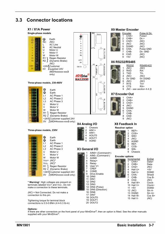
3.3 Connector locations
EarthNC (NC)L AC LineN AC NeutralU Motor UV Motor VW Motor WR1 Regen ResistorR2 (Dynamic Brake)- (NC)+24V Customer0V supplied 24V
(MDHxxxxxx-xxx3only)
EarthEarth
L1 AC Phase 1L2 AC Phase 2L3 AC Phase 3U Motor UV Motor VW Motor WR1 Regen ResistorR2 (Dynamic Brake)+24V Customer supplied 24V0V (MDH4xxxxx-xxx3 only)
EarthEarth
L1 AC Phase 1L2 AC Phase 2L3 AC Phase 3U Motor UV Motor VW Motor WVcc+ (NC)*Vcc- (NC)*R1 Regen ResistorR2 (Dynamic Brake)+24V Customer supplied 24V0V (MDH2xxxxx-xxx3 only)
1 AIN0+ (Command+)2 AIN0- (Command-)3 AGND4 Relay+5 Relay-6 User V+7 CREF8 CGND9 Drive Enable10 DIN011 DIN112 DIN213 DIN314 DIN4 (Pulse)15 DIN5 (Direction)16 DIN617 DIN718 DOUT019 DOUT120 DOUT2
1 Chassis2 AIN1+3 AIN1-4 AOUT05 AOUT16 AGND
1 CHA+2 CHB+3 CHZ+4 (NC)5 DGND6 CHA-7 CHB-8 CHZ-9 (NC)
RS232 RS485/4221 (NC) (NC)2 RXD RX-3 TXD TX-4 (NC) (NC)5 0V GND 0V DGND6 (NC) (NC)7 RTS TX+8 CTS RX+9 (NC - see section 4.4.3)
X3 General I/O
X4 Analog I/O
X6 RS232/RS485
X7 EncoderOut
X8 Feedback In
1 REF+2 COS+3 SIN+4 (NC)5 AGND6 REF-7 COS-8 SIN-9 Chassis
Incremental EnDat1 CHA+ Data+2 CHB+ Data-3 CHZ+ (NC)4 Hall U+ +5V5 Hall U- DGND6 CHA- Shield7 CHB- Cos B-8 CHZ- (NC)9 Hall W+ Clock-10 Hall V+ Clock+11 +5V DGND12 (NC) Sin A-13 DGND Sin A+14 Hall W- Cos B+15 Hall V- (NC)
Resolver option
Encoder options
X1 / X1A PowerSingle-phase models
Three-phase models, 230-460V
Tightening torque for terminal blockconnections is 0.5-0.6Nm (4.4-5.3 lb-in)
X9 Master Encoder
II
Options:If there are other connectors on the front panel of your MintDriveII, then an option is fitted. See the other manualssupplied with your MintDriveII.
* Warning! High voltages are present onterminals labeled Vcc+ and Vcc-. Do notmake a connection to these terminals.
(NC) = Not Connected. Do not make aconnection to this pin.
Three-phase models, 230V
Encoder Pulse & Dir.1 CHA+ Pulse+2 CHB+ Dir.+3 CHZ+ (NC)4 (NC) (NC)5 DGND (NC)6 CHA- Pulse GND7 CHB- Dir. GND8 CHZ- (NC)9 +5V (NC)

3-8 Basic Installation MN1901
3.4 Power connectionsThis section provides instructions for connecting the AC power supply. It is important that yourefer to the correct front panel for your MintDriveII package.
The installer of this equipment is responsible for complying with NEC (National Electric Code)guidelines or CE (Conformite Europeene) directives and application codes that govern wiringprotection, earthing/grounding, disconnects and other current protection.
WARNING: Electrical shock can cause serious or fatal injury. Do not touch anypower device or electrical connection before you first ensure thatpower has been disconnected and there is no high voltage presentfrom this equipment or other equipment to which it is connected.
The power supply module within all MintDriveIImodels provides rectification, smoothing andcurrent surge protection. On 2.5A and 5A models a regeneration resistor (Dynamic Brakeresistor) is also built-in. The power stage is internally fused and therefore self protected, butfuses or circuit breakers are required in the input lines for cable protection (depending on localcodes and regulations).
A power disconnect should be installed between the AC supply and the input of the MintDriveII
for a fail safe method to disconnect mains power. On models with the internally generated24VDC logic supply (catalog numbers MDHxxxxx-xxx0), the MintDriveII will remainoperational until the internal bus voltage is depleted. Position and I/O information will then belost. On models with an external customer supplied 24VDC logic supply (catalog numbersMDHxxxxx-xxx3), position and I/O information will be retained while the 24V supply is present.
Note: A Residual Current Device (RCD) must not be used for fusing the drive. A circuitbreaker or fuse must be used.
All interconnection wires should be in metal conduits between the MintDriveII, AC powersource, motor, host controller and any operator interface stations. Use UL listed closed loopconnectors that are of appropriate size for the wire gauge being used. Connectors are to beinstalled using only the crimp tool specified by the manufacturer of the connector. Only class 1wiring should be used.
Baldor drives are designed to be powered from standard single and three-phase lines(depending on model) that are electrically symmetrical with respect to earth/ground. Due tothe importance of system earthing/grounding for increased reliability, earthing/groundingmethods are shown in sections 3.4.1 and 3.4.2.
Note: When using unearthed/ungrounded distribution systems, an isolation transformerwith an earthed/grounded secondary is recommended. This provides three-phaseAC power that is symmetrical with respect to earth/ground and can preventequipment damage.
Basic Installation 3-9MN1901
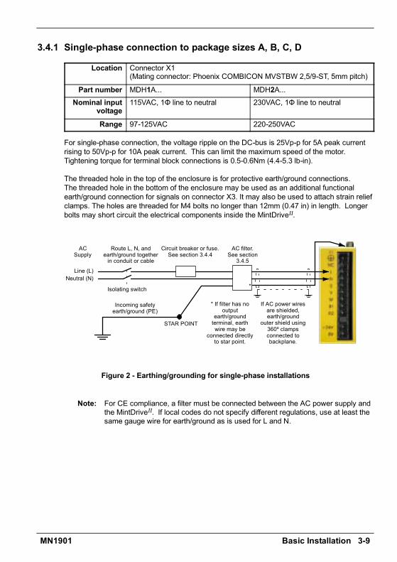
3.4.1 Single-phase connection to package sizes A, B, C, D
Location Connector X1(Mating connector: Phoenix COMBICON MVSTBW 2,5/9-ST, 5mm pitch)
Part number MDH1A... MDH2A...Nominal input
voltage115VAC, 1Φ line to neutral 230VAC, 1Φ line to neutral
Range 97-125VAC 220-250VAC
For single-phase connection, the voltage ripple on the DC-bus is 25Vp-p for 5A peak currentrising to 50Vp-p for 10A peak current. This can limit the maximum speed of the motor.Tightening torque for terminal block connections is 0.5-0.6Nm (4.4-5.3 lb-in).
The threaded hole in the top of the enclosure is for protective earth/ground connections.The threaded hole in the bottom of the enclosure may be used as an additional functionalearth/ground connection for signals on connector X3. It may also be used to attach strain reliefclamps. The holes are threaded for M4 bolts no longer than 12mm (0.47 in) in length. Longerbolts may short circuit the electrical components inside the MintDriveII.
ACSupply
Line (L)Neutral (N)
Route L, N, andearth/ground togetherin conduit or cable
Circuit breaker or fuse.See section 3.4.4
AC filter.See section
3.4.5
STAR POINT
Incoming safetyearth/ground (PE)
Isolating switch
* If filter has nooutput
earth/groundterminal, earthwire may be
connected directlyto star point.
*
If AC power wiresare shielded,earth/ground
outer shield using360º clampsconnected tobackplane.
Figure 2 - Earthing/grounding for single-phase installations
Note: For CE compliance, a filter must be connected between the AC power supply andthe MintDriveII. If local codes do not specify different regulations, use at least thesame gauge wire for earth/ground as is used for L and N.
3-10 Basic Installation MN1901
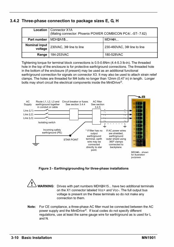
3.4.2 Three-phase connection to package sizes E, G, H
Location Connector X1A(Mating connector: Phoenix POWER COMBICON PC4/..-ST- 7.62)
Part number MDH2A15... MDH4A...Nominal input
voltage 230VAC, 3Φ line to line 230-460VAC, 3Φ line to line
Range 184-253VAC 180-528VAC
Tightening torque for terminal block connections is 0.5-0.6Nm (4.4-5.3 lb-in). The threadedhole in the top of the enclosure is for protective earth/ground connections. The threaded holein the bottom of the enclosure (if present) may be used as an additional functionalearth/ground connection for signals on connector X3. It may also be used to attach strain reliefclamps. The holes are threaded for M4 bolts no longer than 12mm (0.47 in) in length. Longerbolts may short circuit the electrical components inside the MintDriveII.
ACSupply
Line (L1)
Route L1, L2, L3 andearth/ground togetherin conduit or cable
Circuit breaker or fuses.See section 3.4.4
AC filter.See section
3.4.5
Line (L2)Line (L3)
STAR POINT
Incoming safetyearth/ground (PE)
Isolating switch
* If filter has nooutput
earth/groundterminal, earthwire may beconnected
directly to starpoint.
*
MDH4A... shownfor illustrationpurposes
If AC power wiresare shielded,earth/ground
outer shield using360º clampsconnected tobackplane.
Figure 3 - Earthing/grounding for three-phase installations
WARNING: Drives with part numbers MDH2A15... have two additional terminalson the X1 connector labeled Vcc+ and Vcc-. The full output busvoltage is present on the these terminals so do not make anyconnection to them.
Note: For CE compliance, a three-phase AC filter must be connected between the ACpower supply and the MintDriveII. If local codes do not specify differentregulations, use at least the same gauge wire for earth/ground as is used for Land N.
Basic Installation 3-11MN1901
3.4.3 Input power conditioningBaldor drives are designed for direct connection to standard single and three-phase lines(depending on model) that are electrically symmetrical with respect to earth/ground. Certainpower line conditions must be avoided; an AC line reactor, an isolation transformer or a stepup/step down transformer may be required for some power conditions:
H If the feeder or branch circuit that provides power to the MintDriveII has permanentlyconnected power factor correction capacitors, an input AC line reactor or an isolationtransformer must be connected between the power factor correction capacitors and theMintDriveII.
H If the feeder or branch circuit that provides power to the MintDriveII has power factorcorrection capacitors that are switched on line and off line, the capacitors must not beswitched while the drive is connected to the AC power line. If the capacitors are switchedon line while the drive is still connected to the AC power line, additional protection isrequired. A Transient Voltage Surge Suppressor (TVSS) of the proper rating must beinstalled between the AC line reactor (or isolation transformer) and the AC input to theMintDriveII.
3.4.3.1 Input power-cycling
If AC power has been removed from the MintDriveII, it should not be reapplied for at least oneminute. This delay allows the input surge protection circuit to perform correctly. Power-cyclingthe drive more frequently could cause nuisance trips when power is reapplied and reduce thelifetime of the MintDriveII.
3.4.4 Power disconnect and protection devicesA power disconnect should be installed between the input power service and the MintDriveII
for a fail-safe method to disconnect power. The MintDriveII will remain in a powered conditionuntil all input power is removed from the drive and the internal bus voltage has depleted.
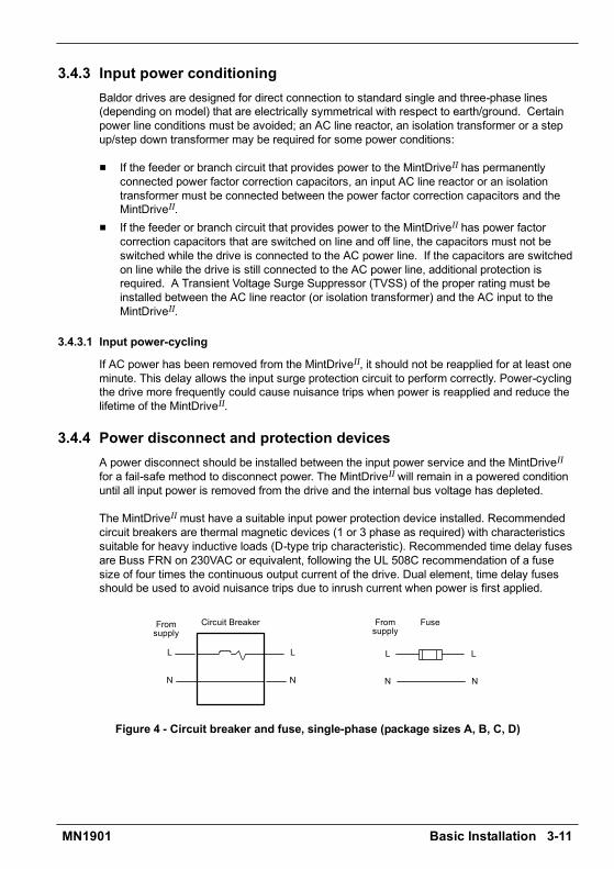
The MintDriveIImust have a suitable input power protection device installed. Recommendedcircuit breakers are thermal magnetic devices (1 or 3 phase as required) with characteristicssuitable for heavy inductive loads (D-type trip characteristic). Recommended time delay fusesare Buss FRN on 230VAC or equivalent, following the UL 508C recommendation of a fusesize of four times the continuous output current of the drive. Dual element, time delay fusesshould be used to avoid nuisance trips due to inrush current when power is first applied.
Circuit Breaker
L
N
Fromsupply
L
N
Fromsupply
Fuse
L
N
L
N
Figure 4 - Circuit breaker and fuse, single-phase (package sizes A, B, C, D)

3-12 Basic Installation MN1901
Note: Power to single phase models may be derived by connecting two phases of anappropriate three-phase supply (L1 and L2 for example). When supplying ACpower in this way, the voltage between the two phases must not exceed the ratedinput voltage of the MintDriveII. A two pole breaker must be used to isolate bothlines. Fuses must be fitted in both lines. Circuit breaker or fuse are not supplied.For CE compliance, see Appendix C.
Circuit Breaker
Circuit breaker or fuse are not supplied.For CE Compliance, see Appendix C.
L1
Fromsupply
Fuses
L2
L3
L1
L2
L3
Fromsupply
L1
L2
L3
Figure 5 - Circuit breaker and fuse, three-phase (package sizes E, G, H)
Note: Metal conduit or shielded cable should be used. Connect conduits so the use of aline reactor or RC device does not interrupt EMI/RFI shielding.
3.4.5 Power supply filtersTo comply with EEC directive 89/336/EEC, an AC power filter of the appropriate type must beconnected. This can be supplied by Baldor and will ensure that the MintDriveII complies withthe CE specifications for which it has been tested. Table 1 lists the appropriate filters:
MintDriveII
currentInput voltages
currentrating 115VAC, 1Φ 230VAC, 1Φ 230VAC, 3Φ 230-460VAC, 3Φ
2.5A FI0014A00 FI0019A00 FI0018A005A FI0015A00 FI0015A00 FI0018A00
7.5A FI0015A01 FI0015A01* FI0018A0015A FI0018A01 FI0018A0120A FI0018A01
27.5A FI0018A01
Table 1 - Baldor filter part numbers
* If this model requires a customer supplied 24V control supply (catalog numbersMDH2A07Tx-xxx3), use filter FI0015A02. For further details of power supply filters seesection A.1.6.

Basic Installation 3-13MN1901
3.4.6 Wire sizes and protection device ratingsTable 2 describes the wire size to be used for power connections and the ratings of theprotection devices.
Incoming Power
C t l N bNominalInput
ContinuousOutput
D-TypeInput
TimeDelay
MinimumCatalog Number Input
VoltageOutputAmps
ypInputBreaker
DelayInput
MinimumWire Gauge
Voltage Amps(RMS)
Breaker(A)
InputFuse(A) AWG mm2
MDH1A02xx-xxxx 115V (1Φ) 2.5A 6 6 14 2.0MDH2A02xx-xxxx 230V (1Φ) 2.5A 6 6 14 2.0MDH1A05xx-xxxx 115V (1Φ) 5A 10 10 14 2.0MDH2A05xx-xxxx 230V (1Φ) 5A 10 10 14 2.0MDH1A07xx-xxxx 115V (1Φ) 7.5A 16 16 14 2.0MDH2A07xx-xxxx 230V (1Φ) 7.5A 16 16 14 2.0
MDH4A02xx-xxxx 230-460V(3Φ) 2.5A 6 6 14 2.0
MDH4A05xx-xxxx 230-460V(3Φ) 5A 10 10 14 2.0
MDH4A07xx-xxxx 230-460V(3Φ) 7.5A 16 16 14 2.0
MDH2A15xx-xxxx 230V (3Φ) 15A 32 32 12 3.3
MDH4A15xx-xxxx 230-460V(3Φ) 15A 32 32 12 3.3
MDH4A20xx-xxxx 230-460V(3Φ) 20A 40 40 10 5.3
MDH4A27xx-xxxx 230-460V(3Φ) 27.5A 60 60 10 5.3
Table 2 - Protection device and wire ratings
Note: All wire sizes are based on 75°C (167°F) copper wire. Higher temperature smallergauge wire may be used per National Electric Code (NEC) and local codes.Recommended fuses/breakers are based on 25°C (77°F) ambient, maximumcontinuous control output current and no harmonic current. Earth/ground wiresmust be the same gauge, or larger, than the Line and Neutral wires.
3-14 Basic Installation MN1901
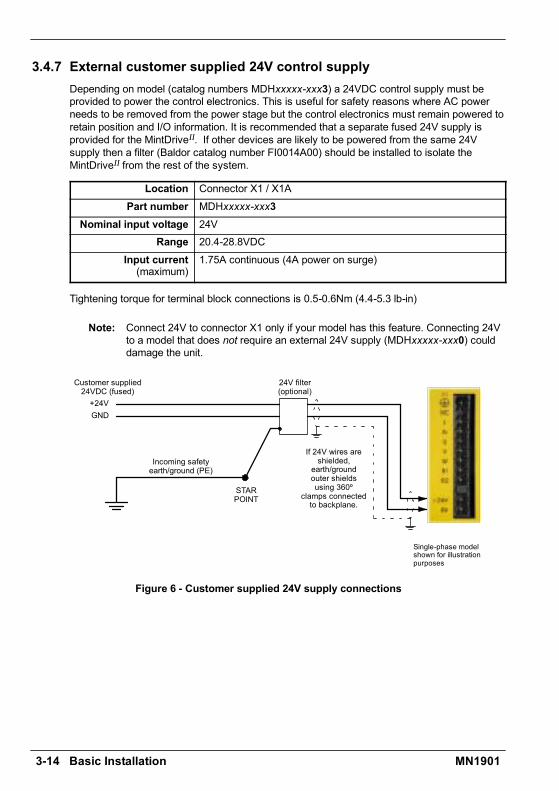
3.4.7 External customer supplied 24V control supplyDepending on model (catalog numbers MDHxxxxx-xxx3) a 24VDC control supply must beprovided to power the control electronics. This is useful for safety reasons where AC powerneeds to be removed from the power stage but the control electronics must remain powered toretain position and I/O information. It is recommended that a separate fused 24V supply isprovided for the MintDriveII. If other devices are likely to be powered from the same 24Vsupply then a filter (Baldor catalog number FI0014A00) should be installed to isolate theMintDriveII from the rest of the system.
Location Connector X1 / X1APart number MDHxxxxx-xxx3
Nominal input voltage 24VRange 20.4-28.8VDC
Input current(maximum)
1.75A continuous (4A power on surge)
Tightening torque for terminal block connections is 0.5-0.6Nm (4.4-5.3 lb-in)
Note: Connect 24V to connector X1 only if your model has this feature. Connecting 24Vto a model that does not require an external 24V supply (MDHxxxxx-xxx0) coulddamage the unit.
Customer supplied24VDC (fused)+24V
24V filter(optional)
GND
Single-phase modelshown for illustrationpurposes
STARPOINT
Incoming safetyearth/ground (PE)
If 24V wires areshielded,
earth/groundouter shieldsusing 360º
clamps connectedto backplane.
Figure 6 - Customer supplied 24V supply connections
Basic Installation 3-15MN1901
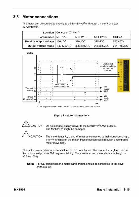
3.5 Motor connectionsThe motor can be connected directly to the MintDriveII or through a motor contactor(M-Contactor).
Location Connector X1 / X1APart number MDH1A... MDH2A... MDH2A15... MDH4A...
Nominal output voltage 160VDC 320VDC 320VDC 565/650VOutput voltage range 135-176VDC 306-350VDC 258-355VDC 254-746VDC
Seesection3.5.4
V
W
U
Motor
To earth/ground outer shield, use 360° clamps connected to backplane
Thermalswitch
AB
Brake(if present)
CD
Seesection3.5.5
Unshieldedlengths should beas short aspossible.
Optional motorcircuit contactors
Figure 7 - Motor connections
CAUTION: Do not connect supply power to the MintDriveII UVW outputs.The MintDriveIImight be damaged.
CAUTION: The motor leads U, V and W must be connected to their corresponding U,V or W terminal on the motor. Misconnection could result in uncontrolledmotor movement.
The motor power cable must be shielded for CE compliance. The connector or gland used atthe motor must provide 360 degree shielding. The maximum recommended cable length is30.5m (100ft).
Note: For CE compliance the motor earth/ground should be connected to the driveearth/ground.

3-16 Basic Installation MN1901
3.5.1 Motor circuit contactorsIf required by local codes or for safety reasons, an M-Contactor (motor circuit contactor) maybe installed to provide a physical disconnection of the motor windings from the MintDriveII (seesection 3.5). Opening the M-Contactor ensures that the MintDriveII cannot drive the motor,which may be necessary during equipment maintenance or similar operations. Under certaincircumstances it may also be necessary to fit a brake to a rotary motor. This is important withhanging loads where disconnecting the motor windings could result in the load falling. Contactyour local supplier for details of appropriate brakes.
CAUTION: If an M-Contactor is installed, the MintDriveIImust be disabled at least20ms before the M-Contactor is opened. If the M-Contactor is openedwhile the MintDriveII is supplying voltage and current to the motor, theMintDriveIImay be damaged. Incorrect installation or failure of theM-Contactor or its wiring may result in damage to the MintDriveII.
Ensure that shielding of the motor cable is continued on both sides of the contactor.
3.5.2 Motor power cable pin configuration - Baldor BSM rotary motorsFigure 8 shows the pin configuration for a typical Baldor motor cable, part numberCBL030SP-MHCE:
Signal name Motor / cable pin Motor cable wire colorMotor U 1 Black, labeled 1Motor V 4 Black, labeled 2Motor W 3 Black, labeled 3
Earth/ground 2 Green/YellowThermal switch A GreenThermal switch B White
Brake C BlueBrake D Red
Cable connector end view(female)
1
BA
3
2
4
Motor power connector(male)
1
BA
3
2
4
CD
CD
Note:Not all motorsare fitted witha brake sopins C and Dmight not beconnected.
Figure 8 - Baldor motor power cable pin configuration

Basic Installation 3-17MN1901
3.5.3 Motor cable pin configuration - Baldor linear motorsThe following table shows the core colors used in a typical Baldor linear motor cable set, partnumber AY1763A00:
Signal name Motor cable wire colorMotor U BlackMotor V RedMotor W White
Motor ground GreenThermal switch BlueThermal switch Orange
Signal name Hall cable wire colorHall 1 (U) WhiteHall 2 (V) RedHall 3 (W) Black
Hall ground GreenHall +5VDC Brown

3-18 Basic Installation MN1901
3.5.4 Thermal switch connectionYou might wish to wire the motors thermal switch contacts (normally open), using a relay, to adigital input on connector X3 (see section 4.3.1). Using the Mint keywordMOTORTEMPERATUREINPUT, this provides a way for the Mint program to respond to motorover-temperature conditions. A typical circuit, using DIN1 as the input, is shown in Figure 9.
A
B
motorthermalswitch
CREF
X3
7
DIN0 (INX.0)
Relay
Customersupplied24VDCsupply
+24VDC 0V
1011121314151617
DIN1 (INX.1)
DIN3 (INX.3)
DIN7 (INX.7)
DIN5 (INX.5)DIN4 (INX.4)
DIN2 (INX.2)
DIN6 (INX.6)
Separatecustomersupplied
24VDC supply
+24VDC 0V
Figure 9 - Motor thermal switch circuit
CAUTION: The 24VDC power supply connected to the thermal switch must be aseparate supply as shown in Figure 9. Do not use the 24V supply usedfor the drive enable signal, or the internally generated supply (if present).The thermal switch wires often carry noise that could cause erratic driveoperation or damage. The thermal switch contacts must never be wireddirectly to a digital input.
The separate 24VDC supply used for the thermal switch may also beused for the motor brake circuit (section 3.5.5).
Basic Installation 3-19MN1901
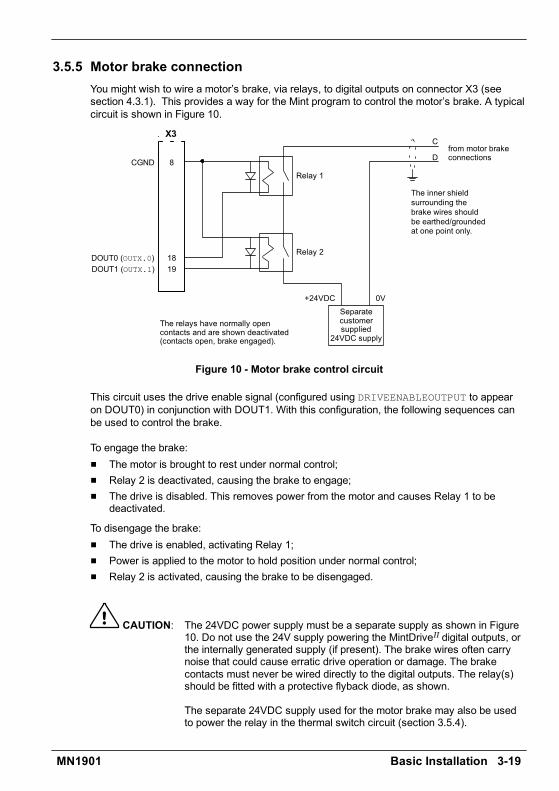
3.5.5 Motor brake connectionYou might wish to wire a motors brake, via relays, to digital outputs on connector X3 (seesection 4.3.1). This provides a way for the Mint program to control the motors brake. A typicalcircuit is shown in Figure 10.
C
Dfrom motor brakeconnections
Separatecustomersupplied
24VDC supply
X3
8
1819
DOUT0 (OUTX.0)DOUT1 (OUTX.1)
CGND
Relay 2
Relay 1
+24VDC 0V
The inner shieldsurrounding thebrake wires shouldbe earthed/groundedat one point only.
The relays have normally opencontacts and are shown deactivated(contacts open, brake engaged).
Figure 10 - Motor brake control circuit
This circuit uses the drive enable signal (configured using DRIVEENABLEOUTPUT to appearon DOUT0) in conjunction with DOUT1. With this configuration, the following sequences canbe used to control the brake.
To engage the brake:H The motor is brought to rest under normal control;H Relay 2 is deactivated, causing the brake to engage;H The drive is disabled. This removes power from the motor and causes Relay 1 to be
deactivated.
To disengage the brake:H The drive is enabled, activating Relay 1;H Power is applied to the motor to hold position under normal control;H Relay 2 is activated, causing the brake to be disengaged.
CAUTION: The 24VDC power supply must be a separate supply as shown in Figure10. Do not use the 24V supply powering the MintDriveII digital outputs, orthe internally generated supply (if present). The brake wires often carrynoise that could cause erratic drive operation or damage. The brakecontacts must never be wired directly to the digital outputs. The relay(s)should be fitted with a protective flyback diode, as shown.
The separate 24VDC supply used for the motor brake may also be usedto power the relay in the thermal switch circuit (section 3.5.4).

3-20 Basic Installation MN1901
3.6 Regeneration resistor (Dynamic Brake resistor)The 2.5A and 5A MintDriveII both have an internally fitted regeneration resistor *. For 7.5A,15A, 20A and 27.5A MintDriveII, an external regeneration resistor must be installed todissipate excess power from the internal DC bus during motor deceleration.
Suitable regeneration resistors are listed in section A.1.7.
WARNING: A regeneration resistor may generate enough heat toignite combustible materials. To avoid fire hazard,keep all combustible materials and flammable vaporsaway from the resistors.
The regeneration resistor should be mounted near the top of an enclosureto maximize heat dissipation. When the motor regenerates, the yellowDB On LED on the front panel of the MintDriveII will illuminate.
* If required by the application, additional external resistors connected to R1 and R2 will beconnected in parallel with the internal resistor.
3.6.1 Controlling regenerationSome regeneration resistor assemblies include an overload switch to indicate when too muchpower is being dissipated by the resistor. This switch can be wired to a digital input on theMintDriveII. Using the WorkBench v5 Digital I/O tool, the input can be configured to be thebrake trip input. This allows the MintDriveII to respond to resistor overload conditions.
The Mint keyword DBEXTTRIPINPUT can also be used to configure a digital input for thispurpose. On three-phase MintDriveIImodels, the operation of the regeneration resistor can becontrolled by further Mint keywords. These also begin with the letters DB..., for exampleDBEXTPEAKPOWER. See the Mint help file for details.
R1R2

Basic Installation 3-21MN1901
3.7 Feedback connectionsTwo feedback options are available for use with linear and rotary motors - commutatingencoder or resolver. Confirm the catalog number of your MintDriveII (see section 2.2.1) toensure you are wiring the correct feedback device. There are some important considerationswhen wiring the feedback device:
H The feedback device wiring must be separated from power wiring.H Where feedback device wiring runs parallel to power cables, they must be separated by at
least 76mm (3 in).H Feedback device wiring must cross power wires at right angles only.H To prevent contact with other conductors or earth/grounds, unearthed/ungrounded ends of
shields must be insulated.H Some larger D-type connector shells may be obstructed by neighboring connector X3.H Linear motors use two separate cables (encoder and Hall). The cores of these two cables
will need to be wired to the appropriate pins of the 15-pin D-type mating connector(supplied).
An encoder output signal is available on connector X7 for supplying other equipment.MintDriveIImodels with the resolver option provide a simulated encoder output, while theencoder based MintDriveII duplicates the encoder signals entering X8. See section 4.4.1 fordetails.
3-22 Basic Installation MN1901
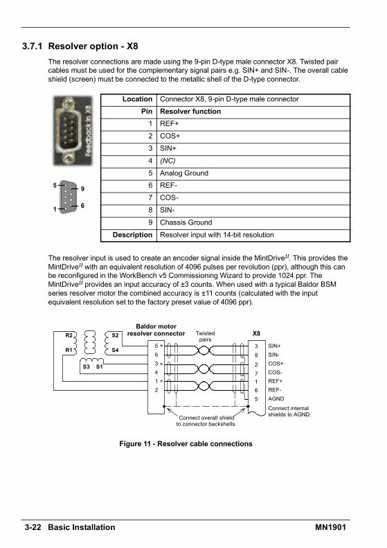
3.7.1 Resolver option - X8The resolver connections are made using the 9-pin D-type male connector X8. Twisted paircables must be used for the complementary signal pairs e.g. SIN+ and SIN-. The overall cableshield (screen) must be connected to the metallic shell of the D-type connector.
Location Connector X8, 9-pin D-type male connectorPin Resolver function1 REF+2 COS+3 SIN+4 (NC)
5 Analog Ground6 REF-7 COS-8 SIN-9 Chassis Ground
Description Resolver input with 14-bit resolution
The resolver input is used to create an encoder signal inside the MintDriveII. This provides theMintDriveII with an equivalent resolution of 4096 pulses per revolution (ppr), although this canbe reconfigured in the WorkBench v5 Commissioning Wizard to provide 1024 ppr. TheMintDriveII provides an input accuracy of ±3 counts. When used with a typical Baldor BSMseries resolver motor the combined accuracy is ±11 counts (calculated with the inputequivalent resolution set to the factory preset value of 4096 ppr).
16
27
38
5
R2
R1
S2
S4
S1S3
X8
SIN+SIN-COS+COS-REF+REF-AGND
+
Twistedpairs
Baldor motorresolver connector
563412
Connect overall shieldto connector backshells.
Connect internalshields to AGND.
+
+
Figure 11 - Resolver cable connections
1
5
6
9
Basic Installation 3-23MN1901
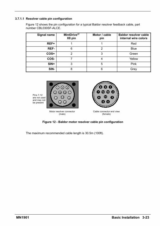
3.7.1.1 Resolver cable pin configuration
Figure 12 shows the pin configuration for a typical Baldor resolver feedback cable, partnumber CBL030SF-ALCE.
Signal name MintDriveII
X8 pinMotor / cable
pinBaldor resolver cableinternal wire colors
REF+ 1 1 RedREF- 6 2 BlueCOS+ 2 3 GreenCOS- 7 4 YellowSIN+ 3 5 PinkSIN- 8 6 Grey
1
2
3
4 5
6
7
89
10
11
12
Motor resolver connector(male)
Pins 7-12are not usedand may notbe present
1
2
3
45
6
7
8 9
10
11
12
Cable connector end view(female)
Figure 12 - Baldor motor resolver cable pin configuration
The maximum recommended cable length is 30.5m (100ft).
3-24 Basic Installation MN1901
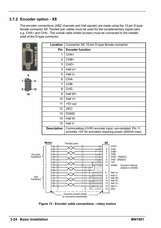
3.7.2 Encoder option - X8The encoder connections (ABZ channels and Hall signals) are made using the 15-pin D-typefemale connector X8. Twisted pair cables must be used for the complementary signal pairse.g. CHA+ and CHA-. The overall cable shield (screen) must be connected to the metallicshell of the D-type connector.
Location Connector X8, 15-pin D-type female connectorPin Encoder function1 CHA+2 CHB+3 CHZ+4 Hall U+5 Hall U-6 CHA-7 CHB-8 CHZ-9 Hall W+10 Hall V+11 +5V out12 (NC)13 DGND14 Hall W-15 Hall V-
Description Commutating (UVW) encoder input, non-isolated. Pin 11provides +5V for encoders requiring power (200mA max)
CHA+CHA-CHB+CHB-
+5VDGND
16273811
X8
CHZ+ (INDEX)CHZ- (INDEX)
459141015
13
Hall U+Hall U-Hall W+Hall W-Hall V+Hall V-
12 (NC)
HallFeedback
Connect overall shieldto connector backshells.
Twisted pairs
Connect internalshields to DGND.
EncoderFeedback
Motor
Figure 13 - Encoder cable connections - rotary motors
1
5 15
6
11
10
Basic Installation 3-25MN1901
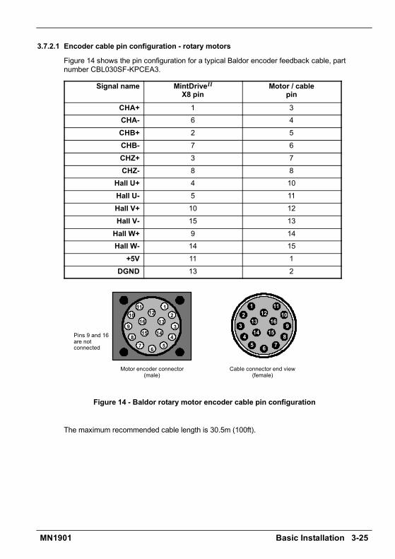
3.7.2.1 Encoder cable pin configuration - rotary motors
Figure 14 shows the pin configuration for a typical Baldor encoder feedback cable, partnumber CBL030SF-KPCEA3.
Signal name MintDriveII
X8 pinMotor / cable
pin
CHA+ 1 3CHA- 6 4CHB+ 2 5CHB- 7 6CHZ+ 3 7CHZ- 8 8
Hall U+ 4 10Hall U- 5 11Hall V+ 10 12Hall V- 15 13Hall W+ 9 14Hall W- 14 15
+5V 11 1DGND 13 2
Motor encoder connector(male)
Pins 9 and 16are notconnected
12
3
4567
8
9
1011
1213
1415
16
Cable connector end view(female)
12
3
45 6 7
8
9
1011
1213
14 15
16
Figure 14 - Baldor rotary motor encoder cable pin configuration
The maximum recommended cable length is 30.5m (100ft).
3-26 Basic Installation MN1901
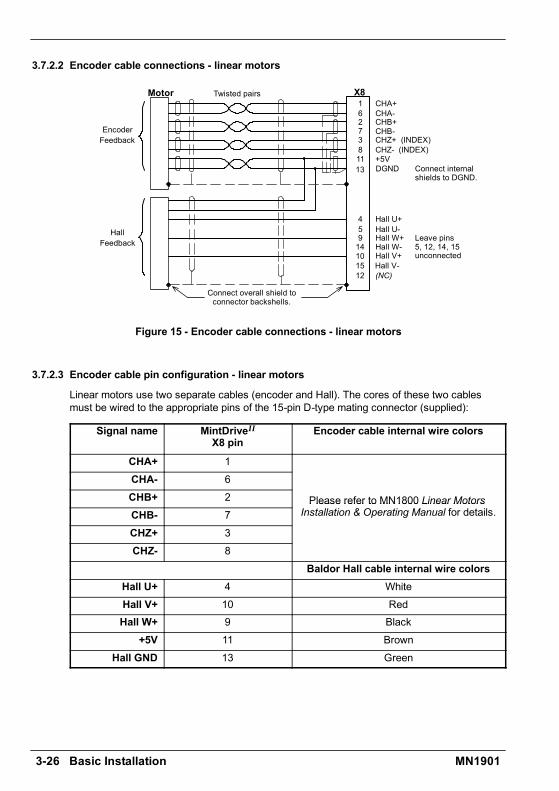
3.7.2.2 Encoder cable connections - linear motors
CHA+CHA-CHB+CHB-
+5VDGND
16273811
X8
EncoderFeedback CHZ+ (INDEX)
CHZ- (INDEX)
459141015
13
Hall U+Hall U-Hall W+Hall W-Hall V+Hall V-
12 (NC)
HallFeedback
Connect overall shield toconnector backshells.
Twisted pairs
Connect internalshields to DGND.
Leave pins5, 12, 14, 15unconnected
Motor
Figure 15 - Encoder cable connections - linear motors
3.7.2.3 Encoder cable pin configuration - linear motors
Linear motors use two separate cables (encoder and Hall). The cores of these two cablesmust be wired to the appropriate pins of the 15-pin D-type mating connector (supplied):
Signal name MintDriveII
X8 pinEncoder cable internal wire colors
CHA+ 1CHA- 6CHB+ 2 Please refer to MN1800 Linear MotorsCHB- 7
Please refer to MN1800 Linear MotorsInstallation & Operating Manual for details.
CHZ+ 3CHZ- 8
Baldor Hall cable internal wire colorsHall U+ 4 WhiteHall V+ 10 RedHall W+ 9 Black
+5V 11 BrownHall GND 13 Green
Basic Installation 3-27MN1901
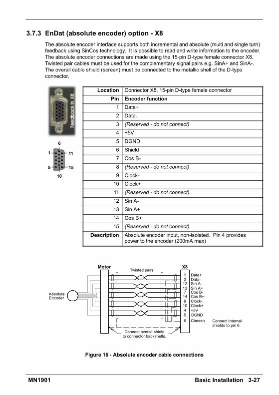
3.7.3 EnDat (absolute encoder) option - X8The absolute encoder interface supports both incremental and absolute (multi and single turn)feedback using SinCos technology. It is possible to read and write information to the encoder.The absolute encoder connections are made using the 15-pin D-type female connector X8.Twisted pair cables must be used for the complementary signal pairs e.g. SinA+ and SinA-.The overall cable shield (screen) must be connected to the metallic shell of the D-typeconnector.
Location Connector X8, 15-pin D-type female connectorPin Encoder function1 Data+2 Data-3 (Reserved - do not connect)4 +5V5 DGND6 Shield7 Cos B-8 (Reserved - do not connect)9 Clock-10 Clock+11 (Reserved - do not connect)12 Sin A-13 Sin A+14 Cos B+15 (Reserved - do not connect)
Description Absolute encoder input, non-isolated. Pin 4 providespower to the encoder (200mA max)
Data+Data-
Cos B-Cos B+
12
714
1213
X8
AbsoluteEncoder
Sin A-Sin A+
6
Twisted pairs
109
Clock+Clock-
5 DGNDChassis
4 +5V
Connect overall shieldto connector backshells.
Connect internalshields to pin 6.
Motor
Figure 16 - Absolute encoder cable connections
1
5 15
6
11
10

3-28 Basic Installation MN1901
3.7.3.1 Absolute encoder cable pin configuration
Figure 14 shows the pin configuration for a typical Baldor absolute encoder feedback cable,part number CBL030SF-KLCEA3.
Signal name MintDriveII
X8 pinMotor / cable
pin
Data - 2 1Sin A+ 13 2Cos B+ 14 4Clock- 9 5Clock + 10 7Cos B- 7 8+5V 4 9
DGND 5 10Sin A- 12 11Data + 1 12
1
2
3
4 5
6
7
89
10
11
12
Motor absolute encoder connector(male)
1
2
3
45
6
7
8 9
10
11
12
Cable connector end view(female)
Figure 17 - Baldor rotary motor absolute encoder cable pin configuration
The maximum recommended cable length is 30.5m (100ft).
Basic Installation 3-29MN1901
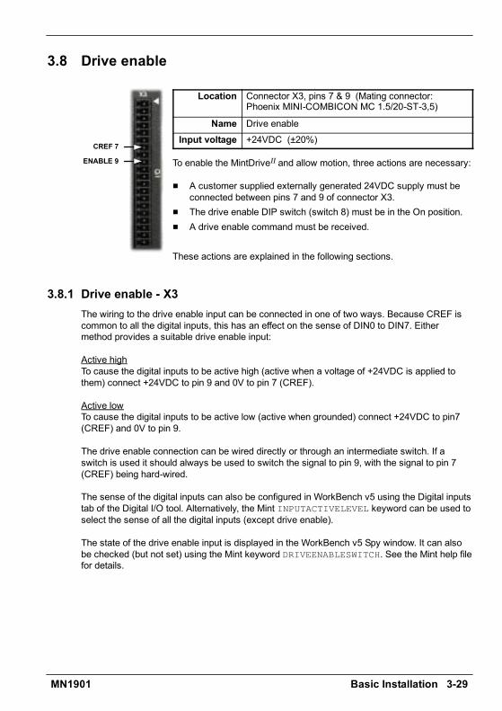
3.8 Drive enable
Location Connector X3, pins 7 & 9 (Mating connector:Phoenix MINI-COMBICON MC 1.5/20-ST-3,5)
Name Drive enableInput voltage +24VDC (±20%)
To enable the MintDriveII and allow motion, three actions are necessary:
H A customer supplied externally generated 24VDC supply must beconnected between pins 7 and 9 of connector X3.
H The drive enable DIP switch (switch 8) must be in the On position.H A drive enable command must be received.
These actions are explained in the following sections.
3.8.1 Drive enable - X3The wiring to the drive enable input can be connected in one of two ways. Because CREF iscommon to all the digital inputs, this has an effect on the sense of DIN0 to DIN7. Eithermethod provides a suitable drive enable input:
Active highTo cause the digital inputs to be active high (active when a voltage of +24VDC is applied tothem) connect +24VDC to pin 9 and 0V to pin 7 (CREF).
Active lowTo cause the digital inputs to be active low (active when grounded) connect +24VDC to pin7(CREF) and 0V to pin 9.
The drive enable connection can be wired directly or through an intermediate switch. If aswitch is used it should always be used to switch the signal to pin 9, with the signal to pin 7(CREF) being hard-wired.
The sense of the digital inputs can also be configured in WorkBench v5 using the Digital inputstab of the Digital I/O tool. Alternatively, the Mint INPUTACTIVELEVEL keyword can be used toselect the sense of all the digital inputs (except drive enable).
The state of the drive enable input is displayed in the WorkBench v5 Spy window. It can alsobe checked (but not set) using the Mint keyword DRIVEENABLESWITCH. See the Mint help filefor details.
ENABLE 9
CREF 7

3-30 Basic Installation MN1901
3.8.2 Drive enable - SW1 DIP switch
To enable the MintDriveII the front panel DIP switch 8 must be set to On.This switch provides a local enable/disable switch that can be usefulduring testing.
The state of the drive enable DIP switch is displayed in the WorkBench v5Spy window. It can also be checked (but not set) using the Mint keywordENABLESWITCH. See the Mint help file for details.
See section 3.9 for full details of other DIP switch functions.
3.8.3 Drive enable commandThe other action required to enable the MintDriveII can be controlled either by software orhardware.
Note: This method is explained here for your information, but cannot be completed untilyou have installed the software and are ready to turn on AC power to the drive.Please continue to read all sections in sequence. Do not turn on AC power untilyou reach the appropriate instructions.
In software, a drive enable command must be issued. The easiest way to do this is by clickingthe Drive enable button in WorkBench v5. Alternatively, the Mint commands RESET orDRIVEENABLE=1 can be used. See the Mint help file for details.
In hardware, a digital input can be used to create the drive enable command. This can beconfigured in WorkBench v5 using the Digital inputs tab of the Digital I/O tool. Alternatively, theMint keyword RESETINPUT can be used to select the required digital input. See the Mint helpfile for details.
Another method is to use the Mint keyword DRIVEENABLEMODE. This allows the combinationof DIP switch 8 and the Enable input to create the drive enable command. Both inputs mustbecome active. Provided one input is already on, as soon as the other input changes from offto on (active), the drive will be enabled. See the Mint help file for details.
On8

Basic Installation 3-31MN1901
3.9 DIP switches - SW1Various functions of the MintDriveII can be controlled by the front panel SW1 DIP switches.
Location Switch block SW1Switch Function
1 8
2 4 Node number selection (serial and fieldbus networks)3 2
Node number selection (serial and fieldbus networks)Bit pattern values shown in italics
4 1
5 Hold6 RS485 terminator7 Offset tuning8 Enable9 (Reserved)
10 RS232/RS485 selectDescription 10-way DIP switch module for major functions
3.9.1 Switches 1-4Switches 1-4 set the network node number (address) after the next power off/on cycle.The switches can be used to select any node number from 1 to 14, as shown in Figure 18.
Switch1
Switch2
Switch3
Switch4
Node number(address)
Off Off Off Off Set by Mint NODE keywordOff Off Off On 1Off Off On Off 2Off Off On On 3Off On Off Off 4Off On Off On 5Off On On Off 6Off On On On 7On Off Off Off 8On Off Off On 9On Off On Off 10On Off On On 11On On Off Off 12On On Off On 13On On On Off 14
On On On On Do not use!See section 3.9.7
Figure 18 - Node number (address) switch settings
OnOff

3-32 Basic Installation MN1901
If switches 1-4 are all in the Off position, the Mint NODE keyword can be used to set the nodenumber. WorkBench v5 (see section 5.2) reads the MintDriveII node number (during the scanprocess) and then uses it to direct commands to the MintDriveII.
Avoid accidentally setting switches 1-4 to the On position at the same time. In combinationwith DIP switch 8, this will reset the MintDriveII to its factory defaults. See section 3.9.7.
3.9.2 Switch 5 - HoldSwitch 5 stops the motor. In the Off position, normal operation is allowed. When switched tothe On position, the motor decelerates to rest and maintains position. The switch position issampled every 100ms.
3.9.3 Switch 6 - RS485 terminatorSwitch 6 is used to connect a termination resistor to the RS485 network. In the Off position,the RS485 network is unterminated at the MintDriveII. In the On position, an internal 120Ωtermination resistor is connected between the RX+ and RX- signals - see section 4.4.5.Switch 6 should remain in the Off position when using RS232.
3.9.4 Switch 7 - Offset tuningSwitch 7 is used to start offset tuning on analog (command) input AIN0. The purpose of offsettuning is to remove DC offset voltages on analog input 0 (the command reference input) toachieve a stationary motor shaft with 0VDC at the input. Confirm that the device supplying theAIN0 command input is set to its intended zero output setting (nominally 0VDC) before startingoffset tuning. When switch 7 is in the On position, offset tuning will start the next time Enable(switch 8) is changed from On to Off.
On7
Wait for 1 secondfor offset tuningto be completed.
Off 7
1. 2. 3. 4.
Off 8On8
Figure 19 - Offset tuning using switch 7 and 8
Leave switch 7 Off in normal use. After offset tuning, remember to set switch 8 to the Onposition to allow the drive to be enabled. The switch positions are sampled every 100ms. TheMint keyword ADCOFFSETTRIM can be used to perform the same action.
3.9.5 Switch 8 - EnableSwitch 8 must be set to On to allow the drive to be enabled. The switch positions are sampledevery 100ms. However, two other actions are necessary to enable the MintDriveII:
H The enable input (see section 3.8) must be active.H The drive must also be enabled by using a drive enable command (see section 3.8.3).
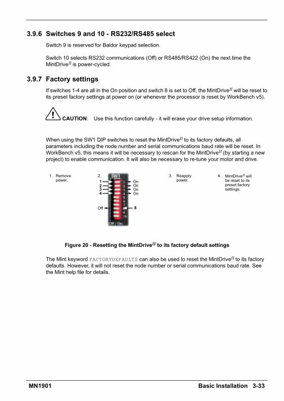
Basic Installation 3-33MN1901
3.9.6 Switches 9 and 10 - RS232/RS485 selectSwitch 9 is reserved for Baldor keypad selection.
Switch 10 selects RS232 communications (Off) or RS485/RS422 (On) the next time theMintDriveII is power-cycled.
3.9.7 Factory settingsIf switches 1-4 are all in the On position and switch 8 is set to Off, the MintDriveII will be reset toits preset factory settings at power on (or whenever the processor is reset by WorkBench v5).
CAUTION: Use this function carefully - it will erase your drive setup information.
When using the SW1 DIP switches to reset the MintDriveII to its factory defaults, allparameters including the node number and serial communications baud rate will be reset. InWorkBench v5, this means it will be necessary to rescan for the MintDriveII (by starting a newproject) to enable communication. It will also be necessary to re-tune your motor and drive.
On1Reapplypower.
1. 2.
On2On3On4
MintDriveII willbe reset to itspreset factorysettings.
3.
Off 8
Removepower.
4.
Figure 20 - Resetting the MintDriveII to its factory default settings
The Mint keyword FACTORYDEFAULTS can also be used to reset the MintDriveII to its factorydefaults. However, it will not reset the node number or serial communications baud rate. Seethe Mint help file for details.

3-34 Basic Installation MN1901
3.9.8 Preventing a program running at startupIf switches 5 and 9 are set to On and switch 8 is set to Off, any program already in theMintDriveII that contains an Auto command will be prevented from running automatically atstartup.
On5
Reapply power. Mint programwith Auto command will not run.
1. 2.
On9
3.
Off 8
Removepower.
Figure 21 - Preventing the Auto command from running a stored Mint program
This completes the basic installation.
You should read the following sections in sequencebefore attempting to start the MintDriveII.
Input / Output 4-1MN1901
4.1 IntroductionThis section describes the various digital and analog input and output capabilities of theMintDriveII, with descriptions of each of the connectors on the front panel.
The following conventions will be used to refer to the inputs and outputs:
I/O Input / Output. . . . . . . . . . . . . .DIN Digital Input. . . . . . . . . . . . .DOUT Digital Output. . . . . . . . . . .AIN Analog Input. . . . . . . . . . . . .AOUT Analog Output. . . . . . . . . . .CH Encoder channel. . . . . . . . . . . . .
4.2 Analog I/OThe MintDriveII provides as standard:
H 1 analog input on the connector block X3 (command input)H 1 analog input on the connector block X4H 2 analog outputs on the connector block X4
The analog inputs are not optically isolated from internal power rails, so care must be taken toavoid earth/ground loops and similar associated problems. The input buffers provide low passfiltering of the applied voltage.
To minimize the effects of noise, each analog input signal should be connected to the systemusing individual shielded/screened cable (a twisted pair cable in the case of the differentialinputs) with an overall shield. The overall shield should then be connected to the chassis atone end only. No other connection should be made to the shield.
If any inputs are unused, then it is advisable to connect them to the AGND pin. Do not leavethe inputs unconnected (floating).
4 Input / Output 4
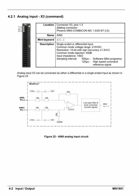
4-2 Input / Output MN1901
4.2.1 Analog input - X3 (command)
Location Connector X3, pins 1-3(Mating connector:Phoenix MINI-COMBICON MC 1.5/20-ST-3,5)
Name AIN0Mint keyword ADC.0
Description Single ended or differential input.Common mode voltage range: ±10VDC.Resolution: 14-bit with sign (accuracy ±1.2mV)Common mode rejection: 40dBInput impedance: >5kΩSampling interval: 500µs - Software (Mint programs)
125µs - High speed commandreference signal
Analog input X3 can be connected as either a differential or a single ended input as shown inFigure 23.
AIN0-Pin 2
AIN0+Pin 1
10k
LF412
AGND
MintADC.0
MintDriveII
10k
10k
10k
-15V+15V
-15V+15V
20k
-
+
20k
Low pass filter &level correction(inverts signal)
Figure 22 - AIN0 analog input circuit
123
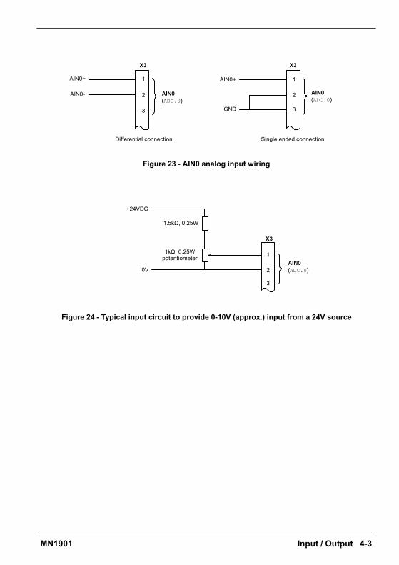
Input / Output 4-3MN1901
AIN0(ADC.0)
X3
AIN0(ADC.0)
1
2
3
X3
AIN0-
Differential connection Single ended connection
AIN0+ 1
2
3
AIN0+
GND
Figure 23 - AIN0 analog input wiring
AIN0
1kΩ, 0.25Wpotentiometer
(ADC.0)2
1
X3
1.5kΩ, 0.25W
0V
+24VDC
3
Figure 24 - Typical input circuit to provide 0-10V (approx.) input from a 24V source
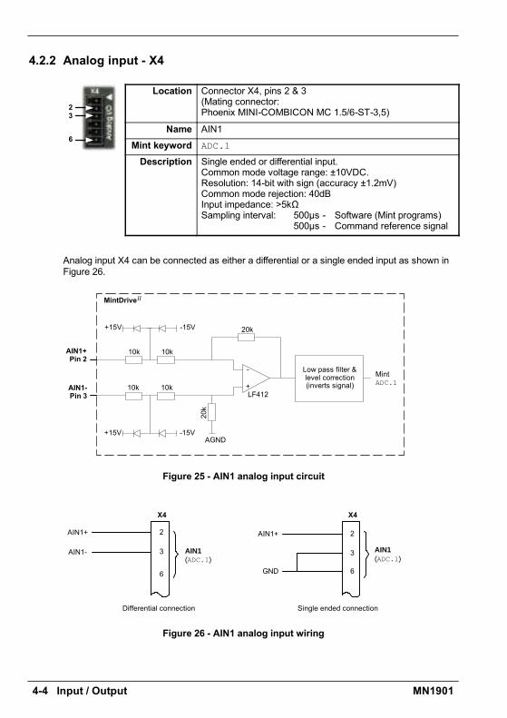
4-4 Input / Output MN1901
4.2.2 Analog input - X4
Location Connector X4, pins 2 & 3(Mating connector:Phoenix MINI-COMBICON MC 1.5/6-ST-3,5)
Name AIN1Mint keyword ADC.1
Description Single ended or differential input.Common mode voltage range: ±10VDC.Resolution: 14-bit with sign (accuracy ±1.2mV)Common mode rejection: 40dBInput impedance: >5kΩSampling interval: 500µs - Software (Mint programs)
500µs - Command reference signal
Analog input X4 can be connected as either a differential or a single ended input as shown inFigure 26.
AIN1+Pin 2
AIN1-Pin 3
10k
LF412
AGND
MintADC.1
MintDriveII
10k
10k
10k
-15V+15V
-15V+15V
20k
-
+
20k
Low pass filter &level correction(inverts signal)
Figure 25 - AIN1 analog input circuit
AIN1(ADC.1)
2
3
6
X4
GND
AIN1(ADC.1)
2
3
6
X4
AIN1-
Differential connection Single ended connection
AIN1+ AIN1+
Figure 26 - AIN1 analog input wiring
23
6
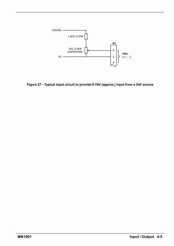
Input / Output 4-5MN1901
AIN1
1kΩ, 0.25Wpotentiometer
(ADC.1)3
2
X4
1.5kΩ, 0.25W
0V
+24VDC
6
Figure 27 - Typical input circuit to provide 0-10V (approx.) input from a 24V source
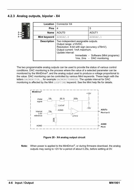
4-6 Input / Output MN1901
4.2.3 Analog outputs, bipolar - X4
Location Connector X4Pins 4 5Name AOUT0 AOUT1
Mint keyword AUXDAC.0 AUXDAC.1
Description Two independent assignable outputs.Output range: ±10VDC.Resolution: 8-bit with sign (accuracy ±78mV).Output current: 1mA maximum.Update interval:
Immediate - Software (Mint programs)1ms, 2ms - DAC monitoring
The two programmable analog outputs can be used to provide the status of various controlconditions. DAC monitoring is the process where the value of a selected parameter can bemonitored by the MintDriveII, and the analog output used to produce a voltage proportional tothe value. DAC monitoring can be controlled by various Mint keywords. These begin with theletters DACMONITOR..., for example DACMONITORMODE. The update interval for DACmonitoring is affected by the Mint LOOPTIME keyword. See the Mint help file for details.
10k
LF412
AGND
MintDriveII
68.1k
75k
-15V
+15V
300k
-
+
300k
0.47nF
Internal2.5V
reference
AOUTxPin 4 or 5
AGNDPin 6AGND
PWMsignal
Figure 28 - X4 analog output circuit
Note: When power is applied to the MintDriveII, or during firmware download, the analogoutputs may swing to +2V for a period of about 0.25s, before settling at 0V.
456
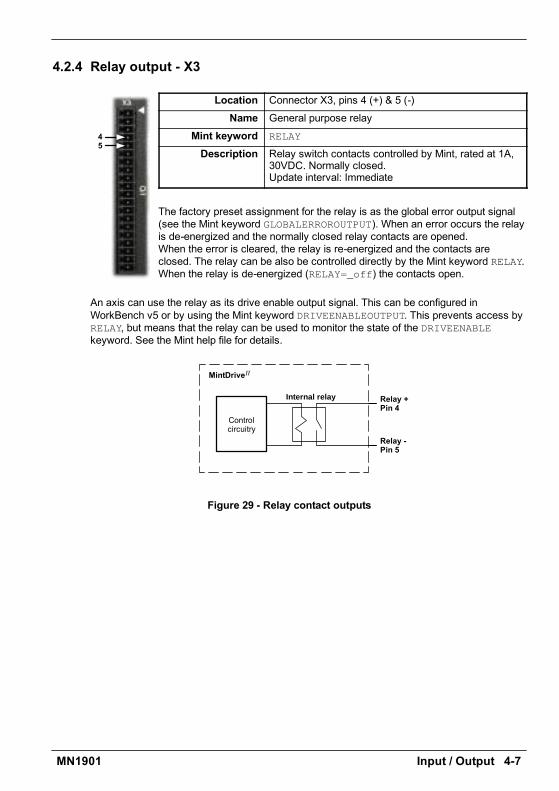
Input / Output 4-7MN1901
4.2.4 Relay output - X3
Location Connector X3, pins 4 (+) & 5 (-)Name General purpose relay
Mint keyword RELAY
Description Relay switch contacts controlled by Mint, rated at 1A,30VDC. Normally closed.Update interval: Immediate
The factory preset assignment for the relay is as the global error output signal(see the Mint keyword GLOBALERROROUTPUT). When an error occurs the relayis de-energized and the normally closed relay contacts are opened.When the error is cleared, the relay is re-energized and the contacts areclosed. The relay can be also be controlled directly by the Mint keyword RELAY.When the relay is de-energized (RELAY=_off) the contacts open.
An axis can use the relay as its drive enable output signal. This can be configured inWorkBench v5 or by using the Mint keyword DRIVEENABLEOUTPUT. This prevents access byRELAY, but means that the relay can be used to monitor the state of the DRIVEENABLEkeyword. See the Mint help file for details.
Internal relay
MintDriveII
Relay +Pin 4
Relay -Pin 5
Controlcircuitry
Figure 29 - Relay contact outputs
45
4-8 Input / Output MN1901
4.3 Digital I/OThe MintDriveII provides as standard: *
H 8 general-purpose inputs on connector block X3H 3 general-purpose outputs on connector block X3
A digital input can be used to support many typical input functions:
H Error inputH Reset inputH Stop inputH Home inputH Forward limitH Reverse limitH Interrupts (controlled from Mint)H Regeneration resistor (Dynamic Brake) overtemperature inputH PLC Task input conditionsH Index selection and triggering for preset move typesH General purpose use.
DIN4 and DIN5 are also capable of special alternative functions:
H DIN4 and DIN5 are fitted with Schmitt trigger devices and can be configured using Mint forposition capture of the axis or the master/auxiliary encoder positions. See section 4.3.4.
H The main axis fast input (assigned using the Mint keyword FASTSELECT) can also beused as a trigger for some motion types, for example CAM moves. See the Mint help filefor details.
* Additional I/O is available on connector X12 if the CAN + I/O option is fitted. See MN1908CAN and I/O option for Flex+DriveII and MintDriveII.
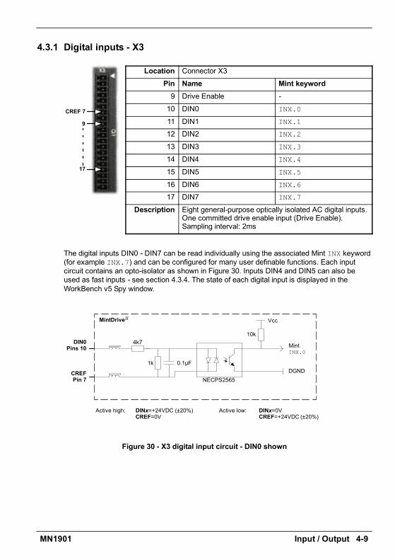
Input / Output 4-9MN1901
4.3.1 Digital inputs - X3
Location Connector X3Pin Name Mint keyword9 Drive Enable -10 DIN0 INX.0
11 DIN1 INX.1
12 DIN2 INX.2
13 DIN3 INX.3
14 DIN4 INX.4
15 DIN5 INX.5
16 DIN6 INX.6
17 DIN7 INX.7
Description Eight general-purpose optically isolated AC digital inputs.One committed drive enable input (Drive Enable).Sampling interval: 2ms
The digital inputs DIN0 - DIN7 can be read individually using the associated Mint INX keyword(for example INX.7) and can be configured for many user definable functions. Each inputcircuit contains an opto-isolator as shown in Figure 30. Inputs DIN4 and DIN5 can also beused as fast inputs - see section 4.3.4. The state of each digital input is displayed in theWorkBench v5 Spy window.
Active high: DINx=+24VDC (±20%)CREF=0V
CREFPin 7
DIN0Pins 10
4k7
1k 0.1µF
NECPS2565DGND
MintINX.0
10k
VccMintDriveII
Active low: DINx=0VCREF=+24VDC (±20%)
Figure 30 - X3 digital input circuit - DIN0 shown
9
17
CREF 7
4-10 Input / Output MN1901
4.3.2 CREF and digital inputsPin 7 (CREF) controls the sense of all the digital inputs (X3 pins 9 to 17) and should bepermanently wired, dependent on the user requirements:
Active high: connect 0V to pin 7.The digital inputs will be active when a voltage of +24VDC (greater than 12VDC) is applied tothem and will sink a current of approximately 5mA each.
Active low: connect +24VDC to pin7.The digital inputs will be active when grounded (less than 2V) and will source a current ofapproximately 5mA each.
The +24VDC supply is from a customer supplied 24VDC supply that should have a continuouscurrent capability of 1.75A.
The sense of the inputs can be configured in WorkBench v5 or controlled individually in Mintusing the keyword INPUTACTIVELEVEL.
See section 3.8 for more information about Drive Enable.
4.3.3 Pulse and direction inputs - DIN4 and DIN5DIN4 and DIN5 can be configured using the MASTERSOURCE keyword to behave as pulse anddirection inputs:
H DIN4 is used as the pulse input. The pulse frequency controls the speed of the motor.H DIN5 is used as the direction input. The state of the direction input controls the direction of
motion. A positive voltage will result in forward motion. If DIN5 is grounded, movement willbe in the opposite direction.
Note: If DIN4 and DIN5 have been configured as pulse and direction inputs, thealternative pulse and direction inputs, available on connector X9, cannot be used.See the Mint keyword MASTERSOURCE.

Input / Output 4-11MN1901
4.3.4 Special functions on inputs DIN4 and DIN5DIN4 and DIN5 can be configured using the FASTSELECT and FASTAUXSELECT keywords toperform special functions:
H Fast interrupt hardware position capture input. The position of the axis is captured in realtime and can be read using the Mint keyword FASTPOS.
H Master or auxiliary encoder input capture, read using the Mint keywordFASTAUXENCODER (DIN5 only).
The maximum latency to read the fast position is approximately 1µs. The fast interrupt will belatched on a pulse width of about 30µs, although a width of 100µs is recommended to ensurecapture. To prevent subsequent inputs causing the captured value to be overwritten, theinterrupt is latched in software. It is necessary to clear the latch before subsequent interruptscan be detected. See the Mint help file. Both inputs are fitted with Schmitt trigger devices.
Note: The fast inputs are particularly sensitive to noise, so inputs must use shieldedtwisted pair cable. The inputs are not opto-isolated.
Do not connect mechanical switches, relay contacts or other sources liable tosignal bounce directly to the fast inputs. This could cause unwanted multipletriggering.
Active high: DINx=+24VDC (±20%)CREF=0V
CREFPin 7
DINxPins 14-15
4k7
33pF
HCPL2231
to CPU
VccMintDriveII
Active low: DINx=0VCREF=+24VDC (±20%)
1k
10k
DGND
Figure 31 - X3 pulse and direction / fast digital input circuit
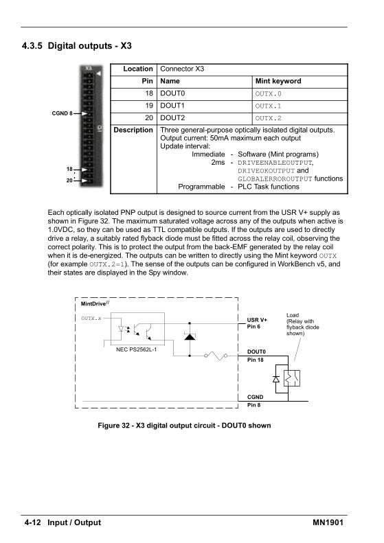
4-12 Input / Output MN1901
4.3.5 Digital outputs - X3
Location Connector X3Pin Name Mint keyword18 DOUT0 OUTX.0
19 DOUT1 OUTX.1
20 DOUT2 OUTX.2
Description Three general-purpose optically isolated digital outputs.Output current: 50mA maximum each outputUpdate interval:
Immediate - Software (Mint programs)2ms - DRIVEENABLEOUTPUT,
DRIVEOKOUTPUT andGLOBALERROROUTPUT functions
Programmable - PLC Task functions
Each optically isolated PNP output is designed to source current from the USR V+ supply asshown in Figure 32. The maximum saturated voltage across any of the outputs when active is1.0VDC, so they can be used as TTL compatible outputs. If the outputs are used to directlydrive a relay, a suitably rated flyback diode must be fitted across the relay coil, observing thecorrect polarity. This is to protect the output from the back-EMF generated by the relay coilwhen it is de-energized. The outputs can be written to directly using the Mint keyword OUTX(for example OUTX.2=1). The sense of the outputs can be configured in WorkBench v5, andtheir states are displayed in the Spy window.
CGND
OUTX.x USR V+
MintDriveII
NEC PS2562L-1 DOUT0
Load(Relay withflyback diodeshown)
Pin 18
Pin 8
Pin 6
Figure 32 - X3 digital output circuit - DOUT0 shown
18
20
CGND 8
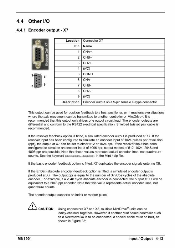
Input / Output 4-13MN1901
4.4 Other I/O4.4.1 Encoder output - X7
Location Connector X7Pin Name1 CHA+2 CHB+3 CHZ+4 (NC)5 DGND6 CHA-7 CHB-8 CHZ-9 (NC)
Description Encoder output on a 9-pin female D-type connector
This output can be used for position feedback to a host positioner, or in master/slave situationswhere the axis movement can be transmitted to another controller or MintDriveII. It isrecommended that this output only drives one output circuit load. The encoder outputs aredifferential and conform to the RS422 electrical specification. Shielded twisted pair cable isrecommended.
If the resolver feedback option is fitted, a simulated encoder output is produced at X7. If theresolver input has been configured to simulate an encoder input of 1024 pulses per revolution(ppr), the output at X7 can be set to either 512 or 1024 ppr. If the resolver input has beenconfigured to simulate an encoder input of 4096 ppr, output modes of 512, 1024, 2048 and4096 ppr are possible. Note that these values represent actual encoder lines, not quadraturecounts. See the keyword ENCODERLINESOUT in the Mint help file.
If the basic encoder feedback option is fitted, X7 duplicates the encoder signals entering X8.
If the EnDat (absolute encoder) feedback option is fitted, a simulated encoder output isproduced at X7. The output ppr is equal to the number of Sin/Cos cycles of the absoluteencoder. For example, if a 2048 cycle absolute encoder is connected, the output at X7 will beequivalent to a 2048 ppr encoder. Note that this value represents actual encoder lines, notquadrature counts.
The encoder output supports an index or marker pulse.
CAUTION: Using connectors X7 and X8, multiple MintDriveII units can bedaisy-chained together. However, if another Mint based controller suchas a NextMoveBX is to be connected, a special cable must be built, asshown in Figure 33:
1
5
6
9

4-14 Input / Output MN1901
5926
7
83
1638
5
27
MintDriveII
X7NextMoveBXencoder input
Connect overall shieldto connector backshells.
Connect internalshields to DGND.
CHA+CHA-
CHB+CHB-
CHZ+CHZ-
DGND
Figure 33 - MintDriveII encoder output to Mint controller encoder input
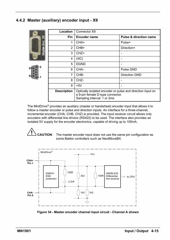
Input / Output 4-15MN1901
4.4.2 Master (auxiliary) encoder input - X9
Location Connector X9Pin Encoder name Pulse & direction name1 CHA+ Pulse+2 CHB+ Direction+3 CHZ+ -4 (NC) -5 DGND -6 CHA- Pulse GND7 CHB- Direction GND8 CHZ- -9 +5V -
Description Optically isolated encoder or pulse and direction input ona 9-pin female D-type connector.Sampling interval: 1 or 2ms
The MintDriveII provides an auxiliary (master or handwheel) encoder input that allows it tofollow a master encoder or pulse and direction inputs. An interface for a three-channel,incremental encoder (CHA, CHB, CHZ) is provided. The input receiver circuit allows onlyencoders with differential line drivers (RS422) to be used. The interface also provides anisolated 5V supply for the encoder electronics, capable of driving up to 100mA.
CAUTION: The master encoder input does not use the same pin configuration assome Baldor controllers such as NextMoveBX.
CHA-Pin 6
CHA+Pin 1
VccMintDriveII
1k51k5
3k3AM26LS32Differentialline receiver
to CPUEMIF01ESDprotection
150R
2.2nF
150R
Figure 34 - Master encoder channel input circuit - Channel A shown
1
5
6
9

4-16 Input / Output MN1901
CHA+CHA--CHB+CHB--
+5VDGND
16273895
X9
CHZ+CHZ --
Twisted pairs
Connect overall shieldto connector backshells.
Connect internalshields to DGND.
MasterEncoder
Figure 35 - Differential encoder connections
4.4.2.1 Pulse and Direction following
The master encoder pulse and direction inputs accept 5V differential line driver (RS422)signals from an external source. The pulse frequency controls the speed, and the state of thedirection signal controls the direction of motion. A positive direction voltage (greater than200mV) will result in motion in one direction. A negative direction voltage (less than -200mV)will result in movement in the opposite direction.
The Mint keyword AUXENCODERMODE (bit 2) is used to configure X9 for pulse and directionoperation. If necessary, the sense of the direction input can be reversed in software using theMint keyword AUXENCODERMODE (bit 0). See the Mint help file for details.
Note: If X9 has been configured for pulse and direction input, the alternative pulse anddirection inputs, available on connector X3, cannot be used. See the Mint keywordMASTERSOURCE.
Pulse +Pulse - (GND)Direction+Direction - (GND)
DGND
1627
5
X9Twisted pairsPulse and direction
source
Pulse
Direction
Connect overall shieldto connector backshells.
Connect internalshields to DGND.
Figure 36 - Pulse and direction connections
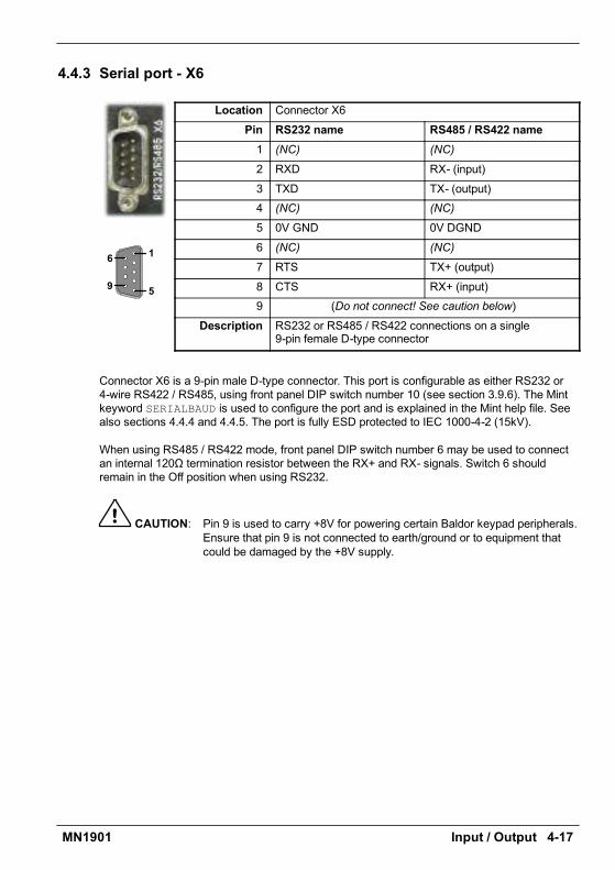
Input / Output 4-17MN1901
4.4.3 Serial port - X6
Location Connector X6Pin RS232 name RS485 / RS422 name1 (NC) (NC)
2 RXD RX- (input)3 TXD TX- (output)4 (NC) (NC)
5 0V GND 0V DGND6 (NC) (NC)
7 RTS TX+ (output)8 CTS RX+ (input)9 (Do not connect! See caution below)
Description RS232 or RS485 / RS422 connections on a single9-pin female D-type connector
Connector X6 is a 9-pin male D-type connector. This port is configurable as either RS232 or4-wire RS422 / RS485, using front panel DIP switch number 10 (see section 3.9.6). The Mintkeyword SERIALBAUD is used to configure the port and is explained in the Mint help file. Seealso sections 4.4.4 and 4.4.5. The port is fully ESD protected to IEC 1000-4-2 (15kV).
When using RS485 / RS422 mode, front panel DIP switch number 6 may be used to connectan internal 120Ω termination resistor between the RX+ and RX- signals. Switch 6 shouldremain in the Off position when using RS232.
CAUTION: Pin 9 is used to carry +8V for powering certain Baldor keypad peripherals.Ensure that pin 9 is not connected to earth/ground or to equipment thatcould be damaged by the +8V supply.
1
5
6
9

4-18 Input / Output MN1901
4.4.4 Using RS232 cable
CAUTION: The serial connector on the MintDriveII (X6) can be configured as eitherRS232 or RS485 / RS422. Pin 9 is used to carry +8V for poweringcertain Baldor keypad peripherals. Ensure that pin 9 is not connected toearth/ground or to equipment that could be damaged by the +8V supply.A suitable cable is available from Baldor, catalog number CBL001-501.
Front panel DIP switch 10 must be in the Off position to select RS232 operation.The MintDriveII has a full-duplex RS232 serial port with the following preset configuration:
H 57.6KbaudH 1 start bitH 8 data bitsH 1 stop bitH No parityH Hardware handshaking lines (RS232) RTS and CTS must be connected.
This configuration can be changed if required. The RS232 connections are brought out onto a9-pin male D-type connector. The RS232 port is configured as a DTE (Data TerminalEquipment) unit. Both the output and input circuitry are single ended and operate between±12V. The port is capable of operation at up to 57.6Kbaud.
MintDriveII(DTE)
9-pinComputerCOM Port(DCE / DTE)
X6
RXD 2
TXD 3
GND 5
2 RXD
3 TXD
5 GND
RTS 7
CTS 8
7 RTS
8 CTS
COM
Connect overallshield to connector
backshell.
Figure 37 - RS232 serial port connections
The maximum recommended cable length is 3m (10ft) at 57.6KBaud (the factory preset rate).When using lower Baud rates, longer cable lengths may be used up to maximum of 15m (49ft)at 9600 Baud.
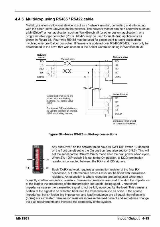
Input / Output 4-19MN1901
4.4.5 Multidrop using RS485 / RS422 cableMultidrop systems allow one device to act as a network master, controlling and interactingwith the other (slave) devices on the network. The network master can be a controller such asa MintDriveII, a host application such as WorkBench v5 (or other custom application), or aprogrammable logic controller (PLC). RS422 may be used for multi-drop applications asshown in Figure 38. Four-wire RS485 may be used for single point-to-point applicationsinvolving only one Baldor controller. If firmware is updated over RS485/RS422, it can only bedownloaded to the drive that was chosen in the Select Controller dialog in WorkBench v5.
Master and final slave areshown with terminatingresistors, TR, typical value120Ω.
Front panel DIP switch 6 maybe used to connect an internal120Ω terminating resistor.
Network slave
TR
RX-
DGND
RX+
TX+TX- RX-
DGND
RX+
TX+
TX-
RX-
DGND
RX+
TX+
TX-
Twisted pairs
TR
Connect overall shieldto connector backshell.
Network slave
Networkmaster
Figure 38 - 4-wire RS422 multi-drop connections
Any MintDriveII on the network must have its SW1 DIP switch 10 (locatedon the front panel) set to the On position (see also section 3.9.6). This willset the serial port to RS422/RS485 mode after the next power off/on cycle.When SW1 DIP switch 6 is set to the On position, a 120Ω terminationresistor is connected between the RX+ and RX- signals.
Each TX/RX network requires a termination resistor at the final RXconnection, but intermediate devices must not be fitted with terminationresistors. An exception is where repeaters are being used which may
correctly contain termination resistors. Termination resistors are used to match the impedanceof the load to the impedance of the transmission line (cable) being used. Unmatchedimpedance causes the transmitted signal to not be fully absorbed by the load. This causes aportion of the signal to be reflected back into the transmission line as noise. If the sourceimpedance, transmission line impedance, and load impedance are all equal, the reflections(noise) are eliminated. Termination resistors increase the load current and sometimes changethe bias requirements and increase the complexity of the system.
On10
On6
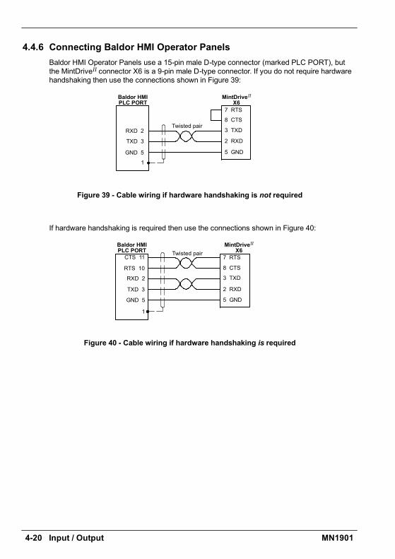
4-20 Input / Output MN1901
4.4.6 Connecting Baldor HMI Operator PanelsBaldor HMI Operator Panels use a 15-pin male D-type connector (marked PLC PORT), butthe MintDriveII connector X6 is a 9-pin male D-type connector. If you do not require hardwarehandshaking then use the connections shown in Figure 39:
7 RTS
8 CTS
3 TXD
2 RXD
5 GND
1
RXD 2
TXD 3
GND 5
Baldor HMIPLC PORT
MintDriveII
X6
Twisted pair
Figure 39 - Cable wiring if hardware handshaking is not required
If hardware handshaking is required then use the connections shown in Figure 40:
7 RTS
8 CTS
3 TXD
2 RXD
5 GND
1
RXD 2
TXD 3
GND 5
Baldor HMIPLC PORT
MintDriveII
X6CTS 11
RTS 10
Twisted pair
Figure 40 - Cable wiring if hardware handshaking is required
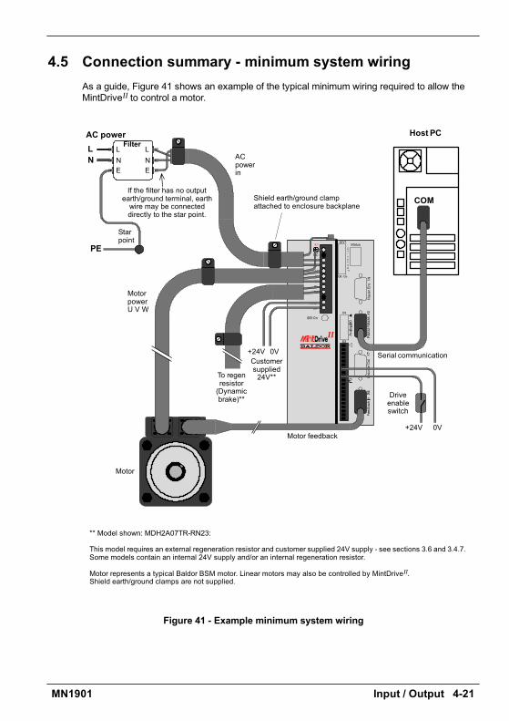
Input / Output 4-21MN1901
4.5 Connection summary - minimum system wiringAs a guide, Figure 41 shows an example of the typical minimum wiring required to allow theMintDriveII to control a motor.
COM
II
Host PCAC powerFilterL
N
PE
LNE
MotorpowerU V W
Motor feedback
Serial communication
** Model shown: MDH2A07TR-RN23:
This model requires an external regeneration resistor and customer supplied 24V supply - see sections 3.6 and 3.4.7.Some models contain an internal 24V supply and/or an internal regeneration resistor.
Motor represents a typical Baldor BSM motor. Linear motors may also be controlled by MintDriveII.Shield earth/ground clamps are not supplied.
To regenresistor(Dynamicbrake)**
Customersupplied24V**
Starpoint
Motor
Driveenableswitch
Shield earth/ground clampattached to enclosure backplane
+24V 0V
+24V 0V
If the filter has no outputearth/ground terminal, earthwire may be connecteddirectly to the star point.
ACpowerin
LNE
Figure 41 - Example minimum system wiring

4-22 Input / Output MN1901
4.6 Option connectorsIf there are additional connectors on the front panel of your MintDriveII that have not beendescribed in previous sections, these are part of a factory fitted option. You will need to refer tothe extra manual supplied with your MintDriveII for details of the options connectors.
This completes the input/output wiring.
You should read the following sections in sequencebefore attempting to start the MintDriveII.

Operation 5-1MN1901
5.1 IntroductionBefore powering the MintDriveII you will need to connect it to the PC using a serial cable andinstall the supplied PC softwareWorkBench v5. This software includes a number of tools toallow you to configure, tune and program the MintDriveII. If you do not have experience ofsoftware installation or Windows applications you may need further assistance for this stage ofthe installation.
5.1.1 Connecting the MintDriveII to the PCConnect the serial cable between a PC serial port (often labeled as COM) to the MintDriveII
connector X6 (RS232/RS485). WorkBench v5 can scan all the COM ports, so you can useany port.
CAUTION: The serial connector on the MintDriveII (X6) can be configured as eitherRS232 or RS485 / RS422. If this is the first time you are installing aMintDriveII then it is strongly recommended that you use RS232 to getstarted (the preset factory setting) and use RS485 later. Pin 9 is used tocarry +8V for powering a Baldor keypad peripheral. Ensure that pin 9 isnot connected to earth/ground or to equipment that could be damaged bythe +8V supply. A suitable cable is available from Baldor, catalog numberCBL001-501.
5.1.2 Installing the softwareThe CDROM containing the software can be found separately within the packaging.
1. Insert the CDROM into the drive.2. After a few seconds the setup wizard should start automatically. If the setup wizard does not
appear, select Run... from the Windows Start menu and type
d:\start
where d represents the drive letter of the CDROM device (use the correct letter for yourinstallation).
Follow the on-screen instructions to installWorkBench v5. The setupwizardwill copy the filesto appropriate folders on the hard drive. The default folder is C:\ProgramFiles\Baldor\MintMT,although this can be changed during setup.
5 Operation 5

5-2 Operation MN1901
5.1.3 Starting the MintDriveII
If you have followed the instructions in the previous sections, you should now have connectedall the power sources, your choice of inputs and outputs and the serial cable linking the PCwith the MintDriveII.
5.1.4 Preliminary checksBefore you apply power for the first time, it is very important to verify the following:
H Disconnect the load from the motor until instructed to apply a load. If this cannot be done,disconnect the motor wires at connector X1/X1A.
H Verify that the front panel DIP switches 1-9 are in the Off position.It is recommended that you use RS232 communications to begin with, in which case DIPswitch 10 must also be in the Off position. However, if you are using RS485/RS422communication then DIP switch 10 must be in the On position (also DIP switch 6 iftermination is required).
H Verify that the AC line voltage matches the specification of the MintDriveII.H Inspect all power connections for accuracy, workmanship and tightness.H Verify that all wiring conforms to applicable codes.H Verify that the MintDriveII and motor are properly earthed/grounded.H Check all signal wiring for accuracy.
5.1.5 Power on checksIf at any time the Status display shows a flashing symbol or E. this indicates that the drive hasdetected a fault - see section 6.
1. Turn on the 24VDC supply (only for MintDriveII with catalog numbers MDHxxxxx-xxx3).2. Turn on the AC supply.
3. After a brief test sequence, the Status display should show a minus sign ( ).
If the display is not lit then re-check the power supply connections.
4. If the motor wires were disconnected in section 5.1.4, turn off the AC supply and reconnectthe motor wires. Turn on the AC supply.
5. To allow the Commissioning Wizard to function, SW1 DIP switch 8 will need to be set to theOn position to allow theMintDriveII to be enabled. If you do not wish to enable theMintDriveII
yet, the Commissioning Wizard will inform you when this step is necessary.6. To allow the Commissioning Wizard to function, the +24VDC drive enable signal will need to
be present on connector X3 (between pins 7 and 9) to allow the MintDriveII to be enabled.If you do not wish to enable the MintDriveII yet, the Commissioning Wizard will inform youwhen this step is necessary.
The MintDriveII is now ready to be commissioned using WorkBench v5.

Operation 5-3MN1901
5.1.6 Offset tuning (optional)If the MintDriveII will be using analog input 0 (AIN0) as a command reference input (or for anyother purpose) you may wish to perform offset tuning before continuing. The purpose of offsettuning is to remove DC offset voltages on the command reference input to achieve a stationarymotor shaft with 0VDC at the input. Offset tuning is controlled by DIP switches 7 and 8.
Before starting, confirm that the device supplying the AIN0 command input is set to itsintended zero output setting (nominally 0VDC).
On7
Wait for 1 secondfor offset tuningto be completed.
Off 7
1. 2. 3. 4.
Off 8On8
Figure 42 - Offset tuning using switch 7 and 8
After offset tuning, remember to set switch 8 to the On position to allow the drive to beenabled.

5-4 Operation MN1901
5.2 WorkBench v5WorkBench v5 is a fully featured application for programming and controlling the MintDriveII.The main WorkBench v5 window contains a menu system, the Toolbox and other toolbars.Many functions can be accessed from the menu or by clicking a button - use whichever youprefer. Most buttons include a tool-tip; hold the mouse pointer over the button (dont click) andits description will appear.
5.2.1 Help fileWorkBench v5 includes a comprehensive help file that contains information about every Mintkeyword, how to use WorkBench v5 and background information on motion control topics. Thehelp file can be displayed at any time by pressing F1. On the left of the help window, theContents tab shows the tree structure of the help file. Each book contains a number oftopics . The Index tab provides an alphabetic list of all topics in the file, and allows you tosearch for them by name. The Search tab allows you to search for words or phrasesappearing anywhere in the help file. Many words and phrases are underlined and highlightedwith a color (normally blue) to show that they are links. Just click on the link to go to anassociated keyword. Most keyword topics begin with a list of relevant See Also links.
Figure 43 - The WorkBench v5 help file
For help on using WorkBench v5, click the Contents tab, then click the small plus signbeside theWorkBench v5 book icon. Double click a topic name to display it.
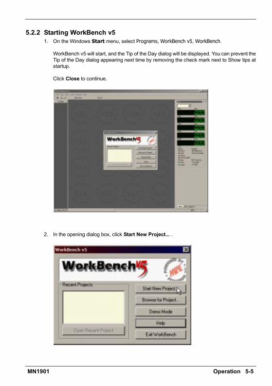
Operation 5-5MN1901
5.2.2 Starting WorkBench v51. On the Windows Start menu, select Programs,WorkBench v5,WorkBench.
WorkBench v5 will start, and the Tip of the Day dialog will be displayed. You can prevent theTip of the Day dialog appearing next time by removing the check mark next to Show tips atstartup.
Click Close to continue.
2. In the opening dialog box, click Start New Project... .
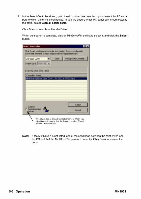
5-6 Operation MN1901
3. In the Select Controller dialog, go to the drop down box near the top and select the PC serialport to which the drive is connected. If you are unsure which PC serial port is connected tothe drive, select Scan all serial ports.
Click Scan to search for the MintDriveII.
When the search is complete, click on MintDriveII in the list to select it, and click the Selectbutton.
This check box is already selected for you. When youclick Select, it means that the Commissioning Wizardwill start automatically.
Note: If the MintDriveII is not listed, check the serial lead between the MintDriveII andthe PC and that the MintDriveII is powered correctly. Click Scan to re-scan theports.

Operation 5-7MN1901
5.2.3 Commissioning WizardEach type of motor and drive combination has slightly different performance characteristics.Before the MintDriveII can be used to control the motor accurately, the MintDriveIImust betuned. This is the process where the MintDriveII powers the motor in a series of tests. Bymonitoring the feedback from the motors resolver or encoder and performing a number ofcalculations, the MintDriveII can make small adjustments to the way it controls the motor. Thisinformation is stored in the MintDriveII EEPROM and can be uploaded to a file if necessary.The Commissioning Wizard provides a simple way to tune the MintDriveII and create thenecessary configuration information for your drive/motor combination, so this is the first toolthat should be used.
5.2.4 Using the Commissioning Wizard
CAUTION: The motor will move during commissioning. For safety it is advisable todisconnect any load from the motor during initial commissioning. Themotor can be tuned with the load connected after the CommissioningWizard has finished.
Each screen of the Commissioning Wizard requires you to enter information about the motoror drive. Read each screen carefully and enter the required information.
If you need extra help, click the Help button or press F1 to display the help file.
When you have completed a screen, click Next > to display the next screen. If you need tochange something on a previous screen, click the < Back button. The Commissioning Wizardremembers information that you have entered so you will not need to re-enter everything if yougo back to previous screens.
5.2.5 Completing the Commissioning WizardThe final screen (Tuning) has a Finish button that is grayed out until the tuning tests have beencompleted. When the tuning tests have finished click Finish to complete the CommissioningWizard.
The parameters that have been calculated by the Commissioning Wizard do not need to bedownloaded to the MintDriveII. They are already in the MintDriveII and will not be lost evenwhen it is powered down.

5-8 Operation MN1901
5.3 Further configurationWorkBench v5 provides a number of tools, each of which has an icon on the left of the screen.Click once on an icon to select the tool. Three of the main tools used for tuning and configuringthe MintDriveII are briefly described here.
Every tool is explained fully in the help file. Press F1 to display the help file, then navigate tothe WorkBench v5 book. Inside this is the Toolbox book.
5.3.1 Fine-tuning toolThe Commissioning Wizard calculates many parameters that allow the MintDriveII to providebasic control of the motor. These parameters may need to be fine-tuned to provide the exactresponse that you require. The Fine-tuning screen allows you to do this.
1. Click the Fine-tuning icon in the Toolbox on the left of the screen.
TheFine-tuningwindow is displayedat the right of the screen.Thisalready shows some of the parameters that have been calculatedby the Commissioning Wizard.
The main area of the WorkBench v5 window displays the capturewindow. When further tuning tests are performed, this will displaya graph representing the response.
2. The Fine-tuning window has three tabs at thebottom - Position, Speed and Current. Click ona tab to select it.
Click the tab for the type of tests you wish toperform.
Note: Some tabs may not be available depending on the configuration mode youselected in the Commissioning Wizard.

Operation 5-9MN1901
5.3.1.1 Fine-tuning - Position tab
The position tab allows you to set position loop gains and perform test moves.The Commissioning Wizard may have already set some of these values, depending on thetype of system selected on the mode screen.
Enter new values in the required boxes and then click Apply to download the values to theMintDriveII. To perform tests, go to the Test Parameters area at the bottom of the tab. Entertest values and then click Go to perform the test move. If you need help, just press F1 todisplay the help file.
5.3.1.2 Fine-tuning - Speed tab
The speed tab allows you to set speed loop gains and perform test moves.The Commissioning Wizard may have already set some of these values, depending on thetype of system selected on the mode screen.
Enter new values in the required boxes and then click Apply to download the values to theMintDriveII. To perform tests, go to the Test Parameters area at the bottom of the tab. Entertest values and then click Go to perform the test move. If you need help, just press F1 todisplay the help file.
5.3.1.3 Fine-tuning - Current tab
The current tab allows you to set current loop gains and perform test moves.The Commissioning Wizard may have already set some of these values, depending on thetype of system selected on the mode screen.
Enter new values in the required boxes and then click Apply to download the values to theMintDriveII. To perform tests, go to the Test Parameters area at the bottom of the tab. Entertest values and then click Go to perform the test move. If you need help, just press F1 todisplay the help file.
The additional Measure and Feedback alignment buttons can be used to repeat the samemeasurement and alignment tests as the Commissioning Wizard.
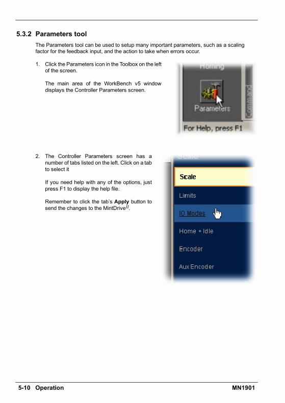
5-10 Operation MN1901
5.3.2 Parameters toolThe Parameters tool can be used to setup many important parameters, such as a scalingfactor for the feedback input, and the action to take when errors occur.
1. Click the Parameters icon in the Toolbox on the leftof the screen.
The main area of the WorkBench v5 windowdisplays the Controller Parameters screen.
2. The Controller Parameters screen has anumber of tabs listed on the left. Click on a tabto select it
If you need help with any of the options, justpress F1 to display the help file.
Remember to click the tabs Apply button tosend the changes to the MintDriveII.

Operation 5-11MN1901
5.3.3 Digital I/O toolThe Digital I/O tool allows you to define how each digital input and output will be triggered andif it is to be assigned to a special function, for example the forward limit or stop input.
1. Click the Digital I/O icon in the Toolbox on the leftof the screen.
The main area of the WorkBench v5 windowdisplays the Digital I/O screen. You can use a dragand drop method to assign triggering options toinputs and outputs and assign them to specialpurpose functions.
If you need help, just press F1 to display the helpfile.
Remember to click the Apply button to send thechanges to the MintDriveII.
5.3.4 Other tools and windowsEach tool and window is explained fully in the help file, so is not described here in detail.
H Homing ToolAllows you to setup homing moves.
H Edit & Debug ToolThis is the tool used for programming the MintDriveII. The tool provides a work areaincluding the Command window and Output window. Multiple editing windows can beopened for entering program code.
H Scope ToolDisplays the capture screen. This screen is also shown when the Fine-tuning tool isselected.
H Presets ToolAllows you to setup preset moves and the way in which they should be triggered. Aninteractive table of the moves is used to make changes.
H Jog ToolAllows you to perform jog moves - useful for testing purposes.
H PLC Task ToolAllows you to setup the PLC Task, a special task that can be used to check for a numberof pre-defined conditions and then perform actions if they become true.
H Error Log ToolDisplays a list showing when errors occurred and when they were cleared.
H Spy windowAllows you to monitor all the important parameters for the axis, and shows the state ofdigital inputs and outputs, limit switches and comms locations.
Remember, for help on each tool just press F1 to display the help file, then navigate to theWorkBench v5 book. Inside this is the Toolbox book.

5-12 Operation MN1901

Troubleshooting 6-1MN1901
6.1 IntroductionThis section explains common problems that may be encountered, together with possiblesolutions.
6.1.1 Problem diagnosisIf you have followed all the instructions in this manual in sequence, you should have fewproblems installing the MintDriveII. If you do have a problem, read this section first.In WorkBench v5, use the Error Log tool to view recent errors and then check the help file.If you cannot solve the problem or the problem persists, the SupportMet feature can be used.
6.1.2 SupportMet featureThe SupportMet feature (on the Help menu) can be used to e-mail information to the Baldorrepresentative from whom you purchased the equipment. If required, you can choose to addyour program files as attachments. WorkBench v5 will automatically start up your e-mailprogram and begin a new message, with comprehensive system information and selectedattachments already in place. You can add any additional message of your own and then sendthe e-mail. The PC must have email facilities to use the SupportMet feature. If you prefer tocontact Baldor technical support by telephone or fax, contact details are provided at the frontof this manual. Please have the following information ready:
H The serial number of your MintDriveII.H Use the Help, SupportMe menu item in WorkBench v5 to view details about your system.H The catalog and specification numbers of the motor that you are using.H Give a clear description of what you are trying to do, for example trying to establish
communications with WorkBench v5 or trying to perform fine-tuning.H Give a clear description of the symptoms that you can observe, for example the Status
display, error messages displayed in WorkBench v5, or the current value of any of theMint error keywords AXISERROR, AXISSTATUS, INITERROR, MISCERROR andDRIVEERROR.
H The type of motion generated in the motor shaft.H Give a list of any parameters that you have setup, for example the motor data you
entered/selected in the Commissioning Wizard, the gain settings generated during thetuning process and any gain settings you have entered yourself.
6.1.3 Power-cycling the MintDriveII
The term Power-cycle the MintDriveII is used in the Troubleshooting sections. On modelswith a customer supplied 24V supply, remove the 24V supply, wait for the MintDriveII to powerdown completely (all Status LED segments will turn off), then re-apply the 24V supply.On models with an internally generated 24V supply, remove the AC power supply, wait for theMintDriveII to power down completely (all Status LED segments will turn off), then re-apply ACpower.
6 Troubleshooting 6

6-2 Troubleshooting MN1901
6.2 MintDriveII indicators
6.2.1 Status displayThe Status LED display indicates general MintDriveII status information.Some characters will flash to indicate an error.
Drive / comms watchdog. Interprocessor communications failure.This is potentially a severe problem if it occurs repeatedly. Communications failurecould indicate a process locking out the interprocessor communications. Clear theerror; if the problem persists then contact Baldor technical support.
Over volts. The DC Bus voltage has exceeded the powerbase overvolts level (seeDRIVEBUSOVERVOLTS). Check the DC Bus level being fed into the system (see Mintkeyword DRIVEBUSVOLTS). This should be close to the nominal voltage (see Mintkeyword DRIVEBUSNOMINALVOLTS). Ensure that your input voltage is relevant to thevoltage rating of your drive. If the input voltage is correct, then this error may be theresult of high deceleration rates. If it is not possible to reduce the harshness of thedeceleration rate, then a regeneration resistor should be used. To help you, useWorkBench v5 capture facility to monitor the DC Bus level during moves.
Integrated Power Module (IPM) trip.The units powerbase has been overloaded. This should not happen in normal use iflimits have been configured correctly. See the Mint keyword CURRENTLIMIT andrelated commands.
Current trip. Instantaneous over-current trip.One or more of the 3 motor phases has exceeded 300% of Drive Rated Current.
Under volts. The DC Bus voltage has dropped below the powerbase undervolts level(see DRIVEBUSUNDERVOLTS). This error will only be generated if the drive is in theenabled state. As with the overvolts error, check the input voltage being fed into thesystem. The error could also occur during high acceleration profiles.
Feedback trip. Can be enabled/disabled using FEEDBACKFAULTENABLE. Fiveconsecutive errors (or five errors in any 500 servo tick period) will cause the drive totrip. This error indicates loss of encoder/resolver feedback and may indicate that thefeedback cable has become detached or one of the signals has broken. Check thewiring in the Feedback cable; check for noise immunity; check the feedback devicefitted to the motor (if possible).
Motor or Drive trip. The motor I2T or the drive I.T current protection algorithms haveexceeded their limit and tripped the drive (disabled it). Check DRIVEERROR or the ErrorLog to determine which error has occurred.The motor and drive current limits are fixed according to the database parameters. Thedrive can demand peak current for a short duration (see DRIVEPEAKDURATION),thereafter it will trip or Foldback according to the setting of DRIVEOVERLOADMODE. Thesame is true for the motor (see MOTORPEAKDURATION and MOTOROVERLOADAREA).Use the Foldback option to automatically foldback the current to a level where thedrive/motor can recover.

Troubleshooting 6-3MN1901
(Symbol not flashing)Motor I2T / It foldback. Motor I2T or Drive I.T algorithm has resulted in the demandcurrent being folded back to a level where the drive/motor can recover. The motor /drive can run with demand currents greater than their rated value for a period of time;after that time the drive will either trip or automatically foldback the demand current.
Overtemperature. The temperature of the drive or motor has exceeded a trip level (seeMint keyword TEMPERATURELIMITFATAL ) or the Motor overtemperature trip inputhas been activated (see Mint keyword MOTORTEMPERATUREINPUT).
Drive enabled. The drive is enabled (except where CONFIG = _cfVirtual, where itis not physically enabled).
Torque mode. The drive is in Torque mode. See the Mint keywords TORQUE,TORQUEREFSOURCE and related commands.
Auto tune test driving motor. Autotune is active and driving the motor. The motor maymove.
Power base not ready. This error condition applies to 3-phase drives only. These driveshave a pre-charge circuit which must activate after power-up before the drive can beenabled. If the drive is enabled prior to this then the error occurs. The error could alsoindicate the loss of one or more of the input phases.
Cam. A Cam profile is being profiled. See the Mint keyword CAM.
General error. See AXISERROR and DRIVEERROR. The motion toolbar displays thestatus of AXISERROR, which is a bit pattern of all latched errors. See also the Error Logtopics in the help file.
Error input. The ERRORINPUT has been activated and generated an error.
Flying shear. A flying shear is being profiled. See the Mint keyword FLY.
Position or velocity following error. A following error has occurred. See the Mintkeyword AXISERROR and associated keywords. Following errors could be caused by abadly tuned drive/motor. At higher acceleration and deceleration rates, the followingerror will typically be greater. Ensure that the drive/motor is adequately tuned to copewith these acceleration rates.The following error limit can be adjusted to suite your application (see Mint keywordsFOLERRORFATAL and VELFATAL). Following error could also be the cause ofencoder/resolver loss (see also Mint keyword FEEDBACKFAULTENABLE).
Follow mode. The drive is in Follow mode. See the Mint keyword FOLLOW.
Hold. The Hold DIP switch is active (see section 3.9.2) or the PLC Task has requesteda Hold state. Motion will be ramped to zero demand and will then hold on position whilethe switch is active.
Homing. The drive is currently homing. See the Mint keyword HOME.
Preset Homing. The drive is currently homing. This motion has been triggered from aPreset move table.

6-4 Troubleshooting MN1901
Incremental move. An incremental move is being profiled. See the Mint keywordsINCA and INCR.
Jog. The drive is jogging. In the Mint help file, see the topics JOG, JOGCOMMAND andJog screen.
Preset jog. The drive is jogging. The jog was triggered from a Preset jog table.
Overspeed. The measured speed of the motor has exceeded the trip level defined byDRIVESPEEDFATAL. Check that the trip level is set to a suitable value for yourapplication. When accelerating to a demand speed close to the trip level, there willtypically be a certain amount of overshoot. Using the Fine-tuning tool, check theamount of overshoot you get with the acceleration and demand speeds being used inyour application.
Positional Move. The drive is performing a linear move. See the Mint keywords MOVEAand MOVER.
Preset positions. The drive is performing a linear move. This motion has been triggeredfrom a Preset move table.
DB Overload. The regeneration resistor (Dynamic Brake) has been overloaded. Seethe Mint keyword DBEXTTRIPSWITCH and associated keywords.
Stop. A STOP command has been issued or the stop input is active.
Drive disabled. The drive must be enabled before operation can continue. See section3.8. Click the Drive enable button in WorkBench v5.
Crash. The drive enable input or the Enable DIP switch have become inactive whilst thedrive was in the enable state (or the drive was enabled whilst they were inactive) - bit13 in AXISEERROR will be set. The drive can be programmed to ignore this state usingthe Mint keyword DRIVEENABLEINPUTMODE (see the Parameters tool).
Suspend. The SUSPEND command has been issued and is active. Motion will beramped to zero demand whilst active.
Speed demand. The drive is under speed control. See the Mint keywords SPEEDREF,SPEEDREFSOURCE and related commands.
Reverse software or hardware limit. A reverse software limit has been activated.See AXISERROR and/or AXISSTATUS to determine which applies.
Forward software or hardware limit. A forward software limit has been activated.See AXISERROR and/or AXISSTATUS to determine which applies.
Firmware being updated (horizontal bars appear sequentially). New firmware is beingdownloaded to the drive.
Initialization error. An initialization error has occurred at power on. See the Error Log orINITERROR topics in the help file. Initialization errors should not normally occur.
User defined symbols can be made to appear using the Mint keywords LED and LEDDISPLAY.

Troubleshooting 6-5MN1901
6.2.2 DB On (Regeneration) LEDThe front panel DB On LED indicates regeneration activity.
Yellow Power is being dissipated into the regeneration resistor
Off No regeneration is occurring.
6.2.3 Communication
Problem Check
Status display isblank
Check that the customer supplied 24VDC power supply is connectedcorrectly to connector X1 and is switched on.On models with an internally generated 24VDC supply, check that theAC power supply is connected correctly to connector X1 and isswitched on.
WorkBench v5 failsto detect theMintDriveII - itdetects Nocontroller found.Communicationfault on COMx.
Ensure that the MintDriveII is powered and the Status display isilluminated (see section 6.2).
Check that the serial cable is connected between the PCs COM portand connector X6 on the MintDriveII.
Check which PC COM port is being used, or use the Scan all serialports option to locate the MintDriveII.
Check the wiring of the serial cable or try an alternate cable. Checkthat DIP switch 10 (RS232/RS422) is set correctly (see section 3.9.6).
On the PC, try an alternative COM port.
Confirm that a mouse driver or other serial device is not conflicting(using the same COM port) as WorkBench v5.
Does the MintDriveII have firmware in it? If you tried to download newfirmware and the download failed, the controller may not havefirmware. If this has happened, the Status display will show a minussign (-) and flash the decimal point repeatedly.
Check that the selected Baud rate is supported by the PC andMintDriveII.
If the Only scan COMx option is selected in WorkBench v5, checkthat the correct COM port is selected.
If the Search up to Nodexx option is selected in WorkBench v5,check that the MintDriveII node number is not higher than this value.
Do you have multiple nodes on the bus? If so, they must all be set tothe same Baud rate. WorkBench v5 scans through all the node Ids atdifferent Baud rates. When it finds a node, it will only continue to scanfor other nodes at the same Baud rate.

6-6 Troubleshooting MN1901
6.2.4 Power on
Problem Check
The Status display isshowing a flashing symbolwith a static decimal point.
The MintDriveII has detected a motion error. Use the ErrorLog tool to view a list of recent errors, or click the Errorbutton on the motion toolbar to view a description of theerror. Alternatively, type any or all of these commands in theCommand window:PRINT AXISERRORPRINT DRIVEERRORPRINT MISCERRORPRINT INITERROR.Click the Clear Errors button on the motion toolbar.
6.2.5 Tuning
Problem Check
Cannot enable theMintDriveII becauseAXISERROR has bit 13 set
Check the drive enable input on connector X3 pins 7 and 9is connected and powered correctly. Check that DIP switch8 (enable) is set to the On position.
When the MintDriveII isenabled the motor isunstable
Check that the current loop has been tuned.Check that the current loop was tuned with the correct motordata. If the motor is still unstable try reducing the SpeedProportional gain (KVPROP) and Speed Integral gain(KVINT) on the Speed tab of the Fine-tuning window.
I get a Following Error(AXISERROR bit 5 is set)and the drive disables whentuning the Mint gains
Set FOLERRORMODE to zero to ignore the following errorwhile tuning the Mint gains.
I get a Software limit error(AXISERROR bits 3 or 4 set)and the drive disables whentuning the Mint gains
Set SOFTLIMITMODE to zero to ignore the software limiterror while tuning the Mint gains.
I get a Hardware limit error(AXISERROR bits 1 or 2 set)and the drive disables whentuning the Mint gains
Set LIMITMODE to zero to ignore the hardware limit errorswhile tuning the Mint gains. Alternatively, disable thehardware limit inputs.
6.2.6 Status display shows a digit or E.If the Status display shows a flashing digit, E, or the forward or reverse hardware limitsymbol, use the Error Log tool to view a list of recent errors. Alternatively, typePRINT DRIVEERROR, PRINT AXISERROR and PRINT MISCERROR as separate commandsin the WorkBench v5 Command window. Each of these commands will return an error code, adescription of which can be found in the help file.Press F1 and locate the DRIVEERROR, AXISERROR and MISCERROR keywords. The ErrorHandling book contains topics listing the Status display indicators and basic error codes.Remember that many error codes are the sum of a bit pattern so may not be listed individually.For help on understanding bit pattern values, see the Bit pattern values topic in the Keywordsbook.
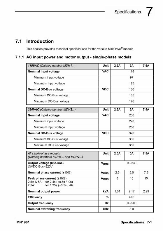
Specifications 7-1MN1901
7.1 IntroductionThis section provides technical specifications for the various MintDriveIImodels.
7.1.1 AC input power and motor output - single-phase models
115VAC (Catalog number MDH1...) Unit 2.5A 5A 7.5A
Nominal input voltage VAC 115
Minimum input voltage 97
Maximum input voltage 125
Nominal DC-Bus voltage VDC 160
Minimum DC-Bus voltage 135
Maximum DC-Bus voltage 176
230VAC (Catalog number MDH2...) Unit 2.5A 5A 7.5A
Nominal input voltage VAC 230
Minimum input voltage 220
Maximum input voltage 250
Nominal DC-Bus voltage VDC 320
Minimum DC-Bus voltage 306
Maximum DC-Bus voltage 350
All single-phase models(Catalog numbers MDH1... and MDH2...)
Unit 2.5A 5A 7.5A
Output voltage (line-line)@VDC-Bus=320V
VRMS 0 - 230
Nominal phase current (±10%) ARMS 2.5 5.0 7.5
Peak phase current (±10%)2.5A & 5A: for 2.4s (+0.5s / -0s)7.5A: for 1.25s (+0.5s / -0s)
ARMS 5 10 15
Nominal output power kVA 1.01 2.17 2.99
Efficiency % >95
Output frequency Hz 0 - 500
Nominal switching frequency kHz 8.0
7 Specifications 7

7-2 Specifications MN1901
7.1.2 AC input power and motor output - 230V three-phase models
230VAC 50/60Hz(Catalog number MDH2A15...)
Unit 15A
Nominal input voltage VAC 230
Minimum input voltage 184
Maximum input voltage 253
Nominal DC-Bus voltage VDC 320
Minimum DC-Bus voltage 258
Maximum DC-Bus voltage 355(Programmable using Mint keyword
DRIVEBUSOVERVOLTS)
Output voltage (line-line)@VDC-Bus=320V
VRMS 0 - 250
Nominal phase current (±10%) ARMS 15
Peak phase current (±10%)for 1.25s (+0.5s / -0s)
ARMS 30
Nominal output power kVA 5.2
Efficiency % >95
Output frequency Hz 0 - 500
Nominal switching frequency kHz 8.0
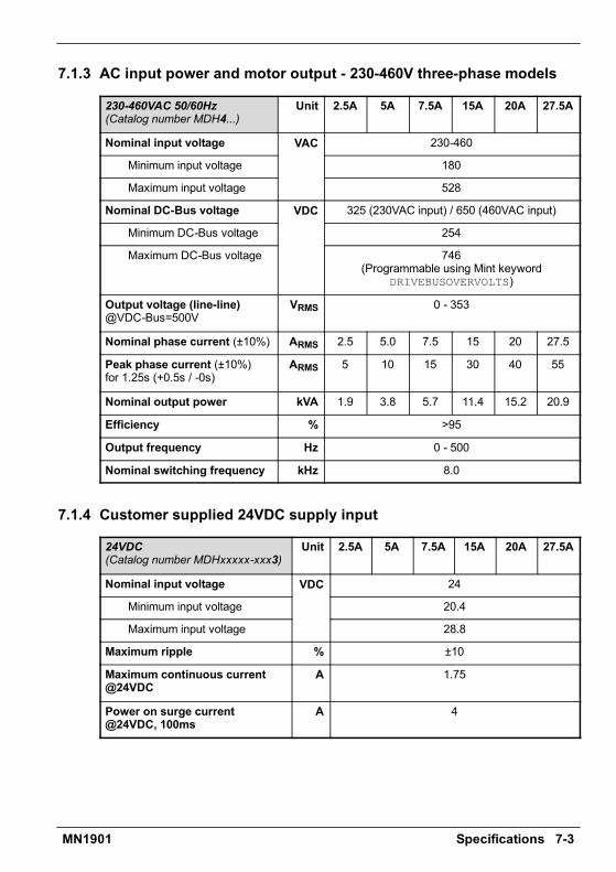
Specifications 7-3MN1901
7.1.3 AC input power and motor output - 230-460V three-phase models
230-460VAC 50/60Hz(Catalog number MDH4...)
Unit 2.5A 5A 7.5A 15A 20A 27.5A
Nominal input voltage VAC 230-460
Minimum input voltage 180
Maximum input voltage 528
Nominal DC-Bus voltage VDC 325 (230VAC input) / 650 (460VAC input)
Minimum DC-Bus voltage 254
Maximum DC-Bus voltage 746(Programmable using Mint keyword
DRIVEBUSOVERVOLTS)
Output voltage (line-line)@VDC-Bus=500V
VRMS 0 - 353
Nominal phase current (±10%) ARMS 2.5 5.0 7.5 15 20 27.5
Peak phase current (±10%)for 1.25s (+0.5s / -0s)
ARMS 5 10 15 30 40 55
Nominal output power kVA 1.9 3.8 5.7 11.4 15.2 20.9
Efficiency % >95
Output frequency Hz 0 - 500
Nominal switching frequency kHz 8.0
7.1.4 Customer supplied 24VDC supply input
24VDC(Catalog number MDHxxxxx-xxx3)
Unit 2.5A 5A 7.5A 15A 20A 27.5A
Nominal input voltage VDC 24
Minimum input voltage 20.4
Maximum input voltage 28.8
Maximum ripple % ±10
Maximum continuous current@24VDC
A 1.75
Power on surge current@24VDC, 100ms
A 4
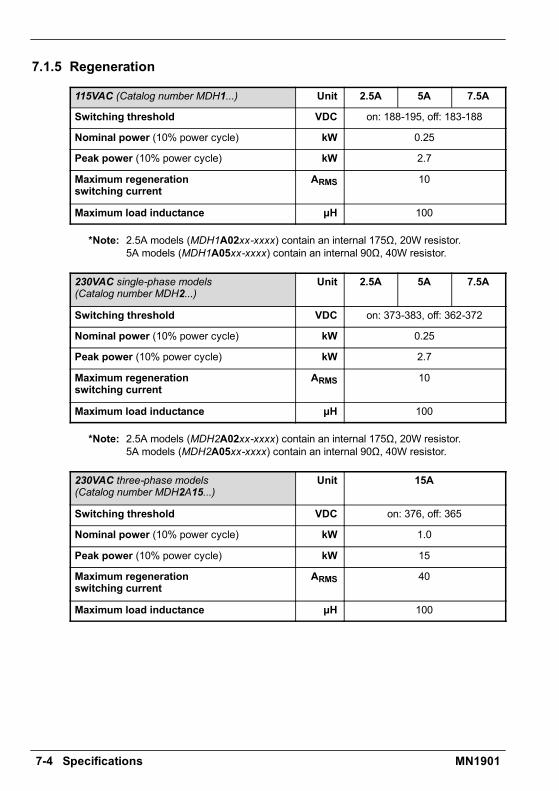
7-4 Specifications MN1901
7.1.5 Regeneration
115VAC (Catalog number MDH1...) Unit 2.5A 5A 7.5A
Switching threshold VDC on: 188-195, off: 183-188
Nominal power (10% power cycle) kW 0.25
Peak power (10% power cycle) kW 2.7
Maximum regenerationswitching current
ARMS 10
Maximum load inductance ìH 100
*Note: 2.5A models (MDH1A02xx-xxxx) contain an internal 175Ω, 20W resistor.5A models (MDH1A05xx-xxxx) contain an internal 90Ω, 40W resistor.
230VAC single-phase models(Catalog number MDH2...)
Unit 2.5A 5A 7.5A
Switching threshold VDC on: 373-383, off: 362-372
Nominal power (10% power cycle) kW 0.25
Peak power (10% power cycle) kW 2.7
Maximum regenerationswitching current
ARMS 10
Maximum load inductance ìH 100
*Note: 2.5A models (MDH2A02xx-xxxx) contain an internal 175Ω, 20W resistor.5A models (MDH2A05xx-xxxx) contain an internal 90Ω, 40W resistor.
230VAC three-phase models(Catalog number MDH2A15...)
Unit 15A
Switching threshold VDC on: 376, off: 365
Nominal power (10% power cycle) kW 1.0
Peak power (10% power cycle) kW 15
Maximum regenerationswitching current
ARMS 40
Maximum load inductance ìH 100

Specifications 7-5MN1901
230-460VAC three-phase models(Catalog number MDH4...)
Unit 2.5A 5A 7.5A 15A 20A 27.5A
Switching thresholdVin=400VACVin=460VAC
VDC on: 794, off: 787 on: 794, off: 764
Nominal power (10% powercycle)
kW 0.94 2.9
Peak power (10% power cycle) kW 9.4 29
Maximum regenerationswitching current
ARMS 15 40 80
Maximum load inductance ìH 100
*Note: 2.5A models (MDH4A02xx-xxxx) contain an internal 200Ω, 300W resistor.5A models (MDH4A05xx-xxxx) contain an internal 200Ω, 300W resistor.
7.1.6 Analog input (X3)
All models Unit All models
Type Differential
Common mode voltage range VDC ±10
Common mode rejection dB 40
Input impedance kÙ >5
Input ADC resolution bits 14(includes sign bit)
Equivalent resolution mV ±1.2
Sampling intervalSoftware (Mint programs)
High speed command reference signal
ìs500125
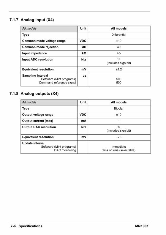
7-6 Specifications MN1901
7.1.7 Analog input (X4)
All models Unit All models
Type Differential
Common mode voltage range VDC ±10
Common mode rejection dB 40
Input impedance kÙ >5
Input ADC resolution bits 14(includes sign bit)
Equivalent resolution mV ±1.2
Sampling intervalSoftware (Mint programs)Command reference signal
ìs500500
7.1.8 Analog outputs (X4)
All models Unit All models
Type Bipolar
Output voltage range VDC ±10
Output current (max) mA 1
Output DAC resolution bits 8(includes sign bit)
Equivalent resolution mV ±78
Update intervalSoftware (Mint programs)
DAC monitoringImmediate
1ms or 2ms (selectable)

Specifications 7-7MN1901
7.1.9 Digital inputs (X3)
All models Unit All models
Type Opto-isolated DC inputs
Input voltage (Active high)NominalMinimum
VDC2412
Input voltage (Active low)NominalMaximum
VDC02
Input current (approximate, per input) mA 5
Sampling interval ms 2
Maximum pulse input frequency(DIN4, pulse and direction mode)
MHz 1
Minimum pulse width(DIN4/DIN5, pulse and direction mode)
ns 250
7.1.10 Digital outputs (X3)
All models Unit All models
Output current(maximum, each output) mA 50
Update intervalSoftware (Mint programs)
DRIVEOKOUTPUT,DRIVEENABLEOUTPUT,
and GLOBALERROROUTPUTfunctions
PLC Task functions
Immediate
2ms
Programmable
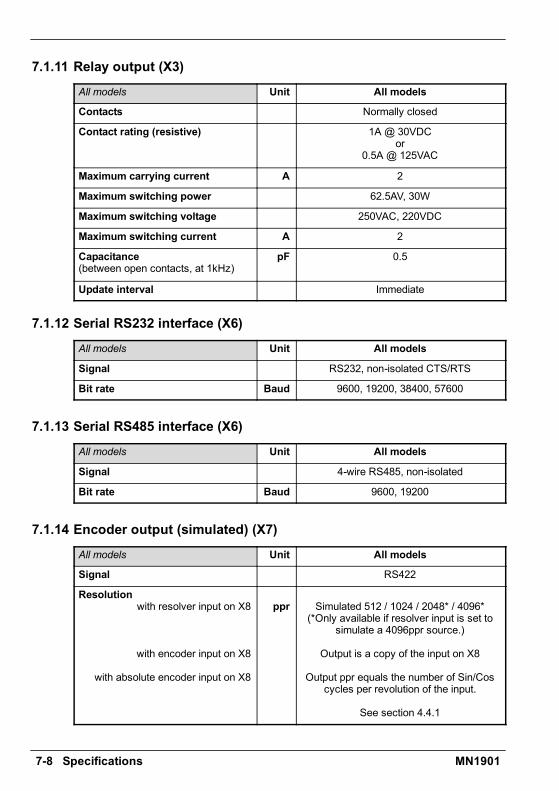
7-8 Specifications MN1901
7.1.11 Relay output (X3)
All models Unit All models
Contacts Normally closed
Contact rating (resistive) 1A @ 30VDCor
0.5A @ 125VAC
Maximum carrying current A 2
Maximum switching power 62.5AV, 30W
Maximum switching voltage 250VAC, 220VDC
Maximum switching current A 2
Capacitance(between open contacts, at 1kHz)
pF 0.5
Update interval Immediate
7.1.12 Serial RS232 interface (X6)
All models Unit All models
Signal RS232, non-isolated CTS/RTS
Bit rate Baud 9600, 19200, 38400, 57600
7.1.13 Serial RS485 interface (X6)
All models Unit All models
Signal 4-wire RS485, non-isolated
Bit rate Baud 9600, 19200
7.1.14 Encoder output (simulated) (X7)
All models Unit All models
Signal RS422
Resolutionwith resolver input on X8
with encoder input on X8
with absolute encoder input on X8
ppr Simulated 512 / 1024 / 2048* / 4096*(*Only available if resolver input is set to
simulate a 4096ppr source.)
Output is a copy of the input on X8
Output ppr equals the number of Sin/Coscycles per revolution of the input.
See section 4.4.1
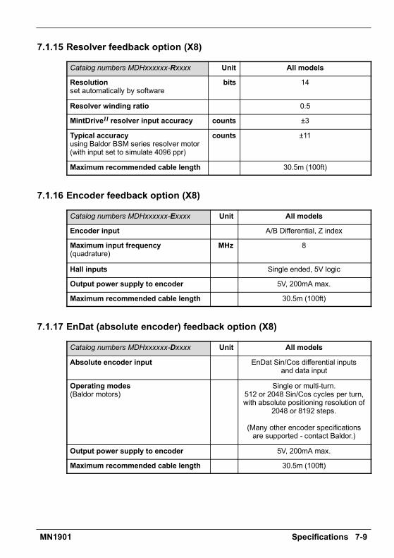
Specifications 7-9MN1901
7.1.15 Resolver feedback option (X8)
Catalog numbers MDHxxxxxx-Rxxxx Unit All models
Resolutionset automatically by software
bits 14
Resolver winding ratio 0.5
MintDriveII resolver input accuracy counts ±3
Typical accuracyusing Baldor BSM series resolver motor(with input set to simulate 4096 ppr)
counts ±11
Maximum recommended cable length 30.5m (100ft)
7.1.16 Encoder feedback option (X8)
Catalog numbers MDHxxxxxx-Exxxx Unit All models
Encoder input A/B Differential, Z index
Maximum input frequency(quadrature)
MHz 8
Hall inputs Single ended, 5V logic
Output power supply to encoder 5V, 200mA max.
Maximum recommended cable length 30.5m (100ft)
7.1.17 EnDat (absolute encoder) feedback option (X8)
Catalog numbers MDHxxxxxx-Dxxxx Unit All models
Absolute encoder input EnDat Sin/Cos differential inputsand data input
Operating modes(Baldor motors)
Single or multi-turn.512 or 2048 Sin/Cos cycles per turn,with absolute positioning resolution of
2048 or 8192 steps.
(Many other encoder specificationsare supported - contact Baldor.)
Output power supply to encoder 5V, 200mA max.
Maximum recommended cable length 30.5m (100ft)
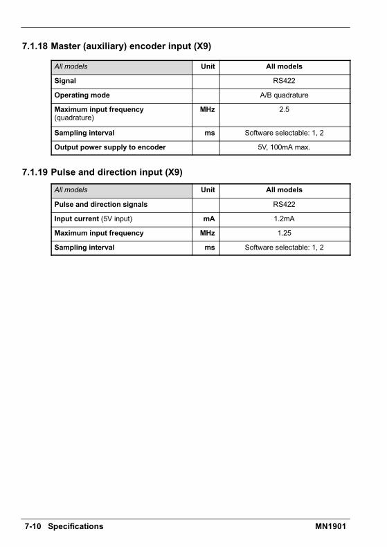
7-10 Specifications MN1901
7.1.18 Master (auxiliary) encoder input (X9)
All models Unit All models
Signal RS422
Operating mode A/B quadrature
Maximum input frequency(quadrature)
MHz 2.5
Sampling interval ms Software selectable: 1, 2
Output power supply to encoder 5V, 100mA max.
7.1.19 Pulse and direction input (X9)
All models Unit All models
Pulse and direction signals RS422
Input current (5V input) mA 1.2mA
Maximum input frequency MHz 1.25
Sampling interval ms Software selectable: 1, 2
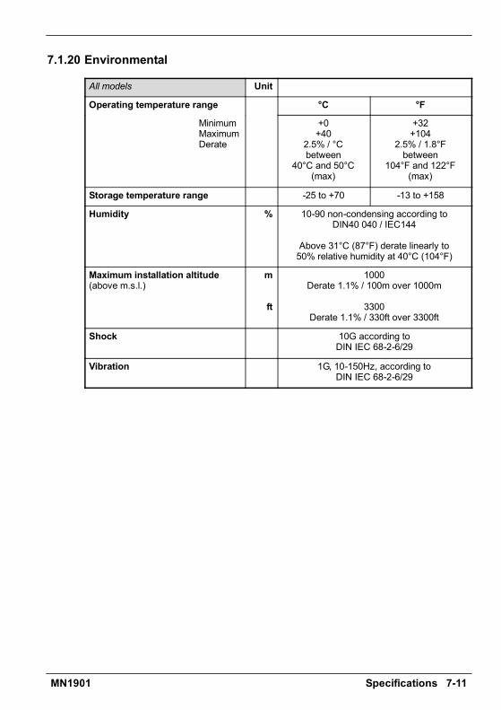
Specifications 7-11MN1901
7.1.20 Environmental
All models Unit
Operating temperature range °C °F
MinimumMaximumDerate
+0+40
2.5% / °Cbetween
40°C and 50°C(max)
+32+104
2.5% / 1.8°Fbetween
104°F and 122°F(max)
Storage temperature range -25 to +70 -13 to +158
Humidity % 10-90 non-condensing according toDIN40 040 / IEC144
Above 31°C (87°F) derate linearly to50% relative humidity at 40°C (104°F)
Maximum installation altitude(above m.s.l.)
m
ft
1000Derate 1.1% / 100m over 1000m
3300Derate 1.1% / 330ft over 3300ft
Shock 10G according toDIN IEC 68-2-6/29
Vibration 1G, 10-150Hz, according toDIN IEC 68-2-6/29

7-12 Specifications MN1901
Accessories A-1MN1901
A.1 IntroductionThis section describes accessories and options that you may need to use with yourMintDriveII. Shielded (screened) cables provide EMI / RFI shielding and are required forcompliance with CE regulations. All connectors and other components must be compatiblewith the shielded cable.
A.1.1 Factory fitted optionsThe MintDriveII can be supplied with a number of factory fitted options. Each option isdescribed in a separate manual that will be supplied with your product as necessary:
H MN1908 - CAN & Auxiliary I/O Option for Flex+DriveII and MintDriveII.Option B provides CANopen, Baldor CAN and additional input / output capabilities. If thisoption is fitted, the MintDriveII front panel will include connectors X10, X11 and X12.
H MN1909 - CAN Option for FlexDriveII, Flex+DriveII and MintDriveII.Option C provides CANopen capabilities. If this option is fitted, the MintDriveII front panelwill include connectors X10 and X11.
H MN1910 - DeviceNet Option for FlexDriveII, Flex+DriveII and MintDriveII.Option D provides DeviceNet capabilities. If this option is fitted, the MintDriveII front panelwill include connector X15.
H MN1911 - PROFIBUS DP Option for FlexDriveII, Flex+DriveII and MintDriveII.Option P provides Profibus capabilities. If this option is fitted, the MintDriveII front panelwill include connector X14.
A Accessories A
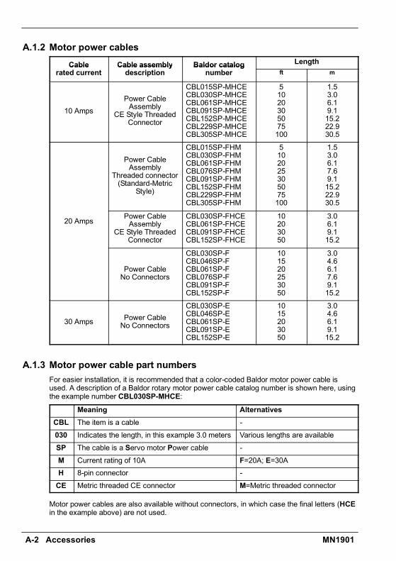
A-2 Accessories MN1901
A.1.2 Motor power cablesCable Cable assembly Baldor catalog LengthCable
rated currentCable assemblydescription
Baldor catalognumber ft m
10 AmpsPower CableAssembly
CE Style ThreadedConnector
CBL015SP-MHCECBL030SP-MHCECBL061SP-MHCECBL091SP-MHCECBL152SP-MHCECBL229SP-MHCECBL305SP-MHCE
51020305075100
1.53.06.19.115.222.930.5
Power CableAssembly
Threaded connector(Standard-Metric
Style)
CBL015SP-FHMCBL030SP-FHMCBL061SP-FHMCBL076SP-FHMCBL091SP-FHMCBL152SP-FHMCBL229SP-FHMCBL305SP-FHM
5102025305075100
1.53.06.17.69.115.222.930.5
20 Amps Power CableAssembly
CE Style ThreadedConnector
CBL030SP-FHCECBL061SP-FHCECBL091SP-FHCECBL152SP-FHCE
10203050
3.06.19.115.2
Power CableNo Connectors
CBL030SP-FCBL046SP-FCBL061SP-FCBL076SP-FCBL091SP-FCBL152SP-F
101520253050
3.04.66.17.69.115.2
30 Amps Power CableNo Connectors
CBL030SP-ECBL046SP-ECBL061SP-ECBL091SP-ECBL152SP-E
1015203050
3.04.66.19.115.2
A.1.3 Motor power cable part numbersFor easier installation, it is recommended that a color-coded Baldor motor power cable isused. A description of a Baldor rotary motor power cable catalog number is shown here, usingthe example number CBL030SP-MHCE:
Meaning AlternativesCBL The item is a cable -030 Indicates the length, in this example 3.0 meters Various lengths are availableSP The cable is a Servo motor Power cable -M Current rating of 10A F=20A; E=30AH 8-pin connector -CE Metric threaded CE connector M=Metric threaded connector
Motor power cables are also available without connectors, in which case the final letters (HCEin the example above) are not used.
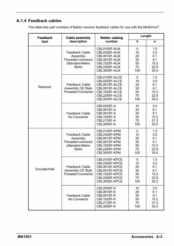
Accessories A-3MN1901
A.1.4 Feedback cablesThis table lists part numbers of Baldor resolver feedback cables for use with the MintDriveII:
Feedback Cable assembly Baldor catalog LengthFeedbacktype
Cable assemblydescription
Baldor catalognumber ft m
Feedback CableAssembly
Threaded connector(Standard-Metric
Style)
CBL015SF-ALMCBL030SF-ALMCBL061SF-ALMCBL091SF-ALMCBL152SF-ALMCBL229SF-ALMCBL305SF-ALM
51020305075100
1.53.06.19.115.222.930.5
ResolverFeedback CableAssembly CE StyleThreaded Connector
CBL015SF-ALCECBL030SF-ALCECBL061SF-ALCECBL091SF-ALCECBL152SF-ALCECBL229SF-ALCECBL305SF-ALCE
51020305075100
1.53.06.19.115.222.930.5
Feedback CableNo Connector
CBL030SF-ACBL061SF-ACBL091SF-ACBL152SF-ACBL213SF-ACBL305SF-A
1020305070100
3.06.19.115.221.330.5
Feedback CableAssembly
Threaded connector(Standard-Metric
Style)
CBL015SF-KPMCBL030SF-KPMCBL061SF-KPMCBL091SF-KPMCBL152SF-KPMCBL229SF-KPMCBL305SF-KPM
51020305075100
1.53.06.19.115.222.930.5
Encoder/HallFeedback CableAssembly CE StyleThreaded Connector
CBL015SF-KPCECBL030SF-KPCECBL061SF-KPCECBL091SF-KPCECBL152SF-KPCECBL229SF-KPCECBL305SF-KPCE
51020305075100
1.53.06.19.115.222.930.5
Feedback CableNo Connector
CBL030SF-KCBL061SF-KCBL091SF-KCBL152SF-KCBL213SF-KCBL305SF-K
1020305070100
3.06.19.115.221.330.5

A-4 Accessories MN1901
A.1.5 Feedback cable part numbersA description of a Baldor feedback cable catalog number is shown here, using the examplenumber CBL030SF-ALCE:
Meaning AlternativesCBL The item is a cable -030 Indicates the length, in this example 3.0 meters Various lengths are availableSF The cable is a Servo motor Feedback cable -
A Resolver feedback cable K=Encoder / Hall feedback cableor EnDat cable
L 12-pin connector (for resolvers and EnDat) P=16-pin connector (for encoders)CE Metric threaded CE connector* M=Metric threaded connector
*Note: Feedback cables terminated with a CE connector (catalog numbersCBLxxxxx-xxCE) have shields tied to the connector housing.
If you are not using a Baldor cable with your chosen feedback device, be sure to obtain acable that is a shielded twisted pair 0.34mm2 (22 AWG) wire minimum, with an overall shield.Ideally, the cable should not exceed 30.5m (100ft) in length. Maximum wire-to-wire orwire-to-shield capacitance is 50pF per 300mm (1ft) length, to a maximum of 5000pF for 30.5m(100ft).
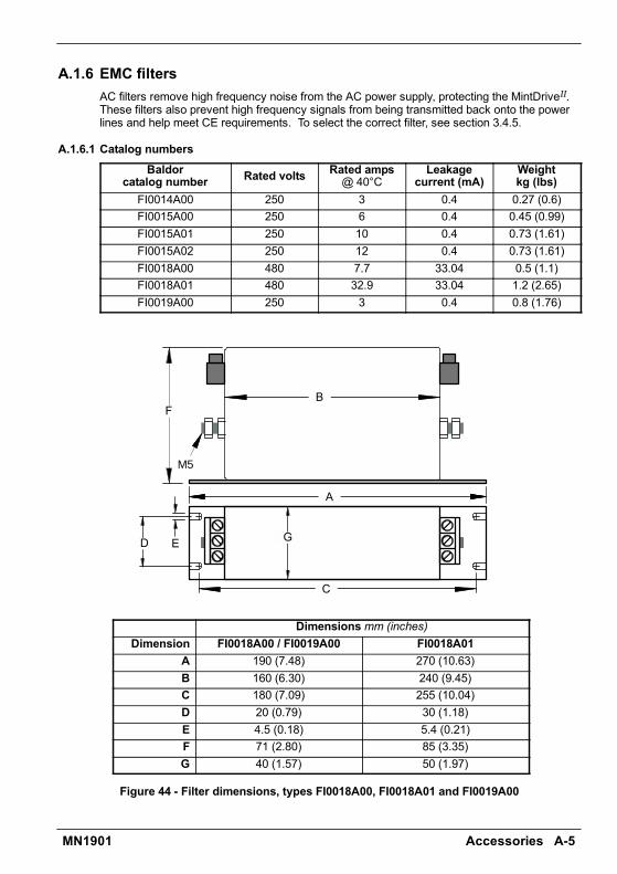
Accessories A-5MN1901
A.1.6 EMC filtersAC filters remove high frequency noise from the AC power supply, protecting the MintDriveII.These filters also prevent high frequency signals from being transmitted back onto the powerlines and help meet CE requirements. To select the correct filter, see section 3.4.5.
A.1.6.1 Catalog numbersBaldor
catalog number Rated volts Rated amps@ 40°C
Leakagecurrent (mA)
Weightkg (lbs)
FI0014A00 250 3 0.4 0.27 (0.6)FI0015A00 250 6 0.4 0.45 (0.99)FI0015A01 250 10 0.4 0.73 (1.61)FI0015A02 250 12 0.4 0.73 (1.61)FI0018A00 480 7.7 33.04 0.5 (1.1)FI0018A01 480 32.9 33.04 1.2 (2.65)FI0019A00 250 3 0.4 0.8 (1.76)
B
M5
A
F
C
ED G
Dimensions mm (inches)Dimension FI0018A00 / FI0019A00 FI0018A01
A 190 (7.48) 270 (10.63)B 160 (6.30) 240 (9.45)C 180 (7.09) 255 (10.04)D 20 (0.79) 30 (1.18)E 4.5 (0.18) 5.4 (0.21)F 71 (2.80) 85 (3.35)G 40 (1.57) 50 (1.97)
Figure 44 - Filter dimensions, types FI0018A00, FI0018A01 and FI0019A00
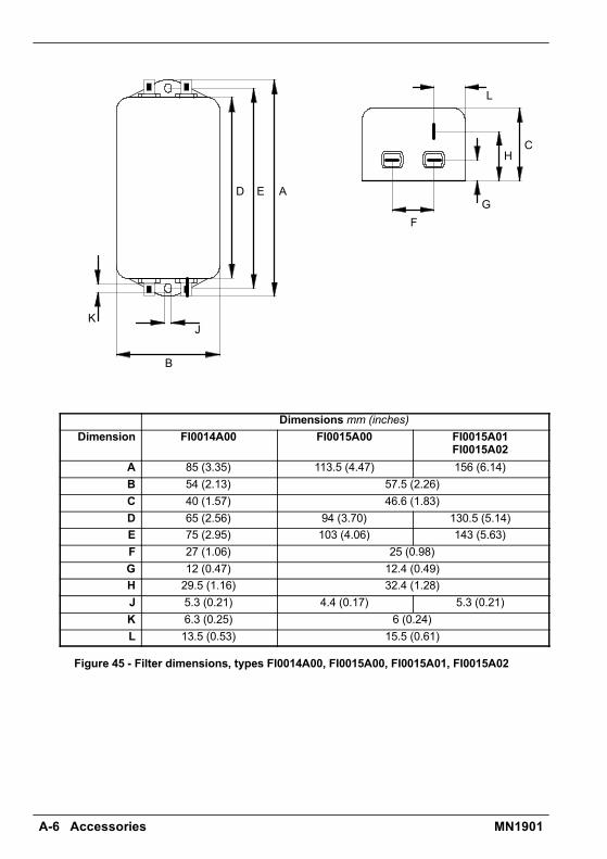
A-6 Accessories MN1901
L
KJ
H
GF
ED
C
B
A
Dimensions mm (inches)Dimension FI0014A00 FI0015A00 FI0015A01
FI0015A02A 85 (3.35) 113.5 (4.47) 156 (6.14)B 54 (2.13) 57.5 (2.26)C 40 (1.57) 46.6 (1.83)D 65 (2.56) 94 (3.70) 130.5 (5.14)E 75 (2.95) 103 (4.06) 143 (5.63)F 27 (1.06) 25 (0.98)G 12 (0.47) 12.4 (0.49)H 29.5 (1.16) 32.4 (1.28)J 5.3 (0.21) 4.4 (0.17) 5.3 (0.21)K 6.3 (0.25) 6 (0.24)L 13.5 (0.53) 15.5 (0.61)
Figure 45 - Filter dimensions, types FI0014A00, FI0015A00, FI0015A01, FI0015A02
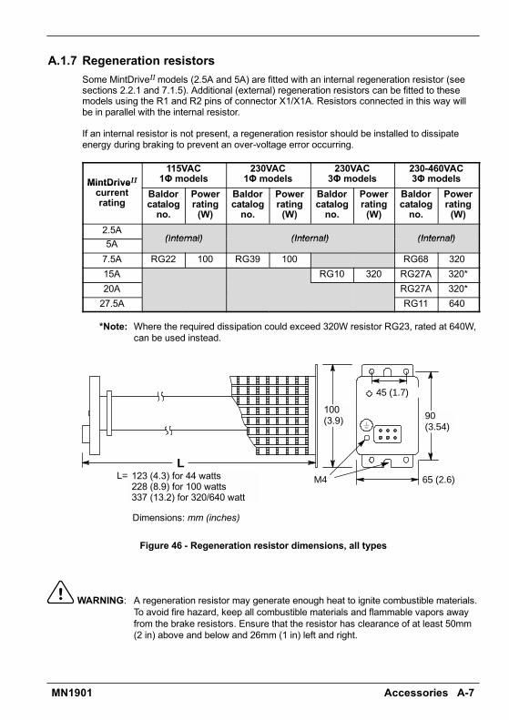
Accessories A-7MN1901
A.1.7 Regeneration resistorsSome MintDriveIImodels (2.5A and 5A) are fitted with an internal regeneration resistor (seesections 2.2.1 and 7.1.5). Additional (external) regeneration resistors can be fitted to thesemodels using the R1 and R2 pins of connector X1/X1A. Resistors connected in this way willbe in parallel with the internal resistor.
If an internal resistor is not present, a regeneration resistor should be installed to dissipateenergy during braking to prevent an over-voltage error occurring.
MintDriveII115VAC1Φ models
230VAC1Φ models
230VAC3Φ models
230-460VAC3Φ modelsMintDrive
currentrating
Baldorcatalogno.
Powerrating(W)
Baldorcatalogno.
Powerrating(W)
Baldorcatalogno.
Powerrating(W)
Baldorcatalogno.
Powerrating(W)
2.5A(Internal) (Internal) (Internal)5A (Internal) (Internal) (Internal)
7.5A RG22 100 RG39 100 RG68 32015A RG10 320 RG27A 320*20A RG27A 320*27.5A RG11 640
*Note: Where the required dissipation could exceed 320W resistor RG23, rated at 640W,can be used instead.
65 (2.6)
90(3.54)
123 (4.3) for 44 watts228 (8.9) for 100 watts337 (13.2) for 320/640 watt
100(3.9)
M4
45 (1.7)
LL=
Dimensions: mm (inches)
Figure 46 - Regeneration resistor dimensions, all types
WARNING: A regeneration resistor may generate enough heat to ignite combustible materials.To avoid fire hazard, keep all combustible materials and flammable vapors awayfrom the brake resistors. Ensure that the resistor has clearance of at least 50mm(2 in) above and below and 26mm (1 in) left and right.

A-8 Accessories MN1901
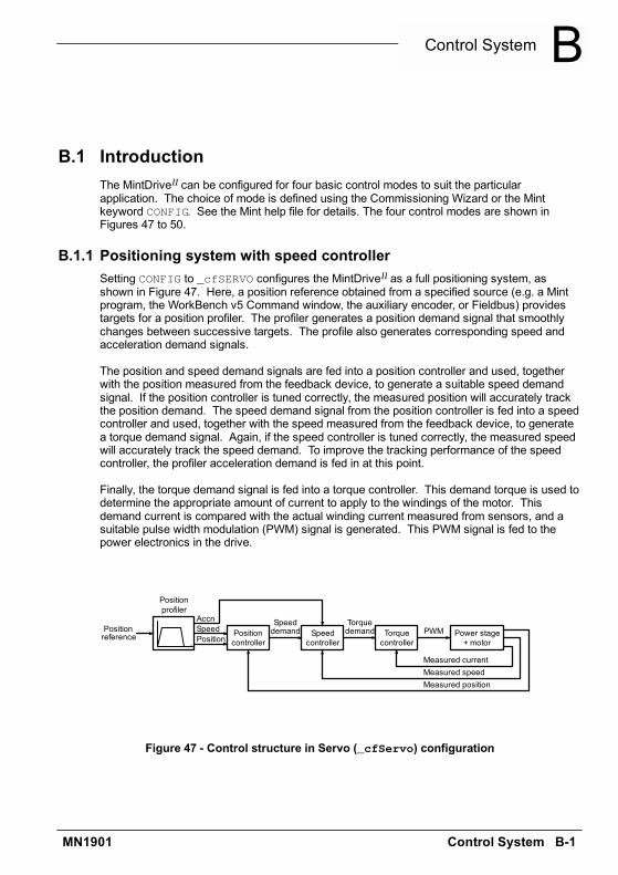
Control System B-1MN1901
B.1 IntroductionThe MintDriveII can be configured for four basic control modes to suit the particularapplication. The choice of mode is defined using the Commissioning Wizard or the Mintkeyword CONFIG. See the Mint help file for details. The four control modes are shown inFigures 47 to 50.
B.1.1 Positioning system with speed controllerSetting CONFIG to _cfSERVO configures the MintDriveII as a full positioning system, asshown in Figure 47. Here, a position reference obtained from a specified source (e.g. a Mintprogram, the WorkBench v5 Command window, the auxiliary encoder, or Fieldbus) providestargets for a position profiler. The profiler generates a position demand signal that smoothlychanges between successive targets. The profile also generates corresponding speed andacceleration demand signals.
The position and speed demand signals are fed into a position controller and used, togetherwith the position measured from the feedback device, to generate a suitable speed demandsignal. If the position controller is tuned correctly, the measured position will accurately trackthe position demand. The speed demand signal from the position controller is fed into a speedcontroller and used, together with the speed measured from the feedback device, to generatea torque demand signal. Again, if the speed controller is tuned correctly, the measured speedwill accurately track the speed demand. To improve the tracking performance of the speedcontroller, the profiler acceleration demand is fed in at this point.
Finally, the torque demand signal is fed into a torque controller. This demand torque is used todetermine the appropriate amount of current to apply to the windings of the motor. Thisdemand current is compared with the actual winding current measured from sensors, and asuitable pulse width modulation (PWM) signal is generated. This PWM signal is fed to thepower electronics in the drive.
Positioncontroller
Speedcontroller
Torquecontroller
Power stage+ motor
Speeddemand
Torquedemand PWM
PositionSpeedAccn
Positionprofiler
Positionreference
Measured currentMeasured speedMeasured position
Figure 47 - Control structure in Servo (_cfServo) configuration
B Control System B
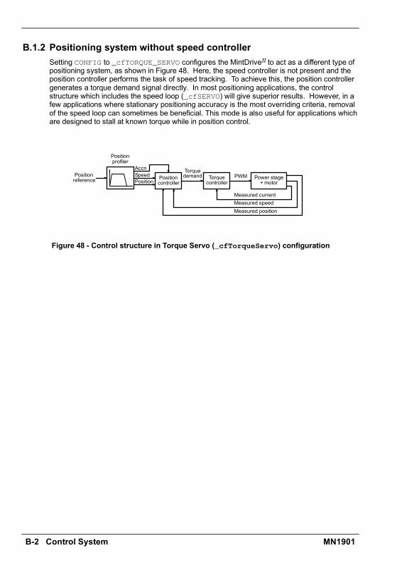
B-2 Control System MN1901
B.1.2 Positioning system without speed controllerSetting CONFIG to _cfTORQUE_SERVO configures the MintDriveII to act as a different type ofpositioning system, as shown in Figure 48. Here, the speed controller is not present and theposition controller performs the task of speed tracking. To achieve this, the position controllergenerates a torque demand signal directly. In most positioning applications, the controlstructure which includes the speed loop (_cfSERVO) will give superior results. However, in afew applications where stationary positioning accuracy is the most overriding criteria, removalof the speed loop can sometimes be beneficial. This mode is also useful for applications whichare designed to stall at known torque while in position control.
Positioncontroller
Torquecontroller
Power stage+ motor
Torquedemand PWM
PositionSpeedAccn
Positionprofiler
Positionreference
Measured currentMeasured speedMeasured position
Figure 48 - Control structure in Torque Servo (_cfTorqueServo) configuration
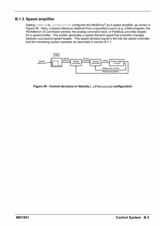
Control System B-3MN1901
B.1.3 Speed amplifierSetting CONFIG to _cfVELOCITY configures the MintDriveII as a speed amplifier, as shown inFigure 49. Here, a speed reference obtained from a specified source (e.g. a Mint program, theWorkBench v5 Command window, the analog command input, or Fieldbus) provides targetsfor a speed profiler. The profiler generates a speed demand signal that smoothly changesbetween successive speed targets. This speed demand signal is fed into the speed controller,and the remaining system operates as described in section B.1.1.
Speedcontroller
Torquecontroller
Power stage+ motor
Torquedemand PWM
Speeddemand
Speedprofiler
Speedreference
Measured currentMeasured speed
Figure 49 - Control structure in Velocity (_cfVelocity) configuration
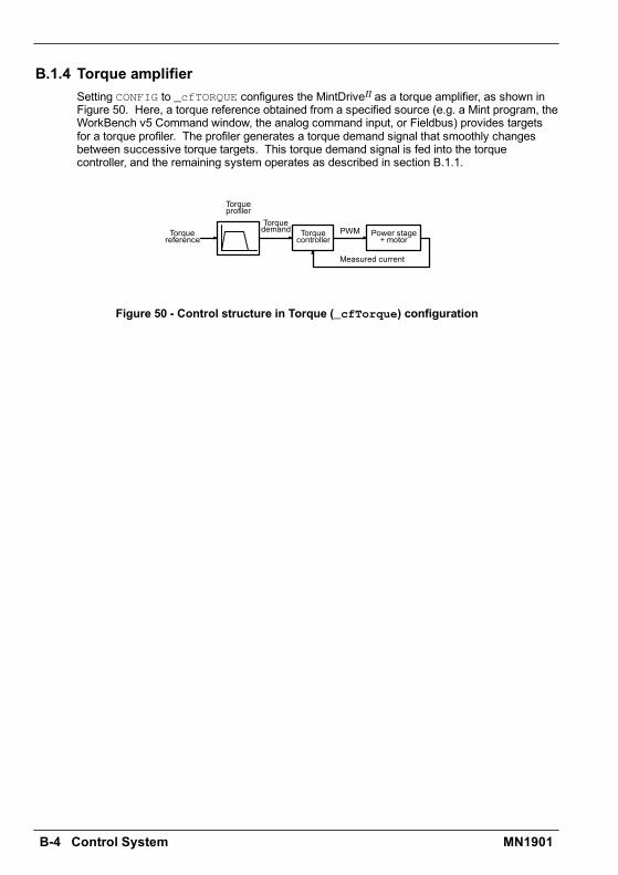
B-4 Control System MN1901
B.1.4 Torque amplifierSetting CONFIG to _cfTORQUE configures the MintDriveII as a torque amplifier, as shown inFigure 50. Here, a torque reference obtained from a specified source (e.g. a Mint program, theWorkBench v5 Command window, the analog command input, or Fieldbus) provides targetsfor a torque profiler. The profiler generates a torque demand signal that smoothly changesbetween successive torque targets. This torque demand signal is fed into the torquecontroller, and the remaining system operates as described in section B.1.1.
Torquecontroller
Power stage+ motor
Torquedemand PWM
Torqueprofiler
Torquereference
Measured current
Figure 50 - Control structure in Torque (_cfTorque) configuration
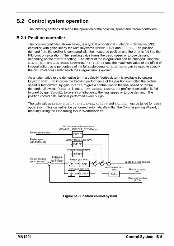
Control System B-5MN1901
B.2 Control system operationThe following sections describe the operation of the position, speed and torque controllers.
B.2.1 Position controllerThe position controller, shown below, is a typical proportional + integral + derivative (PID)controller, with gains set by the Mint keywords KPROP, KINT and KDERIV. The positiondemand from the profiler is compared with the measured position and the error is fed into thePID control calculation. The resulting value forms the basic speed or torque demand,depending on the CONFIG setting. The effect of the integral term can be changed using theKINTLIMIT and KINTMODE keywords. KINTLIMIT sets the maximum value of the effect ofintegral action, as a percentage of the full scale demand. KINTMODE can be used to specifythe circumstances under which the integral term is applied.
As an alternative to the derivative term, a velocity feedback term is available by settingkeyword KVEL. To improve the tracking performance of the position controller, the profilerspeed is fed forward, by gain KVELFF, to give a contribution to the final speed or torquedemand. Likewise, if CONFIG is set to _cfTORQUE_SERVO, the profiler acceleration is fedforward by gain KACCEL to give a contribution to the final speed or torque demand. Theposition control calculation is performed every 500µs.
The gain values KPROP, KINT, KDERIV, KVEL, KVELFF and KACCEL must be tuned for eachapplication. This can either be performed automatically within the Commissioning Wizard, ormanually using the Fine-tuning tool in WorkBench v5.
KVELFF
KACCEL
KPROP
KINT
KDERIV KVEL
dt
ddt
Followingerror
(FOLERROR)
Proportional gain term
Integral gain term
Derivative gain term Velocity feedbackterm Measured speed
(VEL)
Speed or torque demand
Measured position(POS)
Velocity feedforward term
Acceleration feedforward term(CONFIG _cfTORQUE_SERVO only)
Profiler acceleration
Profiler speed(VELDEMAND)
Profiler position(POSDEMAND) ++++
++ ++
--
Figure 51 - Position control system
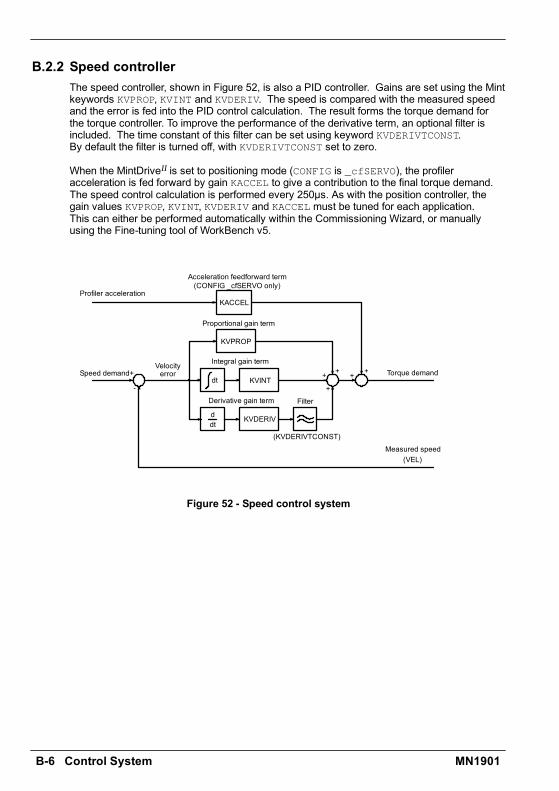
B-6 Control System MN1901
B.2.2 Speed controllerThe speed controller, shown in Figure 52, is also a PID controller. Gains are set using the Mintkeywords KVPROP, KVINT and KVDERIV. The speed is compared with the measured speedand the error is fed into the PID control calculation. The result forms the torque demand forthe torque controller. To improve the performance of the derivative term, an optional filter isincluded. The time constant of this filter can be set using keyword KVDERIVTCONST.By default the filter is turned off, with KVDERIVTCONST set to zero.
When the MintDriveII is set to positioning mode (CONFIG is _cfSERVO), the profileracceleration is fed forward by gain KACCEL to give a contribution to the final torque demand.The speed control calculation is performed every 250µs. As with the position controller, thegain values KVPROP, KVINT, KVDERIV and KACCEL must be tuned for each application.This can either be performed automatically within the Commissioning Wizard, or manuallyusing the Fine-tuning tool of WorkBench v5.
KACCEL
KVPROP
KVINT
KVDERIV
dt
ddt
Velocityerror
Proportional gain term
Integral gain term
Derivative gain term
Measured speed(VEL)
Torque demand
Acceleration feedforward term(CONFIG _cfSERVO only)
Profiler acceleration
Speed demand +
+
++++
-
(KVDERIVTCONST)
Filter
Figure 52 - Speed control system
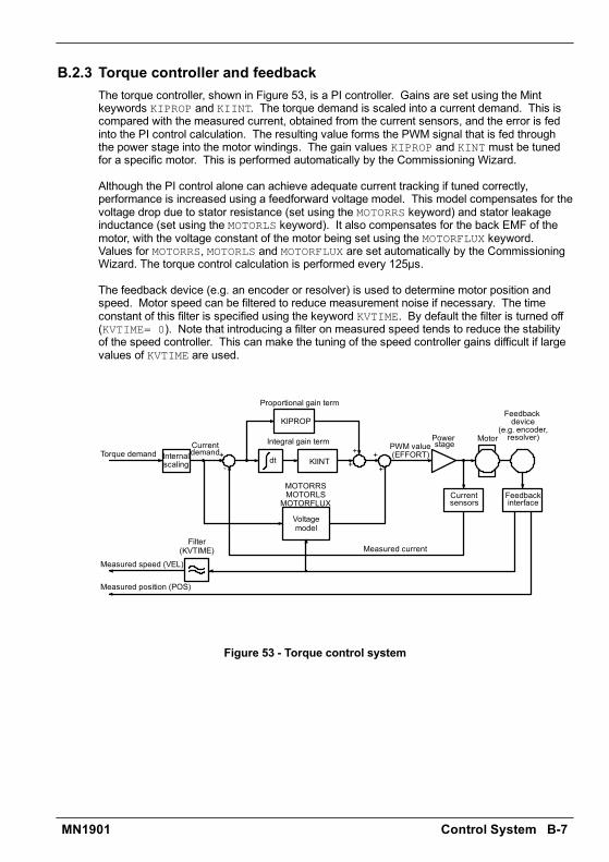
Control System B-7MN1901
B.2.3 Torque controller and feedbackThe torque controller, shown in Figure 53, is a PI controller. Gains are set using the Mintkeywords KIPROP and KIINT. The torque demand is scaled into a current demand. This iscompared with the measured current, obtained from the current sensors, and the error is fedinto the PI control calculation. The resulting value forms the PWM signal that is fed throughthe power stage into the motor windings. The gain values KIPROP and KINT must be tunedfor a specific motor. This is performed automatically by the Commissioning Wizard.
Although the PI control alone can achieve adequate current tracking if tuned correctly,performance is increased using a feedforward voltage model. This model compensates for thevoltage drop due to stator resistance (set using the MOTORRS keyword) and stator leakageinductance (set using the MOTORLS keyword). It also compensates for the back EMF of themotor, with the voltage constant of the motor being set using the MOTORFLUX keyword.Values for MOTORRS, MOTORLS and MOTORFLUX are set automatically by the CommissioningWizard. The torque control calculation is performed every 125µs.
The feedback device (e.g. an encoder or resolver) is used to determine motor position andspeed. Motor speed can be filtered to reduce measurement noise if necessary. The timeconstant of this filter is specified using the keyword KVTIME. By default the filter is turned off(KVTIME= 0). Note that introducing a filter on measured speed tends to reduce the stabilityof the speed controller. This can make the tuning of the speed controller gains difficult if largevalues of KVTIME are used.
KIPROP
KIINTdt
Proportional gain term
Integral gain termTorque demand
+
+++
+-
PWM value(EFFORT)
Currentdemand
Voltagemodel
MOTORLSMOTORFLUX
Internalscaling
Currentsensors
Feedbackdevice
(e.g. encoder,resolver)Motor
Measured current
Feedbackinterface
Measured speed (VEL)
Measured position (POS)
Filter(KVTIME)
Powerstage
MOTORRS
Figure 53 - Torque control system

B-8 Control System MN1901
CE Guidelines C-1MN1901
C.1 OutlineThis section provides general informationregarding recommended methods of installationfor CE compliance. It is not intended as anexhaustive guide to good practice and wiringtechniques. It is assumed that the installer of theMintDriveII is sufficiently qualified to perform thetask, and is aware of local regulations andrequirements. Baldor products that meet theEMC directive requirements are indicated with aCE mark. A duly signed CE declaration ofconformity is available from Baldor.
C.1.1 EMC Conformity and CE markingThe information contained herein is for your guidance only and does not guarantee that theinstallation will meet the requirements of the council directive 89/336/EEC.
The purpose of the EEC directives is to state a minimum technical requirement common to allthe member states within the European Union. In turn, these minimum technical requirementsare intended to enhance the levels of safety both directly and indirectly.
Council directive 89/336/EEC relating to Electro Magnetic Compliance (EMC) indicates that itis the responsibility of the system integrator to ensure that the entire system complies with allrelative directives at the time of installing into service.
Motors and controls are used as components of a system, per the EMC directive. Hence allcomponents, installation of the components, interconnection between components, andshielding and grounding of the system as a whole determines EMC compliance.
The CE mark informs the purchaser that the equipment has been tested and complies with theappropriate standards. It rests upon the manufacturer or his authorized representative toensure the item in question complies fully with all the relative directives in force at the time ofinstalling into service, in the same way as the system integrator previously mentioned.Remember that it is the instructions of installation and the product that should comply with thedirective.
C CE Guidelines C

C-2 CE Guidelines MN1901
C.1.2 Use of CE compliant componentsThe following points should be considered:
H Using CE approved components will not guarantee a CE compliant system!H The components used in the drive, installation methods used, materials selected for
interconnection of components are important.H The installation methods, interconnection materials, shielding, filtering and
earthing/grounding of the system as a whole will determine CE compliance.H The responsibility of CE mark compliance rests entirely with the party who offers the end
system for sale (such as an OEM or system integrator).
C.1.3 EMC wiring techniqueCabinetUsing a typical electroplated zinc coated enclosure, connected to earth/ground, means that allparts mounted on the back plane are connected to earth/ground and all outer shield (screen)connections can be connected to earth/ground. Within the cabinet there should be a spatialseparation between power wiring (motor and AC power cables) and control wiring.
Shield (screen) connectionsAll connections between components must use shielded cables. The cable shields must beconnected to the enclosure. Use conductive clamps to ensure good earth/ground connection.With this technique, a good earth/ground shield can be achieved.
EMC filtersThe filter should be mounted next to the MintDriveII. The connections between the MintDriveII
and the filter should use shielded (screened) cables. The cable shields should be connected toshield clamps at both ends. An exception to this is the analog command signal.
Earthing/groundingFor safety reasons (VDE0160), all Baldor components must be connected to earth/ground witha separate wire. Earth/ground connections must be made from the central earth/ground (starpoint) to the regeneration resistor enclosure and from the central earth/ground (star point) tothe power supply.

CE Guidelines C-3MN1901
C.1.4 EMC installation suggestionsTo ensure electromagnetic compatibility (EMC), the following installation points should beconsidered to help reduce interference:
H Earthing/grounding of all system elements to a central earth/ground point (star point)H Shielding of all cables and signal wiresH Filtering of power lines.
A proper enclosure should have the following characteristics:
H All metal conducting parts of the enclosure must be electrically connected to the backplane. These connections should be made with an earthing/grounding strap from eachelement to a central earthing/grounding point (star point). *
H Keep the power wiring (motor and power cable) and control wiring separated. If thesewires must cross, be sure they cross at 90 degrees to minimize noise due to induction.
H The shield connections of the signal and power cables should be connected to the shieldrails or clamps. The shield rails or clamps should be conductive clamps fastened to thecabinet. **
H The cable to the regeneration resistor must be shielded. The shield must be connected toearth/ground at both ends.
H The location of the AC filter has to be situated close to the drive so the AC power wiresare as short as possible.
H Wires inside the enclosure should be placed as close as possible to conducting metal,cabinet walls and plates. It is advised to terminate unused wires to chassis ground.*
H To reduce earth/ground current, use the largest suitable wire available for earth/groundconnections.
* Earthing/grounding in general describes all metal parts which can be connected to aprotective conductor, e.g. housing of cabinet, motor housing, etc. to a central earth/groundpoint (star point). This central earth/ground point (star point) is then connected to the mainplant (or building) earth/ground.
** Or run as twisted pair at minimum.
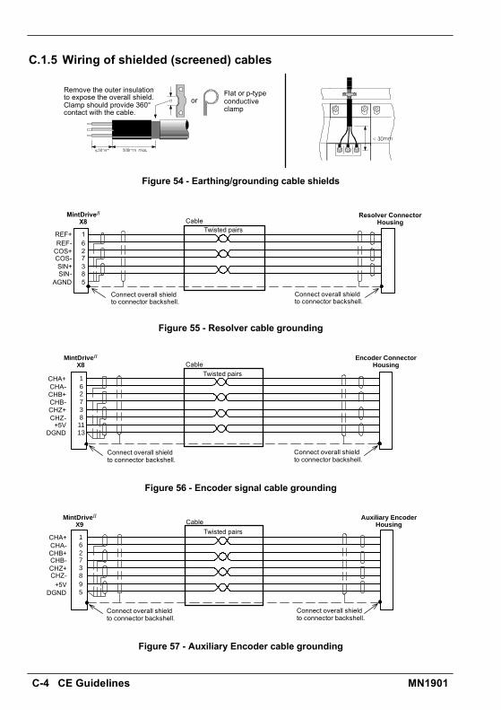
C-4 CE Guidelines MN1901
C.1.5 Wiring of shielded (screened) cables
Remove the outer insulationto expose the overall shield.Clamp should provide 360°contact with the cable.
orFlat or p-typeconductiveclamp
Figure 54 - Earthing/grounding cable shields
Cable
162738
MintDriveIIX8
Twisted pairs
Resolver ConnectorHousing
5
Connect overall shieldto connector backshell.
Connect overall shieldto connector backshell.
REF+REF-COS+COS-SIN+SIN-
AGND
Figure 55 - Resolver cable grounding
1627381113
MintDriveII
X8Encoder Connector
HousingCableTwisted pairs
Connect overall shieldto connector backshell.
Connect overall shieldto connector backshell.
CHA+CHA-CHB+CHB-CHZ+CHZ-+5V
DGND
Figure 56 - Encoder signal cable grounding
162738
5
MintDriveII
X9Auxiliary Encoder
HousingCableTwisted pairs
9
Connect overall shieldto connector backshell.
Connect overall shieldto connector backshell.
CHA+CHA-CHB+CHB-CHZ+CHZ-+5V
DGND
Figure 57 - Auxiliary Encoder cable grounding
IndexMN1901
AAbbreviations. See Units and AbbreviationsAbsolute encodercable, 3-28option, 3-27specification, 7-9
Accessories, A-1EMC filters, A-5feedback cables, A-3motor power cables, A-2regeneration resistors, A-7
Analog I/O, 4-1analog input - X3 (command), 4-2analog input - X4, 4-4analog output - X4, 4-6
BBasic Installation, 3-1
CCatalog number, identifying, 2-2CE Guidelines, C-1Commissioning Wizard, 5-7completing, 5-7using, 5-7
Configuration, 5-8ConnectionsSee also Input / Outputfeedback, 3-21motor, 3-15motor brake, 3-19power, 3-8single phase, 3-9three phase, 3-10
thermal switch, 3-18Connector, locations, 3-7Control system, B-1operationposition controller, B-5speed controller, B-6torque controller and feedback, B-7positioning with speed controller, B-1positioning without speed controller, B-2speed amplifier, B-3torque amplifier, B-4
DDB On LED, 6-5Digital I/O, 4-8CREF, 4-10digital inputs - X3, 4-9digital outputs - X3, 4-12pulse & direction, 4-10special functions, 4-11
Dimensions, 3-6DIP switches, 3-311-4: Node select, 3-315: Hold, 3-326: RS485 terminator, 3-327: Offset tuning, 3-32, 5-38: Enable, 3-329 & 10: RS232/RS485 select, 3-33factory settings, 3-33preventing a program running, 3-34
Drive enablecommand, 3-30DIP switch 8, 3-30X3 CREF, 3-29
Dynamic brake. See Regeneration resistor
Index
Index MN1901
EEncoderabsolute. See Absolute encodercable, 3-25, A-3option, 3-24specification, 7-9
Environmentallocation, 3-43-5specification, 7-11
FFactory fitted options, A-1Factory settings, 3-33Features, 2-1Feedbackabsolute encoder, 3-27cable, A-3A-4connections, 3-21encoder, 3-24resolver, 3-22
Filters24V control supply, 3-14AC power (EMC), 3-12, A-5catalog numbers, A-5
GGeneral Information, 1-1
HHardware requirements, 3-1Help file, 5-4
IIndicators, 6-2DB On LED, 6-5Status display, 6-2
Input / Output, 4-1analog I/O, 4-1analog input - X3, 4-2, 7-5analog input - X4, 4-4, 7-6
analog output - X4, 4-6, 7-6connection summary, 4-21digital I/O, 4-8digital inputs - X3, 4-9, 7-7digital outputs - X3, 4-12, 7-7encoder output - X7, 4-13, 7-8master encoder input - X9, 4-15, 7-10option connectors, 4-22relay - X3, 4-7, 7-8serial port - X6, 4-17, 7-8connecting Baldor HMI panels, 4-20multidrop using RS485/RS422 cable, 4-19using RS232 cable, 4-18
InstallationSee also Basic Installationdimensions, 3-6mechanical, 3-4mounting, 3-5
LLED indicatorsDB On, 6-5Status display, 6-2
MMotorcircuit contactors, 3-16connections, 3-15power cable, 3-163-17, A-2
Motor brake, connection, 3-19Mounting, 3-5
OOperation, 5-1connecting to the PC, 5-1installing software, 5-1offset tuning, 3-32, 5-3power on checks, 5-2preliminary checks, 5-2starting, 5-2
Options, A-1
IndexMN1901
PPower24V control supply, 3-14connections, 3-8disconnect and protection devices, 3-11input conditioning, 3-11input cycling, 3-11, 6-1sources, 3-1supply filters, 3-12, A-5
Precautions, 1-2Product Notice, 1-2Pulse & Directionfollowing, 4-16specification, 7-7, 7-10X3 - DIN4/5, 4-10X9, 4-15
RReceiving and Inspection, 2-2Regenerationcontrolling, 3-20resistor, 3-20specification, 7-4
Relayoutput, 4-7specification, 7-8
Resolvercable, 3-23, A-3option, 3-22specification, 7-9
RS232cable, 4-18specification, 7-8X6, 4-17
RS485 / RS422specification, 7-8systems, 3-2X6, 4-174-20
SSafety Notice, 1-2Specifications, 7-1115V / 230V single-phase models, 7-1230V three-phase models, 7-2230V-460V three-phase models, 7-3
24V control supply, 7-3absolute encoder feedback - X8, 7-9analog input - X3, 7-5analog input - X4, 7-6analog outputs - X4, 7-6digital inputs - X3, 7-7digital outputs - X3, 7-7encoder feedback - X8, 7-9encoder output - X7, 7-8environmental, 7-11master encoder input - X9, 7-10pulse & direction inputs - X9, 7-10regeneration, 7-4relay output - X3, 7-8resolver feedback - X8, 7-9serial RS232 interface - X6, 7-8serial RS485 interface - X6, 7-8
Status display, 6-2
TThermal switch, connection, 3-18Tools, 3-2Troubleshooting, 6-1communication, 6-5DB On LED, 6-5power cycling, 6-1power on, 6-6problem diagnosis, 6-1Status display, 6-2SupportMe, 6-1tuning, 6-6
UUnits and abbreviations, 2-3
WWire sizes, 3-13WorkBench v5, 5-4Commissioning Wizard, 5-7digital I/O tool, 5-11fine-tuning tool, 5-8help file, 5-4other tools and windows, 5-11parameters tool, 5-10starting, 5-5

Index MN1901

CommentsMN1901
If you have any suggestions for improvements to this manual, please let us know. Write yourcomments in the space provided below, remove this page from the manual and mail it to:
ManualsBaldor UK LtdMint Motion Centre6 Bristol Distribution ParkHawkley DriveBristolBS32 0BFUnited Kingdom.
Alternatively, you can e-mail your comments to:
Comment:
continued...
Comments

Comments MN1901
Thank you for taking the time to help us.

Printed in UKE Baldor UK LtdLT0159A02
Europe (Southern)Baldor ASR AG, SwitzerlandTel: +41 52 647 4700Fax: +41 52 659 2394
EuropeBaldor ASR GmbH, GermanyTel: +49 (0) 89 905 080Fax: +49 (0) 89 905 08491
AustraliaAustralian Baldor PTY LtdTel: +61 2 9674 5455Fax: +61 2 9674 2495
MexicoBaldor de MexicoTel: +52 477 761 2030Fax: +52 477 761 2010
U.S.A. (Headquarters)Baldor Electric CompanyTel: +1 479 646 4711Fax: +1 479 648 5792
SingaporeBaldor Electric PTE LtdTel: +65 744 2572Fax: +65 747 1708
JapanBaldor Japan CorporationTel: +81 45 412 4506Fax: +81 45 412 4507
United KingdomBaldor UK LtdTel: +44 1454 850000Fax: +44 1454 859001
For additional office locations visit www.baldor.com
Baldor Electric CompanyP.O. Box 2400
Ft. Smith, AR 72902-2400U.S.A.
Visit www.supportme.net for the latest documentation and software releases.