minutes of the iea wind task 32 workshop #8: … of the iea wind task 32 workshop #8: certification...
TRANSCRIPT
Minutes of the IEA WIND Task 32 Workshop #8:
Certification of Lidar-Assisted Control Applications
Date: 30. – 31. January 2018
Venue: DNV GL, Hamburg, Germany
Workshop leader: Nikolai Hille, DNV GL
Minutes by Holger Fürst, Steffen Raach, Tim Hagemann, David Schlipf
Version: 9. February 2018
Minutes
Day 1
Welcome and Introduction
10:30 Start of workshop - welcome and introduction round
● Nikolai welcomed everybody
● David introduced the IEA Wind Task 32 to the participants
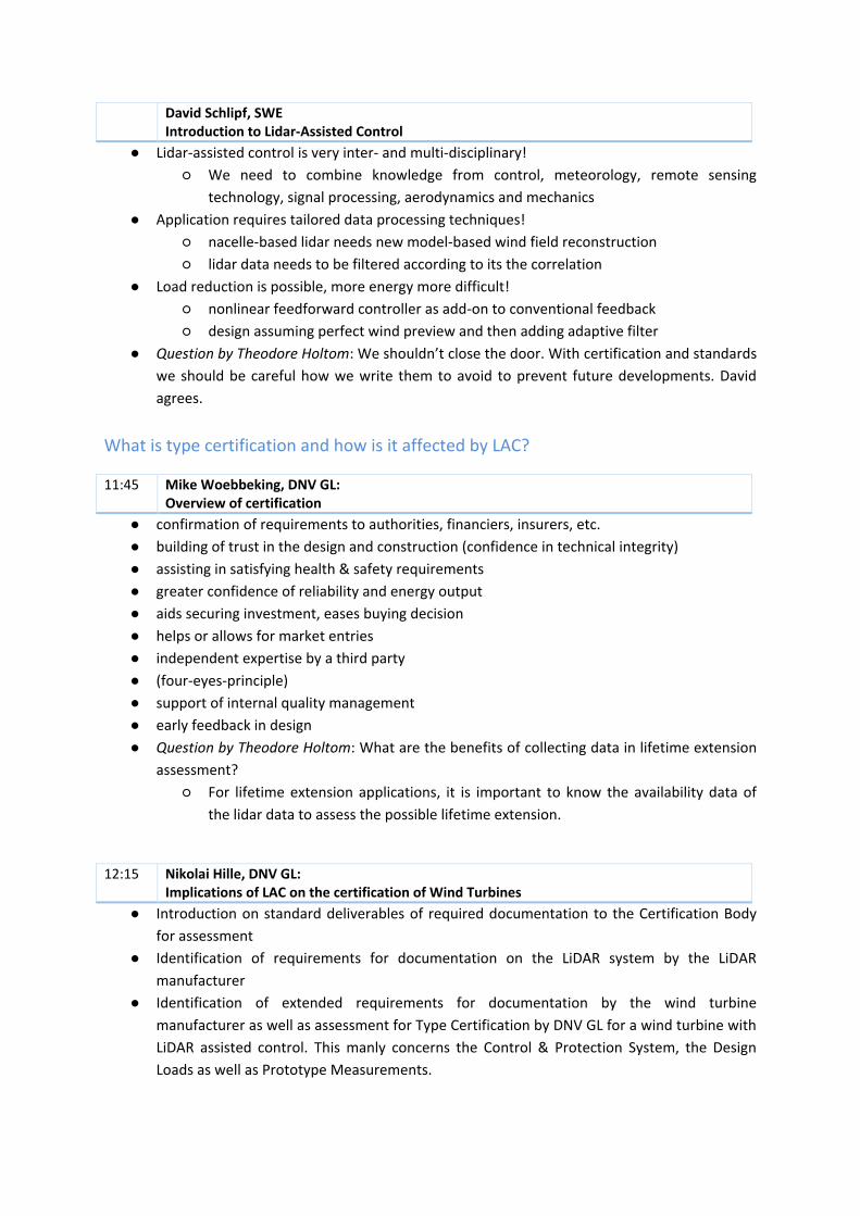
● Nikolai presented the main objectives of the workshop and the program of the two days
David Schlipf, SWE Introduction to Lidar-Assisted Control
● Lidar-assisted control is very inter- and multi-disciplinary!
○ We need to combine knowledge from control, meteorology, remote sensing
technology, signal processing, aerodynamics and mechanics
● Application requires tailored data processing techniques!
○ nacelle-based lidar needs new model-based wind field reconstruction
○ lidar data needs to be filtered according to its the correlation
● Load reduction is possible, more energy more difficult!
○ nonlinear feedforward controller as add-on to conventional feedback
○ design assuming perfect wind preview and then adding adaptive filter
● Question by Theodore Holtom: We shouldn’t close the door. With certification and standards
we should be careful how we write them to avoid to prevent future developments. David
agrees.
What is type certification and how is it affected by LAC?
11:45 Mike Woebbeking, DNV GL: Overview of certification
● confirmation of requirements to authorities, financiers, insurers, etc.
● building of trust in the design and construction (confidence in technical integrity)
● assisting in satisfying health & safety requirements
● greater confidence of reliability and energy output
● aids securing investment, eases buying decision
● helps or allows for market entries
● independent expertise by a third party
● (four-eyes-principle)
● support of internal quality management
● early feedback in design
● Question by Theodore Holtom: What are the benefits of collecting data in lifetime extension
assessment?
○ For lifetime extension applications, it is important to know the availability data of
the lidar data to assess the possible lifetime extension.
12:15 Nikolai Hille, DNV GL: Implications of LAC on the certification of Wind Turbines
● Introduction on standard deliverables of required documentation to the Certification Body
for assessment
● Identification of requirements for documentation on the LiDAR system by the LiDAR
manufacturer
● Identification of extended requirements for documentation by the wind turbine
manufacturer as well as assessment for Type Certification by DNV GL for a wind turbine with
LiDAR assisted control. This manly concerns the Control & Protection System, the Design
Loads as well as Prototype Measurements.
● Even without specific standards on LiDAR assisted control being available yet DNV GL already
today offers Type Certification of wind turbines with LiDAR assisted control based on
individualised interpretation of the standards and assessment of the specific Lidar and
turbine type.
12:45 Reinhard Schleeßelmann, DNV GL: Introduction to ISO 13849: Safety-related parts of control systems
● Definitions of Control Function and Protection Function
● Does LIDAR contribute to Control Functions or Protection Functions?
● Basic principles of the design of Protection Functions
What are the challenges for type certification with LAC for lidar manufacturers?
14:00 Chris Slinger, ZephIR: Practical matters affecting the utility of nacelle mounted lidars for turbine loads measurements and control
● Lidar sensitivity in clear air conditions, including analysis of data from several sites around
the world
● The effect of lidar beam blocking due to nacelle, hub and blades
● The use of lidars, operating inside the turbine inductions zone, for wind speed and TI
measurements for load certification
● New lidar TI algorithms based on Doppler signal analysis which are range independent and
agree very closely (within 3%) with cup measured TI.
14:20 Shumpei Kameyama, Mitsubishi Electric: Description of realistic lidar modelling and lessons learned from field tests for lidar-assisted turbine control
● experience on their LAC experience, and lessons-learned from their field test
● necessity of the lidar simulation model including the blade blocking, atmospheric conditions,
and so on
● necessity of considering on the not-ideal information of turbine power performance (for
example, fast-based)
● Question by Jesús Arellano : Control correction: Adaptation of pitch angle based on FAST -
may interfere with WTC stability;
14:30 Paul Mazoyer, Leosphere: The necessity of a representative Lidar simulator
● Leosphere introduced Simulid®, a representative Lidar simulator based on optical,
electronics, signal processing and atmospheric modeling.
● Simulid® has been developed for years and is regularly used by Leosphere to support the
design of its Lidars.
● For Lidar-assisted control application, Simulid® can be coupled with modeled wind fields or
aero-elastic tools to enable the design and performance assessment of wind turbines
integrating Lidar-assisted control.
● Real-time Lidar wind measurement accuracy and availability are realistically modeled to
offer a full evaluation of Lidar-assisted control and mitigate risks.
● For example, Leosphere presented the impact of blade passing: it shows that Simulid® could
reproduce well experimental observations, it thereby allows considering this effect in the
control design.
● Many other uses cases of Simulid® could be performed such as modeling of extreme
turbulences, atmospheric content or fog conditions.
● Question by Nikolai Hille: Is there a proposal for standard atmospheric conditions?
○ It should be typical conditions to challenge a lidar.
● Question: Is there an interface with Bladed?
○ Not at the moment, but this could be further investigated.
What are the challenges for type certification with LAC for turbine manufacturers?
15:25 Liu Lei, Goldwind: Goldwind EFarm - Lidar Assisted Control Application
● The presentation shows LiDAR Assisted Control application and field testing in Goldwind;
● For evolving turbulence effect, by simulation in Bladed v4.6, evolving turbulence has little
influence on wind turbine load result using LiDAR Assisted Control;
● Field testing results show that, the LAC control technology implemented by Goldwind could
show positive effects on load reduction and stability improvement,
● the on-site testing results are similar with the design based on load simulation.
● Question by David Schlipf: Which model for wind evolution did you use within Bladed?
○ The Kristensen model.
15:40 Eric Simley, Envision: An industrial perspective on LAC at Envision Energy
● LAC combined with modified feedback control can reduce tower and blade fatigue loads.
● Large turbines designed for low wind speeds are increasingly ultimate load dimensioned.
Extreme load and blade tip deflection reduction are important design objectives.
● Although more challenging, by detecting extreme wind events LAC can be optimized for
extreme load reduction.
● The lidar system and scan pattern have a big impact on the load reduction with LAC.
● It is important to verify lidar measurement quality in the field prior to using LAC.
● Simulating turbulent wind design load cases for turbines with LAC is expected to be relatively
straightforward for fatigue loads.
● Clear definitions of how lidars can measure the extreme deterministic wind fields are
needed to fully understand the value creation of LAC for extreme load reduction.
● Question by Francesco Perrone: Does the structural load reduction come for free or is
lifetime of other components also reduced?
○ Lifetime of other components is not affected. But there is a slight impact on AEP.
● Question by Ashim Giyanani: How much does the induction zone impact the coherence?
○ The preview time will change and this is very important to consider.
What are the challenges for type certification with LAC for consultants?
16:18 Oscar Hugues Salas, DNV GL: Considerations in Design Load Cases when using LIDAR Assisted Control
● The inclusion of LIDAR-Assisted Control (LAC) in the wind turbine controller would require
additional Design Load Cases (DLCs) to be considered in the wind turbine design standards
● The control performance improvement due to LAC requires to be proved in the standards,
where a combination of different environmental scenarios, including faults, need to be taken
into account
● LAC should be first designed, in order to do this, aeroelastic modelling softwares are needed,
which have to take some assumptions when resolving line-of-sight wind speed
measurements; blade blockage; tower inclination; nacelle acceleration and its direction;
effect of rotor induced velocity; rotor swept area covered by the LIDAR sampling; turbulence
evolution; use of weighting function. Therefore a standardisation of the assumptions should
be required
● In order to facilitate the simulations and controller design, LIDAR manufacturers should
supply a DLL file which processes raw data to signals ready to be fed to the controller
● DLCs to be added to the standards could be:
○ change the convecting time at which the LIDAR measurement hits the rotor
○ correlation between LIDAR measurements and rotor average wind speed
reconstruction (when using a wind speed estimator), this will increase the loading
○ modify the measurement quality (noise) and simulate a faulty LIDAR, which will have
an effect in the loading
○ when detecting extreme gusts, to vary the approaching time to the turbine and
change of direction
● Comment by Theodore Holtom: Maybe it is not helpful to go into too much detail.
○ Therefore feedback from this workshop is highly appreciated.
16:43 Mike Lüdde, DNV GL: Prototype measurements on Wind Turbines - Considering LiDAR Assisted Control
Recommendations for measurements
● Certification:
○ Additional tests for switching operations and LiDAR control functionality
○ Additional verification of fatigue loads for both operational modes (e.g. toggle test)
○ Metmast always required for independent meteorological measurements
● Experimental:
○ Applicability of LAC under varying conditions
○ Optimization of LAC and load reduction
○ Verification of LiDAR data with independent meteorological data
17:02 Steffen Raach, sowento: Cross-tool realistic lidar simulations
● Realistic lidar simulator independent of simulation model
● Frequency based approach
● Workflow:
○ Define your input data (lidar scan config, turbine properties, wind spectra, seed
number)
○ Insert the wind field
○ Receive the lidar signal
○ Perform load simulation
● Applications: standardized load calculations, system engineering
● Question by Eric Simley: How do you include lidar availability?
○ By decreasing correlation.
What are the challenges for type certification with LAC for researchers?
17:18 Andrew Scholbrock, NREL: Lessons learned from field testing experience on using lidars with wind turbine controls research
● Lidars have shown from field tests that they can used to reject the wind disturbance to
improve rotor speed regulation with feed-forward control such that the feedback controller
can be optimized to reduce tower loading
● Lidars have also been shown from field testing that they can be used to improve the yaw
control of a wind turbine
● Field testing has shown many practical issues that arise and are not accounted for in
modelling
17:36 Eric Simley, Envision: Overview of traditional lidar modeling and wind evolution modeling methods
● Probe volume averaging and line-of-sight velocity modeling for continuous-wave and pulsed
lidars is well-understood and straightforward to implement in simulation.
● Wind evolution can be quantified using longitudinal spatial coherence.
● Several longitudinal coherence wind evolution models exist, including theoretical, empirical,
and simulation-based models.
● Wind evolution can be added to stochastic turbulent wind fields used for simulation by
adding additional planes of wind speeds correlated with each other according to a
longitudinal spatial coherence model.
● Lidar and wind evolution models are both important for simulating preview measurements
with realistic measurement error.
● Question by Ashim Giyanani: How does induction effects the wind evolution?
○ Correction gains are needed, but impact is small.
● Question by Torben Mikkelsen: Why is correlation so poor in stable conditions? Maybe LES is
not sufficient because length scales are smaller?
○ That's probably true.
18:00 Tim Hagemann, SWE: Turbulent extreme event simulations for LAC
● coherent wind fields for deterministic load cases are not valid anymore if used with LAC
● optimising algorithm can be used to shape rotor-effective quantities of wind fields
● results: fully turbulent wind fields containing extreme events (e.g. EOG and EWS)
● algorithm can be used to shape 10 minute turbulent wind field
● possible usage in hybrid simulations: real lidar measurements & wind field shaped to field
measurements
● advantage: re-simulate real situation accurately and retrieve loads not measured in the field
testing
Day 2
9:00 How should we certify wind turbines with LAC? 4 floating working groups rotating every 45 min with a 10 min break in between
14:00 Moderators: Steffen Raach (sowento), Reinhard Schleeßelmann (DNV GL), Johan Olaison (DNV GL), Andrew Scholbrock (NREL): Presentation/discussion of workshop’s results
The summaries of the discussion groups are provided by the group moderators and can be found in
the appended documents.
15:00 David Schlipf, SWE: Presentation/discussion of next steps
Following next steps have been proposed by David Schlipf:
1. Compilation of Minutes and publication of presentations on workshop homepage
(https://www.ieawindtask32.org/workshop-8/) (timeframe: one week).
2. Compilation of an IEA Wind document (most likely a “Best practices document”) led by SWE.
SWE will contact Nikolai Hille and Eric Simley (workshop organisation) as well as the group
moderators and possibly some workshop participants to form an author team and a review
team (timeframe: months).
3. Based on the workshop material and further material, DNV GL aims to publish a DNV GL
document (timeframe: possible end of the year).
No objection for these steps.
Nikolai Hille mentioned that DNV GL offers already Type Certification under current standards.
Nikolai thanks all workshop participants for their valuable confirmation and especially the
moderators for their effort. Torben Mikkelsen as one being involved in the initiation of the Task 32
thanks the workshop organization team and the operation agent for further developing the Task.
David Schlipf thanks DNV GL for hosting the event, sponsoring lunch and coffee breaks and part of
the dinner. Nikolai Hille and Eric Simley get honored for their high personal dedication to the
workshop.
15:30 End of Workshop (as planned!)
15:30 Optional event: Visit of Elbphilharmonie (sponsored by sowento)
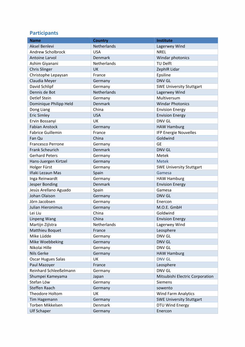
Participants
Name Country Institute
Aksel Benlevi Netherlands Lagerwey Wind
Andrew Scholbrock USA NREL
Antoine Larvol Denmark Windar photonics
Ashim Giyanani Netherlands TU Delft
Chris Slinger UK ZephIR Lidar
Christophe Lepaysan France Epsiline
Claudia Meyer Germany DNV GL
David Schlipf Germany SWE University Stuttgart
Dennis de Bot Netherlands Lagerwey Wind
Detlef Stein Germany Multiversum
Dominique Philipp Held Denmark Windar Photonics
Dong Liang China Envision Energy
Eric Simley USA Envision Energy
Ervin Bossanyi UK DNV GL
Fabian Anstock Germany HAW Hamburg
Fabrice Guillemin France IFP Energie Nouvelles
Fan Qu China Goldwind
Francesco Perrone Germany GE
Frank Scheurich Denmark DNV GL
Gerhard Peters Germany Metek
Hans-Juergen Kirtzel Germany Metek
Holger Fürst Germany SWE University Stuttgart
Iñaki Lezaun Mas Spain Gamesa
Inga Reinwardt Germany HAW Hamburg
Jesper Bonding Denmark Envision Energy
Jesús Arellano Aguado Spain Gamesa
Johan Olaison Germany DNV GL
Jörn Jacobsen Germany Enercon
Julian Hieronimus Germany M.O.E. GmbH
Lei Liu China Goldwind
Linpeng Wang China Envision Energy
Martijn Zijlstra Netherlands Lagerwey Wind
Matthieu Boquet France Leosphere
Mike Lüdde Germany DNV GL
Mike Woebbeking Germany DNV GL
Nikolai Hille Germany DNV GL
Nils Gerke Germany HAW Hamburg
Oscar Hugues Salas UK DNV GL
Paul Mazoyer France Leosphere
Reinhard Schleeßelmann Germany DNV GL
Shumpei Kameyama Japan Mitsubishi Electric Corporation
Stefan Löw Germany Siemens
Steffen Raach Germany sowento
Theodore Holtom UK Wind Farm Analytics
Tim Hagemann Germany SWE University Stuttgart
Torben Mikkelsen Denmark DTU Wind Energy
Ulf Schaper Germany Enercon
DNV GL Headquarters, Veritasveien 1, P.O.Box 300, 1322 Høvik, Norway. Tel: +47 67 57 99 00. www.dnvgl.com
MoM sessons on C&P 2018-01-31.docx
Minutes of meeting to: MoM. No.: - Organiser of Workshop IEA Wind Task 32 Workshop #8
From: DNV GL Date: 2018-02-01
Copied to: -
Prep. By: Reinhard Schleeßelmann
Certification of Lidar-Assisted Control Applications
Time/Place: 2018-01-31, 9:00 … 12:40 Participants: Participants on the workshop in four groups ‘Red’, ‘Blue’, ‘Green’ and ‘Yellow’ Absent: -
Workshop sessions on content of upcoming IEA Best Practice on Lidar-assisted control of wind turbines (WT)
Topic: Control and Protection System
1 GENERAL Propose of this MoM is to comment on the key words given on the flip charts and notes from the workshop session meetings.
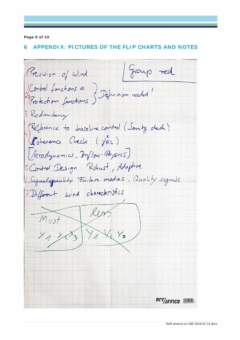
2 GROUP ‘RED’ Brainstorm session was made to create headlines of upcoming Best Practice.
A picture of the flip chart is in the appendix.
2.1 Prevision of wind The novelty of the Lidar on the wind turbine is information on the wind some seconds before it hits the rotor plane.
2.2 Control functions vs Protection functions, definition needed Does the Lidar contribute to control as well as protection functions? How to distinguish the two? How to find out whether a given function is a Control Function or a Protection Function?
2.3 Redundancy What is needed as back up on the signal from Lidar?
2.4 Reference to baseline control (sanity check), coherence check (γ2RL)
What can be done to cross check the plausibility of the Lidar signal?
Page 2 of 10
MoM sessons on C&P 2018-01-31.docx
[Aerodynamics, inflow physics] This item is important but does not belong the scope of discussion inside group ‘Control + Protection’.
2.5 Control design: Robust, Adaptive Along which principal shall the controller be designed?
2.6 Failure modes, quality signals What information need the Lidar supplier to submit to the WT manufacturer in terms of quality of the signals?
2.7 Different wind characteristics How can information – other than common values as wind speed, shear, … – that the Lidar presents be used in WT control?
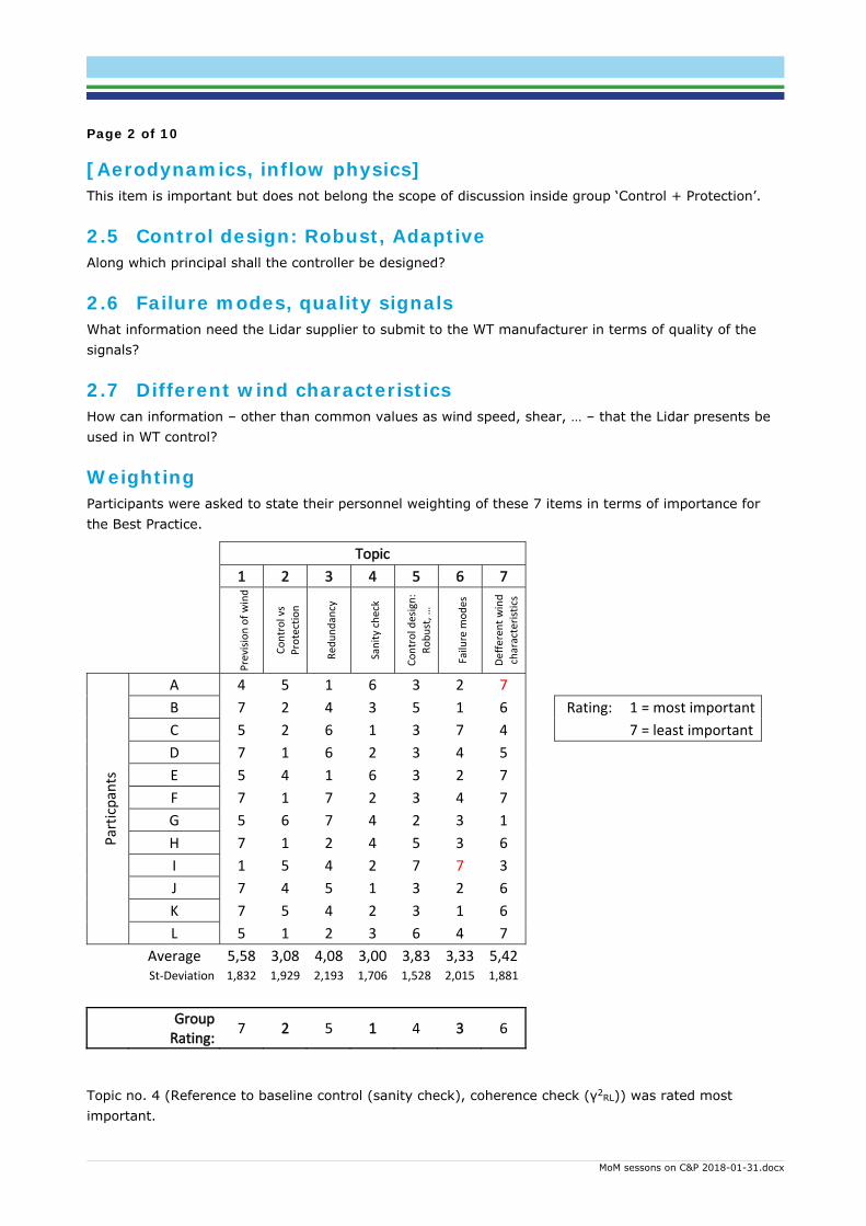
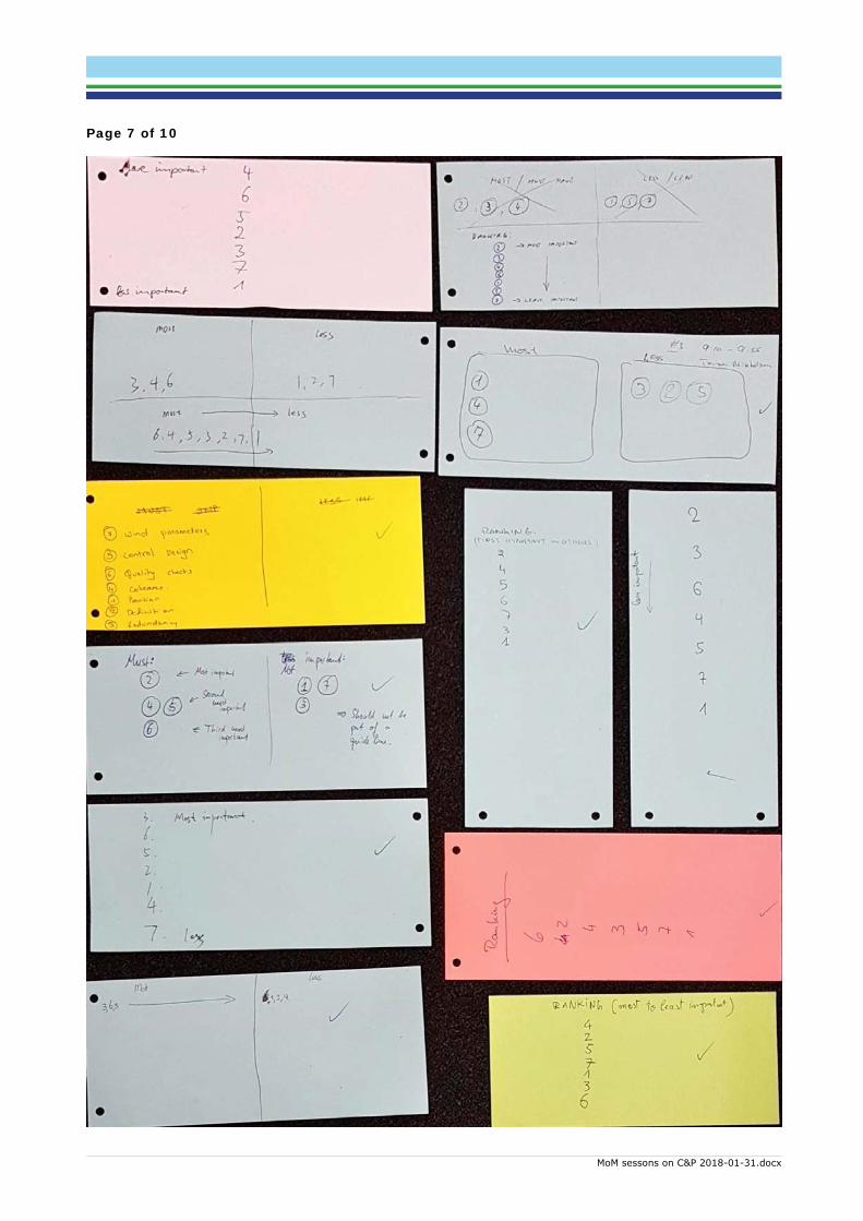
Weighting Participants were asked to state their personnel weighting of these 7 items in terms of importance for the Best Practice.
Topic
1 2 3 4 5 6 7
Prevision of wind
Control vs
Protection
Red
undancy
Sanity check
Control design:
Robust, …
Failure m
odes
Defferent wind
characteristics
Particpants
A 4 5 1 6 3 2 7
B 7 2 4 3 5 1 6 Rating: 1 = most important
C 5 2 6 1 3 7 4 7 = least important
D 7 1 6 2 3 4 5
E 5 4 1 6 3 2 7
F 7 1 7 2 3 4 7
G 5 6 7 4 2 3 1
H 7 1 2 4 5 3 6
I 1 5 4 2 7 7 3
J 7 4 5 1 3 2 6
K 7 5 4 2 3 1 6
L 5 1 2 3 6 4 7
Average 5,58 3,08 4,08 3,00 3,83 3,33 5,42 St‐Deviation 1,832 1,929 2,193 1,706 1,528 2,015 1,881
Group Rating:
7 2 5 1 4 3 6
Topic no. 4 (Reference to baseline control (sanity check), coherence check (γ2RL)) was rated most important.
Page 3 of 10
MoM sessons on C&P 2018-01-31.docx
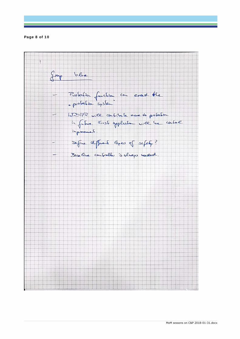
3 GROUP ‘BLUE’ The list of the topics from the previous group was presented. Participants were asked on which topic work shall be done in this session.
Discussion took place on item 2.2 “Control functions vs Protection functions, definition needed”.
A picture of the side notes is in the appendix.
“Protection Function can exceed the ‘Protection System’.” Components, which take part in performing Protection Functions sometimes are not direct components of the Protection System. E.g. sensors or even the control system might in cases be part of the group of components performing a Protection Function.
“Lidar will contribute more to protection in future. First application will be control improvements.” In systems coming up now the Lidar will probably mainly improve control functions. However, in near future it is expected, that Lidar assistance will be used to e.g. reduce extreme load cases and by that the function of the Lidar may directly influence designs limits. This would bring the Lidar in being a component contributing to a Protection Function.
“Define different layers of safety?” It is felt a grey zone between Control Functions and Protection Functions. E.g. an 8 MW turbine might be operated at 9 MW, if external conditions and turbine’s conditions allow for (operational mode ‘extra power’). Turbine would leave this mode ‘extra power’ as soon as the Lidar detects a larger gust on its way towards the turbine. Is the function of leaving this mode a Control Function or Protections Function?
“Baseline controller is always needed.” It is common understanding, that the WT must be able to operate without signals from the Lidar. It shall be possible to continue operation in case the Lidar health signal ceases.
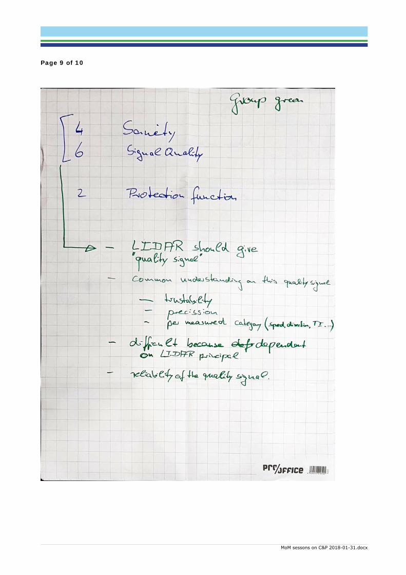
4 GROUP ‘GREEN’ We discussed the list of topics from group ‘Red’. Two areas were chosen to work on:
a) Items 4. Sanity check / 6. Signal quality
b) Protection functions
A picture of the flip chart notes is in the appendix.
Discussion was made on option a) as the previous group had discussed the topic ‘Protection Function’ already.
“Lidar should give ‘quality signal’.” It was discussed that it would be helpful to define a quality signal (QuaSi) given constantly from Lidar to WT’s controller. The signal should be defined uniquely over Lidar and WT manufacturers. It should be either a value (e.g. 1 …. 10) or a status (e.g. bad/medium/good or green/yellow/red).
“Common understanding on this quality signal”
Page 4 of 10
MoM sessons on C&P 2018-01-31.docx
o “Trustability” QuaSi should reflect how large the confidence in the signal is at the moment. “Trustability” could e.g. contain the Signal-to-noise ration.
o “Precision” Also possible shortfalls in the accurateness of the signal should be reflected by QuaSi.
o “per measured category …” QuaSi should be given separately for each of the measured values like e.g. wind speed, wind direction, turbulence intensity, …
“Difficult, because dependent on Lidar principal” The different functional principles of Lidar systems (pulsed, constant, …) function differently. Also, the possible outcome is different. Therefore, a uniform definition of QuaSi will be difficult, maybe impossible.
“Reliability of the quality signal” For risk assessments on wind turbines it will be important to know how reliable the QuaSi and the health signal of the Lidar are. One of the failure scenarios will be: Lidar reports good quality of the signal, but signal is corrupt. What is probability of occurrence of this scenario?
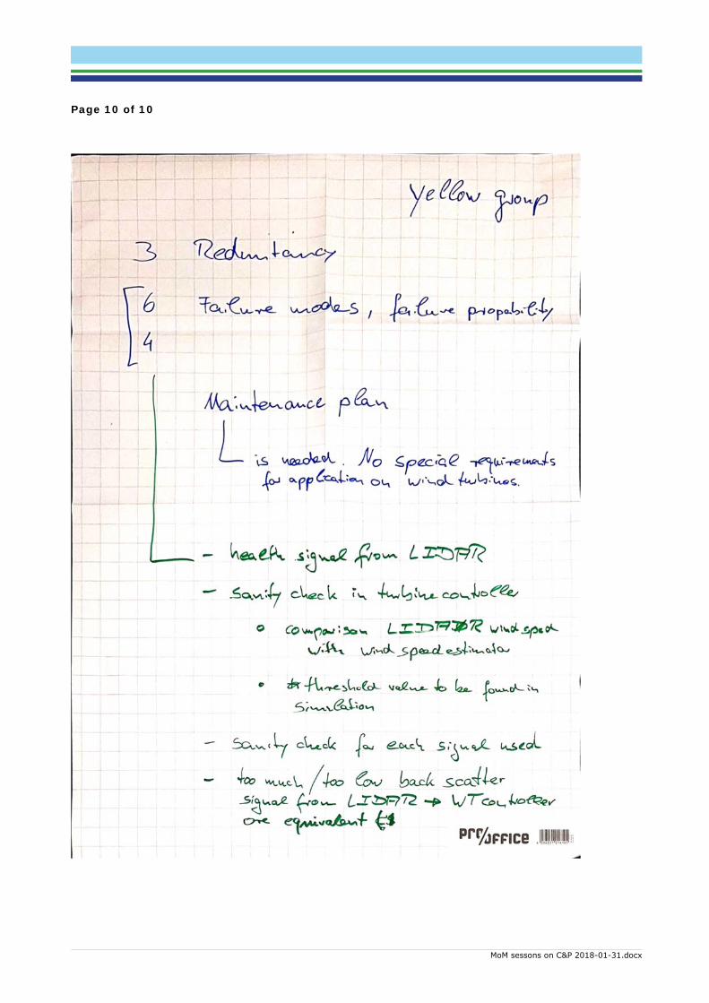
5 GROUP ‘YELLOW’ We discussed the list of topics from group ‘Red’. Three areas were chosen to work on:
a) Item 3. Redundance
b) Items 4./6. Failure modes, failure probability
c) Maintenance plan
The topic of option c) is not on the list from group ‘Red’. It was brought up from participants.
A picture of the flip chart notes is in the appendix.
Discussion was made on option c) “Maintenance plan”:
“is needed. No special requirements for application on wind turbine.” It was concluded that for Lidar application at a wind turbine no special requirements on a maintenance plan are necessary. Standard operation and maintenance manuals including maintenance plan would be sufficient.
Discussion was held on option b) “Items 4./6. Failure modes, failure probability”:
“Health signal from LIDAR” In the communication from the Lidar to the WT, a health signal should be present. The WT controller should ignore the data from the Lidar, if not the health signal is in status ‘healthy’.
“Sanity check in turbine controller” The WT control system should always include a sanity check in its procedures to verify constantly the plausibility of Lidar data.
o “Comparison Lidar wind speed with wind speed estimation” Signals from the Lidar can e.g. be time shifted into the rotor plane and then compared to
Page 5 of 10
MoM sessons on C&P 2018-01-31.docx
the wind speed calculated from turbine’s operational data (rotor speed, pitch angel, generator torque).
o “Threshold value to be found in simulation” Suitable threshold values for this comparison can be derived e,g, by simulation during load simulation.
“Sanity check for each signal used” Each measured signal from the Lidar should undergo such a sanity check in the WT control system. Suitable check procedures should be derived.
“Too much / too low back scatter signal from Lidar WT controller. Or equivalent” Lidar should also convey a signal on the momentary data quality to WT controller. This signal can e.g. be on the amount of back scatter. Other quality related values also can be used as well, like e.g. signal to noise ratio (SNR).
End of MoM. One appendix follows.
Page 6 of 10
MoM sessons on C&P 2018-01-31.docx
6 APPENDIX: PICTURES OF THE FLIP CHARTS AND NOTES
Page 7 of 10
MoM sessons on C&P 2018-01-31.docx
Page 8 of 10
MoM sessons on C&P 2018-01-31.docx
Page 9 of 10
MoM sessons on C&P 2018-01-31.docx
Page 10 of 10
MoM sessons on C&P 2018-01-31.docx
IEA Wind Task 32 workshop #8 on Certification of Lidar-Assisted Control Applications 1
Summary of the group discussion of lidar requirements Steffen Raach (sowento) – 01/31/2018
General perspective Wind turbine is a machinery designed under ISO13849. The lidar must be considered as part of the safety
and control component and therefore quantifications on mean time to failure, probability of failure,
probability of failure on demand (safety chain) need to be provided for the lidar sensor. Everything with
respect to the lidar within the lidar-assisted control framework need to be considered under the
requirements of the norm.
Measurement uncertainty - Guidelines are needed for uncertainty analysis (standardization of methods and models)
- Guidelines are needed how to perform in certification
- Lidar manufacturer are responsible for the quantification
- Uncertainty measure on each delivered signal.
- More meaningful measures like measurement noise/process noise, variance info
Data Processing - Raw signal should be provided (Definition is needed)
- If the processed data is used, a binary (dll) needs to be provided to for the certification to have
the full simulation chain
- Specs on real-time capability (also approximations of the processing)
- Common data format might be needed, however not possible because of a missing reference
and comparability
- Metric of standard signals
Data availability - Everything can be summarized in standardization is needed.
- Standard for definition
- Standard for condition classification / site classification
o Problem: conditions are not reproducible in field-testing
- Suggestion of delivered measures: 1 s availability, 60 s availability
- -> link to measurement uncertainty
- Meaningful measure for every provided signal
- Link to uncertainty
FMEA - Implementation & installation are crucial for preventing higher impact of failures. General
intension: failure should not lead to a worse situation than without lidar.
- FMEA needs to be done on a probabilistic basis, ranked by impact and detectability (detection
coverage)
- Self-monitoring of the lidar system can help to prevent to consider main failures on turbine level,
not everything is covered.
- Treat lidar as normal sensor and learn/adapt from the requirements on normal sensors
- Analysis of the failures of the lidar. The prevention procedures might be redundant to existing
features, also test cases are perhaps already considered (like pitch runaway)
IEA Wind Task 32 workshop #8 on Certification of Lidar-Assisted Control Applications 2
Lightning protection / EMC - Nikolai will collect the standards and procedures the lidar manufacturer already perform to
standardize/align the minimum requirements.
Personal safety - Eye safety
o Documentation
o Certification
o Guidance
- Safety procedures
o Documentation
o Guidance
- Need of clear separation on responsibilities
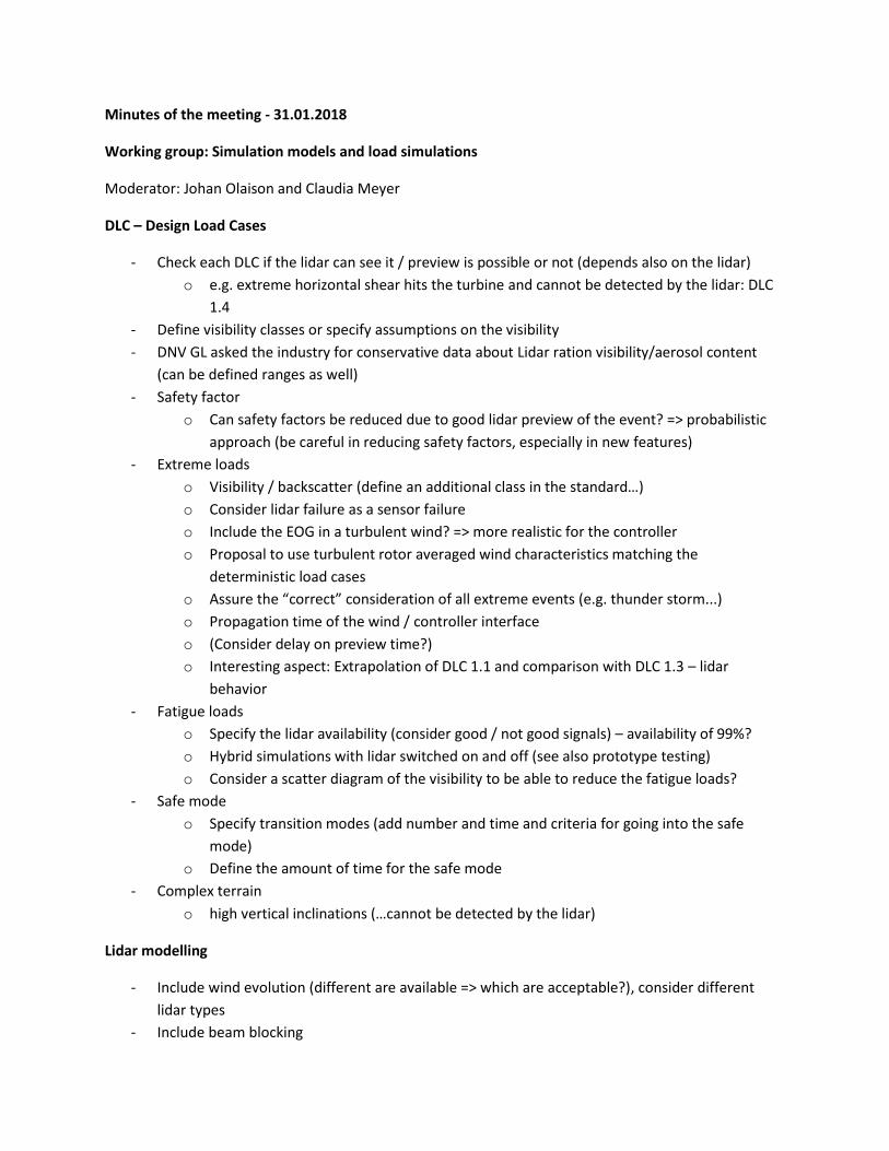
Minutes of the meeting - 31.01.2018
Working group: Simulation models and load simulations
Moderator: Johan Olaison and Claudia Meyer
DLC – Design Load Cases
- Check each DLC if the lidar can see it / preview is possible or not (depends also on the lidar)
o e.g. extreme horizontal shear hits the turbine and cannot be detected by the lidar: DLC
1.4
- Define visibility classes or specify assumptions on the visibility
- DNV GL asked the industry for conservative data about Lidar ration visibility/aerosol content
(can be defined ranges as well)
- Safety factor
o Can safety factors be reduced due to good lidar preview of the event? => probabilistic
approach (be careful in reducing safety factors, especially in new features)
- Extreme loads
o Visibility / backscatter (define an additional class in the standard…)
o Consider lidar failure as a sensor failure
o Include the EOG in a turbulent wind? => more realistic for the controller
o Proposal to use turbulent rotor averaged wind characteristics matching the
deterministic load cases
o Assure the “correct” consideration of all extreme events (e.g. thunder storm...)
o Propagation time of the wind / controller interface
o (Consider delay on preview time?)
o Interesting aspect: Extrapolation of DLC 1.1 and comparison with DLC 1.3 – lidar
behavior
- Fatigue loads
o Specify the lidar availability (consider good / not good signals) – availability of 99%?
o Hybrid simulations with lidar switched on and off (see also prototype testing)
o Consider a scatter diagram of the visibility to be able to reduce the fatigue loads?
- Safe mode
o Specify transition modes (add number and time and criteria for going into the safe
mode)
o Define the amount of time for the safe mode
- Complex terrain
o high vertical inclinations (…cannot be detected by the lidar)
Lidar modelling
- Include wind evolution (different are available => which are acceptable?), consider different
lidar types
- Include beam blocking
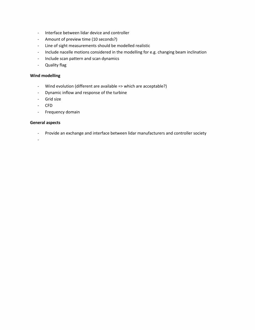
- Interface between lidar device and controller
- Amount of preview time (10 seconds?)
- Line of sight measurements should be modelled realistic
- Include nacelle motions considered in the modelling for e.g. changing beam inclination
- Include scan pattern and scan dynamics
- Quality flag
Wind modelling
- Wind evolution (different are available => which are acceptable?)
- Dynamic inflow and response of the turbine
- Grid size
- CFD
- Frequency domain
General aspects
- Provide an exchange and interface between lidar manufacturers and controller society
-
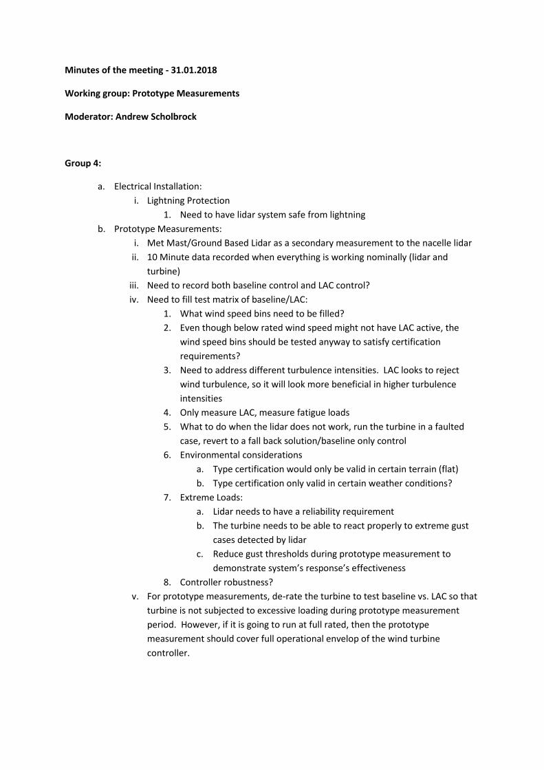
Minutes of the meeting - 31.01.2018
Working group: Prototype Measurements
Moderator: Andrew Scholbrock
Group 4:
a. Electrical Installation:
i. Lightning Protection
1. Need to have lidar system safe from lightning
b. Prototype Measurements:
i. Met Mast/Ground Based Lidar as a secondary measurement to the nacelle lidar
ii. 10 Minute data recorded when everything is working nominally (lidar and
turbine)
iii. Need to record both baseline control and LAC control?
iv. Need to fill test matrix of baseline/LAC:
1. What wind speed bins need to be filled?
2. Even though below rated wind speed might not have LAC active, the
wind speed bins should be tested anyway to satisfy certification
requirements?
3. Need to address different turbulence intensities. LAC looks to reject
wind turbulence, so it will look more beneficial in higher turbulence
intensities
4. Only measure LAC, measure fatigue loads
5. What to do when the lidar does not work, run the turbine in a faulted
case, revert to a fall back solution/baseline only control
6. Environmental considerations
a. Type certification would only be valid in certain terrain (flat)
b. Type certification only valid in certain weather conditions?
7. Extreme Loads:
a. Lidar needs to have a reliability requirement
b. The turbine needs to be able to react properly to extreme gust
cases detected by lidar
c. Reduce gust thresholds during prototype measurement to
demonstrate system’s response’s effectiveness
8. Controller robustness?
v. For prototype measurements, de-rate the turbine to test baseline vs. LAC so that
turbine is not subjected to excessive loading during prototype measurement
period. However, if it is going to run at full rated, then the prototype
measurement should cover full operational envelop of the wind turbine
controller.
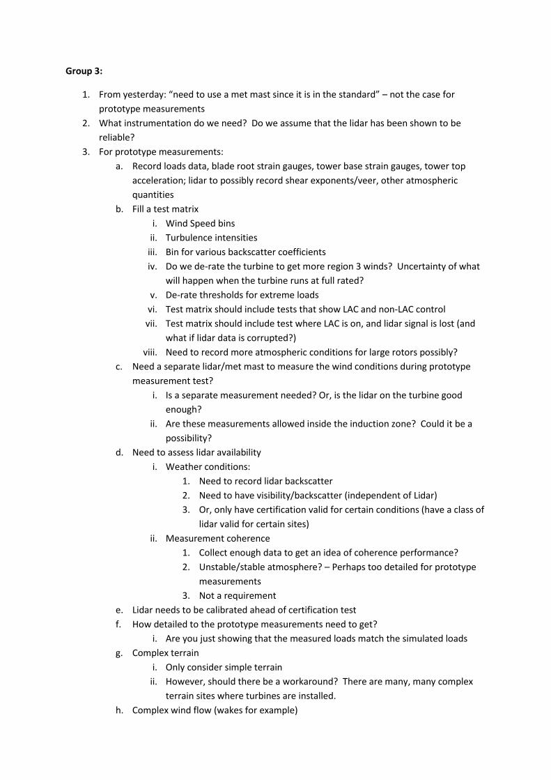
Group 3:
1. From yesterday: “need to use a met mast since it is in the standard” – not the case for
prototype measurements
2. What instrumentation do we need? Do we assume that the lidar has been shown to be
reliable?
3. For prototype measurements:
a. Record loads data, blade root strain gauges, tower base strain gauges, tower top
acceleration; lidar to possibly record shear exponents/veer, other atmospheric
quantities
b. Fill a test matrix
i. Wind Speed bins
ii. Turbulence intensities
iii. Bin for various backscatter coefficients
iv. Do we de-rate the turbine to get more region 3 winds? Uncertainty of what
will happen when the turbine runs at full rated?
v. De-rate thresholds for extreme loads
vi. Test matrix should include tests that show LAC and non-LAC control
vii. Test matrix should include test where LAC is on, and lidar signal is lost (and
what if lidar data is corrupted?)
viii. Need to record more atmospheric conditions for large rotors possibly?
c. Need a separate lidar/met mast to measure the wind conditions during prototype
measurement test?
i. Is a separate measurement needed? Or, is the lidar on the turbine good
enough?
ii. Are these measurements allowed inside the induction zone? Could it be a
possibility?
d. Need to assess lidar availability
i. Weather conditions:
1. Need to record lidar backscatter
2. Need to have visibility/backscatter (independent of Lidar)
3. Or, only have certification valid for certain conditions (have a class of
lidar valid for certain sites)
ii. Measurement coherence
1. Collect enough data to get an idea of coherence performance?
2. Unstable/stable atmosphere? – Perhaps too detailed for prototype
measurements
3. Not a requirement
e. Lidar needs to be calibrated ahead of certification test
f. How detailed to the prototype measurements need to get?
i. Are you just showing that the measured loads match the simulated loads
g. Complex terrain
i. Only consider simple terrain
ii. However, should there be a workaround? There are many, many complex
terrain sites where turbines are installed.
h. Complex wind flow (wakes for example)

i. Is it handled just by modeling?
ii. Or do you only have the certification cover turbines when flow is simple/not
waked?
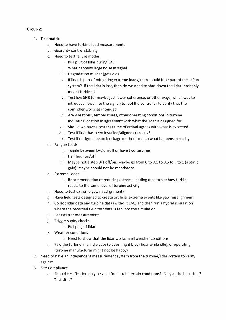
Group 2:
1. Test matrix
a. Need to have turbine load measurements
b. Guaranty control stability
c. Need to test failure modes
i. Pull plug of lidar during LAC
ii. What happens large noise in signal
iii. Degradation of lidar (gets old)
iv. If lidar is part of mitigating extreme loads, then should it be part of the safety
system? If the lidar is lost, then do we need to shut down the lidar (probably
meant turbine)?
v. Test low SNR (or maybe just lower coherence, or other ways; which way to
introduce noise into the signal) to fool the controller to verify that the
controller works as intended
vi. Are vibrations, temperatures, other operating conditions in turbine
mounting location in agreement with what the lidar is designed for
vii. Should we have a test that time of arrival agrees with what is expected
viii. Test if lidar has been installed/aligned correctly?
ix. Test if designed beam blockage methods match what happens in reality
d. Fatigue Loads
i. Toggle between LAC on/off or have two turbines
ii. Half hour on/off
iii. Maybe not a step 0/1 off/on; Maybe go from 0 to 0.1 to 0.5 to… to 1 (a static
gain), maybe should not be mandatory
e. Extreme Loads
i. Recommendation of reducing extreme loading case to see how turbine
reacts to the same level of turbine activity
f. Need to test extreme yaw misalignment?
g. Have field tests designed to create artificial extreme events like yaw misalignment
h. Collect lidar data and turbine data (without LAC) and then run a hybrid simulation
where the recorded field test data is fed into the simulation
i. Backscatter measurement
j. Trigger sanity checks
i. Pull plug of lidar
k. Weather conditions
i. Need to show that the lidar works in all weather conditions
l. Yaw the turbine in an idle case (blades might block lidar while idle), or operating
(turbine manufacturer might not be happy)
2. Need to have an independent measurement system from the turbine/lidar system to verify
against
3. Site Compliance
a. Should certification only be valid for certain terrain conditions? Only at the best sites?
Test sites?
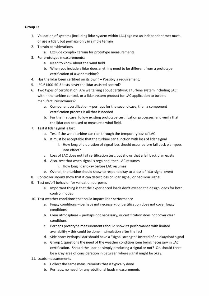
Group 1:
1. Validation of systems (including lidar system within LAC) against an independent met mast,
or use a lidar, but perhaps only in simple terrain
2. Terrain considerations
a. Exclude complex terrain for prototype measurements
3. For prototype measurements:
a. Need to know about the wind field
b. When you include a lidar does anything need to be different from a prototype
certification of a wind turbine?
4. Has the lidar been certified on its own? – Possibly a requirement;
5. IEC 61400-50-3 tests cover the lidar assisted control?
6. Two types of certification: Are we talking about certifying a turbine system including LAC
within the turbine control, or a lidar system product for LAC application to turbine
manufacturers/owners?
a. Component certification – perhaps for the second case, then a component
certification process is all that is needed.
b. For the first case, follow existing prototype certification processes, and verify that
the lidar can be used to measure a wind field.
7. Test if lidar signal is lost
a. Test if the wind turbine can ride through the temporary loss of LAC
b. It must be acceptable that the turbine can function with loss of lidar signal
i. How long of a duration of signal loss should occur before fall back plan goes
into effect?
c. Loss of LAC does not fail certification test, but shows that a fall back plan exists
d. Also, test that when signal is regained, then LAC resumes
i. How long lidar okay before LAC resumes
e. Overall, the turbine should show to respond okay to a loss of lidar signal event
8. Controller should show that it can detect loss of lidar signal, or bad lidar signal
9. Test on/off behavior for validation purposes
a. Important thing is that the experienced loads don’t exceed the design loads for both
control modes
10. Test weather conditions that could impact lidar performance
a. Foggy conditions – perhaps not necessary, or certification does not cover foggy
conditions
b. Clear atmosphere – perhaps not necessary, or certification does not cover clear
conditions
c. Perhaps prototype measurements should show its performance with limited
availability – this could be done in simulation after the fact
d. Side note: Perhaps lidar should have a “signal strength” instead of an okay/bad signal
e. Group 1 questions the need of the weather condition item being necessary in LAC
certification. Should the lidar be simply producing a signal or not? Or, should there
be a gray area of consideration in between where signal might be okay.
11. Loads measurements
a. Collect the same measurements that is typically done
b. Perhaps, no need for any additional loads measurements
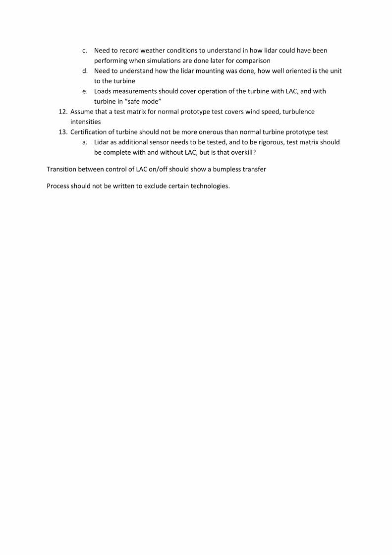
c. Need to record weather conditions to understand in how lidar could have been
performing when simulations are done later for comparison
d. Need to understand how the lidar mounting was done, how well oriented is the unit
to the turbine
e. Loads measurements should cover operation of the turbine with LAC, and with
turbine in “safe mode”
12. Assume that a test matrix for normal prototype test covers wind speed, turbulence
intensities
13. Certification of turbine should not be more onerous than normal turbine prototype test
a. Lidar as additional sensor needs to be tested, and to be rigorous, test matrix should
be complete with and without LAC, but is that overkill?
Transition between control of LAC on/off should show a bumpless transfer
Process should not be written to exclude certain technologies.