mission aircrew reference text
TRANSCRIPT

CIVIL AIR PATROL U.S. Air Force Auxiliary
Mission Aircrew Reference Text
Volume I Mission Scanner
Revision July 2021

i
This text is designed to provide the minimum academic knowledge required by the Civil Air Patrol (CAP) Mission Scanner.
Scanning is a systematic method of looking for objects such as downed aircraft, damage on the ground, or missing persons. The Mission Scanner’s primary responsibility is to maintain constant visual contact with the ground while over the search area. This responsibility makes each scanner a key member of the search aircrew.
The Mission Observer is a scanner with expanded duties who usually sits in the right front seat. In addition to the primary duty of scanning while in the search area, the observer assists the pilot with planning, navigation, and communication. The observer may also serve as mission commander, ensuring that all mission objectives are met.
The SAR/DR Mission Pilot is the aircraft commander and is responsible for the safety of the crew and the aircraft. The Mission Pilot must fly the aircraft precisely in order to execute mission procedures and search patterns so that the scanners have the best possible chance to achieve mission objectives. Naturally, as Pilot-in- Command the pilot must satisfy all pertinent FAA and CAP regulations pertaining to certification, currency and the operation of the aircraft; this text concentrates on mission-specific duties and responsibilities.
The importance of safety is emphasized throughout the text. Lessons learned in this text will enable aircrew members to operate in a safe and efficient manner, thus reducing accidents and incidents.
Before beginning training you should review and understand the current CAP 60-series regulations, which provide current operations and training guidance and requirements. Trainee prerequisites for the ratings are provided in CAPR 60-3 Chapter 2 and in the Specialty Qualification Training Record (SQTR) for Mission Scanner.
NOTE: This text contains links to web sites, and web addresses often change. If selecting the link does not take you to the desired site, either try copying and pasting the url into your browser’s address bar or search for the particular site or document with your favorite search engine.

ii
Acknowledgements
Many dedicated persons have contributed to the development of the text, slides, and attachments that make up the CAP mission aircrew reference texts. Material was taken from CAP sources all over the country. There are too many to thank, but we will mention several important contributors.
The core of this text was developed from the Southwest Region Scanner/Observer Course. Developed, maintained and taught by several Reserve Officers in the CAP/RAP program that serves Texas Wing and Southwest Region, the course has been in existence for several years. Lt. Col. Robert H. Castle, USAFR led this effort.
The text was then modified and expanded to serve as the classroom material for the National Emergency Services Academy (NESA) Mission Aircrew School, which was begun in 2000. One of the school co-founders, Lt. Col. Rich Simerson, developed this text and the associated slides; he now maintains and updates the materials. The other co-founder, Lt. Col. Mike DuBois, provided invaluable input and was indispensable in shaping the course. Several instructors and students of the first two schools also contributed greatly, particularly Major Arden Heffernan, Major Earl Burress, Captain Galen Hall, and Major Scott Lanis. The NESA Director, Lt Col John Desmarais, provided unstinting support and assistance.
This text and associated training materials were developed under the auspices of the National Emergency Services Curriculum Project. Valuable input was provided by one of the Middle East Region representatives, Lt. Col. Robert Ayres. This is a 'living' document that is being tested and improved through its use at the NESA Mission Aircrew School and through field-testing by units throughout the country as part of the Emergency Services Curriculum Project.
Please direct comments (via e-mail) to the text administrator, Lt. Col. Rich Simerson, at [email protected]. Please be specific and provide justification for your comments. If you refer to specific text or figures, please identify them clearly. If you have better pictures or slides than the ones appearing in the text or slides, or have others that you feel will improve the text and/or slides, please send them electronically and include explanatory notes or annotation.
iii
Organization & Guidance
The knowledge gained in this course is a prerequisite for both the Mission Observer (MO) and SAR/DR Mission Pilot (MP) courses. This is consistent with the fact that Mission Scanner (MS) qualification is a prerequisite on both the MO and MP Specialty Qualification Training Records (SQTRs). Task Guides and other aircrew training and reference material are available electronically on the SWR ES Education and Training webpage (http://est.swrcap.com).
This text is augmented by a set of Microsoft PowerPoint slides. Each chapter has a list of objectives to assist students, school directors, project
leaders and instructors. Applicable objectives are tied to related MS Task Guide tasks. For example, Objective 1 of Chapter 1 refers to scanner duties and responsibilities, and is tied to MS Task P-2013. The remainders of the objectives are designed to provide supporting and/or more detailed information to aid in your training.
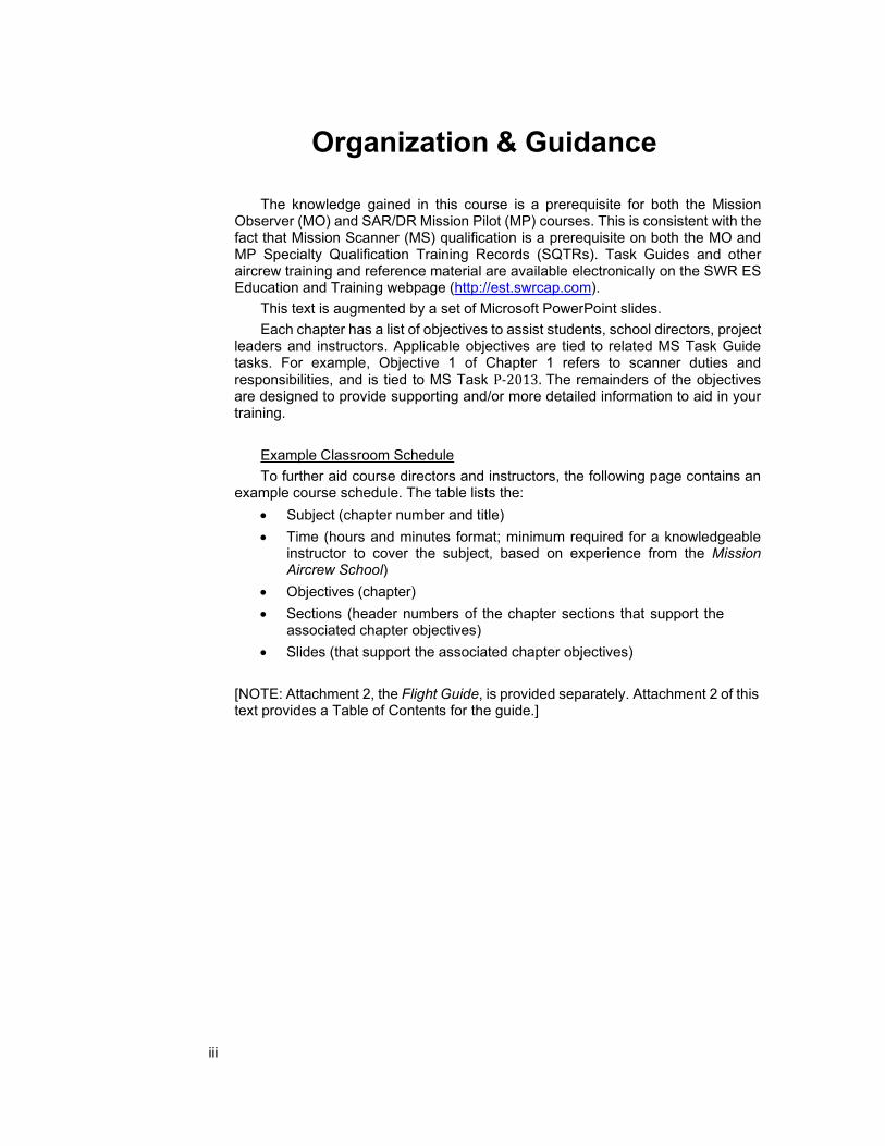
Example Classroom Schedule To further aid course directors and instructors, the following page contains an
example course schedule. The table lists the: • Subject (chapter number and title) • Time (hours and minutes format; minimum required for a knowledgeable
instructor to cover the subject, based on experience from the Mission Aircrew School)
• Objectives (chapter) • Sections (header numbers of the chapter sections that support the
associated chapter objectives) • Slides (that support the associated chapter objectives)
[NOTE: Attachment 2, the Flight Guide, is provided separately. Attachment 2 of this text provides a Table of Contents for the guide.]
iv
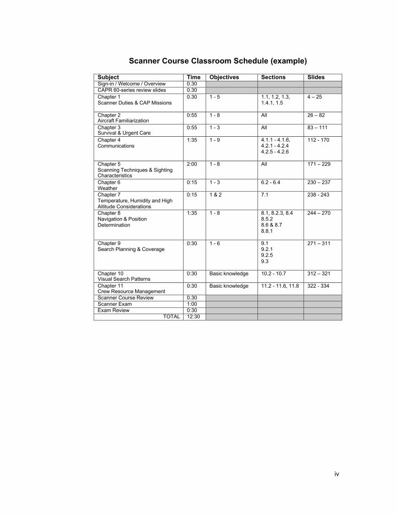
Scanner Course Classroom Schedule (example)
Subject Time Objectives Sections Slides Sign-in / Welcome / Overview 0.30
CAPR 60-series review slides 0.30
Chapter 1 Scanner Duties & CAP Missions
0.30 1 - 5 1.1, 1.2, 1.3, 1.4.1, 1.5
4 – 25
Chapter 2 Aircraft Familiarization
0:55 1 - 8 All 26 – 82
Chapter 3 Survival & Urgent Care
0:55 1 - 3 All 83 – 111
Chapter 4 Communications
1:35 1 - 9 4.1.1 - 4.1.6, 4.2.1 - 4.2.4 4.2.5 - 4.2.6
112 - 170
Chapter 5 Scanning Techniques & Sighting Characteristics
2:00 1 - 8 All 171 – 229
Chapter 6 Weather
0:15 1 - 3 6.2 - 6.4 230 – 237
Chapter 7 Temperature, Humidity and High Altitude Considerations
0:15 1 & 2 7.1 238 - 243
Chapter 8 Navigation & Position Determination
1:35 1 - 8 8.1, 8.2.3, 8.4 8.5.2 8.6 & 8.7 8.8.1
244 – 270
Chapter 9 Search Planning & Coverage
0:30 1 - 6 9.1 9.2.1 9.2.5 9.3
271 – 311
Chapter 10 Visual Search Patterns
0:30 Basic knowledge 10.2 - 10.7 312 – 321
Chapter 11 Crew Resource Management
0:30 Basic knowledge 11.2 - 11.6, 11.8 322 - 334
Scanner Course Review 0.30
Scanner Exam 1:00
Exam Review 0:30
TOTAL 12:30

v
Mission Scanner (MS) tasks:
Task Guides
O-0204 Locate a Point on a Map using Latitude and Longitude O-0205 Locate a Point on a Map using the CAP Grid System O-2015 Demonstrate Ground Operations and Safety O-2016 Demonstrate Safety while Taxiing O-2017 Demonstrate Post-Crash Actions O-2018 Operate the Aircraft Communications Equipment O-2019 Demonstrate Proper Number and Character Pronunciation O-2020 Use Prowords and Code Words O-2021 Interpret Emergency Signals and Demonstrate Air-to-Ground Coordination O-2022 Demonstrate Scanning Patterns and Locate Targets O-2023 Demonstrate Techniques to Reduce Fatigue O-2024 Demonstrate Use of Sectional Charts O-2025 Track and Record Position on Sectionals and Maps
P-2013 Discuss Mission Scanner Duties and Responsibilities P-2014 Discuss CAP Liability coverage and Mishap Reporting P-2015 Enter Data into CAP Forms P-2016 Identify and Discuss Major Aircraft Controls P-2017 Identify and Discuss Major Aircraft Instruments P-2018 Discuss Weight and Balance P-2019 Identify Items Checked During an Aircraft Pre-flight P-2020 Discuss the Dangers of Wake Turbulence P-2021 Discuss how Atmospheric and Lighting Conditions Effect Scanning
Effectiveness P-2022 Identify Visual Clues and Wreckage Patterns P-2023 Discuss Reduced Visibility and Turbulence Effects P-2024 Discuss Strategies to Combat High Altitude Effects P-2025 Discuss Common Search Terms P-2026 Identify What to Look For and Record during Damage Assessments P-2027 Describe CAP Search Patterns P-2028 Discuss Crew Resource Management P-0101 Demonstrate the Ability to Keep a Log

vi
References
1. The following CAP Regulations (CAPR): a. 70-1, CAP Flight Management b. 60-3, CAP Emergency Services Training and Operational Missions c. 60-5, Critical Incident Stress Management d. 62-1, CAP Safety Responsibilities and Procedures e. 62-2, Mishap Reporting and Investigation f. 66-1, CAP Aircraft Maintenance Management g. 100-1, Communications - Electronics h. 173-3, Payment for Civil Air Patrol Support i. 900-5, CAP Insurance/Benefits Program
2. CAPP-2, ELT/EPRIB Search 3. Southwest Region Scanner/Observer Course, Version 3.0 4. Mountain Fury, First Edition 5. United States National Search and Rescue Supplement to the International Aeronautical
and Maritime SAR Manual, May 2000. 6. AC 00-6A, Aviation Weather, 1/1/1975 7. AC 00-45F, Aviation Weather Services, Chg. 2, 3/21/09 8. FAA-H-8083-3, Airplane Flying Handbook. 9. FAA-H-8083-25, Pilot’s Handbook of Aeronautical Knowledge. 10. Federal Aviation Regulations. 11. Aeronautical Information Manual. 12. AOPA/ASA Safety Advisories. 13. Cessna Pilot Operating Handbooks. 14. Cessna Pilot Safety and Warning Supplements. 15. Pocket Guide to USAF Operational Risk Management, John D. Phillips, Air Force Safety
Center. 16. CAP Operational Mission In-Flight Guide and Aircrew Aid, Scott E. Lanis, MAJ, CAP 17. Cessna Nav III G1000 Search Pattern Procedures, V2.0 18. SWR ES Education and Training webpage (http://est.swrcap.com).

vii
Intentionally Blank

viii
Table of Contents
List of Acronyms 1 1. Scanner Duties and CAP Missions 3
OBJECTIVES: 3
1.1 Mission Scanner Duties and Responsibilities 4
1.2 CAP Missions 5
1.3 Liability and Mishap Reporting 8
1.4 Forms 9
1.5 Using eServices for Operations Qualifications 10
2. Aircraft Familiarization 13 OBJECTIVES: 13
2.1 Basic Aircraft Structure 14
2.2 Aircraft Instruments 18
2.3 Weight and Balance 22
2.4 Preflight Inspection 25
2.5 Ground Operations and Safety 27
2.6 Wake Turbulence 35
3. Survival and Urgent Care 41 OBJECTIVES: 41
3.1 Planning 42
3.2 Pre- and Post-Landing Actions 42
3.3 Survival Equipment 44
3.4 Urgent Care 46
4. Communications 47 OBJECTIVES: 47
4.1 Electronic Communications 48
4.2 Non-verbal Communication 54

ix
5. Scanning Techniques and Sighting Characteristics 63 OBJECTIVES: 63
5.1 Scanning 64
5.2 Vision 64
5.3 Fixation Points and Line of Scan 65
5.4 Scanning Patterns 69
5.5 Atmospheric and Lighting Conditions 72
5.6 Visual Clues 75
5.7 Wreckage Patterns (accident signs) 77
5.8 Reducing Fatigue 79
5.9 Directing the Pilot 80
6. Weather 83 OBJECTIVES: 83
6.1 Basic Weather 84
6.2 Reduced Visibility 84
6.3 Turbulence 86
6.4 Thunderstorms 86
7. Temperature, Humidity and High Altitude Considerations 89 OBJECTIVES: 89
7.1 Temperature, Humidity and High Altitude Effects on Crewmember Performance 90
8. Navigation and Position Determination 93 OBJECTIVES: 93
8.1 Navigation Terms 95
8.2 Latitude and Longitude 96
8.3 Airspace 97
8.4 Sectional Charts 101
8.5 Chart Interpretation 102
8.6 Chart Preparation 106
8.7 Tracking and Recording Position 111
8.8 Standardized Grid Systems 111

x
9. Search Planning and Coverage 119 OBJECTIVES: 119
9.1 Search Terms 120
9.2 Disaster Assessment 121
9.3 Missing Person Search 125
10. Visual Search Patterns 127 OBJECTIVES: 127
10.1 Planning Search Patterns 128
10.2 Route (Track Line) Search 128
10.3 Parallel Track (Parallel Sweep) 129
10.4 Creeping Line Search 129
10.5 Expanding Square Search (a point-based search) 130
10.6 Sector Search (a point-based search) 131
10.7 Contour Search 133
11. Crew Resource Management 135 OBJECTIVES: 135
11.1 Statistics 136
11.2 Failures and the Error Chain 137
11.3 Situational Awareness 138
11.4 Overcoming Loss of SA 139
11.5 Barriers to Communication 140
11.6 Task Saturation 140
11.7 Identification of Resources 141
11.8 Assignment and Coordination of Duties 141
Attachment 1 I GRIDDING I
Attachment 2 III FLIGHT GUIDE III

xi
Summary of Changes
Following are the significant changes and updates in the December 2014 revision. Some of the more significant changes are highlighted.
1. Updated to latest CAPR 70-1 requirements


1
List of Acronyms
AFAM Air Force Assigned Mission AFRCC Air Force Rescue Coordination Center AGL Above Ground Level AM Amplitude Modulated AP Airborne Photographer ATA Actual Time of Arrival ATC Air Traffic Control ATD Actual Time of Departure ATIS Automatic Terminal Information Service AWOS Automated Weather Observing System C172/182/206 Cessna aircraft models CAPF CAP Form CAPR CAP Regulation CD Counterdrug CDI Course Deviation Indicator COM/COMM Communication CONUS Continental United States (excludes Alaska and Hawaii) CTAF Common Traffic Advisory Frequency CRM Crew Resource Management DF Direction Finder DME Distance Measuring Equipment DoD Department of Defense DR Disaster Relief DUAT Direct User Access Terminal ECD Electronic Chart Display EFB Electronic Flight Bag ELT Emergency Locator Transmitter ES Emergency Services ETA Estimated Time of Arrival ETD Estimated Time of Departure ETE Estimated Time Enroute FAA Federal Aviation Administration FAR Federal Aviation Regulation FBO Fixed Base Operator FEMA Federal Emergency Management Agency FM Frequency Modulated FRO Flight Release Officer FSS Flight Service Station GPS Global Positioning System HLS Homeland Security IMC Instrument Meteorological Conditions IFR Instrument Flight Rules LED Light Emitting Diode

2
MEF Maximum Elevation Figure MHz Megahertz MO Mission Observer MOA Military Operations Area MOU Memorandum of Understanding MP Mission SAR/DR Pilot MS Mission Scanner MSL Mean Sea Level MTR Military Training Route NESA National Emergency Services Academy NOAA National Oceanic and Atmospheric Administration NOTAM Notice to Airmen NTSB National Transportation Safety Board NWS National Weather Service OPSEC Operational Security ORM Operational Risk Management PA Prohibited Area PIC Pilot-in-Command PLB Personal Locator Beacon PTT Push-to-Talk (radio switch) RA Restricted Area SA Situational Awareness SAR Search and Rescue SARSAT Search and Rescue Satellite-Aided Tracking SQTR Specialty Qualification Training Record SO Safety Officer SUA Special Use Airspace TPA Traffic Pattern Altitude TFR Temporary Flight Restriction USAF United States Air Force UHF Ultra High Frequency VFR Visual Flight Rules VHF Very High Frequency VMC Visual Meteorological Conditions VOR Very High Frequency Omnidirectional Range WMIRS Web Mission Information Reporting System ZULU Coordinated Universal Time

3
1. Scanner Duties and CAP Missions
Chapter
1
OBJECTIVES:
1. State Mission Scanner duties and responsibilities. {P-2013}* 2. Discuss CAP missions. 3. Discuss liability coverage and applicability, and mishap reporting.
{P-2014} 4. List the general rules for entering data into forms. {P-2015] 5. Discuss the types logs you may be asked to keep. {P-0101} 5. Use eServices to document your Mission Scanner training.
* Throughout this text, objectives that match a task in an MS Task Guide are identified by brackets that list the associated MS task (e.g., P-2013). Other (unmarked) objectives are included as emphasis to aid in your training.

4
1.1 Mission Scanner Duties and Responsibilities The scanner’s primary mission role is effective visual search. “Scanning” is a
method of looking for downed aircraft (or other objects) that makes it possible to search an assigned area in a systematic way. Scanners are those people trained in these methods and whose primary responsibility is to maintain constant eye contact with the ground while flying over the search area. This responsibility makes the scanner a key member of each aircrew. While the mission observer has further duties, his or her primary responsibility while in the search area is also visual search.
The following outlines the duties and responsibilities of scanners for a typical mission:
• Report for duty IAW the "IMSAFE" criteria (or equivalent): Illness - Even a minor illness suffered in day-to-day living can seriously degrade performance of many piloting tasks vital to safe flight. The safest rule is not to fly while suffering from any illness. If this rule is considered too stringent for a particular illness, the pilot should contact an Aviation Medical Examiner for advice.
Medication - Pilot performance can be seriously degraded by both prescribed and over-the-counter medications, as well as by the medical conditions for which they are taken. The FARs prohibit pilots from performing crewmember duties while using any medication that affects the faculties in any way contrary to safety. As a scanner, this also applies to you.
Stress - Stress from everyday living can impair pilot performance, often in very subtle ways. Stress and fatigue (lack of adequate rest) can be an extremely hazardous combination.
Alcohol - Extensive research has provided a number of facts about hazards of alcohol consumption and flying. As little as one ounce of liquor, one bottle of beer, or four ounces of wine can impair flying (or scanning) skills.
Fatigue - Fatigue and lack of adequate sleep continue to be some of the most treacherous hazards to flight safety, as it may not be apparent to a pilot until serious errors are made.
Emotion - The emotions of anger, depression, and anxiety may lead to taking risks that border on self-destruction.
• Ensure that he or she obtains sufficient rest during crew rest periods, including approval of extensions to the maximum air crew duty period
• Wear appropriate dress for the mission (e.g., gloves, sunglasses, and uniform appropriate for climate and terrain)
• Carry and properly use equipment (e.g., charts and maps, headsets, binoculars, camera, clipboard, and survival equipment)
• Carry current credentials (e.g., CAP membership card, CAPF 101, and CAPF 76)
• Assist in avoiding obstacles during taxiing

5
• Follow Sterile Cockpit procedures. The “Sterile Cockpit” concept recognizes that flight operations other than routine cruise flight are intrinsically more hazardous and require the undivided and vigilant attention of all crewmembers. The Pilot in Command (PIC) is responsible to ensure that non-essential conversations, activities, and otherwise distracting actions do not occur during critical portions of flight. Critical portions of flight are taxi, takeoff, climb and departure, operating in the search area, and approach, descent, and landing. Operations in high- density traffic areas or heavy Air Traffic Control communications periods can also be critical portions of a flight. The PIC will conduct a crew and passenger briefing prior to boarding the aircraft or prior to engine start. The Sterile Cockpit brief can be as simple as a general statement by the PIC indicating that an announcement will be made when the flight is in a critical phase of flight, or possibly, a detailed briefing of the various phases of flight that are considered busiest and critical for the crewmembers to avoid distractions. The PIC will include in the Sterile Cockpit brief a statement that safety of flight items are always appropriate to be brought to the immediate attention of the PIC. Safety concerns would be such items as potentially conflicting traffic, potential mechanical problems with the aircraft (e.g., electrical smoke, smoke of an unknown origin, or leaking fuel).
• Employ effective scanning techniques • Report observations accurately and honestly. Record all sightings to
include the time and geographical location. Include such things as other aircraft, ground parties, descriptive information concerning your search area, weather conditions (e.g., sun position, clouds, and search visibility), old wreckage, and possible sightings.
• Keep accurate sketches and notes • Properly complete all pertinent paperwork associated with the mission • Report availability for additional assignments • On completion of the day's assignments, return borrowed or assigned
equipment
1.2 CAP Missions As a review, the Civil Air Patrol (CAP) has three equally important missions:
Aerospace Education, the Cadet Program, and Emergency Services. The mission aircrew courses involve all aspects of the Emergency Services mission, including search and rescue (SAR), disaster relief (DR), life support, civil defense, and emergency communications.
As the civilian noncombatant auxiliary of the United States Air Force (USAF) and a private nonprofit corporation, the CAP was established under Federal law by Congress (36 U.S.C. 201-208 1101). CAP conducts a variety of operational missions primarily in the areas of Search and Rescue (SAR), Disaster Relief (DR)), Counterdrug (CD), and Homeland Security (HLS). Most of this is done in CAP's role as the United States Air Force Auxiliary as Defense Support to Civil Authorities, but CAP also provides assistance to State and Local authorities in many cases before there is a defined Federal interest.

6
CAPR 70-1 prescribes the responsibilities of CAP personnel as applicable to the control and management of CAP flying programs, aircraft, and aircrew. CAPR 60-3 prescribes concepts, policies and standards that govern all CAP supervisory, ground, and flight personnel in the training, qualification and execution of CAP operational missions. Supplements or waivers must be approved by CAP NHQ.
1.2.1 The Wartime Mission
CAP OPLAN 1000 provides for CAP support to the National Command Authorities (NCA) in a declared national emergency operation — in other words, war. The CAP would supplement the military defense with a civil defense for the protection of life and property in the event of an attack on the U.S. Specifically, the CAP would:
• Provide a communications network (fixed, mobile, and airborne) • Provide assessment of damage to highways and facilities • Support State and Regional Disaster Airlift (SARDA) • Provide radiological monitoring and decontamination teams Command and control during these operations remains within the CAP chain
of command at all times. Although operational control of a particular mission may rest with another agency, CAP directives apply to CAP resources.
A national emergency may also invoke the Security Control of Air Traffic and Air Navigation Aids (SCATANA) plan. The purpose of this plan is to provide security control of civil and military air traffic, navigational aids, and airspace use. It may involve the use of military interceptors, directed dispersal, landing, or grounding of aircraft, shutdown of navigational aids, or IFR-only operations.
1.2.2 Peacetime Disaster Relief
During a peacetime disaster, CAP resources are tasked for assistance as a component of the Federal Emergency Management Agency (FEMA) Urban Search and Rescue Program, or under USAF auspices for military assistance to civil authorities. These operations could involve assistance during flood, forest fires, toxic spills, earthquakes, storms, etc. It does not include unlawful civil violence or enemy attack.
Command and control of CAP resources always remains with CAP. If the CAP is the lead agency, the CAP incident commander may be assigned as the overall incident commander.
CAP assistance to law enforcement agencies is restricted to patrol, reconnaissance, and reporting only. CAP members may not be deputized, actively arrest or detain individuals, nor do they have any authority to restrict persons by means of force, actual or implicit. The senior CAP member on duty will ensure these restrictions are understood by both the CAP member and law enforcement agencies.
A Natural Disaster Employment Report is called a Tempest Rapid I or III (final). The IC sends it to the CAP-USAF liaison officer.
1.2.3 Search and Rescue (SAR)
The United States Air Force (USAF) is the SAR coordinator for the Inland Region of the Continental United States (CONUS). The Coast Guard controls the

7
Maritime Region and the Overseas Unified Command controls the Overseas Region.
Within the CONUS, the Air Force Rescue Coordination Center (AFRCC) of the USAF carries out the National Search and Rescue Plan. As an auxiliary of the USAF, CAP provides the primary resources (4 out of 5 searches) for SAR.
1.2.4 Counterdrug operations (CD)
The CAP, with the concurrence of the USAF, has established national agreements with the U.S. Customs Service, the Drug Enforcement Administration and the U.S. Forest Service to participate in a program of air reconnaissance to assist in locating illicit drug traffic and growing activities. The CAP role is limited to data gathering and supporting base communications. Actual CAP emergency services missions have priority over CD operations for the use of CAP resources.
No CAP region, wing, or other unit may supplement, amend, restrict or change these agreement guidelines or procedures. CAP members may not participate in arrest, seizure, or detention operations. Command and control remains within the CAP chain of command. Missions are debriefed to the applicable CAP CD officer.
1.2.5 Homeland Security
CAP is now under the USAF Directorate of Homeland Security (AF/XOH). CAP NHQ has established the Counter Drug / Homeland Security department under the Operations directorate, and a National Operations Center is manned 24 hours a day (1-888-211-1812).
The CAP assists the President and/or Secretary of Defense during national security emergency preparedness (NSEP) operations. NSEP operations are those that take place either during or immediately preceding a major disaster, national emergency or national security emergency, as defined by the President.
CAP participates in Military Support to Civil Authorities (MSCA), as well as providing direct support of the Air Force and Department of Defense (DoD) components during national security emergencies.
CAP personnel and equipment may be requested to support the Secretary of Defense, DoD combatant commands, and other DoD, federal, state and local agencies. Depending on the size of the disaster or contingency to be supported, CAP forces may range from elements of a single squadron to multiple wings across the country. If CAP assistance is requested by the Lead Federal Agency (LFA) and/or the Defense Coordinating Officer (DCO), those units closest to the scene will be the first to be called upon.
1.2.6 National Agencies
The CAP has Memorandums of Understanding (MOUs) with national agencies such as the DEA, Customs, U.S. Forest Service, FEMA, Red Cross, Salvation Army, Department of the Interior, Federal Aviation Administration, Federal Highway Administration, NASA, National Communication Systems, National Weather Service, National Transportation Safety Board, and the U.S. Coast Guard Auxiliary. CAP Wings may have MOUs with state agencies such as the Department/Division of Emergency Management, Department of Public Services, State Forest Service, and State Park Service.

8
Air Force assigned mission status may be extended to national, state, and local MOU missions. The basic USAF/CAP MOU provides that Air Force non-reimbursed assigned mission status will apply to “support missions requested by a state/local government or private agencies which are specified in memoranda of understanding or letters of agreement that have been signed and approved by appropriate Air Force authority.”
Air Force mission numbers will not be issued for CAP missions in support of other federal, state, local or private agencies unless there is a MOU or letter of agreement with that agency or organization. Each MOU addresses the issues of third party liability coverage, Workmen’s Compensation benefits, and expense reimbursement, and specifies if the Air Force or the supported agency/activity will provide the coverage.
All of the MOUs make it clear that support is given on an “as available” basis, and that U.S. Air Force missions have top priority.
CAP MOUs can be found on the national web site’s (http://members.gocivilairpatrol.com): CAP National HQ > General Counsel > National MOUs.
1.3 Liability and Mishap Reporting CAP, along with the Air Force, provides liability coverage for the organization
and members. The Air Force coverage applies when CAP is engaged in missions certified by CAP-USAF as an Air Force Assigned Mission (AFAM); CAP coverage applies when CAP is engaged in corporate activities or missions. The following is taken from CAPR 900-5, The CAP Insurance/Benefits Program.
Federal Employee Compensation Act (FECA) coverage is provided for all Air Force Assigned Missions (AFAM) as defined in CAPR 70-1 and the USAF/CAP MOU. This is the Workmen's Compensation Program for federal workers. The coverage provides full medical benefits, plus death, burial and disability benefits.
State and local missions are not covered by FECA; these missions are designated as CAP Corporate (C) missions IAW CAPR 70-1 and are covered by commercial insurance; if an injury or death occurs, this insurance provides a $10,000 death benefit and up to $6,000 medical expenses. Coverage is provided so long as proper CAP authority authorizes the mission and the PIC is licensed and certificated as required by Federal Aviation Regulations. This liability coverage also applies to member owned/furnished aircraft.
The Federal Tort Claims Act (FTCA) offers liability protection on AFAMs. CAP members are covered by "Good Samaritan" laws, but should only attempt the most basic urgent care procedures (unless specifically trained otherwise). There is no FTCA coverage on corporate missions; if a non-member’s property is damaged or a non-member is injured, CAP’s liability insurance will cover CAP and the member in the event of a lawsuit against CAP or the member.
It is extremely important to report all mishaps. There are lessons to be learned from each mishap which help identify trends and some mishaps, that may first appear to be minor, are found to be more severe upon further discovery. For this reason, all mishaps must be reported using the mishap management portions of the eServices Safety Management System.
Unit / Activity Commanders are responsible for ensuring an on-line mishap notification is accomplished within 48 hours of a mishap. The online mishap management database documents all mishaps and is an important legal document

9
that must be completed correctly. Failure to complete an on-line mishap notification could result in the member being held personally responsible for damages or medical expenses incurred, and loss of government- or corporate-provided insurance benefits.
It is vitally important that CAP members follow all rules and regulations during missions. This includes wearing the proper uniform and carrying the proper credentials. Not following the rules may make you ineligible for coverage under FECA, FTCA, and corporate insurance, and can result in a member being held personally responsible for the damages or medical expenses incurred as a result of a mishap.
Region Commanders may assess CAP members for the cost of repairs due to damage of CAP aircraft through negligence (CAP/CC Interim Change Letter).
Another important item for insurance coverage involves protecting the aircraft's avionics and instruments. It is mandatory that the crew properly secures the avionics lock, locks the doors and windows, locks the baggage compartment, and ties down and chocks the aircraft anytime it is left unattended.
1.4 Forms Operational Plans, MOUs, regulations and agreements do not get the work
done — people do. To ensure standardized training and mission accomplishment, a series of forms facilitate scanner and observer upgrade and mission execution. Some of these forms are the CAPF 101, CAP Specialty Qualification Training Records (SQTRs), CAPF 104 and CAPF 108.
CAPF 101 (E), the Specialty Qualification Card, is used to identify mission- qualified personnel. This form is obtained through eServices (My Operations Qualifications). Each member is required to have a valid 101 card to participate in missions.
SQTR, Specialty Qualification Training Records, are available in eServices (My Operations Qualifications) or can be issued by the unit commander to define and document training toward qualification in an ES specialty. Scanners use the MS SQTR Worksheet during training.
CAPF 104 is the Mission Flight Plan/Briefing Form, which is filled out by section in WMIRS (Web Mission Information Reporting System); the Mission Pilot usually fills out this form with the Mission Observer's assistance.
The CAPF 108 is used to claim reimbursement for CAP missions IAW CAPR 173-3. Generally, fuel, oil, limited maintenance, and mission-essential communications expenses are covered by the tasking agency. This form is automatically generated in WMIRS for missions.

10
1.4.1 Entering Data into Forms The most basic rule for filling out forms is to enter data accurately (and legibly
if using paper forms: if your handwriting is poor, print, and if your printing is poor, have another crewmember fill out the form).
CAP forms (.doc or .pdf) are available in electronic format (link from the CAP national website or eServices), and many are capable of performing necessary calculations and the like as you enter data. Most forms are filled out electronically, or transferred from paper copies used in the field.
Some general rules to follow are: • Avoid the use of "Liquid Paper" when making corrections to any forms • To correct mistakes draw a single line through the error and initial • Do not use signature labels or stamped signatures • Attach copies of all receipts that support expenses claimed on the CAPF
108 (most receipts are scanned and uploaded into WMIRS • Attachments (e.g., expense receipts or maps) should have your name, the
date, aircraft 'N' number, mission and sortie numbers, and Hobbs time on them so they can be tied to the CAP form if they become separated. These are usually scanned and uploaded into WMIRS.
• Always have another crewmember review the form before submittal. If there are any blanks or “N/A” entries, make sure that is what you intended.
Logs As a Scanner, you may have to keep a log of some of the mission sortie
activities. The Mission Observer may ask you to assist with the Observer Log, and you may be asked to keep a log during reconnaissance or photography missions. Examples of these logs may be found in Attachment 2 (Flight Guide). Also, see MS P-0101 (Keep a Log) for an example of ICS log.
1.5 Using eServices for Operations Qualifications Training requirements for emergency services specialty qualifications are found
in the appropriate Task Guides and Specialty Qualification Training Records (SQTRs). The Task Guides and other aircrew training and reference material is available electronically on the SWR ES Education and Training webpage (http://est.swrcap.com).
Training to qualify in a specialty is expected to be completed within two years from the time the member is authorized to begin Familiarization and Preparatory Training in Operations Qualification on an SQTR.
All training must be certified as complete by a qualified evaluator, and members cannot certify their own training. Trainees can participate in training or actual missions as allowed on their CAPF 101 if working under qualified supervisors; however, if the supervisor isn't a qualified evaluator, the trainee WILL NOT receive credit for training towards qualification.

11
1.5.1 The ES Training and Qualification process and eServices The requirements for specialty training are found in CAPR 60-3 section 2. All documentation associated with Emergency Services training and
qualification is accomplished in eServices. The gateway to these functions is the "My Operations Qualifications" link, located in the left-hand column under CAP Utilities.
Once on the Operations Qualification page, note the link to the “SQTR Instructions” that appears on the page. Follow these instructions to fill out and update your MS SQTR.
Prerequisites must be completed prior to initiating training requirements. Once trainees have met the Prerequisites they will be required to complete Familiarization and Preparatory Training for the specialty before serving in that position on actual or training missions under supervision. Familiarization and Preparatory Training is the minimum set of tasks that the member must master prior to acting as a supervised trainee on practice or actual missions; these tasks represent those skills that will keep the member safe and allow the member to function under supervision without jeopardizing the mission. This requirement avoids placing personnel not ready to perform certain jobs or those who work for them at risk. Finally, after completing Familiarization and Preparatory Training, supervised trainees must complete Advanced Training and participate satisfactorily in two missions before a CAPF 101 is approved and a member is considered “Qualified.”
For a quick check of your current status, select the "101 Card" located under the "Emergency Services" section on the left-hand side of the page. Note the instructions/requirements listed under your name and CAP ID. You should have your commander upload a photo that will then appear on your 101 Card.
Note the "View Qualifications" link just below your name: selecting this will bring up a complete summary of your ES training and qualification status.
Aircraft Ground Handling Training
Mission Scanners must complete the Aircraft Ground Handling course; in eServices in the CAP Utilities column, select “Aircraft Ground Handling”. This course must be renewed biennially (every second year).
Operational Risk Management (ORM) Training
Mission Scanners should complete the Basic Risk Management course; in eServices, select the Safety Management System page, then select “Online Safety Education” button and look for the Risk Management Courses.

12
Intentionally blank

13
2. Aircraft Familiarization
Chapter
2
OBJECTIVES:
1. State the basic function of the following aircraft controls: {P-2016} a. Ailerons b. Elevator c. Rudder d. Trim tabs e. Fuel selector
2. Discuss the relationship between the magnetic compass and heading indicator. {P-2017}
3. State the basic function of the altimeter, turn coordinator, airspeed and vertical speed indicators, attitude indicator, engine instruments, GPS, Nav/Com radios, audio panel, and transponder. {P-2017}
4. Discuss the consequences of exceeding the gross weight limit. {P-2018}
5. Discuss the importance of maintaining proper balance (cg), and factors in computing Weight & Balance. {P-2018}
6. State the purpose of the preflight inspection, and discuss the items checked during the preflight inspection. {P-2019}
7. Discuss ground operations and safety, including: {O-2015 & -2016} a. Ramp safety b. Moving and loading an aircraft c. Entry and egress d. Fuel management e. Taxiing, including airport signs and markings f. Flight Line hand signals {Figure 2-9}
8. Discuss wake turbulence, including where it is most likely to be encountered. {P-2020}

14
2.1 Basic Aircraft Structure An understanding of the basic elements that make up the structure of most
general aviation aircraft will help you understand how the aircraft is controlled. When executing search patterns, the aircrew should know the aerodynamic parts that cause the aircraft to turn, climb, and roll.
The basic structure of a conventional airplane is the fuselage, and all other parts are attached to it. This is true for most single-engine aircraft. The primary source of lift is the wing while other parts provide stability and control. The tail, or empennage, consists of the horizontal stabilizer with its attached elevators and the vertical stabilizer with its attached rudder.
The basic aircraft control surfaces can be seen in Figure 2-1, along with a general aircraft design. The effects of aileron, elevator, and rudder movements can be seen in Figures 2-2 through 2-4.
Right
Aileron
Right Flap
Empennage
Vertical Stabilizer
Rudder
Right Wing
Trim Tabs
Elevator
Propeller
Left Flap
Left Aileron
Nose Gear
Main Gear
Landing Light
Left Wing
Figure 2-1

15
Figure 2-2
Figure 2-3

16
Figure 2-4
2.1.1 Ailerons Ailerons are movable surfaces attached to the trailing edge of the wing, toward
the wing tip from the flaps. They control roll or movement around the longitudinal axis. When the aileron on one wing goes down, the aileron on the other wing automatically goes up. If the pilot wants to roll to the right, he turns the yoke to the right, and the right aileron goes up. This will create a loss of lift on the right wing and result in a roll to the right. At the same time the left aileron goes down and increases lift on the left side, assisting in the roll action to the right.
2.1.2 Elevator
An elevator is a control airfoil attached to the trailing edge of the tail's horizontal stabilizer. It controls pitch, or movement of the nose up or down. When the stick, or wheel, is moved back, the elevators are raised. The raised elevators and actions of relative winds cause a down force on the tail and raise the nose. The relative wind causes an opposite action when the pilot pushes the yoke forward.
2.1.3 Rudder
The rudder is an airfoil attached at the trailing edge of the tail's vertical fin. It is designed to control the yawing, or side-to-side action around the vertical axis of the aircraft. The action is controlled through right and left pedals at the pilot's feet. If she pushes the left pedal the rudder swings to the left, creating a force that pushes the tail to the right. The nose of the aircraft then moves, or yaws, to the left.
2.1.4 Trim tabs
A trim tab is an auxiliary surface attached to trailing edges of airfoils, and is used for fine control. When a continuous but slight pressure on the controls is required for straight and level flight, the pilot might adjust a trim tab to get the proper balance and be free from exercising continuous control on a long, tiring flight. Small

17
knobs, or wheels, in the cockpit are provided to affect some of these adjustments in flight. Other tabs are adjustable only when the aircraft is on the ground. If the pilot lands and reports tail, nose, or wing heaviness, the remedy might be an adjustment of the tabs according to the need. Trim tabs are sometimes combined with balancing tabs and flying tabs.
This brief look at the basic structure of an airplane does not explain all there is to know about the control surfaces. With this familiarization you should be able to recognize these parts and understand in a general way how they function.
2.1.5 Fuel Selector
Although not part of the aircraft structure, the fuel selector is very important. The POH checklist details when the switch must be in BOTH (e.g., for takeoff and landing) but the PIC will often position the switch to RIGHT or LEFT to even out fuel consumption. The switch is also placed in RIGHT or LEFT prior to refueling. If you move this switch during flight, log it.

18
2.2 Aircraft Instruments NOTE: The following instruments are typical of most CAP aircraft instrument panels. However, it is the information they provide (e.g., heading and altitude) rather than the physical instrument itself that is important to understand. For information on the newer glass panel displays (Garmin G1000), sign into eServices and select the “G1000 Study Material” link in the Utilities column. This page also has links for instruments on the latest refurbished CAP aircraft (Aspen EFD1000 Primary Flight Display, Garmin GNS430 GPS, and Garmin GMX200 Multifunction Display).
2.2.1 Magnetic compass
The magnetic compass (also called a “wet” compass) shows the aircraft’s heading in relationship to the earth’s magnetic North Pole. This instrument requires no power or vacuum, so it can be used even in the event of complete electrical or vacuum system failure. However, it is not as stable as gyro-driven heading indicators, and does not show heading well during turns. It also is affected by the metal structure of the aircraft and by the magnetic fields produced by electronic equipment. It is primarily used to calibrate the other heading systems and as a backup in case they fail.
2.2.2 Heading Indicator The heading indicator is easier to use than the magnetic
compass. Because it is gyroscope-driven it provides a steady, reliable indication during turns. Since gyroscopes can develop errors over time, this instrument must be aligned periodically during a flight. It may be automatically updated through a “slave” connection to a magnetic compass, or the pilot may manually set it. The gyroscope that powers this instrument is normally driven by a vacuum pump but may be electrically powered.
2.2.3 Altimeter
The altimeter shows pressure altitude, and is usually set to show altitude above Mean Sea Level (MSL). If the local barometric pressure is not set in the instrument, the altitude reading will not be correct.

19
2.2.4 Turn Coordinator The turn coordinator combines two instruments. The miniature aircraft indicates
the direction and rate at which the aircraft is turning. The ball on the bottom is a slip indicator that indicates whether the aircraft is flying straight or is yawed to one side or another.
2.2.5 Airspeed indicator
The airspeed indicator shows the speed at which the aircraft is moving through the air. It is normally calibrated in nautical miles per hour (knots), although some indicate statute miles per hour. There are colored arcs around the outside of the dial indicating certain operating limits for the aircraft. These may include flap operating range, normal operating range, and maximum speed. Refer to the aircraft’s operating manual for a complete description of the colored arcs and their meaning.
2.2.6 Vertical speed indicator
The vertical speed indicator indicates the rate at which the aircraft is climbing or descending. It is usually calibrated in feet-per-minute. This instrument is most often used while flying in instrument conditions. Because of its design, it has a one or two second lag before an accurate indication is displayed.

20
2.2.6 A Attitude Indicator The attitude indicator is highly reliable and the most realistic flight instrument on the panel. Its indications are very close approximations of the actual attitude of the airplane. It is normally powered by the vacuum system.
2.2.7 Engine instruments Each aircraft has a different set of engine instruments. These may include a
tachometer to show engine speed (rpm), oil pressure gauge, oil temperature gauge, and cylinder head temperature. Many engine instruments have colored arcs to show normal operating ranges.
2.2.8 Global Positioning System (GPS) The GPS is a satellite-based system that provides highly accurate position and
velocity information. GPS is unaffected by weather and provides a common grid reference based on latitude and longitude. GPS receivers (Apollo GX-50/55 shown below) measure the distance from the satellites (usually the best four) using the travel time of radio signals. The receiver computes navigational values such as distance and bearing to a point, ground track and speed, and estimated time-in- route by using the airplane's known position and referencing this to its database. This database also contains much other useful information concerning airports and navigational aids.
A typical VFR-rated GPS will provide horizontal position accurate to within 30 meters and vertical position accurate to within 160 meters.

21
2.2.9 Navigation/Communications Radios Most civil aircraft use VHF (AM) for short-range communications; military
aircraft use UHF (AM) or VHF. Most CAP aircraft are equipped with dual navigation/communications transceivers (Nav/Com). These allow the pilot to talk to ground agencies, other aircraft and navigate the aircraft. The figure below shows a typical Nav/Com radio (KX 155); the one in your aircraft may be slightly different. The communication side allows the pilot to tune in a voice frequency and have another in "standby" mode. The navigation side works the same way, allowing the pilot to tune the specific frequency for an electronic navigation aid. Either frequency can easily be transferred into the active window by the push of a button (this function is often referred to as "flip-flop").
2.2.10 Audio Panel
The audio panel (KMA 24 and PMA7000MS shown below) serves two primary functions: it selects which radio(s) the crew will be transmitting on and listening to, and allows various communication and navigation instruments to be directed to the aircraft's overhead speaker or to the headphones. Because improper setup of the audio panel can lead to confusion and missed radio calls, do not reposition the switch or any of the pushbuttons without consulting with the Pilot in Command!

22
2.2.11 Transponder The Mode C altitude-reporting transponder (KT76A shown below) provides a
strong signal to ground radar and provides air traffic controllers with information such as airplane identification, position and altitude.
The transponder is usually warmed up in the Standby position while taxiing; it is turned on (ALT) just before you take the active runway. CAP aircraft transponders must be on during flight.
Knobs or pushbuttons allow you to select the desired (or assigned) code on the transponder. The normal code for VFR flight is 1200, although Air Traffic Control (ATC) will assign a different code when you are in a terminal radar service area or have requested flight following. Also, ATC may request that you "Ident"; pressing this switch (or button) will send a pulse that causes a special symbol to appear on the radar screen to allow positive identification by the controller.
There are some codes used only for special situations or emergencies, and you
should avoid passing through these codes when you are setting or changing your assigned code. These codes are 7500 (hijacking), 7600 (lost communications), and 7700 (emergency).
2.3 Weight and Balance You will often hear the phrase “weight and balance” used in conjunction with
preflight planning and preparation of the aircraft. Aircraft are designed to operate within specific design criteria, and exceeding these criteria can have devastating consequences. This section will discuss these issues in general terms. For information relating to weight and balance for a specific make and model of airplane, you should refer to the aircraft’s flight manual.

23
Lift
Weight Force from horizontal
tail surface
2.3.1 Weight The force of gravity continually attempts to pull the aircraft toward the ground.
The only force that counteracts weight is the lift generated by the wings. However, the amount of lift produced by an airfoil is limited by the airfoil design, angle of attack, airspeed, and air density. Therefore, you must avoid overloading the aircraft to ensure sufficient lift is generated to counteract the weight. If aircraft weight exceeds the manufacturer’s recommendations, the aircraft may not be able to take off, or may exhibit unexpected and potentially lethal flight characteristics.
Every item on the aircraft contributes to its weight. Each aircraft is weighed after production and the figures are recorded in the maintenance log. When extra equipment, such as radios or other instruments, is added to the aircraft, the aircraft’s weight is adjusted in the log. This figure is commonly referred to as “empty weight.” For each flight, the pilot computes further increases in the weight for items that are required for that flight. The first of these is oil and fuel for the engine. Fuel weighs approximately 6 pounds per gallon, so this is a very important consideration. If a large load is carried in the aircraft, the pilot may elect to only partially fill the fuel tanks. This, of course, limits range and must be done very carefully because the fuel gauges are not accurate enough to indicate small quantities of fuel.
2.3.2 Balance
Balance refers to the location of the center of gravity (c.g.) of an airplane and is critical to airplane stability and safety of flight. While gravity obviously affects the entire aircraft, for computations it can be assumed that the aircraft’s weight is concentrated at the center of gravity. Figure 2-5 shows that gravity pulls down on the center of gravity, and the wings produce lift to counteract that force. The horizontal tail surface produces lift in a downward direction to balance weight and lift and keep the aircraft level. The pilot can change the force created by the horizontal tail by deflecting the elevator, and that causes the nose of the aircraft to go up and down. The purpose of planning aircraft balance before flight is to ensure the horizontal tail can generate enough lift to balance the aircraft and provide sufficient pitch control. The pilot controls the balance of the aircraft by calculating the center of gravity and loading the airplane to keep the c.g. within certain limits.
Figure 2-5 If the c.g. is not adjusted properly before flight, it can affect the stability of the
aircraft. Modern civilian aircraft are designed to be stable in flight; this makes the aircraft safer and easier to operate. Positive pitch stability causes the aircraft to stay

24
in a stable pitch attitude without constant manipulation of the controls, and pitch stability depends on the location of the c.g. in relationship to the center of lift. If the aircraft is loaded “tail heavy,” the center of gravity will move aft toward the center of lift, and the aircraft will become less stable. In worse case conditions this can make stall recovery difficult or impossible.
Incorrect balance can also affect the control of the aircraft. The elevator on the horizontal stabilizer is used to vary the force on the tail and thereby change the pitch attitude of the aircraft. If the aircraft is loaded “nose heavy,” it could result in a condition where the horizontal tail surface cannot generate enough force to raise the nose. This is especially noticeable at the slow airspeeds that are used during takeoff and landing, and that is the worst possible time to discover you have a balance problem.
The manufacturer establishes limits for the location of the airplane's center of gravity. There are fore and aft limits beyond which the cg should not be located for flight. For some airplanes, the c.g. limits, both fore and aft, may be specified to vary as gross weight changes. They may also be changed for certain operations such as acrobatic flight.
Every item in a balance problem has two components, a weight and a moment arm. Even the empty aircraft has both of these components. The moment arm is the item’s distance from a specified point on the aircraft called the datum. In civilian aircraft the datum is often located at the aircraft’s firewall, but that is not always the case. Figure 2-6 shows the parts of a typical balance problem. The pilot begins with the weight and moment arm of the empty airplane, and then makes changes for the oil, fuel, passengers and baggage. The result must fall within the published limits for the aircraft, or something will have to be moved until the c.g. falls within those limits.
Datum
Pilot
Oil
Empty Airplane
Fuel Baggage
Figure 2-6
2.3.3 Computing weight and balance
Computing weight is very simple. The pilot starts with the documented empty weight of the aircraft and adds the weight of any items that are loaded for the flight. This figure should not exceed the published maximum gross weight for the aircraft.

25
Computing balance is a little more involved. Each item’s weight and moment arm must be used to determine whether the loaded aircraft falls within the manufacturer’s limits. Here’s a simplified example problem:
Item Weight Moment /
1,000 Empty airplane 1340 51.6 Oil 15 -0.3 Pilot and front passenger
320 11.2
Fuel 240 11.6 Rear seat passenger 300 21.6 Baggage 60 5.5 Totals 2,275 101.2
The moment for each item is determined using another chart in the aircraft
manual. Then, the total weight and moment are used to enter the chart shown below and determine whether the aircraft is properly loaded. In this case, the aircraft falls within the c.g. envelope for normal operations.
55 60 65 70 75 80 85 90 50 100 105 110 115
Loaded Aircraft Moment/1000 (LB INS)
Notice the moment arm for the oil is a negative value. This happens because the datum for this aircraft is located at the firewall, and the oil is located in the engine, which is in front of the firewall. The moment for the oil is subtracted from the total moment, and all other calculations proceed as normal.
2.4 Preflight Inspection The act of preflighting an airplane is no more than a safety check and evaluation
of the craft's condition for the flight. This is the pilot's responsibility, and exactly how
Normal Category
Utility Category
2400
2300
2200
Loaded 2100 Aircraft Weight
2000
(LBS) 1900
1800
1700
1600
1500 5

26
it is done will depend on the pilot's individual routine. Normally, the rest of the aircrew stands well clear as this preflighting process is carried out. If you are asked to help, you probably will call out each item on the checklist. When the pilot has examined the item called out, he or she will give a signal such as "check" or "OK." This means the pilot is ready for the next item to be called out. This method of checklist accomplishment is called “challenge and response.” Figure 2-7 shows the major parts of the aircraft that are included in the preflight inspection.
Figure 2-7 The walk-around inspection is the major portion of preflighting (remember that
looking for potential obstructions in the parking area is part of the preflight). A visual inspection will be made to ensure the aircraft is airworthy. Condensation can accumulate in the fuel tanks, and water in the aircraft’s fuel can result in a reduction or complete loss of power. Aircraft fuel tanks have a drain at the bottom, and the pilot will use a "fuel sampler" to extract a small amount of fuel from each tank and inspect it for water contamination. Note: for environmental reasons, fuel that is 'sumped' in this manner should be placed in a designated container rather than being thrown out on the ramp.
Fuel gauges sometimes malfunction, so a visual check of the fuel quantity is accomplished. On high wing aircraft the pilot may have to use a stepladder to get to the fuel filler caps. Remove each cap and peer in the tank to make certain that it is filled. Normal procedure is to fill the tanks upon completion of each sortie, but larger aircraft may not fuel "to the top" after each flight: in this case, each aircraft should have a measuring device to accurately determine fuel levels. As the walk- around continues, every movable, attached part will be tested for freedom of movement. Also hinges will be scrutinized closely to see that they are fully in place and not worn thin.
The propeller and its attachment to the engine receive careful attention. A large nick or hairline crack in a propeller could cause it to fail in flight. There are many other items to check as the pilot continues the walk-around inspection. When it is

27
completed you will be instructed to board the airplane. Remember to fasten your seat belt and shoulder harness securely.
More preflighting will take place after the crew is in the airplane. Other checklists are followed to start the engine, adjust radios and electronic navigation equipment, and check control surfaces. This is the before-takeoff checklist that must be completed upon reaching the runway. It is a short one and is used to see that the engine is working properly, the controls are free, and that the control surfaces (ailerons, elevator, and rudder) are moving in the right directions. In addition to what is on the checklist, every pilot will take a last-minute look at certain items before the actual takeoff is started.
2.5 Ground Operations and Safety Safety begins when you arrive at the airport. We will discuss operations and
safety practices that apply from the time you arrive until takeoff. NOTE: The most dangerous part of any mission is driving to and from the airport
or mission base. Even though you should treat every callout as an emergency, you should always obey traffic signs and speed limits. An accident, even a minor fender bender, will delay you far longer than if you had stopped at all traffic lights and stayed within posted speed limits.
2.5.1 Ramp safety
Safe activity in the vicinity of aircraft depends on everyone knowing certain “do's and “don'ts.” Memorizing a list of what one should and should not do is desirable, but everything that could happen in a situation cannot be contained in a list. So, knowing certain basics are a beginning only; from this point on the person must be observant and think! Distraction and hurrying are part of a sure formula for mistakes.
In addition to remembering some very important do's and don'ts, and thinking, it is good practice to demonstrate courtesy. The Civil Air Patrol and individual aircraft owners who lend their craft to missions have a lot of money invested. Remember, aircraft and the equipment on them are fragile. Because of high investment and the fragility of the craft, owners are very protective of their property. Your demonstration of respect for their property will cause them to accept you quickly as one of the team.
No smoking You will see "No smoking within 50 feet" signs at aviation gasoline pumps. This
distance is stated because of the possibility of igniting gasoline fumes when any closer to the pumps. Such signs will not be displayed on SAR aircraft. Yet, the same rule applies. Why? All aircraft have fuel overflow vents through which gasoline may spill onto the ground when heat causes it to expand. As the gasoline evaporates its fumes may travel in any direction. Therefore, an open flame anywhere near the airplane could cause the airplane to catch fire.
The best or safest precaution is to forget about smoking when you are anywhere near aircraft or gasoline pumps or better yet - the flight line. There may be specially designated smoking areas at your mission headquarters. If so, use them. After all, they were designated for a special purpose - to avoid the loss of valuable property and, possibly, life.

28
Keep clear You should always remember that an aircraft that is moving on the ground
(taxiing) is a dangerous vehicle. You could be injured if struck by any part of the airplane, but the propeller is a real killer. The propeller spins so rapidly it is invisible most of the time, and this may be part of the explanation of why so many people have been killed by propellers. Still another part of the explanation must be that the victims were not paying attention to what they were doing - they were not thinking!
The airplane does not have to be moving for its propeller to be spinning. When a pilot starts the engine the propeller starts spinning. Before the airplane begins to taxi, the pilot lets the engine run while he makes adjustments to radios and other items in the cockpit. The reverse process takes place at the end of the flight. Engine shutdown is one of the last items on the pilot's checklist, so the engine may be kept running for several minutes after the airplane stops moving.
Because of the design of an aircraft electrical system, it may be possible for an engine to start by itself. Therefore, never touch or even get close to a stopped propeller (resist the impulse to position the propeller so that it "looks nice"). Remember, keep well clear when the airplane is moving or when its engine is running, and always stay clear of the propeller even if it is stopped.
The trailing edges of the wings, flaps, and ailerons may be very sharp and are often right at head level. You should take extra care when moving around the aircraft and looking at some other item of detail.
Fire on the ground As a general rule, the action to take in case of fire on the ground is to get away
from the airplane. Whether you should run is a matter of judgment. After all, the fire may be a very small one that is confined to the engine compartment. If this is the case, the fire could be extinguished if action is taken quickly. Know where the nearest fire extinguisher is (each airplane has a small fire extinguisher on board, but it is of little use in this situation).
Remember, however, to use your head. If there is a small fire, but gasoline is pouring out of the fuel tanks and if it isn't necessary to help other members of the aircrew get away, then move away from the aircraft as fast as safely possible.
2.5.2 Moving and loading the aircraft
Aircraft, unlike automobiles and other vehicles, seem very flimsy to us. Actually, they are extremely strong, but only when the loads and forces acting on them are applied in the amounts and directions for which their designers intended. Other forces and loads can easily cause minor or major damage to the aircraft. Due to the complexity of their structure, even minor damage can be very expensive to repair.
When ground handling and pushing an airplane, never push or pull on the propeller. Also, don’t rotate, hold, or stand near the propeller. Aircraft ignition systems are designed differently from those in cars, and even slight propeller movement, especially when the engine is still warm, can sometimes cause the engine to “fire” momentarily, hurting anyone in the propeller’s path. Few individuals survive being struck by a propeller with anything less than major injuries. If you must push the aircraft, first check the aircraft operating manual or handbook to determine the proper locations for ground handling. Never push the aircraft at any point that has "No Push" painted on it.
When loading the aircraft, ensure all loose items are stowed or secured. In moderate to severe turbulence, loose objects in the airplane cabin can suddenly become projectiles that can hurt cabin occupants or damage the aircraft. If the

29
aircraft is equipped with cargo nets or cargo straps, use them. Also, make sure that you do not overload the baggage compartments, as this will affect the aircraft center of gravity.
2.5.3 Entry and egress
Be very careful where you step when boarding or exiting the aircraft. Most aluminum wing skin will not support the weight of even a small adult without dimpling or distorting. On low-wing aircraft like the Cherokee, the portion of the wing that will support such weight is usually covered with black or gray nonskid material and is known as the wing walk. On high-wing aircraft like the single-engine Cessna, never step on the pod or "pant" that often covers each main wheel and tire assembly: wheel pants and mounting supports are not designed as steps, and will be bent or damaged if used as such. You may also see parts of the aircraft labeled “No Step” and “No Handhold.” It is very important to follow the warnings given by these placards.
Entering or exiting an airplane while the engine is running is highly discouraged. Spinning propellers are nearly invisible and can easily injure or kill an inattentive person. If you must board while the engine is running, make sure the aircraft is stopped and pilot has you in sight, and approach the airplane from behind the wing. Also remember that propellers can throw up dust and dirt even when spinning at idle power settings. As a habit, you should also depart an aircraft toward the rear.
Normally, the scanner(s) enter the aircraft's back seat first, followed by the observer in the right front seat. The first thing that one should do upon taking a seat in any aircraft is to fasten your seat belt and shoulder harness. In flight, especially low-level flight, there is almost always some degree of air turbulence. Even when taxiing, there is the possibility of a sudden stop. You normally exit the aircraft in the reverse order: the observer or pilot leaves the front seat forward while crewmembers in the back seat exit.
Always wear your seat belt and shoulder harness in the aircraft. CAP regulations require you to wear seat belts and shoulder harnesses (if available) during takeoff and landing. You must wear your safety restraints during all other phases of flight unless such wear interferes with your duties (such as taking photos), but it makes good sense to leave it fastened in case unexpected turbulence is encountered. Also, don’t touch anything in the aircraft, especially knobs and switches, unless you are familiar with its purpose and use.
Part of the preflight briefing by the pilot will concern emergency egress. Pay attention, because you don't want any confusion when exiting an aircraft during an emergency. As a rule (Cessna), in an emergency all crewmembers will remove their headsets. The pilot will leave her seat full forward while the back-seat crew exits through the pilot's door. The pilot will follow the observer out the right door (either may grab the fire extinguisher on the way out).

30
Fuel management The pilot is responsible for ensuring there is enough fuel on board to complete
the flight safely, while maintaining an adequate reserve. Sometimes, the weight of the passengers and equipment needed for a sortie will necessitate taking off with less than full tanks. The pilot should brief you on the fuel situation before leaving on a sortie, including his assumptions on how much fuel will be needed and where you will refuel, if necessary. Never be hesitant to ask questions about the fuel status.
2.5.4 Taxiing
While taxiing the aircraft, all crewmembers should watch in all directions for any obstacles that might contact and damage the airplane, such as other airplanes, fuel trucks, signposts, linemen, cadets, or fence posts. Frequently, in crowded parking areas, it may be necessary for the pilot to taxi the airplane near an obstruction. Anytime the aircraft is within 10 feet of obstacles the pilot should stop, and then taxi at a speed not to exceed a slow walk; and maintain at least 75' behind light single- engine aircraft, 200' behind light multi-engine or light jet aircraft, and 500' behind helicopters or heavy multi-engine or heavy jet aircraft).
If the obstacle is very close the crew should not attempt to taxi the aircraft; they should get out and push the aircraft clear of the obstacle. The crew can also obtain the assistance of a Marshaller or "wing walker" to visually confirm the airplane will clear an obstruction. When in doubt, get out and push!
Ground crew use hand signals to help pilots during taxi operations. These signals can be found at the end of this chapter (Figure 2-9).
In addition to avoiding obstacles, aircrews must assist the pilot while taxiing around the airport in order to prevent collisions with other aircraft and vehicles. Additionally, all crewmembers should assist the pilot in finding and staying on a taxiway, especially during bad weather or at night on unlighted airports. In order to do this, you should have a basic knowledge of airport signs and markings.
Airport signs and markings Runway markings are white and taxiway markings are yellow.
Taxiway centerlines are solid yellow lines, while taxiway edges are double- yellow lines (if dashed, can cross). May have blue taxiway edge lights or unlighted blue cones.

31
May have green lights imbedded in the centerline (as well as taxi paths) to assist taxiing aircraft in darkness and low visibility conditions. May be enhanced on light-colored pavement with a black border. Enhanced taxiway centerline markings at selected airports have two yellow dashed lines located on either side of the taxiway centerline for approximately 150 feet prior to a runway hold line. Mandatory signs have a red background with a white inscription, and are used to denote an entrance to a runway or critical area where an aircraft is prohibited from entering without ATC permission.
Holding position for a runway, located next to yellow holding position marking on taxiways and on runways that intersect other runways. Do Not Cross without ATC permission!
May have a row of red stop bar lights, embedded in the pavement and extending across the taxiway at the runway holding position. When illuminated they designate a runway hold position. NEVER cross a red illuminated stop bar, EVEN if ATC clearance has been given to proceed.
Holding position for approach area, located next to the yellow holding position markings. Do Not Cross without ATC permission!

32
Holding position for Instrument Landing System; ATC may hold you at this sign when the instrument landing system is being used.
No Entry. Typically located on a one-way taxiway or at the intersection of vehicle roadways with runways, taxiways or aprons where the roadway may be mistaken for a taxiway.
Remember, the aircrew must back up the pilot during heavy workload conditions. If you see the pilot about to cross a holding position without ATC permission, speak up!
Holding position marking for runway boundary
Four yellow lines: two solid and two dashed. The aircraft stops behind the solid line (which ensures you are still on the taxiway). Do Not Cross without ATC permission! [Note: When exiting the runway, make sure you cross the solid lines before stopping; see the runway boundary sign, below.]

33
May have yellow clearance bar lights embedded in the pavement. When installed with geographic position markings they indicated aircraft hold points. May have flashing yellow runway guard lights elevated or in-pavement, at runway holding positions.
Location signs are used to identify either a taxiway (letters) or runway (numbers) on which an aircraft is located, or to provide a visual clue to the aircrew when the aircraft has exited an area.
Shows which taxiway or runway you're on; may be co-located with direction signs or runway holding position signs.
Runway boundary signs have a yellow background with a black inscription. Located adjacent to the holding position marking on the pavement and visible when exiting the runway, they provide a visual clue in determining when you are clear of the runway.

34
ILS Critical Area boundary signs have a yellow background with a black inscription, and are visible when exiting the runway. Make sure you pass before stopping.
Direction signs indicate the direction of intersecting taxiways or runways, and are used in conjunction with location signs (like the black 'A' taxiway location sign shown below).
Airport-related ATC clearances You also need to be familiar with certain ATC ground clearances that involve
these airport signs and markings in order to back up the pilot when taxiing.

35
Controllers are required to get an acknowledgement of "hold short" instructions, so a "hold short" clearance must be read back.
You should read back every clearance. For example, "cleared to taxi" or "taxi" (clearance implied), "cleared for takeoff, turn right on course," "enter a right downwind for 22" (clearance implied), or "cleared to land 22." Other examples: "Taxi to.." Cleared to taxi to any point other than an assigned takeoff runway and cleared to cross all runways that intersect the taxi route to that point. This DOES NOT include authorization to taxi onto or cross the assigned runway. "Taxi to.. hold short of .." Clearance to begin taxiing, but enroute to the taxi clearance limit you must hold short of another taxiway or a crossing runway as specified by the controller. "Cross runway.." Cleared to taxi across the runway crossing your taxi route and continue to the taxi clearance limit. "Hold short.." DO NOT enter or cross the taxiway or runway specified by the controller. If there is a painted hold line, do not cross it. "Line Up and Wait.." Instructs a pilot to enter the runway to await take-off clearance. "Report location" Identify your location on the airport.
2.6 Wake Turbulence All crewmembers must be alert to prevent the CAP aircraft from taxiing closely
behind any large aircraft, either jet or prop, which has its engines running. Thrust produced by the operating engines, even at very low power settings, can blow the light airplane out of control. Rotor "down wash" from an operating helicopter can have a similar disastrous effect. Noise level from both the engines or props and air movement is one means you have of estimating the large aircraft’s power setting and thus any danger from turbulence.
Wake turbulence is the disturbance of air caused by a large airplane's movement and is sometimes called “used air.” This is a major cause for concern to all aircrew members. It develops when the motion of the aircraft structure, especially at the wing tips, disrupts normal air movement. Higher-pressure air beneath the wing continuously "spills" upward and around the tip to the lower pressure area above the wing. This creates a spiral vortex that, if visible, would resemble a horizontal tornado. Figure 2-8 depicts the generation of wing-tip vortices by large (heavy) aircraft.
Figure 2-8 The amount of wake turbulence an aircraft produces is directly related to the
amount of lift the aircraft's wings must produce. All aircraft wings, even the lightest ones, produce some amount of wake turbulence, but it is not normally a danger unless the aircraft creating it is large, or heavy, and its wing is creating lift.

36
Vortex strength varies with the size, speed, and shape of the wing. Large or "jumbo" jets create the most severe wing-tip vortices when they are taking off or landing. In a no-wind condition, the vortices spread outward and away from, and sink beneath the parent aircraft where normal atmospheric turbulence eventually disperses them. Vortices may remain active well after the aircraft that spawned them has passed. The duration of activity depends on the stability of the atmosphere at vortex level.
The FAA has studied wake turbulence and has published avoidance procedures for light aircraft pilots. The agency recommends, when taking off behind a large jet, to wait several minutes for the vortices to disperse, and to make certain that the small plane lifts off the runway well before reaching the point where the jet's nose wheel lifted off. A large airplane does not create strong vortices until its wing makes lift, which generally begins at nose wheel lift off. When landing behind a large jet, the small plane should stay well above the jet's flight path and land beyond the jet's touchdown point. Once the jet's main and nose wheels are on the pavement, the wings produce only negligible lift and wing tip vortices. Turbulence can even be a problem when a large aircraft departs or lands on a runway that is parallel to or intersects the runway you are using.
Wake turbulence is a consideration to CAP aircrews when departing and
arriving at low altitudes. Light aircraft must stay clear of the area behind and below the larger aircraft. The pilot of the smaller airplane should climb to an altitude above the large airplane's flight path. One thousand feet below the larger aircraft's flight path is also considered safe vertical separation for avoiding wake turbulence. The pilot might consider descending more to allow for misjudging the large aircraft's altitude, if uncertain. If it's not practical to climb or descend, the light aircraft pilot should slow or turn the aircraft as required to increase the distance between his aircraft and the larger airplane. Operations from parallel runways can also be dangerous. Wake turbulence can move laterally if a crosswind is present, and may drift across to affect an aircraft on another runway. Air traffic controllers normally allow two to three minutes for the vortices to disperse, but it is the pilot’s final judgment to continue the takeoff or approach and landing.

37
Outward motion with thumbs PULL CHOCKS
Circular motion of right hand at head level with left arm pointing to engine START ENGINE
Raise arm, with fist clenched, horizontally in front of body, and then extend fingers RELEASE BRAKE
Thumb Up OK or YES
Thumb Down NOT OK or NO.
Arms above head in vertical position with palms facing inward THIS MARSHALLER
Arms a little aside, palms facing backwards and repeatedly moved upward and backward from shoulder height MOVE AHEAD
Arms down with palms toward the ground, then moved up and down several times SLOW DOWN
Arms extended with forearm perpendicular to the ground with palms facing body HOT BRAKES

38
Arms extended with forearm perpendicular to ground. Palms facing body (gesture indicates right side) HOT BRAKES - RIGHT
Right or left arm down, other arm moved across the body and extended to indicate direction of next marshaller. PROCEED TO NEXT MARSHALLER
Arms extended with forearm perpendicular to the ground with palms facing body (gesture indicates left side) HOT BRAKES - LEFT
Point right arm downward, left arm repeatedly moved upward- backward. Speed of arm movement indicating rate of turn. TURN TO THE LEFT
Waiving arms overhead EMERGENCY STOP
Point left arm downward, right arm repeatedly moved upward- backward. Speed of arm movement indicating rate of turn. TURN TO THE RIGHT
Arms crossed above the head, palms facing forward STOP
Make a chopping motion with one hand slicing into the flat and open palm of the other hand. Number of fingers extended on left hand indicates affected engine. FEATHER / FUEL SHUT-OFF
Either arm with hand level with shoulder, hand moving across throat, palm downward CUT ENGINES

39
Make rapid horizontal figure-of- eight motion at waist level with either arm, pointing at source of fire with the other. FIRE ONBOARD
Raised right arm with elbow at shoulder height and palm facing forward MARSHALLER FINISHED
Raise arm and hand, with fingers extended horizontally in front of the body, then clench fist. ENGAGE BRAKE
Inward motion with thumbs INSERT CHOCKS
Figure 2-9
Flight Line (Marshaling) Hand Signals

40
Intentionally blank

41
3. Survival and Urgent Care
Chapter
3
This chapter introduces the fundamentals of aircrew survival, and is not meant to make you a survival expert. Remember that your most important survival tool is your attitude -- having a positive mental attitude is often the difference between life and death in a survival situation.
Good training provides better results, helping you to better control your chances of survival. There are numerous classes available, both in person and online.
Much of this chapter derives from the AOPA Safety Advisor Survive: Beyond the Forced Landing. The AOPA website (www.aopa.org) also has several videos on this subject.
OBJECTIVES:
1. Discuss basic post-crash actions. {O-2017} 2. Concerning survival equipment (aircraft & personal), discuss:
{O-2017} a. The importance of water b. Types of signaling devices (CLASS) c. Basic survival equipment
3. Concerning urgent care, discuss: {O-2017} a. The four most important measures (moving the victim,
airway, pulse and bleeding) b. Post-urgent care directions

42
3.1 Planning Having the right clothing for your entire route and briefing everyone onboard
about where to find and how to use survival and rescue gear can significantly influence the outcome of a forced landing in your favor. Even so, eventual rescue can take a significant amount of time.
Be sure all crew members know where the survival kit is located, what is in the kit and how to use it. Inspect contents periodically.
Pay attention to the flight briefings, and modify you plans accordingly. A good flight plan, keeping others in the loop on your whereabouts, and taking
advantage of ATC services can improve your chances of being found. The more others know about your intended flight path and proposed departure and arrival times, the shorter you will likely await rescue.
3.2 Pre- and Post-Landing Actions Having a successful rescue first requires that you survive the forced landing.
The foremost thing to do is to make sure you and your fellow passengers are tightly strapped in; protecting your head is perhaps the single most lifesaving action you can take. Wear your seatbelt and shoulder harness properly!
If there is a fire as a result of the forced landing you will need to quickly evacuate the aircraft, so your only reliable survival gear may be what you are wearing. Dress for the terrain and weather conditions you will be flying over rather than your departure or destination.
In the event of an off-field landing (OK, OK, a crash), there are some basic actions you need to take. Before the off-field landing, follow the aircraft checklist; it will have the crew prop open doors (headsets work nicely), tighten seatbelts and shoulder harnesses, secure loose items (in a 20G crash a 4.4 lb. camera bag becomes an 88 lb. projectile), turn off electrical equipment and fuel, and make sure you know where the fire extinguisher and survival kit is located. Make sure you have your cell or satellite phone, hand-held radio, and/or Personal Locator Beacon (PLB) securely on your person (including spare batteries or power supply). Also, don’t forget your portable GPS or Electronic Flight Bag (EFB).
Familiarize yourself with how the front seats move, paying particular attention to the seat stops. Neither front seat can be moved from the rear seat, so it is important to agree on the sequence of events for emergency egress (this should be briefed during preflight). Also discuss what to do if one or more of the crew is incapacitated. If the doors become jammed, kick them open or kick out the windows; it is also possible to exit through the baggage door.
After the forced landing get clear of the aircraft if you smell fuel or see smoke, or if there is a chance that the aircraft may fall on you. If possible, take the aircraft fire extinguisher with you.
3.2.1 SAGA
You may use SAGA, which stands for Stabilize, Assess, Gather and Act, to help you through your post-impact actions.

43
Stabilize Immediately after a forced landing while you are still disoriented from impact,
the situation can go from bad to worse very quickly. Your first act will be instinctive, regaining awareness of your own immediate situation. But once you’re in control, focus on stabilizing immediate life-threatening situations. Extricating everyone from the aircraft and dealing with critical injuries will be of paramount priority. As a precaution, treat yourself for shock by sipping water.
Assess and Report your Location Once the immediate danger has passed, you need make a more general
assessment of the scene and attempt rescue communications. Hopefully, you were able to communicate your position prior to the forced
landing. The first hour is the golden hour for eventual rescue: the sooner first responders start looking for you, the sooner you will be found and attended to. After your situation is stabilized, activate the aircraft Emergency Locator Transmitter (ELT), activate your PLBs, use your hand-held radio, and try to make a call out with your cell or satellite phone.
Never hesitate to use your cell phone to dial 911. A 911 call will relay signal from any available tower regardless of provider. No signal on your cell phone just means your particular provider has no coverage in the area. Never assume your cell phone is useless because you can’t make a call. Try a text. They often work when the signal is weak. Stick to the basics; for example “SOS plane crash, N 34deg 32,3min W 101deg 5.5min, blue plane, green tent, 3 people, 2 injrd, call 911.”
Even if you can’t send a meaningful message, a cell phone may still have enough power to send data packets as it attempts to log into a network. Attempted but failed log-ins could be enough to help rescuers pin down your location by looking for transmissions from your phone number. CAP has a dedicated cell phone forensics team who can help narrow the search area considerably.
In cold environments, use your body warmth to keep communication devices warm and conserve battery life. Carefully ration your battery life and only periodically turn on your cell phone.
If you do contact emergency personnel, you need to give them information that increases your chances of being sighted quickly and easily, such as:
• Your name and the names of your crewmates • Location of the site, including coordinates if you have them • Any other location details, like “aircraft resting on a south facing slope” • Any injuries • Survival equipment (including the fact that you don’t have any) • Any descriptive or signaling details that will help rescuers locate you, like
the color of your aircraft, tent, or clothing • Your plan of action, like starting a fire, walking to a nearby road or staying
put • Your emergency contact number and/or frequency All the while, you should be continuously assessing your situation and
identifying the most pressing issues that will jeopardize your safety. Cold, wet, or windy weather makes exposure and hypothermia an immediate risk. If your clothing is unsuitable, your most immediate priority may be to put on more appropriate clothing or build a fire or shelter.

44
Gather At first, you should focus on gathering the items needed to stabilize and get
through the first hour: proper clothing, first aid supplies if people are injured, communications, and, if necessary, equipment to manage an existing fire.
Next you should gather the resources you need to remain safe and assist in your rescue, such as water, food, shelter, fire materials, extra clothing, items for signaling, and anything else that will make your wait as safe and comfortable as possible.
You will need to continually identify and prioritize threatening issues and gather the items you need to address them. Some priorities may be immediate, like locating and donning weather gear. Others may be less obvious, like finding a flashlight while it is still light out. Still others may be ongoing, like attending to injuries. The circumstances of every forced landing are so different there is no cookie cutter formula.
Finally, if rescue is not immediately expected (you should at least be ready to remain the night), consider what you are going to do about water, shelter, and food (in that order). If you don't panic, you should survive. Remember that your will to survive is your greatest asset. We’re often told the three most critical keys to survival in any scenario are water, protection from the elements, and food. The most critical factor, however, is your attitude. Much of the time waiting for rescue involves doing nothing, which can dull the senses and make you less aware of your surroundings or incipient threats. The longer you remain in good spirits, the better you can make good decisions and stay alert.
Act It is important to act with purpose and within the limitations of your skills and
physical abilities rather than act for the sake of doing something. In emergency situations, people often act in haste and end up making their situation worse, causing injuries or draining resources. The hardest part of acting is the act of waiting.
The basic rule is to remain at or near the forced landing site and conserve your energy -- your best chance of discovery is to stay with the aircraft. Sometimes there is a compelling reason to leave — unstable terrain, lack of shelter, or a tree canopy that makes the site invisible from the air when there is a meadow nearby. But unless there is a good reason, don’t venture too far. Preserve your resources.
Your focus should remain on meeting basic survival needs and establishing rescue communications. Stabilize yourself and others, assess injuries and the survival environment, gather resources, and act to address threatening issues and priority items. Then you can shift your focus to the next 24 hours and beyond. Basically, your SAGA will continue until you are rescued.
3.3 Survival Equipment Water is your most important survival resource. If you fly over regions where
water is plentiful, have some means to purify water such as a filter or purification tablets or carry a metal cup for boiling water.
Signaling equipment is also a must. For daytime use, nothing beats a signal mirror (in a pinch, you can use a CD or a mirror). For nighttime, a beacon or strobe works well, but nearly anything that produces light will do. Personal satellite

45
messengers like SPOT, SpyderTracks, and InReach are also becoming popular, but do not directly reach SAR authorities and must be manually activated.
If you have no signaling device and you need to improvise one, use the CLASS acronym:
• Color: Make it an unnatural or highly contrasting one (not one you see in nature)
• Location: Put it where it can be seen most easily, usually high and open areas
• Angles: These do not appear in nature, so it can be noticed • Size: Large enough to be seen from the air (at least twelve feet in height) • Shape: Eye-catching (the “rule of threes” has you arrange three signals in
a triangular layout, such as three smoky fires) Fire, clothing, and shelter are all critical protections against the elements. Fire
is indispensable for signaling, protection against weather and critters, staying warm, boiling water or melting snow, and as a morale booster. Proper clothing, including gloves and a hat, are very important. Shelter provides protection from the elements, protects supplies, and lengthens survival times.
Humans can survive a long time without food, but food helps us make better decisions and have more energy for other survival tasks. Packing high-calorie items such as granola and protein bars, seeds, jerky, and candy will help keep you focused and rational. This is especially important if you are unskilled at hunting, fishing, or foraging for vegetation, or have the skills but are not carrying the proper equipment. When your food is limited, be mindful of preserving your energy and limiting exertion to priority activities that have a tangible survival benefit.
Survival Kit All CAP aircraft carry a survival kit designed to last the aircrew for three days.
Familiarize yourself with your aircraft’s survival kit; performing a required inventory is a good way to do this.
It’s a very good idea to carry a personal survival kit or vest. There is no official definition for the items in such a kit, but the following list contains important items:
• Multi-function tool (e.g., Leatherman) that includes knife blades and needle-nosed pliers with side cutters
• Pocket compass • Match safe with matches • Plastic or metallic container • Sewing needles and thread • Chapstick and sun block lotion, SPF 30 or greater • Bar surgical soap or hand soap containing physohex • Small shelter and Paracord • Personal medicines • Water purification tablets or water filter • Cell (or satellite) phone Remember, survival items will do you no good if they are out of date, spoiled, or inoperable. Check the kits periodically and replace items as necessary.

46
3.4 Urgent Care Per CAPR 60-3 Chapter 1, CAP is not an emergency medical care or
paramedic organization and will not be the primary provider of medical support. The only type of medical aid that should be administered by CAP personnel or by any other person at CAP's request is reasonable urgent care deemed necessary to save a life or prevent human suffering. Since approximately 60% of those who survive an aircraft crash will be injured, you should take a First Aid/CPR course.
However, if you are prepared to help others you will be better able to care for yourself in case of injury. Even if your condition is so bad that you are unable to care for yourself, you may be able to direct others in the correct procedures. Here are the most important measures to take in the event of an accident, assuming you have the proper training:
• Do not move the person unless it is absolutely necessary to save a life (e.g., fire, smoke or noxious fumes, falling, or flooding)
• Ensure the victim has an open airway and give mouth-to-mouth artificial respiration if necessary
• Check for a pulse and give CPR if necessary • Locate and control severe bleeding
The following procedures provide additional directions once emergency
measures have been taken to ensure victim's continued safety: • Do not move the victim unless it is necessary for safety • Do not let the victim get up and walk around • Protect the victim from unnecessary manipulation and disturbance • Avoid or overcome chilling by using blankets or covers • Determine injuries and administer required urgent care • Plan actions according to the nature of injury, the needs of situation and
the availability of human and material resources • Remain in charge until the victim can be turned over to qualified persons • Do not discuss the victim’s condition with bystanders or reporters • Know the limits of your capabilities and make every effort to avoid further
injury to the victim in your attempt to provide the best possible emergency care
Blood Borne Pathogens • The hazards associated with exposure to blood necessitate training for
personnel who might be exposed to blood or body fluids • Now included in Red Cross First Aid training • Know the associated risk before you attempt to administer aid • Obtain and use protection kits

47
4. Communications
Chapter
4
Airmen use several means to communicate, whether they are flying, taxiing, or stranded after an accident. Aerial communication has grown from simple techniques of dropping messages from airplanes to the use of highly sophisticated transceivers. In order to fulfill communication responsibilities involving the aircraft radio, mission aircrew must study basic communication techniques that are applicable to general aviation. This chapter will discuss radio communication techniques, and examine other non-verbal communication methods that may be used when circumstances don't permit two-way radio use.
OBJECTIVES:
1. Describe how to use the aircraft radio: {O-2018} a. Frequency increments and number of digits displayed b. Importance of listening before transmitting c. Basic message format (i.e., who, where, and what) d. Pronouncing the CAP call sign (group format)
2. State the purpose of the FM radio. {O-2018} 3. Describe how numbers and characters (phonetic alphabet) are
pronounced. {O-2019} 4. Discuss the use of "prowords," particularly: affirmative and
negative; figures; out and over; read back and say again; and roger versus wilco. {O-2020}
5. Discuss the prohibition on code words. {O-2020} 6. Discuss CAP FM radio reports, and list the minimum required
reports. {4.1.6} 7. Identify body, Paulin, emergency distress, and air-to-ground
signals. {O-2021} 8. Discuss air-to-ground coordination techniques. {O-2021} 9. Deleted.

48
4.1 Electronic Communications The aircraft radio is the primary means of communication in aviation. To
effectively use the radio, mission pilots and observers must be knowledgeable not only of how to communicate, but when communication is required during CAP missions. Observers may operate the aircraft communications radios in order to reduce pilot workload, and they use the FM radio to communicate with ground units. The techniques covered in this section were developed to improve clarity, to help keep communications transmissions brief, and as a means of giving words standardized meanings. Necessary communication should never be delayed while mentally searching for the appropriate terminology or phrase. If in doubt, always use plain language. Keep your radio transmissions clear, simple, and accurate, and practice using the radio so that you will be ready to go into action when the situation arises.
CAP FM radio frequencies are assigned to us by the Air Force and should be used properly. Other frequencies programmed into the CAP FM radio are police, fire, and other emergency departments or agencies. Follow the communications plan; if you hear others using the frequencies improperly, inform your communications officer.
Some aviation frequencies are designed for air-to-air communications and may be used by CAP aircraft (or any other general aviation aircraft). 123.1 is the official SAR frequency. 122.75 and 122.85 MHz are air-to-air communications frequencies (and for use by private airports not open to the general public). 122.90 MHz is the Multicom frequency; it can be used for search and rescue, but is also used for other activities of a temporary, seasonal or emergency nature (note, however, that it is also used by airports without a tower, FSS or UNICOM). Follow your communications plan, if applicable, and don't abuse these frequencies. Look at the sectional to see if 122.90 MHz is used by nearby airports, and always listen before you transmit.
4.1.1 Using the aircraft communications radio
To establish radio communications (a KX-155 is shown in Figure 4-1), first tune the communications radio to the frequency used by the clearance or ground station. Almost all general-aviation aircraft transmitters and receivers operate in the VHF frequency range 118.0 MHz to 136.975 MHz. Civil Air Patrol aircraft normally have 720-channel radios, and the desired frequency is selected by rotating the frequency select knobs until that frequency appears in the light-emitting diode display, liquid crystal display, or other digital frequency readout or window.
Figure 4-1 The 720-channel radios are normally tuned in increments of 50 kilocycles (e.g.,
119.75 or 120.00). They can be tuned in increments of 25 kilocycles (e.g., 119.775) pulling out on the tuning knob, but the last digit of the frequency will not be shown in the display (e.g., 119.775 will be displayed as 119.77). [Sometimes, for brevity,

49
air traffic controllers assign such frequencies as "one-one nine point seven seven," meaning 119.775, not 119.770. The operator cannot physically tune the radio to 119.770, and this may be confusing.]
Before transmitting, first listen to the selected frequency. An untimely transmission can "step on" another transmission from either another airplane or ground facility, so that all the transmissions are garbled. Many pilots have been violated for not complying with instructions that, it was later determined, had been blocked or "stepped on" by another transmission. Next, mentally prepare your message so that the transmission flows naturally without unnecessary pauses and breaks (remember "Who, Where and What"). You may even find it helpful to jot down what you want to say before beginning the transmission. When you first begin using the radio, you may find abbreviated notes to be a convenient means of collecting thoughts with the proper terminology. As your experience level grows, you may find it no longer necessary to prepare using written notes.
Some radios have a design limitation that causes a slight delay from the instant the microphone is "keyed" until the radio actually starts transmitting. If you begin to speak before the radio has actually started to transmit, the first few syllables of the transmission will be lost. Until you become familiar with the characteristics of the individual radio, you may find it desirable to make a slight pause between keying the microphone and beginning to speak. When you are prepared to transmit, place the microphone close to your mouth and speak in a normal voice.
Call Signs CAP aircraft have been authorized to use FAA call signs, just like the major
airlines and commuter air carriers. This helps differentiate us from civil aircraft, air taxis, and many other commercial aircraft. Our FAA authorized call sign is "CAP XX XX," where the numbers are those assigned to each Wing's aircraft. The numbers are stated in 'group' form. For example, the C172 assigned to Amarillo, Texas is numbered 4239, where 42 is the prefix identifying it as a Texas Wing aircraft. The call sign is thus pronounced "CAP Forty-Two Thirty-Nine." It is important to use the group form of pronunciation because FAA air traffic controllers expect it of us. [NOTE: Wing or region commanders may approve the aircraft tail number as a call sign when an external “customer” has specifically requested it.]
The initial transmission to a station starts with the name of the station you’re calling (e.g., Amarillo Ground), followed by your aircraft call sign. You almost always identify yourself using your aircraft's CAP call sign designation. Once you’ve identified the facility and yourself, state your position (e.g., "at the ramp") and then make your request.
CAP aircraft should use the word "Rescue" in their call sign when priority handling is critical. From the example above, this would be "CAP Forty-Two Thirty- Nine Rescue." DO NOT abuse the use of this code; it should only be used when you are on a critical mission and you need priority handling. NEVER use the word "rescue" during training or drills.
4.1.2 The VHF FM radio
CAP has authorization to use special frequencies in order to communicate with government agencies and to our own ground forces. For this purpose CAP aircraft have an FM radio that is separate from the aviation com radios.
This radio is dedicated to air-to-ground communications, and is normally operated by the observer or scanner (there is a push-to-talk switch for the back seat). Several of the frequencies programmed into the radio are frequencies

50
assigned to CAP by the U.S. Air Force, and are used to communicate with CAP bases and ground teams. Others are programmed at the direction of the Wing Communications Officer (e.g., mutual aid, fire, police, park service, forest service, and department of public service); these frequencies almost always require prior permission from the controlling agency before use. All frequencies are known by the designators only: do not release the actual frequencies in writing or over the radio (OPSEC)!
Figure 4-5 The TDFM-136 (Figure 4-5) is a P25-compliant airborne transceiver capable of
operating in the 136 MHz to 174 MHz range (digital or analog) in 2.5 KHz increments. It can have up to 200 operator-accessible memory positions, each capable of storing a receive frequency, a transmit frequency, a separate tone for each receive and transmit frequency, an alphanumeric identifier for each channel, and coded squelch information for each channel.
National and wing communications officers program the radios (Guard 1 and
Guard 2 are preset), so all you will have to know is how to use the radio. The observer will inform you when you need to use the FM radio (usually to coordinate with ground teams) and will set up the radio for your use. As a scanner sitting in the back seat, you have access to a push-to-talk (PTT) located on one of the back seat armrests; you simply toggle the PTT switch to talk and release the toggle when you're finished talking.
4.1.3 Pronunciation
Radios do not always provide crystal clear sound. For example, 5 and 9, or B, D, T, and V may sound the same on a static-filled radio speaker. To minimize confusion, and to increase clarity, pronunciations of certain numbers and alphabetical characters used in radio transmissions have been accentuated.
Numbers are usually transmitted digit-by-digit, but there are some exceptions to that rule. For example, 10,000 is often transmitted as TEN THOUSAND instead of ONE ZERO THOUSAND, and radio frequencies are usually expressed as ONE TWENTY-EIGHT POINT ONE instead of ONE TWO EIGHT POINT ONE.
Table 4-1 provides a sample of how numbers are pronounced when using either the aircraft or FM radio.
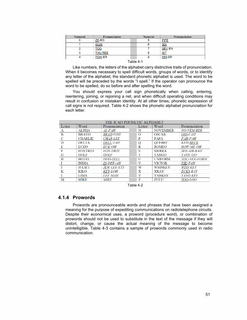
51
Table 4-1
Like numbers, the letters of the alphabet carry distinctive traits of pronunciation. When it becomes necessary to spell difficult words, groups of words, or to identify any letter of the alphabet, the standard phonetic alphabet is used. The word to be spelled will be preceded by the words “I spell.” If the operator can pronounce the word to be spelled, do so before and after spelling the word.
You should express your call sign phonetically when calling, entering, reentering, joining, or rejoining a net, and when difficult operating conditions may result in confusion or mistaken identity. At all other times, phonetic expression of call signs is not required. Table 4-2 shows the phonetic alphabet pronunciation for each letter.
Table 4-2
4.1.4 Prowords Prowords are pronounceable words and phrases that have been assigned a
meaning for the purpose of expediting communications on radiotelephone circuits. Despite their economical uses, a proword (procedure word), or combination of prowords should not be used to substitute in the text of the message if they will distort, change, or cause the actual meaning of the message to become unintelligible. Table 4-3 contains a sample of prowords commonly used in radio communication.

52
Table 4-3
TERM DEFINITION or MEANING AFFIRMATIVE Yes. ALL AFTER The portion of the message that follows (word). ALL BEFORE The portion of the message that precedes (word). BREAK I hereby indicate the separation of the text from other
portions of the message. COPY I understand. CORRECT You are correct, or what you have transmitted is correct CORRECTION An error has been made in this transmission. Transmission
will continue with the last word correctly transmitted. DISREGARD The last transmission was in error. Disregard it. DISREGARD THIS
TRANSMISSION This transmission is in error. Disregard it. This proword
should not be used to cancel any message that has been completely transmitted and for which receipt or acknowledgment has been received.
EXEMPT The addresses immediately following are exempted from the collective call.
FIGURE(s) Numerals or numbers follow. FROM The originator of this message is the address designator that
follows. I READ BACK The following is my response to your instructions to read
back. I SAY AGAIN I am repeating transmission or portion indicated. I SPELL I shall spell the next word phonetically. I VERIFY That which follows has been verified at your request and is
repeated. To be used only as a reply to VERIFY. INFO The addressees immediately following are addresses for
information. INITIALS Personal initials shall be spoken phonetically prefixed by the
word “INITIALS.” MESSAGE FOLLOWS A message that requires recording is about to follow.
Transmitted immediately after the call. (This proword is not used on nets primarily employed for conveying messages. It is intended for use when messages are passed on tactical or reporting nets.)
MORE TO FOLLOW Transmitting station has additional traffic for the receiving station.
NEGATIVE No or “permission not granted” or “that is not correct.” OUT This is the end of my transmission to you and no answer is
required or expected. OVER This is the end of my transmission to you and a response is
necessary. Go ahead; transmit. PRIORITY Precedence PRIORITY. READ BACK Repeat my message back to me. A request to repeat
instructions back to the sender, for the purpose of confirmation. Also, the receiver's reply, repeating the instructions, as in: "Read back is as follows..."
RED CAP Precedence RED CAP RELAY (TO) Re-transmit this message to... ROGER I have received and understand all of your last transmission.
This should not be used to answer a question requiring a yes or no answer.

53
TERM DEFINITION or MEANING ROUTINE Precedence ROUTINE.
SAY AGAIN Repeat all of your last transmission. Followed by identification data means “Repeat (portion indicated).”
SPEAK SLOWER Your transmission is at too fast a speed. Reduce speed of transmission.
SPELL, or I SPELL Please spell, or "I shall spell the next word phonetically.” STANDBY I must pause for a few seconds. THIS IS This transmission is from the station whose designator
immediately follows. TIME That which immediately follows is the time or date-time group
of the message. TO The addressees immediately following are addressed for
action. VERIFY Verify entire message (or portion indicated) with the
originator and send correct version. To be used only at the discretion of or by the addressee to which the questioned message was directed.
WAIT I must pause for a few seconds. WAIT OUT I must pause longer than a few seconds. WILCO I have received your signal, understand it, and will comply.
To be used only by the addressee. Since the meaning of ROGER is included in that of WILCO, these two prowords are never used together.
WORD AFTER The word of the message to which I have reference is that which follows .
WORD BEFORE The word of the message to which I have reference is that which precedes .
WORDS TWICE Communication is difficult. Transmit each phrase or each code group twice. This proword may be used as an order, request, or as information.
As an example of using phonetic letters and numbers, consider the following hypothetical example:
You want to fly an aircraft, CAP 4239, through Restricted Area R-2403B, just north of Little Rock, Arkansas. You must verify the status of that area before proceeding and can do so with a transmission such as this:
"Memphis Center, CAP FORTY-TWO THIRTY-NINE requests flight through Restricted Area TWO FOUR ZERO THREE BRAVO to Fort Smith at NINER THOUSAND, FIVE HUNDRED if that airspace is not presently active."
If the area is not active, you might receive a reply like this from Memphis Center: "CAP FORTY-TWO THIRTY-NINE, Memphis Center. Restricted Area TWO
FOUR ZERO THREE BRAVO is not currently active. Proceed own navigation to Fort Smith."
Now that the controller has answered the request, you must make one final transmission so that the controller knows you have received and understood his instruction:
"Roger Memphis. FORTY-TWO THIRTY-NINE proceeding direct Fort Smith at NINER THOUSAND, FIVE HUNDRED."
In this communication exchange, both observer and controller were consistent in their messages. On the initial call-up, the observer first identified the station being

54
called, then identified his aircraft fully before transmitting the request. [NOTE: Sometimes a controller will ask you for the type of aircraft, especially where speed and timing is a factor.]
The controller did the same, enabling both parties to know with certainty to whom each was speaking. Only when that positive identification has been established may the parties abbreviate the call sign, as in the observer’s later transmissions of "Forty-Two Thirty-Nine."
4.1.5 Code words are prohibited
Locally designed codes or adaptation of official codes, however well intentioned, will not deceive a cryptanalyst; only officially authorized codes are to be used. It has become a practice within CAP to assign "code words" to various mission events, in the belief that doing so will conceal these events from an undesired listener. This practice is seldom effective, violates the principles of the Incident Command System, and is therefore not authorized per CAPR 100-3.
4.1.6 CAP FM radio reports
As a minimum, the aircrew must report the following to mission base: • Radio check (initial flight of the day) • Take off time • Time entering a search area (may be multiple times) • Time exiting a search area (may be multiple times) • Landing time • Operations normal ("Ops Normal"), at intervals briefed by mission staff
4.2 Non-verbal Communication While you are on a mission, nonverbal signals may be the only available
method of communication with a crash survivor or with ground teams. Mission aircrews may have to interpret these nonverbal messages and must be able to do so accurately regardless of the method used.
4.2.1 Body signals
Use of the body is one of the most common means of sending messages. These signals are called "body signals" since they involve the whole body, not just arm movements. They are easy to use because no special materials are needed. Body signals are shown in Figure 4-9 at the end of this chapter.
4.2.2 Paulin signals
“Paulin” is a short form of tarpaulin, which means waterproof canvas. If the victims of an accident are fortunate enough to have some Paulin material, they may be able to aid the rescuers greatly by sending signals with it (Figure 4-6). It would be better if it were large and brightly colored. If the Paulin is laid in clear areas where their colors cause high contrast, they can be seen from substantial distances.

55
Need Medical Assistance
Proceeded in this
Direction
Need First Aid Supplies
Should We Wait for a
Rescue Plane?
Need Warm Clothing
Indicate
Direction of Nearest
Habitation
Figure 4-6
Need Food and Water
Abandoned
Plane-Walking in This
Direction
Do Not Attempt Landing
Need Gas and Oil
4.2.3 Emergency distress signals The standard emergency distress signals (Figure 4-7) are another form of
ground-to-air communication. These signals may be constructed using strips of fabric, pieces of wood, stones, wreckage parts, or any other available material. Each letter is two to three feet wide and six to twelve feet long, with colors that contrast with the background, if possible. Another use for these signals is to inform aerial searchers of ground team findings and intentions, in the absence of radio contact.
Require doctor Serious injuries
Require medical supplies
Unable to proceed
Require food and water
Indicate direction to proceed
Proceeding in this direction
Will attempt takeoff
Aircraft seriously damaged
Require fuel and oil
No
Probably safe to land here
Yes
All well
Require map and compass
Not understood
Require signal lamp
Require firearm and ammunition
Divided into 2
Require engineer Information that A/C in this direction
Have found only
groups, in directions as indicated
Have found all personnel
Unable to continue; returning
Operation complete
Figure 4-7
some personnel
Nothing found. Will continue to search
4.2.4 Air-to-ground signals Communicating by radio is the basic air-to-ground communication method. If
this isn’t possible for any reason, the pilot has a limited number of signals that can

56
be given using the aircraft itself, as illustrated in Figure 4-8. These signals serve as a standard means to acknowledge receiving and understanding signals from the ground. An "affirmative, I understand" response to a survivor’s signal can often be a morale booster, and renew hope for imminent rescue.
In addition to the four signals shown in Figure 4-8, there are two more that aircrews use to communicate with ground rescue teams. First, if the crew believes a ground team should investigate an area, the pilot may fly over the team, “race” the engine or engines, and then fly in the direction the team should go. The pilot may repeat this maneuver until the ground team responds or until another means of communication is established.
Second, you may pinpoint an area for investigation by circling above the area, continuing to do so until the ground team reaches the area and begins the search. The better the communication from ground-to-air and air-to-ground, the more coordinated the search will be and the greater the chances for success.
Figure 4-8
4.2.5 Air-to-ground team coordination The basic plan for a combined air and ground team search is that the aircrew
locates the objective and then guides the ground team to the objective. It sounds simple, but there are several factors to consider.
As an aircrew member, it is important to understand that you have the advantage of perspective; the long-range visibility that is inherent to flying is absent from the ground. You can see over the hills, trees, and other obstacles that are blocking the ground team member's sight, so you may have to explain the situation to the ground pounder in painstaking detail.
Another perspective problem is time: time seems to pass very slowly while waiting for a ground team, and it is easy to get impatient and leave station prematurely.
Naturally, the best means of working with a ground team is to use the radio. However, communications difficulties are par for the course. This gives you additional incentive to practice directing and working with ground teams.

57
Sometimes the ground team member (non-CAP, of course) may not understand radio jargon, so use plain English. For example, if you wanted a ground team to take a left at the next intersection, what would you say? How about “Ground Team 1, CAP 4239, turn left at the next intersection, over.” Most often the plain English answer is the correct way to say it in “radioese”, anyway.
Someone in the aircrew (often the back seat scanner) should continuously have his or her eyes on the ground team; this frees the pilot to fly the aircraft and allows the observer to work the radio to execute the coordination. The observer will likely also have to be the one who keeps track of where you “left” your target.
After these tasks are delegated, the observer simply talks the ground team to the target. What could be easier? Well, of course there are additional factors to consider.
First of all, how do we get the aircrew and the ground team together in the first place? You will often find that a poorly conducted rendezvous with the ground team will result in a frustrating "search for the searchers." It is important to brief the mission with the ground team, if possible, and at least agree on communications frequencies and lost-com procedures, maps/charts to be used by both teams, determine what vehicle the ground team is driving (e.g., type, color, and any markings), determine what the ground team members are wearing (highly visible vests are preferred), and a rendezvous point and time window for rendezvous (+/- 15 minutes). It is also important to agree on how GPS coordinates will be stated; the aircraft GPS is displayed in digital format, while most maps used by ground teams use other formats (e.g., degrees, minutes and seconds).
One tried-and-true method is to rendezvous at a landmark that both the aircrew and the ground team can easily identify. A common rendezvous point is an intersection of prominent roads; these are easily identifiable by both the aircrew and ground team. The rendezvous location should be set up before you leave mission base.
Also, ground teams that have a hand-held GPS can radio their latitude and longitude coordinates to you and say, “Come and get me!” If you are unable to loiter over the target and bring the ground team to it, you can simply radio the coordinates to the ground team and let them navigate to it on their own. This is not nearly as efficient, however, as when you lead them to it. Note that two pieces of technology have to be working properly to make this work: 1) both air and ground operators need to be proficient with their GPS units and 2) two-way radio communication must be established and maintained.
After visual contact with the ground team, the pilot may use flaps to reduce groundspeed. If you lose radio communication, you can use the signals as listed below. However, these signals may be used as a standard to be followed in addition to two-way radio communication for additional clarity and practice. Allow plenty of room for your maneuvers or you may confuse the ground team and do not rush your signals.
Note: It is important to plan for a loss of communications during the briefing. The teams should agree on pre-arranged signals such as: stopping the vehicle means lost com; blinking headlights indicate the message has been received; and operating the flashers means the message hasn't been received.

58
Keeping contact with the ground team.
• Aircraft action: Aircraft approaches the vehicle from the rear and turns in a normal manner right (or left) to re-approach the vehicle from the rear. Circle back as necessary using oval patterns and flying over the team from behind, indicating that they should continue. This process may be referred to as a “Daisy Chain.” Daisy Chain over the ground team as long as necessary.
• Desired team action: Continue driving in indicated direction along this road.
Turning the ground team around.
• Aircraft action: Aircraft approaches the vehicle from the rear and then turns sharply right (or left) in front of the vehicle while in motion. Circle back as necessary, flying against the team’s direction of travel, and then take up the ‘keeping up’ procedure outlined above.
• Desired team action: Turn vehicle around.
SAR
SAR

59
SAR
Turn.
• Aircraft action: Aircraft approaches the vehicle from the rear and then turns sharply right (or left) in front of the vehicle while in motion. Circle back as necessary using oval patterns and flying over the team from behind, indicating that they should continue.
• Desired team action: Turn vehicle to right (or left) at the same spot the aircraft did and then continue in that direction until further signals are received
Stop or Dismount.
• Aircraft action: Aircraft approaches the vehicle low and head-on while the vehicle is moving
• Desired team action: Stop the vehicle and await further instructions
• Aircraft action: Aircraft makes two (or more) passes in same direction over a stopped ground team
• Desired team action: Get out of the vehicle, then follow the aircraft and obey further signals (proceed on foot)
SAR

60
Objective is here.
• Aircraft action: Aircraft circles one geographic place • Desired team action: Proceed to the location where the low wing of the
aircraft is pointing; that is the location of the target
Remember: Air-to-ground coordination is an art that should be regularly practiced, both during daylight and at night
4.2.6 Deleted

61

62
Wave Both arms across face Both arms held over head Cup hands over ears DO NOT ATTEMPT TO LAND PICK UP - PLANE IS ABANDONED OUR RECEIVER IS
WORKING
Lie flat on back with hands above head NEED MEDICAL ASSISTANCE
Both arms horizontal Wave one arm over head Wave cloth horizontally NEED MECHANIC HELP or PARTS ALL OK - DO NOT WAIT NEGATIVE – NO
Wave cloth vertically Both arms pointing in the direction of landing while squatting
One arm horizontal
AFFIRMATIVE – YES LAND IN THIS DIRECTION WAIT IF PRACTICAL
Figure 4-9 Body Signals

63
5. Scanning Techniques and Sighting Characteristics
Chapter
5
OBJECTIVES:
1. Define "scanning" and "fixation,' and describe how aircraft motion effects scanning. {O-2022}
2. Discuss central and peripheral vision, and describe where your focal point is when you are relaxed. {O-2022}
3. Discuss fixation points and lines of scan; define "scanning range." {O-2022}
4. Describe the diagonal and vertical scanning patterns. {O-2022} 5. Discuss how atmospheric and lighting conditions affect scanning.
{O-2022} 6. Discuss common visual clues and wreckage patterns. {O-2022} 7. Discuss tips on reducing fatigue while scanning. {O-2023} 8. Describe how to give directions to the pilot while in flight.

64
5.1 Scanning Scanning is the process of investigating, examining, or checking by systematic
search. In search and rescue operations, the scanner or observer visually searches the search area for distress signals or accident indications by using a systematic eye movement pattern. The observer manages all scanning aboard the search aircraft by assigning an area of responsibility to each individual scanner (e.g., in a C172 the observer will scan out the right side and the scanner will scan out the left side of the aircraft). When the search aircraft nears the designated search area, the mission observer must ensure that all crewmembers are aware of their respective areas of responsibility and ready to begin the visual search.
The most commonly used eye movement pattern involves moving the eyes, and thus the field of view, laterally or vertically while pausing every three to four degrees. This pause is known as a fixation. This pattern should be used at a rate that covers about 10 degrees per second.
Search aircraft motion causes the field of view to continuously change, making this scanning technique most appropriate for occupants in the front seats of small aircraft. At side windows of larger aircraft, eye movements are directed away from the aircraft to the effective visibility range and then back to a point close to the aircraft’s ground track. The scanner should maintain this routine to systematically cover an assigned sector. The mission observer determines when rest periods are taken, or directs other fatigue-reducing measures. Scanning patterns should be practiced often in order to maintain or increase scanning proficiency.
Your job is to concentrate on scanning for the objective within the search area. Anyone can "look," but scanning is more than just looking. Scanning is the skill of seeing by looking in a methodical way, and there are certain techniques that can help you develop this skill. In this section, we will present these techniques. But more than knowing scanning techniques is required. You need practice at using the techniques so that your ability to scan becomes second nature.
5.2 Vision The primary tools of the scanner are your eyes. Although an eye is a marvelous
device, it has some limitation even if it is in perfect physical condition. There also is the problem of interpreting correctly what the eyes convey to the brain.
When a person with normal eyes looks straight ahead at a fixed point, much more than just the point is seen. The brain actively senses and is aware of everything from the point outward to form a circle of 10 degrees (visual acuity outside of this cone of vision is only ten percent of that inside the cone). This is central vision, produced by special cells in the fovea portion of the eye's retina. Whatever is outside the central vision circle also is "picked up" by the eyes and conveyed to the brain, but it is not perceived clearly. This larger area is called peripheral vision; cells less sensitive than those in the fovea produce it. For example, an object that is visible one mile away using central vision would only be visible 500 feet away using peripheral vision. However, objects within the peripheral vision area can be recognized if mental attention is directed to them. Figure 5-1 shows the span of human vision.

65
Top View
Central Vision - 10°
Peripheral Vision - 180°
Side View
Central Vision 10°
Peripheral Vision - 160°
Span of Vision
Figure 5-1 Note that peripheral vision is very important at night, and is also important in
picking up structures such as towers. The fixation area is the area in which "concentrated" looking takes place. If the
search objective happens to come within this fixation area, you probably will recognize it. It is possible to miss a search object even if it is in the fixation area because there are other factors such as fatigue and weather that also influence whether the objective will be recognized (covered later).
For central vision to be effective, the eye must be focused properly. This focusing process takes place each time the eyes, or head and eyes, are moved. When you are not actively focusing for about a minute while looking outside the aircraft, your focal point will shrink to a point about 30 feet out. Thus, daydreaming or thinking about other things while you are supposed to be looking for the target will guarantee you will not see the target even if your eyes are pointed right at it!
Let's introduce a reason for scanners to move their heads while scanning. Good central vision requires that the eyes be directed straight to the front. Side looking, in other words, can reduce the effectiveness of central vision. Why? Very simply, the nose gets in the way. Take a moment and focus on an object well to your right, but keep your head straight. Now close your right eye. Notice that your central vision is cut in half, although you did not realize it.
5.3 Fixation Points and Line of Scan When you wish to scan a large area, your eyes must move from one point to
another, stopping one or two seconds at each point long enough to focus clearly (a continuous scan tends to blur your vision). Each of these points is a "fixation point." When the fixation points are close enough together, the central vision areas will touch or overlap slightly. Focusing on these points enables your central vision to more clearly detect objects, and increases your peripheral vision's ability to detect contrasting objects. Spacing of fixation points should be 3 or 4 degrees apart to

66
ensure the coverage will be complete (Figure 5-2). Consciously moving the fixation points along an imaginary straight line produces a band of effective "seeing."
Fixation Area
Fixation Point or Fixation Point
First Fixation Area Nearest
Airplane
Figure 5-2 The fist, held at arm’s length, approximates the area of central vision so you
can use this fact to help you practice your scanning technique (Figure 5-3). Extend your arm at eye level and picture that you are looking through the back of your fist. Look "through" your fist and focus your eyes on the center of the area that would be covered if you were looking at instead of through your fist. Now move your fist to the right to a position next to and touching the previous area (refer to Figure 5- 4). Again, look “through” your fist and focus on the center of the fist-sized area on the other side of your fist. If you continue to move your fist along a line, stopping and focusing your eyes on the center of each adjacent fist sized area, you will have seen effectively all of the objects along and near that line. You will have “scanned” the line.
Figure 5-3 Repeat this process but establish starting and stopping points for the line of
scan. Pick out an object on the left as the starting point and an object on the right as the stopping point. Start with the object on the left. Extend your arm and look through your fist at that object. As practiced before, continue moving your fist to the next position along an imaginary line between the objects. Remember to stop briefly and focus your eyes. When your eyes reach the object on the right, you will have scanned the distance between the objects.

67
Direction of Flight
Follow the same procedure but scan between the two objects without using your fist as a guide. Move your head and eyes to each fixation point as before. Pause just long enough to focus clearly (about 1/3 second). When you reach the object on the right you will have scanned the line or area between the two objects and you will have scanned the line in a professional manner.
5.3.1 Fixation area
The goal of scanning techniques is to thoroughly cover an assigned search area. Reaching this goal on a single over flight is not possible for a number of reasons. First, the eye’s fixation area is a circle and the search area surface (ground) is flat. Coverage of a flat surface with circles requires much overlapping of the circles. This overlapping is not possible on a search mission because of the aircraft’s motion (Figure 5-4). Also, the surface area covered by the eye’s fixation area is less for the area near the airplane and increases with distance from the airplane. The net result is relatively large gaps in coverage near the airplane and some overlap as distance from the airplane increases. Figure 5-2 is not to scale, but it gives a good idea of how these gaps and overlaps occur. Notice how the surface area covered begins as a relatively small circle near the airplane and takes an increasingly larger and more elliptical shape farther out. Also, Figure 5-3 shows how the forward motion of the aircraft may affect this coverage pattern. You should be aware of this affect and not allow it to cause major gaps in your scanning pattern coverage.
Actual Pattern Intended Pattern
Figure 5-4 Angular displacement is the angle formed from a point almost beneath the
airplane outward to the scanning range, or beyond. By this definition, the horizon would be at 90 degrees displacement. Although the fixation area may be a constant 10-degree diameter circle, the effectiveness of sighting the objective decreases with an increase in this angular displacement. Said another way, your ability to see detail will be excellent at a point near the aircraft, but will decrease as the angular displacement increases. At the scanning range, at which the angular displacement may be as much as 45 degrees, the resolution of detail area probably will have shrunk to a 4-degree diameter circle.

68
This is why having scanners looking out both sides of the aircraft is optimal. With track spacing (explained later) proper for the given search visibility, each scanner will look at roughly the same area (i.e., double coverage).
5.3.2 Field of scan
The area that you will search with your eyes in lines of scan is called the field of scan. The upper limit of this field is the line that forms the scanning range. The lower limit is the lower edge of the aircraft window, while the aft (back) limit is usually established by the vertical edge of the aircraft window. The forward (front) limit for a field of scan will vary. It might be established by a part of the airplane (such as a wing strut). Or, when two scanners are working from the same side of the airplane it might be limited by an agreed upon point dividing the field of scan.
5.3.3 Scanning Range
We are using the term “scanning range” to describe the distance from a moving aircraft to an imaginary line parallel to the aircraft’s ground track (track over the ground). This line is the maximum range at which a scanner is considered to have a good chance at sighting the search objective.
Scanning range sometimes may be confused with search visibility, which is that distance at which an object on the ground (CAP usually uses an automobile as a familiar example) can be seen and recognized from a particular height. Aircraft debris may not be as large as an automobile and may not be immediately recognizable as aircraft debris, particularly when the aircraft is flying at 100 mph. Therefore, scanning range may be less than but never greater than the search visibility (in CAP searches, we rarely credit a search visibility of greater than three or four nautical miles).
From an altitude of 500' AGL and a scanning angle of 45º, the ratio of altitude to scanning range is one-to-one, so scanning range is only 500 feet; at 1000' AGL and 45º, scanning range increases to 1000 feet. To achieve scanning ranges applicable for typical search altitudes, the scanning angle (angular displacement below the horizon) typically would be 10º (farther limit) and 20º (closer limit) for scanning range at each altitude.
The following chart depicts the scanning ranges associated with various combinations of scanning altitudes and angles. From this, scanning ranges of one- half mile or greater would require a compromise in either higher altitudes or low depression angles. For lower scanning angles, the fixation area within the scanning cone would be extremely elongated (and much smaller), whereas for higher altitudes the size of objects on the ground would be smaller and thus harder to detect.

69
Altitude (AGL) Scanning Range (feet) Scanning Range (miles) Scanning Angle (º)
500' 866 0.164 30
1374 0.260 20
2836 0.537 10
1000' 1732 0.328 30
2747 0.520 20 5671 1.074 10
1500' 2598 0.492 30
4121 0.781 20
8507 1.611 10
** Angular displacement measured from the horizon
Concerning scanning technique, with this chart representing the relationship of altitude and angle, use of depression angle would seem to provide the most practical approach for estimating scanning range. Thus, for a deflection angle of 70º, the depression angle is 20º (e.g., about two “fists” below the natural horizon). To provide a reference mark of the scanning range for the scanner in the rear seat, a piece of masking tape could be placed on the front of the window frame equivalent to the depression angle used to estimate the scanning range. A similar reference mark could be placed on the bottom of the window for the scanner in the front seat.
If your pilot states that the search altitude will be 1,000' AGL, you can expect a scanning range of between ½ and 1 mile. If you drop down to 500' AGL to investigate a potential sighting, you can expect your scanning range to be ¼ to ½ mile. There are many variables that affect both the effective scanning range and your probability of detecting the search objective; these are discussed later.
5.4 Scanning Patterns To cover the field of scan adequately requires that a set pattern of scan lines
be used. Research into scanning techniques has shown that there are two basic patterns that provide the best coverage. These are called the diagonal pattern and the vertical pattern.
Figure 5-5 illustrates the way the diagonal pattern is used when sitting in the right rear seat of a small airplane. This line is followed from left to right as in reading. The first fixation point is slightly forward of the aircraft's position. Subsequent fixation points generally follow the line as indicated in the figure.

70
Direction of Flight
Scanning Range
Figure 5-5
The next scan line should be parallel to the first, and so on. Each succeeding scan line is started as quickly as possible after completing the previous one. Remember, the duration of each fixation point along a scan line is about 1/3 second. How long it takes to complete one scan line depends on the distance at which the scanning range has been established. Also, the time required to begin a new scan line has a significant influence on how well the area nearest the airplane is scanned. In other words, more time between starting scan lines means more space between fixation points near the airplane. Note that this is why search speed control is so important; experience has shown that speeds of 80-100 knots are best, depending upon search objectives and conditions.
When the diagonal scanning pattern is used from the left rear window (Figure 5-6), the direction of scan lines still is from left to right, but each line starts at the scanning range and proceeds toward the airplane. Each scan line on this side terminates at the window's lower edge.
Figure 5-6
Direction of Flight
Scanning Range

71
Figure 5-7 gives you an idea of the surface coverage obtained with a diagonal scanning pattern.
Figure 5-7 The second and somewhat less effective scanning pattern is illustrated in
Figure 5-8. This pattern is vertical and is basically the same as the example shown in Figure 5-2. You should use this vertical pattern only from a rear seat position, and the first fixation point should be as near to underneath the airplane as you can see. Subsequent fixation points for this first scan line should progress outward to the scanning range and back.
Scanning Range 6 5
7 4
8 3
9 2
10 1
Figure 5-8 Figure 5-9 reveals the saw tooth shape this vertical pattern makes on the
surface. Observe how much surface area near the airplane is not covered.
Figure 5-9

72
If there are two scanners on the same side of the airplane, it is good practice to combine the diagonal and vertical patterns. As agreed between scanners, one would use the diagonal pattern and the other the vertical pattern. However, the scanner using the vertical pattern would not scan to the scanning range. Some distance short of the scanning range would be selected as the vertical pattern limit. This technique provides good coverage of the surface area near the search aircraft.
When flying in the right front seat of an airplane you will use the diagonal pattern. This is true because it is the only pattern that has a natural flow to it from this particular position. Because of the aircraft's structure, you probably will want to begin your scan line near the line of flight over the surface. This will be somewhat ahead of the airplane (not much). The angle of the scan line and its length will be determined by whatever structural part obstructs your vision. For example, you could use the window post on some aircraft as either a starting point or stopping point, depending on your judgment. If you are in the right front seat of a low wing model, the wing will be the stopping point.
Scanners, especially those with considerable experience, may use a system or pattern that is different from the diagonal and vertical patterns discussed above. Many search objectives were found and many lives were saved long before there was an effort to analyze the scanning process and develop recommendations for its improvement. On the other hand, it is possible that Civil Air Patrol's outstanding search and rescue record would have been better had the scanners of times past used a set pattern and used it consistently.
5.5 Atmospheric and Lighting Conditions During daylight there are many factors that can affect the scanner's ability to
spot the search target. The following table shows the (approximate) distance at which the scanner can sight various objects under average visibility conditions; factors that can alter these distances are discussed below.
Object Distance Person in life jacket (open water or moderate seas) 1/2 mile Person in small life raft (open water or moderate seas) 3/4 mile Person in open meadow within wooded area 1/2 mile or less Crash in wooded area 1/2 mile Crash on desert or open plain 2 miles Person on desert or open plain 1 mile or less Vehicle in open area 2 miles or less
During darkness, scanners make fewer fixations in their search patterns than
during daylight because victims in distress are likely to use lights, fires, or flares to signal rescuers. Contrast between signal light and surrounding darkness eliminates the need for scanners to concentrate on making numerous eye fixations. An attentive scanner or observer should be able to see a light, flare, or fire easily during night operations. Search aircraft interior lighting should be kept to the lowest possible level that still allows normal chart reading. This will help the eyes adjust to the darkness and reduce glare on windshield and window surfaces. Red or green lights are used when flying at night because that color has little or no effect on the low-light adaptation of the human eye. Regardless of light conditions, a scanner

73
should always maintain a systematic scanning pattern with fixations every few seconds. Darkness merely lengthens the interval between fixations.
5.5.1 Atmospheric conditions
All aircrews hope for perfect visibility during a SAR mission. Seldom does this atmospheric condition exist. Most of the time, the atmosphere (especially the lower atmosphere) contains significant amounts of water vapor, dust, pollen, and other particles. These items block vision according to their density. Of course, the farther we try to see the more particles there are and the more difficult it is to sight the objective.
The urgency of finding a downed aircraft may require flight under marginal conditions of visibility. An example here is flight through very light rain or drizzle. Another example is flight during the summertime when the air is not moving appreciably. It may become virtually saturated with pollutants.
5.5.2 Position of the sun
Flying “into the sun,” soon after it rises in the morning or before it sets in the afternoon, poses visibility problems. No doubt you have had this experience while driving or riding as a passenger in an automobile. Recall how difficult it is to distinguish colors and to detect smaller objects.
Research in search and rescue techniques has determined that the best time to fly search sorties is between mid-morning and mid-afternoon. This is when the sun is about 30 degrees or more above the horizon. When the sun is below this angle, it intensifies visibility problems.
As the sun climbs higher in the sky it helps to relieve visibility problems caused by the presence of particles in the atmosphere. The sun’s rays heat the ground and the atmosphere. This heat causes the lower atmosphere to expand. As the atmosphere expands the particles it contains are spread farther apart, decreasing their density within a given volume. Therefore, there are fewer particles between the surface and the scanner’s eyes and the effective scanning range is increased slightly.
5.5.3 Clouds and shadows
Shadows produced by clouds can reduce the effective scanning range. This is due to the high contrast between sunlit area and shadows. Our eyes have difficulty adjusting to such contrasts. The same effect occurs in mountainous areas where bright sunlight causes the hills and mountains to cast dark shadows.
Heavy cloud cover can "wash out" colors on the ground, making wreckage and colored clothes or signal devices harder to sight.
5.5.4 Terrain and ground cover
If flat, open, dry areas were the only areas to be searched, the scanner’s job would be easy. Most aircraft crashes do not happen in such areas; when one does happen, it usually is found quickly without an intensive search effort.
The more intensive search efforts occur over terrain that is either mountainous or covered with dense vegetation, or both. Mountainous area searches demand frequent variation in the scanning range. This you can visualize fairly easily; at one

74
moment the mountain or hill places the surface within, say 200 feet of the aircraft. Upon flying past the mountain or hill the surface suddenly may be a half-mile away.
Forested areas can reduce the effective scanning range dramatically. This is especially true during spring, summer, and fall when foliage is most pronounced. The situation doesn’t change for the better in the winter where trees are of the evergreen types-pine, spruce, etc.-because the height of the trees plus their foliage masks the search objective very effectively. Frequently the only way for a scanner to actually spot an objective under such circumstance is to be looking down almost vertically. There are other signs to look for in such areas, but we will discuss them later.
5.5.5 Surface conditions
Here we are thinking of snow, primarily. Even a thin covering of new snow will change the contour, or shape, of a search objective. Also, the light-reflective quality of snow affects visual effectiveness. The net result is a need to bring the scanning range nearer to the aircraft.
5.5.6 Cleanliness of windows
This might seem to be a very minor factor. On the other hand, it is estimated that the scanner's visibility can be reduced up to 50 percent if the aircraft window isn't clean. If you discover this to be the case in your aircraft, clean the window yourself. However, aircraft windows are made of plastic and they are easily scratched. Ask the pilot what cleaning materials and methods are acceptable before cleaning the window. Window cleaning is a normal part of pre- and post-flight activities.
5.5.7 Use of binoculars and cameras
Binoculars rapidly bring on eye fatigue when used in an aircraft, and may lead to disorientation and airsickness. They should only be used for brief periods to check sightings or for detailed viewing of an assessment area or target.
Looking through a camera or camcorder viewfinder for extended periods can be equally as discomforting. Take breaks whenever possible.
5.5.8 Use of sunglasses
Sunglasses are an important tool for aircrew, reducing eye fatigue and glare. However, sunglasses do have some negative aspects.
Looking through the aircraft windshield with polarized lenses can result in a reduced retinal image. Also, color discrimination is reduced while wearing dark lenses. And, of course, if you are looking for a lost person wearing a blue jacket, don't wear sunglasses with "blue-blocking" lenses. Finally, no matter how cool it may look, don't wear sunglasses while flying in low visibility conditions (i.e., overcast and at dawn, dusk or night).
5.5.9 Use of night vision devices
Approved night vision devices are for use only by scanners and observers who have completed the national training program.

75
5.5.10 Condition of the scanner Your general physical welfare will influence how well you do your job. For
example, if you have a cold or sinus trouble, you may feel so bad you cannot concentrate on scanning. In effect, this reduces your personal effective scanning range to "zero." Only you can determine your fitness to fly and do the job expected of you. If you do not believe that you feel up to the job at the moment, ask for a non- flying assignment. You will be more highly regarded if you know your own limits.
Our discussion of variables could be extended considerably because most anything that happens during a sortie could affect the scanning operation. However, the variables of major importance have been discussed.
5.6 Visual Clues
5.6.1 Sighting Characteristics If you have not had much experience at "looking down" while flying, there are
some surprises in store for you. Objects appear quite different when they are seen from above and at a greater distance than usual. Even if you are very familiar with the territory as seen from the surface, scanning it from the air will reveal features and objects that you had no idea where there.
Experience is the best teacher, and you will soon be able to evaluate what you see from the air. To help with your development of this ability, we will present some visual clues, what you might expect in aircraft wreckage patterns, signals which survivors might be expected to use, and some false clues that are common to selected areas.
5.6.2 Typical Visual Clues
Anything that appears to be out of the ordinary should be considered a clue to the location of the search objective. In addition to this piece of advice, the following are specific clues for which scanners should be looking:
Light colored or shiny objects - Virtually all aircraft have white or other light colors as part of their paint schemes. Some aircraft have polished aluminum surfaces that provide contrast with the usual ground surface features. Also, bright sunlight will "flash" from aluminum surfaces.
Aircraft windshields and windows, like aluminum, have a reflective quality about them. If the angle of the sun is just right, you will pick up momentary flashes with either your central or peripheral vision. A flash from any angle deserves further investigation. Smoke and fire - Sometimes aircraft catch fire when they crash. If conditions
are right, the burning airplane may cause forest or grass fires. Survivors of a crash may build a fire to warm themselves or to signal search aircraft. Campers, hunters, and fishermen build fires for their purposes, but no matter what the origin or purpose of smoke and fire, each case should be investigated.
Blackened areas - Fire causes blackened areas. You may have to check many such areas, but finding the search objective will make the effort worthwhile.
Broken tree branches - If an airplane goes down in a heavily wooded area, it will break tree branches and perhaps trees. The extent of this breakage will depend on the angle at which the trees were struck. The primary clue for the scanner,

76
however, will be color. As you no doubt realize, the interior of a tree trunk or branch and the undersides of many types of leaves are light in color. This contrast between the light color and the darker foliage serves as a good clue.
Local discoloration of foliage - Here we are talking about dead or dying leaves and needles of evergreen trees. A crash that is several days old may have discolored a small area in the forest canopy. This discoloration could be the result of either a small fire or broken tree branches.
Fresh bare earth - An aircraft striking the ground at any angle will disturb or "plow" the earth to some degree. An over flight within a day or so of the event should provide a clue for scanners. Because of its moisture content, fresh bare earth has a different color and texture than the surrounding, undisturbed earth.
Breaks in cultivated field patterns - Crop farmlands always display a pattern of some type, especially during the growing season. Any disruption of such a pattern should be investigated. A crop such as corn could mask the presence of small aircraft wreckage. Yet the pattern made by the crashing airplane will stand out as a break in uniformity.
Water and snow - Water and snow are not visual clues, but they often contain such clues. For example, when an aircraft goes down in water its fuel and probably some oil will rise to the water's surface making an "oil slick" discoloration. Other material in the aircraft may also discolor the water or float as debris. If the aircraft hasn't been under the water very long, air bubbles will disturb the surface. Snow readily shows clues. Any discoloration caused by fire, fuel or debris will be very evident. On the other hand, do not expect easy-to-see clues if snow has fallen since the aircraft was reported missing.
Tracks and signals - Any line of apparent human tracks through snow, grass, or sand should be regarded as possibly those of survivors. Such tracks may belong to hunters, but it pays to follow them until the individual is found or you are satisfied with their termination-at a road, for example. If you do find the originator of such tracks and the person is a survivor, no doubt he will try to signal. More than likely this signal will be a frantic waving of arms.
Birds and animals - Scavenger birds (such as vultures and crows), wolves, and bears may gather at or near a crash site. Vultures (or buzzards) sense the critical condition of an injured person and gather nearby to await the person's death. If you see these birds or animals in a group, search the area thoroughly.
False clues - Examples are campfires and other purposely set fires, oil slicks that may have been caused by spillage from ships; and trash piles or pits. Aircraft parts may not have been removed from other crash sites, although some of the aircraft parts may have been marked with a yellow "X" (you may not be able to see the mark until near the site because the paint has faded or worn off with age).
In certain parts of the country, you will encounter many false clues where you would not ordinarily expect to see them. These false clues are discarded refrigerators, stoves, vehicles and pieces of other metal, such as tin roofing. What makes these false clues unique is that they are in areas far from towns and cities.
Survivors and Signals - If there are survivors and if they are capable of doing so, they will attempt to signal you. The type of signal the survivors use will depend on how much they know about the process and what type signaling devices are available to them. Here are some signaling techniques that survivors might use: [Refer to the Flight Guide for some examples.]
• A fire. Most people carry some means of starting a fire, and a fire probably will be the survivor's first attempt at signaling. The smoke and or flames of a fire are easily seen from the air, as we pointed out earlier.

77
• A group of three fires. Three fires forming a triangle is an international distress signal
• Red smoke, white smoke, or orange smoke • Some types of signaling devices, such as flares, discharge colored smoke.
Other flares are rocket types, and some send up a small parachute to which a magnesium flare is attached.
• Signal mirrors. If the sun is shining, a signal may be used. A special survival signal mirror includes instructions to the survivor on how to aim the signal at the search aircraft. Pocket mirrors will also work but aiming them may not be as easy.
• Panels on the ground. This type signal can be formed with white panels or with colored panels especially designed for the purpose. Of course, survivors may be able to arrange aircraft parts as a signal.
Messages - There are a number of methods and materials which survivors can use to construct messages. In snow, sand, and grassy areas, survivors may use their feet to stamp out simple messages, such as HELP or SOS. More than likely such messages will be formed with rocks, tree branches, driftwood, or any other similar materials. Such materials may also be used to construct standard ground- to-air signals. These signals are familiar to military and professional civilian pilots, including CAP pilots.
Nighttime signals - For various reasons, nighttime searches are very infrequent. If you are requested to scan for a nighttime sortie, your job will be easy. Flights will be at 3,000 AGL, or higher, and you will not need to use the scanning patterns discussed earlier. Light signals of some type will be the only clue to the search objective location.
A fire or perhaps a flashlight will be the survivor's means of signaling. On the other hand, a light signal need not be very bright; one survivor used the flint spark of his cigarette lighter as a signal. His signal was seen and he was rescued.
5.7 Wreckage Patterns (accident signs) Frequently, there are signs near a crash site that the aircrew can use to locate
the actual wreckage. The environment plays a major role in sighting the signs from the search aircraft. In crashes at sea, searchers may be unable to locate the crash site as rough seas can scatter wreckage or signs quickly. On land, the wreckage may be in dense foliage that can obscure it in a matter of days. By knowing signs to look for, the scanner can improve the effectiveness of each sortie. [Refer to the MS slides for examples.]

78
Common signs of accidents include: • Light colored or shiny objects • Sunlight reflections from metal • People • Distress signals • Blackened or burned areas • Broken tree branches • Fresh or bare earth • Discolored water or snow • Tracks or movement patterns in snow, grass, sand, etc. • Excessive bubbles in water • Oil slicks, floating debris, or rafts on water • Smoke • Deep furrows in snow • Abnormalities in the environment In general, don't expect to find anything that resembles an aircraft; most wrecks
look like hastily discarded trash. However, certain patterns do result from the manner in which the accident occurred.
5.7.1 Hole in the ground
Caused from steep dives into the ground or from flying straight into steep hillsides or canyon walls. Wreckage is confined to a small circular area around a deep, high-walled, narrow crater. The structure may be completely demolished with parts of the wings and empennage near the edge of the crater. Vertical dives into heavily wooded terrain will sometimes cause very little damage to the surrounding foliage, and sometimes only a day or two is needed for the foliage to repair itself.
5.7.2 Cork screw or auger
Caused by an uncontrolled spin. Wreckage is considerably broken in a small area. There are curved ground scars around a shallow crater. One wing is more heavily damaged and the fuselage is broken in several places with the tail forward in the direction of the spin. In wooded areas, damage to branches and foliage is considerable, but is confined to a small area.
5.7.3 Creaming or smear
Caused from low-level "buzzing", "flat hatting" from instrument flight or an attempted crash landing. The wreckage distribution is long and narrow with heavier components farthest away from the initial point of impact. The tail and wings remain fairly intact and sheared off close to the point of impact. With power on or a wind milling propeller, there is a short series of prop bites in the ground. Ground looping sometimes terminates the wreckage pattern with a sharp hook and may reverse the position of some wreckage components. Skipping is also quite common in open, flat terrain. In wooded areas, damage to the trees is considerable at the point of impact, but the wreckage travels among the trees beneath the foliage for a greater distance and may not be visible from the air.

79
5.7.4 The Four Winds Caused from mid-air collisions, explosion or in-flight break up. Wreckage
components are broken up and scattered over a wide area along the flight path. The impact areas are small but chances of sighting them are increased by the large number of them. Extensive ground search is required to locate all components.
5.7.5 Hedge Trimming
Caused when an aircraft strikes a high mountain ridge or obstruction but continues on for a considerable distance before crashing. Trees or the obstruction are slightly damaged or the ground on the crest is lightly scarred. Some wreckage components may be dislodged; usually landing gear, external fuel tanks, cockpit canopy, or control surfaces. The direction of flight from the hedge trimming will aid in further search for the main scene.
5.7.6 Splash
Where an aircraft has gone down into water, oil slicks, foam, and small bits of floating debris are apparent for a few hours after the impact. With time, the foam dissipates, the oil slicks spread and streak, and the debris become widely separated due to action of wind and currents. Sometimes emergency life rafts are ejected but, unless manned by survivors, will drift very rapidly with the wind. Oil slicks appear as smooth, slightly discolored areas on the surface and are in evidence for several hours after a splash; however, they are also caused by ships pumping their bilges and by offshore oil wells or natural oil seepage. Most aircraft sink very rapidly after ditching.
5.8 Reducing Fatigue The art of scanning is more physically demanding and requires greater
concentration than mere sight seeing. In order to maintain the effectiveness of all scanning crewmembers, an observer must be aware of his own fatigue level, and that of the scanner or scanners. The following tips can help the observer direct appropriate actions and maintain scanning effectiveness:
• Change scanning positions at 30- to 60-minute intervals, if aircraft size permits.
• Rotate scanners from one side of the aircraft to the other • Find a comfortable position, and move around to stretch when necessary • Clean aircraft windshields and windows. Dirty windows accelerate the
onset of eye fatigue, and can reduce visibility by up to 50 percent. • Scan through open hatches whenever feasible • At night, use red lights and keep them dimmed to reduce reflection and
glare • Use binoculars (sparingly) to check sightings • Focus on a close object (like the wing tip) on a regular basis. The muscles
of the eye get tired when you focus far away for an extended period of time. • Rest during turns outside the search area

80
5.9 Directing the Pilot The "clock position" system is used to describe the relative positions of
everything outside the airplane. The system considers the clock positions to be on a horizontal plane that is centered within the cockpit. Any object above or below this plane is either "high" or "low."
Imagine yourself in the right rear seat of the airplane. Straight ahead is the twelve o'clock position; straight to the rear is six o'clock. In a real-life situation you probably would be able to see as far ahead as the one o'clock position and as far to the right as five o'clock. (Caution: never divide the clock positions into minutes; there is no such thing as a four-fifteen position.) Refer to Figure 5-10.
Figure 5-10
If you occupy the left-rear seat of the airplane, your clock positions probably will be seven o'clock through eleven o'clock. In either the right-rear or left-rear seat, the further designation "low" is not used for objects on the ground. They are low, but this is understood.
The clock positions are especially helpful in designating the location of other aircraft within your area of the airspace. Your pilot needs to see all other airplanes in the area so that she can keep clear of them. If you see another airplane, notify the pilot immediately. The high and low designations are also appropriate if the other airplane is considerably higher or lower than your altitude. For example, an airplane that is directly ahead but above your altitude should be called out as, "aircraft twelve o'clock high."
In spite of this system's relative simplicity, experienced crewmembers still make mistakes during stress or excitement. When reporting an observation to another crewmember, one technique that helps keep mistakes to a minimum is to precede the clock position with either "left" or "right" as appropriate. While many people may mistake three and nine o'clock, few mistake left and right. Preceding the clock position with the direction will more likely initially move all eyes in the proper direction.
Let's say you see a flash of light from the right rear, somewhere near the four o'clock position. You call out "possible target at four o'clock." The pilot starts an immediate, medium-bank turn to the right. The pilot knows the four o'clock position

81
but her concept and your concept of this position may not be exactly the same. It looks as if the pilot might swing past your four o'clock. Now what? Don't let it happen! Say something like "straight ahead and level," or "stop turn," or "wings level." The pilot will get the idea.
Getting close to the area of your clue will require small adjustments to direction. Again, tell the pilot what to do. Pilots are accustomed to turning according to numbers of degrees, as shown by the aircraft compass, so you might want to say "five degrees right," or "ten degrees right." The pilot will turn the number of degrees you specify, level off and hold the heading.
If you see what seems to be the search objective, again give the clock position plus other helpful information, such as "near clump of trees." The pilot will bank the airplane and descend to a lower altitude. At this lower altitude identification may be possible. If the clue turns out to be the search objective, mission base will be notified by radio. Your search aircrew will try to remain in the area to direct ground teams to the site. If the clue is not the search objective, your pilot will return to the search track.
When your aircrew team locates a search objective, the scanner's duties change. He or she is no longer needed to scan the ground, but the scanner now needs to keep a sharp lookout for other aircraft. The pilot and observer will be very busy flying the airplane at low level and communicating with other mission units. The preoccupation of the pilot and observer, plus the tendency of other aircraft to congregate at a crash site, often leaves the responsibility for keeping clear of other aircraft to the scanner.
The scanner's job of looking and seeking is not over until the aircraft is parked at mission base.

82
Intentionally blank

83
6. Weather
Chapter
6
OBJECTIVES:
1. Discuss how reduced visibility affects search operations, and precautions for flight during reduced visibility conditions. {P-2023}
2. Describe how turbulence can affect search operations. {P-2023} 3. Describe the dangers of thunderstorms.
84
6.1 Basic Weather Since weather plays such an important part on any CAP operation, the mission
scanner/observer must become familiar with some basic weather conditions. Weather can have a pronounced effect on how the search is conducted, and is one of the most important variables that influences search effectiveness.
This chapter covers weather effects in order to produce a more informed aircrew. If you know what to expect, you will be better prepared. Also, remember that the decision of whether or not to fly a particular sortie (i.e., "go, no-go") is ultimately the responsibility of the pilot-in-command. However, any crewmember may decline a mission that he or she considers too dangerous.
6.2 Reduced Visibility According to FAA regulations, under almost all circumstances flight using visual
flight rules can only be conducted with at least three miles of visibility (CAPR 70-1 states the minimum flight visibility of three statute miles is required for all VFR flights unless the PIC is a current and qualified instrument pilot). If clouds cover more than one-half the sky, the cloud bases must be no lower than 1,000 feet above the terrain. In addition, search aircraft must usually remain at least 500 feet below the cloud deck.
One of the most common hazardous-weather problems is loss of visibility. This can happen either suddenly or very insidiously, depriving the pilot of his ability to see and avoid other aircraft, and reducing or depriving him altogether of his ability to control the aircraft, unless he has had training and is proficient in instrument flying. In reduced visibility, the crew's ability to see rising terrain and to avoid towers, power transmission lines, and other man-made obstacles is diminished.
Visibility may be reduced by many conditions including clouds, rain, snow, fog, haze, smoke, blowing dust, sand, and snow. A similar condition called “white out” can occur where there has been snowfall.
In most regions of the country, fog and haze are the most common weather conditions that cause reduced visibility. Fog, especially dense fog, can pose a hazard to even the most sophisticated military or civilian aircraft. In thick fog, reduced visibility may make it extremely difficult, if not impossible, to see landing runways or areas. The crew should be alert for a potential problem with fog whenever the air is relatively still, the temperature and dew point are within several degrees, and the temperature is expected to drop further, as around sunset and shortly after sunrise. This is often a factor in delaying the first sorties of the day.
Haze, a fine, smoke-like dust causes lack of transparency in the air. Its most often caused when still air prevents normal atmospheric mixing, allowing the particles to persist, instead of the wind's dispersing them. Like fog, it is most likely to occur when the air is still. The air doesn't mix to scatter the particles of dust, smoke, or pollen. If the wind remains calm for several days, visibility will become progressively worse. This atmospheric condition is most common in heavily populated, industrialized areas of the country; it can also be present anywhere there is still air and a source of particles, like near burning farm fields or thick forests that produce large quantities of pollen. It is especially noticeable in the early morning. Haze can cause your eyes to focus on a point 10-30 feet ahead.

85
Frequently, as the sun warms the cool, hazy air and causes it to expand and rise, visibility at the surface will improve and appear acceptable. What initially appeared to be ample visibility can, after takeoff, become almost a complete obstruction to lateral or forward visibility several hundred feet above the surface. Downward visibility is satisfactory, but pilots may feel apprehensive about the loss of a visible horizon to help judge aircraft control, and about what might come out of the murk ahead. Visibility at this altitude may actually be more than the minimum three miles, yet the pilot may interpret this visual range as a wall just beyond the airplane's nose.
In summer, haze and smoke may extend upward more than 10,000 feet during the heat of the day, hiding rain showers or thunderstorms within the haze and presenting a special hazard. When haze and smoke are present, the best measure a flight crew can take to minimize risk of such an encounter is to get a thorough weather briefing before flying, and update the briefing by radio with Flight Watch (122.0 MHz) as required.
Blowing dust is normally found in the relatively dry areas of the country, like the desert southwest. The condition develops when strong wind picks up small soil particles, and strong air currents carry it upward into the atmosphere. These conditions can spread dust hundreds of miles and up to 15,000 feet. Depending upon wind speed and particle volume, visibility in dust storms may be reduced to very low levels. Blowing sand is much more localized than dust, occurring only when the wind is strong enough to lift loose sand. Since sand particles are much heavier than dust they are rarely lifted more than 50 feet above the surface. Still, the condition eliminates the effectiveness of visual searches, and in many cases can prohibit an aircraft from taking off or landing.
Strong surface winds can also cause blowing snow. Blowing snow is more frequent in areas where dry, powdery snow is found. For the aviator, blowing snow can cause the same problems of reduced visibility. Like dust, it can reach thousands of feet above the surface.
Snow can cause another visibility problem, known as “white out.” This condition can occur anywhere there is snow-covered ground, but is most common in arctic regions. It's not a physical obstruction to visibility like earlier examples, but an optical phenomenon. White out requires a snow-covered surface and low-level clouds of uniform thickness. At low sun angles, light rays are diffused as they penetrate the cloud layer causing them to strike the snow-covered surface at many angles and eliminating all shadows. The net effects are loss of a visible horizon and loss of depth perception, each of which can make low-level flight and landings difficult and hazardous.
From this discussion, it becomes obvious that each member of the aircrew must be vigilant during all phases of the flight when visibility is less than perfect. Crew resource management requires that each member of the crew be assigned an area to search during the takeoff, transit and approach-to-landing phases of the flight in order to help the pilot "see and avoid" obstacles and other aircraft.
The aircrew must also characterize visibility in the search area so as to establish the proper scanning range. Search visibility may be different than expected, and your search pattern may have to be adjusted accordingly. Be sure to cover this during your debriefing.

86
6.3 Turbulence Turbulence is irregular atmospheric motion or disturbed wind flow that can be
attributed to a number of causes. Under almost all circumstances, small amounts of normal atmospheric turbulence can be expected and it usually poses few problems. Previous sections covered wake turbulence and convective activity as causes of turbulence. Convective activity was covered in the context of thunderstorm development, but any phenomenon that causes air to be lifted up, even a hot asphalt parking lot, can cause convective turbulence. Other causes include obstructions to wind flow and wind shear.
Just as a tree branch dangling into a stream creates continuous ripples or waves of turbulence in the water’s surface, obstructions to the wind can create turbulence in the air. This type of turbulence occurs mostly close to the ground, although depending upon wind velocity and the nature of the obstruction, it may reach upward several thousand feet. In an extreme case, when winds blow against a mountainside, the mountain deflects the wind upward creating a relatively smooth updraft. Once the wind passes the summit, it tumbles down the leeward or downwind side, forming a churning, turbulent down draft of potentially violent intensity. The churning turbulence can then develop into mountain waves that may continue many miles from the mountain ridge. Mountain waves may be a factor when surface winds are as little as 15 knots.
Turbulence can be inconsequential, mildly distracting, nauseating, or destructive depending on its intensity. Turbulence can often be avoided by changing altitudes. Aircraft manufacturers publish maneuvering speeds in the operating handbooks. If the maneuvering airspeed of an aircraft is exceeded in turbulent air, structural damage could occur.
Turbulence can become a major factor in search effectiveness. Any scanner or observer who is uncomfortable or nauseous cannot perform their duties at a very high level of effectiveness. If you experience these sensations, inform the pilot immediately. If turbulence detracted from your concentration during the search, be sure to mention this during debriefing.
6.4 Thunderstorms A thunderstorm is any storm accompanied by thunder and lighting. It usually
includes some form of precipitation, and can cause trouble for aircraft in many forms: turbulence, icing, poor visibility, hail, wind shear, micro bursts, lightning, and, in severe cases, tornadoes.
Individual thunderstorms may often be very local in nature, although they often form along weather fronts and appear to march across the land in long lines. This is the situation when weather forecasters announce that a line of thunderstorms is approaching, and thunderstorm warnings go into effect. Individual thunderstorms are rarely larger than 10 miles in diameter, and typically develop, mature, and dissipate within an hour and a half at the most. Each is produced by the growth of a puffy cumulus cloud into a cumulonimbus cloud. The severe elements of a thunderstorm result from the vertical air movement, or convective activity, within the storm.

87
Thunderstorms may be studied by dividing them into three separate growth stages: the cumulus, or building stage, the mature stage, and the dissipating stage. Figure 6-1 demonstrates the physical appearances of each stage of the developing storm.
Figure 6-1 Most cumulus clouds do not become thunderstorms, but all thunderstorms are
born as cumulus clouds. The main feature of this first stage of thunderstorm development is its updraft, a large air current flowing upward from the ground through the chimney-like cloud. The draft can reach speeds of several thousand feet per minute, and continue to an altitude of 40,000 feet or more. During this period, small water droplets grow into raindrops as the cloud builds upward to become a cumulonimbus cloud.
Precipitation at the earth's surface marks the mature stage of a thunderstorm. The raindrops (or ice particles) have now become so large and heavy that the updraft can no longer support them, and they begin to fall. As they fall, the raindrops drag air with them, causing the characteristic strong down draft of mature thunderstorms. These down drafts spread out horizontally when they reach the surface, producing strong, gusty winds, wind shear, sharp drops in temperature (because the air was chilled at high altitudes) and a sharp rise in pressure.
The mature stage of the thunderstorm is when associated hazards are most likely to reach maximum intensity. Micro bursts, extremely intense down drafts, can occur during this mature phase of development. Downward wind velocities in micro bursts may reach 6,000 feet per minute, and even powerful jet aircraft may have insufficient power to recover prior to ground impact.
As down drafts continue to spread, updrafts weaken, and the entire thunderstorm eventually becomes an area of down drafts, which characterizes the dissipating stage of the thunderstorm. During this stage, the cloud develops the characteristic anvil shape at the top and may take on a stratiform or layered appearance at the bottom. Usually this stage is the longest of the three stages of a thunderstorm's life.
No thunderstorm should ever be taken lightly. During the cumulus stage, vertical growth occurs so quickly that climbing over the developing thunderstorm is not possible. Flight beneath a thunderstorm, especially in the mature stage, is

88
considered very foolish, due to the violent down drafts and turbulence beneath them. Flight around them may be a possibility, but can still be dangerous. Even though the aircraft may be in clear air, it may encounter hail, lightning, or turbulence a significant distance from the storm's core. Thunderstorms should be avoided by at least 20 miles laterally. The safest alternative, when confronted by thunderstorms, is to land, tie the aircraft down, and wait for the storms to dissipate or move on.

89
7. Temperature, Humidity and High Altitude Considerations
Chapter
7
OBJECTIVES:
1. Discuss the symptoms and dangers of high temperatures, humidity, and dehydration, and strategies used to combat their effects. {P- 2024}
2. Discuss the symptoms and dangers of ear block, sinus block and hypoxia, and strategies used to combat their effects. {P-2024}

90
7.1 Temperature, Humidity and High Altitude Effects on Crewmember Performance
As air temperature increases, so does each crewmember's susceptibility to nausea, airsickness, and dehydration. As humidity increases with temperature, the body's ability to regulate its own temperature by perspiration can be negatively affected also, beginning the initial symptoms of heat exhaustion.
When operating in high temperatures, crewmembers should make every effort to drink plenty of water, juice, or caffeine-free soft drinks prior to, during, and after each mission to help prevent dehydration. Even though an individual may not be physically active, body water is continuously expired from the lungs and through the skin. This physiological phenomenon is called insensible perspiration or insensible loss of water.
The loss of water through the skin, lungs, and kidneys never ceases. Water loss is increased in flight because of the relatively lowered humidity at altitude, particularly on extended flights. Combating the loss of water during flights requires frequent water intake; experts recommend drinking 13-20 ounces (3-5 mouthfuls) of fluid thirty minutes before you leave, and 4-6 ounces (a couple of mouthfuls) every 15 minutes thereafter.
Typical dehydration conditions are: dryness of the tissues and resulting irritation of the eyes, nose, and throat, and fatigue relating to the state of acidosis (reduced alkalinity of the blood and body tissues). A person reporting for a flight in a dehydrated state will more readily notice these symptoms until fluids are adequately replaced.
Consumption of coffee, tea, cola, and cocoa should be minimized since these drinks contain caffeine. In addition, tea contains a related drug (theophylline), while cocoa (and chocolate) contain theobromine, of the same drug group. These drugs, besides having a diuretic effect, have a marked stimulating effect and can cause an increase in pulse rate, elevation of blood pressure, stimulation of digestive fluid formation, and irritability of the gastrointestinal tract.
Increasing the flow of outside air through the aircraft interior by the use of vents, or opening windows or hatches can usually remedy heat-related problems. If sufficient airflow cannot be gained, cooler air can usually be located by climbing the aircraft to a higher altitude. This may be inconsistent with search altitudes assigned by the incident commander or may be beyond the performance capability of the aircraft.
Altitude has several effects on human performance including ear block, sinus block and hypoxia. Observers should be aware of these factors in their own performance and also watch for them to occur in other crewmembers.
7.1.1 Ear block
As the aircraft cabin pressure decreases during ascent, the expanding air in the middle ear pushes the Eustachian tube open and, by escaping down it to the nasal passages, equalizes in pressure with the cabin pressure. But during descent, the pilot must periodically open the Eustachian tube to equalize pressure. This can be accomplished by swallowing, yawning, tensing muscles in the throat or, if these do not work, by the combination of closing the mouth, pinching the nose closed and attempting to blow through the nostrils (Valsalva maneuver).

91
Either an upper respiratory infection, such as a cold or sore throat, or a nasal allergic condition can produce enough congestion around the Eustachian tube to make equalization difficult. Consequently, the difference in pressure between the middle ear and aircraft cabin can build up to a level that will hold the Eustachian tube closed, making equalization difficult if not impossible. This problem is commonly referred to as an "ear block."
An ear block produces severe ear pain and loss of hearing that can last from several hours to several days. Rupture of the eardrum can occur in flight or after landing. Fluid can accumulate in the middle ear and become infected. An ear block is prevented by not flying with an upper respiratory infection or nasal allergic condition. Adequate protection is usually not provided by decongestant sprays or drops to reduce congestion around the Eustachian tube. Oral decongestants have side effects that can significantly impair pilot performance. If an ear block does not clear shortly after landing, a physician should be consulted.
7.1.2 Sinus block
During ascent and descent, air pressure in the sinuses equalizes with the aircraft cabin pressure through small openings that connect the sinuses to the nasal passages. Either an upper respiratory infection, such as a cold or sinusitis, or a nasal allergic condition can produce enough congestion around the opening to slow equalization and, as the difference in pressure between the sinus and cabin mounts, eventually plug the opening. This "sinus block" occurs most frequently during descent.
A sinus block can occur in the frontal sinuses, located above each eyebrow, or in the maxillary sinuses, located in each upper cheek. It will usually produce excruciating pain over the sinus area. A maxillary sinus block can also make the upper teeth ache. Bloody mucus may discharge from the nasal passages.
A sinus block is prevented by not flying with an upper respiratory infection or nasal allergic condition. Adequate protection is usually not provided by decongestant sprays or drops to reduce congestion around the sinus openings. Oral decongestants have side effects that can impair pilot performance. If a sinus block does not clear shortly after landing, a physician should be consulted.
7.1.3 Hypoxia
Hypoxia is a state of oxygen deficiency in the body sufficient to impair functions of the brain and other organs. Hypoxia from exposure to altitude is due only to the reduced barometric pressures encountered at altitude, for the concentration of oxygen in the atmosphere remains about 21 percent from the ground out to space. The body has no built-in warning system against hypoxia.
Although deterioration in night vision occurs at a cabin pressure altitude as low as 5,000 feet, other significant effects of altitude hypoxia usually do not occur in the normal healthy pilot below 12,000 feet. From 12,000 to 15,000 feet of altitude, judgment, memory, alertness, coordination and ability to make calculations are impaired. Headache, drowsiness, dizziness and either a sense of euphoria or belligerence may also occur. In fact, pilot performance can seriously deteriorate within 15 minutes at 15,000 feet.
At cabin-pressure altitudes above 15,000 feet, the periphery of the visual field grays out to a point where only central vision remains (tunnel vision). A blue coloration (cyanosis) of the fingernails and lips develops. The ability to take
92
corrective and protective action is lost in 20 to 30 minutes at 18,000 feet and 5 to 12 minutes at 20,000 feet, followed soon thereafter by unconsciousness.
The altitude at which significant effects of hypoxia occur can be lowered by a number of factors. Carbon monoxide inhaled in smoking or from exhaust fumes lowers hemoglobin (anemia), and certain medications can reduce the oxygen- carrying capacity of the blood to the degree that the amount of oxygen provided to body tissues will already be equivalent to the oxygen provided to the tissues when exposed to a cabin pressure altitude of several thousand feet. Small amounts of alcohol and low doses of certain drugs, such as antihistamines, tranquilizers, sedatives and analgesics can, through their depressant actions, render the brain much more susceptible to hypoxia. Extreme heat or cold, fever, and anxiety can increase the body's demand for oxygen, and hence its susceptibility to hypoxia.
Hypoxia can be prevented by: heeding factors that reduce tolerance to altitude, by enriching the inspired air with oxygen from an appropriate oxygen system and by maintaining a comfortable, safe cabin pressure altitude. For optimum protection, pilots are encouraged to use supplemental oxygen above 10,000 feet during the day and above 5,000 feet at night. The Federal Aviation Regulations require that the minimum flight crew be provided with and use supplemental oxygen after 30 minutes of exposure to cabin pressure altitudes between 12,500 and 14,000 feet, and immediately on exposure to cabin pressure altitudes above 14,000 feet. Every occupant of the aircraft must be provided with supplement oxygen at cabin pressure altitudes above 15,000 feet.

93
8. Navigation and Position Determination
Chapter
8
Navigation is the process of continuously determining your position so you can get from one place to a desired location. By correctly using various navigational techniques, you can efficiently proceed from one point to the next while keeping off- course maneuvering, elapsed time, and fuel consumption to a minimum. Position determination (situational awareness) enables the crew to accurately determine and report position, respond quickly to changes and emergencies, locate targets, and record and report sightings. This chapter will cover the basic tools of navigation, navigational techniques, and the use of radio aids and instruments for navigation and position determination.
OBJECTIVES:
1. Define the following navigational terms: {O-2025} a. Course, heading and ground track b. Drift and drift correction c. Nautical mile and knot d. Latitude and longitude
2. Given a map or sectional: identify an object given its latitude and longitude; and given a position determine its latitude and longitude. {O-0204}
3. Given a sectional chart, locate and discuss the following: a. Physical features such as topographical details b. Towns and cities c. Highways and roads d. Towers; determine height both in MSL and AGL e. Airways and radio aids to navigation f. Airports and airport data
4. Given a sectional chart, discuss the information found in the legend. 5. Given a sectional chart, locate Maximum Elevation Figures and
state their meaning. 6. Given a sectional chart, a plotter, and two points on the chart:
a. Determine the heading b. Determine distance between the points (nautical & statute
miles) 7. Given data from Navaids, track the current position of an aircraft
and determine the position of a ground feature (sectional and map).

94
{O-2025} 8. Locate a point on a map using the CAP grid system. {O-0205}
95
8.1 Navigation Terms In order to effectively communicate with the pilot and ground teams, the
scanner must have a clear understanding of various terms that are used frequently when flying aboard CAP aircraft. These are not peculiar to search and rescue, but are used by all civilian and military aviators.
Course - The planned or actual path of the aircraft over the ground. The course can be either true course or magnetic course depending upon whether it is measured by referencing true north or magnetic north. The magnetic north pole is not located at the true North Pole on the actual axis of rotation, so there is usually a difference between true course and magnetic course.
Heading - The direction the aircraft is physically pointed. An airplane's track over the ground doesn't always correspond with the direction they're pointed. This is due to the effect of wind. True heading is based on the true North Pole, and magnetic heading is based on the magnetic north pole. Most airplane compasses can only reference magnetic north without resorting to advanced techniques or equipment, so headings are almost always magnetic.
Drift, or Drift Effect - The effect the wind has on an aircraft. The air mass an aircraft flies through rarely stands still. If you try to cross a river in a boat by pointing the bow straight across the river and maintaining that heading all the way across, you will impact the river bank downstream of your initial aim point due to the effect of the river current. In an aircraft, any wind that is not from directly in the front or rear of the aircraft has a similar affect. The motion of the airplane relative to the surface of the earth depends upon the fact that the airplane is moving relative to the air mass and the air mass is moving relative to the surface of the earth; adding these two gives the resultant vector of the airplane moving relative to the surface of the earth. The angle between the heading and the actual ground track is called the drift angle.
Drift Correction - A number of degrees added to or subtracted from the aircraft heading intended to negate drift or drift effect. In the rowboat example, if you had aimed at a point upstream of the intended destination, you would have crossed in a straighter line. The angle between the intended impact point and the upstream aim point is analogous to drift correction.
Ground Track - The actual path of the airplane over the surface of the earth. Nautical mile (nm) - Distances in air navigation are usually measured in nautical
miles, not statute miles. A nautical mile is about 6076 feet (sometimes rounded to 6080 feet), compared to 5280 feet for the statute mile. Most experienced aviators simply refer to a nautical mile as a mile. Aircrews should remain aware of this difference when communicating with ground search teams because most ground or surface distances are measured using statute miles or kilometers. To convert nautical miles into statute miles, multiply nautical miles by 1.15. To find kilometers, multiply nautical miles by 1.85. Also, one nautical mile is equal to one minute of latitude: this provides a convenient scale for measuring distances on any chart. Nautical miles are abbreviated "nm".
Knots (kts) - The number of nautical miles flown in one hour. Almost all airspeed indicators measure speed in terms of knots, not miles per hour. One hundred knots indicates that the aircraft would fly one hundred nautical miles in one hour in a no wind condition. Some aircraft have airspeed indicators that measure speed in statute miles per hour, and the observer should be alert to this when planning. Knots can be used to measure both airspeed and ground speed. The air mass rarely stands still, and any headwind or tailwind will result in a difference between the

96
aircraft’s airspeed and ground speed. If you fly eastward at 100 knots airspeed, with the wind blowing from the west at 15 knots, your speed over the ground would be 115 knots. If you fly westbound into the wind, your speed over the ground drops to 85 knots.
8.2 Latitude and Longitude In order to successfully navigate any vessel, the navigator must first have an
understanding of the basic tools of navigation. Navigation begins with is a common reference system or imaginary grid "drawn" on the earth's surface by parallels of latitude and meridians of longitude. This system is based on an assumption that the earth is spherical. In reality, it's slightly irregular, but the irregularities are small, and errors caused by the irregularities can be easily corrected. The numbers representing a position in terms of latitude and longitude are known as the coordinates of that position. Each is measured in degrees, and each degree is divided into 60 smaller increments called minutes. Each minute may be further divided into 60 seconds, or tenths and hundredths of minutes.
8.2.1 Latitude
Latitude is the angular distance of a place north or south from the equator. The equator is a great circle midway between the poles. Parallel with the equator are lines of latitude. Each of these parallel lines is a small circle, and each has a definitive location. The location of the latitude is determined by figuring the angle at the center of the earth between the latitude and the equator.
The equator is latitude 0º, and the poles are located at 90º latitude. Since there are two latitudes with the same number (two 45º latitudes, two 30º, etc.) the letter designators N and S are used to show which latitude is meant. The North Pole is 90º north of the equator and the South Pole is 90º south of the equator. Thus the areas between the poles and the equator are known as the northern and southern hemispheres.
8.2.2 Longitude
We have seen how the north-south measurement of positions is figured. With only latitude, it is still impossible to locate a point. This difficulty is resolved by use of longitude, which indicates east-west location.
There is no natural starting point for numbering longitude, so the solution is to select an arbitrary starting point. When the sailors of England began to make charts, they chose the meridian through their principal observatory in Greenwich, England, as the zero line. Most countries of the world have now adopted this line. The Greenwich meridian is sometimes called the first or prime meridian (actually, the zero meridian).
Longitude is counted east and west from this meridian through 180º. Thus the Greenwich Meridian is zero degrees longitude on one side of the earth, and after crossing the poles it becomes the 180th meridian (180º east or west of the 0-degree meridian). Therefore we have all longitudes designated either west or east, for example, E 140º or W 90º. The E and W designations define the eastern and western hemispheres.

97
8.2.3 Position location Refer to Figure 8-1. By convention, latitude is always stated first.
Figure 8-1 This system is used to precisely locate any point on the earth's surface. When
identifying a location by its position within this latitude-longitude matrix, you identify the position's coordinates, always indicating latitude first and then longitude. For example, the coordinates N 35° 13.2', W 101° 32.4' are read as “North thirty-five degrees, thirteen point two minutes; West one hundred-one degrees, thirty-two point four minutes.” If you locate these coordinates on any appropriate aeronautical chart of North America, you will always find Rick Husband Amarillo International Airport in Amarillo, Texas.
Note: Geocoded map viewers often express, for North America, latitude as a positive number (e.g., 39.04) and longitude as a negative number (e.g., -95.37).
It is important to remember that in the northern hemisphere, latitude numbers increase as you proceed from south to north (more north), and decrease as you move north to south (less north). In the western hemisphere, longitude numbers increase when proceeding east to west (more west), and decrease when moving west to east (less west). Since the GPS receiver displays latitude and longitude with a great degree of accurately, pilots can use this tool to navigate and to fly very precise search patterns.
8.3 Airspace For traffic management purposes, the FAA has designated that all airspace
within the United States falls into one of six different class designations (A, B, C, D, E, and G). Flight within each class requires certain communication, equipment, pilot experience, and, under some circumstances, weather requirements. Specific requirements for each class are complex, but they can be simplified somewhat with several broad generalizations.
Regardless of flight rules, the most stringent requirements normally are associated with flight in airspace immediately surrounding a major airport, due to the high density of operations conducted there. Observers must be alert for required communication when it appears a search will be conducted within 40 miles of a major airport or within 5 miles of any airport having an operating control tower. These are color coded blue on sectional charts. Major airports in this context are

98
generally near major metropolitan areas and appear at or near the center of concentric blue-, magenta-, or gray-colored circles. Also, crew resource management and the "sterile cockpit" environment are essential in or near these busy airports in order to "see and avoid" obstacles and other aircraft.
When operating the aircraft under VFR, in most classes of airspace the pilot can change the direction of flight or aircraft altitude without any prior coordination with air traffic control. This will almost always be the case when weather allows visual search patterns below the bases of the clouds.
8.3.1 Special Use Airspace
Although not a class of airspace, the FAA has designated some airspace as "special use" airspace. The FAA has specifically created special use airspace for use by the military, although the FAA retains control. Active special use airspace can become a navigational obstacle to search aircraft and uncontrolled objects (e.g., missiles) within the airspace can present a serious threat to the safety of CAP aircraft and personnel. Special use airspace normally appears on sectional charts as irregularly shaped areas outlined by either blue or magenta hatched lines. It is also identified by either a name, such as Tyndall E MOA, or an alphanumerical identifier like R-4404A.
Prohibited Areas contain airspace within which the flight of aircraft is prohibited for national security or other reasons. An example is the airspace around the White House.
In the first example, the letters MOA (Military Operations Area) indicate that the Tyndall E airspace is a military operating area. Within its boundaries, the military may be conducting high-speed jet combat training or practicing air-to-ground weapons attack, without objects actually being released from the aircraft. Figure 8- 2 illustrates how the MOA is portrayed on the sectional chart. MOA boundaries and their names are always printed in magenta on the sectional chart.
Figure 8-2 Civilian aircraft operating under VFR are not prohibited from entering an active
MOA, and may do so at any time without any coordination whatsoever (although this is considered foolish by many pilots). As stated earlier, since the FAA retains control of the airspace, it is prudent to contact the controlling air traffic facility before continuing a search into any MOA.

99
Military aircraft, often flying at very low altitudes and at high speeds, are usually not in radar or radio contact with the air traffic controller (nor can they see or hear you). A controller can only provide positive separation to civilian IFR aircraft from the MOA boundary, not from the military aircraft itself. This may force significant maneuvering off your intended course.
In the second example, the “R” prefix to the five-letter identifier indicates this is a Restricted Area. The Army may be conducting artillery firing within this airspace, or military aircraft may be practicing actual air-to-surface bombing, gunnery, or munitions testing. Shells, bombs, and bullets, as well as the dirt and fragments they throw into the air on ground impact, present a severe hazard to any aircraft that might come in their path. Figure 8-3 illustrates how a typical restricted area is portrayed on the sectional chart. The restricted area’s boundaries are always printed in blue.
Figure 8-3 Warning Areas are similar to restricted areas, except that they are beyond the
three-mile limit from the U.S. coastline and are therefore in international airspace. Alert Areas show airspace within which there may be a lot of pilot training or unusual aerial activity.
Hours of use and vertical limits of special use airspace areas, as well as the FAA facility controlling each area, are printed in one of the margins of the sectional chart. If the CAP crew has any doubt about entering special use airspace, it should contact the appropriate air traffic control facility first to check the status of the area in question.
8.3.2 Military Training Routes
Although not classified by the FAA as special use airspace, military training routes (MTRs) are for military low-altitude high-speed training. An understanding of each type of training route, and the manner in which an active route can affect other traffic, will help the CAP aircrew accomplish their intended mission.
Military training routes that may be used by high-speed jet aircraft are identified by one of two designations, depending upon the flight rules under which the military operates when working within that airspace. Instrument Routes (IR) and Visual Routes (VR) are identified on sectional aeronautical charts by medium-weight solid gray lines with an alphanumeric designation. 4-digit numbers identify MTRs flown at or below 1500 feet AGL; 3-digit (or fewer) numbers identify those flown above 1500 feet AGL. In Figure 8-4 there are two such examples east of the Clarksville Airport symbol -- IR-120, and VR-1102.

100
Figure 8-4
Only route centerlines are printed on sectional charts, but each route includes a specified lateral distance to either side of the printed centerline and a specific altitude “block”. Route widths vary from 4 to 16 miles, but can be determined for any individual route by requesting Department of Defense Flight Information Publication AP-1B at the Flight Service Station.
The letters IR in IR-120 indicate that military aircraft operate in that route according to IFR clearances issued by air traffic control. Other non-military VFR aircraft may enter the lateral or vertical boundaries of an active IR route without prior coordination, while aircraft operating IFR are kept out by air traffic control. Just as in the case of a MOA, air traffic control may not have radar and radio contact with the military aircraft using the route. Therefore, it is necessary to provide separation between other IFR aircraft and the route airspace regardless of where the military aircraft may be located along the route. This may force either a route or altitude change. Civil Air Patrol members can request the status of IR routes from the controlling air traffic facility.
The letters VR in VR-1102 indicate that the military operates under VFR when operating within the lateral and vertical limits of that airspace. The see-and-avoid concept applies to all civilian and military aircraft operating there, and all crew members must be vigilant in visual lookout when within or near a VR training route. Many military missions go to and from visual training routes' start and exit points on IFR clearances, and the prudent crew can inquire about the status of the route with air traffic control when operating through or near a VR training route.
You can determine scheduled military activity for restricted areas, MOAs, and military training routes by checking Notices to Airmen (NOTAMS) at the Flight Service Station. However, checking with the air traffic control facilities is preferable since it will reveal actual, "real time" activity versus scheduled activity. When flying through any special use airspace or training route, crewmembers should be alert and cautious at all times, because incorrect or incomplete coordination between the military and the FAA is the rule rather than the exception.
The FAA now has a website that graphically depicts the real-time status of almost every SUA in the country; it can be found at http://sua.faa.gov/sua/siteFrame.app. SUA can also be found on the Air National Guard’s site (http://www.seeandavoid.org), or on AOPA’s website under “Airport Directory.”

101
8.4 Sectional Charts The most important tool you will use in both mission flight planning and
execution is the chart. Although the earth is spherical, not flat, cartographers can portray small portions of the earth's surface as though it is a flat surface, without affecting accurate navigation. Visual air navigation charts must have certain basic features including:
• Navigational reference system superimposed over the terrain depiction • Identifiable, measurable scale to measure distances • Detailed graphic depiction of terrain and culture, or man-made features Highway road maps are usually not acceptable for air navigation, since most
don't have detailed terrain depiction and also lack the superimposed reference system. Many aeronautical charts have such small scales that the makers are unable to show required levels of detail when trying to put a large area into a small chart space. The most useful chart that has been widely accepted for visual, low- altitude navigation is the sectional aeronautical chart, sometimes simply referred to as the "sectional".
Sectionals use a scale of one to five hundred thousand, or 1:500,000, where all features are shown 1/500,000 of their actual size (1 inch = 6.86 nm). This allows accurate depiction of both natural and cultural features without significant clutter.
Sectionals portray the following: • Physical, natural features of the land, including terrain contours or lines of
equal elevation • Man-made or cultural development, like cities, towns, towers, and
racetracks • Visual and radio aids to navigation, airways, and special-use airspace • Airports and airport data, lines of magnetic variation, controlled airspace,
obstructions and other important information • VFR waypoints • Obstructions to flight An often overlooked but vital part of the sectional (or any other chart) is the
'Legend.' This is a written explanation of symbols, projections, and other features used on the chart. Figure 8-5 illustrates a portion of the St. Louis sectional chart legend. Other important areas of the sectional chart are its title page or "panel", and the margins around the chart edges. The margins contain supplemental radio frequency information, details about military or special use airspace, and other applicable regulations. The title panel identifies the region of the country shown by the chart, indicates the scale used in drawing the chart, explains elevations and contour shading, and shows the expiration date of the chart and effective date of the next issue of that chart. Expired charts should not be used on missions because information on the charts may no longer be correct.
[Note: An excellent reference, the FAA Aeronautical Chart User’s Guide, may be obtained online at http://www.faa.gov/air_traffic/flight_info/aeronav/productcatalog/supplementalchart s/userguide/; it includes explanations of chart terms and a comprehensive display of aeronautical charting symbols organized by chart type.]

102
Figure 8-5
Another chart commonly used by VFR pilots is the VFR Terminal Area Charts. The scale of a VFR Terminal Area Chart is 1:250,000 (1 inch = 3.43 nm). The information found on these charts is similar to that found on sectional charts, but the larger scale provides more detail and allows more precise navigation in busy airspace (e.g., Dallas/Ft. Worth Class B airspace).
Both the Sectional and VFR Terminal Area Charts are revised semi-annually. It is vitally important that you keep current charts in the aircraft at all times. Obsolete charts should be discarded and replaced by new editions. To make certain that your sectionals are up-to-date, you can refer to the National Ocean Survey (NOS) Aeronautical Chart Bulletin in the Airport/Facility Directory. This bulletin provides the VFR pilot with the essential information necessary to update and maintain current charts. It lists the major changes in aeronautical information that have occurred since the last publication date of each chart, such as:
• Changes to airports, controlled airspace and radio frequencies • Temporary or permanent closing of runways or navigational aids • Changes special use airspace that present hazardous conditions or impose
restrictions on the pilot
8.5 Chart Interpretation A significant part of air navigation involves interpreting what one sees on the
chart, then making comparisons outside the aircraft. It is most important that observers be thoroughly acquainted with the chart symbols explained in the chart legend, and the relief information discussed on the chart's title panel.
Basic chart symbols can be grouped into cultural features, drainage features, and relief features. Understanding cultural features is straightforward, and they usually require little explanation. Villages, towns, cities, railroads, highways, airports or landing strips, power transmission lines, towers, mines, and wells are all examples of cultural features. The chart legend explains the symbols used for most cultural features, but if no standard symbol exists for a feature of navigational significance, the cartographer frequently resorts to printing the name of the feature itself, such as factory or prison, on the chart.

103
Drainage features on charts include lakes, streams, canals, swamps, and other bodies of water. On sectional charts these features are represented by lightweight solid blue lines for rivers and streams; large areas of water, such as lakes and reservoirs, are shaded light blue with the edges defined by lightweight solid blue lines. Under most conditions, the drainage features on a map closely resemble the actual bodies of water. However, certain bodies of water may change shape with the season, or after heavy rains or drought. Where this shape change occurs with predictability, cartographers frequently illustrate the maximum size expected for a body of water with light-weight, blue, dashed lines. If you intend to use drainage features for navigation, you should consider recent rains or dry spells while planning and remember the body of water may not appear exactly as depicted on the chart.
8.5.1 Relief
Relief features indicate vertical topography of the land including mountains, valleys, hills, plains, and plateaus. Common methods of depicting relief features are contour lines, shading, color gradient tints, and spot elevations. Contour lines are the most common method of depicting vertical relief on charts. The lines do not represent topographical features themselves, but through careful study and interpretation, you can predict a feature's physical appearance without actually seeing it (Figure 8-6). Each contour line represents a continuous imaginary line on the ground on which all points have the same elevation above or below sea level, or the zero contours. Actual elevations above sea level of many contour lines are designated by a small break in the line, while others are not labeled. Contour interval, or vertical height between each line, is indicated on the title panel of sectionals.
Figure 8-6 Contour lines are most useful in helping us to visualize vertical development of
land features. Contour lines that are grouped very closely together, as in Figure 8- 9, indicate rapidly changing terrain such as a cliff or mountain. More widely spaced lines indicate more gentle slopes. Absence of lines indicates flat terrain. Contour lines can also show changes in the slope of terrain. Figures 8-7 and 8-8 show how to predict the appearances of two hillsides based upon their depictions on a chart.
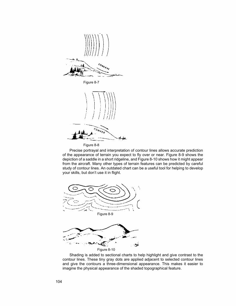
104
Figure 8-7
Figure 8-8 Precise portrayal and interpretation of contour lines allows accurate prediction
of the appearance of terrain you expect to fly over or near. Figure 8-9 shows the depiction of a saddle in a short ridgeline, and Figure 8-10 shows how it might appear from the aircraft. Many other types of terrain features can be predicted by careful study of contour lines. An outdated chart can be a useful tool for helping to develop your skills, but don’t use it in flight.
Figure 8-9
Figure 8-10 Shading is added to sectional charts to help highlight and give contrast to the
contour lines. These tiny gray dots are applied adjacent to selected contour lines and give the contours a three-dimensional appearance. This makes it easier to imagine the physical appearance of the shaded topographical feature.

105
Gradient tints, the "background" colors on charts, indicate general areas of elevation. The height range assigned to each gradient color is indicated on the title panel of each sectional chart. Areas that are near sea level are pale green, while high terrain is color-coded a deep red/brown. Intermediate elevations are indicated by brighter shades of green, tan, or lighter shades of red/brown.
A spot elevation is the height of a specific charted point. On sectional charts, this height is indicated by a number next to a black dot, the number indicating the height of the terrain above sea level.
8.5.2 Aeronautical Data
The aeronautical information on the sectional charts is for the most part self- explanatory. An explanation for most symbols appears in the margin or at the bottom of the chart. Information concerning very high frequency (VHF) radio facilities such as tower frequencies, omnidirectional radio ranges (VOR), and other VHF communications frequencies is shown in blue. A narrow band of blue tint is also used to indicate the centerlines of Victor Airways (VOR civil airways between Omni range stations). Low frequency-medium frequency (LF/MF) radio facilities are shown in magenta (purplish shade of red).
In most instances, FAA navigational aids can be identified by call signs broadcast in International Morse Code. VOR stations and Non-directional Radio Beacons (NDB) use three-letter identifiers that are printed on the chart near the symbol representing the radio facility.
Runway patterns are shown for all airports having permanent hard surfaced runways. These patterns provide for positive identification as landmarks. All recognizable runways, including those that may be closed, are shown to aid in visual identification. Airports and information pertaining to airports having an airport traffic area (operating control tower) are shown in blue. All other airports and information pertaining to these airports are shown in magenta adjacent to the airport symbol that is also in magenta.
The symbol for obstructions is another important feature. The elevation of the top of obstructions above sea level is given in blue figures (without parentheses) adjacent to the obstruction symbol.
Immediately below this set of figures is another set of lighter blue figures (enclosed in parentheses) that represent the height of the top of the obstruction above ground-level. Obstructions which extend less than 1,000 feet above the terrain are shown by one type of symbol and those obstructions that extend 1,000 feet or higher above ground level are indicated by a different symbol (see sectional chart). Specific elevations of certain high points in terrain are shown on charts by dots accompanied by small black figures indicating the number of feet above sea level.
The chart also contains larger bold face blue numbers that denote Maximum Elevation Figures (MEF). These figures are shown in quadrangles bounded by ticked lines of latitude and longitude, and are represented in thousands and hundreds of feet above mean sea level. The MEF is based on information available concerning the highest known feature in each quadrangle, including terrain and obstructions (e.g., trees, towers, and antennas). When looking at MEFs, remember that the data on which they are based are not verified by field surveys.
If a man-made obstacle is more than 200 feet above the highest terrain in the quadrangle, the cartographer determines the elevation of the top of the obstacle above mean sea level. Then he (or she) adds the possible vertical error of the
106
source information, such as 100 feet. Finally, the resulting figure is rounded up to next higher hundred-foot level. For example, a quadrangle showing the highest mountain peak (known as the critical elevation figure) at 5,357 feet above mean sea level would gain 100 feet (5,457) and that would be rounded to the next hundred (5,500); add on 200 more feet for a possible uncharted obstacle on the mountaintop, and the MEF for that quadrangle will be charted at 5,700 feet MSL. If terrain or a "natural vertical obstacle" (such as a tree) is the highest feature in the quadrangle, the cartographer determines the feature's elevation. Next, the possible vertical error (100 feet) is added and then another 200 feet is added to that to allow for natural or man-made obstacles that are not portrayed on the chart (because they are below the chart's minimum height specifications for their portrayal). Finally, the resulting figure is rounded up to the next higher hundred feet.
Since CAP aircraft regularly fly at or below 1000' AGL, aircrews should exercise extreme caution because of the numerous structures extending up as high as 1000' – 2000' AGL. Additionally, guy wires that are difficult to see even in clear weather support most truss-type structures; these wires can extend approximately 1500 feet horizontally from a structure. Therefore, all truss-type structures should be avoided by at least 2000 feet (horizontally and vertically).
Overhead transmission and utility lines often span approaches to runways and scenic flyways such as lakes, rivers and canyons. The supporting structures of these lines may not always be readily visible and the wires may be virtually invisible under certain conditions. Most of these installations do not meet criteria that determine them to be obstructions to air navigation and therefore, do not require marking and/or lighting. The supporting structures of some overhead transmission lines are equipped with flashing strobe lights, which indicate that wires exist between the strobe-equipped structures. Also, some lines have large orange “balls” spaced along their length.
Note: See http://vfrmap.com/ to view U.S. sectional charts.
8.6 Chart Preparation Careful chart preparation and route study before the flight can increase your
efficiency and decrease your workload during the flight. You should try to develop a systematic approach to chart preparation.
The first step in planning any leg is to locate the departure point and destination on the chart, and lay the edge of a special protractor, or plotter, along a line connecting the two points, as shown in Figure 8-11. Read the true course for this leg by sliding the plotter left or right until the center point, or grommet, sits on top of a line of longitude. When the course is more to the north or south, you can measure it by centering the grommet on a parallel of latitude, then reading the course from the inner scale that’s closer to the grommet.

107
Figure 8-11
The discussion that follows concerns one leg of a flight from University-Oxford airport, near Oxford, Mississippi, to the Ripley airport, near Ripley, Mississippi. The same basic principles used in planning this single leg are used in all air navigation and apply to more complex search patterns.
In Figure 8-12, the chart for this “flight”, the two points are connected with a solid line. This line represents the true course from Oxford to Ripley and is 051°. If you were interested in going the opposite direction, the course would be the reciprocal course, 231°, which also appears on the arc of the plotter. Remain aware of the relationship among general directions -- north, east, south, and west -- and their directions indicated by degrees on the compass -- 000, 090, 180, and 270, respectively. Since almost all charts are printed with north to the top of the chart, you can look at the intended direction of flight, which runs right and up, or to the northeast, and know immediately that 051 is correct and 231 is not.
Notice the broken line that nearly passes through the Oxford airport symbol, and follow it toward the bottom of the page. Near the bottom, you'll see the numbers 1°30' E. This is the magnetic variation correction factor for that area.
If you subtract east variation or add west variation to the true course, you can determine the magnetic course. Most fliers advocate writing the "mag" course right on the chart. Round 1° 30' down to 1° and subtract that from the true course to obtain 050 for the magnetic course. Also notice that Oxford is within the boundaries of the Columbus 3 Military Operating Area (MOA). To avoid an unpleasant encounter with a high-speed jet, you can look at the table in the chart's margin, partially shown in Figure 8-18, and determine that jets using this area do not operate below 8,000 feet. You can note this on the chart with a line over 8,000, which means to remain below 8,000 feet.

108
Figure 8-12

109
Next you must determine the total distance you’re going to fly. Measure this using the scale that's printed on the plotter's straight edge, making sure you use a scale appropriate to the scale of the chart. Use the 1:500,000 scale for sectionals. As an alternative, lay a paper's edge along the course line, make pencil marks on the paper's edge at the two airports, and then lay that same edge along the line of longitude. By simply counting the minute marks on the chart's longitude line that fall between those two pencil marks, you can determine the distance between the two airports in nautical miles. In the example, Oxford and Ripley are 33 nm apart.
There are a number of ways you can add information to your chart that will help during the flight. Each flier has his own techniques or variations of the techniques presented here, and over time, you will develop a preference for methods that work best for you.
Tick marks along the course line at specific intervals will help you keep track of your position during flight. Some individuals prefer 5 or 10 nm intervals for tick marks, while others prefer 2 or 4 nm intervals. Four-nautical mile spacing works well for aircraft that operate at approximately 120 knots. Since the 120-knot airplane travels 2 nm every minute, each 4 nm tick mark represents approximately two minutes of flight time. This will become more significant when you study navigational methods in later paragraphs. On the example chart, you have tick marks on the right side of the course line at 4 nm intervals. If the search airplane’s airspeed indicator is marked in miles-per-hour instead of knots, it may be advantageous to space the tick marks in statute mile intervals.
On the left side of the course line you have more tick marks, at 5 nm intervals, but measured backward from the destination. In flight, these continuously indicate distance remaining to the destination. Later in this chapter you will learn about radio aids to navigation that you can use to continuously confirm remaining distance.
The next step in preparing the chart is to identify "check points" along the course; you can use these to check your position on or off course, and the timing along the leg. Prominent features that will be easily seen from the air make the best checkpoints, and many fliers like to circle them or highlight them with a marker in advance. On the example, you might expect to see the large towers east of Oxford about 3 nm to your right shortly after takeoff, and expect later to see the town of Cornersville. Shortly thereafter, you expect to see the road and railroad bend east of Hickory Flat, followed by the Ripley Airport itself. In the example, the checkpoints are widely spaced, but on actual missions checkpoint spacing will be controlled by the search altitude and weather conditions and visibility at the time of the flight.
MOA NAME ALTITUDE OF USE TIME OF USE CONTROLLING AGENCY
ANNE HIGH 7,000 SR - SS MON - FRI ZFW CNTR BIRMINGHAM 10,000 0700-2200 ZTL CNTR COLUMBUS 1, 2, & 3 8,000 SR - SS MON - FRI ZME CNTR MERIDIAN 1 EAST 8,000 SR - SS MON - FRI ZME CNTR Altitudes indicate floor of MOA. All MOAs extend to but do not include FL180 unless otherwise indicated in tabulation or on chart.
Other information that may be written on the chart includes estimated times of arrival (ETA) at each checkpoint and reminders like "check gas", "switch tanks", or "contact mission base". Crewmembers are likely to spend less time "fishing" about the cockpit trying to find information in flight if it is already written on the chart.
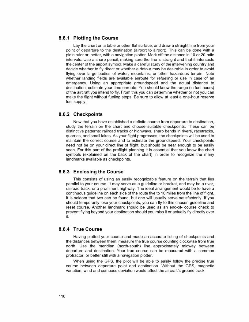
110
8.6.1 Plotting the Course Lay the chart on a table or other flat surface, and draw a straight line from your
point of departure to the destination (airport to airport). This can be done with a plain ruler or, better, with a navigation plotter. Mark off the distance in 10 or 20-mile intervals. Use a sharp pencil, making sure the line is straight and that it intersects the center of the airport symbol. Make a careful study of the intervening country and decide whether to fly direct or whether a detour may be desirable in order to avoid flying over large bodies of water, mountains, or other hazardous terrain. Note whether landing fields are available enroute for refueling or use in case of an emergency. Using an appropriate groundspeed and the actual distance to destination, estimate your time enroute. You should know the range (in fuel hours) of the aircraft you intend to fly. From this you can determine whether or not you can make the flight without fueling stops. Be sure to allow at least a one-hour reserve fuel supply.
8.6.2 Checkpoints
Now that you have established a definite course from departure to destination, study the terrain on the chart and choose suitable checkpoints. These can be distinctive patterns: railroad tracks or highways, sharp bends in rivers, racetracks, quarries, and small lakes. As your flight progresses, the checkpoints will be used to maintain the correct course and to estimate the groundspeed. Your checkpoints need not be on your direct line of flight, but should be near enough to be easily seen. For this part of the preflight planning it is essential that you know the chart symbols (explained on the back of the chart) in order to recognize the many landmarks available as checkpoints.
8.6.3 Enclosing the Course
This consists of using an easily recognizable feature on the terrain that lies parallel to your course. It may serve as a guideline or bracket, and may be a river, railroad track, or a prominent highway. The ideal arrangement would be to have a continuous guideline on each side of the route five to 10 miles from the line of flight. It is seldom that two can be found, but one will usually serve satisfactorily. If you should temporarily lose your checkpoints, you can fly to this chosen guideline and reset course. Another landmark should be used as an end-of- course check to prevent flying beyond your destination should you miss it or actually fly directly over it.
8.6.4 True Course
Having plotted your course and made an accurate listing of checkpoints and the distances between them, measure the true course counting clockwise from true north. Use the meridian (north-south) line approximately midway between departure and destination. Your true course can be measured with a common protractor, or better still with a navigation plotter.
When using the GPS, the pilot will be able to easily follow the precise true course between departure point and destination. Without the GPS, magnetic variation, wind and compass deviation would affect the aircraft’s ground track.

111
8.7 Tracking and Recording Position We have discussed how to use navigational aids and a sectional chart to plot
and navigate a course; the same principles are used during flight to keep track of the aircraft's current position and to record sightings. VORs, DME and the GPS are excellent tools that allow you to fix your current position. This information, in turn, allows a crewmember to plot that position on a sectional chart.
Being able to record and report the position of a ground feature is a critical skill in all CAP ES missions (e.g., search and rescue, disaster relief and assessment, CD, and homeland security). Once an aircrew locates a downed aircraft or determines the location of a breech in a levy, they must be able to pinpoint the location on the sectional and report that position to others. Since the details on the sectional chart are often not detailed enough to be useful to ground units, the scanner or observer usually has to transfer that information to a map (e.g., road or topographical).
The state of knowing where you (the aircraft) are at all times is a large part of "maintaining situational awareness" (see Chapter 11 for further discussion on situational awareness). Navaids allow you to fix your position with great accuracy, and ground features that you can relate to the sectional chart provide confirmation of what your Navaids are telling you about your position. In some situations you may not be able to receive signals from VORs or NDBs, and the GPS may be your only useful navaid; if the GPS fails, then recording you position on the sectional chart is your only means of position determination.
Knowing the aircraft's position at all times is essential if an in-flight emergency should occur. Equipment malfunctions, an electrical fire, or a medical emergency can necessitate landing at the nearest airport: if you don't know where you are, how can you find the nearest airfield?
8.8 Standardized Grid Systems A grid is a network of regularly spaced horizontal and vertical lines used to help
quickly locate points on a map. Most city street maps have grid systems that help motorists locate streets or other points of interest. A commonly used grid system on city street maps involves numerical and alphabetical references. Regularly spaced letters may be printed across the top of such a map designating imaginary vertical columns, while regularly spaced numbers are printed down the sides of the map designating imaginary horizontal rows. If you want to find Maple Street and the map directory indicates Maple Street is located in section K-5, you then look at or near the intersection of column K with row 5. Within that area, you should find Maple Street.
You can construct a grid system on any type of chart or map. You may use numbers and letters like street maps, or you could use only numbers. In either case, the system should give every user a common, standardized method for identifying a location according to its position within the grid. It is very easy to exchange location information over the radio using the grid system. With the known grid positions, other team members can quickly determine on their own charts the location of a sighting or point of interest.
Grid systems are especially helpful when locating a position that has no nearby distinguishable landmarks or features, such as buildings, roads, or lakes. Grid systems will work anywhere, even in the middle of large lakes, in deep woods, or

112
in swamps. Anyone can develop a workable system provided that all members of the search team use the same grid system.
The Civil Air Patrol has found it useful to construct similar grid systems on aeronautical sectional charts for search and rescue operations. Sectional charts cover a land area approximately seven degrees of longitude in width and four degrees of latitude in height. Some maps, like city maps, already have grid systems constructed on them, but sectional charts do not. Below we discuss the ways to grid sectional charts for SAR purposes.
8.8.1 Standardized Latitude and Longitude Grid System
The Standardized Latitude and Longitude Grid System is used by some CAP Wings and by many federal and state agencies. It can be used on any kind of chart that has lines of latitude and longitude already marked. In this system, 1-degree blocks are identified by the intersection of whole numbers of latitude and longitude, such as 36-00N and 102-00W. These points are always designated with the latitude first, such as 36/102, and they identify the area north and west of the intersection of these two lines. In Figure 8-13, the gray shading identifies section 36/102.
-00N
36-00N
103-00W 102-00W
Figure 8-13
Next, the 1° grid is divided into four quadrants using the 30' lines of latitude and longitude. Label each quadrant A through D; the northwest quadrant being 36/102A, the northeast 36/102B, the southwest 36/102C, and the southeast 36/102D, as shown in Figure 8-14.
37-00N
'
103-00W
30' 36-00N
102-00W
Figure 8-14
3
A
B
30
C D

113
Each quadrant can also be divided into four 15' x 15' sub-quadrants, labeled 36/102AA, AB, AC, and AD, again starting with the most northwest and proceeding clockwise, as shown in Figure 8-15. [Note: The GX-55 can be set to use basic grids, refer to Attachment 2.]
45'
45' 37-00N
30'
103-00W
30'
36-00N 102-00W
Figure 8-15
Finally, each quadrant can be further subdivided into four 7.5' x 7.5' sub- quadrants, such as dividing 36/102AA into 36/102AAA, AAB, AAC, and AAD.
8.8.2 CAP Grid System
The CAP Grid System uses a special grid system built upon the matrix of parallels of latitude and meridians of longitude and the sectional aeronautical chart. Information pertaining to this grid system can be found in Attachment E of the U.S. National SAR Supplement to the International Aeronautical and Maritime SAR Manual.
Table 8-1 shows the latitude and longitude boundaries of each sectional chart. The St. Louis chart, for example, covers an area that is bounded by the following latitudes and longitudes: North 40° 00’ (north boundary), North 36° 00’ (south boundary), West 91°-00’ (west boundary), and West 84°-00’ (east boundary).
Chart Identifier North Grid Limit
South Grid Limit
West Grid Limit
East Grid Limit
Total Grids
Seattle SEA 49-00N 44-30N 125-00W 117.00W 576 Great Falls GTF 49-00N 44-30N 117-00W 109-00W 576 Billings BIL 49-00N 44-30N 109-00W 101-00W 576 Twin Cities MSP 49-00N 44-30N 101-00W 93-00W 576 Green Bay GRB 48-15N 44-00N 93-00W 85-00W 544 Lake Huron LHN 48-00N 44-00N 85-00W 77-00W 512 Montreal MON 48-00N 44-00N 77-00W 69-00W 512 Halifax HFX 48-00N 44-00N 69-00W 61-00W 512 Klamath Falls LMT 44-30N 40-00N 125-00W 117-00W 576 Salt Lake City SLC 44-30N 40-00N 117-00W 109-00W 576 Cheyenne CYS 44-30N 40-00N 109-00W 101-00W 576 Omaha OMA 44-30N 40-00N 101-00W 93-00W 576 Chicago ORD 44-00N 40-00N 93-00W 85-00W 512 Detroit DET 44-00N 40-00N 85-00W 77-00W 512 New York NYC 44-00N 40-00N 77-00W 69-00W 512
AA AB B AC AD
D C

114
San Francisco SFO 40-00N 36-00N 125-00W 118-00W 448 Las Vegas LAS 40-00N 35-45N 118-00W 111-00W 476 Denver DEN 40-00N 35-45N 111-00W 104-00W 476 Wichita ICT 40-00N 36-00N 104-00W 97-00W 448 Kansas City MKC 40-00N 36-00N 97-00W 90-00W 448 St. Louis STL 40-00N 36-00N 91-00W 84-00W 448 Cincinnati CVG 40-00N 36-00N 85-00W 78-00W 448 Washington DCA 40-00N 36-00N 79-00W 72-00W 448 Los Angeles LAX 36-00N 32-00N 121-30W 115-00W 416 Phoenix PHX 35-45N 31-15N 116-00W 109-00W 504 Albuquerque ABQ 36-00N 32-00N 109-00W 102-00W 448 Dallas-Fort DFW 36-00N 32-00N 102-00W 95-00W 448 Worth MEM 36-00N 32-00N 95-00W 88-00W 448 Memphis ATL 36-00N 32-00N 88-00W 81-00W 448 Atlanta CLT 36-00N 32-00N 81-00W 75-00W 384 Charlotte
El Paso ELP 32-00N 28-00N 109-00N 103-00W 384 San Antonio SAT 32-00N 28-00N 103-00W 97-00W 384 Houston HOU 32-00N 28-00N 97-00W 91-00W 384 New Orleans MSY 32-00N 28-00N 91-00W 85-00W 384 Jacksonville JAX 32-00N 28-00N 85-00W 79-00W 384 Brownsville BRO 28-00N 24-00N 103-00W 97-00W 384 Miami MIA 28-00N 24-00N 83-00W 77-00W 384
Table 8-1 The sectional grid system used by Civil Air Patrol divides each sectional’s area
into 448 smaller squares. The grid squares usually begin with the most northwest square on the entire sectional, and continuing straight east through number 28. The numbering resumes in the second row, with number 29 placed beneath number 1, 30 beneath 2, and so on through 56. The third row begins with number 57 beneath numbers 1 and 29, and continues through 84. Numbering continues through successive rows until all 448 squares have a number.
The process begins by dividing the whole area into 28 1-degree grids, using whole degrees of latitude and longitude as shown in Figure 8-16. Then each 1- degree grid is divided into four 30-minute grids, using the 30-minute latitude and longitude lines as shown in Figure 8-17. Finally, each of the 30-minute grids is divided into four 15-minute grids, using the 15- and 45-minute latitude and longitude lines as shown in Figure 8-18. [Note: The information on this chart is contained in the GX55 database.]
40-00N
39-00N
40-00N
30'
39-00N
90-00W 89-00W
90-00W 30'
89-00W
Figure 8-16 Figure 8-17

115
5 6 7 8
40-00N
45'
33 34
61 62
89 90
35 36
63 64
91 92
30'
15'
39-00N
90-00W 45'
30' 15'
Figure 8-18
89-00W
Table 8-2 represents the division of the whole St. Louis sectional into 15-minute
grids, with respective grid numbers assigned. To conserve space Table 8-2 doesn’t include the area between longitudes 85° W and 89°30'W.
In Figure 8-19, each 15-minute grid square has the number it would have received if this demonstration had started with the entire St. Louis sectional chart.
40-00N 91-00W 90-00W 85-00W
MKC 25
MKC 26
MKC 27
MKC 28
STL 5
STL 6
< > < > STL 25
STL 26
STL 27
STL 28
MKC 53
MKC 54
MKC 55
MKC 56
STL 33
STL 34
< > < > STL 53
STL 54
STL 55
STL 56
MKC 81
MKC 82
MKC 83
MKC 84
STL 61
STL 62
< > < > STL 81
STL 82
STL 83
STL 84
39-00N
MKC 109
MKC 110
MKC 111
MKC 112
STL 89
STL 90
< > < > STL 109
STL 110
STL 111
STL 112
MKC 137
MKC 138
MKC 139
MKC 140
STL 117
STL 118
< > < > STL 137
STL 138
STL 139
STL 140
MKC 165
MKC 166
MKC 167
MKC 168
STL 145
STL 146
< > < > STL 165
STL 166
STL 167
STL 168
MKC 193
MKC 194
MKC 195
MKC 196
STL 173
STL 174
< > < > STL 193>
STL 194
STL 195
STL 196
38-00N
MKC 221
MKC 222
MKC 223
MKC 224
STL 201
STL 202
< > < > STL 221
STL 222
STL 223
STL 224
MKC 249
MKC 250
MKC 251
MKC 252
STL 229
STL 230
< > < > STL 249
STL 250
STL 251
STL 252
MKC 277
MKC 278
MKC 279
MKC 280
STL 257
STL 258
< > < > STL 277
STL 278
STL 279
STL 280
MKC 305
MKC 306
MKC 307
MKC 308
STL 285
STL 286
< > < > STL 305
STL 306
STL 307
STL 308
37-00N
MKC 333
MKC 334
MKC 335
MKC 336
STL 313
STL 314
< > < > STL 333
STL 333
STL 334
STL 336
Table 8-2 Returning to Table 8-1, notice that the eastern limit of the Kansas City sectional
grid, 90° 00’W, is one full degree of longitude east of the western limit of the St. Louis sectional, 91° 00’ W. The two sectionals overlap by one full degree of longitude. When drawing a grid over this overlap area, which numbers would you assign to these grid squares, the Kansas City or St. Louis grid numbering?
In cases where two sectionals overlap one another, the Civil Air Patrol always uses the numbering system for the western-most chart of the two in question. You can see this in Table 8-2, where the overlap area between 90° 00’ and 91° 00’, shown in the first 4 vertical columns, is identified with Kansas City (MKC) grid numbering, not St. Louis. Note also that, since the Kansas City grid numbering is used in this overlap area, the first 4 columns of the St. Louis grid numbering system are omitted. Several other such overlaps exist within the grid system.
Attachment 2 tells you how many grids are in each sectional. If the table is not available you can compute it using the grid limits. Take the difference in the northern and southern grid limits and multiply by 4 (1/4 degree x 4 to make 1 degree.) Do

116
the same for the east and west grid limits. Then multiply the two products to get the total number of grids on your sectional. For example, the St. Louis sectional extends 4° from 40°-00’ N to 36°-00’ N. Each degree will contain 4 grids, so there will be 4 x 4 = 16 rows of grids. The sectional extends east/west for 7° from 91°-00’ W - 84°- 00’ W, so there will be 7 x 4 = 28 columns of grids. Therefore, the total number of grids on the chart is 16 x 28 = 448. Remember some sectionals don't start counting at 1 because of overlap with an adjacent sectional. If your sectional does this you need to memorize the first grid number:
When circumstances require, a 15-minute grid can be divided into 4 more quadrants using 7 1/2 degree increments of latitude and longitude, creating 4 equal size grids that are approximately 7 1/2 miles square. The quadrants are then identified alphabetically - A through D - starting with the northwest quadrant as A, northeast as B, southwest as C and southeast as D, as in Figure 8-19. A search area assignment in the southeast quadrant may be given as "Search STL 5D."
40-00N
39-52.5N
39-45N
90-00W Figure 8-19
89-45W
Pinpointing an area within the grid system becomes easy once you gain
familiarity with the grids' many uses. You soon will be able to quickly plot any area on a map and then fly to it using the basic navigation techniques already discussed. [Note: Use dotted lines when you grid your charts for ease of reading.]
A ST
B L 5
C D
89-52
.5W

117
Intentionally blank


119
9. Search Planning and Coverage
Chapter
9
This chapter will cover factors that are unique to SAR/DR mission planning. Planning considerations and techniques used in both visual and electronic search missions are included. The incident commander and his general staff perform much of the planning. However, all crewmembers are expected to understand the planning concepts. This comprehension allows more precise mission performance, and increases flexibility to effectively deal with changing circumstances. Much of this information is contained in the U.S. National SAR Supplement to the International Aeronautical and Maritime SAR Manual.
OBJECTIVES:
1. Define the following search terms: {P-2025} a. Ground and Search Track b. Maximum Area of Possibility c. Meteorological and Search Visibility d. Probability Area e. Probability of Detection (POD) f. Scanning Range g. Search Altitude h. Track spacing (S)
2. Discuss how a disaster can effect CAP operations. 3. Discuss the types of questions you must always be asking yourself
during damage assessment missions. 4. List typical things you are looking for during a damage assessment
mission. {P-2026} 5. List the information you should obtain when over a damage
assessment site. {P-2026} 6. Discuss the limitations of an air search for a missing person.

120
9.1 Search Terms A number of terms and planning factors must be understood when planning
and executing search and rescue missions. Ground Track - an imaginary line on the ground that is made by an aircraft's
flight path over the ground. Maximum Area of Possibility - this normally circular area is centered at the
missing airplane’s (or search objective's) last known position (LKP), corrected for the effect of wind. The circle's radius represents the maximum distance a missing aircraft might have flown based on estimated fuel endurance time and corrected for the effects of the wind over that same amount of time. The radius may also represent the maximum distance survivors might have traveled on foot, corrected for environmental or topographical conditions, such as snow, wind, mountains, and rivers.
Meteorological Visibility - the maximum distance at which large objects, such as a mountain, can be seen.
Probability Area - this is a smaller area, within the maximum possibility area, where, in the judgment of the incident commander or planner, there is an increased likelihood of locating the objective aircraft or survivor. Distress signals, sightings, radar track data, and the flight plan are typical factors that help define the probability area's boundaries.
Probability of Detection - the likelihood, expressed in a percent, that a search airplane might locate the objective. Probability of detection (POD) can be affected by weather, terrain, vegetation, skill of the search crew, and numerous other factors. When planning search missions, it is obviously more economical and most beneficial to survivors if we use a search altitude and track spacing that increases POD to the maximum, consistent with the flight conditions, team member experience levels, and safety. Note: POD will be decreased if only one scanner is on board and the search pattern is not adjusted accordingly.
Scanning Range - the lateral distance from a scanner's search aircraft to an imaginary line on the ground and parallel to the search aircraft's ground track. Within the area formed by the ground track and scanning range, the scanner is expected to have a good chance at spotting the search objective. Scanning range can be less than but never greater than the search visibility.
Search Altitude - this is the altitude that the search aircraft flies above the ground (AGL). [Remember, routine flight planning and execution deals in MSL, while searches and assessments are referenced to AGL.]
Search Track - an imaginary swath across the surface, or ground. The scanning range and the length of the aircraft's ground track forms its dimensions.
Search Visibility - the distance at which an object on the ground (CAP uses an automobile as a familiar example) can be seen and recognized from a given height above the ground. Search visibility is always less than meteorological visibility. [Note: On the POD chart the maximum search visibility listed is four nautical miles.]
Track Spacing - the distance (S) between adjacent ground tracks. The idea here is for each search track to either touch or slightly overlap the previous one. It is the pilot's task to navigate so that the aircraft's ground track develops proper track spacing.

121
9.2 Disaster Assessment CAP aircrews may be called upon to assess damage from natural and man-
made disasters. Natural disasters may result from weather related phenomena such as earthquakes, floods, wildfires, winter storms, tornados, and hurricanes. Man-made disasters may result from accidents (e.g., chemical, biological or nuclear industrial accidents) or acts of terrorism or war. Normally, CAP will support FEMA disaster or emergency operations.
Some of the disaster assessment services that CAP may be asked to provide are:
• Air and ground SAR services (e.g., missing persons, aircraft and livestock) • Air and ground visual and/or video imaging damage survey and
assessment • Flood boundary determination using GPS • Air and ground transportation of key personnel, medical and other
equipment, and critical supplies during actual disaster operations • Air transportation of SAR dogs • Radio communications support including a high bird relay and control
aircraft to extend communications over a wide area or to coordinate air traffic into a TFR area over the disaster site
• Courier flights
9.2.1 Effects on CAP operations The conditions that created the emergency or disaster may affect CAP
operations. Extreme weather is an obvious concern, and must be considered in mission planning.
The disaster may affect the physical landscape by erasing or obscuring landmarks. This may make navigation more difficult and may render existing maps obsolete.
Disasters may also destroy or render unusable some part of the area's infrastructure (e.g., roads, bridges, airfields, utilities and telecommunications). This can hamper mobility and continued operations. Also, road closures by local authorities or periodic utility outages can reduce the effectiveness and sustainability of CAP operations in the area.
9.2.2 Biological, Chemical or Radiological Terrorism
The events of September 11th brought home the need for increased vigilance against weapons of mass destruction. The following provide general precautions for CAP aircrews for the three major threats.
For Biological Terrorism, be alert to the following: • Groups or individuals becoming ill around the same time • Sudden increase in illness in previously healthy individuals • Sudden increase in the following non-specific illnesses: pneumonia, flu-like
illness, or fever with atypical features; bleeding disorders; unexplained rashes, and mucosal or dermal irritation; and neuromuscular illness
• Simultaneous disease outbreaks in human and animal populations

122
For Chemical Terrorism, be alert to the following: • Groups or individuals becoming ill around the same time • Sudden increase in illness in previously healthy individuals • Sudden increase in the following non-specific syndromes: sudden
unexplained weakness in previously healthy individuals; hyper secretion syndromes (e.g., drooling, tearing, and diarrhea); inhalation syndromes (e.g., eye, nose, throat, chest irritation and shortness of breath); shin burn- like skin syndromes (e.g., redness, blistering, itching and sloughing)
For Ionizing Radiation Terrorism, be alert to the following: • Nausea and vomiting Pocket guides covering these events may be found on the web
9.2.3 Transportation
In some situations other agencies will wish to conduct the damage assessment, and CAP may be tasked to provide aerial transportation. The rules governing these flights are found in CAPR 70-1 and the FAR Exemptions.
9.2.4 Intelligence gathering
One of the most important commodities during disasters is accurate, timely intelligence. During an emergency or disaster, conditions on the ground and in the air can change rapidly and the emergency managers and responders need this information as quickly as possible.
CAP may be tasked to gather intelligence during emergencies or disasters. Examples of intelligence activities include:
• Signals intelligence. CAP aircrews should report any unusual radio communications overheard during sorties
• Human intelligence. Aircrews returning from sorties will be debriefed on operating conditions, notable changes to infrastructure and terrain, and the condition of local infrastructure
• Imagery intelligence. All aircrews should be equipped with digital cameras, camcorders, instant-film cameras or film cameras for use in recording conditions encountered during operations. Slow-Scan or similar real-time video imagery will also be used. Camcorders are best for large-scale disasters because continuous filming allows coverage of multiple targets and allows for audio comments during filming. Digital cameras are of great value because they allow you to immediately see the results of your shot and they allow for the images to be quickly and widely disseminated.
NOTE: If a CAP aircrew observes unidentifiable, suspicious, or hostile traffic (land, aerospace or sea borne) which, because of its nature, course, or actions, could be considered a threat to the security of the United States or Canada, they will immediately inform CAP mission base.

123
9.2.5 Damage assessment Flying damage assessment sorties is not much different than flying search
patterns. The big difference between a search for a downed aircraft and damage assessment is what you look for in the disaster area. The best way to discuss this is to look at the kinds of questions you should be asking yourselves during your sortie.
When approaching an event scene, don’t just head straight to the scene. First, obtain situational awareness of the entire area surrounding the scene; in particular, check for other traffic such as rescue and media helicopters and other aircraft (gawkers). One method is to circle the area letting your scanners assess the situation while you clear from your side. Once you know the score, then you can proceed to the scene and accomplish your mission.
Most often you will be given specific tasking for each sortie. However, you must always be observant and flexible. Just because you have been sent to determine the condition of a levy doesn't mean you ignore everything else you see on the way to and from the levy.
Different types of emergencies or disasters will prompt different assessment needs, as will the nature of the operations undertaken. Examples of questions you should be asking are (but are certainly not limited to):
• What is the geographical extent of the affected area? • What is the severity of the damage? • Is the damage spreading? If so, how far and how fast? It is particularly
important to report the direction and speed of plumes (e.g., smoke or chemical).
• How has access to or egress from important areas been affected? For example, you may see that the southern road leading to a hospital has been blocked, but emergency vehicles can get to the hospital using an easterly approach.
• What are the primary active hazards in the area? Are there secondary hazards? For example, in a flood the water is the primary hazard; if the water is flowing through an industrial zone then chemical spills and fumes may be secondary hazards.
• Is the disaster spreading toward emergency or disaster operating bases, or indirectly threatening these areas? For example, is the only road leading to an isolated aid station about to be flooded?
• Have utilities been affected by the emergency or disaster? Look for effects on power transmission lines, power generating stations or substations, and water or sewage treatment facilities.
• Can you see alternatives to problems? Examples are alternate roads, alternate areas to construct aid stations, alternate landing zones, and locations of areas and facilities unaffected by the emergency or disaster.
While it is difficult to assess many types of damage from the air, CAP is well suited for preliminary damage assessment of large areas. Generally, you will be looking to find areas or structures with serious damage in order to direct emergency resources to these locations.
A good tool for assessing tornado damage is "A Guide to F-Scale Damage Assessment" (U.S. Department of Commerce, NOAA, NWS; it can be downloaded from the web as a .pdf file).

124
It is very important to have local maps on which you can indicate damaged areas, as it is difficult to record the boundaries of large areas using Lat/Long coordinates.
CAP can quickly provide vital information on the status of: • Transportation routes (road and rail) • Critical facilities/structures such as power stations, hospitals, fire stations,
airports, water supplies, dams and bridges • Levees and other flood control structures • The type and location of areas that have been damaged or isolated • Concentrations of survivors (people and animals) As discussed above, there are many things to look for during your sortie. Some
specific things to look for are: • Breaks in pavement, railways, bridges, dams, levees, pipelines, runways,
and structures • Roads/streets blocked by water, debris or landslide. Same for helipads and
runways • Downed power lines • Ruptured water lines (this may have a major impact on firefighting
capabilities) • Motorists in distress or major accidents • Alternate routes for emergency vehicles or evacuation • Distress signals from survivors
NOTE: Local units should become proficient in identifying their neighborhoods, major facilities, and roads/streets from the air.
At each site, besides sketching or highlighting the extent of the damage on local
maps and identifying access/egress routes, you should record: • Lat/Long • Description • Type and extent of damage • Photo number or time reference for videotape • Status (e.g., the fire is out, the fire is spreading to the northeast, or the
floodwaters are receding)
A sample Photo/Recon Log is provided in Attachment 2, Flight Guide.
After the sortie, remember to replenish your supplies and recharge batteries.

125
9.3 Missing Person Search An individual is very difficult to spot from the air, but CAP aircraft can do well in
some situations: • Persons who are simply lost and are able to assist in their rescue. Persons
who frequent the outdoors are often trained in survival and have the means to signal searching aircraft.
• Persons who may be wandering along roads or highways, such as Alzheimer's patients
• Persons trapped or isolated by natural disasters such as floods. These persons often can be found on high ground, on top of structures, along a road or riverbank.
• Persons who were driving. Their vehicle may be stopped along a road or highway.
Lost children and people with diminished capacities can be especially difficult to find. By the time CAP is called the police have probably already looked in the obvious places. Often, these individuals will be hiding from their searchers. Route and grid searches must be done with great care and with full, well-rested crews. Knowledge of what they are wearing and how they may respond to over-flying aircraft is especially valuable in these instances.
Lost persons often fight topography and are likely to be found in the most rugged portion of the surrounding country (persons who follow natural routes are seldom lost for long periods). Children under five years old frequently travel uphill; they also may hide from searchers (except at night).

126
Intentionally blank

127
10. Visual Search Patterns
Chapter
10
Almost all search and rescue missions are concluded by visual searches of the most probable areas once good information has been received from electronic searches, SARSATs, or other sources. This chapter will cover visual search patterns, some advantages and disadvantages of each, and some of the factors that help determine the type of search pattern you should use. The observer and mission pilot must carefully assess several important factors and their effects that go into the planning phase of a search operation.
Because of the accuracy and reliability of the present Global Positioning System and GPS receivers, CAP aircrews are now able to navigate and fly search patterns with unprecedented effectiveness and ease.
OBJECTIVES:
1. Demonstrate a basic knowledge of a route search. {P-2027} 2. Demonstrate a basic knowledge of a parallel search. {P-2027} 3. Demonstrate a basic knowledge of a creeping line search. {P-2027} 4. Demonstrate a basic knowledge of point-based searches. {P-2027} 5. Demonstrate a basic knowledge of a basic contour search. {P-2027}

128
10.1 Planning Search Patterns Before missions are launched, the briefing officer provides pilots and
crewmembers with information designating the routes to and from the search area, and the types of search patterns to be used upon entering the search area. Mission Scanners should be able to describe each type of search pattern: this allows the scanner to better understand what is happening and anticipate flight maneuvers.
The following descriptions are directed primarily toward a single aircraft search, and will cover track line, parallel, creeping line, expanding square, sector and contour search patterns.
The majority of CAP aircraft are Cessna 172s that only carry three crewmembers, so we assume that the crew consists of a pilot, an observer in the right front seat, and a single scanner in the rear seat. We assume that the observer will be looking out the right side of the aircraft while the scanner covers the left side; therefore the observer's primary duty during the search is to be a scanner. If a larger aircraft is used there may be two scanners in the rear seat.
10.2 Route (Track Line) Search The planner will normally use the route (track line) search pattern when an
aircraft has disappeared without a trace. This search pattern is based on the assumption that the missing aircraft has crashed or made a forced landing on or near its intended track (route). It is assumed that detection may be aided by survivor signals or by electronic means. The track line pattern is also used for night searches (in suitable weather). A search aircraft using the track line pattern flies a rapid and reasonably thorough coverage on either side of the missing aircraft's intended track.
Figure 10-1 Figure 10-1 illustrates the track line search pattern. Search altitude for the track
line pattern usually ranges from 1000 feet above ground level (AGL) to 2000 feet AGL for day searches, while night searches range 2000 to 3000 feet AGL (either depending upon light conditions and visibility).
The search crew begins by flying parallel to the missing aircraft's intended course line, using the track spacing (labeled “S” in Figure 10-1) determined by the incident commander or planner. On the first pass, recommended spacing may be one-half that to be flown on successive passes. Flying one-half “S” track spacing in the area where the search objective is most likely to be found can increase search coverage.
B
A C

129
10.3 Parallel Track (Parallel Sweep) The parallel track (sweep) procedure is normally used when one or more of the
following conditions exist: • The search area is large and fairly level. • Only the approximate location of the target is known. • Uniform coverage is desired. The aircraft proceeds to a corner of the search area and flies at the assigned
altitude, sweeping the area maintaining parallel tracks. The first track is at a distance equal to one-half (1/2) track spacing (S) from the side of the area (Figure 10-2). [Note: In the example the aircraft makes all turns inside the grid; if the briefer and circumstances allow (no aircraft in adjacent girds), turns should be made outside the grid in order to give the scanners short breaks.]
Figure 10-2 This type of search is used to search a grid.
10.4 Creeping Line Search The creeping line search pattern is similar to the parallel patterns. The parallel
pattern search legs are aligned with the major, or longer, axis of the rectangular search areas, whereas the search legs of the creeping line pattern are aligned with the minor or shorter axis of rectangular search areas. Figure 10-3 shows the layout of this search pattern, as used to search along the extended centerline of an airport. The planner uses the creeping line pattern when:
• The search area is narrow, long, and fairly level • The probable location of the target is thought to be on either side of the
search track within two points • There is a need for immediate coverage of one end of the search area

130
Figure 10-3
This coverage is followed immediately by rapid advancement of successive search legs along the line. Rectangular and elongated are the two forms of the creeping line pattern. For each form, the starting point is located one-half search track spacing inside the corner of the search area.
Successive long search legs use track spacing assigned by the incident commander or planner, while the short legs may be flown to within one-half that spacing of the search area's edge.
10.5 Expanding Square Search (a point-based search) The planner normally uses the expanding square search pattern when the search
area is small (normally, areas less than 20 miles square), and the position of the survivors is known within close limits. This pattern begins at an initially reported position and expands outward in concentric squares. If error is expected in locating the reported position, or if the target were moving, the square pattern may be modified to an expanding rectangle with the longer legs running in the direction of the target's reported, or probable, movement.
If the results of the first square search of an area are negative, the search unit can use the same pattern to cover the area more thoroughly. The second search of the area
131
should begin at the same point as the first search; however, the first leg of the second search is flown diagonally to the first leg of the first search. Consequently, the entire second search diagonally overlays the first one. The bold, unbroken line in Figure 10-4 illustrates the first search, while the dashed line represents the second search. Track spacing indicated in Figure 10-4 is "cumulative," showing the total width of the search pattern at a given point on that leg. Actual distance on a given leg from the preceding leg on the same side of the pattern is still only one "S," the value determined by the incident commander or planner.
Figure 10-4
10.6 Sector Search (a point-based search) The sector search is another visual search pattern that can be used after the
approximate location of the target is known. This pattern should be planned on the ground because it involves multiple headings and precise leg lengths. The pilot will fly over the suspected location and out far enough to make a turn, fly a leg that is equal to the maximum track spacing, then turn back to fly over the point again. This pattern continues until the point has been crossed from all the angles as shown in Figure 10-5.

132
Figure 10-5
The sector search has two advantages: • It provides concentrated coverage near the center of the search area • It provides the opportunity to view the suspected area from many angles,
so terrain and lighting problems can be minimized.
For aircraft equipped with the G1000®, the pattern consists of three equilateral triangles (i.e., all leg lengths are equal). The default initial track is 360°, initial turn is to the left, and leg length is five nm.
S max
S mean

133
10.7 Contour Search Flying in mountainous terrain requires special training (i.e., Mountain Fury).
This search pattern (Figure 10-6) is presented for information only, but it may be effectively used for hills and other similar terrain that is not considered high altitude terrain.
Figure 10-6 The contour search pattern is best adapted to searches over mountainous or
hilly terrain. When using this pattern, the pilot initiates the search at the highest peak over the terrain. As in the case of mountains, the pilot flies the aircraft around the highest peak "tucked in" closely to the mountainside. As each contour circuit is completed the pilot lowers the search altitude, usually by 500 feet. While descending to a lower altitude, the pilot turns the aircraft 360º in the direction opposite to the search pattern.
As you may have already gathered, the contour search pattern can be dangerous. The following must be kept in mind before and during a contour search:
• First and foremost, the pilot and crew must be qualified for mountain flying and proficient.
• The crew should be experienced in flying contour searches, well briefed on the mission procedures, and have accurate, large-scale maps indicating the contour lines of the terrain.
• Weather conditions should be good with respect to visibility. • Wind gusts should be minimal to nonexistent. • The search aircraft should be maneuverable with a steep climbing rate and
capable of making small turning circles. • The search should be started above the highest peak of the terrain. Valleys and canyons also pose problems during contour searches. The search
crew should highlight or mark all valleys on their maps that pose possible hazards to contour searching. If the crew believes the aircraft will not be able to turn around or climb out of a certain valley or canyon, mark the area on the chart and report the problem to the planner or debriefing officer. During the sortie, if any crew member senses that further flight may put the search airplane in a situation where it can neither turn around nor climb out of a valley or canyon, the aircraft must not proceed any further.
The search crew should also highlight or mark all valleys on their maps that pose possible hazards to a contour search. Crewmembers must stay alert for wires
134
and power lines that may cross a canyon or valley significantly above its floor. The observer will later report the hazards to the mission debriefer, so that he or she may brief other crews of the hazards.
As a scanner on a contour search mission you should keep an accurate record of the areas searched. Since some areas will be shrouded in fog or clouds, you will have to search those areas when weather conditions permit. One method of keeping records during contour searches is to shade searched areas on the map. The areas that you leave un-shaded are the areas that you have not searched.
NOTE: Take advantage of local or state drills and exercises to train and increase your proficiency. Also, get a MP and use the Air Force Approved Proficiency Flight Profile 1 (A-12 or B-12 in WMIRS) for training. These flights are designed to prepare crews to fly Air Force missions and should include a mission observer, scanner and/or airborne photographer, as appropriate, and though routine flight procedures can be practiced, the majority of a proficiency flight must be focused on the training outlined in the profiles

135
11. Crew Resource Management
Chapter
11
Many professional studies have proven that properly trained team members can collectively perform complex tasks better and make more accurate decisions than the single best performer on the team. Conversely, the untrained team's overall performance can be significantly worse than the performance of its weakest single member. This chapter will cover aspects and attitudes of teamwork and communication among team members.
Crew Resource Management (CRM) was developed by the airlines and later adopted by the U.S. Air Force. Over the years it has gone through several different names and stages. The airlines saw drops in incidents and better crew coordination saw better handling of potential emergencies. The Air Force, and CAP, has recognized this safety concept and over the past several years, aggressively started building programs to protect crewmembers and aircraft.
CRM has evolved to a concept in training and action to get all persons and agencies involved in aviation to help thwart possible accidents. Even now, as CRM is engrained in almost every aspect of aviation, it grows and evolves, becoming better as we make advances.
CAP is a unique organization. Unlike the airlines, where everyone in the cockpit is a rated pilot, CAP often has members in the plane who are not pilots. The Air Force is in a similar situation with their crews made up of pilots, engineers, navigators, and loadmasters.
Having scanners and observers who are also pilots is a different situation, as the pilots may want to compete over who is flying the aircraft. They really need to work together during flights.
It is essential that everyone in the aircraft feel free to speak up and provide input and ideas; even the crewmember that has only flown once may have the critical idea that could save an entire plane. But remember that the pilot is the final authority for safe operation of the aircraft and will make the final decision.
OBJECTIVES:
1. Discuss the fundamentals of Crew Resource Management {P-2028} a. Failures and the error chain b. Situational awareness c. How to regain SA once lost d. Barriers to communication e. Task saturation f. Assignments and coordination of duties

136
11.1 Statistics CAP accident rates compared to General Aviation, per 100,000 hours:
Year Civil Air Patrol General Aviation)
1996 7.79 7.65
1997 4.16 7.17
1998 4.76 7.43
1999 2.34 6.50
2000 0.94 6.57
2001 3.57 6.78
2002 7.37 6.69
2003 4.43 6.68
2004 5.23 6.49
2005 2.77 7.20
2006 1.84 6.35
2007 3.70 6.93
2008 2.84 6.86
2003 3.57 7.20
2010 1.78 6.89 * * NTSB average of past 15 years
CAP FY10 Data: # of Mishaps Reported in Phase of Operation
40 30 20 10
0 # of Mishaps

137
Statistics only mean how they are interpreted. We use statistics to show us where we are having problems, which will hopefully help correct those problems. Some areas where we need to improve are:
Taxi mishaps are mishaps where a crewmember was in the aircraft and moving it under aircraft power. All of these are a result of colliding with something, or going off the paved surface into a ditch. Many occurred when more than one pilot was onboard. Here we need to have everyone looking outside whenever the aircraft is moving.
Handling mishaps were due to moving the aircraft with human power, such as pushing or pulling the aircraft in and out of the hangar. Several of these totals were a result of opening or closing a hangar door and hitting the aircraft. These could be avoided with basic situational awareness and teamwork. While moving aircraft by hand or under aircraft power in close proximity to any objects, use wing walkers.
Landing mishaps (constantly high numbers). Due to the phase of flight, these have a potential for great damages to aircraft and injury to personnel.
A critical concept that needs to be enhanced is that, if any crewmember sees a problem or doesn’t like the landing situation, they need to call “GO-AROUND.” The pilot should then immediately perform a go-around (unless a higher emergency exists). Every crewmember, pilot or not, has the right and the responsibility to keep themselves alive. Maybe the scanner in back notices that the main tire is flat -- tell the pilot! Everyone MUST speak out, and the pilot MUST act on it.
11.2 Failures and the Error Chain Failures are those of parts and physical objects or how people have failed in their actions
or products. • Mechanical failures involve every possible type of mechanical, part, or environmental
failure. Examples are aircraft parts, runway surfaces, lighting, radios, and ATC. • Human failures occur when people fail to perform the required actions. When an
aircraft part fails because the person making the part didn’t do it right, that is a human factors failure. Other examples are failures on the part of the pilot, observer, scanner, and ATC.
Error Chain. A series of event links that, when all considered together, cause a mishap. Should any one of the links be “broken” then the mishap will not occur. Here is an example of an error chain:
• A mechanic does not properly fix aircraft instrumentation during annual • The pilot gets alerted to fly and, in a rush, gets a poor weather briefing • The crew misses indications of broken instrument during the preflight inspection • The pilot enters unexpected (to him) weather and transitions to instrument flying • Flight instruments give the pilot bad information and he begins to get disoriented • The disorientation leads to a stall and subsequent spin • The pilot is unable to recover from the spin and impacts the ground All of these are links in the chain. If any one of them could have been stopped or the link
broken, the accident would not have happened. It is up to everyone on a crew to recognize an accident link and break the chain.

138
11.3 Situational Awareness Simply put, situational awareness (SA) is "knowing what is going on around you at all
times." SA is not restricted to just pilots -- everyone must exhibit SA at all times. Each crewmember must have their SA at peak levels while flying because it takes everyone’s awareness to keep the plane safe in flight. Scanners and observers have their own unique positions and functions that require full attention, so their SA is essential to the safe operation of any CAP flight.
Examples of good SA attitudes are: • Good mental health, where each crewmember is clear and focused • Good physical health. This includes fatigue, sickness, hydration, and stress factors • Attentiveness. Keep your attention on the task at hand • Inquisitiveness. Always asking questions, challenging ideas, and asking for input Examples of SA skills: • Professional skills developed through training, practice and experience. • Personal skills such as good communication skills. This is necessary to effectively get
your point across, or receive valid input. Interpersonal skills such the basic courtesies factor greatly into how a crew will get along, and this will greatly impact crew effectiveness and performance.
To help prevent a loss of SA, use the IMSAFE guidelines. This checklist was developed for the FAA as a quick memory guide for aviators to run through and make self-determination as to their fitness to fly. If a crewmember says yes to any of these, they really shouldn’t fly.
Situational awareness may be lost for many reasons. Five of the more common reasons are:
• Strength of an idea. Someone has an idea so strong and ingrained that they won’t listen to anything else. They find it difficult to alter the idea, even with new or conflicting information. The antidote to this is to ask questions or revert to training.
• Hidden agenda. Someone has a personal agenda, but keeps it hidden. Fail to tell others of their intentions. The antidote is to be honest, and to express ideas and intentions.
• Complacency. Someone has done a certain task so often that they forget about the risk. "I've done this a hundred times," or "It won't happen to me." The antidote is to revert to training, and realize that even if you've done it a hundred times before, the one hundred and first can still hurt you.
• Accommodation. Repeated exposure to threats or stress situations will decrease alertness or awareness, which leads to a form of complacency.
• Sudden Loss of Judgment. Something quickly distracts a person and gets their full attention. Whatever they were doing or should be doing is now gone.
Symptoms of loss of SA vary, but a few are: • Fixation • Ambiguity • Complacency • Euphoria • Confusion • Distraction • Overload • Improper performance of tasks or procedures
139
Also, look for hazardous attitudes: • Anti-authority (Don't tell me!). The antidote is to follow the rules. • Impulsiveness (Do something NOW!). The antidote is to slow down and think first. • Invulnerability (It won't happen to me!). The antidote is to realize that, yes, it can
happen to me. • Macho (I can do it!). The antidote is to realize that this attitude can hurt others beside
you. This attitude can really be detrimental when there is an experience pilot in both the left and right seat! In this case, it is very important that the two pilots agree on who's flying the aircraft.
• Resignation (What's the use?). The antidote is to realize that you can make a difference, and to ask for help.
• Get-There-Itus (I've got to be home by 5!). It’s better to be late than to be dead.
11.4 Overcoming Loss of SA Pilots and aircrew must realize that you can’t have complete SA all the time; the key is to
have a plan to recover. When a crew loses SA it is critical to reduce workload and threats: • Suspend the mission. Stop doing complicated things. [Remember to "Aviate, Navigate
and Communicate."] • Get away from the ground and other obstacles (e.g., climb to a safe altitude) • Establish a stable flight profile where you can safely analyze the situation Once we have lost situational awareness, or recognized the loss in another crewmember,
how do we get it back? A few methods are to: • Listen to your gut feelings. If it acts like an idiot and talks like an idiot, then it’s probably
an idiot. • Use terms like “Knock it Off,” "Time Out," "Abort" or "This is Stupid." Once terms like
these are called, the pilot should terminate the task or maneuver, climb away from the ground if necessary, establish straight-and-level flight and then discuss the problem. [The term you use should be agreed upon before the flight.] A good example comes from a CAP training mission departing a controlled airport. As the aircraft was climbing out the scanner spotted traffic and said "Pilot, traffic at three o'clock." The pilot was talking to departure and replied "Quiet, I'm on the radio." The scanner repeated his sighting, and the pilot repeated his reply. The scanner shut up and the pilot finally saw the traffic. What happened? The pilot ignored a serious safety input from a crewmember. His action alienated the scanner and established a climate not conducive to safety. [Coincidently, the scanner was a commercial pilot and USAF T-37 instructor with more flying experience than the rest of the crew combined.] Be aware that lack of individual respect can cause alienation, which is a serious barrier to communication (see next section) and can shatter teamwork. If an individual is insulted or ignored when making comments they will shut down and stop working with the crew. When this happens the aircrew must solicit input in order to pull the alienated crewmember back into the mission.
• Keep the cockpit sterile -- keep talk to the minimum necessary for safety, particularly during taxi, takeoff, departure, low-level flying, approach, pattern and landing. This helps remove distractions and keep everyone focused on the important things.

140
11.5 Barriers to Communication This section is concerned with the human factors that may act as barriers to effective
communication between team members, adversely affecting mission performance. Rank, gender, experience level, age, personality, and general attitudes can all cause barriers to communication. You may occasionally be hesitant to offer an idea for fear of looking foolish or inexperienced. You may also be tempted to disregard ideas that come from individuals that have a lower experience level. If you are committed to teamwork and good crew coordination, you must look through such emotions and try to constructively and sensitively adapt to each personality involved.
You can deal best with personalities by continually showing personal and professional respect and courtesy to your teammates. Criticism will only serve to build yet another barrier to good communication. Nothing breaks down a team effort faster than hostility and resentment. Always offer opinions or ideas respectfully and constructively. Instead of telling the pilot, "You're wrong," tell him what you think is wrong, such as "I think that new frequency was 127.5, not 127.9."
Personal factors, including individual proficiency and stress, may also create barriers to good communication. Skills and knowledge retention decrease over time, and that is why regular training is necessary. If you don’t practice regularly, you very likely will spend a disproportionate amount of time on normal tasks, at the expense of communication and other tasks. Civil Air Patrol, the FAA, commercial airlines, and the military services all require certain minimum levels of periodic training for the sole purpose of maintaining proficiency.
Stress can have a very significant, negative effect on cockpit communication. An individual's preoccupation with personal, family, or job-related problems distracts him or her from paying complete attention to mission tasks and communication, depending upon the level and source of stress. The flight itself, personalities of the individuals, distractions, flight conditions, and individual performance can all be sources of communication-limiting stress. When stress reaches very high levels, it becomes an effective barrier to communication and job performance. Many fliers and medical specialists advocate refraining from flying or other complex tasks until the stress is removed.
In an emergency, there will likely be much more stress with which each crewmember must cope. Since very few emergencies result in immediate or rapid loss of an airplane, most experienced aviators recommend making a conscious effort to remain calm, taking the amount of time necessary to properly assess the situation, and only then taking the appropriate corrective action.
Part of your job is also to recognize when others are not communicating and not contributing to the collective decision-making process. Occasionally, other crewmembers may need to be actively brought back into the communication process. This can often be done with a simple “What do you think about that?” In a non-threatening way, this invites the teammate back into the communication circle, and, in most cases, he or she will rejoin the information loop.
11.6 Task Saturation At times, crews or individual members may be confronted with too much information to
manage, or too many tasks to accomplish in the available time. This condition is referred to as task saturation. This will most likely happen when a crewmember is confronted with a new or different situation such as an emergency, bad weather, or motion sickness. Preoccupation with the different situation may then lead to a condition of “tunnel vision,” where the individual can lose track of many other important conditions. In an advanced state, comprehension is so far gone that partial or complete situational awareness is lost. When individuals are task saturated to this extent, communication and information flow usually ceases.

141
Everyone needs some workload to stay mentally active and alert. The amount of work that any member can handle is directly related to experience level. Each crewmember must try to keep his or her workload at an acceptable level. If you begin to feel overwhelmed by information or the sheer number of things to do, it's time to evaluate each task and do only those tasks that are most important. If you ever feel over-tasked, you have an obligation to tell the other crewmembers before becoming task-saturated and losing your situational awareness. If others know your performance is suffering, they may assume some of the workload, if they are able. Once the most important tasks are accomplished and as time permits, you can start to take back some of those tasks that were neglected earlier. Allocation of time and establishing priorities is known as time management.
Most people can recognize task saturation and understand how it can affect performance. However, you should also watch for these symptoms in other members of your crew and take over some of their responsibilities if you have the qualifications and can do so without placing your own duties at risk.
The pilot's job is to safely fly the aircraft, and you should be very concerned if he or she becomes task saturated, or spends an excessive amount of his time with tasks other than flying the airplane. No crewmember should ever allow the work management situation to deteriorate to such an extent as to adversely affect the pilot's ability to continue to safely operate the aircraft. Many preventable accidents have resulted from crews’ entire involvement in other areas or problems, while the airplane literally flew into the ground. If any crewmember suspects pilot task saturation to be the case, nonessential discussion should cease, and the crew as a whole should discontinue low-priority aspects of the job, and even return to the mission base if necessary.
11.7 Identification of Resources External resources can be people, equipment, or simply information. Internal resources are
primarily training and experience. Resources are needed for the successful accomplishment of the mission.
Each crewmember must be able to identify the resources available to him or her, determine where the resources can be located when needed, and effectively incorporate those resources into the mission.
11.8 Assignment and Coordination of Duties Assignment of aircrew duties is based on CAPR 60-3. All flight-related duties are
conducted under the supervision of the aircraft commander. Mission-related duties may also be conducted under the supervision of the aircraft commander, but a properly trained observer can also fill the role of mission commander. The key is that positive delegation of monitoring duties is as important as positive delegation of flying duties.
As previously discussed, it is very important for each crewmember to know what they are supposed to be doing at all times and under all conditions. Aircraft safety duties vary with the startup, taxi, takeoff, departure, transit, approach, pattern and landing phases of flight. Mission duties are related to the mission objective, primarily to fly the aircraft safely and precisely (the pilot) and to scan effectively (scanners and observers).
Until recently, the study of crew coordination principles was limited to studying flight crew performance. However, over the last decade, the number of preventable operator-caused errors leading to accidents has caused both the military and commercial aviation communities to expand the study focus. Airline and military crew resource training now includes special emphasis and encouragement that, when making decisions, the pilot or aircraft commander should include all assets and sources of information in the decision-making process. The

142
general assumption or theory is that as more information becomes available, the likelihood of more accurate decisions will increase and operator errors will be reduced.
The same general principles of crew coordination and resource management apply to all the members of the aircrew team. Incident commanders, planners, operations section chiefs, SAR/DR pilots, mission observers, scanners, air traffic controllers, and flight service station personnel should all be considered sources for appropriate information by the aircrew team.
In order for any information to be used, it must be effectively communicated. The effective communication process that leads to good crew coordination actually starts well before a flight begins. Each member must pay close attention during the incident commander briefing to every detail presented. Clear understanding of the "big picture," search objective, altitudes, area assignments, and search patterns to be used prior to departure will preclude questions and debate in flight, when other tasks should take higher priority. Crewmembers having questions are encouraged to ask them at this time. The incident commander or air operations officer will normally establish certain safety-related rules for conducting that particular mission.
Decisions and search assignments are normally clearly stated to the crews, and crewmembers are encouraged to offer their own ideas. Planning and briefing officers should answer each question openly and non-defensively, and you should also make every effort to seek complete understanding of each situation.
In developing the actual mission operational plan workload management and task distribution are very important. An over-tasked crewmember may not develop a complete grasp of mission aspects that later may affect his or her performance. Remain alert for over-tasking in other crewmembers, and offer help if possible. If you find yourself over-tasked, do not hesitate to ask another qualified member for help. Each team member must continually think “teamwork.”
Close attention should be paid during the pilot’s briefing. The pilot will establish flight- specific safety "bottom lines" at this time, such as emergency duties and division of responsibilities. Each individual must again clearly understand his specific assigned duties and responsibilities before proceeding to the aircraft.
Other phases of the flight also require that distractions be kept to a minimum. Recent air transport industry statistics show that 67% of airline accidents during a particular survey period happened during only 17% of the flight time -- the taxi, takeoff, departure, approach, and landing phases. The FAA has designated these phases of flight as critical, and has ruled that the cockpit environment must be free of extraneous activity and distractions during these phases to the maximum extent possible (the sterile cockpit).
In assigning scanning responsibilities to the scanners, mission observers must be receptive to questions and suggestions from the scanners. Carefully consider suggestions and understand that suggestions are almost always offered constructively, and are not intended to be critical. Answer questions thoroughly and openly, and don’t become defensive. All doubts or questions that you can’t answer should be resolved as soon as possible. It is critical to remember that CRM encourages the flow of ideas, but the Mission Pilot must make the final decision based on the crew's input.

I
Attachment 1
Attachment
A
GRIDDING Appendix E, United States National Search and Rescue Supplement to the International Aeronautical and Maritime Search and Rescue Manual, contains tables that enable you to grid all the United States aeronautical sectional charts.
The instructions and the table listing the sectional charts, and the individual tables are provided separately due to space constraints.

II
Intentionally blank

III
Attachment 2
FLIGHT GUIDE
The Flight Guide is provided separately due to its purpose and size. It is designed for printing (full page or knee board size) and may be carried by aircrew members. Members should look through the guide to decide what is applicable to their aircraft and mission, and then print only those pages. The guide is not required to teach the material in the Mission Aircrew Reference Text, but is controlled because it contains material from and related to the MART. The guide contains figures, graphs, tables, operations guides, and forms that will aid the aircrew member in his or her daily tasks. Not all items in the Flight Guide are needed; crewmembers should identify what items they need and then print only those items. If desired, print them in "knee-board" size.
Flight Guide Table of Contents 1. Mission Checklist 2. Documents and Minimum Equipment 3. CAP Operational Risk Management Aviation Worksheet (WMIRS) 4. Density Altitude 5. Crosswind Data Sheet 6. Weight & Balance Work Sheet 7. FAA Flight Plan 8. Basic VFR Traffic Pattern (Uncontrolled Field) 9. VFR Flight Information
a. VFR Airspace Classifications b. Basic VFR Weather Minimums
10. Emergency Egress 11. Flight Line Hand Signals 12. Pilot Guide to Airport Signs and Markings 13. Surface Movement Guidance and Control System 14. PMA7000MS Audio Panel Operations Guide

IV
15. NAT NPX-138 VHF FM Radio Operations Guide 16. TDFM-136 Digital/Analog VHF FM Radio Operations Guide 17. CAP FM Radio Information
a. National Standard Channelization Plan b. Other Important Frequencies and Phone numbers c. Required FM Radio Reports
18. Prowords and Aircraft Clock Positions 19. Visual Signals
a. Paulin b. Emergency Distress c. Ground-to-Air Body d. In-Flight Intercept Procedures e. Air-to-Ground (no com) f. Air-to-Ground Team Coordination
20. Deleted 21. Aircrew Survival Basics and Urgent Care/First Aid 22. POD Charts (Mission and Cumulative) 23. Visual Search Patterns 24. Apollo GX-50/55 GPS - SAR Operations Guide 25. U.S. Grid Chart Table 26. DF Search Patterns
a. Metered b. Audible c. Wing Null
27. ELT Reception Distances 28. L-Tronics DF Functional Checks 29. Becker SAR DF-517 Operations Guide 30. Basic Ground ELT Search Procedures
a. Hand-held DF Procedures b. Silencing an ELT c. Legal Issues

V
31. Forms a. ELT Search Information Required by AFRCC b. Observer Log and Instructions c. Observer/Scanner Search Area Work Sheet d. Mission Pilot Search Area Work Sheet e. High Bird Work Sheet f. High Bird Transmission Log g. CAP Photo/Recon Log h. Standardized Latitude/Longitude Grid System i. Standardized 15' x 15' Grid Coordinates j. Standardized 7.5' x 7.5' Grid Coordinates xxA k. Standardized 7.5' x 7.5' Grid Coordinates xxB l. Standardized 7.5' x 7.5' Grid Coordinates xxC m. Standardized 7.5' x 7.5' Grid Coordinates xxD n. CAP Grid Coordinates Work Sheet o. CAP Quarter Grid Coordinates 'A" p. CAP Quarter Grid Coordinates 'B" q. CAP Quarter Grid Coordinates 'C" r. CAP Quarter Grid Coordinates 'D" s. Route Coordinates t. Creeping Line Coordinates Work Sheet u. Expanding Square Coordinates Work Sheet v. Circling Imaging Pattern Work Sheet w. 4-Square Imaging Pattern (using Port Window) Work Sheet x. 4-Square Imaging Pattern (using Starboard Window) Work Sheet y. Bird’s Eye Imaging Pattern Work Sheet z. 45° Angle to Target Imaging Pattern Work Sheet

VI
Intentionally blank

Index
A
AFRCC · 7 AGL · 69 aileron · 14 ailerons · 16 aircraft balance · 23, 25 aircraft egress · 29 aircraft weight · 23, 24 airfoil · 16 airport signs and markings · 30 airspace · 96 airspeed indicator · 19 air-to-ground signals · 55 air-to-ground team coordination · 56 Alert Areas · 98 altimeter · 18 analgesics · 92 antihistamines · 92 atmospheric and lighting conditions · 72 attitude indicator · 20 audio panel · 21 avionics lock · 9
B
barriers to communication · 138 biological, chemical or radiological
terrorism · 119 body signals · 54 briefings · 9
C
c. g. envelope · 25 callsign · 49 CAP forms · 10 CAPF 101 · 9 CAPF 101Ts · 9 CAPF 104 · 9 CAPF 108 · 9
center of gravity · 23 chart preparation · 105 checklist · 26, 28 checkpoints · 108, 109 clock position · 80 communications radio · 48 compass · 18, 43, 45, 81 condensation · 26 contour · 100 contour lines · 102 contour search · 131 coordinates · 96 course · 94 creeping line search · 127 crew coordination · 139 Crew Resource Management · 133 CRM · 133 cultural feature · 100
D
damage assessment · 121 datum · 24 debrief · 9 debris · 78 decongestant · 91 dehydration · 90 disaster assessment · 119 drift · 94 drift correction · 94 duties · 81
E
ear block · 90 elevator · 14, 16 emergency distress signals · 55 emergency transponder codes · 22 empennage · 14 error chain · 135 expanding square search · 128

F
fatigue · 64, 79 FECA · 8 Federal Employee Compensation Act · 8 Federal Tort Claims Act · 8 FEMA · 6 field of scan · 68 fire · 28 fixation area · 65, 67 fixation points · 65 flaps · 16 FM radio · 48, 49 FM radio reports · 54 fovea · 64 FTCA · 8 fuel management · 30 fuel selector · 17 fuselage · 14
G
GPS · 20 great circle · 95 grid · 110 gridding · 112 ground handling · 28 ground mishaps · 135 ground track · 94, 118 groundspeed · 109 gyroscope · 18
H
heading · 94 horizontal stabilizer · 14, 16 humidity · 90 hypoxia · 91
I
IFR · 6 Instrument Routes (IR) · 98 intelligence gathering · 120
K
knots · 94
L
landing mishaps · 135 latitude · 95 longitude · 95
M
magnetic course · 94 magnetic heading · 94 magnetic variation · 106 maximum area of possibility · 118 Maximum Elevation Figures · 104 MEF · 104 meridians of longitude · 95 meteorological visibility · 118 microbursts · 87 Military Operations Area · 97 Military Training Routes · 98 missing person search · 123 MOA · 97, 108 moment arm · 24 mountainous terrain · 131 MOUs · 7 MSCA · 7 MSL · 18 MTRs · 98
N
nautical mile · 94 navigation terms · 94 navigation/communications radios · 21 Notices to Airmen · 99 NSEP · 7
O
OPLAN 1000 · 6

P
parallel sweep search · 127 parallel track search · 127 parallels of latitude · 95 paulin signals · 54 pilot’s briefing · 140 pitch · 16 placards · 29 planning visual search patterns · 126 plotting a course · 109 POD · 118 preflight inspection · 25 pressure altitude · 18 probability area · 118 probability of detection · 118 Prohibited Areas · 97 pronunciation · 50 prowords · 51
R
Restricted Area · 98 route search · 126 rudder · 14, 16
S
SA · 136 safety in and around aircraft · 27 SARDA · 6 scanner duties · 4 scanning · 64 scanning patterns · 69 scanning range · 68, 118 SCATANA · 6 search altitude · 118 search track · 118 search visibility · 118 search visibility range · 68 sectional aeronautical chart · 100 sectional aeronautical information · 104 sectional chart interpretation · 101 sectional chart legend · 100 sector search · 129 sinus block · 91
situational awareness · 136 Special Use Airspace · 97 Standardized Latitude and Longitude
Grid System · 111 statute mile · 94 stress · 138 survival equipment · 44
T
task saturation · 138 taxi mishaps · 135 taxiing · 30, 35 TDFM 136 · 50 thunderstorms · 86 track crawl · 126 track line search · 126 track spacing · 118, 127, 128, 129 transponder · 22 trim tab · 16 true course · 94, 109 turbulence · 86 turn coordinator · 19
U
urgent care · 46
V
vertical speed indicator · 19 VFR · 97 VFR Terminal Area Chart · 101 VHF · 48 visual clues · 75 Visual Routes (VR) · 98
W
wake turbulence · 35 Warning Areas · 98 weather · 84 weight and balance · 22, 24 wind shear · 86 wreckage patterns · 77

Intentionally blank